Haynes Saab 90, 99 & 900 Owners Workshop Manual 1850104352, 9781850104353
“312 pages : 28 cm Includes index”.
135 105 28MB
English Pages 320 Year 1988
Recommend Papers
![Haynes Saab 9-3 Owners Workshop Manual [4614]
1844256146, 9781844256143](https://ebin.pub/img/200x200/haynes-saab-9-3-owners-workshop-manual-4614-1844256146-9781844256143.jpg)

![Haynes Saab 900 Automotive Repair Manual [84010]
1850105677, 9781850105671](https://ebin.pub/img/200x200/haynes-saab-900-automotive-repair-manual-84010-1850105677-9781850105671.jpg)


File loading please wait...
Citation preview
(Terry Davey)
©HAYNES 1/982
WLUOUNUU 40
ITY
Pa,
~
ithe. 2v0 EDINBURGH CITY LIBRARIES Reference Department q THIS BOOK MUST NOT BE REMOVED UNDER ANY PRETEXT FROM THE REFERENCE DEPARTMENT. INFRINGEMENT OF THIS RULE RENDERS THE OFFENDER LIABLE TO PROSECUTION.
Before leaving the Library readers must return the books to one of the attendants at the issue desk, or they will. be held responsible for them.
Readers are required to take care of the books. Writing or drawing with pen or pencil on any part of a book, or turning down the leaves, or cutting or mutilating them, will be treated as serious damage. CONVERSATION IN THE REFERENCE DEPARTMENT IS ANNOYING TO STUDENTS, AND IS NOT PERMITTED. Class.
:
Location.
>
Accession.
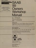
Saab Owners Workshop Manual A
K Legg
Models
T Eng MIMI
covered
All Saab 90, 99 and 900 models; Saloon, Coupe and Hatchback, including Turbo, 16-valve and limited edition versions; 1985 cc Covers most mechanical features of Convertible Does not cover Saab 9000 models
ISBN 1 85010 435 2 © Haynes Publishing Group 1981, 1986, 1988 All rights reserved. No part of this book may be reproduced or transmitted in any form or by any means, electronic or mechanical, including photocopying, recording or by any information storage or retrieval system, without permission in writing from the copyright holder.
Printed in England
(765-5P4) ABCDE FGH
Haynes Publishing Sparkford Nr Yeovil Somerset BA22 7JJ
Group
England
British Library Cataloguing
in Publication
Legg, A. K.
Haynes
:
5
Publications,
Inc
. 861
Lawrence
Newbury
Park
Drive
? : California 91320 USA
rer ‘|
Bue we ine
Saab 90, 99 & 900 owners workshop manual
— (Owners Workshop Manuals). 1.
Automobiles — Maintenance and repair
|. Title
629.28'722
Il. Series
TL152
SBN) -85010-435gO ae
Data
ETS TETS
| EDINBURGH CITY LIBRARIES
Acknowledgements Thanks are due to the Champion Sparking Plug Company Limited who supplied the illustrations showing the sparking plug conditions and to Duckhams Oils who provided lubrication data. Certain other illustrations are the copyright of Saab (Great Britain) Limited, and are used with their permission. Special thanks are also due to Saab (Great
About
this manual
[ts aim The aim of this manual is to help you get the best value from your vehicle. It can do so in several ways. It can help you decide what work
must be done (even should you choose to get it done by a garage), provide information on routine maintenance and servicing, and give a logical course of action and diagnosis when random faults occur. However, it is hoped that you will use the manual by tackling the work yourself. On simpler jobs it may even be quicker than booking the car into a garage and going there twice, to leave and collect it. Perhaps most important, a lot of money can be saved by avoiding the costs a garage must charge to cover its labour and overheads. The manual has drawings and descriptions to show the function of the various components so that their layout can be understood. Then the tasks are described and photographed in a step-by-step sequence so that even a novice can do the work.
/ts arrangement The
manual
Britain) Limited and Saab-Scania of Sweden for the supply of technical information, to Sykes-Pickavant who provided some of the workshop tools, and to all those people at Sparkford who assisted in the production of this Manual.
is divided
into thirteen
Chapters,
each
covering
a
logical sub-division of the vehicle. The Chapters are each divided into Sections, numbered with single figures, eg 5; and the Sections into paragraphs (or sub-sections), with decimal numbers following on from the Section they are in, eg 5.1, 5.2, 5.3 etc.
Introduction
to the Saab
The Saab 900 was first introduced in early 1979 and was similar to the existing 99 Combi Coupe, but with a longer more sloping bonnet, front spoiler and deeper windscreen. The body is of rigid construction employing safety beams in the doors and a reinforced roof. The in-line mounted engine is located over the gearbox or automatic transmission providing drive to the front wheels. Unlike the more conventional layout, the engine is positioned with the flywheel at
It is freely illustrated, especially in those parts where there is a detailed sequence of operations to be carried out. There are two forms of illustration: figures and photographs. The figures are numbered in sequence with decimal numbers, according to their position in the Chapter — eg Fig. 6.4 is the fourth drawing/illustration in Chapter 6. Photographs carry the same number (either individually or in related
groups) as the Section or sub-section to which they relate. There is an alphabetical index at the back of the manual as well as a contents list at the front. Each Chapter is also preceded by its own individual contents list. References to the ‘left’ or ‘right’ of the vehicle are in the sense of a person in the driver's seat facing forwards. Unless otherwise stated, nuts and bolts are removed by turning anti-clockwise, and tightened by turning clockwise. Vehicle manufacturers continually make changes to specifications and recommendations, and these, when notified, are incorporated into Our manuals at the earliest opportunity. Whilst every care is taken to ensure that the information in this manual is correct, no liability can be accepted by the authors or publishers for loss, damage or injury caused by any errors in, or omissions from, the information given.
900, 99 and 90 the front of the car, but this facilitates removal of the clutch without having to remove either the engine or gearbox. Being of an up market design, the car incorporates many extras to add to comfort and driveability. The Saab 90 replaced the 99 in the UK in 1984. Details of this vehicle are explained in the introduction to the supplementary chapter at the end of this manual.
Contents Page
Acknowledgements
2
About
2
this manual
Introduction to the Saab 900, 99 and 90
2
General dimensions, weights and capacities
6
Use of English
7
Buying spare parts and vehicle identification numbers
8
Tools and working facilities
12
General repair procedures
12
Jacking and towing
13
Recommended
14
lubricants and fluids
Safety first!
15
Routine maintenance (a/so see Chapter 73)
16
Fault diagnosis
22
Chapter 1
26
Chapter
Engine (a/so see Chapter 73)
2. Cooling system (a/so see Chapter 73)
55
Chapter 3
Fuel, exhaust and emission control systems (a/so see Chapter 13)
66
Chapter 4
Ignition system (a/so see Chapter 73)
94
Chapter 5
Clutch
Chapter 6 Manual gearbox
Chapter
7
:
108
and final drive
116
Automatic transmission and final drive
131
Chapter 8
Driveshafts (a/so see Chapter 73)
137
Chapter 9
Braking system (a/so see Chapter 73)
143
Chapter 10 Electrical system (a/so see Chapter 713)
156
Chapter 11
208
Suspension and steering (a/so see Chapter 713)
Chapter 12 Bodywork and fittings (a/so see Chapter 73) Chapter 13 Supplement:
Revisions and information
227 on later models
248
Conversion factors
307
Index
30 ie)
RARER Aen Behe
PROG
Es
eErgas
i
5-door Turbo 900 Saab
Gees66 15
400p-Z
General Dimensions
dimensions, weights and capacities
in (mm)
Overall length — 99 models: Saloon — Gary’ 19:7Qiskec Seecattscteusreterteressrastntes-tavc)useuskacieastensersarce ceaStanrs Saloon — late 19.79 Omer tietencsccesesstoriant assataneenestaste cnseus teaentctersett cede COMbI COUPE) ssssisscisccsccreversaeaneavescesestnas tatesverceessarcansas tsatteee: aemmcemecents aemecaes Overall length — 900 models: Saloon’ and’ Combi Coupe ii....-ecctmpere-ctherceaseacsisuttiseeeenetseteetaeeentaserars Overall width: All MOEIS .:.cciscssseasssosessacevsatessteveuasececastantevenieattesutcutcdrety orebecsestaants meartateces
174.01
in (4420 mm)
176.26
in (4477
mm)
178.35 in (4530 mm) 186.57
in (4739 mm)
66.54 in (1690 mm)
Overall height (at curb weight): QO MOde|IS sinsccdiscssccceusoasecedebersusacenereanotanen teedancer nesseeeee tens Pun Tae eeetasse Asan GOO MOde|IS sescscsiennccssacsavectetgcanereantten oeeeeretncees aserase ee eee aece eect antes Track — 99 models:
Non=Turbo. preé=1982 ...cisc.cccsstesnameotetmeresdteccter eorerecerceet meas Turbo and 1982 on models Tack — GOO models iiicsscccscscocescsecvsocovencameeuteenccartecaes arsores seeearte meen sessetcenetesss Wheelbase — Pre=1982 1.982. ON Wheelbase — Pre=1982 T9882 on
99 models: MoOdEIS ic..cocosscessecesccucacataceunant eeteemtece acess attssga anaes tara cteesns MOIS iicicccsscecsscks ossronesepteteeccnetense ccoeaeenaseestneoeasareasicereecantanans 900 models: model viiccccicssscossecesscueereeeectertaereueeneetten ia:deeeserer tensa eee eeeee Model sisiissccsdscctlecuetatecttorsedeessntettes covets nsateweedrieeemeaccr eens
Turninggcircle — 99: models: .....
iS
w
5
107a SV 2.5
ae ag)eee 123 IF !
a
|
pe
3
rs a seis el
321GNOTS—
Aces
HIT9OS
Fig. 10.23 (continued) Wiring diagram for 1980 (UK) 900 Turbo
196
Key to Fig. 10.24
Battery (B2) Alternator (B2) WN
Ground
tab, instrument
console
(C9,
126 Motor, electrically operated rear view
mirror Left (F6)
48
Starter (B2) Ignition coil (B5) Distributor (A5) Ground tab (D2, F3) Light relay (D7) Light switch (E8) High beam (B1, E1) Low beam (B1, E1) Parking light (A1, F1)
49 50 51 52
Clock (D10) Dome light, interior centre (B10) Dome light, interior front (B10) Ignition lock light (B9)
129 130 134 140
53 54
Switch, interior light (B10) Door contact, interior light (B7, B10,
142 Solenoid valve, idle speed raise (F4)
55 56
Trunk light (BQ) Trunk light contact (B9)
Rail light (A13, A14, B14, F13)
57
3-pole
EOE
iPee
Zao
EO:
B12)
58
Light, instruments (C10) Light, glove box (D11) Ignition lock (B8) Ignition lock relay (D5) Fuse box (C3, C4, D4) Flasher relay (F11)
59
60
Direction indicator switch (E10) Warning flasher switch (E11) Direction indicator lamps, Left (A13, A14)
Direction indicator lamps, Right (A13, A14)
Brake light contact (E12) Brake
light lamps
(A13,
B14,
E14,
61 62 63 64
65 66 68 69
F13)
34 35 36 37 39 40 41 42 43 Aa 45 46 47
Hand brake control lamp (C10)
F12)
Dil2
Licence plate light (C13, C14) Instrument light rheostat (C10)
33
Reserve (C10)
N Reserve (C11) OChoke control lamp (C9) Cigarette lighter (F11)
Cif
Sit 32
mirror Right (F12)
K
M_
Back-up light contact (D8)
Back-up light lamps (A13, A14, E14, F13) Rear fog light (A13, B14, E14, F13) (certain markets only) Choke control switch (C12) Fan switch, cabin (C12) Fan motor, cabin (C12)
Cooling fan motor (D1) Thermo contact, cooling fan (D2) Signal horn (E1)
Signal contact (E8) Brake warning contact (C3) Hand brake contact (B12) Oil pressure warning contact (A6) Temperature transmitter (A6) Fuel transmitter (B12) Combination instrument (C10): Fuel gauge (D10) Fuel warning light (D10)
indicator
lamp
Electrically
heated
control lamp (C9)
rear
149 Main switch, fan (C12)
(B3, B7, BY,
B13,
150 Switch, AC (D12) 152 29-pole connector (A7-F7)
2-pole connector (B11, C11, D11, E8,
153 Light, cigarette lighter (E9)
E12) 2-pole connector (A8, A10, A12, B6, BiseGl Dip ine Dil2es, ESury. FQ) 1-pole connector (B6, B8, B10, B11, C7 1D3, E4 ESE ISR E14) Switch, wiper system (E9) 2-speed windshield wiper (F5) Washer motor (B1) Electrical pad with thermostat (A9) Earth point, handbrake (B8) Headlight wiper motor (B1, D1)
154 Light, heating control
Horn relay (B4) Seat belt warning light switch, passenger (B1) Seat belt contact, driver (B11) Seat belt contact, passenger (B11) Lamp seat belt warning (B12) Socket for ignition control (C7) _ Resistance, cabin fan, low speed (C12) Contact, idle speed raise (B8)
155 AC cooling fan relay (B5) 156 Cooling fan relay (D5) 157 Spark plugs (A4, A5) 158 Distribution plinth — (C5) 159 Distribution plinth + 15” (C6) 160 Switch,
162 Electrical 163 Electrical 165 Left-hand
166 167 168 169 170
Right
window
regulator
switch
window
regulator
switch
electrical window
regulator
motor (F7) Cooling fan pressure switch (E4) Throttle contract (F4) Coolant thermo-contact (F3) Pressure switch (B8) Compressor (F4)
171 Cycle contact (B8) 174 175 177 178 179 180 181 182
115 Electrically heated rear window (A112) 116 Switch, electrically heated rear window (E12)
183
118 Cornering light (A1, F1)
184
119 Side back-up light (A1, F1) Seat contact, electrical pad (A10)
185 AQ,
window
Right-hand (F9)
relay
A8,
light
Left (F8)
110 Tachometer (CQ)
(A7,
compartment
173 Diode (F4)
103 Fuel pump (A11) rear window
glove
(D12) 161 Rear fog light switch (E12)
172 Cooling fan (C1)
Switch, starting ratchet (B8) Wiper/washer interval relay (E10) Gear position light (B8)
122 8-pile connector 123 4-pole connector
rear view
148 Ashtray lamp (D12)
Temperature time switch (A2) Starter valve (A4) 95 Make-up air valve (A2) 96 Pilot pressure valve (A2) 102 Fuel pump relay (B6)
121
electrically operated
144 Pressure switch (D8) 146 Control unit, electronic ignition (A6)
(D6)
(D10) ce
Motor,
mirror Right (F11) Buzzer, coolant (E8) Coolant thermocontact (E9) Magnet valve (D2) Fuel lock magnet valve (B5)
C13, F5)
113 Electrically heated
Temperature gauge (C10) Oil pressure warning light (C10) Charging control lamp (C9) Brake warning light (C10) High beam control lamp (C10) Direction indicator lamp Left (D9) Oo >[EA amo Direction w
70 71 72 73 74 76 77 83 91 92 94
connector
127
F7,
Fat2) 124 Switch, electrically operated rear view mirror Left (F8) 125 Switch, electrically operated rear view
186
188
Thermo switch, coolant (E3) Fuel cut-off relay (C7) Electronic unit, APC (F6) Sensor (F4) Solenoid valve (F4) Pressure transmitter (F4) Switch, electrically operated sunroof (FQ) Motor, electrically operated sunroof (F10) Control unit, central lock, Left, LHD (A7) Motor, central lock, Left, RHD (A7) Control unit, central lock, Right, RHD (A8) Motor, central lock, Right, LHD (A8) Motor right, central lock, rear door (A8) Motor left, central lock, rear door (A9) Motor, central lock, tail gate (B9)
,
197
1
18 | isaGno75
119 | 7a8aBLNT 10
45 GN 075
80 RD/ VT 10 221b GR/RD
0.5
335 SV 07 268 SV 075
12 2%6L10 (| 6)
OP tl
44 GN Q75
|_|273aGN0.75_ 273 GN 0.75
96
wipes OS
26vT10
£
bd SV 60
Bs ,-23——GALLER FORG
RD 16_RD 25
6VT 4.0
7
6VT 16
SSGN/VT__
{0.75
122aGL/RD 25 “26ic GR 0.75 GALLER SE |-FORG— he
17 RD1.5
140
eu=h
x 7] 1MaVT 2.5
Uf
0 VT 60 5a VT 60
122bGL/ RD1.5
122c GU RD 0.75 22
1.0 4IGNIRD
0.75 RD a 91b GLO75
BLO.75 43
MaVT 2.5
M3BLO75
3SV 2.5 24GL 1.0
Ey
GN 25
186 GRIRD15 260 BR 2.5
vrord aS 25
39
Foch. 25 | 500aGN1.0 20RD 25
22 | |
con
iS VT
VT RD/ 280GR15 131 1.0
eae mon|25 USGLIS
cra Lt
1
[[
[370060075
S70GRIVT1 |
402SV075 SV_1.0 28
38BRO.75 POS 221 TILL POS 38 GALLER Fl
80 RO/VT1.0 .
166
ae 406 BL15
SS
417aGL0.75 Tae7
3
407BL1.5
406 GN/VT 1.5
A81GLIVT15, 179
oy 482 SV15
221 GR/RD 0.5
Fig. 10.24 Wiring diagram for 1983 (UK) 900
198
:
EE
ee
a
1a a 123
42. BL 0.75
PACCL IS
183 GL/VT 0.75
ae
£
184
5
ot
RIRD 2.5
“4
Htty
co
poeed
SO0aGN10}
123 t 4, 5 Mavisot 692 50610 123 188 PLL Big
621
|[sozBRTid
b8
tel ee |Isonsvi
Herecreos “Pag [ [i2GR/VTO75 fa22 4 334.0R075},024
cw
eee
76
6)
0
TE [ants
4.62 ISV 075
wnE
G
|
—
|
Do. Lie pens
64
| ® 1188
H
' ae
J
NGb BL 15 WsGAee4
isaCURD OTS ZOBGNVTIS
ETO
;
Eb KC 4
ply mSvO7S lean!
a=os--1-—) = GAULER GL GALLER
10
FS | @hes BR/VT
56 BESVOS? S630.075
fs a
et
57 7GR25 156 BRO.75
== GNQ75 593 214BL 0.75
iS
B2RDVT O75 _[
is
cao
]
ee ola lolclola ooc BINS alo [aslertalesl Sal
314 SV 0.75
=
SI60
oom om) ono ory ooo ad 6oAdd deg oA phd
a a
26
H|< 52
SIRES
Y
315 vr 075
freeman eee
123 ieee VTO75 | pm
484GN/RD10
Na
as 780
783 SV1
165
AS5SVIVT 1Speess svvti s
54RD VTA:
59
451
RD 1.
4
A sola
455SVIVT15
454RO/VT1S_f al qesRovnist
b2b—
RSvO
S93GN075
2h,
i
83SV075
312 SV075
i
{peewee phir d —t
wn
S
J
|
|)
Pall fie
62
ew
S0RD15
(3
howd 6)
Zs3swvr1s 29 essswvns
63
452RDIVT 2RDIVTIS|,
\456 sv.075
Fig. 10.24 (continued) Wiring diagram for 1983 (UK) 900
Jassrovris
164
199
MCL 25 59
1
A
cna
121
o Fa 46
SV 075 167eo
g
167 SV.075 ie
153BL075
—=569
m
262 SV 25
189 SV10 ee on ca
a
L--—L
(ae eee
Es
are
=
a
e R iT]
SS
=), 43 Tgrsearo75,
:
5
i f}
kas
H
Eolas
hesdiarse
y LI
svo7|
Hl
67SV0 75
4
&
115
iS)
SV10 AAISVIO 4c
Je
&
ra
140aGL1.0
mSls ! >w
| |
Wy
ma
1}SV 0759 aq
soft
34
& = C To 6 E+»)
iS
as
SS
Bis
|
571)
.
|
:
:
g}]
=
att
=A —y
|
‘ NJI21GR/RDOS d cfeagenn o7s | | g 41848075 BBGRAVT 0 Sh 5 !7qRDVTO7S
E
iu
fo}
iS~wo =
3 g
5|é
1
'
:
ue 3033
Ee
C
| ia
ns]
ee
iz
|
2
(as
[A
B®
(b :
ry
165GR 075 7, 1, 186BR 075| |
'
a
eee ——.
e
4
ee SOGNO75
79 RDIVT 1.0
f
= 213aBL/RD 0.75
D all cco esia
| bh
136 VT 1.0 75
is
|
Alle
“a (Nh
pa
79b RDIVT 1.0
z
| TaRerV trio
PL
5 RD/VT|10
ASL |
F a]
e
S
5
\
— i
ql
0
ile=3S18bSVO75
|
EbBUVT TO
75
[159
128SV075 a
ri
58
OGR/VT 1.0
fa| eras
H
Soest |igs ; atl
,
5
‘
|
'
ee
60
.
Z
=
s
i) is
an
cg
1
83
215SV075 TRO TO
103 2.5 VL
HI7 FO6
Fig. 10.24 (continued) Wiring diagram for 1983 (UK) 900
200
45 GNO75
13
28
192
(305)
95 RD/VT 0.75 (307)
80 RO/VT 1.0 (£2) 221B_GR/RD 05 (A8) 138A _BL/VT 1.0(A8) 143 SV 075 (B6) |
119
| 192 SIA GL _0.75 91B GL_0.75 91C_GL_075 91D GL 075
(E2) (C8) (Da) (E8)
24 GL 1.0 (306)
12 26 VT 1.0 (306) 25 5V 1.0 (B6)
11
FI
179
|
482_SV 15 (B7) 481 GL/VT15
(32)
92 SV 075 (B6) GC)
fe} 30 GL O75 (F7)
|
157
92
Ui eWel)
—
73
D
me 1
94% Reza anor
1W7A_RO 15 (B8)
1
|| c
GN 07
ae
Raa
|&
!i i
5 GR 4.0 (302
5. iD Seana
75
L
237A GN
(ME FE)
401A SV 0.75 (D4
C
401
Ml GN25(8 ae i
1
1
MON
-
C
NANT
29 COG)
(SC7),
Heo A 1
teal
be
eee J
BL 25
eee all 114C GN 2.5(B6)
6
6
BL 16
i
° WA
95A RD 075 (F7)
95
39 SV 075(86).
266 S675
SB _GLO75 (FT) 192
(B5) 1.5 (C7) BL 124 GN/VT 123C 0.75
15 GN/VT (C7) 123H (B5) BL 124A 1.5 FE)
=]
33498-075 -—-
\209%-3 Se
AS
cia
25 BL/VT 1.0 (306)
11
28 SV 10-(87)
N14 GN 2.5_(3C7) N48 GN 2:5 (C8)
4
5ala& mike
S| 8
0.75 SV 92 (FB)
ibs
0.75 108A SV (B7)
(305) 0.75 BR 38
59
POS 221 TILL 38
GALLER FI
7 AUNTS 118
2214
Hon 27 13 ASD
119
VOW
$599.GU/VIE25 (87h suena ates’ 231 GN/VT.O75 (304)
GR/RO 05 (B6)
77BL/VT 10 (02)
138 BL/VT 10 (3E
SC Bas eS 597 SV.075.(A7) AC)
______|FEe
—
iS)
26
Bercaatn (a
eet
ee
8
SI al }
elaGQO} Be
alse
Sie
2/Dolc|lalaicl vz
a
TINT oo
OF;
Ja
et
2)
ola
2|F|
coon] o}
x
Zla|s5
5 S15I}o)
oO}
half
S|
a
felaea
OS
>|45/SIRR a}
o
es ONS =I)
PP jad
—
o1S|Fole1o S|plslal Sls2|
q
— Racy
sy
xs
x
aA
=
se L
Ne
(80)
(€9)
9
89 S6L
(yy (av)
(90)
D919 AS SLO (80)
38
SLO
(Se) SLOLAY8 (43) Oy OT
OL AS
S20 (ZOY
E09 Gy S20 (Za)
TOS NT STO
909 AS SZ0 80) 205 IA/Y 0 ¢
cee if Ot a)
yoo9Ya OL
09 NO $Z0 ($9) 109 19 S£0 (Za)
919 AS
(at)
TIT
INOES70 G3)
IA/0u (€5)_O1
LA/O¥ O1
Ot A718
e01 AS S20 (89) 6Ol 88 $20 (yO)
ZE
6L
9% NO 01 (OY 92 LA/10 Ol €2)
GU/NOSZ0 G4/18S20
SLO1A ($9) $2019 (a)
VEZ
i
Jezi
West78 16 Vie
Se Ye ST (7) vee 89 st GN) sol 88 S1187)
€8 AS SLO (19)
vor GY O1
(01)
ewe
SLO 01ND (Q))
cL AS
EL
Ack leh
an
"
@ S|} i ™m |] F--fA7
»
~ 4
q
N
§
39
9
SO (70)
(73)
V6
ELE AS S¢0
80)
(20)
S20
VOLE
(7)
vzle AS
S20 (ad)
ST1A749 (S38)
(0)
0g 0
IA788SLO (73)
USIyS70
OLE
8b
607 AS
291
66 BW
V66 85 S20
vou 18
AS
AS0
TS3e)
(Z0)_SL0
SLO ZO)
S19}. AS S20
(Zv)
mR EL
1A78ESL0 (a)
(80)
LA7NODS20
SéI
702 1A/19S£0 (S3€) 977)Oy S70 (SJE) V9C 1A S20 (€3) 897 NS STO (23)
(al)
LA/ASSLO (LY)
181
VElZ 08/18S20 (7) Le IA/18S20 (S4€)
6S
GY/Y9 $0
veerAS SZO
Iz1 0) ]
1A/0u S20 (6d) 881 LA/89S20 (L¥) 761 78 $Z0 131) Sect TA/NDS£0 (S3€)
LA789$£0
—= tA |
Sie
(S38)
Bacio
(S3E)
ae Be SEO E81 LA/19S20 (131)
719
ZI AS
Oud S20
0) S20
EAC SLE 1A
waitAS S20 (90)
(OT
1A/¥BSLO
O2z AS S20
G47¥9S20 (131)
12z
Sie
TAGE
(S5)_ (Ss€)
(S3e)
D919 AS S20 OY/NO O1
WL UD O1
IY
(23) (€q)_
AS_WZOL $2
821 AS S20
a
E
=
=
a
.
td ——_
\\on aa
XN
C\
nie oc
\
Fig. 13.24 Insert screwdriver as shown to release the timing chain tension for camshaft sprocket removal — H type engine from 1984 (Sec 4)
Fig. 13.25 Chain tensioner adjustment — H type engine from 1984 (Sec 4)
Cooling system
Cooling system — draining 1 When draining the engie coolant from the cylinder block on the B201 type engine produced from 1985 on, remove the lower plug shown in Fig. 13.27. The upper plug is an access point for an immersion heater if fitted.
Fig. 13.27 The B201
Fig. 13.26 Chain tensioner transit lock removal — H type engine from 1984 (Sec 4)
7 2
engine cylinder block and drain plug — from 1985 (Sec 5)
Cap Coolant drain plug
3
Immersion heater plug
260
Chapter 13 Supplement
——_—COCOCO—
nnn
Cooling system circuit — B202 engine 2 The main cooling system components and B202 type engine are shown in Fig. 13.28. 3 The operation of the thermostat differs on type shown in Chapter 2 in that when fully through the radiator, but also allows a greatly through the heater unit.
6
Fuel system — carburettor
/dle shut-off valve — single carburettor (Zenith/Solex) the system circuit for the this engine to the earlier open, it forces coolant reduced flow of coolant
models
Roll-over valve 1 Models produced from 1984 on are fitted with a roll-over valve, which in the event of an accident prevents fuel from escaping. The valve is located in the right-hand side of the luggage compartment in the rear wing panel. It is connected to the fuel tank vent hose. 2 Access to the roll-over valve is gained after removing the trim panel on the right-hand side of the luggage compartment. To remove the valve, undo the retaining screws, disconnect the hose and withdraw the valve. 3 Refitting is a reversal of the removal procedure, but note that the valve must be fitted with its long outlet uppermost, and the lugs on the
face of the valve must face towards the body panel screw holes.
Carburettor modifications — from 1985 4 A disc valve is now fitted to the carburettor throttle butterfly, its purpose being to assist in regulating the fuel/air mixture on the overrun. This valve replaces the deceleration valve fitted to some earlier models.
=
5 The idle shut-off valve is located on the underside of the carburettor and is screwed into the throttle body. The purpose of the valve is to prevent the engine from running on when the engine is switched off. It achieves this by closing off the idle fuel mixture through the throttle bypass port, the valve being electrically activated by the ignition switch. 6 To check the idle shut-off valve, connect up a tachometer and run the engine at its normal idle speed. Detach the lead from the shut-off valve and check that the engine speed drops by a minimim of 200 rpm. Reconnect the lead to the valve. If the valve is defective it must be renewed. 7 Running-on can be caused by any one or more of the following:
(a) (b) (c) (d)
Incorrect ignition timing (too for advanced) Incorrect fuel grade used (higher octane rating required) Carburettor idle speed set too high, or mixture setting too weak Heavy carbon build-up in combustion chambers caused by use of excessive choke and engine running too coo/
/dle shut-off valve — twin carburettors 8 The idle shut-off valve on twin carburettor engine variants is located on a bracket beneath the air cleaner unit. 9 The shut-off valve is electrically operated and regulates the communication between the area of the float chamber above the fuel level and the constant pressure chamber. As the engine is switched off, a timed relay shuts a circuit, the solenoid valve opens a connection to the float chamber, and the depression above the fuel rises. This does away with the difference in pressure required to draw fuel through the carburettor needle valve and the engine stops. The relay is de-
energised after a period of 6 seconds.
Hot water Cold
water
Fig. 13.28 Cooling system circuit 7
Radiator
2
Water pump
3
Thermostat
4 5 6
Preheater housing Heater valve — open Heater valve — closed
— B202 engine (Sec 5) 7 8
Heat exchanger (heater matrix) Expansion tank
261
Fig. 13.30 Fuel system roll-over valve location (1) (Sec 6)
Fig. 13.29 Coolant flow through the thermostat B202 engine (Sec 5)
7 2
To radiator From engine
3 4
on the
To heater Bypass port
Fig. 13.32 DDC valve location in the throttle butterfly showing the air/fuel inlet direction (arrowed) — 1985 on models (Sec 6)
Fig. 13.33 Idle shut-off valve location — single carburettor (Sec 6)
Fig. 13.34 Idle shut-off valve location - twin carburettor (Sec 6)
262
Chapter 13 Supplement
10 To check the idle shut-off valve, detach the communication hoses from the valve, then blow through the connections to the float chamber vent valves. Initially blow through within six seconds of turning off the ignition. In this instance, the float chamber to suction chamber passage should be open. 11 Make a similar check, but this time with the ignition switched on, or six seconds or more after the ignition has been turned off. The float chamber vent valve should be open, allowing the entry of air. 12 If the idle shut-off valve is proved to be defective it must be renewed. 13 Other possible causes of running-on are listed in paragraph 7.
Solex 175 CD carburettor(s) 14 In some instances, Solex 175 CD carburettor(s) may be fitted in place of the Zenith 175 CD dealt with in Chapter 3. Both carburettor types are identical in detail, and the information detailed in Chapter 3 for the Zenith type can therefore be applied to the Solex type also.
Pierburg 175 CDUS carburettor — description 15 Carburettor engine models produced from 1987 are fitted with a Pierburg 175 CDUS carburettor. Although differing in appearance to the Zenith 175 CD carburettor used on earlier models and dealt with in Chapter 3, the basic operating principles and design features are much the same, being a horizontal constant-pressure carburettor, with a variable jet and air controlled vacuum piston. A manual choke is used for cold starting. The main jet is temperature-compensated by means of bi-metal washers which regulate the axial setting of the jet in accordance with any changes in temperature.
Fig. 13.35 Idle shut-off valve check — twin carburettor (Sec 6)
Fig. 13.36 Pierburg carburettor and connections
(Sec 6)
263
BASS
Gass esos
a —
Lect) aa eos ee aes ‘Scone
|
27 26 25 32 31 28 Fig. 13.37 Pierburg carburettor components — sectional views (Sec 6) 13 14 15 16 17 78 19 21
Carburettor body Float chamber cover Carburettor cover Choke disc Cover, Damper piston cap (and oil filler plug) 12 Piston (damper)
1 2 3 4 5 8
Piston (vacuum) Spring (damper piston) Throttle spindle Throttle Throttle lever Choke /ever Adjustment screw (fast idle) Modulator valve
22 23 24 25 26 27 28 29
Fig. 13.38 General external views of the Pierburg carburettor
1 2 3 4 5
Carburettor body Float chamber cover Carburettor cover Choke disc Cover
8 15 16 17 78
Damper piston cap Throttle spindle Throttle Throttle lever Choke lever
6
Oil filler plug
20
Choke cable holder
Deceleration valve CO adjustment screw Lock plug Damper oil Idle speed adjuster valve plug (air conditioned models) 35 Vacuum connection (ignition advance/retard)
30 31 32 33 34
Float Float valve Jet Jet holder Needle Bi-metal washers Springs Idle bypass duct
30 Deceleration valve 31 CO adjuster screw 34 Idle speed adjuster valve plug (air conditioned models)
(Sec 6)
Vacuum connection (ignition advance/retard) 36 Idle speed adjustment screw
35
264
Chapter 13 Supplement
Fig. 13.39 Detach the lead from the warm start valve — Pierburg carburettor (Sec 6)
Fig. 13.41
Removing
Fig. 13.40 Remove the intake hose flange — Pierburg carburettor (Sec 6)
the carburettor — Pierburg carburettor
(Sec 6) 16 An electromagnetic shut-off valve is fitted to prevent running-on when the engine is switched off, and is located on the underside of the inlet manifold. 17 On models with air conditioning an idle speed adjustment valve is fitted which becomes operational when the air conditioning system is switched on. The purpose of this valve is to increase the mixture supply to the engine and stabilise the engine idle speed accordingly. 18 The main components of the carburettor are shown in Figs. 13.37 and 13.38.
Pierburg 175 CDUS carburettor — removal and refitting 19 Disconnect the battery earth lead. 20 Disconnect the following items. (a)
Vacuum advance/retard hose and the EGR hose (if fitted)
(b)
Warm start valve, float chamber vent shut-off valve and idle speed adjustment valve (as applicable) (c) The accelerator and choke cables (d) The air intake hose from the carburettor flange 21 Detach and remove the intake hose flange and gasket from the carburettor.
22 Detach
the
fuel
hose
from
the
carburettor.
Move
the
hose,
complete with the vapour trap and clamp, out of the way. 23 Undo the retaining nuts and withdraw the carburettor from the inlet manifold. 24 Refitting is a reversal of the removal procedure. Fit new gaskets where applicable. Ensure that the hose and wiring connections are
secure. When fitted, top up the damper cylinder with oil to the depth indicated in Fig. 13.42. On restarting the engine run it up to its normal Operating temperature then check and adjust the carburettor as necessary.
Fig. 13.42 Damper cylinder oil level must be 10 mm (0.4 in) at point indicated. Check ventilation hole (arrowed) in damper piston is clear — Pierburg carburettor (Sec 6)
265 Float level
Oil level in damper cylinder
Position of fuel jet
Needle shoulder flush
of vacuum piston Basic dimensions 2.5mm under the face of the jet mounting boss
see
Konic. 2) 4
Position of float valve Fig. 13.43 Pierburg carburettor showing
setting requirements
(Sec 6)
with bottom
266 Pierburg
Chapter 13 Supplement 175
CDUS carburettor — overhaul
25 The dismantling, inspection and reassembly procedures of this carburettor closely follow those described for the Zenith 175 CD carburettor in Chapter 3. When cleaning the diaphragm, only use paraffin. 26 Check that the axial play of the damper piston is 0.02 to 0.06 in (0.5 to 1.5 mm). Ensure that the ventilation port in the damper piston is not blocked. 27 When fitting the fuel metering needle into position, align the flat section of the needle shoulder with the locking screw and set the needle so that the base of its shoulder is level with the base of the piston. 28 When fitting the float, ensure that its adjustment tongue is located under the locking needle of the float valve, fit the plastic retaining bracket, then check the float level. 29 To check the float level, press the plastic bracket down so that the float is correctly fitted, then tilt the carburettor to the point where the float arm is just in contact with the needle valve ball, but with no pressure applied to the ball. In this position measure the distance between the float and the gasket face. If required, adjust the float height by bendng the tongue at the needle valve to suit. 30 The jet spring, jet and float chamber cover can now be fitted and the jet adjusted for basic setting as follows. 31 Turn the adjuster screw in the float chamber cover to set the jet 0.098 in (2.5 mm) under the face of the jet mounting boss. 32 When fitting the piston and diaphragm into the carburettor, ensure that the diaphragm guide locates in its recess in the carburettor body. The carburettor cover alignment marks must correspond as it is fitted. 33 The remainder of the assembly procedures are a reversal of the dismantling procedures.
Fig. 13.44 CO content (mixture) setting screw Pierburg carburettor (Sec 6)
(arrowed) =
Pierburg 175 CDUS carburettor — adjustments 34 Before checking the carburettor for correct adjustments, it is important that the engine is known to be in good condition, the ignition timing correctly set and the associate items of the fuel system known to be in good condition and working order. 35 The engine should be at its normal operating temperature, the cooling fan having cut in at least once, and the choke be fully disengaged. 36 Connect up a tachometer to the engine in accordance with the manufacturer's instructions, then check that the idle speed is as specified. Adjust if necessary via the idle speed adjustment screw.
37 Idle mixture adjustment should only be carried out if the requirements outlined in paragraphs 34 and 35 are complied with. Detach the crankcase ventilation hose nipple from the valve cover and plug the hose. Connect up a temporary fume extraction hose to the valve cover and direct it to atmosphere (downstream of the CO meter). 38 ACO extraction hose with an open-type coupling must be used to prevent a vacuum build-up in the exhaust system. 39 Detach the EGR vacuum hose and plug the hose to the EGR valve (when so equipped). Detach the vacuum hose from the distributor and plug it. Switch on the driving lights. 40 Start the engine and run it at a steady 2000 rpm. When the radiator cooling fan cuts in, check the CO content reading. If the CO content is
Fig. 13.45 Checking the modulator valve — Pierburg carburettor (Sec 6)
not within the specified amount, adjustment is necessary. : 41 Prise free the seal plug on the float chamber cover then, using an 8mm socket, turn the adjuster as necessary. Turning clockwise will reduce the CO content. If a swivel type spanner is used to make the adjustment, take care not to short it onto the starter motor or alternator
connections. 42 |f a CO adjustment was made the fast idle speed should be checked as follows. 43 With the engine at its normal operating temperature, detach the distributor advance hose and pull out the choke control so that the line on the lever aligns with the fast idle screw. Check the engine speed and compare it with the fast idle speed specified. If adjustment is required, turn the screw in the required direction. 44 Pull out the choke control knob and ensure that the lever at the carburettor fully deflects. Now push the control knob fully in and check that the lever moves back to the lowest travel limit and that the fast idle screw is not in contact with it. Adjust if necessary. 45 To check the modulator valve, disconnect its hose and plug it with the engine idling. The CO level should rise and the idle speed may fall slightly. If not, the valve is faulty or the hose is leaking. 46 When all checks and adjustments are complete, disconnect the test gear and remake the original connections.
Fig. 13.46 APC system control unit location from 1986 on (Sec 7)
wayshSAejas jany duind Aejas
267
Yyoyms
uoiubl Arayjeg
/] 81
61 Og
AINSSAldYIUMS
auly ysaul Jayiy
juawelliy (p)
GI J3}IEIS JOJOW QI
(4)
(a)
ysaw auly (q) 10j99}9g Jojsisal (9) QOD Bursnipe (e) mais+
anjen Aleyixny €1se II PL 4ajaul sseul
Jayiwsuen
YOUMS a/O1Y] ZL
ainjessadway JOINGINSIQ.
L 9g
pjosyuew jaju/ ff
paay jany e aney sjapow 4a}e7 ‘sjapow pgGL O} peizly se (edA} YH]) WeIsAs UONDefu!
sayy
aul OL wnnaep 6anjea jan4 uonsalul
Jang Zp EL “614
pjopiuew
uojgzalus
jany yue]
(Z 99S) dwind
es |)
uoesuadwoj JOjsisal
LC aul] asnf
jan4
(ON ang 4oulf Jojyejnbas ainssasd I1U01IA/F JONUOD UN jany duind =NYNYYOO
268
Chapter 13 Supplement
47 Fit a new seal plug to the CO adjuster screw when required. In some EEC countries (though not yet in the UK) this is required by law. 7
Fuel system - fuel injection models
Control unit
— APC system
1 On 1986 on models, the APC system control unit is located in the engine compartment on the left-hand inner wheel arch. 2 This is a later type control unit, and has the additional function of reducing the charging pressure to its basic setting on the overrun.
Fuel injection system (Turbo 16V) — description and operation 3 Saab 900 models powered by the Turbo 16V engine are equipped with a turbocharger with intercooler and Bosch LH-Jetronic micro processor-controlled fuel injection system. This new system incorporates the best features of previous systems with the capability to measure air mass and hence the density of the induction air rather than just its volume as in previous fuel injection systems. In addition the LH-Jetronic system utilizes a microprocessor which receives information from various sensors to accurately determine fuel injector opening duration. 4 The component parts of the system and their operation are as follows. Fuel pump: The fuel pump is an electrically driven rotary unit located in and totally surrounded by fuel in the fuel tank. On 1985 and later models the pump is located inside a container within the fuel tank. The container is pressurised by an additional feed pump enabling the main pump to draw pressurised fuel, thus eliminating the formation of vapour bubbles. The pump is fitted with a non-return valve in the pressure line to prevent the fuel pressure dropping after the pump stops running. Fuel filter: The filter consists of a nylon filter and paper element located in an aluminium housing. This assembly is connected in the pressure line between fuel pump and fuel pressure regulator. Originally mounted on the left-hand inner wheel arch, on 1986 models onwards it is located underneath the car, forward of the fuel tank on the right-hand side. Fuel pressure regulator: The fuel pressure regulator is mounted on a bracket attached to the cylinder head and inlet manifold, immediately adjacent to the fuel injection manifold. The regulator maintains fuel pressure in the pressure line at a set value above the pressure in the inlet manifold. Excess fuel is returned to the fuel tank via the fuel return line. Fuel injection valves: The fuel injection valves are operated by solenoids according to impulses received from the microprocessor in the electronic control unit. The valves open and close simultaneously, once for each engine revolution during normal running and twice when cold starting. Fuel injection manifold: Each of the fuel injection valves is connected to the fuel injection manifold which supplies fuel to each valve from the fuel pressure line, controlled by the fuel pressure regulator. Inlet manifold: The inlet manifold houses the fuel injection valves and the NTC temperature transmitter and is bolted to the left-hand side of the cylinder head.
Fig. 13.50 Fuel injector valve (Sec 7)
Fig. 13.48 Fuel pumps
71 2
Main pump Container
Fig. 13.51
used on 1985 and later models (Sec 7) 3
Fuel injection manifold
Feed pump
(Sec 7)
\
Chapter 13 Supplement
Fig. 13.52 NTC temperature transmitter
NTC temperature
transmitter:
(Sec 7)
The Negative Temperature Coeffi-
cient temperature transmitter is located in the inlet manifold and provides the microprocessor in the electronic control unit with information on engine temperature. The resistance of the NTC resistor within the unit alters according to temperature and this is interpreted by the microprocessor which responds with longer injection valve
duration (cold engine — richer mixture) or shorter injection valve duration (warm engine — weaker mixture) accordingly. Throttle switch: The throttle switch is attached to the throttle housing which is in turn bolted to the inlet manifold. The switch is connected to the throttle butterfly spindle and consists internally of a cam plate and two sets of switch contacts. When the throttle is open the cam plate actuates the full throttle contacts, a signal is sent to the microprocessor and the engine is provided with full throttle enrichment. With the throttle closed the idling contacts are actuated and the engine is provided with fuel for the idle mode. Auxiliary air valve: On models up to 1985, an auxiliary air valve, located on the thermostat housing, is used to allow air to bypass the throttle butterfly during cold starting. The unit contains a heating coil and bi-metal strip connected to a valve disc. During cold starting the heating coil is energised, causing the bi-metal strip to deform thus opening the valve. Air now bypasses the throttle butterfly by passing through the valve via hoses connected to the throttle housing. After starting the heating coil is de-energised and the valve slowly shuts. AIC actuator: On 1986 and later models an Automatic Idling Control actuator is used to provide a stabilised idling speed under all
=}
124 BL15 (C6)
BL075 (33) 786
12K BLI5(C6)
a
————“errsro
wt
aaa
,-—____—4
p75)
oO}
a
ee
Z
90) SZ°0
1
p24 |
3 Gare. Au GALLER
i
3A RD 0.75
iP5
2
ee
10
909 AS
278
=Sie ws ages
2
St Gy VOrEe
~|~ afOF N 3 ole
Lo -
QH/19
S9lL
(L3L) S20 1A/18 S07
(GW S20 TA/ND_ 907
(74) S4
(7Dt)
LA/1A_67S
1A/19 84S
LA/AS
1SS
(83) SLO
S@
(St) SLO
(VDL) SL'0_LA/ND 97S (13) SLO TA S7S
(Ot) SZ GY/ND 17S (SG1) S20 GY/ND S9S
LA/18
S€S
(sa) SZ0 YO 96S
(85) S20 1A/Y8 BES (SQ) SZ0_LA/GY_LES (S4t) St
(Sat) S20 YD ZES (Sat) SL:0_19 27S (11) S240 1a O€S
(GSE) St GY OFE
t
VSOL
a
CO St AS IVE ares
(sae) SZ_1A_€01 (70) SZ WA VEO! (80) SZ AS VZOI (7a) Sz AS LOL (7G) 01 19 SOL (7a) OF 18 901 (7a) sz NO 801
(OST 89 701 (Ea) SZ NO 801
(0) 01 14 901
Sz 45 701 (Eq) (90) S20 89 WeES
Vel
(Ed) Sz TA veo!! (29) SZ
S20
LA 6le
SEIEEI 12
(TO) SAS (1).S20 IA/ND Oze Le
1d)
(SSE) S20 LA/ TA TE
F
(ZD) SLO _AS BIE (7G) SZ0 1A 6lE (7G) _SZ0 LA/ND_OZE
AS Lt
9797
19
SLO AS SIZ
SLO 48 OSL
SJE) OL YO OL
TOVSLO IAW
(Zo) S018 V7 (0) SZ0 Gung VEIZ
Lowt 30 BOLE AS SZ
a
«
i
:
STND
er
(3) ST 18 88
S 1ue V8
ysl0 O16
98 ST Tat) oy
2
ee
aN oO
S8le (80) ______ SOs Ia TED) S20 AS 82it (75) 50 LA/8S VES
(S3€) S20 Gus 1a Lz (ED) SLO AS SIZ
(OD)OT IA 18 92
GO) S20 TAGS VEL (99) OF LA/GY 6L (23) OT NO EZ
(€9) S20 G8/79 VIL
(Zo) OF Ge vOL (Sse) OF GHD 12 eee Ou/79 VIL
(iv) SL0 IA/ue LSI
(SJE)
(75) SO LA/Y8
(7D)
(S5e)SZ0 18 VIZ
(43) SLO0.ND
(70) SL'0_AS V8LE (13) S20 AS BLE
(ZV) SLO
(7a) Ize GY/HS SLO (7D) W7Iz 1a SLO
(S3€) SL 48 SB
Wal)
2 |
‘ Wo
iO loi~jO |) kn
inila }O}
= cS) > S| > i ° x n
x ho fz
tn i's lo]
ic) zt co =) iS} i~ a)
a=
311_VL/VT 0.75 (204 126 RD 1.0 (204
le)it
04
370 GR/VT 15 (D5) 213 BL/RD 0.75(C7)
31 GL 1-5
123G GN/VT
370 GR/VT 15 (206)
(C4)
co}I (a)— fs) ~ a)
0.75 (C4)
i) iO} (f)
123G GN/VT 075
315 VT 0.75 (C3)
315 VT 0.75 (207
220 BR/VT 15 (D5)
220 BR/VT 0.75 (207),
103 VL 2.5 (D7)
103
VL 25 (203)
192 19A BL 1,0
LA WIL itt
4
18A GL
1.0
41A
GN/RD
1.0
22
2
SLO St LA
23
6 S118 (90)
ZO
(sa)sim9a
19
OL GH/NOD
(94)
(841) SLO
(eat) S20
SV ND
S119 (S93)
ge Ya
@L
(73)
(S93)
SLO
S£0 O1F AS
€9Z AS
(€9) S20
Fs
86 foe)
SLO SLO NOVTLL
18 V787z
(70) Gu Sit
v78z18
O17 AS (s3)_s$'0
as ¥9 St (Za)
(SD) S20 AS £92
(79) SLO AS 9E
(43'3W) (73) SLO LA/NOD 612 (€G) SZ Gy O12
ELZ
(49) S£0 AS VELL
£
(Z9t) OF LA/NO Ez!|
SLO 18 €9
OL (88t) SZ LA/18
LV1)
S20 SZIb LA (83)
(93) SLO GY/1e
LA/18 SOY
(79) SLO AS 212
9K
vOLL
(Z3t) S20
SZ GHu/19
(70)S279
ZL
12 19 G2 (ZO)
(sd) St 78 6
Gat) OLLA 92 93) SLO
HLL
1A O71SEL (93) _71z 18 $20
SZLA
01
(931) 0119 72
(23) O11N/19
(83)
Lés
(80)
LA/Y9
(78L) S20 18 L097
(Za) SZ LA Ott (99) SZ LA Hib
(ZG) SZ0
SZ (9d) LAL
(Za) 587 Gu7us St
ua
a 1A (89)S2
(89) SZ 1A Gl
S6
(93) IZ GYD 01
(Z73)S2
LA/OY
$8
DILL
LA/AA OLE
S148
(Zat)y ot 48 009|
GY/19
LA/19__91L
3)SL0
(241) S20
(731) S20 48 Z6L
(73) SLO AS EL
0°9 OL LA (Sat) S20 LIL LA (9G)
SZ
St (93)
(73a)
Yu
017198€
oO(2) (£3) (ZO1)
(93)
SLL
LAwit] Sz
OLLA
10 OBS
St LA/¥a
VT TIN
O27 OLE LA789 St
NA
158
F
ig
13.73 W
ir
ing d iagram for 1985 (UK) 16 valve 900
part 3
281
152 29-POL
VIT
ELCENTRAL- BAKRE
192 591
BR 25
(07)
140A
5914 BR 15(D2 5918 BR 1.5(D2)
140 160 31 481 485 Iif/486
ae i. a mall
GL/VT
1.0
GL/VT 1.0 (D7) GL 1.0 (D3) RD/VT1.0 (D3 GL/VT15 (184) BL/RD 0.75 (C6) GR7RD 15 (D7)
4 9]
tr s x
5M GR 15
4
=
\508
a |
31
23
505A ets
nas F|
504A BR/VT 1.0(408) 170 SV 075 (2A7) 138_BL/VT 1.0 (407) 454 RD/VT15 (4 15 (4C6) 455 SV/VT 44GN 0.75 (485
lee]
091A BR 15 (46
1.0 (C2) 504A BR/VT 170 SV 0.75 (C3) 738 BL/VT 1.0 (1A6) 254 _RD/VT 15 (C3) 255, SVT IS (CS) 44 GN 0.75 (D5)
HEBBEBEEBEEEEE a]
437 RD 1.0(D3)
eae}
591A _BR 1.5 (E2)
is
30
re
22 | aa aoe bt
505A VE 1.0(C2)
°
1.0
285 BL/RO 0.75 (4D 486 GR/RD _15(4D4 135 VT 10 (407) 500 GN 1.0 (408)
[500 GN 1.0 (D4)
192 tal be c oO © wn
GL/VT
131 RD 1.0 (468 281 GL/VT 1.5 (404
[135 VT 10 (07
192
140A
140 GUIVT 1.5(4B7) 160 GL_0.75 (408)
1.0 (C2) GN/VT \ ie BLOB PSY i
E
re] feZef elle!
437 RD 1.0 (4C3
1.0(408 508 GN/VT 42 BL 075 (253 Z
Scape — est ee ee 12 GR/VT 0.75 (C8)
lel §
el ee
Saltln OM
Sli
Falls
ES
o
=
Aa
Sj
rae
alsisis
Ass]
—s
=
rs
wl
es]
fc}
“o} ia
al
alS
Os}
SEE
=|
ol]
a)
(ee
A
ls] eel) i
fas(02 ar
8LS} sek} Se eRe eg cel —eeele} sh wile
Sik}
8} Slo]
oes]
Seer]
a) &
SIE)
a|
Fla eal
a aaes
al
lols
SBE] SPR)iS S| ~hLiole|o allSab} SeeBE] ia aie
Oyeala] ol -
Saal (aa)
iS) -” Gleol-isjo
NIM [loin
Hele) lela)
MINN] -]
=
oO
||) sine DI
—|n]—
rel
2c} oal
©
al a m a] -|
sz] a]
oltle
“Io cali
al>|
>|z2
o|>
sto) wo
ololo
Slo
SE}
=|”
sis
C
Sh
SER
H/o rlolo
a\< S\6
iva) (Va) (tay
wi)
U VID
RHD
HI7413—
Fig. 13.73 (continued) Wiring diagram for 1985 (UK) 16-valve 900 — part 3
282
449 GR/VT 1.5 (05, 448 RO/VT 15 (D6
467F BR/VT 0.75 (D5)
WY
180
VA
: 508A GN/VT1.0 (08 501A_SV_1.0 (C6
jo}
509A GL 1.0 (D8
A
| SALES
489 BR
192
UAE
RES
7
450 RO 1.5 (05)
9S
3
S|
bese
[skanm 230
(581_BR25(C7) 591A BR 15 GEN
w
54
1
&=
467 BR/VT 0.75 (C8) 467A BRIVT 0.75
163
\
191
4560 SV15
i)
fa) genet
17g
189
me
‘
5 P60)
Z|
a:
a
ZeIC BRIVT-O eine
patie)
:
670 BR/VT 0.75 (D5
wl
467F_ BR/VT
es
67E _BR/VI_0.75(A7;
192
,
—“d
| Ss! PF
laa
S| a 2
a3]
a SC 4
8 ra be
2) ao] 2]
[2500 RD 15.(D5)
4)
ee
5
ral
sales
S|
2)
2
el
8]
ol
&
oy 3
a sa
S| 0ts a] =
algsiasil sl sl & =) LS}S| sl SL} Sl Ss} SS BolSlealo]
ele
S}
fale
‘| 43
|
=
So
&
a a) a SS esl si SS
192
S Zl 5
8} 3gi Ss)&| 5] 4 82
656 SV 0.75 (C7.
2
adn StMTEAEE
=
5
|
rs
167 SV 0.75 (D7
6a]
h
y
ra
as
2
507 BR/VT_1.0(F7
rz! 5
| |!
H
:
'
GALLER
1
,
:
&
I
160 S|
F
4
3
503 VL_1.0 (08
oo
3
502A BR/VT
(A7
oe jo-e) =
(CO.
2m GL _2.5 (3D1)
N67E _SV_0.7XC7. 504 BR/VT 1.0 (F7
507A BR/VT 1.0 (D3 (3€1
Bau
gis
S|
1898 SV 0.75 (C5
wl i g me ro} 60 be a =
1.0
2
aa
z
5
190
502 BR/VT 1.0 (D8,
a5
163 GL_0.75 (D3 161 GL_0.75 (D8 167A SV_0.75 (B6)
a
456F SV 1.5
oa
167D GR0.75 (BS
roe aE 1408 657 GR/RO0. 0.75
= g
5
S|
: f » | do Li] ts}
162
so
Sis
5
sPA
a} =] 2 2 Bl o
167A SV _0.75(B5, 167C_SV_0.75(D7)
/VT 1.5
4S} 3
alc reaye
I
| | 8
OOO KX
@
12) \ A
65
450E RD _1.5(D6
Se 2S ieSles 4]Sleeol S|steelcl Aa >| S| o 3
es!
608
vy ob ldo Li] ts) — 456B SV 15
65
‘
-
450C RD 15. (06)
1 [3]60 ANTENNSTYRN
.
450 RD 1.5 (E7) ee 450B RD_1.5 (C5
S| 3] S| 3] 8
{84a 4 eee elesime|| ik RS) es pees
a] 123{213 204
Sis)
S
aa é al SO} E} in) co]¥} Sl 4] aSi
Aralal
S| Si
7g a
S
g acI
=| ele alecla
F8
=|
a
2 &
=
a
a] o S|o|) Sis SIs
= Q
Fr
al a
O}0,
[spl
Ss als) sl
192
qd wi
A 3)
m
COMBI
COUPE
BAGAGEDORR
|!
al2 70f}il |!
502A BR/VT 1.0 (B6 503A VL 1.0 (B6
467E BR/VT 0.75 (05;
re) 5
|
\
71 || }
' 1
186
1]44 GN 0.75 (3E1)
[aca GN0.75(03)
:2NA SV 15 (C3 | NG 301 1
A
[372 BL/RD 15 (244)
451 RD 1.5 (D6
!
447 GN/VT 1. 446 GN/RD 1.5 (C6
| | ) '
Fig. 13.73 Wiring diagram for 1985 (UK) 16-valve 900 — part 4
RD
rr
57
oe ea roan
a
|
283
[ 29. RO /VT 0.75 (2A7)
28
bs
|O}
5
44B GN 0.75 (B3
14
S| 2
137 VT_0.75 (B3) (B3 133 RD 0.75 (B3) (B3
a9
3
GN
30
372 BL1.5 (B3)
ARM 250
33,30 (ME,FE.AU)
189 SV 1.5 (B3)
4
in
1.0.75 (C8)
S y
(Te)
ees 0.755)
S
2}
VT_0.75 (C6
2
=
VT_0.75 (D6 ¥T_0.75 (05 T_0.75(A7)
a
46
182
» S| al a
ra re
(T_0.75(F7)
aS
T_0.75(06)
|
20202
fe
Sof]
P
5 (06
Sof
S7ES
=
Eee
= ee eee eee oe a
SOAS
Ho onus
55
Ente)
1,
79 RD/VT 1.0 (2A7)
ie (Z)
44A GN_0.75 (AS)
®)
ST
4
137 VT_0.75 (C3)
H+)
32
133 RD_0.75 (C3)
Plea
S
)
5 (C6,
i) ||30
189E SV 0.75 (C4)
5 (E7)
al aq &
ale]
oe}ss) alWRG §
gle fo}fo)
ages
|
i5,(D5)
S|
fi Sl)
co
wo}
oe 5.
08)
ital Ss
B} =
sz}
=
akk
Sle
SES
uw
ES |as
SSS) Sia
Se
ae]
Rlalg]
—Blala
Zils}
sl at ala -|
oles} Sai)
Pate)
—l_|~s
SE
|
a
si sey
Ae el = i
e
a
5
bel
ala)
=
Ln]
e6|
s
=|
°
Cele
~
GALLER
COMBI COUPE
2
al_tald 3|_I5| Oo} =o}
=[Selaise Hlalalalokn
widle|}
mH.
Sl
Gezl
rs (PD S © =
_____GOugié | | of el ‘Nf
,:“a
p° ;
:
i
i]
X:01 (9) zt
}
TE
NZ
ee pal
ce 02 (St
-
7 q
GY OE
Sz du
ot wa sro Liz &)
Sz zz Gund ee tyauAe SSae) zi
ST auras S'Z:
fe
Fl of
E—
GZ GY OE
BL 25
18s ==
O1 STINNOEZT . LANOMEZ
a
9108
2
LAOL aioe
1
ve
aie SLO LA/IND 092
es)Sl) el - 2 a | de for z
iB5 eq in