Haynes Subaru 1600 & 1800 (Nov '79 to '90) Owners Workshop Manual 1850107327, 9781850107323
Haynes Subaru 1600 & 1800 (Nov '79 to '90) Owners Workshop Manual - Larry Holt, John H. Haynes - Haynes Pu
144 69 32MB
English Pages 336 Year 1990
Recommend Papers


- Author / Uploaded
- Larry Holt
- John H. Haynes
- Similar Topics
- Technique
- Transportation: Cars, motorcycles
File loading please wait...
Citation preview
Ds
Se
C50 1684748 36
UP Pe
a
AUTHOR. HOLT,
L
IV) with 2WD and 4WD
ne
WESTERN EDUCATION AND LIBRARY BOARD. LIBRARY SERVICE. id or transmitted in any form or by ting, recording or by any information
Books can be renewed, by personal application, post or telephone, quoting latest date, author and book number.
NO RENEWALS CAN BE GRANTED FOR A BOOK RESERVED BY ANOTHER READER.
from the copyright holder.
cores
eepneciacleamioeeiene rene is
Readers are expected to take care of books. Lost or damaged books must be paid for by the borrower concerned. PD58 SS ah =
a BOOK
©
Haynes Publishing Group
Somerset BA22 7JJ England i
Haynes Publications, Inc
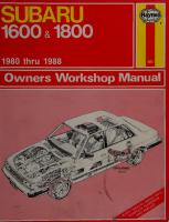
arta Subaru 1600 & 1800 ‘79 to ‘90 owners workshop manual -
3rd ed.
861 Lawrence Drive
Laie mathniedaeeciton rr
Newbury Park California 91320
629.28722 USA
ISBN 1-85010-732-7
LIBRARY SERVICES
2 624.28F saéa || 684748
Acknowledgments Thanks are due to Fuji Heavy Industries Ltd. of Japan, who gave us permission to reproduce certain illustrations and provided technical information.
The Champion Sparking Plug Company provided the illustrations of spark plug conditions.
About this manual /ts purpose The purpose of this manual is to help you get the best value from your vehicle. It can do so in several ways. It can help you decide what work must be done even if you choose to get it done by a dealer service department or a repair shop; it provides information and procedures for routine maintenance and servicing; and it offers diagnostic and repair procedures to follow when trouble occurs. It is hoped that you will use the manual to tackle the work yourself. For many simpler jobs, doing it yourself may be quicker than arranging an appointment to get the vehicle into a shop and making the trips to leave it and pick it up. More importantly, a lot of money can be saved by avoiding the expense the shop must pass on to you to cover its labor and overhead costs. An added benefit is the sense of satisfaction and accomplishment that you feel after having done the job yourself.
Using the manual The manual is divided into Chapters. Each Chapter is divided into numbered Sections, which are headed in bold type between horizontal lines. Each Section consists of consecutively numbered paragraphs.
Introduction
The two types of illustrations used (figures and photographs), are referenced by a number preceding their captions. Figure reference numbers denote Chapter and numerical sequence in the Chapter; i.e. Fig. 12.4 means Chapter 12, figure number 4. Figure captions are followed by a Section number which ties the figure to a specific portion of the text. All photographs apply to the Chapter in which they appear, and the reference number pinpoints the pertinent Section and paragraph; i.e. 3.2 means Section 3, paragraph 2. Procedures, once described in the text, are not normally repeated.
When it is necessary to refer to another Chapter, the reference will be given as Chapter and Section number; i.e. Chapter 1/16. Cross references given without use of the word ‘Chapter’ apply to Sections and/or paragraphs in the same Chapter. For example, ‘see Section 8’ means in the same Chapter. Reference to the left or right side of the vehicle is based on the assumption that one is sitting in the driver's seat facing forward. Even though extreme care has been taken during the preparation of this manual, neither the publisher nor the author can
accept responsibility for any errors in, or omissions information given.
from, the
to the Subaru
The Subaru line of vehicles, manufactured by Fuji Heavy Industries
Ltd. of Japan, is one of the most versatile of all vehicles currently available. Although Subaru models have been available in both the US and
UK for a number of years, this OWM
is involved with only those
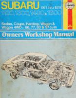
vehicles produced in 1980 and later. Models built prior to 1980 are the subject of another Haynes manual. Subaru vehicles can be purchased in a number of forms and trim levels. In North America the most popular versions include 2-door and 4-door hatchbacks, station wagons and the unique pick-up truck called
the Brat. The UK has a similar line of saloons, hardtop coupes and the MV pick-up truck. One feature which helps to separate Subaru from other vehicle manufacturers is the use of four-wheel drive (4WD), available on most models. Subaru is the worldwide innovator in 4WD passenger cars. As mentioned above, in addition to body form, Subarus can be purchased in a variety of trim levels with many options. Optional equipment includes items such as a digital display instrument panel and the revolutionary Hill-holder device which prevents the vehicle
from rolling backward when accelerating from a stop on ahill.
Page > 3 Q2 ° =
© Q Ko}© S ® S a
N
ona
> a 5 e oF: ot=. a 3 ® z c ES
N
Introduction to the Subaru
2
General dimensions (also see Chapter 13, page 295)
8
Use of English
9
Buying parts
10
Vehicle identification numbers
11
Maintenance techniques, tools and working facilities
12
Automotive chemicals and lubricants
18
Jacking and towing
19
Safety first!
20
Troubleshooting
21
Chapter 1 Engine Tune-up and routine maintenance RNSe ers gma a Ce or eee LBA aasa aE Ee Chapter 2 Engines (also see Chapter 13, page 295) a eee en a Chapter 3 Cooling, heating and air conditioning systems a eee ee ee eee ee n Chapter 4 Fuel and exhaust systems (also see Chapter 13, page 295) ee eee Chapter 5 Engine electrical systems (also see Chapter 13, page 295) eee ee eeee ee Neen eee
Chapter 6 Emissions control systems er a ees ee ae Chapter 7 Transmissions (also see Chapter 13, page 295) er de a e r | Chapter 8 Driveline (also see Chapter 13, page 295) es iySr eee ey ge era e e a e Chapter 9 Brakes (also see Chapter 13, page 295) gS ea ee I Chapter 10 Chassis electrical system (also see Chapter 13, page 295) Chapter 11 Suspension and steering systems (also see Chapter 13, page 295) a a ee eh ig, as as 295) page 13, Chapter Chapter 12 Bodywork (also see
28
eee 56 eee 87 a ee 98 eee 119 eee eeprpepeee oer 133 eee i 144 teen
eee
169
180
ee 201
245
ee
eS 269
295
Chapter 13 Supplement: Revisions and information on later models LL
Conversion factors nnn
Index Spark plug condition and bodywork repair colour section between pages 32 and 33
320 aE 321
eu nieqns 75
uobem
(punosbei0j) pue 7g
uobem
Wee a”
(puno6y9eq) YON)
UedEWYsjapow (umoys
ou nseqns
yOequojey Sjapow YON)
UBDHEWYsjapow (umoys
ayy
NueqngOOVL 41D
UOO|ES1)
UOISIBA (UMoYs
ae
Pero os scene
edu
(UMOYS }e1g ul YYOR CQUOWY AIA) 84) pue BY} AIA] Ul dn-yDId 49NI} UMOU 24} HN ayL Nieqns Se
Sharer Per
rs
ioe
Pee
8
TE
OE ee
He
ST
Genera | dimensions For modifications, and information applicable to later models, see Supplement at end of manual Length (overall) Flatchbacks(DL=2WDB) ieee ee crac enccnas agts a RT a Hatehback::(Gi=2VVD) ics Reese oie, Saeeaaame tes cee bene ee On ee
156.9 in (3985 mm) 157.9 in (4010 mm)
Bae
Rratehback (ANS 4VWVD) ie aatccacsclscce: ccscatesecculncher oeereaceiceene nmemenst bereinechnseaeeeee Sedan and hardtop (De) eae acccabacea caters poaat mov naea Cncante bane teas scot ase Sedan and hardtop (GLE) ache ai casecesad cacsasptaapesecratrtawass ecbsree eee aceaeeae deta Calptasvtesbanteaneactssaveusonanessyves Station wagon (DL- ZWD) is ic8 cercsttounstirensece DD)sordesacscakessncaretopecssiseceunaesesscep areretertetas, Mecanane nese Station wagon (GL- ZN. Station wagon (Alli AWD): oi gesssiavcccsctenssatieosvesttantemneeran usec aan ROK PO EOUCK RE ceases das svsskccevecssuceuesdaccscuncc sana parnneacter terete besaainraxedacetaba arece
157.3 in (3995 mm) 167.3 in (4250 mm)
168.1 in (4270 mm) 168.5 in (4280 mm) 169.3 in (4300 mm) 168.7 in (4285 mm)
174.2 in (4425 mm)
Width (overall) Hatchback: (DES2 WD) oiai said cdsciins coscakecissarse ea citesloca cbeaeneee licen choos oeuepoae cans Pratehifacko(GES2 WD) cee Sauk a eee re Hatchback {Al 4WD) ii 2. a eae ai eee Oe eee ea Sedan and hardtop (DL) ssc eccowscsccssveveae te su denucevocsn ven egauscette steesetesesame
Sedan and hardtop (GLY eh pse etasssades cake ats ear eedesnie caaeee anaes consent epaeataddi eis Station wagon (DL- QW D)) incsetase hucseceteeecae aceite ueates ee eegrnaie Sogseyecateatgeg Nas, Station wagon (GL- ZWD) ysccocnssstvoncnsdencsrsenb salesteaausdantonecactfutecangeetasecareetthen en DLALION WAGON (AIL AWD) vscccstscsscossceneunenadoeiecretan srictesdeatsscacenstagtig@ temmearehaak Pick-up truck ...........
63.4 in (1610 mm) 63.6 in (1615 mm)
63.8 in (1620 mm) 63.4 in (1610 mm) 63.6 in (1615 mm)
63.4 in (1610 mm) 63.6 in (1615 mm) 63.8 in (1620 mm) 64.4 in (1635 mm)
Height (overall) Hatchback (2WD).. Hatchback (4WD)..
53.7 in (1365 mm)
SOCAN eitscecctcsacpeassnts
53.7 in (1365 mm) 53.1 in (1350 mm)
ERAT CUO
55.7 in (1415 mm)
evs cou acscvatsucsnacwnvastssctusiondescbusbusnaceaaeseevspwbrceua cxGente saniOrns ananween a Sos
Station wagon (2W Dy)isckscsstect eatescceseustanscvonertetauesicasaeniimntmictegerimecraaNadd Station wagon (4W DD) eccece azeepavecus Geansesbavangsatees aressrate asta he senscee teaver vais Pick-up truck ...........
54.7 in (1390 mm)
56.9 in (1445 mm) 56.9 in (1445 mm)
Wheelbase Hatchback (2WD).. Hatchback (4WD)..
93.7 in (2380 mm) 93.3 in (2370 mm)
Sedan and hardtop
96.9 in (2460 mm)
Station wagon (2W Dy recacenatanpi de stvuneaipaiiesne lara: ssunteanees tase tusvsuaeeo vanes eer Aas stuns easatuer sBester te Station wagon (4W Dives: hi Rcscassssauscusescteceescephporseansncestestawas
96.7 in (2455 mm)
Pick-up truck ...........
96.3 in (2445 mm)
Track
Front
Rear
Hatchback (2WD).. AAA n Nene eee seen tener ne ee eens eee n Een enR EERO DaCe eee MERE EAH DERE ESHER SED EERE OOOR ESSE H EOE EE ES Hatchback (4WD).. Seen nena eee eeeeeeeeeeeneeeeneeeeReeseaeneeneeneneseenssessassesseesssusssussensesgaeseuens Sedan and hardtop nee ene eee eeneneunennceneaeaeeneeaSSONs Aes Seaaseaeaee Es renee Hnee eee nneoeAUESeonaneneonaEoneS Station wagon (2W DD) isatetiaeshes tated, tonnutotbatastsitescusei ensatoipecaan egtaveewecay Mettee Station wagon (4W DD); cazssitesusarcssuectcsoscucvcutauesacsssastersecetessacttencnctunrenmmierere tatiana PIGK=UPs CUCK sacessscocsesscousstescssvocosvscecth coansasucrcnnachcacasdsaved secesnsvesssdanssuianuscasealepaass
52.4 in (1330 mm)
53.0 in (1345 mm)
52.6 in (1335 mm) 52.4 in (1330 mm)
53.9 in (1370 mm)
96.3 in (2445 mm)
52.5 in (1325 mm) 52.6 in (1335 mm) 52.6 in (1335 mm)
Turning circle Hatchback ........s.0000 Meee oecosesscascoecescvesessecencgascacesensccoscessensesoanesceseeseuoneconceseocensoeeNee All Others .......cccccseeees Pea eensececescesseeseccecensensecscopssessescossucasensscccecssoosoesousessesassosscseoesce
Curb weight Fateh backs Hatchback: RlatCHD ACK. Sodan (DU) Seca (GL)
(DL=2.W DD) sis: ccccisatuscestocossuccssiuscastbectastecntscasoiacneasehenue tization (GLA2Z WD) ciiuuiss cecsccascssavvecedesoyessaselcereeicascecagsaaesnms seeaaenunuouniseias aca (AWD) iiticcnccovsascccccesiceceteateateactaccuacs odoneconuacia SeerTne ects e iesseaccees Po rrr tasvcscsctess See eee eeoseceseseseceoosessseoNesseoDs eases eoossesseasscccesseessosessceosseecescuseesoeeD
FHARCLOPS UDLe)sccnccsssesevsssovscetedsheauslusvaseseetssostebeuas ivoscedvcesestecoccascnertnsctentece nr toietare PLETE OP (GL) ishecacavteyescaeedevsanesanescancedascuonscavcuueencvetsesessesGsdesesseeceeeeen atti neaaoae Station wagon (DL- QW) sracicbepecmorseeemieae aiiiak aude vacuum ee Station wagon (GL- QW) cuiicdecieuwetenehne uccae ee eae Stator Wagan! (DA WD) \.cccsiscsasssscotscccarceucsuotaacoatuevaavecesatsabuceccuaapaccteaseetaasenas Station WaGon: (GU-4WD)). cs. :ctsscscccesscsvarconeareetedecctescecveesecesearsiciammetsmoreatone Pick-up truck (DL).. Oe Oe noon ree seroeerencerense eres eDee Ose EE BOSC OD NOOSE ERED SOOO SOOO COVEL ODES HOOD ODODONOROOS
Pick-up truck (GL)..
CP
rir
i ry
15.5 ft (4.7 m) 15.8 ft (4.8 m)
2060 2120 2235 2130 2190 2110 2180 2250 2310 2365 2405 2175 2245
Ib (934 kg) Ib (962 kg) Ib (1014 kg) Ib (966 kg) Ib (993 kg) Ib (957 kg) Ib (989 kg) Ib (1021 kg) Ib (1048 kg) Ib (1072 kg) Ib (1091 kg) Ib (987 kg) Ib (1018 kg)
53.0 in (1345 mm) 53.0 in (1345 mm)
53.7 in (1365 mm) §3.7 in (1365 mm)
Use of English As this book has been written in England, it uses the appropriate English component names, phrases, and spelling. Some of these differ from those used in America. Normally, these cause no difficulty, but to make sure, a glossary is printed below. In ordering spare parts remember the parts list may use some of these words:
English
American
English
Accelerator Aerial Anti-roll bar Big-end bearing Bonnet (engine cover) Boot (luggage compartment) Bulkhead Bush Cam follower or tappet Carburettor Catch Choke/venturi
Gas pedal Antenna Stabiliser or sway bar Rod bearing Hood Trunk Firewall Bushing Valve lifter or tappet Carburetor Latch Barrel
Locks Methylated spirit Motorway Number plate Paraffin Petrol Petrol tank ‘Pinking’ Prise (force apart) Propeller shaft Quarterlight Retread
Circlip Clearance Crownwheel Damper
Snap-ring Lash Ring gear (of differential) Shock absorber, shock Rotor/disk Spacer Pitman arm Convertible Generator (DC) Ground Prussian blue Station wagon Header Troubleshooting Float bowl
Reverse Rocker cover Saloon Seized Sidelight Silencer Sill panel {beneath doors) Small end, little end Spanner Split cotter (for valve spring cap) Split pin Steering arm Sump Swarf Tab washer
Disc (brake) Distance piece Drop arm Drop head coupe Dynamo Earth (electrical) Engineer's biue Estate car Exhaust manifold Fault finding/diagnosis Float chamber
American Latches Denatured alcohol Freeway, turnpike etc License plate Kerosene Gasoline (gas) Gas tank ‘Pinging’ Pry Driveshaft Quarter window Recap
Back-up Valve cover Sedan Frozen Parking light Muffler Rocker panel Piston pin or wrist pin Wrench Lock (for valve spring retainer) Cotter pin Spindle arm Oil pan Metal chips or debris Tang or lock
Free-play
Lash
Tappet
Valve lifter
Freewheel Gearbox
Coast Transmission
Thrust bearing Top gear
Throw-out bearing High
Gearchange Grub screw Gudgeon pin Halfshaft Handbrake
Shift Setscrew, Allen screw Piston pin or wrist pin Axleshaft Parking brake
Hood
Soft top
Hot spot Indicator Interior light Layshaft (of gearbox) Leading shoe (of brake)
Turn signal Dome lamp Countershaft Primary shoe
Heat riser
Torch Trackrod (of steering) Trailing shoe (of brake) Transmission Tyre Van
Vice Wheel nut Windscreen Wing/mudguard
Flashlight Tie-rod (or connecting rod) Secondary shoe Whole drive line Tire Panel wagon/van
Vise Lug nut Windshield Fender
Buying parts Replacement parts are available from many sources, which generally fall into one of two categories — authorized dealer parts departments and independent retail auto parts stores. Our advice concerning these parts is as follows: Authorized dealer parts department: This is the best source for parts which are peculiar to your vehicle and not generally available elsewhere (i.e. major engine parts, transmission parts, trim pieces, etc.). It is also the only place you should buy parts if your vehicle is still under warranty, as non-factory parts may invalidate the warranty. To be sure of obtaining the correct parts, have your vehicle’s engine and . chassis numbers available and, if possible, take the old parts along for
positive identification. Retail auto parts stores: Good auto parts stores will stock frequently needed components which wear out relatively fast (i.e. clutch components, exhaust systems, brake parts, tune-up parts, etc.). These stores often supply new or reconditioned parts on an exchange basis, which can save a considerable amount of money. Discount auto parts stores are often very good places to buy materials and parts needed for general vehicle maintenance (i.e. oil, grease, filters, spark plugs, belts, touch-up paint, bulbs. etc.). They also usually sell tools and general accessories, have convenient hours, charge lower prices, and can often be found not far from your home.
Vehicle
identification
numbers
The Vehicle Identification Number (VIN) is located in two different
Other
important
vehicle
labels which
may
be included
are the
piaces. It is stamped on the firewall of the engine compartment (photo) and on US models is also on a plate fastened to the dash on the driver's side (photo).
Safety Certification plate, found on the driver's side door pillar (photo) and the Vehicle Color Code label, stuck on the top radiator crossmember, near the hood latch (photo).
The engine serial number is stamped on the right side of the engine crankcase, near the front (photo). The transmission serial
An Emissions Control Information label is supplied with all North America models. It is attached to the underside of the hood. It contains
number label is attached to the right upper surface of the main case of the manual transmission (photo) or the converter housing of the automatic transmission.
information concerning certification, vacuum connections and high altitude settings (photo). For California vehicles, there is an Emission Data label found on the driver's side of the dash.
LTT
6 Vehicle Identification Number (VIN) engine compartment location
—_-Vehicle Identification Number (VIN) driver's side dash location
The engine serial number (arrow) is stamped into the right side of the crankcase, near the front
Transmission serial number
Manual transmission serial number location (arrow)
Automatic transmission serial number location
Safety Certification plate location (arrow) on driver's side door pillar
AY
4
*
Vehicle Color Code label location (arrow)
we
The Emissions Data label (California The Emission Control Information label (arrow) is attached to the underside of the _ vehicles only) is attached to the driver's side of the dash, near the VIN hood
Maintenance techniques, tools and working facilities Maintenance
techniques
There are a number of techniques involved in maintenance
and
repair that will be referred to throughout this manual. Application of these techniques will enable the home mechanic to be more efficient, better organized and capable of performing the various tasks properly, which will ensure that the repair job is thorough and complete.
Fasteners Fasteners are nuts, bolts, studs and screws used to hold two or more parts together. There are a few things to keep in mind when working with fasteners. Almost all of them use a locking device of some type; either a lock washer, locknut, locking tab or thread adhesive. All threaded fasteners should be clean and straight, with undamaged threads and undamaged corners on the hex head where the wrench fits. Develop the habit of replacing damaged nuts and bolts with new ones. Special locknuts with nylon or fiber inserts can only be used once. If they are removed, they lose their locking ability and must be replaced with new ones. Rusted nuts and bolts should be treated with a penetrating fluid to ease removal and prevent breakage. Some mechanics use turpentine in a spout-type oil can, which works quite well. After applying the rust penetrant, let it ‘“work’’ for a few minutes before trying to loosen the ‘nut or bolt. Badly rusted fasteners may have to be chiseled or sawed off or removed with a special nut breaker, available at tool stores. If a bolt or stud breaks off in an assembly, it can be drilled and removed with a special tool commonly available for this purpose. Most automotive machine shops can perform this task, as well as other repair procedures (such as repair of threaded holes that have been stripped out). Flat washers and lock washers, when removed from an assembly should always be replaced exactly as removed. Replace damaged washers with new ones. Always use a flat washer between a lock washer and any soft metal surface (such as aluminum), thin sheet metal or plastic.
metric and standard bolts can also be distinguished by examining the bolt heads. To begin with, the distance across the flats on a standard bolt head is measured in inches, while the same dimension on a metric bolt is measured in millimeters (the same is true for nuts). As a result, a standard wrench should not be used on a metric bolt and a metric wrench should not be. used on a standard bolt. Also, standard bolts have slashes radiating out from the center of the head to denote the grade or strength of the bolt (which is an indication of the amount of torque that can be applied to it). The greater the number of slashes, the greater the strength of the bolt (grades O through 5 are commonly used on automobiles). Metric bolts have a property class (grade) number, rather than a slash, molded into their heads to indicate bolt strength. In this case, the higher the number the stronger the bolt (property class numbers 8.8, 9.8 and 10.9 are commonly used on automobiles). Strength markings can also be used to distinguish standard hex nuts from metric hex nuts. Standard nuts have dots stamped into one side, while metric nuts are marked with a number. The greater the number of dots, or the higher the number, the greater the strength of the nut. Metric studs are also marked on their ends according to property
class (grade). Larger studs are numbered (the same as rnetric bolts), while smaller studs carry a geometric code to denote grade. It should be noted that many. fasteners, especially Grades O through 2, have no distinguishing marks on them. When such is the case, the only way to determine whether it is standard or metric is to measure the thread pitch or compare it to a known fastener of the same size.
Since fasteners of the same size (both standard and metric) may have different strength ratings, be sure to reinstall any bolts, studs or nuts removed from your vehicle in their original locations. Also, when replacing a fastener with a new one; make sure that the new one has a strength rating equal to or greater than the original.
Fastener sizes
Tightening sequences and procedures
For a number of reasons, automobile manufacturers are making wider and wider use of metric fasteners. Therefore, it is important to be able to tell the difference between standard (sometimes called U.S., English or SAE) and metric hardware, since they cannot be
Most threaded fasteners should be tightened to a specific torque value (torque is basically a twisting force). Over-tightening the fastener can weaken it and lead to eventual breakage, while under-tightening can cause it to eventually come loose. Bolts, screws and studs, depending on the materials they are made of and their thread diameters, have specific torque values (many of which are noted in the Specifications at the beginning of each Chapter). Be sure to follow the torque recommendations closely. For fasteners not assigned a specific torque, a general torque value chart is presented here as a guide. As was previously mentioned,-the sizes and grade of a fastener determine the amount of torque that can safely be applied to it. The figures listed here are approximate for Grade 2 and Grade 3 fasteners (higher grades can tolerate higher torque values).
interchanged. All bolts, whether standard or metric, are sized according to diameter, thread pitch and length. For example, a standard $ — 13 x 1
bolt is + inch in diameter, has 13 threads per inch and is 1 inch long. An M12 — 1.75 x 25 metric bolt is 12 mm in diameter, has a thread pitch of 1.75 mm (the distance between threads) and is 25 mm long. The two bolts are nearly identical, and easily confused, but they are not interchangeable. In addition to the differences in diameter, thread pitch and length,
\
13
Maintenance techniques, tools and working facilities Ft-Ib
Nm
6 to 9
9 to 12
Metric thread sizes
U.S. thread sizes Ce eee eI, '
1 '
EET OE Mt SHEN ee 1c
rasa hc
you meteors
NB —
ao
i)5S
ojo Baloo alorajnm|— N+
14 to 21
19 to 28
28 to 40 50 to 71
38 to 54 68 to 96
80 to 140
109 to 154
5 to 8 12 to 18 22 to 33 25 to 35
7 to 10 17 to 24 30 to 44 34 to 47
6 to 9 12 to 18 14 to 20 2240532 27 to 38 40 to 55 40 to 60 55 to 80
9 to 12 17 to 24 19 to 27 30 to 43 37 to 51 55 to 74 55 to 81 75 to 108
| a
P—
CG—>
“7
a
D
oS
Standard (SAE) bolt dimensions/grade marks
G — Grade marks (bolt strength) L ~Length (in inches) T — Thread pitch (number of threads per inch) D —Nominal diameter (in inches) Fasteners
laid out in a pattern (i.e. cylinder head bolts, oil pan
bolts, differential cover bolts, etc.) must be loosened and tightened in a definite sequence to avoid warping the component. This sequence will normally be shown in the appropriate Chapter. If a specific pattern is not given, the following procedures can be used to prevent warping. Initially, the bolts or nuts should be assembled finger-tight only. Next, they should be tightened one full turn each, in a criss-cross or diagonal pattern. After each one has been tightened one full turn, return to the first one and tighten them all one-half turn, following the same pattern. Finally, tighten each of them one-quarter turn at a time until they all have been tightened to the proper torque value. To loosen and remove them the procedure would be reversed.
Component disassembly
Component disassembly should be done with care and purpose to help ensure that the parts go back together properly. Always keep track of the sequence in which parts are removed. Make note of special characteristics or marks on parts that can be installed more than one way (such as a grooved thrust washer on a shaft). It is a good idea to lay the disassembled parts out on a clean surface in the order that they were removed. It may also be helpful to make simple sketches or take instant photos of components before removal. When removing fasteners from an assembly, keep track of their the locations. Sometimes threading a bolt back in a part or putting
Metric bolt dimensions/grade marks P—Property class (bolt strength) L —Length (in millimeters) T — Thread pitch (distance between threads; in millimeters) D —Nominal diameter (in millimeters)
washers and nut back on a stud can prevent mixups later. If nuts and bolts cannot be returned to their original locations, they should be kept in a compartmented box or a series of small boxes. A cupcake or muffin tin is ideal for this purpose, since each cavity can hold the bolts and nuts from a particular area (i.e. oil pan bolts, valve cover bolts, engine mount bolts, etc.). A pan of this type is especially helpful when working on assemblies with very small parts such as the carburetor, alternator, valve train or interior dash and trim pieces. The cavities can be marked with paint or tape to identify the contents. Whenever wiring looms, harnesses or connectors are separated, it’s a good idea to identify them with numbered pieces of masking tape so that they can be easily reconnected.
Gasket sealing surfaces Throughout any vehicle, gaskets are used to seal the mating surfaces between two parts and keep lubricants, fluids, vacuum or pressure contained in an assembly. Many times these gaskets are coated with a liquid or paste-type gasket sealing compound before assembly. Age, heat and pressure can sometimes cause the two parts to stick together so tightly that they are very difficult to separate. Often, the assembly can be loosened by striking it with a soft-faced hammer near the mating surfaces. A regular hammer can be used if a block of wood is placed between the hammer and the part. Do not hammer on cast parts or parts that could
14
Maintenance techniques, tools and working facilities
Grade 1 or 2
Grade 5
Grade 8
Bolt strength markings (top — standard/SAE; bottom — metric)
Grade
Identification
Class
Identification
Hex Nut Hex Nut
Property
Grade 5
Class 9 3 Dots
Arabic 9
Hex Nut
Hex Nut
Property
Grade 8
Class 10 6 Dots
Arabic 10
Standard hex nut strength markings be
easily
damaged.
With
any
particularly
stubborn
Metric hex nut strength markings part,
always
recheck to see that every fastener has been removed.
Avoid using a screwdriver or bar to pry apart an assembly, as they can easily mar the gasket sealing surfaces of the parts (which must remain smooth). If prying is absolutely necessary, use an old broom handle, but keep in mind that extra clean-up will be necessary if the wood splinters.
After the parts are separated, the old gasket must be carefully scraped off and the gasket surfaces cleaned. Stubborn gasket material can be soaked with rust penetrant or treated with a special chemical to soften it so that it can be easily scraped off. A scraper can be fashioned from apiece of copper tubing by flattening and sharpening one end. Copper is recommended because it is usually softer than the surfaces to be scraped, which reduces the chance of gouging the part.
Some gaskets can be removed with a wire brush, but regardless of the method
used, the mating surfaces must be left clean and smooth. If,
for some reason the gasket surface is gouged, then a gasket sealer
(0)
O° OS CLASS 10.9
CLASS 9.8 Metric stud strength markings
CLASS 8.8
Maintenance techniques, tools and working facilities
|
ee ee
eee eee
thick enough to fill scratches will have to be used upon reassembly of the components. For most applications, a non-drying (or semi-drying)
gasket sealer should be used.
Hose removal tips Caution:
/f the vehicle
is equipped
with air conditioning,
do not
disconnect any of the a/c hoses without first having the system depressurized by a dealer service department or air conditioning specialist. Hose removal precautions closely parallel gasket removal precau-
tions. Avoid scratching or gouging the surface that the hose mates against or the connection may leak. This is especially true for radiator hoses. Because of various chemical reactions, the rubber in hoses can
bond itself to the metal spigot that the hose fits over. To remove a hose, first loosen the hose clamps that secure it to the spigot. Then, with slip-joint pliers, grab the hose at the clamp and rotate it around the spigot. Work it back-and-forth until it is completely free, then pull it off. Silicone or other lubricants will ease removal if they can be applied between the hose and the spigot. Apply the same lubricant to the inside of the hose and the outside of the spigot to simplify installation. As the last resort (and if the hose is to be replaced with a new one anyway), the rubber can be slit with a knife and the hose peeled from its spigot. If this must be done, be careful that the metal connection is not damaged. lf a hose clamp is broken or damaged, do not re-use it. Wire-type clamps usually weaken with age, so it is a good idea to replace them with screw-type clamps whenever a hose is removed.
Tools A selection of good tools is a basic requirement for anyone who plans to maintain and repair his or her own vehicle. For the owner who has few tools, if any, the initial investment might seem high, but when compared to the spiraling costs of professional auto maintenance and repair, it is a wise one. To help the owner decide which tools are needed to perform the tasks detailed in this manual, the following tool lists are offered: Maintenance and minor repair, Repair and overhaul and Special. The newcomer to practical mechanics should start off with the Maintenance and minor repair tool kit, which is adequate for the simpler jobs performed on a vehicle. Then, as his confidence and experience grow, he can tackle more difficult tasks, buying additional tools as they are needed. Eventually the basic kit will be expanded into the Repair and overhaul tool set. Over a period of time, the experienced do-ityourselfer will assemble a tool set complete enough for most repair and overhaul procedures and will add tools from the Specia/ category when he feels the expense is justified by the frequency of use.
Maintenance and minor repair tool kit The tools in this list should be considered the minimum for performance of routine maintenance, servicing and minor repair work. We recommend the purchase of combination wrenches (box end and open end combined in one wrench); while more expensive than openended ones, they offer the advantages of both types of wrench.
Combination wrench set (4 in to 1 in or 6 mm to 19 mm) Adjustable wrench — 8 in Spark plug wrench (with rubber insert) Spark plug gap adjusting tool Feeler gauge set Brake bleeder wrench
Standard screwdriver (% in x 6 in) Phillips screwdriver (No. 2 x 6 in) Combination pliers — 6 in Hacksaw and assortment of blades Tire pressure gauge Grease gun Oil can Fine emery cloth Wire brush Battery post and cable cleaning tool Oil filter wrench
Funnel (medium size) Safety goggles
Jack stands (2) Drain pan
15
ee eS
ee
Note: /f basic tune-ups are going to be a part of routine maintenance, it will be necessary to purchase a good quality stroboscopic timing light and a combination tachometer/dwell meter. Although they are included in the list of Special tools, they are mentioned here because they are absolutely necessary for tuning most vehicles properly.
Repair and overhaul tool set These tools are essential for anyone who plans to perform major repairs and are in addition to those in the Maintenance and minor repair tool kit. Included is a comprehensive set of sockets which, though expensive, are invaluable because of their versatility (especially when various extensions and drives are available). We recommend the 4 in drive over the 3 in drive. Although the larger drive is bulky and more expensive, it has the capability of accepting a very wide range of large sockets (ideally, the mechanic would have a # in drive set and a
+ in drive set). Socket set(s) Reversible ratchet Extension — 10 in Universal joint Torque wrench (same size drive as sockets) Ballpeen hammer — 8 oz
Soft-faced hammer (plastic/rubber)
Standard screwdriver (% in x 6 in) Standard screwdriver (stubby — % in) Phillips screwdriver (No.3 x 8 in) Phillips screwdriver (stubby — No.2) Pliers Pliers Pliers Pliers
— — — —
vise grip lineman’s needle nose spring clip (internal and external)
Cold chisel — + in Scriber Scraper (made from flattened copper tubing) Center punch
Pin punches (%, +4, % in) Steel rule/straightedge — 12 in Allen wrench set (4 to 3 in or 4 mm to 10 mm) A selection of files Wire brush (large) Jack stands (second set)
Jack (scissor or hydraulic type) Note: Another too! which is often useful is an electric drill motor with
a chuck capacity of 3 in (and a set of good quality drill bits).
Special tools
The tools in this list include those which are not used regularly, are expensive to buy, or which need to be used in accordance with their manufacturer's instructions. Unless these tools will be used frequently, it is not very economical to purchase many of them. A consideration would be to split the cost and use between yourself and a friend or friends. In addition, most of these tools can be obtained from a tool rental shop on a temporary basis. This list contains only those tools and instruments widely available to the public, and not those special tools produced by vehicle manufacturers for distribution to dealer service departments. Occasionally, references to the manufacturer's special tools are included in the text of this manual. Generally, an alternate method of doing the job without the special tool is offered. However, sometimes there is no alternative to their use. Where this is the case, and the tool cannot be purchased or borrowed, the work should be turned over to the dealer, a repair shop or an automotive machine shop. Valve spring compressor Piston ring groove cleaning tool Piston ring compressor Piston ring installation tool Cylinder compression gauge Cylinder ridge reamer Cylinder surfacing hone Cylinder bore gauge Micrometer(s) and/or dial calipers Hydraulic lifter removal tool (not all models) Balljoint separator
Valve spring compressor
Piston ring groove cleaning tool
Piston ring compressor
Piston ring removal/installation tool
Cylinder ridge reamer
Cylinder surfacing hone
Dial caliper
Hydraulic lifter removal tool.
Universal type puller
Dial indicator set
\
Maintenance techniques, tools and working facilities
Hand operated vacuum pump
Universal-type puller Impact screwdriver Dial indicator set
Stroboscopic timing light (inductive pickup) Hand-operated vacuum/pressure pump
Tachometer/dwell meter Universal electrical multimeter Cable hoist Brake spring removal and installation tools Floor jack
Buying tools
For the do-it-yourselfer who is just starting to get involved in
vehicle maintenance and repair, there are a couple of options available when purchasing tools. If maintenance and minor repair is the extent of the work to be done, the purchase of individual tools is satisfactory. If, on the other hand, extensive work is planned, it would be a good idea to purchase a modest tool set from one of the large retail chain stores. A set can usually be bought at substantial savings over the individual tool prices (and they often come with a tool box). As
additional tools are needed, add-on sets, individual tools and a larger tool box can be purchased to expand the tool selection. Building a tool set gradually allows the cost of the tools to be spread over a longer period of time and gives the mechanic the freedom to choose only those tools that will actually be used.
Tool stores will often be the only source of some of the special tools that are needed, but regardless of where tools are bought, try to avoid cheap ones (especially when buying screwdrivers and sockets) because they won't last very long. The expense involved in replacing cheap tools will eventually be greater than the initial cost of quality tools.
Care and maintenance of tools
Good tools are expensive, so it makes sense to treat them with them respect. Keep them in a clean and usable condition and store properly when not in use. Always wipe off any dirt, grease or metal in the chips before putting them away. Never leave tools lying around the under closely check always job, a of n completio Upon area. work hood for tools that may have been left there (so they don't get lost during a test drive). Some tools, such as screwdrivers, pliers, wrenches and sockets,
17
Brake shoe spring tool
can be hung on a panel mounted on the garage or workshop wall, while others should be kept in a tool box or tray. Measuring instruments, gauges, meters, etc. must be carefully stored where they cannot be damaged by weather or impact from other tools. When tools are used with care and stored properly, they will last a very long time. Even with the best of care, tools will wear out if used frequently. When a tool is damaged or worn out, replace it; subsequent jobs will be safer and more enjoyable if you do.
Working facilities Not to be overlooked when discussing tools is the workshop. If anything more than routine maintenance is to be carried out, some sort of suitable work area is essential. It is understood, and appreciated, that many home mechanics do not have a good workshop or garage available and end up removing an engine or doing major repairs outside. It is recommended, however, that the overhaul or repair be completed under the cover of a roof. A clean, flat workbench or table of comfortable working height is an absolute necessity. The workbench should be equipped with a vise that has a jaw opening of at least four inches. As mentioned previously, some clean, dry storage space is also required for tools, as well as the lubricants, fluids, cleaning solvents, etc. which soon become
necessary.
Sometimes waste oil and fluids, drained from the engine or transmission during normal maintenance or repairs, present a disposal problem. To avoid pouring oil on the ground or into the sewage system, simply pour the used fluids into large containers, seal them with caps and deliver them to a local recycling center or disposal facility. Plastic jugs (such as old antifreeze containers) are ideal for this purpose. Always keep a supply of old newspapers and clean rags available. Old towels are excellent for mopping up spills. Many mechanics use rolls of paper towels for most work because they are readily available and disposable. To keep the area under the vehicle clean, a large cardboard box can be cut open and flattened to protect the garage or shop floor. Whenever working over a painted surface (such as when leaning over a fender to service something under the hood), always cover it
with an old blanket or bedspread to protect the finish. Vinyl covered pads, made especially for this purpose, are available at auto parts stores.
Automotive
chemicals
and lubricants
A number of automotive chemicals and lubricants are available for use in vehicle maintenance and repair. They include a wide variety of products ranging from cleaning solvents and degreasers to ijubricants and protective sprays for rubber, plastic and vinyl. Contact point/spark plug cleaner is a solvent used to clean oily film and dirt from points, grime from electrical connectors and oil deposits from spark plugs. It is oil free and leaves no residue. It can also be used to remove gum and varnish from carburetor jets and other orifices. Carburetor cleaner is similar to contact point/spark plug cleaner but it is a stronger solvent and may leave a slight oily residue. It is not recommended for cleaning electrical components or connections.
Brake system cleaner is used to remove grease or brake fluid from brake system components where clean surfaces are absolutely
necessary and petroleum-based solvents cannot be used. It also leaves no residue. Silicone-based /ubricants are used to protect rubber parts such as hoses, weatherstripping and grommets and are used as lubricants for
hinges and locks. Multi-purpose grease is an all-purpose lubricant used whenever grease is more practical than a liquid lubricant such as oil. Some multipurpose grease is white and specially formulated to be more resistant to water than ordinary grease. Bearing grease/wheel bearing grease is a heavy grease used where increased loads and friction are encountered (i.e. wheel bearings, universal joints, etc.). High temperature wheel bearing grease is designed to withstand the extreme temperatures encountered by wheel bearings in disc brake equipped vehicles. It usually contains molybdenum a ‘dry’ type lubricant.
disulfide, which is
Gear oil (sometimes called gear lube) is a specially designed oil used in differentials, manual transmissions and transfer cases, as well as other areas where high friction, high temperature lubrication is required. It is available in a number of viscosities (weights) for various applications. Motor oil, of course, is the lubricant specially formulated for use in the engine. It normally contains a wide variety of additives to prevent corrosion and reduce foaming and wear. Motor oil comes in various
weights (viscosity ratings) of from 5 to 80. The recommended weight of the oil depends on the seasonal temperature and the demands on the engine. Light oil is used in cold climates and under light load conditions; heavy oil is used in hot climates and where high loads are encountered. Multi-viscosity oils are designed to have characteristics of both light and heavy oils and are available in a number of weights from 5W-20 to 20W-50. Oil additives range from viscosity index improvers to slick chemical treatments that purportedly reduce friction. It should be noted that most oil manufacturers caution against using additives with their oils. Gas additives perform several functions, depending on their
chemical makeup. They. usually contain solvents that help dissolve gum and varnish that build up on carburetor and intake parts. They also serve to break down carbon deposits that form on the inside surfaces of the combustion chambers. Some additives contain upper cylinder lubricants for valves and piston rings. Brake fluid is a specially formulated hydraulic fluid that can withstand the heat and pressure encountered in brake systems. Care must be taken that this fluid does not come in contact with painted surfaces or plastics. An opened container should always be resealed to prevent contamination by water or dirt. Undercoating is a petroleum-based, tar-like substance that is designed to protect metal surfaces on the underside of a vehicle from corrosion. It also acts as a sound deadening agent by insulating the bottom of the vehicle. Weatherstrip cement is used to bond weatherstripping around doors, windows and trunk lids. It is sometimes used to attach trim pieces as well. Degreasers are heavy-duty solvents used to remove grease and grime that accumulate on engine and chassis components. They can be sprayed or brushed on and, depending on the type, are rinsed with either water or solvent. Solvents are used alone or in combination with degreasers to clean parts and assemblies during repair and overhaul. The home mechanic should use only solvents that are non-flammable and that do not produce irritating fumes. Gasket sealing compounds may be used in conjunction with gaskets, to improve their sealing capabilities, or alone, to seal metalto-metal joints. Many gaskets can withstand extreme heat, some are impervious to gasoline and lubricants, while others are capable of filling and sealing large cavities. Depending on the intended use, gasket sealers either dry hard or stay relatively soft and pliable. They are usually applied by hand, with a brush, or are sprayed on the gasket sealing surfaces. Thread cement is an adhesive locking compound that prevents threaded fasteners from loosening because of vibration. It is available in a variety of types for different applications. Moisture dispersants are usually sprays that can be used to dry out electrical components such as the distributor, fuse block and wiring connectors. Some types can also be used as a treatment for rubber and as a lubricant for hinges, cables and locks. Waxes and polishes are used to help protect painted and plated surfaces from the weather. Different types of paint may require the use of different types of wax or polish. Some polishes utilize a chemical or abrasive cleaner to help remove the top layer of oxidized (dull) paint in older vehicles. In recent years, many non-wax polishes that contain a wide variety of chemicals such as polymers and silicones have been introduced. These non-wax polishes are usually easier to apply and last longer than conventional waxes and polishes.
Jacking and towing Jacking The jack supplied with the vehicle should only be used for raising the vehicle for changing a tire or placing jack stands under the frame. Under no circumstances should work be performed beneath the vehicle or the engine started while this jack is being used as the only means of support. All vehicles are supplied with a lug wrench and a scissors-type
jack which fits into notches in the vertical rocker panel flange nearest to the wheel being changed.
The vehicle should be on level ground with the wheels blocked and the transmission in Park (automatic) or Reverse (manual). Pry off the hub cap (if equipped) using the tapered end of the lug wrench. Loosen the lug nuts one-half turn and leave them in place until the wheel is raised off the ground. Place the jack under the side of the vehicle in the appropriate jacking notch. Use the supplied wrench or handle to turn the jackscrew clockwise until the wheel is raised off the ground. Remove the lug nuts, pull off the wheel and replace it with the spare. With the beveled side in, replace the lug nuts and tighten them until snug. Lower the vehicle by turning the jackscrew counterclockwise. Remove the jack and tighten the nuts in a crisscross pattern. Replace the hubcap by placing it into position and using the heel of your hand or a rubber mallet to seat it.
Towing
Jacking point (front)
The vehicle can be towed with all four wheels on the ground, as long as speeds do not exceed 20 mph (30 kmh) and the distance is not over six miles (10 km). Towing hooks are located at the front and the rear of the vehicle (photo). For distances exceeding six miles, on vehicles with automatic transmission, the front wheels must be raised. Towing equipment specifically designed for this purpose must be used and should be attached to the main structural members of the vehicle, not the bumper or brackets. While towing, the parking brake should be fully released and the transmission should be in Neutral. The steering must be unlocked (ignition switch in the Off position). Remember that power steering and power brakes will not work with the engine off. Avoid towing another vehicle with your front towing hooks and never use the tie-down tabs for towing. Safety is a major consideration when towing and all applicable state and local laws must be obeyed. A safety chain system must be used for all towing in the US.
CoE
Jacking point (rear)
Towing hooks (arrows) are located at the front and rear of the vehicle
Safety first! Professional motor mechanics are trained in safe working procedures. However enthusiastic you may be about getting on with the job in hand, do take the time to ensure that your safety is not put at risk. A moment's lack of attention can result in an accident, as can failure to observe certain elementary precautions. There will always be new ways of having accidents, and the following points do not pretend to be a comprehensive list of all dangers; they are intended rather to make you aware of the risks and to encourage a safety-conscious approach to all work you carry out on your vehicle.
Fire
DON'T rely on a single jack when working underneath the vehicle. Always use reliable additional means of support, such as axle stands, securely placed under a part of the vehicle that you know will not give
Remember at all times that petrol (gasoline) is highly flammable. Never smoke, or have any kind of naked flame around, when working on the vehicle. But the risk does not end there — a spark caused by an electrical short-circuit, by two metal surfaces contacting each other, by careless use of tools, or even by static electricity built up in your body under certain conditions, can ignite petrol vapour, which in a confined space is highly explosive. Always disconnect the battery earth (ground) terminal before working on any part of the fuel or electrical system, and never risk spilling fuel on to a hot engine or exhaust. It is recommended that a fire extinguisher of a type suitable for fuel and electrical fires is kept handy in the garage or workplace at all times. Never try to extinguish a fuel or electrical fire with water. Note: Any reference to a ‘torch’ appearing in this manual should always be taken to mean a hand-held battery-operated electric lamp or flashlight. It does NOT mean a welding/gas torch or blowlamp.
way. DON'T attempt to loosen or tighten high-torque nuts (e.g. wheel hub
Fumes
Essential DOs and DON'Ts
nuts) while the vehicle is on a jack; it may be pulled off. DON'T start the engine without first ascertaining that the transmission is in neutral (or ‘Park’ where applicable) and the parking brake applied. DON’T suddenly remove the filler cap from a hot cooling system — - cover it with a cloth and release the pressure gradually first, or you may get scalded by escaping coolant. DON'T attempt to drain oil until you are sure it has cooled sufficiently to avoid scalding you. DON'T grasp any part of the engine, exhaust or catalytic converter without first ascertaining that it is sufficiently ccol to avoid burning
you. : / DON'T allow brake fluid or antifreeze to contact vehicle paintwork. DON'T syphon toxic liquids such as fuel, brake fluid or antifreeze by mouth, DON’T below). DON'T straight DON'T
or allow them to remain on your skin. inhale dust — it may be injurious to health
(see Asbestos
allow any spilt oil or grease to remain on the floor — wipe it up away, before someone slips on it. use ill-fitting spanners or other tools which may slip and cause
injury. DON'T attempt to lift a heavy component which may be beyond your capability — get assistance. DON'T rush to finish a job, or take unverified short cuts. DON'T allow children or animals in or around an unattended vehicle. DO wear eye protection when using power tools such as drill, sander, bench grinder etc, and when working under the vehicle. DO use a barrier cream on your hands prior to undertaking dirty jobs — it will protect your skin from infection as well as making the dirt easier to remove afterwards; but make sure your hands aren't left slippery. Note that long-term contact with used engine oil can be a health hazard. DO keep loose clothing (cuffs, tie etc) and long hair well out of the way of moving mechanical parts. DO remove rings, wristwatch etc, before working on the vehicle — especially the electrical system. DO ensure that any lifting tackle used has a safe working load rating adequate for the job. DO keep your work area tidy — it is only too easy to fall over articles left lying around. DO get someone to check periodically that all is well, when working alone on the vehicle. DO carry out work in a logical sequence and check that everything is correctly assembled and tightened afterwards. DO remember that your vehicle's safety affects that of yourself and others. If in doubt on any point, get specialist advice. IF, in spite of following these precautions, you are unfortunate enough
Certain fumes are highly toxic and can quickly cause unconsciousness and even death if inhaled to any extent. Petroi (gasoline) vapour comes into this category, as do the vapours from certain solvents such as trichloroethylene. Any draining or pouring of such volatile fluids should be done in a well ventilated area. When using cleaning fluids and solvents, read the instructions carefully. Never use materials from unmarked containers — they may give off poisonous vapours. Never run the engine of a motor vehicle in an enclosed space such as a garage. Exhaust fumes contain carbon monoxide which is extremely poisonous; if you need to run the engine, always do so in the open air or at least have the rear of the vehicle outside the workplace. If you are fortunate enough to have the use of an inspection pit, never drain or pour petrol, and never run the engine, whil. the vehicle is standing over it; the fumes, being heavier than air, will concentrate in the pit with possibly lethal results.
The battery Never cause a spark, or allow a naked light, near the vehicle's battery. It will normally be giving off a certain amount of hydrogen gas, which is highly explosive. Always disconnect the battery earth (ground) terminal before working on the fuel or electrical systems. If possible, loosen the filler plugs or cover when charging the battery from an external source. Do not charge at an excessive rate or
the battery may burst. Take care when topping up and when carrying the battery. The acid electrolyte, even when diluted, is very corrosive and should not be allowed to contact the eyes or skin. If you ever need to prepare electrolyte yourself, always add the acid slowly to the water, and never the other way round. Protect against . Splashes by wearing rubber gloves and goggles. When jump starting a car using a booster battery, for negative earth (ground) vehicles, connect the jump leads in the following sequence: First connect one jump lead between the positive (+) terminals of the two batteries. Then connect the other jump lead first to the negative (—) terminal of the booster battery, and then to a good earthing (ground) point on the vehicle to be started, at least 18 in (45 cm) from the battery if possible. Ensure that hands and jump leads are clear of any moving parts, and that the two vehicles do not touch. Disconnect the leads in the reverse order.
Mains electricity and electrical equipment
to injure yourself, seek medical attention as soon as possible.
When using an electric power tool, inspection light etc, always ensure that the appliance is correctly connected to its plug and that, where necessary, it is properly earthed (grounded). Do not use such appliances in damp conditions and, again, beware of creating a spark or applying excessive heat in the vicinity of fuel or fuel vapour. Also ensure that the appliances meet the relevant national safety standards.
Asbestos
Ignition HT voltage
Certain friction, insulating, sealing, and other products — such as brake linings, brake bands, clutch linings, torque converters, gaskets, etc — contain asbestos. Extreme care must be taken to avoid inhalation of dust from such products since it is hazardous to health. \f in doubt, assume that they do contain asbestos.
A severe electric shock can result from touching certain parts of the ignition system, such as the HT leads, when the engine is running or being cranked, particularly if components are damp or the insulation is defective. Where an electronic ignition system is fitted, the HT voltage is much higher and could prove fatal.
Troubleshooting Contents
Pluie’ feeakenfe isch Ras ak oes ates hoe a
Engine DAaCKFITES ....:cccsecccccecececesesssessdescsossndsessaceessnessscnsnsesesszechssseanseedoosess ‘diesels’ (continues to run) after switching Off ........... hard to start WheN COI .......ccccssscesseeeseeeseseneneesnensnensnscanacaeaenens hard to start WhEM NOt .......scsceseseceseeseeeeteseseseenesensscneeresnsaeens lacks POWER «......cssscssssssssesssesssessesssescnsanenetensneeserenansnescesneseneneenenes ‘lopes’ while idling or idles erratically ...........csssssseeeeeeeees
13 15 4 5 12 8
Engine POLTATES lit Wil MOTE SEAM caccccnccscccsananaventacmnnatarscraccancsenesspnsaisnnaess Engine stalls soseencenccenuuunnnnnncangnnessuuunnnsnsagnnensnuunannarecggcanuunnnanacggggaqaeenennst
2 11
ENgine Engine Engine Engine Engine Engine
Engine misses at Idle SPeOd ....ssssseesseeeeeeestssessssssssssssssnnnnnrnnnnnsennssenssees 9 Engine misses throughout Ariving Speed FANGE ......ceeeeeseseceeeeseesees 10 Engine starts but stops immediately ...........s.sseseseeseseeseseeteseeteneeteneenens
will not rotate when attempting to Start... Engine Pinging or knocking engine sounds during hard
acceleration OF Uphill ...........sscsssssssesseseessseesesseecsescarsenescnsnsssarensnsenenenens
Starter motor noisy or excessively rough in engagement...............
without rotating engine rrr Starter2 motor operates :
Engine electrical system
Battery will not Hold a Charge .......ecseceecseseceesesnsseensesesseseensenennenenens Charge light fails to come on when key is turned OM... Charge light fails to GO OUt .....ssecssessseesssnseseenesnecssenenneeneententensennsensens
Engine fuel system
Excessive fuel CONSUMPTION .........ccescecesseseesseesetetseeensetseteseeeteseenenenneages
7
14. 6
39
atlas chcdes ee neers
Mechanism probleM ........ccsccccsssseesescesereeesteeseneeeeneceees 40 slips, shifts rough, is noisy or has no drive OF FEVEFSE GOALS «0... sssescssesssrscsssssessesesesetereenensssnevereteasenes 43 will not downshift with the accelerator pedal the FlOOK .......csscsssesesssssseseersenecesrereneensnnesnsensseenesenseseeneeats 41
Driveshaft (4WD vehicles) Knock or clunk when the transmission is under initial load (just after transmission is put into GOSI) cumini Leakage of fluid at front of driveshaft ..........s.ssssssssssssssseseessseeseessettteen
47
beta etgra ee pene ca
Front differential Bearing noise
igs whenanen eee 3 pee Gear noise WhEN Living ......cscscececesecercesssssesseesesssssseneceneneasesncncnseravenes
16 18 17
19
Rear differential (4WD vehicles) Noise’ whey: starting: on shiftirig-qearsxcieains atalveee. eho
oae
53 54
Gil leakage {605.228 cvicsse cata el eit
eee alae ema
Axleshafts
Brakes Brake pedal feels spongy when depressed .scsecscvststutisssstnnntu
57
Brake pedal pulsates during brake application ae ee aie Ne 2 Exéesdive’ brake pedal travel
Excessive effort required to Stop VEHICIE .........ccsseseeessessesneresenereseneee
ese tetae smatlatesuaeneianaarnine Hill-holder fails to HO 2..s..ciecle
Clutch pedal stays on floor when GISENGAGEM .........-.sesscssereseseseassenses 32
52
Clicking NOISE iN TUFTS .......cccccccesseseseeeeseseeteneseetenencananscenceesenenerenenenecnsnaes 55 Knock or clunk when accelerating after COaStING ........scesesesereeess 56
OVE COOLING ..eesecscceesessessesessessescesecucsecnsenecnsnecscenesussseneenecnenscasensensenenscnseesesnes 22s Overheating .............+ seranersnnesnnenunnennanenunsecunengnnegnanggnnnrnenenanansanenie 21
Clutch
48
Noise WheN turning ....cecesscsscsesescssesesescessesrseesensassenenseaesenssececsssesensensennens
Shudder or vibration during acceleration ....s.sssssssssscsssseecssssseecssees
Poor Coolant CirCUlAtiON .........cccescsesesesseeenetessessnetenessseeeeeseseeresenerennensnaes 26 Coolant JOSS ...cccsseccssssssessssssssescccesssecsseresssencaseesecseseeenacsasscensusesesassenenneneneness 25
50
Noise When. turning, sossissorseipsscousensseasecssysnecsoordssesepenesqarannesnnneesuaienrsenroesres 51
23 24
External Coolant leakage ......c.scsccsesesssescncneneterenenssenscseetecscsssssensseneneasanaees Internal COOlaNt lEAKAGE ........ssssesesecsseseeeeeeenesesescscesseeessnsenenssereteeeeneets
45 44
Metallic grating sound consistent with vehicle Speed ......-.sssseesee 46
1. SNR patiOn, © cece wie cet cao oe
Fuel leakage and/or fuel OCOF ........sscsssssscssecssneessseessstsessneensnesseneesenneeees 20
s 2 Engine cooling system
General shift Transmission in forward Transmission Pressed to
Noise (high-pitched squeal without brake applied) .........::-sssse
59
In Vehicle SPCEd) .....--.sscscssssecsesesseesecessentenessssseseenesncntentensensestaeneensnnets Fails to release (pedal pressed to the floor — shift lever does
28
Pedal travels to floor with little resistance ..........sssssssessesesseeneenneennes 63 Vehicle pulls to one side during braking .....sssssseccseseeeessssssssnnneee 58
27
Suspension
Grabbing (chattering) on take-up ..... svonennnnennvnneennarecnnsoenunnnngannnngneet
29
Excessive pitching and/or rolling around corners or
Gepressed) .....-ssssssesssssccsssenseessseersnesssnecssneccnnscnnaseesnsterssennssecnssangnnsegsanets
31
Srcatcte Olay Wn stenting
Clutch slips (engine speed increases with no increase
not move freely in and out of OAM) on snessssssssvsesssecsseaccecesentseeseovenes
Squeal or rumble with clutch fully disengaged (pedal
and steering
dudna ake
oea
ee
te ue are
74 76
Squeal or rumble with clutch fully engaged (pedal released) ........ 30
Excessive tire wear (NOt SPECIFIC tO OME AEA) ....ssesesssssseeseeessneeeetseey 66
Manual transmission
Excessive tire Wear ON OUtSIde Ede .......ssssssecssessseeseesseesseesneenneeneecsess 67
Difficulty in ENGAGING GOATS .........sececseeserrereereesessseenerensenecnseeascnsensnsstets 37 Oil leakage .....sescseecoessssessecsscsnseesscesnessnssnsecnsessnsccnsecnnesssssnneanancasuccnnqunnseanees 38 Noisy in all Gears .....-ssccssesssssessesnesssnscsseesnecsneesneesssecsnscnnsenuscquneqansquncgnsstess
34
Excessive tire Wear ON iINSIdE CAGE ........cecseseseereeseeneseesersssneeatenessnses
68
Excessively Stiff Ste@rimg ......-sssssssssssssssessssssssnesesessnnnecsssnsesecessanescenssnnness 75 70
General vibration at highway Speeds .........:ssssessssescessesssnesensneessneesnsess Lack of power aSSistamCe .....sssssssssssseessssseeseeeeseenssssnnnnnnasnsnssssceseessnnesesen
Ti
Vehicle pulls to OME Side .......sseceesseseeeseseeseesseseensaenenecnteseensonsesessntntes
72
coasting OF im rive ......ssescssesssessnessneesstesneensntensneess 71 Noisy in Neutral with engine running .....---s--ccssssecssecesnneeecensersenssseeets 33 —_ Noise — whether Vibration ........ccsssssssscssssssessessssenseesssnsesecessnnnaceennnnnats 73 or shake Shimmy, — 35 Noisy in one particular Gear .......-sersersserseeesessseerseesnsenscsssennennsseensstens 36 teas 69 Tie LEGA UPEETL AN OWNS TOTACD sai.s00s5scnsosnsessenscaseotinrecnnsessttatiaepieecrbsvncs
Slips out Of high Gear ....sssccsssecsssssssssesessneescnneeesssseecsnnsccssnaennnasesnssseensess
Automatic transmission
Engine will start in gears other than P (Park) or N
42 (N@Utral) ...ss.sscssscresssssccesessssssersnccsncecnssnsnsonecsapeenscceaseesecessonouenasenasennasenye®
22
Troubleshooting
This section provides an easy-reference guide to the more common faults which may occur during the operation of your vehicle. These faults and their probable causes are grouped under their respective systems, i.e. Engine, Cooling system, etc., and also refer to the Chapter and/or Section which deals with the problem. Remember that successful troubleshooting is not a mysterious ‘black art’ practiced only by professional mechanics, it's simply the result of a bit of knowledge combined with an intelligent, systematic approach to the problem. Always work by a process of elimination, starting with the simplest solution and working through to the most complex — and never overlook the obvious. Anyone can forget to fill the gas tank or leave the lights on overnight, so don’t assume that you are above such oversights. Finally, always get clear in your mind why a problem has occurred and take steps to ensure that it doesn’t happen again. If the electrical system fails because of a poor connection, check all other connections in the system to make sure that they don’t fail as well; if a particular fuse continues to blow, find gut why — don't just go on replacing fuses. Remember, failure of a small component can often be indicative of potential failure or incorrect functioning of a more important
component or system.
Engine 1.
Engine will not rotate when attempting to start
1. Battery terminal connection loose or corroded. Check the cable terminals at the battery; tighten or remove corrosion as necessary. 2 Battery discharged or faulty. If the cable connections are clean and tight at the battery posts, turn the key to the On position and switch on the headlights and/or windshield wipers. If these fail to function, the battery is discharged. 3 Automatic transmission not fully engaged in Park. 4 Broken, loose or disconnected wiring in the starting circuit. Inspect all wiring and connectors at the battery, starter solenoid (at lower left side of engine) and ignition switch (on steering column). 5 Starter motor pinion jammed on flywheel ring gear. If manual transmission, place in gear and rock the vehicle to manually turn the engine. Remove starter (Chapter 5) and inspect pinion and flywheel at earliest convenience.
6 7 8
Starter solenoid faulty (Chapter 5). Starter motor faulty (Chapter 5). Ignition switch faulty (Chapter 10).
3
Starter motor operates without rotating engine
1.
Starter
pinion
sticking.
Remove
the
starter
(Chapter
5) and
inspect. 2 Starter pinion or engine flywheel teeth worn or broken. Remove the starter to inspect.
4
Engine hard to start when cold Battery discharged or low. Check as described in Section 1. Choke control inoperative or out of adjustment (Chapter 4). Carburetor flooded (see Section 2). Fuel supply not reaching the carburetor (see Section 2).
Carburetor afRWN— 5
worn and in need of overhauling (Chapter 4).
Engine hard to start when hot
Choke sticking in the closed position (Chapter 1). Carburetor flooded (see Section 2). Air filter in need of replacement (Chapter 1). WN Fuel not reaching the carburetor (see Section 2).
6
Starter motor noisy or excessively rough in engagement
1
Pinion or flywheel gear teeth worn or broken.
2
Starter motor mounting bolts loose or missing.
7
Engine starts but stops immediately
1
Loose
or
faulty
electrical
connections
at distributor,
coil
or
alternator. ND Insufficient fuel reaching the carburetor. Disconnect the fuel line at the carburetor. Place a container under the disconnected fuel line.
Observe the flow of fuel from the line. If little or none at all, check for blockage in the lines and/or replace the fuel pump (Chapter 4). 3 Vacuum leak at the gasket surfaces of the intake manifold and/or carburetor. Make sure that all mounting bolts (nuts) are tightened securely and that all vacuum hoses connected to the carburetor and manifold are positioned properly and in good condition. Faulty ignition ballast resistor (Chapter 5).
BS
2
Engine rotates but will not start 8
1 Fuel tank empty. 2 Battery discharged (engine rotates slowly). Check the operation of electrical components as described in previous Section (Chapter 5). 3 Battery terminal connections loose or corroded. See previous Section. 4 Carburetor flooded and/or fuel level in carburetor incorrect. This will usually be accompanied by a strong fuel odor from under the hood. Wait a few minutes, depress the accelerator pedal all the way to the
ak
Engine ‘lopes’ while idling or idles erratically
‘Vacuum
leakage. Check mounting bolts (nuts) at the carburetor
and intake manifold for tightness. Check that all vacuum hoses are connected and in good condition. Use a stethoscope or a length of fuel hose held against your ear to listen for vacuum leaks while the engine
floor and attempt to start the engine. 5 ~ Choke control inoperative (Chapter 4). 6 Fuel not reaching carburetor. With ignition switch in Off position, open hood, remove the top plate of air cleaner assembly and observe the top of the carburetor (manually move choke plate back if necessary). Have an assistant depress the accelerator pedal fully and make sure that fuel spurts into carburetor. If not, check fuel filter (Chapter 1), fuel lines and fuel pump (Chapter 4). 7 Excessive moisture on, or damage to, ignition components
Section 7).
(Chapter 5). 8 Worn, faulty or incorrectly adjusted breaker points or spark plugs (Chapter 1). 9 Broken, loose or disconnected wiring in the starting circuit (see previous Section). 10 Distributor loose, causing ignition timing to change. Turn the distributor as necessary to start the engine, then set ignition timing as soon as possible (Chapter 1). 11 Ignition condenser faulty (Chapter 5). 12 Broken, loose or disconnected wires at the ignition coil or distributor, or faulty coil (Chapter 5).
9
Engine misses at idle speed
Spark plugs faulty or not gapped properly (Chapter 1).
Faulty spark plug wires (Chapter 1).
Carburetor choke not operating properly (Chapter 1). Sticking or faulty emissions systems (see Chapter 6). Clogged fuel filter and/or foreign matter in fuel. Remove the fuel — aobhWON
23
Troubleshooting
os
filter (Chapter 1) and inspect. 14 Pinging or knocking engine sounds during 6 Vacuum leaks at carburetor, intake manifold or hose connections. uphill Check as described in Section 8. Be a 7 Incorrect speed or idle mixture (Chapter 1). 1. Incorrect grade of fuel. Fill tank with fuel 8 Incorrect ignition timing (Chapter 1). rating. 9 Uneven or low cylinder compression. Check compression as 2 Ignition timing incorrect (Chapter 1). described in Chapter 1. 3 Carburetor in need of adjustment (Chapter Improper spark plugs. Check plug type with 4 located inside engine compartment. 10
Engine misses throughout driving range
1 Fuel filter clogged and/or impurities in the fuel system (Chapter 1). Also check fuel output at the carburetor (see Section 7). 2 Faulty or incorrectly gapped spark plugs (Chapter 1).
3 Incorrectly set ignition timing (Chapter 1). 4 Check for a cracked distributor cap, disconnected distributor wires or damage to the ignition system components (Chapter 5). 5 Leaking spark plug wires (Chapter 1). 6 Emission system comporients faulty (Chapter 6). Check 7 Low or uneven cylinder compression pressures. compression as described in Chapter 1. 8 Vacuum leaks at carburetor, intake manifold or vacuum hoses (see Section 8). 9 Faulty breaker points or condenser (Chapter 1).
aT
11
Engine stalls
ena ee I eee Carburetor idle speed incorrectly set (Chapter 1). 1 Fuel filter clogged and/or water and impurities in the fuel system 2 (Chapter 1). Choke improperly adjusted or sticking (Chapter 4). 3 Distributor components damp, points out of adjustment or 4 damage to distributor cap, rotor, etc. (Chapter 1). 5 Emission system components faulty (Chapter 6). Faulty or incorrectly gapped spark plugs (Chapter 1). Also check 6
A
hard acceleration or
eee
ee
of the proper octane
4). that specified on label Also check plugs and wires for
damage (Chapter 1). 5 6
Worn.or damaged distributor components (Chapter 5). Faulty emission system (Chapter 6).
7
Vacuum
leak (check as described in Section 8). ST
15 Engine ‘diesels’ (continues to run) after switching off eee a Cee eee et ee eeeeeeee
1
Idle speed too fast (Chapter 1).
Electrical solenoid(s) at side of carburetor not functioning properly 2 (not all models, see Chapter 6). 3. Ignition timing incorrectly adjusted (Chapter 1). 4 Air cleaner baffle not operating properly (Chapter 1). Excessive engine operating temperatures. Probable causes of this 5 are malfunctioning thermostat, clogged radiator, faulty water pump (see Chapter 3).
Engine electrical system 16
Battery will not hold a charge
Alternator drivebelt defective or not adjusted properly (Chapter 1).
Electrolyte level too low or too weak (Chapter 1). Battery terminals loose or corroded (Chapter 1). Alternator not charging properly (Chapter 5). Loose, broken or faulty wiring in the charging circuit (Chapter 5). Short in vehicle circuitry causing a continual drain on battery. WN—Battery defective internally. NOOR
spark plug wires (Chapter 1).
Vacuum leak at the carburetor, intake manifold or vacuum hoses. 7 Check as described in Section 8. 8 Valve clearance incorrectly set (Chapter 1).
ee ee Pe 12 Engine lacks power aE eee 1 Incorrect ignition timing (Chapter 1). Excessive play in distributor shaft. At the same time check for 2 worn or misadjusted contact points, faulty distributor cap, wires, etc. (Chapter 1).
3 4 5 6
Faulty or incorrectly gapped spark plugs (Chapter 1).
Carburetor not adjusted properly or excessively worn (Chapter 4). Weak coil or condenser (Chapter 5). Brakes or Hill-holder binding (Chapter 9).
a
17
Charge light fails to go out
1 2
Fault in alternator or charging circuit (Chapter 5). Alternator drivebelt defective or not properly adjusted (Chapter 1).
18 Charge light fails to come on when key is turned on Se 1. Wanrning light bulb faulty (Chapter 10). 2 Alternator faulty (Chapter 5). 3.
ee
Fault in the printed circuit, dash wiring or bulb holder (Chapter 10).
Engine fuel system eS
19 Excessive fuel consumption 7 Automatic transmission fluid level incorrect, causing slippage Te ee een (Chapter 1). choked or air Dirty filter 1 element (Chapter 1). 8). (Chapter Manual transmission clutch slipping 8 2 Incorrectly set ignition timing (Chapter 1). 1). Fuel filter clogged and/or impurities in the fuel system (Chapter 9 3. Choke sticking or improperly adjusted (Chapter 1). 6). (Chapter properly ng functioni not system control 10 Emission Emission system not functioning properly (Chapter 6). 4 11 Use of sub-standard fuel. Fill tank with proper octane fuel. idle speed and/or mixture not adjusted properly Carburetor 5 comwith Test pressures. 12 Low or uneven cylinder compression (Chapter 1). blown also detect leaking valves and/or pression tester, which
will
head gasket (Chapter 1).
Carburetor 6 (Chapter 4).
7.
internal
parts
are
excessively
worn
Low tire pressure or incorrect tire size (Chapter 1).
a 13
Engine backfires
1
Emission system not functioning properly (Chapter 6).
2
Ignition timing incorrect (Chapter 1).
(Chapter 4). 3. Carburetor in need of adjustment or worn excessively hoses. 4 Vacuum leak at carburetor, intake manifold or vacuum Check as described in Section 8. 1). 5 Valve clearance incorrectly set, and/or valves sticking (Chapter
20 Fuel leakage and/or fuel odor Leak in a fuel feed or vent line (Chapter 4). Tank overfilled. Fill only to automatic shut-off.
ECS canister faulty (Chapter 1). leaks from system lines (Chapter 4).
Vapor — WN
or
damaged
Nha
Troubleshooting
5 Carburetor internal parts excessively worn (Chapter 4).
or out of adjustment
not move freely in and out of gear)
Engine cooling system 21
1. 2
Improper free play adjustment (Chapter 1). Clutch disc warped, bent or excessively damaged (Chapter 8).
Overheating
—= Insufficient coolant in system (Chapter 1). 2 Radiator core blocked or radiator grille dirty and restricted (Chapter 3). 3 Thermostat faulty (Chapter 3). 4 Electric cooling fan inoperative (Chapter 3). 5 Radiator cap not maintaining proper pressure. Have cap pressure tested by gas station or repair shop. oO Ignition timing incorrect (Chapter 1).
28 Clutch slips (engine speed increase with no increase in vehicle speed)
1. 2
Clutch cable in need of adjustment (Chapter 1). Clutch disc oil soaked or facing worn. Remove disc (Chapter 8)
and inspect. 3 Clutch disc not seated. It may take 30 or 40 normal starts for a new disc to seat.
22
Overcooling
29 Grabbing (chattering) on take-up
ND =
Thermostat faulty (Chapter 3). Inaccurate temperature gauge or sensing unit (Chapter 10).
1 Oil on clutch disc. Remove disc (Chapter 8) and inspect. Correct any leakage source. 2 Worn or loose engine or transmission mounts. These units may move slightly when clutch is released. Inspect mounts and bolts.
23
External coolant leakage
3
1 Deteriorated or damaged hoses. Loose clamps at hose connections (Chapter 1). 2 Water pump seals defective. If this is the case, water will drip from
the ‘weep’ hole in the water pump body (Chapter 3). 3 Leakage from radiator core or header tank. This will require the radiator to be professionally repaired (see Chapter 3 for removal procedures). 4 Engine drain plugs or water jacket freeze plugs leaking (see Chapters 1 and 3).
24
Internal coolant leakage
Note: /nternal coolant leaks can usually be detected by examining the oil. Check the dipstick and inside of rocker arm covers for water deposits and an oil consistency like that of a milkshake. = Faulty cylinder head gasket. Have the system pressure-tested or
remove the cylinder head (Chapter 2) and inspect.
Worn splines on clutch disc. Remove clutch components (Chapter
8) and inspect. 4 Warped pressure and inspect.
plate or flywheel.
Remove
clutch components
30 Squeal or rumble with clutch fully engaged (pedal released) 1. Improper adjustment; no free play (Chapter 1). . 2 Release bearing binding on transmission bearing retainer. Remove clutch components (Chapter 8) and check bearing. Remove any burrs or nicks, clean and relubricate before reinstallation. 3 Weak pedal return spring. Replace the spring.
31
Squeal or rumble with clutch fully disengaged (pedal
depressed) a Worn, faulty or broken release bearing (Chapter 8). 2 Worn or broken pressure plate springs (or diaphragm (Chapter 8).
fingers)
32 Clutch pedal stays on floor when disengaged Bind in cable or release bearing. Inspect cable or remove clutch components as necessary. 2 Clutch pressure plate weak or broken. Remove and inspect clutch pressure plate (Chapter 8). —
25
Coolant joss
Overfilling system (Chapter 1). Coolant boiling due to overheating (see causes in Section 21). Internal or external leakage (see Sections 23 and 24). PWN Faulty
radiator cap. Have the cap pressure tested.
Manual transmission Note: A// the Sections referred to here are contained within Chapter 7
ceoO a aie=|
a
=v. 2.© 8$ ¢e
Any of the above causes, and/or: Insufficient lubricant (see checking procedures in Chapter 1).
\
Troubleshooting
35
Noisy in one particular gear
1 2
Worn, damaged or chipped gear teeth for that particular gear. Worn or damaged synchronizer for that particular gear.
36
41 Transmission will not downshift pressed to the floor
Transmission mounting bolts loose. Shift mechanism not working freely. 3 Damaged pilot bearing. 4 Dirt between transmission housing and engine or misalignment of transmission. 5 Worn or improperly adjusted linkage.
pedal
Disconnected or damaged vacuum hose between intake manifold _ and vacuum diaphragm on transmission. N
Faulty vacuum
control diaphragm.
42
Engine will start in gears other than P (Park) or N (Neutral)
Chapter 7 deals with automatic transmissions,
checking
the
43 Transmission slips, shifts rough, forward or reverse gears
Difficulty in engaging gears
1 Clutch not releasing (see clutch adjustment, Chapter 1). 2 Loose, damaged or maladjusted shift linkage. Make a thorough inspection, replacing parts as necessary. Adjust as described in Chapter 8.
38
with the accelerator
Slips out of high gear
1 2
37
2 ol
Neutral
switch
used
with
is noisy or has no drive in —
1 There are many probable causes for the above problems, but the home mechanic should concern himself only with one possibility: fluid level. 2 Before taking the vehicle to a repair shop, check the level of the fluid and condition of the fluid as described in Chapter 1. Correct fluid level as necessary or change the fluid and filter if needed. If problem persists, have a professional diagnose the probable cause.
Oil leakage
1 Excessive amount of lubricant in transmission (see Chapter 1 for correct checking procedures). Drain lubricant as required. 2 Drive axle oil seals defective. 3 Rear oil seal or speedometer oil seal in need of replacement.
Automatic transmission Note: Due to the complexity of the automatic transmission, it is difficult for the home mechanic to properly diagnose and service this component. For problems other than the following, the vehicle should be taken to a reputable mechanic.
Driveshaft (4WD vehicles) 44
Leakage of fluid at front of driveshaft
Defective transmission rear oil seal. See Chapter 7 for replacing procedures. While this is done, check the splined yoke for burrs or a rough condition which may be damaging the seal. If found, these can be dressed with crocus cloth or a fine whetstone.
45
Knock or clunk when the transmission is under initial load (just
after transmission is put into gear) 39
Fluid leakage
1
1. Automatic transmission fluid is a deep red color and fluid leaks should not be confused with engine oil which can easily be blown by air flow to the transmission. 2 To pinpoint a leak, first remove all built-up dirt and grime from around the transmission. Degreasing agents and/or steam cleaning will achieve this. With the underside clean, drive the vehicle at low speeds so that air flow will not blow the leak far from its source. Raise the vehicle and determine where the leak is coming from. Common
areas of leakage are: a)
b)
c)
d)
e)
checking procedures, Chapter 1)
f)
Speedometer connector: replace the O-ring where ometer cable enters transmission case
40 General shift mechanism
speed-
problems
Chapter 7 deals with checking and adjusting the shift linkage on automatic transmissions. Common problems which may be attributed
to out-of-adjustment linkage are:
a) b)
c)
Engine starting in gears other than P (Park) or N (Neutral) Indicator pointing to a gear other than the one the transmission is actually in Vehicle will not hold firm when in P (Park) position
rear suspension
components.
Check
3 Worn or damaged universal joint bearings. Replace (Chapter 8). 4 Worn sleeve yoke and mainshaft splines (Chapter 8).
46
Vent pipe: transmission over-filled and/or water in fluid (see
or disconnected
all
specified torque.
Fluid pan: tighten mounting bolts and/or replace pan gasket
as necessary (see Chapter 7) Rear cover: tighten bolts and/or replace oil seal as necessary (Chapter 7) Filler pipe: replace the rubber oil seal where pipe enters transmission case Transmission fluid cooler lines: tighten connectors where lines enter transmission case and/or replace lines
Loose
mounting bolts and bushings (Chapters 1 and 11). Loose driveshaft bolts. Inspect all bolts and nuts and tighten to the Nh bearings
Metallic grating sound consistent with vehicle speed a a° = ° = 3 ° ® a = ® © = >
= ® c a: < ® = a =
co
o
5 ov oOo @ a 3 a o
aD @
a 2°o
oO®
@ = 3 aa
(Chapter 8).
47
Vibration
2 s @ . & g g 3 =: 2 S 3 > ® wa” < 3 ® Q > 3 * > 3 > = 3 a > 3 >? a % & > = . 3 a al ® sure the tires are perfectly balanced and perform the following test. 1 Install a tachometer inside the vehicle to monitor engine speed as it is driven. Drive the vehicle and note the engine speed at which the vibration (roughness) is most pronounced. Now shift the transmission to a different gear and bring the engine speed to the same point. 2. If the vibration occurs at the same engine speed (rpm) regardless of which gear the transmission is in, the driveshaft is NOT at fault since the driveshaft speed varies. 3. If the vibration decreases or is eliminated when the transmission is in a different gear at the same engine speed, refer to the following probable causes. Bent or dented driveshaft. Inspect and replace as necessary 4
(Chapter 8). 5 Undercoating or built-up dirt, etc. on the driveshaft. Clean the shaft thoroughly and test. 6
Worn universal joint bearings (Chapter 8).
N6
Troubleshooting 2 Worn or damaged inboard or outboard joints. Repair or replace as necessary (Chapter 8).
Front differential 48
Gear noise when driving If noise increases
insufficient
gear
oil
3
as vehicle speed increases,
(Chapter
1), incorrect
gear
it may be due to
engagement
or
damaged gears. Remove the transmission/differential unit and have it checked
and repaired by a Subaru dealer service department.
Sticking inboard joint assembly. Correct or replace as necessary
(Chapter 8).
Brakes Note: Before assuming that a brake problem exists, make sure that the tires are in good condition and inflated properly (see Chapter 1),
the front end alignment is correct (see Chapter 11) and that the vehicle is not loaded with weight in an unequal manner. 49
Gear noise when coasting
Damaged gears caused by bearings and shims that are worn or out of adjustment (see Section 48).
58 Vehicle pulls to one side during braking Defective, damaged or oil-contaminated disc pad on one side. Inspect as described in Chapter 1. Refer to Chapter 9 if replacement
_—
50
Bearing noise
is required.
Usually caused by cracked, broken or otherwise damaged bearings (see Section 48).
51
Noise when turning
Nh
Excessive wear of brake pad material or disc on one side. Inspect
and correct as necessary.
3 Loose or disconnected front suspension components. Inspect and tighten all bolts to the specified torque (Chapter 11). 4. Defective caliper assembly. Remove caliper and inspect for stuck piston or damage (Chapter 9).
Damaged or worn differential side gear, pinion gear or pinion shaft
(see Section 48). 59
Rear differential (4WD 52
vehicles)
Oil leakage
Noise (high-pitched squeal without brake applied)
Front brake pads worn out. This noise comes from the wear sensor or pad backing plate rubbing against the disc. Replace pads with new ones immediately (Chapter 9).
Worn, scratched or incorrectly installed pinion seal or axleshaft oil oOo —eal
Scored or excessively worn sliding surface of companion flange. Clogged breather.
Loose side bearing retainer bolts or damaged O-ring (Chapter 8). Loose rear cover attaching bolts or damaged gasket. oOoaRWN Loose oil fill or drain plug.
53
Noise when
starting or shifting gears
1 2 3
€xcessive gear backlash. Insufficient bearing preload. Loose drive pinion nut.
4
Loose side bearing retainer bolts (see Chapter 8).
60
Excessive brake pedal travel
1
Partial brake system failure. Inspect entire system (Chapter 1) and
correct as required.
Insufficient fluid in master cylinder. Check (Chapter 1), add fluid and bleed system if necessary (Chapter 9). 3 Rear brakes not adjusting properly. Make a series of starts and ND
stops while
the vehicle
is in Reverse.
If this does
not correct the
situation, remove drums and inspect self-adjusters (Chapter 9).
61
Brake pedal feels spongy when depressed
1 2 54
Noise when
turning
1 2 3 4
Damaged or worn side gears or bearings. Broken or seized spider gear shaft. Excessively worn side gear thrust washer. Broken teeth on differential hypoid gears.
Axleshafts
Air in hydraulic lines. Bleed the brake system (Chapter 9). Faulty flexible hoses. Inspect all system hoses and lines. Replace parts as necessary. 3 Master cylinder mount loose. Inspect master cylinder bolts (nuts) and tighten to the specified torque.
4
Master cylinder faulty (Chapter 9).
62
Excessive effort required to stop vehicle
Power brake booster not operating properly (Chapter 9). Excessively worn linings or pads. Inspect and replace if necessary (Chapter 1).
hb —
Worn or damaged outboard CV joint. Check for cut or damaged boots. Repair as necessary (Chapter 8).
56
Knock or clunk when accelerating after coasting
Worn or damaged inboard joint. Check for cut or damaged boots. Repair as necessary (Chapter 8).
w One or more caliper pistons (front wheels) or wheel cylinders (rear wheels) seized. Inspect and rebuild as required (Chapter 9). 4 Brake linings or pads contaminated with oil or grease. Inspect and replace as required (Chapter 1). 5 New pads or linings installed and not yet seated. It will take a
while for the new material to seat against the drum (or rotor).
63
57
Shudder or vibration during acceleration
—
Excessive joint angle. Check and correct as necessary (Chapter 8).
Pedal travels to floor with little resistance
Little or no fluid in the master cylinder reservoir (caused by leaking wheel cylinder(s), leaking caliper piston(s), loose, damaged or disconnected brake lines). Inspect entire system and correct as necessary.
Troubleshooting 64
Brake pedal pulsates during brake application
1
Wheel bearings not adjusted properly or in need of replacement
(Chapter
1).
2 ~S
71
Noise — whether coasting or in drive
—s
Road noise. No corrective procedures available.
2
2 Caliper not sliding properly due to improper installation or obstructions. Remove and inspect (Chapter 9). 3 Rotor not within specifications. Remove the rotor (Chapter 9) and check for excessive lateral run-out and parallelism. Have the rotor machined or replace it with a new one. 4 Out-of-round rear brake drums. Remove and have them machined, or replace them.
Tire noise. Inspect tires and tire pressures (Chapter 1). Front wheel bearings loose, worn or damaged. Check (Chapter 1) Ww and replace if necessary (Chapter 11). Lack of lubrication in the balljoints or tie-rod ends (Chapter 1). S 5 Damaged shock absorbers or mounts (Chapter 1). 6
the drums
Loose
road
wheel
lug nuts.
Check
and
tighten
as
necessary
(Chapter 9)
65
Hill-holder fails to hold
1 2
Incline of hill may be too gentle to activate holder. Pressure holder valve in need of adjustment (Chapter 9).
Tire pressures uneven (Chapter 1).
Defective tire (Chapter 1). Excessive wear in suspension or steering components (Chapter 1).
Front end in need of alignment (Chapter 11). Front brakes aORWN-
dragging. Inspect brakes as described in Chapter 1.
Suspension and steering 66
Excessive tire wear
(not specific to one area)
1 2 3 4
Incorrect tire pressures (Chapter 1). Tires out of balance. Have professionally balanced. Wheel damaged. Inspect and replace as necessary. Suspension or steering components excessively worn (Chapter 1).
73
Shimmy,
shake or vibration
1 Tire or wheel out of balance or out of round. Have professionally balanced. Loose or worn wheel bearings (Chapter 1). Replace as necessary N
(Chapter
3
Shock
11).
absorbers
and/or
suspension
components
worn
or
damaged (Chapter 11). 67
Excessive tire wear on outside edge
1. 2
Inflation pressures not correct (Chapter 1). Excessive speed on turns. 3. Front end alignment incorrect (excessive toe-in). Have professionally aligned (Chapter 11). 4 Suspension arm bent or twisted.
68
Excessive tire wear on inside edge
1
Inflation pressures incorrect (Chapter 1).
2
Front
end
alignment
incorrect
(toe-out).
1
pitching
and/or
rolling
around
corners
or during
Defective shock absorbers. Replace as a set (Chapter 11).
2. Broken or weak coil springs and/or Inspect as described in Chapter 11.
75
suspension
components.
Excessively stiff steering
Lack of fluid in power steering fluid reservoir (Chapter 1). Have
professionally
aligned (Chapter 11). 3 Loose or damaged steering components (Chapter 1).
69 Tire tread worn
74 Excessive braking
in one place
1 2
Tires out of balance. Balance tires professionally. Damaged or buckled wheel. Inspect and replace if necessary.
3
Defective tire.
70 General vibration at highway speeds Out-of-balance front wheels or tires. Have them professionally 1 balanced. Front or rear wheel bearings loose or worn. Check (Chapter 1) and 2 replace as necessary (Chapter 11). 3. Defective tire or wheel. Have them checked and replaced if necessary.
Incorrect tire pressures (Chapter 1). Lack of lubrication at balljoints (Chapter 1). Front end out of alignment. Rack and pinion out of adjustment or lacking lubrication. See also Section 77. OahWN
76
Excessive play in steering
1 2 3
Loose wheel bearings (Chapter 1). Excessive wear in suspension or steering components (Chapter 1). Rack and pinion out of adjustment (Chapter 11).
77
Lack of power assistance
1
Steering pump
drivebelt faulty, broken or not adjusted properly
(Chapter 1). 2 Fluid level low (Chapter 1). 3
Hoses or lines restricting the flow. Inspect and replace parts as
necessary. 4
Air in power steering system. Bleed system (Chapter 11).
Chapter 1 Tune-up and routine maintenance Contents Accelerator pedal — check and adjustMent ..........csssccseseetsenseeeeseeees Air cleaner and PCV filters — check and replacement ..........cseeee Air conditioning system — Ch@CKS .........cssscsssceccssssssssssesscecsccseseseessers Automatic choke — check, adjustment and lubrication .............008 Battery — check and Maintenance: ...........ssessesccssseestecsssssesessssscscesseses BAKES VSCOMM —v COCKS rarctv ctencssvenvanvanth cari ccectsscececsauumessteestrstnont sccetantens Brake system — overhaul and lubrication ...........ccesssesseesseseeseeeeeeees Brake vacuum booster — CHECK ......ccsssccsssscssstesssecsssssecssesseesesseeneers
40 14 12 16 27 28 29 30
Contact breaker points/condenser — removal, installation and adjustment (UK models Only) .......cccscsseesseccseesecscssesssesseeeers
49 WOOMNG SVS CEN COCKS xicacaccctearinscecsnccevtesscvosstanccciqdcaraayectenolasaceutsaiees 9 Clutch pedal and cable — check and adjustment ..........cccsceeseseeeee 43 Cy lincleh COMPLESSION' CHECK sare. coctercstacsstzcosescoesecsetuertaseeseonatsrssouvarneess 41 Disc=brakez pad) and iis: =. CHECKS hisiccscckssescssavisscoseessasesonscceisacasovereonce 31 Drivebelts — adjustment and replaceEMENt ........ccccscessessessesseseeeseeneeees il Drum brake shoes and drum — CheCKS ........ccccsescssesscsscscsesssesesseesens 32 ECS canister — check and replacement (not UK models) ............... 24 EGR valve — check (not UK models) .............ccscccsseceseeesseeesseeenseeeesees 25 Engine oil and oil filter — CHANGE ..........cescscecesesseesessesceceeeessesecaeseeeeses 8
Exhatistesystemic= CheCKS ss ssiivsiesarsoiacie shioncncoGustecteeeune ian
26
Flexible hoses — check and replaceMent .............:cesseescsseesecssecseesesenses 10 Fluid: changes (every 24 -mOMths) is.cicicz.cecsevacsvecsesctasieasssessnaceactetss coetecsnt 6
Fluid changes (every 48 MOmths) .........csscsssecssescsesstscsssesessarsseseseecseaees
7
Fluid levels — check (every 6 MONTHS) ......ccccccccsscsscsssesseescscsscevsesseees Fluid levels — check (Weekly) ......c:ccscessssscssessessssssceseseeeeseseeesscsseneescarenees Front/rear wheel bearings — check and repacking .......ssseeseeesseseeees
5 4 35
Front wheel alignment — ChOCK .......ssccsscesscssssssecccccesesssensnsscasesetecssecsees 39 Fuel: filter: =: replaCemmie int xcce-coerce cco tapes teecasceonep sdusuyces onevenonananetapponarasnennans 15 Fuel: system, CHECKS 050-0 asd.cascsassssasnvesusivsecssas optonteseancsseastassedesre Red - Yellow
LG)' Bive
O Bock-up
- white
checker
UK models — 5 of 6 — (right-hand drive) — (rear components on all except Station wagon)
228
Weeng
Tua ystens Ment
Outer
v2 -21W
ave av3
24
«(C09)
Stop
Aav2
(9
(007)
AV! 25
15
(006)
ond tart
ign
12v- 2175W
a %
oscay
wiper
Fp)
motor
License clote lignt 12v-5w Exomple
ve
=
!
:
of
.
'0
(004)
the
corcuil
Fue! gouge unt
:
License
12V-Sw
Color
Reor fog ignt 12V-21W
ew whRiterneBlock ww wG.
o3-8
Wo
td
\\\\
=
bbad
} I
n
- we
code
of electric
\
ae ae
]
12V-
StS
21/7
.
hignt
5w
} Ee
Rea
-Green | RG ' Red
white
-Bu@
+
| RL|
+
RY;
YW! YR:
Yellow-Red
Yellow- write
1s | Gw!
YB,
Yellow-
| Shh
YG.
Yellow
Yu!
Yerlow
end een
4
indication
\
white Yellow
Reor washer motor
‘
Block
5 Brock -Green
Red
-Bive
Red
-Yellow
Gu.
=
wires
re
, SB
Green
2 cw
Bive
, . R =
=
LY
L(G
Green-Yellow
Green-Biue
BW
© BR
Galt ant
12v-2t6
Fig. 10.36 1980/1981 UK models (right-hand drive) — 6 of 6 (rear components on Station wagon)
- Bioce
Biue +
Bue
-Ye'tow
Bive
-Green
ee
Biock
oa ‘ BY, Bock Sp ones
Bock up tight 12v-2tw Turn signal
1
+ > Green ts Bue ee Green-write 8 B.ock se
Sere -Green | GR, Green-Red teaSakae -B ve
‘
ipigcasnunneln
clote tignr
Reor window
12N-110w
3¢
crite -Block
05
md defogger
$9
12 (005)
Ss
avos
cawo onty?
(a)
ea
;
37 (orcs)
:
Reor
Aliowadie
‘current
60: (024)
Bock up lrgnr 1av-21W
Y
veed
of
mm un)
AL Av20
O3-.Ww
code
diameter
_ | conductor
Bock
-Biock -white
- Yellow Rea
229 Re
3t
Charge RL
2B
28
3W
License, Tail
|AR Fusible link
0.85GW
3L
= 10
Wo
12-13-14
Fuse box
Fuse box (Australia model only)
Lw
Wiper motor S }
fay
Wiper &
L
washer
WY)
switch
Washer motor
-
Ls
LW LG RW
5
\
Oo;
|
(3-speed;
;
c
= Bes
iS
with intermittent
Y
"El (2-speed)
Intermittent
LW switch)
ae
=
wiper unit
Fig. 10.50 1982/1983 UK models (14 of 16) — windshield washer/wiper systems
Fuse box
(Australia model only) Front wiring
a
Pee.
[Se(mtelwefofesof
| ey
eit
3
Igetess?ais)
e(e(agern 910
1°12°13
eee
14
«15
16
2
Rear wiring
> 0.85GW
5aee [iam les
[Battery
[ees] Fusible
usibie
tin
harness
0.85 Gw
+
g
Seen
et tetotor hed T1811] ist] fey
link
“a, Rear D ) wiper | motor
yi
s G
fic] |
Y 0.85
Ignition-starter
3Ww 3L
oH
Gw B
R
switch
‘
x 2 mea
0.858
2
Ey ss ‘
y
poof ton]a]
Loree ro) iwlLTS) Rear wiper switch
B
R TE]
d
Rear
¢ washer
Peper os Ri 8
Fig. 10.51 1982/1983 UK models (15 of 16) — rear window washer/wiper systems
237
Fuse box
1.25 Bw | (Australia model
wirng wR A
a IE
a
;
Oud
Fuse| 2 32 ? # } e(elod _ ; box ott TD Da Tepe
Wes
wR 4WR
ES a ee Alternator
(With IC
|
aca FE...
regulator)
a ow
sy
Fusible link
a Ignition-starter
ol @ fase
[\JorFfacc]on]st]
switch
2 O
5
B: tt
eetieclew] &
O
3Ww.
tetste ee| bea isequr C}
O10
is] [ Tolo)
eae
ede sje feaoy
Sedan and
ear
Stop light a)
Hardto
o
Ce
P
switch 2S G
Spe a
Br warning light
light Stop LH
J
Sstop liah: light!
[Gilad Lew_| 3 Se
7,
Hatchback
Stop light checker
Station Wagon
Stop light checker
. Stop light checker
Fig. 10.52 1982/1983 UK models (16 of 16) — stoplights
aft
a
pious|os GMP OMY
EG‘OL EMELUO yf
yd
¥1S8°0
S|EPOW — GMP pue
(wh
DIZeEWOINe
4
ss0 ¥u1
uOISsiWuSUeI]
yuo
wo
;
4849049
A 8s80
S80 @
sso 8
yu
01N{e@s3adUI8}
LV-OMP PIN yous
S,
Fie
wt
yt |
P
iS
‘Hi4
mw
a (1204M)
3461)
S21 Ma
s02201pu}
6 =
Szt
$80 wT
M1
wa aed poe ee
OF
nn
tt
25 sso 8
Sot Ma
p=
Zi
)=
Ct
j=
s8'0y7
j=
os
j=
S80 1
ofufof/u/a/e/lo 6°6>O>O7O"6>6” =
ot St
°
|
yw $80
STL Ms
Leo
©
yous 1v-OMy
U
SZ" Ma ea S80u7
qoux 1414S GMy
238
9980
9szt
(ur
U O
S80
HOLIMS LH9IT 4n-yOve
iW LHOIN
HOT én-wOve
orxove 5 Ls
ses° woopova
H 7"MS YOOO vay : Hu O"MS HOOd ANOS
WOOY ANAL i}|| HOLIMS O~o O~o—+4
AHO woOU LF 7% pF 44 Sy
©) ©}
LL] ©) |
=
, o
= als
YaMOTe BOLOW HOLIMS
a 39NWHD
BVOLVDION!I YVR. GINT4 T3A37 ONINU 4HOIT
B3ILIWOHIVI
YM
13NS dN
b FO
2
Ox
10114 rN
7'MS OOO LNOWS zo~o—4 eS HOLIMS 31.V9Hvae
53 ze
Fig. 10.54 1983/1984 UK models (1 of 2)
z
2]
W3IMOd MOONIM TONLNOD eLINN
2r o 3
=
HOLIMS
© >
0) dWv1 904!
"OPTION
ip 2
IHL OWN
ae
LH HEADLIGHT
thangsat Oo mettle ss, BRO
FRONT LH POWER WINDOW MOTOR®
4INQ 38
BREAKER
oe HOLIMS NMOO:¥01>1
'
HOLIMS 3UNSS3Ud 110 f
SPARK PLUG
3AWA GIONS TOS IN3A
HOLVNY3LIW
(wOsvIno3y
\\
HMIM) 3)
oe La 3] FUSIBLE LINK
© 39NV9 3UNSS3ud 110
'
7 Co)
s39O3A INO 401s
POWER WINDOW OY
4H9N dOLs
|
RH
HOLIMS inom40S
AU3LLVE
x
'
S
MOT 1393 BOLVSIGNI 4H9oI0 (Linn TO¥LNOD NOILIND!)
i
_3
zs
22
#|2
2
aus o/s
c
c
g
Slyke
» 6
}
=
r
ois z
°
~
=
3
gee
é
.
8
a
2
38
é
Oo
xog asn4
OH>
OO] a.) | youms| OTO] NY
tt seg eat
St
FHP
afadadaldofo old ov
O=O=0
491483s-uolq!u6} O
pov oO]OT FTL
Qt
Oo
>KPhrdOL>
o/afo)a/a
az
972
(Ajuo Japow eeisny) xOq asn4
| 1S | No [>ovj330]
O16tt Zi Cl wi
241
(3)
:
ile:
242 ; 604-Y
490|D
Se ‘WOH wooy
(LV-GMb)
Jay
H71 ‘HY
JOIIW uey
2y461)peay
a
14bIeaH “1!09-D]
‘asuaoiq
abieyD ‘puezey 49e39H 4aea} ‘oipey ‘sebID ‘dois Jadina
pou “un
Wedhe
i
-
y8z
a
O=0=0=0=0
Ht O”O OD
:
O
cea
AH Dt
mazAgZ
= M8 9Z sat
O=0
C=O
€ )
Z
9
uv-omoiltf
17)
Maz
ABZ une
post
4QU01}!PUOD cane mopuim ;
4aMod
109(403s!Sayy) Of
uoniuBbi
OF
z
ie
Mae
MSE
i
ME gZ
Ma £
Sh aloe
moans
ma MS am € [ese pos
8 Asayieg
| fe ig
voz
rme a)
rec
oe
si
UswOY
|
asn4
ME
ie
491421S
M S$
“8
ae
STae
g
eS
;
(4032;n684
(au16u3) Be
@ (Apog)
nM
= 10jJeUI9I
D) Yd!M)
|
Hl
‘On
|
t
(Ajuo 1¥)
YOUIMS 41071Gi Yu;
ee
V [!€13Q
—~
Cae ~wVa-
|
M8 Z
Te
am
Ag Z
|
1d80x 3)
| | | emz
(Ajuo
(1V-OMp
|| [ oe[mee]
82
J291439a/9
Peepen| =
eulBue
gate a
jasieic
sjapow —
M9 aaa 7 S80 S80 Set ; M8
ZG‘OL HELUO 1M
Sano iG a
Mg—_—_A8 M1S8°0 iz St wz{ SZ'L
J8UOIIPUOD
Te
uorub|
——
OF 41e
—
ouae
“B14
jie)
243
Ful
(0.85)
0
39NVvD
(LINO
|
Z S
>e3
0
1HONT
WM 13A37 GINT NES
a
wasnzanoo
(1%
:
OU
0 se
5
«x
a
3E a 23DNVHD YOLVDION! 92
YOSN3S
3
HT 1HOIT dOLS
3SION
ONING
V3A30 ainns
® HEADLIGHT
LH
=z w
“
g
i
aa
me
Se) (se)
eas
(SoS)
i.
aw Saas oF 52 55 wt
@
SuS= < ©
a>,
ala
2az
83
° =
x
‘
Chapter 13 Supplement 7 Move the brush springs aside and pull the starter brushes from their holders. 8 If the brushes are worn down to their minimum length (see Specifications), cut the worn ones from their leads and solder the new ones into position. Grip the lead with a pair of pliers to act as a heat sink to prevent solder running down the leads and spoiling their flexibility. 9 Clean the commutator with a petrol-soaked cloth. If it is badly discoloured, burnish it with a piece of fine glasspaper, not emery. 10 The mica insulators in the commutator should be slightly below the surface of the copper segments, not less than 0.008 in (0.2 mm) and not more than 0.031 in (0.8 mm). If necessary, slightly undercut the insulators using a fine hacksaw blade. It is rare for undercutting to be required. If it is, check that the reason is not due to the commutator having worn below its minimum diameter (see Specifications). 11 Reassembly is a reversal of removal, but observe the following points. 12 Apply grease to the end frame cap before fitting it. 13 Make sure that the solenoid hook engages with the engagement lever correctly (Fig. 13.14). Reduction gear type starter 14 Remove the starter and clean away external dirt. 15 Disconnect the lead from the solenoid lower terminal. 16 Unscrew and remove the two tie-bolts. 17 Extract the two screws from the drive end housing.
305
Magnetic switch installing screws
y lhe
Wrong
18 On some versions, two screws will require extracting from the rear
frame. 19 Separate the drive end housing from the solenoid switch.
Fig. 13.14 Correct method of connecting starter solenoid hook (Sec 5)
hp
‘‘ J
-3
ee Crees
Verne eek
Pinion Felt washer Armature Ball-bearing Ball-bearing Yoke with field coils Brush holder Brush spring Tie-bolt DOANDAAWNH™ Screw End frame Nut ~~ NINN Nut WNH»S Spring washer Solenoid Spring Ball Gear/clutch assembly Screw Drive end housing Clutch rollers
Retaining cage
Fig. 13.15 Exploded view of reduction gear type starter motor (Sec 5)
306 20 21 22 23
Chapter 13 Supplement
On some versions, remove the drive gear from the armature shaft. Separate the yoke from the solenoid switch. Remove the rear frame from the yoke. Using long-nosed pliers, remove the brushes from the brush
holder, remove the holder.
24 If the brushes are worn to their minimum length (see Specifications), renew the brush holder assembly complete. 25 Clean and check the commutator as described in paragraphs 9 and 10. 26 Reassembly is a reversal of removal; apply a little grease to the armature shaft bearings.
Battery — maintenance-free type 27 After June 1981, the battery fitted in production is of maintenancefree type which never requires the electrolyte level to be checked. 28 A battery condition indicator is incorporated which shows blue if the battery is fully charged, or white or red if charging is required. 29 A normal home trickle charger may be safely used provided the battery has been removed from the vehicle; anti-explosion traps are built into the unit.
6
Fig. 13.16 Revised selector rod lever retention method (Sec 6)
Synchroniser sleeve modification — 1600 cc 4WD and 19871 models 2 On these models it is possible disengage while driving downhill.
3
for the 4WD
selector
1980 lever to
Should this occur check the following: Tyres are of specified type and size with recommended pressures All four tyres have similar tread wear
Transmissions
Selector rod lever retention —- 4WD
4 lf the tyres are satisfactory but the problem remains, change the synchro sleeve for a modified type which has universally tapered
1 On models built before January 1981, a split (cotter) pin should be fitted in addition to the roll pin used to connect the lever to the selector rod, as shown in Fig. 13.16.
Dual range models — reverse gear disengagement
splines.
5 Where a problem of the transmission jumping out of reverse gear occurs on vehicles built before 1982, a modified reverse idler gear can be fitted to eliminate the difficulty.
Four-speed gearchange /ever — elimination of vibration on 4WD models 6 Should vibration or chatter be a problem from the gearchange lever, dismantle the lever as described in Chapter 7, Section 4.
7 On Series 1 models, and MV versions, remove the bushes (6 — Fig. TSA 8 On Series 2 models, remove the sleeve (7) and bushes (8 and 9 — Figuens). 9 Clean the components thoroughly and reassemble with RTV instant gasket so that the bushes are encapsulated within the gasket material. Allow time for the gasket material to set before operating the gearchange linkage. 10 It is also possible for noise to be generated by the bush (4 — Fig. 7.3) in which case, renew the bush with a modified type.
Reverse check sleeve — later 2WD MV models 11 The reverse accent (detent) components shown 7.13, have been superseded by the assembly shown 12 The accent shaft and check plate are available different fittings respectively to enable the most shifting to be obtained.
in Chapter 7, Fig. in Fig. 13.18. in three and five satisfactory gear-
Automatic transmission fluid temperature warning lamp 13 On 4WD models, should the automatic transmission fluid temperature warning lamp come on, stop the vehicle but allow it to idle until the
lamp
goes
out.
Unless
this procedure
is complied
with,
excessively high fluid temperatures will damage the transmission oil seals.
Automatic transmission (4€WD) control system 14 All 4WD models with automatic transmission are fitted with a select lever and push-button switch instead of a shift lever. 15 When the switch is operated, the 4WD changeover valve is actuated by means of a solenoid mounted on the transmission extension casing.
Fig. 13.17 Four-speed gearchange, Series 1 and MV (Sec 6) 7 2 3 4 5.
Gearchange /ever 2or4 WD selector Bracket Bracket Boot
6 Bush 7 Dust seal GamnCiip 9 Bush
7
Drive line
a)
ee
Clutch pedal — removal and refitting 1 Disconnect the battery. 2 Disconnect the clutch cable from the release fork and release the cable clamp. 3. Remove the trim panel from under the facia panel.
307
8 Spring 9 Gasket 70 Plug
Rear case
Oil guide Shift arm Gasket
77 Reverse check sleeve
72 Shim 13 O-ring
Back-up (reverse) light switch
Oil seal Ball NOOAARWNH™
74 715 76 17 78 19
Reverse accent Cam Reverse return Reverse check Reverse check Snap-ring
shaft spring spring plate
SHAFT RETURN
REVERSE
CHECK
SPRING CAM
Reverse check spring
SPRING PLATE SNAP RING
Snap ring (IN)
H.20188
Fig. 13.18 Transmission rear case (later 2WD
Plate
MV) with details of reverse check assembly (Sec 6)
308
Chapter 13 Supplement
Hydraulic multi-disc clutch 4WD select switch
(push button type) .
Select lever
Extension case
4WD-AT checker
Ignitionstarter switch
Drain
pressure
Fusible link
4WD changeover
valve (AWD + FWD) 4WD indicating light
. Fig. 13.19 Automatic transmission
4 Unscrew the steering column upper mounting bolts and lower the column. 5 Disconnect the brake pedal pushrod by extracting the spring clip and clevis pin. 6 Disconnect the electrical leads from the stop-lamp switch. 7 Disconnect the accelerator cable from the pedal. 8 With an assistant supporting the brake servo (booster) unit within the engine compartment, unbolt the pedal bracket and ‘lower it. 9 From the bracket, disconnect the clutch cable and brake pedal return spring. 10 Extract the circlip from the end of the pedal cross-shaft. Push out the shaft and remove the clutch and. brake pedals. 11 Refitting is a reversal of removal but observe the following points. 12 Apply grease to the cross-shaft bushes. 13 Make sure that two washers are located on each side of the brake
pedal pivot bush.
14 Check the brake pedal and stop-lamp adjustment as described in
Chapter 9, Section 2. 15 Check the clutch pedal adjustment as described in Chapter 1, Section 43. 16 Check the accelerator cable adjustment as described in Chapter 1, Section 40.
Axleshaft boot protectors 17 Boot protective kits may be fitted to front and rear axleshafts. 18 The front kits consist of plates and clamps for attachment to the steering tie-rods. 19 The rear kits consist of a bell-shaped protector which is secured by the boot retaining band.
Front DOJ boot — renewal 20 The front inboard joint boot may be renewed in the following way without having to remove the axleshaft from the vehicle. 21 Raise the vehicle, support it securely under the body crossmembers and.sills,,and release the handbrake.
(4WD) control system (Sec 6)
22 Disconnect the exhaust downpipe from the manifold.
23 Separate the front section of the exhaust pipe from the rear section, and remove the front section. 24 Separate the transverse link (track control arm) from the crossmember.
25 Drive out the roll pin which secures the axleshaft joint to the differential and withdraw the axleshaft from the differential. 26 Remove the boot bands from the inboard joint of the axleshaft. 27 Slide back the boot and extract the circlip from the outer race which can then be pulled from the axleshaft. 28 Extract the circlip which secures the joint inner race to the axleshaft and pull the inner race from the axleshaft. 29 Slide off and discard the faulty boot.
30 Remove as much of the old grease as possible. 31 Locate a new (smaller) boot band on the axleshaft and slide on the new boot. 32 Fit the inner race and circlip. 33 Apply 20 to 30 grams of special driveshaft grease to the cage pockets and locate the six bails.
34 Apply another 20 to 30 grams of grease to the outer race inner surface. 35 Fit the outer race and circlip. Make sure that the ends of the circlip are not impinging on any of the ball tracks and that the circlip is positively locked in its groove. Pull the axleshaft outwards to check this. 36 Apply 20 to 30 grams of grease to the interior of the joint and a similar quantity to the interior of the boot. 37 Position the boot and fit the securing bands. If necessary, first use a thin screwdriver under the boot lip to equalise the interior air pressure if the boot appears deformed. 38 Connect the axleshaft to the differential and drive in a new roll pin. 39 Reconnect the track rod and the exhaust pipe using a new gasket
at the manifold flange.
40 Lower the vehicle to the ground.
.
309 (AT only)
Fig. 13.20 Typical pedal arrangement (Sec 7) py 2
ee Cross-shaft
4ee Stop-lamp switch
5
Kick-down switch (auto trans)
6
Accelerator pedal return spring
7 8
Stopper Accelerator pedal
9
Pedal pad
710 77 12 73
14 75 76 ; 17
Washer Bush Brake pedal Clevis pin : 4 Spring clip Pedal pad Stopper : Brake pedal return spring
78 Clutch pedal 79 Washer
20 21 22 23
Clip Clevis pin : Clip Clutch cable clamp
24 25 26 27
Clutch cable Clamp Clamp ; Clip
28 Washer (auto trans) 29 Clip (auto trans)
310
.
Chapter 13 Supplement
CLAMP (A) CLAMP (B)
PROTECTOR
.20189
Fig. 13.21 CVJ boot protective kit for pre 1980 models
(Sec 7) For section A —A see Fig. 13.22
Axleshaft boot — positioning 41 The axleshaft joint boots should always be located in accordance with the setting diagram (Fig. 13.24) in order to avoid excessive flexing of the boots during steering and suspension movements.
Limited slip differential 42 This is an option on 4WD models. It is a device which limits the difference in rotational speed of the output shafts. Basically it consists of clutches which clamp the differential side gears when torque is transmitted. 43 The device operates whenever one front roadwheel and its diagonally opposite rear wheel start to slip under driving conditions.
BOLT
FRONT-> SECTION
A-A
Fig. 13.22 CVJ boot protective kit for post 1980 models (Sec 7)
PROTECTOR 44 Observe the following precautions:
Never start the engine when one roadwheel is jacked up Never use a tyre of different section from the other three on a rear wheel 45 The components of the limited slip differential are not available as spare parts and in the event of overhaul or repair being required, the complete differential assembly must be renewed or exchanged for a factory-reconditioned unit. 46 When topping-up the limited slip differential, use only Subaru LSD oil.
8
Braking system
a
Sire
i Se
ae
Front disc pad clips — modification 1 Since June 1980 modified pad clips have been used and, as this type only is supplied as spares for earlier models, the following work
must be carried out when changing the pads on pre 1980 vehicles (see
Chapter 9, Section 5).
2
Fig. 13.23 DOJ boot protective kit (4WD rear axle) (Sec 7)
Always renew the pads as a complete axle set.
3 Taking great care not to damage the brake disc, file the edges of the pad support as shown in Fig. 13.26 to give a chamfer of between 1.0
and 1.5 mm.
311 Fig. 13.24 Axleshaft boot setting diagram (Sec 7)
2WD 4wWD Front axle Rear axle
:
Nf
NR
D (shaft diameter)
L (distance between boots)
0.98 in (25.0 mm)
8.82 in (224.0 mm)
7.06 in (27.0 mm)
8.66 in (220.0 mm) 7.13 in (181.0 mm)
0.98 in (25.0 mm)
GNF
aif: “ DA 4 a fit AN ce
ae 5 } an 47 VINNY
A
SS
Fig. 13.25 Limited slip differential (Sec 7) 1 2 3 4 5
Crownwhee!l bolt Differential case Thrust washer Friction plate Friction disc
6 7 8 9 70
Spring plate Spring disc Pressure ring Side gear Pinion
DISC
17 12 73 14
Pinion shaft Differential case Screw Crownwheel
ROTOR
OUTER
PAD SHIM
FILE OFF EDGES DIAGONALLY H.20193
-1.5mm
FIT PAD CLIP LONGER
THE
N
SUPPORT
Fig. 13.26 Brake pad support modification diagram (Sec 8)
OUTER WITH TAB OUTWARD
312 4
Chapter 13 Supplement
Check that you have got hold of the correct (outer) clips and locate
them on the pad support. Fit the inner pad clips (longer legs towards the driveshaft). 5 Apply a smear of silicone grease to the clip cut-outs in the pad backplates. Avoid contaminating the pad friction material. 6 Apply a smear of silicone grease to the end face of the caliper piston. 7 Fit the pads, apply silicone grease to the lockpin hole and then refit the caliper, lockpin and other components as described in paragraph 17 onwards of Section 5, Chapter 9.
Snap ring pliers
Master cylinder modification — MV models (1982 on) 8
The diameter of the master cylinder has been increased as shown in
Specifications. 9 The dismantling and reassembly procedure described in Chapter 9,
Section 16 still applies except that check valves and springs are no longer fitted. The pistons are retained in the cylinder by a circlip which can be extracted with circlip pliers while the primary piston is held depressed with a screwdriver. 10 A new design of seal is used on the brake hydraulic fluid reservoir cap. The purpose of this is to exclude air which would otherwise cause contamination of the fluid with moisture. Pressure differences inside the reservoir will open the seal on those occasions when air must be admitted or emitted.
11 Although it might be assumed that, with the new seal fitted, the brake fluid renewal interval could be extended, the manufacturers still specify the original 12 month interval until 1986 model year. From 1986 the interval is extended to 24 000 miles/24 months.
Brake pedal — removal and refitting 12 The operations are described in Section 7 of this Supplement conjunction with the clutch pedal.
in
Brake discs — 1984 on 13 As from this date, all models are fitted with ventilated discs. 14 The operations described in Chapter 9 are not affected.
Fig. 13.27 Extracting brake master cylinder circlip (Sec 8)
Bleeding — alternative methods 15 In addition to the method described in Chapter 9, Section 22, one of the two following methods may also be used.
Bleeding — using one-way valve kit 16 There is a number of one-man, one-way brake bleeding kits available from motor accessory shops. It is recommended that one of these kits is used wherever possible as it will greatly simplify the bleeding operation and also reduce the risk of air or fluid being drawn back into the system quite apart from being able to do the work without the help of an assistant. 17 To use the kit, connect the tube to the bleed screw and open the screw one half a turn. 18 Depress the brake pedal fully and slowly release it. The one-way valve in the kit will prevent expelled air from returning at the end of each pedal downstroke. Repeat this operation several times to be sure of ejecting all air from the system. Some kits include a translucent
© Fig. 13.28 Power-operated Lift motor Switch Lift motor Lift motor
window
circuit components
Driver's main switch Relay/ breaker Switch Lift motor
(Sec 9)
9 Switch 70 Switch 77 Control unit
®
-
Chapter 13 Supplement
313
container which can be positioned so that the air bubbles can actually be seen being ejected from the system. 19 Tighten the bleed screw, remove the tube and repeat the operations on the remaining brakes. 20 On completion, depress the brake pedal. If it still feels spongy repeat the bleeding operations as air must still be trapped in the system.
Bleeding — using a pressure bleeding kit 21 These kits too are available from motor accessory shops and are usually operated by air pressure from the spare tyre. 22 By connecting a pressurised container to the master cylinder fluid reservoir, bleeding is then carried out by simply opening each bleed screw in turn and allowing the fluid to run out, rather like turning on a tap, until no air is visible in the expelled fluid. 23 By using this method, the large reserve of hydraulic fluid provides a safeguard against air being drawn into the master cylinder during bleeding which often occurs if the fluid level in the reservoir is not maintained. 24 Pressure bleeding is particularly effective when bleeding ‘difficult’ systems or when bleeding the complete system at time of routine fluid
(Sec 9)
renewal.
All methods 25 When bleeding is completed, check and top up the fluid level in the master cylinder reservoir.
26 Check the feel of the brake pedal. If it feels at all spongy, air must still be present in the system and further bleeding is indicated. Failure to bleed satisfactorily after a reasonable period of the bleeding operation, may be due to worn master cylinder seals. 27 Discard brake fluid which has been expelled, it is almost certain to be contaminated with moisture, air and dirt making it unsuitable for further use. Clean fluid should always be stored in an airtight container as it absorbs moisture readily (hygroscopic) which lowers its boiling point and could affect braking performance under severe conditions.
9
Chassis electrical system
Power-operated windows 1 Power-operated windows are available as a factory-fitted option on certain models. 2 The individual motors are located within the door cavity or behind the rear quarter panel trim (Hardtop). For access see Chapter 12, Section 13. 3. The circuit incorporates a relay and circuit breaker (Fig. 13.28).
Fig. 13.30 Rear number plate lamps (Estate) (Sec 9)
Rear number plate lamps 4 Later models incorporate rear number plate lamps of modified design. Access to the bulbs is self-explanatory by reference to Figs.
13.29, 13.30 and 13.31.
Headlamp washer system
5 Where this is fitted, the system consists of a fluid reservoir, electric pump, switch and timer. 6 The reservoir is located behind the front underwing eee shield, which must be removed for access. 7 The timer (0.5 second jet period) is located above the Hehinet release behind the facia panel.
-Electrically-operated rear view mirror 8
This type of door mirror is available as an option.
Fig. 13.31
Rear number plate lamps (MV) (Sec 9)
9 Access to centre console 10 Access to window glass 11 The mirror
the control switches is obtained after removal of the or radio housing. the wiring harness is obtained after removing the door as described in Chapter 12. is secured to the door by two screws. ET
10 Suspension and steering systems EET IEEnEIEEEEESnE EEEEEE
Steering column — removal, overhaul and refitting 1 Set the steering in the straight-ahead attitude. 2 Disconnect the battery negative lead. 3 Working inside the engine compartment at the bulkhead, unscrew and remove the pinch-bolt from the steering shaft/pinion coupling. 4 Remove the trim panel from under the driver's side facia. 5 Disconnect the steering column switch wiring harness and ignition switch wiring harness connectors. 6 Unscrew and remove the steering column upper mounting bolts. 7 Withdraw the column, complete with steering wheel. 8 The steering wheel may be removed as described in Chapter 11, Section 17, the column shrouds and combination switch may be removed as described in Chapter 10, Section 9. 9 Wear in the column shaft bearings should be rectified by renewing
them. 10 The upper bearing can be driven out with a piece of wooden dowel rod.
314
Chapter 13 Supplement
Fig. 13.32 Headlamp washer system components (Sec 9) 7 2 3
Rearview mirror cord
_
Clip Jet nozzle Motor/pump Reservoir filler Reservoir Switch Timer
Tilt steering wheel assembly — removal, dismantling, reassembly and refitting
oe | ee) ok Detail “A”
4 5 6 7 8 9 70
11 The lower bearing is secured to the column tube by small setscrews and the shaft/bearing should be removed downwards. 12 The lower bearing is secured to the shaft with a circlip and sealed with an O-ring. 13 Apply grease to the new bearings and note that, when inserting the shaft with lower bearing attached, the notch in the bearing housing must align with the weld bead on the column tube. 14 When refitting the column, check that the steering wheel and the front roadwheels are in the straight-ahead attitude before connecting the splined coupling. Insert the pinch-bolt which should pass - smoothly through the pinion shaft groove. Tighten the pinch-bolt after the column upper bolts have been tightened. 15 Reconnect the electrical connectors and battery, refit the facia trim panel.
Instrument panel wiring harness
Front door cord
Jet nozzle Non-return valve Hose
-
Fig. 13.33 Electrically-operated rear view mirror (Sec 9)
16 This type of steering wheel is fitted to certain iater models and provides several adjustment positions both up and down. 17 Remove the steering column as described earlier. 18 Remove the steering wheel (Chapter 11, Section 17) and the column upper shrouds, 19 Set the tilt mechanism in the full upward tilt mode. 20 Disconnect the tension.cords and balance springs together. 21 Remove the upper shaft coupling pinch-bolt. 22 Remove the lower bearing setscrews from the base of the column tube and then withdraw the steering shaft/lower bearing downwards. 23 Extract the circlip, then remove the washer, O-ring, and the bearing and its housing from the steering shaft. 24 Unbolt the ignition switch and remove it and the upper universally-jointed shaft from the tilt bracket. 25 Remove the stop ring (11 — Fig. 13.36) from the ignition switch then remove the needle bearing (9) and sleeve (10). 26 Remove the spring (8). 27 Remove the components (3), (4), (5) and (6) in a similar way.
28 Remove the lever spring (39) and plate (36). 29 Remove the lock gear (32) and tilt lever (35) together. 30 Extract the circlip, remove the washer and withdraw the shaft (18).
Seamed portion
Steering shaft
®
®
® ©
Fig. 13.34 Cross-sectional view of steering column lower bearing (Sec 10)
Circlip Washer
O-ring Screw &SMYN AA Shaft
6 7 8 7
Column tube Lock washer
Housing Bearing
Bearing Notch on bearing housing
Fig. 13.35 Lower steering shaft bearing-to-column alignment (Sec 10)
315
nt !
| ' ‘
prcccccr
Fig. 13.36 Exploded view of tilt type steering wheel and column (Sec 10) Column upper shroud Column lower shroud Stop ring Needle bearing Bearing track Spring Ignition switch Spring Needle bearing BOANDAARWBH™ Bearing track NS = ~OStop ring Universally-jointed shaft Bolt Spring washer NAN ~~ DMA GNTilt bracket
16 17 18 19 20 27 22 23 24 25 26 27. 28 29 30
Bolt Bush
Shaft Wave washer Washer Clip Bolt Spring washer Clip Column tube Stopper Lock washer Self-tapping screw Rod Nut
31 32 33 34 35 36 37 38 39 40 41 42 43
44
Shaft Lock gear Spacer Shaft Tilt lever Plate Washer Self-locking nut Spring Plastic sleeve Earth lead Spring washer Self-tapping screw Balance spring
45 46 47 48 49 50 57 52 53 54 55 56 57 58
Tension cord Steering shaft Lower bearing O-ring Washer Circlip Self-tapping screw Washer Spring washer Self-tapping screw Plate Plastic sleeve Washer
Column end cap
316
Chapter 13 Supplement
31 Remove the bolt (16) and the bush (17). 32 Remove the tilt bracket (15), retaining the wave washer. 33 Loosen the nuts and remove the shafts (31) and (34). Reassembly 34 Attach the springs (6 and 8) to the grooves in the ignition switch. Make sure that they are the correct way round (Fig. 13.37). 35 Reassemble the bearing races to the ignition switch, having applied grease to the bearing needles. 36 Fit the universally jointed shaft into the ignition switch housing and set it as shown in Fig. 13.38. 37 Smear the mating surfaces of the shaft and tilt bracket with grease,
locate the wave washer and fit the tilt bracket. 38 Align the holes and connect the tilt bracket and column bracket using the shaft, bush, washers and circlip (Fig. 13.39). Grease the bushes. 39 Locate the bolt and shafts shown in Fig. 13.40 and temporarily tighten the nuts. 40 Grease the shafts and insert the lock gear guide pin into the tilt lever groove. Fit the tilt lever. Grease the lock and sector gears. 41
Fit the spacer and plate and connect the return spring with its vinyl
sleeve. 42 Move the tilt lever up and down until the clearance between the cut-out portion on the plate and the tilt lever is between 4.0 and 8.0 mm, then tighten all nuts securely. 43 Guide the universal joint through the hole in the tilt bracket and bolt the ignition switch to the tilt bracket. 44 Make sure that the coupling pinch-bolt holes align with the groove in the lower steering shaft when connecting them. 45 Tighten the coupling pinch-bolt to the specified torque. 46 Reconnect the balance springs and tension cords. 47 Check that the tilt lever locks the steering wheel at all positions. 48 Refit the steering column as described in the preceding subsection. Make sure that the earth lead is connected to the right-hand bolt of the column bracket.
Fig. 13.38 Steering universally jointed shaft setting diagram (Sec 10)
A= 252
— 0.004
_jgo99
0.7 in (64.0 Cie mm)
Fig. 13.37 Tilt steering wheel needle bearings and springs at ignition switch (Sec 10)
1
Stop ring (A)
5
Track
2
Needle bearing
6
Washer
3
Track
7
Stop ring (B)
4
Spring
8
Spring
Fig. 13.39 Fitting order of tilt bracket components 7 2 3 4
Bush Tilt bracket Circlip Washer
5 6 7
(Sec 10)
Wave washer Shaft Column mounting bracket
Cutout portion on plate
Tighten nuts
Adjust so that the clearance is
temporarily
Fig. 13.40 Tilt bracket-to-column bracket fixings (Sec 10)
1 2.
Shaft Shaft
3
Bolt
Lever
assembly
4to 8mm (0.16 to 0.31 in)
Fig. 13.41 Tilt lever-to-plate cut-out setting diagram
(Sec 10)
-
Chapter 13 Supplement
317.
Rear suspension — modifications 49 In order to correct knocking from bottoming of the rear shock absorbers surface, later models (1982 on) have gas-filled shock absorbers. 50 To eliminate the problem on earlier
the rear suspension due to when travelling over a rough heavy-duty torsion bars and
HELPER PLATE HELPER
models, helper plates can be
fitted as shown in Fig. 13.42. 51 In addition, adjust the rear road clearance (posture) to the maximum specified figure (see Chapter 11), or alter the torsion bar setting as described in the following paragraphs.
y
w
Rear road clearance — adjustment 52 In addition to adjusting the vehicle height (posture), the road clearance can be adjusted by altering the.engagement of the inboard and outboard splines of the torsion bars. 53 Having measured the rear road clearance, decide by how many splines the torsion bars should be moved. As the inboard and outboard ends of the torsion bar incorporate a different number of splines, by rotating the torsion bar in opposite directions, a wide variation in adjustments can be made. A movement by one spline alters the height setting in the following way: Inboard spline Outboard spline
HELPER PLATE
i>
HELPER
4wDd
2.68 in (68.0 mm) 2.91 in (74.0 mm)
Thus, if the outboard end of the bar is moved by one spline to raise the vehicle, and the inboard end by one spline to lower it, the overall effect
will be to raise the vehicle by 2.91 — 2.68 = 0.23 in (74-68 = 6mm). 54 Raise the vehicle and disconnect the shock absorber top mounting
and remove the rear roadwheels.
arm-to-wheel arch dimension. If satisfactory, refit the outer arm to the inner arm. 63 Repeat the operations on the opposite torsion bar, fit the bush lockbolt and the roadwheels, and reconnect the shock absorber. 64 Lower the vehicle to the ground and check the rear road clearance (posture). eT
Body
Plastic components
helper plate location (Sec 10)
:
55 Remove the lock bolt from the outer bush, refer to Fig. 11.9 and photo 14.4 (both in Chapter 11). 56 Unscrew the three bolts which hold the outer arm to the inner arm. Support the brake drum to avoid straining the brake hose. 57 Scribe the outer bush, crossmember and torsion bar to identify their original settings. 58 Measure between the end of the outer arm and the wheel arch. 59 Pull the outer arm to disengage the torsion bar inboard splines. 60 Turn the outer arm by the decided number of splines and re-engage the torsion bar. 61 Without disengaging the torsion bar inboard end, remove the outer arm and turn it by the decided number of splines in the opposite direction to that carried out in paragraph 60. (A puller may be needed — see Chapter 11, Section 14, paragraph 6). 62 Connect the outer arm to the torsion bar and check the
11
Fig. 13.42 Rear suspension
1 With the use of more and more plastic body components by thevehicle manufacturers (eg bumpers, spoilers, and in some cases major body panels), rectification of more serious damage to such items has become a matter of either entrusting repair work to a specialist in this field, or renewing complete components. Repair of such damage by the DIY owner is not really feasible owing to the cost of the equipment and materials required for effecting such repairs. The basic technique involves making a groove along the line of the crack in the plastic using a rotary burr in a power drill. The damaged part is then welded back together by using a hot air gun to heat up and fuse a plastic filler rod into the groove. Any excess plastic finish is then removed and the area rubbed down to a smooth finish. It is important that a filler rod of the correct plastic is used, as body components can be made of a variety of different types (eg polycarbonate, ABS, polypropylene). 2 Damage ofa less serious nature (abrasions, minor cracks etc) can be repaired by the DIY owner using a two-part epoxy filler repair material. Once mixed in equal proportions, this is used in similar fashion to the bodywork filler used on metal panels. The filler is usually cured in twenty to thirty minutes, ready for sanding and painting. 3 If the owner is renewing a complete component himself, or if he has repaired it with epoxy filler, he will be left with the problem of
finding a suitable paint for finishing which is compatible with the type of plastic used. At one time the use of a universal paint was not possible owing to the complex range of plastics encountered in body component applications. Standard paints, generally speaking, will not bond to plastic or rubber satisfactorily. However, it is now possible to obtain a plastic body parts finishing kit which consists of a pre-primer treatment, a primer and coloured top coat. Full instructions are normally supplied with a kit, but basically the method of use is to first apply the pre-primer to the component concerned and allow it to dry for up to 30 minutes. Then the primer is applied and left to dry for about an hour before finally applying the special coloured top coat. The result is a correctly coloured component where the paint will flex with the plastic or rubber, a property that standard paint does not normally
possess.
Door mirror — glass renewal 4 Remove the mirror from the door. 5 Carefully remove the broken pieces of mirror glass. 6 Heat the mirror housing using a hair dryer or hot air gun. Do not exceed 80°C (176°F). When the housing is warm enough, the retaining lips for the glass will distort so that the new glass can be fitted. Do this by tilting the housing forwards and then inserting the upper edge of the glass under the lip, then push the glass fully home. As the housing: cools, the lips will return to their original configuration and grip the glass.
Seat belts 7 Seat belts should be examined frequently for fraying and if evident they should be renewed. 8 Should the vehicle be involved in a collision where the belts have been subjected to severe strain, they should be renewed. 9 When removing or refitting a belt, always observe and maintain the original fitted sequence of anchor plate, wave washer and spacer. 10 Clean the belts only with warm water and liquid detergent and do not allow the belts to retract into the reel housing until dry. 11 Rear seat belts are standard on later models and may be fitted to earlier versions using the tapped anchor bolt holes provided.
Windscreen and rear window glass — removal and refitting Windscreen 12 If the windscreen is to be removed and/or replaced for any reason, it is a job which is better left to an auto glass replacement specialist. They will do the job more quickly and, most important, ensure that it is correctly fitted with no leakages around the surround rubber. However if you wish to do it yourself proceed as follows. 13 Where a windscreen is to be replaced due to shattering, the facia air
vents should be covered before attempting removal. Adhesive sheeting
318 TILT HOUSING FORWARDS
Vertical line
MIRROR BODY
D) oA / ps )
Parallel to center vertical plane
ik /
// /|
Co
H.20194
MIRROR HOUSING
Anchor nut
Fig. 13.45 Typical rear seat belt reel location (Sec 11)
Fig. 13.43 Sectional view of door mirror (Sec 11)
Fig. 13.46 Sunroof panel fixings (Sec 11) 7 2
Glass panel Handle
5 6
Weatherstrip Drain tube
8 9
Safety catch striker Deflector
3 4
Safety catch Hinge (male)
7
Baseplate
70 Hinge (female)
ae
Chapter 13 Supplement
319
_——
is useful to stick to the outside of the glass to enable large areas of crystallised glass to be removed. 14 Where the screen is to be removed intact or is of laminated type, then an assistant will be required. First release the rubber surround from the bodywork by running a blunt, small screwdriver around and under the rubber weatherstrip both inside and outside the car. This operation will break the adhesive of the sealer originally used. Take care not to damage the paintwork or catch the rubber surround with the screwdriver. Remove the windscreen wiper arms and interior mirror and place a protective cover on the bonnet. Salvage your tax disc. 15 Prise out the trim strip from the rubber surround. 16 Have your assistant push the inner lip of the rubber surround off the flange of the windscreen body aperture. Once the rubber surround Starts to peel off the flange, the screen may be forced gently outward by careful pressure. The second person should support and remove the screen complete with rubber surround. 17 Fit a new rubber weatherseal to the glass and ensure that all old sealant is removed from the body flange. Scrape it away and then clean it off with a fuel-soaked cloth. 18 Apply a bead of sealant to the body flange all round the windscreen aperture. 19 Cut a piece of strong cord greater in length than the periphery of the glass and insert it into the body flange !ocating the channel of the rubber surround. 20 Offer the windscreen to the body aperture and pass the ends of the cord, previously fitted and located at bottom centre, into the vehicle interior. 21 Press the windscreen into place, at the same time have an assistant pull the cords to engage the lip of the rubber channel over the body flange. 22 Remove any excess sealant with a paraffin-soaked rag. 23 Refit the bright moulding to the rubber surround. A special tool will facilitate this operation but take care not to tear the lips of the rubber. 24 Refit the windscreen wipers, the interior mirror and the tax disc. Rear window or tailgate glass 25 The operations are very similar to those described for the windscreen in the preceding paragraphs but first remember to disconnect the leads from the heater element, also disconnect the washer hose and wiper arm (where fitted).
Sunroof Glass panel — removal and refitting 26 Operate the control handle and tilt the panel. 27 Remove the handle from its baseplate. 28 Slide the safety knob to release the safety lock. 29 Lift the glass panel and separate the two hinge sections. 30 When refitting the glass panel, take care not to trap or deform the weatherstrip and then depress the deflectors with the panel. Sunroof drain tubes — cleaning or renewal , 31 Access to the drain tubes is obtained by pulling off the weatherseal from the door apertures and peeling back the headlining. 32 Withdraw the drain tube from the body pillar. 33 When fitting the front drain tube, first remove the footwell side trim panel so that the routing of the tube can be correctly established. 34 When fitting the rear drain tube remove the trim from around the rear quarter window for the same reason.
SS -~
Fig. 13.47 Sunroof front drain tube at lower end (Sec 11)
320
Conversion
factors
Length (distance) 25.4 » 0.305 1.609
Inches (in) Feet (ft) Miles
Millimetres (mm) Metres (m) Kilometres (km)
0.0394 3.281 0.621
Inches (in)
Cubic centimetres (cc; cm’)
Cubic inches (cu in; in?)
OK KK x