Haynes Subaru 1100, 1300, 1400 & 1600 Owners Workshop Manual 0856962376, 9780856962370
“215 pages : 28 cm Models covered: Subaru FF-1 1100 Sedan and Station wagon, 66 cu in; Subaru FF-1 1300G Sedan and Stat
147 102 22MB
English Pages 220 Year 1977
Recommend Papers


- Author / Uploaded
- John H. Haynes
- Bruce Gilmour
- Similar Topics
- Technique
- Transportation: Cars, motorcycles
File loading please wait...
Citation preview
) aie ||
Terry Daveys—
Digitized by the Internet Archive in 2022 with funding from Kahle/Austin Foundation
https://archive.org/details/subaruownersworkOO00Ohayn_y4b2
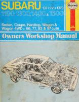
Subaru Owners Workshop Manual by J H Haynes Member of the Guild of Motoring Writers
and B Gilmour Models covered
Subaru FF-1 1100 FF-1 1300G 1300 1400 1400 1600
Sedan and Station wagon, 66 cu in and Station wagon, 77 cu in Coupe and Station wagon, 77 cu in Coupe, GL and GSR and Station wagon, 83 cu in Coupe, Hardtop, Station wagon and 4WD, 83 cu in Coupe, Hardtop, Station wagon and 4WD, 97 cu in
Subaru Subaru Subaru Subaru Subaru
ISBN
0 85696
Sedan Sedan, Sedan, Sedan, Sedan,
237 6
© _ Haynes Publishing Group 1977
sacoe 2
All rights reserved. No part of this book may be reproduced or transmitted in
any form or by any means, electronic or mechanical, including photocopying, recording or by any information storage or retrieval system, without permission in writing from the copyright holder.
Printed in England
Stk HAYNES PUBLISHING GROUP SPARKFORD
YEOVIL
SOMERSET
distributed in the USA by
HAYNES PUBLICATIONS INC 861 LAWRENCE DRIVE NEWBURY PARK CALIFORNIA 91320 USA
ENGLAND
KLMNO
°°"S
Acknowledgements Thanks are due to the Fuji Heavy Industries Ltd. of Japan for the supply of technical information and certain illustrations. The spark plug photographs used in Chapter 4 were provided by the Champion Sparking Plug Company Limited. Lloyds Industries Limited, who supply ‘Turtle Wax’, ‘Dupli-Color Holts’ and other Holts range products, provided the photographs used in the bodywork repair section.
Lastly thanks to all of those at Sparkford who helped to produce this manual - Martin Penny and Brian Horsfall who took the car to pieces and reassembled it and gave valued advice as how best to proceed; Les Brazier who took the photographs, often in most undignified positions; John Rose for editing the text and lan Robson for planning the layout of each page.
About this manual Its aim The aim of this book is to help you get the best value from your car. It can do so in two ways. First, it can help you decide what work must be done, even should you choose to get it done by a garage, the routine maintenance and the diagnosis and course of action when random faults occur. But it is hoped that you will also use the second and fuller purpose by tackling the work yourself. This can give you the satisfaction of doing the job yourself. On the simpler jobs it may even be quicker than booking the car into a garage and going there twice, to leave and collect it. Perhaps most important, much money can be saved by avoiding the costs a garage must charge to cover their labour and overheads. The book has drawings and descriptions to show the function of the various components so that their layout can be understood. Then the tasks are described and photographed in a step-by-step sequence so that even a novice can cope with complicated work. Such a person is the very one to buy a car needing repair yet be unable to afford
garage costs. The jobs are described assuming only normal spanners are available, and not special tools. However a reasonable outfit of tools will be a worthwhile investment. Many special workshop tools produced by the makers merely speed the work, and in these cases guidance is
given as to how to do the job without them. On the few occasions a special tool is essential to prevent damage to components, then their use is described. Though it might be possible to borrow the tool such work may have to be entrusted to the official agent. To avoid labour costs a garage will often give a cheaper repair by fitting a reconditioned assembly. The home mechanic can be helped
by this book to diagnose the fault and make a repair using only a minor spare part. The manufacturer’s official workshop manuals are written for their trained staff, and so assume special knowledge; therefore detail is left out. This book is written for the owner, and so goes into detail.
Using the manual The manual is divided into twelve Chapters. Each Chapter is divided into numbered Sections which are headed in bold type between horizontal lines. Each Section consists of serially numbered paragraphs. There are two types of illustration: (1) Figures which are numbered
according to Chapter and sequence of occurence in that Chapter. (2) Photographs which have a reference number on their caption. All photographs apply to the Chapter in which they occur so that the reference figure pinpoints the pertinent Section and paragraph number. Procedures, once described in the text, are not normally repeated. If it is necessary to refer to another Chapter the reference will be given in Chapter number, Section number and where necessary, paragraph number. Cross references given without use of the word ‘Chapter’ apply to Section and/or paragraphs in the same Chapter (eg. ‘see
Section 8’ also means ‘in this Chapter’). When the left or right side of the car is mentioned it is as if one is seated in the driver’s seat looking forward. Whilst every care is taken to ensure that the information in this manual is correct, no liability can be accepted by the authors or
publishers for loss, damage or injury caused by any errors in, or omissions from, the information given.
' Chapter
Section
Introductory Sections
Page
Introduction to the Subaru Buying spare parts Routine maintenance
5 5 6
Chapter 1/Engine
General description 19 20 Removal Dismantling and inspection 24 AE eh eo en eee e 88 a ea e
Chapter 2/Cooling, heating and exhaust systems
General description
ee
ee
44
Draining, flushing and filling Radiator Thermostat ee 8 A ee ee
ee
Air cleaner Fuel tank Fuel pump Carburettors Evaporative emission control
56 56 56 60 69
Chapter 5/Clutch
Chapter 6/Transmission
8
ee
ee
35 41 43 eee 51 53 53
control systems
en
Reassembly ~=Refitting ~=Fault diagnosis ee ee
9 10
49
56
ree
Recommended lubricants Tools and working facilities
Water pump
General description
Chapter 4/Ignition system
Page
Heater 46 Exhaust 46 49 Fault diagnosis ee Se Ee
Chapter 3/Carburetion; fuel and emission
a
Section
ee
ee 71 71 74 74 77
Crankcase emission control
Exhaust emission control = Air pump ~—Hot air control system = Fault diagnosis
ee
ee
General description
79 ~~ «Gol
Contact breaker points Condenser
90 80
= Timing = Spark plugs
Distributor
80
=‘Fault diagnosis
rei
eee 85 85 86 86
General description
88
Removal, inspection, renovation
Cable
88
andrefitting
90
Fault diagnosis
92
General description
96
5-speed reassembly
109
Removal
96
4WDdismantling and reassembly
109
Rear differential Automatic Fault diagnosis
111 he) 115
Dismantling Reassembly 5-speed dismantling
97 101 107
Chapter 7/Ax\le-shafts, driveshafts and propeller
General description
116
~~ Propeller shaft
119
shaft
Front axle shaft
116
Fault diagnosis
120
Rear axle driveshaft
119
Chapter 8/Steering, wheels and tires
General description Steering
122 122
Wheels and tires Fault diagnosis
129 130
Chapter 9/Brakes
General description Bleeding Adjustment Front brake shoes Front disc pads Disc brake caliper
132 132
Rear brake shoes Wheel cylinders
139 139
133 135 136 137
Chapter 10/Electrical system
General description Battery Alternator Starter motor Windshield wipers Instruments
147 148 149 153 155 158
~Horn Fuses Headlamp Lamps and switches Fault diagnosis Wiring diagnosis
161 163 163 165 167 168
Chapter 11/Suspension and axles
General description Front wheel Control arms Road clearance Shock absorbers
180 183 185 185 186
Camber and caster Front suspension Rear brake drum Rear suspension Fault diagnosis
186 188 189 191 192
eee
I
Chapter 12/Bodywork
Ce
ee
Metric conversion tables Index
Master cylinder Servo unit, hoses and pipes ~=Parking brake Fault diagnosis
139 141 143 144
———————————————E————————————— General description Maintenance
193 193
Front door Rear door and tailgate
201 205
Repairs Bumpers
194 195
Instrument panel Windows
206 207 210 212
L
L
RES
C
.
Se
6L (vsn ) NYVENS OOPL 9Z
Introduction to the Subaru The Subaru, which
is manufactured
by Fuji Heavy Industries
Ltd.
With the introduction of the 4WD station wagon in 1975, Subaru
of Japan, was first introduced in the United States in 1968 as a mini car, the Subaru 360. The 360 was followed by the FF-1 series, front engine, front wheel drive cars with a horizontally opposed flat four, liquid cooled engine, the 1100 and 1300G. The range included 2 door
became the only small 4WD vehicle on sale in the United States. Also added to the range was a Hardtop model and 5 speed transmission was available on Coupe and Hardtop models.
and 4 door sedan and station wagon. In 1972 the 1400 was introduced and the Coupe GL and GSR was added to the range. Automatic transmission was introduced in 1974.
Automatic transmission being available on all models and a 5 speed
In 1976 the 1600 with a larger (97 cu in) engine was introduced. transmission available on Hardtop and Coupe models.
Buying spare parts and vehicle identification numbers Buying spare parts
Vehicle identification numbers
Spare parts are available from many sources, for example: Subaru garages, other garages and accessory shops, and motor factors. Our advice regarding spare part sources is as follows: Officially appointed Subaru garages - This is the best source of parts which are peculiar to your car and are otherwise not generally available (eg. complete cylinder heads, internal gearbox components, badges, interior trim etc). It is also the only place at which you should buy parts if your car is still under warranty - non-Subaru components may invalidate the warranty. To be sure of obtaining the correct parts it will always be necessary to give the storeman your car’s engine and chassis number, and if possible, to take the ‘old’ part along for positive identification. Remember that many parts are available on a factory exchange scheme - any parts returned should always be clean! It obviously makes good sense to go straight to the specialists on your car for this type of part tor they are best equipped to supply you. Other garages and accessory shops - These are often very good
Modifications are a continuing and unpublished process in vehicle manufacture, quite apart from major model changes. Spare parts manuals and lists are Compiled upon a numerical basis, the individual vehicle numbers being essential to correct identification of the component required. The vehicle identification number plate is \ocated on top of the dashboard and is visible thru the windshield, see Fig. 1. The die stamped chassis serial number is |ocated on the firewall in the engine compartment, see Fig. 2. The engine number is die stamped on the right-hand side of the
crankcase (photo).
places to buy materials and components needed for the maintenance of your car (eg. oil filters, spark plugs, bulbs, fan belts, oils and greases, touch-up paint, filler paste etc). They also sell general accessories, usually have convenient opening hours, charge lower prices and can often be found not far from home. Motor factors - Good factors will stock all of the more important components which wear out relatively quickly (eg. clutch components, pistons, valves, exhaust systems, brake cylinders/pipes/hoses/seals/
shoes and pads etc). Motor factors will often provide new or reconditioned components on a part exchange basis - this can save a considerable amount of money. ee
ret
The engine number is die stamped on the crankcase
ee
a
oe ol)
he
Vehicle identification number plate is on the dashboard
5)
4
The vehicle chassis number is on the firewall
Routine maintenance Introduction In the paragraphs that follow are detailed the routine servicing that = should be performed on your vehicle. This work has the prime aim of doing adjustments and lubrication to ensure the least wear and most efficient function. But there is another important gain. By looking the car over, on top and underneath, you have the opportunity to check that all is in order. 2 Every component should be looked at, your gaze working systematically over the whole car. Dirt cracking near a nut or a flange can indicate something loose. Leaks will show. Electric cables rubbing, or rust appearing through the underneath paint will all be found before they bring on a failure on the road, or if not tackled quickly, a more expensive repair. Also it prevents the car becoming a danger to yourself or others because of an undetected defect. 3 The tasks to be done are in general those recommended by the maker. But we have also put in some additional ones which will help to keep your car in good order. For someone getting his service done at a garage it may be more cost effective to accept component renewal after a somewhat short life in order to avoid labour costs. For the home mechanic this tends not to be so.
4
When you are checking the car, and find something that looks
wrong, look it up in the appropriate Chapter. If something seems to be working badly, look in the fault finding Section. 5 Always drive the car on a road test after a repair, and then inspect the repair is holding up all right, and check nuts or hose connections for tightness. Check again after about another 150 miles.
Every 250 miles or weekly - whichever comes first Check Check Check Check Check Check Check Check
radiator coolant level. engine oil level. battery electrolyte level. tire pressures. Examine tread depth and for other damage. operation of all lights. windshield washer fluid level. brake master cylinder reservoir hydraulic fluid level. operation of windshield wipers and washers.
Lubricate pedal system and linkage. Check level of rear differential gear oil (4WD vehicle). Check manual linkage and inhibitor switch. Lubricate the distributor cam. Check disc brake pads for wear. Check the hydraulic brake system for leaks. Check steering linkage for security and wear. Check the front suspension for wear or damage.
Rotate tires (to even out wear). Check wheel nuts and hub nuts for tightness. Check operation and efficiency of parking brake. Check clutch and gearshift operation. Check exhaust system for leaks and security.
Every 12,000 miles or 12 months
Adjust intake and exhaust valve clearances. Check the drivebelt tension. Inspect all cooling system hoses and connections. Inspect all vacuum fittings, hoses and connections. Check idling speed and adjust as necessary. Check choke mechanism. Renew the in-line fuel filter.
Check fuel filler cap (with relief valve) tank, pump and fuel lines. Renew the air cleaner element. Renew distributor breaker points. Check ignition timing. Renew spark plugs. Check distributor cap, rotor and condenser (breakerless ignition). Examine all emission control hoses.
Check air suction valve (air suction system). Check carburetor float level. Renew the hydraulic brake fluid. Check shock absorbers for signs of leakage. Check whee! alignment. Lubricate hinge and locks of doors, hood and trunk lid. Check front and rear bumper shock absorbers.
ree
Every 24,000 miles or 2 years eee Every 3,000 miles or 3 months Check engine oil. Check automatic transmission fluid level.
Renew the coolant in the cooling system. Check all ignition wiring. Check air suction manifolds. Inspect and renew EGR components as necessary. Check all evaporative fuel vapor lines. Renew the one in the engine compartment.
Every 6,000 miles or 6 months Renew engine oil filter. Check level of transmission oil. Examine engine and transmission for oil leaks.
Check level of differential gear oil (automatic transmission).
Renew Change Change Change
canister filter in fuel evaporative control system. the transmission gear oil. the automatic transmission fluid. the differential gear oil (automatic transmission).
Change the rear differential gear oil (4WD vehicles).
Check the engine mountings for deterioration and security.
Engine oil pan drain plug
Transmission oil level dipstick
Transmission drain plug
The wheel change jack is stowed on the left-hand front wheel apron
inner Front
cross ae
SRO.
bushing
membe at’
yy,
Front jacking-up point
Front support points
Rear jacking-up point
Rear support points
(erry Daveys—~ ©HayNes
Se
Recommended Component
1
Engine
2
lubricants
bi
and fluids
.
By
=
nc
Type
ag
re
ve
Ne
By
ute
SAE 20W/50 multigrade engine oil
Gearbox and differential
Es
0
a
a.
e
b
Pe
oe
ice
HHH HHH
©
et
a rs
3
®
:@OQO
@
Ge
O5e
ne
ao
4
ssl
i
5£5
35
|
:
-—}—-
ue LS
©)
‘
1S Oy, rs
H
2
p
E
ro)
2
:
2
s
=
I
"
{=}
oO
i
OO
=
s°
Z
Ey
3
fo
238
a &
3 2h
a=e
Fs
3=
=e
a
=
2wee ©
ei
BE so %
>8} 9)
Se 3
ta
ee HDG)
@) 2 ie se
x
os! .
A § 3)
=
ay
o
JaxsoW 1461)
[a]
sexs0W146!)
wUJ04/eD [9POw
O ZN
juosy apis
ast
LOLiUby 11N3419 404
YouIMs
99U0108|9/;0uUb1s (s]ba
ius0Mm Bul
yuazzng iyBi)
1Dag )aqQ 4
joubis
209 dn-
usny
/dois OL|
Joey
of
MB/E2-AZI
YOuIMs
BSUaDIq~
YoIoUlquiod 4461,
ST, 1u0dqu
VouDUIwnt (\)
GQ)
MOPUIM
MEZ-AZ
MEZ-AZI
MB/EZ-AZ1
UoIsoUIqwo> 1yb1)
840)d ZEMB-AZI
juos4
:
|
JO8Y
say, jDUIQuio> Yo! 4Y61] dois101 MB/E2-AZI
1461;
usin
(8)
woeq
Ja;0aHJun
J09y MOPUIM
MOR we
dwind M9-AZI
ang Buiys 94029
211owoIny ayour
jany
TI swum
mo>
“NQUASIG
Gee ||
By
oy
JOb
3} —63
psoz04 WLIMS
ps0z0Hjiun
4
% aunjio)
19°91 ove eel
«
auN|10}
Buiuiom Ydiims
-AZI
04
Burjasaip
146s)
axoug
49 OB 660j;0p
uy -
so1ojnbas
ax01g
YoLims
& 010A 26
(iW)
bursog
JOINGIULSID
420g dm
moleo) I
(HI)
Oe +
(H¥)
ArT GE
Udy Jolow
La
in|
4009
say)ow-
GQ
YLIMS
/w098q
A2/ HVO9-
IO
D
4009
J}@
| | |
ZXMe
a
YOY
Asaog
oe
| I Oman
ya'zang
iv
HH
hay
ee hd
yu] JO;IQi ¥ dn_490q 161 WHemsTiv)
= YD1IMS
{a]
cs
See)
1yB1)
Ss
4a1J0IS JOJOW
OM 6 a]
-AZI Me 1084
ba f9]by
ha
W0eq
mee-azi\_&
/Wo0ag MOT
auiog
/OS-A2I MOv
YOLIMS
neon
poaH 1461)
|
Ls
apis
YbI,y
a
1461)
Jajawouay
MB/E2
inne
20440
jun
AZI-
sabbojap
dn-4209
Q
|
1
usny
BAIOA
92W0103|5/)0ubis
UMOPHIIYILIMS
Le ME2-AZI MEZ-AZI
MSG-AZ!
uiny
UMOPHIIy, Plouajos
4
VoloUIQwos 1461}
Y Sas un
{nat
juos4
Jawwig
36
Youims
saxsOW141]
sausoM Gwnd
4a1s01s- vorjiub)
Jojow sadiM
~AZIMB
(3
MOv -AZI
juosy apIs
176
of
sajaw iyi)
(5)
wnt
MB/EZ -AZ! 2
# dois
dn-y90g AZIl MEZ-
dn-9909
s0ay
EXMB/E2-AZI
asuacq
uiny dois
NEZ- AZ!
aiojd
Uorsoulquiod
2*MB-AZI
/jouBis
(OL/;oubis
1u61)
[101
1y61)
FH
apis
Bem
4axJ0W 1y61|
soay voILoUIqwo> 1y61)
boy} foal
JOIOW
dwndsagsom
Ja4xJOW apiscS, ee MSE aJOAY
JAadiM
UDLIMS WOH
zs) ‘8 4
D
10D 90D10
uobejj uoie1S 2726) - wesb eip Burin “LG'OL “614
HOLIMS QUWZ¥H 9 TWNOIS NUL
UOILISOD 501 3a/aS
{>}
JOLODIPUI
JDAY
wn ORTETTT sl
YI 103g
78660)
puozou
Buny614 8)
|
wees ff
f
5) JOLOSIpU!
yoiims
@
| M
MOPUIM
SO
erewenn
YoLiMs
Ja1aW
UOIMS
ypjoubIs win)
}y6l) UOlfoulMN)||
Jaysom
wv JadiM
AY
S-
AJaWOWJOY saiaw
I
&
fra 1038S19Q
100,
YdIMS-_ =
400Q
YDLIMS
{He
«Tyre BuiusJOM
mae}
yajy6s|
-A2I MB
@2u0I02|9/joubIs ©
40} e14J0}1/2D JaPOW YOInIUB} 11ND419
UO4
rue} OL15-91 wut
Apis jU0s4
by
jUu0I4
uuny
usny
UOILOUIQWOD
-AZi
mo7/wo0eq woaq Y6IH
9ou0s09)D/|oubIs
1y6ty
MOv/OS
juoy Ly) JoU;quiod Yor
saxJ0W
il
8
4OL0}NBay
Ooeyag 02
1y6i|
MS8-AZI JOJOW
4x20 1y61)
ao1jon
-AZI IMSS Lt
eelSe
sO 404
AION
butjasaip
‘®
-ijuy
MS-OWJOUL 11 Ud
a1 J01S
JOLOUIaIIY
JOVINOA - 4OLVNYSLIV
-A2I
$13
8
J:
H¥0O9 Kiajiog
a
asny
YOLVINDIY
Tv
JOIOW
B] isuod
N
4
{ey 3 aBO1I0A, | | | be} | ial YDIIMS
youims (1¥) l
vw
@)
JO) OUJ21IY
Gre!
vos-Azi
HY 40 10)/ND2d aw) Qw JOINQUII
cvs y |
WJOH
ayoud I1OWOINY
us Ey}4
ls Sle HeIES &
2 MOb
7
yiun Jajawowsau,
I _@)a—
SS CODY Wee HEE
©)
3x01 aunjioy
|
JO1sIs3y iA}
UMOPYXD!y Piouajos
juoLy APIS WW
(LW)
ue
asas0615
Buiusom
{>
YOLIMS UMOPHI14
dey909g
&
19108}tiun
AY} jy61)
2 JOLIQIUUT Peas
W2LUWLSNOILIND! HOLIMS UeUaa)ey1 PAIRSIO IF 4207 4/6
uin2m9med [U860
ap
mBAZ!
ybIH /woag mo7 woaqg
S
=
9ou0108/9,/joubrs
Ht
MB/ez - rzi
usny
ce
17
il:
aie
['
nyprune
)0A 3601
1010|NB8s
‘B14
‘ZG'OL Bui
wesbeip LLGL GM
Ce
“ones uobem
ow
OWVIWH MOLINE
= w
*
far:
|
YYNOIE 9 w
HNL Aad
| \ |aq
4010U381
+
+
ay
Mei
|
ia
4
wb, Burwom ayoud Buiyuod
[oe§
HOLYNYIL JOVLIOA INDY HOLY
attest
MONLINOF LE MIAMW HOLME payed 18 14 1901
Jaiybi|
vans a 9
aiias06)5
IV
vos
17| SOL JOVI
18108H liun x -A21 MSS +
ealeaie at
ti
(9) [3] a ed (ca
Le
|
=e
Jaysom
axug
PIED MUJO |POUW
DOWOINY
anour
jany Jownd O -A2IM9
dois 1461)
auN|iOJ
Buiusom yotims
ax0ug
UudtIMs
TS
ag
+€
UDLIMS
3401Q 6uiys0g
11NDHD 404
@Ajon
Burjaseip
bd
Pi
os
duind
Basi
(el)
mow ow] mua wo]
vamos,DA]
mw mo
WA
RD 960910
enie tom wy]
Mey
4sazmqQ 1y6i)
s00y apis
womsory mowervemy
1289 Wr
Sar
wmeowoims
ventoryAv] carvan 4]
coreg
“AZ MB
JaxV0W 1464
saxs0Wi461,
-AZIMB
rO
MB-
uy-
igoieyomer
{a}
seinaulisip
uB} uo!
[|
t®
re ce
IMopuim
AZ)
,
vs)
7
+
404031
usny| Pull
Of
TasN|10)
UBy VOR
19°51 lien
®
6
|
out
eat
bat]
6ulusom
s0oay apis
Gs
tuo, apis saxs0W 1461)
04
Yo) IMS-oW
|
I
afdn-pog 6 4401)
10193/9S YDIIMS
2xME
bd
C-A6
ass)
04
tTHh)
a
hae
xy,
say =
|
iNBbas2010
@HOIIOA
[x9]
GMb
4JO1091
}—volouRuny 1461]
Kay
ATG)
UDLIMS
AZ!
YVorlouIqwos 1461)
*¥/o5
"
G
fa]
484401 JOJOW
pul
YBIH| 103q
saa; |!
mn Me &it
aunssaid ©
Brui0m
263045
Biuj0M ME
JOLO9IPU!
WH CA
a
1u6] uo} -
ag
soay-
juOs4
nzi-
eS
L
MSB-AZ!
JojOW
S
4Ja660)ap
YOIH aq MO7/“WoeQ
Ae
be | bo by fd| 29
UDF
Aiaiiog -AZI HVO9
110
Capt
|
J03y
;
MOMo¢
Mo7/woaq woaq
JOayIMS You
§ 5 ? 2 ¢
1u611poaH
21-
poaH sys)
y6iy
92U0303|D/joubis MB/E2
MOPUIM 4
Prenasath
-AZI
YosIMs
sau
{a}
wun
way
QO 4azznq
7009
MOB saBBojap§
JA PAWOUWUIAY |
juos4 1461) UooUIqWos
saysom, dwind
(s] (KH)
|©
JOYSOM
MSE-A2I
ing
3
BadiM
-AZI MB
On fag]
JaxJOW
awog wy61)
(H
qy61)
-yo0g dn
soay dois
wins
MEZ-AZI
Jouds / |10L
vooulquios 146!)
asuasiqdyBi; 2*M8-AZ)
M2
/JOubIs 1101
volLDUIquios 1461)
-A2l
usin{
490gdn-
JOEY
dois
ue
[= ee
a)
YoiIms 100g
JUdI4 PIS
-Az
Z*MB/ez
MB/E2-AZ 2%
178
Buiusom v
ioas
i 2
Yokims te
vol
Ct)
Chapter 11 Suspension and axles Contents
Camber (FF-1 models) - adjustment Caster (FF-1 models) - adjustment = ee Damper strut assembly (1972 - 77 models) - dismantling, inspection and reassembly Fault diagnosis
aS
General description
ze
Lower control arm (FF-1 models) - removal and refitting
ats
Front end road clearance Height WEE: 1models) -- adjustment Front suspension balljoints - inspection, removal and refitting
Front suspension control arm FEnIMtCMGiree. acess
(1972 - 77 models) - removal and
Front suspension Sueape strut (1972 -77 models) - ene Tefigmnmg.
...
...
...
Front suspension Sebiizer (1972 - 77 smodels) - Sire and refitting ee aa Front wheel hubs: pearines and Steering knuckle - removal, inspection and refitting
and
Rear brake drum and spindle assembly oil seals, 4WD - renewal Rear brake drum, spindle and vee assembly, 4WD - general description ... ... cb Rear end road clearance iheight -Sacdustrent oc wes Rear end road clearance height (FF-1 models) - adjustment Rear drum/hub and bearing assembly - removal and refitting Rear suspension - removal, dismantling and refitting Rear wheel alignment - checking and adjustment Rear wheel bearings, 4WD - renewal
Shockabsorbers (FF-1 models) - removal, checkin and rerittinia Upper control arm and torsion bar (FF-1 models) - removal! and refitting
Specifications
FF-1 1100 and 1300G madels Front suspension Type Spring
Wishbone independent type Torsion bar
Rear suspension Type Spring
Semi-trailing arm type Torsion bar
Shock absorbers Front and rear
Oil damper
- cylindricai double action
Wheel alignment Front axle: Toe-in Camber
Sedan 5 mm (0.2 in)
1° 50’
Ge
Caster
2° —20' 20)
20 —1° 45'
0 - 0.20 in (0 -5 mm)
0 - 0.20 in (0 - 5 mm)
1
0° 40’
King pin angle Rear axle:
Toe-in
Camber
Sports Sedan 5 mm (0.2 in)
1300, 1400 and 1600 models Front suspension Type
Coil spring: Diameter ... Free length
McPherson
strut type
1975 -77
1972 -74 4.13 in (105 mm)
4.13 in (105 mm)
15.4 in (390 mm)
13.48 in (342 mm)
180 cdl
EY
and axles
sion Chapter 11/Suspen tanned NO
Ts
Rear suspension Semi-trailing arm type Torsion bar
Type
Spring
Shock absorbers Front and rear Front stabilizer: Diameter ...
Cylindrical double action 1972 -74
1975-77
087 in (22 mm)
0.79 in (20 mm)
Wheel alignment (1972 - 74) Front axle: Toe-in Camber
0.08 - 0.32 in (2 -8 mm)
Caster King pin angle
12307 0° 45’ 12° 55’
Rear axle:
Sedan
Toe-in
0.04 -0.20 in (1 -5 mm) 42
Camber
Wheel alignment (1975 - 77) Front axle:
Sedan - Coupe - Hardtop
Toe-in
0.08 - 0.32 in (2 -8 mm)
Station Wagon 0.08 - 0.24 in (2 1° 30’
Station Wagon DL
1° 50’+ 30’ 45’ +45
Camber Caster Rear axle:
0.04 - 0.20 in (1 -5 mm)
Toe-in
o +4 45 30° 1°
Camber
-6 mm)
4WD 0.24 -0.47 in (6 - 12 mm)
2° 30’ + 30’ 0.08 -0.24 in (2 -6 mm)
1° 30’ + 30°
1° 50’ + 30’
Torque wrench settings Ib f ft
kg fm
26 - 32 33 - 43 58 - 72 33 -54 44 -65 26 - 32 87 - 101 116 - 133 44 -65 116 - 133 80 - 144 42 -54
3.5 -450 45-60 8-10 45-75 6-9 3.5-45 12-14 16-185 6-9 16-185 1-20 7-15
FF-1 110 and 1300G models Lower control arm to body bolt Lower control arm shaft bolt Front suspension mounting bolt Lower arm castle nut Rear suspension outer bracket bolt Torsion bar lock bolt Front hub to CVJ Upper arm ball stud nut = Knuckle upper and lower balljoint nut Front drum to axle shaft nut Rear drum bearing nut ...
Front drum to DOJ
1300, 1400 and 1600 models Front suspension and axle Strut to knuckle Strut to body Control arm to crossmember Stabilizer to leading rod Tie-rod end to knuckle ...
ass aa
Front hub nut (1972 - 73)
Front hub nut (1974) Front hub nut (1975 - 77) Balljoint stud to knuckle Balljoint to control arm
Shock absorber upper nut
22 - 29 22-29 73 -86 13 -16 18 -22 160 - 188 174 145 - 181 35 - 40 80 - 94 44 -54
Rear suspension and axle Brake drum nut ... es Torsion bar outer bushing lock bolt Torsion bar outer bracket bolt
4WD vehicles Link nut ... ah Companion flange to spindle nut Brake drum nut ...
SS
1
General description
rr
1
The front suspension on FF-1 models is a wishbone type, independ-
80 - 145 13 -18 43 -65
130 -166 145 -181 174 ent system with torsion bar mounted upper arms and shockabsorbers. The suspension and crossmembers are attached to the body thru rubber cushions to improve riding comfort. 2 On 1300, 1400 and 1600 models the MacPherson strut type
181
Nut
Spring washer Washer
Cap (cushion rubber body mount A)
Cushion rubber B (body mount) Cushion rubber A (body mount) Collar A (body mount) Upper arm assembly (rh) AWN BDH O©MN Upper arm assembly (Ih) 10 Pin (shock absorber) 11. Torsion bar (F.rh) 12 Torsion bar (F./h) 73 14
Lock bolt Nut
15
Anchor arm (rh)
16 17. 718 79 20 21 22 23
Anchor arm (Ih) Snap-ring Cam (cross member) Nut Spring washer Plate Bushing (lower arm) Cross member assembly
24
(F suspension) Dust seal (upper arm)
25 26 27
Plug Bearing (upper arm) Oil seal (upper arm)
28
Dust cover (upper arm)
29 30
Plate Spacer
31 32
Lower arm assembly (rh Lower arm assembly (Ih)
34 35
Shaft (lower arm) Bushing (lower arm rear)
Bracket (lowerarmrh)
— 59
37
Bracket (lower arm /h)
51
Rubber (shock absorber)
38 39
Spring washer Bolt (10 x 72)
52 53
Washer (shock absorber) Nut
40 41 42
Bolt (10 x 36) Bolt (lower arm) Cam (castor/camber)
54 55 56
Nut Bolt Spring washer
43 44 45
Spring washer Castle nut Cotter pin
57 58 59
Washer Stopper Cushion rubber
46
Nut
60
Bracket (cross member)
33
36
Bushing (lower arm front)
47
Shock absorber assembly (front)
48
Washer (shock absorber) Rubber (shock absorber)
49
Rubber (shock absorber)
Fig. 11.2. Exploded view of front suspension
®
(FF1 models)
4 Fig. 11.3. Front and rear suspension - 1300, 1400 and 1600 models
ar aa
suspensi ea
@ ae
eeOD
suspension DEEL
1 Stabilizer 2 Damper strut 3
Transverse link
4 5
Front axle Front cross member
Fig. 11.4. Exploded view of front suspension 1972 - 74)
(1300 and 1400 models
7
Nut
22
Bolt
2
Spring washer
23
Self locking nut
3 4 5
Washer Cap (strut mount) Self locking nut
24 25 26
Washer (transverse link inner) Bushing (link outer) Bushing (link outer)
6
Washer
27
Washer (transverse link outer)
7 8
Strut mount Oil seal (strut mount)
28 29
Bushing (stabilizer) Stabilizer
9
Washer (thrust bearing)
30
Bolt
10 Thrust washer
31
Washer
11 Spring retainer (upper)
32
Bolt (10 x 40)
12 Rubber seat (coil spring)
33
Washer
13 Helper
34
Lock plate
14 Coil spring
35
Bracket (stabilizer)
15 Shock absorber complete
36
Nut
16 Washer 17 Spring washer
37 38
Spring washer Washer
18 Bolt
39
Crossmember complete (F)
19 Bracket complete (brake hose
40
Washer (transverse link inner)
41
Bushing (inner pivot)
rh) 20 Bracket complete
(brake hose
Ih)
Washer (transverse link outer) Self locking nut
21 Spring washer
Strut
mounting
Cross
Stabilizer
Ball joint
Transverse
member (front)
Cross
link
Fig. 11.5. Front suspension on models from 1975
member (rear)
Chapter 11/Suspension and axles
183
system is used. It consists of independent struts with cylindrical
‘double action shockabsorbers and coil springs mounted on the control arms. The control arms have a maintenance free balljoint riveted at the Outer end and the inner end is bolted to the crossmember, thru rubber cushions. The upper end of each strut is secured to the wheel apron, while the lower end is retained by a knuckle
housing, bolted
to the hub. The stabilizer bar is bolted to the floor of the body and the ends are fastened to the control arms with bushings. 3 On models from 1975, leading rods are added to the suspension system. The leading rod is welded at one end to the control arm and the balljoint is bolted to the control arm instead of being riveted. The ends of the stabilizer bar are connected to the leading rods thru rubber bushings. 4 The rear suspension is basically the same for all models. It is a semi-trailing arm type consisting of a torsion bar and double action shockabsorbers.
2
Front wheel hubs, bearings and steering knuckle - removal,
inspection and refitting
FF-1
1100 and 1300G models
1 Chock the rear wheels. Jack up the front of the car and support it On jackstands. Remove the road wheels. 2 Straighten the lockplate and remove the wheel hub nut. 3 Disconnect the tie-rod end from the knuckle arm, refer to Chapter
8, Section 10. 4 Remove the bolts securing the lower arm balljoint and separate the arm from the balljoint. Note: When the camber and caster adjusting cams are removed, note the setting number for reassembly, see Fig. 11.20%. 5 Separate the upper arm balljoint from the upper arm by straightening the backplate and removing the nut. 6 Remove the hub and knuckle assembly from the splined section of the axle shaft.
7
Separate the hub from the knuckle.
8 Remove the lockplate retaining bolt, washer and lockplate. 9 Remove the inner oil seal from the knuckle, then press out the bearing. 10 Clean the parts and examine them for wear and damage. Check the balljoints for play and their rubber boots for deterioration. If the balljoints have to be renewed, use a balljoint separator to remove them from the knuckle. The two halves of the bearing must be renewed as a set. Always fit new oil seals at reassembly.
‘
Fig. 11.7. Disconnect the lower arm balljoint (FF - 1)
Fig. 11.8. Separating the hub from the knuckle (FF - 1)
Fig. 11.6. Front wheel (FF - 1 models)
71 2 3 4 5 6
Hub Hub bolt Washer tock plate Wheel nut Hub nut
7
Bolt (wheel cap)
8 9 70 11 72 13 14 15
hub and knuckle assembly
Knuckle assembly Spacer Ojl seal Bearing assembly Nut Oil seal Lock plate Spring washer
ie vip. ee
nae
18 19
Bolt Spring washer
20 21 22 23 24
Cotter pin Castle nut Washer Baffle plate Brake drum
25
Brake adjusting port cover
26 27
(brake drum) Ball joint assembly (lower) Clip
28 29 30
Boot Cotter pin Castle nut
31
Ball joint assembly (upper)
32
Lock plate
33
Nut
184 Approximately
(0.0394
1 mm
in.)
“4 RUA 5 IRS (CORRECT)
(INCORRECT)
ae
(INCORRECT)
&
\
mn
¢
£
3
|
c
YI
)\
\
WS
\
:
lez)
c
\
3 O
.
Fig. 11.9. Assembie the two halves of the bearing correctly (FF - 1)
Fig. 11.10. Fitting the outer oil seal (FF - 1)
Fig. 11.11.
Front hub and knuckle assembly for drum
brake (1300,
1400 and 1600 models)
1
Spring pin
71
2
Axle shaft
12
Circlip
3
Oil seal (in)
13
Spacer
4 5 6
Bearing Housing Spring washer
74 715 16
7
Bolt
17
8 9
Castle nut Cotter pin
718 19 20 21
Oil seal (out) Hub bolt Sleeve Brake drum Center piece Lock washer Lock plate Nut
10
Transverse link
Dust seal (ball joint)
12 10
ig. 11.12. Exploded view of upper arm and torsion bar assembly
(FF - 1 models) 71 2 3
9
13
Upper arm Dust seal Dust cover
4
Torsion bar
5 6
Nut Lock bolt
7
Anchor arm
8 9 10
Nut Lock bolt Cam
11.
Plate (cross member)
12 13
Snap ring Oil seal
Chapter 11/Suspension and axles
185
11 When refitting the bearing, ensure that the two parts are assembled ‘correctly, refer to Fig. 11.9, and pack it with wheel bearing grease. 12 Press the outer oil seal into the knuckle so that it protrudes approx-
imately 1 mm (0.04 in) from the knuckle end surface, see Fig. 11.10. 13 Fit the spacer and bearing nut. Tighten the nut to 115 - 133 Ib f ft (16 - 18.5 kg f m), then align the lockplate groove with the groove in the nut, bend over the tab and fit the lockplate bolt. 14 Coat the lip of the inner oil seal with grease and press it into the bearing nut. 15 Refitting of the steering knuckle is the reverse of the removal procedure. When refitting the lower balljoint to the lower arm, refit the camber and caster adjusting cams to the same setting as noted at dismantling. Check the wheel alignment.
1300, 1400 and 1600 models 16 On models with drum brakes remove the backplate as described in Chapter 9, Section 5.
Fig. 11.13. Removal of the torsion bar anchor arm (FF - 1 models)
17 On models with disc brakes remove the caliper unit as described in Chapter 9, Section 7. 18 Remove the bolts connecting the damper strut to the knuckle housing. 19 Disconnect the tie-rod balljoints from the knuckle arms, using a balljoint separator, refer to Chapter 8. 20 Carefully pull the knuckle housing downwards to separate the damper strut from the knuckle. 21 Separate the control arm balljoint from the knuckle. 22 Using a puller remove the knuckle from the axle shaft or the disc and hub assembly (disc brakes) . 23 Centralize the spacer and insert a brass or copper drift to the surface of the inner race of the bearing and drive the bearing, together with the oil seal, out of the housing. Remove the spacer. 24 Remove the outer race and oil seal in the same way. Discard the Oil 25 10 26
seals. Clean and inspect the dismantled parts as described in paragraph above. Always fit new oi! seals. Refitting is the reverse of the removal procedure. Tighten the bolts
and nuts to the torque specified in Specifications at the beginning of this Chapter.
3