Haynes Ford Sierra 1982 to 1992 Handbook & Drivers Guide 1850108137, 9781850108139
“160 pages : 24 cm Covers all Ford Sierra models (including Sapphire) except RS Cosworth derivatives, P100 Pick-up and
133 92
English Pages 164 Year 1992
Recommend Papers


- Author / Uploaded
- Steve Rendle
- Royal Society for the Prevention of Accidents
- Similar Topics
- Technique
- Transportation: Cars, motorcycles
File loading please wait...
Citation preview
HAYNES m0)1D
1982 to 1992
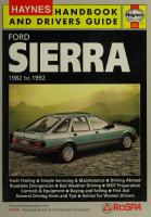
Fault Finding @ Simple Servicing & Maintenance @ Driving Abroad Roadside Emergencies @ Bad Weather Driving @ MOT Preparation Controls & Equipment @ Buying and Selling @ First Aid General Driving Hints and Tips @ Advice for Women Drivers Produced in association with RoSPA - The Royal Society for the Prevention of Accidents
FORD
Ws 1982 to 1992 All Ford Sierra models (including Sapphire) except RS Cosworth derivatives, P100 Pick-up and Diesel engine models.
LEY
GF
SNSY
A Haynes Handbook and Drivers Guide © Haynes Publishing Group 1992 Printed and published by J H Haynes & Co Ltd Sparkford Nr Yeovil Somerset BA22 7JJ England ISBN 1 85010 8137
HANDBOOK
by Steve Rendle
& DRIVERS GUIDE
ale erotik ila
British Library Cataloguing in
Full details of all servicing and repair tasks for the models covered by this Handbook can be found in the relevant Owners Workshop Manual OWM 903 Ford Sierra 4-cylinder, OWM 904 Ford Sierra V6. Ing fom the copyright
ABCDEFGHJKLMNOPQRST
holder
2
ACKNOWLEDGEMENTS We gratefully acknowledge the assistance of RoSPA in compiling the information used in this Handbook. Thanks are also due to Duckhams Oils who provided lubrication data and to Britax who supplied information on child safety. Certain illustrations, including the cover photography, are the copyright of the Ford Motor Company Limited and are used with their permission. Additional photographs were supplied by Quadrant Picture Library/Auto Express. Thanks are also due to all those people at Sparkford who helped in the production of this Handbook.
We take great pride in the accuracy of information given in this Handbook, but vehicle manufacturers make alterations and design changes during the production run of a particular vehicle of which they do not inform us. No liability can be accepted by the authors or publishers for loss, damage or injury caused by any errors in, or omissions from, the information given.
FORD
SIERRA
ee) ESR About this Handbook The Sierrafamily Buying and selling
|
4 z 9
General tips on buying ae
9
Points tolook for when bbuying Generaltips on selling _
a 10
te
Interiorequipment
15 19
Checking battery electrolyte level
78
Checking wipers and washers
36
"Service schedule. Pa
82
Safety 7first!
Essential details torecord
z
38
Buying spare parts
42
Howto cope'with a broken windscreen
42
_ What todo if yourr caris|broken ir into 42
Breakdowns Breakdowns on an ordinary road
43 43
Motorway breakdowns Changing awheel _
=
Dn)
44 L 44
Towing |
me
46
Starting a car with a flat battery
47
What to carry in case of a breakdown 48
Driving safety
Beforestarting a journey
Driving in bad weather
49
- ’ 249
Neo.
50
Motorway driving 19 Towingatrailer or ‘caravan See Alcohol and driving
51 ee
soe
Skid control apa
54
Advice to womensndrivers.
Childsafety
55
FORD
SIERRA
Service tasks
ens _
59 63
86
or
89
ae
95
_Seasonal servicing _
ia
at
114
Tools
What to buy
116
bi as
=
L ;116
Care of your tools a Bodywork :and interior care’ Cleaning the ‘interior
= =
ETF,
Dealing with scratches
118
Bulb, fuse and relay | renewal Bulbs ~ exterior lights
Ss
Bulbs~interiorlights Fuses.
116 117 a 17
Cleaning the bodywork |
_
119 120
125
_.
Relays
386
ine MRS
Preparing for the MOT test eeraultiinding «ss.
129 tay
Car jjargon
ai3t
Local radio frequencies
147
Conversion factors
ss 57_—«éDiistance Tables
Driving Abroad Reducing the cost of motoring
79
79 81
35
How to cope with a fire
; :
78
Checking for fluid leaks Servicing
os 3
39
.
Checking lights andhorn
Requirements of the law
Check listt andaccident report form
75 76
eS2
-
Checking coolant level
76 78
sh
a, o
74
Checking tyres Checking washer fluid level
Accidents and emergencies | 34 How tocope with an accident 7c 35 First aid
=
Checking brake fluid level
ne
Exterior equipment | .
Checking oil level
65 67 71
in
Dimensions and weights _ Yoru Controls and equipment Driver's instruments and controls
Car crime prevention Service specifications Regular checks
Index
152
Ee ee
Sr be e156
ABOUT THIS HANDBOOK
FORD
SIERRA
ABOUT THIS HANDBOOK The idea behind this Handbook is to help you to get the most out of your motoring. Apart from the things that every owner needs to know, to deal with unexpected mishaps like a puncture or a blown light bulb, you'll find clearly presented information on road safety, hints on driving abroad, and tips on how to prepare your car for the MOT test. We've also included details of local radio frequencies to help you avoid those inevitable ‘jams’, and there’s a Section on what to do in the unfortunate event of an accident. For those not familiar with their car, there’s a Section to explain the location and the operation of the various controls and instruments. Additionally, there’s a Section on fault finding, and a useful glossary of car jargon. Garage labour charges usually form the major part of any car servicing bill, and we hope to help you to reduce those bills by carrying out the more straightforward routine servicing jobs yourself. If you're about to start carrying out your own servicing for the first time, we aim to provide you with easy-to-follow instructions, enabling you to carry out the simpler tasks which perhaps you've left to a garage or a ‘car-minded’ friend in the past. Even if you prefer to leave regular servicing to a suitably qualified expert, by using this book you'll be able to carry out regular checks on your car to make sure that your motoring is safe and hopefully trouble-free. You'll also find advice on buying suitable tools, and safety in the home workshop. Some readers of this Handbook may not yet have bought a Sierra, so we've included a brief history of the range, and some useful tips on buying and selling. All in all, we hope that this book will prove a handy companion for your motoring adventures, and hopefully we'll help to reduce the problems which inevitably crop up in everyday driving. If you're bitten by the DIY bug, and you're keen to tackle some of the more advanced repair jobs on your car, then you'll need our Owners Workshop Manual for your particular model (OWM 903 for Sierra 4-cylinder engine models, or OWM 904 for Sierra V6 engine models). These manuals give a step-by-step handbook to all the repair and overhaul tasks, with plenty of illustrations to make things even clearer. Happy motoring!
LAC SIKL NOO . FORD
SIERRA
THE SIERRA FAMILY
ASierra Sapphire 1.8 LX (1989)
FORD
SIERRA
THE SIERRA FAMILY The Sierra was first introduced into the UK in late 1982 as the successor to the famous Cortina, and was one of the first cars to make use of the ‘aeroback’ body style, designed to reduce the air drag and improve fuel economy. To begin with, only Hatchback and Estate bodystyles were available, but the range was gradually developed to include a vast variety of different models and equipment. In 1987, the whole range was facelifted and heavily revised to incorporate many improvements over the original design. At the same time the Saloon models, known as Sapphires, were launched. Models have been produced with 1.3, 1.6, 1.8, 2.0, 2.3, 2.8 & 2.9 litre engines, 4- & 5-speed manual gearboxes or 3- & 4-speed automatic transmissions, and two-wheel or four-wheel-drive. A large number of different trim levels have been available over the years, from the Base Hatchback, Saloon and Estate, to the performance-orientated XR4i and XR4x4 Hatchback models. All members of the Sierra family share a similar mechanical layout, and they all use the same large family of engines and gearboxes, although many detailed modifications and improvements have been made since the original design was introduced. Most of the mechanical components of the cars are fairly conventional, and the main systems are designed to keep servicing time and costs as low as possible. The electronic
ignition system, clutch, brakes, wheel bearings, etc are all routine-maintenance-free, and should only require attention when certain items need to be renewed. On all models, the engine is mounted at the front of the car, with the gearbox positioned behind the engine. On four-wheel-drive models, an additional ‘transfer’ gearbox is mounted behind the main gearbox to provide drive to all four wheels. A wide range of standard and optional equipment is available across the model ranges, including items such as sunroofs, electric windows, central door locking and,
on certain models, anti-lock brakes. With the wide availability of spare parts, these cars are ideal for the enthusiastic amateur mechanic, who wants to keep running costs to a minimum.
A Sierra XR4i (1985)
FORD
SIERRA
Wau SHL-
ote
A Sierra LX
FORD
SIERRA
BUYING AND SELLING
ie
ae
l)
.
=
am
_
eal
A
os ae_
®
pe
~
Sie
Pa
=
GENERAL TIPS ON BUYING @ @ @ @
Don’t rush out and buy the first car to catch your attention Always buy from a recognised dealer in preference to buying privately Have the car checked over by someone knowledgeable before you buy it In general, you get what you pay for!
Before buying a second-hand car, it’s worthwhile doing some homework to try and avoid some of the pitfalls waiting for the unwary. First of all, don’t rush out and buy the first car to catch your attention (all that glitters is not gold!), and remember that much of the responsibility is yours when it comes to the soundness of the deal, especially when buying a car privately. Wherever possible, buy from a recognised dealer, and check that the dealer is a member of the Retail Motor Industry Federation, as this will provide you with certain legal safeguards if you have any problems. If you buy from a dealer, you are covered by the Sale Of Goods Act, which in summary states that the goods must be fit for their intended purpose, the goods must be of proper quality, and the goods must be as described by the seller. If you're buying a car privately, ask to see the service receipts and the MOT certificates going back as long as the car has been in the possession of the current owner (this will help to establish that the car hasn't been stolen, and that the recorded mileage is genuine), and always ask to view the car at the seller’s private address (to make sure that the car isn't being sold by an unscrupulous dealer posing as a private seller). Check the vehicle documents for obvious signs of forgery and, if in doubt, contact the DVLA and give them details of the Registration Document, as they will be able to run a check on its authenticity. _ As far as the soundness of the car itself is concerned, a genuine service history is helpful. This is provided by the service book supplied with the car when new, which should be completed and officially stamped by an authorised garage after each service. Cars with a full service history (fsh) usually command a higher price than those without. To check the condition of a car, a professional examination is well worthwhile, if you can afford it, and organisations such as the AA and RAC will be able to provide such a
FORD
SIERRA
SNIT 3DNI..
W(t)
}=BUYING AND SELLING service. Otherwise, you must trust your own judgement, and/or that of a knowledgeable friend. Although it’s tempting, try not to overlook the mechanical soundness of the car in favour of the overall appearance. It’s relatively easy to clean and polish a car every week, but when were the brakes and tyres last checked? Above all, safety must always take priority. Don’t view a car in the wet, as water on the bodywork can give a misleading impression of the condition of the paintwork. First of all, check around the outside of the car for rust, and for obvious signs of new or mis-
matched paintwork which might show that the car has been involved in an accident. Check the tyres for signs of unusual wear or damage, and check that the car ‘sits’ evenly on its suspension, with all four corners at a similar height. Open the bonnet and check for any obvious signs of fluid leakage (oil, water, brake fluid), then start the engine and listen for any unusual noises — some background noise is to be expected on older cars, but there should be no sinister rattles or bangs! Also listen to the exhaust to make sure that it isn’t ‘blowing’ indicating the need for renewal, and check for signs of excessive exhaust smoke. Black smoke may be caused by poorly adjusted fuel mixture, which can usually be rectified fairly easily, but blue smoke usually indicates worn engine components, which may prove expensive to repair. Finally, drive the car, and test the
brakes, steering and gearbox. Make sure that the car doesn’t pull to one side, and check that the steering feels positive and that the gears can be selected satisfactorily without undue harshness or noise. Listen for any unusual noises or vibration, and keep an eye on the instruments and warning lights to make sure that they are working and indicating correctly. If all proves satisfactory, try to negotiate a suitable deal, but remember that a dealer has
to work to a profit margin, and it’s unlikely that you'll find a good car for a silly price. Always obtain a receipt for your money. On the whole, it’s true to say that you get what you pay for. Above all, don’t be rushed into making a hasty decision.
POINTS TO LOOK FOR WHEN BUYING A SIERRA In addition to the points outlined previously, there are a few special points to look for when buying a Sierra. In general, the later models built from 1987 are an all-round improvement on the earlier models, and will prove a better buy if your budget allows. Corrosion is not usually a problem on Sierras, but there are a few areas which are prone to trouble. Firstly, check the wheel arches behind each front wheel. Flying stones can damage the underseal, and this leads to rust. Turn the steering wheel to full lock to allow access, and probe the wheel arches with your finger or a screwdriver. Other areas prone to rust are the bottom rear edges of the doors, and the lower edge of the tailgate on Hatchback models. Also check the windscreen pillars, and on Estate models the curved panel under the rear bumper. Check the bumpers for any signs of damage or cracks, as these components are expensive to renew.
Check carefully for accident damage at the front and rear of the car, especially on early models. Look behind the front bumpers, and
FORD
SIERRA
BUYING AND SELLING check for signs of corrosion, damage or repairs to the body panels. On Hatchback models,
check for ridges or other distortion in the floor of the luggage compartment (lift up the carpet to check). The Sierra is a popular company car, and is also a target for ‘clocking’ by unscrupulous dealers. Check the interior for signs of unusual wear (worn driver's carpet, steering wheel, pedal rubber pads etc) which may indicate that the recorded mileage is not genuine. Also check the facia around the instruments for any marks or damage which may indicate that the speedometer has been tampered with. After high mileages, all the engines used in the Sierra are prone to a build-up of black sludge inside the engine if the oil is not changed regularly. To check for this, remove the oil filler cap from the top of the engine, and run a finger around the inside of the hole. If sludge is present, reject the car. High-mileage cars, especially early 2.0 litre models, are prone to engine camshaft wear, which can be expensive to cure. A worn camshaft will cause a loud rattle when the engine is running, and the rattle will become louder as the engine is ‘revved’. Another point to note on OHC and CVH engines is that the camshaft drivebelt (timing belt) should be renewed every 36 000 miles. If you're not sure whether this has been done, it’s sensible to have the necessary work carried out as soon as you buy the car, as if the drivebelt breaks in service, very serious and expensive engine damage can occur. Unfortunately Sierras are a common target for thieves, so check the interior trim, particularly around the radio, for signs of damage. If possible, try to avoid 1.3 & 2.3 litre models. 1.3 litre models suffer from poor performance (they are rather underpowered), while 2.3 litre
models give poor economy and very little extra performance over 2.0 litre models. Sierras are plentiful on the secondhand market (although low-mileage examples are rare), and it shouldn't be difficult to find a . good car which will give trouble-free service.
FORD
SIERRA
GENERAL TIPS ON SELLING @ Make sure that the car is clean and tidy @ Make sure that all of the service documents, registration document etc, are available for inspection @ Ask yourself ... ‘Would | buy this car?’ Obviously when selling a car, bear in mind the points which the prospective buyer should be looking for, as described in the above sections. It goes without saying that the car should be clean and tidy, as first impressions are important. Any fluid leaks should be cured, and there’s no point in trying to disguise any major bodywork or mechanical problems. If you're trading the car in with a dealer, you will always get a lower price than if you sell privately, but you can be fairly sure that there will be less comeback to you should any unexpected problems develop. If selling privately, don’t allow the buyer to take the car away until you have his/her money, and it’s a good idea to ask him/her to sign a piece of paper to say that he/she is happy to buy the car as viewed, just in case any problems develop later on. Give a receipt for the money paid.
11
DIMENSIONS
AND WEIGHTS
lettin
FORD
SIERRA
MOL
GER
alc hic
13
Note: A// figures are approximate, and will vary depending on model
DIMENSIONS
[mm (in)]
Overall length Saloon (Sapphire) models
4467 (176.0)
Hatchback models
4407 to 4460 (173.6 to 175.7)
Estate models
4506 to 4522 (177.5 to 178.2)
Overall width All models
1820 to 1920 (71.7 to 75.6)
Overall height Saloon (Sapphire) models
1352 to 1407 (53.3 to 55.4)
Hatchback models
1352 to 1420 (53.3 to 55.9)
Estate models
1386 to 1506 (54.6 to 59.3)
WEIGHTS [kg (Ib)] Nominal kerb weight Saloon (Sapphire) models
1025 to 1135 (2260 to 2503)
Hatchback models: All except V6 engine models
1010 to 1145 (2227 to 2525)
V6 engine models
1165 to 1290 (2569 to 2844)
Estate models:
All except V6 engine models
1065 to 1185 (2348 to 2613)
V6 engine models
1200 to 1315 (2646 to 2900)
Maximum
roof rack load
All models
75 (165)
Maximum
towing weight (for trailer or caravan)
All except 1.3 and 1.6 litre models
1350 (2977)
1.3 litre models
825 (1819)
1.6 litre models (except Estate)
1100 (2426)
' 1.6 litre Estate models
1250 (2756)
Maximum trailer/caravan noseweight All models
RORD
50 (110)
SIERRA
8SNO SLH
14
\o O ra = ce O
eelV)
< ra Q
a) Le;|
==
ae = bs
i | Fa
:
i iB
ere
®
Fs
.
cr
on ea
FORD
SER
WA
CONTROLS AND EQUIPMENT
exeUi
For those not familiar with the Sierra models, this Section will help to identify the instruments and controls. Typical instrument panel layouts are shown in the accompanying illustrations. The operation of most equipment is selfexplanatory, but some items require further explanation to ensure that their use is fully understood. Note that not all items are fitted to all models.
os 16
E
ee
15 |—|14|-|13 eD
12 —@
A Typical instrument panel for ‘low series’ Sierra models up to 1987 Clock Temperature gauge
Fuel gauge Headlight main beam warning light Ignition warning light Handbrake ‘on’/low brake fluid level DAnRWNm warning light 7 Lowoil pressure warning light 8 Speedometer 9 Mileage recorder reset button 10 Heated rear window switch
Rear foglight switch Ignition switch/steering lock Glow plug warning light (Diesel models only) Direction indicator warning light Hazard flasher switch Temperature warning light (Diese! models only) Horn switch Cigarette lighter Ashtray
LNSI STO 8 FORD
SIERRA
©=CONTROLS AND EQUIPMENT
.(7
A Typical instrument panel for ‘low series’ Sierra models from 1987 1 2
3
4
5 6 7
Glow plug warning light (Diesel models only) Temperature warning light (Diesel models only) Clock Air temperature control lever Air distribution control lever Temperature gauge
Fuel gauge 8 Ignition warning light 9 Headlight main beam warning light 1 0 Handbrake ‘on‘/low brake fluid level/ABS warning light 11 Low oil pressure warning light 12 Speedometer
Mileage recorder reset button Heated rear window switch Rear foglight switch Exterior lights switch Ignition switch/steering lock Direction indicator warning light Horn switch Hazard flasher switch Cigarette lighter Heater booster fan switch Ashtray Radio
FORD
SIERRA
CONTROLS AND EQUIPMENT
13][14] [15 hn} ep) |) |G)
22
18
gle KS A Typical instrument panel for ‘high series’ Sierra models up to 1987
1 2 3h) 4 5 6 7 8 9 10 11 12 13 14 15 16 17
Brake pad wear warning light Low coolant level warning light Glock Lowwasher fluid level warning light Low fuel level warning light Graphic warning display Instrument illumination control Tachometer (‘Rev. counter’) Fuel gauge ABS warning light Temperature gauge Speedometer Mileage recorder reset button Tailgate wash/wipe switch Heated rear window switch Rear foglight switch Front foglight switch
FORD
SIERRA
18 Windscreen wash/wipe switch 19 Handbrake ‘on’/low brake fluid level/ABS warning light 20 Ignition switch/steering lock 21° Ignition warning light 22 Direction indicator warning light 23 Hazard flasher switch 24 Lowoil pressure warning light 25 Horn switch 26 Headlight main beam warning light 27 Loudspeaker balance control 28 Cigarette lighter 29 Heated driver's seat switch 30 Ashtray 31 Radio 32 Heated front passenger's seat switch
18
CONTROLS AND EQUIPMENT
30]
|29]
|28) | 27}
|26}
|25
$6] [|[4]fz)fe]lee
24]
[23]
[22]
[21]
[20]
[19]
[18]
[17
A Typical instrument panel for ‘high series’ Sierra models from 1987 Low fuel level warning light Low washer fluid level warning light Clock Graphic warning display Air temperature control lever
Air distribution control lever Instrument illumination control Tachometer (‘Rev. counter’)
Fuel gauge
ABS warning light Temperature gauge
Speedometer Heated windscreen switch Heated rear window switch Rear foglight switch Front foglight switch Variable intermittent wipe control
Exterior lights switch Mileage recorder reset button Ignition switch/steering lock Ignition warning light Handbrake ‘on‘/low brake fluid level/ABS warning light Hazard flasher switch Horn switch Direction indicator warning light Low oil pressure warning light Headlight main beam warning light Loudspeaker balance contro! Cigarette lighter Heater booster fan switch Ashtray Radio
FORD
SIERRA
ee New DRIVER’S INSTRUMENTS AND CONTROLS
eee
iam
Indicates the car's road speed in miles per hour (mph). Also incorporates a mileage recorder, and a separate trip meter which can be reset by pressing the button protruding from the instrument.
both buttons. Release the buttons at the time signal, and set the time as described previously. On early models, the clock displays the time in the 12-hour format, but on later models the time can be displayed in the 12- or 24-hour format. To set the time format on later models, press both buttons simultaneously and then release them — if the display shows 1:00, the clock is in the 12-hour mode, and if the display shows 0:00 the clock is in the 24-hour mode.
Tachometer (‘Rev. counter’)
MULTI-FUNCTION
Indicates engine speed in revolutions per
The clock can display the date, and has a timer feature. No display is shown with the ignition switched off, but the display can be recalled for 4 seconds by pressing the ‘select’ button (A). One press will display time, and further presses will display the date and timer. The ignition must be switched on to carry out all setting and adjustments.
Speedometer
minute (rpm). For normal driving and the best
fuel economy, the engine speed should be kept in the 2000 to 4000 rpm range. The red band indicates the maximum permissible engine speed.
Fuel gauge
DIGITAL TYPE
Indicates the quantity of fuel remaining in the tank. When the needle enters the red band, there are approximately 8litres (1.8 gallons) of fuel remaining.
Temperature gauge Indicates the engine coolant temperature. As the engine warms up, the needle should move from the blue (cold) end of the scale into the middle region. If the needle remains in the blue section, or enters the red (hot) section, a fault is indicated and advice should be sought (refer to ‘Fault finding’ on page 131). Do not continue to run an engine which shows signs of overheating
Clock Four different types of clock have been used.
ANALOGUE TYPE To adjust the time, push in the button and turn it.
DIGITAL TYPE To adjust the time, switch on the ignition. Press the button on the left to change the hour . setting, and press the button on the right to change the minutes setting (note that some early models may have recessed buttons which must be pressed using a pointed instrument such as a ballpoint pen). To synchronise the clock with an exact time signal, press and hold
FORD
SIERRA
A Multi-function digital clock A Select button B C D E
Reset button Stop/start button Timer symbol Colon
Adjusting time and date The time and date must be set using the following sequence. With the display showing the time, press the ‘reset’ button (B) once. The display should flash, showing ‘12H’ or ‘24H’ depending on whether the display has been set to the 12- or 24-hour format. Press the ‘stop/start’ button (C) to change the format. Press the ‘reset’ button again. The hour number on the left will flash. If the 24-hour
699
20
Menuitrurnsio ian format was selected, the minute number on the right will remain stationary, but if the 12hour format was selected, an ‘A’ for am or ‘P’ for pm will appear in place of the minutes. Press the ‘stop/start’ button to increase the hour number as required. Press the ‘reset’ button again. The minute number on the right of the display will now flash. Press the ‘stop/start’ button to increase the minute number. Press the ‘reset’ button again. The date will now be displayed, with the day number flashing on the left, and the month number stationary on the right. Press the ‘stop/start’ button to increase the day number. Press the ‘reset’ button again. The display now shows the date with the day stationary on the left, and the month number flashing on the right. Press the ‘stop/start’ button to increase the month number. When the adjustments are complete, press the ‘reset’ button to return to the time display. To return to the time display at any point during the procedure, press the ‘select’ button.
pressing the ‘stop/start’ button. The recorded time when the timer was stopped will be stored in the memory until the timer is restarted again, even if the ignition is switched off. If the ignition is switched off when the timer is still running, it will continue to count until the ignition is switched on again and the timer is stopped or reset; the timer can therefore be used to record actual journey time.
COMBINED ANALOGUE/MULTIFUNCTION DIGITAL TYPE The clock can display the date, and has alarm, stop-watch and timer functions. The functions are controlled by three buttons, and indicator lights below the digital display indicate which function has been selected.
Date display To display the date, press the ‘select’ button (A) once. The date will be displayed for 4 seconds, after which the time will reappear. Timer To operate the timer, with the display showing the time, press the ‘select’ button (A) twice. The timer can now be started by pressing the ‘stop/start’ button (C). Pressing the ‘stop/start’ button again will stop the timer and freeze the display. A third press will restart the timer from where.it stopped. The timer will count to 59 minutes 59 seconds, and then roll over to 1 hour 00 minutes and continue to count at one minute intervals. When the timer reaches 59 hours 59 minutes, it automatically resets to 0 and continues counting. Either of the two other displays can be selected when the timer is working. To display the time, press the ‘select’ button once, and to display the date, press the ‘select’ button again. To reset the timer to zero with the clock showing time, press the ‘select’ button twice to display the timer, then to zero the timer press the ‘reset’ button (B). The display can now be set to show the normal time by pressing the ‘select’ button, or the timer can be restarted by
A Combined analogue/multi-function digital type clock A Seconds indicator B Colon C Alarm symbol D Timer symbol E Analogue clock adjustment knob
Adjusting time (‘CLOCK’) The digital clock displays two figures; hours/minutes followed by minutes/seconds. Each figure is shown for 4 seconds; then, provided no adjustments are made, the date is displayed. The analogue clock will not operate unless the digital clock has been started, as both clocks are directly coupled. To set the time on the digital clock, proceed as follows. Press button (1) to select ‘CLOCK’ (clock indicator light illuminates). The display should show hours/minutes. Press button (2) for fast set, or button (3) for slow set (note that 4 seconds after any button was last pressed, the display will return to ‘DATE’).
FORD
SIERRA
CONTROLS AND EQUIPMENT Press button (1) again to display minutes/seconds, then press button (2) or (3) which will stop both the digital and analogue clocks, and zero the seconds. Set the time on the analogue clock using the knob (E). To start both clocks, press button (2) or (3). The display will show minutes/seconds for 4 seconds, then the date will be displayed.
Adjusting date (‘DATE’) With the ignition switched on, press button (2) for fast set, or (3) for slow set until the desired date is displayed.
Alarm (‘ALARM’) Press button (1) to select ‘ALARM’ (alarm
indicator light illuminates). The time when the alarm will operate will be displayed in the 24hour format. To adjust the time, press button (2) for fast
set, or (3) for slow set until the desired time is displayed. The alarm symbol (C) will appear in the bottom right-hand corner of the display. If no further adjustments are made within 4 seconds, the display will revert to ‘DATE’. To activate the alarm, look to see if the alarm symbol (C) is displayed. If it isn’t, press button (1) again, and allow the display to revert to ‘DATE’, when the alarm symbol (C) should be displayed. To cancel the alarm, press button (1), and allow the display to revert to ‘DATE’ when the alarm symbol (C) should disappear. To cancel the alarm buzzer when It sounds,
press button (1). If the button is pressed twice, the alarm will be cancelled, and the alarm
The flashing colon (B) will indicate that the
stopwatch is still running. Press button (2) again to ‘unfreeze’ the display and show the current time count. Press button (3) to stop the stopwatch, then button (1) to select another function.
Timer (‘TIMER’) Press button (1) to select ‘TIMER’ (timer
indicator light illuminates). The display will show this mode until another mode is selected. Press button (3) to stop or reset the timer. Press button (3) again to start the timer. The
display will show the total driving time. Press button (2) to display the total journey time. Press button (2) again to revert to total driving time. The timer will continue to count when the ignition is switched off, to indicate total journey time, until the button (3) is pressed to reset the timer. The timer indicator light will be illuminated whenever the timer is running.
Fuel computer Provides information on fuel level, distance and economy. There is also an audible warning to indicate low fuel level. The computer is controlled by three pushbuttons, and a tone will sound to indicate that a button has been pressed. The ‘function’ button (D) is used to switch between the four functions of the computer, and indicator lights show which function has been selected.
INSTANT
ECONOMY
symbol (C) will disappear. If the button is
Shows the instantaneous fuel consumption,
pressed once, the buzzer will stop, but will sound again every 10 minutes until the button is pressed a second time to cancel the alarm.
and this figure will change rapidly as driving conditions change during acceleration, braking, etc.
Stopwatch (‘CHRONO’)
AVERAGE ECONOMY Shows the average fuel consumption since the function was last reset.
Press button (1) to select ‘CHRONO’ (chrono indicator light illuminates). The display will show this mode until another mode is selected.
Press button (3) to stop or reset the stopwatch. Press button (2) to start the stopwatch. The flashing colon (B) will indicate that the
stopwatch is running. Press button (2) again to ‘freeze’ the display.
FORD
SIERRA
FUEL USED Shows the quantity of fuel used since the function was last reset. RANGE Gives an estimate of the distance the car will
21
2D Mee ieee Peels Trip computer Certain early models were fitted with a trip computer which can provide extensive information on fuel, speed, distance and time, and which has a number of alarm and warning functions. The trip computer is a complex piece of equipment, and a full description of its operation is beyond the scope of this Handbook. Full details of the trip computer can be found in a special booklet produced by Ford, which should have been supplied with the car when new.
Warning lights A Fuel computer and analogue clock A Analogue clock reset knob B Mode button C Clear button D Function button E ‘Instant economy’ indicator light F ‘Average economy’ indicator light G ‘Fuel used’ indicator light H ‘Range’ indicator light
travel on the fuel remaining in the tank. To remind the driver that the fuel level is low, an audible warning will sound when the range decreases to 50, 25 and 10 miles (80, 40 and 20 km) respectively. To stop the warning, any of the three buttons can be pressed, but in any case, the warning will stop automatically after sounding five times. Approximately 7 litres (1.5 gallons) of fuel are left in the tank when the
range indicates 0. The computer will automatically calculate a new range when more than 9litres (2 gallons) of fuel are added to the tank. When the ignition is switched on, the computer shows the last selected display. However, if the range is less than 50 miles (80 km), the audible warning will sound and the range will be displayed to remind the driver that the fuel level is low. Pressing the ‘clear’ button (C) while in the ‘Fuel used’ function sets the value to 0. Pressing the ‘clear’ button while in the ‘Average economy’ function sets the value to the current ‘Instant economy’ value. Pressing the ‘mode’ button (B) changes the units displayed from metric to imperial, and vice-versa.
These lights warn the driver of a fault, or inform the driver that a particular device is in operation.
HANDBRAKE ‘ON’/LOW BRAKE FLUID LEVEL/ABS WARNING LIGHT Warns that the handbrake is applied, or the brake fluid level is low. If the light comes on while driving, and the handbrake is fully released, stop immediately and check the brake fluid level (refer to ‘Regular checks’ on page 70). On models fitted with an Anti-lock Braking System (ABS), this light has an extra function, and may illuminate in conjunction with the ABS warning light. If this happens, be prepared for the possibility of increased brake pedal travel and increased stopping distance, and refer the problem to a Ford dealer as soon as possible. Do not continue to drive the car if a brake fluid leak is suspected
LOW OIL PRESSURE WARNING
LIGHT
Warns that the engine oil pressure is low. If the light stays on for more than a few seconds after start-up, it’s likely that the engine is worn and advice should be sought. If the light comes on while driving, switch off the engine immediately and seek advice.
IGNITION WARNING
LIGHT
Acts as a reminder that the ignition circuit is switched on if the engine isn’t running, and
acts as a no-charge warning light. If the light stays on after starting, or comes on while driving, the battery is not charging properly.
FORD
SIERRA
CONTROLS AND EQUIPMENT The battery may therefore become fully discharged, and the best course of action is to stop and seek advice.
HEADLIGHT MAIN BEAM WARNING LIGHT Acts as a reminder that the headlight main beam is switched on.
DIRECTION INDICATOR WARNING LIGHT switched on.
ABS (ANTI-LOCK BRAKING SYSTEM) WARNING LIGHT This light should come on when the ignition is first switched on. If the light stays on for any longer than one minute after the engine has been started, or comes on while driving, there is a fault in one of the ABS circuits. Normal braking will still be available, but the braking system should be checked by a Ford dealer as soon as possible.
LIGHT
This light comes on when the ignition is first switched on, and acts as a reminder that seat belts should be worn. The light should go out after approximately 20 seconds.
ECONOLIGHTS These lights provide a rough indication as to how economically the car is being driven. Where fitted, the lights are positioned above the direction indicator warning light. As a guide, aim to drive so that the lights come on only momentarily, or not at all. The amber light will come on when the car is being driven less economically, and the red light will come on when the car is being driven uneconomically. In practice, it will be very difficult to drive without causing the lights to come on at some stage, especially when accelerating.
Auxiliary warning system _ Consists of five lights which are connected to sensors to monitor various fluid levels and front brake pad wear. When the ignition is first switched on, the auxiliary warning lights will all come on for approximately 5 seconds. Check that the lights all go out before starting the
FORD
SIERRA
BRAKE PAD WEAR WARNING
LIGHT
Indicates that the front brake pads are worn to the stage where they require renewal. If the light comes on, the pads should be renewed as soon as possible.
LOW OIL LEVEL WARNING
Shows that the direction indicators are
SEAT BELT WARNING
engine. The function of each individual light is as follows.
LIGHT
Indicates that the oil level has reached the ‘MIN’ mark on the dipstick. If the light comes on, the oil level should be topped up as soon as possible (refer to ‘Regular checks’ on page 70). Note that the oil level check only works during initial start-up, and does not work with the engine running.
LOW COOLANT LEVEL WARNING LIGHT Indicates that the coolant level has reached the ‘MIN’ mark on the reservoir. If the light comes on, the coolant level should be topped up as soon as possible (refer to ‘Regular checks’ on page 70).
LOW FUEL LEVEL WARNING
LIGHT
Comes on when there are approximately 10 litres (2.2 gallons) of fuel left in the tank.
LOW WASHER FLUID LEVEL WARNING LIGHT Indicates that the windscreen washer fluid
reservoir is below quarter-full.
Graphic warning system Consists of a graphic display which uses symbols to warn of a light bulb failure, a door or tailgate/boot not properly closed, or a danger of ice. When the ignition is switched on, all the warning symbols should illuminate for approximately 5 seconds and then go out, with the exception of the brake light symbols. The brake light symbols should go out when the brake pedal has been pressed once. The symbols provide the following warnings:
DANGER OF ICE A yellow symbol is displayed when the outside temperature falls to between 4 and 1°C. A red symbol is displayed when the temperature drops to 0°C or below.
[P:
~=CONTROLS AND EQUIPMENT BULB FAILURE
Gearbox
The paired light symbols will illuminate to indicate a faulty bulb or fuse.
MANUAL
DOOR/TAILGATE/BOOT NOT CLOSED The relevant symbol will illuminate.
GEARBOX
Either a 4- or 5-speed gearbox may be fitted. The gear positions follow the usual ‘H’ pattern, but the method of selecting reverse gear varies depending on model. Reverse is selected in the same way for all types of gearbox except the ‘MT 75’ type 5-speed gearbox which was introduced in late 1988.
All gearboxes except ‘MT 75’ type
aday eK
ae
Reverse gear is positioned to the left of 1st gear, and Is selected by moving the lever fully left from the neutral position, then pressing down against spring pressure and pushing forwards.
‘MT 75’ type gearbox If an ‘MT 75’ type gearbox is fitted to your car, there will be a collar fitted under the gear lever knob.
A Graphic warning system display A Door or tailgate not closed B Likelihood of frost or ice (yellow at 4°C, red at 0°C)
C Defective dipped headlight, sidelight, tail light, or related fuse or wiring
D Defective brake light, or related fuse or wiring
Ignition switch/steering lock The switch has four positions as follows: O Ignition off, steering locked |
Ignition off, accessory circuits on,
steering unlocked Il Ignition on, and all electrical circuits on Ill Starter motor operates (release the key immediately the engine starts)
A Ignition switch/steering lock positions (see text)
A Manual gearbox reverse gear selection 1 Collar under gear lever knob (‘MT 75’ type gearbox) 2 Selecting reverse (‘MT 75’ type gearbox) 3 Selecting reverse (All gearboxes except ‘MT 75’ type)
FORD
SIERRA
CONTROLS AND EQUIPMENT Reverse gear is positioned opposite 5th gear, and is selected by moving the lever fully right from the neutral position, then lifting the collar under the gear lever knob before pulling the lever rearwards.
AUTOMATIC TRANSMISSION Two different types of automatic transmission have been fitted to Sierra models. Earlier models were fitted with a 3-speed transmission, but later models use a 4-speed unit. The 3-speed transmission has six selector positions, while the 4-speed unit has seven: P — locks the transmission and should be used when parking. The engine can be started. Only select P after parking when the car is stationary, and always apply the handbrake. R — selects Reverse gear. N — selects Neutral. The engine can be started. No power is transmitted to the wheels. D (or DE on some 4-speed transmissions) — selects Drive. The transmission will change gear automatically using 1st, 2nd and 3rd gears on 3-speed transmissions, or 1st, 2nd, 3rd and 4th gears on 4-speed transmissions. 3 (or D on some transmissions) — only available on 4-speed transmissions, allows the transmission to change automatically between 1st, 2nd and 3rd gears only. 2 — locks the transmission in 2nd gear. Useful when driving up or down hills, or driving through a series of bends. It should only be used at speeds above 25 mph (40 km/h). 1 — locks the transmission in 1st gear. It should only be used when driving up or down extremely steep slopes. The handbrake or footbrake must be applied before selecting R, DE, D, 3 or 1, when the car is stationary. To select positions R and P, the selector lever must first be pushed down in the N position. The lever must also be pushed down to move it out of the P position.
Multi-function switch Controls the direction indicators, headlight flash and main beam, and on certain models .the horn (if there is no horn button on the multi-function switch, the horn is controlled by
a button in the centre of the steering wheel). On models fitted with driving lights, the driving lights operate with the headlight main beam and headlight flash.
FORD
SIERRA
A Multi-function switch 1 Right direction indicator 2 Left direction indicator 3 Headlight main beam (and driving lights where fitted)
4 Headlight flash 5 Horn (certain models only)
Exterior lights switch Controls the sidelights/tail lights and headlights.
C25) A Exterior lights switch 1 Sidelights/tail lights 2 Headlights
Windscreen wash/wipe switch (models up to 1987) Controls the windscreen wipers and washers. Where fitted, the headlight washers will operate at the same time as the windscreen washers when the headlights are switched on. On certain models with intermittent wipe, the interval between wipes can be varied using the
25
yi
;
Note: 7.6 /itre CVH engine models are fitted with a distributorless ignition system — on these models, the spark plug HT leads ar e connected directly to the ignition coil, and a distributor is not used. te Where applicable, remove the distributor screening shroud from the top of the distributor, and disconnect the earth strap to
SSS ——
IZA
(et
A Air cleaner air intake temperature control operation — CVH engine models A Flap fully open to admit hot air B Flap fully closed to admit cold air 1 Air intake spout 4 Link arm 2 Hot air intake hose 5 Waxstat (temperature-sensitive operating mechanism) 3 Flap valve
6 Air cleaner body
FORD
SIERRA
SA Leh ite enable access to the distributor cap (some distributors may not be fitted with screening shrouds).
On OHC and 2.8 litre V6 engine models, the screening shroud can simply be unclipped from the distributor.
Ch a
A Unclipping the distributor screening shroud — OHC engine model
A Removing the distributor shroud -
On DOHC engine models, the screening shroud is secured by clips and screws, as shown in the accompanying illustration.
1.8 litre CVH engine model A Shroud in position
B Separating the two halves of the shroud
On 2.9 litre V6 engine models, there is no
need to remove the distributor screening shroud, as it can be removed complete with the distributor cap.
A Distributor screening shroud —- DOHC engine model A Shroud securing screws B Shroud securing clips
On 1.8 litre CVH engine models, the plastic shroud can be removed after pulling the two halves of the shroud apart, and disconnecting the earth lead from the front of the engine.
FORD
SIERRA
A Releasing a distributor cap securing clip OHC carburettor engine model
nC Remove the distributor cap, which may be secured with spring clips or screws, depending on model.
of hairline cracks in the plastic, renew the cap. Make sure that the carbon contact in the centre of the cap is not excessively worn. The contact should be free to move, and should protrude from its holder. If the contact is worn or damaged, renew the cap.
A Removing a distributor cap securing injection engine model
A Distributor cap HT lead contacts (A) and carbon contact (B)
Identify the spark plug leads by wrapping sticky labels around them, numbered from (for example) 1 to 4, counting from the front of
the engine. Trace each plug lead through to the connection on the distributor cap, and
attach a numbered sticky label next to the connection on the cap. Similarly identify the coil HT lead, if wished. On carburettor models, it may be necessary to remove the air cleaner from the top of the carburettor for access to
the spark plugs — refer to the air cleaner filter element renewal procedure earlier in this Section for details. A Removing the distributor cap complete with screening
shroud — 2.9 litre V6 engine model
coil clean, and check the contacts on the coil,
All except 1.6 litre CVH engine models Thoroughly clean the distributor out with a dry lint-free cloth. Examine the inside of the cap, the four HT lead contacts inside badly burnt or pitted, or if there
Disconnect the HT leads from the coil,
distributor cap, and the spark plugs. Wipe the
cap inside and
and if any of the cap appear are any signs
distributor cap and the ends of the HT leads for corrosion. Carefully clean away any corrosion, and wipe the leads clean over their entire length before refitting. Make sure that the HT leads are refitted in their correct positions, as noted before removal.
FORD
SIERRA
111 1.6 litre CVH engine models These models are fitted with a distributorless ignition system, so all that is required is that the spark plug HT leads and their connections to the ignition coil are kept clean. It may be necessary first to remove the air cleaner for access to the spark plug leads — refer to the air cleaner filter element renewal procedure earlier in this Section for details. It’s probably easiest in this case to remove and clean one HT lead at a time — this will minimise confusion when reconnecting. Remove one HT lead from its spark plug and trace the lead through to the connection on the ignition coil. For access to the coil HT connections, remove the two screws and lift off the coil plastic shroud. Squeeze together the two legs on the ignition coil connector to remove the HT lead. Clean away any corrosion and dirt on and around the lead and coil connections, and wipe the lead over its entire length before refitting it. Repeat these operations for the remaining three HT leads in turn. Finally, wipe the coil body and the plastic shroud clean, and refit the shroud to complete.
STEERING
Check the condition and adjustment of the power steering pump drivebelt (where applicable) The power steering pump may be driven by the same belt which drives the alternator, or it may be driven by a separate belt, depending on model. lf the pump is driven by the alternator drivebelt, refer to the procedure given for
alternator drivebelt checking and adjustment under ‘ELECTRICAL SYSTEM’ in the ‘12 000 mile (20 000 km)’ service Section on page 102. lf the pump is driven by a separate drivebelt, proceed as follows: Examine the drivebelt for signs of cracking, obvious wear, or contamination, and renew it if necessary. _ To check the tension of the belt, press down on the belt at the midway point of its longest run.
The deflection of the belt should be approximately 4.0 mm (0.16 in), under moderate pressure.
FORD
SIERRA
To adjust the tension, slacken the power steering pump bracket securing bolts, or the pump pivot and adjustment bolts, as applicable, and move the pump as necessary to give the correct tension.
A Power steering pump bracket securing bolts (arrowed) — certain V6 engine models
Once the tension is correct, tighten the bracket securing bolts, or the pump pivot and adjustment bolts as applicable. For details of the drivebelt renewal procedure, refer to the Owners Workshop Manual.
ADDITIONAL TASKS Note that as well as the tasks described in the preceding paragraphs, the additional tasks given in the ‘Service schedule’ on page 82 chart should be carried out every 24 000 miles (40 000 km) or 2 years — whichever comes first. These tasks require more detailed explanation, or the use of special tools, and are considered beyond the scope of this Handbook. For details of these additional tasks, refer to the Owners Workshop Manual.
Every 36 000 miles (60 000 km) In addition to the items listed in the previous services, the additional engine task given at the end of the ‘Service schedule’ chart on page 82, should be carried out every 36 000 miles (60 000 km). For details, refer to the Owners Workshop Manual.
112 Every 36 000 miles (60 000 km) or 2 years whichever comes first
Check to see if a drain plug is fitted to the lower right-hand or left-hand side of the radiator.
COOLING SYSTEM Renew the coolant Note: The following items will be required for this task: @ A suitable quantity of coolant solution (made up from approximately 55% clean water and 45% antifreeze) @ A suitable container to catch the old coolant as it drains @ A spanner or socket to fit the cylinder block drain plug (where applicable)
Draining the system The coolant should be drained with the engine cold. Remove the cooling system pressure cap from the expansion tank. Loosen the cap slowly in stages to gradually release any pressure in the system.
Certain OHC engine models have a bleed spigot on the thermostat housing (located at the front right-hand side of the engine when viewed from the driver's seat), which is covered by a rubber cap. The cap should be removed from the spigot before draining the system.
A Loosening the rubber cap securing clip on the thermostat housing bleed spigot - OHC engine model
A Radiator drain plug (arrowed) — CVH engine model
If a drain plug is fitted, position a suitable container underneath the radiator, making sure that the container is big enough to hold all the coolant, then unscrew the drain plug and allow the coolant to drain. If no drain plug is fitted, position the container beneath the radiator bottom hose connection, then slacken the hose clip, release the hose, and allow the coolant to drain.
A Slackening the radiator bottom hose clip - OHC model
FORD
SIERRA
113 A cylinder block drain plug is fitted to certain models as follows: OHC engines — lower rear right-hand side (when viewed from the driver's seat) of the engine.
DOHC engines — no drain plug. CVH engines — no drain plug. 2.3 and 2.8 litre V6 engines — towards the lower rear right-hand side of the engine (when viewed from the drivers seat), just in front of the oil filter. 2.9 litre V6 engines — towards the lower rear left-hand side (when viewed from the driver's seat) of the engine, above the starter motor (cover the starter motor with a plastic bag before removing the drain plug).
On all except V6 engine models, to flush the engine, insert the garden hose into the expansion tank filler neck. Allow water to circulate until it runs clear from the disconnected radiator bottom hose or radiator drain plug, and the cylinder block drain plug as applicable. On V6 engine models, to flush the engine, insert the garden hose into the disconnected radiator top hose. Allow water to circulate until it runs clear from the disconnected radiator bottom hose or radiator drain plug, and the cylinder block drain plug as applicable. Reconnect the top hose to the radiator and tighten the securing clip on completion.
Filling the system Reconnect the radiator bottom hose and tighten the clip, or refit and tighten the radiator drain plug, and/or the cylinder block drain plug, as applicable. On OHC models fitted with a bleed spigot on the thermostat housing, make sure that the rubber cap is removed. A solution of 55% clean water and 45% antifreeze should be used to fill the system all year round. It’s important to note that because of the different types of metals used in the engine, it’s vital to use antifreeze
A Gjlinder block drain plug locations (arrowed)
A OHC engine models B 2.3 and 2.8 litre V6 engine models
Where a drain plug is fitted, reposition the container, then unscrew the plug and allow the remaining coolant in the cylinder block to drain into the container. lf rust or sludge is evident in the coolant which has been drained, the cooling system should be flushed to remove any further contamination from the engine and radiator. lf the coolant drained is clean, then the cooling system can be refilled as described later in this Section.
Flushing the system To flush the radiator, disconnect the top hose from the radiator, then insert a garden hose into the top of the radiator. Allow water to circulate until it runs clear from the bottom of the radiator.
FORD
SIERRA
with suitable anti-corrosion additives all year round. Never use plain water to fill the whole system. If there’s any doubt about the strength of the coolant mixture, it’s better to add too much antifreeze than not enough. Pour coolant in through the expansion tank until the level is up to the MAX mark. Where applicable on OHC models, refit the rubber cap to the bleed spigot on the thermostat housing when coolant starts to flow from the spigot. Make sure that the clip is tight. Wait a few moments for trapped air to escape, then add more coolant to the expansion tank. Squeeze the coolant hoses to help to disperse air locks, then top-up the coolant level if necessary. Repeat this procedure until the level does not drop, then refit the pressure cap. Start the engine and run it to normal operating temperature, then switch off. Once the engine has cooled, squeeze the hoses and check for air locks (it should be possible to feel coolant in all the hoses).
)(ta If necessary, air can be removed from a hose by loosening a hose clip, and squeezing the hose until all the air is forced out (obviously some coolant will be forced out too). Recheck the coolant level, and carry out any final topping-up to the expansion tank.
Every 36 000 miles (60 000 km) or 3 years whichever comes first In addition to the items listed in the previous services, the additional braking system task
given in the ‘Service schedule’ chart on page 84 should be carried out every 36 000 miles (60 000 km) or 3 years — whichever comes first. For details, refer to the Owners Workshop Manual.
SEASONAL SERVICING If you carry out all the procedures described in the previous Section, at the recommended
mileage or time intervals, then you'll have gone a long way towards getting the best out of your car in terms of both performance and long life. In spite of this, there are always other areas, not dealt with in regular servicing, where neglect can spell trouble. A little extra time spent on your car at the beginning and end of every winter will be well worthwhile in terms of peace of mind and prevention of trouble. The suggested tasks which follow have therefore been divided into Spring and Autumn Sections — but it’s always a good idea to do them more frequently if you feel able.
Autumn COOLING
SYSTEM
Check the radiator and all hoses for signs of deterioration or damage Refer to ‘ENGINE COMPARTMENT in the ‘6000 miles (10 000 km)’ service Section on page 95.
Check the strength of the coolant solution This can be done using a coolant hydrometer, which should be available from most motor accessory shops and motor factors. The hydrometer will give an indication of the amount of antifreeze in the system, and should be used exactly in accordance with the manufacturer's instructions. The strength of the solution should never be allowed to drop below 55% clean water, and 45% antifreeze. If there is any doubt about the strength of the coolant solution, the system should be drained and refilled as described in ‘Service tasks’ on page 112.
ELECTRICAL SYSTEM
Where applicable, check the battery electrolyte level Refer to ‘Regular checks’ on page 78.
Check and if necessary clean the battery terminals Make sure that the terminals are secure, and clean any corrosion from the metal. To prevent corrosion, the terminals can be coated with petroleum jelly (don't use ordinary grease).
Check the condition and adjustment of the alternator drivebelt Refer to the procedure given in the ‘12 000 miles (20 000 km)’ service Section on page 102.
Check the operation of all lights, electrical equipment and accessories Refer to ‘Fault finding’ on page 131 if any problems are discovered. If any of the bulbs need to be renewed, refer to ‘Bulb, fuse and relay renewal’ on page 119.
Check the washer fluid level, and the wipers and washers Refer to ‘Regular checks’ on page 78.
FORD
SIERRA
115 TYRES Check tread depth and condition Refer to ‘Regular checks’ on page 76. Remember that you may be driving in slippery conditions during the Winter.
BODYWORK
Thoroughly clean the car Wash the car, and then polish it thoroughly to help protect the paint during the Winter.
Spring UNDERBODY Thoroughly clean the underside of the car
To clean the car, first of all the car must be jacked up as high as possible (making sure that it is safely supported — refer to ‘Safety first!’ on page 88).
Gather together a quantity of paraffin, or water-soluble solvent, a stiff-bristled brush, a scraper, and a garden hose.
With the car jacked up and safely supported, get underneath the car, and cover the brake
components at each wheel with polythene bags to stop dirt and water getting into them. Loosen any encrusted dirt, scraping or brushing it away — the paraffin or solvent can be used where there’s oil contamination. Pay particular attention to the wheel arches. Take care not to remove the underseal (a waxy substance applied to the car underbody to protect against corrosion).
When all the dirt is loosened, a wash down
The best time to clean the underside of the car is after the car has been driven in wet conditions, when the accumulated dirt will be softened up.
with the hose will remove the remaining dirt and mud. You can now check for signs of damage to the underseal. If there’s any sign of the underseal breaking away, patch it up by spraying or brushing on a suitable underseal wax (available from motor accessory shops and motor factors). Make sure the area is clean and
dry before applying the wax. Take the opportunity to check for signs of rusting. Likely places are the body sills and floor panels. If rust is found, seek advice and have the
affected area repaired before the problem gets too bad. On completion, lower the car to the ground.
BODYWORK
Thoroughly check and clean the surfaces of the bodywork Give the car a thorough wash, and check for stone chips and rust spots. For details of how to treat these minor paint problems, refer to ‘Bodywork and interior care’ on page 118. After any repairs to the paint have been carried out (not before, otherwise the paint will not stick), give the car a polish.
FORD
SIERRA
116
TOOLS WHAT TO BUY If you're intending to carry out your own servicing, you'll need to obtain a few basic tools. Although at first sight you may think that tools seem expensive, once you've bought them they should last a lifetime if you look after them properly. The tools supplied with the car will enable you to change a wheel, and not much more. The absolute minimum tool kit you'll need to carry out any maintenance or servicing will be a range of metric spanners, two screwdrivers (one for crosshead or ‘Phillips’ type screws), and a pair of pliers. With a bit of ingenuity, these items should enable you to complete the more basic routine servicing jobs, but they won't allow you to do much else. When buying tools, it’s important to bear in mind the quality. You don’t need to buy the most expensive tools available, but generally you get what you pay for. Cheap tools may prove to be a false economy, as they're unlikely to last as long as better quality alternatives. It’s very difficult to lay down hard and fast rules on exactly what you're going to need, but the following list should be helpful in building up a good tool kit. Combination spanners (ring one end, open-ended the other) are recommended because, although more expensive than double open-ended ones, they give the advantages of both types.
@ Combination spanners to cover a reasonable range of sizes (say 7 mm
to 17 mm at least)
@ Adjustable spanner @ Spark plug spanner (with rubber insert) @ Spark plug gap adjustment tool | @ Set of feeler gauges @ Screwdriver (Plain) — 100 mm long
blade x 6 mm diameter (approx) @ Screwdriver (Crosshead) — 100 mm
long blade x 6 mm diameter (approx) @ Oil filter wrench @ Pliers
@ Tyre pump @ Tyre pressure gauge
@ A suitable key (Torx or Allen type
depending on model) to fit the gear-
@ @ @ @
box oil filler plug (later models only) Oil can Funnel (medium size) Stiff brush (for general cleaning jobs) Too! box
@ Hydraulic jack (ideally a trolley jack) @ Pair of axle stands
@ Suitable containers for draining engine oil and coolant @ Inspection lamp
This is by no means a comprehensive list of tools, and you'll probably want to gradually add to your tool box as you discover the need for other tools, especially if you decide to tackle some of the more advanced servicing jobs described in the Owners Workshop Manual for your particular car.
CARE OF YOUR TOOLS Having bought a reasonable set of tools, it’s worth taking the trouble to look after them. After use, always wipe off any dirt or grease using a clean, dry cloth before putting them away. Never leave tools lying around after they've been used — a tool rack, or better still a proper toolbox will prove the best way of keeping everything up together. Rags can be wrapped around loose tools to prevent them from rattling if you're going to keep them in the boot of the car. Feeler gauges should be wiped with an oily cloth from time to time, to leave a thin coating of oil on the metal which will prevent corrosion. Screwdriver blades inevitably lose their keen edges, and a little occasional attention with a file or an oilstone will keep them in good condition.
FORD
SIERRA
BODYWORK
AND INTERIOR CARE |
117
It’s well worth spending the time and effort necessary to look after your car’s bodywork and interior. Cleaning your car regularly will not only improve its appearance, it will also protect the bodywork against the elements and the grime encountered in everyday driving. It’s worth bearing in mind that if your car looks clean and tidy, it will also be worth more money when you come to sell it or trade it in for a newer model. This Section will help you to keep your car in ‘showroom’ condition. If you wish to tackle repairs to more serious bodywork damage or corrosion, comprehensive details can be found in our ‘Car Bodywork Repair Manual’.
CLEANING THE INTERIOR It's a good idea to clean the interior of the car first, before cleaning the exterior, as this will avoid spreading, the dirt from inside over the bodywork. Start by removing all the loose odds and ends from inside the car, not forgetting the ashtrays, glovebox and any interior pockets. Take out any loose mats or carpets, which should be shaken and brushed, and if possible vacuum-cleaned. The inside of the car can be cleaned with a brush and dustpan, or preferably a vacuum-cleaner. If you can’t use your household vacuum-cleaner, it may be worth investing in one of the small 12-volt hand vacuum-cleaners which can be powered from the car battery. If the carpets are very dirty, use a suitable proprietary cleaner with a brush to remove the ingrained dirt. Ideally, it’s best to remove the carpets for cleaning, but this is an involved task in most modern cars, and it will probably be easier to leave them in place. The facia, door trim, seats, and any other items which require attention can now be wiped over with a cloth soaked in warm water containing a little washing up liquid. If the trim is particularly dirty, use one of the proprietary cleaners available from motor accessory shops — a number of different types are available, suitable for vinyl, cloth or leather upholstery, etc, as required. An old nail brush or tooth brush will help to remove any ingrained dirt. On completion, wipe the surfaces dry using a lint-free cloth, and leave the windows open to speed up drying. The inside of the windscreen and windows should be cleaned using a proprietary glass cleaner, or methylated spirits. Be careful about using certain household products such as washing-up liquid which may leave a smeary film. Finish off by wiping with a clean, dry paper tissue. Don’t forget to clean the boot. ; Check for any nicks or tears in the interior trim, seats, headlining, etc. Various repair kits are available from motor accessory shops to suit most types of trim, but if the damage is very serious, the relevant trim panel will probably have to be renewed.
CLEANING THE BODYWORK Ideally, the car should be washed every week, either by hand (preferably using a hosepipe), or by using a local car-wash. If you're washing the car by hand, use plenty of water to loosen the dirt and dust, and if possible use a suitable car shampoo or wax additive in the water. Any stubborn dirt such as road tar or bird droppings can be removed using methylated spirit or preferably one of the special proprietary cleaning solutions (in which case make sure that the product is suitable for use on car paint) — in
either case, wash the affected area down with plenty of water after removing the dirt. Never just wipe over a dirty car, as this will scratch the paint very effectively.
PORD
SIERRA
GO NAO 8
ut:
BODYWORK
AND INTERIOR CARE
Two or three times a year, a good silicone or wax polish can be used on the paintwork. It’s important to wash the car and remove all stubborn dirt, tar, etc, before using polish, as the polish will effectively seal over the top of any dirt, making it extremely difficult to remove in the future. Good polishes actually form a protective coating over the paint finish, which should help to make future accumulated dirt easier to remove. Always follow the manufacturer’s recommendations closely when using polish. Try to avoid getting polish on any unpainted plastic or rubber body parts such as bumpers and spoilers, as it tends to leave a stain when dry. Chrome parts are best cleaned with a special chrome cleaner, as ordinary metal polish will wear away the finish. Plastic or rubber body parts such as bumpers and spoilers should be cleaned using a suitable proprietary cleaner. A number of different types are available, including colour restorers, and special solvents to remove any stray polish which may have crept onto the plastic when polishing the paintwork. Make absolutely sure that any solvents or cleaners used are suitable, as certain products may attack plastic and/or rubber. If the paint is beginning to lose its gloss or colour, and ordinary polishing doesn't seem to solve the problem, it’s worth considering the
use of a polish with a mild ‘cutting’ action to remove what is in effect a surface layer of ‘dead’ paint. In this case, follow the manufacturer's instructions, and don’t polish too vigorously, or you might remove more paint than you intended!
DEALING WITH SCRATCHES With superficial scratches which don’t penetrate down to the metal, repair can be very simple. Very light scratches can be polished out by carefully using a suitable ‘cutting’ polish. Follow the manufacturer's instructions, and take care not to remove too much of the surrounding paint. lf the scratch cannot be polished out, touchup paint will be required. Touch-up paint is usually available in the form of a touch-up stick from the car manufacturer's dealers, or in various forms from motor accessory shops. You will probably have to quote the year and model of the car in order to make sure that you obtain the correct matching colour, and in some cases you may have to quote a paint
reference number which will usually appear on the car’s Vehicle Identification Number (VIN)
plate under the bonnet (refer to ‘Servicing’ on page 89).
Lightly rub the area of the scratch with a very fine cutting paste to remove loose paint from the scratch and to clear the surrounding bodywork of polish. Rinse the area with clean water. Apply suitable touch-up paint to the scratch using a fine paint brush, and continue to apply fine layers of paint until the surface of the paint in the scratch is level with the surrounding paintwork. Allow the new paint at least two weeks to harden, then blend it into the surrounding paintwork by rubbing the scratch area with a paintwork renovator or a very fine cutting paste. If the paint finish requires a lacquer coat (in which case the lacquer will be supplied with the touch-up paint), it should now be applied to the newly painted area and allowed to dry in accordance with the manufacturer's instructions. Finally, apply a suitable wax polish to the affected area for added protection.
FORD
SIERRA
BULB, FUSE AND RELAY RENEWAL
119
BULBS A defective exterior light can be not only dangerous, but also illegal. Carrying spare bulbs will enable you to renew blown ones as they occur. A failed interior light bulb may be just a nuisance, but a faulty exterior light could be a life or death matter. Before assuming that a bulb has failed, check for corrosion on the bulbholder and wiring connections, particularly around the rear light assemblies. @ Note that as a safety precaution, the battery earth (black) lead should always be disconnected before renewing a bulb. @ Remember to reconnect the lead on completion.
Bulb ratings Always make sure that when a bulb is renewed, a new bulb of the correct rating is used. All the bulbs are of the 12-volt type, and their ratings are as follows: Bulb
Pee
eb
oo
Te
vl.
tee
Rating [watts]
608s
Frontsidelights
5
Front and rear direction indicator lights Front driving light
4
Bee cE1 ie -
Dil
;
bsi. 55
Fronttfoglight |
55
Front direction indicator repeater light
eT tN
Rear brake/tail |light (Hatchback models up to1987)
ie
Piles
nis.
a
: 25
Rear fog/tail light (all models from 1987 to 1990 except Estate)
21/5
Rear fog/tail light(all models from 1990 except Estate)
e,
2/4
Rear brake light (all Estate models and all other models from 1987)
21
Taillight (Estate models) _
5
Rear foglight (Hatchback models UPD to 1987and allEstate» models) Reversing light
ie
oe
Rear numberor plate light A teSee0 Courtesy light
My:
Map reading light Luggage compartment light
Glovebox light FORD
SIERRA
© ee ee
21
eee
PZT
a
a
i
_ .
10 5 5
S81 S3S 8SAV
.pli)
BULB, FUSE AND RELAY RENEWAL Exterior light bulbs HEADLIGHT Note that on some V6 engine models, it may improve access to the left-hand headlamp if the air cleaner cover is removed — refer to the procedure for air cleaner element renewal in the ‘24 000 mile (40 000 km)’ service Section on page 107.
ie
A Releasing a headlight bulb securing spring clip
Open the bonnet, and remove the protective cover from the rear of the headlight by turning it anti-clockwise. Pull the wiring plug from the rear of the headlight bulb. Rotate the bulb securing clip anti-clockwise, or release the spring clip arms from the bulb housing, according to type, and withdraw the bulb.
LTS
lier
A Removing a headlight bulb
FORD
SIERRA
BULB, FUSE AND RELAY RENEWAL
A Removing a front sidelight bulbholder
FRONT DIRECTION INDICATOR LIGHT Models up to 1987
A Removing a headlight bulb from its securing clip (alternative type)
Fit the new bulb (which is an ‘H4’ type),
taking care not to touch it with your fingers (hold the bulb using a clean cloth or paper tissue), using a reversal of the removal
procedure. If the glass on the new bulb is inadvertently touched, wipe it with a cloth moistened with methylated spirit. Make sure that the protective cover is securely fitted to the back of the headlight.
On models not fitted with front foglights, gently push the indicator light unit rearwards into the bumper until the plastic retaining clip is heard to click into the locked position, when the light unit will spring forward out of the bumper opening. On models with front foglights, push the release lever (A) upwards (the lever is hidden under the upper edge of the bumper), until the light unit springs forward out of the bumper opening.
FRONT SIDELIGHT Open the bonnet, and remove the protective cover from the rear of the headlight by turning it anti-clockwise. Pull the sidelight bulbholder from the rear of the headlight, then pull the bulb from the holder. Fit the new bulb using a reversal of the removal procedure. Make sure that the bulbholder is properly located in the rear of the headlight, and make sure that the protective cover is securely fitted to the back of the headlight.
FORD
SIERRA
a —=
eo
A Front direction indicator light release lever (A) -
models without front foglights up to 1987
Twist the bulbholder anti-clockwise to
remove it from the light, then press in the bulb and turn it anti-clockwise to remove it from the holder.
121
.)24
BULB, FUSE AND RELAY RENEWAL Fit the new bulb using a reversal of the removal procedure. Make sure that the light unit retaining clip is in the released position, then push the light assembly evenly into the bumper until the retaining clip is heard to click into position.
Models from 1987 Open the bonnet, and unhook the direction indicator light unit retaining spring from the lug next to the headlight, then withdraw the light unit forwards and sideways from the car’s front wing. Twist the bulbholder anti-clockwise to remove it from the light, then press in the bulb and turn it anti-clockwise to remove it from the holder.
FRONT DRIVING LIGHT Open the bonnet, and remove the protective cover from the top of the driving light. On models up to 1987 the cover can be removed by twisting anti-clockwise, and on models from 1987 the cover can be removed after swinging the wire retaining clip forwards. Release the bulb retaining spring clip by
A Front driving light bulb cover(arrowed) ae models up to 1987
A Front direction indicator light bulb renewal models from 1987 A Light unit retaining spring B Bulbholder C Bulb
Fit the new bulb using a reversal of the removal procedure. Make sure that the locating pins on the light unit engage in the holes in the front wing, and make sure that the light unit retaining spring is securely located on its lug.
A Removing the front driving light bulb models up to 1987
FORD
SIERRA
BULB, FUSE AND RELAY RENEWAL
A Front driving light bulb cover and retaining clip models from 1987
pushing it downwards or squeezing the legs together, depending on type, then withdraw the bulb (which is an ‘H3’ type with integral bulbholder and wire). Pull the wiring out from the light, and
disconnect at the connector plug. Fit the new bulb, taking care not to touch it with your fingers (hold the bulb using a clean cloth or paper tissue), using a reversal of the removal procedure. If the glass on the new bulb is inadvertently touched, wipe it with a cloth moistened with methylated spirit. Make sure that the protective cover is securely fitted to the top of the light.
FRONT FOGLIGHT Models up to 1987 First, remove the front direction indicator light unit, as described in the Section for front
direction indicator light bulb renewal for models up to 1987. Release the foglight by pushing the retaining tab (A) rearwards, then withdraw the light,
and disconnect the wiring plug. - Turn the bulb cover anti-clockwise to gain access to the bulb, then unhook the retaining clip, disconnect the wiring, and withdraw the bulb (which is an ‘H3’ type with integral bulbholder). Fit the new bulb, taking care not to touch it
FORD
SIERRA
A Removing a front foglight — models up to 1987 A Retaining tab
with your fingers (hold the bulb using a clean cloth or paper tissue), using a reversal of the removal procedure. If the glass on the new bulb is inadvertently touched, wipe it with a cloth moistened with methylated spirit. Make sure that the locating pins on the light unit engage in the bumper, and secure the unit in position with the retaining tab before refitting the direction indicator light unit.
Models from 1987 Unscrew the two retaining screws from the front of the light unit rim, and remove the lens
P