Haynes Chrysler Mid-size Front Wheel Drive Automotive Repair Manual [1337] 1563921960, 9781563921964
“Includes index "25030 (1337)"--Cover”.
126 31 32MB
English Pages 324 Year 1998
Recommend Papers

![Haynes Lincoln Rear-Wheel Drive Automotive Repair Manual [59010, 4 ed.]
156392434X, 9781563924347](https://ebin.pub/img/200x200/haynes-lincoln-rear-wheel-drive-automotive-repair-manual-59010-4nbsped-156392434x-9781563924347.jpg)
![Haynes Chrysler Cirrus, Dodge Stratus, Plymouth Breeze Automotive Repair Manual [25015]
1563922967, 9781563922961](https://ebin.pub/img/200x200/haynes-chrysler-cirrus-dodge-stratus-plymouth-breeze-automotive-repair-manual-25015-1563922967-9781563922961.jpg)
![Haynes Chrysler LH-Series Automotive Repair Manual [25025, 2 ed.]
1563923165, 9781563923166](https://ebin.pub/img/200x200/haynes-chrysler-lh-series-automotive-repair-manual-25025-2nbsped-1563923165-9781563923166.jpg)


![Haynes Chrysler Mid-size Front Wheel Drive Automotive Repair Manual [1337]
1563921960, 9781563921964](https://ebin.pub/img/200x200/haynes-chrysler-mid-size-front-wheel-drive-automotive-repair-manual-1337-1563921960-9781563921964.jpg)
- Author / Uploaded
- Robert Maddox
- Larry Warren
- John H. Haynes
- Similar Topics
- Technique
- Transportation: Cars, motorcycles
File loading please wait...
Citation preview
ff"
'Chrysler Mid-size 1
1982 thru 1995
Front-wheel drive
|
Chrysler LeBaron Sedan (1982 thru 1989), LeBaron
j
Convertible, LeBaron GTS, E-Class,
'
Dodge
400, 600, Lancer
yne:
New Yorker
Coupe &
(4 cyl)
Plymouth Caravelle
Haynes Repair Manual Based on a complete teardown and rebuild
^V ^tt^.
ncludes essential information for today's more complex vehicles
l
^B
%&
\ k
f*f:
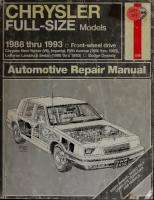
Chrysler
Mid -size Front wheel drive
Automotive Repair
Manual by Robert Maddox, Larry Warren
and John H Haynes Member
of the Guild of Motoring Writers
Models covered: All
front-wheel drive
Chrysler LeBaron Sedan models (1982 thru 1989), LeBaron coupe and convertible, LeBaron GTS, E-Class and four-cylinder New Yorker models
Dodge
400, 600 and Lancer
Plymouth Caravelle 2.2, 2.5
and 2.6
liter
and 3.0 liter V6 engines and turbocharged models)
four-cylinder engines
(includes carbureted, fuel-injected
1982 through 1995
#
(10C11
(1337)
AirrcMCnvE h
l>VJ?73
ASSOCIATION
Haynes Publishing Group Sparkford Nr Yeovil
Somerset BA22 7JJ England
Haynes North America, 861 Lawrence Drive Newbury Park California
91320 USA
ABCOE
25030)
Inc
MtlVBfcli?
FGHU KLMN
About this manual Its
must pass on to you to cover its labor and overhead costs. An added benefit is the sense of satisfaction and accomplishment that you feel after doing the job your-
purpose
The purpose of this manual is to help you get the best value from your vehicle. It can do so in several ways. It can help you decide what work must be done, even if you choose to have it done by a dealer service department or a repair shop; it provides information and procedures for routine maintenance and servicing; and it offers diagnostic and repair procedures to follow when trouble
Section 3 and Step (or paragraph) 2 within that Section.
Procedures, once described are not normally repeated. When
Using the manual is
number. Cross references given without use word "Chapter" apply to Sections and/or paragraphs in the same Chapter. For example, "see Section 8" means in the same
Each Chapter is divided into numbered Secwhich are headed in bold type between horizontal lines. Each Section consists of
Chapter.
consecutively numbered paragraphs.
We
hope you use the manual to tackle the work yourself. For many simpler jobs, doing yourself may be quicker than arrang-
References to the left or right side of the assume you are sitting in the driver's
At the beginning of each numbered Sec-
vehicle
you will be referred to any illustrations which apply to the procedures in that Section. The reference numbers used in illustra-
seat, facing forward.
tion
it
an appointment to get the vehicle into a shop and making the trips to leave it and pick it up. More importantly, a lot of money can be saved by avoiding the expense the shop ing
Even though we have prepared this manual with extreme care, neither the publisher nor the author can accept responsibility for any errors in, or omissions from, the infor-
tion captions pinpoint the pertinent Section
and the Step within that Section. That illustration 3.2
means
is,
mation given.
the illustration refers to
NOTE A Note make
provides information necessary to properly complete a procedure or information which
will
the procedure easier to understand.
CAUTION A Caution
provides a special procedure or special steps which must be taken while completing the procedure where the Caution is found. Not heeding a Caution can result in damage to the assembly
being worked on.
WARNING A Warning
provides a special procedure or special steps which must be taken while completing the
procedure where the Warning
Acknowledgements We are grateful to the Chrysler and vehicle photos. Technical
©
Haynes North America,
is
found. Not heeding a Warning can result
in
personal
injury.
Corporation for their assistance with technical information, certain illustrations who contributed to this project include Mark Ryan and Mike Stubblefield.
writers
Inc. 1993, 1996,
1998
With permission from J.H. Haynes & Co. Ltd.
A book
in
the Haynes Automotive Repair Manual Series
Printed
in
the U.S.A.
reserved. No part of this book may be reproduced or transmitted in any form or by any means, electronic or mechanical, including photocopying, recording or by any information storage or retrieval system, without permission in writing from the copyright holder.
All rights
ISBN1 56392 196 Library of
Congress Catalog Card Number 96-76010
While every attempt is made to ensure that the information in this manual is correct, no liability can be accepted by the authors or publishers for loss, damage or injury caused by any errors in, or omissions from, the information given.
98-320
it's
of the
divided into Chapters.
tions,
occurs.
the text,
necessary to refer to another Chapter, the reference will be given as Chapter and Section
self.
The manual
in
0-3
Contents Introductory pages About this manual Introduction to the Chrysler mid-size models Vehicle identification numbers
Buying parts Maintenance techniques, tools and working Jacking and towing Booster battery (jump) starting Automotive chemicals and lubricants Conversion factors Safety first! Troubleshooting
Chapter
facilities
0-2 0-4 0-5 0-6 0-6 0-12 0-12
0-13 0-14 0-15 0-16
1
Tune-up and routine maintenance
1-1
A
Chapter 2 Part
2.2L and 2.5L four-cylinder engines
2A
2B-1
2B
2C-1
2C
2D-1
2D
Chapter 2 Part C 3.0L V6 engine
Chapter 2 Part D General engine overhaul procedures
Chapter 3 Cooling, heating and
air
conditioning systems
Chapter 4 Fuel and exhaust systems
Chapter 5 Engine
electrical
systems
3-1
3
4-1
4
5-1
5
6-1
6
Chapter 6 Emissions control systems
Chapter 7 Part A Manual transaxle
7A-1
7A
7B-1
7B
Chapter 7 Part B Automatic transaxle
Chapter 8 Clutch and driveaxles
Chapter 9
1
2A-1
Chapter 2 Part B 2.6L four-cylinder engine
)
8-1
8
9-1
9
Brakes
Chapter 10 Suspension and steering systems
Chapter
11 11-1
Body
Chapter 12 Chassis
electrical
system
Wiring diagrams
Index
10-1
12-1
10 11
12
12-17
IND-1
IND
0-4
Haynes author, photographer and mechanic with Chrysler LeBaron
Introduction to the Chrysler mid-size models
four-cylinder engines, equipped with carbu-
The engine drives the front wheels through either a five-speed manual or a three- or four-speed automatic transaxle via independent driveaxles. The fully-independent front suspension
retors or electronic fuel injection are used.
consists of coil spring/strut units, control
Some
arms and a stabilizer bar. The rear suspension uses shock absorbers, coil springs, a
These models are available in two-door coupe, four-door sedan, station wagon and convertible
body
styles.
Transversely mounted V6 and
four-cylinder
bocharged.
engines
are
inline
tur-
solid axle with integral trailing
arms and a
track bar (Panhard rod).
The power-assisted rack-and-pinion mounted behind the unit is
steering engine.
Front brakes are discs; the rears are drum or optional disc-type. Power
either assist
is
standard.
0-5
Vehicle identification
The Vehicle Identification Number (VIN) is stamped into a metal plate fastened to the dashboard on the driver's side - it's visible through the windshield
Modifications
a
are
unpublicized process
in
continuing and manufactur-
vehicle
Since spare parts manuals and lists are compiled on a numerical basis, the individual ing.
vehicle identify
numbers are essential to the component required.
Vehicle Identification
correctly
Number
(VIN) The Vehicle Identification Number (VIN), which appears on the Vehicle Certificate of Title and Registration, is also embossed on a gray plate located on the upper left (driver's side) corner of the
dashboard, near the wind-
shield (see illustration).
when and where a its
vehicle
The VIN tells you was manufactured,
country of origin, make, type, passenger line, series, body style, engine
safety system,
and assembly
plant.
numbers
The Body Code
located on the the wheel driver's side of the housing or the upper radiator support (shown) - it provides information about the type of engine, transaxle, paint, etc. of the model to which it's attached Plate
is
firewall,
Body Code left
ing or the
which
Plate
The body code on the
plate,
which is located wheel hous-
(driver's side) firewall,
upper radiator support (see
tration), provides
more
specific information
Engine Identification Number
required also
when buying replacement into the block. On 2.2L
stamped
and 2.5L engines, is located just below the EIN on the block. On 2.6L and 3.0L engines, is located on the right-rear side of the engine it
block, adjacent to the exhaust manifold stud (firewall
side of the vehicle) (see illustration).
Transaxle Identification
four-cylinder engines, the Engine
transaxle bellhousing (see illustration).
On
2.6L and 3.0L engines, the it is on the radiator side of the of the block, between the core plug and the transaxle end of the block (see illustration).
Engine Serial Number
Location of the engine identification number on 2.6L and 3.0L engines
is is
Number (TIN)
Identification Number (EIN) is stamped into a machined boss on the engine block. On 2.2L and 2.5L engines it is stamped into the left end of the engine block, just about the
In
parts,
it
illus-
about the vehicle - type of engine, transaxle, paint, etc. - to which it's attached.
(EIN) On
Location of the engine identification number on 2.2L and 2.5L engines
addition the EIN, a serial number,
Location of the engine serial number on 2.6L and 3.0L engines
(TIN)
The Transaxle Identification Number is stamped on a boss located on top of
the transaxle housing (see illustration).
Transaxle Serial
Number
Besides the TIN, the transaxle also has a number which you'll need to reference when buying transaxle parts. On manual serial
transaxles, the serial
number
is
embossed on
a metal tag attached to the front side of the transaxle; on automatic transaxles, the serial number is located on a pad just above the oil
pan
at the rear of the transaxle.
The Transaxle Identification Number (TIN) is stamped into a flat spot on top of the transaxle housing
t
0-6
Buying parts Replacement parts are available from sources, which generally fall into one of
many
two categories - authorized dealer parts departments and independent retail auto parts stores. Our advice concerning these parts
is
as follows:
Retail auto parts stores: Good auto parts stores will stock frequently needed components which wear out relatively fast, such as clutch components, exhaust systems, brake parts, tune-up parts, etc. These stores often supply new or reconditioned
parts on an
which can save money. Discount auto parts stores are often very good places to buy materials and parts needed for general vehicle maintenance such as oil, grease, filters, spark plugs, belts, touch-up paint, bulbs, etc. They also usually sell tools and general accessories, have convenient hours, charge lower prices and can often be found not far from home. Authorized dealer parts department: This is the best source for parts which are
exchange
a considerable
unique to the vehicle and not generally elsewhere (such major as engine parts, transmission parts, trim pieces,
basis,
amount
available
of
etc.).
Warranty information: If the vehicle is covered under warranty, be sure that any replacement parts purchased - regardless of the source - do not invalidate the warranty! To be sure of obtaining the correct parts, have engine and chassis numbers still
.
available and, if possible, take the old parts along for positive identification.
Maintenance techniques, tools and working facilities Maintenance techniques
this task,
There are a number of techniques in maintenance and repair that will
involved
be referred to throughout this manual. Application of these techniques will enable the home mechanic to be more efficient, better organized and capable of performing the various tasks properly, which will ensure that the repair job is thorough and complete.
as well as other repair procedures,
such as the repair of threaded holes that have been stripped out. Flat washers and lockwashers, when removed from an assembly, should always
be replaced exactly as removed. Replace any damaged washers with new ones. Never use a lockwasher on any soft metal surface (such as aluminum), thin sheet metal or plastic.
Fasteners Fasteners are nuts, bolts, studs and screws used to hold two or more parts together. There are a few things to keep in mind when working with fasteners. Almost all of them use a locking device of some type, either a lockwasher, locknut, locking tab or thread adhesive. All threaded fasteners should be clean and straight, with undamaged threads and undamaged corners on the hex head where the wrench fits. Develop the habit of replacing all damaged nuts and bolts with
new
Grade
1
Grade 5
or 2
Grade 8
ones. Special locknuts with nylon or
fiber inserts
can only be used once.
If
they
Bolt strength marking (standard/SAE/USS;
bottom
-
metric)
are removed, they lose their locking ability
and must be replaced with new ones. Rusted nuts and bolts should be treated with a penetrating fluid to ease removal and prevent breakage. Some mechanics use turpentine in a spout-type oil can, which works
Grade Hex Nut Grade 5
quite well. After applying the rust penetrant, let
it
work
for a
few minutes before
loosen the nut or
may have
to
bolt.
i
t
^"Nw, T
T
Hex Nut Property Class 9
3 Dots
Identification
&
off or
special nut breaker, available
Hex Nut Grade 8
Jf ^»k
s^-Aj
a bolt or stud breaks off in an assembly, it can be drilled and removed with a special tool commonly available for this purpose. Most automotive machine shops can perform
6 Dots
Standard hex nut strength markings
B
Arabic 9
Badly rusted fasteners
at tool stores. If
Grade
trying to
be chiseled or sawed
removed with a
Identification
Hex Nut Property Class 10
®
© Class
Class
Class
10.9
9.8
8.8
Arabic 10
Metric hex nut strength markings
Metric stud strength markings |
00-1
HAYNES|
Maintenance techniques, tools and working Fastener sizes For a number
of reasons, automobile manufacturers are making wider and wider use of metric fasteners. Therefore, it is important to be able to tell the difference between standard (sometimes called U.S. or SAE) and metric hardware, since they cannot be interchanged. All bolts, whether standard or metric, are sized according to diameter, thread pitch and length. For example, a standard 1/2-13x1 bolt is 1/2 inch in diameter, has 13 threads per inch and is 1 inch long. An M12 - 1.75 x 25 metric bolt is 1 2 mm in diameter, has a thread (the distance between pitch of 1.75 threads) and is 25 mm long. The two bolts are nearly identical, and easily confused, but they
Metric thread sizes
Ft-ibs
Nm
M-6 M-8 M-10 M-12 M-14
6 to 9 14 to 21 28 to 40 50 to 71 80 to 140
9 to 12 19 to 28 38 to 54
5 to 8 12 to 18
7 to 10
1/8 1/4
to 96 109 to 154
1/2
U.S. thread sizes 1/4-20 5/16
-
6 to 9 12 to 18 14 to 20
18
5/16-24
diameter, thread pitch and length, metric and standard bolts can also be distinguished by examining the bolt heads. To begin with, the distance across the flats on a standard bolt head is measured in inches, while the same dimension on a metric bolt is sized in millime-
16 24 7/16 - 14
in
17 to 24 30 to 44 34 to 47
22 to 33 25 to 35
3/8
are not interchangeable.
addition to the differences
68
Pipe thread sizes
mm
In
0-7
facilities
3/8
-
3/8
-
22 27 40 40 55
7/16-20 1/2-13
9 to 12 1 7 to 24 19 to 27 30 to 43 37 to 51 55 to 74
32 38 to 55 to 60 to 80 to to
55 75
to 81 to
108
same is true for nuts). As a result, a standard wrench should not be used on a metric bolt and a metric wrench should not be used on a standard bolt. Also, most standard bolts have slashes radiating out from the center of the head to denote the grade or strength of the bolt, which is an indication of the amount of torque that can be applied to ters (the
it.
The greater the number
of slashes, the
greater the strength of the bolt. Grades
through 5 are commonly used on automobiles. Metric bolts have a property class (grade) number, rather than a slash, molded into their
heads
to indicate bolt strength. In
number, the stronger 8.8, 9.8 and 10.9 are commonly used on automobiles. Strength markings can also be used to distinguish standard hex nuts from metric hex nuts. Many standard nuts have dots stamped into one side, while metric nuts are marked with a number. The greater the number of dots, or the higher the number, the
this case, the higher the
the bolt. Property class
numbers
00-2
Grade marks
L
Length (in inches) Thread pitch (number of threads per inch) Nominal diameter (in inches)
T
greater the strength of the nut.
Metric studs are also marked on their
ends according to property class Larger studs are numbered (the
code
D
(bolt strength)
P
Property class (bolt strength)
L
T
Length (in millimeters) Thread pitch (distance between
D
Diameter
threads
in millimeters)
(grade).
same
as
metric bolts), while smaller studs carry a geo-
strength ratings, be sure to reinstall any bolts,
made
studs or nuts removed from your vehicle
specific torque values,
denote grade. It should be noted that many fasteners, especially Grades through 2, have no distinguishing marks on them. When such is the case, the only way to determine whether it is standard or metric is to measure the thread pitch or compare it to a known fastener of the
their original locations. Also,
same
procedures
metric
Metric bolt dimensions/grade marks
Standard (SAE and USS) bolt dimensions/grade marks
G
MAYNCS
to
size.
Standard fasteners are often referred to as SAE, as opposed to metric. However, it should be noted that SAE technically refers to a non-metric fine thread fastener only. Coarse thread non-metric fasteners are referred to as USS sizes. Since fasteners of the same size (both standard and metric) may have different
a fastener with a
new one has
new
one,
in
when replacing make sure that the
a strength rating equal to or
greater than the original.
Tightening sequences and Most threaded fasteners should be tightened to a specific torque value (torque is the twisting force applied to a threaded component such as a nut or
bolt).
weaken
Overtightening
and cause it to break, while undertightening can cause it to eventually come loose. Bolts, screws and studs, depending on the material they are the fastener can
it
of
and
their
thread diameters, have
many
of
which are
noted in the Specifications at the beginning of each Chapter. Be sure to follow the torque recommendations closely. For fasteners not assigned a specific torque, a general torque value chart is presented here as a guide. These torque values are for dry (unlubncated) fasteners threaded into steel or cast iron (not aluminum). As was previously mentioned, the size and grade of a fastener determine the amount of torque that can safely be applied to it. The figures listed here are approximate for Grade 2 and Grade 3 fasteners. Higher grades can tolerate higher torque values. Fasteners laid out in a partem, such as cylinder head bolts, oil pan bolts, differential cover bolts, etc., must be loosened or tight-
0-8
Maintenance techniques, tools and working
Micrometer set in sequence to avoid warping the component. This sequence will normally be shown in the appropriate Chapter. If a specific pattern is not given, the following procedures can be used to prevent warping. Initially, the bolts or nuts should be assembled finger-tight only. Next, they should be tightened one full turn each, in a criss-cross or diagonal pattern. After each
ened
one has been tightened one full turn, return to the first one and tighten them all one-half turn, following the
tighten each of
same
pattern.
them one-quarter
Finally,
turn at a
each fastener has been tightened to To loosen and remove the fasteners, the procedure would be reversed.
time
until
the proper torque.
Component disassembly
Dial indicator set
two halves with numbered pieces masking tape so they can be easily recon-
identify the
Hose removal
of
is equipped with air do not disconnect any of the A/C hoses without first having the system depressurized by a dealer service department
nected.
Gasket sealing surfaces Throughout any vehicle, gaskets are used to seal the mating surfaces between two parts and keep lubricants, fluids, vacuum or pressure contained
in
done with care and purpose to help ensure go back together properly. Always keep track of the sequence in which parts are removed. Make note of special
are coated
with a liquid or paste-type gasket sealing
compound
before assembly. Age, heat and
pressure can sometimes cause the two parts to stick together so tightly that they are very to separate. Often, the
be loosened by
striking
it
assembly can
with a soft-face
hammer near the mating surfaces. A regular hammer can be used a block of wood is placed between the hammer and the part. Do not hammer on cast parts or parts that
grooved thrust washer on a shaft. It is a good idea to lay the disassembled parts out on a clean surface in the order that they were removed. It may also be helpful to make sketches or take instant photos of compo-
easily damaged. With any stubborn part, always recheck to make sure that every fastener has been removed. Avoid using a screwdriver or bar to pry apart an assembly, as they can easily mar the gasket sealing surfaces of the parts, which must remain smooth. If prying is absolutely necessary, use an old broom handle, but keep in mind that extra clean up will be nec-
nents before removal.
essary
that the parts
characteristics or installed
marks on parts
that
can be
more than one way, such as a
When removing
comSome-
fasteners from a
ponent, keep track of their locations.
times threading a bolt back
in
a part, or
washers and nut back on a stud, can prevent mix-ups later. If nuts and bolts cannot be returned to their original locations, they should be kept in a compartmented box or a series of small boxes. A cupcake or muffin tin is ideal for this purpose, since each cavity can hold the bolts and nuts from a particular area (i.e. oil pan bolts, valve cover bolts, engine mount bolts, etc.). A pan of this type is especially helpful when working on assemblies with very small parts, such as the putting the
carburetor, alternator, valve train or interior
dash and trim pieces. The cavities can be marked with paint or tape to identify the contents.
Whenever
wiring looms, harnesses or
connectors are separated,
it
is
a good idea to
If
the vehicle
be
could
particularly
if
the
wood
splinters.
After the parts are separated, the old
gasket must be carefully scraped off and the gasket surfaces cleaned. Stubborn gasket material can be soaked with rust penetrant or treated with a special chemical to soften it so it can be easily scraped off. A scraper can be fashioned from a piece of copper tubing by flattening
and sharpening one end. Copper
recommended because
it
is
or a service station.
Hose removal precautions closely paralgasket removal precautions. Avoid scratching or gouging the surface that the hose mates against or the connection may lel
an assembly.
Many times these gaskets
difficult
Warning:
tips
conditioning,
if
Component disassembly should be
facilities
is
usually softer
than the surfaces to be scraped, which reduces the chance of gouging the part. Some gaskets can be removed with a wire brush, but regardless of the method used, the mating surfaces must be left clean and smooth. If for some reason the gasket surface is gouged, then a gasket sealer thick enough to fill scratches will have to be used during reassembly of the components. For most applications, a non-drying (or semi-drying) gasket sealer should be used.
leak. This is especially true for radiator hoses.
Because of various chemical reactions, the rubber in hoses can bond itself to the metal spigot that the hose fits over. To remove a hose, first loosen the hose clamps that secure it to the spigot. Then, with slip-joint pliers, grab the hose at the clamp and rotate it around the spigot. Work it back and forth until it is completely free, then pull it off. Silicone or other lubricants will ease removal if they can be applied between the hose and the outside of the spigot. Apply the same lubricant to the inside of the hose and the outside of the spigot to simplify installation.
As a
last resort
replaced with a
(and
the hose
if
new one anyway),
is
to
be
the rubber
can be slit with a knife and the hose peeled from the spigot. If this must be done, be careful that the metal connection
is
not
dam-
aged. If a hose clamp is broken or damaged, do not reuse it. Wire-type clamps usually weaken with age, so it is a good idea to replace them with screw-type clamps when-
ever a hose
is
removed.
7bo/s A selection
of
good
tools
a basic
is
who plans to mainher own vehicle. For the
requirement for anyone tain
and
repair his or
owner who has few tools, the initial investment might seem high, but when compared to the spiraling costs of professional auto
maintenance and
repair,
it
is
a wise one.
To help the owner decide which tools needed are to perform the tasks detailed in this
manual, the following tool
offered:
lists
Maintenance and minor
are
repair,
Repair/overhaul and Special.
The newcomer
to
practical
mechanics
Maintenance techniques, tools and working
Dial caliper
Compression gauge with spark plug
Hand-operated vacuum
pump
0-9
facilities
Timing
light
Damper/steering wheel puller
General purpose puller
Valve spring compressor
Valve spring compressor
Piston ring groove cleaning tool
Ring removal/installation tool
hole adapter
Hydraulic
lifter
removal tool
Ridge reamer
0-10
Maintenance techniques, tools and working
Ring compressor
Cylinder hone
Brake cylinder hone
Clutch plate alignment tool
should start
off
with the maintenance
and
Phillips
which is adequate for the simpler jobs performed on a vehicle. Then, as confidence and experience grow, the owner can tackle more difficult tasks, buying additional tools as they are needed. Eventually the basic kit will be expanded into the repair and overhaul tool set. Over a period minor repair
tool
screwdriver (No.
Combination
kit,
Oil
should be considered the minimum required for performance of routine maintenance, servicing and minor repair work. We recommend the purchase of combination wrenches (box-end and openend combined in one wrench). While more expensive than open end wrenches, they offer the advantages of both types of wrench. in
this
list
Combination wrench set (1/4-inch to 1 inch or 6 to 19 mm) Adjustable wrench, 8 inch Spark plug wrench with rubber insert Spark plug gap adjusting tool
mm
2x6 inch)
die set
has the capacity of accepting a very wide range of large sockets. Ideally, however, the mechanic should have a 3/8-inch drive set and a 1/2-inch drive set. it
6 inch of blades
Socket set(s) Reversible ratchet
Extension
Wire brush
Universal joint
Oil filter
tools
Tap and
Fine emery cloth Battery post
The
Brake hold-down spring tool
can
assemble a tool set complete enough for most repair and overhaul procedures and will add tools from the special category when it is felt that the expense is justified by the frequency of use.
tool kit
-
Hacksaw and assortment Tire pressure gauge Grease gun
of time, the experienced do-it-yourselfer will
Maintenance and minor repair
pliers
facilities
and cable cleaning
wrench Funnel (medium
tool
-10
inch
Torque wrench (same size drive as sockets)
size)
Ball
peen hammer - 8 ounce
Safety goggles
Soft-face
Jackstands
Standard screwdriver (1/4-inch x 6 inch) Standard screwdriver (stubby -
Drain
Note:
If
(2)
pan
basic tune-ups are going to be part of
routine maintenance,
be necessary
hammer (plastic/rubber)
5/16-inch)
3x8 inch)
to
Phillips
screwdriver (No.
purchase a good quality stroboscopic timing light and combination tachometer/dwell meter. Although they are included in the list of special tools, it is mentioned here because they are absolutely necessary for tuning most
Phillips
screwdriver (stubby
vehicles properly.
Cold chisel
it
will
Pliers
-
-
No. 2)
vise grip
-lineman's needle nose Pliers - snap-ring (internal and external) Pliers Pliers
-
-
1/2-inch
Scribe
Repair and overhaul tool set
Scraper (made from flattened copper
anyone who plans to perform major repairs and are in addition to those in the maintenance and minor repair tool kit. Included is a compre-
Centerpunch Pin punches (1/16,
hensive set of sockets which, though expen-
Allen
These tools are essential
sive, are invaluable
especially
because of
when
Feeler gauge set
ity,
Brake bleeder wrench Standard screwdriver (5/16-inch x 6 inch)
drives are available.
for
their versatil-
various extensions and
We recommend
the 1/2-
inch drive over the 3/8-inch drive. Although
the larger drive
is
bulky and
more expensive,
tubing)
1/8,
Steel rule/straightedge
4
wrench set
mm to
A selection
10 of
3/16-inch)
-12 inch
(1/8 to 3/8-inch or
mm)
files
Wire brush (large) Jackstands (second set) Jack (scissor or hydraulic type)
Maintenance techniques, tools and working Note: Another tool which electric drill with a
and a
is often useful is an chuck capacity of 3/8-mch
set of good quality
Special tools The
tools
include those which
in this list
are not used regularly, are expensive to buy,
need
be used in accordance with their manufacturer's instructions. Unless these tools will be used frequently, it is not very economical to purchase many of them. A consideration would be to split the cost and use between yourself and a friend or friends. In addition, most of these tools can be obtained from a tool rental shop on a temor which
to
porary basis.
This
primarily contains only those
list
and instruments widely available to the public, and not those special tools produced
tools
by the vehicle manufacturer for distribution to dealer service departments. Occasionally, references to the manufacturer's special tools are included in the text of this manual. Generally, an alternative method of doing the is offered. Howsometimes there is no alternative to use. Where this is the case, and the tool
job without the special tool ever, their
cannot be purchased or borrowed, the work should be turned over to the dealer service department or an automotive repair shop. Valve spring compressor
Piston ring groove cleaning tool Piston ring compressor Piston ring installation tool
Cylinder ridge reamer
hone
Cylinder bore gauge
Care and maintenance of tools Good tools are expensive, so it makes sense to treat them with respect. Keep them clean and in usable condition and store them properly when not in use. Always wipe off any dirt, grease or metal chips before putting them away. Never leave tools lying around in the work area. Upon completion of a job, always check closely under the hood for tools that may have been left there so they won't get lost during a test drive.
Some
such as screwdrivers, pliwrenches and sockets, can be hung on a panel mounted on the garage or workshop wall, while others should be kept in a tool box or tray. Measuring instruments, gauges, meters, etc. must be carefully stored where they cannot be damaged by weather or tools,
ers,
used frequently. When a tool is damaged or worn out, replace it. Subsequent jobs will be safer and more enjoyable if you do. tools
Micrometers and/or dial calipers Hydraulic lifter removal tool Balljoint
over a longer period of time and gives the mechanic the freedom to choose only those tools that will actually be used. Tool stores will often be the only source of some of the special tools that are needed, but regardless of where tools are bought, try to avoid cheap ones, especially when buying screwdrivers and sockets, because they won't last very long. The expense involved in replacing cheap tools will eventually be greater than the initial cost of quality tools.
impact from other tools. When tools are used with care and stored properly, they will last a very long time. Even with the best of care, though,
Cylinder compression gauge Cylinder surfacing
needed, add-on sets, individual tools and a larger tool box can be purchased to expand the tool selection. Building a tool set gradually allows the cost of the tools to be spread
drill bits.
separator
Universal-type puller
will
wear out
How
Dial indicator set
Stroboscopic timing
light (inductive
pick-up)
Tachometer/dwell meter Universal electrical multimeter Cable hoist Brake spring removal and installation tools
Floor jack
Buying tools For the do-it-yourselfer
who
ing to get involved in vehicle
and
repair, there are a
available
is
maintenance
number
when purchasing
just start-
tools.
of options If
mainte-
nance and minor repair is the extent of the work to be done, the purchase of individual tools is satisfactory. If, on the other hand, extensive work is planned, would be a good idea to purchase a modest tool set from one it
of the large retail chain stores.
A
set can usu-
be bought at a substantial savings over the individual tool prices, and they often ally
come
with a tool box.
As
additional tools are
to repair
damaged
threads Sometimes, the
Hand operated vacuum/pressure pump
internal
become
or bolt hole can
threads of a nut
stripped, usually
from overtightening. Stripping threads is an all-too-common occurrence, especially when working with aluminum parts, because aluminum is so soft that it easily strips out. Usually, external or internal threads are only partially stripped. After they've been cleaned up with a tap or die, they'll still work. Sometimes, however, threads are badly dam-
aged.
When
this
happens, you've got three
choices: 1)
Dhll
and
tap the hole to the next suitable
oversize bolt,
2)
Drill
and
install
a larger diameter
screw or stud.
and
nut.
3)
tap
to accept a and tap the plug screw size. You can also
the
threaded plug, then to the original
hole
drill
buy a plug already threaded to the original size. Then you simply drill a hole to the specified size, then run the threaded plug into the hole with a bolt and jam
Once
the plug
is
fully
seated,
remove the jam nut and bolt. The third method uses a patented thread repair
kit like
These easy-to-use repair
damaged
Heli-Coil or Slimsert.
are designed to threads in straightkits
through holes and blind holes. Both are can handle a vahety of sizes and thread patterns. Dhll the hole, then tap it with the special included tap. Install the Heli-Coil and the hole is back to its onginal diameter and thread pitch. available as kits which
Regardless of which method you use, be sure to proceed calmly and carefully. A little impatience or carelessness during one of these relatively simple procedures can ruin your whole day's work and cost you a bundle if you wreck an expensive part.
Working
facilities
Not to be overlooked when discussing tools is the workshop. If anything more than routine maintenance
is to be carried out, work area is essential. It is understood, and appreciated, that many home mechanics do not have a good workshop or garage available, and end up removing an engine or doing major repairs outside. It is recommended, however, that the overhaul or repair be completed under
some
sort of suitable
the cover of a roof.
A
clean,
flat
workbench or
fortable working height
table of
com-
an absolute necessity. The workbench should be equipped with a vise that has a jaw opening of at least four is
inches.
As mentioned
if
Impact screwdriver
0-11
facilities
dry storage space
previously, is
some
clean,
also required for tools,
as well as the lubricants, fluids, cleaning solvents, etc. which soon become necessary.
Sometimes waste oil and fluids, drained from the engine or cooling system during normal maintenance or repairs, present a disposal problem. To avoid pouring them on the ground or into a sewage system, pour the used
fluids into large containers, seal
with caps and take
them
them
to an authorized
disposal site or recycling center. Plastic jugs,
such as old antifreeze containers, are for this
ideal
purpose.
Always keep a supply
of old
newspa-
pers and clean rags available. Old towels are
up spills. Many mechanics use rolls of paper towels for most work because they are readily available and disposable. To help keep the area under the vehicle clean, a large cardboard box can be cut open and flattened to protect the garage or shop floor. Whenever working over a painted surface, such as when leaning over a fender to service something under the hood, always cover it with an old blanket or bedspread to protect the finish. Vinyl covered pads, made excellent
for
mopping
especially for this purpose, are available at
auto parts stores.
0-12
Jacking and towing being changed, loosen the lug nuts oneand leave them in place until the wheel is raised off the ground. Make sure no
Jacking The jack supplied with the vehicle should be used only for raising the vehicle when changing a tire or placing jackstands under the frame. Warning: Never work under the vehicle or start the engine when this jack is being used as the only means of support. The vehicle should be on level ground with the wheels blocked and the transaxle in Park (automatic) or Neutral (manual). If a tire
remember
is
rary spare
half turn
only for temporary use
one
is in
the vehicle as
it's
being raised
tire,
that
until
it
is
intended
the regular
tire
can be repaired. Do not exceed the maximum speed that the tire is rated for.
off
the ground.
Towing
Place the jack under the side of the vehicle at the jacking point nearest the wheel to be changed. Caution: Never place the jack under the rear trailing arms. If you're using a floorjack, place it beneath the crossmember at the front or rear (see illustrations). Operate the jack with a slow, smooth motion until the wheel is raised off the ground. If you're using jackstands, position them beneath the support points along the front or rear side sills.
Remove
install
the lug nuts,
pull off
The
must be towed with the front the ground to prevent damage to the transaxle. If the vehicle must be towed backward, place the front wheels on a dolly. Caution: Don't use the hook loops under the vehicle for towing (they're intended only for use as tie-downs). A wheel lift is recommended. A flatbed truck can also be used. In this case, pull the vehicle onto the truck towards the front, using J-hooks at the front suspension control arms with the points turned down. While towing, the parking brake must be released and the transaxle must be in Neutral. The steering must be unlocked (ignition switch in the OFF position). Don't exceed 50 mph (35 mph on rough roads). Safety is a major consideration while towing and all applicable state and local laws must be obeyed. A safety chain system must be used at all times. Remember that power steering and power brakes will not work with (drive)
the wheel,
the spare and thread the lug nuts back
on with the beveled sides facing
in.
Tighten
them snugly, but wait until the vehicle is lowered to tighten them completely. Lower the vehicle, remove the jack and (if loosened or removed) a criss-cross pattern. If possible, tighten them with a torque wrench (see Chapter 1 for the torque figures). If you don't have access to a torque wrench, have the nuts checked
tighten the lug nuts in
There's a jack locator pin like this (arrow) near each wheel - when raising the vehicle with the standard scissor-type jack, make sure the jack head is securely engaged with the pin nearest the wheel you're raising
by a service station or repair shop as soon as possible. Retighten the lug nuts after 500 miles. If
the vehicle
is
equipped with a tempo-
vehicle
wheels
the engine
off
off.
Booster battery (jump) starting Observe these precautions when using a booster battery
to start
a vehicle: a)
c)
is in
Turn off the
lights,
the ignition
heater and other electrical loads.
Your eyes should be shielded. Safety goggles are a good idea. the booster battery is the same voltage as the dead
Make sure
e)
one in the vehicle. The two vehicles MUST NOT
g)
make sure
the Off position.
d)
f)
Make
sure the transaxle
is in
TOUCH each
other!
Neutral (manual) or Park (automatic),
not a maintenance-free type, remove the vent caps and lay a cloth over the vent holes.
If
Battery
'
Booster battery
2
1
Before connecting the booster battery, switch
b)
Dead
the booster battery
^
o%!
o 8
o e
"Te
8%y o _ %*
o
4 ,d
is
Connect the red jumper cable to the positive
(+)
terminals of each
battery (see illustration).
Connect one end
of the black
jumper cable to the negative
(-)
termi-
The other end of this cable should be connected to a good ground on the vehicle to be started, such as a bolt or bracket on the body. nal of the booster battery.
Start the engine using the booster battery, then, with the engine run-
ning at idle speed, disconnect the jumper cables
connection.
in
the reverse order of
I00-3HAYNESI
Make the booster battery cable connections in the numerical order shown (note that the negative cable of the booster battery is NOT attached to the negative terminal of the dead battery)
0-13
Automotive chemicals and lubricants A number
of
automotive chemicals and
in
disc brake equipped vehicles.
lubricants are available for use during vehicle
contains
maintenance and
is
repair.
They include a wide
variety of products ranging from cleaning sol-
vents and degreasers to lubricants and protective sprays for rubber, plastic
and
vinyl.
Cleaners Carburetor cleaner and choke cleaner a strong solvent for gum, varnish and carbon. Most carburetor cleaners leave a drytype lubricant film which will not harden or up.
It
usually
disulfide (moly),
which
a dry-type lubricant.
White grease
Because
of this film
it
is
not recom-
mended for use on electrical components. Brake system cleaner is used
to
remove grease and brake fluid from the brake system, where clean surfaces are absolutely necessary. It leaves no residue and often eliminates brake squeal caused by contami-
cants,
working loose and cure only after
+190-degrees F), and will not wash off or dilute in the presence of water. Assembly lube is a special extreme pressure lubricant, usually containing moly, used to lubricate high-load parts (such as main and rod bearings and cam lobes) for initial start-up of a new engine. The assembly lube lubricates the parts without being squeezed out or washed away until the engine oiling system begins to function. Silicone lubricants are used to protect
contacts, restoring
lubricate metal parts while remaining
current flow.
It
can also
be used to clean spark plugs, carburetor jets, voltage regulators and other parts where an oil-free surface is desired.
Demoisturants remove water and moisture from electrical components such as alternators, voltage regulators, electrical connectors and fuse blocks. They are non-conductive, non-corrosive and non-flammable. Degreasers are heavy-duty solvents used to remove grease from the outside of the engine and from chassis components. They can be sprayed or brushed on and, depending on the type, are rinsed off either with water
Lubricants Motor use
in
rubber, plastic, vinyl
the lubricant formulated for
oil is
engines.
It
normally contains a wide
variety of additives to prevent corrosion
and
reduce foaming and wear. Motor oil comes in various weights (viscosity ratings) from 5 to
uncon-
taminated by
dirt, water, oil or acids. It is conductive and will not foul eleccontacts in locks such as the ignition
electrically trical
switch.
Moly penetrants loosen and lubricate and corroded fasteners and
frozen, rusted
prevent future rusting or freezing.
Heat-sink grease
is
a special electri-
non-conductive grease that is used for mounting electronic ignition modules where it
is
essential that heat
is
transferred
away from
the module.
one
most widely used gasket compounds. Made from silicone, RTV is air curing, it seals, bonds, is
of the
waterproofs, fills surface irregularities, remains flexible, doesn't shrink, is relatively easy to remove, and is used as a supplementary sealer with almost
low and
all
medium
temperature gaskets. Anaerobic sealant is much like RTV in that it can be used either to seal gaskets or to form gaskets by itself. It remains flexible, is
high loads are encountered. Multi-viscosity oils are designed to have characteristics of
The difference between an anaerobic sealant and an RTV-type sealant is in the curing. RTV cures when exposed to air, while an anaerobic sealant cures only in the absence of air. This means that an anaerobic sealant
Gear oil is designed to be used in differentials, manual transmissions and other areas where high-temperature lubrication is required.
Chassis and wheel bearing grease is a heavy grease used where increased loads and friction are encountered, such as for wheel bearings, balljoints, tie-rod ends and
solvent resistant and
fills
surface imperfec-
tions.
cures only after the assembly of parts, seal-
them together. Thread and pipe sealant sealing hydraulic and pneumatic ing
is
used
fittings
for
and
vacuum lines. It is usually made from a Teflon compound, and comes in a spray, a paint-on liquid
and as a wrap-around tape.
High-temperature
wheel
bearing
designed to withstand the extreme temperatures encountered by wheel bearings is
the absence of
ing
compound
Medium
used
for small nuts, bolts
that
and studs which
bolts
installation,
strength lock-
may be removed later. Highlocking compound is for large nuts,
and screws strength
is
air.
aren't
removed on a
regular basis. Oil additives range from viscosity index
improvers to chemical treatments that claim to reduce internal engine friction. It should be noted that most oil manufacturers caution against using additives with their oils.
Gas additives perform depending on
tions,
their
several funcchemical makeup.
They usually contain solvents that help dissolve gum and varnish that build up on carburetor, fuel injection and intake parts. They also serve to break down carbon deposits that form on the inside surfaces of the combustion chambers. Some additives contain upper cylinder lubricants for valves and piston rings, and others contain chemicals to remove condensation from the gas tank.
compound
galling, cold welding, rust
and pressure encountered in brake systems. Care must be taken so this fluid does not
come
contact with painted surfaces or An opened container should always be resealed to prevent contamination by water or dirt. in
plastics.
Weatherstrip adhesive is used to bond weatherstnpping around doors, windows and trunk
lids.
It
is
sometimes used
to attach trim
pieces.
Undercoating
is a petroleum-based, substance that is designed to protect metal surfaces on the underside of the vehicle from corrosion. It also acts as a sounddeadening agent by insulating the bottom of
tar-like
the vehicle.
Waxes and polishes protect painted
are used to help and plated surfaces from the
may wax and
weather. Different types of paint
require
the use of different types of
polish.
Some
polishes
a chemical or abrasive cleaner to help remove the top layer of oxidized (dull) paint on older vehicles. In recent years
utilize
many non-wax
polishes that contain a
prevents seizing,
and corrosion
polishes.
Chemicals Anti-seize
Miscellaneous
wide variety of chemicals such as polymers and silicones have been introduced. These non-wax polishes are usually easier to apply and last longer than conventional waxes and
universal joints.
grease
in
Anaerobic locking compounds are to keep fasteners from vibrating or
Brake fluid is specially formulated hydraulic fluid that can withstand the heat
80. The recommended weight of the oil depends on the season, temperature and the demands on the engine. Light oil is used in cold climates and under light load conditions. Heavy oil is used in hot climates and where
both light and heavy oils and are available in a number of weights from 5W-20 to 20W-50.
used
bolts.
cally
Sealants RTV sealant
or solvent.
exhaust system and
for
low and high temperatures (usually from -100
Electrical cleaner removes oxidation, corrosion and carbon deposits from electrical full
used
is
exhaust manifold
and nylon parts. Graphite lubricants are used where oils cannot be used due to contamination problems, such as in locks. The dry graphite will
nants.
fasteners. High-temperature ant-seize, usumade with copper and graphite lubri-
ally
a heavy grease for metal-to-metal applications where water is a problem. White grease stays soft under both is
to
is
gum
molybdenum
in
0-14
Conversion factors Length (distance) X X X
Inches (in) Feet (ft) Miles
Volume
(mm)
Millimetres
Metres (m) Kilometres (km)
X 16.387 = Cubic centimetres (cc; cm 3 X 0.568 = Litres (I) X 1.137 = Litres (I) X 1.201 = US quarts (US qt) X 0.946 = Litres (I) X 4.546 = Litres (I) X 1.201 = US gallons (US gal) X 3.785 = Litres (I)
3
)
gallons (US gal)
Mass
= = =
= = =
X X X
0.0394
X X X X X X X X
0.061 1.76 0.88 0.833 1.057 0.22
0.833 0.264
= Cubic inches (cu in; in 3 = Imperial pints (Imp pt) = Imperial quarts (Imp qt) = Imperial quarts (Imp qt) = US quarts (US qt) = Imperial gallons (Imp gal = Imperial gallons (Imp gal = US gallons (US gal)
X X
0.035 2.205
= Ounces = Pounds
X X X
0.225
X
14.223
3.281 0.621
Inches (in) Feet (ft) Miles
(capacity)
Cubic inches (cu in; in Imperial pints (Imp pt) Imperial quarts (Imp qt) Imperial quarts (Imp qt) US quarts (US qt) Imperial gallons (Imp gal) Imperial gallons (Imp gal)
US
25.4 0.305 1.609
)
)
)
>
(weight)
Ounces Pounds
(oz) (lb)
X X
28.35 0.454
= Grams (g) = Kilograms
X X X
0.278 4.448
— Newtons (N) = Newtons (N) = Kilograms-force
X
0.070
(kg)
(oz) (lb)
Force Ounces-force Pounds-force
Newtons
(ozf; oz) *
(Ibf; lb)
(N)
0.1
(kgf; kg)
3.6 9.81
= Ounces-force = Pounds-force = Newtons (N)
(ozf; oz) (Ibf; lb)
Pressure Pounds-force per square inch (psi; lbf/in
2 ;
)
2 ;
2 ;
lb/in
2 ;
0.068
=
0.069
—
6.895
=
X
14.696
=
X
Bars
14.5
=
0.145
=
X
X
Kilopascals (kPa)
2
X
Kilopascals (kPa)
0.01
=
Kilograms-force per square 2 2 kg/cm centimetre (kgf/cm
X
98.1
=
X
0.868
=
)
2 ;
lb/in
2 )
2 ;
lb/in
2 )
Pounds-force per square inch (psi; lbf/in
)
lb/in
Pounds-force per square inch (psi; lbf/in
)
;
Pounds-force per square inch (psi; lbf/in
X
2
2
2
lb/in
Pounds-force per square inch (psi; lbf/in
)
Pounds-force per square inch (psi; lbf/in
X
=
)
2
lb/in
Pounds-force per square inch (psi; lbf/in
Kilograms-force per square 2 2 centimetre (kgf/cm kg/cm Atmospheres (atm) ;
Pounds-force per square inch (psi; lbf/in
=
2
lb/in
2
2 ;
lb/in
)
Kilopascals (kPa)
)
;
Torque (moment of force) X
Pounds-force inches
1.152
=
Kilograms-force centimetre cm; kg cm)
(kgf
(Ibf in; lb in)
X
Pounds-force inches
0.113
= Newton
Pounds-force inches (Ibf in; lb in)
X
metres (Nm)
8.85
=
Pounds-force inches (Ibf in; lb in)
(Ibf in; lb in)
X 0.083 = Pounds-force
Pounds-force inches
feet (Ibf
X
ft; lb ft)
=
12
Pounds-force inches (Ibf in; lb in)
(Ibf in; lb in)
Pounds-force feet
(Ibf ft; lb ft)
X
0.138
=
Kilograms-force metres m; kg m)
X
7.233
=
X X
0.738 9.804
= Pounds-force feet (Ibf = Newton metres (Nm)
X X
0.2961
0.0394
= Inches mercury = Inches mercury
X
0.0013
=
x
0.621
=
X X
2.825 2.352
Pounds-force feet
(Ibf ft; lb ft)
(kgf
Pounds-force feet (Ibf Newton metres (Nm)
ft;
lb ft)
X X
1.356 0.102
= Newton metres = Kilograms-force (kgf
(Nm) metres
ft;
lb ft)
Miles per hour (miles/hr;
mph
m; kg m)
Vacuum Inches mercury Inches mercury
(in.
(in.
Hg) Hg)
X X
3.377 25.4
= Kilopascals (kPa) = Millimeters mercury
X
745.7
= Watts
X
1.609
=
(mm
Hg)
Power Horsepower
(hp)
(W)
Horsepower
(hp)
Velocity (speed) Miles per hour (miles/hr; mph)
Kilometres per hour (km/hr; kpr
)
Fuel consumption* Miles per gallon, Imperial (mpg) Miles per gallon, US (mpg)
X 0.354 X 0.425
Kilometres per Kilometres per
litre
(km/I)
litre
(km/I)
Miles per gallon, Imperial (mpg) Miles per gallon, US (mpg)
Temperature Degrees Fahrenheit *lt is
=
(°C x 1.8) + 32
Degrees Celsius (Degrees Centigrade; °C)
common practice to convert from miles per gallon (mpg) to litres/ 100 mpg (Imperial) x 1/100 km = 282 and mpg (US) x 1/100 km = 235
where
kilometres
(1/1
00km),
=
(°F
-
32) x 0.56
0-15
Safety
how
Regardless of
may be about
first! enthusiastic you
hand, take the time to ensure that your safety is not jeopardized. A moment's lack of
an accident, as can failure to observe certain simple safety precautions. The possibility of an accident will always exist, and the following points should not be considered a comprehensive list of all dangers. Rather, they are intended to make you aware of the risks and to encourage a safety conscious approach to all work you carry out on your vehicle. attention can result
Essential DON'T
in
DOs and DON'Ts
attempt to loosen extremely tight fasteners (i.e. wheel lug nuts) while the vehicle is
on a jack
DON'T
-
it
may
fall.
engine without first making sure that the transmission is in Neutral (or Park where applicable) and the parking brake start the
DON'T remove cooling system
the radiator cap from a hot -
let
it
cool or cover
and release the pressure
it
with a
gradually.
not burn you.
DON'T touch any haust system
until
part of the engine or exit
has cooled
sufficiently to
avoid burns.
DON'T
siphon toxic liquids such as gasoline, and brake fluid by mouth, or allow them to remain on your skin. antifreeze
DON'T
inhale brake lining dust
-
is
it
poten-
hazardous (see Asbestos below).
DON'T on the on it.
allow spilled
floor
-
DON'T use tools which
wipe loose
may
it
oil
or grease to remain
up before someone
fitting
wrenches
slips
or other
and cause injury. DON'T push on wrenches when loosening or tightening nuts or bolts. Always try to pull the wrench toward you. If the situation calls for pushing the wrench away, push with an open hand to avoid scraped knuckles if the wrench should
DON'T -
DON'T
slip
slip.
attempt to get
someone
lift
a heavy
component
DON'T
rush or take unsafe shortcuts to finish
a logical sequence and is
correctly
assem-
DO keep chemicals and fluids tightly capped and out of the reach of children and pets.
DO remember
that your vehicle's safety
on any
and others.
If
in
Never use materials from unmarked
containers.
Never run the engine in an enclosed space, such as a garage. Exhaust fumes contain carbon monoxide, which is extremely poisonous. If you need to run the engine, always do so in the open air, or at least have the rear of the vehicle outside the work area. If you are fortunate enough to have the use of an inspection pit, never drain or pour gasoline and never run the engine while the vehicle is over the pit. The fumes, being heavier than
air, will
concentrate
the
in
pit
with possibly lethal results.
doubt
point, get professional advice.
The battery
Asbestos
Never create a spark or allow a bare bulb near a battery. They normally give a certain amount of hydrogen gas, which
light
Certain friction, insulating, sealing, and
bands, clutch
-
such as brake
linings,
brake
torque converters, gaskets, etc. - may contain asbestos. Extreme care must be taken to avoid inhalation of dust from such products, since it is hazardous to health. tain
If
in
off is
highly explosive.
linings,
doubt,
assume
that they
do con-
asbestos.
Fire Remember
Always disconnect the battery ground (-) at the battery before working on the
cable
systems.
fuel or electrical If
possible, loosen the
filler
caps or
cover when charging the battery from an external source (this does not apply to sealed
maintenance-free batteries). Do not charge at an excessive rate or the battery at
all
times that gasoline
is
smoke or have any open flame around when working on a
kind of
does not end there. A spark caused by an electrical short circuit, by two metal surfaces contacting each other, or even by static electricity built up in your body under certain conditions, can ignite gasoline vapors, which in a confined space are highly explosive. Do not, under any circumstances, use gasoline for cleaning parts. Use an vehicle. But the risk
approved safety solvent. Always disconnect the battery ground (-) cable at the battery before working on any part of the fuel system or electrical system. Never risk spilling fuel on a hot engine or exhaust component. It is strongly recom-
mended
that a fire extinguisher suitable for use on fuel and electrical fires be kept handy in the garage or workshop at all times. Never try to
extinguish a fuel or electrical
fire
allow children or animals
in
or around it.
wear eye protection when using power such as a drill, sander, bench grinder,
may
burst.
Take care when adding water to a non maintenance-free battery and when carrying a battery. The electrolyte, even when diluted, is very corrosive and should not be allowed to contact clothing or skin. Always wear eye protection when cleaning
the
battery
When
the
caustic
using an electric power tool,
etc., which operates on household current, always make sure that the
inspection
light,
connected to its plug and necessary, it is properly that, grounded. Do not use such items in damp conditions and, again, do not create a spark or apply excessive heat in the vicinity of fuel tool
is
correctly
where
or fuel vapor.
Secondary
Fumes
voltage
Certain fumes are highly toxic and can quickly cause unconsciousness and even inhaled to any extent. Gasoline vapor
category, as do the vapors from cleaning solvents. Any draining or pouring of such volatile fluids should be done
falls into this
a well ventilated area. When using cleaning fluids and solvents, read the instructions on the container in
prevent
Household current
water.
if
to
deposits from entering your eyes.
with
some
the vehicle while you are working on
DO
in
bled and tightened.
death
to help you.
a job.
tools
work
sure that everything
highly flammable. Never
DON'T attempt to drain the engine oil until you are sure it has cooled to the point that it
alone
carry out
make
periodically
carefully.
or
set.
tially
DO
other products
DON'T
will
DO get someone to check on you when working alone on a vehicle.
rely
points.
cloth
DO make sure that any hoist used has a safe working load rating adequate for the job.
affects that of yourself
on a jack when working under the vehicle. Always use approved jackstands to support the weight of the vehicle and place them under the recommended lift or support
is
and when working under a vehicle. DO keep loose clothing and long hair well out of the way of moving parts. etc.
getting on with the job at
ignition
system
A severe electric shock can result from touching certain parts of the ignition system (such as the spark plug wires) when the engine is running or being cranked, particularly
if
components
are
damp
or the insulation
case of an electronic ignisystem, the secondary system voltage is much higher and could prove fatal. is
defective. In the
tion
0-16
Troubleshooting Contents
Symptom
Section
Engine Engine backfires Engine diesels (continues to run) after switching Engine hard to start when cold Engine hard to start when hot Engine lacks power Engine lopes while idling or idles erratically Engine misses at idle speed Engine misses throughout driving speed range Engine rotates but will not start Engine runs with oil pressure light on Engine stalls Engine starts but stops immediately Engine stumbles on acceleration Engine surges while holding accelerator steady Engine will not rotate when attempting to start Oil puddle under engine Pinging or knocking engine sounds during
15
18 3 4 14
off
8
in
engagement
in all
gears
in
neutral with engine running
in
one
particular gear
Slips out of gear
Vibration
Automatic transaxle
12
Transaxle
2 17 13 6
1
7
slips, shifts roughly, is noisy or has no drive forward or reverse gears Transaxle will not downshift with accelerator pedal
5
Alternator light
Battery
will
fails to
Shudder
go out
20
not hold a charge
Alternator light
fails
to
19
come on when key
is
turned on
21
Fuel system Excessive
fuel
consumption
22 23
Fuel leakage and/or fuel odor
Cooling system 28 26 27 25 24 29
Coolant loss External coolant leakage Internal coolant leakage Overcooling Overheating Poor coolant circulation
36
Clutch pedal stays on floor Clutch pedal travels to floor little
-
resistance
turns
or vibration during acceleration
Vibration at highway
*
speeds
vehicle
speed
Grabbing (chattering) as clutch High pedal effort Noise in clutch area Transaxle
is
engaged
rattling (clicking)
Unable to select gears
Brake pedal feels spongy when depressed Brake pedal travels to the floor with little resistance Brake rouo^mes s or chatter (pedal pulsates) Dragging brakes Excessive brake pedal travel Excessive pedal effort required to stop vehicle Grabbing or uneven braking action Noise (high-pitched squeal when the brakes are applied) Parking brake does not hold
68 69 63 66 65 64 67 62 70
Vehicle pulls to one side during braking
61
Suspension and steering systems
Clicking noise
in
turns
Clunk on acceleration or deceleration Knocking noise at low speeds Leaks lubricant Locked in second gear Noise most pronounced when turning
Cupped
72 77 84 79
tires
when
braking
around corners
Excessive pitching and/or
32 33 37 35 34
Excessive play or looseness in steering system Excessive tire wear on inside edge Excessive tire wear on outside edge
31
Rattling or clicking noise
rolling
or during braking
Manual transaxle 41
40 38 47 48 39
58 59 60
Brakes
30
Clutch slips (engine speed increases with no increase in
in
Erratic steering
no pressure or very
57 55 50
52
floor
Abnormal or excessive tire wear Abnormal noise at the front end
Clutch
51
Driveaxles Clicking noise
Engine electrical system
56 53 49
54
in
pressed to the
'.
45 43 44 46 42
11
10
16
motor noisy or excessively rough
Noisy Noisy Noisy
Section
Buzzing noise when in Reverse gear Engine will start in gears other than Park or Neutral FluidJeakage General shift mechanism problems Harsh 2-to-1 downshift when coasting High-pitched whistling noise in Park, Neutral and Overdrive Transaxle fluid brown or has burned smell
9
acceleration or uphill Starter
Symptom
.
Hard steering Poor retumability of steering to center in
steering gear
Squeaking noise from sway bar bushings Squeaking noise from front suspension Shimmy, shake or vibration Suspension bottoms Tire tread worn in one place Vehicle pulls to one side Wander or poor steering stability Wheel makes a thumping noise
80 88 86 85 75 76 89 81
82 74 83 87 70 78 73
0-17
Troubleshooting This section provides an easy reference
guide to the more common problems which may occur during the operation of your vehicle. These problems and their possible causes are grouped under headings denoting various
components
or systems, such as
Engine, Cooling system, etc. They also refer
you to the chapter and/or section which deals with the problem. Remember that successful troubleshooting is not a mysterious black art
Engine 1
practiced only by professional mechanics. is
It
simply the result of the right knowledge
combined with an
systematic approach to the problem. Always work by a process of elimination, starting with the simplest solution and working through to the most complex - and never overlook the obvious. Anyone can run the gas tank dry or leave the lights on overnight, so don't assume that you are exempt from such oversights. Finally, always establish a clear idea of intelligent,
Engine hard to start when hot
1
Air filter
2
Fuel not reaching the carburetor or fuel
1 Battery terminal connections loose or corroded (Chapter 1). 2 Battery discharged or faulty (Chapter 1). 3 Automatic transaxle not completely engaged in Park (Chapter 7) or clutch not completely depressed (Chapter 8). 4 Broken, loose or disconnected wiring in the starting circuit (Chapters 5 and 12). Starter motor pinion jammed in flywheel 5 ring gear (Chapter 5). Starter solenoid faulty (Chapter 5). 6 7 Starter motor faulty (Chapter 5). 8 Ignition switch faulty (Chapter 12). Starter pinion or flywheel teeth worn or 9 broken (Chapter 5).
will
clogged (Chapter
2
not start
5
motor noisy or excessively rough in engagement Starter
1 Pinion or flywheel gear teeth worn or broken (Chapter 5). 2 Starter motor mounting bolts loose or
missing (Chapter
2
discharged
slowly) (Chapter
(engine
rotates
Leaking
Loose or
sure regulator, etc. (Chapter 5
7
Worn,
faulty or incorrectly
gapped spark
is
in
5).
changing
ignition
1).
Broken, loose or disconnected wires at
the ignition coil or faulty coil (Chapter
Leaking head gasket (Chapter 2). Timing belt and/or pulleys worn (Chap-
Camshaft lobes worn (Chapter 2). Idle Speed (AIS) motor defec-
8 tive
Automatic (Chapter 4)
9
Engine misses at
1
Spark plugs worn or not gapped prop-
erly
(Chapter
idle
speed
1).
2
Faulty spark plug wires (Chapter
3 4
Vacuum
5
Uneven
10
Engine misses throughout driving speed range
1
Fuel
leaks (Chapter
Incorrect ignition timing (Chapter
filter
Low
fuel
1
and
4).
output at the injector(s) (Chap-
ter 4).
Faulty or incorrectly
(Chapter
gapped spark plugs
1).
distributor cap,
distributor wires or
puddle under engine pan gasket and/or
Oil
2
Oil
oil
,3
pan drain
bolt
2).
pressure sending unit leaking (Chap-
Valve covers leaking (Chapter
4
Engine
5
Oil
oil
pump
2). 2).
housing leaking (Chapter oil
return
distributor
com-
line
1
5).
Faulty emission system
(Chapter
components
6).
Low or uneven cylinder compression 8 pressures (Chapter 2). 9 Weak or faulty ignition system (Chapter 5).
seals leaking (Chapter
6 Turbocharger (Chapter 4).
damaged
5).
disconnected
ponents (Chapters 1 and 5). Leaking spark plug wires (Chapters 6 or
1
in
1).
Cracked
leak at
body (Chapters
Oil
2).
clogged and/or impurities
the fuel system (Chapter
5
throttle
1).
compression (Chapter
or low
Incorrect ignition timing (Chapter
Vacuum
1).
1).
4
10 2).
leaking
Vacuum
leak at the carburetor/ fuel
injection throttle body, intake manifold, or
vacuum hoses (Chapter
4).
5).
11
8 3
more
important component or system.
intake manifold or carburetor/ fuel injection
ter 2).
1).
distributor
timing (Chapter
10
damaged
Broken, loose or disconnected wiring
Loose
often be indicative of poten-
3
1
pump, pres-
or
the
don't just replace one fuse failure of a small
failure or incorrect functioning of a
2
Insufficient fuel reaching the carburetor
washer leaking (Chapter
the starting circuit (Chapter
9
at
5).
4).
damp
If
Remember,
component can tial
7
plugs (Chapter 8
(Chapter
4).
Ignition components 6 (Chapter 5).
-
and 4). the gasket between the
Fuel not reaching fuel injection system
(Chapter
connections
faulty electrical
or fuel injector(s) (Chapters
3
fuel injector(s), fuel
doesn't happen again.
5).
5).
3 Battery terminal connections loose or corroded (Chapter 1). 4
why
after another.
Engine starts but stops immediately 1
Fuel tank empty.
Battery
find out
7
1).
system (Chapter 4). Corroded battery connections, espe3 cially ground (Chapter 1).
distributor, coil or alternator 1
it
system fails because of a poor connection, check the other connections in the system to make sure that they don't fail as well. If a particular fuse continues to blow, electrical
ter 2).
Engine will not rotate when attempting to start
Engine rotates but
a problem has occurred and take steps
to ensure that
5 6
4
injection
2
why
Engine hard to start when cold
Engine lopes while
Engine stumbles on acceleration
idling or idles
erratically
Spark plugs fouled (Chapter 1). Spark plug wire(s) faulty. Carburetor or fuel injection system 3 needs adjustment or repair (Chapter 4). 4 Fuel filter clogged (Chapters 1 and 4). 1
2 1
Battery discharged or low (Chapter
2
Malfunctioning fuel system (Chapter
3
Carburetor needs overhaul or
tors) leaking (Chapter
4
Distributor rotor
ter 5).
1).
4).
fuel injec-
4).
carbon tracked (Chap-
1
Vacuum leakage (Chapters
2
Leaking
EGR
3
Air filter
clogged (Chapter
4
Fuel
pump
2 and
valve (Chapter
6).
1).
not delivering sufficient fuel
to the carburetor or fuel injection
(Chapter
4).
4).
system
5 6
and
Incorrect ignition timing (Chapter
1).
Intake manifold air leak (Chapters 2 4).
3 1
0-18
Troubleshooting
Engine surges while holding accelerator steady
12
16
Pinging or knocking engine sounds during acceleration or
21
come on
Alternator light fails to
when key
is
turned on
uphill 1
Intake air leak (Chapter
2
Fuel
3
Loose
pump
fuel injector wire
tors (Chapter
4).
harness connec-
1
Incorrect grade of fuel.
2
Ignition timing incorrect
Defective
13
Engine
stalls
1
Fuel
clogged and/or water and impu-
(Chapter
6).
wires (Chapter
rities in
2
filter
the fuel system (Chapters
Distributor
1
and
components damp
4).
or
17
Vacuum
leak
in
1).
the carburetor/fuel injec-
system, intake manifold or vacuum hoses (Chapters 2 and 4). 7 Idle speed too low (Chapter 1).
tion
1
Incorrect ignition timing (Chapter
2
Excessive
(Chapter
play
in
5).
distributor
on
2
Idle
3
Short
in
4
Faulty
5
Worn
pressure sender (Chapter 2). engine bearings and/or oil pump
(Chapter
18
oil
level
(Chapter
Engine backfires Emission control system not functioning
properly (Chapter
6).
Ignition timing incorrect (Chapter 1). 2 3 Faulty secondary ignition system (cracked spark plug insulator, faulty plug wires, distributor cap and/or rotor) (Chap-
rpm below
specification (Chapter
1).
wiring circuit (Chapter 12).
Dirty or
2).
supply
line
element (Chap-
air filter
1).
Emissions system not functioning prop-
erly
(Chapter
leaking
6).
Carburetor or
parts excessively
fuel
injection
internal
worn or damaged (Chap-
ter 4).
Low
5 oil
clogged
Incorrectly set ignition timing (Chap-
4
oil
Turbocharger
(Chapter
tire
pressure or incorrect
tire
size
1).
4).
Engine diesels (continues to run)
23
Fuel leakage and/or fuel odor
after switching off Leaking fuel feed or return
Excessive engine operating temperature (Chapter 3).
2
and Tank
3
Evaporative
ters
1
2
Idle
speed too high (Chapter
1).
1
(Chap-
line
4).
overfilled.
canister
clogged
filter
and 6). 4 Carburetor or Fuel injection parts excessively worn (Chapter 4). (Chapters
Engine electrical system 19
Battery
1
internal
will
Cooling system
not hold a charge
24 1
Overheating
Alternator drivebelt defective or not
adjusted properly (Chapter
1
1).
ter
2
Battery electrolyte level low (Chapter
3
Battery terminals loose or corroded
2
(Chapter 1). 4 Alternator not charging properly (Chap-
3
1).
Insufficient coolant in
system (Chap-
1).
Water pump
drivebelt defective or out of
adjustment (Chapter
1).
Radiator core blocked or
grille restricted
ter 5).
(Chapter
5 Loose, broken or faulty wiring in the charging circuit (Chapter 5). 6 Short in vehicle wiring (Chapter 12). 7 Internally defective battery (Chapters 1
4
Thermostat
5
Electric coolant fan blades
and
5).
(Chapter
(Chapter
2
3).
faulty (Chapter 3).
cracked (Chapter 6
light fails to
broken or
3).
Radiator cap not maintaining proper
pressure (Chapter
20 Alternator
and 5). 4 Carburetor or fuel injection syotem in need of adjustment or worn excessively 5
1
5).
Brakes binding (Chapter 9). 8 Automatic transaxle fluid level incorrect (Chapter 1). Clutch slipping (Chapter 8). 9 10 Fuel filter clogged and/or impurities in the fuel system (Chapters 1 and 4). 1 Emission control system not functioning properly (Chapter 6). 12 Low or uneven cylinder compression pressures (Chapter 2). 1 Turbocharger inoperative (Chapter 4).
ters
Excessive fuel consumption
3
1).
ter 4).
1
22
2
adjustment or excessively worn (Chap-
15
dash wiring
Fuel system
1
Faulty coil (Chapter
circuit,
or bulb holder (Chapter 12).
ter
shaft
4 Faulty or incorrectly gapped spark plugs (Chapter 1). Carburetor or fuel injection system out 5
6 7
the printed
in
ter 1).
5).
Worn rotor, distributor cap or wires 3 (Chapters 1 and 5).
of
pressure
Low
(Chapter
Engine lacks power
oil
1
6
14
Fault
1).
Engine runs with light
6).
Faulty spark plug wires (Chapter
6
2
Worn or damaged distributor compo5 nents (Chapter 5). 6 Faulty emission system (Chapter 6). 7 Vacuum leak (Chapters 2 and 4).
4 Faulty or incorrectly gapped spark plugs (Chapter 1). 5
1).
dam-
aged (Chapter 5). Faulty emissions system components 3 (Chapter
(Chapter
Carburetor or fuel injection system in need of adjustment (Chapter 4). Improper or damaged spark plugs or 4
4
bulb defective (Chap-
light
ter^).
3
4).
ECU
Warning
1
faulty (Chapter 4).
3).
(Chapter
7
Ignition timing incorrect
25
Overcooling
1
Faulty thermostat (Chapter
2
Inaccurate temperature gauge sending
5).
go out
1
4).
Vacuum
leak at carburetor/throttle
body
or fuel injector(s), intake manifold, air control
valve or
vacuum hoses (Chapters
2 and
4).
1
Faulty alternator or charging
circuit
5).
Alternator drivebelt defective or out of adjustment (Chapter 1). 3 Alternator voltage regulator inoperative (Chapter 5).
unit
(Chapter
3)
3).
0-19
Troubleshooting
32
External coolant leakage
26
Clutch slips (engine speed increases with no increase vehicle speed)
Deteriorated/damaged hoses; loose 1 clamps (Chapters 1 and 3). Water pump seal defective (Chap2
1
ter 3).
2
Clutch plate
3
Clutch plate not seated.
Leakage from radiator core or coolant
3
reservoir bottle (Chapter
3).
Engine drain or water jacket core plugs leaking (Chapter 2). Turbocharger coolant supply or return 5 4
leaking (Chapter
line
4).
39
Noise most pronounced when turning
in
Clutch plate worn (Chapter
or 40 normal starts for a
may
new one
Warped pressure
4
It
plate
rear
40
take 30
Clunk on acceleration or deceleration
to seat.
or
flywheel 1
(Chapter
8).
Loose engine
Weak diaphragm
6
Clutch plate overheated. Allow to cool.
spring (Chapter
8).
2
Internal coolant leakage
Grabbing (chattering) as clutch
3
Worn Worn
mounts
4
differential pinion shaft in case."
side gear shaft counterbore
case (Chapter
Worn
or
is
in dif-
7A).'
damaged
(Chapter
joints
engaged
Leaking cylinder head gasket (Chap-
1
transaxle
or
(Chapters 2 and 7A).
5
33
7A).*
8).
soaked by leaking main seal (Chapters 2 and 8). is oil
ferential
27
gear noise (Chapter
Differential
driveaxle inboard
CV
8).
ter 2).
Cracked cylinder bore or cylinder head
2
(Chapter
on clutch plate
burned or
lining,
41
glazed facings (Chapter 8). 2 Worn or loose engine
2).
mounts (Chapters 2 and 7). Worn splines on clutch 3
Coolant loss
28
Oil
1
Clicking noise
turns
transaxle
or
Worn plate
in
hub (Chap-
(Chapter
damaged outboard CV
or
joint
8).
ter 8).
Too much coolant
1
ter
in
system (Chap-
1).
Coolant boiling away because of overheating (Chapter 3). 3 Internal or external leakage (Chapter 3). 4 Faulty radiator cap (Chapter 3). Turbocharger coolant supply or return 5 2
line
leaking (Chapter
4).
Warped pressure
4
(Chapter
or
plate
flywheel
8).
Glazed clutch disc, flywheel or pressure
5
plate (Chapter
1
and
34
Transaxle rattling (clicking)
Release fork loose (Chapter 8). Clutch plate damper spring (Chapter 8). 1
Poor coolant circulation
1
Inoperative water
2 ters
3
5
(Chapter
3).
in cooling system (Chapand 3). Water pump drivebelt defective/out of
failure
Noise
1
Fork shaft improperly installed (Chap-
in
clutch area
1).
2
•
Faulty bearing (Chapter
(Chapters
Damaged
5
1
driveaxle (Chapter
8).
10).
Noisy in neutral with engine running
Damaged
input gear bearing (Chap-
ter 7 A).*
8).
2
Thermostat sticking (Chapter 3). Restriction in turbocharger coolant sup-
ply or return line (Chapter 4).
bearing
Out-of-round tires (Chapter 1). Tire out of balance (Chapters 1 and Worn CV joint (Chapter 8).
1
ter 8).
wheel
3 4
43
35
Rough 10).
2
Restriction
1
adjustment (Chapter 4
pump
Vibration
8).
2
29
42
Damaged
clutch release bearing (Chap-
ter 8).
36
Clutch pedal stays on floor
1
Broken release bearing or fork (Chap-
44
Noisy
1
Damaged
in
one particular gear
ter 8).
2
Clutch cable broken (Chapter
8)
Clutch 37
30
Clutch pedal travels to floor - no pressure or very little resistance Clutch cable broken (Chapter
31
Unable to select gears
1
Faulty transaxle (Chapter
2
Faulty clutch disc (Chapter
3 erly
4
8).
2
High pedal effort
worn constant-mesh gears
Damaged
or
worn synchronizers (Chap-
ter 7A).' 1
Pressure plate faulty (Chapter
2
Damaged
(Chapter
or
binding
8).
clutch
cable
8).
Bent reverse fork (Chapter 7A).' 3 Damaged fourth speed gear or output 4 gear (Chapter 7A).' Worn or damaged reverse idler gear or 5 idler bushing (Chapter 7 A).*
Manual transaxle
7). 8).
38
Knocking noise
1
Worn
at
8).
Faulty pressure plate (Chapter 8). Pressure plate-to-flywheel bolts loose 5 (Chapter 8).
joints
2
driveaxle constant velocity (CV)
(Chapter
Worn
ferential
Noisy
1
Insufficient lubricant
2
Damaged
in all
or
(Chapter 7A).
worn bearings (Chap-
ter 7 A).*
8).
side gear shaft counterbore
case (Chapter
gears
45 low speeds
Fork and bearing not assembled prop(Chapter
or
(Chapter 7 A).*
7A).*
in dif-
Worn or damaged input gear shaft 3 and/or output gear shaft (Chapter 7A).*
0-20
Troubleshooting
46
Slips out of gear
1
Worn
50
Transaxle fluid brown or has a burned smell burned (Chapter
Transaxle
fluid
(Chapter 7A). Input gear bearing retainer broken or
4
51
Dirt
General
shift
equipped with 41 TE transaxles.
mechanism
between clutch cover and engine
housing (Chapter 7A). Worn shift fork (Chapter 7A).* 6
Chapter
1
7,
Part B, deals with checking
and adjusting the transaxles.
57
linkage on automatic problems which may be
shift
Common
attributed to poorly adjusted linkage are: a)
Leaks lubricant
47 1
Side gear shaft seals worn (Chapter
2
Excessive
amount
of
and
7A).
transaxle (Chapters
1
Engine starting
in
lubricant
8).
c)
2
Loose or broken input gear shaft bear-
Indicator on shifter pointing to a gear
other than the one actually being used.
in
downshift when coasting to a stop or after applying pressure to the accelerator at low speeds
Harsh 2 to
1
gears other than Park
or Neutral. b)
3
reverse
in
problems
loose (Chapter 7A).* 5
when
A technical service bulletin has been issued concerning 1992 and some 1993 LeBaron coupe and convertible models
1).
Transaxle loose on engine (Chapter 7 A). Shift linkage does not work freely, binds
3
Buzzing noise gear
or improperly adjusted linkage
(Chapter 7A). 2
56
moves when Refer to Chapter 7B Vehicle
in Park.
A
technical service bulletin has been
1992 models LeBaron coupe and convertible equipped with 41 TE transaxles. issued
concerning
1989
through
for the shift linkage
adjustment procedure.
ing retainer (Chapter 7 A).*
Input gear bearing retainer O-ring and/or
4 lip
seal
damaged (Chapter
7A).*
52 48
Locked
in
second gear
Transaxle will not downshift with accelerator pedal pressed to the
Driveaxles
floor
58 pin or interlock pin missing (Chap-
Lock
ment (Chapter
ter 7 A).*
Although the corrective action necessary to remedy the symptoms described is beyond the scope of the home mechanic, the above information should be helpful in isolating the cause of the condition so that the owner can communicate clearly with a transmission spe-
Clicking noise in turns
Throttle Valve (TV) cable out of adjust7B).
Worn
*
(Chapter
53
or
damaged outboard CV
joint
8).
Engine will start in gears other than Park or Neutral
59 Neutral
start
switch
Shudder or
vibration during
acceleration
malfunctioning
cialist.
(Chapter 7B).
Excessive toe-in (Chapter 10). or damaged inboard or outboard
1
Worn
2
Automatic transaxle Note:
Due
transaxle,
to the
it
54
complexity of the automatic
is difficult
for the
home mechanic
diagnose and service this component. For problems other than the following, the vehicle should be taken to a dealer or
Transaxle slips, shifts roughly, is noisy or has no drive in forward or reverse gears
CV joints
(Chapter
Sticking
3
(Chapter
8).
inboard
CV
joint
assembly
8).
to properly
transmission shop.
There are many probable causes for the above problems, but the home mechanic should be concerned with only one possibility -
49
Fluid leakage
fluid level.
Before taking the vehicle to a
and condition of Chapter 1 Correct the fluid level as necessary or change the fluid and filter if needed. If the problem persists, have a professional diagnose the repair shop,
check the
the fluid as described
Automatic transmission
1
fluid is
a deep
red color. Fluid leaks should not be confused
which can easily be blown onto the transaxle by air flow. 2 To pinpoint a leak, first remove all builtup dirt and grime from the transaxle housing with degreasing agents and/or steam cleaning. Then drive the vehicle at low speeds so air flow will not blow the leak far from its source. Raise the vehicle and determine where the leak is coming from. Common
with engine
oil,
and
a)
Pan (Chapters
b)
Dipstick tube (Chapters
c)
Transaxle
d)
Speed sensor (Chapter
1
oil lines
.
55
High pitched whistling noise at with shift lever in Park, Neutral or Overdrive idle
1
and
(Chapter 7)
7)
7)
1
Out-of-balance front wheels and/or 1 and 10). Out-of-round front
tires
(Chapters 2
and
tires
Worn CV joint(s) (Chapter
3
(Chapters
1
10). 8).
technical service bulletin has been
coupe and
convertible
Note: Before assuming that a brake problem make sure that: a) The tires are in good condition and properly inflated (Chap-ter 1). b) The front end alignment is correct
models equipped with
41TE (1992 and 1993) and 42LE transaxles.
Brakes exists,
issued concerning 1992 and 1993 LeBaron
7)
Vibration at highway speeds
cause.
A
areas of leakage are:
level
in
60
(1993)
(Chapter c)
10).
The vehicle is not loaded with weight an unequal manner.
in
Troubleshooting Vehicle pulls to one side during
61
66
Dragging brakes
1
Incorrect
0-21
71
Vehicle pulls to one side
1
Mismatched
braking pressures (Chapter
Incorrect
2
Front end out of line (have the front end
tire
1).
matched
Front or rear tires not
to
one
Restricted brake lines or hoses (Chap-
4
and
1
Malfunctioning caliper or drum brake assembly (Chapter 9). 6 Loose suspension parts (Chapter 10). 7 Loose calipers (Chapter 9). Excessive wear of brake shoe or pad 8 material or disc/drum on one side.
9).
parking
brake
comes from
Malfunction
of
proportioning
valve
9).
Malfunction of power brake booster unit (Chapter 9).
all
68
vehi-
Brake pedal feels spongy when depressed
ately (Chapter 9).
2
new pads (many compound on the
incorrectly installed
require an anti-squeal
backing
Air in hydraulic lines (Chapter 9).
2
Master cylinder mounting bolts loose
(Chapter
plates).
5
balance (Chapter damper (Chapter Overloaded vehicle.
6
Tires not rotated regularly.
73
Wheel makes a thumping noise
1
Blister or
2
Improper
3
Tire out of
10).
4
Worn
10).
2
Uneven pad wear (Chapter
3
Defective disc (Chapter
runout (Chapter
little
9).
(Chapter
9).
Excessive brake pedal effort required to stop vehicle
Malfunctioning power brake booster (Chapter 9).
or
9).
Loose,
damaged
or disconnected brake
lines
(Chapter
70
Parking brake does not hold Parking
1
9).
brake
adjusted (Chapters
1
linkage
Shimmy, shake or
1
Tire or
and
Piston
in
caliper or
or sluggish (Chapter
5 oil
9).
Brake pads or shoes contaminated with or grease (Chapter 9).
New pads
6
seated. rial
wheel cylinder stuck
will
It
or shoes installed and not yet
take a while for the
to seat against the disc or
new mate-
drum.
3 4
Worn
ters
and
1
Partial
2
Insufficient
3
and
Air 9).
fluid
and 9). trapped
(Chapters
failure
in
(Chapter
Tires for
Hard steering
3
and
wrong pressure and uneven
master cylinder
system (Chapters
1
at balljoints. tie-rod
Front wheel alignment (Chapter 10).
Low
tire
pressure(s)
(Chapters
1
10).
76
Poor
damaged
1
Lack of lubrication
at balljoints
and
tie-
rod ends (Chapter 10).
2 3
Binding
Binding
parts.
ter 10).
Out-of-round or out-of-balance tires, bent rims and loose and/or rough wheel
4
bearings.
returnability of steering to
center
Steering universal joints from the column to the steering gear for loose connectors or wear. Front and rear suspension and the steering gear assembly for loose or
9).
d) in
1
10).
75
following preliminary checks: a)
1
(Chapters
Note: Before attempting to diagnose the suspension and steering systems, perform the
c)
brake system
balljoints
Excessive wheel runout (Chapter 10). Blister or bump on tire (Chapter 10).
wear.
Excessive brake pedal travel
lower
5 6
2
Suspension and steering systems
b)
65
10).
Loose or worn wheel bearings (Chap1, 8 and 10). Worn tie-rod ends (Chapter 10).
1 Lack of lubrication ends and steering gear assembly (Chapter 10).
ter 9).
4
wheel out-of-balance or out-of-
9).
Partial
3
vibration
improperly
system failure (Chapter 9). Excessively worn pads or shoes (Chap-
2
bump on tire (Chapter 1 0). strut damper action (Chap-
round (Chapter
resistance
no fluid in the master cylinder reservoir caused by leaking caliper piston(s) Little
1
9).
2
64
strut
74
2 lateral
(Chap-
9).
Brake pedal travels to the floor with
(pedal pulsates) Excessive
Wheel alignment (Chapter 10). Sagging or broken springs
9).
Master cylinder defective (Chapter
69
Brake roughness or chatter
1
wear
tire
ter 10).
1
3
63
Abnormal or excessive
ter 9).
Replace pads with new ones immedi-
cles).
72
9).
Binding brake pedal mechanism (Chap-
3
the wear sensor rubbing
against the disc (does not apply to
Front brake dragging (Chapter
10).
ter 10).
Front disc brake pads worn out. The
1
noise
4
2
2
when
Broken or sagging springs (Chapter Wheel alignment (Chapter 10).
1
action
1
Noise (high-pitched squeal the brakes are applied)
3
2
adjustment
Grabbing or uneven braking
(Chapter
62
(Chap-
tires
9).
5
67
uneven
9).
Incorrect
4
or
ter 10).
Restricted brake lines or hoses (Chap-
3
(Chapter
ter 9).
light
Master cylinder pistons not returning
2
ters
another.
brake
9).
correctly (Chapter
aligned).
3
adjustment of
switch (Chapter
1
in balljoints
in
(Chapter
steering
10).
column (Chap-
Lack of lubricant in steering gear assembly (Chapter 10). Front wheel alignment (Chapter 10). 5
0-22
Troubleshooting Excessive speed in turns. Front end alignment incorrect (excessive
2
77 1
Abnormal noise
and tieand 1 0). Damaged strut mounting (Chapter 1 0). Worn control arm bushings or tie-rod Lack
2 3
81
of lubrication at balljoints
rod ends (Chapters ii
end
at the front
1
or
uneven
(Chap-
tires
ter 10).
2 Lack of lubrication at balljoints and tierod ends (Chapters 1 and 10). Worn strut assemblies (Chapter 1 0). 3 4 Loose stabilizer bar (Chapter 1 0). Broken or sagging springs (Chap5
A
Wheel alignment (Chapter
professionally aligned.
technical service bulletin has been
convertible models with improperly installed
86
Excessive
tire
wear on
inside
edge
sway bar bushings.
Squeaking noise from the front suspension strut mount when
pressures incorrect (Chapter
1
Inflation
2
Front end alignment incorrect (toe-out).
Have
turning Technical Service Bulletin #02-05-92 has been issued concerning 1992 and 1993 coupe and convertible models with improper strut mounts.
83
Suspension bottoms
1
Overloaded vehicle.
worn
Tire tread
1
Tires out of balance.
2
Damaged
3
Worn strut dampers (Chapter 10). 3 Incorrect, broken or sagging springs (Chapter 10).
damaged
if
steering
compo-
10).
87
replace
10).
1).
professionally aligned.
3 Loose or nents (Chapter
ter 10).
6
Have
Suspension arm bent or twisted (Chap-
issued concerning 1992 and 1993 coupe and
or poor steering stability
Mismatched
4
3
ter 10).
82
Wander
toe-in).
bump
1
ends (Chapter 1 0). 4 Loose stabilizer bar (Chapter 10). 5 Loose wheel nuts (Chapters 1 and 10). 6 Loose suspension bolts (Chapter 10).
78
Squeaking noise from the sway bar bushings when going over a
in
one place
or buckled wheel. Inspect
and
necessary.
Defective
(Chapter
tire
1).
2
79 1
2
Erratic steering
when braking
Wheel bearings worn (Chapter 10). Broken or sagging springs (Chap-
84
Cupped
tires
er10).
3
Leaking wheel cylinder or caliper (Chap1
ter 10).
4
Warped
80
Excessive pitching and/or around corners or during
rotors or
drums (Chapter
1 0).
rolling
braking
Front wheel or rear wheel alignment
(Chapter 10). 2 Worn strut dampers (Chapter 1 0). 3 Wheel bearings worn (Chapter 10). 4 Excessive tire or wheel runout (Chap-
88
Worn
85
Excessive
balljoints
(Chapter
1
Wheel
Tie-rod end loose (Chapter 10).
3 4
Steering gear loose (Chapter 10). Worn or loose steering intermediate
Loose
stabilizer bar
(Chapter
10).
2 Worn strut dampers or mountings (Chapter 10). Broken or sagging springs (Chapter 1 0). 3 4 Overloaded vehicle.
tire
89
1 0).
1 0).
Rattling or clicking noise in
steering gear
wear on outside
Insufficient
2
pressures incorrect (Chapter
or
improper lubricant
in
steering gear assembly (Chapter 10).
Steering gear attachment loose (Chap-
ter 10). Inflation
worn (Chapter
1 0).
edge 1
bearing(s)
shaft (Chapter
1
1
in
2
ter 10).
5
Excessive play or looseness steering system
1).
1
1-1
Chapter 1 Tune-up and routine maintenance Contents Section replacement Airbag system check Automatic transaxle band adjustment (three-speed
models
Section replacement Fuel system check Heated inlet air system check Idle speed check and adjustment (carbureted
21
Air filter
Fuel
37 41
only)
Automatic transaxle fluid level check Automatic transaxle fluid and filter change Battery check, maintenance and charging Brake system check Carburetor choke check and cleaning Carburetor/fuel injection throttle body mounting bolt/nut torque check Chassis lubrication
Combustion chamber conditioner application (Canadian leaded fuel models only) Cooling system check Cooling system servicing (draining, flushing and Differential lubricant change (1982 automatic transaxle models only) Differential lubricant level check (1982 automatic transaxle models only) Driveaxle boot check Drivebelt check, adjustment and replacement Engine oil and filter change Evaporative emissions control system check Exhaust Gas Recirculation (EGR) system check Exhaust system check Fluid level checks
models
6
40 10 34 25
28 27
See Chapter 4
only)
Ignition timing
check and adjustment
36
Introduction
1
2
13 42
Maintenance schedule Manual transaxle lubricant change Manual transaxle lubricant level check Positive Crankcase Ventilation (PCV) valve check and replacement Power steering fluid level check Rear wheel bearing check, repack and adjustment Seat belt check Spark plug check and replacement Spark plug wire, distributor cap and rotor check and replacement Steering and suspension check Steering shaft seal lubrication (1985 and earlier models Tire and tire pressure checks
20
Tire rotation
1
Tune-up general information Underhood hose check and replacement Valve clearance check and adjustment (2.6L engine Wiper blade inspection and replacement
24 15 9
26 16 14
29 35
refilling)
17
filter
39
8
43 23 30
38 12 22 7
33 44 18 19 31 only)
32 5 3
only)
4
Specifications
Recommended Engine
lubricants
and
fluids
oil
SG
SG/CD
Type
API
Viscosity
See accompanying chart
Manual transaxle lubricant 1986 and earlier models 1987 and later models Automatic transaxle fluid
or
DEXRON
multigrade and fuel efficient
oil
II
SAE 5W30
engine
Mopar Plus Type
oil
71 76
ATF
or equivalent fluid meeting the
manufacturer's specifications Differential lubricant
Power Brake
DEXRON
(1982 automatic transaxle only)
II
Mopar 4-253 power
steering fluid
DOT
fluid
ENGINE OIL VISCOSITY CHART
3 brake
steering fluid or equivalent
fluid
MANUAL TRANSAXLE LUBRICANT VISCOSITY CHART Y -20W 40- - 20W 50-
For best fuel
economy and cold starting, SAE viscosity grade for
select the lowest
the expected temperature range
20 40 60 80 DEGREES FAHRENHEIT -30
-20
-10
10
20
DEGREES CELSIUS
30
100
40
20 40 60 80 DEGREES FAHRENHEIT -30
-20
-10
10
20
30
100
40
DEGREES CELSIUS 1-A1
HAVNESI
1-2
Chapter
Recommended
lubricants
and
1
Tune-up and routine maintenance
fluids (continued)
Engine coolant Transaxle
shift
50/50 mixture of ethylene glycol-based antifreeze and water NLGI no. 2 chassis grease NLGI no. 2 chassis grease White lithium-based grease NLGI no. 2 NLGI no. 2 EP grease NLGI no. 2 EP high-temperature wheel bearing grease API GL-4 SAE 90W gear oil NLGI no. 2 EP grease Engine oil NLGI no. 2 multi-purpose grease Graphite spray
linkage grease
Clutch linkage grease Parking brake mechanism grease Chassis lubrication grease Rear wheel bearing grease
o®®®
Steering gear lubricant Steering shaft seal
Hood, door and trunk/liftgate hinge lubricant Door hinge and check spring grease Key lock cylinder lubricant Hood latch assembly lubricant Door latch striker lubricant
Mopar Lubriplate or equivalent Mopar Door Ease no. 3744859
0754H
four-cylinder engine
or equivalent
O®® ®®@
Capacities* Engine oil (including Automatic transaxle Drain and
filter) - all
models
4.5 qts 4.0 qts
refill
From dry (including torque converter) Manual transaxle
2.3 qts
Cooling system
9.0 qts
'All
capacities approximate.
Add as
necessary to bring to appropriate
FRONT
8.9 qts
I
level.
V6 engine
Cylinder location and distributor rotation
Brakes
t
Disc brake pad wear
Drum brake shoe
limit (including
lining
wear
metal shoe)
limit
The blackened terminal shown on the distributor cap indicates the
5/16 inch
Number One
1/16 inch
spark plug
wire position
Ignition
system
Spark plug type Four-cylinder engines... Six-cylinder engine
,
Champion RN12YC or equivalent Champion RN1 1 YC4 or equivalent
Spark plug gap Four-cylinder engines.... Six-cylinder engine
-
0.035 inch 0.044 inch
Spark plug wire resistance
Minimum
,
Maximum
,
Ignition timing
,
3000 ohms per foot 7200 ohms per foot See the Vehicle Emissions Control Information engine compartment
Firing order
-3-4-2
Four-cylinder engines.
1
Six-cylinder engine
1-2-3-4-5-6
Drivebelt deflection Alternator
New
1/8 inch
Used Power steering pump
1/4 inch
New
1/4 inch
Used
7/16 inch
Water pump
New
1/8 inch
Used Air conditioning
1/4 inch
compressor
New
5/16 inch
Used
7/16 inch
Automatic transaxle band adjustment Kickdown (front) 1983 and earlier 1984 and later Low-Reverse (all)
Tighten to 72
in-lbs,
then back off 2-3/4 turns
Tighten to 72
in-lbs,
Tighten to 41
in-lbs,
then back off 2-1/2 turns then back off 3-1/2 turns
Valve adjustment Valve clearance
-
engine hot (2.6L engine only)
Intake
Exhaust valves Jet valves
0.006 inch 0.010 inch 0.006 inch
label in the
1
Chapter
1
Torque specifications
Ft-lbs (unless otherwise indicated)
Carburetor mounting bolts/nuts
17
body mounting bolts/nuts Turbo models Non-turbo models
1-3
Tune-up and routine maintenance
Throttle
Spark plugs
40 175 26
Wheel lug nuts 1983 and earlier models 1984 and later models
80 95
in-lbs
Automatic transaxle
Pan
bolts
body screws Low-Reverse band adjusting screw Low-Reverse band adjusting band locknut 1982 models 1983 and later models Filter-to-valve
170 in-lbs 40 in-lbs 41
20 10
Engine compartment components V6 shown, others similar 1 Windshield washer reservoir 2 Power steering fluid dipstick 3 Air filter housing
Brake fluid reservoir 5 Battery 6 Radiator cap 7 Automatic transaxle 8 Engine oil dipstick 9 Engine oil filler cap 10 Coolant reservoir 4
Typical engine
compartment
underside components
1
2 3 4
5 6 7 8
Engine oil drain plug Engine oil filter Automatic transaxle fluid pan Brake hose Brake caliper Driveaxle boot Exhaust pipe Front suspension strut
cap
1
Distributor
12
Upper radiator hose
13
Serpentine drivebelt
fluid dipstick
1-4
Chapter
Tune-up and routine maintenance
1
Typical rear underside
1
Muffler
2 3 4 5 6
Fuel lines Fuel
components
hose
filler
Shock absorber Fuel tank
Parking brake cable
7 Exhaust system hanger
Introduction This Chapter
designed to help the home mechanic maintain the Chrysler midsize models with the goals of maximum performance, economy, safety and reliability in
is
mind.
various components.
to
critical
fasteners
The first step in this maintenance program is to prepare yourself before the actual work begins. Read through all the
of
procedures you're planning to do, then all the parts and tools needed. If it looks like you might run into problems during a particular job, seek advice from a mechanic or an experienced do-it-yourselfer. gather up
to
For example, if the vehicle is raised, you should inspect the exhaust, suspension,
Maintenance schedule
based on the assumption be doing the maintenance or service work, as opposed to having a dealer service department do the work. Although the time/mileage intervals are loosely based on factory recommendations, most have been shortened to ensure, for example, that such items as lubricants and fluids are following maintenance intervals are
that the vehicle
owner
checked/changed driveline service
will
at
life.
that
intervals
promote maximum engine/
Also, subject to the preference of the individual
owner interested in keeping his or her vehicle in peak condition at all times, and with the vehicle's ultimate resale in mind, many of the maintenance procedures may be performed more often than recommended in the following schedule. We encourage such owner initiative.
When
the vehicle
is
new
it
should be serviced
initially
by a
factory authorized dealer service department to protect the factory In
many cases the
initial
maintenance check
is
done
at
no cost to
the owner (check with your dealer service department for information).
more
Every 250 miles or weekly, whichever comes first Check the engine
oil level;
Section 4) Check the engine coolant
add
oil
level;
as necessary (see
add coolant as necessary
(see Section 4) the windshield washer fluid level (see Section 4) the battery electrolyte level (see Section 4)
Check Check Check Check Check Check Check Check Check
the brake
it
as time allows.
performing or because of the close proximity
two otherwise unrelated components one another.
tires,
are
check the torque of as many
the nature of the particular procedure you're of
you're rotating the
check the brakes, already removed. Finally, let's suppose you have to borrow or rent a torque wrench. Even if you only need it to tighten the spark plugs, you might as well
same results. As you service the vehicle, you'll discover that many of the procedures can be grouped together because
systems while you're under
since the wheels
not produce the
and should
fuel
When
makes good sense
items but not others at the specified intervals
-
and
Chrysler mid-size model
2
warranty.
steering
the vehicle.
and vehicle service life. Keep in mind that it's a comprehensive program - maintaining some will
Included is a master maintenance schedule, followed by procedures dealing specifically with each item on the schedule. Visual checks, adjustments, component replacement and other helpful items are included. Refer to the accompanying illustrations of the engine compartment and the underside of the vehicle for the locations of
The
Adhering to the mileage/time maintenance schedule and following the step-by-step procedures, which is simply a preventive maintenance program, will result in maximum reliability
fluid level (see
the tires and
Section
4)
pressures (see Section 5) the automatic transaxle fluid level (see Section 6) the power steering fluid level (see Section 7) the wiper blade condition (see Section 9) tire
the operation of
all
the horn operation
lights
Chapter
1
Check and
Every 3000 miles or 3 months, whichever comes first Change
the engine
oil
and
filter (all
1-5
Tune-up and routine maintenance service the rear wheel bearings
(see Section 33)*
models) (see Section
Check the brakes (see Section 34)' Check the parking brake operation (see Section 34) Drain and replace the engine coolant (see Section 35) Check and adjust necessary, the ignition timing (see
8)*
if
Section 36) Check the airbag system (see Section 37)
Every 7500 miles or 6 months,
whichever comes Check and clean the Rotate the
Check Check
first
battery (see Section 10)
Section
tires (see
Change the manual transaxle lubricant (see Section 38)' Change the differential lubricant (1982 automatic transaxle 1
models only) (see Section 39)* Change the automatic transaxle fluid and filter (see Section Adjust the automatic transaxle bands (3-speed models
1)
the manual transaxle lubricant level (see Section 12) the differential lubricant level (1983 and earlier
only) (see Section 41)*
models only) (see Section 13) Add combustion chamber conditioner to the engine (Canadian leaded fuel models only) (see Section 14)
Check the Check the
driveaxle boots (see Section 42)"
evaporative emission system hoses and
fuel
connections (see Section 43)
Check the operation
Every 15,000 miles or 12 months, whichever comes first
of the seatbelts (see Section 44)
Every 50,000 miles or 60 months,
whichever comes Check and
adjust
if
Replace the oxygen sensor (Chapter
6)*
This item
driving In
Every 25,000 miles or 18 months, whichever comes first
distributor
Replace the Replace the
Check the
cap and
air filter
Idling for
extended periods and/or low-speed operation
outside temperatures remain below freezing and
heavy
trips are less city traffic
than four miles
where outside temperatures
the vehicle in question
tions,
perform
asterisk
regularly
(')
all
is
operated under "severe" condi-
maintenance procedures marked with an
at the following intervals:
element (see Section 21)*
PCV valve (see Section 22) EGR system components for
Every 1,000 miles proper operation
(see Section 23)
Change the engine
Every 30,000 miles or 24 months, whichever comes first Check the condition
.
reach 90-degrees F or higher If
rotor (see Section 19)
.
most
trailer
and spark
drivebelts (see Section 20)
.
if
Towing a
In
of the primary ignition wires
affected by "severe" operation conditions
done
most
plug wires (see Section 19)
Check the Check the
is
is
dusty areas
When
Replace the fuel filter (see Section 17) Replace the spark plugs (see Section 18)
Check the condition
6)
balljoints (see *
1
first
necessary, the valve clearance (2.6L
engine only) (see Section 15) Lubricate the front suspension and steering Section
40)'
of
all
oil
and
filter
(turbo
models
only)
Every 2,000 miles
vacuum hoses and connections
Change the engine oil and filter (non-turbo models only) Check the driveaxle, suspension and steering boots
(see Section 24)
Check the operation of the carburetor choke (see Section 25) Check the carburetor/fuel injection throttle body mounting
Check the brakes
nut/bolt torque (see Section 26)
Check the operation
of the
heated
Every 9,000 miles
air
intake system (see
Service the rear wheel bearings
Section 27)
Check the
fuel
damage
system hoses and connections
for leaks
and
Every 15,000 miles
(see Section 28)
Check the cooling system hoses and connections
for leaks
and damage (see Section 29) Check the exhaust pipes and hangers (see Section 30) Check for freeplay in the steering linkage and balljoints (see Section 31) Lubricate the steering shaft seal (see Section 32)
Replace the
air filter
element
Lubricate the tie-rod ends
Change
the automatic transaxle
fluid
and
filter
Adjust the automatic transaxle bands
Change the manual magnet
transaxle lubricant and clean the pan
1
1-6
Chapter
Tune-up and routine maintenance
1
Check and adjust
Tune-up general information
3
The term "tune-up" is used in this manual to represent a combination of individual operations rather than
one
specific
procedure. If,
from the time the vehicle
is
minimized. likely
be times when
due
than not, however, there will the engine is running poorly
to lack of regular maintenance. This
even more
is
a used vehicle, which hasn't received Tegular and frequent maintenance checks, is purchased. In such cases, an engine tune-up will be needed outside of likely
Check the air filter (see Section 21) Check the PCV valve (see Section 22) Check all underhood hoses (see Section 24) Check the cooling system (see Section 29) Check and adjust the ignition timing (see Section 36)
new, the
routine maintenance schedule is followed closely and frequent checks are made of fluid levels and high wear items, as suggested throughout this manual, the engine will be kept in relatively good running condition and the need for additional work will be
More
the drivebelts (see Sec-
tion 20)
if
first
step
in
any
tune-up
or
Major tune-up items listed under Minor tune-up plus Adjust the valves (2.6L engine only) (Sec-
All
.
.
.
tion 15)
Replace the air filter (see Section 21) Replace the distributor cap and rotor (see Section 19)
Replace the spark plug wires (see Section 18) Check the EGR system (see Section 23) Check the fuel system (see Section 28) Check the ignition system (see Chapter 5) Check the charging system (see Chapter 5)
is a cylinder compression compression check (see Chapter 2, Part C) will help determine the condition of internal engine components and should be used as a guide for tune-up and repair procedures. For instance, if a compression check indicates serious internal engine wear, a conventional tune-up will not improve the performance of the engine and would be a waste of time and money. Because of its importance, the compression check should be done by someone with the right equipment and the knowledge to use it
4
Fluid level
checks
A
Note: The following are
fluid level
checks
to
be done on a 250 mile or weekly basis. Additional fluid level checks can be found in specific maintenance procedures which follow.
Regardless of the
intervals,
develop
the habit of checking under the vehicle periodically for evidence of fluid leaks.
Fluids are an essential part of the lubri-
1
and window washer
cation, cooling, brake
Because
systems.
the
become depleted
gradually
fluids
and/or
contaminated
properly.
during normal operation of the vehicle, they
The following procedures are those most often needed to bring a generally poor running engine back into a proper state of
must
Recommended
tune:
to
Minor tune-up
fluid levels are
be
replenished
periodically.
lubricants
and
See
fluids at the
beginning of this Chapter before adding
fluid
any of the following components. Note: The vehicle must be on level ground when
all
engine related
Clean, inspect
and
fluids (see
Section 4)
test the battery (see
Engine
Section 10) Replace the spark plugs (see Section 18) Inspect the distributor cap and rotor (see
Refer to
Section 19) Inspect the spark plug
(radiator)
and
coil wires (see
Section 19)
checked immediately
oil is
the vehicle,
some
of the
after driving
remain
in
the
upper engine components, resulting inaccurate reading on the dipstick.
in
an
4
illus-
Pull
oil will
the dipstick out of the tube (see
and wipe all the oil off the end with a clean rag or paper towel. Insert the clean dipstick all the way back into the tube, then pull it out again. Note the oil level at the end of the dipstick. Add oil as necessary to keep the level at the Full mark (see illustration). 5 Oil is added to the engine after removing a cap located on the valve cover (see illustration). The cap will be marked "Engine oil" or something similar. A funnel may help reduce spills as the oil is poured in. 6 Don't allow the level to drop below the
Add mark
or engine
damage may
checked.
The engine
2
dipstick
which
oil is
side of
4.4b and 4.5
checked with a located on the front the engine block. The level is
dipstick extends through a tube oil
pan
at the
bottom
oil oil
-
it
occur.
may
result in
and
into the
Checking the oil level is an important preventive maintenance step. A consistently low oil level indicates oil leakage through damaged seals, defective gaskets or past worn rings or valve guides. If the oil looks color or has water droplets
milky
in
block
may be
in
4.4a The engine oil dipstick is located on the front (radiator side) of the engine
Full
the
Engine coolant Refer to illustrations 4.8 and
4.
12
Warning: Do not allow antifreeze to come in contact with your skin or painted surfaces of the vehicle. Flush contaminated areas
they're attracted
by
its
sweet
smell. Ingestion
amount of coolant can be fatal! Wipe up garage floor and drip pan spills immediately. Keep antifreeze containers covered and repair cooling system leaks as of even a small
they're noticed.
level
raise the level
it,
cracked. The engine should be
checked immediately. The condition of the oil should also be checked. Each time you check the oil level, slide your thumb and index finger up the dipstick before wiping off the oil. If you see small dirt or metal particles clinging to the dipstick, the oil should be changed (see Section 8).
soon as
of the engine.
should be between the marks on the dipstick - if it isn't, add enough oil to bring the level up to or near the Full mark (it takes one quart to oil
ADD and
oil
leaks or seal failures.
1 4.4b The
On
the engine by
immediately with plenty of water. Don't store new coolant or leave old coolant lying around where it's accessible to children or pets -
oil
illustrations 4.4a,
adding too much fouled spark plugs,
overfill
7
(every 250 miles or weekly)
running engine
Check
the
the other hand, don't
diagnostic procedure to help correct a poor
check.
If
tration)
the regular routine maintenance intervals.
The
The oil level should be checked before 3 the vehicle has been driven, or about 15 minutes after the engine has been shut off.
from the Add to
Full
mark)
l^k. 4.5 Turn the oil filler cap counterclockwise to remove
it
Chapter
Make
4.12 Flip up the cap to add more coolant to the reservoir
sure the coolant level in the between the MIN and MAX marks - if it's below the MIN mark, add more coolant mixture or water 4.8
reservoir
is
All vehicles covered by this manual are equipped with a pressurized coolant recovery system, which makes coolant level checks
8
A
very easy.
coolant reservoir attached to the
inner fender panel or the radiator itself
Tune-up and routine maintenance
1
is
connected by a hose to the radiator filler neck (see illustration). As the engine warms up, some coolant escapes through a valve in the radiator cap and travels through the hose into the reservoir. As the engine cools, the coolant is automatically drawn back into the cooling system to maintain the correct level.
noted, have the radiator
filler
cap pressure
tested by a service station.
Windshield washer fluid Refer to
illustration 4.
15
15 The fluid for the windshield washer system is stored in a plastic reservoir. The level inside each reservoir should be maintained about one inch below the filler cap. The reservoir is accessible after opening the hood (see illustration). 16 In milder climates, plain water can be used in the reservoir, but should be kept no
1-7
The windshield washer reservoir on most models is mounted in the cavity between the windshield and the engine compartment
4.15
installed, the caps on top of the battery should be removed periodically to check for a low electrolyte level. This check is more critical during warm summer months. 19 Remove each of the caps and add distilled water to bring the level in each cell to
the
split ring in
the
opening (see
filler
illus-
tration).
20
At the
same
time the battery water level
checked, the overall condition of the battery and related components should be noted. See Section 10 for complete battery check and maintenance procedures. is
it
The coolant
9
when
should be checked at normal operating
level
the engine
is
temperature. Simply note the reservoir
-
fluid level in
should be at or near the
it
the
Max
mark.
The coolant
can also be checked by removing the radiator cap. Warning: Don't remove the cap to check the coolant level when the engine is warm! Wait until the engine has cooled, then wrap a thick cloth around the cap and turn it to the first stop. If any steam escapes from the cap, allow the engine to cool further, then remove the cap and check the level in the radiator. 10
11
If
level
only a small
amount
of coolant is
more than two-thirds expansion climates, antifreeze,
if
allow
to
full
the water freezes.
In
for
colder
use windshield washer system available at any auto parts store,
to lower the freezing point of the fluid. Mix the
antifreeze with water
in
accordance with the
manufacturer's directions on the container. Caution: Don't use cooling system antifreeze - it'll damage the vehicle's paint. To help prevent icing in cold weather, warm the windshield with the defroster before using the washer.
Battery electrolyte
required to bring the system up to the proper
Refer to
regular water can be used. However, to maintain the proper antifreeze/water mixture
precautions must be or servicing a battery. Hydrogen gas, which is highly flammable, is produced in the cells, so keep lighted tobacco, open flames, bare light bulbs and sparks away from the battery. The
level,
in
to
the system, both should be mixed together replenish a low level. High-quality
be mixed with the proportion specified on the
antifreeze/coolant should
water
in
Coolant
added
be
should
reservoir after removing the
the
to
cap (see
illus-
tration).
13
As the coolant
followed
level is
checked, note the It should be
condition of the coolant as well.
relatively clear. If it's brown or rust colored, the system should be drained, flushed and
17
radiator, hoses,
water
pump
filler
the system.
Check
the
cap, drain plugs and
(see Section 35).
If
no leaks are
located on
firewall.
22 fluid,
Before removing the cap(s) to check the use a rag to clean all dirt off the top of
any foreign matter enters the master cylinder when the caps are removed, blockage in the brake system lines can occur. Also, make sure all painted surfaces around the master cylinder are covered, since brake fluid will ruin paint. The level should be maintained at the bottom of the rings in the the reservoir.
If
is
dilute sulfuric
direct short.
free battery require
in
is
which can burn skin and cause serious if splashed in your eyes (wear safety glasses). It'll also ruin clothes and painted surfaces. Remove all metal jewelry which could contact the positive battery terminal and a grounded metal source, causing a
the coolant level drops consistently, a leak
The brake master cylinder
the driver's side of the engine compartment
injury
14
may be
4.22
acid,
(see Section 35).
there
21
fluid illustration
when checking
refilled If
19
Refer to
Certain
electrolyte inside the battery
antifreeze container.
12
illustration 4.
Warning:
Brake
Vehicles equipped with a maintenance-
battery case
caps 18
for If
is
no maintenance - the sealed and has no removable
maintenance-type
Remove
water
adding water. a
4.19
battery
is
the
cell
caps
level in the battery
low add
distilled
check the the level is
to
- if
water only
1-8
Chapter
Tune-up and routine maintenance
1
5
and tire pressure checks (every 250 miles or weekly)
Tire
Refer to illustrations 5.2, 5.3, 5.4a, 5.4b and 5.8 1
4.22
The brake
fluid reservoir
should be
kept at or near the bottom of the rings inside the reservoir filler neck
Use a
tread depth indicator to monitor tire wear - they are available at auto parts stores and service stations and cost very little 5.2
tire
Periodic inspection of the tires
neck of the reservoir (there are actually two separate reservoirs, so be sure to check both
seen
in the fluid, the system should be dismantled, cleaned and refilled with fresh
3
of them) (see illustration).
fluid.
illustration).
23
If
additional fluid
is
necessary to bring
the level up, carefully pour new, clean brake fluid into
to
spill
the master cylinder.
Be
careful not
the fluid on painted surfaces.
the specified fluid
is
Be
sure
used; mixing different
types of brake fluid can cause damage to the system. See Recommended lubricants and fluids at the beginning of this Chapter or your owner's manual. 24 At this time the fluid and the master cylinder can be inspected for contamination. Normally the brake hydraulic system won't need periodic draining and refilling, but if rust deposits, dirt particles or water droplets are
25 26
illustration).
Reinstall the
Note any abnormal tread wear (see Tread pattern irregularities such as cupping, flat spots and more wear on one
The brake
side than the other are indications of front
master cylinder caps. the master cylinder will drop slightly as the brake shoes or pads at each wheel wear down during normal operation. If the master cylinder requires repeated replenishing to keep the level up, it's an indication of leaks in the brake system which should be corrected immediately. Check all brake lines and connections, along with the wheel cylinders and calipers (see Chapter 9 for more information). 27 If you discover one or both reservoirs empty or nearly empty, the brake system should be bled (see Chapter 9). fluid in
end alignment and/or balance problems. vehicle to a tire
shop or service
station to
correct the problem.
4
Look closely
embedded will
hold
down
air
for cuts,
nails or tacks.
punctures and
Sometimes a
very slowly after a nail has
embedded
a slow leak persists, check the valve stem core to make sure it's tight (see illustration). Examine the tread for an object that may have embedded itself in itself in
the tread.
If
Cupping may be caused by: • Underinflation and/or mechanical irregularities such as out-of-balance condition of wheel and/or tire, and bent or damaged wheel. • Loose or worn steering tie-rod or steering idler arm. Loose, damaged or worn front
suspension parts.
BB FEATHERING DUE TO MISALIGNMENT
INCORRECT TOE-IN 5.3 This chart will help
you determine the condition of the
tires,
the probable cause(s) of abnormal wear and the corrective
action necessary
tire
pressure for a short time or leak
CUPPING
OR EXTREME CAMBER
If
any of these conditions are noted, take the
OVERINFLATION
UNDERINFLATION
•
may
spare you the inconvenience of being stranded with a flat tire. It can also provide you with vital information regarding possible problems in the steering and suspension systems before major damage occurs. 2 The original tires on this vehicle are equipped with 1/2-inch wide bands that will appear when tread depth reaches 1/16-inch (when the tires are worn out). Tread wear can be monitored with a simple, inexpensive device known as a tread depth indicator (see
Chapter
5.4a If a tire loses air on a steady basis, check the valve core first to make sure it's snug (special inexpensive wrenches are
commonly
the
tire
available at auto parts stores)
or for a "plug" that
may have begun
to
punctures are repaired with a plug that's installed in a puncture). If a leak (radial
tire
puncture is suspected, it can be easily by spraying a solution of soapy water onto the puncture area (see illustration). The soapy solution will bubble if there's a leak. Unless the puncture is unusually large, a tire shop or service station can usually repair the verified
Carefully inspect the inner sidewall of
5
each tire for evidence of brake fluid leakage. If you see any, inspect the brakes immediately.
Correct air pressure adds miles to the lifespan of the tires, improves mileage and
6
enhances overall ride quality. Tire pressure cannot be accurately estimated by looking at a tire, especially if it's a radial. A tire pressure gauge is essential. Keep an accurate gauge in the vehicle. The pressure gauges attached to the nozzles of air hoses at gas stations are often inaccurate.
Always check
5.4b If the valve core is tight, raise the corner of the vehicle with the low tire and spray a soapy water solution onto the tread as the tire is turned slowly - leaks will cause small bubbles to appear
Note the reading on the gauge and
tration).
compare the
figure to the
recommended
tire
pressure shown on the placard on the driver's side door pillar. Be sure to reinstall the valve cap to keep dirt and moisture out of the valve stem mechanism. Check all four tires and, if necessary, add enough air to bring them up to the recommended
tires are cold.
vehicle has not
Cold,
in this
case,
when means
been driven over a mile
three hours preceding a
tire
in
the the the
pressure check.
A pressure rise of four to eight pounds uncommon once the tires are warm.
is
not
Unscrew the valve cap protruding from wheel or hubcap and push the gauge firmly onto the valve stem (see illus-
8 the
5.8 To extend the life of the tires, check the air pressure at least once a week with
an accurate gauge (don't forget the spare!)
illustration) and wipe all the fluid from the end with a clean rag. 4 Push the dipstick back into the transaxle until the cap seats completely. Remove the dipstick again and note the fluid on the end. The level should be in the area marked Hot (between the two upper holes in the dipstick)
(see
illustration).
If
the
fluid
pressure.
(temperature about 100-degrees
Don't forget to keep the spare tire inflated to the specified pressure (refer to your owner's manual or the tire sidewall). Note that the pressure recommended for the compact spare is higher than for the tires on
should be
the vehicle.
the area
in
5
If
is
dipstick,
raise the level to
Do
6 the
illustrations 6.3
and
6.4
The fluid inside the transaxle should be normal operating temperature to get an accurate reading on the dipstick. This is done by driving the vehicle for several miles, making frequent starts and stops to allow the at
transaxle to shift through
all
not
spills.
the transaxle. Never allow go above the upper hole on could cause internal transaxle
overfill
fluid level to - it
damage. The best way to prevent overfilling is to add fluid a little at a time, driving the vehicle and checking the level between additions.
7
Use only the transaxle
fluid
specified by
the manufacturer. This information can be
found
gears.
Park the vehicle on a level surface, place the gear selector lever in Park and leave the engine running.
should
directly into the dipstick hole, using
the dipstick
Refer to
the level
F),
marked Warm (between
at or below the Add add enough fluid to within the marks indicated
the fluid level
mark on the
a funnel to prevent
Automatic transaxle fluid level check (every 250 miles or weekly)
hot
the two lower holes).
be added
6
isn't
for the appropriate temperature. Fluid
1
pressure
tire
1-9
Tune-up and routine maintenance
9
tire.
7
1
fluids
the
in
Recommended
Section
at
the
lubricants
beginning
of
and this
2
Remove
3
the transaxle dipstick
(see
Chapter.
The condition of the checked along with the 8
fluid
should also be If it's a dark
level.
reddish-brown color, or if it smells burned, it should be changed. If you're in doubt about the condition of the fluid, purchase some new fluid and compare the two for color and smell.
7
Power
steering fluid level check
(every 250 miles or weekly) Refer to
illustrations 7.2a, 7.2b, 7.5a
and
7.5b 1
The automatic transaxle fluid is checked by removing the dipstick on the transaxle case - don't confuse it with the 6.3
engine
oil
dipstick
Check the
with the transaxle at normal operating temperature - the level should be kept in the HOT range (between the two upper holes or marks) 6.4
fluid
Unlike
manual steering,
the
power
steering system relies on fluid which may,
over a period of time, require replenishing. 2 The reservoir for the power steering
pump
is
located on the rear side of the
1-10
Chapter
Tune-up and routine maintenance
1
6
If
additional fluid
required, pour the
is
specified type directly into the reservoir using
a funnel to prevent
spills.
the reservoir requires frequent fluid additions, all power steering hoses, hose connections, the power steering pump and 7
If
the steering box should be carefully checked for leaks.
Engine oil and filter change (every 3000 miles or 3 months)
8 7.2a
The power steering
fluid reservoir is
located at the front of the engine, near the passenger's side of the firewall
7.2b
On V6 engines, the power steering located at the front of the engine near the firewall
reservoir dipstick
is
and 8. 19 1 Frequent oil changes are the most important preventive maintenance procedures that can be done by the home
Refer to
illustrations 8.3, 8.9, 8.
14
mechanic. When engine oil ages, it gets diluted and contaminated, which ultimately leads to premature engine wear. 2 Although some sources recommend oil filter changes every other oil change, a new filter should be installed every time the oil is changed. Gather together all necessary tools and 3 materials before beginning this procedure (see illustration). Note: To avoid rounding off the corners of the drain plug, use a sixpoint socket.
you should have plenty of mop up any spills. Access to the underside of the vehicle is greatly improved if it can be lifted on a hoist, driven onto ramps or supported by jackstands. Warning: Don't work under a vehicle that is supported only by a jack! If this is your first oil change on the 5 vehicle, crawl underneath it and familiarize 4
The power steering dipstick on fourcylinder models is marked on both sides for checking the fluid cold (as shown) or hot
The V6 power steering dipstick is marked so the fluid can be checked hot or cold - keep the level between the two holes
engine on the passenger's side of the engine compartment (see illustrations). The power steering fluid level can be 3 checked with the engine cold. 4 With the engine off, use a rag to clean the reservoir cap and the area around the cap. This will help prevent foreign material from falling into the reservoir when the cap is removed.
5 Turn and pull out the reservoir cap, which has a dipstick attached to it. Remove the fluid at the bottom of the dipstick with a clean rag. Reinstall the cap to get a fluid level reading. Remove the cap again and note the fluid level. It should be at the Full Cold mark on the dipstick (see illustrations). If the engine is warm, the level can be checked on
7.5a
7.5b
addition,
yourself with the locations of the
drain
Drain pan - It should be fairly shallow in depth, but wide to prevent spills Rubber gloves - When removing the drain plug and filter, you will get oil on your hands (the gloves will prevent burns)
Chapter.
the other side of the dipstick.
plug
is tight,
Sometimes the oil drain and a long breaker bar is -
with the breaker
bar or a ratchet (must fit
be
the drain plug
-
the correct six-point
preferred) Filter
wrench
-
This
is
a metal band-
type wrench, which requires clearance
around the Filter
filter
wrench
bottom of he
-
to
be
effective
This type
filter
fits
on the
and can be turned
with a ratchet or breaker bar (differentsize
wrenches are available
types of
for different
oil
With the engine
7
and
filter
oil
and more
drain better
it),
warm (warm
built-up sludge
oil will
will
be
the vehicle and
raise
support it securely on jackstands. They should be placed under the portions of the body designated as hoisting and jacking points (see Jacking and towing at the front of this
manual).
Move
8
all
necessary
newspapers under the pan under the drain
drain
that the
with
oil will initially
some
force,
tools,
rags and
vehicle. Place the plug.
Keep
in
mind
flow from the engine
so position the pan accord-
ingly.
Being careful not to touch any of the hot exhaust components, use the breaker bar and socket to remove the drain plug near the 9
filters)
These tools are required when changing the engine
oil filter.
removed with
needed to loosen it Socket - To be used size to
plug and the
oil
Since the engine and exhaust components will be warm during the actual work, it's a good idea to figure out any potential problems beforehand. 6 Allow the engine to warm up to normal operating temperature. If oil or tools are needed, use the warm-up time to gather everything necessary for the job. The correct type of oil to buy for your application can be found in the Recommended lubricants and fluids section at the beginning of this
Breaker bar
8.3
In
clean rags and newspapers handy to
Chapter
To avoid rounding
8.9
use
off the corners,
the correct size box-end wrench or a sixpoint socket to remove the engine oil drain plug
bottom of the oil pan (see illustration). Depending on how hot the oil is, you may want to wear gloves while unscrewing the plug the
10
final
few
Allow the
oil
Tune-up and routine maintenance
1
8.14 The oil and normally for
removal
the
to drain into the pan.
may
It
-
filter!
the drain pan. Lower the vehicle off
oil in
9
the jackstands.
Move
22 23
If
the
to the engine
compartment and
cap on the engine. opening is obstructed, use a
oil filler filler
when adding
be necessary to move the pan further under the engine as the oil flow reduces to a trickle. 11 After all the oil has drained, clean the plug thoroughly with a rag. Small metal particles may cling to it and would immediately contaminate the new oil. 12 Clean the area around the oil parj opening and reinstall the plug. Tighten it
Pour the specified amount of new oil into the engine. Wait a few minutes to allow the oil to drain to the pan, then check the level on the dipstick (see Section 4 if necessary). If the oil level is at or above the Add mark, start the engine and allow the new
securely.
25
13
Move
the
oil filter.
14
Now
oil
band-type
filter
wrenches may
canister, but don't worry
Sometimes the
15
distort the
about
the
-
it
be discarded anyway.
filter will
on so
oil filter is
tight
it
cannot be loosened, or it's positioned in an area inaccessible with a conventional filter wrench. Other type of tools, which fit over the end of the filter and turned with a ratchet/breaker bar, are available and may be better suited for removing the filter. If the filter is extremely tight, position the filter wrench near the threaded end of the filter, close to
Completely unscrew the old
16 the
it's full
filter
to circulate.
Run the engine
then shut drain plug
it
off.
about a minute, Immediately look under the for only
of
oil.
Empty the
old
filter. oil
Be
inside
and around the
oil filter.
oil If
pan
either
one is leaking, tighten with a bit more force. 26 With the new oil circulated and the filter now completely full, recheck the level on the dipstick. If necessary, add enough oil to bring the level to the Full mark on the dipstick. 27 During the first few trips after an oil change, make it a point to check for leaks and keep a close watch on the oil level. 28 The old oil drained from the engine cannot be reused in its present state and should be disposed of. Oil reclamation centers, auto repair shops and gas stations
illustrations 9.4 and 9.5 The windshield wiper blade elements should be checked periodically for cracks 1
and 2
will
normally accept the
(plastic
it
oil.
After the
should be drained
bottles
with
oil
has
into containers
screw-on tops are
preferred) for transport to a disposal site.
deterioration.
To gain access
on the
to the wiper blades, turn
ignition switch
and cycle the wipers
to
a position on the windshield where the work
can be performed, then turn off the ignition. Lift the wiper blade assembly away from 3 the glass.
4 Press the release button and slide the wiper off the pin (see illustration) 5
Use needle-nose
pliers to
squeeze the
tabs, then slide the element out of the frame
(see illustration). 6
Slide the
until
it
new element
into the
frame
locks.
7
Installation is the reverse of removal.
10
Battery check, maintenance and charging (Every 7500 miles or
.
cooled,
the engine. careful,
oil
Wiper blade inspection and replacement (every 7,500 miles or 6 months)
Refer to
oil.
24
vehicle and check for leaks at the
use the filter wrench to loosen the (see illustration). Chain or metal
filter
filter
the drain pan into position under
funnel
8.19 Lubricate the oil filter gasket with clean engine oil before installing the filter on the engine
filter is
will
tighten the
locate the
turns.
usually on very tight require a special wrench DO NOT use the wrench to
1-11
6 months) Refer to 10.7a 1
illustrations 10.1, 10.5, 10.6a, 10.6b.
and 10.7b
A
program
routine
preventive maintenance your vehicle is the
for the battery in
into the drain pan.
Compare the old filter with the new one make sure they're identical. 18 Use a clean rag to remove all oil, dirt
17 to
and sludge from the area where the oil filter mounts on the engine. Check the old filter to
make
sure the rubber gasket
isn't
stuck to
the engine mounting surface.
19 Apply a light coat of oil to the rubber gasket on the new oil filter (see illustration). 20 Attach the new filter to the engine following the tightening directions printed
the
filter
canister or packing box.
Most
on
filter
manufacturers recommend against using a filter
wrench
due to the possibility of damaging the canister. Remove all tools and materials from
overtightening and 21
under the vehicle, being careful not to
spill
9.4
Use a small screwdriver to press the release lever, then slide the wiper assembly
arm in the shown
off the
direction
9.5
Squeeze in on the tabs, then slide the element out of the wiper assembly
_
1-12
Chapter 1
1
Tune-up and routine maintenance
Face shield/safety goggles
-
When
removing corrosion with a brush, the
(lU
acidic particles can easily
W*B
D
H|\
i
^
fly
up
into
your eyes 2 Rubber gloves
- Another safety item to consider when servicing the battery remember that's acid inside the battery! 3 Battery terminal/cable cleaner • This wire brush cleaning tool will remove all traces of corrosion from the battery and cable
4
f^^M^fl^^l
wBmM^
Treated felt washers - Placing one of these on each terminal, directly under the cable end, will help prevent corrosion (be sure to get the correct type for side-terminal batteries)
5 Baking soda - A solution of baking soda and water can be used to
t^M
A layer of this on
battery terminal bolts
fc©J
10.1
-
will
the
help prevent
corrosion
\kn
0L. 1 w™
:
:*^^S
A
t
f-
&r'
I
Never ingest
i
On
tSmLt later
models the battery
secured by a clamp at the base sure the nut
is tight
-
10.6a Battery terminal corrosion usually
is
make
appears as
light, fluffy
powder
(arrow)
only
way to ensure quick and reliable starts. But before performing any battery maintenance, make sure that you have the proper equipment necessary to work safely around
should be taken whenever battery maintenance is performed. Before servicing the battery, always turn the engine and all accessories off and disconnect the cable from the
the battery (see illustration).
negative terminal of the battery.
2
There are also several precautions that
Removing the cable from a battery post with a wrench - sometimes special battery pliers are required for this procedure if corrosion has caused deterioration of the nut hex (always remove the ground cable first and hook it up last!) 10.6b
Wear
protective
safety
battery.
Keep
Note the external condition of the If the positive terminal and cable clamp on your vehicle's battery is equipped battery.
make sure that it's not torn or damaged. It should completely cover the terminal. Look for any corroded or loose connections, cracks in the case or with a rubber protector,
illus-
check the entire length of each cable for cracks and frayed conductors. If corrosion, which looks like white, fluffy 6 deposits (see illustration) is evident, particu-
sure that the solution doesn't get into
battery.
When
cleaning
the
cables,
and battery top, wear safety goggles and rubber gloves to prevent any solution from coming in contact with your terminals
^
10.5
to get
it
5
the
v
L
it.
when working near the children away from the battery. glasses
make
^^_jM±
not allow
around the terminals, the battery should be removed for cleaning. Loosen the cable clamp nuts with a wrench, being careful to remove the negative cable first, and slide them off the terminals (see illustration). Then disconnect the hold-down clamp nuts, remove the clamp and lift the battery from the engine compartment. 7 Clean the cable clamps thoroughly with a battery brush or a terminal cleaner and a solution of warm water and baking soda (see illustration). Wash the terminals and the top of the battery case with the same solution but
—
T
Do
your eyes, on your skin on your clothes.
larly
jp—-^,.
SB
in
cover or loose hold-down clamps (see
Tools and materials required for battery maintenance
^
corrosive sulfuric acid.
tration). Also
neutralize corrosion
6 Petroleum jelly
which is both flammable and explosive. Never create a spark, smoke or light a match around the battery. Always charge the battery in a ventilated area. 4 Electrolyte contains poisonous and
3
The battery produces hydrogen gas,
10.7a When cleaning the cable clamps, all corrosion must be removed (the inside of the clamp is tapered to match the taper on the post, so don't remove too
much
material)
eyes or hands. Wear old clothes too - even diluted, sulfuric acid splashed onto clothes will burn holes in them. If the terminals have been extensively corroded, clean them up with a terminal cleaner (see illustration). Thoroughly wash all cleaned areas with plain water.
Before reinstalling the battery in the engine compartment, inspect the plastic 8
10.7b Regardless of the type of tool used on the battery posts, a clean, shiny surface should be the result
Chapter dirty or covered with and clean it in the same solution of warm water and baking soda. Inspect the metal brackets which support the carrier to make sure that they are not covered
battery carrier.
corrosion,
it's
If
remove
with corrosion.
corrosion
If
it
they are,
wash them
off.
Further information on the battery and
17
jump
starting
Refer to
battery back into the engine compartment.
1
sure that no parts or wires are laying on
the carrier during installation of the battery.
10
a pair of specially treated
Install
felt
washers around the terminals (available
at
auto parts stores), then coat the terminals and the cable clamps with petroleum jelly or
OO
nuts can crack the battery case.
should be rotated
the
at
whenever uneven wear is noticed. Since the vehicle will be raised and the tires removed anyway, this is a good time to check the brakes (see Section
Read over the appropriate other work will be done at the same
(see Section 33).
Section
if
The
depends
pattern
rotation
whether or not the spare
is
included
vehicle
12 Remove all of the cell caps (if equipped) and cover the holes with a clean cloth to
parking brake as stated.
sure the
tires
prevent spattering electrolyte. Disconnect the
negative battery cable and hook the battery
rolling.
charger leads to the battery posts (positive to
4
positive, negative to negative), then plug in
raised at the
sure
it
is
set at 12 volts
if it
a
come
Use only the specified
- see Recommended lubncants and fluids at the beginning of this
Chapter.
Push the plug securely back into the and check for
5
leaks around the plug.
the vehicle
5
it
onto jackstands.
to
is
safely supported.
After the tire rotation, tire
check and adjust
pressures as necessary and be sure
check wheel
available inexpensively from auto parts stores
follow the instructions that
Caution:
transaxle lubricant
Always use four jackstands and make sure
hydrometer every hour during the last few hours of the charging cycle. Hydrometers are -
lubricant into the plug hole to restore the level.
a hoist or by jacking up each corner of the
12
with
time. This can
The recommended tire rotation patter for these models
vehicle and lowering
measure
gravity
same
11.2
transaxle. Drive the vehicle
the
specific
be be done on
Preferably, the entire vehicle should
has a selector switch. If you're using a charger with a rate 13 higher than two amps, check the battery regularly during charging to make sure it doesn't overheat. If you're using a trickle charger, you can safely let the battery charge overnight after you've checked it regularly for the first couple of hours. 14 If the battery has removable cell caps, the
H-AJHAYNESI
the
in
are blocked to prevent the vehicle from
Make
RADIAL TIRE ROTATION
on
and changing a tire; however, if the brakes are to be checked, don't apply the
Make
RR
LR
rotation (see illustration). 3 See the information in Jacking and towing at the front of this manual for the proper procedures to follow when raising the
Charging
the charger.
oo
34) and/or repack the rear wheel bearings
2
Tighten the nuts only enough to hold the battery firmly in place. Overtightening these
tires
specified intervals and
careful to install the negative cable last.
the hold-down clamp and nuts.
RF
LF
illustration 11.2
The
time.
Install
Chapter 5 and
(every 7500 miles or 6 months)
grease to prevent further corrosion. In-stall the cable clamps and tighten the nuts, being 11
in
manual.
Tire rotation
11
down to bare metal and spray them with a zinc-based primer (available in spray cans at auto paint and body supply stores). Reinstall the battery carrier and the 9 Make
can be found
at the front of this
If
extensive, sand the brackets
is
1-13
Tune-up and routine maintenance
1
13
lug nut tightness.
Differential lubricant level
check
(1982 automatic transaxle models only) (every 7500 miles or 6 months)
Manual transaxle lubricant check (every 7500 miles or 6 months)
level
Refer to
illustration 13.2
On
these models the differential must be checked separately from the transaxle. Raise the vehicle and support 1
lubricant
it
with the
securely on jackstands.
hydrometer. Consider the battery charged there's no change in the specific gravity reading for two hours and the electrolyte in the cells is gassing (bubbling) freely. The specific gravity reading from each cell should be very close to the others. If not, the battery probably has a bad cell(s). 15 Some batteries with sealed tops have built-in hydrometers on the top that indicate the state of charge by the color displayed in the hydrometer window. Normally, a brightcolored hydrometer indicates a full charge and a dark hydrometer indicates the battery
Refer to
needs charging. Check the battery manufacturer's instructions to be sure you know what the colors mean. 16 If the battery has a sealed top and no built-in hydrometer, you can hook up a digital
the transaxle
when
still
voltmeter across the battery terminals to check the charge. A fully charged battery should read 12.6 volts or higher.
illustration 12.3
Manual transaxles don't have a dipstick. The lubricant level is checked by removing a rubber plug from the side of the transaxle 1
Check the
ease.
lubricant level with the
engine cold.
Locate the plug and use a rag to clean it the surrounding area. It may be necessary to remove the left inner fenderwell cover for access to the plug. 2
and
3
Pry the plug out with a small screwdriver
(see illustration)
If
lubricant immediately
starts leaking out, insert the plug -
the lubricant level
back
is all
lubricant doesn't leak out, completely
into
right
If
remove
the plug and use a finger to feel the lubricant level.
The
lubricant level should
be even with
the bottom of the plug hole.
4
If
the
transaxle
requires
additional
use a funnel with a rubber tube or a syringe to pour or squeeze the recommended lubricant,
12.3
Use a small screwdriver
rubber
fill
to pry the
plug out of the transaxle
4
1
1-14
Chapter
1
Tune-up and routine maintenance
DIFFERENTIAL
COVER BOLTS \
13.2
On 1982 models with an automatic
transaxle, the differential lubricant
checked by removing the
2
Remove
fill
the the differential
fill
plug
plug (see
The
4
If
lubricant level should filler
be even with
hole.
is
low,
slight
drag as the
15.12
2).
The number one
and the camshaft should be facing away from the slightly)
rocker arms.
With the crankshaft
in this
position, the
checked and adjusted. Note: Some engines
conditioner application
(Canadian leaded fuel models only) (every 7500 miles or 6 months)
next to the intake valves which are actuated by extensions of the intake valve rocker arms). If
you're not sure whether or not the engine
equipped with jet
Chapter) must be sprayed into the carburetor or fuel injection throttle
body
the buildup of deposits
chamber and on the 2
Remove
inlet
hose.
3
With
in
to help prevent
the combustion
the carburetor or throttle body
the
engine
idling
at
operating temperature, the transaxle
normal in Park
or Neutral (manual) and the parking brake applied, spray a can of the specified conditioner into the carburetor of
(automatic)
fuel injection throttle
4
15
body opening.
Reattach the hose to the
air inlet.
Valve clearance check and adjustment (2.6L engine only) (every 15,000 miles or 12 months)
Refer to
illustrations 15.7
vicinity 1
and 15.12
when working
in
the
of the fan. at the specified intervals with
the engine at normal operating temperature.
2
Remove
Chapter
the
air
cleaner assembly (see
4).
Remove
the valve cover (see Chapter 2). Place the number one piston at Top Dead Center (TDC) on the compression
3
4
jet
illustration 15.7.
valve
-
if
equipped
-
(if the engine is not equipped with jet valves, loosen the intake adjusting screw two turns and proceed to Step 9). Make sure the intake
valve adjusting screw has been backed off two full turns, then loosen the locknut on the jet
Loosen the locknut on the exhaust valve
size feeler
gauge between the valve stem and
the adjusting screw. Carefully tighten the adjusting screw until you can feel a slight
drag on the feeler gauge as you withdraw it from between the stem and adjusting screw. Hold the adjusting screw with a screw12 driver (to keep it from turning) and tighten the locknut (see illustration). Recheck the clearance to make sure it hasn't changed. 13
Rotate the crankshaft to position each pistons at TDC on the
of the remaining
compression stroke (see Chapter 2) and adjust the valves for each cylinder. Only adjust the valves for the cylirider that's at
TDC. Always 1
Install
adjust the
jet
valve
first.
the valve cover and the
air
cleaner
assembly.
valve adjusting screw.
Turn the jet valve adjusting screw counterclockwise and insert the appropriate size feeler gauge (see this Chapter's Specifications) between the valve stem and adjusting screw. Carefully tighten the adjusting screw until you can feel a slight drag on the feeler gauge as you withdraw it from between the stem and adjusting screw (see illustration). Since the jet valve spring is relatively 8 weak, use special care not to force the jet valve open. Be particularly careful if the adjusting screw is hard to turn. Hold the adjusting screw with a screwdriver (to keep it from turning) and tighten the locknut.
Recheck the clearance
to
make
sure
it
hasn't
adjusting
screw. screw.
16
Chassis lubrication (every 15,000 miles or 12 months)
Refer to
illustrations 16.1
and
16.6
A
grease gun and a cartridge filled with the proper grease (see Recommended lubricants and fluids), graphite spray and an oil can filled with engine oil will be required to lubricate the chassis components (see illus1
tration).
Occasionally,
vehicles, plugs will
be
on
later
model
installed rather than
grease fittings. If so, grease fittings will have to be purchased and installed. Look under the vehicle and see if grease 2 fittings or plugs are installed. If there are
Carefully
tighten
the
remove them with a wrench and buy fittings which will thread into the component. A dealer parts department or auto parts store will be able to supply the correct fittings. Straight and angled fittings
Carefully
tighten
the
are available.
clearance. Insert the appropriate size feeler gauge between the intake valve stem and the
adjusting
The valve clearances must be checked
and adjusted
see
valves,
the
changed. 9 Next, check and adjust the intake valve
Warning: Disconnect the fan motor or negative battery cable
First adjust
is
7
valves.
1
counterclockwise and insert the appropriate
move up and down
are not equipped with jet valves (small valves
At the specified intervals, combustion
is
chain end of the engine) should be loose
6 1
the locknut
adjusting screw. Turn the adjusting screw
arms
Combustion chamber
chamber conditioner (see Recommended lubricants and fluids at thee beginning of this
move when
tightened, use a box-end wrench and have a good grip on the screwdriver
number one cylinder jet valve (if equipped), intake and exhaust clearances can be
14
To make sure the adjusting screw
doesn't
pulled
(closest to the timing
5
the plug
is
stroke (see Chapter
(able to
add the specified or pump and install with a syringe
the level
lubricant
gauge
cylinder rocker
the bottom of the
be a
between the jet valve adjusting screw and the valve stem
illustration).
3
15.7 There should feeler
is
adjusting screw until you can feel a slight drag as you withdraw it from between the
stem and adjusting screw. Hold the adjusting screw with a screw10 driver (to keep it from turning) and tighten the locknut. Recheck the clearance to make sure it hasn't changed.
plugs,
grease
For easier access under the vehicle, a jack and place jackstands it with under the portions of the body designated as
3
raise
hoisting and jacking points front and rear (see Jacking and towing at the front of this manual). Make sure it's securely supported
by the stands.
3
Chapter
1-15
Tune-up and routine maintenance
1
Engine oil Light engine oil in a can like this can be used for door and hood hinges Graphite spray - Used to -
lubricate lock cylinders
Grease - Grease, in a vahety of types and weights, is available for use in a grease gun. Check the Specifications for your
requirements
Grease gun
-
A common
needed
Pump
16.6
grease gun, shown here with a detachable hose and nozzle, is
the grease into the balljoint the rubber seal is firm
fitting until
for chassis lubrication.
After use, clean
it
thoroughly
Caution: The electric cooling fan on some models can activate at any time, even when
16.1
Materials required for chassis and body lubrication
Before beginning, force a
4
the ignition switch is in the Off position. Disconnect the negative battery cable when working in the vicinity of the fan.
out of the nozzle to remove any
little
grease
12
The key lock cylinders can be lubricated
from the end of the gun. Wipe the nozzle clean with a
with spray-on graphite or silicone lubricant
rag.
1
5
dirt
With the grease gun and plenty of clean under the vehicle and begin lubri-
rags, crawl
which
is
available at auto parts stores.
Lubricate the door weatherstripping with
silicone spray. This will
reduce chafing and
6
Wipe
the suspension balljoint grease
clean and push the nozzle firmly over
it
(see illustration). Operate the lever on the grease gun to force grease into the component. The balljoints should be lubricated until the rubber seal is firm to the touch. Don't pump too much grease into the fitting as it could rupture the seal. For all other suspension and steering components, continue pumping grease into the fitting until it oozes out of the joint between the two components. If grease escapes around the grease gun nozzle, the fitting is clogged or the nozzle is not completely seated on the fitting.
and
Resecure the gun nozzle
try again.
If
to the fitting
necessary, replace the
fitting
new one. Wipe the excess grease from the 7 components and the grease fitting. Repeat with a
the procedure for the remaining
carburetor (see illustrations).
will
17
replacement (every miles or 18 months) 25,000 Fuel
Refer to
filter
illustrations 17.1a, 17.1b, 17.10a,
type
fire
is
extinguisher on hand.
fittings.
Slide back the clamps, pull the hoses off and remove the filter. On 2.6L engines it will be necessary to detach the mounting
bracket.
Push the hoses onto the new
5
install
Connect the
6
filter
and
the clamps. battery.
Fuel-injected models Depressurize the fuel system (see Chapter 4). The fuel filter is a disposable canister 8 type and is located in the fuel line under the 7
right rear of
Lubricate the sliding contact and pivot points of the manual transaxle shift linkage
the vehicle, adjacent to the fuel
tank.
9
TO CARBURETOR
with the specified grease. While you're under
the vehicle, clean and lubricate the parking brake cable along with the cable guides and
rags.
Place the rags under the filter to catch 3 any fuel that is spilled as the fuel line is disconnected. 4
extremely flammable, so take extra precautions when you work on any part of the fuel system. Don 't smoke or allow open flames or bare light bulbs near the work area, and don 't work in a garage where a natural gas-type appliance (such as a water heater or clothes dryer) with a pilot light is present. If you spill any fuel on your skin, rinse it off immediately with soap and water. When you perform any kind of work on the fuel system, wear safety glasses and have a Class
B
pliers to loosen and slide back the clamps, the correct replacement filter
and some clean
17.10b and 17.10c
Warning: Gasoline
need
fuel line
8
levers. This
1 The fuel filter is a disposable unit and is located between the fuel pump and the
This job is best done with the engine 2 cold (after sitting at least three hours). You
retard wear.
cating the components.
fitting
Carbureted models
it
TO
FUEt
Raise the rear of the vehicle and support securely on jackstands.
FUEL FILTER
TANK
can be done by smearing some and
of the chassis grease onto the cable
related parts with your fingers. Lubricate the
clutch adjuster and cable, as well as the cable positioner, with a thin film of multi-
purpose grease. Lower the vehicle 9
to the ground. 10 Open the hood and smear a little chassis grease on the hood latch mechanism. Have an assistant pull the hood release lever from inside the vehicle as you lubricate the cable at the latch. 11 Lubricate all the hinges (door, hood, etc.) with
them
in
the
recommended
lubricant to
proper working order.
keep
FUEL
17.1a 2.2L engine fuel
filter
PUMP
details
17.1b (arrow)
On is
2.6L engines, the fuel
filter
mounted near the carburetor
.
1-16
Chapter
1
On later models, use a small wrench push on the black plastic ring (arrow) and release the quick-disconnect fitting detach the hose from the fuel line first
Tune-up and routine maintenance
17.10a
17.10b
to
.
Detach the hoses. On later models this is accomplished by using a small wrench to push the black plastic rings on the quickdisconnect fittings (see illustrations). 11 Wrap a cloth around the fuel filter to catch the residual fuel (which may still be under slight pressure) and disconnect the hoses. It's a good idea to tie rags around your wrists to keep fuel from running down your arms. . 12 Remove the bracket mounting bolt and detach the filter from the vehicle; hold your finger over the outlet to keep the residual fuel from running out. 13 Place the new filter in position, install the mounting bolt and tighten it securely. If
damaged
install
new ones
new
filter.
14
followed by the hose at the filter
the
15
Insert the quick filter until
disconnect
they lock
Start the engine
in
17.10c
Remove
this bolt (arrow) to
the
detach
filter
and check
18
with an
carefully for
spark plugs. 3 The best approach when replacing the spark plugs is to purchase the new spark plugs beforehand, adjust them to the proper gap and then replace each plug one at a time. When buying the new spark plugs, be sure to obtain the correct plug for your specific engine. This information can be found on the Vehicle Emissions Control Information label located under the hood, in the factory owner's
Spark plug check and replacement (every every 25,000 miles or 18 months)
Refer to illustrations 18.2, 18.5a, 18.5b, 18.7, 18.9a, 18.9b and 18.11
Warning: Before beginning won\, disconnect the negative battery cable to prevent the electric cooling fan from coming on. 1 On four-cylinder models, the spark plugs are located on the front side of the engine, facing the radiator. On V6 models, the spark plugs are located on the front
© £S ^w
2
In
aluminum cylinder head, a torque wrench should be used for tightening the
fittings into
place.
leaks at the hose connections.
cylinder
*
©^
.
bank (by the radiator) and the rear bank (near the firewall). most cases the tools necessary for
cylinder
©
0^
©
or deteriorated,
along with the
.
.
10
the hoses are
.
spark plug replacement include a spark plug socket which fits onto a ratchet (this special socket will be padded inside to protect the porcelain insulators on the new plugs), various extensions and a feeler gauge to check and adjust the spark plug gap (see illustration). A special plug wire removal tool is available for separating the wire boot from the spark plug, but it isn't absolutely necessary. Since these engines are equipped
18.2 Tools required for changing
manual or
in
the Specifications at the front of
If differences exist between the purchase the spark plug type specified on the VECI label as it was printed
this
Chapter.
sources,
your specific engine. 4 Allow the engine to cool completely before attempting to remove any of the plugs. During this cooling off time, each of the new spark plugs can be inspected for defects and the gaps can be checked. The gap is checked by inserting the 5 proper thickness gauge between the electrodes at the tip of the plug (see illustration). The gap between the electrodes should be as specified on the VECI label in the engine compartment. The wire should touch each of the electrodes. If the gap is incorrect, use the adjuster on the thickness gauge body to bend the curved side for
electrode slightly until the proper gap is obtained (see illustration). Also, at this time
spark plugs
1
2
3 4
Spark plug socket - This will have special padding inside to protect the sparkplug's porcelain insulator Torque wrench - Although not mandatory, using this tool is the best way to ensure the plugs are tightened properly Ratchet - Standard hand tool to fit the spark plug socket
Depending on model and you may need special extensions and universal joints to reach one or more of the plugs Spark plug gap gauge - This gauge for checking the gap comes in a variety of styles. Make sure the gap for Extension
-
accessories,
5
your engine
is
included
18.5a Spark plug manufacturers
recommend using a wire-type gauge when checking the gap - if the wire does not slide between the electrodes with a slight drag, adjustment is required
18.5b To change the gap, bend the side electrode only, as indicated by the arrows, and be very careful not to crack or chip the porcelain insulator surrounding the center electrode
Chapter
on the spark plug wire boot and back-and-forth to remove it
18.7 Pull
twist
place. The
center one, use the adjuster to align the two.
to turn
Cover the
damage
front of the vehicle to prevent
to the paint.
plug wire from one spark plug. Pull only on the boot at the end of the wire; don't pull on
Use a
the wire.
the plug to use as a tool to thread
twisting motion to free the
boot and wire from the plug. A plug wire removal tool (mentioned earlier) should be used if available (see illustration). If compressed air is available, use it to 8 blow any dirt or foreign material away from the spark plug area. A common bicycle pump will also work. The idea here is to eliminate the possibility of material falling into the plug
turning
it
in
a counterclockwise direction (see
illustrations).
10
Compare
shown
in
the
accompanying photos
to get
an
indication of the overall running condition of
the engine.
Thread one of the new plugs
on the plug
to cross-thread in the hole
damaged
12
and
threads in
boot
Attach the plug wire to the
stripped easily.
It
may be a good idea
to slip a
the
on the
13 Repeat the above procedure for the remaining spark plugs, replacing them one at a time to prevent mixing up the spark plug wires.
19
Check
4
which
Spark plug wire, distributor cap and rotor check and replacement (every 25,000 miles or 18 months)
will
inside the boot for corrosion,
look like a white, crusty
powder
(don't mistake the white dielectric grease
used on some plug wire boots for corrosion). Now push the wire and boot back onto 5 the end of the spark plug. It should be a tight fit on the plug end. If not, remove the wire and use a pair of pliers to carefully crimp the metal connector inside the wire boot until the fit
is
snug.
Now, using a
6
seated on the spark plug.
until it's
along
its
each wire
cloth, clean
entire length.
Remove
all
built-up
and grease. As this is done, inspect for burned areas, cracks and any other form of damage. Bend the wires in several places to ensure that the conductive material inside hasn't hardened. Repeat the procedure for dirt
the
remaining
wires
(don't
forget
the
distributor cap-to-coil wire).
Remove
the distributor cap splash and check the wires at the cap, making sure they aren't loose and that the wires and boots aren't cracked or damaged. Note: Don'f attempt to pull the wires off the cap they're retained on the inside by wire clips. The manufacturer doesn't recommend removing the wires from the cap for inspection because this could damage the integrity of the boot seal. If the wires appear to be damaged, replace them with new ones. 7
shield
Refer to
illustrations 19.7a, 19.7b, 19.9
and
19.10
The spark plug wires should be checked recommended intervals or whenever
at the
new spark plugs
are installed.
The wires should be inspected one at a time to prevent mixing up the order which is 2
and then
be
this
new spark
means
the spark plug hole threads can
-
the
illustration).
essential for proper engine operation.
it
if
repairing
into the as much as possible by hand. Caution: Be extremely careful - these engines have aluminum cylinder heads, which 11
hole, tightening
into
it
enough
plug, again using a twisting motion
1
the spark plug with those
the plug well
will start to slip
prevent
them (see
removed.
is
but
it,
will grip
accompanying costs involved
cylinder through the plug hole as the spark
9 Now place the spark plug socket over the plug and remove it from the engine by
hose
plug begins will
With the engine cool, remove the spark
7
end of
short length of rubber hose over the
for cracks in the spark plug body (if any are found, the plug should not be used). If the side electrode is not exactly over the
6
18.9b The rear bank spark plugs on V6 models are accessible once the air cleaner assembly has been removed
Use a ratchet and short extension to remove the spark plugs
18.9a
it
check
1-17
Tune-up and routine maintenance
1
Disconnect the plug wire from the spark plug. A removal tool can be used for this, or you can grab the rubber boot, twist slightly 3
wire
pull
itself,
the wire free. Don't pull on the
only on the rubber boot.
Remove
the distributor cap, release the wire
clips with a pair of pliers
and remove the
wires (see illustrations). Insert the into the
new
wires
cap while squeezing the boots to
WIRE
19.7b 18.11
hose
A
will
threads
When
replacing the spark plug
compress the wire retaining clips inside the distributor cap before pulling the wires out
wires, use a pair of pliers to
length of 3/16-inch ID rubber
save time and prevent damaged installing the spark plugs
when
19.7a After removing the splash shield, loosen the two screws (arrows) and lift the distributor
cap
off (four-cylinder
models)
1-18
Chapter
1
Tune-up and routine maintenance INSUFFICIENT
SPRING TENSION
BROKEN OR CRACKED TOWER
CRACKS
ROTOR
CRACKS
TIP
CORRODED CARBON TRACK
19.10 The ignition rotor should be checked for wear and corrosion as indicated here (if in doubt about its condition, buy a new one)
CHARRED OR ERODED TERMINALS
purchase a complete pre-cut set for your particular engine. The terminals and rubber boots should already be installed on the wires. Replace the wires one at a time to avoid mixing up the firing order and make
Shown here
are some of the defects to look for when inspecting the distributor cap (if in doubt 19.9
common
about
its
condition, install a
new
sure the terminals are securely seated distributor
the
one)
20 release any trapped
in
cap and on the spark plugs.
as you push them into place. Continue pushing until you feel the air
wire clips snap into position.
Drivebelt check, adjustment
and
TENSILE BREAK
replacement (every 25,000 miles or 18 months)
20.3 Here are
A visual check of the spark plug wires can also be made. In a darkened garage 8
Refer to
20.10a and 20.10b
engine parts.
the ignition switch
at the
damaged
there's a crack in the see arcing or a small spark
If
area.
Remove
the distributor cap with the wires attached and check the cap for cracks, carbon tracks and other damage. Examine the terminals inside the cap for corrosion
9
corrosion can be removed with a pocket knife) (see illustration). 10 Check the rotor (now visible on the end of the distributor shaft) for cracks and a secure fit on the shaft. Make sure the terminals aren't burned, corroded or pitted excessively. A small fine file can be used to (slight
restore the rotor terminals (see illustration). 11
If
new spark
plug wires are needed,
BELT DEFLECTION
Warning: The electric cooling fan on some models can activate at any time, even when is in the Off position. Disconnect the negative battery cable when working in the vicinity of the fan.
more common
how much
play an important role
amount
in
the overall operation
and its components. Due to their function and material makeup, the belts are prone to failure after a period of time and should be inspected and adjusted periodically to prevent major damage. 2 The number of belts used on a particular engine depends on the accessories installed. Drivebelts are used to turn the alternator, power steering pump, water pump and air conditioning compressor. Depending on the pulley arrangement, a single belt may be used for more than one of these components. Some later models use a serpentine of the vehicle
in place of multiple V-belts. A serpentine belt requires no adjustment, as this is taken care of by a tensioner. With the engine off, open the hood and 3
locate the various belts at the front of the engine. Using your fingers (and a flashlight if
EDGE
necessary), examine the belts. Check for cracks and separation of the plies. Look for
IS
PERPENDICULAR TO STRAIGHT EDGE
I
20.4 Measuring drivebelt deflection with a straightedge and ruler
The tightness of each beltls checked by pushing on it at a distance halfway between the pulleys (see illustration). Apply about 10 pounds of force with your thumb and see 4
The drivebelts, or V-belts as they are 1 sometimes called, at the front of the engine,
drivebelt
STRAIGHT
MAKE SURE RULER
of the
(check the belts very carefully to prevent an untimely breakdown)
illustrations 20.3, 20.4, 20.5a, 20.5b,
(make sure there is ventilation), start the engine and look at each plug wire. Be careful not to come into contact with any moving insulation, you'll
some
problems associated with drivebelts
the belt
moves down
(deflects).
Refer to this Chapter's Specifications for the of deflection allowed in each belt. adjustment is necessary, it's done by moving the belt-driven accessory on the bracket (see illustrations). For each component, there's a locking 6
5
If
bolt
and a pivot
loosened 7
After the
move (to
the
bolt or nut.
slightly to
two
move
bolts
Both must be
the component.
have been loosened,
component away from the engine
tighten the belt) or toward the engine (to
loosen the
belt).
Many accessories
are
equipped with a square hole designed to accept a 3/8-inch or 1/2-inch square drive breaker bar. The bar can be used to lever the component and tension the drivebelt. Hold the accessory in position and check the belt tension. If it's correct, tighten the two bolts until
snug, then recheck the tension.
right, tighten
If
it's all
the two bolts completely.
8 To adjust the alternator drivebelt, loosen the pivot nut and the locking screw or T-bolt locknut,
then turn the adjusting bolt to
contamination by grease or oil and glazed areas, which give the belt a shiny appearance. Both sides of each belt should be inspected, which means you'll have to twist them to check the underside (see illus-
tension the
tration).
or the part being pried against.
9
It
belt.
may be necessary to use some sort of move a component while the belt is
prybar to
adjusted. not to
If
this
damage
must be done, be very careful component being moved,
the
Chapter
1
1-19
Tune-up and routine maintenance
LOCKING NUT
REAR SUPPORT BRACKET
ADJUSTING
SCREW
LOCKING NUT
IDLER BRACKET
PIVOT
(T-BOLT)
SCREW
20.5a Typical non-turbo, four-cylinder engine drivebelt adjustment details
10
When
replacing a serpentine belt, use a
PIVOT NUT
1/2-inch drive breaker bar to rotate the tensioner counterclockwise (1990 and earlier
models) or clockwise (1991 on) as required to release the belt tension (see illustrations). Make sure the new belt is routed correctly (refer to the label in the engine compartment). 11 Run the engine for about 15 minutes, then recheck the belt tension.
21
replacement (every 25,000 miles or 18 months)
Air filter
Refer to
illustrations 21.3a, 21.3b, 21.5, 21.6,
21.10a, 21.10b 1
ADJUSTING BOLT
and 21.11
At the specified intervals, the
element and
air filter
equipped) crankcase ventilation filter should be replaced. 2 The air filter element is located in a housing on top of or adjacent to the engine. (if
20.5b Typical 2.6L engine drivebelt details
RIBBED (POLY V") BELT
ACCESSORY DRIVE BELT TENSIONER
FRAME (REFERENCE)
INSTALL
1
2"
BREAKER BAR INTO FORWARD 1/2"
SQUARE OPENING IN
TENSIONER
FORWARD
BAR TO REDUCE BELT TENSIONER LIFT
20.10a Rotate the serpentine drivebelt tensioner
counterclockwise on 1990 and earlier models
ROTATE CLOCKWISE TO RELEASE TENSION 20.10b
On
1991 and later serpentine belt models, the idler pulley rotated clockwise to relieve belt tension
is
.
1-20
Chapter
Tune-up and routine maintenance
1
TIGHTEN THESE
AIR
WING NUTS
CLEANER CROSSOVER ALIGN THREE
FIRST
HOLD
DOWN
CLIPS
CARBURETOR
TIGHTEN THIS
WING NUT
LAST
21.3a 2.2L carbureted engine air cleaner details - The wing nuts must be removed and the clips disengaged to access the air filter element - when reinstalling, tighten the wing nuts in the order shown
Carbureted models accompanying illustraremove the nuts (if equipped, detach the clips, remove the cover, then lift the element and remove the ventilation filter (see Referring to the
3
tions,
illustrations).
4
Installation
,
is
the reverse of removal.
Models with Throttle Body Injection (TBI) Remove the screws and 5
into the throttle body or air cleaner assembly. Clean the inside of the housing with a rag. 8 Pull the crankcase ventilation filter (if equipped) out of the housing. Wash the crankcase filter in solvent and oil it lightly
before reinstalling. 9 Place the new filter element in position and install the cover. Be sure to tighten any
clamps
hose
which
were
loosened
21.3b 2.6L engine air cleaner details
or housing
off
22
Injection (MPI) 10
Release the hold-down clips or
separate the cover from the
air
the element out (see illus-
or
removed.
the cover
(see illustration). 6 Lift the element out (see illustration). 7 Be careful not to drop anything down
lift
11- Pull the crankcase ventilation filter (if equipped) out of the housing (see illustration). Wash the crankcase filter in solvent and oil it lightly before reinstalling. 12 Place the new filter into the air cleaner and install the cover.
Models with Multi-Point lift
and
trations).
bails,
Crankcase Ventilation (PCV) valve check and replacement (every 25,000 miles or 18 months) Positive
cleaner body
Refer to
illustrations 22.2a, 22.2b,
22.2c and
22.26 1
The PCV valve on 2.6L engines
located
in
is
the rubber hose connected to the
valve cover, or on 2.2L models,
module adjacent
to
it.
screwed into the intake manifold. With the engine idling 2 operating temperature,
in
a vent
On V6 models,
pull
at
its
normal
the valve (with the
hose attached) from the rubber fitting (see illustrations). On V6 models, detach the hose and, unscrew the valve (see illustration). 3 If
21 .5 to
A socket and
remove the
air
extension are required cleaner cover on later
21.6
Lift
the element out of the housing
TBI models
21.10a Use a screwdriver to detach the cover hold-down clips .
.
21.10b ... then lift the air cleaner housing cover up for access to the filter element
Place your finger over the valve opening. no vacuum at the valve, check for a
there's
plugged hose, manifold port or valve. Replace any plugged or deteriorated hoses. 4 Turn off the engine and shake the PCV
21 .1 1 Pull the crankcase
the housing
filter
out of
Chapter
1-21
Tune-up and routine maintenance
1
CRANKCASE
TO HEAT TUBE ASSY
PCV VALVE
INLET
HOSE AIR CLEANER
PCV VALVE
VENT MODULE PCV HOSE
AIR
CLEANER TO CARBURETOR
VENT' HOSE 22.2a 2.2L carbureted engine
valve, listening for a rattle. rattle,
5
replace
with a
it
To replace the
If
new
of the hose, noting
the valve doesn't
it
from the end
and
direction.
a replacement PCV for your particular vehicle and engine size. Compare the old valve with the new one to make sure they're the same. On 2.2L carbureted engines, part of PCV valve maintenance involves detaching
When purchasing valve, make sure it's 6
the vent
washing
manifold,
out with solvent. Pour a small
module, shaking to distribute it, then reinstall the module. Push the valve into the end of the hose 7 or vent module until it's seated. 8 Inspect the rubber fitting for damage and replace it with a new one if necessary. Push the PCV valve and hose securely 9 of
oil
into the
into position.
2
Exhaust Gas Recirculation (EGR) system check (every 25,000 miles or 18 months)
Refer to
illustration
2.2L, 2.5L 1
The
EGR
valve hose and pipe for
damage and
leaks (see illustration). With the engine idling at normal 3 operating temperature, watch the stem under the valve for movement and increase the engine speed to approximately 2500 rpm. 4 The stem should move up and down as the engine speed changes, indicating that the EGR system is operating properly.
2.6L engines 5
These models use two
sub
EGR
EGR
and 3.0L V6 engines
22.2c Pull the
is
is is
EGR
valves.
The
located at the base of the
operated by the carburetor
The dual EGR valve bolts to the intake manifold and is controlled by engine vacuum. 6 Check the sub EGR valve linkage to make sure it's securely connected and inspect the dual EGR valve vacuum hoses 7 See Chapter 6 for more information on linkage.
24
EGR
system.
Underhood hose check and replacement (every 30,000 miles or 24 months)
23.2
valve
valve
carburetor and
the
23
adjacent to the carburetor or
body. Check the
module from the valve cover and it
amount
22.2b 2.6L engine
details
throttle
installed position
its
PCV valve
one.
valve, pull
FITTING
located on the intake
PCV valve
out of the
fitting
PCV valve
location details
department or air conditioning shop equipped to depressurize the system safely. Never remove air conditioning components or hoses until the system has been depressurized.
General High temperatures under the hood can of the rubber and plastic hoses used for engine, accessory and emission systems operation. Periodic inspection should be made for cracks, loose clamps, material hardening and leaks. 2 Information specific to the cooling system hoses can be found in Section 29. 3 Some, but not all, hoses use clamps to secure the hoses to fittings. Where clamps are used, check to be sure they haven't lost their tension, allowing the hose to leak. Where clamps are not used, make sure the hose hasn't expanded and/or hardened where it slips over the fitting, allowing it to 1
cause the deterioration
leak.
Vacuum hoses 4
It's
quite
common
especially those
in
for
vacuum hoses,
the emissions system, to
be color coded or
identified
by colored
molded into the hose. Various systems require hoses with different wall thicknesses, collapse resistance and temperstripes
Warning: Replacement of air conditioning hoses must be left to a dealer service
On V6 models, pull the hose off and use a wrench to unscrew the PCV valve from the manifold
22.2d
23.2 Inspect the rubber hose on the
EGR
valve (arrow) for hardening and cracks
1
1-22
Chapter
ature resistance.
When
make sure the new ones same material.
replacing are
made
way
hoses, of the
check a hose is to remove it completely from the vehicle. Where more than one hose is removed, be sure to label the hoses and their attaching points to insure proper Often the only effective
5
to
reattachment.
checking vacuum hoses, be sure to include any plastic T-fittings in the check. Check the fittings for cracks and the hose where it fits over the fitting for enlargement, which could cause leakage.
A
7
on
fuel lines.
small piece of
vacuum hose
(1/4-inch
inside diameter) can
be used as a stethoscope to detect vacuum leaks. Hold one end of the hose to your ear and probe around vacuum hoses and fittings, listening for the "hissing" sound characteristic of a vacuum leak. Warning: When probing with the vacuum hose stethoscope, be careful not to allow your body or the hose to come into contact with moving engine components such as the drivebelt, cooling fan, etc.
These clamps often lose
their
tension over a period of time, and can be "sprung" during the removal process. Therefore it is recommended that all spring-
type clamps be replaced with screw clamps whenever a hose is replaced.-
Metal lines Sections of metal
1
When
6
Tune-up and routine maintenance
1
between the
fuel line
line
fuel
are often used for
pump and
carbu-
Check carefully to has not been bent and
retor or fuel injection unit.
be sure the line crimped and that cracks have not started the
in
line.
12
If
a section of metal fuel
line
must be
4
Press the accelerator to the
plate should close completely.
floor.
engine while you watch the plate
carburetor, as the engine could backfire,
causing serious burns. When the engine starts, the choke plate should open slightly. Allow the engine to continue running at 5 idle speed. As the engine warms up to operating temperature, the plate should slowly open, allowing more air to enter through the top of carburetor. 6 After a few minutes, the choke plate should be fully open to the vertical position.
Tap the accelerator
to
make
sure the fast
idle
cam
be used, since copper and aluminum tubing
7 You'll notice that the engine speed corresponds with the plate opening. With the plate fully closed, the engine should run at fast idle speed. As the plate opens and the throttle is moved to disengage the fast idle cam, the engine speed should decrease.
do not have the strength necessary
to
withstand normal engine operating vibration. 13 Check the metal brake lines where they enter the master cylinder and brake proportioning unit
loose
(if
fittings.
calls for
used) for cracks
Any
in
the lines or
disengages.
sign of brake fluid leakage
an immediate thorough inspection of
the brake system.
Cleaning 8
With the engine
off,
use aerosol carbu-
retor solvent (available at auto parts stores) to
Warning: Gasoline
extremely flammable, so take extra precautions when you work on any part of the fuel system. Don't smoke or allow open flames or bare light bulbs near the work area, and don't work in a garage where a natural gas-type appliance (such as a water heater or clothes dryer) with a pilot light is present. If you spill any fuel on your skin, rinse it off immediately with soap and water. When you perform any kind of work on the fuel system, wear safety glasses and have a Class B type fire extinguisher on hand. Before working on any part of the fuel system, relieve the fuel system pressure (see Chapter 4). 8 Check all rubber fuel hoses for damage and deterioration. Check especially for cracks in areas where the hose bends and just before clamping points, such as where a hose attaches is
to the fuel injection unit.
High quality fuel line, specifically designed for fuel injection systems, should be used for fuel line replacement. Warning: Never use vacuum line, clear plastic tubing or water hose for fuel lines. 10 Spring-type clamps are commonly used 9
25
Carburetor choke check and cleaning (every 30,000 miles or 24 months)
illustrations 25.3, 25.8a and 25.8b Warning: Disconnect the fan motor or
Refer to
negative battery
when working
in
clean the contact surfaces of the choke plate
where it passes through the carburetor body. Also clean the idle cam and link mechanism (see illustrations). 9 Refer to Chapter 4 for specific information on adjusting and servicing the choke shaft
components.
the vicinity
of the fan.
26
Check 1 The choke operates only when the engine is cold, so this check should be performed before the engine starts for the
Carburetor/fuel injection throttle body mounting bolt/nut torque check (every 30,000 miles or 24
months)
day.
2
Expose the top
of the carburetor by
taking off the top of the air cleaner assembly
any vacuum hoses must be disconnected, make sure you tag the hoses for reinstallation in their original positions. Place the top plate and wing nut aside, out of the way of moving engine components. 3 Look at the center of the air cleaner or the inlet air duct.
housing.
You
will
If
notice a
flat
plate at the
carburetor opening (see illustration). APPLY SOLVENT
TO CHOKE SHAFT
Refer to
illustration
26.4
1 The carburetor or fuel injection throttle body is attached to the intake manifold by bolts or nuts. These can sometimes work loose during normal engine operation and cause a vacuum leak. 2 To properly tighten the mounting bolts
wrench is necessary. If you do not own one, they can usually be rented on a daily basis.
or nuts, a torque
3
Remove
the
air
cleaner assembly.
APPLY SOLVENT
FAST IDLE
The choke
at the
carburetor. Don't position your face near the
replaced, only seamless steel tubing should
Fuel hose
25.3
The
Start the
plate (arrow)
is
located
the carburetor throat and should be closed when the engine is cold
in
25.8a Apply the solvent to the choke shaft in the areas indicated by arrows
CAM
25.8b On 2.2L engines, apply the solvent to the link between the choke shaft and the thermostat and the sealing block
Chapter
1-23
Tune-up and routine maintenance
1
welding torch or any open flame can easily cause the fuel vapors to explode if the proper precautions are not taken.
6 Carefully check all rubber hoses and metal lines leading away from the fuel tank. Check for loose connections, deteriorated hoses, crimped lines and damage of any kind (see illustration). Follow the lines up to the front of the vehicle, carefully inspecting
them
Repair or replace damaged sections as necessary (see Chapter 4).
all
26.4 Fuel injection throttle
body
28.6
bolt
Check the
fuel tank
damage and
locations (arrows) - upper arrows point to the rear bolts, which are not visible
hoses
29
for
deterioration
the way.
Cooling system check (every 30,000 miles or 24 months)
Refer to
Locate the mounting bolts at the base of the throttle body (see illustration). Decide what special tools or adaptors will be necessary, if any, to tighten the bolts with a socket and the torque wrench. Tighten the bolts to the torque listed in 5 Specifications. this Chapter's Do not overtighten the bolts, as the threads may strip. If you suspect a vacuum leak exists at 6 the bottom of the throttle body, obtain a short length of rubber hose. Start the engine and place one end of the hose next to your ear as you probe around the base of the carburetor or throttle body with the other end. You should hear a hissing sound if a leak exists. 7 If, after the bolts/nuts are properly 4
If the air cleaner isn't operating properly, 6 see Chapter 4 for more information.
the fan
if
28
Fuel system check (every 30,000 miles or 24 months)
Refer to
illustration
thoroughly inspected immediately.
4
4
65-degrees
damage, corrosion and a proper sealing imprint on the gasket. Replace the cap with a new one necessary.
still
exists, the
and a new gasket more information.
See Chapter 4
for
After tightening the bolts/nuts, reinstall
8 the
installed.
air
cleaner housing.
Heated
27
inlet air
system check
(every 30,000 miles or 24 months) Carbureted and TBI-equipped models are equipped with a heated inlet air cleaner which draws air to the carburetor or fuel injection throttle body from different locations, depending on engine temperature. This is a simple visual check; however, 2 the outside air duct must be removed. 3 Locate the vacuum air control valve in the air cleaner assembly. It's located inside the air cleaner duct fitting, where you 1
undamaged. The check should be done when the engine and outside air are cold (less than the duct
F).
Start the
fitting at
engine and look through
the valve (which should
move
Remove
5
air
cannot enter through the end of the duct
punctures, cracks and other damage. The connection between the filler neck and the tank
but instead enters the
air
cleaner through
As the engine warms up to operating temperature, the valve should move down to 5
the "heat off" position to allow
duct
fitting.
ature, this
through the air tempertake 10 to 15 minutes. To air
Depending on outside
may
the vicinity of the fan.
chafed area that prematurely.
for a
fail
Check for a soft area indicating the hose has deteriorated inside.
Overtightening the clamp on a hardened hose will damage the
hose and cause a
leak.
Check each hose
for swelling and oil-soaked ends. Cracks and breaks can be located by squeezing the hose.
if
to the "heat on" position). With the valve up,
fitting,
Check
in
the gas tank cap and check for
up
the heat duct attached to the exhaust manifold.
when working
could
Disconnect
motor or the negative battery cable
28.6
securely attached and
leak
ignition switch is in the Off position.
Warning: Gasoline
removed the outside air duct from. Make sure the flexible heat duct under the air cleaner is
vacuum
carburetor or throttle body must be removed
29.4
Warning: The electric cooling fan on these models can activate at any time, even when the
is extremely flammable, so take extra precautions when you work on any part of the fuel system. Don 't smoke or allow open flames or bare light bulbs near the work area, and don 't work in a garage where a natural gas-type appliance (such as a water heater or clothes dryer) with a pilot light is present. If you spill any fuel on your skin, rinse it off immediately with soap and water. When you perform any kind of work on the fuel system, wear safety glasses and have a Class B type fire extinguisher on hand. On fuel injected models the fuel system 1 is under pressure even when the engine is off. Consequently, the fuel system must be depressurized (see Chapter 4) whenever it is worked on. Even after depressurization, if any fuel lines are disconnected for servicing, be prepared to catch some fuel as it spurts out. Plug all disconnected fuel lines immediately to prevent the tank from emptying itself. The fuel system is most easily checked 2 with the vehicle raised on a hoist where the components on the underside are readily visible and accessible. If the smell of gasoline is noticed while 3 driving, or after the vehicle has been parked in the sun, the fuel system should be
tightened, a
illustration
speed up the check you can reconnect the outside air duct, drive the vehicle and then check to see the valve has moved down.
Inspect the gas tank and
filler
neck
for
Sometimes a rubber filler clamps or deteriorated rubber; problems a home mechanic can usually rectify. Warning: Do not, under any is
especially
neck
will
critical.
leak
due
circumstances,
to loose
try to repair a fuel tank yourself (except to replace rubber components). A
29.4 Hoses, like drivebelts, have a habit of failing at the worst possible time - to prevent the inconvenience of a blown radiator or heater hose, inspect them carefully as shown here
1-24 1
Chapter
Many major engine
failures
can be
attributed to a faulty cooling system.
vehicle
is
equipped
transaxle, the cooling
an
with
system
Tune-up and routine maintenance
1
If
automatic
been shut
correct torque.
the radiator cap and thoroughly
clean the cap (inside and out) with water. Also clean the filler neck on the radiator. All traces of corrosion should be removed. 4 Carefully check the upper and lower radiator hoses along with the smaller
diameter heater hoses. Inspect the entire length of each hose, replacing any that are cracked, swollen or deteriorated. Cracks may become more apparent when a hose is squeezed (see illustration). 5 Also check that all hose connections are tight. A leak in the cooling system will usually show up as white or rust-colored deposits on
Use compressed air or a soft brush to remove bugs, leaves, and other debris from
6
the front of the radiator or
air
conditioning
condenser. Be careful not* to damage the delicate cooling fins, or cut yourself on them. 7 Finally, have the cap and system pressure tested. If you do not have a pressure tester, most gas stations and repair shops will do this for a minimal charge.
Exhaust system check (every 30,000 miles or 24 months)
With the engine cold (at least three hours after the vehicle has been driven), check the complete exhaust system from its starting point at the engine to the end of the tailpipe. This should be done on a hoist where unrestricted access is available. 2 Check the pipes and connections for signs of leakage and/or corrosion indicating a 1
potential failure.
and hangers are
Make in
sure that
all
brackets
good condition and
tight.
same time, inspect the underside of the body for holes, corrosion and open seams which may allow exhaust gases to 3
At the
enter the passenger compartment. Seal
body openings with
Crawl under the vehicle and check for loose bolts, broken or disconnected parts and deteriorated rubber bushings on all 7
31.3 This leaking fluid (arrow) indicates a blown seal, which means the shock
absorber must be replaced
31
silicone sealant or
Steering and suspension check (every 30,000 miles or 24 months)
Refer to 1
the areas adjoining the leak.
30
supported. 6 Check the driveaxle/hub nuts for the
off for three or four hours.
Remove
illustrations
Whenever the
raised for service
it
front of the vehicle is
Rattles
check the suspension and steering components for wear and damage. 2 Indications of wear and damage include excessive play in the steering wheel before
Steering shaft seal lubrication
(1985 and earlier models only) (every 30,000 miles or 24 months)
corners,
body movement over rough roads
binding at
some
point as the steering wheel
or is
turned.
3
1
Before
the
vehicle
raised
for
of at
is
pushing down to rock the vehicle at each
does not come back to a level position within one or two bounces, the shocks are worn and should be replaced. As If it
done, check for squeaks and unusual noises from the suspension components. Check the shock absorbers for fluid leakage (see illustration). Information on shock absorbers and suspension components can be found in Chapter 10. 4 Check the balljoints for wear by grasping the grease fittings securely and this is
move them (see illustration). If move easily, the balljoints worn and must be replaced with new
seal protects the
where it passes The inner circumference the seal should be lubricated with grease the specified interval or if the shaft makes
through the
inspection, test the shock absorbers by
corner.
The steering shaft
steering shaft at the point firewall.
noise or sticks 2
in
the seal
when
turned.
Raise the vehicle and support
it
securely
on jackstands. Peel back the upper edge of the seal and apply a light coat of the specified grease where it contacts the steering shaft. 4 Lower the vehicle.
3
33
Rear wheel bearing check, repack and adjustment (every 30,000 or 24 months)
attempting to
the grease fittings
Refer to illustrations 33.
are
and 33.26 1 In most cases the rear wheel bearings won't need servicing until the brake shoes
ones.
1,
33.7, 33.8, 33. 14
all
are changed. However, the bearings should
be checked whenever the rear of the vehicle is raised for any reason. Several items, including a torque wrench and special grease, are required for this procedure (see
black and sooty or
coated with white deposits, the engine may be in need of a tune-up (including a thorough fuel system inspection and adjustment).
32
body
running condition of the engine by inspecting the very end of the tailpipe. The exhaust deposits here are an indication of engine is
to
the front wheels react, excessive lean around
mounts and hangers. Try to move the pipes, muffler and catalytic converter. If the components can come into contact with the body, secure the exhaust system with new mounts. 5 This is also an ideal time to check the
the pipe
try
is
and other noises can often be
If
Check the steering joints for wear. 8 Have an assistant turn the steering wheel from side-to-side and check the steering components for free movement, chafing and binding. If the wheels don't respond to the
a good idea to visually
traced to the exhaust system, especially the
state-of-tune.
suspension and steering components. Look for grease or fluid leaking from around the steering gear boots. Check the power steering hoses and connections for leaks.
movement of the steering wheel, determine where the slack is located.
31.3 and 31.4
putty.
4
it
placed under the jacking and hoisting points (see Jacking and towing at the front of this manual). Because of the work to be done, the vehicle must be stable and safely
cool the transaxle fluid. 2 The cooling system should be checked with the engine cold. Do this before the vehicle is driven for the day or after it has
3
end of the vehicle securely with jackstands
raise the front
and support
also used to
is
Now
5
the
illustration).
With the vehicle securely supported on jackstands, spin each wheel and check for 2
and freeplay. Grasp the top of each tire with one hand and the bottom with the other. Move the wheel in-and-out on the spindle. If there's any noticeable movement, the bearings should be checked and then repacked with noise, rolling resistance
3
31 .4 With the vehicle weight resting on the suspension, try to move the balljoint grease fittings with your fingers - if the fittings can be moved easily, the balljoints are worn and must be replaced
grease or replaced if necessary. 4 Remove the wheel. On rear-disc brakeequipped models, remove the caliper (see
Chapter
9).
^MfH^MHI
Chapter
1
1-25
Tune-up and routine maintenance DUST SEAl
BRAKE DRUM
BEARING CONE
COTTER
(OUTER)
PIN
lOCK
WHEEL NUT
BRAKE DRUM RETAINING NUT GREASE
CAP 33.1
1
Tools and materials needed for front wheel bearing maintenance
33.7
An exploded view
of the rear brake
drum/hub and bearing components
Hammer - A common hammer will do just fine
2
3
Grease
- High-temperature grease that formulated specially for wheel bearings
is
should be used Wood block - If you have a scrap piece of 2x4, it can be used to drive the new
hub Needle-nose pliers - Used to straighten and remove the cotter pin in the spindle Torque wrench - This is very important in seal into the
4 5
procedure; if the bearing is too tight, the wheel won 't turn freely - if it 's too loose, the wheel will "wobble" on the spindle. Either way, it could mean this
damage Screwdriver - Used
extensive
6
from the hub
(a
to
remove
the seal
long screwdriver
is
preferred)
7
Socket/ breaker bar - Needed to loosen the nut on the spindle if it's extremely tight
8
Brush
-
Together with
solvent, this will
some
be used
to
clean
remove old
grease from the hub and spindle
5
Pry the grease cap out of the hub with a
screwdriver or
6
hammer and
chisel.
Straighten the bent ends of the cotter
then pull the cotter pin out of the lock. Discard the cotter pin and use a new one during reassembly. 7 Remove the lock and the hub nut from the end of the spindle (see illustration). Pull the brake drum/hub assembly out 8 slightly, then push it back into its original position. This should force the outer bearing and washer off the spindle enough so they can be removed (see illustration). Pull the brake drum/hub assembly off 9 the spindle. If it does not come off easily, back off the adjuster as described in the drum brake shoe replacement procedure in Chapter 9. 10 Use a screwdriver to pry the dust seal out of the rear of the hub. As this is done, note how the seal is installed. 11 Remove the inner wheel bearing from pin,
Use solvent
the parts to
13
air dry.
Carefully
inspect
to
remove
all
traces of old
the
bearings
for
cracks, heat discoloration, worn rollers, etc.
check the bearing races inside the hub for wear and damage. If the bearing races are defective, the hubs should be taken to a machine shop with the facilities to remove the old races and press new ones in. Note that the bearings and races come as matched sets - old bearings should never be installed on new races and vice-versa. 14 Use high-temperature wheel bearing grease to pack the bearings. Work the grease completely into the bearings,
forcing
it
between the rollers, cone and cage from the back side (see illustration). 15 Apply a thin coat of grease to the spindle at the outer bearing seat, inner bearing seat, shoulder and seal seat. 16 Put a small quantity of grease on the inner side of
each bearing race inside the
hub. Using your finger, form a
dam
at
these
points to provide extra grease availability to
and
keep thinned grease from flowing out
of
the bearing.
17
Place the grease-packed inner bearing
drum/hub out slightly wheel bearing, then remove the washer and bearing
33.8 Pull the brake
to dislodge the outer
the hub.
12
grease from the bearings, hub and spindle. A small brush may prove helpful; however, make sure no bristles from the brush embed themselves inside the bearing rollers. Allow
into the rear of the
hub and put a
little
more
grease on the outer side of the bearing. 18 Place a new dust seal over the inner bearing and tap the seal evenly into place with a hammer and block of wood until it's flush with the hub.
19 Carefully place the drum/hub assembly on the spindle and push the grease-packed outer bearing into position.
20
Install
the washer and nut. Tighten the
nut only slightly (no
than 12
more
ft-tbs of torque).
Spin the drum/hub in a forward direction to seat the bearings and remove any grease or burrs which could cause excessive bearing 21
play
later.
22
Verify that the tightness of the nut
approximately 12 ft-lbs. 23 Loosen the nut until
it's
is still
just loose,
no
more. 24 Using your hand (not a wrench of any kind), tighten the nut until it's snug. Install the lock and a new cotter pin through the hole in the spindle and lock. If the lock slots don't line up, take it off and rotate it to another position.
Bend the ends
25
they're
flat
of the cotter pin until
against the nut. Cut off any extra
length which could interfere with the grease
cap.
Work the grease into each bearing from the large diameter side until it's forced out of the small diameter side
33.14
6 7
1
1-26
Chapter
Tune-up and routine maintenance
1
\
X 33.26 Tap the grease cap into place with a large punch and a hammer (work around the outer edge)
26
the grease cap, tapping
Install
place with a
27
Install
it
into
hammer
(see illustration). the wheel and tighten the lug
nuts.
28 Grasp the top and bottom of the tire and check the bearings in the manner described earlier in this Section.
29
34
Lower the
vehicle.
«
Brake system check (every 30,000 miles or 24 months)
Refer to
illustrations 34.5, 34. 13,
and 34. 15
1 The brakes should be inspected every time the wheels are removed or whenever a defect is suspected. Indications of a potential brake system problem include the vehicle pulling to one side when the brake pedal is
depressed, noises coming from the brakes when they are applied, excessive brake pedal travel, pulsating pedal and leakage of fluid, usually seen on the inside of the tire or wheel.
Disc brakes (front and on later models, rear) Disc brakes can be visually checked without removing any parts except the wheels. Raise the vehicle and place it securely 3 on jackstands. Remove the wheels (see
34.5 There's an inspection hole like this in each caliper - by looking through the hole
you can determine the thickness of the remaining friction material on both the inner and outer pads Jacking and towing at the front of if
necessary).
4
Now
visible
this
manual
the disc brake caliper
is
which contains the pads. There is an outer brake pad and an inner pad. Both should be checked for wear. 5 Note the pad thickness by looking at each end of the caliper and through the inspection hole in the caliper body (see illustration). If the combined thickness of the pad lining and metal shoe is 5/16-inch or less, the pads should be replaced. Since it'll be difficult, if not impossible, to 6 measure the exact thickness of the pad, if you're in doubt as to the pad quality, remove them for further inspection or replacement. See Chapter 9 for disc brake pad replacement. Before installing the wheels, check for 7 leakage around the brake hose connections leading to the caliper and for damaged brake hoses (cracks, leaks, chafed areas, etc.). Replace the hoses or fittings as necessary (see Chapter 9). Also check the disc for score marks, 8 wear and burned spots. If these conditions exist, the hub/disc assembly should be removed for servicing (see Chapter 9).
2
Drum brakes
(rear)
it
will
lock the
drums
in
place.
Remove the wheels, referring to Jacking 10 and towing at the front of this manual if Remove
the brake
drum as described
in
With the drum any accumulations of dirt and dust using brake system cleaner. Warning: Don't blow the dust out with compressed air and don 't inhale any of it (it may contain asbestos, which is harmful to your health). 13 Note the thickness of the lining material on both front and rear brake shoes. If the material has worn away to within 1/8-inch of the recessed rivets or metal backing, the shoes should be replaced (see illustration). 12
check
for fluid leakage
they're
shoes (see illustration). Any leakage here is an indication that the wheel cylinders should be overhauled immediately of the brake
(see Chapter
connections 1
9).
Also,
check
hoses and
all
for signs of leakage.
Wipe the
inside of the
drum
with a clean
rag and denatured alcohol or brake cleaner.
be careful not dangerous asbestos dust.
Again,
1
Check the
breathe
to
inside of the
drum
the
for cracks,
score marks, deep scratches and "hard spots" which will appear as small discolored areas. If imperfections cannot be removed
emery cloth, the drum must be taken to an automotive machine shop for with fine
resurfacing.
Repeat the procedure for the remaining 18 wheel. If the inspection reveals that all parts are in good condition, reinstall the brake drums. Install the wheels and lower the
35
Cooling system servicing
and refilling) (every 30,000 or 24 months) (draining, flushing
illustrations
removed, carefully clean
35.5a and 35.5b
Warning: Do not allow engine coolant (antifreeze) to
Section 33. off
if
cracked, glazed (shiny areas), or covered with brake fluid. 14 Make sure all the brake assembly springs are connected and in good condition. 15 Check the brake components for signs of fluid leakage. Carefully pry back the rubber cups on the wheel cylinder located at the top
Refer to
necessary. 1
The shoes should also be replaced
vehicle to the ground.
Raise the vehicle and support it securely 9 on jackstands. Block the front tires to prevent the vehicle from rolling; however, don't apply the parking brake or
34.15 Use a small screwdriver to carefully pry the boot away from the cylinder and
34.13 If the lining is bonded to the brake shoe, measure the lining thickness from the outer surface to the metal shoe, as shown here; if the lining is riveted to the shoe, measure from the lining outer surface to the rivet head
come
in
contact with your skin
or painted surfaces of the vehicle. Rinse off spills immediately with plenty of water. Antifreeze is highly toxic if ingested. Never leave antifreeze lying around
in
an open
container or in puddles on the and pets are attracted by it's sweet smell and may drink it. Check with local authorities about disposing of used antifreeze. Many communities have collection centers floor; children
which safely.
will
see that antifreeze
is
disposed of
5
Chapter
1
1-27
Tune-up and routine maintenance
1 Periodically, the cooling system should be drained, flushed and refilled to replenish the antifreeze mixture and prevent formation of rust and corrosion, which can impair the performance of the cooling system and cause engine damage. When the cooling system is serviced, all hoses and the radiator cap should be checked and replaced, if
necessary.
Draining same
time the cooling system is hoses and the radiator cap should be inspected and replaced if faulty 2
At the
serviced,
all
35.5a The drain fitting (arrow) is located at the bottom of the radiator
(see Section 29).
3
With
the
engine
cap and
radiator
remove the
cold,
35.5b To allow the system to drain on fuel-injected four-cylinder engines, remove the vacuum switch or bleeder plug (shown here) located on the
set the heater control to
Heat (Max). 4
Move
thermostat housing
under the
container
large
a
the engine
housing on the engine on 2.2L and 2.5L four-cylinder engines (see
on the antifreeze container or in your owner's manual. Chapter 3 also contains information on antifreeze mixtures. 16 Keep a close watch on the coolant level and the various cooling system hoses during the first few miles of driving. Tighten the hose clamps and add more coolant mixture as
illustration).
necessary.
the light must be connected to the battery
radiator to catch the coolant mixture as
it's
drained.
5
Open
the drain
the bottom of
fitting at
Remove
the radiator (see illustration).
vacuum switch
the
or bleeder plug from the top
of the thermostat
6
On V6
for
engines, remove the drain plugs
located on each side of the block. 7
reservoir
and
flush
it
36
with clean
fine)
Place a hose (a common garden hose is in the radiator filler neck at the top of the
and
radiator
runs clear at
flush the all
system
until
the water
drain points.
Flushing In severe cases of contamination or 9 clogging of the radiator, remove it (see
and reverse flush it. This involves inserting the hose in the bottom radiator
Chapter
3)
outlet to allow the clean water to run against
the normal flow, draining through the top. radiator repair
shop should be consulted
A if
Ignition timing
check and
adjustment (every 30,000 miles or 24 months)
water.
8
illustrations 36.2, 36.5a,
36.5b and
1 All vehicles are equipped with a Vehicle Emissions Control Information label inside the engine compartment. The label contains important ignition timing specifications and the proper timing procedure for your specific vehicle. If the information on the emissions label is different from the information included in this Section, follow the procedure on the label.
2
At the specified intervals, or
when
the
necessary.
Where the coolant
is
regularly drained
distributor has
with the correct
timing must be checked and adjusted
refilled
be no need employ chemical cleaners or descalers.
antifreeze mixture there should
to
Install
include an inductive pick-up timing
the coolant reservoir, reconnect
the hoses and close the drain
models 12
install
Add
fitting.
On V6
the block drain plugs.
been removed, the
ignition
©.
fs
light,
the plug or tighten
it
vacuum switch
in
©
On
it
Add coolant
is
accordance
and the number one spark plug is some The number one spark plug wire or terminal should be marked at the distributor; trace back to the spark plug and attach the it
timing light lead near the plug. Caution:
an
a
will misfire.
Locate the timing marks
5
at the
window
the transaxle bellhousing or front of the
in
engine (see illustrations). 6 Locate the notched groove across the It may be necessary to have an assistant temporarily turn the ignition on and off in short bursts without starting the engine in order to bring the groove into a position where it can easily be cleaned and marked. Warning: Sfay clear of all moving
flywheel/driveplate.
Vacuum plugs
Vacuum hoses will, in most cases, have to be disconnected and plugged. Molded plugs in vahous shapes and sizes are available for this -
Inductive pick-up timing light Flashes a bhght, concentrated beam
with the light
reaches the radiator cap
3
to the reservoir until the
wrench - On some models, the hold- down bolt for the distributor is difficult to reach and turn Distributor
with conventional wrenches or
sockets.
reached and, with the engine
add coolant up the correct level. Always refill the system with a mixture of antifreeze and water in the proportion called
If
the timing light pick-up lead. Instead, use an adapter between the spark plug and plug wire. If the insulation on the plug wire is damaged, the secondary voltage will jump to ground at the damaged point and the engine
the hole and
between the Min and Max marks. Run the engine until normal operating
temperature
light in
of light when the number one spari< plug fires. Connect the leads according to the instructions supplied
level is
14
sure
with the manufacturer's instructions. Usually,
2
seat.
13
Connect a timing
4
securely. Continue adding coolant
to the radiator until
make
normal operating temper-
ature.
1
2.2L and 2.5L four-cylinder engines, add coolant until it reaches the bottom of the threaded bleeder plug hole in the thermostat housing. Reinstall coolant to the radiator.
if
necessary. Tools required for this procedure
Refilling 11
is at
don't puncture the spark plug wire to attach
Refer to 36.12
is
10
Before you check the timing,
inductive pick-up timing light isn't available,
further cleaning or repair
and the system
illustration).
3
fashion.
Disconnect the coolant reservoir hose,
remove the
tachometer and a distributor wrench (see
A
special wrench
must be used
idling, 1
36.2 Tools
needed
to
check and adjust the
ignition timing
like this
2 1
7
1-28
Chapter
1
Tune-up and routine maintenance MAGNETIC TIMING PROBE^
Manual transaxle lubricant change (every 30,000 or 24
38
RECEPTACLE
months) Raise the front of the vehicle and 1 support it securely on jackstands. Apply the parking brake. 2
the transaxle
If
is
equipped with a drain fluid into a
remove plug and drain
plug,
suitable container.
3 the
36.5a The bellhousing window (2.2L and 2.5L four-cylinder engines) allows you to
view the flywheel/driveplate notch (arrow) - mark this notch and the mark along side it on the window that corresponds to the number of degrees specified on the Vehicle Emissions Control Information label in the engine compartment engine components when the engine is turned over in this manner. 7 Use white chalk or paint to mark the groove in the flywheel (see illustration 36.5a). Also, mark the number corresponding to the number of degrees specified on the Vehicle Emissions Control Information label in the engine compartment. 8 Connect a tachometer to the engine,
36.5b On V6 and 2.6L four-cylinder engines, the timing marks are attached to the front of the engine and the crankshaft pulley has a groove in it for reference
position.
Make
9
clear of
is
sure the wiring for the timing all
light
moving engine components,
alignment, the timing
is
correct.
If
the marks
are not aligned, turn off the engine.
Loosen the hold-down bolt at the base of the distributor. Loosen the bolt only 14
slightly, just
enough
(see Chapter
5).
Now
restart the
Shut
off
illustration).
13 Aim the timing light at the marks, again being careful not to come into contact with
moving parts. The marks you made should appear stationary. If the marks are in
draw
plug opening with
a suction syringe. 4 Replace the drain plug,
if
equipped, and
tighten securely.
5
the transaxle with the
Fill
Recommended
plug.
recommended lubricants and
beginning of this Chapter)
fluids at the
until
bottom edge of the filler Drive the vehicle and check the cover is
at the
for leaks.
39
the engine and tighten the
distributor bolt, being careful not to
move
Differential lubricant
change
(1982 automatic transaxle models only) (every 30,000 miles or 24 months)
are aligned.
16
fill
to turn the distributor
engine and turn the distributor very slowly until the timing marks 15
the
distributor.
Raise the front of the vehicle and support it securely on jackstands. 2 Remove the differential fill plug (see 1
and recheck the timing to make sure the marks are still in alignment. Reconnect the vacuum hoses or coolant Start the engine
temperature sensor.
Section 13). 3 Use a suction lubricant through the
On
2.6L engines, disconnect the vacuum hose from the distributor and plug it. 1 On 2.2L carbureted engines, disconnect and plug the vacuum hose at the Spark Control Computer. If equipped with a carburetor switch, connect a jumper between the switch and a good ground. 1 On fuel-injected engines, disconnect the coolant temperature sensor connector (located on the thermostat housing) (see
out through the
the level
then start the engine.
10
not equipped with a drain plug,
lubricant (see
1
setting the selector to the correct cylinder
If
fluid
4
37
Airbag system check (every 30,000 miles or 24 months)
1 At the specified intervals, the airbag system should be checked. 2 Turn the ignition switch On and make sure the airbag warning light goes on, then
seconds goes out. If the light doesn't go on or goes on and stays lit for more than ten seconds, take the vehicle to a dealer service department and have the system checked. 3 Refer to Chapter 12 for more information on the airbag system.
pump fill
to
remove the
plug hole.
the differential with the specified is just below the fill hole and install the plug. Lower the vehicle. 5 Fill
lubricant until the level
40 Automatic transaxle filter
after ten
fluid
and
change
(every 30,000 miles or 24 months) illustrations 40.3, 40.4 and 40.8 The automatic transaxle fluid and filter should be changed, the magnet cleaned and the bands adjusted at the recommended
Refer to 1
intervals.
Raise the front of the vehicle and 2 support it securely on jackstands. Apply the parking brake.
3
Position a container under the transaxle
pan. Loosen the pan bolts. Completely remove the bolts along the rear of the pan. Tap the corner of the pan (see illustration) to break the seal and allow the fluid to drain into fluid
the container (the remaining bolts
will
prevent
the pan from separating from the transaxle).
Remove
the remaining bolts and detach the
pan.
4
Remove
filter (a
36.12
On fuel-injected four-cylinder
models, unplug the coolant sensor connector (arrow) before checking the ignition timing
40.3 Use a soft-face hammer to break the gasket seal at the corner of the pan so the .
fluid will drain
out
the
filter
special Torx
screws and detach the may be required for
bit
the screws) (see illustration).
Refer to Section 41 and adjust the bands before proceeding with the fluid change. 5
1
.
Chapter
40.4
A Torx-head
tool
removing the
6
Install
the
filter
the
may be
filter
new gasket and
RTV
filter.
Tighten
screws securely.
remove all traces of old sealant from the pan and transaxle body (don't nick or gouge the sealing surfaces). Clean the magnet in the pan with a clean, lint-free cloth. 8 Apply a 1/8-inch bead of RTV sealant to the pan sealing surface and position it on the 7
Carefully
transaxle (see illustration).
and tighten them
40.8 Apply a 1/8-inch diameter bead of sealant and install the pan before the sealant dries
required for
screws
Install
the bolts
to the torque listed in this
Chapter's Specifications following a crisscross pattern. Work up to the final torque in
may
and allow
mark
it
move
then
two minutes, through each of the
to idle for at least
the shift lever
gear positions, ending in Park or Neutral. Check for fluid leakage around the pan. 10 Add more fluid until the level is between the Add and Full marks. Add fluid a little at a time
until
11
Make
is
it
completely
(be careful not to overfill
sure or
the dirt
dipstick
could
get
into
the
transaxle.
lubricants
and
fluids at the
41
beginning of this
position
away from
the cable
Move
the band adjustment
screw.
Loosen the locknut approximately five make sure the adjusting screw
4
turns and
Tighten the adjusting screw to the torque listed in this Chapter's Specifications. Back the adjusting screw off the 6 5
number
specified
Recommended
band adjustment. If so. and then remove the
interfere with its
and wrench
can't turn
turns freely.
it).
seated
is
it
accelerator cable adjustment bolt.
tions
Lower the vehicle and add three quarts
of the specified fluid (see
41.7 Hold the screw so
tighten the locknut with a box-end
Chapter) to the transaxle. Start the engine
three or four steps.
9
1-29
Tune-up and routine maintenance
1
Automatic transaxle band adjustment (three-speed models only) (every 30,000 miles or 24 months)
section
of turns (see the Specifica-
the
at
beginning
of
this
Chapter).
Hold the screw
7
in
position
and tighten
the locknut securely (see illustration).
Low-Reverse band Refer to
illustrations 41.7, 41.9, 41.10,
1
The transaxle bands should be adjusted specified in the maintenance schedule at the time of a fluid and filter change (see
Section 40).
To determine the band is worn excessively, remove the Low-Reverse pressure 9
if
plug from the transaxle case (see illus-
location (arrow)
10
The kickdown band adjustment screw
located at the top
is
psi of air pressure to
ends
Measure the gap between the band (see illustration). It should be
left
side of the transaxle
0.080-inch minimum.
On some models
the accelerator cable
band should be replaced with a new one. 1 To proceed with adjustment, pry off the parking rod E-clip and remove the rod (see
case.
3
and apply 30
the port.
Kickdown band 41.9 Low-Reverse band pressure plug
Low-Reverse
(see Section 40).
tration)
2
to the
band, the transaxle pan must be removed
when or
To gain access
8
and 41.15
41.11a, 41.11b, 41.12a, 41.12b
If
it's
less than that, the
illustrations).
SCREWDRIVER
r
clip
PARKING ROD
41.10 Insert feeler gauges between the
Low-Reverse band end to measure wear if the gap is less than 0.080-inch, a new band is needed
41.11a Use a screwdriver to pry off the parking rod E-clip .
.
41.11b ... then lower the rod from the transaxle
3 5
1-30
41
.1
Chapter
Tune-up and routine maintenance
1
2a Loosen the locknut the specified
41.12b
number of turns
It
may be necessary to use
41.15 Push the shift pawl with your finger before inserting the parking rod
a
between the socket and extension when tightening the LowReverse band adjusting screw
universal joint
them
42
Driveaxle boot check (every
30,000 miles or 24 months) Refer to 1
If
illustration
42.3
the driveaxle boots are
deteriorated, serious
occur to the
CV joints
damaged
or
and costly damage can the boots are designed
The boots should be inspected very carefully at the recommended intervals. 2 Raise the front of the vehicle and to protect.
securely on jackstands (see Jacking and towing at the front of this manual
support if
42.3 Push on the boot to check for
damage and
look for signs of grease (arrow) indicating a leak
it
to the intake manifold during normal engine operation. 2 The most common symptom of a fault in the evaporative emissions system is a strong fuel odor in the engine compartment. If a fuel odor is detected, inspect the charcoal canister, located in the engine compartment on the passenger's side, behind the headlight. Check the canister and all hoses for
damage and
3
system
Loosen the locknut approximately five Use an inch-pound tighten the adjusting screw torque wrench to to the torque listed
in
this
Chapter's Specifi-
1
Back the screw
off
the specified
Crawl under the vehicle and check the
very carefully for cracks, tears, holes, deterio-
If
the boots are
them clean before beginning the 4
If
damage
dirty,
44
or deterioration
is
the
CV joints
for
evident,
new ones and check damage (see Chapter 8).
number
tighten the locknut securely.
Evaporative emissions control system check (every 30,000 miles or 24 months)
Push the shift pawl in the transaxle case to the rear and reinstall the parking rod (see
The
43
Hold the adjusting screw
in
position
and
1
illustration).
16
Install
the pan and
(see Section 40).
refill
the transaxle
1
function
of
the
Seat belt check (every 30,000 miles or 24 months)
wipe
inspection.
replace the boots with
beginning of this Chapter).
14
Chap-
four driveaxle boots (two on each driveaxle)
cations (see illustration). of turns (see the Specifications section at the
control in
necessary).
3
(see illustration).
12
is
deterioration.
evaporative emissions explained in more detail
ter 6.
rated rubber and loose or missing clamps
turns (see illustration).
The
evaporative
emissions control system is to draw fuel vapors from the gas tank and fuel system, store them in a charcoal canister and route
1
Check the seat
plates
belts,
and guide loops
for
buckles, latch
obvious
damage
and signs of wear. 2 See if the seat belt reminder light comes on when the key is turned to the Run or Start positions. A chime should also sound. 3 The seat belts are designed to lock up during a sudden stop or impact, yet allow movement during normal driving. Make sure the retractors return the belt against
free
your chest while driving and rewind the belt fully when the buckle is unlatched. any of the above checks reveal 4 If problems with the seat belt system, replace parts as necessary.
1
2A-1
Chapter 2 Part A 2.2L and 2.5L four-cylinder engines Contents Section
Camshaft and hydraulic lash adjusters/rocker arms inspection and installation Camshaft oil seal - replacement Crankshaft front
oil
seal
-
-
-
10 7
removal and
9
See Chapter 2D installation
and replacement Engine mounts - check, replacement and adjustment Engine oil and filter change Drivebelt check, adjustment
Engine overhaul - general information Engine - removal and installation Flywheel/driveplate - removal and installation General information Intake/exhaust manifold - removal and installation
Section Intermediate shaft
replacement
Cylinder compression check Cylinder head
removal,
1
See Chapter
1
16 See Chapter 1 See Chapter 2D See Chapter 2D 14 1
replacement
8 12 Oil pump - removal, inspection and installation 13 Rear main oil seal - replacement 15 Repair operations possible with the engine in the vehicle 2 Spark plug replacement See Chapter 1 Timing belt and sprockets - removal, inspection Oil
oil
removal and
pan
-
and
installation
seal
installation
Top Dead Center (TDC) Valve cover
Valves
-
-
for
removal and
-
number one
-
pump
-
removal and
6 3 4
locating
installation
See Chapter 2D
servicing
Valve springs, retainers and seals
Water
piston
-
replacement
17
See Chapter 3
installation
5
Specifications
General 1-3-4-2
Firing order
numbers Bore and stroke
Cylinder
(drivebelt end-to-transaxle end)
1
Q©@®
-2-3-4
2.2L
3.44 X 3.62 inches
2.5L
3.44 X 4.09 inches
0(*®\d
Displacement 2.2L
135 cubic inches 153 cubic inches
2.5L
Camshaft SOHC engine
blackened terminal shown distributor cap indicates the Number One spark plug 7"he
on the
Endplay Runout
0.005 to 0.013 inch 0.0004 inch
Journal diameter
Standard Oversize DOHC engine Endplay Journal diameter
Lobe wear (maximum) 1982 thru 1984 2.2L engine All
others
Warpage
1.375 to 1.376 inch
1.395 to 1.396 inch 0.001 to 0.008 inch
1.886 to 1.887 inch
0.005 inch 0.010 inch
limits
warpage limit (all engines) Intake/exhaust manifold warpage limit
Cylinder head
SOHC engine DOHC engine Oil
0.004 inch
0.008 0.006
in
per foot of manifold length
in
per foot of manifold length
pump
Outer rotor-to-housing clearance Standard Service
limit
Outer rotor thickness 1982 thru 1985 2.2L engines Standard Service All
limit
0.010 inch 0.014 inch
0.826 to 0.827 inch 0.825 inch
others
Standard Service
^ont
limit
0.944 to 0.945 inch 0.9435 inch
wire position
Cylinder location and distributor rotation
2A
2A " 2 Oil
Chapter 2 Part
pump
A
2.2L a nd 2.5L four-cylinder engines
(continued)
Inner rotor-to-outer rotor tip clearance
1982 thru 1985 2.2L engines standard Service All
0.010 inch 0.010 inch
limit
others
standard Service
0.004 inch 0.008 inch
limit
and outer rotor-to-housing clearance
Inner
Standard Service
Pump
001 t0 003 incn 0.0035 inch
limit
cover flatness
1982 thru 1985 2.2 engines standard Service All
limit
0.010 inch 0.015 inch
maximum
0.002 inch 0.003 inch
maximum
others
standard Service
limit
Relief spring free length
1
Torque specifications
95 ncn j
Ft-| b s (unless otherwise indicated)
Camshaft
SOHC engines Bearing cap bolts 1987 and earlier 1988 on Sprocket bolt
165 215 55
jn .| bs
in-lbs
DOHC
* engines Thrust plate retaining nut Sprocket bolt Crankshaft
55 to 72 47
in-lbs
SOHC engines Front
oil
seal housing bolts
Pulley Torx
head
105 250
bolts
Sprocket bolt 1987 through 1989 1990 on DOHC engines Sprocket bolt
'
Cylinder head bolts (engine cold)
-
SOHC and DOHC
in-lbs
50 85
80 280
Pulley bolts
in-lbs
in-lbs
engines
1982 thru 1985 First
step
Third step
30 45 45
Fourth step
1/4 turn
Second step
1986 on First
step
45 65 65
Second step Third step
Fourth step
1/4-turn
Driveplate-to-crankshaft bolts
Exhaust manifold bolts
(DOHC
50 engines)
210
in-lbs
65 70 16 200
in-lbs
Flywheel-to-crankshaft bolts
1982 thru 1985 1986 on
!"."".""!
Intake/exhaust manifold nuts/bolts Intake manifold bolts
(DOHC
(SOHC
engines)
engines)
Intermediate shaft
SOHC
engines
housing bolts Sprocket bolt DOHC engines Sprocket bolt Oil pan drain plug pan-to-engine block fasteners SOHC engines Oil seal
Oil
M8 M6
105 65
in-lbs
53 20
16 105 in-lbs
Chapter 2 Part
A
2.2L and 2.5L four-cylinder engines
Torque specifications Oil
Ft-lbs (unless otherwise indicated)
pan-to-engine block fasteners (continued)
DOHC
engines
M8 M6
21
18
pump
Oil
pick-up tube-to-oil
Oil
pump cover bolts pump mounting bolts
Oil
2A-3
housing bolt
16
105
Rear main oil seal housing bolts Rocker arm assemblies (DOHC engine)
105
in-lbs
105 in-lbs 17
Initial
Final
Timing
in-lbs
21
belt
SOHC
engines Tensioner bolt DOHC engines Tensioner bolt
45
40 40
Idler pulley bolt
Valve cover bolts/nuts
pump hub
Water
(all
105
engines)
bolt
in-lbs
21
2A components, such as oil pan pump), the water pump, the
Exterior engine
General information
engine in place. Since the cylinder head can be removed without pulling the engine, camshaft and valve component servicing can also be
wheels. Also, disable the ignition system by disconnecting the electrical connector(s) from the distributor or, on models equipped with a Direct Ignition System (DIS), by disconnecting the electrical connectors at the ignition module (see Chapter 5). Remove the spark plugs (see Chapter 1). 4 In order to bring any piston to TDC, the crankshaft must be turned using one of the
accomplished with the engine in the vehicle. Replacement of the timing belt and sprockets
front
the intake and exhaust manifolds, the
(and the This Part of Chapter 2
devoted to invehicle repair procedures for the 2.2L and 2.5L four-cylinder engines. All information concerning engine removal and installation and engine block and cylinder head overhaul can be found in Part D of this Chapter. The following repair procedures are based on the assumption that the engine is installed in the vehicle. If the engine has been removed from the vehicle and mounted on a stand, many of the steps outlined in this Part of Chapter 2 will
is
not apply.
The Specifications included in this Part of Chapter 2 apply only to the procedures contained in this Part. Part D of Chapter 2 contains the Specifications necessary for cylinder head and engine block rebuilding.
2
and the removed
is
Refer to
from the vehicle. Clean the engine compartment and the exterior of the engine with some type of degreaser before any work is done. It will
make
the job easier and help keep
dirt
out of
the internal areas of the engine. Depending on the components involved, it may be
in
the vehicle.
and 3.8 Note: The following procedure
is
distributor are correctly installed.
TDC
feeling for
the
engine as to Chapter 1 1
to
improve
repairs
are
performed (refer if necessary). Cover the fenders to prevent damage to the paint. Special pads are available, but an old bedspread or blanket will also work. If vacuum, exhaust, oil or coolant leaks develop, indicating a need for gasket or seal replacement, the repairs can generally be
with the engine in the vehicle. The and exhaust manifold gaskets, oil pan gasket, crankshaft oil seals and cylinder head gasket are all accessible with the engine in place.
crankshaft
The preferred method is to turn the crankshaft with a socket and ratchet to the bolt
threaded into the
A remote starter switch, which may save some time, can also be used. Follow the instructions included with the switch.
Once the piston is close to TDC, use a socket and ratchet as deschbed in the previous paragraph. c)
If
an assistant
is
available to turn the
ignition switch to the Start position in
Make sure your assistant is out of the vehicle, away from the ignition switch, then use a socket and ratchet as described in Paragraph a) to complete switch.
to install the distributor
must be determined compression at the number one
and
to
remove the hood
b)
based on and If you are
intake
to
looking at the
front of the crankshaft.
correctly, piston position
by
When
normal
engine,
clockwise.
attached
the assumption that the spark plug wires trying to locate
is
the
short bursts, you can get the piston close to TDC without a remote starter
made
helpful
a)
outlined below.
of
rotation
illustrations 3.6
spark plug hole, then aligning the ignition timing marks as described in step 8. Top Dead Center (TDC) is the highest 1 point in the cylinder that each piston reaches as it travels up-and-down when the crankshaft turns. Each piston reaches TDC on the compression stroke and again on the exhaust stroke, but TDC generally refers to piston position on the compression stroke. Positioning the piston(s) at TDC is an 2 essential part of many procedures such as camshaft and timing belt/sprocket removal
access
methods
Top Dead Center (TDC) for number one piston - locating
Many major
accomplished without removing the engine
system components can be
In extreme cases caused by a lack of necessary equipment, repair or replacement of piston rings, pistons, connecting rods and rod bearings is possible with the engine in the vehicle. However, this practice is not recommended because of the cleaning and preparation work that must be done to the components involved.
3
can be
fuel
for repair with the
also possible with the engine
Repair operations possible with the engine in the vehicle repair operations
oil
starter motor, the alternator, the distributor
distributor removal.
Before beginning this procedure, be 3 sure to place the transmission in Neutral and apply the parking brake or block the rear
the procedure. is powered by a 2.2L engine with Direct Ignition System (DIS), you won't be able to perform the following procedure entirely (those steps concerning the crankshaft pulley still apply; those steps concerning the position of the distributor rotor don't apply - 2.2L DOHC engines don't have a distributor). Instead, you'll have to remove the spark plug for the number one cylinder and place your finger over the spark plug hole verify to compression. When the piston in the number one cylinder comes up to TDC on the compression stroke, the valves will be closed, so you'll be able to feel the pressure
5
the vehicle
If
DOHC
at the
spark plug hole;
up on the exhaust
if
the piston
is
coming
stroke, the exhaust valve
2A-4
A
Chapter 2 Part
2.2L and 2.5L four-cylinder engines can be located by turning the crankshaft and following the firing order.
Mark the remaining
spark plug wire terminal locations on the
body
distributor
number one
just like
you did
for the
number the marks the cylinder numbers. As
terminal, then
to correspond with
you turn the crankshaft, the rotor will also turn. When it's pointing directly at one of the marks on the distributor, the piston for that particular cylinder is at TDC on the compression stroke. On models with a Distributorless Ignition System, rotate the engine 180-degrees rotation to find
On four-cylinder engines, use a feltmarker or chalk to mark the distributor housing directly beneath the number one
3.8
3.6
tip
When you're bringing the number one
piston to TDC, look at the timing
edge
the normal direction of
for the next cylinder in
firing order.
mark on the
of the ftywheel/drtveplate through the
opening
spark plug wire terminal (arrow)
the
in
TDC
in
the bellhousing, and align the
Valve cover
mark with the O-degree mark on the bellhousing - you may have to remove a plug
removal and
-
installation
from the bellhousing to see the flywheel
SOHC engines will
be open, so you won't
feel
pressure at
the plug hole.
Note the position of the terminal for the wire on the distributor terminal isn't marked, follow cap. If the the plug wire from the number one cylinder spark plug to the cap. Use a felt-tip pen or chalk to make a mark on the distributor body directly under the terminal (see illus6
number one spark plug
Detach the cap from the distributor and set it aside (see Chapter 1 if necessary). 8 Locate the round window in the bellhousing. You'll see the timing increments on the edge of the window. Turn the crankshaft (see Paragraph 3 above) until the TDC mark (zero) on the edge of the bellhousing is aligned with the groove in the 7
Look
at the distributor rotor
be pointing
directly at the
the distributor body.
If
-
it
should
mark you made on
the rotor
is
pointing
mark, go to Step 12. If it isn't, go to Step 10. If 10 the rotor is 180-degrees off, the number one piston is at TDC on the exhaust at the
stroke. 11 To get the piston to TDC on the compression stroke, turn the crankshaft one complete turn (360-degrees) clockwise. The rotor should now be pointing at the mark on
the distributor.
When
the rotor
is
pointing at
the number one spark plug wire terminal in the distributor cap and the ignition timing
4.4a
An exploded view of a typical valve cover assembly (SOHC engines)
4.4b
Remove
the valve cover bolts (arrows) (SOHC engines)
marks are aligned, the number one piston is at TDC on the compression stroke. 12 After the number one piston has been positioned at TDC on the compression stroke, TDC for any of the remaining pistons
4.5 Carefully pry the valve cover off the
cylinder head be careful not to bend the rails, which could cause oil leaks later on -
(SOHC
Refer to 1
illustrations 4.4a, 4.4b, 4.5
engines)
and 4.6
Detach the cable from the negative
battery terminal.
Detach the accelerator cable from the
2
cable bracket. 3
Wipe
off
the valve cover thoroughly to
prevent debris from
flywheel (see illustration).
9
tration).
Removal
head
cylinder
onto the exposed camshaft/valve train
falling
or
assembly. Remove the upper half of the timing belt 4 cover (see Section 6). Remove the valve cover bolts (see illustrations). «. Carefully lift off the valve cover and 5 gasket. If the gasket is stuck to the cylinder head, use a putty knife or flat-bladed screwdriver to remove it (see illustration). Set the cover aside. the vehicle is fuel-injected or turbo, note a "curtain" under the valve cover. If you're simply replacing a leaking valve cover gasket, you don't need to remove the
6
If
you'll
curtain.
If
you want to adjust the valves or
service the camshaft assembly or cylinder
head, remove the curtain (see illustration). Don't lose the two small rubber "bumpers" which act as cushions between the curtain
and the valve cover.
4.6 Lift the curtain off the cylinder
(SOHC
engines)
head
61
8
7
Chapter 2 Part
A
2.2L and 2.5L four-cylinder engines
2A-5 IGNITION CABIE COVER FASTENERS
\.J
•
L._ 4.13
Remove these
(arrows) and 4.9a Pull the tabs (arrows) through the
housing, insuring the seal is flush against the valve cover. Make sure the gasket overlaps the rubber seal at the corners (SOHC engines)
Make
7
4.9a
illustrations
remove the
ignition cable
cover from the valve covers
(DOHC
engines)
GASKET
17
Installation
Refer to
4.9b Apply a small amount of RTV sealant to the corners of the cylinder head to prevent oil leaks (SOHC engines)
four fasteners
Install
the ignition
cable cover and
tighten the fasteners securely.
and 4.9b
sure the gasket mating surfaces of
the fresh
duct (see Chapter
1
Install
5
Intake/exhaust manifold
air
2A 4).
the cylinder head and the valve cover are clean.
8
equipped with a curtain has been removed), install it now,
the engine
If
(and
it
manifold side
is
contacting the cylinder head
then press the opposite (distributor)
floor,
side into position below the gasket mating
Be sure
surface.
on top 9
the
Install
to install the rubber
bumpers
of the curtain.
new gaskets on
Install
the valve cover.
molded rubber seals
to the
ends
of
the cover by pushing the tabs through the slots
the cover (see illustration). Apply a
in
RTV
1/8-inch wide bead of
sealant to the
head rail (see illustration), then install the cover and bolts and tighten them to the cylinder
torque
listed in this
Chapter's Specifications.
Turbo versions of the newer 2.2L engine molded one-piece rubber gasket, but
10
also use a
the gasket
molded
slot
gasket. rail
1
attached
and
differently.
into the valve
Install
A
continuous
cover retains the
the gasket by pressing the gasket
section into the
bolts this
is
slot. Install
the cover and
tighten the bolts to the torque listed
in
Chapter's Specifications.
The remainder
of
installation
is
the
reverse of removal.
DOHC engines Refer to illustrations
12
Remove
4.
Remove
13
the fresh
and 4. 16 air
duct (see Chap-
the ignition cable cover (see
solvents contact the timing
deteriorate the rubber
belt,
as they can
and cause
the teeth
to skip.
the valve covers and gaskets (see on the head and tighten the bolts
illustration)
to the torque listed in this Chapter's Specifi-
cations.
heater or clothes dryer) with a pilot light is If you spill any fuel on your skin, rinse it off immediately with soap and water. When you perform any kind of work on the fuel present.
system, wear safety glasses and have a Class
B
type
fire
extinguisher on hand.
SOHC engines (except turbos) Removal Refer to illustrations
5.
15
and
5.
18
On
these models the throttle body assembly and intake manifold must be removed as a unit before the exhaust manifolds can be removed.
Note:
Relieve the fuel system pressure (see 1 Chapter 4). 2 Detach the cable from the negative
ter
Drain the cooling system (see
A
valve cover with the gasket (DOHC engines)
correctly positioned
11 Raise the front of the vehicle and support it securely on jackstands. Detach the exhaust pipe from the exhaust manifold (see Chapter 4). 12 Remove the power steering pump (if equipped) and set it aside (see Chapter 10). 13 Remove the intake manifold support bracket and detach the EGR tube from the exhaust manifold. 14 If you're working on a Canadian model with a 2.2L engine, you may have to remove the air injection tube assembly. 15 Remove the intake manifold fasteners (see illustration). 16 Lower the vehicle. 1
Remove
the throttle body and the intake
manifold as a single assembly. Detach the throttle body and gasket from the intake manifold (see Chapter 4) after the unit is on the bench.
Chap-
1).
4
Remove
5
Clearly label, then detach
the
air
cleaner (see Chapter all
4).
vacuum
and fuel lines. Detach the accelerator cable from the throttle linkage (see Chapter 4). Loosen the power steering pump (if 7 equipped) and remove the drivebelt (see Chapter 1). Detach the power brake vacuum hose 8 lines, electrical wiring
14 Remove the six bolts from each valve cover and remove the valve covers. 15 Before installing the valve covers, clean the mating surfaces of the cylinder head and valve covers. Caution: Make sure no oil or
Install
a natural gas-type appliance (such as a water
battery terminal.
illustration).
1
4.16
Warning: Gasoline is extremely flammable, so take extra precautions when you work on any part of the fuel system. Don 't smoke or allow open flames or bare light bulbs near the work area, and don't work in a garage where
3
ter 4).
13
installation
with the cutouts over the
first,
cam towers and
removal and
-
6
from the intake manifold. If you're working on a Canadian model 9 with a 2.2L engine, you may have to remove the coupling hose from the air injection tube. 10 Remove the water hoses from the coolant crossover lines.
5.15 Intake manifold fasteners (2.2L TBI engine)
9
2A-6
Chapter 2 Part
A
2.2L and 2.5L four-cylinder engines
d)
Position the intake manifold on the head. Raise the vehicle and support it securely
surface. Discard the old gaskets and clean both surfaces (manifolds and cylinder head).
e)
on jackstands. Working under the
39 Check the gasket mating surfaces of the manifolds for flatness with a precision straightedge and feeler gauges. Refer to this Chapter's Specifications for the warpage
c)
manifold
intake
vehicle, install the
bolts
Starting at the center
finger
tight.
and working out
both directions, tighten the bolts
in
in
a
criss-cross pattern until the torque listed in
Chapter's
this
Specifications
is
reached.
The
25
remainder
procedure
is
of
the
instaflation
limit.
40
Inspect
the
manifolds
corrosion and damage.
for
cracks,
warped or cracked, an automotive machine shop may be able to resurface/repair them. If
they're
the reverse of removal.
Installation
Turbo
5.18 Exhaust manifold fasteners (2.2L TBI engine)
Removal Refer to
18
Remove
the exhaust manifold nuts (see
and
detach
the exhaust manifold. Discard the old gaskets and clean all gasket mating surfaces. 1 Clean the manifolds with solvent and dry illustration)
them with compressed air. 20 Check the mating surfaces
of
the
manifolds for flatness with a precision straightedge and feeler gauges. Refer to this Chapter's Specifications for the warpage limit.
21
SOHC engines
t
Inspect the manifolds for cracks and
distortion.
22
If the manifolds are cracked or warped, replace them or see if they can be resurfaced/repaired at an automotive machine shop.
26
illustration
Disconnect the negative cable from the
27 ter
Drain the cooling system (see Chap-
28
Raise the front of the vehicle and support it securely on jackstands. 29 Remove the front engine mount through bolt and rotate the engine away from the
the nuts.
cowl.
Working under the vehicle, remove the turbocharger (see Chapter 4). 31 Lower the vehicle. 32 Working in the engine compartment, remove the air cleaner assembly along with the throttle body, hose and air cleaner box and bracket (see Chapter 4). 33 Disconnect the throttle linkage and throttle body electrical connector and 30
Position the fuel rail out of the way (complete with injectors, wiring harness and fuel line) by removing the hose retainer bracket screw, the four bracket screws from the intake manifold and the two retaining clips (see Chapter 4). 35 Disconnect the upper radiator hose from the thermostat housing.
36
Remove
the bolts and nuts securing the and exhaust manifolds (see illus-
Starting at the center, tighten the nuts in
intake
a criss-cross pattern until the torque listed in this Chapter's Specifications is reached.
tration).
37 38
in
Remove
gasket. Note: Don't use
the manifolds as an assembly.
Place the manifolds on a clean working
INTAKE MANIFOLD
in both directions, tighten the 1/4-turn increments to the torque this Chapter's Specifications.
43
Place the intake manifold in position and the bolts and washers. Working from the center out in both directions, tighten the install
bolts
in
at the
34
install
nuts
listed in
vacuum hoses.
on the cylinder head and
new
a
42 Place the exhaust manifold in position. Apply anti-seize compound to the threads and install the mounting nuts. Working from
1).
23
you're replacing either manifold, transfer the studs from the old manifold to the new one. 24 When working on a SOHC engine: a) Apply a thin coat of gasket sealant to the manifold sides of the new gaskets and place them in position on the manifolds. b) Place the exhaust manifold in position
Install
the center out
battery.
Installation If
5.36
41
sealant on the manifold gasket.
1/4-turn increments until
torque
listed in this
all bolts are Chapter's Specifi-
cations.
44
Place the turbocharger in position on the exhaust manifold (see Chapter 4). Apply anti-seize compound to the threads and install the retaining nuts. Tighten the nuts to the torque listed
Chapter's Specifica-
in this
tions. Tighten the
connector tube clamps
securely.
45 Install the coolant return tube in the water box connector, tighten the tube nut and install the tube support bracket on the cylinder head.
46 Connect the turbocharger oil feed line. 47 Install the air cleaner assembly and reconnect the throttle linkage, wires and
vacuum hoses. 48 49 50
the fuel rail (see Chapter 4). Reconnect the exhaust pipe. Connect the upper radiator hose to the Install
thermostat housing. 51 Fill the cooling system (see Chapter 52 Connect the negative battery cable.
1).
DOHC engine Intake manifold
Removal Refer to
illustrations
5.63
and 5.66
53 Relieve the fuel system pressure (see Chapter 4). 54 Detach the cable from the negative terminal of the battery.
55 56
EXHAUST MANIFOLD
5.36 Intake/exhaust manifold fasteners on the turbo engine
Drain the cooling system (see Chapter
Remove
1).
duct from the air filter housing and the inlet hose from the intercooler (see Chapter 4). 57 Detach the radiator hose from the thermostat housing (see Chapter 3). 58 Remove the DIS ignition coils from the intake manifold (see Chapter 5). 59 Detach the accelerator and cruise control cables from the engine (see Chapter 4). 60 Disconnect the intercooler-to-throttle body outlet hose (see Chapter 4). the fresh
air
Chapter 2 Part A 2.2L and 2.5L four-cylinder engines
2A-7
PCV SYSTEM BREATHER/SEPERATOR
5.66 Intake manifold mounting bolts (turbo
DOHC
engine)
2A
vacuum hoses for the brake booster, the vacuum vapor harness hose, the fuel pressure regulator harness, the PCV vacuum hose and breather/separator box from the intake manifold and unplug the electrical connector for the charge temperature sensor (turbo DOHC engine)
5.63 Detach the
Disconnect the vacuum hoses from the throttle body and remove the vacuum harness (see Chapter 4). 61
Unplug the electrical connectors from the Automatic Idle Speed (AIS) motor (see Chapter 6) and the Throttle Position Sensor 62
(TPS) (see Chapter
4).
Detach the vacuum hoses for the brake booster, the vacuum vapor harness and the fuel pressure regulator harness (see illus-
63
tration).
Remove
the
PCV
breather/separator
box (see Chapter 6). 64 Unplug the charge temperature sensor (see illustration 5.63). Unplug the electrical
damage
and,
if
The mounting
5.82
necessary, replace them (see
Chapter 4). Lubricate the fuel tube with clean 30-weight engine oil, connect the fuel supply and return hoses to the chassis fuel lines. Check each connection by pulling on the connector to verify that it's locked together. 71 Reconnect the fuel injector, charge temperature sensor, Automatic Idle Speed (AIS) and Throttle Position Sensor (TPS)
clamps securely. 74 Reattach the accelerator
housing.
Install
a
new
and head and
intake manifold gasket
deviation listed
in this
85
the
Inspect
distortion.
and
68
head.
84 Test the manifold and cylinder head gasket surfaces for flatness with a precision straightedge and a feeler gauge. These surfaces must be flat within the allowable
86
75 Install the DIS ignition coil pack (see Chapter 5). 76 Install the upper radiator hose and tighten the hose clamps securely. 77 Fill the cooling system (see Chapter 1). 78 Attach the fresh air duct to the air filter
Installation
83 Discard the old gasket and clean the mating surfaces of the manifold and cylinder
Reconnect the vacuum hoses to the throttle body (see Chapter 4). 73 Install the hose between the intercooler and the throttle body and tighten the hose 72
control cables (see Chapter
and
speed
4).
for the exhaust manifold engine)
DOHC
electrical connectors.
connector for the fuel injector harness. 65 Disconnect the fuel supply and return hose fittings (see Chapter 4). 66 Remove the eight intake manifold bolts (see illustration) and remove the intake manifold. Note that each bolt has a washer don't lose these washers. 67 Discard the gasket and clean all gasket surfaces of the manifold (see Steps 38, 39 40).
and nuts
bolts
(turbo
Chapter's Specifications.
manifold
Replace if necessary. a new manifold gasket. Do
exhaust manifold and and working your way - tighten the mounting in both directions out bolts and nuts to the torque listed in this 87
Install
the
starting at the center
Chapter's Specifications.
88 Install the turbocharger assembly (see Chapter 4).
6
79 Attach the inlet hose to the intercooler and tighten the hose clamp securely. 80 Connect the cable to the negative
Timing belt and sprockets removal, inspection and
-
installation
Exhaust manifold
Timing belt removal
69 Install the PCV breather/separator box and the vacuum harness assembly. Connect the brake booster, vacuum vapor harness and vacuum hose to the fuel pressure
Refer
Refer to
regulator.
mounting bolts and nuts and remove the
2
70
manifold (see illustration).
Chapter
this
NOT
apply any type of sealant.
SOHC engines
tighten the fasteners to the torque listed
cracks or
Install
battery cable.
intake manifold onto the cylinder
for
in
Chapter's Specifications.
Inspect the quick-connect fittings for
81
to illustration
Remove
Chapter 4). 82 Remove
5.82
the turbocharger assembly (see
nine
exhaust
manifold
6.6a 6.6b,
and 6.8c Detach the cable from the negative
6.6c, 6.7. 6.8a. 6.8b 1
all
illustrations 6.3, 6.4, 6.5,
battery terminal.
Remove 1).
all
accessory drivebelts (see
2A-8
Chapter 2 Part
A
2.2L and 2.5L four-cylinder engines
CRANKSHAFT PULLEY
SCREW
WATER PUMP
SPLASH
PULLEY
SHIELD
SCREW 6.3 Details of the crankshaft
pump
6.6a
pulleys
Remove
(SOHC
engines)
the two bolts (arrows) that
secure the upper timing cover to the valve cover (SOHC engines)
Remove
the four Torx head bolts (arrows) from the crankshaft pulley (SOHC engines)
6.4
and water
the timing belt cover to the cylinder head and
illustration).
halves of the timing belt cover.
Raise the vehicle, support it securely on 5 jackstands and remove the right inner splash shield (see illustration). Remove the crankshaft pulley.
7
6
Remove
you have correctly positioned the piston at TDC, the marks on the crankshaft and intermediate shaft sprockets will be aligned (SOHC engines)
crankshaft pulley
(SOHC
engines)
block
(see
BOLT
the screws and nuts holding illustrations).
Position the
6.6c Remove the fasteners and detach the two timing belt cover halves
Remove both
number one
piston at
(SOHC
Top
Dead Center on the compression stroke (see 3). The marks on the crankshaft and
Use a wrench
engines)
to loosen the center bolt,
Section
8
intermediate shaft sprocket will be aligned (see illustration) and the arrows on the camshaft sprocket will line up with the bearing cap parting line (see illustration
releasing the tension from the timing belt.
Remove
the belt (see illustrations).
the tensioner. Note:
If
the engine
is
Remove
equipped
remove the air condicompressor (see Chapter 3) and the
with air conditioning, tioning
6.19).
6.7
and detach the right remove the
inner splash shield to
6.6b Remove the bolts (arrows) from the lower timing cover (the third bolt is located behind the water pump) (SOHC engines)
Remove the bolts and detach the water pump pulley (see illustration). 4 Remove the crankshaft pulley bolts (see 3
6.5 Raise the vehicle
If
number one
6.8a
Loosen the tensioner locking and remove the tensioner
(SOHC
engines)
bolt
6.8b
Remove
the
air
conditioning
compressor, then unscrew the bolts (arrows) and lift off the compressor bracket from the engine (SOHC engines)
1
Chapter 2 Part A 2.2L and 2.5L four-cylinder engines
2A-9 Rounded
CAMSHAFT
TIMING BELT COVER UPPER
SPROCKET
belt tide
SEAL
Separation
Abnormal wear (Fluffy
Flank
worn
canvas
fiber)
Rubber exposed
(On load sidel
Tooth missing and canvas fiber
exposed
6.10 Carefully inspect the timing belt for the conditions shown here
(SOHC) engines 16
25L'
Make
sure the Woodruff keys are
place, then install the crankshaft
An exploded view
6.8c
of the timing belt
and related components (SOHC engines)
and
in
inter-
mediate shaft sprockets. Turn the shafts
until
the marks are aligned (see illustration).
17
bracket (see illustration). Also, in order to remove the belt from the engine compartment, it is necessary to support the engine with a block of wood and a floor jack and remove the engine mount.
Timing
tensioner and sprocket
belt,
inspection Refer to
9
illustration 6.
10
Rotate the tensioner pulley by hand and
move
it side-to-side to detect roughness and excessive play. Replace it if it doesn't turn smoothly or if play is noted. 10 Inspect the timing belt for cracks, wear, signs of stretching, ply separation and damaged or missing teeth. Look for contamination by oil, gasoline, coolant and other liquids, which could damage the belt (see illustration). Replace the belt if it's worn or damaged. Note: Unless the engine has very low mileage, it's common practice to replace
the timing belt with a
removed. Don't
6.13
A
pin
new one
reinstall
spanner
every time
it's
the original belt
(or
homemade
substitute like the one shown here) will hold the intermediate shaft sprocket while
the bolt
is
loosened (SOHC engines)
unless
it's
like-new condition. Never questionable condition.
in
a belt in 1 Visually inspect the sprockets for wear and damage. If any of the sprockets are damaged or worn, replace them. 12 Inspect the area directly below each sprocket for leaking engine oil. If there is oil below a sprocket, the seal behind that sprocket is leaking and must be replaced (see Sections 7, 8 and 9).
reinstall
Sprocket removal and Refer to
13
installation
illustrations 6. 13, 6. 14, 6.
Remove
16
and
6.
19
spanner or a
homemade
illustration). Pull the
substitute (see
sprocket
off
the shaft.
Remove
the bolt and use a puller to remove the crankshaft sprocket (see illustration).
15 Hold the camshaft sprocket described in Step 13 and remove the then detach the sprocket from the cam.
6.14
Use
the crankshaft sprocket bolt, lock it
from rotating and
tighten the bolt to the torque listed
in this
Chapter's Specifications.
18 bolt
Install
the intermediate shaft sprocket
and tighten
it
to the torque listed
in this
Chapter's Specifications. Double-check to make sure the marks are aligned as shown in illustration 6.16.
19 Install the camshaft sprocket and bolt. Tighten the bolt to the torque listed in this Chapter's Specifications. The triangles on the sprocket hub must align with the camshaft bearing cap parting
line
(see illustration)
the intermediate shaft sprocket
bolt while holding the sprocket with a pin
14
Install
the crankshaft to keep
as bolt,
a puller to get the crankshaft
sprocket
off
(SOHC
engines)
Timing belt Installation Refer to illustrations 6.23 and 6.25
20 When installing the timing belt, the marks on the sprockets MUST BE ALIGNED as described in Steps 16 and 19. 21 Install the timing belt without turning any of the sprockets.
22
Install
the tensioner pulley with the bolt
finger tight.
6.16 Use a straightedge to make sure the marks (dimples) line up with the centers of
the sprocket bolt holes
(SOHC engines)
2A
2A-10
Chapter 2 Part
A
2.2L and 2.5L four-cylinder engines COVER TIMING .HOLE PLUG
6.23
Use a
ruler to
belt deflection
The small hole must be at the top and the triangles on the camshaft sprocket must be aligned with the bearing cap parting line (arrows)
measure the timing
(SOHC
engines)
6.19
(arrow)
(SOHC
engines)
DOHC engines Timing belt removal Refer to
6.35
and 6.37
Detach the cable from the negative
27 With the help of an assistant, apply tension to the timing belt and temporarily tighten the tensioner bolt. Measure the
illustrations 6.29,
23
battery terminal.
deflection of the belt half-way
28 Remove the PCV tube (see Chapter 6). 29 Remove the upper timing belt cover screws (see illustration) and remove the
between the
camshaft sprocket and tensioner
pulley.
Adjust the tensioner until belt deflection is approximately 5/16-inch (see illustration). 24 Turn the crankshaft two complete revolutions in a clockwise direction (viewed from the front). This will align the belt on the pulleys.
Recheck the
belt deflection
and
When
tighten the tensioner pulley. Note:
tightening the tensioner, use two wrenches.
One wrench must keep
the larger bolt in a
cover.
30 Remove all accessory drivebelts (see Chapter 1). 31 Loosen - but don't remove - the lug nuts for the right (passenger's side) front wheel.
Raise the front of the vehicle and place it securely on jackstands. Remove the right front wheel.
Remove
32
illustration 6.5).
number one
TDC
33
the other wrench tightens the smaller bolt
(see Section
(locking bolt).
34 Remove the retaining bolts from the water pump pulley and the crankshaft pulley (see illustration 6.3) and remove both pulleys. Note: Even though the valve timing mark for the engine is on the flywheel, it's a good idea to have a more convenient timing mark for installing the timing belt. So check
Recheck the camshaft timing mark with the timing belt cover installed and the number one piston at TDC on the compression stroke. The small hole in the camshaft sprocket must be centered in the timing belt cover hole (see illustration).
26
The remainder
of
installation
is
the
reverse of removal.
bolt(s) for the crankshaft pulley),
then scribe
or paint an- alignment mark on the crankshaft
sprocket and the block. 35 Remove the idler and tensioner pulleys for the accessory drivebelt (see illustration). 36 Support the engine with a hoist, or a floor jack and a wood block, and remove the right (passenger's side) engine mount (see illustration 16.4b).
37
Remove
the bracket for the accessory
drivebelt idler pulley (see illustration).
Loosen the timing belt tensioner and remove the drivebelt and the idler pulley.
38 the inner splash shield (see
stationary position (adjusted position) while
25
6.25 To check the camshaft timing when the timing belt cover is installed, bring the number one piston to TDC on the compression stroke and verify the small hole in the camshaft sprocket is aligned with the hole in the cover - DO NOT rotate the engine unless the marks are correctly aligned (SOHC engines)
Bring the
piston to
3).
mark on the flywheel one more time (it may have moved when you loosened the the
Caution: Do NOT turn the crankshaft or the camshafts while the drivebelt is removed; if
you move them while the belt is off, they'll have to be re-timed prior to installation of the drivebelt.
Timing belt, tensioner, idler pulley and sprocket inspection 39 Refer to Steps 9 through 12 above for these procedures. Note: Inspect the "idler pulley" the same way you inspect the tensioner.
UPPER TIMING BELT
COVER SCREWS
(2)
ACCESSORY DRIVE BELT IDLER PULLEY BRACKET
LOWER TIMING BELT COVER SCREWS (2)
6.29 Timing belt cover screws
(DOHC
engine)
6.35 Idler pulley and tensioner for the accessory drivebelt (DOHC engine)
6.37 Bracket for the accessory drivebelt idler pulley, idler pulley and timing belt tensioner (DOHC engine)
Chapter 2 Part
A
2.2L and 2.5L four-cylinder engines
2A-11
IDENTIFY SHAFTS FOR INSTALLATION
_0_(z)_®
3
•
CAP REAR
BOTTOM)
FRONT BEARING CAP
CAP NO.
4
WAVED 5.6
WASHER
WAVED WASHER ROCKER ARM, (INTAKE) WITH JET VALVE
5.5
ROCKER ARM, (INTAKE) WITHOUT JET VALVE
An exploded view
of the rocker
illustration). Keep the parts in order so you can reassemble them in the same positions. Thoroughly clean the parts and inspect 6 them for wear and damage. Check the rocker arm faces that contact the camshaft and the adjusting screw tips (see illustration). Check the surfaces of the shafts that the rocker
arms
9
or excessively worn. Also,
holes
bolts finger tight.
make
the shafts are not
in
plugged.
Installation and 5.8b Loosen the locknuts and back off the
Refer to 7
illustrations 5.
adjusters
until
7,
5.8a
they only protrude
1
15
mm
all
oil
the shaft directly
caps (see
in line
Back
off the adjusters until they only protrude 1 (0.040 in)
mm
This procedure is essentially the same as for the 2.2L/2.5L engine. Refer to Part A Section 1 1 and follow the procedure outlined there.
Run the engine and check
for
oil
Intake manifold
7
leaks
Valve springs, retainers and seals -
extremely flammable, so take extra precautions when you work on any part of the fuel system. Don't smoke or allow open flames or bare light bulbs near the work area, and don't work in a garage where a natural gas-type appliance (such as a water
for the jet valve servicing procedure.
SHAFT, LEFT
IDENTIFICATION
OIL HOLES AT SHAFT BOTTOM)
(12
(2:
FRONT BEARING CAP
illustration 7.11
Warning: Gasoline
replacement
Note: The jet valve is mounted directly beside each intake valve. Refer to Chapter 2, Part D
keep them aligned
removal and
installation
Refer to
6
with the marks on the
illustration) to
5.7
and proper operation.
components with assembly and reassemble the shafts. When installing the rocker arms, shafts and springs, note the markings and the difference between the left and right side parts (see illustration). Place the marks in the end of Lubricate
lube or engine
install
reverse order of removal.
(0.040-inch) (see illustration).
8
arm assemblies on the mounting Note: Check the numbered
Position the rocker
markings on the caps to make sure the caps are in the correct numerical sequence. 10 Tighten the camshaft bearing cap bolts as described in Section 13. 11 Adjust the valve clearances (cold) as described in Chapter 1 12 Temporarily install the valve cover and run the engine until it is fully warmed up. 13 Readjust the valves while the engine is still warm (see Chapter 1). 14 Reinstall the remaining parts in the
rocker arms, for scoring and excessive wear. Replace any parts that are oil
they are ready to be installed onto the
the cylinder head and
ride on, as well as the bearing surfaces
sure the
(typical)
cylinder head.
inside the
damaged
FOR INSTALLATION
arms and shafts
until
Check the contact faces and
adjusting screw tips (arrows)
DIRECTED
NO.
MARK
2, 3:
NO.
is
(CENTER CAP ONLY) 3, 4: NO. 4)
ROCKER SHAFT,
ROCKER SHAFT,
RIGHT
LEFT
MATING MARK
ON
MATING MARK
THE SHAFT
ON
THE SHAFT
SHAFT, RIGHT OIL HOLES AT
(4
SHAFT BOTTOM)
ARROW MATING MARK ON THE CAP
FRONT OF ENGINE 5.8a Install the rocker shafts into the front bearing
cap
5.8b
INDICATING THE FRONT
MATING MARK ON THE CAP
Be sure the mating mark on the cap is aligned with the mating mark on the shaft
7
1
Chapter 2 Part B
2B-5
2.6L four-cylinder engine
GASKET
y ce*. HEAT COWl
SCREW
STUD
FORWARD
7.11
An exploded view
of the
8.9
Remove
heater or clothes dryer) with a pilot light
is
on your skin, rinse it off immediately with soap and water. When you perform any kind of work on the fuel system, wear safety glasses and have a Class B type fire extinguisher on hand.
present.
you
If
spill
any
fuel
Removal Detach the cable from the negative
1
battery terminal.
Drain the cooling system (see Chap-
2 ter
the carburetor
air
Remove the exhaust manifold nuts from the exhaust manifold. Be sure to soak the nuts with penetrating oil before attempting to remove them
heater
8.10
from the exhaust manifold
intake manifold
gasket material from the cylinder head and manifold mating surfaces. Clean the surfaces with lacquer thinner or acetone.
18 Install the intake manifold with a new gasket and tighten the bolts finger-tight. Starting at the center and working out in both directions, tighten the bolts
in
pattern until the torque listed
in this
a criss-cross
Chapter's
is reached. 18 The remainder of the installation procedure is the reverse of removal.
Specifications
1).
Remove
4
Clearly label, then detach
the
cleaner (see Chapter
air
lines, electrical wiring
and
all
4).
vacuum
Exhaust manifold
8
intake manifold.
Disconnect the (see Chapter 4).
Remove
1
the fuel
pump and
11
Remove
illustration)
fuel filter
and
4).
the intake manifold bolts (see
and remove the manifold from
the engine.
Installation 12
Clean the manifold with solvent and dry
them with compressed
air.
Warning: Wear
eye protection! 13 Check the mating surfaces of the manifold for flatness with a precision straightedge and feeler gauges. Refer to this Chapter's Specifications for the warpage limit.
14
distortion.
15
the manifold
cracked or warped, replace it or see if it can be resurfaced/repaired at an automotive machine If
is
shop.
16
the exhaust manifold and assembly in position on the head and install the nuts. Starting at
Place
cylinder
the center, tighten the nuts
in
pattern until the torque listed
in this
15
Check
carefully for
defective bolts with
new
parts.
Using a scraper, remove
all
Refer to
Chapter's
reached.
The remainder
of
installation
is
the
Start the engine
and check
for
exhaust
exhaust pipe.
illustrations 8.9
and
8.
10
Disconnect the negative battery cable
1
from the battery. Drain the cooling system (see Chap2 ter
1).
3
•
9
the
air
cleaner (see Chapter
Loosen the power steering remove the belt (see Chapter 1).
removal, inspection and
4).
pump and
Raise the front of the vehicle and support it securely on jackstands. Detach the exhaust pipe from the exhaust manifold (see Chapter 4). Apply penetrating oil to the fastener threads if they are difficult to remove. 5
Disconnect the air injection tube assembly from the air pump and move the tube assembly to one side. 6
7
Silent shaft chain/sprockets
installation
Remove
4
Remove
power steering pump
the
equipped) and set
it
aside (see Chapter
(if
10).
Removal Refer to
illustrations 9.5a. 9.5b, 9.
7
and 9.8
Disconnect the cable from the negative of the battery. Remove the air cleaner assembly. Remove the drivebelts. Remove the 2 1
terminal
alternator,
power steering pump and
air
it equipped, and Warning: 7he air conditioning under high pressure - don't
conditioning compressor,
them system lay
aside. is
disconnect the hoses!
soak the bolts and nuts before attempting to
Remove the valve cover (see Section 4). Remove the two front cylinder head-to-timing chain cover bolts. Caution: Do not loosen
remove them from the manifold. 9 Remove the carburetor air heater from the exhaust manifold assembly (see illus-
any other cylinder head bolts. 4 Raise the vehicle and support it securely on jackstands. Remove the nght-side splash
tration)
guard.
8
Remove
the heat cowl from the exhaust
Be sure
to
with penetrating
Remove
illustration)
oil
the exhaust manifold nuts (see
and
detach
the
exhaust
manifold. 1
traces of old
is
a criss-cross
head and between the manifold and the
Removal
10
any stripped or broken intake manifold bolts. Replace any 1
13
converter
leaks between the manifold and the cylinder
manifold.
Inspect the manifold for cracks and
lacquer thinner
or acetone.
fuel inlet line at the fuel
them aside (see Chapter
in
reverse of removal.
installation
fuel lines.
Detach the accelerator cable from the throttle linkage (see Chapter 4). 6 Remove the drivebelts (see Chapter 1). Remove the carburetor from the intake 7 manifold (see Chapter 4). 8 Remove the coolant hoses from the
lay
surfaces with a rag soaked
14
removal and
5
filter
12 Discard the old gaskets and use a scraper to clean the gasket mating surfaces on the manifold and head, then clean the
Specifications
3
9
Installation
Separate the front catalytic converter
from the exhaust manifold.
3
Remove
the large bolt at the front of
the crankshaft and slide the pulley
off.
Note:
To keep the crankshaft from turning while you're removing this bolt, remove the starter (see Chapter 5) and wedge a large screwdhver into the flywheel/dnveplate nng gear. If
2B
4 1
Chapter 2 Part B 2.6L four-cylinder engine
2B-6
CHAIN CASE COVER GASKET
Remove the
and from separate the engine mount
9.5a
bolts (arrows)
COVER
SCREW
the chassis
SEAL
9.5b Engine mounting plate
9.7 Timing chain cover installation details
installation details
the pulley
does not come
off easily, pullers
are available at auto parts stores that
make removal 5
will
and
easy.
Position a floor jack with a block of
the engine block can
damage
the gasket
end
of the crankshaft in place. -Do not lose
sealing surfaces.
the keys that index the sprockets to the
wood on
8
Remove the chain guides labeled A, B and C (see illustration). Each guide is held in
shafts.
Inspection
mount (see
place by two bolts. Again, draw a simple diagram showing the location of each bolt so that it can be returned to the same hole from
the jack head under the engine. Jack the engine up slightly to relieve the pressure and remove the right-side engine illustration).
Remove
the engine
mounting plate and the timing indicator from the timing cover (see illustration). 6 Drain the engine oil and remove the oil pan (see Section 1 5). 7
Remove
the bolts attaching the timing
chain cover to the engine block (see illustration). Draw a simple diagram showing the location of each of the bolts so they can be returned to the same holes from which they were removed. Tap the timing chain cover with a soft-faced hammer to break the gasket seal, then remove the cover from the engine block. Caution: Prying between the cover
which it was removed. 9 Reinstall the large bolt in the end of the crankshaft. Hold it in place with a wrench to prevent the crankshaft from turning while loosening the bolt on the end of the rear (firewall side) silent shaft,
the rear silent shaft drive sprocket to the
pump
shaft
and the
bolt in the
'
CHAIN GUIDE
B'
end
or
worn rollers. Replace any defective worn parts with new ones.
Installation Refer to
the crankshaft sprocket, the silent shaft sprockets and the chain off the engine as an assembly. Leave the bolt in the
10
Inspect the chain for cracked side plates and pitted or
oil
of the
front (radiator side) silent shaft.
Slide
DISTRIBUTOR GEAR
BOLT
the bolt attaching
Check the sprocket teeth for wear and 1 damage. Check the sprocket cushion rings and ring guides (silent shaft sprockets only) for wear and damage. Rotate the cushion rings and check for smooth operation.
CAMSHAFT SPROCKET
"B"
12
illustrations 9. 16a, 9.
16b*and
9.
16c
Before installing the silent shaft chain
and sprockets, the timing chain must be properly installed and the number one piston must be at TDC on the compression stroke. Both silent shafts and the oil pump must also be in place. 13 Slide the crankshaft sprocket part way onto the front of the crankshaft by lining up the keyway in the sprocket with the key on
SPRING PIN
the shaft. 1 Install the front silent shaft sprocket part way. The dished or recessed side of the front silent shaft sprocket must face out. Install the silent shaft chain onto the crankshaft sprocket and the front silent shaft sprocket.
Line up the plated links on the chain with the
mating marks stamped into the sprockets
FLANGE BOLTS
(see illustration 9.16c). 15 With the dished or recessed side facing in,
slide rear silent shaft sprocket part
way
onto the lower oil pump gear shaft. Line up the plated link on the chain with the mating FLANGE BOLT
TIMING CHAIN
CRANKSHAFT SPROCKET
mark on the sprocket. Push the sprockets
TENSION GUIDE
all
the
way onto
silent shaft
their respective
up the keyways in the sprockets on the shafts. Simultaneously, push the crankshaft sprocket back until it bottoms on the crankshaft timing chain sprocket. Recheck the position of the mating marks on the chain and sprockets, then install the silent shaft sprocket bolts and shafts, lining
with the keys
CRANKSHAFT
(SILENT
SHAFT) SPROCKET
FLANGE BOLTS
9.8
An exploded view
CHAIN GUIDE "A"
of the silent shaft chain
and the timing chain
tighten
them
to the torque listed in this
Chapter's Specifications.
97
Chapter 2 Part B
2B-7
2.6L four-cylinder engine I
(04
TO 3 TO
5
mm
U
PtATEO UNK
IN)
MATING MASK
m *»
chain guide
e
CHAIN GUIDE B
CHAIN -GUIDE A
9.16b Installing the silent shaft chain guide B
9.16a Installing the silent shaft chain guide C
1ATEO LINK
16
Install
the chain guides labeled A,
and C (see illustrations) and tighten the mounting bolts for chain guides A and C
MATING MAPK
CHAIN GUID€ C
B
Timing chain and sprockets removal, inspection and
10
securely (leave the mounting bolts for chain
-
9.16c Push
in
the direction of arrow F to
remove the slack from the
installation
silent
shaft chain
guide B
finger-tight). Note the difference between the upper and lower chain guide B mounting bolts. Make sure they are installed in
Refer to
illustrations 10.6, 10.7, 10.8, 10.9a
and 10.9b
the proper location.
5
Adjust the chain slack as follows: rotate
1
the rear silent shaft clockwise and the front silent shaft
slack
is
counterclockwise so the chain
collected at point F (see illustration
9.16c). Pull the chain with your finger tips
the direction of arrow F, then
end
move
in
the lower
guide B up or down, as required, until the clearance between the chain and the guide (chain slack) is as of the chain
specified (see illustration 9.16c). Tighten the
B mounting bolts securely, then recheck the slack to make sure it has not changed. If the chain is not tensioned chain guide
properly, engine noise
will result.
Apply a coat of clean moly-based grease to the chain and chain guides. 1 Using a hammer and punch, drive the oil seal out of the timing chain case (see Sec18
tion 12).
Lay a new seal in place - make sure the lip faces inward - and tap around its circumference with a block of wood and a hammer
20
until
it
is
properly seated.
Using a new gasket and RTV-type fit the timing chain cover onto the engine (see illustration 9.6). Install the bolts in a crisscross pattern and tighten them to 21
sealant,
the torque listed
Installation
Removal The silent shaft chain and sprockets must be removed to gain access to the timing
Remove
2
and the
right
9).
the camshaft sprocket holder
and
left
timing chain guides
from the front of the engine block (see
illus-
tration 9.8).
Depress the timing chain tensioner plunger on the oil pump and slide the camshaft sprocket, the crankshaft sprocket and the timing chain off the engine as an assembly. Do not lose the key that indexes the crankshaft sprocket in the proper place. Remove the timing chain tensioner plunger and spring from the oil pump. 3
.
the
in
left
ones.
The upper bolt be installed
timing chain guide should
finger-tight only.
Then coat the
entire length of
the chain contact surfaces of the guides with
moly-based grease. Turn the crankshaft bolt with a large
clean, high-quality
6
wrench until the number one piston is at Top Dead Center (TDC) (refer to Section 3 for TDC locating). Apply a layer of clean moly-based grease or engine assembly lube to the timing chain tensioner plunger and install the tensioner spring and plunger loosely into the oil pump body (see illustration) Note: Chrysler Corporation officially recognizes a problem with the timing chain at start-up. Because of insufficient
oil
to
will
make a
is first
started.
pressure, the timing chain
This will not
Inspect the sprocket teeth for wear and
damage. Check the chain for cracked plates and pitted or worn rollers. Check the chain tensioner rubber shoe for wear and the tensioner spring for cracks and deterioration. Check the chain guides for wear and damage. Replace any defective parts with
new
timing chain guides onto the engine
knocking noise when the engine
Inspection 4
left
block. Tighten the bolts securely.
1
chain assembly (see Section
the sprocket holder and the right
Install
and
harm
the engine, but
it
is
necessary
update the tensioner. Purchase from a
dealership parts department a rubber spacer
and
insert
spacer
will
it
into the tensioner spring.
prevent the
oil
the tensioner and back into the
7
This
from flowing out of oil
pump.
Position the timing chain sprocket on
the end of the crankshaft with the wide
shoulder facing out (see illustration) Line up
Chapter's Specifications. If the gasket protrudes beyond the top or bottom of the case and engine block, trim off
in this
the excess with a razor blade.
22
Install the engine mounting plate onto the face of the timing chain cover (see illustration 9.5). Tighten to the torque listed in
r-.
Chapter's Specifications. 23 Apply a thin layer of clean moly-based grease to the seal contact surface of the crankshaft pulley, then slide it onto the this
crankshaft. Install the bolt and tighten finger-tight only. Note:
4.*
it
The bolt should be
tightened to the specified torque only after the cylinder
head and camshaft have been 10.6 Lubricate the timing chain tensioner
installed.
24
The remainder
reverse of removal.
of
installation
is
the
plunger and
install
pump
it
bore
in
the
oil
10.7 Install the timing chain sprocket
on
the end of the crankshaft with the wide shoulder facing out
2B
Chapter 2 Part B 2.6L four-cylinder engine
2B-8
CAMSHAFT SPROCKET
PLATED LINK
MATING MARK
TIMING CHAIN
MATING MARK
Mesh
the camshaft sprocket and the timing chain with the mark on the sprocket directly opposite the plated link on the chain
10.8
the keyway
in
the sprocket with the key on
the crankshaft. the camshaft sprocket onto the up the plated link on the chain with the marked tooth on the sprocket (see illus-
8
Install
chain, lining
over the crankshaft sprocket, lining up the plated link on the chain with the marked tooth on the sprocket (see illustration). Slide the crankshaft sprocket all the way onto the crankshaft while depressing the chain tensioner so the chain fits into place in the guides. Rest the camshaft sprocket on the sprocket holder (see illustration) and make sure the plated links
opposite each other)
PLATED LINK
the cylinder head (see illustration). If the special tool is not available, wrap the tip of a small screwdriver with tape and use it to carefully pry out the seal.
Slip
the
chain
and mating marks are aligned properly.
Caution: Do not rotate the crankshaft for any reason until the cylinder head and camshaft
have been properly installed. 10 The remainder of installation
is
the
scratch the camshaft journal or the
new
Thoroughly clean and inspect the seal 3 bore and the seal journal on the camshaft. Both must be clean and smooth. Use emery cloth or 400-grit
Camshaft (water pump seal
-
pulley) oil
replacement
illustrations
1
1.2
and
1
1.5
Remove the water pump pulley from the 1 camshaft (see Chapter 3). 2
Use a special
tool, available at
most
auto parts stores, and remove the seal from
11.2
remove the from the cylinder head
Use a special
tool to
seal
12
sandpaper to remove small
Crankshaft front replacement
oil
seal
-
burrs.
4
If
a groove has been worn into the
journal on the camshaft (from contact with
the seal
lip),
installing a
new
seal probably
Refer to 1
2
illustration 12.3
Remove Remove
the drivebelts (see Chapter
1).
the crankshaft pulley.
won't stop the leak. Such wear normally indicates the camshaft or the bearing surfaces in the caps are worn. It's probably time to overhaul the cylinder head (see Chapter 2, Part D) or replace the head or
Carefully pry the seal out of the front 3 cover (see illustration) with a seal removal tool or a screwdriver. Don't scratch the seal bore or damage the crankshaft inlhe process (if the crankshaft is damaged, the new seal
camshaft.
will
Coat the lip of the new seal with clean engine oil or moly-base grease and carefully
4
tap the seal into place with a special tool that
Refer to
sprocket relationship
seal
5
reverse of removal.
1 1
10.9b Correct chain and
Don't nick or
will leak.
tration).
9
10.9a Installing the timing chain on the crankshaft sprocket (note that the sprocket mark and the plated link are
most auto parts stores (see illustration). If a one is not available, use a large socket or piece of pipe and a hammer. If is
available at
you don't have a socket as large in diameter as the seal, tap around the outer edge of the seal with the large end of a punch. Install the water pump pulley and belt 6 (see Chapter 3). 7 Start the engine and check for oil leaks. .
11.5
Tap the
seal into place with a
special tool
end up
leaking).
Clean the bore in the timing chain cover and coat the outer edge of the new seal with engine oil or multi-purpose grease. Using a socket with an outside diameter slightly smaller than the outside diameter of the seal, carefully drive the seal into place with a hammer. If a socket is not available, a short section of a large diameter pipe will work.
Check the
seal after installation to
spring did not
5 6
pop
be sure the
out.
Installation is the reverse of removal.
Run the engine and check
12.3 Crankshaft front
for leaks.
oil
seal
Chapter 2 Part B
13
2B-9
2.6L four-cylinder engine
Camshaft - removal, inspection and installation
Removal Refer to
illustration 13.6
2
Remove Remove
3
Position the
1
the valve cover (see Section the distributor (see Chapter
4). 5).
Top then remove the
number one
piston at
Dead Center (see Section 3), rocker arm assembly (see Section 5). If the camshaft bearing caps do not have numbers on them, number them before removal. Be
sure to put the marks on the same ends of all the caps to prevent incorrect orientation of the caps during installation.
order to keep the tensioner from collapsing once the sprocket has been 4
In
removed, install a special retaining tool between the timing chain, near the tensioner (see illustration 14.7). The tool will extend down into the timing chain cover, so be sure the strap or wire hanger on the tool does not fall into the cover or it will be very difficult to remove the tool when the camshaft has been installed. 5 If a tensioner retaining tool is not available, try using a block of wood with some mechanics wire tied through it as an
2B
alternative.
Remove
6
the camshaft sprocket bolt and
gear. Note: Lock the camshaft using a large pair of Vise-grips or Channel-locks. Fasten the tool onto the camshaft without contacting the camshaft lobes. Position the tool only on the spaces between the lobes that are equipped with a notched relief specifically designed for distributor
drive
Remove
the timing
and camshaft sprocket as a
single unit
retaining the camshaft.
chain
camshaft (see illustration). Suspend the camshaft sprocket, with the from
the
chain 7
still
Lift
SEMI- CIRCULAR
attached, out of the way.
out the camshaft, wipe
clean shop towel and set
it
it
off with
SEAL
a
aside.
An exploded view
13.6
of the rocker
arm assembly and
cylinder
head
Inspection Refer to illustrations 13.8 and 13.11 8 a)
b)
To check camshaft endplay: Install the camshaft and secure it with caps 1 and 5. Mount a dial indicator on the head (see
c)
d)
Chapter's Specifica-
d)
the indicated runout exceeds
If
the
Using a large screwdriver as a lever at the opposite end, move the camshaft forward-and-backward and note the dial
10 Check the camshaft bearing journals and caps for scoring and signs of wear. If
indicator reading.
a
Compare
the reading with the endplay
listed in this
Chapter's Specifications.
the indicated reading
a)
camshaft or the head is worn. Replace parts as necessary. To check camshaft runout: Support the camshaft with a pair of V-
is
the
blocks and attach a dial indicator with the stem resting against the center bearing journal on the camshaft.
Rotate
the
camshaft and note
indicated runout.
they are worn, replace the cylinder head with
new
Measure the journals on the camshaft with a micrometer, comparing or rebuilt unit.
your readings with this Chapter's Specifica-
higher, either
If
b)
in this
tions.
specified runout, replace the camshaft.
e)
9
the results to the camshaft
runout listed
illustration) c)
Compare
the
tions.
If
the diameter of any of the journals
is
out of specification, replace the camshaft. 1 1
a)
b)
Check the cam lobes for wear: Check the toe and ramp areas of each cam lobe for score marks and uneven wear. Also check for flaking and pitting. If there's wear on the toe or the ramp, replace the camshaft, but in
the
oil
to find
Look for abrasive and inspect the oil
the cause of the wear.
substances
first try
13.8
set up a gauge the camshaft
To check camshaft endplay,
dial indicator like this, with the
plunger touching the nose of
.
Chapter 2 Part B 2.6L four-cylinder engine
2B-10 UNWORN AREA_, WEAR ZONE
-ACTUAL WEAR
DOWEL PIN
3.1 1 Measure the height of the camshaft lobes at the wear zone and unworn area, then subtract the wear zone measurement from the unworn area measurement to get the actual wear - compare the wear to the limit listed in this Chapter's Specifications 1
c)
pump and
oil
Lobe wear
is
passages for blockage. usually caused by inade-
quate lubrication or dirty oil. Using a micrometer, calculate the lobe
wear (see
illustration).
If
the lobe
wear
greater than listed in this Chapter's Specifications, replace the camshaft. Inspect the rocker arms for wear, galling
is
12
and
pitting of
the contact surfaces.
any of the conditions described above is probably lubrication or dirty oil, so insufficient getting make sure you track down the cause of this problem (low oil level, low oil pump capacity, clogged oil passage, etc.) before installing a new head, camshaft or followers. 13
If
are noted, the cylinder head
13.16 Install the camshaft with the dowel pin pointing up
Gradually tighten all four fasteners 1/4-turn at a time - until the camshaft is drawn down and seated in the bearing tighten the fasteners saddles. Don't completely at this time. 20 Install the bolts into bearing caps 3 and 5 and tighten the fasteners the same way you 4.
did for caps 2
and
new
Refer to
illustration 13.
16
Thoroughly clean the camshaft, the in the head and caps and the rocker arms. Remove all sludge and dirt. 14
bearing surfaces
seal on the camshaft,
Install
a
then
install
bearing cap
oil
1.
Don't tighten the
fasteners completely at this time.
Remove any excess sealant from the 22 two end bearing caps. 23 Working in a criss-cross pattern, tighten the fasteners for bearing caps 2 and 4 to the torque listed in this Chapter's Specifications. Then torque the fasteners for bearing caps 3 and 5 the same way. Finally, tighten the fasteners for bearing cap
24
Install
1
the camshaft sprocket and timing
timing
components
with a clean, lint-free
cloth.
15
Lubricate the contact surfaces on the
in
their original
marks on the sprockets should
still
be
locations.
aligned.
Lubricate the camshaft bearing surfaces the head and the bearing journals and lobes on the camshaft with assembly lube or
chain to the sprockets (see Section 10). Note: If you feel resistance while rotating the crankshaft, stop immediately and check the valve timing by referring to Section 10. 26 The remainder of installation is the
16 in
moly-base grease. Carefully lower the camshaft into position with the dowel pin pointing up (see illustration). Caution: Failure to adequately lubricate the camshaft and related components can cause serious
damage
to
during the start-up,
bearing and first
when
If
they're not, reindex the timing
reverse of removal.
14
surfaces few seconds after engine the oil pressure is low or
Cylinder head
removal and
friction
nonexistent.
17 Apply a thin coat of assembly lube or moly-base grease to the bearing surfaces of the camshaft bearing caps. 18 Apply anaerobic-type sealant to the cylinder head contact surfaces of bearing caps 1 and 5 and install the rocker arm assembly. 19 Install the bolts for bearing caps 2 and
you leave the manifolds attached, you may need an assistant to help lift the head off the engine, since it will be manifolds.
including the
making sure you put them
all
installation
Caution: Allow the engine to cool completely this procedure.
before beginning
Removal Refer to 1
Position
2
Remove Remove
the valve cover (see Section
4).
the distributor (see Chapter
5),
cap and
wires.
Remove the silent shaft chain and sprockets (see Section 9) and the timing chain and sprocket (see Section 10). Note: It is possible to use a tensioner locking tool (see illustration) to hold the chain and tensioner in place while the cylinder head is off the engine. This will save time you by not having to remove the timing chain and silent 7
shaft chain assemblies.
Be sure
tool very tight to prevent
when
it
to install the
from popping out
shaken or jarred. 8 Loosen the head bolts in 1/4-turn increments until they can be removed by hand. Follow the recommended sequence to avoid warping the head (see illustration). Note where each bolt goes so it can be returned to the same location on installation. 9 Lift the head off the engine. If resistance is felt, don't pry between the head and block gasket mating surfaces - damage to the mating surfaces will result. Instead, pry against the casting protrusions on the sides of the cylinder head. Set the head on blocks of wood to prevent damage to the gasket 10
7
(see Section
at
Top
3).
Disconnect the negative cable from the
battery.
5 6
If
the engine
is
sealing surfaces.
and 14.8 the number one piston
illustrations 14.
Dead Center
remove
1).
4 Remove the intake and exhaust manifold (see Sections 7 and 8). Note: If you're only replacing the cylinder head gasket, it isn't necessary to remove the
chain or sprockets, the valve timing should still be correct. Rotate the camshaft as necessary to reattach the sprocket to the
top of the rocker arms with assembly lube or moly-base grease. Install the rocker arms,
off
Drain the cooling system and
quite heavy.
related
camshaft, if the valve timing was disturbed, align the sprockets and install the chain as described in Section 10. 25 Remove the spark plugs and rotate the crankshaft by hand to make sure the valve timing is correct. After two revolutions, the
Wipe
3
the spark plugs (see Chapter
components (see Section 10). If you suspended the camshaft sprocket out of the way and didn't disturb the timing
chain and
Installation
4.
21
14.7 Before removing the camshaft sprocket, position the tensioner locking tool between the chain, at the tensioner be sure the tool has a long rope or wire attached to the end of it so it can be easily removed after the job - if the tool is not available, a block of wood and a length of mechanic's wire may also work
Cylinder
head
in detail in
Chapter 2, Part D. It's a good idea the head checked for warpage, even just replacing the gasket.
and
disassembly
inspection procedures are covered
to if
have
you're
1
Chapter 2 Part B
14.8
Loosen the head bolts 1/4- turn at a time, in the sequence shown, until they can be removed by hand
Refer to
illustration 14.
16
and second ("engine
The mating surfaces of the cylinder 11 head and block must be perfectly clean when the head is installed. 12 Use a gasket scraper to remove all traces of carbon and old gasket material, then clean the mating surfaces with lacquer thinner or acetone. If there's oil on the mating surfaces when the head is installed, the gasket may not seal correctly and leaks may develop. When working on the block, stuff the cylinders with clean shop rags to keep out debris. Use a vacuum cleaner to remove material that falls into the cylinders.
Since the
head
is
made
of
aluminum,
aggressive scraping can cause damage. Be extra careful not to nick or gouge the mating surfaces with the scraper.
13
Check
surfaces for
block and head mating nicks, deep scratches and other the
damage. If damage is removed with a file;
slight,
it
can be
if it's excessive, machining may be the only alternative. 14 Use a tap of the correct size to chase the threads in the head bolt holes. Mount each head bolt in a vise and run a die down the threads to remove corrosion and restore
the threads.
Dirt,
14.16 Cylinder head bolt
the stages and to the torque's listed in this Chapter's Specifications. Note: Use the first
Installation
cold") steps in the
Reinstall the timing chain
removed.
and
silent
a tensioner locking tool was used, attach the camshaft sprocket shaft chain,
if
and remove the 18
If
tool.
the remaining
Reinstall
parts
in
the
reverse order of removal.
19 Be sure to refill the cooling system and check all fluid levels. 20 Rotate the crankshaft clockwise slowly by hand through two complete revolutions. Recheck the camshaft timing marks (see Sec-tion 10). Caution: If you feel any resistance while turning the engine over, stop and
recheck the camshaft timing. The valves
be
hitting the pistons.
21
Start the engine
timing (see Chapter
may
ignition
1).
proper operation. Remove the valve cover and re-torque cylinder head bolts while the engine is hot the (use Step 3 in the Specifications), then re-
23
the valve cover.
corrosion, sealant and
damaged threads will affect torque readings. 15 Place a new gasket on the block. Check see if there are any markings (such as "TOP") on the gasket that say how it is to be installed. Set the cylinder head in position. 16 Install the bolts. They must be tightened in a specific sequence (see illustration), in
15
Oil
pan
the engine, then drain the
oil
and replace the oil filter (see Chapter 1). Detach the cable from the negative 2
-
Raise the vehicle and support it securely on jackstands. Remove the bolts securing the oil pan to 4 the engine block (see illustration). 5 Tap on the pan with a soft-face hammer to break the gasket seal, then detach the oil pan from the engine. Don't pry between the block and oil pan mating surfaces. Using a gasket scraper, remove all 6 traces of old gasket and/or sealant from the engine block and oil pan. Remove the seals from each end of the engine block or oil pan. Clean the mating surfaces with lacquer thinner or acetone. Make sure the threaded 3
removal and installation
7
to
illustration 15.4
Note: The following procedure is based on the assumption that the engine is in the vehicle.
Clean the
thoroughly.
oil
pan with solvent and dry
Check the gasket flanges
it
for
around the bolt holes. necessary, place the pan on a block of wood and use a hammer to flatten and restore the gasket surfaces. 8 Install the oil pan end seals, then apply a 1/8-inch wide bead of RTV sealant to the oil pan gasket surfaces. Continue the bead across the end seals. Make sure the sealant is applied to the inside edge of the bolt
distortion, particularly If
holes.
9 Refer to
Warm up
bolt holes in the block are clean.
and check the
22 Run the engine until normal operating temperature is reached. Check for leaks and
install
1
TIGHTENING sequence
battery terminal.
Specifications.
17
2B-11
2.6L four-cylinder engine
Carefully place the
oil
pan
in
position.
10 Install the bolts and tighten them in 1/4-turn increments to the torque listed in this Chapter's Specifications. Start with the bolts closest to the center of the pan and work out in a spiral pattern. Don't overtighten them or leakage may occur. 1 Add oil, run the engine and check for oil leaks.
16
Oil
pump
and
-
removal, inspection
installation
Removal Refer to 1
15.4
Remove
the bolts from the
oil
pan
illustration 16.3
Remove
the timing chain (see Sec-
tion 10).
2
Remove
the
oil
pan (see Section
15).
2B
Chapter 2 Part B
2B-12
2.6L four-cylinder engine
DRIVE GEAR
16.5
Check
pump
oil
bearing clearance
on each gear
3
Remove
the
and remove the
oil oil
pump mounting pump assembly
bolts
(see
illustration).
Inspection Refer to
illustrations 16.5, 16.6a 16.6b, 16.7,
16.8, 16.9
and
Remove pump cover.
4 5
16.11
the bolts and
Check the
oil
pump
lift
off
the
oil
bearing clearance
on each gear (see illustration). Using feeler gauges and a straightedge, 6 check the endplay of the driven gear and the drive gear (see illustrations).
*
Check the clearance between the driven gear and the pump housing with feeler gauges (see illustration). Check the clearance between the drive 8 gear and the pump housing with feeler gauges (see illustration). Extract the spring and oil pump relief 9 7
valve from the
Measure
tration).
16.3
An exploded view
of the
oil
pump assembly and
the
oil
pan
pump
pressure
relief
housing (see
valve spring.
FEELER
GAUGE
Use a straightedge and a feeler gauge to check the endplay on the
16.6a
driven gear
16.6b Use a straightedge and a feeler gauge to check the endplay on the drive gear
illus-
the free length of the
16.7 Check the driven gear-to-housing clearance
oil
1
1
Chapter 2 Part B
2B-13
2.6L four-cylinder engine WNVEN GEAR
MATING MARK
FEELER
GAUGE
Check the
16.8
Remove
16.9
drive
the
spring and
gear-to-housing clearance
oil
pressure
measure
its
relief
valve
free length
16.11
Be sure the mating marks on the
pump
gears are set when assembling the oil
Compare the measurements to 10 pump Specifications at the beginning Chapter.
any of them are outside the
If
the
oil
of this limits,
Tighten the bolts to the torque listed
Install
the
oil
Engine mounts - check, replacement and adjustment
19
pan (see Section
pump
in this
Chapter's Specifications.
15
oil
15).
2B
replace the pump. the gears with the mating marks
Install
1
aligned together (see illustration). oil
pressure
Install
the
Refer to
the
valve and spring assembly.
relief
pump
Install
illustrations 19. la
This procedure
Flywheel/driveplate
17
cover and tighten the bolts
and
to the torque listed in this Chapter's Specifi-
-
is
and
19.
1b
essentially the
same
engines. See Part A and follow the procedure outlined there, but refer to the
for
removal
installation
all
illustrations in this
Section (see illustrations)
cations.
This procedure
Installation
for
all
tions.
block.
18
13
Coat the threads
with
RTV
securely
them
of the
in
pump
Install
tube
- if
Install
Refer to
a
new gasket on
oil
oil
SEAL
RETAINER
seal
-
replacement
the
oil
pick-up
- (see illustration 16.3) and pick-up tube and screen.
all
is
essentially the
engines. Refer to Part
A and
same
GASKET
follow the
procedure outlined there. However, use the bolt torque listed
in this
Chapter (see
illus-
18.1
An exploded view seal
tration)
^
RIGHT YOKE BRACKET &
of the rear
assembly
/N* SCREW INSULATOR
INSULATOR
SCREW SCREW
CAUTION NUT "C MUST SIDE RAIL
19.1a
SCREW
illustration 18.
This procedure for
removed the
Rear main
Chapter's
this
Specifications.
14
same
follow the
bolt torque listed in this Chapter's Specifica-
place, install the bolts. Tighten
to the torque listed
A and
mounting bolts
sealant and, while holding the in
essentially the
procedure outlined there. However, use the
Apply a thin coat of RTV sealant to the mating surface of the pump and place the pump in position. Rotate it back-and-forth little to ensure there's positive a contact between the pump and the engine 12
is
engines. Refer to Part
An exploded view
BE
TIGHTENED BEFORE BOLT "6"
of the right engine
mount
NUT 19.1b
An exploded view
of the front
engine mount
main
oil
2B-14
Chapter 2 Part B 2.6L four-cylinder engine
Notes
IIL
1
2C-1
Chapter 2 Part 3.0L V6 engine
C
Contents Section
Camshaft and bearing surfaces - inspection Camshaft oil seal - replacement Camshaft(s) - removal and installation replacement Crankshaft pulley/vibration damper - removal Crankshaft front
and
oil
seal
-
16
General information
12
Hydraulic lash adjusters Intake manifold
1
Oil
pan
Oil
pump
9
Cylinder head(s)
-
See Chapter 2D
removal and
Drivebelt check, adjustment
installation
and replacement
Engine mounts - check and replacement Engine oil and filter change Engine overhaul - general information Engine - removal and installation Exhaust manifolds - removal and installation Flywheel/driveplate - removal and installation
14
See Chapter
1
21
See Chapter 1 See Chapter 2D See Chapter 2D 8 19
-
1 -
check, removal and installation
- removal and installation removal and installation
15
installation
Cylinder compression check
Section
-
Rear main
7 ...
removal, inspection and installation oil
seal
-
6
...
replacement
18
20
Repair operations possible with the engine
Rocker arm components
17
in
the vehicle
removal and installation 5 Spark plug replacement See Chapter 1 Thermostat replacement See Chapter 3 Timing belt - removal, installation and adjustment 10 Top Dead Center (TDC) for number one piston - locating 3 Valve covers - removal and installation 4 Valve springs, retainers and seals - replacement 13 Water pump - removal and installation See Chapter 3
2C
Specifications
General Displacement
181 cubic inches 1-2-3-4-5-6
Firing order
Cylinder
Rear
numbers
(drivebelt end-to-transaxle end)
(firewall side)
Front (radiator side)
1-3-5
2-4-6
Camshaft and related components Camshaft runout Lobe height Lobe wear limit
limit
0.004 inch
The blackened terminal shown on the distributor cap indicates the Number One spark plug wire position
1.624 inch
0.020 inch
Cylinder location and distributor rotation
pump
Oil
Case-to-outer rotor clearance Rotor end clearance Case-to-inner rotor clearance
0.004 to 0.007 inch 0.0015 to 0.0035 inch 0.0010 to 0.0028 inch
Torque specifications
Ft-lbs (unless otherwise indicated)
Rocker arm shaft bolts
180 174 130
Intake manifold nuts/bolts Distributor drive adapter bolts
Engine mounts (see
B
C D E F
G Exhaust manifold nuts Exhaust manifold heat shield bolts Exhaust pipe-to-manifold bolts Exhaust crossover pipe bolts Crankshaft pulley-to-crankshaft bolt Camshaft sprocket bolt Timing belt cover (see Section 10)
C(M6X25) D(M6X10)
in-lbs
in-lbs in-lbs
illustration 21.1)
A
A (M6 X 20) B(M6X55)
2
-
125 100 75 50 40 16 16 175 in-lbs 130 in-lbs 21
51
112 70 115 115 115 115
in-lbs in-lbs in-lbs
in-lbs
2C-2
Chapter 2 Parte
3.0LV6 engine
Torque specifications (continued)
Ft-lbs (unless otherwise indicated)
Timing
21
belt tensioner locking bolt
Cylinder head bolts
70 72 to 80 50 in-lbs 130 in-lbs 36
Flywheel/driveplate mounting bolts*
Oil
pan mounting bolts pump assembly mounting bolts
Oil
pump
Oil
relief plug pick-up tube-to-pump bolts
Oil
191 in-lbs
Oil pump cover bolts Valve cover bolts *
104 in-lbs 88 in-lbs
Apply a thread locking compound
to the threads prior to installation
and you are
the assumption that the spark plug wires
General information
2
devoted to invehicle repair procedures for the 3.0L V6 engine. All information concerning engine removal and installation and engine block and cylinder head overhaul can be found in This Part of Chapter 2
Part
D
repair procedures are
based on the assumption that the engine is installed in the vehicle. If the engine has been removed from the vehicle and mounted on a stand, of
many
Chapter 2
of the steps outlined in this Part will
not apply.
The Specifications included in this Part of Chapter 2 apply only to the procedures contained in this Part. Part D of Chapter 2 contains the Specifications necessary for cylinder head and engine block rebuilding. The 60-degree V6 has a cast iron block and aluminum heads with a camshaft in each head. The block has thin-walled sections for light weight. A "cradle frame" main bearing casting - the main bearing caps are cast as a unit, with a bridge, or truss, connecting them - supports the cast ductile iron crankshaft. Both camshafts are driven off the crankshaft by a cog belt. A spring loaded tensioner, adjusted by an eccentric type locknut, maintains belt tension. Each camshaft actuates two valves per cylinder through hydraulic lash adjusters and shaftmounted forged aluminum rocker arms. Each cast aluminum three-ring piston has two compression rings and a three-piece oil control ring. The piston pins are pressed into forged steel connecting rods. The flattopped pistons produce 8.85:1 a
compression ratio. The distributor, which drivebelt
end
is
mounted on the
driven by a helical gear on the camshaft. is
is
The
bolted to the timing belt
end of the block, is driven off the crankshaft by a drivebelt and pulley. The gear type oil pump is mounted in the oil pump case and attached to the timing belt cover. by the crankshaft.
From the
oil
pump,
main
oil
It
is
travels through
filter
to the
oil
gallery,
TDC
to install the distributor
must be determined compression at the number one spark plug hole as the crankshaft is slowly turned clockwise, then aligning the ignition
Many major repair operations can be accomplished without removing the engine from the vehicle. Clean the engine compartment and the exterior of the engine with some type of degreaser before any work is done. It will make the job easier and help keep dirt out of the internal areas of the engine. Depending on the components involved, it may be helpful to remove the hood to improve access to the engine as repairs are performed (refer to Chapter 1 1 if necessary). Cover the fenders to prevent damage to the paint. Special pads are available, but an old
by
feeling for
timing marks.
Top Dead Center (TDC)
1
point
in
is
the highest
the cylinder that each piston reaches
when
the
crankshaft turns. Each piston reaches
TDC
as
it
travels
up-and-down
the intake and exhaust manifolds, the
on the compression stroke and again on the exhaust stroke, but TDC generally refers to piston position on the compression stroke. Positioning the piston(s) at TDC is an 2 essential part of many procedures such as camshaft and timing belt/sprocket removal and distributor removal. Before beginning this procedure, be 3 sure to place the transmission in Neutral and apply the parking brake or block the rear wheels. Also, disable the ignition system by detaching the coil wire from the terminal marked 'C on the distributor cap and grounding it on the block with a jumper wire. Remove the spark plugs (see Chapter 1). 4 In order to bring any piston to TDC, the crankshaft must be turned using one of the
(and the
methods
bedspread or blanket will also work. If vacuum, exhaust, oil or coolant leaks develop, indicating a need for gasket or seal replacement, the repairs can generally be made with the engine in the vehicle. The intake and exhaust manifold gaskets, oil pan gasket, camshaft and crankshaft oil seals and cylinder head gaskets are all accessible with the engine
in
place.
components, such as oil pan pump), the water pump, the
Exterior engine
oil
starter motor, the alternator, the distributor
and the removed
fuel
system components can be
for repair with the
engine
in
drivebelt
place.
a)
heads
can be removed without pulling the engine, camshaft and valve component servicing can also be accomplished with the engine in the vehicle. Replacement of the timing belt and sprockets Since
is
the
cylinder
also possible with the engine
in
that
clockwise.
The preferred method
is
Once
c)
the piston
is
close to TDC, use a
If
an assistant
is
short bursts, you can get the piston close to TDC without a remote starter switch. Make sure your assistant is out of the vehicle,
Top Dead Center (TDC) for number one piston - locating
described
away from
3.6c and 3.8
heads.
Note: The following procedure
is
based on
in
Paragraph
the ignition
and
ratchet as
a) to
complete
the procedure.
5 illustrations 3.6a, 3.6b,
the
available to turn the
switch, then use a socket
Refer to
in
ignition switch to the Start position in
of the cleaning and prepamust be done to the compo-
pistons and cylinder walls or to the cylinder
turn the
previous paragraph.
nents involved.
3
to
socket and ratchet as described
mended because work
normal crank-
of the engine, is
instructions included with the switch.
of
necessary equipment, repair or replacement of piston rings, pistons, connecting rods and rod bearings is possible with the engine in the vehicle. However, this practice is not recomration
end
looking at the
crankshaft with a socket and ratchet attached to the bolt threaded into the front of the crankshaft. b) A remote starter switch, which may save some time, can also be used. Follow the
the vehicle.
extreme cases caused by a lack
When
outlined below.
shaft rotation
driven
from which it is routed either directly to the main bearings, crankshaft, connecting rod bearings and
the
trying to locate
If
correctly, piston position
In
of the front cylinder head,
water pump, which
distributor are correctly installed.
is
of this Chapter.
The following
Repair operations possible with the engine in the vehicle
Note the position of the terminal
number one spark plug wire on the cap.
If
the terminal
isn't
for the
distributor
marked, follow the
.
Chapter 2 Part C
Use mark the
3.6a
a felt-tip
marker or chalk
the terminals inside the V6 cap are offset from their respective spark plug wire terminals on top of the cap, so it's easy to become confused by the rotor's position relative to the apparent spark plug wire terminal when the number one piston is at TDC 3.6b
to
distributor housing directly
plug wire from the
number one
.
.
distributor
beneath the number 1 spark plug wire terminal, but note that .
.
.
cylinder spark
the
number one spark plug
wire terminal
Use a felt-tip pen or chalk to make a mark on the distributor body directly under will be necessary to the terminal. To do this, refer to the accompanying illustrations, as the distributor cap on these engines have offset terminals - the terminals inside the cap are 6
it
offset from their respective spark plug wire
terminals on the top of the
cap (see
TDC
on the compression stroke. piston has been positioned at TDC on the compression stroke, TDC for any of the remaining pistons can be located by turning the crankshaft and piston
12
is
at
After the
number one
following the firing order.
8
Detach the cap from the distributor and aside (see Chapter 1 if necessary). Turn the crankshaft (see Step 3 above)
until
the "0" notch
the rotor
it
the crankshaft pulley
in
is
the front of the engine) (see illustration).
Look
at the distributor rotor
be pointing
the rotor
If
number one stroke
-
-
it
should
mark you made on go to Step 12. 180-degrees off, the
directly at
will
one
also turn. of the
When
it's
marks on the
pointing
distributor,
the piston for that particular cylinder
TDC
piston
proceed
If it
is
is at
is
on the compression stroke.
the distributor.
the rotor
is
pointing at
To bring the number one piston to engines, watch the timing notch on the edge of the crankshaft pulley and align it with the 0-degree mark on the 3.8
TDC on V6
timing cover
Valve covers
-
removal and
installation
to the next Step.
When
Detach the breather hose by sliding back the hose clamp (if equipped) and pulling the hose off the fitting on the valve cover (see illustration).
4 Remove the spark plug wires from the spark plugs. Mark them clearly with pieces of masking tape to prevent confusion during installation.
5 6
Remove
1
the wires and hoses attached
Remove
Relieve the fuel system pressure (see
Chapter 4). Disconnect the negative cable from the 2
valve cover
the
bolts
and
washers. 7
4
2C
3
Detach the valve cover (see
tration).
the exhaust
11 To get the piston to TDC on the compression stroke, turn the crankshaft one complete turn (360-degrees) clockwise. The rotor should now be pointing at the mark on
Front (radiator side) cover illustrations 4.3 and 4. 7
Refer to
at
is,
TDC on
Removal
to the valve cover.
directly at the
the distributor body.
10
13
terminal locations on the distributor
aligned with the timing indicator (located at
9
the number one piston (or doing any procedure that involves alignment of the rotor with the correct terminal) - this view is from the top of the cap
cap and the ignition timing marks are aligned, the number one
Mark the remaining spark plug wire body just like you did for the number one terminal, then number the marks to correspond with the cylinder numbers. As you turn the crankshaft,
illustra-
tions).
7
3.6c To avoid confusion, refer to this terminal guide for the V6 distributor cap whenever you're trying to locate TDC for
inside the distributor
plug to the cap.
set
2C-3
3.0L V6 engine
head,
Caution:
If
the cover
bump one end
is
illus-
stuck to the
with a block of
wood
and a hammer
to jar
work,
a flexible putty knife between
try to slip
it
loose.
If
that doesn't
the head and cover to break the gasket seal.
Don't pry at the cover-to-head
joint
or
battery.
4.3 To remove the front (radiator side) valve cover, detach the breather hose and the spark plug wires, then remove the two
cover retaining bolts and washers
4.7 Try to break the valve cover loose with your hands - if it's stuck to the head, try to jar it loose with a block of wood and a hammer or slip a flexible putty knife between the head and cover to break the
gasket
head
seal; don't pry at the cover-to-
joint or
you may damage the sealing will cause an oil leak)
surfaces (which
2
7
Chapter 2 Parte 3.0LV6 engine
2C-4
Kl
the cover.
If
the gasket
^"OjCtfK
§
>kk
installed
COVER GASKET
16
the sealant
may
fall
on the engine. on the head
Carefully position the cover
and
install
the bolts.
Tighten the bolts
1
the torque listed
I
allowed to set, out of the cover as it's isn't
in
three or four steps to
in this
Chapter's Specifica-
tions.
The remaining
18
installation
steps are the
reverse of removal.
&
f t
10
and
you swing the you can work the cover off without removing the plenum/intake assembly
the firewall alternator
damage
but
oil
leaks
in
if
Refer to
illustration 4.
IS
it
11
cover
Remove
5).
the valve cover bolts
and
1
Lift off
Tag and detach the spark plug wires. Loosen the front alternator mounting bolt and nut, remove the rear bolt and nut and pivot the alternator up and forward to 10
Read the Caution
in
Step
7.
Refer to
illustration
4.15
The mating surfaces
of
each cylinder
head and valve cover must be
perfectly clean
13
the covers are installed. Use a gasket sealant and
little
5.2, 5.4a, 5.4b, 5.4c,
Position the engine at
1
for the
number
1
TDC
compression
cylinder (see Section
the valve cover (see Section
3).
4).
Loosen the rocker arm shaft bolts (see two or three stages, working your way from the ends toward the middle of
arm
at a time in the
sequence shown
hydraulic lash adjusters into their bores
the tips of the rocker arms, or they'll fall out
in
of the valves
will
be open when you loosen the rocker arm and the rocker arm shafts will be under a certain amount of valve spring pressure. Therefore, the bolts must be loosened gradually. Loosening a bolt all at once near a rocker arm under spring pressure could bend or break the rocker arm shaft. 3
Prior to removal, scribe or paint identi-
fying
falling
are removed.
develop.
4
lift
14 If necessary, clean the mounting screw threads with a die to remove any corrosion
arm shaft assemblies (see illustration). Lay them down on a nearby workbench in the
and restore damaged threads. Make sure the threaded holes in the head are clean - run a tap into them to remove corrosion and
same relationship to each other that they're in when installed (see illustration). They must be reinstalled on the same cylinder head. Note the location of the stamped
damaged
threads.
15 The gaskets should be mated to the covers before the covers are installed. Apply a bead of RTV sealant to the cover in the areas indicated (see illustration), then position the gasket inside the cover and allow the sealant to set up so the gasket adheres to
be
marks on the rockers
5.4b The rocker assembly is springloaded, so it pops apart when you remove it from the cylinder head; so, it's a good idea to set the assembly on a clean surface with all the parts in order
to ensure they
installed in their original locations.
will
Wrap
the ends of the rocker arms with tape to prevent the hydraulic lash adjusters from out when the rockers Remove the bolts and
bearing cap
notches (see
5.4c
5.4a Before you lift the rocker assembly off the head, make sure you tape the
Some
scraper to remove all traces of old gasket material, then clean the mating surfaces with lacquer thinner or acetone. If there's sealant or oil on the mating surfaces when the cover is installed, oil leaks may
restore
shafts a
Refer to illustrations 5.5a, 5.5b and 5.5c
-
shaft -bolts
Installation
when
for the rocker
Rocker arm components removal and installation
5
the shafts. Caution: the valve cover (see illustration).
4
Loosen the bolts
carefully for
up.
illustration) in
washers.
9
5.2
warms
2
12
cover.
leaks as the engine
Remove clear the valve cover (see Chapter
Detach the breather hose from the
8
necessary to apply RTV to the edges (arrows) on the outside of the gasket where it mates with the camshaft seal
but
may occur
the future).
(firewall side)
oil
4.15 It isn't necessary to use RTV gasket sealant on the inside of the gasket if the gasket is a tight fit and doesn't budge once it's installed inside the valve cover -
like this,
to the sealing surfaces
(leading to
Rear
up
-
BEAD
and check
Start the engine
19 {1/16 INCH)
OF RTV 3/8 INCH LONG IN FOUR PLACES
4.12 The rear valve cover is a little trickier to remove because of its close proximity to the intake plenum, the alternator
mm
A
number and the
off
the rocker
position of the
illustration).
numerical ("1,""2",
etc.)
should be
stamped on each bearing cap, listing its position on the head (center arrow) (if the number's missing, make one with a scribe or punch) - also note the flat space (left and right arrows); when you reassemble the rocker assembly, position the flats
as shown
1
Chapter 2 Part C OH. INTAKE SHAFT
ARROW MARK
HAS EXTRA HOU IN BOTTOM
CAP
CAP
NO
2C-5
3.0L V6 engine
NO
(lEARING CAP)
i
I
NO
CAP
7
WITH OIL INLET (INTAKE)
FROM CYLINDER HEAD
©£3=3=5
ROCKER ARM
ARROW MARK (MARINO
An exploded view of the rocker arm assembly - note that bearing cap #2 on each head must be in the proper position to ensure that the rocker assembly gets oil from the
5.5b The arrows on the bearing caps should point in the same direction as the arrows on the cylinder heads
5.5a
galley in
each head
below the #2 cap
directly
Installation is the reverse of the removal procedure (see illustration). Note: Be sure the arrows stamped into the cylinder head and the bearing caps (see illustration) are pointing in the same direction. Tighten the rocker arm shaft bolts, in several steps, to the
CAP)
5
torque
listed in this
Chapter's Specifications.
Work from the ends
Intake manifold
7
2C
installation
Removal Refer to illustrations 7.10 and
toward the middle the reverse of the order in which you loosened the rocker arm shaft bolts in Step 2
2
(see illustration).
terminal of the battery.
of the shafts
removal and
7. 7 7
Relieve the fuel system pressure (see
1
Chapter 4). Disconnect the cable from the negative Drain the cooling system (don't forget to
3
drain the cylinder block) (see Chapter
Hydraulic lash adjusters
-
check,
Remove
4
the
air
Chapter 4). 5 Disconnect the
removal and installation
1).
cleaner assembly (see
5.5c Using an inch-pound torque wrench, arm assembly bolt pairs
tighten the rocker coil
high tension spark
in
the exact opposite order
plug lead and the three spark plug leads to the rear cylinder (see Chapter
Check
the
Refer to 1
illustration 6.
Check the hydraulic bleed hole
in
lash adjusters for
arm while
lightly
down (see
illus-
the rocker
pushing the check
they're
ball
Remove
6
in
the Throttle Valve (TV) cable from the throttle
the coil assembly (see
Chap-
body (see Chapter 8
ter 5).
Disconnect the accelerator cable and
7
which you
of the bolt at the right rear corner of
the plenum.
freeplay by inserting a small wire through the air
way
1) -
in
loosened them
Remove
throttle
the
4).
air
intake
body as a
single
plenum and the assembly (see
tration).
While lightly holding the check ball down, move the rocker arm up and down to check for freeplay. There should be a small amount of movement. If there is no freeplay, 2
replace the adjuster with a
new
unit.
Removal and installation Refer to
3 4)
Remove
the valve cover(s) (see Section
and the rocker arm shaft components (see
Section 4
illustration 6.4
Pull the hydraulic lash adjuster(s) out of
the rocker arm(s) (see illustration) Note:
Be
sure to label each rocker arm and adjuster and place them in a partitioned box or
something suitable to keep them from getting mixed with each other. 5
HYDRAULIC LASH ADJUSTER
5).
Installation is the reverse of removal.
When
performing the freeplay test, sure the adjuster that's being tested has the corresponding camshaft lobe pointing away from the rocker arm (closed valve)
6.1
make
6.4
The hydraulic lash adjusters are
precision units installed in the machined opening in the rocker arm assemblies
8
1
2C-6
Chapter 2 Part
C 3.0LV6 engine removal solvents in aerosol cans are available most auto parts stores and may be helpful when removing old gasket material that's
at
stuck to the heads and manifold (since they're made of aluminum, aggressive scraping can
«».
cause damage). Be sure to follow the directions printed on the container. 15 Use a gasket scraper to remove all traces of sealant and old gasket material, then clean the mating surfaces with lacquer
^
thinner or acetone.
•*
installed,
7.10 Location of the MAP sensor bracket bolts (arrows)
Chapter 4). two parts. 9
It's
Remove
unnecessary to separate the
the fuel injectors (see Chap-
ter 4).
10 (see 1
Remove
MAP
the
PCV
valve hose (see illus-
tration).
12
Remove
13
Loosen the manifold
coolant tube flange bolts (arrows at far right) then loosen the eight nuts in the sequence shown, in 1/4-turn increments, until they're loose enough to remove by hand
or
vacuum
leaks
may
compressed
air
(if
available) to
debris from the holes. Warning:
Position the gaskets on the cylinder
17
No sealant is sure the beaded sealant
illustration).
damage
side
may
illustrations
new
you're installing a
If
intake manifold,
remove the coolant temperature sending unit (single-wire connector) and coolant temper-
Installation Refer to
facing up.
is
1
leaks.
remove the Wear safety
when using compressed air!
make
vacuum
material
glasses or a face shield to protect your eyes
required, but
gasket sealing surfaces
is
develop.
in the heads. 16 Use a tap of the correct size to chase the threads in the bolt holes, then use
heads (see
to the
oil
that falls into the intake ports
to break the gasket seal. Caution: Don'f pry
in
increments until they can be removed by hand. Loosen the outer nuts first, then the inner nuts. Remove the washers. 14 The manifold will probably be stuck to the cylinder heads and force may be required
1/4-tum
oil
between the manifold and the heads or occur, leading to
the coolant tube flange bolts. retaining nuts
there's old sealant or
Use a vacuum cleaner to remove any
To remove the intake manifold, detach the PCV valve hose (right next to the coolant tube flange), remove the two 7.11
sensor bracket bolts
illustration).
Detach the
If
on the mating surfaces when the manifold
7.17
ature sensor (two-wire connector) from the
and 7.20
Note: The mating surfaces of the cylinder heads and manifold must be perfectly clean when the manifold is installed. Gasket
old manifold and
Be sure
install
or thread sealant. Also
check
it
them
in
the
(see Chapter
remove the PCV 1) and install it
new
manifold (see Chapter
unit.
19
Carefully set the manifold
valve,
the
in
1).
in
place, being
careful not to disturb the gaskets. all
new
to coat the threads with Teflon tape
Make
sure
intake port openings, coolant passage
holes and bolt holes are aligned torrectly.
20
Install
them
in
the washers and nuts and tighten
the
illustration)
recommended sequence (see to the torque
listed
in
Chapter's Specifications. Work up to the
this final
in two steps. Coat the coolant tube flange gasket with sealant, place it on the flange, place the flange in position, install the flange bolts and
torque 21
EXHAUST
CROSSOVER
tighten
them
securely.
PIPE
22
Install
the
MAP
sensor bracket bolts and
them securely. The remainder
tighten
23
of
installation
is
the
reverse of removal. Start the engine and check carefully for oil and coolant leaks at the intake manifold joints.
HEAT SHIELD
REAR EXHAUST
MANIFOLD
7.17
FRONT
An exploded view
of the intake
and exhaust manifold assemblies
7.20 Nut tightening sequence for the intake manifold
1
.
Chapter 2 Part C
8.5 If you're removing the front exhaust manifold, remove the bolts from the front flange of the crossover pipe (left arrow); if you're removing the rear manifold, remove the bolts from the rear flange (right arrow); if you're removing both
manifolds,
remove
all
upper flange bolts are
8
the bolts (only the
visible in this photo)
Exhaust manifolds
removal and
illustrations 8.5, 8.6, 8.8, 8.9a, 8.9b,
8.9c, 8.12a
and 8.12b
Warning: Let the engine cool completely before
procedure
this
2
Spray penetrating
oil
on the exhaust
manifold fasteners and allow 3
is
performed.
Removal
If
to soak in. you're removing the front exhaust it
you're removing the front exhaust manifold, remove the dipstick tube (see next illustration) and the heat shield bolts (arrows)
8.8
If
you're removing the rear exhaust manifold, disconnect the EGR tube (see 7
If
Chapter
remove the coolant reservoir (see Chapter 3) and the dipstick tube (follow the tube down the front of the block and you'll
8
tube to
9
manifold,
If
6).
you're removing the front exhaust
manifold,
remove the three heat
Remove
the exhaust manifold(s) and
gasket(s) (see illustrations)
If 4 you're removing the rear exhaust manifold, remove the air cleaner assembly and the intake ducting (see Chapter 4). 5 Remove the bolts and nuts that attach the flange(s) of the crossover pipe to the front and/or rear exhaust manifold(s) (see illus-
10
you're removing the rear exhaust manifold, disconnect the exhaust pipe flange
6
If
bolts (see illustration).
shield bolts
(see illustration) and remove the shield.
the block).
tration).
Disconnect the negative cable from the battery. Raise the vehicle and support it securely on jackstands. 1
$**mi
If
find a single bracket bolt securing the
installation
Refer to
you're removing the rear exhaust manifold, remove the exhaust pipe flange bolts
8.6
2C-7
3.0L V6 engine
Carefully inspect the manifold(s)
and
damage. remove all traces
fasteners for cracks and
1 of old Use a scraper to gasket material and carbon deposits from the manifold and cylinder head mating surfaces. If the gasket was leaking, have the manifold
checked for warpage at an automotive machine shop and resurfaced necessary. if
Installation 12
Position the
new
gasket(s) over the
head studs. Note: Install the gasket with the numbers 1-3-5 on the top onto the
cylinder
rear bank (cylinder head) and install the gasket with the numbers 2-4-6 onto the front bank (cylinder head) (see illustrations).
13
Install
the
manifold and thread the
mounting nuts into place. 14 Working from the center nuts to the torque listed in Specifications
15
Reinstall
in
.
Chapter's
the remaining parts
when connecting 8.9b Rear exhaust manifold lower bolts (arrows)
this
three or four equal steps.
reverse order of removal.
8.9a Front exhaust manifold bolts and dipstick tube bracket bolt (arrows)
out. tighten the
in
the
Use new gaskets
the exhaust crossover pipe
to the exhaust manifold(s).
16
Run the engine and check
for
exhaust
.
leaks.
\
FRONT BANK
8.12b Be sure to install the correct exhaust manifold gasket onto the
corresponding cylinder head
I
2C
.
2C-8
Chapter 2 Part
C 3.0LV6
engine
BOLT-WASHER ASSEMBLY
CRANKSHAFT BOLT 22 mm OR 1/2" SQUARE
CRANKSHAFT SPROCKET
TORSIONAL DAMPER
WAS> CRANKSHAFT PULLEY B
To remove the two-piece pulley from the vibration damper, remove these bolts (arrows); then remove the large center bolt and use a puller to remove the damper 9.4a
Crankshaft pulley/vibration damper - removal and
9
Removal illustrations 9.4a, 9.4b,
9.5a and 9.5b
Disconnect the negative cable from the
1
Loosen the
lug nuts of the right front
wheel, raise the front of the vehicle and support it securely on jackstands. Remove the wheel. Remove the right inner splash shield (see illustration 6.5
in
Chapter
2,
Part A).
Remove
3
Chapter
the bolts (see illustration)
and remove the pulley
is
pulley.
damper
Note: The crankshaft
actually a two-piece design (see
illustration).
Wrap
around the vibration damper to protect the belt surface and attach a chain wrench to the pulley. Hold the crankshaft from turning and use a socket wrench to loosen the damper bolt. If you don't have a chain wrench, make a crank holding tool with a piece of angle iron and a 5
9.5a
If
10
a
cloth
you don't have a chain wrench, you
can fabricate a crankshaft holding tool with a piece of angle iron and a couple of bolts of the same thread pitch and diameter as the holes
in
the crankshaft pulley
.
.
remaining parts
in
the
Timing belt - removal, installation and adjustment
and lock the crank by jamming a
screwdriver between the ring gear teeth and
Removal
the bellhousing.
Refer to illustrations 10.5, 10.6a, 10.6b,
6
Remove
the vibration damper.
If
it's
stuck, install a vibration damper/steering
wheel puller onto the damper and pull it off the nose of the crankshaft. Caution: Don't attempt to remove it using a jaw-type puller.
10.6c, 10.6d, 10.7, 10.8, 10.10, 10.11,
10.12a, 10.12b, 10.13a, 10.13b, 10.13c,
10.14
Installation 7
Lightly lubricate the seal contact surface
and position it on the nose of keyway in the pulley with the key in the crankshaft and push the pulley into place by hand. If necessary, tap lightly on the damper using a block of wood and a hammer. 8 Prevent the crankshaft from turning as described in Step 5, then install the bolt and with engine
oil
the crankshaft. Align the
tighten
it
to the torque listed
in this
Chapter's
Specifications.
remove the flywheel/driveplate cover and immobilize the crank by jamming a large screwdriver between the ring gear and the bellhousing
9.5b ... or
and 10.16
Disconnect the cable from the negative
1
terminal of the battery.
2
attaching the pulley to the vibration
Reinstall the
reverse order of removal.
the flywheel/driveplate cover (see illus-
1).
Remove
4
the accessory drivebelts (see
9
the pulley holes (see illustration). Or, remove tration)
battery.
2
9.4b This cross-section view shows the relationship between the two pulley halves and the vibration damper - note the keyway (half-moon piece) which locks the damper onto the nose of the crankshaft
couple of bolts of the correct diameter and thread pitch, drill a couple -of holes in the angle iron the same distance apart as any two holes in the crank pulley, insert the bolts through the angle iron and thread them into
installation
Refer to
CRANKSHAFT PULLEY A
Loosen the
lug nuts
on the
right front
wheel, raise the front of the vehicle and support it securely on jackstands. Remove the right front wheel. Remove the right inner splash shield. Position the number one piston at TDC on the compression stroke (see Section 3).
3
4
Remove
the drivebelt for the
air
condi-
compressor and the serpentine belt and power steering pump
tioning
for the alternator
(see Chapter
5
Remove
1).
the tensioner pulley assembly
for the serpentine belt
10.5
Remove
(see illustration).
the bolts (arrows) and
remove the tensioner
pulley
assembly for
the serpentine belt
Chapter 2 Part
C
2C-9
3.0L V6 engine
Remove
the tensioner pulley assembly compressor drivebelt (see illustrations) and the compressor mounting bracket. 7 Remove the bolts from the power steering
6
for the
pump mounting
bracket and set the
pump and
bracket aside (see illustration).
Remove
8
vibration
the
damper
crankshaft
(see Section
9).
and
pulley
Remove
the
crankshaft sprocket flange (see illustration). Note: Don't allow the crankshaft to rotate during
removal of the the
9
pulley.
If
i
the crankshaft moves,
number one piston won be at TDC. 't
Position a floor jack
and a block
of
wood
under the engine oil pan for support. Scribe or mark the relationship of the 10
10.6a Remove these bolts (arrows) and remove the tensioner pulley assembly for the air conditioning compressor drivebelt
engine support assembly to the engine bracket, then remove the
right
engine mount (see
illus-
Remove
this compressor bracket push the compressor and bracket assembly aside and support it
10.6b
bolt (arrow),
with a piece of wire
tration).
ALTERNATOR
POWER STEERING PUMP
2C
10.7 Remove these two bolts from the power steering pump bracket, swing the pump and bracket assembly aside and
DRIVEBELT
TENSIONER
support
A/C
COMPRESSOR
A/C
it
with a piece of wire
COMPRESSOR
IDLER PULLEY
10.6c
An exploded view
you need to remove to get on pre-1991 models
of the parts
at the timing belt covers
ALTERNATOR
TENSIONER ASSEMBLY
removed the crankshaft and vibration damper, remove this
10.8 After you've pulley POWER
crankshaft sprocket flange
STEERING
PUMP POWER STEERING PUMP
DIRECTION Of
ENGINE
An exploded view
ARROW
2
&*
PLATE
10.6d
VIEW IN
BRACKET
9^
^ PULLEY ASSEMBLY
you need to remove to get on 1991 and later models
of the parts
A.C
COMPRESSOR
at the timing belt
covers
remove the right engine mount, remove the bolts from the engine mount bracket and the vehicle body (arrows)
10.10 To
,
1
2C-10
.
C 3.0LV6 engine
Chapter 2 Part
Remove
1
the engine
mount bracket (see
illustration).
Remove
12
the timing belt covers (see
illus-
Note the various type and sizes of bolts by recording a diagram or making specific notes while the timing belt cover is being removed. The bolts must be reinstalled in their
trations).
original locations.
Confirm that the number one piston
13 at
TDC on
that the timing
10.11
Remove these three
10.12a You need to remove a total of ten bolts (arrows) to remove the three timing belt covers (not all the bolts are visible in this photo)
bolts (arrows)
and remove the engine mount bracket
COVER (REAR
BRACKET .HARNESS CUP
REFERENCE)
REAR
COVER D
BRACKET
\ \
HARNESS
marks on
all
three timing belt
sprockets are aligned with their respective
marks (see illustrations).. 14 Relieve tension on the timing belt by loosening the nut on the timing belt tensioner pulley (see illustration). Push the pulley towards the firewall, then retighten the bolt. 15 Check to see that the timing belt is marked with an arrow as to which side faces out. If there isn't a mark, paint one on (only if the same belt will be reinstalled). Slide the stationary alignment
timing belt off the sprockets.
CLIP
BOLTS
is still
the compression stroke by verifying
Check the
condition of the tensioner.
Inspect the timing belt (see illustration).
16
Look
backside (the side without the cracked or peeling, or it's hard, glossy and inflexible, and leaves no indent when pressed with your fingernail, replace
teeth):
at the If
the belt.
it's
Now
look at the drive side:
If
any
teeth are missing, cracked or excessively
worn, replace the
belt.
UPPER REAR COVER
LOWER COVER
10.12b There
UPPER FRONT COVER (OUTER)
/
are four different lengths of timing belt cover bolts bolts are designated as A, B,
C and
-
in this illustration,
the
D, according to their size
10.13a To confirm that the number one piston is still at TDC on the compression stroke, verify that the timing mark on the rear camshaft sprocket .
10.13b ...the front camshaft sprocket
.
and the crankshaft sprocket 10.13c are aligned with their respective stationary alignment marks (some models, such as the one shown, don't have a mark on the crankshaft sprocket, .
so
.
.
you'll
have to make your own)
10.14 belt,
To
.
on the timing nut (arrow) on the timing
relieve tension
loosen this belt tensioner pulley
.
Chapter 2 Part C
3.0L V6 engine
2C-11
ROUNDED EDGE
*£0i ABNORMAL WEAR (FLUFFY
STRAND) RUBBER EXPOSED
CRACKS
10.17a Before installing the timing belt, rotate the tensioner away from the spring
PEELING
(counterclockwise) to the end of the
When you
10.16
inspect the timing
belt,
10.13a, 10.13b
Installation Refer to 17
10.17a and 10.17b
illustrations
Prepare to
install
the timing belt by
away from the
prying the tensioner
spring to
the end of the adjustment slot (see illustration), then temporarily tightening the locking bolt.
these are the conditions you should look for
Make
sure the tensioner spring
positioned properly (see illustration). Install 18 the belt on the crankshaft sprocket first, and simultaneously keep the belt tight on the tension side. 19 Install the belt on the front (radiator side) camshaft sprocket and then onto the water is
pump
pulley and finally the rear camshaft sprocket and timing belt tensioner. Be careful not to nudge the camshaft sprocket(s) or
install
and
Be sure
to
the crankshaft sprocket flange onto the
crankshaft gear (see illustration 10.8).
turning the crankshaft,
coming
the pistons are valves.
slot
it's
.
.
an indication
that
into contact with the
Go back over the procedure
to correct
the situation before proceeding.
Adjustment
23
Make
sure
all
the timing marks are
still
Refer to illustrations 10.23 and 10.25
aligned properly (see illustration) Tighten
Loosen the tensioner nut and let the tensioner assembly spring toward the belt -
the tensioner bolt to the torque listed
the spring tension
tensioner steady with your hand.
21
will
automatically apply the
proper amount of tension to the
belt.
22 Slowly turn the crankshaft clockwise two full revolutions, returning the number one piston to
Caution:
TDC on If
the compression stroke.
excessive resistance
crankshaft gear off the timing marks. Install the timing belt with the directional arrow pointing away from the engine.
20
10.13c). Note:
adjustment
is felt
while
in this
Chapter's Specifications while keeping the
24 Check the deflection of the timing belt by observing the force the tensioner pulley applies to the timing belt.
If
the belt
seems
loose, replace the tensioner spring.
25
TIMING MARK \(AlTERNATOR BRACKET)
Install
the various
tuuhmt had* ,UWNO "***
components removed
TIMING MARK (TIMING BELT COVER INNER (A)
Align the factory-made white lines on
the timing belt with the punch of the
mark on each camshaft sprockets and the crankshaft
sprocket.
Make
sure
all
three sets of timing
marks are properly aligned (see
illustrations
CAMSHAFT SPROCKET (REAR)
CAMSHAFT SPROCKET (FRONT)
TIMING BELT TENSIONER
TIMING MARK
(Oil
PUMP)
CRANKSHAFT SPROCKET TIMING MARK
10.17b ... then temporarily tighten the locking bolt with the spring positioned as shown
10.23 After turning the crankshaft two full revolutions and returning the number one piston to TDC, the timing belt and marks should look like this - if they don't, loosen the
tensioner pulley, remove the
belt, realign
the
marks and
reinstall the belt
2C
2C-12
Chapter 2 Parte 3.0LV6 engine
ALTERNATOR BRACKET
TIMING BELT COVER (UPPER OUTER-B)
ENGINE SUPPORT BRACKET
TIMING BELT COVER (INNER-A)
TIMING BELT COVER (UPPER OUTER-A) TIMING BELT COVER (FRONT LOWER)
TORSIONAL DAMPER
-CRANKSHAFT
PULLY
CRANKSHAFT PULLY 10.25
An exploded view
during disassembly, referring to the appropriate sections
as necessary (see
illus-
of the timing belt
assembly and related components
3 You should be able to slide the crankshaft sprocket (see illustration) off by
hand. If the sprocket is stuck, wedge two screwdrivers behind it and carefully pry the sprocket off the crankshaft. Some sprockets
tration).
11
(A)
(B)
Crankshaft front replacement
oil
seal
are
-
more
difficult
to
remove
crankshaft.
If
the pulley on your engine
really difficult to pry off, don't
Refer to
illustrations 11.3, 11.4, 11.7,
11.8a
pump
and 11.8b 1
Disconnect the negative cable from the
Remove
crankshaft
the drivebelts (see Chapter
pulley
Sections 9 and
and
timing
belt
1),
(see
1 0).
you're lucky, you'll be able to pull the crankshaft sprocket off by hand
11.3
If
damage
the
is oil
with the screwdrivers. Instead, try the
4
If
the sprocket won't
come
loose,
drill
and tap two holes into the face of the sprocket and use a bolt-type puller to slip it off the
crankshaft (see illustration). Caution:
Do not reuse
a drilled sprocket
-
replace
it.
the crankshaft sprocket is stuck on the nose of the crank and you can't pry it off with a pair of screwdrivers, here's the last-resort solution: Drill and tap two holes and remove the sprocket with a 1 1 .4
sprocket
comes
off.
Remove
until
the
the timing belt
plate.
Carefully pry the oil seal out with a 6 screwdriver or seal removal tool. Don't
scratch or nick the crankshaft
Before
in
the process!
apply a coat of multipurpose grease to the inside of the seal (see
7
installation,
illustration).
Fabricate a seal installation tool with a
8
short length of pipe of equal or slightly
following solution.
battery.
2
because
corrosion fuses them onto the nose of the
Turn the bolt of the puller
5
If
bolt-type puller
smaller outside diameter than the seal File
itself.
will bear down on sharp edges. You'll
the end of the pipe that
the seal
until it's free of
also need a large washer,, slightly larger
in
diameter than the pipe, on which the bolt
11.7 Apply a film of grease to the lips of
the new seal before installing it - if you apply a small amount of grease to the outer edge, it will be easier to push into the bore
.
Chapter 2 Part C
11.8a Fabricate a seal installation tool from a piece of pipe and a large washer.
and push the seal into the bore the pipe must bear against the outer edge
1
1.8b
.
.
2C-13
3.0L V6 engine
.
of the seal as the bolt is tightened
12.3 Fabricate a sprocket holding tool from a piece of angle iron and a couple of bolts to lock the camshaft sprocket in place while you loosen the retaining bolt
2C
you're replacing the seal on the remove the inner timing cover bolts (arrows) and remove the cover 12.4a
12.4b If you're removing the seal on the rear camshaft, remove the alternator bracket bolts (arrows) and then remove the bracket
If
front camshaft,
12.5a To remove the distributor drive adapter, remove the distributor hold-down nut (upper arrow), remove the distributor (see Chapter
5)
and remove the three
adapter retaining bolts (arrows)
head can seat (see
illustration). Install the
seal by pressing
into position with the seal
installation tool
see and 9
(see illustration).
When you
the seal stop moving, don't turn
feel
the bolt any
it
oil
more
or you'll
damage
the seal.
nose
Slide the timing belt plate onto the
of the crankshaft.
Make
10 in
sure the Woodruff key
place
is in
the crankshaft.
11
Apply a
the inside of
assembly lube to the timing belt sprocket and
thin coat of
onto the crankshaft.
slide
it
12
Installation of the
nents
is
10 for the timing belt
instal-
and adjustment procedure. Tighten
bolts to the torque values listed Chapter's Specifications.
12
Fabricate a camshaft sprocket holding from a piece of angle iron and a couple of large bolts that will fit through the holes in the sprocket, then lock the camshaft sprocket in place and loosen the sprocket retaining bolt (see illustration). Once the bolt is out, the sprocket can be removed by hand. Note: Don'f mix up the camshaft sprockets. If you're removing both sprockets, mark each one with an "F" (front, radiator side) or an "R" (rear, firewall side). They must be installed on 3
tool
the same cam from which they were removed. 4 If you're replacing the seal for the front camshaft, remove the inner timing belt cover (see illustration). If you're removing the seal for the rear camshaft, remove the alternator
bracket (see illustration) 5
If
you're replacing the seal on the front
it's a good idea to replace the Obetween the distributor drive adapter
camshaft, ring
and the cylinder head. Remove the distributor (see Chapter 5) and the adapter (see illustrations). Note: If you remove the adapter, skip
the reverse of removal.
refer to Section lation
remaining compoBe sure to
crankshaft pulley (see Section 9) and timing belt (see Section 10).
Camshaft
oil
seal
-
in
ORING
all
this
replacement
Refer to illustrations 12.3, 12.4a, 12.4b,
and 12.7b Note: The 3.0L engine is equipped with two camshaft oil seals on the front (timing belt side) as well as two camshaft oil plugs on the 12.5a, 12.5b, 12.6, 12.7a
DISTRIBUTOR DRIVE
ADAPTOR
rear (transaxle side) of the engine. 1
Disconnect the negative battery cable
from the battery. 2
Remove
the drivebelts (see Chapter
12.5b 1),
An exploded view
of the distributor drive adapter
assembly
6
'
Chapter 2 Part C
2C-14
3.0LV6 engine
12.7a You can press a new seal into place with a large socket and a bolt of the proper size and thread pitch (don't let the camshaft turn as the bolt is tightened)
To extract a camshaft seal, drill a couple of small holes in the old seal, thread a pair of sheetmetal screws into the holes and lever the seal out with a » screwdriver and a claw hammer 12.6
sensor) (see Chapter
the following Steps describing on-vehicle seal
replacement. Instead, pry out the old seal, install a new seal with the adapter on the
14
Cylinder head(s)
-
removal and
installation
bench, reattach the adapter, tighten the bolts securely and
6
Drill
install
Note: Allow the engine to cool completely
the distributor.
a couple of small holes
in
the old
a pair of sheetmetal screws into the holes, then carefully remove the old oil seal, thread
seal with a screwdriver
and a claw hammer
(see illustration). Don't nick or scratch the
camshaft in the process. 7 There are several ways to install the new If you've already fabricated the seal. crankshaft seal installation described in Step eight in Section 1 1 use that. It will also work on camshaft seals. If you haven't, use a very large socket (see illustration) with an ,
inside diameter big
enough
nose
If
of the camshaft.
to clear the
you have the socket,
but not the bolt, you can even drive the seal into place
-
you're careful
if
we
illustration), but
recommend
don't
method, because
third
of the
damaging the sprocket (unless you can pull
it
out)
(see
-
this
danger of
positioning
pin
the nose of the
in
cam. 8
If
you replaced the
front
cam
seal,
before beginning
When you
sure the
R
or F
install
the sprocket,
mark faces
out!
make
The side
this
procedure.
TDC
Position the engine at
1
(see Section
Chapter
3).
1).
for the
number
on the
Drain the engine coolant (see
.
means
must face out. 10 Using your
(see Section
the rocker arm components
holding
tighten the bolt to the torque
as 5 Remove the exhaust described in Section 8. Note: If desired, each manifold may remain attached to the cylinder head until after the head is removed from the engine. However, the manifold must still be disconnected from the exhaust system and/or crossover pipe.
Front (radiator side) cylinder head
Remove
6
the distributor (crank angle
of
©3
©7
©6
©2
©4
©
©5
E)l
tool,
listed in this
8
Chapter's Specifications. 11
remaining compo-
Installation of the
nents
is
air
its
hoses.
conditioning compres-
sor bracket (see Chapter
3).
Rear
(firewall side) cylinder
head
Detach the heater hoses and brackets 9 from the transaxle end of the head. Remove the air cleaner housing from the 1 engine compartment (see Chapter 4).
Remove
11
the alternator (see Chapter 5) illustration 12.4b) from the
cylinder head.
Both sides
6).
manifold(s)
the shallow recess
sprocket
doesn't hang by
the
(see Section 5) and hydraulic lash adjusters
the pulley with the deep recess must face the
engine, which
it
air
and bracket (see
7).
Remove
4
make sure Remove
the
cylinder
1
2 Remove the timing belt cover, timing belt and the camshaft sprockets see Sections 10 and 12). Remove the intake manifold (see 3
Section
5).
conditioning compressor from the bracket without disconnecting any hoses (see Chapter 3) and set it aside. It may be helpful to secure the compressor to the vehicle with rope or wire 8
compression stroke
Remove
7
to
Removal
reattach the inner timing belt cover.
9
12.7b As a last resort, you can also drive a cam seal into place with a hammer and a large socket, but make sure you don't damage the sprocket positioning pin on the end of the camshaft
10
mm
ALLEN HEX
the reverse of removal. CYLINDER HEAD BOLT AND WASHER
TIMING
Refer to
12
Loosen the cylinder head bolts with a
12
10
illustration 14.
mm
hex drive
tool in 1/4-turn
increments
they can be removed by hand. Be sure to follow the proper numerical sequence (see until
illustration).
Head
must be reinstalled in their original locations. To keep them from getting mixed up, store them in cardboard holders marked to indicate the bolt pattern. Mark the holders F (front) and R (rear) and indicate the timing belt end of the engine. 14 Lift the head off the block. If resistance is felt, dislodge the head by striking it with a wood block and hammer. If prying is required, pry only on a casting protrusion - be very careful not to damage the head or block! 15 If necessary, remove the camshaft(s) as 13
described
bolts
in
Section 15.
Installation
BELT
Refer to
END
13
r©i
£?5
©2
©6
Valve springs, retainers and seals -
replacement
This procedure
as for the 2.2/2.5 Refer to Chapter
is
liter
essentially the
same
four-cylinder engines.
2, Part A,
procedure outlined there.
©7
and follow the
©3
illustration
Remove all traces of old gasket material 1 from the cylinder heads and the engine block. The mating surfaces of the cylinder heads and block must be perfectly clean when the heads are
14.12 Cylinder head bolt
REMOVAL sequence
14.23
17
installed.
Use a gasket scraper
to
remove
all
traces of carbon and then clean the mating surfaces with lacquer old gasket material,
Chapter 2 Part C
2C-15
3.0L V6 engine
threads to remove corrosion and restore the threads. Dirt, corrosion, sealant and damaged threads will affect torque readings.
2
Ensure that the threaded holes
(see illustration 12.5a)
in
the block
new gaskets over
the dowel
are clean and dry.
20
Position the
heads on the
block without disturbing the gaskets.
22
Lightly
bolts
in their
the threads and
oil
install
original locations. Tighten
the
them
finger tight.
23
Follow the
recommended sequence and
tighten the bolts listed in this
Remove
Section
remove the bolts and anve adapter
the rocker
arm assembly (see
5).
Carefully pry the camshaft plugs from
4
Carefully position the
you're removing the front (radiator
gently pry off the distributor 3
pins on the block.
21
If
side) cylinder head,
the rear section (transaxle end) of the cylinder
head (see illustration). Don't scratch or nick the camshaft in the process! Carefully lift the camshaft from the 5 cylinder head. Inspect the camshaft as described
in
Section 16.
three steps to the torque
in
Chapter's Specifications (see
Installation
illustration).
24 14.23 Cylinder head bolt
If
there's
oil
on the mating
is -
slight, if
it's
it
bolt in a vise
Add
and
filter
coolant and change the engine (see Chapter
1),
and lobes with moly-base grease or engine assembly lube, then install it carefully in the oil
then start the oil
Lubricate the camshaft bearing journals
6
and coolant
head. Don't scratch the bearing surfaces with the
cam
7
lobes!
Install
the
retaining bolts listed in this
15
Camshaft(s)
-
removal and
installation
distributor
and tighten
drive it
adapter
to the torque
Chapter's Specifications.
8
Check
the
crankshaft
to
make
sure the mark on sprocket is still aligned
its mark on the oil pump. Slide the camshaft sprockets onto the camshafts and align the marks on the sprockets with their corresponding marks on the cylinder
with
can be
Removal
excessive,
Refer to 1
illustration 15.4
Position the engine at
compression stroke
and run a die down the
(see Section
for the
TDC on
number
1
the
cylinder
heads. 9
The remaining steps are the reverse
the removal procedure.
3).
BREATHER
\r*f
steps are the
leaks.
machining may be the only alternative. 19 Use a tap of the correct size to chase the threads in the head bolt holes. Mount
each
25
engine and check carefully for
surfaces when the heads are installed, the gaskets may not seal correctly and leaks may develop. Use a vacuum cleaner to remove any debris that falls into the cylinders. 18 Check the block and head mating surfaces for nicks, deep scratches and other
damage. If damage removed with a file
installation
reverse of removal.
TIGHTENING sequence thinner or acetone.
The remaining
ROCKER ARM VALVE COVER
HOSE
SHAFT ASSEMBLY
VALVE COVER
CAMSHAFT (REAR)
CAMSHAFT PLUG
SEAL
DISTRIBUTOR
ADAPTOR
O-RING 15.4
An exploded view
of the cylinder
head assembly
of
2C
2 1
2C-16
Chapter 2 Parte
3.0LV6 engine OIL
PICKUP
OIL LEVEL
SENSOR OR
OIL DRAIN PLUG
PLUG
and a set measure the
16.2 You'll need a dial indicator of V-blocks to
17.11
16.3
Check the rocker arms and
5 -
inspection
and 16.3 check the camshaft bearing pitting, score marks, galling and
illustrations 16.2
shafts for
abnormal wear, pits, galling, score marks and rough spots. Don't attempt to restore rocker arms by grinding the pad surfaces. Replace any defective parts.
Visually
1
surfaces for
abnormal wear. If the bearing surfaces are damaged, the head will have to be replaced. Check camshaft runout by placing the 2 camshaft between two V-blocks and set up a dial indicator on the center journal (see illustration). Zero the dial indicator. Turn the camshaft slowly and note the total indicator reading. Record your readings and compare
them with the specified runout Chapter.
runout
If
in
this
the measured runout exceeds the
listed in this
Chapter's Specifications,
replace the camshaft.
Check the camshaft lobe height by
3
measuring each lobe with a micrometer (see illustration).
the
cam
Compare
Specifications.
cam
the measurement to
lobe height listed
in
of the oil pan and pick-up assemblies
lobe height
Camshaft and bearing surfaces
Refer to
oil
Use a micrometer to measure cam
camshaft runout
16
An exploded view
Chapter's
this
Then subtract the measured
lobe height from the specified height to
compute wear on the cam lobes. Compare wear limit. If it's greater than the specified wear limit, replace the
it
to the specified
camshaft. Inspect the contact and sliding surfaces each hydraulic lash adjuster for scoring or damage (see Section 6). Replace any
4
of
defective parts.
3mm DIAMETER
17
Oil
pan
-
removal and
installation
Removal Refer to
8
the
Unbolt the
assembly (see
17.11
oil
pan
bolts.
Detach the oil pan. Don't pry between 9 the pan and block or damage to the sealing surfaces may result and oil leaks could develop. If the pan is stuck, dislodge it with a hammer and a block of wood. 10 Use a gasket scraper to remove all traces of old gasket material and sealant from the block and pan. Clean the mating surfaces with lacquer thinner or acetone. 1
illustration
Remove
oil
pick-up tube and screen
illustration).
Disconnect the negative cable from the
1
Installation
battery.
Raise the vehicle and support
2
it
securely
on jackstands. 3 4
Remove
filter
(see Chapter
Refer to
illustrations
1 7.
14
and
1 7.
15
Replace the gasket on the flange of the oil pick-up tube and reinstall the tube. Tighten the pick-up tube bolts to the torque 1
the under-vehicle splash pan.
Drain the engine
oil
and
install
a
new
oil
Chapter's Specifications. 13 Ensure that the threaded holes in the block are clean (use a tap to remove any sealant or corrosion from the threads). 14 Apply a small amount of RTV sealant (or equivalent) to the oil pump-to-block and rear seal retainer-to-block junctions (see illuslisted in this
1).
Unbolt the exhaust pipe from the rear 5 manifold (see Section 8). Support the engine/transaxle securely 6 with a hoist from above or a jack under the bellhousing. Protect the bellhousing by
wood Warning: Be
block on the jack pad. certain the absolutely engine/transaxle is securely supported! DO NOT place any part of your body under the engine/transaxle - it could crush you if the jack or hoist fails! 7 Unbolt the engine mounts (see Section 21). Raise the engine/transaxle assembly to provide clearance for oil pan removal. placing a
and apply a thin continuous bead along the circumference of the oil pan flange. Note: Allow the sealant to "set-up" (slightly harden) before installing the gasket. 15 Install the oil pan and tighten the bolts in three or four steps following the sequence shown (see illustration) to the torque listed tration)
in this
Chapter's Specifications.
SEALANT MUST NOT
OF RTV
BE FORCED THIS
OUT FROM
?&
FLANGE AREA
13
K BRAKE SWITCH
t$?
wT
r4 DISTANCE
*
,
UPSHIFT LAMP
NEUTRAL
CONDITIONING CLUTCH SWITCH
SENSOR
POWER LOSS LAMP
SAFETY SWITCH
I
I
OXYGEN SENSOR MANIFOLD REFERENCE PICK UP
ABSOLUTE
Q]
DIAGNOSTIC READ OUT
t|L
w
ma
RADIATOR FAN RELAY
f^+
SPEED
PURGE CONTROL SOLENOID
POWER MODULE
Diagram
of a typical EFI
system
the
throttle position or
module
will
so the vehicle can
IGNITION COIL
still
'
IN
FUEL INJECTOR
11.2
in
go into a "limp-in" mode be driven. The logic module stores trouble codes 5 which can be checked using the POWER LOSS/LIMITED light. Refer to Section 14 for more information. the logic
IDLE
MOTOR
THROnLE DISTRIBUTOR
MAP,
coolant temperature sensor circuits. If the fault is severe enough to affect driveability,
SENSOR
POSITION •SENSOR
self-testing
will
ation or a fault
AUTOMATIC
PRESSURE
and a be indicated by the Power Loss/Limited light on the dash. The Power Loss/Limited light will come on when there is electrical system voltage fluctuis
1
COOLANT TEMPERATURE SENSOR
The logic module problem in the system
4
TOOL c A/C CUTOUT RELAY
or
Consequently, diagnosis confined to inspection and
should be checking of all electrical and vacuum connections to make sure they are secure and not obviously damaged.
I
t I
Read Out Tool number C-4805
equivalent.
its
TANK PUMP
(early four-cylinder
ALTERNATOR
12
model shown)
Logic Module (1984 through 1987 EFI models) - removal and installation
tank mounted module receives the input signals from all of the sensors and switches which monitor the engine and then relay
which energizes the
electric fuel
pump. The
fuel
logic
determines the fuel injector operation as well as the spark advance, ignition coil dwell, idle speed, canister purge solenoid, cooling fan operation and alternator charge rate. The electric fuel pump which delivers fuel to the
injectors
and maintains pressure
system,
located
is
in
in
the
the fuel tank (Chapter
4).
Four components which provide basic information so the logic module (see illustration) can operate the EFI system are the 2
Manifold Absolute Pressure (MAP) sensor, Throttle
Position
Sensor (TPS),
oxygen
sensor and the coolant temperature sensor. The MAP sensor is located on or adjacent to the logic module, is connected to the throttle body by a vacuum line and monitors the manifold vacuum. The TPS is located in the throttle body and monitors the actual position of the throttle lever which is connected to the throttle pedal. The oxygen sensor (located in the exhaust manifold) provides information on the exhaust gas makeup and the temperature sensor (threaded into the water box) monitors engine operating temperature. 3 Because the EFI system is controlled by the logic module and power module or
Refer to
illustrations 12.2, 12.3a.
Disconnect the negative cable
1
The cowl trim panel covering the module is held in place by two screws (arrows)
M fP
at the
battery.
2
Remove
the passenger's side cowl trim
panel (see illustration).
Remove
module off the studs, unplug the connectors and remove the module from the vehicle (see 3
the nuts,
lift
the logic
illustrations).
Installation 4 in
Place the logic module the connectors and
in
install
position, plug
the mounting
nuts. Tighten the nuts securely.
5
Install
the trim panel and connect the
negative battery cable.
SMEC
combination with a variety of sensors and switches, the home mechanic can do very little in the way of diagnosis without factory logic
and
Removal
VACUUM
in
12.2
12.3b
12.3c
CONNECTOR
CONNECTORS
SENSOR
m 12.3a Use a ratchet and deep socket to remove the logic module mounting bolts
12.3b The MAP sensor and Automatic Shutdown Relay are located adjacent to the logic module on 1984 models
12.3c
On 1985 through 1987 models,
MAP
sensor
is
logic
located on the
module
the
g
6-10
Chapter 6
Emissions control systems
ENGINE CONTROLLER OUTPUTS
ENGINE CONTROLLER INPUTS
13
Single Module Engine Controller
(SMEC)/Sing!e Board Engine Controller (SBEC) and
information sensors (1988 and later models) - description
SMEC/SBEC Refer to
LOCKUP TORQUE CONVERTER SOLENOID
ELECTRIC
EXHAUST
GAS DISTRIBUTOR
TRANSDUCER
(EET)
13.2a Single-point EFI system used on the 2.5L engine (typical)
SINGLE
electronic fuel injection (EFI)
The "brain" of all EFI systems is a computer known as a Single Module Engine Controller (SMEC) (1988 and 1989 models) or a Single Board Engine Controller (SBEC) (1990 and later models) (see illustrations). The SMEC/SBEC is located at the front left corner of the engine compartment, between the battery and the left inner fender panel. 2
RECIRCULATION
»»™w.t.
13.2b and 13.2c
illustrations 13.2a,
The
system provides the correct air-fuel ratio under all driving conditions. The 2.2L and 2.5L engines are equipped with a computer-controlled, "single-point" (one injector in the throttle body) electronic fuel injection (EFI) system. The 2.2L and 2.5L turbo and 3.0L engines are equipped with similar "multi-point" (injector in each intake port) EFI systems. 1
DIAGNOSTIC TOOL
MODULE ENGINE CONTROLLER (SMEQ
The SMEC/SBEC receives variable voltage inputs from a variety of sensors, switches and relays. All inputs are converted 3
which are "read" by the
into digital signals
SMEC/SBEC, which
constantly fine-tunes
such variables as ignition timing, spark advance, ignition coil dwell, fuel injector pulse width and idle speed to minimize exhaust emissions and enhance driveability. It
also controls the operation of the radiator
cooling fan, the alternator charging rate and
IN-TANK FUEL
ALTERNATOR
PUMP
such emissions-related components as the EGR solenoids and the purge solenoid for the EVAP canister. The SMEC/SBEC even updates and revises its own programming in response to changing operating conditions. 4
monitors
13.2b Typical multi-point EFI system used on turbo engines
circuits,
ENGINE CONTROLLER INPUTS
SMEC/SBEC
The if
many a
the information
ENGINE CONTROLLER OUTPUTS
of
its
is
own
found
fault is
stored
memory. You really components of the
constantly
also input in
in
and output
the EFI system,
the
SMEC/SBEC
check or test the EFI system without an
can't
expensive factory tool, the Diagnostic (number C-4805) or its Readout Box DRB equivalent, but you can often determine where a problem is coming from, or at least which circuit it's in. This process always begins with reading any stored fault codes to identify the general location of a problem, followed by a thorough visual inspection of the system components to ensure that everything is properly connected and/or plugged in. The most common cause of a problem in any EFI system is a loose or corroded electrical connector or a loose vacuum line. To learn how to output this information and display it on the CHECK ENGINE light on the II
BATTERY
DISTRIBUTOR
EMISSION
MAINTENANCE
COOLANT THROTTLE TRANSMISSION POSITION PARK/NEUTRAL TEMPERATURE SENSOR
SWITCH
REMINDER
AUTOMATIC
(EMR)
IDLE
LAMP
SPEED MOTOR
PURGE SOLENOID ALTERNATOR
SENSOR
AUTO HEATED
OXYGEN SENSOR
LOCKUP TORQUE CONVERTER SOLENOID
SHUTDOWN
OR
RELAY
ELECTRONIC AUTOMATIC
TRANSMISSION
FUEL PUMP
SPEED CONTROL SOLENOIDS
DISTANCE
SENSOR
FUEL INJECTORS
13.2c Multi-point EFI system used on the 3.0L engine
dash, refer to Section 14.
Information sensors 5
Various
information to
components provide basic the SMEC; they include:
6-11
Emissions control systems
Chapter 6
ELECTRICAL
CONNECTION
THREADS
The detonation (knock) sensor used on turbo engines
13.10
COOLANT SENSOR
CHARGE SENSOR
13.8 Typical charge temperature sensor
13.6 Typical array of engine compartment relays, located next to the battery
(3.0L engine)
and coolant temperature
sensor Air conditioning cut-out relay (2.5L, turbo
Charge temperature sensor
and 3.0L engines) Auto shutdown relay (all engines) Brake switch (turbo and 3.0L engines)
engines)
Charge temperature sensor
Refer to
(3.0L engines)
(all
engines)
Neutral safety switch
(all
engines)
Throttle Position
Sensor (TPS)
SMEC/SBEC.
(3.0L engines)
used
turbo and 3.0L engines) The
air
conditioning cut-out relay (see is
connected
in
series electrically
conditioner damped pressure switch, the air conditioner switch and (on 2.5L engines) the radiator/condenser fan relay. The cut-out relay is energized (in its with the
air
when
engine is operating. When the SMEC/SBEC senses a low idle speed, or the throttle position sensor indicates a wide open throttle condition, the cut-out relay is de-energized, its contacts closed
position)
open and the
air
(all
to turn
threaded into the monitors coolant
this information to the
This data, along with the infor-
on the radiator
the
conditioner
clutch
10
illustration 13.
The detonation (knock) sensor (see in
when spark
the combustion chambers.
mounted on the intake manifold (turbo) where detonation in each cylinder can be It's
MANIFOLD ABSOLUTE
M PRESSURE (MAP)
(3.0L engines) to create a pulsing signal that is sent to the SMEC/SBEC. These electronic
mation.
Manifold Absolute Pressure (MAP) sensor (all engines) Refer to
and
A
C
illustrations 13.12a, 13.12b,
13.12c
13.1 2d
The MAP sensor (see illustrations) is 12 located on the firewall. It monitors intake manifold vacuum through a vacuum line to the throttle body. The MAP sensor transmits this data, along with data on barometric in
the form of a variable voltage
output to the SMEC/SBEC. When combined with data from other sensors, this information helps the SMEC/SBEC determine the correct air-fuel
10
illustration) generates a signal
knock occurs
shutter
pressure,
fan.
engines) Refer to
The distributor uses an internal and Hall effect sensor (2.5L engines) or an internal metal disc and optical sensor
engines).
is
Detonation (knock) sensor (turbo
illustration 13.6
1991 2.5L and 3.0L engines, engine speed input is supplied to the SMEC/SBEC by the distributor Hall effect pick-up (2.5L engines) or the optical system pick-up (3.0L
On
pulses are converted to engine rpm infor-
mation from the charge temperature sensor, is used by the SMEC/SBEC to determine the correct air/fuel mixture and idle speed while the engine is warming up. The sensor is also
Air conditioning cut-out relay (2.5L,
illustration)
which
housing, thermostat temperature and sends
engines)
Refer to
ratio of fuel to air.
illustration 13.8),
Transmission neutral-safety switch (turbo and 3.0L engines) Vehicle distance sensor (2.5L and turbo
speed sensor
illustration 13.8
engines) 9 The coolant temperature sensor (see
(all
and
3.0L engines) 11
Coolant temperature sensor
engines)
Vehicle
(3.0L
The charge temperature sensor (see illustration), which is mounted in the underside of the intake manifold, measures the temperature of the incoming air and sends this information to the SMEC/SBEC. This data is used by the SMEC/SBEC to modify the
Oxygen sensor (all engines) Speed control switch (all engines) Throttle body temperature sensor (1988 and later 2.5L engines)
advance and eliminate detonation. Distributor pick-up (1991 2.5L
8
Coolant temperature sensor (all engines) Detonation (knock) sensor (turbo engines) Manifold Absolute Pressure (MAP) sensor
6
engines)
(all
detected. The sensor provides information used by the SMEC/SBEC to modify spark
mixture
ratio.
Miscellaneous switches
(all
engines)
Various switches (such as the trans13 mission neutral safety switch, the air conditioning switch, the speed control switch and
MANIFOLD ABSOLUTE
DAMPEN PRESSURE
~
PRESSURE
CYCLING SWITCH
SENSOR I
SENSOR
is
prevented from engaging. The cut-out relay is located on the left inner fender panel, next to the battery and right
Auto shutdown 7
If
relay
above the SMEC/SBEC. (all
engines)
there's no ignition (distributor) signal
and 3.0L engines) present when the ignition key is turned to the Run position, the auto shutdown relay interrupts power to the electric fuel pump, the fuel injectors, the ignition coil and (on 1987 and later models) the heated oxygen sensor. The cut-out relay is located on the left inner fender panel, next above the right the battery and to
MANIFOLD ABSOLUTE
(2.5L, turbo
SMEC/SBEC.
PRESSURE (MAP)
UPDATE
13.12a Manifold Absolute Pressure (MAP) sensor used on 1987 through 1989 2.5L
engines and 1987 and 1988 3.0L engines
BAROMETRIC SOLENOID
13.12b Manifold Absolute Pressure (MAP) sensor used on the 1989 turbo engine
g
6-12
Emissions control systems
Chapter 6
motor under
FUEL PRESSURE
MAP SENSOR
to maintain the desired
MAP
value;
the SMEC/SBEC adjusts the AIS motor to maintain the desired
REGULATOR
conditions,
idle
engine speed.
Self-diagnosis system -
14
description and code access
l
Note
PLENUM VACUUM CONNECTOR
AIR INTAKE
MAP SENSOR 3-WAY ELECTRICAL'^^j^^P" CONNECTOR
^ ^W
13.12c Manifold Absolute Pressure (MAP)
sensor used on 1989 and 3.0L engines
later
1
Absolute Pressure (MAP) sensor used on 1990 and later 2.5L and turbo engines
13.1 2d Manifold
and hoses. Make sure all electrical connections are tight, clean and free of corrosion; make sure all hoses are properly connected, fit tightly and are in good condition (no cracks or
tears).
the
light
switch) provide information to
SMEC/SBEC, which
adjusts
engine
accordance with what switch states are present at these inputs. The state operation
in
of these switch inputs (high/low)
determine without the
DRB
is difficult
II
to
diagnostic
meter.
Oxygen sensor Refer to
engines)
(all
13.14
illustration
The oxygen sensor (see illustration), which is mounted in the exhaust manifold 14
on the 3.0L engines), produces a voltage signal when exposed to the oxygen present in the exhaust gases. The sensor is electrically heated internally for (the rear manifold
faster switching
when
When
lot
there's a
of
the engine
is
running.
oxygen present
(lean
Throttle Position illustration
other sensors, enables the computer to adjust the air/fuel ratio in accordance with the operating conditions, such as acceleration, deceleration, idle
body temperature sensor
Throttle
(2.5L engine)
15
The
which
body temperature sensor, mounted in the throttle body,
and wide open
throttle.
Vehicle distance (speed) sensor (2.5L and turbo engines) 17 The vehicle distance (speed) sensor, the transaxle extension housing, senses vehicle motion. It generates eight pulses for every revolution of the is
located
monitors the temperature of the throttle body (fuel temperature). When transmitted to the SMEC/SBEC, this data helps determine the correct air/fuel mixture during a hot restart
driveaxle and transmits
are
them as voltage
SMEC/SBEC. These
compared by the SMEC/SBEC
signals with a
from the throttle can distinguish between a closed throttle deceleration and a normal idle (vehicle stopped) condition. Under decel conditions, the SMEC/SBEC controls the AIS closed
throttle
signal
position sensor so
it
FUEL SUPPLY
QUICK CONNECT FITTING
condition.
for three
seconds as a bulb
1
to
diagnose problems
The
self-diagnosis
contained
accessed
in
in
the
the EFI system.
information
SBEC/SMEC
can
either by the ignition key or
be by
using a special tool called the Diagnostic Readout Box (DRB II). This tool is attached to the diagnostic connector in the engine
compartment and reads the codes and parameters on the digital display screen. The tool is expensive and most home mechanics prefer to use the alternate method. The drawback with the ignition key method is that does not access all the available codes for display.
If
you're
still
unable to determine the
cause of a problem after extracting any stored codes, have the vehicle's selfdiagnosis system analyzed by a dealer service department or other properlyequipped repair shop. 2 To obtain the codes using the ignition key method, first set the parking brake and put the transaxle in Park (automatic) or Neutral (manual). Raise the engine speed to approximately 2500 rpm and slowly let the speed down to idle. Also cycle the air condi-
system (on briefly, then off). Next, if is equipped with an automatic transmission, with your foot on the brake, select each position on the transmission (Reverse, Drive, Low etc.) and bring the shifter back to Park. This will allow the computer to obtain any fault codes that might be linked to any of the sensors controlled by the transmission, engine speed or air conditioning
the vehicle
tioning system.
SENSOR OUTPUT (BLACK WIRE)
To display the codes on the dashboard (CHECK ENGINE or Power Loss/Limited light), turn the ignition key ON, OFF, ON, OFF and finally ON. The codes will begin to flash. The light will blink the number of the first digit then pause and blink the number of the second digit. For example: Code 23, throttle body temperature sensor circuit, would be indicated by two flashes, then a pause 3
THROTTLE POSITION
SENSOR (TPS)
POWER AND
GROUND
used
in
throttle
is
on
when the engine is started. The light comes on and stays on when there's a problem in the EFI system and can also be test
it
signals to the
sensor acts as a lean-rich switch. The voltage signal to the SMEC/SBEC alters the pulse width of the injector(s).
13.16
16 The TPS (see illustration), which is located on the throttle body, monitors the angle of the throttle plate. The voltage produced increases or decreases in accordance with the opening angle of the throttle plate. This data, when relayed to the SMEC/SBEC, along with data from several
and converting
to electrical voltage, the
2:
panel, flashes
Refer to
which
it
(all
engines)
produces a low voltage signal; when there's little oxygen present (rich mixture), it produces a signal of higher voltage. By monitoring the oxygen content mixture), the sensor
Sensor (TPS)
On
the models covered by this manual, the CHECK ENGINE or Power Loss/Limited light, located in the instrument
Note
the brake
Before outputting the trouble codes, ALL electrical connectors
:
thoroughly inspect
4-WAY ELECTRICAL
CONNECTOR
13.14 Typical heated oxygen sensor used
on
all
engines
13.16 Throttle Position Sensor (TPS) on the throttle body of a 2.5L engine with single-point EFI
followed by three flashes.
4
Certain criteria must be met for a fault
1
Chapter 6
2400 rpm, the MAP sensor output circuit shorts to ground and will not allow a fault code to be entered into the memory. Then
code to be entered into the engine controller memory. The criteria may be a specific range of engine rpm,
engine temperature or input
voltage to the engine controller. that a fault
code
It
for a particular
is
again, the exact opposite could occur:
possible
may not be entered into the memory despite a malfunction. This may happen because one of the fault code criteria has not been met. For example, the engine must be circuit
operating between 750 and 2000 rpm in order to monitor the Map sensor circuit correctly. If the engine speed is raised above
Fault
code
Code 88 Code 1 Code 12
in the computer for the oxygen other words, the sensors and
each other and with the fuel injection system. The following table is a list of the trouble 5 codes, the circuit or system which is causing the code and a brief description of the nature circuits are highly interrelated with
A
the
of
problem.
From the descriptions
provided, you should be able to troubleshoot the faulty circuit or component.
If
you
can't,
take the vehicle to a dealer service department or other qualified repair shop.
.Start of test (pre- 1988
No ignition reference signal Number of key-ons since last
Slow change
.No distributor reference signal detected during engine cranking.
were erased
in
MAP
models)
fault
Direct battery input to controller disconnected within last 50 to
**
In
Description of fault condition
N/A
13*
sensor.
is
Circuit
or since faults
Code
stored code
entered into the memory that suggests a malfunction within another component that is not monitored by the computer. For example, a fuel pressure problem cannot register a fault directly but will instead cause a rich/lean fuel mixture problem. Consequently, this will cause an oxygen sensor malfunction, resulting in a
code
monitored
6-13
Emissions control systems
100
No
idle signal
ignition key-ons.
variation
in
MAP
sensor signal
is
detected.
or
Code
**
14*
MAP
MAP from
voltage too low
No difference is recognized between the engine MAP reading and the stored barometric pressure reading. MAP sensor input below minimum acceptable voltage.
voltage too high
MAP
No change
in
Start to
Run
or
MAP Code 15" Code 16* " Code 17 Code
21**
No
sensor input above
maximum
acceptable
level.
speed signal Battery input sense
No
Engine runs cold too long
Engine coolant temperature remains below normal operating temperatures during vehicle travel (thermostat problem). Neither rich nor lean signal is detected from oxygen sensor input.
vehicle
Oxygen sensor
distance sensor signal detected during road load conditions.
Battery voltage sense input not detected during engine running.
signal stays at center
or
Oxygen sensor shorted
Code
22*
**
to voltage
Coolant sensor voltage too low
Oxygen sensor input voltage maintained above normal range (1990 and later models). Coolant temperature sensor input below minimum acceptable voltage,
or
Coolant sensor voltage too high
Code 23
Throttle
body temperature voltage low
Coolant temperature sensor input above maximum acceptable voltage. Throttle body temperature sensor input below minimum acceptable voltage (single-point EFI systems only),
or Throttle
body temperature voltage high
body temperature sensor input above maximum acceptable voltage (single-point EFI systems only),
Throttle
or
Charge temperature voltage low
Charge temperature sensor input below the minimum acceptable voltage (1988 and 1989 3.0L engines only),
or
Sensor voltage low
Charge temperature sensor input above the maximum acceptable voltage (1988 and 1989 3.0L engines only). Throttle position sensor input below minimum acceptable
Sensor voltage high
Throttle position sensor input
Charge temperature voltage high
Code
24*
**
Throttle Position
voltage.
or Throttle Position
above maximum acceptable
voltage.
Code Code
25**
26*
Automatic **
Injector
1
Idle Speed motor peak current
circuits
Shorted condition detected in one or more of AIS control circuits. High resistance condition detected in injector output circuit (pre- 1990 single-point systems),
or
INJ
1
peak current not reached
High resistance condition detected in the INJ 1 injector bank (1989 turbo and all multi-point systems),
circuit
or
INJ 2 peak current not reached
High resistance condition detected in the INJ 2 injector bank (1989 turbo and all multi-point systems)
circuit
or
INJ 3 peak current not reached
High resistance condition detected in the INJ 3 injector bank (all multi-point systems, except turbos).
circuit
6-14 Code
Chapter 6 "
27*
Injector
1
Emissions control systems
control circuit.
.Injector
output driver doesn't respond properly to the control
signal (single-point systems).
or
INJ
control circuit
1
Injector
number one output
driver doesn't respond properly and multi-point systems),
control signal (turbo
to the
or
INJ 2 control circuit
Injector
number two output
driver doesn't respond properly and multi-point systems),
control signal (turbo
to the
or
INJ 3 control circuit
number three output
Injector
driver doesn't
to the control signal (1990 turbo
and
all
respond properly
multi-point systems),
or
INJ 4 control circuit
Injector
number four output
driver doesn't
respond properly to the
control signal (1990 turbo systems).
Code 31" Code 32**
Purge solenoid
EGR
An open An open
circuit
solenoid circuit
(some
or shorted condition detected
in
purge solenoid
or shorted condition detected
in
the
EGR
circuit.
solenoid circuit
California models),
or
EGR system
Required change
failure
in air/fuel ratio
not detected during diagnostic
(some California models). An open or shorted condition detected
test
Code 33
Air conditioning clutch relay circuit
in
the
in
the speed control
in
the radiator fan
in
the turbocharger
air
conditioning
clutch relay circuit.
Code 34
Speed
Code 35
Radiator fan relay circuit
control solenoid circuits
An open or shorted condition detected vacuum or vent solenoid circuits. An open or shorted condition detected relay circuit.
Code
**
36*
An open
Wastegate solenoid
or shorted condition detected
wastegate control solenoid
Code 37
Part throttle unlock solenoid circuit **
41*
or shorted condition detected
in
the torque converter
part throttle unlock solenoid circuit (automatic transaxles only).
4
Code
An open
circuit (turbos only).
Alternator field not switching properly
An open
or shorted condition detected
in
the alternator
in
the auto shutdown relay
field
control circuit.
Code 42
Auto shutdown
relay control circuit
An open
or shorted condition detected
circuit.
or
No Z1
Z1 voltage sense
(turbo
voltage sensed
systems
when auto shutdown
relay
is
energized
only),
or
No ASD
relay voltage
sense
at controller
No ASD
relay voltage
ASD
sensed when
relay
is
energized (1991
multi-point systems).
Code 43
Output driver stage
Ignition control circuit
for ignition coil
doesn't respond properly
to the dwell control signal (1989 turbos).
Code 44
FJ2 voltage sense
Code 45
Boost
limit
exceeded
Code
46*
**
Charging system voltage too high
Code
47*
**
Charging system voltage too low
Code
51**
Oxygen sensor
signal stays
below center
Code
52**
Oxygen sensor
signal stays
above center
No FJ2 voltage present at logic board during controller operation (1988 and 1989 single-point systems; 1988 and 1989 multi-point systems; turbo models). MAP reading above overboost limit detected during engine operation (turbo systems only). Battery voltage sense input above target charging voltage during engine operation. Battery voltage sense input below target charging voltage during engine operation, and no significant change in voltage detected during active test of alternator output. Oxygen sensor signal input indicates lean fuel/air ratio condition during engine operation. Oxygen sensor signal input indicates rich fuel/air ratio condition during engine operation,
or
Adaptive
Excessive leaning
fuel value
leaned excessively due to a sustained
rich condition.
Code 53 Code 54*
engine controller fault condition detected. signal detected during engine rotation. Completion of fault code display on the Check Engine light (turbos only). Completion of fault code display on the Check Engine light. An open or shorted condition detected in the BARO read solenoid
Internal controller failure **
No sync
Code 55 Code 61*
N/A
Code 62
Controller failure
BARO
Internal
No sync
pick-up signal
read solenoid
circuit (turbo
(EMR
miles not stored)
controller
Code 63
Controller failure
(EEPROM
write denied)
models
only).
Unsuccessful attempt to update
EMR
mileage
in
the
EPROM.
Unsuccessful attempt to write to an
EEPROM
location by
the controller. *
**
These codes light up the Check Engine or Power Loss/Limited light on the instrument panel. These codes light up the Check Engine or Power Loss/Limited light on the instrument panel on vehicles with special
controls.
California emissions
77
4 5
1
Chapter 6
6-15
Emissions control systems
Information sensors - check and replacement
15
Charge temperature sensor (3.0L engines) - replacement Note: This sensor requires a special factory (DRB- 1 1) to diagnose voltage and resistance values under specific working conditool
diagnostic tests are required,
tions. If further
have the sensor and the circuit diagnosed by a dealer service department or a qualified automotive repair shop. Refer to
illustration 75.
Charge temperature and coolant temperature sensors (3.0L engine)
sensor.
Unscrew the sensor. Coat the threads of the new sensor
3 4
the old one, tape,
5
screw
you're reinstalling
if it
in
it)
(or
with teflon
and tighten securely.
Reattach the
electrical
connector.
Coolant temperature sensor General description Refer to
6
illustration 15.6
The coolant temperature sensor (see
illustration)
is
a thermistor
varies the value of
its
(a resistor
voltage output
in
which
from the coolant temperature sensor. As the sensor temperature DECREASES, the resistance values will INCREASE. As the sensor temperature INCREASES, the resistance values will DECREASE. A failure in this sensor circuit affect the voltage signal
should set a Code 22. This code indicates a failure in the coolant temperature sensor
so
in
most cases the appropriate
problem will be either repair a wire or replacement of the sensor. solution to the
of
Check Refer to 7
illustration 15.
To check the sensor, check the
engine shown, turbo model similar)
tance value (see illustration) of the coolant temperature sensor while it is completely cold (50 to 80 degrees F = 5,000 to 5,600 ohms). Next, start the engine and warm it up until it reaches operating temperature. The resistance should be lower (180 to 200 degrees F = 900 to 1 ,000 ohms). Note: Access to the coolant temperature sensor makes it difficult to position electrical
probes on the terminals. If necessary, remove the sensor and perform the tests in a pan of heated water to simulate the condi-
resis-
screw
Replacement Warning: Wait until the engine is completely cool before replacing the coolant temperature sensor.
The coolant temperature sensor is mounted in the thermostat housing (see illustration 15.6 for the 2.5L and illustration 8
in,
it
tighten securely
and reattach the
electrical lead.
12 if
Check
the coolant level and
add coolant
necessary.
Detonation (knock) sensor (turbo engines) - replacement Refer to
illustrations 15.
13
and
15. 14
Note: This sensor requires a special factory
(DRB- 1 1) to diagnose voltage and resistance values under specific working condi-
tool
tions.
tions.
accor-
dance with temperature changes). The change in the resistance values will directly
circuit,
15.6 Coolant temperature sensor (2.5L
15.1
Locate the charge temperature sensor on the right (passenger side) end of the air intake plenum (see illustration). 2 Unplug the electrical connector from the 1
further diagnostic tests are required,
If
have the sensor and the circuit diagnosed by a dealer service department or a qualified automotive repair shop. 13 Unplug the electrical connector to the detonation (knock) sensor (see illustration). 1
Unscrew the sensor (see
1
Installation
is
illustration)
the reverse of removal.
15.7 for 3.0L engine.
9
Open
residual radiator
the radiator cap to release any pressure. Squeeze the upper
hose and
create a slight
reinstall
vacuum
in
the cap
(this will
the cooling system,
which.will minimize coolant loss). 1 Unplug the electrical connector from the coolant temperature sensor, unscrew the sensor and remove it. 1 Coat the threads of the new sensor (or
the old one,
if
you're reinstalling
it)
with teflon
tape, or a non-hardening thread sealant,
FUEl INJECTORS
WIRING
of
worn or
besides lubricant leaks, is a clicking noise in turns, a clunk when accelerating from a coasting condition or vibration at highway speeds. To check for wear in the CV joints and driveaxle shafts, grasp each axle (one at a time) and rotate it in both directions while holding the CV joint housings. Watch for movement, indicating worn splines or sloppy CV joints. Also, check the driveaxle shafts for cracks and joints,
distortion.
7
Driveaxles
-
removal and
installation
Removal Refer to
illustrations 7.1, 7.2a, 7.2b, 7.7
and
7.8
Remove the wheel cover (or hub cover). Remove the front hub nut cotter pin, nut lock and wave washer, if equipped. With the 1
weight of the vehicle on the wheels, loosen the hub nut. Loosen the wheel lug nuts, raise
the front of the vehicle and SAGINAW 2200 AUTOMATIC
SAGINAW AUTOMATIC
SAGINAW MANUAL
6.4b Use this chart to identify the driveaxles used on later models
support
it
securely on jackstands (apply the parking brake and block the rear wheels). Remove the lug nuts, the front wheel, the hub nut and the big washer (see illustration).
On some 1982 models with an automatic transaxle, the inner ends of the driveaxle are retained by circlips which must be released before the driveaxle can be removed. Remove the differential cover (see Chapter 1, Section 39) and rotate the driveaxle to expose the circlip tangs (see 2
supported
various lengths and angles. These bearings
by a bearing and bracket. The inner end of the intermediate shaft is connected to the differential side gear via a Cardan-type joint. Each driveaxle assembly consists of
must be lubricated with special grease and
at
which the two are connected
three parts:
A
"Rzeppa"
type
is
"tripod" type inner
outer
CV
CV
joint
joint,
and
axleshaft which connects the two. Outer
grease leaking out. Torn boots and moisture to enter the CV joints;
CV
wear and
if
dirt
not fixed, a simple tear accelerates bearing
eventually
causes
their
range of travel, ball bearings inside the CV housings allow them to operate at
premature
failure.
The vehicles covered by this manual can be equipped with driveaxles manufactured by ACI, Citroen, GKN, SSG or Saginaw (see illustrations).
If,
after referring to the illus-
unable to determine the manufacturer, take the driveaxle assembly with you when buying boots or CV joint parts. Don't try to substitute one brand of driveaxle for another or swap parts from one brand to
tration, you're
still
another.
Inspection Periodically, inspect the
gears.
joint
and/or allow
housings on both equal and unequal length driveaxles have a splined stub axle which engages with the front hub and is retained by a large nut. Inner CV joint housings have a short, splined stub axle which engages with the differential side gear (the CV joint housing for the right driveaxle on equal length systems engages with the intermediate shaft). The inner splined end of the CV joint housing is held in place by a spring inside the CV joint housing which pushes the housing toward the transaxle, keeping the stub axle fully seated in the differential side
by rubber boots. You should
periodically inspect these boots for tears
an an
joint
As the driveaxles move through
protected
boots for leaks,
damage and deterioration (see Chapter 1). Replace damaged CV joint boots immediately or the CV joints may be damaged. You
7.1 If there's no assistant handy to apply the brakes while you unscrew the hub nut, use a large screwdriver or pry bar to immobilize the hub
8
Chapter 8 Clutch and driveaxles illustration).
Compress the
circlip
8-7
tangs with
a pair of needle-nose pliers and use a screwdriver to
push the axleshaft
into the splined
cavity of the side gear (see illustration). Pull
the axle out slightly.
3
If
you're removing the right driveaxle
from a vehicle with unequal length driveaxles, remove the speedometer drive gear (see Chapter 7) prior to removing the right axle. 4 Remove the steering knuckle-to-balljoint clamp bolt (see Chapter 1 0). Disconnect the stabilizer bar from the 5 suspension arm to allow enough movement to separate the balljoint (see Chapter 10). Pry the lower balljoint stud out of the steering 6 knuckle (see Chapter
10).
Grasp the outer CV steering knuckle and pull the 7
joint
and the 7.2a The driveaxle retaining circlips (arrows) are difficult to see and may be hard to reach with a pair of pliers
steering knuckle
out to separate the driveaxle from the hub
(see illustration). Be careful not to damage the CV joint boot. Caution: Don't pry on or
damage
the wear sleeve on the
separating
the circlip tangs while
pushing the shaft into the side gear
differential
CV joint when
from the hub.
it
Pry the inner end of the
8
Compress
7.2b
CV
joint
out of
the differential (or intermediate shaft) with a large screwdriver or prybar (see illustration).
The driveaxles, when in place, secure the hub bearing assemblies. If the vehicle must be supported or moved on the front 9
wheels while the driveaxles are out, install bolts through the hubs and thread nuts onto them to keep the bearings from loosening.
Installation clean the wear sleeve on the driveaxle outer CV joint and the 10
Prior to installation,
seal
in
lip
and
fill
with grease. Apply a 1/4-inch
the seal cavity
bead
grease to the wear sleeve seal contact area as well. 11 Apply a small amount of multi-purpose grease to the splines at each end of the driveaxle. Place the driveaxle in position and carefully insert the inner
end
of
of the shaft into
the transaxle.
Push the steering knuckle out and
the outer splined shaft of the
CV joint
insert
into the
hub.
13
Insert the balljoint stud into the steering
knuckle,
install
the clamp bolt and tighten
to the torque listed in the
cations. Caution: This
is
it
Chapter 10 Specifi-
a self-locking bolt.
If
worn, replace it with an equivalent new bolt. Don't use an ordinary bolt. 14 Reattach the stabilizer bar (see Chapit's
Install
the speedometer drive gear (see
Chapter 7). 16 Install the wheels and hand tighten the wheel lug nuts. Install the spacer washer and
hub nut and to tighten
17 lug
screwdriver or pry bar
Driveaxle position check Refer to
illustration 7.21
19
models have engine mounts with
All
slotted
it
tighten the nut securely (don't try
holes that allow for side-to-side
positioning of the engine.
If
the vertical bolts
on the right or left upper engine mounts have been loosened for any reason, or if the vehicle has been damaged structurally at the front end, driveaxle length must be checked/corrected. A driveaxle that's shorter than required will result in objectionable noise, while a driveaxle that's longer than necessary may result in damage.
20 The vehicle must be completely assembled, the front wheels must be properly aligned and pointing straight ahead and the weight of the vehicle must be on all
Using a tape measure, check the distance from the inner edge on the outside of the boot to the inner edge of inside the
Chapter's Specifications, then the wave washer, nut lock and a new
install
cotter pin.
Compare
length listed
Take
the
lower edge of the o'clock position) (see illusthe
in this
measurement with the
Chapter's Specifications.
Note that the required dimension varies with transaxle type and driveaxle manufacturer (see illustrations 6.4a and 6.4b to identify the driveaxle type).
22
If
mount
the dimensions aren't as specified, the bolts
can be loosened and the engine
repositioned to obtain the specified driveaxle lengths.
within
If
the engine can't be
moved enough
range of the slotted
the
mounts, check
for
damaged
engine
or distorted
support brackets and side rails. 23 If the engine is moved, see Chapter 7
and adjust the
shift linkage.
8
Intermediate shaft (turbo models only)
-
removal and
INBOARD BOOT
^
TAPE LOCATION
to the specified torque yet).
Tighten the driveaxle hub nut to the torque
driveaxles (six tration).
driveaxles.
the
at
installation OUTBOARD BOOT
r =
Removal
-*
Refer to
Specifications. 1
both
21
Lower the vehicle and tighten the wheel nuts to the torque listed in the Chapter 1
listed in this
on
boot
measurement
four wheels.
ter 10).
15
end of the CV joint out of the differential side gears with a large
7.8 Pry the inner
the hub. Lubricate the entire circum-
ference of the seal
12
Swing the steering knuckle away from the transaxle and pull out the driveaxle
7.7
1
7.21
Measure the distance between
arrows to
verify that the driveaxle is the
correct length
when
installed
tion
illustration
Remove
8.3
the right driveaxle (see Sec-
7).
Remove the speedometer drive gear from the transaxle extension housing (see Chapter 7). 2
8
8-8
Chapter 8 Clutch and driveaxles
i
driveaxles (see Section 7) and identify which types of CV joints are installed (see Section 6). Place one of the driveaxles in a vise, 2 using wood blocks to protect it from the vise jaws. If the CV joint has been operating properly with no noise or vibration, replace
BUSHING AND ROLLERS
SCREW
BRACKET
in Section 1 0. If the CV badly worn or has run for some time with no lubricant due to a damaged boot, it should be disassembled and inspected.
the boot as described SEAL SEAL
joint is
SEAL RETAINER
BUSHING
OUTER
RETAINER
SLINGER
INNER SLINGER
BEARING ASSEMBLY
SEAL RETAINER
Inner
CV joint
Refer to
illustrations 9.3
through
9. 7, 9.8a,
9.8b, 9.10, 9.11a, 9.11b, 9.12, 9.15, 9.16a,
9.16b, 9.16c, 9.18, 9.19, 9.20, 9.24, 9.26a,
and 9.27b Remove the clamps and
9.26b, 9.26c, 9.27a SEAL
y^
^P ^^\.
^X^
RETAINER
BUSHING
BUSHING
AND
RETAINER
8.3
An exploded view
ROLLERS
of the intermediate shaft
assembly
OAM>-
CAGE CROSS
3 slide the boot back to gain access to the tripod (see illustration). Depending on the type of CV joint involved, separate the tripod from the housing as follows. 4 Citroen driveaxles utilize a tripod retainer ring wWch is rolled into a groove in the housing. Slightly deform the retainer ring at each roller with a screwdriver (see illustration). The retention spring will push the housing from the tripod. The retainer can also be cut carefully from the housing. New rings are included in the rebuild kit and can be installed by rolling the edge into the machined groove in the housing with a hammer and punch.
\ BUSHING
/
(DRIVER)
HOUSNG (RIGHT
MOUSING (OUTER)
SDE SHOWN)
5 On early GKN driveaxles, the retaining tabs are an integral part of the housing cover. Hold the housing and lightly compress the
COUAR
retention spring while bending the tabs
with
INTERCONNECTING SHAH
DAWKS WEIGHT SEC ONLY,
iFAmxxif)
9.3
3
Remove
An exploded view
of a typical driveaxle
assembly
the bearing bracket mounting
9
bolts (see illustration).
Place a drain pan underneath the right side of the transaxle to catch any lubricant that leaks out during removal of the intermediate shaft. Grasp the intermediate shaft securely with both hands and pull it out of the 4
transaxle.
pair
of
pliers
(see
back
illustration).
Support the housing as the retention spring pushes it off the tripod. This will prevent the housing from reaching an unacceptable angle and keep the tripod rollers from being pulled from the tripod studs. On later GKN driveaxles, secure the CV 6 joint housing in a vise. Hold the shaft at an angle and pull on it gently to free one of the tripod rollers (see illustration). Detach the other tripod rollers in the same manner and
naroo
s |l£FT
a
Constant velocity (CV) joints disassembly, inspection and reassembly
take the housing
-
On SSG
7
retained
in
off.
driveaxles,
the
tripod
is
the housing with a wire ring which
expands
Loosen the hub nut and the wheel lug and support it securely on jackstands. Remove the 1
nuts, then raise the vehicle
Installation
into a groove around the top of the housing. Using a screwdriver, pry this ring out of the groove (see illustration) and slide the tripod from the housing. On ACI driveaxles, the tripod retaining 8 tabs are part of the boot retaining collar,
Place the intermediate shaft and bearing in position and carefully insert the splined stub axle into the transaxle. 6 Place the bearing bracket in position, install the bracket mounting bolts and tighten them to the torque listed in this Chapter's 5
assembly
Specifications.
Lubricate the splines inside the pilot bore of the intermediate shaft with a liberal
7
amount 8 9
of multi-purpose grease.
Install
GKN
the right driveaxle (see Section
7).
Check and, if necessary, add the recommended type of transaxle lubricant to bring
it
TRIPOD RETAINING TABS
up
to the proper level (see
Chapter
1).
9.4 Carefully pry
each bearing
up on the retainer ring disassemble a
roller to
Citroen driveaxle inner
CV joint
at
9.5
To separate the
on an
earlier
tripod from the housing
GKN inner CV joint, bend up
the retaining tabs with a pair of pliers
1
.
8-9
Chapter 8 Clutch and driveaxles BOOT RETAINING CCHLAR
WIRE RING TRIPOD RETAINER interconnecting bah
TWCO
TRIPCO
HOUSNG
BEARING
RIPOO RETAINING TABS
9.8a
On 1984 ACI
driveaxles, align the tabs and snap them out, one at a time
rollers with the
9.7 To separate the tripod from the housing on an SSG inner CV joint, pry out this expander ring with a screwdriver
SNAP
HNG PIOS
To separate the tripod from the housing on a later-type GKN inner CV 9.6
TRJPOO
hold the shaft at an angle to the housing and pull on it gently to disengage each of the rollers in turn joint,
•COT RETAINING COLLAR
9.10 The tripod on all except later GKN driveaxles is held on the axleshaft by a snap-ring - remove it with a pair of snap-
TRIPOD RETAINING TABS
ring pliers
9.8b
To separate the
tripod from the
ACI inner CV joint, spring and bend back each compress the housing on a
later
tab with pliers
which
is
staked
in
place.
On 1984 models,
housing while angling
the joint slightly so that the rollers can be
snapped through the
tabs,
one
at
a time. Be
careful not to angle the joint too far as this
could cause the tripod rollers to be pulled from the studs. On 1985 and later models, compress the retaining spring lightly while bending the tabs back with a pair of pliers (see illustration). Be sure to support the housing as the spring pushes it off the tripod.
When removing
the housing from the on the studs
SHAFT
9.11a On later GKN driveaxles, expand the snap-ring that secures the inner end of the tripod and move it back along the axleshaft .
.
tripod, hold the rollers in place
to prevent the rollers
from
place the housing in position so that the three rollers are flush with the retaining tabs (see illustration). Pull the
9
INTERCONNECTING
falling. After
the tripod
housing, secure the rollers
in
is
All
1
Later
and
slide
GKN it
axles:
Remove
Expand the stop
away from the
SHAFT
out of the
place with tape.
except later GKN axles: snap-ring (see illustration).
10
INTERCONNECT**;
and needle bearings
the SCREW
ring
DRIVER
tripod (see illus-
tration). Pry off the circlip (see illustration).
12 Use a brass punch to drive the bearing and tripod assembly off the splined shaft (see illustration). Loosen the boot clamp and remove the boot from the axle. 13 Clean the grease from the tripod assembly. Check for score marks, wear, corrosion and excessive play. Replace any
8 9.11b ... then pry off the circlip with a screwdriver or worn components. Inspect the inner splined area of the bearing tripod for
damaged wear
9.12 Secure the bearings with tape and drive the tripod off the shaft with a brass
punch and hammer
¥3
9.15 Detach the Citroen driveaxle retainer ring with a pair of pliers
and
damage.
Replace
parts
as
necessary.
Remove all old grease from the housing. 14 Inspect the housing splines, ball races, spring, spring cup and the spherical end of the shaft for wear, damage, nicks and corrosion. Replace parts as necessary. 15 On some driveaxles. such as the Citroen assembly, place the housing in a vise and remove the retainer nng with a pair of pliers (see illustration)
7
8-10
Chapter 8 Clutch and driveaxles MALLET SLINGER COLLAR FLUSH WITH SLINGER JOURNAL
RUBBER WASHER SEAL
PIPE liD.
NOTE DIRECTION OF SLINGER COLLAR
38.1mm(l-VilN..
O.D.44.45mm(l-%| N .)
MINIMUM LENGTH
SEAL
3 IN.
RETAINING
GROOVE
SLINGER
9.16b Proper installation of the right inner slinger on 1984 turbo models
9.16c On 1984 turbo models, install the rubber seal washer over the splines and into the retaining groove
INNER RIGHT C/V JOINT CHAMFERED
16
On 1984
slinger
on the
SIDE
CHAMFERED END
9.16a 1984 turbo models use a slinger collar on the right inner CV joint
turbo models, install a new housing (see illus-
right inner
NON-CHAMFERED END
trations). Install the new boot on the axle. 18 On ACI and early GKN driveaxles, slide the tripod onto the shaft with the nonchamfered end facing out (next to the snapring groove) (see illustration). On later GKN driveaxles, slide the stop 19 ring into its groove on the driveaxle. Install 1
the tripod with
its
toward the stop install
the
circlip.
shaft by hand;
if
internally
TRIPOD RETAINING RING GROOVE
On ACI and early GKN CV joints, the non-chamfered end of the tripod must face out when installed on the
9.18
chamfered side
(see illustration), then Try to pull the tripod off the it comes off, the circlip isn't ring
22
Install
a new snap-ring or
circlip
and make
20 Citroen and SSG driveaxles are equipped with tripods that can be installed with either end out (both sides are
23 On ACI driveaxles, distribute one of the two supplied packets of grease in the boot and the remaining packet in the housing. On
Be sure
to install the wire ring
sliding the tripod
onto the shaft (see
illus-
21
If
necessary, use a section of pipe or a
socket and
it's
hammer
onto the shaft
until
it
to carefully tap the tripod just clears the snap-ring
groove.
seated
in
the groove.
Citroen driveaxles, distribute two-thirds of the grease
in
the packet on the boot and the
remaining amount
GKN
tration).
The chamfer must face
GKN
sure
tripod retainer on the driveaxle shaft before
9.19
driveaxle splines
properly seated.
the same).
TRIPOD ASSEMBLY
in
the housing.
driveaxles, distribute
two
On
early
of the three or
four packets of grease supplied with the
the boot and the remaining packet(s)
housing.
On
later
GKN
and
all
kit in
in
the
SSG
driveaxles, distribute half the supplied grease in
the boot and the other half
in
the housing.
Make sure
the grease is applied to the bearing grooves in the housing.
SPRING CUP
in
on
later
driveaxles
24 Position the spring in the housing spring pocket with the cup attached to the exposed end of the spring (see illustration). Apply a small amount of grease to the concave surface of the spring cup.
25
On
into the
early
GKN
driveaxles, slip the tripod
housing and bend the retaining ring
tabs down to,their original positions. Make sure the tabs retain the tripod in the housing. On later GKN driveaxles, secure the shaft in a vise and position the housing over the rollers. Hold the housing at an angle and push it down over each of the tripod rollers in turn so the rollers lock into the housing. Make sure the rollers are locked into the housing. 26 On Citroen driveaxles, slide the housing over the tripod until it bottoms (see illustration). Install a new retainer ring by rolling the edge into the machined groove in the housing with a hammer and punch (see illustration). If the retainer ring won't stay in place during this step, hold it with two C-clamps (see illustration). Check the ability of the retainer ring to hold the tripod in the housing.
27
On 1984 model ACI
driveaxles, align the
tripod rollers with the retaining tabs
9.20 Citroen and SSG driveaxles are equipped with tripods that can be installed either way - make sure you tape the bearings as shown to prevent them from falling off during reassembly
the inner CV joint, sure the spring is seated securely in the spring pocket and the spring cup is installed in the outer end
9.24
make
When assembling
and
housing tracks and snap one roller at a time through the retaining tabs (see illustration). Make sure the retaining tab holds the tripod securely in the housing. On 1985 and later ACI driveaxles, slip the tripod into the housing but don't bend the retaining tabs
(see
illustration)
back to
their
original
I
8-11
Chapter 8 Clutch and driveaxles HAMM£R
OUU PUNCH
9.26a Make sure the bearing grooves in the housing have been greased, then slide the housing over the tripod until it
9.26b The new retainer ring should be staked in place with a hammer and punch
use C-clamps to steady
BOOT RETAINING COUARv
TRIPOD RETAINING TABS
TRIPOD RETAINING TABSi
On 1984 model ACI
each
roller into place,
snap
driveaxles,
one
at a
time
positions. Reattach the boot instead, which will
hold the housing on the shaft.
driveaxle
the tripod
28
is
On SSG
driveaxles, install the tripod it
retainer should hold
Make
centered
sure
the
off;
is
installed
the
on.
retention
spring
the housing spring pocket
in
the tripod
it
in
with the wire
Try to pull the housing
retainer.
the
on the vehicle, make sure re-engaged in the housing.
the housing and secure
29
When
reinstalled
is
and seated
in
is
when
the spring
cup.
30
Section
32
Wipe the grease out hammer to drive
soft-face
CV joint
Refer to illustrations 9.32a, 9.32b, 9.32c, 9.36, 9.37, 9.38, 9.39, 9.42, 9.44, 9.45,
and 9.50 Remove the boot clamps and push the
9.46a, 9.46b, 9.46c, 9.46d
of the joint.
this is
done
Use a
the housing off the
axle (see illustrations). Support the
CV joint as
and rap the housing sharply on the
outer edge to dislodge
it
from the internal
on the shaft. On SSG driveaxles equipped with a damper weight), a single circlip located in a groove on the cross circlip installed
(axleshaft
locks to the axleshaft (see illustration). To remove this type, mark the position of the damper weight, loosen the damper weight it
inner joint, pliers
10).
Outer
31
9.27b On 1985 and later ACI driveaxles, press the housing onto the tripod - but don't try to bend the retaining tabs back to their original positions
bolts, slide the
the boot and retaining clamp (see
Install
it
bottoms
BOOT RETAINING COUAR x
9.27a
9.26c If the retainer ring is difficult to hold in place while staking it into the groove,
and
weight and the boot toward the
remove the
circlip with
snap-ring
slide the inner joint off the axle.
33
Slide the boot off the driveaxle.
joint
was operating
If
the
CV
properly and the grease
doesn't appear to be contaminated, just replace the boot (see Section 10). Skip the following disassembly procedure. If the CV
9.32a On ACI and GKN driveaxles, give the outer CV joint housing a sharp tap with a soft-face hammer to disengage it from the internal circlip installed in a groove on the outer end of the axleshaft noisy or the grease was contamiproceed with the disassembly procedure to determine if it should be
joint
was
nated,
replaced with a
new
one.
34 Remove the circlip from the driveaxle groove and discard it (the rebuild kit will include a new circlip). GKN and ACI driveaxles are equipped with a large spacer ring, which must not be removed unless the is being replaced with a new one. Clean the axle spline area and check the splines for wear, damage and conosion. 36 Clean the outer CV joint bearing assembly with a clean cloth to remove
driveaxle
35
excess grease. Mark the
relative position of
the bearing cage, cross and housing (see illustration).
boot back. CIRCLIP
RETAINER
9.32b
.
.
.
and remove the outer CV from the housing
joint
9.32c On SSG driveaxles, a single circlip located in a groove in the cross locks it to the axleshaft
9.36 After removing the grease,
mark the
bearing cage, cross and housing to ensure that they're reinstalled in the same relationship to one another
8
8-12
Chapter 8 Clutch and driveaxles
BALL RACE
at a time
Tilt the cross and cage 90-degrees, then align the windows in the cage with the lands and rotate the cross up and out of the housing
the wear sleeve (on models so equipped) requires replacement, pry it off the housing with a large screwdriver
The bearing cross will slide into the cage by aligning one of the lands with the elongated window in the cage
9.38
9.37 With the cage and cross tilted like this, remove the ball bearings one
9.42
37
If
Grip the housing shaft securely
wood
blocks
in
the vise. Push
in
down one
the side
cage and remove the ball bearing from the opposite side. Repeat the procedure in a of the
criss-cross pattern
until all of
the balls are
removed (see illustration). If the joint is tight, tap on the cross (not the cage) with a hammer and brass punch. 38 Remove the bearing cage assembly from the housing by tilting it vertically and aligning two opposing elongated cage windows in the area between the ball grooves (see illustration).
39 Turn the cross 90-degrees to the cage and align one of the spherical lands with an elongated cage window. Raise the land into JOINT HOUSING
9.44
window and swivel the cross out of the cage (see illustration). 40 Clean all of the parts with solvent and dry them with compressed air (if available). 41 Inspect the housing, splines, balls and races for damage, corrosion, wear and cracks. Check the cross for wear and scoring in the races. If any of the components are not serviceable, the entire CV joint assembly must be replaced with a new one. 42 Check the outer housing wear sleeve for damage and distortion. If it's damaged or worn, pry the sleeve off the housing (see illustration) and replace it with a new one. A the
special tool
is
available for installing the
new
sleeve, but a large section of pipe slightly CROSS LANDS FEES THROUGH ELONGATED WINDOWS -CITROEN
BOOT RETAINING GROOVE-A.C.I.
9.39 Turn the cross 90-degrees, align the race lands with the cage windows and rotate the race out of the cage
9.45
Lower the cage and cross assembly housing with the elongated window aligned with the race
into the
in
sleeve
will
nick or
gouge the
elongated window (see illustration). 45 Rotate the cross into position
"
OUT
WEAR
in
the
the
CV joint
housing, again using the elongated
window
cage and
install
the assembly
in
for clearance (see illustration).
Rotate the cage into position in the housing. On GKN and ACI driveaxles, the large counterbore of the cross must face out (see illustration). On Citroen driveaxles, the cage and cross chamfers must face out (see
46
illustration).
On SSG
the cross
will
driveaxles, the internal
be facing out from the
housing (see illustration). On all driveaxles, make sure the marks made during disas-
CROSS- LARGE COUNTERBORE
WEAR
seal mating surface).
Apply a thin coat of oitto all CV joint components before beginning reassembly. 44 Align the marks and install the cross in the cage so one of the lands fits into the 43
circlip in JOINT HOUSING
diameter than the outer edge of the work if care is exercised (don't
smaller
CAGE CHAMFERED SIDE OUT
CIRCLIP
RETAINER
SLEEVE
SLEEVE
CROSS-SMALL COUNTERBORE INWARD
CROSS-SMALL
COUNTERBORE INWARD
BOOT RETAINING SHOULDER-G.K.N.
9.46a On GKN and ACI CV joints, make sure the large counterbore faces out when the joint is reassembled
BOOT RETAINING GROOVE
9.46b On Citroen driveaxles, make sure the cross and cage chamfers face OUT when the CV joint is reassembled
9.46c
On SSG
driveaxles,
make
sure the
internal circlip in the cross is facing out
from the housing
1
Chapter 8 Clutch and driveaxles sembly face out and are aligned (see
8-13
illus-
tration).
Pack the lubricant from the
47 ball
kit
into the
races and grooves.
48 Install the balls into the elongated holes, one at a time, until they're all in position. 49 Place the driveaxle in the vise and slide the boot over it. On all except SSG driveaxles, install a new circlip in the axle groove, taking care not to twist it. SSG driveaxles have a reusable retainer integral with the driver assembly. 50 Place the CV joint housing in position on the axle, align the splines and rap it sharply with a soft-face hammer (see illustration). Make sure it's seated on the circlip by attempting to pull it off the shaft. 51 Install the boot (see Section 10). 52 Install the driveaxle (see Section 7).
Constant velocity (CV) - replacement
10
joint
9.46d Make sure the marks are aligned properly and that the bearing cross is installed with the correct side out (see
9.50 Strike the end of the housing shaft with a soft-face hammer to engage it with the shaft circlip
text for details)
boots
Note: If the instructions supplied with the replacement boot kit differ from the instructions here,
boots.
A
follow the ones with the
special
parts stores,
is
tool,
available at
required to
install
new
most auto
supplied boot clamps. Do-it-yourself kits which offer greatly simplified installation may be available for your vehicle. Consult an auto parts store or dealer parts department for more information on these kits. 1 If the boot is cut, torn or leaking, it must be replaced and the CV joint inspected as soon as possible. Even a small amount of dirt in the joint can cause premature wear and failure. Obtain a replacement boot kit before beginning this procedure. There are several different types of boots, each with its own replacement procedure. Compare the boots on your vehicle to the following illustrations to determine which procedure to follow.
Remove
2
the driveaxle (see Section
Disassemble the
3
the boot as described
Inspect the
4
CV
CV in
joint
Section
installation details
little lubricant. If you have any doubts about the condition of the joint components, perform the inspection proce-
with too
(GKN and ACI)
9.
9
aligned with the
6
Pack the
interior of the
new boot
with
the remaining grease. 7
Install
Soft rubber boots Earlier
boots (except Citroen) illustrations 10.9, 10.
1 1
and
10.
12
Earlier boots are usually equipped with 8 metal ladder-type clamps. Two other types of
clamps
-
a small
shaft. Slide the small
shaft
and
rubber clamp at the
axleshaft end of the inner
CV
joint or
a large
some
end
clamp over the
boot over the as follows: On nght inner the small end of the boot lip must be
and
all
boot
the boot and clamps as follows.
are also used on
Slide the small rubber
joints,
kit.
-
models.
the
7).
and remove
spring-type clamp
dures described in Section 9. 5 Clean the old grease out of the CV joint and repack it with the grease supplied with
Refer to
determine if it's been damaged by contamination or running joint to
CV joint boot
10.9
the factory-
position
of the
it
mark on the
shaft.
On
left
inner
outer joints, position the small end of the
the groove in the shaft (see illustration) Place the rubber clamp in the boot groove (if so equipped) or install the metal clamp. 1 Make sure the boot is properly located on the shaft, then locate the metal clamp tangs in the slots, making the clamp as tight as possible by hand (see illustration) 12 Squeeze the clamp bridge with a special in
10
tool or
its
equivalent to complete the tight-
ening procedure (see illustration)
Do
not
CLAMP
8
ALTERNATE (RUBBER)
CLAMP
***»
SlEFVl
HOUSING
10.11 -
Installing a ladder-type boot clamp by hand (GKN driveaxles) note the rubber clamp installed the small end of the boot
10.12 Squeeze the ladder-type boot clamp bridge with the special tool as shown
.
.
4 8-14
Chapter 8 Clutch and driveaxles
TOOL
10.18
Wrap the clamp around the boot twice,
10.19 Pass the strap around the buckle and fold it back about 1-1/8 inch on the inside of the buckle
leaving about 2-1/2 inches of extra
material, then cut off the
excess
the groove (see illustration 10.9). Note: Clamping procedures are identical for attaching the boot to the shaft and the CV joint housing.
18 Wrap the clamping strap around the boot twice, plus 2-1/2 inches, and cut it off (see illustration).
19 Pass the end of the strap through the buckle opening and fold it back about 1-1/8 inch on the inside of the buckle (see illustration).
20 10.21a
Install
bend
it
the strap on the boot and
back so
can't
it
10.21b Attach the tool about 1/2-inch from the buckle
unwind
.
»
Position the clamping strap around the
boot, on the clamping surface, with the eye of
the buckle facing you.
Wrap
.
the boot once and pass cut through the
clamp bridge or damage the
rubber boot. 13 Reassemble the
components
CV joints and
(see Section
driveaxle
9).
then wrap
Locate the large end of the boot over the shoulder or in the groove in the housing (make sure the boot isn't twisted). 15 Install the spring-type clamp or laddertype clamp. If a ladder-type clamp is used, repeat the tightening procedure described above in Steps 1 1 and 12. 14
Citroen and later GKN, SSG and ACI driveaxles (except SSG right
Slide the small
or
to
then push the tool forward and up engage the tool hook in the buckle eye .
.
.
groove (see illustration 10.9). 17 Place the large diameter of the boot
in
and
align
10.23a Close the tool handles slowly to tighten the clamp strap .
.
it
with the locating
10.23b
it
through the buckle again. 21 Fold the strap back slightly to prevent it from unwinding itself (see illustration), then use a special tool or its equivalent and place the strap in the narrow slot, aoout 1/2-inch
from the buckle (see illustration). 22 Hold the strap with one hand and push the tool forward and up slightly, then fit the tool hook into the buckle eye (see illus-
tool
of the boot over the
mark
shaft
10.22
and 10.23b
end
around a second time and pass
23 Tighten the strap by closing the tool handles (see illustration), then rotate the
illustrations 10.18, 10.19, 10.21a,
10.21b, 10.22, 10.23a
16
the strap around through the buckle,
tration).
inner joint) Refer to
it
it
down
slowly while releasing the pressure
on the handles (see illustration). Allow the handles to open progressively, then open the tool all the way and slide it sideways off the strap. Caution: Never fold the strap back or
then rotate the tool down while releasing the pressure on the handles (allow the handles to open)
.
8-15
Chapter 8 Clutch and driveaxles MNHCV POSITION
ON
XXNT HOUSING
FLAT
BETWEEN LOCATING SHOULDERS
lOWPROHf CLAMP
MCtCV JONTSCOT
CLAMPS 10.28 Position the
edge
on the
of the boot
secure
rotate the tool
down
handles together
(if
it
while squeezing the
this is
done, the strap
flat
between the locating shoulders, then
as shown
will
31
the
Install
and position
its
made
using special tools
24 If the strap isn't tight enough, repeat the procedure. Always engage the tool about 1/2-inch from the buckle. Make sure the strap moves smoothly as tightening force is applied and don't allow the buckle to fold over as the strap passes through it. 25 When the strap is tight, cut it off 1/8-inch above the buckle and fold it back neatly. It must not overlap the edge of the
equivalents. Automatic and manual trans-
buckle.
Repeat the procedure
for the
remaining
if
you're using
illustrations).
Hard plastic boots (SSG left inner and both outer CV joints) Refer to illustrations 10.33 and 10.35
32
clamp
Slip the
for the small
end
of the
boot onto the driveaxle shaft. 33 Slip the boot onto the shaft and position its lip in
boot clamps.
.
for the job or their
axles require different tools,
them (see
.
large end of the boot clamp. Tighten the clamp
break).
26
10.31a Install the large clamp
with the clamp
the third locating groove, nearest the
center of the driveaxle shaft (see illus-
SSG
right inner
Refer to
CV joint
illustrations 10.28,
only 10.31a and
27
Slip the
clamp
for the small
end
Center the clamp over the end of the
34
10.31b of the boot
boot (see illustration 10.33). 35 Install a clamp crimping tool on the
onto the driveaxle shaft.
clamp bridge (see
28 Slip the boot onto the shaft and position on the flat between the locating shoulders
tool until
it
(see illustration).
29
Slip the small
crimp
30
it
clamp over the boot and
CV
with a special tool or equivalent.
Install
the
CV
joint
(see Section
36 37 38
then place the prongs of the in the holes in the clamp and compress the tool until the two
10.31b
tration).
.
.
.
special tool
ends meet
illustration). Tighten the jaws touch each other. Release the crimping tool. its
Install
the
CV joint
(see Section
9).
Place the large end of the boot over the joint housing. Install and secure the clamp
(see Steps 27 through 29).
9).
,BOOT
CLAMP
8
BRIDGE
Of CLAMP
10.35 Because the clamps used with hard LIP IN
10.33 Position the
THIRD
GROOVE
of the boot in the third groove on the axleshaft
lip
plastic boots must generate approximately 100 times the clamping force of those used with rubber boots, this special tool or its equivalent is
necessary to crimp the clamps securely
8-16
Chapter 8 Clutch and driveaxles
Notes
1
9-1
Chapter 9
Brakes
Contents Section
Section 12 System (ABS) general information See Chapter 1 Brake check See Chapter 1 Brake fluid level check 1 Brake hoses and lines - inspection and replacement 13 Brake hydraulic system - bleeding 18 Brake light switch - check and replacement 4 Front and rear brake disc - inspection, removal and installation... 3 Front disc brake caliper - removal, overhaul and installation 2 Front disc brake pads replacement 1 General information 10 Master cylinder - removal and installation Anti-lock Brake
-
adjustment - removal and installation Parking brake shoes (rear disc brake models) - removal
14 15
and installation Power brake booster
16 17
Parking brake
-
Parking brake cables
-
check, removal and installation
brake shoes (1982 models) - replacement 7 brake shoes (1983 and later models) - replacement 8 disc brake caliper - removal, overhaul and installation 6 disc brake pads - replacement 5 wheel bearing check, repack and adjustment See Chapter 1 Wheel cylinder - removal, overhaul and installation 9
Rear Rear Rear Rear Rear
Specifications
Brake
fluid
type
See Chapter
1
Disc brakes Brake pad wear
Minimum
See Chapter 1 See specs cast
limit
disc thickness
Disc runout (maximum) Disc thickness (parallelism) variation
into disc
0.004 inch limit
0.0005 Inch
Drum brakes Brake shoe wear
limit
See Chapter
1
Drum Standard diameter 1982 and 1983 Standard Heavy duty 1984 on Maximum diameter Runout (maximum) Out-of-round (maximum) In 30-degrees In 360-degrees Parking brake adjustment diameter
Torque specifications Master cylinder-to-booster (or firewall) nuts Power brake booster-to-firewall nuts Caliper guide pin(s)
ATE All
7.87 inches
8.66 inches 8.66 inches
See specs cast
drum
0.0025 inch 0.0035 inch 6-3/4 inches Ft-lbs (unless otherwise indicated) 1
7 to 25
17 to 25 18 to 26
others
1984 through 1991 1992 on Caliper mounting bracket-to-steering knuckle bolts 1982 and 1983 1984 through 1991 1992 on Brake hose-to-caliper inlet fitting bolt 1984 through 1991 1992 on Wheel cylinder-to-brake backing plate bolts
into
0.006 inch
25 30
to
35
70 to 100 130 to 190 160 19 to 29
35 75
in-lbs
9
.
9-2
Brakes
Chapter 9
BRAKING
General information All
DISC
models are equipped with hydrauli-
operated disc front brakes. Rear drum brakes are standard on all models. Rear disc brakes are optional on later models. The front brakes use a single-piston, floating-caliper design. Three types of caliper, all manufactured by Kelsey-Hayes, are used: single-pin, double-pin family and double-pin non-family. Warning: The calipers differ in design, so parts are not interchangeable. Using parts from the wrong design could lead to complete brake failure. cally
1
The single-pin
caliper,
used on
attached to the steering knuckle. The doublepin family caliper is secured by two steel pins
which
in
2.2a To get at the pads, remove the guide pins (arrows) (double-pin family shown;
some
early
models, floats on a single steel pin that threads into an adapter. The adapter is
that thread into an adapter,
CALIPER
turn
is
attached to the steering knuckle. The doublepin non-family caliper is attached directly to the steering knuckle by two steel pins. rear drum brakes are The a
automatic design with adjustment. The brakes may be manufactured by Kelsey-Hayes or Varga. Service procedures for both designs are nearly identical; leading/trailing
calipers have only a single
lower
pin)
.
On
drum
brakes, the parking brake expands the brake
shoes. On rear disc brake models, the parking brake uses a separate set of drum brakes,
mounted
inside
drums
integral with
the rear brake discs.
The
optional rear disc brakes use single-
Warning: There are two
changeable between the two sizes or between front and rear disc brakes. Using the wrong parts could cause complete brake failure. Front-wheel drive vehicles tend to wear the front brake pads at a faster rate than reardrive vehicles. Consequently, it's very important to inspect the brake pads frequently
make sure they haven't worn to the point where the disc itself is scored or damaged. Note that the pad thickness limit on these models includes the metal portion of the brake
to
lining material (see
Chapter
1).
The hydraulic system consists of two separate circuits. The master cylinder has a separate section in
in
2
Front disc brake pads
-
circuit,
the other circuit
Some
later
will
in
When
servicing the disc brakes, use
high-quality, nationally-recognized,
If
or clean brake fluid only! OUTBOARD SHOE ASSEMBLY
Single-pin
knuckle or to attached directly
to the steering
the caliper
attached to an adapter,
Warning: Disc brake pads must be replaced on both front wheels at the same time never replace the pads on only one wheel. Also, the dust created by the brake system may contain asbestos, which is harmful to your health. Never blow it out with compressed air and don't inhale any of it. An approved filtering mask should be worn when working on the brakes. Do not, under any circumstances, use petroleum-based solvents to clean brake parts. Use brake system cleaner
name-
brand parts. 1 Raise the front of the vehicle and support it securely on jackstands. Block the rear wheels and apply the parking brake, then remove the front wheels. Note: The pad replacement procedure varies, depending on which design you have. Count the caliper mounting pins. If it has one pin, it's a singlepin caliper; if it has two, note whether it's
to the knuckle, it's a
replacement
the reservoir for each circuit
the event of a leak or failure
Note:
if
an adapter.
sizes of rear disc brakes. Parts are not inter-
pad, not just the
.
attached directly
differences are pointed out as*they occur.
pin floating calipers.
.
necessary) - note the anti-rattle clip at the top of the caliper
.
vehicles with rear
.
bracket
have a load sensing dual proportioning valve which modulates the rear brake pressure, depending on vehicle load. All models are equipped with a cableactuated parking brake, which operates the rear brakes.
and pivot the caliper up off the mounting bracket (pry it loose from the
2.2b
is
non- family caliper; it's
a family
if
caliper.
and double-pin
family caliper Refer to illustrations 2.2a, 2.2b, 2.4b and 2.6
2.3, 2.4a,
Remove
the caliper guide pin(s) (see swing up the lower end of the caliper and pull it off the caliper mounting 2
illustration),
bracket (see illustration). Support the caliper out of the way with a 3 wire hanger (see illustration). Warning: Don't allow the caliper to hang by the brake hose! 4 Detach the outer brake pad from the caliper
mounting bracket (see
illustrations).
one hydraulic
remain operative.
models have an Anti-lock
system (ABS) that aids vehicle heavy braking or on wet or uneven road surfaces. All non-ABS models Braking
stability during
BRAKING DISC
2.4a To remove the outer pad from a single-pin or early double-pin family caliper, simply pull it straight off - then
remove the 2.3
Hang the
piece of wire
caliper out of the -
DO NOT let brake hose!
W^M
it
way on
a hang by the
anti-rattle spring clip at the
bottom of the pad and transfer new outer pad
it
to the
2.4b To remove the outer pad from a later double-pin family caliper, disengage the
upper end of the brake backing plate from the anti-rattle spring and remove the pad after you remove the inner pad, the antirattle spring (arrow) will fall out of the caliper mounting bracket, so note how it's installed BEFORE you remove the inner pad
1
9-3
Brakes
Chapter 9 ANTI-RATHE CUP
GUIDE PIN BOLT
BLEEDER SCREW
BRAKING DISC
CALIPER ASSEMBLY
2.6 Slide the inner
pad
off
BRAKE SHO€
the mounting
/
early double-
on single-pin and pin family calipers, remove the anti-rattle clip from the top of the pad and transfer it to the new pad bracket
-
you're replacing the pads on a single-pin or early double-pin caliper, remove the antiIf
spring from the bottom of the
rattle install
it
on the new outer pad.
Remove
5 6
pad and
the brake disc (see Section
Detach the inner brake pad (see
illus-
If
on the new inner pads on a later the replacing you're
the inner
pad and
install
it
pad. If double-pin caliper, note how the anti-rattle spring clip is installed on the caliper mounting bracket, in case it falls off before you install the
new pads.
Inspect the caliper and caliper mounting bracket for wear, damage, rust and evidence of fluid leaks. If the caliper-to-bracket mating 7
surfaces are rusty, clean them thoroughly with a wire brush (the caliper must be able to move freely when the brakes are applied). Also inspect the brake disc (see Section 4). Siphon some brake fluid from the master 8 or
rags newspapers underneath the reservoir to catch the overflow that will occur when the piston is cylinder
reservoir,
or
place
pushed back to make room for the new pads. Then use a piece of wood to carefully push the piston into the caliper bore far enough to provide clearance for the
Apply a
9
thin film of
new pads. Mopar Multipurpose
Lubricant or high-temperature brake grease pad and caliper
4).
you're replacing the pads on a single-pin caliper or early double-pin caliper, remove the anti-rattle spring from the top of
tration).
2.18 Kelsey-Hayes non-family mounting details
several stops to wear off any foreign pads and seat them on the
make
material on the
to the adapter-to-brake
disc.
mating surfaces. Caution: Don'f get any grease on the pad lining material, gasket
Double-pin non-family caliper
surface or brake disc. 10 Remove the protective paper from the
noise suppression gasket on both pads. Install the inner brake pad, making sure the anti-rattle spring is secure.
the brake disc (see Section 4). Place the outer pad in position in the caliper mounting bracket. Make sure the antiInstall
1
12
is secure. caliper into position over the the Slide 13 On single-pin or early assembly. pad and disc double-pin types, be sure the anti-rattle clip
spring
rattle
is
engaged
14
Install
the
guide
pin(s)
and
in this
tighten
Chapter's
Specifications. Don't cross-thread the guide pin(s)
15
during installation.
Repeat Steps 2 through 14
for the other
caliper.
the wheel, tighten the wheel lug nuts to half the torque listed in the Chapter 1 Specifications and lower the vehicle. Tighten the lug nuts to the torque listed in the Install
Chapter
1
Refer to
illustrations 2. 18, 2. 19, 2.20, 2.21,
2.26a and 2.26b
18
Remove
the caliper guide pin bolts (see
illustration)
Pivot the bottom of the caliper away 19 from the brake disc and lift it off (see illustration), together with the brake pads.
Warning: Once the caliper is off, don't let it hang by the brake hose! Support it by hand while removing the pads, then hang it from the vehicle with wire (see illustration 2.3) 20 Pry the outer pad away from the caliper
(see illustration).
correctly.
it/them to the torque listed
16
MACHINED ABUTMENT
Pump the brake pedal several times to 17 bring the pads into contact with the disc. Check the brake fluid level (see Chapter 1). Drive the vehicle in an isolated area and
Specifications.
21
Remove the
away from the 22
inner
pad by
pulling
it
straight
piston (see illustration)
Inspect the caliper and caliper mounting
bracket for wear, damage, rust and evidence of fluid leaks. If the caliper-to-bracket mating surfaces are rusty, clean them thoroughly with a wire brush (the caliper must be able to
when
the brakes are applied). Also inspect the brake disc (see Section 4). 23 Siphon some brake fluid from the
move
freely
master cylinder reservoir, or place rags or
9
OUTBOARD SHOE ASSEMBLY
2.19
Work
the hold-down spring out from
under the machined abutment and remove the caliper together with the pads
2.20 Pry the outer
pad loose from the
caliper with a screwdriver
2.21 To disengage the retainer spring (on the back of the inner pad) from the piston, pull the inner pad straight out
9-4
Chapter 9 Brakes
INBOARD SHOE ASSEMBLY (RIGHT
AND
LEFT
COMMON)
3.2 Place CALIPER
OUTBOARD SHOE ASSEMBLY (RIGHT SIDE SHOWN) 2.26a Inner pads on non-family calipers are interchangeable; outer pads must be installed on the proper side of the vehicle - the pads are marked to indicate the correct side
engage the pad
will
to
is
pushed back
to
new pads. Then use
pads.
24
Apply a
thin film of
Mopar Multipurpose
Lubricant or high-temperature brake grease
pad and caliper mating surfaces. Caution: Don'f get any grease on the pad lining material, gasket to the adapter-to-brake
surface or brake disc.
25
Install
the inner pad by pressing the
26
Select the correct outer pad for the side
of the vehicle you're working to the identification
Remove
on by
marks (see
referring
illustration).
the protective paper from the noise
suppression gasket and install the pad on the caliper (see illustration). 27 Install the caliper on the steering knuckle and position the hold-down spring under the steering knuckle abutment (see illustration 2.19). Caution: Don't damage the steering knuckle bushing seals when you install
Repeat Steps 18 through 27
for the
Perform Steps 16 and 17 to complete
the installation.
3
Front disc brake caliper removal, overhaul and installation
Warning: Dust created by the brake system may contain asbestos, which is harmful to your health. Never blow it out with compressed air and don't inhale any of it. An approved filtering mask should be worn when working on the brakes. Do not, under any petroleum-based circumstances, use solvents to clean brake parts. Use brake Note:
If
is
indicated (usually
fluid leakage),
all
options
New and
factory
explore
on an exchange basis, which makes this job quite easy. If you decide to rebuild the calipers, make sure a rebuilt calipers are available
rebuild
kit is
available before proceeding.
Always rebuild the calipers rebuild just one of them.
in pairs
-
never
illustration
3.2
and the
access to other components. If you're removing the caliper for overhaul, remove the brake hose inlet fitting bolt and detach the hose (see illustration). Have a rag handy to catch spilled fluid and wrap a plastic bag tightly around the end of the hose to prevent fluid loss and contamination. Remove the caliper guide pin(s) and 3 detach the caliper from the vehicle (see Section
2).
Overhaul Refer to
illustrations 3.6, 3.
7,
3.8, 3.9a, 3.9b,
4
and 3.15 Remove the brake pads (see Section
5
Clean the exterior of the caliper with brake
3.9c, 3.9d, 3.9e, 3. 14
2).
new brake fluid. Never use gasoline, kerosene or petroleum-based cleaning solvents.
Place the caliper on a clean workbench. Position a wooden block or several shop 6 rags in the caliper as a cushion, then use compressed air to remove the piston from the caliper (see illustration). Use only
enough
air
the bore.
If
pressure to ease the piston out of the piston in
is
place,
blown
it
out,
even with
may be damaged.
when applying compressed
Loosen the wheel lug nuts, raise the front of the vehicle and support it securely on
caliper
the brake hose from
you're only removing the caliper
Warning: Never place your fingers in front of the piston in an attempt to catch or protect it
1
3.6 Place a piece of
't
the cushion
Removal
jackstands.
Don remove if
cleaner or
fluid only!
before beginning the job.
Refer to
the caliper.
an overhaul
because of
the caliper to gain
other caliper.
cleaner or clean brake
retainer into the piston recess.
Note:
2
28
or newspapers
body
occur when the
make room for the a piece of wood to carefully push the piston into the caliper bore far enough to provide clearance for the new piston
the caliper and
retainer spring with the
caliper
29
newspapers underneath the reservoir catch the overflow that
Work the pad onto
2.26b
some shop rags
under the brake hose inlet fitting bore, then plug it to prevent contamination right after you disconnect it
Remove the front
wheels.
could
air serious injury
result!
Carefully pry the dust boot out of the
7
caliper bore (see illustration).
wood between the
piston, then force the
piston out of the caliper bore with
compressed air - be sure to keep your hands and fingers out of the way during this
procedure
3.7
Use a screwdriver to pry the dust boot out of the cylinder bore
piston seal with a wood pencil or a plastic eating utensil so you don't damage the bore and seal groove
3.8
Remove the
Chapter 9
9-5
Brakes PIN
BOOT
HOLD DOWN
BUSHING
SEAL
RETAINER
ADAPTER
CALIPER PIN
3.9a
An exploded view
of a typical early
Kelsey-Hayes disc brake caliper assembly
OUTBOARD
Using a wood or plastic tool, remove the 8 piston seal from the groove in the caliper bore (see illustration). Metal tools may
INBOARD SHOE ASSEMBLY
SHOE ASSEMBLY
AOAPTER
damage the bore. 9 Remove the
caliper bleeder screw. On double-pin calipers, remove the bushing sleeves. Remove and discard the caliper (guide) pin bushing(s) from the caliper ears. Discard all rubber parts (see illustrations). 10 Clean the remaining parts with brake system cleaner or new brake fluid then blow
(fin.
them dry with compressed air. 11 Carefully examine the piston for nicks, burrs and excessive wear. If surface defects are present, the parts must be replaced. 12 Check the caliper bore in a similar way. Light polishing with crocus cloth sible to
rust
remove
or
light
pitting
/
k".,-.
1 9J
permis-
BOOT
SEM
CALIPER PiN
EG
\
DUST is
,
r
'BUSHING CALIPER
PISTON
corrosion and stains, but will
require
caliper
3.9b
An exploded view
of a typical later (single-pin)
caliper
replacement.
ADAPTER
CALIPER GUIDE PIN BOLT
BUSHING
CALIPER
ATE
or Kelsey-Hayes
assembly
DUST SEAL
PISTON SEAL
9 PISTON
WEAR BUSHING
INDICATOR
L I
.BRAKE
SHOE CALIPER GUIDE PIN BOLT
BRAKE SHOE
ANTI RATTLE CLIP
3.9c
An exploded view
of a typical
Kelsey-Hayes double-pin family caliper assembly separate anti-rattle clips)
(late
design shown; earlier models use three
5 6
Brakes
Chapter 9
9-6 PISTON
SHOE ASSEMBLY
SHOE ASSEMBLY (OUTBOARD)
CAP
BLEEDER
SLEEVE
BOLT
BUSHING
SCREW
(INBOARD)
BUSHING
BOOT
An exploded view
3.9d
of a typical double-pin
BOLT
SLEEVE
CALIPER
SEAL
Kelsey-Hayes non-family caliper assembly
Grab the ends of the mounting pin bushings with needle-nose pliers and push them through the caliper ears with a twisting motion 3.9e
the bolt to the torque listed
in this
Chapter's
Specifications.
22
If
the
line
was disconnected, be
sure to
bleed the brakes (see Section 1 3). Install the wheels and lower the vehicle.
23
Tighten the lug nuts to the torque listed
in
the
Chapter 1 Specifications. 24 After the job has been completed, firmly depress the brake pedal a few times to bring the pads into contact with the disc.
25
Check brake operation before
the vehicle
4 3.14 sure
When you it
doesn't
push
install
make
bore
in
the caliper
Front and rear brake disc inspection, removal
the correct seal tool isn't available, use a drift punch to tap around the edge until the dust boot is seated
3.15
become cocked as you
into its
it
the piston,
driving
in traffic.
-
and
If
installation
Loosen the wheel lug nuts, raise the and support it securely on jackstands. Remove the wheel and reinstall the lug nuts 1
When
the caliper, reassembling lubricate the bore and seal with clean brake fluid. Position the seal in the caliper bore groove - make sure it isn't twisted. Lubricate the piston with clean brake 14 fluid, install it squarely in the bore and apply pressure to bottom it in the caliper (see illus-
13
tration).
Stretch the dust boot over the groove
1
the piston, then carefully seat
it
in
in
the caliper
bore (see illustration). 1 Install the bleeder screw. 17
Install
make
new
caliper pin bushings
sure they're centered
double-pin
calipers,
in
install
and
their bores.
the
On
bushing
sleeves and
make
sure the bushings engage
the sealing grooves
in
the sleeves.
Installation
vehicle
to hold the disc
Inspect the caliper guide pin(s) for 18 excessive corrosion. Replace them if necessary.
19 Clean the caliper and caliper mounting bracket contact surfaces with a wire brush, then apply a thin film of high-temperature brake grease to them. 20 Install the brake pads and caliper (see Section 21 bolt,
2).
the brake hose and inlet fitting using new copper washers, then tighten
Install
in
place.
Remove
the brake caliper (see Section 2). It's not necessary to disconnect the brake hose. After removing the caliper guide 2
pin(s),
suspend the
caliper out of the
with a piece of wire. Don't
let
way
the caliper hang
by the hose and don't stretch or twist the hose. On all except double-pin non-family calipers,
remove the outer brake pad.
Inspection Refer to 3
illustrations 4.4a, 4.4b,
4.5a
and 4.5b
Visually inspect the disc surface for
scoring and other damage. Light scratches and shallow grooves are normal after use and may not affect brake operation, but deep score marks over 0.015-inch require disc
removal and refinishing by an automotive machine shop. Be sure to check both sides of the disc. If pulsating has been noticed during application of the brakes, suspect disc runout.
4
To check disc
runout,
mount
a dial
indicator with the stem resting about 1/2-inch
from the outer edge of the disc (see illustration). Set the indicator to zero and turn the disc. The indicator reading should not exceed
Make
sure the lug nuts are in place and evenly tightened, then measure the disc runout with a dial indicator
4.4a
4.4b Using a swirling motion, remove the glaze from the disc surface with sandpaper or emery cloth
maximum allowable runout listed in this Chapter's Specifications. If it does, the disc should be refinished by an automotive
the
Chapter 9
9-7
Brakes
MINIMUM THICKNESS MARKING
4.5b
Measure the disc thickness with a
micrometer its
at several points
4.6a
around
If
retaining
circumference
the discs on your vehicle use
washers
disc thickness less than the
stamped on
in
a
minimum
it
machine shop. Note: Professionals recom-
bring the brake
pads
into contact with the system isn't necessary unless the brake hose was disconnected from the caliper. Check the operation of the
produce a
Rear disc brake pads replacement
smooth, flat surface that will eliminate brake pedal pulsations and other undesirable symptoms related to questionable discs). At discs
if
you elect not to have the deglaze them with
resurfaced,
sandpaper or emery cloth (use a
swirling
motion to ensure a non-directional
finish)
(see illustration). The disc must not be machined to a 5 thickness less than the minimum listed in this Chapter's Specifications. The minimum wear (or discard)
thickness
is
in
traffic.
discs regardless of
the dial indicator reading (to
the very least,
also cast into the
inside of the disc (see illustration).
The disc
thickness can be checked with a micrometer
(see illustration).
Refer to
-
illustrations 5.2, 5.3, 5.4
and 5.5
Warning: Disc brake pads must be replaced on both rear wheels at the same time never replace the pads on only one wheel. Also, the dust created by the brake system may contain asbestos, which is harmful to your health. Never blow it out with compressed air and don't inhale any of it. An approved filtering mask should be worn when working on the brakes. Do not, under any circumstances, use petroleum-based solvents to clean brake parts. Use brake system cleaner
Removal
Note:
and 4.6b Remove the lug nuts you installed to 6 hold the disc in place during inspection. The discs on some models are equipped with retaining washers to prevent them from illustrations
4.6a
When
servicing the disc brakes, use
high-quality, nationally-recognized,
name-
brand parts. 1 it
4.6b When you remove the disc, make sure you don't damage the threads on the wheel studs
wheels so the vehicle can't roll in either direction, then remove the rear wheels. 2
Remove
3
Lift
tration).
the caliper off the adapter (see illusIt's
not necessary to disconnect the
hose.
After
hang by the hose and don't stretch or
twist the hose.
4
Pry the retaining clip on the outer pad
is removed; if the discs on your vehicle are so equipped, remove the washer with needle-nose pliers
slipping off while the caliper
(see
illustration)
and
discard
it.
removing the caliper
attaching bolts, suspend the caliper out of the way with a piece of wire. Don't let the caliper
Raise the rear of the vehicle and support securely on jackstands. Block the front
the caliper attaching bolts (see
illustration).
brake
or clean brake fluid only!
Refer to
off
disc. Bleeding of the
brakes carefully before driving the vehicle
mend resurfacing of brake
them
discard them
The disc can be resurfaced by an automotive machine shop, provided the 4.5a
machining operation doesn't result
like this, pull
with a pair of needle-nose pliers and
CALIPER-
Slide
the disc off the threaded studs (see illustration).
Installation Place the disc threaded studs. 7
8
Install
Section
2).
in
position over the
the caliper and brake pads (see Tighten the caliper guide pin(s) to
the torque listed
in this
Chapter's Specifica-
tions. Install the wheel and lug nuts, then 9 lower the vehicle to the ground. Tighten the lug nuts to the torque listed in the Chapter 1
Specifications.
10
Depress the brake pedal a few times to
5.2
Remove
the caliper attaching bolts
the caliper away from the disc, together with the pads
5.3 ...
and
lift
9-8 i
Chapter 9
.
to the adapter-to-brake
RETAINING
CALIPER FINGERS
9
Brakes pad and caliper
mating surfaces. Caution: Don'f get any grease on the pad lining material, gasket surface or brake disc.
Push the new inner pad into the piston recess (see illustration 5.5). Slide the new outer pad onto the caliper 9 and make sure the retaining finger locks over the raised area on the caliper (see illus8
INBOARD SHOE
tration 5.4).
10 Position the bottom of the caliper on the adapter (see illustration 5.3). Make sure the
and the lower tabs on the pads are beneath the mounting rail, then pivot the caliper and pads over the disc. 11 Install the caliper attaching bolts and tighten them to the torque listed in this caliper casting projections
5.5 Pull
on the inner pad to disengage retainer from the piston
its
from the master cylinder reservoir, or place rags or newspapers underneath the reservoir to catch the overflow that will occur when the piston is
Chapter's Specifications.
pushed back to make room Then use a piece of wood
Specifications.
over the raised area on the caliper, then slide the pad off the caliper (see illustration).
the piston into the caliper bore far
5 Pull the inner pad away from the piston to disengage its retainer from the piston (see
provide clearance for the 7
illustration).
Lubricant or high-temperature brake grease
RETAINING
5.4 Lift the tab
on the outer pad away
from the raised part of the caliper, then slide the pad off
*
Siphon some brake
6
CLIP
FRONT
Apply a
CYLINDER BOOT
BRAKE CYLINDER RETURN SPRING
(PRESS
FIT)
thin film of
fluid
for the
new
pads.
push enough to
to carefully
new pads. Mopar Multipurpose
RETURN SPRING
12
lug nuts to the torque listed
13
HOLD
DOWN
^SPRING PIN
,
1
into contact with
Check the brake
fluid level (see
Rear disc brake caliper removal, overhaul and
-
installation
These procedures are the same as
III iff
for
the double-pin non-family front caliper (see Section
3).
;
7
TRAILING
SHOE AND LINING
Rear brake shoes (1982 models) replacement
Refer to
PARKING BRAKE CABLE
LEADING SHOE
AND LINING
ANCHOR
SHOE TO ANCHOR
PLATE
(left
and
7.21
Caution: Always replace the brake shoes on both wheels at the same time - never replace just one set. Disassemble one brake at a time so the remaining brake can be used as a guide if difficulties are encountered during reassembly.
SPRING Rear drum brake components
-
illustrations 7.3, 7.4, 7.5, 7.6, 7.7a,
7.7b, 7.8, 7.15, 7.17
7.3
the Chapter
Chapter 1). Drive the vehicle in an isolated area and make several stops to wear off any foreign material on the pads and seat them on the disc.
6
ASSEMBLY,-,
SPRING
in
the brake pedal several times to
pads
the disc.
ADJUSTER SCREWS
DOWN&
Pump
bring the
PARKING BRAKE LEVER
HOLD
the wheel, hand tighten the wheel and lower the vehicle. Tighten the
Install
lug nuts
side shown) (1982 models)
1 Raise the rear of the vehicle, support it securely on jackstands and block the front
Remove the rear wheels. Remove the hub/brake drum assembly
wheels. 2
as described
in
Chapter
1,
Rear wheel
bearing check, repack and adjustment. If the drum won't pull off easily, refer to Section 8,
7.4 Pull the parking brake cable to the
rear to disengage
it
from the lever
7.5 Hold the parking brake cable out of
the
way
while disconnecting the shoe-toanchor springs
Step 2. 3 Use brake system solvent to remove dust and brake fluid from the shoe assembly components (see illustration). Warning: Brake dust contains asbestos, which is harmful to your health. Do not blow it out of the brake shoe assembly with compressed air and do not inhale any of it. Disconnect the parking brake cable 4 from the lever (see illustration). Remove the two lower brake shoe-to5 anchor springs (see illustration).
.
Chapter 9
7.6
Compress the hold-down springs and slide them off the pins
9-9
Brakes
7.7a Use a pair of pliers to hold the adjuster clip out of the way while backing off the adjuster screw, then .
there
(see illustration).
(see illustration 8.16).
Back off the adjuster screw assembly and remove (see illustrations). 8 Rotate the rear shoe forward and remove followed by the leading shoe (see
1 5 Check for rough or rusted shoe contact areas on the backing plate, then lubricate the
illustration).
16 Insert the upper return spring into the backing plate and install the leading shoe. Be sure to seat the ends securely in the wheel cylinder piston and anchor pivot. 17 Install the trailing shoe return spring and then rotate the shoe and parking brake lever
7
it
it,
Check the shoe
9
they indicate
full
linings to
make
sure
contact with the drum.
Check the drum
score marks Measure the inside diameter of the drum and compare it to the size stamped on the drum (see illustration 10
and signs
for cracks,
of overheating.
Minor imperfections in the drum surface can be removed with fine emery paper. Deep score marks can be removed by having the drum turned by an automotive machine shop (as long as the maximum diameter is not exceeded). Check the drum for runout. Replace the brake drum with a new one if it is not usable. 11 Check the brake springs for signs of discolored paint, indicating overheating, and distorted end coils. Replace them with new ones if necessary. 8.13).
12
and
Check the adjuster screw assembly threads
damaged assembly
for
bent,
components. if the screw
corroded Replace
and the
threads are damaged or rusted. Clean the threads and lubricate them with white lithium-based grease.
Check the wheel cylinder boots damage and signs of leakage. 13
for
Rebuild or replace the wheel cylinder is
.
.
.
disengage the adjuster clevis from the front shoe
.
6 Remove the shoe hold down springs by depressing them and sliding them off the pins
14
7.7b
if
any sign of leakage around the boots
contact points with high-temperature grease (see illustration).
assembly
to the rear, into position (see illus-
Seat the shoe ends in the anchor pivot and wheel cylinder. 18 Insert the adjuster screw assembly into the shoe notch, making sure the forward facing clevis of the screw is pointed down. Turn the adjusting star wheel until the screw is secure in the support. 19 Lightly lubricate the hold down springs with high-temperature grease and install tration).
them. 20 Install the shoe-to-anchor springs. 21 Pull the parking brake cable housing spring back to expose the cable and attach
it
to the lever (see illustration).
22'
Install the hub/drum assembly and the wheel. Repeat the procedure for the other wheel.
23 24
Adjust the brakes (Section
6).
Lower the vehicle and check the brake operation very carefully before placing the vehicle into normal service.
7.8 Rotate the rear shoe and parking brake lever assembly forward to remove from the backing plate
Rear brake shoes (1983 and models) • replacement
8
Refer to
it
later
illustrations 8.2a, 8.2b, 8.4a, 8.4b,
8.4c, 8.5, 8.6, 8.7, 8.8a, 8.8b, 8.9a, 8.9b, 8. 10, 8. 1 1, 8. 13, 8. 15, 8. 16, 8. 18, 8. 19,
8.20,
and 8.28 Warning: Drum brake shoes must be replaced on both wheels at the same time never replace the shoes on only one wheel. Also, the dust created by the brake system 8.27,
may
contain asbestos, which
is
harmful to
Never blow it out with compressed air and don inhale any of it. An approved filtehng mask should be worn when working on the brakes. Do not, under any
your
health.
't
9
7.15 Lubricate
all
of the
shoe pivot and
backing plate contact points with hightemperature grease
7.17 Rotate the rear shoe and parking brake lever assembly into position in the wheel cylinder piston
7.21 Pull back the spring cover and attach the end of the cable to the lever
.
9-10
Chapter 9
Brakes BRAKE CYLINDER
AUTOMATIC
BRAKE CYLINDER
AUTOMATIC ADJUSTER
RETURN SPRING
SCREW
ADJUSTER
ASSEMBLY
LEVER
AND SPRING
' |
r
GUIDE BUTTON (EACH SHOE)
HOLD
DOWN
SPRING(S)
PARK BRAKE LEVER PARK BRAKE CABLE
LEADING
AND
LINING
ANCHOR
(HANDED)
SHOE TO SHOE SPRING PLAT?
ANCHOR
8.2a Typical Kelsey-Hayes rear drum brake assembly (left side shown)
use
circumstances,
petroleum-based
solvents to clean brake parts.
Use brake
8.2b Typical Varga rear
securely on jackstands and block the front
Remove the rear wheels. Remove the hub/brake drum assembly
wheels.
cleaner or denatured alcohol only!
2
Caution: Whenever the brake shoes are
Rear wheel bearing check, repack and adjustment). If the drum won't slide off, you'll have to back off the automatic
replaced,
the
and hold-down be replaced. Due to the
retractor
springs should also
.TRAILING SHOE
SHOE
LEADING SHOE
(see Chapter
1
,
Remove
the rubber
continuous heating/cooling cycle that springs to, they lose tr\eir tension over a period of time any may allow the shoes to
then insert a screwdriver through the hole and
drag on the drum and wear at a much faster rate than normal. When replacing the rear brake shoes, use only high quality, nationallyrecognized brand-name parts. 1 Raise the rear of the vehicle, support it
use it to push the adjuster lever off the automatic adjuster (see illustrations). Insert another screwdriver or brake adjusting tool and use it to turn the star wheel on the automatic adjuster screw until the drum will pull off.
are subjected
8.4a On Kelsey-Hayes brakes, use pliers to detach the adjuster lever spring .
adjuster screw, as follows.
plug from the rear of the brake backing plate,
8.4b
.
.
.
and remove the adjuster
lever
PLATE
SHOE-TO-ANCHOR SPRING(S)
drum brake assembly
(left
side shown)
Use brake system cleaner
3
dust and brake
fluid
to
remove
from the shoe assembly
components.
Remove
4
the adjuster lever spring and
adjuster lever (see illustrations).
Back
5
off the adjuster
screw
star
wheel
(see illustration). Qisconnect the parking brake cable with 6 a pair of pliers (see illustration). 7 Remove the hold-down springs by depressing them with a pair of pliers or a special tool and turning the retainer until the slot aligns with the flattened
end
of the pin,
allowing removal (see illustration).
On Varga
brakes, the procedure but the spring location is the same,
8.4c
.
is
slightly different
8.5
Back
off
the adjuster star wheel
8.6
Use needle-nose
pliers to pull the
cable from the parking brake lever
Use a brake hold-down spring tool or pliers to depress the hold-down spring and turn the retainer
8.7
1
.
8.8a Pull the upper ends of the brake shoes away from the wheel cylinder .
.
8.8b
.
.
.
then disengage the lower ends of
.
and use pliers to disengage the upper spring from the shoes .
.
8.9a
Unhook
the lower spring
the shoes from the anchor plate (Kelsey-
Hayes brakes shown; Varga brakes
8.9b
9-11
Brakes
Chapter 9
similar)
8.10 Detach the adjuster from the shoes
8.1
1
Use a small screwdriver to pry the parking brake lever off the post
Disengage the brake shoe assembly 8 from the wheel cylinder at the top and the anchor plate at the bottom and remove it from the backing plate (see illustrations). Place the assembly on a work surface 9 and remove the springs (see illustrations). 10 Separate the shoes from the adjuster
clip with
discolored paint, indicating overheating, and
lever to the
distorted
(see illustration).
will
1
Remove
the parking brake lever retainer
a small screwdriver and transfer the new shoe (see illustration). 12 Check the shoe linings to make sure they indicate full contact with the drum. 13 Check the drum for cracks, score marks
and signs
of overheating.
Measure the
inside
diameter of the drum (most auto parts stores
do this for you) and compare to the size stamped on the drum (see illustration). Minor imperfections in the drum surface can be removed with fine emery paper. Deeper score marks can be removed by having the drum resurfaced by an automotive machine shop (as long as the maximum diameter is it
end
coils.
It's
a
good idea
to
replace them as a matter of course.
15 Check the self-adjuster assembly and threads for bent, corroded and damaged components. Replace the assembly if the screw threads are damaged or rusted. Clean the threads and lubricate them with white lithium-based grease (see illustration). 16 Check the wheel cylinder boots for damage and signs of leakage (see illustration).
17 there
Rebuild or replace the wheel cylinder if is any sign of leakage around the boots
not exceeded). Note: Professionals recom-
(see Section
mend
18 Check for rough or rusted shoe contact areas on the backing plate, then lubricate the contact points with high-temperature grease (see illustration)
resurfacing the
drums whenever
shoes are replaced. It's a good idea replace them as a matter of course. 14
Check the brake springs
the to
for signs of
6).
9
The maximum allowable inside diameter of the drum is stamped on it 8.13
OUTBOARD FORWARD
SELF
ADJUSTER
OUTBOARD REAR
SELF
8.15
ADJUSTER LEVER
An exploded view of the components
adjuster
8.16 Carefully peel back the wheel cylinder boots to check for brake fluid
leakage
The area on the backing plate where the brake shoes contact it must be smooth and lubricated with high-
8.18
temperature grease
9-12
Chapter 9
'
*
A
M^* ..
a
Brakes
4fcs
"Wl
•
XJ
8.19 Assemble the shoes, adjuster and springs prior to installation on the backing plate
Use
8.20
pliers to insert the parking
brake
23 Insert the pins through the backing plate from the rear and hold them in place while installing the hold-down springs and retainers.
24
Install
spring to
25
the adjuster lever and connect the
enough
until
the shoes are
to allow the
drum
to
be
the hub/drum assembly and the
Install
wheel. Repeat the procedure for the other wheel.
27
Remove the rubber
plug from the hole
in
the backing plate (see illustration). Insert a
hole
in
wheel 19
Assemble the shoes over the adjuster
and connect the return springs (see
illus-
29
20 Place the assembly in position on the backing plate and insert the parking brake
30
cable into the parking brake lever (see
31
illus-
tration).
Spread the bottom spring enough to allow the lower ends of the shoes to be 21
in
until
the brake drags slightly as the
tire
turned (see illustration).
is
Back
off
the star wheel
until
the
the anchor plate.
22 Spread the top spring and seat the shoes in the wheel cylinder pistons.
Refer to
Raise the rear of the vehicle and support securely on jackstands, then block the front
it
Remove the rear wheels. Remove the rear hub/drum (see Chapter
wheels.
1
)
and the brake shoes (see Section
Repeat the adjustment on the opposite in
8).
Disconnect the brake line (tube) from the back of the wheel cylinder and plug it. Use a flare-nut wrench, if available. Unbolt the wheel cylinder and remove it 4 from the backing plate (see illustration). Clean the backing plate and wheel cylinder mating surfaces. 3
Refer to
the plugs
illustration 9.4
Overhaul
wheel. Install
or rebuilt
tire
turns freely.
tration).
seated
narrow screwdriver through the the backing plate and turn the star
28
new
it.
Removal
2
reinstalled.
26
the old wheel cylinder with a unit instead of rebuilding
1
it.
Turn the adjuster
retracted
8.28 Insert the screwdriver into the hole and turn the star wheel
8.27 Pry the rubber plug out of the adjusting hole with a screwdriver
cable into the lever
the backing plate
access holes. 32 Adjust the parking brake. 33 Lower the vehicle and check the brake operation very carefully before placing the vehicle into normal service.
illustration 9.5
Note: You'll need a clean place to work, clean rags, some newspapers, a wheel cylinder rebuild kit, a container of brake fluid and some denatured alcohol to perform a wheel cylinder overhaul.
5
Remove
tration)
the bleeder screw (see illusto make sure it is not
and check
obstructed.
6
Carefully pry the boots from the wheel
and remove them. Push in on one piston and force out the opposite piston, cups and spring with the cup expanders from the bore. 8 Clean the wheel cylinder, pistons and spring with clean brake fluid, denatured alcohol or brake system solvent and dry them cylinder
9 SUPPORT
Wheel cylinder - removal, overhaul and installation
7
Note: Before deciding to rebuild a wheel
CYLINDER
ATTACHING BOLTS
cylinder,
make sure
parts are available.
sometimes more practical
It's
to simply replace
BOOT PISTON PISTON CUP
SPRING PISTON
CUP
BOOT
BLEEDER SCREW
9.4
To detach the wheel cylinder from the
brake backing plate, disconnect the brake tube fitting and remove the two attaching bolts
PISTON
9.5
An exploded view
of a typical wheel cylinder assembly
3 8 1
.
.
Chapter 9
9-13
Brakes
with compressed air. Warning: Do not, under any circumstances, use petroleum-based
1 Place a container and several layers newspaper under the master cylinder
solvents or gasoline to clean brake parts.
catch spilled brake
Check the cylinder bore and pistons for 9 score marks and corrosion (pitting). Slight imperfections in the bore can be removed with fine crocus cloth (use a circular motion). Black stains on the cylinder walls are caused by the cups and will not impair brake operation. If the pistons or wheel cylinder bore are badly scored or pitted, replace the
2
wheel cylinder. 10 Lubricate the components with clean brake fluid or brake assembly lubricant prior to installation.
With the cylinder bore coated with clean brake fluid or brake assembly lube, install the 1
spring and
cup expanders.
Install
the cups
in
each end of the cylinder. Make sure the open ends of the cups are facing each other. Engage the boot on the piston and slide 12 the assembly into the bore. Carefully press the boot over the cylinder end until it is seated. Repeat the procedure for the remaining boot and piston. 1
Install
the bleeder screw.
Installation 14
Apply RTV-type sealant to the wheel
cylinder mating surface of the backing plate.
15
To
install
position,
the wheel cylinder, hold
the
install
it
in
mounting bolts and
them to the specified torque. 16 Unplug the brake line, insert it into the wheel cylinder fitting and carefully thread the
tighten
flare nut into place.
started, tighten
it
Once
the nut
is
properly
securely with a wrench (use
a flare nut wrench
if
available).
17 Install the brake shoes (see Section and the hub/drum (see Chapter 1).
8)
Bleed the brakes (see Section 1 3). Install the wheels and lower the vehicle. Check the brake operation very carefully before placing the vehicle into normal service. 1
19
Unscrew the
illustration),
Use
hole to keep
the master cylinder. Wait several seconds for
fluid.
brake
steel line flare nuts (see
the piston bore, then depress the piston
remove the
lines
and cap them.
wrench, if available, to unscrew the nuts. Allow the fluid in the master cylinder to drain into the container. 3 Remove the mounting nuts and detach the master cylinder from the booster (see illustrations). If you are installing a new master cylinder, it may be necessary to a
flare-nut
transfer the plastic fluid reservoir to the
new
master cylinder. To do so, first drain the reservoir, then place the aluminum portion of the master cylinder in a vise and use your hand (no tools) to gently pull the reservoir off while gently rocking it back and forth. Replace the two rubber grommets with new ones, put them in place in the master cylinder, lubricate them with clean brake fluid and press the reservoir back into place, using a rocking motion. Make sure the bottom of the reservoir touches the top of each grommet. 4 Every time the master cylinder is removed, the complete hydraulic system must be bled. The time required to bleed the system can be reduced if the master cylinder is filled with fluid and bench bled before the master cylinder is installed on the vehicle. 5
Insert
and fill both The master
Master cylinder
-
removal and
installation
brake fluid. be supported in a level manner so that brake fluid will not spill during the bench bleeding procedure. Loosen one plug at a time and push the 6 piston assembly into the bore to force air from the master cylinder. To prevent air from being drawn back into the cylinder, the plug must be tightened before allowing the piston with
to return to
its
original position.
Since high pressure is not involved in the bench bleeding procedure, an alternative to the removal and replacement of the plug with each stroke of the piston assembly
is
available. Before pushing in
Refer to
illustrations 10.2. 10.3a
and 10.3b
Note: The master cylinder installed on these vehicles cannot be rebuilt. If problems are encountered, replace it with a new unit.
fluid to
be drawn from the reservoir
into
into
again, removing your finger as the brake fluid
expelled. Be sure to put your finger back over the hole each time before releasing the piston. When the bleeding procedure is is
complete tighten
for that port, replace the plug
and
snugly before going on to the other
it
port to repeat the procedure.
8
Stroke the piston three or four times for
each
ensure that
outlet to
all air
has been
expelled.
9 voirs
the master cylinder reservoirs and
Refill
install
the cover assembly. Note: The reser-
should only be
filled to
the top of the
reservoir divider to prevent overflowing
the cover
10
To
install
the master cylinder, hold
it
in
pushrod and master piston and install the mounting nuts.
position, cylinder
when
installed.
is
align
the
Tighten the nuts to the torque listed in this Chapter's Specifications. 11 Install the lines and carefully start the flare nuts, taking care not to cross-thread them. After they have been started by hand, tighten them securely with a flare-nut wrench. 12 Fill the master cylinder reservoir and bleed the brakes.
11
Brake hoses and lines inspection and replacement
cylinder should
7
10
air
threaded plugs of the correct size
into the cylinder outlet holes
reservoirs
from being drawn back
of
to
on the piston assembly, remove the plug, then depress the piston as described above. Before releasing the piston, however, instead of replacing the plug, simply put your finger tightly over the
Refer to
illustrations
11.4a
and 11.4b
1 About every six months, the flexible hoses which connect the steel brake lines with the rear brakes and the front calipers should be inspected for cracks, chafing of the outer cover, leaks, blisters and other damage. Replacement steel and flexible brake 2 lines are commonly available from dealer parts departments and auto parts stores. Do
not, under any circumstances, use anything other than steel lines or approved flexible brake hoses as replacement items.
3
When
installing the
least 3/4-inch
moving or 4
brake
between the
line,
line
leave at
and any
vibrating parts.
When
disconnecting a hose and a
line,
9
10.2 To remove the master cylinder, disconnect the two brake line fittings
(arrows) with a flare nut
wrench
.
.
10.3a
.
.
.
then remove the mounting nuts
from the
driver's side
.
.
and passenger's side of the 10.3b master cylinder - once the nuts are removed, lift the master cylinder off the booster .
.
.
.
Brakes
Chapter 9
9-14
also
be
bled, but this
is
a separate procedure.
ABS
system requires the same special tester used to diagnose the system and must be done by a dealer service department. Note 2: Bleeding the hydraulic system is necessary to remove air that manages to find its way into the system when it's been opened during removal and installation of a hose, line, caliper or master cylinder. It'll probably be necessary to bleed the 1 system at all four brakes if air has entered the system due to low fluid level, or if the brake lines have been disconnected at the master Bleeding the
11.4a
To detach a metal brake
the flexible hose, loosen the flare-nut
wrench
.
line
fitting
from
with a
11.4b ... then pull off the retaining clip with needle-nose pliers
.
cylinder. If a brake line was disconnected only at a wheel, then only that caliper or wheel
2
cylinder
wrench (see fitting has been Once the illustration). removed clip can be loosened, the spring loosen the
fitting
with a flare-nut
(see illustration). When connecting two hoses, use open5 end wrenches on the hose ends. When connecting two hoses, make sure they're not bent, twisted or strained
in
system. The function of the controller is to accept and process information received from the wheel speed sensors to control the hydraulic line pressure and avoid wheel lock up. It also monitors the system and stores fault codes which indicate specific problems.
Wheel speed sensors
any way.
A speed
sensor
is
mounted
Steel brake lines are usually retained at several points with clips. Always remove the
The speed sensors send
before detaching a steel brake line. Always reinstall the clips (on new ones if the old ones are damaged) when replacing a brake line
Diagnosis and repair
6
clips
they provide support and keep the lines from vibrating, which can eventually break them. After installing a line or hose, bleed the 7 brakes (see Section 1 3).
controller indicating
Anti-lock Brake System (ABS) general information
-
later models have an System (ABS) designed to
maintain vehicle maneuverability, directional stability, and optimum deceleration under
severe braking conditions on most road surfaces. It does so by monitoring the
wheels and controlling the brake line pressure to the wheels during braking. This prevents the wheels from rotational
speed
of the
Components for
pumps
provide high-pressure brake
the
ABS system
is
various valves and orifices.
mounted below the
and any
of the brakes, that part of the
system
served by the disconnected line must be bled. 4 Remove any residual vacuum from the brake power booster by applying the brake several times with the engine off. Remove the master cylinder reservoir 5 cover and fill the reservoir with brake fluid. Reinstall the cover. Note: Check the fluid level often during the bleeding operation and add fluid as necessary to prevent the fluid
from falling low enough to allow air into the master cylinder. 6 Have an assistant on hand, as well as a supply of new brake fluid, a clear plastic container partially filled with clean brake fluid, a length of tubing (preferably clear) to fit over
level
the bleeder screw and a wrench to open and
close the bleeder screw. the bleeder screw slightly, then tighten
system are indicated by a red warning light. Although a special electronic tester is necessary to properly diagnose the system, the home mechanic can perform a few preliminary checks before taking the vehicle to a dealer service department which is
equipped with a)
Make
Beginning at the
right rear
wheel, loosen it
to a
snug but can still be loosened quickly and easily. 8 Place one end of the tubing over the bleeder screw and submerge the other end in point
brake
where
fluid in
it's
the container (see illustration).
this tester.
sure the brake calipers are
in
good
condition. b)
Check
the
60-way
connector
electrical
at the controller. c)
Check
d)
Follow the wiring harness to the speed sensors and brake light switch and make sure all connections are secure and the
the fuses.
damaged. the above preliminary checks don't the problem, the vehicle should be
wiring isn't
diagnosed by a dealer service department.
activated.
regulates brake pressure during a stop the ABS system is activated. The is
bled.
7
If
when
modulator
fitting
must be
a brake line was disconnected at a located between the master cylinder
will
rectify
The modulator assembly contains the It
the
system. However, the main brake system function normally. Faults in the main brake
when
Modulator assembly pump motor and
started,
is
If
ABS
fluid to
the accumulators or hydraulic system
Each time the vehicle
one to two seconds). amber warning light comes on and stays on during vehicle operation, or if comes on intermittently, there may be a fault in the
each hydraulic The
are driven by an electric motor.
speed.
(usually for
Pumps The pumps, one
rotational
the system runs a self-test. The amber ABS warning light comes on during the test
locking up prematurely during hard braking.
circuit,
wheel
it
Description Some 1991 and Anti-lock Brake
each wheel.
voltage signals to the
The ABS system has self-diagnostic capabilities.
If
12
at
3
battery
and
protected by an acid shield.
Controller The controller is mounted on the passenger side frame rail in the engine compartment and is the "brain" for the
13
Brake hydraulic system
-
bleeding Refer to
illustration
13.8
Warning: Wear eye protection when bleeding the brake system. If the fluid comes in contact with your eyes, immediately rinse them with water and seek medical attention. Note 1 The main brake system on vehicles equipped with ABS is bled in the same manner as for non-ABS models. The ABS system must :
When bleeding the brakes, push one end of a clear plastic tube onto the bleeder screw at the caliper or wheel cylinder and submerge the other end in a container of brake fluid; build up pressure in the lines with the brake pedal and open the bleeder screw - air expelled from the 13.8
lines is visible as bubbles; when the bubbles disappear, you've bled the line to that caliper or wheel cylinder
1
1
9-15
Brakes
Chapter 9
WIRE HOOK-PULL 30*1 WHEN ADJUSTING
EQUALIZER
OUTPUT CABLE
INSERT 7/32' ALIEN
WRENCH
MERE
APPROXIMATE MIDPOINT
parking brake
9 Have your assistant pump the brakes slowly a few times to get pressure in the system, then hold the pedal down firmly. 10 While the pedal is held down, open the bleeder screw. Watch for air bubbles to exit the submerged end of the tube. When the fluid
flow slows, tighten the screw, then have
your assistant release the pedal. 1 Repeat Steps 9 and 10 until no more air is seen leaving the tube, then tighten the
bleeder screw and proceed to the left
left
front
rear
gets hot.
13
end
Refill
the master cylinder with
Have an
5 to
make
fluid at
the
of the operation.
14 Check the operation of the brakes. The pedal should feel solid when depressed, with no sponginess. If necessary, repeat the entire process. Warning: Don'f operate the vehicle if you're in doubt about the condition of the brake system.
Parking brake
Refer to
-
adjustment
illustration 14.4
Note: Models since 1993 are equipped with a parking brake system. The parking brake does not require any routine adjustment unless a cable has been
self-adjusting
The
drum brakes must be
proper working order before adjusting the parking brake (see Section 5 or 6). Block the front wheels to prevent vehicle 2 rear
in
freely
Install all
wrench
15
Parking brake cables
rod from turning by holding
without
items removed.
17
it
with a
or pair of pliers.
and
Loosen the nut until the rear wheels turn freely, then back it off an additional two full
-
removal
installation
7
Raise the rear of the vehicle and support
1
turns.
Apply and release the parking brake times to make sure it operates properly. It must lock the rear wheels when applied and the wheels must turn easily,
securely on jackstands.
8
several
without dragging,
9
Lower the
when
it's
released.
Front cable (1982 through 1992 models) Refer to
vehicle.
2
illustrations 15.3
Working under the
adjusting nut
until
(see illustration 14.4).
Refer to
illustration 14.
3
Note
This procedure
1
:
12 is
required only after
a cable has been replaced. Note 2: Steps 10 through 14 are required
to
Remove
courtesy 11
light
Pull the
the
ash
receiver
and the
from the center console. carpet back from the sides of
the console.
Use
a wire
15.8
vehicle, loosen the in
the cables
Detach the rear end of the front cable from the connector that attaches it to the middle cable (see illustration). From inside the vehicle, remove the 4 driver's side kick panel.
reload the self-adjuster.
10
and
there's slack
1993 and later models
hook and
pull
up on the
5
Pull
up the forward end
cable and disconnect
of the front
it.
Pinch the cable retainer with needlenose pliers and pull it down through the cable
6
retaining bracket. Pull the
cable assembly through the
equalizer cable with about 30 lbs of force.
7
Continue to pull until the self adjuster lockout pawl is positioned about midway on the self
grommet
adjuster sector (see illustration).
(see illustration overleaf) 9 Adjust the parking brake (see Sec-
Insert a 7/32-inch Allen wrench into the 13 hex socket and rotate the lockout pawl
8
in
the hole
Installation
is
in
the floor.
the reverse of removal
tion 14).
clockwise into the self adjuster sector. This requires very -
device
1982 through 1992 models
wheel should rotate
Tighten the adjusting nut until a slight drag can be felt when the rear wheels are turned. You may have to keep the adjuster
pawl
replaced.
1
rear
dragging.
sure they turn easily.
6
12
14
assistant rotate the rear wheels
15.3
it
wheel and the right front wheel, in that order, and perform the same procedure. Be sure to check the fluid in the master cylinder reservoir frequently. 12 Never use old brake fluid. It contains moisture which will deteriorate the brake system components and boil when the fluid
wheel, the
Once you've loosened the equalizer adjusting nut, detach the rear end of the front cable from this connector
14.12 Pull up on the equalizer cable with about 30 lbs of force using a wire hook
14.4 Turn this nut to adjust the
little
effort to rotate the lockout
do not force the lockout pawl will fail
or the
to operate correctly.
14 Adjust the rear brake so the rear brake shoes are expanded to 6-3/4 inches in diameter.
Rear cable (1982 through 1992
9
models) Drum brakes Refer to
illustrations 15. 14
Remove
and
15.
15
wheels and the hub/drum assemblies (see Chapter 1). 1 Back off the equalizer adjusting nut (see 10
the
rear
3 Clean the cable adjuster threads with a wire brush and lubricate them with multipurpose grease. 4 Loosen the adjusting nut (see illus-
15 Insert a 7/32-inch Allen wrench into the hex socket and rotate it counterclockwise 15-degrees (see illustration 14.12). At first, the lockout device will emit a loud snapping noise followed by a softer detent noise that is more felt on the wrench than hearing of the snapping noise. Very little effort is required to seat the lockout arm into the detent. 16 Apply the parking brake lever several
Disconnect the rear brake cable from the brake shoe lever (see illustration 8.6) 13 Locate the retainer at the end of the rear cable, where it enters the brake shoe backing plate. Pinch this retainer with pliers (or use a hose clamp) and pull the retainer through the
tration) until there's slack in the cable.
times to correctly position the cables. The
backing
movement, support
it
raise the rear of the vehicle
and
securely on jackstands. Release
the parking brake.
illustration 14.4) until the cable
12
plate.
is
slack.
6
9-16
Chapter 9 ADJUSTING
CABLE ADJUSTING
HOOK
Brakes
EQUAUZER
NUT
'
REAR
WIRE GUIDE
DISC BRAKE.
ROUTING
VIEW IN DIRECTION OF ARROW Z RT & LT SIDE
15.8 Parking brake cable installation details (1982 through 1992 models)
14
Remove
the cable lock from the brake
cable support bracket on the
trailing
arm (see
and detach the cable from the arm assembly. 15 Disconnect the rear brake cable from the connector at the end of the middle cable illustration)
trailing
The above procedure also applies
to the
other rear cable.
17
the adapter.
in
22
(see illustration). 1
20 Disconnect the parking brake cable from the lever on the parking brake shoe. Compress the retainer on the end of the 21 cable housing with pliers or a hose clamp and feed the cable through the retaining hole
Installation is the reverse of
(see illustration 15.8). 18 Adjust the parking
removal
Remove
the parking brake cable clip at
the cable support bracket and remove the
backing
cable from the vehicle.
28 Pull the cable out from the rear suspension trailing arm. 29 Remove the bolt and nut retaining the cable to the floor pan and pull the cable
23
The above procedure also applies
24
Installation
is
the reverse of removal.
tion 14).
Single rear cables (1993
Disc brakes 19 Remove the
later)
Sections 4 and
caliper
to the
other rear cable.
brake (see Sec-
and brake disc (see
5).
26 Disconnect the parking brake cable from the brake shoe lever. 27 Locate the retainer at the end of the cable, where it enters the brake shoe backing plate. Pinch this retainer with pliers to depress the tangs (or use a screw-type hose clamp) and pull the retainer through the
and
through the floor pan.
30
25 Remove the rear wheels and hub/drum assembles (see Chapter 1).
plate.
the
Disconnect the cable from the equalizer
at the parking brake lever.
31
The above applies
32
Installation
16
Parking brake shoes (rear disc brake models) - removal
and ——-
—-i
n
Refer to 1
15.14 Using a hammer and punch, knock the cable lock loose from the brake cable support bracket on the trailing arm and detach the cable from the bracket
15.15 Pull forward on the rear cable to
disconnect
it
from
this
connector
—
—
"^*^
!
"
illustrations 16.3, 16.4, 16.5
Remove 4,
'
and 16.6
the brake caliper and disc (See
5 and
Remove
Chapter 3
to both cables.
the reverse of removal.
installation
'
Sections 2
is
6).
the hub and bearings (see
1).
Remove
forward
the hold-down clip from the
parking
brake
shoe
(see
illustration).
4
Back
off the
parking brake adjuster
the way, then remove
it
all
(see illustration).
II
1
.
Chapter 9 DOWN
MOID
16.3
Use
5
adju:
OJP
pliers to
remove the hold-down
Remove
the upper shoe-to-shoe spring
Back
16.4
off
then remove
secures the forward brake shoe
clip that
9-17
Brakes
it
mance
Pull the forward shoe away from its 6 anchor, then remove the shoe and lower
unit with a
spring (see illustration).
brake master cylinder (see Section 1 0). 7 Disconnect the vacuum hose between the engine and the booster. Make sure you don't damage this hose when removing it from the booster fitting. Caution: Disconnect the hose from the check valve on the booster; don t remove the check valve from the booster. Detach the brackets that secure the 8 steel heater coolant tube to the dash panel
7
Remove
the hold-down clip from the
remove the rear shoe. Reverse Steps 3 through 7 to install the 8 shoes. Position the adjuster star wheel toward the front of the vehicle. Turn the star wheel to adjust the parking 9 rear shoe, then
brake shoes to the diameter
listed in this
Chapter's Specifications.
10
The remainder
of installation
is
the
Perform Steps
1
through 10 on the other
side of the vehicle.
17
and 9
reverse of the removal steps. 1
6
Power brake booster
- check, removal and installation
Operating check Depress the brake pedal several times with the engine off and make sure there's no change in the pedal reserve distance. Depress the pedal and start the engine. 2 If the pedal goes down slightly, operation is 1
.
FORWARD
best to replace a defective booster
new
or rebuilt one.
To remove the booster,
driver's side
On
.
brake perfor-
their critical relationship to
(see illustration).
it's
16.5 Remove the upper shoe-to-shoe spring
all the way, from between the shoes
the adjuster
frame
first
remove the
rail.
vehicles with a manual transaxle,
remove the clutch cable mounting bracket. Also push aside the wiring harness on the shock tower. If you need more room, unplug the harness at the multi-connector on the firewall. 10 Working under the dash, position a small screwdriver between the center tang on the retainer clip and the pin in the brake pedal, then rotate the screwdriver enough to allow the retainer clip center tang to pass over the end of the brake pedal pin and pull it from the pin. Disconnect the pushrod from
LOWER SPRING
16.6
from
.
then pull the forward shoe away anchor and disconnect the lower shoe-to-shoe spring from it
.
.
its
the pedal pin. Discard the retainer clip and
use a new one on reassembly. 11
Remove
the nuts and washers holding
the brake booster to the firewall (see illus-
You may need a up under the dash.
tration).
they're
light to
see them
BOOSTER INPUT PEDAL BRACE
ROD POWER BRAKE BOOSTER ASSY
normal.
Airtightness check and turn off after one two minutes. Slowly depress the brake pedal several times. If the pedal goes down
3
Start the engine
it
u-Nirr
or
farther the
first
time but gradually rises after
the second or third depression, the booster
is
9
airtight.
4
DASH
Depress the brake pedal while the
engine
is
running, then stop the engine with
the pedal depressed.
If
there's
no change
in
the pedal reserve travel (distance between the pedal and the floor) after holding the pedal for 30 seconds, the booster
PANEL PIVOT SHAFT
BOOSTER
MOUNTING NUT
is airtight.
5
illustration 17.11
Power brake booster
RETAINER
BUSHING (2)1 BRAKE PEDAL PIN BOOSTER INPUT
Removal and installation Refer to
(4)
CLIP
ROO units should not
be disassembled. They require special tools not normally found in most service stations or shops. They're fairly complex and because of
BRAKE PEDAL 17.11
Power brake booster mounting
details
1
9-18
Brakes
Chapter 9
Slide the booster straight out until the 12 studs clear the holes and lift it (along with any installed gaskets) out of the engine
BRAKE PEDAL BRACKET ASSEMBLY
compartment. Lubricate the bearing surfaces of the 13 brake pedal pin and the tip of the pushrod
STRIKER
NUT
AND
with multi-purpose grease.
14
SWITCH
WASHER
AND BRACKET ASSEMBLY
the booster, along with any previ-
Install
ously installed gaskets. Connect the pushrod to the pedal pin
and
a
install
new
retainer
NUT
clip.
The remainder
AND
the Tighten the of the removal procedure. reverse booster mounting nuts to the torque listed in
15
of
installation
Chapter's Specifications. 16 Adjust the brake light Section 18, Step 8).
is
WASHER
this
18
BRAKE PEDAL ASSEMBLY 18.1
light
switch installation details
light
switch (see illustration)
located under the dash, at the upper end of
is
the brake pedal assembly.
A
plunger on the
switch is in constant contact with a striker at the top of the pedal assembly. When the
pedal
depressed,
is
the
striker
switch and the brake lights pedal is not depressed. a)
moves
the circuit to the brake
b)
there
If
the test
Check Note: Refer of Chapter voltage
in
Diagrams
at the
end
If
fix it
b)
b)
If
(see Chapter
there
Now
is,
proceed
use the test
there's no voltage
in
to the
next Step.
If
there
it.
voltage
in
is,
the switch itself is
is
functioning
somewhere
between the switch and the brake lights. f there isn't, the switch is has an open replace
open and
12).
light to verify that there's
normally the problem
test light to verify that there's
find the short or
or adjust
come To
7
it
(proceed to the next
step).
light to verify that
5
Unplug the
6
The
electrical
you
pull
free.
install
new
the
bracket and plug
8
on the
switch, insert the
in
mounting
the electrical connector.
Push the switch forward as far as it will As you push the retainer socket through in
the bracket,
it
acts
like
a ratchet
(it
can be pushed into the bracket but it can't slip back). The brake pedal will move forward slightly.
9 (very
Gently little
pull
back on the brake pedal
movement
is
needed). This brings
until the brake pedal can't go any further. The switch then
the plunger toward the switch
Replacement
the wire between the
some
if
force, the retainer socket
retainer socket through the switch
the hole
a)
isn't,
it
proceed to the next Step. depress the brake pedal and use
will
lights.
the wire between the battery and
there
switch with
shorted or not
go.
the switch. a)
is
the mounting bracket, but
the wire between the switch and the brake
12.
Use a
2
to the Wiring
the switch
is,
the brake
there isn %
Now
4
lights.
If
when
adjusted correctly- replace
forward, releasing the plunger, which closes
3
Brake
illustration 18.
The brake
1
CLIP
(see
check and
Brake light switch replacement
Refer to
switch
connector.
retainer socket locks the switch into
ratchets
backward
further adjustment
to the correct position. is
necessary.
No
1
10-1
Chapter 10 Suspension and steering systems Contents Section Automatic suspension systems - general information Balljoints - check and replacement Chassis lubrication Control arm
-
12
See Chapter
removal, inspection and installation
Front end alignment
-
steering
pump
7
Steering gear boots
1
Steering gear
5
Steering knuckle, hub and bearing
1 -
steering system
removal and -
17
installation
18
bleeding
Rear axle assembly - removal and installation Rear shock absorbers and coil springs - removal, inspection
and installation Rear spindle - inspection, removal and installation Rear wheel bearing check, repack and adjustment Stabilizer bar - removal and installation
and
20
general information
General information
Power Power
Section Steering and suspension checks
1
See Chapter
-
See Chapter
replacement removal and installation -
-
removal and installation Strut assembly - removal and installation Strut - replacement Tie-rod ends - removal and installation Tire and tire pressure checks -
8
Tire rotation
9
Track bar assembly
1
Wheels and
tires
-
-
removal and
15 16
removal, inspection
installation
Steering wheel
1
installation
general information
6 13 2 3 14
See Chapter See Chapter
1 1
10 19
4
Specifications
Torque specifications
Ft-lbs (unless otherwise indicated)
Front suspension clamp bolt/nut 1982 and 1983 1984 through 1990 1991 on
Balljoint
50 70 105
See Chapter 8
Driveaxle/hub nut Control arm
pivot bolt nuts
1982 through 1985 1986 through 1990 1991 on Stabilizer bar bolts
105 95 125
(all)
1982 through 1990 1991 on Strut assembly
25 50
Strut-to-steering knuckle nuts
1982 and 1983 1984 on Upper mounting nuts
Damper
45 plus 1/4-turn 75 plus 1/4-turn 20
shaft nut
1987 and earlier 1988 through 1990 (without variable damping) 1990 (with variable damping) 1991 on..
60 55 75 55 plus 1/4-turn
Rear suspension arm-to-hanger bracket mounting nuts 1989 to 1991 1992 Track bar Trailing
Pivot bolt at axle (lower end)
40 45
Shock absorber mounting bolts/nuts Spindle/brake assembly mounting bolts (drum and disc brakes)
70 55 45 55
Steering Crossmember mounting
90
Pivot bolt at frame bracket (upper end)
bolts
Ignition switch/shifter interlock
Non-power steering Power steering
adjustment nut
15 to 25 in-lbs to 65
45 55
10
Chapter 10 Suspension and steering systems
10-2
Ft-ibs (unless otherwise indicated)
Torque specifications (continued) Steering gear mounting bolts/nuts
21
1982 through 1990 1991 on Steering wheel retaining nut
50 45
Tie-rod end-to-steering knuckle nut Non-power steering
25 t0 50 38
Power steering Wheel lug nuts
See Cha P ter
1
General information Refer to
illustrations 1.1
and
Warning: On models so working
in
1.2
equipped, whenever
the vicinity of the front grille/bumper,
steering wheel, steering column or other components of the airbag system, the system should be disarmed. To do this, perform the following steps: a)
b)
Turn the ignition switch to Off. Detach the cable from the negative then detach the battery terminal, positive cable. Wait two minutes for the electronic module backup power supply to
be depleted.
To enable the system a)
Turn the ignition switch to the Off position.
b)
Connect the positive battery cable then connect the negative cable.
first,
Front suspension is by MacPherson struts. The steering knuckles are located by control arms and both control arms are connected by a stabilizer bar (see illus-
1.1 1
Strut
assembly
Front suspension and steering components
2
Control arm
3
Stabilizer
bar
4
Steering gear
tration).
The
rear suspension features a
beam-
type axle with coil springs, located by trailing arms and a track bar (see illustration). Damping is handled by vertically-mounted shock absorbers located between the axle
and the chassis.
The rack-and-pinion steering gear
is
located behind the engine and actuates the steering arms which are integral with the steering knuckles. Power assist is optional
and the steering column
is
designed to
collapse in the event of an accident. Note: These vehicles use a combination of standard and metric fasteners on the various
suspension and steering components, so it would be a good idea to have both types of tools available
A
when beginning
work.
shifter-ignition interlock
is
used on
automatic transaxle models to 1992 and lock the shifter in Park when the ignition switch is in the Lock or Accessory position. Frequently, when working on the later
suspension or steering system components, you may come across fasteners which seem impossible to loosen. These fasteners on the
underside of the vehicle are continually subjected to water, road grime, mud, etc.,
and can become rusted or frozen, making them extremely difficult to remove. In order to unscrew these stubborn fasteners without damaging them (or other components), be sure to use lots of penetrating oil and allow it
1
Shock absorber
1.2
Rear suspension components
2
Coil spring
soak in for a while. Using a wire brush to clean exposed threads will also ease removal of the nut or bolt and prevent damage to the threads. Sometimes a sharp blow with a hammer and punch will break the bond between a nut and bolt threads, but care must be taken to prevent the punch from
to
3
Rear axle assembly
4
Track bar
and ruining the threads. Heating the stuck fastener and surrounding area with a torch sometimes helps too, but isn't recommended because of the obvious dangers associated with fire. Long breaker bars and extension, or slipping off the fastener
"cheater", pipes
will
increase leverage, but
1
10-3
Chapter 10 Suspension and steering systems
2.3
Mark the position
of the
camber cam
Remove
the bolt (arrow) and detach the brake hose bracket from the strut
2.5
(arrow) in relation to the strut
securely on jackstands.
never use an extension pipe on a ratchet - the ratcheting mechanism could be damaged.
wheels.
Sometimes
3
tightening the nut or bolt
help to break
it
first will
loose. Fasteners that require
measures to remove should always be replaced with new ones. Since most of the procedures dealt with in this Chapter involve jacking up the vehicle and working underneath it, a good pair of jackstands will be needed. A hydraulic floor drastic
jack
is
the preferred type of jack to
and
the
lift
can also be used to support certain components during various operations. Warning: Never, under any circumstances, rely on a jack to support the vehicle while working on it. Whenever any of the suspension or steering fasteners are loosened or removed they must be inspected and, if necessary, replaced with new ones of vehicle,
the
same
Remove
the front
of the
Remove the strut-to-steering knuckle cam and washer plate. Disconnect the brake hose bracket from
Remove
the upper mounting nuts (see
1
illustration),
disengage the strut from the and detach it from the
telltale
number
or
of
original
7 Inspect the strut and coil spring assembly for leaking fluid, dents, damage and corrosion. If the strut is damaged, see
Section
To
8
install
the strut, place
it
in
position
with the studs extending up through the
shock tower.
Install
the nuts and tighten
them
cations.
attempt to heat or straighten any suspension
then insert the strut-to-steering knuckle bolts
Or steering components. Instead, replace any
through the
in this
Chapter's Specifi-
Attach the strut to the steering knuckle,
9
cam and washer
plate. Install the
them yet. Attach the brake hose bracket
nuts, but don't tighten
10
Strut
assembly
-
removal and
Refer to illustrations
Loosen the
1
Raise
2
2.3, 2.5, 2.6
and
2. 1
wheel lug nuts. vehicle and support
front
the
r
removing
the
spring
coil
it
aside
in
a
from
the
strut
safe, isolated area.
wood
made on
damage
and don't tighten the vise
the
cam and
strut.
Tighten the to
it
in this
Chapter's Specifica-
tions.
STRUT
complete with springs may be available on an exchange basis, which eliminates much time and work. Whichever route you choose to take, check on the cost and availability of parts before disassembling your vehicle. Warning: Disassembling a strut assembly is a potentially dangerous undertaking and utmost attention must be directed to the job, or sehous injury may result. Use only a high-quality spring compressor and carefully follow the manufac-
the vise jaws with
Install
steering knuckle-to-strut bolts and nuts
ASSEMBLY
and must be replaced
a problem develops. However, strut assem-
assembly, set
the torque listed C-OAMP
if
a C-clamp on the strut and knuckle (see illustration). Tighten it just enough to remove any looseness between the knuckle and strut. Align the marks you 11
installation
blies are not serviceable
or
turer's instructions furnished with the tool. After
to the
strut.
2
loss of
sagging
chipped,
capability,
blies
3.
to the torque listed
new one.
fluid,
vehicle.
quality and design. Torque specimust be followed for proper reassembly and component retention. Never
with a
signs of wear (leaking
cracked coil springs), explore all options before beginning any work. The strut insert assem-
fications
damaged part
the struts or coil springs exhibit the
damping
equipment
bent or
If
steering knuckle
it
part
illustrations 3.4, 3.5
parts stores or equipment yards.
the strut (see illustration).
6
replacement
-
and 3.6 Note: You'll need a spring compressor for this procedure. Spring compressors are available on a daily rental basis at most auto Refer to
nuts, bolts,
5
Strut
camber cam
(see illustration). 4
-
3
Mark the position
Remove these
three upper mounting nuts (arrows) DO NOT remove the center nut!
2.6
12
Install
the wheels and lower the vehicle.
2
Remove
(see Section
3
the strut and spring assembly
2).
Mount the
strut
to the unit
assembly
in
a vise. Line
or rags to prevent
excessively. Install the spring compressor in accordance with the manufacturer's instructions (see illustration). Compress the spring until
4
CAM BOU
•
\\ K*7^ —:,-»
INDEX
10
MARKS a\\W««w«'
^^Sj/*
_CAM RTMT
KNUCKLE-
£^
Install a C-clamp to hold the knuckle 1 and strut together while you align the camber cam, then tighten the knuckle-tostrut bolts and nuts
2.1
compressor in accordance with the tool manufacturer's instructions and compress the spring until all pressure is removed from the upper spring seat
3.4 Install the spring
:
Chapter 10 Suspension and steering systems
10-4
SPACER
i
(AS REQUIRED)
'
DUST SHIELD
To remove the damper shaft nut, hold the shaft in place with a box-end wrench and loosen the nut with another box
3.5
end wrench you can wiggle the mount assembly and spring seat.
To loosen the damper shaft nut, hold the box-end wrench while loosening the shaft nut with another box-end wrench 5
shaft with a
3.6
(see illustration).
6
Disassemble the
out the parts
shown (see
in
assembly and
strut
removing the compressed spring, very carefully
and
set
in
it
lift it
off
a safe place, such
as a steel cabinet. Keep the ends of the sphng away from your body. Note: Mark the spring so it can be reinstalled on the same of the
side
which
from
vehicle
it
was
removed. 7 Inspect all rubber parts for damage, cracking and hardness and replace as
Remove
2
Reassembly is the reverse of disasBe careful not to damage the
sembly.
When
damper
shaft or the strut
installing
the spring, be sure the spring ends
leak.
will
mesh
with the spring anti-rotation stops provided by the spring upper and lower seats.
nuts and retainers from the control arms (see illustration).
Support the stabilizer bar and remove 3 the stabilizer bar clamp bolts and clamps from the crossmember (see illustration). Remove the stabilizer bar from the vehicle.
Check the bar
4
and signs
Stabilizer bar
-
removal and
installation
for
damage, corrosion
the
clamps,
wear.
Replace the inner bushings by prying them open at the split and removing them. Install the new bushings with the curved surface (early models) or external rib (later models) up and the split facing toward the front of the vehicle. The outer bushings can be removed by cutting them off or hammering them from the bar. Force the new bushings onto the end the
bar
until
1/2-inch
of
the
protruding. Silicone spray lubricant
bar
will
is
ease
this process.
6
1
illustrations 4.2
Loosen the
front
and
wheel
lug nuts, raise
the front of the vehicle, support
it
securely on
jackstands and remove the front wheels.
back-up wrench on each nut (on top of control arm, not visible) and remove these retainer bolts (arrows) and retainers from both control arms 4.2 Put a
7
Control arm - removal, inspection and installation
5
them completely
Install
Refer to
yet.
the bushing retainers and bolts on
illustrations 5.3, 5.4, 5.5
Disconnect the stabilizer bar from the arms (see Section 4) and rotate the. bar down, out of the way. 3 Remove the front pivot bolt and nut from the control arm (see illustration). 4 Remove the rear pivot bolt and nut (see illustration) from the control arm. 2
control
Remove
the balljoint clamp pinch bolt
and nut from the steering knuckle (see
illus-
tration).
6
Pull the balljoint
knuckle. Caution:
stud from the steering the steering
Do not move
knuckle/strut assembly
completely
separate the inner
4.3 Remove these clamp bolts (arrows) and both clamps from the crossmember
5.9
wheels.
the control arms, but don't tighten the bolts yet.
and
Raise the front of the vehicle, support it securely on jackstands and remove the front 1
5
Attach the bar to the crossmember, then the clamps, bolts and nuts, but don't
tighten
4.3
Raise the control arms to normal ride height and tighten the bolts to the torque listed in this Chapter's Specifications. 9 Install the wheels and lower the vehicle.
and
bushings
damage and
install
Refer to
assembly
8
of twisting.
Check
5
of
4
the stabilizer bar retainer bolts,
retainers for distortion,
necessary.
8
of the strut
lay
same order as Warning: When
exactly the
illustration).
An exploded view
5.3
out or you
may
CV joint.
Use a back-up wrench to remove the and nut from the front of the control arm
pivot bolt
1
a balljoint are worn, have them replaced by a
from the
dealer service department or repair shop with
retainer.
the special tools necessary to
do the
job.
Some
bushings are not serviceable and the entire control arm must be replaced if the bushings are worn. Installation is the reverse of removal 9 (see illustration). Don't tighten the pivot bolts until the vehicle is at normal ride height. 10 After you've installed the wheels and lowered the vehicle so that its weight is on the suspension, tighten the pivot bolts to the torque listed in this Chapter's Specifications. Note:
5.4
Remove
by removing the
strut
Remove the caliper and brake pads (see Chapter 9), then remove the caliper mounting bracket from the steering knuckle. Taking care not to twist the brake hose, hang the caliper out of the way in the wheel well with a piece of wire.
Remove
9
the
Steering knuckle, hub and bearing - removal, inspection and
washer
retainer
(if
equipped) from the wheel stud and pull off the brake disc. 10 Mark the position of the camber cam (see Section
2).
Remove
the balljoint pinch bolt and nut
and disengage the
6
and
bolt
8
1
the pivot bolt from the rear of the control arm
10-5
Suspension and steering systems
Chapter 10
balljoint
knuckle (see Section
Remove
12
from the steering
5).
the steering knuckle-to-strut
and nuts (see Section 2). With the knuckle and hub assembly in the straight-ahead position, grasp it securely bolts
installation
13
Removal
and
Refer to
splines. Caution:
1
illustrations 6.
1
and
6.
14
With the vehicle weight resting on the
front suspension,
remove the hub cap,
cotter
pin, nut lock and spring washer. Loosen, but do not remove, the front hub (driveaxle) nut
back-up wrench, remove the pinch bolt and nut for the balljoint stud clamp at the bottom of the steering
5.5 Using a
knuckle, then pull the control arm down to separate the stud from the knuckle
straight
8
the control arm by pulling
it
down.
Inspect the control arm for distortion
and the bushings deterioration.
If
or bent, replace
for
wear,
it.
If
damage and is damaged
arm
the control
an inner pivot bushing or
driveaxle
directly out
Inspection Place the assembly on a clean work
14
surface and wipe
wheels.
cracks.
Remove
the driveaxle
hub nut and
washer. 4 Push the driveaxle in until it is free of the hub. It may be necessary to tap on the axle drift
and hammer
to
5
Remove
it off with a Inspect the knuckle for rust,
7
it
them
If
the bearings are bad or
in
do the following: 1982 through 1990 models: Further disassembly will have to be left to your dealer service department or a repair shop because of the special tools
doubtful condition, a)
required. b)
Disconnect the brake hose bracket
damage and
the bearings by rotating
make
clean grease.
the cotter pin and nut and use
with a piece of wire.
Check
lint-free cloth.
sure they move freely, without excessive noise or looseness. The bearings should be packed with an adequate supply of
to
a puller to disconnect the tie-rod end from the steering knuckle (see Section 14). Move the tie-rod out of the way and 6
secure
the driveaxle
off
CVjoint.
lug nuts (see illustration). Raise the front of the vehicle, support it securely on jackstands and remove the front
3
and
Be careful not to pull the out or you may disengage the inner
2
dislodge the driveaxle from the hub.
Remove
it
and wheel
end with a brass 7
pull
1991 and
later
models: Remove four
bolts that secure the
hub and bearing
STRUT DAMPER
CROSSMEMBER
CAM
BOLT NUT
(REFERENCE)
PIVOT BOOT
FRONT
ADAPTOR SCREW AND WASHER PIVOT BOLT REAR
DRIVE SHAFT
•RAKE CALIPER
NUT
CLAMP BOLT
10
LOWER CONTROL
ARM
ASSEMBLY
LOWER CONTROL ARM (REFERENCE
NUT LOCK BOIT
6.1
5.9
An exploded view of typical arm components
control
HUB NUT
An exploded view of a typical steering knuckle assembly and related components (pre-1991 model shown; 1991 and later models use a one-piece hub and bearing assembly which is bolted to the hub)
.
10-6
Chapter 10 Suspension and steering systems
HUB AND BEARING ASSEMBLY
Balljoints - check and replacement
7
Refer to
illustration 7.2
The suspension
1
balljoints are
designed
to operate without freeplay.
To check
2
for wear, place a prybar or
between the control arm and the underside of the steering knuckle and try to lever the knuckle from side to side large screwdriver
^ m
7.2 Try to lever the steering knuckle
KNUCKLE
On 1991 and later models, the hub and bearing assembly is unbolted from the knuckle and replaced as a unit
6.14
strut.
to the torque listed in this
21
t
Prior to installation, clean the
CV
joint
and the hub grease seal with solvent (don't get any solvent on the CV joint boot). seal
Lubricate the entire circumference of the joint
CV
wear sleeve and seal contact surface
with multi-purpose grease (see Chapter
8).
16 Carefully place the knuckle and hub assembly in position. Align the splines of the axle and the hub and slide the hub into place. 17 Install the knuckle-to-strut bolts, camber cam, washer plate and nuts, followed by the balljoint pinch bolt and nut. Adjust the
automotive machine shop to have the old balljoint pressed out and a new one pressed in.
in
Chapter's Specifications. 18 Reattach the tie-rod end to the steering knuckle, tighten the nut and install a new
20
Chapter's
2)
this
Tighten the bolts in a criss-cross pattern
Installation 15
position of the camber cam (see Section and tighten the nuts to the torque listed
assembly to the knuckle, then remove the assembly (see illustration). Make sure the mounting surfaces are completely clean and free of nicks, then install a new hub and bearing assembly.
Specifications.
from
side-to-side with a prybar or large screwdriver
(see illustration). 3 If there is any movement, the balljoint is worn and must be replaced with a new one. Remove the control arm (see Section 5) and take it to a dealer service department or
Rear shock absorbers and
8
springs
-
coil
removal, inspection and
installation
cotter pin (see Section 14).
19
Install
brake
the
and
pads
disc,
caliper/adapter assembly (see Chapter
9).
Removal
Reattach the brake hose bracket to the
Refer to illustrations 8.2a, 8.2b, 8.3a and 8.3b
Push the CV
it
Raise the rear of the vehicle and support
1
completely into the seated and install the
joint
hub to make sure it is washer and hub nut finger tight. Install the wheels, hand tighten the lug 22 nuts, lower the vehicle and tighten the wheel lug nuts to the torque specified in
Chapter
1
2
securely on jackstands. '
Support the axle with a jack and remove
the rear wheels (see illustrations).
3
Remove
mounting
the lower and upper shock
(see illustrations) detach the shock absorber. bolts
and
23
With an assistant applying the brakes, hub nut to the torque specified in Chapter 8. Install the spring washer, nut lock and a new cotter pin. 24 With the weight of the vehicle on the suspension, check the steering knuckle and tighten the
balljoint
nuts to
make
sure they are tightened
properly.
25
Have the vehicle
front
end alignment
checked.
8.2b Support the rear axle with a jack before removing the shock absorber mounting bolts - if you don't, the coil spring, which is under a great deal of pressure, will snap the axle down violently
BRACE (DIAGONAL)
TRACK BAR
PIVOT BUSHING
8.2a
An exploded view
of typical rear suspension
components
8.3a Use a back-up wrench when removing the upper mounting bolt and nut from the shock absorber
Chapter 10 Suspension and steering systems
8.3b Use a back-up wrench when removing the lower mounting nut and bolt from the shock absorber (arrow) 4
you wish to remove the
If
coil springs,
carefully lower the jack, supporting the axle until all
compression
is
relieved
and remove
the coil spring.
10.3
Remove
the track bar pivot bolts (upper bolt shown)
Disconnect and plug the rear brake line at the wheel cylinder (see Chapter 9). Remove the four backing plate 6 mounting bolts and detach the brake 5
assembly and spindle. The bolts may have
Inspection With the shock upright, grasp
each end and pump it in and out several times. The action should be smooth, with no binding or dead spots. 6 Check for fluid leakage. Replace the shock with a new one if it is leaking or if the action is rough. Always replace the shocks in 5
it
at
7
Inspect the jounce of the coil spring.
If
bumper it's
at the upper cracked or dried
remove the two screws that jounce bumper cup to the underside of the frame rail and remove it.
out, replace
attach
Make
any spindle shims.
7
it:
the
sure the
new cup
fasteners are firmly
Place the shim(s)
(if
equipped), spindle
and brake assembly in position, install the bolts and tighten them to the torque listed in Chapter's Specifications, following a
criss-cross pattern.
Connect the brake line and parking brake cable. 9 Install the hub/drum or disc (see Chapter 1), bleed the brakes and adjust the parking brake (see Chapter 9). 8
Check the springs
for
breakage, nicks if you notice
Track bar assembly and installation
and cracks. Replace the spring any of these conditions.
10
Installation
Refer to
9
To
install
removal
the coil springs,
make
sure
1
illustration 10.3
Loosen the
the axle back into position with the jack.
10
2
Hold the shock in position and install the bolts. Tighten the upper bolt to the torque Chapter's Specifications. Lower
the vehicle and tighten the lower bolt to the listed in this
Chapter's Specifications.
vehicle, place
it
Raise the rear axle to normal ride height with a jack. 3
Rear spindle removal and
bar-to-frame pivot bolt (see illustration). Remove the track bar. Inspect the
cracks and deterioration. A dealer service department or automotive machine shop can install new bushings in the
-
inspection,
installation
track bar,
5
for
if
necessary.
Installation
is
the reverse of removal.
Chapter
1
,
the
assembly.
Disconnect the brake lines from the hoses at the trailing arm pivot points. Be prepared for fluid leakage. Disconnect the lower ends of the shock 5 absorbers (see Section 8) and the track bar (see Section 10). Support the lower end of 4
the track bar with a piece of sturdy wire.
6 the
assembly until no longer under
Carefully lower the axle coil
springs
are
compression, then remove the coil springs and isolators. 7 Support the forward ends of the trailing arms with stands and remove the pivot bolts
Remove
the axle assembly.
Inspect the pivot bushings. 9 cracked or dried out, replace them.
If
they're
10 Installation is the reverse of removal. Be sure to bleed the brakes after the job is complete (see Chapter 9).
12
Automatic suspension systems
-
general information
Variable damping Some models are equipped variable
Removal Remove
in
clear of the axle
Support the track bar while you remove
bushings
1
cables through the holes
arms so they're
the track bar-to-axle pivot bolt and the track
4
9
trailing
8
rear wheel lug nuts, raise the
securely on jackstands and remove the rear wheels.
torque
Disconnect the rear parking brake 3 cables from the middle cable at the connectors, detach the retaining brackets
(see illustration)
they're seated properly, then carefully raise
listed in this
bracket - it looks like the bolt will hit the body, but there's a small hole in the body behind the rubber flap on the right
Pull the rear
tightened.
8
To remove the pivot bolts for the arms, remove the nuts (arrow) and drive the bolt through the bushing and 11.7
trailing
and remove the cable retainer clips from the brackets on the trailing arms (see Chapter 9).
Installation
this
pairs.
end
Torx-type heads, which require a special tool for removal. Be sure to mark the location of
10-7
with
a
damping system, which consists
of
special variable-damping struts, a variable the rear hub/drum or disc (see
Rear wheel bearing check, repack
1 1
and adjustment). Clean the spindle and inspect the 2 bearing contact surfaces for wear and
damage. The spindle should be replaced with a 3 new one if it is bent, damaged or worn. 4 Disconnect the parking brake cable from the brake assembly (see Chapter 9).
Rear axle assembly and installation
Refer to 1
removal
illustration 11.7
Loosen the
vehicle, place
it
rear
wheel lug nuts, raise the
securely on jackstands and
remove the rear wheels. Support the axle at the center with a
2
floorjack.
damping control module (VDCM). a selector switch and the wiring harness connecting these components. The variable damping system allows you to select between three different calibrations
-
firm,
normal or soft
-
anytime the ignition is turned on. An electnc motor-driven valve within each strut can
change the size of the fluid bypass onfices m each unit to obtain each of the above damping calibrations. This system controls
10
.
10-8
.
Chapter 10 Suspension and steering systems
1
removed the steering mark the relationship of the
13.3 After you've
wheel
nut,
13.4
Use a bolt-type puller like this one remove the steering wheel
14.2a To disconnect the tie-rod end from the steering knuckle, remove the cotter pin and loosen the castellated nut
to
steering wheel to the shaft to ensure
.
.
proper alignment at reassembly vehicle ride only
-
it
doesn't control vehicle
height.
Servicing this system
scope
is
beyond the
home mechanics.
most
of
If
it
malfunctions, take the vehicle to an authorized dealer to
have
Automatic system
air
it
serviced.
load leveling
Some models
are equipped with an
optional automatic air load leveling system,
which consists
of
an
air
compressor, a
delay circuit and, 12 to 18 seconds
later,
the
module activates the exhaust solenoid circuit. Air is vented from the shock absorbers through the air dryer and exhaust solenoid to the atmosphere. As the body comes down, so does the height sensor. When the sensor reaches its original height above the ground, the module opens the exhaust solenoid valve circuit. Servicing this system is beyond the scope of the average home mechanic. If it malfunctions, take the vehicle to an authorized dealer to have the system serviced.
control module, a height sensor, a pair of air
adjustable rear shock absorbers and the lines
and
fittings
air
connecting the compressor
13
to the shocks.
As the vehicle
This activates an internal time delay circuit. After 12 to 18 seconds, the control
the
compressor
ground
circuit
module to
the
With the relay energized, air is sent through the system. As the shock absorbers inflate, the vehicle body moves upward toward its former height. When the body reaches the prescribed height, the control module stops the compressor. As the vehicle is unloaded, its weight decreases, which raises the vehicle and moves the height sensor farther from the ground. This again activates the internal relay.
the compressor motor runs and
Chapter 12 to disarm the airbag system prior to performing any work described below. 1 Disconnect the negative cable at the battery. Place the cable out of the way so it cannot accidentally come in contact with the negative terminal of the battery, as this would
later models), refer to
once again allow power system of the 2
Remove
into the electrical
puller to
remove the
Do not hammer on
the shaft to
remove the
steering wheel.
5
To
install
the wheel, align the mark on
the steering wheel hub with the mark
made
on the shaft during removal and slip the wheel onto the shaft. Install the hub nut (and damper if removed) and tighten it to the torque
listed in this Chapter's Specifications. Connect the horn wires and install the 6 center pad assembly.
7
Connect the negative battery cable.
14
Tie-rod ends
the center pad assembly and
disconnect the horn connectors. 3 Remove ttie steering wheel retaining nut and mark the relationship of the steering
and hub
-
removal and
installation
Refer to 14.3b 1
illustration 14.2a, 14.2b,
14.3a
and
Raise the front of the vehicle, support
it
securely on jackstands, block the rear wheels
and set the parking brake. Remove the
front
wheels. 2
Remove
the tie-rod-to-steering knuckle
cotter pin, loosen the nut, then disconnect
the tie-rod from the steering knuckle with a
vehicle.
to simplify installation (see
14.3a Using a back-up wrench on the rod end, loosen the jam nut with
separating violently
another wrench
.
Use a bolt-type
steering wheel (see illustration). Caution:
illustrations 13.3
install a puller and separate the end from the knuckle; note how the nut is still in place, loosened a few turns - this prevents the components from .
4
removal and
and 13.4 Warning: If the vehicle is equipped with an airbag (some 1989 models and all 1990 and Refer to
shaft
14.2b
automatic transaxle models,
is
height sensor closer to the ground.
activates
-
On
remove the damper.
installation
loaded, its weight increases, which lowers the vehicle and
moves a
Steering wheel
illustration).
puller (see illustrations).
Loosen the jam nut (see illustration), mark the position of the tie-rod end on the inner tie-rod (see illustration), unscrew the tie-rod end and remove it. 3
.
tie-rod
.
.
tie-
then paint an alignment mark on 14.3b the threads of the inner tie-rod to mark the position of the tie-rod end .
.
.
10-9
Suspension and steering systems
Chapter 10
16 MARK BREATHER
Steering gear
-
removal and
installation
TUBE LOCATION
Removal Refer to
'6.8a
illustration 16.3, 16.7.
and
16.8b
BOOT CLAMP
Warning 1: On models equipped with airbags, make sure the steering shaft is not turned while the steering gear or box is removed or you could damage the airbag
(OUTER)
BOOT SEAL
BOOT CLAMP
system. To prevent the shaft from turning, turn the ignition key to the lock position before beginning work or run the seat belt through the steenng wheel and clip the seat
JAM NUT
(INNER)
USE LUBE HERE
15.4 Steering gear boot details
belt into place.
equipped with 4
To
install
the tie-rod end, thread
marked position and
it
onto
2
Remove the tie-rod end (see Remove the boot clamps.
Section
Install
6
groove
tighten
5
Connect the
knuckle,
torque
install
tie-rod
end
to the steering
the nut and tighten
it
to the
Chapter's Specifications.
listed in this
a new cotter pin. Have the front end alignment checked
in
type grease.
alignment shop.
6
new boot
Slide the
replacement Refer to 1
illustration 15.4
Raise the vehicle and support
it
securely
on jackstands.
TIE
is
airbags, refer to Chapter 12 to
Disconnect the tie-rod ends from the
steering knuckles (see Section 14).
3
Support the front crossmember with a
it
on the the groove and
4
Make
the
into position
seats
in
Remove
the four bolts (early models) or
three bolts and one nut (later models) holding
7
Install
the clamp(s).
8
Install
the tie-rod end.
the steering input shaft and the intermediate
9
Lower the
a
new
breather tube
-
vehicle
crossmember to the body. 5 Lower the jack and crossmember far enough to gain access to the U-jomt between
install
Steering gear boots
If
jack (see illustration).
steering gear until
15
2
the steering tie-rod with silicone-
by a dealer service department or an
2:
disarm the airbag system prior to performing any work deschbed below. 1 Loosen the wheel lug nuts, raise the vehicle, support it securely on jackstands and remove the front wheels.
14).
3 Mark the location of the breather tube, 4 use a small screwdriver to lift the boot out of the groove in the steering gear and remove the boot (see illustration). 5 Prior to installation, lubricate the boot
the rod to the
the jam nut securely.
Warning
inner clamp. fits
securely
in
sure the
the boot.
shaft of the steering column.
vehicle.
Have the front end alignment checked 10 by a dealer service department or an alignment shop.
ROD ADJUSTING NUT (2)
BCHT
AND WASHER
ASSEMBLY
(2)
BOLT
6 joint.
Remove
the boot that protects the U-
Mark the relationship
the intermediate shaft so
of the U-joint to it
can be
re-
AND WASHER
ASSEMBLY
(2)
STEERING
KNUCKLE
(2)
COTTER PIN
(2)
10
STEERING GEAR
VIEW
IN CIRCLE Z
BRACKET
16.3
An exploded view
of the steering gear
assembly and related components
.
10-10
Chapter 10 Suspension and steering systems
r* jj mm- Tin"
5^^ 3
TJfai?
16.7 Disconnect the
two
^^^y^*
Remove
16.8a
fluid line fittings
indicated by arrows; leave the others connected
bolt
(one
the fluid line retainer clip
is
driver's side
visible in this photo)
.
16.8b remove both mounting bolts on the passenger side (one is behind the steering gear) and detach the steering gear from the crossmember .
mounting bolts behind the steering gear and not
and both
.
15 Install the four crossmember bolts models) or three bolts and one nut
member a little farther to separate the U-joint from the intermediate shaft (the U-joint stays
models). Start with the right rear bolt or nut,
and
which
bracket.
with the steering gear).
member correctly, and
On power-steering-equipped models,
7
disconnect the lines (see illustration) and drain the fluid into a container.
Remove
8
and
bolts
the steering gear mounting
fluid line retaining clip bolt
illustrations)
(see
and separate* it from the cross-
member by withdrawing
it
to the
left
side of
the vehicle.
Installation on the crossthe steering gear mounting line retaining clip bolt and
Position the steering gear
9
member, install bolts and fluid tighten them securely. 10 Raise the crossmember and steering gear
into position with the jack.
11
On power
reconnect the
2
(later
(see illustration) from the front of the
securely.
16 Attach the tie-rod ends to the steering knuckles (see Section 14). 17 Install the front wheels and lower the vehicle.
On power
steering-equipped models, start the engine and bleed the steering system (see Section 18). While the engine is running, check for leaks at the hose connections. 19 Have the front end alignment checked by a dealer service department or an alignment shop. 18
17
Power steering pump and installation
-
removal
Use new O-rings on the
Note: Metric fasteners are used on the power steering
pump.
Connect the
U-joint to the intermediate
shaft, aligning the
marks made on disas-
sembly.
13 14
Install
the U-joint pinch bolt.
Install
the U-joint boot.
equipped) the nut from the end hose
drivebelts.
Disconnect both hoses from the pump. open hose ends to prevent contami-
6
Cap
all
nation.
Loosen the two lower pump mounting fasteners, a bolt and a stud nut, disconnect the drivebelt, then remove the fasteners. 8 To remove the pump, move it rearward to clear the mounting bracket then remove the bracket. Then rotate the pump clockwise 7
the
pump
pulley faces toward the rear of
the vehicle and pull the
pump up and
out.
V6 models
fittings.
12
(if
pump
3 Raise the vehicle and support it securely on jackstands. 4 Disconnect the pump return hose and drain the fluid from the pump into a container. While the pump is draining, remove the 5 right side splash shield that protects the
until
steering equipped models,
lines.
them
the drivebelt adjustment bolt
(early
the pilot that aligns the crosstighten
.
Remove
connected the same way. Remove the pinch bolt from the U-joint. Lower the cross-
is
.
Removal
Refer to
illustrations 17.10, 17.
Open
9
the
hood
and
13 and 17.16
remove
the
Four-cylinder models
serpentine drive belt (see Chapter
Refer to
10 Unbolt the power steering pump filler tube from the alternator bracket (see illustration). Remove the hose clamp and detach the filler tube from the pump.
1
illustration
Open (if
7.2
the hood and disconnect the two
wires from the switch
1
air
conditioner clutch cycling
equipped).
ALTERNATOR
FILLER
1).
TUBE
DIPSTICK ASSEMBLY
ENGINE ASSEMBLY
17.10
MOUNTING BOLT
HOSE
CLAMP 17.2
To detach the power
steering
pump
its mounting bracket on 2.2L and 2.5L engine models, remove these three fasteners
from
1
2 3
Drivebelt adjustment bolt
Lower pivot bolt Mounting stud nut
POWER STEERING
PUMP
Power steering
filler
tube mounting details (V6 engine models)
7
1
1
10-11
Chapter 10 Suspension and steering systems may
affect the ride
and handling
of
the
vehicle. Don't mix different types of tires,
and bias belted, on the same may be seriously affected. Always try to replace tires in pairs on the same axle. However, if only one tire is being replaced, be sure it's the same size, structure and tread design as the other. Because tire pressure has a substantial effect on handling and wear, the pressure in all tires should be checked at least once a month or before any extended trips (see Chapter 1). Wheels must be replaced they're bent, dented, leak air, have elongated bolt holes, are heavily rusted, out of vertical symmetry or if the lug nuts won't stay tight. Wheel repairs by welding or peenmg aren't recommended. Tire and wheel balance is important to the overall handling, braking and performance of the vehicle. Unbalanced wheels can adversely affect handling and ride characteristics as well as tire life. Whenever a tire is installed on a wheel, the tire and wheel should be balanced by a shop with the such as
radials
vehicle; handling
it
17.13 These
To detach the front side of the pump on V6 engine models, reach through the access holes in the pulley with a deep socket and remove the two mounting
components must be
17.16
disconnected from the rear side of the pump on V6 engine models Fluid return
1
fitting to
2 3
the
hose (follow the metal hose clamp)
bolts (the lower bolt
Fluid pressure line flare nut
Raise the vehicle and support
securely
it
on jackstands. Detach the exhaust pipe from the 12 manifold (see Chapter 4). Push the pipe toward the driver's side of the vehicle to provide removal clearance for the pump. Place a drain pan beneath the vehicle to 13 catch dripping fluid. Disconnect the hose from the fluid return fitting (see illustration) and let the fluid drain into the pan. 14 While the fluid drains, disconnect the pressure fitting from the pump (see illus-
Remove
15
the nut that secures the
the
out.
Using a deep socket, reach through the
16
holes
in
the
the reservoir; add
fluid level in
up to the proper Chapter 1 if necessary). Start the engine and slowly turn the 3 steering wheel several times from left to right and back again. Do not turn the wheel fully it
level (see
proper equipment.
from lock to lock.
Check the
20
topping it up as necessary until it remains steady and no more bubbles appear in the reservoir.
4
19
fluid level,
Wheels and
tires
-
pump
pulley
and remove the two
pump
bolts which secure the front of the
Front end alignment information
-
general
A front end alignment refers to the adjustments made to the front wheels so they're in proper angular relationship to the suspension and the ground. Front wheels that are out of proper alignment not only
general
pump
bracket (see illustration 17.13). Unbolt the bracket from the engine and take it
Check the
the specified fluid to bring
information
tration 17.13).
to
bolt)
Support bracket nut 2
1
hidden beneath the
is
upper
affect steering control, but also increase tire
Refer to
wear. The front end adjustments normally
illustration 19.
All vehicles covered by this manual are equipped with metric-size fiberglass or steelbelted radial tires (see illustration). The
installation of different size or other
type
required are
camber and
toe-in.
Getting the proper front wheel alignment is a very exacting process in which complicated and expensive machines are necessary
tires
to
the mounting plate (see illustration).
Lower the pump away from the engine. Pass it between the suspension crossmember and the exhaust pipe tunnel in the
METRIC TIRE SIZES
1
floorpan, then take
out.
it
Installation is the reverse of removal.
18
2.2L and 2.5L engine models, tab on the mounting bracket left
front
O-rings
mounting
when you
pump. Don't
/
TIRE TYPE P-PASSENGER T-TEMPORARY
C-COMMERCIAL
Installation make
On
sure the
use new
attach the hoses to the
ETC
hole.
Be sure
to
RIM DIAMETER [ (INCHES)
(SECTION HEIGHT) (SECTION WIDTH)
13 14 15
(MILLIMETERS)
the lower
\
ASPECT RATIO
SECTION WIDTH 185 195 205
is in
8Q R 13
/
70 75 80
CONSTRUCTION TYPE R-RADIAL B-BIAS - BELTED D-DIAGONAL (BIAS)
tighten the fasteners until you've
adjusted the belt tension.
19
Adjust the belt to the proper tension
and tighten the fasteners.
(see Chapter
1)
20
pump
Fill
the
(see Chapter 21
10
with the specified fluid
1).
Start the engine, bleed the air from the
system (see Section
18)
and check the
fluid
level.
18
Power
1
The power steering system must be
steering system
-
bleeding 19.1
bled whenever a
line is
disconnected.
A
Metric
Section width
tire size
B
code
Section height
10-12
Chapter 10 Suspension and steering systems
Because of this, you should have a technician with the proper equipment perform these tasks. We will, however, use this space to give you a basic idea of what's involved with front end alignment so you can better understand the process and deal intelligently with the shop that does the work. to perform the job properly.
Toe-in is the turning in of the front wheels. The purpose of a toe specification is to ensure parallel rolling of the front wheels. In
a vehicle with zero toe-in, the distance front edges of the wheels will be
between the
the
same as
edges
the distance between the rear The actual amount of
of the wheels.
The amount
is
negative
in
degrees from
(-).
vertical
-
of
this
tilt is measured measurement is
wear
camber angle. This angle affects amount of tire tread contacting the road and compensates for changes in the suspension geometry when the vehicle is
improperly by making them scrub against the
cornering or traveling over an undulating
road surface.
surface.
toe-in
is
Toe-in
normally only a fraction of an inch. controlled by the is
adjustment
positions of the tie-rod ends on the tie-rods.
Incorrect toe-in
Camber from
vertical
the vehicle. top, the
When
is
will
the
cause the
tilting
tires to
of the front
when viewed from
When
camber
the wheels
the wheels
is tilt
wheels
the front of
tilt
out at the
said to be positive in
at the top the
called the
the
(+).
camber
Caster
is
the
tilting
of the top of the front
A
tilt
and a
tilt
steering axis from vertical. rear front
is
positive caster is
negative
caster.
adjustable on these vehicles.
toward the toward the Caster isn't
1
11-1
Chapter
Body
1 1
Contents Section
Body repair - major damage Body repair - minor damage Body - maintenance Bumpers - removal and installation Center console - removal and installation Cowl cover - removal and installation Dashboard panels - removal and installation Door - removal, installation and adjustment Door latch, lock cylinder and outside handle
Section
6 5 2 13 19 26 22 15 -
Front fender
removal and
Coupe and and later)
to
remove
components of the airbag system, the system should be disarmed. To do this, perform the following steps: Off.
positive cable. Wait two minutes for the
module backup power supply be depleted.
electronic
To enable the system the
ignition
switch to the Off
position. b)
Connect the positive battery cable then connect the negative cable.
first,
These models feature a "unibody" layout, using a floor pan with front and rear frame side rails which support the body components, front and rear suspension systems and other mechanical components. Certain
2
Body
components
vulnerable to accident
are
particularly
damage and can be
unbolted and repaired or replaced. Among these parts are the body moldings, bumpers,
1
The condition
of your vehicle's
body
is
it.
It's
much more damaged
a neglected or
body than is to repair mechanical components. The hidden areas of the body, such as the wheel wells, the frame and the engine compartment, are equally important, it
although they don't require as frequent attention as the rest of the body. 2
Once
a year, or every
1
2,000 miles,
it's
a
good idea to have the underside of the body steam cleaned. All traces of dirt and oil will be removed and the area can then be inspected carefully
for
damaged brake lines, wires, damaged cables and
rust,
frayed electrical
problems. The front suspension should be greased after completion of this job. At the same time, clean the engine and 3 the engine compartment with a steam
components
cleaner or water-soluble degreaser.
allowing rust to set
of the do-it-yourselfer are included
in
4
in.
If
rust
is
found, clean
this chapter.
down
Although all models are very similar, some procedures may differ somewhat from one body family to another. The body family
paint.
5
a week.
Wet
the vehicle thoroughly to soften
designations are as follows:
the
then
wash
Town and Dodge 400 (1988 and
Chrysler LeBaron, earlier)
Chrysler
E
Class,
New
Dodge 600 (1988 and
H
the chrome,
-
maintenance
so use
it
Chrysler LeBaron
Yorker, earlier)
GTS and
Dodge Lancer four-door models (1989 and earlier)
3
Vinyl trim
Don't clean vinyl trim with detergents, caustic soap or petroleum-based cleaners.
soap and water works
Plain soft
brush to clean
Wash
dirt that
just fine, with a
may be
ingrained.
the vinyl as frequently as the rest of the
vehicle. After cleaning, application of a high-
quality rubber
and
vinyl protectant will
help
prevent oxidation and cracks. The protectant
can also be applied to weatherstnpping, vacuum lines and rubber hoses, which often fail as a result of chemical degradation, and to the tires.
to the bare metal
and apply an
anti-rust
The body should be washed about once dirt,
and plenty surplus
down
with a soft sponge soapy water. If the not washed off very carefully, it
of clean
dirt is
4
Upholstery and carpets
-
maintenance 1
Every three months remove the carpets
mats and clean the interior of the vehicle (more frequently if necessary). Vacuum the upholstery and carpets to remove loose dirt and dust. Leather upholstery requires special 2 care. Stains should be removed with warm water and a very mild soap solution. Use a or
scope
E
of
other
hood and trunk lids and all glass. Only general body maintenance practices and body panel repair procedures within the the
Country,
part
that the cleaner also
very important, because the resale value
The wheel wells should be given close attention, since undercoating can peel away and stones and dirt thrown up by the tires can cause the paint to chip and flake,
CIV
from any of the vehicle's
remember
maintenance
-
difficult to repair
Detach the cable from the negative terminal, then detach the
Turn
4
3 8
sparingly.
depends a great deal on
Turn the ignition switch to battery
a)
1
27 23 20
column or other
steering wheel, steering
to
rust
plated parts,
removes
b)
24
grille
Warning: On models so equipped, whenever
a)
7
21
25
convertible (1987
the vicinity of the front grille/bumper,
9
-
Radiator
Chrysler LeBaron
in
1
10
removal and installation - removal and installation Seats - removal and installation Steering column cover - removal and installation Trunk lid - removal, installation and adjustment Upholstery and carpets - maintenance Vinyl trim - maintenance Windshield and fixed glass - replacement Mirrors
16 14 17 18
General information
won\ing
12
installation
General information Hood latch and cable - removal and installation Hood - removal, installation and adjustment Hinges and locks - maintenance Instrument cluster bezel - removal and installation
removal
and installation Door trim panel - removal and installation Door window glass - removal, installation and adjustment Door window regulator - removal and installation Engine dnvebelt and wheelhouse splash shields - removal and installation
-
it
can wear down the paint. 6 Spots of tar or asphalt thrown up from the road should be removed with a cloth soaked in solvent. 7 Once every six months, wax the body and chrome trim. If a chrome cleaner is used
damp cloth to remove the soap, then wipe again with a dry cloth. Never use alcohol, gasoline, nail polish remover or clean,
11
thinner to clean leather upholstery.
3
After cleaning, regularly treat leather
upholstery with a leather wax. Never use car
wax on
leather upholstery.
4
areas where the
is
In
interior of
the vehicle
subject to bright sunlight, cover leather
seats with a sheet
if
the vehicle
out for any length of time.
is
to
be
left
.
These photos
damage
method of repairing simple dents. They are intended to supplement Body repair - minor Chapter and should not be used as the sole instructions for body repair on these vehicles.
illustrate a
in this
MMBHyi
1
If
you can't access the backside of the body panel to hammer
out the dent, pull it out with a slide-hammer-type dent puller. In the deepest portion of the dent or along the crease line, drill or punch hole(s) at least one inch apart .
.
... then screw the slide-hammer into the hole and operate it. Tap with a hammer near the edge of the dent to help 'pop' the metal back to its original shape When you're finished, the dent area should be close to its original contour and about 1/8-inch
2
below the surface of the surrounding metal
3 Using coarse-grit sandpaper, remove the paint down to the bare metal. Hand sanding works fine, but the disc sander shown here makes the job faster. Use finer (about 320-grit) sandpaper to feather-edge the paint at least one inch around the dent area
4
When the
paint
is
removed, touch
will
probably be more
the metal is straight. Hammer down the high spots or raise the low spots as necessary. Clean the repair area with wax/silicone remover
helpful than sight for telling
if
—
5 Following label instructions, mix up a batch of plastic filler and hardener. The ratio of filler to hardener is critical, and, if you mix it incorrectly, it will either not cure properly or cure too quickly (you won't have time to file and sand it into shape)
6 Working quickly so the filler doesn't harden, use a plastic applicator to press the body filler firmly into the metal, assuring bonds completely. Work the filler until it matches the original contour and is slightly above the surrounding metal
it
7
Let the
fingernail.
Use
harden until you can just dent it with your body file or Surform tool (shown here) to roughshape the filler
filler
a
Use coarse-grit sandpaper and a sanding board or block to work the filler down until it's smooth and even. Work down to finer grits of sandpaper - always using a board or block ending 8
-
up with 360 or 400
9 the
You shouldn't be able filler
to feel
any ridge
at the transition
from
to the bare metal or from the bare metal to the old paint.
As soon as the
mask
is flat and uniform, remove the dust and the adjacent panels or trim pieces
repair off
The primer
help reveal imperfections or scratches. Fill these with glazing compound. Follow the label instructions and sand it with 360 or 400-grit sandpaper until it's smooth. Repeat the glazing, sanding and respraying until the primer reveals a perfectly smooth surface 11
will
grit
10 Apply several layers of primer to the area. Don't spray the primer on too heavy, so it sags or runs, and make sure each coat is dry before you spray on the next one. A professional-type spray gun is being used here, but aerosol spray primer is available inexpensively from auto parts stores
sandpaper (400 or 600grit) to remove the primer overspray. Clean the area with water and allow it to dry. Use a tack rag to remove any dust, then apply 12
Finish
sand the primer with very
fine
the finish coat. Don't attempt to rub out or wax the repair area until the paint has dried completely (at least two weeks)
1
11-4
Chapter pulling
Body
5
repair
minor damage
-
the scratch
is
and does not
penetrate to the metal of the body, repair is very simple. Lightly rub the scratched area with a fine rubbing
compound
loose paint and
up wax. Rinse the area
to
remove
with clean water.
Apply touch-up paint to the scratch, using a small brush. Continue to apply thin layers of paint until the surface of the paint in
2
the scratch is level with the surrounding paint. Allow the new paint at least two weeks to harden, then blend it into the surrounding paint by rubbing with a very fine rubbing
compound.
Finally,
apply a coat of
wax
to the
scratch area. If the scratch has penetrated the paint and exposed the metal of the body, causing
3
the metal to rust, a different repair technique is
required.
Remove
all
loose rust from the
bottom of the scratch with a pocket knife, then apply rust inhibiting paint to prevent the formation of rust in the future. Using a rubber or nylon applicator, coat the scratched area
with glaze-type
required, the
filler. If
filler
can
be mixed with thinner to provide a very thin paste, which is ideal for filling narrow scratches. Before the glaze filler in the scratch hardens, wrap a piece of smooth cotton cloth around the tip of a finger. Dip the cloth in thinner and then quickly wipe it along the surface of the scratch. This will ensure that the surface of the
of the
screws
of repair
damaged
the removal
is
area and from an
inch or so of the surrounding metal. This
superficial
built
The next stage
of paint from the
Repair of scratches •
If
on the protruding heads
with locking pliers.
7
1
Body
1 1
slightly hollow.
filler is
The scratch can now be painted over as described earlier in this section.
easily
done
is
with a wire brush or sanding disk
in a drill motor, although it can be done just as effectively by hand with sandpaper. To complete the preparation for filling, score the surface of the bare metal with a screwdriver or the tang of a file or drill small holes in the affected area. This will provide a good grip for the filler material. To complete the repair, see the section on filling and painting.
Repair of rust holes or gashes 8
Remove
all
paint from the affected area
and from an inch or so
of the surrounding
metal using a sanding disk or wire brush mounted in a drill motor. If these are not available, a few sheets of sandpaper will do the job just as effectively. With the paint removed, you will be able 9 determine the severity of the corrosion and to decide whether to replace the whole panel, if possible, or repair the affected area. New body panels are not as expensive as most people think and it is often quicker to install a new panel than to repair large areas of rust. 1 Remove all trim pieces from the affected area except those which will act as a guide to the original shape of the damaged body, such as headlight shells, etc. Using metal snips or a hacksaw blade, remove all loose metal and any other metal that is badly affected by rust. Hammer the edges of the hole on the inside to create a slight depression for the
filler
material.
Wire brush the affected area to remove the powdery rust from the surface of the metal. If the back of the rusted area is acces1
Repair of dents See photo sequence 4
When
repairing dents, the
sible, treat first
job
is
to
is as shape. There is no point in trying to restore the original shape completely as the metal in the damaged area will have stretched on impact
pull
the dent out
until
close as possible to
the affected area
its
original
and cannot be restored contours.
It
is
to
its
original
better to bring the level of the
dent up to a point which is about 1/8-inch below the level of the surrounding metal. In cases where the dent Is very shallow, it is not worth trying to pull it out at all. 5 If the back side of the dent is accessible, it can be hammered out gently from behind using a soft-face hammer. While doing this, hold a block of wood firmly against the opposite side of the metal to absorb the hammer blows and prevent the metal from If
the dent
is in
which has double
makes
it
with rust inhibiting paint.
the hole with wire mesh.
Once
blocked off, the affected area can be filled and painted. See the following subsection on filling and 13
the
hole
is
painting.
Filling 14
and painting
Many types
of
body
but generally speaking,
fillers
are available,
body
repair kits
paste and a tube of resin hardener are best for this type of repair work. A wide, flexible plastic or nylon applicator will be necessary for imparting a smooth and contoured finish to the surface of the filler
which contain
filler
Mix up a small amount of filler on a clean piece of wood or cardboard (use the hardener sparingly). Follow the manufacon the package, instructions turer's material.
being stretched.
6
it
Before filling is done, block the hole in some way. This can be done with sheet metal riveted or screwed into place, or by stuffing 12
a section of the body
layers, or
some
other factor
inaccessible from behind, a different
technique is required. Drill several small holes through the metal inside the damaged area, particularly in the deeper sections. Screw long, self tapping screws into the holes just enough for them to get a good grip in the metal. Now the dent can be pulled out by
otherwise the
filler will
set incorrectly.
15 Using the applicator, paste to the prepared area. cator across the surface achieve the desired contour filler surface. As soon as
apply the
Draw the of the
filler
appli-
filler
to
and to level the a contour that
original one is achieved, stop working the paste. If you continue, the paste will begin to stick to the applicator. Continue to add thin layers of paste at 20-
approximates the
minute intervals just
until
the level of the
filler is
above the surrounding metal.
16 Once the filler has hardened, the excess can be removed with a body file. From then on, progressively finer grades of sandpaper should be used, starting with a 180-grit paper and finishing with 600-grit wet-or-dry paper. Always wrap the sandpaper around a flat rubber or wooden block, otherwise the surface of the filler will not be completely flat. During the sanding of the filler surface, the wet-or-dry paper should be periodically rinsed in water. This will ensure that a very smooth finish is produced in the final stage. 17 At this point, the repair area should be surrounded by a ring of bare metal, which in turn should be encircled by the finely feathered edge of good paint. Rinse the repair area with clean water until all of the dust produced by the sanding operation is gone.
18
Spray the entire area with a light coat of primer. This will reveal any imperfections in the surface of the
filler.
Repair the imperfec-
paste or glaze filler and once more smooth the surface with sandpaper. Repeat this spray-and-repair procedure until you are satisfied that the
tions with fresh
filler
and the feathered edge of the paint are perfect. Rinse the area with clean water and allow it to dry completely. 19 The repair area is now ready for painting. Spray painting must be carried out in a warm, dry, windless and dust free atmosphere. These conditions can be created if you have access to a large indoor work area, but if you are forced to work in the open, you will have to pick the day very carefully. If you are working indoors, dousing the floor in the work area with water will help settle the dust which would otherwise be in the air. If the repair area is confined to one body panel, mask off the surrounding panels. surface of the
This
will
filler
help minimize the effects of a slight
mismatch
in
paint color. Trim pieces such as
chrome strips, door handles, etc., will also need to be masked off or removed. Use masking tape and several thicknesses of newspaper for the masking operations. 20 Before spraying, shake the paint can thoroughly, then spray a test area until the spray painting technique is mastered. Cover
the repair area with a thick coat of primer. The thickness should be built up using several thin layers of primer rather than one thick one. Using 600-grit wet-or-dry sandpaper, rub down the surface of the
primer until it is very smooth. While doing this, the work area should be thoroughly rinsed with water and the wet-or-dry sandpaper periodically rinsed as well. Allow the primer to dry before spraying additional coats. 21 Spray on the top coat, again building up the thickness by using several thin layers of paint. Begin spraying in the center of the
1
Chapter
11-5
Body
11
and then, using a circular motion, work out until the whole repair area and about two inches of the surrounding original paint is covered. Remove all masking material 10 to 15 minutes after spraying on repair area
the
final
coat of paint. Allow the
two weeks
least fine
rubbing
the
new
new
to harden, then
compound
paint at
use a very edges of
to blend the
paint into the existing paint. Finally,
apply a coat of wax.
99 major damage
6
Body
repair
1
Major
damage must be
-
9.2
repaired by an
auto body shop specifically equipped to perform unibody repairs. These shops have the specialized equipment required to
do the
job properly.
2
If
the
damage
must be checked
is
extensive, the
body
proper alignment or the
for
may be
vehicle's handling characteristics
Use a marking pen to outline the hinge plate and bolt heads
Removal and installation 1 Use blankets or pads to cover the cowl area of the body and the fenders. This will protect the body and paint as the hood is
12
lifted off.
Scribe alignment marks around the bolt
adversely affected and other components may wear at an accelerated rate.
2
3
Due to the fact that all of the major body components (hood, fenders, etc.) are
installation (a
separate and replaceable units, any seriously
work for this) (see illustration). Disconnect or wire 3 any cables harnesses which will interfere with removal. 4 Have an assistant support the weight of
damaged components should be replaced rather than repaired.
Sometimes the compo-
nents can be found
in
specializes
in
a wrecking yard that
used vehicle components,
often at considerable savings over the cost of
new
parts.
heads also
to insure proper alignment during
permanent-type
felt-tip
marker
Hinges and locks
maintenance
-
the hood.
miles, or every three
Remove
5 6
Lift off
Installation is the reverse of removal.
7
Fore-and-aft
and
adjustment of the hood
hood
in
is
side-to-side
done by moving
relation to the hinge plate after
loosening the bolts.
lubricant.
alignment.
Replacement
of
-
the windshield and
fixed glass requires the
white lithium-base grease to prevent sticking
and wear.
10
Hood and
Refer to
the hood.
Scribe or trace a line around the entire 8 hinge plate so you can judge the amount of
Windshield and fixed glass replacement
latch assembly, as well as the
hinges, should be periodically lubricated with
latch
and cable
-
removal
installation
the hinge-to-hood or bolts
months, the hinges and latch assemblies on the doors, hood and trunk should be given a few drops of light oil or lock lubricant. The door latch strikers should also be lubricated with a thin coat of grease to reduce wear and ensure free movement. Lubricate the door and trunk locks with spray-on graphite
8
details
(see illustration).
the
Once every 3000
The hood
Hood
will
Adjustment 7
9.4
movement. Loosen the bolts or nuts and move the 9 hood into correct alignment. Move it only a little
at a time. Tighten the
and
carefully lower the
hinge bolts or nuts
hood
to
check the
illustrations 10.1
and
10.4
Warning: On airbag-equipped models, always disconnect the negative battery cable when working in the vicinity of the impact sensors to avoid the possibility of accidental deployment of the airbag, which could cause personal injury.
Latch 1 Remove the bolts, detach the latch assembly, then use a screwdriver to detach the cable end (see illustration).
2
Installation is the reverse of removal.
Cable For to the cable-latch access connection, either remove the latch (see illustration 10.1) or use a small screwdriver 3
10 Adjust the hood bumpers on the radiator support so the hood is flush with the fenders when closed (see illustration). The safety catch assembly on the hood 1 itself can also be adjusted fore-and-aft and side-to-side after loosening the bolts.
WONT
REINFORCEMENT
acmm
PLATE
PANEL
use of special fastand some
setting adhesive/caulk materials
specialized tools and techniques.
operations should be
left
These
to a dealer service
department or a shop specializing
in
glass
work.
11 9
Hood
-
removal, installation and
adjustment and 9. 10 Note: The hood is heavy and somewhat awkward to remove and install - at least two
Refer to
illustrations 9.2, 9.4
people should perform
this
procedure.
9.10 Adjust the the hood
hood height by screwing bumpers in or out
10.1
Hood
latch
and cable
details
!
11-6
Chapter
1 1
Body
INSTRUMENT PANEL
LATCH GRILLE
PANEL
ENGINE COMPARTMENT DASH PANEL GRILLE
PANEL
HOC©
MOULDING RELEASE
CABLE
10.4
Hood
release cable and handle attachment details
to pry out the push-in fasteners
and detach
the black plastic latch cover.
4 In the passenger compartment, remove the screws and detach the hood release cable and handle assembly (see illustration). Under the dash, remove the cable 5 grommet from the firewall. Connect a string or piece of wire to the 6 engine compartment end of the cable, then
detach the cable and pull it through the firewall into the passenger compartment. 7 Connect the string ort wire to the new cable and pull it through the firewall into the
engine compartment. 8 The remainder of installation
is
11.1 Typical earlier
Remove
the screws retaining the
grille
Push down on the top of the bumper cover for clearance, then push the grille down and pull out to detach it. Installation is the reverse of removal. 5 4
grille -
12
5 6
Installation
.
'
Tighten
is
illustrations 11.1
Front fender
Refer to
and
1
1.3
Warning: On airbag-equipped models, always disconnect the negative battery cable when working in the vicinity of the impact sensors to avoid the possibility of accidental deployment of the airbag, which could cause personal injury.
Early models Open the hood, remove 1 screws, then detach the return springs and remove the grille (see illustration). Installation is the reverse of removal. 2 the retaining
bolts
and screws
securely.
-
removal and
13
Bumpers
-
removal and
installation
Refer to
illustration 12.3
Warning: On airbag-equipped models, always disconnect the negative battery cable when working in the vicinity of the impact sensors to avoid the possibility of accidental deployment of the airbag, which could cause personal injury. 1 Raise the vehicle, support
it securely on jackstands and remove the front wheel. Disconnect the antenna and all light 2 bulb wiring harness connectors and other components that would interfere with fender
removal.
3
Remove
the fender mounting bolts and
nuts (see illustration).
4
Detach the fender.
It's
a good idea to
illustrations
13.4a
and 13.4b
Warning: On airbag-equipped models, always disconnect the negative battery cable when working in the vicinity of the impact sensors to avoid the possibility of accidental deployment of the airbag, which could cause personal injury. Detach the bumper cover. 1 Disconnect any wiring or other compo2 nents that would interfere with bumper removal.
Support the bumper with a jack or have an assistant support the bumper as the bolts are removed. 4 Remove the mounting bolts and detach 3
the
bumper (see
illustrations).
FRONT FENDER
FRONT BUMPER GRILLE
body
the reverse of removal. nuts,
all
removal and
installation
Refer to
to the surrounding
panels.
installation
Radiator
damage
prevent
to the header (see illustration).
the
reverse of removal.
11
details
have an assistant support the fender while it's being moved away from the vehicle to
Later models 3
model radiator
FRONT SUSPENSION
AND HEADLAMP
STRUT TOWER
MOUNTING ASSEMBLY
FASCIA J-NUT
J-NUTS
GRILLE ASSEMBLY
RADIATOR CLOSURE PANEL 1 1 .3
Typical later model LeBaron radiator grille details
LOWER FRONT FENDER BRACE
12.3 Front fender details
ENERGY ABSORBING UNIT
FRONT FASCIA REINFORCEMENT
13.4a Typical later model front
bumper
details
i
.
Chapter
11
11-7
Body
*EAR FASCIA
SUPPOtT FASCIA
•EINFCWCEMENT
13.4b Typical later model rear
bumper
details
14.2a
Remove
the screws, pull the door lift the bezel off
handle out,
.
then use a screwdriver to detach any electrical connectors
14.2b
.
.
.
Installation is the reverse of removal.
5 6
Tighten the mounting bolts securely.
7
Install
the
components
14
.
bumper cover and any other
that
were removed.
Door trim panel
removal and
installation
Refer to 14.8a 1
illustrations 14.2a, 14.2b. 14.5, 14.6,
and 14.8b
Disconnect the negative cable from the
battery.
Remove
door trim panel retaining screws and door pull/armrest assemblies 2
all
(see illustrations).
14.5 Pry the clips at the
comer free,
pull
14.6 Pull the watershield off very
out sharply on the panel to detach it from the door, then lift it up and off the door
carefully,
so
14.8a Place the trim panel
14.8b
then use the heel of your hand to seat the clips
it
won't be torn or distorted
On manual window models, remove the 3 window crank. On power window models, remove the screw, pry out the control switch assembly and unplug it. 4 Insert a putty knife between the trim panel and the door and disengage the retaining clips. Work around the outer edge until
the panel
Once
is free.
of the clips are disengaged, detach the trim panel, unplug any wire harness connectors and remove the trim panel from the vehicle (see illustration). For access to the inner door, carefully 6 peel back the plastic watershield (see illus-
5
all
tration).
door panel, be sure to reinstall any clips in the panel which may have come out during the removal procedure and remain in the door itself. Plug in the wire harness connectors and 8 place the panel in position in the door (see illustration). Press the trim panel into place until the clips are seated (see illustration). Install the armrest/door pulls and the 9 window switch or crank. Re-connect the 7
Prior to installation of the
in
position
.
.
.
FRONT
DOOR
FRONT DOOR HINGE PILLAR
battery negative cable.
15
Door
-
11
removal, installation and
adjustment HINGE PINS
Refer to illustrations 15.3a and 15.3b 1 Remove the door trim panel. Disconnect any wire harness connectors and push them through the door opening so they won't interfere with door removal.
WELDED HINGE HALF 15.3a Typical front door hinge details
Chapter
11-8
^
B-PILLAR
Body
1 1
HINGE
Door
16
PINS
and removal and
latch, lock cylinder
outside handle
-
installation
Refer to illustrations 16.2a, 16.2b, 16.3, 16.7, 16.8, 16.10a and 16.10b
Latch Close
1
the
remove the door (see Section
WELDED
and watershield
1 4).
Disconnect the
2
HINGE HALFS
window completely and trim panel
link
rods from the latch
(see illustrations). 3 Remove the three Torx-head mounting
(see illustration). It may be necessary to use an impact-type screwdriver to loosen them. 4 Remove the latch from the door. 5 Place the latch in position and install the screws. Tighten the screws securely. Connect the link rods to the latch. 6 7 Check the door to make sure it closes
screws
15.3b Rear door hinge details
2 Place a jack under the door or have an assistant on hand to support it when the hinge bolts are removed. Note: If a jack is
a)
bending the hinges
Drive out the pins
and
carefully
lift
off
b)
the door (see illustrations).
4 5
Installation
is
slightly,
using a special
tool (take the vehicle to a dealer service
used, place a rag between it and the door to protect the door's painted surfaces. 3
Up-and-down and forward-and-backward adjustments are made by carefully
the reverse of removal.
department or auto body repair shop). The door lock striker can also be adjusted both up-and-down and sideways to provide positive engagement with the
mechanism.
Following installation of the door, check the alignment and adjust i{ if necessary as
lock
follows:
the striker as necessary.
This
is
loosening the mounting bolts
done by and moving
properly. Readjust the latch (by loosening the
screws and moving it) as necessary until the door closes smoothly (with the door handle flush with the door). After installation, loosen
the linkage adjusting screw by inserting a 5/32inclT hex-head
hole
wrench through the adjustment
the end of the door (see illustration).
in
LATCH
LOCK BUTTON
ADJUSTMENT HOLE CHILD
BELL
PROTECTION LOCK
CRANK
H
POWER DOOR
ROD
LOCK ACTUATOR
CLIPS
16.2b Rear door latch details
16.2a Typical front door latch details
LINK
16.3
A Torx-head to
tool will
be required
remove the door latch screws (arrows)
16.7 Insert a hex-head
wrench
into the
adjustment hole, loosen the screw and
move
the wrench up in the slot to remove the slack from the linkage
16.8 Typical earlier model lock cylinder details
3 1
1
Chapter outside
RELEASE
1 1
11-9
Body
ROD
RETAINER •RACKET
DOC* PANH
stripping, align the clips
place. Install the door
and press them
into
trim panel.
Hbody Lower the glass enough to provide 9 access to the glass slide and rear glass guide Insert a door glass removal tool such as 10 tool C-4867 (available at your dealer) between the glass slide and the channel retaining lip at a point about two inches from the top of the glass (see illustration).
OUTSIDE
LATCH
Push the handle
1
OUTSIDE DOOR RELEASE HANDLE
HANDLE
16.10b Rear door handle details
16.10a Typical later model outside door
handle details Loosen the adjustment screw and push it up in remove all slack from the linkage,
the slot to
then tighten
it.
C/V and E body Lower the glass enough
to
provide
access and remove the mounting nuts and
On earlier models, disconnect the link, 8 use a screwdriver to push off the retainer clip and withdraw the lock cylinder from the door (see illustration). On later models where the lock cylinder is part of the outside door handle assembly, first remove the door
handle (see below). Disconnect the link, push the retainer off with a screwdriver and
remove the lock
Front door 2
Lock cylinder
cylinder.
bolt.
Lower the window mechanism 3 completely and disengage the glass. 4 Remove the outer glass weatherstrip from the door by pushing it up from underneath and disengaging the clips. Lift the glass up and out of the door 5 toward the outside of the window opening. Install the glass by lowering it into door 6
down
from the channel. Insert the tool approximately two inches 12 from the bottom of the glass. Push the tool handle toward the glass to open the channel, then push down at the front to separate the slide from the channel, making sure the upper slide doesn't snap back into the channel. 1 Angle the front of the glass down, slide it forward to detach it from the regulator lift arm
up and out of the door. lower the glass into the door, insert the regulator arm roller into the glass
roller,
then
To
14
lift it
install,
channel, then guide front of the glass into the
weatherstripping at the front of the door.
7
into place.
10
bolts securely.
Disconnect the outside handle (remote link from the latch, remove the mounting nuts and detach the handle from the door (see illustrations). 1 Place the handle in position, attach the link and install the nuts. Tighten the nuts
it
the front of the glass to separate the slide
and seating
control)
Outside handle
toward the
15 Push the top of the glass to the rear to snap the top slide into the channel, then push down at the front to snap the bottom slide
it in the regulator mechanism. the nuts and bolts finger tight, raise the glass until it seats in the channel at the top of the door, then tighten the nuts and
Installation is the reverse of removal.
of the tool
glass to open the channel, then push at
9
Klfl
8
Install
J
Body
16
Lower the glass and seat the weather-
the
Raise the glass about four inches from
down
position.
securely. DIVISION
17
Door window glass - removal, installation and adjustment
CHANNEL
GLASS RUN WEATHERSTRIP
FIXED GLASS
OR PlUG
Refer to 1
illustrations 17.10,
Remove
1
7.22
and
1
7.32
GLASS
the door trim panel and water-
shield (see Section 14).
SUPPORT BRACKET
END SEAL RUN
DOOR GLASS RUN WtATHERSTRIP
END SEAL DRIVE
ARM
GLASS
ATTACHMENT DIVISION BRACKETS
11
FLEX DRIVE
REGULATOR
17.10
Use the special
tool to separate the
glass from the channel
17.22 C/V and E
body rear door window glass
details
11-10
Chapter
11
Body remove the glass-to-drive arm bolt. On H body models, prop the glass one inch from the full up position.
On all models, drill out the rivets securing 3 the regulator to the door (see illustration).
REMOTE
CONTROL HOUSING
Rotate the regulator and flex drive it from the door through the access hole. Installation is the reverse of removal. 5 Make sure the flex drive is clean and well lubricated before installation. Tighten the nuts and screws evenly to prevent the possi-
4
assembly and withdraw
REMOTE
U-NUT
CONTROL BEZEL
SPACER
bility
DIVISION
BAR BRACKET
of binding.
Gear-type regulator C/V and E body
DOWN
STOP BUMPER
HANDLE
6
ASSEMBLY
Prop the window glass
in
the
up
fully
position.
DOWN
MANUAL REGULATOR
STOP
7
ASSEMBLY
Drill
regulator
17.32
H body
rear door
window glass
details
Loosen the bolts/nuts holding the glass and guide hook mount to the top of the door frame. 17
the roller out of the
windows).
the
lift it
20
channel (manual
Detach the glass from the lift plate and up and out of the door window opening. Installation is the reverse of removal.
32
lift
19
lift
a door glass removal tool such as tool C-4867 (available at your dealer) between the glass slide and the division bar channel and pry the glass out of the glass run. 31 Lower the glass down into the door.
Remove
18
30
the nuts holding the glass to
plate.
Remove
the two mounting screws on
Rear door C/V and E body
33 Remove the beltline screw through the access hole in the inner panel. 34 Lift the glass up and remove it from the
22
(see illustration).
Remove the end seals from the door. Remove the fixed vent window support
bracket and detach the division channel-todoor inner panel brackets (see illustration).
23 24
Remove the door glass run weatherstrip. Remove the screw from the top of the
division channel
25
Detach the
and remove the fixed glass. and remove the outside
35 Installation is the reverse of removal. On manual regulator models, secure the regulator to the door with rivets or 1/4-20 screws and nuts.
Door window regulator and installation
and connecting the arm to the
full
up
1
Remove
-
removal
plate.
the rivets, slide the regulator off the glass
position.
Refer to 2
place of rivets to secure the regulator to the door. Rotate the regulator and
through the opening
in
lift
the door trim panel and water-
out
Refer to
illustration 18.
14
Raise the glass to the within
place.
in
one inch
door opening, then tape
On power window models,
in
Remove
the regulator bolts and detach arm roller from the glass. Rotate the regulator and lift it out through the opening in
the
illustration 18.3
the
glass attachment to the door access hole and
lift
the door (see illustration).
15
MIRROR ASSEMBLY
Installation is the reverse of removal.
REGULATOR ASSEMBLY
(FLEX DRIVE)
regulator installation details
it
disconnect
the negative battery cable.
1 4).
On C/V aad E body models, move
POWER WINDOW REGULATOR
window
it
the door.
CHANNEL
18.3 Typical flex drive
lift
channel and remove it from the door. 12 Installation is the reverse of removal. Short 1/4-20 screws and nuts can be used in
13
Flex drive-type regulator
29 Remove the regulator arm bolt (power windows) or drill out the three rivets and slide
FRONT DOOR GLASS
in position,
9 Raise the glass to within 1/2-inch of the top of the door opening and tape it in place. 10 On manual regulator models, disconnect the negative battery cable. Remove the regulator-to-arm bolt and unplug the motor harness connector. Drill out the rivets, detach the regulator and withdraw it from the door. 11 On manual regulator models, drill out
14
Brace the glass 1/4-inch from the
lift
it
Hbody
of the top of the
shield (see Section
Hbody
the regulator by placing
J body
18
26 Raise the division channel, door glass and drive arm assembly, rotate it 90-degrees and lift it out through the glass opening. 27 Installation is the reverse or removal.
28
door.
clips
weatherstripping.
Install
Insert
the division bar and detach the lower bracket
21
detach the
rivets,
the door.
8 stabilizers
out the retaining
arm and remove the regulator from
18.14 Later model LeBaron gear type regulator details
1
Chapter CENTER
ARM
1 1
Body
11-11
R
CONSOLE
BRACKET
MANUAL TRANS
BRACKE
AUTO TRANS. 19.3 C/V
and E body console
5
19
Center console
removal and
6
illustrations 19.3, 19.10,
19.23
On manual
transaxles,
unscrew the
and
Warning: On airbag-equipped models, always disconnect the negative battery cable when working in the vicinity of the instrument panel or steering column to avoid the possi-
transaxles,
it
may be
necessary to disconnect the shift cable to allow clearance so the console can be removed. 7
Remove
8
Installation
the console. is
the reverse of removal.
Adjust the automatic transaxle
if
so that the engine starts only
necessary, in
Park or
Neutral.
Hbody
C/V and E body
9 10
4
Lift
access
the to
console up sufficiently for the wiring and unplug the
connectors.
it.
Remove the automatic transaxle bezel Remove the two screws, lift up
and remove the shifter knob. Loosen the hex head bolt on the right side of the shifter, slide the selector off the bracket and remove the cable. Remove the two mounting screws, lift the bezel up from the front, unplug the wiring harness and remove the bezel from the
Remove
16
follows.
Pry out the two screw covers from the
12 Remove the cubby box by opening the door, removing the mounting screw, then detach the box from the console. 13 Remove the two Torx-head screws, pull the navigator housing out and then unplug
STORAGE BIN MAT
the manual transaxle bezel as
Unscrew the
remove the nut and
shifter
knob and
up on the front of the bezel, unplug the electncal connector and lift the bezel off. 17 Unplug the rear console electncal ring. Lift
connector.
18
Remove
the console nuts and bolts (see
illustration 19.10). Slide the console to the rear
19
INSTRUMENT PANE
cassette storage unit straight
as follows.
the carpet panels from the
rear of the console.
tration).
15
remove
Remove
equipped). illus-
Pull the
console.
sides of the console (see illustration).
the mounting screws (see
14
out to
shift lever in Neutral.
Pry out the retainers and remove the carpet from both sides of the console (if
Remove
details
the electrical connector and detach the
Place the
2
1
H body console
housing.
On automatic
of accidental deployment of the airbag, which could cause personal injury. 1 Disconnect the negative battery cable.
bility
3
shift
knob.
installation
Refer to 19.33
19.10
details
and remove
Remove
it.
the three screws from the
underside of the front console and
lift
off
the
rear console.
20
Installation
Adjust the
shift
is
the reverse of removal.
mechanism as necessary.
J body Floor console 21
Move
remove the 22 23
the seats
all
the
way forward and
ashtray.
Remove the carpeted end cover. Remove the console-to-floor bracket
nuts (see illustration).
24 Move the seats to the rear. 25 Remove the storage bin mat and the screws under it. 26 Remove the screws retaining the console side cover to the instrument panel, disengage the fasteners and detach the side covers.
VIEW THROUGH RIGHT OP CONSOLE^
SIDE
PARK BRAKE
COVER
19.23 Later model LeBaron console
-
exploded view
27 Working through the side of the console, disconnect the shift indicator cable and clip from the mechanism. 28 Detach the parking brake cover. 29 Remove the center instrument panel.
11
i
11-12
Chapter ROOF PANEL
REINFORCEMENT BRACKET
Body
1 1
RETAINING TAB
•
HEAD LINING
OVERHEAD CONSOLE EYEGLASS
COMPARTMENT
Draw around the bolt heads with a marking pen so the trunk lid can be
20.3
19.33 Overhead console details
installed in the
30 Remove the mounting screws/bolts, detach the console and lift it up. 31 Unplug any electrical connectors and remove the console from the vehicle. Installation is the reverse of removal. 32
Overhead console Remove
33
Installation
Note:
the console-to-reinforcement
from the bracket and lower it sufficiently to unplug the electrical connectors, then remove it from
is
the reverse of removal.
reinstalling the trunk
6
align the
made
lid and see if proper alignment with the surrounding
After installation, close the
panels. Fore-and-aft of the
lid
and side-to-side adjust-
are controlled by the position
of the hinge bolts in the slots.
it
To adjust
loosen the hinge bolts, reposition the
lid
it,
and
retighten the bolts.
The height
of the
the vehicle.
7
35
surrounding body panels
Installation is the reverse of removal.
lid,
hinge bolt flanges with the marks
ments
Slide the console to rear, detach
When
during removal.
it's in
bracket screws (see illustration).
34
5
lid in
relation to the
when closed can be
adjusted by loosening the lock striker bolts, repositioning the striker
20
Trunk lid - removal, and adjustment
Refer to 1
of
illustration
Open
installation
21
and cover the edges the trunk compartment with pads or cloths lid
to protect the painted surfaces
when
the
Instrument cluster bezel removal and installation
Refer to
illustrations 21.3a, 21.3b,
21.3c and
flanges (see illustration).
bility
While an assistant supports it's weight, remove the hinge bolts from both sides and
4
21.3d
Warning:
On
airbag-equipped
models,
always disconnect the negative battery cable when working in the vicinity of the instrument of accidental deployment of the airbag, which could cause personal injury. 1 On column shift models, place the shift lever in Neutral.
lid off.
BEZEL
models,
ATTACHING POINTS
small pick with a bent end (available at auto
parts stores) makes the job of detaching these clips easier. Insert the tool into the gap
between the bezel and surrounding dash panel, rotate the end of the tool behind the bezel until you have a good purchase and pull out sharply to detach the clips. Work around the outer circumference until all of the clips are detached, then lift the bezel off. 4 Place the bezel in position and push it into place until any clips are seated and
the screws.
Dashboard panels
-
removal and
Warning: On airbag-equipped models, always disconnect the negative battery cable when working in the vicinity of the instrument panel or steering column to avoid the possibility
which could cause personal
injury.
Lower steering column cover Refer to 1
CLIP
of accidental deployment of the airbag,
illustration
22.3
Detach the parking brake release rod.
ATTACHING POINTS
CLUSTER BEZELBEZEL
lower the
lowest position.
lid is
panel or steering column to avoid the possi-
the trunk
it's
installation
removed. 2 Disconnect any cables or electrical connectors attached to the trunk lid that would interfere with removal. 3 Use a marking pen to make alignment marks around the hinge bolt mounting
lift
steering
position
Remove the screws and detach the 3 bezel (see illustrations). Some bezels are held in place with clips as well as screws. A
22
-
tilt
steering wheel to
install
20.3
the trunk
and retightening the
bolts.
On
2
same
ATTACHING POINTS
21.3a C/V and E body cluster bezel attachment details
CUP21 .3b Typical
H body
cluster bezel details
Chapter VENT OPENING
•REMOVE VENT
11
11-13
Body REMOVE RIGHT FRONT SCREW
21.3d This tool (available at auto parts stores) make the job of detaching any bezel clips easier - simply insert it between the bezel and the dashboard, rotate it to get a good purchase on the bezel and pull out
Glove box Refer to
21.3c Later model J body cluster details
8 the fuse panel access door.
2
Pry
3
Remove
off
the screws and detach the
cover from the dashboard (see illustration). 4 Installation is the reverse of removal.
5
On
floor shift
models, remove the floor
console (see Section 1 9). Remove the screws and push nuts, then 6 detach the silencer panels (see illustration). 7
Installation is the reverse of removal.
illustrations
Open
retainer strap
9
22.9a and 22.9b
the glovebox and detach the
Remove
(if
equipped).
the glovebox retaining screws,
detach the glovebox and remove it from the dashboard (see illustrations) 10 Installation is the reverse of removal.
Instrument panel silencers Refer to
illustration
22.6
22.3 Typical lower steering
column 22.6 Typical instrument panel silencer panel details
cover details
INSTRUMENT PANEL
GLOVE BOX
11
GLOVE BOX RETAINER
MOUNTING SCREW TIME OEIAV
RELAY
22.9a C/V and E body glovebox details
22.9b H body glovebox details
11-14
Chapter
Body
11
MIRROR WINDSHIELD
23.2 On later models, two different size Torx-head screwdrivers may be needed to remove the column cover screws
23.3
On models so
equipped, unscrew the
tilt
lever ^BUTTON
23
Steering column cover
and Refer to
-
removal
installation
illustrations
Warning:
On
Unscrew the steering column tilt lever 3 and remove the upper half of the cover (see illustration).
23.2 and 23.3
airbag-equipped
models,
always disconnect the negative battery cable when working in the vicinity of the instrument panel or steering column to avoid the possibility of accidental deployment of the airbag, which could cause personal injury. 1 Disconnect the negative battery cable. 2 Remove the screws and detach the lower half of the column cover (see illus-
24
Mirrors
-
removal and installation
Exterior 3
Refer to
illustrations 24.
1
and 24.4
4
Use a remove the
Phillips
off the
head screwdriver to
set screw, then slide the mirror
button on the windshield (see
illus-
tration).
Installation
the reverse of removal.
is
ADJUSTER CABLE OR WIRE HARNESS
door trim
the
panel
(see
14).
Remove
mirror
1
up
Remove
Section
Interior
2
tration).
MIRROR
The interior mirror fits over a button on the glass and is held in position by a screw
24.1
the screws and detach the knob and bezel (see illustration). On
power
t
mirrors,
unplug
the
electrical
connector. 5
Remove
the nuts and detach the mirror
from the door. Installation 6
is
the reverse of removal.
SILENCER SEAL
25
Engine drivebelt and wheelhouse splash shields - removal and installation
MIRROR BEZEL
illustrations 25.2a and 25.2b Loosen the wheel lug nuts, raise the front of the vehicle and support securely on
Refer to 1
it
jackstands.
ACCESS HOLE
SET-
COVER
SCREW
IRROR IREMOTE
with pliers or wire cutters (see illustration).
COVER
The transaxle and engine shields are held
24.4 Exterior mirror details
INNER WHEEL
FRONT FENDER
the wheel(s).
after removal. Carefully pry the fasteners out
KNOB
F,
Remove
The
wheelhouse splash shield is retained by screws and plastic (tree-type) fasteners, which generally aren't reusable 2
in
drivebelt splash
place by bolts (see
tration).
RIGHT FRONT
FRAME
RAIL
HOUSE
RUBBER
ENGINE
PLUG
DRIVE BELT SPLASH SHIELD
FRONT CROSS MEMBER USH-IN TREE TYPE
WHEELHOUSE
FASTENERS
SPLASH SHIELD 25.2a Typical wheelhouse and transaxle splash shield details
25.2b Engine drivebelt splash shield details
illus-
Chapter
1 1
Body
11-15 DASH PANEL TO HOOD SEAL
COWL COVER
PLASTIC
\
EXPANDING FASTENER''^
MM
c a
\0fL Use wire cutters as shown here
26.2
to
gently pull the center portion out of the
expanding fastener (don't cut the head off!),
then remove the fastener
DASH PANEL
After all the screws and fasteners have been removed, detach the splash shield.
3
To
4
position
a splash shield, hold
install
and
install
the screws and
it
26.3
in
new these fasteners, press the expander into place then insert the screw fully by pushing it
plastic fasteners.
in
26
Cowl cover
removal and
illustrations
with a Phillips head screwdriver.
26.2 and 26.3
Disconnect the windshield washer hoses and remove the wiper arms. Remove the 2 plastic expanding fasteners. While these look like plastic Phillips head screws, they are actually press
4
5
Installation is the reverse of removal.
in
fasteners.
Use wire first
cutters to gently pry
the screw portion, then
the expanding portion of the fastener (don't cut the head
SEAT
off!)
(see illustration). To
install
27
Seats
-
remove the
bolts at
(see illustration). Unplug any electrical connectors attached to the seat. Lift the seat from the vehicle. 3 the front
Rear
4
Installation is the reverse of removal.
Remove
the seat cushion-to-floor bolts,
push the seat belts through the cushion openings, then detach the cushion and lift
1
out and remove
the seat to the rear and
After removing the fasteners, lift up the back of the cowl cover and separate it from the rubber seal (see illustration). Remove the cover toward the windshield.
3
installation
Refer to
Cowl cover components
it
removal and installation
out (see illustration).
Refer to illustrations 27.2 and 27.5
Fold the back of the seat forward and detach the push-in fasteners holding the
Front
carpet to the seat back. Remove the seat back-to-hinge arm bolts and lift the seat back
6
1
2
Move the seat forward. Remove the seat track
REAR TRACK
out of the vehicle. nuts, then
move
7
Installation is the reverse of removal.
BRACKET
BRACKET
COVERS
BRACKET ASSEMBLY
OUTBOARD TRACK
HINGE ASSEMBLY
INBOARD TRACK
FRONT TRACK COVER 27.2 Typical front seat details
SEAT
ASSEMBLY
REAR BOLSTER
27.5 Typical rear seat details
11
Chapter
11-16
11
Notes
•u.
Body
1
12-1
Chapter 12 Chassis electrical system Contents Section Airbag system
Antenna - removal and installation Battery check and maintenance Battery - removal and installation Bulb replacement Circuit breakers
-
general information
Cruise control system
-
Dual-function switch (airbag equipped models)
-
-
check 12
general information
-
general information
Fusible links
-
21
See Chapter 7B
Relays
3
Speedometer cable - removal and installation Turn signal and hazard flashers - check and replacement
24 25 17
27 6 23
general information
-
7
Turn signal/hazard warning switch (non-airbag equipped models) - check and replacement
1 -
1
20
2
4
general information
General information Headlight dimmer switch (non-airbag equipped models) and replacement Headlights - adjustment Headlight - replacement Headlight switch - removal and installation
-
Instrument cluster
26
and replacement Fuses
Ignition switch
5
description and check
Electrical troubleshooting
check and replacement - removal and installation Instrument panel - removal and installation Neutral start and back-up light switch - check and replacement Power door lock system - description and check Power window system - description and check Radio - removal and installation Rear window defogger - check and repair
22 18 See Chapter 1 See Chapter 5 15
general information
-
Section
check
9 10 19
Wiper/washer switch - check and replacement Windshield wiper motor - check and replacement Wiring diagrams - general information
8
14 13 16
28
Specifications
Light bulb types
Number
Headlight
Sealed beam-type High beam
PH4651 PH4656
Low beam Aero-type bulb High beam
9005 9006 2057
Low beam Front parking and turn signal
Center high-mounted brake light Rear stop and turn signals Rear license and side marker lights
Back-up
921
2057 168 1156
light
and
General information
all
electrical
accessories
supplied by a
is
lead/acid-type battery which
is
Chrysler
J
charged by
LeBaron coupe and - 1987 and later
convertible
the alternator.
Warning: On models so equipped, whenever working
in
the vicinity of the front grille/bumper,
steering wheel, steering
components of
column or other
the airbag system, the system
should be disarmed. To do
this,
perform the
following steps: a)
b)
Turn the ignition switch to Off. Detach the cable from the negative battery terminal, then detach the
two minutes for the module backup power supply
positive cable. Wait
electronic to
one body family
be depleted.
Turn the ignition switch to the Off
Country,
position. b)
Connect the
to another.
The body family
designations are as follows: CA/ Chrysler LeBaron,
To enable the system a)
This Chapter covers repair and service procedures for the various electrical components not associated with the engine. Information on the battery, alternator, distributor and starter motor can be found in Chapter 5. Warning: When working on the electrical system, disconnect the negative battery cable from the battery to prevent electrical shorts and/or fires. Although all models are very similar, some procedures may differ somewhat from
Town and
Dodge 400
-
1988 and
earlier
positive battery cable
first,
E
then connect the negative cable.
The electrical system is a 12-volt, negative ground type. Power for the lights
Chrysler E Class,
Dodge 600
H
New
Yorker,
1988 and earlier Chrysler GTS and Dodge Lancer four-door models - 1 989 and earlier -
2
Electrical troubleshooting
-
general information
A
typical electncal circuit consists of an
electrical
component, any switches,
relays,
motors, fuses, fusible links or circuit breakers related to the component and the winng and connectors that link the component to both the battery and the chassis. To help pinpoint an electrical circuit problem, wiring diagrams are included at the end of this Chapter. Before tackling any troublesome electrical circuit, first study the appropriate wiring diagrams to get a complete understanding of what makes up that individual circuit. Trouble spots, for instance, can often be narrowed down by noting if other components related to the circuit are operating properly.
If
several
components
or circuits
fail
12
— !
12-? r
Chapter 12 Chassis
electrical
system
at one time, chances are the problem is in a fuse or ground connection, because several
circuits are often routed
through the
same
fuse and ground connections.
problems usually stem from simple causes, such as loose or corroded connections, a blown fuse, a melted fusible link or a bad relay. Visually inspect the condition of all fuses, wires and connections Electrical
in
a problem
before troubleshooting
circuit
it.
testing instruments are going to
be use the diagrams to plan ahead of time where to make the necessary connecIf
utilized,
tions to accurately pinpoint the trouble spot.
The basic tools needed for electrical troubleshooting include a circuit tester or voltmeter (a 12-volt bulb with a set of test leads can also be used), a continuity tester (which includes a bulb, battery and set of test leads) and a jumper wire, preferably with a circuit
breaker incorporated, which can be
used to
bypass
electrical
is located under the side of the instrument panel on
left
most models
A if
check
continuity
there are breaks
a
in
is
power
in
the
done
circuit
to determine
capable
- if it's
circuit),
Voltage checks Voltage checks should be performed circuit isn't functioning prope/ly.
circuit (or if
a
Connect one
lead of a circuit tester to either the negative
battery terminal or a
known good ground.
Connect the other lead
to a connector in the being tested, preferably nearest to the battery or fuse. If the bulb of the tester lights, voltage is present, which means the part of circuit
the circuit between the connector and the battery is problem free. Continue checking the rest of the circuit
in
the
same
somewhere
Keep
mind that some circuits receive voltage only when the ignition key is in the Accessory or Run position. connection. Note:
in
One method
of finding a short in a
remove the fuse and connect a
test light or voltmeter in
There
terminals.
its
should
place to the fuse
be no
voltage
present in the circuit. Move the wiring harness from side-to-side while watching the test light.
If
the bulb
The
circuit.
same
Finding an open circuit When
diagnosing for possible open them by
circuits, it's often difficult to locate
because
sight
oxidation
or
terminal
misalignment are hidden by the connectors. Merely wiggling a connector on a sensor or in the wiring harness may correct the open circuit condition.
open
is
indicated
Remember
lights, there's
3
Fuses
Refer to
-
general information
illustrations 3. 1a, 3. 1b, 3. 1c
The
protected by a combination of fuses, circuit breakers and fusible links. The fuse block is located under the instrument panel on the left side of the dashboard, adjacent to the
column or in the glovebox behind a panel (see illustration). Some later models also have a power distribution center containing both fuses and relays located in the engine compartment (see illustrations). steering
Each a specific identified
is designed to protect and the various circuits are
of the fuses circuit,
on the fuse panel
Miniaturized fuses are
fuse block. These
compact
a
in
the
each
electrical
component
terminal tips are
Be sure
exposed in the fuse body. blown fuses with the
to replace
a short to
Perform a ground test to check whether a component is properly grounded. Disconnect the battery and connect one lead of a self-powered test light, known as a contito
employed
fuses, with blade
replacement. If an electrical component fails, always check the fuse first. A blown fuse is easily identified through the clear plastic body. Visually inspect the element for evidence of damage (see illustration). If a continuity check is called for, the blade
CIRCUIT BREAKER
Ground check
tester,
itself.
when troubleshooting a
basically electricity running from the battery, through the wires, switches, relays, fuses and
ground somewhere in that area, probably where the insulation has rubbed through. The same test can be performed on each component in the circuit, even a switch.
nuity
and 3.3
electrical circuits of the vehicle are
terminal design, allow fingertip removal and
problems may also be caused by oxidized or loose connections. Electrical troubleshooting is simple if you keep in mind that all electrical circuits are
fusible links to
bulb, motor, etc.) and to ground, where passed back to the battery. Any electrical problem is an interruption in the flow of electricity to and from the battery. it's
when an
this
circuit. Intermittent
Finding a short circuit is to
the
in
procedure can be used to test a switch by connecting the continuity tester to the switch terminals. With the switch on, the test light should come on.
When you
the time the problem can be traced to a loose
if
is
fashion.
reach a point where no voltage is present, the problem lies between that point and the last test point with voltage. Most of
-
relays
it.
ends of the to the "power" end and a good test leads to both
the test light comes on the circuit passing current properly. If the light doesn't come on, there's a break (open)
ground)
models have a power
a self-powered
continuity tester can be used to check
Connect the
later
distribution center in the engine
(light
of passing electricity properly. With the circuit off (no
Some
3.1b
compartment containing fuses and
Continuity check
components.
Before attempting to locate a problem with test instruments, use the wiring diagram(s) to decide where to make the connections.
The fuse block
3.1a
known good ground.
Connect the other lead to the wire or ground connection being tested. If the bulb lights, the ground is good. If the bulb doesn't light, the ground is no good.
HORN RELAY
TURN SIGNAL
TIME DELAY
FLASHER
RELAY
3.1c Typical fuse block component layout
^ Bad
W
>\
—fM~JP Good
3.3 The fuses used on these models can be easily checked visually to determine if they are blown (left) or operative (right)
i
7
1
Chapter 12 Chassis
electrical
12-3
system properly, an audible click can
CUT Off HtRI
•IOWN fUSJUE UNK^. CUT Off HERE
-t_
__>f
>
'^8 MAIN HARNESS
====
INSTAU ANY TIE
^
ONE INCH Of INSULATION FROM BOTH WIRES
WRAPS
MAIN UNK
4.2b Typical fusible link repair details in
The
fusible links (arrow) are located
the engine
compartment adjacent
to
5
Circuit breakers
-
recommended. Each electrical circuit needs a specific amount of protection. The amperage value of each fuse molded
is
fails,
not
body. If the replacement fuse immediately don't replace it again until the cause of into the fuse
is isolated and corrected. In most cases, the cause will be a short circuit in the wiring caused by a broken or deterio-
the problem
components such as power windows, power door locks Circuit breakers protect
and headlights. Some circuit breakers are located in the fuse box (see illustration 3.1c). On some models the circuit breaker resets itself automatically, so an electrical overload in the circuit will cause it to fail momentarily, then come back on. If the circuit doesn't come back on, check it immediately.
Once
the condition
the circuit breaker
Some
function.
rated wire.
will
circuit
breakers
corrected,
is
resume
normal
its
may have
a
button on top and must be reset manually.
Fusible links information
general
6
Relays
-
general information
Several electrical accessories Refer to
illustrations 4.2a
Some
and 4.2b
The
circuits are protected
links are
component (see relay
is
If
Although the fusible links appear to be a heavier gauge than the wires they're
appearance
is
due
to the thick
the
illustration 3.1b).
defective,
the
are several wire
as follows: a) Disconnect the negative cable from the battery.
Disconnect the fusible
from the
link
wiring harness.
d)
Cut the damaged fusible link out of the wire just behind the connector. Strip the insulation back approximately Position
the connector
fusible link f)
g)
and cnmp
it
Use
rosin core solder at
new
link to
obtain a
on the new
into place.
each end of the
good connection,
Use plenty of electhcal tape around the soldered joint. No wires should be exposed,
h)
new
one.
5
Make
electrical
flasher, simply detach it connector and plug in the
sure the replacement is identical Compare the old one to the
before installing
it.
Installation is the reverse of removal.
If
Refer to
illustration
7.
7 The hazard flasher, a small canistershaped unit located in the fuse block or relay module under the dash, flashes all four turn
signals simultaneously
when
On some
activated (see
models the incorporated with the turn signal flasher into one unit (see Step 1). 8 The hazard flasher is checked just like the turn signal flasher (see Steps 2 and 3). 9 To replace the hazard flasher, pull it out of the fuse block, harness or relay module. 10 Make sure the replacement is identical to the original. Compare the old one to the new one before installing it. 1 Installation is the reverse of removal. illustration).
hazard flasher
later
unit is
Headlight dimmer switch (nonairbag equipped models) -
8
the
check and replacement
a faulty relay
is
suspected,
it
can be
Refer to
illustrations 8.2, 8.3
and 8.6
department or a repair shop. Defective relays must be replaced as a unit.
Check Remove
1
the steenng column cover.
7
Turn signal and hazard flashers check and replacement
TIME DELAY RELAY
-
a
HAZARD
WARNING FLASHER
Warning:
On
airbag-equipped
models,
always disconnect the negative battery cable when working in the vicinity of the instrument panel or steehng column to avoid the possibility
HORN RELAY
of accidental deployment of the airbag.
which could cause personal
injury.
Turn signal flasher
1-inch (see illustration). e)
its
gauges smaller than the wire
be repaired, but a new link of the same size wire can be installed. The procedure is
c)
To replace the
from
removed and tested by a dealer service
can't
b)
fuse.
4
component won't
insulation (see illustration). All fusible links
they're designed to protect. Fusible links
indicated.
operate properly.
circuit.
protecting, the
in
vehicle utilize relays to transmit current to the
by fusible used in circuits which are not ordinarily fused, such as the ignition links.
is
Hazard flasher
physically interchangeable, but only fuses of
is
new
6
information
specified
bulb
If
new one
general
correct type. Fuses of different ratings are
fuse with one of a higher or lower value than
characteristic clicking sound, a
to the original.
the battery
the proper rating should be used. Replacing a
its
both turn signals fail to blink, the problem may be due to a blown fuse, a faulty flasher unit, a broken switch or a loose or open connection. If a quick check of the fuse box indicates the turn signal fuse has blown, check the wiring for a short before installing a 3
fUSIBLE
4.2a
be heard during fail on one
the turn signals
If
faulty turn signal
STRIP
EXISTING
FROM BOTH WIRES
make
_^
____5=±i
ONE INCH Of INSULATION
operation.
side or the other and the flasher unit doesn't
\
STRIP
its
Connect the negative battery
cable. Test
the circuit for proper operation.
1 The turn signal shaped unit located
flasher, a small canisterin
the fuse block,
in
the
adjacent harness or on a relay module under the instrument panel, flashes the turn signals
(see illustration 3.1c). On later models the turn signal and hazard flasher are combined into one unit. This unit is coded yellow for
easy
identification.
2
When
the flasher unit
RELAY
7.7
On some models located
is
functioning
12
MODULE
in
the hazard flasher the relay module under the dash
is
1
12-4
Chapter 12 Chassis
electrical
system
HIGH BEAM
STEERING
WHEEL
ILol IvJIINIo
ySw
H
^r
IB
L
LOW BEAM. |
-CONNECTOR REMOVED FROM DIMMER SWITCH
I
TEST POINTS
HIGH BEAM
LOW BEAM
POSITION
POSITION
8.3 Terminal continuity guide for a typical electrical connector of
8.2
Unplug the
electrical
connector from the dimmer switch
the headlight
dimmer switch (non-airbag models)
Unplug the
2
electrical
connector from the
switch (see illustration).
IGNITION SWITCH
Use an ohmmeter to check the contibetween the switch terminals. There should be continuity between the B and H
3
nuity
STEERING
COLUMN
terminals with the switch
the high
and the B and L terminals
position
beam
in
position (see illustration).
If
in
beam
the low
there
isn't,
replace the switch.
DIMMER
Replacement
SWITCH
Remove
4
the two bolts and lower the
switch from the steering column.
Place the new switch in position and the mounting bolts finger tight. Insert an adjustment pin fabricated from
5
ACTUATOR
install
LEVER
6
a piece of wire. Push the switch to the rear to
ADJUSTMENT PIN
take up the slack 8.6
An exploded view
of a typical
dimmer switch assembly you can -
adjustment pin using a piece of coat hanger or paper
clip,
fabricate your
or use proper size
drill
own
bits
and IGNITION
MOUNTING
COLUMN
SWITCH
LUGS
illus-
Remove install
the pin, plug
in
the connector
the steering column cover.
IGNITION
SWITCH
CONTROL
ASSEMBLY
the actuator control rod,
tration).
7
STEERING
in
then tighten the bolts securely (see
9
Turn signal/hazard warning switch (non-airbag equipped models) - check and replacement
Refer to
illustrations 9.4, 9.5
The top end 1
turn signal switch
and 9. is
1
located at the
of the steering column and is operated by the multi-function control stalk. The hazard warning switch is mounted under the turn signal switch, next to the ignition key light.
TO
KEY-IN
Check
BUZZER
WIRING
2
Disconnect the negative cable from the
battery. TO SPEED CONTROL WIRING TO WINDSHIELD WIPER WIRING
9.4 Details of the steering
column
electrical connectors equipped models)
TO INTERMITTENT WIPE CONTROL MODULE
(typical
non-airbag
3
Remove
the
steering
column lower
cover.
Unplug the turn signal switch electrical connector (see illustration). 5 Use an ohmmeter or self-powered test light to check for continuity between the indicated switch connector terminals (see 4
illustration).
2 1
12-5
Chassis electrical system
Chapter 12
SWITCH CONTINUITY CHART STEERING SHAFT Left
Neutral
Right
7 and 4 7 and 8
10 and 9 10 and 8
and 5 and 9 22 and 21 10 and 8
Switch Position:
Between Between Between Between
Continuity Continuity Continuity Continuity
LOCK HOUSING
7 7
— —
21 and 23 10 and 9
COLUMN
STEERING
BEARING
Turn Signal Switch
Hazard Warning Switch Switch Position.
On
Oft
and and and and
6 6 6 6
10 and 9 10 and 8
Between Between Between Between
Continuity Continuity Continuity Continuity
4 5
TURN SIGNAL SWITCH
9.5 Typical turn signal
mk
SHAFT BEARING
Lamps Only
'Cornering
HI
8 9
HOUSING
and hazard switch continuity check
details
INTERMITTENT WIPE SWITCH CONTINUITY CHART SWITCH
CONTINUITY
BETWEEN
POSITION
OFF
L
R and l
2
HEADLAMP
WIPER-WASHER
SWITCH ASSEMBLY
SYSTEMS SWITCH ASSEMBLY
and P 2
P] and
DELAY
Typical turn signal switch mounting details
9.11
I,
TURN
4 I,
SIGNAL
and G
LOW
Pi and L
HIGH
P,
LEVER
and H
maximum delay position should be between 270,000 ohms and 330,000 ohms. •Resistance at minimum delay position should be zero with ohmmeter set on the high ohm scale. •Resistance at
10.5 Wiper switch continuity
specified
check chart
-
the continuity
is
Disconnect the negative battery cable, 7 then remove the steering wheel (see Chap-
Check
Detach the wiring harness trough from
Unplug the
battery.
electrical
connector (see
the
10 Remove the wiper/washer switch pivot screw, leaving the control stalk in place. 11 Remove the three screws and detach the turn signal switch (see illustration). Carefully pull the wiring harness out through the top of the steering column. 12 Installation is the reverse of removal,
illustration 9.4).
contact surfaces with multi-purpose grease and
make
to
securely
10
sure the in
dimmer switch rod
is
located
the pocket of the control stalk.
Wiper/washer switch replacement
-
check and
electrical
connector (see
illustrations 10.5.
10.16
and 10.17
1
These models are equipped with a
multi-function lever located on the
left
side of
column which controls the wiper/washer, turn signal and dimmer switches mounted on the steering column. Some are equipped with two speed wipers
the
steering
(see illustration).
Replace the wiper/washer switch continuity is not as specified (see
if
the
illus-
Use an ohmmeter or self-powered test check for continuity between the
5
light to
switch terminals at the electrical connector
PH2
(see illustration).
Replace the wiper/washer switch
6
continuity
is
if
the
3,
then
in
Steps 2 and
remove the steering wheel (see
Chapter 10). 8 Detach the wiring harness trough from the steering column. Unplug the electrical connector (see 9 10
Remove Pull the
Remove
^A "N"^
the two screws and detach the
knob from the end
of the stalk.
Rotate the control stalk fully clockwise, and pin, then pull the stalk out.
align the slot
Installation
is
the reverse of removal.
PW7
s.
~\Jf
\«,
Wl«» SWITCH INS SWITCH POSITION Off
iow
switch from the stalk, then remove the wiper
14
m§
"""-'wj
^FW5
_o r>
off.
switch hider out for access.
1
1
13
^7
~-^
the lock housing cover screws
the cover
1
ZIJJ.
DtlAT
pull
— «N
"
HN4
PH6
Perform the procedures
7
J
not as specified.
Replacement
and
Non-airbag equipped models
Use an ohmmeter or self-powered test check for continuity between the
light to
tration).
illustration 9.4)
Refer to
Remove the instrument cluster (see 15 Chapter 11).
17
Unplug the
4
to lubricate the steering shaft
column lower
steering
cover.
illustration 9.4).
remembering
Check
switch terminals at the electrical connector
Remove
3
the steering column.
Airbag equipped models
16
Disconnect the negative cable from the
2
ter 10).
9
with an intermittent feature, operated by a
module located under the steering column (H body), or on a bracket below the fuse block (C/V, E and J).
not as specified.
Replacement
8
10.16 Wiper/washer switch installation details
continuity should be as
the four switch positions (non-airbag equipped models)
Replace the turn signal or hazard switch
6 if
in
CLUSTER ASSEMBLY
MOM
CONTINUITY
MTWIIN
PIN S AND PM 10 9 AN AND PM 9 AND ft 10 i rn 9 and 1
m m
10.17 Wiper/washer switch continuity
equipped models continuity should be as specified in each
check
for airbag
of the switch positions
12
i
12-6
Chapter 12 Chassis
electrical
system
LOCK CYLINDER
Y
=1 i
'
IGNITION SWITCH CONNECTOR LOOKING INTO SWITCH GNITION SWITCH
GEARSHIFT HOUSING
WIRE
WIRE
CAVITY
COLOR
"MOUNTING BOLT 11.1
On
switch
is
non-tilt columns, the ignition located on the top right side of the steering column
1
YELLOW
STARTER RELAY
2
DARK BLUE
IGNITION RUN'START
3
GRAY-BLACK
BRAKE WARNING LAMP
4
PINK.BLACK PINK
check and
Ignition switch
OR
BUCK; ORANGE
OR BLACK/TAN
On
Warning:
airbag-equipped
models,
i
Non-tilt Refer to 1
column
illustrations 11.1
The
on the actuated by a rod
is
attached to the key lock cylinder (see
ACCESSORY
7
RED
IGNITION SWITCH BATTERY FEED
illus-
tration).
2
Remove
through
the switch
Steps 5
8).
Use an ohmmeter or self-powered test and the accompanying diagram to check for continuity between the switch 3
is
it
small screwdriver
until
it
is
flush with the
surface (see illustration).
18
Turn the key clockwise to the Off which will unseat the lock cylinder, but don't try to remove it yet. With the cylinder unseated, rotate the key counterclockwise to the Lock position, remove the key;- then remove the lock cylinder from the position,
side of the steering column and
is held in place by three Torx T-20 tamper proof screws which require a special tool for removal (available at auto parts stores).
Check
ignition switch.
through
Installation
making sure
Remove
11
light
Check
If
cylinder, insert the key
11.3 Ignition switch continuity chart
12
(refer to
necessary to remove the lock and turn it to the Lock position. Press the retaining pin in with a 17
BLACK OR BLACK WHITE
19
11.3
ignition switch is located
column and
steering
and
RUN ACCESSORY
6
replacement
always disconnect the negative battery cable when working in the vicinity of the steering column to avoid the possibility of accidental deployment of the airbag, which could cause personal injury.
11.16 The tilt column ignition switch is held in place by three Torx-head tamperproof screw (arrows) (the lower screw is located under the cover)
IGNITION SWITCH BATTERY FEED
PINK WHITE 5
11
APPLICATION
the
switch
(see
Steps
14
the reverse of removal,
on column
shift
As the switch
shifter is in Park.
is
models the engaged to
the column shift park slider linkage,
1 6).
Use an ohmmeter or self-powered test and check for continuity between the
20
the switch does not have correct continuity, replace it.
position until
If
Replacement
make
sure the column lock flag on the switch parallel with the electrical connectors.
switch terminals (see illustration 11.3).
13
is
that
Insert the it
is
lock cylinderjn the Lock bottoms in the switch. While
pushing the lock cylinder in, insert the key and turn it clockwise to the Run position.
light
terminals (see illustration).
the switch does not have correct continuity, replace it.
4
If
Replacement 5
Disconnect the negative cable from the
battery.
6 turn
Insert the it
to the
key
Ace
14
Disconnect the negative cable from the
battery.
into the lock cylinder
15 Remove the steering column cover (see Chapter 11). 16 Remove the tamper proof screws, detach the switch from column, then unplug the electrical connector and remove switch from the steering column (see illustration).
Remove the steering column cover (see Chapter 11). On some models it may be necessary to remove the bolts or nuts and lower the steering column for access to the
Dual-function switch (airbag-
equipped models) replacement Refer to
illustrations 12.2a, 12.2b, 12.6,
SMALL SCREWDRIVER
personal
8 Unplug the electrical connector, remove the bolts, then detach the switch from the
function switch
actuator rod and lower column.
remotely
Tilt
fully
from the steering CYLINDER RETAINING PIN
column models
11.17 Push the retaining pin in to unseat the lock cylinder
Refer to illustrations 11.16 and 11.17
10
The
ignition switch is located
on
right
in
The
the
left
the dual-
located on either the
left
mounted
side of instrument cluster
and hazard warning functions are incorporated into one switch. bezel.
turn signal
Check IGNITION SWITCH
tightening the bolts.
is
side of the steering column or
Installation is the reverse of removal. 9 With the switch in the Lock position engage it to the actuator rod, then push up on the switch to remove any slack from the rod
12.13
injury.
On airbag-equipped models
1
before
check and
and 12.24 Warning:
switch.
it
-
On airbag-equipped models, always disconnect the negative battery cable when working in the vicinity of the steering column to avoid the possibility of accidental deployment of the airbag, which could cause
and
position.
7
12
Column-mounted switch Hazard switch Remove the
2
steering
column upper and
electrical Unplug the lower covers. ohmmeter or selfconnector, and use an
1
12-7
Chassis electrical system
Chapter 12
HAZARD
=n
WARNING BUTTON
HAZARD WARNING BUTTON
? ? ? ? VIEW FROM TERMINAL SIDE
CONTINUITY •ITWIIN
SWITCH POSITION OFF
DUAL FUNCTION SWITCH
ON
6
AND
8
6
AND AND
9 10
7
DUAl FUNCTION SWITCH ASSEMBLY
12.2b Hazard switch continuity chart
-
airbag-equipped models cancellation paw;
Remote switch DUAl FUNCTION SWITCH
Continuity check
CONNECTOR
12
Remove
Chapter 13
the instrument cluster (see
11).
Make
plugged
way connector is and use an ohmmeter or self-
sure the white 7
in
powered
test light to check for continuity between the terminals with the switch in the
12.2a Dual-function switch connector location
12.6 Details of the
column-mounted dual-
function switch (airbag-equipped models)
indicated positions (see illustration).
Cancellation check
powered
test light
and the accompanying
diagram to check for hazard warning switch continuity between the switch terminals with the switch in each position (see illustrations).
Turning signal cancellation check With the ignition switch on, refer to illustration 12.2b and connect a voltmeter positive lead ,to terminal pin 8 and the negative lead to a good ground. The voltmeter should read battery voltage. If it doesn't, check for voltage at the pin 8 feed wire. If battery voltage is present, continue with the check. 4 Install a jumper wire between pin 3 and a good ground. Connect the voltmeter positive lead to 5 3
and the negative lead to good ground. Caution: Make sure that pin 5 doesn't become grounded because this will damage
14
Install
a jumper wire between pin 6 and
Column-mounted switch
12.13).
18
steering
Place the turn signal switch in the left and connect one end to a good ground, then momentarily touch the other end to pin 11 or 14. This should energize the turn signal solenoid, returning the switch to
7
Place the turn signal switch in the right and repeat the test. If the switch doesn't return to the Off 17 position in either test, it is defective and should be replaced with a new one.
column
21
Installation
PIN 7
14
WAY CONNECTOR
PIN 6
the multi-function switch
the reverse of removal.
Remote switch Remove the instrument cluster (see 22 Chapter 11). 23 Remove the two screws from the bottom and loosen the five screws from the inside of the cluster assembly, then detach the inner plastic piece.
24
Disconnect the
the end of the slot
pigtail
connector from
is is
operating properly
9 volts or more.
the reading
in
the headlight switch
(see illustration)
illustration).
voltage reading
is
between
if It
25
the
Installation
is
the reverse of removal.
is
and 8 LOCKING TAB
volts.
8
is
the circuit board and slide the switch out of
The switch if
equipped) and
away from and detach the electrical connector, then remove the switch. Lift
16
(if
tration 12.2a).
20
turn position
lever
tilt
19 Remove the bolts, then detach the switch from the steering column (see illus-
the
Push down on the switch cancellation
defective
the
column cover.
the Off (center) position.
the switch.
pawl (see
Remove
15
turn position
pin 5
6
Replacement
the battery positive terminal (see illustration
Install
a jumper wire between pin 4 and
a good ground. 9 pin
VIEWED FROM
Connect the voltmeter positive lead to 5 and the negative lead to good ground.
REAR OF SWITCH
Caution: Make sure that pin 5 doesn't
become grounded because
this will
damage
the switch.
10 Push down on the switch cancellation pawl (see illustration 12.6). 11 The switch is operating properly if the voltage reading is 9 volts or more. It is defective if the reading is between and 8 volts.
CONNI
SWITCH POSITION
12.13
AND AND
PIN 1 PIN 14 1
PIN 8 AND PIN 1 PIN SAND PIN 14
RIGHT
Remote
s
CONTINUITY ITWIIN PIN 7 PIN 7
LEFT
•
turn signal switch
continuity chart
12
TURN SIGNAL HANDLE
12.24
Remote
turn signal
switch details
2
12-8
Chapter 12 Chassis
electrical
system
ADJUSTER SCREW
SPRING
13.2a Typical headlight bezel screw locations (arrows)
SCREW RETAINER
13.2b
13
Headlight
-
illustrations 13.2a, 13.2b, 13.7a
and
retractable headlight models, turn
the parking lights on and actuate the
dimmer
switch to open the headlight doors. 2
-
don't disturb the adjuster screws
headlight
connector
out,
unplug
remove
and
the the
14
Headlights
-
adjustment
headlight assembly.
Sealed beam-type On
the
Pull
electrical
4
1
the headlight retainer screws
replacement 3
Refer to 13.7b
Remove
Remove
the
headlight
screws
and
detach the bezel, then remove the headlight retainer screws (see illustrations). Don't disturb the adjustment screws.
Installation is the reverse of removal.
Bulb-type
and handle the bulbs carefully, grasping only the base whenever possible. Don't touch the surface of the bulb with your fingers because the oil from your skin could cause it to overheat and fail prematurely. If you do touch the bulb surface, clean it with rubbing alcohol. Disconnect the negative cable from the 5 protection
battery.
Open
7
Remove
headlight
the hood.
the
bolts
module from the
and detach the grille
opening (see
On
13.7a body (LeBaron coupe and convertible) models, the headlight module is held in place by bolts (arrows) later J
adjusted incorrectly, they could
vehicle
oncoming and cause an accident or seriously
reduce your
see the road. The be checked for proper aim every 12 months and any time a new headlight is installed or front end body work is performed. The following procedure is only an interim step to provide temporary adjustment until the headlights can be adjusted by a properly equipped shop. 1 Headlights have two spring loaded adjusting screws, one on the top controlling up-and-down movement and one on the side ability to
headlights should
controlling
left
and-right
movement (see
illustrations).
This procedure requires a blank wall 25
2
Unplug the electrical connector, unscrew the bulb retaining ring and pull the holder assembly out for access to the bulb. Grasp the bulb base and unplug it from 9
feet in front of the vehicle
the holder.
4 Position a horizontal tape line in reference to the centerline of all the headlights. Note: It may be easier to position the tape on the wall with the vehicle parked only a few inches away.
10
Insert the
11
Install
new
bulb into the holder.
the bulb holder
in
the headlight
assembly. 1
13.7b Detach the bolts and electrical connections, then withdraw the module from the opening
If
temporarily blind the driver of an
illustrations).
8
i
illustrations 14.1a
correctly.
Warning: Halogen bulbs are gas-filled and under pressure and may shatter if the surface is scratched or the bulb is dropped. Wear eye
6
and 14.1b Warning: The headlights must be aimed Refer to
Installation
is
the reverse of removal.
14.1a On later LeBaron coupe and convertible models, use a Torx-head screwdriver to make up-and-down headlight adjustments
3
and a
level floor.
Position masking tape vertically on the
wall in reference to the vehicle centerline
and
the centerlines of both headlights.
14.1b The adjuster screw at the corner of the module housing is used to adjust the headlights from side-to-side
Chapter 12
Adjustment should be made with the vehicle sitting level, the gas tank half-full and no unusually heavy load in the vehicle. Starting with the low beam adjustment, 6 position the high intensity zone so it's two inches below the horizontal line and two 5
MACKET
12-9
Chassis electrical system
be made, keep in mind that the low beams are the most used and have the greatest effect
on dnver safety.
Have the headlights adjusted by a
8
dealer service department or service station at the earliest opportunity.
inches to the right of the headlight vertical
MOUNTING NUT
Adjustment is made by turning the top adjusting screw clockwise to raise the beam and counterclockwise to lower the beam. The adjusting screw on the side should be used in
15
line.
VIEW IN DIMCTIQN Of AMQW
MOUSING
the
same manner
to
move
the
beam
left
or
right.
With the high beams on, the high zone should be vertically centered with the exact center just below the horizontal line. Note: It may not be possible 7
intensity
15.1a Front parking and turn signal light details (1985
and
earlier
C/V and E body)
to position the headlight
high
and low beams.
If
aim exactly
for
both
a compromise must
Bulb replacement
Refer to illustrations 15.3a through 15.3f
15. 1a
through
15. It
and
1 The lenses of many lights are held in place by screws, which makes it a simple procedure to gain access to the bulbs (see
illustrations)
On some lights the lenses are held in place by clips. The lenses can be removed either by unsnapping them or by using a small screwdriver to pry them off. 2
PLATE
HOUSING
FROfT BUMPER 15.1c
15.1b The park and turn signal light bulbs are reached after removing the bezel
H body
front parking
and turn signal
details
SIDE
MARKER LAMP HIGH-UNE -^ CORNERING LAMP ASSEMBLY
PREMIUM PARK
AND
TURN LAMP 15.1d Later LeBaron coupe and convertible front light details
MARKER LAMP
SIDE
L£NS
LICENSE PLATE
LAMP
(2)
DECK
LID
MOUNTED TAILLAMP
MOULDING
BACK-UP LAMP
STOP, TURN SIGNAL AND
TAILLAMP
15.1e
H body
rear bulb replacement details
15.1f Later
model LeBaron stop, turn signal, backup, license plate and side marker light details
12
12-10 i
;
'
Chapter 12 Chassis
CENTER HIGH-MOUNTED BRAKE LIGHT
electrical
system
CENTER HIGH-MOUNTED BRAKE LIGHT
PUSH FASTENERS
ADAPTER' 15.3a C/V
body center high mounted brake
light details
CENTER HIGH-MOUNTED BRAKE LIGHT
ADAPTED BULB
15.3b
AND
H body
center high mounted brake
light details
SOCKET
COVER 15.3c E body center high
mounted brake
CENTER HIGH-MOUNTED BRAKE LIGHT
light details
CENTER HIGH-MOUNTED BRAKE LIGHT
GASKET 15.3e 1986 and earlier convertible center high
15.3d Station
wagon center
high
mounted brake
light details
ATTACHING SCREWS
CENTER HIGH
MOUNTED STOP
mounted brake
light details
LAMP
3
Several types of bulbs are used.
Some
and turning them counterclockwise. Others can simply be undipped from the terminals or pulled are
removed by pushing
in
straight out of the socket (see illustrations).
4
To gain access
lights,
the
removed CENTER HIGH-MOUNTED STOP LAMP
16 LAMP COVER
to the instrument panel
instrument
cluster
must
be
first.
Headlight switch
-
removal and
installation
Refer to illustrations 16.4, 16.5, 16.6, 16.8, 16.10 and 16.13
LAMP ASSEMBLY
15.3f Later
model J body center high mounted brake
light details
Warning: On airbag -equipped models, always disconnect the negative battery cable when working in the vicinity of the steering column to avoid the possibility of accidental deployment of the airbag, which could cause personal injury. Disconnect the negative battery cable. 1
1
Chapter 12
12-11
Chassis electrical system
ESCUTCHEON
MOUNTING NUT
16.4 Depress the headlight switch burton
Grasp the escutcheon securely and unsnap it from the switch (C/V and E body)
16.5
with a screwdriver to release the knob (C/V and E body)
16.6
Unscrew the mounting nut
to
remove
the headlight switch (C/V and E body)
HEADLIGHT
fr**^
• WITCH
SWITCH
MODULE
REAR WIPER
AND WASHER
HEADLIGHT SWITCH 16.8
WINDOW SWITCH
H body headlight switch module
C/V and E body 2
details
16.10
Hbody
Remove the instrument switch assembly Remove the three screws and detach
trim bezel.
the switch assembly plate from the dash panel.
3
SWITCH
HEATED REAR
Carefully pull the switch
assembly out
of
8 Remove the headlight and accessory switch module (see illustration). 9 Press the release button on the side of the switch and withdraw the switch knob and
the dash and unplug the electrical connector.
shaft.
Press the release button on the side of the switch and withdraw the switch knob and shaft (see illustration). Snap the escutcheon out of the dash, 5 then remove the nut holding the switch on
Remove the screws and detach the 10 switch from the module (see illustration).
4
the mounting plate (see illustration).
6
Remove
the nut, detach the switch from
the mounting plate then
remove the switch
Installation is the reverse of removal.
Installation is the reverse of removal.
12
Remove
straight out,
the instrument cluster bezel the turn signal lever by pulling
remove
turn signal switch
SWITCH REAR VIEW
Radio
Refer to
it
for
-
removal and
installation
illustrations 17.3a. 17.3b. 17.4. 17.11
and 17.15 Warning:
(see Chapter 11).
Remove
headlight switch details
access, then remove the screws and detach the headlight switch (see illustration) 14 Installation is the reverse of removal.
17
J body 13
(see illustration). 7
1
H body
On
airbag-equipped
models,
always disconnect the negative battery cable when working in the vicinity of the steering column to avoid the possibility of accidental deployment of the airbag. which could cause personal
INSTRUMENT PANEL TOP
injury.
MOUNTING SCREW
COVER
MOUNTING SCREW
TURN SIGNAL
SWITCH
SWITCH
16.13 Later LeBaron
12
INSTRUMENT PANEL
HEADLIGHT MULTI-FUNCTION
.
coupe and convertible headlight
switch details
17.3a
On C/V and E body models equipped
with monaural radios,
remove the instrument panel cover
.
.
.
2 3 6 1
12-12
Chapter 12 Chassis
electrical
system
SPEAKER
MOUNTING SCREW
'
GROUND STRAP MOUNTED TO DASH PANEL
INSTRUMENT PANEL 17.3b
.
17.4 C/V
and then the speaker
and E body radio mounting
details
INSTRUMENT PANEL RADIO ASSEMBLY
LOWER STEERING
17.11
H body
Chapter 1
11).
Remove
Disconnect the ground strap and detach
the radio.
instrument panel top cover (see illustra-
J body
tions).
the mounting screws, pull the
enough to allow the connectors be unplugged, then remove the radio from the dash (see illustration). radio out far
to
5
1
1
of the console trim bezel
pull
Remove
is
the reverse of removal.
Grasp the center bezel securely and pull it sharply out to remove it. 15 Remove the mounting screws, pull the 14
6
for
Installation is the reverse of removal.
radio out of the instrument panel, disconnect
it
from the vehicle (see
illus-
1
Installation is the reverse of removal.
the two mounting screws and
18
Antenna
Hbody the instrument cluster (see
-
removal and
installation
the radio out, then unplug the electrical
Remove
and pull the shield access to the antenna. Detach the antenna from the fender and 5 remove it from the vehicle.
away
and detach
connectors and ground strap. Remove the radio from the dash. 8 9 Installation is the reverse of removal.
10
gasket (see illustrations). 4 Working under the vehicle, remove the three plastic rivets from the rear edge of the
tration).
the
the bezel from the console.
7
unscrew the antenna mast, then remove the cap nut and lift off the upper adapter and
inner fender splash shield
Installation
then remove
Console-equipped models 6 Remove the two screws from
coupe and convertible
the electrical connectors and antenna lead,
Installation is the reverse of removal.
bottom
the two mounting screws, pull
illustration).
Standard models 2 Remove the left instrument panel bezel. On monoaural models, remove the 3
Remove
BEZEL
the radio out and disconnect the wiring (see
C/V and E body
4
CENTER
COVER
17.15 1990 and later model LeBaron radio details
radio mounting details
1 Disconnect the negative battery cable from the battery.
COLUMN
Refer to illustrations 18.3a, 18.3b and 18.3c 1
Disconnect the negative battery cable.
2
Working under the dash, unplug the
antenna cable. 3 Use a small
18.3a
open-end
wrench
to
Unscrew the antenna mast with a small wrench
Chapter 12 Chassis
electrical
12-13
system 5
the wipers
If
still
don't work, turn on
the wipers and check for voltage at the
motor connector. If there's voltage, remove the motor and check it off the vehicle with fused jumper wires from the battery. If the motor now works, check for a binding linkage. If the motor still doesn't work, replace
6
If
it.
there's no voltage at the motor, the
problem
is in
the switch or wiring.
Replacement 18.3b Use needle-nose pliers to unscrew the cap nut - be careful, the pliers can easily slip and scratch the fender
18.3c
Windshield wiper motor and replacement
Refer to
illustration 19.
-
check
10
Check 1
If
the wiper motor does not run at
al
check the fuse block
(see Section
for
a blown fuse
Mark their locations, remove the nuts 8 and detach the wiper arms. Remove the cowl cover (see Chapter 9 11).
3).
2
Check the wiper switch
3
Turn the ignition switch and wiper
(see Section
1 0).
10 Unplug the wiper motor electrical connector and remove the mounting bolts
switch on.
(see illustration)
4
Connect a jumper wire between the wiper motor and ground, then retest. If the motor works now, repair the ground
11 Hold the motor drive crank with a wrench, remove the crank nut and detach the crank, then lift the motor out.
connection.
12
Installation is the reverse of removal.
LEFT
RIGHT WIPER
RIGHT WIPER BLADE
Disconnect the negative cable from the
7
the adapter off the fender
battery.
first
19
Lift
WIPER BLADE
ARM
LEFT
WIPER
ARM
LINK
CRANK MOUNTING
WIPER
MOTOR
NUT
MOTOR MOUNTING
ASSEMBLY LINKS
AND
NUT
PIVOT
ASSEMBLY
WIPER
MOTOR COVER ASSEMBLY
WIPER
MOTOR ASSEMBLY
VIEW
IN DIRECTION
OF ARROW Z
PIVOT
MOUNTING SCREW VIEW
19.10 Typical wiper motor installation details
12 IN CIRCLE Y
12-14
Chapter 12 Chassis COWL PANEL
electrical
system 1
INSTRUMENT PANEL TOP COVER
Remove
the instrument panel top cover.
Loosen the left and right instrument panel pivot bolts (see
hand
11
illus-
tration).
12
Remove
screws
the
attaching
the
instrument panel to the cowl.
13
Roll
instrument panel
the
access and unplug any remaining
back
for
electrical
connectors.
14
With an assistant supporting the weight,
remove the
pivot bolts, then
remove the
instrument panel from the vehicle.
15
Installation
is
the reverse of removal.
22 Airbag system
-
general
information Refer to
illustrations 22. 1a
Some models
PIVOT BOLTS
airbag system. This driver and,
on
is
later
designed to protect the models, the front seat
passenger from serious
and top cover
details
work described below.
20
Instrument cluster
-
removal and
1
installation
1
Disconnect the negative cable from the
Remove
the cluster bezel (see Chap-
ter 11).
3
Remove
Pull the
assembly out and disconnect the connectors.
4
Installation
is
air
conditioning
3 Remove the relay panel above the glovebox opening (some models). Remove the left and right side cowl and 4
the cluster mounting screws.
electrical
system by a service station or an
the
discharged automotive air conditioning shop. Disconnect the negative battery cable. 2 Refer to Chapter 1 1 and remove the instrument cluster bezel, steering column cover and the dashboard panels.
battery.
2
Have
scuff plate panels.
the reverse of removal.
On some models
necessary to remove the 5
21
Instrument panel
6
removal and
installation
7
it
may be
A-pillar covers.
Remove the hood release handle. Remove the center floor console
Chapter
(see
11).
Remove
,the radio
and
heater/air condi-
illustration
and 21.11
8
equipped with airbags, refer to Section 22 in this Chapter to disarm the airbag system prior to performing any Warning:
If
vehicle
is
CLOCKSPRING
AIR
signal to heat and ignites a sodium/copper oxide powder charge, in turn producing nitrogen gas, which inflates the electrical
bag.
Electronic diagnostic monitor electronic
monitor
diagnostic
Unplug the instrument panel bulkhead
supplies the current to the airbag system
connector. Disconnect the heater/air conditioner
the event of the collision, even
electrical
9
sensors located at the radiator center, in the center cowl area, and behind the right side kick panel, in the airbag diagnostic monitor; and an airbag warning indicator on the instrument panel (see illustrations). Each of the airbag modules contains a housing incorporating the airbag, an ignitor and an inflator, The inflator is activated when an electrical signal from any of trie sensors is sent to the the ignitor, which converts the
The
tioner controls.
Refer to
injury in frontal colli-
The system consists
of an airbag contained in the center of the steering wheel to protect the driver; a similar passenger airbag on the right side of the instrument panel (on models so equipped); crash
sions.
21.11 Typical instrument panel
and 22. 1b
are equipped with an
electrical
and vacuum
BAG
MODULE
power
is
cut
off.
time the vehicle
lines.
PASSENGER AIRBAG
MODULE
It
is
checks
this
if
system every
started, causing the "AIR
IMPACT
SENSOR
CRASH SENSOR
DIAGNOSTIC MODULE W/INTERNAl
KNEE BOLSTER
CRASH SENSOR
22.1a Driver's side airbag system
components
in
battery
22.1b Passenger's side airbag system components
Chapter 12 Chassis
UPPER SPEEDOMETER CABLE
electrical
12-15
system
SPEEDOMETER CABLE
O-RJNG
TRANSAXLE LOWER
DISTANCE SENSOR
SPEEDOMETER CABLE
TO SPEEDOMETER = |ofuMN
ADAPTER RETAINER
SPEEDOMETER PINION
CABLE
TO
TRANSAXLE 23.3a
Unscrew the speedometer cable
BAG" light to go on then off, if the system is operating properly. If there is a fault in the system, the light will go on and stay on, flash, or the dash will make a beeping sound. If this happens, the vehicle should be taken to your dealer immediately for service.
associated wiring.
Installation Route the cable through the instrument panel through the dash, making sure not to kink it and to seat the grommet securely. Connect the cable to the coupling or 6 transaxle and install the instrument cluster.
Diagnosis can usually be limited to
5
simple checks of the wiring connections and
motors a)
in
the vicinity of the
column or near other components of the airbag system, the system should be disarmed. To do this, perform the following steps: a)
Turn the ignition switch to
b)
Detach the cable from the negative then detach the battery terminal, positive cable. Wait two minutes for the electronic module backup power supply to be depleted.
24
Off.
b)
These
Check
b)
Check
positive battery cable
c)
Remove
the door panel(s)
and check
the if
damaged. Inspect the actuator rods (if equipped) to make sure they aren't bent or damaged. Inspect the they're loose or
removal
actuator wiring for damaged or loose connections. The actuator can be
Refer to illustrations 23.3a and 23.3b
momentarily.
A
discernible click indicates
that the solenoid
Disconnect the negative battery cable. 2 Remove the instrument cluster (see Section 20) and lower steering column cover (see Chapter 11).
is
operating properly.
1
Disconnect the cable at the transaxle coupling in the engine compartment by unscrewing the collar (see illustrations). 4 In the passenger compartment, pull the speedometer cable and grommet out through the instrument panel and remove it from the 3
vehicle.
could cause binding.
26
Cruise control system
by a cable. The system consists of the servo motor, clutch switch, brake switch, control which
is
connected
to the throttle linkage
switches, a relay and associated
Because
of the
control system
complexity of the cruise
and the special tools and
techniques required
for
diagnosis, repair
to a dealer service
left
or a repair shop. However,
Power window system
the
-
description and check
mechanisms
is
department possible for
home mechanic to make simple checks and vacuum connections for
and
which can be easily repaired.
minor
faults
These
include:
a)
Inspect the cruise control actuating switches for broken wires and loose connections.
consists of the control switches, the motors
glass
it
of the wiring
The power window system operates the electric motors mounted in the doors which lower and raise the windows. The system (regulators),
vacuum
hoses.
should be
25
-
The cruise control system maintains vehicle speed with a vacuum actuated servo motor located in the engine compartment,
checked by applying battery power
Removal
damaged. Inspect the mechanisms for damage which
damage and
actuator electrical connections to see
-
Remove the door panel(s) and check the power window motor wires to see if
description and check
the switch wires for
for continuity.
first,
power window fuse/and or
include:
the system fuse and/or circuit
loose connections. Check the switches
then connect the negative cable.
the
they're loose or
Diagnosis can usually be limited to simple checks of the wiring connections and actuators for minor faults which can be easily repaired.
Check
glass
breaker.
Turn the ignition switch to the Off
Speedometer cable and installation
power window actuating
Inspect the
circuit breaker.
actuators and associated wiring.
position.
23
include:
connections.
-
c)
Enabling the system
Connect the
Power door lock system description and check
The power door lock system operates the door lock actuators mounted in each door. The system consists of the switches,
a)
b)
These
switches for broken wires and loose
steering wheel, steering
a)
minor faults which can be easily
for
repaired.
Disabling the system Whenever working
at the transaxle
23.3b
at the coupling or
b)
Check
the cnjise control fuse.
12
5
i
12-16
Chapter 12 Chassis
electrical
system
VIEW FROM INSIDE
BREAK
VEHICLE
GROUND
GRID LINE
"B"
PARCEL SHELF
C.H.M.S.L. TRIM
COVER 27.4 Rear
c)
MASKING TAPE
window defogger test
The cruise control system
27.13 To repair a broken grid, first ^pply a strip of tape to either side of the grid to mask off the area
points
operated by
Repair
switches, hoses
system switches On. Ground the negative lead of a voltmeter 4 to terminal B and the positive lead to terminal
10
Repair the break
secure.
A
kit
recommended
vacuum so
it's critical
is
that
all
vacuum
and connections are Check the hoses in the engine compartment for tight connections, cracks and obvious vacuum leaks.
(see illustration).
The voltmeter between 10 and 15
5 If
the reading
lower, there
is
is
volts.
a poor ground
Rear window defogger and repair «
Refer to 1
illustrations
The
number
27.4
check
-
and 27. 13
window defogger consists of a horizontal elements baked onto
rear
of
Contact the negative lead to a good body ground. The reading should stay the
11
Small breaks in the element can be repaired without removing the rear window.
2
Check 3
Turn the ignition switch and defogger
Included
(or equivalent).
system and allow
it
If
the reading
is
0,
there
is
A
a break "A".
an indication of a break between mid-point "C". Move the lead toward the break; the voltage will change when the break is crossed. 9
1
to
1
4
volt
reading
is
this
No.
in this kit is
to de-energize for a
rubbing alcohol.
between mid-point "C" and terminal
Kit
few
minutes.
with the positive lead. six
for
conductive epoxy.
steel wool, then clean
The reading should be approximately
using repair
Prior to repairing a break, turn off the
same. 7 Connect the negative lead to terminal B, then touch each grid line at the mid-point
volts.
the glass surface.
4267922 plastic
8
line
purpose, such as Mopar Repair
connection.
6
27
the
in
specifically
12
13
Lightly buff the
element area with fine it thoroughly with
Use masking tape
to
mask
off the
area
of repair (see illustration).
14
Mix the epoxy thoroughly, according to
the instructions on the package. 1 Apply the epoxy material to the slit in the masking tape, overlapping the\indamaged area about 3/4-inch on either end. 16 Allow the repair to cure for 24 hours before removing the tape and using the
system.
COLOR CODE CHART STANDARD STANDARD COLOR COLOR TRACER COLOR TRACER COLOR CODE CODE CODE COLOR 1
BK BR
DB
DG
BLACK
WIRE
WT
PK
PINK
BKOR
WH
BROWN
WT
RD
RED
WT
DARK
WT
TN
TAN
WT
BLUE
DARK GREEN
28
Wiring diagrams information
Refer to
illustration
VT
VIOLET
WT
GY
GRAY
BK
WT
WHITE
BK
LB
LIGHT BLUE
BK
YL
YELLOW
BK
BK
•
OR
LIGHT
GREEN
ORANGE
28.4
check the fuses, fusible
WT
BK
28.4 Wire color
WITH TRACER
general
Since it isn't possible to include all wiring diagrams for every year covered by this manual, the following diagrams are those that are typical and most commonly needed. Prior to troubleshooting any circuits, breakers
good
(if
equipped) to
condition.
links
make
circuit in
Make
sure the battery is and check the cable
your vehicle (see illustration).
code chart
and
sure they're
charged connections (see Chapter 1). When checking a circuit, make sure that all connectors are clean, with no broken or loose terminals. When unplugging a connector, do not pull on the wires. Pull only on the connector housings themselves. Refer to the accompanying table and legend for the wire color codes applicable to properly
LG
-
1
»
Chapter 12
Chassis electrical system
12-17
El
i"
"-si£LDr
„£-£ ^ •^
r
-£
*
8
»
a
J
5
t
- o •
-
Si
:
^
:
^
ft^ i
2?s *
^1
rvl *j¥
_
» * M
-
if:
* * •» u o a * — im 3 o --< * o ». f* irt
II!
us
"Si
-nnTUV
o o „
1
L si -n
r
v*
«^r
_3
O
u-
= mi
smiV
at
a.
rs
~ r
68 a j o
>**
z a
•.SB'S* •t * o — SC » 3 m - s 3 a J k _. a ^ u " «_i
M _,
O
j
ft.
!
« "
a
x
UJ
—
i
^frfi^l!
5
S j
— -O
t_i
«
lf=
W 5
.n
a a a —
H3l
-HJ1T^T
Mi
^
i
•»>
?!
-s 8
i
S
-5
*
S
2
S
o k ^ •
_< *.
-
>
..
a »
^ o
fr^.S-l!
!
I
!£!
31
•A
1
-I
5 O H
/
tti
IS * a i
-*
3 o ~
3 =
ion :»* 3 «n
->
in
o
»-
u.
»
*
_ j
j
s
I 3 « -
to.
«
o
3 © W
MS
2 -
*»
X t
*>
^
«
a
;3
a
r
r ~
r o 3
» «
S: "
; j
5S |8
S-"
'
r
J
E
5
.
S :
-XLQr"= T^T
_ * a
w O
3 o ~ u _-
«
o • O
u.
|
s?
8
Ss .*
3 e
Is 3S:
= •J
!/
3 O
-
>
I CO J
',
—
B B
CO
c
> tr
5
^^[^^
E 0)
s?
c "5> CO
4
@
CO
o
'5.
JC3 -i(—3
aDa C3
C=3
O O O Z f£ 3 MJ Z w O « J u fl.
u.
?* Is
ffl
< I
? I S
t S
CM
I
o
E CO
o> CO
r— a
05
S
c
\cg
B
§^-..- I/)
c
y-i^
Li
i
|
_J
w o
1
*»
55« 2
ss
P *- t3
O
—
II-
= J 11 s « - 05 ?
T
o>
w
CO
co ra
o
a :*
12-19
Chassis electrical system
Chapter 12
I
I
o m m Q
*n **
n5=====zi e '
4 T
'
— o
*
3» ~*
.
—— *
^ -»-
12
I
12-20
Chapter 12 Chassis
electrical
B
S
^
«-
v
I
25
system
-«-
in •*-
o
U -«-
(0
u
a -«-
I
E n -«-
o> (0
2
o
-«-
u w
TO
c *c
—
jzfzz^
ZH^>
-«-
E
t ST
3
«-
1 U
c o
:
SI 5-
-«-
M*
8—
o ~
c 'C
3 E
«> (0 O)
c
s 75
u
a >
Chapter 12
Chassis electrical system
12-21
in
o G-
E
2
*
o
I I c
!
5? "5
r 3
E 2 o> .S •o
? r i
i c
c 0)
12
12-22
Chapter 12 Chassis
electrical
system
m o 52. ra
u
a il I
E ra
ra
#
c
*c
E
V)
c g "E
2 2
a>
c
-«-
"5>
-«-
TJ
c Q>
|S
V
1
5
I
~S
0)
O) ra
U o
ss
V-s||-
° I o
"T
sr U)
lZ
uj
o eo re
J
u
if; - o l*8
•-
T \
u
a
T
ii 2 re
igqqU^)
3
E
aw
•
•
>>
ra
o
a >
!
Chapter 12 Chassis
electrical
12-27
system
H
- —
52
zs
IS
r
1
A
o 5
\
B
\
-«
"!» -«
"5
V. »
r-«" r .
i
r-'E---
!
1
I
5
5 I
i
is—(Z@H|I1*3 1:1
&
S
**B s I
T
!
.75
T
>° *
I
-
•*
-
H»
—
*•
—
s
M
—
l
s
FStfi
II
I
CT
5 -_-J
I
/t * •
••
£81
-
1
i
X.
I
1
O
O 8
I
H IS
a —
-«-
8
I -
el ilcl 3s 3s 3s
J
I
/ill
T7*-*?l 7EUI
* 5 I
yr
r*
f
ii
>
>^i
l
si
a g£
. o
ill
I
g«m
»
i
12
!l*
b:
J 1
12-28
Chapter 12 Chassis
electrical
system
E 2 o> (0
O)
c E
0)
In
3? 4)
Q.
n o
a
— a Ml
o|
T
«>_«•_ 2
o -
5S
,
IT> E
2 o> cs
tj o>
c
-»-
•c
H""
3 E a> (0
>
(0
$
•B
c o re
o
Q.
I
Chapter 12 Chassis o — xx
electrical
12-29
system
a o o
«
CM
t,.
5b »\
o a
^
M
I 1
O
o o
E 2
s
c
J. a
s V
"«*
h
n
a p5
«p5 A
c E
I •o a o mj Sfk 3
— a a CO
~5
B
c
* *
'55
6!
B I
o '5.
>>
H
i a
CM
CD
O
«
gl
3 O
1*.
w
E 2
QJ
-:
•m
a x uj
x " ;
a w _ x ex _
S &
o a i
-*
u.
o^"
i«^B
.c (A re
= in
•
— a.
3 a
v)
55
1
IS
3
*>
I" *>>-
E
a> re
* re
o
12
12-30
Chapter 12 Chassis
o
o
o
electrical
X CO
X
B
system
X S
E 2 (0
c •c
E (0
c
I DC 0) k.
a £ CD
O CM
X z o K
UJ
-I
O O
1
ii
0. H**ctesea on
IT
saJ»mffWgbe*»«
rog between the detnputor dme adapter and me cyfcnaer head Remove the dsmputor see Chapter 5) and me adapter (see »«babons} Hote: *rOurenx>« the adapter. s*p
acr me adapter, tighten and rss* me ofeotJUKr-
problems
me pft replaced me fa
prewrt oaragng
To replace me sea on the front oea to replace the OrBE
Mrtft»VW me*•
helps
secure*,.
commonly
Speetfcatons 11
» youre repiac*ig a rear sea or you do not wan: to rempve the OsMXJW dnve a couple ol smat holes - fee adapter,
6
mstateoon
0* the
Written from hands-on experience based on a vehicle teardown using
rema*wig cc*
nentss*
available tools
dm
of sheetmetat screws careMty remove fee old o and a daw hanv see fcstrabon* Dent n*x or scratch sanshef: n me process, "
old sea.
B re
;
mread a par
rto me holes, oi sea wife a
•
ffien
iacroworw r
1
*ameter
Cnec* Check me hydnaukc "iash adfusWrs lor 1 oy ^sarting a smal w#e through fie ar t>eeC note n me rocke* arm whae ^he> pushing me check oat down (see
Bge enough .
-
'and care-
tips give
for special tools
freeplay
-c &ace (see flustra-
valuable short cuts to make the job easier and eliminate the need
Haynes
mMw-
,trmJ*3T ptMhP""^, P*t = -zissary. :c
bon»
:
•
•
Notes, Cautions and Warnings the home mechanic
for
Color spark plug
diagnosis 9.7b As a last resort, you can atso dnre a cam seat r*o ptac* w«h a hammer and a targe socket, but make sure you dont
-1-2-
-"
'-\
--
---
--
•
Easy to use index
'--='me end
ol the
camshaft
ISBN
Sv
Models covered by All
this
1
56392 196
799-1104
manUi ABCDEFGHIJKLMN
mid-size front-wheel drive^rfbdels
Coupe Chrysler LeBaron Sedan (1982 thru 1989), LeBaron LeBaron GTS, E-Class, New Yorker (4-cylinder engines) Dodge 400, 600, Lancer, Plymouth Caravelle
&
Convertible, -*
Haynes Manual #25020 LeBaron Landau & Sedan (1990 thru 1993) covered in -
i
38345"01337
2