Haynes Subaru 1600 & 1800 Owners Workshop Manual 1850105278, 9781850105275
“340 pages : 28 cm Cover title: Subaru 1600 & 1800 Includes index”.
133 50 26MB
English Pages 348 Year 1988
Recommend Papers


- Author / Uploaded
- Larry Holt
- John H. Haynes
- Similar Topics
- Technique
- Transportation: Cars, motorcycles
File loading please wait...
Citation preview
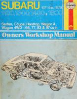
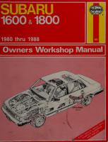
SUBARU
Haynes
1600s 1800 1980 thru 1988
Owners Workshop Manual
f@HAYtVES
Subaru Owners Workshop Manual by Larry Holt and John H Haynes Member of the Guild of Motoring Writers
Models covered All models with 1600 cc and 1800 cc engines, automatic and 4 & 5-speed manual transmissions, two-wheel and four-wheel drive
ISBN 1 85010 527 8 © Haynes Publishing Group 1983, 1986, 1987, 1988 All rights reserved. No part of this book may be reproduced or transmitted in any form or by any means, electronic or mechanical, including photocopying, recording or by any information storage or retrieval system, without permission in writing from the copyright holder.
Printed in England
(6P3 — 681) ABCDE FGHI
Haynes Publishing Group Sparkford Nr Yeovil Somerset BA22 7JJ England Library of Congress
Haynes Publications, Inc 861 Lawrence Drive Newbury Park California 91320 USA
Catalog card number
88-81715
Acknowledgments Thanks are due to Fuji Heavy Industries Ltd. of Japan, who gave us permission to reproduce certain illustrations and provided technical information.
The Champion Sparking Plug Company provided the illustrations of spark plug conditions,
About this manual Its purpose The purpose of this manual is to help you get the best value from your vehicle. It can do so in several ways. It can help you decide what work must be done even if you choose to get it done by a dealer service department or a repair shop; it provides information and procedures for routine maintenance and servicing; and it offers diagnostic and repair procedures to follow when trouble occurs. It is hoped that you will use the manual to tackle the work yourself. For many simpler jobs, doing it yourself may be quicker than arranging an appointment to get the vehicle into a shop and making the trips to leave it and pick it up. More importantly, a lot of money can be saved by avoiding the expense the shop must pass on to you to cover its labor and overhead costs. An added benefit is the sense of satisfaction and accomplishment that you feel after having done the job yourself.
Using the manual The manual is divided into Chapters. Each Chapter is divided into numbered Sections, which are headed in bold type between horizontal lines. Each Section consists of consecutively numbered paragraphs.
The two types of illustrations used (figures and photographs), are referenced by a number preceding their captions. Figure reference numbers denote Chapter and numerical sequence in the Chapter; i.e. Fig. 12.4 means Chapter 12, figure number 4. Figure captions are followed by a Section number which ties the figure to a specific portion of the text. All photographs apply to the Chapter in which they appear, and the reference number pinpoints the pertinent Section and paragraph; i.e. 3.2 means Section 3, paragraph 2. Procedures, once described in the text, are not normally repeated. When it is necessary to refer to another Chapter, the reference will be given as Chapter and Section number; i.e. Chapter 1/16. Cross references given without use of the word 'Chapter' apply to Sections and/or paragraphs in the same Chapter. For example, 'see Section 8' means in the same Chapter. Reference to the left or right side of the vehicle is based on the assumption that one is sitting in the driver's seat facing forward. Even though extreme care has been taken during the prep¬ aration of this manual, neither the publisher nor the author can accept responsibility for any errors in, or omissions from, the information given.
Introduction to the Subaru The Subaru line of vehicles, manufactured by Fuji Heavy Industries Ltd. of Japan, is one of the most versatile of all vehicles currently available. Although Subaru models have been available in both the US and UK for a number of years, this OWM is involved with only those vehicles produced in 1980 and later. Models built prior to 1980 are the subject of another Haynes manual. Subaru vehicles can be purchased in a number of forms and trim levels. In North America the most popular versions include 2-door and 4-door hatchbacks, station wagons and the unique pick-up truck called
the Brat. The UK has a similar line of saloons, hardtop coupes and the MV pick-up truck. One feature which helps to separate Subaru from other vehicle manufacturers is the use of four-wheel drive (4WD), available on most models. Subaru is the worldwide innovator in 4WD passenger cars. As mentioned above, in addition to body form, Subarus can be purchased in a variety of trim levels with many options. Optional equipment includes items such as a digital display instrument panel and the revolutionary Hill-holder device which prevents the vehicle from rolling backward when accelerating from a stop on a hill.
Contents Acknowledgements About this manual Introduction to the Subaru General dimensions Use of English
Page
2 2 2 8 9 10
Buying parts Vehicle identification numbers Maintenance techniques, tools and working facilities Automotive chemicals and lubricants Jacking and towing
11 12 18 19 20
Safety first! Troubleshooting Chapter 1
Tune-up and routine maintenance
Chapter 2
Engine
Chapter 3
Cooling, heating and air conditioning systems
Chapter 4
Fuel and exhaust systems
Chapter 5
Engine electrical systems
Chapter 6
Emissions control systems
Chapter 7
Transmissions
Chapter 8
Driveline
Chapter 9
Brakes
Chapter 10 Chassis electrical system
21 28 57 88 99 120 134 145 170 181
The Subaru GL wagon (foreground) and DL wagon (background) (North American models shown)
The Subaru hatchback models (North American models shown)
5
The Subaru 1600 GLF Saloon (UK version shown)
6
V
The Subaru pick-up truck known as the Brat in North America and as the MV in the UK {MV shown)
7
General dimensions Length (overall) Hatchback (DL-2WD). Hatchback (GL-2WD). Hatchback (All 4WD). Sedan and hardtop (DL).. Sedan and hardtop (GL).. Station wagon (DL-2WD) Station wagon (GL-2WD) Station wagon (All 4WD) Pick-up truck.
1 56.9 1 57.9 1 57.3 167.3 168.1 168.5 169.3 168.7 1 74.2
in in in in in in in in in
(3985 (4010 (3995 (4250 (4270 (4280 (4300 (4285 (4425
mm) mm) mm) mm) mm) mm) mm) mm) mm)
Width (overall) Hatchback (DL-2WD). Hatchback (GL-2WD). Hatchback (All 4WD). Sedan and hardtop (DL).. Sedan and hardtop (GL).. Station wagon (DL-2WD) Station wagon (GL-2WD) Station wagon (All 4WD) Pick-up truck.
63.4 63.6 63.8 63.4 63.6 63.4 63.6 63.8 64.4
in in in in in in in in in
(1610 (1615 (1620 (1610 (1615 (1610 (1615 (1620 (1635
mm) mm) mm) mm) mm) mm) mm) mm) mm)
53.7 55.7 53.7 53.1 54.7 56.9 56.9
in in in in in in in
(1365 (1415 (1365 (1350 (1390 (1445 (1445
mm) mm) mm) mm) mm) mm) mm)
Hatchback (2WD). Hatchback (4WD). Sedan and hardtop. Station wagon (2WD) Station wagon (4WD) Pick-up truck.
93.7 93.3 96.9 96.7 96.3 96.3
in in in in in in
(2380 (2370 (2460 (2455 (2445 (2445
mm) mm) mm) mm) mm) mm)
Track
Front
Hatchback (2WD). Hatchback (4WD). Sedan and hardtop. Station wagon (2WD) Station wagon (4WD) Pick-up truck.
52.4 in 52.6 in 52.4 in 52.5 in 52.6 in 52.6 in
(1330 mm) (1335 mm) (1330 mm) (1325 mm) (1335 mm) (1335 mm)
is k
m -?
Height (overall) Hatchback (2WD). Hatchback (4WD). Sedan. Hardtop. Station wagon (2WD). Station wagon (4WD). Pick-up truck.
Wheelbase
Rear
Turning circle Hatchback. All others.
Curb weight Hatchback (DL-2WD). Hatchback (GL-2WD). Hatchback (4WD). Sedan (DL). Sedan (GL). Hardtop (DL). Hardtop (GL). Station wagon (DL-2WD). Station wagon (GL-2WD). Station wagon (DL-4WD). Station wagon (GL-4WD). Pick-up truck (DL). Pick-up truck (GL).
91 in ik iqrr i,„\
9iQO ih (Qcn imi 91 in ih /q^7 o i on ik iqqq
\*rt\
53.0 in 53.9 in 53.0 in 53.0 in 53.7 in 53.7 in
(1345 (1370 (1345 (1345 (1365 (1365
mm) mm) mm) mm) mm) mm)
Use of English As this book has been written in America, it uses the appropriate American component names, phrases, and spelling. Some of these differ from those used in the U.K. Normally, these cause no difficulty, but to make sure, a glossary is printed below. In ordering replacement parts remember the parts list may use some of these words:
American
English
American
English
Antenna
Aerial Accelerator Anti-roll bar Bonnet (engine cover) Boot (luggage compartment) Bulkhead Cam follower or tappet Carburettor
Freeway, turnpike etc License plate Kerosene Gasoline-(gas) Gas tank 'Pinging' Driveshaft Quarter window
Motorway Number plate Paraffin Petrol Petrol tank 'Pinking' Propeller shaft Quarter light
Catch Choke/venturi Circlip Clearance Crownwheel Disc (brake) Drop arm Drop head coupe Dynamo Earth (electrical) Engineer’s blue
Recap Back-up Valve cover Sedan Frozen Side marker lights Parking light Muffler Wrench Rocker panel Lock (for valve spring retainer)
Retread Reverse Rocker cover Saloon Seized Side indicator lights
Cotter pin Spindle arm Oil pan Tang; lock Valve lifter Throw-out bearing High Tie rod (or connecting rod) Secondary shoe Whole drive line
Split pin Steering arm Sump Tab washer Tappet Thrust bearing Top gear Trackrod (of steering) Trailing shoe (of brake) Transmission
Tire Panel wagon/van
Dome lamp Countershaft Primary shoe
Estate car Exhaust manifold Fault finding/diagnosis Float chamber Free-play Freewheel Gudgeon pin Gearchange Gearbox Halfshaft Handbrake Hood Hot spot Indicator Interior light Layshaft (of gearbox) Leading shoe (of brake)
Tyre Van Vice Wheel nut Windscreen Wing/mudguard
Latches
Locks
Gas pedal Stabilizer or sway bar Hood Trunk Firewall Valve lifter or tappet Carburetor Latch Barrel Snap-ring Lash Ring gear (of differential) Rotor/disc Pitman arm Convertible Generator (DC) Ground Prussian blue Station wagon Header Troubleshooting Float bowl Lash Coast Piston pin or wrist pin Shift Transmission Axleshaft Parking brake Soft top Heat riser Turn signal
-
Vise Lug nut Windshield Fender
Side light Silencer Spanner Sill panel (beneath doors) Split cotter (for valve spring cap)
Miscellaneous points
An'oil seal', is also fitted to components lubricated by grease! A 'shock absorber' is a 'damper', it damps out bouncing and absorbs shocks of bump impact. Both names are correct, and both are used Note that British drum brakes are different from the Bendix type that is common in America, so different descriptive names result. The shoe end farthest from the hydraulic wheel cylinder is on a pivot; interconnection between the shoes, as on Bendix brakes, is most uncommon. Therefore the phrase 'Primary' or 'Secondary' shoe does not apply. A shoe is said to be 'Leading' or 'Trailing'. A 'Leading' shoe is one on which a point on the drum, as it rotates forward, reaches the shoe at the end worked by the hydraulic cylinder before the anchor end. The opposite a 'Trailing' shoe and this one has no self servo from the wrapping effect of the rotating drum.
Buying parts Replacement parts are available from many sources, which generally fall into one of two categories — authorized dealer parts departments and independent retail auto parts stores. Our advice concerning these parts is as follows: Authorized dealer parts department: This is the best source for parts which are peculiar to your vehicle and not generally available elsewhere (i.e. major engine parts, transmission parts, trim pieces, etc.). It is also the only place you should buy parts if your vehicle is still under warranty, as non-factory parts may invalidate the warranty. To be sure of obtaining the correct parts, have your vehicle s engine and chassis numbers available and, if possible, take the old parts along for
positive identification. Retail auto parts stores: Good auto parts stores will stock frequently needed components which wear out relatively fast (i.e. clutch components, exhaust systems, brake parts, tune-up parts, etc.). These stores often supply new or reconditioned parts on an exchange basis, which can save a considerable amount of money. Discount auto parts stores are often very good places to buy materials and parts needed for general vehicle maintenance (i.e. oil, grease, filters, spark plugs, belts, touch-up paint, bulbs, etc.). They also usually sell tools and general accessories, have convenient hours, charge lower prices, and can often be found not far from your home.
Vehicle identification numbers The Vehicle Identification Number (VIN) is located in two different places. It is stamped on the firewall of the engine compartment (photo) and on most models is also on a plate fastened to the dash on the driver's side (photo). The engine serial number is stamped on the right side of the engine crankcase, near the front (photo). The transmission serial number label is attached to the right upper surface of the main case of the manual transmission (photo) or the converter housing of the automatic transmission.
Other important vehicle labels which may be included are the Safety Certification plate, found on the driver’s side door pillar (photo) and the Vehicle Color Code label, stuck on the top radiator crossmember, near the hood latch (photo). An Emissions Control Information label is supplied with all North America models. It is attached to the underside of the hood. It contains information concerning certification, vacuum connections and high altitude settings (photo). For California vehicles, there is an Emission Data label found on the driver's side of the dash.
Vehicle Identification Number (VIN) engine compartment location
Vehicle Identification Number (VIN) driver's side dash location
The engine serial number (arrow) is stamped into the right side of the crankcase, near the front
Manual transmission serial number location (arrow)
Automatic transmission serial number location
Safety Certification plate location (arrow) on driver's side door pillar
The Emission Control Information label (arrow) is attached to the underside of the hood
The Emissions Data label (California vehicles only) is attached to the driver's side of the dash, near the VIN
Maintenance techniques, tools and working facilities Maintenance techniques There are a number of techniques involved in maintenance and repair that will be referred to throughout this manual. Application of these techniques will enable the home mechanic to be more efficient, better organized and capable of performing the various tasks properly, which will ensure that the repair job is thorough and complete.
Fasteners are nuts, bolts, studs and screws used to hold two or more parts together. There are a few things to keep in mind when working with fasteners. Almost all of them use a locking device of some type; either a lock washer, locknut, locking tab or thread adhesive. All threaded fasteners should be clean and straight, with undamaged threads and undamaged corners on the hex head where the wrench fits. Develop the habit of replacing damaged nuts and bolts with new ones. Special locknuts with nylon or fiber inserts can only be used once. If they are removed, they lose their locking ability and must be replaced with new ones. Rusted nuts and bolts should be treated with a penetrating fluid to ease removal and prevent breakage. Some mechanics use turpentine in a spout-type oil can, which works quite well. After applying the rust penetrant, let it "work" for a few minutes before trying to loosen the nut or bolt. Badly rusted fasteners may have to be chiseled or sawed off or removed with a special nut breaker, available at tool stores. If a bolt or stud breaks off in an assembly, it can be drilled and removed with a special tool commonly available for this purpose. Most automotive machine shops can perform this task, as well as other repair procedures (such as repair of threaded holes that have been stripped out). Flat washers and lock washers, when removed from an assembly should always be replaced exactly as removed. Replace damaged washers with new ones. Always use a flat washer between a lock washer and any soft metal surface (such as aluminum), thin sheet metal or plastic.
metric and standard bolts can also be distinguished by examining the bolt heads. To begin with, the distance across the flats on a standard bolt head is measured in inches, while the same dimension on a metric bolt is measured in millimeters (the same is true for nuts). As a result, a standard wrench should not be used on a metric bolt and a metric wrench should not be used on a standard bolt. Also, standard bolts have slashes radiating out from the center of the head to denote the grade or strength of the bolt (which is an indication of the amount of torque that can be applied to it). The greater the number of slashes, the greater the strength of the bolt (grades 0 through 5 are commonly used on automobiles). Metric bolts have a property class (grade) number, rather than a slash, molded into their heads to indicate bolt strength. In this case, the higher the number the stronger the bolt (property class numbers 8.8, 9.8 and 10.9 are commonly used on automobiles). Strength markings can also be used to distinguish standard hex nuts from metric hex nuts. Standard nuts have dots stamped into one side, while metric nuts are marked with a number. The greater the number of dots, or the higher the number, the greater the strength of the nut. Metric studs are also marked on their ends according to property class (grade). Larger studs are numbered (the same as metric bolts), while smaller studs carry a geometric code to denote grade. It should be noted that many fasteners, especially Grades 0 through 2, have no distinguishing marks on them. When such is the case, the only way to determine whether it is standard or metric is to measure the thread pitch or compare it to a known fastener of the same size. Since fasteners of the same size (both standard and metric) may have different strength ratings, be sure to reinstall any bolts, studs or nuts removed from your vehicle in their original locations. Also, when replacing a fastener with a new one, make sure that the new one has a strength rating equal to or greater than the original.
Fastener sizes
Tightening sequences and procedures
For a number of reasons, automobile manufacturers are making wider and wider use of metric fasteners. Therefore, it is important to be able to tell the difference between standard (sometimes called U.S., English or SAE) and metric hardware, since they cannot be interchanged. All bolts, whether standard or metric, are sized according to diameter, thread pitch and length. For example, a standard | - 13 x 1 bolt is \ inch in diameter, has 13 threads per inch and is 1 inch long. An M12 — 1.75 x 25 metric bolt is 12 mm in diameter, has a thread pitch of 1.75 mm (the distance between threads) and is 25 mm long. The two bolts are nearly identical, and easily confused, but they are not interchangeable. In addition to the differences in diameter, thread pitch and length,
Most threaded fasteners should be tightened to a specific torque value (torque is basically a twisting force). Over-tightening the fastener can weaken it and lead to eventual breakage, while under-tightening can cause it to eventually come loose. Bolts, screws and studs, depending on the materials they are made of and their thread diameters, have specific torque values (many of which are noted in the Specifications at the beginning of each Chapter). Be sure to follow the torque recommendations closely. For fasteners not assigned a specific torque, a general torque value chart is presented here as a guide. As was previously mentioned, the sizes and grade of a fastener determine the amount of torque that can safely be applied to it. The figures listed here are approximate for Grade 2 and Grade 3 fasteners (higher grades can tolerate higher torque values).
Fasteners
13
Maintenance techniques, tools and working facilities Nm
Ft-lb
Metric thread sizes M-6. M-8. M-10. M-12. M-14.
9 to 12 19 to 28 38 to 54 68 to 96 109 to 154
Pipe thread sizes 1
7 to 10 17 to 24 30 to 44 34 to 47
*.
i. 1
25 to 35
U.S. thread sizes i - 20. - 18. h - 24. 1-16. | - 24. .
9 to 12 17 to 24 19 to 27 30 to 43 37 to 51 55 to 74 55 to 81 75 to 108
A
AA1-
27 to 38
14. 20. 13.
Standard (SAE) bolt dimensions/grade marks G - Grade marks (bolt strength) L — Length (in inches) T - Thread pitch (number of threads per inch) D - Nominal diameter (in inches)
Metric bolt dimensions/grade marks P - Property class (bolt strength) L - Length (in millimeters) T — Thread pitch (distance between threads; in millimeters) D - Nominal diameter (in millimeters)
Fasteners laid out in a pattern (i.e. cylinder head bolts, oil pan bolts, differential cover bolts, etc.) must be loosened and tightened in a definite sequence to avoid warping the component. This sequence will normally be shown in the appropriate Chapter. If a specific pattern is not given, the following procedures can be used to prevent warping. Initially, the bolts or nuts should be assembled finger-tight only. Next, they should be tightened one full turn each, in a criss-cross or diagonal pattern. After each one has been tightened one full turn, return to the first one and tighten them all one-half turn, following the same pattern. Finally, tighten each of them one-quarter turn at a time until they all have been tightened to the proper torque value. To loosen and remove them the procedure would be reversed.
washers and nut back on a stud can prevent mixups later. If nuts and bolts cannot be returned to their original locations, they should be kept in a compartmented box or a series of small boxes. A cupcake or muffin tin is ideal for this purpose, since each cavity can hold the bolts and nuts from a particular area (i.e. oil pan bolts, valve cover bolts, engine mount bolts, etc.). A pan of this type is especially helpful when working on assemblies with very small parts such as the carburetor, alternator, valve train or interior dash and trim pieces. The cavities can be marked with paint or tape to identify the contents. Whenever wiring looms, harnesses or connectors are separated, it's a good idea to identify them with numbered pieces of masking tape so that they can be easily reconnected.
Component disassembly
Gasket sealing surfaces
Component disassembly should be done with care and purpose to help ensure that the parts go back together properly. Always keep track of the sequence in which parts are removed. Make note of special characteristics or marks on parts that can be installed more than one way (such as a grooved thrust washer on a shaft). It is a good idea to lay the disassembled parts out on a clean surface in the order that they were removed. It may also be helpful to make simple sketches or take instant photos of components before removal. When removing fasteners from an assembly, keep track of their locations. Sometimes threading a bolt back in a part or putting the
Throughout any vehicle, gaskets are used to seal the mating surfaces between two parts and keep lubricants, fluids, vacuum or pressure contained in an assembly. Many times these gaskets are coated with a liquid or paste-type gasket sealing compound before assembly. Age, heat and pressure can sometimes cause the two parts to stick together so tightly that they are very difficult to separate. Often, the assembly can be loosened by striking it with a soft-faced hammer near the mating surfaces. A regular hammer can be used if a block of wood is placed between the hammer and the part. Do not hammer on cast parts or parts that could
14
Maintenance techniques, tools and working facilities
Bolt strength markings (top - standard/SAE; bottom - metric)
Grade
Hex Nut Grade 5
Identification
Class
©
Hex Nut Property Class 9
/»-A
Hex Nut Property Class 10
/£T\
Identification
/^T\
(q)
3 Dots
Hex Nut Grade 8
/♦(
]«
Arabic 9
6 Dots Standard hex nut strength markings be easily damaged. With any particularly stubborn part, always recheck to see that every fastener has been removed. Avoid using a screwdriver or bar to pry apart an assembly, as they can easily mar the gasket sealing surfaces of the parts (which must remain smooth). If prying is absolutely necessary, use an old broom handle, but keep in mind that extra clean-up will be necessary if the wood splinters. After the parts are separated, the old gasket must be carefully scraped off and the gasket surfaces cleaned. Stubborn gasket material can be soaked with rust penetrant or treated with a special chemical to soften it so that it can be easily scraped off. A scraper can be fashioned from a piece of copper tubing by flattening and sharpening one end. Copper is recommended because it is usually softer than the surfaces to be scraped, which reduces the chance of gouging the part. Some gaskets can be removed with a wire brush, but regardless of the method used, the mating surfaces must be left clean and smooth. If, for some reason the gasket surface is gouged, then a gasket sealer
Arabic 10 Metric hex nut strength markings
j CLASS 10.9
Wb
© © CLASS 9.8
Metric stud strength markings
CLASS 8.8
Maintenance techniques, tools and working facilities thick enough to fill scratches will have to be used upon reassembly of the components. For most applications, a non-drying (or semi-drying) gasket sealer should be used.
Hose removal tips Caution: If the vehicle is equipped with air conditioning, do not disconnect any of the a/c hoses without first having the system de¬ pressurized by a dealer service department or air conditioning specialist. Hose removal precautions closely parallel gasket removal precau¬ tions. Avoid scratching or gouging the surface that the hose mates against or the connection may leak. This is especially true for radiator hoses. Because of various chemical reactions, the rubber in hoses can bond itself to the metal spigot that the hose fits over. To remove a hose, first loosen the hose clamps that secure it to the spigot. Then, with slip-joint pliers, grab the hose at the clamp and rotate it around the spigot. Work it back-and-forth until it is completely free, then pull it off. Silicone or other lubricants will ease removal if they can be applied between the hose and the spigot. Apply the same lubricant to the inside of the hose and the outside of the spigot to simplify installation. As the last resort (and if the hose is to be replaced with a new one anyway), the rubber can be slit with a knife and the hose peeled from its spigot. If this must be done, be careful that the metal connection is not damaged. If a hose clamp is broken or damaged, do not re-use it. Wire-type clamps usually weaken with age, so it is a good idea to replace them with screw-type clamps whenever a hose is removed.
Tools A selection of good tools is a basic requirement for anyone who plans to maintain and repair his or her own vehicle. For the owner who has few tools, if any, the initial investment might seem high, but when compared to the spiraling costs of professional auto maintenance and repair, it is a wise one. To help the owner decide which tools are needed to perform the tasks detailed in this manual, the following tool lists are offered: Maintenance and minor repair. Repair and overhaul and Special. The newcomer to practical mechanics should start off with the Mainten¬ ance and minor repair tool kit, which is adequate for the simpler jobs performed on a vehicle. Then, as his confidence and experience grow, he can tackle more difficult tasks, buying additional tools as they are needed. Eventually the basic kit will be expanded into the Repair and overhaul tool set. Over a period of time, the experienced do-ityourselfer will assemble a tool set complete enough for most repair and overhaul procedures and will add tools from the Special category when he feels the expense is justified by the frequency of use.
15
Note: if basic tune-ups are going to be a part of routine maintenance, it will be necessary to purchase a good quality stroboscopic timing light and a combination tachometer/dwell meter. Although they are included in the list of Special tools, they are mentioned here because they are absolutely necessary for tuning most vehicles properly.
Repair and overhaul tool set These tools are essential for anyone who plans to perform major repairs and are in addition to those in the Maintenance and minor repair toot kit. Included is a comprehensive set of sockets which, though expensive, are invaluable because of their versatility (especially when various extensions and drives are available). We recommend the y in drive over the f in drive. Although the larger drive is bulky and more expensive, it has the capability of accepting a very wide range of large sockets (ideally, the mechanic would have a f in drive set and a y in drive set). Socket set(s) Reversible ratchet Extension — 10 in Universal joint Torque wrench (same size drive as sockets) Ballpeen hammer - 8 oz Soft-faced hammer (plastic/rubber) Standard screwdriver (\ in x 6 in) Standard screwdriver (stubby — ^ in) Phillips screwdriver (No.3 x 8 in) Phillips screwdriver (stubby - No.2) Pliers - vise grip Pliers - lineman's Pliers - needle nose Pliers - spring dip (internal and external) Cold chisel - y in Scriber Scraper (made from flattened copper tubing) Center punch Pin punches (^ ^ in) Steel rule/straightedge - 12 in Alien wrench set (y to f in or 4 mm to 10 mm) A selection of files Wire brush (large) Jack stands (second set) Jack (scissor or hydraulic type) Note: Another tool which is often useful is an electric drill motor with a chuck capacity of f in (and a set of good quality drill bits).
Special tools Maintenance and minor repair tool kit The tools in this list should be considered the minimum for performance of routine maintenance, servicing and minor repair work. We recommend the purchase of combination wrenches (box end and open end combined in one wrench); while more expensive than openended ones, they offer the advantages of both types of wrench. Combination wrench set (j in to 1 in or 6 mm to 19 mm) Adjustable wrench — 8 in Spark plug wrench (with rubber insert) Spark plug gap adjusting tool Feeler gauge set Brake bleeder wrench Standard screwdriver ($ in x 6 in) Phillips screwdriver (No. 2x6 in) Combination pliers - 6 in Hacksaw and assortment of blades Tire pressure gauge Grease gun OH can Fine emery doth Wire brush Battery post and cable cleaning toot Oil filter wrench Funnel (medium size) Safety goggles Jack stands (2) Drain pan
The tools in this list include those which are not used regularly, are expensive to buy, or which need to be used in accordance with their manufacturer's instructions. Unless these tools will be used frequently, it is not very economical to purchase many of them. A consideration would be to split the cost and use between yourself and a friend or friends. In addition, most of these tools can be obtained from a tool rental shop on a temporary basis. This list contains only those tools and instruments widely available to the public, and not those special tools produced by vehicle manufacturers for distribution to dealer service departments. Oc¬ casionally, references to the manufacturer's special tools are included in the text of this manual. Generally, an alternate method of doing the job without the special tool is offered. However, sometimes there is no alternative to their use. Where this is the case, and the tool cannot be purchased or borrowed, the work should be turned over to the dealer, a repair shop or an automotive machine shop. Valve spring compressor Piston ring groove cleaning tool Piston ring compressor Piston ring installation tool Cylinder compression gauge Cylinder ridge reamer Cylinder surfacing hone Cylinder bore gauge Micrometer(s) and/or dial calipers Hydraulic lifter removal tool Balljoint separator
Valve spring compressor
Piston ring groove cleaning tool
Piston ring compressor
Piston ring removal/installation tool
Cylinder ridge reamer
Cylinder surfacing hone
Cylinder bore gauge
Micrometer set
Dial caliper
Hydraulic lifter removal tool
Universal type puller
Dial indicator set
Maintenance techniques, tools and working facilities
17
&
Hand operated vacuum pump
Universal-type puller Impact screwdriver Dial indicator set Stroboscopic timing light (inductive pickup) Hand-operated vacuum/pressure pump Tachometer/dwell meter Universal electrical multimeter Cable hoist Brake spring removal and installation tools Floor jack
Buying tools For the do-it-yourselfer who is just starting to get involved in vehicle maintenance and repair, there are a couple of options available when purchasing tools. If maintenance and minor repair is the extent of the work to be done, the purchase of individual tools is satisfactory. If, on the other hand, extensive work is planned, it would be a good idea to purchase a modest tool set from one of the large retail chain stores. A set can usually be bought at substantial savings over the individual tool prices (and they often come with a tool box). As additional tools are needed, add-on sets, individual tools and a larger tool box can be purchased to expand the tool selection. Building a tool set gradually allows the cost of the tools to be spread over a longer period of time and gives the mechanic the freedom to choose only those tools that will actually be used. Tool stores will often be the only source of some of the special tools that are needed, but regardless of where tools are bought, try to avoid cheap ones (especially when buying screwdrivers and sockets) because they won’t last very long. The expense involved in replacing cheap tools will eventually be greater than the initial cost of quality tools.
Care and maintenance of tools Good tools are expensive, so it makes sense to treat them with respect. Keep them in a clean and usable condition and store them properly when not in use. Always wipe off any dirt, grease or metal chips before putting them away. Never leave tools lying around in the work area. Upon completion of a job, always check closely under the hood for tools that may have been left there (so they don't get lost during a test drive). Some tools, such as screwdrivers, pliers, wrenches and sockets,
Brake shoe spring tool
can be hung on a panel mounted on the garage or workshop wall, while others should be kept in a tool box or tray. Measuring instruments, gauges, meters, etc. must be carefully stored where they cannot be damaged by weather or impact from other tools. When tools are used with care and stored properly, they will last a very long time. Even with the best of care, tools will wear out if used frequently. When a tool is damaged or worn out, replace it; subsequent jobs will be safer and more enjoyable if you do.
Working facilities Not to be overlooked when discussing tools is the workshop. If anything more than routine maintenance is to be carried out, some sort of suitable work area is essential. It is understood, and appreciated, that many home mechanics do not have a good workshop or garage available and end up removing an engine or doing major repairs outside. It is recommended, however, that the overhaul or repair be completed under the cover of a roof. A clean, flat workbench or table of comfortable working height is an absolute necessity. The workbench should be equipped with a vise that has a jaw opening of at least four inches. As mentioned previously, some clean, dry storage space is also required for tools, as well as the lubricants, fluids, cleaning solvents, etc. which soon become necessary. Sometimes waste oil and fluids, drained from the engine or transmission during normal maintenance or repairs, present a disposal problem. To avoid pouring oil on the ground or into the sewage system, simply pour the used fluids into large containers, seal them with caps and deliver them to a local recycling center or disposal facility. Plastic jugs (such as old antifreeze containers) are ideal for this purpose. Always keep a supply of old newspapers and clean rags available. Old towels are excellent for mopping up spills. Many mechanics use rolls of paper towels for most work because they are readily available and disposable. To keep the area under the vehicle clean, a large cardboard box can be cut open and flattened to protect the garage or shop floor. Whenever working over a painted surface (such as when leaning over a fender to service something under the hood), always cover it with an old blanket or bedspread to protect the finish. Vinyl covered pads, made especially for this purpose, are available at auto parts stores.
Automotive chemicals and lubricants A number of automotive chemicals and lubricants are available for use in vehicle maintenance and repair. They include a wide variety of products ranging from cleaning solvents and degreasers to lubricants and protective sprays for rubber, plastic and vinyl. Contact point/spark plug cleaner is a solvent used to clean oily film and dirt from points, grime from electrical connectors and oil deposits from spark plugs. It is oil free and leaves no residue. It can also be used to remove gum and varnish from carburetor jets and other orifices. Carburetor cleaner is similar to contact point/spark plug cleaner but it is a stronger solvent and may leave a slight oily residue. It is not recommended for cleaning electrical components or connections. Brake system cleaner is used to remove grease or brake fluid from brake system components where clean surfaces are absolutely necessary and petroleum-based solvents cannot be used. It also leaves no residue. SHicone-based lubricants are used to protect rubber parts such as hoses, weatherstripping and grommets and are used as lubricants for hinges and locks. Multi-purpose grease is an all-purpose lubricant used whenever grease is more practical than a liquid lubricant such as oil. Some multi¬ purpose grease is white and specially formulated to be more resistant to water than ordinary grease. Bearing grease/wheel bearing grease is a heavy grease used where increased loads and friction are encountered (i.e. wheel bearings, universal joints, etc.). High temperature wheel bearing grease is designed to withstand the extreme temperatures encountered by wheel bearings in disc brake equipped vehicles. It usually contains molybdenum disulfide, which is a 'dry' type lubricant. Gear oil (sometimes called gear lube) is a specially designed oil used in differentials, manual transmissions and transfer cases, as well as other areas where high friction, high temperature lubrication is required. It is available in a number of viscosities (weights) for various applications. Motor oil, of course, is the lubricant specially formulated for use in the engine. It normally contains a wide variety of additives to prevent corrosion and reduce foaming and wear. Motor oil comes in various weights (viscosity ratings) of from 5 to 80. The recommended weight of the oil depends on the seasonal temperature and the demands on the engine. Light oil is used in cold climates and under light load conditions; heavy oil is used in hot climates and where high loads are encountered. Multi-viscosity oils are designed to have characteristics of both light and heavy oils and are available in a number of weights from 5W-20 to 20W-50. Oil additives range from viscosity index improvers to slick chemical treatments that purportedly reduce friction. It should be noted that most oil manufacturers caution against using additives with their oils. Gas additives perform several functions, depending on their
chemical makeup. They usually contain solvents that help dissolve gum and varnish that build up on carburetor and intake parts. They also serve to break down carbon deposits that form on the inside surfaces of the combustion chambers. Some additives contain upper cylinder lubricants for valves and piston rings. Brake fluid is a specially formulated hydraulic fluid that can withstand the heat and pressure encountered in brake systems. Care must be taken that this fluid does not come in contact with painted surfaces or plastics. An opened container should always be resealed to prevent contamination by water or dirt. Undercoating is a petroleum-based, tar-like substance that is designed to protect metal surfaces on the underside of a vehicle from corrosion. It also acts as a sound deadening agent by insulating the bottom of the vehicle. Weatherstrip cement is used to bond weatherstripping around doors, windows and trunk lids. It is sometimes used to attach trim pieces as well. Degreasers are heavy-duty solvents used to remove grease and grime that accumulate on engine and chassis components. They can be sprayed or brushed on and, depending on the type, are rinsed with either water or solvent. Solvents are used alone or in combination with degreasers to clean parts and assemblies during repair and overhaul. The home mechanic should use only solvents that are non-flammable and that do not produce irritating fumes. Gasket sealing compounds may be used in conjunction with gaskets, to improve their sealing capabilities, or alone, to seal metalto-metal joints. Many gaskets can withstand extreme heat, some are impervious to gasoline and lubricants, while others are capable of filling and sealing large cavities. Depending on the intended use, gasket sealers either dry hard or stay relatively soft and pliable. They are usually applied by hand, with a brush, or are sprayed on the gasket sealing surfaces. Thread cement is an adhesive locking compound that prevents threaded fasteners from loosening because of vibration. It is available in a variety of types for different applications. Moisture dispersants are usually sprays that can be used to dry out electrical components such as the distributor, fuse block and wiring connectors. Some types can also be used as a treatment for rubber and as a lubricant for hinges, cables and locks. Waxes and polishes are used to help protect painted and plated surfaces from the weather. Different types of paint may require the use of different types of wax or polish. Some polishes utilize a chemical or abrasive cleaner to help remove the top layer of oxidized (dull) paint in older vehicles. In recent years, many non-wax polishes that contain a wide variety of chemicals such as polymers and silicones have been introduced. These non-wax polishes are usually easier to apply and last longer than conventional waxes and polishes.
Jacking and towing Jacking The jack supplied with the vehicle should only be used for raising the vehicle for changing a tire or placing jack stands under the frame. Under no circumstances should work be performed beneath the vehicle or the engine started while this jack is being used as the only means of support. All vehicles are supplied with a lug wrench and a scissors-type jack which fits into notches in the vertical rocker panel flange nearest
r>
to the wheel being changed. The vehicle should be on level ground with the wheels blocked and the transmission in Park (automatic) or Reverse (manual). Pry off the hub cap (if equipped) using the tapered end of the lug wrench. Loosen the lug nuts one-half turn and leave them in place until the wheel is raised off the ground. Place the jack under the side of the vehicle in the appropriate jacking notch. Use the supplied wrench or handle to turn the jackscrew clockwise until the wheel is raised off the ground. Remove the lug nuts, pull off the wheel and replace it with the spare. With the beveled side in, replace the lug nuts and tighten them until snug. Lower the vehicle by turning the jackscrew counterclockwise. Remove the jack and tighten the nuts in a crisscross pattern. Replace the hubcap by placing it into position and using the heel of your hand or a rubber mallet to seat it.
Towing
Jacking point (front)
Jacking point (rear)
The vehicle can be towed with all four wheels on the ground, as long as speeds do not exceed 20 mph (30 kmh) and the distance is not over six miles (10 km). Towing hooks are located at the front and the rear of the vehicle (photo). For distances exceeding six miles, towing equipment specifically designed for this purpose must be used and should be attached to the main structural members of the vehicle, not the bumper or brackets. While towing, the parking brake should be fully released and the transmission should be in Neutral. The steering must be unlocked (ignition switch in the Off position). Remember that power steering and power brakes will not work with the engine off. Avoid towing another vehicle with your front towing hooks and never use the tie-down tabs for towing. Safety is a major consideration when towing and all applicable state and local laws must be obeyed. A safety chain system must be used for all towing.
Towing hooks (arrows) are located at the front and rear of the vehicle
Safety first! Regardless of how enthusiastic you may be about getting on with the job at hand, take the time to ensure that your safety is not jeopard¬ ized. A moment's lack of attention can result in an accident, as can failure to observe certain simple safety precautions. The possibility of an accident will always exist, and the following points should not be considered a comprehensive list of all dangers. Rather, they are in¬ tended to make you aware of the risks and to encourage a safety con¬ scious approach to all work you carry out on your vehicle.
Essential DOs and DON'Ts DON'T rely on a jack when working under the vehicle. Always use ap¬ proved jackstands to support the weight of the vehicle and place them under the recommended lift or support points. DON'T attempt to loosen extremely tight fasteners (i.e. wheel lug nuts) while the vehicle is on a jack — it may fall. DON'T start the engine without first making sure that the transmission is in Neutral (or Park where applicable) and the parking brake is set. DON'T remove the radiator cap from a hot cooling system — let it cool or cover it with a cloth and release the pressure gradually. DON'T attempt to drain the engine oil until you are sure it has cooled to the point that it will not burn you. DON'T touch any part of the engine or exhaust system until it has cooled sufficiently to avoid burns. DON'T siphon toxic liquids such as gasoline, antifreeze and brake fluid by mouth, or allow them to remain on your skin. DON'T inhale brake lining dust — it is potentially hazardous (see Asbestos below) DON'T allow spilled oil or grease to remain on the floor — wipe it up before someone slips on it. DON'T use loose fitting wrenches or other tools which may slip and cause injury. DON'T push on wrenches when loosening or tightening nuts or bolts. Always try to pull the wrench toward you. If the situation calls for pushing the wrench away, push with an open hand to avoid scraped knuckles if the wrench should slip. DON'T attempt to lift a heavy component alone — get someone to help you. DON'T rush or take unsafe shortcuts to finish a job. DON'T allow children or animals in or around the vehicle while you are working on it. DO wear eye protection when using power tools such as a drill, sander, bench grinder, etc. and when working under a vehicle. DO keep loose clothing and long hair well out of the way of moving parts. DO make sure that any hoist used has a safe working load rating adequate for the job. DO get someone to check on you periodically when working alone on a vehicle. DO carry out work in a logical sequence and make sure that everything is correctly assembled and tightened. DO keep chemicals and fluids tightly capped and out of the reach of children and pets. DO remember that your vehicle's safety affects that of yourself and others. If in doubt on any point, get professional advice.
Asbestos Certain friction, insulating, sealing, and other products — such as brake linings, brake bands, clutch linings, torque converters, gaskets, etc. — contain asbestos. Extreme care must be taken to avoid inhalation of dust from such products since it is hazardous to health. If in doubt, assume that they do contain asbestos.
Fire Remember at all times that gasoline is highly flammable. Never smoke or have any kind of open flame around when working on a vehicle. But the risk does not end there. A spark caused by an electrical short circuit, by two metal surfaces contacting each other, or even by static electricity built up in your body under certain conditions, can ignite gasoline vapors, which in a confined space are highly explosive. Do not, under any circumstances, use gasoline for cleaning parts. Use an approved safety solvent. Always disconnect the battery ground (-) cable at the battery before working on any part of the fuel system or electrical system. Never risk spilling fuel on a hot engine or exhaust component. It is strongly recommended that a fire extinguisher suitable for use on fuel and electrical fires be kept handy in the garage or workshop at all times. Never try to extinguish a fuel or electrical fire with water.
Fumes Certain fumes are highly toxic and can quickly cause unconscious¬ ness and even death if inhaled to any extent. Gasoline vapor falls into this category, as do the vapors from some cleaning solvents. Any drain¬ ing or pouring of such volatile fluids should be done in a well ventilated area. When using cleaning fluids and solvents, read the instructions on the container carefully. Never use materials from unmarked containers. Never run the*engine in an enclosed space, such as a garage. Exhaust fumes contain carbon monoxide, which is extremely poisonous. If you need to run the engine, always do so in the open air, or at least have the rear of the vehicle outside the work area. If you are fortunate enough to have the use of an inspection pit, never drain or pour gasoline and never run the engine while the vehicle is over the pit. The fumes, being heavier than air, will concentrate in the pit with possibly lethal results.
The battery Never create a spark or allow a bare light bulb near the battery. The battery normally gives off a certain amount of hydrogen gas, which is highly explosive. Always disconnect the battery ground (-) cable at the battery before working on the fuel or electrical systems. If possible, loosen the filler caps or cover when charging the battery from an external source. Do not charge at an excessive rate or the bat¬ tery may burst. Take care when adding water and when carrying a battery. The elec¬ trolyte, even when diluted, is very corrosive and should not be allowed to contact clothing or skin. Always wear eye protection when cleaning the battery to prevent the caustic deposits from entering your eyes.
Household current When using an electric power tool, inspection light, etc., which operates on household current, always make sure that the tool is cor¬ rectly connected to its plug and that, where necessary, it is properly grounded. Do not use such items in damp conditions and, again, do not create a spark or apply excessive heat in the vicinity of fuel or fuel vapor.
Secondary ignition system voltage A severe electric shock can result from touching certain parts of the ignition system (such as the spark plug wires) when the engine is run¬ ning or being cranked, particularly if components are damp or the insula¬ tion is defective. In the case of an electronic ignition system, the secon¬ dary system voltage is much higher and could prove fatal.
Troubleshooting Contents
Engine Engine backfires. Engine 'diesels' (continues to run) after switching off. Engine hard to start when cold. Engine hard to start when hot. Engine lacks power. Engine 'lopes' while idling or idles erratically. Engine misses at idle speed. Engine misses throughout driving speed range. Engine rotates but will not start. Engine stalls. Engine starts but stops immediately. Engine will not rotate when attempting to start. Pinging or knocking engine sounds during hard acceleration or uphill. Starter motor noisy or excessively rough in engagement. Starter motor operates without rotating engine.
13 15 4 5 12 8 9 10 2 11 7 1 14 6 3
Engine electrical system Battery will not hold a charge. 16 Charge light fails to come on when key is turned on. 18 Charge light fails to go out. 17
Engine fuel system Excessive fuel consumption. 19 Fuel leakage and/or fuel odor. 20
Engine cooling system External coolant leakage. Internal coolant leakage. Overcooling. Overheating. Poor coolant circulation. Coolant loss.
23 24 22 21 26 25
Clutch Clutch pedal stays on floor when disengaged. Clutch slips (engine speed increases with no increase in vehicle speed). Fails to release (pedal pressed to the floor — shift lever does not move freely in and out of gear). Grabbing (chattering) on take-up. Squeal or rumble with clutch fully disengaged (pedal depressed). Squeal or rumble with clutch fully engaged (pedal released).
32 28 27 29 31 30
Manual transmission Difficulty in engaging gears. Oil leakage. Noisy in all gears. Noisy in Neutral with engine running. Noisy in one particular gear. Slips out of high gear.
37 38 34 33 35 36
Automatic transmission Engine will start in gears other than P (Park) or N (Neutral)..C.. 42
Fluid leakage. General shift mechanism problems. Transmission slips, shifts rough, is noisy or has no drive in forward or reverse gears. Transmission will not downshift with the accelerator pedal pressed to the floor.
39 40 43 41
Driveshaft (4WD vehicles) Knock or clunk when the transmission is under initial load (just after transmission is put into gear). Leakage of fluid at front of driveshaft. Metallic grating sound consistent with vehicle speed. Vibration.
45 44 46 47
Front differential Bearing noise. Gear noise when coasting. Gear noise when driving. Noise when turning.
50 49 48 51
Rear differential (4WD vehicles) Noise when starting or shifting gears. 53 Noise when turning. 54 Oil leakage. 52
Axle shafts Clicking noise in turns. 55 Knock or clunk when accelerating after coasting. 56 Shudder or vibration during acceleration. 57
Brakes Brake pedal feels spongy when depressed. Brake pedal pulsates during brake application. Excessive brake pedal travel. Excessive effort required to stop vehicle. Hill-holder fails to hold. Noise (high-pitched squeal without brake applied). Pedal travels to floor with little resistance... Vehicle pulls to one side during braking.
61 64 60 62 65 59 63 58
Suspension and steering Excessive pitching and/or rolling around corners or during braking. Excessive play in steering. Excessive tire wear (not specific to one area). Excessive tire wear on inside edge. Excessive tire wear on outside edge. Excessively stiff steering. General vibration at highway speeds. Lack of power assistance. Noise - whether coasting or in drive. Shimmy, shake or vibration. Tire tread worn in one place. Vehicle pulls to one side.
74 76 66 68 67 75 70 77 71 73 69 72
22
Troubleshooting
This section provides an easy-reference guide to the more common faults which may occur during the operation of your vehicle. These faults and their probable causes are grouped under their respective systems, i.e. Engine, Cooling system, etc., and also refer to the Chapter and/or Section which deals with the problem. Remember that successful troubleshooting is not a mysterious 'black art' practiced only by professional mechanics, it’s simply the result of a bit of knowledge combined with an intelligent, systematic approach to the problem. Always work by a process of elimination, starting with the simplest solution and working through to the most complex — and never overlook the obvious. Anyone can forget to fill the gas tank or leave the lights on overnight, so don't assume that you are above such oversights. Finally, always get clear in your mind why a problem has occurred and take steps to ensure that it doesn't happen again. If the electrical system fails because of a poor connection, check all other connections in the system to make sure that they don't fail as well; if a particular fuse continues to blow, find out why — don't just go on replacing fuses. Remember, failure of a small component can often be indicative of potential failure or incorrect functioning of a more important component or system.
Engine
3 Starter motor operates without rotating engine 1 Starter pinion sticking. Remove the starter (Chapter 5) and inspect. 2 Starter pinion or engine flywheel teeth worn or broken. Remove the starter to inspect.
4
Engine hard to start when cold
1 2 3 4 5
Battery discharged or low. Check as described in Section 1. Choke control inoperative or out of adjustment (Chapter 4). Carburetor flooded (see Section 2). Fuel supply not reaching the carburetor (see Section 2). Carburetor worn and in need of overhauling (Chapter 4).
5
Engine hard to start when hot
1 2 3 4
Choke sticking in the closed position (Chapter 1). Carburetor flooded (see Section 2). Air filter in need of replacement (Chapter 1). Fuel not reaching the carburetor (see Section 2).
6
Starter motor noisy or excessively rough in engagement
1 2
Pinion or flywheel gear teeth worn or broken. Starter motor mounting bolts loose or missing.
7
Engine starts but stops immediately
1 Engine will not rotate when attempting to start 1 Battery terminal connection loose or corroded. Check the cable terminals at the battery; tighten or remove corrosion as necessary. 2 Battery discharged or faulty. If the cable connections are clean and tight at the battery posts, turn the key to the On position and switch on the headlights and/or windshield wipers. If these fail to function, the battery is discharged. 3 Automatic transmission not fully engaged in Park. 4 Broken, loose or disconnected wiring in the starting circuit. Inspect all wiring and connectors at the battery, starter solenoid (at lower left side of engine) and ignition switch (on steering column). 5 Starter motor pinion jammed on flywheel ring gear. If manual transmission, place in gear and rock the vehicle to manually turn the engine. Remove starter (Chapter 5) and inspect pinion and flywheel at earliest convenience. 6 Starter solenoid faulty (Chapter 5). 7 Starter motor faulty (Chapter 5). 8 Ignition switch faulty (Chapter 10).
1 Loose or faulty electrical connections at distributor, coil or alternator. 2 Insufficient fuel reaching the carburetor. Disconnect the fuel line at the carburetor. Place a container under the disconnected fuel line. Observe the flow of fuel from the line. If little or none at all, check for blockage in the lines and/or replace the fuel pump (Chapter 4). 3 Vacuum leak at the gasket surfaces of the intake manifold and/or carburetor. Make sure that all mounting bolts (nuts) are tightened securely and that all vacuum hoses connected to the carburetor and manifold are positioned properly and in good condition. 4 Faulty ignition ballast resistor (Chapter 5).
2 Engine rotates but will not start 8 1 Fuel tank empty. 2 Battery discharged (engine rotates slowly). Check the operation of electrical components as described in previous Section (Chapter 5). 3 Battery terminal connections loose or corroded. See previous Section. 4 Carburetor flooded and/or fuel levei in carburetor incorrect. This will usually be accompanied by a strong fuel odor from under the hood. Wait a few minutes, depress the accelerator pedal all the way to the floor and attempt to start the engine. 5 Choke control inoperative (Chapter 4). 6 Fuel not reaching carburetor. With ignition switch in Off position, open hood, remove the top plate of air cleaner assembly and observe the top of the carburetor (manually move choke plate back if necessary). Have an assistant depress the accelerator pedal fully and make sure that fuel spurts into carburetor. If not, check fuel filter (Chapter 1), fuel lines and fuel pump (Chapter 4). 7 Excessive moisture on, or damage to, ignition components (Chapter 5). 8 Worn, faulty or incorrectly adjusted breaker points or spark plugs (Chapter 1). 9 Broken, loose or disconnected wiring in the starting circuit (see previous Section). 10 Distributor loose, causing ignition timing to change. Turn the distributor as necessary to start the engine, then set ignition timing as soon as possible (Chapter 1). 11 Ignition condenser faulty (Chapter 5). 12 Broken, loose or disconnected wires at the ignition coil or distributor, or faulty coil (Chapter 5).
Engine 'lopes' while idling or idles erratically
1 Vacuum leakage. Check mounting bolts (nuts) at the carburetor and intake manifold for tightness. Check that all vacuum hoses are connected and in good condition. Use a stethoscope or a length of fuel hose held against your ear to listen for vacuum leaks while the engine is running. A hissing sound will be heard. A soapy water solution will also detect leaks. Check the carburetor and intake manifold gasket surfaces. 2 Leaking EGR valve or plugged PCV valve (Chapter 6). 3 Air cleaner clogged and in need of replacement (Chapter 1). 4 Fuel pump not delivering sufficient fuel to the carburetor (see Section 7). 5 Carburetor out of adjustment (Chapter 1). 6 Leaking head gasket. If this is suspected, take the vehicle to a repair shop or dealer where it can be pressure checked without the need to remove the head. 7 Timing gears worn and in need of replacement (Chapter 2). 8 Camshaft lobes worn, necessitating the removal of the camshaft for inspection (Chapter 2).
9 Engine misses at idle speed 1 2 3 4 5
Spark plugs faulty or not gapped properly (Chapter 1). Faulty spark plug wires (Chapter 1). Carburetor choke not operating properly (Chapter 1). Sticking or faulty emissions systems (see Chapter 6). Clogged fuel filter and/or foreign matter in fuel. Remove the fuel
Troubleshooting filter (Chapter 1) and inspect. 6 Vacuum leaks at carburetor, intake manifold or hose connections. Check as described in Section 8. 7 Incorrect speed or idle mixture (Chapter 1). 8 Incorrect ignition timing (Chapter 1). 9 Uneven or low cylinder compression. Check compression as described in Chapter 1.
10 Engine misses throughout driving range
1 Fuel filter clogged and/or impurities in the fuel system (Chapter 1). Also check fuel output at the carburetor (see Section 7). 2 Faulty or incorrectly gapped spark plugs (Chapter 1). 3 Incorrectly set ignition timing (Chapter 1). 4 Check for a cracked distributor cap, disconnected distributor wires or damage to the ignition system components (Chapter 5). 5 Leaking spark plug wires (Chapter 1). 6 Emission system components faulty (Chapter 6). 7 Low or uneven cylinder compression pressures. Check compression as described in Chapter 1. 8 Vacuum leaks at carburetor, intake manifold or vacuum hoses (see Section 8). 9 Faulty breaker points or condenser (Chapter 1).
23
14 Pinging or knocking engine sounds during hard acceleration or uphill
1 Incorrect grade of fuel. Fill tank with fuel of the proper octane rating. 2 Ignition timing incorrect (Chapter 1). 3 Carburetor in need of adjustment (Chapter 4). 4 Improper spark plugs. Check plug type with that specified on label located inside engine compartment. Also check plugs and wires for damage (Chapter 1). 5 Worn or damaged distributor components (Chapter 5). 6 Faulty emission system (Chapter 6). 7 Vacuum leak (check as described in Section 8).
15 Engine 'diesels' (continues to run) after switching off
1 Idle speed too fast (Chapter 1). 2 Electrical solenoid(s) at side of carburetor not functioning properly (not all models, see Chapter 6). 3 Ignition timing incorrectly adjusted (Chapter 1). 4 Air cleaner baffle not operating properly (Chapter 1). 5 Excessive engine operating temperatures. Probable causes of this are malfunctioning thermostat, clogged radiator, faulty water pump (see Chapter 3).
Engine electrical system 11 Engine stalls 16 Battery will not hold a charge
1 Carburetor idle speed incorrectly set (Chapter 1). 2 Fuel filter clogged and/or water and impurities in the fuel system (Chapter 1). 3 Choke improperly adjusted or sticking (Chapter 4). 4 Distributor components damp, points out of adjustment or damage to distributor cap, rotor, etc. (Chapter 1). 5 Emission system components faulty (Chapter 6). 6 Faulty or incorrectly gapped spark plugs (Chapter 1). Also check spark plug wires (Chapter 1). 7 Vacuum leak at the carburetor, intake manifold or vacuum hoses. Check as described in Section 8. 8 Valve clearance incorrectly set (Chapter 1).
1 2 3 4 5 6 7
Alternator drivebelt defective or not adjusted properly (Chapter 1). Electrolyte level too low or too weak (Chapter 1). Battery terminals loose or corroded (Chapter 1). Alternator not charging properly (Chapter 5). Loose, broken or faulty wiring in the charging circuit (Chapter 5). Short in vehicle circuitry causing a continual drain on battery. Battery defective internally.
17 Charge light fails to go out
1 2
Fault in alternator or charging circuit (Chapter 5). Alternator drivebelt defective or not properly adjusted (Chapter 1).
12 Engine lacks power
1 Incorrect ignition timing (Chapter 1). 2 Excessive play in distributor shaft. At the same time check for worn or misadjusted contact points, faulty distributor cap, wires, etc. (Chapter 1). 3 Faulty or incorrectly gapped spark plugs (Chapter 1). 4 Carburetor not adjusted properly or excessively worn (Chapter 4). 5 Weak coil or condenser (Chapter 5). 6 Brakes or Hill-holder binding (Chapter 9). 7 Automatic transmission fluid level incorrect, causing slippage (Chapter 1). 8 Manual transmission clutch slipping (Chapter 8). 9 Fuel filter clogged and/or impurities in the fuel system (Chapter 1). 10 Emission control system not functioning properly (Chapter 6). 11 Use of sub-standard fuel. Fill tank with proper octane fuel. 12 Low or uneven cylinder compression pressures. Test with com¬ pression tester, which will also detect leaking valves and/or blown head gasket (Chapter 1).
18 Charge light fails to come on when key is turned on
1 2 3
Warning light bulb faulty (Chapter 10). Alternator faulty (Chapter 5). Fault in the printed circuit, dash wiring or bulb holder (Chapter 10).
Engine fuel system 19 Excessive fuel consumption
1 Dirty or choked air filter element (Chapter 1). 2 Incorrectly set ignition timing (Chapter 1). 3 Choke sticking or improperly adjusted (Chapter 1). 4 Emission system not functioning properly (Chapter 6). 5 Carburetor idle speed and/or mixture not adjusted properly (Chapter 1). 6 Carburetor internal parts are excessively worn or damaged (Chapter 4). 7 Low tire pressure or incorrect tire size (Chapter 1).
13 Engine backfires
1 Emission system not functioning properly (Chapter 6). 2 Ignition timing incorrect (Chapter 1). 3 Carburetor in need of adjustment or worn excessively (Chapter 4). 4 Vacuum leak at carburetor, intake manifold or vacuum hoses. Check as described in Section 8. 5 Valve clearance incorrectly set, and/or valves sticking (Chapter 1).
20 Fuel leakage and/or fuel odor
1 2 3 4
Leak in a fuel feed or vent line (Chapter 4). Tank overfilled. Fill only to automatic shut-off. ECS canister faulty (Chapter 1). Vapor leaks from system lines (Chapter 4).
24
Troubleshooting Clutch
5 Carburetor internal parts excessively worn or out of adjustment (Chapter 4).
27 Fails to release (pedal pressed to the floor - shift lever does not move freely in and out of gear)
Engine cooling system 21
1 2
Improper free play adjustment (Chapter 1). Clutch disc warped, bent or excessively damaged (Chapter 8).
Overheating
1 Insufficient coolant in system (Chapter 1). 2 Radiator core blocked or radiator grille dirty and restricted (Chapter 3). 3 Thermostat faulty (Chapter 3). 4 Electric cooling fan inoperative (Chapter 3). 5 Radiator cap not maintaining proper pressure. Have cap pressure tested by gas station or repair shop. 6 Ignition timing incorrect (Chapter 1).
28 Clutch slips (engine speed increase with no increase in vehicle speed) 1 Clutch cable in need of adjustment (Chapter 1). 2 Clutch disc oil soaked or facing worn. Remove disc (Chapter 8) and inspect. 3 Clutch disc not seated. It may take 30 or 40 normal starts for a new disc to seat.
22 Overcooling
29 Grabbing (chattering) on take-up
1 2
1 Oil on clutch disc. Remove disc (Chapter 8) and inspect. Correct any leakage source. 2 Worn or loose engine or transmission mounts. These units may move slightly when clutch is released. Inspect mounts and bolts. 3 Worn splines on clutch disc. Remove clutch components (Chapter 8) and inspect. 4 Warped pressure plate or flywheel. Remove clutch components and inspect.
Thermostat faulty (Chapter 3). Inaccurate temperature gauge or sensing unit (Chapter 10).
23 External coolant leakage 1 Deteriorated or damaged hoses. Loose clamps at hose connections (Chapter 1). 2 Water pump seals defective. If this is the case, water will drip from the 'weep' hole in the water pump body (Chapter 3). 3 Leakage from radiator core or header tank. This will require the radiator to be professionally repaired (see Chapter 3 for removal procedures). 4 Engine drain plugs or water jacket freeze plugs leaking (see Chapters 1 and 3).
30 Squeal or rumble with clutch fully engaged (pedal released) 1 Improper adjustment; no free play (Chapter 1). 2 Release bearing binding on transmission bearing retainer. Remove clutch components (Chapter 8) and check bearing. Remove any burrs or nicks, clean and relubricate before reinstallation. 3 Weak pedal return spring. Replace the spring.
24 Internal coolant leakage Note: Internal coolant leaks can usually be detected by examining the oil Check the dipstick and inside of rocker arm covers for water deposits and an oil consistency like that of a milkshake. 1 Faulty cylinder head gasket. Have the system pressure-tested or remove the cylinder head (Chapter 2) and inspect. 2 Cracked cylinder bore or cylinder head. Dismantle engine and inspect (Chapter 2).
31 Squeal or rumble with clutch fully disengaged (pedal depressed) 1 Worn, faulty or broken release bearing (Chapter 8). 2 Worn or broken pressure plate springs (or diaphragm finqers) (Chapter 8).
32 Clutch pedal stays on floor when disengaged
25 Coolant loss 1 2 3 4
Overfilling system (Chapter 1). Coolant boiling due to overheating (see causes in Section 21). Internal or external leakage (see Sections 23 and 24). Faulty radiator cap. Have the cap pressure tested.
26 Poor coolant circulation 1 Inoperative water pump. A quick test is to pinch the top radiator hose closed with your hand while the engine is idling, then let it loose. You should feel a surge of coolant if the pump is workinq properly (Chapter 3). 2 Restriction in cooling system. Drain, flush and refill the system (Chapter 1). If it appears necessary, remove the radiator (Chapter 3) and have it reverse-flushed or professionally cleaned. 3 Water pump drivebelt defective or out of adjustment (Chapter 1). 4 Thermostat sticking (Chapter 3).
1 Bind in cable or release bearing. Inspect cable or remove clutch components as necessary. 2 Clutch pressure plate weak or broken. Remove and inspect clutch pressure plate (Chapter 8).
Manual transmission Note: All the Sections referred to here are contained within Chapter 7 unless noted.
33 Noisy in Neutral with engine running 1 2
Mainshaft bearing worn. Damaged pinion shaft bearing.
34 Noisy in all gears 1 2
Any of the above causes, and/or: Insufficient lubricant (see checking procedures in Chapter 1).
Troubleshooting 35 Noisy in one particular gear 1 2
Worn, damaged or chipped gear teeth for that particular gear. Word or damaged synchronizer for that particular gear.
25
41 Transmission will not downshift with the accelerator pedal pressed to the floor 1 Disconnected or damaged vacuum hose between intake manifold and vacuum diaphragm on transmission. 2 Faulty vacuum control diaphragm.
36 Slips out of high gear 1 Transmission mounting bolts loose. 2 Shift mechanism not working freely. 3 Damaged pilot bearing. 4 Dirt between transmission housing and engine or misalignment of transmission. 5 Worn or improperly adjusted linkage.
37 Difficulty in engaging gears 1 Clutch not releasing (see clutch adjustment, Chapter 1). 2 Loose, damaged or maladjusted shift linkage. Make a thorough inspection, replacing parts as necessary. Adjust as described in Chapter 8.
42 Engine will start in gears other than P (Park) or N (Neutral) Chapter 7 deals with checking the Neutral switch used with automatic transmissions.
43 Transmission slips, shifts rough, is noisy or has no drive in forward or reverse gears 1 There are many probable causes for the above problems, but the home mechanic should concern himself only with one possibility: fluid level. 2 Before taking the vehicle to a repair shop, check the level of the fluid and condition of the fluid as described in Chapter 1. Correct fluid level as necessary or change the fluid and filter if needed. If problem persists, have a professional diagnose the probable cause.
38 Oil leakage 1 Excessive amount of lubricant in transmission (see Chapter 1 for correct checking procedures). Drain lubricant as required. 2 Drive axle oil seals defective. 3 Rear oil seal or speedometer oil seal in need of replacement.
Automatic transmission Note: Due to the complexity of the automatic transmission, it is difficult for the home mechanic to properly diagnose and service this component. For problems other than the following, the vehicle should be taken to a reputable mechanic.
Driveshaft (4WD vehicles) 44 Leakage of fluid at front of driveshaft Defective transmission rear oil seal. See Chapter 7 for replacing procedures. While this is done, check the splined yoke for burrs or a rough condition which may be damaging the seal. If found, these can be dressed with crocus cloth or a fine whetstone.
45 Knock or clunk when the transmission is under initial load (just after transmission is put into gear) 39 Fluid leakage 1 Automatic transmission fluid is a deep red color and fluid leaks should not be confused with engine oil which can easily be blown by air flow to the transmission. 2 To pinpoint a leak, first remove all built-up dirt and grime from around the transmission. Degreasing agents and/or steam cleaning will achieve this. With the underside clean, drive the vehicle at low speeds so that air flow will not blow the leak far from its source. Raise the vehicle and determine where the leak is coming from. Common areas of leakage are: a) b) c) d) e) f)
Fluid pan: tighten mounting bolts and/or replace pan gasket as necessary (see Chapter 7) Rear cover: tighten bolts and/or replace oil seal as necessary (Chapter 7) Filler pipe: replace the rubber oil seal where pipe enters transmission case Transmission fluid cooler lines: tighten connectors where lines enter transmission case and/or replace lines Vent pipe: transmission over-filled and/or water in fluid (see checking procedures, Chapter 1) Speedometer connector: replace the O-ring where speed¬ ometer cable enters transmission case
40 General shift mechanism problems Chapter 7 deals with checking and adjusting the shift linkage on automatic transmissions. Common problems which may be attributed to out-of-adjustment linkage are: a) b) c)
Engine starting in gears other than P (Park) or N (Neutral) Indicator pointing to a gear other than the one the transmission is actually in Vehicle will not hold firm when in P (Park) position
1 Loose or disconnected rear suspension components. Check all mounting bolts and bushings (Chapters 1 and 1 1). 2 Loose driveshaft bolts. Inspect all bolts and nuts and tighten to the specified torque. 3 Worn or damaged universal joint bearings. Replace bearings (Chapter 8). 4 Worn sleeve yoke and mainshaft splines (Chapter 8).
46 Metallic grating sound consistent with vehicle speed Pronounced wear in the universal joint bearings. Replace bearings (Chapter 8).
47 Vibration Note: Before it can be assumed that the driveshaft is at fault, make sure the tires are perfectly balanced and perform the following test. 1 Install a tachometer inside the vehicle to monitor engine speed as it is driven. Drive the vehicle and note the engine speed at which the vibration (roughness) is most pronounced. Now shift the transmission to a different gear and bring the engine speed to the same point. 2 If the vibration occurs at the same engine speed (rpm) regardless of which gear the transmission is in, the driveshaft is NOT at fault since the driveshaft speed varies. 3 If the vibration decreases or is eliminated when the transmission is in a different gear at the same engine speed, refer to the following probable causes. 4 Bent or dented driveshaft. Inspect and replace as necessary (Chapter 8). 5 Undercoating or built-up dirt, etc. on the driveshaft. Clean the shaft thoroughly and test. 6 Worn universal joint bearings (Chapter 8).
26
Troubleshooting
Front differential 48 Gear noise when driving If noise increases as vehicle speed increases, it may be due to insufficient gear oil (Chapter 1), incorrect gear engagement or damaged gears. Remove the transmission/differential unit and have it checked and repaired by a Subaru dealer service department.
2 Worn or damaged inboard or outboard joints. Repair or replace as necessary (Chapter 8). 3 Sticking inboard joint assembly. Correct or replace as necessary (Chapter 8).
Brakes Note: Before assuming that a brake problem exists, make sure that the tires are in good condition and inflated property (see Chapter 1), the front end alignment is correct (see Chapter 11) and that the vehicle is not loaded with weight in an unequal manner.
49 Gear noise when coasting Damaged gears caused by bearings and shims that are worn or out of adjustment (see Section 48).
50 Bearing noise Usually caused by cracked, broken or otherwise damaged bearings (see Section 48).
51
Noise when turning
58 Vehicle pulls to one side during braking 1 Defective, damaged or oil-contaminated disc pad on one side. Inspect as described in Chapter 1. Refer to Chapter 9 if replacement is required. 2 Excessive wear of brake pad material or disc on one side. Inspect and correct as necessary. 3 Loose or disconnected front suspension components. Inspect and tighten all bolts to the specified torque (Chapter 11). 4 Defective caliper assembly. Remove caliper and inspect for stuck piston or damage (Chapter 9).
Damaged or worn differential side gear, pinion gear or pinion shaft (see Section 48). 59 Noise (high-pitched squeal without brake applied)
Rear differential (4WD vehicles) 52 Oil leakage
Front brake pads worn out. This noise comes from the wear sensor or pad backing plate rubbing against the disc. Replace pads with new ones immediately (Chapter 9).
1 Worn, scratched or incorrectly installed pinion seal or axleshaft oil seal. 2 3 4 5 6
Scored or excessively worn sliding surface of companion flange. Clogged breather. Loose side bearing retainer bolts or damaged 0-ring (Chapter 8). Loose rear cover attaching bolts or damaged gasket. Loose oil fill or drain plug.
53 Noise when starting or shifting gears 1 2 3 4
Excessive gear backlash. Insufficient bearing preload. Loose drive pinion nut. Loose side bearing retainer bolts (see Chapter 8).
54 Noise when turning 1 2 3 4
Damaged or worn side gears or bearings. Broken or seized spider gear shaft. Excessively worn side gear thrust washer. Broken teeth on differential hypoid gears.
60 Excessive brake pedal travel 1 Partial brakp system failure. Inspect entire system (Chapter 1) and correct as required. 2 Insufficient fluid in master cylinder. Check (Chapter 1), add fluid and bleed system if necessary (Chapter 9). 3 Rear brakes not adjusting properly. Make a series of starts and stops while the vehicle is in Reverse. If this does not correct the situation, remove drums and inspect self-adjusters (Chapter 9).
61 Brake pedal feels spongy when depressed 1 Air in hydraulic lines. Bleed the brake system (Chapter 9). 2 Faulty flexible hoses. Inspect all system hoses and lines. Replace parts as necessary. 3 Master cylinder mount loose. Inspect master cylinder bolts (nuts) and tighten to the specified torque. 4 Master cylinder faulty (Chapter 9).
Axle shafts
62 Excessive effort required to stop vehicle
55 Clicking noise in turns
1 Power brake booster not operating properly (Chapter 9). 2 Excessively worn linings or pads. Inspect and replace if necessary (Chapter 1).
Worn or damaged outboard CV joint. Check for cut or damaged boots. Repair as necessary (Chapter 8).
56 Knock or clunk when accelerating after coasting Worn or damaged inboard joint. Check for cut or damaged boots. Repair as necessary (Chapter 8).
3 One or more caliper pistons (front wheels) or wheel cylinders (rear wheels) seized. Inspect and rebuild as required (Chapter 9). 4 Brake linings or pads contaminated with oil or grease. Inspect and replace as required (Chapter 1). 5 New pads or linings installed and not yet seated. It will take a while for the new material to seat against the drum (or rotor).
63 Pedal travels to floor with little resistance 57 Shudder or vibration during acceleration 1 Excessive joint angle. Check and correct as necessary (Chapter 8).
Little or no fluid in the master cylinder reservoir (caused by leaking wheel cylinder(s), leaking caliper piston(s), loose, damaged or discon¬ nected brake lines). Inspect entire system and correct as necessary.
Troubleshooting
27
64 Brake pedal pulsates during brake application
71 Noise - whether coasting or in drive
1 Wheel bearings not adjusted properly or in need of replacement (Chapter- 1). 2 Caliper not sliding properly due to improper installation or obstruc¬ tions. Remove and inspect (Chapter 9). 3 Rotor not within specifications. Remove the rotor (Chapter 9) and check for excessive lateral run-out and parallelism. Have the rotor machined or replace it with a new one. 4 Out-of-round rear brake drums. Remove the drums (Chapter 9) and have them machined, or replace them.
1 Road noise. No corrective procedures available. 2 Tire noise. Inspect tires and tire pressures (Chapter 1). 3 Front wheel bearings loose, worn or damaged. Check (Chapter 1) and replace if necessary (Chapter 11). 4 Lack of lubrication in the balljoints or tie-rod ends (Chapter 1). 5 Damaged shock absorbers or mounts (Chapter 1). 6 Loose road wheel lug nuts. Check and tighten as necessary (Chapter 1 1).
72 Vehicle pulls to one side 65 Hill-holder fails to hold 1 2
Incline of hill may be too gentle to activate holder. Pressure holder valve in need of adjustment (Chapter 9).
1 2 3 4 5
Tire pressures uneven (Chapter 1). Defective tire (Chapter 1). Excessive wear in suspension or steering components (Chapter 1). Front end in need of alignment (Chapter 11). Front brakes dragging. Inspect brakes as described in Chapter 1.
Suspension and steering 66 Excessive tire wear (not specific to one area) 1 2 3 4
Incorrect tire pressures (Chapter 1). Tires out of balance. Have professionally balanced. Wheel damaged. Inspect and replace as necessary. Suspension or steering components excessively worn (Chapter 1).
73 Shimmy, shake or vibration 1 Tire or wheel out of balance or out of round. Have professionally balanced. 2 Loose or worn wheel bearings (Chapter 1). Replace as necessary (Chapter 1 1). 3 Shock absorbers and/or suspension components worn or damaged (Chapter 11).
67 Excessive tire wear on outside edge 1 2 3 ally 4
Inflation pressures not correct (Chapter 1). Excessive speed on turns. Front end alignment incorrect (excessive toe-in). Have profession¬ aligned (Chapter 11). Suspension arm bent or twisted.
68 Excessive tire wear on inside edge 1 Inflation pressures incorrect (Chapter 1). 2 Front end alignment incorrect (toe-out). Have professionally aligned (Chapter 11). 3 Loose or damaged steering components (Chapter 1).
74 Excessive pitching and/or rolling around corners or during braking 1 Defective shock absorbers. Replace as a set (Chapter 11). 2 Broken or weak coil springs and/or suspension components. Inspect as described in Chapter 11.
75 Excessively stiff steering 1 2 3 4 5 6
Lack of fluid in power steering fluid reservoir (Chapter 1). Incorrect tire pressures (Chapter 1). Lack of lubrication at balljoints (Chapter 1). Front end out of alignment. Rack and pinion out of adjustment or lacking lubrication. See also Section 77.
69 Tire tread worn in one place 76 Excessive play in steering 1 2 3
Tires out of balance. Balance tires professionally. Damaged or buckled wheel. Inspect and replace if necessary. Defective tire.
1 2 3
Loose wheel bearings (Chapter 1). Excessive wear in suspension or steering components (Chapter 1). Rack and pinion out of adjustment (Chapter 11).
70 General vibration at highway speeds
77 Lack of power assistance
1 Out-of-balance front wheels or tires. Have them professionally balanced. 2 Front or rear wheel bearings loose or worn. Check (Chapter 1) and replace as necessary (Chapter 11). 3 Defective tire or wheel. Have them checked and replaced if necessary.
1 Steering pump drivebelt faulty, broken or not adjusted properly (Chapter 1). 2 Fluid level low (Chapter 1). 3 Hoses or lines restricting the flow. Inspect and replace parts as necessary. 4 Air in power steering system. Bleed system (Chapter 11).
Chapter 1 Tune-up and routine maintenance Refer to Chapter 13 for specifications and information applicable to 1984 thru 1988 models Contents Accelerator pedal - check and adjustment. Air cleaner and PCV filters — check and replacement. Air conditioning system — checks. Automatic choke — check, adjustment and lubrication. Battery - check and maintenance. Brake system - checks. Brake system - overhaul and lubrication. Brake vacuum booster - check. Contact breaker points/condenser - removal, installation and adjustment (UK models only). Cooling system - checks. Clutch pedal and cable - check and adjustment. Cylinder compression check. Disc brake pad and disc - checks. Drivebelts - adjustment and replacement. Drum brake shoes and drum - checks. ECS canister - check and replacement. EGR valve - check. Engine oil and oil filter - change. Exhaust system - checks. Flexible hoses - check and replacement. Fluid changes (every 24 months). Fluid changes (every 48 months). Fluid levels - check (every 6 months). Fluid levels - check (weekly). Front/rear wheel bearings - check and repacking.
40 14 12 16 27 28 29 30 49
g 43 41 31 11 32 24 25 8 26 10 6 7
5 4
35
Front wheel alignment - check. Fuel filter - replacement. Fuel system - checks. Headlights - check and adjustment. Hill-holder components — check. Hot air intake system - check. Idle speed and fuel/air mixture - check and adjustment. Ignition timing - check and adjustment. Introduction to routine maintenance. PCV valve - check and replacement. Routine maintenance intervals. Spark plugs - check and replacement. Spark plug wires and distributor cap - check and replacement. Steering and axle rubber boots - check. Suspension and steering system - checks. Tire rotation. Tire wear and tire pressure - checks. Tune-up sequence. Universal joints (4WD) - check. Vacuum hose and connections - checks. Valve clearance - check and adjustment. Vehicle chassis *lubrication. Vehicle fastener - checks. Window wiper and washer components - check and blade replacement.
Specifications
Recommended lubricants, fluids and capacities Engine oil type. Engine oil viscosity 0° to 30°F (-18° to 0°C). 30° to 60°F (0° to 1 6°C). 60° to 90°F (16° to 32°C). Engine oil capacity
Grade SE
1600 cc engine. 1 800 cc engine. Coolant
3.7 qt (3.5 liters) 4.2 qt (4.0 liters)
TyPe. Capacity
10W-30 1 0W-40 or 20W-40 10W-50 or 20W-50
Ethylene glycol
1 600 cc engine. 1 800 cc engine. Radiator only. Brake fluid type. Manual transmission and differential lubricant type/viscosity -30° to 90°F (-34° to 32°C). —30° to above 90°F (—34° to above 32°C). 30° to above 90°F (0° to above 32°C). Automatic transmission fluid type. Power steering fluid type.
5.6 qt (5.3 liters) 5.8 qt (5.5 liters) 2.0 qt (1.9 liters) DOT 3
GL-5, 80W GL-5, 85W GL-5, 90W ATF Dexron ATF Dexron
Radiator cap opening pressure
13 ± 1.4 psi (88 ± 10 KPa)
Drivebelt deflection (tension) Alternator and water pump. Power steering pump. Air conditioner.
0.51 to 0.55 in (13 to 14 mm) 0.59 to 0.79 in (15 to 20 mm) 0.47 to 0.59 in (12 to 15 mm)
39 15 13 45 33 22 17 20 1 23 3 18 19 36 34 38 37
2 44
21 42 48 47
46
29
Chapter 1 Tune-up and routine maintenance Engine idle speed USA models 1980 Hatchback STD, DL, Sedan DL and Hardtop DL. All others. 1981 California... All others. 1982 and 1983 Automatic transmission... Manual transmission. UK models.
800 ± 50 rpm 900 ± 50 rpm 900 ± 50 rpm 850 ± 50 rpm 800 ± 100 rpm 700 ± 100 rpm 800 ± 50 rpm
Ignition system Spark plug type USA models NGK. ND. Champion. UK models NGK. ND. Hitachi. Spark plug gap 1980 USA models and all UK models 1981 through 1983 USA models. Breaker point gap. Dwell angle. Ignition timing. Firing order.
BPR6ES-11 W20EPR-U11 RN9YC-4 BP6ES W20EP L45PW 0.028 to 0.035 in (0.7 to 0.9 mm) 0.039 to 0.043 in (1.0 to 1.1 mm) 0.018 to 0.022 in (0.45 to 0.55 mm) 49° to 55° See Emission Control Information label 1-3-2-4
Battery electrolyte specific gravity at 68°F (20°C) Full charge. f charge. y charge. | charge .
1.280 1.250
1.220 1.190
Brakes Front disc brake pad thickness (including metal backing plate) Standard. Service limit. Disc thickness (solid disc) Standard.. Service limit. Disc thickness (vented disc) Standard. Service limit. Maximum disc runout. Rear brake shoe lining thickness (including metal plate) Standard. Service limit. Brake drum inside diameter Standard. Service limit. Parking brake lever stroke.
0.59 in (1 5 mm) 0.295 in (7.5 mm) 0.492 in (12.5 mm) 0.390 in (1 0 mm) 0.710 in (18 mm) 0.610 in (1 5.5 mm) 0.0039 in (0.10 mm) 0.200 in (5 mm) 0.059 in (1.5 mm) 7.09 in (180 mm) 7.17 in (182 mm) 3 to 4 notches
Compression pressure 1980 1981 1600 1800
US models. through 1983 US models. cc UK models. cc UK models.
156 170 1 561 ^
PSI t0 175 Psi psi Ps'
Valve clearances (engine COLD) Intake. Exhaust.
Pedal free play Accelerator pedal ... Clutch pedal. Brake pedal.
Torque specifications Engine oil drain plug. Spark plug. Valve locknut.
0.010 in (0.25 mm) 0.014 in (0.35 mm)
0 to 0.20 in (0 to 5 mm) 0.5 to 0.8 in (13 to 20 mm) 0.20 to 0.43 in (5 to 11 mm) Ft-lb 18 13 to 17 10 to 13
Nm 25 1 8 to 24 14 to 18
30
Chapter 1 Tune-up and routine maintenance
Rocker arm cover bolt. PCV valve. Cylinder head nut/bolt. Intake manifold bolt. Manual transmission drain plug. Automatic transmission drain plug. Automatic transmission differential drain plug Idler pulley lock bolt. Tension pulley bracket bolt. Wheel lug nut.
1 Introduction to routine maintenance This Chapter was designed to help the home mechanic maintain his (or her) vehicle for peak performance, economy, safety and long life. On the following pages you will find a maintenance schedule along with Sections which deal specifically with each item on the schedule. Included are visual checks, adjustments and item replace¬ ments. Servicing your vehicle using the time/mileage maintenance sched¬ ule and the sequenced Sections will give you a planned program of maintenance. Keep in mind that it is a full plan, and maintaining only a few items at the specified intervals will not give you the same results. You will find as you service your vehicle that many of the procedures can, and should be grouped together, due to the nature of the job at hand. Examples of this are as follows: If the vehicle is fully raised for a chassis inspection, this is the ideal time for the following checks: manual transmission fluid, exhaust system, suspension, steering and the fuel system. If the tires and wheels are removed, as during a routine tire rotation, go ahead and check the brakes and wheel bearings at the same time. If you must borrow or rent a torque wrench, it is a good idea to service the spark plugs and/or repack (or replace) the wheel bearings all in the same day to save time and money. The first step of this or any maintenance plan is to prepare yourself before the actual work begins. Read through the appropriate Sections for all work that is to be performed before you begin. Gather together all necessary parts and tools. If it appears you could have a problem during a particular job, don't hesitate to ask advice from your local parts man or dealer service department.
2 Tune-up sequence The term 'tune-up' is loosely used for any general operation that puts the engine back in its proper running condition. A tune-up is not a specific operation, but rather a combination of individual operations, such as replacing the spark plugs, adjusting the idle speed, setting the ignition timing, etc. If, from the time the vehicle is new, the routine maintenance schedule (Section 3) is followed closely and frequent checks are made of fluid levels and high wear items, as suggested throughout this manual, the engine will be kept in relatively good running condition and the need for additional tune-ups will be minimized. More likely than not, however, there will be times when the engine is running poorly due to lack of regular maintenance. This is even more likely if a used vehicle is bought which has not received regular and frequent maintenance checks. In such cases an engine tune-up will be needed outside of the regular routine maintenance intervals. The following series of operations are those most often needed to bring a generally poor running engine back into a proper state of tune.
Minor tune-up Clean, inspect and test battery (Sec 27) Check all engine-related fluids (Sec 4) Test engine compression (Sec 41) Check and adjust drivebelts (Sec 11) Replace spark plugs (Sec 18) Inspect distributor cap and rotor (Sec 19) Replace breaker points (Sec 49) Check/adjust breaker point gap and dwell (Sec 49) Inspect spark plug and coil wires (Sec 19)
Ft-lb 2 to 3 17 to 20 47 13 to 16 33 18 18 14 to 22 17 to 29 58 to 72
Nm 3 to 4 23 to 26 64 1 8 to 22 44 25 25 20 to 29 24 to 39 78 to 98
Check and adjust idle speed (Sec 17) Check and adjust timing (Sec 20) Check and adjust fuel/air mixture (Sec 17) Replace fuel filter (Sec 1 5) Replace PCV valve (Sec 23) Adjust valve clearances (Sec 42) Check cooling system (Sec 9)
Major tune-up (the above operations and those listed below) Check vacuum advance system (Chapter 5) Check EGR system (Chapter 6) Test alternator and regulator (Chapter 5) Test ignition system (Chapter 5) Test charging system (Chapter 5) Check fuel system (Chapter 4)
3 Routine maintenance intervals Note: The following maintenance intervals are recommended by the manufacturer. In the interest of vehicle longevity, we recommend shorter intervals on certain operations such as fluid, lubricant and filter replacements. Please note that the following schedule is divided into sections indicating specific odometer readings and time periods from when the vehicle was new. If the vehicle was purchased second-hand, every effort should be made to obtain maintenance history from the original owner.
At 1000 miles (1600 Km) Check intake and exhaust valve clearances (Sec 42) Adjust drivebelts (Sec 11) Change engine oil (Sec 8) Replace engine oil filter (Sec 8) Retighten cylinder head nuts and intake manifold bolts (Sec 47) Check engine idle speed (Sec 17) Check fuel/air mixture (UK only) (Sec 17) Check ignition timing (UK only) (Sec 20) Inspect brake system for leaks and damage (Sec 28) Adjust clutch pedal and cable (Sec 43) Adjust Hill-holder components (Sec 33) Inspect power steering and suspension systems (Sec 34) Tighten wheel lug nuts (Sec 47)
At 6000 miles (10 000 Km) or 6 months Change engine oil (Sec 8) Replace engine oil filter (Sec 8) Check and adjust contact breaker points and lubricate point cam (UK only) (Sec 49) Check automatic transmission differential oil (Sec 5) Inspect disc brake pad and disc (Sec 31) Inspect clutch pedal and cable (Sec 43) Inspect Hill-holder components (Sec 33) Inspect steering and axle boots (Sec 36)
At 12 000 miles (20 000 Km) or 12 months Cjieck intake and exhaust valve clearances (Sec 42) Inspect drivebelts (Sec 11)
Chapter 1 Tune-up and routine maintenance Change engine oil (Sec 8) Replace engine oil filter (Sec 8) Check engine coolant (Sec 4) Check idle speed and fuel/air mixture (UK only) (Sec 17) Check choke operation (Sec 1 6) Replace fuel filter (Sec 15) Inspect the air cleaner and PCV filter elements (UK only) (Sec 14) Check and adjust the ignition timing (UK only) (Sec 20) Replace the contact breaker points and condenser (UK only) (Sec 49) Check the distributor cap and rotor (UK only) (Sec 19) Replace the spark plugs (UK only) (Sec 18) Check the EGR system (Chapter 6) Check manual transmission oil (Sec 5) Check automatic transmission fluid (Sec 5) Check automatic transmission differential oil (Sec 5) Check rear differential oil (Sec 5) Inspect disc brake pad and disc (Sec 31) Inspect brake system for leaks and damage (Sec 28) Inspect parking brake and cable (Sec 28) Check brake vacuum booster operation (Sec 30) Lubricate front disc caliper (Sec 29) Inspect clutch pedal and cable (Sec 43) Inspect Hill-holder components (Sec 33) Inspect steering and axle boots (Sec 36) Inspect suspension system (Sec 34) Tighten wheel lug nuts (Sec 47) Lubricate door, hood and trunk lid hinges and locks (Sec 48)
At 18 000 miles (30 000 Km) or 18 months Change engine oil (Sec 8) Replace engine oil filter (Sec 8) Check and adjust contact breaker points and lubricate point cam (UK only) (Sec 49) Check automatic transmission differential oil (Sec 5) Inspect disc brake pad and disc (Sec 31) Inspect clutch pedal and cable (Sec 43) Inspect Hill-holder components (Sec 33) Inspect steering and axle boots (Sec 36)
At 24 000 miles (40 000 Km) or 24 months Check intake and exhaust valve clearances (Sec 42) Inspect drivebelts (Sec 11) Change engine oil (Sec 8) Replace engine oil filter (Sec 8) Replace engine coolant (Sec 6) Inspect cooling system (Sec 9) Check idle speed and fuel/air mixture (UK only) (Sec 17) Lubricate choke mechanism (Sec 16) Replace fuel filter (Sec 15) Inspect fuel and evaporative emission system hoses (Sec 13) Replace air cleaner and PCV filter elements (Sec 14) Check and adjust ignition timing (UK only) (Sec 20) Replace spark plugs (UK only) (Sec 18) Replace the contact breaker points and condenser (UK only) (Sec 49) Check the distributor cap and rotor (UK only) (Sec 19) Check the EGR system (Sec 25) Replace the PCV valve (Sec 23) Replace manual transmission oil (Sec 6) Replace automatic transmission fluid (Sec 6) Replace automatic transmission differential oil (Sec 6) Inspect disc brake pad and disc (Sec 31) Inspect drum brake shoes and drum (Sec 32) Inspect brake system for leaks and damage (Sec 28) Inspect parking brake and cable (Sec 28) Replace brake cylinder cups and seals (Sec 29) Check brake vacuum booster operation (Sec 30) Lubricate front disc caliper (Sec 29) Inspect clutch pedal and cable (Sec 43) Inspect Hill-holder components (Sec 33) Inspect steering and axle boots (Sec 36) Inspect suspension system (Sec 34) Check grease in front and rear wheel bearings (Sec 35)
31
Check wheel alignment (Sec 39) Tighten wheel lug nuts (Sec 47) Check headlight aim (Sec 45) Lubricate door, hood and trunk lid hinges and locks (Sec 48)
At 30 000 miles (50 000 Km) or 30 months Change engine oil (Sec 8) Replace engine oil filter (Sec 8) Check and adjust contact breaker points and lubricate point cam (UK only) (Sec 49) Check automatic transmission differential oil (Sec 5) Replace spark plugs (Sec 18) Inspect disc brake pad and disc (Sec 31) Inspect clutch cable pedal and cable (Sec 43) Inspect Hill-holder components (Sec 33) Inspect steering and axle boots (Sec 36)
At 36 000 miles (60 000 Km) or 36 months Check intake and exhaust valve clearances (Sec 42) Inspect drivebelts (Sec 11) Change engine oil (Sec 8) Replace engine oil filter (Sec 8) Check engine coolant (Sec 4) Check idle speed and fuel/air mixture (UK only) (Sec 17) Check choke operation (Sec 16) Replace fuel filter (Sec 1 5) Inspect the air cleaner and PCV filter elements (UK only) (Sec 14) Check and adjust the ignition timing (UK only) (Sec 20) Replace the contact breaker points and condenser (UK only) (Sec 49) Check the distributor cap and rotor (UK only) (Sec 19) Replace the spark plugs (UK only) (Sec 18) Check the EGR system (Sec 25) Check manual transmission oil (Sec 5) Check automatic transmission fluid (Sec 5) Check automatic transmission differential oil (Sec 5) Check rear differential oil (Sec 5) Inspect disc brake pad and disc (Sec 31) Inspect brake system for leaks and damage (Sec 28) Inspect parking brake and cable (Sec 28) Check brake vacuum booster operation (Sec 30) Lubricate front disc caliper (Sec 29) Inspect clutch pedal and cable (Sec 43) Inspect Hill-holder components (Sec 33) Inspect steering and axle boots (Sec 36) Inspect power steering system (Sec 34) Inspect suspension system (Sec 34) Tighten wheel lug nuts (Sec 47) Lubricate door, hood and trunk lid hinges and locks (Sec 48)
At 42 000 miles (70 000 Km) or 42 months Change engine oil (Sec 8) Replace engine oil filter (Sec 8) Check and adjust contact breaker points and lubricate point cam (UK only) (Sec 49) Check automatic transmission differential oil (Sec 5) Inspect disc brake pads and disc (Sec 31) Inspect clutch pedal and cable (Sec 43) Inspect Hill-holder components (Sec 33) Inspect steering and axle boots (Sec 36)
At 48 000 miles (80 000 Km) or 48 months Check intake and exhaust valve clearances (Sec 42) Inspect drivebelts (Sec 11) Change engine oil (Sec 8) Replace engine oil filter (Sec 8) Replace engine coolant (Sec 6) Replace the power steering fluid (Sec 7) Inspect cooling system (Sec 9)
32
CL o QC gi e> o ki CL
Si o CJ
.v>
Qq o ^
O N CO
r'-
^
05
o
c\j
c
cb .
CO
o
Q. > 4-» ■¥■•
D O > JO
^ S •y S 4'-' ■♦nJ CO CO •9*
+*
c 0) c o a E o o +■• c a)
E
tr CO
a E o o
(b .O lo >— v.
2?
QJ .O
e £ a ■•G 5> $ .5
l|. > to
O t) !0 ® C 6) .cor1 si 5) £ -c ■t a c -i; ,o> ^ oo ou ^ S5 o 1c\i cn c
Q-
*■«. ^ •
0) c U)
c LU
r— T— u>
iZ
s 0)
28' / / 1 0.85 0 850 85
Motor (R.L.)
85
Fig. 10.52 1982/1983 UK models (9 of 16) - power windows
242 0.85 LW
Rear defogger
Fig. 10.53 1982/1983 U K models (10 of 16) - rear window defogger
*(
): For Australia 0.85 G
0.85G
(Digital only)
Fig. 10.54 1982/1983 UK models (11 of 16) - cigarette lighter and horn
V.
1.25 BW
Fig. 10.55 1982/1983 UK models (12 of 16) - brake fluid level warning
1.25 BW
Fig. 10.56 1982/1983 UK
models
(13
of
16)-4WD system
0.85GW
Fig. 10.57 1982/1983 U K models (14 of 16) — windshield washer/wiper systems
Fuse box
o.85gw
Fig. 10.58 1982/1983 UK models (15 of 16) — rear window washer/wiper systems
Fuse box
Fig. 10.59 1982/1983 UK models(16of 16) - stoplights
Chapter 11 Suspension and steering systems Refer to Chapter 13 for specifications and information applicable to 1984 thru 1988 models Contents Shock absorber cartridge (front) - replacement. 3 Shock absorber (rear) - replacement. 11 Stabilizer bar (front) - removal and installation. Steering column combination switch - check. See Chapter 1 Steering gearbox boots - check. See Chapter 1 Steering gearbox boots - replacement. 18 Steering gearbox (manual) - removal and installation. 19 Steering gearbox (power) - removal and installation. 20 Steering gearboxes - disassembly and reassembly. 21 Steering knuckle and axleshaft (front) - removal and installation. 9 Steering wheel - removal and installation. 17 Suspension and steering checks. See Chapter 1 Suspension arm (front) - removal and installation. 6 Tire rotation. See Chapter 1 Tire wear and tire pressure checks. See Chapter 1 Wheel bearings - check, repacking and adjustment. 10
^ o
Balljoint (front) - removal and installation. 7 Center arm (rear - 4WD) - removal and installation. 15 Crossmember (front) - removal and installation. 8 Crossmember (rear) - removal and installation. 13 Front wheel alignment. See Chapter 1 General information. 1 Ground clearance (4WD) - check and adjustment. 16 Inner suspension arm (rear) - removal and installation. 12 Leading rod (front) - removal and installation. 5 Outer suspension arm (rear) - removal and installation. 14 Power steering drivebelt check, adjustment and replacement. See Chapter 1 Power steering fluid check and replacement. See Chapter 1 Power steering idler pulley - removal and installation. 23 Power steering pump - removal and installation. 22 Power steering system - air bleeding procedure. 24 Rubber boots - check. See Chapter 1 Shock absorber assembly (front) - removal and installation. 2
Specifications
Front suspension Type. Coil spring free length.
MacPherson strut, independent 12.56 in (319 mm)
Rear suspension Type. Torsion bar spring diameter
Semi-trailing arm, independent 0.83 in (21 mm)
Front wheel alignment Camber Station wagon (2WD). All other 2WD. 4WD (1980 through 1982). 4WD (1983). Caster Station wagon (2WD). All other 2WD. Hatchback (4WD). All other 4WD. Toe-in (1980 and 1981) All 2WD. All 4WD. Toe-in (1982) All 2WD. All 4WD. Toe-in (1983) All 2WD. All 4WD.
1° to 2°30' 45' to 2° 15' 1 °40' to 3°20' 1 °40’ to 3° 10' -50' to 40' -1°10 to 20' -1 ° 15' to 15' -1°25‘ to 5' 0.08 to 0.31 in (2 to 8 mm) 0.24 to 0.47 in (6 to 12 mm) 0.04 + 0.04 in (1 +1 mm) 0.08 ± 0.04 in (2 ± 1 mm) 0.04 + 0.04 in (1 + 1 mm) OUT 0.20 ± 0.04 in (OUT 5 ± 1 mm)
Rear wheel alignment Camber Station wagon and Brat (4WD) All others (2WD and 4WD). Toe-in (all models).
-25' to 1 °05’ -45’ to 45' -0.12 to 0.12 in (-3 to 3 mm)
247
Chapter 11 Suspension and steering systems Steering system Minimum turning radius Hatchback. All others. Steering wheel turns (lock-to-lock).
15.4 ft (4.7 m) 15.7 ft (4.8 m) 3.8
Manual steering gearbox Rack shaft bend limit. Pinion free play limit.
0.004 in (0.1 mm) 0.012 in (0.3 mm)
Power steering gearbox Turning resistance (maximum) at straight-ahead position Within 1.18 in (30 mm) from rack center. Within 6.89 in (175 mm) from rack center.
1.39 lb (0.63 kg) 1.90 lb (0.86 kg)
Power steering pump Relief pressure. Pulley shaft play Radial. Axial. Regular pressure. Working pressure.
782 psi (5394 kpa) 0.008 in (0.2 mm) or less 0.012 in (0.3 mm) or less 142 psi (981 kpa) or less 668 to 853 psi (4609 to 5884 kpa)
Ground clearance - North American models Front (standard) Hatchback (std). Hatchback (GL). Wagon and pick-up (DL). Wagon and pick-up (GL). Maximum additional height (all). Rear (standard) Hatchback (std). Hatchback (GL). Wagon and pick-up (DL). Wagon and pick-up (GL). Maximum additional height (all).
1 0.43 to 11.42 in 10.63 to 11.61 in 10.43 to 11.42 in 10.63 to 11.61 in 0.98 in (25 mm)
(265 (270 (265 (270
to to to to
290 295 290 295
mm) mm) mm) mm)
12.60 to 13.39 in 12.80 to 13.58 in 13.19 to 13.98 in 13.39 to 14.17 in 1.18 in (30 mm)
(320 (325 (335 (340
to to to to
340 345 355 360
mm) mm) mm) mm)
Ground clearance - UK models Front (standard) Hatchback/Sedan. Station wagon/pick-up. Maximum additional height (all). Rear (standard) Hatchback/sedan. Station wagon. Pick-up. Maximum additional height (all).
Torque specifications Front shock top mounting nut. Wheel lug nut. Front shock bottom mounting bolt. Suspension arm-to-ball stud nut. Rear shock bottom mounting bolt. Rear shock top mounting bolt. Rear crossmember mounting bolt. Wheel bearing nut. Tie-rod balljoint nut. Idler pulley lock bolt. Front shock cartridge assembly nut. Leading rod mounting bolt. Suspension arm-to-front crossmember. Stabilizer bar bracket bolt. Brake hose bracket bolt. Front crossmember-to-frame nut. Outer arm-to-inner arm bolt... Steering gearbox mounting bolt. Tie-rod to gearbox. Tie-rod balljoint to tie-rod jam nut. Power steering pump mounting bolt. Idler pulley bracket bolt. Front shock mount-to-piston rod nut. Rear crossmember lock bolt... Rear crossmember-to-engine mount. Power steeri .g U-joint bolt. Steering wheel nut.
10.43 to 11.42 in (265 to 290 mm) 10.63 to 11.61 in (270 to 295 mm) 0.98 in (25 mm) 12.60 to 13.39 in (320 to 340 mm) 13.19 to 13.98 in (335 to 355 mm) 13.58 to 14.37 in (345 to 365 mm) 1.18 in (30 mm) Ft/lb 22 to 29 58 to 72 22 to 29 29 65 to 87 65 to 94 87 to 108 145 43 to 51 18 to 25 43 to 54 27 to 31 43 to 51 13 to 23 9 to 13 59 to 71 87 to 108 33 to 40 58 58 to 65 33 to 40 18 to 25 43 to 54 23 to 29 14 to 24 1 6 to 19 21 to 29
Nm 29 to 39 78 to 98 29 to 39 39 88 to 118 88 to 127 118 to 147 196 59 to 69 25 to 34 59 to 74 36 to 42 59 to 69 1 8 to 31 12 to 18 80 to 96 1 18 to 147 44 to 54 78 78 to 88 44 to 54 25 to 34 59 to 74 31 to 39 19 to 32 22 to 25 28 to 40
248
CD'
/l
(Except 4WD)
Fig. 11.1 Front suspension components-exploded view
Cap Strut mount OH seat Thrust washer Spring seat Helper Dust cover Coil spring
9 10 11 12 13 14
Damper strut (cartridge) Steering knuckle Ball joint Suspension arm Rubber bushing Stabilizer front bracket
15 16 17 18
Leading rod Bushing Plate Stabilizer front bushing 19 Stabilizer bar 20 Stabilizer rear bushing
21 Stabilizer rear bracket 22 Crossmember 23 Plate 24 Suspension arm mounting bolt 25 Posture adjusting nuts
Chapter 11
Suspension and steering systems
249
1 General information
Suspension The front suspension consists of MacPherson strut type shock absorbers. These consist of independent struts with cylindrical, double-acting shocks and coil springs mounted on the control arms. The upper end of each strut is secured to the wheel apron, while the lower end is retained by a knuckle housing bolted to the hub. The control arms have a maintenance-free balljoint riveted at the outer end with the inner end bolted to the crossmember through rubber cushions. The stabilizer bar is bolted to the floor of the body and the ends are fastened to the control arms with bushings. The leading rod is welded at one end to the control arm and the balljoint is bolted to the control arm instead of being riveted. The ends of the stabilizer bar are connected to the leading rods through rubber bushings. The rear suspension is a semi-trailing arm type consisting of a torsion bar set-up and double-acting shock absorbers.
Steering All models contain a simple and reliable rack and pinion type of steering system. The steering wheel is splined to the shaft, which is connected to the gearbox pinion by use of a universal joint, a torque rod and a flexible rubber coupling. The collapsible steering column prevents the steering from being driven toward the driver in the event of a front-end collision. The pinion teeth mesh with the teeth machined into the rack so that rotation of the pinion moves the rack from one side of the housing to the other. Backlash is automatically adjusted to zero, therefore no maintenance is required. Located at each end of the rack are tie-rods. These rods are installed with balljoints which provide for the adjustment of the front wheel toe-in. The tie-rods are connected to the steering knuckle arms. A steering lock mechanism is incorporated in the ignition starter switch. The ignition key cannot be pulled out of the switch except in the 'steering locked’ position. Note: 2WD stands for two-wheel drive, while 4WD stands for
2.3A Remove the bolts holding the bottom of the strut to the steering knuckle
four-wheel drive.
2 Shock absorber assembly (front) - removal and installation Refer to Figs. 11.1 and 11.2
Removal 1 Before removing your shock absorbers, apply penetrating oil to the area where the bottom of the strut mounts in the top of the steering knuckle. Make sure you have the correct replacement shock absorbers for your vehicle. Loosen, but do not remove, the wheel lug nuts. Block the rear wheels, raise the front of the vehicle and place it on jackstands (position them in the front rocker panel notches). 2 Remove both wheels and detach the clips holding the flexible
2.3B Grasp the knuckle and twist back-and-forth while pushing down on it
brake line to the shock absorber strut. 3 Remove the mounting bolts holding the bottom of the strut to the steering knuckle (photo). Now, grab the knuckle with your hands and turn it back and forth (photo) as you push down on the knuckle. This will allow the knuckle to free itself from the strut. Note: You may have to pry the top of the knuckle apart. 4 When the strut releases itself from the knuckle, allow the knuckle to rest in its lowered position. Now, go working within the engine compartment, remove the mounting nuts holding the top of the strut in position (photo). „ . „ , 5 Remove the strut assembly from vehicle and refer to Section 3 tor cartridge removal and installation procedures. An alternative would be to take it to a dealer or repair shop where the strut cartridge can be safely replaced with a new one.
Installation
D ,
6 Attach the new strut assembly to the vehicle at the top first. Refer to the accompanying illustration and make sure that you install it correctlv. 7 Attach the mounting nuts to the top of the strut but do not tighten them. Place a jack under the steering knuckle and use the jack to
2.4 Remove the top strut mounting bolts
250
Chapter 11 Suspension and steering systems
'Station Wagon, 4WD vehicle and vehicle with power k steering
Hatchback, Sedan and Hardtop Fig. 11.3 Mount the shock assembly in a vise and hold it in a horizontal position (Sec 3)
Fig. 11.2 Correct installation of the top shock mount (Sec 2)
slowly raise the knuckle into position until it is engaged with the bottom of the strut. 8 Install the mounting bolts at the bottom of the strut and tighten them according to the Torque specifications. 9 Attach the flexible brake hose to the strut with the clip. Install the wheel with the lug nuts. 10 Lower the vehicle to the ground and tighten the wheel lug nuts as well as the top strut mounting nuts according to the Torque specifica¬ tions.
3 Shock absorber cartridge (front) - replacement Refer to Figs. 11.1 through 11.5
Removal 1 If you find that your shock absorber is defective, it is recommended that you only replace the cartridge and not disassemble it. Remove the shock assembly by referring to the appropriate Section in this Chapter. Caution: To remove the cartridge from the shock assembly you will need a spring compressor, which you may be able to rent from a parts store. Be extremely careful when compressing the spring and follow the instructions included with the tool. 2 Attach the spring compressor to the shock assembly. 3 Compress the spring until the cartridge floats freely. Remove the cartridge mounting nut on top of the assembly. This self-locking nut should be replaced with a new one on reassembly. 4 Now, remove the strut mount, the oil seal and thrust washer, the spring seat the helper and the dust cover from the shock assembly. 5 Carefully release the tension on the coil spring. Remove the tool attach it to the new cartridge and install the spring
Fig. 11.4 Correct installation of the coil spring on the new shock strut cartridge (Sec 3)
Installation 6 Inspect any of the parts that you removed for damage or deteriorauon. Replace any defective parts with new ones, if necessary
the iKX g“n
C°“ SPri"9 " ™,a"ed Pr0Pe'IV bV ,B,e,rin3 “
8 Install the compressor and compress the spring until there is enough room to instell the remaining parts. 9 Extend the piston rod to its maximum stroke and install the dust cover, the upper spring seat and the thrust washer. Note: Install the ground surface of the washer facing the Up side of the oil seal. 1° Now install the oil seal and washer assembly over the thrust washer. Note: Install this assembly with the oil seal Up facing the upper spring seat. y 11 Install the strut mount and the new self-locking mounting nut. 12 Slowly and carefully remove the spring compressor from the assembly and then ll9hte" the mounting nut to the specified torque. 13 Install the shock absorber on your vehicle.
Fig. 11.5 Correct installation of the strut oil seal and thrust washer (Sec 3) 1 2 3
Washer Oil seal Thrust washer
4 5
Piston rod Upper spring seat
Chapter 11
Suspension and steering systems
4 Stabilizer bar (front) - removal and installation Refer to Fig. 11.1
Removal 1 First, loosen the wheel lug nuts. Block the rear wheels, raise the front of the vehicle and place it on jackstands (position them in the front rocker panel notches). Remove the front wheel(s). 2 Remove the bolts mounting the stabilizer bar (photo) to the leading rod. 3 Remove the bracket that holds the front bushing in place. Remove the stabilizer front bushing. 4 Pull the front of the stabilizer bar down. Now, remove the stabilizer rear bracket mounting bolts (photo). 5 Remove the rear brackets and bushings from the stabilizer bar and remove the bar from the vehicle.
2 Remove the nut holding the rear of the leading rod to the frame (photo). Remove the leading rod bushing and metal retaining plate. 3 Now, remove the bolts mounting the front of the leading rod to the suspension arm (photo). Remove the leading rod from the vehicle. 4 Remove the remaining bushing from the rod. 5 Check the bushings for cracks or deterioration. Inspect the leading rod for cracks and deformation. Replace any parts, if necessary, with new ones.
Installation 6 the 7 the 8
Install the leading rod, the metal retainer and the bushings with mounting hardware. Do not completely tighten the mounting hardware until you install wheels and lower the vehicle to the ground. Now, tighten the hardware according to the Torque specifications.
6 Suspension arm (front) — removal and installation
Installation 6 Check the bushings for cracks or deterioration. Inspect the stabilizer bar for cracks in the curved portions and deformation. Replace any parts, if necessary, with new ones. 7 Install the stabilizer bar, the front and rear bushings and the brackets with the mounting hardware. 8 Do not completely tighten the mounting bolts until you install the wheels and lower the vehicle to the ground. 9 Now tighten the bolts according to the Torque specifications.
5 Leading rod (front) - removal and installation Refer to Fig. 11.1
Removal 1 First, loosen the wheel lug nuts. Block the rear wheels, raise the front of the vehicle and place it on jackstands (position them in the front rocker panel notches). Remove the front wheel(s).
Refer to Fig. 11.1
Removal 1 First, loosen the wheel lug nuts. Block the rear wheels, raise the front of the vehicle and place it on jackstands (position them in the front rocker panel notches). Remove the front wheel(s). 2 Remove the parking brake cable bracket from the suspension arm. 3 Straighten the tangs on the suspension arm balljoint cotter pin and remove the cotter pin. 4 Loosen the balljoint mounting nut about halfway and then attach a puller to the balljoint (photo) in order to break it loose from the suspension arm. 5 Remove the mounting bolts holding the front of the leading rod to the suspension arm. 6 Now remove the rear mounting bolt holding the suspension arm to the frame (photo). Remove the arm from the vehicle. 7 Check the bushings for cracks or deterioration. Inspect the suspension arm for cracks and deformations. Replace any parts, if
4
4.2 Remove the bolts holding the stabilizer bar to the leading rod
5.3 Remove the bolts holding the front of the leading rod to the suspension arm
251
4.4 Remove the stabilizer bar rear mounting bolts
6.4 Attach a puller to the balljoint and remove the balljoint from the steering knuckle
5.2 Remove the nut holding the rear of the leading rod to the frame
6.6 Remove the bolt holding the rear of the suspension arm to the frame
252
Chapter 11 Suspension and steering systems
necessary, with new ones.
Installation 8 Install the bushings in the arm and install the arm on the vehicle with its mounting hardware. 9 Do not completely tighten the mounting hardware until you install the wheels and lower the vehicle to the ground. 10 Now, tighten the hardware to the Torque specifications.
7 Balijoint (front) - removal and installation Refer to Fig. 11.1
Removal 1 Loosen the wheel lug nuts. Block the rear wheels, raise the front of the vehicle and place it on jackstands (position them in the front rocker panel notches). Remove the front wheel(s). 2 First, you have to disconnect the suspension arm from the balijoint by referring to Section 6 in this Chapter. 3 Remove the bolt holding the balijoint in place in the bottom of the steering knuckle. 4 Now, use a large screwdriver and pry open the slot in the steering knuckle (photo) in order to remove the balijoint. 5 Remove the balijoint by installing the castle nut part of the way onto its threads and pulling on it. 6 Remove the boot ring (photo) from the balijoint. Now remove the rubber boot from the joint. 7 Inspect the boot for cracks or deterioration. Check the balijoint for rust, pitting and abnormal wear. Replace any parts, if necessary, with new ones.
7.4 Use a screwdriver to pry open the slot in order to remove the balijoint
Installation 8 Apply wheel bearing grease to the balijoint and pack the inside of the rubber boot. Also apply a thin coat of oil to the part of the balijoint that fits into the steering knuckle. 9 Install the balijoint into the knuckle and tighten its mounting bolt according to the Torque specifications. 10 Refer to Section 6 in this Chapter and attach the suspension arm to the balijoint.
8 Crossmember (front) - removal and installation Refer to Fig. 11.1
Removal 1 Loosen the wheel lug nuts. Block the rear wheels, raise the front of the vehicle and place it on jackstands (position them in the front rocker panel notches). Remove the front wheel(s). 2 Remove the spare tire. Remove the complete air cleaner assembly from the carburetor. Note: Lay a dean doth over the opening in the carburetor so that foreign objects do not enter it. 3 Remove the pitching stopper rod by referring to the appropriate Section in Chapter 2. 4 Remove the parking brake cable bracket from the suspension arm. 5 Remove the cotter pin and castle nut from the steering tie-rod balijoint connected to the steering knuckle. Disconnect the balijoint from the knuckle by referring to Section 6 in this Chapter. 6 Remove the front exhaust pipe by referring to the appropriate Section in Chapter 4. 7 Remove the suspension arms from the crossmember by referring to the appropriate Section in this Chapter. 8 Disconnect the steering torque rod from the steering pinion shaft by referring to the appropriate Section in this Chapter. 9 Using a chain block and engine hoist, raise the engine about 0 400 in (10 mm). 10 Support the bottom of the crossmember with a jack and remove its mounting nuts. Slowly lower the crossmember (with steerina gearbox installed) with the jack. a 11 Refer to the appropriate Section in this Chapter to remove the steering gearbox from the crossmember. 12 Inspect the crossmember for cracks and deformation and replace it, if necessary, with a new one. Check any mounting rubber or cushions for cracks and deterioration and replace, if necessary with new ones.
7.6 Remove the boot ring from the balijoint
Installation 13 Refer to the appropriate Sections in this Chapter to install the steering box, the steering torque rod, the suspension arms and the tierod balijoint. 14 Refer to the appropriate Section in Chapter 4 to install the exhaust pipe and in Chapter 2 to install and adjust the engine pitching stopper 1 5 Tighten all mounting hardware to the specified torque. 9 Steering installation
knuckle
and
axleshaft
(front)
-
removal
and
Refer to Figs. 11.1 and 11.6
Removal 1 First, loosen the wheel lug nuts. Block the rear wheels raise the front of the vehicle and place it on jackstands (position them in the front rocker panel notches). Remove the front wheel(s). 2 Refer to the appropriate Sections in Chapter 9 and remove the disc calipers, the pads, the pad supports and the hub/rotor assembly. 3 Remove the brake backing plate (photo). 4 Refer to the appropriate Sections in this Chapter and remove the steering tie-rod balijoint and the crossmember from the knuckle 5 Remove the spring pin from the transmission side of the axleshaft
Chapter 11
Suspension and steering systems
253
10 Wheel bearings - check, repacking and adjustment Refer to Figs. 11.6 through 11.8
Front 1 Because of the special tools required (which are not available to the home mechanic), disassembly of the axle from the steering knuckle should be performed by a dealer service department. Note: It would be to your advantage to have some other work done at this time. Have the wheel bearings checked, repacked or replaced and adjusted. Have the rubber boots replaced and the Constant Velocity (CV) joints repacked on the axle assembly. In doing this, you may save yourself a lot of time and money in the future. 2 To remove the knuckle and axleshaft assembly, refer to the appropriate Section in this Chapter.
Rear
9.3 Remove the bolts holding the backing plate to the steering knuckle
3 Remove the rear brake drum by referring to the appropriate Section in Chapter 9. 4 Check the bearings for grease. Make sure that they are packed full of grease. 5 If they do not have a lot of grease around them, clean the bearings thoroughly with solvent, and dry them with compressed air. Check for any scoring or burned spots. 6 Pack them with wheel bearing grease and install them by referring to the appropriate Section in Chapter 9. 7 Tighten the axle nut to 36 ft-lb (49 Nm) and then back it off slightly. Turn the drum back and forth a few times to make sure that the bearings seat properly. 8 Make sure that the drum turns easily and smoothly. Bend the locking washer into place. Install a new 0-ring on the grease cap, then install the grease cap with a soft-faced hammer.
11
Shock absorber (rear) - replacement
Refer to Fig. 11.9
Removal
9.7 Remove the steering knuckle and axleshaft as an assembly
Note: Make sure that you have the correct replacement shocks for your vehicle. 1 First, loosen the wheel lug nuts. Block the front wheels, raise the rear of the vehicle and place it on jackstands (position them in the rear rocker panel notches). Remove both rear wheels. 2 Support the suspension inner arm with a floor jack to aid in the installation. 3 Remove the upper shock absorber mounting bolts (photo), and then remove the lower mounting bolt (photo). 4 Remove the shock absorber from the vehicle.
Installation using a slender punch and a hammer. 6 Remove the shock absorber strut from the knuckle by referring to Section 2 in this Chapter. 7 Now, remove the steering knuckle (with the axleshaft installed) from the vehicle (photo). 8 The suspension arm balljoint can be serviced at this time by referring to the appropriate Section in this Chapter. 9 Because of the special tools required (which are not available to the home mechanic), disassembly of the axle from the steering knuckle should be performed by a dealer service department. Note: It would be to your advantage to have some other work done at this time. Have the wheel bearings checked, repacked or replaced and adjusted. Have the rubber boots replaced and the Constant Velocity (CV) joints repacked on the axle assembly. In doing this, you may save yourself a lot of time and money in the future.
Installation 10 Install the steering knuckle and axle assembly back onto your vehicle by installing the spring pin in the axleshaft. 11 Install all of the parts that you removed from the knuckle by referring to the appropriate Sections and Chapters. 12 Make sure that all mounting hardware is tightened according to the Torque specifications.
5 Attach the shock absorber to the vehicle. Use the jack to raise or lower the suspension arm for connection. 6 Make sure that the mounting hardware is tightened according to the Torque specifications. Repeat the procedure for the remaining shock absorber. 7 Install the wheels and lower the vehicle to the ground.
12 Inner suspension arm (rear) - removal and installation Refer to Fig. 11.9
Removal 1 The inner arm can be removed without having to remove any other suspension parts from your vehicle. Note: The photos show the rear suspension removed. 2 Refer to the appropriate Section in Chapter 8 and remove the rear driveshaft from the inner arm and the differential on 4WD vehicles. 3 Remove the bolt holding the inner arm and bushing to the crossmember (photo). 4 Remove the bolts holding the inner arm to the outer suspension arm (photo). . 5 Remove the inner arm and brake drum assembly from the vehicle.
Fig: 11.6 Front wheel bearing components - exploded view (Sec 10) 1 2 3 4 5
Steering knuckle Bearing Oil seal Axle shaft assembly Spring pin
6 7 8 9
Spacer Backing plate Spring washer Bolt
Fig. 11.7 2WD rear wheel bearing components - exploded view (Sec 10) 1 2 3 4 5 6 7
O-ring Spacer OH seal Bearing Brake drum Hub bolt Lug nut
8 9 10 11 12 13
Bearing (outer) Lock plate Lock washer Axle nut O-ring Grease cap
255
Fig. 11.8 4WD rear wheel bearing components - exploded view (Sec 10) 1 2 3 4 5 6
Packing Rear spindle Inner oil seal Ring nut Bearing assembly Outer oil seal
7 8 9 10 11
Brake drum Center piece Spring washer Axle nut Cotter pin
Fig. 11.9 Rear suspension components - exploded view /
2 3 4 5
6 7
Crossmember Torsion bar Outer bushing Outer arm Inner bushing Inner arm Shock absorber
8 Helper (wagon) 9 Center arm (4WD) 10 Center arm bolt (4WD) 11 Rear bushing 12 Front bushing
256
Chapter 11 Suspension and steering systems
1 1,3A Remove the upper shock absorber mounting bolts
1 1,3B Remove the lower shock absorber mounting bolt
12.3 Remove the bolt that holds the inner arm to the crossmember
12.4 Remove the bolts holding the inner arm to the outer arm
6 To replace Chapter 9 and 7 To replace on a block of bushing.
the inner arm itself, refer to the appropriate Section in remove the drum and brake assembly. the inner arm bushing, place the bushing end the arm wood with a hole in it large enough to accept the
8 Drive the old bushing out with a socket the same size as the bushing. Install a new bushing by carefully driving it into place with a hammer.
Installation 9 Install the inner arm onto your vehicle without the brake drum assembly attached to it. 10 Install the driveshaft and the brake assembly by referring to the appropriate Chapters. 1 1 Make sure all of the mounting hardware is tightened according to the Torque specifications. 12 Adjust the rear wheel bearings by referring to the appropriate Section in this Chapter.
13 Crossmember (rear) - removal and installation Refer to Fig. 11.9
Removal 1 Remove the rear shock absorber by referring to the appropriate Section in this Chapter. 4WD only 2 Refer to the appropriate Section in Chapter 8 and remove the rear axleshafts. 3 Refer to the appropriate Section in Chapter 8 and remove the driveshaft from the vehicle. 4 Now, support the rear differential with a floor jack. Refer to the appropriate Section in Chapter 8 and remove the differential 2WD and 4WD 5 Refer to the appropriate Section in Chapter 4 and remove the front and rear exhaust pipes.
Chapter 11
Suspension and steering systems
6 Disconnect the brake line fitting attached to the inner arm. 7 Plug the brake line with the bleeder cap off of the rear brake to keep brake fluid from leaking. 8 Support the crossmember with a floor jack and then remove the mounting bolts (photo). 9 Lower the crossmember assembly with the floor jack and prepare to remove the outer suspension arm and torsion bar. 10 Keep the crossmember on the floor jack to disassemble it.
Installation 1 1 Attach the crossmember to your vehicle. Make sure the mounting bolts are tightened according to the Torque specifications. 12 Install the shocks, the front and rear exhaust pipes, (on 4WD vehicles the rear differential, the driveshaft and the rear axleshafts) and the rear wheels by referring to the appropriate Sections and Chapters. 13 Make sure that all mounting hardware is tightened according to the Torque specifications.
8 9
257
Apply grease to the exterior of the bushing before installing it. Apply grease to the splines of the torsion bar.
Installation 10 Without disturbing the crossmember, install the outer arm with torsion bar into the crossmember and line up the match marks. 11 Temporarily install the outer bushing locking bolt. 12 Install the crossmember and other associated suspension compo¬ nents by referring to the appropriate Chapters. 13 With everything installed on the vehicle and tightened according to the specified torque, lower the vehicle to the ground. Now tighten the outer bushing locking bolt to the specified torque.
15 Center arm (rear - 4WD) - removal and installation Refer to Fig. 11.9
Removal 14 Outer suspension arm (rear) - removal and installation Refer to Fig. 11.9
Removal 1 To remove the outer suspension arm you first have to remove the crossmember from the vehicle. To do this, refer to the appropriate Section in this Chapter. 2 Match mark the torsion bar to the outer arm and the outer arm to the crossmember (photo), so they will be reassembled correctly. 3 Remove the bolts holding the outer arm to the inner arm bracket. 4 Remove the outer bushing locking bolt (photo). 5 Now, remove the outer arm together with the torsion bar from the crossmember. 6 Remove the torsion bar from the outer arm with a gear puller (photo). 7 Inspect and replace the outer bushing if necessary. To remove the bushing, use a puller (photo).
1 3.8 Remove the bolts holding the crossmember to the frame
14.4 Remove the outer bushing locking bolt
1 First, remove the outer arm and torsion bar assembly by referring to the appropriate Sections in this Chapter. 2 Remove the center arm by removing any mounting bolts holding it in place on the crossmember.
Installation 3 and 4 5
Make sure that grease is applied to the inside of the center arm also to the splines on both of the torsion bars. Install the center arm onto the crossmember. Install the outer arm and torsion bar assembly.
16 Ground clearance (4WD) - check and adjustment Refer to Figs. 11.10 and 11.11 1 Before making any check of your vehicle's ground clearance, make sure that the tire pressure is correct and place the vehicle (unloaded)
14.2 Match mark the torsion bar to the outer arm and then to the crossmember
14.6 Remove the torsion bar from the outer arm with a puller
14.7 Remove the outer bushing from the outer arm with a puller
Chapter 11
258
Suspension and steering systems 4
on a level surface.
After any adjustments have been made, have the toe-in checked
and adjusted.
Front posture (see Fig. 11.1) 2 Check the clearance by measuring between the flat of the front suspension arm mounting bolt to the ground. Compare with the Specifications. 3 To adjust the clearance, turn both of the adjusting nuts (on both of the struts) the same number of turns. Refer to the accompanying illustrations. A 21-mm wrench is required for these adjusting nuts.
Rear posture 5 Check the clearance by measuring between the lowest point of the rear crossmember’s round section and the ground. Compare with the Specifications. 6 To adjust the clearance, turn the height adjustment bolt on the center arm of the crossmember. A service hole is provided on the floor of the vehicle for access to this bolt. 7 Turning the bolt clockwise increases vehicle height and counter¬ clockwise decreases height.
17 Steering wheel - removal and installation
Removal 1 Note: A steering wheel puller is not needed for this procedure. Disconnect the cable from the negative terminal of the battery. 2 Remove the steering wheel pad mounting screws (photo) and then the pad. 3 You can also remove the horn button pads (photo) at this time. 4 Remove the steering wheel-to-column mounting bolt (photo). Remove the steering wheel from the column by pulling straight out.
Installation 5 Install the steering wheel and tighten the mounting nut to the specified torque. 6 Make sure that all of the cover pad mounting screws are tight.
18 Steering gearbox boots - replacement Refer to Fig. 11.13
(width across flats; \
Manual gearbox
21 mm (0.83 in) / Fig. 11.10 Vehicle front height adjusting bolts (Sec 16)
Removal 1 The boots can be replaced with the steering unit still mounted on your vehicle, even though the photographs show the unit removed from the vehicle. Note: If, by inspecting the boots, it is found that they have holes or tears in them, remove the whole unit from your vehicle so it can be thoroughly cleaned and greased.
Fig. 11.11 Vehicle rear height adjustment (Sec 16) / 2
Outer arm Torsion bar
3
Crossmember
4
Center arm
5
Inner arm
Chapter 11
Suspension and steering systems
259
17.2 Remove the steering wheel pad mounting screws
1 7.3 You can also remove the horn button pad screws
17.4 Remove the steering wheel-to-column mounting nut
1 8.4 Remove the tie-rod end boot ring
1 8.6 Loosen and back the jam nut away from the tie-rod end
18.7 Remove the tie-rod end from the tie-rod
18.8 Remove the small boot retaining spring
2 Refer to Section 9 of this Chapter to disconnect the tie-rod ends from the steering knuckle. 3 Remove the splash shield that protects the steering box and is attached to the crossmember. 4 First, remove the boot ring and the rubber boot (photo) from the tie-rod end. Replace the boot with a new one. 5 Clean as much of the old grease from the tie-rod end as possible. 6 Note: Before loosening the jam nut, count and record the number of threads that are visible on the tie-rod. This will allow you to install the tie-rod and jam nut in approximately the same location. Now, use two wrenches (one on the tie-rod end — the other on the jam nut) and loosen the jam nut (photo) and thread it away from the tie-rod end. 7 Now engage the flat portion of the tie-rod with a wrench and remove the tie-rod end (photo). 8 Remove the small boot retaining spring (photo) from the rubber boot. 9 Now, remove the large boot retaining spring (photo) from the rubber boot.
18.9 Remove the large boot retaining spring
10 Carefully remove the rubber boot from the tie-rod assembly. Installation 11 Inspect the boot for deterioration, cracks and holes. Replace it with a new one if necessary. 12 Using the steering wheel, turn the wheel all the way to one side and apply grease to the rack teeth. Turn the wheel in the opposite direction and do the same. 13 Apply grease to both of the tie-rod ends that are connected to the rack. 14 Carefully install the rubber boot and make sure that the indented portions of the boot fit tightly into the slots. 15 Install both boot retaining springs. 16 Fill the threaded cavity of both tie-rod ends with grease prior to installing them onto the tie-rods. As you install them, the grease will be forced through the balljoints and purge the old grease. 17 Install the jam nuts and the tie-rod ends onto the tie-rods. Note: There are identification marks on the tie-rod ends for left and right
260
Chapter 11 Suspension and steering systems
side. Make sure that you do not interchange them. 18 Position the tie-rod ends and the jam nuts according to the number of threads that you counted when they were removed or refer to the accompanying illustration and maintain the given measurement. 19 Tighten the jam nut against the tie-rod end according to the Torque specifications. 20 Install the new rubber boot, filled with grease, onto the tie-rod end. Install its retaining ring. 21 Position the large lip of the rubber boot toward the rubber boot itself as shown in the accompanying illustration. 22 Attach the protective shield to the crossmember. Attach the balljoint ends to the steering knuckle by referring to Section 9 in this Chapter. 23 Make sure that all mounting hardware is tightened according to the Torque specifications.
Power gearbox 24 The procedure for replacing the rubber boots on the power steering gearbox is basically the same as for the manual gearbox. 25 Note that the power gearbox boots have three boot retaining springs instead of two. 26 Also, there is an air vent pipe between the boots on the power
gearbox. When removing this pipe from the boots, make sure that it is open (no restrictions) and that it is reinstalled after both boots are in place.
19 Steering gearbox (manual) — removal and installation Refer to Fig. 11.12
Removal 1 Loosen the wheel lug nuts. Block the rear wheels, raise the front of the vehicle and place it on jackstands (position them in the front rocker panel notches). Remove the front wheel(s). 2 Straighten the tangs of the cotter pin on the tie-rod end balljoints and then remove it. 3 Remove the castle nut holding the balljoints in place on the steering knuckle (photo). 4 Using a puller (photo), disengage the balljoint from the knuckle. 5 Remove the coupling cover from around the steering coupling (it is attached to the crossmember). 6 Remove the bolts holding the rubber steering coupling to the gearbox pinion (photo).
Fig. 11.12 Manual steering system components - exploded view / 2 3 4 5 6 7 8 9
Bushing Spring washer Bolt Universal joint Torque rod Rubber coupling Washer Nut Coupling cover
& (3/
\
©
©
10 11 12 13 14 15 16 17 18
Screw Castle nut Cotter pin Clamp Clamp Flange bolt Protective shield Gearbox Shaft assembly
Chapter 11
Suspension and steering systems
1 9.3 Remove the castle nut holding the tie-rod to the steering knuckle
1 9.4 Remove the balljoint from the knuckle using a puller
19.6 Remove the bolts holding the coupling to the pinion
19.7 Remove the protective shield from around the gearbox
261
7 Remove the protective shield from around the gearbox (photo). 8 Now you can remove the gearbox mounting bolts (photo) as well as the rubber mounts from around the gearbox tube. 9 Carefully remove the steering gearbox assembly from the vehicle.
Installation 10 Carefully install the gearbox assembly in the vehicle. 1 1 Install the rubber mounts around the gearbox tube. Note: Install the mounts with the slit in the mount facing down. 12 Install the gearbox mounting clamps and bolts and tighten them according to the Torque specifications. 13 Make sure that the steering wheel is pointed straight ahead. Reconnect the rubber coupling to the gearbox pinion. Make sure that the bolts are tight. 14 Install the coupling cover around the rubber coupling and to the crossmember. Make sure the bolts are tight. 15 Attach the balljoints to the steering knuckles. 16 Install the castle nuts and tighten them according to the Torque
19.8 Remove the bolts holding the gearbox to the frame
specifications. 17 Install new cotter pins in the nuts. 1 8 Install the front wheels, lower the front of the vehicle and tighten the wheel lug nuts.
262
Chapter 11 Suspension and steering systems
20 Steering gearbox (power) - removal and installation Refer to Fig. 11.1 7
Removal 1 Loosen the wheel lug nuts. Block the rear wheels, raise the front of the vehicle and place it on jackstands (position them in the front rocker panel notches). Remove the front wheel(s). 2 Straighten the tangs of the cotter pins on the tie-rod end balljoints and then remove them. 3 Remove the castle nuts holding the balljoints in place on the steering knuckles. 4 Using a puller, disengage the balljoints from the knuckles. Note: Refer to Section 19 for photo coverage. 5 Disconnect the cap from the oxygen sensor and remove the front exhaust pipe. 6 Remove the boot protector that is attached to the crossmember. 7 Remove the power steering fluid from the gearbox. To do this, disconnect the hydraulic lines attached directly to the tube of the gearbox. Attach vinyl hoses to these fittings and plug the ports of the gearbox. 8 Place the other end of the vinyl hoses in a container, start the engine and turn the steering wheel several times from lock-to-lock until the fluid is completely pumped out of the system. 9 Now disconnect the bolts holding the steering universal joint together. 10 Remove all of the hydraulic lines to the steering box control valve. 11 Remove the gearbox mounting bolts and then remove the gearbox from the vehicle. 12 Disassembly of the steering gearbox is not recommended. Refer to Section 21.
21.1 Mount the gearbox in a vise
Installation 13 Attach the gearbox to the vehicle using the mounting bolts. Make sure you tighten the bolts to the specified torque. 14 Attach the hydraulic lines to the gearbox and the control valve. Make sure they are tight. 15 Install the rubber boot protector on the crossmember. 16 Install the cap on the oxygen sensor. 17 Reconnect the steering universal joint and make sure that the mounting bolts are tightened according to the Torque specifications. 18 Reconnect the rod ends to the steering knuckle. Make sure that the castle nuts are tightened according to the Torque specifications. 19 Install the front wheels. Fill the steering system with the rec¬ ommended fluid and then check for leaks. 20 Bleed any air from the system by referring to Section 24 of this Chapter. 21 Have the front end alignment checked by a dealer service department.
21.4 Flatten the tangs on the locking washer with a chisel
21 Steering gearboxes - disassembly and reassembly Refer to Figs. 11.13 through 11.15
Manual gearbox Disassembly 1 Place the gearbox assembly in a vise. To do this safely and effectively, place a block of wood on both sides of the gearbox tube. Make them only thick enough to allow the vise jaws to clamp onto the wood and the flanged boss of the gearbox tube. This will stabilize the gearbox in the vise (photo). 2 Remove the tie-rod ends and the rubber boots by referring to Section 18 in this Chapter. 3 Now you can remove the tie-rods from the rack. To do this, push the tie-rod into the gearbox until it bottoms against the gearbox tube. 4 Use a chisel and hammer and bend the tangs of the lockwasher until the washer is flat (photo). 5 Pull the tie-rod out of the gearbox tube until you can engage the flats on the rack with a wrench. Now engage the flats on the balljoint and remove the tie-rod (photo). 6 Remove the lock washer and replace it with a new one. 7 Remove the adjusting screw locknut (photo). Remove the adjusting screw (photo). Replace the O-ring on the adjusting screw with a new one.
c D L . 215 Rem0ve the tie-rod from the racks
263 (Right-hand drive vehicle)
(Left-hand drive vehicle)
® Fig. 11.13 Manual steering gearbox components - exploded view (Sec 21) 1 2 3 4 5 6 7
Tie-rod end (LH) Tie-rod end (RH) Dust seal Snap-ring Nut Spring Boot
8 9 10 11 12 13 14
21.7 A Remove the adjusting screw locknut...
Spring Tie-rod Lock washer Rack Pinion assembly Oil seal Snap-ring
15 16 17 18 19 20
Ball bearings Snap-ring Gearbox Adapter Adapter Bushing
21 22 23 24 25 26
Clip Sleeve Spring O-ring Adjusting screw Locknut
21,7B ... and then remove the adjusting screw
©
264
Chapter 11 Suspension and steering systems
8 Now remove the adjusting screw tension spring and the sleeve from the gearbox. To remove the sleeve, you first have to remove the pinion assembly. 9 Use a screwdriver and carefully pry on the rubber seal of the pinion in order to lift it (photo) and remove the retaining ring. 10 Remove the retaining ring (photo) and then the pinion assembly from the gearbox. 11 Now you can remove the sleeve by pushing on it with a screwdriver until it falls into the gearbox. 12 Remove the rack from the gearbox. Note: There is no reason to remove the opposite tie-rod end from the rack unless you are going to replace it with a new one. 13 Remove the gearbox tube from the vise and install the pinion assembly in the vise. Do this by installing the pinion-to-steering shaft mounting nuts and clamping onto them with the vise. 14 Remove the pinion bearing retaining ring (photo). 15 Remove the bearing from the pinion using a puller (photo). 16 Remove the rubber seal ring and then remove the seal from the pinion. Reassembly 17 Install the new pinion rubber seal and its retaining ring. 18 Install the bearing using a deep socket (photo) with the same inside diameter as the outside diameter of the pinion shaft. Install the retaining ring.
21.9 Use a screwdriver and lift the rubber seal off the pinion
21.10 Remove the retaining ring from the pinion
21.14 Remove the pinion bearing retaining ring
21.15 Remove the bearing from the pinion using a pulle
21.18 Install the bearing on the pinion using a deep socket
Chapter 11
Suspension and steering systems
19 Remove the pinion assembly from the vise and then install the gearbox back into the vise as before. 20 Install the rack into the gearbox after cleaning the old grease off it. Note: Apply dean grease to the rack and install it from the pinion side of the gearbox so that you do not damage the bushing on the other end of the gearbox. 21 After installing the rack, position it to the dimension from the pinion side of the gearbox as shown in the accommpanying illustration. 22 Fill as much of the cavity where the pinion goes as you can with the specified grease. Install the pinion to the gearbox. 23 When inserting the pinion to mesh with the teeth of the rack, make sure that the pinion flange is inclined in the straight-ahead drive condition as shown in the accompanying illustration. Note: Refer to your vehicle - make sure the steering wheel is in the straight-ahead
21.24 Maintain this measurement between the rack and the gearbox end during reassembly
265
position - then look at the rubber coupling that connects to the pinion flange. 24 After you have accomplished this, while maintaining the specified dimension between the rack and the pinion end of the gearbox (photo), install the large retaining ring that holds the pinion to the gearbox. 25 Make sure the retaining ring is seated properly by turning the pinion back and forth. Make sure the seal is installed properly. 26 Now install a dial indicator (photo) and measure the clearance in the parallel direction to the pinion shaft. Compare it to the Specifica¬ tions. If the clearance is different from the Specifications, the retaining ring may be installed improperly. 27 If everything is correct, install the adjustment sleeve, making sure that it engages the rack correctly. Fill the cavity with grease. 28 Install the spring and then the adjusting screw (with a new O-ring).
21.26 Install a dial indicator and measure pinion free play
266
Chapter 11 Suspension and steering systems
Do not completely tighten the screw. 29 The rack-to-pinion backlash must be set now. To do this, turn the adjusting screw in until the effort to turn it increases sharply. At this point, back the screw off about 15 degrees. 30 Hold the adjusting screw with a wrench to keep it from turning, then install the locknut and tighten it securely. Note: Check the engagement of the pinion and rack by turning the pinion by hand, if it turns abnormally hard, back off the adjusting screw a little more. 31 Install the new lock washer on the rack and then install the tie-rod onto the rack. Note: The ball end of the tie-rod is hollow. Fill the threaded cavity of the baiijoint with grease prior to installing it. As you install the baiijoint, the grease will be forced through the ball, thereby purging the old grease and adding new grease. 32 Tighten the rod end as tight as you can and then peen the sides of the lock washer up against the flats of the baiijoint.
33 Refer to Section 18 of this Chapter to install the boots and the rod ends. 34 Refer to Section 19 and install the gearbox in your vehicle.
Power gearbox 35 Because of the special tools needed to do the job, it is rec¬ ommended that you do not attempt to overhaul your power steering gearbox. Remove it from the vehicle by referring to the appropriate Section in this Chapter, then take it to a dealer service department and have it repaired (or replace it with a new one).
22 Power steering pump - removal and installation Refer to Figs. 11.16 and 11.17 1 If your power steering pump is found to be defective, it must be replaced with a new one.
Removal 2 First, loose the wheel lug nuts. Block the rear wheels, raise the front of the vehicle and place it on jackstands (position them in the front rocker panel notches). Remove the front wheel(s). 3 Remove the power steering fluid from the system. To do this, disconnect the hydraulic fittings attached directly to the tube of the gearbox. Attach vinyl hoses to these fittings and plug the ports of the gearbox. 4
Place the other end of the vinyl hoses in a container, start the
Fig. 11.16 Power steering pump components - exploded view (Sec 22) / 2 3 4
Pump assembly Cap Strainer OH pump
5 6 7 8
Pulley Spring washer Bolt Spring washer
9 10 11 12
Bolt Flange nut Stay Supporter
13 Spring washer 14 Bolt 15 Hose damp
Chapter 11
267
Suspension and steering systems
engine and turn the steering wheel from lock to lock several times until the fluid is completely pumped out of the system. 5 Grab the brim of the idler cap with a pliers and remove it. 6 Loosen the lock bolt by turning it about two turns. 7 Turn the adjustment bolt counterclockwise and take out the drivepump belt. Note: After turning the adjustment bolt, the idler pulley will move up
due to the tension of the drivebelt, which will allow the belt to be removed easily. 8 Disconnect the hoses to the air cleaner assembly. Remove the air cleaner assembly. Note: Place a rag inside the carburetor after the air cleaner is removed to avoid getting dirt inside. 9 Remove the hoses on the backside of the power steering pump and plug them to keep dirt out.
Fig. 11.17 Left-hand drive power steering system components - exploded view
1 2 3 4 5 6 7 8 9 10
Bushing Spring washer Bolt Universal joint Joint Rubber coupling Washer Self-locking nut Grommet Castle nut
11 12 13 14 15 16 17 18 19 20
Cotter pin Flange nut Clamp Flange bolt Protector Gearbox assembly Shaft assembly Cap Idler pulley Ball bearing
21 22 23 24 25 26 27 28 29 30
Snap-ring Dust seal Shaft Beltline bracket Drivebelt Clip Supporter OH pump Connector bolt Line
31 32 33 34 35 36 37 38 39
Line Line Line damp Clamp Connector Pressure hose Return hose Hose damp
268
Chapter 11 Suspension and steering systems
10 Remove the oil pump stay by removing its mounting bolts. 11 Remove the mounting bolts holding the pump in position, then lift out the pump.
Installation 12 Install the oil pump and tighten the mounting bolts according to the Torque specifications. 13 Attach the hoses to the oil pump making sure that they are not twisted. 14 Install the pump hose stay and tighten the mounting bolts. Attach the hoses to the stay. 15 Install the air cleaner assembly and its associated hoses and filters. 16 Install the drivebelt and adjust its tension by referring to the appropriate Section in Chapter 1. Install the idler cap in its correct position. 1 7 Attach the hydraulic lines to the tube of the steering gearbox and make sure that they are tight. 18 Install new power steering fluid and check for any leaks in the system. Tighten fittings if necessary. 19 Make sure that all of the fittings and hose clamps are installed correctly. 20 Bleed any air from the system by referring to Section 24 of this Chapter.
23 Power steering idler pulley - removal and installation Refer to Figs. 11.17 and 11.18
Removal 1 Grab the brim of the idler cap with pliers and remove it. 2 Loosen the lock bolt by turning it about two turns. 3 Turn the adjustment bolt counterclockwise and take out the drivebelt. Note: After turning the adjustment bolt, the idler pulley will move up due to the tension of the drivebelt, which will allow the belt to be removed easily. 4 Disconnect the hoses to the air cleaner assembly. 5 Disconnect the air hose and duct connected to the right-hand side rocker cover. Remove the wing nuts holding the air cleaner in place. 6 Remove the bolts on the front of the pump assembly while lifting up the air cleaner air horn slightly. 7 Remove the belt line bracket together with the idler pulley assembly. Disassembly 8 Now remove the lock and adjustment bolts from the belt line bracket. 9 Push the idler pulley out of the bracket.
Chapter 11
Suspension and steering systems
10 Remove the dust seal and the shaft from the bracket. 11 Remove the snap-ring and then the bearing from the idler pulley. Reassembly 12 Install the bearing and snap-ring on the idler pulley. 13 Apply grease to both sealing surfaces of the dust seal, install the shaft and the seal on the bracket. 14 Apply grease to the inner surface of the idler pulley and then install the idler pulley. 15 Install the lock bolt in position but do not completely tighten it. 16 Remove any excess grease from between the idler pulley and the belt line bracket. 1 7 Install the adjustment bolt in the bracket. Insert it only enough to come in contact with the threads of the shaft.
Installation 18 Install the mounting bolts that hold the bracket and the pump in place. Tighten the bracket bolts according to the Torque specifications. 19 Now, tighten the pump mounting bolts according to the Torque specifications. 20 Tighten the wing nuts on the top of the air cleaner assembly. Attach the air duct and hose to the rocker cover. 21 Install the belt and adjust it by referring to the appropriate Section
269
in Chapter 1. 22 Install the idler cap. Start the engine and make sure that no moving parts come in contact with other parts.
24 Power steering system - air bleeding procedure 1 Bleeding air out of the power steering system is accomplished in the following manner. Check the fluid level first and add fluid if necessary. 2 Raise and support the front of the vehicle with jackstands. 3 Turn the steering wheel from lock-to-lock two or three times and recheck the fluid level. 4 Start the engine and let it idle. Turn the steering wheel from lockto-lock again (two or three times) and recheck the fluid level one more time. 5 Lower the front of the vehicle to the ground. Run the engine and again turn the wheel from lock-to-lock two or three times. Recheck the fluid level. Position the wheels in the straight-ahead position. 6 Bleeding is complete if the fluid level did not rise, from the Full mark, more than 0.200 in (5 mm) and if no foaming is observed when the engine is stopped.
Chapter 12 Bodywork Contents Body exterior — maintenance. Body repair - major damage. Body repair - minor damage. Bumpers - disassembly and reassembly. Bumpers - removal and installation. Cowl panel (hood) - removal and installation. Door components and window glass - removal and installation . Door trim panels - removal and installation. Doors - removal, installation and adjustment. Fenders (front) - removal and installation. Fuel filler door/key lock - removal and installation. Gate (rear) - disassembly and reassembly. Gate (rear) - removal, installation and adjustment. General information. Grille (front) - removal and installation. Fleater control panel - removal and installation. Flinges and locks - maintenance.
2 7 6 19 18 27 13 12 14 28 33 15 16 1 17 32 5
Hood - removal, installation and adjustment. Hood components - removal and installation. Instrument panel - removal and installation. Molding (interior/exterior) - removal and installation. Mud guard (inner fender) - removal and installation. Radio console - removal and installation. Skirt (front) - removal and installation. Splash board (rear) - removal and installation. Trunk lid - removal and installation. Trunk lid components - removal and installation. Upholstery and carpets — maintenance... Vinyl trim - maintenance. Window glass (fixed quarter) - removal and installation. Window glass (opening quarter) - removal and installation. Window glass (rear) - removal and installation. Windshield glass - removal and installation.
22 21 31 29 26 30 20 25 24 23 3 4 11 10 9 8
Specifications
Torque specifications Window stopper bolt A. Window stopper bolt B. Window adjuster nut. Window regulator mounting bolt Door hinge bolt. Door striker screw. Door latch screw. Front and rear glass sash nut. Gate gas stay mounting bolt. Gate latch bolts. Gate handle nut. Key lock cylinder set screw. Gate striker bolt. Gate hinge bolt. Bumper-to-damper mounting nut Damper-to-frame mounting bolt.. Front seat mounting bolt. Rear seat mounting bolt.
1 General information The body used on the Subaru is of combined body and integral frame construction, having all of the panels welded. The only exception is the front fenders, which are bolted in place. The different body types that are covered in this book are the sedan, hardtop, hatchback, station wagon and the pick-up truck. 2WD means two-wheel drive, while 4WD means four-wheel drive. 2WD models have energy absorbing bumpers, while the 4WD models are rigid. Certain components are particularly vulnerable to accident damage and can be unbolted and replaced with new ones. Among these parts are the body molding, bumpers, front fenders, doors/gates hood/trunk lid and all glass.
2 Body exterior - maintenance 1
The condition of your vehicle's body is of considerable importance
Ft-lb 5.1 to 6.5 3.6 to 5.1 13 to 17 5 to 6 14 to 1 9 7 to 10 2.9 to 4.3 7 to 9 4.3 to 6.5 1 6 to 19 5.1 to 7.2 3.6 to 4.3 16 to 19 9 to 17 35 to 52 12 to 20 9 to 17 2.2 to 4.3
Nm 7 to 9 5 to 7 18 to 23 7 to 8 20 to 25 1 0 to 14 4 to 6 10 to 12 6 to 9 22 to 25 7 to 10 5 to 6 22 to 25 13 to 23 47 to 71 16 to 27 13 to 23 3 to 6
as it is on this that the resale value will mainly depend. It is much more difficult to repair neglected bodywork than to replace mechanical components. The hidden portions of the body, such as the wheel arches, fender skirts, frame and engine compartment, are equally important, although obviously not requiring as frequent attention as the exterior paint. 2 Once a year or every 12 000 miles it is a good idea to have the underside of the body steam cleaned. All traces of dirt and oil will have to be removed, and the underside can then be inspected carefully for rust, damaged hydraulic brake lines, frayed electrical wires and similar problems. The front suspension should be greased after completion of this job. 3 At the same time, clean the engine and the engine compartment with a water-soluble cleaner. 4 The fender wells should be given particular attention, since undercoating can easily come away and stones and dirt thrown up from the wheels can soon cause the paint to chip and flake and allow rust to set in. If rust is found, clean down to the bare metal and apply an anti-rust paint. 5
The
body should
be washed
once
a week
or when dirty.
Chapter 12 Bodywork Thoroughly wet the vehicle to soften the dirt and then wash it down with a soft sponge and plenty of clean water. If the surplus dirt is not washed off very gently, in time it will wear down the paint. 6 Spots of tar thrown up from the road surfaces are best removed with a cloth soaked in a cleaner made especially for this purpose. 7 Once every six months, or more frequently depending on the weather conditions, give the body and chrome trim a thorough wax job. If a chrome cleaner is used to remove rust on any of the vehicle's plated parts, remember that the cleaner can also remove part of the chrome, so use it sparingly.
3 Upholstery and carpets - maintenance 1 Remove the carpets or mats and thoroughly vacuum the interior of the vehicle every three months (more frequently if necessary). 2 Beat out the carpets and vacuum them if they are very dirty. If the upholstery is soiled, apply an upholstery cleaner with a damp sponge and wipe it off with a clean dry cloth. 3 Consult your local dealer or auto parts store for cleaners made especially for newer automative upholstery fabrics. Always test the cleaner in an inconspicuous place.
4 Vinyl trim - maintenance Vinyl trim should not be cleaned with detergents, caustic soaps or petroleum-based cleaners. Plain soap and water or a mild vinyl cleaner is best for stains. Test a small area for color fastness. Bubbles under the vinyl can be corrected by piercing them with a pin and then working the air out.
5 Hinges and locks - maintenance Every 3000 miles or 3 months, the door, hood and trunk hinges and locks should be lubricated with a few drops of oil. The door and trunk lid-striker plates should also be given a thin coat of grease to reduce wear and ensure free movement.
6 Body repair - minor damage Refer to the accompanying color photos which illustrate the following procedures.
Repair of minor scratches If the scratch is very superficial and does not penetrate to the metal of the body, repair is very simple. Lightly rub the scratch with a fine rubbing compound to remove loose paint from the scratch and to clear the surrounding paint of wax buildup. Rinse the area with clean water. Apply touch-up paint to the scratch using a small brush. Continue to apply thin layers of paint until the surface of the paint in the scratch is level with the surrounding paint. Allow the new paint at least two weeks to harden, then blend it into the surrounding paint by rubbing with a very fine rubbing compound. Finally, apply a coat of wax to the scratch area. If the scratch has penetrated the paint and exposed the metal of the body, causing the metal to rust, a different repair technique is required. Remove any loose rust from the bottom of the scratch with a pocket knife, then apply rust inhibiting paint to prevent the formation of rust in the future. Using a rubber or nylon applicator, coat the scratched area with glaze-type filler. If required, this filler can be mixed with thinner to provide a very thin paste which is ideal for filling narrow scratches. Before the glaze filler hardens in the scratch, wrap a piece of smooth cotton cloth around the top of a finger. Dip the cloth in thinner and then quickly wipe it along the surface of the scratch. This will ensure that the surface of the filler is slightly hollowed. The scratch can now be painted over as described earlier in this Section.
Repair of dents When deep denting of the vehicle's body has taken place, the first task is to pull the dent out until the area nearly attains its original shape. There is little point in trying to restore the original shape completely as the metal in the damaged area will have stretched on
271
impact and cannot be completely restored to its original contours. It is better to bring the level of the dent up to a point which is about ^ inch below the level of the surrounding metal. In cases where the dent is very shallow, it is not worth trying to pull it out at all. If the underside of the dent is accessible, it can be hammered out gently from behind using a mallet with a wooden or plastic head. While doing this, hold a block of wood firmly against the metal to absorb the hammer blows and prevent large areas of the metal from being stretched out. If the dent is in a section of the body which has double layers, or some other factor making it inaccessible from behind, a different technique is in order. Drill several small holes through the metal inside the damaged area, particularly in the deeper sections. Screw long self¬ tapping screws into the holes just enough for them to get a good grip in the metal. Now the dent can be removed by pulling on the protruding heads of the screws with a pair of locking pliers. The next stage of the repair is the removal of the paint from the damaged area and from an inch or so of the surrounding 'sound' metal. This is easily accomplished by using a wire brush or sanding disc in a drill motor, although it can be done just as effectively by hand with sandpaper. To complete the preparation for filling, score the surface of the bare metal with a screwdriver or the tang of a file (or drill small holes in the affected area). This will provide a really good 'grip for the filler material. To complete the repair, see the Section on filling and painting.
Repair of rust holes or gashes Remove all paint from the affected area and from an inch or so of the surrounding 'sound’ metal using a sanding disc or wire brush mounted in a drill motor. If these are not available, a few sheets of sandpaper will do the job just as effectively. With the paint removed, you will be able to determine the severity of the corrosion and, therefore, decide whether to replace the whole panel, if possible, or to repair the affected area. New body panels are not as expensive as most people think and it is often quicker and more desirable to install a new panel than to attempt to repair large areas of rust. Remove all trim pieces from the affected area (except those which will act as a guide to the original shape of the damaged body (ie. headlamp shells, etc.). Then, using metal snips or a hacksaw blade, remove all loose metal and any other metal that is badly affected by rust. Hammer the edges of the hole in to create a slight depression for the filler material. Wire brush the affected area to remove the powdery rust from the surface of the metal. If the back of the rusted area is accessible, treat it with rust inhibiting paint. Before filling can be done, it will be necessary to block the hole in some way. This can be accomplished with sheet metal riveted or screwed into place or by stuffing the hole with wire mesh. Once the hole is blocked off, the affected area can be filled and painted (see the following Section on filling and painting).
Filling and painting Many types of body fillers are available but generally speaking, body repair kits which contain filler paste and a tube of resin hardener are best for this type of repair work. A wide, flexible plastic or nylon applicator will be necessary for imparting a smooth contoured finish to the surface of the filler material. Mix up a small amount of filler on a clean piece of wood or cardboard (use the hardener sparingly). Follow the makers instructions on the package, otherwise the filler will set incorrectly. Using the applicator, apply the filler paste to the prepared area. Draw the applicator across the surface of the filler to achieve the desired contour and to level the filler surface. As soon as a contour that approximates the correct one is achieved, stop working the paste. If you continue, the paste will begin to stick to the applicator. Continue to add thin layers of filler paste at 20-minute intervals until the level of the filler is just above the surrounding metal. Once the filler has hardened, excess can be removed using a body file. From then on, progressively finer grades of sandpaper should be used, starting with a 180-grit paper and finishing with 600-grit wetor-dry paper. Always wrap the sandpaper around a flat rubber or wooden block, otherwise the surface of the filler will not be completely flat. During the sanding of the filler surface, the wet-or-dry paper should be periodically rinsed in water. This will ensure that a very smooth finish is produced in the final stage. At this point, the repair area should be surrounded by a ring of
272
Chapter 12 Bodywork
bare metal, which in turn should be encircled by the finely feathered edge of the good paint. Rinse the repair area with clean water until all of the dust produced by the sanding operation is gone. Spray the entire area with a light coat of primer. This will reveal any imperfections in the surface of the filler. Repair these imperfections with fresh filler paste or glaze filler and once more smooth the surface with sandpaper. Repeat this spray-and-repair procedure until you are satisfied that the surface of the filler and the feathered edge of the paint are perfect. Rinse the area with clean water and allow it to dry completely. The repair area is now ready for painting. Paint spraying must be carried out in warm, dry, windless and dustfree atmosphere. These conditions can be created if you have access to a large indoor working area but if you are forced to work in the open, you will have to pick your day very carefully. If you are working indoors, dousing the floor in the work area with water will help to settle the dust which would otherwise be in the air. If the repair area is confined to one body panel, mask off the surrounding panels. This will help to minimize the effects of a slight mismatch in paint color. Trim pieces such as chrome strips, door handles, etc., will also need to be masked off or removed. Use masking tape and several thicknesses of newspaper for the masking operations. Before spraying, shake the paint can thoroughly, then spray a test area until the technique is mastered. Cover the repair area with a thick coat of primer. The thickness should be built up using several thin layers of primer rather than one thick one. Using 600-grit wet-or-dry sandpaper, rub down the surface of the primer until it is very smooth. While doing this, the work area should be thoroughly rinsed with water, and the wet-or-dry sandpaper periodically rinsed as well. Allow the primer to dry before spraying additional coats. Spray on the top coat, again building up the thickness by using several thin layers of paint. Begin spraying in the center of the repair area and then, using a circular motion, work out until the whole repair area and about two inches of the surrounding original paint is covered. Remove all masking material 10 to 15 minutes after spraying on the final coat of paint. Allow the new paint at least two weeks to harden, then using a very fine rubbing compound, blend the edges of the paint into the existing paint. Finally, apply a coat of wax.
7 Body repair - major damage 1 Major damage must be repaired by an auto body/frame repair shop with the necessary welding and hydraulic straightening equipment.
r
2 If the damage has been checked for correct alignment affected. Other problems, such transmission and steering may
serious, it is vital that the frame be as the handling of the vehicle will be as excessive tire wear and wear in the also occur.
8 Windshield glass - removal and installation Because of the special tools, adhesives and techniques required to properly replace the windshield glass, it should be done by a Subaru dealer's service department or a reputable auto glass shop.
9 Window glass (rear) - removal and installation 1 Because of the special tools, adhesives and techniques required to properly replace the rear window in sedans, hatchbacks and station wagons, it should be done by a Subaru dealer's service department or a reputable auto glass shop. 2 When replacing the sliding glass on the pick-up, position the two pieces of glass in the middle of the sash and slide them into their respective sides. Then, install the sash in the vehicle.
10 Window glass (opening quarter) - removal and installation Refer to Figs. 12.1 through 12.3 and 12.13
Hatchback 1 To remove the side window, first remove the plastic hinge covers. Open the glass halfway and then remove the mounting screws holding the lock to the body. 2 Remove the mounting screws holding the hinges to the body. Now, carefully grab the window and remove it from the vehicle. 3 If you want to replace the glass and use the original mounts, place the glass on a mat or rug to keep from damaging the finish. Remove the hinges and lock assembly. 4 Install the hinges and lock assembly on the new glass. To engage the nut plate with the hinges or lock, align all of the flats with each other and then install the screws. 5 Do not completely tighten the screws until the correct glass position has been established. 6 You can also replace the weatherstripping at this time. Remove the old weatherstripping and then install the new one by attaching the lower corner to the bottom of the window flange first. Repeat this
Fig. 12.1 Hatchback side window components-exploded view (Sec 10) 1 2 3
Side window glass Hinge plate Flange screw
4 5
Nut plate Packing
6 7
Rosette Screw
8 9
Hinge cover Lock
Chapter 12 Bodywork process at the front upper corner and then the rest of the window. 7 Install the glass by loosely installing the mounting screws. 8 Adjust the glass by shifting it until there is uniform spacing on all sides. 9 Be sure to tighten all of the mounting screws.
Hardtop 10 In order to remove the side window or the window glass regulator, the rear seat and backrest must be removed. 11 To do this, remove the mounting bolts at the front bottom of the rear seat cushion. Lift the front of the cushion slightly and push the rear of the cushion down while you pull the cushion forward and out. 12 Remove the mounting bolts at the bottom of the rear backrest. Now, lift the backrest off of its retainer (on the back side) and pull it out of the vehicle. 13 Remove the seat belt shoulder anchor. Detach and remove the
273
window glass regulator handle, the armrest, the rear pillar trim, the upper trim panel and the lower trim panel. Note: If you need any help with this, refer to the door trim panel removal Section in this Chapter. 14 Remove the seat belt restrictor, disconnect the electrical connector for the door switch and then remove the moisture-proof sheet. 15 Temporarily attach the glass regulator handle and lower the window all the way down. Remove the mounting screw holding the outer weatherstripping (from the inside). Then, remove the screws holding the grille (from the outside). Lift the grille slightly and then pull out the outer weatherstripping. 16 Close the glass about halfway and then disconnect the glass holder from the regulator arm. Note: Be careful not to drop any mounting hardware inside the body panel. You might want to stuff some old rags in the panel opening to prevent this. 17 Remove stopper B and the adjuster nuts shown in the accompany¬ ing illustration. Do not remove stopper A at this time.
Fig. 12.2 Hardtop side window components - exploded view (Sec 10) 1 2 3 4 5 6 7 8 9 10
Retainer Roof side weatherstrip Side window weatherstrip StopperB Outer weatherstrip Corner patch Stopper A Adjuster nuts Regulator Guide plate
E
Fig. 12.3 Side window stopper and adjuster locations and adjustment details (Sec 10)
Chapter 12 Bodywork
274
18 To help in the glass removal, lower the regulator arm with the regulator handle. 19 Now, carefully and slowly lift and remove the glass, together with the guide plate, from the vehicle. 20 If they are in good working order, you can use the regulator arm and any mounting hardware on the new window. 21 To remove the glass regulator, remove the bolts holding the regulator in place and then remove the regulator. 22 Installation is basically the reverse of the removal procedure. 23 Adjust the glass by referring to the illustration provided. Loosen the adjuster bolts and reposition the glass for a good fit.
11 Window glass (fixed quarter) — removal and installation Because of the special tools, adhesives and techniques required to properly replace the non-opening quarter glass, it should be done by a Subaru dealer's service department or a reputable auto glass shop.
12 Door trim panels - removal and installation Refer to Fig. 12.4 1 The front and rear doors (if applicable) are basically the same. The door trim panel has to be removed to do any work on the interior of the
door. To remove the trim panel, first remove the door armrest mounting screws (photo) and then remove the armrest. 2 Remove the window glass regulator handle by pulling out the retainer clip. To do this, use a hooked tool or a fairly stiff wire with a curved hook bent into the end (photo). Push in slightly on the door panel to get a better look at the clip. Remove the plastic protective ring from behind the handle. 3 Now, remove the interior door handle cover by removing its mounting screw (photo). The cover can be removed by pulling the handle slightly toward you and getting your fingers behind the cover and pulling on it. 4 To remove the lower trim panel, insert a screwdriver between the panel and the door and carefully pry the panel away from the door (photo). If there is enough room to slip your fingers in between the panel and the door, do so, and finish removing the panel by slowly pulling on it with your hands. 5 Remove the upper trim panel in the same manner. Note: If your vehicle is equipped with power windows, do not forget to disconnect all electrical connectors. 6 To gain access to the door interior, the moisture-proof sheet will have to be removed. Start at an upper corner and slowly pull the sheet away from the door with your hands. Be careful not to tear it or disrupt the adhesive any more than you have to. 7 Installation is basically the reverse of the removal procedure. 8 Make sure the moisture-proof sheet is positioned correctly on the door before you press it into place.
..
1 Removing the door armrest screws
12.3 Removing the interior door handle cover screw
1 2.2 Removing the window regulator handle cl
1 2.4 Carefully pry the door panels away from the door to remove them
Chapter 12 Bodywork
275
Fig. 12.4 Door components - exploded view (typical) (Sec 12) / 2 3 4 5 6 7 8 9 10 11 12 13 14 15 16 17 18 19 20
9 Install the door panels, making sure the plastic retaining clips are in their correct holes before you press them into position. Note: Reconnect the power window electrical connectors to the upper panel 1if applicable) before you install the lower panel. 10 Install the handle cover by again pulling out on the handle and inserting the cover into place. 11 Attach the window regulator handle clip to the handle as shown (photo). With the window rolled all the way to the top, place the handle in the four o'clock position and push the handle onto its shaft until it locks into position. 12 Install the armrest and make sure that all mounting screws are tight.
12.11 Attach the clip (arrow) to the regulator handle before installing the handle
13 Door components installation
and
Door panel Upper hinge Lower hinge Regulator Door glass Glass holder Door latch Door striker Interior door handle Moisture proof sheet Upper trim panel Lower trim panel Armrest Door pocket Inner weatherstrip Outer weatherstrip Door handle Key lock cylinder Regulator handle Hook
window
glass
-
removal
and
Refer to Figs. 12.4 through 12.11 1 The front and rear doors (if applicable) are basically the same. To remove the door trim panels, refer to the appropriate Section in this Chapter.
Disassembly Interior door handle assembly 2 Remove the screws and detach the door handle linkage from the door latch linkage (photo). 3 Now, detach the lower linkage from the latch rod holder by using a screwdriver and turning the rod holder toward the bottom of the door. 4 Remove the interior door handle mounting screws (photo) and then the handle assembly. Key lock cylinder 5 To remove the key cylinder, detach the cylinder linkage from the door latch rod holder. 6 Using pliers, remove the retaining clip from the cylinder inside the door (photo). 7 Now you can remove the cylinder from the door (photo). Door latch assembly 8 If not already done, detach both interior door handle linkages and the key cylinder linkage from the door latch. Refer to the above procedures. 9 Remove the door latch mounting screws (photo). 10 Now, carefully remove the latch assembly by moving it down and out of the lower access hole. Exterior door handle 11 The door handle can be removed by removing the mounting nuts. Remove the handle from the door (photo). 12 The door handle has a plastic adjusting nut (photo) which is inserted into the door latch and then adjusted for free play (explained during installation).
13.2 Detaching the door handle linkage from the door latch linkage
Fig. 12.5 Detach the lower linkage (arrow) from the latch rod holder (Sec 13)
13.4 Removing the interior door handle mounting screws
« 13.6 Removing the key cylinder retaining clip
1 3.7 Removing the key cylinder from the outside of the door
13.9 Removing the door latch mounting screws
t
rA
13.11 Removing the exterior door handle from the outside
1 3.1 2 The exterior door handle adjusting nut (arrow)
13.13 Remove both upper window stops
13.14 Remove the rubber weather seal
13.15 Remove the upper weatherstripping screws
13.17 Removing the glass mounting screws
277
Chapter 12 Bodywork
1 3.1 9 Detach the regulator by removing the regulator baseplate bolts and the regulator channel bolts (arrows)
1 3.20 Collapse and remove the regulator assembly through the access hole
Door window glass 13 To remove the door glass, first remove both upper window stops (photo). 14 Carefully remove the rubber weatherseal by inserting a screwdriver underneath it at the point where it is held in place by plastic retainers (photo). Carefully pry the rubber seal away from the door, but only as far as is necessary for the glass to clear it. 15 Remove the upper weatherstripping molding screws (photo) and then carefully remove the weatherstripping from the door by pulling on it with your hands. 16 Now, slowly position the window glass with the regulator handle until you can see the glass mounting screws through the access holes. 17 Remove the glass mounting screws (photo). 18 Carefully remove the window glass by grabbing the sides with your hands and lifting it out of the door. Window glass regulator assembly 1 9 Note: If your vehicle is equipped with power windows, the motor to run the windows is attached to the regulator and is removed with it. Replacement should be as a complete assembly. Remove the glass regulator by removing the regulator baseplate mounting bolts and the regulator channel mounting bolts (photo). 20 Carefully collapse the regulator assembly to lower, and easily remove, the regulator from the access hole (photo). Door glass sashes 21 To remove the glass sashes, just remove their mounting nuts and lift them up and out through the glass opening. Note: Mark in some way which sash goes where because they are different. Door rear view mirror 22 To remove the rear view mirror, just remove its mounting screws (photo). Note: If your vehicle is equipped with a remote-controlled mirror, the electrical connector will have to be disconnected in order to remove it. 23 To remove the doors from the vehicle, refer to the appropriate Section in this Chapter.
Reassembly Door rear view mirror the mirror making sure the mounting screws are tight and
1 3.22 Removing the rear view mirror mounting screws
the electrical connector is connected (if applicable). Note: If your mirror is too tight or loose, it can be adjusted by turning the glass mounting nut inside the mirror casing (prior to installation). Door glass sashes 25 Make sure you get the correct sash mounted in the front or rear position. Tighten the nuts according to the Torque specifications. Window glass regulator assembly 26 Inspect the gear for excessive wear, the spring for cracks and the other components for damage or wear. Repair or replace these parts with new ones if necessary. 27 Lubricate the channels and sliding pins, the spring and the gear thoroughly with a good white grease. 28 When installing the regulator assembly, first install the regulator baseplate mounting bolts and tighten them, then install the channel mounting bolts while making any adjustments necessary to align the channel holes. 29 Make sure all mounting bolts are tightened according to the Torque specifications. Door window glass 30 Carefully lower the glass into the door and onto the mounting channel. Make sure the glass mounting claws are securely resting on the channel before tightening the mountings screws. 31 You can now adjust the window glass for a good fit. 32 Install both window glass upper stops, but do not tighten them. Loosen the upper adjusting bolt of the front sash (sedan or wagon) or the upper adjusting bolt of the rear sash (hardtop or hatchback). Position them to the center of the elongated slot and temporarily tighten them. Loosen the regulator channel B mounting bolts, position them in the center of the elongated slots and temporarily tighten them. 33 The vertical adjustment is done by shifting the upper glass stops until the dimensions shown in the accompanying illustration are achieved. 34 The inclination adjustment is made by moving the regulator channel B up or down. Note: Make sure that when the adjustment is made, the channel is horizontal and not diagonal. 35 The backward/forward adjustment is done by shifting the applicable sash (depending on your model vehicle), forward or backward to meet the requirements in the illustration.
This sequence of photographs deals with the repair of the dent and paintwork damage shown in this photo. The procedure will be similar for the repair of a hole. It should be noted that the procedures given here are simplified - more explicit instructions will be found in the text
In the case of a dent the first job - after removing surrounding trim - is to hammer out the dent where access is possible. This will minimise filling. Here, the large dent having been hammered out, the damaged area is being made slightly concave
Now all paint must be removed from the damaged area, by rubbing with coarse abrasive paper. Alternatively, a wire brush or abrasive pad can be used in a power drill. Where the repair area meets good paintwork, the edge of the paintwork should be 'feathered', using a finer grade of abrasive paper
In the case of a hole caused by rusting, all damaged sheet-metal should be cut away before proceeding to this stage. Here, the damaged area is being treated with rust remover and inhibitor before being filled
Mix the body filler according to its manufacturer's instructions. In the case of corrosion damage, it will be necessary to block off any large holes before filling — this can be done with aluminium or plastic mesh, or aluminium tape. Make sure the area is absolutely clean before ...
... applying the filler. Filler should be applied with a flexible applicator, as shown, for best results; the wooden spatula being used for confined areas. Apply thin layers of filler at 20-minute intervals, until the surface of the filler is slightly proud of the surrounding bodywork
Initial shaping can be done with a Surform plane or Dreadnought file. Then, using progressively finer grades of wetand-dry paper, wrapped around a sanding block, and copious amounts of clean water, rub down the filler until really smooth and flat. Again, feather the edges of adjoining paintwork
The whole repair area can now be sprayed or brush-painted with primer. If spraying, ensure adjoining areas are protected from over-spray. Note that at least one inch of the surrounding sound paintwork should be coated with primer. Primer has a 'thick' consistency, so will find small imperfections
Again, using plenty of water, rub down the primer with a fine grade wet-and-dry paper (400 grade is probably best) until it is really smooth and well blended into the surrounding paintwork. Any remaining imperfections can now be filled by carefully applied knifing stopper paste
When the stopper has hardened, rub down the repair area again before applying the final coat of primer. Before rubbing down this last coat of primer, ensure the repair area is blemish-free use more stopper if necessary. To ensure that the surface of the primer is really smooth use some finishing compound
The top coat can now be applied. When working out of doors, pick a dry, warm and wind-free day. Ensure surrounding areas are protected from over-spray. Agitate the aerosol thoroughly, then spray the centre of the repair area, working outwards with a circular motion. Apply the paint as several thin coats
After a period of about two weeks, which the paint needs to harden fully, the surface of the repaired area can be 'cut' with a mild cutting compound prior to wax polishing. When carrying out bodywork repairs, remember that the quality of the finished job is proportional to the time and effort expended
\
280
Unit: mm (in)
Fig. 12.9 Door glass adjustment details (Sec 13)
A B C D
V.
Vertical adjustment Inclination adjustment Front/back adjustment Fitting pressure adjustment
1 2 3 4
Glass Retainer Front sash Rear sash
5 6 7 8
Regulator channel A Regulator channel B Upper stoppers Upper adjuster bolts
9 Lower adjuster bolts 10 Nuts with conical spring washers
281
Chapter 12 Bodywork 36 The glass fitting pressure adjustment is made with both upper sash adjusting bolts. By turning the bolts in or out, the window glass will move toward or away from the weatherstripping for a good seal (photo). 37 Now make sure the window operates smoothly and tighten all mounting hardware according to the Torque specifications. Exterior door handle 38 Install the door handle, making sure the linkage with the adjuster nut fits into the correct hole in the door latch assembly. Tighten the mounting nuts securely. 39 You can adjust the free play of the handle by turning the adjuster nut up or down accordingly. The free play is how much the handle moves before the linkage activates the latch. It should be 0.020 to 0.039 in (0.5 to 1.0 mm). Door latch assembly 40 Install the latch assembly and make sure you connect the exterior handle, the key lock cylinder and both of the interior door handle linkages. 41 After installation, make sure the locking mechanism works prop¬ erly and lubricate any sliding pieces with a good white grease. Tighten the mounting screws according to the Torque specifications. Key lock cylinder 42 Install the lock cylinder, making sure it is installed in the correct position and that the linkage is correctly connected to the door latch. To check this, refer to the illustration provided. Interior door handle assembly 43 Install the door handle by first connecting the lower linkage to the rod holder of the door latch. Then install the handle assembly to the
door with the mounting screws, but do not tighten them. 44 Next, connect the upper linkage to the latch linkage and loosely install the screw (photo). 45 To adjust the door handle, first grab the lower handle linkage with your hand and pull it to the rear until it just comes in contact with the locking stopper. Hold the handle assembly in this position until you tighten the mounting screws. 46 Now grab the latch linkage with your hand and move it to the rear as far as it will go. With your other hand, grab the upper handle linkage and line it up with the latch linkage. Install the screw in this position. 47 Finally, make sure that all of the controls work properly, apply a good white grease to any working parts and tighten all hardware according to the Torque specifications. 48 To install the door panels, refer to the appropriate Section in this Chapter. 14 Doors - removal, installation and adjustment Refer to Fig. 12.12 1 The front and rear doors (if applicable) can be removed in the same way. The front door must be open during the rear door removal. 2 To remove the door you will need a jack, a block of wood and a rag. 3 Refer to the accompanying illustration and place the rag on top of the block of wood and then place the wood on top of the jack. Place the jack under the outside corner of the door and raise it just enough to make contact with the bottom of the door and stay in place.
W
13.36 Upper sash adjusting bolts
Fig. 12.10 Door handle free play adjusting nut location (Sec 13)
13.44 Connect the upper linkage to the latch linkage and install the screw (do not tighten it at this time)
Chapter 12 Bodywork
282
Fig. 12.12 Support the door with a floor jack during removal and installation (Sec 14)
1 4.8 Adjustments to the door are made with the hinge body mounting bolts (arrow)
4 Remove all but one of each of the door hinge mounting bolts (top and bottom). Now carefully remove the last bolt from the bottom hinge and then the top. Carefully remove the door from the vehicle. 5 If you are replacing the door with a new one and want to use some of the internal parts of the old door, refer to the appropriate Section in this Chapter to remove and install the parts. 6 Installation is basically the reverse of the removal procedure. 7 Install one mounting bolt in each hinge (top and bottom), then install the rest of the mounting bolts. Tighten these bolts according to the Torque specifications. 8 Adjustments can be made using the hinge body (not door) mounting bolts (photo). Loosen the bolts and adjust the door in either a horizontal or a vertical direction, whichever is required to make it fit and close good. 9 Tighten these bolts according to the Torque specifications and lubricate all moving hinge parts with a good white grease. 10 To adjust the closing/locking effectiveness of the door, loosen the door striker (photo) and move it up or down. 11 If the door still does not lock very well (or not at all), you may need to put a spacer behind the striker plate. The size (thickness) of the spacer wili depend on how much will be needed to get the door to lock right. 12 After the adjustment is made, tighten the striker mounting screws to the specified torque.
15 Gate (rear) - disassembly and reassembly Refer to Figs. 12.13 through 12.17
Station wagon and hatchback 1 To gain access to most of the following components, the gate trim panel must be removed. To do thus, use a small screwdriver and carefully remove the plastic retaining clips from the trim panel (photo). Note: These dips are tncky and in order to remove them, you have to position the screwdriver between the outside Up and the inside of each dip and pry (photo).
14.10 Adjust the closing/locking effectiveness by loosening and moving the striker
Window wiper and motor 2 Remove the wiper and motor by referring to the appropriate Section in Chapter 10. Latch mechanism 3 To remove the latch, first remove the trim panel by referring to the beginning of this Section. 4 Now, disconnect the latch rod from its retainer on the key lock cylinder (photo). 5 Remove the latch mounting bolts (photo) and then remove the latch, together with the latch rod. 6 Installation is the reverse of the removal procedure. 7 Install the latch (photo) and make sure the mounting bolts are tightened to the specified torque. Add some white grease to the latch inner mechanism. 8 To adjust the lock cylinder/latch free play, use a screwdriver and activate the latch by pushing on the latch claw (photo) until it locks into position. Check the free play with a feeler gauge (photo). If it is more than 0.030 in (0.76 mm), disconnect the latch rod from the lock cylinder and turn it (in or out) to achieve the right adjustment. Outer handle (station wagon) 9 First, remove the trim panel by referring to the beginning of this Section. 10 Disconnect both license plate bulb connectors from the outer handle (photo). Disconnect the latch rod that is connected to the key cylinder. 11 Remove the nuts holding the outer handle to the gate (photo). Then, remove the bolts mounting the handle to the outside of the gate (photo). 12 Carefully remove the handle with the key cylinder and wiring from the gate (photo). 13 The key cylinder can now be removed from the handle by removing its mounting screws (photo). 14 The installation is the reverse of removal. 15 Make sure you connect the license plate bulb connectors and tighten all mounting hardware according to the Torque specifications. Key lock cylinder (station wagon) 16 To remove the key cylinder you first have to remove the gate outer
\
15.1A Remove the plastic clips from the rear panel
1 5.1 B Position the screwdriver between the outside and inside lips and pry
Fig. 12.13 Removing the latch from the hatchback (Sec 15)
283
Fig. 12.14 Hatchback rear gate components (Sec 15) 1 2 3 4 5 6 7 8 9 10
Hinge Striker Stopper Air-vent grille Gas stay Weatherstrip Key cylinder Rod Latch Rear gate opener cable
Fig. 12.15 Station wagon rear gate components (Sec 15) 1 2 3 4 5 6 7 8 9
V
Stopper Key cylinder Outer handle Latch Air-vent grille Gas stay Hinge Weatherstrip Striker
1 5.4 Disconnect the latch rod from the key cylinder
1 5.7 Install the latch with its rod
1 5.5 Remove the latch from the rear gate
1 5.8A Activate the lock by pushing the latch claw into the locking position to adjust free play
1 5.8B Check the latch free play with a feeler gauge
1 5.11A Remove the outer handle inner nuts, then ...
1 5.11 B ... the outer handle outer bolts
w
1 5.10 Disconnect both license plate bulb connectors
15.12 Removethehandlewithkey cylinder from the gate
1 5.13 Remove the key cylinder screws
285
Chapter 12 Bodywork handle. Refer to the appropriate paragraph in this Section. Key lock cylinder (hatchback) 1 7 Remove the screws retaining the trim panel to the rear skirt and then remove the panel. 18 Disconnect the rod between the latch and the key cylinder. 19 Remove the spring clip from behind the cylinder and then remove the cylinder from the outside of the vehicle. 20 Installation is the reverse of the removal procedure. Remember to connect the latch rod to the key cylinder. Free play adjustment can be made by referring to the latch mechanism information in this Section.
Pick-up truck Note: The illustrations shown are for the years 1982 and 1983. Your gate and procedure will be similar. Latch 21 Remove the covers of the rear gate. 22 Remove the screws connecting the rods to the levers. 23 Remove the latch, along with the rod, by removing the bolts. 24 Installation is the reverse of the removal procedure. 25 Position the claw of the latch into the locked position by pushing on the claw with a screwdriver. 26 Now, properly connect, the rods to the levers with the screws without pulling on the rods. 27 Check the locking performance of the latch by working the outer handle. 28 Apply white grease to all of the working parts of the latch. Install the rear gate covers and make sure all of the mounting hardware is tight.
Striker 29 Remove the striker by turning it using the hexagon area or the cross-hole. 30 Install a new striker but do not completely tighten it. 31 Carefully close the rear gate until the striker contacts the latch. 32 Check the striker to see if it is positioned in the center of the notch in the latch. If not, move the striker up or down until it is positioned correctly. 33 Add or remove shims to the striker until the clearance between the striker and the claw allows the gate to close correctly and tightly.
16 Gate (rear) - removal, installation and adjustment Refer to Figs. 12.13 through 12.17
Station wagon and hatchback 1 To start the removal process, the gate trim panel must be removed. To do this, refer to the gate disassembly Section of this Chapter. 2 Now, disconnect both defogger electrical connectors by grabbing and pulling the terminals with your fingers (photo). Note: Never pull the wires themselves. 3 Disconnect the window wiper connector (photo) and the rear washer hose (photo). Disconnect the washer hose by carefully grabbing it and pulling. Note: If you have a station wagon, also disconnect both license plate bulb connectors. 4 Remove the rubber wiring harness grommet (photo) and remove
Detail "A"