Haynes Ford Cortina III 1600 & 2000 ohc Owners Workshop Manual 0856962953, 9780856962950
“224 pages : 27 cm 1970 thru November 1975 Models covered: Cortina 1600L & XL Saloon & Estate, Cortina 1600 GX
162 83 20MB
English Pages 260 Year 1976
Recommend Papers


- Author / Uploaded
- John H. Haynes
- P. G. Strasman
- Similar Topics
- Technique
- Transportation: Cars, motorcycles
File loading please wait...
Citation preview
F 0) 513, 1600 & 2000 ohc
CORINA
1970 to 1976 7AN| Wa avece (=) wai bolo e101 oman [oho Pol exes
Withc. awn a
1 GaWR
oF
a=
Reference Department q THIs BOOK MUST NOT BE REMOVED UNDER ANY PRETEXT FROM THE REFERENCE DEPARTMENT. INFRINGEMENT OF THIS RULE RENDERS THE OFFENDER LIABLE TO PROSECUTION.
Before leaving the Library readers must return the books to one of the attendants at the issue desk, or they will be held responsible for them. Readers are required to take care of the books. Writing or drawing with pen or pencil on any part of a book, or turning down the leaves, or cutting or mutilating them, will be treated as serious damage.
q CONVERSATION IN THE REFERENCE DEPARTAND
IS NOT
caer cence enesececerceenercccedenseneensscesecenersseeenseene
Pevesssenes
TO STUDENTS,
MENT IS ANNOYING PERMITTED.
:
Class.
eae
°
View
woHt i Dy
y
Location. =
CC
a
Accession.
-
ae) Kye beset) CininakOaRCL Gls05 vane cates Renee eas Caleee
25 DEC 199
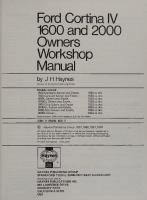
Ford Cortina Ill 1600 & 2000 ohc Owners Workshop Manual * by J H Haynes Meriter of ttre Guid cf Werorng Wrrers
and P G Strasman Models cowered:
Cortima Carting Cartine Cortina Corting Cartine Cortina
SBM ©
©
TG00L & XL Saloom & Estate 1600 GXL Saloon 1600 GT Saicon 20001 & Xi Saicom & Estate 2000 GX Saloon 2008 GT Saicon 2000E Szicom & Estate
ese
225 5
Haynes Pubiisting Group 1976, 1979, 1S1_ 1S8S, 1986, 1987_ Sas
AQ) crqintss nesexwest, ary SasrmarOy any Tearding ar Oy ary m wetting tram tie
Ravres
Sparkford Somerset
Near dart ar tins Doak: may Oe renroducest ar transmittest in mesats; seetrame ar mechameai, inciuding ohatocanving, information Surag= ar retrieve system, without germissian canyrrant Taider.
Publishing
Group
Nin Yeawii BAZIZ Tu
Havnes Publications, Sen Lawrenee Orive Newidurs
England Inc
Fark
Caiifarma& STSZ@
US*
ees
ascne siune
Acknowledgements Thanks are due to the Ford Motor Company for the supply of technical information and certain illustrations, to Duckhams Oils who provided lubrication data, and to the Champion Sparking Plug Company Limited who supplied the illustrations showing the various spark plug conditions.
The section of Chapter 10 dealing with the suppression of radio interference was originated by Mr |. P. Davey, and was first published in Motor magazine. Lastly, thanks are due to all of those people at Sparkford who helped in the production of this manual.
About this manual /ts aims The aim of this book is to help you get the best value from your car, It can do so in two ways. First it can help you decide what work must be done, even should you choose to get it done by a garage, the routine maintenance and the diagnosis and course of action when random faults occur, But it is hoped that you will also use the second and fuller purpose by tackling the work yourself. This can give you the satisfaction of doing the job yourself. On the simpler jobs it may even be quicker than booking the car into a garage and going there twice, to leave and collect it. Perhaps most important, much money can be saved by avoiding the costs a garage must charge to cover labour and overheads. The book has drawings and descriptions to show the function of the various components so that their layout can be understood. Then the tasks are described and photographed in a step-by-step sequence so that even a novice can cope with complicated work. Such a person is the very one to buy a car needing repair yet be unable to afford garage costs. The jobs are described assuming only normal spanners are available, and not special tools unless absolutely necessary. But a reasonable outfit of tools will be a worthwhile investment. Many special workshop tools produced by the makers merely speed the work, and in these cases guidance is given as to how to do the job without them. On a very few occasions a special tool is essential to prevent damage to components, then their use is
described. Though it might be possible to borrow the tool, such work may have to be entrusted to the official agent. To avoid labour costs a garage will often give a cheaper repair by fitting a reconditioned assembly. The home mechanic can be
helped by this book to diagnose the fault and make a repair using only a minor spare part. The manufacturer's official workshop manuals are written for
their trained staff, and so assume special knowledge; therefore detail is left out. This book is written for the owner, and so goes into detail.
Using the manual The manual is divided into twelve Chapters. Each Chapter is divided into numbered Sections which are headed in bold type
between horizontal lines. Each Section consists of serially numbered paragraphs.
There are two types of illustration: (1) Figures which are numbered according to Chapter and sequence of occurrence in
that Chapter. (2) Photographs which have a reference number in their caption. All photographs apply to the Chapter in which they occur so that the reference figure pinpoints the pertinent Section and paragraph number. Procedures, once described in the text, are not normally repeated. If it is necessary to refer to another Chapter the reference will be given in Chapter number and Section number thus: Chapter 1/16. Cross-references given without use of the word ‘Chapter’ apply to Section and/or paragraphs in the same Chapter, eg, ‘see Section 8’ means also ‘in this Chapter’. When the left or right side of the car is mentioned it is as if One is seated in the drivers seat looking forward.
Whilst every care is taken to ensure that the information in this manual is correct no liability can be accepted by the authors or publishers for loss, damage or injury caused by any errors in, or omissions from, the information given.
Chapter
Section
Introductory sections
Routine maintenance Buying spare parts
7 11.
Recommended lubricants Lubrication chart
12 12
1
Removal Dismantling
19 20
Reassembly ~=Refitting gearbox
36 46
Examination and renovation
34
Replacement
48
Decarbonization
36
Fault diagnosis
53
Draining; flushing; filling
57 ~—~Fan belt adjustment
61
Radiator
57
~Antifreeze
62
Carburettor (Ford downdraught) Carburettor (Weber dual barrel) Emission control system
68 73 77
Spark plugs
89
2
Engine
Cooling system
3 Carburation; fuel and emission control systems
4
5
Ignition system
Clutch
6 Manual gearbox and automatic transmission
Page
Air cleaner Fuel pump Fuel tank
‘64 65 67
Section
Page
Contact breaker points
82
Distributor (Bosch) Distributor (Ford)
84 85
Ignition timing =‘Fault diagnosis
89 90
Removal Dismantling
92 93
Installation Fault diagnosis
94 95
Manual gearbox Removal and installation Dismantling Inspection Reassembly
99 100 104 106
Removal and installation
118
Universal joints
121
Centre bearing
119
Fault diagnosis
121
Removal and installation
123
Axle-shaft
125
Drive pinion oil seal
125
Pinion drive angle adjustment
127
Bleeding the system Flexible hose Front brakes Rear brakes
130 130 130 133
Handbrake adjustment Master cylinder Vacuum servo Fault diagnosis
137 138 140 143
Battery Alternator Starter motor Windscreen wipers
Voltage regulator Direction indicators Radios and tape players Fault diagnosis Wiring diagrams
156 160 163 166
Headlight alignment
145 146 149 152 154
11 Suspension and steering
Front hubs Front suspension Rear suspension
181 182 187
Steering column Rack and pinion gear Fault diagnosis
191 193 201
12 Bodywork and fittings
Maintenance Repairs
198 198
Replacing windscreen Heater
200 214
13 Supplement
Introduction Engine Carburation
217 219 219
Gearbox ~=Electrical system
223 235
7
8
9
Propeller shaft
Rear axle
Braking system
10 Electrical system
110 111 115 117
168
249
Safety first!
General repair procedures
Automatic transmission ~=—-Fluid level checking Removal and installation Selector linkage adjustment Fault diagnosis
:
250
Conversion factors
251
Index
25
ND
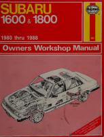
Introduction to the Ford Cortina Mk Ill The Cortina MkIII models were introduced in 1970. All 2000cc models and the 1600GT were fitted with a new overhead-camshaft engine. Other 1300cc/1600cc models of the Cortina MkII! introduced at the same time, retained the overhead valve pushrod engine from the earlier Cortina MkII range, (the Cortina MkIII chv models are the subject of another manual). In September 1973, several changes were made. The ohc engine became a standard fitting in all 1600cc models. Some fairly major modifications were made to the suspension and drive-line of all models and the car interior was redesigned. September 1973 also saw the introduction of the 2000E as
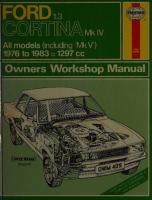
a direct replacement for the 2000 GXL model. An Estate version of the 2000E was introduced in September 1974. Other minor changes to the Cortina III include improved interior trim for the 2O00GT model and similar modifications to ‘L’ models in December 1974. October 1975 saw several further modifications to trim, both interior and exterior, and the standard fitment to all models of such items as servo brakes, heated rear window, hazard flashers, etc. In August 1976 the Cortina Mk II! was discontinued to be superseded by the Mk IV range.
1972 Ford Cortina 2000 GXL (now superseded by 2000E)
ae ee et &
1973 Ford Cortina 2000 E saloon
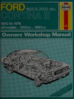
1973 Ford Cortina XL 1600 2-door saloon
x
a
ee
RRR
Routine maintenance safety and desirable for Maintenance is essential for ensuring performance and the purpose of getting the best in terms of the need for periodic economy from your car. Over the years has been drastically lubrication - oiling, greasing and so on has unfortunately tended reduced if not totally eliminated. This no such action is to lead some owners to think that because or will last required, components either no longer exist, therefore that the for ever. This is a serious delusion. It follows visual examination. largest initial element of maintenance is but should help avoid breakThis may lead to repairs or renewals, downs. safety’ items are In the summary given here the ‘essential for d to at the regular shown in bold type. They must be attendé
ity of accidents frequencies shown in order to avoid the possibil lity, increased unreliabi in results neglect Other life. of loss and depreciation of rapid more and wear rapid more costs, running the vehicle in general.
eee
ae
first Every 250 miles (400 km) or weekly - whichever comes
Examine tyres for wear or damage. Is steering smooth and accurate?
Brakes Check reservoir fluid level.
Is there any fall off in braking efficiency?
Try an emergency stop.
Lights, wipers and horns
Do all bulbs work at the front and rear? Are the headlamp beams aligned properly?
Do the wipers and horns work?
Check windshield washer fluid level.
Engine
required. Check the engine oil level and top-up if if required. Check the radiator coolant level and top-up top-up to the level of Check the battery electrolyte level and
the separators with distilled water.
Steering Check the tyre pressures.
Removing radiator cap
Checking battery electrolyte level
8
Routine maintenance er s renner ee —— ee Lubricate door hinges, locks At the first 3000 miles (4800 km) only
er
Renew the engine oil. —
Every 6000 miles (9600 km)
esses Check tension of alternator drivebelt. Clean fuel pump filter. Check wear in disc pads. Check rear brake shoe lining wear. Renew engine oil and filter. Check fluid level in brake master cylinder and top-up as necessary. Check transmission oil level and top-up if necessary. Check rear axle oil level and top-up if necessary. Check and adjust the clutch cable free movement. Inspect steering and suspension components for wear. Check and adjust valve clearances. With rocker cover removed, remove distributor rotor and crank engine on starter motor. Check that oil is discharged from the lubrication tube nozzles onto the cam followers. Clean and re-gap spark plugs. Inspect brake lines and flexible hoses for damage or deterioration. Check exhaust system for leaks or broken mountings. Check carburettor adjustment. Change position of roadwheels to even out tyre wear, if wished.
etc. Clean crankcase ventilation P.V.C. valve.
Every 12000 miles (1900 km)
OO Check distributor contact points and renew if necessar y. Renew spark plugs. Renew fuel evaporative emission control carbon canister filter
(where fitted).
Check ignition timing. Check front wheel alignment
Every 18000 miles (29000 km) Renew air cleaner element. _-__eooooo
Every 24000 miles (38000 km) or at two yearly intervals eee Drain cooling system and refill with ‘long-life’ type antifreeze mixture. Clean, repack with grease and adjust front wheel bearings.
oo eeeeeeeeeeesSe Every 36000 miles (58000 km) ee Bleed hydraulic system, renew all system seals and refill with clean, fresh fluid. Remove plugs and grease front suspension upper swivel
balljoints.
Cleaning fuel pump filter
Manual gearbox filler and drain plug Topping-up engine oil
é
Greasing front suspension upper swivel balljoint
Jacking and Towing
ees Jacking points To change a wheel in an emergency, use the jack supplied with the vehicle. Ensure that the roadwheel nuts are released before jacking-up the car and make sure that the arm of the jack is fully engaged with the body bracket and that the base of the jack is standing on a firm level surface. The jack supplied with the vehicle is not suitable for use when raising the vehicle for maintenance or repair operations. For this work, use a trolley, hydraulic or screw type jack located under the front crossmember, bodyframe side-members or rear axle casing, as illustrated. Always supplement the jack with axle stands or blocks before crawling beneath the car.
Front jacking Rear jacking point point Jacking points (for use only with jack supplied with
Towing points
vehicle)
If your vehicle is being towed, make sure that the tow rope is attached to a towing eye or the front crossmember. If the vehicle is equipped with automatic transmission, the distance towed must not exceed 15 miles (24 km), nor the speed 30 mph (48 km/h), otherwise serious damage to the transmission may result. If these limits are likely to be exceeded, disconnect and remove the propeller shaft.
If you are towing another vehicle, attach the tow rope to the lower suspension arm bracket at the axle tube.
Vehicle jacking points (for maintenance and repair
operations)
|
|
VAN rh f\
ee
sy = ZZ
Tow rope attachment to front of vehicle
Loy
=e,
(6 y
Q
GT
Tow rope attachment to rear of vehicle
Quick reference capacities Engine oil capacity: Excluding filter (oil change only) ... With new filter
tp
As
Cooling system: 1600cc 2000cc
see
Fuel tank capacity
5.3 Imp. pints (3.0 litres) ° 6.6 Imp. pints (3.75 litres) Up to 1974
1974 onwards
11.4 Imp. pints (6.5 litres) 12.4 Imp. pints (7.1 litres)
10.0 Imp. pints (5.8 litres) 10.75 Imp. pints (6.1 litres)
11.9 Imp. gals. (54.0 litres)
Gearbox capacity: 1600cc 2000cc
=
a
ee
“A
1.75 Imp. pints (1.00 litres) 2.9 Imp. pints (1.66 litres)
Automatic transmission fluid capacity: Borg-Warner ... Ford Bordeaux
cae xe
SU B,
11.25 Imp. pints (6.4 litres) 10.5 Imp. pints (6.0 litres)
Rear axle capacity: 1.76 Imp. pints (1.0 litre) 1.94 Imp. pints (1.1 litres)
Buying spare parts and vehicle identification numbers home.
Buying spare parts
for example: Spare parts are available from many sources, shops, and motor Ford garages, other garages and accessory is as follows: factors. Our advice regarding spare part sources source of Officially appointed Ford garages - This is the best otherwise not parts which are peculiar to your car and are internal gearbox generally available (eg; complete cylinder heads, the only place components, badges, interior trim etc). It is also is still under warranty at which you should buy parts if your car . To be sure -non-Ford components may invalidate the warranty necessary to give be always will it parts correct the g obtainin of number, and if the storeman your car’s vehicle identification identification. positive for along part ‘old’ the take to possible, exchange Remember that many parts are available on a factory be clean! It obviously scheme - any parts returned should always car makes good sense to go straight to the specialists on your to supply you. for this type of part for they are best equipped often very Other garages and accessory shops - These are needed for the good places to buy materials and components bulbs, fan maintenance of your car (eg; oil filters, spark plugs, paste, etc). They belts, oils and greases, touch-up paint, filler nt opening also sell general accessories, usually have convenie
Motor factors - Good factors will stock all of the more (eg; important components which wear out relatively quickly clutch components, pistons, valves, exhaust systems, brake
cylinders/pipes/hoses/seals/shoes and pads etc). Motor factors
part will often provide new or reconditioned components on a exchange basis - this can save a considerable amount of money.
Vehicle identification numbers Although many individual parts, and in some cases sub-
assemblies, fit a number of different models it is dangerous to assume that just because they look the same, they are the same.
Differences are not always easy to detect except by serial numbers. Make sure therefore, that the appropriate identity number for the model or sub-assembly is known and quoted when a spare part is ordered.
The vehicle identification plate is mounted on the right-hand
side of the front body panel and many be seen once the bonnet is open. Record the numbers from your car on the blank spaces of the accompanying illustration. You can then take the manual
with you when buying parts; also the exploded drawings the throughout the manual can be used to point out and identify components required.
not far from hours, charge lower prices and can often be found
FORD MOTOR CO. LTD. LONDON ENGLAND.
Typ/Type
Version
Fahrgestell/Vehicle
No.
hinten Zul. Gesamtgew. Zul.Achslast Vorn Zul. Achslast Axle Ld.Rear C)) @) ross Vehicle Wat. Perm.Axle ld. Front Perm.
Lenk Drive
Motor Getr. Achse EngineTrans. Axle
Farbe
Colour
Polst
Trim
K.D.
Bremsen
Ref.
Brakes
alias aeolian BS. AU48:1965
|
ered |
Vehicle identification plate and location
12
iat al
NA
1
TT
—6
har aoestill KS
Aw
d)
A uy 5
\
Recommended
3
lubricants
Component
Castrol Product
1
Engine
2
Gearbox (manual)...
3
Gearbox (automatic):
te
Par
Borg-Warner Bordeaux
ait
ears
re
=$
er ob
£5
ay
oe
Castrol GTX
=
i
as
A,
Castrol Hypoy Light (80 EP)
wi ae
ase =
a oe
ae es.
ar bes
Ford auto trans fluid M-2C33F (Castro! TOF) Ford auto trans fluid SQ-M2C-9007-AA (Castrol TOF)
4
Rear axle (differential)
a
pe
tis
=
a
2
Castrol Hypoy B (90 EP)
5
Front wheel bearings
oa
dea
a
acto
PRaed
=e
Castrol LM Grease
6
Steering
=
ous
ak
wis
ae
sus
Castrol Hypoy B (90 EP)
i
oe
Note: The above are general recommendations. Lubrication requirements vary from territory-to-territory and Gepend on-the usage to which the vehicle is put - consult the operators handbook supplied with your car.
Chapter 1 Engine Contents
es Oe
ie
oe
ek
ee
ES
41
Engine - reassembly general
Auxiliary shaft -removal ; Auxiliary shaft and timing cover - refitting Cam followers- refitting Cam followers - examination Camshaft - installation ...
Engine/gearbox - reconnecting Engine - installation (with gearbox)
Engine - installation (without gearbox)
Camshaft -removal Camshaft and camshaft bearings’ examination andis renovation Camshaft drivebelt - refitting and timing Camshaft drivebelt - removal, engine in car Camshaft drivebelt tensioner and thermostat housing - rofitting Connecting rods and gudgeon pins - examination and renovation Pe Connecting rods to crankshaft -vreessernbly ae Crankshaft and main bearings -removal Crankshaft rear oil seal - installation Crankshaft -examination and renovation Crankshaft, main and big-end bearings- exarnination. ‘and
renovation en Crankshaft pulley, sprocket and ‘timing. cover -reaigit as Crankshaft - installation Crankshaft sprocket and pulley ‘and auxiliaryshaft oy sprocket- refitting Cylinder bores -examination and concniatiion|
Cylinder head - removal (engine in car) Cylinder head -removal (engine on bench) Cylinder head- refitting : ee .« Cylinder head and piston erowns decarbonization Engine dismantling -general Engine removal with gearbox Engine removal without gearbox Engine removal without automatic transmission Engine -removing ancillary components Engine components - examination for wear ...
Engine - initial start-up after major overhaul or repair Fault diagnosis -engine.. Flywheel and sump - removal aa ite Flywheel ring gear- examination and renovation Flywheel and clutch - refitting General description Gudgeon pin- removal ... Lubrication and crankcase ventilation avsiens, ... Major operations possible with the engine in place Major operations requiring engine removal Methods of engine removal Oil filter -removal and refitting 3 Oil pump and strainer- removal Oil pump- dismantling, inspection and Se eearably. Oil pump- refitting Ae Pistons - installation Pistons and connecting rods - reassembly Piston rings - removal Piston rings - installation ; Pistons, connecting rods and big-end bearingsremoval Pistons and piston rings - inspection and testing
Sump - inspection be ie Sump - installation Thermostat housing and belt tensioner >- removal Timing gears and belt -examination and renovation Valves - refitting Valves -removal Valve guides - inspection ap ae 3 Valve clearances -checking and adjustment ea Valves and valve seats -examination and renovation
Water pump - refitting
...
Specifications
Engine (general) Engine type Firing order
...
Bore
Four in-line, single overhead camshaft } e ve Re ay TAs
... ...
ti
a
Pe
1600 cc 3.451 in. (87.65 mm)
*,
2.6 in. (66.00 mm) 1593 cc (97.2 cu in.)
Stroke Cubic capacity
Compression ratio sas Maximum continuous onalne ‘speed (rpm) Engine bhp (DIN); Standard
GT Max. torque (DIN): Standard
GT
.
ise
a
es
Sie
ee
x
ta
ie
os
2000 cc
3.575 in. (90.8 mm) 3.03 in. (76.95 mm) 1993 cc (115.9 cu in.)
9.2:1 6300
5850
72 @ 5500 rpm 88 @ 5700 rpm
98 @ 5500 rpm
86 |b/ft @ 2700 rpm 91 |b/ft @ 4000 rpm
111 Ib/ft @ 3500 rpm
61 62 63 64 65 13 37 53 1
22 24 2
3
4
26 14 25 47
45 43 23 44 16 31 40 50 21 36 54 19
39 60 35 52
14
Chapter 1/Engine
OO
eee
Cylinder block Cast identification marks Number of main bearings Cylinder bore dia. grades: Standard grade: 1 wi 2 3 4 ae Oversize A Oversize B Oversize C eee os Standard supp. in service Oversize 0.5 : i Oversize 1.0 ee a
Spigot bearing length in (mm) Main bearing liners fitted: Inner diameter: Standard:
RED in (mm) BLUE in (mm)
1600 (all models)
2000 (all models) 20 5
16 5 inches 3.4508—3.4512 3.4512—3.4516 3.4516—3.4520 3.4520—3.4524 3.4709—3.4713 3.4713—3.4717 3.4717—3.4720 3.4520—3.4524 3.4717—3.4720 3.4913—3.4917
mm (87.650—87.660) (87.660-—-87.670)
(87.670—87.680)
inches 3.5748—3.5752 3.5752—3.5756 3.5756—3.5760 3.5760—3.5764 3.5949--3.5953 3.5953—3.5957 3.5957—3.5961 3.5760--3.5764 3.5957—3.5961 3.6154—3.6157
(87.680—87.690) (88.160—88.170) (88.170—88.180) (88.180—88.190) (87.680—87.690) (88.180—88.190) (88.680—88.690) 1.072—1.070 (27.22—27.17)
2.2446—2.2456 (57.014—57.038) 2.2442—2.2452 (57.004—57.028)
Crankshaft: Undersize:
0.25 RED in (mm) BLUE in (mm) 0.50 in (mm) 0.75 in (mm) 1.00 in (mm) Main bearing parent bore dia:
RED in (mm) BLUE in (mm)
2.2348—2.2357 2.2344--2.2354 2.2250—2.2263 2.2151—2.2164 2.2053—2.2066
(56.764—56.788) (56.754—56.778) (56.514—-56.548) (56.264—56.298) (56.014—56.048)
2.3866—2.3870 (60.620—60.630) 2.3870—2.3874 (60.630—60.640)
Crankshaft Endfloat in (mm)
rae
Main bearing journal diameters: Standard:
RED in (mm) BLUE in (mm) Undersize:
0.25 0.50 0.75 1.00
in in in in
(mm) (mm) (mm) (mm)
Thrust washer thickness:
Standard in (mm) Undersize in (mm) : Main bearing clearance in (mm) Crankpin journal diameter: Standard:
RED in (mm) BLUE in (mm) Undersize:
0.25 0.25 0.50 0.75
REDin(mm) . BLUE in (mm) in (mm) in (mm)
0.0032—0.0110 (0.08—0.28) 2.2441—2.2437 (57.000—56.990) 2.2437—2.2433 (56.990—56.980)
2.2338—2.2335 2.2244—2.2240 2.2146—2.2142 2.2047—2.2043
(56.740—56.730) (56.500—56.490) (56.250—56.240) (56.000—55.990)
0.091—0.0925 (2.3—2.35) 0.098—0.100 (2.5—2.55) 0.0005—0.0019 (0.014—0.048)
2.0472—2.0468 (52.000—51.990) 2.0468—2.0465 (51.990—51.980) 2.0374—2.0370 2.0370—2.0366 2.0276—2.0272 2.0177--2.0173
(51.750—51.740) (51.740—51.730) (51.500—51.490) (51.250—51.240)
Camshaft Drive ... ae 72 Thrust plate thickness:
Type
1in (mm)
...
Type 2in (mm)
...
Width of camshaft groove in (mm)
Toothed belt
0.158 (4.01) 0.157 (3.98) +0.0028 ( +0.070) 0.1600 —0.0000 (4.064 —0.000)
Cam lift in (mm) ie oe: Cam heel to toe dimensions in (mm)
1600 0.2338 (5.938) 1.418—1.412 (36.01—35.87)
Cam lift in (mm) oe BS Cam heel to toe dimensions in (mm)
1600 GT and 2000 0.2518 (6.397) 1.435—1.430 (36.46—36.32)
mm (90.800—90.810) (90.810—90.820) (90.820-—-90.830) (90.830—90.840) (91.310—91.320) (91.320—91.330) (91.330--91.340) (90.830—90.840) (91.330—91.340) (91.830—91.840)
15
Chapter 1/Engine Journal diameter (all models): : Front in (mm) Centre in (mm) ... ie Rearin(mm) — ... es Bearing - inside diameter (all models): ‘ as Front in (mm) Centre in (mm) ... Rearin(mm)
_ ...
1.6539—1.6531 (42.01—41.99) 1.7606—1.7528 (44.72—44.52) 1.7720—1.7713 (45.01—44.99) 1.6557—1.6549 (42.055—42.035) 1.7588—1.7580 (44.675—44.655) 1.7738—1.7730 (45.055—45.035) 0.002—0.0035 (0.05—0.09) White (1600) Yellow (1600 GT/2000)
3S
Camshaft endfloat in (mm) Identification colour
2000 (all models)
1600 (all models)
Pistons Piston diameter: Standard:
Grade 1 in (mm) 2 in (mm) 3 in (mm) 4in (mm) Standard supplied in service in (mm) ... Oversize supplied in service:
0.5in(mm) 1.0in (mm)
3.4490—3.4494 3.4494—3.4498 3.4498—3.4502 3.4502--3.4506 3.4500—3.4510
(87.605—87.615) (87.615—87.625) (87.625—87.635) (87.635—87.645) (87.630—87.655)
3.4697—3.4707 (88.130—88.155) 3.4894—3.4904 (88.630—88.655)
... ...
3.5730—3.5734 3.5734—3.5738 3.5738—3.5742 3.5742—3.5746 3.5740—3.5750
(90.755—90.765) (90.765—90.775) (90.775—90.785) (90.785—90.795) (90.780—90.805)
3.5937—3.5947 (91.280—91.305) 3.6134—3.6144 (91.780—91.805)
1600 and 2000 (all models)
Piston clearance in cylinder bore in (mm) Ring gap (in situ): Top in (mm) Centre in (mm) ... Bottom in (mm)
0.001—0.0024 (0.025—0.060)
Ring gap position:
450° from one side of the helical expander gap 150° from the side opposite the helical expander gap Top mark towards piston crown front side Helical expander: opposite the marked piston
Top Centre
0.015—0.023 (0.38—0.58) 0.015—0.023 (0.38—0.58) 0.0157—0.055 (0.4—1.4)
expander Intermediate rings: 1 in (25 mm) each side of helical
Bottom
gap Gudgeon pins
2.83—2.87 (72—72.8)
Length in (mm) Diameter:
0.94465—0.94476 (23.994—23.997) 0.94476—0.94488 (23.997—24.000) 0.94488—0.94500 (24.000—24.003) 0.0002—0.00043 (0.005—0.011) 0.0007—0.00153 (0.018—0.039)
RED in (mm) BLUE in (mm) YELLOW
in (mm)
Ses
at
Interference fit in piston in (mm) ... Clearance in small end bush in (mm)
Connecting rods Big end bore: RED in (mm)
oc ws BLUEin (mm)... Small end bush diameter in (mm) ... Inside diameter: Standard: RED in (mm)
2.0478—2.0487 (52.014—52.038) 2.0474—2.0483 (52.004—52.028)
BLUE in (mm) Undersize: 0.25 RED in (mm) ... 0.25 BLUE in (mm)
0.50 in (mm) 0.75 in (mm)
1.00 in (mm)
a
_
Crankpin to bearing liner clearance:
Standard in (mm) Undersize in (mm)
Cylinder head Cast identification number
2.1653—2.1657 (55.00—55.01) 2.1657—2.1661 (55.01—55.02) 0.9434—0.9439 (23.964—23.976)
a
2.0379—2.0388 2.0376—2.0385 2.0281—2.0294 2.0183—2.0196 2.0084—2.0100
(51.764—51.788) (51.754—51.778) (51.514—51.548) (51.264—51.298) (51.014—51.048)
0.00055—0.0018 (0.014—0.048) 0.00055—0.0023 (0.014—0.058) 1600 models
2000 models
6
0
1600 and 2000 (all models) Valve seat angle
44° 30’—45°
16
Chapter 1/Engine
RL
ee
Valve guide inside diameter, inlet and exhaust:
Standard in (mm)
a
3
0.3174—0.3184 (8.063—8.088)
Oversize:
0.2in({mm) 0.4in (mm)
... ...
0.3253—0.3263 (8.263—8.288) 0.3332—0.3342 (8.463—8.488)
Ss
Parent bore for camshaft bearing liners:
Frontin(mm) Centre in (mm) Rear in (mm)
. ...
a
1.6557—1.6549 (42.055—42.035) 1.7589—1.7580 (44.675—44.655) 1.7738—1.7730 (45.055—45.035)
Valves
1600 and 2000 (all models)
Valve clearances (cold):
Inlet in (mmy
0.008 0.010
Exhaust in (mm)
(0.20) (0.25)
1600 models 16° BTDC 60° ABDC 58° BBDC 18° ATDC
Inlet opens Inlet closes Exhaust opens Exhaust closes
Inlet valve Length in (mm)
1600 GT and 2000 models 18° BTDC 70° ABDC 64° BBDC 24° ATDC
1600 models 4449+ 1.516+
Valve head diameter in (mm) Valve stem diameter:
Standard in (mm)
4.3760 (111.15) 1.654+ 0.008 (42+ 0.2)
0.3167—0.3159 (8.043—8.025)
Oversize:
0.2in (mm)... 0.4 in (mm) Valve stem to guide clearance iin (mn) Valve lift in (mm)
1600 GT and 2000 models
0.016 (113+ 0.4) 0.008 (38.5+ 0.2)
0.3245—0.3238 (8.243—8.225) 0.3324—0.3317 (8.443—8.425) 0.0008—0.0025 (0.020—0.063)
".. 0.3730 (9.474)
0.3993 (10.142)
Valve spring free-length in (mm)
1600 and 2000 (all models) 1.73 (44)
Spring load, valve open Ib (kp)
1600 models 169.4+ 6.6(77+
68+ 4(31+ - 0.945 (24)
Exhaust valves
2)
1600 models 4.449+ 0.19 (113+
Length in (mm) 1600
1.18+ 0.08(30+
1600 GT and 2000 models 4.37+ 0.19 (111+ 0.5)
0.5)
1600 GT 1.34+ 0.08 (34+ 0.2)
02)
2000 1.42+ 0.08 (36+ 0.2)
1600 and 2000 (all models)
Valve stem diameter:
Standard in (mm
0.3156—0.3149 (8.017—7.999)
Oversize:
0.2in (mm) 0.4in(mm)
3)
1600 and 2000 (all models)
Spring load, valve closed Ib (kp)
Spring length, compressed in (mm)
Valve head diameter in (mm)
2000 models 176+ 6(80+
3)
... ...
Valve stem to guide clearance'iin enirdh
0.3235—0.3228 (8.217—8.199) 0.3314—0.3307 (8.417—8.399) 0.0034—0.0035 (0.086—0.089)
Valve lift in (mm)
1600 0.3728 (9.47)
Valve spring free length in (mm)
1600 and 2000 (all models) 1.732 (44)
Spring load, valve open Ib (kp) Spring load, valve closed Ib (kp) Spring length, compressed in (mm)
1600 models
170+
6(77+
Oil change without renewal of filter. imp. pints (litres)
2000 models
3)
1600 and 2000 (al! models) 68.3+ 4.4(31+4 2) 0.95 (24)
Engine lubrication data (all models) Oil change with renewal of filter. Imp. pints (litres)
1600 GT and 2000 0.3992 (10.14)
5.3 (3.0) 6.6 (3.75)
176+
6(80+
3)
=
17
Chapter 1/Engine
e 4) a Minimum oil pressure:
At 700 rpm lb fin2 (kpfem) At1,500epenIbfin (per Relief velve opens atIbf in? (kp/em?)
16 (1.1)
ois,
ghora d-9
tele s
~
aes
_
Oil pume outer rotor and housing clearance in (mm) te mae
Inner and outer rotor clearance in (mm) ... Inner snd outer rotor endflost in (mm) -.
Torque wrench settings Main besring
Oil pump
=
36 (2.5) 57-67 (4.0—4.7) 0.006—0.012 (0.15—0.30) 0.002—0.008 (0.05—0.20) 0.0012—0.004 (0.03—0.10)
aed a4 oe
Ib f ft
caps).
=4
we
ce
sac
=
ae
aes
{
f
{
ie ed f 3
is
{ |i
f a
f
f
f
f
Second stage
2
nee
i
=
aa
= ae Third stage (sfter20 mins weit) Fourth stsge (after warming engine at 1000 rpm e me ate o~ .. foriSmins}
Rocker cover: ist to 6th
athe
7th to Sth bolt .. Sth and 10th bolt 7th and Sth bolt
Sperk plugs . 1
-
~~
=
ue
... (Sequence (1))
—
~~
a
—
~
_—
~
—
=
f a Tt a teak
(2) (3) (4)
General description
are of the Engines fitted to models covered by the menusl e in two four cylinder overhead camsheft design and aveilabl identifying especities, 1600 cc and 2000 ce. An exploded view
the mein comeonents is shown in Fig. AA
inlet The cylinder head is ofthe crossfiow design with the
the other. Asfiat manifold one side and the exhaust manifold on are contained in top pistons are used the combustion chambers
the cylinder hesd.
made of cast The combined crankesse and cylinder block is
to the ~ ipo and houses the pistons and crankshaft. Attached which acts 8s&
underside of the crankesse is8 pressed steel sump lubricating reservoir for the engine oil. Full informstion on the system will be found in Section 24. the The cast iron cylinder head is mounted on top of camshaft. cylinder block and acts ss@ support for the overhead cylinder hesd The slightly sngied velves operate directly in the s. The camand ere controlled by the camshaft vie cam follower e rubber belt shaft isopersted by s toothed reinforced composit slackness from the crankshaft. To eliminate beckissh and prevent of 3 jockey of the belt s spring losded tensioner in the form
two whee! is in contact with the beck of the belt. It serves
weter pumMe further functions, to keep the belt awey from the and crankand also toincrease the contact area of the camshaft sheft sprocket. and itis The drive belt also drives the balance shaft sprocket fuel pump from this shaft that the oil pump, distributor and
kg fm
645-745 46.5—50.9 12-15 64-3.3
9.0—-10.4 65—7.1 17-21 0.9-1.3
07-14 43-57 43-57 15-20
0.1—0.2 06-08 0.6-0.8 2.1-28
15 to 30 36 to 51 54 to 61
2.1 to 4.1 5.0 to 7.0 75to 84
70 to 85
9.7 to
3.65.0 14-18 3.6—-5.0 3.6—-5.0 14.3—20
0.5—0.7 0.2—-0.25 0.5—0.7 0.5—0.7 2.0-2.8
117
pin, are fitted. d the gudgeon ate above one scraper ring, all loc and endfloat The forged crankshaft runs in five main bearings of the is accommodated by fitting thrust weshers either side tre cen main bearing. refer Before commencing any overhaul work on the engine tools that to Section 8, where information is given sbout special r are required to remove the cylinder head drive belt tensione and oil pump.
a
2 Major operations possible with engine in place to the The following major operations can be carried out engine with it in place: and replacement of camshaft Removal Removal and replacement ofcylinder head Removal and replacement of camshaft drivebelt Removal and replacement of balance shaft gs Removal and replacement of engine front mountin OhwWh
i 3
Major operations requiring engine removal
be carried out with the The following major operations can bench or floor: the on frame body the of out e engin bearings Removal and replacement of the main and replacement of the crankshaft Removal el Removal and replacement of the flywhe haft rear oil seal Removal and replacement of the cranks pump af oilnt Removal and replaceme sump ent of Removal and replacem gs Removel and replacement of big end bearin connecting rods mm he Oo te OF Co Removal and replacement of pistons and
i 4 Methods of engine removal right-hand side of The exhaust manifold ismounted on the pe and silencer downpi single 8 to ts connec and head er the cylind aft by ‘Alurninium alloy pistons are connected to the cranksh The pins. gudgeon and rods ing connect steel forged “Wy section the connecting rod queigeon pin is8 press fitinthe small end of rings and but 2 flosting fitin the piston boss. Two compression
in unit The engine may be lifted out either on its own or
sion with the gearbox. On models fitted with automatic transmis
it is recommended that the engine be lifted out on its own,
;
, because unless 8 substantial crane or overhead hoist isavailable 8s 8 of the weight factor. if the engine and gearbox are removed make sure so angle, steep very @ at out lifted be to have they unit
18
Fig. 1.1. Exploded view of the engine
1 2 2
Timing cover Cam follower arm Spring
4 5
Crankshaft front cover Auxiliary shaft front cover
6 7 8 9
Retaining plate Auxiliary shaft Crankshaft thrust plate Crankcase ventilation valve
10 17 12
Oil separator Crankshaft rear oil seal Thrust washers
De
ee
ignition coil. 411 Detach the HT lead from the centre of the compartment. Remove the distributor cap from the engine cooling system. 12 Refer to Chapter 2, Section 2, and drain the to the water 13 Slacken the clip that secures the heater hose pump. Pull off the hose.
available. that there is sufficient lifting height nL 5 Engine removal with gearbox
1 The do-it-yourself owner should be able to remove the power unit fairly easily in about 4 hours. It is essential to have a good hoist and two axle stands if an inspection pit is not available. 2 The sequence of operations listed in this Section is not critical as the position of the person undertaking the work, or the tool in his hand, will determine to a certain extent the order in which the work is tackled. Obviously the power unit cannot be removed until everything is disconnected from it and the following sequence will ensure that nothing is forgotten. 3 Open the bonnet and using a soft pencil mark the outline position of both the hinges at the bonnet to act as a datum for refitting. 4 With the help of a second person to take the weight of the bonnet undo and remove the hinge to bonnet securing bolts with plain and spring washers. There are two bolts to each hinge. _Lift away the bonnet and put in a safe place where it will 5 not be scratched. Remove the battery as described in Chapter 10, Section 2. 6 Place a container having a capacity of at least 8 Imp. pints
(4.55 litres) under the engine sump and remove the oil drain
plug. Allow the oil to drain out and then refit the plug. Refer to Chapter 3, Section 2, and remove the air cleaner 7 assembly from the top of the carburettor. 8 Mark the HT leads so that they may be refitted in their original positions and detach from the spark plugs. Release the HT lead rubber moulding from the clip on the 9 top of the cover.
10 Spring back the clips securing the distributor cap to the distributor body. Lift off the distributor cap.
) 5.18 Detaching throttle cable from operating rod
19
Chapter 1/Engine
the heater 14 Slacken the clip that secures the heater hose to unit. Pull off the hose. c 15 Slacken the clips that secure the hoses to the automati choke and pull off the two hoses. the adaptor 16 Slacken the clip securing the water hose to off the hose. elbow on the side of the inlet manifold and pull to the 17 Slacken the clip that secures the fuel feed pipe Plug the end to carburettor float chamber and pull off the hose. stop dirt ingress or fuel loss due to syphoning. the operating 18 Detach the throttle control inner cable from
rod (photo).
nut and 19 Unscrew the throttle control outer cable securing detach the cable from the mounting bracket (photo). on the side 20 Detach the vacuum pipe from the vacuum unit
of the distributor (photo).
secure the 21 Undo and remove the four nuts and washers that the carburettor carburettor to the inlet manifold. Carefully lift up and away from the studs on the manifold. may now be 22 The combined insulation spacer and gasket FRONT’ and lifted from the studs. Note that it is marked ‘TOP it must be refitted the correct way round. branch 23 Slacken the clip securing the hose to the manifold pipe adaptor and pull off the hose. at the 24 Slacken the clip securing the hose to the adaptor centre of the manifold and pull off the hose. the 25 Undo and remove the self lock nuts and bolts securing inlet manifold to the side of the cylinder head. retains the 26 Note that one of the manifold securing bolts also
air cleaner support bracket (photo). 27 Lift away the inlet manifold (photo).
we
P
5.19 Detaching throttle cable assembly from mounting bracket
5.20 Detaching vacuum pipe from distributor
~~ Nee x
5.26 Air cleaner support bracket retained by one manifold bolt
"5.27 Lifting away inlet manifold
5.33 Crankcase ventilation valve removal
20
Chapter 1/Engine
eee 28 Carefully lift away the inlet manifold gasket. 29 Undo and remove the two nuts that secure the exhaust downpipe clamp plate to the exhaust manifold.
housing. On some models it will be necessary to pull back the rubber gaiter first. 61 Pull the clutch cable assembly through the locating hole in the flange on the clutch housing. 62 Suitably support the weight of the gearbox by using either a jack or an axle stand. Using a rope sling passed under the engine
30 Slide the clamp plate down the exhaust pipe. 31 Refer to Chapter 2, Section 5, and remove the radiator. 32 Detach the thermal transmitter electric cable from the inlet manifold side of the cylinder head. 33 Pull the crankcase ventilation valve and hose from the oil separator located on the left-hand side of the cylinder block
mountings support the weight of the engine (photo).
63 Undo and remove the one bolt that secures the rubber mountings to the gearbox extension housing. 64 Undo and remove the four bolts, spring and plain washers that secure the gearbox support crossmember to the body. Lift away the crossmember. 65 Undo and remove the two engine mountings lower securing nut and large plain washer. 66 Check that no electric cables or controls have been left connected and are tucked well out of the way. 67 The complete unit may now be removed from the car. Commence by removing the support from the rear of the gearbox and carefully lower the end to the ground. It will be beneficial if a piece of wood planking is placed between the end of the gearbox and the floor so that it can act as a skid. 68 Carefully raise the engine and pull slightly forward. It will now be necessary to tilt the engine at a very steep angle so that the sump clears the front grille panels. Continue to raise the
(photo).
34 Detach the oil pressure warning light cable from the switch located below the oil separator. 35 Detach the Lucar terminal connector from the starter motor
solenoid (photo). Also detach the terminal connector from the rear of the alternator. If tight a screwdriver will be of assistance. 36 Make a note of the electrical cable connections on the rear
of the starter motor solenoid and detach the cables (photos). 37 Undo and remove the distributor clamp bolt and clamp
(photo). Lift away the distributor.
38 Undo and remove the bolt that secures the cable terminal to the engine just in front of the fuel pump (photo). 39 Undo and remove the two bolts and spring washers that
secure the fuel pump to the cylinder block (photo). 40 Place the fuel pump on the battery tray (photo). Withdraw
the pump operating rod from the cylinder block and putina safe place. 41 Slacken the alternator securing bolts and push the alternator towards the engine. Lift away the fan belt. 42 Undo and remove the four bolts that secure the fan pulley to the water pump pulley hub. Lift away the fan and pulley
engine until the sump is just above the front panel (photos).
69 A second person should now lift the rear of the gearbox Over the front panel, and when all is clear lower the unit to the floor. 70 Thoroughly wash the exterior with paraffin or water soluble cleaner. Wash off with a strong water jet and dry thoroughly. 71 The gearbox may now be separated from the engine. Undo and remove the bolts that secure the starter motor to the bellhousing flange. Lift away the starter motor. 72 Remove the rear engine cover plate and bracket assembly from the clutch housing. 73 Undo and remove the remaining bolts that secure the clutch bell housing to the rear of the engine. The gearbox may now be parted from the engine. DO NOT allow the weight of the gear-
(photo).
43 Working under the car slacken the exhaust downpipe to ; silencer clamp. 44 Detach the exhaust pipe rubber mounting from the body mounted bracket and pull the exhaust system to one side to give
better access. Tie in position with string or wire (photo). 45 Models fitted with centre console proceed to paragraph 49; otherwise as follows: 46 Carefully ease the gearchange lever gaiter from the body
panel and slide it up the gearlever. : 47 Using a screwdriver bend back the locking tabs on the lock ring and carefully unscrew the lock ring and gearchange lever retainer. 48 The gearchange lever can now be lifted upwards and away from the gearbox. 49 Models fitted with centre console: Undo and remove the screws that secure the parcel tray and lift away the parcel tray. 50 Unlock the nut located at the base of the gearchange lever knob. Unscrew the gearchange lever knob and locknut. 51 Undo and remove the centre console and instrument cluster mounting screws. 52 Move the console unit until it is possible to gain access to the rear of the instrument cluster. Make a note of the electrical cable connections and detach from the rear of the instruments. 53 Undo and remove the centre bolt from the handbrake lever compensator and pull the lever handle fully up. The console unit may now be lifted away from inside the car. 54 All models: Mark the mating flanges of the propeller shaft and final drive so that they may be reconnected in their original Positions and undo and remove the four securing bolts. 55 Where a split type propeller shaft is fitted, undo and remove the centre bearing retainer securing bolts, spring and plain washers. 56 Wrap some polythene around the end of the gearbox and secure with string or wire to stop oil running out.. 57 Pull off the plug attached to the reverse light switch located on the side of the remote control housing. 58 Using a pair of circlip pliers remove the circlip retaining the speedometer drive cable end to the gearbox extension housing. 59 Pull the speedometer drive cable away from the side of the extension housing. 60 Using a pair of pliers detach the clutch operating cable from the actuating arm that protrudes from the side of the clutch
box to hang on the input shaft (first motion shaft),
SEE e SSRI e ee ee ee 6 Engine removal without gearbox ee ee eee 1 Follow the instructions given in Section 5, Paragraphs 1 to 44, inclusive. 2 Suitably support the weight of the gearbox by using either a jack or an axle stand. Using a rope sling passed under the engine mountings support the weight of the engine. 3 Undo and remove the two engine mounting lower securing nuts and large plain washers. 4 Undo and remove the bolts that secure the starter motor to the gearbox flange. Lift away the starter motor. 5 Remove the rear engine cover plate and bracket assembly from the clutch housing. Detach the bracket assembly from the cylinder block and swing it back out of the way. 6 Undo and remove the remaining bolts that secure the clutch bell housing to the rear of the engine. 7 Follow the instructions given in Section 5, paragraphs 66,
68 and 70. 7
Engine removal without automatic transmission
The procedure is similar to that described in Section 6 of this Chapter, but it will be necessary to refer to Chapter 6, Section 9 for the precautionary measures to be taken when separating the engine from the automatic transmission.
8
Engine - dismantling (general)
1 It is best to mount the engine ona dismantling stand, but if this is not available, stand the engine on a strong bench at a
5.35 Removal
of starter solenoid Lucar
cable terminal
5.37 Removal of distributor clamp and clamp bolt
5.62 Lifting rope sling positioned around engine mounting brackets
5.36A Detachment of cables at rear of solenoid
5.38 Detachment of earth cable from engine
5.36B Detachment of third cable from rear of starter motor
5.39 Removal of fuel pump securing bolts
22
Chapter 1/Engine ee ce comfortable working height. Failing this, it will have to be stripped down on the floor. 2 During the dismantling process, the greatest care should be taken to keep the exposed parts free from dirt. As an aid to achieving this, thoroughly clean down the outside of the engine, first removing all traces of oil and congealed dirt. 3 Agood grease solvent will make the job much easier, for, after the solvent has been applied and allowed to stand for a time, a vigorous jet of water will wash off the solvent and grease with it. If the dirt is thick and deeply embedded, work the solvent into it with a strong stiff brush. 4 Finally wipe down the exterior of the engine with a rag and only then, when it is quite clean, should the dismantli ng process begin. As the engine is stripped, clean each part ina bath of paraffin or petrol. 5 Never immerse parts with oilways in paraffin eg; crankshaf t. To clean these parts, wipe down carefully with a petrol dampened rag. Oilways can be cleaned out with wire. If an airline is available, all parts can be blown dry and the oilways blown through as an added precaution. 6 Re-use of old gaskets is false economy. To avoid the possibility of trouble after the engine has been reassembl ed always use new gaskets throughout. 7 Do not throw away the old gaskets, for sometimes it happens that an immediate replacement cannot be found and the old gasket is then very useful as a template. Hang up the gaskets as they are removed. 8 To strip the engine, it is best to work from the top down. The crankcase provides a firm base on which the engine can be supported in an upright position. When the stage is reached where the crankshaft must be removed, the engine can be turned On its side and all other work carried out with it in this position. 9 Wherever possible ‘replace nuts, bolts and washers finger tight from wherever they were removed. This helps to avoid loss and muddle. If they cannot be replaced then arrange them in a fashion that it is clear from whence they came. 10 Before dismantling begins it is important that three special tools are obtained otherwise certain work cannot be carried out. The special tools are shown in the photo, and will enable the cylinder head bolts, the oil pump bolts and the valve springs to be removed.
Pa SE SES EE A aie) oe
eh
Sc
9 Engine - removing ancillary components pan SSS SaVARI a ee
ee a Before basic engine dismantling begins, it is necessary to
strip it of ancillary components
a) Fuel system components Carburettor and manifold assembly Exhaust manifold Fuel pump Fuel line b) Ignition system components Spark plugs Distributor c) Electrical system components Alternator Starter motor
d) Cooling system components Fan and hub Water pump Thermostat housing and thermostat Water temperature indicator sender unit
e) Engine Oil Oil Oil Oil
filter pressure sender unit level dipstick filler cap and top cover
Engine mountings
Crankcase ventilation valve and oil separator f) Clutch Clutch pressure plate assembly Clutch friction plate assembly
g) Where emission control systems are installed (see
Chapter 3) remove the air pump, valves and hoses or disconnect the decel valve. All nuts and bolts associated with the foregoing. Some of
these items have to be removed for individual servicing or renewal periodically and details can be found in the appropriate Chapter. ————————————
1 0 Cylinder head - removal (engine in car)
—
—eeeeeSeeSSSSSFSSFSSFSsses 1 Open the bonnet and using a soft pencil mark the outline of both the hinges at the bonnet to act as a datum for refitting. 2 With the help of a second person to take the weight of the bonnet undo and remove the hinge to bonnet securing bolts with plain and spring washers. There are two bolts to each hinge. 3 Lift away the bonnet and put in a safe place where it will not be scratched.
4 Refer to Chapter 10, Section 2, and remove the battery. 5 Place a container having a capacity of at least 8 Imp. pints (4.55 litres) under the engine and sump and remove the oil drain
plug. Allow the oil to drain out and then refit the plug. 6 Refer to Chapter 3, Section 2, and remove the air cleaner assembly from the top of the carburettor. 7 Mark the HT leads so that they may be refitted in their Original positions and detach from the spark plugs. 8 Release the HT lead rubber moulding from the clip on the top of the cover. 9 Spring back the clips securing the distributor cap to the distributor body. Lift off the distributor cap. i 10 Detach the HT lead from the centre of the ignition coil. Remove the distributor cap from the engine compartme nt. 11 Refer to Chapter 2, Section 2, and drain the cooling system. 12 Refer to Chapter 3, Section 16 or 20, and remove the
carburettor.
13 The combined insulation spacer and gasket may now be
lifted from the studs. Note that it is marked ‘TOP FRONT’ and
it must be refitted the correct way round. 14 Slacken the clip securing the hose to the inlet manifold branch pipe adaptor and pull off the hose. 15 Slacken the clip securing the hose to the adaptor at the centre of the manifold and pull off the hose.
16 Undo and remove the self lock nuts and bolts securing the inlet manifold to the side of the cylinder head. Note that one of the manifold securing bolts also retains the air cleaner support bracket. 17 Lift away the inlet manifold and recover the manifold gasket. 18 Undo and remove the two nuts that secure the exhaust downpipe and clamp plate to the exhaust manifold. 19 Slide the clamp plate down the exhaust pipe. 20 Detach the thermal transmitter electric cable from the inlet
manifold side of the cylinder head (photo).
21 Slacken the radiator top hose clips and completely remove
the hose (photo).
22 Undo and remove the bolts, spring and plain washers that
secure the top cover to the cylinder head (photos). 23 Lift away the top cover (photo).
24 Undo and remove the two self locking nuts that secure the
heat deflector plate to the top of the exhaust manifold. Lift
away the deflector plate (photo). 25 Undo and remove the bolts, spring and plain washers that secure the toothed drivebelt guard (photo),
26 Lift away the guard (photo). 27 Release the tension from the drivebelt by slackening the spring loaded roller mounting plate securing bolt (photo). 28 Lift the toothed drivebelt from the camshaft sprocket
(photo). 29 Using the special tool (21 - 002) together with a socket wrench (photo), slacken the cylinder head securing bolts in a diagonal
and progressive manner until all are free from tension. Remove the ten bolts noting that because of the special shape of the bolt head no washers are used. Unfortunately there is no other tool
8.10 Three special tools necessary for dismantling
10.20 Thermal transmitter electric cable detachment
Hf
10.22A Removing top cover front securing bolts
10.27 Releasing belt tensioner mounting plate securing bolt
10.28 Removing belt from camshaft sprocket
10.29 Slackening cylinder head securing bolts
24
Chapter 1/Engine ended spanner undo and remove the bolt and washer that secures the sprocket to the shaft (photo). 2 Undo and remove the three bolts and spring washers that secure the shaft timing cover to the cylinder block (photo). 3 Lift away the timing cover (photo). 4 Undo and remove the two crosshead screws that secure the shaft thrust plate to the cylinder block (photo).
5
Lift away the thrust plate (photo).
6
The shaft may now be drawn forwards and then lifted
away (photo).
eee 13 Flywheel and sump - removal
eee 1 With the clutch removed, as described in Chapter 5, lock the flywheel using a screwdriver in mesh with the starter ring gear
and undo the six bolts that secure the flywheel to the crankshaft
in a diagonal and progressive manner (photo). Lift away the
Fig. 1.2. Correct order for slackening or tightening cylinder head bolts (Secs. 10 and 57)
suitable to slot into the bolt head so do not attempt to improvise which will only cause damage to the bolt (Fig. 1.2). 30 The cylinder head may now be removed by lifting upwards
(photo). If the head is stuck, try to rock it to break the seal.
Under no circumstances try to prise it apart from the cylinder block with a screwdriver or cold chisel, as damage may be done to the faces of the cylinder head and block. If the head will not readily free, temporarily refit the battery and turn the engine over using the starter motor, as the compression in the cylinders will often break the cylinder head joint. If this fails to work, strike the head sharply with a plastic headed or wooden hammer, or with a metal hammer with an interposed piece of wood to cushion the blow. Under no circumstances hit the head directly with a metal hammer as this may cause the casting to fracture. Several sharp taps with the hammer, at the same time pulling upwards, should free the head. Lift the head off and place to one
side (photo).
and then lift away the flywheel (photo).
3 Undo the remaining engine backplate securing bolts and ease the backplate from the two dowels. Lift away the backplate
(photo).
4
Undo and remove the bolts that secure the sump to the
underside of the crankcase (photo). 5 Lift away the sump and its gasket (photo). Sa RR 14 Oil pump and strainer - removal
eee 1 Undo and remove the screw and spring washer that secures the oil pump pick-up pipe support bracket to the crankcase.
2
Using special too! (21 - 012) undo the two special bolts that
secure the oil pump to the underside of the crankcase. Unfortunately there is no other tool suitable to slot into the screw head so do not attempt to improvise which will only cause damage to
the screw (photo).
3 Lift away the oil pump and strainer assembly (photo). 4 Carefully lift away the oil pump drive making a special note of which way round it is fitted (photo).
11 Cylinder head - removal (engine on bench)
3V—————————
eee The procedure for removing the cylinder head with the
engine on the bench is similar to that for removal when the engine is in the car, with the exception of disconnec ting the controls and services. Refer to Section 10, and follow the
sequence given in paragraphs 22 to 30, inclusive.
12 Auxiliary shaft - removal 1
bolts. 2 Mark the relative position of the flywheel and crankshaft
Using a metal bar lock the shaft sprocket and with an open
a 15 Crankshaft pulley, sprocket and timing cover - removal
SE
en
ee
EL
1 Lock the crankshaft using a block of soft wood placed between a crankshaft web and the crankcase then using a socket and suitable extension, undo the bolt that secures the crankshaft pulley. Recover the large diameter plain washer. 2 Using a large screwdriver ease the pulley from the crankshaft. Recover the large diameter thrust washer. 3 Again using the screwdriver ease the sprocket from the
crankshaft (photo).
ve
10.30A Cylinder head removal
—
removed
12.1 Auxiliary shaft sprocket securing j bolt removal
12.2 Removing auxiliary shaft timing cover securing bolts
12.3 Removing auxiliary shaft timing cover
12.4R plate securing screws
-
13.1 Removal of flywheel securing bol
in
13.3 Backplate removal
13.5 Lifting away sump
.
14.2 Removal of oil pump securing bolts
aa
ss =
13.4 Removal of sump securing bolts
14.3 Lifting away oil pump and pick up
pipe
%
a
15.3 Removal of sprocket from crankshaft
a
a
~
16.1 Piston identification marks stamped on crown
17.9 Cylinder block and crankcase with crankshaft removed
“la
tia
16.3 Lifting away big-end cap
18.6 Lifting away crankshaft pulley
17.1 Main bearing - cap identification marks
18.8 Drive belt removal
27
Chapter 1/Engine that secure 4 Undo and remove the bolts and spring washers the timing cover to the front of the crankcase.
5
Lift away the timing cover and the gasket (photo).
EE 16 Pistons, connecting rods and big-end bearings - removal
e nn n Sennen
1 Note that the pistons have an arrow marked on the crown showing the forward facing side (photo). Inspect the big-end tion bearing caps and connecting rods to make sure identifica are marks are visible. This is to ensure that the correct end caps rods fitted to the correct connecting rods and the connecting
placed in their respective bores (Fig. 1.3);
in 2 Undo the big-end nuts and place to one side in the order which they were removed. in the 3 Remove the big-end caps, taking care to keep them
the shell right order and the correct way round. Also ensure that
bearings are kept with their correct connecting rods unless the
rods are to be renewed (photo).
4 \f the big-end caps are difficult to remove, they may be gently tapped with a soft hammer. the 5 To remove the shell bearings, press the bearing opposite groove in both the connecting rod and its cap, and the bearing
will slide out easily. 6 Withdraw the pistons and connecting rods upwards and
in the ensure they are kept in the correct order for replacement same bore as they were originally fitted.
a 17 Crankshaft and main bearings - removal d from With the engine removed from the car and separate and sprocket, the gearbox, and the drivebelt, crankshaft pulley and pistons flywheel and backplate, oil pump, big-end bearings and main all dismantled, proceed to remove the crankshaft bearings. main 1 Make sure that identification marks are visible on the bearing end caps, so that they may be refitted in their original
positions and also the correct way round (photo).
the five 2 Undo by one turn at a time the bolts which hold bearing caps. half of 3 Lift away each main bearing cap and the bottom in the each bearing shell, taking care to keep the bearing shell
right caps (photo).
that this 4 When removing the rear main bearing end cap note also retains the crankshaft rear oil seal (photo). 5 When removing the centre main bearing, note the bottom semi-circular halves of the thrust washers, one half lying on main either side of the main bearing. Lay them with the centre
bearing along the correct side.
y 6 As the centre and rear bearing end caps are accuratel caps located by dowels it may be necessary to gently tap the end to release them. of the 7 Slightly rotate the crankshaft to free the upper halves
bearing shells and thrust washers which can be extracted and placed over the correct bearing cap.
8 9
Carefully lift away the crankshaft rear oil seal (photo).
crankRemove the crankshaft by lifting it away from the
case (photo). EE 18 Camshaft drivebelt - removal (engine in car) the engine It is possible to remove the camshaft drivebelt with
is very reliable in-situ but experience is such that this type of belt during and unlikely to break or stretch considerably. However, a new belt is a major engine overhaul it is recommended that
fitted. To renew the belt, engine in the car:
(see 4 Rotate the crankshaft until No 1 piston is at TDC 2, and Section 59, paragraph 1). Refer to Chapter 2, Section clips and drain the cooling system. Slacken the top hose securing remove the top hose,
unit 2 Slacken the alternator mounting bolts and push the towards the engine. Lift away the fan belt.
tion Fig. 1.3. Big-end bearing cap and connecting rod identifica
marks (Sec. 16)
guard 3 Undo and remove the bolts that secure the drivebelt to the front of the engine. Lift away the guard. bolt and 4 Slacken the belt tensioner mounting plate securing release the tension on the belt. apply the 5 Place the car in gear (manual gearbox only), and washer that brakes firmly. Undo and remove the bolt and plain t. On secure the crankshaft pulley to the nose of the crankshaf starter must be vehicles fitted with automatic transmission, the crankshaft removed and the ring gear jammed to prevent the rotating. (photo). 6 Using a screwdriver carefully ease off the pulley 7 Recover the plain large diameter thrust washer.
The drivebelt may now be lifted away (photo).
8
reDo not move the crankshaft or camshaft with the belt
9
moved, as the pistons and valves may touch.
i
19 Valves - removal i 1 To enable the valves to be removed a special valve spring compressor is required. This has a part number of ‘21 - 005’. However, it was found that it was just possible to use a universal valve spring compressor provided extreme caution was taken. are 2 Makea special note of how the cam follower springs fitted and using a screwdriver remove these from the cam
followers (photo). 3
Back off fully the cam follower adjustment and remove the
4
Using the valve spring compressor, contract the valve springs
they cam followers. Keep these in their respective order so that can be refitted in their original positions.
and lift out the collets (photo).
r 5 Remove the spring cap and spring and using a screwdrive valve prise the oil retainer caps out of their seats. Remove each and keep in its respective order unless they are so badly worn that they are to be renewed. If they are going to be used again, place them in a sheet of card having eight numbered holes corresponding with the relative positions of the valves when order. fitted. Also keep the valve springs cups etc., in the correct 6 If necessary unscrew the ball head bolts.
EEE 20 Camshaft - removal
eee It is not necessary to remove the engine from the car in order remove to remove the camshaft. However, it will be necessary to the cylinder head first (Section 10) as the camshaft has to be withdrawn from the rear. 4 Undo and remove the bolts, and spring washers and bracket the pipe that secure the camshaft lubrication pipe. Lift away
(photo). 2
Carefully inspect the fine oil drillings in the pipe to make
sure that none are blocked. (photo) 3
Using a metal bar lock the camshaft drive sprocket then
_
~
x
a
¢
&
19.2 Cam follower spring removal
~
‘a
20.1 Removing camshaft lubrication pipe
(Later models have a modified oil pipe)
20.2 Camshaft lubrication pipe oi! holes
(Later models have a modified oil pipe)
a ae
20.3 Using a metal bar to lock camshaft sprocket
;
Soe,
20.5 Removing camshaft thrust plate securing bolts
“i
War ae
20.9 Camshaft removal
‘
iow:
van
20.8 Tapping camshaft through bearings
Pi.
a
20.10 Camshaft oil seal remova
ss. 21.3 Thermostat housing removal
29
Chapter 1/Engine (photo). undo and remove the sprocket securing bolt and washer sprocket Using a soft faced hammer or screwdriver ease the
4
from the camshaft (photo).
that 5 Undo and remove the two bolts and spring washers support secure the camshaft thrust plate to the rear bearing
(photo). 6
it is Lift away the thrust plate noting which way round
fitted (photo).
followers 7 Remove the cam follower springs and then the cam as detailed in Section 19, paragraphs 2 and 3. a soft faced 8 The camshaft may now be removed by using cut the fingers hammer and tapping rearwards. Take care not to of the lobes can when the camshaft is being handled as the sides
be sharp (photo).
lobes 9 Lift the camshaft through the bearing inserts as the can damage the soft metal bearing surfaces (photo). be 10 If the oil seal has hardened or become damaged, it may removed by prising it out with a screwdriver (photo).
aD 21 Thermostat housing and belt tensioner - removal if the 4 Removal of these parts will usually only be necessary cylinder head is to be completely dismantled. that 2 Undo and remove the two bolts and spring washers the cylinder secure the thermostat housing to the front face of head. gasket 3 Lift away the thermostat housing and recover its
(photo).
secures 4 Undo and remove the bolt and spring washer that necessary to the belt tensioner to the cylinder head. It will be
override the tension using a screwdriver as a lever (photos).
of the oil 5 Using tool number ‘21 - 012’ (the tool for removal plate and pump securing bolts) unscrew the tensioner mounting
spring shaped bolt and lift away the tensioner assembly (photo).
EE 22 Gudgeon pin - removal De and it is important Interference fit type gudgeon pins are used and refitting. Because that no damage is caused during removal pistons, take the parts of this, should it be necessary to fit new have the special equipalong to the local Ford garage who will
ment to do this job.
eee
(0.508 mm) feeler is helpful to make use of an old 0.020 inch gauge. removed out of its 2 Lift one end of the piston ring to be
the feeler gauge. groove and insert under it the end of the piston and, as the 3 Turn the feeler gauge slowly round upward pressure so that ring comes out of its groove, apply slight then be eased off the piston it rests on the land above. It can g into an empty with the feeler gauge stopping it from slippin that is being removed. groove if it is any but the top piston ring systems - description 24 Lubrication and crankcase ventilation d to the underside of 1 The pressed steel oil sump is attache the engine oil. The oil the crankcase and acts as a reservoir for under the oil surface, pump draws oil through a strainer located the full flow oil filter. passes it along a short passage and into of the filter The freshly filtered oil flows from the centre Five small drillings connect element and enters the main gallery. The big-end bearings the main gallery to the five main bearings. main bearings via are supplied with oil by the front and rear
skew oil bores. from the hole in When the crankshaft is rotating, oil is thrown thrust side of the piston each big-end bearing and splashes the and bore. y from the main oil 2 The auxiliary shaft is lubricated directl with oil passing along a gallery. The distributor shaft is supplied drilling inside the auxiliary shaft. main oil gallery to the 3 A further three drillings connect the bearing has a semioverhead camshaft. The centre camshaft along a pipe running passed is oil which from groove circular opposite to each parallel with the camshaft. The pipe is drilled to the cams and tion lubrica ng providi so r followe cam and cam via large sump, the to back passes then Oil cam followers. r block. drillings in the cylinder head and cylinde is used to control A semi enclosed engine ventilation system the amount of air drawn in crankcase vapour. It is controlled by hput of the regulator by the engine when running and the throug
valve (Fig. 1.5).
system (Positive Crankcase 4 The system is known as the P.C.V. system is that should the Ventilation) and the advantage of the alve, excess fumes ‘blow-by’ exceed the capacity of the P.C.V.v cleaner. This is caused are fed into the engine through the air creates a reverse flow in by the rise in crankcase pressure which the air intake pipe.
2
them carefully over the 1 To remove the piston rings, slide aluminium alloy; top of the piston, taking care not to scratch the piston skirt. It is very never slide them off the bottom of the if they are pulled off easy to break the cast iron piston rings
rubber grommet cally, pull the valve and hose from the
Periodi valve for free-movement. If it of the oil separator and inspect the with sludge, dismantle it and clean
5
23 Piston ring - removal
21.4A Removal of belt tensioner mounting plate securing bolt
with extreme care. It roughly, so this operation should be done
is sticky in action or is choked the components. condition of the system 6 Occasionally check the security and connecting hoses.
21.4B Easing off the belt spring tension with a screwdriver
21.5 Using special tool to remove mounting plate and spring securing bolt from belt tensioner
ares SS
TW. wt,
tl
OIL FILLER CAP
Fig.1.6. Exploded and sectional views of P.C.V. valve (Sec. 24) 1
2 3
Valve body
Spring Piston
4
Washer
5
Circlip
Large Throttle Openings
Small Throttle Openings
31
Chapter 1/Engine NY y 25 Oil pump - dismantling, inspection and reassembl
a repair 1 1f oil pump wear is suspected it is possible to obtain and if kit. Check for wear first as described later in this Section confirmed, obtain an overhaul kit or a new pump. The two nt unit. rotors are a matched pair and form a single replaceme rotor, prior Where the rotor assembly is to be re-used the outer in order to to dismantling, must be marked on its front face ensure correct reassembly. that 2 Undo and remove the two bolts and spring washers the cowl secure the intake cowl to the oil pump body. Lift away
and its gasket (Fig. 1.7).
and body 3 Note the relative position of the oil pump cover washers. and then undo and remove the three bolts and spring Lift away the cover. 4 Carefully remove the rotors from the housing. the pressure 5 Using a centre punch tap a hole in the centre of relief valve sealing plug, (make a note to obtain a new one). 6 Screw ina self tapping screw and using an open ended in Fig. 1.8. spanner withdraw the sealing plug as shown wipe dry 7 Thoroughly clean all parts in petrol or paraffin and now be using a non-fluffy rag. The necessary clearances may steel rule) and a checked using a machined straight-edge (a good the set of feeler gauges. The critical clearances are between outer rotor; lobes of the centre rotor and convex faces of the both rotors between the rotor and the pump body; and between and the end cover plate. gauges 8 The rotor lobe clearance may be checked using feeler - 0.20 and should be within the limits 0.002 - 0.008 in (0.05
mm).
9 The clearance between the outer rotor and pump body should be within the limits 0,006 - 0.012 in (0.15 - 0.30 mm) (Fig. 1.9) a steel 10 The endfloat clearance may be measured by placing the gap straight-edge across the end of the pump and measuring in either rotor gap The dge. straight-e the and rotors the between
should be within the limits 0.0012 - 0.004 in (0.03 - 0.10 mm),
as shown in Fig, 1.10. to 11 If the only excessive clearances are endfloat it is possible face of the reduce them by removing the rotors and lapping the body ona flat bed until the necessary clearances are obtained. must be emphasised, however, that the face of the body must remain perfectly flat and square to the axis of the rotor spindle otherwise the clearances will not be equal and the end cover will not be a pressure tight fit to the body. It is worth trying, of course, if the pump is in need of renewal anyway but unless done properly, it could seriously jeopardise the rest of the overhaul. Any variations in the other two clearances should be overcome with a new unit. 12 With all parts scrupulously clean first refit the relief valve and spring and lightly lubricate with engine oil. 13 Using a suitable diameter drift drive in a new sealing plug, flat side outwards until it is flush with the intake cowl bearing face. 14 Well lubricate both rotors with engine oil and insert into the body. Fit the oil pump cover and secure with the three bolts in a diagonal and progressive manner to a final torque wrench
setting of 6.4 - 9.3 Ib f ft (0.9 - 1.3 kg f m). 15 Fit the intermediate shaft into the rotor driveshaft and make sure that the rotor turns freely. 16 Fit the cowl to the pump body, using a new gasket and secure
YA
Fig. 1.8. Removal of sealing plug from oil pump pressure relief
valve (Sec. 25)
SS Fig. 1.9. Checking oil pump outer rotor and body clearance
(Sec, 25)
Fig. 1.10, Checking oil pump endfloat clearance (Sec. 25)
32
H.4638
WQ
A With either the crankshaft main or big end bearings a bearing comprises the bore, crankshaft journal and two bearing liner halves. The main bearing bore and also the crankshaft Journal are marked with blue colour if of minimum size within the tolerance grade and with red colour if of maximum size within the toler-
ance grade. The parent bore in the cylinder block is marked with
letters r red
b
B The parent bore identification letters are stamped on the oil sump side of the machined face of the cylinder block. Where the code letters are followed by the letters ‘OS’ the parent bores are of 0.4 mm oversize
blue
C (fall main bearing journals are within the same tolerance grade, a red or blue colour mark is to be found on the crankshaft
web behind the centre bearing
D If the main bearing journals vary in tolerance the colour marks are to be found on the narrow side of the web behind the respective bearing, but for the rear bearing in front.
(ms
Fig. 1.11. Crankshaft identification codes
E /f the main bearing journals have been ground to undersize a colour line is to be found on the front web
33
grade F If all big-end bearings are within the same tolerance a red or blue paint spot is to be found on the web behind the third bearing journal
H_ If the big-end journals are undersize the front side of the
counterweight is marked with a paint spot
J Ared or blue paint spot for connecting rod identification is next to the big-end bore
grade, G Ifall the big-end bearings are of a di fferent tolerance the respective the paint spot is to be found on the web behind journal
= |_—‘If the main bearing and big-end bearing journals have been
ground undersize, the crankshaft is marked by a paint stripe and a paint spot on the front web
K Ared or blue paint spot for bearing shell identification ison the outer edge of the shell. If oversize shells are fitted they are marked on their outer face - see Specifications
identification codes Fig. 1.12. Crankshaft main and big-end bearing
34
Chapter 1/Engine
———— e —— e with the two bolts.
—eeeeeeeSsSsSSh 26 Oil filter - removal and refitting ees The oil filter is a complete throw away Cartridge screwed into the left-hand side of the cylinder block. Simply unscrew the old unit, clean the seating on the block and lubricate with engine oil. Screw the new one into position taking care not to cross the thread. Continue until the sealing ring just touches the block face then tighten between three quarters of a turn and a full turn using the hands only. Always run the engine and check for signs of leaks after installation.
re ee
eee
27 Engine components - examination for wear
ee Ae ee
a ee ee
When the engine has been stripped down and all parts properly cleaned decisions have to be made as to what needs renewal and the following sections tell the examiner what to look for. In any border line case it is always best to decide in favour of a new part. Even if a part may still be serviceable its life will have been reduced by wear and the degree of trouble needed to replace it in the future must be taken into consideration. However, these things are relative and it depends on whether a quick ‘survival’ job is being done or whether the car as a whole is being regarded as having many thousands of miles of useful
and economical life remaining. ee ee
eee
28 Crankshaft - examination and renovation Se re eee
ee ad 1 Look at the main bearing journals and the crankpins and if there are any scratches or score marks then the shaft will need regrinding. Such conditions will nearly always be accompanied by similar deterioration in the matching bearing shells. 2 Each bearing journal should also be round and can be checked with a micrometer or caliper gauge around the Periphery at several points. If there is more than 0.001 in of ovality regrinding is necessary.
3 Amain Ford agent or motor engineering specialist will be able to decide to what extent regrinding is necessary and also supply the special undersize shell bearing to match whatever may need grinding off. 4 Before taking the crankshaft for regrinding check also the cylinder bores and pistons as it may be advantageous to have the
whole engine done at the same time.
eS ea 29 Crankshaft, main and big-end bearings - examination and renovation
ee
ee
1 With careful servicing and regular oil and filter changes bearings will last for a very long time but they can still fail for unforeseen reasons. With big-end bearings the indication is a regular rhythmic loud knocking from the crankcase. The frequency depends on engine speed and is Particularly noticeable when the engine is under load. This symptom is accompanied by a fall in oil pressure although this is not normally noticeable unless an oil pressure gauge is fitted. Main bearing failure is usually indicated by serious vibration, particularly at higher engine revolutions, accompanied by a more significant drop in oil pressure and a ‘rumbling’ noise. 2 Big-end bearings can be removed with the engine still in the car. If the failure is sudden and the engine has a low mileage since new or overhaul this is possibly worth doing. Bearing shells in good condition have bearing surfaces with a smooth, even matt silver/grey colour all over. Worn bearings will show patches of a different colour when the bearing metal has worn away and exposed the underlay. Damaged bearings will be pitted or scored.
It is always well worthwhile fitting new shells as their cost is relatively low. If the crankshaft is in good condition it is merely
a question of obtaining another set of standard size. A reground crankshaft will need new bearing shells as a matter of course.
Eee
er ree ee 30 Cylinder bores - examination and renovation
1 Anew cylinder is perfectly round and the walls parallel throughout its length. The action of the piston tends to wear the walls at right angles to the gudgeon pin due to side thrust. This wear takes place principally on that section of the cylinder swept by the piston rings.
2 It is possible to get an indication of bore wear by removing the cylinder head with the engine still in the car. With the
piston down in the bore first signs of wear can be seen and felt just below the top of the bore where the top piston ring reaches and there will be a noticeable lip. If there is no lip it is fairly reasonable to expect that bore wear is not severe and any lack of
compression or excessive oil consumption is due to worn or
broken piston rings or pistons (see Section 31).
3 If it is possible to obtain a bore measuring micrometer, measure the bore in the thrust plane below the lip and again at the bottom of the cylinder in the same plane. If the difference is more than 0.003 inch then a rebore is necessary. Similarly, a difference of 0.003 inch or more across the bore diameter is a sign of ovality calling for rebore. 4 Any bore which is significantly scratched or scored will need reboring. This symptom usually indicates that the piston or rings are damaged also. In the event of only one cylinder being in need of reboring it will still be necessary for all four to be bored and fitted with new oversize pistons and rings. Your Ford agent or local motor engineering specialist will be able to rebore and obtain the necessary matched pistons. If the crankshaft is undergoing regrinding also, it is a good idea to let the same firm renovate and reassemble the crankshaft and pistons to the block. A reputable firm normally gives a guarantee for such work. In cases where engines have been rebored already to their maximum, new cylinder liners are available which may be fitted. In such cases the same reboring processes have to be followed and the services of a specialist engineering firm are required. ee 31 Pistons and piston rings - inspection and testing eee 1 Worn pistons and rings can usually be diagnosed when the symptoms of excessive oil consumption and lower compressi on occur and are sometimes, though not always, associated with
worn cylinder bores. Compression testers that fit into the spark plug hole are available and these can indicate where low compression is occurring. Wear usually accelerates the more it is left so when the symptoms occur, early action can possibly save the expense of a rebore. 2 Another symptom of piston wear is piston slap - a knocking noise from the crankcase not to be confused with big-end bearing failure. It can be heard clearly at low engine speed when there is no load (idling for example) and is much less audible when the engine speed increases. Piston wear usually occurs in the skirt or lower end of the piston and is indicated by vertical streaks in the worn area which is always on the thrust side. It can also be seen where the skirt thickness is different. 3 Piston ring wear can be checked by first removing the rings from the pistons as described in Section 23. Then place the rings in the cylinder bores from the top, Pushing them down about 1%
inches (38.1 mm) with the head of a piston (from which the
rings have been removed) so that they rest square in the cylinder. Then measure the gap at the ends of the ring with a feeler gauge.
If it exceeds 0.023 inch (0.58 mm) for the two top compression rings, or 0.055 inch (1.4 mm) for the lower oil control ring then
they need renewal. 4 The grooves in which the rings locate in the piston can also become enlarged in use. The clearance between ring and piston,
in the groove, should not exceed 0.004 inch (0.102 mm) for the
top two compression rings and 0.003 inch (0.076 mm) for the
lower oil control ring. 5 However, it is rare that a piston is only worn in the ring grooves and the need to replace them for this fault alone is hardly ever encountered. Wherever pistons are renewed the
35
Chapter 1/Engine weight of the four piston/connecting rod assemblies should be kept within the limit variations of 8 gms. to maintain engine balance. EEE
32 Connecting rods and gudgeon pins - examination and renovation
(SS
ee
1 Gudgeon pins are a shrink fit into the connecting rods. Neither of these would normally need replacement unless the pistons were being changed, in which case the new pistons would automatically be supplied with new gudgeon pins. 2 Connecting rods are not subject to wear but in extreme circumstances such as engine seizure they could be distorted. Such conditions may be visually apparent but where doubt exists they should be changed. The bearing caps should also be examined for indications of filing down which may have been attempted in the mistaken idea that bearing slackness could be remedied in this way. If there are such signs then the connecting rods should be replaced. EEUU
EEE
33 Camshaft and camshaft bearings - examination and renovation
ee
eee
1. The camshaft bearing bushes should be examined for signs of scoring and pitting. If they need renewal they will have to be dealt with professionally as, although it may be relatively easy to remove the old bushes, the correct fitting of new ones requires special tools. If they are not fitted evenly and square from the very start they can be distorted thus causing localised wear ina very short time. See your Ford dealer or local engineering specialist for this work. 2 The camshaft itself may show signs of wear on the bearing journals, or cam lobes. The main decision to take is what degree of wear justifies replacement, which is costly. Any signs of scoring or damage to the bearing journals cannot be removed by regrinding. Renewal of the whole camshaft is the only solution. When overhauling the valve gear, check that oil is being ejected from the nozzles onto the cam followers. Turn the engine on the
starter to observe this. 3 The cam lobes themselves may show signs of ridging or pitting on the high points. If ridging is light then it may be possible to smooth it out with fine emery. The cam lobes how-
ever, are surface hardened and once this is penetrated wear will be very rapid thereafter.
EEE EEE nnn,
34 Cam followers - examination LS The faces of the cam followers which bear on the camshaft should show no signs of pitting, scoring or other forms of wear. They should not be a loose sloppy fit on the ballheaded bolt. Inspect the face which bears onto the valve stem and if pitted the cam follower must be renewed. UU NUEEEUENEEINES ee
35 Valves and valve seats - examination and renovation
ee eS eee ee Se 1 With the valves removed from the cylinder heads examine the heads for signs of cracking, burning away and pitting of the edge where it seats in the port. The seats of the valves in the cylinder head should also be examined for the same signs. Usually it is the valve that deteriorates first but if a bad valve is not rectified the seat will suffer and this is more difficult to repair. 2 Provided there are no obvious signs of serious pitting the valve should be ground with its seat. This may be done by placing a smear of carborundum paste on the edge of the valve and, using a suction type valve holder, grinding the valve in situ. This is done with a semi-rotary action, rotating the handle of the valve holder between the hands and lifting it occasionally to redistribute the traces of paste. Use a coarse paste to start
with. As soon as a matt grey unbroken line appears on both the valve and seat the valve is ‘ground in’. All traces of carbon should also be cleaned from the head and neck of the valve stem. Awire brush mounted in a power drill is a quick and effective way of doing this. 3 If the valve requires renewal it should be ground into the seat in the same way as the old valve. 4 Another form of valve wear can occur on the stem where it runs in the guide in the cylinder head. This can be detected by trying to rock the valve from side to side. If there is any movement at all it is an indication that the valve stem or guide is worn. Check the stem first with a micrometer at points along and around its length and if they are not within the specified size new valves will probably solve the problem. If the guides are worn, however, they will need reboring for oversize valves or for fitting guide inserts. The valve seats will also need recutting to ensure they are concentric with the stems. This work should be given to your Ford dealer or local engineering works.
5
When valve seats are badly burnt or pitted, requiring
renewal, inserts may be fitted - or replaced if already fitted once before - and once again this is a specialist task to be carried out by a suitable engineering firm. 6 When all valve grinding is completed it is essential that every trace of grinding paste is removed from the valves and ports in the cylinder head. This should be done by thorough washing in petrol or paraffin and blowing out with a jet of air. If particles of carborundum should work their way into the engine they would cause havoc with bearings or cylinder walls. ae
36 Timing gears and belt - examination and renovation
pee
en
1 Any wear which takes place in the timing mechanism will be on the teeth of the drive belt or due to stretch of the fabric. Whenever the engine is to be stripped for major overhaul a new belt should be fitted. 2 tis very unusual for the timing gears (sprockets) to wear at the teeth. If the securing bolt/nuts have been loose it is possible for the keyway or hub bore to wear. Check these two points and if damage or wear is evident a new gear must be obtained. EEEENEESER EERE ne
37 Flywheel ring gear - examination and renovation
EE
EE
1 If the ring gear is badly worn or has missing teeth it should be renewed. The old ring can be removed from the flywheel by cutting a notch between two teeth with a hacksaw and then splitting it with a cold chisel. 2 To fit a new ring gear requires heating the ring to 4009F (204°C). This can be done by polishing four equal spaced sections of the gear laying it on a suitable heat resistant surface (such as fire bricks) and heating it evenly with a blow lamp or torch until the polished areas turn a light yellow tinge. Do not overheat or the hard wearing properties will be lost. The gear has a chamfered inner edge which should go against the shoulder
36
Chapter 1/Engine
when put on the flywheel. When hot enough place the gear in Position quickly, tapping it home, if necessary and let it cool naturally without quenching in any way.
Te
Se
ee eee SE SE Ee 38 Cylinder head and piston crowns - decarbonization Ce ee eS ee EN ASPET 1 When the cylinder head is removed, either in the course of an overhaul or for inspection of bores or valve condition when the engine is in the car, it is normal to remove all carbon deposits from the piston crowns and heads. 2 This is best done with a cup shaped wire brush and an electric drill and is fairly straightforward when the engine is
surface of the piston in any way.
3 When the engine is in the car certain precautions must be taken when decarbonising the piston crowns in order to prevent dislodged pieces of carbon falling into the interior of the engine which could cause damage to cylinder bores, piston and rings - or if allowed into the water passages - damage to the water pump. Turn the engine so that the piston being worked on is at the top of its stroke and then mask off the adjacent cylinder bores and all surrounding water jacket orifices with paper and adhesive tape. Press grease into the gap all round the piston to keep carbon particles out and then scrape all carbon away by hand carefully. Do not use a power drill and wire brush when the engine is in the car as it will virtually be impossible to keep all the carbon dust clear of the engine. When completed, carefully clear out the grease around the rim of the piston with a matchstick or something similar - bringing any carbon particles with it. Repeat the process on the other piston crown. It is not recommended that a ring of carbon is left round the edge of the piston on the theory that it will aid oil consumption. This was valid in the earlier days of long stroke low rewving engines but modern engines, fuels and lubricants cause less carbon deposits anyway and any left behind tends merely to cause hot spots.
eee ee
42 Crankshaft - installation
SeSeSSeSSeSSeSeSSMSSSSSsFsFeF Ensure that the crankcase is thoroughly clean and that all oilways are clear. A thin twist drill or a Piece of wire is useful
for cleaning them out. If possible blow them out with compressed air. Treat the crankshaft in the same fashion, and then inject engine oil into the crankshaft oilways. Commence work of rebuilding the engine by replacing the crankshaft and main bearings: 1
dismantled and the pistons removed. Sometimes hard spots of
carbon are not exactly removed except by a scraper. When cleaning the pistons with a scraper, take care not to damage the
a See ee 39 Valve guides - inspection a a i a
———
ed ee
Wipe the bearing shell locations in the crankcase with a
soft, non-fluffy rag. 2 Wipe the crankshaft journals with a soft, non-fluffy rag. 3 If the old main bearing shells are to be renewed (not to do so, is a false economy unless they are virtually new) fit the five upper halves of the main bearing shells to their location in the
crankcase (photo).
4 Identify each main bearing cap and place in order. The number is cast onto the cap and with intermediate caps an arrow is also marked so that the cap is fitted the correct way round.
(photo)
5 Wipe the end cap bearing shell location with a soft nonfiuffy rag. 6 Fit the bearing half shell onto each main bearing cap
(photo).
7 Fit the bearing half shell into each location in the crankcase. 8 Apply a little grease to each side of the centre main bearing
sO as to retain the thrust washers (photo).
9 Fit the upper halves of the thrust washers into their grooves either side of the main bearing. The slots must face
outwards (photo).
10 Lubricate the crankshaft journals and the upper and lower
main bearing shells with engine oil (photo). 11 Carefully lower the crankshaft into the crankcase (photo). 12 Lubricate the crankshaft main bearing journals again and then fit No. 1 bearing cap (photo). Fit the two securing bolts but do not tighten yet. 13 Apply a little gasket cement to the crankshaft rear main bear-
ing end cap location (photo). 14 Next fit No. 5 end cap (photo). Fit the two securing bolts
Examine the valve guides internally for wear. If the valves are a very loose fit in the guides and there is the slightest suspicion of lateral rocking using a new valve, then the guides will have to be reamed and oversize valves, fitted. This is a job best left to the local Ford garage.
but as before do not tighten yet. 15 Apply a little grease to either side of the centre main bearing end cap so as to retain the thrust washers. Fit the thrust washers with the tag located in the groove and the slots facing
40 Sump - inspection
16 Fit the centre main bearing end cap and the two securing bolts. Then refit the intermediate main bearing end caps. Make sure that the arrows point towards the front of the engine.
outwards (photo).
(photo)
Wash out the sump in petrol and wipe dry. Inspect the exterior for signs of damage or excessive rust: If evident, a new sump must be obtained. To ensure an oil tight joint scrape away all traces of the old gasket from the cylinder block mating face.
17 Lightly tighten all main cap securing bolts and then fully tighten in a progressive manner to a final torque wrench setting
of 64.5 - 74.5 Ib ft (9.0 - 10.4 kg m) (photo). 18 Using a screwdriver ease the crankshaft fully forwards and with feeler gauges check the clearance between the crankshaft journal side and the thrust washers. The clearance must not
exceed 0.0032 - 0.0110 in (0.08 - 0.28 mm). Undersize thrust washers are available (photo). 41 Engine reassembly - general All components of the engine must be cleaned of oil, sludge and old gaskets and the working area should also be cleared and clean. In addition to the normal range of good quality socket spanners and general tools which are essential, the following must be available before reassembling begins:
Complete set of new gaskets (photo). Supply of clean rags. Clean oil can full of clean engine oil. Torque spanner. QAAWh™ All new spare parts as necessary.
19 Test the crankshaft for freedom of rotation. Should it be stiff to turn or possess high spots, a most careful inspection must be made with a micrometer, preferably by a qualified mechanic, to get to the root of the trouble. It is very seldom that any trouble of this nature will be experienced when fitting the crankshaft. a See Se eee 43 Pistons and connecting rods - reassembly a a ea
Se eeties el ee ee
As a press type gudgeon pin is used (see Section:22) this operation must be carried out by the local Ford garage.
©6202 %e2 208
pei 41.1 Items found in gasket set
42.3 Inserting bearing shells into crankcase
ig
4
42.8 Applying grease to either side of centre main bearing
cap
42.4 Main bearing cap identification marks
42.9 Fitting thrust washers to centre main bearing
42.12 Refitting No. 1 main bearing cap Note identification mark
Se
Ite,
42.13 Applying gasket cement to rear main bearing cap location
>
42.14 Refitting rear main bearing cap
P
j
42.15 Fitting thrust washers to centre main bearing cap
Chapter 1/Engine
42.17 Tightening main bearing cap
42.18 Using feeler gauge to check end-
securing bolts
float
-_eee eeeS ee eSeSeSSSSSFFSses
44 Piston rings - replacement
ee
eeeeeSeSeSeSeseeSFSFSeSFSFSFsSses 1 Check that the piston ring grooves and oilways are thoroughly clean and unblocked. Piston rings must always be fitted over the head of the piston and never from the bottom. 2 The easiest method to use when fitting rings is to wrap a
.020 in (0.5080 mm) feeler gauge round the top of the piston
and place the rings one at a time, starting with the bottom oil control ring, over the feeler gauge. 3 The feeler gauge, complete with ring can then be slid down the piston over the other piston ring grooves until the correct groove is reached. The piston ring is then slid gently off the feeler gauge into the groove. 4 Analternative method is to fit the rings by holding them slightly open with the thumbs and both of the index fingers. This method requires a steady hand and great care as it is easy to open the ring too much and break it.
Fig. 1.14. Piston identification mark relative to piston
lubrication jet hole (Sec. 45) SSFSFeFeeeeeseSSSSSSSSSFSFsFesse 45 Pistons - replacement
eeEeeeeSeSeSeSeeeeSFSFsSseseseseseseF The piston, complete with connecting rods, can be fitted to the cylinder bores in the following sequence: 1 With a wad of clean rag wipe the cylinder bores clean.
2 The pistons, complete with connecting rods, are fitted to their bores from the top of the block.
3
Locate the piston ring gaps in the following manner (photo):
Top: Centre:
150° from one side of the helical expander gap. 150° from the side opposite the helical expander i gap.
Bottom:
Helical expander: opposite the marked piston front side.
Intermediate rings: 1 inch (25 mm) each side of the helical expander gap. 4 Well lubricate the piston and rings with engine oil (photo). 5 Fit a universal piston ring compressor and prepare to insert the first piston into the bore. Make sure it is the correct pistonconnecting rod assembly for that particular bore, that the con-
necting rod is the correct way round and that the front of the piston is towards the front of the bore, ie; towards the front of
the engine (photo).
6 Again lubricate the piston skirt and insert into the bore up to the bottom of the piston ring compressor (photos). 7 Gently but firmly tap the piston through the piston ring compressor and into the cylinder bore with a wooden or plastic
faced hammer (photo).
eee
46 Connecting rods to crankshaft - reassembly ————— Ee 1
Wipe clean the connecting rod half of the big-end bearing
cap and the underside of the shell bearing and fit the shell bearing in position with its locating tongue engaged with the corresponding cut out in the rod. 2 If the old bearings are nearly new and are being refitted then ensure they are replaced in their correct locations on the correct rods. 3 Generously lubricate the crankpin journals with engine oil and turn the crankshaft so that the crankpin is in the most advantageous position for the connecting rods to be drawn onto it. 4 Wipe clean the connecting rod bearing cap and back of the
shell bearing, and fit the shell bearing in Position ensuring that
the locating tongue at the,back of the bearing engages with the locating groove in the connecting rod cap. 5 Generously lubricate the shell bearing and offer up the connecting rod bearing cap to the connecting rod.
6 Refit the connecting rod nuts (photo). 7 Tighten the bolts with a torque wrench set to 35 Ib f ft (4.8 kg f m) (photo). 8 When all the connecting rods have been fitted, rotate the crankshaft to check that everything is free, and that there are no high spots causing binding. The bottom half of the engine is now nearly built up.
CE ee ee ee 47 Oil pump - refitting
Ce
Se ee eS ee Senne eee Eo 1 Wipe the mating faces of the oil pump and underside of the cylinder block. : 2
Insert the hexagonal drive shaft into the end of the oil
pump (photo). 3
Offer up the oil pump and refit the two special bolts. Using
|
;
45.4 Lubricating pistons prior to
,
pe
45.5 Piston identification marks
refitting
45.6A Inserting connecting rod into cylinder bore
45.6B Piston ring compressor correctly positioned
46.7 Tightenin g
47.3 Tightening oil pump securing bolts
.
Behe
big-end cap sec
48.1 Refitting rectangular shaped seals to rear of crankshaft
48.2 Fitting seal into rear main bearing cap
40
Chapter 1/Engine
the special tool (21 - 012) and a torque wrench tighten the two bolts to a torque wrench setting of 12 - 15 Ib f ft (1.7 - 2.1
must be inwards (photo). 4
kg f m) (photo).
———— eee
Using a soft metal drift carefully tap the seal into position
(photo).
4 Refit the one bolt and spring washer that secures the oil pump pick-up pipe support bracket to the crankcase.
eee 49 Auxiliary shaft and timing cover - refitting
——————————————
48 Crankshaft rear oil seal - installation
——— —SSeSeSSSSSSSSSSSSFSFsse 1 Apply some gasket cement to the slot on either side of the rear main bearing end cap and insert a rectangular shaped seal
(photo).
2 Apply some gasket cement to the slot in the rear main bearing end cap and carefully insert the shaped seal (photo). 3 Lightly smear some grease on the crankshaft rear oil seal and carefully ease it over the end of the crankshaft. The spring
1
ee
Carefully insert the auxiliary shaft into the front face of the
cylinder block (photo).
2 Position the thrust plate into its groove in the auxiliary shaft - countersunk faces of the holes facing outwards - and refit
the two crosshead screws (photo). 3
Tighten the two crosshead screws using a crosshead screw-
driver and an open-ended spanner (photo). 4 Smear some grease on the cylinder block face of a new
gasket and carefully fit into position (photo).
Oe Le (oe
ud
48.4 Tapping crankshaft rear oil seal into position
49.3 Tightening auxiliary shaft thrust plate securing screws
49.6A Refitting crankshaft timing cover
bd
49.4 Positioning new gasket on cylinder block front face
{
49.6B Tightening crankshaft timing cover securing bolts
49.8 Tightening auxiliary shaft timing cover securing bolts
Reenter,
5 =
ee
41
Chapter 1/Engine
5 Apply some gasket cement to the slot in the underside of the crankshaft timing cover. Insert the shaped seal. 6 Offer up the timing cover and secure with the bolts and
spring washers (photos).
2 Slide the sprocket into position on the crankshaft. This sprocket is the small diameter one (photo).
3
7 Smear some grease onto the seal located in the shaft timing cover and carefully ease the cover over the end of the auxiliary shaft. 8 Secure the auxiliary shaft timing cover with the four bolts and spring washers (photo).
4
ee
7 8
50 Sump - installation 1 Wipe the mating faces of the underside of the crankcase and the sump. 2 Smear some multi-purpose lithium-based grease on the underside of the crankcase.
3. Fit the sump gasket making sure that the bolt holes line up (Fig. 1.15). 4 Offer the sump up to the gasket taking care not to dislodge the gasket and secure in position with the bolts (photo). 5 Tighten the sump bolts in a progressive manner, to a final
ee wrench setting of 4.3 - 5.7 Ib f ft (0.6 - 0.8 kg f m) (Fig. 1.16).
Ease the drive belt into mesh with the crankshaft sprocket
(photo).
Slide the large diameter plain washer onto the crankshaft
(photo). 5
Check that the keyway in the end of the balance shaft is
clean and the key is free of burrs. Fit the key to the keyway. 6 Slide the sprocket onto the end of the auxiliary shaft
(photo). Slide the pulley onto the end of the crankshaft (photo). Refit the bolt and thick plain washer to the end of the
crankshaft (photo). 9 Lock the crankshaft pulley with a metal bar and using a socket wrench fully tighten the bolt (photo). LT
52 Water pump - refitting
a ee ee S e Nee 1 Make sure that all traces of the old gasket are removed and then smear some grease on the gasket face of the cylinder block. 2 Fit a new gasket to the cylinder block 3 Offer up the water pump and secure in position with the
four bolts and spring washers (photo). TS
51 Crankshaft sprocket and pulley and auxiliary shaft sprocket refitting 1. Check that the keyways in the end of the crankshaft are clean and the keys are free from burrs. Fit the keys into the key-
ways (photo).
O72
ae
53 Flywheel and clutch - refitting oe Se 1 Remove all traces of the shaped seal from the backplate
and apply a little adhesive to the backplate. Fit a new seal to the
backplate (photo). 2
Wipe the mating faces of the backplate and cylinder block
SSS
H. 424
Fig. 1.15. Correct fitment of sump gasket at front and rear
Fig. 1.16. Correct order for tightening sump bolts (Sec. 50)
main bearing caps (Sec. 50)
.
fie.
weer
,
50.4 New gaskets fitted to greased under-
51.1 Refitting Woodruff key to crank-
side of crankcase, ready for sump
shaft
er
51.2 Sliding on crankshaft sprocket
51.3 Fitting drive belt to crankshaft
51.4 Refitting large diameter plain washer
sprocket
51.8 Crankshaft pulley securing bolt and large washer
52.3 Water pump is offered up to matin face fitted with new gasket
Sar,
22 Check the de-choke setting by first opening the throttle slightly so that the choke plate closes by the action of the bi-metal spring. Open the throttle fully and hold it against the the bottom of the choke stop. Now check the clearance between. plate and the carburettor body. Use a twist drill for this purpose, 0.21 in (5.33 mm) in diameter. If necessary, bend the projection on the fast idle cam. 23 Where the foregoing adjustments have all been correctly carried out and yet the fast idle speed is incorrect under cold starting conditions, the tab which contacts the stops of the fast idle cam should be bent as necessary to achieve the specified speed. 24 When installing the thermostatic spring and cover, engage the spring in the centre slot of the operating lever and ensure that the cover and housing marks are in alignment. 25 On manual choke carburettors: close the choke valve plate with the fingers and measure the gap between the edge of the valve plate and the internal wall of the carburettor intake. Use a twist drill to measure the clearance which should be between 0.14 and 0.16 inch (3.6 to 4.1 mm). If necessary, bend the tab on the choke spindle to correct. If the fast idle speed is incorrect during full choke starts, bend the tab which contacts the throttle
fast idle cam.
SHEE EE EERE EERE ee
20 Carburettor (Weber) - removal and installation ee 1
The procedure is very similar to that described for the Ford
carburettor, in Section 16, except that four nuts are used to secure the unit to the manifold. a
ETTETEI EIEN
EERE
21 Carburettor (Weber) - dismantling and reassembly CR 1 Before dismantling wash the exterior of the carburettor and wipe dry using a non-fluffy rag. Select a clean area of the workbench and lay several layers of newspaper on the top. Obtain severa! small containers for putting some of the small parts in, which could be easily lost. Whenever a part is to be removed look at it first so that it may be refitted in its original position. As each part is removed place it in order along one edge of the newspaper so that by using this method reassembly is made easier.
2 3
All parts of the carburettor are shown in Fig. 3.24. Unscrew and remove the fuel filter retainer from the upper
body. Recover the cylindrical filter. 4 Disconnect the choke plate operating rod at its upper end (Fig. 3.22). 5 Undo and remove the screws and spring washers that retain the upper body to the lower body. Lift away the upper body and the gasket. 6 Carefully extract the float pivot pin and lift out the float assembly followed by the needle valve (Fig. 3.23). 7 Using a box spanner unscrew the needle valve carrier. 8 Undo and remove the three screws and spring washers that secure the spring loaded diaphragm cover. Lift away the cover
and spring.
9
Undo and remove the four screws and spring washers that
secure the accelerator pump cover to the lower body. Lift away the cover gasket, diaphragm and spring. 10 If necessary using a parallel pin punch, drive out the pivot pin from the plain end and lift away the accelerator pump lever.
a_i”
19 Carburettor (Weber dual barrel) - description LUNI EISEN ee
The component parts of this carburettor are shown in Fig. 3.24 and it will be seen that it is of the dual barrel design having vertical downdraft and incorporating a fully automatic strangler type choke to ensure easy starting whilst the engine is cold. The float chamber is internally vented. The carburettor body comprises two castings which form the upper and lower bodies. The upper body incorporates the float chamber cover, float pivot brackets, fuel inlet union, gauze filter, spring loaded needle valve, twin air intakes, choke plates and the section of the power valve controlled by vacuum. Incorporated in the lower body is the float chamber, accelerator pump, two throttle barrels and integral main venturies, throttle plates, spindles, levers, jets and the petrol power valve. The throttle plate opening is in a preset sequence so that the primary starts to open first and is then followed by the secondary in such a manner that both plates reach full throttle position at the same time. The primary barrel, throttle plate and venturi are smaller than the secondary, whereas the auxiliary venturi size is identical in both the primary and secondary barrels. All the carburation systems are located in the lower body : and the main progression systems operate in both barrels, whilst the idling and the power valve systems operate in the primary barrel only and the full load enrichment system in the secondary barrel. The accelerator pump discharges fuel into the primary barrel. A connection for the vacuum required to control the distributor advance/retard vacuum unit is located on the lower body.
a (Sec. 21)
Fig. 3.23. Float pivot pin removal (Weber) (Sec. 21)
74
Chapter 3/Carburation; fuel and emission control systems
Fig. 3.24. Component parts of Weber carburettor Choke plate Choke plate shaft Choke plate jever assembly Fast idle lever Filter Filter retaining screw Float Float pivot pin
BANAGHAWH™» Main jet (primary)
Accelerator blanking plug Secondary throttle shaft Primary throttle shaft
Throttle plate
14 15 16 17 18 19 20 271
22 23 24
25
Accelerator pump diaphragm Gasket Accelerator pump cover Gasket Retaining ring Coolant housing Thermostatic spring housing Insulating gasket assembly
Shaft and lever assembly
Slow running jet and holder assembly Diaphragm and shaft assy.
Cover
11 Also if necessary remove the split pin (or clip) that retains the upper end of the choke plate operating rod to the spindle lever and detach. Remove the dust seal from the air cleaner flange. 12 Undo the two screws that secure each choke plate to the shaft. Lift away the choke plates. Remove the burrs from the threaded holes and then withdraw the shaft. 13 Obtain a selection of screwdrivers with the ends in good condition and square so that the jets may be removed without damage. 14 Unscrew the primary and secondary main jets from the base
Volume control screw Throttle stop lever Throttle control lever Secondary throttle lever Lower body Primary diffuser tube Accelerator pump discharge jet Accelerator pump discharge ball check valve Primary main air correction jet Needle valve Needle valve housing Spring loaded diaphragm assy. Upper body
of the float chamber. Do not remove the power valve from the
centre of the base of the float chamber (Fig. 3.25). 15 Unscrew and remove the accelerator pump discharge valve from the top of the carburettor body together with the discharge
jet (Fig. 3.26). 16 Unscrew the air correction jets from the top of the lower carburettor body. Invert the latter and slide out the emulsion tubes. 17 Unscrew the two idling jet holders, one from either side of
the carburettor body and remove the idling jets (Fig. 3.27).
18 Remove the volume control screw and spring from the base
75
Chapter 3/Carburation; fuel and emission control systems of the body. 19 Unhook the secondary throttle return spring from the
the nut secondary throttle control lever and then unscrew conlocated on the primary throttle shaft. Remove the throttle wave trol lever, spacer, secondary throttle control lever, bush, and spring washer, fast idle lever, washer, slow running stop lever
from the spindle (Fig. 3.28).
the 20 Unscrew and remove the nut, washer and lever from secondary throttle spindle. to the 21 Undo the two screws that secure each throttle plate burrs from shaft. Lift away the two throttle plates. Remove the the threaded holes and then withdraw the shaft. opera22 Undo and remove the retaining screws, washer, choke
29 Fit the dust seal to the air cleaner mounting flange. 30 Carefully insert the choke rod through the seal and connect it to the choke spindle lever. 31 Position the spring loaded diaphragm assembly in the upper body and secure with three screws and spring washers. 32 Using a box spanner screw in the needle valve housing. A new fibre washer should always be fitted under the housing. 33 Fit the needle valve into the housing (make sure it is the correct way up). Offer up the float to the pivot bracket and retain in position with the pivot pin. 34 Refer to Section 22 and check the float level settings. 35 The emulsion tubes, air correction jets and the primary and secondary main jets may next be refitted to their locations in the lower body.
ting lever and spring. 23 Undo and remove the centre screw to release the water housing and its gasket. Lift away the water housing. the rings, 24 Unscrew the three clamping ring screws, lift away thermostatic spring housing and insulating gasket. m and 25 Undo and remove the screws to release the diaphrag
36 Position the idling jets within their holders and then assemblies together with new ‘O’ rings, one to each side lower body. 37 Locate the discharge valve, fitted with a new washer on the top and lower face, onto the discharge valve and
spindle assembly. be 26 Dismantling is now complete and all parts should sediment thoroughly washed and cleaned in petrol. Remove any scratch the in the float chamber and drillings but take care not to
ator pump cover and secure the cover assembly with the four
fine drillings whilst doing so. Remove all traces of old gaskets using a sharp knife. When all parts are clean reassembly can begin. body 27 To reassemble first insert the fuel filter into the upper and screw in the retaining plug. choke plate in 28 Insert the choke spindle in its bore, locate the the shaft with the minus (-) sign uppermost. Secure the choke threaded plates in position with two screws each. Peen over the ends to lock.
Fig. 3.25. Removal of primary and secondary main jets
(Weber) (Sec. 21)
/
fit the of the to both secure
the assembly to the lower body. 38 Position a new gasket, diaphragm and spring onto the accelerscrews and spring washers.
39 Refit the volume control screw and spring to the base of the
lower body. 40 Slide the throttle shafts into their appropriate bores and fit
the throttle plates into the shafts so that the 78° mark is to-
wards the base of the lower body. Secure the throttle plates with two screws each and peen over the ends to stop them working loose. 41 Fit the lever and washer onto the secondary throttle spindle and secure with the nut and spring washer.
Fig. 3.26. Removal of accelerator pump discharge valve (Weber)
(Sec. 21)
rt
Fig. 3.27. Idling jet holder removal (Weber) (Sec. 21)
Fig. 3.28. Throttle return spring location (Weber) (Sec. 21)
76
Chapter 3/Carburation; fuel and emission contro! systems
42 Slide the following parts onto the primary throttle shaft: spring, slow running stop lever, washer, fast idle lever, wave washer, bush, secondary throttle control lever, spacer and throttle control lever. Secure with the plain washer and nut.
Refer to Fig. 3.29.
43 Next engage the secondary throttle return spring with the throttle control lever. Locate the choke Operating lever, spring and washer and retain in position with the screw. 44 Fit a new gasket onto the top face of the lower body and
offer up the upper body to the lower body. Secure the two body halves with the retaining screws and spring washers. 45 With the primary throttle closed against its stop, check that the secondary throttle plate is closed in the bore; adjust the secondary throttle stop screw as necessary. 46 Refit the accelerator pump lever and secure with the pin. Carefully drive the pin home until the serrated end is flush with the casting. 47 The automatic choke is all that remains to be fitted. Position
Pc shenerb
;
SH Nines
pire
oe
Specifications
pUneeeno: /Weliat 2
apteieao
leis ee
‘oe a
a3 20
JZ 6
Fault diagnosis - engine fails to start Fault diagnosis -engine misfires
... Ase
we #
aoe ue
re P16 ee!7
General description =F, Ps Ignition system- fault findingit: Ignition timing... eae ae Spark plugs and leads... Ay,
= oh ae 333
455 tea ae OS
AG Ae ase a8
see whe 2 ae
1 15
14 1S
1600 Autolite BF 22 2000 Autolite BF 32 18mm 0.025 in (0.64 mm)
Coil
Oil filled low voltage used in conjunction with 1.5 ohm ballast
...
resistor
Resistance at 20°C (68°F) Primary Secondary
-Distributor
Autolite
Bosch
0.95 - 1.2 ohms 5.900 - 6.900 ohms
1.2 to 1.3 ohms 7000 to 9300 ohms
Ford (Motorcraft) or Bosch Colour code
a ...
2000 Contact points gap setting: Bosch cas
Ford (Motorcraft) Rotation of rotor Automatic advance ... Drive ... 3 a Initial static eavance:
1600 (except GT) 2000 and 1600 GT Firing order ... Condenser capacity. ‘ Contact breaker gored tension Dwell angle
aS
1
= abe
re
...
Type ... Application: 1600 1600 GT
“55 os
=|=-ONOWMDNWNA
Size Plug gap
Type
bis bes
aEL RETR
ye ae eee Ee
Spark plugs Type
EEE TEESE DEES
General description
Dee In order that the engine can run correctly it is necessary for an electrical spark to ignite the fuel/air mixture in the combustion chamber at exactly the right moment in relation to engine speed and load. The ignition system is based on feeding
Bosch Bosch or Ford Ford
71 - HM- 12100- SA 71 - HM- 12100- DA 71 - BB - 12100 - UB 71 - BB - 12100 - UB
(Black) (Blue)
(Red) (Red)
0.018 in (0.45 mm) 0.025 in (0.64 mm) Clockwise from top Mechanical and vacuum Skew gear
6° BTDC 4° BTDC (up to 1976), 8° BTDC tes4'2 0.21 - 0.25 m.fd.
(1976)
15 - 19 oz (430 - 530 gms) 48—52°
low tension voltage from the battery to the coil where it is converted to high tension voltage. The high tension voltage is powerful enough to jump the spark plug gap in the cylinders many times a second under high compression pressures, providing that the system is in good condition and that all adjustments are correct. The ignition system is divided into two circuits, low tension
82
Chapter 4/Ignition system Spark plugs
and high tensio1 Primary winding
The low tension‘circuit (sometimes known as the primary) consists of the battery, lead to the control box, lead to the ignition switch, lead from the ignition switch to the low tension
Secondary
winding
or primary coil windings (terminal SW), and the lead from the low tension coil windings (coil terminal CB) to the contact breaker points and condenser in the distributor. The high tension circuit consists of the high tension or secondary coil windings, the heavy ignition lead from the centre of the
Ignit Ignition switch
Battery
coil to the centre of the distributor cap, the rotor arm and the spark plug leads and spark plugs.
The system functions in the following manner: Low tension voltage is changed in the coil into high tension voltage by the opening and closing of the contact breaker points in the low tension circuit. High tension voltage is then fed via the carban brush in the centre of the distributor cap to the rotor arm of the distributor cap, and each time it comes in line with one of the four metal segments in the cap, which are connected to the
spark plug leads, the opening and closing of the contact breaker points causes the high tension voltage to build up, jump the gap from the rotor arm to the appropriate metal segment and so via the spark plug lead to the spark plug, where it finally jumps the spark plug gap before going to earth. The ignition is advanced and retarded automatically, to ensure the spark occurs at just the right instant for the particular
load at the prevailing engine speed. The ignition advance is controlled both mechanically and by a vacuum operated system. The mechanical governor comprises two lead weights, which move out from the distributor shaft as the engine speed rises due to centrifugal force. As they move outwards they rotate the cam relative to the distributor shaft, and so advance the spark. The weights are held in position by two light springs and it is the tension of the springs which is largely responsible for correct spark advancement. The vacuum control consists of a diaphragm, one side of which is connected via a small bore tube to the carburettor, and the other side to the contact breaker plate. Depression in the inlet manifold and carburettor, which varies with engine speed and throttle opening, causes the diaphragm to move, so moving the contact breaker plate, and advancing or retarding the spark. A fine degree of control is achieved by a spring in the vacuum assembly.
The wiring harness includes a high resistance wire in the ignition coil feed circuit and it is very important that only a
‘ballast resistor’ type ignition coil is used. This lead is identified
Fig. 4.1. Ignition system theoretical wiring diagram (Sec. 1) feeler gauges, by turning the crankshaft until the heel of the breaker arm is on the highest point of the cam. The gap should be:
Bosch Ford
0.018 in (0.45 mm) 0.025 in (0.64 mm)
6 If the gap varies from the amount slacken the contact plate securing screw/s, Bosch distributor 1 screw, Ford distributor 2
screws (photo). 7 Adjust the contact gap by inserting a screwdriver in the notched hole in the contact breaker plate. Turn clockwise to increase, and anticlockwise to decrease, the gap. When the gap is correct, tighten the securing screw/s and check the gap again.
(photo) 8 Replace the rotor arm and distributor cap. Retain in position with the two clips.
eeeeeEeSeSFSFSseseF 3 Contact breaker points - removal and refitting eee 1 If the contact breaker points are burned, pitted or badly worn, they must be removed and either replaced or their faces must be filed smooth. The contact breaker points fitted to the
Ford distributor are mounted on the breaker plate and the assembly must be renewed as a complete unit as opposed to the Bosch distributor where the contact breaker points may be renewed as a set. 2 Lift off the rotor arm by pulling it straight up from the top end of the cam spindle.
by its white with pink colour tracer colour coding and has a
Bosch
resistance of 1.4 - 1.6 ohms. The starter solenoid has an extra
a) Detach the low tension lead terminal from the internal terminal post and then undo and remove the screw that retains the contact breaker assembly to the base plate. Lift away the two contact breaker points. b) To refit the points first locate the fixed point and lightly tighten the retaining screw. Smear a trace of grease onto the cam to lubricate the moving point heel and then fit the moving point pivot and then reset the gap as described in Section 2.
terminal so that a wire from the solenoid to the coil supplies current direct to the coil when the starter motor is operated. The ballast resistor wire is therefore by-passed and battery voltage is fed to the ignition system so giving easier starting.
Ce
ae eee ee 2 Contact breaker points - adjustment Sn a Aa a et 1 To adjust the contact breaker points to the correct gap, first release the two clips securing the distributor cap to the distributor body, and lift away the cap. Clean the cap inside and out with a dry cloth. It is unlikely that the four segments will be badly burned or scored, but if they are the cap will have to be renewed. 2 Inspect the carbon brush contact located in the top of the cap to ensure that it is not broken and stands proud of the plastic surface.
3
Lift away the rotor arm and check the contact spring on the
top of the rotor arm. It must be clean and have adequate tension to ensure good contact. } 4 Gently prise the contact breaker points open to examine the condition of their faces. If they are rough, pitted or dirty it will be necessary to remove them for resurfacing, or for replacement points to be fitted. 5 Presuming the points are satisfactory, or that they have been cleaned or replaced, measure the gap between the points with
Ford a) Slacken the self tapping screw that secures the condenser and low tension lead to the contact breaker point assembly. Slide out the forked ends of the lead terminals b) Undo and remove the two screws that secure the contact breaker points base plate to the distributor base plate. Lift away the points assembly. c) To refit the points is the reverse sequence to removal. Smear a trace of grease onto the cam to lubricate the moving point heel, and then reset the gap, as described in Section 2. 3 Should the contact breaker points be badly worn, a new set must be fitted. As an emergency measure clean the faces with fine emery paper folded over a thin steel rule. It is necessary to
rub the pitted point right down to the stage where all the pitting has disappeared. When the surfaces are flat a feeler gauge can be used to reset the gap. 4 Finally replace the rotor arm and distributor cap. Retain in Position with the two clips.
Chapter 4/Ignition system
2.6 Slackening contact plate screw (Ford)
4 Condenser - removal, testing and refitting a as a capaci1 The purpose of the condenser (sometimes known open there tor) is to ensure that when the contact breaker points and cause is no sparking across them which would waste voltage
wear. breaker 2 The condenser is fitted in parallel with the contact
ignition failure points. If it develops a short circuit, it will cause correctly as the contact breaker points will be prevented from interrupting the low tension circuit. or begins to miss 3. If the engine becomes very difficult to start show signs after several miles of running and the breaker points r must of excessive burning then the condition of the condense g the points be suspect. One further test can be made by separatin accompanied by by hand with the ignition switched on. If this is has failed. a bright flash, it is indicative that the condenser to diagnose 4 Without special test equipment the only safe way unit with a new one condenser trouble is to replace a suspected and note if there is any improvement. take off the 5 To remove the condenser from the distributor distributor cap and rotor arm. side of the 6 Bosch: Release the condenser cable from the that distributor body and then undo and remove the screw distributor body. Lift the of side the to r condense the secures away the condenser. 7 Ford:Slacken the self tapping screw holding the condenser lead and low tension lead to the contact breaker points. Slide out the forked terminal on the end of the condenser low tension lead. Undo and remove the condenser retaining screw and remove the condenser from the breaker plate. 8 To refit the condenser, simply reverse the order of removal.
83
2.7 Resetting contact breaker points (Ford)
4 To lubricate the automatic timing control allow a few drops of oil to pass through the holes in the contact breaker base plate through which the four sided cam emerges. Apply not more than one drop of oil to the pivot post of the moving contact breaker point. Wipe away excess oil and refit the rotor arm and distributor cap. i
6
Distributor - removal
eT
1 To remove the distributor from the engine, mark the four spark plug leads so that they may be refitted to the correct plugs and pull off the four spark plugs lead connectors. 2 Disconnect the high tension lead from the centre of the distributor cap by gripping the end cap and pulling. Also disconnect the low tension lead from the ignition coil. 3 Pull off the rubber union holding the vacuum pipe to the distributor vacuum advance housing. Refer to the note in paragraph 5. 4 Remove the distributor body clamp bolt which holds the distributor clamp plate to the engine and lift out the distributor
(Fig. 4.2). 5 Note: If it is not wished to disturb the timing turn the crankshaft until the timing marks are in line and the rotor arm is pointing to number 1 spark plug segment in the distributor cap.
iS
5 Distributor - lubrication ene i 1 It is important that the distributor cam is lubricated with vaseline (petroleum jelly) or grease at 3,000 miles (5,000 km) or 3 monthly intervals. Also the automatic timing control weights and cam spindle are lubricated with engine oil. 2 Great care should be taken not to use too much lubricant as any excess that finds its way onto the contact breaker points could cause burning and misfiring.
3
To gain access to the cam spindle, lift away the distributor
oil cap and rotor arm. Apply no more than two drops of engine onto the felt pad. This will run down the spindle when the engine
is hot and lubricate the bearings.
Fig. 4.2. Distributor clamp plate and securing bolt (Sec. 6)
84
Chapter 4/Ignition system
This will facilitate refitting the distributor providing the crankshaft is not moved whilst the distributor is away from the engine. Mark the position of the rotor in relation to the distributor body.
7
Distributor (Bosch) - dismantling
1
With the distributor on the bench, release the two spring clips
retaining the cap and lift away the cap (Fig. 4.3). 2 Pull the rotor arm off the distributor cam spindle. 3 Remove the contact breaker points, as described in Section 3. 4 Unscrew and remove the condenser securing screw and lift away the condenser and connector. 5 Next carefully remove the ‘U’ shaped clip from the pull rod of the vacuum unit. 6 Undo and remove the two screws that secure the vacuum unit to the side of the distributor body. Lift away the vacuum
Fig. 4.3. Component parts of Bosch distributor* (Sec. 7)
Rotor Felt Circlip Cam
Advance spring
6 7 8 9 10
Shaft Plug Plate
711.
Condenser
Spring
12
Base plate
Advance weights
Spacer
13 14
Points assembly Points assembly
Clip Vacuum unit
LT lead
15
Cap
Spring
Distributors fitted from 1972 onwards may differ slightly in detail.
Chapter 4/Ignition system
85
EEE
unit. 7 Undo and remove the screws thet secure the distributor cap spring clip retainer to the side of the distributor body. Lift away the two clips and retainers. This will also release the breaker plete assembly. S Litt awey the contact breaker plete assermbly from the inside of the distributor body. @ Seperate the breaker plate by removing the spring clip that holds the lower and upper plates together. 10 It is important that the primary and secondary springs of
the automatic advance system are refitted in their original position during reassembly so the springs, weights and upper plate must be marked accordingly.
11 the 12 the
Refer to Fig. 4.4 and unhook the springs from the posts on centrifugal weights. Using a screwdriver as shown in Fig. 4.5 release the cam from cam spindle and recover the felt pad, lock ring, and thrust
washers from the cam. Release the two springs from the cam plate and lift away the centrifugal weights and washers.
13. Should it be necessary to remove the drive gear, using a suitable diameter parallel pin punch tap out the gear 14 The gear may now be drawn off the shaft with a puller as shown in Fig. 4.6_ If there are no means of legs these must be bound together with wire to stop
lock pin. universal holding the them spring
ing apart during removal. 15 Finally withdraw the shaft from the distributor body.
8
Distributor (Ford) - dismantling
1
Refer to Section 7, and follow the instructions given in pare
graphs 1 and 2. The component parts are shown in Fig. 4.7. 2
Next prise off the smail circlip from the vacuum unit pivot
post.
3 Take out the two screws that hold the breaker plate to the distributor body and lift away. 4 Undo and remove the condenser retaining screw and lift away Fig. 4.4. Springs correctly located on centrifugal weights
(Bosch) (Sec. 7) left}
Early type
(right)
Later type
the condenser. 5 Take off the circilip, flat washer and wave washer from the
pivot post. Separate the two pilates by bringing the holding down screw through the keyhole slot in the lower plate. Be careful not to lose the spring now left on the pivot post. 6 Pull the low tension wire and grommet from the lower plate. 7 Unde the two screws holding the vacuum unit to the body. Take off the unit. 8 To dismantie the vacuum unit, unscrew the bolt on the end of the unit and withdraw the vacuum spring, stop and shims. 9 The mechanical advance is next removed but first make a careful note of the assembly particularly which spring fits which post and the position of the advance springs. Then remove the
advance spring. (photo) 10 Prise off the circlips from the governor weight pivot pins and
take out the weights. 11 Dismantie the spindle by taking out the felt pad in the top of the spindle. Expand the exposed circlip and take it out. 12 Now mark which siot in the mechanical advance plate is oc cupied by the advance stop which stands up from the action plate, and lift the cam from the spindie.
89 Mechanical advance mechanism (Ford). Note different size springs
Fig, 46. Removal of drive gear (Bosch) (Sees. 7 and 8)
Fig. 4.7. Exploded view of Ford distributor (Sec. 8)
Cap
Condenser Contact pants assembly Baseplate Thrust washer HDHAAWYO™® Thrust washer
Advance springs Washers Circlip Counterweights Shaft Spacer
87
Chapter 4/Ignition system 13 It is only necessary it is excessively worn. parallel pin punch tap 14 The gear may now
to remove the spindle and lower plate if If this is the case, with a suitable diameter out the gear lock pin. be drawn off the shaft with a universal
puller as shown in Fig. 4.6. If there are no means of holding the legs these must be bound together with wire to stop them springing apart during removal. 15 Finally withdraw the shaft from the distributor body.
9
Distributor - inspection and repair
1 Check the contact breaker points for wear, as described in Section 3. Check the distributor cap for signs of tracking indicated by a thin black line between the segments. Replace the cap if any signs of tracking are found. 2 If the metal portion of the rotor arm is badly burned or loose, renew the arm. If only slightly burned clean the end with a fine file. Check that the contact spring has adequate pressure and the bearing surface is clean and in good condition.
3 Check that the carbon brush in the distributor cap is unbroken and stands proud of its holder. 4 Examine the centrifugal weights and pivots for wear and the advance springs for slackness. They can best be checked by comparing with new parts. If they are slack they must be renewed. 5 Check the points assembly for fit on the breaker plate, and
the cam follower for wear. 6 Examine the fit of the spindle in the distributor body. If there is excessive side movement it will be necessary either to fit a new bush or obtain a new body.
breaker plate with the two screws. 8 Position the contact breaker point assembly in the breaker plate in such a manner that the entire lower surface of the assembly contacts the plate. Refit the contact breaker point assembly securing screw but do not fully tighten yet. 9 Hook the diaphragm assembly pull rod into contact with the pivot pin. 10 Secure the diaphragm to the distributor body with the two screws. Also refit the condenser to the terminal side of the diaphragm bracket securing screw. The condenser must firmly contact its lower stop on the housing. 11 Apply a little grease or petroleum jelly to the cam and also to the heel of the breaker lever. 12 Reset the contact breaker points, as described in Section 2, and then replace the rotor arm and distributor cap.
11 Distributor (Ford) - reassembly 1 Reassembly is a straightforward reversal of the dismantling process but there are several points which must be noted. 2 Lubricate with engine oil the balance weights and other parts of the mechanical advance mechanism, the distributor shaft and the portion of the shaft on which the cam bears, during assembly. Do not oil excessively, but ensure these parts are adequately lubricated. 3 When fitting the spindle, first replace the thrust washers below the lower breaker plate before inserting into the distributor body. Next fit the wave washer and thrust washer at the lower end and replace the drive gear. Secure it with a new pin. 4 Assemble the upper and lower spindle with the advance stop
in the correct slot (the one which was marked) in the mechanical 10 Distributor (Bosch) - reassembly 1 To reassemble first refit the two centrifugal weight washers onto the cam spindle. Smear a little grease onto the centrifugal weight contact faces and pivots and replace the weights in their original positions. 2 Lubricate the upper end of the spindle with engine oil and slide on the cam. Hook the two springs onto the weight retainers so that they are refitted in their original positions. 3 Position the thrust washer and lock ring in the cam. Carefully manipulate the lock ring into position using a thin electrician’s screwdriver. 4 Refit the felt pad and thoroughly soak with engine oil. 5 Lubricate the distributor spindle with engine oil and insert it into the housing. The gear may now be tapped into position taking care to line up the lock pin holes in the gear and spindle. Support the spindle whilst performing this operation. 6 Fit anew lock pin to the gear and spindle and make sure that it is symmetrically positioned. 7 Locate the lower breaker plate in the distributor body. Place the distributor cap retaining spring clip and retainers on the outside of the distributor body and secure the retainers and lower
11.6 Reassembly of breaker plates (Ford)
advance plate. 5 After assembling the advance weights and springs, check that they move freely without binding.
6
Before assembling the breaker plates make sure that the
nylon bearing studs are correctly located in their holes in the upper breaker plate, and the small earth spring is fitted on the
pivot post. (photo) 7 As the upper breaker plate is being refitted pass the holding down stud through the keyhole slot in the lower plate. (photo) 8 Hold the upper plate in position and refit the wave washer,
flat washer and circlip. (photo) 9 When all is assembled reset the contact breaker points, as described in Section 2. 12 Distributor - installation
1 If anew shaft or gear has not been fitted (ie; the original parts are still being used), it will not be necessary to re-time the ignition. 2 Insert the distributor into its location with the vacuum advance assembly to the rear.
11.7 Breaker plates correctly assembled
11.8 Fitting spring clip to breaker plate
(Ford)
post (Ford)
88
Chapter 4/Ignition system
3 Notice that the rotor arm rotates as the gears mesh. The rotor arm must settle in exactly the same direction that it was in before the distributor was removed. To do this lift out the assembly far enough to rotate the shaft one tooth at a time lowering it home to check the direction of the rotor arm. When it points in the desired direction with the assembly fully home fit the distributor clamp plate, bolt and plain washer. 4 With the distributor assembly fitted reconnect the low tension lead from the side of the distributor to the CB terminal on the coil. Reconnect the HT lead to the centre of the distributor cap and refit the rubber union of the vacuum pipe which runs from the induction manifold to the side of the vacuum advance unit. 5 If the engine has been disturbed, refer to Section 14.
13 Spark plugs and HT leads
1
The correct functioning of the spark plugs is vital for the
correct running and efficiency of the engine. 2 At intervals of 3,000 miles (5,000 km), the plugs should be removed, examined, cleaned, and if worn excessively, renewed. The condition of the spark plugs will also tell much about the
overall condition of the engine (Fig. 4.8). 3. If the insulator nose of the spark plug is clean and white, with no deposits, this is indicative of a weak mixture, or too hot a plug (a hot plug transfers heat away from the electrode slowly a cold plug transfers it away quickly). 4 The plugs fitted as standard are as listed in Specifications at the head of this Chapter. If the tip and insulator nose are covered with hard black looking deposits, then this is indicative that the mixture is too rich. Should the plug be black and oily, then it is likely that the engine is fairly worn, as well as the mixture being too rich. : 5 If the insulator nose is covered with light tan to greyish brown deposits, then the mixture is correct and it is likely that the engine is in good condition. 6 If there are any traces of long brown tapering stains on the outside of the white portion of the plug, then the plug will have to be renewed, as this shows that there is a faulty joint between the plug body and the insulator, and compression is being allowed to leak away. 7 Plugs should be cleaned by a sand blasting machine which will free them from carbon more thoroughly than cleaning by hand. The machine will also test the condition of the plugs under compression. Any plug that fails to spark at the recommended pressure should be renewed. 8 The spark plug gap is of considerable importance, as, if it is too large or too small, the size of the spark and its efficiency will
in the Specifications at the beginning of this Chapter. 3 Turn the engine until No. 1 piston is coming up to TDC on the compression stroke. This can be checked by removing No. 1 spark plug and feeling the pressure being developed in the cylinder or by removing the oil filler cap and noting when the cam is in the upright position. If this check is not made it is all too easy to set the timing 180° out. The engine can most easily be turned by engaging top gear and edging the car along (except
automatic). 4 Continue turning the engine until the appropriate timing mark on the crankshaft pulley is in line with the pointer. This setting must be correct for the initial advance for the engine which has already been looked up (Fig. 4.9). For later models, the crankshaft pulley is marked by a heavy mark, indicating TDC,
and then thick lines at 4°, 8° and 12° BTDC and thin lines at 2°, 6° and 10° BTDC.
UW” Ma
)
AMES
pois bea fa Yh
\
H AGI
be seriously impaired. The spark plug gap should be set to the figure given in Specifications at the beginning of this Chapter. 9 To set it, measure the gap with a feeler gauge, and then bend open, or close, the outer plug electrode until the correct gap is achieved. The centre electrode should never be bent as this may crack the insulation and cause plug failure if nothing worse.
10 When replacing the plugs, remember to use new plug washers, and replace the leads from the distributor in the correct firing order, which is 1 3 4 2 (No. 1 cylinder being the one nearest
the radiator). 11 The plug leads require no routine attention other than being kept clean and wiped over regularly. 12 At intervals of 3,000 miles (5,000 km) or 3 months, however, pull the leads off the plugs and distributor one at a time and make sure no water has found its way onto the connections. Remove any corrosion from the brass ends, wipe the collars on top of the distributor, and refit the leads. 14 Ignition timing
Fig.4.9. Ignition timing marks (alternative types) — typical 1 When a new gear or shaft has been fitted or the engine has been rotated, or if a new assembly is being fitted, it will be necessary to retime the ignition. Carry it out this way: 2
Look up the initial advance (static) for the particular model
ee
Measuring plug gap. A feeler gauge of the correct size (see ignition system specifications) should have a slight ‘drag’ when slid between the electrodes. Adjust gap if necessary
:
Se
a
a
ae
sem)
Adjusting plug gap. The plug gap is adjusted by bending the earth electrode inwards, or outwards, as necessary until the correct clearance is obtained. Note the use of the correct tool
1
Normal. Grey-brown deposits, lightly coated core nose. Gap increasing by around 0.001 in (0.025 mm) per 1000 miles (1600 km). Plugs ideally suited to engine, and engine in good condition
Carbon fouling. Dry, black, sooty deposits. Will cause weak spark and eventually misfire. Fault: over-rich fuel mixture. Check: carburettor mixture settings, float level and jet sizes; choke operation and cleanliness of air filter. Plugs can be reused after cleaning
“ y
p
cal
‘
ae
*
ies
¢
Oil fouling. Wet, oily deposits. Will cause weak spark and eventually misfire. Fault: worn bores/piston rings or valve guides; sometimes occurs (temporarily) during running-in period. Plugs can be re-used after thorough cleaning
Overheating. Electrodes very white — few deposits. Fault: plug overheating. Check: plug value, ignition timing, fuel octane rating (too low) and fuel mixture (too weak). Discard plugs and cure fault immediately
Electrode damage. Electrodes burned away; core nose has
Split core nose (may appear initially as a crack). Damage is
burned, glazed appearance. Fault: pre-ignition. Check: as for ‘Overheating’ but may be more severe. Discard plugs and remedy fault before piston or valve damage occurs
self-evident, but cracks will only show after cleaning. Fault: preignition or wrong gap-setting technique. Check: ignition timing, cooling system, fuel octane rating (too low) and fuel mixture (too weak). Discard plugs, rectify fault immediately
90
;
Chapter 4/Ignition system
5 Now with the vacuum advance unit pointing to the rear of the engine and the rotor arm in the same position as was noted before
removal insert the distributor into its location. Notice that the rotor arm rotates as the gears mesh. Lift out the distributor far enough to rotate the shaft one tooth at a time, lowering it home to check the direction.of the rotor arm. When it points in the desired direction with the assembly fully home fit the distributor clamp plate, bolt and plain washer. Do not fully tighten yet. 6 Gently turn the distributor body until the contact breaker points are just opening when the rotor is pointing at the contact in the distributor Cap which is connected to No. 1 spark plug. A convenient way is to put a mark on the outside of the distributor body in line with the segment in the cover, so that it shows when the cover is removed. 7 If this position cannot be reached check that the drive gear has meshed on the correct tooth by lifting out the distributor
once more. If necessary, rotate the drive shaft gear one tooth and try again. 8 Tighten the distributor body clamp enough to hold the distri-
butor, but do not overtighten. 9 Set in this way the timing should be approximately correct but small adjustments may have to be made following a road test. 10 The setting of a distributor including the amount of vacuum and mechanical advance can only be accurately carried out on an electric tester. Alterations to the vacuum advance shims or tension on the mechanical advance unit springs will change the characteristics of the unit. 11 Since the ignition timing setting enables the firing point to be
correctly related to the grade of fuel used, the fullest advantage of a change of grade from that recommended for the engine will only be attained by readjustment of the ignition setting.
Fig. 4.10. Alignment of distributor rotor and body marks after correct installation of distributor (no. 1 piston at T.D.C.) (Sec. 14) (5 mm) away from the cylinder block. Spin the engine on the
starter motor. 4 Sparking between the end of the cable and the block should be fairly strong with a strong regular blue spark. (Hold the lead with rubber to avoid electric shocks). If current is reaching the plugs, then remove them and clean and regap them to 0.025
inch (0.64 mm). The engine should now start.
or high tension circuits. There are two main symptoms indicating ignition faults. Either the engine will not start or fire, or the engine is difficult to start and misfires. If it is a regular misfire, ie; the engine is
5 If there is no spark at the plug leads take off the HT lead from the centre of the distributor cap and hold it to the block as before. Spin the engine on the starter once more. A rapid succession of blue sparks between the end of the lead and the block indicate that the coil is in order and that the distributor cap is cracked, the rotor arm faulty, or the carbon brush in the top of the distributor cap is not making good contact with the spring on the rotor arm. Possibly, the points are in bad condition. Clean and reset them as described in this Chapter, Section 2 or 3. 6 If there are no sparks from the end of the lead from the coil check the connections at the coil end of the lead. If it is in order
running on only two or three cylinders, the fault is almost sure to
start checking the low tension circuit.
15 Ignition system - fault finding By far the majority of breakdown and running troubles are caused by faults in the ignition system either in the low tension
be in the secondary or high tension circuit. If the misfiring is intermittent, the fault could be in either the high or low tension circuits. If the car stops suddenly, or will not start at all, it is likely that the fault is in the low tension circuit. Loss of power and overheating, apart from faulty carburation settings, are normally due to faults in the distributor or to incorrect ignition
timing. 16 Fault diagnosis - ergine fails to start 1 If the engine fails to start and the car was running normally when it was last used, first check there is fuel in the petrol tank. If the engine turns over normally on the starter motor and the battery is evidently well charged, then the fault may be in either the high or low tension circuits. First check the HT circuit. Note: If the battery is known to be fully charged, the ignition light comes on, and the starter motor fails to turn the engine check the tightness of the leads on the battery terminals and also the secureness of the earth lead to its connection to the body. It is quite common for the leads to have worked loose, even if they look and feel secure. If one of the battery terminal posts gets very hot when trying to work the starter motor this is a sure indication of a faulty connection to that terminal.
2
One of the commonest reasons for bad starting is wet or
damp spark plug leads and distributor. Remove the distributor cap. If condensation is visible internally dry the cap with a rag and also wipe over the leads. Replace the cap. 3 If the engine still fails to start, check that current is reaching the plugs, by disconnecting each plug lead in turn at the spark plug end, and holding the end of the cable about 3/16 inch
7 Use a 12v voltmeter or a 12v bulb and two lengths of wire. With the ignition switched on and the points open, test between
the low tension wire to the coil (it is marked SW or +) and earth. No reading indicates a break in the supply from the ignition switch. Check the connections at the switch to see if any are loose. Refit them and the engine should run. A reading shows a faulty coil or condenser, or broken lead between the coil and the distributor. 8 Take the condenser wire off the points assembly and with the points open test between the moving point and earth. If there now is a reading then the fault is in the condenser. Fit a new one
and the fault is cleared. 9 With no reading from the moving point to earth, take a reading between earth and the CB terminal of the coil. A reading here shows a broken wire which will need to be replaced between the coil and distributor. No reading confirms that the coil has failed and must be replaced, after which the engine will run once more. Remember to refit the condenser wire to the points assembly. For these tests it is sufficient to separate the points with a piece of dry paper while testing with the points open.
17 Fault diagnosis - engine misfires 1 If the engine misfires regularly run it at a fast idling speed. Pull off each of the plug caps in turn and listen to the note of the engine. Hold the plug cap in a dry cloth or with a rubber glove as additional protection against a shock from the HT supply. 2 No difference in engine running will be noticed when the lead from the defective circuit is removed. Removing the lead from one of the good cylinders will accentuate the misfire.
Chapter 4/Ignition system
91
EETTEESE TE
3
Remove the plug lead from the end of the defective plug and
hold it about 3/16 inch (5 mm) away from the block. Re-start the engine. If the sparking is fairly strong and regular the fault must lie in the spark plug. 4 The plug may be loose, the insulation may be cracked, or the points may have burnt away giving too wide a gap for the spark to jump. Worse still, one of the points may have broken off. Either renew the plug, or clean it, reset the gap, and then test it. 5 If there is no spark at the end of the plug lead, or if it is weak and intermittent, check the ignition lead from the distributor to the plug. If the insulation is cracked or perished, renew the lead. Check the connections at the distributor cap. 6 If there is still no spark, examine the distributor cap carefully
earth. The only answer is a new distributor cap. 7 Apart from the ignition timing being incorrect, other causes
of misfiring have already been dealt with under the section dealing with the failure of the engine to start. To recap - these are that: a) The coil may be faulty giving an intermittent misfire; b) There may be a damaged wire or loose connection in the low tension circuit; c) The condenser may be short circuiting; or d) There may be a mechanical fault in the distributor
(broken driving spindle or contact breaker spring).
running between two or more electrodes, or between an electrode
8 If the ignition timing is too far retarded, it should be noted that the engine will tend to overheat, and there will be a quite noticeable drop in power. If the engine is overheating and the power is down, and the ignition timing is correct, then the
and some other part of the distributor. These lines are paths which now conduct electricity across the cap thus letting it run to
the fault lies.
for tracking. This can be recognised by a very thin black line
carburettor should be checked, as it is likely that this is where
Chapter 5 Clutch Contents
Clutch cable - removal and refitting ... Clutch- dismantling and inspection... Clutch - installation sie
‘ie sed ais
Clutch pedal - removal and installation | Clutch release bearing -removal and refitting
ab re
ies Se
6 a a8 8 7
Clutch - removal eA ste es be Fault diagnosis-clutch e iis General description a Routine maintenance and clutch adjustment.
3 9 1 2
Specifications
Clutch Type fe Lining material
Laycock single dry plate diaphragm spring, cable operated Ferodo RYZ
Lining diameter:
1600 GT and 2000 5.67 in (144.0 mm)
Inner
1600 5.00 7.64 0.28 0.08
(except GT) in (127.0 mm) in (189.0 mm) in (7.2 mm) in (2.0 mm)
Outer fe Lining thickness
8.46 in (215.0 mm) 0.33 in (8.4 mm)
Lining thickness Grinionami:
0.12 in (3.0 mm)
Dampers 5 Number of torsion sorinige”. Pedal free-play (measured at ‘belthousing) Total pcp stroke os a
6 4 0.12 to 0.14 in (3.05 to 3.56 mm) 6.50 in (165 mm) plus 0.75 in (19 mm) allowance for wear
Two driven fibre plates
Torque wrench settings Clutch to flywheel bolts... Bellhousing to gearbox ues
4 on
es ae
Ib f ft
kg fm
12-17 40 - 45
1.6 - 2.07 5.5 - 6.22
pushed out, so moving the pressure plate backwards and
1.
General description
All models covered by this manual are fitted with a single diaphragm spring clutch. The unit comprises a steel cover which is dowelled and bolted to the rear face of the flywheel and contains the pressure plate, diaphragm spring and fulcrum rings. The clutch disc is free to slide along the splined first motion shaft and is held in position between the flywheel and the pressure plate by the pressure of the pressure plate spring. Friction lining material is rivetted to the clutch disc and it has a spring cushioned hub to absorb transmission shocks and to help ensure a smooth take off. The circular diaphragm spring is mounted on shoulder pins and held in place in the cover by two fulcrum rings. The spring is also held to the pressure plate by three spring steel clips which are rivetted in position. The clutch is actuated by a cable controlled by the clutch pedal. The clutch release mechanism consists of a release fork and bearing which are in permanent contact with the release fingers on the pressure plate assembly. There should therefore never be any free play at the release fork. Wear of the friction material in the clutch is adjusted out by means of a cable adjuster at the lower end of the cable where it passes through the bellhousing. Depressing the clutch pedal actuates the clutch release arm by means of the cable. The release arms pushes the release bearing forwards to bear against the release fingers so moving the centre of the diaphragm spring inwards. The spring is sandwiched between two annular rings which act as fulcrum points. As the centre of the spring is pushed in, the outside of the spring is
disengaging the pressure plate from the clutch disc. When the clutch pedal is released the diaphragm spring forces the pressure plate into contact with the high friction linings on the clutch disc and at the same time pushes the clutch disc a fraction of an inch forwards on its splines so engaging the clutch disc with the flywheel. The clutch disc is now firmly sandwiched between the pressure plate and the flywheel so the drive is taken
up. 2
Routine maintenance and clutch adjustment
1 Every 6,000 miles (10,000 km) adjust the clutch cable to compensate for wearin the linings. 2 The clutch should be adjusted until there is a clearance of
between 0.12 and 0.14 in (3.05 and 3.56 mm) between the adjusting nut and its abutment on the bellhousing, as shown in
Fig. 5.2. 3 To obtain the correct adjustment slacken off the locknut and with an assistant pulling the clutch pedal onto its stop turn the adjusting nut until the correct clearance has been obtained. 4 Hold the adjusting nut steady to prevent it moving and retighten the locknut. Check the clearance again. 5 When a new clutch friction plate has been fitted it will be found that the cable will require fairly extensive adjustment, particularly if the old friction plate was well worn before renewal. 3
Clutch - removal
This job may be carried out with the engine either in or
out
93
Chapter 5/Clutch
Fig. 5.1. Clutch assembly components
1 2
Friction disc Pressure plate assembly
3
Ring (if fitted)
4 5
7 8 9
Clutch release bearing Release bearing carrier
Clutch actuating arm
6
Inner cable Outer cable Pin
10 11 12
Bush Spring clip Clutch pedal
the term ‘dismantling’ is usually used for simply fitting a new clutch friction plate.
2 \fanewclutch disc is being fitted it is a false economy not to renew the release bearing at the same time. This will preclude having to replace it at a later date when wear on the clutch linings is still very small. 3 If the pressure plate assembly requires renewal an exchange unit must be purchased. This will have been accurately set up
0.12 to 0.14 in 21
H
(3.05 to 3.56 mm)
and balanced to very fine limits.
1
4
Fig. 5.2. Clutch clearance (Sec. 2) 1. Adjustment nut
2
highly glazed, but as long as the clutch material pattern can be clearly seen this is satisfactory. Compare the amount of lining
Locknut
of the car. The gearbox must be detached from the rear of the engine as described in Chapter 6. Then proceed as follows: 1 With a file or scriber mark the relative position of the clutch cover and flywheel which will ensure identical positioning on replacement. This is not necessary if a new clutch is to be fitted. 2 Undo and remove, in a diagonal and progressive manner, the six bolts and spring washers that secure the clutch cover to the flywheel. This will prevent distortion of the cover and also the cover suddenly flying off due to binding on the dowels. 3 With all the bolts removed lift the clutch assembly from the locating dowels. Note which way round the friction plate is fitted and lift it from the clutch cover. T
i
4
Clutch-
dismantling and inspection
ana
1
Examine the clutch disc friction linings for wear and loose
rivets and the disc for rim distortion, cracks, broken hub springs, and worn splines. The surface of the friction linings may be
ETERS
It is not practical to dismantle the pressure plate assembly and
wear with a new clutch disc at the stores in your local garage or measure the lining thickness (see Specifications). If worn the friction plate must be renewed. 5 It is always best to renew the clutch driven plate as an assembly to preclude further trouble, but, if it is wished to merely renew the linings, the rivets should be drilled out and not knocked out with a punch. The manufacturers do not advise that only the linings be renewed and personal experience dictates that it is far more satisfactory to renew the driven plate complete rather than to try and economise by only fitting new friction linings. 6 Check the machined faces of the flywheel and the pressure
plate. If either is grooved it should be machined until smooth, or renewed. 7 If the pressure plate is cracked or split it is essential that an exchange unit is fitted, also if the pressure of the diaphragm spring is suspect. 8 Check the release bearing for smoothness of operation. There should be no harshness or slackness in it. It should spin reasonably freely bearing in mind it has been pre-packed with grease.
94
5
Chapter 5/Clutch
Clutch - installation
1 It is important that no oil or grease gets on the clutch plate friction linings, or the pressure plate and flywheel faces. It is advisable to replace the clutch with clean hands and to wipe down the pressure plate and flywheel faces with a clean rag before assembly begins. 2 Place the clutch plate against the flywheel, ensuring that it is the correct way round. The projecting torsion spring plate should be furthest from the flywheel. 3 Replace the clutch cover assembly loosely on the dowels. Replace the six bolts and spring washers and tighten them finger tight so that the clutch plate is gripped but can still be moved. 4 The clutch disc must now be centralised so that when the engine and gearbox are mated, the gearbox first motion shaft splines will pass through the splines in the centre of the driven plate.
5 Centralisation can be carried out quite easily by inserting a round bar or long screwdriver through the hole in the centre of the clutch, so that the end of the bar rests in the small hole in the end of the crankshaft containing the spigot bush. Ideally an old Ford first motion shaft should be used. 6 Using the first motion shaft spigot bush as a fulcrum, moving the bar sideways or up and down will move the clutch disc in whichever direction is necessary to achieve centralisation.
7 Centralisation is easily judged by removing the bar and viewing the driven plate hub in relation to the hole in the centre of the clutch cover plate diaphragm spring. When the hub appears exactly in the centre of the hole all is correct. Alternatively the first motion shaft will fit the bush and centre of the clutch hub exactly, obviating the need for visual alignment.
8
Tighten the clutch bolts firmly in a diagonal sequence to
ensure that the cover plate is pulled down evenly and without
distortion of the flange (Fig. 5.4). Finally tighten the bolts toa torque wrench setting of 12 - 15 Ib f ft (1.6 - 2.07 kg fm). 6
Clutch cable - removal and refitting
1 Open the bonnet, and for safety reasons disconnect the battery. 2 Carefully prise out the rubber bung from the upper bulkhead over the pedal assembly. 3 Chock the rear wheels, jack up the front of the car and support on firmly based stands. Ease off the rubber grommet from
the side of the clutch housing located as shown in Fig. 5.5. 4 Push the clutch pedal hard against the stop and with an open ended spanner slacken the locknut and clutch adjustment nut.
These are located on the clutch bellhousing. 5 It will now be possible to lift the cable ball end from the slotted end of the release lever. Whilst this is being done take great care not to accidentally disengage-the release lever from the bearing hub. 6 Lever the cable eye end and pin from the cable retention bush
in the pedal with a small screwdriver (See Figs. 5.7 and 5.8). 7 Withdraw the pin from the eye and withdraw the cable assembly from the abutment tube in the dash panel.
8 Replacement is a straightforward reversal of the removal sequence. Well lubricate the pivot pin. Refer to Section 2 and adjust the cable.
7
Clutch release bearing - removal and refitting Fig. 5.5. Removal of rubber grommet from side of clutch
1 With the gearbox and engine separated to provide access to the clutch, attention can be given to the release bearing located in the bellhousing, over the input shaft. 2 The release bearing is a relatively inexpensive but important component and unless it is nearly new it is a mistake not to replace it during an overhaul of the clutch. 3 To remove the release bearing, first pull off the release arm rubber gaiter. .
bellhousing (Sec. 6)
4
The release bearing and arm can be separately withdrawn from
the clutch housing (photos). 5
Free the bearing from the release arm by rotating it through
90° and pulling it free (photo). If necessary, with the aid of two
95
Chapter 5/Clutch
)
ee
H.4566
Fig. 5.7. Clutch inner cable eye with pin correctly fitted
(Secs. 6 and 8) wooden blocks and a vice, press off the release bearing from its hub. Note which way round the bearing is fitted. Later types of release bearing are supplied complete with holder, and cannot be separated. This type of release bearing is secured to the release arm by two spring clips. To remove the bearing from the arm, give it a sharp pull.
6
a
1
removed (Secs. 6 and 8)
as the brake pedal, once the cable has been released from the pedal. % A full description of how to remove and replace the brake
pedal can be found in Chapter 9, Section 15 (See also Figs. 5.6, 5.7 and 5.8).
eee 9 Clutch - fault diagnosis eS
Replacement is a straightforward reversal of removal.
8 Clutch pedal - removal and installation TT TT, R EET
Fig. 5.8. Clutch cable adjustment backed off enabling pin to be
aa
The clutch pedal is removed and replaced in the same manner
There are four main faults to which the clutch and release mechanism are prone. They may occur by themselves or in conjunction with any of the other faults. They are clutch squeal, slip, spin and judder.
96
Chapter 5/Clutch
Clutch squeal 1 If on taking up the drive or when changing gear, the clutch squeals, this is a sure indication of a badly worn clutch release bearing.
2 As well as regular wear due to normal use, wear of the clutch release bearing is much accentuated if the clutch is ridden, or held down for long periods in gear, with the engine running. To minimise wear of this component the car should always be taken out of gear at traffic lights and for similar holdups.
Clutch slip 1 Clutch slip is a self evident condition which occurs when the clutch friction plate is badly worn, when oil or grease have got onto the flywheel or pressure plate faces, or when the pressure plate itself is faulty. 2 The reason for clutch slip is that, due to one of the faults listed above, there is either insufficient pressure from the pressure plate, or insufficient friction from the friction plate to ensure solid drive. 3 If small amounts of oil get onto the clutch, they will be burnt off under the heat of clutch engagement, and in the process, gradually darken the linings. Excessive oil on the clutch will burn off leaving a carbon deposit which can cause quite bad slip, or fierceness, spin and judder. 4 \f clutch slip is suspected, and confirmation of this condition is required, there are several tests which can be made. 5 With the engine in second or third gear and pulling lightly up a moderate incline sudden depression of the accelerator pedal may cause the engine to increase its speed without any increase in road speed. Easing off on the accelerator will then yive a definite drop in engine speed without the car slowing. 6 In extreme cases of clutch slip the engine will race under normal acceleration conditions.
Clutch spin 1. Clutch spin is a condition which occurs when the release arm travel is excessive, there is an obstruction in the clutch either on the primary gear splines or in the operating lever itself, or the oil may have partially burnt off the clutch linings and have left a resinous deposit which is causing the clutch disc to stick to the pressure plate or flywheel. 2 The reason for clutch spin is that due to any, or a combination of, the faults just listed, the clutch pressure plate is not completely freeing from the centre plate even with the clutch pedal fully depressed. 3 If clutch spin is suspected, the condition can be confirmed by extreme difficulty in engaging first gear from rest, difficulty in changing gear, and very sudden take up of the clutch drive at the fully depressed end of the clutch pedal travel as the clutch is released. i 4 Check that the clutch cable is correctly adjusted and, if in
7.4B Release arm removal
order, the fault lies internally in the clutch. It will then be necessary to remove the clutch for examination, and to check the gearbox input shaft.
Clutch judder
Sak
7.5 Removal of clutch release bearing by rotating through 90°
1 Clutch judder is a self evident condition which occurs when the gearbox or engine mountings are loose or too flexible, when there is oil on the faces of the clutch friction plate, or when the clutch pressure plate has been incorrectly adjusted during assembly. 2 The reason for clutch judder is that due to one of the faults just listed, the clutch pressure plate is not freeing smoothly from the friction disc, and is snatching. 3 Clutch judder normally occurs when the clutch pedal is released in first or reverse gears, and the whole car shudders as it moves backwards or forwards.
Chapter 6 Manual Gearbox and automatic transmission Contents ht ci
General description - manual gearbox cE is Gearbox - dismantling a ne Gearbox - inspection... x Gearbox - reassembly Gearbox - removal and installation
Automatic transmission (Borg Warner) - fluid level checking ... Automatic fransmission itFocay™ “fluid ‘level ehackina. Automatic transmission- general description
Automatic transmission (Borg Warner) - removal =
ce fe installation ion Automatic transmission (Ford) -dpentodsl and ‘installat
Downshift cable (Borg Warner) -adjustment or renewal Downshift cable (Ford) - adjustment ... Fault diagnosis - automatic transmission Fault diagnosis - manual gearbox
i
OT
age Ste
al lala
Specifications
ee
ee
Bee ae
1 a 4 5 2
Starter inhibitor/reverse lamp switch (Borg Warner) acl ae adjustment Bs} Starter ieee tleaverse’ ing dlitch (Ford) Meaiccimnent Aas Ss: cued ft Selector linkage (Borg Warner) -adjustment
Selector linkage
(Ford) - adjustment
RS
ok
2
a
3
Te
4 forward, 1 reverse Helical constant mesh All forward gears
Number of gears Type of gears Synchromesh Countershaft gear train endfloat Thrust washer thickness Countershaft diameter Oil type/specification Oil capacity
0.006 — 0.018 in (0.15 — 0.45 mm) 0.061 — 0.063in (1.55 — 1.60 mm) 0.6818— 0.6823 in (17.317 — 17.329 mm)
Hypoid gear oil, viscosity SAE 80EP (Duckhams Hypoid 80)
1600 cc 1.75 Imp. pints (1.00 litre); 2000 cc 2.9 Imp. pints (1.66 litres)
Ratios: First Second
Third Top Reverse
Automatic transmission i to 1974) ss Type Torque converter ratio range. Lubricant type/specification ...
1600 GT
3.65: 1 1.97: 1 Svan
2.97: 1 Zot 4s
1.00: 1 3.66: 1
1.00: 1 B.S 2eul
2.395: 1 1.450: 1 y Wace
2.094: 1 Tubes/fins
Oil cooler hoses: Inner diameter Wall thickness
0.272 — 0.300 in (6.91 — 7.62 mm) 0.232 — 0.315 in (5.89 — 8.00 mm)
Automatic transmission (1974 onwards) ca © Type .. Torque converter Fitio Lubricant type/specification Lubricant capacity Gear ratios: Low am Intermediate Top a aa ase
1600 and 2000
Borg Warner BW 35 all gears Infinitely variable between 1: 1 and 1.91: 1 operating in ATE to Ford spec M-2C-33F (Duckhams Q-Matic) 11.25 Imp. pints (6.4 litres)
re
Oil cooler type
Reverse
As aa
ee
Manual gearbox
Lubricant capacity Gear ratio: Low Intermediate Top Reverse
ies eae
Ford Bordeaux
ae
oo
ea a
ae
Ke
aa
ate
2021 ATF to Ford spec SOQM-2C-9007-AA (Duckhams Q-Matic) 10.5 Imp. pints (6 litres) 2.47:1 1.47:1 qe 2A 1
98 Chapter 6/Manual gearbox and automatic transmission eee Torque wrench settings Manual gearbox Gearbox top cover ae Gearbox spigot bearing NEE Extension housing to gearbox
a oe aC
iS aa
Ib f ft
kg fm
8-9 8-9 33 — 36
11 — 1.3 1.7=—1.3 4.6 — 5.0
25 — 35 8—13 4-6 30 — 40 8—13 9-12
3.5 — 4.1 1.1—1.8 0.6 — 0.8 4.1-—5.5 1.1-—18 14-16
26 — 39 26 — 30 12 — 17 12—15 22—27 20 — 30
3.6 — 5.3 3.6 — 4.1 1.6 — 2.4 1.6 — 2.0 3.0 — 3.7 2.7 — 4.0
Automatic transmission (Borg-Warner) Torque converter to drive plate
Converter housing to transmission case Starter inhibitor switch locknut Centre support to transmission case Oil sump to transmission case Oil drain plug or oh
Automatic transmission (Ford) Torque converter housing to transmission Torque converter to driveplate Fluid pan to transmission Inhibitor switch ; Hi Torque converter housing to engine Torque converter drain plug
1
General description (manual gearbox)
The gearbox fitted to all models contains four constant mesh helically cut forward gears and one straight cut reverse gear. Synchromesh is fitted between 1st and 2nd, 2nd and 3rd and 3rd and 4th, The individual cast iron bellhousing and gearbox casings are bolted together whereas the gearbox extension housing is of cast aluminium and incorporates the remote control gearchange
system. The gearbox is of simple design using a minimum number of components, Where close tolerances and limits are required,
manufacturing tolerances are compensated for and excessive end float or backlash eliminated by the fitting of selective circlips, located as shown in Fig. 6.2. When overhauling the gearbox always use new circlips, never replace ones that have already been used. The gear selector mechanism is unusual in that the selector forks are free to slide on one selector rod which also serves as the gearchange shaft. At the gearbox end of this rod lies the selector arm, which, depending on the position of the gearlever, places the appropriate selector fork in the position necessary for the synchroniser sleeve to engage with the dog teeth on the gear selected. It is impossible to select two gears at once because of an
Fig.6.2. Location of selective fit circlips on type B gearbox
(Sec.1) interlock guard plate which pivots on the right-hand side of the gearbox casing. The selector forks when not in use are positively held by the guard plate in their disengaged positions.
Chapter 6/Manual gearbox and automatic transmission
99
TS et
2 Gearbox - removal and installation eT 1 The gearbox can be removed in unit with the engine through
the engine compartment as described in Chapter 1, Section 5, Alternatively the gearbox can be separated from the rear of the engine at the bellhousing and the gearbox lowered from under the car. The latter method is easier and quicker than the former. 2 \fahoist or an inspection pit are not available then run the back of the car up a pair of ramps or jack it up and fit axle ‘stands. Next jack up the front of the car and support on axle stands 3 For safety reasons, disconnect the battery earth terminal. 4 Working inside the car, push the front seats rearwards as far as possible, 5 Models fitted with parcel tray instead of centre console proceed to paragraph 9, otherwise continue as follows, 6 Carefully ease the gearchange lever gaiter from the body panel and slide it up the gear lever. (photo) 7 Using a screwdriver bend back the locking tabs on the lock ring and very carefully unscrew the lock ring and gearchange
lever retainer. (photo) 8
The gearchange lever can now be lifted upwards and away
from the gearbox. (photo)
9 Models fitted with centre console: Undo and remove the screws that secure the parcel tray bolts and lift away the parcel tray. 10 Unlock the nut located at the base of the gearchange lever. Unscrew the gearchange lever and locknut. 11 Undo and remove the centre console and instrument cluster
mounting screws. 12 Move the console unit until it is possible to the rear of the instrument cluster. Make a note cable connections and detach from the rear of 13 Undo and remove the centre bolt from the
gain access to of the electrical the instruments. handbrake lever compensator and pull the lever handle fully up. The console unit may now be lifted away from inside the car. 14 All models. Mark the mating flanges of the propeller shaft
and final drive so that they may be reconnected in their original positions and undo and remove the four securing bolts. 15 Where a split type propeller shaft is fitted, undo and remove the centre bearing retainer securing bolts, spring and plain
washers. (photo)
16 Draw the propeller shaft rearwards so detaching the front end from the rear of the gearbox and lift away from under the car. 17 Wrap some polythene around the end of the gearbox and secure with string or wire to stop any oil running out. 18 Make a note of the cable connections to the starter motor
Sali Bending back lock ring tabs with screwdriver
2.8 Lifting away gearchange lever
2.15 Removal of centre bearing retainer securing bolt
100
Chapter 6/Manual gearbox and automatic transmission
and detach the cables. 19 Undo and remove the bolts that secure the starter motor to the gearbox flange. Lift away the starter motor. 20 Remove the rear engine cover plate and bracket assembly from the clutch housing. Detach the bracket assembly from the cylinder block and swing it back out of the way. This bracket is shown in Fig. 6.3. 21 Pull off the plug attached to the reverse light switch located on the side of the remote control housing. 22 Using a pair of circlip pliers remove the circlip retaining the speedometer drive cable end to the gearbox extension housing
(photo). 23 Pull the speedometer drive cable away from the side of the extension housing. 24 Using a pair of pliers detach the clutch operating cable from the actuating arm that protrudes from the side of the clutch housing (photo). On some models it will be necessary to pull
back the rubber gaiter first. 25 Pull the clutch cable assembly through the locating hole in the flange on the clutch housing. 26 Suitably support the weight of the gearbox by either using a jack or an axle stand. Insert a wooden chock between the sump
Fig. 6.3. Location of bracket between engine and clutch
housing (Sec. 2)
and engine support so that the engine does not drop when the gearbox is removed.
ends.
d) Refill the gearbox with the correct gear oil.
27 Undo and remove the remaining bolts that secure the clutch
bellhousing to the rear of the engine. 28 Undo and remove the exhaust pipe securing nuts at the ex-
3
haust manifold and the exhaust mounting bracket. Push the assembly away. from the gearbox and tie back with string. 29 Undo and remove the one bolt that secures the rubber mounting to the gearbox extension housing.
1. Place the complete unit on a firm bench or table and ensure that you have the following tools available, in addition to the normal range of spanners etc.
Gearbox - dismantling
30 Undo and remove the four bolts, spring and plain washers that secure the gearbox support crossmember to the body.
a) Good quality circlip pliers, 2 pairs - 1 expanding and 1
(photo)
b) Copper headed mallet, at least 2 Ib (0.14 kg)
31 Lift away the crossmember. (photo)
c) d) e) f)
contracting
32 The assistance of a second person is now required who should
be ready to help in taking the weight of the gearbox. 33 Do not allow the weight of the gearbox to hang on the input
shaft (first motion shaft) as it is easily bent. Carefully separate the gearbox from the engine by sliding it rearwards out of the clutch housing. It will be necessary to lower the jack or stand to
give clearance of the gearbox from the underside of the body. 34 If major work is to be undertaken on the gearbox it is recommended that the exterior be washed with paraffin or ‘Gunk’ and dried with a non-fluffy rag. 35 Refitting the gearbox is the reverse sequence to removal but the following additional points should be noted: a) Make sure that the engine cover plate gasket is correctly positioned. b) Adjust the clutch control cable in such a manner that
after two pedal applications, a clearance of 0.12 to 0.14 in (3.05 to 3.56 mm) exists between the adjuster nut and its abutment. c) Before refitting the gearchange lever well grease the fork
Drifts, steel and brass 0.375 inch (9.525 mm) diameter Small containers for needle rollers Engineer’s vice mounted on firm bench Selection of metal tubing
Any attempt to dismantle the gearbox without the foregoing is not impossible, but will certainly be very difficult and inconvenient.
2 3
Read the whole of this Section before starting work. The internal parts of the gearbox are shown in Fig. 6.4. Undo and remove the ten bolts and shakeproof washers that
4 secure the top cover to the main casing.
5
Lift away the top cover and its gasket. (photo)
6 Detach the release bearing from the release lever by turning the carrier through 90° and pulling forwards. (photo) 7 This photo shows the cut-outs in the release bearing carrier that have to be lined up with the two protrusions in the release lever to enable removal of the bearing carrier. 8 Undo and remove the four bolts and spring washers that
secure the clutch housing to the gearbox main case. (photo) 9
Draw the clutch housing forwards away from the main case.
ane
2.22 Speedometer cable retaining circlip
2.24 Detaching clutch inner cable from actuating arm
2.30 Removal of gearbox support crossmember to body securing bolt
101
Chapter 6/Manual gearbox and automatic transmission
3.6 Release bearing removal
3.5 Gearbox top cover removal
2.31 Crossmember removal
10 Using a suitably sized Allen key unscrew the side plug that retains the selector rail blocker bar. (photo) 11 Withdraw the spring and blocker bar. (photo)
14 Undo and remove the four bolts and spring washers that secure the extension housing to the main casing.
spring pin that secures the reverse selector boss to the selector
the selector rail as it is withdrawn.
15 Carefully pull the selector rail through the extension housing.
It will be found necessary to ease each selector fork boss from
12 Using a suitable diameter parallel pin punch tap out the
(photo)
16 This photo shows the selector forks in position but with the
rail. (photo) Allow to drop into the bottom of the gearbox main
selector rail removed. 17 Lift the selector forks up which will at the same time pivot the lock plate up. (photo)
case. 13 Again using a parallel pin punch and working through the gearchange lever aperture tap out the extension housing rear
148 Detach the selector forks from the lock plate. (photo)
cover. (photo)
Fig. 6.4. Type B gearbox internal components (Sec.3) Synchroniser sleeve
gear)
11.
gear) 3rd gear 2nd gear Synchroniser hub (1st/2nd
Input shaft bearing Input shaft Needle roller bearing Mainshaft
13 14 15 16
12
Circlip
Synchroniser hub (3rd/top
10
;
Oil scoop ring
Needle roller (19 off)
Speedometer driven gear 1st gear Spacer sleeve Spacer shim
Countershaft Countershaft gear train Reverse idler gear Idler shaft
Mainshaft bearing
Thrust washer
ee
lever
it
3.8 Removal of clutch housing to gearbox
3.10 Selector rail blocker bar plug re-
securing bolts
moval
o 3.11 Blocker bar and ‘spring removal
3.12 Reverse selector boss spring pin removal
ae
=
ae
-
~
9
3.13 Extension housing rear cover removal
2
3.16 Selector forks correctly located in main casing
er4. 3.18 Detaching selector forks from lock plate
3.19 Lock plate spring pin removal
3.21 Spigot bearing and ‘O’ ring removal
Chapter 6/Manual gearbox and automatic transmission
e, EE e =) T | pin on which 19 Using 2 suitable diemeter rod tap out the spring the lock plate pivots. (photo)
that 20 Undo and remove the four bolts and spring washers
main case. secure the spigot bearing to the front face of the shaft. Re21 Lift away the spigot bearing from over the input cover the ‘O’ ring. (photo)
mainshaft constant 22 Working in the small space between the the circlip using a s compres case, main the and th geartec mesh groove in pair of pointed pliers and release it from its location
the main case. (photo) is in such a 23 Rotate the extension housing until the cutaway the main position that the countershaft can be drawn from
casing. This position is showm in photo 3.25. countershaft 24 Using 2 suitable diameter soft metal drift tap the
of the rearwards until it is possible to pull it from the rear face main case. (photo) 25 Remove the countershaft from the main case. (photo) of %G Allows the countershaft gear train to drop to the bottom
103
the main case. soft metal drift, tap the 2 parallel pin punch or tapered 27 Using outer track of the input shaft bearing forwerds until there isa gap between the circlip located in the outer cacurnference of the outer track. (photo) 23 Using 2 screwsdriver with the blade between the crclip and main case gently prise the bearing from the facia of the mam
case. (photo) 29 Lift the ceged bearing from the spigot end of the mainshaft (photo) 30 Lift the synchroniser sieeve from the 3rd and top synchroniser hub. (photo) 31 The extension housing and meinsheft esembiy may now be dravm rearwards from the main cese. (photo) 32 Lift the countershaft geartrain from imside the maim case. Note which way round it is fitted (photo). Recover the two counttershaft thrust weshers.
33 Using a suitable diameter drift carefully tap the idler shaft
3.24 Countershaft removal using 2 drift
3.27 Using pin punch to move input shaft
3.28 Prising bearing outer track from
bearing outer track
main casing with screwdriver
3.30 Synchroniser sleeve remove
~ = c 3.31 R
of extension housing mainsheft assembly
3.32 Countershaft geer train removel
104
Chapter 6/Manual gearbox and automatic transmission
rearwards. (photo) 34 Note which way round the idler shaft and reverse idler gear
they may be refitted in their original positions.
are fitted and lift away the shaft, gear and spacer sleeve. 35 To separate the mainshaft from the extension housing, first using a pair of pointed pliers compress the circlip located in the space between the 1st gear and the extension housing face.
blocker bars and springs.
Carefully disengage it from its groove. (photo) 36 Using a soft faced hammer tap the end of the mainshaft so releasing the mainshaft bearing outer track from its bore in
53 Slide the synchromesh sleeve from the hub and lift away the 54 The input shaft assembly may be dismantled by first removing
the circlip using a pair of circlip pliers. (photo) 55 Place the drive gear on the top of the vice with the outer
track of the race resting on soft faces. 56 Using a soft faced hammer drive the input shaft through the race inner track. The strain placed on the bearing does not
the extension housing. (photo)
matter, as the bearing would not be removed unless it was being
37 Lift the mainshaft forwards and away from the extension
renewed. Alternatively use a three legged universal puller. 57 Lift away the race from the drive gear noting that the circlip
housing. (photo) 38 The gearbox is now completely stripped out from the main casing and extension housing. 39 Clean out the interior thoroughly and check for dropped needle rollers and spring pins. 40 The mainshaft is dismantled next. With the mainshaft on the bench, using a pair of circlip pliers expand the circlip that retains the 3rd and top synchromesh hub on the mainshaft. Lift away
the circlip. (photo) 41 Lift the 3rd and top synchromesh sleeve and hub assembly from the end of the mainshaft. Note which way round it is fitted. Lift away the synchroniser sleeve from the coned face of
groove on the outer track is offset towards the front. 58 To assemble the input shaft, place the race against soft metal (old shell bearing suitably straightened) on the top of the jaws of the vice and, using a drift located in the mainshaft spigot bearing holes in the rear of the input shaft, drift the shaft into the bearing. Make quite sure the bearing is the correct way round. Alternatively use a piece of long tube of suitable diameter
(photo). 59 Refit the circlip that secures the bearing and also the one located in the bearing outer track.
the 3rd gear (photo). Keep these parts together and if possible do not separate the synchromesh sleeve from the hub. 42 Slide the 3rd speed gear from the mainshaft. 43 Using a pair of circlip pliers expand the circlip that retains
4
Gearbox - inspection
1
It is assumed that the gearbox has been dismantled for
the 2nd speed gear and thrust washer on the mainshaft. (photo) 44 Slide the circlip and the thrust washer from the mainshaft.
reasons of excessive noise, lack of synchromesh on certain gears, or for failure to stay in gear. If anything more drastic than this
(photo)
exists (eg; total failure, seizure, or gear case cracked) it would be
45 The 2nd speed gear and synchroniser sleeve may next be
better to leave well alone and look for a replacement, either a second-hand or exchange unit. 2 Examine all gears for excessively worn, chipped or damaged teeth. Any such gears should be replaced. It will usually be found that if a tooth is damaged in the countershaft gear train the mating gear teeth on the mainshaft will also be damaged. 3 Check all synchroniser sleeves for wear on the bearing surface which normally have clearly defined oil reservoir grooves in them. If these are smooth or obviously uneven, replacement is essential. Also, when fitted to their mating cones - as they would be when in operation - there should be no rock. This would signify ovality, or lack of concentricity. One of the most satisfactory ways of checking is by comparing the fit of a new sleeve on the hub with the old one. If the grooves of the sleeve are obviously worn or damaged (causing engagement difficulties) the sleeve should be renewed.
lifted away from the mainshaft. (photo) 46 Using a pair of circlip pliers expand the circlip located at the rear of the mainshaft bearing, lift it from its groove and slide it down the mainshaft towards the speedometer drive gear.
(photo) 47 Place the mainshaft on soft faces placed on the jaws of a bench vice so that the rear end is uppermost and the face of the 1st gear is on the vice. Note the exact location of the speedometer drive gear.
48 Using a soft faced hammer drive the mainshaft ee the gear and bearing assembly. It may be found that the speedometer drive gear is tight and in extreme cases it may be necessary to gently heat it with a blow torch. 49 It should be noted that the 1st and 2nd gear synchroniser hub is an integral part of the mainshaft and no attempt may be made to remove it (see photo 3.52). 50 Lift away the speedometer drive gear, small circlip, bearing, oil scoop ring, large circlip, 1st gear and synchroniser sleeve (photo). 51 This photo shows the order of the parts as they are removed from the mainshaft. 52 The mainshaft is now dismantled with the exception of the
synchroniser hub which stays on (photo). Mark the synchromesh sleeve, hub and blocker bars for each synchromesh unit so that
3.33 Idler shaft removal
4
All ball bearings should be checked for chatter. It is advisable
to replace these anyway, even though they may not appear to be too badly worn. 5 Circlips which in this particular gearbox are all important in locating bearings, gears and hubs, should also be checked to ensure that they are not distorted or damaged. In any case a selection of new circlips of varying thickness should be obtained to compensate for variations in new components fitted, or wear in old ones.
3.35 Circlip being released from extension housing
3.36 3. Mainshaft being tapped prners extension housing
*
: Sere ee OS 3.37 Lifting away mainshaft
eek
S
ere
et
=
saad
3.40 Circlip removal from end of mainshaft
‘
s
+
3.43 2nd speed gear and thrust washer retaining circlip removal
3.46 Mainshaft rear bearing retaining circlip removal
3.52 Synchroniser hub which cannot be removed from mainshaft
:
—
o
es
Ease
oe
3.44 Lifting away circlip and thrust washer
3.50 Lifting away speedometer drive gear small circlip, bearing, oil scoop ring, large circlip, 1st gear and synchroniser sleeve
3.41 Removing 3rd and top synchromesh sleeve and hub assembly
ae
3
:
s
Se
3.45 2nd speed gear and synchroniser sleeve removal
3.50 in correct order
106
Chapter 6/Manual gearbox and automatic transmission
6 The thrust washers at the ends of the countershaft gear train should also be replaced as they will almost certainly have worn, if the gearbox is of any age. 7 The caged bearing between the input shaft and the mainshaft will usually be found in good order, but if in any doubt replace the needles as necessary. 8 The sliding hubs themselves are also subject to wear and where the fault has been failure of any gear to remain engaged, or actual difficulty in engagement, then the hub is one of the likely suspects. 9 The ends of the splines are machined in such a way as to form a ‘keystone’ effect on engagement with the corresponding mainshaft gear. Do not confuse this with wear. Check also that the blocker bars (sliding keys) are not sloppy and move freely. If there is any rock or backlash between the inner and outer sections of the hub, the whole assembly must be renewed, particularly if there has been a complaint of jumping out of gear.
mainshaft. (photo) 8 Fit anewcirclip into the groove on the mainshaft so retaining the 2nd gear. 9 Fit anewcirclip into the groove on the mainshaft at the rear
of the bearing. (photo) 10 Using a suitable diameter tube drive the speedometer drive gear into position on the mainshaft as noted during removal.
(photo) 11 Slide the 3rd gear, synchroniser sleeve and hub assembly onto
the front of the mainshaft. (photo) 12 Retain the assembly with a new circlip. Make sure that it is
correctly seated in its groove. (photo) 13 Using a screwdriver ease a new large diameter circlip over the mainshaft bearing and into the gap between 1st gear and the
bearing. (photo) 14 The mainshaft is now completely reassembled and may be refitted to the extension housing. 15 Lay the extension housing on its side and carefully insert
5
the mainshaft. (photo) 16 Place the extension housing on the edge of the bench so that
Gearbox - reassembly
1 Start by reassembling the mainshaft. Fit the two springs into the synchromesh hub which is part of the mainshaft. (photo) 2 Fit the blocker bars into the grooves in the hud and grasp
using the thumb and index finger. (photo) 3
Carefully slide the sleeve onto the hub so retaining the
blocker bars. The grooved end should be towards the front of
the mainshaft end can protrude when fully home. Using a soft faced hammer drive the mainshaft bearing into the extension
housing bore. (photo) 17 Using a pair of pointed pliers and small screwdriver refit the bearing retaining circlip. This is a fiddle and can take time.
(photo) 18 Apply grease to the mating face of the extension housing and
the mainshaft. (photo)
fit a new gasket. (photo)
4
19 Check to see that the reverse relay arm is free yet without
Fit the synchroniser sleeve and 1st gear to the mainshaft.
signs of wear otherwise it should be renewed. (photo)
(photo)
position on the mainshaft. (photo)
20 Place the reverse idler gear into its location in the main casing and engage it with the reverse relay arm. Slide in the idler shaft, plain end first and push fully home. (photo) 21 The countershaft gear train needle roller bearings are next
7
reassembled. (photo)
5 Slide the oil scoop ring, larger diameter to the rear of the mainshaft, and bearing onto the mainshaft. (photo) 6 Using a piece of suitable diameter tube drift the bearing into Slide the 2nd gear synchroniser sleeve and 2nd gear onto the
hub
ie
-—
Wi
Tih.
5.3 Synchromesh sleeve being slid into hub
pat
5.4 Fitting synchroniser sleeve and 1st gear outer mainshaft
5.5 Fitting oil scoop ring and bearing onto mainshaft
5.6 Drifting bearing onto mainshaft
ee,
5.7 2nd gear synchroniser
sleeve and 2nd
5.9 Rear bearing retaining circlip refitting
Be:
=
|
’
2
5.11 3rd gear, synchroniser sleeve and
5.12 Fitting circlip to mainshaft to
hub assembly
retain 3rd gear assembly
_
ne
5.13 Easing circlip over mainshaft bearing and into position between Ist gear and
bearing
,
.
5.10 Drifting the speedometer drive gear onto mainshaft
gear being fitted to mainshaft
—
e
oe
Se
5.15 Fitting mainshaft into extension housing - stage 1
5.16 Drifting mainshaft bearing into extension housing - stage 2
5.17 Fitting besring retaining circlip
5.18 Fitting new gasket to greased face of extension housing
5.19 Reverse relay arm
5.20 Fitting reverse idler gear and shaft into main casing
P
‘
.
a
a
*
:
5.37 Drifting input shaft into its final
5.39 Inserting countershaft into main
5.40 Correct positioning of countershaft
fitted position
casing
cutaway
;
Chapter 6/Manual gearbox and automatic transmission IR 22 Slide the spacer tube into the countershaft gear train bore. 23 Smear some grease in either end of the bore. 24 Insert one of the spacer shims. (photo) 25 Refer to photo 5.21 and it will be seen that the longer needle rollers are fitted to the smaller diameter end of the countershaft gear train bore. 26 Fit the smaller needle rollers into the forward end of the bore. Do not handle the needle rollers more than absolutely necessary as they will warm up and therefore not adhere to the
grease. (photo) 27 With the first set of needle rollers in position carefully fit the
second spacer shim. (photo) 28 Obtain a piece of bar or tube having approximately the same diameter as the countershaft and the same length as the countershaft gear train. Slide this halfway into the bore of the countershaft gear train so acting as a retainer for the needle rollers. 29 Insert a spacer shim into the rear end of the countershaft gear train bore and fit the second set of needle rollers in the same manner as for the first set. (photo) 30 Fit the last spacer shim and push the previously obtained bar or tube through the second set of needle roller bearings. 31 Smear grease on each thrust washer face of the countershaft gear train. 32 Fit the thrust washers to the countershaft gear train. (photo) 33 Carefully lower the countershaft gear train into the main casing making sure that the thrust washers are not dislodged.
(photo) 34 Support the main casing on the bench so that it is upright and then insert the mainshaft through the rear face of the main
casing. (photo) 35 Apply some grease to the caged bearing that fits into the bore in the rear of the input shaft. Fit the bearing into the bore.
(photo) 36 Fit the synchroniser sleeve to the taper on the rear of the input shaft and insert the input shaft into the front face of the main case. Manipulate the mainshaft spigot so that it enters the
me
5.43 Fitting new ‘O' ring to front face of main casing
5.46 Fitting selector rail into extension housing
109
caged bearing in the rear of the input shaft. 37 Using a soft faced hammer on the spigot at the front of the input shaft, tap the shaft until the bearing outer track circlip is
fully home in its recess in the main casing. (photo) 38 Insert the gearbox and turn the extension housing until the cutaway is positioned such that the countershaft can be inserted through the main casing rear face. 39 Turn the input shaft and mainshaft so that the countershaft gear train can drop into engagement. Visually line up the countershaft bore hole in the main case with the centre of the countershaft gear train and slide the countershaft into position. The milled end of the countershaft is towards the rear of the
main case. (photo) 40 Turn the countershaft until it is positioned as shown in this photo. Tap in until the main part of the shaft is flush with rear
face. (photo) 41 Check that the idler shaft and countershaft protrusions will line up with the slots in the extension housing and push the extension housing up to the rear face of the main casing. 42 Secure the extension housing with the bolts and spring washers.
43 Smear some grease on the groove in the front face of the
main casing and fit a new ‘O* ring seal. (photo) 44 Slide the spigot bearing over the input shaft. Make sure the slight internal recess is towards the bottom, or line up the marks
made during dismantling. (photo) 45 Secure the spigot bearing with the four bolts and spring washers (photo). Tighten in a diagonal manner to ensure that the ‘O' ring seals correctly. 46 Slide the selector rail through the extension housing until the end protrudes into the main casing. (photo) 47 The selector forks may next be fitted into the main casing as shown in this photo. Check to ensure that the fork ends engage into the sleeve grooves.
48 Slide the reverse selector boss into the lock plate. (photo)
49 The selector rail can now be passed through the selector fork
va
5.44 Sliding spigot bearing over input shaft
5.45 Securing spigot bea casing
5.47 Fitting selector forks to main casing
5.48 Sliding reverse selector boss into the lock plate
110
Chapter 6/Manual gearbox and automatic transmission
5.49 Sliding selector rail through selector forks
5.50 Fitting spring pin to reverse selector boss and rail
pin
5.52 Fitting blanking plug to main case rear face
5.56 Fitting new gasket and top cover
5.59 Securing clutch housing with bolts
‘ a3
and spring washers
bosses until the cutaway is just at the rear of the front face.
(photo) 50 Line up the hole in the reverse selector boss and selector rail
and insert the spring pin to lock the two parts together. (photo) 51 Fit the spring pin to the lock plate mounting and tap fully
home. (photo)
:
52 Refit the blanking plug to the main case rear face. (photo) 53 Insert the selector rail blocker bar and spring into the drilling in the front left-hand side of the main case (photos 3.10 and 3.11). 54 Screw in the side plug and tighten with an Allen key. 55 Fit the extension housing rear cover; smear some sealing compound on the outer circumference. Do not tap it down the bore more than necessary otherwise it could cause problems in selecting gears. > 56 Smear some grease on the top face of the main case, fit the
new gasket and then replace the top cover. (photo) 57 Secure the top cover with the ten bolts and shakeproof washers. 58 Wipe the mating faces of the clutch housing and main casing and offer up the clutch housing. 59 Secure the clutch housing with the four bolts and spring
washers. (photo)
60 Fit the clutch release arm to the clutch housing and then the release bearing to the release arm. Turn through 90° to lock. 61 The gearbox is now ready for refitting. Do not forget to refill with the correct grade of oil.
a 6
Automatic transmission - general description
ee ee
i $ |
capable of torque multiplication at an infinitely variable ratio. 2 A torque/speed responsive and hydraulically operated epicyclic gearbox comprising a planetary gearset providing three forward ratios and one reverse ratio. Due to the complexity of
the automatic transmission unit, if performance is not up to standard, or overhaul is necessary, it is imperative that this be left to the local main agents who will have the special equipment for fault diagnosis and rectification. The content of the following sections is therefore confined to supplying general information and any service information and instruction that can be used by the owner.
3 During 1974, an automatic transmission of Ford manufacture was introduced in place of the previously fitted Borg-Warner type. The new unit has a large aluminium content which helps to reduce its overall weight and it is of compact dimensions. A transmission oil cooler is fitted as standard and ensures cooler operation of the transmission under trailer towing conditions. A vacuum connection to the inlet manifold provides smoother and more consistent downshifts under load than is the case with units not incorporating this facility. 4 The information given in this Chapter in respect of the BorgWarner transmission will generally apply to the Ford unit but reference should be made to Specifications for the oil capacity and other details.
7
Automatic transmission (Borg-Warner) - fluid level checking
1 Every 6000 miles (10,000 km) bring the engine transmission to its normal operating temperature. Running the vehicle on the eee
The automatic transmission takes the place of the clutch and gearbox, which are. of course, mounted behind the engine. The system comprises two main components: 1 A three element hydrokinetic torque converter coupling,
road for a minimum distance of 5 miles (8 km) will achieve this. 2 Select ‘P’ and allow the engine to idle for two or three minutes. 3 Switch off the engine and immediately withdraw the transmission dipstick. Wipe it clean, re-insert it, withdraw it for the
111
Chapter 6/Manual gearbox and automatic transmission (13) PINION CARRIER
— CLUTCH PISTONS (10)
IMPELLER (1)
FRONT CLUTCH (9)
STATOR (2)
CENTRE SUPPORT (2) ~
FRONT OIL
TURBINE (3)
PUMP $
\
bie
SP
(
Waag,
(5) REAR OL PUMP (16) GOVERNOR
aa
ta Ne
©)
(4) PINIONS \
6 (Sere gun), ft, —
>
2
Z at 2
YD
1 ae :
D
are N, \ \ \-(18)FORWARD SUN GEAR
\ \_@® REVERSE SUN GEAR
FRONT BRAKE
BAND
—
(il)
(9 REAR BRAKE BAND
ONE WAY CLUTCH (4)
REAR CLUTCH ey
DRIVE PLATE AND STARTER RING GEAR (5)
(4) ONE WAY CLUTCH
(7) FRONT PUMP ADAPTOR Fig. 6.5. The Borg Warner Type 35 Automatic transmission
Dipstick
second time and read off the level. 4 Top-up if necessary with specified fluid to the ‘FULL’ mark. The difference between the ‘LOW’ and ‘FULL’ marks on the dip-
stick is 1 Imp. pint (0.6 litre).
Filling tube
5 Always keep the exterior of the transmission unit clean and free from mud and oil and the air intake grilles must not be obstructed.
8
Automatic transmission (Ford) - fluid level checking
1
The procedure is identical to that described in the preceding
Section, except that the engine should be allowed to idle while
the level is checked. 2 The identity of the two alternative types of transmission can be established by observing the shape of the dipstick knob.
9 Automatic transmission (Borg-Warner) - removal and installation
Any suspected faults must be referred to the main agent before unit removal, as with this type of transmission the fault must be confirmed, using specialist equipment, before it has been removed from the car. 1 Open the engine compartment lid and place old blankets over the wings to prevent accidental scratching of the paintwork. 2 Undo and remove the battery earth connection nut and bolt
from the battery terminal. 3 Remove the air cleaner and the starter motor. 4 Position the vehicle on a ramp or over an inspection pit or if
these are not available, jack it up and support securely under the bodyframe. Make sure that there is sufficient clearance under the vehicle to permit withdrawal of the transmission
5
Unscrew and remove the upper bolts which secure the torque
Fig. 6.7. Ford type dipstick (Sec. 8)
112
INTGUNL tht :
“ L]
OAYAS ALVIGAWHALNI
ps
13d 437
ANIVA TONLNOON
HOIH HO.LATD
YSIYYVWO LANVId GYVMYOS GNV SASYSAIY
HOLN1O GHYWMHOd
:
=—
AGO
HOLN10 AVM 4NO Y3.LYIANOO
YOLVLS 1LYOddNS
LONI 4LAVHS
|,
ay
YALAWOGS3dS AAINGO YV49
3SU3A3Y GNVa MOT
ONIN
¥3LYSANO9 SNISNOH MOT ASH3A3Y WNYG SLVIGAWHYSLNI GNV8
YWd
INO AVM10
ONV ONIY Y¥VdD
j
GYVMYyO4
YV4D ONIY ASYSASY
LNdNI TV13HS
HOLM
HOLNID
LNdLNO LAVHS
113
Chapter 6/Manual gearbox and automatic transmission
Eee converter housing to the engine. One of these bolts secures the dipstick tube support bracket. under the 6 Place acontainer of at least 10 Imp. pints capacity the fluid. transmission fluid pan. Remove the drain plug and drain Take extreme care if the car has just been driven as the fluid may be at or near boiling water temperature.
7
Disconnect the ‘kick-down’ cable from the throttle rod
arm (Fig. 6.9).
8 Acirclip or alternatively a split pin may be used to retain the ‘kick-down’ cable clevis pin. 9 Make a note of the electrical cable connections to the reverse inhibitor switch and disconnect the cables from the switch. drive 10 Using a pair of circlip pliers contract the speedometer withdraw the cable to transmission casing retaining circlip and speedometer inner and outer cable. To stop 41 Refer to Chapter 7, and remove the propeller shaft. the end of accidental dirt ingress, wrap some polythene around or wire. the automatic transmission unit and secure with string by 12 Disconnect the exhaust front stiffener bracket mounting plain undoing and removing the two nuts, bolts, spring and washers.
down 13 Undo and remove the two nuts that secure the exhaust the studs, pipe to the manifold studs. Ease the coupling from lower the down pipe and recover the sealing cone. pin connecting 14 Extract the spring clip lock pin from the clevis the transthe selector cable to the operating arm on the side of
6.10). mission unit. Withdraw the clevis pin (Fig.
nut up 45 Unscrew the cable to bracket locknut and slide the bracket. the inner cable. Remove the bolt and cable from the
Fig. 6.11. Torque converter securing bolt as seen after removal
of starter motor (Sec. 9)
16 Undo and remove the set bolts and spring washers that secure the torque converter housing cover plate and lift away the cover plate. 17 The torque converter should next be disconnected from the crankshaft driving plate. Rotate the crankshaft until each bolt may be seen through the starter motor aperture. Undo each bolt
and turn one at a time until all the bolts are free (Fig. 6.11). 18 Place a piece of soft wood on the saddle of a jack and support the weight across the rear of the engine. Take care to position the jack securely so that it cannot fly out when the automatic transmission unit is being disconnected or reconnected to the rear of the engine. 19 Place an additional jack under the automatic transmission unit and remove the two bolts and spring washers that secure the unit to the crossmember. Also remove the four bolts that locate the crossmember to the underside of the floor panel
(Fig. 6.12). 20 Slowly lower the transmission unit and engine jacks until
there is sufficient clearance for the dipstick tube to be removed. 21 Withdraw the dipstick and pull the oil filter tube (dipstick tube) sharply from the side of the transmission unit. Recover the ‘O' ring. 22 Undo and remove the remaining bolts and spring washers that secure the converter housing to the engine. 23 Continue to lower the jacks until there is sufficient clearance between the top of the converter housing and underside of the floor for the transmission unit to be satisfactorily withdrawn. 24 Check that no cables or securing bolts have been left in position and tuck the speedometer cable out of the way. 25 The assistance of at leest one other person is now required
Fig. 6.12. Automatic transmission support and crossmember
(Sec. 9)
114
Chapter 6/Manual gearbox and automatic transmission
because of the weight of the complete unit. 26 Carefully pull the unit rearwards and, when possible, hold the converter in place in the housing as it will still be full of hydraulic fluid. 27 Finally withdraw the unit from under the car and place on wooden blocks so that the selector lever is not damaged or bent. 28 To separate the converter housing from the transmission case first lift off the converter from the transmission unit, taking suitable precautions to catch the fluid upon separation. Undo
Fig. 6.13. Shift rod and adjustment link (2) and retaining clips (1) Ford Automatic transmission (Sec. 10)
and remove the six bolts and spring washers that secure the converter housing to the transmission case. Lift away the converter housing. 29 Refitting the automatic transmission unit is the reverse sequence to removal, but there are several additional points
which will assist. 30 If the torque converter has been removed, before refitting the transmission unit it will be necessary to align the front drive tangs with the slots in the inner gear and then carefully replace
Fig. 6.14. Downshift cable connection (Ford Automatic Transmission) (Sec. 10)
Peon
Fig. 6.15. Vacuum pipe connection (Ford Automatic transmission) (Sec. 10)
Fig. 6.17. Fluid cooler pipes (Ford Automatic transmission) (Sec. 10)
Fig. 6.16. Starter inhibitor switch (Ford Automatic transmission) (Sec. 10)
Fig. 6.18. Torque converter drain plug (1) alignment and installation diagram (Ford Automatic transmission) (Sec. 10)
115
Chapter 6/Manual gearbox and automatic transmission the torque converter. Take extreme precautions not to damage the oil seal.
31 Adjust the selector cable and inhibitor switch as described later in this Chapter. 32 Refill the transmission unit with the specified fluid before starting the engine and check the oil level as described in Section TZ Ee
10 Automatic transmission (Ford) - removal and installation i 4 The procedure is similar to that described in the preceding
Section, but the following alternative or supplementary operations must be implemented. 2 Remove the shift rod retaining clips and remove the rod
Fig. 6.19. Downshift valve cable adjustment (Borg-Warner) A B
(Fig. 6.13).
3 Disconnect the downshift cable from the lever and the holder (Fig. 6.14). 4 Disconnect the vacuum pipe from the transmission end
Idling position Kickdown position
(Fig. 6.15).
5 Disconnect the leads from the starter inhibitor switch (Fig. 6.16). 6 Disconnect the oil cooler pipes from the base of the radiator
and plug them (Fig. 6.17). by re\t should be noted that the fluid can only be drained
7
fitted. When withconverter pressed loss of fluid. ensure that the torque To converter drain plug is in line with the hole in the driveplate. check that the torque converter is positively engaged, measure mating the distance ‘A’ between the converter housing to engine mm. face and the end of stub shaft. This should be at least 10
moving the fluid pan - no drain plug being drawing the transmission, keep the torque firmly against the transmission to prevent 8 Installation is a reversal of removal but
(Fig. 6.18). ts, 9 Fill the unit with specified fluid and check the adjustmen as described in Section 8. nn
Automatic transmission) (Sec. 12)
EEE
41 Downshift cable (Borg-Warner) - adjustment or renewal a Before the cable is adjusted, it is necessary to confirm that it
is the cable that is not correctly adjusted and not some other fault. Generally, if difficulty is experienced in obtaining downshift from 2 to 1 in the ‘kick-down’ position at just below 31 mph it is an indication that the outer cable is too long. By means of the outer cable locknuts adjust the cable at the support bracket so that the crimped stop on the inner cable just touches the endface of the outer cable. If a new cable is to be fitted, it will be supplied with the crimped stop loose. 4 Drain the transmission oil, remove the oil pan and fit the new cable to the downshift valve. 2 Refer to Fig. 6.19 and check that the position of the downshift cam is in the idling position as shown in the illustration.
3
Fig. 6.20. Downshift cable adjustment points (Ford
Adjust the length of the outer cable so as to remove all the
2 Move the downshift lever on the transmission to the ‘kickdown’ position. 3 Adjust the two cable nuts so that the clearance between the throttle valve shaft and the drive lever is between 0.020 and
0.052 in (0.8 mm and 1.3 mm) (Fig. 6.20). 4 Tighten the locknut and reconnect the return springs. ne
EEE
13 Selector linkage (Borg-Warner) - adjustment
ee De 1 It is best if this adjustment is carried out with the car placed on ramps. As an alternative the car may be placed on high axle stands.
2 3
Slacken the locknuts on the outer cable (Fig. 6.10).
Move the selector lever to the ‘D' position on the lever
quadrant.
Position the transmission selector lever in the third location
slack from the inner cable.
4
4 Again refer to Fig. 6.19 and check the position of the downshift cam with the throttle pedal in the ‘kick-down’ position as
forward from the fully rearward positon. 5 Tighten the outer cable locknuts, without moving the selector lever or transmission selector lever.
- shown in the illustration. 5 Refit the sump pan joint, sump pan and retaining bolts with
spring washers. Tighten the bolts in diagonal manner. 6 Refill the transmission with correct fluid or use the fluid that was drained originally if it is clean with no streaks showing signs of contamination. 7 Crimp the stop so that it just touches the endface of the outer cable. EEE
12 Downshift cable (Ford) - adjustment 1 Slacken the inner nut on the adjuster right off and then turn the carburettor throttle rod to the fully open position. Disconnect the upper and lower return springs.
6
Road test the car and check the six positions of the selector
lever. EEE EEE EEUU
14 Selector linkage (Ford) - adjustment EEUU
1 First check that the selector lever is correctly adjusted. To do this, use feeler gauges to check the end-clearance between the lever pawl and the quadrant notch. This should be between 0.004 and 0.008 in (0.10 and 0.20 mm). If necessary adjust the cable locknut which is accessible after removal of the selector
lever housing plug (Fig. 6.21). 2
Disconnect the shift rod from the shift lever at the base of
116
Chapter 6/Manual gearbox and automatic transmission
Seacoeont
Fig. 6.22. Speed selector lever and linkage (Ford Automatic
(0.004-0.008in) : , ‘ Fig. 6.21. Hand selector lever adjustment diagram (Ford Automatic transmission) (Sec. 14)
Fig. 6.23. Starter inhibitor and reverse lamp switch (Borg-
Warner) (Sec. 15)
transmission) (Sec. 14) 1 Pawl 2 Cable 3 Push button
4 5 6
Handle Adjusting link Shift rod
Fig. 6.24. Starter/reverse lamp inhibitor switch and actuating
mechanism (Ford Automatic transmission) (Sec. 16)
the hand control lever (adjustable end of rod).
3
Place the hand control lever in ‘D’.
4 Place the selector lever on the side of the transmission housing in ‘D’. This can be determined by counting two ‘clicks’
15 Starter inhibitor/reverse lamp switch (Borg-Warner) - adjustment
back from the fully forward position.
1
5 Now attempt to reconnect the shift rod to the selector hand control lever by pushing in the clevis pin. The pin should slide
inhibitor and reverse lamp switch cable connections and disconnect the cables from the switch (Fig. 6.23).
Select the ‘D’, ‘1’ or ‘2’ position. Make a note of the starter
in without any side stress at all. If this is not the case, release the
2
locknut on the shift rod and adjust its effective length by screwing the adjusting link in, or out.
inhibitor terminals and further test lamp and battery across the two larger reverse light terminals.
Connect a test lamp and battery across the smaller starter
Chapter 6/Manual gearbox and automatic transmission -aaEEI ET anSEEaRSREEES ee 3 Undo the locknut and screw out the switch about two turns, Slowly screw in the switch again until the test light connected to the reverse light terminal goes out. Mark the relative position of the switch again. 4 Continue screwing in the switch until the test lamp connected to the starter inhibitor terminals lights. Mark the relative position
of the switch again. 5 Unscrew the switch until it is halfway between the two positions and tighten the locknut. 6 Reconnect the cables and check that the starter motor only operates when the selector lever is in the ‘P’ or ‘N’ position. Also check that the reverse light only operates with the selector in
117 RnR
the ‘R’ position. If the switch does not operate correctly it should be renewed.
16 Starter inhibitor/reverse lamp switch (Ford) - removal and installation
1 ee 2
ee
ee
|
1 This switch is non-adjustable and any malfunction must be due to a wiring fault, a faulty switch or wear in the internal
actuating cam (Fig. 6.24). 2 When removing and installing the switch, always use a new ‘O' ring seal and tighten to specified torque.
17 Fault diagnosis - manual gearbox
ee Remedy
Reason/s
Symptom
a Synchronising cones worn, split or damaged
Weak or ineffective synchromesh
Baulk ring synchromesh dogs worn, or
damaged Broken gearchange fork rod spring Gearbox coupling dogs badly worn
Jumps out of gear
Selector fork rod groove badly worn
Excessive difficulty in engaging gear
18 Fault diagnosis - automatic transmission
i
—_———
Dismantle and replace spring Dismantle gearbox. Fit new-coupling dogs Fit new selector fork rod
Countershaft thrust washers worn allowing excessive end play
Drain, refill or top up gearbox with correct grade of oil Dismantle and overhaul gearbox. Renew bearings Dismantle, overhaul gearbox. Renew gearwheels Dismantle and overhaul gearbox. Renew thrust washers
Clutch cable adjustment incorrect
Adjust clutch cable correctly
Incorrect grade of oil in gearbox or oil level too low Bush or needle roller bearings worn or damaged Gear teeth excessively worn or damaged
Excessive noise
Dismantle and overhaul gearbox. Fit new gear wheels and synchronising cones Dismantle and overhaul gearbox. Fit new baulk ring synchromesh
a
naa
the selector linkage or downshift cable. Faults in these units are nearly always the result of low fluid level or incorrect adjustment of to carry out the work. Internal faults should be diagnosed by your main Ford dealer who has the necessary equipment
Chapter 7 Propeller shaft Contents
Constant velocity joint - renewal
east
seh
ce
as
4
Propeller shaft - removal and installation
Fault diagnosis... General description
weg
oP
wey
a
6
Propeller shaft centre bearing - removal and installation Universal joints - tests for wear
vis
Set
Bis
a
Specifications
Type (1600 manual gearbox) 50.75 inch (1.289 mm)
Single piece type, length
Type (2000 manual gearbox) 20.63/29.27 in (524/743.5 mm)
Two piece type, lengths
Type (1600/2000 automatic) 22.24/29.27 in (565/743.5 mm)
Two piece type, lengths
Single piece type, number of splines
20
Two piece type, number of splines
25
Single piece tube outer diameter ...
1.18 - 1.19 in (30.137 - 30.163 mm)
Two piece tube outer diameter Manual gearbox Automatic transmission
re
1.37 - 1.38 in (34.915 - 34.941
mm)
1.19 in (30.163 mm)
Depth of splines 0.046 - 0.053 in (1.17 - 1.35 mm) 0.059 - 0.066 in (1.52 - 1.70 mm) 0.059 - 0.066 in (1.52 - 1.70 mm)
1600 manual gearbox 1600 automatic transmission 2000 engine ...
~ Universal joints
Needle roller bearings
Constant velocity joint grease
S-MIC-75-A
Torque wrench settings
Ib f ft 43-47 13-17 30
Propeller shaft to drive pinion flange Drive shaft centre bearing support bolts Constant velocity joint bolts
1
...
General description
Drive is transmitted from the gearbox to the rear axle by means of a finely balanced tubular propeller shaft. Fitted at each end of the shaft is a universal joint which allows for vertical movement of the rear axle. Each universal joint comprises a four legged centre spider, four needle roller bearings and two yokes. Fore and aft movement of the rear axle is absorbed by a sliding spline in the front of the propeller shaft which slides over a mating spline on the rear of the gearbox mainshaft. On some models a split propeller shaft is used where a third universal joint is fitted behind the centre bearing. As an alternative to this third universal joint, a constant velocity joint may be encountered, On some 2000 cc models, a rubber coupling replaces the conventional universal joint at the front splined end. All models are fitted with the sealed type of universal joint
:
kg fm 6-6.5 13-23 4.1
which requires no maintenance. The propeller shaft assembly is a relatively simple component and therefore reliable in service. Unfortunately it is not possible to obtain spare parts for the conventional universal joints, therefore when these are worn a new assembly must be fitted.
2
Propeller shaft - removal and installation
Single piece propeller shaft 1 Jack-up the rear of the car, or position the rear of the car over a pit or on a ramp. 2 If the rear of the car is jacked-up, supplement the jack with support blocks so that danger is minimised should the jack collapse. 3 If the rear wheels are off the ground place the car in gear and apply the handbrake to ensure that the propeller shaft does not
2 3
5
119
Chapter 7/Propeller shaft
Fig. 7.1 Propeller shaft component parts
1 Bolt 2 Spring washer 3 ‘U’ shaped retainer 4 Bolt
5 6 7 8
A_ Single piece propeller shaft B Two piece propeller shaft 9 Nut 10 Plain washer 11 Spring washer 12 Bolt
Dust cover Bearing housing and retainer Rubber bush Bearing
13 14 15 16
Dust cover Bolt Nut Spring washer
centre bearing (right) Fig. 7.2. Split type propeller shaft with conventional universal joints (left); with constant velocity joint behind turn when an attempt is made to loosen the four nuts securing the propeller shaft to the rear axle. 4 The propeller shaft is carefully balanced to fine limits and it is important that it is replaced in exactly the same position it was in prior to removal. Scratch marks on the propeller shaft and rear axle flanges to ensure accurate mating when the time comes for reassembly.
5
Unscrew and remove the four bolts and spring washers which
hold the flange on the propeller shaft to the flange on the rear axle. 6 Slightly push the shaft forward to separate the two flanges, and then lower the end of the shaft and pull it rearwards to disengage the gearbox mainshaft splines. 7 Place a large can or a tray under the rear of the gearbox extension to catch any oil which is likely to leak past the oil seal when the propeller shaft is removed. 8 Replacement of the propeller shaft is a reversal of the above procedure. Ensure that the mating marks scratched on the propeller shaft and rear axle flanges line up and always use new spring washers. Check the oil level in the gearbox and top up if
necessary.
Split type propeller shaft 9 The removal sequence is basically identical to that for the single piece propeller shaft with the exception that the centre bearing support must be detached from the underside of the body. This should be done before the rear flange securing nuts, bolts and spring washers are removed. Support the centre of the propeller shaft during removal. 10 To detach the centre bearing support, undo and remove the two bolts, spring and plain washers securing it to the underside of the body. Retain any mounting shims, noting their location. 11 Replacement is the reverse sequence to removal. eee aEaEUENUInE SINAN
3
Propeller shaft centre bearing - removal and installation
1 Refer to Section 2 and remove the complete propeller shaft assembly. 2 Using a blunt chisel carefully prise open the centre bearing support retaining bolt locking tab. 3. Slacken the bolt located in the end of the yoke and witha screwdriver ease out the ‘U' shaped retainer through the side of
120
Chapter 7/Propeller shaft
the yoke. These parts are shown in Fig. 7.3. 4 Mark the propeller shaft and yoke for correct refitting. Disconnect the propeller shaft from the yoke and lift off the in-
the bearing together with cup from the end of the propeller shaft. 7 To fit anew bearing and cup onto the end of the propeller
sulator rubber together with collar from the ball race.
shaft use a piece of suitable diameter tube and drive into
5
Part the insulator rubber from the collar.
position.
6
Refer to Fig. 7.4 and using a universal two leg puller draw
8 With a pair of pliers bend the six metal tongues of the collar
Fig. 7.3. Centre bearing components (Sec. 3) 7 2 3 4 5 ‘A’
Rubber bush Bearing housing and retainer Washer Bolt Dust cover
6 7 8 9
Ball race Dust cover Yoke U-shaped retainer
_
shows flange which must be located at top of housing.
Fig. 7.6. The centre bearing and ‘U’ shaped retainer (Sec. 3) Note the semi circular recess on the periphery of the support
Fig. 7.5. Using ‘Parrot jaw’ pliers to bend over rubber bush
locking tabs in housing (Sec. 3)
Fig. 7.7. Correct relative positions of the propeller shaft forward and centre yokes (Sec. 3)
Fig. 7.8. Alignment marks made on constant velocity joint and
propeller shaft prior to dismantling (Sec. 4)
121
Chapter 7/Propeller shaft
Fig. 7.9. Removing circlip from front face of constant velocity
Fig. 7.10. Constant velocity joint and attachments (Sec. 4)
joint (Sec. 4)
slightly outwards and carefully insert the insulator rubber. It is important that the flange of the insulator rubber, when fitted
into the support, is uppermost see ‘A’ (Fig. 7.3). 9 Using a pair of ‘parrot jaw’ pliers or a chisel bend the metal tongues rearwards over the rubber lip as shown in Fig. 7.5. 10 Next slide the support with the insulator rubber over the ball race. The semi-circular recess in the support periphery must be
positioned towards the front end of the car when fitted (Fig. 7.6). 11 Screw in the bolt together with locking tab into the propeller shaft forward end bearing leaving just sufficient space for the ‘U’ shaped retainer to be inserted. 12 Assemble the two propeller shaft halves in their original positions as denoted by the two previously made marks or by the
Centre bearing support
5
Circlip Circlip Flange
6
7
Constant velocity joint Cup spring
Propeller shaft (rear
section)
the rubber sleeve so that the spring rests against the outer circumference of the constant velocity joint. 7 Attach the joint to the flange with two bolts only, inserted
finger-tight. 8 Offer up the propeller shaft (marks made before dismantling in alignment) and engage the splines. Now remove the two bolts, push the joint against the cup spring and fit the circlip. 9 Fill the constant velocity joint with 30 grams of specified
grease, once again align the marks and connect the propeller shaft sections. Insert the bolts and tighten to a torque of 30 Ib f ft. (4.1 kg f m).
5
Univeral joints - tests for wear
13 Refit the ‘U’ shaped retainer with the tagged end towards the
1
Wear in the needle roller bearings is characterised by vibration
splines (Fig. 7.6).
in the transmission ‘clonks' on taking up the drive, and in extreme cases of lack of lubrication, metallic squeaking and ultimately grating and shrieking sounds as the bearings break up. 2 It is easy to check if the needle roller bearings are worn with the propeller shaft in position, by trying to turn the shaft with one hand, the other hand holding the rear axle flange when the rear universal joint is being checked, and the front half coupling
double tooth (Fig. 7.7). 44 Finally tighten the retainer securing bolt and bend over the lockwasher. i
4
Constant velocity joint - renewal
oe Ce eee ee Note: Before starting work, check the availability of a new joint. 4 Remove the propeller shaft, as previously described. 2 Place alignment marks on the constant velocity joint flange and the rear section of the propeller shaft so that the original
balance can be maintained (Fig.7.8). 3.
Remove the six bolts and circlip from the front face of the
constant velocity joint (Fig. 7.9). 4
Remove the joint from the splined shaft and then extract the
cup spring through the opening of the rubber sleeve. 5 No further dismantling should be carried out, but the old joint should be discarded and a new one purchased. 6 Commence reassembly by inserting the cup spring through
when the front universal joint is being checked. Any movement between the propeller shaft and the front and the rear half couplings is indicative of considerable wear. If worn, a new assembly will have to be obtained. Check also by trying to lift the shaft and noticing any movement of the joints. 3 The centre bearing is a little more difficult to test for wear when mounted on the car. Undo and remove the two support securing bolts, spring and plain washers and allow the propeller shaft centre to hang down. Test the centre bearing for wear by grabbing the support and rocking it. If movement is evident the bearing is probably worn and should be renewed, as described in
Section 3.
6 Fault diagnosis - propeller shaft Ee
Symptom
Reason/s
Remedy
i
Vibration when car running on road
Out of balance shaft Wear in splined sleeve Loose flange bolts Worn shaft joints
Renew Renew Tighten Renew joints or exchange complete assembly as appropriate
Chapter 8 Rear axle Contents Axle-shaft -removal and installation ...
Ax\le-shaft bearing/oil seal - renewal
Drive pinion oil seal (fixed length pinion spacer) renewal
Drive pinion oil seal (collapsible: type pinion ‘spacer) = renewal fs ae
Fault diagnosis - rear axle General description
ze
qe
eae
RSs
aa
1
Pinion drive angle- auideinent Rear axle - removal and installation Rear axle - repair and overhaul Roadwheel stud - renewal
O—-O NO
Specifications
Type designation Salisbury, Type A Salisbury, Type B
1600cc 2000cc
Axle ratio 1600 2000
3.89: 1
... ...
3.44 : 1 (optional 3.7 : 1)
Number of gearteeth Crownwheel: Standard Optional Drive pinion: Standard Optional
... ...
31 37
... ...
9 10
Drive pinion bearing preload
6.8 - 30 Ib in (8 - 30 kg cm)
Crownwheel and pinion backlash TypeA Type B
Bs
ee
on
Number of gears within differential assembly
0.004 - 0.008 in (0.10 - 0.20 mm) 0.0047 - 0.0087 in (0.12 - 0.22 mm) 2
Thickness of thrust washers - differential Pinions FF Pinion bearing preload
0.406 - 0.434 in (10.30 - 11.03 mm) 0.0012 - 0.004 in (0.03 - 0.10 mm)
Lubrication Oil type/specification Oil capacity: TypeA ... pas Type B
Torque wrench settings Bearing cap bolts Drive pinion self locking he Crownwheel securing bolts.. Rear axle housing cover Axle-shaft to side flange retainer Siete Propeller shaft to drive pinion flange Propeller shaft centre bearing securing bolt
1
General description
The rear axle is of the semi-floating type and held in place by two lower swinging arms which are able to pivot on brackets welded to the chassis. Coil springs are located between the underside of the body and the swinging arms. Longitudinal and
Hypoid gear oil, viscosity SAE 90 (Duckhams Hypoid 90S) 1.76 pints (1.0 litre) 1.94 pints (1.1 litres)
Ib f ft
kgf m
43 - 49
6-6.8
71 57 22 29
86 62 29 36
10-12 8-8.7 3-4 4-5
43 - 47
6-6.5
13-17
1.8 -2.3
-
diagonal location of the rear axle is also controlled by two upper swinging arms which locate between the underside of the body and the outer ends of the final drive housing. The differential unit is of the two pinion design and driven by a hypoid crownwheel and pinion. It is mounted in a cast iron differential housing into which the halfshaft and hub outer tubes are pressed.
123
Chapter 8/Rear axle
a Until the end of 1974, the pinion was mounted on two taper roller bearings which are specially pre-loaded using a selective length spacer and shim located between the pinion bearings
(types A and B). From the beginning of 1975 collapsible type
pinion spacers were used in both types of Salisbury rear axles. The differential cage is also mounted on two taper roller beatings which are pre-loaded by spreading the differential carrier. The drive is taken through two differential side-gears to both axle-shafts. The axle-shafts are splined to the differential side gears and run in ball races at their outer ends. These ball races have integral oil seals.
underside of the body before the propeller shaft can be lowered. 5 Release the handbrake. Undo and remove the two cheese head
screws that secure the brake drum to the axle-shaft. Using a soft faced hammer carefully tap outwards on the circumference of each brake drum and lift away the brake drums. 6 Using a screwdriver placed between brake shoe and relay lever, ease the handbrake cable relay lever inwards. Grip the handbrake cable end with a pair of pliers and release it from the relay lever. Pull the handbrake cable through each brake back-
plate (Fig. 8.4).
— ail
i
2
Rear axle - removal and installation
Ea 1 Remove the rear wheel trims and slacken the roadwheel nuts. Chock the front wheels, jack-up the rear of the car and place on axle stands located beneath the lower radius arms. Remove the
two rear wheels (Fig. 8.2).
2 Support the weight of the rear axle by placing the saddle of a jack (preferably trolley type) under the centre of the rear axle. 3 With a scriber or file mark a line across the propeller shaft and pinion driving flanges so that they may be refitted together in their original positions. 4 Undo and remove the four bolts and spring washers securing the propeller shaft and pinion driving flanges and carefully lower the propeller shaft. For models fitted with the split type propeller shaft, it is necessary to undo and remove the two bolts with spring and plain washers that secure the centre bearing support to the
Fig. 8.1. Major differences between Type A and B rear axles
(Housing design and drive pinion flange)
Fig. 8.2. Correct positioning of axle stand under lower radius
arm (Sec. 2)
Fig. 8.4. Disconnection of handbrake cable (Sec. 2)
124
Chapter 8/Rear axle
Fig. 8.5. Rear axle component parts (Type A)* Bearing cap” Taper roller bearing Spacer shim, drive pinion Drive pinion gear Taper roller bearing Spacer shim Crown wheel Differential case AWD WNAA
9 10 11 72 13 14 15
Side gear Shim Differential pinion Thrust washer, differential pinion Self locking nut Drive pinion flange Oil seal
Taper roller bearing, drive pinion Shim, drive pinion
Locking sleeve Ball race, axle-shaft Retainer plate Axle-shaft
*Type B differs in design of pinion flange and axle housing (see Fig. 8.1).
Fig. 8.6 Upper radius arm attachment to axle housing (Sec. 2) 7 Wipe the top of the brake master cylinder reservoir and unscrew the cap. Place a piece of polythene sheeting over the reservoir neck and refit the cap. This is to stop hydraulic fluid syphoning out during subsequent operations. 8 Wipe the area around the brake flexible pipe to metal pipe union just in front of the rear axle and referring to Chapter 9, Section 3, detach the brake flexible hose from the metal pipe.
9 Undo and remove the bolt, nut and plain washer that secures each upper radius arm to the axle housing (Fig. 8.6). 10 Undo and remove the bolt, nut and plain washer that secures each shock absorber to the rear axle. Contract the shock
Fig. 8.7. Lower radius arm attachment to rear axle (Sec. 2) absorbers.
11 Undo and remove the bolt, nut and plain washer that secures
each lower radius arm to the rear axle (Fig. 8.7). 12 Lower the rear axle and remove both coil springs, retaining the upper mounting rubber rings. 13 The complete rear axle assembly may now be withdrawn. 14 Refit the rear axle in the reverse sequence to removal. Realign the marks on the propeller shaft and pinion flange. 15 For 1972 models onwards, the rear axle drive angle must be checked and adjusted, as described in Section 9, of this Chapter. 16 The lower radius arm mounting bolts must only be tightened
Chapter 8/Rear axle to a torque wrench setting of 42 - 50 Ib ft (5.8 - 6.9 kg m) when the roadwheels have been refitted and the car is standing on the ground. 17 The centre bearing retaining bolts should be tightened to a
torque wrench setting of 13 - 17 Ib ft (1.8 - 2.3 kgm) 18 It will be necessary to bleed the brake hydraulic system as described in Chapter 9, Section 2. 19 Check the amount of oil in the rear axle and top-up if neces-
sary. 3
Drive pinion oil seal (fixed length pinion spacer) - renewal
1 This operation may be performed with the rear axle in position on the bench. 2 With a scriber or file mark a line across the propeller shaft and pinion driving flanges so that they may be refitted together in their original positions. 3 Undo and remove the four bolts and spring washers securing the propeller shaft and pinion driving flanges and carefully lower the propeller shaft. Models fitted with the split type propeller shaft: it is necessary to undo and remove the two bolts and spring and plain washers that secure the centre bearing support to the underside of the body before the propeller shaft can be lowered. Retain any shims. 4 Carefully clean the front of the final drive housing as there will probably be a considerable amount of oil and dirt if the seal has been leaking for a while. 5 Using a mole wrench or large wrench, grip the drive pinion flange and with a socket undo and remove the pinion flange retaining self locking nut. This nut must be discarded and a new One obtained ready for reassembly. 6 Place a container under the front of the final drive housing to catch any oil that may issue once the oil seal has been removed. 7 Using a universal puller and suitable thrust pad pull off the drive pinion flange from the drive pinion. 8 Using a screwdriver or small chisel carefully remove the old oil seal. It will probably be necessary to partially dismantle it. Note which way round it is fitted with the lip facing inwards. 9 Before fitting a new seal apply some grease to the inner face between the two lips of the seal. On the ‘B’ type axle (see specificiations) this operation is not necessary. 10 Apply a little jointing compound to the outer face of the seal. -11 Using a tubular drift of suitable diameter carefully drive the oil seal into the final drive housing. Make quite sure that it is fitted squarely ‘nto the housing. 12 Replace the drive pinion flange and once again hold securely with a mole wrench or large wrench. Fit a new self locking nut and tighten to a torque wrench setting of 71 - 86 Ib ft (10 - 12
kg m). 13 Reconnect the propeller shaft aligning the previously made marks on the flanges, and refit the bolts with new spring washers. Tighten to a torque wrench setting of 43 - 47 lb ft (6 - 6.5 kgm). 14 With the split type propeller shaft refit the shims, the centre bearing support securing bolts, spring and plain washers and
tighten to a torque wrench setting of 13 - 17 Ib ft (1.8 - 2.3 kg m). 15 Finally check the oil level in the rear axle and top-up if necessary. 4 Drive pinion oil seal (collapsible type pinion spacer) renewal
125
2 Remove the rear roadwheels and brake drums. 3 Disconnect the propeller shaft from the rear axle drive Pinion after marking them for correct alignment. 4 Using a spring balance and length of cord wound round the drive pinion flange, determine the torque required to turn the drive pinion and record it. Alternatively, a socket wrench fitted to the pinion nut and a suitable torque wrench may be used. 5 Mark the coupling in relation to the pinion splines to ensure that they are refitted in the same position. 6 Hold the pinion coupling flange by placing two 2 inch long bolts through two opposite holes, bolting them up tight; undo the self-locking nut whilst holding a large screwdriver or tyre lever between the two bolts for leverage. Using a standard twoor three-leg puller, remove the coupling flange from the pinion shaft. 7 Using a hammer and a small chisel or screwdriver, remove the oil seal from the pinion housing. During this operation great care must be taken to ensure that the pinion shaft is not scored in any way. Note that there will be some spillage of the axle oil as the seal is removed. 8 Carefully clean the contact area inside the pinion housing, then apply a film of general purpose grease to this surface and between the lips of the new oil seal. Do not remove the existing grease from the replacement seal. 9 Using a tube of suitable diameter, press in the new seal to its full depth in the pinion housing. 10 Refit the coupling in its correct relative position to the Pinion shaft. 11 Using a new self-locking nut, prevent the flange from turning, then carefully and slowly tighten the nut until the same turning torque is achieved as recorded at paragraph 4. Continue tightening until an additional 2 to 3 Ibf in (2 to 4 kgf cm) is achieved, to allow for the friction of the new oil seal. After this torque has been obtained, do not tighten the self-locking nut or the collapsible spacer will be damaged (see note at beginning of
Section). 12 Remove the two bolts from the coupling flange then refit the propeller shaft taking note of the alignment marks made when removing. 13 Top up the rear axle with the correct grade of oil, then refit the brake drums and roadwheels. 14 Lower the car to the ground.
5
Axle-shaft (halfshaft) - removal and installation
1 Chock the front wheels, remove the rear wheel trim and slacken the wheel nuts. Jack-up the rear of the car and support on firmly based axle stands. Remove the roadwheel and release the handbrake. 2 Undo and remove the two cheese head screws that secure the brake drum to the axle-shaft. Using a soft faced hammer carefully tap outwards on the circumference of the brake drum and lift away the brake drum. ; 3 Using a socket wrench placed through the holes in the axle shaft flange, undo and remove the four bolts that secure the
bearing retainer plate to the axle casing (Fig. 8.8). 4 Place a container under the end of the rear axle to catch any oil that may drain out once the axle-shaft has been removed. 5 The axle-shaft may now be withdrawn from the rear axle.
6 It is possible for the ball races to bind onto the axle-shaft in which case screw in two long bolts through the rear end of the
axle tube and thereby ease the axle-shaft assembly out (Fig.8.9). Note: Renewal of the drive pinion oil seal requires a great deal of care and the use of some special equipment. Without these, the collapsible spacer can be damaged which will require its renewal, and this operation is outside the scope of the do-ityourself motorist because a special tool is required for removal of the pinion bearing. Whenever the pinion oil seal is renewed,
it is essential that the self-locking pinion nut is also renewed. 1 Jack up the rear of the vehicle and support is securely under the bodyframe.
7
Before refitting the axle-shaft assembly, smear a little grease
along the length of the axle-shaft and also on the ball race to prevent corrosion due to moisture. 8 Insert the axle-shaft into the rear axle tube, keep the shaft horizontal until its splines are felt to engage with those of the differential gears.
9 Secure the bearing retainer with the four bolts which should be tightened to a torque wrench setting of 29 - 36 Ib ft (4-5
kg m).
126
Chapter 8/Rear axle
OMIA
be
Fig. 8.9. Using long bolts to assist withdrawal of axle-shaft
(Sec. 5)
Fig. 8.11. Fitting new wheel stud to axle-shaft flange (Sec. 7) Fig. 8.10. Drilling hole in bearing inner ring prior to cutting
with chisel (Sec. 6)
pas Fig. 8.12. Pinion drive angle adjustment washers at lower radius
Fig. 8.13. Protractor and plumb line suitable for checking ini i Sec. 9 ! pinion crive ene {
arm pivot (Sec. 9) 10 Refit the brake drum and secure with the two cheese head bolts. 11 Refit the roadwheel and lower the car to the ground.
6
Axle-shaft (halfshaft) - bearing/oil seal - renewal
1 2
Remove the axle-shaft, as described in the preceding Section. Secure the axle-shaft in a vice fitted with jaw protectors and
: Fig. 8.14. Checking bodyframe side-member for level (Sec. 9)
127
Chapter 8/Rear axle then carefully drill a hole in the bearing retaining collar. Do not
drill right through the collar or the axle-shaft will be damaged. Use a sharp cold chisel and cut the collar from the shaft. 3 Apress or suitable bearing extractor will be required to remove the bearing from the shaft. Do not damage the retainer
plate during this operation. 4 Commence installation by fitting the retainer plate to the axle-shaft, followed by the bearing (oil seal away from axleshaft flange) and a new bearing retaining collar. 5 Using a press or two-legged puller, apply pressure to the collar to draw all three components into their correct positions, tight against the axle-shaft end-flange. 6 Apply alittle grease to the bearing recess in the end of the axle tube and install the axle-shaft, as described in Section 5.
7
Roadwheel retaining studs-
renewal
1 A wheel retaining stud which has broken or whose threads have stripped may be removed and the new one installed using a socket wrench or short piece of tubing as a distance piece in the
Fig. 8.15. Checking pinion drive flange angle (Sec. 9)
jaws of a vice (Fig. 8.11). 2 When installing the new stud, make sure that its securing splines are correctly aligned with those in the axle-shaft flange before applying pressure.
8
Rear axle - repair and overhaul
1 It is not recommended that servicing of the rear axle should go beyond the operations described in this Chapter. 2 Special tools and gauges are required to set up the differential, and dismantling and reassembly should be left to your Ford main dealer. 3 The latest trend is in fact for rear axle components not to be supplied individually but the complete factory-built unit only to
be supplied as a spare. 4 Reference to the Fault Diagnosis Chart will however assist the home mechanic in eliminating some sources of noise and wear before deciding that it is the rear axle which is undoubtedly due for major overhaul or reconditioning. 9
Fig. 8.16. Exploded view of lower radius arm pivot and
serrated plates (Sec. 9)
Pinion drive angle - adjustment
1 Since January 1972, a modified lower radius arm/rear axle mounting is fitted to enable the drive angle to be adjusted. The modified mounting is identified by the serrated washers located
behind the radius arm pivot bolts (Fig. 8.12). 2 Position the vehicle on level ground (without any occupants) and usinga protractor and plumb line,applied to the centre point of a body frame side-member, raise the front or rear of the vehicle as necessary to ensure that the side-member is perfectly
horizontal (Figs. 8.13 and 8.14). 3 Using a right-angled set square located on the rear face of the drive pinion flange, check by means of the protractor and plumb line the inclination of the flange. Where a single piece propeller shaft is installed, the flange should be inclined forward at the top by between 2° and 3° 30’. For a split type propeller shaft, the inclination should be between 0° and 1° 30’ forward at the top (Fig. 8.15). 4 Where adjustment is called for, slacken the nuts on the lower radius arm pivot bolts at the axle casing sufficiently to permit
Fig. 8.17. Jacking-up differential carrier to adjust drive pinion
angle (Sec. 9)
the serrated washers to slide over each other (Fig. 8.16). 5
Jack-up the differential carrier until (again using the
protractor) the specified pinion drive angle is achieved (Fig 8.17). 6 Engage the serrated washers on both sides of the axle bracket so that identical serrations on the plates with the elongated holes engage with similar ones on the plates with the circular bolt holes. 7 Tighten the pivot bolt nuts finger-tight and then lower the
vehicle to the ground and re-check the drive angle. If it is correct, tighten the radius arm pivot bolts to the specified torque with
the normal weight of the vehicle on the roadwheels. 8 When the drive angle is correctly adjusted, the distance between the rear end of the propeller shaft and the underside of the floor should be in accordance with the following measure
ments, Single piece propeller shaft Split propeller shatt
4,1 in (106.0 mm) 8.1 in (130.0 mm)
128
Chapter 8/Rear axle
10 Fault diagnosis - rear axle
Symptom
Reason/s
Remedy
Oil leakage
Faulty pinion oil seal Faulty axle-shaft oil seals Defective cover gasket
Renew Renew Renew
Noise
Lack of oil Worn bearings General wear
Top-up Renew
Incorrectly tightened pinion nut Worn components Worn axle-shaft splines Elongated roadwheel bolt holes
Check (see Sections 3 or 4)
‘Clonk’ on taking up drive and excessive backlash
Have assembly reconditioned or purchase new unit
Renew or recondition unit Renew unit Renew wheels
Chapter 9 Braking system Contents
bss Bleeding the hydraulic system Brake master cylinder - dismantling, exannmation and oh ae reassembly hae Brake master cy/inder - Som and rorining” Brake pedal - removal and refitting...
eacths
ee
15 ee 1G as
Drum brake shoes (up to 1974) - inspection, fomevel and 210b8 refitting ... Drum brake shoes (1974 “onwerds) - inépection) remcivel Bee and refitting Drum brake wheel evildoers removal’ jnepection and) ne fe ... Overhaul aie Drum brake Sack plete reniaeel ‘ond rohtunal sae awa ise Fault diagnosis -braking system
ar
9
ete La Sse eee
3 ij
Flexible hose - inspection, removal and refitting Front brake disc and hub - removal and installation Front brake pads - inspection, removal and refitting Front brake caliper - removal and refitting Front brake caliper - dismantling and reassembly
ane “As na General description it Handbrake- adjustment Handbrake cable -removal and refitting
ue ase =o
wet 3
BA te oes
5 6
a ael]e WPS
Le ab oe Handbrake lever- removal and refitting ee ea 5 Stop light switch - removal and refitting ane Vacuum servo unit- description Vacuum servo unit - dismantling, inspection end heeweinbly’ An ote Vacuum servo unit - removal and installation
AT aL 18 20 Eo)
i Specifications To Hydraulic on all four wheels
System type Front... Rear
ie
Be
r
ms
are
Ls
a
Mechanical, on rear wheels only
Br
Front brakes Disc diameter as Pad swept area oF Max. disc runout... Cylinder diameter Minimum pad thickness
oe ae ea
ce ne Ree
9.74 in (247.5 mm) 191.87 sq in (1254.9 sq cm) 0.002 in (0.05 mm) 2.13 in (54.0 mm) 0.06 - 0.12 in (1.5 - 3 mm)
555 are ce
1600 GT and 2000
Rear brakes Drum diameter Shoe swept area Wheel cylinder diameter
Vacuum servo unit ...
Boost ratio
at
oa
soe
“A
:
8.0 in (203.2 mm) 74.39 sq in (486.5 mm)
0.70 in (17.78 mm)
0.816 in (20.64 mm)
38 2231
Torque wrench settings Brake caliper to front suspension oe Brake disc to hub i Rear brake backplate to axle housing Hydraulic pipe union be Bleed screw Master cylinder- tipping valve securing nut Master cylinder to servo nn
1600
9.0 in (228.6 mm) 97.63 sq in (638.5 sq cm) 0.06 in (1.52 mm)
Minimum lining thickness (all i anelel Type
Dual line disc, self adjusting Dual line drum, self adjusting
oy
Handbrake
———
EEEEIEEE
1 General description ee ——————E———— ECE Disc brakes are fitted to the front wheels and drum brakes to the rear. All are operated from the brake pedal, this being connected to the master cylinder and servo assembly (when
Ib f ft
kg fm
45 - 50 30 - 34 15-18
6.22 - 6.91 4.15 - 4.70 2.07 - 2.49
9-11
1.2-1.5
5-7 35 - 45 17
0.70-1 4.8 -6.22 2.3
fitted), mounted on the bulkhead. The hydraulic system is of the dual line principle whereby the front disc brake calipers have a separate hydraulic system to that of the rear drum brake wheel cylinders so that if failure of the hydraulic pipes to the front or rear brakes occurs half the braking system is still operative. Servo assistance in this condition is still
130
Chapter 9/Braking system
available. The front brake disc is secured to the hub flange and the caliper mounted on the steering knuckle and wheel stub, so that the disc is able to rotate in between the two halves of the calipers. Inside each half of the caliper is a hydraulic cylinder this being interconnected by a drilling which allows hydraulic fluid pressure to be transmitted to both halves. A piston operates in each
cylinder, and is in contact with the outer face of the brake pad. By depressing the brake pedal, hydraulic fluid pressure is increased
by the servo unit and transmitted to the caliper by a system of metal and flexible hoses whereupon the pistons are moved outwards so pushing the pads onto the face of the disc so slowing down the rotational speed of the disc. The rear drum brakes have one cylinder operating two shoes. When the brake pedal is depressed hydraulic fluid pressure, increased by the servo unit, is transmitted to the rear brake wheel cylinders by a system of metal and flexible pipes. The pressure moves the pistons outwards so pushing the shoe linings into contact with the inside circumference of the brake drum and slowing down the rotational speed of the drum. The handbrake provides an independent means of rear brake application. Also, attached to each of the brake units is an automatic adjuster which operates in conjunction with the handbrake
mechanism (up to 1974) or the footbrake (after 1974). Whenever system great are obtained fitted to the
it is necessary to obtain spare parts for the braking care must be taken to ensure that the correct parts because of the varying types of braking components Cortina Mk III range of cars.
Le 2
Bleeding the hydraulic system
1
Removal of all the air from the hydraulic system is essential
Pe rest caraisbcr saree
eso
ee a
e
to the correct working of the braking system, and before undertaking this, examine the fluid reservoir cap to ensure that the vent hole is clear. Check the level of fluid in the reservoir and topup if required. 2 Check all brake line unions and connections for possible seepage, and at the same time check the condition of the rubber hoses which may be perished. 3 If the condition of the caliper or wheel cylinders is in doubt, check for possible signs of fluid leakage. 4 If there is any possibility that incorrect fluid has been used in the system, drain all the fluid out and flush through with methylated spirits. Renew all piston seals and cups since they will
be affected and could possibly fail under pressure.
5
Gather together a clean jam jar, a 12 inch (300 mm) length
of tubing which fits tightly over the bleed screws and a tin of the correct brake fluid. 6 To bleed the system, clean the area around the bleed valves and start on the front right-hand bleed screw by first removing
the rubber cup over the end of the bleed screw (Fig. 9.1). 7 Place the end of the tube in a clean jar which should contain sufficient fluid to keep the end of the tube underneath during the operation. 8 Open the bleed screw % turn with a spanner and depress the brake pedal. After slowly releasing the pedal, pause for a moment to allow the fluid to recoup in the master cylinder and then dePress it again. This will force air from the system. Continue until no more air bubbles can be seen coming from the tube. At intervals make certain that the reservoir is kept topped-up, otherwise air will enter at this point again. 9 Finally press the pedal down fully and hold it there whilst the
bleed screw is tightened. To ensure correct seating it should be tightened to a torque wrench setting of 5 - 7 Ib ft (0.70 - 1.0 kg m). 10 Repeat this operation on the second front brake, and then the rear brakes, starting with the right-hand brake unit. 11 When completed check the level of the fluid in the reservoir and then check the feel of the brake pedal, which should be firm and free from any ‘spongy’ action, which is normally associated with air in the system.
Ea Fig. 9.1. Bleed tube on front disc brake caliper bleed screw
(Sec. 2) 12 It will be noticed that during the bleeding operation the effort required to depress the pedal the full stroke will increase because of the loss of vacuum assistance as it is destroyed by repeated Operation of the servo unit. Although the servo unit will be inoperative as far as assistance is concerned it does not affect the brake bleed operation. ee 3 Flexible hose - inspection, removal and refitting a ae
1 Inspect the condition of the flexible hydraulic hoses leading to each of the front disc brake calipers and also the one at the front of the rear axle. If they are swollen, damaged or chafed, they must be renewed. 2 Wipe the top of the brake master cylinder reservoir and unscrew the cap. Place a piece of polythene sheet over the top of the reservoir and refit the cap. This is to stop hydraulic fluid syphoning out during subsequent operations.
3 To remove a front flexible hose, wipe the union and brackets free of dust and undo the union nuts from the metal pipe ends. 4 Undo and remove the locknuts and plain washers securing each flexible hose end to the bracket and lift away the flexible hose. 5 To remove the rear flexible hose follow the instructions for the front flexible hose. 6 Refitting in both cases is the reverse sequence to removal. It will be necessary to bleed the brake hydraulic system as described in Section 2. If one hose has been removed it is only necessary to bleed either the front or rear brake hydraulic system.
— a 4 Front brake pads - inspection, removal and refitting 1 Apply the handbrake, remove the front wheel trim, slacken the wheel nuts, jack-up the front of the car and place on firmly based axle stands. Remove the front wheel. 2 Inspect the amount of friction material left on the pads. The pads must be renewed when the thickness has been reduced to a
minimum of 0.12 inch (3.0 mm). 3 If the fluid level in the master cylinder reservoir is high, when the pistons are moved into their respective bores to accommodate
new pads the level could rise sufficiently for the fluid to overflow. Place absorbent cloth around the reservoir or syphon a little fluid out so preventing paintwork damage caused by being in contact
with the hydraulic fluid. 4 Using a pair of long nosed pliers extract the two small circlips that hold the main retaining pins in place. 5 Remove the main retaining pins which run through the caliper and the metal backing of the pads and the shims (photo). 6 The friction pads can now be removed from the caliper. If they prove difficult to remove by hand a pair of long nosed
131
Chapter 9/Braking system pliers can be used. Lift away the shims (photo).
7 Carefully clean the recesses in the caliper in which the friction pads and shims lie, and the exposed faces of each piston from all traces of dust or rust. 8 Using a piece of wood carefully retract the pistons. 9 Fit the new friction pads and shims (the latter can be fitted either way up) and insert the main pad retaining pins. Secure the
pins with the small wire clips. 10 Refit the roadwheel and lower the car. Tighten the wheel nuts securely and replace the wheel trim. 11 To correctly seat the pistons pump the brake pedal several times and finally top-up the hydraulic fluid level in the master cylinder reservoir as necessary. nnn
LUE
5 Front brake caliper - removal and refitting EE 1 Apply the handbrake, remove the front wheel trim, slacken the wheel nuts, jack-up the front of the car and place on firmly based axle stands. Remove the front wheel. 2 Wipe the top of the brake master cylinder reservoir and unscrew the cap. Place a piece of polythene sheet over the top of the reservoir and refit the cap. This is to stop hydraulic fluid syphoning out during subsequent operations. 3 Remove the friction pads, as described in Section 4. 4 If it is intended to fit new caliper pistons and/or the seals, depress the brake pedal to bring the pistons into contact with the disc and so assist subsequent removal of the pistons. 5 Wipe the area clean around the flexible hose bracket and detach the pipe as described in Section 3. Tape up the end of the pipe to stop the possibility of dirt ingress. 6 Using a screwdriver or chisel, bend back the tabs on the locking plate and undo the two caliper body mounting bolts. Lift away the caliper from its mounting flange on the steering knuckle and wheel stub. 7 To refit the caliper, position it over the disc and move it until the mounting bolt holes are in line with the two front holes in the steering knuckle and wheel stub mounting flange. 8 Fit the caliper retaining bolts through the two holes in a new locking plate and insert the bolts through the caliper body. Tigh-
ten the bolts to a torque wrench setting of 45 - 50 Ib ft (6.22 -
6.91 kgm).
9 Using a screwdriver, pliers or chisel, bend up the locking plate tabs so as to lock the bolts. 140 Remove the tape from the end of the flexible hydraulic pipe and reconnect it to the union on the hose bracket. Be careful not to cross thread the union nut during the initial turns. The union nut should be tightened securely, if possible using a torque wrench and special slotted end ring spanner attachment set to 5 - 7 Ib ft (0.70 - 1.00 kg m). 11 Push the pistons into their respective bores so as to accommodate the pads. Watch the level of hydraulic fluid in the master cylinder reservoir as it can overflow if too high whilst the pistons are being retracted. Place absorbent cloth around the reservoir or syphon a little fluid out so preventing paintwork damage caused by being in contact with the hydraulic fluid. their respec12 If the old pads are being re-used, refit them into it does not tive original positions. If new pads are being used shims. matter which side they are fitted. Replace the secure in 43 Insert the two pad and shim retaining pins and position with the spring clips. Replace 14 Bleed the hydraulic system as described in Section 2. the roadwheel and lower the car. eT
Fig. 9.2. Front disc brake caliper component parts
Pad shim Brake pad Pad retainer clip Bleed nipple Caliper body QAWN™
Pad retainer
Piston bellows retainer Piston bellows Piston Piston seal =SoaOnod
6
Front brake caliper - dismantling and reassembly
en 1 The pistons should be removed first. To do this, half withdraw one piston from its bore in the caliper, body. (See Fig. 9.2 for the location of the various parts. 2 Carefully remove the securing circlip and extract the sealing bellows from their location in the lower part of the piston skirt. Completely remove the piston.
132 —_—_—_———sn
Chapter 9/Braking system ee eee
ee
ee
3 If difficulty is experienced in withdrawing the piston use a jet of compressed air or a foot pump to move it out of its bore. 4 Remove the sealing bellows from their location in the annular
ring which is machined in the cylinder bore. 5 Remove the piston sealing ring from the cylinder bore using a small screwdriver but do take care not to scratch the fine finish of the bore. 6 To remove the second piston repeat the operations in Paragraphs 1 - 5 inclusive.
7
It is important that the two halves of the caliper are not
separated under any circumstances. If hydraulic fluid leaks are evident, from the joint, the caliper must be renewed. 8 Thoroughly wash all parts in methylated spirits or clean hydraulic fluid. During reassembly new rubber seals must be fitted and these should be well lubricated with clean hydraulic
fluid. 9 Inspect the pistons and bores for signs of wear, score marks or damage, and if evident, new parts should be obtained ready for fitting or a new caliper obtained. 10 To reassemble, fit one of the piston seals into the annular groove in the cylinder bore. 11 Fit the rubber bellows to the cylinder bore groove so that the lip is turned outwards. 12 Lubricate the seal and rubber bellows with clean hydraulic fluid. Push the piston, crown first, through the rubber sealing bellows and then into the cylinder bore. Take care as it is easy for the piston to damage the rubber bellows. 13 With the piston half inserted into the cylinder bore fit the inner edge of the bellows into the annular groove that is in the piston skirt. 14 Push the piston down the bore as far as it will go. Secure the rubber bellows to the caliper with the circlip. 15 Repeat the operations in paragraphs 10 to 14 inclusive for the second piston. 16 The caliper is now ready for refitting. It is recommended that the hydraulic pipe end is temporarily plugged to stop any dirt ingress whilst being refitted, before the pipe connection is made.
7
Front brake disc and hub - removal and installation
1 the 2 the 3
After jacking-up the car and removing the front wheel, remove caliper as described in Section 5. By judicious tapping and levering remove the dust cap from centre of the hub. Remove the split pin from the nut retainer and lift away the adjusting nut retainer. 4 Unscrew the adjusting nut and lift away the thrust washer and outer tapered bearing. 5 Pull off the complete hub and disc assembly from the stub
axle (Fig. 9.3).
Fig. 9.3. Removing the hub and disc assembly from the stub axle
(Sec. 7)
6 From the back of the hub assembly carefully prise out the grease seal and lift away the inner tapered bearing. 7 Carefully clean out the hub and wash the bearings with
petrol making sure that ro grease or oil is allowed to get onto the brake disc. 8 Should it be necessary to separate the disc from the hub for renewal or regrinding, first bend back the locking tabs and undo : the four securing bolts. With a scriber mark the relative positions of the hub and disc to ensure refitting in their original positions and separate the disc from the hub. 9 Thoroughly clean the disc and inspect for signs of deep scoring or excessive corrosion. If these are evident, the disc may be reground but no more than a maximum total of 0.060 inch (1.524 mm) may be removed. It is, however, desirable to fit a new disc if at all possible. 10 To reassemble make quite sure that the mating faces of the disc and hub are very clean and place the disc on the hub, lining up any previously made marks. 11 Fit the four securing bolts and two new tab washers and tighten the bolts in a progressive and diagonal manner to a final
torque wrench setting of 30 - 34 Ib ft (4.15 - 4.70 kg m). Bend up the locking tabs. 12 Work some grease well into the bearing, fully pack the bearing cages and rollers. Note: leave the hub and grease seal empty to allow for subsequent expansion of the grease. 13 To reassemble the hub, first fit the inner bearing and then gently tap the grease seal back into the hub. A new seal must always be fitted as during removal it was probably damaged. The lip must face inwards to the hub. 14 Replace the hub and disc assembly on the stub axle and slide on the outer bearing and thrust washer.
15 Refit the adjusting nut and tighten it to a torque wrench setting of 27 Ib ft (3.7 kg m) whilst rotating the hub and disc to ensure free movement and centralisation of the bearings. Slacken the nut back by 90° which will give the required endfloat of 0.001 - 0.005 inch (0.03 - 0.13 mm). Fit the nut retainer and a new split pin but at this stage do not lock the split pin. 16 If a dial indicator gauge is available, it is advisable to check the disc for run out. The measurement should be taken as near to the edge of the worn yet smooth part of the disc as possible, and must not exceed 0.002 inch (0.05 mm). If the figure obtained is found to be excessive, check the mating surfaces of the disc and hub for dirt or damage and also check the bearings and cups for excessive wear or damage. 17. lfa_ dial indicator gauge is not available the runout can be checked by means of a feeler gauge placed between the casting
of the caliper and the disc (Fig. 9.4). Establish a reasonably tight fit with the feeler gauge between the top of the casting and the disc and rotate the disc and hub. Any high or low spot will immediately become obvious by extra tightness or looseness of the fit of the feeler gauge. The amount of runout can be checked by adding or subtracting feeler gauges as necessary. It is only
Fig. 9.4. Disc runout check points when using feeler gauges
(Sec. 7)
133
Chapter 9/Braking system fair to point out that this method is not as accurate as when using a dial indicator gauge owing to the rough nature of the caliper casting. } 18 Once the disc runout has been checked and found to be correct bend the ends of the split pin back and replace the dust cap. 19 Reconnect the brake hydraulic pipe and bleed the brakes as described in Section 2 of this Chapter. rT
8
Drum brake shoes (up to 1974) - inspection, removal and
| refitting i
a
he
ee
eee
After high mileages, it will be necessary to fit replacement shoes with new linings. Refitting new brake linings to shoes is not considered economic, or possible without the use of special equipment. However, if the services of a local garage or workshop having brake re-lining equipment are available then there is no reason why the original shoes should not be successfully relined. Ensure that the correct specification linings are fitted to the shoes. 4 Chock the front wheels, jack-up the rear of the car and place on firmly based axle stands. Remove the roadwheel. 2 Release the handbrake, remove the brake drum retaining screw, and using a soft faced hammer on the outer circumference of the brake drum remove the brake drum. 3 Should the situation exist whereby the shoes foul the drum making removal impossible, the shoes must be collapsed by
Fig. 9.5 Rear drum brake component parts (up to 1974) 1 2 3 4 5 6 7 8
Shoe hold down pin Backplate Wheel cylinder
Self-adjusting lever Handbrake relay lever Pushrod and ratchet Leading shoe ‘U'clip
9 10
11
12
Trailing shoe Hold down spring and washer Handbrake cable retracting spring Handbrake adjustment plunger
detaching the handbrake cable from the body mounted brackets and then the plunger assembly removed from the backplate.
Whenever the plunger is removed it must be discarded and a new one obtained.
4 The brake linings should be renewed if they are so worn that the rivet heads are flush with the surface of the lining. If bonded linings are fitted, they must be renewed when the lining material has worn down to 0.06 inch (1.52 mm) at its thinnest part. 5 Depress each shoe holding down spring and rotate the spring retaining washer through 90° to disengage it from the pin secured to the backplate. Lift away the washer and spring. 6 Ease each shoe from its location slot in the fixed pivot and then detach the other end of each shoe from the wheel cylinder. 7 Note which way round and into which holes in the shoes the two retracting springs fit and detach the retracting springs. 8 Lift away the front shoe followed by the self adjusting pushrod and ratchet assembly. 9 Completely remove the handbrake cable from the body mounted brackets and disconnect the cable from the relay lever
(photo).
8.9 Disconnection of handbrake cable from relay lever (drum brakes up to 1974)
10 Lift away the rear shoe together with the self adjusting mechanism. 11 If the shoes are to be left off for a while, place a warning on the steering wheel as accidental depression of the brake pedal will eject the pistons from the wheel cylinder. 12 To remove the relay lever assembly, using a screwdriver prise open the ‘U’ clip on the rear brake shoe and lift away the relay lever assembly. The ‘U’ clip must be discarded and a new one obtained ready for reassembly. 13 Thoroughly clean all traces of dust from the shoes, backplates and brake drums using a stiff brush. It is recommended that compressed air is not used as it blows up dust which should not be inhaled. Brake dust can cause judder or squeal and, therefore, it is important to clean out as described.
14 Check that the pistons are free in the cylinder, that the rubber dust covers are undamaged and in position, and that there are no hydraulic fluid leaks. 15 Prior to reassembly smear a trace of brake grease on the shoe support pads, brake shoe pivots and on the ratchet wheel face
and threads. 16 To reassemble first fit the relay lever assembly to the rear brake shoe and retain in position using a new ‘U’ clip. Using a pair of pliers close up the ends of the clip. 17 Fit the retracting springs to the shoe webs in the same position as was noted during removal. Replace the adjusting
8.17 Refitting adjusting pushrod and retracting springs (drum
brakes up to 1974)
134
Chapter 9/Braking system
————e
"7:0 _OO_ _
ae
pushrod (photo). 18 Position the rear brake shoe on the fixed pivot and wheel cylinder piston extension and using a screwdriver ease the front shoe into position on the brake backplate and wheel cylinder piston extension. ; 19 Reconnect the handbrake cable to the relay lever taking care to ensure that it does not foul the adjustment plunger. 20 Refit the handbrake cable to the body mounted brackets. 21 Place each shoe holding down clip on its pin followed by the washer, dished face inwards. Depress and turn the washer through 90° to lock in position. Make sure that each shoe is firmly seated on the backplate.
22 Rotate each adjuster pushrod ratchet until all slack in the pushrod is removed. Check that the adjusting arm positively locates in the ratchet wheel serrations. 23 Refit the brake drum and push it up the studs as far as it will
go. 24 The shoes must next be centralised by the brake pedal being depressed firmly several times. 25 Pull on and then release the handbrake lever several times until it is no longer possible to hear the clicking noise of the ratchet being turned by the adjusting arm. 26 Refit the roadwheel and lower the car. Road test to ensure correct Operation of the rear brakes.
Fig. 9.7. 1974 onwards rear brake internal identification. A
hold down springs, B return spring (Sec. 9)
Fig. 9.10. Removing front shoe (1974 onwards) (Sec. 9)
Fig. 9.11. Disconnecting handbrake cable (1974 onwards) (Sec. 9)
Chapter 9/Braking system
135 E
LEU EEEE a 2 9 Drum brake shoes (1974 onwards) - inspection, removal and refitting OT
1 These brakes are of the self-adjusting type but the adjusting mechanism is actuated by the footbrake not the handbrake as with earlier designs. 2 The brakes may be identified by the round shape of the wheel cylinder which engages in the cut-out in the brake backplate (Fig. 9.6). 3 With the brake drum removed, points of identification are
from the pivot pin and extracting the pin. Lever the strut from
the shoe and detach the lever return spring (Figs. 9.12 and 9.13). the clip tied by removing 9 The front brake shoe can be disman and separating the longer ratchet lever from the shoe. Remove and discard the spring washer and then separate the shorter ratchet lever and spring from the shoe (Fig. 9.14). 10 Reassembly of the new shoes is a reversal of removal and dismantling, but note the following points:
(i} (ii)
the shoe hold-down springs and the handbrake lever return
the necessary rotational clearence. Make sure that the retaining tabs are correctly positioned as shown in
spring (Fig. 9.7). 4
Usinga hooked piece of wire, disconnect both brake shoe
Fig 215
return springs (Fig. 9.8).
Arod or old 5 Release and remove the shoe hold-down springs. screwdriver, slotted at the end is useful to first depress and then unhook the spring from its retaining bracket (Fig. 9.9). 6 Pull the bottom of the front brake shoe towards the front of the vehicle. This will actuate the self-adjust mechanism to the point where the two ratchets slip out of engagement. Now twist the brake shoe to release it from the spacer strut and remove it
(Fig. 9.10). 7
Move the rear shoe away from and below the backplate and
at the same time disconnect the handbrake operating cable from
the shoe lever (Fig. 9.11). 8 The rear brake shoe can be dismantled by removing the clip
Fig. 9.14, Dismantiing front shoe (1974 onwards) (Seo, 9)
No lubricant must be supplied to the components. | When assembling the smaller ratchet, spring and pivot pin to the front brake shoe, slide two 0.008 in (02 mm) feeler blades between the shoe and the ratchet before installing anew spring wesher. This will provide
(iii)
Having fitted the longer ratchet and securing clip,
liv)
§ teeth (Fig. 2.76). of 4 orap overl The spring loeded ratchet lever must be pulled down
arrange the engagement of both ratchets to provide an
with a hooked piece of wireso that the second retchet can be pushed forwerd to the minimum adjustment
position (Fig 93 17).
(v)
The larger shoe return spring és located at the top of the breke assembly.
11 Once the brake drum has been installed, spply the foot brake pedal several times to adjust the shoes to their minimum drum clearance position.
Fig. 9.18 Reassembiing shoe smuiter ratchet, spring and
washer (1974 onwards) (See.9)
136
Chapter 9/Braking system
Fig. 9.16. Correct engagement of long and short ratchets
(1974 onwards) (Sec. 9)
10 Drum brake wheel cylinder - removal, inspection and overhaul If hydraulic fluid is leaking from the brake wheel cylinder, it will be necessary to dismantle it and replace the seals. Should brake fluid be found running down the side of the wheel, or if it is noticed that a pool of liquid forms alongside one wheel or the level in the master cylinder drops it is also indicative of failed seals. 1 Refer to Sections 8 or 9 and remove the brake drum and shoes. Clean down the rear of the backplate using a stiff brush. Place a quantity of rag under the backplate to catch any hydraulic fluid that may issue from the open pipe or wheel cylinder. 2 Wipe the top of the brake master cylinder reservoir and unscrew the cap. Place a piece of polythene sheet over the top of the reservoir and replace the cap. This is to stop hydraulic fluid syphoning out. 3 Using an open ended spanner, carefully unscrew the hydraulic Pipe connection union/s to the rear of the wheel cylinder. Note that on the left-hand wheel cylinder two pipes are attached to the wheel cylinder. Note the location of each pipe as these must not be interchanged. To prevent dirt ingress tape over the pipe
ends (Fig. 9.18). 4 Undo and remove the two bolts and washers that secure the - wheel cylinder to the brake backplate. 5 Withdraw the wheel cylinder from the front of the brake backplate (Fig. 9.18).
Fig. 9.18. Removal of wheel cylinder from brake backplate
(Sec. 10) (Left-hand wheel with double hydraulic pipe connection)
Fig. 9.17. Adjusting ratchets to minimum position (1974
onwards) (Sec. 9) 6 To dismantle the dust cover retaining 7 Carefully lift out wheel cylinder bore. 8 Using the fingers
wheel cylinder first ease off each rubber ring and lift away each rubber dust cover. each piston together with seal from the Recover the return spring. only, remove the piston seal from each
piston, noting which way round it is fitted (Fig. 9.19). Do not use a metal screwdriver as this could scratch the piston. 9 Inspect the inside of the cylinder for score marks caused by impurities in the hydraulic fluid. If any are found, the cylinder and pistons will require renewal. Note: if the wheel cylinder requires renewal always ensure that the replacement is exactly similar to the one removed. 10 If the cylinder is sound, thoroughly clean it out with fresh hydraulic fluid. 11 The old rubber seals will probably be swollen and visibly worn. Smear the new rubber seals with hydraulic fluid and refit to the pistons making sure they are the correct way round with the flap face of the seal adjacent to the piston rear shoulder (Fig. 9.19). 12 Wet the cylinder bore with clean hydraulic fluid and insert the return spring. Carefully insert the piston seal end first into the cylinder, making sure that the seals do not roll over as they are initially fitted into the bore. 13 Position the rubber boots on each end of the wheel cylinder and secure in position with the retaining rings. 14 Fit a new ring seal onto the rear of the wheel cylinder and position this in its slot in the backplate. Secure in position with the two bolts and washers.
Fig. 9.19. Dismantling wheel cylinder (Sec. 10) Note which way round seal is fitted
137
Chapter 9/Braking system 15 Reconnect the brake pipe(s) to the rear of the wheel cylinder, taking care not to cross thread the union nuts. On the left-hand wheel cylinder make sure the pipes are connected the correct way round as was noted during removal. 16 Refit the brake shoes and drum as described in Section 8 or o
17 Refer to Section 2 and bleed the brake hydraulic system. 11 Drum brake backplate - removal and refitting 1
To remove the backplate refer to Chapter 8, Section 5 and
/ remove the axle-shaft (halfshaft). 2 Detach the handbrake cable from the handbrake relay lever. 3 Wipe the top of the brake master cylinder reservoir and unscrew the cap. Place a piece of polythene sheet over the top of the reservoir and replace the cap. This is to stop hydraulic fluid syphoning out. 4
Using an open ended spanner, carefully unscrew the hydraulic
pipe connection union(s) to the rear of the wheel cylinder. Note that on the left-hand wheel cylinder two pipes are attached to the wheel cylinder. Note the location of each pipe as these must not be interchanged. To prevent dirt ingress tape over the pipe ends. 5 The brake backplate may now be lifted away. 6 Refitting is the reverse sequence to removal. It will be necessary to bleed the brake hydraulic system as described in Section 2.
12 Handbrake - adjustment 1 It is important to check that lack of adjustment is not caused by the cable becoming detached from the body mounted clips, that the equaliser bracket and pivot points are adequately lubricated and that the rear shoe linings have not worn excessively. 2 Chock the front wheels. Jack-up the rear of the car and support on firmly based axle stands located under the rear axle. Release the handbrake. 3 Check the adjustment of the handbrake by measuring the amount of movement of the adjustment plungers located in the
Fig. 9.21. Handbrake cable adjustment location on body
mounted bracket (Sec. 12)
brake backplate (Fig. 9.20). This should be 0.02 to 0.04 inch (0.5 to 1.0 mm). If the results obtained differ on one side com” pared with the other it may be equalised by gripping the handbrake cable at the equaliser bracket and adjusting the position of the cable. 4 \fthe movement of the adjustment plungers is correct pull on and then release the handbrake lever several times until it is no longer possible to hear the clicking noise of the ratchet being turned by the adjusting arm.
5
1f the movement of the adjustment plungers is incorrect the
cable may then be adjusted as described in the following paragraphs. 6 Make sure that the handbrake is in the fully off position. 7 Remove all free movement of the adjustment plungers by slackening off the cable as necessary at the right-hand cables to body abutment bracket (Fig. 9.21). The relay levers in the rear brake units will automatically return to the fully off position. 8 Now adjust the cable at the right-hand cable to body abutment bracket so as to give a plunger free movement of 0.02 to
Fig. 9.22. Handbrake lever clevis pin (later vehicles) (Sec. 13)
ratchet being turned by the adjuster arm. On 1974 onwards vehicles, apply the footbrake several times. 13 Remove the axle stands and lower the car to the ground.
0.04 in (0.5 to 1.0 mm) on each brake backplate, 9 Equalise the movement of the plungers by gripping the handbrake cable at the equaliser bracket and adjusting the position of the cable. 10 Should adjustment of the cable not alter the plunger free movement, it is an indication that the cable is binding or the automatic brake adjuster is not operating correctly - usually due to seizure of the moving parts within the brake unit. It could also be that the adjustment plungers have seized in their locations in the backplate. Further investigation will therefore be necessary. 11 When adjustment is correct tighten the adjuster locknuts. 12 Pull on and then release the handbrake lever several times until it is nc longer possible to hear the clicking noise of the
13 Handbrake cable - removal and refitting
1 Chock the front wheels, jack-up the rear of the car and support on firmly based axle stands located under the rear axle. Release the handbrake. Remove the two rear wheels. 2 Onearly vehicles, remove the centre console and using a pair of pliers, remove the spring clip and withdraw the clevis pin and wave washer that secures the handbrake primary rod to the handbrake lever. Detach the cable from the handbrake lever. On later vehicles, the clevis pin is accessible from beneath
the vehicle (Fig. 9.22).
:
138
Chapter 9/Braking system
3 Undo the cable adjuster nuts and then detach the cable from the clips located under the body and on the radius arms. Using a pair of pliers withdraw the retaining ‘U’ shaped Clip at the adjuster bracket. 4 Remove the brake drums. If they are tight they may be removed using a soft faced hammer on the outer drum circumference and tapping outwards. 5 Detach the brake cable from each brake unit relay lever and pull the cable rearwards through the rear of the backplate. 6 Detach the cable from the equaliser. 7 Torefit the cable first feed the cable ends through the rear of the backplate and reconnect to the relay levers. Replace the brake drums. 8 Attach the cable to the underbody brackets and clips on the radius arms. Take care to make sure that the adjuster is correctly located in its bracket. 9 Engage the cable within the groove of the equaliser and then connect the primary rod to the handbrake lever. 10 Refit the rear wheels and referring to Section 12 adjust the handbrake cable. 11 Remove the axle stands and lower the car to the ground.
14 Brake master cylinder - removal and refitting 1. Apply the handbrake and chock the frontwheels. Drain the fluid from the master cylinder reservoir and master cylinder by attaching a plastic bleed tube to one of the brake bleed screws. Undo the screw one turn and then pump the fluid out into a clean glass container by means of the brake pedal. Hold the brake pedal against the floor at the end of each stroke and tighten the bleed screw. When the pedal has returned to its normal position
loosen the bleed screw and repeat the process until the reservoir is empty.
2 Wipe the area around the two union nuts on the side of the master cylinder body and using an open ended spanner undo the two union nuts. Tape over the ends of the pipes to stop dirt ingress. 3 Undo and remove the two nuts and spring washers that secure the master cylinder to the rear of the servo unit. Lift away the master cylinder taking care that no hydraulic fluid is allowed to drip onto the paintwork. 4 Refitting is the reverse sequence to removal. Always start the union nuts before finally tightening the master cylinder nuts. It will be necessary to bleed the hydraulic system: full details will be found in Section 2.
15 Brake master cylinder - dismantling, examination and reassembly
\f a replacement master cylinder is to be fitted, it will be necessary to lubricate the seals before fitting to the car as they have a protective coating when originally assembled. Remove the blanking plugs from the hydraulic pipe union seatings. Inject clean hydraulic fluid into the master cylinder and operate the primary piston several times so that the fluid spreads over all the internal working surfaces. If the master cylinder is to be dismantled after removal proceed as follows: 1 Undo and remove the two screws and spring washers holding the reservoir to the master cylinder body. Lift away the reservoir. Using a suitable sized Allen key, or wrench, unscrew the tipping valve nut and lift away the seal. Using a suitable diameter rod
AD)
\v
ais Fig. 9.23. Exploded view of brake master cylinder
Reservoir cap Cap seal Seal retainer Reservoir
9 10 17. 12
Gasket Master cylinder body Washer Screw
Sealing ring
13
Seal
14 15 16
Primary piston Spring Secondary piston
Tipping valve retainer Tipping valve WBNAGHAWY™= Circlip
Seal Spring retainer thimble Spring Spring retainer Valve Washer Seal
Chapter 9/Braking system
139
push the primary plunger down the bore, this operation enabling the tipping valve to be withdrawn. 2 Using a compressed air jet, very carefully applied to the rear outlet connection, blow out all the master cylinder internal components, Alternatively, shake out the parts. Take care that adequate precautions are taken to ensure all parts are caught as they emerge. 3 Separate the primary and secondary plungers from the intermediate spring. Use the fingers to remove the gland seal from the primary plunger. 4 The secondary plunger assembly should be separated by lifting the thimble leaf over the shouldered end of the plunger. Using the fingers, remove the seal from the secondary plunger. 5 Depress the secondary spring, allowing the valve stem to slide through the keyhole in the thimble, thus releasing the tension on the spring. 6 Detach the valve spacer, taking care of the spring washer which will be found located under the valve head. 7 Examine the bore of the cylinder carefully for any signs of scores or ridges. If this is found to be smooth all over new seals can be fitted. If, however, there is any doubt of the condition of the bore, then a new cylinder must be fitted. 8 If examination of the seals shows them to be apparently oversize, or swollen, or very loose on the plungers, suspect oil contamination in the system. Oil will swell these rubber seals, and if one is found to be swollen, it is reasonable to assume that all seals in the braking system will need attention. 9 Thoroughly clean all parts in clean hydraulic fluid or methylated spirits. Ensure that the bypass ports are clear. 10 All components should be assembled wet by dipping in clean brake fluid. Using fingers only, fit new seals to the primary and secondary plungers ensuring that they are the correct way round.
\
Note that the seal on the primary plunger is chamfered and must be fitted with its wide end into the cylinder and its small end towards the pedal pushrod. Place the dished washer with the dome against the underside of
the valve seat. Hold it in position with the valve spacer ensuring that the legs face towards the valve seal. 11 Replace the plunger return spring centrally on the spacer, insert the thimble into the spring, and depress until the valve stem engages in the keyhole of the thimble. 12 Insert the reduced end of the plunger into the thimble, until the thimble engages under the shoulder of the plunger, and press _home the thimble leaf. Replace the intermediate spring between the primary and secondary plungers. 13 Check that the master cylinder bore is clean and smear with clean brake fluid. With the complete assembly suitably wetted with brake fluid, carefully insert the assembly into the bore. Ease the lips of the piston seals into the bore taking care that they do not roll over. Push the assembly fully home. 14 Refit the tipping valve assembly, and seal, to the cylinder bore and tighten the securing nut to a torque wrench setting of 27 - 35 Ib ft (4.8 - 6.22 kg m). 15 Using a clean screwdriver push the primary piston in and out checking that the recuperating valve opens when the screwdriver is withdrawn and closes again when it is pushed in. 16 Check the condition of the front and rear reservoir gaskets
4.454
Fig. 9.25. Instrument cluster drawn forwards giving access to
speedometer cable and wiring loom multi-pin connector (Sec. 16)
(F
A
Fig. 9.26. Clevis pin securing brake servo pushrod to brake pedal
and brake pedal return spring (Sec. 16)
and if there is any doubt as to their condition they must be
replaced. 17 Replace the hydraulic fluid reservoir and tighten the two retaining screws. 18 The master cylinder is now ready for refitting to the servo unit. Bleed the complete hydraulic system and road test the car.
16 Brake pedal - removal and refitting 1 Open the bonnet and for safety reasons disconnect the battery. 2 Undo andremove the screw and annulus that holds the two halves of the steering column shroud together. Using a knife, split the two halves of the column shroud and lift away. 3 Undo and remove the crosshead screws that secure the facia
panel to the instrument panel. Lift away the facia panel (Fig. 9.24). 4 Undo and remove the screws that secure the instrument cluster to the instrument panel. Draw the cluster away from the instrument panel by a sufficient amount to give access to the rear. Detach the wiring loom multi plug connector and the speedometer drive cable. Lift away the instrument cluster (Fig. 9.25). 5 Detach and lift away the demister duct. 6 Withdraw the spring clip from the brake servo pushrod to brake pedal clevis pin. Lift away the clevis pin and the bushes
(Fig. 9.26). 7
Detach the brake pedal return spring from the brake pedal
bracket (Fig. 9.26).
140
Chapter 9/Braking system
8 Remove the circlips that secure the pedal shaft to the pedal shaft bracket and carefully push the shaft through the bracket
and pedal (Fig. 9.27). 9 Lift away the brake pedal and split bushes. Remove the half bushes from each side of the brake pedal. 10 Inspect the bushes for signs of wear and, if evident, they must be renewed. 11 Refitting the brake pedal is the reverse sequence to removal. Lubricate all moving parts with engine oil. EEE EEEEE SEES EEEEEnSEEESSSE ESSER nnn
17 Handbrake lever - removal and refitting 2 SS i
eee
41. If acentre console is fitted it must first be removed. It is attached to the transmission cover panels by self-tapping screws. 2 Undo and remove the self-tapping screws that secure the handbrake lever rubber gaiter to the floor. Slide the gaiter up the
handbrake lever. 3 Lift away the carpeting from around the handbrake area.
4 Onearly models, disconnect the primary rod from the handbrake lever by working inside the vehicle. On later models, access to these components is obtained from beneath the car. 5 Undo and remove the two bolts and spring washers that
secure the handbrake lever to the floor. The handbrake lever assembly may be lifted away from its location on the floor. 6 Refitting is the reverse sequence to removal. Smear the clevis pin with a little grease. On /ater vehicles, the handbrake lever seal must be installed with the paintspot uppermost.
nn eS UEEUEEEESSENE EEREESSERE EERE
18 Vacuum servo unit - description 1 Avacuum servo unit is fitted into the brake hydraulic circuit in series with the master cylinder, to provide assistance to the driver when the brake pedal is depressed. This reduces the effort required by the driver to operate the brakes under all braking conditions. 2 The unit operates by vacuum obtained from the induction manifold and comprises basically a booster diaphragm and check valve. The servo unit and hydraulic master cylinder are connected together so that the servo unit piston rod acts as the master cylinder pushrod. The driver’s effort is transmitted through another pushrod to the servo unit piston and its built-in control system. The servo unit piston does not fit tightly into the cylinder, but has a strong diaphragm to keep its edges in constant contact with the cylinder wall, so assuring an air tight seal between the two parts. The forward chamber is held under vacuum conditions created in the inlet manifold of the engine and, during periods when the brake pedal is not in use, the controls open a passage to the rear chamber so placing it under vacuum conditions as well. When the brake pedal is depressed, the vacuum passage to the rear chamber is cut off and the chamber opened to atmospheric pressure. The consequent rush of air pushes the servo piston forward in the vacuum chamber and operates the main pushrod to the master cylinder.
3
Fig. 9.28. Removal of servo unit mounting bracket securing
nuts (Sec. 19)
The controls are designed so that assistance is given under all
conditions and, when the brakes are not required, vacuum in the ‘rear chamber is established when the brake pedal is released. All air from the atmosphere entering the rear chamber is passed through a small air filter. 4 Under normal operating conditions the vacuum servo unit is very reliable and does not require overhaul except at very high mileages. In this case it is far better to obtain a service exchange
unit, rather than repair the original unit. eEEEEEEnIEnESEESESSEEIE SISSIES er
19 Vacuum servo unit - removal and installation ae ee eS ee ae
ee
1 Slacken the clip securing the vacuum hose to the servo unit and carefully draw the hose from its union. 2 Refer to Section 14 and remove the master cylinder. 3 Using a pair of pliers remove the spring clip in the end of the
Fig. 9.29. Special tools required to dismantle servo unit (Sec. 20) 1
Lever
2 Base plate
3
Scribe line
4
Vacuum appliec
141
Chapter 9/Braking system
Fig. 9.30. Exploded view of the servo unit Bolt Seat assembly Front shell Seal Valve assembly
Pushrod assembly Dished washer NQOAWD™
8 9 10 17 12 13 14
Brake servo pushrod Reaction disc Washer Filter Castellated washer
Stop key Seal
brake pedal to pushrod clevis pin. Lift away the clevis pin and the bushes. 4 Undo and remove the nuts and spring washers that secure the servo unit mounting bracket to the bulkhead. Lift away the servo
unit and bracket (Fig. 9.28). 5 Undo and remove the four nuts and spring washers that secure the bracket to the servo unit. 6 Refitting the servo unit is the reverse sequence to removal. It will be necessary to bleed the brake hydraulic system as described in Section 2. 20 Vacuum servo unit - dismantling, inspection and reassembly Note: Before dismantling the brake servo for major repair, ensure that service parts are available from your Ford dealer. Thoroughly clean the outside of the unit using a stiff brush and wipe with a non-fluffy rag. It cannot be too strongly emphasised that cleanliness is important when working on the servo. Before any attempt is made to dismantle, refer to Fig. 9.29. where it will be seen that two items of equipment are required. Firstly, a base plate must be made to enable the unit to be safely held in a vice. Secondly, a lever must be made similar to the form shown. Without these items it is impossible to dismantle satisfactorily.
To dismantle the unit proceed as follows: 1 Refer to Fig. 9.29 and, using a file or scriber, make a line across the two halves of the unit to act as a datum for alignment. 2 Fit the previously made base plate into a firm vice and attach the unit to the plate using the master cylinder studs. 3 Fit the lever to the four studs on the rear shell as shown in
Fig. 9.29. 4 Use a piece of long rubber hose and connect one end to the adaptor on the engine inlet manifold and the other end to the
Piston guide Filter retainer Dust cover Rear shell Diaphragm Diaphragm plate Spring
non-return valve. Start the engine and this will create a vacuum
in the unit so drawing the two halves together. 5 Rotate the lever in an anti-clockwise direction until the front shell indentations are in line with the recesses in the rim of the rear shell. Then press the lever assembly down firmly whilst an assistant stops the engine and quickly removes the vacuum pipe from the inlet manifold connector. Depress the operating rod so as to release the vacuum, whereupon the front and rear halves should part. If necessary, use a soft faced hammer and lightly tap the front half to break the bond. 6 Lift away the rear shell followed by the diaphragm return spring, the dust cap, end cap and the filter. Also withdraw the diaphragm. Press down the valve rod and shake out the valve retaining plate. Then separate the valve rod assembly from the diaphragm plate. 7 Gently ease the spring washer from the diaphragm plate and withdraw the pushrod and reaction disc. 8 The seal and plate assembly in the end of the front shell are a press fit. It is recommended that, unless the seal is to be renewed, they be left in situ.
9 Thoroughly clean all parts. Inspect all parts for signs of damage, stripped threads etc., and obtain new parts as necessary. All seals should be renewed and for this a ‘Major Repair Kit’ should be purchased. This kit will also contain two separate greases which must be used as directed and not interchanged. 10 To reassemble first smear the seal and bearing with Ford grease numbered 64949008 EM-1C-14 and refit the rear shell positioning it such that the flat face of the seal is towards the bearing. Press into position and refit the retainer. 11 Lightly smear the disc and hydraulic pushrod with Ford grease number 64949008 EM-1C-14. Refit the reaction disc and pushrod to the diaphragm plate and press in the large spring washer. The small spring washer supplied in the ‘Major Repair
142
Chapter 9/Braking system
Kit’ is not required. It is important that the length of the pushrod is not altered in any way and any attempt to move the abutment bolt will strip the threads. If a new hydraulic pushrod has
been required, the length will have to be reset. Details of this operation are given at the end of this Section. 12 Lightly smear the outer diameter of the diaphragm plate neck and the bearing surfaces of the valve plunger with Ford grease number 64949008 EM-1C-14. Carefully fit the valve rod assembly into the neck of the diaphragm and fix with the retaining plate. 13 Fit the diaphragm into position and also the non-return valve to the front shell. Next smear the seal and plate assembly with Ford grease numbered 64949008 EM-1C-15 and press into the
front shell with the plate facing inwards. 14 Fit the front shell to the baseplate and the lever to the rear shell. Reconnect the vacuum hose to the non-return valve and the adaptor on the engine inlet manifold. Position the diaphragm
return spring in the front shell. Lightly smear the outer head of the diaphragm with Ford grease numbered 64949008 EM-1C-14 and locate the diaphragm assembly in the rear shell. Position the rear shell assembly on the return spring and line up the previously made scribe marks. 15 The assistant should start the engine. Watching one’s fingers very carefully, press the two halves of the unit together and, using the lever tool, turn clockwise to lock the two halves together. Stop the engine and disconnect the hose. 16 Press a new filter into the neck of the diaphragm plate, refit the end cap and position the dust cover onto the special lugs of the rear shell. 17 Hydraulic pushrod adjustment only applies if a new pushrod has been fitted. It will be seen from Fig. 9.30 that there is a bolt (1) screwed into the end of the pushrod. The amount of protrusion has to be adjusted in the following manner: Remove the bolt and coat the threaded portion with Loctite Grade B. Reconnect the vacuum hose to the adaptor on the inlet valve and non-return valve. Start the engine and screw the prepared bolt into the end of the pushrod. Adjust the position of the bolt head
so that it is 0.011 to 0.016 inch (0.28 to 0.40 mm) below the face of the front shell as shown by dimension A in Fig. 9.31. Leave the unit for a minimum of 24 hours to allow the Loctite to set hard. 18 Refit the servo unit to the car as described in the previous Section. To test the servo unit for correct operation after overhaul, first start the engine and run for a minimum period of two minutes and then switch off. Wait for ten minutes and apply the
footbrake very carefully, listening to hear the rush of air into the servo unit. This will indicate that vacuum was retained and,
therefore, operating correctly.
Fig. 9.31. The correct pushrod setting (Sec. 20)
A Pushrod setting to 0.011 - 0.016 in. (0.28 -0.40 mm) 71
Vacuum applied
2
Pushrod against reaction disc
halves of the steering column shroud together. Using a sharp knife split the two halves of the column shroud and lift away. 3 Undo and remove the crosshead screws that secure the facia panel to the instrument panel. Lift away the facia panel. 4
Undo and remove the screws that secure the instrument
cluster to the instrument panel by a sufficient amount to give access to the rear. Detach the wiring loom multi-pin connector and the speedometer drive cable. Lift away the instrument cluster. 5 Detach the electric cables from the switch. Undo and remove the switch locknut and remove the switch. 6 Refitting the switch is the reverse sequence to removal.
21 Stop light switch - removal and replacement
Up to 1973 models
Post 1973 models
1 2
7 The facia need not be removed from these models as the switch can be reached from underneath the dashboard.
Open the bonnet; for safety reasons disconnect the battery. Undo and remove the screw and annulus that holds the two
143
Chapter 9/Braking system
—————————
i
22 Fault diagnosis - braking system a Remedy Cause Symptom OO Pedal travels almost to floor before
Brake fluid level too low
brakes operate Caliper leaking
Master cylinder leaking (bubbles in master
cylinder fluid) Brake flexible hose leaking Brake line fractured Brake system unions loose Pad or shoe linings over 75% worn
Brake pedal feels springy
New linings not yet bedded-in Brake discs or drums badly worn or cracked Master cylinder securing nuts loose
Brake pedal feels spongy and soggy
Caliper or wheel cylinder leaking
Master cylinder leaking (bubbles in master cylinder reservoir) Brake pipe line or flexible hose leaking Unions in brake system loose Excessive effort required to brake car
Pad or shoe linings badly worn New pads or shoes recently fitted - not yet bedded-in Harder linings fitted than standard causing increase in pedal pressure
Linings and brake drums contaminated with oil, grease or
Brakes uneven and pulling to one side
hydraulic fluid
Linings and discs or drums contaminated with oil, grease or hydraulic fluid Tyre pressures unequal Radial ply tyres fitted at one end of the car only Brake caliper loose Brake pads or shoes fitted incorrectly
Different type of linings fitted at each wheel Anchorages for front suspension or rear suspension loose Brake discs or drums badly worn, cracked or distorted
Top up master cylinder reservoir. Check for leaks Dismantle caliper, clean, fit new seals and bleed brakes Dismantle master cylinder, clean and fit new seals. Bleed brakes Examine and fit new hose if old hose leaking Bleed brakes Replace with new brake pipe. Bleed brakes
Check all unions in brake system and tighten as necessary. Bleed brakes Fit replacement pads or shoes
Use brakes gently until springy pedal feeling disappears Fit new brake discs or drums Tighten master cylinder securing nuts. Ensure spring washers are fitted Dismantle caliper or wheel cylinder, clean, fit new seals and bleed brakes Dismantle master cylinder, clean and fit new seals and bleed brakes. Replace cylinder if internal walls scored Fit new pipeline or hose
Examine for leaks, tighten as necessary Fit replacement brake shoes and linings Use brakes gently until braking effort normal Remove pads or shoes and replace with normal units Rectify source of leak, clean brake drums, fit new linings Ascertain and rectify source of leak, clean discs or drums, fit new pads or shoes Check and inflate as necessary Fit radial ply tyres of the same make to all four wheels Tighten backplate securing nuts and bolts Remove and fit correct way round Fit the pads or shoes specified by the manufacturer all round Tighten front and rear suspension pick-up points Fit new brake discs or drums
Chapter 10 Electrical system Contents
Alternator brushes (Lucas) - inspection, removal and refitting Alternator brushes (Bosch) - inspection, removal and refitting
_=
=N
Alternator - fault finding and repair
Instrument voltage regulator (up to 1973) - removal and refitting Instrument voltage regulator (1973 onwards). :_ernewvel and refitting Light switch - removal and refitting
Alternator - general description Alternator - removal and refitting Alternator - routine maintenance
Radios and tape players - installation ... “ Radios and tape players - suppression of interference
Alternator - special procedures Battery- charging “4 Battery- electrolyte replenishment Battery -maintenance and inspection Battery- removal and refitting Direction indicator switch - removal and refitting Fault diagnosis - electrical system Flasher circuit -fault tracing and rectification sas Front direction indicator light assembly and bulb removal and refitting aca Fuel tank indicator. unit - removal and {installation as Fuses General description ee Hazard warning and heated reare window switches : removal and installation Headlight - alignment
Rear direction indicator, ‘stop and tail. light assembly
(general)
Headlight assembly (circular type) - removal and refitting a3 Headlight assembly (rectangular type) - removal and refitting =
Horn- fault tracing and rectification
con
Ignition switch and lock (up to 1973) - removal and refitting
ue
Ignition switch and lock (1973 ‘onwarda) - removal and refitting Interior light - removal and refitting Instrument cluster and printed circuit (up to 1973) removal and installation Instrument cluster and printed circuit (1973 ‘onwards) removal and installation
Instrument cluster glass or bulb (up to1973) -removal
...
£3
and bulbs - removal and refitting
and refitting Relays - renewal . Sidelight bulb - removal ‘and refitting .. Speedometer head - removal and refitting Speedometer inner and outer cable - removal and Spey >oom NWOAAOANODO refitting ws Starter motor bushes (Typec).-_ inspection, removal and refitting . Starter motor (Type C) -= dismantling and reassembly =888Starter motor (Type D)- dismantling and reassembly Starter motor (Types E and F) - dismantling and reassembly Starter motor - general description Starter motor - removal and installation Starter motor - testing on engine Windscreen washer/wiper foot operated sviltch - comovel and installation ... Ks Windscreen wiper arms - removal and refitting, Windscreen wiper blades - removal and refitting Windscreen wiper linkage - removal and installation Windscreen wiper mechanism - fault diagnosis and rectification oth Windscreen wiper mechanism - maintenance. Windscreen wiper motor - dismantling, ineaention and reassembly
Windscreen wiper motor: -- removal and refitting Windscreen wiper switch - removal and refitting
and installation
Specifications
Lead acid 12 volt, negative (—) earth Standard (a) ... Optional (b) ...
(chs (dia Specific gravity charged
Capacity at 20 hr. rate 38 amp/hr
Plates per cell 9
44 amp/hr
9
55 amp/hr 66 amp/hr
11 13
1.270 - 1.290 at temperature of 25°C (77°F)
Starter motor Type
Pre-engaged
Model:
Cc Baa E and F
“3
Rear number plate light assembly and bulb- rornioval
Lucas M35 G Lucas M 35 J Lucas M 100
Chapter 10/Electrical system
nt
asce a e la tse at Number of brushes
Type of drive
.
oh
ae
750 watts (M 100); 700w (M 35 J) 12
650 watts 12
or 35A-KI Lucas type 15 ACR or 17 ACR or Bosch type 28 GI Lucas 17 ACR Lucas 15 ACR Clockwise 36 amps 34 amps 12 ae! 12500 0.133
...
.
4.33 + 5%
Rotor winding resistance (ohms @ 20°C)
Slip ring end brushes (length) Regulating voltage
Bosch 28 GI
4.165 + 5%
% in (13 mm) 14.0 to 14.4 volts Bosch 35A - KI
Clockwise
Rotation Ae bee ae Minimum length of brushes Minimum diameter of slip rings Maximum current
28 amp
9/16 in (14.0 mm) 1% in (31.5 mm) 35 amp 1:1.9
Speed (ratio to engine) Ib f ft 29
Torque wrench settings Alternator pulley nut a
1 General description . SEED GIS Rae
Clockwise
Clockwise
ang
Stator winding resistance (ohms)
10 135
10 135
...
Output (6000 rpm) ... No. of poles ... Stator phases we oe Max. continuous speed (rpm)
(0.1 - 0.3 mm) Solenoid
Solenoid
Alternator for
0.004 - 0.012 in
1.338 in (34 mm)
0.004 - 0.012 in (0.1 - 0.3 mm)
Number of flywheel ring teeth Direction of rotation Maximum output Voltage
Rotation
0.38 in (9.5 mm) 17 oz (480 gm)
30 oz (850 gm)
Number of pinion gear teeth
Type
M 100 and M 35J 4 Carbon
M35G 4 Carbon 0.35 in (9.0 mm)
Brush material Min. brush length Brushes spring pressure Commutator min. diameter Armature endfloat
—————
ee
ee
The electrical system is of the 12 volt negative earth type and the major components comprise a 12 volt battery of which the negative terminal is earthed, an alternator which is driven from the crankshaft pulley, and a starter motor. The battery supplies a steady amount of current for the ignition, lighting and other electrical circuits and provides a reserve of electricity when the current consumed by the electrical equipment exceeds that being produced by the alternator. The alternator has its own integral regulator which ensures a high output if the battery is in a low state of charge or the demand from the electrical equipment is high, and a low output if the battery is fully charged and there is little demand for the
kg fm 4.0
valance of the engine compartment. It should be removed once every three months for cleaning and testing. Disconnect the negative and then the positive leads from the battery terminals by undoing and removing the plated nuts and bolts (photo). Note that two cables are attached to the positive terminal.
2 Unscrew and remove the bolt, and plain washer that secures the battery clamp plate to the carrier. Lift away the clamp plate. Carefully lift the battery from its carrier and hold it vertically to ensure that none of the electrolyte is spilled. 3 Replacement is a direct reversal of this procedure. Note: Replace the positive lead before the negative lead and smear the terminals with petroleum jelly to prevent corrosion. Never use
electrical equipment. When fitting electrical accessories to cars with a negative earth system it is important, if they contain silicone diodes or transistors, that they are connected correctly, otherwise serious damage may result to the components concerned. Items such as radios, tape players, electronic ignition systems, electronic tachometer, automatic dipping etc, should all be checked for ' correct polarity. It is important that the battery positive lead is always disconnected if the battery is to be boost charged, also if body repairs are to be carried out using electric arc welding equipment - the alternator must be disconnected otherwise serious damage can be caused to the more delicate instruments. Whenever the battery has to be disconnected it must always be reconnected with the negative terminal earthed. ee IEEEEEIEIRRE IEEE REE nn
2
Battery - removal and refitting
EERE UE EEE TEU
1
145
The battery is on a carrier fitted to the left-hand wing
2.1 Removing battery clamp plate
146 eerste
Lannie gp
Chapter 10/Electrical system ye ee e ih
an ordinary grease.
3
Table A - Specific gravity - battery fully charged
1.268 1.272 1.276 1.280 1.284 1.288 1.292 (1.296
Battery - maintenance and inspection
1 Normal weekly battery maintenace consists of checking the electrolyte level of each cell to ensure that the separators are covered by % inch (6 mm) of electrolyte. If the level has fallen, top-up the battery using distilled water only. Do not overfill. If a battery is overfilled or any electrolyte spilled, immediately wipe away the excess as electrolyte attacks and corrodes any metal it comes into contact with very rapidly. 2 If the battery has the ‘Auto-fil’ device as fitted on original production of the car, a special topping-up sequence is required. The white balls in the Auto-fil battery are part of the automatic topping-up device which ensures correct electrolyte level. The vent chamber should remain in position at all times except when topping-up or taking specific gravity readings. If the electrolyte level in any of the cells is below the bottom of the filling tube top up as follows:
a) Lift off the vent chamber cover. b) With the battery level, pour distilled water into the trough until all the filling tubes and trough are full. c) Immediately replace the cover to allow the water in the
trough and tubes to flow into the cells. Each cell will automatically receive the correct amount of water.
3
As well as keeping the terminals clean and covered with
petroleum jelly, the top of the battery, and especially the top of the cells, should be kept clean and dry. This helps prevent corrosion and ensures that the battery does not become partially discharged by leakage through dampness and dirt. 4 Once every three months remove the battery and inspect the battery securing bolts, the battery clamp plate, tray and battery leads for corrosion (white fluffy deposits on the metal which are brittle to touch). If any corrosion is found clean off the deposit with ammonia and paint over the clean metal with
an anti-rust/anti-acid paint.
‘
5 At the same time inspect the battery case for cracks. Ifa crack is found, clean and plug it with one of the proprietary compounds marketed by such firms as Holts for this purpose. If leakage through the crack has been excessive then it will be necessary to refill the appropriate cell with fresh electrolyte as detailed later. Cracks are frequently caused to the top of the battery case by pouring in distilled water in the middle of winter after instead of before a run. This gives the water no chance to mix with the electrolyte and so the former freezes and splits the battery case.
6 If topping up the battery becomes excessive and the case has been inspected for cracks that could cause leakage, but none are found, the battery is being overcharged. 7 With the battery on the bench at the three monthly interval check, measure the specific gravity with a hydrometer to determine the state of charge and condition of the electrolyte.
There should be very little variation between the different cells and, if a variation in excess of 0.025 is present it will be due to either:
a) Loss of electrolyte from the battery at some time caused by spillage or a leak, resulting in a drop in the specific gravity of the electrolyte when the deficiency was replaced with distilled water instead of fresh electrolyte. b) An internal short circuit caused by buckling of the plates
or similar malady pointing to the likelihood of total
battery failure in the near future.
ae
;
8 The specific gravity of the electrolyte for fully charged conditions, at the electrolyte temperature indicated, is listed in Table A. The specific gravity of a fully discharged battery at
different temperatures of the electrolyte is given in Table B.
at at at at at at at at
100°F 90°F 80°F 70°F 60°F 50°F 40°F 30°F
or or or or or or or or
38°C 32°C 27°C 21°C 16°C 10°C 4°C -1.5°C
electrolyte temperature electrolyte temperature electrolyte temperature electrolyte temperature electrolyte temperature electrolyte temperature electrolyte temperature electrolyte temperature
Table B - Specific gravity - battery fully discharged
1.098 1.102 1.106 1.110 1.114 1.118 1.122
at at at at at at at
1.126 at
4
100° F 90°F 80°F 70°F 60°F 50°F 40°F
or or or or or or or
38°C 32°C 27°C 21°C 16°C 10°C 4°C
electrolyte electrolyte electrolyte electrolyte electrolyte electrolyte electrolyte
temperature temperature temperature temperature temperature temperature temperature
30°F or -1.5°C electrolyte temperature
Battery - electrolyte replenishment
1_ If the battery is in a fully charged state and one of the cells maintains a specific gravity reading which is 0.025 or more lower than the others and a check of each cell has been made with a voltage meter to check for short circuits (a four to seven second test should give a steady reading of between 1.2 and 1.8 volts), then it is likely that electrolyte has been lost from the cell with the low reading at some time. 2 Top-up the cell with a solution of 1 part sulphuric acid to 2.5 parts of water. If the cell is already fully topped-up draw some electrolyte out of it with a pipette.
5
Battery
charging
1 In winter time when heavy demand is placed upon the battery, such as when starting from cold and much electrical equipment is continually in use, it is a good idea to occasionally have the battery fully charged from an external source at the rate of 3.5 to 4 amps. 2 Continue to charge the battery at this rate until no further rise in specific gravity is noted over a four hour period. 3 Alternatively, a trickle charger charging at the rate of 1.5 amps can be safety used overnight. 4 Specially rapid ‘boost’ charges which are claimed to restore the power of the battery in 1 to 2 hours are most dangerous as they can cause serious damage to the battery plates through overheating. 5 While charging the battery note that the temperature of the
electrolyte should never exceed 100°F (37.8°C).
6
Alternator - general description
The main advantage of an alternator lies in its ability to provide a high charge at low revolutions. Driving slowly in heavy traffic with a dynamo invariably means no charge is reaching the battery. In similar conditons even with the wiper, heater, lights and perhaps radio switched on the alternator will ensure a charge reaches the battery. An important feature of the Lucas alternator is a built in . output control regulator, based on ‘thick film’ hybird integrated micro-circuit technique, which results in the alternator being a
self contained generating and control unit. The system provides for direct connection of a charge indicator light, and eliminates the need for a field switching relay or warning light control unit, necessary with former systems. The alternator is of rotating field, ventilated design. It comprises, principally, a laminated stator on which is wound a star
a
ee
147
Chapter 10/Electrical system
connected 3-phase output winding; a twelve pole rotor carrying the field windings - each end of the rotor shaft runs in ball race bearings which are lubricated for life; natural finish aluminium die cast end brackets, incorporating the mounting lugs; a rectifier pack for converting the AC output of the machine to DC for battery charging; and an output control regulator. The rotor is belt driven from the engine through a pulley j keyed to the rotor shaft. A pressed steel fan adjacent to the pulley draws cooling air through the machine. This fan forms an integral part of the alternator specification. It has been designed to provide adequate air flow with a minimum of noise, and to withstand the high stresses associated with the maximum speed. Rotation is clockwise viewed on the drive end. Maximum continuous rotor speed is 12500 rpm. Recitification of an alternator output is achieved by six silicone diodes housed in a rectifier pack and connected as a 3-phase full wave bridge. The rectifier pack is attached to the outer face of the slip ring end bracket and contains also three
‘field’ diodes; at normal operating speeds, rectified current from the stator output windings flow through these diodes to provide the self excitation of the rotor field, via brushes bearing on face type slip rings. The slip rings are carried on a small diameter moulded drum attached to the rotor shaft outboard of the slip ring end bearing. The inner ring is centred on the rotor shaft axle, while the outer ring has a mean diameter of % inch approximately. By keeping the mean diameter of the slip rings to a minimum relative speeds between brushes and rings, and hence wear, are also minimal. The slip rings are connected to the rotor field winding by wires carried in grooves in the rotor shaft. The brush gear is housed in a moulding screwed to the outside of the slip ring and bracket. This moulding thus encloses the slip ring and brush gear assembly, and together with the shielded bearing, protects the assembly against the entry of dust
and moisture. The regulator is set during manufacture and requires no
Fig. 10.1. Lucas alternator 1
2 3 4
Brush gear and regulator assembly
Rectifier pack Stator Ball race bearing
Ball race bearing Drive end bracket Pulley Fan
12 pole rotor Slip ring Slip ring end bracket Cover
Fig. 10.2. Bosch alternator Nut
Fan
Drive end bracket Washer
Retaining screw
Brush end housing
Brush box Brush box retaining screw Diode support Stator
Rotor Through bolt Bearing Pulley
148
Chapter 10/Electrical system
further attention. Briefly, the ‘thick film’ regulator comprises resistors and conductors screen printed onto a 1 inch square alumina substrate. Mounted on the substrate are Lucas semiconductor dice consisting of three transistors, a voltage reference
can cause irreparable damage.
6
ment at the centre of the run between the alternator and water pump pulleys.
diode and a field recirculation diode, and also two capacitors. The internal connections between these components and the substrate are made by special Lucas patented connectors. The whole assembly is 0.0625 inch (1.588 mm) thick, and is housed in a recess in an aluminium heat sink, which is attached to the slip ring and bracket. Complete hermetic sealing is achived by a silicone rubber encapsulant to provide environmental protection. Electrical connections to external circuits are brought out to Lucar connector blades, these being grouped to accept a moulded connector socket which ensures correct connection. The Bosch alternator operates on the same principles as the Lucas alternator and only differs in design as may be seen when
Se ee EASES 10 Alternator - fault finding and repair ee ee ne Due to the specialist knowledge and equipment required to test or service an alternator it is recommended that if the performance is suspect, the car be taken to an automobile electrician who will have the facilities for such work. Because of this recommendation, information is limited to the inspection and renewal of the brushes. Should the alternator not charge or the system be suspect the following points may be checked before seeking further assistance: 1 Check the fan belt tension, as described in Section 7. 2 Check the battery, as described in Section 3. 3 Check all electrical cable connections for cleanliness and security.
Fig. 10.1 and Fig. 10.2 are compared.
7
Alternator - routine maintenance
1 The equipment has been designed for the minimum amount of maintenance in service, the only items subject to wear being
the brushes and bearings. 2 Brushes should be examined after about 75,000 miles (120,000 km) and renewed if necessary. The bearings are prepacked with grease for life, and should not require further attention.
Refitting the alternator is the reverse sequence to removal.
Adjust the fan belt so that it has 0.5 inch (13 mm) total move-
a a ee ee 11 Alternator brushes (Lucas) - inspection, removal and refitting Se Sea A serene ie Senne ed SL id 1 Refer to Fig. 10.1 and undo and remove the two screws that hold on the end cover. Lift away the end cover. 2 To inspect the brushes correctly the brush holder moulding should be removed by undoing the two securing bolts and disconnecting the ‘Lucar’ connector to the diode plates. 3 With the brush holder moulding removed and the brush assemblies still in position check that they protrude from the
3 Check the fan belt every 3,000 miles (5,000 km) for correct adjustment which should be 0.5 inch (13 mm) total movement at the centre of the run between the alternator and water pump pulleys.
face of the moulding by at least 0.2 inch (5 mm). Also check
8
Alternator - special procedures
Whenever the electrical system of the car is being attended to or external means of starting the engine are used, there are certain precautions that must be taken otherwise serious and expensive damage can result.
1 Always make sure that the negative terminal of the battery is earthed. If the terminal connections are accidentally reversed or if the battery has been reverse charged the alternator diodes will burn out. 2 The output terminal on the alternator marked ‘BAT’ or B+ must never be earthed but should always be connected directly to the positive terminal of the battery. 3 Whenever the alternator is to be removed or when disconnecting the terminals of the alternator circuit always disconnect the battery earth terminal first. 4 The alternator must never be operated without the battery to alternator cable connected. : 5 If the battery is to be charged by external means always disconnect both battery cables before the external charge is connected. ‘ 6 Should it be necessary to use a booster charger or booster battery to start the engine always double check that the negative cable is connected to negative terminal and the positive cable to positive terminal. ee te as ts GP eee See 9 Alternator - removal and refitting EE ieee AA i SE a Beet) oe 1 Disconnect the battery leads. 2 Note the terminal connections at the rear of the alternator and disconnect the plug or multi pin connector. 3 Undo and remove the alternator adjustment arm bolt, slacken the alternator mounting bolts and push the alternator inwards towards the engine. Lift away the fan belt from the pulley. 4 Remove the remaining two mounting bolts and carefully lift the alternator away from the car.
5
Take care not to knock or drop the alternator otherwise this
that when depressed, the spring pressure is 7 - 10 oz (198 -283
gms) when the end of the brush is flush with the face of the
brush moulding. To be done with any accuracy this requires
a push type spring scale.
4 Should either of the foregoing requirements not be fulfilled the spring assemblies must be renewed. This can be done by simply removing the holding screws of each assembly and replacing them, 5 With the brush holder moulding removed the slip rings on the face end of the rotor are exposed. These can be cleaned with a petrol soaked cloth and any signs of burning may be removed very carefully with fine glass paper. On no account should any other abrasive be used or any attempt at machining be made. 6 Reassemble in the reverse order of dismantling. Make sure that leads which may have been connected to any of the screws are reconnected correctly.
a
on
SO
12 Alternator brushes (Bosch) - inspection, removal and refitting
pe 1
Se
eS
ee
ee
ee
Ce
EA
EN
Undo and remove the two screws, spring and plain washers
that secure the brush box to the rear of the brush end housing
(see Fig. 10.2). Lift away the brush box. 2 Check that the carbon brushes are able to slide smoothly in their guides without any sign of binding. 3 Measure the length of the brushes and if they have worn down to 0.35 inch (9 mm) or less, they must be renewed. 4 Hold the brush wire with a pair of engineer's pliers and unsolder it from the brush box. Lift away the two brushes. 5 Insert the new brushes and check to make sure that they are free to move in their guides. If they bind, lightly polish with a very fine file. 6 Solder the brush wire ends to the brush box taking care that solder is allowed to pass tothe stranded wire. 7 Whenever new brushes are fitted new springs should be
fitted. 8
;
Refitting the brush box is the. reverse sequence to removal.
149
Chapter 10/Electrical system
te i Oes 2 —_—————
13 Starter motor - general description ee The starter motor fitted to engines covered by this manual is of the pre-engaged type and of Lucas manufacture. The ‘C’ type as shown in Fig. 10.3 is a series parallel wound four pole, four brush motor fitted with a pre-engagement solenoid. Incorporated in the pinion assembly is a roller clutch which is able to transmit torque from the starter motor to the engine but not in the reverse direction thereby ensuring that the armature is not driven by the engine at any time. The solenoid comprises a soft iron plunger, starter switch contacts, main closing winding (series winding) and a hold on (short winding). When the starter ignition switch is operated both the coils are energised in parallel but the closing winding is shorted out by the starter switch contacts when they are
closed. The ‘D’ type starter motor is basically identical to the *C type. The operating position of the engaging lever in the drive end bracket is pre-set and cannot be altered. This eliminates the adjustment of setting the pinion position to obtain the correct operation of the actuating solenoid. The lever pivots on a nonadjustable pivot pin which is retained in the drive end bracket by a special type of retaining ring which is a spring fit into a groove in the pin. The ‘E’ type starter motor is basically identical to the ‘D’ type with the exception that the solenoid is slightly larger and
\f the headlights continue to glow brightly and it is obvious
that the battery is in good condition, then check the tightness of the battery wiring connections (and in particular the earth lead from the battery terminal to its connection on the body frame).
If the positive terminal on the battery becomes hot when an attempt is made to work the starter this is a sure sign of a poor connection on the battery terminal. To rectify remove the
terminal, clean the mating faces thoroughly and reconnect. Check the connections on the starter solenoid. Check the wiring with a voltmeter or test lamp for breaks or shorts. 3 Test the continuity of the solenoid windings by connecting a test lamp circuit comprising a 12 volt battery and low wattage bulb between the ‘STA’ terminal and the solenoid body. If the two windings are in order the lamp will light. Next connect the test lamp (fitted with a high wattage bulb) between the solenoid main terminals. Energise the solenoid by applying a 12 volt supply between the unmarked ‘Lucar’ terminal and the solenoid body. The solenoid should be heard to operate and the test bulb light. This indicates full closure of the solenoid contacts. 4 lf the battery is fully charged, the wiring in order, and the starter/ignition switch working and the starter motor still fails to operate then it will have to be removed from the car for examination. Before this is done ensure that the starter motor pinion has not jammed in mesh with the flywheel by engaging a gear (not automatic) and rocking the car to-and-fro. This should free the pinion if it is stuck in mesh with the flywheel teeth.
a different commutator end plate is fitted. —
14 Starter motor - testing on engine eee sas eS ee ee eee 1 If the starter motor fails to operate then check the condition of the battery by turning on the headlamps. If they glow brightly for several seconds and then gradually dim the battery
is in an uncharged condition.
15 Starter motor - removal and installation
1 Disconnect the terminals from the battery. 2 Make a note of the cable connections to the front of the solenoid and detach the cables. 3
Undo and remove the starter motor securing nuts, bolts and
(man
PIRATEis,
24wal
Fig. 10.3. ‘C’ type starter motor Brush spring Brush Through bolts Commutator
Solenoid connecting Solenoid Spring
Engagement lever Grommet Pivot pin Bush
link
Drive end bracket Jump ring Gear
Drive assembly
Field coil(s) Pole shoe(s) Yoke Brush Commutator end bracket Clamp
150
Chapter 10/Electrical system
spring washers and lift away the starter motor. 4 Refitting is the reverse sequence to removal.
an open circuit. Connect a 12 volt battery with a 12 volt bulb in one of the leads between the field terminal post and the tapping point of the field coils to which the brushes are connected. An
open circuit is proved by the bulb not lighting.
16 Starter motor (Type C) - dismantling and reassembly 1
With the starter motor on the bench, loosen the screw on the
cover band and slip the cover band off (Fig. 10.3). With a piece of bent wire in the shape of a hook lift back each of the brush springs in turn and check the movement of the brushes in their holders by pulling on the flexible connectors. If the brushes are so worn that their faces do not rest against the commutator or if the ends of the brush leads are exposed on their working faces they must be renewed. 2 If any of the brushes tend to stick in their holders then wipe them with a petrol moistened cloth and if necessary, lightly polish the sides of the brushes with a very fine file, until the brushes move quite freely in their holders.
3 Undo the large nut holding the heavy duty cable to the lower solenoid terminal (marked STA). Remove the nut, spring washer and cable connector. 4 Undo and remove the nuts and spring washers that secure the solenoid to the drive end bracket. Carefully withdraw the solenoid from its mounting. It will be observed that the plunger will be left attached to the engagement lever. 5 Lift the plunger return spring from the plunger and put it in a safe place. Disengage the end of the plunger from the top of the engagement lever. 6 Undo the locknut securing the eccentric pivot pin to the starter motor body. This will be found towards the top of the drive end bracket. Unscrew the eccentric pivot pin. 7 Unscrew and remove the two through bolts and spring washers from the rear of the commutator end bracket which will release the yoke from the end bracket. With a scriber mark the relative position of the drive end bracket and yoke. To separate the two parts, using a soft faced hammer tap on the end bracket whilst holding the yoke. 8 Pull the commutator end bracket off the rear of the yoke.
Lift off the steel thrust washer and fibre thrust washer from the spigot on the end of the commutator (if these washers are fitted). Also lift away the rubber grommet located at the top of the yoke
and commutator end bracket. 9
18 If the bulb lights, it does not necessarily mean that the field coils are in order, as there is a possibility that one of the coils will be earthed to the starter yoke or pole shoes. To check this, remove the lead from the brush connector and place it against a clean portion of the starter yoke. If the bulb lights then the field coils are earthing. Replacement of the field coils calls for the use of a wheel operated screwdriver, a soldering iron, caulking and riveting operations and is beyond the scope of the majority of owners. The starter yoke should be taken to a reputable electrical engineering works for new field coils to be fitted. Alternatively purchase an exchange Lucas starter motor. 19 If the armature is damaged this will be evident after visual inspection. Look for signs of burning, discoloration, and for conductors that have lifted away from the commutator. 20 Reassembly is the reverse sequence to dismantling but it will be necessary to adjust the pinion movement. 21 Once the starter motor has been completely reassembled, test for correct operation by securing it in a vice and connecting a heavy gauge cable between the starter motor solenoid lower terminal and a 12 volt battery. Connect the cable from the other battery terminal to earth on the starter motor body. If the motor turns at high speed it is in good order. 22 Disconnect the heavy duty cable from the lower terminal marked ‘STS’ and by referring to Fig. 10.4 connect a 12 volt battery to the starter motor as shown. Do not make the final battery connection yet. 23 Undo but do not remove the eccentric pin locknut on the side of the fixing bracket. Then screw the eccentric pin fully. 24 Connect the final battery connection so energising the solenoid pull in winding and hold in winding which will, via the engaging lever, move the pinion to its engagement position. 25 Refer to Fig. 10.4 and locate a feeler gauge between the pinion and thrust washer. With the fingers gently press the pinion towards the motor, so that any lost motion in the linkage may be taken up. 26 With a screwdriver rotate the eccentric pin until the gap is
between 0.005 - 0.150 inch (0.13 - 3.8 mm). Finally tighten the eccentric pin locknut.
Carefully withdraw the armature with the drive pinion
assembly and engagement lever from the fixing bracket. 10 If it is necessary to dismantle the starter pinion drive, place the armature between soft faces in a bench vice and using a universal puller draw the jump ring from the armature. 11 Tap down the circlip retaining cover and remove the washer, circlip and cover. The pinion assembly may now be removed. 12 Draw the actuating bush towards the pinion so as to expose the circlip and remove the circlip, bush, spring and large washer. It is very important that the one way clutch is not gripped in the vice at the point adjacent to the pinion whilst this is being carried
17 Starter motor bushes (Type C) - inspection, removal and refitting 1 With the starter motor stripped down check the condition of the bushes. They should be renewed when they are sufficiently worn to allow visible side movement of the armature shaft.
out otherwise the clutch will be damaged. 13 The drive pinion and one way clutch are serviced as a complete assembly so if one part is worn or damaged a new assembly must be obtained. 14 At this stage if the brushes are to be renewed, their flexible
connectors must be cut leaving 0.25 inch (7 mm) attached to the field coils. Discard the old brushes. Solder new brushes to the flexible connector stubs. Check that the new brushes move freely in their holders as described in paragraph 2.
15 If cleaning the commutator with petrol fails to remove all the burnt areas and spots, then wrap a piece of glass paper round the commutator and rotate the armature. 16 If the commutator is very badly worn remove the drive gear, (if still in place on the armature), and mount the armature in a
lathe. With the lathe turning at high speed take a very fine cutout of the commutator and finish the surface by polishing with
013-3:-82mm (0-005 -0150in)
glass paper. Do not undercut the mica insulators between the
commutator segments. 17 With the starter motor dismantled test the four field coils for
Fig. 10.4. Setting eccentric pin (Sec. 16)
151
Chapter 10/Electrical system 2
The old bushes are simply driven out with a suitable drift and
TS is St SP Ge ee
the new bushes inserted by the same method. As the bushes are
18 Starter motor (Type D) - dismantling and reassembly
of the phosphor bronze type it is essential that they are allowed to stand in engine oil for at least 24 hours before fitment. If times does not allow, place the bushes in oil at 100°C (212°F) for 2 hours.
Due to the fact this starter motor uses a face commutator on which the brushes make contact end on, a certain amount of thrust is created on the armature at the commutator end. A
S130:
295
28s
27
25
Fig. 10.5. ‘D’ type starter motor (Sec. 18) 1 2 S3
4
5 6 7 8
Terminal nuts and washers
Commutator end bracket Bush
17
Engagement lever
Sleeve Pivot pin
Washer Pole piece screw
Spring Brush
Terminal lead
Solenoid Return spring
Screw location Field coil Pole shoe
Thrust washer
Bush
18
Drive end bracket
719
Jump ring
20 21
Collar Drive assembly
22
Bolts
23 24
Yoke Commutator
Brush box moulding Screw
Thrust collar
Washer (shim) Washer (plate)
Split pin
Fig. 10.6. ‘E’ and ‘F’ type starter motors (Sec. 19) Commutator end bracket Commutator Solenoid
Engagement lever
5 6 7
Drive end bracket Drive assembly Pole shoe
8
Yoke
9 10 11
Armature Brush Brush box moulding
152
Chapter 10/Electrical system
thrust bearing is therefore incorporated at the commutator end. Dismantling, overhaul and reassembly is basically identical to that of the type ‘C’ as described in Section 16, but the following operations should be borne in mind during dismantling: 1 Remove the split pin from the rear end of the armature shaft
and slide off the shims, washer and thrust plate (Fig. 10.5). 2 Remove the two screws which retain the end plate and pull off the end plate complete with brush holders and brushes. 3 Should the brushes have to be renewed because they have worn, follow the instructions given in Section 16, paragraph 14 with the exception that the brush flexible connectors must be unsoldered and not cut. 4 To remove the armature, long through bolts are not used to hold the commutator end bracket and drive end bracket to the yoke. Short bolts which screw into the yoke are used at each end. 5 Reassembling this starter motor is the reverse sequence to dismantling. The armature endfloat should be measured and if
H.4A563
©
more than 0.010 inch (0.254 mm) with an 8 volt current activating the solenoid it must be corrected by fitting an appropriate size shim or shims between the thrust plate and split pin. Always fit a new split pin. 6 The engagement lever movement is not adjustable but is located by a straight pivot pin.
Fig. 10.7. Location of direction indicator flasher unit (Sec. 20)
2 To fit a new blade, slide the end of the wiper arm into the slotted spring fastening in the centre of the blade. Push the blade firmly onto the arm until the raised portion of the arm is fully home in the hole in the blade.
19 Starter motor (Types E and F) - dismantling and reassembly Follow the instructions given in Sections 16 and 18 as these starter motors are basically identical to the ‘D’ type with the exception of the commutator end bracket and a larger solenoid.
An exploded view of these motors is shown in Fig. 10.6.
20 Flasher circuit - fault tracing and rectification 1 The actual flasher unit consists of a small alloy container Positioned at the rear of the instrument panel (Fig. 10.7). 2 If the flasher unit works twice as fast as usual when indicating either right or left turns, this is an indication that there is a broken filament in the front or rear indicator bulb on the side operating too quickly. 3 If the external flashers are working but the internal flasher warning light has ceased to function, check the filament of the warning bulb and replace as necessary. 4 With the aid of the wiring diagram check all the flasher circuit connections if a flasher bulb is sound but does not work. 5 With the ignition switched on check that the current is reaching the flasher unit by connecting a voltmeter between the ‘plug’ terminal and earth. If it is found that current is reaching the unit, connect the two flasher unit terminals together and operate the direction indicator switch. If one of the flasher warning lights comes on this proves that the flasher unit itself is at fault and must be replaced as it is not possible to dismantle and repair it.
21 Windscreen wiper mechanism - maintenance
1 Renew the windscreen wiper blades at intervals of 12,000 miles (20,000 km) or 12 months, or more frequently if found necessary. 2 The washer round the wheelbox spindle can be lubricated with several drops of glycerine every 6,000 miles (10,000 km). The windscreen wiper linkage pivots may be lubricated with a little engine oil.
23 Windscreen wiper arms - removal and refitting 1 Before removing a wiper arm, turn the windscreen wiper switch on and off to ensure the arms are in their normal parked Position parallel with the bottom of the windscreen. 2 To remove the arm, pivot the arm back and pull the wiper arm head off the splined drive. If the arm proves difficult to remove, a screwdriver with a long blade can be used to lever the wiper arm head off the splines. Care must be taken not to damage the splines. 3 When replacing an arm, position it so it is in the correct relative parked position and then press the arm head onto the splined drive until it is fully home on the splines.
24 Windscreen wiper mechanism - fault diagnosis and rectification
1
Should the windscreen wipers fail, or work very slowly,
then check the terminals on the motor for loose connections and make sure the insulation of all wiring has not been damaged thus causing a short circuit. If this is in order then check the current the motor is taking by connecting an ammeter in the circuit and turning on the wiper switch. Consumption should be
between 2.3 and 3.1 amps. 2 If no current is passing through the motor, check that the switch is operating correctly. 3 If the wiper motor takes a very high current check the wiper blades for freedom of movement. If this is satisfactory check the gearbox cover and gear assembly for damage. 4 If the motor takes a very low current ensure tha the battery is fully charged. Check the brush gear and ensure the brushes are bearing on the commutator. If not, check the brushes for freedom of movement and, if necessary, renew the tension springs. If the brushes are very worn, they should be replaced with new ones. Check the armature by substitution if this part is suspect.
25 Windscreen wiper linkage - removal and installation
22 Windscreen wiper blades - removal and refitting 1 Lift the wiper arm away from the windscreen and remove the old blade by turning it in towards the arm and then disengage the arm from the slot in the blade.
1 For safety reasons disconnect the battery. Undo and remove the fixing screw and unclip the plastic wiper motor cover. Lift
away the cover. (photo) 2
Undo and remove the bolts that secure the wiper assembly
153
Chapter 10/Electrical system oe mounting bracket to the scuttle panel; note that one of the bolts retains the earth wire terminal. Detach the multi-pin plug from the motor. 3 Carefully lever off the wiper system linkage from the windscreen wiper motor. Undo and remove the three bolts and spring washers that secure the motor to the bracket assembly (Fig. 10.8). 4 Undo and remove the bolts that secure the heater unit and draw the heater unit box to one side just sufficient for the wiper motor and bracket assembly to be withdrawn. 5 Refer to Section 23, and remove the wiper arms and blades. 6 Carefully unscrew the spindle nuts and washers and working within the engine compartment lift away the wiper linkage. 7 Refitting is the reverse sequence to removal. Lubricate all moving parts with the exception of the wiper spindles with engine oil. Lubricate the wiper spindles with three drops of glycerine. UE NEEEEE EERE ee
26 Windscreen wiper motor - removal and refitting 2
1 Refer to Section 25 and follow the sequence described in paragraphs 1 to 3 inclusive. 2 Undo and remove the bolts that secure the heater hose and pull the heater box to one side. Lift away the windscreen wiper
25.1 Windscreen wiper motor with plastic cover removed
Fig. 10.8. Windscreen wiper motor and linkage
motor from the mounting bracket and the operating arm from the motor. 3 Refitting the windscreen wiper motor is the reverse sequence to removal.
27 Windscreen wiper motor - dismantling, inspection and reassembly
1
Refer to Fig. 10.9 and undo and remove the two crosshead
screws that secure the gearbox cover plate to the gearbox. 2 Undo and remove the nut that secures the operating arm to the gear shaft. Lift away the operating arm, wave and plain
washers. 3 Release the spring clips that secure the case and armature to
the gearbox. Lift away the case and armature. 4 Wipe away all the grease from inside the gearbox and using a pair of circlip pliers remove the circlip that secures the gear to the shaft. Separate the gear from the shaft. 5 Undo and remove the screw that secures the brush mounting plate, detach the wiring loom plug and remove the brushes. 6 Clean all parts and then inspect the gears and brushes for wear or damage. Refit the spindle and check for wear in its bush in the gearbox body. Obtain new parts as necessary. 7 Reassembly is the reverse sequence to dismantling. Pack the gearbox with grease.
154
Chapter 10/Electrical system
28 Horn - fault tracing and rectification 1
If the horn works badly or fails completely, first check the
wiring leading to the horn for short circuits and loose connections. Also check that the horn is firmly secured and that there is nothing lying on the horn body. ; 2 Using a test lamp check the wiring to the number 5 fuse on the fuse box located in the engine compartment. Check that the fuse has not blown. 3 If the fault is an internal one it will be necessary to obtain a replacement horn. 4 To remove the horn, disconnect the battery and rernove the radiator.
5 Detach the lead at the rear of the horn and then undo and remove the retaining bolt, spring, horn bracket and star-washer. 6
Refitting the horn is the reverse sequence to removal.
ak Fig. 10.10. Removing bulb holder from semi-sealed headlamp
(Sec. 29) 29 Headlight assembly (circular type) - removal and refitting 1
Open the bonnet and for safety reasons disconnect the
battery. 2 Undo and remove the nine crosshead screws that secure the radiator grille to the front body panels. Lift away the radiator grille. 3 Sealed beam unit: Undo and remove the three inner bezel retaining screws that secure the sealed beam unit to the backplate. 4 Carefully lift away the bezel and sealed beam unit. Detach the plug from the rear of the sealed beam unit. Note the plug also carries the side light bulb. 5 Fit the plug to the new sealed beam unit and refit the unit
30 Headlight assembly (rectangular type) - removal and refitting 1
Open the bonnet, disconnect the battery leads and remove
the radiator grille. 2
Remove the single screw which secures the headlight unit to
the body (Fig. 10.11). 3 Pull the headlamp far enough forward to enable the bulb and its holder to be detached from the rear of the reflector. 4 Refitting is a reversal of removal.
and radiator grille, this being the reverse sequence to removal. 6 Semi-sealed beam unit: Detach the bulb holder from the lens
31 Headlight alignment
by rotating in an anticlockwise direction and pulling away the
1 It is always advisable to have the headlights aligned using special optical beam setting equipment but if this is not available the following procedure may be used for single headlight units. Models fitted with twin headlight units must be taken to the
bulb holder. Lift away the bulb (Fig. 10.10). 7 Refitting the new bulb and the radiator grille is the reverse sequence to removal.
155
Chapter 10/Electrical system
38:1mm
([-Sins)
H
Fig. 10.13. Headlamp alignment (Sec. 31) local Ford garage.
2
Position the car on level ground, 10 ft (3 m) in front of a
dark wall or board. The wall or board must be at right angles to the centre-line of the car. Drawa vertical line on the board in line with the centre-line 3
_ of the car (Fig. 10.13).
4 Bounce the car on its suspension to ensure correct settlement and then measure the height between the ground and the centre of the headlights. 5 Drawa horizontal line across the board at this measured height. On this horizontal line mark a cross either side of the vertical centre line equal to half of the distance between the centres of the two headlights. Switch the headlights on to main beam. 6 By careful adjustment of the two plastic adjusters at the rear of the headlight assembly and accessible from within the engine compartment set the centres of each beam onto the crosses which have been previously marked on the board or wall. 7 Bounce the car once more and recheck the setting. Now lower the beams by about 1.5 inch (38.1 mm) on vehicles
equipped with circular headlights or 1.75 in (45.0 mm) on vehicles equipped with rectangular headlights, so as not to dazzle other road users and to compensate for those occasions when there is weight in the back of the car.
32 Sidelight bulb - removal and refitting eee eee eee 1 Models fitted with ‘sealed beam’ type headlights have the sidelight bulb mounted on the connecting plug at the rear of the sealed beam unit. To remove the bulb is a simple matter of pulling away from the connecting plug once the headlight unit has been removed as described in Section 29. Refitting is a reversal of removal.
32.2 Sidelight bulb holder
sea ed beam unit connector
2 Models fitted with ‘semi-sealed’ type headlights have the sidelight bulb inserted in the rear of the outer reflector and lens assembly. To remove the bulb refer to Section 29 and remove the headlight unit and then detach the bulb holder from the reflector (photo). Press in and turn the bulb in an anticlockwise
156
Chapter 10/Electrical system
direction to release the bayonet fixing and lift away the bulb. Refitting is a reversal of the removal procedure.
33 Front direction indicator light assembly and bulb - removal and refitting .
1
Working under the wheel arch disconnect the electric cable
to the light assembly. 2 Undo and remove the retaining nut and push the light
assembly forwards away from its location in the front wing. 3 Refitting is the reverse sequence to removal. 4 If it is necessary to remove the bulb, undo and remove the two crosshead screws that secure the lens to the light body. Lift
away the lens (Fig. 10.16). 5 To detach the bulb press in and turn in an anticlockwise direction to release the bayonet fixing and lift away the bulb.
Refitting the bulb and lens is the reverse sequence to removal. Make sure that the lens gasket is correctly fitted to prevent dirt and water ingress.
34 Rear direction indicator, stop and tail light assembly and bulbs - removal and refitting 1 Open the luggage compartment and detach the cables from the rear of the unit noting the location of the cables. 2 Undo and remove the nuts that secure the rear light assembly to the rear wing. Lift away the rear light assembly. 3 Refitting is the reverse sequence to removal. 4 Should it be necessary to fit a new bulb undo and remove the
four crosshead screws that secure the lens to the light body. Lift away the lens and its sealing washer. 5
knob. 3 Undo and remove the screw and annulus that holds the two halves of the steering column shroud together. Using a knife split the two halves of the column shroud and lift away. 4 Undo and remove the crosshead screws that secure the facia Panel . the instrument panel. Lift away the facia panel (Fig. 10.18). 5 Undo and remove the screws that secure the instrument cluster to the instrument panel. Draw the cluster away from the instrument panel by a sufficient amount to give access to the rear. Detach the wiring loom multi pin connector and also the speedometer drive cable by depressing the knurled pad on the speedometer cable ferrule and pull the cable from the speedometer head. Lift away the instrument cluster. 6 Remove the eight illuminating bulbs and voltage regulator
unit (retained by one crosshead screw) from the rear of the instrument cluster. 7 Undo and remove the instrument securing nuts and very carefully detach the printed circuit. 8 Refitting the instrument cluster and facia is the reverse sequence to removal.
38 Instrument cluster glass or bulb (up to 1973) - removal and installation
Glass Refer to Section 37 and remove the instrument cluster as described in paragraphs 1 to 5 inclusive. The glass many now be removed once the screws have been removed. If a clock is fitted the control knob must be removed. Refitting the glass is the reverse sequence to removal.
Remove the applicable bulb by pressing and turning in an
anticlockwise direction. (photo)
Bulb
6 Refitting the bulb and lens is the reverse sequence to removal. Take care to ensure that the lens sealing washer is correctly fitted to prevent dirt and water ingress.
Refer to Section 37 and remove the instrument cluster, as described in paragraphs 1 to 5 inclusive. Refitting is the reverse sequence to removal.
35 Rear number plate light assembly and bulb - removal and refitting =
Undo and remove the two crosshead screws that secure the
light assembly to the bumper. Detach the electric cables and lift away the lamp.
2 Undo and remove the two crosshead screws that fasten the lens to the assembly, Lift away the lens and sealing washer. 3 To remove the bulb press and turn in an anticlockwise direction. 4 Refitting the bulb, lens and assembly is the reverse sequence
to removal. Take care to ensure that the lens sealing washer is correctly fitted to prevent dirt and water ingress.
39 Instrument voltage regulator (up to 1973) - removal and refitting 1 Refer to Section 37 and remove the instrument cluster as described in paragraphs 1 to 5 inclusive. Undo and remove the crosshead screw that secures the voltage regulator to the cluster
and lift away the regulator (Fig. 10.19). 2 Refitting the voltage regulator is the reverse sequence to removal.
40 Instrument cluster and printed circuit (1973 onwards) removal and installation
36 Interior light - removal and refitting =
Very carefully pull the interior light assembly from its
location in the roof panel (Fig. 10.17). 2
Disconnect the wires from the terminal connectors and lift
away the light unit.
3
If the bulb requires renewal either lift the bulb from its clips
(festoon type) or press and turn in an anticlockwise direction (bayonet cap type). 4
Refitting the interior light is the reverse sequence to removal.
37 instrument cluster and printed circuit (up to 1973) - removal and installation 1 Open the bonnet, and for safety reasons disconnect the battery.
2
\f amanual choke control is fitted pull off the choke control
1 2
Open the bonnet and disconnect the battery leads. Unscrew the lower shroud from the steering column and
remove it; then unclip the upper half (Fig. 10.20). 3 Pull off the instrument panel light switch knob and the two radio control knobs. 4 Remove the six countersunk screws which retain the instrument cluster and its bezel. 5 Holding the bezel assembly square to the dashpanel, pull it forward far enough to allow disconnection of the two multiconnectors at the back of the instruments, also the leads from the cigar lighter, the hazard flasher switch and the heated rear
window switch (Fig. 10.21). 6 Disconnect the speedometer cable head and then remove the instrument 7 The instruments, the warning light and the printed circuit can now all be instrument assembly. 8 Refitting is a reversal of removal.
from the speedometer cluster and bezel. bulbs and their holders removed from the
157
Fig. 10.15. Rear view of front direction indicator lamp (Sec. 33)
Fig. 10.16. Removing a front indicator lens (Sec. 33)
:
34.5 Three bulbs, light baffles and sealing washer of rear light cluster
Fig. 10.19. Location of instrument voltage regulator (up to
1973) (Sec. 39)
Fig. 10.20. Removing steering column shroud (Sec. 40)
Fig. 10.21. Withdrawing instrument panel bezel (Sec. 40)
“8°:
as i BY
°
10
oe
y
v pay
hesy {it bam]
%
Fig. 10.22. Instrument cluster - basic and L models (up to 1973) Screw Voltage regulator Screw Shaped bush Nut Spring washer QBQrAwd~
Printed circuit
Lens
Bulb holder Cluster front cover Cluster frontice
Foam pad Speedometer Temperature gauge
Fuel gauge Washer Light holder Cluster body Bulb capless type
Cluster glass Packing Cluster top rail Screw
x
Fig. 10.23. Instrument cluster - XL models (up to 1973) Screw Voltage regulator Screw Shaped bush Nut Spring washer Printed circuit BNAGAwWD~ Screw
Gasket Foam pad Speedometer Clock Lens Cluster body Bulb - capless type
Bulb holder
Fuel gauge Washer Light holder Shaped clip Cluster front cover Cluster frontice Packing Cluster top rail
25 27 28
30
Screw Trip reset knob Tapered insert Clock winder knob Cluster glass Temperature gauge
159
Chapter 10/Electrical system ee 41 Instrument voltage regulator (1973 onwards) - removal and refitting
a 1 Remove the instrument panel, as described in the preceding Section. 2 Unscrew and remove the single screw which secures the voltage regulator to the printed circuit and withdraw it (Fig. 10.24).
EEE
42 Speedometer head - removal and refitting
nD
1 Refer to Section 37 and remove the instrument cluster, as described in paragraphs 1 to 5 inclusive. 2 Undo and remove the crosshead screws that secure the speedometer head, to the instrument cluster. Lift away the speedometer head. 3 Refitting the speedometer head is the reverse sequence to removal.
Fig. 10.24. Location of instrument v oltage regulator (1973
onwards) (Sec. 41)
————
43 Speedometer inner and outer cable - removal and refitting
a 1 Manual gearbox: Working under the car using a pair of
D
circlip pliers remove the circlip that secures the speedometer cable to the gearbox extension housing and withdraw the speedometer cable. Automatic transmission: Undo and remove the bolt, and spring washer that secures the forked plate to the extension housing. Lift away the forked plate and withdraw the speedo-
meter cable (Fig. 10.25).
2 Remove the clip that secures the speedometer outer cable to the bulkhead. 3 Working under the facia depress the knurled pad on the speedometer cable ferrule and pull the cable from the speedometer head. 4 Remove the grommet that seals the cable at the bulkhead. Withdraw the speedometer cable. 5 Refitting the speedometer cable is the reverse sequence to
removal. 6 It is possible to remove the inner cable from the outer cable whilst still attached to the car. Follow the instructions in paragraphs 1 and 3 and pull the inner cable from the outer cable.
——————————
Fig. 10.25. Speedometer cable and driven gear
A B
Manual and Automatic transmission Alternative Automatic transmission type
44 Fuel tank indicator unit - removal and installation eSe ne 1 With the level of petrol in the tank lower than the bottom of the indicator unit wipe the area around the unit free of dirt. 2 Detach the fuel tank indicator unit cable from its terminal
(photo).
3 Using two crossed screwdrivers in the slots of the indicator unit body or a soft metal drift carefully unlock the indicator unit. Lift away the indicator unit and sealing ring.
4 Refitting the indicator unit is the reverse sequence to removal. Always fit a new seal in the recess in the tank to ensure no leaks develop.
LL
45 Light switch - removal and refitting EC c nsereesonsinte st ete aceneenseaneme sec 1 Disconnect the battery. Pull the knob from the switch stalk and using a pair of pliers unscrew the bezel. 2 Working under the dash panel pull the wiring loom from its retaining clips. 3 Pull the light switch rearwards from its location and detach the wiring loom plug from the back of the switch. 4 Refitting the light switch is the reverse sequence to removal.
44,2 Fuel tank sender unit
g
Chapter 10/Electrical system
46 Direction indicator switch - removal and refitting 1
Open the bonnet and for safety reasons disconnect the
battery.
2 \famanual choke control is fitted pull off the choke control knob. 3 Undo and remove the screw and annulus that holds the two halves of the steering column shroud together. Using a knife split the two halves of the column shroud and lift away. 4 Detach the multi pin plug from the underside of the switch. 5 Undo and remove the two screws and shakeproof washers located on lever side of the switch and detach the switch assembly from the steering column (Fig. 10.26). 6 Refitting the direction indicator switch is the reverse sequence to removal. Before the shroud is refitted check that the switch and self cancel system operates correctly; for this the battery will have to be reconnected.
47 Ignition switch and lock (up to 1973) - removal and refitting
1
Open the bonnet and for safety reasons disconnect the
battery. 2 Makea careful note of the cable connections to the ignition switch and lock body. Detach these cables. 3 Carefully unscrew the chrome bezel that secures the lock to the switch panel. 4 Using a suitable diameter drill remove the headless bolts that clamp the lock to the steering column. An alternative method of removal is to use a centre punch and unscrew the bolts. Lift away the complete assembly. Note: new shear bolts will be
required during reassembly (Fig. 10.27). 5 To refit, place the lock assembly with the key in the lock onto the steering column. Withdraw the lock so as to allow the
pawl to enter the steering shaft. 6 Position the loose half of the clamp on the lock and engage new shear bolts in their tapped holes. Tighten the bolts a turn
at a time until the heads shear off. Whilst the bolts are being tightened continually check that operation of the paw! is smooth and free. 7 Refitting is now the reverse sequence to removal. 48 Ignition switch and lock (1973 onwards) - removal and refitting 1 Remove the instrument cluster and bezel, as described in Section 40. 2 Unscrew and remove the dash lower insulation panel. 3 Remove the two bolts which secure the wiper switch and light switch in position. Unplug the multi-connector and detach the switch assembly. 4 Pull off the section of air duct which passes across the
steering column. 5
}
Remove the wiring harness block from the base of the ignition
switch (two screws).
77
H.asee
6 Unscrew and remove the clamp bolts from the steering column brackets both at the instrument panel and the foot pedal support. Allow the steering column to be lowered until it is supported by the steering wheel resting on the front seat squab. 7 Working within the engine compartment, bend back the locking tabs on the flexible coupling clamp plate. Slacken both bolts and then remove one of them and swing the clamp plate to one side. 8 Withdraw the steering column completely into the vehicle interior and then remove it.
9 Secure the steering column in a vice fitted with jaw protectors and drill out the two shear bolts which retain halves of the steering column lock to the column. 10 Commence reassembly by fitting the new lock to the column so that the lock tongue engages in the cut-out in column. Tighten the bolts slightly more than finger-tight
cae
Fig. 10.27. Ignition switch and lock removal (Sec. 47)
check the operation of the lock by inserting the ignition key. Move the lock assembly fractionally if necessary to ensure smooth and positive engagement when the key is turned. 11 Fully tighten the bolts until the heads shear.
12 Refit the steering column, applying brake fluid to the lower floor pan seal if necessary to ease installation. 13 Before tightening the column clamp securing bolts move the steering column to achieve the dimension illustrated in Fig.
the two
10.28. Tighten the bracket bolts to 15 Ib ft (2.1 kg m).
steering the and
14 Position the flexible coupling on the shaft, swing the plate into position and insert the bolt which was removed and then tighten both coupling bolts only finger-tight. 15 Check that the whole of the sealing plug in the end of the
161
Chapter 10/Electrical system
75 mm
+ 2 mm
Fig. 10.29. Location of steering column shaft sealing plug
(2.952 + 0.078 in.)
in relation to lower clamp plate (Sec. 48) Fig. 10.28. Steering column setting dimension (Sec. 48)
A_ Sealing plug
plate bolts to a torque of 15 Ib ft (2.1 kg m). Bend up the clamp plate locking tabs (Fig. 10.29). 16 Refit all switches and other components. a EEE TUNERS eee
49 Windscreen wiper switch - removal and refitting ea See 1 Pull the heater control knobs from their respective operating levers. It will be necessary to tap out the dowel pin of the lower knob: take care not to bend the operating lever.
2
Remove the radio switch bezel (if fitted).
4 Pull the windscreen wiper switch knob from the switch stalk and unscrew the bezel. Detach the plug from the rear of the
switch and finally remove the switch. 5
C
Steering column shaft
2 Withdraw the switch far enough to permit the multi-plug to be disconnected.
51 Windscreen washer/wiper foot-operated switch - removal and installation
1
Disconnect the battery and peel back the carpet from
around the switch. 2 Disconnect the leads, the water pipe and remove the securing
screws from the switch (Fig. 10.31). 3
Installation is a reversal of removal.
Working under the dashboard carefully press out the
operating levers bezel.
3
Clamp plate
Fig. 10.31. Foot-operated washer/wiper switch (Sec. 51)
Fig. 10.30. Removing heated rear window switch (Sec. 50) steering column shaft is exposed beyond the end of the lower clamp plate. Tighten the flexible coupling bolts and the clamp
B
Refitting the switch is the reverse sequence to removal.
50 Hazard warning and heated rear window switches - removal and installation
_ =
SS
1 Both switches are removed from the instrument panel by inserting a screwdriver at their lower edge and then levering
them from their locations (Fig. 10.30).
52 Fuses EE
ee
ee
1 Onvehicles built up to 1972, the fuses are located on a block which is mounted on the engine compartment inner wing panel
and upon inspection it will be seen that there are seven fuses, Their function is shown on the plastic cover. (photo) There are three unused connections, these being 1, 2 and 7 and these may be used for the fitment of accessories. Fuses numbered 2 and 7 are connected via the ignition switch whilst fuse 1 is connected to a direction current supply and is live all the time. There are two additional fuses mounted on the inner wing panel, these being integral with the headlamp relay. All fuses have an 8 amp rating.
162
Chapter 10/Electrical system
Fig. 10.32. Location of headlamp flasher relay (A) and horn relay (B) (Sec. 53)
Fig. 10.33. Removing multi-plug connector from headlamp
flasher relay (Sec. 53) Fuse
Function
1
Interior lights, warning indicator system, clock, cigar lighter, glove box lamp Rear number plate light, instrument panel lights, switching stage indicator light Tail light RH, side light RH Tail light LH, side light LH Hom, heater blower motor, current control heated rear window Windscreen wiper motor, foot operated windscreen wiper motor, reverse light Flasher system, stop light, voltage divider Main beam RH and LH Dipped bear RH and LH.
SON HAW Df NN
2 On vehicles built after 1972, the fuse circuits are shown on the relevant wiring diagram at the end of this Chapter. 3 Before any fuse that has blown is renewed, it is important to find the cause of the trouble and for it to be rectified, as a fuse acts as a safety device and protects the electrical system against expensive damage should a fault occur.
Fig. 10.35. Location of heated rear window relay (Sec. 53)
Headlamp flasher relay 2
This is located together with the horn relay on the side apron
within the engine compartment (Fig. 10.32). 3 The relay can be removed after disconnecting the multi-plug and two other connectors and unscrewing the relay securing
screws (Fig. 10.33).
53 Relays - renewal ee ee eS
ee
ae
1 Three relays are incorporated in the electrical system: headlamp flasher, heated rear window and horn.
Horn relay 4
The horn relay is removed in a similar manner to that
described for the flasher relay (Fig. 10.32). 5
When installing the new unit, ensure thet the earth lead is
Chapter 10/Electrical system
163
EAREEEET ETE en ea aes a secured under the relay securing screw (Fig. 10.34).
Heated rear window relay
6 This relay is located on the support bracket for the bonnet release lever which is located under the instrument panel (Fig. 10.35). 7 Access to the relay can be facilitated if the parcels tray and the instrument panel lower insulation panel are first removed and the flasher unit extracted from its securing clip. ESE
54 Radios and tape players - installation Ee De A radio or tape player is an expensive item to buy; and will only give its best performance if fitted properly. It is useless to expect concert hall performance from a unit that is suspended from the dashpanel by string with its speaker resting on the back seat or parcel shelf! If you do not wish to do the installation can yourself there are many in-car entertainment specialists who do the fitting for you. Make sure the unit purchased is of the same polarity as the vehicle. Ensure that units with adjustable polarity are correctly set before commencing installation. It is difficult to give specific information with regard to fitting, as final positioning of the radio/tape player, speakers and aerial is entirely a matter of personal preference. However, the following paragraphs give guidelines to follow, which are relevant to all installations,
Radios
Most radios are a standardised size of 7 inches wide, by 2 inches deep - this ensures that they will fit into the radio
aperture provided in most cars. If your car does not have such
an aperture, then the radio must be fitted in a suitable position either in, or beneath, the dashpanel. Alternatively, a special console can be purchased which will fit between the dashpanel and the floor, or on the transmission tunnel. These consoles can also be used for additional switches and instrumentation if required. Where no radio aperture is provided, the following points should be borne in mind before deciding exactly where
to fit the unit. a) The unit must be within easy reach of the driver wearing a seat belt. b) The unit must not be mounted in close proximity to an
electric tachometer, the ignition switch and its wiring, or the flasher unit and associated wiring.
c) The unit must be mounted within reach of the aerial lead, and in such a place that the aerial lead will not have to be routed near the components detailed in the preceding paragraph ‘b‘.
d) The unit should not be positioned in a place where it
might cause injury to the car occupants in an accident; for instance, under the dashpanel above the driver's or
passenger's legs.
e) The unit must be fitted really securely. Some radios will have mounting brackets provided together with instructions: others will need to be fitted using drilled and slotted metal strips, bent to form mounting brackets - these strips are available from most accessory stores. The unit must be properly earthed, by fitting a separate earth lead between the
casing of the radio and the vehicle frame. Use the radio manufacturer's instructions when wiring the
radio into the vehicle's electrical system. If no instructions are available refer to the relevant wiring diagram to find the location of the radio ‘feed’ connection in the vehicle's wiring circuit. A
1-2 amp ‘in-line’ fuse must be fitted in the radio's ‘feed’ wire - a
choke may also be necessary (see next Section). The type of aerial used, and its fitted position is a matter of personal preference. In general the taller the aerial, the better the reception. It is best to fit a fully retractable aerial - especially, if a mechanical car-wash is used or if you live in an area where cars
are tend to be vandalised. In this respect electric aerials which radio on or raised and lowered automatically when switching the the off are convenient, but are more likely to give trouble than manual type.
When choosing a site for the aerial the following points should be considered: means a) The aerial lead should be as short as possible,- this that the aerial should be mounted at the front of the vehicle, b) The aerial must be mounted as far away from the distributor and HT leads as possible. c) The part of the aerial which protrudes beneath the mounting point must not foul the roadwheels, or anything else. d) If possible the aerial should be positioned so that the coaxial lead does not have to be routed through the e)
engine compartment. The plane of the panel on which the aerial is mounted
should not be so steeply angled that the aerial cannot be mounted vertically (in relation to the ‘end-on’ aspect of the vehicle). Most aerials have a small amount of adjust: ment available.
Having decided on a mounting position, a relatively large hole will have to be made in the panel. The exact size of the hole will depend upon the specific aerial being fitted, although, generally, the hole required is of % inch diameter. On metal bodied cars, a ‘tank-cutter’ of the relevant diameter is the best tool to be used for making the hole, This too! needs a small diameter pilot hole drilled through the panel, through which, the tool clamping bolt is inserted. On GRP bodied cars, a ‘hole saw’ is the best tool to use, Again, this tool will require the drilling of a small pilot hole. When the hole has been made the raw edges should be de-burred with a file and then painted, to prevent corrosion. Fit the aerial according to the manufacturer's instructions. \f the aerial is very tall, or if it protrudes beneath the mounting panel for a considerable distance it is a good idea to fit a stay between the aerial and the vehicle frame. This stay can be manufactured from the slotted and drilled metal strips previously mentioned. The stay should be securely screwed or bolted in place. For best reception it is advisable to fit an earth lead between the aerial body and the vehicle frame « this is essential on fibre glass bodied vehicles. It will probably be necessary to drill one, or two holes through bodywork panels in order to feed the aerial lead into the interior of the car. Where this is the case ensure that the holes are fitted with rubber grommets to protect the cable, and to stop possible entry of water. Positioning and fitting of the speaker depends mainly on its type. Generally, the speaker is designed to fit directly into the aperture already provided in the car (usually in the shelf behind the rear seats, or in the top of the dashpanel). Where this is the case, fitting the speaker is just a matter of removing the protective grille from the aperture and screwing or bolting the speaker in place, Take great care not to damage the speaker
diaphragm whilst doing this. It is a good idea to fit a ‘gasket’ between the speaker frame and the mounting panel in order to prevent vibration - some speakers will already have such 4
gasket fitted,
If a ‘pod’ type speaker was supplied with the radio, the it best acoustic results will normally be obtained by mounting the on the shelf behind the rear seat, The pod can be secured to mounting pane! with self-tapping screws, When connecting a rear mounted speaker to the radio, the
wires should be routed through the vehicle beneath the carpets or floor mats - preferably through the middle, or along the side of the floorpan, where they will not be trodden on by passengers. Make the relevant connections as directed by the radio manufacturer, By now you will have several yards of additional wiring in the car; use PVC tape to secure this wiring out of harm's way, Do
164
Chapter 10/Electrical system
a ee
not leave electrical leads dangling. Ensure that all new electrical connections are properly made (wires twisted together will not
do) and completely secure. The radio should now be working, but before you pack away your tools it will be necessary to ‘trim’ the radio to the aerial. Follow the radio manufacturer's instructions regarding this adjustment.
Tape players Fitting instructions for both cartridge and cassette stereo tape players are the same and in general the same rules apply as when fitting a radio. Tape players are not usually prone to electrical interference like radio - although it can occur - so positioning is not so critical. If possible the player should be mounted on an ‘even-keel’. Also, it must be possible for a driver wearing a seat belt to reach the unit in order to change, or turn over, tapes.
For the best results from speakers designed to be recessed into a panel, mount them so that the back of the speaker protrudes into an enclosed chamber within the vehicle (eg; door
interiors or the boot cavity). To fit recessed type speakers in the front doors first check that there is sufficient room to mount the speaker in each door without it fouling the latch or window winding mechanism. Hold the speaker against the skin of the door, and draw a line, around the periphery of the speaker. With the speaker removed
draw a second ‘cutting’ line, within the first, to allow enough room for the entry of the speaker back, but at the same time providing a broad seat for the speaker flange. When you are sure that the ‘cutting-line’ is correct, drill a series of holes around its periphery. Pass a hacksaw blade through one of the holes and
then cut through the metal between the holes until the centre section of the panel falls out. De-burr the edges of the hole and then paint the raw metal to prevent corrosion. Cut a corresponding hole in the door trim panel - ensuring that it will be completely covered by the speaker grille. Now drill a hole in the door edge and a corresponding hole in the door surround. These holes are to feed the speaker leads through - so fit grommets. Pass the speaker leads through the door trim, door skin and out through the holes in the side of the door and door surround. Refit the door trim panel and then secure the speaker to the door using self-tapping screws. Note: if the speaker is fitted with a shield to prevent water dripping on it, ensure that this shield is at the top. ‘Pod’ type speakers can be fastened to the shelf behind the rear seat, or anywhere else offering a corresponding mounting point on each side of the car. If the ‘pod’ speakers are mounted on each side of the shelf behind the rear seat, it is a good idea to drill several large diameter holes through to the trunk cavity beneath each speaker - this will improve the sound reproduction. ‘Pod’ speakers sometimes offer a better reproduction quality if they face the rear window - which then acts as a reflector - so it is worthwhile experimenting before finally fixing the speakers. 55 Radios and tape players - suppression of interference (general) To eliminate buzzes, and other unwanted noises, costs very little and is not as difficult as sometimes thought. With a modicum of common sense and patience and following the instructions in the following paragraphs, interference can be virtually eliminated. The first cause for concern is the generator. The noise this makes over the radio is like an electric mixer and the noise speeds up when you rev up the engine (if you wish to prove the point, you can remove the fanbelt and try it). The remedy for this is simple; connect a 1.0 mf - 3.0 mf capacitor between earth, probably the bolt that holds down the generator base, and the large terminal on the alternator. This is most important, for if you connect it to the small terminal, you will probably damage
between earth and the SW or + terminal on the coil (see Fig. 10.37). This may stop the tick-tick-tick sound that comes over the speaker. Next comes the spark itself. There are several ways of curing interference from the
ignition HT system. One is the use of carbon-cored HT leads as Original equipment. Where copper cable is susbstituted then
you must use resistive spark plug caps (see Fig. 10.38) of about 10,000 ohm to 15,000 ohm resistance. If, due to lack of room, these cannot be used, an alternative is to use ‘in-line’ suppressors — - if the interference is not too bad, you may get away with only One suppressor in the coil to distributor line. If the interference does continue (a “’clacking”’ noise) then modify all HT leads.
At this stage it is advisable to check that the radio is well earthed, also the aerial and to see that the aerial plug is pushed
well into the set and that the radio is properly trimmed (see
preceding Section). In addition, check that the wire which supplies the power to the set is as short as possible and does not wander all over the car. At this stage it is a good idea to check that the fuse is of the correct rating. For most sets this will be about 1 to 2 amps. At this point the more usual causes of interference have been suppressed. If the problem still exists, a look at the causes of interference may help to pinpoint the component generating the stray electrical discharges. The radio picks up electromagnetic waves in the air; now some are made by regular broadcasters, and some, which we do not want, are made by the car itself. The home made signals are produced by stray electrical discharges floating around in the car. Common producers of these signals are electric motors, ie, the windscreen wipers, electric screen washers, electric window winders, heater fan or an electric aerial if fitted. Other sources of interference are flashing turn signal and instruments. The remedy for these cases is shown in Fig. 10.39 for an electric motor whose interference is not too bad and Fig. 10.40 for instrument suppression. Turn signals are not normally suppressed. In recent years, radio manufacturers have included in the line (live) of the radio, in addition to the fuse, an ‘in-line’ choke. If your circuit lacks one of these, put one in as shown in Fig. 10.41. All the foregoing components are available from radio stores or accessory stores. If you have an electric clock fitted this should be suppressed by connecting a 0.5 mf capacitor directly across it as shown for a motor in Fig. 10.39. If after all this, you are still experiencing radio interference, first assess how bad it is, for the human ear can filter out unobtrusive unwanted noises quite easily. But if you are still adamant about eradicating the noise, then continue. As a first step, a few ‘‘experts’’ seem to favour a screen between the radio and the engine. This is OK as far as it goes literally! - for the whole set is screened anyway and if interference can get past that then a small piece of aluminium is not going to stop it. A more sensible way of screening is to discover if interference is coming down the wires. First, take the live lead; interference can get between the set and the choke (hence the reason for keeping the wires short). One remedy here is to screen the wire and this is done by buying screened wire and fitting that. The loudspeaker lead could be screened also to prevent ‘‘pick-up” getting back to the radio although this is unlikely. Without doubt, the worst source of radio interference comes from the ignition HT leads, even if they have been suppressed. The ideal way of suppressing these is to slide screening tubes over the leads themselves. As this is impractical, we can place an aluminium shield over the majority of the lead areas. In a veeor twin-cam engine this is relatively easy but for a straight engine, the results are not particularly good. Now for the really impossible cases, here are a few tips to trv out. Where metal comes into contact with metal, an electrical
the generator permanently (see Fig. 10.36).
disturbance is caused which is why good clean connections are essential. To remove interference due to overlapping or butting panels you must bridge the join with a wide braided earth strap
A second common cause of electrical interference is the ignition system. Here a 1.0 mf capacitor must be connected
common
(like that from the frame to the engine/transmission). The most moving parts that could create noise and should be
4
165 TO DISTRIBUTOR GENERATOR
BOLT DOWN TO EARTH (CLEAN WELL FIRST)
Fig. 10.36. The correct way to connect a capacitor to the generator
Fig. 10.37. The capacitor must be connected to the ignition
DISTRIBUTOR
a
switch side of the coil
ee
re
SCREW IN =
Fig. 10.38. Ignition HT lead suppressors
FORHT LEAD
Resistive spark plug caps (top left) ‘In-line’ suppressors (bottom left) sea Ae
INTERNAL RESISTOR
col
TWIN SCREW-IN
a
0-25 pF-0-5pf
OPTIONAL CAPACITOR
(GivES MARGINAL
C-25pF-0 5,f Live
OO
FUSE
IMPROVE MENT Us=
= LIVE
6
SWITCH
(F F FITTED)
MOTOR
'
EARTH
Fig. 10.39. Correct method of suppressing electric motors
CONTROL
UGE
FUEL]oaTEMPERATURE
Fig. 10.40. Method of suppressing gauges and their control units
ae
KEEP THIS LEAD AS SHORT
AS POSSIBLE
LIVE INL INE CHOKE (SEE TEXT)
FUSE
Fig. 10.41, An ‘in-line’ choke should be fitted into the live supply lead as close to the unit as possible
166 Chapter 10/Electrical system -_—__—_—— e — ee strapped are, in order of importance:
(a) Silencer to frame. (b) Exhaust pipe to engine block and frame. (c) Air cleaner to frame (d) Front and rear bumpers to frame. (e) Steering column to frame: (f) Bonnet and boot lids to frame. (g) Hood frame to bodyframe on soft tops. These faults are most pronounced when (1) the engine is idling, (2) labouring under load. Although the moving parts are
already connected with nuts, bolts, etc, these do tend to rust and corrode, thus creating a high resistance interference source. If you have a “ragged” sounding pulse when mobile, this could be wheel or tyre static. This can be cured by buying some anti-static powder and sprinkling it liberally inside the tyres. If the interference takes the shape of a high pitched screeching noise that changes its note when the car is in motion and only comes now and then, this could be related to the aerial, especially if it is of the telescopic or whip type. This source can be cured quite simply by pushing a small rubber ball on top of the aerial as this breaks the electric field before it can form; but
56 Fault diagnosis - electrical system Fe ss ge pine en
it would be much better to buy yourself a new aerial of a
reputable brand. If, on the other hand, you are getting a loud rushing sound every time you brake, then this is brake static. This effect is most prominent on hot dry days and is cured only by fitting a special kit, which is quite expensive. In conclusion, it is pointed out that it is relatively easy, and therefore cheap, to eliminate 95 per cent of all noise, but to eliminate the final 5 per cent is time and money consuming. It is up to the individual to decide if it is worth it. Please remember also, that you cannot get a concert hall performance out of a cheap radio. Finally, players and eight track players are not usually affected by car noise but in a very bad case, the best remedies are the first three suggestions plus using a 3 - 5 amp choke in the “live” line and in incurable cases screen the live and speaker wires. Note: if your car is fitted with electronic ignition, then it is not recommended that either the spark plug resistors or the ignition coil capacitor be fitted as these may damage the system. Most electronic ignition units have built-in suppression and should, therfore, not cause interference.
ee
i
ee
ee
IE
Symptom
Cause
Remedy
Starter motor fails to turn engine
Battery discharged Battery defective internally Battery terminal leads loose or earth lead not securely attached to body Loose or broken connections in starter motor circuit Starter motor switch or solenoid faulty
Charge battery Fit new battery Check and tighten leads
Le eae
ee
Starter brushes badly worn, sticking, or brush wires loose Commutator dirty, worn or burnt Starter motor armature faulty Field coils earthed
Check all connections and tighten any that are loose Test and replace faulty components with new Examine brushes, replace as necessary, tighten down brush wires Clean commutator, recut if badly burnt Overhaul starter motor, fit new armature Overhaul starter motor
Starter motor turns engine very slowly
Battery in discharged condition Starter brushes badly worn, sticking, or brush wire loose Loose wires in starter motor circuit
Charge battery Examine brushes, replace as necessary, tighten down brush wires Check wiring and tighten as necessary
Starter motor operates without turning engine
Starter motor pinion sticking on the screwed sleeve Pinion or flywheel gear teeth broken or worn
Remove starter motor, clean starter motor
Starter motor noisy or excessively rough engagement
Pinion or flywheel gear teeth broken or worn Starter motor retaining bolts loose
Battery will not hold charge for more than a few days
Battery defective internally Electrolyte level too low or electrolyte too weak due to leakage Plate separators no longer fully effective Battery plates severely sulphated
Fan/alternator belt slipping Battery terminal connections loose or corroded Alternator not charging properly Short in lighting circuit causing continual battery drain
Ignition light fails to go out, battery runs flat in a few days
Fan belt loose and slipping or broken Alternator faulty
Fit new gear ring to flywheel, and new pinion to starter motor drive Fit new gear teeth ot flywheel, or new pinion to starter motor drive Tighten starter motor securing bolts. Fit new spring washer if necessary Remove and fit new battery Top up electrolyte level to just above plates
Remove and fit new Remove and fit new Check belt for wear, and tighten Check terminals for all corrosion
battery battery replace if necessary,
tightness, and remove
Take car to specialist Trace and rectify
Check, replace and tighten as necessary
Take car to specialist
167
Chapter 10/Electrical system
On is dealt with alphabetically, item-by-item, under the headings listed Failure of individual electrical equipment to function cor rectly below. Fill fuel tank Fuel tank empty! Fuel gauge gives no reading Electric cable between tank sender unit and gauge earthed or loose Fuel gauge case not earthed Fuel gauge supply cable interrupted Fuel gauge unit broken
Check cable for earthing and joints for tightness Ensure case is well earthed Check and replace cable if necessary Replace fuel gauge
Fuel gauge registers full all the time
Electric cable between tank unit and gauge broken or disconnected
Check over cable and repair as necessary
Horn operates all the time
Horn push either earthed or stuck down
Disconnect battery earth. Check and rectify source of trouble Disconnect battery earth. Check and recitfy source of trouble
Horn cable to horn push earthed
Horn fails to operate
Blown fuse Cable or cable connection loose, broken or disconnected Horn has an internal fault
Check and renew if broken. Ascertain cause Check all connections for tightness and cables for breaks Remove and overhaul! horn
Horn emits intermittent or unsatisfactory noise
Cable connections loose Horn incorrectly adjusted
Check and tighten all connections Adjust horn until best note obtained
Lights do not come on
If engine not running, battery discharged Light bulb filament burnt out or bulbs broken Wire connections loose, disconnected or broken Light switch shorting or otherwise faulty
Push-start car and charge battery (not
automatics) Check all connections for tightness and wire cable for breaks By-pass light switch to ascertain if faulty is in switch and fit new switch as appropriate
Lights come on but fade out
If engine not running battery discharged
Push-start car and charge battery (not
Lights give very poor illumination
Lamp glasses dirty Reflector tarnished or dirty
Clean glasses
Lamps badly out of adjustment Incorrect bulb with too low wattage fitted Existing bulbs old and badly discoloured Electrical wiring too thin not allowing full current to pass
automatics) Fit new reflectors Adjust lamps correctly Remove bulb and replace with correct grade Renew bulb units Re-wire lighting system
Lights work erratically - flashing on and off, especially over bumps
Battery terminals or earth connection loose Lights not earthing properly Contacts in light switch faulty
Tighten battery terminals and earth connection Examine and rectify By-pass light switch to ascertain if fault is in switch and fit new switch as appropriate
Wiper motor fails to work
Blown fuse Wire connections loose, disconnected or broken Brushes badly worn Armature worn or faulty
Check and replace fuse if necessary Check wiper wiring. Tighten loose connections Remove and fit new brushes lf electricity at wiper motor remove and overhaul and fit replacement armature Purchase reconditoned wiper motor
Field coils faulty Wiper motor works very slowly and takes excessive current
Commutator dirty, greasy or burnt Drive to wheelboxes bent or unlubricated
Wheelbox spindle binding or damaged Armature bearings dry or unaligned Armature badly worn or faulty
Clean commutator thoroughly Examine drive and straighten out severe curvature. Lubricate Remove, overhaul, or fit replacement Replace with new bearings correctly aligned Remove, overhaul, or fit replacement
armature
Wiper motor works slowly and takes little current
Brushes badly worn Commutator dirty, greasy, or burnt Armature badly worn or faulty
Remove and fit new brushes Clean commutator thoroughly
Wiper motor works but wiper blades remain static
Wheelbox gear and spindle damaged or worn Wiper motor gearbox parts baldy worn
Examine and if faulty, replace
Remove and overhaul armature or fit replacement
Overhaul or fit new gearbox
168
at)
y/RO—
Gy/RD
Wiring diagram for L and XL models up to 1973 (Part A)
169
ome:
39
Vis eres
aiteners
Wiring diagram for L and XL models up to 1973 (Part B)
170
Key to wiring diagram for L and XL models up to 1973 Indicator switch
Front indicator Headlamp Horn Headlamp relay Ignition coil Series resistance — coil Temperature gauge sender unit Oil pressure switch Generator Distributor Starter motor Starter solenoid Reversing lamp switch Regulator Battery Wiper motor Heater motor Fuse block Flasher unit Relay — heated rear window Wiper motor foot switch Stop light switch Interior light Courtesy light
Steering lock/Ignition switch Light switch Instrument cluster
1 2 3 4
6 Temperature gauge 7 Fuel gauge
9 Voltage regulator 12 Instrument lights 13 Electric clock Heated rear window Fuel gauge sender unit
Wiper motor switch Heater blower switch Switch — heated rear window Heated rear window warning light Cigarette lighter Glove box lamp Glove box lamp switch Rear lamp assembly Number plate lamp
Cigarette lighter, electric clock, interior light, glove box light Instrument lights, number plate light Rear light RH, side light RH Rear light LH, side light LH arwnHeater blower motor,
Indicator warning light (red) Main beam warning light (blue) Ignition warning light (red) Oil pressure warning light (amber)
Wiper motor, reversing lamps Voltage regulator, indicator lamps, brake lights Dipped beam Main beam
Heated rear window (operating current)
horn, heated rear window
(control current) All unmarked fuses are 8 amps
Colour BK WH RD
Codes = Black = White = Red
PK GN
=
Pink Green
Standard wire Standard wire for L only Standard wire for XL only
Yellow Blue
GY BN Vi
= = =
Grey Brown Violet
171
Key to wiring diagram for GT and GXL models up to 1973 1 2 4 5 7 8 9 12 13 19 21 22
23 24 25 26 27 29 30 31 32 33 35
38
Front indicator Headlamp Horn Headlamp relay Ignition coil Series resistance — coil Temperature gauge sender unit Distributor Starter motor Reversing lamp switch Alternator with regulator Battery sensing wire Battery Wiper motor Heater motor Fuse block Flasher unit Relay — heated rear window Wiper motor foot switch Stop light switch Interior light Courtesy light switch Indicator warning light
Instrument cluster
1 Indicator warning light (red) 2 Main beam warning light (blue) 3 Ignition warning light (red)
39 43
Steering lock/Ignition switch Light switch
9 Voltage regulator 11 Tachometer 12 Instrument lights 13 Electric clock Heated rear window Fuel gauge sender unit Console 5 Oil pressure gauge 6 Temperature gauge 7 Fuel gauge 10 Ammeter 12 Instrument lights Wiper motor switch Heater blower switch Heated rear window switch Heated rear window warning light Cigarette lighter Glove box lamp Glove box lamp switch Rear lamp assembly Number plate lamp
F
1 2 3 4 5
Wiper motor, reversing lamps Voltage regulator, indicator lamps, brake lights Dipped beam Main beam ne oon Heated rear window (operating current)
Cigarette lighter, electric clock, interior light Instrument lights, number plate light Rear light RH, side light RH Rear light LH, side light LH Heater blower motor, horn, heater blower motor
(control current) All unmarked fuses are 8 amps
Colour BK WH RD
codes = Black = White = Red
ee
PK GN
= =
Pink Green
For GXL Export only
YW
Yellow
GY
=
Grey
Blue
BN Vi
= =
Brown Violet
172
49/13
27
era ba
BN BK /Vvi BL
2 IS 68AB oa
MK—su/x9
Na/n@
BN
31
39
e
ch BL /BK \qormee=a
lagty
Soi. 7S baa
BL/ 8k: BN
pe
GN
57
Wiring diagram for GT and GXL models up to 1973 (Part A)
iii as Sos =i Se
ora TL cept
|
aessans:
Wiring diagram for GT and GXL models up to 1973 (Part B)
174
=44—
:
+——++ + Gite +
+e +e
++
$4 —
oO °°
apd RD
00
Ii
——
=
00-—— 00-— ++00— —— ‘00—— 00-00
rats) re = mies =
°
— Wy Ha]187 +
BK/WH Bei
—* =a
RD
L/S -
09 ——90 00 ——o0.
$+ —— 4 4+ —— Hs —
at
YN
sooneeste=
heme
—
aw
42 BK/GN fo
B/GN
Wiring diagram for Export models and those with special equipment up to 1973 (Part A)
=
175
Berk
ds
a4 i 1
W{u..
+—— +4 —— 44.—
4
/ a1
|
ci |
pee +Sys
6
co—ee—— =. Pe
0o——
90-00
:
ee
| -
T
——
19/79
2 +3
+ #9
(op) ;
(ap)
— °
s-
[= | Se ie
bd/xe 3
2 2 Mr 43/38 48/05 —s2 sf
: i
Wiring diagram for Export models and those with special equipment up to 1973 (Part B)
176
Key to wiring diagram for Export models and those with special equipment up to 1973 Hazard flasher unit Light switch Hazard flasher warning light Instrument cluster
Front indicator Headlamp
Headlamp relay (Italy only) Headlamp relay (France only)
o
1 2 3 4
Front side repeater lamp
Temperature gauge sender unit Oil pressure switch Distributor Starter motor Windshield washer motor Dual brake warning light switch
6 7 9 12
Inhibitor switch (auto trans)
Indicator warning light (red) Main beam warning light (blue) Ignition warning light (red) Oil pressure warning light (amber) Temperature gauge Fuel gauge Voltage regulator Instrument lights
Relay for dual intensity rear lamps (RPO Great Britain)
Alternator with regulator Battery sensing wire Battery Wiper motor
Luggage compartment lamp Luggage compartment lamp switch Resistor dual intensity rear lamps Auto trans quadrant illumination Wiper motor switch Radio Dual brake warning light test switch Dual brake warning light Fuse — radio Rear lamp assembly Number plate lamp
Fuse block Flasher unit Wiper motor foot switch Windshield washer motor foot switch Stop light switch
Interior light Courtesy light Indicator warning light
BSSSBBNERBRSBA2ISZaANS0onw Steering lock/Ignition switch Fuses Luggage compartment light, hazard flasher warning light, interior light Instrument lights, number plate light, auto trans quadrant lamp, reversing lamps (Italy only) Wiper motor, reversing lamps Indicator lamps, windshield washer motor, dual
oO
Dipped beam — RH/LH
(Italy and France only) Main beam — RH/LH CON(Italy and France only)
brake warning light All unmarked fuses are 8 amps
Colour codes BK = Black WH = White
RD
=
PK GN
= =
Pink Green
YW BL
iow
Yellow Blue
Red
Ee A SEN —o—0—0—0—0—0—0—0—0 —o0—00—00—00—00—00— —t—+—+—+—4-+- 4-4-4 —tt+—t4+—4+4— 44 H+ aa
Standard wiring For Italy For Great Britain For Denmark, Italy and Norway For Sweden For Switzerland and Norway For France Special wiring
Wire SH1 BL/RD is broken at the front bulkhead multi-plug for Austria only
GY BN vi
= = =
Grey Brown Violet
Chapter 11 Suspension and steering ag
Contents
Oe Fault diagnosis-suspension and steering a rer Front axle assembly - overhaul Front axle mounting bushes - removal and refitting. Front axle assembly - removal and installation Front hub - removal and installation ... Front hub bearings - adjustment 4 Front hub bearings - removal and refitting Front shock absorber - removal and refitting Front wheel alignment and steering angles General description Lower suspension arm- foroval ‘and installation th Rack and pinion steering gear -adjustments.. Rack and pinion steering gear -dismantling and desecrinly Rack and pinion steering gear - removal and installation
Rear shock absorber - removal and refitting ... Rear Rear Rear Rear Rear
stabilizer bar - removal and installation suspension bump rubber- removal and suspension and rear axle - removal and suspension lower radius arm - removal suspension upper radius arm -removal
... ec refitting installation and refitting and
a ies installation 3 Stabilizer bar eonuecting link bush - removal ‘and refittingh Stabilizer bar mounting bushes- removal and installation ... Sn a Stabilizer bar -removal and installation Steering column assembly (up to July 1973) - rergavel and installation ... WOhantou
16 12 11 10 24
Steering column assembly (after: July 1973) -s sernoval
25 and installation ... Steering column flexible ‘coupling and universal joint 28 assembly- removal and refitting Steering column shaft (up to July 1973) - removal ana refitting 26 O-NWN
NO =
Steering column shaft (after July 1973) - removal and refitting Steering rack rubber goiter - removal etd refitting a a Steering - lubrication +r Steering wheel - removal and refitting) oa Stub axle - removal and installation... a ie Tie bar - removal and refitting ... ae Trackrod end - removal and refitting ... Wheels and tyres
wt ay a orc pas ae As
EDT eS enctoY4 he PZ mp3 MM 8 ee 14 dn 183 nti 34
Specifications
e ee n Ne Front suspension Type
Independent, coil spring, long and short swinging arms. Double acting, hydraulic, telescopic shock absorbers
...
Up to Aug. 1973 Springs: Number of coils ... Identification
7.5 or 8.08 7.2 or 7.5 Coded with different paint colours. For replacement use spring of same colour coding.
Toe-in - checking
0.08 in toe out to 0.16 in toe in
0.16 in + 0.04 in
0.04 in + 0.04 in (1mm = 1 mm)
(4mm = 39 09'+ 0° 37’ + 3° 35’ +
Castor Camber Steering axis inclination Toe-out on turns
Front wheel bearing grease type/specification
Rear suspension
1mm) 10 0° 45’ 0° 30'
20° back lock, front lock 19°
...
2° 45’ + 10 0° 18’ + 0° 45’ 3° 35’ + 0° 30’ 20° back lock, front lock 18°
35° back lock, front lock 32°
40' 35° back lock, front lock 31°
18°
50’
Multi-purpose lithium-based grease (Duckhams LB 10) Radius arms, coil springs. Double acting, hydraulic, telescopic shock absorbers
...
Saloon models Spring wire diameter Coil inside diameter ... Number of turns Free-height of spring: Standard ... Heavy duty Installed height: Standard. Heavy duty
0 to 0.28 in (0 to 7 mm)
(2 mm toe out to 4 mm toe in)
- adjusting
Type
Aug. 1973 onwards
ie
Spring rate (mm/100 kg)
1600
1600 GT and 2000
0.516 in (13.1 mm) 4.047 in (102.8 mm)
0.528 in (13.4 mm) 4.024 in (102.2 mm)
6.3
6.0
11.0 in (279 mm)
10.75 in (273 mm)
10.9 in (277 mm)
10.9 in (277 mm)
8.49 in (215.7 mm) 8.47 in (215.2 mm)
8.54 in (217 mm) 8.47 in (215.2 mm)
26.6
23.2
178
Chapter 11/Suspension and steering
Estate car (1600)
Standard
Heavy duty
Spring wire diameter Coil inside diameter ... Number of turns
0.516 in (13.1 mm) 4.05 in (102.8 mm)
0.563 in (14.3 mm)
6.3
Freespring height Fitted height ... Spring rate
6.8
8.488 in (215.6 mm) 26.6 mm/100kg
3.95 in (100.4 mm)
11.4 in (290 mm)
Estate car (2000) Spring wire diameter
9.192 in (233.5 mm) 19.95 mm/100kg
Standard Heavy duty 0.528 in (13.4 mm) 0.563 in (14.3 mm) 4.02 in (102.2 mm) 3.95 in (100.4 mm) 6.0 6.8 11.4 in (290 mm) 8.5 in (215.9 mm) 9.19 in (233.5 mm) 23.2 mm/100 kg 19.95/100 kg
Coil inside diameter ... Number of turns
Free spring height Fitted height ...
Spring rate
Steering Type
...
ws
Rack and pinion 15.51 x 14.53 in (394 x 369 mm) 3.7 1857-341 Shims =. Up to 1973 1973 onwards 31ft 10 in (9.7 m) 32ft. 8 in (9.9 m)
Steering wheel diameter
Turns (lock-to-lock) Steering ratio
F
Steering gear adjustment
Minimum turning circle diameter Maximum turning angle: Outer wheel
...
38° 48’
35° 28’
35° 36’
Inner wheel Lubricant type/specification Lubricant capacity ...
38° 47’
Hypoid gear oil, viscosity SAE 9OEP (Duckhams Hypoid 90S)
0.25 pint (0.14 litre)
38° 47'
Wheels and tyres Wheel size: Standard. Optional and GT ead 2000
4%5 x 13 5%J x 13
"i
Tyre pressures -kg sq cm (Ib sq in): Normally ladern* Saloon:
Tyre size 6.00 — 13 4PR 6.95 — $13 4PR 165 — SR13 185/70 HR13
Front 1.6 (23) 1.6 (23) 1.8 (26) 1.6 (23)
6.95 — S13 4PR 1.6 165 — SR13 1.8 185/70 — HR13 1.6 **Four or five people, * Up to three people, plus luggage Estate car:
- Torque wrench settings
(23) (26) (23)
Fully laden** Rear
Front
Rear
1.7 1.6 1.8 1.6
1.8 1.8 2.0 1.8
2.1 2.0 2.5 2.1
(24) (23) (26) (23)
1.7 (24) 1.8 (26) 1.7 (24)
(26) (26) (28) (26)
1.8 (26) 2.0 (28) 1.8 (26)
2.4 (34) 2.8 (40) 2.3 (33)
plus luggage Ib f ft
kg
fm
5-7 12-15 12-15 17-22 22 - 27 30-35 40 - 45 45 - 50 50 - 60 60 - 70 65-75
0.69 - 0.97 1.66 - 2.07 1.66 - 2.07 2.35 - 3.04 3.04 - 3.73 4.15 - 4.84 5.53 - 6.22 6.22 - 6.91 6.91 - 8.29 8.29 - 9.67 9.98 - 10.37
Front suspension
%in-20UNC ... 5/16 in - 18 UNC 5/16 in - 24 UNF 3/8 in- 16 UNC ... 3/8 in -24 UNF ... 7/16 in -14 UNC 7/16 in -20 UNF % in- 13 UNC %in-20UNF ... 9/16 in - 12 UNC 9/16 in - 18 UNF 5/8 in- 11 UNC. 5/8 in- 18 UNF . Upper and lower arm balljoint nuts: Stage 1 Stage 2
75 - 85
10.37 - 11.75
100-110
13.82 - 15.20
30 to 45 43 to 66
4.15 to 6.22 5.93 to 9.11
Rear suspension Upper radius arm to body* 42 - 50 Upper radius arm to axle* 42 - 50 42 - 50 Lower radius arm to body* Lower radius arm to axle* 42-50 Coil spring to bottom plate 28 - 34 *These bolts must be tightened after the VGhicte fas been fowered to the ground.
5.8 5.8 5.8 5.8 3.9
(30) (28) (36) (30)
-6.9 - 6.9 -6.9 - 6.9 - 4.8
Chapter 11/Suspension and steering
179
i
Torque wrench settings
Ib f ft
Steering Steering gear to crossmember ... Track rod end to steering arm ...
ee
ps
see
Coupling to pinion spline
Universal joint to steering shaft spline Steering wheel to steering shaft Track rod end locknut ... Track rod end ball housing Pinion pre-load cover aa Rack slipper cover
15-18 18 - 22 12-15 12-15 20 - 25 40 - 45 33 - 37
2.1-2.4 2.5 - 3.0
0.9-1.1
Vet
TF 2.8-3.4 5.5-6.3 4.6 - 5.2
=
=
we
“ee
ae
6-8
a