Haynes Suzuki Twin 500 Owner's Workshop Manual 0856961353, 9780856961359
“90 pages : 27 cm Includes index”.
120 13 12MB
English Pages 100 Year 1974
Recommend Papers


![Haynes Porsche 914 Owners Workshop Manual [239]
0856962392, 9780856962394](https://ebin.pub/img/200x200/haynes-porsche-914-owners-workshop-manual-239-0856962392-9780856962394.jpg)

File loading please wait...
Citation preview
ae
| A
/ hla
ffj fe
Ya vN
il
( Terry Davey )
Digitized by the Internet Archive in 2022 with funding from Kahle/Austin Foundation
https://archive.org/details/suzukitwin5000wn0000rabo
|
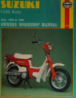
SUZUKI:::: 900
WORKSHORSVIANUAI P
by
L.J.Rabone,B:Tech
Models covered 1968 1969 1970
1972
T1500 Cobra T500 II T1500 II! Charger T500R T500J
1973 T500K 1974 T500L
ISBN 0 85696 135 3 (c) J.H. HAYNES & COMPANY
LTD. 1974
J.H.Haynes and Company Limited Sparkiord, Yeovil, Somerset, England distributed in the USA by
HAYNES PUBLICATIONS INC. 9421 WINNETKA AVENUE CHATSWORTH LOS ANGELES
CALIFORNIA
91311
USA
Acknowledgements Grateful thanks are due to Suzuki (Great Britain) Limited for permission to reproduce their drawings. Brian Horsfall gave the necessary assistance with the dismantling of the TSOOR used for the photographs in this manual and devised the ingenious methods for overcoming the lack of service tools. Les Brazier arranged and took the photographs; Jeff Clew edited the text and John Murphy originated the layout.
Thanks are also due to Mr Brian Ingle-Finch and the staff of Huxhams (Motor Cycles} Limited, Parkstone, Poole, for the supply of the above machine and also for their kind co-operation
in providing information about the T500 series of motor cycles, based on their very extensive knowledge as Suzuki agents. Final acknowledgements are due to the Avon Rubber Company who kindly supplied the illustrations that apply to tyre fitting.
About this manual This manual contains a detailed stripdown and replacement procedure for every major assembly of the T500 series of rotor cycle. The author advises that where only part of a stripdown is required, the owner should read fully both the relevant stripdown and replacement procedures and decide which parts of the machine he must remove in order to reach his objective, ie if 9 carburettor overhaul is desired, it is not necessary to remove the engine but it is necessary to remove all the fittings such as the petrol pipes, vacuum pipe inlet and air cleaner ducts and the carburettor top complete with slide and needle.
The
author
learnt his motor
cycle
mechanics
by ‘trial and
error’ - an expensive and time consuming method. With the help of this manual and a little patience, the owner should find maintaining his own motor cycle an interesting hobby which will
save him many pounds in garage fees and spare him the burden of taking his machine to a garage for its routine maintenance. Unless specially mentioned and therefore corisidered essential,
Suzuki service tools have not been used. There is invariably some alternative means of loosening or slackening some vital component when service tools are not available and risk of damage has to be avoided at all costs. Each of the six chapters is divided into numbered sections. Within the sections are numbered paragraphs. Cross-reference
throughout this manual is quite straightforward and logical. When reference is made ‘See Section 6.10’ it means Section 6, paragraph 10 in the same Chapter. If another chapter were meant, the text would read ‘See Chapter 2, Section 6.10’. All photographs are captioned with a section/paragraph number’ to which they refer and are always relevant to the chapter text adjacent.
Figure numbers (usually line illustrations) appear in numerical order, within a given first figure in Chapter
chapter. Fig 1.1 therefore refers to the 1. Left hand and right hand descriptions
of the machines and their components refer to the left and right of a given machine, when the rider is seated norrrally.
Modifications to the Suzuki T500 range Over five years have passed since the first T500 reached the UK market - a period during which design changes and detail improvements have been made. All significant changes are mentioned in the main text. It must be appreciated that some variants of the models included in this manual were supplied to
countries other ‘than the UK, but in the main these differences are either ‘cosmetic’ or relate to the lighting equipment, which has to meet. the statutory requirements of the country into Which the machine is imported, and the procedures in this manual may be followed with confidence. %
Contents Chapter
Introductory
Section
pages
Introduction
Page
to the Suzuki T500 range
6
Routine maintenance List of illustrations
7 10
Chapter 1/Engine, clutch and gearbox
Specifications Dismantling Examination and renovation Reassembly Fault diagnosis eee Chapter 2/Fuel system and lubrication Specifications Petrol tank - removal and replacement
Chapter 3/Ignition system
Chapter 4/Frame and forks
- Chapter 5/Wheels, brakes and final drive
Chapter 6/Electrical system
4
Ordering spare parts
11 es P| 31 44 46 46
Carburettors - general description
47
Synchronising carburettors Exhaust system Fault diagnosis
50 50 52
Specifications Contact breakers
53 54
Ignition timing Spark plugs Fault diagnosis
54 56 58
Specifications Front forks
59 59
Swinging arm Speedometer and tachometer Cleaning Fault diagnosis
64 69 70 70
Specifications Front wheel Front brake Rear wheel Rear brake
71 71 72 vi) 75
Final drive Tyres Fault diagnosis
77 WT) 81
Specifications
82
Battery Fuse Lights * Wiring Fault diagnosis
83 83 83 88 88
Introduction to the Suzuki T500 range The Suzuki Motor Company commenced making motor cycles in 1936. However, their machines were not imported to the UK until 1963. Backed by the success of their racing machinery, the 250 cc models quickly caught on and their impressive performance has maintained their popularity. In November 1968 Suzuki introduced their first 500 cc machine, the T500 Cobra and showed they had overcome the
dealers have indicated that the motor is reliable and rarely requires a complete stripdown as long as regular maintenance has been carried out by the owner. In addition, riders comments must place it as one of the best motor cycles available today - a high performance, finely balanced, well designed machine. Suzuki have shown that, with their ‘Possi-force’ (or ‘CC\I’) lubrication system, they can produce reliable, large capacity
design problems
two-stroke
of building a high revving large capacity two-
stroke engine. Once again, the performance obtainable from Suzuki’s machine immediately took it into the production racing field and it was later developed for road racing - its only apparent drawback being its high fuel consumption which necessitated large fuel tanks for long distance events. A year after
its introduction,
the Cobra
was
revamped
and
introduced to the UK as the T500 II. This machine, in turn, was discontinued in August 1970 and replaced in October 1970 by the T500 II! Charger which possessed a luggage grid on the
motor
cycle engines and, unlike their other Japanese
competitors, have remained faithful to the two-stroke for their two and three cylinder machines. Experience gained in the early
1960's
under
the exacting conditions
Championship;
leaders stroke recent by the
proof
enough
that
of racing led to a World Suzuki
rank
amongst
petrol tank and a few minor modifications. However, in January 1971 the T500 II! became the T500R with the disappearance of
the luggage grid and the inclusion
of a restyled
tank and new
colour scheme,a tripmeter in the speedometer and a new lighting switch. January 1972 and another paint scheme plus a few minor modifications turned the ‘R’ to a 'T’; January 1973 brought the T500K and January 1974 the T500L which shows that Suzuki must be well pleased with their T500 series. In general, the T500 series of motor cycles have been virtually unchanged since the initial revamping of the T500 Cobra. This shows that extensive development work must have been carried out by Suzuki before they introduced the tried and tested machine to the UK. From the maintenance viewpoint, the engine is relatively easy to work on, as are most two-strokes, and should present few problems to the home mechanic. Also,
the
in the design and manufacture of high performance twoengines. The trend continues, as emphasised by Suzuki's victory in the British ‘Formula 750’ Championship and formation of the Suzuki Owners Club of Great Britain.
Dimensions
Overall length
86.2 in (2190 mm)
Overall width
34.3 in (870 mm)
Overall height
44.3 in (1125 mm) «
Wheelbase
57.3 in (1455 mm) ’
Ground clearance
Dry weight
6.9 in (175 mm)
412 |b (187 kg)
apis
Mata40 a4}
!INZNg00S
Ordering spare parts When wishing to purchase spare parts for the Suzuki twins, it is best to deal direct with an accredited Suzuki agent or Suzuki (Great Britain) Limited. Either is in the best position to supply ex-stock and have more technical experience in the event of any problems that may arise. When ordering parts, always quote the frame and engine numbers IN FULL, without omitting any prefixes or suffixes. It is also advisable to take note of the colour scheme, the model designation from the handbook (ie 1500, T500 II T500K, T500L), and the number stamped on the carburettor top (when requiring carburettor parts).
The engine number upper crankcase.
The the
frame
steering
number head.
is stamped
There
is also
along a
the right hand side of
manufacturer’s
nameplate
rivetted to the left hand side of the steering head, on which the corresponding frame and engine numbers are stamped. Always fit parts of genuine Suzuki manufacture and not pattern parts, which are often available at lower cost. Pattern parts do not necessarily make a satisfactory replacement for the
Originals and there are many cases where reduced life or sudden failure has occurred, to the detriment of performance.
Location of engine number
Manufacturer's name plate
is stamped below the lip at the rear of the
Location of frame number
Routine maintenance Periodic routine maintenance is a continuous process that commences immediately the machine is used and continues until the machine is no longer fit for service. It must be carried out at specified mileage recordings or on a calendar basis if the machine is not used regularly, whichever is the soonest. Maintenance should be regarded as an insurance policy, to help keep the machine in the peak of condition and to ensure long, trouble-free service. It has the additional benefit of giving early warning of any faults that may develop and will act as a safety check, to the Obvious advantage of both rider and machine alike.
The
various
maintenance
tasks
are
described» under
their
respective mileage and calendar headings. Accompanying diagrams are provided, where necessary. It should be remembered that the
interval
between
the various
maintenance
tasks serves
Some
of the tasks are described
in detail, where they are not
mentioned fully as a routine maintenance item in the text. If a specific item is mentioned but not described in detail, it will be covered fully in the appropriate chapter. No special tools are required for the normal routine maintenance tasks. The tools contained in the tool kit supplied with every new machine will suffice,
but
if they
are
not
available,
the
tools
average household will make an adequate substitute.
RM1. TORQUE SETTINGS
°
Part Front axle nut Fork inner tube fitting bolt
Quantity
200 kg cm (14 Ib ft)
250 kg cm (18 Ib ft) 130 kg cm (9.5 Ib ft)
Handlebar clamp bolt
AAKRWH~Z BANA
Muffler fitting bolt aie 9 ~9O
72 ifS3 14
Rear swinging arm pivot shaft Engine mounting bolt Exhaust pipe fitting bolt Spoke nipple
Tightening Torque
650 kg cm (47 Ib ft)
Steering stem head fitting bolt Spark plug Cylinder head nut and bolt Kickstarter fitting bolt Rear shock absorber nut Rear axle nut
only as a
guide. As the machine gets older, is driven hard or is used under particularly adverse conditions, it is advisable to reduce the period between each check.
200 kg cm (14 Ib ft) 350 kg cm, 200 kg cm
300 kg cm (21 Ib ft) 250 kg cm (18 Ib ft) 650 kg cm (47 Ib ft) 300 kg cm (217 Ib ft) 650 kg cm (47 Ib ft) 600 kg cm (43 |b ft) 130°kgcm (9.5 Ib ft) AWWADAAWDNAWNHA NN
RM1. Torque wrench settings: check regularly
found
in the
fo]
Routine Maintenance
Weekly, or every 200 miles Check the oil level through the inspection window in the side of the oil tank. If the level is close to or below the centre screw, top up with one of the prescribed oils.
Check
the tyre pressures.
Always
check
when
the tyres are
cold, using a pressure gauge known to be accurate. Check the level of the electrolyte in the battery.
Use only distilled water to top up, unless there has been a spillage of acid. Do not overfill. Give the whole machine a close visual inspection, checking for loose nuts and fittings, frayed contro! cables etc. Make sure the lights, horn and traffic indicators function correctly, also the speedometer.
Monthly, or every 750 miles Complete
all the checks listed in the weekly/200 mile service,
and then the following: Check the operation of the oil pump. If necessary, adjust the control lever to correspond with the adjusting marks.
4
.
:
‘
RM2. Window in oil tank shows level of contents
Clean both spark plugs. Change the oil in the gearbox.
Adjust the play in the throttle and brake cables. If
necessary,
adjust
the
carburettors
to
ensure
smooth
running at lowrpm. Check the contact breaker points gaps and verify whether the ignition timing is correct. Adjust both brakes and also the amount of play in the final drive chain. Check
the tightness of the cylinder head bolts, exhaust
pipe
clamps and exhaust rear mounting bolts. Check the steering head bearings for slackness. Check both wheels for loose or broken spokes. Check the clutch adjustment.
Three-monthly, or every 2000 miles Complete all the checks under the weekly and monthly headings, then carry out the following additional tasks: Remove and clean the oil tank outlet cap and strainer. Remove, clean and lubricate the final drive chain. Clean the air filter. Adjust the gaps of both spark plugs. Lubricate the contact breaker. Grease the swinging arm.
¥
RMS. Crosshead
screw acts as gearbox oil level indicator, when removed
Six-monthly, or every 4000 miles Complete all the checks under three-monthly headings, then attend Replace both spark plugs. Lubricate the throttle, brake and Decarbonise the engine and clean Grease the twist grip throttle. Clean the oil outlet filter and the
the weekly, monthly to the following:
and
oil pump control cables. out the exhaust system.
fuel tap filter.
Yearly, or every 8000 miles
Again complete ail the checks listed under the weekly, monthly, three-monthly and six-monthly headings. The following additional tasks are now necessary: Dismantle and clean both carburettors. Replace both sets of contact breaker points.
Remove both wheels and check condition of front and rear brake shoes. Replace, if linings have worn thin.
RM4. Grease swinging arm using the nipple provided
Routine Maintenance
Quick glance routine maintenance
adjustments and capacities
Contact breaker gaps
0.012 in - 0.016 in
Spark plug gaps
0.020 in - 0.024 in
Spark plugs - standard
NGK
Ignition timing
24°
Fuel tank capacity
3.1 Imp gallons *
Oil tank capacity
3.16 pints *
B-77HC
BTDC
(0.134 in)
* See list of recommended lubricants for grades Tyre pressures Solo Duo
o
Front 23 psi 23 psi
Rear 27 psi 33 psi
ea nipple
inner cable
A
plasticine funnel
1
around outer cable
cable suspended ___:dverrtically
SSN ANS ERR EEE eer
RM5. Brakes are fitted with adjusters, as shown
cable lubricated
when oil drips —_
from far end
RMB. Control cable oiling
List of illustrations Fig. No. RM1. RM3.
Page
RM6. Use a2. 1.3. 1.4. in5:
Torque settings Brake adjusters Control cable Power and transmission unit Cylinders and air cleaner assembly Freeing gummed rings Clutch assembly Spragging the clutch
7) 9
9 14 22 24 25 26
1.6. TE7S
Crankcases Piston and crank assembly
Di, 28
1.8. 1.9.
Gear clusters Ring profiles
30 31
1.10. elite 1.12.
Gearchange mechanism Kickstart assembly Oil pump
32 33 42
2.1 PLP 2:3.
Carburettor components Checking float level Engine lubrication
48 50 51
Sh. 3.2a and 3.2b.
Alternator and ignition coils Spark plug maintenance
55 57
4.1. 4.2.
Front forks Frame and oil tank
63 67
4.3 4.4 4.5
Swinging arm Settings for rear suspension Checking wheel alignment
68 69 69
fei 5:2
Front wheel Rear wheel
73 74
5.4a
Tyre removal
79
5.4b
Tyre fitting
80
Gale
Headlight assembly
34
6.2.
Electrical equipment
85
6.3.
Wiring diagram
Chapter 1 Engine Clutch and Gearbox Contents
General description ... ... Operations with the engine/gearbox iinn the frame hada septs Operations with the engine/gearbox removed ... ... .. we ve Method of engine/gearbox removal Removing the engine/gearbox ' Dismantling the engine and gearbox- general Dismantling the engine and gearbox - removing the carburettors 3 Dismantling the engine and gearbox - Sromaving ‘the cylinder heads and barrels ... ... ... ; Dismantling the engine and gearbox - renioving ‘the piston and piston rings ...
...
...
Engine and gearbox reassembly - fitting the crankshaft ... Engine and gearbox reassembly - attaching the upper crankcase Engine and gearbox reassembly -- replacing gear‘selector pawls and gearbox and tachometer Engine and gearbox drive and clutch
— OAorWHNH Engine
Engine and gearbox reassembly crankcase cover
PACES MOH aetomcat
Neco
eaceeeerr
nero CoCEE
- fitting the neutral ohes
Engine and gearbox Cent, - Heine the eae) and cylinder barrels . : Engine and gearbox reassembly - refitting the eylinder: heads Engine and gearbox reassembly .- refitingthe twin” carburettors ; Replacing the engine/gearbox ome in “the frame Reconnecting the oil pump control cable and the oil
ssl os
pump feed
as
i Bae
ees
Refitting the exhaust pipes ond siete.
and renovation
Starting and running the rebuilt engine ... ... ... 20. cee Taking the rebuilt machine on the road ... ... ... 0... cee [email protected] «esmeclccamstsule-cuces mee sae umrene Fault diagnosisi-.clutch\cc. cca esti eee cece tome ceetencren Fault diagnosis - gearbox
Gearbox components - examination and renovation ... ... ... Clutch - examination and renovation Engine and gearbox reassembly- general Engine and gearbox reassembly - rebuilding the semnor cata Engine and gearbox i eassembly- kickstart replacement
...
...
nn
Specifications
i
ne
EU
cee wee cee nee ae ee mee
EE SIS
——————————————————————————————————————————
Model
7500,
Engine Cylinder Bends CViindembanrelSine. Bore yao}Fase cpceca ag ew Cubic capacity
Pistons Type Oversizes Bante.
T500II!,
cenmees
sseyuaen
eecuie spe
pleases
oMiesoyteasiiecniiions
70 mm
(2.75 in)
Pe
get
RE
Go
cee
64 mm
(2.52 in)
RSE
bhp at 7000 rpm torque at 6000 rpm
Weight
T500I!,
Twin cylinder two stroke Aluminium alloy Aluminium alloy
A
Compression ratio (Gonrected) =. Maximum Maximum
- fitting the right hand
.
Engine and gearbox reassembly- fitting the left hand crankcase cover ... ... .
and renovation .
Pistons and piston rings - examination and fonovations Cylinder heads - examination
...
contact and final drive sprocket ... ... ... Engine and gearbox reassembly - refitting the generator. sv
Disn.antling the engine and gearbox - removing the clutch Removing the oil pump assembly Separating the crankcases Removing the crankshaft and gearbox main bearings . baa Geille Dismanclingthergeamclusters: ao cece. 15 cralecs sratees sac ‘oe Examination and renovation- general Big end and main bearings - examination and renovation Oil seals - examination and renovation es Cylinder barrels -examination
...
Engine and gearbox reassembly
:
Dismantling the engine and Gearbox:- Tomeuing the
ToS RIEL 201 8) espera eet leen eC
reassembly - fitting the on pong! drive reassembly - refitting ie Shmarys ... ... .
;
RIE
Berne
olin
Maco
Sec
ON
25
RGD
nS
care OE
492 6.6: 47 37.5 139
T500R,
T500J,
cc 1 Ib ft 38.3 Ib ft Ib (63 kg)
Aluminium
with piston ring pegs
+ 0.5 mm (0.020 in), + 1.0 mm (0.040 in)
TSO00K,
T500L
12
Chapter 1/Engine, Clutch and Gearbox
i
Piston rings Number Gape ease «3 Groove clearance Capacities Oil tank Gearbox Gear ratios Bostomigea nt cccn.s-
Two per piston
0.008 - 0.040 in Not greater than 0.006 in
1.8 litres (3.2 pints) 1.2 litres (2.2 pints) oct
ory
cetee
Maree
e
Maree ene
eee
tee
ane
Second gear Third gear Fourth gear
2.50 : 1 1:56
1 1
(Ohi 3 1
Top gear PGIMmanVvxGnivG vce
a cco
css)
hee)
cre
cote
ee
ees
1
Final drive (standard)
1 (33/15)
Overall reduction in top gear
...
0.0...
0c.
cee
cee
cee
tee
tee
tee
ee
Clutch Friction plates Number Thickness Standard
oe PAO) 1
36 PRP) 1
= G'S) 1
7
3.5 mm 3.2 mm 0.4 mm
Maximum warpage Steel plates Number Thickness
Standard
OSHE 1
sc.
(0.138 in) (0.126 in) (0.016 in)
7
cs
ose:
coe
eee
ee
ee
a
es
2 mm (0.08 in) 1.85 mm (0.07 in) 0.1 mm (0.004 in)
tree
Bec
40.4 mm (1.58 in) 39.0 mm (1.53 in)
Maximum warpage Clutch springs Free length SHENG BTdelt cncrerts
tere
Bioeth
yetenen eee
nee
AAs
R
eres
eee
Torque wrench settings Ib ft 25
Cylinder head nuts Gylindemhead bolts c..
..6
cen
es
aes
che
cen,
Gee
eee
ee
14.4
200
ce se
29 3.6 36 7 14
400 50 500 100 200
Engine sprocket nut Oil pump union bolt Primary pinion Grankeaseibolts:- Gitmitic-cs sunset Grankease bolts = Simitiz-e eases cae
ro
eels eens
pecs Gop
es ce
omers ree
kg cm 350
Miscellaneous
Backlash in primary drive Standard
0.025 - 0.065 mm
Maximum Maximum cranksiatitnum-OUt. cere cen sen Maximum sideways play at small end Gear selector fork - gearwheel clearance
Standard Maximum ecto insite es) Clutch housing - axial play Standard Maximum fen Oe Maximum
aes)
sea
eee
eee)
eee
two-stroke
and
as ‘loop
0.4 -0.6 mm
0.05 - 0.20 mm
piston clearance
exhaust
type
employing
scavenging’
sequence.
A
flat
top
pistons
and
what
is
to achieve a satisfactory induction rigid
(0.0024 in)
(0.118 in)
0.8 mm (0.03 in)
beds
The engine/gear unit fitted to the 500 cc Suzuki twins is of known
(0.006 in)
0.06 mm
3 mm
1 General description
the
0.16 mm
built-up
crankshaft
with
thick
flywheels ensures good crankcase compression; the shape and arrangement of the ports guarantees a very high standard of performance without need for mechanical aids such as rotary or reed induction valves.
0.25 mm
(0.01 in)
0.15 mm
(0.006 in)
The crankcase assembly is arranged to split horizontally thereby giving maximum access to the engine and gearbox components. In fact, it is not possible to work on the gearbox without first removing the engine from the frame and then splitting the crankcase assembly. This disadvantage of the horizontally-split, unit construction engine should be weighed
against the general increase in oil tightness obtained. The gearbox has five speeds and is fitted with a conventional kickstart. Primary drive is through a pair of helically-cut pinions, via a muiti-plate clutch. A positive stop mechanism is
incorporated in the gear,change selected with a positive action. *
system,
to ensure each gear is
13
Chapter 1/Engine, Clutch and Gearbox Unlike many other two-strokes, the engine does not rely upon a petro:/oil mix for lubrication. Oil is contained within a separate oil tank, from which it is fed by gravity to a mechanical
oil
pump
interconnected
(later renamed
with
the
throttle.
This
‘Posi-Force’
‘CClI') system ensures that oil is delivered under
pressure at all times to the crankshaft assembly and to the cylinder walls. The output of the pump is controlled by engine speed (via the throttle linkage) and thus the correct amount of oil is supplied under all operating conditions. The pump has a limited range of adjustment. The gearbox has its own separate oil content and is fitted with a level plug to prevent accidental overfilling. It holds only a small quantity of oil, which must be changed at the recommended
intervals.
2 Operations with the engine/gearbox in the frame It is not
necessary
to remove
frame unless the crankshaft components require attention.
the engine/gear
tinit from
the
assembly and/or the gearbox Most operations can be accom-
plished with the engine in place, such as:
Removal
and replacement of the cylinder heads.
Removal and replacement of the cylinder barrels and pistons. Removal and replacement of the flywheel magneto generator. BWNHRemoval and replacement of the clutch. When several operations need to be undertaken simultaneously it would probably be an advantage to remove the complete unit from the frame, a comparatively simple operation that should
take
approximately
thirty minutes.
This will give the advantage
of better access and more working space.
3 Operations with engine/gearbox removed 1 2 3
Removal Removal Removal
and replacement of the outboard oil seals. and replacement of the crankshaft assembly. and replacement of the gear clusters, selectors and
gearbox main bearings.
4
Renewal of the kickstart return spring.
4 Method of engine/gearbox removal As described previously, the engine and gearbox are built as a unit and it is necessary to remove the unit complete in order to gain access to either. Separation of the crankcases is accomplished
6 The exhaust systems may be removed as complete units. Unscrew both the bolts which hold each exhaust pipe clamp to the barrels. Also remove the rear (pillion) footrests and neighbouring bolts; these act as the rear support for the exhaust system. During this operation, the exhaust system will drop on the ground unless supported. Note that the exhaust pipes are a
sliding fit in the silencers. 7 Detach the clutch outer cable from the handlebar lever in order to gain sufficient slack for the other end to be later removed from the engine sprocket cover. 8 Remove the final drive chain by detaching the spring link. This task is made easier if the spring link is located on the rear wheel sprocket. 9 Unscrew the tachometer drive cable connection at the top of the oil pump cover, and pull the cable end free. Remove the
outer oil pump cover (two bolts) and remove the throttle cable linkage. Note that the cable has a detachable nipple - do not lose. Unscrew the cable from the cable stop. 10 Detach the flexible plastic pipe from the bottom of the oil tank by removing the union bolt. To prevent the oil content escaping from the tank, screw a 6 mm bolt into the union joint,
to act as a temporary plug - a crosshead screw from the outer engine covers is suitable. 11 Pull off both spark plug caps complete with leads and secure them away from the engine. 12 Remove both carburettor tops by unscrewing each screwed ring. The tops can be lifted away complete with their control cables, springs and throttle slide assemblies. Care is necessary at
this
stage
to
prevent
damage
to
the
slides
or
the
needles
suspended from them. Tape each top and slide assembly to a convenient frame tube, so that they are out of harm’s way when the engine is lifted out. 13 Remove the air cleaner hoses from each carburettor intake by undoing the crosshead screws which tighten the retaining clips. A third clip at the air cleaner box now holds the rubber duct; loosen the screw and remove the duct. Although not strictly necessary, better access for engine removal is gained if the air filter box is removed too. This is retained at the back and the front by two small nuts and screws. 14 Pull off the electrical connections to the rear brake stop lamp switch. Remove the operating spring and then loosen the plate
retaining bolt and remove the switch unit. 15 Disconnect the rear brake cable from the split pin and clevis pin.
the lever by removing
place until the crankcases have been reassembled.
16 Remove both forward footrests by unscrewing the two bolts which screw into the bosses on the frame; disconnect the rear brake lever return spring and pul! off the lever (right hand side). 17 Remove COMPLETELY the pinch bolts which hold the
5 Removing the engine/gearbox unit
kickstart and gear change levers on their respective splined shafts. Pull off the levers and inspect the splines for wear. Note:
after the engine unit has been removed and refitting cannot take
1 Place the machine on the centre stand and make sure that it is standing firmly. Remove the gearbox drain plugs and drain off the oil, preferably when warm. 2 Make sure the diaphragm-type petrol tap is in the ‘ON’ position and pull off the two fuel pipes. Remove also the vacuum pipe which connects the left hand carburettor flange with the petrol tap diaphragm. 3 Disconnect the electrical leads from the battery at the snap the battery; these parts are situated and remove connectors behind the battery cover on the left hand side behind the air
filter. the alternator wires by pulling them apart at the socket connector and the other snap connector joints: these are also situated in the battery box, to the rear of the battery. Note 4
Disconnect
the wires are colour-coded to make reconnection easy. 5 Remove the seat by loosening the bolts through the rearmost lugs of the top frame tube and pulling the seat back and up. This operation exposes a large bolt at the back of the petrol tank; unscrew this bolt from the frame and the tank may now he removed. The tank rests on rubber mats at the rear and rubber stops at the front; do not lose these or the tank will vibrate against the frame when the engine !s running.
The gear change shaft goes right through the engine unit thus a right hand gear change conversion may be made. 18 The rear left hand engine cover (the final drive sprocket cover) is retained by six crosshead screws. Remove these and pull off the cover complete with clutch cable; the cover also contains the clutch actuating mechanism. Disconnect the clutch cable
nipple
noting
that
it is
retained
by
a bent
over
tab.
Unscrew the outer cable from the cover. 19 Remove the screw and bolt which attach the chainguard to the swinging arm and lift out the chainguard. 20 There are now only the three large engine bolts to be removed. Unscrew the nuts and pull out the bolts slowly, allowing the engine to settle % inch onto the bottom frame loop; note the position of the spacer on the rear engine bolt.
21 The engine unit is heavy (139 !bs) and so the removal is a twoman job. Pick up the engine in a straight lift and move out to the left, when clear of the engine mounting lugs.
6 Dismantling the engine and gearbox - general 1
Before
surfaces
commencing
must
be cleaned
work
on
the
thoroughly.
engine
A motor
unit,
the
external
cycle engine
has
“6i4 ‘LL
OOGL SAl4aS —
JAMOYPu
UOlssiwisUes} 21UN
14
5.3 Disconnect the battery leads at the
5.4 Disconnect the alternator wires from
5.5 Bolts through the rearmost lugs of
snap Connector
the large snap connector and the other
the top frame tube retain the seat
single snap connectors
5.6a Remove the bolts which retain the exhaust pipe clamp to the barrels
5.6b Rear footrest and neighbouring bolt act as rear support for the exhaust
5.9 Throttle cable linkage shown removed. The nipple is detachable
system
5.10 An engine cover screw may be used to blank the union
5.12 Screw cap and slide assembly should be removed complete
5.14a Pull off the leads from the brake light switch
5.14b Disconnect the brake light spring
5.17 Ease kickstart lever, with pinchbolt
5.18 Pull off the final drive cover com:
and rear brake cable
completely removed off its splines
plete with clutch cable
16
Chapter 1/Engine, Clutch and Gearbox bodies. 2 Place the carburettors aside for further attention. They are easily damaged or broken if they receive harsh treatment. If required they can be separated by withdrawing the split pin from the end of the rod which operates both chokes in unison.
3
Remove
the cylinder
the nuts and washers holding the inlet manifolds to barrels,
Pull off the manifolds and the heat resistant
gaskets.
5.20 Use a Mole Wrench to extract the engine bolts - NEVER hammer the threaded ends to remove bolts or damage to the threads may occur
7.1 Pull the carburettor bodies from the rubber inlet manifold and remove as a pair 8 Dismantling the engine and gearbox heads and barrels
- removing
the cylinder
1 Each cylinder has its own separate cylinder head. To remove each head, unscrew the cylinder head retaining nuts and bolts in a.diagonal sequence, to prevent distortion. 2 When the nuts and bolts have been slackened fully and withdrawn, each cylinder headcan be lifted off the long retaining studs
which
aluminium
pass
through
each
cylinder
barrel.
to the barrel joint. These should be discarded even if they appear to be in good condition.
52 very
Lift out the engine from the left hand side little
protection
from
road
grit and
other
foreign
matter,
which will sooner or later find its way into the dismantled engine if this simple precaution is not observed. 2 One of the proprietary engine cleaning compounds such as Gunk or Jizer can be used to good effect, especially if the compound is allowed to penetrate the film of oil and grease before it is washed away. When washing down, make sure that
water cannot enter the carburettors or the electrical system, particularly if these parts are now more exposed. 3 Never use force to remove any stubborn part, unless mention is made of this requirement in the text. There is invariably good reason
why a
part
is difficult
to
remove,
often
because
the
dismantling operation has been tackled in the wrong sequence. 4 Dismantling will be made easier if a simple engine stand is constructed that will correspond with the engine mounting points. This arrangement will permit the complete unit to be clamped rigidly to the workbench, leaving both hands free for the dismantling operation.
7 Dismantling the engine and gearbox - removing the carburettors
1 The removal
carburettors may be removed before or after engine by loosening the crosshead screws in the retaining clips
around the rubber inlet manifolds and pulling out the carburettor
Note
that
an
cylinder head gasket is used to seal the cylinder head and
not re-used,
3 Each of the separate cylinder barrels can now be lifted off by drawing them upwards along the holding down studs. Take care to support each piston as it falls clear of the cylinder barrel, otherwise the piston may be damaged or the rings broken. If only a ‘top’ overhaul is contemplated, it is advisable to pad the mouth of each crankcase with clean rag before the pistons are drawn clear of the cylinder barrel. This will prevent particles of broken piston ring (or displaced circlips from the next stage of the dismantling procedure) from dropping into the crankcase
and causing further unnecessary dismantling. 4 Remove and discard the cylinder base gaskets which will also have to be renewed. \
9 Dismantling the engine and piston rings
and gearbox
1 Remove both circlips from each them. Circlips should never be re-used
- removing
the pistons
piston boss and discard if risk of displacement is
to be obviated. 2 Using a drift of the correct diameter, tap each gudgeon pin Out of the piston bosses until the piston complete with rings can be lifted off the connecting rod. Make sure the piston is properly supported during this operation, to prevent the connecting rod
from bending. 3 If the gudgeon pin is a tight fit, the piston should first be warmed in order to expand the gudgeon pin bosses. A convenient way of warming hot water on the crown.
the piston is to place a rag soaked in
17
Chapter 1/Engine, Clutch and Gearbox 4 When the pistons have been detached from the connecting rods, mark them on the inside of the skirt so that they will be replaced in the barrel from which they came. Note that the pistons are not identical and that the ports in the barrels and pistons will not align if the pistons are interchanged. There is no need to mark the back and front because each piston has an
arrow cast in the crown, which must always face the front of the machine.
5 The small end bearings take the form of caged needle rollers. Each roller assembly will lift out of the connecting rod eye. 6 Note that the piston rings are pegged so that they will remain in a set location. This is important, otherwise the rings will rotate whilst the engine is running, permitting the ends to become trapped in the ports and broken. 7 To remove the rings spread the ends sufficiently with the thumbs to allow each ring to be lifted clear of the piston. This is a very delicate operation which must be handled with great care. Piston rings are brittle and they break very easily. « 8 If the rings are stuck in their grooves or have become gummed by oily deposits, it is sometimes possible to free them by working small strips of tin along the back to give a ‘peeling’ action.
10
Dismantling the engine and gearbox - removing the alternator
1
Remove
the
alternator
cover
(the
front
left
hand
engine
cover) by undoing the three crosshead screws. 2
Also
crankcase
remove
which
the
holds
small
plate
the rubber
within
the
grommet
outer
through
half of the
which
the
generator leads pass. It is located in the top right hand side of the alternator compartment and is retained by a single crosshead screw. When this plate is removed, and the cable retaining clips
necessary. Never use a screwdriver to lever off alloy casings. 2 Remove the gasket. 3 Lock the engine again and withdraw completely the six clutch spring bolts. The clutch pressure plate will now lift off and expose the seven plain and seven friction plates which make up the clutch assembly. These plates align with the clutch inner and outer drums respectively and can be prised out of position. Lift out the clutch pushrod end piece which fits within the hollow gearbox mainshaft and also the main clutch pushrod from
the left hand end of the mainshaft. 4
With the engine still locked by the bar through the small end,
lock the inner and outer clutch bodies together (known as ‘spragging the clutch’). The clutch centre may now be removed by undoing the central large nut (which is retained by a tab washer) from the end of the gearbox layshaft. This nut has a right hand thread. 5 Having removed the clutch centre, pull off the washer, the clutch outer (with driven pinion) and the second thrust washer from the mainshaft. Note the positions of the washers.
12
Removing the oil pump assembly
| Undo the three banjo bolts which retain the oil inlet and the two oil outlet pipes to the pump body. 2 The oil pump is held to the crankcase by two crosshead screws - one either side. Remove these screws and pull off the pump body and gasket. 3 The pump is driven from the gearbox via a shaft with a worm drive. This shaft is exposed on removing the pump - pull out the shaft to avoid it dropping out when the crankcase is later inverted.
(along the top of the crankcase) are slackened, the stator plate assembly complete with wiring harness can be detached. It is necessary to remove the three crosshead screws which retain the stator plate, complete with contact breaker assemblies, to the
left hand crankcase. There is sufficient clearance for the large terminal connector to pass through the hole in the outer crankcase once the rubber grommet Is removed. 3 To remove the flywheel rotor, lock the engine by passing a stout metal rod through the eyes of the connecting rods so that it rests across the crankcase mouth, and is supported by two short lengths of wood. Slacken the centre bolt of the rotor (right hand thread) and if the appropriate Suzuki extractor is not available, use a three-legged sprocket puller as shown in the accompanying photograph. Excessive force should not be necessary to break the taper joint. Tighten the sprocket puller until it is hard up against the slackened centre bolt and then give a smart hammer blow on the end of the puller. The rotor can now be withdrawn when the centre bolt is removed completely and the Woodruff key placed in a safe place until it is required for reassembly. Note that the contact breaker cam will also be freed when the centre bolt is removed. Its position is predetermined by a dowel pin which engages with the rotor keyway. It is advisable at this stage to also remove the final drive 4 sprocket which is retained by a nut and tab washer. Once again, lock the engine with the gearbox ‘in gear’, flatten the tab washer and undo the nut which has a right hand thread. Pull off tne sprocket.
13 Separating the crankcases 1 Before the crankcases can be separated, a further amount of preparatory work has to be undertaken. 2 Remove the crankshaft pinion by first flattening the tab
washer and undoing the nut (right hand thread) with the engine locked. The pinion is retained by a Woodruff key on a parallel shaft and may require a sprocket puller,to ease it off. Also, remove the spacer behind the pinion. 3 Remove the bearing retainer which is immediately behind the mainshaft. An impact screwdriver will be required for this operation.
4
Pull
out
quadrant,
the
from
Dismantling the engine and gearbox - removing the clutch
1 Working from the right hand side of the engine unit, first remove the outer cover. This is held in place by nine crosshead an screws which are often very tight and may require the use of impact screwdriver. Make provision for catching any surplus oil which may drain away when the cover 's removed. Note that the two long screws pass through spacers seated in the crankcase
remove the spacers and keep them safe, if loose. Before the cover may be removed, the plastic cover over the end of the gear change if shaft must be pulled off. Use a wooden drift to ease it off
change
selecting
right hand
side
shaft,
complete
of the engine.
Note
with
the
spacer over the shaft in the engine sprocket compartment. 5 The oil seal support around the final drive shaft is retained by four crosshead screws which will also require an impact screwdriver to slacken them. Pull off the seal support. 6 Remove the neutral switch lead by unscrewing the small crosshead screw from the neutral switch. This unit is located in front and below the gearbox final drive shaft. 7 The crankcases are now ready for separation. Invert the
engine the
and remove
crankcases
the
together.
16 bolts (13 on earlier models) Also
remove
the two
holding
gearchange
cam
retaining bolts (in front of the gearbox drain plug) if required. 8 Reinvert the engine and remove the last four bolts in the upper half which located close to
11
gear
the
retain the crankcases together. One of these is the oi! pump cable adjuster, which must be
withdrawn 9 A few
before the bolt can be released. light taps with a rawhide mallet on the projecting portions of the crankcases should ensure the crankcases separate, leaving the remainder of the engine and gearbox components in the lower half. 10 Lift out the gearbox mainshaft and layshaft complete, noting
the ‘C’ ring locaters for the journal bearings. 11 Remove the central crosshead screw and clip which retains the kickstart shaft and lift out the kickstart assembly; as the screw 1s undone, the shaft will rise because of the tension in the kickstart spring.
FIG. 1.2. CYLINDERS AND AIR CLEANER
ASSEMBLY
RH cylinder head
26
Air cleaner duct
LH cylinder head Cylinder head gasket (2 off) RH cylinder barrel
27 28 29
Clamp (2 off) Clamp Clamp screw (3 off)
LH cylinder barrel
30
Air cleaner assembly
Cylinder base gasket (2 off) Cylinder retaining stud (8 off} Cylinder head nut (8 off) Spring washer (8 off) OMANAGAAWY™ Washer (8 off)
31 Air filter SONG 33 Washer 34 Air cleaner assembly * SH Air filter *
Cylinder head bolt (8 off)
36
Bolt *
Spring washer (8 off) Washer (8 off)
S/S 38
Calne Washer *
Inlet manifold stud (4 off)
39
Butterfly nut *
Inlet manifold gasket (2 off) Inlet manifold (2 off)
40 41
Screw (2 off) Spring washer (2 off)
Clamp (2 off)
42
Washer (2 off)
Screw (2 off)
43
Spark plug cap assembly ( 2 off)
Inlet manifold * (2 off) Inlet manifold * (2 off) Clamp * (2 off) Clamp * (2 off) Clamp screw * ( 4 off)
44
Plug cap seal ( 2 off)
45 46
Plug cap seal/HT lead seal (2 off) Spark plug assembly ( 2 off)
Spring washer (4 off)
47
Clip - overflow hose
Nut (4 off)
48
Overflow hose (2 off)
* Post T500J only.
23
Chapter 1/Engine, Clutch and Gearbox Some vibration will also be experienced. 2 There should be no vertical play whatsoever in the big end bearings, after the oil has been washed out. If even a small amount of vertical play is evident, the bearings are due for replacement.
(A small
amount
of end float is both necessary and
acceptable).
Do not continue to run the machine with worn big end bearings, for there is risk of breaking the connecting rods or crankshaft. 3 The built-up nature of the crankshaft assembly precludes the possibility of repair, as mentioned earlier. It will be necessary to obtain a replacement crankshaft assembly complete, under the
Suzuki Service Exchange Scheme. 4 Failure of the main bearings is usually evident in the form of an audible rumble from the bottom of the engine, accompanied by vibration which is felt through the footrests. 5 The crankshaft main bearings are of the journal ball type. If wear is evident in the form of play, or if the bearings feel rough as they are rotated, replacement is necessary. Always check after the old oil has been washed out of the bearings. Whilst it is possible to remove
the outer
bearings at each end
of the crank-
shaft, it is probable that the centre bearing will also require attention. Here again, it will be necessary to obtain a replacement crankshaft assembly, under the Suzuki Service Exchange Scheme.
6
Failure of both the big end bearings and the main bearings
may
not necessarily occur as the result of high mileage covered.
If the machine is used only infrequently, it is possible that condensation within the engine may cause premature bearing failure. The condition of the flywheels is usually the best guide. When condensation troubles have occurred, the flywheels will rust and become discoloured.
3
If a measuring
cylinder
bore
wear
instrument can
be
is not available, the amount measured
by
inserting
the
of
piston
without rings so that it is approximately % inch from the top of the bore. If it is possible to insert a 0.006 inch feeler gauge between the piston and the cylinder wall on the thrust side of the piston, remedial action must be taken. 4 Suzuki provide pistons in two oversizes: 0.5 mm (0.020 inch)
and 1.0 mm 5
Check
(0.040 inch). that
the
surface
of the
cylinder
bores
is free from
score marks or other damage that may have resulted from an earlier engine seizure or a displaced gudgeon pin. A rebore will be necessary to remove any deep indentations, irrespective of the amount of bore wear that has taken place. If the 1 mm overbore does remove all scratches and ridges froin the bore, a new barrel is required otherwise a compression
leak will occur.
6 Make sure the external cooling fins of the cylinder barrels are not clogged with oil or road dirt, which will otherwise prevent the free flow of air and cause the engine to overheat. Remove any carbon that has accumulated in the exhaust ports, using a blunt-ended scraper so that the surface of the ports is not scratched. Finish off with metal polish so that the ports have a smooth, shiny appearance. This will aid gas flow and prevent carbon from adhering so firmly on future occasions. 7 Under no circumstances modify or re-profile the ports in the search for extra performance. The size and location of the ports
is critical in terms of engine performance and the dimensions chosen have been selected to give good performance consistent with a high standard of mechanical reliability. 8 If the cylinder barrels have been rebored, it will be necessary to round off the extreme edges of the ports, to prevent rapid
wear of the piston rings. Use a scraper or hand grinder and finish off with fine emery cloth. 18
Oil seals - examination and renovation
1 The crankshaft oil seals form one of the most critical parts in any two-stroke engine because they perform the dua! function of preventing oil from leaking along the crankshaft and preventing air from leaking into the crankcase when the incoming mixture is under crankcase compression. 2 Oil seal failure is difficult to define precisely, although in most cases the machine will become difficult to start, particularly when warm. The engine will also tend to run unevenly and there will be a marked fall-off in performance, especially in the higher gears. This is caused by the intake of air into the crankcases which dilutes the mixture whilst it is under crankcase compression, giving an exceptionally weak mixture for ignition. 3 It is possible to renew the outer crankcase oi! seals without difficulty, but the inner seals form part of the crankshaft assembly. In this latter case, a replacement crankshaft assembly is the only way of ensuring a satisfactory crankcase seal. 4 \t is unusual for the crankcase seals to become damaged during normal service, but instances have occurred when particles of broken piston rings have fallen into the crankcases and lacerated the seals. A defect of this nature will immediately be obvious.
Lae. ee 2 A ee 19
Cylinder barrels - examination
pes SER
Ee
a
eee
and renovation
ee Sa
a
ee
piston ring. 2 Measure the bore diameter just below the ridge, using an internal micrometer, or a dial gauge. Compare this reading with the diameter
at the bottom
subjected
0.05 mm
to wear.
of the cylinder
If the difference
bore, which
has not
in readings exceeds
(0.002 inch) the cylinder should be rebored and fitted
with an oversize piston and rings.
Pistons and piston rings - examination and renovation
1
If a rebore
can
is necessary,
be disregarded
because
the existing pistons and piston rings
they will have
to be replaced with
their new oversize equivalents as a matter of course. 2 Remove all traces of carbon from the piston crowns, using a blunt-ended scraper to avoid scratching the surface. Finish off by polishing the crowns with metal polish, so that carbon will not adhere so readily in the future. Never use emery cloth on the soft aluminium. 3 Piston wear usually occurs at the skirt or lower end of the piston and takes the form of vertical streaks or score marks on the thrust face. There may also be some variation in the thickness of the skirt, in an extreme case. 4 The piston ring grooves may have become enlarged in use, allowing the rings to have greater side float. If the clearance exceeds 0.006 inch, the pistons are due for replacement. It is unusual for this amount of wear to occur on its own.
5 Piston ring wear is measured by removing the rings from the piston and inserting them in the cylinder, using the crown of a piston to locate them about 1% inches from the top of the bore. Make sure they rest square in the bore. Measure the end gap with a feeler gauge; if the gap exceeds 0.040 inch the rings must be
replaced ee
1 The usual indication of badly worn cylinder barrels and pistons is excessive smoking from the exhausts and piston slap, a metallic rattle which occurs when there is little or no load on the engine. If the top of the bore of the cylinder barrels is examined carefully, it will be found that there is a ridge on the thrust side, the depth of which will vary according to the rate of wear which has taken place. This marks the limit of travel of the uppermost
been
20
(standard gap 0.008 inch to 0.014 inch). When refitting
new piston rings, it is also necessary to measure the ring gap. If the gap is too small, the rings will break while the engine is running and cause extensive damage. The ring gap may be increased by filing the ends of the rings with a fine file. Never hold the rings in a vice for this operation - hold the ring in one hand
and
the
file
possible by placing possible and only rechecking the gap.
in the
other.
Support
the
ring as much
as
the fingers as near the end of the ring as remove small amounts of metal before
6 All machines are fitted with Keystone rings, which can be identified by their shape. These rings are not interchangeable with the conventional type of rings and must be used only in conjunction with Keystone pistons. They have a 7° taper on their uppermost surface. They are handled in the same fashion as
conventional rings.
13.3 Remove the bearing retainer which is immediately behind the gearbox mainshaft
13.4 Pull out the gearchange shaft and quadrant
13.5 Pull off the final-drive shaft seal support after removing the four screws
13.9 From the top - kickstart shaft, final drive shaft shaft
main-
13.12a Remove the cam retaining plate ...
21
Chapter 1/Engine, Clutch and Gearbox
Sere
2 Generally speaking, it is preferable to service exchange the entire crankshaft assembly if any of the bearings are suspect. If the two outer bearings need replacing, it is highly probable that the centre bearing will be in the same condition. It is quite beyond the means of the home mechanic, or for that matter, the majority of motor cycle repair specialists, to separate and re-align the
crankshaft
assembly
without
the appropriate
equipment.
In
consequence, the Suzuki Service Exchange Scheme will provide a completely reconditioned crankshaft assembly together with
new
13.12b ... and striker plate. Note the blanking plug/gearchange stop immediately behind the cam end
main
bearings, small end bearings and oil seals ‘for a fixed
sum, in exchange for the crankshaft which requires attention. Any accredited Suzuki dealer should be able to provide this facility, often ex-stock. 3 By way of explanation, the crankshaft assembly can be regarded as two quite independent flywheel assemblies, coupled together by a ‘middle’ crankshaft which presses into the inner flywheels. The middle crankshaft carries the centre main bearing and also the two innermost oil seals. The two separate flywheel assemblies are built up first, aligned and checked for run-out. They are then coupled together by the middle crankshaft and the entire assembly is checked for run-out at both ends. It follows that a very high standard of accuracy has to be observed, in order to preserve the smooth running of the engine. 4 The gearbox assembly has an oil seal, located immediately behind the final drive sprocket, on the final drive shaft. This will pull off the shaft without difficulty. The final drive shaft has a large diameter journal ball bearing at the left hand or drive side
end and a caged needle roller bearing on the right hand end. The reverse
applies
in the
case
of the
mainshaft;
the journal
ball
bearing is on the right and the caged needle roller bearing on the left. There should be no difficulty in pulling these bearings off the shafts.
15
Dismantling the gear clusters
1 It should not be necessary to dismantle either of the gear clusters unless damage has occurred to any of the pinions or if the caged needle roller bearings require attention. 2 The accompanying illustration shows how both clusters of the five speed gearbox are assembled on their respective shafts. It is imperative that the gear clusters, including the thrust washers, are assembled in EXACTLY the correct sequence, otherwise &
13.15 Remove
——s
the neutral switch cover and the central contaci
12 Unscrew two of and pull out the third oil spray guides. 13 Remove the gearchange striker plate and cam retainer using an impact screwdriver. 14 Pull off the selector
pawls
- note that the ratchet assembly is
operated by four small spring and plunger assemblies which will drop out on release. 15 Remove the blanking plug and pull out the selector rod, noting the relative positions of each selector fork for replacement purposes.
16 Remove
the neutral switch cover
the crosshead
screw
and
contact
(two crosshead screws) and
in the end
cam. If the two guide bolts have been
of the gearchange
removed,
the cam
will slide
out through the right hand side of the crankcase. 17 Lift out the crankshaft assembly complete. Once again, note the positions of the ‘C’ ring and also the dowel pins which locate
the main bearings to the crankcase. 14
Removing the crankshaft and gearbox main bearings
1 Before the crankshaft outer is first necessary to remove the fit on the crankshaft and are circlips are removed. A special
main bearings can be removed, it outer oil seals. These are a push quite easily withdrawn once the puller is needed to remove the outer main bearings without risk of damage to the crankshaft assembly, although it is possible to use a sprocket puller with thin jaws since there is a thrust washer between each bearing and the nearest flywheel, which provides the necessary clearance.
constant gear selection problems will occur. 3 In order to eliminate the risk of misplacement,
make
rough
sketches as the clusters are dismantled. Also strip and rebuild as soon as possible to reduce any confusion which might occur at a
later date.
16
Examination and renovation - general
1
Before examining the parts of the dismantled engine unit for
Wear, it is essential that they should be cleaned thoroughly. Use a paraffin/petrol mix to remove all traces of old oil and sludge which may have accumulated within the engine.
2
Examine
damage.
the crankcase
If a crack
castings for cracks or other signs of
is discovered,
it will
require
professional
repair.
3
Examine
carefully each part to determine the extent of wear,
checking with
the tolerance
section of this Chapter. safe and renew.
figures listed in the Specifications
If there is any question
of doubt, play
4 Use a clean, lint-free rag for cleaning and drying the various components. This will obviate the risk of small particles
obstructing to fail.
the internal oilways, causing the lubrication :
system
17
Big end and main bearings - examination and renovation
1
Failure of the big end bearings is invariably accompanied by a
knock
within
the crankcase
which
progressively
becomes
worse.
_ 8.2 Remove the cylinder head complete with long ‘nuts’ and short bolts
:
8.3 Pull the barrels off individually
9.2 Tap out the gudgeon pin and remove the piston complete with rings
10.2a Remove the rubber grommet which holds the alternator wires
10.2b Pull off the stator plate
10.3a Lock the engine and slacken the rotor retaining bolt one turn
11.3a Remove completely the six clutch spring bolts and washers
10.3b Use a sprocket puller to remove the rotor
24
Chapter 1/Engine, Clutch and Gearbox
Note: Keystone rings are designed to cut down carbon build-up on the rings; this helps to lessen groove wear and ‘gumming’. Also, their shape is such that compression holds the ring tighter against the barrel than conventional rings, making them more efficient in containing the hot gases above the piston.
3
Check
kickstart rounded,
in
serrations
internal
the
of
condition
the
the
pinion. If these serrations become worn or the edges the kickstart will slip. Replacement of the pinion is
the only means of restoring the full action. 4 Check also that the tip of the kickstart pawl is not worn because this too will promote slip during engagement. If the kickstart
pinion
is renewed,
it is good policy to renew also the
pawl. 5 Make sure that the pawl plunger is in good shape and is free from any ‘flats’. If in doubt, renew.
23
Clutch - examination and renovation
1
Cork is used as the friction
plates. When
the inserts become
material worn,
in the friction
the clutch
if clutch adjustment is correct. 2 Each inserted plate should have a thickness of 3.5 mm
inch). The wear limit is 3.2 mm
clutch
will slip, even
(0.138
(0.126 inch). If the plates have
reached the wear limit, they must be replaced. 3 Measure the free length of each clutch spring,
will take a permanent
set after an
because they period of service.
extended
The free length of a new spring is 40.4 mm (1.58 inch). Replace ALL the clutch springs if any spring has reached the serviceable
limit of 39.0 mm
(1.53 inch).
4 Check also that none of the plates, either plain or friction, is buckled. Replacement will be necessary if the plates do not lie flat, since it is difficult to straighten them with any success. See the Specifications for acceptable warpage.
5
Check
plates
for burrs on
and/or
the protruding
slots worn
in the
tongues
edges
of the
of the inserted outer
drum
with
which they engage. Wear of this nature will cause clutch drag and
Fig. 1.3. Freeing gummed rings
other troubles, since the plates wil not free fully when the clutch is withdrawn. A small amount of wear can be treated by
dressing
21
6 1 Remove all traces of carbon from both cylinder heads, using a blunt-ended scraper. Finish by polishing with metal polish, to
give a smooth, shiny surface. This will aid gas flow and will also prevent carbon from adhering so firmly in the future. 2 Check the condition of the threads in the spark plug holes. If the
threads
are
worn
or
stretched
as
tightening the plugs, they can be reclaimed insert. Most dealers have the means effective repair.
3
the
result
of over-
by a Helicoil thread
of providing
with
a
file;
more
extensive
wear
will
necessitate
replacement of the parts concerned.
Cylinder heads - examination and renovation
this cheap but
Make sure the cylinder head fins are not clogged wth
oil or
road dirt, otherwise the engine will overheat. If necessary, use a wire brush to clean the cooling fins. 4 Lay each cylinder head on a sheet of plate glass to check for distortion. Aluminium alloy cylinder heads will distort very easily, especially if the cylinder head bolts are tightened down unevenly. If the amount of distortion is only slight, it is permissible to rub the head down until it is flat once again by wrapping a sheet of very fine emery cloth around the plate glass
sheet and rubbing with a rotary motion. 5 If either of the cylinder heads is distorted badly, it is advisable to fit a new replacement. Although the head joint can be restored by skimming in a lathe, this will raise the compression ratio of the engine and may adversely affect performance.
22 Gearbox components - examination and renovation 1 Give the gearbox components a close visual inspection for signs of wear or damage such as broken or chipped teeth, worn dogs, damaged or worn splines and bent selectors. Replace any parts found unserviceable because they cannot be reclaimed ina
satisfactory manner. 2 Check the condition of the various pawl springs and the kickstart return spring. If the latter spring fails after the engine has been rebuilt, a further complete stripdown of the engine unit will be necessary.
If the
machine
has
covered
a considerable
mileage,
it is
possible that play will develop in the clutch housing, producing a mysterious rattle in the region of the clutch. This play develops in the axial direction and can be checked by pulling and pushing on the clutch. It can be reduced by grinding down one end of
the spacer
bush
care to remove
on, which
the clutch
outer
drum
seats, taking
only a little at a time.
7 Check that the clutch operating mechanism in the final drive cover works quite freely. The mechanism operates on the quick start worm principle.
8
Check
the rivets in the clutch outer drum.
If they are loose, a
new drum is required.
24
Engine and gearbox reassembly - general
1 Before reassembly is commenced, the various engine and gearbox components should be thoroughly clean and placed close to the working area. 2 Make sure all traces of old gaskets have been removed and
that the mating surfaces are clean and undamaged. One of the best ways to remove old gasket cement, which is needed only on the crankcase and cover joints, is to apply a rag soaked in methylated spirit. This acts as a solvent and will ensure the cement is removed without resort to scraping and the consequent risk of damage. 3 Gather together all the necessary tools and have available an
oil can filled with clean engine oil. Make sure all the new gaskets and oil seals are available; there is nothing more frustrating than having to stop in the middle
of a reassembly sequence
because a
vital gasket or replacement has been overlooked. 4 Make sure the reassembly area is clean and well lit, with adequate working space. Refer to the torque and clearance settings wherever they are given. Many of the smaller bolts are easily sheared if they are over-tightened. Always use the correct size screwdriver bit for the crosshead screws and NEVER an Ordinary screwdriver or Dunch. °»s
25
FIG. 1.4. CLUTCH ASSEMBLY Primary driven gear assembly
Nut
Shock absorber (8 off)
Clutch adjusting screw Clutch release mechanism cover Inner drum retaining nut Tab washer Clutch push-rod
Backplate
Rivet (8 off) Inner clutch drum
Clutch plate - plain (7 off) Clutch plate - friction (7 off) Thrust washer (2 off) Clutch drum spacer OBNAGAAWhH™
Spring Clutch release worm drive assembly Pushrod oil seal
Screw (2 off)
Pushrod end piece
Clutch spring bolt (6 off) Clutch spring bolt (6 off) Washer (6 off)
Clutch spring (6 off) Pushrod end piece oil seal
Chapter 1/Engine, Clutch and Gearbox
25
Engine and gearbox reassembly - rebuilding the gearbox
1
Place the lower crankcase on the workbench
SCREWDRIVER
operations
and commence
METAL
by replacing the gear change cam oil seal in the outer, ENGAGE WITH SLOT IN INNER ORUM
left hand side of the crankcase. 2 Reassemble the ratchet assembly in the end of the gearchange cam
OR
STRIP
and slide the cam
into position
from
the right hand side of
the crankcase. 3
Invert
the
crankcase
and
insert
the gearchange
cam
guide
THROUGH SLOT OUTER DRUM
(solid bolt) in the clutch side of the crankcase. Also replace the gearchange cam stop ensuring that the spring and plunger assembly is free to move easily. Both these bolts should have new washers to ensure a good oil seal.
4 Re-invert the crankcase and slide the gear selector fork rod through the right hand side - locate each fork on the rod and in the cam in EXACTLY the same order as they were removed push the rod home and screw in the retaining plug (gearchange stop) and washer. 5 Replace the ‘C’ rings for the location of the mainshaft and
H1102
final drive shaft journal bearings.
6 Offer up the final drive shaft gear assembly to the selector forks ensuring that the fork ends mate up with the gear selector Fig. 1.5. Spragging the clutch
wheels and also that the journals are properly seated. 7 Slide in the rear oil splash plate. Subsequently, offer up the
main shaft assembly so that the gears engage with the drive shaft 27
and the journals are properly seated.
Engine and gearbox reassembly - fitting the crankshaft
The crankshaft assembly can be fitted to the lower crankcase = immediately following reassembly of the gearbox components. The extreme right hand main bearing is located by a ‘C’ ring which must be positioned first; the other two main bearings have depressions
in their outer faces which
must
register with dowel
pins in the lower bearing housings. 2 Check that the oil seals are seating correctly in their housings. It may be necessary to lightly tap the crankshaft assembly in order to ensure all components are seating correctly prior to the
attachment of the upper crankcase.
28 Engine and gearbox reassembly - attaching the upper crankcase 1 Before the upper crankcase is lowered into position it is first necessary to coat the mating face of the lower crankcase with a
thin layer of gasket cement. 25.1 Replace the gearchange cam oil seal in the lower crankcase
consequence compression.
No gasket is used at this joint, in
a perfect seal is necessary to prevent crankcase Use a cement of the non-drying type, which will
half
make any later dismantling operation much easier.
26
Engine and gearbox reassembly - kickstart replacement
2 Lower the upper crankcase into position, making sure it registers with the two dowel pins located at the front and rear of the lower crankcase. Replace the four bolts, one of which is close
1
Offer up the kickstart shaft ensuring that the bearings locate
to the oil pump housing, and tighten them.
on their kickstart
respective dowel pins. In order to pre-tension the spring, commence by fitting the central clip which
retains the complete shaft assembly in position. Slacken off the kickstart stop pin. 2 Temporarily fit the kickstart lever making sure it is adequately secured so that damage will not occur to the splines when it is operated by hand. 3
From
the left hand side, rotate the kickstart
lever clockwise
3 Invert the now complete crankcase assembly and replace the sixteen bolts. A number is cast into the crankcase close to each of the bolt holes, to indicate the sequence in which they should be tightened. \
29
Engine and gearbox
reassembly - replacing the gear selector
pawls
until the end of the spring locates in its socket in the crankcase.
4
Continue
until the
turning
kickstart
the
stop
kickstart
lever, through about
plate appears
above
the
kickstart
200°, stop
pin (which was slackened). 5 Hold the lever in this position while screwing in the kickstart stop pin. Upon releasing the lever, the stop plate will engage with the stop pin and the spring is now fully tensioned.
6
It is advisable
to check
still in a serviceable
will
necessitate
renew.
condition
a further
A replacement
that the kickstart since replacement
complete
engine
return spring is at a later stage
strip.
If in doubt,
spring is a low cost item. Check also that
the oil seal has been renewed in order to prevent oil leakage from the reassembled unit.
1 As mentioned previously, the ratchet drive for changing the gears Is located in the end of the cam. 2 Replace the ‘T’ plate which retains the cam in position. Also replace the pawl striker plate. This plate depresses the ratchet drive when the pawls are rotated. If the sliding face is worn, renew the plate otherwise selection problems will occur. 3 Replace the ’C’ plate which retains the drive shaft. All three of these plates are held in position by two crosshead screws which
should be tightened with an imipact screwdriver. 4 Slide the gearchange lever shaft through the engine from the right hand side - do not forget the gearchange return spring which is positioned between the quadrant and the crankcase.
27
FIG. 1.6. CRANKCASES Crankcase assembly
Dowel pin (2 off) Bolt Bolt Bolt Bolt
Bolt (2 off) Bolt (4 off) Bolt (2 off) OMNAAAWHY™ Bolt (4 off)
Bolt
Bolt (3 off) Spring washer (8 off) Washer (8 off) Spring washer (2 off) Washer (2 off) Spring washer (10 off) Washer (10 off) Breather plug Breather plug washer
Oil plug
Crankcase drain plug (3 off) Drain plug washer (3 off) Gearbox drain plug Drain plug washer Oil spray plate
Spring washer (3 off) Screw - plate mounting (3 off) Oil spray plate Front engine bolt Centre engine bolt Rear engine bolt Front support bush spacer Centre support bush spacer
Rear support bush spacer Spacer
Flexible bush (2 off} Flexible bush (4 off) Washer (6 off) Nut (3 off)
28
FIG. 1.7. PPSTONS AND CRANKSHAFT
ASSEMBLY
RH/LH piston alternative
Oil guide plate (2 off)
RH/LH piston alternative RH/LH piston alternative RH/LH piston alternative Gudgeon pin (2 off) Gudgeon pin circlip (4 off)
LH crankshaft/fly wheel
Piston ring assembly Crankshaft assembly
Central crankshaft bearing RH central flywheel
BOBNAARWH™ Con rod (2 off)
Crank pin (2 off) Big end needle roller cage (2 off) Big end needle roller cage (32 off) Small end bearing (2 off) Thrust washer (4 off) Oil seal retaining circlip (2 off) Oil seal
‘O’ ring (4 off) Crankshaft main bearings (2 off)
Thrust washer (2 off)
LH central flywheel Central crankshaft
Circlip (2 off) Central oil seals (2 off) RH crankshaft/fly wheel Oil seal
Dowel pin - bearing locator (3 off) Woodruff key - rotor Woodruff key - primary pinion Primary pinion spacer Primary drive pinion Washer Nut
‘C’ ring
ia
Chapter 1/Engine, Clutch and Gearbox en Ae
nn
Note
that the ‘flat’ side of the spring is next to the quadrant;
the
prongs
of
the
spring
go
either
side
of the
selector
rod
blanking plug which also acts as the gearchange stop. 5 Temporarily fit the gearchange lever and ensure that all the gears can be selected. The engine will require turning over using the kickstart. If the engine is very stiff, strip the motor and investigate. 6 Ensure that the six tooth quadrant is centrally aligned with the FIVE tooth side of the gearchange dog. a ee ee ee 30 Engine and gearbox reassembly - fitting the oil pump and tachometer drive ee ge ee 1
From
the top of the crankcase, insert the oil pump
its mounting so that the worm
engages with the worm
the left hand side of the kickstart pinion. 2 Refit the oil pump complete with a new
drive in
29
if an impact screwdriver is not available and oil seepage is a problem. However, extreme care must always be taken when
using steel screws in an aluminium casting because of the risk of stripping the threads.
33 Engine and gearbox reassembly - fitting the neutral contact and final drive sprocket 1 Reverting to the left hand side of the engine, fit the neutral gear electrical contact to the end of the gear selector drum. It is
retained by a countersunk screw through the centre. 2 Fit the outer cover of the neutral contact, which is made of a plastic material and has an internal brass segment wiper contact.
Make sure the contact surface is clean and free from oil.
drive on
3 The outer cover is fitted with the terminal uppermost. It has an internal O ring seal, which must be replaced if it is in any
gasket, ensuring
way damaged. Tighten fully the two small crosshead screws which
that the drive flat of the shaft engages in the slot of the oil pump.
hold the cover in position.
3 It is not normally necessary from the crankcases. However, them at this stage, ensuring that that new washers are used either nyion oil pipe cover (one screw
4
to remove the oil feed pipes if this has been done, replace they are scrupulously clean and side of each union. Replace the on the right hand side and one
bolt on the left hand side). 4 Do not replace the oil pump cover at this stage, since it will be necessary to gain access to the pump union bolt when the pump is bled at a later stage.
Replace the oil seal in the gearbox drive shaft retaining plate.
Refit the plate with the four countersunk crosshead screws. Do not forget the engine sprocket spacer. 5 Replace the final drive sprocket on the splines of the gearbox layshaft,
followed
by the tab washer
and
the centre
retaining
nut. Lock the engine and tighten the centre nut fully before the tab washer is bent into the locking position.
34 Engine and gearbox reassembly - refitting the alternator 31 Engine and gearbox reassembly - refitting the primary drive and clutch
1
Slide the spacer into the oil seal on the crankshaft (right hand
side). 2
Replace the engine pinion after positioning the Woodruff key
in the end of the right hand crankshaft. The pinion is retained by a nut and tab washer; it must be tightened fully, with the engine
locked by means of a stout rod passed through both connecting rods. Bend the tab washer to secure the nut, after the latter has been tightened. 3 Replace the outer drum of the clutch on the gearbox mainshaft. It is preceded by a thrust washer and a bush which acts as a spacer. Subsequently, replace the second thrust washer. 4 Fit the inner drum of the clutch, tab washer and securing nut.
Lock the engine in position and tighten the centre nut fully
before securing it with the tab washer. It will be necessary to, once again, ‘sprag’ the inner drum with the outer drum during the tightening operation, see Fig 1.5. Extreme care is necessary during this operation, to prevent damage to any of the castings. 5 Fit the clutch plates, commencing with a plain metal plate which engages with the serrations of the inner drum. There are seven
plain
and
seven
friction
ending with a friction plate.
plates to be inserted alternately,
;
6 Fit the clutch pushrod end piece, with the longer shouldered end within the hollow mainshaft. Do not omit the oil seal which locates with the other end of the end piece which projects from the shaft. It seats against the shoulder. 7 Fit the clutch pressure plate and then the six clutch springs together with their retaining bolts and washers. Tighten each bolt fully until it is firmly seated.
2
eee Engine and gearbox 32 crankcase cover 1
a ee
The
right
hand
side
ee reassembly
of
the
Ee eee - fitting the right hand
crankcase
assembly
is now
two complete and the end cover can be added. It is located by joint, dowel pins at the front and rear. A gasket is used at this
but there is no necessity for gasket cement unless the mating surfaces are in poor condition. 2 The cover is retained by a total of nine crosshead screws - the tenth screw is the oil level plug. Tighten these fully. Note: Allen screw conversions are available for this cover and should be used
1
Replace
the
generator
rotor
on
the
left
hand
end
of the
crankshaft, after locating the Woodruff key. A taper joint fitting is used; when the rotor is located correctly, fit also the contact breaker cam and the rotor retaining bolt with its spring washer. The contact breaker cam can be fitted in only one position, as determined by the dowel pin in its base which will engage with the keyway of the rotor. 2 Tighten the rotor bolt fully, with the engine locked in position.
3 Before the stator plate assembly is slid into position, thread the wiring harness through the aperture in the crankcase housing. 4 Fit the stator plate assembly by sliding it over the rotor. The stator plate is held by 3 long crosshead screws which screw into the crankcase. When the stator plate has been secured fully, the plate containing the grommet through which the wiring harness
passes can be attached to the crankcase by its retaining crosshead screw. This will form an effective seal to the rear of the left hand crankcase cover when it is attached at a later stage. 5 Do not omit to attach the blue coloured wire to the terminal of the neutral contact cover. 6 Later, after refitting the pistons and barrels, check that the
ignition timing is still correct by aligning the timing marks of the rotor with the line on the stator plate. A full explanation of checking and resetting the ignition timing is given in Chapter 3 of this manual.
25 Engine and crankcase cover
gearbox
reassembly
- fitting
the
left hand
1 Before the rear left hand crankcase cover is replaced, it is necessary to insert the clutch pushrod into the hollow gearbox mainshaft. 2 Replace the spacer over the gearchange shaft. This spacer serves to protect the shaft from a slack rear chain.
3
It is advisable to check the action of the clutch operating
worm, the mechanism of which is attached to the inner side of the left hand crankcase cover. The mode of operation is both simple and self-explanatory; if the operating action is harsh or
uneven,
the assembly
should
be dismantled
and
well
greased
prior to reassembly.
4
Replace
these
covers
both
front and rear engine covers. The addition
at this stage
is recommended
of
only as a temporary
Ref.No.
27620-15012
31]
27620-15015
Color: Blue
ives
FIG. 1.8. GEAR CLUSTERS 1st driven gear wheel
Mainshaft Outer bush
Outer bush
Needle roller bearing (3 off) Thrust washer (3 off)
5th driven gear ring (2 off)
Final drive shaft
Screw (2 off) Dowel pin (2 off)
5th driven gear ring 5th driven gear wheel 4th driven gear Engine sprocket nut Tab washer Chain assembly Spring link
3rd driven gear wheel Circlip
Screw (4 off)
Ball bearing ‘C’ ring Oil reservoir cap plate
Screw (3 off) Drive shaft bearing retaining plate BOBNAAAWH™
Washer
Driven gear bearing set (4 off)
Engine sprocket Drive shaft oil seal plate Drive shaft oil seal plate
3rd driven gear
‘O’ ring
2nd driven gear Washer (4 off) Circlip (4 off)
Engine sprocket spacer Ball bearing ‘C’ ring
1st driven gear wheel
Dowel pin (2 off)
;
Chapter 1/Engine, Clutch and Gearbox
expedient to prevent damage to the alternator and also to protect hands from the sprocket whilst the engine is being refitted. They
will have to be detached later to insert the clutch cable and check
the timing. 5 Re-attach the alternator cable loom to the top of the crankcase.
Cylinder
piston ring compressor. Feed each ring into the cylinder bore separately, using as little force as possible. When the pistons and rings are well up the cylinder bores, remove the rag padding from
the crankcase
ring
piston
and
Piston
Ring
and lower the cylinder barrels until they
Engine and gearbox reassembly - refitting the cylinder heads
1 Place a new aluminium cylinder head gasket on each cylinder barrel. 2 Fit the cylinder head bolts and tighten them down until they begin to bite. Then tighten each cylinder head separately, in a diagonal sequence, tightening each bolt a little at a time. Cuntinue tightening in the diagonal sequence until the recommended torque wrench setting is obtained. 3 Refit the spark plugs, if only as a temporary expedient, to prevent foreign matter from dropping into the engine whilst it is being replaced. Do not over-tighten; it is sufficient to obtain a good seating between the plugs, their sealing washers and the cylinder heads, without excessive force.
4
Conventional
mouths
seat firmly on their base gaskets. 9 Holding down the cylinder barrels by hand, rotate the engine a few times in both directions to make quite sure both pistons are running free in the bores. If everything appears in order, the cylinder heads can be fitted.
37
Piston
a
SS Cylinder.
Piston 38 Engine and gearbox reassembly - refitting the twin carburettors
Piston Keystone
Piston
piston
ring 1 Place new gaskets over each set of carburettor mounting studs and replace the two inlet manifolds. 2 Replace the carburettors and tighten the clips around che manifolds. 3 Join together both chokes by means of the common operating rod, which is retained by a split pin through the extreme right hand end.
and
Ring
H 1098
Fig. 1.9. Ring profiles
36
Engine and gearbox
reassembly
- refitting the pistons and
cylinder barrels
39
1 Before commencing assembly of the pistons and cylinder barrels, pad the mouth of each crankcase with clean rag, to prevent any misplaced component from dropping in. Replace the needle roller bearings in the connecting rod eyes.
1 This is a task requiring the assistance of a second person because the complete engine unit is heavy and needs to be supported whilst the engine bolts are replaced. 2 Lift the complete unit into the frame and lower it in approximately the correct position until it rests on the lower frame tubes. It is probably easier if the engine is lifted in from the left, where there should be adequate access.
2 Fit each piston in turn, complete with rings. If the gudgeon pins are a tight fit in the piston bosses, warm the pistons first by placing a rag soaked in hot water on the crown. 3 Use only new circlips and make sure each is positively located after the gudgeon pins have been pressed home. Never be tempted
to re-use
the original
circlips;
if they
work
loose as a
result of having lost their tension, serious engine damage is inevitable. 4 Make sure both small ends are well lubricated by using a hand oi! can filled with engine oil. Pump some into the crankshaft and big end assemblies too, before the cylinder barrels are fitted. This will necessitate removing the rag which pads each crankcase,
which should be replaced until the pistons and piston rings have engaged with each cylinder bore. 5 Before refitting each cylinder barrel, oil the bore surfaces. If the cylinders have been rebored, check to ensure the edges of the ports
Section
have
been
rounded
off
correctly.
Details
are
given
in
19.8 of this Chapter. Fit new base gaskets (no cement).
6 Before inserting each piston into its respective cylinder barrel, check that the piston rings are aligned correctly with regard to their end pegs. Failure to observe this precaution will lead to ring breakages, apart from extreme difficulty in fitting. 7 The pistons should be replaced in their original order, as
defined by the marks scratched on the inside of the skirt during
the dismantling operation. Make sure that the arrow stamped on the crown of each piston faces the forward direction ie the front
of the machine. 8 ‘There is a generous taper on the base of each cylinder barrel which should act as a good lead-in and obviate the need for a
Replacing the engine and gearbox unit in the frame
3 The engine bolts are all of the same diameter but have different lengths. The short bolt locates at the front of the engine and the longest bolt goes underneath. The remaining bolt supports the rear of the engine. It is customary to fit the engine bolts from the left hand side of the machine, using a second person to feed them into position whilst the engine unit is lifted.
A
Support the engine unit and lift it slightly in the frame until
the engine mounting lugs correspond with the engine bolt holes in the frame. Locate the rearmost engine bolt first, noting that it has a spacer close to the left hand rear mounting plate. Fit the front engine bolt next, then the engine bolt which fits below the engine. 5 Each engine bolt has a nut, of the self-locking type, and a washer. Tighten all three bolts fully to obviate the risk of
engine vibration. 6 When the engine is firmly secured, remove the final drive sprocket cover and refit the final drive chain by positioning both ends in the teeth of the rear wheel sprocket and add the spring link. Make sure the spring clip is located positively, with the closed end facing the direction of travel. Adjust the chain to the correct tension, by following the procedure described in Chapter 5. 7 Refit the chainguard. 8 Screw the clutch cable adjuster into the final drive cover as far as it will go. Replace the clutch operating mechanism (two crosshead
screws)
and attach
the small
return spring. Attach the
32
FIG. 1.10. GEAR CHANGE MECHANISM
Selector fork (3 off)
Plug washer (2 off)
Selector fork shaft Gear change cam Cam operating gear Gear change pawl Gear change pawl
Spring Gearchange cam guide bolt Gearchange striker plate Cam retainer
Ratchet plunger (2 off) Plunger spring (2 off)
Selector shaft blank/gearchange stop Spring washer Gearchange shaft plastic cap
Cam oil seal OBNAGHAWNH™~ Neutral switch contact Screw Neutral switch/cover ‘O’ ring
Switch gasket (T500 only) Screw (2 off) Electrical screw Washer Gearchange cam stop plug Plunger
Screw (4 off)
Gearchange shaft oil seal (2 off) Cushion pad Gearchange shaft Gearchange shaft return spring Spacer
Gearchange lever Gearchange lever rubber Bolt Spring washer,
33
| i
FIG. 1.11. KICKSTART Kickstarter shaft RH bush Thrust washer Kickstart pawl Pawl plunger Plunger spring Kickstart stop bolt Washer
Dowel pin (2 DOANDAAAWYs»
off)
Clamp - shaft Screw Kickstart - drive gear Thrust washer
ASSEMBLY
Thrust washer (2 off) Circlip (2 off) Kickstart return spring inner guide Kickstart return spring inner guide Washer LH bush Oil seal Kickstart lever assembly Kickstart lever rubber Grease nipple Kickstart lever pinch bolt Spring washer
25.3 Left to right: Gearchange cam stop, gearchange cam guide and gearbox oil drain plug
25.4 Showing the selector forks located on the fork rod and the pegs aligned with the holes in the cam
Zp
Zo:obic.a
d final drive shaft bearings
25.5a Replace the ‘C’ rings for the location of the mainshaft ...
: 25.6 Replace the drive shaft ensuri ng the gear wheels locate with the fork ends
=
25.7a Locate the rear oil splash plate and...
.
26.1a Fit the central clip and crosshead screw which retains the
7575.4 replace the mainshaft
26.1b Slacken off the kickstart stop pin
kickstart shaft
28.2 Lower the upper crankcase into position, locating on the two dowel pins
28.3 The lower crankcase showing the sixteen crankcase bolts, three crankcase drain bolts, gearbox drain plug and the two
gearchange cam locating bolts
29.6 Ensure that the six tooth quadrant is centrally aligned with the five tooth gearchange dog
29.3 Replace the drive shaft plate, cam retaining plate and striker plate
30.1 Showing the position of the oil pump drive shaft a upper crankcase removed
os
31.2 Drive pinion onto crankshaft until it seats against the spacer
31.3a Slide the first thrust washer and spacer/bush on the gearbox mainshaft
rs
31;3b Replace the outer drum
cs
31.5b ... and alternating with friction plates
=
WS
31.6 Insert the ciutch pushrod end piece
32.1 Refitting the engine cover with a new gasket. Note locating dowels
33.1 Replace the countersunk screw and contact in the gearchange cam
33.4 Driveshaft retaining plate and new oil seal
33.5 Final drive sprocket, nut and tab washer
34.1a Replace the Woodruffe key followed by the rotor ...
34.1b ... contact breaker cam, bolt and spring washer
34.4 Thread cable through aperture in crankcase and mount statoy plate
35.1 Don't forget to insert the clutch pushrod after replacing the mainshaft seal
35.2 Replace the spacer over the gearchange shaft
36.3 Use only new circlips at both ends of each gudgeon pin
36.5 Fit new cylinder base gaskets
SAAS
2
37.2 Note the plain and spring washer under each cylinder head nut and bolt
39.3 The rear engine bolt has a spacer between the frame and the
39.6 Refit the spring link with the closed end of link facing the
39.7 The final drive cover contains the clutch cable, operating
direction of travel
mechanism and retaining spring
engine unit
Chapter 1/Engine, Clutch and Gearbox
41
clutch cable to the operating arm and also to the handlebar lever. Refit the cover with the six crosshead screws. There is no need for a gasket or gasket cement. 9 Refit the kickstart and gearchange pedal. Set the timing and replace the alternator cover.
10 Replace both carburettor tops, with their respective slide and needle assemblies. Care is necessary to ensure the needles engage with
the
line
with
needle
the
jet orifice
pegs
in the
and
the slides
carburettor
with their grooves
body.
Check
in
that both
slides operate correctly as the throttle is opened and closed; it is easy for a throttle cable to become displaced during the fitting
operation. 11
Refit the air cleaner
box complete.
This is held to the frame
by two crosshead screws and their nuts through lugs at the front and rear. Slide the air hoses over the carburettor intakes and secure them in position with their respective clips. 12 Replace the battery and reconnect the electrical leads both to
the
battery
and
from
the generator
wiring
harnes§
and
snap
connectors. Colour coding eliminates the possibility of crossconnection. The battery is retained by a strap and seats on a moulded rubber mat. Make sure the overflow pipe is connected; it is led away via a small bracket attached to the rear subframe so that battery acid will not damage the paintwork. 13 Replace the cover which fits over the battery housing and the
electrical
connections.
This fits over two
39.9 Replace the carburettor tops complete with needles, springs, slides and cables
lugs attached to the
seat tube and is held in position by a captive screwed knob. This cover contains also the tool roll, which is retained behind a flat spring clamp. 14 Replace both footrests. Note how an extension of each footrest has a separate bolt fixing to the frame, to prevent the footrests from rotating. The right hand footrest holds the brake pedal in position. Reconnect the rear brake return spring. 15 Reconnect the rear brake operating cable to the brake pedal. Make sure the clevis pin is greased and a new split pin is used to
retain the clevis pin in position. 16 Connect the stop lamp switch operating arm to the brake pedal by means of the spring connection. The end of the spring threads through the small hole in the top of the brake pedal arm. Check whether both the brake and the stop lamp are operating correctly and adjust either or both as necessary. The stop lamp switch has a threaded body permitting it to be either raised or lowered. The lower the switch, the later its action and vice-versa.
40
Reconnecting the oil pump control cable and oi! pump feed
1 Returning to the right hand side of the machine, screw the oil pump cable adjuster into its support projecting from the crankcase. Fit the small barrel-shaped nipple over the fixing on the end of the control cable and insert this in the spring-loaded operating arm of the oil pump. The control cable is a take-off
39.10 Fit the inlet duct complete with clips
from the throttle cable junction box and passes through a cable adjuster and guide fitted close to the oil pump. A rubber sleeve fits over the cable and the adjuster, to exclude water. 2 Pump adjustment is correct when the line inscribed on the
operating arm is aligned exactly with the line inscribed on the oil pump body, when the throttle is fully open. If adjustment is necessary, the cable adjuster can be used to either increase or decrease the operating arm movement. Check also that a second on the operating arm corresponds when the line inscribed throttle is closed. 3 Remove the 6 mm bolt which acts as a temporary plug to the oi! feed union and reconnect the oil feed pipe which is attached to the pump. Fit new washers to the banjo union, to obviate the
risk of oil leakage in service. 4 Bleed the feed pipe to the oi! pump by slackening the large union nut at the forward end of the oi! pump. Oil should be drained off from this point until the feed pipe is entirely free of air bubbles. If the oil does not flow out of the bleed valve, prime the pump by opening the throttle fully and turning the engine over with the kickstart until the inlet system is bled. Retighten the union nut and drain the crankcases of fuel if necessary. In addition, if the oil feeds from the pump have been removed from
39.11a Replace the battery mat and battery and re-connect the leads
42
Chapter 1/Engine, Clutch and Gearbox 2
OPERATING
____.
ae
ARM
Fig. 1.12. Oil pump
For correct operation:— A and B should align with the throttle open. Check that C and B also align for throttle fully closed.
the crankcase, they will also require bleeding. Inject engine oll into all the union holes in the crankcase and pour some oil into each oil pipe. Connect the pipes in position and proceed to Section 42.7, carrying out all the intermediate steps except for fitting the oil pump cover. 5 Refit the oil pump cover and reconnect the tachometer drive.
41
Refitting the exhaust pipes and silencers
1 Before refitting the exhaust system, check that the exhaust system is clean, particularly the detachable baffles fitted to the silencers. A two-stroke engine is particularly susceptible to back pressure caused by blocked or partially blocked exhaust systems, due to the oily nature of the exhaust gas2s and the resultant
build up of sludge. 2 Do not be tempted to replace the exhaust system without the baffles in the silencers because this will have a very adverse effect on performance. The greatly increased exhaust note may give the illusion of more speed; it is entirely false. Engine damage is liable to occur if the machine is run in this condition for an extended period.
3 When the exhaust pipes are fitted to the cylinder barrels, use new sealing washers at the port joint. Replace the exhaust systems a.id clamps and secure in position with the bolts - two off per clamp. 4 The silencers are held to their respective frame number by the pillion footrests, which pass through lugs welded to the top of each silencer body. The silencers have an extra bracket to which is attached a rubber when it is retracted.
5
stop
to
cushion
the centre
stand
Check that the screw retaining each baffle tube in the silencer
ends is tight. If the screw works loose, it will eventually fall out and the baffle tubes will work free.
42 Starting and running the rebuilt ergine 1 Refill the gearbox with oil of the correct viscosity until it commences to emerge from the level plug hole. Replace the filler cap. 2 Adjust the clutch by, initially, unscrewing the locknut in the centre of the clutch operating mechanism. Insert a screwdriver and turn the rod either in or out until the screw just touches the pushrod through the middle of the gearbox layshaft. Screw back % of a turn and lock in position. Using the cable adjusters, remove the slack from the cable until there is 4 mm (0.16 inch) free movement
at the handlebar
lever.
Check
the operation
of
the clutch and replace the blanking cover. 3 Check that the throtile cables are properly adjusted using the adjuster at the handlebar end. 4 Tension the rear chain and check the operation of the front and rear brakes. 5 Replace the plug caps. Connect the petrol feed pipes to the carbruettors and also the pipe from the flange of the left hand. carburettor to the diaphragm chamber of the petrol tap. This latter pipe is reinforced by an outer coil spring. All pipes have Push-on connections. 6 Set the tap in the ‘Prime’ position, close the chokes and switch On the ignition. After a few depressions of the ickstarter, the engine should fire and commence to run. Raise the chokes es soon as possible, without causing the engine to stall.
7 With the engine running at between 1500 and 2000 rpm open the oil pump fully by pulling on the operating cable. Continue running with the oil pump in this position until all oil bubbles are expelled from the oil pipes attached to the upper crankcase. Stop the engine and return the control cable to its normal operating position, making sure the cable end is not
displaced from the guide. It will be appreciated that the machine
will smoke excessively whilst the engine is run with the oil pump
43
Chapter 1/Engine, Clutch and Gearbox SS
open fully, but this is the only effective way to bleed air from the feed pipes. Excess oil may be drained from the crankcases after the engine has stopped, by removing the 14 mm drain
miles, so that oil can circulate properly and the new parts have a
reasonable chance to bed down. 2 Even greater care is necessary if the engine has been rebored or if a new crankshaft has been fitted. In the case of a rebore, the engine will have to be run-in again as if the machine were new. This means more use of the gearbox and a restraining hand
plugs. Replace the cover over the crankcase oil pipes, check the marks on the oil pump and ensure the level of oil in the oil tank is well above the sight glass minimum level. Temporarily disconnect the tachometer drive to fit the oil pump cover (early
On the throttle until at least 500 miles have been covered. There is nO point in keeping to any set speed limit; the main need is to keep only a light load on the engine and to gradually work up
models only). 8 Check the exterior of the engine for signs of oi! leaks or blowing gaskets. Before taking the machine on the road for the
the performance
until the 500 mile mark is reached. As a general
guide, it is inadvisable to exceed 4000 rpm during the first 500 miles and 5000 rpm for the next 500 miles. These periods can
first time, check that all nuts and bolts are tight and nothing has been omitted during the reassembly sequence.
be lessened
when
a new crankshaft only is fitted; experience
the best guide since 43
Taking the rebuilt machine on the road
1
Any
it is easy to tell when
is
the engine will run
freely. 3 If at any
time the oil feed shows signs of failure, stop the engine immediately and investigate the cause. If the engine is run without oil, even for a short period, irreparable engine damage is inevitable.
rebuilt engine will take time to settle down, even if parts
have been replaced in their original order. For this reason it is highly advisable to treat the machine gently for the first few
39.11b Fit the battery strap/t ooi holder
i
oe
affix the 39.15 Do not omit split pin through end of brake pedal clevis pin 40.1 Screw oil pump cable into its support and detachable nipple
44
Chapter 1/Engine, Clutch and Gearbox
42.1 Refill the gearbox with oil
41.3 Use only new sealing washers at the exhaust port joint
EEE a
44 Fault diagnosis - engine i
Symptom
Reason/s
Engine will not start
Defective spark plugs
Remove
Dirty or closed contact breaker points
Check whether spark occurs when engine is kicked over. Check condition of points and whether gap is correct. Check whether petrol is reaching the spark
Air leak oil seals
Engine runs unevenly
Remedy
at crankcase
or worn
crankshaft
plugs
and
lay on
cylinder
heads.
plugs (tap in prime position).
Ignition and/or fuel system fault
Check
Blowing cylinder head gaskets
engine will not start. Leak should be evident
systems
independently
Incorrect ignition timing
where gas escapes. Check timing very
frors
accurately
as
though
oil leakage and
reset if
necessary. Lack of power
High fuel/oil consumption
Fault in fuel system timing Choked silencers
or incorrect
Cylinder barrels oversize pistons
need
in
ignition
Remove and clean out baffles. of
rebore
and
Oil leaks or air leaks from damaged gaskets or oil seals Excessive mechanical
Worn cylinder barrels (piston slap) Worn small end bearings (rattle)
noise
Worn big end bearings (knock) Worn main bearings (rumble)
Pre-ignition and/or weak mixture
Engine overheats and fades
See above.
Lubrication failure
Fit new rings and pistons after rebore. Trace source of leak and replace damage gasket and/or seal. z Rebore and fit oversize pistons.
Replace needle roller bearings (caged) and if necessary, gudgeon pins. Fit replacement crankshaft assembly. Fit new journal bearings and seals. If centre bearing, new crankshaft. Check carburettor settings. Check whether plug grades correct. Check oil pump setting and whether oil tank is empty.
ee npn ayn
45
Fault diagnosis - clutch
earn
Reason/s
Symptom
Remedy
0
Engine
speed
increases
as
shown
by
Clutch slip
Check
clutch
adjustment
for free
play
at
45
Chapter 1/Engine, Clutch and Gearbox SteS
SSSnNSSSsenneceSco-Susene-asnveS sane
tachometer but machine does not respond
handlebar lever. Check condition of clutch plate linings, also whether clutch spring bolts are tight.
Difficulty in engaging gears. Gear changes jerky and machine creeps forward, even when clutch is withdrawn. Difficulty in selecting neutral
Clutch drag
Check clutch adjustment for too much free play. Check for burrs on clutch plate tongues or indentations in clutch drum slots. Dress with file if damage not too great.
Check
for warpage
of clutch plates. Check
grade of oil used.
Check
Clutch assembly loose on mainshaft
tightness
of retaining nut. If loose,
fit new tab washer and retighten. Operation action stiff
46
Damaged, trapped or frayed control cable
Bent pushrods
Check cable and replace if necessary. Make sure cable is lubricated and has no sharp bends. Replace.
Reason/s
Remedy
Fault diagnosis - gearbox
Symptom
Difficulty in engaging gears :
Machine jumps out of gear
Gear
lever
does
not
return
to normal
Gear selector forks bent
Replace.
Gear clusters assembled incorrectly
Gear selector forks worn
Check that thrust washers rectly. Replace.
Worn dogs on ends of gear pinions Cam plate pawls stuck
Replace pinions involved. Free pawl assembly.
Broken return spring
Replace spring.
Broken or poorly tensioned return spring
Replace spring or re-tension.
position
Kickstart does not return is turned over or started Kickstart slips
when
engine
Kickstart drive pinion springs worn badly
internals,
pawls
or
Replace all worn parts.
are located
cor-
Chapter 2 Fuel System and Lubrication Contents
General description ... ... . Petrol tank - removal and sopucsent pean Petrol tap - removal, dismantling and replacement. Carburettors - general description Carburettors - removal ... ... ... . ines ae Carburettors - dismantling and reassembly Scan eoreeeol Garburettors =acdjustiments:..c) c.c weed col cactices) (reeleccttecel
Aa
te
soe
iest
Synchronising the carburettors Carburettor settings.. mere Exhaust system- eening wets iets parce Air cleaner - dismantling, servicing and reassembly ee Engine lubrication Fault diagnosis
ere
ee eS a WNH-
— NQOORWN
Specifications
Fuel tank capacity All models
3.1 Imp gallons (3.7 US gallons/14 litres)
Oil tank capacity All models
3.16 pints (3.80 US pints/1.8 litres)
T500
Carburettors Make
Type Main jet SPevs, SlOW:RUNMING:|Otes eas. Needle Throttle valve
wows ees een
ee
esp
cee
cucu
eee
eee
eae
De eee 1 General description 20 EES
which
is actuated
by vacuum
from
T500I!I!
VM34SC 410 25 5DP2
TS500R Mikuni VM 32 SC 150 30 SEP8 25
They utilise the ’Posi-Force’
The fuel system comprises a petrol tank from which petrol is fed by gravity to the twin carburettors, via a petro! tap of the diaphragm type. The tap is of unusual construction in the sense that it has no ‘off’ position. The flow of petrol is controlled by a
diaphragm,
T500I!1
the left hand
TS500J
T500K
TS500L
97:5 5FP17-3
(or ‘'CCI’) lubrication system which
takes the form of a separate oil supply contained in an oil tank which is fed by gravity to an oil pump interconnected’ with the throttle. The oil pump provides a pressure feed to the crankshaft, big ends and main bearings, also to the rear of each cylinder bore. The feed rate varies according to the degree of throttle opening, in a manner reminiscent of that pioneered by a British manu-
carburettor flange. During each inlet cycle, the diaphragm is deflected by the vacuum effect, permitting petrol to flow to the two float chambers. When the engine stops, the diaphragm returns to its original position and the flow of petrol is shut off. All models are fitted with twin carburettors of Mikuni
facturer of two-strokes during the early 1930's.
manufacture which have integral float chambers and manuallyoperated chokes. The administration of the correct petrol/air mixture to the engine is controlled by a conventional throttle slide and needle arrangement. A large capacity air cleaner serves
1 It is unlikely that the petrol tank will need to be removed except on very infrequent occasions, because it does not restrict
the dual purpose of supplying clean air to the carburettor intakes
and effectively silencing the intake ‘roar’. Unlike most two-strokes of conventional design, the Suzuki twins do not depend on a petrol/oil mix for engine lubrication.
2 Petrol tank - removal and replacement
access
to the engine
unless
a top overhaul
is to be carried out
whilst the engine is in the frame. 2 The petrol tank is secured at the rear by a single bolt, washer and rubber buffer that threads into a strut welded across the two top frame tubes. It is necessary first to remove the dual seat before access is available.
a
rc
ee
47
Chapter 2/Fuel System and Lubrication
3 When the bolt and washer are withdrawn, the petrol tank can be lifted clear from the frame. The nose of the tank is a push fit over two small rubber buffers, attached to a peg that projects from each side of the frame, immediately to the rear of the steering head. A small rubber ‘mat’ cushions the rear of the tank and prevents contact with the two top frame tubes. 4 Early models have a ‘screw down’ type filler cap on the petrol tank; later models utilise a quick action, flip-up type. 5 Unlike most two-strokes, there is no dependence on the use
the sealing washer which may otherwise tend to leak after it has
of a petrol/oil
prevent
mix
for
lubrication
of the engine.
lubrication system is quite separate and petrol alone is carried in the petrol tank.
The
in consequence
engine
only
been disturbed. 8 Check also that the feed pipes and the vacuum pipe from the left hand carburettor flange are good push-on fits, secured by their respective wire clips. The condition of the vacuum pipe is of particular importance since air leaks will seriously affect the operation of the diaphragm and the carburation of the left hand cylinder. If in doubt, renew this pipe as a precaution; it is protected by an external coil spring throughout its length to accidental
damage
and to provide additional
reinforce-
ment.
4 Carburettors - general description
1
The
Mikuni
twin
carburettors fitted to the Suzuki
500 cc
twins are of the ‘homo-pressure’ Amal type. A conventional throttle slide and needle arrangement is coupled with a main
jet to control the amount
of petrol/air mixture administered to
the engine; the main jet flow is also controlled by the pressure drop in the air stream as it passes through the venturi, or bell mouth section, at the carburettor inlet. The carburettors are of identical specification, apart from the addition of a short tube to the upper portion of the left hand carburettor flange, to which the vacuum pipe for the diaphragm petrol tap is attached. 2 Air is drawn into the carburettor bell mouths via a large capacity air cleaner which has a detachable paper element. The air cleaner acts also as an effective carburettor intake silencer and
eliminates induction ‘roar’. The engine must not be run without the air cleaner
attached
because
the carburettors
are jetted to
compensate for the slight restriction in air flow. Removal of the air cleaner will result in a greatly weakened mixture, which will cause overheating and subsequent engine damage.
2.2 The petrol tank is secured at the rear of the tank by a single bolt, washer and rubber buffer 3 Petrol tap - removal, dismantling and replacement 1 As explained earlier, the petrol tap is of the diaphragm type and has no ‘off’ position. It is threaded into the bottom of the petrol tank on the left hand side and has three operating positions - prime, on and reserve. The ‘prime’ position is for starting only. Do not allow the petrol tap to stay in this Position for longer than one minute as it is possible to fill the crankcase with petrol, should the float stick down. The resulting hydrostatic lock can cause extensive damage to the
engine. Also, the tap is designed such that, in the ‘on’ position no fuel will flow when the engine is stopped in order to guard against fire risks in the event of a ‘tumble’ or should the bike fall over. 2 Before the petrol tap can be removed, it is first necessary to drain the petrol tank. This is accomplished by turning the tap lever into the ‘prime’ position, when petrol will commence to flow through the tap without the engine running. 3 When the tank has been drained, unscrew the tap from the bottom of the petrol tank, using a set spanner across the flats closest to the bottom of the tank. It will be necessary to detach the three push-on pipes, one to the left hand carburettor intake
flange and one each to the carburettor
float chambers, before
the tap is unscrewed. 4 The filter bow! is located at the base of the tap. It is retained
in position by a centre bolt which should be removed to release the filter bowl, sealing gasket and filter gauze. 5 Itis not recommended that the vacuum chamber is dismant!cd. If the unit malfunctions, a replacement tap is required. 6 The petrol tap lever assembly is held to the tap body by two small screws. It is inadvisable to disturb this assembly unless leakage occurs, in which case the sealing gaskets will have to be
renewed. 7 Reassemble by reversing the dismantling procedure and check that the filter gauze is clean before the filter bowl assembly is replaced at the base of the tap.
It is a wise precaution
to renew
3 The Mikuni VM 32 SC carburettors have been continually modified as the Suzuki T500 range of motor cycles has evolved. Although the main body of the carburettor has remained basically common, the float chamber, float and mixing chamber cap have all been modified. It is suggested that the following procedures, which apply to the latest version of the carburettor, are closely adhered to, noting any small differences which may occur. 4 A wide range of optional main jets are available if required. However, there are three distinct ranges of main jet size with a corresponding
size
of
needle
Check the carburettor for alternative jets. The range Specifications.
and
needle
jet for
each
range.
the required range before buying is dependent on the model; see
5 Carburettors - removal 1 Remove both carburettors either as a pair or separately by following the procedure described in Chapter 1, Section 7. They are linked together by the common choke-operated rod, which is freed by withdrawing the split pin through the extreme right hand end. 2 Check the condition of the rubber inlet manifolds and replace if they show any signs of splitting or perishing.
6 Carburettors - dismantling and reassembly
1 Invert each carburettor and remove the float chamber by withdrawing the four retaining screws. The float chamber bowls will
lift
needie.
away,
There
the carburettor
exposing
the
float
is a gasket between body
which
need
assembly,
hinge
the float chamber not
be disturbed
and
fioat
bowl and unless
it is
leaking. 2
With a pair of thin nosed
pliers, withdraw the pin which acts
as the hinge for the twin floats. This will free the floats and the float needle. Check that none of the floats has punctured and that the float needle and seating are both clean and in good condition. If the needle has a ridge, it should be renewed in
48
aes
B-
FIG. 2.1. CARBURETTOR RH carburettor assembly LH carburettor assembly Drain plug Drain plug washer Float chamber gasket *
Float * (2 off) Float chamber gasket * DHBANDAARWH™ ~ j=) Spring washer
17 12 13
* (4 off)
Float pin Float assembly Float chamber gasket
14 ~—-Screw (4 off) 15 — Spring washer (4 off) * T500 only 16 Float needle valve assembly
17
Needle valve gasket
18
Pilot air adjusting screw
19
Pilot screw spring
20 21 22
Pilot jet Main jet Main jet
COMPONENTS Main jet Main jet washer
Vacuum pipe (to petrol tap) Choke connecting rod Choke rod bolt Needle jet RH throttle valve LH throttle valve Throttle valve spring seat Needle retaining clip Throttle needle Throttle valve adjusting rod Throttle valve spring alternatives Cable adjuster Cable adjuster nut Throttle stop screw alternative Throttle stop screw alternative Throttle stop spring Cable adjuster boot alternative Cable adjuster boot alternative Split pin *
49
Chapter 2/Fuel System and Lubrication LL
conjunction with its seating. 3 Punctured floats made of brass can be repaired by soldering, after the internal petrol has been allowed to evaporate. It is questionable whether such a repair can be justified, however, other than in an emergency because the solder will add weight to the float and thus affect the petrol level. It is generally advisable to fit anew replacement float assembly in view of the compara-
tively low cost involved. 4
The
main
jet is located
in the centre
of the circular mixing
chamber housing. It is threaded into the base of the needle jet and can be unscrewed from the bottom of the carburettor. The needle jet lifts out from the top of the carburettor, after the main jet has been unscrewed. 5 The float needle seating is also found in the underside of the carburettor,
towards
the
bell
mouth
intake.
It is threaded
into
the carburettor body and has a fibre sealing washer fitted on the underside. If the float needle and the seating are worn, they should both be replaced, never separately. Wear usualfy takes the form of a ridge or groove, which may cause the needle to seat imperfectly.
6 The carburettor slides, return springs and needle assemblies, together with the mixing chamber tops, are attached to the throttle cable. The throttle cable divides into two at a junction box located within the two top frame tubes. There is also a third cable, which is used to link the oil pump with the throttle. 7 After an extended period of service the throttle slides will
wear and may body.
Wear
produce a clicking sound within each carburettor
will be evident
from
inspection,
usually at the base
of the slide and in the locating groove. Worn
slides should be
replaced as soon as possible because they will give rise to air leaks which will upset the carburation. 8 The needies are suspended from the slides, where they are retained by a circlip. The needle is normally suspended from the centre groove, but other grooves are provided as a means of
adjustment so that the mixture strength can be either increased or decreased by raising or lowering the needle. Care is necessary when replacing the carburettor tops because the needles are easily bent if they do not locate with the needle jets.
a
i
LEE:
6.8 Retainer clip must be released to free cable from slide 9 The chokes are manually operated using the single lever on the left hand side of the carburettors. This cold starting system should be checked for play in the linkages as excessive wear will
inhibit the required
richening of the mixture.
the plunger in the carburettor
rich
mixture
will
result
Also check that
body is seating properly or a too
during
normal
running.
When
the
starting (or choke) lever is depressed, it raises the starting plungers in the carburettor bodies. This allows a very rich mixture of fuel, aerated by air from the float chamber, to be mixed with air
drawn through the starter air inlet (a passageway runningthrough the carburettor body). The resultant mixture, still very rich in fuel, emerges from the starter outlet on the engine side of the throttle valve and is drawn into the engine. The accompanying
component diagram system components
shows the location of the various choke and their relationship with the other
carburettor components.
10 Before
the carburettors
are reassembled,
using the reversed
dismantling procedure, each should be cleaned out thoroughly, preferably by the use of compressed air. Avoid using a rag because there is always risk of fine particles of lint obstructing the internal air passages or the jet orifices. 11 Never use a piece of wire or any sharp metal object to clear a blocked jet. It is only too easy to enlarge the jet under these circumstances and increase the rate of petrol consumption. Always use compressed air to clear a blockage; a tyre pump makes an admirable substitute when a compressed air line is not available.
12 Do
not
use
excessive
force
when
reassembling
the carbur-
ettors because it is quite easy to shear the small jets or some of the smaller screws. Before attaching the air cleaner hoses, check that both throttle slides rise when the throttle is opened.
7 Carburettors - adjustment 1 When adjustments are required it is best to regard each carburettor as a separate entity. Remove the spark plug from the cylinder which is not receiving attention so that only the one
cylinder will fire during the adjustments. Then change over and 6.6 Throttle cable locates with slot in slide
follow a similar routine. These adjustments should be made with the engine warm. 2 Commence operations by checking the float level, which will involve detaching the carburettor concerned, inverting it and
removing the float chamber bowl. If the float level is correct the distance
flange VM
between
the
of the mixing
uppermost
chamber
32 SC carburettors.
portion
of the floats and the
body will be 27.3 mm
Adjustments
are made
for the
by bending the
tang on the float arm in the direction required (see accompanying diagram). Also, before replacing the float bowl, check that the
50
Chapter 2/Fuel System and Lubrication
float needle is seating properly. This is accomplished by holding the carburettor body vertical with the float in the closed position and filling the fuel pipe with petrol. 3 Replace the carburettor and turn the slow running screw until it is closed fully. Then turn it back approximately 1% turns. Adjust the amount of play in the throttle cable to within
synchronising adjustments
0.5 - 1 mm and then start the engine.
1 Some of the carburettor settings, such as the sizes of the needle jets, main jets and needle positions are predetermined by
4 Slowly screw the throttle valve in and out % a turn (ie through one complete turn) and finally set in the position of lowest engine rpm. Re-adjust the slow running screw (pilot air screw) through a further % turn and set in the position of the lowest engine rpm at which the engine runs smoothly. Note that a two-stroke engine will never fire evenly at very low engine speeds, so the setting will take the form of the best compromise. Also, if the carburettor is being set up after a complete stripdown, it may be necessary to repeat the throttle valve and pilot screw adjustments 2 or 3 times in order to obtain the best
slow running characteristics. 5 Stop the engine, replace the spark plug and lead and then repeat the procedure with the other cylinder and carburettor
after removing the spark plug from the cylinder which has just been adjusted. 6 The engine will now be running at a high idling speed with both cylinders firing. Hence screw out the throttle valve adjusting screws an EQUAL amount both sides - a fraction of a turn ata time - until the engine idles at approximately 1500 rpm. Note:
with the engine warm, to obviate the
risk of a false setting.
9 Carburettor settings
the manufacturer. Under normal circumstances, it is unlikely that these settings will require modification, even though there is provision made. If a change appears necessary, it can often be
traced to a developing engine fault. 2 As a rough guide, the slow running screw controls the engine speed up to 1/8 throttle. The throttle valve cutaway controls the engine speed from 1/8 to 1/4 throttle and the position of the needle from 1/4 to 3/4 throttle. The main jet is responsible
for the engine speed at the final 3/4 to full throttle. It should be added that none of these demarkation lines is clearly defined; there is a certain amount of overlap between the carburettor components involved. 3 Always err on the side of a rich mixture because a weak
mixture has a particularly adverse effect on the running of any two-stroke engine. A weak mixture will cause rapid overheating, which may eventually promote engine seizure. Reference to Chapter 3 will show how the condition of the spark plugs can be used as a reliable guide to carburettor mixture strength.
The pilot screw should always be kept in the range 1% + % full turns out.
10
Distance Xmm
Exhaust system - cleaning
1 The exhaust system is often the most neglected part of any two-stroke despite the fact that it has quite a pronounced effect on performance. It is essential that the exhaust system is
inspected and cleaned out at regular intervals because the exhaust gases from a two-stroke engine have a particularly oily nature which will encourage the build-up of sludge. This will cause back pressures and affect the ‘breathing’ of the engine. 2 Cleaning is made easy by fitting the silencers with detachable baffles, held in position by a setscrew which passes through each silencer end. If the screw is withdrawn, the baffles can be drawn Out of position for cleaning. 3 A wash with a petrol/paraffin mix will remove most of the oil and carbon deposits, but if the build-up is severe it is permissible to heat the baffles with a blow lamp and burn off the carbon and old oil.
4
At less frequent
decarbonising,
intervals, such as when
the engine requires
it is advisable also to clean out the exhaust pipes.
This will prevent the gradual build-up of an internal coating of carbon and oil, over an extended period.
5 Do not run the machine with the baffles detached or with a quite different type of silencers fitted. The standard production
Fig. 2.2. Checking float level
A
Float tongue
B 4
Float valve 27.3 mm
silencers have been designed to give the best possible performance
whilst subduing the exhaust note. Although a modified exhaust
8 Synchronising the carburettors 1 Power output will be unbalanced unless both carburettors work in perfect harmony with each other. Many cases of poor performance and low power output can be traced to carburettors which are out of phase with each other. 2 It is imperative to check that both carburettor slides enter the bore of the carburettor at the same time. Remove the air cleaner hoses and open the throttle wide (engine dead) so that both slides are raised to their maximum height. Slowly close the throttle and check that both slides enter the carburettor bores at the same time. If they do not, make adjustments with either cable adjuster until they are in phase. Check that both slides
close fully when the throttle hoses and run the engine.
is shut.
Reconnect
the air filter
3 If carburettor adjustments are required, they should be made BEFORE the carburettors are synchronised. Always make the
system may give the illusion of greater speed as a result of the changed exhaust note, the chances are that performance will have suffered accordingly. \ 6 When replacing the exhaust system, use new sealing rings at the exhaust port joints and check that the baffle retaining screws are tightened fully in the silencer ends. ;
11
Air cleaner - dismantling, servicing and reassembling
1
Before access can be gained to the air cleaner box and hoses
it is necessary first to remove the left hand cover which protects the battery and wiring. The air cleaner and box as fitted to the
T500J and earlier models are identical. The following procedure should be used as a guide for later models. 2 To remove the air cleaner assembly, detach
from
the carburettor
intakes
the two hoses by slackening the retaining clips
around the bell mouths. Remove also the two screws which secure the air cleaner assembly to the frame of the machine. The air cleaner will now lift away, complete with hoses.
Oil tank
Re| grip Throttle
Pp a
52
Chapter 2/Fuel System and Lubrication
3 The air cleaner element is contained within the air cleaner box. The box is separated by unscrewing the central bolt or butterfly nut and removing the lid and air cleaner element. 4 The resin-impregnated paper element is cleaned by using a
correct viscosity. The machine ground when this check is made.
blast of compressed
with a detachable cap which contains an integral magnet. This cap must be removed and cleaned during every three-monthly or 2000 mile service. 4 The oil pump is driven by a worm and pinion arrangement from the kickstart shaft in the gearbox. It is of the plunger
air to blow away
the accumulation
of dust
and other foreign matter. Check both the inside and the outside. 5 If the element is damp or badly choked, it is advisable to replace the element. A dirty or blocked element will increase the rate of petrol consumption and will cause a marked fall-off in performance. 6 Do not run the machine with the air cleaner detached, even for a short period. The carburettors are jetted to compensate for the addition of the air cleaner and the carburation will be upset
should
be
standing
on
level
3 Oil flows from the oil tank to the oil pump by gravity, viaa banjo union in the main outlet. The base of the outlet is fitted
type and must be replaced as a complete unit if it malfunctions. 5 The oil pump is interconnected to the throttle by means of a spring-loaded operating arm which is actuated by an extra control cable from the throttle cable junction box. Provision is
badly if it is removed. The effect will be overheating as a direct
included for bleeding the pump and also for adjusting the setting
result
of the operating arm, as described in Chapter 1, Sections 40.2, and 40.4. This procedure must be followed when the engine is dismantied or if the oil tank is permitted to run dry. Air bubbles will impede the free flow of oil. 6 In order to sustain a positive pressure, each of the oil pipe unions is fitted with a spring-loaded ball valve at the point where they connect with the crankcase drillings. If the ball valves are dismantled, it is essential that they are primed with oil prior to assembly and they are subsequently bled as detailed in Section 40.4 of Chapter 1. 7 A major advantage of the ‘Posi-Force’ system is the fact that a pressure feed of oil will be maintained even when the throttle
of the
permanently-weakened
risk of subsequent engine damage. 7 The air cleaner is reassembled
mixture
strength
and the
by reversing the dismantling
procedure. If the rubber hoses are split or perished, renew them in order to preclude the possibility of air leaks.
12 Engine lubrication 1 The engine oi! is contained in an oil tank mounted on the right hand side of the machine. The tank holds 1.8 litres of oil and is fitted with an oil level inspection ‘window’ as a precaution
against running out. 2 If the oil level falls below inspection
window,
is closed. This obviates the risk of engine seizure which is liable the screw
in the centre
of the
the tank must be replenished with oil of the
to occur with
petrol lubricated engines when the machine coasts
down a long incline with the throttle closed.
13 Fault diagnosis Symptom
Reason/s
Remedy
i
Engine gradually fades and stops
Fuel starvation
Leaking vacuum pipe from carburettor to petrol tap. Replace pipe. Check vent hole in filler cap and clear if blocked.
Sediment
in filter bowl
or blocking
float
needle. Dismantle and clean.
Engine runs exhausts
badly,
black
smoke
from
Carburettors flooding
Dismantle and clean carburettors. Look for punctured float, or for leaking needle valve. Remove feed pipe and check whether petrol flows when in normal running position. If
Ruptured diaphragm in petrol tap
so, replace diaphragm.
Engine lacks response and overheats
Weak mixture
Check
for partial
blockage
in fuel/carbur-
ettors. Air cleaner disconnected or hoses split White smoke from exhausts
Oil
pump
setting
incorrect;
Passing
General
lack
of
throttle openings.
response
to
varying
too
much
Reconnect or repair.
oil
Check and reset oil pump.
Incorrect oil in oil tank
Drain and refill with recommended grade.
Blocked exhaust system
Remove silencer baffles and clean.
Chapter 3 Ignition System Contents
Generali GeseniatlOnimcsarca
een
apes
ye
ee
Crankshaft alternator - checking the output
...
eee ...
...
...
..
«62
Ignition coils - checking
3
Contact breakers - adjustments
ee
Contact breaker points - remova, renovation and replacement
5
Condensers - iemoval and replacement
«6
...
Ignition timing - checking and resetting...
ee
...
...
2.
wwe
ee
... ...
0.
0.
ee
7
... ... ... ... ..
8
Spark plugs - checking and resetting the gaps Fault diagnosis
Se
eer
we
eee
9
Specifications Spark plugs Make Type Stamcand Cold Hot
NGK
re,
ec Be
Nl
LSU YS. pcan tu
UAB es
AE TAKCAGsomerete
cea
tees tse
cre
Reece eee
eer
AAT
OS
era Beane
ere ey cosseerrcet
ce
A
cis, nosticar
eee rere SES mee
EE
B-77HC B-8HC, B-8HS or B-SH B-7H, B-7HC or B-7HS
cae
te Sy
% in (12.7 mm)
corse nae
Mite: (oie
Mar
aed amen Sete
eaters
cee
tees
14 mm
Gap
0.020 - 0.024 in (0.5 - 0.6 mm)
Plug equivalents :
geet size
Heat
NGK
denso
Hot
B-6HS
W17F
14mm x 12.7 mm Reach x
Nippon-
Range
(% in)
20.6 HEX Cold
B-7HS B-77HC
W22F W24F
B-8HS B-9H
W24F
Auto-
Champion
AC
Lite
44F
L87 ey et LS L4J, L62R
Bosch
Lodge
H14, HN 2HN, 3HN
42F
AES
44FF 42FF
AE2
W225T1 W240T1
AE23
W240P11S
MC41F M42FF L4J
W260T 1
HH14
Contact breakers Gap
0.012 in - 0.016 in (0.3 - 0.4 mm)
Ignition timing
0.134 in (3.40 mm) BTDC both cylinders, measured by dial gauge
24° BTDC both cylinders, measured by degree disc
Capacitor (condenser)
0.22 - 0.28 pi F
Rating
10 + Meg ohm
Resistance
1 General description
assembly
The spark necessary to ignite combustion chambers is derived from coils. Each cylinder has its own condenser and coil to determine the spark will occur. When the contact
low
tension
developed
circuit
is broken
by the coil which
and
the petrol/air mix in the a battery and twin ignition separate contact breaker, exact moment at which the breaker points separate the
a high
tension
voltage
is
jumps the air gap across the points
of the spark plug and ignites the mixture. An alternator attached
to the left hand end of the crankshaft
generates an alternating current which
is rectified and
used to charge the 12 volt, 7 amp hr battery. The rectifier is located below the nose of the dual seat, on the left hand side of the machine, close to the battery. The twin ignition coils are mounted within the top frame tubes, ciose to the steering head of the machine. Both contact breakers and their condensers form part of the stator plate assembly which surrounds the generator rotor. The circuit is actuated by an ignition switch and key on the left hand side of the machine, immediately below the nose of
the petrol tank. This switch running and parking.
also operates
the lights for both
54
Chapter 3/Ignition System
i
reaches the contact surfaces.
2 Crankshaft alternator - checking the output 1 The output from the alternator mounted on the end of the crankshaft can be checked only with specialised test equipment of the multi-meter type. It is unlikely that the average
5 Contact breaker points - removal, renovation and replacement
owner/rider will have access to this equipment or instruction
worn, they should be removed for dressing. If it is necessary to remove a substantial amount of material before the faces can be
in
its use. In consequence, if the performance of the alternator is in any way suspect, it should be checked by a Suzuki agent or an auto-electrical specialist.
1
If the
contact
breaker
points
are
burned,
pitted
or badly
restored, the points should be replaced without question. 2 To remove the contact breaker points, slacken and remove the nut of the moving contact terminal to which the condenser lead is attached. Lift off the condenser lead and also the spring strip of the contact breaker arm, taking note of the way in which
the
insulating
washers
are
assembled.
Failure
to observe
method of assembly may result in the contact being inadvertently during reassembly, with the consequent of the contact breaker circuit. 3 Detach the small circlip on the end of the moving pivot, using a pair of thin nosed pliers. The moving complete with insulating arm, spring and washers can
removed. 4 The fixed contact together with its mounting removed by withdrawing the one retaining screw.
the
earthed isolation
contact contact now
be
plate
is
5 The points should be dressed with an oilstone or fine emery cloth. Keep them absolutely square during the dressing operation
otherwise they will make angular contact with each other when they are replaced and will quickly burn away. 6 Replace the contacts by reversing the dismantling procedure, making sure the insulating washers are replaced in the correct order. It is advantageous to apply a thin smear of grease to the
1.2 The twin ignition coils are mounted within the top frame tubes
Each
ignition
coil
is a sealed
contact
pivot pin, prior
to replacement
unit, designed
to give long
service without the need for attention. They are located close together within the two top frame tubes, immediately to the rear of the steering head. If a weak spark and difficult starting cause the performance of either coil to be suspect, have the coils tested by a Suzuki agent or an auto-electrical specialist who will have the appropriate test equipment. A faulty coil must be replaced; it is not possible to effect a satisfactory repair. 2 It is extremely unlikely that both coils will fail on the same occasion. If the complete ignition system fails, it is highly probable that the source of the fault will be found elsewhere. Apart from the common low tension supply, both coils work on independent circuits.
4 Contact breakers - adjustments 1 To gain access to the contact breaker assembly it is necessary to detach the left hand crankcase cover by removing the three crosshead screws. 2 Rotate the engine slowly by means of the kickstarter until first one and then the other set of contact breaker points is in the fully-open position. Examine the faces of the contacts. If they are pitted or burnt it will be necessary to remove them for further attention, as described in Section 5 of this Chapter. 3 Adjustment is carried out by slackening the screw which retains the fixed contact plate in position and inserting the point of a screwdriver between the slot in the baseplate and the projecting pegs, so that the contact can be moved in the direction desired. When the contact breaker gap is within the range 0.012 inch to
‘6 Condensers - removal and replacement 1 The condensers are included in the contact breaker circuitry to prevent arcing across the contact breaker points when they separate. Each condenser is connected in parallel with its own set of points and if a fault develops, ignition failure will occur in the circuit involved.
2
If the engine is difficult to start or if misfiring occurs on one
cylinder, it is possible that the condenser in the ignition circuit of that cylinder has failed. To check, separate the contact breaker points by hand whilst the ignition is switched on. If a spark occurs across the points and they have a blackened and burnt appearance, the condenser can be regarded as unserviceable. 3 It is not possible to check the condenser without the appropriate test equipment. It is best to fit a replacement condenser in view of the low cost involved, and observe the effect on engine performance. 4 Each condenser is attached to the contact breaker baseplate by a screw which passes through an integral clamp. It is Necessary to remove also the condenser lead wire attachment to the
terminal of the moving contact breaker arm.
:
5 It is highly improbable that both condensers will fail simultaneously. If this impression is given, commence looking for
the source of the trouble in some other part of the ignition Circuit. 6 Replace the new condenser by reversing the dismantling procedure.
Make
sure the clamp screw is tight because this forms
the earth connection of the condenser. Check also that the insulating washers at the condenser lead terminal connection are
0.016 inch, as measured with a feeler gauge, tighten the clamp screw and recheck the gap. The feeler gauge must be a good sliding fit. 4 Repeat this adjustment for the second set of contact breaker points, making sure that the gap is EXACTLY identical with that of the other set of points. 5 Before replacing the cover, place a very light smear of
———— ee
grease
1
on
the
contact
breaker
of the contact
7 Re-adjust the contact breaker gap before passing to the second contact breaker assembly. Repeat the dismantling, renovating, reassembly and re-adjustment procedure.
3 Ignition coils - checking 1
moving
arm.
cam,
making
sure
that none
in
the
correct
order,
to
prevent
electrical
isolation
and
the
recurrence of arcing across the points.
——So
ee
ee ee
ee
ee
7 Ignition timing - checking and resetting
If the ignition timing is correct,
the inscribed
lines on the
55
25 FIG. 3.1. ALTERNATOR
AND IGNITION COILS
Generator assembly Stator assembly
16 ~~ Spring washer (2 off) 17. _—~Washer (2 off)
Capacitor (condenser) - RH Capacitor (condenser) - LH Screw (2 off)
18 19 20 21 22,
Spring washer (2 off) Oil pad - felt Screw
Screw (4 off) BONAAAWNH™
Wiring harness grommet Rotor Contact breaker cam Spring washer Cam/rotor retaining bolt
23 ~— Screw (3 off) 24 ~~ Spring washer (3 off)
Spring washer (4 off} Washer (4 off) Contact breaker points assembly (2 off)
25
Screw
26 27
Wattage regulator assembly !gnition coil
Contact breaker base plate - RH Contact breaker base plate - LH
28 29
Screw (2 off)
= Nut {2 off) Spring washer (2 off)
56
Chapter 3/Ignition System
rotor
of the alternator
will coincide
EXACTLY
with
the line
inscribed on the fixed stator plate as the contact breaker points for the cylinder concerned are on the point of separation.
2 The black the timing of The red line timing of the
3
Before
ensure
the
line - or the right - or line left hand
checking contact
line stamped R - on the rotor applies to hand cylinder (right hand set of points). stamped L - on the rotor applies to the cylinder (left hand set of points).
or
resetting
breaker
gaps
the are
ignition correct.
timing, If the
always gaps
are
altered after the timing has been checked, some variation of the
accuracy of the ignition timing will be inevitable. 4 If the timing is incorrect, the position of the contact breaker points in relation to the contact breaker cam can be adjusted within fixed limits. It is necessary to slacken the baseplate screws and move the complete points assembly in the direction
required, using a screwdriver between the slots at the extreme edge of the baseplate and the projecting pegs close by. Retighten the baseplate screws when the timing adjustment is correct, and check again. 5 It cannot be overstressed that good performance is dependent on the accuracy with which the ignition timing is set. Even a small error can cause a marked reduction in performance and the possibility of engine damage, particularly to the pistons. Although alignment of the rotor - stator timing marks will verify whether the timing is accurate within certain limits, it is preferable to cross-check with a dial gauge and timing tester - the latter may simply consist of a small battery and bulb connected across the points with crocodile clips. Insert the dial gauge through the spark plug hole in the left hand cylinder head and set the ignition timing so that the points commence to separate when the piston is 3.4 mm (0.134 inch) before top dead centre. The timing tester will show when the points have broken contact. Repeat this procedure for the right hand cylinder. 6 For those who prefer to use a timing disc attached to the end of the crankshaft, the corresponding setting is 24° before top dead centre. 7 The contact breaker circuit does not contain any provision for either advancing or retarding the ignition timing whilst the
7.2a Aligning the right hand ...
engine is running.
8 Spark plugs - checking and resetting the gaps 1. A matched pair of 14 mm short-reach spark plugs should be fitted to all 500 cc twin cylinder engines. 2
All models are fitted with NGK
type B-77HC
spark plugs as
standard, gapped within the range 0.020 - 0.024 inch (0.5 - 0.6 mm). The correct reach is % inch (12.7 mm). Certain operating
7.2b ... and left hand timing marks
conditions may dictate a change in spark plug grade. For example, for competition work where the engine is being revved to its maximum continuously, the standard plug may run too hot and burn away. In this case, the plugs should be replaced with a colder running type such as the B-8HS. Conversely, if the machine is used for low speed touring and town work such
that the plugs ‘oil up’ (ie black deposits on the plug) causing misfiring, it is advisable to fit hotter running plugs such as the B-7HS. In either case, if changing the plugs does not remove the malfunction, replace the standard plugs and look elsewhere for the problem - eg carburation and ignition systems. 3 The preceding table shows the various plug recommendations
with their British and Continental equivalents. Always use the grade of plug recommended to obviate the risk of ignition problems.
4
Check the gap of the plug points during every three-monthly
or 2000 mile service. The spark plug has a particularly hard life in any high performance two-stroke engine. To reset the gap, bend the outer electrode to bring it closer to the centre electrode and check that a 0.020 inch feeler gauge can be inserted. Never bend the centre electrode or the insulator will crack, causing engine damage if particles fall in whilst the engine is running. 5 The condition of the spark plug electrodes and insulator can be used as a reliable guide to engine operating conditions, with some experience. See the accompanying diagram.
7.3 Ensure the points are fully open when checking the gap
Cleaning
deposits
from
elec-
trodes and surrounding area using a fine wire brush.
Checking plug gap with feeler gauges
Fig. 3.2
Spark plug maintenance
White deposits and damaged porcelain insulation indicating overheating
Broken porcziain insulation due to bent central electrode
deposits
Mild white deposits and elec-
Excessive
black
caused by over-rich mixture or wrong heat value
Aitering the plug gap. Note use of correct tool.
Electrodes burnt away
wrong
heat
value
due to
or chronic
pre-ignition (pinking)
trode burnt indicating weak a fuel mixture
too
Example of spark plug conditions
Plug in sound condition with light greyish brown deposits
98
Chapter 3/Ignition System
6 To guard against the rare event of plug failure, always carry a spare pair of spark plugs of the correct grade. 7 Beware of overtightening the spark plugs, otherwise there is risk of stripping the threads from the aluminium alloy cylinder heads. The plugs should be sufficiently tight to seat firmly on their copper sealing washers and no more. Use a spanner which is a good fit, to prevent the spanner from slipping and breaking the insulator. 8 If the threads in the cylinder heads strip as a result of overtightening the spark plugs it is possible to reclaim the heads by the use of a Helicoil thread insert. This is a cheap and convenient way of replacing the threads; many motor cycle dealers operate a service of this nature specifically for 14 mm inserts.
9 Make sure the plug insulating caps are a good fit and have their rubber seals. These caps contain the suppressors which eliminate both radio and TV interference.
9 Fault diagnosis Symptom
Reason/s
Remedy
Engine will not start
Discharged battery
Recharge
(lf
the
battery
with
symptoms
period, have
a
battery
return
the alternator
after output
charger.
a
short
and the
battery checked). Short circuit in wiring system Break in wiring system Plug oiled Dirty/damp points
Blown fuse
Check wiring to locate source of fault. Check wiring to locate break. Replace or clean. Clean/dry. Replace fuse.
Coil failure
Replace Replace Replace Replace Replace
Engine lacks response and overheats
Reduced contact breaker gaps
Check and reset gaps.
Engine ‘fades’ when under heavy load
Pre-ignition
Replace grades.
Engine ‘pinks’ under load
Ignition advanced
Reset ignition timing.
Engine misfires and eventually stops
Whiskered spark plugs Oiled spark plugs Condenser breakdown Points pitted
plugs, using a hotter grade. plugs, using a ‘softer’ grade. condenser. points and re-set ignition. coil.
plugs,
using
only
recommended
Chapter 4 Frame and Forks Contents
General description ... ... . Front forks - removal from the ea Front forks - dismantling c ee Steering head races -examination andi renovation . Front forks -examination and renovation Front forks - replacement ... ... ... ... ..
Steering head lock si Steering damper - function and | use Frame - examination and renovation.
Prop stand-examination ... ... Ree eS at eam MS THIS Footrests -examination and denovalione Ae Cre ere CC EAL UC Rear brake pedal - examination and rengvation ere eo) Dual seat - removal and renovation ... ... Arcot We Speedometer and tachometer heads - removal end replacement ... ... ... Speedometer and Pachorneter ave eae
and maintenance...
;
Swinging arm rear fork- emandings examination renovation... ... bs it ed hat antral ees Reagsuspension units =examimatlonier. \caie css Centrestand/=examimaiOMm) | wes aa.) se. esnueedl ees)
ODNMDAAHPWH Speedometer
Teed sain, arenes ase) wes) Gan ees
|8 tt U2
1 General description The various Suzuki 500 cc models which are basically similar. The most differences are as follows:
have frames and forks noticeable mechanical
Lower fork yoke pinch bolt position.
b) Method of mounting upper fork yoke.
the speedometer and tachometer to the
c) Front mudguard stays mounting position. These variations should not affect the stripdown procedures. The front forks are of the telescopic type, with oil-filled one-way damper units. The frame is the full cradle type
employing duplex tubes. Rear suspension is provided by a swinging arm fork, controlled by hydraulically-damped, adjustable rear suspension units.
2 Front forks - removal from the frame
that the front forks wil! need to be removed as a complete unit unless the steering head attention or the forks are damaged in an
Se
awe}
tee
see
core an
eres
een
TS
se e ny one oe ee n e eeee een
ee
ne
ee
7()) DT
accident. 2 Commence operations by removing either the control cables from the handlebar control levers or the levers complete with
cables. The shape of the handlebars fitted and the length of the control cables will probably dictate which method is used.
Detach
the
handlebars
by removing
either side of the steering damper.
the handlebar
clamps,
The clamps are each retained
by two bolts. Note that the mountings pass through rubber bushes in the top yoke of the forks, which act as a vibration damper. They are each retained by a castellated nut and washer which can be detached after the split pin has been removed. 4 lf it is required to dismantle the steering damper, remove the spring clip from the extreme bottom end of the steering damper rod and unscrew the damper knob until it lifts clear complete with the rod attached. Detach also the headlamp complete which is held to the upper fork shrouds by two bolts, one either side. 5 If the machine is equipped with a centre stand, the front wheel may be elevated by placing a block of wood under the stand. Alternatively, balance the machine such that the bottom
frames 1 It is unlikely from the frame bearings require
..
Cleaningithermaciin cua ssessss mre. Fault diagnosis iteuierm:t.c-eeteae.
3
a)
LA
and tachometer Gree - Slocation adn
EXamMINatlOnmewmcer Renan eee ae
roa. ACaneier
tubes are resting on a suitably sized solid object
(eg a
wooden box or a breeze block and wood support) such that the front wheel is well clear of the ground. 6 Remove the speedometer drive cable from the gearbox in the
60
Chapter 4/Frame and Forks
front hub by unscrewing the round coupling nut. Detach also the front brake cable by unscrewing the adjusting nut and withdrawing the cable together with its outer cable adjuster and rubber gaiter from the brake hub anchorage. The wheel can now be released from the forks by unscrewing the clamp bolt through the bottom of the right hand fork leg and withdrawing the wheel spindle which has two flats on the end to accept a spanner. The spindle will unscrew from the left hand fork leg and pull clear. 7
Remove
the front wheel complete with brake plate assembly.
If desired, the front mudguard can be removed at this stage. On earlier models, this may be achieved by detaching the nuts and bolts which retain the fork stays to the lugs on the lower fork legs and the two bolts on either side of the mudguard bridge which thread into the lower fork legs. On later models, remove the two bolts on either side of the mudguard bridge. Subsequently, free both the speedometer cable and the brake cable from the guide attached to the lower left hand end of the front mudguard and from the cable clips on the bottom yoke of the telescopic forks. These clamps are bent easily without disturbing the
retaining bolts.
an O ring seal and a seating washer. 9 The top yoke of the forks can now be pulled clear together with the speedometer and tachometer heads, and the flashing indicator lamps. 10 Whilst the forks are supported in position, remove the steering head locknut and washer. The locknut is slotted, to facilitate the use of a C spanner. The forks are now completely free and can be withdrawn from the bottom of the steering head stem. It may be necessary to raise the machine even higher so that they can be pulled clear of the frame completely.
11 Note that when the forks are removed from the frame, the uncaged ball bearings in the top and bottom steering head races are liable to fall free. It is advisable to wrap some rag around each race as it separates, to trap the bearings as they work free.
3 Front forks - dismantling 1 It is advisable to dismantle each fork leg separately, using an identical procedure. There is less chance of unwittingly interchanging parts if this approach is adopted. Commence by draining the forks; there is a drain screw in each leg, above the wheel spindle. 2 Slacken the pinch bolt through the lower yoke and withdraw the fork leg assembly complete. Remove the upper gaiter support, the rubber gaiter, the spring, the dust seal and the
spring seating. 3
Unscrew the chromium
plated collar which
threads
onto the
lower outer leg of the forks. This collar has a normal right hand thread and should not prove too difficult to unscrew if the fork leg is held in a vice. A wide rubber band, or a piece of old inner tube, around the collar will improve the grip; in an extreme case this may be augmented by a strap or a chain wrench. 4 Remove the collar and withdraw the inner fork tube complete with limit ring and lower bush. The top bush and O ring seal will be a sliding fit over the inner fork tube after they have been released from the top of the lower fork leg by the screwed collar. The fork leg is now dismantled completely, leaving the headlamp and top fork shrouds in position. Repeat this procedure for the other fork leg.
5 If it is desired to dismantle either or both fork legs without disturbing the steering head races, follow the procedure given in the preceding Section from paragraphs 5 to 7 inclusive. Then continue from paragraph 2 of this Section, after first removing the large chromium plated bolt which threads into the top of the fork leg, through the top yoke of the forks.
2.6 Remove the speedometer cable and front brake cable
ws
2.7 The mudguard is held by two bolts inside each fork leg 8 Unscrew the large diameter nut in the centre of the top yoke of the forks and remove it together with washer and clip which bears
on
the
inside
of the steering
damper
knob.
Detach
the
speedometer drive cable and the tachometer drive cable from their respective indicators and remove both of the large bolts which
thread
into the top of each fork leg. The bolts will release
3.2a Slacken the pinch bolt through the lower fork yoke
BsaUaD 40}
fac
aesYIIMAK OIIY
ya
4
ext
Kejay
jeuZig
wing
79a M|
uk
7
fe)
.O
WYBITT...... use
q---- ani
weasbeip
M/D
M/8 D/A 5a
Recouece ERs
eee ens OUN SP Levees [A MO]
97
uolz!u3}
Jaij20y
[105
18
reds Bnig {
ees U99I)..
9/Y
84
18
M
F)
eH
fe)
a
o7
y
Asayyeg
HVL
tet pe
“By ‘¢-g
jeuzis dwe
(MEZ
5
Et
NYOH
nNLJ
0
a
TTTTIT
yuo jeusig y dwe
yuoi
itech
yaq 4
;
g
uo}ing
UsOoH
ie
=|
{3Ss
t =
Sil
AZ1)
yUBiy 4 wn)
87
io]8
Chapter 6/Electrical System
moulded rubber sleeves. The bulbs have a bayonet fitting.
13 Speedometer head - replacement of bulb — The speedometer dial is illuminated by a 12 volt, 3.4W bulb which is a push fit into the base of the head, as in the case of the matching tachometer. 2 The speedometer illuminating bulb also has a bayonet fitting.
14
they are designed so that reconnection can be made only in the one correct position. 2 Visual inspection will show whether any breaks or frayed outer coverings are giving rise to short circuits. Another source of trouble may be the snap connectors and sockets, where the connector has not been pushed home fully in the outer, housing.
3
Intermittent
short circuits
can
often
be traced
to a chafed
wire which passes through or is close to a metal component,
such
as a frame member. Avoid tight bends in the wire or situations where the wire can become trapped between casings.
Horn - location and examination
The horn is suspended from a flexible steel strip mounted on the crossmember which joins the two front down tubes of the frame, immediately below the steering head. The flexible steel
16
Ignition and lighting switch
1
On early models
—
strip isolates the horn frequency vibration.
from
the
undesirable
effects
of
high
2 The horn has no external means of adjustment. If it malfunctions it must be replaced; it is a statutory requirement that the machine must be fitted with a horn which is in working order.
15 Wiring - layout and examination = The wiring harness is colour-coded and will correspond with the accompanying diagram. Where socket connectors are used,
17
in one
unit.
the ignition and lighting switch is combined
It is operated
by a key which
cannot
be removed
when the ignition is switched on. 2 The number stamped on the key will match also the number of the steering head lock. A replacement key can be obtained if the number is quoted; if either lock or the ignition switch is changed extra keys will be needed. 3 It is not practicable to repair the ignition switch if it malfunctions. It should be replaced with a new lock and key to suit. 4 Later models have the ignition and lighting switches separate but working in conjunction with each other, ie the main lights are
inoperative when the ignition switch is in the OFF or the PARK position.
Fault diagnosis
Symptom
Reason/s
Complete electrical failure
Blown fuse
Remedy
Check
wiring and electrical components
for
short circuit before fitting new 15 amp fuse. Check battery connections, also whether
connections show signs of corrusion. Dim lights, horn inoperative
Discharged battery
Recharge battery with battery charger and check whether alternator is giving correct
output (electrical specialist). Constantly ‘blowing’ bulbs
Vibration, poor earth connection
Check whether bulb holders are secured correctly. Check earth return or connections to frame.
Metric conversion tables Inches
Decimals
1/64 1/32 3/64 1/16 5/64 3/32 7/64 1/8 9/64 5/32 11/64 3/16 13/64 7/32 15/64 1/4 17/64 9/32 19/64 5/16 21/64 11/32 23/64 3/8 25/64 13/32 27/64 7/16 29/64 16/32 31/64 1/2 33/64 17/32 35/64 9/16 37/64 19/32 39/64 5/8 41/64 21/32 43/64 11/16 45/64 23/32 47/64 3/4 49/64 25/32 51/64 13/16 53/64 27/32 55/64 7/8 57/64 29/32 59/64 15/16 61/64 31/32 63/64
0.015625 0.03125 0.046875 0.0625 0.078125 0.09375 0.109375 0.125 0.140625 0.15625 0.171875
0.34375 0.359375 0.375 0.390625 0.40625 0.421875
0.515625 0.53125 0.546875 0.5625 0.578125 0.59375 0.609375 0.625 0.640625 0.65625 0.671875 0.6875 0.703125 0.71875 0.734375 0.75 0.765625 0.78125 0.796875 0.8125 0.828125 0.84375 0.859375 0.875 0.890625 0.90625 0.921875 0.9375 0.953125 0.96875 0.984375
Millimetres
0.3969 0.7937 1.1906 1.5875 1.9844 2.3812 2.7781 3.1750 3.5719 3.9687 4.3656 4.7625 5.1594 5.5562 5.9531 6.3500 6.7469 7.1437 7.5406 7.9375 8.3344 8.7312 9.1281 9.5250 9.9219 10.3187 10.7156 11.1125 11.5094 11.9062 12.3031 12.7000 13.0969 13.4937 13.8906 14.2875 14.6844 15.0812 15.4781 15.8750 16.2719
16.6687 17.0656 17.4625 17.8594 18.2562 18.6531 19.0500 19.4469 19.8437 20.2406 20.6375 21.0344
21.4312 21.8281 22.2250 22.6219 23.0187 23.4156 23.8125 24.2094 24.6062 25.0031
Millimetres to Inches Inches
0.00039 0.00079 0.00118 0.00157 0.00197 0.00236 0.00276 0.00315 0.00354 0.00394 0.00787 0.01181 0.01575 0.01969 0.02362 0.02756 0.03150 0.03543 0.03937 0.07874 0.11811 0.15748 0.19685 0.23622 0.27559 0.31496 0.35433 0.39370 0.43307 0.47244 0.51181 0.55118 0.59055 0.62992 0.66929 0.70866 0.74803 0.78740 0.82677 0.86614 0.90551 0.94488 0.98425 1.02362 1.06299 10236 14173
18110 .22047 .25984 .29921 33858 RU/UEK) 41732
4567 .4961 5354 5748 6142 6535 6929 WS28 INT.
ee a ne ee a
Inches to Millimetres Inches mm 0.001 0.002 0.003 0.004 0.005 0.006 0.007 0.008 0.009 0.01 0.02 0.03 0.04 0.05 0.06 0.07 0.08 0.09 0.1 0.2 0.3 0.4 0.5 0.6 0.7 0.8 0.9 1 2) 3
0.0254 0.0508 0.0762 0.1016 0.1270 0.1524 0.1778 0.2032 0.2286 0.254 0.508 0.762 1.016 1.270 1.524 1.778 2.032 2.286 2.54 5.08 7.62 10.16 12.70 15.24 17.78 20.32 22.86 25.4 50.8 76.2
4
101.6
5 6 7 8 9 10
127.0 152.4 177.8 203.2 228.6 254.0
11
279.4
22 383 14 15 16 17 18 19 20 21 22 248} 24 25 26 27 28 29 30 31 32 33 34 35 36
304.8 330.2 355.6 381.0 406.4 431.8 457.2 482.6 508.0 533.4 558.8 584.2 609.6 635.0 660.4 685.8 Zlleg 736.6 762.0 787.4 812.8 838.2 863.6 889.0 914.4
Index A Air cleaner - 50 Alternator - 46, 83 Adjusting twin leading shoe front brake - 75 Adjusting rear brake - 75
Handlebar dipswitch - 86 Headlamp - 83 Horn - 83
Ignition coils - 54
Ignition system - 46 Barrels - 23 Battery - 83
Ignition timing - 54
Big end and main bearings - 23 Brake adjustment - 75 Brake pedal - 75
Kickstart - 26
Oil pressure release valve - 52 Oil pump - 41 Oil seals - 23
Carburettors - 47
Carburettors - synchronising - 50 Centre stand - 65 Cleaning - 70 Clutch plates - 24 Clutch operation - 24 Contact breaker adjustment - 54 Condensers - 54 Cush drive assembly - 75 Cylinder barrels - 23
Oil tank - 52
Petrol tank - 46 Petrol tap - 47 Pistons - 23 Primary drive - 29 Prop stand - 65
Rear brake assembly - 75
Dual seat - 69
Rear brake pedal - 69 Rear suspension unit - 64 Rear wheel - 72
Engine lubrication - 52 Exhaust system - 50 F Fault diagnosis - 44, 52, 58, 70, 81, 88 Final drive chain - 77
Flasher uit - 86 Footrests - 69 Front forks - 59
Separating crankcases - 17 Spark plugs - 56 Speedometer - 69 Steering head lock - 64 Swinging arm rear fork - 64
Front wheel - 71 Fuse location - 83
Tachometer - 69, 12 Timing marks - 54
Gearbox components - 24
Wheels - 71, 72
Gearbox dismantling - 17
Wiring - 83 Wiring diagram - 87
Gearbox removal - 13
Tyres - 77
OTHER
MODELS
OWNERS
COVERED
BY HAYNES
WORKSHOP
MANUALS
These manuals are available from Halfords, all good accessory shops, and through most bookshops or direct from our retail bookshop, CARBOOKS. See the postal voucher.
Model
Model Year
Book No.
Model
Model Year
Book No.
Austin A35/Van Austin A40
1956-67 1958-67. 1959-61
118 118
004
Rover 2000 SC/TC Simca 1000
1963-73 1962 on
1967 on
034 095
Austin A60
= 088
1961-71
004
Singer Chamois
1964-70
022
Austin A99
1959-61
048
Singer Gazelle
Austin A110
1961-68
048
Singer Vogue
1959 on 19620n 1964 on
018 019 027
Austin A55 Mk It
Austin Mini, Cooper Austin 1100/1300 Austin 1800
& S
Simca 1100, 1204
Ila - V
1958-65
012
1961-65
012
Sunbeam Imp/Stilleto Sunbeam Alpine | - V Sunbeam Alpine
1966 on 1959-65 1967 on
022 012 051
| - III
Austin Maxi
1969 on
052
Sunbeam Rapier ! - V
1955-65
012
Austin Healey Sprite
1958-73
115
Sunbeam
1967 on
051
Austin Healey 100/6
1956-58
049
Triumph Herald
1959-71.
010
Austin
Healey 3000
1959-68
049
Triumph Spitfire
1962 on
113
BLMC
Mini, Cooper
1959 on
018
Triumph Toledo
1970 0n
O86
BLMC 1100/1300
1962 0n
019
Triumph Vitesse
1962-72
112
BLMC
1964 on
027
Triumph 1300/1500
1965-73
054
Datsun 1200
1970 on
124
Triumph 2000/2.5 Pl
1963 on
030
Datsun 1300, 1400, 1600. Datsun 160B, 180B, 180SSS Fiat 500
1968-72 1972 on 1957-73
123 119 090
Triumph GT 6 Triumph TR2/3/3a/4/4a Triumph TR 5/250/6
1966 on 1952-67 1967 on
2 028 = 031
~ Fiat 600D
1960-70
083
Vanden-Plas Princess 3 litre
1959-64
048
Fiat 850
1964-73
038
080
Vanden-Pias 1100/1300
Vauxhall Firenza 1159/1256
1963 0n
1971-73
019
Fiat 124 Sport
1967 on
094
Vauxhall
1972 on
& S
1800
Fiat 124 Saloon, Estate & S
1966 on
Rapier/H120
Firenza
OHC
089 093
Fiat 128
1969 on
087
Vauxhall Viva HA
1963-66
020
Ford Anglia 105E, 123E
1959-68
001
Vauxhall Viva HB
1966-70
026
Ford Capri 1300 and 1600 to ‘73.
19690n
029
Vauxhall Viva HC
1970 on
047
Ford
1973 0n
130
Vauxhall
1968-73
093
Ford Capri 2000/3000 Ford Consul/Granada Ford Consul/Zeph/Zod Mk 1,2,3.
1969 0n 19720n 1951-66
035 128 025
Vauxhall Victor FB/FC(101) Vauxhall Victor FD Vauxhall Victor FE
1961-67 1967-72 1972 on
006 053 108
1963 on
036
Capri
1600
OHC
Viva
OHC/GT
Ford Corsair V4
1965-70
023
VW Beetle 1200
Ford Cortina Mk 1/Corsair 1500
1962-66
078
VW Beetle 1300/1500
1965 on
Ford Cortina Mk 2
1966-70
014
VW
1970-72
110
Ford Cortina Mk 3 1300/1600 Ford Cortina Mk 3 1600GT/2000
1970 on 19700n
070 071
VW 1500/1600 Type 3 VW 411 and 412
1963-73 1968 on
084 091
082
Beetle
1302S
039
Ford Escort
1968 on
017
VW Transporter 1600
1968-72
Ford Escort Mexico/RS1600
19700n
139
Volvo 142, 144, 145
1966 on
129
Ford Prefect/Anglia 100E
Ford Transit (Petrol) Ford Zephyr/Zodiac Mk IV
1953-62
069
Wolseley Hornet
1961-69
018
1965 0n 1966-72
068 032
Wolseley 1500 Wolseley 16/60
1957-65 1961-71
007 004
Hillman Avenger Hillman Imp
1970 on = =037 1963 0n 022 1956-65 1966 0n
009 033
Wolseley 18/85 Wolseley 6/99
1967 0n 1959-61
027 048
Honda
360, 600, Z
1967 on
138
We
Jaguar Mk 1 & 2, 240, 340
1955-69
098
appear
Hillman Minx | - V Hillman Hunter/Minx
Wolseley 6/110
1961-68
048
are increasing our on
range all the time. !f your car does this list use the voucher to enquire.
Mazda RX2
1971 on
109
BY
Mazda RX 3
1972 0n
096
Complete and post your voucher, enclosing cheque/PO made
1959-68 eae ah
005 47
CAR OWNERS WORKSHOP MANUALS £2.70 inc. p & p charge MOTOR CYCLE OWNERS WORKSHOP MANUALS £2.00 inc. p & p ch
MG 1100/1300
1962-71
MG Magnette Mk Ill & IV me el ed wAsciis Mini, Cooper
& S
019
1959 on
018
Morris 1100/1300
19620n
019
Morris 1800
1964 on
027
RETURN
POSTAL
not
SERVICE.
payable to ‘CARBOOKS’. We will despatch by return. MAINTENANCE
(e
Bee
tee
ey
HANDBOOKS
ey
Oe
he
£0.85 inc. p & p charge
Satay
Morris Marina 1.3
1971 0n
073
Morris Marina 1.8
1971 on
Boe
Morris Minor 1000
1956-71
1959-72
005
Reliant
1956-73
055
1961 0n
072
092
I
HANDBOOK []
1962-72 1970 on
079 097
|
Weatiaencaecun Makerere
Morris Oxford Mk V & VI Regal 3 Wheeler
ult 4
eis 6
enault 812and 10 htt Renault
Riley Elf
16 and 16TS
19680n
1965 0n
081
Riley Kestre!
1961-69 1965-68
018 019
Riley 1.5 Riley 4/68, 4/72
1957-65 1959-69
007 004
pri
rr
Please tick the appropriate
POSTAL
VOUCHER
box and fill in
Please send me by return
CAR OWNERS WORKSHOP MANUAL [] |
| | |
MOTOR
CYCLE
OWNERS
i=)
Mode lnar renner
(crossed and made payable
valuef£......
CAPITALS PLEASE NAME ADDRESS
MANUAL
ENQUIRY L]
| enclose a cheque/PO
to CARBOOKS)
WORKSHOP
MOTORCYCLE
OWNER
WORKSHOP
MANUALS
We also have a range of MOTOR
CYCLE OWNERS WORKSHOP MANUALS in exactly the same style as the car OWNERS WORKSHOP MANUALS. These are available from all good motor cycle dealers, through any good bookshop or direct from our bookshop ‘CARBOOKS’. See over page for postal voucher. BSA Bantam BSA A7/A10
BSA 250/350/440/500 Unit Honda 50
1948-71 1947-62
1958-73
117 121
127
Norton Commando ‘
1967 on
125
Puch Maxi
Pacha geal E)
Suzuki 250/350 Twins
1964 on
120
Honda 65/90
19620n
114
1964 0n
116
Triumph 650/750 Twins
1963 on
122
Honda 125/160/175 Twins Honda 750/4 cyl
1964 on. 1969 on
067 131
Yamaha 250/350 Twins
1970-73
040
OWNERS
HANDBOOKS/MAINTENANCE
MANUALS
For those who do not want to get involved with their car to the extent of using an OWNERS WORKSHOP MANUAL but still Wish to service and maintain it regularly we publish a range of OWNERS HANDBOOKS/MAINTENANCE MANUALS. These too are available from all good accessory shops and through any good bookshop, or direct by post from ‘CARBOOKS’. See over page for postal voucher. Austin Allegro Austin A35/A40
142 101
Hillman imp Morris Marina
044 066
Austin Maxi
075
Morris Minor 1000
058
BLMC Mini
041
MGB
146
BLMC
042
Reliant Regal
147
BLMC 1800 BLMC Sprite/Midget
105 143
Rover 2000 Triumph Herald
151 060
1100/1300
FIAT 850
168
Triumph Spitfire
148
Ford Anglia 105E
045
Triumph 1300/1500
077
Ford Cortina Mk 1
046
Ford Cortina Mk 2
056
Ford Cortina Mk 3 Ford Corsair 1500
099 065
Vauxhall Victor FC 101 Vauxhall Victor FD
104 076
Ford Corsair V4
100
Vauxhall Victor FE
104
Ford Capri 1300, 1600 to 73 Ford Escort Ford Transit Ford Zeph/Zod V4/V6 Hillman Avenger
063 057 144 103 062
Vauxhall Viva HA Vauxhall Viva HB (all models) Vauxhall Viva HC 1159/1259 VW Beetles
059 043 064 106
Hillman Hunter/Minx
145
Triumph 2000/2.5 PI! ~ Vauxhall Victor FB
OUR RANGE HANDBOOKS AND ADDED LISTED USE WHETHER A MODEL.
102 061
OF OWNERS WORKSHOP MANUALS AND ARE BEING CONSTANTLY REVISED TO. IF YOU DO NOT SEE YOUR MODEL THE POSTAL VOUCHER TO ENQUIRE BOOK IS NOW AVAILABLE FOR YOUR \
Send to
J.H. HAYNES & Co. Ltd Registered in England 659701
Sparkford Yeovil Somerset
ENGLAND
Printed by J.H. HAYNES & Co. Ltd Sparkford Yeovil Somerset ENGLAND
, Haynes Ovine’s Workshop Manuals for Motorcycles are written with the home mechanic in mind who does “not have the luxury of a well equipped’ workshop nor factory service tools. Each manual covers a well defined model range of motorcycles. A second hand example is purchased and is used as the basis for the “manual. Before overhaul begins the author undertakes considerable research into the mgdel range and modification history talking with the manufacturers, dealers, repair specialists and riders. / ett ae
Each ‘manual presents the dismantling, overhaul and reassembly in a logical sequence describing the component parts in the minutest. detail. Te outcome is best described by the following comments of the press:
What the press Say... ” Re
Renal “well illustrated manual ‘written in everyday language......
\
Motor Cycle News
“ah
a)
“Information is given clearly without assuming you've had a ten year course in engineering...... as
“In each case the author has stripped down experience...... Motorcyclist Illustrated
and rebuilt an example of each machine
learning by practical
facet matochs but also to offer very good value for money as well” Motorcycle Rider
“They show simple to follow step by step overhauls and are well illustrated’”’ Motorcycle Mechanics
}
H
“8Pb Le Hone
es
i
Ee
“
ae er he
eae
Maree
a
PRES 0.ahapeee esSNR . “3 3
ROE
TUG.
PAAR
ns
ors ae
Mee
iy HT wann