Oil Sands, Heavy Oil & Bitumen: From Recovery to Refinery 1593702604, 978-1-59370-260-1
Unlike conventional oil resources, 'unconventional' resources have been known to exist only for the last few d
323 81 3MB
English Pages 208 [204] Year 2012
Recommend Papers


![Sustainable In-Situ Heavy Oil and Bitumen Recovery: Techniques, Case Studies, and Environmental Considerations [1 ed.]
0323908489, 9780323908481](https://ebin.pub/img/200x200/sustainable-in-situ-heavy-oil-and-bitumen-recovery-techniques-case-studies-and-environmental-considerations-1nbsped-0323908489-9780323908481.jpg)
![Hybrid Enhanced Oil Recovery Processes for Heavy Oil Reservoirs [1 ed.]
0128239549, 9780128239544](https://ebin.pub/img/200x200/hybrid-enhanced-oil-recovery-processes-for-heavy-oil-reservoirs-1nbsped-0128239549-9780128239544.jpg)


![Principles of Enhanced Oil Recovery [1st ed. 2023]
9819901928, 9789819901920](https://ebin.pub/img/200x200/principles-of-enhanced-oil-recovery-1st-ed-2023-9819901928-9789819901920.jpg)

File loading please wait...
Citation preview
OIL SANDS, HEAVY OIL & BITUMEN FROM RECOVERY TO REFINERY
Dwijen K. Banerjee
Disclaimer: he recommendations, advice, descriptions, and the methods in this book are presented solely for educational purposes. he author and the publisher assume no liability whatsoever for any loss or damage that results from the use of any of the material in this book. Use of the material in this book is solely at the risk of the user. Copyright© 2012 by PennWell Corporation 1421 South Sheridan Road Tulsa, Oklahoma 74112-6600 USA 800.752.9764 +1.918.831.9421 [email protected] www.pennwellbooks.com www.pennwell.com Marketing Manager: Amanda Alvarez National Account Executive: Barbara McGee Director: Mary McGee Managing Editor: Stephen Hill Production Manager: Sheila Brock Production Editor: Tony Quinn Book Designer: Susan E. Ormston Cover Designer: Karla Pfeifer Banerjee, Dwijen K. Oil sands, heavy oil, and bitumen : from recovery to reinery / Dwijen K. Banerjee. p. cm. Includes bibliographical references and index. ISBN 978-1-59370-260-1 1. Oil sands. 2. Heavy oil. 3. Bitumen. 4. Enhanced oil recovery. I. Title. TN870.54.B36 2012 665’.4--dc23 2012010934 All rights reserved. No part of this book may be reproduced, stored in a retrieval system, or transcribed in any form or by any means, electronic or mechanical, including photocopying and recording, without the prior written permission of the publisher. Printed in the United States of America 1 2 3 4 5
16 15 14 13 12
Contents List of Illustrations . . . . . . . . . . . . . . . . . . . . . . . . . . . . . . . . . . . . . . . . . . . . .xi Preface. . . . . . . . . . . . . . . . . . . . . . . . . . . . . . . . . . . . . . . . . . . . . . . . . . . . . . . xv Acknowledgments. . . . . . . . . . . . . . . . . . . . . . . . . . . . . . . . . . . . . . . . . . . xviii 1 Introduction . . . . . . . . . . . . . . . . . . . . . . . . . . . . . . . . . . . . . . . . . . . . . . . . . . 1 Deinitions of Oil Sands, Heavy Oil, and Bitumen . . . . . . . . . . . . . . . . . . 1 History of Oil Sands and Bitumen . . . . . . . . . . . . . . . . . . . . . . . . . . . . . . . . 3 Deposits and Reserves of Extraheavy Oil and Bitumen . . . . . . . . . . . . . . 5 Alberta. . . . . . . . . . . . . . . . . . . . . . . . . . . . . . . . . . . . . . . . . . . . . . . . . . . . . 5 Venezuela . . . . . . . . . . . . . . . . . . . . . . . . . . . . . . . . . . . . . . . . . . . . . . . . . . 7 Alaska . . . . . . . . . . . . . . . . . . . . . . . . . . . . . . . . . . . . . . . . . . . . . . . . . . . . . 8 References. . . . . . . . . . . . . . . . . . . . . . . . . . . . . . . . . . . . . . . . . . . . . . . . . . . . 10 2 he Chemistry of Bitumen . . . . . . . . . . . . . . . . . . . . . . . . . . . . . . . . . . . . 11 Composition of Oil Sands and Bitumen . . . . . . . . . . . . . . . . . . . . . . . . . . 11 Properties of bitumen . . . . . . . . . . . . . . . . . . . . . . . . . . . . . . . . . . . . . . . 12 Asphaltenes and heir Role in Bitumen . . . . . . . . . . . . . . . . . . . . . . . . . . 16 Pre-asphaltenes . . . . . . . . . . . . . . . . . . . . . . . . . . . . . . . . . . . . . . . . . . . . 18 SARA Classiication of Bitumen. . . . . . . . . . . . . . . . . . . . . . . . . . . . . . . . . 18 Asphaltenes. . . . . . . . . . . . . . . . . . . . . . . . . . . . . . . . . . . . . . . . . . . . . . . . 18 Maltenes . . . . . . . . . . . . . . . . . . . . . . . . . . . . . . . . . . . . . . . . . . . . . . . . . . 19 Resins. . . . . . . . . . . . . . . . . . . . . . . . . . . . . . . . . . . . . . . . . . . . . . . . . . . . . 20 Oil—saturates and aromatics. . . . . . . . . . . . . . . . . . . . . . . . . . . . . . . . . 20 Comparison of SARA . . . . . . . . . . . . . . . . . . . . . . . . . . . . . . . . . . . . . . . 20 PONA characterization . . . . . . . . . . . . . . . . . . . . . . . . . . . . . . . . . . . . . 22 Distillation/Simulated Distillation . . . . . . . . . . . . . . . . . . . . . . . . . . . . . . . 22 Distillation . . . . . . . . . . . . . . . . . . . . . . . . . . . . . . . . . . . . . . . . . . . . . . . . 23 Simulated distillation . . . . . . . . . . . . . . . . . . . . . . . . . . . . . . . . . . . . . . . 23 Resid/Residue/Residuum. . . . . . . . . . . . . . . . . . . . . . . . . . . . . . . . . . . . . . . 26 Comparison of resid versus distillate . . . . . . . . . . . . . . . . . . . . . . . . . . 26 Comparison of asphalt and de-asphalted oil . . . . . . . . . . . . . . . . . . . 27 Metals . . . . . . . . . . . . . . . . . . . . . . . . . . . . . . . . . . . . . . . . . . . . . . . . . . . . . . . 29 Oxygen and TAN . . . . . . . . . . . . . . . . . . . . . . . . . . . . . . . . . . . . . . . . . . . . . 30 CCR . . . . . . . . . . . . . . . . . . . . . . . . . . . . . . . . . . . . . . . . . . . . . . . . . . . . . . . . 30 Molecular Weight . . . . . . . . . . . . . . . . . . . . . . . . . . . . . . . . . . . . . . . . . . . . . 31 Challenges Facing Bitumen Characterization . . . . . . . . . . . . . . . . . . . . . 31 References. . . . . . . . . . . . . . . . . . . . . . . . . . . . . . . . . . . . . . . . . . . . . . . . . . . . 33
vi
Oil Sands, Heavy Oil, and Bitumen: From Recovery to Refinery
3 Analytical Techniques . . . . . . . . . . . . . . . . . . . . . . . . . . . . . . . . . . . . . . . . 35 Density and API Gravity . . . . . . . . . . . . . . . . . . . . . . . . . . . . . . . . . . . . . . . 38 Viscosity . . . . . . . . . . . . . . . . . . . . . . . . . . . . . . . . . . . . . . . . . . . . . . . . . . . . . 39 Viscosity versus temperature. . . . . . . . . . . . . . . . . . . . . . . . . . . . . . . . . 41 Viscosity versus diluent . . . . . . . . . . . . . . . . . . . . . . . . . . . . . . . . . . . . . 41 Viscosity of visbroken liquid . . . . . . . . . . . . . . . . . . . . . . . . . . . . . . . . . 42 Asphaltene Analysis . . . . . . . . . . . . . . . . . . . . . . . . . . . . . . . . . . . . . . . . . . . 43 SARA Analysis. . . . . . . . . . . . . . . . . . . . . . . . . . . . . . . . . . . . . . . . . . . . . . . . 43 Distillation and HTSD . . . . . . . . . . . . . . . . . . . . . . . . . . . . . . . . . . . . . . . . . 45 A word of caution . . . . . . . . . . . . . . . . . . . . . . . . . . . . . . . . . . . . . . . . . . 45 CHNS . . . . . . . . . . . . . . . . . . . . . . . . . . . . . . . . . . . . . . . . . . . . . . . . . . . . . . . 46 Metals . . . . . . . . . . . . . . . . . . . . . . . . . . . . . . . . . . . . . . . . . . . . . . . . . . . . . . . 46 TAN . . . . . . . . . . . . . . . . . . . . . . . . . . . . . . . . . . . . . . . . . . . . . . . . . . . . . . . . . 46 Water . . . . . . . . . . . . . . . . . . . . . . . . . . . . . . . . . . . . . . . . . . . . . . . . . . . . . . . 47 Challenges in Analysis of Heavy Petroleum Fractions . . . . . . . . . . . . . . 47 References. . . . . . . . . . . . . . . . . . . . . . . . . . . . . . . . . . . . . . . . . . . . . . . . . . . . 48 4 Recovery to Reinery. . . . . . . . . . . . . . . . . . . . . . . . . . . . . . . . . . . . . . . . . . 49 Major Steps from Recovery to Reinery . . . . . . . . . . . . . . . . . . . . . . . . . . 50 Step 1: Recovery. . . . . . . . . . . . . . . . . . . . . . . . . . . . . . . . . . . . . . . . . . . . 51 Step 2: Oil/water separation. . . . . . . . . . . . . . . . . . . . . . . . . . . . . . . . . . 51 Step 3: Transportation. . . . . . . . . . . . . . . . . . . . . . . . . . . . . . . . . . . . . . . 52 Step 4: Upgrading . . . . . . . . . . . . . . . . . . . . . . . . . . . . . . . . . . . . . . . . . . 52 Challenges in Establishing the Worth of Bitumen . . . . . . . . . . . . . . . . . 53 Monetary value . . . . . . . . . . . . . . . . . . . . . . . . . . . . . . . . . . . . . . . . . . . . 53 Net energy value . . . . . . . . . . . . . . . . . . . . . . . . . . . . . . . . . . . . . . . . . . . 54 Heating values of common fuels. . . . . . . . . . . . . . . . . . . . . . . . . . . . . . 55 5 Bitumen Production and Recovery. . . . . . . . . . . . . . . . . . . . . . . . . . . . . 57 Surface Mining . . . . . . . . . . . . . . . . . . . . . . . . . . . . . . . . . . . . . . . . . . . . . . . 57 In Situ Recovery . . . . . . . . . . . . . . . . . . . . . . . . . . . . . . . . . . . . . . . . . . . . . . 59 SAGD . . . . . . . . . . . . . . . . . . . . . . . . . . . . . . . . . . . . . . . . . . . . . . . . . . . . 59 Hybrid steam/solvent processes . . . . . . . . . . . . . . . . . . . . . . . . . . . . . . 63 Cyclic steam stimulation . . . . . . . . . . . . . . . . . . . . . . . . . . . . . . . . . . . . 63 Cold heavy oil production with sand. . . . . . . . . . . . . . . . . . . . . . . . . . 65 Vapor-assisted petroleum extraction . . . . . . . . . . . . . . . . . . . . . . . . . . 65 In situ combustion. . . . . . . . . . . . . . . . . . . . . . . . . . . . . . . . . . . . . . . . . . 66 Challenges Facing In Situ Recovery and Upgrading. . . . . . . . . . . . . . . . 67 Paradigm Shit in Emerging Subsurface Technologies. . . . . . . . . . . . . . 68 References. . . . . . . . . . . . . . . . . . . . . . . . . . . . . . . . . . . . . . . . . . . . . . . . . . . . 70
Contents
6 Transportation of Heavy Oil/Bitumen . . . . . . . . . . . . . . . . . . . . . . . . . . 71 Pipeline Speciication . . . . . . . . . . . . . . . . . . . . . . . . . . . . . . . . . . . . . . . . . . 71 Condensate. . . . . . . . . . . . . . . . . . . . . . . . . . . . . . . . . . . . . . . . . . . . . . . . . . . 72 Synthetic Crude Oil . . . . . . . . . . . . . . . . . . . . . . . . . . . . . . . . . . . . . . . . . . . 73 Transportation Options . . . . . . . . . . . . . . . . . . . . . . . . . . . . . . . . . . . . . . . . 73 DilBit . . . . . . . . . . . . . . . . . . . . . . . . . . . . . . . . . . . . . . . . . . . . . . . . . . . . . 74 Syncrude/SynBit . . . . . . . . . . . . . . . . . . . . . . . . . . . . . . . . . . . . . . . . . . . 74 SynDilBit. . . . . . . . . . . . . . . . . . . . . . . . . . . . . . . . . . . . . . . . . . . . . . . . . . 75 Composition of Pipeline Blends . . . . . . . . . . . . . . . . . . . . . . . . . . . . . . . . . 76 Blend composition and API gravity . . . . . . . . . . . . . . . . . . . . . . . . . . . 77 Orimulsion . . . . . . . . . . . . . . . . . . . . . . . . . . . . . . . . . . . . . . . . . . . . . . . . 79 Challenges Facing the Pipeline Industries . . . . . . . . . . . . . . . . . . . . . . . . 79 Stability issues. . . . . . . . . . . . . . . . . . . . . . . . . . . . . . . . . . . . . . . . . . . . . . 79 Stability measurement . . . . . . . . . . . . . . . . . . . . . . . . . . . . . . . . . . . . . . 80 References. . . . . . . . . . . . . . . . . . . . . . . . . . . . . . . . . . . . . . . . . . . . . . . . . . . . 81 7 Upgrading of Heavy Oil/Bitumen . . . . . . . . . . . . . . . . . . . . . . . . . . . . . . 83 Why Upgrade Bitumen? . . . . . . . . . . . . . . . . . . . . . . . . . . . . . . . . . . . . . . . 83 Synthetic Crude versus Conventional Crude. . . . . . . . . . . . . . . . . . . . . . 84 Severity of Upgrading. . . . . . . . . . . . . . . . . . . . . . . . . . . . . . . . . . . . . . . . . . 86 Major Upgrading Processes. . . . . . . . . . . . . . . . . . . . . . . . . . . . . . . . . . . . . 87 Carbon-rejection processes . . . . . . . . . . . . . . . . . . . . . . . . . . . . . . . . . . 88 Hydrogen-addition processes . . . . . . . . . . . . . . . . . . . . . . . . . . . . . . . . 93 Challenges in Upgrading of Bitumen . . . . . . . . . . . . . . . . . . . . . . . . . . . . 98 Challenges in Catalyst Development. . . . . . . . . . . . . . . . . . . . . . . . . . . . . 98 References. . . . . . . . . . . . . . . . . . . . . . . . . . . . . . . . . . . . . . . . . . . . . . . . . . . . 99 8 Potential Heavy Oil–Upgrading Technologies . . . . . . . . . . . . . . . . . . 101 Technology and Feedstock Properties. . . . . . . . . . . . . . . . . . . . . . . . . . . 101 Carbon-Rejection Technologies . . . . . . . . . . . . . . . . . . . . . . . . . . . . . . . . 103 Commercial technologies . . . . . . . . . . . . . . . . . . . . . . . . . . . . . . . . . . 103 Emerging technologies . . . . . . . . . . . . . . . . . . . . . . . . . . . . . . . . . . . . . 108 Solvent De-asphalting . . . . . . . . . . . . . . . . . . . . . . . . . . . . . . . . . . . . . . . . 110 Commercial SDA process—Residual Oil Supercritical Extraction . . . . . . . . . . . . . . . . . . . . . . . . . . . . . . . . . . . . . . . . . . . . . . . . 111 Emerging SDA process—Selective Separation Recovery Process. . . . . . . . . . . . . . . . . . . . . . . . . . . . . . . . . . . . . . . . . . . . . . . . . . . 112 Hydrogen-Addition Technologies . . . . . . . . . . . . . . . . . . . . . . . . . . . . . . 113 Process parameters . . . . . . . . . . . . . . . . . . . . . . . . . . . . . . . . . . . . . . . . 114 Product yields. . . . . . . . . . . . . . . . . . . . . . . . . . . . . . . . . . . . . . . . . . . . . 115 Liquid API . . . . . . . . . . . . . . . . . . . . . . . . . . . . . . . . . . . . . . . . . . . . . . . 115
vii
viii
Oil Sands, Heavy Oil, and Bitumen: From Recovery to Refinery
Liquid composition. . . . . . . . . . . . . . . . . . . . . . . . . . . . . . . . . . . . . . . . 117 Gaseous hydrocarbons . . . . . . . . . . . . . . . . . . . . . . . . . . . . . . . . . . . . 118 Hydrogenation Eiciency . . . . . . . . . . . . . . . . . . . . . . . . . . . . . . . . . . . . . 119 Desulfurization . . . . . . . . . . . . . . . . . . . . . . . . . . . . . . . . . . . . . . . . . . . 119 Asphaltenes and CCR conversion . . . . . . . . . . . . . . . . . . . . . . . . . . . 120 Hydrogen consumption . . . . . . . . . . . . . . . . . . . . . . . . . . . . . . . . . . . . 121 Resid Hydrocracking Technologies . . . . . . . . . . . . . . . . . . . . . . . . . . . . . 122 Ebullated-bed technology . . . . . . . . . . . . . . . . . . . . . . . . . . . . . . . . . . 122 Moving-bed technology . . . . . . . . . . . . . . . . . . . . . . . . . . . . . . . . . . . . 124 Slurry-phase technology . . . . . . . . . . . . . . . . . . . . . . . . . . . . . . . . . . . 124 Stages of Development . . . . . . . . . . . . . . . . . . . . . . . . . . . . . . . . . . . . . . . . 127 First stage . . . . . . . . . . . . . . . . . . . . . . . . . . . . . . . . . . . . . . . . . . . . . . . . 128 Second stage . . . . . . . . . . . . . . . . . . . . . . . . . . . . . . . . . . . . . . . . . . . . . . 128 hird stage . . . . . . . . . . . . . . . . . . . . . . . . . . . . . . . . . . . . . . . . . . . . . . . 130 Fourth stage . . . . . . . . . . . . . . . . . . . . . . . . . . . . . . . . . . . . . . . . . . . . . . 130 Fith stage . . . . . . . . . . . . . . . . . . . . . . . . . . . . . . . . . . . . . . . . . . . . . . . . 132 References. . . . . . . . . . . . . . . . . . . . . . . . . . . . . . . . . . . . . . . . . . . . . . . . . . . 132 9 Upgrader Project Scenarios and the Future of Clean-Bitumen Technology . . . . . . . . . . . . . . . . . . . . . . . . . . . . . . . . 135 Present Commercial Upgraders . . . . . . . . . . . . . . . . . . . . . . . . . . . . . . . . 136 Long Lake upgrader . . . . . . . . . . . . . . . . . . . . . . . . . . . . . . . . . . . . . . . 137 Clean-Bitumen Upgraders. . . . . . . . . . . . . . . . . . . . . . . . . . . . . . . . . . . . . 138 Base case . . . . . . . . . . . . . . . . . . . . . . . . . . . . . . . . . . . . . . . . . . . . . . . . . 140 Option 1: Vacuum lash unit . . . . . . . . . . . . . . . . . . . . . . . . . . . . . . . 141 Option 2: Delayed-coker unit . . . . . . . . . . . . . . . . . . . . . . . . . . . . . . . 142 Option 3: SDA unit . . . . . . . . . . . . . . . . . . . . . . . . . . . . . . . . . . . . . . . 143 Option 4: SDA and delayed-coker units . . . . . . . . . . . . . . . . . . . . . . 144 Option 5: Hydrocracker unit. . . . . . . . . . . . . . . . . . . . . . . . . . . . . . . . 146 he Black Diamond Process . . . . . . . . . . . . . . . . . . . . . . . . . . . . . . . . . . . 147 he Clean-Coal-Bitumen Process . . . . . . . . . . . . . . . . . . . . . . . . . . . . . . 150 Hydrogen Production and Gasiication . . . . . . . . . . . . . . . . . . . . . . . . . 152 References. . . . . . . . . . . . . . . . . . . . . . . . . . . . . . . . . . . . . . . . . . . . . . . . . . . 154 10 Challenges Facing Conventional Reineries Using Unconventional Oil . . . . . . . . . . . . . . . . . . . . . . . . . . . . . . . . . . . . 157 Diiculties in Reining Syncrude . . . . . . . . . . . . . . . . . . . . . . . . . . . . . . . 158 Diiculties in Reining SynBit. . . . . . . . . . . . . . . . . . . . . . . . . . . . . . . . . . 159 Diiculties in Reining SynDilBit. . . . . . . . . . . . . . . . . . . . . . . . . . . . . . . 159 Diiculties in Reining DilBit . . . . . . . . . . . . . . . . . . . . . . . . . . . . . . . . . . 159
Contents
11 Final hought—Going Green. . . . . . . . . . . . . . . . . . . . . . . . . . . . . . . . . 161 Is Nuclear Energy a Viable Solution?. . . . . . . . . . . . . . . . . . . . . . . . . . . . 163 References. . . . . . . . . . . . . . . . . . . . . . . . . . . . . . . . . . . . . . . . . . . . . . . . . . . 164 Appendix A: Glossary . . . . . . . . . . . . . . . . . . . . . . . . . . . . . . . . . . . . . . . . . . . 165 Appendix B: Additional Reading . . . . . . . . . . . . . . . . . . . . . . . . . . . . . . . . . 169 Appendix C: Collaborators. . . . . . . . . . . . . . . . . . . . . . . . . . . . . . . . . . . . . . . 171 Index. . . . . . . . . . . . . . . . . . . . . . . . . . . . . . . . . . . . . . . . . . . . . . . . . . . . . . . . . . . 173
ix
Illustrations Figures 1–1 1–2 1–3 1–4 1–5 1–6 2–1 2–2 2–3 2–4 2–5 2–6 2–7 2–8 2–9 2–10 2–11 3–1 3–2 3–3 4–1 5–1 5–2 5–3 6–1 6–2 6–3
Deinition of heavy oil and bitumen. . . . . . . . . . . . . . . . . . . . . . . . . . . . 2 Trend in the extent of biodegradation of heavy oil and bitumen . . . 4 Map showing oil sands deposits in Alberta . . . . . . . . . . . . . . . . . . . . . 6 Cross-sectional view of oil sands deposit in Alberta . . . . . . . . . . . . . . 6 Venezuela’s major extraheavy oil deposits. . . . . . . . . . . . . . . . . . . . . . . 8 Map showing heavy oil deposits in northern Alaska. . . . . . . . . . . . . . 9 Composition of oil sands bitumen . . . . . . . . . . . . . . . . . . . . . . . . . . . . 11 Typical composition of Alberta bitumen . . . . . . . . . . . . . . . . . . . . . . 13 Molecular structure of asphaltene proposed for residue of Venezuelan crude . . . . . . . . . . . . . . . . . . . . . . . . . . . . . . . . . . . . . . . . . . 16 SARA classiication of bitumen based on solvent extraction and adsorption chromatography . . . . . . . . . . . . . . . . . . . . . . . . . . . . . 19 Variation of average molecular weight and density of SARA fractions in bitumen . . . . . . . . . . . . . . . . . . . . . . . . . . . . . . . . . . . . . . . . 21 Typical example of HTSD of whole bitumen.. . . . . . . . . . . . . . . . . . . 24 Classiication of Alberta bitumen based on distillation and solvent extraction . . . . . . . . . . . . . . . . . . . . . . . . . . . . . . . . . . . . . . . . . . 27 Relative concentrations of S, N, metals, and CCR in resid and distillate. . . . . . . . . . . . . . . . . . . . . . . . . . . . . . . . . . . . . . . . . . . . . . . . . . . 28 Relative concentrations of S, N, metals, and CCR in asphalt and DAOs of the resid . . . . . . . . . . . . . . . . . . . . . . . . . . . . . . . . . . . . . . 28 Example of a proposed vanadium-porphyrin ring structure in bitumen . . . . . . . . . . . . . . . . . . . . . . . . . . . . . . . . . . . . . . . . . . . . . . . . 29 Trend in variation of average values of various properties of crude oil with API gravity . . . . . . . . . . . . . . . . . . . . . . . . . . . . . . . . . 32 Typical variation of viscosity of bitumen with temperature . . . . . . 40 Typical variation of viscosity of bitumen blend with the addition of naphtha diluent at 20°C . . . . . . . . . . . . . . . . . . . . . . . . . . 40 Quantitative and preparative SARA analysis of whole bitumen using column chromatography. . . . . . . . . . . . . . . . . . . . . . . . . . . . . . . 44 Steps from recovery to reinery in the oil sands . . . . . . . . . . . . . . . . . 50 Generalized scheme of a commercial oil sands mining process in northern Alberta . . . . . . . . . . . . . . . . . . . . . . . . . . . . . . . . . . . . . . . . 58 Cross-sectional view of the SAGD concept. . . . . . . . . . . . . . . . . . . . . 60 Cross-sectional view of the CSS concept. . . . . . . . . . . . . . . . . . . . . . . 64 Types of pipeline blends . . . . . . . . . . . . . . . . . . . . . . . . . . . . . . . . . . . . 73 Variation in efective pipeline capacity with type of blend. . . . . . . . 76 Composition of various types of blends . . . . . . . . . . . . . . . . . . . . . . . 76
xii
Oil Sands, Heavy Oil, and Bitumen: From Recovery to Refinery
6–4 Diluent API gravity and corresponding vol% to meet target of 19°API. . . . . . . . . . . . . . . . . . . . . . . . . . . . . . . . . . . . . . . . . . . . . . . . . . 78 7–1 Typical route of bitumen to reinery. . . . . . . . . . . . . . . . . . . . . . . . . . . 84 7–2 Heavy oil–upgrading options . . . . . . . . . . . . . . . . . . . . . . . . . . . . . . . . 88 7–3 Proposed coking reaction mechanism. . . . . . . . . . . . . . . . . . . . . . . . . 90 8–1 Potential choice of upgrading technology based on feedstock properties . . . . . . . . . . . . . . . . . . . . . . . . . . . . . . . . . . . . . . . . . . . . . . . . 102 8–2 Schematic of delayed-coking technology . . . . . . . . . . . . . . . . . . . . . 104 8–3 Inluence of coker-drum exit temperature on product yields . . . . 105 8–4 Variation of product yields with API/CCR of feedstock. . . . . . . . . 106 8–5 Schematic of luid/lexicoking technologies . . . . . . . . . . . . . . . . . . . 107 8–6 Schematic of HTL process . . . . . . . . . . . . . . . . . . . . . . . . . . . . . . . . . . 109 8–7 Schematic of IyQ process . . . . . . . . . . . . . . . . . . . . . . . . . . . . . . . . . . . 110 8–8 Variation of DAO qualities and yields by solvent type . . . . . . . . . . 111 8–9 Schematic of ROSE process . . . . . . . . . . . . . . . . . . . . . . . . . . . . . . . . . 112 8–10 Schematic of SSRP process. . . . . . . . . . . . . . . . . . . . . . . . . . . . . . . . . . 113 8–11 Variation of product yields with resid conversion . . . . . . . . . . . . . . 115 8–12 Variation of liquid product API gravity with resid conversion . . . 116 8–13 Variation of percent by volume syncrude yield with resid conversion . . . . . . . . . . . . . . . . . . . . . . . . . . . . . . . . . . . . . . 117 8–14 Variation of C5+ liquid composition with resid conversion . . . . . 118 8–15 Trend in variation of C1–C4 yields with resid conversion . . . . . . . 119 8–16 Trend in variation of sulfur removal with resid conversion . . . . . 120 8–17 Trend in variation of asphaltenes and CCR conversion with resid conversion . . . . . . . . . . . . . . . . . . . . . . . . . . . . . . . . . . . . . . 121 8–18 Trend in variation of chemical hydrogen consumption with resid conversion . . . . . . . . . . . . . . . . . . . . . . . . . . . . . . . . . . . . . . 122 8–19 Schematic of ebullated-bed reactor design and process . . . . . . . . . 123 8–20 Schematic of proposed slurry-phase upgrading process . . . . . . . . 125 8–21 Various slurry-phase hydrocracking technologies over time. . . . . 127 8–22 Block diagram of EST process developed by Eni . . . . . . . . . . . . . . . 131 9–1 Schematic of Long Lake upgrader by OPTI/Nexen. . . . . . . . . . . . . 138 9–2 Block diagram for base case. . . . . . . . . . . . . . . . . . . . . . . . . . . . . . . . . 140 9–3 Block diagram for option 1 . . . . . . . . . . . . . . . . . . . . . . . . . . . . . . . . . 141 9–4 Block diagram for option 2 . . . . . . . . . . . . . . . . . . . . . . . . . . . . . . . . . 142 9–5 Block diagram for option 3 . . . . . . . . . . . . . . . . . . . . . . . . . . . . . . . . . 144 9–6 Block diagram for option 4 . . . . . . . . . . . . . . . . . . . . . . . . . . . . . . . . . 145 9–7 Block diagram for option 5 . . . . . . . . . . . . . . . . . . . . . . . . . . . . . . . . . 147 9–8 Diagram of the proposed Black Diamond process . . . . . . . . . . . . . 148 9–9 Block diagram of clean-coal-bitumen process . . . . . . . . . . . . . . . . . 151 10–1 Composition of blend types at the gate of a conventional reinery . . . . . . . . . . . . . . . . . . . . . . . . . . . . . . . . . . 158
Illustrations
Tables 2–1 Typical properties of Athabasca bitumen . . . . . . . . . . . . . . . . . . . . . . 13 2–2 Expected ranges of elemental and metal composition of Alberta bitumen . . . . . . . . . . . . . . . . . . . . . . . . . . . . . . . . . . . . . . . . . 14 2–3 Various fractions of petroleum crude oil. . . . . . . . . . . . . . . . . . . . . . . 15 2–4 Comparison of trend of SARA composition of resids in Alberta bitumen and Venezuelan heavy oil . . . . . . . . . . . . . . . . . . 21 3–1 Recommended initial analytical test runs for raw bitumen . . . . . . . 36 3–2 Suggested properties for the second set of analysis for feed and upgraded products . . . . . . . . . . . . . . . . . . . . . . . . . . . . . . . . . . . . . 37 4–1 High heating values (HHV) in MJ/kg of certain fuels related to the oil sands business . . . . . . . . . . . . . . . . . . . . . . . . . . . . . . . . . . . . . 55 8–1 Typical properties of 525°C+ resid fraction from Alberta bitumen. . . . . . . . . . . . . . . . . . . . . . . . . . . . . . . . . . . . . . 103 9–1 Upgraders in northern Alberta . . . . . . . . . . . . . . . . . . . . . . . . . . . . . . 137
xiii
Preface
D
uring the late 1970s, when I was a graduate student just stepping into the petroleum arena and working toward my doctorate, the biggest fear in this ield was the Organization of Petroleum Exporting Countries (OPEC). At that time, OPEC had an extraordinary inluence over world oil industries. Baby boomers will remember the notorious “OPEC shock” of the ’70s, which caused panic in this country and had an immediate economic impact all over the world. More than a quarter-century later, that worry has diminished. OPEC’s ability to control the industry has immensely decreased, mostly because of the increasing availability of unconventional resources around the world. he vast oil sands deposits found in Canada—which are the second largest reserve, ater the conventional resources in Saudi Arabia—changed everything. Few would disagree that the balance of power has shited from the Middle East to the West. Canadian oil sands have become the focal point and comprise a major future energy source for the entire world—and will remain such as long as the price of conventional oil remains high. At present, increasing concern for the environment marks a new age in the energy industry, with the move toward alternative clean and renewable energy. Such energy sources will have a considerable impact, reducing our dependence on hydrocarbon resources; nevertheless, this shit certainly will not reverse the demand for oil. he world is highly dependent on hydrocarbon resources and will remain so; hence, Canadian oil sands will remain a major source of energy for a long time. Keep in mind, though, to switch to the new energy system, we will need a new breed of professionals, skilled in the emerging technologies. his will take extensive research, millions of dollars in investments, and a huge infrastructure. Finally, reliable, robust technologies at afordable cost to the consumers will need to be developed, and this will take time. Any visitor to northern Alberta can see the vast black land buried under the boreal forest across the Athabasca River. Further, visitors may notice busy mining operations that resemble other surface mining, as for precious metals. hose 400-ton monster-looking trucks are digging out black-oil sands with their shovels and are loading the sands into the back of another immense truck. he sands are then transported for the next step, which is the extraction of the black oil from the oil sands. his black oil is commonly known as bitumen. here was a resemblance of Alberta in 2008, when the oil price was skyrocketing toward $150 a barrel, to the Gold Rush of the 1850s in California. In the past decade, the heavy oil business became so proitable
xvi
Oil Sands, Heavy Oil, and Bitumen: From Recovery to Refinery
that almost every energy company in the world rushed toward one town: Fort McMurray, in northern Alberta. As San Francisco did during the Gold Rush, Fort McMurray is becoming a boomtown. Consequently, the United States is the biggest importer of oil from Canada, at about a million barrels of bitumen per day, and this number may still be on the rise. his book outlines the fundamental aspects of oil sands, heavy oil, and bitumen for the beneit of scientists, engineers, and graduate students interested in learning about the booming unconventional hydrocarbon resources. his book can also help junior- and senior-level managers whose experience is in conventional petroleum industries but not yet in oil sands and heavy oil crudes, so that they can deal with heavier and heavier crudes in the future. Further, it is my hope that this text will be used to complement advanced courses in petroleum engineering. (hose readers with no prior knowledge of conventional petroleum and reining industries, however, may irst refer to Petroleum Reining in Nontechnical Language, by William Leler; this is included along with other references of general interest to readers in appendix B.) his will be the irst book to cover a wide variety of subjects: the upstream, midstream, and downstream aspects of heavy oil industry—in other words, unconventional resources from recovery to reinery. his book describes the fundamental physical and chemical properties of heavy oil and bitumen, and it outlines analytical techniques that will be of use to analytical chemists working in heavy oil laboratories. It also discusses the various types of crude blends used for pipeline transportation. Bitumen is an extremely poor-quality oil. It is a hydrogen-deicient resource and requires several energy-intensive and expensive steps to recover and upgrade. Several chapters in this book are devoted to those techniques. In northern Alberta, bitumen is mined from the earth because it so thick, heavy, and viscous that it can hardly move by itself and thus is removed only when it is shallow enough to make mining economical; otherwise, other techniques have to be utilized, such as steam injection. One such process is in situ recovery, which requires a large amount of natural gas to generate steam for the production of bitumen. In my opinion, a much cleaner energy source, such as natural gas, should not be used for the recovery of the much dirtier, environmentally unfriendly bitumen (see chap. 11). A new, integrated concept for the production and upgrading of bitumen (clean-bitumen process) is discussed in chapter 9; in this process, natural gas is replaced by the heaviest part of the bitumen itself. Being in the heavy oil research and development ield for more than 25 years, I have been involved in characterizing and processing heavy oil, as well as in various emerging upgrading projects in several countries. However, to avoid reference to any conidential data of emerging or semicommercial
Preface
upgrading technologies, detailed process data on individual technologies are not discussed in this book. I also do not endorse any particular emerging upgrading process; it has been my intent merely to discuss them. It is true that our knowledge of conventional hydrocarbons is still maturing. For example, analytical techniques and computer models are being devised for the prediction of their properties and process design. However, the molecular composition of the new, unconventional resources—heavy oil and bitumen—are too complex for reliable analytical techniques to be developed. Although some experts in conventional resources use computer models for predicting the properties and process data of unconventional resources, acquisition of accurate results remains a great challenge. herefore, readers should be extremely careful when using data without full knowledge of their source. On one hand, the global supply of crude oil is getting heavier and heavier, and the quality of the oil is becoming poorer and poorer; on the other hand, the expectation of the quality of the reined product is increasing because of stringent environmental regulations. Engineers and scientists are struggling to ind ways to meet the cost of converting poor-quality feedstocks into high-quality transportation fuel. At every step in the chain of production, recovery, transportation, upgrading, and reining, the oil industry is looking for innovative technologies to handle unconventional crudes in environmentally challenged cost-efective ways. However, cost-efectiveness of any project is highly dependent on the energy eiciency of the steps leading to the inal product. Nevertheless, as always, economics beats technology. I am conident that this book will serve as a reference for researchers. Moreover, I have cited several books and articles on heavy oil, which will be valuable sources of more-detailed information, for interested readers. Virtually every explanation in this book is simpliied and expressed in igures, which will be of particular value to readers for whom English is not their primary language. Most of the work in this arena is done by Canadian and Venezuelan researchers. I hope that this book summarizes the available knowledge base in regard to oil sands, heavy oil, and bitumen and will add to the momentum that is driving continued research in this area. Although this book mostly deals with the commercial aspects of the oil sands business and less with the academic aspects, a great amount of research and development activities remains to be performed.
xvii
Acknowledgments I extend my thanks to my speciic collaborators with whom I have been privileged to work at various stages of my research career (from my doctorate degree onward), listed in appendix C. Additionally, I thank my numerous past colleagues and the researchers around the world who have devoted their careers to this most diicult ield of heavy oil. In addition, I am indebted to Steve Hill, of PennWell, for his helpful suggestions on the structure of the manuscript. Further, I would like to acknowledge the major contribution made by my son Christopher, a medical student at the University of Miami, who tirelessly edited the manuscript and provided constructive suggestions. Finally, my heartiest appreciation and thanks go to my wife Anca for her constant support and encouragement during the many months I devoted to writing this manuscript.
INTRODUCTION
1
Definitions of Oil Sands, Heavy Oil, and Bitumen
P
eople all over the world are familiar with the terms petroleum and crude oil. hese are referred to in the industry as conventional oil, which is available in almost every part of the world. he main characteristics of this oil are that it is light and that its viscosity is low enough that it can be recovered from the subsurface by conventional means. In some places, simply digging a well is suicient to recover the crude oil. We should remember the tension of summer 2010, when the ofshore accident happened in the Macondo ield in the Gulf of Mexico— the crude gushing out through the broken rig at the bottom of the ocean, polluting the water, and eventually reaching the Gulf Coast of the United States. Had that oil been heavy oil, it would have remained on the ocean loor, being heavier and much more viscous than the water. Because of these properties, heavy oil cannot be recovered by conventional means, and it is thus called unconventional oil. he international deinition of heavy oil was irst discussed at the World Petroleum Congress in 1980, and the U.S. Department of Energy (DOE) continued the work through UNITAR (an international group of the United Nations). he body ultimately came out with the following deinition: heavy crude oil is described as dead oil (gas-free oil) when its density is below 21°API and its viscosity is between 100 and 10,000 centipoise (cP) at original reservoir temperature. Dead oil was chosen because it is easily handled and because standardized analytical techniques were available to measure the properties. By contrast, a representative sample of live oil (actual core sample from the reservoir) is diicult to obtain, handle, and analyze. he World Petroleum Congress later adopted UNITAR’s deinition, in 1987, with minor modiications. Later, Venezuela added its own deinition of extraheavy oil, as a crude that is less than 10°API, with viscosity less than 10,000 cP. By contrast, Canadian heavy oil, which is obtained from the oil sands or carbonates, has an API gravity less than 1
2
Oil Sands, Heavy Oil, and Bitumen: From Recovery to Refinery
10° and a viscosity above 10,000 cP at reservoir conditions. It is the most viscous hydrocarbon and is practically a solid at room temperature, now recognized all over the world as bitumen. When the deinition of heavy oil (API gravity 535°C), and the top half is distillable gas oil product (boiling point 1.00
1,000 ppm) contents. Similarly, asphaltenes and CCR contents increase (>15 wt%) with the decrease in API gravity (40°C), where it lows by itself. he capillary viscometer method (ASTM D-445), used for the measurements of the viscosity of conventional crude at normal conditions, cannot be used for bitumen, especially at normal temperatures. Because there is a need to measure the viscosity of bitumen at room temperature, special viscosity measurement techniques were developed for highly viscous liquid—for example, using bob-and-cup and cone-and-plate viscometers. Details of these techniques are given in an excellent review article on viscosity by Seyer and Gyte.2 In these techniques, the viscosity of bitumen at normal temperatures is measured on the basis of shear efects, rather than conventional low efects. Because bitumen is almost solid at room temperature, this technique is suitable at lower temperatures. his technique has its own limitations because the temperature of the system rises as a consequence of the frictional efect. Hence, exact experimental temperature for the viscosity measurement cannot be determined accurately. Because the value of the viscosity of bitumen is high, error induced in its measurement is also high; therefore, great care is needed in viscosity measurement. Figures 3–1 and 3–2 are adapted from the curves presented by Seyer and Gyte.3 Only some of their data are used, to reduce the level of detail for simplicity’s sake.
39
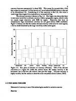
Fig. 3–1. Typical variation of viscosity of bitumen with temperature
Fig. 3–2. Typical variation of viscosity of bitumen blend with the addition of naphtha diluent at 20°C
Chapter 3 Analytical Techniques
Viscosity versus temperature Figure 3–1 presents a graph of the variation of viscosity with temperature for Athabasca bitumen. Viscosity is exquisitely sensitive to temperature, decreasing exponentially—from a value of 1 million at room temperature to below 100 mPa·s at 100°C. Over the years, attempts have been made to predict the viscosities of bitumen at diferent temperatures. he irst basic equation to predict the viscosity was developed by Walther and was presented at the 1937 World Petroleum Congress: ln ln(γ + 0.7) = mlnT + b
(3–2)
where γ is the kinematic viscosity (in cSt), T is the absolute temperature (273 + °C), and m and b are constants for a particular oil. Equation 3–2 permits a straight-line plot of kinematic viscosity versus temperature within a certain temperature range. he values of the constants are determined from known viscosities at known temperatures, and then viscosity at an unknown temperature is calculated. However, the values of the constants in equation 3–2 have been modiied by diferent researchers to predict the viscosity more accurately. If kinematic viscosities of any liquid hydrocarbons at two temperatures are available, then the kinematic viscosity at any other temperature (within a limited range) can be determined from a standard chart (see ASTM D-341).
Viscosity versus diluent he viscosity of bitumen also varies with its dilution. Figure 3–2 shows that the blending of bitumen with a very light hydrocarbon, such as naphtha, will decrease the viscosity exponentially, similar to the case of decrease in temperature. he addition of only 10 wt% naphtha decreases the viscosity from 1 million to 10,000 millipascal-seconds, and the addition of a further 10 wt% (i.e., total 20 wt%) naphtha causes the viscosity to go down below 1,000 millipascal-seconds, making it mobile. his is one of the reasons why lighter hydrocarbons, such as naphtha or condensates, are used as diluent to transport bitumen through pipelines (discussed in chap. 6). Furthermore, there is a need to predict the viscosity of a blend, and several equations serve that purpose. However, the most commonly used method to predict the viscosity of crude blends is ASTM D-341, along with the Rafutas index method. he blending index is given as follows: I = f(γ) = 23.097 + 33.468 log log (γ + 0.8)
(3–3)
41
42
Oil Sands, Heavy Oil, and Bitumen: From Recovery to Refinery
where I is the Refutas index and γ is the kinematic viscosity. In this method, the viscosity of each hydrocarbon component in the blend is determined irst, and then the Refutas index of the blend is calculated as follows: n
Iβ =
ΣIW i
i
(3–4)
i
where Ii is the Refutas index and Wi is the weight fraction of the component i. Kinematic viscosity γ of a blend is calculated from equation 3–3 once the Refutas index value Iβ of the blend is known from equation 3–4. Readers are cautioned to use data derived from these equations carefully, because they are not valid over a wide range of temperatures or diluents. Also note that some researchers in diferent laboratories modify the values of the constants to meet their expected results. here is almost always a deviation between the predicted value and the real value (because models based on ideal cases will difer from reality). he viscosity of a blend is strongly dependent on the molecular weight of the diluent used.4 For example, the higher the molecular weight is of a diluent (e.g., methane [16], ethane [30], or toluene [92]), the higher will be the amount of the diluent required in order to meet the same viscosity at the same conditions.
Viscosity of visbroken liquid Banerjee et al. have carried out viscosity measurements of a bitumen feedstock and its mildly thermally cracked visbroken product samples by using shear techniques in coaxial cylinders.5 Bitumen samples were placed between two cylinders, and torque was applied at various shear rates, measuring stress at a constant temperature. Viscosity was calculated as the ratio between stress and shear rate.6 In the same study, it was observed that the viscosity of a visbroken product was quite sensitive to air exposure. Viscosity was signiicantly lowered, by about 50%, when oxygen was excluded from the reaction system. With no particular explanation, visbreaking of Athabasca bitumen was found to be more sensitive to oxygen than that of the Cold Lake bitumen.7
Chapter 3 Analytical Techniques
Asphaltene Analysis he asphaltene fraction of bitumen is separated either from the resid or from the whole bitumen by precipitation using a normal parain as a solvent. It is purely a physical separation, with no resultant chemical change in the structure of asphaltene. In a laboratory setup, asphaltene is separated by adding almost 40 times its volume of n-pentane, n-hexane, or n-heptane. he mixture is agitated for an hour in an ultrasonic bath at constant temperature; then, ater the mixture is iltered, the solid material is dried and collected as asphaltenes. Commercially, by contrast, lower hydrocarbons—such as propane, butane, or a mixture of both—are used. Yields of asphaltenes are dependent not only on the type of solvent used but also on the length of time the feedstock is kept in contact with the solvent. Several standard ASTM methods (e.g., D-2006, D-2007, D-4124, or IP -143) are used to determine the quantity of asphaltenes by use of various solvents. Readers should refer to those methods for more details.
SARA Analysis Classiication of bitumen into its four major groups, SARA (saturates, aromatics, resins, and asphaltenes), is done by several methods.8 With the development of new analytical techniques, now it is done either by high-performance liquid chromatography or on a micro scale more popularly by TLC-FID (thin-layer chromatography with lame ionization detector), using an Iatroscan instrument. By contrast PONA analysis (see chap. 2) is done strictly on distillate fractions by chromatographic and mass-spectroscopic techniques per ASTM D-3239, D-2549, or D-2786. Figure 3–3 represents the various steps involved in SARA analysis of bitumen on the basis of combined solubility and adsorption characteristics in a chromatography column.9 he sample is recovered by evaporating the solvent in a rotator evaporator. he amount of solvent required in order to elute any sample is directly related to the amount of sample retained in the column. However, the amount of solvent required can be visually estimated by noticing the change in color of the solvent as soon as all the desired sample is recovered. Note that, in this method, the resin is further separated into two fractions—namely, high-density and low-density resin. It is strongly recommended that this procedure be done only under proper protection in the laboratory, using a fume hood, because the solvents are toxic.
43
44
Oil Sands, Heavy Oil, and Bitumen: From Recovery to Refinery
R
Saturates Aromatics Resins Asphaltenes
Fig. 3–3. Quantitative and preparative SARA analysis of whole bitumen using column chromatography
Step 1 in igure 3–3 represents solvent extraction of bitumen into asphaltenes and maltenes by using 40 times the bitumen’s volume of n-pentane as solvent. he mixture is shaken for about 10–12 hours in a normal bath or about an hour in an ultrasonic bath and is then iltered to recover the asphaltene fraction. Maltene is recovered by evaporation of the solvent. In step 2, the maltene fraction is further separated into resin and oil by column chromatography, using the technique recommended by ASTM D-2007, where the clay column is irst eluted by n-pentane to recover the oil and the resin fraction is retained in the column. In step 3 (ig. 3–3), the same clay column is irst eluted with methyl ethyl ketone (MEK) to extract a dark-colored oily liquid, which is low-density resin. A further elution with tetrahydrofuran (THF) recovers a dark-colored crystalline semisolid, which is high-density resin. he pentane-soluble oil fraction obtained in step 2 is further separated in step 4 (ig. 3–3), into saturated and aromatic fractions in an activated silica-alumina column. he saturated fraction is irst eluted by n-pentane as a colorless liquid. he adsorbed aromatic portion in the column is then eluted by toluene.
Chapter 3 Analytical Techniques
Distillation and HTSD Normal distillation of a heavy crude oil in the laboratory is done in a distillation apparatus per ASTM D-86, for atmospheric distillation, followed by ASTM D-1160, for vacuum distillation under reduced pressure. Another standard test method is ASTM D-2892, for the distillation of crude up to an atmospheric equivalent temperature of 400°C in a fractionating column of 15 theoretical plates. An alternative vacuum distillation method for heavy oil is ASTM D-5236. Once the normal distillation is complete, then the experimental data are converted to true boiling point (TBP) data at atmospheric pressure or 101 kilopascals (kPa). A distillation curve is then drawn between volume percent (vol%) or wt% distilled versus TBP. his is a time-consuming method; however, the method is indispensable when detailed properties of fractionated products are required. Capillary-column GC is being used for SimDist, per ASTM D-2887, to determine various boiling fractions of heavy crude oils. he advantage of this chromatographic technique is that the sample that contains a nonvolatile component, such as resid, can be analyzed by injecting simply the diluted original sample (i.e., the way it was when it was received). he unrecovered resid portion of the bitumen could be back-calculated from the amount of sample injected. Another advantage of the capillary-column GC technique is that the SimDist curve can be sliced at any desired fraction’s boiling range, and the yield of the various fractions can then be calculated theoretically. SimDist curves of several samples can be compared directly by overlapping them on the same plot. Recent advancement of this technique can reach more than 700°C (1,300°F), by use of HTSD per ASTM D7169-2005 (based on ASTM D-2887). However, this temperature range is practically impossible to achieve in a commercial vacuum tower in a reinery without cracking the bitumen.
A word of caution his technique needs careful calibration method in order to identify the components and corresponding equivalent boiling points. For example, SimDist calibration is based on the retention times of normal parains and their boiling points; however, aromatic compounds’ boiling points do not fall within the same range. Sometimes, researchers refer to average boiling points instead of actual boiling points. hus, one has to be very careful when using these data, especially when comparing data from diferent laboratories.
45
46
Oil Sands, Heavy Oil, and Bitumen: From Recovery to Refinery
CHNS In the coal industry, CHNS is determined by ultimate analysis. For bitumen, a similar combustion technique can be used for the analyses of carbon and hydrogen only (e.g., ASTM D-3178). However, sulfur and nitrogen are determined separately by more precise techniques. As the sulfur concentration in the sample changes, the protocol for sulfur determination also changes. For example, in case of bitumen, where the sulfur concentration is higher than 1 wt%, ASTM D-4294 is used. By contrast, for bitumenderived products, where the sulfur concentration is below 0.5 wt%, ASTM D-1266 may be used; for bitumen-derived hydrotreated products, where the sulfur concentration has been reduced to below 100 ppm, ASTM D-3170 may be used. he total nitrogen in bitumen can be determined by combustion, using ASTM D-3179. However, for a more precise determination, other methods are preferred, such as oxidation followed by the chemilumenescence (ASTM D-4629); for trace-nitrogen analysis, ASTM D-3431 can be used.
Metals Metals are usually analyzed in the whole bitumen or in the resid fraction. Metals are irst recovered from the sample as ash by combustion. he metals in the ash are then analyzed by inductively coupled argon plasma techniques (ICAP) or by atomic absorption (AA) spectroscopy. Standard methods (e.g., ASTM D-2788 or D-3340) can be used for the determination of metals in heavy oil or its processed products.
TAN Acidity of a crude oil is measured by a simple potentiometric or pH titration method by neutralizing the acid functional group by using a basic solution, such as sodium or potassium hydroxide (KOH). he TAN value is deined as the milligrams of KOH required to neutralize the acidic group of one gram of the oil sample; thus, the TAN value is expressed in units of mg KOH/g. he TAN value is also known as the basicity number.
Chapter 3 Analytical Techniques
Water Accurate analysis of water in a bitumen sample is extremely diicult because of emulsion formation. Usually, the water content is determined by the Karl Fischer titration method in a Mettler-Toledo model DL-32 instrument.
Challenges in Analysis of Heavy Petroleum Fractions Critical to the characterization of heavy oil or bitumen are the analytical techniques and protocol used by the chemist for the analysis of the feedstock and the product sample obtained from any process or experiments. he characterization of high-molecular-weight species is extremely diicult; nevertheless, there is a deinite need to characterize bitumen at the molecular level. Chemists interested in this area must anticipate fractionating the bitumen as much as possible before considering its characterization. Recently there has been great interest in the fractionation and characterization of larger molecules by using high-performance liquid chromatography (HPLC) or, more recently, using supercritical luid chromatography, in combination with various spectroscopic techniques. Although detailed description of the analysis of heavy oil or bitumen is beyond the scope of this book, analytical chemists interested in the detailed spectroscopic analysis of heavy petroleum fractions may consult the book Composition and Analysis of Heavy Petroleum Fractions, by Altegelt and Boduszynski, which describes in detail the combination of a high-performance chromatographic separation followed by various spectroscopic techniques to characterize heavy fractions at the molecular level.10
47
48
Oil Sands, Heavy Oil, and Bitumen: From Recovery to Refinery
References 1 Speight, J. G., 2000. he Desulfurization of Heavy Oils and Residue, 2nd edition New York: Marcel Dekker, p. 55. 2 Seyer, F. A., and C. W. Gyte. 1989. A Review of Viscosity—AOSTRA Technical Handbook Publication on Oil Sands, Bitumens and Heavy Oils. L. G. Hepler and C. His (eds.). Edmonton, AB: Alberta Oil Sands Technology and Research Authority (AOSTRA). 3 Ibid. 4 Ibid. 5 Banerjee, D. K., W. C. McCafrey, and M. R. Gray. 1998. Enhanced Stability of Products from Low Severity Upgrading of Residue. Internal report, Department of Chemical and Materials Engineering, University of Alberta, Canada. 6 Seyer and Gyte, 1989. 7 Banerjee, McCafrey, and Gray, 1998. 8 Wallace, D. 1988. A Review of Analytical Methods for Bitumens and Heavy Oils. Edmonton, AB: Alberta Oil Sands Technology and Research Authority. 9 Banerjee, D. K. and K. J. Laidler (1985). CANMET Project Report #42105109, Ottawa, Ontario. Banerjee, D. K., K. J. Laidler, B. N. Nandi, and D.J. Patmore, (1986). Kinetic studies of coke formation in heavy crudes, Fuel, 65, pp. 480–485. 10 Altegelt, K. H., and M. M. Boduszynski. 1994. Composition and Analysis of Heavy Petroleum Fractions. New York: Marcel Dekker.
RECOVERY TO REFINERY
4
T
he demand for energy is increasing rapidly. he heavy oil and bitumen industry will undoubtedly play a vital role in meeting this challenge. However, tapping into heavy oil reserves is not a short-term solution: it is highly capital intensive, it does not provide an immediate high rate of return or a high proit margin, and the heavy oil business strongly depends on the price diferential between heavy crude and light crude. Increasing the proit margin of a company requires the complete integration of upstream and downstream portfolios from recovery to reinery. Bitumen is exceedingly diicult to handle, recover, transport, and reine. he most diicult challenge is posed by the bottom-of-the-barrel portions—namely, the resids and asphaltenes. In the heavy oil/bitumen business, the purpose is not to ind more oil deposits, but rather to maximize the project economics through optimization of each and every step involved. he whole purpose of the business is to convert heavy crude into synthetic crude that will substitute for the conventional crude. he industry needs to develop new technologies to meet those challenges. Even today, few reineries in the United States are capable of processing heavy oil. he development of oil sands is energy intensive, as compared to the development of conventional crudes. Because the quality of the crude becomes poorer with the increase in density, aromaticity, or impurities, the severity of the processing increases, as does the energy consumption in each step. Chief among the problems with the Alberta oil sand deposits is its location—far up north, in a harsh climate, and away from major infrastructure. Up front, that increases the cost of capital and the operating expenses, starting with the recovery of the bitumen from the subsurface reservoirs, then proceeding through the transportation of the bitumen either to a nearby upgrader or to a reinery in Canada or the United States.
49
50
Oil Sands, Heavy Oil, and Bitumen: From Recovery to Refinery
Another problem facing the bitumen industry is the perception around the world that Canadian bitumen is dirty and high in greenhouse-gas (GHG) emissions (see chap. 11). here is a great ongoing debate on this subject inside and outside the industry.
Major Steps from Recovery to Refinery In the oil sands business, the entire value chain, from recovery to reinery, needs to be considered, rather than only the single step in which each independent company or a particular group within a big company specializes. his is because the value of bitumen depends on the price at which bitumen producers can sell their product to reineries, in spite of competition from light (conventional) crude producers. Figure 4–1 represents the major steps involved, from the production of bitumen to its transportation to a reinery gate. Each step in the process needs external energy input, and that should be matched relative to the energy available in the bitumen. As the energy input increases, the operating cost of production and transportation increases. At the same time, the environmental impact of each step needs to be mitigated.
Fig. 4–1. Steps from recovery to refinery in the oil sands
Chapter 4 Recovery to Refinery
Step 1: Recovery In the northern-most part of Alberta, the bituminous oil sands are surface mined. he bitumen is then removed from the solid sand and clay particles by a hot-water extraction process (for details, see chap. 5). In southern Alberta, by contrast, the irst step in the recovery of bitumen from the subsurface reservoir involves steam injection. he latest technology for in situ recovery is known by the acronym SAGD (pronounced “sag-dee”), which stands for steam-assisted gravity drainage (for details, see chap. 5). he steam is produced on the surface by burning of natural gas. As a rule of thumb, about three barrel equivalents of cold water need to be converted into steam to extract one barrel of bitumen. Next, steam is pumped down the hole, through the injection well. he steam transfers its own heat into the reservoir and raises the temperature enough to decrease the viscosity of the bitumen, making it mobile. Near Fort McMurray, Alberta, the cold reservoir temperature is about 10–12°C. As was shown in igure 3–1, the viscosity of bitumen is more than 1 million mPa·s at those conditions. Steam heats the reservoir to above 200°C to decrease the viscosity, to approach that of water (30 years old) that has been tried unsuccessfully by many companies and research institutes. However, development of in situ technologies remains an area of interest. For example, the process of in situ hydro-visbreaking, with or without catalysts, has been studied extensively in Canada and Venezuela since the early 1980s, and research is still being performed in Alberta. Many researchers, especially in Canada, are working on developing new technologies to simultaneously upgrade and recover bitumen. One of the most recent interests is in in situ catalytic upgrading, whereby researchers attempt to upgrade heavy oil by cracking heavier molecules into smaller sizes in the presence of an ultradispersed nanocatalyst and hydrogen.10 his is expected to reduce the density and the viscosity of the bitumen in the subsurface reservoirs before it is recovered aboveground. No public information about this project is yet available; however, if it is successful, this process promises to reduce the cost of production and transportation of heavy oil, as well as to reduce GHG emissions considerably.
67
68
Oil Sands, Heavy Oil, and Bitumen: From Recovery to Refinery
It is certain that in situ upgrading will be less eicient than surface upgrading. he following concerns need to be addressed regarding in situ processes: • here will be uncontrolled mobility of the dispersed catalyst and hydrogen in the reservoir. • A temperature of at least 350°C is required for hydro-visbreaking, which cannot be reached in a shallow reservoir. In deeper reservoirs, other problems regarding the operating conditions will occur. • At low pressures (i.e., below fracture pressure [19°) than the pipelines require, there is room to blend bitumen with the syncrude. When a synthetic crude is blended with the bitumen, the blend is called SynBit. he volume of syncrude needed in the blend is directly related to the API of the syncrude. In Alberta, the most common synthetic crude used for blending is known as OSA (Suncor Oil Sands Blend A) and has an API gravity of 33.0°; it requires 50 vol% of OSA to meet the target API value of 19° when blended with Athabasca bitumen with an API gravity of 7.7°. Suncor also markets a Sour Synthetic Blend, similarly known by the acronym OSE, that is a mixture of hydrotreated naphtha, coker gas oil, straight-run gas oil, and Athabasca bitumen. Syncrude Canada markets a diferent SynBit known as SSB (Syncrude Sweet Blend), which is a mixture of hydrotreated luid coker product and bitumen. Husky Oil markets a fully upgraded premium-quality synthetic crude known as HSB (Husky Sweet Blend).
SynDilBit It is challenging for the reiners to accept various grades of pipeline blends such as DilBit, SynBit, or syncrudes (discussed in detail in chap. 10). Not all the products are the same; thus, reiners have to know the detailed assays of each and every crude blend before processing them through their reinery or even before purchasing the crude. Not all crudes can be handled by all reiners. To eliminate the large numbers of synthetic blends in the market and to achieve consistency for the reiners, EnCana (Canadian Oil company) in consultation with other companies decided to market a special blend that meets a consistent assay so that the reiners will not worry about the variation of crude blend quality every time. his blend consists of 65 vol% bitumen where the other 35 vol% is a mixture of condensate, synthetic crude, and some conventional crude. his blend is known as SynDilBit because it close resembles a mixture of SynBit and DilBit. he targeted assay of SynDilBit is as follows: • API gravity, 19–22° • Sulfur content, 2.8–3.2 wt% • TAN value, 0.7–1.0 mg KOH/g sample • CCR, 7.0–9.0 wt% he most widely used SynDilBit in the market is WCS (Western Canadian Select). Another blend is WH (Wabasca Heavy).
75
76
Oil Sands, Heavy Oil, and Bitumen: From Recovery to Refinery
Composition of Pipeline Blends Figures 6–2 and 6–3 show the composition of various types of blends available in the market. Synthetic crude has no bitumen in it; hence, there is no resid in the crude.
Fig. 6–2. Variation in effective pipeline capacity with type of blend
Fig. 6–3. Composition of various types of blends
Chapter 6 Transportation of Heavy Oil/Bitumen
As shown in igure 6–2, the bitumen concentration in the blend increases from SynBit (50 vol%) to SynDilBit (65 vol%) to DilBit (75 vol%). Hence, for a ixed capacity of pipeline of 100,000 BPD, SynBit would transport 50,000 BPD, SynDilBit would transport 65,000 BPD, and DilBit would transport 75,000 BPD of bitumen. From an economic point of view, although the cost of transportation through the pipeline of a particular volume of blend is the same, on a simple bitumen-volume basis, the amount of bitumen transported per unit volume will be diferent for the production companies and consequently will afect their economics. Hence, there is a penalty for transporting the diluent. Figure 6–3 illustrates the detailed composition of various synthetic blends as compared to typical conventional crude. Increase in the bitumen concentration in the blend increases the resid concentration in the same ratio. Conventional crude has the minimum amount of resid (15 vol%) as compared to the other synthetic blends (20–30 vol%). DilBit has the highest concentrations of naphtha (35 vol%) because it is added as a diluent, while syncrude has almost the same amount of naphtha because it is produced from the cracking of the bitumen. Conventional crude has natural straight-run naphtha (30 vol%). DilBit has very small amount of distillate (5 vol%) because it is not present in either the bitumen or the condensate. It has some gas oil (20 vol%), which comes directly from the bitumen. Syncrude has a large volume of distillate (35 vol%) and gas oil (30 vol%) as cracked product from the bitumen; subsequently, they are proportionately distributed in the synthetic blends. Typical conventional crude consists of about 30 vol% distillate and about 25 vol% gas oil. Because of the large scale of mining operations as compared to in situ operations, almost all mining development projects are associated with upgraders in the ield. his eliminates the diluent demand for the mining projects. By contrast, in situ projects are too small and an upgrader is too expensive to be integrated in the projects. Hence, in the future, because bitumen production is expected to increase through in situ projects, the demand for diluent will therefore increase. For this demand to be met, in situ projects must either include a small-scale ield upgrader or partially upgrade the bitumen.
Blend composition and API gravity he amount of diluent required in order to meet the targeted pipeline speciication is directly related to the API gravities and viscosities of the diluent and the bitumen. he higher the molecular weight is of the diluent,
77
78
Oil Sands, Heavy Oil, and Bitumen: From Recovery to Refinery
the higher will be the amount of diluent required in order to achieve the same API value of the blend. Figure 6–4 illustrates the amount of diluent required in order to meet pipeline speciications if it were blended with bitumen that has an API gravity of 10° or a density of 1,000 kg/m3 to make the blend have an API gravity of 19° or a density of 940 kg/m3. According to the author’s experience (not a published work) it has been observed that, for a blend, if the density speciication is met, then the viscosity speciication of 350 cSt is always met, but not vice versa. he lower the diluent’s API gravity is, the higher will be the volume of diluent required in order for the blend to meet the pipeline speciication of 19°API. For example, to make 100 bbl of a blend (bitumen + diluent), it will take 60 bbl of diluent of 25°API, or 50 bbl of diluent of 30°API to meet the pipeline speciication. If very light naphtha or condensate of 65°API is used as diluent, then only 20 bbl of diluent will be enough to transport 80 bbl of bitumen of 10°API through the pipeline.
Fig. 6–4. Diluent API gravity and corresponding vol% to meet target of 19°API (given raw bitumen API gravity of 10°)
Chapter 6 Transportation of Heavy Oil/Bitumen
Care should be taken, however, when blending raw bitumen with a large excess of parainic diluent, because of the risk of precipitating the asphaltenes, leading to an increase in fouling. Moreover, if the bitumen has already gone through any partial or full upgrading process(es), the chance of fouling increases much more as compared to when raw bitumen is used.
Orimulsion Orimulsion is a proprietary technology developed by the Petroleum Research Organization (Pdvsa) of Venezuela, where heavy oil is transported and sold as fuel in the form of an emulsion: a mixture of 70% heavy oil and 30% water with added phenolic or alcohol-based surfactant. Use of this mixture also reduces the viscosity of the heavy oil, thus facilitating transportation of the heavy crude. Initially, Orimulsion was a huge success as a fuel competing with coal in electricity-generation plants because there was no upgrading cost. However, in light of the present disruption in the Venezuelan oil industries (due to internal problems), the present status of Orimulsion is unknown.
Challenges Facing the Pipeline Industries Stability issues A milestone for the pipeline industry will be to accept various categories of blends. Every blend behaves diferently because the fouling tendency strongly depends on the quality and composition. he fouling tendency of a blend is deined in terms of stability. A crude blend is deined as unstable when fouling takes place as a result of solid settlement, precipitation of asphaltenes, and sediment or gum formation during transportation. here are economic penalties for transporting such crude blends. Major stability problems are due to blending incompatibilities. It is common to blend conventional crudes with standard compatible crudes, such as West Texas Intermediate (WTI) or Alaskan North Slope (ANS). Because processed heavy oil and bitumen have diferent compositions, they may be incompatible with WTI or ANS. It is well known that there are incompatibilities between the high-asphaltene and high-parainic crudes. Precipitation of asphaltenes when blending crudes can lead to catastrophic fouling in the pipeline or coking in the preheat train, resulting in net economic loss. he blending of crudes known to be incompatible should always be avoided.
79
80
Oil Sands, Heavy Oil, and Bitumen: From Recovery to Refinery
In addition, severely thermally cracked bitumen products, such as coker liquid, contain oleins and dioleins, which cause fouling as a result of polymerization or gum formation. Also, mildly thermally cracked visbroken products are notorious for their instability. A visbreaking study determined that the instability due to sediment formation increases by about 100 times in a mildly visbroken product as compared to raw Athabasca bitumen.2 he reason for the increase in instability of the thermally cracked product is that once the asphaltene structure is disturbed as a result of thermal cracking, it starts agglomerating. Consequently, the tendency to precipitate out increases such that it precipitates out into its own liquid. his enhances the rate of fouling.
Stability measurement Every pipeline blend has to meet stability criteria before transportation. herefore, it is important for the pipeline industry and for reiners to measure stability before purchasing a blend. Several compatibility models and laboratory tests measure stability and thus can be employed to prevent fouling. Unfortunately, most of these methods are proprietary and not available publicly, for the purpose of standardization; even large oil companies are using diferent proprietary methods of their own. he following sections describe available, standard laboratory methods to measure the stability of a blend. Bromine number test. Olein concentration is measured by titration using a bromine solution per method ASTM D-1159. It is cautioned here that the bromine number should be measured only in distilled product and not on whole crude containing resid, because the latter will give erroneous results. he higher the bromine number is, the higher will be the unsaturated components in the blend and the greater the tendency to foul. he bromine number is expressed as the number of grams of bromine required in order to saturate 100 grams of the test sample (i.e., in units of g Br2 /100 g sample). A bromine number above 10 in a naphtha fraction is considered an unstable product. Recently, PONA analysis has been introduced as the standard analytical technique for the olein determination. he maximum limit is set to 1 wt% in a light distillate. Centrifuge method. Stable emulsion and ine solid particles also cause fouling. It is determined by BS&W measurement by the standard ASTM D-4007 method, and a value of above 0.5 wt% is considered unstable.
Chapter 6 Transportation of Heavy Oil/Bitumen
Shell Hot Filtration Test. Sediment formation is measured by a standard method known as the Shell Hot Filtration Test. he standard method for the measurement of sediment is ASTM D-4870. In this method, the sample in question is diverted into a hot, sintered ilter at 100°C and passes through a Whatman GF/A glass-iber ilter medium. Hot iltration is performed under vacuum by using a steam-jacketed metallic funnel. Ater iltration, the solid sediment is washed with hot n-heptane. he amount of dry sediment retained is weighed. If the amount of sediment collected is greater than 0.1 wt% in the blend, then it is considered unstable (i.e., unsuitable for transportation). P-value test. his method was developed by Shell (method 1600-80) as a stability test for asphaltenes. In this method, the oil sample is titrated with a known volume of n-parain, such as n-cetane, as solvent. Precipitation is observed under a microscope. his is measured by the maximum amount of n-cetane (in ml) added to a gram of oil sample to keep the asphaltenes in solution—that is, when the irst indication of the precipitation starts. he P value is calculated as follows: ml of n-cetane P = 1 + ————————— 1 gram of sample
(6–1)
If the P value calculated using equation 6–1 is greater than 1.1, then the solution is considered stable. In other words, if it takes more solvent to precipitate the asphaltenes, then it is more stable.
References 1 Segato R. 2010. Enbridge Condensate Pool Speciications, Feb. 11, COQA meeting, New Orleans; Canadian Association of Petroleum Producers. 2010. Crude Oil and Oil Sands Publications, Calgary, Alberta http://www.capp.ca/library/publications/crudeOilAndOilSands/pages/. 2 Banerjee, D. K., W. C. McCafrey, and M. R. Gray. 1998. Enhanced Stability of Products from Low Severity Upgrading of Residue. Internal report, Department of Chemical and Materials Engineering, University of Alberta, Edmonton.
81
UPGRADING OF HEAVY OIL/BITUMEN
7
Why Upgrade Bitumen?
A
s discussed in earlier chapters, the virgin (unprocessed) bitumen is not mobile at normal conditions; it has poor cold-low properties. Hence, raw bitumen and heavy oil are never sold as recovered, because it is not suitable for transportation. It is either transported to the market and sold as diluted bitumen or upgraded in the ield and sold as synthetic crude oil. For the value of the bitumen to be increased so that it may compete with the conventional crude, it is absolutely necessary to increase the quality of the bitumen by upgrading. With the increase in production of bitumen, the market for syncrude will have to be increased, which requires investment by the producer in a heavy oil upgrader. Whether it is attractive to invest in an upgrader will be determined by the price diferential between light and heavy crude. A steady price diferential market will be required over the planning, design, and construction period, which typically takes several years. Current environmental demand for emission control in heavy oil requires such considerable investment that the proit margins are greatly curtailed. Hence, for an increase in the synthetic crude market to be realized, upstream and downstream interests must be merged. As shown in igure 7–1, the upgrading of bitumen comprises two stages: primary and secondary upgrading. Primary upgrading is usually carried out either thermally, by the coking process, or catalytically, by the resid-hydrocracking process. In the primary upgrading step the bigger molecules are cracked into lower-molecular-weight molecules to make a desirable distillable product. In both cases, the processed oil’s composition is fundamentally diferent from the virgin oil’s composition in terms of sulfur, nitrogen, oxygen, and hydrogen. he gaseous components consist of lighter hydrocarbons, or liqueied petroleum gas (LPG), that are separated and used as fuel. Primary upgrading processes are discussed in detail later in this chapter. 83
84
Oil Sands, Heavy Oil, and Bitumen: From Recovery to Refinery
Fig. 7–1. Typical route of bitumen to refinery
In the secondary-upgrading stage, the resulting liquid oil from the primary step is further processed to produce a syncrude that meets the reinery feedstock speciications. he most common process to remove heteroatoms and metals, as well as to saturate the aromatics, is hydroprocessing. his resembles a conventional reining hydrotreating process and is therefore not discussed here in detail. hus, syncrude quality depends not only on the properties of the bitumen as feedstock but also on the history of the thermal and catalytic processes that took place. Hence, the syncrude is drastically diferent from the conventional oil with the same boiling-point distribution. Conventional reineries cannot always handle syncrude owing to its limited catalyst performance. Syncrude at the reinery gate mainly consists of naphtha, distillate, and heavy gas oil. he naphtha fraction goes to a reformer to be converted into high-octane gasoline. he distillate fraction is treated in a hydrotreater to meet the speciications of diesel, kerosene, and jet fuel. he gas oil fraction is directed to a luidized catalytic cracking (FCC) unit or to a hydrocracker, to convert the heavier feedstock into diesel and gasoline range products. To ind out more about the reining processes, readers may consult additional sources.1
Synthetic Crude versus Conventional Crude Synthetic crude is one of many misnomers in the oil industry. It is neither a synthetic material nor a crude; rather, it is a thermally processed liquid derived from bitumen.
Chapter 7 Upgrading of Heavy Oil/Bitumen
he formation of the synthetic crude oil from the bitumen is dominated by a thermal cracking reaction in an upgrading process. he long-chain parainic groups in the residue are likely to cleave β or γ bonds on an aromatic or naphthenic ring, to form lower molecular-weight products with alkyl-aromatics and naphthenic rings in the distillate. When hydrocracking is used instead of coking in the primary upgrading, there will be lower amounts of sulfur and nitrogen in the distillate. Still, secondary hydrotreating is required in order to meet the reinery speciications. Heteroatoms that migrate to the syncrude are resistant to further hydrotreating. Hydroprocessing of syncrude is a major process in a reinery. It is also diicult, because several reactions occur simultaneously (e.g., the removal of S, N, O, and metals, along with the saturation of aromatics and oleins). Above 400°C, the coking reaction competes with the hydrogenation reaction, and the availability of hydrogen and the reaction pressure dictate which reaction dominates. he cetane number of the diesel fraction of a synthetic crude is less than that of a conventional crude, and the diesel fraction requires further treatment before use. Parain in the bitumen usually moves into the naphtha range ater cracking instead of into the diesel range, where it is needed to be for cetane improvement. Aromatic hydrogenation is another way to improve diesel quality; however, it reaches thermodynamic equilibrium and limits the process of naphthenic compound formation. Fractions of synthetic crude are more aromatic than conventional crude. his property is desirable in the gasoline fraction because it acts as an octane improver; however, it is undesirable in diesel and jet fractions because it gives poor cetane and smoke numbers. Similarly, the VGO fraction in syncrude is rich in aromatics and heteroatoms, making it diicult to crack in an FCC unit. VGO in syncrude poisons the catalyst faster than VGO in conventional crude. Because of the heavy demand for gasoline in the United States, the cracking of gas oil in an FCC unit is an important process. Most syncrude is produced by a delayed-coking process. he product is more aromatic and oleinic as compared to conventional crude. his requires suicient hydrotreating, which a conventional reinery may not be able to handle without major capital investment. Syncrude is better than conventional crude in certain respects, because it does not contain any resid, asphaltenes, metals, or salt. However, most of these advantages are negated when syncrude is blended with bitumen to produce SynBit. If a grassroots reinery is built, then the most probable choice would be to design it to handle boutique syncrude reinery feedstock only. he most important advantage will be that no vacuum tower or desalter is
85
86
Oil Sands, Heavy Oil, and Bitumen: From Recovery to Refinery
required. Syncrude’s acidity is lower than that of the conventional crude; hence, metallurgy of the crude tower will be simpler, with the choice being between an FCC unit and a gas oil hydrocracker unit. On the one hand, the FCC product would be more hydrogen deicient and thus would require severe hydrotreating to produce a marketable product. On the other hand, a hydrocracker product would be more hydrogenated than the FCC product and would have the added beneit of controlling the gasoline-to-diesel yield ratio according to market demand. However, the choice of catalyst in a hydrocracker is diicult, because syncrude contains a higher concentration of refractory nitrogen as compared to conventional crude. Carbon deposits on the catalyst surface are also prevalent in syncrude feedstock owing to higher concentrations of oxygen, nitrogen, and aromatics. he shit in reinery feedstocks from conventional to synthetic crude necessitates the improvement of catalyst quality, toward the selectivity of the desired products. he overall hydrogen demand is higher in a syncrude reinery than in a conventional crude reinery, even though it does not have to deal with resid or asphaltenes. In general, a conventional reinery cannot handle the unpredictable variation of syncrude properties that would cause an increase in corrosion, fouling, and process upsets. On the other hand, in the case of hydrogen-addition technologies, a major part of the emission of CO2 is associated with the production of hydrogen from natural gas and other utilities.
Severity of Upgrading he following are the biggest problems in processing heavy crudes: • Low API gravity ( 1,000 kg/m3) • High asphaltenes (>10 wt%) • Low H/C ratio (100 ppm) • High heteroatom contents (S > 3 wt%; N > 1,000 ppm) • High acidity (TAN > 2 mg KOH/g sample) • High carbon residue (CCR > 10 wt%) • Unknown chemistry of big resid molecules
Chapter 7 Upgrading of Heavy Oil/Bitumen
Because of the aforementioned poor properties of bitumen, severe processing conditions are needed to upgrade it. Severity of the process depends on several factors: • Temperature • Total pressure • Residence time • Hydrogen-to-feed ratio • Partial pressure of hydrogen Severity is usually an indication of resid conversion. he higher the severity is, the higher will be the resid conversion. Resid conversion is deined as follows: wt of resid in feed – wt of resid in product wt% resid conversion = —————————————— × 100 wt of resid in feed
(7–1)
Similarly, the degree of removal of sulfur, nitrogen, or metals in a secondary hydrotreating process is deined as follows: wt of S,N in feed – wt of S,N in product wt% S/N conversion = ———————————————————— × 100 (7–2) wt of S,N in feed Of course, in a catalytic process, conversion is highly dependent on the catalyst activity.
Major Upgrading Processes he irst step in upgrading is to separate the lighter, distillable fraction (1,000°F]) by using a vacuum distillation unit. he lighter fraction behaves similarly to the medium-sour conventional crude familiar to reiners. However, handling of the heavier, nondistillable resid poses a challenge. Half of a barrel of bitumen consists of this resid. A key criterion in choosing an upgrading process is the ability to optimize the cracking process for the breaking of the most diicult bigger molecules, to maximize the distillable liquid yield.
87
88
Oil Sands, Heavy Oil, and Bitumen: From Recovery to Refinery
Bitumen is deicient in hydrogen, having an H/C ratio of less than 1.5. his calls for the upgrading of bitumen to increase the H/C ratio to above 1.5 in the inal product. here are two major ways to increase the H/C ratio—either by rejecting the carbon or by adding hydrogen. As shown in igure 7–2, there are two major upgrading processes: carbon rejection and hydrogen addition. here are several carbon-rejection options available in the market, and they are all commercially proven and economically attractive residue upgrading options as compared to hydrogen addition. However, carbon-rejection processes typically have a substantial reduction in liquid volume yield, since part of the crude is converted into solid coke or pitch. Details of the individual upgrading technologies are discussed in chapter 8; however, the general processes are described below.
Fig. 7–2. Heavy oil–upgrading options
Carbon-rejection processes Carbon rejection can be done by a thermal process in which chemical changes take place in the molecular structure of the feedstock, or it can be done by a simple physical process in which highly concentrated bigger carbon structures, such as asphaltenes, are physically separated by solvent extraction. he most fundamental reaction for the upgrading of bitumen is the thermal cracking of the bigger molecules into smaller ones. Cracking of the molecules is dependent on the bond energies. Because there are various types of bonds involved with diferent bond energies, the thermal reactions are not simple. he following sections describe the various types of carbonrejection processes.
Chapter 7 Upgrading of Heavy Oil/Bitumen
Visbreaking. he most economical and easiest thermal process is visbreaking. (he terminology comes from viscosity breaking.) It is the oldest technology, in which the heavy feedstock is subjected to mild thermal cracking at a lower severity to reduce the viscosity and to produce fuel oil. In the visbreaking process, bigger molecules are partially broken, so that the viscosity of the crude is decreased to such an extent that the liquid becomes mobile. his process has its limitations, and the most common problem is the relative instability of the visbroken product. his process is not of much use in the United States and Canada and has only limited use in Europe because there is no market for the residual fuel oil produced in visbreaking. Hence, detailed discussion of the process is avoided. he thermal cracking takes place in the furnace coil, while the feedstock is travelling through the furnace. he visbreaker temperature is usually 450–500°C in the furnace, and the feed rate is maintained between 1 and 5 minutes. In another type of visbreaker, called a soaker drum, the temperature is lowered to 430–450°C, and residence time is increased to 5–8 minutes. he disadvantage of the soaker-drum process is that it forms more coke than the coil-type visbreaking process and requires frequent decoking—at additional cost and handling but yielding the same product qualities. Most commercial units operate at between 20% and 30% of the resid-conversion range. his is because, as the conversion increases, the product becomes more unstable, owing to asphaltenes precipitation. Ater visbreaking, the lighter fraction is used as blendstock in the reinery, and the heavier fraction is used as a source of fuel oil. Coking. he most widely used thermal commercial process is coking. In particular, it is the most dominant process in U.S. reineries, and there is increasing use of coking as an upgrader technology in Canada and Venezuela. In the coking process, the feedstock is subjected to severe thermal conditions (i.e., very high temperature and longer residence times). Under these conditions, the resid conversion is almost 100% complete. Figure 7–3 represents a proposed reaction mechanism of the formation of coke from a hypothetical resid structure. hrough severe cracking, side chains of the aromatic structure are randomly broken to produce aromatic and parainic liquids. he big aromatic molecules, with the elimination of hydrogen and polycondensation, ultimately turn into coke (labeled as coke-1 in ig. 7–3). he liquid product is further cracked and dehydrogenated to produce a highly oleinic liquid product known as coker oil, as well as gaseous products. Certain of the oleinic hydrocarbons also undergo polycondensation reactions and produce coke (labeled as coke-2 in ig. 7–3). Because the coke is derived from a petroleum-based feedstock, it is widely known as petcoke in the world market.
89
90
Oil Sands, Heavy Oil, and Bitumen: From Recovery to Refinery
Fig. 7–3. Proposed coking reaction mechanism
In igure 7–3, coke-1 is derived from the aromatic nucleus containing heteroatoms and metals; thus, coke-1 consists of large amounts of sulfur, nitrogen, and metals. Although coker oil has higher market value, the economics of the process is driven by the value of the coke. Coke-2, produced from the parainic and aromatic liquid hydrocarbons, contains a much lower amount of heteroatoms and almost no metals. he H/C ratio of coke-2 is expected to be higher than that of coke-1. Coke-2 is more crystalline in structure as compared to coke-1, which is amorphous. Hence, coke-2 has higher market value than coke-1 does. he yields and properties of coke, coker oil, and gaseous products are highly dependent on the feedstock quality. his is because the severity is maintained at maximum to run the process essentially at 100% resid conversion. here are two major commercial coking processes: • Delayed coking • Fluidized-bed coking (also called luid or lexicoking) With the ever increasing bitumen production in Canada, the coking capacity is also increasing rapidly in the United States and Canada. he majority of the commercial coking processes are controlled by the delayedcoking technology. By contrast, in luidized-bed coking, the net coke yield is less, because part of the coke is burned during the process to generate heat. Delayed coking. he delayed coker acts as the garbage can of the reinery, into which any unwanted material in the reinery stream is thrown. In
Chapter 7 Upgrading of Heavy Oil/Bitumen
delayed coking, the heaviest part—the material that is most diicult to convert—is converted into coke, part of which is then converted into liquid product. he coke yield and its properties are inluenced by the feedstock characteristics. he most common feedstock is vacuum residue, containing high sulfur and metals. Coke yield is directly related to the concentrations of asphaltenes and CCR in the resid. he coking reaction takes place in a drum. he drum outlet temperature is maintained in the range of about 430–450°C (800–850°F) at a pressure of 30–60 psig (pounds per square inch, gauge). he feed is charged at the bottom of the coker drum ater being heated in a furnace at a higher temperature (490–500°C [910–930°F]). he material at the bottom of the drum sits for several hours, during which it turns into coke. his coke is porous, allowing the passage of liquid and gaseous products. he coke accumulates from the bottom to the top of the drum; the vaporized product comes out the top of the drum. Delayed coking is a semibatch process that works in a 24-hour cycle. A typical coking plant consists of two drums. In the irst 12 hours, the irst drum is illed with coke; then, the feedstock is switched to the second drum. For the next 12 hours, decoking takes place in the irst drum while the second drum is illed with coke. he coke is removed from the drum by cutting with high-pressure (~3,000 psig) steam. he coke drops from the bottom of the drum directly onto a conveyer belt or transportation cars (e.g., truck or rail). Although coking is generally thought of as a good way for reiners to get rid of the low-value dirty material in the feedstock, delayed coking can also be used to produce a high-quality coke that is more valuable and in greater demand than that produced by luid-coking technology. Commercially, the coke produced from a coker is known as green coke. he green coke is calcined at very high temperature (1,200–1,350°C) in a rotator kiln before being marketed to carbon and graphite industries. he calcined coke loses its volatile matter and attains a crystalline structure. hree major types of cokes are produced commercially: sponge coke, shot coke, and needle coke. hey difer signiicantly in properties and end use. Sponge coke is produced in a delayed coker when resid is rapidly heated and fed into a coker drum. he coke formed is spongy in character and hence gets its name. his coke from Alberta bitumen usually contains most of the sulfur and metals and sometimes is not even suitable for burning, depending on the level of impurities. However, calcined sponge coke with low impurities is used for making anodes in the aluminum industry. When the coker is operated in such a way that the operator wants to maximize the liquid product yield instead of the coke yield, shot coke is
91
92
Oil Sands, Heavy Oil, and Bitumen: From Recovery to Refinery
formed. As the name suggests, shot coke is usually spherical in shape, and it ranges in sizes. his is the least valuable coke. he production of needle coke involves a special application of delayedcoking technology. his is the most valuable coke. Unlike the other delayedcoking processes, in which the feedstock is resid, in this case, the feedstock is a lower-molecular-weight, highly aromatic resid-free liquid, with very low levels of asphaltenes and of impurities (e.g., metals). he coking reaction is represented by the reaction path to coke-2 shown in igure 7–3, and there is no metal or sulfur in the resultant coke. Because the coke is formed through polycondensation of low-molecular-weight molecules, the coke forms a layered or crystalline structure with no cross-linking; the appearance of these needlelike structures gives this type of coke its name. Needle coke is processed under extremely strict operating conditions, and most of the information on it is kept proprietary and conidential. he pretreated feedstocks are free of impurities. Examples of such feedstock include slurry oil, decant oil, and thermal tar. Needle coke yield and quality depend on coker operating conditions—such as coker temperature, drum pressure, feed recycle ratio, and steam addition—in addition to the feedstock properties. Needle coke has a very particular market for the production of graphite electrodes. Needle coke speciications are very strict, with very low sulfur ( thiophenes > benzothiophenes > dibenzothiophenes As the boiling point of the heavier fractions increases, the removal of sulfur becomes progressively more diicult. In all cases, sulfur is removed as hydrogen sulide (H2S), and as the concentration of H2S increases in the reactor system, the rate of the HDS reaction decreases. Hence, it may be necessary to remove the H2S online to increase the removal of sulfur. he HDS reaction is also afected by the presence of nitrogen in the system. he removal of sulfur in a ring structure (e.g., benzothiophene) occurs either with hydrogenation of the ring irst or without hydrogenation of the ring. However, in the case of nitrogen in the ring structure, HDN always follows hydrogenation of the ring, subsequently breaking the ring and removing the nitrogen. Note that the initial step of hydrocracking resid is not a catalytic process, even though there is catalyst present. he irst cracking of the aliphatic side chain of the bigger molecules takes place at a temperature above 350°C (>660°F) and is a thermal process. Hydrogenation of the cracked product is a catalytic process. By contrast, polynuclear aromatic hydrocarbons undergo hydrocracking in the presence of catalyst only. Aromatic rings in the outer layer irst get hydrogenated to a naphthenic ring, which subsequently cracks. Hydrogenation of an aromatic ring requires higher pressures (>2,000 psi); hence, the hydrocracking of resid requires a combination of high temperature and high pressure in order to complete the reactions without forming coke. It is easier to hydrocrack polynuclear aromatic hydrocarbons than simple aromatic ring hydrocarbons. All hydrogenation reactions are highly exothermic. he heat released per mole of hydrogen consumed varies in the range of 60–70 kilojoules per mole (kJ/mol). In the hydrocracking process, the presence of asphaltenes is a major issue.3 he most undesirable consequences of their presence are the formation of coke and the precipitation of asphaltenes on the catalyst surface. he actual chemistry behind asphaltene hydrocracking is still unknown. he severity of the hydrocracking process increases as the feedstock gets progressively heavier and as the desired quality of product increases. he coniguration of the reactor and the severity of the hydroprocessing operation for bitumen are diferent than for lighter (conventional) crude oil.
Chapter 7 Upgrading of Heavy Oil/Bitumen
Catalyst. A number of metal catalysts are available for hydrogenation reactions. Among the most commonly used metals are nickel, chromium, tungsten, molybdenum, palladium, cobalt, iron, and copper. Metal catalysts get poisoned easily in the presence of sulfur and nitrogen. herefore, oxides or sulides of the metals are usually used, to avoid poisoning. Nickel and vanadium porphyrin structures are about four to ive nanometers in diameter.4 During high-temperature operations, the organometallic structure decomposes, and the metals are deposited on the surface of the catalyst. Nickel and vanadium irreversibly cover the catalyst pore and deactivate the catalyst. hus, the process of deactivation is a metal adsorption process, not a catalyst deactivation process as commonly considered. he thermal deposition of the metals is a very rapid process and usually takes place in the initial stage at the front end of the catalyst bed of ixed-bed hydroprocessing reactors. Hence, the demetallization of heavy oil is carried out in a guard reactor with a proper catalyst pore-size design to capture the metals. Hydrocracking of heavy crude comprises a combination of reactions— namely, cracking the bigger molecules, followed by their hydrogenation. Usually, bifunctional catalysts are used for this purpose, and these are made of both acid functional groups, for cracking, and active metals, for hydrogenation. Commercial catalysts are made of a support containing acidic crystalline zeolites and amorphous silica-alumina compounds that provide acid groups. hat support is impregnated with active metals—such as palladium, molybdenum, nickel, or tungsten—that provide the hydrogenation activities. Basic nitrogen in the feed, such as pyridine or ammonia, as a product, destroys the acidity of the catalyst and deactivates it. Researchers are now actively involved in the development of the latest generation of ultradispersed (UD) homogeneous catalysts for the hydroprocessing of heavy oil and bitumen.5 All slurry-phase hydrocracking technologies under development are switching to UD catalysts (discussed in chap. 8). UD catalysts are made of nanoparticles of active metals (e.g., Ni, Mo, Co, and W). hey are injected as liquid phase into the reaction zone, either in solution or as an oil-water emulsion. he active nanocatalyst is formed inside the reactor and is dispersed throughout the oil phase. here are two main advantages of using a UD catalyst over a solid support–based catalyst: • Because of its nano size, it has high surface-area-to-volume ratio and is much more active than the solid support–based catalyst.
95
96
Oil Sands, Heavy Oil, and Bitumen: From Recovery to Refinery
• Because there is no solid support, metals from the bitumen feedstock cannot be deposited into and plug the pore volumes; thus, the catalyst remains active for a longer period of time. he concentration and the partial pressure of hydrogen in the hydroprocessing of heavy oil are very important. Increasing the hydrogen increases the quality of the inal product, decreases the reactor temperature needed for the same reaction, and decreases the rate of deactivation of the catalyst. hus, for economic reasons, it is essential that the hydrogen be recycled as much as possible and that a higher partial pressure of hydrogen be maintained. Inside the reactor, the recycled hydrogen should be kept as pure as possible. Hydroprocessing reactors. he main purpose of the hydroprocessing of bitumen during the upgrading process is to prepare the upgraded product as quality feedstock for the reiners. Most of the metals need to be removed so as not to plug the pore volume of the FCC or hydrotreating catalysts, and the basic (alkaline) nitrogen compounds need to be removed so as not to destroy the acid sites of the FCC catalyst. Basically, the lower the impurities content is in the feedstock, the better it is for the reiners. Over the years, generations of heavy oil hydroprocessing—and especially hydrocracking—technologies have been developed. Improvements in the reactor design from one generation to the next have contributed most to the improvement of catalyst activity by controlling metal deposit and coking. he following sections describe examples of several generations of hydroprocessing reactor designs, developed over a quarter of a century. Fixed-bed hydrocracker. his is the irst generation of hydroprocessing reactor and was designed to treat lighter crude with low sulfur, nitrogen, and metals. With the increasing impurities in the heavier feedstocks, the deactivation rate of the catalyst increased. As a consequence of plugging the catalyst pore size with the metals in the crude, catalyst life was reduced drastically and process shutdowns were frequent. With conventional heavy oil around a 15–20°API range and a metal content below 100 ppm, reiners were able to handle the ixed-bed process for some time, using swing beds and guard reactors. Moving-bed hydrocracker. he ixed-bed reactor system was improved in the next generation, by the development of moving-bed catalyst systems. he catalyst bed was moved by gravity from top to the bottom, and by doing so, the deactivated catalyst was replaced periodically. Ebullated-bed hydrocracker. As unconventional heavy oil/bitumen (100 ppm) started coming onto
Chapter 7 Upgrading of Heavy Oil/Bitumen
the market, the ixed-bed and moving-bed processes became prohibitively expensive to maintain. In the next generation of hydroprocessing technology, the catalyst bed was expanded upward by luidizing the bed with liquid low, with continuous addition and replacement of the catalyst. his technology is also called an expanded-bed process. Ebullated-bed reactors were successful in handling heavier feedstock, such as atmospheric or vacuum resid, having not only high metal concentrations but also high asphaltenes and CCR contents. he main purpose of this development was to make the catalyst life no longer be an issue. he two most commercialized technologies in the market today are LC-Fining, by Chevron Lummus Global, and H-Oil, by Axens/IFP. he problem with this design is that it requires a relatively high hydrogen partial pressure and a very high catalyst replacement rate. Hence, the process becomes expensive. Another set of problems are scale-up issues, because the reactor is complicated with the combination of liquid and solid low and expansion of the bed at severe conditions. Because of the luidization of the catalyst, the attrition rate is high and requires a high-mechanicalstrength catalyst. he ebullated-bed process is limited to high conversion rates ( 30 angstrom) and very high molecular weight (>1,000)—is mostly responsible for creating diiculties in the catalytic conversion of bitumen. For treatment of these bigger molecules, the pore size of the catalyst should
Chapter 7 Upgrading of Heavy Oil/Bitumen
be bigger. Because these molecules difuse slowly, they end up blocking the pore mouth, either by coking or by metal deposition. Once the pore is blocked, the active surface area within the pore is not efectively available for hydrogenation, thus deactivating the catalyst. One of the most remarkable improvements over the years has been the dramatic decrease in catalyst particle size. With the development of technologies from one generation to the next—from ixed-bed to ebullated-bed to slurry-phase—the catalyst particle size has decreased from over 10,000 microns to below 100 microns. In the latest catalyst development, researchers are moving away from the high-surface-area support and are developing supportless UD nanoparticle catalysts.5 Several of the newest generations of slurry-phase processes inject catalyst precursors in liquid phase inside the reactor along with the feedstock, and then the active nanoparticle catalyst is generated in-situ at the reaction conditions.6 Liquid catalysts are usually made of oil-soluble organometallic compounds or water-soluble salts that break down at reactor temperatures to form active metal sulides. Because there is no support—and, therefore, no pore—in the nanocatalyst, there is no issue of blocking the pore volume. Hence, catalyst activity remains for a longer period of time. Because of a very high surfacearea-to-volume ratio, these nanocatalysts are highly active and could be even reused by recycling the unconverted pitch—that is, where all the catalyst particles remain ater distillation of the liquid product. he biggest challenge still remains the recovery and regeneration of the catalyst from the liquid phase. he costs of these catalysts are extremely high. Disposal of the spent catalyst also represents a daunting environmental concern. Details of the nanocatalysts are still proprietary information; they are still under development.
References 1 Gary, J. H., and G. E. Handwerk. 2001. Petroleum Reining Technology and Economics. 4th ed. New York: Marcel Dekker; Leler, W. L. 2000. Petroleum Reining in Nontechnical Language. 3rd ed. Tulsa, OK: PennWell. 2 Ancheyta, J., and J. G. Speight. 2007. Hydroprocessing of Heavy Oils and Residue. Boca Raton, LA: CRC Press; Speight, J. G. 2000. he Desulfurization of Heavy Oils and Residue. 2nd ed. New York: Marcel Dekker; Oballa, M. C., and S. S. Shih. 1993. Catalytic Hydroprocessing of Petroleum and Distillates. New York: Marcel Dekker.
99
100
Oil Sands, Heavy Oil, and Bitumen: From Recovery to Refinery
3 Ancheyta and Speight, 2007; Gray, M. R. 1994. Upgrading Petroleum Residues and Heavy Oils. New York: Marcel Dekker. 4 Oballa and Shih, 1993, pp. 9–10. 5 Pereira, P. A., V. A. Ali-Marcano, F. Lopez-Linares, and A. Vasquez. 2011. Ultradispersed catalyst composition and method of preparation. US Patent 7,897,537; Pereira, P. A., R. Marzin, L. Zacarias, J. Cordova, J. Carrazza, and M. Marino. 1999. Steam conversion process and catalyst. US Patent 5,885,441. 6 Montanari, R., M. Marchionna, and N. Pannariti. 2004. Process for the conversion of heavy charges such as heavy crude oils and distillation residue. World patent WO 2004056946; Cyr, T., L. Lewkowicz, L. Ozum, R. Lot, and L. K. Lee. 1996. Hydroprocessing process involving colloidal catalyst formed in situ. US Patent 5,578,197.
POTENTIAL HEAVY OIL— UPGRADING TECHNOLOGIES
8
T
his chapter outlines commercial, as well as several semicommercial, or emerging, upgrading technologies that will have applications mostly at the wellhead, for upgrading. Although many of the emerging technologies discussed here may not be of academic interest, the concepts have been tested, in either a pilot-scale or a demonstration-scale unit, and have the potential for future commercial or semicommercial applications. he discussion of results or the comparison of particular emerging technologies is intentionally avoided. Hence, the processes are discussed in general terms throughout. Interested readers may, however, contact the original source of any particular technology.
Technology and Feedstock Properties he choice of a technology strongly depends on the characteristics of the feedstock and the quality of the product. Figure 8–1 illustrates various preferred feedstock qualities for which a given technology will be most suitable. For example, if the feedstock consists of very-poorquality vacuum resid or pitch of API gravity close to zero (i.e., very high CCR/asphaltenes [>25 %], sulfur [>5%], and metals [>500 ppm]), then the preferred choice would be a carbon-rejection process; this is because hydrogen-addition technology would be prohibitively expensive and diicult to operate. However, resid luidized catalytic cracking (RFCC), though a carbonrejection process, cannot be used for a feedstock with high impurities, because the catalyst replacement rate would be extremely high and the operation would be diicult. Only a low-resid feedstock with very low CCR, asphaltenes, and metal content could be used for an RFCC plant. By contrast, when the quality of the feedstock is relatively good, various resid hydrocracking processes are available, depending on the degree of impurities. Key targets of the hydrocracking process are the 101
Oil Sands, Heavy Oil, and Bitumen: From Recovery to Refinery
102
cost and ease of operation. he main cost is catalyst utilization and hydrogen consumption. he deactivation rate of a catalyst is directly related to the metal and coke deposition on the catalyst surface.
Sulfur, wt%
Metals, ppm
Feed °API
CCR/asphaltenes, wt% Fig. 8–1. Potential choice of upgrading technology based on feedstock properties
A ixed-bed reactor can tolerate a minimum catalyst deactivation rate at low metal (500 ppm), the slurry-phase technology is more suitable, because catalyst deactivation rate is not an issue. hus, slurry-phase technology could handle a feedstock similar to that of a delayed coker. In the irst step of the crude distillation process, a typical barrel of Alberta bitumen will yield 15 vol% AGO and another 43 vol% VGO. hese two straight-run fractions combined (58 vol%) could be treated in a conventional reinery through the existing plants. However, the remaining 42 vol% vacuum resid requires special processing to make it suitable for further reining into cleaner fuel.
Chapter 8 Potential Heavy Oil—Upgrading Technologies
All technologies discussed below are based on Alberta resid, fractionated from Alberta bitumen as feedstock. he typical properties of this resid are shown in table 8–1. Note that the bitumen characteristics resemble those shown previously, in igure 2–2 and table 2–1. Table 8–1. Typical properties of 525°C+ resid fraction from Alberta bitumen Properties, units
Average value
API, degrees
2.5
n-C5–asphaltenes, wt%
19.0
CCR, wt%
24.5
Sulfur, wt%
5.5
Nitrogen, wt%
0.6
Metals V/Ni, ppm
800/200
Kinematic viscosity @100˚C, cSt
100,000
Carbon-Rejection Technologies Commercial technologies Delayed coking and luid coking are the oldest commercial technologies for carbon rejection. Consequently, most of the commercial data are openly available in the literature. Delayed coking. he most widely used bitumen-upgrading technology is delayed coking because the process is simple and economical. he process was developed more than 50 years ago; however, basically there has been no major improvement in the process since then. he overall process is not eicient; the vacuum resid is heated to above 500°C (> 930°F) in a furnace and is then fed into a coker drum, where the temperature drops 430–450°C and coke accumulates for over 10–12 hours. Coking produces less than 80 vol% or 70 wt% poor-quality liquid, and about one-third of the feed carbon is converted into low-value coke. As shown in igure 8–2, a typical commercial delayed-coking plant consists of two drums. While the irst drum is charged with hot feedstock at the bottom and is being illed with coke, the second drum is decoked. Usually, it runs on a 24-hour cycle.
103
104
Oil Sands, Heavy Oil, and Bitumen: From Recovery to Refinery
Fig. 8–2. Schematic of delayed-coking technology
he liquid vapor exits from the top of the drum and is directed to a fractionator. he product is highly unsaturated and requires hydrotreating even for short-term storage or for pipeline transportation. he top portion of the drum usually develops a foaming problem; subsequently, carryover of the foam causes operation problems. Operators use silicon-based antifoaming agents to avoid the foaming problem. However, those antifoaming agents deteriorate catalysts in the downstream hydroprocessing of coker oil. Some delayed-coker operators recycle distillate or gas oil to improve the liquid yield and decrease the coke yield. he advantage of recycling in terms of yield is about 1–5 wt%, and the economical justiication of recycling depends on the product quality and yield. Delayed coking has limited lexibility in terms of operating conditions as compared to the hydrogen-addition processes. he liquid phase has a residence time of hours, but the vapor phase has a residence time of only a few minutes. here is a narrow window of temperature available for the operation of the commercial delayed coker because the coker-drum temperature is controlled by the furnace temperature, which is limited by the rate of fouling on the furnace wall. However, not much economic beneit results from running a coker at very high temperatures, as the results in igure 8–3
Chapter 8 Potential Heavy Oil—Upgrading Technologies
show; liquid yield increases and coke yield decreases by less than 5 wt% with the increase of 25°C in coker-drum exit temperature. he results shown in igure 8–3 are for 5°API resid feedstock.
Fig. 8–3. Influence of coker-drum exit temperature on product yields
Commercial delayed cokers are run at a nominal pressure of 20–50 psig. If the operator wants to increase the coke yield and decrease the coker oil yield, then there is an advantage to running it at a higher pressure; otherwise, if the purpose of the coking operation is to increase the oil yield, then a lower pressure is preferred. However, the maximum yield advantage is less than 5 wt% when pressure is increased from 20 to 50 psig. Figure 8–4 illustrates a typical range of expected product yields as a function of the API gravity (or CCR value) of the feedstock. When vacuum resid of 2.0°API is used as feedstock for the delayed coker, only a little over 50 wt% liquid and about 40 wt% coke is produced, with the remaining 10 wt% being C1–C4 hydrocarbons, H2S, and some hydrogen. As the feedstock API gravity increases or the CCR value decreases, the liquid yield increases and the coke yield decreases; however, the total gas yield remains almost constant, within a single percentage point. When whole bitumen of 10°API is used instead of the vacuum resid as feedstock, the liquid yield increases, approaching 70 wt%, and the coke yield decreases, to just below 30 wt% of the feed.
105
106
Oil Sands, Heavy Oil, and Bitumen: From Recovery to Refinery
Fig. 8–4. Variation of product yields with API/CCR of feedstock. API gravity is given in °API and CCR in terms of wt%.
he increase in liquid yield and decrease in coke yield with the increase in API gravity (or decrease in CCR value) of the feedstock are not necessarily because of the eiciency of the coking process. Rather, these improvements are due to the cracking of the additional heavier distillable liquid already present in the feed as well, as due to the relatively lower resid content in higher-API-gravity feedstocks. A typical coker liquid consists of about 50 vol% gas oil, 20 vol% middle distillate, and 30 vol% naphtha. hus, most of the liquid product in the coker is in the heavier and lighter ranges, rather than in the middle range. A typical gaseous product stream from a delayed coker consists of about 30 wt% C1, 25 wt% C2, 20 wt% C3, and 15 wt% C4 hydrocarbons; that is, the concentration of hydrocarbons decreases with the increase in carbon number. he remaining 10 wt% in the gaseous stream consists of H2S, although the yield of H2S depends on the concentration of sulfur in the feed. Most of the higher gaseous hydrocarbons are oleinic in nature. Because delayed coking is a carbon-rejection process, it rejects feed carbon as coke and releases feed hydrogen. However, most of the hydrogen is consumed in producing less-useful, gaseous hydrocarbons instead of liquid; for example, methane consumes the maximum amount of hydrogen. Another major cause of consumption of the hydrogen is that it reacts with the feed sulfur in the vapor phase to produce H2S. A small amount (100 ppm) of metals are present in a conventional feed. In a moving-bed process, the fresh catalyst is added at the top, and the spent catalyst is withdrawn at the bottom of the reactor. he system requires special equipment to operate at high pressure. However, as the feed becomes heavier and the metal concentration increases beyond 100–200 ppm, it becomes more diicult to operate the process at higher conversion levels. here are three main moving-bed processes: • OCR (online catalyst replacement), developed by Chevron • Hycon process, developed by Shell • Hyvahl process, developed by IFP Because of the limited applications of these processes, especially in North America, detailed discussion is beyond the scope of the present text.
Slurry-phase technology Emerging slurry-phase hydrocracking technologies are being developed by various groups all over the world. Over the past quarter century, there has been a great deal of interest in the development of slurry-phase hydrocracking technology. Despite a surplus of experience in running commercial and semicommercial plants (combining experience in VCC, CANMET, HDH, and EST proprietary technologies), there is no commercial unit running today anywhere in the world; however, as of mid-2011, Eni announced that they are constructing a commercial 23,000 BPD plant in Italy based on the EST technology they developed (see the section “Stages of Development,” below, for further discussion). he main objective of a slurry-phase process is to achieve greater than 90% resid conversion in a single-train system, without recycling. A general overview of a proposed slurry-phase process is shown in igure 8–20. he
Chapter 8 Potential Heavy Oil—Upgrading Technologies
reactor is simple—made of a high-pressure empty cylinder (with no internal components)—and looks much less complicated than the ebullated-bed reactor. Nevertheless, it is a three-phase process, using an up-low bubblecolumn reactor, and the “hydrodynamics” of the reactor is complicated enough to make the operation much more diicult than it looks. Engineers apply results of cold-model hydrodynamic studies to the actual reaction conditions; however, this usually does not work. hus, hot-model studies, despite being expensive and more diicult to do, are needed, to build conidence in a commercial-scale design. he biggest problem during operation of the slurry-phase reactor is the need to maintain optimum conditions of three phases—namely gas holdup, liquid holdup, and solid holdup. All three are interrelated—that is, once one goes up, another goes down. High gas holdup will create more foaming and will decrease liquid holdup. However, the process requires higher liquid holdup in order to achieve high conversion. An increase in pressure increases gas holdup, and the process requires a high pressure of hydrogen. If the solid holdup increases, then it would afect both liquid and gas holdups. Solid settlement is also a signiicant problem. herefore, running a commercial plant at optimum condition is absolutely necessary, and a very small window of operating conditions exists in which a greater than 90 wt% conversion level can be achieved.
Fig. 8–20. Schematic of proposed slurry-phase upgrading process
125
126
Oil Sands, Heavy Oil, and Bitumen: From Recovery to Refinery
Four major concerns need to be addressed in the design of a slurryphase reactor: • Solid settlement • Foaming • Hydrogen starvation (i.e., coking/fouling) • Catalyst activity In the end, the success of an operation of a slurry-phase bubble-column reactor is solely dependent on the experience of the operators. In the early days of their development, slurry-phase reactors used inely ground fresh solid catalyst or additives. he concentration of the additives ranged from 2 wt% to 5 wt% of the feed, and the particle size ranged from 50 to 500 microns. Additive was slurried with the heavy oil feedstock and fed into the reactor. he main purpose of the solid additive was to maintain the solid holdup of the reactor and to suppress coke deposition. More recently, however, with the development of a homogeneous catalyst system, liquid-phase catalyst precursor is injected into the system. he type of catalyst and point of injection depends on the developer and is mostly conidential. Homogeneous catalyst is made of either oil-soluble or watersoluble complex organometallic compounds, and the metal concentration varies from 500 to 1,000 ppm. Also, in certain cases, an inert solid is added (1–2 wt%) to the feedstock in a slurry tank and is then slurried with the resid feedstock before entering the reactor. he slurry, along with the catalyst, is heated close to the reaction temperature in a heater before being fed to the bottom of the reactor. Hot hydrogen is also fed to the bottom of the reactor. Hydrogen passes through a distributor at the inlet. Everything fed at the bottom lows upward, cocurrent, along the whole length of the reactor. his is a well-mixed reactor, and the temperature throughout the reactor is controlled within 1°C. his is a highly exothermic reaction, and runaway temperature is exceedingly common, eventually coking up the reactor. Fine control of the temperature is essential, which is usually done by injecting quench hydrogen. All products, including catalyst, exit from the top of the reactor and irst go through a high-pressure hot separator, where the heavier portion is separated from the lighter one. he bottom of the hot separator is vacuumlashed to recover the maximum amount of carryover lighter liquid. In a future commercial plant, the bottom pitch either will be sent to another unit, such as a coker, an SDA, or a gasiier, or will be partially recycled back to the reactor.
Chapter 8 Potential Heavy Oil—Upgrading Technologies
he top stream from the hot separator then goes through a cold separator, where the gaseous stream is separated from the lighter liquid product. he gaseous stream is cleaned, and hydrogen is separated and puriied before being recycled back to the reactor. In a future commercial plant, syncrude (without pitch) will be directed to a hydrotreater. he end product would be a stable higher-quality sweet synthetic crude. he biggest disadvantage of the homogeneous catalyst system in particular is that all the metals from the feed and the catalyst remain in the liquid phase, and ater fractionation they are mostly concentrated in the pitch. So, it is essential to separate the pitch before selling the liquid product. Because of the very high concentrations of the metals in the pitch, it is not environmentally friendly, and it can be neither disposed of nor burned of. Another disadvantage is that the homogeneous catalyst is made of traditional expensive metals, such as cobalt, nickel, molybdenum, and tungsten, and it is particularly diicult to recover them; as yet, there is no cost-efective method to recover the catalyst.
Stages of Development Figure 8–21 lists various slurry-phase technologies developed over the past quarter century. hese are further classiied among several stages of development.
Fig. 8–21. Various slurry-phase hydrocracking technologies over time
127
128
Oil Sands, Heavy Oil, and Bitumen: From Recovery to Refinery
First stage his phase describes the pioneering work done simultaneously by three groups: • CANMET process, by CANMET Energy Research Laboratory, in Canada • VCC process, by Veba Oel, in Germany (although this technology was originally developed much earlier for coal liquefaction) • HDH process, by Pdvsa’s Intevep laboratory, in Venezuela In all cases, solid iron-based catalyst and carbon-based additives were used to control the coke formation. All three processes were tested at very high (>90 wt%) conversion levels in commercial and semicommercial-size reactors. he CANMET process was run in a 5,000 BPD commercial plant in the Petro-Canada reinery in Montreal, and the plant stopped operation in the late 1990s. he VCC commercial plant of 3,500 BPD in Bottrop, Germany, was initially run with heavy oil and, in the mid-1990s, was run with plastic wastes for economic reasons; in the late 1990s, the whole plant was dismantled. he HDH process was tested in a 150 BPD semicommercial plant in the late 1980s in Bottrop, Germany.
Second stage his stage of development started with the utilization of a liquid-phase homogeneous catalyst: HDH PLUS. he HDH process using heterogeneous catalyst was originally developed by Pdvsa in Venezuela in the early 1980s.6 Later in the program, in the mid-1990s, when the HDH process switched to use of a dispersed homogeneous catalyst, the name was changed to HDH+. he HDH+ process was successfully tested at close to 95 wt% resid conversion levels in Pdvsa’s demonstration plant at the Intevep laboratory, near Caracas, Venezuela. Using vacuum resid feedstock from Venezuelan heavy crude and traditional nickel-moly–based homogeneous catalyst, the syncrude yield was more than 100% by volume. In the early 2000s, while Pdvsa was trying to commercialize this technology in one of its reineries, the political situation in Venezuela disrupted the process, leaving the fate of this technology to be determined; however, in 2010, IFP announced that they will be joining with Pdvsa to commercialize the process.
Chapter 8 Potential Heavy Oil—Upgrading Technologies
(HC)3. he Alberta Research Council (ARC), in Edmonton, has been active in developing the (HC)3 process, which uses a special formation of a micron-size colloidal hydrocracking moly-based homogeneous catalyst.7 hey claimed that the special catalyst was designed to convert asphaltene molecules and have achieved greater than 95 wt% resid and asphaltenes conversions, producing a syncrude of greater than 35°API. While the process was tested in a small-scale pilot plant, for a while ARC attempted to scale it up directly to a much bigger size semicommercial plant. Eventually, the process was sold to Headwaters in the United States (see also “HCAT,” below). Micro-Cat and Aurabon. Early on, Exxon developed the Micro-Cat process, which used a well-dispersed micron-size moly-based homogeneous catalyst. Very little information is now available on either the success or the failure of development of the process, and no activities have been reported for a long period of time. During the same period, UOP developed the Aurabon process using a moly-based homogeneous catalyst. Ater unsuccessful attempts to commercialize the process, they abandoned it too. It seems both the technologies are withdrawn. herefore, further discussion of both processes is unnecessary. Super Oil Cracking (SOC). he SOC process was developed by Japan Energy to convert heavy crude into light naphtha at a very high temperature and pressure, using a moly-based liquid catalyst and a carbon-based solid support. Ater it was tested in a pilot-scale unit, the process was directly demonstrated for a while at a commercial scale in a reinery in Japan. CED coprocessing. Canadian Energy Development (CED), in Edmonton, Alberta, developed two coprocessing technologies, for the simultaneous upgrading of Alberta bitumen and coal, based on slurry-phase technology.8 Unlike other slurry-phase processes, inely divided coal, instead of inert carbon-based additives, was mixed with the oil. Results clearly showed that the combination of coal and oil had a synergistic efect and that the total syncrude yield was higher than in the only-oil case. In 1992, ater detailed technical and economical feasibility studies, CED submitted a project report to the Alberta Government proposing to build a commercial plant, the “Canadian Energy Upgrader” in Alberta; however, because of the poor economic situation of the energy sector at that time, the project was never started.
129
130
Oil Sands, Heavy Oil, and Bitumen: From Recovery to Refinery
Third stage Two technologies are described here, even though they do not resemble a slurry-phase process. heir inclusion is, however, warranted because both are based on hydroprocessing technology and use water as a source of hydrogen. GenOil Upgrader. his hydroprocessing technology was developed by GenOil of Edmonton, Alberta.9 he purpose of this technology was to develop a ield-based unit to upgrade bitumen at the wellhead. he pilot plant reported to have used pure hydrogen produced from water by electrolysis, and hydroprocessing was done in a ixed-bed reactor. For the future commercial scale upgrader, GenOil plans to introduce a combination of moving-bed and ixed-bed reactors and also plans to convert the pitch into hydrogen. Aquaconversion. his process was developed based on the same concept as that of HDH+ technology at Intevap, in Venezuela.10 he process is based on steam cracking in the presence of homogeneous catalyst. hey claimed to have generated hydrogen radicals from water using alkaline catalyst and consequently added the hydrogen catalytically (nickel-based) to upgrade the heavy oil. he purpose of developing this process was to use it as a ield upgrader at the wellhead and to upgrade the heavy oil to produce pipelinequality product. hey claim to have tested the process in a commercial scale plant in Venezuela. Lately, UOP was involved in licensing the process, but there is no news of any activities now.
Fourth stage Slurry-phase technologies reported here are the latest most active processes, where the process developers are close to commercialization. EST. EST technology was developed by Eni in Italy.11 Within the last decade, they have successfully developed the technology from 0.3 BPD pilot plant test run to 1,200 BPD demonstration plant test run. Eni announced that they have already started construction of a 23,000 BPD commercial plant and expected to complete the construction at the Sannazzaro reinery before the end of 2012.12 Because of the EST process’s unique feature set and its being close to commercial status, a more-detailed description of the process is provided here. Figure 8–22 shows a block diagram of EST process. Unlike other slurry-phase processes, EST is designed to run at almost 100% resid conversion through process integration of a slurry-phase hydrocracker with
Chapter 8 Potential Heavy Oil—Upgrading Technologies
SDA unit. he hydrocracker product is de-asphalted in an SDA unit. he asphaltene is recycled back to the hydrocracker to extinction. he DAO is further hydrotreated to directly produce light transportation fuel, without producing any heavy fuel or pitch. In the process traditional moly-based homogeneous catalyst is used, and the catalyst is recycled along with asphaltenes ater de-asphalting of the liquid product stream. here is almost no waste stream let in the process.
Fig. 8–22. Block diagram of EST process developed by Eni
HCAT. he parent version of HCAT is the (HC)3 process discussed above. Headwaters acquired (HC)3 and changed the name to HCAT ater basically improving the catalyst system to achieve better mixing and higher conversion. Like EST, this process also intends to recycle the resid fraction, along with the catalyst, to achieve greater than 95 wt% conversion and to produce high-quality light syncrude. In a recent news release, Headwaters Heavy Oil reported that Neste Oil’s Porvoo reinery, in Finland, is the irst commercial implementation of the HCAT upgrading technology.13 Headwaters is licensing and working on commercializing the process. Chevron Activated Slurry Hydroprocessing (CASH)/Vacuum Resid Slurry Hydrocracking (VRSH). Based on the principle of slurry-phase technology, Chevron initially developed the CASH process using a moly-based highly dispersed homogeneous catalyst. In the mid-2000s, they further developed the proprietary process to convert heavy resid into light transportation fuel, called the VRSH process. All the activities are conidential; however, Chevron’s Web site reports that they have tested the process in several pilot-scale plants and are ready for a semicommercial test run; Chevron claims to have achieved 100% resid conversion using
131
132
Oil Sands, Heavy Oil, and Bitumen: From Recovery to Refinery
slurry hydrocracking technology.14 he principal goal of this technology development is to further expand their hydroprocessing portfolio and to be able to convert heavy crude directly into clean transportation fuel.
Fifth stage his stage of development consists of two projects, whose original developers are listed in the irst stage (see also ig. 8–21). SRC Unilex. his process is the latest version under investigation by UOP. Ater analyzing the potential of CANMET process, UOP acquired the technology licensing rights from Natural Resources Canada.15 To convert heavy oil directly into high-quality fuels, UOP intended to improve the CANMET process by process integration through use of their own hydrotreating processes. he product from the high-conversion CANMET process was fractionated and individually hydrotreated in Unionining and Unioncracking reactors. UOP’s eventual goal is to produce ultralow-sulfur gasoline and diesel as inished products. VCC. In 2002, Bristish Petroleum (BP) acquired Veba Oel and consequently now also owns the Veba Combi Cracking (VCC) slurry-phase hydrocracking process (discussed earlier). To the author’s knowledge, this is the irst time BP has had access to the latest generation of hydroprocessing technology. BP is planning to improve the process to handle the bottom of the heavy crude and convert it into clean transportation fuel as required by law in Europe. BP recognizes that it is in their interest to improve the technology portfolio.
References 1 Ivanhoe Energy, Bakersield, CA. Silverman M. 2011. HTL—he ield and midstream solution of heavy oil. Paper #WHOC11-419, World Heavy Oil Congress, Edmonton, AB, March 14–17. 2 ETX System Inc., Calgary, AB., Brown, W. 2011. Commercialization of the IyQ upgrading technology. Paper #WHOC11-623, World Heavy Oil Congress, Edmonton, AB, March 14–17. 3 KBR, Houston, TX, I. Rashid. 2008. Unlocking current reinery constraints. Petroleum Technology Quarterly. Q2: 31–34.
Chapter 8 Potential Heavy Oil—Upgrading Technologies
4 Zhao S, C. Xu, R.Wang, Z. Xu, X. Sun, K. Chung. 2009. Deep separation method and processing system for the separation of heavy oil. US Patent 7,597,794. 5 Ancheyta, J., and J. G. Speight. 2007. Hydroprocessing of Heavy Oils and Residue. Boca Raton, LA: CRC Press; Speight, J. G. 2000. he Desulfurization of Heavy Oils and Residue. 2nd ed. New York: Marcel Dekker; Gray, M. R. 1994. Upgrading Petroleum Residues and Heavy Oils. New York: Marcel Dekker; Oballa, M. C., and S. S. Shih. 1993. Catalytic Hydroprocessing of Petroleum and Distillates. New York: Marcel Dekker; Banerjee, D. K., and K. J. Laidler. 1985. CANMET Final Report #42105109. Ottawa, ON; Banerjee, D. K., K. J. Laidler, B. N. Nandi, and D. J. Patmore. 1986. Kinetic studies of coke formation in heavy crudes. Fuel. 65: 480–485; Banerjee, D. K., H. Nagaishi, and T. Yoshida 1998. Hydroprocessing of Alberta coal and petroleum residue. Catalysis Today. 45: pp. 385–391. 6 Solari, B. 1990. HDH hydrocracking as an alternative for high conversion of the bottom of the barrel. Paper presented at the NPRA Annual Meeting, San Antonio, TX. 7 Cyr T., L. Lewkowicz, L. Ozum, R. Lot, and L.K.Lee. 1996. Hydroprocessing Process Involving Colloidal Catalyst Formed In Situ, US Patent # 5,578,197. 8 Boehm F. G., R. D. Caron, and D. K. Banerjee 1989. Coprocessing Technology Development in Canada. Energy & Fuels. 2: pp.116–119; Weyliw J. R., N. E. Anderson, D. J. Berger, and D. K. Banerjee. 1992. Recycling of hydrocarbon waste to produce petrochemical feedstock, Canadian Patent publication #CA 2026840. Canadian Energy Development Inc., Coprocessing Process Development Screening Study, 1992. Project Report #2835, a proposal submitted to Alberta Government to build a commercial plant in Alberta. 9 GenOil Inc. Edmonton AB., J. F. Runyan. 2006. GenOil hydroconversion upgrader for heavy high sulfur crude and residue upgrading. Paper presented at the RRTC Conference, Moscow. September. 10 Pereira, P. A., R. Marzin, L. Zacarias, J. Cordova, J. Carrazza, and M. Marino. 1999. Steam conversion process and catalyst. US Patent 5,885,441. 11 Montanari, R., M. Marchionna, and N. Pannariti. 2004. Process for the conversion of heavy charges such as heavy crude oils and distillation residue. World patent WO 2004056946.
133
134
Oil Sands, Heavy Oil, and Bitumen: From Recovery to Refinery
12 ENI Slurry Technology (EST). Updated May 2011. Total conversion of the barrel. Conversion of heavy crudes and residues into lighter product, EST project. http://www.eni.com/en_IT/innovation-technology/technologicalanswers/total-conversion-barrel/total-conversion-barrel.shtml. 13 Headwaters Bulletin. Issued January 2011. Headwater Inc announces successful commercial implementation of the HCAT heavy oil upgrading technology. http://www.headwaters.com/data/upiles/pressreleases/1.18 .11HCATCommercialImplementation.pdf. 14 Chevron, D. C. Kramer. 1994. Process to prevent catalyst deactivation in activated slurry processing. US Patent 5,298,152; Chen, K. and J. Chabot. 2011. Process for recycling an active slurry catalyst composition in heavy oil upgrading. U.S. Patent 7,972,499. 15 UOP, B. Haizmann. 2008. UOP SRC UniFlex Process, Oil Sands and Heavy Oil Technologies Conference, Calgary, Alberta. July 15–17.
UPGRADER PROJECT SCENARIOS AND THE FUTURE OF CLEAN-BITUMEN TECHNOLOGY
9
T
he main purpose of the operation of any commercial upgrader is to meet reasonable project goals for cost, schedule, and operability—and, ultimately, to keep the proit margin high. It is essential for energy companies to consider environmental efects and incorporate highly innovative technologies at a certain cost. Even though new technologies entail considerably more risk to implement than do commercial ones, the responsibility to mitigate this risk belongs to the developers of these emerging technologies. Certain technologies failed to get of the ground, because early on, developers focused on completion, skipping pilot plant work or scale-up steps and substituting models and engineering for reliable basic experimental data. Furthermore, some leading energy companies have demonstrated that they have no courage to take the risks even to investigate, much less implement, new technologies. his chapter highlights various scenarios for the potential design of clean-bitumen upgraders that deploy commercial resid conversion technologies. his discussion is especially pertinent to the situation in Alberta, where the processes of in situ recovery and surface upgrading have been integrated. Another topic of discussion in this chapter is the application of residue gasiication for the production of hydrogen, heat, and power for these integrated plants. Integration and cogeneration allow the process to generate power and heat from its own feed, reducing overall energy demand as compared to the case where power and steam were generated separately from external sources. In brief, this proposed project is a stand-alone upgrader, independent of external sources. It is done in an environmentally sensitive way— hence, the name clean-bitumen technology. Critics may say that the proposal does not make economic sense; nevertheless, it deinitely makes environmental sense. his project does not burn a cleaner fuel to get a dirtier one. In fact, this project becomes more feasible with the implication of strict environmental regulations and with improvements in the eiciencies of the technologies, such as gasiication, carbon capture, and bitumen upgrading. Moreover, although this may not make 135
136
Oil Sands, Heavy Oil, and Bitumen: From Recovery to Refinery
economic sense today, it deinitely will if the oil price jumps back to the 2008 level, of above $130/bbl; in that year alone, the industry spent more than $20 billion in Alberta. Natural gas, with the highest H/C atomic ratio, is a much cleaner energy source compared to not only bitumen but any other fossil fuel. It is strongly recommended not to burn the cleanest hydrocarbons to generate steam for the recovery of the dirtiest hydrocarbons. Natural gas is used as a feedstock in the steam methane reformer (SMR) unit, to produce hydrogen for the upgraders. Natural gas is also a main source for condensate production for pipeline transportation of bitumen. he cost of upgrading and transportation is highly dependent on natural gas availability and price, and natural gas prices are notoriously volatile. If the utilization of natural gas is avoided for the production, upgrading, and transportation of the bitumen—and if one replaces the bitumen-derived fuel with the same natural gas for vehicles (although this concept is not popular in North America)—then the overall environmental efect will be much better than the current methods (see chap. 11). he factors that inluence the utilization of more-expensive gasiiers instead of burners include the reduction in GHG emissions, the easy capture of CO2, the use of enhanced oil recovery (EOR), the production of hydrogen, and the safe disposal of the solid-waste stream. he ultimate aim of this proposal is to use the least valuable part of the bitumen itself as a source of fuel for the production of syngas. For example, asphalt or vacuum resids are the most diicult portion of the bitumen to handle, as well as the most expensive to upgrade. So why upgrade them? Indeed, removing the resid portion instead facilitates subsequent upgrading of the resid-free bitumen (see arguments in chap. 2). Another advantage of using the gasiier is that the metals in the resid will exit as vitriied slag and can be disposed of safely, whereas the metals in any other form cannot be disposed of in an environmentally safe manner. Before further discussion of the future options, it will be worthwhile to review some of the current upgraders in Alberta. hey are extremely large in size and capital intensive. hey represent high-risk investments, are not eicient for environmental control, and come with issues about the disposal of by-products.
Present Commercial Upgraders
1
here are currently four major upgraders in Northern Alberta, all associated with the integration of mining projects. None of the major
Chapter 9 Upgrader Project Scenarios and the Future of Clean-Bitumen Technology
upgraders includes a gasiier, although the proposal has been on the table to expand it in the near future. However, the ith and latest upgrader, located in Long Lake, Alberta, is the only project integrated with the SAGD operation that includes a gasiier. he ive upgraders in northern Alberta as of this writing are listed in table 9–1. he combined capacity of all ive upgraders is about 1.3 million BPD. All the upgraders listed in table 9–1 consist of atmospheric and vacuum towers, and vacuum resid is fed to the main upgrading reactor. As shown above, the main upgrading process is coking, hydrocracking, or a combination of both. he liquid product from the upgrader is further hydrotreated to produce the inal product. he only upgrader in southern Alberta is along the border with Saskatchewan. his is the Lloydminster (Husky/Biprovincial) upgrader, of capacity 72,000 BPD and consisting of two technologies: an ebullated-bed H-Oil process and a delayed coker. he pitch from the H-Oil hydrocracker is fed into the coker. Liquid products from the hydrocracker and hydrotreated coker are blended together to produce high-quality syncrude. Table 9–1. Upgraders in northern Alberta Upgrader name
Capacity, BPD
Upgrader type
1. Alberta Oil Sands Project (AOSP)
255,000
LC-Fining (hydrocracking)
2. Canadian Natural Resource, Horizon
135,000
Delayed coking
3. Suncor’s Voyageur/Millennium
440,000
Delayed coking
4. Syncrude’s Oil Sandsa
407,000
LC-Fining and fluid coking
5. Long Lake
72,000 Proprietary OrCrude process, hydrocracking, and gasifier
aA part of the vacuum resid is fed to the LC-Fining, and the LC-Fining pitch, along with the rest of the vacuum
resid, is fed to the coker.
Long Lake upgrader1 he Long Lake upgrader is unique in being integrated with SAGD and a gasiier. his 72,000 BPD upgrader has a capacity of expected syncrude production of 58,000 BPD. Its goal is to produce low-sulfur ($100/bbl), the economics of this process would be even better,
Chapter 9 Upgrader Project Scenarios and the Future of Clean-Bitumen Technology
because of the advantage in terms of cost of feedstock; in some countries, the worth of the coal used is a fraction of that of imported crude. he concept of coprocessing is not new. HRI in New Jersey (an H-Coal process) (now owned by Axens/IFP) and CANMET in Ottawa, Ontario, developed this process in the late 1980s. his process provides important improvements in both coal liquefaction and heavy oil upgrading, as follows: • In coal liquefaction, the coal-derived recycled oil is replaced with heavy oil. • In heavy oil upgrading, additional synthetic crude through synergistic efect from relatively low-value coal feedstock (i.e., worth less than bitumen). Figure 9–9 shows a block diagram of a proposed commercial clean-coal– bitumen plant, based on a study done by the author and coworkers.3 In this case, 30,000 BPD of raw Alberta bitumen is irst vacuum distilled to recover 14,000 BPD of VGO and 16,000 BPD of resid. In the coal-preparation area, 2,200 TPD of run-of-mine subbituminous coal is crushed and dried. Alberta subbituminous coal contains about 20%–23% moisture and 10%–15% ash; this provides equivalent dry-ash–free coal of about 1,500 TPD of organic material that could be converted into liquid. Crushed coal is then mixed with vacuum resid in a slurry tank, and the slurry is then pumped to a high-pressure tubular slurry-phase reactor. A coprocessing reactor runs between 450–470°C and 15–20 MPa hydrogen pressure.
Fig. 9–9. Block diagram of clean-coal-bitumen process
151
152
Oil Sands, Heavy Oil, and Bitumen: From Recovery to Refinery
Based on the resid content plus coal in the feedstock, the total conversion of organic coal plus resid exceeds 85–90 wt% under the operating conditions. he total hydrogen consumption is about 2.5–2.8 wt% of the organic feed. he reactor product stream is separated into a gaseous stream, pitch plus unreacted coal, and synthetic crude. Coprocessing yields 19,000 BPD of resid-free synthetic crude of 27°API that is diverted to a mixed-feed hydrotreater to further remove sulfur and nitrogen. Usually, coal consists of a higher percentage of nitrogen than the heavy oil; thus, synthetic crude needs severe hydrotreating to remove the nitrogen. Coprocessed liquid usually contains a higher percentage (35–40 vol%) of naphtha and less distillate (30–35 vol%) and gas oil (25–30 vol%). Straight-run VGO from the vacuum lash unit is also directed to the hydrotreater. Here, it is blended with the syncrude to produce a inal blend of 33,000 BPD of 21°API that is sold to the reineries. he recovered hydrocracker bottoms (450 TPD) consist of unreacted resid, unconverted coal, and ash. he bottom stream is gasiied to generate heat for steam in SAGD and power for the upgrader plant. All CO2 emissions from this gasiier could be easily captured and buried underground. he original calculation did not include hydrogen production and total heat balance; hence additional fuel and hydrogen need to be purchased. All the metals—consisting of ash from the coal, metals from the heavy oil, and added catalysts—form a vitriied slag. his comes out of the gasiier as a nontoxic solid that can be disposed of or buried in an environmentally acceptable way.
Hydrogen Production and Gasification As discussed in earlier chapters, bitumen is a highly hydrogen-deicient material, and upgrading thus requires considerable quantities of hydrogen. Several hydrogen plants are under construction in Canada to meet such demands for hydrogen. he most common method of commercial hydrogen production is SMR, wherein natural gas (mostly methane) is the most common feedstock. he SMR reaction takes place in the presence of high-pressure steam and catalyst, as follows: CH4 + H2O ←→ CO + 3 H2 ΔH 206 kJ/mol
(9–1)
his is a strong endothermic reaction; hence, it requires a lot of energy to produce hydrogen. he syngas thus produced consists of three times the
Chapter 9 Upgrader Project Scenarios and the Future of Clean-Bitumen Technology
volume of hydrogen as compared to that of carbon monoxide. However, the H2 to CO ratio changes depending on the molecular structure of the hydrocarbon feedstock. he CO thus produced is further converted into hydrogen in a CO shit reactor (WGS) as shown below in equation 9–3. Today, because of the high demand for hydrogen, reiners and upgraders are looking for alternate technologies. Gasiication of low-value by-products—such as coke, pitch, vacuum resid, and gaseous hydrocarbons—gives the most suitable feedstocks for the upgrader scenarios discussed earlier in this chapter. he gasiication technology is still not widely used for hydrogen production, but only because of its high capital and operating costs. However, it is still advantageous to use gasiication, considering environmental issues and the lexibility of the wide ranges of low-value feedstocks. Unlike SMR, gasiication is based on partial oxidation of carbon or hydrocarbons; thus it is an exothermic reaction, as follows: CH4 + ½ O2 ←→ CO + 2 H2 ΔH −520 kJ/mol
(9–2)
he heat produced in reaction 9–2 is used for the second step, a moderately exothermic reaction (WGS reaction), where in the presence of steam CO is converted into additional hydrogen and CO2, as follows: CO + H2O ←→ CO2 + H2 ΔH −41 kJ/mol
(9–3)
In theory, the two steps combined (reactions 9–2 and 9–3) yield three volume units of hydrogen per volume unit of methane; in practice, though, the actual yield depends on the eiciency of the two steps and the type of feedstocks. he two most commonly used commercial gasiiers are the Texaco process (now owned by GE) and the Shell process. Both are mostly used for the conversion of low-value carbonaceous feed, such as coal and petcoke, by partial oxidation into syngas. Gasiiers operate at very high temperatures of 1,100–1,500°C and high pressures in the range of 500–1,200 psig. Higher pressure has advantages in recovering hydrogen and capturing CO2. Hot syngas from the gasiier is cooled, cleaned (i.e., sulfur recovery), and converted into petrochemicals and hydrogen. Hot syngas is cooled with water, and the waste heat is used for steam production. he slag from a gasiier is an inert material and can be disposed of easily, with no environmental problem. here is a worldwide interest in carbon capturing and storage (CCS). here are technologies available for CCS; however, political and environmental
153
154
Oil Sands, Heavy Oil, and Bitumen: From Recovery to Refinery
pressure will be needed to implement them. As discussed earlier, in new upgrader projects, CSS could be applied as part of the upgrading facilities along with gasiication technology. Concentrated CO2 under pressure could be separated from the synthesis gas either by chemical process or by physical methods. Captured CO2 could be compressed further and pumped down underground for enhanced oil recovery (EOR) and sequestration. his could provide producers with additional economic advantages through increased production and tax incentives. he most expensive operating costs for the gasiication technology result from the cryogenic air-separation unit and acid gas removal from the syngas prior to further processing. For the production of high-purity hydrogen, the pressure swing adsorption (PSA) unit is preferred, although other technologies (e.g., membrane separation or the cryogenic process) could be used, depending on the purity and recovery of hydrogen required. Importantly, gasiication is advantageous not only for hydrogen production but also for its ability to convert heavy carbonaceous feeds, such as coal, resid, or bitumen, into clean liquid hydrocarbons via syngas. Conversion of syngas to liquid hydrocarbons is achieved using a very old process (developed in early 1920s) known as the Fisher-Tropsch synthesis (FT synthesis), named for its famous developers. he major products of these conversions are a series of straight-chain alkanes, alkenes, and oxygenated hydrocarbons. In particular, the diesel product from FT synthesis is of higher value, with a much higher cetane number (>50) and no sulfur and nitrogen, than the corresponding bitumen/oil-derived diesel. he only commercial operation based on FT synthesis, using coal as feedstock in CTL (coal-to-liquid) process and gas as feedstock in GTL (gas-to-liquid) process, is conducted by the South African state-owned oil company SASOL.
References 1 Canada’s Oil Sands Overview and Outlook. Aug. 2010. Canadian Association of Petroleum Producers, Crude Oil and Oil Sands Publications. Calgary, Alberta; Government of Alberta Energy, July 2011. Oil Sands Publications (updated July); http://www.energy.alberta. ca/OilSands/oilsands.asp, Edmonton, Alberta.
Chapter 9 Upgrader Project Scenarios and the Future of Clean-Bitumen Technology
2 Banerjee, D. K. 2011. Supercritical water processing of extra heavy crude in a slurry-phase up-low reactor system. US Patent 7,922,895; Banerjee, D. K. 2004. Combined thermal and catalytic treatment of heavy petroleum in a slurry-phase counter-low reactor. US Patent 6,755,962. 3 Canadian Energy Development. 1990. Coprocessing process development screening study report 2835. Proposal submitted to Alberta government to build a commercial plant in Alberta; Boehm, F. G., R. D. Caron, and D. K. Banerjee. 1989. Coprocessing Technology Development in Canada. Energy & Fuels. 2: pp. 116–119.
155
CHALLENGES FACING CONVENTIONAL REFINERIES WITH UNCONVENTIONAL OIL
10
A
conventional reinery may process one type of crude or several types, depending on the pipeline supply logistics. If a reinery handles several crudes being processed in sequence over a length of time, then reiners need to adjust the reinery process conditions on the basis of the quality of the crude. If all crudes are conventional crude and compatible to each other, then reiners may blend the crudes to reduce the changes they have to make in the reinery process conditions in order to increase the production and economics of operation. When oil sands–derived raw bitumen, or the upgraded bitumen product, is diluted with condensate or synthetic crude and pipelined to a reinery, such a change in the type of blend creates a big challenge for the reiners, requiring them to make several adjustments. (For a detailed description of the diferences between conventional crude and synthetic crude, see chap. 7.) Figure 10–1 depicts a conventional reinery, illustrating the types of diferent synthetic blends that could arrive at the gate of a reinery. Four blends are shown in igure 10–1: syncrude, SynBit, SynDilBit, and DilBit (for details, see chap. 6). For simplicity, approximate rounded igures are used for the composition of the blends almost at the same ratio as that of the real blends. here are atmospheric and vacuum towers in a reinery, but they are not shown in igure 10–1, for simplicity’s sake. he center of igure 10–1 shows capacities of various plants in a 100,000 BPD conventional crude reinery (e.g., the reinery has a naphtha reformer of 25,000 BPD capacity, a distillate hydrotreater of 30,000 BPD capacity, an FCC plant of 25,000 BPD capacity to treat VGO, and a delayed coker of 20,000 BPD capacity to handle the resid). he four boxes around the reinery show four diferent synthetic pipeline blends and their compositions in thousands of barrels per day (KBPD), the total volume of each blend being 100,000 BPD. he following sections review the diiculties facing a conventional reinery on the arrival of a synthetic blend. Figure 10–1 is used as a reference example for comparing capacities when using each of these blends of unconventional oil. 157
158
Oil Sands, Heavy Oil, and Bitumen: From Recovery to Refinery
Fig. 10–1. Composition of blend types at the gate of a conventional refinery
Difficulties in Refining Syncrude When conventional crude is replaced by synthetic crude, the biggest challenge for the reiners is that synthetic crudes are not compatible with conventional crude. he molecular level properties of each synthetic crude vary considerably, based on its history (i.e., processing and origin). First, reiners have to change the catalysts and the process conditions (severity) of each and every plant. Second, because the syncrude has no resid, a reinery with a delayed-coker unit will not be able to process anything through the coker. However, the naphtha reformer will run at its full capacity of 25,000 BPD, while the distillate hydrotreater and the FCC units will have to deal with excess volumes (by 10,000 BPD each) of feedstocks. hese all have economic impacts on the reineries.
Chapter 10 Challenges Facing Conventional Refineries with Unconventional Oil
Difficulties in Refining SynBit When the syncrude is replaced by the SynBit at the reinery gate, it leaves the reiner with an excess volume (40 KBPD) of VGO; consequently, the reinery will need to build another FCC unit to handle it. he reiner has to decide what to do with the VGO before receiving the SynBit. By contrast, the because there is not enough of naphtha and distillate in the blend, the naphtha reformer and distillate hydrotreater will receive less feedstock and thus will both run at lower capacities. If a reinery were to run its two plants at 20%–40% lower capacity, it would have a negative impact on the proit margin. However, in this case, the only advantage to the reiner is that the coker will run at full capacity, because SynBit has 20 KBPD of resid.
Difficulties in Refining SynDilBit he SynBit may be replaced by SynDilBit, a mixture of synthetic crude, condensate, and bitumen. his blend contains high concentrations of naphtha (30 KBPD) coming from the condensate and syncrude, 30 KBPD of VGO coming from the syncrude and from the raw bitumen, and 25 KBPD of resid coming from the bitumen. he reiners will face problems with the distillate hydrotreater, which will run at half capacity because the amount of distillate is only 15 KBPD, while the other three plants (i.e., the naphtha reformer, the FCC unit, and the coker) will have to handle an excess 5,000 BPD of each feedstock. If a reinery were to decide to process SynDilBit for a longer period of time, then they might increase the capacities of all the three plants and decrease the capacity of the distillate hydrotreater. However, this represents a major investment for the reiners.
Difficulties in Refining DilBit When the SynDilBit is replaced by the DilBit, or dumbbell crude, at the reinery gate, the reiners will suddenly receive a very large volume (40 KBPD) of naphtha, because it is added as a diluent. In most cases, the DilBit contains very light condensate (not naphtha). Because reiners usually do not prefer those lighter hydrocarbons, they may return it to the producers despite the additional cost of shipping it back. In addition, there
159
160
Oil Sands, Heavy Oil, and Bitumen: From Recovery to Refinery
is a very low distillate fraction (5%) in the blend because the fraction is not present either in the condensate or in the bitumen. hus, the distillate hydrotreater will have a supply of feedstock of only about 15% of its capacity. Consequently, production of diesel/jet fuel will be very low and may not meet the market demand. his will also have a considerable negative impact on the reinery’s proit margin. In DilBit, there are gas oils and resid from the bitumen itself. he FCC will run at its full capacity of 25 KBPD; however, the quality of the gas oil is poorer than that of the gas oil from the conventional crude, even though they share the same boiling range. he life of the FCC catalyst will decrease if the reiners use the same catalyst for bitumen-derived gas oil. Hence, the operating cost of the FCC unit will increase. he resid concentration is about 50% more in DilBit as compared to the coker capacity. Consequently, reiners must either deal with the excess resid or increase the coker capacity. Besides the simple problems discussed above, when switching to nonconventional feedstocks, reiners may face more diicult challenges, such as corrosion and fouling. Bitumen is a high-acid, high-asphaltene, and high-sulfur crude that accelerates corrosion and fouling in the reinery. High-acid crude could be handled only by changing the metallurgy of the wall of the reactors, which is impractical for an existing plant. hus, if a grassroots reinery is built, then it should be designed on the basis of a boutique feedstock that will be processed through the reinery for a long period of time.
FINAL THOUGHT—GOING GREEN
11
F
inally, on September 2, 2011, just as I thought I had inished writing this book, the idea for this chapter came to me at 30,000 t, lying from the United States to Canada, as I was reading that day’s issue of the Globe and Mail. he business section drew my attention because several pages were devoted to Alberta oil sands, discussing in particular the issues related to two proposed pipelines from Alberta: the Gateway pipeline, going west toward Vancouver; and the Keystone XL pipeline, going south toward the Gulf of Mexico. Pictures showed the demonstrations on the previous day that took place in the United States against the Keystone XL pipeline project, with one noticeable poster reading, “No more dirty oil sands.”1 What the demonstrators believe in depends on who they listen to, among so many pundits. Especially in the media and political lobbying, scientiic facts are ignored. Today’s biggest challenge is to handle the recent rapid rise in the energy demand all over the world. herefore, the question becomes, Can we manage without the Alberta oil sands? he answer, at least for today, is no. It is true that the oil sands and bitumen are dirty; nevertheless, there is an environmentally responsible way to handle these resources. Further, although the oil industries depend on high proit margins, it is their responsibility to handle the matter in an environmentally responsible way—at any cost. Most important, the industry needs to improve its image by communicating with the public and using solid scientiic data to back up practices. Finally, the people in the United States need to understand that they will be much better of dependent on the dirty oil from Canada than on oil from the rest of the world, unless they choose to stop driving. In the preface, I mentioned that it is not desirable to burn cleaner natural gas to recover dirty bitumen. Instead, it makes better sense to use part of the bitumen for its own production. he options discussed in chapter 9 represent an integrated approach to reducing GHG emissions for bitumen production and upgrading by using the bitumen-derived fuel in a gasiier. 161
162
Oil Sands, Heavy Oil, and Bitumen: From Recovery to Refinery
Let us see what we can do with the natural gas instead of burning it for the production of SAGD steam. For example, presently, bitumen producers are burning 92 MMSCFD of natural gas to generate steam for the production of 100,000 BPD of bitumen (see ig. 9–2). If we do not burn the natural gas for the bitumen production (as discussed in chap. 9) and instead run vehicles with the same amount of natural gas, which burns much cleaner than the bitumen-derived gasoline, the results would be as follows: • Gasoline has a heating value of 115,400 BTU/gallon. • Assume that a gasoline car drives at a rate of 25 miles per gallon. • Strictly on the basis of heating value (950 BTU/SCF) and not eiciency, a gallon of gasoline is equivalent to about 125 SCF of natural gas, or one can drive 25 miles using 125 SCF of natural gas or LNG. • Hence, with 92 MMSCFD of natural gas, it will be possible to drive 735,000 vehicles within 25 miles per day. • Or, one can imagine that in Alberta’s capital city of Edmonton, with a population of 800,000, everyone could drive their cars 25 miles per day using the same amount of natural gas, as long as it is not used for any bitumen production. So, the conclusion is that, if we do well-to-wheel CO2 emissions calculations from bitumen production to exhaust emission from transportation fuel, there will be an signiicant overall reduction in environmental emissions, especially achieving more than 99% lower SOx and 90% lower NOx emissions from LNG vehicles—a huge change compared to cars propelled by bitumen-derived gasoline. As far as CO2 emission is concerned, • One car driving 25 miles per day with one gallon of gasoline emits about 20 pounds of CO2. • One car driving 25 miles per day replacing one gallon of gasoline with 125 SCF of natural gas emits about 12 pounds of CO2. • hus, replacing gasoline with natural gas for vehicles will decrease 8 pounds of CO2 emissions per car per day. • Hence, 735,000 vehicles will decrease CO2 emissions by 5.88 million pounds or 2,670 TPD. According to National Geographic, conventional crude production emits 128 pounds/bbl of CO2, as compared to 364 pounds for mining operations and 388 pounds for in situ operations per barrel of production and upgrading.2
Chapter 11 Final Thought—Going Green
hus, the bitumen-derived gasoline emits three times more CO2 (in production and upgrading) than does the conventional, crude-derived gasoline; hence, it emits even higher levels of CO2 than natural gas production. • It is true that gasoline, being liquid, has higher energy density and is easier to handle and transport as compared to LNG; however, the overall carbon emission is much higher from the bitumenderived gasoline. hus, not only does natural gas cost less than the bitumen-derived fuel, but it also emits much less GHG as compared to gasoline (in emissions from both production and exhaust). Although it is true that the natural gas emits more methane (a GHG) as compared to the gasoline, the nonmethane GHG emissions ofset the total emissions. Note that the carbon emissions from coal-ired power plants are much higher than for the oil sands in Alberta. here is no nuclear reactor in Alberta.
Is Nuclear Energy a Viable Solution? Environmentalists do not like nuclear energy either, even though it is the cleanest energy available. Again, which pundits are they listening to? Not long ago, serious thought was given to using nuclear reactors as a source of clean energy for the production of Alberta bitumen. his really is an interesting concept: through the integration of two energy industries (i.e., petroleum with nuclear), the oil industry would be dedicating itself to reducing emissions and going relatively green. he case was so serious that, at the 2008 Oil Sands and Heavy Oil Technologies Conference, Atomic Energy of Canada showed the beneit of using a nuclear reactor to reduce CO2 emissions for bitumen production. According to them, it will take a nuclear reactor of capacity 1,000 megawatts electrical (MWe) to produce enough steam for a SAGD operation at SOR of 2.5 for 300,000 BPD of bitumen production.3 here are zero emissions from nuclear energy, and this may be the only way to meet the CO2 emissions target. Is nuclear really a solution of the future? Especially ater what happened in Japan in March 2011, the question must be weighed carefully.
163
164
Oil Sands, Heavy Oil, and Bitumen: From Recovery to Refinery
Currently, in-situ bitumen production in Alberta exceeds 1 million barrels per day. So it will take four nuclear reactors of 1,000 MWe capacity each to meet the energy demand just for the bitumen production. hen, what about the additional energy required for further upgrading and reining of the bitumen to transportation fuel? And what about the emissions from vehicle tailpipes? Does this mean we could have nuclear-powered vehicles? No, not yet! What about electric vehicles? We already have started down that path, and that would deinitely make for a greener, carbonless solution. However, that’s assuming that the power comes from nuclear energy, not coal. Who will pay for it? Will environmentalists allow it? Ultimately, economics drives the decision, not the environment. What about alternative clean energy? We have a long way to go, but we have enough time. Let us discuss that in the next book.
References 1 Canada reveals expectation that US will back pipeline. 2011. Globe and Mail. September 2. Business section. 2 Kunig R. 2009. he Canadian oil boom: scraping bottom. National Geographic. March: p. 46. 3 Bird G., C. Cottrell, M. Tankus, S. Kuran. 2008. Nuclear applications in the oil sands. Oil Sands and Heavy Oil Technologies Conference, Calgary. Alberta, July 16.
APPENDIX A: GLOSSARY
A
API gravity: Used in the petroleum industry as a density scale, deined mathematically by equation (3–1). Named ater the American Petroleum Institute (API). Asphalt: A product from deep distillation or extraction by parainic solvent, similar to asphaltenes. Asphaltenes: he heaviest and most concentrated aromatic fractions of bitumen that precipitate out in the presence of normal parain and are soluble in benzene or toluene. (See also pre-asphaltenes.) Atmospheric gas oil (AGO): he liquid portion recovered under atmospheric distillation below 350°C. Atmospheric resid: he undistillable fraction that remains ater atmospheric distillation of a crude oil. Usual temperature of distillation is 350°C (660°F); therefore, the atmospheric resid is that found at 350°C+ (660°F+) and is oten referred to in those terms. Barrels of oil equivalent (BOE): Units used for the comparison of various energy sources with an energy equivalent to that of a barrel of oil. Speciically, 1 BOE = 5.8 million BTU. Biodegradation: Degradation of hydrocarbons by natural environment or bacteria or other biological means. Bitumen: Naturally occurring highly viscous hydrocarbons of viscosity greater than 10,000 cSt at reservoir conditions and API gravity less than 10°, recovered only by thermal process or mining and usually used in reference to the crude obtained from the oil sands in Alberta. Carbon residue: What remains when a sample is pyrolyzed in an inert atmosphere. his indicates the tendency of a crude to form coke. Various methods are used, and usually the names indicate special 165
166
Oil Sands, Heavy Oil, and Bitumen: From Recovery to Refinery
equipment used for the analysis of the residue (e.g., Conradson residue [CCR], micro residue, or Ramsbottom residue). Coke, calcined coke, and green coke: In a commercial operation, the raw coke formed during delayed coking is green coke. Before being sold to carbon and graphite industries, green coke is calcined (or heated to a very high temperature) to reduce the volatile matter and increase the crystalline structure, the product of which is calcined coke. Coking: A thermal cracking process wherein there is no hydrogen and catalyst. he bigger molecules crack into lower-molecular-weight hydrocarbons and solid coke. Condensate: A mixture of very light hydrocarbons recovered from a gas reservoir or natural gas and used as diluent for bitumen transportation. Conventional crude oil: he type of crude that can be recovered from the reservoir by conventional means (e.g., by pumping). Conventional heavy oil: Hydrocarbons in the range of 10–21°API that can be recovered along with the conventional oil. Coprocessing: Simultaneous upgrading of coal and heavy oil. Cracking: A series of reactions that takes place by breaking bonds (e.g., C–C, C–S, C–N, or C–H) of heavier molecules into smaller molecules. Crude oil: A naturally occurring liquid hydrocarbon mixture generally deined by its physical properties. Dead oil: Gas-free heavy oil used as a sample for analysis in the laboratory. De-asphalted oil (DAO): he portion of bitumen recovered by n-parain solvent extraction. Extraheavy oil (unconventional heavy oil): Heavy oil that cannot move by itself and cannot be recovered by conventional means. Extraheavy oil falls below 10°API, with viscosity less than 10,000 cSt. Gasiication: Conversion of carbonaceous materials into syngas at high temperature and pressure. Heavy oil: In general, heavy oil refers to a crude petroleum hydrocarbon of below 21°API.
Appendix A Glossary
Hydrocracking: he process of cracking the C–C bond accompanied by the addition of hydrogen, where bigger molecules in the heavy oil are transferred to the lower-molecular-weight liquid oil. Hydrogenation: he process of adding hydrogen to remove contaminants (e.g., S, N, and metals) and to saturate the unsaturated oleins or aromatics. Live oil: Actual core sample from the reservoir with gas. Maltene: Portion of the whole bitumen soluble in n-parains. Oil sands: Bitumen-soaked sand, located mostly in Alberta. Pitch: A semisolid product, equivalent to a resid, that is obtained through the processing of heavy oil or bitumen. PONA: Parains, oleins, naphthenes, and aromatics. Porphyrin: Metals in heavy oil that are chelated with nitrogen bonds in a ring structure. Pre-asphaltenes: he portion of asphaltene that is insoluble in benzene or toluene. Produced water: Water that comes out through the production well along with the heavy oil (in the case of ofshore drilling) or bitumen (in the case of SAGD). Residue/residuum/resid: Nondistillable portion remaining ater atmospheric or vacuum distillation of heavy oil, usually referred to by the equivalent atmospheric temperature at which it was distilled (e.g., 535°C+ [1,000°F+]). Resin: Portion of the maltenes adsorbed by silica gel or clay column and not eluted by n-pentane. SARA: Saturates, aromatics, resins, and asphaltenes. Simulated distillation (SimDist): Method of quickly determining the boiling-point distribution of a crude oil sample by GC. Steam methane reforming (SMR): Method of production of hydrogen from natural gas by using steam.
167
168
Oil Sands, Heavy Oil, and Bitumen: From Recovery to Refinery
Syngas: Mixture of carbon monoxide and hydrogen as product from a gasiier. Synthetic crude oil (SCO; also called syncrude): A product resulting from the upgrading of heavy oil or bitumen that does not contain residue. Tar: Highly viscous material resulting from destructive distillation of bitumen or coal. Tar sands: Term incorrectly used to refer to oil sands, which, by deinition, are not a tar. (See also tar.) Upgrading: Conversion of heavy oil into lighter oil. Vacuum gas oil (VGO): he portion distilled under vacuum as volatile material ater atmospheric distillation. Usually, this is the fraction at 350–535°C (660–1,000°F). Vacuum resid: Material remaining undistilled at maximum temperature achievable under vacuum without thermal decomposition of the crude oil. he equivalent atmospheric temperature of distillation depends on the vacuum applied; in this book, for simplicity, 535°C+ (1,000°F+) is used. Water gas shit (WGS) reaction: Method of production of hydrogen from syngas by using steam.
APPENDIX B: ADDITIONAL READING
B
Ancheyta, J., and J. G. Speight. 2007. Hydroprocessing of Heavy Oils and Residue. Boca Raton, LA: CRC Press. Mullins, O. C., E. Y. Sheu, A. Hammami, and A. G. Marshall, eds. 2006. Asphaltenes, Heavy Oils, and Petroleomics. New York. Springer-Verlag. Flint, L. 2004. Bitumen and Very Heavy Crude Upgrading Technology: A Review of Long Term R&D Opportunities. Calgary, AB: Alberta Energy Research Institute publication. Strausz, O. P., and E. M. Lown. 2003. he Chemistry of Alberta Oil Sands, Bitumen and Heavy Oils. Calgary, AB: Alberta Energy Research Institute publication. Gary, J. H., and G. E. Handwerk. 2001. Petroleum Reining Technology and Economics. 4th ed. New York: Marcel Dekker. Leler, W. L. 2000. Petroleum Reining in Nontechnical Language. 3rd ed. Tulsa, OK: PennWell. Speight, J. G. 2000. he Desulfurization of Heavy Oils and Residue. 2nd ed. New York: Marcel Dekker. Berkowitz, N. 1997. Fossil Hydrocarbons Chemistry and Technology. San Diego, CA: Academic Press. Berkowitz, N. 1994. An Introduction to Coal Technology, San Diego, CA: Academic Press. Altegelt, K. H., and M. M. Boduszynski. 1994. Composition and Analysis of Heavy Petroleum Fractions. New York: Marcel Dekker. Gray, M. R. 1994. Upgrading Petroleum Residues and Heavy Oils. New York: Marcel Dekker. 169
170
Oil Sands, Heavy Oil, and Bitumen: From Recovery to Refinery
Oballa, M. C., and S. S. Shih. 1993. Catalytic Hydroprocessing of Petroleum and Distillates. New York: Marcel Dekker. Le Page, J. F., S. G. Chatila, and M. Davidson. 1992. Resid and Heavy Oil Processing. Paris: Editions Technip. Butler, R. M. 1991. hermal Recovery of Oil and Bitumen. Englewood Clifs, New Jersey: Prentice-Hall. Seyer, F. A., and C. W. Gyte. 1989. A Review of Viscosity—AOSTRA Technical Handbook Publication on Oil Sands, Bitumens and Heavy Oils. L. G. Hepler and C. His (eds.). Edmonton, AB: Alberta Oil Sands Technology and Research Authority (AOSTRA) publication. Wallace, D. 1988. A Review of Analytical Methods for Bitumens and Heavy Oils. Edmonton, AB: Alberta Oil Sands Technology and Research Authority. Strausz, O. P., and E. M. Lown. 1978. Oil Sands and Oil Shale Chemistry. New York: Verlag Chemie International Inc.
APPENDIX C: COLLABORATORS
Namea
Affiliation at time of collaboration
C
Comments
Dr. P. K. Mukhopadhyaya
Indian Institute of Technology (IIT) Delhi; and Director, R&D, Indian Oil Corp., Faridabad
President’s award recipient for his contribution to India’s petroleum sector; he is the person responsible for inspiring me to join petroleum research while I was a graduate (M.Tech) student
Dr. B. Karunesh
Dean of Postgraduate Studies, IIT, Delhi
Prof. S. L. Chawla
IIT, Delhi
Dr. K. L. Mallik
Indian Institute of Petroleum, Dehradun
Later became General Manager, Lubrizol India Ltd, Bombay
Prof. Dr. Docent V. Vantu
Institute of Petroleum and Gas (IPG) , Ploiesti, Romania
Fellow of the Romanian Academy of Sciences
Dr. V. Matei
IPG Ploiesti, Romania
Prof. K. J. Laidler
University of Ottawa, Ontario
Recipient of numerous international honors and awards in chemical kinetics
Dr. W.H. Dawson
CANMET Energy Research Laboratory, Ottawa, ON
Later became Head of the National Center for Upgrading Technology (NCUT), Edmonton, AB
Dr. D. J. Patmore
CANMET, Ottawa, ON
Later joined NCUT, Edmonton, AB
Dr. F. G. Boehm
President, Canadian Energy Development (CED) Inc., Edmonton, AB
Prof. Emeritus N. Berkowitz University of Alberta (UofA) and Recipient of Order of Canada (1984) CED, Edmonton, AB for his contribution to coal research Dr. N. E. Anderson
Kilborn Energy, Toronto, ON
Dr. L. K. Lee
Alberta Research Council, Edmonton, AB
Later joined HRI, Princeton, New Jersey
171
172
Oil Sands, Heavy Oil, and Bitumen: From Recovery to Refinery
Namea
Affiliation at time of collaboration
Comments
Prof. M. R. Gray
Holder of NSERC/Imperial Oil Chair in Oil Sands Upgrading, and Director, Centre for Oil Sands Innovation U of A, Edmonton
Present position: Vice-Provost Research, U of A Edmonton
Prof. J. H. Masliyah
Holder of NSERC Chair in Oil Sands Engineering, U of A , Edmonton
Recipient of Order of Canada (2006) for his contribution to oil sands research
Dr. T. Yoshida
Director, Hokkaido National Research Institute, (HNRI) Sapporo, Japan
Dr H. Nagaishi
HNRI, Sapporo, Japan
Dr. B. Solari
Intevep (Petroleum Research Center), Pdvsa Los Teques, Venezuela
Dr. B. S. Chahar and Dr. B. A. Newman
R &D Center Conoco Inc., Ponca City, Oklahoma
Dr. Y. T. Shah
Sr. Vice-Provost Research, Clemson University, Clemson, South Carolina
Prof. Emeritus A. K. Bose
Stevens Institute of Technology, President’s award recipient for his Hoboken, New Jersey contribution to green chemistry research
Dr. S. Dighe
President, Westinghouse Plasma Corp., Pittsburg, Pennsylvania
Prof. P. Pereira-Almao
Holder of NSERC/Nexen Chair in In-Situ Recovery, University of Calgary, AB, Canada
a Listed in chronological order of collaboration, from 1970 to the present.
INDEX
A acidity, 30 active metals, 95 AGO (atmospheric gas oil), 12, 23, 148 Alaska, 5, 9–10, 65, 67 Alberta, Canada, 5–7, 20, 70, 109, 113, 129 Alberta bitumen, 27, 102 Alberta Research Council (ARC), 63, 129 Alberta resid, 20 alkaline catalyst, 130 Altgelt, K. H., 31, 39 American Petroleum Institute (API), 38 analytic techniques about, 35–38 analysis of heavy petroleum, 47 asphaltenes analysis, 43 CHNS (carbon, hydrogen, nitrogen, sulfur), 46 density and API gravity, 38 distillation and HTSD, 45 metals, 46 SARA analysis, 43–44 TAN (total acid number), 46 viscosity, 39–42 water, 47 analytical processes, 37 API gravity bitumen, 7, 13 blend composition and, 77–79 CCR (Conrad carbon residue), 32 condensate, 72 conventional oil, 35 crude oil, 32 DAO process, 111
I
deinitions, 1–3 density and, 38 DilBit, 74 ebullated-bed technology, 102 heavy oil, 7–8 light crude oil, 32 liquid API, 115–116 low, 35 oil sands, 5 product yields, 105 syncrude/SynBit, 74 Ugnu, 10 unconventional oil, 9 Aquaconversion, 130 aromatic fractions, 20 aromatic /olein saturation, 93 aromatic rings, 94 aromatic structure, 21 aromatics, 18, 85 ART process, 109 Asia, 71 asphalt vs. asphaltenes, 27–29 vs. bitumen, 3 deinitions, 26 SDA unit, 145 yields and properties, 27 asphaltenes analysis, 43 catalyst, 66 catalyst deactivation, 97 and CCR conservation, 120–121 concentration in bitumen, 13, 17 conversion, 121 efects of, 17–18 EST technology, 131 fouling from, 18, 118 heating value, 55, 112 Long Lake upgrader, 138 173
Oil Sands, Heavy Oil, and Bitumen: From Recovery to Refinery
174
molecular weights, 16, 18, 19–21 nonporphyrin metals, 29 oxidation of, 30 precipitation catalyst, 66 precipitation of, 16, 65, 79, 80, 81, 94, 111 quantity in bitumen barrel, 12, 17, 19 role of, in bitumen, 16–18 solvents extraction, 44 solvents for, 43, 65 ASTM D-86, 45 ASTM D-341, 41 ASTM D-445, 39 ASTM D-1159, 80 ASTM D-1160, 45 ASTM D-1266, 46 ASTM D-2007, 44 ASTM D-2549, 43 ASTM D-2786, 43 ASTM D-2887, 45 ASTM D-2892, 45 ASTM D-3170, 46 ASTM D-3178, 45 ASTM D-3179, 46 ASTM D-3239, 43 ASTM D-3431, 46 ASTM D-4007, 80 ASTM D-4294, 46 ASTM D-4529, 46 ASTM D-4870, 81 ASTM D-5236, 45 ASTM D-7169-2005, 45 ASTM protocol, 35 ASTM tests, 31 atmospheric distillation, 45 atmospheric emissions, 55 atmospheric gas oil (AGO), 12 atmospheric residue, 23, 26 atomic absorption (AA) spectroscopy, 46 Axens/IFP, 97, 122, 151
B Banerjee, D. K., 42, 61, 69 basicity number, 46 biodegradation, 3
biomarkers, 3 bitumen vs. asphalt and pitch, 3 asphaltenes, 16–18 characteristics, 31–33 chemistry of, 11–16 classes of, 16 deinition, 1–3 deposits and reserves of, 5–10 dirtiest part of, 110 distillation, 23 distillation/simulated distillation, 22–25 extraction of, 44 extraction process, 57–58 feedstock, 22 history of, 3–5 key properties, 13 major fractions, 18–22 major groups, 43 natural gas for production, 55, 162 net energy from, 54 pre-asphaltenes, 18 prediction of performance, 32 resid/residue/residium, 26–29 sample problems, 31 SARA classiication, 18–22 simulated distillation, 23–25 solvents extraction, 44 sulfur concentration in, 46 total nitrogen, 46 water analysis, 47 bitumen properties about, 12–14 distillation, 15–16 elemental composition, 14–16 metal content, 15 bitumen worth establishment heating values of common fuels, 55–56 monetary value, 53–54 net energy value, 54 bitumen-derived gasoline, 162, 163 Black Diamond process, 147–150 blend, 76 blending crudes, 79 blending index, 41 bob-and-cup viscometers, 39 Boduszynski, M. M., 31, 39
Index
boiling fractions, 15 boiling points, 45 boiling-point ranges, 37 bond energies, 88 bottom of barrel portions, 49 boutique synthetic crude, 113 Bowmen, C. W., 57 British Petroleum (BP), 132 bromine number test, 80 business challenge, 49–50 Butler, R. M., 59 byproduct disposal, 136
C calcined coke, 91 California, 109 Canada, 7, 65, 109, 128, 137, 151, 161 Canadian Association of Petroleum Producers (CAPP), 69, 71 Canadian Energy Development (CED), 129 Canadian Energy Upgrader, 129 Canadian Natural Resources, 57 CANMET Energy Research Laboratory, 128 CANMET process, 128, 132, 151 capillary-column GC technique, 45 capillary-viscometer method, 39 Capri process, 66 carbon, 14 carbon capturing and storage (CCS), 152–153 carbon dioxide (CO2) emissions, 61 carbon emissions, 163 carbon residue, 31 carbon sequestration. see carbon capturing and storage (CCS) carbon-rejection process, 88–93, 101, 106 carbon-rejection technologies commercial technologies, 103–108 emerging technologies, 108–110 catalysts activity, 14, 15, 126 additives, 126 for asphaltenes, 129 Black Diamond process, 147 Capri, 66
consumption, 146 damage to, 29 development challenges, 98–99 expense of, 127 hydrogen-addition processes, 95–96 metals from, 118 moly-based, 129 particle size, 99 poisoning of, 111 quality, 85–87 replacement, 101 slurry-phase technology, 114 spent, disposal of, 99 catalytic hydroprocessing, 98 caution with distillation and HTSD, 45 CCR (Conrad carbon residue), 13 and coke, 30–31 conversion, 120–121 levels and efects of, 28 CED coprocessing, 129 centipoise (cP), 1, 5, 39 centistokes (cSt), 39 centrifuge method, 80–81 cetane number, 85 challenges, 67–68 chemistry of bitumen bitumen properties, 12–16 oil sands and bitumen, 11–16 Chevron, 124 Chevron Activated Slurry Hydroprocessing (CASH), 131 Chevron Lummus Global, 97, 122, 138 China, 71, 112 Chinese national oil company (CNOOC), 138 CHNS (carbon, hydrogen, nitrogen, sulfur), 14, 15, 46 CHOPS (cold-heavy production with sand), 65 chromatographic techniques, 22 Clark, K. A., 57 clean-bitumen technology future about, 135–136 Black Diamond process, 147–150 clean-bitumen upgraders, 138–147 clean-coal-bitumen process, 150– 152 commercial upgraders, 136–137 hydrogen production and gasiication, 152–154
175
176
Oil Sands, Heavy Oil, and Bitumen: From Recovery to Refinery
Long Lake upgrader, 137–138 clean-bitumen upgraders about, 138–140 base case, 140–146 delayed-coker unit, 142–143 hydrocracker unit, 146–147 potential design, 135 SDA and delayed coker units, 144–146 SDA unit, 143–144 vacuum lash unit, 141–142 clean-coal-bitumen plant, 151 clean-coal-bitumen process, 150–152 CO2 capture, 139, 150, 152–153 CO2 emissions, 98, 152, 162–163 coal-ired power plants, 163 coal-to-liquids (CTL) process, 154 coeicient of thermal expansion (CTE), 92 cogeneration, 135 coil-type visbreaking, 89 coke and CCR, 30–31 types of, 91 coke yield, 91 coke-1, 89–90 coke-2, 89–90 coker, 74 coker oil, 89, 90, 142, 144 coking, 89–90, 103–107 cold heavy oil production with sand, 65 Cold Lake Blends, 74 cold production, 59 cold separator, 127 cold-heavy production with sand (CHOPS), 65 cold-model hydrodynamic studies, 125 colloidal hydrocracking, 128 column chromatography, 44 commercial hydrocracking process, 114 commercial SDA process, 111–112 commercial technologies delayed coking, 103–107 luid coking/lexicoking, 107–108 commercial upgraders, 136–137 Composition and Analysis of Heavy Petroleum Fractions (Altgelt and Boduszynski), 39
condensate, 52, 72 cone-and-plate viscometers, 39 conventional crude oil, 12, 15, 22, 26, 77 conventional heavy oil, 2, 3–4 conventional oil, 1 conversion levels, 123 coprocessing, 151 coprocessing yields, 152 corrosion, 160 coupling, 69 coupling agent, 69 crude oil API gravity, 32 composition, 117 deinitions, 1 price cycle, 53 CTE (coeicient of thermal expansion), 92 cyclic steam stimulation (CSS), 7, 63–64
D deactivation, 95 dead oil (gas-free oil), 1 de-asphalted oil (DAO), 27, 110–111 de-asphalted oil (DAO) fraction, 113 degrees API. see API gravity delayed coker, 137 delayed coking, 90–92, 103–107 delayed-coker unit, 142–143 delayed-coking process, 85, 103–105 Demex process, 111 densities, 21 density and API gravity, 38 deposits and reserves Alaska, 9–10 Alberta, Canada, 5–7 of bitumen, 5–10 of extra heavy oil, 5–10 Venezuela, 7–9 desulfurization, 119–120 development stages about, 127 Aquaconversion, 130 CANMET process, 128 CED coprocessing, 129
Index
Chevron Activated Slurry Hydroprocessing (CASH), 131 ESL technology, 130–131 Gen Oil Upgrader, 130 HCAT technology, 131 HDH Plus, 128–129 HDH process, 128 Micro-Cat and Aurabon, 129 SRC Unilex, 132 Super Oil Cracking (SOC), 129 Vacuum Resid Slurry Hydrocracking (VRSH), 131–132 Veba Combi Cracking (VCC) process, 128, 132 dielectric heating (RF/MW), 68–69 diesel, 37, 84 diesel fraction, 85 diesel product, 154 DilBit, 74, 77, 140, 141, 143, 144 DilBit blends, 74 DilBit reining diiculties, 159–160 diluent blend composition and API gravity, 77–79 coker oil for, 142, 144 DilBit transportation, 140–141 vs. viscosity, 41–42 dioleins, 80 distillable, vs. undistillable products, 12 distillate, 12, 26, 84 distillate fraction, 84, 117 distillate hydrotreaters, 159 distillate portion yield, 26–27 distillation, 15–16, 23, 45 distillation curve, 45 distillation/simulated distillation, 22–25 dumbbell crude, 74
E ebullated-bed hydrocracker, 96–97 ebullated-bed process, 137 ebullated-bed technology, 102, 122– 124 elemental composition, 14–16 elution time, 23
emerging technologies, 101 heavy-to-light (HTL) upgrading, 108–109 PQ upgrading, 109–110 subsurface technologies, 68–69 emission controls, 98 emulsion, 51 Enbridge, 71 EnCana, 75 Energy Resource Conservation Board (ERCB), 5, 7, 59 energy-intensive steps, 54 Engelhart, 109 enhanced oil recovery (EOR), 136, 142, 153 enhanced steam processes, 63 Eni, 124, 130 Ensyn Group, 108 environmental efects, 135 environmental footprint, 58 equivalent atmospheric temperature, 23 ERCB. see Energy Resource Conservation Board (ERCB) ESL technology, 130–131 EST technology, 124, 130 ETX, 109 expanded-bed process, 97 extraheavy oil, 1–5, 7, 10, 20, 38, 59 Exxon, 107, 129
F feedstock hydrocracking process severity, 94–95 metals from, 118 natural gas as, 152 qualities, 101 Fisher-Tropsch synthesis (FT synthesis), 154 ixed-bed hydrocracker, 96 ixed-bed reactor technology, 102 low efects, 39 luid coking/lexicoking, 92–93 luidized catalytic cracking (FCC) unit, 84, 86, 107–108 luidized-bed coking process, 108
177
Oil Sands, Heavy Oil, and Bitumen: From Recovery to Refinery
178
foaming, 125, 126 fouling, 18, 80, 160 fouling tendency, 79 French Petroleum Institute (IFP), 122, 128–129 frictional efect, 39 fuel gas, 145–146
G gas chromatography (GC), 23 gas holdup, 125 gas oil, 84, 117 gas oil hydrocracker, 86 gas oil product, 12 gaseous hydrocarbons, 118–119 gasiication of low-value by-products, 152 gasiiers, 56, 108, 136, 137 gasoline, 84, 85, 117 gasoline-to-diesel yield ratio, 86 gas-permeation chromatography (GPC), 20 gas-to-liquids (GTL) process, 154 Gateway pipeline, 161 GE, 152 gel permeation chromatography (GPC), 31 Gen Oil Upgrader, 130 Germany, 128 Globe and Mail, 161 Gray, M. R., 15, 42 green coke, 91 green future about, 161–163 nuclear power, 163–164 greenhouse gas (GHG) emissions, 50, 53, 65, 67, 136, 139, 161. see also carbon capturing and storage (CCS) gum formation, 80 Gyte, C. W., 39
H H/C ratio, 88, 90 HCAT technology, 131 H-Coal process, 151 HDH Plus, 128–129
HDH process, 128 HDH+ technology, 130 HDM (metal removal), 120 HDN (nitrogen removal), 120 HDS (sulfur removal), 120 Headwaters, 129, 131 heating values of common fuels, 55–56 heat-transfer source, 108–109 heavy crude oil properties, 86–87 heavy gas oil, 37 heavy oil, 1–3 heavy-to-light (HTL) upgrading, 108–109 heteroatoms, 15, 16, 26, 32, 84 heterogeneity, 4–5 high viscosity, 35 high-density resin, 20 high-parainic crudes, 79 high-performance liquid chromatography (HPLC), 43, 47 high-temperature Sim Dist (HTSD), 23 H-Oil, 97, 122, 137 homogeneous oil sands reservoirs, 67 hot separator, 126–127 hot-model studies, 125 hot-water extraction, 11, 38 HRI, 151 HTL process, 109 HTSD, 45 huf, 64 huf-and-puf method, 63 Husy/Biprovincial, 137 hybrid steam/solvent processes, 63 Hycon process, 124 Hydrocarbon Research Institute (HRI), 122 hydrocarbon solvents, 63, 65–66 hydrocrackate, 149 hydrocracker bottoms, 152 hydrocracker unit, 146–147 hydrocracking process, 93, 94, 95, 101–102 hydrodenitogenation (HDN), 93 hydrodesulfurization (HDS), 93–94 hydrodmetallization (HDM), 93 hydrodynamics, 125 hydrogen addition process, 88, 93–97 in bitumen, 14
Index
for hydrocracker, 147, 148 syngas for, 142 in WGS reactor, 145–146 hydrogen consumption, 121–123, 146 hydrogen production and gasiication, 139, 152–154 hydrogen starvation, 126 hydrogen to carbon (HC) ratio, 14 hydrogen-addition processes about, 113 catalysts, 95–96 gaseous hydrocarbons, 118–119 hydroprocessing and hydrotreating, 93–94 hydroprocessing reactors, 96 liquid API, 115–117 liquid composition, 117–118 process parameters, 114–115 product yields, 115 hydrogen-addition technology, 101 hydrogenation, 74, 93, 94, 95 hydrogenation eiciency asphaltenes and CCR conservation, 120–121 desulfurization, 119–120 hydrogen consumption, 121–123 hydrogen-to-oil ratio, 122 hydroprocessing hydrocracking, 93 hydrodesulfurization (HDS), 94–95 hydrogenation, 93 hydrotreating, 93 secondary-upgrading stage, 84 hydroprocessing reactors ebullated-bed hydrocracker, 96–97 ixed-bed hydrocracker, 96 moving-bed hydrocrackers, 96 slurry-phase hydrocracker, 97 hydrotreater, 114 hydrotreating, 93–94 hydrotreating process, 14 Hyvahl process, 124
I IFP. see French Petroleum Institute (IFP) Imperial Oil, 63
in situ catalytic upgrading, 67 in situ combustion, 66 in situ combustion (ISC), 66 in situ hydro-visbreaking, 67 in situ operations vs. in mining operations, 77 in situ recovery about, 59 challenges, 67–68 cold heavy oil production with sand, 65 cyclic steam stimulation (CSS), 63–64 hybrid steam/solvent processes, 63 mining depth, 7 SAGD, 59–66 SAGD conditions, 61 SAGD process, 51, 60–61 vapor-assisted petroleum extraction, 65–66 in situ upgrading challenges, 68 inductively coupled argon plasma techniques (ICAP), 46 insoluble sediments, 97 integration, 135 International Petroleum Encyclopedia, 69 Intevap, 130 Italy, 130 Ivanhoe Energy, 108, 109 IyQ technology, 109
J Japan Energy, 129 jet fuel, 84
K Karl Fisher titration method, 47 KBR process, 111 kero, 37 kerosene, 84 Keystone XL pipeline project, 71, 161 kinematic viscosity, 41–42
179
Oil Sands, Heavy Oil, and Bitumen: From Recovery to Refinery
180
L laboratory analysis variability, 20 LC-Fining, 97, 122, 123, 137, 149 light gas oil, 37 light transportation fuel, 131 liqueied petroleum gas (LPG), 83 liquid API, 115–117 liquid catalyst, 148 liquid composition, 117–118 liquid holdup, 125 live oil, 1 Lloyd blends, 74 Lloydminster upgrader, 137 Long Lake upgrader, 137–138 low API gravity, 35 low-BTU gas, 108 low-density resin, 20 LR process, 109 Lurgi, 109
M major upgrading processes, 87–98 maltenes, 16, 19, 44 Mara resid, 17 mass-spectroscopic techniques, 43 McCafney, W. C., 42 metal catalysts, 95 metals analytic techniques, 46 API gravity, 32 in asphalt, 29 in bitumen, 15–16, 29–30 from catalyst, 118 from feedstock, 118 homogeneous catalyst system, 127 hydroprocessing, 84 organometallic complexes, 29–30 in resid fraction, 26 methane problems, 118 methyl ethyl ketone (MEK), 44 Mexico, 17 microcarbon residue, 31 Micro-Cat and Aurabon, 129 microwave steam heating, 61 Milne Point, 9 mining. see surface mining
mining operations vs. in situ operations, 77 molecular weights asphaltenes, 16, 18, 19–21 blend viscosity, 42 of dilutent, 42 methods for, 31 moly-based homogenous catalyst, 131 monetary value, 53–54 moving-bed hydrocrackers, 96 moving-bed technology, 124
N naptha, 37, 77, 84, 117, 159 napthenic acid, 30 National Geographic, 162–163 natural gas availability and price, 136 in bitumen production, 55 for bitumen production, 161–162 in cars, 162 clean-bitumen upgraders, 138 condensate, 72 as feedstock, 152 SAGD process, 61 steam methane reformer (SMR), 136 utilization reduction, 138 VAPEX, 65 Natural Resources Canada, 132 needle coke, 91, 92 Neste Oil, 131 net energy from bitumen, 54 net energy value, 54 Nexen, 137 nickel, 14, 15, 29, 95 nitrogen, 14, 15 nitrogen removal, 152 nondistillable resid, 87 nonporphyrin metals, 29 North Slope (ANS), 9 Northern Gateway, 71 n-parain, 19, 23–24, 27, 81
Index
O OCR (online catalyst replacement), 124 Oil & Gas Journal, 57, 69 oil sands and bitumen, 11–16, 161 in Canada, 5 classes of, 12 deinition, 1–3 deposits, 7 history of, 3–5 hot-water extraction, 38 vs. shale oil, 11 vs. tar sands, 3 oil-saturates and aromatics, 20 oil/water separation, 51 oil-wet, 11 oleins, 80 once-through steam generator (OTSG), 62 OPTI Canada, 137, 138 Orimulsion, 79 Orinoco belt, 5 overburden depth, 70 OxCrude process, 138 oxygen asphaltenes in, 18 in situ production, 66, 68 and TAN, 30 and viscosity, 42
P paradigm shit in emerging subsurface technologies, 68–69 parain, 22, 43, 45, 85 Pasternack, D. S., 57 pay-zone thickness, 7 Pdvsa Intevep laboratory, 128 PennWell Press, 69 pentane, 19 pentane-soluble oil fraction, 44 permafrost, 9, 67 permeability, 7, 9 petcoke, 55, 89, 112 Petrobank, 66 Petro-Canada, 128 petroleum, 1
Petroleum Research Organization (Pdvsa), 79 physical separation process, 110 pipeline blend combination about, 76–77 and API gravity, 77–79 Orimulsion, 79 pipeline capacity vs. blend, 76 pipeline industry challenges stability issues, 79–80 stability measurement, 80–81 pipeline projects, 71 pipeline speciications, 71–72 pipeline transportation blends available, 73 pitch, 3, 26, 112, 124, 147 pitch fraction, 118 plug low, 109 polymerization, 80 PONA (parains, oleins, naphthenes, and aromatics) analysis, 43, 72, 80 classiication, 16 pore size, 98 porosity, 7, 9 porphyrins, 29 Porvoo reinery, 131 POx (partial oxidation) unit, 147, 150 pre-asphaltenes, 18 precipitation, 81 pressure swing adsorption, 154 primary separation cell, 58 primary upgrading, 83 process factors, 87 process parameters, 114–115 produced waters recycling, 63 product yields, 105, 115 production well, 61 puf, 64 P-value test, 81
R Ramsbottom carbon residue, 31 Rapid hermal Process, 108 reactor train conversion levels, 123 recovery, 51 recovery percentage, 63, 64
181
182
Oil Sands, Heavy Oil, and Bitumen: From Recovery to Refinery
recovery steps bitumen value chain, 50 oil/water separation, 51 recovery, 51 transportation, 52 upgrading, 52–53 recovery to reinery about, 49–50 bitumen worth establishment, 53–56 recovery steps, 50–53 reineries expansion, 86 feedstock, 22 reineries with unconventional oil about, 157–158 SynBit reining diiculties, 159 syncrude reining diiculties, 158 reining cost, 54 reservoir, 61 reservoir temperature, 51, 63 resid conversion, 87, 89, 114 resid luidized catalytic cracking (RFCC), 101 resid fraction, 4, 17, 25 resid hydrocracking, 114–115 resid hydrocracking technologies ebullated-bed technology, 122–124 moving-bed technology, 124 slurry-phase technology, 124–127 residiuum, 26 resid/residue/residuum asphalt vs. asphaltenes, 27–29 vs. distillate, 26 residual fuel oil supercritical extraction, 101, 111–112 from visbreaking, 89 residue, 15, 26 residue gasiication, 135 resins, 18, 19, 20, 21 resistive heating, 69 retention time, 23 Rufutas index method, 41–42
S SAGD (steam-assisted gravity drainage) cold heavy oil production with sand, 65 conditions, 61 cyclic steam stimulation, 63–64 deposit depth, 7 heat for, 144, 146 hybrid steam/solvent processes, 63 process, 55, 60–61, 137, 138, 140, 147 in situ combustion, 66 in situ recovery, 51 steam generation, 62 steam injection thermal method, 59 THAI technology, 66 vapor-assisted petroleum extraction, 65–66 sampling technique, 35 sand, 108–109 SARA (saturates, aromatics, resins, and asphaltenes), 43 SARA analysis, 43–44 SARA classiication about, 18–19 asphaltenes, 19 comparison of, 20–21 maltenes, 19 oil-saturates and aromatics, 20 resins, 20 SARA fractions, 20 SASOL, 154 saturated fractions, 20 saturates, 18 SDA (solvent de-asphalting) about, 110–111 commercial SDA process, 111–112 selective separation process (SSRP), 112–113 SDA and delayed coker units, 144–146 SDA pitch, 112 SDA plant, 138, 145 SDA unit, 131, 143–144 secondary hydrotreating, 85 secondary-upgrading, 84 selective separation process (SSRP), 112–113 separation, 98
Index
severity, 85–87 Seyer, F.A., 39 shear efects, 39 Shell, 81 Shell Canada, 57 Shell gasiier, 138 Shell process, 152 shell shot iltration test, 81 shot coke, 91–92 SimDist (simulated distillation) curve, 24–25, 45 gas chromatography (GC), 23 method, 24 simulated distillation (SimDist). see SimDist (simulated distillation) size-exclusion chromatography, 31 slurry-phase hydrocracker, 97 slurry-phase technology, 102, 114, 124–127, 129 SMR reaction, 152 S/N conversion, 87 soaker drums, 89 solid catalyst, 148 solid holdup, 125 solid settlement, 125, 126 solvent de-asphalting (SDA). see SDA (solvent de-asphalting) solvent extraction, 16, 88 solvent-to-feed ratio, 110 South Africa, 154 Speight, J. G., 15 sponge coke, 91 SRC Unilex, 132 stability issues, 79–80 stability measurement bromine number test, 80 centrifuge method, 80–81 P-value test, 81 shell shot iltration test, 81 Stalder, J. K., 61, 69 steam generation, 62 steam injection, 59, 60–61 steam methane reformer (SMR), 136 steam processes, enhanced, 63 steam-assisted gravity, 51 steam-assisted gravity drainage (SAGD). see SAGD (steam-assisted gravity drainage) steam-injected thermal recovery, 22
steam-to-oil ratio (SOR), 61, 63 subbituminous coal, 151 sulfur concentration in bitumen, 46 content, 14 removal, 119 Suncor, 57, 69 Super Oil Cracking (SOC), 129 supercritical extraction, 111–112 supercritical luid chromatography, 47 surface mining about, 57–58 challenges, 67–68 recoverable reserves, 5 vs. in situ recovery, 51, 59–66 surfactant, 79 SynBit, 77, 85, 142, 150 SynBit reining diiculties, 159 syncrude (synthetic crude oil) API gravity, 74–75 vs. DilBit, 74 ebullated-bed technology, 124 heating value, 55 hydroprocessing, 85 incompatible, 158 pricing, 53 product yields, 115, 116–117 upgrading decision, 73 VGO fraction in, 85 yield, 146 Syncrude Canada, 57 syncrude reining diiculties, 158–160 syncrude/SynBit, 74–75 SynDilBit, 75, 77 SynDilBit reining diiculties, 159 syngas hydrogen from, 142–146, 150, 152 OrCrude process, 138 POx (partial oxidation) unit, 148 WGS reaction, 139, 143, 145, 146 synthetic crude oil (syncrude) vs. conventional crude, 84–86
T tailing ponds, 58 TAN (total acid number), 13, 30, 46 tar sands vs. oil sands, 3
183
Oil Sands, Heavy Oil, and Bitumen: From Recovery to Refinery
184
technology and feedstock properties, 101–103 temperature control, 126 temperature vs. viscosity, 41 tetrahydrofuran (THF), 44 Texaco process, 152 THAI technology, 66 thermal cracking, 85, 89 thermal processing, 98 TLC-FID (thin-layer chromatography with lame ionization detector), 43 toluene insoluble material, 18 topped bitumen, 26 TransCanada, 71 transportation cost, 77 upgrading prior to, 52 transportation fuel, 132 transportation of heavy oil/bitumen condensate, 72 pipeline blend combination, 76–79 pipeline industry challenges, 79–81 pipeline speciication, 71–72 synthetic crude oil, 73 transportation options, 73–75 transportation options, 73–75 true boiling point (TBP), 45 T-Star, 122 tubular slurry-phase reactors, 149, 151
U Ugnu, 9 ultradispersed (UD) homogenous catalysts, 95–96 ultradispersed (UD) nanoparticle catalysts, 99 unconventional heavy oil, 2, 3–4, 10 unconventional oil, 1 undegraded oil, 3 UNITAR, 1 United States, 7, 71. see also Alaska United States Department of Energy (DOE), 1 United States Geological Survey (USCG), 8 unstable crude blend, 79 UOP, 111, 129, 130
up-low bubble column reactor, 125 upgraders. see also clean-bitumen technology future Aquaconversion, 130 business cycle, 53 calculations for, 139 in Canada, 137 coking, 89 diluent demand, 77 feedstock, 22 future of, 135–136 Gen Oil Upgrader, 130 HTL process, 108 hydroprocessing, 114 risk, 54 scenarios, 139 upgrading, 52–53, 67–68 upgrading, potential technologies carbon-rejection technologies, 103–110 development stages, 127–132 hydrogen-addition processes, 113–119 hydrogenation eiciency, 119–122 resid hydrocracking technologies, 122–127 solvent de-asphalting (SDA), 110–113 technology and feedstock properties, 101–103 upgrading challenges, 98 upgrading heavy oil/bitumen challenges in catalyst development, 98–99 challenges in upgrading, 98 hydrogen-addition processes, 93–98 major upgrading processes, 87–98 reasons for, 83–84 severity of, 85–87 synthetic crude oil vs. conventional crude, 84–86 upgrading processes about, 87–88 carbon rejection process, 88–93 coking, 89–90 delayed coking, 90–92 luid coking/lexicoking, 92–93 visbreaking, 89
Index
V vacuum bottoms, 26 vacuum distillation, 87, 151 vacuum lash unit, 141–142 vacuum gas oil (VGO), 12, 85, 148 vacuum resid, 141 Vacuum Resid Slurry Hydrocracking (VRSH), 131–132 vanadium, 14, 15, 29, 95 vapor-assisted petroleum extraction (VAPEX), 65–66 Veba Combi Cracking (VCC) process, 128, 132 Veba Oel, 128 Venezuela, 1, 5, 7–9, 15, 20, 65, 79, 128, 130 visbreaking coil-type visbreaking, 89 in situ hydro-visbreaking, 67 upgrading processes, 89 visbroken liquid viscosity, 42 viscosity about, 39–41 analytic techniques, 39–42 of bitumen, 14, 18 vs. diluent, 41–42 measurement techniques, 39 and oxygen, 42 vs. temperature, 41 of visbroken liquid, 42 vitriied slag disposal, 136, 146, 152 VRSH (Vacuum Resid Slurry Hydrocracking) process, 131–132
W Wabasca Heavy (WH), 75 Walther, C., 41 water, 47 water gas shit (WGS), 139 water gas shit (WGS) reactor, 142, 145, 146, 147 water washing, 4 water-soluble salts, 30 water-wet, 11 websites, 69 West Sak, 9
Western Canadian Select (WCS), 75 World Petroleum Congress, 1
185