Haynes Ford Transit Owners Workshop Manual 0856964182, 9780856964183
“256 pages : 28 cm Includes index”.
168 61 24MB
English Pages 264 Year 1979
Recommend Papers


- Author / Uploaded
- John H. Haynes
- A. K. Legg
- Similar Topics
- Technique
- Transportation: Cars, motorcycles
File loading please wait...
Citation preview
FORD TOAC^SOT
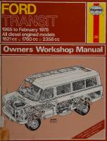
1965 to February 1978 All diesel engined models 1621 cc □ 1760 cc □ 2358 cc
BOOK
Owners Workshop Manual
©HAYNES
Ford Transit Owners Workshop Manual by J H Haynes Member of the Guild of Motoring Writers
and A K Legg T Eng (CEI), AMIMI
Models covered
All diesel engined Transit models. Perkins 4/99 1621 cc and 4/108 1760 cc and Ford 2358 cc engines Does not cover petrol engined models or 'Mk
//'
models
ISBN 0 85696 41 8 2
© Haynes Publishing Group 1990
All rights reserved. No part of this book may be reproduced or transmitted in any form or by any means, electronic or mechanical, including photocopying, recording or by any information storage or retrieval system, without permission in writing from the copyright holder.
Haynes Publishing Group
Sparkford Nr Yeovil Somerset BA22 7JJ England Haynes Publications, Inc
861 Lawrence Drive Newbury Park California 91320 USA
-5=? SOCf
5141400 oo^
Acknowledgements Thanks are due to the Ford Motor Company Limited for the supply of technical information and certain illustrations and to Castrol Limited who supplied lubrication data.
Lastly, special thanks are due to all those people at Sparkford who helped in the production of this manual,
About this manual Its aims The aim of this manual is to help you get the best value from your vehicle. It can do so in several ways. It can help you decide what work must be done (even should you choose to get it done by a garage), provide information on routine maintenance and servicing, and give a logical course of action and diagnosis when random faults occur. However, it is hoped that you will use the manual by tackling the work yourself. On simpler jobs it may be even quicker than booking the vehicle into a garage, and going there twice to leave and collect it. Perhaps most important, a lot of money can be saved by avoiding the costs the garage must charge to cover its labour and overheads. The manual has drawings and descriptions to show the function of the various components so that their layout can be understood. Then the tasks are described and photographed in a step-by-step sequence so that even a novice can do the work.
Its arrangement The manual is divided into eleven Chapters, each covering a logical sub-division of the vehicle. The Chapters are each divided into
Sections, numbered with single figures, eg 5; and the Sections into paragraphs (or sub sections), with decimal numbers following on from the Section they are in, eg 5.1,5.2, 5.3 etc. It is freely illustrated, especially in those parts where there is a detailed sequence of operations to be carried out. There are two forms of illustration; figures and photographs. The figures are numbered in sequence with decimal numbers, according to their position in the Chapter: eg Fig. 6.4 is the 4th drawing/illustration in Chapter 6. Photographs are numbered (either individually or in related groups) the same as the Section or sub-section of the text where the operation they show is described. There is an alphabetical index at the back of the manual as well as a contents list at the front. References to 'left' or 'right' of the vehicle are in the sense of a person in the driver's seat facing forwards. Whilst every care is taken to ensure that the information in this manual is correct, no liability can be accepted by the authors or publishers for loss, damage or injury caused by any errors in, or omissions from, the information given.
Introduction to the Transit The Transit range of vehicles was first introduced in 1965 and replaced the Thames 1 5 cwt series range. Its construction is simple and effective, and throughout the many years of production the Transit has proved a most popular vehicle for private use, small business use, and fleet use. The fact that the range has enjoyed such a long produc¬ tion run provides for stable second-hand values, and ensures that spare parts are readily available.
The Ford Motor Company's policy of continual improvement has meant that a number of changes have taken place to the Transit, but many of these have been component modifications which have not affected the general construction of the vehicle. However, the brakes have been considerably improved and this, together with other innova¬ tions' has meant that the modern Transit is particularly safetyorientated.
Contents
Page
Acknowledgements
2
About this manual
2
Introduction to the Transit
2
Buying spare parts and vehicle identification numbers
5
Tools and working facilities
6
General dimensions and capacities
8
Jacking
8
Lubrication chart
9
Recommended lubricants and fluids
9
Routine maintenance
10
Chapter 1
Part A Perkins engines
12
Chapter 1
Part B Ford engine
36
Chapter 2 Cooling system
67
Chapter 3 Fuel and exhaust systems
77
Chapter 4 Clutch
106
Chapter 5 Manual gearbox, overdrive and automatic transmission
113
Chapter 6 Propeller shaft
143
Chapter 7 Rear axle
147
Chapter 8 Braking system
154
Chapter 9 Electrical system
180
Chapter 10 Suspension and steering
215
Chapter 11
235
Bodywork and fittings
General repair procedures
250
Safety first!
251
Conversion factors
252
Index
253
Diesel Transit van - long wheelbase version
4
Buying spare parts and vehicle identification numbers Buying spare parts Spare parts are available from many sources. Ford have many dealers throughout the UK, and other dealers, accessory stores and motor factors will also stock Ford spare parts. Our advice regarding spare part sources is as follows: Officially appointed vehicle main dealers - This is the best source of parts which are peculiar to your vehicle and are otherwise not generally available (eg complete cylinder heads, internal transmission components, badges, interior trim etc). It is also the only place at which you should buy parts if your vehicle is still under warranty. To be sure of obtaining the correct parts it will always be necessary to give the storeman your vehicle's engine and chassis number, and if possible, to take the 'old' part along for positive identification. Remem¬ ber that many parts are available on a factory exchange scheme - any parts returned should always be clean I It obviously makes good sense to go straight to the specialists on your vehicle for this type of part, for they are best equipped to supply you. Other dealers and auto accessory stores - These are often very good places to buy materials and components needed for the maintenance of your vehicle (eg oil filters, bulbs, fan belts, oils and greases, touch-up paint, filler paste etc). They also sell general accessories, usually have convenient opening hours, charge lower prices and can often be found not far from home. Motor factors - Good factors will stock all the more important components which wear out relatively quickly (eg clutch components, pistons, valves, exhaust systems, brake cylinders/pipes/hoses/
The vehicle identification plates
seals/shoes and pads etc). Motor factors will often provide new or reconditioned components on a part exchange basis - this can save a considerable amount of money.
Vehicle identification numbers Modifications are a continuing and unpublicised process in vehicle manufacture. Spare parts manuals and lists are compiled on a numerical basis, the individual vehicle numbers being essential to identify correctly the component required. The engine number is located on the right-hand side of the cylinder block. The rear axle number is located on a metai tab affixed to the differential casing retaining nuts (models 75 to 125 only). The vehicle identification numbers are located on metal plates fitted to the front door step risers. The table below gives the old model identifications with their new equivalents: Previous identification V10 V20 V30 —
Revised equivalent 75 90 115 125 (new model)
Model type LCX 106 inch (Short wheelbase)
V40 V50 V60
130 150 175
LCY 118 inch (Long wheelbase)
Rear axle identification tab
Tools and working facilities Introduction A selection of good tools is a fundamental requirement for anyone
contemplating the maintenance and repair of a motor vehicle. For the owner who does not possess any, their purchase will prove a considerable expense, offsetting some of the savings made by doing-it-yourself. However, provided that the tools purchased meet the relevant national safety standards and are of good quality, they will last for many years and prove an extremely worthwhile investment. To help the average owner to decide which tools are needed to carry out the various tasks detailed in this manual, we have compiled three lists of tools under the following headings: Maintenance and minor repair. Repair and overhaul, and Special. The newcomer to practical mechanics should start off with the Maintenance and minor repair tool kit and confine himself to the simpler jobs around the vehicle. Then, as his confidence and experience grows, he can undertake more difficult tasks, buying extra tools as, and when, they are needed. In this way, a Maintenance and minor repair tool kit can be built-up into a Repair and overhaul tool kit over a considerable period of time without any major cash outlays. The experienced do-ityourselfer will have a tool kit good enough for most repair and over¬ haul procedures and will add tools from the Special category when he feels the expense is justified by the amount of use to which these tools will be put. It is obviously not possible to cover the subject of tools fully here. For those who wish to learn more about tools and their use there is a book entitled How to Choose and Use Car Tools available from the publishers of this manual.
Maintenance and minor repair tool kit The tools given in this list should be considered as a minimum requirement if routine maintenance, servicing and minor repair opera¬ tions are to be undertaken. We recommend the purchase of combina¬ tion spanners (ring one end, open-ended the other); although more expensive than open-ended ones, they do give the advantages of both types of spanner. It should be noted that metric sizes have been introduced during the production run of the Transit and therefore it will be prudent to check with the local Ford garage to ascertain which sizes and types are applicable to the vehicle being worked on. Combination spanners - consult your dealer for types/sizes Adjustable spanner - 9 inch Engine sump/gearbox/rear axle drain plug key (where applicable) Set of feeler gauges Brake adjuster spanner (where applicable) Brake bleed nipple spanner Screwdriver - 4 in long x | in dia (fiat blade) Screwdriver - 4 in long x \ in dia (cross blade) Combination pliers - 6 inch Hacksaw, junior Tyre pump Tyre pressure gauge Grease gun (where applicable) OH can Fine emery doth (1 sheet) Wire brush (small) Funnel (medium size)
Repair and overhaul tool kit These tools are virtually essential for anyone undertaking any major repairs to a motor vehicle, and are additional to those given in the Maintenance and minor repair list. Included in this list is a comprehen¬ sive set of sockets. Although these are expensive they will be found invaluable as they are so versatile - particularly if various drives are included in the set. We recommend the y in square-drive type, as this can be used with most proprietary torque wrenches. If you cannot afford a socket set, even bought piecemeal, then inexpensive tubular box spanners are a useful alternative. The tools in this list will occasionally need to be supplemented by tools from the Special list. Sockets (or box spanners) to cover range applicable to vehicle Reversible ratchet drive (for use with sockets) Extension piece, 10 inch (for use with sockets) Universal joint (for use with sockets) Torque wrench (for use with sockets) 'Mole' wrench - 8 inch Ball pein hammer Soft-faced hammer, plastic or rubber Screwdriver - 6 in long x ,-| in dia (fiat blade) Screwdriver - 2 in long x ^ in square (fiat blade) Screwdriver - 1\ in long x y in dia (cross blade) Screwdriver - 3 in long x j in dia (electricians) Pliers - electricians side cutters Pliers - needle nosed Pliers - circlip (internal and external) Cold chisel - y inch Scriber (this can be made by grinding the end of a broken hacksaw blade) Scraper (this can be made by flattening and sharpening one end of a piece of copper pipe) Centre punch Pin punch Hacksaw Valve grinding tool Steel rule/straight edge Alien keys Selection of files Wire brush (large) Axle stands Jack (strong scissor or hydraulic type)
Special tools The tools in this list are those which are not used regularly, are expensive to buy, or which need to be used in accordance with their manufacturers' instructions. Unless relatively difficult mechanical jobs are undertaken frequently, it will not be economic to buy many of these tools. Where this is the case, you could consider clubbing together with friends (or a motorists' club) to make a joint purchase, or borrowing the tools against a deposit from a local garage or tool hire specialist. The following list contains only those tools and instruments freely available to the public, and not those special tools produced by the vehicle manufacturer specifically for its dealer network. You will find occasional references to these manufacturers' special tools in the text of this manual. Generally, an alternative method of doing the job
Tools and working facilities without the vehicle manufacturer's special tool is given. However, sometimes, there is no alternative to using them. Where this is the case and the relevant tool cannot be bought or borrowed you will have to entrust the work to a franchised garage Valve spring compressor Piston ring compressor B alljoint separator Universal hub/bearing puller Impact screwdriver Micrometer and/or vernier gauge Dial gauge Tachometer Universal electrical multi-meter Cylinder compression gauge Lifting tackle Trolley jack Light with extension lead
Buying tools For practically all tools, a tool factor is the best source since he will have a very comprehensive range compared with the average garage or accessory shop. Having said that, accessory shops often offer excellent quality tools at discount prices, so it pays to shop around. Remember, you don't have to buy the most expensive items on the shelf, but it is always advisable to steer clear of the very cheap tools. There are plenty of good tools around at reasonable prices, but always aim to purchase items which meet the relevant national safety standards. If in doubt, ask the proprietor or manager of the shop for advice before making a purchase.
Care and maintenance of tools Having purchased a reasonable tool kit, it is necessary to keep the tools in a clean serviceable condition. After use, always wipe off any dirt, grease and metal particles using a clean, dry cloth, before putting the tools away. Never leave them lying around after they have been used. A simple tool rack on the garage or workshop wall, for items such as screwdrivers and pliers, is a good idea. Store all normal span¬ ners and sockets in a metal box. Any measuring instruments, gauges, meters, etc, must be carefully stored where they cannot be damaged or become rusty. Take a little care when tools are used. Hammer heads inevitably become marked and screwdrivers lose the keen edge on their blades fom time to time. A little timely attention with emery cloth or a file will soon restore items like this to a good serviceable finish.
Working facilities Not to be forgotten when discussing tools, is the workshop itself. If anything more than routine maintenance is to be carried out, some form of suitable working area becomes essential. It is appreciated that many an owner mechanic is forced by circumstances to remove an engine or similar item, without the benefit of a garage or workshop. Having done this, any repairs should always be done under the cover of a roof. Wherever possible, any dismantling should be done on a clean flat workbench or table at a suitable working height. Any workbench needs a vice: one with a jaw opening of 4 in (100 mm) is suitable for most jobs. As mentioned previously, some clean dry storage space is also required for tools, as well as the lubricants, cleaning fluids, touch-up paints and so on which become necessary. Another item which may be required, and which has a much more general usage, is an electric drill with a chuck capacity of at least ^ in (8 mm). This, together with a good range t)f twist drills, is virtually essential for fitting accessories such as wing mirrors and reversing lights. Last, but not least, always keep a supply of old newspapers and clean, lint-free rags available, and try to keep any working area as clean as possible.
7
Spanner jaw gap comparison table Jaw gap (in)
Spanner size
0-250 0-275 0-312 0-315 0-340 0-354 0-375 0-393 0-433 0-437 0-445 0-472 0-500 0-512 0-525 0-551 0-562 0-590 0-600 0-625 0-629 0-669 0-687 0-708 0-710 0-748 0-750 0-812 0-820
g in AF 7 mm AF ll in AF 8 mm AF 53 in AF;f in Whitworth 9 mm AF f in AF 10 mm AF 11 mm AF
0-866 0.875 0-920 0-937 0-944
1 -000 1 -010 1 -023 1 -062 MOO 1-125 1-181
1 -200 1-250 1-259 1 -300 1 -312 1 -390 1 -417 1 -437 1 -480 1 -500 1 -574 1 -614 1 -625 1- 670 1 -687 1 -81 1 1 -812 1 -860 1 -875 1 -968
2- 000 2-050 2-165 2-362
is in AF ^ in Whitworth;^ in BSF 1 2 mm AF | in AF 1 3 mm AF g in Whitworth; ^ in BSF 14 mm AF ft in AF 1 5 mm AF ft in Whitworth; f in BSF f in AF 16 mm AF 17 mm AF Is in AF 18 mm AF f in Whitworth; ft in BSF 19mmAF | in AF
Is in AF ft in Whitworth; f in BSF 22 mm AF f in AF 3- in Whitworth; $ in BSF If in AF 24 mm AF 1 in AF ft in Whitworth; f in BSF 26 mm AF 1 ft in AF; 27 mm AF f in Whitworth; ft in BSF 1 ft in AF 30 mm AF ft in Whitworth; ft in BSF 1 ft in AF 32 mm AF ft in Whitworth; ft in BSF 14 in AF in Whitworth; jf in BSF 36 mm AF 1 ft in AF ft in Whitworth; 1 in BSF 1 ft in AF 40 mm AF; || in Whitworth 41 mm AF If in AF 1 in Whitworth; 1 f in BSF 1 ft in AF 46 mm AF 1in AF 1 f in Whitworth; 1 ft in BSF If in AF 50 mm AF 2 in AF 1 ft in Whitworth; 1 f in BSF 55 mm AF 60 mm AF
General dimensions and capacities Note: Due to the fact that there are over WOO body variations in the Transit range, the following data applies to basic van versions only.
Dimensions Overall length . Overall width . Overall height . Wheelbase .
Short wheelbase 178-5 in (4530 mm) 77-16 in (1960 mm) 80 in (2030 mm) 106 in (2690 mm)
Long wheelbase 208-25 in (5290 mm) 81-06 in (2060 mm) 86 in (2182 mm) 118 in (3000 mm)
T rack' Front . Rear .
64-56 in (1638 mm) 62-54 in (1588 mm)
64-56 in (1638 mm) 60-59 in (1539 mm)
Capacities Engine (total): Perkins . Ford . Gearbox (manual) . Automatic transmission (total). Rear axle: 2750 and 3400 lb . 5200 lb . Cooling system: Perkins engines (standard) . Perkins engines (with heater) . Ford engines (standard) . Ford engines (with heater) . Ford engines (extra cooling - standard) Ford engines (extra cooling - with heater) Fuel tank: 75 to 125 models . 130 to 175 models .
10-6 pints (6-0 litres) (12-7 US pints) 14- 3 pints (8-1 litres) (17-1 US pints) 4-5 pints (2-6 litres) (5-4 US pints) 11 -25 pints (6-39 litres) (13-5 US pints) 3-75 pints (2-13 litres) (4-5 US pints) 2-50 pints (1-7 litres) (3-0 US pints) 11 -5 13-5 16-8 18-7 1 8-8 20-6
pints pints pints pints pints pints
(6-5 litres) (13-8 US pints) (7-7 litres) (16-2 US pints) (9-6 litres) (20-1 6 US pints) (10-6 litres) (22-44 US pints) (10-7 litres) (22-56 US pints) (11-7 litres) (24-72 US pints)
9-25 gallons (42-1 litres) (11-1 US gallons) 15- 0 gallons (68-1 litres) (18 0 US gallons)
Jacking A screw-type jack is supplied with the vehicle and should be positioned under the front or rear axle in the proximity of the spring Ubolts. Never jack up the front of the vehicle with a jack positioned under the centre of the front axle. The vehicle should always be unladen when using the screw-type
The screw type jack positioned under the front axle beam
jack and it is recommended that supplementary axle stands are always used as a safety precaution. The spare wheel is normally located beneath the rear floor of the vehicle in a metal carrier.
Location of the spare wheel
r
v
j
Recommended lubricants and fluids Component
Engined)
Castrol product
.Castrol CRI (SAE 30)
Transmission (2): Manual .Castrol Hypoy Light (SAE 80 EP) Automatic .Castrol TQF (Ford Spec M-2C—33—F) Rear axle (3).Castrol Hypoy (SAE 90 EP) Steering box (4): Standard .Castrol graphite grease Heavy duty. ..*.Castrol Hypoy (SAE 90EP) Front wheel bearings (5) .Castrol LM grease Brake hydraulic fluid (6) Steering swivel joints (7)
.Castrol Girling Universal Brake and Clutch Fluid .Castrol LM grease *
In addition, engine oil or Castrol Everyman Oil can be used for hinges, pivots, linkages etc.
Note: The above are general recommendations only. Lubrication requirements vary from territory to territory and depend on vehicle usage, if in doubt, consult the operator's handbook supplied with the vehicle, or your nearest dealer.
Routine maintenance Maintenance is essential both for safety and for obtaining the best in terms of performance and economy from your vehicle. Over the years, the need for periodic lubrication - oiling, greasing, and so on has been drastically reduced, and this has led some owners to think that the various components either no longer exist or will last forever. This is a serious delusion. It follows, therefore, that the largest initial element of maintenance is visual examination. The following routine maintenance summary is based on the manufacturer's recommendation, but is supplemented by certain checks which the author feels will add up to improved reliability and an increase of component life.
Every 250 miles (400 km) or weekly, whichever is sooner
Electrical Remove and clean the battery terminals and clean the battery case. Check the battery specific gravity.
Cooling system Check the radiator and heater hoses for deterioration and security. Check the specific gravity of the antifreeze.
Brakes Check all brake pipes and hoses for damage or deterioration. Check the brake linings or disc pads for wear. Check the wheel cylinders for leaks, damage, or deterioration. Adjust the brakes (where applicable) including the handbrake. Lubricate the handbrake linkage
Steering and suspension Engine Check the engine oil level with the vehicle standing on level ground; top-up if necessary.
Electrical Check the battery electrolyte level and top-up as necessary with distilled water.
Cooling system
Lubricate the multi-leaf springs (except where anti-squeak strips are fitted). Grease the front axle spindle pins. Adjust the front wheel bearings. Check the steering and balljoint covers for wear. Check the steering and suspension linkages for wear. Check the front and rear spring U-bolts for tightness. Check the front wheel 'toe-in' and adjust if necessary. Adjust the steering gear sector shaft pre-load.
Check the level of the coolant in the radiator and top-up as necessary.
Transmission Brakes Check the reservoir fluid level, and, if it requires topping up, examine the brake pipes and hoses for leaks. Check the handbrake for efficiency.
Steering and suspension
Renew the manual gearbox oil. Check the automatic transmission fluid level and top-up if necessary. Check the rear axle oil level and top-up if necessary. Grease the propeller shaft sliding joint (130 to 190 models only). Check and adjust the clutch linkage or cable and lubricate the cable ends (where applicable).
Check the tyre pressures and adjust them if necessary. Examine the tyres for wear and damage. Check the steering for smooth and accurate response.
Lights
Lights, wipers, horns and instruments
Bodywork
Check the operation of the lights, wipers, horn(s), instruments and gauges. Check the windscreen washer reservoir fluid level and top-up if necessary.
Lubricate all door locks and hinges including the bonnet safety catch. Lubricate the sliding step and sliding door (where applicable). Check the seat belts for security and wear.
Check and adjust the headlamp beam alignment.
At the first 3000 miles (5000 km)
Every 3000 miles (5000 km) - Ford engines; 2000 miles (3300 km) - Perkins engines
Engine
Engine
Renew the engine oil and oil filter. Clean oil filler cap (Ford engines only). Clean air cleaner element. Lubricate the accelerator linkages and cable and adjust if necessary. Check the engine for water, oil and fuel leaks. Check and adjust the valve clearances. Check and adjust the fan and vacuum pump drivebelts as applicable. Check the exhaust system for damage or leakage. Check the security of the manifold and exhaust downpipe bolts and tighten if necessary. Adjust the injection pump idling speed where applicable. Check all engine nuts and bolts for tightness.
Renew the engine oil and oil filter.
Every 6000 miles (10 000 km) after initial 3000 miles (5000 km) ie At 9, 15, 21 etc thousand miles (15, 25, 35 etc thousand km) Carry out the work given in the first 3000 mile (5000 km) section with the following amendments: Check the gearbox oil level and top-up if necessary. Do not check the automatic transmission fluid level. Do not adjust the steering gear sector shaft pre-load. Do not adjust the injection pump idling speed.
11
Routine maintenance
Engine dipstick oil level marks
Checking the brake fluid reservoir level
Typical windscreen washer reservoir
Rear axle filler plug (models 125 to 190)
Checking the tyre pressures
Refilling the gearbox with oil
Heavy duty steering box filler plug location
Check the steering gear oil level and top-up if necessary (heavy duty First and subsequent 12 000 miles (20 000 km) - Perkins engines only Clean and test the injectors. Renew the fuel filter element and clean the fuel sediment bowl. Adjust the injection pump idling speed.
steering only). Adjust the automatic transmission front and rear bands (where applic¬ able). Clean and test the injectors (Ford engines only). Renew the fuel filter element (Ford engines only). Clean the fuel sediment bowl (Ford engines only).
Every 36 000 miles (60 000 km) or 2 years whichever is sooner Every 18 000 miles (30 000 km) interval, starting at 15 000 miles (25 000 km)___
Cooling system Flush the cooling system and refill with fresh mixture.
ie At 15, 33, 51 etc thousand miles (25, 55, 85 etc thousand km) Carry out the work given in the first 3000 mile (5000 km) section with the following amendments: Check the gearbox oil level and top-up if necessary. Renew the air cleaner element (disposable type only).
Renew the air cleaner oil (Perkins engines only). Clean, repack, and adjust the front and rear wheel bearings (where applicable).
First 51 000 miles (85 000 km) and subsequent 54 000 miles (90 000 km) - Ford engines only
Engine Renew the timing belt.
Chapter 1 Part A Perkins engines Contents Big-end bearings - examination and renovation . Camshaft and camshaft bearings - examination and renovation . Camshaft and front plate-refitting . Camshaft and front plate - removal . Connecting rods - examination and renovation . Crankcase ventilation-description and maintenance. Crankshaft and rear oil seal - refitting. Crankshaft - examination and renovation . Cylinder head - decarbonising . Cylinder head - refitting . Cylinder head - removal . Cylinder liners - examination and renovation. Dismantling the engine - general. Dismantling the rocker assembly . Driveplate (automatic transmission) - refitting . Driveplate (automatic transmission) - removal . Engine - final assembly . Engine front mountings - removal and refitting . Engine - initial start-up after major overhaul . Engine refitting - general . Engine - refitting with transmission . Engine-refitting without transmission. Engine reassembly - general . Engine—removal with transmission . Engine - removal without transmission . Examination and removation - general . Flywheel (manual gearbox) - refitting. Flywheel (manual gearbox)-removal . General description .
29 33 46 15 30 25 42 28 39 52 9 31 7 11 44 20 54 26 58 55 56 57 41 6 5 27 43 19 1
Gudgeon pins - removal . Lubrication system -description . Major operations requiring engine removal . Major operations possible with the engine in the vehicle . Method of engine removal . Oil filter-removal and refitting . Oil pump - refitting . Oil pump - removal . Oil pump - servicing. Piston rings - removal . Pistons and piston rings - examination and renovation . Pistons, connecting rods and big-end bearings - refitting . Pistons, connecting rods and big-end bearings - removal . Rear oil seal, main bearings and crankshaft - removal . Removing ancillary engine components . Rocker assembly - reassembly . Rockers and rocker shaft - examination and renovation . Starter ring gear - examination and renovation . Sump - refitting. Sump-removal . Tappets (cam followers) - examination and renovation. Timing cover and gears - refitting . Timing cover and gears - removal . Timing gears - examination and renovation . Valve clearances - adjustment . Valve guides - examination and renovation. Valves and valve seats - examination and renovation. Valves - refitting . Valves-removal .
Specifications
4/99 diesel engine
General Bore . Stroke. Capacity . Compression ratio. Firing order . Maximum bhp . Maximum torque .
3.0 in (76.2 mm) 3.5 in (88.9 mm) 99 cu in (1621 cc) 20 : 1 1-3-4-2 42 at 3600 rpm 73 Ibf ft (10.09 kgf m) at 2250 rpm
Cylinder block Bore diameter (parent) . Camshaft bore diameter: No 1 . No 2. No 3. Cylinder liner protrusion .
3.0 to 3.001 in (76.2 to 76.23 mm) 1.794 to 1.784 to 1.776 to —0.001
1.7955 in (45.568 to 45.696 mm) 1.787 in (44.314 to 45.390 mm) 1.778 in (45.110 to 45.161 mm) to + 0.003 in (—0.025 to + 0.076 mm)
Crankshaft Main journal diameter. Main journal undersizes available Crankpin diameter . Crankpin undersizes available . . . Crankshaft endfloat. Standard thrust washer thickness Oversize thrust washer thickness
2.248 to 2.2485 in (57.099 to 57.112 mm) 0.010, 0.020, 0.030 in (0.254, 0.508, 0.762 mm) 1.9995 to 2.000 in (50.787 to 50.80 mm) 0.010, 0.020, 0.030 in (0.254, 0.508, 0.762 mm) 0.002 to 0.014 in (0.051 to 0.36 mm) 0.091 to 0.093 in (2.311 to 2.362 mm) 0.0985 to 0.1005 in (2.502 to2.553 mm)
17 22 3 2 4 23 47 14 24 18 32 45 16 21 8 50 36 38 48 13 37 49 12 35 53 40 34 51 10
Chapter 1 Part A Perkins engines
13
Camshaft Journal diameter: No 1 . No 2 . No 3 . Thrust washers: Type . Endfloat.
1.791 to 1.792 in (45.491 to 45.51 7 mm) 1.781 to 1.782 in (45.237 to 45.263 mm) 1.773 to 1.774 in (45.034 to 45.060 mm) Oil impregnated sintered iron 0.003 to 0.009 in (0.076 to 0.228 mm)
Timing gears Camshaft gear: Number of teeth. Transition fit of gear on hub .... Injection pump gear: Number of teeth. Interference fit of hub bearing .. Hub endfloat . Idler gear: Number of teeth. Endfloat. Crankshaft gear: Number of teeth. Transition fit of gear to crankshaft Timing gear backlash .
48 0.0003 to 0.0014 in (0.008 to 0.036 mm) 48 0.0004 to 0.0027 in (0.010 to 0.069 mm) 0.005 to 0.008 in (0.127 to 0.203 mm) 57 0.003 to 0.008 in (0.076 to 0.203 mm) 24 0.0006 to 0.0012 in (0.01 5 to 0.030 mm) 0.001 5 to 0.003 in (0.038 to 0.076 mm)
Pistons Type . Piston to bore cleaance (cold) .
Flat topped aluminium alloy 0.005 to 0.006 in (0.127 to 0.152 mm)
Piston rings Gap: Top compression . 0.012 to 0.017 in (0.305 to 0.432 mm) 2nd and 3rd compression . 0.009 to 0.01 5 in (0.229 to 0.381 mm) Oil control . 0.009 to 0.015 in (0.229 to 0.381 mm) Note: Add 0.003 in {0.076 mm) for every 0.001 in (0.025 mm) above standard bore
Connecting rods Type . Small-end bush bore.
H - section 0.9382 to 0.93875 in (23.828 to 23.844 mm)
Valves Head diameter: Inlet . Exhaust. Face angle. Stem diameter: Inlet . Exhaust . Clearance below cylinder head face: Inlet . Exhaust.
Valve guides Protrusion above cylinder head top face
1.410 to 1.414 in (35.814 to 35.91 6 mm) 1.191 to 1.195 in (30.251 to 30.353 mm) 45° 0.312 to 0.313 in (7.925 to 7.950 mm) 0.311 5 to 0.3125 in (7.912 to 7.937 mm) 0.028 to 0.048 in (0.711 to 1.22 mm) 0.021 to 0.048 in (0.523 to 1.22 mm)
0.800 to 0.81 5 in (20.320 to 20.701 mm)
Valve springs Fitted length: Inner . Outer .
Valve clearances Hot. Cold .
Lubrication system Capacity (sump). Capacity (filter). Oil pressure . Filter type . Bypass valve setting (filter) .
Oil pump Type-...... Delivery (minimum)
1.530 in (38.862 mm) 1.780 in (45.212 mm)
0.010 in (0.25 mm) 0.012 in (0.305 mm)
8.6 pints (4.9 litres) (10.3 US pints) 2.0 pints (1.1 litres) (2.4 US pints) 40 lbf/in2 (2.81 kgf/cm2) Full-flow Opens between 13 and 17 lbf/in2 (0.91 and 1.2 kgf/cm2) pressure differential
Bi-rotor 40 lbf/in2 (2.81 kgf/cm2) at 800 pump rpm or equivalent to 2.0 gall/mm (9.1 litre/min) (2.4 US gall/min)
Chapter 1 Part A Perkins engines
14 Relief valve: Type . Pressure setting. Spring free length. Rotor clearances: Inner rotor to outer rotor. Outer rotor to pump body . Top of rotor to pump body surface
Spring loaded plunger 50 to 65 lbf/in2 (3.5 to 4.6 kgf/cm2) 1.5625 in (39.688 mm) 0.006 in (0.1 52 mm) max 0.0055 to 0.010 in (0.140 to 0.250 mm) 0.001 to 0.005 in (0.025 to 0.127 mm)
4/108 diesel engine Note: Specifications are identical to those for the 4/99 engine with the following exceptions
General Bore . Capacity . Compression ratio Maximum bhp . . Maximum torque
3.125 in (79.375 mm) 107.4 cu in (1760 cc)
22
:
1
52 at 4000 rpm 79 Ibf ft (10.92 kgf m)
Cylinder block Bore diameter (parent) . Cylinder liner protrusion .
3.249 to 3.250 in (82.525 to 82.550 mm) + 0.023 to + 0.027 in (+ 0.584 to + 0.686 mm)
Crankshaft Main journal diameter: Nos 1 and 2. No 3 . Crankshaft endfloat. Standard thrust washer thickness. Oversize thrust washer thickness .
As 4/99 engine 2.2475 to 2.248 in (57.086 to 57.099 mm) 0.002 to 0.016 in (0.051 to 0.38 mm) 0.089 to 0.091 in (2.261 to 2.311 mm) 0.0965 to 0.1005 in (2.451 to 2.553 mm)
Piston rings Gap: Top compression . 2nd and 3rd compression 4th scraper . 5th scraper .
0.009 0.009 0.012 0.009
to to to to
0.01 5 0.014 0.01 7 0.014
in in in in
(0.229 (0.229 (0.305 (0.229
to to to to
0.381 0.356 0.432 0.356
mm) mm) mm) mm)
Connecting rods Small-end bush bore (before reaming) Small-end bush bore (after reaming) . Running clearance .
1.0495 to 1.0545 in (26.657 to 26.784 mm) 1.0632 to 1.06375 in (27.005 to 27.01 9 mm) 0.0005 to 0.00125 in (0.0127 to 0.031 8 mm)
Valves Clearance below cylinder head face: ln|et . Exhaust...
0.028 to 0.039 in (0.711 to 0.991 mm) 0.021 to 0.032 in (0.53 to 0.813 mm)
Lubrication system Capacity (sump). Capacity (filter).
8.75 pints (5.0 litres) (10.5 US pints) 1.8 pints (1.02 litres) (2.16 US pints)
Torque wrench settings
4/99 diesel engine Cylinder head nuts . Connecting rod bolts. Main bearing bolts . Flywheel bolts . Idler gear set-screws.. Crankshaft pulley centre bolt . Rocker shaft pedestal nuts. Camshaft and injection pump drive gear retaining bolts
Ibf ft
kgf m
38 to 42 36 to 38 79 to 85 55 to 60 33 to 36 140 to 150 12 to 15 19 to 21
5.25 to 5.81 5.0 to 5.2 10.9 to 11.75 7.6 to 8.3 4.56 to 4.98 19.35 to 20.73 1.66 to 2.08 2.6 to 2.9
4/108 diesel engine Note: Torque wrench settings are identical to those for the 4/99 engine with the following exceptionCylinder head nuts . 55 to 60
7.6 to 8.3
Chapter 1 Part A Perkins engines
1 General description 1 Transit models 75 to 115 manufactured before May 1966 are fitted with the Perkins 4/99 engine whereas models 75 to 130 manufactured after May 1966 are fitted with the Perkins 4/108 engine. 2 Both engines are of four cylinder overhead valve construction and the main difference, besides capacity, is that the 4/99 version is fitted with flange mounted 'wet' cylinder liners, the 4/108 version having centrifugally cast 'dry' cylinder liners of the thih wall type. 3 An indirect injection system is employed and the combustion chambers, which are in the cylinder head, are in the form of detachable inserts. 4 The valves, mounted in the cylinder head, are each equipped with two springs of the damper type which have closely wound coils at one end; the inlet valves have an oil seal fitted to their stems. 5 The idler gear, which is driven by the crankshaft gear, in turn drives both the camshaft and injection pump drive gears. 6 The camshaft is located on the right-hand side of the engine and operates the valve pushrods (via the mushroom type tappets). In addi¬ tion, the bi-rotor oil pump is driven by skew gears from the camshaft, and the fuel lift pump is operated by an eccentric and pushrod. The camshaft rotates in three bearings. 7 The crankshaft runs in three large diameter main bearings, and endfloat is controlled by semi-circular thrust washers located either side of the rear main bearing. 8 Aluminium alloy pistons with flat crowns are fitted and each has three compression rings and two- oil control rings. The pistons incorporate fully floating gudgeon pins.
2 Major operations possible with the engine in the vehicle The following major operations can be carried out without taking the engine from the vehicle. Removal and refitting of the: (a) (b) (c) (d) (e) (f) (g) (h)
Cylinder head Sump Big-end bearings Pistons and connecting rods Timing gears OH pump Engine front mountings Enginejgearbox rear mounting
3 Major operations requiring engine removal The following major operations can be carried out with the engine removed from the vehicle. Removal and refitting of the: (a) (b) (c) (d)
Flywheel Crankshaft rear main bearing oil seal Crankshaft and main bearings Camshaft and camshaft bushes
4 Method of engine removal The engine is removed from the front of the vehicle after with¬ drawing the grille panel and, unless the gearbox requires attention at the same time, it is recommended that the engine is separated from the gearbox and removed independently. However the following Sec¬ tions describe both alternative methods of engine removal.
5 Engine - removal without transmission Note: The procedure for removing the engine from a vehicle fitted with automatic transmission is similar to that given in the following paragraphs with the exception of the following points: (a) Detach the downshift cable at the throttle link and bracket (b) With the bellhousing front cover removed, unscrew the four driveplate to torque converter retaining bolts; it will be
15
necessary to turn the engine in order to gain access to each of the bolts (c) Make sure when separating the engine from the transmission that the torque converter is held firmly inside the bellhousing, using a piece of wood 1 Before starting work it is essential to have a good hoist which can be positioned over the engine and also a trolley jack to support the gearbox; if an inspection pit is not available two strong stands will be required to support the vehicle whilst working beneath the gearbox. 2 Open the bonnet and disconnect the battery negative terminal. 3 Using a pencil, mark the location of the bonnet hinges then, while an assistant supports the bonnet, unscrew and remove the bonnet retaining bolts and the engine compartment light bracket retaining bolt (where fitted). Carefully pull the windscreen washer tubing from the jets and place the tubing and light to one side, then lift the bonnet away and position it in a safe place. 4 Drain the coolant from the radiator and block as described in Chapter 2. 5 Place a container of at least 9 pints (5.1 litres) beneath the engine sump, unscrew and remove the drain plug, and drain the oil from the engine. Refit and tighten the plug when completely drained. 6 Remove the radiator as described in Chapter 2. 7 Unscrew and remove the screw retaining each headlamp bezel to the front wings and lift the bezels from the upper flanges. 8 Loosen the bonnet release cable adjuster locknuts, unclip the cable from the front panel and disconnect the inner cable from the release spring; place the cable to one side. Disconnect the left-hand side headlamp and flasher wiring if necessary. 9 Using a pencil, mark the position of the front panel to wing retain¬ ing bolts, then remove the front grille panel by referring to Chapter 11. 10 Loosen the clip retaining the air cleaner hose to the inlet manifold then unscrew and remove the support bracket retaining bolt and lift the air cleaner from the engine, keeping it upright to prevent spilling the oil. Recover the hose clip. 11 On the right-hand side of the engine loosen the clip securing the fuel feed pipe to the lift pump and carefully withdraw the pipe. 12 Place a tray beneath the Thermostart fuel reservoir then unscrew and remove the drain plug and the fuel; refit the plug when completely drained. 13 Unscrew and remove the Thermostart supply pipe unions and remove the pipes from the reservoir and heater plug. 14 Identify and disconnect the Thermostart heater plug supply lead. 15 Detach the throttle linkage and stop control cable from the fuel injection pump on the left-hand side of the engine. 16 Identify and then disconnect the following wires, placing them to one side; (a) Starter main cable and solenoid supply wire; (b) Water temperature sender unit; (c) Alternator multi-plug; (d) Oil pressure sender unit. 17 Loosen the heater hose jubilee clips and remove the hoses from the bulkhead and engine. 18 If servo assisted brakes are fitted, loosen the clip securing the vacuum pipe to the exhauster and remove the pipe. 19 Unscrew and remove the starter motor retaining bolts and carefully lift the starter motor from its mounting; take care not to damage the flywheel ring gear or the starter motor pinion. 20 Unscrew and remove the exhaust manifold to downpipe clamp retaining nuts, separate the joint, and remove the sealing ring where fitted. 21 If an inspection pit is not available, temporarily jack up the front of the vehicle and support it on stands in order to gain access to the gearbox. 22 Unhook the clutch return spring where fitted, then detach the clutch bellhousing lower dust cover. 23 Unscrew and remove the clutch bellhousing to engine retaining bolts, noting the location of the engine earth strap and speedometer cable support clip. 24 Lower the vehicle to the ground (if applicable), then take the weight of the gearbox with the trolley jack. 25 Position the hoist over the engine and connect it to the lifting brackets on the cylinder head, then take the weight of the engine by raising the hoist. The lifting tackle should be arranged so that it does not damage the wiring loom or brake pipes on the bulkhead. The engine must be kept horizontal during subsequent operations. 26 Unscrew and remove the two front engine mounting nuts and washers and unbolt the left-hand side mounting bracket from the engine block.
Chapter 1 Part A Perkins engines
16
27 If available, place a further trolley jack beneath the rear of the engine with a wooden block interposed to prevent damage to the sump. 28 Slightly lift the engine so that it clears the right-hand side mount¬ ing then separate it from the gearbox by easing it forwards. 29 Lift the engine from the vehicle and lower it onto a workbench or large piece of board.
6 Engine - removal with transmission Note: The procedure for removing the engine with automatic transmission is very similar to that given in the following paragraphs. The following points, however, should be noted: (a) Detach the selector cable from the selector lever, then unbolt the bracket and release the cable (b) Disconnect the two inhibitor switch wires (c) Drain the transmission fluid with reference to Chapter 5, then detach the oil cooler connection (d) Detach the downshift cable at the throttle link and bracket (e) Refer to Chapter 10 and disconnect one track rod baiijoint, then swing the rod to one side (f) Refer to Chapter 5 if necessary when disconnecting the automatic transmission from the engine 1 Carry out the instructions given in paragraphs 1 to 18 inclusive, 20 and 21 of Section 5 of this Chapter. 2 From inside the vehicle unscrew and remove the crosshead screws securing the gear lever gaiter plate to the floor, remove the plate, and slide the gaiter up the lever. 3 Working beneath the vehicle, unscrew the nylon gear lever retain¬ ing cap and then lift the complete gear lever from the gearbox, into the cab. 4 Detach the clutch linkage and/or cable from the gearbox by refer¬ ring to Chapter 4 and tie the cable (where fitted) to one side. 5 Place a container of at least 5 pints (2.84 litres) capacity beneath the gearbox, unscrew and remove the gearbox drain plug and drain the oil. Refit and tighten the drain plug. 6 Refer to Chapter 6 of this manual and remove the propeller shaft. 7 Unscrew and remove the bolt, washer and clamp retaining the speedometer cable to the gearbox casing, remove the cable, and tie it to one side. 8 Unscrew and remove the one bolt securing the earth strap to the clutch housing. 9 Lower the vehicle to the ground (if applicable) then support the weight of the gearbox with a trolley jack. 10 Unscrew and remove the gearbox rear mounting nut, bolt, spacer and washer, noting their location in relation to the gearbox casing. 11 Position the hoist over the engine and connect it to the lifting brackets on the cylinder head, then take the weight of the engine by raising the hoist. The lifting tackle should be arranged so that it does not damage the wiring loom or brake pipes on the bulkhead; it should also be arranged so that the engine will attain an angle of approximately 30° from horizontal when suspended. 12 Unscrew and remove the two front engine mounting nuts and washers and unbolt the left-hand side mounting bracket from the engine block. 13 Carefully lift the engine clear of the right-hand side mounting and ease it forwards from the engine compartment, at the same time allowing the trolley jack beneath the gearbox to move forwards as far as possible. 14 Lift the engine until the gearbox is clear of the trolley jack, then guide the assembly away from the vehicle and lower it onto a workbench or large piece of board.
make the job much easier, as, after the solvent has been applied and allowed to stand for a time, a vigorous jet of water will wash off the solvent and all the grease and filth. If the dirt is thick and deeply embedded, work the solvent into it with a stiff paintbrush. 4 Finally wipe down the exterior of the engine with a rag and only then, when it is quite clean, should the dismantling process begin. As the engine is stripped, clean each part in a bath of paraffin. 5 Never immerse parts with oilways in paraffin, eg the crankshaft, but to clean wipe down cafefully with a paraffin-dampened rag. Oilways can be cleaned out with wire. If an air line is present all parts can be blown dry and the oilways blown through as an added precau¬ tion. 6 Re-use of old engine gaskets is a false economy and can give rise to oil and water leaks, if nothing worse. To avoid the possibility of trouble after the engine has been reassembled always use new gaskets throughout. 7 Do not throw away the old gaskets as it sometimes happens that an immediate replacement cannot be found and the old gasket is then very useful as a template. Hang up the old gaskets as they are removed on a suitable hook or nail. 8 To strip the engine it is best to work from the top down. The sump provides a firm base on which the engine can be supported in an upright position. When the stage where the sump must be removed is reached, the engine can be turned on its side and all other work carried out with it in this position. 9 Wherever possible, refit nuts, bolts and washers fingertight from wherever they were removed. This helps avoid later loss and muddle. If they cannot be refitted then lay them out in such a fashion that it is clear from where they came. 10 If the engine was removed in unit with the gearbox, separate them by unbolting the starter motor and carefully removing it. Unscrew and remove the clutch bellhousing to engine retaining bolts noting the location of the speedometer cable support clip, then detach the bellhousing lower dust cover. 11 Carefully lift the gearbox off the engine.
8 Removing ancillary engine components 1 Before basic engine dismantling begins, the engine should be stripped of all its ancillary components. These items should also be removed if a factory exchange reconditioned unit is being purchased. The items comprise: A Iternator and brackets Water pump and thermostat Inlet and exhaust manifolds Fuel lift pump injectors and fuel lines Fuel filter assembly injection pump OH filler cap Clutch assembly Engine mountings Oil pressure and water temperature sender units Exhauster (when fitted) Dipstick 2 Without exception all these can be removed with the engine in situ if it is merely an individual item which requires attention. (It is necessary to remove the gearbox if the clutch is to be renewed with the engine in position). 3 To remove each of the listed items, refer to the relevant Chapter of this manual.
9 Cylinder head - removal 7 Dismantling the engine - general 1 It is best to mount the engine on a dismantling stand but if one is not available, then stand the engine on a strong bench so as to be at a comfortable working height. 2 During the dismantling process the greatest care should be taken to keep the exposed parts free from dirt. As an aid to achieving this, it is a sound scheme to thoroughly clean down the outside of the engine, removing all traces of oil and congealed dirt. 3 Use paraffin or a good grease solvent. The latter compound will
1 If the engine is still in the vehicle, follow the instructions in paragraphs 2 to 8 inclusive of this Section. 2 Disconnect the battery negative terminal. 3 Drain the cooling system (see Chapter 2). 4 Remove the air cleaner, injector leak-off and delivery pipes. Ther¬ mostart supply and fuel return pipes, and detach the exhaust pipe from the exhaust manifold (see Chapter 3). 5 Remove the alternator and brackets (see Chapter 9). 6 Disconnect the radiator and heater hoses from the cylinder head by loosening the jubilee clips and carefully twisting the hoses to
Chapter 1 Part A Perkins engines
release them. 7 Disconnect the Thermostart and water temperature sender unit supply leads and identify them with adhesive tape. 8 To provide extra working room, the radiator and front grille panel should be removed with reference to Chapters 2 and 11 of this manual. 9 Loosen the breather pipe to engine block retaining bolt, then loosen the clip securing the intermediate breather hose to the rocker cover and withdraw the breather pipe and clip from the engine. 10 Unscrew and remove the two rocker cover retaining nuts and washers, then lift off the rocker cover and gasket; if the cover appears to be stuck, a sharp blow with the palm of the hand should release it. 11 Unscrew and remove the rocker shaft oil supply pipe union at the head, then unscrew and remove the rocker shaft support bracket retaining nuts and washers evenly. 12 Lift the complete rocker shaft assembly from the studs and place it to one side. 13 Unscrew and remove the injector retaining nuts and remove the injectors and copper sealing washers from the cylinder head. To prevent the ingress of dirt and dust, place the injectors in separate plastic bags. 14 Unscrew and remove the inlet and exhaust manifold retaining nuts and carefully withdraw the manifolds and gaskets from the cylinder head. 15 Remove the pushrods, keeping them in the relative order in which they were removed. The easiest way to do this is to push them through a sheet of thick paper or thin card in the correct sequence. 16 Detach the alternator adjusting link from the front of the cylinder head by unscrewing and removing the retaining bolt. 17 Detach the low pressure fuel pipe clip from the rear of the cylinder head. 18 Unscrew the cylinder head nuts half a turn at a time in the reverse order to that shown in Fig. 1.28. When all the nuts are no longer under tension unscrew and remove them from the cylinder head noting that the five nuts adjacent to the injectors are longer than the rest in order to facilitate tightening them with the injectors installed. 19 The cylinder head can now be removed by lifting it upwards; if necessary the lifting eyes at each end of the head can be utilised for this operation. If the head is jammed, try to rock it a little to break the seal, but under no circumstances should a screwdriver or cold chisel be used as damage to the head and block surfaces will occur. In extreme cases, refitting the injectors and rotating the engine may free the cylinder head joint.
17
Fig. 1.2 Location of the engine lifting eyes on the cylinder head (Sec 9)
20 Place the cylinder head on a bench ready for dismantling and, if required, remove the retaining studs from the cylinder block. 21 It should be remembered that the head retains the cylinder liners in the block, and if it is required to rotate the engine with the cylinder head removed from 4/99 engines, it will be necessary to position spacers on the flange of the liners to prevent them from moving. The spacers can be tightened down by utilizing the head studs and nuts; the spacers must not positioned directly over the open bore as the piston crowns protrude slightly above the face of the block.
10 Valves - removal 1 Before removing the valves remember that they must be kept in their correct sequence unless they are being renewed. Place them in a sheet of card having eight holes numbered 1 to 8 corresponding with their relative positions in the cylinder head, and also keep the valve springs, seats, retainers and collets next to their corresponding valve. The valve positions are reversed to the normal arrangement, the inlet valves being 1,4, 5 and 8 and the exhaust valves being 2,3,6 and 7.
AIR CLEANER MOUNTING
18
r
l
19
Fig. 1.4 Camshaft and valve operating components (Sec 10)
CYLINDER BLOCK
CYLINDER LINER
SEALING RINGS CRANKSHAFT REAR OIL SEAL RETAINERS (fi) INJECTION PUMP J DRIVING GEAR BEARING
L. H. ENGINE MOUNTING
CRANKSHAFT FRONT OIL SEAL (?) TIMING COVER R. H. ENGINE MOUNTING (12
(?) FRONT PLATE (?) MAIN BEARING CAP
SUMP(n}
® DRAIN PLUG
Fig. 1.5 Exploded view of the engine lower half stationary components (4/99 version) (Sec 12)
21
Chapter 1 Part A Perkins engines 2 Using a suitable valve spring compressor, compress each pair of springs until the two halves of the retainer collets can be removed, then release the compressor and remove the retainer, springs and spring seats. Note that the springs have closely wound damper coils at the end in contact with the cylinder head, and that the inlet valve retainers are deeper than the exhaust retainers in order to accom¬ modate the sealing ring positioned on the inlet valve stem; remove the seal when removing the split collet. 3 If when the valve spring compressor is screwed down, the retainer refuses to free to expose the split collet, do not continue to screw down the compressor as it could be damaged, but tap the top of the tool directly over the retainer with a light hammer; hold the tool firmly when doing this to avoid it slipping off the retainer. 4 Push the valves out of the guides and withdraw them from the cylinder head.
11 Dismantling the rocker assembly 1 Using a pair of circlip pliers, remove the circlip from the front of the rocker shaft and withdraw the double coil spring with plain washer on either side. Subsequently, as each item is removed, place it in its exact order of removal to facilitate reassembling procedures. 2 Withdraw the rocker arms, support brackets, spacer springs and oil feed pipe banjo connection from the rocker shaft; it will be necessary to unscrew the oil feed pipe from the banjo connection as the pipe protrudes into the rocker shaft.
Fig. 1.6 Removing the crankshaft gear with a two leg puller (Sec 12)
12 Timing cover and gears - removal 1 The timing cover and gears can be removed with the engine in the vehicle provided the front panel, radiator, and fan belt are first removed (see Chapters 2 and 11). 2 Turn the engine with a spanner on the crankshaft pulley centre bolt (or starting handle) until the piston in number 1 cylinder is at top dead centre (TDC) on the compression stroke, and the timing mark on the flywheel periphery is visible through the aperture on top of the flywheel housing; the timing mark should be in alignment with the 'V' notch. If the cylinder head has also been removed on 4/99 engines, to prevent the 'wet' cylinder liners from moving it will be necessary to position suitable spacers between the cylinders, tightening them down onto the liners with the cylinder head nuts. 3 Having turned the crankshaft to the TDC position it does not necessarily follow that the timing gear alignment marks will be in alignment when the cover is removed, since the idler gear has an uneven number of teeth to ensure even wear. However the engine must be in the TDC position when refitting the timing gears. 4 Unscrew and remove the crankshaft pulley centre bolt; this is best achieved by fitting a ring spanner and giving it a sharp blow with a club hammer. If the engine is in the vehicle, engage top gear and apply the handbrake to stop the engine from turning. 5 The crankshaft pulley wheel may pull off quite easily; if not, place two large screwdrivers behind the wheel at 180° to each other and carefully lever the wheel off. 6 Unscrew and remove the bolts and washers retaining the timing cover to the cylinder block and withdraw the cover and gasket. 7 Remove the oil slinger from the crankshaft noting that the concave side faces outward. 8 Using a chisel or screwdriver, bend back the idler gear hub retain¬ ing bolt lock tabs, unscrew and remove the two bolts, and carefully withdraw the idler gear and hub. 9 Unscrew and remove the camshaft gear retaining bolts and washers noting that they are located in the round holes as opposed to the elongated holes. Withdraw the camshaft gear from the camshaft. 10 If not already evident, mark the position of the injection pump drive gear in relation to the hub. then unscrew and remove the three retaining bolts and washers and withdraw the gear from the hub, note that the bolts are located in the elongated holes. 11 If it is required to remove the injection pump drive gear hub, the injection pump must first be removed (see Chapter 3). 12 Using circlip pliers, remove the locating circlip from the rear of the hub and press the hub forwards out of the bearing. 13 Remove the crankshaft gear from the crankshaft by using a universal puller after removing the pulley wheel Woodruff key; finally remove the crankshaft gear Woodruff key.
Fig. 1.7 Location of the oil pump (Sec 14)
13 Sump-removal 1
_
The sump can be removed with the engine either in or out of the
vehicle. 2 Make sure that all oil is drained, then unscrew and remove the sump retaining bolts and withdraw the sump from the engine block. 3 If difficulty is experienced in removing the sump due to its being stuck to the gasket, a sharp blow with the palm of the hand on the side of the sump should free it. Failing this, cut the joint with a sharp knife. 4 Thoroughly clean and scrape the mating surfaces of the sump flange and cylinder block and remove the packing strips from the front and rear main bearing caps.
14 Oil pump - removal
_
1 With the sump removed as described in Section 13, release the strainer from the bottom of the oil pump, and detach the cover by un¬ screwing and removing the retaining bolt and washer.
CYLINDER BLOCK ( I
2) CYLINDER LINER
CRANKSHAFT REAR OIL SEAL RETAINERS (Tl) INJECTION PUMP DRIVING GEAR BEARING
TAPPET COVER (10
CRANKSHAFT FRONT OIL SEAL {?) TIMING COVER {6) FRONT PLATE
(7) MAIN BEARING CAP
SUMP(V)
(s) DRAIN PLUG
Fig. 1.8 Exploded view of the engine lower half stationary components (4/108 version) (Sec 12)
Chapter 1 Part A Perkins engines
23
2 Unscrew the delivery pipe union at the cylinder block and carefully release the joint. 3 Locate the oil pump locating bolt on the cylinder block and bend back the lock tab, located below the alternator mounting. 4 Unscrew and remove the locating bolt and withdraw the oil pump.
15 Camshaft and front plate - removal 1 It is recommended that the camshaft is removed with the engine out of the vehicle; this is because the easiest method of removal is with the engine inverted. The alternative method is to remove the cylinder head and tappet cover, and to secure the mushroom type tappets away from the camshaft with suitable clips. 2 Before removal of the camshaft, the oil pump and fuel lift pump must first be removed, and the lift pump pushrod secured away from the camshaft. 3 Unscrew and remove the front plate locating stud and withdraw the front plate and gasket from the block. 4 If necessary the injection pump drive gear hub bearing can now be removed from the block. 5 Carefully remove the camshaft from the cylinder block, at the same time recover the two thrust washers as they are forced from the locating dowel in the block recess. Take great care to prevent the cam lobe peaks damaging the camshaft bearings as the shaft is pulled forward. 6 If required, remove the mushroom tappets from the block but make sure that they are identified so that they can be refitted in their original positions.
Fig. 1.9 Removing the camshaft (Sec 15)
16 Pistons, connecting rods and big-end bearings - removal 1 The pistons, connecting rods and big-end bearings can be removed with the engine either in the vehicle or on a workbench. 2 The cylinder head, sump and oil pump must be removed to gain access to the pistons, and on 4/99 engines, the 'wet' liners must be prevented from moving by clamping suitable spacers on them using the cylinder head stubs and retaining nuts; remember that the pistons protrude slightly above the block face when at TDC. 3 Rotate the crankshaft until numbers 1 and 4 pistons are at the bottom of the cylinders. On 4/99 engines use a screwdriver or chisel to bend back the lock tabs on the big-end retaining bolts. 4 Unscrew and remove the big-end retaining bolts from number 1 cylinder and recover the lockwashers (4/99 engine) or plain washers (4/108 engine). 5 Remove the big-end cap noting that the cap and connecting rod are numbered on the same side as the big-end location tags are positioned. 6 Extract the big-end shells by pressing them at a point opposite the location tags but, if they are to be refitted, note the location of each shell so that they can be reassembled in their original positions. 7 Using the wooden handle of a hammer, gently tap the piston up through the cylinder block and remove it from the top, then temporarily refit the shells and cap to the connecting rod. 8 Repeat the procedure given in paragraphs 3 to 7 inclusive on number 4 cylinder, then turn the crankshaft until number 2 and 3 pistons are at the bottom of the cylinders and similarly remove the remaining pistons. 9 The connecting rod webs are marked 'FRONT' to facilitate refit¬ ting, and original pistons are numbered according to the bore from which they are removed. However, as an extra precaution, mark each piston crown with the cylinder number from which it is removed and also an arrow indicating the front of the engine.
17 Gudgeon pins - removal
_
1 To remove the gudgeon pin from the piston and connecting rod, first use circlip pliers to remove one of the circlips from one end of the 2 The pistons must be heated to between 100° and 120° F (37.8° and 48.9° C) before removing the pins, and this is best accomplished by immersing them in water heated on a hot plate; use a thermometer to reach the correct temperature range. 3 Carefully press the gudgeon pin out of the piston and connecting
Fig. 1.10 Location of the camshaft thrust washers (Sec 15)
rod immediately it is removed from the water by using a suitable length of dowel rod. 4 Ensure that each gudgeon pin is kept with the piston from which it is removed to facilitate refitting.
18 Piston rings - removal 1 On 4/108 engines note that the top ring groove has a steel insert fitted in it, and this must not be removed. 2 Remove the three compression rings and upper oil control ring from the top of the piston but remove the lower oil control ring from the bottom of the piston. Note that on 4/108 engines the upper oil control ring is laminated and comprises four separate segments; remove each of these separately starting with the top one. 3 Care should be taken when removing the rings to avoid scratching the aluminium alloy of the piston. It is also very easy to break the rings if they are pulled off roughly; to prevent this use three strips of thin metal or feeler gauges to act as guides and to assist the rings to pass over the empty grooves. 4 Lift one end of the piston ring to be removed out of its groove and insert the end of the feeler gauge under it.
24
Chapter 1 Part A Perkins engines
22 Lubrication system - description 1 A forced feed system of lubrication is fitted, with oil circulated around the engine by a bi-rotor type pump drawing oil from the sump below the block. 2 The full-flow filter is mounted externally on the left-hand side of the engine, and the oil pump> driven by a skew gear off the camshaft, pumps oil directly to the filter through a drilling in the cylinder block. 3 Oil from the filter is fed to the main oil gallery below the camshaft and then directly to the crankshaft main bearings; the rear oil seal assembly prevents oil leaking from the rear of the crankshaft. 4 The big-end bearings and camshaft bearings are supplied with oil from the crankshaft main bearings by internal oilways. 5 The camshaft centre bearing journal has an oil feed slot machined in it, and oil from this bearing at reduced pressure is fed to the rocker shaft assembly through oilways in the cylinder block and head. 6 The valve stems, guides, and rocker gear, are supplied with oil through internal oilways in the rocker shaft assembly and oil mist, surplus oil being returned to the sump by gravity. 7 The front timing gears are lubricated with oil from the main oil gallery and, although a small amount of oil is permanently retained in the timing cover, most surplus oil is returned to the sump. 8 The pistons, cylinder bores, small-ends, cams, and tappets are all lubricated by splash and oil mist. Fig. 1.11 Cross-section view of the laminated oil control ring fitted to 4/108 pistons (Sec 18) 23 Oil filter - removal and refitting 5 Turn the feeler gauges slowly round the piston, and as the ring comes out of its groove, rest it on the adjacent land; in this way it can be eased off the piston.
19 Flywheel (manual gearbox) - removal 1 Remove the clutch (see Chapter 4). 2 Using a screwdriver or cold chisel, bend back the lock tabs from the five flywheel retaining bolts. 3 Unscrew and remove the flywheel retaining bolts and lift the flywheel from the crankshaft flange. The retaining bolts are unevenly spaced to ensure that the flywheel is only fitted in one position. 4 If difficulty is experienced in loosening the retaining bolts through rotation of the crankshaft, wedge a block of wood between the crank¬ shaft and block inside the crankcase.
1 The full-flow type oil filter is located in the left-hand side of the engine and contains a renewable element. 2 To remove the filter element, unscrew the bowl retaining bolt and carefully lower the bowl from the filter head, keeping it upright. 3 Drain the oil from ther bowl and remove the element, then extract the sealing ring from the head assembly. 4 Thoroughly clean the filter bowl with paraffin and wipe it dry with a lint-free cloth. 5 Insert the new element into the filter bowl making sure that it locates on the spring tensioned ring. 6 Fit the new sealing ring into the groove in the head assembly by entering the complete ring at the same time; if the ring is entered at one point then worked around, it may stretch and have to be discarded. 7 Assemble the bowl to the head, tightening the retaining bolt finger-tight, then check that it is correctly located by turning the bowl. 8 Finally tighten the retaining bolt and wipe away any surplus oil.
20 Driveplate (automatic transmission) - removal 1 Use a screwdriver or cold chisel to bend back the retaining bolt lock tabs. 2 Unscrew and remove the retaining bolts and lift the driveplate from the crankshaft; note the reinforcing plate and spacer. 3 Wedge a block of wood between the crankshaft and block if difficulty is experienced in loosening the retaining bolts with the sump removed.
21 Rear oil seal, main bearings and crankshaft - removal 1 Unscrew and remove the rear oil seal retaining bolts, then separate each half of the oil seal assembly by unscrewing and remov¬ ing the two further retaining bolts. 2 Remove the gaskets from the cylinder block and the asbestos packing from the oil seal housing halves. 3 Unscrew and remove each of the six bolts retaining the three main bearing caps after straightening the lock tabs. 4 Mask each main bearing cap to ensure that it is fitted in its original position on reassembly. 5 Remove the rear main bearing cap together with the lower semi¬ circular thrust washers, then remove the two remaining main bearing caps. Prise the shell bearings from the caps but keep them together for identification. 6 Lift the crankshaft from the crankcase, then withdraw the one upper semi-circular thrust washer and shell bearings from the crankcase.
24 Oil pump - servicing 1 If the pump is worn, it is best to purchase an exchange reconditioned unit. However, if it is wished to overhaul the pump, carry out the procedures given in the following paragraphs. It is wise to renew or overhaul the oil pump whenever the engine is reconditioned. 2 Remove the oil pump as described in Section 14. 3 Unscrew and remove the delivery pipe union and withdraw the pipe. 4 Withdraw the suction pipe from the bottom of the pump. 5 In diagonal sequence, unscrew and remove the end cover retain¬ ing bolts, but before separating the cover mark its position in relation to the pump body to facilitate reassembly. 6 Straighten the split pin on the end cover, then remove it and with¬ draw the pressure relief valve components noting the order of removal. 7 Check the clearance between the inner and outer rotors with a feeler gauge (see Fig. 1.15); this should not exceed the specified clearance. 8 Check the clearance between the outer rotor and the pump body (see Fig. 1.16); this should not exceed the specified clearance. 9 Check the endfloat of the rotors by placing a straight edge across the open face of the pump casing and measuring the clearance between the end of the rotors and the pump lower face; this should not exceed the specified clearance (see Fig. 1.17). 10 If the rotor endfloat is too great but otherwise the pump is service¬ able, the lower face can be carefully lapped on a flat surface to bring the clearance within the acceptable limits.
V
J
Chapter 1 Part A Perkins engines
26
Fig. 1.13 Exploded view of the oil filter (Sec 23)
1 2 3
Head assembly Sealing ring Element
4 5
Bowl Retaining bolt
11 Replacement rotors are only supplied as matched pairs; therefore if the rotor clearance is excessive, a new rotor assembly must be fitted. Should the pump body be excessively worn it will be more economical to purchase a reconditioned unit. 12 To remove the rotors, pull the skew gear from the shaft with a suit¬ able puller, then withdraw the inner rotor and outer rotor. 13 Thoroughly wash all the pump components and dry with a lint-free cloth, then examine them for wear, fractures, and deterioration. Check the pressure relief valve seats and compare the length of the return spring with the Specifications to determine whether it has lost any tension. 14 Reassembling the oil pump is a reversal of the dismantling proce¬ dure, but the following additional points should be noted:
(a) Install the outer rotor with its chamfered end towards the pump body lb) After pressing the oil pump drive onto the shaft, and refitting the end cover, rotate the pump by hand to check that it turns freely; a clearance of 0.031 to 0.047 in (0.787 to 1.194 mm) must exist between the skew gear and the pump body
Fig. 1.14 Exploded view of the oil pump (Sec 24)
1 2 3 4 5
Drive gear Retaining bolt Pump body Inner rotor Outer rotor
6 7 8 9
Outlet port Relief valve components Inlet pipe Strainer
25 Crankcase ventilation — description and maintenance 1 A road draught ventilation breather pipe is fitted to the right-hand side of the rocker cover, and crankcase fumes reach the breather pipe via the oil drain drillings in the cylinder block and head. 2 It is recommended that once a year the breather pipe is removed together with the rocker cover and thoroughly cleaned of sludge by washing with paraffin. Dry the components before refitting them to the engine.
27
Chapter 1 Part A Perkins engines
OUTER ROTOR
OUTER ROTOR BODY
FEELER BLADE PUMP BODY
2) INNER ROTOR
OIL PUMP BODY
Fig. 1.15 Checking the oil pump inner to outer rotor cleerance (Sec 24)
Fig. 1.16 Checking the oil pump outer rotor to body clearance (Sec 24)
27 Examination and renovation - general With the engine stripped down and all parts thoroughly cleaned, it is now time to examine everything for wear. The following items should be checked and where necessary renewed or renovated as described in the following Sections. 28 Crankshaft - examination and renovation 1 Examine the crankpin and main journal surfaces for signs of scoring or scratches. Check the ovality of the crankpins at different positions with a micrometer. If more than 0.001 in (0.0254 mm) out of round, the crankpins will have to be reground. Check the main journals in the same fashion. Any signs of scoring or scratching will also necessitate regrinding. 2 Your local Ford garage or engineering works will be able to decide how much metal to grind off and the size of new bearing shells. 3 After regrinding the crankshaft on 4/108 engines, it must be reTuftrided and this can be carried out by the regrinding works. 4 Check the condition of the spigot bearing in the end of the crank¬ shaft and renew it if necessary.
29 Big-end and main bearings - examination and renovation Fig. 1.17 Checking the oil pump rotor endfloat using a steel rule and feeler gauge (Sec 24)
26 Engine front mountings - removal and refitting 1 With time the bonded rubber insulators, one on each of the front mountings, will perish causing undue vibration and noise. In extreme cases the vehicle will 'judder' severely, especially when reversing or moving off from rest. 2 The front engine mounting rubbers can be changed with the engine in the vehicle. 3 Apply the handbrake firmly, jack up the front of the vehicle and support it adequately on stands. 4 Take the weight of the engine using a trolley jack with a block of wood beneath the front end of the sump. 5 Unscrew and remove the mounting nut and bracket to the cylinder block retaining bolts and withdraw the brackets. 6 Unscrew and remove the mounting to crossmember retaining bolts and withdraw the mountings. 7 Refitting of the engine front mountings is a reversal of the removal procedure.
1 Big-end bearing failure is accompanied by a knocking from the crankcase, and a slight drop in oil pressure. Main bearing failure is accompanied by vibration which can be quite severe as the engine speed rises. Inspect the big-end bearings, main bearings and thrust washers for signs of general wear, scoring, pitting and scratches. The bearings should be matt grey in colour. With lead-indium bearings, should a trace of copper colour be noticed, the bearings are badly worn as the lead bearing material has worn away to expose the copper underlay. Renew the bearings if they are in this condition or if there is any sign of scoring or pitting. 2 The undersizes available are designed to correspond with the regrind sizes, ie -0.010 inch (0.2540 mm) bearings are correct for a crankshaft reground -0.010 inch (0.2540 mm) undersize. The bear¬ ings are in fact slightly more than the stated undersize as running clearances have been allowed for during their manufacture.
30 Connecting rods - examination and renovation 1 Examine the mating serrations of the big-end caps to check whether they have ever been filed in a mistaken attempt to take up wear, if so, the offending rods must be renewed.
28
Chapter 1 Part A Perkins engines
2 Insert the gudgeon pin into the small-end of the connecting rod; if excessive slackness is present, either obtain a new rod or alternatively press the old bush out and fit a new one. Make sure that the oil holes in the bush and rod are aligned and then ream them in line with the big-end bore to suit the relevant gudgeon pin. The small-end diameter must be as specified.
5 To ensure the correct compression, the pistons must protrude from the face of the cylinder block by 0.0085 to 0.012 in (0.216 to 0.305 mm) on 4/99 engines, or 0.002 to 0.006 in (0.051 to 0.152 mm) on 4/108 engines. The pistons are graded to give the correct protrusion on production, and the three corresponding service grades are given in the following chart.
31 Cylinder liners - examination and renovation
Height from gudgeon pin centre line to piston crown
1 4/99 engines are fitted with detachable 'wet' cylinder liners which are flange mounted at the top and sealed at the bottom by two sealing rings located in cylinder block grooves. The area between the sealing rings is vented to the atmosphere by small holes in the block and occasional drops of water at the outlet of these holes are permissible and are caused by condensation. 2 If the liners are to be removed and refitted to, for instance, renew the sealing rings, they should be marked in relation to the block so that they are refitted in their exact original position. Do not score the liners or use a centre punch as this will damage them. 3 4/108 engines are fitted with detachable 'dry' cylinder liners which are an interference fit in the parent cylinder block bores. 4 Neither type of liner can be rebored if excessively worn, and although the 'wet' liner can be installed by the home mechanic as it is pre-finished, it will be necessary for a suitably equipped garage or works to fit the 'dry' type as it must be honed in position. 5 The cylinder liners must be examined for taper, ovality, scoring and scratches. Start by carefully examining the top of the cylinder liners. If they are at all worn a very slight ridge will be found on the thrust side. This marks the top of the piston ring travel. The owner will have a good indication of the bore wear prior to dismantling the engine or removing the cylinder head. Excessive oil consumption accompanied by blue smoke from the exhaust is a sure sign of worn cylinder liners and piston rings. 6 Measure the bore diameter just under the ridge with a micrometer and compare it with the diameter at the centre and bottom of the bore. Take a further three readings at right angles to the first readings; if there is more than 0.006 in (0.1524 mm) taper or ovality the liners and pistons must be renewed. 7 If a micrometer is not available, remove the piston rings from each piston in turn and insert it into its relevant liner in its fitted position with the crown about 0.75 in (19.05 mm) below the surface of the cylinder block. If a 0.010 in (0.254 mm) feeler gauge can be slid between the piston and the thrust side of the liner, the liners and pistons must be renewed. 8 Note that it is not possible to obtain undersize liners or oversize pistons; both must be renewed at the same time if either is excessively worn. 9 To remove the 'wet' liners fitted to 4/99 engines, push them up through the cylinder block and extract the sealing rings from the grooves in the block. If difficulty is experienced, use Ford tool number CT 6075 which should be obtained from a tool agent. 10 Before fitting a 'wet' liner ensure that it is scrupulously clean and similarly clean the block mating areas. 11 Dip the sealing rings in liquid soap and insert them into the block location grooves, then carefully press the liner fully home by hand. 12 Check that the top of the liners are within the limits given in the Specifications Section of this Chapter, then retain them in position with suitable spacers clamped down by using the cylinder head studs and nuts.
32 Pistons and piston rings - examination and renovation 1 If the old pistons are to be refitted, carefully remove the piston rings and then thoroughly clean them. Take particular care to clean out the piston ring grooves but be careful to avoid scratching the aluminium. 2 Before refitting the piston rings, check each ring gap by placing it in the liner; ensure that the ring is located correctly by temporarily inserting the piston and pressing the ring onto the piston crown. 3 The gap can be checked at the top of a new liner or at the bottom of a worn liner, and reference should be made to the Specifications at the beginning of this Chapter for the exact gap. 4 If the ring gap is too small, carefully rub down the ends of the ring with a very fine file until the gap, when fitted, is correct.
Service grade
Production grades
4/99 engines 1.7955 to 1.7965 in (45.63 to 45.65 mm)F 1.7925 to 1.7935 in (45.55 to 45.57 mm)L 1.7905 to 1.7915 in (45.50 to 45.52 mm)P
B, D,and F H, J,and L N and P
4/108 engines 1.9803 to 1.9774 in (50.30 to 50.23 mm)F 1.9773 to 1.9744 in (50.22 to 50.14 mm)L 1.9743 to 1.9723 in (50.12 to 50.10 mm)P
B, D,and F H, J,and L N and P
6 When the correct grade pistons have been obtained, their protru¬ sion above the cylinder block should be checked using a dial gauge and suitable stand, after fitting them. 7 Should pistons with unfinished crowns be fitted, it is imperative that they are machined to give the correct protrusion.
33 Camshaft and camshaft bearings - examination and renova¬ tion 1 Carefully examine the camshaft bearings for wear. If the bearings are obviously worn or pitted, then they must be renewed. This is an operation for your local Ford dealer or the local engineering works as it demands the use of specialised equipment. The bearings are removed with a special drift after which new bearings are pressed in, care being taken to ensure the oil holes in the bearing line up with those in the block. 2 The camshaft itself should show no signs of wear. If scoring on the cams is noticed, the only permanently satisfactory cure is to fit a new camshaft. 3 Examine the skew gear for wear, chipped teeth or other damage. 4 Carefully examine the camshaft thrust washers. Excessive wear will be visually self-evident and will require the fitting of new washers.
34 Valves and valve seats - examination and renovation 1 Examine the cylinder head valve seats and the heads of the valves for pitting and burning, especially the exhaust valve heads. If the pitting on valve and seat is slight, the marks can be removed by lapping the two surfaces together using coarse then fine valve grinding paste. 2 In extreme cases of valve seat pitting, new inserts will need to be fitted and this work will have to be entrusted to a suitably equipped garage or engineering works. 3 Where the valves are worn or pitted, it will be necessary to obtain new ones; if they are still serviceable, all traces of carbon should be removed from them using a scraper. 4 New and used valves should be ground into the seats before reassembling to ensure that a good seal is made. Due to the minimal clearance between valve heads and piston crown when the piston is at TDC, it is important to maintain the correct cylinder head face to valve head clearances, which should be checked when work on the valves and seats has been completed. 5 Valve grinding is carried out as follows: Smear a trace of coarse carborundum paste on the seat face and apply a suction grinder tool to the valve head. With a semi-rotary motion, grind the valve head to its seat, lifting the valve occasionally to re-distribute the grinding paste. When a dull matt even surface finish is produced on both the valve seat and the valve, then wipe off the paste and repeat the process with fine carborundum paste, lifting and turning the valve to redistribute the paste as before. A light spring placed under the valve head will greatly ease this operation. When a smooth, unbroken ring of light grey matt finish is produced, on both valve and valve seat faces, the grinding operation is complete. 6 Remove all traces of grinding compound from the valves and cylinder head using paraffin and wipe dry with a lint-free cloth.
Chapter 1 Part A Perkins engines
29
38 Starter ring gear - examination and renovation 1 If the teeth on the converter (automatic transmission) are worn then the converter can be renewed as an assembly, or alternatively the ring gear can be renewed separately. 2 If the flywheel ring gear teeth are worn, the ring gear can be renewed without the need to renew the flywheel. 3 To renew the starter ring gear from the flywheel, drill two in (6.35 mm) holes next to each other through the ring gear; take care not to drill the flywheel. Then use a cold chisel to split the ring gear and release it. 4 Clean and polish with emery cloth four evenly spaced areas on the outside face of the new starter ring. 5 Heat the ring evenly with an oxyacetylene flame until the polished portions turn dark blue (400° F/206° C). Hold the ring at this temperature for five minutes and then quickly fit it to the flywheel. 6 The ring should be tapped gently down onto its register and left to cool naturally when the contraction of the metal on cooling will ensure that it is a secure and permanent fit. Great care must be taken not to overheat the ring, indicated by it turning light metallic blue, as if this happens the temper of the ring will be lost.
\
Fig. 1.18 Checking the valve head to cylinder head face clearance (Sec 34) Remember to keep the valves identified in relation to the cylinder in which they operate.
35 Timing gears - examination and renovation 1 Examine the teeth on the crankshaft gear, idler gear, camshaft gear, and injection pump drive gear for wear and deterioration. If there is any evidence of pitting or breakdown of the tooth surface, the particular gearwheel should be renewed. 2 Check the idler gear hub and ignition pump drive gear hub and bearing for wear and renew them as necessary.
36 Rockers and rocker shaft - examination and renovation 1 Thoroughly clean the rocker shaft and rocker assembly com¬ ponents in paraffin and dry out completely. 2 Check the rocker shaft for distortion by rolling it on a piece of plate glass, and check its surface for wear, ridges, and score marks; renew the rocker shaft as necessary. 3 Check the rocker arms for wear of the rocker bushes, for wear at the rocker arm face which bears on the valve stem, and for wear of the adjusting ball ended screws. Wear in the rocker arm bush can be checked by gripping the rocker arm tip and holding the rocker arm in place on the shaft, noting if there is any lateral rocker arm shake. If shake is present, and the arm is very loose on the shaft, a new bush or rocker arm must be fitted. 4 Check the top of the rocker arm where it bears on the valve head for cracking or serious wear on the case hardening. If none is present re-use the rocker arm. Check the lower half of the ball on the end of the rocker arm adjusting screw. Check the pushrods for straightness by rolling them on a piece of plate glass. Renew any that are bent. 5 When renewing the rocker arm bushes, make sure that the oil hole in the bush is aligned with the oil hole in the arm. The bushes do not need reaming as they are pre-sized on manufacture.
37 Tappets (cam followers) - examination and renovation Examine the bearing surface of the mushroom tappets which lie on the camshaft. Any indentation in this surface or any cracks indicate serious wear and the tappets should be renewed. Thoroughly clean them out, removing all traces of sludge. It is most unlikely that the sides of the tappets will prove worn, but if they are a very loose fit in their bores and can readily be rocked, they should be exchanged for new units. It is very unusual to find any wear in the tappets, and any wear is likely to occur only at very high mileages.
39 Cylinder head - decarbonising 1 This can be carried out with the engine either in or out of the vehicle. First place the cylinder head on its side and, using a curved bar inserted through each injector bore in turn, carefully tap out the com¬ bustion chamber inserts. 2 Remove the insert retaining welch plugs from the head. 3 Using a blunt scraper and a wire brush mounted in an electric drill, carefully remove all traces of carbon deposits from the combustion spaces and ports, and also the valve guides. Use a steel rule or similar article to remove the carbon from the cylinder head surface. Wash all foreign matter from the head with paraffin and wipe dry with a lint-free cloth. 4 Clean the pistons and top of the cylinder bores. If the pistons are still in the block then it is essential that great care is taken to ensure that no carbon gets into the cylinder bores as this could scratch the cylinder liners or cause damage to the piston and rings. To ensure that this does not happen, first turn the crankshaft so that two of the pistons are at the top of their bores. Stuff rag into the other two bores or seal them off with paper and masking tape. The waterways should also be covered with small pieces of masking tape to prevent particles of carbon entering the cooling system and damaging the water pump. 5 To remove the carbon from the piston crowns, press a little grease into the gap between the cylinder liners and the two pistons which are to be worked on. With a blunt scraper carefully scrape off the carbon from the piston crown, taking great care not to scratch the aluminium. Also scrape away the carbon from the surrounding lip of the cylinder liner. When all carbon has been removed, scrape away the grease which will now be contaminated with carbon particles, taking care not to press any into the bores. To assist prevention of carbon build-up the piston crown can be polished with a metal polish. Remove the rags or masking tape from the other two cylinders and turn the crankshaft so that the two pistons which were at the bottom are now at the top. Place rag or masking tape in the cylinders which have been decar¬ bonised and proceed as already described. 6 If the cylinder head retaining studs have been removed, clean out the threaded holes in the top face of the block. 7 When the cylinder head is thoroughly clean, new combustion chamber inserts should be fitted making sure that the throat is positioned in line with the channel towards the valves (Fig. 1.19). 8 Secure the inserts by placing the new expansion welch plugs in their recesses and tapping the concave sides until the plugs are fully home; use a suitable diameter metal dowel rod for this operation.
40 Valve guides - examination and renovation 1 Examine the valve guides internally for scoring and deterioration. If a new valve is a loose fit in a guide, new guides will have to be fitted. 2 A special tool, Ford tool number PD1 C, should be obtained from a tool agent and used to remove the guides. 3 Using the special tool, press the new guides into the cylinder head
30
Chapter 1 Part A Perkins engines
42 Crankshaft and rear oil seal - refitting
Fig. 1.19 Fitting the combustion chamber insert retaining plug (Sec 39)
so that they protrude the specified amount above the upper face of the cylinder head. 4 If new valve seat inserts are required, new guides must first be fitted, to act as a pilot for the insert cutter.
41 Engine reassembly-general 1 To ensure maximum life with minimum trouble from a rebuilt engine, not only must everything be correctly assembled, but everything must be spotlessly clean, all the oilways must be clear, locking washers and spring washers must always be fitted where indicated and all bearing and other working surfaces must be thoroughly lubricated during assembly. 2 Before assembly begins renew any bolts or studs, the threads of which are in any way damaged, and whenever possible use new spring washers. 3 Apart from your normal tools, a supply of clean rags, an oil can filled with engine oil, a new supply of assorted spring washers, a set of new gaskets, and a torque wrench, should be collected together.
Fig. 1.20 Locating the thrust washers to the crankshaft rear main bearing (Sec 42)
1 If new bearing shells are being fitted, first clean away all traces of preservative from the shells with paraffin and carefully wipe them dry with a lint-free cloth. 2 Position the upper halves of the main bearing shells in their loca¬ tions in the cylinder block, making sure that the tags are fully engaged with the machined keyways. 3 Locate the upper rear thrust washer to the block with the oil groove facing outwards and retain it in position with a little grease. 4 Oil the main bearing shells liberally with engine oil. 5 Carefully lower the crankshaft into the three main bearings. 6 Position the lower halves of the main bearing shells in their caps ensuring that the tags are fully engaged with the keyways. 7 Locate the lower thrust washers either side of the rear main bearing cap, retaining them in position with a little grease; ensure that the oil grooves face outwards. 8 Oil the lower main bearing shells then refit the caps to their correct locations and tighten the bolts to the correct torque wrench settings; bend the lock tabs to secure. 9 Spin the crankshaft to make certain that it turns freely, then use a dial gauge or feeler gauge to check that the endfloat is within limits. 10 Insert new asbestos packing strips into each half of the rear oil seal assembly and position new gaskets on each half using a little grease to retain them. Assemble the halves onto the crankshaft and bolt them together securely, then bolt the complete assembly to the rear of the cylinder block, tightening the bolts in diagonal sequence.
43 Flywheel (manual gearbox) - refitting 1 Locate the flywheel onto the crankshaft flange, insert the retaining bolts and locktabs, and tighten the bolts to the correct torque wrench setting. 2 To prevent the crankshaft rotating, wedge a block of wood between one of the webs and the crankcase, and after tightening the bolts, use a screwdriver or cold chisel to bend the lock tabs against the bolt heads. 3 Refit the clutch assembly (see Chapter 4).
44 Driveplate (automatic transmission) - refitting 1 Locate the driveplate onto the crankshaft flange together with the reinforcing plate and spacer, insert the retaining bolts and lockwasher and tighten the bolts to the correct torque wrench setting; bend the lockwasher tabs to secure the bolts.
Fig. 1.21 Checking the crankshaft endfloat (Sec 42)
Chapter 1 Part A Perkins engines
31
2 Prevent the crankshaft from turning by wedging a block of wood between one of the webs and the crankcase.
45 Pistons, connecting rods and big-end bearings - refitting 1 Heat each piston to between 100° and 120°F (37.8° and 48.9°C) by immersing them in water heated on a hot plate. 2 After removing them from the water, immediately assemble the gudgeon pin and connecting rod, making sure that the word 'FRONT' on the rod is facing the same direction as the previously made arrow on the piston crown. New pistons can be fitted either way round. 3 Insert the circlips in the piston at either side of the gudgeon pin and blow away any drops of water left on the piston. 4 Assemble the piston rings in a similar manner to dismantling them, using strips of thin metal or feeler gauges to assist them into their correct grooves. Start by fitting the oil control rings, one above and one below the gudgeon pin; the slotted channel type can be fitted either way up but on 4/108 engines the upper oil control ring is laminated and must be fitted as follows. Locate the first ring at the bottom of the groove with its gap over the gudgeon pin bore, then locate the second ring with its gap over the opposite end of the gudgeon pin bore. Locate the third ring with its gap over the first ring, and the fourth ring with its gap over the second ring. 5 The two lower compression rings are marked 'BTM' on their lower faces and should be located with the internal step uppermost. The top compression ring may be fitted either way up. With the exception of the laminated oil control ring, position each ring gap at 120° to the adjacent ring gap. 6 Oil the piston rings and the outer surface of the pistons then com¬ press the rings with a suitable clamp. Locate the big-end shell into the connecting rod. 7 Ensure that the cylinder liners are scrupulously clean, then insert number 1 piston into number 1 liner ensuring that the front of the con¬ necting rod is facing forwards. 8 Slide the piston into the liner as far as the lower oil control ring, then carefully tap the piston into the liner with the wooden handle of a hammer until the clamp is free. 9 Make sure that the big-end shell is correctly located in the con¬ necting rod with the locating tag fully entered, then lubricate the crankshaft journal with engine oil and continue to tap the piston down through the liner, at the same time guiding the connecting rod onto the crankshaft. 10 Locate the lower half of the big-end bearing shell into the big-end cap with the locating tag fully entered, and assemble the cap to the connecting rod making sure that the identification numbers are adjacent. 11 Insert the two retaining bolts and tighten them to the correct torque wrench setting, then rotate the engine to check that it turns freely. Bend the lock tabs to secure (where fitted). 12 Refit the remaining pistons into their respective liners using the same procedure.
Fig. 1.22 Piston and connecting rod showing the location of the piston ring (Sec 45)
46 Camshaft and front plate - refitting 1 Lubricate the mushroom type tappets with engine oil and refit them to their original bores; if necessary clip them in position away from the camshaft location by inserting clips through the tappet cover aperture. 2 Clip the fuel lift pump pushrod away from the camshaft, then lubricate the camshaft bearings with engine oil. 3 Carefully insert the camshaft into the cylinder block being very careful to prevent the cam lobe peaks damaging the bearing surfaces. Before the camshaft is pushed fully home, locate the two semi-circular thrust washers to the front of the camshaft and push one washer onto the locating dowel in the block recess. 4 Remove the clips from the tappets and lift pump pushrod, and fit the tappet cover with a new gasket, tightening the retaining nuts in a diagonal sequence. , 5 If removed, the injection pump drive gear hub bearing must be pressed back into the cylinder block. 6 Position a new front plate gasket on the cylinder block and refit the engine front plate onto the locating stud; make sure that the stud is screwed firmly into the block.
7 Temporarily refit two or three timing cover bolts to retain the front plate in position during subsequent operations.
47 Oil pump - refitting 1 Before refitting the oil pump, prime it by immersing it in engine oil and rotating the drive gear in an anti-clockwise direction when viewed from the top. 2 Insert the oil pump into the cylinder block and secure it in position by tightening the locating bolt after inserting it in its hole just below the alternator mounting. Bend the lock tab to retain the bolt. 3 Tighten the delivery pipe union at the cylinder block, then locate the strainer cover and tighten the retaining bolt and washer. 4 Secure the strainer to the bottom of the pump. 5 Rotate the camshaft one or two turns in a clockwise direction to check that the oil pump skew gears are meshed correctly.
Chapter 1 Part A Perkins engines
32
48 Sump - refitting 1 Insert new packing strips to the front and rear main bearing caps. 2 Make sure that the sump flanges are clean then position new joints on them and retain them in position with a little grease. 3 Locate the sump in position on the crankcase and tighten the retaining bolts evenly in diagonal sequence; on 4/99 engines fit the reinforcing plates to each corner. 4 The engine can now be positioned upright on the workbench.
49 Timing cover and gears - refitting 1
Press the injection pump drive gear hub into the bearing and refit
Fig. 1.24 Location of the timing gear alignment marks (Sec 49)
Fig. 1.25 Checking the timing gear backlash with a feeler gauge (Sec 49)
the retaining circlip to the groove at the rear of the hub using circlip pliers. 2 Check the hub endfloat with a dial gauge with reference to the Specifications at the beginning of this Chapter. 3 Fit the injection pump drive gear to the hub ensuring that the pre¬ viously made marks are in alignment and also that the retaining bolts are inserted through the elongated holes in the drive gear; do not tighten the bolts at this stage. 4 Turn the engine until the Woodruff key slots are uppermost on the front of the4crankshaft then press the rearmost key evenly into its slot. Push the crankshaft gear fully onto the key and locate the oil slinger onto the crankshaft with the convex side facing forwards. 5 Fit the camshaft gear to the camshaft ensuring that the 'D' marks on the gear and shaft are in alignment and that the retaining bolts are entered through the round holes. Delay tightening the retaining bolts until all the timing gears are fitted. 6 Turn the engine until number 1 piston is at TDC and the mark on the flywheel periphery is uppermost; the crankshaft pulley keyway will also be uppermost. 7 Refer to Fig. 1.24 and turn the camshaft and injection pump drive gears to the approximate positions shown. 8 Locate the idler gear onto its hub so that the timing marks will be facing forwards when fitted, then fit the hub and gear to the cylinder block, ensuring that the oil feed hole in the hub locates with the drilling in the block and that the timing marks on all four gears are in align¬ ment. Screw the hub retaining bolts in finger tight. 9 Tighten the camshaft gear retaining bolts to the correct torque wrench setting. 10 Tighten the injection pump drive gear bolts to the correct torque wrench settings, ensuring that the previously made marks are aligned; if a new gear is being fitted, temporarily tighten the bolts. 11 Adjust the position of the idler gear hub so that when the retaining bolts are tightened to a torque of 33 to 36 Ibf ft (4.56 to 4.98 kgf m), the backlash between the idler, camshaft, and crankshaft gears is 0.0015 to 0.003 in (0.038 to 0.076 mm). Bend the lock tabs onto the retaining bolt when the backlash is correct. 12 Check the idler gear endfloat with reference to the Specifications Section of this Chapter. 13 If a new injection pump drive gear has been fitted or if the position of the timing marks on the drive gear and hub is not clear first loosen the gear retaining bolts. 14 Fit the injection pump (see Chapter 3) ensuring that the timing marks on the mounting flange and block are aligned with the mount¬ ings nuts and bolts tightened securely. 15 Remove the injection pump inspection cover (see Chapter 3).
Fig. 1.26 Checking the idler gear endfloat (Sec 4S
Chapter 1 Part A Perkins engines 16 Position the engine using the timing peg (see Chapter 3) or alter¬ natively use a dial gauge to position number 1 piston on the compres¬ sion stroke at the following dimensions before TDC: 4/99 engine 4/108 engine to engine number 108 UD 20214 4/108 engine from engine number 108 U D 20215 to engine number 108 UD 27696 4/108 engine from engine number 108 UD 27697
33
FUEL PUMP PUSH ROD
0.226 in (5.74 mm) 0.12 in (3.05 mm)
0.134 in (3.404 mm) 0.108 in (2.75 mm)
17 Without removing the engine, rotate the injection pump drive gear hub until the scribed line, on the driveplate, visible through the inspec¬ tion cover aperture, is in alignment with the timing circlip squared end (see Chapter 3). 18 Tighten the injection pump drive gear retaining bolts and check the setting again. When correct, mark the drive gear and hub for future reference, then refit the injection pump inspection cover and place a plastic cap over the fuel return outlet. 19 Remove the front oil seal from the timing cover and carefully press a new seal into position; lubricate the seal with a little engine oil. 20 Locate the timing cover onto the engine front plate and cylinder block and screw in the retaining bolts finger tight. 21 Fit the crankshaft pulley onto the Woodruff key at the front of the crankshaft, locating it carefully into the front oil seal. Insert the centre bolt and tighten it to the correct torque wrench setting. 22 Tighten the timing cover retaining bolts in diagonal sequence to the correct torque wrench setting.
50 Rocker assembly - reassembly 1 Insert the retaining circlip to the rear of the rocker shaft and arrange each component on the shaft in the reverse order to removal. 2 With the oil feed pipe banjo in its correct location, tighten the feed pipe union with the pipe end facing downwards, ensuring that the upper end protrudes into the rocker shaft port. 3 When all the components and washers have been fitted, insert the front retaining circlip into the groove on the front of the rocker shaft.
51 Valves-refitting 1 With the cylinder head on its side lubricate the valve stems with engine oil and refit the valves to their correct guides as previously identified. 2 Locate a spring seat over the inlet valve stem at one end of the cylinder head, followed by the two valve springs with the closely wound coils adjacent to the seat. 3 Position a deep retainer over the valve stem and, using a suitable valve spring compressor, compress the retainer down onto the springs until the split collet groove is visible. 4 Fit a new sealing ring into the valve stem gear then locate the split collet onto the valve stem, retaining the two halves if necessary with a little grease. 5 Release the spring compressor and make sure that the collet remains in the valve stem groove; finally remove the compressor. 6 Repeat the procedure given in paragraphs 2 to 5 inclusive for the remaining valves remembering that the deep retainers and sealing rings are only fitted to the inlet valves.
52 Cylinder head - refitting 1 Thoroughly clean the faces of the cylinder head and block, and, if the cylinder head studs were removed, tighten them firmly into the block. 2 The 4/99 engine is fitted with an asbestos and copper type head gasket and jointing compound should be applied to both sides of the gasket. The 4/108 engine is fitted with the 'Klinger' type head gasket which must be fitted dry with the word 'Klinger uppermost. 3 Carefully locate the head gasket over the studs and lower it onto the cylinder block face. 4 Lower the cylinder head over the studs and onto the gasket.
Fig. 1.27 The 'Klinger' type cylinder head gasket fitted to 4/108 engines (Sec 52) 5 Lubricate all the cylinder head nuts with engine oil then screw them onto the studs finger tight, noting that the five nuts adjacent to the injectors are longer than the rest. 6 Refer to Fig. 1.28 and tighten the cylinder head nuts in the sequence shown to the torque wrench settings given in the Specifica¬ tions Section of this Chapter in three stages. 7 Insert the pushrods through the head and block and into the cam followers, locating them in their original positions, then lower the rocker shaft assembly onto the locating studs, at the same time press¬ ing the adjustment screws into the tops of the pushrods. 8 Tighten the rocker shaft retaining nuts evenly to the correct torque wrench setting, then tighten the oil feed pipe union to the cylinder head. 9 Adjust the valve clearances as described in Section 53. 10 Fit the low pressure fuel pipe and clip to the rear of the cylinder head and the alternator adjusting link to the front of the cylinder head. 11 Fit the inlet and exhaust manifolds to the cylinder head with new gaskets and tighten the retaining nuts evenly. 12 Position the injector sealing rings (see Chapter 3) in the cylinder head locations and fit the injectors but do not tighten the retaining nuts. 13 Connect the injector delivery pipes and leak off pipes to the injectors, injection pump, and fuel filter, then tighten the injector retaining nuts to the correct torque wrench settings; make sure that they are tightened evenly otherwise the copper sealing washers may leak. 14 Fit the rocker cover with a new gasket and tighten the two retain¬ ing nuts, then fit the breather pipe and hose. 15 If the engine is still in the vehicle reverse the procedures given in Section 9, paragraphs 2 to 8 inclusive, then bleed the fuel system (see Chapter 3).
53 Valve clearances - adjustment 1 The importance of correct valve clearances cannot be overstressed as they vitally affect the performance of the engine. Incorrect clearances may lead to excess smoke emerging from the exhaust pipe, overheating, and a general lack of power. If the clearances are too wide, the valves will open later and close earlier than intended; too close and the valves will open earlier and close later than intended. 2 If the engine is in the vehicle it will first be necessary to remove the air cleaner and rocker cover, and to enable the engine to be turned easily, the injectors should be removed (see Chapter 3). If the injectors are left in position, make sure that the stop control is pulled (where applicable) before turning the engine. 3 The clearances must be set when the tappet of the valve being adjusted is on the heel of the cam on the camshaft (ie opposite the peak). This position coincides with certain positions of other valves and the following procedure will ensure correct adjustment. 4 Turn the engine with the starting handle or with a spanner on the
Chapter 1 Part A Perkins engines
34
Fig. 1.28 Cylinder head nut tightening sequence (Sec 52)
crankshaft pulley centre bolt, until valves 1 (inlet nearest the radiator) and 6 (exhaust) are both open. With the engine in this position adjust valves 3 (exhaust) and 8 (inlet) to the correct clearance given in the Specifications Section of this Chapter. To do this insert the correct feeler gauge between the valve stem head and the rocker arm; the gauge should be a firm sliding fit. Loosen the adjustment locknut with a ring spanner and turn the adjusting screw with a screwdriver until the clearance is correct, then tighten the locknut and check the adjust¬ ment again. 5 Repeat the procedure given in paragraph 4 for the remaining valves using the following sequence: Valves open 7 in 6 ex 5 in 7 ex 3 ex 8 in 2 ex 4 in
Valves to adjust 3 ex 8 in 2 ex 4 in 1 in 6 ex 5 in 7 ex
6 When completed, refit the injectors (see Chapter 3), rocker covers, and air cleaner.
54 Engine - final assembly 1 Refit all the ancillary components to the engine as listed in Section 8 of this Chapter, referring where necessary to the relevant Chapter of the manual. 2 If the gearbox was removed with the engine, lift it onto the rear of the engine and tighten the bolts to the correct torque wrench setting; provided the clutch centre plate has been centralised, the gearbox input shaft will enter the clutch and crankshaft bearing quite easily.
55 Engine refitting - general 1 Although the engine can be installed by one man and a suitable hoist, it is easier if two are present so that the upper and lower parts of the assembly can be observed whilst the unit is being guided into posi¬ tion. 2 At this stage one or two tips may come in useful. Ensure all the loose leads, cables, etc are tucked out of the way. If not, it is easy to trap one and so cause much additional work after the engine is refitted. Smear grease on the top of the gearbox input shaft before fitting the gearbox. 3 Always fit a new fan belt and new cooling hoses and jubilee clips as this will help eliminate the possibility of failure while on the road.
56 Engine - refitting with transmission The procedure is a reversal of the instructions given in Section 6 of this Chapter but the following additional points should be noted: fa) Adjust the dutch linkage and/or cable by referring to Chapter 4 (b) Fill the engine and transmission with the correct quantities and grades of oil (see Specifications) (c) Refill the cooling system (see Chapter 2). (d) Bleed the fuel system (see Chapter 3). (e) To ensure that the Thermostart operates on initial start-up, top up the reservoir with fuel oil and bleed the Thermostart (see Chapter 3) (f) Tighten all nuts and bolts securely to the correct torque wrench settings (g) The procedure for vehicles fitted with automatic transmission is very similar to that for manual gearbox vehicles, but reference should be made to Chapter 5 for details of adjusting the selector and downshift cables, it will also be necessary to reverse the procedures listed in the note at the beginning of Section 6
57 Engine - refitting without transmission The procedure is a reversal of the instructions given in Section 5 of this Chapter, but the following additional points should be noted: (a) Position the engine horizontally on the hoist before installing it (b) Adjust the dutch linkage and/or cable by referring to Chapter 4 (c) Fill the engine with the correct quantity and grade of oil (see Specifications) (d) Refill the cooling system (see Chapter 2) (e) Bleed the fuel system (see Chapter 3) (f) To ensure that the Thermostart operates on initial start-up top up the reservoir with fuel oil and bleed the Thermostart (see Chapter 3) (g) Tighten all nuts and bolts securely to the correct torque wrench settings (h) The procedure for vehicles fitted with automatic transmission is very similar to that for manual gearbox vehicles, but reference should be made to Chapter 5 for details of adjusting the downshift cable. Make sure that the torque converter is held firmly into the transmission when connecting the engine
Chapter 1 Part A Perkins engines
58 Engine - initial start-up after major overhaul 1 There is no reason why the reassembled engine should not fire at the first operation of the starter. If it fails to do so after two or three attempts, bleed the fuel system again (see Chapter 3) and assist the engine to start, using a proprietary 'easy-start' aerosol. 2 If the engine still refuses to start, work systematically through the fault diagnosis chart at the end of Chapter 1 Part B.
35
3 Run the engine until it reaches the normal operating temperature, then stop it and remove the rocker shaft from the top of the cylinder head. Tighten all the cylinder head nuts in the correct sequence to the specified torque wrench setting. 4 Refit the rocker shaft and adjust the valve clearances while hot, then refit the rocker cover and air cleaner. 5 Check for any oil, water, or fuel leaks and, when the engine has cooled, check the oil and water levels again and replenish as necessary.
Chapter 1 Part B Ford engine Contents Big-end and main bearings - examination and renovation . 87 Camshaft and camshaft bearings-examination and renovation . 91 Camshaft and front housing - refitting .104 Camshaft and front housing - removal . 73 Connecting rods-examination and renovation . 88 Crankcase ventilation system - description and maintenance ... 83 Crankshaft and rear oil seal- refitting .100 Crankshaft - examination and renovation . 86 Cylinder bores - examination and renovation . 89 Cylinder head - decarbonising . 97 Cylinder head - refitting .110 Cylinder head - removal . 67 Dismantling the engine-general. 65 Dismantling the rocker assembly . 69 Driveplate (automatic transmission)- refitting .102 Driveplate (automatic transmission) - removal . 78 Engine - final assembly .112 Engine front mountings-removal and refitting . 84 Engine - initial start-up after major overhaul .116 Engine refitting - general .113 Engine - refitting with transmission .114 Engine - refitting without transmission.115 Engine reassembly-general . 99 Engine - removal with transmission . 64 Engine - removal without tranmission . 63 Examination and renovation - general . 85 Fault diagnosis - engine ..117 Flywheel (manual gearbox) - refitting.101 Flywheel (manual gearbox) — removal . 77 General description . 5g
Gudgeon pin - removal. 75 Lubrication system - description . 80 Major operations requiring engine removal . 61 Major operations possible with the engine in the vehicle . 60 Method of engine removal ... 62 Oil filter-removal and refitting . 81 Oil pump and crankshaft front oil seal - refitting .106 Oil pump and crankshaft front oil seal - removal . 71 Oil pump - servicing. 82 Piston rings - removal . 76 Piston and piston rings - examination and renovation . 90 Pistons, connecting rods and big-end bearings - refitting .103 Pistons, connecting rods and big-end bearings - removal . 74 Rear oil seal, main bearings and crankshaft - removal . 79 Removing ancillary engine components . 66 Rocker assembly-reassembly .108 Rockers and rocker shaft - examination and renovation . 94 Starter ring gear - examination and renovation . 96 Sump-refitting.105 Sump-removal . 72 Tappets (cam followers) - examination and renovation. 95 Timing belt and gears - examination and renovation . 93 Timing cover, belt and gears - refitting .107 Timing cover, belt and gears - removal . 70 Valve clearances - adjustment .111 Valve guides - examination and renovation. 98 Valves and valve seats-examination and renovation . 92 Valves - refitting .109 Valves-removal . 68
Specifications
General Bore . Stroke. Capacity . Compression ratio. Firing order . Bhp at 3600 rpm: Full rate. De-rate . Torque at 2250 rpm: Full rate. De-rate .
3.6879 in (93.672 mm) 3.3299 in (85.580 mm) 144 cu in (2358 cc)
22
:
1
1-2-4-3 62 DIN (46 233W) 51 DIN (38 030 W) 97 Ibf ft (13.6 kgf m) 82 Ibf ft (11.4 kgf m)
Cylinder block Bore diameter (90 mm from top face): Grade 1. Grade 2. Grade 3. Grade 4.
3.6869 3.6874 3.6879 3.6884
to to to to
3.6874 3.6879 3.6884 3.6889
in in in in
(93.648 (93.660 (93.672 (93.684
to to to to
93.660 93.672 93.684 93.696
mm) mm) mm) mm)
Chapter 1 Part B Ford engine
37
Crankshaft Main journal diameter: 1 to 4 . Rear . Main journal length: Front. Intermediate . Centre. Rear .... Main bearing shell thickness: Standard: Red. Blue . Undersizes available. Oversizes available. Bearing clearance. Standard thrust washer thickness Thrust washer oversizes available Crankshaft endfloat. Crankpin journal diameter . Crankpin journal length. Crankpin journal clearance. Big-end shell thickness: Standard. Undersizes available.
2.7550 to 2.7560 in (69.98 to 70.00 mm) 3.0267 to 3.0275 in (76.98 to 77.00 mm) 1.100 to 1.120 in (27.95 to 1.3402 to 1.3505 in (34.04 1.3996 to 1.4026 in (35.55 1.185 to 1.21 5 in (30.10 to
28.45 mm) to 34.30 mm) to 35.60mm) 30;85 mm)
0.0676 to 0.0679 in (1.970 to 1.979 mm) 0.0679 to 0.0683 in (1.980 to 1.989 mm) 0.010, 0.020, 0.030in (0.254, 0.508, 0.762 mm) 0.01 5 in (0.40 mm) 0.0020 to 0.0034 in (0.052 to 0.090 mm) 0.091 to 0.093 in (2.311 to 2.362 mm) 0.0025 in (0.06 mm), 0.005 in (0.12 mm), 0.007 in (0.18 mm), 0.01 in (0.025 mm), 0.01 5 in (0.40 mm), 0.020 in (0.50 mm) 0.002 to 0.010 in (0.05 to 0.25 mm) 2.3617 to 2.3622 in (59.98 to 60.00 mm) 1.2709 to 1.2748 in (32.28 to 32.38 mm) 0.001 5 to 0.0035 in (0.036 to 0.088 mm) 0.0680 to 0.0685 in (1.726 to 1.735 mm) 0.010 in (0.25 mm), 0.020 in (0.50mm), 0.030 in (0.75 mm), 0.040 in (1.0 mm)
Camshaft Journal diameter . Bearing oversizes available . Bearing clearance. Camshaft endfloat .
2.2030 to 2.2025 in (55.957 to 55.944 mm) 0.020 in (0.50mm) 0.003 to 0.0045 in (0.075 to 0.114 mm) 0.002 to 0.008 in (0.05 to 0.20 mm)
Pistons Type . Piston to bore clearance (cold). Piston diameter: Grade 1 . Grade 2. Grade 3. Grade 4. Oversizes available. Piston crown to block face clearance at TDC . Piston pin (gudgeon pin) clearance in piston at 70° F
Swirl cavity crown, aluminium alloy 0.005 to 0.006 in (0.128 to 0.1 52 mm) 3.6814 to 3.681 9 in (93.508 to 93.520 mm) 3.681 9 to 3.6824 in (93.520 to 93.532 mm) 3.6824 to 3.8829 in (93.532 to 93.544 mm) 3.6829 to 3.6834 in (93.544 to 93.556 mm) 0.025 in (0.65 mm), 0.039 (1.0 mm) +0.0084 in (0.213 mm) to —0.0045 in (0.114 mm) 0.0000 to 0.0002 in (0.0000 to 0.0050mm)
Piston rings Gap: Top compression . Lower compression. Oil control . Ring to groove clearance: Compression rings . Oil control rings .
Connecting rods Type . Small-end bush bore. Big-end shell clearance on crankpin .
0.010 to 0.020 in (0.25 to 0.50 mm) 0.010 to 0.020 in (0.25 to 0.50 mm) 0.010 to 0.023 in (0.25 to 0.58 mm) 0.001 6 to 0.0035 in (0.041 to 0.089 mm) 0.001 5 to 0.0030 in (0.039to 0.076 mm)
H - Section 1.1421 to 1.1426 in (29.010 to 29.022 mm) 0.0014 to 0.0035 in (0.036 to 0.088 mm)
Valves Head diameter: Inlet .. • ■ • Exhaust. Face angle: Inlet . Exhaust . Stem diameter: Inlet . Exhaust . Stem to guide clearance: Inlet . Exhaust . Clearance below cylinder head face: Inlet . Exhaust .
1.748 to 1.736 in (44.10 to 44.40 mm) 1.433 to 1.421 in (36.10 to 36.40 mm) 44° 30' to 45° 29° 30' to 30° 0.3520 to 0.3530 in (8.941 to 8.966 mm) 0.3513 to 0.3523 in (8.923 to 8.948 mm) 0.0006 to 0.0028 in (0.016 to 0.072 mm) 0.0013 to 0.0035 in (0.034 to 0.090 mm) 0.032 to 0.053 in (0.81 to 1.33 mm) 0.022 to 0.042 in (0.55 to 1.07 mm)
38
Chapter 1 Part B Ford engine
Valve guides Protrusion above cylinder head upper face
0.768 in (19.5 mm)
Valve springs Free length: Exhaust outer. Exhaust inner. Inlet .
2.04 in (51.4 mm) 1.854 in (47.1 mm) 1.765 in (44.83 mm)
Valve timing At 0.021 in (0.534 mm) clearance: Inlet opens. Inlet closes . Exhaust opens . Exhaust closes.
10° 30° 54° 10°
BTDC ABDC BBDC ATDC
Valve clearances Cold
.
0.013 to 0.015 in (0.33 to 0.38 mm)
Lubrication system Capacity (sump). Capacity (filter). Filter type .
12.5 pints (7.08 litres) (1 5.0 US pints) 1.8 pints (1.0 litre) (2.16 US pints) Full-flow
Oil pump Type . Delivery. Gear backlash . Rotor endfloat . Rotor tip clearance (maximum). Outer rotor to body clearance.
Bi-rotor 12.3 gall/min (56 litres/min) (14.76 US gall/min) at 2.460 rpm 0.002 to 0.013 in (0.051 to 0.338 mm) 0.0007 to 0.0039 in (0.017 to 0.098 mm) 0.006 in (0.152 mm) 0.007 to 0.012 in (0.1362 to 0.3132 mm)
Torque wrench settings
Ibfft
kgf m
87 to 94 94 to 100
12 to13 13 to 14
35 to 45 45 to 55 100 to 110 43 to 47 55 to 70 15 to 20
4.8 to 6.2 6.2 to 7.3 14.2 to 15.2 6.0 to 6.5 7.6 to 9.6 2.1 to 2.8
48 to 51 12 to 1 5
6.6 to 7.0 1.6 to 2.0
20 to 23 15 to 18 10 to 12 10 to 15 8 to 10 30 to 37 230 to 250 12 to15 12 to 15 12 to 15 18 to 22 1 5 to 1 8 7 to 11 40 to 43 3.6 to 6.5 7 to 11
2.7 to 3.3 2.0 to 2.5 1.4 to 1.6 1.4 to 2.0 1.2 to 1.5 4.1 to 5.1 31.8 to 34.6 1.8 to 2.1 1.8 to 2.1 1.8 to 2.1 2.5 to 3.0 2.1 to 2.5 1.2 to 1.5 5.5 to 6.0 0.5 to 0.9 1.2 to 1.5
Main bearing cap bolts: 1st stage. 2nd stage . Big-end nuts: 1 st stage.. 2nd stage . Cylinder head bolts. Flywheel retaining bolts. Camshaft centre bolt. Sump drain plug. Rocker shaft pedestal bolts: Large. Small . Front housing retaining bolts: 1 to 9 . 10. Oil pump cover bolts. Sump bolts . Inlet manifold bolts. Exhaust manifold bolts . Crankshaft centre bolt. Rear oil seal housing bolts. Oil pump retaining bolts . Camshaft rear cover bolts . Camshaft thrust plate bolts Oil filter retaining bolt. Oil pick-up pipe bolts . Pressure relief valve plug. Timing belt cover bolts . Alternator mounting bracket bolts
59 General description 1 The Ford 2-4 litre diesel engine was introduced to the Transit range of vehicles in 1971 and eventually replaced the Perkins engine. 2 The engine is of four cylinder, in-line overhead valve construction and, to reduce its height, the cylinders are arranged at 22-5° to the left of vertical. 3
An indirect injection system is employed and the pre-combustion
chambers are set in the cylinder head. Swirl cavities machined into the piston crowns ensure efficient mixing of fuel oil and air, and provide a recess for valve head clearance (photo). 4 The valves are mounted in the cylinder head and are equipped with one spring (inlet) or two springs (exhaust). Each valve stem is fitted with an oil seal which is located on the valve guide by a circlip. 5 The cylinder head is of crossflow design, the inlet manifold being located on its right-hand side and the exhaust manifold on its left-hand side.
Chapter 1 Part B Ford engine
39
Fig. 1.29 Ford 2.4 litre engine (Sec 59) 6 A reinforced synthetic rubber toothed belt is employed to drive the camshaft and injection pump from the crankshaft. 7 The bi-rotor oil pump is mounted on the front housing and is driven by a gear at the front of the crankshaft. 8 The camshaft is located on the left-hand side of the engine and operates the valve pushrods via the mushroom type tappets. 9 The crankshaft runs in five main bearings and endfloat is con¬ trolled by thrust washers located either side of the centre main bearing. 10 Tin plated, aluminium alloy pistons are fitted and each has two compression rings and one oil control ring. The pistons incorporate fully floating gudgeon pins. 11 The majority of engine ancillary components are fitted to the righthand side of the engine to provide a compact engine and facilitate easy servicing. 12 Short wheelbase (LCX) models can be fitted with an optional de¬ rated engine on which the injection pump calibration is decreased. 13 A semi-closed crankcase ventilation system is used whereby crankcase fumes are recirculated through the engine via the inlet manifold.
60 Major operations possible with the engine in the vehicle 59.3 Piston crown recess (Ford engine) The following major operations can be carried out without taking
40
Chapter 1 Part B Ford engine
Fig. 1.30 Cross-sectional view of the Ford 2.4 litre engine (Sec 59) 1 2 3
Alternator Timing belt injection pump
4 5 6
injector Exhaust valve Thermostart'
the engine from the vehicle. Removal and refitting of the: (a) (b) (c) (d) fe) (f) (g) (h)
Cylinder head Sump Big-end bearings Pistons and connecting rods Timing belt and gears Oil pump Engine front mountings Engine/gearbox rear mounting.
61 Major operations requiring engine removal Refer to Part A of this Chapter, Section 3.
7 8 9
Inlet valve Inlet Camshaft
10 Water pump 11 Belt drive gear 12 OH pump
paragraphs, but reference should be made to the note at the beoinnina of Part A, Section 5. 1 Before starting work it is essential to have a good hoist which can be positioned over the engine, and a trolley jack to support the gearbox, if an inspection pit is not available two strong stands will be required to support the vehicle whilst working beneath the gearbox. 2 Open the bonnet and disconnect the battery terminals; release the battery clamp and remove the battery from the vehicle. 3 Using a pencil, mark the location of the bonnet hinges then, while an assistant supports the bonnet, unscrew and remove the bonnet retaining bolts and the engine compartment light bracket retaining bolt (where fitted). Carefully pull the windscreen washer tubing from the jets and place the tubing and light to one side, then lift the bonnet away and position it in a safe place. 4 Drain the coolant from the radiator and block as described in Chapter 2.
62 Method of engine removal Refer to Part A of this Chapter, Section 4.
63 Engine — removal without transmission Note: The procedure for removing the engine from a vehicle fitted with automatic transmission is simitar to that given in the following
5 Place a container of at least 15 pints (8-5 litres) beneath the engine sump, unscrew and remove the drain plug, and drain the oil rom the engine. Refit and tighten the plug when completely drained. 6 Unscrew and remove the screws retaining each headlamp bezel to the front wings and lift the bezels from the upper flanges. 7 ^LOrOSen !he b°nnet release cable adjuster locknuts, unclip the cable from the front panel and disconnect the inner cable from the release spring; place the cable to one side. Release the stop cable from the front panel. 8
On early models disconnect the left-hand side headlamp and
41
Chapter 1 Part B Ford engine flasher unit wires, detach the two earth wires from the grille, and unclip the wiring loom from the grille panel; place the wires beneath the right-hand side wing. 9 Disconnect the wiring from the horn(s) and place it beneath the left-hand side wing (early models only). 10 Using a pencil, mark the position of the front grille panel to wing retaining bolts then unscrew and remove them. 11 Unscrew and remove the two top radiator retaining bolts, and the two grille retaining bolts located beneath each wheel arch. 12 Unscrew and remove the grille lower edge retaining bolts and carefully lift the front grille panel from the vehicle, leaving the radiator in position. 13 Unscrew and remove the air cleaner to stay retaining bolt, also the wing nut on the top cover, then withdraw the air cleaner from the engine. 14 Loosen the jubilee clips retaining the top and bottom hoses, and expansion tank hoses, to the radiator and detach the hoses from the radiator. 15 Unscrew and remove the lower radiator retaining bolts and carefully lift the radiator from the vehicle. 16 Loosen the jubilee clip retaining the main hose to the expansion tank and detach the hose, then loosen the tank clamp retaining bolt and withdraw the expansion tank. 17 Loosen the jubilee clips retaining the top hose and expansion hose to the thermostat housing and downpipe respectively and remove the hoses. Similarly disconnect the heater hoses from the bulkhead and engine (photos). 1 8 Detach the expansion tank bracket from the engine by unscrewing and removing the retaining bolts. 19 Place a tray beneath the Thermostart fuel reservoir, then unscrew and remove the drain plug and drain the fuel; refit the plug when com¬ pletely drained. 20 Unscrew and remove the Thermostart supply pipe unions and remove the pipe from the reservoir and heater plug. 21 Identify and disconnect the Thermostart heater plug supply lead and the engine earth lead (on the starter). 22 Identify and then disconnect the following wires, placing them to
63.17A Heater hose to bulkhead connections (Ford engine)
63.23 Fuel lift pump location (Ford engine Simms/CAV equipment)
one side; (a) Starter main cable, earth and solenoid supply wires (photo); (b) Water temperature sender unit; (c) Alternator multi-plug; (d) Oil pressure sender unit; (e) Heater motor. 23 Unscrew and remove the unions as necessary securing the follow¬ ing pipes to the fuel system; (a) Sediment bowl outlet pipe; (b) Ther¬ mostart reservoir return pipe; (c) Number 4 injector leak-off pipe (early models); (d) Lift pump and filter pipes (photo); (e) Injection pump supply pipe. Plug the open ports with plastic caps or similar articles to prevent foreign matter contaminating the fuel system. 24 Detach the throttle and stop control cables (as applicable) from the fuel injection pump on the right-hand side of the engine. If an electrical stop control is fitted, disconnect the supply wire. 25 Loosen the clip securing the vacuum pipe to the brake vacuum pump and remove the pipe. 26 Unscrew and remove the exhaust manifold to downpipe clamp retaining nuts and separate the joint; if necessary tie the exhaust away from the engine (photo). 27 Unscrew and remove the starter motor retaining bolts and carefully lift the starter motor from its mounting; take care not to damage the flywheel ring gear or the starter motor pinion. 28 If an inspection pit is not available, access to the lower parts of the engine and gearbox can be gained by temporarily jacking up the front of the vehicle and supporting it on stands. 29 Unscrew and remove the clutch bellhousing retaining bolts. 30 Unscrew and remove the lower engine mounting nuts (photo). 31 Lower the vehicle to the ground (if applicable), then take the weight of the gearbox with the trolley jack. 32 Position the hoist over the engine and connect it to the engine, making sure that it does not foul or damage the fuel system com¬ ponents. Arrange the lifting tackle so that it does not damage the wiring loom or brake pipes on the bulkhead, and remember that the engine must be kept horizontal during subsequent operations (photo). 33 Raise the hoist and take the weight of the engine, then unbolt the left-hand side mounting bracket from the engine block. 34 If available, place a further trolley jack beneath the rear of the engine with a wooden block interposed to prevent damage to the sump.
63.17B Heater box to cylinder head connections (Ford engine)
63.22 Earth lead to starter terminal (Ford engine)
63.26 Removing the exhaust downpipe clamp (Ford engine)
63.30 Location of the left-hand side engine mounting (Ford engine)
42
Chapter 1 Part B Ford engine
63.32 Positioning the hoist over the engine (Ford engine)
63.35 Elongated hole in the engine mounting bracket (Ford engine)
63.36 Removing the engine assembly (Ford engine)
64.11 Location of the right-hand side engine mounting (Ford engine)
35 Slightly lift the engine so that it clears the right-hand side mount¬ ing, then separate it from the gearbox by easing it forwards (photo). 36 Lift the engine from the vehicle and lower it onto a workbench or large piece of board (photo).
64 Engine - removal with transmission Note: The procedure for removing the engine with automatic transmission, is similar to the following, but reference should be made to the note at the beginning of Part A, Section 6. 1 Carry out the instructions given in Section 63 of this Chapter, paragraphs 1 to 26 inclusive, and 28. 2 From inside the vehicle unscrew and remove the crosshead screws securing the gear lever gaiter plate to the floor, remove the plate, and slide the gaiter up the lever. 3 Working beneath the vehicle, unscrew the nylon gear lever retain¬ ing cap and then lift the complete gear lever from the gearbox, into the cab. 4 Detach the clutch linkage and/or cable from the gearbox by refer¬ ring to Chapter 4 and tie the cable (where fitted) to one side. 5 Place a container of at least 5 pints (2-84 litres) capacity beneath the gearbox, unscrew and remove the gearbox drain plug and drain the oil. Refit and tighten the drain plug.
6 Refer to Chapter 6 of this manual and remove the propeller shaft. 7 Unscrew and remove the bolt, washer, and clamp, retaining the speedometer cable to the gearbox casing, remove the cable, and tie it to one side. 8 Lower the vehicle to the ground (if applicable), then support the weight of the gearbox with a trolley jack. 9 Unscrew and remove the gearbox rear mounting nut, bolt, spacer, and washer, noting their location in relation to the gearbox casing. 10 Position the hoist over the engine and connect it to the engine making sure that it does not foul or damage the fuel system com¬ ponents. Arrange the lifting tackle so that it does not damage the wiring loom or brake pipes on the bulkhead, it should also be arranged so that the engine will attain an angle of approximately 30° from horizontal when suspended. 11 Raise the hoist and take the weight of the engine then unscrew and remove the lower engine mounting nuts and washers (photo). 12 Unbolt the left-hand side mounting bracket from the engine block. 13 Carefully lift the engine clear of the right-hand side mounting and ease the assembly forwards from the engine compartment at the same time allowing the trolley jack beneath the gearbox, to move forwards as far as possible. . a-ycmuuA i» uiear or ine trolley jack, th< guide the assembly away from the vehicle and lower it onto workbench or large piece of board.
Chapter 1 Part B Ford engine
43
65 Dismantling the engine - general Refer to Part A of this Chapter, Section 7 paragraphs 1 to 9 inclu¬ sive. If the engine was removed in unit with the gearbox, separate them by unbolting the starter motor and carefully removing it, then unscrew and remove the clutch bellhousing to engine retaining bolts, and lift the gearbox off the engine.
66 Removing ancillary engine components 1 Before basic engine dismantling begins, the engine should be stripped of all its ancillary components. These items should also be removed if a factory exchange reconditioned unit is being purchased. The items comprise: Alternator and brackets Water pump and thermostat Inlet and exhaust manifolds Injectors and fuel lines Fuel filter assembly and dipstick Injection pump Oil filler cap or breather assembly Oil separator unit (see paragraph 4) Clutch assembly Engine mountings Oil pressure and water temperature sender units Brake vacuum pump 2 With the exception of the clutch assembly, all of these items can be removed with the engine in-situ if it is merely an individual part which requires attention. Refer to the relevant Chapter of this manual for the removal procedure for the above items. 3 To remove the inlet and exhaust manifolds first, if the engine is in the vehicle, remove the air cleaner or disconnect the exhaust downpipe as necessary. If the inlet manifold is being removed, drain the Thermostart reservoir and detach the pipe and lead from the manifold; disconnect all heater wires from the manifold where fitted, and detach the crankcase ventilation hose after loosening the clip. Unscrew and remove in diagonal sequence the manifold retaining bolts and carefully withdraw the manifolds (photo). 4 The oil separator unit (if fitted) should only be removed if it is damaged externally and then it should be renewed.
Fig. 1.31 Location of the alternator mounting bracket (Sec 66)
67 Cylinder head - removal 1 If the engine is still in the vehicle, follow the instructions given in paragraphs 2 to 14 inclusive of this Section. 2 Disconnect the battery negative terminal. 3 Drain the cooling system (see Chapter 2). 4 Using a pencil, mark the location of the bonnet hinges then, while an assistant supports the bonnet, unscrew and remove the bonnet retaining bolts and the engine compartment light bracket retaining bolt (where fitted). Carefully pull the windscreen washer tubing from the jets and place the tubing and light to one side, then lift the bonnet away and position it in a safe place. 5 Loosen the expansion tank clamp, slide the tank out of the bracket, then detach the bracket from the head. 6 Loosen the clip securing the top water hose to the thermostat housing outlet and carefully pull the hose from the outlet. 7 Unscrew and remove the air cleaner to stay retaining bolt, also the wing nut on the top cover, then withdraw the air cleaner from the engine. 8 Loosen the clip securing the heater hose to the cylinder head and carefully pull the hose free. 9 Unscrew and remove the exhaust manifold to downpipe clamp nuts and disconnect the joint. 10 Unscrew and remove the bolts securing the accelerator cable bracket and filter bracket to the head; it will be necessary to detach the stop control cable at the same time. 11 Drain the Thermostart reservoir fuel into a suitable container and detach the supply pipe and lead from the inlet manifold. 12 Where fitted, disconnect the inlet manifold heater element con¬ nections. 13 Disconnect the water temperature sender unit supply lead.
66.3 Exhaust manifold location (Ford engine)
14 Detach the injector leak-off pipe from number 4 injector. 15 Loosen the clip securing the engine ventilation pipe to the inlet manifold and pull the pipe free. 16 Unscrew and remove the injector delivery pipe unions at the injec¬ tion pump and injectors and remove the pipes. 17 Unscrew and remove the injector leak-off pipe retaining bolts and lift the pipe assembly from the injectors; recover the sealing washers from the banjo connections. 18 Unscrew evenly the injector retaining bolts and withdraw the
Chapter 1 Part B Ford engine
44
injectors (refer to Chapter 3 if necessary); extract the sealing washers from the cylinder head. 19 Unscrew and remove the rocker cover retaining crosshead screws then lift off the rocker cover and gasket; if the rocker cover appears to be stuck, a sharp blow with the palm of the hand should release it. 20 Release the rocker shaft assembly from the cylinder head by un¬ screwing and removing the retaining bolts evenly, withdraw the assembly, and place it to one side. 21 Remove the pushrods, keeping them in the relative order in which they were removed. The easiest way to do this is to push them through a sheet of thick paper or thin card in the correct sequence. 22 Locate the water pump by-pass hose connection at the front of the cylinder head and loosen the retaining clip. If the engine is still in the vehicle, it may be necessary to temporarily release the front engine mountings and raise the engine in order to gain access to the bypass hose. 23 Unscrew and remove the timing belt cover to cylinder head retain¬ ing bolt. 24 Unscrew the cylinder head bolts half a turn at a time in the reverse order to that shown in Fig. 1.70 when all the bolts are no longer under tension,unscrew and remove them from the cylinder head (photo). 25 The cylinder head can now be removed by lifting it upwards; if necessary, a hoist can be used for this operation but it will be necessary to bolt suitable lifting eyes to the front and rear of the head. If the head is stuck to the block or binding on the two dowels, try to rock it a little, but under no circumstances should a screwdriver or cold chisel be used or damage to the head and block surfaces will occur. In extreme cases, refitting the injectors and rotating the engine may free the cylinder head joint. 26 Place the cylinder head on a bench ready for dismantling.
68 Valves - removal
69 Dismantling the rocker assembly 1 Unscrew and remove the rocker shaft retaining screws from the pedestals positioned second in from each end. 2 Withdraw the pedestals, rocker arms, and spacer springs noting and placing them in their exact order of removal to facilitate reassembling procedures.
67.24 Location of the central cylinder head retaining bolts (Ford engine)
1 Before removing the valves remember that they must be kept in their correct sequence unless they are being renewed. Place them in a sheet of card having eight holes numbered 1 to 8 corresponding with their relative positions in the cylinder head, and also keep the valve springs, oil seals, retainers and collets next to their corresponding valve. 2 Using a suitable valve spring compressor, compress the spring(s) until the two halves of the retainer collets can be removed, then release the compressor and remove the retainer and spring(s). Note that double valve springs are fitted to the exhaust valve only (photos). 3 If, when the valve spring compressor is screwed down, the retainer refuses to free to expose the split collet, do not continue to screw down the compressor as it could be damaged, but tap the top of the tool directly over the retainer with a light hammer; hold the tool firmly when doing this to avoid it slipping off the retainer. 4 Using a screwdriver carefully extract the circlips retaining the oil seals to the valve guides and remove the oil seals. 5 Push the valves out of the guides and withdraw them from the cylinder head (photo).
Fig. 1.32 Removing the rocker shaft assembly (Sec 67)
Fig. 1.33 Exploded view of the valve components (Sec 68)
Chapter 1 Part B Ford engine
68.2A Using a compressor to compress the valve springs (Ford engine)
68.2B Removing the valve spring and retainer (Ford engine)
70 Timing cover, belt and gears - removal 1 The timing cover, belt and gears can be removed with the engine in the vehicle provided the front panel, radiator and fan belt are first removed (see Chapters 2 and 11). 2 Unscrew and remove the four bolts retaining the fan and pulley
Fig. 1.35 The crankshaft TDC marks and camshaft timing peg in position (arrowed) (Sec 70)
45
68.5 Removing an inlet valve (Ford engine)
wheel to the water pump flange and remove the fan and pulley. 3 Using a socket key if necessary, unscrew and remove the five timing cover retaining bolts and carefully withdraw the cover over the water pump. 4 Turn the engine with a spanner on the crankshaft pulley centre bolt until the piston in number 1 cylinder is at top dead centre (TDC) on the compression stroke; this is indicated when the timing marks on the crankshaft belt retaining collar and oil pump cover are in align¬ ment, and the timing peg hole in the camshaft gear and front housing is also in alignment. 5 Lock the crankshaft in this position with a tool similar to that shown in Fig. 1.36 if the engine is still in the vehicle or, if the engine is removed, by bolting a suitable bracket to a clutch plate retaining bolt and camshaft rear cover bolt. If the tool is being used it will be necessary to unbolt the crankshaft pulley wheel from the front flange (photo). 6 Unscrew and remove the crankshaft pulley centre bolt; this is best achieved by fitting a heavy ring spanner and giving it a sharp blow with a club spanner in an anti-clockwise direction. If the engine is in the vehicle it may be possible to restrain the crankshaft sufficiently by engaging top gear and applying the handbrake although the methods described in paragraph 5 are to be preferred. Should the bolt be difficult to remove, the application of heat from a blowlamp or oxyacetylene plant will help, but the timing belt should first be removed, and
46
Chapter 1 Part B Ford engine
Fig. 1.37 Removing the timing belt (Sec 70)
70.5 Withdrawing the crankshaft pulley (Ford engine)
the crankshaft must not be rotated if the head is still in position. 7 Loosen the timing belt tensioner pivot and locking bolts, push the tensioner wheel away from the belt, and lock it in this position. 8 Mark the rotation of the timing belt with an arrow on its periphery then remove it from the timing gears. 9 If the timing belt is simply being renewed it will not be necessary to remove the crankshaft pulley centre bolt, but the pulley flange may need to be positioned as shown in Fig. 1.37 in order to withdraw the belt. 10 Using a suitable universal puller, pull the crankshaft gear and hub from the key on the front of the crankshaft, and remove the belt retain¬ ing collar. 11 Insert a suitable length of metal dowel rod through the camshaft gear and front housing then unscrew and remove the retaining bolt. 12 Pull the camshaft gear from the key on the front of the camshaft. 13 Remember that the crankshaft should not be turned with the cylinder head in position otherwise the valve heads and piston crowns will be damaged.
Fig. 1.38 Loosening the camshaft drive gear centre bolt (Sec 70)
71 Oil pump and crankshaft front oil seal - removal 1 Remove the crankshaft timing belt gear as described in Section 70 of this Chapter. 2 Unscrew and remove the vacuum pump drive pulley retaining bolts and remove the pulley. 3 Unscrew and remove the vacuum pump flange retaining nut and use a suitable universal puller to withdraw the flange from the pump driveshaft. 4 Extract the Woodruff key then unscrew and remove the three crosshead screws and withdraw the seal housing assembly. 5 Unscrew and remove the oil pump cover retaining bolts in diagonal sequence and carefully withdraw the cover and gasket. 6 Prise the spacer from the crankshaft using a screwdriver. 7 Rotate the crankshaft away from the TDC position until the apertures in the oil pump drive gear expose the oil apertures in the oil retaining bolts, then unscrew and remove the bolts using a socket, and withdraw the gear and oil pump from the front housing. 8 Extract the two rubber seals from their location in the cylinder block oilways. 9 Support the oil pump cover on suitable blocks of wood then press the crankshaft front oil seal from the front of the cover using suitable diameter tubing.
72 Sump-removal The procedure is identical to that described in Section 13 of this Chapter except that there are no main bearing packing strips. A socket key will be required to unscrew four of the retaining bolts.
Fig. 1.39 Removing the vacuum pump drive flange (Sec 71)
73 Camshaft and front housing — removal 1 The engine must be removed in order to withdraw the camshaft, as the only method of keeping the cam followers (tappets) from the camshaft is to invert the engine. If the camshaft alone is being removed there is no need to remove the cylinder head, although the rocker shaft and pushrods must be removed. 2 If necessary the front housing can be removed with the injection pump, water pump, and vacuum pump still attached; the oil pump, however, must be removed as described in Section 71, and the sumo as described in Section 72. 3
Using two screwdrivers at 180° to each other, prise the spacer
Chapter 1 Part B Ford engine from the front of the camshaft, locating the screwdrivers in the annular groove. 4 If the cylinder head is fitted, disconnect the water pump bypass hose. 5 Unscrew and remove the front housing retaining bolts in the reverse order to that shown in Fig. 1.62, then lift the complete housing from the cylinder block. 6 With the engine inverted, unscrew and remove the camshaft thrust plate retaining bolts and withdraw the plate. 7 Rotate the camshaft once to make sure that the cam followers will
47
not be damaged, then carefully remove the camshaft from the cylinder block (photo). 8 If required, remove the mushroom type cam followers from the block but make sure that they are identified so that they can be refitted in their original positions (photo). 9 From the rear of the engine, unscrew and remove the three camshaft rear cover plate retaining bolts and lift the cover and gasket from the cylinder block. 10 The tensioner assembly can be detached from the front housing if necessary by loosening the pivot and locking bolts, releasing the spring, then unscrewing and removing the pivot and locking bolts.
74 Pistons, connecting rods and big-end bearings - removal 1 The pistons, connecting rods and big-end bearings can be removed with the engine either in the vehicle or on a workbench but in both instances the cylinder head and sump must be removed. 2 Unscrew and remove the oil pick-up pipe retaining bolts and with¬ draw the pipe and gasket from the cylinder block. 3 Rotate the crankshaft until numbers 1 and 4 pistons are at the bottom of the cylinders, then carefully scrape away any carbon build¬ up at the top of the bores. 4 Check that the connecting rod and big-end caps are numbered with the cylinder number in which they operate and that the markings
Fig. 1.40 Extracting the camshaft spacer (Sec 73)
73.7 Removing the camshaft (Ford engine)
Fig. 1.42 Removing the camshaft rear cover (Sec 73)
73.8 Extracting the cam followers (Ford engine)
Chapter 1 Part B Ford engine
48
7 Using the wooden handle of a hammer, gently tap the piston up through the cylinder block and remove it from the top, then temporarily refit the shells and cap to the connecting rod (photo). Take care not to scrape the bore walls during this operation. 8 Repeat the procedure given in paragraphs 3 to 7 inclusive on number 4 cylinder, then turn the crankshaft until number 2 and 3 pistons are at the bottom of the cylinders and similarly remove the remaining pistons. 9 The connecting rod webs and pistons are marked 'FRONT' to facilitate refitting. On non-original components which are not marked, scribe the cylinder number and an arrow indicating the front of the engine on the piston crown and connecting rod web.
75 Gudgeon pins - removal Refer to Part A of this Chapter, Section 17. Fig. 1.43 Timing belt tensioner assembly (Sec 73) 76 Piston rings - removal ensure that they can be reassembled in their original positions (photo). 5 Unscrew and remove the big-end retaining nuts from number 1 connecting rod and carefully withdraw the cap. 6 Extract the big-end shells by pressing them at a point opposite the location tags but, if they are to be refitted, note the location of each shell so that they can be reassembled in their original positions (photo).
1 To remove the piston rings, slide them carefully over the top of the piston, taking care not to scratch the aluminium alloy. Never slide them off the bottom of the piston skirt. It is very easy to break the iron piston rings if they are pulled off roughly so this operation should be done with extreme caution. It is useful to employ three strips of thin metal or feeler gauges and to prevent them from dropping in. 2 Lift one end of the piston ring to be removed out of its grove and
Fig. 1.44 Exploded view of the piston components (Sec 74)
74.4 The connecting rod and big-end cap identification numbers (Ford engine)
74.6 Showing the big-end shell location tag
74.7 Piston and connecting rod components (Ford engine)
Chapter 1 Part B Ford engine insert the end of the feeler gauge under it. 3 Turn the feeler gauges slowly round the piston and as the ring comes out of its groove apply slight upward pressure so that it rests on the land above. It can then be eased off the piston. 4 Note that the oil control ring has an expander fitted beneath it.
77 Flywheel (manual gearbox) - removal 1 Remove the clutch (see Chapter 4). 2 Unscrew and remove the flywheel retaining bolts and lift the flywheel from the crankshaft flange. The retaining bolts are unevenly spaced to ensure that the flywheel is only fitted in one position. 3 If difficulty is experienced in loosening the retaining bolts through rotation of the crankshaft, wedge a block of wood between the crank¬ shaft and block inside the crankcase, or alternatively temporarily bolt a suitable bracket to a clutch plate retaining bolt hole and camshaft rear cover retaining bolt hole (photo).
78 Driveplate (automatic transmission) - removal
77.3 Using a metal bracket to restrain the flywheel (Ford engine)
Refer to Part A of this Chapter, Section 20.
79 Rear oil seal, main bearings and crankshaft - removal 1 Unscrew and remove the crankshaft rear oil seal housing retaining bolts and withdraw the cover and gasket from the rear face of the cylinder block (photo). 2 Unscrew and remove each of the ten bolts retaining the five main bearing caps. 3 Note that each cap is marked to signify its location and orientation so that it can be refitted in its original position. 4 Remove the main bearing caps noting that thrust washers are fitted either side of the central cap; it may be necessary to gently tap the caps in order to release them. 5 Carefully lift the crankshaft from the crankcase and remove the thrust washers from the central main bearing. 6 Extract the shell bearings from the crankcase and caps by pressing them at a point opposite the location tags, but, if they are to be refitted, keep them strictly in the order of removal together with the matching cap. 79.1 Crankshaft rear oil seal housing (Ford engine)
80 Lubrication system - description 1 A forced feed system of lubrication is fitted, with oil circulated around the engine by a bi-rotor type pump mounted at the front of the cylinder block and driven by a crankshaft gear. 2 Oil is drawn from the sump and fed to a relief valve which regulates the circuit pressure. It is then fed via a full-flow type filter to the main oil gallery on the right-hand side of the engine (photo). 3 Internal drillings in the crankcase direct the oil from the main gallery to the five crankshaft main bearings and further drillings in the crankshaft carry the oil to each big-end bearing. 4 Each main bearing support casting incorporates a small drilling which directs jets of oil into the pistons; this provides the pistons with a certain amount of cooling, and spillage of the oil from the pistons lubricates the cylinder bores. 5 The camshaft is initially supplied with oil at its centre bearing by a direct drilling from the crankshaft centre main bearing, and the remain¬ ing bearings are lubricated by internal drillings within the camshaft. 6 The drilling from the crankshaft centre main bearing also supplies oil to the rocker shaft assembly via a further drilling in the cylinder head, and in the rocker shaft centre pedestal. The hollow rocker shaft supplies oil to the rocker arms through internal oilways and surplus oil and oil mist lubricate the valve stems and guides. 7 The front housing incorporates three oilways which direct oil to and from the injection pump cambox (Simms/CAV only) and the brake vacuum pump.
Fig. 1.45 Removing the centre main bearing cap (Sec 79)
49
Chapter 1 Part B Ford engine
50
80.2 Location of the oil pressure sender unit (Ford engine)
81.3 Removing the oil filter bowl and element (Ford engine)
8 Assemble the bowl to the block, tightening the retaining bolt finger tight, then check that it is correctly located by turning the bowl. 9 Finally tighten the retaining bolt to the correct torque wrench setting and wipe any surplus oil from the bowl extension.
82 Oil pump —servicing 81
Oil filter - removal and refitting
1 The full-flow type oil filter is located on the right-hand side of the engine and contains a renewable element. 2 Position a tray beneath the filter to catch the oil which will spill from the filter bowl. 3 Unscrew the bowl retaining bolt and carefully withdraw the bowl from the side of the cylinder block (photo). 4 Drain the oil from the bowl and remove the element, then extract the sealing ring from the groove in the block. 5 Thoroughly clean the filter bowl with paraffin and wipe it dry with a lint-free cloth. 6 Insert the new element into the filter bowl making sure that it locates on the spring tensioned ring. 7 Fit the new sealing ring into the groove in the block; to prevent stretching the ring enter it at four points at the same time rather than at one point.
1 If on examination the oil pump is found to be worn it may be more economical to obtain a reconditioned or new unit; however, if internal parts are available the pump may be overhauled. It is wise to renew or overhaul the oil pump whenever the engine is reconditioned. 2 Remove the oil pump as described in Section 71. 3 From the rear of the pump unscrew and remove the end cover retaining crosshead screw and withdraw the cover (photo). 4 Using a feeler gauge, check the clearance between the inner and outer rotors (see Fig. 1.48); this should not exceed that specified. 5 In a similar manner check the clearance between the outer rotor and the pump housing (see Fig. 1.49); this should be as specified. 6 Check the endfloat of the rotors by placing a straight-edge across the face of the pump housing (see Fig. 1.50) and measuring the clearance between the end of the rotors and the rear face of the pumpthis should be as specified. 7 If the rotor endfloat is too great, but otherwise the pump is serviceable, the rear face can be carefully lapped on a flat surface to
Chapter 1 Part B Ford engine
82.3 Withdrawing the oil pump end cover (Ford engine)
51
Fig. 1.48 Checking the oil pump inner to outer rotor clearance (Sec 82)
Fig. 1.50 Checking the oil pump rotor endfloat (Sec 82) Fig. 1.49 Checking the oil pump outer rotor to housing clearance (Sec 82)
Fig. 1.51 Internal components of the oil pump (Sec 82)
bring the clearance within the acceptable limits. 8 Replacement rotors are only supplied as matched pairs; therefore, if the rotor clearance is excessive, a new rotor assembly must be fitted. Should the pump body be excessively worn it will be more economical to purchase a new unit. 9 To dismantle the oil pump, first drive the gear retaining pin from the gear using a parallel pin punch. 10 The use of a bench press is desirable for the next operation.
Support the gear (rear face downwards) and press the inner rotor from the gear using a suitable diameter metal rod. Note the order of removal of the pump components. 11 Wash all the pump components in paraffin and dry them with a lint-free cloth, then examine them visually for wear, fractures, and deterioration, including the gearwheel. 12 Unscrew and remove the oil pressure relief valve retaining bolt from the right-hand side of the engine and extract the plunger and spring (photo). Clean the spring, plunger, bolt and washer in paraffin and, if possible, compare the length of the return spring with a new one to determine whether it has lost any tension. Check the plunger for wear and renew if necessary. 13 Lubricate the plunger with engine oil, then locate the spring in the block and position the plunger onto the spring engaging the machined extension. 14 Fit a new sealing ring and tighten the retaining bolt to the correct torque wrench setting. 15 Reassembling the oil pump is a reversal of the dismantling proce¬ dure but the following additional points should be noted:
(a) If a new gearwheel is fitted to the existing inner rotor shaft, press the gear on so that the retaining pin hole will be at right angles to the existing hole; it will be necessary to drill the shaft and a new retaining pin should be fitted (b) Install the outer rotor with the chamfered end facing the gearwheel end (c) Lubricate the rotors with engine oil then secure the end cover with the crosshead screw, ensuring that the retaining plate slot is located over the screw end (photo) (d) When fully assembled, rotate the pump by hand to check that it turns freely
52
Chapter 1 Part B Ford engine
y In *13*
Fig. 1.52 The oil pressure relief valve components (Sec 82) 82.12 Extracting the oil pressure relief valve and spring (Ford engine) 83 Crankcase ventilation system — description and maintenance 1 A semi-closed positive crankcase ventilation system is fitted and the crankcase is vented to the inlet manifold to provide the necessary flow of air (photo). 2 Air enters the system through the oil filler cap breather and is drawn through the rocker cover, cylinder head and block drain holes into the crankcase. 3 Having accumulated crankcase fumes and a certain amount of oil mist, the air then passes through the oil separator located on the righthand side of the block (early models). The air is then subjected to a violent change of direction and the small droplets of oil are deposited in the separator and drain back into the sump. 4 The air and crankcase fumes then pass through a rubber tube to the inlet manifold and are drawn into the engine together with air from the air cleaner. 5 The system ensures that contamination of the lubrication oil by combustion end products is reduced, and provides for a more efficient engine by recirculating unburnt gases.
82.15 Correct location of the oil pump retaining plate (Ford engine)
83.1 The rocker cover breather crankcase ventilation system fitted some later models (Ford engine)
Fig. 1.53 The crankcase ventilation circuit diagram (Sec 83)
Chapter 1 Part B Ford engine
53
Refer to Part A of this Chapter, Section 28, paragraphs 1 and 2 (photo).
Several different types are available and the manufacturers' instruc¬ tions concerning their fitting must be followed closely. 4 If new pistons are being fitted and the bores have not been reground, it is essential to slightly roughen the hard glaze on the sides of the bores with fine glass paper so the new piston rings will have a chance to bed in properly. 5 The pistons and cylinder bores are graded into four main groups and pistons can also be obtained in two oversizes; refer to the Specification Section at the beginning of Part B. 6 The correct piston clearance in the cylinder bore should be checked by measuring the piston and bore diameters 3-5 in (90 0 mm) from the crown or cylinder upper face; the difference between these measurements should be between 0 005 and 0 006 in (0-128 and 0-152 mm). The measurements must be taken at right angles to the gudgeon pin or crankshaft as applicable.
87 Big-end and main bearings - examination and renovation
90 Pistons and piston rings - examination and renovation
84 Engine front mountings - removal and refitting Refer to Part A of this Chapter, Section 26.
85 Examination and renovation - general Refer to Part A of this Chapter, Section 27.
86 Crankshaft - examination and renovation
Refer to Part A of this Chapter, Section 29 (photos).
88 Connecting rods - examination and renovation 1 Examine the mating faces of the big-end caps to see if they have ever been filed in a mistaken attempt to take up wear; if so, the offend¬ ing rods must be renewed. 2 Insert each gudgeon pin into the small-end of the corresponding connecting rod; if excessive slackness is present, either obtain a new rod or alternatively have the small-end bush renewed by a Ford garage.
89 Cylinder bores - examination and renovation 1 The cylinder bores must be examined for taper, ovality, scoring and scratches. Start by carefully examining the top of the cylinder bores. If they are at all worn a very slight ridge will be found on the thrust side. This marks the top of the piston ring travel. The owner will have a good indication of the bore wear prior to dismantling the engine, or removing the cylinder head. Excessive oil consumption accompanied by blue smoke from the exhaust is a sure sign of worn cylinder bores and piston rings. 2 Measure the bore diameter just under the ridge with a micrometer and compare it with the diameter at the bottom of the bore which is not subject to wear. If the difference between the two measurements is more than 0-006 inch (0-1 524 mm) it will be necessary to fit special pistons and rings or to have the cylinders rebored and fit oversize pistons. If a micrometer is not available, remove the rings from each piston in turn (do not mix the rings from piston to piston) and place each piston in its respective bore about | inch (19 mm) below the top surface of the cylinder block. If a 0-010 in (0-254 mm) feeler gauge can be slid between the piston and the cylinder wall on the thrust (right-hand) side of the bore then reboring is necessary. 3 If the bores are slightly worn but not so badly worn as to justify reboring them, then special oil control rings and pistons can be fitted which will restore compressing and stop the engine burning oil.
86.1 Location of the crankshaft spigot bearing (Ford engines)
1 If the old pistons are to be refitted, carefully remove the piston rings and then thoroughly clean them. Take particular care to clean out the piston ring grooves. At the same time do not scratch the aluminium in any way. If new rings are to be fitted to the old pistons then the top ring should be stepped so as to clear the ridge left above the previous top ring. If a normal but oversize new ring is fitted, it will hit the ridge and break because the new ring will not have worn in the same way as the old. This will have worn in unison with the ridge. 2 Before refitting the piston rings, check each ring gap by placing it in the bore; ensure that the ring is located square by temporarily insert¬ ing the piston and pressing the ring onto the piston crown. 3 The gap should be checked at the top of a reground bore and at the bottom of a worn bore; reference should be made to the Specifica¬ tions at the beginning of Part B (Fig. 1.54). 4 If the ring gap is too small, rub down the ends of the ring with a very fine file until the gap, when fitted, is correct. 5 Besides being graded in size, the pistons are also graded in weight, having the letter 'H' or 'L' (Heavy or Light) stamped on the crown. To maintain correct engine balance, all pistons should be of the same weight grading. 6 After refitting the piston rings, the groove clearance should be checked with a feeler gauge; if the clearance is greater than that given in the Specifications, the pistons should be renewed (Fig. 1.55).
91 Camshaft and camshaft bearings - examination and renova¬ tion 1 Carefully examine the camshaft bearings for wear. If the bearings are obviously worn or pitted, then they must be renewed (photo). This is an operation for your local Ford dealer or the local engineering works as it demands the use of specialised equipment. The bearings are removed with a special drift after which new bearings are pressed in, care being taken to ensure the oil holes in the bearing line up with those in the block. 2 The camshaft itself should show no signs of wear. If scoring on the cams is noticed, the only permanently satisfactory cure is to fit a new camshaft.
87.1 A Crankshaft thrust washer identification numbers (Ford engine)
87.1 B Main bearing shell identification numbers (Ford engine)
54
Chapter 1 Part B Ford engine 3 Carefully examine the camshaft thrust plate on both sides and if scoring or wear is evident, renew it.
92 Valves and valve seats - examination and renovation Refer to Part A of this Chapter, Section 34, but the cylinder head face to valve head clearances given in paragraph 4 are as given in the Specifications Section of Part B.
93 Timing belt and gears - examination and renovation
Fig. 1.54 Checking the piston ring gap with a feeler gauge (Sec 90)
1 Examine the timing belt for wear and signs of deterioration; at major engine overhauls it is wise to renew the timing belt, regardless of its condition. 2 Examine the teeth on the crankshaft oil pump drive gear, timing belt drive gear, camshaft drive gear, and injection pump drive gear. With the exception of the oil pump drive gear,there should be little evidence of wear, but where pitting or breakdown of the tooth surface is noticed, the particular gearwheel should be renewed.
94 Rockers and rocker shaft - examination and renovation Refer to Part A of this Chapter, Section 36, paragraphs 1 to 4 inclusive.
95 Tappets (cam followers) - examination and renovation Refer to Part A of this Chapter, Section 37.
96 Starter ring gear - examination and renovation Refer to Part A of this Chapter, Section 38.
97 Cylinder head — decarbonising
Fig. 1.55 Checking the piston ring to groove clearance (Sec 90)
91.1 An example of excessive camshaft eccentric wear (Ford engine)
1 This can be carried out with the engine either in or out of the vehicle. With the cylinder head off, carefully remove, with a wire brush mounted in an electric drill and a blunt scraper, all traces of carbon deposits from the combustion spaces and the ports. The valve head, stems, and valve guides should also be freed from any carbon deposits. Wash the combustion spaces and ports down with paraffin and scrape the cylinder head surface free of any foreign matter with the side of a
Fig. 1.56 Checking the cylinder head face to valve head clearance with a dial gauge (Sec 92)
55
Chapter 1 Part B Ford engine steel rule, or a similar article. 2 Clean the pistons and top of the cylinder bores. If the pistons are still in the block then it is essential that great care is taken to ensure that no carbon gets into the cylinder bores as this could scratch the cylinder walls or cause damage to the piston and rings. To ensure that this does not happen, first turn the crankshaft so that two of the pistons are at the top of their bores. Stuff rag into the other two bores or seal them off with paper and masking tape. The waterways should also be covered with small pieces of masking tape to prevent particles of carbon entering the cooling system and damaging the water pump. 3 When removing the carbon from the piston crowns, press a little grease into the gap between the cylinder walls and the two pistons which are to be worked on. With a blunt scraper carefully scrape all the carbon from the piston crown, taking great care not to scratch the aluminium. Also scrape away the carbon from the surrounding lip of the cylinder wall. When all carbon has been removed, scrape away the grease, which will now be contaminated with carbon particles, taking care not to press any into the bores. To assist prevention of carbon build-up the piston crown can be polished with a metal polish. Remove the rags or masking tape from the other two cylinders and turn the crankshaft so that the two pistons which were at the bottom are now at the top. Place rag or masking tape in the cylinders which have been decarbonised and proceed as already described. 4 Thoroughly clean out the cylinder head bolt holes in the top face of the block. If these are filled with carbon, oil or water it is possible for the block to crack when the bolts are screwed in due to the hydraulic pressure created by the trapped fluid. 5 Check the exhaust manifold for any accumulation of carbon and clean it away as necessary. 6 Should the ante-chambers become blocked with carbon and it is not possible to clear them, the chamber inserts will have to be removed and this job should be entrusted to a Ford garage.
98 Valve guides - examination and renovation 1 Examine the valve guides internally for scoring and deterioration. If
a new valve is a loose fit in a guide, new guides will have to be fitted. 2 A suitable press will be required to remove the guides, and the special removing and fitting tool should be obtained from a tool hire agent. 3 The new guides should be pressed into the cylinder head from the top until the legs of the tool touch the head; the protrusion of the guide is then correct. 4 If new valve seat inserts are required, it will first be necessary to fit new guides to act as pilots for the insert cutter.
99 Engine reassembly - general Refer to Part A of this Chapter, Section 41.
100 Crankshaft and rear oil seal - refitting 1 If new bearing shells are being fitted, first clean away all traces of preservative from the shells with paraffin and carefully wipe them dry with a lint-free cloth. 2 Position the upper halves of the main bearing shells in their loca¬ tions in the cylinder block making sure that the tags are fully engaged with the machined keyways and that the oilways are in alignment. 3 Locate the upper thrust washer halves to the cylinder block at either side of the centre main bearing, retaining them in position with a little grease; the oil grooves must face outwards (photo). 4 Oil the main bearing shells liberally with engine oil then carefully lower the crankshaft onto the main bearing (photo). 5 Position the lower halves of the main bearing shells in their caps ensuring that the tags are fully engaged with the keyways. 6 Locate the lower thrust washers either side of the centre main bearing cap, retaining them in position with a little grease; ensure that the oil grooves face outwards (photo). 7 Oil the lower main bearing shells, then refit the caps to their correct locations and tighten them evenly in two stages as shown in the Specifications Section (photo).
100.3 The crankshaft thrust washers and main bearing shells fitted to the cylinder block (Ford engines)
100.6 The centre main bearing shell and thrust washers correctly assembled to the cap (Ford engine)
100.7 Tightening the crankshaft bearing caps (Ford engine)
main
100.4 The crankshaft assembled to the block (Ford engine)
100.8 Checking (Ford engine)
the
crankshaft
endfloat
Fig. 1.58 Checking the crankshaft endfloat with a dial gauge (Sec 100)
101.1 Tightening the flywheel retaining bolts (Ford engine)
100.9 Correct assembly of the crankshaft rear oil seal (Ford enqine)
103.2A 'FRONT marking on the piston (Ford engine)
Chapter 1 Part B Ford engine 8 Spin the crankshaft to make certain that it turns freely, then use a dial gauge or feeler gauge to check that the endfloat is within limits; if not, oversize thrust washers must be fitted (photo and Fig. 1.58). 9 Using a special tool or suitable diameter tubing, carefully remove the oil seal from the crankshaft rear housing, then press a new seal into position (photo). The seal should be located in the housing so that it runs on an unused part of the crankshaft just forward (engine side) of the existing location. 10 Locate a new gasket to the rear oil seal housing, retaining it in position with a little grease, then lightly grease the crankshaft oil seal journal. 11 Fit the rear oil seal housing to the rear of the cylinder block and loosely fit the retaining bolts. To be certain that the seal is central in relation to the crankshaft it will be necessary to use a special centralis¬ ing tool. 12 With the lower face of the housing aligned to the lower block face, tighten the housing retaining bolts evenly to the correct torque wrench setting.
101 Flywheel (manual gearbox) - refitting
57
7 Using a suitable clamp, compress the rings. 8 Locate the upper big-end shell into number 1 connecting rod, pressing it firmly home, then cover the big-end bolts with short lengths of cardboard or plastic tubing to prevent damage to the cylinder walls in subsequent operations. 9 Ensure that the cylinder bores are scrupulously clean, then insert number 1 piston into number 1 bore ensuring that the front of the con¬ necting rod and piston is facing forwards. 10 Turn the crankshaft so that number 1 crankpin is away from the block and slide the piston into the bore until the clamp contacts the block. Using the wooden handle of a hammer, tap the piston into the bore until the clamp is free (photo). 11 Lubricate the crankpin with engine oil and continue to tap the piston into the cylinder, at the same time guiding the connecting rod onto the crankshaft. 12 Locate the lower half of the big-end bearing shell into the big-end cap with the locating tag fully entered, then assemble the cap to the connecting rod after removing the protective tubing (photo). Check that the cap is fitted in the original position as previously noted. 13 Fit new self-locking big-end nuts and tighten them to the correct torque wrench setting, then rotate the engine to check that it turns freely (photo).
1 Ensure that the crankshaft rear flange and flywheel mating faces are clean, then locate the flywheel onto the flange, insert the retaining bolts, and tighten them to the correct torque wrench setting in diagonal sequence (photo). 2 Prevent the crankshaft from turning by wedging a block of wood between one of the webs and the crankcase. 3 Using a dial gauge, check the clutch face run-out on the flywheel at a radius of 5 0 in (120 0 mm); if it exceeds that given in Specifica¬ tions the flywheel must be either machined or renewed. 4 Refit the clutch assembly (see Chapter 4).
102 Driveplate (automatic transmission) - refitting Refer to Part A of this Chapter, Section 44.
103 Pistons, connecting rods and big-end bearings - refitting 1 Heat each piston to between 100° and 120°F (37-8° and 48-9°C) by immersing them in water heated on a hot plate. 2 After removing them from the water, immediately assemble the gudgeon pin and connecting rod making sure that the word 'FRONT' on the rod and piston face the same way (photos). 3 Insert the circlips in the piston at either side of the gudgeon pin and blow away any drops of water left on the piston. 4 Assemble the piston rings in a similar manner to dismantling them, using strips of thin metal or feeler gauges to assist them into their correct grooves. Start by fitting the expander to the oil control groove then fit the oil control ring, either way up. 5 The two compression rings must be fitted with the surface marked 'TOP' uppermost; the upper compression ring is distinguished from the lower one by its upper surface being recessed slightly (photo). 6 Position the ring gaps at 120° to each other, then lubricate the rings and outer surface of the pistons with clean engine oil.
103.10 Inserting a piston into the bore showing the clamp in position (Ford engine)
Fig. 1.60 Installing a piston into the cylinder (Sec 103)
103.12 Fitting a big-end cap to the connecting rod (Ford engine)
103.13 Tightening the big-end cap retaining nuts (Ford engine)
58
103.14 Checking the piston crown to the block face clearance with a feeler gauge (Ford engine)
Chapter 1 Part B Ford engine
103.15 Location of the oil pick-up pipe on the cylinder block (Ford engine)
14 Refit the remaining pistons into their respective bores using the same procedure, then check the piston crown to cylinder block face clearance (see Specifications), using a feeler gauge (photo). 15 Check that the oil pick-up pipe screen is free to move, then locate a new gasket and secure the pipe to the cylinder block (photo).
104 Camshaft and front housing - refitting 1 Insert the engine and stand it on the block upper face. 2 Lubricate the mushroom type cam followers with engine oil and refit them to their original bores (photo). 3 Check that the sealing balls at each end of the camshaft are firmly in place, then lubricate the camshaft bearing journals and cam lobes with engine oil. 4 Carefully insert the camshaft into the cylinder block, being very careful to prevent the cam lobe peaks damaging the bearing surfaces.
104.2 Location of the mushroom type cam followers (Ford engine)
5 Position the thrust plate over the front of the camshaft. Insert the retaining bolts and tighten them to the correct torque (photo). 6 Fit the camshaft rear cover plate together with a new gasket to the rear of the camshaft and tighten the retaining bolts to the correct torque (photo). 7 With the front housing thoroughly cleaned, check that all the oilways are clear by probing them with wire or blowing through them (photo). 8 Using suitable tubing or preferably borrowing a special tool from a tool hire agent, drive the camshaft oil seal from the front housing. Fit a new seal so that it will run on an unused section of the camshaft collar or alternatively, renew the collar (photo). 9 Locate the collar on the front of the camshaft and lightly grease the outer diameter. Lubricate the thrust washer with a little engine oil. 10 Position a new gasket to the front face of the cylinder block, retaining it in position with a little grease, then fit the front housing to the block ensuring that the oil seal is seated centrally. Insert the ten retaining bolts loosely and, if available, use the special tool to centralise the housing around the camshaft. 11 With the lower face of the housing level with the cylinder block sump face, tighten the housing retaining bolts to the specified torque wrench setting in the sequence shown in Fig. 1.62. 12 If the tensioner assembly was removed from the front housing, refit it by locating the pivot and locking bolts loosely, then engaging the spring. 105 Sump - refitting 1 Make sure that the sump flanges, and mating faces of the block and covers are clean. 2 Apply an even coat of sealer (Ford specification EM-4G-47 or equivalent) to the block and cover faces, then press the four-section gasket onto the sealer ensuring that the dovetail joints fit accurately (photo). 7
Fig. 1.61 Correct fitted position of the camshaft thrust plate (Sec 104)
104.5 Location of the camshaft thrust plate (Ford engine)
3 Cover the gasket with a further even coat of sealer. 4 Position the sump on the block with the well at the front, insert the retaining bolts and spring washers, and tighten them to the torque
104.6 Camshaft rear cover plates (Ford engine)
104.7 Engine front housing inner side (Ford engine)
Chapter 1 Part B Ford engine
59
Fig. 1.62 Engine front housing bolt tightening sequence (Sec 104)
Fig. 1.63 Important areas of the sump gasket to be coated with sealer (see arrows) (Sec 105)
105.2 Sump gasket dovetail joint (Ford engine)
wrench setting given in the Specifications Section. The socket bolts should be located at the front and rear of the sump (photo). 5 The oil pick-up screen filter is spring loaded and a slight resistance may be felt as the sump is being installed.
106 Oil pump and crankshaft front oil seal - refitting 1 Carefully insert two new rubber seals to the oilway apertures in the cylinder block. 2 Fill the pump with engine oil then check that the steel retaining plate notch is located over the end of the crosshead screw. 3 Fit the pump to the front housing, making sure that the oilways are aligned and that the apertures in the gear expose the retaining bolt
105.4 Correct location of the sump socket bolts (Ford engine)
holes. 4 Insert the three retaining bolts and tighten them to the correct torque wrench setting in two or three stages. 5 If not already fitted, locate the oil pump drive gear onto the crank¬ shaft key and press it fully home so that both oil pump gears are fully in mesh (photo). 6 Check the backlash between the oil pump gears with a feeler gauge as shown in Fig. 1.66, whilst holding the crankshaft gear stationary (the keyway clearance can give a false reading if this action is not taken). 7 Rotate the engine through 180° and take a further measurement; if the backlash is greater than that given in Specifications, one or both gears should be renewed as necessary. 8 Using suitable tubing press a new oil seal into the oil pump cover from the rear; it will be necessary to support the cover with blocks of wood. 9 Position a new gasket to the oil pump cover and locate it on the
60
Fig. 1.64 Location of the oil pump to block rubber seals (Sec 106)
106.5 Fitting the oil pump drive gear (Ford engine)
Fig. 1.65 Oil pump gear positioned to expose the retaining bolts (Sec 106) Fig. 1.66 Checking the oil pump to crankshaft gear backlash with a feeler gauge (Sec 106)
Fig. 1.67 Fitting the oil pump cover to the front housing (Sec 106)
106.10 Fitting the crankshaft spacer (Ford engine)
Chapter 1 Part B Ford engine
106.11 The oil pump cover fitted to the front housing (Ford engine)
106.13 Fitting the vacuum pump oil seal housing (Ford engine)
Fig. 1.68 Location of sealer areas on the crankshaft spacer, drive gear and centre bolt (Sec 107)
front housing with the dowel bolt fitted at the vacuum pump end of the cover. 10 A tool is manufactured to align the crankshaft oil seal to the crankshaft and, if possible, this should be borrowed from a tool agent; alternatively the crankshaft spacer should be fitted to the crankshaft after lightly greasing its outer diameter. Make sure that the chamfered edge is entered first and avoid damaging the oil seal (photo). 11 Insert the remaining oil pump cover retaining bolts and tighten them evenly in diagonal sequence to the correct torque wrench setting (photo). Remove the alignment tool, if used, and fit the crankshaft spacer as described in the preceding paragraph. 1 2 Using suitable diameter tubing, press the oil seal from the vacuum pump seal housing whilst supporting it adequately on wooden blocks. Similarly, press a new seal into the housing. 13 Position a new gasket on the oil pump cover and fit the oil seal housing, tightening the crosshead retaining screws evenly. Make sure that the seal is seated centrally on the driveshaft (photo). 14 Insert the Woodruff key and fit the vacuum pump flange (photo), then tighten the retaining nut to the correct torque wrench setting. Restrain the flange from moving during this operation by tightening two bolts to it and using a length of metal bar between them. 15 Refit the vacuum pump drive pulley and install the timing belt drive gear as described in Section 107.
61
106.14 Fitting the vacuum pump flange (Ford engine)
Fig. 1.69 Fitting the crankshaft timing belt drive gear (Sec 107)
107.6 Fitting the crankshaft front drive gear (Ford engine)
107 Timing cover, belt and gears — refitting 1 Apply an even coat of sealer (Ford specification EM-4G-47 or equivalent) to the front face of the camshaft collar and the rear face of the camshaft drive gear, making sure that the oil seal is kept clean. 2 Locate the camshaft gear on the Woodruff key and press it* fully home. 3 Apply sealer to the rear face of the camshaft centre bolt and tighten it to the correct torque wrench setting. It will be necessary to align the gear timing holes and insert a metal dowel rod in order to restrain the gear from turning.
4 Using a dial gauge check that the camshaft endfloat is within limits. 5 Carefully apply an even coat of sealer to the front face of the crankshaft spacer and the rear face of the timing belt drive gear, making sure that the oil seal is kept clean. 6 Fit the belt retaining collar and drive gear assembly to the front of the crankshaft, locating them on the Woodruff key (photo). 7 Apply sealer to the crankshaft centre bolt rear face, insert the bolt, and tighten it to the correct torque wrench setting. The crankshaft will have to be locked during this operation (refer to Section 70).
107.10 Crankshaft TDC timing marks (Ford engine)
107.11 Using a twist drill to align the camshaft gear timing holes (Ford engine)
107.14 Fitting the timing belt (Ford engine)
(A to C) Rocker shaft assembly sequence (Ford engine)
108.ID Rocker shaft assembly (Ford engine) - continued
sequence
109.2 Location of a valve oil seal (Ford engine)
110.3 Lowering the cylinder head onto the block (Ford engine)
Chapter 1 Part B Ford engine 8 If the injection pump has been removed together with the mount¬ ing plate, fit two new oil seal rings (Simms/CAV pumps only) to the mounting plate, then bolt the pump to the front housing (refer to Chapter 3 if necessary). Loosen the four drive gear retaining nuts (multi-element pumps only). 9 The water pump can be installed at this stage if necessary (refer to Chapter 2) together with the bypass hose. 10 Turn the engine with a spanner on the crankshaft pulley centre bolt until the piston in number 1 cylinder is at top dead centre (TDC) and the timing marks on the bolt retaining collar and oil pump cover are aligned (photo). 11 Turn the camshaft gear until the timing holes are aligned and insert a suitable diameter metal rod to retain it in this position (photo). 12 Turn the injection pump drive gear until the 13° BTDC marks (multi-element pumps) or single pointers (Bosch VE pumps) are aligned. 13 Lubricate the tensioner assembly and tighten it in its retracted position. 14 Fit the timing belt to the gears ensuring that the previously made arrow faces the direction of rotation. It may be necessary to temporarily turn the crankshaft in order to locate the bolt on the crank¬ shaft gear (photo). 15 With the timing marks aligned loosen the tensioner pivot and locking bolts and allow the unit to tension the timing belt. Depress the timing belt several times to ensure that the unit is free. 16 Tighten the tensioner pivot and Iqcking bolts. 17 Remove the metal rod from the camshaft gear and rotate the engine two revolutions. The timing marks on the crankshaft, camshaft, and injection pump should still align correctly. On multi-element injec¬ tion pumps, the hub may be adjusted slightly within the limits of the retaining nut elongated holes if necessary; tighten the four nuts when the adjustment is completed. Make sure that the injection pump advance unit is fully retarded during the adjustment. 18 Fit the timing belt cover to the front housing and tighten the retaining bolts; a socket key may be required for some bolts. 19 Fit the fan and pulley wheel to the water pump flange and tighten the retaining bolts. 20 If the engine is already in the vehicle, refit the fan belt, radiator, and front panel (see Chapters 2 and 11).
108 Rocker assembly - reassembly 1 the the 2 the
With the two pedestal retaining bolt holes uppermost, assemble spacer springs, rocker arms, and pedestals to the rocker shaft in reverse order to removal (photos). Ensure that the second from end pedestal holes are aligned with rocker shaft, insert the retaining bolts and tighten them securely.
109 Valves - refitting 1 With the cylinder head on its side, lubricate the valve stems with engine oil and refit the valves to their original guides as previously identified. 2 Working on one valve at a time, locate a new oil seal over the valve guide and secure by fitting a circlip in the groove (photo).
110.5 Tightening the cylinder head bolts (Ford engine)
63
3 Locate the valve spring (inlet valve) or springs (exhaust valve) over the valve stem and position a retainer at the end of the spring(s). 4 Using a suitable valve spring compressor, compress the retainer onto the springs until the split collet groove is visible. 5 Locate the split collet onto the valve stem, retaining the two halves if necessary with a little grease. 6 Release the spring compressor and make sure that the collet remains in the valve stem groove; finally remove the compressor. 7 Repeat the procedure given in paragraphs 2 to 6 inclusive for the remaining valves; note that inlet valve retainers are smaller than the exhaust valve retainers as they only accommodate one spring.
110 Cylinder head - refitting 1 Throughly clean the faces of the cylinder head and block. 2 Position a new cylinder head gasket to the upper face of the block with the stamped part number facing upwards. 3 Rotate the engine so that there are no pistons at the top of the cylinders, then carefully lower the cylinder head onto the gasket making sure that it engages with the two locating dowels (photo). 4 Lubricate the cylinder head bolt threads with engine oil and screw them into the block finger tight. 5 Refer to Fig. 1.70 and tighten the cylinder head bolts in the sequence shown to the correct torque wrench settings given in the Specifications (photo). To prevent stress in the head, tighten the bolts in two stages. 6 Connect the water pump bypass hose to the cylinder head and tighten the jubilee clip (photo). If the engine is already in the vehicle, refer to Section 67, paragraph 22. 7 Insert the socket head bolt retaining the timing belt cover to the head, and tighten it. 8 Insert the pushrods through the head and block and into the cam followers, locating them in their original positions (photo), then lower the rocker shaft assembly onto the cylinder head, at the same time pressing the ball-ended adjustment screws into the tops of the pushrods. 9 Tighten the rocker shaft retaining bolts evenly to the correct torque wrench setting (photo). 10 Adjust the valve clearances as described in Section 111. 11 Position a new rocker cover gasket on the cylinder head making sure that the screw holes are aligned; if the gasket tends to bend inwards, carefully stretch it before locating it. 12 Place the rocker cover onto the gasket with the filler towards the front and tighten the retaining screws evenly. 13 Clean the mating faces of the cylinder head and inlet and exhaust manifolds, then apply an even coat of sealer (Ford specification EM-4G-44 or equivalent) to the manifolds and to the exhaust manifold tapped holes. 14 Fit the manifolds to the cylinder head and tighten the retaining bolts to the correct torque wrench setting in diagonal sequence (Fig. 1.71); note that a gasket is only fitted to the inlet manifold. 15 Refit the injectors (see Chapter 3) together with the leak-off pipes and delivery pipes. 16 Connect the engine ventilation pipe to the inlet manifold and tighten the jubilee clip.
110.6 Location of the water pump bypass hose (Ford engine)
110.8 Pushrods located in the cam followers (Ford engine)
Chapter 1 Part B Ford engine
64
17 Where the engine is already in the vehicle, reverse the instruc¬ tions given in Section 67, paragraphs 1 to 14 inclusive. 18 Bleed the fuel system (see Chapter 3), and refill the cooling system (see Chapter 2).
Ill Valve clearances - adjustment 1 Refer to Part A of this Chapter, Section 53 paragraphs 1 to 3 inclusive; on early models the cold start tube must be removed before removing the rocker cover. 2 Turn the engine with a spanner on the crankshaft pulley centre bolt until valve number 1 (nearest the radiator) is fully open. With the engine in this position, adjust valves 4 and 7 to the correct clearance given in the Specifications Section of Part B. To do this insert the correct feeler gauge between the valve stem head and the rocker arm; the blade should be a firm sliding fit. Using a ring spanner, turn the self-locking adjusting screw until the clearance is correct (photo). 3 Repeat the procedure given in paragraph 2 for the remaining valves using the following sequence:
110.9 Tightening the rocker shaft retaining bolts (Ford engine)
Valve open 1 ex 2 in 4 in 5 ex
Valves to adjust 4 in 5 ex 1 ex 2 in
7 8 6 3
ex in in ex
4 When completed, refit the injectors (see Chapter 3), rocker cover, cold start tube, and air cleaner.
112 Engine - final assembly
Fig. 1.71 Location of the exhaust manifold (Sec 110)
111.2 Adjusting the valve clearances (Ford engine)
1 If the oil separator unit has been removed for renewal, clean the cylinder block location, then apply an even coat of sealer (Ford specification ESEE-M4G-1005-A or equivalent) to the stem of the separator and press it firmly into the cylinder block (early models only). 2 Refit all the ancillary components to the engine as listed in Section 66 of this Chapter, referring where necessary to the relevant Chapter of the manual. 3 If the gearbox was removed with the engine, lift it onto the rear of the engine and tighten the bolts to the correct torque wrench setting; provided the clutch centre plate has been centralised, the gearbox input shaft will enter the clutch and crankshaft bearing quite easily. 4 Fit the starter motor to the engine and gearbox assembly and tighten the retaining bolts. 5 After a major engine overhaul it is recommended that the main oil gallery is primed prior to starting the engine. To do this, use a plastic container of the type in which rear axle oil is supplied, and inject a minimum of 2 pints (1-14 litres) of clean engine oil into the main oil gallery; it will be necessary to unscrew and remove the plug (photo) and the filter bowl should be fitted in position prior to priming.
112.5 Using an Allen key to remove the oil gallery plug (Ford engines)
Chapter 1 Part B Ford engine
113 Engine refitting - general
65
115 Engine - refitting without transmission
Refer to Part A of this Chapter, Section 55.
The procedure is a reversal of the instructions given in Section 63 of this Chapter but the additional points listed in Section 57 should be noted.
114 Engine - refitting with transmission 116 Engine - initial start-up after major overhaul The procedure is a reversal of the instructions given in Section 64 of this Chapter, but the additional points listed in Section 56 should be noted.
Refer to Part A of this Chapter, Section 58, paragraphs 1,2, and 5.
See overleaf for 'Fault diagnosis - engine'
66
Chapter 1 Part B Ford engine
117 Fault diagnosis - engine
Symptom
Reason/s
Engine fails to start
Discharged battery Loose battery connection Empty fuel tank Faulty starter motor Faulty fuel lift pump Faulty injection pump or timing incorrect Insufficient cylinder compression Faulty injectors Leaking injector seatings Faulty 'Thermostart' or manifold heater Air in fuel system Fuel tank vent blocked Crystalised fuel due to very low ambient temperature Stop control faulty or not returned
Engine misfires or runs unevenly
Valve clearances incorrect Loose fuel injection pump mounting and drive nuts Faulty injectors Faulty injection pump Delivery pipes connected incorrectly Uneven cylinder compressions Leaking injector seatings Blocked fuel delivery pipes
Engine stalls or refuses to idle
Choked fuel filters or pipes Faulty fuel lift pump Faulty injection pump Incorrect injection pump timing Dirty air cleaner element Loose throttle linkage Uneven cylinder compressions Injection pump adjustments incorrect
Excessive smoke from exhaust
Faulty injection pump Excess fuel device jammed Dirty air cleaner element Low cylinder compressions Incorrect valve clearances Faulty injectors Incorrect ignition pump timing Incorrect number of injector sealing washers Engine mechanical condition poor Too much oil in air cleaner (Perkins engines only) Engine operating temperature too low due to faulty thermostat
Engine lacks power
Knocking noise from engine Note: To distinguish between an engine knock (mechanical) and
a diesel knock (fuel system), run the engine at maximum speed, listen to the knock then pull the stop control. A fuel originated knock will cease immediately, whereas a mechanical knock will continue, though at a reduced volume Engine 'surges'
Water or sediment in fuel Air in fuel system Fuel pipes loose Dirty air cleaner element Incorrect valve clearances Loose throttle linkage Faulty injectors Faulty injection pump Obstructed exhaust system Low cylinder compressions Brakes dragging Incorrect injection pump timing Faulty injectors Blocked or restricted injector delivery pipes Faulty injector pump Engine mechanical condition poor
Loose throttle linkage Faulty injectors Faulty injection pump
Chapter 2 Cooling system Contents Antifreeze solution . Cooling system - draining . Cooling system-filling. Cooling system - flushing . Fan belt - adjustment. Fan belt - removal and refitting . Fault diagnosis - cooling system . General description . Radiator - removal, inspection, cleaning and refitting.
14 2 4 3 12 13 16 1 5
Temperature gauge and sender unit - testing, removal and refitting. Thermostat - removal, testing and refitting . Water pump - description . Water pump (Ford engine) - overhaul. Water pump (Ford engine) - removal and refitting . Water pump (Perkins engines) - overhaul . Water pump (Perkins engines) - removal and refitting .
Specifications
System type.
Pressurised - pump and fan assisted
Capacity - Perkins engines With heater. Without heater.
13.5 pt (16.2 US pt) (7.7 litres) 11.5 pt (13.8 US pt) (6.5 litres)
Capacity - Ford engine Standard, with heater. Standard, without heater. Extra cooling, with heater . Extra cooling, without heater.
18.7 pt (22.4 US pt) (10.6 litres) 16.8 pt (20.1 US pt) (9.6 litres) 20.6 pt (24.7 US pt) (11.7 litres) 18.8 pt (22.5 US pt) (10.7 litres)
Thermostat Type . Opening temperature: Perkins engines . Ford engine . Fully open temperature: Perkins engines . Ford engine .
Wax capsule 79.5° to 83.5° C (175° to 182° F) 69.0° to 73.0° C (156.2° to 1 63.4° F) 93.5° to 96.0° C (200° to 205° F) 86.7° C (188° F)
Radiator cap pressure rating Perkins engines . Ford engine .
7 psi (0.49 kgf cm2) 13 psi (0.91 kgf cm2)
Radiator type Perkins engines . Ford engine .
Vertical core Crossflow core
Fan type Perkins engines: Pre- 1970 . Post - 1970 . Ford engine .
4 or 8 blade steel 8 blade polypropylene 7 blade polypropylene
Water pump Type . Drive. Overhead clearances: Impeller to pump body (Perkins engines) . Impeller blade to pump body (Ford engine)
Centrifugal V - belt
Fan belt free play.
0.5 in (12.7 mm) between alternator and fan pulleys
Torque wrench settings
Ibf ft 14 to 18 1 5 to 19
Water pump (Ford engine). Thermostat housing (Ford engine) .
0.005 to 0.025 in (0.127 to 0.635 mm) 0.030 in (0.76 mm)
kgf m 2.0 to 2.5 2.1 to 2.7
15 6 7 11 9 10 8
68
Chapter 2 Cooling system
1 General description 1 The cooling system is of a water pump assisted thermal syphon type and is pressurised by means of a pressure valve filler cap. The main components of the system include a radiator, impeller type water pump, heat sensitive wax thermostat, cooling fan and connecting water hoses, and the system operates as follows. 2 Cold water from the bottom of the radiator is drawn towards the water pump where it is then pumped into the water passages of the engine cylinder block and cylinder head. Heat from the moving parts of the engine is absorbed by the water, which is then directed to the upper section of the radiator. Owing to the passage of air through the radiator by the action of the cooling fan and movement of the vehicle, the water cools as it passes through the radiator matrix and the cycle is then repeated. 3 In order to accelerate the process of warming up, and to help the engine achieve its most economical operating temperature quickly, a thermostat is fitted to the water outlet from the engine to the radiator top hose. When the coolant is cold the thermostat is closed and the circulation of water is restricted within the engine water passages by means of a bypass route. 4 When an interior heater is fitted to the vehicle, water from the engine is directed through the heater matrix and returned to the water pump by two hoses. 5 The system is pressurised in order to allow the engine to operate at its most efficient operating temperature and to reduce the amount of coolant necessary to cool the engine; by being pressurised the boiling point of the coolant is also increased.
Fig. 2.1 Location of the radiator drain plug on Ford engine models (Sec 2)
2 Cooling system - draining 1 If the system is being drained and left empty for any length of time, it is imperative that the coolant is completely removed from both radiator and cylinder block, otherwise corrosion of the water pump may occur with subsequent early failure of the water pump bearings and impeller. 2 On Perkins engine models a radiator drain plug is fitted to the lower left-hand side of the radiator, and cylinder block drain taps are fitted on the left-hand side of the engine above the starter motor on the 4/99 engine, and on the right-hand side of the engine at the rear of the water jacket on the 4/108 engine. 3 On Ford engine models a radiator drain plug is fitted to the rear lower left-hand side of the radiator on some models, and a cylinder block drain tap is located on the left-hand side of the engine (photo). 4 Move the heater temperature control to the 'hot' position and make sure that the vehicle is on level ground. A container of at least two gallons capacity should be placed beneath the radiator, and, if it is intended to re-use the coolant, the container must be clean. 5 Unscrew and remove the filler cap located on the radiator or expansion tank (when fitted); if the engine is hot, do this very slowly and allow the pressure to dissipate before finally removing the cap. A piece of rag held over the cap will prevent personal injury when the system is hot. 6 Drain the radiator first then the cylinder block, and clear any scale or sediment from the drain taps by probing their orifices with a length of wire. If no drain tap is provided on the radiator, it will be necessary to disconnect the bottom hose. 7 If re-usable coolant has been drained, it must be suitably covered to prevent dust and dirt contaminating it.
3 Cooling system-flushing 1 Every two years or 36 000 miles (60 000 km) whichever is the sooner, the cooling system should be completely flushed and the coolant renewed; this is necessary because sediment, rust and scale will have accumulated within the radiator and engine internal waterways. 2 Drain the system as described in Section 2 of this Chapter and remove the drain taps from their locations, then insert a hose in the filler neck and flush the system with fresh water for ten to fifteen minutes. 3 In extreme cases of sediment formation, it may be necessary to use a proprietary chemical cleaner, or alternatively to reverse flush the
2.3 Location of the cylinder block drain tap (Ford engine)
cooling system. In the latter case, remove the thermostat (Section 6) and force water into the head, through the engine passages and out of the bottom hose. To reverse flush the radiator, it is advisable to first remove it as described in Section 5 of this Chapter, and invert it whilst flushing. 4 Flushing should be continued until the water runs clear, then refit the radiator (if removed), thermostat, and drain taps.
4 Cooling system - filling Check the condition and security of all cooling system hoses and connections, and ensure that the drain taps are firmly closed and that the heater temperature control is in the hot* position. 2 Fill the system slowly, using filtered rain water if possible until the level approaches the radiator filler neck. Carefully compress the top and bottom hoses with the hand to remove any air locks from the system, then continue filling until the level is within 1.0 in (26 mm) of the bottom of the filler neck. 3 If the original antifreeze is being re-used, remember that toppinq it up with plain water will dilute the mixture and weaken its properties; therefore it is best to use an antifreeze mixture for topping up. Rrmly refit the radiator filler cap and then start the engine and let it idle until the coolant is just warm. At this stage accelerate the engine several times to a fast speed to help remove any air locks, then switch It off. 5 Carefully remove the filler cap and top up the coolant level as
Chapter 2 Cooling system described in paragraph 2, then refit the cap. 6 Finally run the engine again and check the system for any leaks.
5
Radiator - removal, inspection, cleaning and refitting
1 Drain the cooling system as described in Section 2 of this Chapter. 2 On Perkins engine models, loosen the clips securing the top and bottom hoses to the radiator and carefully ease the hoses off the con¬ necting tubes. 3 Unscrew and remove the two lower radiator retaining bolts from the front panel support bars, then support the radiator and unscrew the two upper radiator retaining bolts. 4 The radiator can now be lifted away from the vehicle, being careful not to damage the matrix on the fan blades. 5 On Ford engine models, detach the stop control cable from the front panel retaining clips and tie it to one side. 6 Unscrew and remove the expansion tank clamp bolt and withdraw the expansion tank (photo). 7 Loosen the clips securing the top and bottom hoses to the radiator and carefully ease the hoses off the connecting tubes; similarly discon¬ nect the expansion hoses from the radiator and intermediate pipe. 8 Unscrew and remove the two lower radiator retaining bolts then support the radiator and unscrew the two upper radiator retaining bolts (photos). Note the location of each rubber bush to facilitate refit¬ ting. 9 Carefully lift the radiator away from the vehicle making sure that the matrix is not damaged (Fig. 2.5). 10 AH models: Radiator repairs are best left to a specialist, as without the relevant equipment it is quite easy to make matters worse, although minor repairs can be tackled with a proprietary compound. The radiator matrix, header and bottom tanks should be thoroughly
5.6 Location of the expansion tank (Ford engine)
69
examined for signs of damage, deterioration and leakage; very often a rusty sediment will have been deposited where a leak has occurred. 11 After locating any leaks, the radiator shoud be flushed as described in Section 3 of this Chapter and the matrix and exterior cleaned of dirt and dead flies with a strong jet of water. 12 Refitting the radiator is a reversal of the removal procedure but the following additional points should be noted: (a) Examine and renew any dips and hoses which have deteriorated (bl Refill the cooling system as described in Section 4 of this Chapter
Fig. 2.2 Location of the expansion tank and hoses on the Ford engine (Sec 5)
5.8A Radiator lower retaining bolts (Ford engine)
5.8B Radiator upper retaining bolts (Ford engine)
70
Chapter 2 Cooling system
Fig. 2.5 Removing the radiator and expansion tank (Ford engine models) (Sec 5)
6
Thermostat - removal, testing and refitting
1
The function of the thermostat is to enable the engine to reach its
most efficient operating temperature in the shortest time, and this is accomplished by restricting the circulation of coolant to the engine during warming up; after reaching the operating temperature the ther¬ mostat opens and allows the coolant to circulate through the radiator. 2 A faulty thermostat can cause overheating or slow engine warm¬ up as well as affecting the performance of the heater. 3 The thermostat is located on the front upper face of the cylinder head and to remove it, approximately 7 pints (4.0 litres) of coolant must be drained from the cooling system. 4 Loosen the top hose jubilee clip and ease the top hose from the thermostat housing outlet. 5 Unscrew and remove the two thermostat housing retaining bolts (one long and one short on the Ford engine) and carefully lift the housing from the cylinder head (photo). 6 Remove the gasket, using a knife if necessary to release it, then extract the thermostat from its recess (photo). 7 To test whether the thermostat is serviceable, suspend it by a piece of string in a pan of water which is then heated, but make sure that it does not touch the pan. Use a similarly suspended thermometer to check the operating temperatures of the thermostat with reference to the information given in the Specifications Section of this Chapter. If the thermostat is faulty it must be renewed. 8 Refitting the thermostat is a reversal of the removal procedure but it will be necessary to use a new gasket, and the cooling system must be refilled as described in Section 4 of this Chapter. To prevent leaks, the mating surfaces of the water outlet and head must be clean and free of excessive corrosion.
Fig. 2.6 Removing the thermostat housing outlet (Ford engine models) (Sec 6)
6.6 Removing the thermostat from the cylinder head (Ford engine) Fig. 2.7 Testing the thermostat (Sec 6)
Chapter 2 Cooling system
7
Water pump - description
1 An impeller type water pump is fitted to the front of the engine and is driven by a fan belt connected to the crankshaft pulley.
r
71
2 On Perkins engines, the water pump is located above the front timing case, but on Ford engines it is located beneath the timing belt cover on the front cover backplate. 3 Before starting water pump overhaul procedures it is advisable to check on the availability of spare parts; it will also be necessary to have the use of a suitable press.
©SLINGER—
© PULLEY -
©SHAFT ASSY
Fig. 2.8 Cross-section of the water pump fitted to the Perkins 4/99 engine (Sec 7)
©CLIP
Fig. 2.9 Exploded view of the water pump fitted to the Perkins 4/99 engine (Sec 7) © BEARING -v
© DISTANCE
©SEAL-, pRETAINER©
INSERT ASSY©
©CIRCLIP
(12) SHAFT
Fig. 2.10 Cross-section of the water pump fitted to the Perkins 4/108 engine (Sec 7} © PULLEY
©FLANGE
Fig. 2.11 Exploded view of the water pump fitted to the Perkins 4/108 engine (Sec 7)
72
Chapter 2 Cooling system
Fig. 2.12 Exploded view of the water pump fitted to the Ford engine (Sec 7) 1 2
8
Pulley hub Pump body
3
Shaft and bearing assembly
Water pump (Perkins engines) - removal and refitting
1 Remove the radiator as described in Section 5 of this Chapter. 2 Remove the fan belt as described in Section 13 of this Chapter. 3 Unscrew and remove the fan retaining bolts and lift the fan from the water pump pulley wheel. 4 Unscrew the water pump retaining bolts and remove the one bolt and spring washer which is not 'trapped' by the pulley wheel. 5 Carefully withdraw the water pump from the engine together with the backplate and two gaskets. Note the location of the retaining bolts to facilitate refitting. 6 Separate the backplate and gaskets from the water pump and thoroughly clean the mating surfaces of the pump, backplate and cylinder block, at the same time ensuring that there is not any corro¬ sion present which would prevent a watertight sealing being made. 7 Refitting the water pump is a reversal of the removal procedure but the following additional points should be noted:
4 5
Thrower Seal assembly
6
Impeller
5 Using a socket key, unscrew and remove the five timing belt cover retaining bolts and carefully withdraw the cover over the water pump. 6 Loosen the bypass hose upper clip located under the cylinder head, then, in diagonal sequence, unscrew and remove the water pump retaining bolts and spring washers. 7 Carefully withdraw the water pump and bypass hose from the engine together with the gasket, being careful not to damage the toothed timing belt. 8 Loosen the bypass hose lower clip and remove the hose from the water pump, then thoroughly clean the mating surfaces of the pump and cylinder block, at the same time ensuring that there is not any corrosion present which would prevent a watertight seal being made. 9 Refitting the water pump is a reversal of the removal procedure
(a) Always fit new gaskets to the water pump using a suitable jointing compound. (b) Tighten the retaining bolts to the torque wrench settings given in the Specifications Section of this Chapter. (c) Refill the cooling system as described in Section 4 of this Chapter (d) Adjust the fan belt tension as described in Section 12 of this Chapter.
9
Water pump (Ford engine) - removal and refitting
1 Remove the radiator as described in Section 5 of this Chapter. 2 Remove the fan belt as described in Section 13 of this Chapter. 3 Unscrew and remove the fan retaining bolts and spring washers and withdraw the fan, spacer, and pulley from the water pump hub. 4 Refer to Chapter 8 of this manual and remove the brake vacuum pipe drivebelt where fitted.
Fig. 2.13 Location of the water pump bypass hose (Ford engine)
Chapter 2 Cooling system
Fig. 2.14 Removing the water pump (Ford engine) (Sec 9)
73
is used, screw the two legs into the fan retaining bolt holes. 3 On the 4/99 engine water pump only, extract the shaft locating clip from the slot in the pump body. 4 Support the pump body with the pulley end of the shaft uppermost and, using a suitable diameter dowel rod, press the shaft out of the body together with the impeller, seal, insert and thrower. 5 Press the shaft through the impeller, then withdraw the seal, insert and thrower, noting which way round they are fitted. 6 On the 4/108 engine water pump only, use circlip pliers to extract the bearing retainer circlip from the body, then press the bearings and distance piece out through the front of the body and withdraw the felt seal, retainer and plate, noting the order of removal. 7 Clean the water pump components and examine them for damage, wear and corrosion. It may be possible to obtain a repair kit from a Ford garage, or alternatively individual items should be obtained. Check in particular the seal and insert mating faces and ensure that the pulley and impeller central diameters are in good con¬ dition. It should be noted that modified inserts and seals were introduced in 1 968. 8 To reassemble the 4/108 water pump, first soak the felt seal in engine oil and squeeze out the excess, then fit the oil seal retainer into the body followed by the oil seal and retaining plate. 9 Assemble the two bearings and distance piece onto the shaft and pack the bearings and intermediate space approximately threequarters full of high melting point grease. 10 With a length of tubing located on the bearing inner track, support the water pump body and press the bearings and shaft into the body, then insert the retaining circlip into its groove. 11 Press the water thrower, larger diameter end first, onto the impeller end of the shaft until it abuts the collar. 12 Apply Loctite 'AW' or equivalent to the contact faces of the insert and body recess, then press the insert into the recess and wipe away any excess Loctite, being careful not to mark the seal contact face. 13 Locate the seal on the shaft with the carbon touching the insert face, then support the pulley end of the shaft and press on the impeller (large diameter first) until the clearance between the impeller and pump body is as specified when measured with a feeler gauge as shown in Fig. 2.16. 14 Support the impeller end of the shaft and, with the three retaining
9.9 Fitting the water pump to the front housing (Ford engine)
but the following additional points should be noted: (a) Always fit a new gasket to the water pump using a suitable jointing compound (photo). (b) To maintain the impeller to housing clearance, the water pump should first be loosely fitted in position with the bypass hose connected loosely to the cylinder head outlet. Note that the lower bolt hole is fitted with a dowel bolt to assist in align¬ ment. With the bolts loosely in position, turn the water pump clockwise as far as possible, then tighten the retaining bolts. (o) Tighten all bolts to the torque wrench settings given in the Specifications Section of this Chapter. (d) Make sure that the bypass hose is not kinked before tightening the upper dip. (e) Refill the cooling system as described in Section 4 of this Section. (f) Adjust the fan belt and vacuum pipe drive belt tension as described in Section 12 of this Chapter and Section 22 of Chapter 8.
10 Water pump (Perkins engines) - overhaul 1 To overhaul the pump it will be necessary to have the use of a press together with a selection of tubing and a three-leg puller or Ford tool number C61 56. Check on the availability of spares before starting work. 2 Using the special tool number C6156 or a suitable three-leg puller, pull the pulley wheel off the water pump shaft; if the special tool
Fig. 2.15 Removing the pulley wheel from the water pump (Perkins engines) (Sec 10)
74
Chapter 2 Cooling system
Fig. 2.17 Pressing the water pump shaft from the impeller (Ford engine) (Sec 11)
Fig. 2.16 Checking the impeller to pump body clearance with a feeler gauge (Perkins engines) (Sec 10)
bolts and washers inserted into the three 'trapped' holes, press the pulley onto the shaft until it abuts the bearing inner track. If the pressure required to fit the pulley is less than 5600 Ibf (2540 kgf) the pulley or shaft is unserviceable and should be renewed. 15 To reassemble the 4/99 water pump, apply Loctite 'AW' or equivalent to the contact faces of the insert and body recess, then press the insert into the recess and wipe away any excess Loctite, being careful not to mark the seal contact face. 16 Press the water thrower, larger diameter end first, onto the impeller end of the shaft until it is firmly against the collar. 17 With suitable tubing, press the shaft assembly (longer end first) into the front of the water pump body until the clip retaining groove can be seen through the slot in the pump body; take care not to touch the insert during this operation. 18 Push the shaft retaining clip fully into position, then insert the three retaining bolts and spring washers into the holes which will be 'trapped' by the pulley wheel. 19 Support the impeller end of the shaft and press the pulley onto the shaft until its outer face is flush with the end of the shaft. If the pressure required to fit the pulley is less than 5600 Ibf (2540 kgf), the pulley or shaft is unserviceable and should be renewed. 20 Support the pulley end of the shaft, locate the seal on the shaft with the carbon touching the insert face, then press the impeller (large diameter first) onto the shaft until the clearance between the impeller and pump body is as specified when measured with a feeler gauge as shown in Fig. 2.1 6.
11
Fig. 2.18 Installing the shaft and bearing assembly into the water pump body (Ford engine) (Sec 11)
Water pump (Ford engine) - overhaul
1 To overhaul the pump it will be necessary to have the use of a press together with a selection of tubing and a two-leg puller. Check on the availability of spares before starting work. 2 Using the puller, pull the pulley hub off the water pump shaft; to facilitate reassembly, mark the outer face of the hub. 3 Support the water pump body around the shaft location and, using a suitable diameter metal dowel rod, press the shaft and bearing assembly through the body from the pulley end, ie the impeller will be removed with the assembly. 4 Support the impeller and press the shaft assembly out of the impeller. 5 Withdraw the seal assembly and ceramic sealing face and the thrower bush off the shaft.
Fig. 2.19 Pressing the pulley hub onto the water pump shaft (Ford engine) (Sec 11)
6 Clean the water pump components and examine them for damage, wear and corrosion. Check the sealing faces, and ensure that the pulley hub and impeller central diameters are in good condition. Obtain new components as necessary. 7 To reassemble the water pump, support the front end of the shaft assembly and press the thrower bush onto the rear of the shaft (large diameter end first) until the flanged end is 0.5 in (12.7 mm) from the end of the shaft.
8 Support the rear of the body and, with a suitable tube located on the bearing outer track, press the assembly into the body until the bearing is flush with the front of the body; the shaft must be free of pressure during this operation. 9
Support the rear (impeller) end of the shaft and press the pulley
th® fr°nt of the shaft until the front face of the hub is flush with the end of the shaft. Make sure the previously made mark is
Chapter 2 Cooling system
75
facing forwards. 10 Support the front of the body and press the seal into the body; make sure that the flange inner face is flush with the housing face with the spring uppermost, and that the sealing face is clean and undamaged. 11 Clean the ceramic sealing washer face, then locate it onto the impeller end of the shaft with the rubber surface towards the impeller. 12 With the front of the shaft supported, press the impeller onto the rear of the shaft (blades first) until the clearance between the impeller blades and the body is as specified as shown in Fig. 2.20.
12 Fan belt - adjustment 1 The fan belt tension is correct when there is the specified amount of movement under firm thumb pressure at a point midway between the alternator and fan pulleys. 2 To adjust the belt loosen the alternator pivot and adjustment bolts, then carefully lever the alternator towards or away from the engine until the correct tension is obtained. The alternator should be levered near the front of the body to avoid stressing the mountings lugs. 3 Tighten the adjustment and mounting bolts and check the adjust¬ ment again. 4 It is important to keep the fan belt correctly adjusted at all times; a loose fan belt will slip and the alternator and water pump will not func¬ tion correctly; a tight fan belt will cause unnecessary bearing wear to the alternator and water pump.
Fig. 2.20 Checking the impeller blade to body clearance with a feeler gauge (Ford engine) (Sec 11)
13 Fan belt - removal and refitting 1 If the fan belt is worn or stretched unduly it should be renewed. However, the most common reason for fitting a new fan belt is that the original has broken, and it is therefore advisable to carry a replacement on the vehicle for such an occurrence. 2 To remove the fan belt first loosen the alternator mounting and adjustment bolts and swivel the unit towards the engine thus releasing the fan belt tension. 3 On Ford engines fitted with a brake vacuum pump, it will be necessary to remove the pump drive belt as described in Chapter 8, Section 22. 4 Slip the old fan belt over the crankshaft, alternator and water pump pulleys and lift it over the fan blades away from the engine. 5 Place the new belt onto the pulleys and adjust its tension as described in Section 12 of this Chapter making sure that the alternator mounting and adjustment bolts are tightened securely. After fitting a new fan belt, adjustment will be required on completion of 600 miles (965 km) due to initial stretching. 6 Refit the vacuum pump drivebelt on Ford engines as described in Chapter 8.
14 Antifreeze solution 1 In weather conditions where the ambient temperature is likely to drop below freezing point, it is essential to use an antifreeze solution in the cooling system; if the coolant is permitted to freeze in the engine or radiator, serious damage can result which could be very expensive to repair. 2 The codling system is initially filled with a solution of 45% antifreeze and it is recommended that this percentage is maintained throughout the year, as the solution supplied by Ford contains a rust and corrosion inhibitor. A suitably equipped Ford garage will have the hydrometer necessary to check the antifreeze strength. 3 After a period of two years the antifreeze solution should be renewed by draining and flushing the cooling system as described in Sections 2 and 3 of this Chapter. Check all the hose connections for security and then mix the correct quantity of antifreeze solution in a separate clean container. 4 Fill the cooling system as described in Section 4 of this Chapter.
15 Temperature gauge and sender unit - testing, removal and refitting
_
1 If the temperature gauge is faulty and gives an incorrect reading
either the gauge, sender unit, voltage stabiliser, wiring, or connections are responsible. 2 First check that all the wiring and connections are clean and secure. The gauge, sender unit and voltage stabiliser cannot be repaired by the home mechanic, and therefore must be renewed if faulty. 3 If the voltage stabiliser is suspect, connect a wire from the unit to a good earth point and note any change on the temperature gauge; if it is still incorrect, renew the stabiliser and check again. 4 The wiring can be checked by connecting a substitute wire between the sender unit and the temperature gauge and observing the result. 5 The sender unit is best tested by substituting a new unit. On Perkins engines the unit is located at the front of the cylinder head to
76
Chapter 2 Cooling system
15.5 Location of the water temperature sender unit (Ford engine)
the right of the thermostat housing outlet; on Ford engines it is located on the front of the cylinder head to the left of the thermostat housing outlet (photo). 6 To remove the unit, first drain approximately 7 pints (4.0 litres) of coolant from the cooling system as described in Section 2 of this
Chapter, then disconnect the supply lead and unscrew the unit. 7 Refit the sender unit using a reversal of the removal procedure and then refill the cooling system as described in Section 4 of this Chapter. 8 Details of removing and refitting the temperature gauge are given in Chapter 9 of this manual.
16 Fault diagnosis-cooling system
Symptom
Reason/s
Overheating Heat generated in cylinder not being successfully disposed of by radiator
Insufficient water in cooling system Fan belt slipping (accompanied by a shrieking noise on rapid engine acceleration) Radiator core blocked or radiator grille restricted Bottom water hose collapsed, impeding flow Thermostat not opening properly Injection pump needs calibrating Faulty injector(s) Exhaust system partially blocked Oil level in sump too low Blown cylinder head gasket (water/steam being forced down the radiator overflow pipe under pressure) Engine not yet run-in Brakes binding
Engine runs cool Too much heat being dispersed by radiator
Thermostat jammed open Incorrect grade of thermostat fitted allowing premature opening of valve Thermostat missing
Loss of cooling water Leaks in system
Loose clips on water hoses Top, bottom, or by-pass water hoses perished and leaking Radiator core leaking Thermostat gasket leaking Radiator pressure cap spring worn or seal ineffective Blown cylinder head gasket (pressure in system forcing water/steam down overflow pipe) Cylinder wall or head cracked
Chapter 3 Fuel and exhaust systems Contents Accelerator cable - removal and refitting . Air cleaner-maintenance, removal and refitting . Bleeding the fuel system. Cold starting devices - description and maintenance . Engine stop control motor - description, removal and refitting . . Exhaust system - general . Fault diagnosis - fuel and exhaust systems . Fuel filter and sediment bowl - servicing . Fuel injection pump (Ford engine Bosch distributor type) removal and refitting . Fuel injection pump (Ford engine Bosch multi-element) adjusting the timing . Fuel injection pump (Ford engine Bosch multi-element) idling adjustment . Fuel injection pump (Ford engine Bosch multi-element) removal and refitting .
23 2 4 21 22 24 26 3 19 16 17 15
Fuel injection pump (Ford engine Simms/CAV multi-element) removal and refitting . Fuel injection pump (Perkins engines) - checking the timing .... Fuel injection pump (Perkins engines)-idling adjustment . Fuel injection pump (Perkins engines) - removal and refitting ... Fuel injection pumps - description and maintenance. Fuel injectors - maintenance, removal and refitting . Fuel lift pump - description and testing . Fuel lift pump (Perkins engines) - dismantling, examination and reassembly . Fuel lift pump - removal and refitting . Fuel lines and injector pipes - general . Fuel system — tracing faults. Fuel tank - cleaning . Fuel tank - removal and refitting . General description .
Specifications
Fuel injection pump (Perkins engines)
CA V distributor Rotation . Governor type . Maximum full load speed: 4/99 engine. 4/108 engine. Maximum no load speed: 4/99 engine. 4/108 engine. Idling speed.
Clockwise from drive end Hydraulic 3800 rpm 4175 rpm 4100 rpm 4480 rpm 625 rpm
Fuel injection pumps (Ford engines)
Bosch multi-element Rotation . Governor type . Cold starting device . Pump timing . Maximum full load speed. Maximum no load speed: Full rate engine. De-rate engine. Idling speed. Lubricant.*•
Clockwise from drive end Centrifugal Automatic 13° BTDC 3600 rpm 4030 rpm 3990 rpm 680 to 750 rpm Engine oil
Simms/CAV Micromec multi-element Rotation . Governor type . Cold starting device . Pump timing . Maximum full load speed. Maximum no load speed: Full rate engine. De-rate engine. Idling speed. Lubricant.
Clockwise from drive end Centrifugal Excess fuel control 13° BTDC 3600 rpm 4050 rpm 4010 rpm 680 to 750 rpm Engine oil
18 13 14 12 11 20 5 7 6 10 25 9 8 1
Chapter 3 Fuel and exhaust systems
78 Bosch VE distributor
Rotation . Governor type . Cold starting device . Pump timing .
Clockwise from drive end Centrifugal Automatic TDC
Fuel injector type
Pintle
.
Fuel lift pump Perkins engines Type . Operation . Delivery pressure. Inlet depression . Diaphragm spring free length. Ford engines: Type: Bosch multi-element. Simms/CAV multi-element . Operation .
Diaphragm Pushrod from engine camshaft 6 to 10 Ibf in1 2 3 4 5 (0.422 to 0.703 kgf cm2) 8.5 in (21.6 cm) Mercury 1.125 in (28 mm)
Plunger Diaphragm Eccentric on injection pump camshaft
Fuel filters Primary. Secondary .
Sediment bowl and gauze screen Renewable paper element
Thermostat cold starting aid Maximum current consumption . Reservoir capacity . Flow rate.
12.9 amps at 11.5 volts 25 cc 4.3 to 4.9 cc per minute at 21 °C (70°F)
Air cleaner (early Perkins engines) Type . Capacity . Oil grade .
Oil bath 0.25 pt (132 cc) (0.3 US pt) As engine
Fuel tank capacity Models 75 to 125. Models 130 to 1 90.
9.25 gall (42.1 litres) (11.1 US gall) 15.0 gall (68.1 litres) (1 8.0 US gall)
Torque wrench settings
Ibf ft 14.0
Injector retaining nut (Perkins engines) . Injector retaining bolt (Ford engines). Bleed screw assembly (Bosch multi-element) . Bleed screws (Bosch distributor) . Injection pump to mounting plate (Ford multi-element pumps) Injection pump flange to front cover (Ford engines) . Injection pump drive gear retaining bolts (Ford engines) . . . . Inlet and outlet unions (Ford engines). Injector leak-off bolt . Injector delivery pipe union . Filter bleed screw. Filter mounting bolt . Banjo bolts . Fuel line union bolts .
1 General description 1 The fuel system comprises a fuel tank, sediment bowl, mechanically operated lift pump, filter, injection pump, injectors, and air cleaner. A reservoir located on the engine compartment bulkhead is incorporated into the fuel return system, and provides a gravity feed to the Thermostart cold starting aid in the inlet manifold. 2 The fuel tank is located beneath the left-hand side body floor and a lever type fuel gauge sender unit is fitted to its upper face. 3 The fuel gauge is of the bi-metallic type on which the indicator needle moves slowly, taking approximately thirty seconds initially to give a true reading. 4 The fuel lift pump may be either of diaphragm or plunger type and its function is to draw the fuel from the fuel tank via the sediment bowl and deliver it via the filter to the injection pump. 5 The injection pump is driven by a drive gear in mesh with an idler gear on Perkins engines, or a drive gear driven by a toothed timing belt on Ford engines. Its function is to deliver fuel at high pressure to the
1 1.0 to 14.5 14.5 5.9 to 7.4 9.4 to 1 1.57 15.0 to 20.0 1 1.0 to 15.0 14.7 to 18.4 8.6 to 1 1.0 13.0 to 15.0 5.2 to 6.6 1 1.0 to 15.0 1 1.0 to 15.0 4.9 to 7.0
kgf m 1.93 1.5 to 2.0 2.0 0.8 to 1.0 1.3 to 1.6 2.0 to 2.8 1.5 to 2.1 2.0 to 2.5 1.2 to 1.5 1.8 to 2.0 0.8 to 1.0 1.5 to 2.1 1.5 to 2.1 0.68 to 0.97
injectors. 6 The injectors inject fuel into the engine combustion chambers in a finely atomised state so that it readily ignites when it contacts the hot compresed air. 7 Due to the precision construction of fuel injection equipment it is recommended that servicing procedures are limited to those described in this Chapter; all other work should be entrusted to a suitably equipped fuel injection service agent. 8 As there are different fuel systems fitted to the Ford engine, it is imperative that individual components are only matched with their correct system. This is particularly important in connection with injectors as these can have differing opening pressures.
Warning: It is necessary to take certain precautions when working on the fuel system components, particularly the fuel injectors. Before carrying out any operations on the fuel system, refer to the precautions given in Safety First/ at the end of this manual and to any additional warning notes at the start of the relevant Sections.
Chapter 3 Fuel and exhaust systems
2 Air cleaner - maintenance, removal and refitting 1 On Perkins engines an oil bath type air cleaner is fitted, and it should be dismantled and cleaned every 6000 miles (10 000 km) or more frequently in dusty operating conditions. 2 Ford engines are fitted with a disposable paper type air cleaner element which should be cleaned or renewed at the intervals specified in the Routine Maintenance Section of this manual. In dusty operating conditions this should be more frequent. 3 To remove the air cleaner fitted to Perkins engines, first open the bonnet and loosen the clip retaining the air cleaner hose to the inlet manifold. 4 Unscrew and remove the wing nut retaining the top cover to the air cleaner body and lift off the top cover and inlet hose. 5 Withdraw the oil bath reservoir and drain the oil. 6 If necessary the air cleaner body can be removed by unscrewing and removing the bracket retaining bolts and washers. 7 Thoroughly clean the wire gauze element incorporated into the top cover with paraffin, and after drying it, dip the element in clean engine oil and suspend it over a suitable container to drain. 8 Thoroughly clean the oil bath reservoir and air cleaner body with paraffin and dry with a lint-free cloth; if the body is fitted to the engine, cover the intake manifold to prevent the ingress of foreign material.
79
9 With the oil bath reservoir on a level surface, pour in clean engine oil to the level mark indicated; do not overfill the reservoir as this could cause an uncontrolled engine 'runaway'. 10 Refitting the air cleaner is a reversal of the removal procedure but make sure that the hose is correctly located between the cover and inlet manifold. 11 To remove the air cleaner fitted to Ford engines, first open the bonnet. 12 Unscrew and remove the air cleaner bracket to inlet manifold retaining bolt and washer, and the wing headed bolt located on the cover. 13 Lift the air cleaner assembly off the inlet manifold intake and with¬ draw it from the engine. 14 Unscrew and remove the three bolts and washers retaining the cover to the lower pan, and separate the two halves. 15 Remove the air cleaner element and, if it is to be cleaned, tap it on a hard surface to dislodge the accumulation of dust and dirt (photo). 16 Thoroughly clean the air cleaner cover and lower pan with paraffin and dry with a lint-free cloth. 17 Refitting the air cleaner is a reversal of the removal procedure, but ensure that the element is located correctly between the cover and pan, and that the air cleaner is positioned correctly on the inlet manifold intake.
Fig. 3.2 Air cleaner retaining bolt and nut locations on Ford engines (Sec 2)
Fig. 3.1 Oil bath type air cleaner fitted to Perkins engines (Sec 2)
2.15 Removing the air cleaner element (Ford engine) Fig. 3.3 Removing the air cleaner element (Ford engines) (Sec 2)
80
Chapter 3 Fuel and exhaust systems
3 Fuel filter and sediment bowl - servicing
3.3 Location of the fuel filter assembly (Ford engine)
VENT SCREW
FILTER BOWL
Fig. 3.4 The filter assembly fitted to Perkins engines (Sec 3)
1 On Perkins engine vehicles the fuel filter should be renewed and the sediment bowl cleaned every 12 000 miles (20 000 km). On Ford engine vehicles the identical work should be carried out at the intervals specified in the Routine Maintenance Section of this manual. 2 It is most important to prevent dirt and foreign matter entering the fuel system otherwise the precision components of the injection pump and injectdrs will be subjected to wear or even failure; therefore the following procedure should be carried out with cleanliness as a prime consideration. 3 The fuel filter assembly is mounted on the left-hand side of the engine on Perkins engines, below the rear of the exhaust manifold, and on the right-hand side of the engine on Ford engines, behind the injec¬ tion pump (photo). The sediment bowl is mounted either on the engine compartment bulkhead (Perkins engines) or the left-hand side member (Ford engines). 4 Clean the area around the filter assembly and sediment bowl with paraffin and wipe dry with a lint-free cloth. 5 Place a small container below the filter to catch any fuel oil spillage. 6 On Perkins engines, support the filter bowl and unscrew and remove the retaining bolt from the head assembly; the bowl can then be lowered and the sealing ring carefully prised out of the groove in the head assembly. 7 On Ford engines fitted with Bosch equipment, use a strap wrench or improvised 'tourniquet' to unscrew the filter canister from the head assembly, then prise the sealing ring out of the groove in the head assembly. 8 On Ford engines fitted with Simms/CAV equipment, support the lower bowl and unscrew and remove the retaining bolt from the head assembly; the filter and lower bowl can then be lowered and the filter cylinder separated from the bowl. Prise the sealing rings out of the head and lower bowl (photo).
Chapter 3 Fuel and exhaust systems
81
Fig. 3.6 Location of the sediment bowl on vehicles fitted with a Ford engine (Sec 3) 3.8 Fuel filter head assembly (Ford engine - Simms/CAV system)
3.1 OA Fitting the fuel filter (Ford engine - Simms/CAV system)
3.1 OB Drain plug fitted to some fuel filters (Ford engine)
3.11 Location of the fuel sediment bowl (Ford engine)
9 Where fitted, clean the filter bowl with a brush and clean fuel oil but do not use cloth to wipe it. 10 Position new sealing rings as applicable in the locating groove(s) then assemble the new filter element using a reversal of the dismantl¬ ing procedure (photos). On Bosch filters fitted to Ford engines screw on the new filter until it touches the gasket then turn it through a further 180°. 11 To clean the sediment bowl first clean the surrounding area with paraffin and wipe dry with a lint-free cloth (photo). 12 Unscrew the clamp nut and swivel it to one side, then carefully lower the glass bowl, sealing ring and gauze filter screen (Fig. 3.7). 13 Clean the bowl and screen with a brush and clean fuel oil, but on no account use cloth to wipe the components. 14 Examine the sealing ring for deterioration and renew it if necessary, then reassemble the sediment bowl using a reversal of the dismantling procedure. Make sure that the sealing ring is positioned correctly, but do not overtighten the clamp nut, and on Ford engine models, ensure that the inlet pipe is aligned with the arrow on the body. 15 Bleed the fuel system as described in Section 4 of this Chapter, then start the engine and check the filter and sediment bowl for leakage.
Chapter 3 Fuel and exhaust systems
82
Fig. 3.8 Alternative locations of the vent screws and adjusting screws on the injection pump fitted to Perkins engines (Sec 4) 1 Hydraulic head bleed screw 2 and 5 Anti-stall adjusting screw 3 and 6 Governor housing bleed screw 4 Anti-stall adjusting screw locknut
Fig. 3.7 Exploded view of the sediment bowl (Sec 3) Fig. 3.9 Bosch system filter vent screw (arrowed) (Sec 4) 4 Bleeding the fuel system 1 Aft,er cleaning the filters or removing any component in the fuel supply system, the system should be bled, as air will be present. All fuel line and pipe connections should be checked for security prior to bleeding with reference to Section 10 of this Chapter. 2 On Perkins engines loosen the vent screw located at the rear of the governor housing on the injection pump (not the anti-stall device adjusting screw), and the vent screw located below the throttle lever on the side of the injection pump body (refer to Fig. 3.8 for alternative locations). 3 Loosen the fuel filter vent screw located on the filter head by two or three turns but do not loosen the fuel tank return pipe. 4 Locate the fuel lift pump on the tappet chamber cover on the righthand side of the engine, and operate the priming lever until bubble-free fuel emerges from all vent screws; it may be necessary to turn the engine slightly in order to operate the pump. 5 Tighten the vent screws in the following order: (1) Fuel filter; (2) Pump body; (3) Governor. 6 Loosen the injection pump inlet union (rear) and operate the lift pump until bubble-free fuel emerges, then tighten the union. 7 Loosen the high pressure inlet pipe unions at two injectors and
make sure that the stop control knob is returned to the 'run' position, then have an assistant fully depress the accelerator pedal and turn the engine over with the ignition switch. 8 When bubble-free fuel emerges from the unions, stop turning the engine and tighten the union nuts. 9 On Ford engines fitted with multi-element injection pumps, loosen the vent screw located on the filter head two or three turns, and operate the fuel lift pump mounted on the injection pump or filter head. The Bosch pump has a plunger primer and the Simms/CAV pump has a lever primer mounted beneath the lift pump. With the latter it may be necessary to turn the engine slightly in order to operate the pump. 11 Loosen the injection pump bleed screw located in the top of the pump two or three turns, and operate the lift pump primer until bubblefree fuel emerges, then tighten the screw. 12 On Ford engines fitted with a Bosch distributor type injection pump, loosen the unit screw located on the filter head two or three turns and operate the hand primer located on the filter until bubblefree fuel emerges, then tighten the screw. 13 Loosen the fuel outlet banjo marked 'OUT' located on the top of
Chapter 3 Fuel and exhaust systems
83
Fig. 3.10 Simms/CAV system filter vent screw (arrowed) (Sec 4)
Fig. 3.11 Fuel primer location on the Bosch multi-element injection pump (Sec 4)
Fig. 3.12 Fuel primer lever location on the Simms/CAV lift pump (Sec 4) Fig. 3.13 Typical location of the injection pump bleed screw (arrowed) (Sec 4)
1
assembly and seriously damage internal components. 16 On all engine versions, wipe away any excess fuel oil then start the engine and check the vent screws and unions for leakage. 1 7 Should the fuel system run dry for any reason it is important to remember that the complete bleeding sequence should be carried out as described in this Section; operating the fuel injection pump without fuel can seriously damage internal components since they rely on fuel oil for lubrication. 18 If the injection pump fitted does not incorporate a bleed screw, bleed the system to the filter then loosen and disconnect the four delivery pipes at the injectors. Rotate the engine with the control rod at maximum until the fuel is free of air then stop the engine and tighten the unions.
5
the injection pump and switch on the ignition to release the stop control solenoid. 14 With the stop control lever in the start position, operate the hand primer until bubble-free fuel emerges, then tighten the outlet banjo. 15 On no account should the hexagon headed bolts located to the rear of the injection pump on either side be loosened in an attempt to bleed the pump, as this action will displace the governor control lever
Fuel lift pump - description and testing
1 The fuel lift pump fitted to Perkins engines is of the diaphragm type and is mounted on the right-hand side of the engine on the tappet chamber cover. The diaphragm is actuated by an integral rocker arm which in turn is operated by a pushrod from an eccentric on the engine camshaft. 2 Ford engines fitted with Simms/CAV equipment have a diaphragm type pump located on the injection pump body and actuated by a rocker arm from an eccentric on the pump camshaft (photo). 3 Ford engines fitted with a Bosch multi-element injection pump have a piston type lift pump located on the injection pump body and actuated by a roller in contact with an eccentric on the pump camshaft. 4 Ford engines fitted with a Bosch distributor injection pump do not
84
Chapter 3 Fuel and exhaust systems have an external lift pump, as the vane type pump incorporated into the injection pump draws the fuel from the fuel tank and also supplies the internal pump pressure. 5 To test the fuel lift pump fully, a vacuum and pressure gauge is required and, as this equipment will not normally be available to the home mechanic, a quick check can be made by removing the fuel filter vent screw and operating the priming lever or plunger as applicable. With a lift pump in good working order, well defined spurts of fuel should emerge from the vent in sequence with the primer movement, but it may be necessary to turn the engine one complete turn if the diaphragm type rocker arm is positioned on the peak of the cam eccentric. 6 Tighten the vent screw when the test is completed. 7 If the fuel lift pump is faulty it must be renewed as an assembly with the exception of the pump fitted to Perkins engines which may be dismantled as described in Section 7 of this Chapter. However, it would be wise to check whether component parts are readily available before starting an overhaul.
6 5.2 Removing the lift pump filter screen (Ford engine - Simms/CAV system)
Fuel lift pump - removal and refitting
1 On Ford engines place a container beneath the injection pump to catch the oil which will drain from the cambox. 2 On all models note the location of the fuel inlet and outlet pipes, then unscrew the pipe unions and detach the pipes. 3 Unscrew and remove the two pump retaining nuts and washers and withdraw the pump from its mounting together with the joint. 4 To prevent the ingress of foreign matter on Ford engines, cover the injection pump aperture with a piece of polythene sheeting then wrap the lift pump in a plastic bag; also cover the ends of the fuel pipes. On Ford engines do not turn the engine with the fuel lift pump removed otherwise oil will flow from the cambox. 5 To refit the fuel lift pump, clean the mating faces of the pump and cambox or tappet screw, and position a new gasket on the locating stub. 6 Locate the pump flange on the studs and tighten the retaining nuts evenly to the correct torque wrench setting. 7 Reconnect the fuel inlet and outlet pipes ensuring that the inlet pipe is aligned with the arrow on the pump body, and that the unions are tightened securely. 8 Bleed the fuel system as described in Section 4 of this Chapter. 9 On Ford engines equipped with multi-element injection pumps, top up the cambox through the filler orifice with engine oil until it reaches the correct level, then refit and tighten the filler plug. 10 Start the engine and check for fuel and oil leaks.
Fig. 3.15 Removing the fuel lift pump from the Simms/CAV injection pump (Ford engines) (Sec 6)
7 Fuel lift pump (Perkins engines) - dismantling, examination and reassembly 1 Clean the exterior of the fuel lift pump with a paraffin moistened cloth. 2 Mark the upper and lower body sections relative to each other, then, in diagonal sequence, unscrew and remove the five retaining screws and spring washers and carefully separate the upper body from the lower body and diaphragm. Make sure that the diaphragm does not stick to the upper body by running a thin screwdriver over the diaphragm. 3 Note the position of the diaphragm tab, then depress the pullrod, turn it through 90°, and release it; the diaphragm and pullrod can then be withdrawn. 4 Remove the pullrod oil seal then turn the sealing washer through 90° and detach it from the pullrod together with the return spring. 5 Note that the pullrod cannot be separated from the diaphragm. 6 The valve assemblies can be removed from the upper body by un¬ screwing and removing the two plate retaining screws and lifting off the plate, valves, and double gasket, but note the position of the valves before doing this.
Fig. 3.16 Showing the correct location for the inlet and outlet pipes on the Bosch lift pump (Ford engines) (Sec 6)
7 Using a fine chisel, remove the staking from the rocker arm pin retainers located in the lower body then extract them from the slots. 8 Push the rocker arm pin from the lower body and withdraw the rocker arm, link, spring and thrust washers; it is not necessary to remove the priming lever. 9 Thoroughly clean all the pump components in paraffin and dry them. Examine each component for wear, damage and deterioration,
Chapter 3 Fuel and exhaust systems
85
(d) Assemble the upper and lower bodies loosely with the align¬ ment marks adjacent, then, with the operating arm lifted fully, the diaphragm depressed, tighten the five retaining screws in diagonal sequence (e) Plug the pump inlet and outlet ports to prevent the ingress of dirt and foreign materiaI until it is fitted to the engine
8 Fuel tank - removal and refitting
Fig. 3.17 Exploded view of the lift pump fitted to Perkins engines (Sec 7) 1 2 3 4 5
Upper body Inlet valve Outlet valve Diaphragm Return spring
6 7 8 9 10
Lower body Rocker arm pin Link Rocker arm Pushrod
1 Depending on the type of body, the position of the fuel tank may vary, but it is usually retained by two straps to the underbody, and adjustable hooks are fitted between the tank, the straps, and the underbody (photo). 2 To remove the fuel tank, note the location of the fuel hoses on the fuel tank gauge sender unit, loosen the clips and detach the hoses. If crimped clips are fitted, cut them free and fit screw type clips when refitting. 3 Detach the hoses from the underbody clips, then disconnect the vent pipe from the sender unit. 4 Place a clean container of suitable size beneath the fuel tank, unscrew and remove the drain plug, and drain the contents. When completely empty, refit and tighten the drain plug and washer. 5 Loosen the filler pipe to tank hose clips and ease the hose from the tank connection. 6 Disconnect the fuel gauge sender unit supply lead. 7 Support the fuel tank with a piece of wood and a trolley jack, then unscrew and remove the clamp nuts and unhook the straps from the underbody. 8 Note the position of the flexible anti-squeak pads and lower the fuel tank to the floor. 9 Refitting the fuel tank is a reversal of the removal procedure but delay tightening the retaining straps until all the hoses have been reconnected. After filling the tank with fuel, check the operation of the fuel gauge and sender unit by switching on the ignition and observing whether the correct reading is registered after a period of thirty seconds.
in particular checking the diaphragm and valves. Renew any faulty components as necessary and obtain a new set of gaskets and sealing washers. 10 Reassembly of the lift pump is a reversal of the dismantling proce¬ dure, but the following additional points should be noted: (a) After assembing the rocker arm and link to the lower body, stake the pin retainers into position, then check the operation of the arm and link; each should be free to Move independently without any 'binding' action (b) Locate the diaphragm tab on its original position below the upper body outlet port (c) Fit the valve assembly retaining plate with the convex side facing the diaphragm
9 Fuel tank - cleaning 1 With time it is likely that sediment will collect in the bottom of the fuel tank. Condensation resulting in rust and other impurities, will usually be found in the fuel tank of any vehicle more than three or four years old. 2 When the tank is removed, it should be swilled out using several changes of paraffin, then finally rinsed out with clean fuel oil. Remem¬ ber that the float mechanism is delicate and the tank should not be shaken violently or turned upside down quickly in case damage to the sender unit is incurred.
86
Chapter 3 Fuel and exhaust systems
3 If the tank is leaking it should be renewed or taken to a specialist firm for repair. Do not attempt to solder, braze or weld it yourself; it can be lethal. Temporarily repairs can be made using fibreglass or similar material but a new tank should be fitted as quickly as possible.
10 Fuel lines and injector pipes - general 1 The fuel feed and return pipes are clipped to the underbody and at 6000 mile (10 000 km) intervals the unions and securing clips should be checked for tightness (photo). 2 At the same interval examine the fuel pipes for signs of corrosion, deterioration and damage, and check that ample clearance exists where the pipe is in the proximity of any moving part. This is particularly important on vehicles fitted with a side loading door sliding step; a minimum clearance of 0.25 in (6 mm) must exist between the fuel feed pipe and the sliding step mechanism otherwise chafing will occur. 3 To remove an injector delivery pipe first detach any combined clamp by loosening the central screw, then unscrew the union nut at the injector and injection pump ends and withdraw the pipe. 4 If all four delivery pipes are to be removed, leave the clamps in position to facilitate refitting (photo). 5 Check the condition of the olives on each end of the pipe and clean them with a brush and clean fuel; if they are damaged, do not attempt
to fit new olives but obtain a new pipe assembly. 6 Check that the holes at each end of the pipe are not restricted or closed up, and if necessary use a 2 mm drill inserted to a depth of 0.39 in (10 mm) to clear them. 7 It should not be necessary to bend the pipes when refitting them, but if this is unavoidable it is likely that scale will be released in the pipe bore. It is therefore imperative to clear this away using clean fuel and compressed air. 8 After refitting a delivery pipe and tightening the union nuts to the specified torque wrench setting, start the engine and check the pipe for leakage.
11
Fuel injection pumps - description and maintenance
1 Perkins engines are fitted with a distributor type injection pump located on the left-hand side of the engine; it has a single pumping element in the form of two opposed plungers operating within a cam ring (Figs. 3.21 to 3.23). 2 Fuel enters the injection pump end housing and is fed via a sliding vane transfer pump to the metering valve. The metering valve is indirectly controlled by the throttle lever, an intermediate governor spring determining the exact amount of fuel to be admitted to the pumping element. 3 On rotation of the injection pump rotor, the opposed plungers are forced together and at the same time the delivery part of the rotor communicates with the outlet in the hydraulic head. Fuel at high pressure is thus delivered to the injector. 4 The cam ring has four main peaks and therefore fuel is supplied to all four injectors in turn; a secondary peak on the cam ring maintains delivery pipe line pressure. 5 The point of injection is advanced by moving the cam ring in rela¬ tion to the rotor, and this is achieved by a piston which responds to the hydraulic pressure produced by the vane pump. 6 The governor also relies on the vane pump hydraulic pressure, because the effect of increased pressure will move the metering valve to decrease the amount of fuel being supplied to the plungers. 7 Ford engines are fitted with either a multi-element or a distributor
Fig. 3.18 Disconnecting an injector delivery pipe from the injection pump (Ford engines) (Sec 10)
10.4 Location of the injector delivery pipes (Ford engine)
Fig. 3.19 Injector delivery pipe end showing location of olive (Sec 10)
Chapter 3 Fuel and exhaust systems
87
Fig. 3.20 Location of the injection pump and injector fuel pipes (Perkins engines) (Sec 10)
type injection pump mounted on the right-hand side of the engine. 8 The multi-element pump incorporates four separate plungers which are operated by a camshaft within the pump body. Two ports located at the upper end of each plunger barrel communicate with a suction chamber common to all barrels, and on its downward stroke the plunger draws fuel into the barrel with the assistance of a return spring. 9 In order to control the amount of fuel delivered to the injectors, each plunger has a vertical groove machined from its upper edge to a further annular groove, and one side of the vertical groove is machined in the form of a helix. 10 By rotating the plungers within the barrels, the effective stroke of the plungers can be varied and the amount of fuel delivered to the injectors can be finely metered. 11 The plungers are rotated by means of a control rod and this in turn is controlled by a centrifugal governor acting against the pressure of a spring in contact with the accelerator pedal. 12 A further centrifugal mechanism coupled to the injection pump drive gear advances the point of injection in relation to the engine speed. 13 The distributor type injection pump fitted to Ford engines has a single pumping element in the form of a rotor which is rotated by the driveshaft and also reciprocated by a camplate (Fig. 3.24). 14 Fuel is forced by a vane type pump into the area above the rotor plunger and also into the plunger internal drillings. The plunger rotates and when the inlet port is closed, the camplate forces the plunger upwards and fuel is delivered to the injector through the internal drill¬ ing. 15 A centrifugally operated governor control sleeve, located on the bottom of the plunger, determines the effective stroke of the plunger by opening the plunger spill ports, and the injection pump control lever is also connected to the control sleeve by one main and one starting spring, , 16 The point of injection is advanced as the engine speed increases by rotating the camplate rollers with a hydraulically operated piston. 17 Due to the very fine limits necessary on the injection pump ihternal components, and the requirement of calibrating and phasing test equipment in dust-free surroundings, it is not possible for the home mechanic to service the injection pump, if a fault is apparent, the injec¬ tion pump should be removed and taken to a suitably equipped service agent.
12 Fuel injection pump (Perkins engines) - removal and refitting 1 Lift the bonnet and support it with the stay. 2 On 4/99 engines only, unscrew and remove the exhaust pipe clamp bolts and withdraw the clamp and insert, then unscrew and remove the exhaust manifold clamp bolts, withdraw the manifold and place it to one side (Fig. 3.25). 3 On all models, unscrew the four injector pipe union nuts and similarly unscrew the feed pipe and return pipe unions at the injection pump and filter ends. 4 Unscrew and disconnect the throttle connecting rod from the injection pump throttle lever. Unhook the lever return spring. 5 Unscrew and disconnect the stop control cable from the injection pump stop control lever. 6 Check that the timing marks are clearly visible on the injection pump body flange and the cylinder block mounting, then unscrew and remove the retaining nuts, and bolt (4/108 engine) and carefully with¬ draw the injection pump (the use of an Allen key may be required on some engines) (Fig. 3.26). 7 Be careful not to damage the injector delivery pipe ends during removal, and plug all fuel apertures in the injection pump to prevent the subsequent ingress of foreign matter. 8 The injection pump driveshaft incorporates a master spline and provided the timing gears have not been disturbed, the pump can be removed and refitted with the engine in any rotational position. 9 Refitting the fuel injection pump is basically a reversal of the removal procedure but the following additional points should be noted: (a) Align the timing marks on the injection pump body flange and cylinder block mounting before tightening the retaining nuts, and bolt (4/108 engine), to the correct specified torque wrench setting (b) Make sure that the throttle rod is located in the inner lower hole of the throttle lever with the return spring located in the upper hole (c) Ensure that the fuel feed pipe to the injection pump is con¬ nected to the filter outlet marked 'OUT' (d) Bleed the fuel system as described in Section 4 of this Chapter (e) Adjust the idling speed as described in Section 14 of this Chapter.
ANTI-STALL DEVICE
u z
D CO