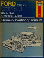
Haynes Ford Capri II 1600 & 2000 Owners Workshop Manual 0856965170, 9780856965173
“279 pages : 27 cm Models covered: UK: Capri II 1600 L, XL & GL, 1593 cc; Capri II GT, GTXL & S, 1593 cc; Capri
152 91
English Pages 288 Year 1979
Recommend Papers


- Author / Uploaded
- John H Haynes
- Peter Ward
- Similar Topics
- Technique
- Transportation: Cars, motorcycles
File loading please wait...
Citation preview
J
nNGe!Y
j ) )1
|
jet
eerie
‘
—
‘
i
=
-
.
|
|
,
&
wo
=
'
a
ees
SRT
eS
y
Te ge
ee
Sth
ob)
Oe
RY
Re
t
ee ae Co -
e |
'
——.
—_— =
ae
oD al
|
a
}
f &
| sea
| ‘
\
}
Wy
UY
ow...
wit
[wa
=
—
é
Ze y
2
zy
Pw
ito
te
Pe
) | la
spy.we.*
Dy
| aoe,
ee
Mea
| ih '\ |
rrr
.
EDINBURGH -
Withd
:
fawt
q THIS BOOK MUST NOT BE REMOVED UNDER ANY PRETEXT FROM THE REFERENCE DEPARTMENT. INFRINGEMENT OF THIS RULE RENDERS THE OFFENDER LIABLE TO PROSECUTION.
Before leaving the Library readers must return the books to one of the attendants at the issue desk, or they will be held responsible for them. Readers are required to take care of the books, Writing or drawing with pen or pencil on any part of a book, or turning down the leaves, or cutting or mutilating them, will be treated as serious damage. q CONVERSATION IN THE REFERENCE DEPARTMENT IS ANNOYING TO STUDENTS, AND IS NOT
ecececves,
=
Soocecvecces
= ae,
ia
t
spall ‘«
é
of
.
a5;
6
os
~
— 48
£09
Vet rs ue—< te
€-
|
89
>—
WY1N3N
NOISSINSNVYL (AINO
»>
5 cy|
—
48
ve
INO!
BS
I
929
sho sio 5
TWANVW)
—< ma
(fhe
4B
x8
99
AWB
wazzne
1v3S 1738
——48 18
Y3ONIW3H HOLIMS
HOLIMS
wae
N3dONI
839
x8
932
A3X
89 >
QLEL
yOLNsiNusic
3ONWISIS3H
48
4a
99 NO
NO.
?
ssne
= LOBHLJTL
7848
=
AG
8
DV
a
en
yaleees
199
Axa
Guvanwis Is—
HOLIMS ay £9
NuOH
>
st €
SivaAty
H3NW379 HOLIMS
6-0 of rafo
Cr)
80
~
18>
60 >
Vie)
18-48D—
BONO
‘
s
589
689
909 aire)
Ne
ue
M
¥
48
OML
K€
Peckow
= 431V3H
=
wi99
LHOIN NUOH A vis oN
= ice
1337 NYOH
48
ae
k
ae
s
Ss ssn@
vipa
ag
AuvaS 02 7 . 3ANIWA AVI3HNYOH (4nvoy _2199) dno. =
3499
ADE
Axa vigo
(HOLIMS zs
3NOL
ae HOLOWWH3HL dWNG ne
18-9 fe-4 € sé
ie 8
ase
ai99 oH
Biy
4) Ay
189 A
bah) Aya je
K
¥OLSIS3Y
u3M018 4OLOW
yy
Wov-2
\
8D
8199
VWNOILdO
83103HANO
Tae
|
ia +
NO
7 veo
e) y3mor78 HOLIMS 4OLOW
v8i
=
HOLVOIONI
=
ee ya aS
08-9 \
48 “A
tate wo L
669 ae
An
aL
)v =HOLIMS 3411498 Q31v3H
4OVE
@31v3H
a)
Avi3u aL ove 310 3H eS) =reg > >— 48 >
T
O31v3H
34/7x9v8
Ye
i
ee
(9/¥ NON) HOLIMS
NE
(Te)
yy
ot
we:
¥30N3S
*8
$2
ids
mB 39NV9 4W3L
M—>
—18 »8-
eee
y, SNVUL olny HOLIMS
dW OVE
el
8
|
NS
Ik
NO
u18a—> > uo
43L3WOHOVL
veo
059 zs= [Yie) HOLIMS HOLIMS ONINU WM, avy Ina —O-
fe
Gos ea, A
rots 48 A
3XVNB
ONINY YM
LHONT
39Nv9 134
CEN ue ok
ua eon
wo
L105)
1X
ii
us
=
>) Y a8 My Ye--=--4,
OLGL a ua
4HOIT
mi
4a
oo
y
3LI1XOV8 O31V3H
38
wnat
anos x8
CAE r) ‘i lay 48 u N48 4a x8
|| 0} ded Aanosayy (PanuizuOd)
a
|
>
—
.
a
2
—t
S
v
L
1HOIN Lav
ANB
1848
>>as)
we
Zz
veo
t $9 YE
\
+
uh
ab Vi
1848 “5
ue
2
ua
Sy
HOLIMS LOO
SS
r< 09-9)
y
oso
YOLOW Y3dIM
,
£99
HOLIMS LHOI1dOLS
Pe)
SS
“gG'OL piNDAID wesbeip “614 aas) abed pzz 4045 Bulsim (sepod
221
ub
urs
4—
rev Ax8
ee
fae
1s
>>>
+6 ONILHOTTHOLIMS io
2
AD
a
3tsHW
L
001-9)
4
vee
MOONIM
H3dIM HOLIMS ANS
Yv3u
be)
L
+3—_—_—
224 Code relating to circuit diagrams on pages 220 - 223 Component
Air conditioner clutch Alternator Alternator regulator Battery Buzzers
Key reminder Seat belt Cigar lighter Clock Distributor Exterior lights Back-up Headlights Left Right License plate Park and turn signal Left Right Side marker Left front Left rear Right front Right rear Stop lights Left Right Taillights Left Right Rear turn signal
Location
F-9
Component
Indicator lights Alternator Brake warning Heated backlight High beam Seat belt Turn signal
B-1 C-1 A-1
B-4 C-4 B-31 C-32 E-6
Right Flashers Hazard flasher
Turn signal Gauges
Instrument voltage regulator
A/C blower Heater blower Starter
D-26, F-27
Windshield wiper (front) Windshield wiper (rear)
E-19 E-20 B-24
Radio Relays
Air conditioning Automatic transmission Dimmer Heated backlight Starter motor Two-tone horn and ignition warning actuator
E-25 C-26 E-25 E-26 B-26 C-28
Seat belt logic box Senders Fuel gauge Water temperature gauge Switches A/C blower A/C control
E-26 D-27 F-26 D-27
Dimmer Instrument panel illumination
Blower switch
Cigar lighter Clock Dome Fuel gauge Glove box Hazard flasher Lighting switch Map PRND21 Tachometer Temperature gauge Windshield wiper switch
Black Red Yellow Blue White
= cop)
pO
paren -ht
.Deu0O 090 (OOF mov
QO
Door jamb Driver's
B-28 D-28
Passenger’s
fo) anOonn
Door jamb - key buzzer Dual brake warning Gear Glove box lamp Hazard flasher Heated backlight Heater blower Horn Ignition Lighting Neutral start Parking brake
Seat belt retractor Driver’s Passenger’s T.A.V. air cleaner Thermactor air dump Throttle return Turn signal Seat sensor Driver's Passenger’s Spark control valve Stoplight Windshield wiper (front) 7 Foot switch YO V99EMIPOOPIETD NNMUNNYNWYNNYNAN PNHONWNWAH]-NHOANA Windshield wiper (rear) Rear washer switch
Wiring colour code BK R x4 BL WwW
= So
High beam
Ammeter Fuel Tachometer Temperature
Heated backlight Heater blower motor Heater blower motor resistor Horns Ignition coil Ignition resistor wire Illumination lights Ammeter and oil pressure gauge
C-12 C-13 E-16 E-21
Motors
F-26 D-27
Left
Location
GN GY BR Vv
Green Grey Brown Violet
oO
Orange
Ww Ow oo
NWOWSIOwW& Oo NN — O10
QVPOTAMMP oO
on=] NINWNN w
ogPeTmMm wMNoQonvan fe)
De&o
Chapter 11 Suspension and steering ) Contents
| Fault diagnosis - suspension and steering Front coil spring - removal and refitting Front hub bearings - adjustment
Rear leaf spring - removal, renewal of bushes and refitting ... Rear shock absorber - removal and refitting ... ies Rear stabilizer bar - removal, renewal of bushes and Wetting Steering angles and front wheel alignment : s Steering column - removal, dismantling, reassembly Ae refining .. Steering gear - adjustments es AOMOWNO Steering gear - dismantling, overhaul an reascemibhy Steering gear - removal and refitting a a
Front hub bearings and oil seal - renewal Front stabilizer bar - removal and refitting | Front suspension strut - removal and refitting
| General description Power steering - bleeding Power steering gear - removal and potiming Power steering - general description ' Power steering pump - removal and PeHennGh
Track control arm (suspension arm) - removal and refitting Wheels and tyres as
aid
eee
|Specifications i, H
Front suspension ype
oa
| Lateral control | Longitudinal control
Shock absorbers Fluid type: FOB
| FOG: ... Fluid capacity:
Independent, MacPherson strut Track control arms Stabilizer bar Hydraulic, telescopic, double-acting
SM6C-1003-A GES-M6C-4503-A 325 + 15 cc (0.18 Imp. pint, approx/0.22 US pint approx.) 340 + 15 cc (0.19 Imp. pint, approx/0.23 US pint approx.)
FOB
7” FOG |Spring rating
The spring rating varies according to the vehicle and intended market. When replacements are required, consult a Ford dealer for further information.
Rear suspension Type es es Shock absorbers Spring rating
Semi-elliptic, leaf spring with rigid axle and stabilizer bar. Hydraulic, telescopic, double-acting The spring rating varies according to the vehicle and intended market. When
replacements are required, consult a Ford dealer for
further information
Manual steering gear Type
FS
Rack travel Mock: fe lock) Steering wheel turns (lock-to-lock) Turning circle (between kerbs) Teeth on pinion (helical) Lubricant type Lubricant capacity
Steering gear adjustment Pinion bearing shim thicknesses Rack slipper bearing shim thicknesses
Power steering gear Pump type Ratio
Steering wheel ters (lock:-to-tock)
Turning circle (between kerbs) Lubricant type Lubricant capacity Fluid type Fluid capacity
Rack and pinion.
5.08 in (129 mm) 3.36 32.8 ft (10.0 m) 5 Capri ll; 6 Mercury Capri II
SAE 90 EP gear oil
0.15 litre (0.25 Imp. pint/0.3 US pint) By shims
0.005, 0.007, 0.010, 0.090 in (0.127, 0.178, 0.254, 2.286 mm) 0.002, 0.005, 0.010, 0.015, 0.020 in (0.051, 0.127, 0.254, 0.381,
0.508 mm)
Hobourn-Eaton 16.8: 1 BIS
roller pump
32.0 ft (9.7 m) SAE 40 or 20W/50 oil 0.19 litre (0.33 Imp. pint/0.4 US pint) Automatic transmission fluid, ESWM-2C-33E SQM-2C9007 AA or D2AZ-19582-A
0.5 litre (0.9 Imp. pint/1.1 US pint)
or
10 8 ) 19 18 12 13 11 7 20
Chapter 11/Suspension and steering 226 en Front wheel alignment (unladen) Castor angle
‘ie
ee
0° 30’ to 1° 45’ positive
a
0° 45'
Maximum difference (side to side) Camber angle
aS
ve
0° 18’ to 1° 48’ positive
ees
1°90’
Maximum difference (side to side)
0 to 0.28 in (0 to 7.0 mm)
Toe-in
Wheels L versions
cea
Boe
:
Pressed steel, sports style Cast‘aluminium 5%Jx 13
“i
Tyres
165SR13 or 185/70 HR13
Size
24 Ibf/in2 (1.7 kgf/em2) 27 Ibf/in2 (1.9 kgf/cm?)
Load up to 3 persons Load in excess of 3 persons
27 Ibf/in2 (1.9 kgf/cm?) 31 Ibf/in2 (2.2 kgf/cm)
j excess of 100 mph, consult the tyre manufacturer or a !Ford dealer. high j speeds in ] For sustained
this for recommended tyre pressures and loads. Where there is a tyre chart on the inside of the glove compartment door, refer to
Ibf ft
Torque wrench settings Suspension unit upper mounting bolts Spindle to top mount assembly * Track control arm ball stud nut Stabilizer bar attachment clamps **
Stabilizer bar to track control arm nut ** Track control arm inner bushing ** ...
ae
A
Front suspension crossmember to body sidemember Shock absorber to rear axle ae Shock absorber to floor assembly ** ... Stabilizer bar to axle tube ** Stabilizer bar to side member ** ss Locknut on stabilizer bar end-piece ** Spring U-bolts ** a Front of rear spring ** ...
Rear of rear spring ** ... es Steering arm to suspension unit Steering gear to crossmember Trackrod-end to steering arm Ses Coupling to pinion spline ae Universal joint to steering shaft spline Steering wheel to shaft Steering column tube to pedal box Power steering fluid pressure lines
Power steering fluid return lines
:
Act
H6
Pinion bearing cover plate bolts (14 ball lower bearing) Pinion bearing cover plate bolts (11 ball lower bearing) Rack slipper cover plate bolts (14 ball lower bearing)
Rack slipper cover plate bolts (11 ball lower bearing)
Wheelnuts (conical face) Wheelnuts (flat face) *
.
3
Rear
Front
Pressures:
Note 7: Note 2:
54x13
Pressed steel
sea
Other versions (except Ghia types) Ghia types
ee
kgf m
15 to 18 29 to 33 30 to 35 21 to 24 14 to 45 18 to 22 29 to 37 39 to 46 20 to 24 29 to 37 26 to 30 29 to 37 18 to 27 26 to 30 8 to 10 30 to 34 15 to 18 18 to 22 12 to 15 17 to 22 20 to 25 15 to 18 19 to 23 “12 to 15 7to9 13 to 18 7to9 13 to 18 63 to 85 85 to 103
DZ Vto225 4.0 to 4.6 4.1 to 4.8
2.9 1.9 2.5 4.0 5.4 2.8 4to
to 3.3 to 6.2 to 3.0 to 5.1 to 6.4 to 3.3 5.1
3.6 to 4.1
4to 5.1 2.5't0.S.7 3.6 to 4.1 1.1 to 1.4 4.1 to 4.7
2.1 to 2.5 2.5 to 3.0 1.6 to 2.1 2.3 to 3.0 2.8 to 3.5 2.1 to 2.5 2.6 to 3.2 1.6 to 2.1 tito: 1.2 1.7 to 2.4 1to 1.2 1.7 to 2.4 8.7 to 11.8 11.8 to 14.2
These are to be tightened with the wheels in the ‘straight-ahead’ position and the weight of the car resting on its wheels.
They are to be
locked by punching the nut intc the slot using a 0.10 in (3 mm) diameter ball ended punch. ** These are to be tightened with the weight of the car resting on its wheels.
1
General description
Each of the independent front suspension MacPherson strut units
spring becoming fully compressed but this is damped by the addition of a rubber bump stop fitted around the suspension unit piston rod which comes into operation before the spring is fully compressed. Whenever
repairs have been carried out on a suspension
unit it is
consists of a vertical strut enclosing a double acting damper surrounded by acoil spring. The upper end of each strut is secured to the top of the wing valance
essential to check the wheel alignment as the linkage could be altered which will affect the correct front wheel settings. Every time the car goes over a bump vertical movement of a front
under the bonnet by The wheel spindle forged integrally with The steering arms
wheel pushes the damper body upwards against the combined
rubber mountings. carrying the brake assembly and wheel hub is the suspension unit foot. are connected to each unit which is in turn
connected to trackrods and thence to the rack and pinion steering gear. The lower end of each suspension unit is located by a track control arm. A stabilising torsion bar is fitted between the outer ends of each track control arm and secured at the front to mountings on the body front member. A rubber rebound stop is fitted inside each suspension unit thus preventing the spring becoming over-extended and jumping out of its mounting plates. Upward movement of the wheel is limited by the
resistance
of the coil spring and the damper piston. Hydraulic fluid in the damper is displaced and forced through the compression
valve into the space between
the inner and outer cylinder.
On the downward movement of the suspension, the road spring forces the damper body downwards against the pressure of the hydraulic fluid which is forced back again through the rebound valve. In this way the natural oscillations of the spring are damped out and a comfortable ride is obtained. On the front uprights it is worth noting that there is a shroud inside the coil spring which protects the machined surface of the piston rod from road dirt.
Chapter 11/Suspension and steering a de al The steering gear is of the rack and pinion type and is located on the front crossmember by two ‘U’ shaped clamps. The pinion is connected to the steering column by a flexible coupling. On Mercury Capri II
models an optional power steering unit is available. The steering wheel is mounted on a convoluted collapsible can which is designed to collapse progressively in the event of impact damage, thus protecting the driver to some degree. _ Turning the steering wheel causes the rack to move in a lateral direction and the trackrods attached to each end of the rack pass this movement to the steering arms on the suspension/axle nuts thereby moving the roadwheels. Two adjustments are possible on the steering gear, namely rack damper adjustment and pinion bearing pre-load adjustment, but the steering gear must be removed from the car to carry out these adjustments. Both adjustments are made by varying the thickness of _ shim-packs,
At the rear, the axle is located by two inverted ‘U’ bolts at each end
of the casing to underslung semi-elliptic leaf springs which provide both lateral and longitudinal focation. Lateral movement of the rear axle is further controlled by fitting a stabilizer bar. Double acting telescopic shock absorbers are fitted between the spring plates on the rear axle and reinforced mountings in the boot of the car. These shock absorbers work on the same principle as the front shock absorbers. In the interests of lessening noise and vibration, the spring and dampers are mounted
on rubber bushes. A rubber spacer is also
227
incorporated between the axle and the springs.
2 Front hub bearings - adjustment 1 The lubricant packed in the front hub bearings should normally last the life of the components, but adjustment will be required at the intervals specified in ‘Routine Maintenance’. 2 Apply the handbrake fully, jack-up the front of the car. Remove the roadwheels and extract the disc brake pads (see Chapter 9).
3
Tap the dust cap from the end of the hub.
4 Extract the split-pin, remove the nut retainer and unscrew the hub nut a few turns. 5 Tighten the stub axle nut to the specified torque whilst rotating the hub/disc in an anti-clockwise direction. Now slacken the nut one half a
turn (180°) and then tighten it again only finger tight. 6 If a torque wrench is not available, tighten the nut initially until a slight drag is felt as the hub is rotated. 7 Fit the nut retainer so that a new split-pin can be inserted without disturbing the previously set position of the nut. Bend the split-pin legs
tightly against the nut retainer. Refit the disc pads. 8 Fit the dust cap and roadwheel. Grip the top and bottom of the tyre and rock the roadwheel. If the bearing has been correctly adjusted, there should be just a perceptible movement. No movement or excessive movement will indicate worn or damaged components or the adjustment procedure having been carried out incorrectly.
VIEW Z
Fig. 11.1. Major parts of the front suspension
Chapter 11/Suspension and steering
228
3 Front hub bearings and oil seal - renewal 1 Raise the front of the car and remove the roadwheels. 2 Disconnect the hydraulic brake pipe at the union on the suspension strut and plug the pipe ends.
3
Unbolt and remove the brake caliper (see Chapter 9).
4 Tap the dust cap from the end of the hub, extract the split-pin, remove the nut retainer, the nut and the thrust washer. 5 Pull the hub/disc towards you to displace the outer bearing. Be ready to catch it.
6 7
Prise out the oil seal and remove the inner bearing. Drive out the bearing tracks from the hub using a brass drift. Clean
out the grease from the hub interior. 8 If the disc is to be renewed because of deep scoring, bend down the tabs of the lockplates and unbolt it from the hub. 9 Reassembly is a reversal of removal. Do not mix up the bearing components as new kits are supplied as matched sets. Half fill the hub
interior with grease and work some into the bearing races. Fit a new oil seal. Use new disc locking plates. Fit and adjust the hub as described in the preceding Section. On completion, bleed the brakes.
correctly on the flats cut on the piston rod. 10 Fit the dished washer to the piston rodiensuring that the convex side faces upwards. 11 Now fit the top mounting assembly. With the steering in the straightahead position, fit the cranked retainer so that the ear on the retainer
faces inwards and is at 90° to the centre-line of the car. Later models have retainers which incorporate two ears. Screw the piston rod nut on having previously applied Loctite or a similar compound to the threads. Do not fully tighten the piston nut at this stage. 12 If necessary pull the top end of the unit upward until it is possible to locate correctly the top mount bracket and fit the three retaining bolts from under the bonnet. These nuts must be tightened down to the specified torque. 13 Remove the spring clips, fit the roadwheel and lower the car to the ground. 14 Finally slacken off the piston rod nut, get an assistant to hold the upper spring seat to prevent it turning and retighten the nut to the specified torque. Ensure that the cranked retainer faces inwards (ie;
towards the engine). (photo).
6 4
Front suspension strut - removal and refitting
1
It is difficult to work on the front suspension without one or two
special tools, the most important of which is a set of adjustable spring
clips which is Ford tool No. P.5045 (USA tool number T70P-5045). This tool or similar clips or compressors are vital and any attempt to
dismantle the units without them may result in personal injury. 2 Get someone to sit on the wing of the car and with the springpartially compressed in this way, securely fit the spring clips. 3 Jack-up the car and remove the roadwheel, then disconnect the brake pipe at the bracket on the suspension leg and plug the pipes or
have a jar handy to catch the escaping hydraulic fluid. 4 Disconnect the trackrod from the steering arm (see Section 11, paragraph 4), thus leaving the steering arm attached to the suspension unit. 5 Remove the outer end of the track control arm from the base of the suspension strut unit (for further information see Section 7). 6 Working under the bonnet, undo the three bolts holding the top end of the suspension strut to the side panel and lower the unit complete with the brake caliper away from the car. 7 Refitting is a direct reversal of the removal sequence but remember to use a new split pin on the steering arm to track rod nut and also on the track control arm to suspension unit nut. 8 The top suspension unit mounting bolts, the track control arm to suspension strut nut, and the steering arm to trackrod end nut must all be tightened to the specified torque.
1 Jack-up the front of the car, support the car on suitable stands and remove both front roadwheels. 2 Working under the car at the front, knock back the locking tabs on the four bolts securing the two front clamps that hold the stabilizer bar to the frame and then undo the four boits and remove the clamps and rubber insulators. 3 Remove the split pins from the castellated nuts retaining the stabilizer bar to the track control arms then undo the nuts and pull off the large washers, carefully noting the way in which they are fitted. 4 Pull the stabilizer bar forward out of the two track control arms and remove from the car.
5 With the stabilizer bar out of the car remove the sleeve and large washer from each end of the bar again noting the correct fitting positions. 6 Reassembly is a reversal of the above procedure, but new locking tabs must be used on the front clamp bolts and new split pins on the castellated nuts. The nuts on the clamps and the castellated nuts on each end of the stabilizer bar must be fully tightened down until the car is resting on its wheels. 7 Once the car is on its wheels the castellated nuts on the ends of the stabilizer bar should be tightened down to the specified torque and the new split pins fitted. The four clamp bolts on the front mounting points must be tightened down to the specified torque and the locking tabs knocked
7 5
Front coil spring - removal and refitting
1 Get someone to sit on the front wing of the car and with the spring partially compressed in this way securely fit spring clips or a
roadspring compressor. (See Fig. 11.2). 2
3
Jack-up the front of the car, fit stands, and remove the road wheel
Working under the bonnet remove the piston nut and the cranked
retainer. 4 Undo and remove the three bolts securing the top of the suspension
unit to the side panel. 5 Push the piston rod downwards as far as it will go. It should now be possible to remove the top mounting assembly, the dished washer and the upper spring seat from the top of the spring. 6 The spring can now be lifted off its bottom seat and removed over the piston assembly.
7
\f anew spring is being fitted check extremely carefully that it is of
the same rating as the spring on the other side of the car. The colour
coding of the springs can be found in the Specifications at the beginning of this Chapter. 8 Before fitting a new spring it must be compressed with the adjustable restrainers and make sure that the clips are placed on the same number of coils, and in the same position as on the spring that has been removed. 9 Place the new spring over the piston and locate it on its bottom
seat, then pull the piston and fit the upper spring seat so that it locates
Front stabilizer bar - removal and refitting
up.
Track control arm (suspension arm) - removal and refitting
1 Jack-up the front of the car, support it on suitable stands and remove the front wheel. 2 Working under the car remove the split pin and unscrew the castellated nut that secures the track control arm to the stabilizer bar.
3 Lift away the large dished washer noting which way round it is fitted. 4 Remove the self-lock nut and flat washer from the back of the track control arm pivot bolt. Release the inner end of the track control arm. 5 Withdraw the split pin and unscrew the nut securing the track control arm balljoint to the base of the suspension unit. Separate the joint using a balljoint separator or wedges. 6 To refit the track control arm first assemble the track control arm ball stud to the base of the suspension unit. 7 Refit the nut and tighten to the specified torque. Secure with a new split pin. 8 Place the track control arm so that it correctly locates over the stabilizer bar and then secure the inner end. 9 Slide -the pivot bolt into position from the front and secure with the flat washer and a new self-locking nut. The nut must be to the rear. Tighten the nut to the specified torque when the car is on the ground.
10 Fit the dished washer to the end of the stabilizer bar making sure it
is the correct way round and secure with the castellated nut. This must be tightened when the car is on the ground, to the specified torque. Lock the castellated nut with a new split pin.
Chapter 11/Suspension and steering SSS —_—_—_—_—_—_——
8
a ea
a
I
—
5 Remove the two screws from the rocker panel at the rear end and pull off the door weatherstrip in the region of the side trim.
Rear shock absorber - removal and refitting
—_ee ne—"—" eee —SOO
6 7
1 Remove the back seat after having removed the two screws from the floor assembly crossmember. 2 Remove the screws securing the seat belt to the top of the ‘B’ pillar.
3 4
229
a
Take out the boot side trim (2 screws) and the carpet. Remove the lining of the rear panel (5 screws) and of the side panel
(10 screws) folding the rear seat forward for access. 8 Note the position of the steel and rubber washer at the wheel arch and axle mounting, then remove the shock absorber. 9 Refitting is a direct reversal of the removal procedure, but ensure that the rubber and steel washers are correctly positioned (where these are showing signs of deterioration, replacement items should be used). Commence the refitting by first connecting the shock absorber at the axle end then extending it for fitting at the wheel arch end.
Detach the ‘B’ pillar cover (2 screws). Remove the top trim from the side window (4 screws).
9
Rear stabilizer bar - removal, renewal of bushes and refitting
1
Chock the front wheels to prevent the car moving, the jack-up the
rear of the car for access to the rear axle and stabilizer bar mountings. 2 Using a multi-grip wrench or similar tool to hold the stabilizer bar towards the axle tube, remove the two bolts at each stabilizer bar-toaxle tube bracket.
3 Disconnect the nut and bolt at each end of the stabilizer bar where it is attached to the floor assembly. 4 To renew a stabilizer bar mounting bush, remove the locknut at one end and unscrew the end piece. Remove the nut and withdraw both rubber bushes from the stabilizer bar. 5 Dip the new rubber bushes in glycerine or brake fluid, ensure that the stabilizer bar surface is clean and not scored, then slide on the bushes
and refit the end piece. When fitted, the endpiece should be positioned as shown in Fig. 11.6, and the difference between the two sides must
not be greater than 0.1 inch (2.5 mm). 6
If the bushes in the end pieces require renewal, it may be found
more convenient to remove the end pieces from the stabilizer bar although this is not essential. The bushes can be pressed out using a
5.14 Suspension unit cranked retainer - installed position
oe
i SS
ATTACHMENT ge
Xs
PR
OTOBItIZER
« BUSHING
CLAMP CLAMP WASHER
TAB
INNER BUSHING
TRACK
CONTROL
ARM
INSULATOR
Fig. 11.2. Front strut supported in vice with special tool compressing coil spring (Sec. 4 and 5)
Fig. 11.3. The track control arm and stabilizer bar (Secs. 6 and 7)
Chapter 11/Suspension and steering
230
STABILIZER
BAR
‘Mein
STABILIZER BAR RETAINING CLAMPS
Fig. 11.4. The rear suspension layout
| ee
ye
Fig. 11.5. The rear shock absorber mount-
ings (Sec. 8))
e/
Fig. 11.7. The stabilizer bar rubber bush correctly positioned
(Sec. 9)
suitable drift whilst the endpiece is supported on a suitable diameter
tube. Installation is straightforward, the new bushes being pressed in until the steel case on the outside of the bush is flush with the inside of the end piece. Note the position of the semi-circular recess in the bush as shown in Fig. 11.7. 7 When refitting the stabilizer bar it should be fitted at the floor end first with the washers and self-locking nuts loosely installed. 8 The bar is then fitted to the axle tube using a suitable tool to pull it towards the axle. The brackets, clamps and rubber insulators should now be fitted and the bolts tightened to the specified torque. 9 Lower the vehicle to the ground then load the vehicle so that the
centre of the axle tube and the spring rear eye are on the same horizontal level (the weight required is approximately that of two adults). The nuts and bolts securing the stabilizer bar to the floor can
now be torque tightened to the specified value.
ee
eeesesesS“N
10 Rear leaf spring - removal, renewal of bushes and refitting 1 Chock the front wheels to prevent the car moving, then jack-up the rear of the car and support it on suitable stands. To make the springs
Fig. 11.6. Installation of the stabilizer bar (Sec. 9)
more accessible remove the roadwheels. 2 Then place a trolley jack underneath the different ial housing to support the rear axle assembly when the springs are removed. Do not
Chapter 11/Suspension and steering
231
STABILIZER BAR MOUNTING CLAMP
g
INSULATOR
REAR STABILIZER
BAR
eo
Sy
SPRING
Det
SHACKLE
—_
INSULATOR ASS’Y
STABILIZER END ASS’Y
BUSHINGS
mg__
CENTER MOUNTING INSULATOR
BUSHING No. 1 SPRING
SPRING
INSERT
LEAF
(4)
ma
ee. No. 2 SPRING LEAF
e
A 8
SPRING PLATE
CLAMP
oo
CLAMP
LINER
9 Fig. 11.8. Rear suspension - exploded view raise the jack under the differential housing so that the springs are
flattened, but raise it just enough to take the full weight of the axle with the springs fully extended. 3 Undo the rear shackle nuts and remove the combined shackle bolt and plate assemblies. Then remove the rubber bushes. 4 Undo the nut from the front mounting and take out the bolt running through the mounting. 5 Undo the nuts on the ends of the four ‘U’ bolts and remove the ‘U’ bolts together with the attachment plate and rubber spring insulators. 6 The rubber bushes can be pressed or driven out, and replacements fitted as described for the bushes in the stabilizer bar and end pieces in the previous Section. A little glycerine or brake fluid will allow the bushes to be pressed in more easily. Note that the front bushes are 7/16
inch (11 mm) diameter and the rear bushes are 5/16 inch (8 mm) diameter. 7 Refitting the spring is the reverse of the removal procedure. The nuts on the ’U’ bolts, spring front mounting and rear shackles must be torqued down to the figures given in the Specifications at the beginning of this Chapter only after the car has been lowered onto its wheels.
eee 11 Steering gear - removal and refitting EE EEE ee ww
ds eee
1 Before starting this job, set the front wheels in the straight-ahead position. Then jack-up the front of the car and place blocks under the wheels; lower the car slightly on the jack so that the trackrods are ina near horizontal position. 2 Remove the nut and bolt from the clamp at the front of the flexible coupling on the steering column. This clamp holds the coupling to the
pinion splines. (photo). 3
Working on the front crossmember, knock back the locking tabs on
the two nuts on each rack housing ‘U’ clamp, undo the nut and remove the locking tabs and clamps.
4 Remove the split pins and castellated nuts from the ends of each from trackrod where they join the steering arms. Separate the trackrods lower the the steering arms using a ball joint separator or wedges and steering gear downwards out of the car. 5 Before refitting the steering gear make sure that the wheels have remained in the straight-ahead position. Also check the condition of the mounting rubbers round the housing and if they appear worn or damaged
renew them.
6 Check that the steering gear is also in the straight-ahead position. the ends of This can be done by ensuring that the distances between the both trackrods and the steering gear housing on both sides are same.
11.2 Steering column clamp nut and bolt (arrowed)
7 Place the steering gear in its location on the crossmember and at the same time mate up the splines on the pinion with the splines in the clamp on the steering column flexible coupling.
8
Refit the two ‘U’ clamps using new locking tabs under the bolts,
tighten down the bolts to the specified torque. 9 Refit the trackrod ends into the steering arms, refit the castellated nuts and tighten them to the specified torque. Use new split pins to retain the nuts.
10 Tighten the clamp bolt on the steering column flexible coupling to
the specified torque, having first made sure that the pinion is correctly located in the splines. 11 Jack-up the car, remove the blocks from under the wheels and lower the car to the ground. It is advisable at this stage to take the car to your
local dealer and have the toe-in checked (see Section 19).
iS
12 Steering gear - adjustments
___. ee 1
For the steering gear to function correctly, two adjustments are
232
qs
i
eas,
BON
HOUSING END COVER
Oa
waster
RACK ADJ BEARING
eo
SPRING.
é e Oy* OUTER
BEARING
INNER
BEARING NYLON
)
SEAT
O sOcrmre WASHER
7 SPRING LOCK
NUT
wa
eee
SEA
ac
Gi)2
qgo—
SPRING
LOCK NUT
ys STEERING
GEAR PINION
WASHER
(Cc am
INNER BEARING
OUTER BEARING —
ihe
(3) SHIMS VARIABLE (1) SHIM THICK
GASKET WACKER oy BOLT ae)
Fig. 11.10. Steering gear - component parts (Sec. 13)
Chapter 11/Suspension and steering
233
necessary. These are pinion bearing preload and rack slipper adjustment. Ideally this will require the use of a dial gauge and mounting block, a surface tavle, a torque gauge and a splined adaptor. It is felt that most people will be able to suitably improvise using other equipment, but if this cannot be done and the equipment listed is not available, the job should be entrusted to your local vehicle main dealer. 2 To carry out these adjustments, remove the steering gear from the car as described in the previous Section. Mount the assembly in a soft
jawed vice then remove the rack slipper cover plate, shim pack gasket and spring. 3 Remove the pinion bearing cover plate, shim pack and gasket. Check the number of balls in the lower bearing as the torque on reassembly will depend on this.
Pinion bearing preload Fig. 11.11. Removing a track rod (Sec. 13)
4 Place the shim pack and cover plate on the bearing, tighten the bolts then slacken them so that the cover plate touches the shim. The shim pack must comprise at least three shims one of which must be 0.093
A and B are special tools available for the purpose
inch (2.35 mm), this being immediately against the cover plate. 5 Measure the cover plate-to-housing gap, and if outside the range 0.011 to 0.013 inch (0.28 to 0.33 mm) reduce the shim pack thickness
remain immediately against the cover plate. 6 When the correct gap is obtained, remove the cover plate, install the gasket and refit the cover plate. Apply a sealer such as Loctite to the cover bolt threads, fit them and torque tighten to the specified setting.
WASHER
AO
SPRING
7 Having set the pinion bearing preload measure the height of the slipper above the main body of the rack as the rack is transversed from lock-to-lock by turning the pinion. Note the height reading obtained. 8 Prepare a shim pack which, including the thickness of the rack : slipper bearing gasket, is 0.002 to 0.006 inch (0.05 to 0.15 mm) thicker than the dimension noted in paragraph 7. 9 Fit the spring, gasket, shim pack and cover plate to the rack housing
(gasket nearest housing). Apply a sealer such as Loctite to the cover _ bolt threads, fit them and torque tighten to specification. 10 Measure the torque required to turn the pinion throughout its range
of travel. This should be 10 to 18 Ibf inch (11.5 to 20.7 kg cm); if outside this range, faulty components, lack of lubricant, etc., should be suspected. EE
13 Steering gear - dismantling, overhaul and reassembly
e ee E a
ee
ee
eee
The procedure given may be beyond the capabilities of many d-i-y motorists. Read through the Section before commencing any work and if not considered to be feasible, entrust the job to your local vehicle main dealer. 1 Remove and discard the wire retaining clips, remove the bellows and drain the lubricant. 2 Mount the steering gear in a soft-jawed vice and drill out the pins securing the trackrod housings to the locknuts. Centre-punch the pins Note:
(5/32 inch or No. 22) drill but do not
drill too deeply. 3. It is now necessary to unscrew the housings from the ball joints so that the trackrods, housings, locknuts, ball seats, washers and springs can be removed. Ideally this requires the use of special tools which
should be available from a vehicle main dealer but if improvised grips or wrenches are used take care that no parts are damaged (if parts are damaged, replacement items must be obtained).
4 5
Remove Remove
the rack slipper cover plate, shim pack, gasket and slipper. the pinion bearing preload cover plate, shim pack, gasket
and lower bearing. seal. 6 Using a screwdriver or similar tool, prise out the pinion oil pinion 7 Clean all dirt and paint from the pinion shaft then push the out of the housing. 8 Take out the pinion upper bearing and washer. Examine the 9 Clean and inspect all the parts for damage and wear. if worn it bush in the end of the rack tube furthest from the pinion; can be pressed out and a replacement fitted. and 10 Commence reassembly by fitting the pinion upper bearing washer into the housing. it in the central 11 Position the rack into the housing, and leave
position.
ROD
HOUSING
On sv /
Rack slipper adjustment
before drilling then use a 4 mm
TRACK
LOCK NUT
{if the gap is too large) or increase it (if the gap is too small) until this gap is obtained. Remember that the 0.093 inch (2.35 mm) shim must
NYLON
SEAT
Fig. 11.12. Tie rod (track rod or connecting rod) ball joint -
exploded view (Sec. 13)
12 Install the pinion, ensuring that after installation the flat is towards the right-hand side of the vehicle (irrespective of right or left-hand
drive vehicles). 13 Fit the pinion lower bearing cover plate and adjust the preload as described in the previous Section. 14 Assemble the rack slipper, spring, gasket, shim pack and cover plate, adjusting as described in the previous Section.
15 Lubricate the ball seats, balls and housings with SAE 90 EP gear oil. Screw the locknuts onto the ends of the steering rack. 16 Assemble the springs, washers, ball seats, trackrod ends and housing. Tighten the housings to obtain a rotational torque of 5 Ibf ft (0.7 kgf m) then lock them with the locknuts. Recheck the torque after tightening the lockrut.
17 Drill new holes (even if the old holes are in alignment),
4 mm
(5/32
inch or No. 22 drill) diameter x9 mm (0.38 inch) deep along the break lines between the housing and the locknut, approximately opposite the spanner locating hole in the housing. 18 Fit new retaining pins and peen over the surrounding metal to retain them. 19 Lightly grease the inside of the bellows where they will contact the trackrods, install one bellows ensuring that it locates in the trackrod
groove; then fit a new retaining clip. 20 Add the specified quantity of steering gear oil, operating the rack over its range of travel co assist the lubricant in flowing. Do not overfill. 21 Fit the other beliows. 22 Check the pinion turning torque, as described in paragraph 10 of the previous Section.
EE
14 Power steering - general description —— a |! cars has a Capri Mercury on 1 The power steering system available
pulley-driven Hobourn-Eaton series 110 roller pump. This pump delivers fluid to a servo assisted rack and pinion gear assembly. on the rack 2 Servo assistance is obtained through a piston mounted controlled by and running in the rack tube. The degree of assistance is pinion shaft. a spool valve mounted concentrically with the input and fluid reservoir. integral an tes incorpora pump steering power The 3 system it is 4 Owing to the complexity of the power steering in the following recommended that servicing etc., is limited to that given
234
Chapter 11/Suspension and steering
Sections. In the event of a fault occurring it is recommended that repair or overhaul is entrusted to a specialist in this type of work.
12 Tap the lower end of the shaft with a soft-faced hammer to remove the shaft and bearing from the top of the column. 13 Using the shaft as a drift, tap the lower bearing out of the column.
15 Power steering - bleeding
15 Commence
14 Inspect all the parts for wear and damage, renewing if necessary.
1 The power steering system will only need bleeding in the event of air being introduced into the system ie; where pipes have been disconnected or where a leakage has occurred. To bleed the system proceed as described in the following paragraphs. q 2 Open the bonnet (hood) and check the fluid level in the integral reservoir. Top-up if necessary using the specified type of fluid. 3 If fluid is added, allow two minutes then run the engine at
approximately 1500 rpm. Slowly turn the steering wheel from lock-tolock, whilst checking and topping-up the fluid level until! the level remains steady and no more bubbles appear in the reservoir. 4 Clean and refit the reservoir cap, and close the bonnet.
ee ab a et
ee
Ee
oe
ee
16 Power steering pump - removal and refitting A ee eee
a
ee ee
eee
1
Disconnect the battery earth lead.
2
Raise the car on a hoist or place it over an inspection pit if possible.
reassembly by positioning the shaft in the column, then
assemble the lower bearing (smaller diameter towards the column), spring, washer and circlip to the shaft. Push the assembly into the column to locate the bearing against the stops. 16 Press the upper bearing onto the column. 17 Secure the steering lock to the column and shear the bolts.
18 Use the steering lock to locate the shaft in the column, then fit the direction indicator actuating cam and steering wheel (check that the roadwheels are still in the ‘straight-ahead’ position). 19 Install the steering column grommet at the lower end. 20 Locate the column assembly and secure it with the two mounting bolts. 21 The remainder of the refitting procedure is the reverse of the removal procedure. 19 Steering angles and front wheel alignment
Alternatively, the car must be jacked-up to provide the working room beneath. 3 Where applicable, remove the engine splash shield. 4 Loosen the alternator mounting bolts and remove the driveshaft (refer to Chapter 10 if necessary). 5 Disconnect the power system fluid lines and drain the fluid into a suitable container. 6 Remove the fuel pump from the engine, but do not disconnect the fuel lines. Move the pump away from the power steering bolts. (Refer to Chapter 3 for further information, if necessary). 7 Remove the power steering pump. As applicable, remove the pump pulley and adaptor bracket. 8 Refitting is a direct reversal of the removal procedure. Ensure that the fluid lines are tightened to the specified torque, top-up the system with an approved fluid, adjust the alternator drivebelt tension (see Chapter 10), then bleed the system, as described in the previous Section
1 Accurate front wheel alignment is essential for good steering and tyre wear. Before considering the steering angle, check that the tyres are correctly inflated, that the front wheels are not buckled, the hub bearings are not worn or incorrectly adjusted and that the steering linkage is in good order, without slackness or wear at the joints. 2 Wheel alignment consists of four factors: Camber which is the angle at which the front wheels are set from the vertical when viewed from the front of the car. Positive camber is the amount (in degrees) that the wheels are tilted outwards at the top from the vertical. Castor is the angle between the steering axis and a vertical line when viewed from each side of the car. Positive castor is when the steering axis is inclined rearwards. Steering axis inclination is the angle when viewed from the front of the car, between the vertical and an imaginary line drawn between the upper and lower suspension strut pivots. Toe-in is the amount by which the distance between the front inside
eee
distance measured between the rear inside edges.
1S:
edges of the roadwheels (measured at hub height) is less than the 3
17 Power steering gear - removai and refitting a eeeeeSSSSSSSSSSSSSSSSSSSSSSSSSSSSSSsSsSsSs
S
1 The procedure for removing the power steering gear is similar to that described in Section 11 for the manual steering gear with the additional task of disconnecting the pump lines. When refitting, ensure that the fluid lines are tightened to the specified torque, top-up the system with an approved fluid adjust the alternator driveshaft tension see Chapter 10, then bleed the system, as described in Section 15.
ees
18 Steering column - removal, dismantling, reassembly and refitting 1
Disconnect the battery earth lead.
2 Remove the upper and lower steering coupling clamp bolts, and tap the coupling shaft down the pinion shaft to disconnect the coupling shaft from the column. 3 Carefully prise out the motif from the centre of the steering wheel and then unscrew the wheel retaining nut (photo). 4 Ensure that the roadwheels are in the straightahead position then pull off the steering wheel. 5 Remove the direction indicator actuator cam. 6 Remove the steering column shroud (2 screws at the bottom, then pull out at the top) and lower the dash panel trim. 7 Disconnect the direction indicator switch from the column (two
bolts - see Fig. 11.15). 8
9
Disconnect the loom wiring from the ignition switch.
Remove the two steering column retaining bolts (see Fig. 11.16) and
pull the column assembly from the vehicle. Push the grommet out of the floor pan.
10 Drill off the steering column lockbolt heads, or tap them round with
a pin punch, then use suitable grips to pull out the bolt shanks. Remove
the steering lock (refer to Chapter 10, if necessary).
11 Remove the circlip snap ring, washer and spring from the lower end of the column.
The angles of camber, castor and steering axis are set in
production and are not adjustable. 4 Front wheel alignment (toe-in) checks are best carried out with modern setting equipment but a reasonably accurate alternative is by means of the following procedure.
5
Place the car on level ground with the wheels in the ‘straight-ahead’
Position. It should be unladen apart from the spare wheel, jack and wheelspanner. Tyre pressures should be normal. Bounce the car, front and rear, up and down about 2 ins (50 mm) to settle the suspension. Don’t disturb the ride height by jacking or sitting in the car before the toe-in checks are done. 6 Obtain or make a toe-in gauge. One may easily be made from a length of rod or tubing, cranked to clear the sump or bellhousi ng and having a setscrew and locknut at one end. 7 With the gauge, measure the distance between the two inner wheel rims at hub height at the front of the wheel.
8 Rotate the roadwheel through 180° (half a turn) by pushing or pulling the car and then measure the distance again at hub height
between the inner wheel rims at the rear of the roadwheel. This
measurement should either be the same as the one just taken or greater
by not more than 0.28 inch (7 mm).
9 Where the toe-in is found to be incorrect slacken the locknuts on each trackrod, also the flexible bellows clips and rotate each trackrod by an equal amount until the correct toe-in is obtained. Tighten the trackrod-end locknuts while the ball joints are held in the centre of their arcs of travel. It is imperative that the lengths of the trackrods are always equal otherwise the wheel angles on turns will be incorrect. If new components have been fitted, set the roadwheels in the ‘straightahead’ position and also centralise the steering wheel. Now adjust the lengths of the trackrods by turning them so that the trackrod-end ball joint studs will drop easily into the eyes of the steering arms. Measure the distances between the centres of the ball joints and the grooves on the inner ends of the trackrods and adjust, if necessary so that they are equal. This is an initial setting only and precise adjustment must be carried out as described in earlier Paragrap hs of this Section.
Chapter 11/Suspension and steering
235
NO. 2 CROSSMEMBER
Fig.
11.13. Basic layout of the power
steering gear (Sec. 14) POWER
STEERING
Fig. 11.14. Power steering reservoir and dipstick
GEAR
(Sec. 15)
Fig. 11.15. Retaining bolts for direction indicator switch (arrowed) (Sec. 18)
COUPLING & UNIVERSAL JOINT ASSEMBLY
6
GROMMET
sNAP RING
INDICATOR ACTUATING CAM
WASHER x)
; oo
—
LOWER BEARING
BEARING PRE-LOAD SPRING Fig. 11.17. The steering column assembly (Sec. 18)
(Sec. 18) Fig. 11.16. Retaining bolts for the steering column (arrowed)
a 20 Wheels and tyres eS are cold). 1 Check the tyre pressures weekly (when they damage and pick 2 Frequently inspect the tyre walls and treads for
the tread pattern. out any large stones which have become trapped in on the car then they 3. |f the wheels and tyres have been balanced If they have been should not be moved to a different axle position. g tread life, they extendin of interests the in then, car the off balanced of the car and side same the on rear and front can be moved between the spare incorporated in the rotational pattern.
4 Never mix tyres of different construction or very dissimilar tread patterns. if 5 Always keep the roadwheels tightened to the specified torque and wheel. the renew flattened, or elongated become holes the bolt there is 6 Occasionally, clean the inner faces of the roadwheels and if any sign of rust or corrosion, paint them with metal preservative paint. Note:
Corrosion on aluminium
alloy wheels may be evidence of a more
Is serious problem which could lead to wheel failure. If corrosion
evident, consult your Ford dealer for advice. car, 7 Before removing a roadwheel which has been balanced on the may always mark one wheel stud and bolt hole so that the roadwheel be refitted in the same relative position to maintain the balance.
236
Chapter 11/Suspension and steering
21 Fault diagnosis - Suspension and steering Before diagnosing faults from the following chart, check that any irregularities are not caused by: 1 2 3
4
Binding brakes. Incorrect ‘mix’ of radial and crossply tyres. Incorrect tyre pressures. Misalignment of the bodyframe.
Symptom
Reason(s)
a ee ee Steering wheel can be moved considerably before any sign of movement
ee
ee
eee
eee ae
ee
Wear in the steering linkage, gear and column coupling.
of the roadwheels is apparent
Vehicle difficult to steer in a consistent straight line - wandering
As above. Wheel alignment incorrect (indicated by excessive or uneven
tyre
wear). Front wheel hub bearings loose or worn. Worn ball joints. Steering stiff and heavy
Incorrect wheel alignment (indicated by excessive or uneven tyre
wear). Excessive wear or seizure in one or more of the joints in the steering linkage or suspension.
Excessive wear in the steering gear. Failure of power steering gear pump.
Wheel wobble and vibration
Roadwheels out of balance. Roadwheels buckled. Wheel alignment incorrect. Wear in the steering linkage, suspension ball joints or track control
arm pivot.
Broken front spring
Excessive pitching and rolling on corners and during braking
Defective shock absorbers and/or broken spring.
Chapter 12 Bodywork
and fittings
Contents
Air-conditioning system- general “te Bonnet (hood) release cable - removal and regiuaas
Bonnet (hood) - removal, refitting and adjustment
...
Bumpers - removal and refitting Centre console - removal and refitting Demister nozzles - removal and refitting Door lock assembly - removal and refitting
Door Door Door Door Door
rattles -tracing and rectification An Se remote control handle - removal and refitting trim panel - removal and refitting window frame - removal and refitting ... window glass - removal and refitting
Door window regulator assembly - removal and refictinn Exterior door handle - removal and refitting
Face level vents (vent registers) - removal and pening Fault diagnosis - heating system Fuel filler flap - removal and refitting General description oe ee
ie
45 24 25
31 42 17 12 13 14 19 18 15 16 43 44 29
asi
Heater assembly (Behr) - dismantling and reassembly Heater assembly - removal and refitting
40 39
Heater assembly (Smiths standard and heavy duty) -emeeal and installation
Z
Heater controls- aiustricnt
Heater controls - removal and eiicanee
41 36 37
Heater water valve (heavy duty heater) - removal and refitting Instrument panel crash pad - removal and refitting ...
Load space trim panel - removal and refitting Maintenance - bodywork and underframe Maintenance - upholstery and carpets Maintenance - vinyl external roof covering Maintenance - locks and hinges Major body damage - repair Minor body damage - repair Opening rear quarter glass assembly - remnensl end retinas Radiator grille - removal and refitting Rear quarter trim panel - removal and refitting
Seatbelts - general Sunroof bracket and drive sesceauly - Marneval ‘aid rarittinge
Sunroof panel - adjustments Sunroof - removal and refitting Tailgate assembly - removal and refitting Tailgate glass -removal and refitting Tailgate lock assembly - removal and refitting ineleidie reinous
of the lock barrel)
eri
Tailgate striker plate - removal anal Pefitting Window frame mouldings and door weathersimps - renova’ and refitting Windscreen - removal that feritting
Chapter 12/Bodywork and fittings
238
EE
5 1
General description
Thoroughly wet the car to soften the dirt and then wash the car down
The body is of a monocoque all-steel, welded construction with impact absorbing front and rear sections. The car has 2 side doors and a full-length lifting tailgate for easy access to the rear compartment. The side doors are fitted with antiburst locks and incorporate a key operated lock in each handle; window frames are adjustable for position. The tailgate hinges are bolted to the underside of the roof panel and to the tailgate itself. Gas-filled dampers support the tailgate in the open position; when closed it is fastened by a key-operated lock incorporating a release pushbutton.
An automatic bonnet (hood) locking mechanism operates when the bonnet is closed, a release lever being fitted at the edge of the instrument panel on the driver's side. The bonnet (hood) is hinged at the rear and is held in the open position by a support stay. A cable-operated sliding roof is available as an option, this being controlled by a handle fitted flush to the head lining. Toughened safety glass is fitted to all windows, the windscreen having an additional ‘zone’ toughened band in front of the driver. In the event of the windscreen shattering this zone crazes into large sections to give a greater degree of visibilty as a safety feature. An optional glass/plastic/glass laminated windscreen is available at extra cost; this has the advantage of cracking only, to give an even greater degree of visibility in the event of accidental damage. The front door windows have a conventional winding mechanism. On certain variants, frameless opening rear quarter windows are fitted. These are hinged at the forward edge and are operated from an ‘over-centre’ type latch. A heated rear window is available as an optional extra throughout the range. All vehicles have individual reclining front bucket seats. GT versions have individual rear folding seats whereas a folding rear bench seat is used On other models. The standard seat and panel upholstery is a viny! material but a cloth fabric trim is available for all models. A padded facia crash panel is standard equipment together with deep pile wall-to-wall carpeting. Inertia reel seatbelts are fitted to all models. To prevent damage under minor impacts, rubber faced bumpers are used, with rubber overriders on GT models. All models are fitted with a heating and ventilating system which operates by ram air when the car is moving, or by a blower when
stationary or for increased airflow. The control panel and airflow is directed to according to the control lever settings. for some markets, and USA models can air conditioning system.
heater is operated from a central the windscreen or car interior A heavy duty heater is available be supplied with an optional
eS 2 Maintenance - bodywork and underframe Se
ee ee
1 The condition of your car’s bodywork is of considerable importance as it is On this that the secondhand value of the car will mainly depend. It is very much more difficult to repair neglected bodywork than to renew mechanical assemblies. The hidden portions of the body, such as the wheel arches and the underframe and the engine compartment are equally important though obviously not requiring such frequent attention as the immediately visible paintwork.
2
eee
The bodywork should be washed once a week or when dirty.
Once a year or every 12,000 miles (19000 km), it is a sound scheme
to visit your local main agent and have the underside of the body steam cleaned. This will take about 1% hours. All traces of dirt and oil will be removed and the underside can then be inspected carefully for rust, damaged hydraulic pipes, frayed electrical wiring and similar maladies. 3 At the same time the engine compartment should be cleaned in the same manner. If steam cleaning facilities are not available then brush a water soluble cleanser over the whole engine and engine compartme nt with a stiff paintbrush, working it well in where there is an accumulati on of oil and dirt. Do not paint the ignition system but protect it with oily rags when the cleanser is washed off. As the cleanser is washed away
it will take with it all traces of oil and dirt, leaving the engine looking clean and bright. 4 The wheel arches should be given particular attention as undersealing can easily come away here and stones and dirt thrown up from the road wheels can soon cause the paint to chip and flake, and so allow rust to set in. If rust is found, clean down to the bare metal with wet and dry Paper, paint on an anti-corrosive coating and renew the paintwork and undercoating.
with a soft sponge and plenty of clean water. If the surplus dirt is not washed off very gently, in time it will wear the paint down as surely as wet and dry paper. It is best to use a hose if this is available. Give the car a final wash down and then dry with a soft chamois leather to prevent the formation of spots. 6 Spots of tar and grease thrown up from the road can be removed with a rag dampened with petrol. 7 Once every six months, or every three months, if wished, give the
bodywork and chromium trim a thoroughly good wax polish. If a chromium cleaner is used to remove rust or any of the car’s plated parts remember that the cleaner also removes part of the chromium so use sparingly.
3
Maintenance - upholstery and carpets
1 Remove the carpets and thoroughly vacuum clean the interior of the car every three months or more frequently if necessary. 2 Beat out the carpets and vacuum clean them if they are very dirty. If the headlining or upholstery is soiled apply an upholstery cleaner with a damp sponge and wipe off with a clean dry cloth.
4
Maintenance - viny! roof covering Under no circumstances try to clean any external viny! roof covering
with detergents, caustic soaps or spirit cleaners. Plain soap and water is all that is required with a soft brush to clean dirt that may be ingrained. Wash the covering as frequently as the rest of the car.
5
Minor body damage - repair
Repair of minor scratches in the car’s bodywork If the scratch is very superficial and does not penetrate to the metal of the bodywork, repair is very simple. Lightly rub the area of the
scratch with a paintwork renovator, or a very fine cutting paste, to remove loose paint from the scratch and to clear the surrounding bodywork of wax polish. Rinse the area with clean water.
Apply touch-up paint to the scratch using a thin paintbrush, continue to apply thin layers of paint until the surface of the Paint in
the scratch is level with the surrounding paintwork. Allow the new paint at least two weeks to harden; then blend it into the surrounding paintwork by rubbing the paintwork, in the scratch area with a
paintwork renovator, or a very fine cutting paste. Finally apply wax Polish. Where the scratch has penetrated right through to the metal of the bodywork, causing the metal to rust, a different repair technique is required. Remove any loose rust from the bottom of the scratch with a penknife, then apply rust inhibiting paint to prevent the formation of rust in the future. Using a rubber nylon applicator, fill the scratch with bodystopper paste. If required, this paste can be mixed with cellulose thinners to provide a very thin Paste which is ideal for filling narrow scratches. Before the stopper-paste in the scratch hardens, wrap a piece
of smooth cotton rag around the top of a finger. Dip the finger in cellulose thinners and then quickly sweep it across the surface of the stopper-paste in the scratch; this will ensure that the surface of the stopper-paste is slightly hollowed. The scratch can now be painted over as described earlier in this Section.
Repair of dents in the car’s bodywork
When deep denting of the car's bodywork has taken place, the first task is to pull the dent out, until the affected bodywork almost attains its original shape. There is little point in trying to restore the Original shape completely, as the metal in the damage d area will have stretched On impact and cannot be reshaped fully to its Original contour. It is better to bring the level of the dent up to the point which is about
SST
TB
a
aS
Chapter 12/Bodywork and fittings
1/8 inch (3 mm) below the level of the surrounding bodywork. In cases
where the dent is very shallow anyway, it is not worth trying to pull it | Outatall. If the underside of the dent is accessible, it can be hammered
out
gently from behind, using a mallet with a wooden or plastic head. Whilst doing this, hold a suitable block of wood firmly agdinst the impact from the hammer blows and thus prevent a large area of
bodywork from being ‘belled-out’.
Should the dent be in a section of the bodywork which has a double
skin or some other factor making it inaccessible from behind, a different technique is called for. Drill several small holes through the metal inside the dent area - particularly in the deeper sections. Then screw long selftapping screws into the holes just sufficiently for them to gain a good purchase in the metal. Now the dent can be pulled out by pulling on the protruding heads of the screws with a pair of pliers. The next stage of the repair is the removal of the paint from the damaged area, and from an inch or so of the surrounding ‘sound’ bodywork. This is accomplished most easily by using a wire brush or abrasive pad on a power drill, although it can be done just as effectively by hand using sheets of abrasive paper. To complete the preparations for filling, score the surface of the bare metal with a screwdriver or the
tang of a file, or alternatively, drill small holes in the affected area. This
will provide a really good ‘key’ for filler paste. To complete the repair see the Section on filling and respraying.
Repair of rust holes or gashes in the car’s bodywork Remove all paint from the affected area and from an inch or so of the surrounding ‘sound’ bodywork, using an abrasive pad or a wire brush on a power drill. If these are not available a few sheets of abrasive paper will do the job just as effectively. With the paint removed you will be able to gauge the severity of the corrosion and therefore decide whether to replace the whole panel (if this is possible) or to repair the affected area. Replacement body panels are not as expensive as most people think and it is often quicker and more satisfactory to fit a new panel than to attempt to repair large areas of corrosion.
Remove all fittings from the affected area except those which will act as a guide to the original shape of the damaged bodywork (eg; headlamp shells etc.). Then, using tin snips or a hacksaw blade, remove all loose metal and any other metal badly affected by corrosion. Hammer the edges of the hole inwards in order to create a slight depression for the filler paste. Wire brush the affected area to remove the powdery rust from the surface of the remaining metal. Paint the affected area with rust inhibiting paint; if the back of the rusted area is accessible treat this also. Before filling can take place it will be necessary to block the hole in some way. This can be achieved by the use of one of the following materials:
Zinc gauze, Aluminium
tape or Polyurethane foam.
Zinc gauze is probably the best material to use for a large hole. Cut a piece to the approximate size and shape of the hole to be filled, then position it in the hole so that its edges are below the level of the surrounding bodywork. It can be retained in position by several blobs of filler paste around its periphery. Aluminium
tape should be used for small or very narrow holes. Pull
a piece off the roll and trim it to the approximate size and shape
required, then pull off the backing paper (if used) and stick the tape over the hole; it can be overlapped if the thickness of one piece is insufficient. Burnish down the edges of the tape with the handle of a screwdriver or similar, to ensure that the tape is securely attached to the metal underneath. Polyurethane foam is best used where the hole is situated ina section of bodywork of complex shape, backed by a small box section (eg; where the sill panel meets the rear wheel arch - most cars). The usual mixing procedure for this foam is as follows: Put equal amounts of fluid from each of the two cans provided in the kit, into one container. Stir until the mixture begins to thicken, then quickly pour this mixture into the hole, and hold a piece of cardboard over the larger apertures. Almost immediately the polyurethane will begin to
239
a
a
Ea
proprietary kits which contain a tin of filler paste and a tube of resin hardener are best for this type of repair. A wide, flexible plastic or nylon applicator will be found invaluable for imparting a smooth and well contoured finish to the surface of the filler. Mix up a little filler on a clean piece of card or board - use the hardener sparingly (follow the maker's instructions on the packet) otherwise the filler wiil set very rapidly. Using the applicator, apply the filler paste to the prepared area; draw the applicator across the surface of the filler to achieve the correct contour and to level the filler surface. As soon as a contour that approximates to the correct one is achieved, stop working the paste - if you Carry on too long the paste will become sticky and begin to ‘pick-up’ on the applicator. Continue to add thin layers of filler paste at twentyminute intervals until the level of the filler is just ‘proud’ of the
surrounding bodywork. Once the filler has hardened, excess can be removed using a metal plane or file. From then on, progressively finer grades of abrasive paper should be used, starting with a 40 grade production paper and finishing with 400 grade ‘wet-and-dry’ paper. Always wrap the abrasive paper around a flat rubber, cork or wooden block - otherwise the surface of the filler will not be completely flat. During the smoothing of the filler
surface the ‘wet-and-dry’ paper should be periodically rinsed in water. This will ensure that a very smooth finish is imparted to the filler at the
final stage. At this stage the ‘dent’ should be surrounded by a ring of bare metal, which in turn should be encircled by the finely ‘feathered’ edge of the good paintwork.
Rinse the repair area with clean water, until all
of the dust produced by the rubbing-down operation is gone. Spray the whole repair area with a light coat of grey primer - this will show up any imperfections in the surface of the filler. Repair these imperfections with fresh filler paste or bodystopper, and once more smooth the surface with abrasive paper. If bodystopper is used, it can be mixed with cellulose thinners to form a really thin paste which is ideal for filling small holes. Repeat this spray and repair procedure until you are satisfied that the surface of the filler, and the feathered edge of the paintwork are perfect. Clean the repair area with clean water and allow to dry fully. The repair area is now ready for spraying. Paint spraying must be carried out in a warm, dry, windless and dust free atmosphere. This condition can be created artificially if you have access to a large indoor working area, but if you are forced to work in the open, you will have to pick your day very carefully. If you are working indoors, dousing the floor in the work area with water will ‘lay’ the dust which would otherwise be in the atmosphere. If the repair area is confined to one body panel, mask off the surrounding panels; this will help to minimise the effects of a slight mis-match in paint colours. Bodywork fittings (eg; chrome strips, door handles etc.), will also need to be masked off. Use genuine masking tape and several thicknesses of newspaper for the masking operation. Before commencing to spray, agitate the aerosol can thoroughly,
then spray a test area (an old tin, or similar) until the technique is mastered. Cover the repair area with a thick coat of primer; the thickness should be built up using several thin layers of paint rather than one thick one. Using 400 grade ‘wet-and-dry’ paper, rub down the surface of the primer until it is really smooth. While doing this, the work area should be thoroughly doused with water, and the ‘wet-anddry’ paper periodically rinsed in water. Allow to dry before spraying on more paint. Spray on the top coat, again building up the thickness by using
several thin layers of paint. Start spraying in the centre of the repair area and then, using a circular motion, work outwards until the whole repair area and about 2 inches of the surrounding original paintwork is covered. Remove all masking material 10 to 15 minutes after spraying on the final coat of paint. Allow the new paint at least 2 weeks to harden fully; then, using a paintwork renovator or a very fine cutting paste, blend the edges of the new paint into the existing paintwork. Finally, apply wax polish.
expand, gushing frantically out of any small holes left unblocked. When the foam hardens it ca
be cut back to just below the level of the
surrounding bodywork with a hacksaw blade. 6
Bodywork repairs - filling and re-spraying
Before using this Section, see the Sections on dent, deep scratch, rust hole, and gash repairs. Many types of bodyfiller are available, but generally speaking those
Major body damage - repair
1 Because the body is built on the monocoque principle and is integral with the underframe, major damage must be repaired by competent
mechanics with the necessary welding and hydraulic straightening
240 Chapter 12/Bodywork and fittings ae ae ce nn equipment.
2 If the damage has been serious it is vital that the body is checked for correct alignment as otherwise the handling of the car will suffer and many
other faults such as excessive tyre wear and wear in the
transmission and steering may occur. 3 There is a special body jig which most large body repair shops have and to ensure that all is correct it is important that this jig be used for
2 Cover the bonnet with a blanket or cloth to prevent accidental damage and remove the windscreen wiper blades and arms as detailed in Chapter 10.
Windscreen intact 3
Put ona
pair of lightweight shoes and get into one of the front seats.
With a piece of soft cloth between the soles of your shoes and the
windscreen glass, place both feet in one top corner of the windscreen
all major repair work.
and push firmly. (See Fig. 12.6). 7
Maintenance - locks and hinges
Once every 6 months or 6000 miles (10000 km) the door, bonnet and tailgate hinges should be lubricated with a few drops of engine oil. Door striker plates can be given a thin smear of grease to reduce wear and ensure free movement.
8
Bumpers - removal and refitting
Front bumper (Capri !1) 1 Initially disconnect the battery earth lead. 2 Remove the radiator cover which is retained by five screws. 3 Remove the four bumper retaining screws and lift away the bumper. 4 Refitting is the reverse of the removal procedure, but do not fully tighten the bolts until the bumper is correctly aligned.
4 When the weatherstrip has freed itself from the body flange in that area, repeat the process at frequent intervals along the top edge of the windscreen until, from outside the car, the glass and weatherstrip can be removed together.
Windscreen shattered 5 If you are having to replace your windscreen due to a shattered screen, remove all traces of sealing compound and broken glass from the weatherstrip and body flange. 6 Gently prise out the clip which covers the joint of the chromium finisher strip and pull the finisher strip out of the weatherstrip. Then remove the weatherstrip from the glass or, if it is still on the car (as in the case of a shattered screen) remove it from the body flange.
9 Remove the nuts from the bolts securing the bumper to the bumper brackets and lift the bumper away. 10 Remove the front license plate brackets. 11 Remove the bolts securing the bumper reinforcement then lift the
7 To fit a new windscreen start by fitting the weatherstrip around the new windscreen glass. 8 Apply a suitable sealer to the weatherstrip to body groove. In this groove then fit a fine but strong piece of cord right the way round the groove allowing an overlap of about 6 in (15 cm) at the joint. 9 From outside the car place the windscreen in its correct position making sure that the loose end of the cord is inside the car. 10 With an assistant pressing firmly on the outside of the windscreen get into the car and slowly pull out the cord thus drawing the
reinforcement away.
weatherstrip over the body flange. (See Fig. 12.7).
12 Refitting is a direct reversal of the removal procedure but do not fully tighten the bolts until the bumper is correctly aligned.
11 Apply a further layer of sealer to the underside of rubber to glass groove from outside the car. 12 Replace the chromium finisher strip into its groove in the weatherstrip and replace the clip which covers its joint. 13 Carefully clean off any surplus sealer from the windscreen glass before it has a chance to harden and then replace the windscreen wiper arms and blades. Retrieve the tax disc from the old screen.
Front bumper (Mercury Capri !1)
Rear bumper (Capri !1) 5 6
Open the tailgate, then remove the mat and the sub-floor. Remove the jack and washer water reservoir (where applicable).
7 Remove two nuts, spring washer and flat washers at each end and lift away the bumper. 8 Refitting is the reverse of the removal procedure, but do not fully tighten the nuts until the bumper is correctly aligned.
nner is De
Rear bumper (Mercury Capri !1)
11 Tailgate window glass - removal and refitting eS ee te EE Ae Bee 1 Where applicable, remove the window glass wiper arm and blade,
13 Remove the eight bolts and washers securing the bumper assembly to the brackets then remove the assembly. 14 Remove the special bolts securing the bumper reinforcement to the bumper. 15 Refitting is a direct reversal of the removal procedure but do not fully tighten the bolts until the bumper is correctly aligned.
Bumper trim strips 16 The bumper trim strips can be removed, and replacements fitted, by prising them in and out of the retaining grooves. The job is made a little easier if a soap and water solution is applied to the T-shaped retaining groove.
9
Radiator grille - removal and refitting
1
Initially disconnect the battery earth lead.
2 Remove the eight screws and washers and lift away the grill. On Mercury Capri I! models it is necessary to disconnect the turn
signal leads before the grille can be removed fully. 3 When refitting, ensure that the eight special nuts are correctly positioned on the front and lower crossmembers, then align and secure the bumper with the screws and washers. On Mercury Capri !! models the turn signal leads must be connected before the grille is fitted. 4 Reconnect the battery earth lead. eeeeeeeeeeSeSeSSSSSSSSSSSSSSSSSSSSSSsSsSsSh
10 Windscreen - removal and refitting
oo
eeeeeeSSeSSeSSeSSSFSFSsSsSs
1 If you are.unfortunate enough to have a windscreen shatter, or should you wish to renew your present windscreen, fitting a replacement is one of the few jobs which the average Owner is advised to leave to a professional but for the owner who wishes to attempt the job himself the following instructions are given.
and carefully disconnect the heater element connections. 2 Carefully prise out the bright trim from the rubber moulding. 3 If possible, obtain help from an assistant and caretully use a blunt bladed screwdriver to push the weatherstrip lip along the upper transverse section under the tailgate aperture flange. When approxima tely two thirds of the weatherstrip lip has been treated in this manner, Pressure should be applied to the glass from inside the car. The glass and Weatherstrip can then be removed from the outside. 4 Clean the lip of the window aperture, and the glass and weatherstr ip if they are to be used again. Do not use solvents such as petrol or white spirit on the weatherstrip as this may Cause deterioration of the rubber. 5 When refitting, initially fit the Weatherstrip to the glass then insert a drawcord in the rubber-to-body groove so that the cord ends emerge at the bottom centre with approximately 6 in (15 cm) of Overlap. During this operation it may help to retain the Weatherst rip to the glass by using short lengths of masking tape. 6 On British built vehicles only, apply a suitable sealer to the body flange. Position the glass and weatherstrip assembly to the body aperture and push up until the Weatherstrip groove engages the top transverse flange of the body aperture. Ensure that the ends of the
draw cord are inside the car, then get the assistant to push the window firmly at the base whilst one end of the draw cord is pulled from the weatherstrip groove. Ensure that the cord is pulled at right-angles to the flange (ie; towards the centre of the glass) and that pressure is always being applied on the outside of the glass in the vicinity of the point where the draw cord is being pulled. 7 When the glass is in position, remove any masking tape which may have been used then seal the weatherstrip to the glass. 8 Lubricate the bright trim with a rubber lubricant and refit it. 9 Refit the wiper arm and blade (where applica ble), and reconnect the heater element connections.
241
Fig. 12.2. Front bumper mounting - Capri II (Sec. 8) A
Mounting bracket - inner SELF. TAPPING —————> SCREW
HEADLAMP BEZEL——__»
——
—
x
B
moe
FLAT SA NY GR +—
!
LEFT SIDE OF BUMPER SYMMETRICALLY OPPOSITE
CLIP
Fig. 12.3. Rear bumper mounting - Capri I! (Sec. 8)
Mounting bracket - outer
7
7 GRILLE
v=> \
——»>
SPEED NUT
SSL A
S
SYA)
SPECIAL NUT
|
“
“
, f:
: sae
HEADLAMP BEZEL ee
=———
Q
'
‘
CN FLAT WASHER
—GAP BETWEEN BUMPER AND. FENDER TO BE EQUAL ON BOTH SIDES
\ \
=
eis
LEFT SIDE SYMMETRICALLY OPPOSITE
GAP BETWEEN BUMPER AND. BODY TO BE EQUAL ON BOTH SIDES REINFORCEMENT
BUMPER
REPLACEABLE TRIM STRIP
spunea
12.6. Windscreen removal (Sec. ; 10) Fig.ig. 12.6.
Fig. 12.5. Rear bumper - Mercury Capri I! (Sec. 8)
Fig. 12.7. Windscreen fitting using a length of cord (Sec. 10)
;
242
Fig. 12.8. Aligning the striker to lock
13.3a Lift the protective cap off the rear of the
Fig. 12.9. Lock claw to striker clearance
support plate (Sec. 12)
(Sec. 12)
ee
13.3b ... and twist the assembly to disengage it from the operating rod
a
remote control handle...
SOs
13.4 The remote control handle protective cap
HANDLE ASSEMBLY (OUTSIDE)
STRIKER
BUSHING SCREW
ROD DOOR HANDLE
ROD RELEASE CONTROL
ROD HANDLE TO LOCK
STRIKER ASSEMBLY
LOCK ASSEMBLY
DOOR PANEL INNER REMOTE CONTROL ROD
HANDLE ASSEMBLY (INSIDE)
Fig. 12.10. Door handle assembly (Sec. 13)
Chapter 12/Bodywork and fittings
243
12 Door rattles - tracing and rectification SCREW
1
The most common
PLATE
cause of door rattles is a misaligned, loose or
worn striker plate. However, other causes may be:
a) Loose door or window winder handles. b) Loose or misaligned door lock components. c) Loose or worn remote contro! mechanism. N It is quite possible for rattles to be the result of a combination of the above faults so a careful examination should be made to determine the exact cause. 3 If it is found necessary to adjust the striker plate, close the door to the first of the two locking positions. Visually check the relative attitude of the striker outside edge to the lock support plate edge. The edges ‘A’ and ‘B’ (Fig. 12.8) should be parallel and can be checked by shining a torch through the door gap from above and below the striker. 4 Also check the amount by which the door stands proud of the adjacent panel. Adjust the striker plate as necessary to obtain a
dimension of 0.24 in (6 mm). 5
With the lock in the open position check the lock claw striker
clearance (dimension ‘A’ in Fig. 12.9). This should be 0.28 in (7 mm) and the The but
can be checked by placing a small ball of plasticine or similar on striker post and checking its height after gently closing the door. striker plate can be repositioned vertically to obtain this dimension take care not to disturb any previous initial settings of the plate.
13 Door remote control handle - removal and refitting 1 Remove the door trim panel, as described.in Section 14. 2 Push the remote control handle assembly towards the front of the car and pull it out of the opening in the door inner panel. 3 Lift the protective cap off the rear and twist the assembly to disengage it from the operating rod (photos).
4 5
Remove the protective cap from the operating rod (photo). Refitting is the reverse of the removal procedure.
14 Door trim panel - removal and refitting 1 2 and 3
Carefully lift up and remove the window winder handle insert strip. Remove the winder handle retaining screw and pull off the handle escutcheon. Remove the two armrest retaining screws, turn the armrest through
90° and pull out the top fixing. 4
Carefully prise out the remote control bezel and unscrew the private
lock button (photo). 5
Taking care that no damage to the panel or paintwork occurs,
carefully prise the trim panel from the door panel. 6 When refitting, press in the panel so that it is secured by its clips. 7 Refit the lock button, then position the bezel on the door remote control housing, push the trim pad clear of the housing and push the bezel rearwards to secure. 8 Position the spacer over the armrest stud. Position the armrest to the door and push the stud to secure it. Secure the armrest with the
two screws. 9 Assemble the escutcheon over the winder shaft and install the winder so that when the window is closed the winder is in the lower vertical position. Secure the winder with the screw and refit the insert strip.
15 Door window regulator assembly - removal and refitting
1 2 3 the
Remove the door trim panel, as described in the previous Section. Peel off the plastic sheet. Temporarily refit the winder handle and lower the window. Remove four gear plate fixing screws and the three pivot plate screws.
4
Draw the regulator assembly towards the rear of the door to
disengage it from the runner at the base of the window. 5 Push the window glass up and use adhesive tape On each side of the glass and over the window frame to retain it. If it is to be left for any length of time, additionally use a wooden support. 6 Withdraw the regulator from the door. 7 Installation is the reverse of the removal procedure, alignment being obtained by adjusting the pivot plate as necessary.
Fig. 12.12. Door lock to handle connecting links (Sec. 16) 16 Exterior door handle - removal and refitting 1 Remove the door trim panel, as previously described. 2 Pull back the plastic sheet behind the exterior handle then disconnect the two connecting links from the door lock to the exterior handle. 3 Remove the two handle retaining bolts and withdraw the handle. 4 Installation is the reverse of the removal procedure but do not forget to install the bushes for the link rods. A little petroleum jelly on the rod ends will assist with their installation.
17 Door lock assembly - removal and refitting 1 Remove the door trim panel as previously described, and remove the plastic sheeting. 2 Remove the remote control handle and two window frame bolts.
3
Using a screwdriver, prise the clips from the exterior handle rod and
detach the rods from the lock.
4
Remove the crosshead screws securing the lock to the shell and the
plastic clips securing the remote control rod to the inner panel. 5 Remove the lock from the door through the lower rear access
244
Chapter 12/Bodywork and fittings
aperture.
6 When refitting, insert the remote control rod through the door aperture ensuring that the rod lies against the door inner panel. Locate the lock on the door shell, pushing the frame towards the outer panel to enable the lock to be correctly positioned on the rear shell. 7 Secure the lock with the three screws, and the remote control rod to the inner panel with the two plastic clips. 8 Replace the exterior handle rods in their respective lock locations.
Position the black bush ‘A’ and white bushes ‘B’ as shown in Fig. 12.13. 9
The remainder of the refitting procedure is the reverse of the removal
procedure.
oe 18 Door window glass - removal and refitting JESS ee eee 1 Remove the door trim panel, as previously described, then peel the plastic sheeting away from the door panel apertures.
2 Remove the door belt moulding/weatherstrip assembly (see Fig. 12.14). 3 Wind up the window glass then remove the pivot plate screws. Remove the four regulator gear plate securing screws, then disengage
the studs and rollers of the regulator arms from the door glass channel and carefully lift out the glass. Allow the regulator to fall away, pivoting on the regulator handle shaft. 4 When refitting, initially insert a small block of wood in the bottom of the door assembly. Locate the glass in the door panel so that it is resting on the wooden block. 5 Locate the studs and rollers of the regulator arm into the door glass channel then temporarily install the winder handle and turn it to align the gear plate with the panel fixings. Secure the plate to the inner panel. 6 Loosely assemble the pivot plate then wind up the glass and align it
in the frame. Tighten the pivot plate screws. 7 The remainder of the refitting procedure is the reverse of the removal procedure.
19 Door window frame - removal and refitting 1 Remove the door trim panel as previously described then peel the plastic sheeting away from the lower door panel apertures.
2
Remove the door belt moulding/weatherstrip assembly (see Fig.
12.14). 3 Lower the window glass, then peel back the lower front corner of the plastic sheeting and remove the reflector (where applicable) to gain access to the front and rear lower fixing bolts. 4 Remove the five bolts and frame seals to free the frame from the shell. Push the glass out of the frame at the rear of the door so that the frame lies between the glass and the outer panel. Repeat for the front of the door. 5 Pull the rear of the frame from the shell whilst guiding the front of the frame rearwards past the first door bolt moulding retaining clip to
enable the frame to be lifted clear. 6 When refitting, insert the front of the frame so that the vertical leg lies to the rear of the first moulding clip. 7 Spring the rear of the frame into the shell so that the frame lies between the glass and the outer panel whilst springing the frame front vertical leg past the moulding clip so that this also lies between the glass and the inner panel. 8 Spring the frame around the glass and secure it with the five bolts. 9 Pull the weatherstrip from the door aperture flange, then shut the door and adjust the frame to obtain a gap between the frame and
flange (in and out) of 0.4 to 0.56 in (10 to 14 mm) and between the frame and the ‘A’ pillar (fore and aft) of 0.32 to 0.48 in (8 to 12 mm). Tighten the bolts. 10 The remainder of the refitting procedure is the reverse of the removal procedure.
pe ee ee ee 20 Window frame mouldings and door weatherstrips - removal and refitting EESS E ee Se Sea 1 Where applicable wind the window down to its fullest extent. Carefully prise the weatherstrip out of the groove in the door outer
bright metal finish moulding. 2
When refitting, correctly position the weatherstrip over its groove.
Fig. 12.16. Window frame retaining bolts at A, B and as indicated by
arrows (Sec. 19)
Chapter 12/Bodywork and fittings ar
245
With the thumbs, carefully press the Strip fully into the groove.
a ee
weatherstrip is correctly fitted.
23 Load space trim panel - removal and refitting
a ee a
ee
1
Remove the rear quarter trim panel, as previously described.
2
Pull the seat forward and remove the ten securing screws. It may also
3
Wind the window up (where applicable) and check that the
21 Rear quarter trim panel - removal and
refitting ere
panel does not foul the seat release hinge mechanism.
through the opening in the cushion. 4 Remove the three trim panel screws and the step plate. Also, where
a
applicable, remove the luggage compartment hook. Carefully prise
(2.1 to 2.9 kg fm).
Yn
22 Opening rear quarter glass assembly - removal and refitting
ee
eee
Remove the trim covers from the ‘B’ panel and the quarter window
surround (trim). 2 Remove the two toggle retaining screws and remove the toggle from the rear ‘C’ pillar. 3 Remove the window frame weatherstrip then drive out the toggleto-catch retaining pin, remove the toggle. 4 Refitting is the reverse of the removal procedure, but lubricate the ‘B’ pillar hinge pivots with a soap solution prior to fitting the glass r assembly. Adjust the toggle or weatherstrip flange to achieve 0.32 to
0:39 in (8 to 10 mm) gap between the glass and the weatherstrip flange.
the radiator grille to operate the lock spring by hand. Grille removal is dealt with in Section 9, but since it is not possible to open the bonnet it will be found a little difficult (though not impossible) to gain access to the upper retaining screws. 2 To remove the release cable in normal circumstances, remove the radiator upper cowl panel. 3 From inside the car remove both the clevis pins and the spring, and disconnect the release cable from the control lever. 4 Slacken the cable adjuster clamp and release the cable from the hood lock spring. 5 Remove the cable retaining clips then pull the cable through the dashpanel to remove it. 6 Refitting of the cable is essentially the reverse of the removal procedure, adjusting, as necessary, to remove any cable slack. For further information on this refer to paragraph 6, of the following Section.
Fig. 12.17. Seat cushion securing screws
(Sec. 21)
Fig. 12.19. Load space trim panel fixing points (Sec. 23)
ee
Sa ieee a ee 1 In the event of the release cable breaking it is possible to remove
5 Installation is the reverse of the removal procedure, but on completion tighten the seatbelt bolt to a torque of 15 to 20 lb f ft
ee
a
24 Bonnet (hood) release cable - removal and refitting
away the trim panel.
ee
ee
sound deadening material is correctly positioned and that the trim
3 Remove the two screws (A in Fig. 12.17) and remove the rear seat cushion. Where applicable, feed the seatbelt and buckle assemblies
a
ee
3 Remove the panel after removing the interior light connection and the seatback lock knob. 4 Refitting is the reverse of the removal procedure. Ensure that the
applicable) (photo).
1
a
be necessary to detach the back trim panel (five screws).
Se
1 Remove the screws retaining the window Quarter trim and lift away ‘the trim. 2 Remove the ‘B’ pillar vertical trim and the seatbelt screw (where
pe
ee
Fig. 12.18. Quarter window toggle fixing
screws (Sec. 22)
Fig. 12.20. Bonnet (hood) adjustment points (Sec. 25) A_
Hinge
B
Bump rubber
C
Striker
This sequence of photographs deals with the repair of the dent
and scratch (above rear lamp) shown in this photo. The procedure will be similar for the repair of a hole. It should be noted that the procedures given here are simplified - more explicit instructions will be found in the text :
Now all paint must be removed from the damaged area, by rubbing with coarse abrasive paper. Alternatively, a wire brush or abrasive pad can be used in a power drill. Where the repair area meets good paintwork, the edge pf the paintwork should be ‘feathered’, using a finer grade of abrasive paper
Mix the body filler according to its manufacturer's instructions.
In the case of corrosion damage, it will be necessary to block off any large holes before filling - this can be done with zinc gre or aluminium tape. Make sure the area is absolutely clean
ore ...
In the case of a dent the first job - after removing surrounding trim - is to hammer out the dent where access is possible. This will minimise filling. Here, the large dent having been hammered out, the damaged area is being made slightly concave ~
In the case of a hole caused by rusting, all damaged sheet-metal should be cut away before proceeding to this stage. Here, the damaged area is being treated with rust remover and inhibitor before being filled
oe applying the filler. Filler should be applied with a flexible
applicator, as shown, for best results: the wooden spatula being
used for confined areas. Apply thin layers of filler at 20-minute intervals, until the surface of the filler is slightly proud of the surrounding bodywork
i
a
a
Initial shaping can be done with a Surform plane or Dreadnought
file. Then, using progressively finer grades of wet-and-dry paper, wrapped around a sanding block, and copious amounts of clean water, rub-down the filler until really smooth and flat. Again, feather the edges of adjoining paintwork
Again, using plenty of water, rub down the primer with a fine
grade of wet-and-dry paper (400 grade is probably best) until it is really smooth and well blended into the surrounding paintwork. Any remaining imperfections can now be filled by carefully applied knifing stopper paste
St
ile
The whole repair area can now be sprayed or brush-painted with primer. If spraying, ensure adjoining areas are protected from over-spray. Note that at least one-inch of the surrounding
sound paintwork should be coated with primer. Primer has a ‘thick’ consistency, so will fill small imperfections
When the stopper has hardened, rub-down the repair area again before applying the final coat of primer. Before rubbing-down this last coat of primer, ensure the repair area is blemish-free - use more stopper if necessary. To ensure that the surface of the primer is really smooth use some finishing compound
neue
The top coat can now be.applied. When working out of doors, pick a dry, warm and wind-free day. Ensure surrounding areas are protected from over-spray. Agitate the aerosol thoroughly, then spray the centre of the repair area, working outwards with a circular motion. Apply the paint as several thin coats.
After a period of about two-weeks, which the paint needs to harden fully, the surface of the repaired area can be ‘cut’ with a mild cutting compound prior to wax polishing. When carrying out bodywork repairs, remember that the quality of the finished job is proportional to the time and effort expended
Chapter 12/Bodywork and fittings
248
STRIKER
Ue
ASSEMBLY
SOL PLATE
!
16mm
+ 0.5
hs
0.63in
+ 0.019
— 0.04
FLAT WASHER FLAT WASHER
SPRING
LOCKWASHER CONTROL LEVER BRACKET
WASHER LOCKWASHER GUIDE
GROMMET
—>-&.
PIN
~]
Own
SAFETY CATCH SCREW.
GUIDE
CLIP
CONTROL LEVER ASSEMBLY
SAFETY CATCH
BOLT AND WASHER ASSEMBLY CLAMP
CLIP
SPRING
SPRING
SS
CLAMP
y/~ .
SCREW aie RETAINING
CLIP
HOOD
RELEASE LEVER CABLE GROMMET
CONTROL
HO
WEATHERSTRIP
WEATHERSTRIP HOODPROP gumpeR RETAINER Fig. 12.21. Bonnet assembly - component parts (Sec. 24)
HOOD
Bere
CABL
i Fig. 12.23. The damper (strut) in-line connectors (Sec. 26)
25 Bonnet (hood) - removal, refitting and adjustment 1 Open the bonnet to its fullest extent. Using a suitable implement scribe a line around the hinges. 2 Remove the two bolts and washers on each side securing the bonnet
to its hinges. With assistance it can now be lifted off. 3 Replacement is a reversal of the removal procedure. However, before fully tightening the securing bolts, ensure that the hinges are aligned with the scribed marks. This will ensure correct alignment. 4 If it is found that the bonnet requires adjustment, this can be effected in the vertical plane by slackening the catch post locknut and screwing the catch post in or out. Fore-and-aft adjustment can be effected by slackening the hinge bolts. 5 Adjustable bump rubbers are also provided, and these should be positioned as necessary to stop vibration but at the same time must allow the bonnet to be closed easily. 6 Adjustment of the bonnet locking spring can be made by slackening the cable clamp on the upper crossmember and sliding the outer cable through the clip as necessary. When correctly positioned, the hood lock spring/cable setting dimension should be as shown in Fig. 12.22. Tighten the clamp screw when the adjustment is satisfactory.
26 Tailgate assembly - removal and refitting 1
Open the tailgate and detach the inline connectors from the
damper(s)/strut(s). 2
Detach each damper by removing the securing bolt at each end.
3
With help from an assistant, support the tailgate and remove it by
MATING BUMPERS
removing the hinge bolts. 4 When installing, align the tailgate so that the edges are flush with the
rear of the roof and the ‘C’ pillar sides, and the gap between the tailgate
and the roof edge is 0.275 to 0.353 in (7 to 9 mm) - see Fig. 12.24. 5
Align the lower edges of the tailgate so that it is flush with the rear
corners of the body with the striker plate in the upper Central position.
6 Pads can be used beneath the ‘C’ pillar bumpers for alignment of the tailgate sides with the ‘C’ pillar slope. Note that the thick end of the bumper faces towards the front of the vehicle. 7 Oncompletion, refit the dampers. Assemble the spacer to the screw, then locate the screw and spacer through the pushrod end of the damper. Secure the damper to the ‘C’ pillar bracket, with the terminals facing
STRIKER PLATE
Fig. 12.25. Tailgate adjustment points (Secs. 26 and 28)
Chapter 12/Bodywork and fittings
ep
249
WEATHERSTRIP
“®
CYLINDER 4
ey
SPIDER =
>
i
‘
R
AMMETER C5 C24 PaaS V6 ONLY c-102
3
8K
BL
:
Bk-w-
14
BR
c
ALTERNATOR
ii
>- BR-GN
C-76
iN
BK
i
A
A
C17
ELECTRIC
¥
inl
€
Jai
TIME RELAY
SEAT BELT CONTROL
R
CHOKE
liane Wt
tw tel
5
c3 ied
aus
“ BK-GN
| >8K
=
=f
L
>BL-w =
7 t
¢ ae
e
c
BK
STARTER
MOTOR
C68
A ;
oes
=
ane)
BK
=
o——eKGN
BK-GN
on
S)
H
KY
RELAY ELECTRIC CHOKE
6
sey -
>-3R
|
|
BkK—
BS
RELAY MANUAL
BK-GN
TRANSMISSION
AUTOMATIC
"|
[ests BR
BK-R
L C73 BRGN——5R
BK-BR
»—
EY BUZZER
BK-BR
BR
BK-Y
DRIVER'S DOOR JAMB SWITCH
RADIO
BK.
ry >
BEY ca
a=:
ca\| +—
BREAKERLESS IGNITION
FASTEN
c-28
C-28A
q
cai >fob>— AIR DUMP.
BR
(T.A.V. SWITCH)
as a
2
8k 8K-V
A/C ONLY
BK
ax-y.p—HEATER ONLY
LIGHT
BR
THERMACTOR
SWITCH
+) ice
Sey
C81
T.AV. AiR CLEANER
Fé
BK
MODULATOR ASSEMBLY
SEAT BELT
C39 39 €exfoofaxd
BK-GY
8K
CSIA
Bean
cs BK
SPARK TWO HORN
BK-GN
TONE RELAY
c-30 STANDARD
CONTROL
VALVE V6 ONLY
C610
“a an —+|
©
PTH
EMA
BK Y—
8K
BK-GN gow BKGN
20 }
O—
|
‘ RMS
BLW
if
R
BK-GN teen
BK-W
GN BLUR
BK.W
a BK-W
BK
19 [era
-8k BKBL (Sex
AT FUSE PANEL—IN ENGINE COMPARTMENT C1
R
BK BK-GN 8K BUAUECS
aN eh
GY-BK aia Bk-Y
COMPARTMENT SIDE COMPARTMENT SIDE ON DASH PANEL (TOP LEFT SIDE)
fe
|
ry
R
C12
UNDER INSTRUMENT PANEL VENT REGISTER mon el (al
BEHIND CIGAR LIGHTER
a
ve:
UNDER INSTRUMENT PANEL — EXTREME LEFT SIDE (UNDER FUSE PANEL) 2 8K
(— sr eee ATIDOMETTE En
en —() "
a3
[
C18 R
BK
GR BR
©—asr
BKV
[Ser BEHIND INSTRUMENT CLUSTER
AT GLOVE BOX LAMP R GRY BR
i
v— GY —_]]
UNDER INSTRUMENT PANEL EXTREME
LEFT SIDE
(UNDER
FUSE
PANEL)
AT RIGHT DOOR JAMB SWITCH
Bal
Ene
BEHIND ASH TRAY
Circuit diagram - Mercury Capri I1. 1977--1978 (continued) (see page 270 for wiring codes)
BEHIND INSTRUMENT PANEL DIMMER CONTROL
267 od
2
2
23
2
ES
BK. 8K.W
BK ae R-BL
R-BL
,
y —————“—-
Y
3
8K-BR
c-92 cy
oo
Ry ——
RY
¥-W
GY-W
BKR
BK-R
BKW
BK-W
a)
GY —
Q
c-93
LICENSE PLATE LIGHTS
C8
>—GY-8K >—GY-8K cg
HEADLIGHT
SWITCH
ILLUM.
mis
cLock 1LLUM
cyw ————____~