Baidarka Kayak Boat Boats Plan Plans
Kayak plan , very famous and well covered within article and plans.
519 59 1MB
English Pages 10 Year 2015
Recommend Papers


![Baidarka Kayak Boat Skin on Frame Materials [2021 ed.]](https://ebin.pub/img/200x200/baidarka-kayak-boat-skin-on-frame-materials-2021nbsped.jpg)


File loading please wait...
Citation preview
A Strip-Built
Baidarka
Part 1
Simple beauty in a complex and highly functional kayak Text and photographs by Rob Macks
S
peed and seaworthiness were critical for the kayaks that Aleut hunters used for thousands of years to work the coastline of what is now Alaska. They ventured into some of the roughest conditions in the world: Low temperatures, very strong winds, and towering waves were routine for them. Early fur traders from Russia and Europe admired the Aleut boats, now commonly called baidarkas—the Russian name for them. In 1992, I heard George Dyson, whose influential 1986 book Baidarka focused on Aleut kayaks, give a sixhour lecture on the type. I was riveted by it; because of my formal training as a sculptor, the shape and complexity of the baidarka immediately appealed to me. This kayak’s voluminous bow and stern were similar to the shapes that modern whitewater boats, especially canoes, had evolved toward. I knew from experience (I had been paddling whitewater for 15 years) how well a boat with that shape would ride in big waves. Dyson made what seemed to me to be some pretty extravagant claims about the capabilities and speed of these sophisticated skin-covered kayaks. If half of his
claims were true, I thought, a baidarka would still be an outstanding sea kayak, and one that could be adapted for wood-strip construction. My first baidarka design, North Star, was inspired by documented kayaks and surviving boats at the Canadian Canoe Museum in Peterborough, Ontario; the Canadian Museum of Civilization in Hull, Québec; and the Smithsonian Institution in Washington, D.C., where I also had the opportunity to handle six Aleut paddles. The North Star hull, bow, and tail closely follow Aleut shapes, but I made the hull round-bottomed instead of V-bottomed. A kayak meant to carry a heavy load would track well with the traditional V-bottom, but recreational paddlers rarely carry more than a lunch most of the time, and a lightly loaded boat is more stable if it is round-bottomed. North Star proved to be an exceptionally fast and straight-tracking design. For the Shooting Star design presented on the following pages (and continuing in WB No. 243), I sought to make a slightly smaller and lighter boat. Shooting Star is 16' 6" LOA , almost 2’ shorter than North Star. However, Shooting Star uses exactly the same construction
Above—This 21st-century wood-strip kayak is an interpretation of the Aleut “iqyax” style of kayak, called “baidarka” by early Russian fur traders. These skin-covered boats were refined over millennia to achieve the great speed required for pursuing prey and the seaworthiness necessary to deal with the constant storms and towering waves around the Aleutian Islands in the Bering Sea. The woods used are western red cedar, mahogany, flame African cherry, flame maple, and ash. The boat weighs 32 lbs.
62 • WoodenBoat 242
methods—with a few innovations. The first notable departure in this construction is thinner-than-usual strips, which save weight, make a more flexible skin, and ease the planking process. (The real strength of a strip-built hull comes from interior and exterior sheathings of fiberglass cloth set in epoxy, which has ample strength despite the thinner planking.) Another unusual process in this construction is
the use of a heat gun when bending the strips. I also use a hot-melt glue gun for temporary holding in numerous innovative ways. Over the years, I learned how quick a baidarka is to surf waves, how stable it is in rough water, and how it resists weathercocking or rolling in following seas. Like George Dyson, I developed a deep respect for these boats and the culture that created them.
1.
2.
1. The fore stem To build a wood-strip baidarka, I had to solve the problem of how to adapt the unusual bow and stern for this method of construction. For the lower part of the bifurcated fore stem (for which details are shown in the drawing below), I designed a three-layer lamination of mahogany. In this photo, the three pieces are glued up and beveled forward. A lighter-colored strip is being bent and glued into place in the recess, as shown, which will fair into a similarly colored hull strip to accentuate the bow’s shape by contrasting with adjacent darker-colored hull strips.
2. The bifurcated bow To remain true to the baidarka’s bifurcated bow, planking strips transition into the fore stem’s permanent wooden structures. The upper bow piece is shaped from a solid block of wood, with recesses to receive plank strips. Using hot glue, a temporary plywood stem mold holds the parts in alignment, and its aft edge fixed, exactly amidships and perfectly vertical, to the forward face of the mold at station No. 1.
Bevel the leading edge of the lower stem forward of this dotted line.
Fore stem profiles
Plug
Mold No. 1
Temporary plywood stem piece stempiece
2” grid lines Bevel edges below this dotted line. The forward lower stem is a three-layer hardwood lamination, with the middle layer oriented 90° to the others. Use the 2” grid lines shown to loft the shapes full-sized, then make templates. Light- and dark-gray areas combined show the center layer profile. Dark gray alone shows the profile for both outer layers.
This end-on, aft view shows crosssectional shapes, especially important for the carved upper stempiece. Both pieces and the plug are hot-glued to the plywood spacer, which in turn is glued to the forward face of mold No. 1. January/February 2015 • 63
Bevel the edges of the molds as needed so that strips lie in contact with the edge for the full thickness of the mold.
Sheerline
Molds
No. 7 No. 6
No. 1
No. 2
No. 5
No. 2
No. 3 No. 4
No. 3 No. 4
Sheerline No. 5
2” grid lines
No. 6 Centerline
Fore
No. 7 2” grid lines
Aft Body plan
Centerline Using the 2”-square grid lines for reference, loft the mold shapes full-size. (Full-sized templates come with the plans set available from the author.) The horizontal dotted lines in the three drawings above and at left are reference lines. Mount the molds on the strongback bottom-up, accurately leveled athwartships, and mounted so that the reference lines are consistently 9” above the top surface of the strongback.
2” grid lines No. 8 No. 8
No. 9
No. 9
No. 10 No. 11 No. 11
No. 12
No. 10
Stern stem
No. 14
Sheerline No. 14
Centerline The tail form shown at right is overlain with a grid of 2” squares for lofting to full size. (Templates at full size are included in the plans set from the author.) Two molds (Nos. 13 and 14) are made up in halves that are hot-glued to the centerline mold between the paired dashed lines shown. Bevel the molds and aft stem trailing edge as shown.
Small cockpit profile
2x4
Large cockpit profile
Viewed from above
Use these proiles to guide the lofting of full-sized templates. The hatch line is used to mark the outline of both fore and aft hatches. Cockpit and hatch width can be adjusted, depending on how the lines of the halves are joined. The 2x4 blocks, screwed to plywood following the proile, show a typical method for bending the cockpit coaming.
2x4 Hatch profile
Bevel the edges of No. 13 and No. 14
Bevel both sides Leave 1/8” edge
Deck openings
No. 13
No. 13
2x4 2x2
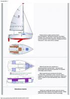
Footbraces 1” below sheer Stern bulkhead Forward bulkhead Cockpit Air chamber Tail bulkhead Forward storage Aft storage
Outboard profile
Deck layout
About 13½”, hatch to cockpit 15½” x 33” cockpit opening
25”, hatch 19” x 12¾” aft hatch to tail deck
41” fore hatch About 31”, cockpit 19” x 12½” to end of fore hatch to fore hatch upper stem
Strongback setup Mold No. 1 2 3 4 On center 81/8” 9” 9” Bow
5 19¼” Sheerline
Top of strongback
64 • WoodenBoat 242
6 19¼”
7 19¼” Deck line
8 19¼”
9 19”
10 19”
11
12
18½” 14 3/8” Stern
Cockpit Blocking from stem to strongback (both ends) opening
5. 3.
5. Tail “cheater” strips
3. Strongback setup I use a plywood box-beam strongback, which is extremely stable. Blocks fastened to the top surface receive uprights to which the station molds, in turn, are fastened, resulting in the mold spacing specified in the drawing at the bottom of page 64. Note that because the hull is built upside-down, the molds are installed deck-side down. The mold plans all show dashed reference lines, 9" above the top of the strongback. Pay careful attention to getting the molds centered and plumb. The installation and bracing of the fore stem, shown here, and the aft stem, which comes next, will complete the setup.
Strips that run the full length of the tail piece align in parallel along the aft edge of the stem. But because the shape of the tail is complex, with much more girth at mold No. 12 than at the aft edge, wedge-shaped “cheater” strips need to be inserted. A wedge-shaped opening, visible at left above as a new strip is installed, shows an example of allowing the strip to lie fair to the mold, leaving a space to be filled with such a cheater strip. Here and throughout this construction tack the strips to the forms with hot glue, and use yellow carpenter’s glue to permanently bond their edges. Note that here, wood strips are “stitched” together with beads of hot glue spaced closely together along the seams on the exterior face to hold them until the structural glue sets. Compared with other methods, such as temporarily fastening with staples, this technique—which will be repeated throughout the construction—leaves the surface completely unblemished.
6. Joining tail-stem halves The tail halves are planked for all but the bottom-most couple of strips, which come later. Once this part of the strip-planking is done on each half, both sides can be removed from their forms. Sand the interior surfaces. The two sides will now be joined on a separate form, this one built to accommodate both sides. Tack each side symmetrically to the molds with hot glue, and use carpenter’s glue to join their aft edges together permanently.
6.
4.
7.
4. The tail piece The baidarka’s unusual tail shape is reproduced by sharply bending strips to fit to small half-stations glued to the aft stem form (details of which are shown in the drawings on page 64). A heat gun is an essential aid in bending and twisting each strip to conform to the tail shape. I use separate port- and starboard-side forms to strip-plank each half separately, which speeds up the process.
7. Mount the tail on the strongback The tail stem assembly is set up on the strongback the same way the fore stem was, carefully centered and aligned. The tail stem strips left incomplete near the keel will allow full-length strips, running along the keel, to tie the tail firmly into the main strips of the hull. Once the fore and aft stems are in place and braced, the hull is ready for stripping. January/February 2015 • 65
8. 9.
8. Hot-glue stapleless stripping I use 3⁄16"-thick strips 3⁄4" wide with one edge square and the other given a 3˚ bevel on the tablesaw. This bevel allows the strip edges to mate flush for most of the hull and deck. At the turn of the bilge, some strips will need rolling bevels, which can be worked in with a block plane. Strips of this thickness and form are easy to bend, twist, and align, resulting in a fair hull. Strips are “tacked” to the edges of station molds using hot glue specifically formulated for use with wood. Hot glue is best thought of as a clamping tool, not for permanent bonds. Later, the molds are removed from the inside, and the key to releasing hot glue is to hit it hard with a hammer to shear it off cleanly. Small dots of hot glue work best. The glue sets in 90 seconds, keeping the strips firmly tacked to the stations, which ensures a hull shape true to the forms. When hot-gluing, spring clamps hold strips to the molds with consistent pressure, ensuring that the bond between strips and station molds will be strong and accurate.
9. Prefit strips Time and care devoted to prefitting each strip, as shown here, will result in more accurate results and less work in every following step. Use a heat gun to make the strips supple enough to bend so they can be twisted into place without force when cool. Use spring clamps to hold each strip exactly to the molds. For extra holding power for “rogue” strips, spring clamps can even be anchored with sheetrock screws driven into the molds. While applying bending force, heat the inside of the desired curve. Experiment for best results. If a strip is bent or twisted too far, it can be straightened by reheating. In all, 85 full-length strips are needed, including extra to ensure color match.
10.
10. More on heat-gun bending Here, the strip is captured just above the area to be shaped by using a small spring clamp to hold the strip itself and two larger clamps to anchor the small clamp to the station mold. Placing a small clamp on the strip’s end permits greater hand leverage during bending. Shape the strip by loading hand pressure into a small section of strip and twisting or bending the strip while applying heat with the heat gun. You’ll feel the pressure release as the heat takes effect on the lignin in the wood. Work down the strip, shaping it to fit the molds perfectly without force. (Note that the strips here were lined off ahead of time to fair into the stempiece in a pleasing line.) 66 • WoodenBoat 242
11. 13.
11. Working with edges Applying glue to the edge of a bottom strip on the hull can be difficult. I use spring clamps in various configurations to hold ready-to-install strips on-edge vertically, using the molds for support, so that the edge needing glue stands straight up. If you place your little finger alongside the glue bottle’s tip, it will act as a guide to quickly apply glue along the length of the edge. Handspring clamps in conjunction with molds help in other ways, too, for example when holding strips that are ready for placement or when hand-beveling the edges. Long, unwieldy strips are easy to handle when part of the strip is always held by spring clamps.
12.
13. Using hot glue for supporting structure 12. Hot-glue “stitching” Once a new strip is shaped and glue applied for final installation, clamps are placed back in the same order as used in pre-fitting, assuring a perfect fit. Then, small beads of hot glue are applied, spaced 1" apart, along the entire length of the joint to stitch the strips together. In only 90 seconds, after the hot glue sets, all the clamps can be removed and work can proceed on the next strip.
As strip-planking continues down from the sheerline and out from the keel, the pieces don’t always join on a smooth curve. This sequence of photos shows my technique for making this kind of joint a smooth one. I save short offcuts of flexible 1⁄16"-thick strips, which I hot-glue to the interior so that they are fair to the planking between stations, thus creating a temporary “bridge,” which looks like an extra mold. In the first photo, I am placing the scrap strip in the gap and marking its location. In the second photo, the hot glue is applied, and in the final photo the piece is held in place inside the hull until the hot glue sets. The technique is especially helpful when holding the tip of a tapered strip. January/February 2015 • 67
14. 17.
14. Remove glue beads, scrape, and sand Use a scraper to remove hot-glue beads after the planking is finished and the permanent glue is fully cured. Hold the scraper handle high, knocking off glue beads like a hammer, as shown in the photo at left. If held too low, the scraper will skip, gouging the soft wood. Once the beads are removed, scrape away any glue remnants as usual. Rough-sand with a random-orbit sander using 60-grit to level the surface quickly, holding the sander as flat as possible and following the curves of the surface, as shown in the right photo. Wet the surface to raise the grain, then sand again with 120-grit, followed by 220-grit. Wet the surface again to detect any missed sander marks, then use a sanding block to go over the surface by hand as needed with 80-, 120-, and 220-grit.
15. Sealing coat
15.
Apply a single coat of epoxy to the bare wood while shop temperatures are falling to prevent bubbles from forming by off-gassing, which occurs when air is expelled from the wood cells during rising temperatures. The reason for this coat is that bare wood and dry fiberglass cloth compete for resin in the “one step” wet-out technique, which can result in a less-than-transparent layup. The sealing coat, applied to the bare wood, stops the wood from absorbing too much resin when wetted-out.
17. Knocking out molds Trace the mold locations on the inside of the hull planking. Now, knock out each mold with a firm blow of a mallet. This will cleanly release the hot glue holding the molds in place. Then, tack them back into place in the hull, using only a dot of hot glue at the sheerline. This will make the removal of the deck easier later.
18.
16.
18. Starting the deck 16. Wetting-out With the shop temperature at 80˚ and falling, everything in the shop is the same temperature, so the epoxy resin is relatively thin. This thin coat of resin, with slow hardener, mixed in small 6-oz batches and applied to warm 4-oz S-glass fiberglass cloth, will produce a perfectly transparent and consistent wetout every time. Add three to four epoxy filler coats to the wetted-out fiberglass cloth. When these have cured, remove the hull from the strongback. 68 • WoodenBoat 242
Starting at the sheerline, fit and apply planking strips until they reach the sides of the cockpit opening, patterns for which are shown in two variations on page 64. Use the same strip-planking technique used for the hull: prefit each strip, clamp to the molds, and bend the ends as needed with a heat gun. Use carpenter’s glue on the edges, then clamp the strips and stitch the joints together with hot-glue beads. Remove the clamps in 90 seconds and continue installing strips.
19. 21.
19. Strips in way of the cockpit opening The deck planking strips don’t run over the cockpit opening area, so the forward and aft decks can be filled in separately with strips, continuing from the sides to the centerline. Make a template to the shape of the cockpit opening, and check to ensure that the strip ends extend into the opening, so they can be trimmed off cleanly later. Note that in the after deck shown above, the last full mold is in place, but the form used for the tail section is removed. The aft deck planks end at the mold; the tail deck is finished separately, later.
20.
21. Keeping deck strips in alignment
20. Coaxing strips into place The foredeck has a distinctive hump, reflecting the baidarka’s heritage as a skin-on-frame boat, in which a centerline carlin held the skin tight and ended in a curve, creating a hump in the skin. This distinctive hump, visible in the photos on page 62, can be distinctly hard to strip. If the fine ends of tapered and fitted strips end in this area, they are likely to pop up instead of staying put. Hot-glued scraps bridging over the tips, as shown above, coax them to remain in place until the permanent carpenter’s glue cures.
The tapered tips of fitted deck strips have a tendency to dive below the rest of the deck when they are unsupported between molds. Like the hull planking technique shown in the sequence on page 67, strips can be supported between molds by hot-gluing scrap strip “bridges” under the deck. Very near the tip, a 3⁄16" × 3⁄16" piece of scrap (barely visible as a light-colored strip close to the apex of the opening in the photos above) can be held in place with needle-nose pliers while the hot glue sets. In the top photo, an interior bridge is shaped and has hot glue applied. In the second photo, the bridge is held in place while the glue sets. The final photo shows how well the end is supported during dry-fitting.
January/February 2015 • 69
22. 24.
22. Trimming the cockpit opening After the deck planking is completed, the cockpit opening is cut to shape. The plans set has a paper template, which is used to transfer the cockpit profile onto the planking; lacking that, make a full-sized template from the profiles shown on page 64. Before the cut is made the molds at the front and center of the cockpit must be knocked out to allow a jigsaw to pass. Knock out the center mold with a firm blow of a mallet. Knock out the station at the forward end of the cockpit by using a flat pry bar. There should be just enough room to insert the pry bar between the edge of the deck and the hull, in such a way that its edge bears against the forward face of the mold. Then, strike the pry bar smartly with a mallet toward the cockpit opening. Place the loose stations back in place to support the deck as you cut the cockpit opening to shape.
23.
24. Strip-planking the cockpit recess 23. Recessing the cockpit’s leading edge I like to recess the leading edge of the cockpit so it doesn’t throw up spray when a wave washes over the deck. And I like the way it looks. To do this I draw lines parallel to the curved forward edge of the cockpit opening, 21⁄2" out. Using a utility knife with a new blade, I carefully cut along these lines to separate this recessed section of deck from the main deck. 70 • WoodenBoat 242
A small piece of deck has to be removed from the center of the recess to allow the recessed section to drop below deck level. As shown in the top photo in the sequence above, small scraps are temporarily tacked with hot glue to hold and shape the space between the main deck and the recess. Then, strips are shaped and fitted into the space, bonded to the deck and recess with yellow carpenter’s glue, and tacked across their edge joints with hot glue, as shown in the second photo, until the space is filled. This structure may seem weak at this point, but the shape of this recess will actually reinforce the deck once the sheathing of fiberglass cloth set in epoxy is finished on both the interior and the exterior.
25.
27.
25. Stripping the tail deck After the deck planking is finished, the deck is sanded, given a sealing coat of epoxy, then sheathed in fiberglass cloth set in epoxy, in the same manner as the hull. Remove the deck by using the flat pry-bar method, as described in photo 22. Knock out all of the molds by striking the pry bar sharply, working from the ends toward amidships, so the molds move toward a wider part of the hull. Carefully remove the deck and place it so that the narrow sections at the sides of the cockpit are not stressed. Replace the aftermost mold, No. 12, tacking it to the sheerline with hot glue, so the tail can be planked. This small section is on a different plane from the main deck—another bow to the boat’s skin-on-frame ancestry—and it must be strip-planked separately. Strips are placed from the last mold over the top of the curving sheerline of the tail section, and they are left long. The ends of the strips that touch the sheerline must be twisted using a heat gun to fully contact the top edge of the sheer plank. These strips are applied in a manner similar to those in other parts of the hull. While the planks are long, the tail deck top surface is sanded, sealed, and ’glassed. After the sheathing is cured, trace the curves of the tail’s sheer onto the underside of the tail deck, then remove it so the final outline can be cut on a bandsaw.
26.
26. Cleaning up the interior All the bridges applied inside the deck and hull with hot glue must be removed. This is done by using a scraper, as described in photo 14, and a mallet to firmly knock off the hot-glued bridging scraps. The hull and deck are very light in weight, so they need to be held in place somehow to resist the mallet blows. I use a 30-lb hunk of bronze wrapped in neoprene wetsuit material, the dark object shown inside the hull in photos 26 and 27. Once all the hot-glued bridges are removed, all excess yellow carpenter’s glue must be removed with scrapers.
27. Interior sanding The interior surfaces of the hull and deck must be sanded in preparation for interior glassing. I sand with a random-orbit sander, using 60-grit sandpaper on a soft interface pad, which will conform to the interior curves. Rob Macks is the proprietor of Laughing Loon Custom Canoes & Kayaks in Jefferson, Maine. He has designed six different baidarkas, plus numerous other kayaks and canoes. Contact him at 344 Gardiner Rd., Jefferson, ME 04348; 207–549– 3531; www.laughingloon.com. Although completed boats can be built using the plans and information presented in this series, we strongly recommend that for the best results prospective builders should purchase full plans sets, which are available from the author. For the Shooting Star design, the plans set, at $145 (plus shipping), includes full-scale drawings for molds, stem, stern, and other components, together with the author’s manual, Building Instruction Book for Sea Kayaks. For further reading, see Baidarka, by George B. Dyson, Alaska Northwest Publishing Company, 1986. See also The Starship and the Canoe, by Kenneth Brower, (Holt, Rinehart and Winston), 1978; and Qajak: Kayaks of Siberia and Alaska, by David Zimmerly (University of Alaska Press, 2000). January/February 2015 • 71