16-30 Sailing Canoe Boat Plan Plans
In the early years of the 20th century, the Gilbert Boat Company of Brockville, Ontario, built a num ber of hard-chined
429 86 3MB
English Pages 18 Year 2011
Recommend Papers


File loading please wait...
Citation preview
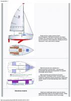
Build a 16-30 Sailing Canoe PART 1 A simple hull with great performance At 16‘ long with a beam of 30”, this decked canoe is meant for exhilarating sailing, as the author demonstrates. JIM WILSON
by John Summers
I
n the early years of the 20th century, the Gilbert Boat Company of Brockville, Ontario, built a number of hard-chined sailing canoes for the Gananoque Canoe Club under the American Canoe Association’s so-called “16-30” rule, meaning 16' long with 30" of beam (see sidebar, page 44). One of these boats survives in the collections of Heritage Toronto. In 2004, I took the lines off this boat, then adapted the design for modern construction using readily available materials. My aim was not only to revive a unique small-boat type but also to bring a high-performance sailing experience to a new generation of canoe sailors with a boat that would be easy to build and modest in cost. This reproduction is built using stitch-and-glue construction, which relies on twisted copper wires to tie together plywood panels and hold them securely while the structure is glued together with thickened epoxy. This technique has been well described numerous times in the pages of WoodenBoat; check the online index at www.woodenboat.com for further reading. I would also recommend two books: Chris Kulczycki’s Stitch and Glue Boatbuilding: How to Build Kayaks and Other Small Boats (International Marine, 2005) and Sam Devlin’s Devlin’s Boatbuilding: How to Build Any Boat the Stitch-and-Glue Way (International Marine/ 36 • WoodenBoat 214
Ragged Mountain Press, 1996), both of which are available through The WoodenBoat Store. Because the construction of this hull is typical of the technique, I’ll spend most of my time here describing the details that make this canoe unique.
Construction: Getting Started Because of their curvature, the glued-together plywood panels that make up the sides and bottom need to be longer than the boat’s 16' overall length. How do we get panels longer than 16' out of two 8' sheets of plywood? Most nominally 4' × 8' sheets of the okoume plywood I’ve speciied—which is a good type to use for this construction—are actually more than a couple of inches longer than 8'. So there’s usually just enough material to get the panels out of two sheets placed endto-end if you use butt blocks instead of scarf joints to join the panels. These butt blocks will be completely hidden by the cockpit structure. Some people prefer to use scarf joints. In this technique, the ends of the panels are planed carefully to feather edges, allowing two panels to be epoxied together at the overlap (see WB Nos. 106, 175, and others). A scarf is a good gluing surface and leaves the completed joint the same thickness as the rest of the panel.
JOHN SUMMERS
A hard-chined hull makes this boat simple to build in stitch-and-glue construction. (Sail plans will be published with Part 2; for tables of offsets, see page 38.)
WOOD
—— Materials List ——
5— 4’ x 8’ x 6mm ( 1⁄4”) okoume, BS 1088 plywood panel 2— 4’ x 8’ x 3mm ( 1⁄8”) okoume, BS 6566 plywood panel 1— Hardwood 1” x 6” x 4’ (inner stem and sternpost) 1— Hardwood, 1” x 6” x 4’ (outer stem) 1— Hardwood, 1” x 6” x 8’ (seat bridge/supports) 1— Hardwood, 1” x 4” x 10’ (coamings) 1— Hardwood, 2” x 2” x 12’ (rails for aluminum strips/ sliding seat) 1— Hardwood, 2” x 2” x 3’ (daggerboard head ledges and iller) 1— Hardwood, 2” x 4” x 4’ (steps for masts, crosshead) 1— White pine 1” x 8” x 10’ (booms) 1—White pine 1” x 6” x 10’ (bulkhead and cockpit nailers) 2—White pine 1” x 6” x 10’ (king planks) 1— White pine 1” x 10” x 10’ (deck blocking) 1— White pine 1” x 6” x 10’ (gunwales) 2—Fir dowel, 8’, 11⁄4” outside-diameter (crosshead tiller, tiller rod)
EPOXY AND FIBERGLASS 2— Epoxy resin gallon 2— Epoxy slow hardener to match gallon 1— Epoxy adhesive iller (glue powder) 1— Epoxy fairing iller (colloidal silica) 25 yards— 3” iberglass tape for illets 10 yards— 50”-wide 4-oz iberglass cloth
FASTENINGS 1 box— No. 8 x 2” lathead stainless-steel wood screws
1 box— No. 8 x 1 1⁄4” lathead stainless-steel wood screws 1 box— No. 8 x 3⁄4” lathead, stainless-steel wood screws 1 box— No. 8 x 3⁄4” round-head stainless-steel wood screws 1 box— No. 8 x 1⁄2” round-head stainless-steel wood screws 8 — No. 8–32 x 3⁄4” stainless-steel machine screws 8 — 8–32 stainless-steel stop nuts with insert 1 box— No. 8 stainless-steel washers 1 box— No. 12 x 3⁄4” bronze ring nails 1 box— No. 14 x 3⁄4” bronze ring nails
HARDWARE 2— 25’ roll, 18-gauge copper wire (for stitching hull panels) 1— 5’ aluminum pipe 1 5⁄8” outside diameter (rudder cross-head tube) 1—3’ aluminum round tube, 1 1⁄4” outside diameter (crosshead post) 1— aluminum slip-on structural framing crossover (rudder cross-head) 1— aluminum shaft collar, 1 1⁄4” inside diameter (cross-head post cap) 1— aluminum slip-on structural framing panel connector (rudder cross-head) 1— 3’ aluminum round tube, 2 1⁄2” inside diameter (mast tubes) 1— 3’, 1”x 1⁄8” aluminum lat bar (ends of tiller rod) 2— 6’, 1 1⁄2”x 1⁄8” aluminum lat bar (sliding seat rails) 1—clevis pins 1⁄4”x 1 1⁄8”, package of 2 (for tiller rod) 1— cotter rings, 7⁄8”, package of 4 (for tiller rod) May/June 2010 • 37
Bulkhead patterns can be determined from a hull lofting (remembering to deduct planking thickness), but full-size patterns are included in the full plans set. Limber and lightening holes should be bored as shown. JOHN SUMMERS (ALL DRAWINGS THIS PAGE)
OFFSETS FOR HULL LINES SHOWN ON PAGE 37 (inches-eighths) Heights Above Baseline Station 0 1 Keel Chine Sheer Deck
8–7 9–0 20–6 21–0
Half-Breadths Station 0 Sheer Chine
0–2 0–2
6–1 8–3 18–2 n/a
2
3
4
5
6
7
8
4–1 8–0 16–7 n/a
3–6 7–5 16–1 n/a
3–6 7–4 15–4 n/a
4–5 7–6 15–1 n/a
5–7 8–0 14–7 n/a
7–2 8–4 15–2 n/a
8–4 9–2 15–6 16–1
1
2
3
4
5
6
7
8
7–4 5–4
13–1 10–2
16–1 13+
17–4 14–6
16–6 14–5
14–0 12–3
8–7 7–4
0–2 0–2
Rake of Inner Stem Face— distance aft of 0 Waterline 9 18
3–1 1–4
38 • WoodenBoat 214
Notes: Station spacing = 2’ Proile lines to outside of plank Half-breadth lines to outside of plank Outer stem to suit builder, not included in measurements above
KEY MEASUREMENTS (feet, inches, eighths) Use these measurements for layout—do not scale from drawing Distances aft from forward face of INNER stem Forward edge of bulkhead 1 1–0–0 Forward edge of bulkhead 2 3–11–0 Forward edge of bulkhead 3 6–3–0 Forward edge of bulkhead 4 9–8–0 Forward edge of bulkhead 5 11–3–0 Forward edge of bulkhead 6 12–9–0 Forward edge of bulkhead 7 13–11–0 Centerline of mainmast tube Centerline of forward deck hatch Forward end of daggerboard trunk Aft end of daggerboard trunk Centerline of seat bridge Centerline of cross-head post Centerline of aft deck hatch Centerline of mizzenmast tube
0–10–3 5–0–0 6–5–7 8–4–0 8–9–0 9–10–0 10–8–0 11–5–4
JOHN SUMMERS
Suggested Panel Layout for Main Components (no scale)
LAYOUT DIMENSIONS FOR HULL PANELS (shown on page 38) Notes: Station spacing 1' ; Dimensions in feet-inches-eighths; Distances up from baseline Station
1
2
3
4
5
6
7
BOTTOM PANEL to bottom edge 0-3-0+ 0-2-4+ 0-2-0 0-1-5 0-1-2 0-1-0+ 0-1-0 of panel to top edge 0-3-3+ 0-6-1 0-8-5 0-11-0+ 1-0-7 1-2-2 1-3-3 of panel SIDE PANEL to bottom edge of panel to top edge of panel
8
9
10
11
12
0-1-0
0-1-0
0-1-0
0-1-1
0-1-1
1-3-7
1-4-2 1-4-2+ 1-4-0 1-3-0+
15
16
17
18 n/a
1-1-4 0-11-0+ 0-8-0+ 0-4-7 0-2-2*
n/a
0-3-0* 0-3-4 0-4-2+ 0-4-7+ 0-5-4 0-5-7+ 0-6-2+ 0-6-3+ 0-6-4+ 0-6-6 0-6-6+ 0-6-6
0-6-5
1-2-4* 1-2-2+ 1-2-2+ 1-2-2+
1-1-5
1-2-4
1-2-4+
1-2-7
1-3-0+
1-3-1
1-2-7
1-2-5+
at top of sternpost, 0–11–3+ above baseline, point is 0–8–2+ forward of Station 18 at bottom of sternpost, 0–4–7 above baseline, point is 0–8–5+ forward of Station 18 BOTTOM PANEL STERN ANGLE
at center of panel, 0–1–4+ above baseline, point is 0–2–1+ forward of Station 17 at top edge of panel, 0–2–2 above baseline, point is 0–2–1 forward of Station 17
It also avoids the slight weight added by butt blocks. But because some panel length is lost to the overlap, you’ll have to use three lengths of plywood instead of two to make the inished panels long enough for the boat. (Note that if you choose plywood panels that actually are 8' long, you’ll have to use three lengths in any event.) The hull panels can be laid out and lofted, or drawn out full-size on the plywood sheets, using the coordinate dimensions given on the plans. Place two 6mm panels tightly together end-to-end. Tack them to the loor if you can, or clamp them in some manner so that the ends are irmly together and can’t slip. (Plan the use of materials carefully: out of two sheets of 6mm plywood, you should have enough material to get both bottom panels and all seven bulkheads, with a little material
1-2-2
0-1-2+ 0-1-2+ 0-1-3+
0-6-2
0-5-7 0-5-3+ 0-5-0
n/a
1-1-1
1-0-4+ 1-0-0 0-11-4+
n/a
*Lines extended to stations for fairing
SIDE PANEL STERNPOST RAKE
JON SUMMERS (BOTH)
14
0-1-4 0-1-4+*
SIDE PANEL STEM RAKE at top of stem, 1–2–4 above baseline, point is 0–0–3 aft of Station 1 at bottom of stem, 0–3–3 above baseline, point is 0–3–3 aft of Station 1
1.
13
Although it is possible to build a boat from the information presented here, we highly recommend obtaining full-sized plans sheets. The author and his associates have also produced an instructional manual. See the end notes for ordering information. —Eds
left over.) Measure the station heights carefully from the plans, and when you have them all marked on the panels, use a long, limber batten to scribe a fair line through the points (Photo 1). After scribing the lines, separate the panels and cut them out close to the line. Rejoin one pair of forward and after sections end-to-end, with waxed paper under the joint to prevent gluing them to the loor. Make sure that the lines match perfectly and the joint is tight. Make a plywood butt block as shown in the plans. This is set back 1⁄2" from the edges of the panels to simplify the stitch-and-glue work later. Glue and fasten the butt block in place (Photo 2). After the glue has fully set, plane the panel edges fair, square, and to their inished dimensions. Repeat this process for the second bottom panel, and follow the same method to
2. May/June 2010 • 39
make the sides—double-checking to make sure you’ve placed the butt blocks on the inside faces (Photo 3).
Wiring the Hull Together
3.
JOHN SUMMERS (THIS PAGE)
4.
5. 40 • WoodenBoat 214
Wire the two completed bottom panels together irst. At the centerline seam, bore corresponding 3⁄32" holes in each panel about 3⁄16" away from the edges, spaced about every 3". Next, wire the completed two bottom panels together loosely, using 4" pieces of copper wire with the twist outboard. As you wire these slightly curved panels together, the bottom will take on a V-shape and the rocker will develop. Follow the same procedure to wire each side panel to its corresponding bottom panel (Photo 4). At the bow and stern, the side panels won’t come tight together; these gaps will later accommodate the stem and sternpost. Level the hull side-to-side and fore-and-aft and brace it on a couple of well-spaced sawhorses before installing any bulkheads. The bulkheads need to be in the right places and they need to be square to the longitudinal axis of the boat, so take some care in aligning them. For each bulkhead in turn, measure to the bulkhead’s vertical forward face from the forward upper corner of the inside face of the side panel at the bow. Always measure from this same point; don’t measure from bulkhead to bulkhead, which would not only be less accurate but also allow errors to compound. Make sure that the measurements match the plan and that each bulkhead is plumb. Bore holes for wires along the bottom and side edges of each bulkhead before putting them in the boat, and bore holes in the side and bottom panels to correspond to the holes in the bulkheads. Once the irst two bulkheads are in the right places and plumb, square, and lightly wired into place (Photo 5), you may want to add some longitudinal braces to keep everything in alignment. These can be made from 2×2s cut to it between the bulkheads and temporarily fastened with screws driven through the bulkheads into each brace’s end. Stiffen the wide bulkheads amidships with a 2×4 temporarily screwed in place horizontally, inboard from the sheer. Once all of the bulkheads are loosely wired in place, start tightening all of the wires gradually, a turn at a time for each wire. Work around the hull and back and forth from one side to the other, too, to keep the overall tension even. Some small stitch-and-glue hulls, especially canoes and kayaks, dispense with the stem and sternpost, instead irming up the ends of the planks by pouring in thickened epoxy. You could build this boat that way, but I’d recommend using the stem and sternpost as shown on the plans. The bow can take a real beating, especially if you sail from a dock, and the outer stem makes a good sacriicial piece in the event of a too-fast landing. This hull has a very narrow “transom” block to which the stock stainless-steel gudgeons can be fastened by screws. If you’d prefer to have a true sharp stern, you’ll have to fashion your own gudgeons to it—but even then, I’d still recommend itting an internal sternpost to provide a good, solid hold for their fastenings.
Checking Alignment After all of the wires are tightened, your hull should be pretty solid. Now is the time to make certain the hull
has no twist. To check the alignment, irst ind three or four straight pieces of 2x4 or other stock that is at least 2' longer than the boat is wide. Lay these across the hull perpendicular to the centerline and on the top edges of the side panels at equal intervals along the hull. Now, get down on one knee forward of the bow and sight down the boat across them. The tops of these “winding sticks,” as they’re called, should be parallel (Photo 6). If they are not, there’s a twist in the boat. Sight the boat from bow and stern, from close and far, and invite anyone who’s around to do the same. Adjust the tension in the wires as necessary to align the hull. Then go for lunch. After lunch, come back and sight it all over again. Make a inal check to see that all the wires are snug and that the bulkhead corners are tight against the plywood panels at the chines and also at the centerline seam. Once you’re satisied, it’s time to glue in the stem and sternpost and inish off the seams inside.
6.
The stem has two pieces. The inner piece goes in irst. Start with a hardwood block (or lamination) that is 3" longer than the inished dimension. Side bevels are shown in the plans and can be cut on a tablesaw, or marked off and cut with a handsaw. Trial-it the piece and trim it as needed to get a snug it. Then, trim the heel so it its lush against the bottom. Dry-it the piece once more, ensuring a good it and checking to see that the stem is plumb and that there is no distortion in the side panels, which should align equally side to side. Drive two temporary screws per side to hold the stem in place. Remove it once more, then coat its faying surfaces (and the planking, too) with epoxy. (Whenever you glue wood together with epoxy, it’s best to irst spread unthickened epoxy in the area to be glued, then mix up epoxy with illers meant for adhesive use—as opposed to fairing—and spread that, too, before clamping or fastening the pieces together. Throughout this article, references to gluing with epoxy assume you’ll follow this technique.) Put the stem piece back into place, pressing it into the epoxy, and drive the screws again, making sure to ind your original holes. Use the squeeze-out inside to create illets, but wipe away the excess on the outside. After the glue cures, remove the screws and cut the top of the stem lush with the side planking. To it the outer stem, use your block plane to dress down the ends of the side panels to be lush with the outer face of the stem, making a landing that is square and has no concavity or convexity across its face. The outer stem is shown in the plans, but you can adjust its dimensions if necessary to assure a good it. Use duct tape to hold it in place temporarily, then drive two stainless-steel screws outward through the inner stem so that they drive about 1⁄2" into the outer stem. Remove, apply epoxy, and reinstall. After the epoxy has cured, plane the outer stem’s sides lush and fair with the rest of the hull, trim its bottom and top ends lush, and round-over its outboard edge to a 1⁄2" radius. The sternpost installation follows the same method, but it doesn’t have an outer piece, since its width is needed for rudder hardware attachment.
JOHN SUMMERS (THIS PAGE)
Stem and Sternpost
7. Taping and Filleting Inside Seams Before mixing any epoxy, cut and organize all the iberglass tape (actually 3"-wide bands of iberglass cloth) that you’ll need. Also check to see whether any of the seam wires protrude too far into the interior, and, if they do, push them toward the joint with a screwdriver to make the illeting easier and cleaner. Before illeting, spread unthickened epoxy on the panels to about 1 1⁄2" each side of the joint. For the illet, mix epoxy with thickener until it is the consistency of thick peanut butter. Work one area at a time, between bulkheads. Be sure not to block the centerline limber holes at the bottom of each bulkhead. There are several ways to get the illet mixture into the joint, but my favorite is to put it into a heavy-duty one-pint freezer bag. Cut off one corner of the bag diagonally to make a 1⁄2" opening. Twist the upper opposite corner of the bag with your right hand to generate some internal pressure, and, cradling the bag in your left hand, gently squeeze the mixture into the apex of the joint (Photo 7). As the bag empties, give it another twist at intervals to keep up the pressure while your left hand guides the mixture into the joint. When that mix runs out, start again with a fresh bag. By piping the illet mixture into the apex this way and then making one pass with a May/June 2010 • 41
8.
radiused illeting tool (which you can easily make out of scrap plywood), you’ll have a nearly perfect joint (Photo 8). Cooks use this “baker’s bag” technique, too, so you may also be ready to enroll in a cake-decorating class. Generally speaking, a second coat of epoxy can be put on before a previous coat has fully cured—during what’s called its “green” stage. (Check the manufacturer’s instructions for your particular brand for their guidelines about this so-called “hot-coating.”) So while the illet is still green, you can lay the precut tape down along the seam and press it gently into place. Then wet it out with unthickened epoxy, illing the weave. As with the illeting, tape section by section between bulkheads. After the illeting has been completed (Photo 9), but while the epoxy is still in the green stage, roll at least two coats of unthickened epoxy onto the inside of the hull and then let it cure fully. After the interior coating has fully cured, invert the hull, clip all the wires off lush, and gently radius the chines, after illing any gaps in those seams or at the stem and sternpost with thickened epoxy. When the hull is smooth, drape 6-oz iberglass cloth over the entire hull, cutting it to overlap at the stem and sternpost. Flow unthickened epoxy over the cloth. Use enough coats of epoxy to ill the weave, allowing the epoxy to cure to the green stage between coats (Photo 10). Before the inal coat has fully cured, trim the excess cloth along the sheer with a razor blade, being careful not to pull the cloth away from the hull.
Preparing for the Deck
JOHN SUMMERS (THIS PAGE)
9.
10.
After the exterior sheathing has fully cured, turn the boat right-side up again so you can it out the interior. Each of the bulkheads needs a pine strip along its upper edge, glued and ring-nailed to the bulkheads, to accept the deck nails and provide a suficient gluing surface (Photo 11). Full-length gunwales also have to be glued and ringnailed along the sheer. Make these from a nice, clear 10'-long piece of 1×6 pine, ripped into four 3⁄4"-wide strips. You’ll need two per side, and you can scarf them or butt them where they join. After installation, add a small illet of thickened epoxy where the lower edge of the gunwale meets the hull. Forward and aft of the cockpit, a pine 1 × 6 kingplank ties the upper edges of the bulkheads together, makes a landing for the middle of the deck planking, and supports the mast tubes, the steering gear, and the deck hatches. At the tops of most bulkheads, both the plywood and pine nailing strip are notched to receive the kingplank. The exceptions are bulkheads No. 3 and No. 4, which are at the forward and after ends of the cockpit; at these bulkheads, only the pine nailing strip is notched. Measure the notch thickness down from the centerline, not from the edges of the kingplank. This way, the kingplank can be planed to match the crown of the bulkheads so as to solidly support the deck.
Maststeps and Rudder Cross-Head Post Before installing the kingplank and shaping the
42 • WoodenBoat 214
bulkhead tops, make and install the maststeps. These are solid hardwood blocks, bored with a 2 5⁄8" holesaw or Forstner bit to accept the aluminum tubes into which the masts will slip. These steps will have to be shaped to it the bottom of the boat. After making sure the hull is plumb and level, it the mast tubes into their steps, and place them in the boat so that the steps it snugly against the appropriate bulkhead. Sight the tubes to be certain they are plumb both to the centerline and fore-and-aft, and then mark the locations of the steps on the bottom panels. Repeat this process to make the rudder cross-head post. In this boat, the tiller is an athwartship dowel running through a horizontal aluminum tube, or “crosshead,” which will be mounted to rotate on this vertical post. When the helmsman moves one end of the tiller fore-and-aft (from either side of the boat), the steering linkage is made to the rudder by way of a separate long dowel that connects one arm of the cross-head to a yoke on the rudderhead. Using the same methods used in making the maststeps, make the step with a 1 3⁄8" bore to accept the heel of the cross-head post, and align it the same way you aligned the maststeps. Take the mast tubes and cross-head post out without moving their steps, and then put the kingplanks in place. Plumb up from the step blocks to establish the center of the kingplank holes, then bore 2 1 ⁄2" holes for the mast tubes in the kingplanks and a 11⁄4" for the cross-head post. Return the tubes, post, and kingplanks to the boat, and plumb and level everything again. Take the tubes and post out and glue the blocks to the bottom. Before the glue sets, reinsert the tubes and post, make a inal check for plumb and level, and then leave the boat alone until the epoxy has cured. Then, make a inal check on the it of the kingplanks and install them with glue and ring nails (Photo 12). You’ll glue the tubes and post in place, too, but before you do, take them out and plane the kingplank to a camber that matches that of the bulkhead tops. Also, cut the mast tubes to their inal lengths from the bottom of the steps to the top of the kingplank, plus 1⁄4" to allow for deck thickness, 1⁄2" for trim rings, and an additional 3" to support the masts above the deck. Leave the cross-head post long for now. Mix up a batch of thickened epoxy and ill the holes in the mast steps two-thirds full. Plunk the tubes into this mixture and make a inal check for vertical alignment before the glue sets.
11.
12.
JOHN SUMMERS (THIS PAGE)
The Daggerboard Trunk With the kingplanks and tubes in place, it’s time to build the daggerboard trunk assembly on the bench (Photo 13). Before you cut any wood, measure the distance between bulkheads No. 3 and No. 4 on your boat. Whatever that measurement, add 1⁄2" and make that the overall length of the daggerboard trunk assembly to allow for inal itting later. Get out the plywood sides and precoat what will become the inside of the trunk with two coats of unthickened epoxy before assembling further. First attach each side’s longitudinal pine pieces—the bedlogs at the bottom and the nailing strips at the top—to the outboard
13. May/June 2010 • 43
Speed Never Goes Out of Style
I
as “16-30s.” Those dimensions (16' length × 30" beam with 90 sq ft of sail) were typical for boats built under Rule IV, “Sailing Canoes,” of the ACA’s classiication system. As published in the ACA yearbook of 1930, that rule reads as follows: “Maximum length 18', minimum beam 30". Beam in no case to be less than 5⁄32 , nor more than 1⁄5 , of length. Greatest beam at waterline, with 150 lbs load aboard, shall be not less than 88% of greatest beam wherever found. Minimum depth amidship shall be not less than 51⁄4% of length. Minimum weight in pounds, exclusive of centerboard, rudder, steering gear, and deck seat, shall be not less than length in inches multiplied by beam in inches divided by 60. A centerboard shall be capable of being raised so as not to project below the keel. On a canoe of length 16' and beam 30", sail area allowed is 90 sq ft. For each inch that beam is increased, sail area may be increased 3 sq ft. For each inch that length is increased, sail area must be decreased 1⁄2 sq ft. Maximum height in feet of any sail above the level of gunwale shall not exceed the square root of the total sail area plus 5.5. A paddle, at least 3' long, shall be carried throughout every sailing race.” —JS
face of their respective sides, using glue and nails driven from what will become the inside of the trunk. Cut the three 7⁄8"-thick vertical pieces to length, making sure to leave the two head ledges—the pieces that will extend through the bottom of the hull—at least 3⁄4" long on the bottom to project through the daggerboard slot for inal trimming after the trunk is installed. Glue and ring-nail the two completed sides to the three upright pieces to complete the trunk assembly. When the trunk is assembled and the epoxy has cured, measure the exact distance between your bulkheads again and cut the trunk to length for a irm it. Set the trunk in the boat between the bulkheads and on the centerline, keeping it plumb. Where the protruding head ledges touch the hull at the centerline, trace their perimeters onto the plywood bottom. You’ll use these marks in cutting the daggerboard slot. Take the trunk out of the boat. In the resulting perimeter tracings, measure 7⁄8" toward amidships from the outer extremity of each tracing, and square this measurement athwartships. This results in a 7⁄8"
square. Bore 3⁄32" pilot holes from the inside of the hull in the center of each of the resulting 7⁄8" squares. (You can scribe lines from corner to corner in each of the squares to ind the center.) Flip the boat upside down, and, using these pilot holes as a guide, it your drill with a 7⁄8" Forstner bit and bore two clean, plumb holes through the bottom. Then, use a straightedge to scribe parallel straight lines tangent to these two holes, one on each side of the hull’s centerline. Cut the resulting slot plumb with a jigsaw. The protruding lengths of the trunk’s head ledges will have to be rounded. Put the trunk upside down in a bench vise, and use a rasp to round the forward corners of the forward head ledge and the after corners of the after one until they match the 7⁄8" radius of the holes you bored earlier at each end of the daggerboard slot (Photo 14). Slip the assembled trunk back into place to check the it of the head ledges. After you’re satisied, scribe the pine bedlogs to it the boat’s bottom. Remove the trunk again and plane the bedlogs to the scribe marks. Several dry-its may be necessary.
44 • WoodenBoat 214
YACHTING/ANTIQUE BOAT MUSEUM
n the middle of the 19th century, an intrepid Scots army oficer named John MacGregor constructed a small decked canoe which he dubbed ROB ROY. An astute promoter as well as an intrepid adventurer, he wrote a series of popular books about his travels in this tiny canoe (see WB No. 168). Inspired by MacGregor, sportsmen formed canoe clubs in both Europe and North America and staged annual meets where they assembled for camping, fellowship, and competition. Not long after recreational canoeists started to paddle their craft, some added sails as well. At irst, these were an addition to the paddle to be used on long cruises when the wind was right: “Sail when you can, paddle when you must,” was the rubric. Human nature being what it is, however, the canoeists soon began racing each other under sail, and this led to rapid development in hulls, rigs, and hardware. The irst sailing canoes were cruising boats with sails added, and the sailor sat down on the loorboards in the cockpit. Getting the skipper’s weight up on deck to windward allowed boats to carry more sail. An expert but small-of-stature sailor named Paul Butler took the idea one step further by creating a sliding seat mounted above the deck, which allowed him to get his weight even farther out to windward. In the search for sail-carrying power, cockpits became smaller and side decks wider. Canvas liners were added to make cockpits waterproof in the event of a capsize, and eventually the cockpits were completely enclosed and made self-bailing. By the late 1890s, recreational canoe design had diverged into three main branches: deckedover canoes for racing under sail, all-round canoes for cruising under sail or paddle, and racing paddling canoes. Each was optimized for its particular use. The canvas spread by racing sailing canoes grew ever larger, to more than 120 sq ft on some 16' hulls, and capsizes became a constant feature of competition. In the early 20th century, in response to concerns that canoes were becoming “unhealthy” racing machines, the American Canoe Association (ACA) formulated a set of rules that governed the dimensions of all classes of canoes, both paddling and sailing, and it was that rule that produced the canoe that I’ll describe in this two-part series. Decked sailing canoes like this one were most often known
Kenneth Friede, in his sailing knickers, hikes out on the sliding seat and puts the helm hard to starboard in a circa-1930s photograph of his 16-30 canoe PRESTIGE .
When the trunk its snugly, epoxy it into place and make a tidy illet with the squeeze-out. Then turn the boat upside down and fasten through the plywood bottom planking into the bedlogs with countersunk screws. After the epoxy has set, add a screw from the forward side of bulkhead No. 3 and the after side of bulkhead No. 4 into the uprights just for insurance. Finally, trim the ends of the head ledges lush with the boat’s bottom on the outside, using a plane, rasp, and sandpaper. Remove any epoxy squeeze-out that crept into the trunk (Photo 15). The next step is to install the deck—and that’s where we’ll take up the project in Part 2.
14.
The development of this design was generously supported by the Antique Boat Museum, and complete building plans and instructions, including detailed hardware and materials lists and sources, are available for $125 (plus $10 shipping) from the museum, 750 Mary St., Clayton, NY 13624; 315–686–4104; www.abm.org. Encouragement, advice, troubleshooting, and moral support are available from the author at [email protected]. For information about classes in which you can build your own 16-30, contact Dan Miller, curator of the Antique Boat Museum, [email protected].
JOHN SUMMERS (BOTH)
John Summers has been fascinated by sailing canoes since he irst read a magazine article about the International 10 Square Metre Canoe in the mid-1980s. A curator, boatbuilder, and U.S. Sailing– certiied instructor, he is currently general manager of the Canadian Canoe Museum in Peterborough, Ontario.
15.
JOHN SUMMERS
—— Plan Details ——
May/June 2010 • 45
Build a 16-30 Sailing Canoe JOHN SUMMERS
A simple hull with great performance PART 2
H
aving completed the hull as shown in Part 1 (WB No. 214), the next step is to complete the 16-30 sailing canoe’s self-bailing cockpit, which will be the last project before the deck goes on. Start with the amidship cockpit sole supports, made up of one half-bulkhead on each side of the daggerboard trunk (Photo 1). These are built like the bulkheads described in Part 1, itted to the bottom and then illeted to the bottom and sides, and reinforced at the top edge with 3⁄4" × 3⁄4" pine. In addition to holding the daggerboard, the trunk functions as the cockpit drain, so the cockpit sole is made up of two plywood panels that slope toward the centerline. Before making the amidship half-bulkheads, ensure that the hull is once again plumb and level. Then, rough-cut a pattern from scrap, making it large
by John Summers
enough to extend a few inches higher than the centerboard trunk. Fit the pattern into place on one side of the trunk and scribe the bottom angle with a pencil compass. Mark the height of the daggerboard trunk on the inner edge, and square that height horizontally across to the outer edge. Then, add 3⁄4" of height to the outer edge to give a good amount of slope. Connect these two points, and you have the master angle for the slope of your cockpit sole. Transfer this angle from the pattern to plywood stock. Mark the heights and widths of the daggerboard trunk’s longitudinals, and mark off a 45-degree cut on the lower inside corner to provide a limber hole. Cut the marked plywood to shape, and cut ventilation holes as shown. The same pattern should work for both sides, but check it before cutting the second piece. After the plywood pieces are inished to
Above—With her simple rigging completed, this 16-30 sailing canoe is ready for paint—after which she can be launched. Learning to sail the boat will be a task of its own, as explained on page 57.
50 • WoodenBoat 215
their inal shapes, attach the 3⁄4" × 3⁄4" reinforcing strips to their upper edges with glue and nails. After this is done, illet the sole supports into the boat. The other athwartship cockpit sole supports are four 3 ⁄4" clamps epoxied and nailed to the bulkheads, one per side at each end of the cockpit (visible in Photo 1). To determine where the top edges of these should lie, use a straightedge the length of the cockpit placed so that it lies atop the amidship sole support about a foot out from the centerline and level fore-and-aft. Mark where the underside of this straightedge intersects the bulkheads. Line up each clamp so that its top surface is lush with the top of the daggerboard trunk at its inboard end and hits the mark on the bulkhead at the outboard end. These pieces should extend 13" out from the centerline. Fasten them to the bulkheads with epoxy and ring shank nails. The outboard edges of the cockpit sole panels are supported by longitudinal plywood supports made the same way as the half-bulkheads (Photo 2). These supports run parallel to, and 13" outboard of, the centerline, connecting the outboard ends of the clamps on the bulkheads to the center cockpit sole support. You’ll need four of them. Make several limber holes along the bottom edge of each to allow bilge water to move freely. Glue and nail 3⁄4" × 3⁄4" strips along their top edges, too.
1.
Cockpit Sole and Sides
2.
3.
JOHN SUMMERS (THIS PAGE)
Next, measure and cut the two halves of the cockpit sole from 6mm plywood (visible in Photo 4). Each should extend a little way outboard of the outer longitudinal cockpit sole beams. Remember to make a notch the length of the daggerboard slot and half its width along the inboard edge of each side panel (visible in Photo 4). Trim the ends of the panels so they it irmly in place between the bulkheads. Mark and cut the holes for the inspection ports (visible in Photo 4), but don’t fasten the sole in place yet. The side decks alongside the cockpit take a lot of stress, because they support not only the sliding seat but also the cleats and turning blocks for the sheets. So they are fully backed up with horizontal, solid pine blocking that extends from bulkhead No. 3 back to bulkhead No. 4 (Photo 3). Cut two pieces of 1 × 10 pine to it snugly between the bulkheads, lush with the sheer and matching the camber of the bulkheads. Scribe the curve of the hull side along their outer edges, and cut and bevel them to it. Fasten these pieces into place with epoxy and also with screws driven into both ends through the bulkheads and their nailing strips. After the epoxy cures, use a plane to fair the blocking to match the camber of the bulkheads. We have more to do before the cockpit sole can be permanently installed. First, make sure the boat is still level athwartships, then plumb downward from the inner edge of the side deck blocking to the cockpit sole pieces to mark for the longitudinal clamps to which the cockpit sides will attach. Mark two positions, one forward and one aft, on each side. Remove the sole pieces and use epoxy and bronze ring nails (from the underside) to install a 3⁄4" × 3⁄4" clamp on each side so that its inboard face lies on this lines (visible in Photo 4).
4. July/August 2010 • 51
While the sole panels are still out of the boat, reinforce the inspection holes. For each hole, cut a hole the same size in 6mm plywood scrap, then epoxy this piece onto the underside of the cockpit sole panel, lining up the hole and making sure the piece won’t get in the way of the sole panel’s it to the cockpit supports. Before installing the cockpit sole pieces, apply two coats of unthickened epoxy to their undersides and also to the plywood cockpit supports. (Also, if you wish to install through-hull drain plugs that line up with the inspection ports, visible in Photos 2 and 4, this is the time to do it.) After the epoxy has cured, put the cockpit sole panels in place once more and mark where they will be fastened with screws along each edge. Bore holes and countersinks for the screws, then coat the sole beams and nailing strips with epoxy and fasten both sole pieces in place. Next, use 6mm plywood to make the two cockpit sides, which extend between the bulkheads and it snugly to the cockpit sole and lush to the top of the inboard edge of the side deck blocking. It’s best to cut the plywood to length irst and leave the pieces a little high, then place them in the boat, trim their bottom edges as needed, and scribe along the upper edges of the side deck blocking to determine where to cut their tops. Do this separately for each side to account for any variations from side to side.
5.
More Structure, Then Coamings
52 • WoodenBoat 215
6.
JOHN SUMMERS (THIS PAGE)
Before installing the cockpit sides, we also need to add a backing piece to each of them to support the uprights for the seat bridge. First, establish and mark the location of the centerline of the seat bridge, which is 14" forward of the centerline of the rudder cross-head post (visible in Photo 4). The seat bridge uprights are 31⁄2" wide, but their backing pieces should be 6" wide and made up of two layers of 6mm plywood. Glue them to the outboard face of each cockpit side, centered on the seat bridge location. Don’t forget to leave 1" at the bottom to clear the cockpit side nailing strips and 1" at the top to clear the side deck blocking. The backs of the cockpit sides and these backing pieces should be epoxy coated, too, and when they’re done, you can bore for 3⁄4" screws and glue and fasten them into place. The forward end of the cockpit coaming offers you some room for artistic expression. You have to decide its shape now, because you’ll need to install pine blocking to support the deck and coaming at the forward end of the cockpit (Photo 5). The photos show a straight coaming that’s raked and angled and laps onto the deck at its forward end. Though good-looking, this is probably the most complicated shape to build, owing to the multiple bevels in each piece. A gently curving coaming also looks good, either plumb (easier) or raked (more dificult to it). When you’ve chosen your coaming shape, make the blocking out of pine and install it with glue as well as screws driven through the bulkhead. Toe-screw the after ends into the cockpit sides. Be sure the blocking isn’t set too low, because you’ll fair these pieces to the deck camber, as well.
7. The Deck The deck is made of 3mm plywood. This is very light but not particularly strong. You’ll want to be careful never to stand or sit on the deck. You may even want to stencil “No Step” here and there, the way aircraft builders do. For a more robust deck, you can add some longitudinal stringers between the bulkheads parallel to the kingplank. You could also add a second layer of 3mm plywood and skip the stringers. Either way, the deck
8.
Once the deck is epoxied and fastened down, make built-up trim rings for the mast and cross-head tubes (Photo 7). Use the same method to make lat surfaces for the deck-mounted inspection ports shown in the plans. All of these are glued-up from two layers of 6mm plywood. After the trim rings are glued up, “back out” their undersides as necessary—meaning shape a concavity into them—so that they will it tight to the cambered deck. Round-over their exposed corners, too. The trim ring for the cross-head post should also have an aluminum or nylon washer set into it to take the wear of the pivoting cross-head tube assembly, which slips over the top of the post. Glue down the trim rings and illet the joints where they meet the deck.
The Seat Bridge
JOHN SUMMERS (THIS PAGE)
9.
10.
The seat bridge is made from hardwood, such as mahogany or oak, supported by two upright supports per side (Photo 8). First make the inner supports, which fasten to the cockpit sides where the plywood backing pieces were placed earlier. Cut them long enough so that the top face of the seat bridge will be at least 31⁄2" above the deck at the cockpit coaming. Next, cut the bridge itself to length; you’ll need to do this before you establish the locations of the outer supports. Set the bridge on the inner supports, centered athwartships. Square down from the bridge to the deck to mark the outboard locations of the outer posts (Photo 9). It’s best if these are close to the outer edge of the deck, so place them so that their inboard faces are 5" outboard of the cockpit coaming to give room for the mizzen sheet to pass between the outer post and the coaming on each side. Pick off the bevel for the bottom of the support with a bevel gauge. Cut this bevel on the bottom of the support, then put it back in position and mark its inal height. Note that the outer support needs to be lared out at the bottom to accept the screws that will fasten it through to the side-deck blocking (visible in Photo 9). Give the support as much width as you can from your stock and then cut a pleasing curved transition to its 3 1⁄2" width at the upper end. The lower edge of this post will sometimes be underwater on the leeward side of the boat, so you might want to taper the forward and after edges. Dry-it the supports and the bridge and check for alignment. When you’re satisied, bore and countersink for screws through the seat bridge and into the vertical supports, and dry-it again, driving the screws this time. When you’re really satisied, assemble with screws and epoxy. After the seat bridge is in place, inish the rest of the cockpit coaming so the aft end and sides match what you did with the forward end (visible in Photo 8).
Sliding Seat is ring nailed and epoxied in two halves, one forward and the other aft, with the athwartships joint landing in the middle of the side-deck blocking (Photo 6). Use battens to check the supporting structure for fairness, and plane it where necessary. Mark the deckbeam locations on the upper sides of the deck panels while you’re dry-itting them, so you’ll know right where to drive the nails during inal installation.
The sliding seat is a shallow box made from pine stock and 6mm plywood, liberally glued and screwed together (Photo 10). The square cutout in the center is an optional handhold or foothold to assist in sliding the seat from side to side and in pushing yourself outboard to the end of the seat. (If you make the hole round, it can also be a drink holder—on calm days!) In laying out the sliding seat, space the aluminum rails July/August 2010 • 53
11. you’ll attach to the bottom of the seat so that they have at least 1⁄4" of slop when the seat is riding on the seat bridge (Photo 11). This will prevent binding when the seat slides back and forth.
The Daggerboard The daggerboard is glued up from three pieces of 6mm plywood, liberally coated with epoxy, and clamped lat while drying. The blocks at the top can be made from hardwood scrap. For sailing, it will be easier to lift the board if you fashion a groove in each side of the blocks to give your ingertips something to grip. After the board is glued up, taper its edges with a block plane, making sure the sides are symmetrical.
12.
The Rudder and Cross-head
54 • WoodenBoat 215
13.
14.
JOHN SUMMERS (THIS PAGE)
The rudder is built in the same way as the daggerboard except with only two layers of 6mm plywood (Photo 12). The yoke arm at the top is also made from two layers of 6mm plywood. The rudderhead and yoke are braced by a support bracket you can make from 1⁄8" × 1" aluminum bar stock, bending it to 90 degrees and boring holes for its fastenings. Use epoxy and bolts to install the bracket. Mount the gudgeons on the sternpost, but don’t attach the pintles to the rudder yet. The cross-head is assembled from aluminum tubing and scaffolding connectors (Photo 13). The vertical tube, which has a 15⁄8" outside diameter, slides over the exposed top of the stationary 11⁄4" cross-head post and bears against the washer set into the trim ring as it rotates. How high to make the tube is a matter of personal preference, but it should be long enough to bring the bottom of the transverse tube that holds the tiller at least 8" above the top of the seat bridge to allow the tiller to clear the top of the seat and the skipper’s leg even if it delects during use. When the tubes are cut to length and assembled, place the unit onto the post, add the retaining ring to the top, mark the height, and cut the cross-head post to this inal height. The cross-head and yoke are connected by a rigid tiller rod made from 11⁄4"-outside-diameter ir dowel, sometimes called a “closet pole” (Photos 14 and 15). Each end is slotted to receive a piece of 1⁄8" × 1" aluminum bar stock, epoxied and riveted in place.
15.
To it the pieces of the steering system together, irst place the cross-head assembly onto the post. Slip the pintles onto the rudder (without fastenings) and adjust the rudder’s height until the top of the rudder yoke matches the height of the tab on the cross-head arm, then mark where the pintles and gudgeons will go, then inal-it them. Hang the rudder, then clamp a rigid piece of stock to both hold the rudder amidships and the cross-head arm square to the boat’s centerline. While they’re clamped, determine the length of the tiller rod including its aluminum end ittings. Cut the tiller rod to length, then cut slots in each end and rivet and epoxy the bar stock in place without cutting it to inal length or drilling for the clevis pins. Place the tiller rod assembly onto the boat and mark the inal center-to-center distance for the clevis pin holes. Bore the holes, then cut the bar stock to length and round the ends.
Deck Hardware (Photo 16) The two cam cleats for the main and mizzen sheets should be placed on a plywood pad that’s high enough for the line to clear the cockpit coaming. Locate the turning blocks for the sheets so that the line doesn’t chafe on the seat bridge support. It’s best if the cleats are close together so that you can grab both sheets with one hand when sailing. At the base of each mast, there should be an eye strap to take the downhaul, with a cleat nearby where it can be made off. Another cleat goes at the bow, forward of the mast tube, to take the painter. Two swivel blocks go at the stern for the mizzen sheet. The swivel blocks for the mainsheet go near the forward end of the cockpit. Remember to locate all hardware so that it can be screwed into the deck blocking or the kingplank.
Spars and Rigging
JOHN SUMMERS (THIS PAGE)
16.
17.
There are several options for spars (Photo 17). The original 16-30s had hollow spars of spruce. Some of the new boats use carbon-iber masts. You could make hollow wooden spars using the “bird’s mouth” method (see WB No. 149). In any case, the dimensions are on the plans. You have several options for the booms, ranging from round wooden ones to T-shaped wooden ones, to carbon iber, to aluminum. For the 16-30 prototype, we experimented with windsurfer spars but found them to be too lexible. Sails for the 16-30 are readily available from sailmaker Douglas Fowler, whose contact information is included in the rigging materials list on page 56. You will receive a class sail number when you order your plans. The eye snaps for the main and mizzen sheets should be lashed to the booms above the deck blocks with heavy waxed nylon whipping twine. The sliding seat needs a leash to keep it from being accidentally ired out of the boat when tacking or going adrift after a capsize (visible in Photo 15). The leash should be just long enough to let the leeward end of the seat come even with the leeward end of the seat bridge. Put an eye strap at the aft end of the cockpit and another under the aft edge of the seat. Tie one end of the line off on the seat’s eye and then use an eye snap to attach the other end to the eye strap on the cockpit. That way, July/August 2010 • 55
Diameters for Wooden Spars Station 0 is foot of spar, stations 1' on center
Station “ “ “ “ “ “ “ “ “ “ “ “ “ “ “ “
0 1 2 3 4 5 6 7 8 9 10 11 12 13 14 15 16 17
Main Mast 16‘8” 2 1 ⁄2” 2 1 ⁄2” 2 1 ⁄2” 2 1 ⁄2” 2 1 ⁄2” 2 1 ⁄2” 2 1 ⁄2” 2 1 ⁄2” 2 1 ⁄2” 2 1 ⁄2” 2 3⁄8” 2 1 ⁄4” 2 1 ⁄16” 2” 1 3⁄4” 1 3⁄4” 1 1 ⁄2” 1 1 ⁄4”
SPARS Carbon-iber masts, preitted with goosenecks, ForteRTS, www.forterts.com.
SAILS Douglas Fowler, Sailmaker, 1182 East Shore Dr., Ithaca, NY 14850; 607–277–0041
RIGGING 2— gooseneck ittings (if not ordered with spars) 3— eye snap bronze swivel (sheets on booms, seat leash) 2— single bullet block (sheets on booms)
Mizzen Mast 12‘ 6” 2 1 ⁄2” 2 1 ⁄2” 2 1 ⁄2” 2 1 ⁄2” 2 1 ⁄2” 2 3⁄8” 2 3⁄8” 2 3⁄16” 2 1 ⁄8” 2 1 ⁄16” 1 15 ⁄16” 1 7 ⁄8” 1 3 ⁄4” 1 1 ⁄2”
Main Boom 9‘5” 1 1 ⁄2”
Mizzen Boom 7‘2” 1 1 ⁄2”
2” 2”
1” 1”
Sails and Rigging Materials List 4— single swivel bullet block (deck sheet blocks) 4— stand-up spring, 1”, for bullet blocks (sheet blocks) 14— 1 5⁄8” stainless-steel eye strap (bullet blocks, 4; sheet ends, 4; seat leash, 2; downhauls, 2; outhauls, 2) 4— single cheek bullet block (sheet blocks on deck) 4— small cam cleats (main and mizzen sheets) 4— angled fairleads for cam cleats (for main and mizzen sheets)
the leash travels with the seat and won’t log around the boat when trailering. The simplest setup for the main and mizzen sheets is to use one sheet per side, with stopper knots in their ends. If you’d like to spend a little more time on a more elegant solution, you can make your sheets continuous. You can do this either by using three-strand and learning how to do a longsplice (which doesn’t increase the diameter of the line much) or by taking the sheet to a marine store and having them do an end-to-end splice in braided line. The advantage is a little less tangle in the cockpit when you’re under way, and no possibility of having the stopper knot come undone and causing a dramatic wipeout. The disadvantage is that your sheets will always be on the boat, and if you’re using braided line and you send the sheets out to be spliced, you’ll have to put the blocks on them before the ends are joined. There are various treatments for the dead ends of the sheets if you don’t make them continuous. Some sailors make them off to an eye strap on the end of the sliding seat. Others make them off to an eye strap 56 • WoodenBoat 215
JOHN SUMMERS
Stick Length
6 – 3” nylon cleats (painter, 2; outhauls, 2; downhauls, 2) 1— rudder pintles and gudgeons kit 4— 4” white screw-in deck plates (1 bow, 1 stern, 2 cockpit) 1— set of air low telltales 26’— 1⁄4” poly yacht braid, black (main sheet) 12’— 1⁄4” poly yacht braid, black (painter) 8’— 1⁄4” poly yacht braid, black (tiller rod retainer) 34’— 1⁄4” poly yacht braid, green (mizzen sheet)
50’— 1⁄8” Dacron cord (downhauls, outhauls)
OTHER 1— Daggerboard blade carpet to line trunk, 10’ (Annapolis Performance Sailing, www.apsltd.com) 1— telescoping paddle 1— Self-bonding rigging tape, 10’ roll (for adjusting it of masts in mast tubes) 2— 1⁄2” bronze garboard drain plugs with pin 1—Sail repair tape, 15’ roll (for adjusting it of cross-head)
inside the cockpit. Either way, they should be just long enough to let the boom go out almost at right angles to the centerline of the hull but no farther—anything longer just makes a mess in the cockpit. Your boat is ready for the paint of your choice (after washing the hull with warm, soapy water to remove the epoxy amine blush). Then, it’s time to learn how to sail her. John Summers has been fascinated by sailing canoes since he irst read a magazine article about the International 10 Square Metre Canoe in the mid-1980s. A curator, boatbuilder, and U.S. Sailingcertiied instructor, he is currently general manager of the Canadian Canoe Museum in Peterborough, Ontario. The development of this design was generously supported by the Antique Boat Museum, and complete building plans and instructions, including detailed hardware and materials lists and sources, are available for $125 (plus $10 shipping) from the museum, 750 Mary St., Clayton, NY 13624; 315–686–4104; www.abm.org. Encouragement, advice, troubleshooting, and moral support are available from the author at [email protected]. For information about classes in which you can build your own 16-30, contact Dan Miller, curator of the Antique Boat Museum, [email protected].
LYNN MILLER
As with their historical counterparts, these 16-30 sailing canoes take some getting used to, and capsizes are as common as in high-performance dinghy racing.
Learning to Sail the 16-30
T
here are two important ways in which a sailing canoe is like a bicycle: 1) It won’t stand up on its own; and 2) it’s easier to ride it faster than slower. As you try your canoe for the irst time, remember also that it took you probably at least ten tries to ride down the driveway without falling over when you were learning to ride your bike. Remember how frustrating that was? And remember how satisfying it was on the eleventh time when you lew down the driveway, turned at the mailbox, and rode off down the street? Learning to sail your canoe is a little like that. There isn’t another small sailboat aloat that will give you a better education in how to read and respond to the wind and the waves than a sailing canoe, but it takes a little getting used to. Here are some general tips. You’ll ind out two things as soon as you head out. First, your canoe is very sensitive to your weight—in fact, your position in the boat is the key to the whole operation. Second, a decked canoe is a subtle boat, and you need make only small adjustments of the tiller to steer. For the most part, you slide the seat as far as it can go to windward and keep it there until you tack. Most of the movement is done by your seat, not the sliding seat. This is why sailing-canoe enthusiasts often wear shorts with padding at the rear, and why International Canoes (the big brothers and sisters of the 16–30) sometimes have names like STICKY BUNS or ROSY CHEEKS. Think of yourself as the manager of the boattrim department. The secret to canoe sailing is to be constantly aware of your degree of heel and the factors (sheet, seat, skipper’s position, wind) that can affect it.
Eventually you’ll learn to be one step ahead of the game. That irst generation of 16–30 canoes was set up with cleats designed to be operated with the skipper’s toe. After you tacked, you cleated the sheets, shifted your weight out onto the sliding seat, and stayed there until you tacked again, only releasing the sheets in an emergency. Changes in wind strength were dealt with mostly by hiking out or feathering the boat into the wind. These days, dinghy sailors tend to sail with the sheet in their hand, playing it in and out to help trim the boat. In fact, if you’ve taken sailing lessons recently, you’ll probably recall that they wouldn’t let you cleat the mainsheet. This canoe is designed so that its cam cleats and crosscockpit sheeting allow you the choice of sailing the old way or the new way. Three important thoughts about capsizing in the 16–30: • You will. (When you start, you’ll capsize a lot). • It happens to everyone. • It’s no big deal. If you’ve done a good job in building your canoe, the boat can be thought of as one big buoyancy tank and will loat quite high in the water. When (not if) you capsize, try not to fall on the sail, as you could break the battens or even tear the cloth. If you see a capsize coming, the best way to recover is to end up astride the side of the boat as it goes over, just as in dinghy sailing. From there, it’s easy to put some weight on the daggerboard, pull on the coaming and climb back in as the boat comes upright. —JS July/August 2010 • 57