The Application of Textiles in Rubber 1859572774, 9781859572771
This book starts by describing the history of the use of textiles in rubber composites and progresses through the techno
264 31 4MB
English Pages 249 Year 2001
Contents ......Page 5
1 Historical Background......Page 11
2 Production and Properties of Textile Yarns......Page 22
3 Yarn and Cord Processes......Page 48
4 Fabric Formation and Design of Fabrics......Page 65
5 Heat-Setting and Adhesive Treatments......Page 89
6 Basic Rubber Compounding and Composite Assembly......Page 119
7 Assessment of Adhesion......Page 134
8 Conveyor Belting......Page 160
9 Hose......Page 191
10 Power Transmission Belts......Page 202
11 Applications of Coated Fabrics......Page 216
12 Miscellaneous Applications of Textiles in Rubber......Page 228
Abbreviations and Acronyms......Page 235
Glossary......Page 236
Index......Page 240
Recommend Papers


- Author / Uploaded
- D.B. Wootton
File loading please wait...
Citation preview
The Application of Textiles in Rubber
David B. Wootton
Rapra Technology Limited Shawbury, Shrewsbury, Shropshire SY4 4NR, United Kingdom Telephone: +44 (0)1939 250383 Fax: +44 (0)1939 251118 http://www.rapra.net
First Published in 2001 by
Rapra Technology Limited Shawbury, Shrewsbury, Shropshire, SY4 4NR, UK
©2001, Rapra Technology Limited
The right of David Wootton to be recognised as the author of this work has been asserted by him in accordance with sections 77 and 78 of the Copyright, Designs and Patents Act 1998. All rights reserved. Except as permitted under current legislation no part of this publication may be photocopied, reproduced or distributed in any form or by any means or stored in a database or retrieval system, without the prior permission from the copyright holder. A catalogue record for this book is available from the British Library.
ISBN: 1-85957-277-4
Typeset by Rapra Technology Limited Printed and bound by Polestar Scientifica, Exeter, UK
Preface
Rubber and textiles have been used together, each working with the other to give improved performance in a very wide range of applications, since the earliest days of the rubber industry in the more developed areas of the world. For many years, rubber companies of reasonable size, using textile reinforcement, would employ their own textile technologist working alongside the rubber technologists. Over the last third of the twentieth century, faced with global competition and the need to control and reduce total costs, this luxury has largely disappeared apart from the largest companies (particularly the tyre companies). Most organisations now rely on their textile suppliers to provide technical knowledge and expertise. As a result, the textile component for many applications is now considered in much the same way as the other raw materials, that is as an existing product, which only requires introducing into the manufacturing process, without any special knowledge or understanding, and is supplied against an agreed specification, which was probably drawn up by the textile manufacturer anyway. The aim of this current work is to provide a general background to and a basic awareness of the technology of textiles, to give the rubber technologists an improved understanding of the uses, processes and potential problems associated with the use of textiles in rubber products. The most important and by far the largest use of textiles in rubber is in the tyre industry. This area is not covered in this book, as the field covers such a wide range that it would require a volume on its own. In addition, most tyre companies have their own textile specialists and have developed their own technologies, shrouded in the mysteries of ‘trade secrets’. The first part of this volume covers the basic technology of the textile fibres and the processes used in preparing these ‘ready made’ raw materials for rubber reinforcement. Particular attention is given to various aspects of adhesion, adhesive treatments, the effects of rubber compounding and processing and the assessment of adhesion. In the second half of the book, the major applications of textiles in rubber are described; the aim here is to illustrate the way that the textile component can be designed and engineered to obtain the optimum reinforcement and performance for each particular application. These descriptions are not intended to be definitive technological theses on
1
The Application of Textiles in Rubber the different applications. However, they indicate the balance of properties required and how these can be obtained in the textile component by selection of the fibres used, the physical form of the reinforcement and the processes and treatments required. Over the years since the earliest days of Hancock, Goodyear and Macintosh, there have been many significant breakthroughs and developments, in both textile and rubber technologies. Originally, there were only cotton and natural rubber, now there are wide ranges of both synthetic rubbers and of man-made fibres. There have been great advances in the technologies of vulcanisation and of adhesive treatments; the service requirements have become more stringent and operating conditions more severe, but these issues have largely been overcome by improving expertise and knowledge. However, over the last two decades, there has been relatively little advance in the general technologies of textiles or rubbers; most developments have been targeted either at cost containment or at very high performance (and consequently very high cost) applications, particularly aerospace, with only minor spin-offs for everyday terrestrial applications. Where possible, the general content of the chapters has been kept as simple and practical as possible but where there is a more theoretical discussion of certain aspects, these have been separated into appendices, at the end of the relevant chapters. The general discussion can thus be read without the intrusion of the more theoretical aspects, but these are still available, if desired. A glossary of terms has been included to assist the reader. I wish to thank all those at Rapra who have encouraged and assisted me in the preparation and publication of this book, in particular Clair Griffiths and Steve Barnfield, for their work in preparing the manuscript for publication. David B. Wootton
2
Contents
Preface ................................................................................................................... 1 1
H istorical Background ..................................................................................... 3 Introduction ..................................................................................................... 3 1.1
The Textile Industry ................................................................................ 3
1.2
The Rubber Industry ............................................................................... 6
1.3
Textile and Rubber Composites ............................................................ 10
References ...................................................................................................... 13 2
Production and Properties of Textile Yarns .................................................... 15 Introduction ................................................................................................... 15 2.1
Production M ethods for Textile Fibres ................................................. 15 2.1.1
Cotton ...................................................................................... 15
2.1.2
Rayon ....................................................................................... 21
2.1.3
N ylon ....................................................................................... 24
2.1.4
Polyester ................................................................................... 26
2.1.5
Aramid ..................................................................................... 28
2.2 General Characteristics of Textile Fibres .................................................. 30
2.3
2.2.1
Cotton ...................................................................................... 30
2.2.2
Rayon ....................................................................................... 32
2.2.3
N ylon ....................................................................................... 33
2.2.4
Polyester ................................................................................... 34
2.2.5
Aramid ..................................................................................... 35
General Physical Properties of Textile Fibres ........................................ 36 2.3.1
Cotton ...................................................................................... 36
i
The Application of Textiles in Rubber
2.3.2
Rayon ....................................................................................... 38
2.3.3
N ylon ....................................................................................... 39
2.3.4
Polyester ................................................................................... 40
2.3.5
Aramid ..................................................................................... 40
References ...................................................................................................... 40 3
Yarn and Cord Processes ................................................................................ 41 Introduction ................................................................................................... 41 3.1
3.2
Yarn Preparation M ethods .................................................................... 41 3.1.1
Twisting .................................................................................... 42
3.1.2
Texturing .................................................................................. 49
Warp Preparation ................................................................................. 52 3.2.1
Direct Warping ......................................................................... 53
3.2.2
Sectional Warping ..................................................................... 54
3.3 Sizing ....................................................................................................... 57 4
Fabric Formation and Design of Fabrics ........................................................ 59 Introduction ................................................................................................... 59 4.1
4.2
5
Fabric Formation .................................................................................. 59 4.1.1
Weaving .................................................................................... 59
4.1.2
Knitting .................................................................................... 64
4.1.3
N on-Woven Fabrics .................................................................. 68
The Design of Woven Fabrics ............................................................... 70 4.2.1
Physical Property Requirements ................................................ 70
4.2.2
Selection of Fibre Type .............................................................. 71
4.2.3
Selection of Fabric Construction ............................................... 74
H eat-Setting and Adhesive Treatments ........................................................... 83 Introduction ................................................................................................... 83 5.1
ii
H eat-Setting M achinery ........................................................................ 83
Contents
5.2
H eat-Setting .......................................................................................... 90
5.3
Adhesive Treatment .............................................................................. 94 5.3.1
Cotton ...................................................................................... 94
5.3.2
Rayon ....................................................................................... 95
5.3.3
N ylon ....................................................................................... 98
5.3.4
Polyester ................................................................................... 99
5.3.5
Aramid ................................................................................... 101
5.4
The In Situ Bonding System ................................................................ 102
5.5
M echanisms of Adhesion .................................................................... 103
5.6
Environmental Factors Affecting Adhesion ......................................... 107
Appendix V Interfacial Compatibility .......................................................... 109 References .................................................................................................... 112 6
Basic Rubber Compounding and Composite Assembly ................................ 113 6.1
Compounding ..................................................................................... 113 6.1.1
Polymers ................................................................................. 113
6.1.2
Curing Systems ....................................................................... 114
6.1.3
Fillers ...................................................................................... 116
6.1.4
Antidegradants ....................................................................... 117
6.1.5
O ther Compounding Ingredients ............................................ 117
6.2
Processing ........................................................................................... 117
6.3
Composite Assembly ........................................................................... 118 6.3.1
Calendering ............................................................................ 118
6.3.2
Coating ................................................................................... 124
References .................................................................................................... 127 7
Assessment of Adhesion ............................................................................... 129 Introduction ................................................................................................. 129 7.1
Cord Tests ........................................................................................... 129
iii
The Application of Textiles in Rubber
7.1.1
Pull-O ut Tests ......................................................................... 130
7.1.2
Cord Peel Test ......................................................................... 130
7.2
Fabric Test M ethods ........................................................................... 133
7.3
Testing and Interpretation of Results .................................................. 138
7.4
Adhesion Tests for Lightweight Fabrics and Coatings......................... 140
7.5
Peeling by Dead-Weight Loading ........................................................ 142
7.6
Direct Tension Testing of Adhesion .................................................... 143
7.7
Adhesion and Fatigue Testing ............................................................. 145
7.8
Assessment of Penetration into the Textile Structure ........................... 146
Appendix VII: The Physics of Peeling ........................................................... 148 References .................................................................................................... 153 8
Conveyor Belting ......................................................................................... 155 Introduction ................................................................................................. 155 8.1
8.2
Belt Construction and O peration ........................................................ 160 8.1.1
Carcase ................................................................................... 160
8.1.2
Insulation ................................................................................ 161
8.1.3
Covers .................................................................................... 162
Belt Design .......................................................................................... 165 8.2.1
Plied Belting ............................................................................ 167
8.2.2
Single-Ply and Solid-Woven Belting ........................................ 171
8.2.3 Steel Cord Belting ...................................................................... 172 8.3
8.4
Belting M anufacture ........................................................................... 172 8.3.1
Belt Building ........................................................................... 173
8.3.2
Pressing and Curing ................................................................ 173
8.3.3
Belt Joining ............................................................................. 178
Belt Testing ......................................................................................... 182 8.4.1
iv
Tensile Strength and Elongation .................................... 182
Contents
8.4.2 8.4.3 8.4.4 8.4.5 8.4.6
Gauge ........................................................................... 183 Adhesion ...................................................................... 183 Abrasion ....................................................................... 183 Troughability ................................................................ 183 Fire Resistance .............................................................. 183
References .................................................................................................... 184 9
H ose ............................................................................................................. 187 Introduction ................................................................................................. 187 9.1
H ose M anufacture .............................................................................. 188 9.1.1
Braiding .................................................................................. 188
9.1.2
Spiralling ................................................................................ 190
9.1.3
Wrapped H ose ........................................................................ 191
9.1.4
Knitted H ose ........................................................................... 192
9.1.5
O il Suction and Discharge H ose ............................................. 192
9.1.6
Circular Woven H ose .............................................................. 193
Appendix IX ................................................................................................ 195 i. N eutral Angle .................................................................................. 195 ii.
Bursting Pressure ....................................................................... 196
10 Power Transmission Belts ............................................................................. 199 Introduction ................................................................................................. 199 10.1 M ain Types of Power Transmission Belts ............................................ 200 10.1.1 V-Belts .................................................................................... 200 10.1.2 Timing Belts ............................................................................ 203 10.1.3 Flat Belting ............................................................................. 203 10.1.4 Cut-Length Belting.................................................................. 205 10.2 M anufacture of Power Transmission Belting ...................................... 206 10.2.1 M anufacture of V-Belts ........................................................... 206 10.2.2 M anufacture of Timing Belts .................................................. 209
v
The Application of Textiles in Rubber
10.3 Effect of the Textile Reinforcement on Belt Performance .................... 209 References .................................................................................................... 212 11 Applications of Coated Fabrics .................................................................... 213 Introduction ................................................................................................. 213 11.1 Inflatable Structures ............................................................................ 214 11.1.1 Inflatable Boats ....................................................................... 214 11.1.2 O il Booms ............................................................................... 218 11.1.3 Inflatable Dams ...................................................................... 219 11.1.4 Inflatable Buildings ................................................................. 220 11.1.5 Dunnage Bags ......................................................................... 221 11.2 N on-Inflated Structures ...................................................................... 222 11.2.1 Reservoir and Pond Liners ...................................................... 222 11.2.2 Flexible Storage Tanks ............................................................ 223 11.2.3 Supported Building Structures ................................................ 223 References .................................................................................................... 224 12 M iscellaneous Applications of Textiles in Rubber ........................................ 225 Introduction ................................................................................................. 225 12.1 H overcraft Skirts ................................................................................ 225 12.1.1 Types of Skirt .......................................................................... 226 12.2 Air Brake Chamber Diaphragms ......................................................... 229 12.3 Snowmobile Tracks ............................................................................. 230 References .................................................................................................... 231 Abbreviations and Acronyms............................................................................. 233 Glossary ............................................................................................................ 234 Index ................................................................................................................. 239
vi
1
Historical Background
Introduction The modern world relies to a great extent, on textile/polymer composites, the majority of which are rubber/textile compositions. In fact, it is difficult to imagine the functioning of modern everyday life without the use of such products. It is only necessary to consider the need for transport systems (relying on textile/rubber tyres), materials handling systems (relying on textile/rubber conveyor belting) and mechanical drive systems (using rubber/ textile drive belts) to see the important role played by such materials. Whereas textiles have been produced and used for many thousands of years, it was only some 500 years ago that rubber was introduced to Europe and really only in the last two hundred years that textiles and rubber have been used together in this region. Since then, however, there has been very great development in the design and use of these materials. Within the last 75 years, there has been a great move away from natural materials (natural rubber and cotton) to synthetic products, both as regards the fibres and the polymers used, resulting in a very wide diversity of engineered composites, to meet many and varied performance requirements.
1.1 The Textile Industry The origin of the textile industry is lost in the past. Fine cotton fabrics have been found in India, dating from some 6-7000 years ago, and fine and delicate linen fabrics have been found from two to three thousand years ago, at the height of the Egyptian civilisations. More recent archaeological excavations, among some of Europe’s oldest Stone Age sites, have found imprints of textile structures, dating back some 25,000 years, but in the humid conditions obtaining in these more northerly areas, all traces of the actual textiles have long disappeared, unlike those from the dry areas of India and Egypt. Until more recent times, the spinning of the yarns and the weaving of the fabrics were generally undertaken by small groups of people, working together – often as a family group. However, during the Roman occupation of England, the Romans established a
3
The Application of Textiles in Rubber ‘factory’ at Winchester, for the production, on a larger scale, of warm woollen blankets, to help reduce the impact of the British weather on the soldiers from southern Europe. In the family context, it generally fell to the female side to undertake the spinning, while the weaving was the domain of the men. Spinning was originally done using the distaff to hold the unspun fibres, which were then teased out using the fingers and twisted into the final yarn on the spindle. In the 1530s, in Brunswick, a ‘spinning wheel’ was invented, with the wheel driven by a foot pedal, giving better control and uniformity to the yarns produced. Often, great skill was developed, as shown by the records of a woman in Norwich, who spun one pound of combed wool into a single yarn measuring 168,000 yards, and from the same weight of cotton, spun a yarn of 203,000 yards. In today’s measures this is equivalent to a cotton count of 240, or approximately 25 decitex. Cotton count is the number of hanks of 840 yards (768 metres) giving a total weight of 1 lb (453.6 g). A Tex is a measurement of the linear density of a yarn or cord, being the weight in grams of a 1,000 m length; a decitex is the weight in grams of a 10,000 m length. By the eighteenth century, small co-operatives were being formed for the production of textiles, but it was really only with the mechanisation of spinning and weaving during the Industrial Revolution, that mass production started. Up to this time, both spinning and weaving were essentially hand operations. Handlooms were operated by one person, passing the weft (the transverse threads) by hand, and performing all the other stages of weaving manually (see Chapter 4 for a description of the weaving process). In 1733, John Kay invented the ‘flying shuttle’, which enabled a much faster method for inserting the weft into the fabric at the loom and greatly increased the productivity of the weavers. Until the advent of the flying shuttle, the limiting factor in the production chain for fabrics was the output of the individual weaver, but this now changed and with the more rapid use of the yarns, their production became the limiting factor in the total process. In 1764, this was partly resolved by the invention, by James Hargreaves, of the ‘Spinning Jenny’, which was developed further by Sir Richard Arkwright, with his water spinning frame, in 1769, and then in 1779, by Samuel Crompton, with his ‘spinning mule’. Alongside these developments in spinning, similar changes were taking place in the weaving field, with the invention of the power loom by Edmund Cartwright, in 1785. With this increase in mechanisation of the whole industry, it was logical to bring the production together, rather than keeping it widely spread throughout the homes of the producers. Accordingly, factories were established. The first of such was in Doncaster in
4
Historical Background 1787, with many power looms powered by one large steam engine. Unfortunately, this was not a financial success, and the mill only operated for about 3 or 4 years. Meanwhile, other mills were being established, in Glasgow, Dumbarton and Manchester. A large mill was erected at Knott Mill, Manchester, although this burnt down after only about 18 months. The first really successful mill was opened in Glasgow in 1801. However, this industrialisation was not to everyone’s liking; many individuals were losing their livelihoods to the mass production starting to come from the increasing number of mills. This led to a backlash from the general public, resulting in the Luddite Riots in 1811-12, when bands of masked people under the leadership of ‘King Ludd’ attacked the new factories, smashing all the machinery therein. It was only after very harsh suppression, resulting in the hanging or deportation of convicted Luddites in 1813, that this destruction was virtually stopped. However, there were still some outbreaks of similar actions in 1816, during the depression following the end of the British war with France, and this intermittent action only finally stopped when general prosperity increased again in the 1820s. Following this, the textile industry expanded considerably, particularly in the areas where the raw materials were readily available. For example, the woollen mills in East Anglia, where there was good grazing for the sheep, and in West Yorkshire and Eastern Lancashire, where either coal was available for powering the new steam engines, or where fast flowing streams existed to provide the energy source for water-powered mills (particularly in central Lancashire). The main woollen textile production developed in Yorkshire, as it was easier and cheaper to transport the raw wool there, than to carry the large quantities of coal required to power the mills to the wool growing areas. In Lancashire, with the ports of Liverpool and Manchester close by for the importation of cotton from America, the cotton industry grew and flourished. However, in the 1860s, due to the American Civil War, the supply of cotton from America dried up and caused great hardship among the cotton towns of south and east Lancashire. On account of this, and with the great strides being made in chemistry, research was begun to try to find ways of making artificial yarns and fibres. The first successful artificial yarn was the Chardonnet ‘artificial silk’, a cellulosic fibre regenerated from spun nitrocellulose. Further developments lead to the cuprammonium process and then to the viscose process for the production of another cellulosic, rayon. This latter viscose was fully commercialised by Courtaulds in 1904, although it was not widely used in rubber reinforcement until the 1920s, with the development of the balloon tyre. Research continued into fibre-forming polymers, but the next new fully synthetic yarn was not discovered until the 1930s, when Wallace Hume Carothers, working for DuPont, discovered and developed nylon. This was first commercialised in 1938 and was widely
5
The Application of Textiles in Rubber developed during the 1940s to become one of the major yarn types used. Continuing research led to the discovery of polyester in 1941, and over the ensuing decades, polyolefin fibres (although because of their low melting/softening temperatures, these are not used as reinforcing fibres in rubbers) and aramids. As the chemical industry greatly increased the types of yarns available for textile applications, so the machinery used in the industry was being developed. Whereas the basic principles of spinning and weaving have not significantly changed over the millennia, the speed and efficiency of the equipment used for this has been vastly been improved. In weaving, the major changes have been related to the method of weft insertion; the conventional shuttle has been replaced by rapiers, air and water jets, giving far higher speeds of weft insertion. Other methods of fabric formation have similarly been developed, such as the high speed knitting machines and methods for producing fabric webs known as ‘non-wovens’.
1.2 The Rubber Industry Whereas the basic properties of rubber, or caoutchouc as it was then called, were known to the natives of South America, the first reports of it in Western Europe were given by Christopher Columbus in 1492 and then more detailed accounts were given by Gonzalo Fernandez d’Ovideo y Valdas, in his Universal History of the Indies [1], in which he describes the game of ‘batos’ as like a game of balls, ‘But played differently and the balls are of other material than those used by Christians’. Later, Juan de Torquemada [2] describes the use of elastic balls from the sap of the Ulaqahil tree, which juice was also used for painting on linen fabrics, to protect the wearer from the rain; water did not penetrate but the sun’s rays ‘had an evil effect on the coating’. In 1731 the French government sent the geographer Charles Marie de La Condamine to South America on a geographical expedition. In 1736 he sent back to France a report to the Paris Academy, together with several rolls of crude rubber and a description of the products fabricated from it by the people of the Amazon Valley. In this report, he stated that the resin (caoutchouc) from the Hévé tree was used, in the province of Quito, to cover linen material, which was then used like oilcloth. Fresnau, an engineer, later reported more fully on this use and suggested other possible applications, such as waterproof sails, divers’ hoses and bags for keeping food, etc. He also commented, however, that such goods could only be produced in those areas where the trees grew, as the juice dries very quickly and looses its fluidity. During the 18th century, small quantities of rubber were sent to Europe and found some limited applications. For example, in 1770, Joseph Priestly drew attention to the
6
Historical Background fact that small pieces of caoutchouc could be used for rubbing out pencil marks. Since 1775, small pieces have been available in stationers’ shops for this purpose, called ‘India Rubbers’, by which name this material has been known ever since, in English speaking countries. More important uses were found for this material, however, and in spite of the comments by Fresnau some fifty years earlier, one of these earlier applications was for coating fabrics, to render it waterproof, where the ‘loss of fluidity’ was overcome by solution of the rubber in turpentine; this was the subject of one of the earliest patents for the use of rubber, granted to Samuel Peal in 1796 [3]. All the rubber available at this time, was, of course, wild rubber, gathered from the rain forests of Central and Southern America. This rubber was mainly in the form of ‘bottles’, from the wooden formers on which the latex was dried and smoked, or roughly spherical ‘negro-heads’, consisting of many small lumps of dried rubber stuck together. Originally, products could only be made by cutting the rubber from these rough blocks or by dissolving it in a suitable solvent, such as turpentine, and spreading it onto fabric or some similar substrate. However, in 1820 Thomas Hancock [4] noted that on heating, rubber became soft and plastic; also on kneading it in a dough mixer, without solvent, it would become soft and more easily worked. Accordingly, he designed a machine to enable the rough lumps and offcuts to be worked together into a soft mass. This could then be pressed into a heated mould to give a regular and uniform block of rubber, which was much easier to handle and work with. From these prepared blocks, sheets of various sizes and thicknesses were cut for many applications; one of these was for use as pads between the railway lines and the sleepers, to reduce vibration. More complicated mouldings were also made and textiles were plied up with thinly cut sheets or coated for solution. One of the best known names in this latter context was that of Charles Macintosh, who patented many applications e.g., [5] for proofing fabrics. In 1823 he established a factory in Glasgow and then later moved to Manchester, building his plant in Cambridge Street, which site is still used for rubber manufacture and coating. Many other uses were found for rubber; by 1825, hoses were being built on mandrels, with reinforcement of two or more plies of fabric, and with wire spiralling for suction hose. In 1826, rubber insulated cables were use by Baron Schilling, for detonating explosives in mines; drive belts made from layers of fabric bonded together with rubber were used by Isambard Kingdom Brunel to drive the machines used in sinking the Thames Tunnel. Inflatables of many kinds were produced from coated fabrics. Hancock [4] in collaboration with Macintosh produced air beds and pillows, such as were used by King George IV on his deathbed. Large floating pontoons, for floating bridges, were produced
7
The Application of Textiles in Rubber and tested to the satisfaction of the Duke of Wellington. Throughout this period, waterproof cloaks were worn by the passengers on the stagecoaches. All these products, however, had severe service limitations. They would soften and become sticky in warm weather or would harden and become brittle in the cold. Much work was done to overcome these problems and, independently, Charles Goodyear in the USA and Hancock in England, discovered the effects of sulphur in vulcanising rubber. This discovery of vulcanisation gave a great boost to the rubber industry. The properties, and especially the service life, of all the rubber articles were vastly improved and new outlets and applications were continually being found. In 1845 a Scotsman, Robert William Thomson, invented the pneumatic tyre [6]. However, this was designed for use with steam road engines, which were not in favour with the Government of the time, it was not developed further until the advent of the bicycle and motor car, when it was reinvented by John Boyd Dunlop [7, 8]. Between these times, the solid tyre sufficed and indeed was given royal approval, in 1846, by Queen Victoria. This was all accomplished with supplies of wild rubber. In 1836, the consumption of rubber in Western Europe was some 65 tonnes per annum. As the industry grew, so did consumption, reaching 2,250 tonnes in 1853 and 15,600 tonnes by 1887. At this time, rubber from sources other than the Hevea brasiliensis, such as Ficus elasticus and the shrub Guyale, was being imported into Europe. By this time it was obvious that the industry could not survive on wild rubber only. In 1876 the British explorer Sir Henry Wickham collected about 70,000 seeds of Hevea brasiliensis, and, despite a rigid embargo, smuggled them out of Brazil. The seeds were successfully germinated in the hothouses of the Royal Botanical Gardens at Kew in London, and were used to establish plantations first in Ceylon in 1888 and then in other tropical regions of the eastern hemisphere. During the next decade, plantations were more widely established in Ceylon and Malaya but significant imports of plantation rubber into Europe were not made until 1901, by which time the consumption of wild rubber had increased to 27,000 tonnes per year. The plantations soon proved their worth, and by 1936 over 1,000,000 tonnes of rubber were being produced annually, generally within the geographical range of around 1,100 km either side of the Equator. While the production of rubber and its uses were expanding, so the technology was developing. It was quite soon found that the addition of certain metal oxides assisted in vulcanisation. In 1880, while trying to use ammonia to produce sponge rubber, T. Rowley found that this vastly increased the rate of vulcanisation [9]. Work in this area continued and in 1906, George Oenslager discovered two much more readily applicable materials, to accelerate vulcanisation, aniline and thiocarbanilide.
8
Historical Background Research continued and, in 1912, the use of piperidine was patented [10] to be followed by the thiuram disulphides, which were also shown, in 1919, to be able to cure rubber without the addition of sulphur. Then, in 1923, mercaptobenzthiazole, the basis of many modern accelerators, was discovered. Meanwhile, chemists were also studying the composition of the rubber itself. It had been shown to possess the same empirical formula as isoprene and, in 1860, Charles Greville Williams established that it was in fact a linear polymer of isoprene. By the 1890s, it was shown that isoprene could change, on standing, into a rubbery solid, albeit with rather different properties from those of natural rubber itself. This reaction is now known as polymerisation. The generally poor properties of the spontaneously polymerised isoprene arise from the lack of steric regularity, a problem only overcome some 60 years later. The search for a synthetic rubber continued and was spurred on, in the early 20th century, by the increasing price of natural rubber and then by the First World War. Various dienes were investigated for their potential for polymerisation. The most promising of these was dimethyl butadiene and, during the period from 1915 to 1918, Germany was able to produce some 2,500 tonnes of ‘methyl rubber’ using the sodium polymerisation route still in use today. These early synthetic rubbers left much to be desired in their overall properties; the use of carbon black for reinforcement was not known in Germany and the technology of vulcanisation and the use of protective anti-oxidants were in the very early stages of development. On account of these shortcomings, research into synthetic rubbers was largely allowed to drop. However, Father Julius Nieuwland, of the University of Notre Dame but working for the DuPont Company, discovered polychloroprene in 1930, which was first marketed under the trade name of ‘Duprene’ but latterly called ‘Neoprene’. This group of synthetic rubbers, as they became available during the 1930s, largely changed the attitude of the rubber industry towards synthetics. The general properties of these rubbers were quite good but the ageing and properties, such as the resistance to oils and solvents, were very much better than with the natural rubber. This gave a further boost to research and in 1935, the chemists of IG Farbenindustrie in Germany, developed the ‘Buna’ rubbers, the name being derived from butadiene, one of the common monomers, and Na, the chemical symbol for sodium, used as the catalyst. The major types developed were the standard Buna rubbers, copolymers of butadiene with styrene, and the Buna N types, with acrylonitrile as one of the monomers. A further great impetus was given to research by the advent of the Second World War, when supplies of natural rubber from the Far East were completely cut off and the US Government launched a crash programme to develop a viable alternative. This quickly
9
The Application of Textiles in Rubber led to the development of the GR-S rubbers (styrene-butadiene rubber, now known as SBR) and the rapid establishment of large scale production of these polymers. In the 1950s work by Natta and Ziegler on catalysation processes led to the discovery of novel methods for obtaining highly stereo-regular polymers, including the high cispolyisoprene, ‘synthetic natural rubber’, which had been sought since the composition of natural rubber had been established a century before. Today, there are many synthetic polymers available, ranging from the general purpose hydrocarbons with properties largely similar to those of natural rubber; to the special purpose types with excellent resistance to ageing, oils and solvents; to highly sophisticated (albeit very expensive) polymers with outstanding resistance to the most hostile of environments, as found in aerospace, marine and oil exploration applications.
1.3 Textile and Rubber Composites From the very first references to rubber in South America, its use with textiles has been noted. This is not very surprising, as from the earliest times, one of the major drawbacks of textiles was their performance under wet conditions; in the dry, they gave excellent protection and warmth, but in the wet they soon became saturated and, if anything, made things seem worse. Many treatments were tried over the years to overcome this deficiency, using coatings of tars, resins and waxes; the most successful of these was the treatment with natural drying oils, to give the waterproof oilcloths. The main disadvantage of these was the stiffness and brittleness imparted to the fabrics. With rubber, many of these disadvantages virtually disappeared, giving a soft, flexible and waterproof material (at least at normal ambient temperatures). This is essentially the stage that Macintosh and Hancock started. Macintosh improved the coating process, with his single and double textures (this latter consisting of two layers of fabric adhered together with a thin film of rubber) but it was largely Hancock, with his imaginative approach, who developed a wide range of applications. Apart from waterproof coats and cloaks for travellers, he produced waterproof bags. Some were used by Captain Parry on his expedition to the North Pole, who, in his report on the voyage, refers to saving a bag of cocoa, which fell off an ice-floe during unloading, but ‘…the bag being made of Macintosh’s waterproof canvas, did not suffer the slightest injury.... I know of no material which, with an equal weight, is equally durable and waterproof’ [11]. Hancock realised the advantages of combining the strength of the textile with the other properties of rubber. He produced hose by wrapping successive layers of rubber and
10
Historical Background fabric onto a mandrel. In spite of fierce opposition from the traditional leather hose makers, he persuaded Barclays Brewery, in London, to completely re-equip with rubber hose. This quickly proved its worth as, being seamless, leakage, which had always been a problem with the stitched leather hose, was reduced to negligible levels. In the same way that bags could be made waterproof, so also could they be made airtight and a great many applications for inflatable articles were found, covering air cushions and pillows, air beds and inflatable boats. A development from these, using inflatable bags, connected with rubber/fabric air hose, was used for lifting sunken ships. The concept worked well, but in the end, the project failed because of difficulties in attaching the bags to the object to be lifted. In the early days, many of these applications foundered simply because of the poor service life of the raw rubber. Being unvulcanised, the rubber was susceptible to changes in temperature but the major problem arose from the poor ageing characteristics. As all these applications relied on only thin layers of rubber, they were very susceptible to oxidation and the service life was accordingly very short. It is only over the last few decades, with the development of effective anti-ageing products, that this has satisfactorily been overcome and many of Hancock’s inventions have been ‘rediscovered’ and proved to be sound concepts. Not all the early products were doomed to failure, however. One of the early successes was in the field of textile machinery. One of the processes in the spinning of cotton is carding (for more detail of this, see Chapter 2). The carding engine is equipped with rollers to which are attached a multitude of fine steel wires; originally these wires were fixed by means of a leather backing, but the variability of the natural product led to considerable problems in achieving uniformity when these wired leather strips were wound onto the steel rollers. Hancock solved this problem by producing a backing of textile laminated with rubber: this enabled a very uniform ‘card clothing’ to be provided, with significant advantages in consistency and life of the clothing. The advantages of this material were rapidly recognised and within a few years, the textile/rubber backed clothing had completely replaced the original leather version on the cotton cards, and in fact is still used today. The earlier products were, with the exception of hose, flat composites. The next great development, however, was the pneumatic tyre. The tyre, developed by Dunlop, was originally based on a tube strapped to the wheel by means of rubberised fabric, but soon, the inner tube with a separate outer tyre was evolved. The outer tyre was made from layers of square woven cotton canvas and rubber, with wire beads to hold it in place on the rim of the wheel. By 1915, however, the canvas was replaced by cord fabrics. These gave improved properties and performance to the tyres, but the limiting properties were
11
The Application of Textiles in Rubber still those of the rubber. At this time, carbon black was starting to be used: this effectively doubled the life of the tyres, which now lasted up to 4,000 miles. Further improvements in tyre life were achieved by the introduction of the balloon tyre in 1923: this used a much larger cross-section tyre, operating at considerably lower pressure (200-300 kPa) than the earlier narrow section tyres, which required pressures of up to 700 kPa. These improvements in tyre performance now threw the restrictions on performance back to the textile component. The answer to this was to employ the relatively new artificial fibre, rayon, for the reinforcing plies of fabric. But this introduced another problem. This was the first major use of fibres other than cotton. Up to now there had been no problem in adhering the rubber to the textile inserts: the techniques of spreading or frictioning had resulted in good mechanical adhesion, due to the embedding of the fibre ends of the staple yarns into the rubber. With the continuous filament artificial fibre, there were no fibre ends to embed. The search to find some system to give adequate adhesion led to the first adhesive dips. These were originally based on natural latex and casein, but the casein component was soon replaced with a resorcinol/formaldehyde resin. When natural rubber had to be replaced with synthetic, this, of course, applied to the adhesive systems too. The SBR latex behaved similarly to natural and gave adequate adhesion to rayon, albeit with some loss of building tack. When nylon was introduced, it was found that these resorcinol/formaldehyde/latex (RFL) dips did not give satisfactory adhesion. Research led to the development of a terpolymer latex, containing vinyl pyridine as the third monomer, which gave significantly improved adhesion with nylon and rayon. With the introduction of polyester, further adhesion problems arose: the standard RFL systems did not work. The first systems found to give good adhesion to polyester were based on very active isocyanates from solvent solution, either on their own, to be subsequently treated with RFL, or in a rubber cement, in which case, no further treatment was required. Solvent systems not being popular, much effort was devoted to the search for a satisfactory aqueous based process and this was finally achieved. Then, several years later, a similar exercise had to be undertaken to find a system suitable for use with the newly introduced aramid fibres. Similarly, with each new synthetic polymer introduced, special adhesive systems have had to be developed in order to obtain the optimum performance from the resultant textile/rubber composite. Thus, over the years, the two technologies, those of rubber and of textiles, have developed side by side. Today, composites are available which satisfy the stringent performance requirements met under such diverse and hostile environments as those of outer space or the depths of the sea and at extremes of temperature.
12
Historical Background
References 1.
Gonzalo Fernandez d’Ovideo y Valdas, Universal History of the Indies, Volume V, Madrid, 1536, Chapter 2, 165.
2.
Juan de Torquemada, Monarquia Indiana, Madrid, 1615.
3.
S. Peal, inventor; GB Patent 1,801, 1796.
4.
T. Hancock, The Origin and Progress of the Caoutchouc or India Rubber Manufacture in England, Longmans and Roberts, London, 1857.
5.
C. Macintosh, inventor; BP Patent, 4,804, 1823.
6.
R.W. Thomson, inventor; GB Patent 10,990, 1845.
7.
J.B. Dunlop, inventor; GB Patent 10,607, 1888.
8.
J.B. Dunlop, inventor; GB Patent 4,116, 1889.
9.
J. Rowley, inventor; GB Patent 787, 1880.
10. F. Hoffman and K. Gottlob, inventors; Bayer Co., assignee; DT 226,619, 1912. 11. Capt. W.E. Parry, Narrative of an Attempt to Reach the North Pole in Boats, attached to HMS HECLA, in 1827, London, 1828.
13
2
Production and Properties of Textile Yarns
Introduction There are five main types of fibres used in the production of reinforcements for rubbers. Cotton, one of the original reinforcing fibre types, is still in use in many applications, but is steadily being replaced by man-made fibres. It is worth mentioning there is a difference between the USA and Europe concerning the term ‘synthetic’. In the USA the term is taken to mean any fibre which is produced by man, and so rayon is classified as a synthetic yarn. In Europe, however, the term synthetic is used only when referring to fibres in which the fibre-forming polymer is not of natural origin. Thus in Europe, rayon, based on naturally occurring cellulose, is classified as ‘man-made’ or ‘artificial’ but is not considered to be a ‘synthetic’ yarn. Rayon, the first of the successful artificial fibres, is chemically very similar to cotton, but the various processes by which the yarn is produced introduce certain differences in properties between the two. The nylons (both nylon 6.6 and nylon 6) were the first of the truly synthetic fibres to be adopted for use by the rubber industry, and offer certain advantages over the cellulosic fibres. Polyester, with strength similar to nylon, has a higher modulus, which renders it more suitable for certain applications. The aramids, with considerably higher strength and modulus, are the latest reinforcing yarns to be introduced. The latter are still somewhat limited in their application due mainly to their relatively high cost, although on a strength/cost basis, they are comparable with steel wire. Although not strictly textile fibres, glass and steel have found many applications as reinforcements in elastomers. Their general physical properties are briefly compared with the true textiles, in order to cover the complete range of materials in use at the present time.
2.1 Production Methods for Textile Fibres 2.1.1 Cotton Cotton is a natural fibre, consisting of the seed hairs of a range of plant species in the Mallow family (Genus Gossypium). The plants are grown, mainly as an annual crop, in many countries around the world between latitudes 40°N and 40°S.
15
The Application of Textiles in Rubber The seed is usually sown in the spring and by early summer the plants are in flower: within three days, the flowers fall, leaving the small seed-pod or boll. The boll, containing the seeds with the cotton fibres attached, grows and in about three months, bursts. At this stage, the cotton fibres are wet and tightly crushed together, but they rapidly dry out and form a fluffy ball, ready for picking. This was originally all done by hand, but machinery is now available to do this work. Average production these days is something in excess of 600 kg/ha. On picking, the cotton is still attached to the seeds in the boll and so needs separating. This is done with a machine called a gin. Essentially, this consists of a steel comb, with toothed discs running between the teeth of the comb. The disc teeth catch the cotton fibres and pull them through the comb, but the seeds are too large to pass through and so are separated. The cotton, known at this stage as lint, is collected, compressed and baled ready for shipment to the spinning mills. Not all of the cotton is stripped off at this first pass, so the residue is usually passed through the gin for a second time; on this second pass, it is only the remaining broken and short fibres that are removed and these, known as linters, are used mainly for stuffing upholstery or as a source of cellulose for industrial uses, such as the production of rayon. After baling, the cotton is sent to the Cotton Exchanges in various parts of the world, for sale to the spinners. At this stage, it is necessary to grade the cotton. This grading takes into account many properties of the fibres, such as general appearance, cleanliness, maturity, etc., but the main characteristic is the staple length, that is the average length of the individual fibres. Broadly speaking, the cotton falls into four main types, known as Sea Island, Egyptian, American Upland and Indian. These designations originally indicated the areas where the cotton has been grown, but they have now become more of a type classification rather than an indication of origin, as is shown in Table 2.1.
Table 2.1 General classification of cotton types Designation
Fibre Length Range (mm)
Major Applications
Sea Island
40–60
Fine high quality yarns
Egyptian
30–50
Good quality medium to fine yarns
American Upland
20–40
Medium to coarse yarns, for general and industrial applications
Indian
10–30
Coarse yarns and twines; cheap fabrics
16
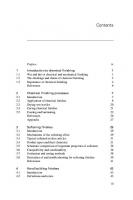
Production and Properties of Textile Yarns At the spinning mill the cotton goes through various processes to convert it from the rough compressed bales to a strong coherent and uniform yarn. The various stages are as follows: (1) Bale Breaking: the bales are opened and slabs pulled off and fed into the breaking machine, in which the lumps are subjected to the action of contrarotating rollers, fitted with steel spikes. These pull tufts of the cotton off the compressed mass, and these then pass over various screens, to remove some of the impurities present, such as twigs, leaves and sand. As cottons of different grades and from different sources are usually blended together, in order to obtain the desired properties in the final yarn, the blending normally starts at this stage, by feeding slabs from different bales consecutively. After bale breaking, the cotton, still in fair-sized lumps, passes to the next stage. (2) Opening and Cleaning: the lumps of cotton from the breaker pass through fluted steel rollers to a beating section, where rotary bladed cylinders beat the lumps, reduce the size of the tufts and at the same time remove still more of the contaminants, which fall through the bottom mesh of the machine. At the output end of the opener, the sheet of loose randomly laid fibres is fed through nip rollers and wound up into a lap, for feeding to the next stage. By this point, the cotton has changed from a hard compressed bale to a soft fibre web, similar to ‘cotton wool’. (3) Carding: a diagram of a cotton card is shown in Figure 2.1. The cotton, in the form of the lap from the opener, passes through a feed nip and is presented to the ‘takerin’, which consists of a roller covered with ‘card clothing’. Card clothing comprises a heavy backing made from rubberised fabric, through which angled steel wires pass, as shown in Figure 2.1 (a) ; the angle and length of these wires are of great importance as they control the efficiency and performance of the card. As the lap approaches the taker-in, the wires take hold of the fibres; as the roller has a much higher surface speed than the lap feed, the web of cotton becomes considerably attenuated. This web of fibres passes round the taker-in until it reaches the main cylinder, also covered with card clothing, with the wires angled in the same relative direction. As the main cylinder is moving faster than the taker-in, the condition as shown in Figure 2.1 (b)(i) applies and the fibres are stripped from the taker-in, being completely transferred to the main cylinder and becoming still more attenuated. As the fibres are carried round the main cylinder, they reach the point where they meet the ‘flats’, also covered with clothing. These are moving more slowly than the cylinder,
17
The Application of Textiles in Rubber Flats
ROVING OUT Comb LAP IN
Feed nip
Takerin
Doffer
Main cylinder
(a) CARD CLOTHING (b) CARDING ACTIONS Position Motion Action
Wires Textile/ rubber backing
(i)
stripping
(ii)
carding
Figure 2.1 Cotton carding
but in the same direction and with the wires angled in the opposite direction, as in Figure 2.1(b)(ii). A carding action occurs; the fibres are divided between the two surfaces and thereby the tufts are teased out more fully still, until ultimately, all agglomerations of fibres are broken down, giving a web of largely unentangled fibres. As the flats are carried round, they are cleaned so that clear surfaces are continuously presented to the cylinder. The fibre web continues round the cylinder until it meets the ‘doffer’, which rotates faster than the cylinder and strips the web off; the web is then in turn stripped from this by the ‘doffer comb’, from whence it passes over guide rollers and a funnel shaped guide, which reduces its width to about 25 mm, in which form it is coiled into a large can for passing to the next stage. In this form, the continuous ‘rope’ of cotton is called a ‘roving’. (4) Drafting: the drafting stage in the spinning process performs three essential functions. The first of these is the parallelisation of the individual fibres, which up to now have been laid in a more or less random manner. Secondly, it enables further blending of the different fibre types to take place. Thirdly, it can thin down the rovings to a much finer form, with a slight twist inserted, to give sufficient strength for the final spinning.
18
Production and Properties of Textile Yarns Drafting is performed by passing the roving, from the card or from a previous drafting, between pairs of rollers, each succeeding pair rotating faster than the previous, so that the fibres are pulled out in a lengthwise direction. This action not only helps to align the fibres but also enables the size of the fibre bundle to be reduced. Generally, in the first passes through the drafting frames, it is desirable to maintain the thickness of the roving; in order to do this, it is necessary to feed in several rovings at the same time, so that when they have been pulled out, the final thickness of the one output roving is the same as the individual ones originally fed in; in this way, additional blending occurs. In the final stage, it is necessary to reduce the thickness to suit the feed requirement of the spinning frame; in this case, the roving is allowed to become thinner, but in order to have sufficient strength to be fed through rollers, it is necessary to introduce a slight twist into the yarn bundle, which is now referred to as a sliver. Whereas in the intermediate stages of drafting, the rovings are wound into large cans, in this final stage, the sliver is wound onto a supporting tube, for presentation to the spinning frame. (5) Spinning: in the final spinning stage, the sliver is reduced still further in size and the required level of twist is inserted. In selecting the twist to be used there are various factors to be considered. The higher the twist level, the more firmly held together are the individual fibres. However, a high twist level gives a much harder and stiffer yarn and the ultimate tensile strength of the yarn is reduced. It is therefore usually necessary to compromise to some extent on the level of twist used. It is also necessary to decide which way to twist the yarn: the standard designation of twist direction refers to it as S or Z. It can be seen that the central sections of the two letters slope in opposite directions; the designation relates to the direction of the twist of the yarn, when held vertically. The fibres either slope from top left to bottom right, as in the central bar of the S or in the opposite direction as in the central bar of the Z; this is illustrated in Figure 2.2. A schematic representation of a ring spinning spindle is given in Figure 2.3. The sliver from the drafting frame is fed between three pairs of drafting rollers, to reduce the size to that required, and fed through a guide eye. From here, it passes down, through the ‘traveller’ and then to the tube on which it is to be wound up. The traveller consists of a metal or plastic C-shaped piece, which is clipped onto the ring; the traveller is not driven, but the spindle on which the tube is mounted is rotated at high speed (up to about 12,000 rpm.) This rotation pulls the traveller around and in so doing, for each revolution of the traveller, one turn of twist is inserted into the yarn. At the same time, of course, the yarn is being fed forward and wound up onto the tube on the spindle; by adjustment of the rate at which the yarn is fed forward and the speed of rotation of the spindle, so the level of twist inserted into the yarn can be controlled.
19
The Application of Textiles in Rubber
Figure 2.2 Disignation of twist direction
Figure 2.3 Ring spinning
Sliver IN
Guide eye
Dra f tin ro lle g rs
Yarn
Traveller Ring
Spun yarn
Tube Rotation
Driven spindle
Figure 2.3 Ring spinning
20
Rotation (pulled by yarn)
Production and Properties of Textile Yarns An alternative method for the spinning of staple fibres, which has been developed over recent years, is the ‘rotor’ or ‘open-end’ method. In this system, the ring and spindle are replaced by a rapidly rotating hollow cylinder; the drawn-down sliver is introduced into one end of this rotor and is thrown by centrifugal force onto the surface of the rotor, where it is carried round for several revolutions, before being withdrawn from the other end and wound up onto a bobbin. In passing through the rotor, a slight twist is imparted to the yarn, although generally less than on the ring system, but some of the longer protruding fibre ends are picked up by the rotor wall and wrapped round the bundle of fibres, thus binding them together into a coherent yarn. With the rotor system, the bulk of the fibres are not compressed together to the same extent as on ring spinning with the higher level of twist, and so a bulkier yarn is obtained. The binding together of the fibres is not as firm with the rotor system, so inter-fibre slippage can occur more readily, which results in a somewhat weaker yarn. However, the productivity and economics of open-end spinning are such, that it has become widely adopted, and, except where strength is of paramount importance, open-end yarn is perfectly acceptable for most applications.
2.1.2 Rayon Rayon is a man-made fibre, based on regenerated cellulose. The raw materials used are either cotton linters, as mentioned above, or, more usually, wood pulp, both of which have a very high cellulose content. A schematic of the chemistry of the viscose rayon process is given in Figure 2.4. As can be seen, the basic structure of the cellulose is essentially unchanged and the various stages are primarily to solubilise and regenerate the cellulose. However, during this process there is some degradation of the polymer, giving a significantly lower molecular weight (the regenerated cellulose molecule contains approximately 200-300 repeating units, compared with some 2,000 units in the original raw material). Also, in the spinning of the fibres, the regularity of orientation of the molecules in rayon is very much less than in the naturally laid down structure of cotton, so that, although continuous filament rayon yarns are stronger than spun cotton (see Table 2.3 later in this chapter), the individual fibre or ‘hair’ strength of cotton, at around 50 cN/Tex, is greater than that of rayon. In production, the wood pulp is first steeped in and then boiled with caustic soda, to give soda cellulose. One side effect of this stage is that much of the non-cellulose content of the raw pulp dissolves in the caustic soda and can be washed out, so that the filtered and pressed sheet consists of essentially pure soda cellulose. In the next stage, this sheet is crumbed and treated with carbon disulphide, with which it reacts to give sodium cellulose xanthate. This is then dissolved in dilute caustic soda to give the spinning solution.
21
The Application of Textiles in Rubber CH.OH
CH.OH
CH.OH
CH
CHO CH
NaOH
CH
Boiling
O
CH.ONa CHO
CH
CH2OH
O
CH2OH n
n Soda cellulose
Cellulose CS2
CH.OH
CH.O.CS.S.Na
CH
CH.OH
CHO CH
H2SO 4
O
CH
CHO CH
CH2OH
CH.OH
O
CH2OH n
n
Sodium cellulose xanthate
Regenerated cellulose
n >> n
Figure 2.4 Viscose rayon synthesis
Initially, this solution is quite viscous, but on standing the viscosity falls due to oxidative scission of the cellulose chains. On further standing, partial hydrolysis of the xanthate to cellulose results in a rise in viscosity. The solution is allowed to ‘ripen’ to the required viscosity, when it is considered ready for spinning. At the spinning stage, the solution is filtered and pumped through spinnerets (usually made of platinum or some other highly corrosion resistant material) into the coagulant bath. This process of extruding a solution of the polymer into a bath which causes coagulation of the polymer, is known as a wet spinning process. The coagulant bath for the standard rayons consists of approximately 10% sulphuric acid, with addition of sodium and zinc sulphates and a small amount of glucose. These additives are used to retard the coagulation of the outside of the spun filaments, to allow the centre to coagulate more rapidly, so that the whole thickness of the fibre
22
Production and Properties of Textile Yarns is coagulated at the same time. The main effect of this retardation of the outer layers is to allow a much greater orientation of the cellulose molecules in the skin layer compared with the core. As the core dries it contracts, which causes the skin to wrinkle up giving the characteristic many lobed cross-section of the lower tenacity rayons. (Tenacity is a measure of the strength of a yarn, quoted as strength per unit linear density, e.g., cN/Tex.) By modification of the coagulant bath composition, increasing the time of coagulation and stretching the coagulating filaments, it is possible to increase the ratio of skin to core. This gives an increase in strength and modulus and a reduction in elongation, compared with the standard process fibre. This method is used to produce the higher tenacity industrial grades of rayon. This can be taken even further, resulting in a fibre, which consists essentially of all skin and no core. In these fibres, strength is even higher and elongation lower, but the most significant effect is on the wet strength of the fibre. With the standard and high tenacity yarns, the wet strength is as much as 50% lower than that when dry. The ‘all skin’ yarns, produced by slower coagulation and higher stretch on spinning, are classified as ‘polynosic’ yarns and possess much higher wet strength, losing only around 15%-20% of their dry strength on wetting. Another effect of the increase in the skin content of the higher tenacity and polynosic yarns is to reduce the relative shrinkage of the core on drying; this in turn reduces the wrinkling of the skin so that these yarns have a more regular and smoother surface than the standard yarns. After spinning, the yarn is washed and dried and then wound up onto packages suitable for supply to the converters. Much development has gone into the engineering of the viscose rayon process, so that what was originally a batch process, giving only moderate control of the uniformity of the yarn, has now become a high speed continuous process, with very stringent control of every stage, giving a very consistent product. The majority of all rayon for polymer reinforcement is used as continuous filament, but there is still some use of spun staple rayon, where the main property required is bulk rather than strength. The production of the staple fibre is the same as for the continuous filament up to the final winding, where for staple, many ends are taken together to give a ‘tow’ of many thousand decitex. This is passed through a machine which chops the filaments into the required short lengths, of the desired staple length. This staple is then spun in much the same way as described above for cotton.
23
The Application of Textiles in Rubber
2.1.3 Nylon Nylon is the generic name for the linear aliphatic polyamides. Chemically, they are related to the naturally occurring proteins, including silk and wool. The major difference between the natural products and the synthetics lies in the relative position of the amide groups. The natural products are derived from α-amino carboxylic acids. The polyamide nylon 6 is derived from ε-amino caproic acid (caprolactam) which contains 6 carbon atoms, hence giving the designation nylon 6. Nylon 6.6 is obtained from the polycondensation of hexamethylene diamine and adipic acid, each monomer containing six carbon atoms so giving the designation of nylon 6.6.
2.1.3.1 Nylon 6.6 The original route for synthesis of nylon 6.6 started with benzene as shown in Figure 2.5(a). The benzene is catalytically reduced to cyclohexane, which on oxidation yields cyclohexanol. This is then dehydrogenated to give cyclohexanone (which also serves as the intermediate for nylon 6). On oxidation with nitric acid, the ring opens to give adipic acid. Here the route splits, part of the acid passing directly to the nylon salt formation and the other portion being used for the production of the other monomer, hexamethylene diamine. For this, adipic acid is converted, by reaction with ammonia, to the acid amide, which on dehydration and subsequent hydrogenation, yields the diamine. The two monomers are dissolved in methanol and react together to give the nylon salt, which crystallises out of solution. The salt is then dissolved in water and, on acidification of this solution, polymerises to nylon 6.6; polymerisation is usually controlled to give a molecular weight of between 12,000 and 20,000. An alternative route, starting from butadiene, has been developed (Figure 2.5(b)). The butadiene is chlorinated to give dichlorobutadiene, which is then reacted with hydrogen cyanide. On reduction of this, adiponitrile is obtained, which can either be reduced further to hexamethylene diamine, or be hydrolysed by alkali to adipic acid, which two monomers are then processed as before. The polymer is washed and dried, to prepare it for spinning. As nylon is thermoplastic, a melt spinning technique is used. The polymer is melted and forced through the fine holes of a spinneret; on cooling, the fibre is formed. On emerging from the spinneret, the polymer starts to solidify immediately; at this stage, the filaments are pulled away and stretched by between four to six times their original length. This drawing stage brings about considerable orientation and alignment of the polymer molecules, resulting in the formation of crystallites, which significantly affect the final properties of the yarn. By control and adjustment of the degree of stretch at this stage, and by selection of the molecular weight distribution, it is possible to vary considerably the main properties of the yarn, such as strength, modulus and thermal shrinkage.
24
Production and Properties of Textile Yarns (a) The benzene route
OH
O
H2
O2
- H2
Catalyst
Catalyst
Cu Catalyst
Cyclohexane
Benzene
Cyclohexanone
Cyclohexanol
O2 (HNO 3)
O - H2
CN.[CH 2]4.CN Adiponitrile
NH3
NH2.CO.[CH2]4.CO.NH2
Adipic acid
Solution In methanol
H
2
Ca taly st
HOOC.[CH 2]4.COOH
Adipamide
NH2.[CH 2]6.NH 2 Hexamethylene
diamine
[NH3.(CH2)6.NH3]2+[COO.(CH2)4.COO]2Nylon salt Dilute
Acid
[NH.(CH 2)6.NH.CO.(CH 2)4.CO]n Nylon 6.6
(b) The butadiene route CH2=CH-CH=CH 2
Cl2
Cl.CH 2.CH2.CH2.CH2.Cl
HCN
CN-CH=CH-CH=CH-CN H2
Alkali
HOOC.[CH 2]4.COOH
CN.CH2.CH2.CH 2.CH2.CN
Adipic Acid
Adiponitrile
lyst Cata H2
NH2.[CH 2]6.NH 2 Hexamethylene diamine
(c) The caprolactam process for nylon 6 NOH
O
CH2.CH 2.CH2 H2SO4
NH(OH)2
CH2 NH
Cyclohexanone
Cyclohexanone oxime
CH 2
H2O
-[NH.(CH2)5.CO] n-
CO
Caprolactam
Nylon 6
Figure 2.5 Nylon synthesis
25
The Application of Textiles in Rubber
2.1.3.2 Nylon 6 Nylon 6 is a homopolymer of caprolactam. The caprolactam is obtained from cyclohexanone, as shown in Figure 2.5(c), by reaction with hydroxylamine to yield cyclohexanone oxime. On treatment with sulphuric acid this undergoes a Beckmann transformation to caprolactam. This monomer is then heated, with approximately 10% of its weight of water, which causes the ring structure to open and the reactive groups to interact to yield the nylon 6 polymer. The polymer is washed with warm water to remove any unreacted monomer, and dried, after which it is melt spun and drawn in the same manner as for nylon 6.6. In addition to the production of multifilament yarns, using many very fine holes in the spinneret, monofilaments are also produced, in diameters ranging from around 0.10 mm up to 2.5 mm. These monofilaments are used in the production of industrial fabrics, particularly for filtration fabrics (usually covering the range from 0.10 up to 0.25 mm diameter, corresponding to a decitex range of 100 to 1000). The heavier diameters are used for stringing tennis and squash rackets, etc.
2.1.4 Polyester In the textile industry, polyester is the general name given to the fibres made from polyethylene terephthalate. The synthetic route for the production of polyester is given in Figure 2.6. Ethylene glycol is prepared by the oxidation of ethylene to ethylene oxide, which on hydrolysis yields the glycol (Figure 2.6(a)). Terephthalic acid is obtained by the direct oxidation of p-xylene (Figure 2.6(b)). There are two methods for the preparation of the polymer. In Europe, the more widely used route is by ester interchange via dimethyl terephthalate (Figure 2.6(c)(i)), but in the USA, the direct esterification of the acid with ethylene glycol is the more favoured method (Figure 2.6(c)(ii)). After polymerisation, the polymer passes through melt spinning and drawing stages, as for the nylons. A considerable proportion of the polyester produced is used as spun, but because of problems with adhesion, there is also a requirement for pretreated yarns. For these, at the spinning stage, the filaments are treated with various materials to modify the surface of the polyester. Although many materials have been patented for this application, the most popular are epoxy derivatives. The epoxy is applied, from aqueous solution or emulsion, at the spinnerets, and subsequent heat treatment brings about the modification to the fibre surface, so that adequate adhesion can be obtained with standard RFL dips,
26
Production and Properties of Textile Yarns (a) Ethylene glycol process
CH2
CH2
O2
CH2 Ethylene
O
H2O
CH2 Ethylene oxide
CH2OH CH2OH Ethylene glycol
(b) The terephthalic acid process
CH3
COOH
O2
CH3 p-Xylene
COOH Terephthalic acid
CH2
(c) Polymerisation (i) Ester interchange method
O COOH
CO
COO.CH3 Ethylene
Methanol
glycol
CO COO.CH3 Di-methyl terephthalate
Terephthalic acid
O
COOH
CH2
n
Polyethylene terephthalate
(c) Polymerisation (ii) Direct esterification method
CH2 O
COOH
CO
+
CH2OH CH2OH CO
COOH
O
Terephthalic acid
CH2
n
Figure 2.6 Polyester synthesis
27
The Application of Textiles in Rubber as used for nylon. Yarns which have been treated in this way are variously referred to as pretreated, pre-activated, adhesive primed or rubber receptive. Often incorporated with this treatment and its included heat treatment, is the relaxation of the yarns to reduce the normal shrinkage level of polyester, of around 10%-12%, to values between 2% and 4%, which offers advantages in some subsequent processes.
2.1.5 Aramid The aramids are aromatic polyamides. Although they are closely related to the nylons (the aliphatic polyamides), the substitution of the aliphatic carbon backbone by aromatic groups brings about considerable changes in the properties of the resultant fibres. The first fibre of this class to be developed was Nomex from DuPont. This yarn is of only medium tenacity, but is non-flammable and widely used for the production of fireproof clothing, etc. The newly introduced very high strength yarns, under the trade names of Kevlar (from DuPont) and Twaron (from Akzo Nobel Fibres) are fibres of poly-p-phenylene terephthalamide. The route for the production of the polymer is shown in Figure 2.7. Aniline is first acetylated and then nitrated (Figure 2.7(a)): the yield of the p-amino derivative is over 90% (a straight nitration would give approximately equal amounts of the o- and p-derivatives). Hydrolysis followed by reduction yields p-phenylene diamine. Terephthalic acid (produced as shown for polyester) is reacted with chlorine to give the acid chloride (Figure 2.7(b)). This is then reacted with the diamine to give the aramid polymer (Figure 2.7(c)). The major problem to be overcome in the production of the aramid yarns, was the selection of the right solvent system both for polymerisation and for spinning. As aramids are infusible, they cannot be melt spun. The polymerisation is carried out in a mixed solvent system consisting of an amide with lithium chloride: using this solvent it is not possible to obtain a high solids solution, which adversely affects the rate at which the fibres can be spun. Also, yarns spun from this solvent required considerable after-treatment in order to develop the optimum fibre properties. Other useful solvents were not readily found, not only due to the properties of the polymer itself but also due to its behaviour in solution, where it exhibits anisotropy and exists in a liquid crystal phase. A suitable solvent was found in concentrated sulphuric acid; this enabled the necessary solids content for good spinning to be achieved and also gave better liquid crystal formation. This resulted not only in better spinning performance but also gave much better properties to the final fibre.
28
Production and Properties of Textile Yarns (a)
NH2
NH.CO.CH3 CH3COCl
NH.CO.CH3 HNO3
Aniline
NO2 Hydrolysis and reduction
NH2
(b)
COOH
COCl NH2 Cl2 p-Phenylene diamine
COOH
COCl Terephthalic acid chloride
Terephthalic acid
(c)
NH2
COCl
NH
+
NH.CO
CO n
COCl Terephthalic acid chloride
NH2 p-Phenylene diamine
ARAMID Poly(p-phenylene terephthalamide)
Figure 2.7 Aramid synthesis
Further development of the spinning stage produced even better results. The present process utilises a dry jet/wet spinning system [1]. The spinning solution is extruded through the spinneret just above the coagulant bath (of water or dilute sulphuric acid); this allows further orientation of the polymer in the solution before the polymer starts to coagulate, 29
The Application of Textiles in Rubber due to the streamlined flow induced by the spinneret. As a result of this, the as-spun yarns are superior to the original yarns. After-treatments are not necessary, although by including such treatment, it is possible to produce yarns with even higher modulus. Kevlar 49, a special high modulus yarn for fibre reinforced plastics, gives higher strength with lower weight than standard glass reinforced products. The anisotropy of the solutions of aramid and the existence of liquid crystals are indicative of the very high orientation and association of the polymer molecules, which accounts for the very high strength and modulus of the yarns. This is even more remarkable when it is considered that the average aramid molecule comprises not more than 100 repeat units, which degree of polymerisation is very much lower than is the case with the cellulosics, nylons and polyesters.
2.2 General Characteristics of Textile Fibres The main characteristics of the textile fibres are summarised in Table 2.2; greater detail is given below for the various types, including simple tests for the identification of the different fibres. A proprietary blend of dyes is available for fibre identification and test results are listed in each section (Shirlastain A from Shirley Developments Ltd., Didsbury, Manchester).
2.2.1 Cotton Cotton is a naturally occurring 100% cellulose fibre. It is only encountered in spun staple form, as a naturally occurring short staple fibre. Water: Cotton swells on immersion in water, but the wet strength of the yarn is up to 20% higher than in the dry state; on drying, the properties revert to the original. On exposure to a standard atmosphere (20 °C and 65% relative humidity) cotton will regain approximately 8.5% moisture. Regain is a measure of moisture content of a yarn or fabric and is expressed as:
Weight of moisture × 100% Oven - dry weight of yarn as distinct from moisture content, which is:
Weight of moisture × 100% Original weight of yarn
30
Table 2.2 General characteristics of textile fibres Fibre Type
Cotton
Rayon
Nylon
Polyester
Aramid
8.5
13.0
4.5
0.5
2.5
120
Approx. 60
≥ 90
≥ 90
≥ 90
Heat resistance
Good to 150 °C
Good to 150 °C
Good to 180 °C
Good to 180 °C
Good to 250 °C
Melting point
Decomposes over 230 °C
Decomposes over 210 °C
Nylon 6 - 225 °C Nylon 6.6 - 250 °C
250 °C
Decomposes over 500 °C
Resistance to acids
Attacked by hot dilute and cold concentrated acids
Attacked by hot dilute and cold concentrated acids
Good in normal use: soluble in hot concentrated acids
Good in normal use: soluble in hot concentrated acids
Excellent in normal use: soluble in boiling concentrated sulphuric acid
Resistant
1
Moisture regain (%)
2
Wet strength (% of dry)
Resistant
Resistant
Resistant
3
Resistant
Resistant
Resistant
Resistant
Resistant
Solvents; other
Soluble in 70% sulphuric acid and cuprammonium hydroxide
Soluble in 70% sulphuric acid and cuprammonium hydroxide
Soluble in boiling 80% acetic acid
Soluble in phenols, hot concentrated alkali, ethylene glycol
Soluble in boiling concentrated sulphuric acid
Burning
Burns readily Burnt paper odour
Burns readily Burnt paper odour
Burns with clear bluish flame; forms bead Celery odour
Burns with smoky yellowish flame: forms bead Slight sweetish odour
Does not burn or melt
Purple -
Pink Purple
Dull yellow Orange
Not stained
Not stained
Solvents; standard
Shirlastain A: cold boiling 1
Moisture regain is the weight of water present in a material as compared to the oven-dry weight, expressed as a percentage Wet strength is the tensile strength measured with yarns soaked in water, as compared with oven-dry 3 Aliphatic or aromatic hydrocarbons, alcohols, ketones or chlorinated solvents 2
31
Production and Properties of Textile Yarns
Resistance to alkalis
Generally good, but slightly hydrolysed, especially with amines and hot concentrated alkalis
The Application of Textiles in Rubber Heat: Cotton generally has good resistance to heat and is only slightly affected by temperatures of up to 150 °C, but above this temperature, and on prolonged exposure between 100 °C and 150 °C, will progressively lose strength. It starts to decompose at around 230 °C. Cotton will burn readily, but in an oxygen starved atmosphere will char and leave a carbon skeleton (albeit without any significant strength). Acids: Cotton is quite susceptible to attack by acids. It is quickly attacked by hot dilute or cold concentrated acids. Traces of acid, not properly washed out from certain dyeing and finishing processes, can lead to a progressive tenderising of the fibres and consequent loss of strength. Alkalis: Cotton is resistant to alkali, but will swell. This forms the basis of the mercerisation process, where cotton yarns are stretched in fairly concentrated alkali: during this, the fibres swell, but since they are held, this swelling introduces certain re-orientation of the molecular structure, which results in an improved strength and a more glossy appearance. Solvents: Cotton is not affected by the usual hydrocarbon, aromatic or chlorinated solvents. It will dissolve in some mineral acids, e.g., 70% sulphuric acid, but this is usually accompanied by chemical decomposition. Cotton will dissolve in a solution of cuprammonium hydroxide and this solution can be used to measure the viscosity of a known concentration of cotton and so give a measure of any chemical degradation the yarn has undergone. Miscellaneous: Cotton is subject to microbiological attack, especially mildew. Identification: Burns readily with a characteristic ‘burnt paper’ smell; gives a purple colour on cold staining with Shirlastain A.
2.2.2 Rayon Rayon is a regenerated cellulosic yarn and is used as both continuous filament and as spun staple yarn. Water: As with cotton, rayon is swollen on immersion in water, but the wet strength of rayon is some 40% lower than the dry except for the polynosic yarns when it is around 25% lower; again this is reversible on drying, provided the yarn is not allowed to shrink. Standard moisture regain of rayon is 13%.
32
Production and Properties of Textile Yarns Heat: Rayon is generally resistant to heat up to about 150 °C, but loses strength on prolonged exposure and more rapidly at higher temperatures. It starts to decompose at around 210 °C. Rayon burns readily but as with cotton, under certain conditions, will char and leave a carbon residue. Acids: The susceptibility of rayon to acids is very similar to that of cotton. Alkalis: The reaction of rayon to alkali is also similar to that of cotton, but rayon will lose some strength on swelling in concentrated alkali. Solvents: As for cotton; however, the viscosity of a solution of rayon in cuprammonium hydroxide is much lower than that of a similar concentration of cotton (due to the reduction in molecular weight during the manufacturing process). Miscellaneous: Rayon is susceptible to microbiological attack, but the absence of the small amounts of naturally occurring proteins found in cotton, and the presence of traces of chemicals from the manufacture, render rayon slightly more resistant than cotton. Identification: Burns readily with the characteristic burnt paper smell; with Shirlastain A, gives a pink colour in the cold and purple on boiling.
2.2.3 Nylon The chemical properties of both nylon 6.6 and nylon 6 are very similar; significant differences in behaviour will be specifically mentioned here. Water: Nylon is not significantly affected by immersion in water; there is perhaps a slight drop in tenacity, but this is fully reversible on drying. The standard regain of nylon is 4.5%. Heat: Nylon is generally quite resistant to heat and is not appreciably affected by temperatures of up to 180 °C (unless exposed for prolonged periods). Nylon 6.6 melts at 250 °C and nylon 6 at 225 °C. On burning, nylon tends to melt away from the flame, and burns less readily than cotton and rayon (the Limiting Oxygen Index of nylon is 0.26 so it has a tendency to be selfextinguishing). However, in bulk, when a molten mass is formed it will burn fairly readily. On burning, nylon has a characteristic celery-like odour.
33
The Application of Textiles in Rubber Acids: Nylon has good general resistance to acids in normal service contact, but will disintegrate on heating with concentrated acids. Nylon is soluble in 80% acetic acid at the boil and in formic acid at room temperature. Alkalis: Nylon is resistant to alkali. Solvents: Nylon is not affected by the standard hydrocarbon, aromatic or chlorinated solvents. Nylon is soluble in phenols, especially m-cresol. Nylon 6.6 and 6 can be differentiated by their reaction to boiling dimethylformamide; nylon 6.6 is soluble while nylon 6 is insoluble. Miscellaneous: Nylon is not subject to microbiological attack and is transparent to ultraviolet light. Identification: Nylon melts away from a flame and burns less readily than cellulosic fibres, with a characteristic ‘celery’ smell. In Shirlastain A it gives a dull yellow colour in the cold, which deepens to orange on boiling.
2.2.4 Polyester Polyester is generally far more stable and less reactive than would be expected in view of the presence of ester groups: these groups are much less reactive than the simple aliphatic esters. Water: Polyester is not significantly affected by immersion in water, losing perhaps a few per cent in tenacity when wet, but returning to its original properties on drying. The standard regain of polyester is 0.5%. Boiling water will cause polyester to shrink and can also cause some slight permanent loss of strength, due to hydrolysis. This tendency to hydrolyse is far more pronounced in the presence of steam and is greatly accelerated by the presence of small amounts of amines, especially cyclohexylamine, which is often used as a boiler water treatment, and can frequently be found in high pressure steam. Heat: Polyester is quite resistant to dry heat and is not greatly affected by temperatures of up to 180 °C (except on prolonged exposure). The melting point of polyester is 250 °C. On burning, it tends to melt away from the flame and burns with a smoky flame. It gives a slightly sweetish odour on burning.
34
Acids: Polyester is quite resistant to acids, but will disintegrate on heating in concentrated mineral acids. Alkalis: Generally, the resistance of polyester to alkali is good, but hydrolysis will occur slowly at ambient temperatures and more rapidly at elevated temperatures. The resistance to amines is not so good; immersion in 15% aqueous ammonia can give a loss of up to 50% in strength in about 10 days at ambient temperatures. Similarly, the presence of amine residues from additives in vulcanised rubbers can cause severe degradation of polyester bonded to the rubber. Solvents: Polyester is resistant to the standard hydrocarbon, aromatic and chlorinated solvents. It is soluble in phenols and in other solvents at their boiling points including cyclohexanone, benzyl alcohol, nitrobenzene and dimethyl phthalate. Polyester will dissolve in boiling concentrated alkali and boiling ethylene glycol, although in these cases, solution is largely due to de-polymerisation rather than to true solvent action. Miscellaneous: Polyester is not susceptible to microbiological attack and gives slight fluorescence under ultraviolet light. Identification: On burning, polyester tends to melt away from the flame. It burns with a rather smoky flame and gives a slightly sweetish odour. Polyester is not stained by Shirlastain A.
2.2.5 Aramid The aromatic polyamides are very much more inert than the aliphatic nylons. Water: There is no significant effect on the properties of aramid on immersion in water. The standard regain of aramid is 2.0%. Heat: Aramid is not significantly affected by temperatures up to at least 250 °C. Aramid does not burn but starts to decompose on heating at temperatures of around 500 °C. Acids: Aramid is resistant to normal acids, but will dissolve in boiling concentrated sulphuric acid. Alkalis: Aramid is resistant to alkalis. Solvents: Aramid is not affected by most solvents, but will dissolve in boiling concentrated sulphuric acid and in certain mixed solvent systems based on amides and alkali chlorides.
35
The Application of Textiles in Rubber Miscellaneous: Unless protected, aramid is adversely affected by ultraviolet light and progressively loses strength on exposure. Identification: Kevlar (from DuPont) and Twaron (from Akzo Nobel Fibres), two commercially available aramids, are both yellow in colour; they do not burn and are not stained by Shirlastain A.
2.3 General Physical Properties of Textile Fibres The main physical properties of the textile fibres are given in Table 2.3: included here are glass and steel, both of which are quite widely used as reinforcements in elastomers. The first major difference between the textile fibres and the two inorganic materials lies in their specific gravities (s.g.): those of the textiles lie between 1.0 and 1.5 whereas glass is at 2.5 and steel much higher at 7.85. As regards strength, when measured as conventional tensile strength, that is as strength per unit cross-section, the organic fibres, with the exception of aramid, are much weaker than glass or steel. If however, the strength is considered as tenacity, in which specific gravity is taken into account, the picture is very different, with glass showing a tenacity similar to nylon and polyester, but with steel lying between cotton and rayon. Modulus values lie in favour of the inorganic materials, with the exception of aramid, but this is of course largely coupled with the differences in elongation at break. The stress-strain curves of the fibres are given in Figure 2.8.
2.3.1 Cotton From Table 2.3 and Figure 2.8, it can be seen that cotton is of only moderate strength. However, this is coupled with a relatively high bulk, so that dense fabrics of lower strength can be produced. Cotton has largely been replaced by the stronger man-made fibres, but it still finds application where the requirement is not primarily for high strength but also demands a reasonable bulk. The other advantage possessed by cotton derives from its staple nature. This relates to its use as an adhesion contributor, particularly in polyvinyl chloride (PVC) applications, where cotton is widely used in combination with the synthetics. In these fabrics, the strength is primarily obtained from the synthetic and the cotton contributes both bulk and the means whereby adhesion is obtained (this is discussed more fully in Chapter 4).
36
Table 2.3 General physical properties of textile fibres Rayon Fibre Type
Cotton
Polyamide
Viscose
Polynosic
Nylon 6
Nylon 6 .6
Polyester
Aramid
Glass
Steel
a
Specific gravity
1.54
1.52
1.52
1.14
1.14
1.38
1.44
2.54
7.85
Mean filament diameter (µm)
15
8
8
25
25
25
12
-
-
Mean decitex per filament
1.6
1.8
1.8
6.7
6.7
5.7
1.7
-
-
Tensile strength (MPa)
230
685
850
850
950
1100
2750
2 2 50
2750
Tenacity (cN/Tex)
15
40
50
80
85
80
190
85
35
Elongation at break (%)
8
10
6
19
16
13
4
5
2.5
225
600
800
300
500
850
4 0 00
2150
1500
0
0
0
6
5
11
0.2
0
-
Initial modulusb (cN/Tex) Shrinkage at 150 °C (%)
Notes: Properties for an 840 decitex ring-spun American cotton yarn. b Initial modulus is the stress, extrapolated from that at 2% elongation, to give 100% elongation. a
37
The Application of Textiles in Rubber 1 cotton 2 viscose rayon 3 polynosic rayon 4 nylon 6.6 5 nylon 6 6 polyester 7 aramid 8 glass 9 steel
7
8
4 6
5
3 2
9
1
Figure 2.8 Stress-strain characteristics of textile fibres
2.3.2 Rayon The rayons, in continuous filament form, are much stronger than cotton. They also possess good modulus characteristics although this tends to be linked with a rather low value for elongation at break, which can be a disadvantage in some applications. One other disadvantage of the rayons lies in their sensitivity to moisture; in moist conditions, they lose a significant proportion of their dry strength. For many applications, where the direct ingress of moisture is restricted, this does not pose a very significant problem (as for
38
example in tyres, hose and moulded edge conveyer belting). However, in applications such as cut-edge belting, where the textile is exposed, rayon will rapidly absorb moisture and this will readily wick along the fibres, resulting in loss of strength. The higher strength polynosic rayons are less affected by moisture, but because of their even lower values of elongation at break, they are somewhat more restricted in their applications. The main areas of use are in radial tyre breakers and in high pressure hydraulic hose. Spun staple rayon is used in much the same way as cotton, in order to contribute bulk rather than strength. Rayon is particularly of benefit where the resultant fabric is to be dipped, as it is far more readily wetted by the dip than is cotton, where the natural waxes tend to prevent wetting and give rise to very patchy application of the dip. Additionally, under US nomenclature, the use of spun rayon in place of cotton enables the resultant fabric to be designated as ‘all synthetic’.
2.3.3 Nylon Compared with the cellulosics, the nylons are of much higher strength and also give much higher values of elongation at break. This latter property imparts to nylon fabrics a greatly improved impact resistance, higher work to rupture and much better tear resistance. It is largely on account of these properties that nylon has been adopted as the principal weft yarn for conveyor belting fabrics; additionally, the lower modulus of nylon also contributes to very good troughing characteristics in the finished belt. One characteristic of nylon, not possessed by the cellulosics, is thermal shrinkage. Being a thermoplastic material, when heated nylon tends to shrink; on account of this, when processing nylon fabrics, either some restraint must be employed to control or limit this shrinkage or adjustment must be made in the design to allow for the subsequent changes in dimensions during processing. By choosing suitable conditions of processing, it is possible to modify the shrinkage characteristics to suit more precisely the final parameters to be satisfied. This aspect of heat setting will be discussed in more detail in Chapter 4. Generally speaking, however, if nylon is allowed to shrink, the elongation at break will increase and modulus will fall, depending on the degree of shrinkage. Nylon is almost entirely used as continuous filament, but there is a small application for spun staple nylon, as with rayon, primarily for bulk and adhesion requirements and to meet the ‘all synthetic’ designation in Europe.
39
The Application of Textiles in Rubber
2.3.4 Polyester Broadly, polyester combines the strength and elongation characteristics of the nylons with the modulus characteristics of the rayons. This combination of properties suits many applications, but there are two main areas where problems exist. The first concerns adhesion: being relatively inert chemically, it is somewhat more difficult to obtain adequate levels of adhesion with polyester than with rayon or nylon. However, as shown later, methods of treatment have been developed to overcome this. The second area relates to thermal shrinkage, which is even greater than with nylon. Processes exist to modify the shrinkage characteristics of polyester and there are also various grades of fibres with differing shrinkage/modulus relationships, achieved by modification of the basic polymer. By judicious selection of the yarn type, the final properties of the cord or fabric can be tailored to the requirements of the specific applications.
2.3.5 Aramid The properties of aramid are more akin to those of the inorganic materials than to the other textile fibres. The tensile strength, even assessed by the engineering method as strength per unit cross-section, is of the same order as those of steel and glass, so that when quoted as tenacity (where the advantage of low specific gravity is taken into account), the strength is exceptional. The modulus is also very high, but this is coupled with a very low value for elongation at break, which introduces some difficulties in certain applications. The major disadvantage of this low elongation occurs when aramid is used in several layers. When flat, each layer of textile is able to contribute its own share of strength, but on bending, the low elongation of the outermost layer prevents it from accommodating to the curve, which places the other layers in compression. This directly reduces the contribution of the inner plies to the total strength but also, and more seriously, the performance of aramid in compression (especially its dynamic fatigue resistance) is not good. Under such conditions, premature failure of the inner plies is likely to occur. However, many applications have been developed which enable the excellent properties of aramid to be realised and much effort is being devoted to ways of overcoming the problems associated with this low elongation, so that other areas of use can be found for the unique combination of properties possessed by aramid.
References 1.
40
E. I. DuPont de Nemours & Co. Inc., assignee; GB Patent 393011, 1971.
3
Yarn and Cord Processes
Introduction There are very few applications where textile fibres can be used in the form in which they are originally produced. It is usually necessary to modify the yarn form or construction, in order to obtain the optimum benefit from their incorporation as reinforcement in elastomeric composites. For some applications, single-end yarns or cords (several twisted yarns twisted together) are the preferred form, especially for hose and V-belts. In some cases (particularly in tyres) although the single-end cord is the right form of reinforcement, it is preferable for the cords to be assembled together into a cord-fabric. This represents a halfway stage between the single cord and the fully woven constructions. For most other applications, woven fabrics provide the most satisfactory form of textile reinforcement, but even in these constructions, it is generally necessary to modify the yarn, rather than using the asproduced form. The final yarn processing step, prior to fabric formation, is the preparation of the warp (or weaver’s) beam, to assemble the required number and lengths of yarns onto one carrier, ready for the fabric formation process.
3.1 Yarn Preparation Methods As produced, the yarns are in single-end form. The single yarns exist as individual, coherent threads, containing many individual filaments or fibres. The staple yarns, produced from short fibres by the spinning process, are already twisted and may be used directly. Often, several single yarns are assembled together to give heavier and stronger threads. On the other hand, the man-made yarns, consisting of many individual filaments, may be produced ‘flat’, that is without any binding together of the filaments, each filament running individually and potentially able to be separated from the remainder; or as a more coherent yarn, either with a low level of twist (producer twist) or with some tangling of the individual filaments together, known as intermingling.
41
The Application of Textiles in Rubber The most common methods of obtaining the required yarn construction are twisting and texturing (the bulking up of yarns). For some of the lighter fabrics, a chemical modification in the form of sizing is employed for the warp yarns.
3.1.1 Twisting The twisting of yarns and the doubling of them together to give plied yarns, is usually performed on ring-doublers. These are essentially like the ring spinning frames used in cotton spinning (Figure 2.3). For twisting the drafting system on the feed side is replaced by a simple roller feed system, to control the forward supply of the yarns and the spin tube replaced with a bobbin. As in cotton spinning, the control of the relative feed rate of the yarn and the rotational speed of the spindle govern the level of twist inserted. If the yarn were fed forward at the same speed as the surface of the bobbin, it would just wind on flat, but when fed slower, the yarn is pulled round in the ‘traveller’, introducing one turn of twist for each rotation of the traveller. The standard units of twist are turns per metre (tpm). There are various advantages gained in the final yarn properties, from twisting. Firstly, the yarns are rather more compact and the filaments more firmly held, which gives greater resistance to damage from abrasion. Secondly, the twisting imparts to the yarn a rather rounder cross-section, which is often advantageous in obtaining the optimum packing density of threads to achieve the desired level of reinforcement. The other major effect of twist is to improve the fatigue resistance of the yarns. Using the same basic twisting method, it is possible to assemble several single yarns together, into a single coherent yarn, by feeding these together to the twisting frame. Such yarns, referred to as ‘plied’ or ‘folded’ yarns, enable the incorporation of a higher volume of yarn into the final structure. It is obvious that only a certain number of single yarns can be placed side by side, but by increasing the number of singles in each yarn, it is possible to increase the number of single yarns in the same width. If the yarns are considered to be circular in cross-section, it can be seen that by increasing the number of plies in each yarn, the diameter of the resultant yarn is only increased by the square root of the number of plies, thereby allowing more single yarns to be placed in the same area. For example, if twenty threads of a certain yarn occupy one unit space when placed side by side, by plying together four single yarns the diameter of the resultant yarn will increase by √4, so ten of the four-fold yarns can be placed in the same unit space, and there will be forty (i.e., 4 x 10) single yarns in the space originally occupied by twenty. The different forms of yarn, singles, as produced and twisted, plied and cabled constructions are illustrated in Figure 3.1. At (a), the individual filaments of the single
42
Yarn and Cord Processes
Figure 3.1 Yarn and cord constructions
flat yarn lie roughly parallel, but not significantly bound into the yarn and therefore potentially liable to be caught and damaged. The twisted single yarn (b) shows the effect of a low level of twist in producing a more compact and coherent yarn, with the individual filaments held together in the final thread. At (c), the plied yarn consists of several individual single yarns, each flat, but twisted together, again giving a coherent and more compact structure. Finally, at (d), the individual single yarns have been twisted in one direction and then twisted together in the opposite sense in the cable. The aim of this is to give a ‘balanced’ yarn, that is one which shows very little tendency to twist up on itself and snarl, as would be the case in an unbalanced yarn or if both singles and cable twist were in the same direction. Ideally, in the final cabled cord, the individual filaments in each ply should, essentially, lie parallel to the length of the cabled cord.
43
The Application of Textiles in Rubber Twisted and plied yarns are mainly used for hose-braiding and as the basic components of woven fabrics. For other applications such as V-belts, large-bore hose and tyres, cabled cords are the preferred form of single end structure, as the higher twist levels and cabled construction give improved fatigue resistance to the final yarn. In the plied yarns, the single yarns are fed forward together and twisted into the thread in one twisting operation, or ‘throw’, usually with only a relatively low level of twist. However, in a cabled construction, the singles (or a number of single yarns together) are twisted, in one direction, before being cabled together, again by twisting, this time in the opposite twist direction. In fact, the cabling operation can be applied to already plied and twisted yarns or to cabled constructions, enabling much heavier cords to be produced. Generally, with cabled cords, higher levels of twist are used, in order to obtain good resistance to dynamic fatigue, and also to give dense, circular cross-section cords. In order to achieve a properly balanced cord, it is essential that the helix angle of the components in each throw, or twisting operation, be the same. It is obvious that as the size of the cord increases so the helix angle will increase for the same level of twist inserted; in order to allow for this, the ‘twist multiplier’, which automatically compensates for this change, is used. The original work on twist multipliers was empirical and based on turns per inch and cotton counts, so that to use the established factors these units must be used in calculations. However, the principle can be applied using any units and it is usually more convenient to use metric units for calculations. The fundamental statement of the principle is: Twist x √ (Linear Density) = Constant The linear density should be based on a ‘direct’ measurement system, i.e., one based on weight per unit length, such as decitex, rather than an ‘indirect’ system, such as cotton count, based on length per unit weight. If an indirect system is used, the reciprocal of the linear density must be used in the calculation. By applying this calculation to the total linear densities of the first and second throws of a cabling, the correct twists for a balanced cord can be obtained, using the same constant in each calculation. For example, taking the 1100 decitex yarn, 2/5 V-belt cord shown in Table 3.1, the nominal resultant decitex for the first throw is 2 x 1100, i.e., 2200, and the twist level is 220 turns per metre, giving Twist Multiplier = 220 x √2200 = 1.032 x 10⁴ For a balanced twist in the second throw, the cable twist (in the opposite direction) is calculated thus: Twist = 1.032 x 10⁴ ÷ √ (2 x 5 x 1100) = 98.4 tpm which, within normal tolerances, is the twist used (100 tpm).
44
To be strictly correct, the ‘resultant’ linear densities, for each throw, should be used. It is obvious that as a yarn is twisted it will contract in length, depending on the level of twist inserted, giving an apparent increase in linear density, this increased value being the resultant linear density. For the majority of applications, however, the nominal linear density is perfectly adequate for the calculation, as twist uptake (the apparent shortening of the yarn) is usually of the order of 1%-2%, and the twist inserted cannot be controlled more accurately than this. Reference so far has only been made to the ring twisting of yarns. However, with the large volume of high-twist cords required for tyres, in particular, development has led to modified twisting machinery, to increase output, either by imparting two turns of twist into the yarn for each revolution of the spindle or by combining into one operation both the singles twisting and the cabling. These two techniques are illustrated in Figure 3.2. At (a) is the ‘two-for-one’ twister. In this case, the supply package is stationary, the yarn is fed down through the hollow holder and is threaded through a rotating concentric disc. In passing from the guide at the top of the hollow holder to the rotating disc, one turn is inserted into the yarn for each revolution of the disc, and then on ballooning around the supply package to the take-up rollers, a second turn is inserted. In this way,
Figure 3.2 Alternative twisting systems
45
Construction
Single yarn
Actual linear density (decitex)
1,100
2,400
2,535
single
-
400
ply
-
cable
Low twist folded 3-fold
6-fold
2/5 cabled V-belt cord
2,640
3,335
6,712
12,200
475
500
-
-
-
-
-
-
100
60
220
-
400
475
550
-
-
100
81
158
150
136
239
472
757
Elongation at break (%)
12.4
17.1
18.3
19.2
12.7
14.3
16.6
Tenacity (cN/Tex)
73.6
65.8
59.1
51.5
71.7
70.3
62.0
at 2% Elongation
727
422
292
201
716
701
382
at 5% Elongation
537
309
247
175
5 10
490
265
10.5
12.9
13.8
14.7
10.7
10.8
11. 5
Strength
97.5
92.5
84.0
98.3
97.1
93.5
Tenacity
89.4
80.3
70.0
97.4
95.5
84.2
Twist (tpm)
Tensile strength (N)
Modulus (cN/Tex)
Shrinkage at 150 °C (%) Conversion Efficiency (%)
Two-ply tyre cord
The Application of Textiles in Rubber
46
Table 3.1 Effect of twisting, plying and cabling on polyester yarn properties
Yarn and Cord Processes it is possible to achieve production rates approaching double that which can be obtained on conventional doubling frames, without the problems of attempting to drastically increase the speed of rotation of the spindle, with the attendant mechanical difficulties. While this type of equipment was originally designed for twisting single yarns, by assembling several single yarns onto one supply package, it is possible to ply or twist these yarns together. Figure 3.2 (b) shows the principle of the twister-cabler. In this case, the singles packages are rotated and the yarn taken off through a flyer; this is a freely rotating arm, with a guide eye at the end, through which the yarn passes. This imparts the desired level of twist to the singles yarns, which are then fed forward to what is in effect a conventional ring doubler. This system enables the complete cabling operation to be performed in one pass. By these methods, the plied or cabled cords are produced. For single-end applications, they may pass to further stages, for heat-setting, adhesive dipping, etc., and then to rewinding, so that they are on suitable packages for use in the production of the final product. The same processes are used for the preparation of the yarns for weaving, etc. Unfortunately, in the plying together of single yarns, there is usually some loss of strength, that is, a four-fold yarn will not have the same strength as four single yarns. The level of this loss of strength, or as it is called, the conversion efficiency of the doubling, depends on several factors, including the number of singles plied together and the level of twist inserted in the doubling operation. In Table 3.1 are shown the resultant properties of a series of doubling and cabling operations on a polyester yarn. It can be seen that all properties are altered by doubling; the most obvious are tensile strength and elongation at break. It can be seen that the higher the twist, the lower the conversion efficiency; this effect is exaggerated if the comparison is made on tenacity rather than on actual strength. This is due to the effective increase in linear density, arising from the twisting operation. When two or more yarns are twisted together there will be an apparent loss of length as the individual yarns take up a helical path, rather than the original straight one, and this will result in an increase in linear density, which in turn results in a drop in tenacity, greater than the corresponding loss in absolute strength. However, it is often necessary to accept this effect, because for certain applications the benefits of twist on fatigue more than outweigh the loss of strength. For example, it has been shown in a disc fatigue test, a two-ply nylon cord with twists of 510 tpm in both singles and cable, loses some 8% of its original strength after 4 million cycles; but a similar cord, with only 435 tpm twist, loses over 20%.
47
The Application of Textiles in Rubber Apart from such requirements as fatigue resistance, other factors must be taken into account in selecting the correct levels of twist for any specific application. In yarns for fabrics, where low levels of twist are most usual, the twist serves mainly to hold the single or plied yarns together into a coherent thread and so the lowest twist consistent with this will be satisfactory. For the higher twist cabled constructions, another consideration arises in the selection of the twist levels. This is the need to balance the twist in the two operations, so that the final cord is not too lively and does not twist up on itself and cause snarls. Another factor to be decided is the direction of twist used. With the low levels of twist, generally used in fabrics, the direction of twist has little effect, although for certain applications it is considered desirable that the twist on alternate ends in the warp should be in opposite directions, to avoid possible problems due to deformation of the fabric or curling of the edges: it is debatable how essential this is in view of the low levels of twist used. However, when dealing with high-twist and cabled cords, the selection of twist direction is very important. In order to obtain a balanced cabled cord construction, as mentioned above, it is essential that the twist directions in each successive throw be reversed, otherwise if the same direction were used, the resultant cord would be very lively and difficult to handle. Apart from these considerations, there is no rule, other than conventional practice, as to the direction of twist to be selected. The foregoing has been primarily related to the twisting and doubling of single fibre type yarns and this, indeed, covers the majority of twisting. However, it is often desirable to combine together fibres of different types, to obtain certain specific properties. There are three main application areas where this is done: the first is mixing together of two (or more) different staple yarns at the beginning of the spinning process, to give blended yarns, such as the polyester/cotton blends, widely used in domestic and apparel fabrics, but not widely used for reinforcement fabrics. The second application area consists of the combining together of a high strength continuous filament yarn with a weaker but bulkier spun yarn. Typical of this is the combined doubling of cotton with nylon for the production of fabrics, as in the reinforcement of fire-resistant PVC belting. The two yarns are combined in much the same way as the standard twisting of single component yarns, on a ring doubler. By this means, threads, which combine the strength of the continuous filament component with the bulk of the staple component, (which also significantly contributes to the adhesion to the PVC), can be obtained. In practice, there is but little contribution to the strength by the staple component, largely owing to the difference in ultimate elongation of the two components. (Nylon has an elongation at break of around 15% compared with some 9% for spun cotton.) It is, however, possible to increase the contribution of the cotton, by means of differential doubling: in this case, the roller feed system on the doubling frame is modified to allow individual
48
Yarn and Cord Processes control of the fed lengths of the two components. A greater length of the lower elongation yarn is fed forward and accommodated by the twisting operation, so that when under strain, both components reach their breaking length at approximately the same total final extension of the composite yarn. The third important area where two dissimilar fibres are used together is in core-spun materials. In this instance, the modification is also at the spinning stage, but here, a continuous filament yarn is fed forward and the staple portion is drafted down and spun around this continuous filament core, in much the same manner as conventional spinning. These core-spun yarns, for example with a polyester core and cotton sheath, are widely used in the production of fabrics for chemical proofing, for tents and tarpaulins, etc. (A similar effect can be obtained with air texturing, as will be described below.) While conventional twisting and doubling satisfy the vast majority of industrial applications, other methods of yarn assembly have been developed. Probably the most important, and potentially, the most useful, is a system in which the singles yarns are fed through a hollow spindle and bound together into a coherent form by wrapping with a light helically laid binder yarn. Although this system was primarily aimed at the fancy effect yarn market, it is possible to produce very heavy yarns, with good strength characteristics, at speeds and cost comparable to the conventional methods: such systems have not yet found much favour in industrial applications, however.
3.1.2 Texturing Texturing covers various processes whereby the continuous filament yarns are bulked up; this modifies their properties and increases the bulk of the yarn, allowing certain specific properties to be achieved in the final yarn or fabric. There are two main systems used for texturing yarns for industrial applications, air texturing and false-twist texturing.
3.1.2.1 Air Texturing This is the more important method of texturing yarns for industrial applications, in which the filaments are tangled and looped together, giving a bulky and coherent yarn. Figure 3.3 illustrates the general principle of the air texturing process. The yarn is fed, flat, through a water applicator, to apply a small amount of water to act as a lubricant to the filaments, and then passes into the air jet. Here the yarn passes through a fine tube, or ‘needle’, into a venturi chamber, where compressed air is blown onto the filaments, separating them and tangling them together (Figure 3.3(b)). After this entanglement, the yarn is led
49
The Application of Textiles in Rubber
Figure 3.3 Principle of air texturing
away, at right angles to the air stream, so that the filaments stabilise in this tangled form. The yarn is then wound up, ready for the next process, warping, weaving, etc. By controlling the relative speeds of feed and take-up, the amount of bulking can be varied – generally, a speed differential of around 10% between feed and take-up is used (the feed being the higher value), which will result in an increase of approximately this amount in the linear density (and in the bulk) of the yarn. The air-texturing process modifies the properties of the yarn significantly, not just in bulk and linear density, but also reducing tensile strength, increasing elongation and increasing the inter-yarn frictional properties. Typical changes in properties are shown in Table 3.2.
50
Yarn and Cord Processes
Table 3.2 Typical properties of air-textured nylon 6.6 yarn Property
Feed yarn (flat)
Textured yarn
Decitex
940
1010
Tensile strength (N)
77.5
40.0
Tenacity (cN/Tex)
82.0
39.6
Elongation at break (%)
12.0
21.0
Shrinkage at 150 °C (%)
5.0
7.0
Whereas the drop in tensile strength is quite significant, this is generally acceptable, as the other benefits of texturing outweigh this and also, frequently, textured synthetic yarns are used as a replacement for spun staple yarns, such as cotton, and the resultant strength is still higher than with the natural fibre yarn. The increase in elongation (and a related reduction in modulus) occurs directly as a result of the tortuous path of the filaments in the textured yarn, which, of course, increases the measured elongation as the filaments are pulled out straight. The other major change in properties lies in the increase in the inter-yarn friction, which allows much more open but still dimensionally stable fabrics to be produced. It is also possible to produce a ‘core/sheath’ effect with air texturing. To achieve this, the core yarn and covering yarns are fed into the texturing jet separately, with the core yarn being held under greater tension, nominally to length, while the sheath yarn is overfed, as described above. In this way, the core receives minimal texturing, just sufficient to bind it to the sheath, which, with the higher overfeed, is textured around the core, resulting in a yarn with the strength and elongation of the core feed yarn, but with the bulk and associated properties of the sheath.
3.1.2.2 False Twist Texturing As described above, when a yarn is twisted, the individual filaments take up essentially a sinusoidal path. This is taken advantage of in False Twist Texturing. The yarn is held at both ends as it is passed through a heating and cooling tube; in the centre, rotating discs apply a twisting action, so that the filaments are twisted together, heated and cooled in this configuration, as the yarn is held at both ends, the twist is not permanent. The
51
The Application of Textiles in Rubber
Figure 3.4 False twist texturing
filaments are deformed by this twisting, and, being heated and cooled, retain this configuration; as the actual twist is removed, a flat but textured yarn is produced. This is illustrated in Figure 3.4. The resultant yarns are of high bulk and, if relaxed during finishing, give a final yarn with very high elongation properties. Most false twist texturing is done with fine, low to medium tenacity yarns. These do not find great application in industrial reinforcement fabrics, but the high elongation, coupled with very low modulus, are of value in certain specific applications, as in the cover fabrics for toothed timing belts (see Chapter 10).
3.2 Warp Preparation In most fabric formation processes, the warp yarns (that is the threads running the length of the fabric) are presented to the fabric forming machine in the form of a ‘warp beam’. This is a single carrier, holding the necessary number of threads to achieve the required finished width of fabric, at the correct length to give the right finished length; frequently, there will be sufficient length to give more than one finished length of fabric, each length produced being referred to as a ‘cut’ from the warp beam. The main exception to this is in the weaving of tyre cord fabric; here the fabric is generally woven direct from single end packages. The relatively high speed of weaving, coupled with the relatively small number of ends required (usually less than 2,000) renders this method to be a viable alternative to warping.
52
Yarn and Cord Processes
3.2.1 Direct Warping As the name implies, in this case the warp beam is prepared directly from the yarn supply packages. A creel holds the required number of packages, the yarns from which are fed forward, over various guides, rollers and end-break detectors, to a comb, which controls the spacing of the yarns. These are then wound onto the weaver’s beam, with the length being measured; at the required tape length (the length necessary, allowing for crimp, shrinkage, etc., to give the specified finished length) the yarns are marked with a ‘cut mark’ or, when the beam is full, the yarns are cut off. At this stage, a ‘lease’ is drawn; the yarns are separated (in the case of plain weave, one up/ one down) and a cord pulled across the sheet of yarns, to keep the yarns separate and to facilitate the drawing in of the yarns on the fabric forming machine. The ends are secured on the beam, which is then ready to pass to the fabric formation stage. This is shown schematically in Figure 3.5. During the warping process, it is essential that the tensions on each yarn are maintained at the same level. If unequal tensions exist between the yarns, this would lead to difficulties during the fabric forming process, giving loose or tight ends, or in the worst cases, giving such problems as to render the warp unweaveable. On modern sophisticated creels, each end has an individual tensioner, often electronically controlled, which maintain the correct tensions, throughout the warping process, irrespective of the package size, i.e., whether it is a full package or nearly finished. Less sophisticated systems may control the total sheet of yarns, using tension rollers, to maintain an equal tension across all the ends. Whichever system may be used, an equal tension across the whole warp is essential for production of a flat high quality fabric, no matter which fabric forming process is used. In direct beaming, the main advantage is that the warp is prepared in one single process, eliminating other handling of the yarns, as occurs in the other methods of warp preparation. The main disadvantage however, is the size of the creel required. For warps with a relatively low number of ends, up to around 2,000 ends, the creel may be of manageable size, depending on the yarn supply package. With twister bobbins as the yarn carriers, the creel could be as small as 3 metres wide by 7 metres long, but if the packages are larger, such as cheeses, which also require more space to allow the yarn to ‘balloon’ off, a creel only holding around 200 packages would require a floor space of around 3 metres width by 12 metres long, so it would not be feasible to use direct warping for such yarns, or if the total number of ends exceeds around 2,000 to 2,500. In such cases alternative methods of warp preparation are used, as described below.
53
The Application of Textiles in Rubber
Figure 3.5 Direct warp beaming
3.2.2 Sectional Warping In this type of operation, the warping process occurs in two stages, firstly, preparing parts or sections of the warp, several of which are then combined together to give the final warp. There are two main ways in which this is achieved.
54
Yarn and Cord Processes
3.2.2.1 Back Beaming In this case, a fraction of the total warp ends are wound onto an intermediate or ‘back’ beam (generally 10 back beams or less per warp). When the required number of back beams have been prepared, these are then mounted behind the warping machine and the total number of ends rewound onto the weavers beam. This is illustrated, diagrammatically, in Figure 3.6(a).
Figure 3.6 Sectional warping techniques
55
The Application of Textiles in Rubber The creel and preparation of the back beams is basically the same as for direct warping, although the beams themselves would probably have a smaller overall width and a different bearing spindle for mounting the beams, for unwinding. After these beams have been prepared, they are mounted on a suitable stand and the ends from each beam led forward, through guides, tensioning systems, etc., to be wound onto the weavers beam. Usually, the ends are taken alternately from each beam, rather than each set of yarns being fed directly, as one group, onto the warp.
3.2.2.2 Section Warping Here, the sections of the warp are assembled on an intermediate drum or ‘swift’ of a specially designed machine; each section being built up directly following the previous section, until the total number of ends are obtained on the swift. These ends are then transferred directly onto the weavers beam. This is illustrated in Figure 3.6(b). The swift comprises a large diameter drum, with a conical section at one end. As the sections of yarns are wound onto the swift, this is traversed slowly, allowing the ends to build up on the conical section, which supports the yarns and provides a firm basis for each section as it is formed. After each section is built, the swift is traversed back beyond the beginning of this section to a distance equal to the width of the sections, so that the next section is built directly against the previous one. At the end of each section, the yarns are secured together and to the swift, so that the swift plus yarn can rotate without disturbing the yarns already wound, When all the sections have been built up on the swift, containing the required total number of yarns, the yarns from all sections are taken and led onto the weavers beam, where they are secured and evened out, to give the necessary even distribution of the ends. The yarns are then rewound onto the weaver’s beam, again the swift being traversed so that the ends are fed straight onto the weaver’s beam. One potential problem, that may arise from these sectional systems of warp preparation, relates to the effects of inclusion of a non-standard yarn. In the case of direct warping, this rogue yarn would still be present, but would only occur as a single thread in the warp. On section warping, however, this rogue end would reappear at the same relative place in each section (for as long as the package lasts) giving rise to multiple faults across the final fabric, while, with back beaming, the rogue would appear as a band of incorrect ends, as the corresponding ends from each back beam would come together during the final assembly winding of the weaver’s beam.
56
Yarn and Cord Processes
3.3 Sizing For certain applications, particularly with lighter and finer yarns and where flat yarns are used in the warp, as for example in coating fabrics, it is desirable to apply a size to the yarns to facilitate the weaving process. The size, which may be a starch derived product or a synthetic polymer, such as polyvinyl acid, is applied to the yarns to protect them from abrasion and to hold the filaments together during weaving. There are two major methods used for sizing warps, both based on the back beam system of warping. In the first, referred to as single end sizing, the individual yarns are passed through a size bath, the add-on being controlled by squeeze, etc., and the size dried and baked before winding the yarns onto the back beams. The final warp is then prepared as described above for back beam warping. In the second case, generally known as ‘slashing’, the back beams are assembled as above, and the size applied and dried, etc., to the total warp sheet during the final warp assembly.
57
4
Fabric Formation and Design of Fabrics
Introduction As previously mentioned, for many industrial reinforcement applications, it is desirable for the yarns to be assembled together into a coherent form rather than as single-ends. There are several methods whereby such assemblies can be prepared, but the majority of industrial reinforcements are in the form of woven fabrics, although other methods of production, such as knitting or non-woven systems, can offer certain advantages for special applications.
4.1 Fabric Formation 4.1.1 Weaving Modern looms (weaving machines would perhaps be a better description, nowadays) are very sophisticated items of equipment. However, they still operate on the same principles that have been used for many centuries, to achieve the interlacing of two sets of yarns at right angles to one another, to produce a fabric. Figure 4.1 shows the main features of the weaving principle. The warp yarns are fed from the weaver’s beam, (as described in Chapter 3). For certain applications, especially tyre-cord fabrics, the warp beam may be replaced by a creel, which holds the ends on separate packages, thereby enabling greater lengths of warp to be presented than could be held on a beam and also eliminating one operation, namely the preparation of the warp beam. For most applications, however, the weaver’s beam is the more suitable supply for the warp. From the beam, the ends pass over a series of rods or rollers to apply tension to the threads and to present them in a flat sheet. From here, the ends are split up alternately (for a plain fabric) and pass through eyes in the middle of steel wires, known as healds, which are held on frames. By suitable mechanisms, the heald frames can be lowered or lifted; in this way, the alternate ends are separated to produce the shed opening, through which the weft yarn is passed. Immediately after the healds, the yarns pass through the 59
The Application of Textiles in Rubber
Figure 4.1 Principles of weaving
60
Fabric Formation and Design of Fabrics reed, essentially a steel comb, with the teeth spaced to the desired sett of the threads. The reed is mounted on the top of a pivoted arm, called the sley, which enables the reed to be swung from the back position, behind the weft insertion point, to the forward position, at the ‘fell’ of the fabric. With the reed in the back position and the yarns separated to give the maximum shed, an opening is formed, through which the weft is inserted, at right angles to the warp. After the weft thread, or pick, is inserted, the reed is swung forward and pushes the newly inserted weft yarn up to the fell, against the previously inserted picks; this point, the fell of the cloth, is where the fabric actually starts to be formed. After each pick is inserted, the healds are reversed in position so that the yarns that were originally lifted drop down and the lower ones are raised, again forming a shed, but with the last pick held between the crossover of the warp yarns. As these operations are repeated, so the fabric is woven and passes forward over the guides and round the breast roller to the sand roller (which is covered with high friction material, varying from a matt rubber finish to what is in effect card-clothing, depending on the weight and thickness of the fabric) which grips the fabric and leads it forward over further guide rollers to the fabric take-up. The fabric take-up may be incorporated in the loom itself, directly below the sand roller set-up, but this, of course, will restrict the size of roll that can be produced. Accordingly, for most industrial fabric production, a separate take-up unit is mounted in front of the loom, the drive of which is controlled to maintain a constant tension on the fabric, allowing much larger rolls to be woven. It can readily be appreciated that by dividing the warp ends over more than two sets of healds, or shafts, as needed for a plain weave fabric, many different interlacing patterns can be obtained; in fact, in the ultimate, each end can be controlled separately, as in a Jacquard loom, which enables very complicated designs and indeed pictures, to be woven. However, for the heavier industrial fabrics, the dobby mechanisms, which control the lifting of the healds, are usually capable of operating up to 18 shafts. Over the centuries, much development has been devoted to the mechanisms of weft insertion. In conventional looms, the weft is inserted by means of a shuttle, which holds a small bobbin or pirn on which the weft yarn is wrapped and from which it unwinds as the shuttle traverses across the loom, in the shed. As the pirn can only hold a relatively short length of yarn, on account of size restrictions, it is necessary to replenish the weft yarn supply regularly - usually there is only sufficient yarn on the pirn to enable a few centimetres of fabric to be woven. In the original hand looms and the earlier power looms, it was necessary to remove the shuttle from the loom in order to change the pirn. The first great advance came with the automatic pirn change, where sensors detected that the pirn was virtually empty and a mechanism on the loom automatically knocked out the empty pirn and replaced it in the shuttle with a full one. The full pirns were loaded in a magazine or battery which needed filling by hand, and the pirns required
61
The Application of Textiles in Rubber winding on a separate machine. Nevertheless, this system significantly increased productivity and enabled the weavers to tend more looms than had been possible when the shuttle needed removal. This system is still widely used. A further development was to incorporate the pirn winding onto the loom, so that the procedure became virtually completely automatic, with large yarn supply packages placed on the looms giving long running without any interruption to the weft supply. The next great stride forward was the replacement of the shuttle system with an alternative method of weft insertion, such as the rapier system. Here the weft yarn passes through a guide-eye on the end of a long rigid rod, the width of the loom, which is driven across the loom through the shed, thereby carrying the weft yarn through. As the weft passes through the eye of the rapier, it is obvious that this will form a loop, which requires catching at the opposite side of the loom with a special ‘catch-thread’ mechanism (similar in operation to a sewing machine), and that two picks will be inserted in each shed. In spite of this necessity of inserting two picks per shed, which limits, to some extent, the designs that can be woven on such a rapier loom, other advantages outweigh this. Firstly, the weft can be supplied on very large packages, and the finishing end of one package can be tied to the starting end of a second package, thereby giving virtually endless weft supply. Secondly, as the cross-section of the rapier is much less than that of a shuttle, the size of the shed opening can be reduced; this means that the shafts holding the healds do not require to be lifted as far and the reed does not need to swing as far at each beat-up after every pick insertion, so these mechanisms can be greatly speeded up, enabling the loom to run faster and giving a higher rate of weft insertion. One disadvantage of the rigid rapier is that this has to be taken clear of the edge of the forming fabric in each cycle, which implies that additional space, approximately equal to the width of the loom itself, must be provided, to enable the rapier to be fully withdrawn. This makes the rigid rapier looms expensive in terms of floor space. Because of this, flexible rapiers were developed, in which the rapier can be wound round a semi-circular guide so reducing the space requirements. Unfortunately, due to the flexibility of these rapiers, they were not capable of being positioned sufficiently accurately, at the opposite side of the loom, as required for satisfactory operation of the catch-thread mechanism. This problem was overcome by adopting a different system in which two shorter rapiers, one at each side of the loom, met at the centre of the loom. The first gripped the yarn from the supply package and carried it half way across the loom where the yarn is transferred to the second rapier, which then carries the end of the yarn to the other side of the warp sheet. The yarn is cut, by a suitable mechanism, to the right length for each pick and special systems were developed to anchor each pick at the edges of the fabric; the simplest system uses a ‘leno’ mechanism, in which additional warp ends twist around each other as well as interlacing with the weft, thereby firmly locking the weft in position. The other major system uses ‘tuckers’, which tuck the loose ends of each pick to the next
62
Fabric Formation and Design of Fabrics shed, giving a neat and firm edge to the fabric. These looms give even greater advantages in production, as, apart from the small shed and beat-up motion, as mentioned above, each rapier has only to traverse half the width of the loom and so the picking action can be speeded up even further. Further developments reverted to rigid rapiers, with the central transfer mechanism, but as these can be more accurately positioned than the flexible types, more rapid transfer mechanisms were developed again increasing the operating speed of the weaving machines. Other systems have also been developed, in some the weft is carried by free projectiles, which grip the weft yarn and carry it across the loom, the projectiles then passing back across beneath the fabric path to the firing point. In alternative systems, jets of air or water shoot the weft yarns across. These latter were originally only satisfactory with very light weft yarns, but the latest types are capable of handling quite heavy yarns, as is also the case with the projectile looms. All these later developments have the advantage over the original single rigid rapiers in that they are capable of inserting only one pick per shed. The effects of these changes in weft insertion mechanisms are illustrated in Table 4.1, where the approximate insertion rates are given for the different types of weaving machines (these figures are intended only as a guide). With these developments, productivity has greatly increased, not only as regards the speed of weaving but also with the number of looms that can be tended by each weaver. The limiting factors have changed from the need to remove the shuttle frequently to change the pirn, to the physical limits of the speed at which the weft yarn can be moved without damage and the speed that the shed can be changed. Both these latter areas are receiving much study with the aim of improving still further the efficiency of weaving techniques.
Table 4.1 Pick insertion rates for different weaving systems Weaving machine
Pick insertion rate (picks per minute)
Hand loom
30-40
Shuttle loom
150-160
Rapier - flexible
250
Rapier - double, rigid
450
Projectile
600
Air/water jet
1,000-1,200
63
The Application of Textiles in Rubber
4.1.2 Knitting Knitted fabrics do not find the same general use as reinforcements as do woven structures, on account of their characteristic high elongations. However, with their softer drape and handle, arising from the high elongation/low modulus construction, they do find use as the substrate for coatings, especially for soft PVC leather-cloths. Again, modification to the basic structures can produce fabrics with specific properties that can be tailored for particular applications. There are two types of knitting, namely warp and weft. As the names imply, in warp knitted fabric a plurality of threads are looped and interlaced in the lengthwise direction, whereas in weft knitting one thread is looped with itself across the width of the fabric.
4.1.2.1 Warp Knitting The basic stitch of warp knitting is the chain stitch, as illustrated in Figure 4.2(i). A chain of interlaced loops is formed as shown in Figure 4.2(ii). Of course, this cannot be used to make a fabric on its own, as there is no link with adjacent chains. However, by displacing every other loop onto the next needle, the chains link together to form a simple knitted structure, as shown in Figure 4.3(i), the basic tricot or Raschel fabric. One disadvantage of this simple structure is that if one loop is broken, it will let the next loops on the same yarn come undone and progressively allow the fabric to ‘unzip’ down the line of the yarn, thus splitting the fabric in two. This can be avoided by adjusting the throw of the stitches, so that instead of looping only one row on either side, the loops are displaced two or more rows; although this will not prevent the loops from undoing, it will stop the fabric from splitting into two. The basic warp knitted fabrics are of high elongation, arising from their looped nature, with considerably greater lengths of yarn than the length of fabric. This gives the structures a high tear strength, as the stress applied can be spread over a wider area due to the give of the fabric, thereby reducing the local stress below that necessary to propagate the tear. However, due to the physical limitations of the mechanism of the knitting machine, the size and number of yarns that can be knitted into a fabric are limited, thus restricting the weight and strength of such fabrics. This reduces the range of possible applications of knitted fabrics for reinforcement, in spite of the favourable economics and rate of production of warp knitting machines. Modifications to the basic warp knitting machines have been made which allow of the laying in of straight yarns, in both longitudinal and transverse directions, to give increased strength and to modify the elongation characteristics of the final fabric. 64
Fabric Formation and Design of Fabrics
Figure 4.2 Basic principles of warp knitting
65
The Application of Textiles in Rubber
Figure 4.3 Basic warp knitted structures
66
Fabric Formation and Design of Fabrics These structures do not compare favourably with conventionally woven fabrics for general applications on account of the weight of knitting threads needed to give coherence to the fabric which do not contribute directly to the final strength. However, special constructions can be formed for particular applications. Such constructions, weft insertion and warp inlay fabrics, are illustrated in Figure 4.3(ii).
4.1.2.2 Weft Knitting As the name implies, in weft knitting the looping yarn runs transversely to the length of the fabric. Loops are formed on a row of needles and the next loops are caught in the hooks of the needles and then drawn through the first loops; the resulting fabric is represented in Figure 4.4. In order to avoid the necessity of reversing at the end of each row of loops, weft knitting machines are normally circular, so that the loop-forming is continuous. After removal from the knitting machine, the tubular fabric is slit to give a flat fabric. Although weft knitting is essentially a single yarn process, it is not uncommon to feed in additional yarns at intervals around the circumference of the machine; in this way, each yarn adopts a helical path and interloops with yarns other than itself. This process enables much higher rates of production, as each revolution of the machine produces as many courses, or rows of stitches, as there are feed points, whereas with the simple single feed, each revolution only produces one course.
Figure 4.4 Basic weft knitted structure
67
The Application of Textiles in Rubber From the reinforcement point of view, the drawbacks with warp knitting also apply to weft knitted fabrics. In this latter case, the elongations are even higher than with the warp knits and associated with necking in, in the direction at ninety degrees to that in which the stretch is applied. Apart from their use as the substrate for some coating applications, weft knitted fabrics do not find wide use in elastomer reinforcement. The main applications for weft knitted fabrics are in footwear, such as the linings of wellington boots.
4.1.3 Non-Woven Fabrics Various methods other than weaving and knitting have been developed for the production of coherent fabrics. There are four main methods in use and these products are broadly classified as non-woven fabrics.
4.1.3.1 Melt Bonding This is a cheap and quick method of preparing thin non-woven fabrics; they are not generally suitable for reinforcement as they are too thin and weak, but are mainly used for disposable clothing, etc. In this method, advantage is taken of the different melting points of the various fibres. A web of randomly laid blended fibres, such as the lap formed by a carding machine, is fed through an oven or heated nip, at such a temperature that one of the component fibres is melted. These molten fibres then adhere to the other fibres at all points of contact and on cooling, solidify to give a coherent sheet with all the fibres bonded into the structure at various points along their length. Such fabrics possess approximately equal strength in all directions and also exhibit relatively good tear strength, because of the random lay of the constituent fibres. However, the strength to weight and strength to bulk characteristics of these materials are not generally as favourable for reinforcement applications as are those of the woven fabrics.
4.1.3.2 Chemically Bonded Non-Wovens These fabrics are produced from a web, or batt of fibres (as from carding) and the cohesion is obtained by impregnation with an adhesive system, usually based on a rubber latex. There are various ways in which this impregnation can be performed; the simplest is by direct immersion in a bath of suitable composition and solids content, with the excess liquor removed by squeezing. With this method there is relatively poor control of the
68
Fabric Formation and Design of Fabrics amount of bonding agent added and the use of squeeze also compresses the batt and reduces the resilience of the resultant fabric. Other methods of impregnation include the spraying on of the binder or the application of a frothed latex, which is then sucked through the batt by vacuum. Both these methods give better control of the binder addition and the latter method, in particular, also allows some control of the depth of penetration of the binder. After the application of the binder, the fabric is passed through an oven to dry off the liquid carrier and to cure the binder polymer. These fabrics are generally much loftier than the melt bonded fabrics, that is they are of significantly lower density and are much more bulky. They do not generally possess very high strength and if bonded between two surfaces, are liable to split within the thickness of the fabric. Additionally, having already been impregnated, they do not necessarily adhere well to an elastomer, for reinforcement of the latter, as the binder systems are usually compounded to give optimum coherence to the fibre mass rather than good adhesion to other elastomers. The typical binder latex for non-wovens is an acrylic. Such polymers are generally not compatible with rubbers for good adhesion. The major applications of this type of non-woven include insulation (thermal, acoustic and vibrational), and padding (as, for example, in upholstery).
4.1.3.3 Needle-Punched Fabrics In these fabrics, coherence is obtained by purely physical methods. A batt is passed beneath an array of special needles. These needles are equipped with a number of barbs, which, when the needle is forced through the batt, grip some of the fibres and push them down through the thickness of the batt, giving a similar effect to that obtained by passing a thread or yarn through the batt. By controlling the frequency of the needling, that is the number of penetrations per unit area, it is possible quite easily to control the density, thickness and permeability of the resultant fabric. One of the major uses of needlepunched non-wovens is for air and gas filtration.
4.1.3.4 Stitch-Bonded Fabrics This system is really a development of knitting; mention was made of the laying-in of additional yarns with modified knitting machines, but in this case, special machines have been developed, where sheets of yarns, in transverse, longitudinal or both directions, are fed to the knitting zone and are stitched together into a coherent fabric. These machines give greater versatility to the size and number of yarns that can be fed in either direction than the in-laying knitting machines, and so allow more scope in the construction of the final fabric.
69
The Application of Textiles in Rubber By this means, fabrics with good physical properties can be produced and they have found some application in the reinforcement of elastomers. Especially in Eastern Europe, where some of the more successful machines have been developed (particularly the ‘Malimo’ family of machines), these fabrics have been used in place of conventionally woven fabrics, with reasonable success. Conveyor belting has been made with them, but some problems in service can arise due to the lack of crimp in the warp, which gives longitudinal stiffness and can cause compression ridging, where the lower plies of fabric buckle and distort when the belt is bent, as in passing round the driving pulleys. The main outlet in Western Europe and in the US has been in PVC proofed fabrics, largely for wagon covers, where these stitch-bonded fabrics compare quite favourably with the conventional woven fabrics and can offer some advantage in improved tear strength. Other variations are possible: the stitching of a batt of fibres gives increased strength compared with the simple needle-punched fabrics; combining a batt with sheets of fibres gives increased bulk to the resultant composite stitched fabric. The main methods of fabric production used throughout the world have been outlined above. To give an idea of their relative importance, something in the order of 75% of all fabric produced is woven, about 15% weft knit and 5% warp knit with the other methods accounting for barely 5% of total output. Also, as indicated, the majority of all elastomer reinforcements, excepting single-end cords, are woven, so in considering general design and properties, only woven fabrics will be discussed in greater detail.
4.2 The Design of Woven Fabrics In selecting or designing a fabric for a specific application, there are three main questions which have to be answered: 1. What are the physical property requirements? 2. Which fibre type should be used? 3. Which fabric construction should be selected?
4.2.1 Physical Property Requirements The application itself will largely dictate the physical properties to be satisfied by the fabric. The most important property, generally, is strength: this is stipulated by the application. The working load is often a definite proportion of the ultimate: for example, conveyor belting is usually designed to operate at 10% of the nominal breaking strength, while for hose the accepted safety factor requires a ratio of 6:1 for tensile strength to operating load.
70
Fabric Formation and Design of Fabrics Thus the strength of the textile reinforcement can be derived from the required final strength of the composite. It must be borne in mind that when more than one layer or ply of textile is used (as is generally the case) each ply will only contribute approximately 70-80% of its strength as measured before incorporation into the composite. Other properties are often as important as strength, such as elongation characteristics, flexibility and fatigue resistance, gauge, tear strength, etc. All properties which bear on the performance of the final structure should, whenever possible, be specified by the user, to enable the fabric producer to provide the most suitable and efficient design for the reinforcement.
4.2.2 Selection of Fibre Type The choice of fibre type to be used in the fabric is often governed by the requirements of the final product, as for example the need for heat resistance or chemical resistance. More often than not, the general strength and elongation requirements will restrict the choice of materials and, not infrequently, economic rather than technical considerations have a bearing. The general physical properties of the range of fibres available have been outlined in Chapter 2. With such a selection of materials available, it is apparent that fabrics covering a very wide range of physical properties can be produced. In order to assist in the reference to various fabric types, a system of nomenclature has been devised (primarily for conveyor belting fabrics) which denotes both the fibre types used and the strength rating. The outline of this system is given in Table 4.2; the designation letters are based on the German names. For example, a fabric designated EbPb 100/50 would consist of a warp prepared from polyester, the major strength component, combined with cotton (Eb), with the weft comprising a combined yarn of nylon with cotton (Pb); the warp strength would be at least 100 kN/m and the weft at least 50 kN/m. This system gives a rapid and concise description of the basic constitution of the fabric. The preferred nominal strength ratings for conveyor belting, as listed in many standards, are based on a logarithmic scale based on the nominal strength ratings, in the ratios of 1.0, 1.25, 1.6, 2.0, 2.5, 3.15, 4.0, 5.0, 6.3, 8.0, 10.0 (the corresponding logarithms being 0, 0.1, 0.2, 0.3, etc., the actual ratings being slightly adjusted to the nearest round number). As noted above, in selecting the fibres to be used, there are various factors to be decided. The main one is usually ultimate strength. In some cases this will automatically indicate the fibre to be used, however, quite a wide range of strengths can be met with a number of fibre types or combinations. Probably, the required modulus or elongation characteristics will indicate more definitely the correct fibres to be used, but other considerations, such as bulk or gauge, subsequent adhesion, heat or chemical resistance will often have to be borne in mind.
71
The Application of Textiles in Rubber
Table 4.2 Fabric designation system (A) Designation of fibre type B
cotton
(baumwolle)
Z
rayon, spun staple
(zellwolle)
R
rayon, continuous filament
(reyon)
P
nylon
(polyamid)
E
polyester
(polyester)
A
aramid
(aramid)
(B) Code letters: First capital
major component of warp yarn
Second capital:
major component of weft yarn
Lowercase letters:
secondary yarn components in warp/weft
(C) Strength designation: First number:
minimum warp strength (kN/m)
Second number:
minimum weft strength (kN/m)
To illustrate the diverse properties that can be obtained from fabrics based on different fibre types, Table 4.3 gives the properties of four fabrics, each designed to give a tensile rating of 100 kN/m in the final composite, but woven using different fibre types. From these data, there are various points to be noted. Firstly, although all four fabrics are rated at 100 kN/m strength in the composite, the two fabrics based on synthetic fibres are considerably above this tensile strength whereas the cotton containing fabrics are just at this level. The fabric ratings are based on the strength realised in the final composite and take into consideration the efficiencies of conversion. Due to the processing of the synthetics, that is the heat-setting and dipping, the fabrics are well stabilised and there is minimal change in fabric dimensions during the subsequent processing into the final laminate. However, with the other two fabrics, there will be significant changes during processing, in particular loss of width, resulting in an increase of the number of threads per unit width, giving an apparent increase in strength. These changes arise from two effects. Firstly, the tension applied to the fabric during such operations as calendering, pulls the width down and gives some interchange of crimp from the warp to the weft. Secondly, heating, especially in the Pb fabric, will result in further loss of width due to thermal shrinkage.
72
Fabric Formation and Design of Fabrics
Table 4.3 Physical properties of comparable strength fabrics Fabric Designation
B 100/50
Pb 100/50
P 100/50
EP 100/50
cotton
nylon + cotton
nylon
polyester
840/12
940/2 + 840/3
940/2
1100/2
cotton
nylon + cotton
nylon
nylon
840/7
940/2 + 840/2
940/2
940/2
warp
87
73
106
100
weft
47
43
51
50
warp
25.0
14.0
2.0
3.7
weft
4.0
4 .0
25.0
6.0
Tensile strength (kN/m)
102
106
140
140
Elongation @ break (%)
40
29
21
23
Elongation @ 10% breaking load (BL) (%)
17
10
2.5
2.0
Tensile strength (kN/m)
42
57
65
60
Elongation @ break (%)
12
24
52
32
Gauge (mm)
2.4
1.4
0 .8
0.8
1,340
585
3 55
365
Warp fibre type yarn (decitex/fold) Weft fibre type yarn (decitex/fold) Threads (dm) Crimp (%) Warp
Weft
2
Weight (g/m )
The conversion efficiency of the process must also be considered when incorporating the fabrics into the elastomer. With the synthetics, which have relatively lower elongations, the conversion efficiency, from fabric to laminate, is usually in the order of 80%, this being due to the effects of slight misalignment and inequality of length feed in the process, which are virtually unavoidable. With the other two fabrics, the higher elongations allow the various plies to ‘work’ together, each contributing a greater proportion of its strength to the final laminate, therefore resulting in a considerably higher conversion efficiency. The synthetic fabrics are more efficient structures, giving much higher strengths coupled with significantly lower fabric weights. In spite of these differences, it must not be assumed that the less efficient fabrics are of no great value; for example, where bulk is required, the combined and all-cotton fabrics are twice and three times as bulky (as assessed by gauge) respectively, as the synthetics. In certain applications, especially in PVC belting, 73
The Application of Textiles in Rubber the presence of the staple portion is of great importance to the satisfactory performance of the fabric, particularly from the aspects of fire resistance and adhesion, as discussed more fully in Chapter 5. Another considerable difference between these fabric types lies in their modulus characteristics. As can be seen from the elongations at 10% of breaking load (a typical working load for conveyor belting), the cotton-containing fabrics have a much higher stretch. These values will reduce to some extent when the fabrics are incorporated into the elastomer, but there will still remain a very big difference. For certain applications where, for example, very good impact resistance is required, a construction with a high elongation would give a better performance. However, on a long run installation, a much lower elongation under working load would be desirable, as this would reduce the stretch of the composite under operating tension, thereby reducing the length of travel necessary on the compensating take-up mechanism. For other applications, as for instance in hovercraft skirt reinforcement, the fabric requirements are quite different. Ultimate strength is of less importance and tear resistance, flex and fatigue resistance are of much greater concern. To increase the tear resistance, more can be done by selection of the most appropriate weave, as will be discussed below, but the other requirements call for a lower modulus yarn and the use of higher twist levels than are used in belting and proofing fabrics. Usually, moderately highly twisted cabled cord constructions are used for these applications.
4.2.3 Selection of Fabric Construction Finally, having decided the general properties required and the type of fibre to be used, the fabric structure design must be considered, i.e., the actual interlacing patterns of the threads.
4.2.3.1 Plain Weave The simplest weave is the plain weave. In this construction, each thread, both warp and weft, passes alternately above and below the threads in the other direction and out of phase with the adjacent yarns on either side, running in the same direction. A diagram of a plain-weave fabric is given in Figure 4.5(a). The plain weave is the basic woven fabric structure and is very widely used. It forms the basis for the development of the more complicated interlacing patterns used in weaving. Most ply belting fabrics are plain weave as are most fabrics for coating applications; in this latter case, the plain weave construction, using very low twist yarns, enables a very smooth and flat surface to be produced, the yarns flattening out at the intersections and spreading to give minimum gaps or interstices between adjacent yarns, thereby giving a very full cover fabric.
74
Fabric Formation and Design of Fabrics
Figure 4.5 Basic weave constructions
4.2.3.2 Matt Weave As the strength requirements for the fabrics increase, it becomes increasingly difficult to insert the necessary number of yarns into the space available, notwithstanding the use of folded yarns, so it becomes necessary to modify the interlacing to obtain the yarn density required. The easiest way to modify the plain weave is to run two threads together. This is illustrated in Figure 4.5(b), where two threads run together in the warp to give a construction referred to as a 2 x 1 matt or, more colloquially, as an Oxford weave.
75
The Application of Textiles in Rubber Similarly, the weft density can be increased by running two threads together as well - this would give a 2 x 2 matt; this principle can be continued, running three or four threads together in matt weaves. Another advantage gained from the matt weave constructions, is that by running more than one thread together, the tear strength of the fabric is improved; this arises from the fact that under the tearing action, the multiple threads bunch closely together, thereby requiring a higher applied force to propagate the tear. This effect is also used in lighter fabrics, such as are used for proofings and tarpaulins, where two threads are run together in both warp and weft directions, every seven to nine ends or picks, to give a ‘rip-stop’ fabric. This very simple modification to the basic weave gives a most significant improvement to the tear resistance of the final fabric compared with the basic plain weave version.
4.2.3.3 Twill Another simple derivative of the matt weave is the twill. In this case, warp and weft threads still pass alternately over (say) two and under two, but instead of each pair of threads running together, each is displaced one thread from the adjacent thread, thus giving a pronounced diagonal appearance to the fabric; this is illustrated in Figure 4.5(c), for a 2 x 2 twill. It can be seen that the weave pattern repeats every four threads in both warp and weft. With both the matt and twill weaves, the longer ‘float’ of the yarns - that is the increased length from one intersection to the next - gives an improvement in tear strength, but at the same time, the total number of warp/weft intersections is reduced. In many applications this is not necessarily a disadvantage, but where mechanical fastening is required, the number of intersections has a very significant effect on the ease with which an object piercing the fabric, such as a fastener, can comb threads out of the woven structure, giving lower fastener retention strength. This can be improved in the twill by breaking the regularity of the pattern, as illustrated in Figure 4.5(d), giving a 2 x 2 broken twill or ‘Crowfoot’ weave. Here, the interlacing pattern of the third and fourth ends of the basic twill design are reversed. In this case, the increased float is maintained for all warp ends and for alternate picks, but every other pick now runs one up, one down, thereby increasing the number of intersections and giving the higher comb-out resistance and improved fastener retention. These represent the basic weave designs used for relatively thin and smooth fabrics, such as are required for proofings, hose, hovercraft skirts and plied belting, etc. Admittedly, for the higher strength ratings, the fabrics can be quite heavy and relatively thick, with fabrics rated at 500 kN/m being around 1500 g/m2 and approaching 3 mm in gauge.
76
Fabric Formation and Design of Fabrics
4.2.3.4 Leno Weave Another basic weave construction, used for more specialised applications, is the leno weave. In this construction, the warp ends are arranged in pairs, and apart from interlacing with the weft, they also cross over each other, but one of the pair always crosses over the top of the weft and the other under the weft. This construction is illustrated in Figure 4.6; the major advantage of this weave is that the structure is very stable, with both warp and weft threads held firmly, allowing much more open fabrics to be produced. As mentioned above, a pair (or two pairs) of leno ends is used with rapier weaving machines to hold the weft tails firmly, to give a secure edge to the woven fabric. Generally, in leno weave fabrics, the warp yarns are half the size of the weft, so that, with the doubling of the warp yarns in the construction, the fabrics have effectively the same size yarns in both directions, giving very square properties. These fabrics possess good tear strength, and are often used as ‘breakers’, that is as an additional layer of fabric reinforcement, close to the surface of the final composite, to impart improved tear and cut resistance to the final product. One other specialised application, in which a very heavy weft yarn is held by much lighter warp threads, is as a breaker in steel cord belting, where the heavy weft yarns act as a rip-stop, to prevent the belt splitting longitudinally if it is punctured between the steel cords.
Figure 4.6 Leno fabric construction
77
The Application of Textiles in Rubber
4.2.3.5 Stress Warp Fabric Structures For very high strength fabrics, particularly those used for single- or two-ply reinforcement of belting, alternative designs are required. There is a limit to the number of threads that can be woven into a given fabric design; also, generally as the warp strength requirement increases, so also does the weft strength, thus greatly increasing the total bulk of yarn that must be woven into a given area. There are basically two routes whereby the yarn density, that is the total number of yarns, both warp and weft, that can be incorporated in a unit area of the fabric, can be increased - these are the ‘straight’ or ‘stress’ warp fabrics and the ‘solid-woven’ fabrics. Considering the stress warp fabrics first, the main strength threads in the warp and weft lie in different planes and do not interlace with one another, thus allowing much greater density to be obtained, as it is the interweaving of these threads that limits the number that can be woven together; effectively, the weft is divided into two layers, one above and one below the straight warp ends, and much finer ‘binder’ warp ends, lying between the stress warp ends, interlace with the two layers of weft, so giving the fabric its integrity. In this type of construction, with only fine binder ends passing between the stress ends and interlacing with the weft, it is possible to use much heavier yarns in both the stress warp and in the weft than would be possible if it were necessary for these to interlace one with the other. The simplest of these stress warp fabrics is the plain rib fabric - a cross-sectional diagram, in the warp direction, of this weave is shown in Figure 4.7(a). It can readily be seen that the heavy stress warp lies straight through the centre of the fabric, with the weft disposed in two layers, above and below this, and with the finer binder warp holding these two otherwise separate parts of the fabric together. There are many variations of this basic structure possible by altering the ratio of stress to binder ends. In the simplest form, there is one binder end to every stress end, but it is possible to reduce the number of binders, although this is likely to reduce the fastener retention strength of the final fabric. Also, it is possible to use more than one layer of stress ends, with, of course, a corresponding increase in the number of layers of weft; for example, there could be two stress warp layers, with three layers of weft, one between the two stress layers and one on either face of the fabric. This introduces still further possible variations, as the binder warp could either interlace with two weft layers only, thereby requiring two separate binder warps, both interlacing with the centre weft layer, or alternatively, the binder could pass from one face of the fabric to the other, adjacent binders following different paths to give satisfactory coherence to the fabric. A two stress-layer fabric, with two binder warps, is illustrated in Figure 4.7(b).
78
Fabric Formation and Design of Fabrics
Figure 4.7 Stress warp fabric structures
In a similar way, the number of binders can be increased in relation to the number of stress ends, particularly to increase the mechanical fastener holding properties of the final laminate. This permits a more complicated interlacing pattern for the binder ends and results in a structure with much improved fastener holding. UsFlex, patented by Uniroyal Ltd., is such a construction. It is illustrated in Figure 4.7(c).
79
The Application of Textiles in Rubber
4.2.3.6 Solid-Woven Fabric Structures Turning now to the solid-woven fabric types, again the weft is divided into at least two layers, but the warp ends all interlace in a more open fashion, which allows of a much greater yarn density (i.e., number of threads per unit width of fabric) being achieved. The simplest form of this type of construction is illustrated in Figure 4.8(a), which represents a ‘double equal’ fabric. The weft lies in two layers with the warp threads all interlacing with them, but at each intersection, only one in four of the warp ends actually interlaces with each pick, the other ends being disposed throughout the thickness of the fabric. In this way, a much higher yarn density can be achieved, enabling very thick and heavy fabrics to be produced.
Figure 4.8 Solid woven structures
80
Fabric Formation and Design of Fabrics In the same way as with the stress warp fabrics, it is possible to increase the number of weft layers, and so to increase the total number of warp ends per unit width and consequently the ultimate strength of the fabric. This is illustrated in Figure 4.8(b), where a true solid-woven construction is shown. This fabric can be considered as two double fabrics, woven together, with ends from both the top and bottom portions interlacing with a common centre layer of weft. This structure is typical of those used as the carcase of heavy duty solid-woven PVC conveyor belting. This section has outlined the main basic woven structures used in the reinforcement of elastomers. There are many other possible variations of these basic designs, which could be used, and there are even more basic constructions available, although these are mainly of application in the lighter apparel and domestic fabrics.
4.2.3.7 Triaxial Woven Fabric Structures One recent development in fabric constructions has been the ‘triaxial’ fabric, as illustrated in Figure 4.9. For this, the warp supply system has been modified so that, after each weft
Figure 4.9 Triaxial woven fabric structures
81
The Application of Textiles in Rubber insertion, each warp end is displaced one position prior to the next weft insertion; this is achieved by rotating the warp supply beams, in such a manner that each end in the length of the fabric follows a zigzag path, traversing from one side of the fabric to the other and back again. The shedding mechanism is also modified, so that the warp ends do not pass through the eyes of the healds, but are picked up in prongs of the mechanism and displaced to give the necessary shedding action. As a result of this, the warp ends run at a mutual angle of 60° to both the other portion of the warp and the weft; on account of this, the properties are much more uniform in all directions (including in the bias or diagonal direction) and the tear strength is much improved. A similar effect can be achieved in a knitted structure, with the inlaid warps crossing at 60° to each other and held in this configuration by the knitting stitches. So far, the potential of these triaxial fabrics has not been fully developed and the special looms needed for their production can, at present, only produce moderate strength fabrics. Also, because of the ‘jamming’ effect of the weave, it is not easy to change the sett of the fabrics, so the range of such fabrics available is relatively limited.
82
5
Heat-Setting and Adhesive Treatments
Introduction With the increasing use of the artificial fibres, the need for additional treatments, before the textile can be satisfactorily used for elastomer reinforcement, has greatly increased. With cotton, the only pretreatment needed was drying to reduce the moisture content and so eliminate porosity in the final composite. With the introduction of rayon, this remained necessary and further processes to improve the adhesion were found to be essential. With the synthetics, although moisture was not such a problem, adhesion treatment was needed, but also it was soon found that shrinkage presented difficulties and methods had to be developed to overcome this, which gave rise to the heat-setting operations. Heatsetting and adhesive treatment are usually combined into one process, which is normally the final stage in the manufacture of the textile component. Special machinery has been developed for these treatments, for both single-end cords and for fabrics, which allow very close control of the properties of the textile material. These treatments can be adjusted to tailor the adhesive characteristics and physical properties of the textile to meet the particular requirements for specific applications. Similarly, control must be exercised in the formulations and processes of manufacture of the composite, so that the optimum properties can be realised in the ultimate product.
5.1 Heat-Setting Machinery Before considering the effects of the treatments, it is desirable, briefly, to review the machinery used for the various processes. The basic principle of a single-end heat-setting and dipping unit is illustrated in Figure 5.1. The term single-end refers to the form in which the textile is processed rather than to the number of cords that can be processed on the machine: in fact, apart from experimental units, which literally process only on end, most production units process from ten up to one hundred or more ends at the same time.
83
The Application of Textiles in Rubber
84 Figure 5.1 ‘Single end’ cord heat-setting/dipping unit
Heat-Setting and Adhesive Treatments In Figure 5.1, the yarn or cord supply packages are held in a creel; often the creels are magazined, that is, the tail end of one package is joined to the leading end of a second package, so that when the first package is emptied, the supply automatically changes to the second, giving effectively uninterrupted running. From the creel, the ends are brought into one sheet of yarns at the entry nip, which is driven, to advance the yarns at as uniform tension as possible to the impregnation and hold-back system. The system illustrated is a ‘snub’ arrangement, where the yarns pass round one driven roller, over a floating roller and then round a third roller, the tension on the yarns pulling the floating roller into tight contact with the other two rollers, thereby giving a positive grip on the yarns for tension control. One potential disadvantage of the snub type system, as compared to a series of pull-rollers, is that the pressure, generated between the snub roll and the other two, can deform the yarn, giving it an oval cross-section, rather than truly circular; this can be a serious drawback in subsequent processing, and for this reason, the snub system has largely been replaced by the conventional pull-roll system. This system can also double as the immersion point, with one roller passing into a bath containing the relevant adhesive dip. Under these conditions, the snub arrangement also acts as a squeeze system to control the level of dip pick-up. With a pull-roll system, separate squeeze rollers would be required, to control the level of dip pick-up. From these hold-back rollers, the yarn passes over a grooved roller, the grooves serving to guide and control the cords, and into the oven where the cords are dried (in the case of dipping), and heat-set, by exposure to elevated temperature. Generally, for cord units, the ovens are double pass, with the cords being returned into the oven by the reversing roll, or rollers, to complete the second pass through the oven. After this, the cords pass round a series of rollers, driven at a controlled speed differential from the hold-back rolls, to give the required degree of stretch. From here, the cords pass for a short distance at ambient temperature to allow them to cool, before being rewound onto individual packages at the re-spool winder. On the earlier machines, the hold-back and pull-out rollers were driven at fixed speed differentials, by a series of change gear wheels, from a master motor, so that a fixed stretch was applied to the cords during their passage through the oven. This system worked quite well, but with the introduction of the high modulus yarns and the need for closer control of the heat-set properties, the relatively coarse adjustment (usually a change of one per cent in stretch) did not give sufficiently accurate control. More modern and sophisticated machines have the reversing rollers mounted on strain transducers, so that the actual tension applied to the sheet of yarns, is measured and used to control, electronically, the relative speeds of the input and output roller systems. This gives much more accurate control of the production and also automatically compensates for slight variations in the raw yarns. Furthermore, some of the more sophisticated machines have two ovens, with independent control of the tension and temperature in both zones and with the facility of applying
85
The Application of Textiles in Rubber two different dips, prior to entry into each of the ovens. These modifications give much greater versatility to the machines and also allow the use of two-stage adhesive systems, such as are required for some of the polyester and aramid treatments. The machines used for fabric treatment operate on similar principles to the cord units, described above. There are, however, two basic types of fabric machines available: the first group are the stenter type, in which the fabric is supported at the edges on pins or in clips, mounted on continuous chains, so that there is control of the weft and of the finished width. The second type, usually referred to as tyre-cord machines, do not have any control of the width of the fabric, but are capable of applying tension to the warp, in order to adjust the elongation and modulus characteristics of the fabric in the longitudinal direction, the width being obtained by correct design of the loomstate fabric, to allow for the free shrinkage of the weft yarns and for the interchange of crimp between the warp and weft. Both types of machine have their special areas of application. The tyre-cord machines are eminently suitable for the heavy, high-strength fabrics, where it is necessary to apply high tension to the warp in order to achieve the required modulus characteristics, and, in the case of nylon, to reduce creep and growth in service. The stenters are capable of treating the lighter fabrics, giving higher warp crimps for improved flexibility, and allowing more open constructions to be produced, by greatly reducing the loss of width and the consequent increase of warp end count, during processing. Essentially the two types of machine are complementary, but there does exist some overlap of capability. Fabrics of around 100-200 kN/m warp strength can be processed perfectly satisfactorily on either type of machine. The physical properties of fabrics produced by the two routes are generally very similar, but the stenter is able to produce fabrics with a much more open construction, whereas those from the tyre-cord machines usually have denser warp constructions. The stenter also has an advantage in the treatment of fabrics where the properties of both warp and weft are required to be as similar as possible, especially as regards crimp and elongation characteristics, as for example in the fabrics for hose and hovercraft skirts. The basic principles of operation of a stenter machine are shown in Figure 5.2(i). The fabric is let off from the roll, and is fed forward by rollers to the impregnation bath, after which excess dip is removed by squeeze rolls, suction or air jets, to give the necessary level of pick-up. The fabric then passes over other feed rollers, which can control the degree of overfeed relative to the pin or clip chains. Here the edge of the fabric is gripped and carried through the oven, to receive the necessary heat treatment for heat-setting or baking the dip. After passage through the oven, the fabric, still held by the pins or clips, passes to the unpinning roller where it is removed from these restraints; it then passes over various guide rollers, to the rewind unit.
86
(i)
87
Heat-Setting and Adhesive Treatments
Figure 5.2 Stenter fabric treatment unit
The Application of Textiles in Rubber Fabrics can be held either on pins or by clips, depending on the construction and weight: the pins and clips are illustrated at (ii) and (iii) in Figure 5.2. The pins (Figure 5.2(ii)), usually of hardened steel, are mounted in brass blocks, which are attached to the endless chains of the machine. The pins are generally staggered in two rows and incline away from the centre of the machine, so that the transverse shrinkage force, generated by heating, will pull the fabric further down the pins, to give a very secure grip. Pins will leave small holes in the edge of the fabric, and if the shrinkage force is too great, can on occasion cause the edge of the fabric to be torn. With clips (Figure 5.2(iii)), these are opened by a cam mechanism to allow the edge of the fabric to enter. When the cam releases the clip, it closes onto the edge of the fabric and the subsequent increase of tension in the fabric pulls the clip tighter, again ensuring a good grip. As the holding force is spread over a longer distance than in the case of pins, clips are less likely to cause severe damage to the edge of the fabric. Another advantage of the clip system is that, although the grip on the fabric restrains any transverse movement, a slight amount of longitudinal movement is possible which can reduce distortion in the pick line (the line of any individual weft pick across the width of the fabric). The principles of operation of a tyre-cord machine are represented in Figure 5.3. A twin let-off stand, is usually provided to allow for continuous running, the fabric being pulled off by the entry nip, and fed to the entry accumulator. This normally runs with a floating carriage in the upper position, giving the maximum length of fabric in suspension. When the end of one feed roll is reached, the entry nip is stopped, to allow the leading end of the next roll, on the second let-off stand, to be attached to the trailing end of the previous roll. While this is occurring, the floating carriage of the accumulator falls, allowing the fabric in suspension to feed into the machine, thereby giving uninterrupted running. After jointing is completed the entry nip is restarted and runs at above the line speed of the range until the accumulator is again full, when the speed is reduced to line-speed. From the accumulator, the fabric passes to a bank of rollers, which apply the hold-back tension for the first treatment zone. The fabric then passes through the first impregnation tank, through a de-webbing and dip pick-up control system, and thence into the first zone drying and baking ovens. The fabric then passes to the master tension stack of rolls; this stack runs at the selected line speed and the other tension stacks run at controlled differential speeds relative to this, to give the required tension or stretch. The fabric then passes through the second zone, which is essentially a repeat of the first, with an impregnation tank and ovens to the pull-out roller stack. From here, the fabric enters the exit accumulator, which operates in the opposite mode to the entry one, in that it normally runs with minimum fabric, with the floating carriage at the bottom. Thus when the rewind unit and exit nip are stopped to remove a full roll, the fabric coming out of the treatment zones can be accommodated in the accumulator, by the ascent of the floating carriage, so that the running of the machine is not interrupted.
88
89
Heat-Setting and Adhesive Treatments
Figure 5.3 General layout of tyre-cord fabric treatment unit
The Application of Textiles in Rubber These machines can be controlled to operate at a selected tension or at a fixed stretch. For tension control, rollers, such as those immediately prior to the immersed impregnation rollers, are mounted on transducer assemblies and measure directly the tension in the fabric web, these signals being processed electronically to give the required speed differential for the hold-back or pull-out stack drives. Similarly, a fixed speed differential can be maintained for stretch control. For processing tyre-cord fabrics, such machines are usually fitted with additional rollers, with variable bow or curvature, to allow control of the width and end-spacing of the cords. An increased bow on these rollers causes the cords to move towards the centre of the machine, from each side, thus reducing width and increasing the end-count. A reduced bow curvature expands the fabric, reducing the end-count. Some modern, highly sophisticated fabric treatment units combine features of both types of machine, so that tension can be applied bi-axially, through pull-rolls, in the warp direction, and with heavy duty clip chains in the weft direction. These machines offer great versatility in the range of treatment conditions that can be applied and allow very close control, especially of elongation and crimp characteristics in both warp and weft directions.
5.2 Heat-Setting As produced, the thermoplastic synthetic yarns, nylon and polyester, have a high latent shrinkage, which is realised if these yarns are exposed to elevated temperatures. Changes in physical properties also occur under these conditions, especially in modulus and elongation, but also in others such as tensile strength. In many applications, particularly those involving elastomers, exposure to heat occurs in at least one stage of the manufacturing process, and it is desirable to minimise these changes so that the optimum performance can be realised from the textile reinforcements. This is achieved by treating the textile at elevated temperatures under tension, this process is known as heat-setting. By selection of the conditions of heat-setting, the general physical properties of the resultant cord or fabric can be adjusted to the required levels. As mentioned in Chapter 2, in the production of thermoplastic yarns, the spun yarn is stretched to several times its original length, which brings about orientation of the polymer molecules, inducing the formation of crystallites. During the heat-setting process, this crystallinity is modified, thereby bringing about the desired changes in properties. Furthermore, heat-setting also stabilises the yarn and reduces the changes in properties on subsequent exposure of the yarn to heat. Shrinkage occurs primarily when the yarn is exposed to the elevated temperature free from any restraint. If the movement of the yarn is restricted, opposing the free shrinkage, a force is generated; this is known as the shrinkage force. In both nylon and polyester, this shrinkage force is approximately 1.8-2.0 cN/Tex
90
Heat-Setting and Adhesive Treatments
Figure 5.4 Effects of heat-setting polyester yarn
The effects of heat-setting a polyester cord under a variety of conditions are illustrated in Figure 5.4, where the stress-strain curves for the cords and the residual heat shrinkages are given. If during heat-setting the tension applied is equal to the shrinkage force (Curve 2: Held-to-length), the general stress-strain properties are not greatly altered; residual shrinkage is greatly reduced and the initial modulus increased. If the tension applied is greater than the shrinkage force (Curve 3: Stretched), there is a net gain in
91
The Application of Textiles in Rubber length and an increase in modulus: shrinkage is reduced below the level of the unset yarn, but is greater than after setting at lower tensions. Similarly, if the tension is less than the shrinkage force (Curve 1: Relaxed), there will be a loss of length but, provided that complete relaxation is avoided, initial modulus is little changed. However, ultimate strength is slightly lower and elongation at break is much higher than the unset cord; residual shrinkage is very much reduced. The curves given in Figure 5.4 show the changes in stress-strain properties of the cords; this tends to exaggerate the apparent loss of tensile strength due to changes in the linear density of the cords as a result of the processing. However, the actual strengths, measured as Newtons per cord, are not significantly different. Figure 5.4 relates to a special polyester yarn, specifically developed (for V-belts, etc.), to combine high modulus with low shrinkage. With a standard tyre-cord polyester, the general changes in properties are very similar, but the levels of shrinkage are somewhat higher, as illustrated in Table 5.1.
Table 5.1 Effect of heat-setting on residual shrinkage of a standard polyester yarn Yarn heat-set at 235 °C Setting Tension (cN/Tex)
Residual Shrinkage (% at 150 °C)
Unset
12.0
1
3.0
2
3.8
3
5.0
4
6.2
5
7.75
In the case of nylon, the reaction to heat-setting is very similar, modulus and shrinkage increasing with processing tension. However, the changes in elongation at break are rather greater than with polyester, varying from around 12-14% for the high-tension setting to around 30% when relaxed. Also, with the lower initial shrinkage of nylon, the higher tension setting gives a residual shrinkage of around 4%, whereas with the lowtension setting, it is possible to achieve shrinkages as low as 0.5-0.7%.
92
Heat-Setting and Adhesive Treatments In addition to the changes in shrinkage, the heat-setting of nylon also reduces creep and growth of the textile reinforcement under dynamic strain conditions. This was one problem area which restricted the initial acceptance of nylon in the earlier days of its development. Generally, when heat-setting nylon to obtain the optimum stability of the yarn or fabric, it is desirable to use a two stage process, with a high tension and temperature for the first stage, followed by a lower tension at a somewhat reduced temperature, for the second. Aramid, although not a thermoplastic fibre, also benefits from heat-setting. The mechanism for this is not fully understood, but as produced, the yarn has a moisture content of around 4%. After exposure to heat, whereby the moisture will be removed, the modulus properties of the yarn are fixed and the (reversible) regain of the yarn becomes 2%. In other words, there is a loss of some 2% of moisture which is irreversible and coupled with some change in the chemical structure of the fibre, which results in the fixing of the modulus level. Subsequent temperature/tension treatment of the yarn does not significantly alter the modulus. For optimum modulus properties with aramid, the recommended tension/temperature for heat-setting is around 10 cN/Tex tension at a temperature of not less than 225 °C. While the above comments relate to the heat-setting of single-end yarns, the same principles and effects apply to the treatment of woven fabrics. In the case of fabrics, however, certain other factors have also to be considered. These concern changes in the crimp levels of the threads and changes in the dimensions of the fabric, which are reflected in changes in the sett of the finished fabric, compared with the greige fabric. The degree to which these changes occur is controlled by various factors, including the type of fibres used, temperature and tension applied, the loomstate fabric construction and the type of machine used for processing. Considering firstly the effects on crimp, when woven the crimp in the warp yarns is usually higher than in the weft. This is logical considering the weaving operation, where the weft is laid in straight and the warp yarns crossed over it to hold it in the fabric structure. However, on unwinding the fabric from the roll and pulling it through the treating machine, tension is applied to the warp which is therefore straightened out to a certain degree, transferring some of its crimp to the weft: this will of course also result in some loss of width. The lighter and more open the construction of the fabric the greater will be this effect. On a stenter machine this effect can be partially reversed when the fabric is held on the pins or clips, by stretching it widthways and reversing the interchange of crimp, but on a tyre-cord machine there is no possibility of this. The other factors all interact so closely that their effects cannot be considered in isolation. As the fabric is heated to dry and bake the dip and to heat-set the yarns, the yarns themselves will generate forces due to their latent shrinkage. These forces will, of course,
93
The Application of Textiles in Rubber depend on the temperature used and on the type of yarn. In a tyre-cord machine, the warp yarns are controlled so that the warp yarn shrinkage forces are counteracted: in the weft, however, there is no such restraint. Therefore, the shrinkage forces will be added to the crimp interchange forces, generated by the warp tension, resulting in further loss of width and increase in warp end-count. The extent to which this occurs is largely governed by the construction of the fabric, as these dimensional changes will continue until the various forces generated achieve equilibrium. Usually, this occurs when the sett of the fabric has closed to such an extent that no further movement is possible, that is when the structure has ‘jammed’, this accounting for the denser constructions produced by tyrecord machine processing. On a stenter machine, however, the applied restraint is in the weft direction. As a result, the weft shrinkage force is largely counteracted (there is usually slight loss of width, but very much less than with a tyre-cord machine) so that a lower level of crimp is generated in the weft, resulting in higher warp crimp, and less change in the warp sett. This, of course, permits a more open construction.
5.3 Adhesive Treatment As previously mentioned, adhesive treatment is usually combined with the heat-setting process. The actual adhesive system used is largely dictated by the fibre type, but certain modifications to the basic systems are often necessary to obtain optimum adhesion to some of the speciality elastomers.
5.3.1 Cotton Textile components made from cotton, or containing a significant proportion of cotton, do not generally require any adhesive treatment. Adhesion is obtained basically by the mechanical anchoring of the staple fibre ends into the elastomer matrix. On stripping the bond, it is necessary to pull out these embedded fibre ends. The bond strength arises from the frictional forces that have to be overcome in order to remove the fibres, or, in the case of the longer fibre ends, where the frictional forces exceed the strength of the individual fibre, to rupture them. This mechanism has been studied [1] and a relationship demonstrated between the number of protruding ends and the bond strength achieved. It has also been shown that with rubbers, there is generally very little penetration of the elastomer between the filaments of the yarns, although some contribution to the final bond strength does arise from penetration of the elastomer into the structure of the fabric, i.e. the elastomer will penetrate into the interstices of the fabric but not into the yarns themselves.
94
Heat-Setting and Adhesive Treatments In the case of PVC plastisols there is significantly more penetration into the yarns, but this would appear to arise largely from wicking down by capillary action, the plastisol gaining entry where the fibre ends protrude into the mass of the plastisol. Mechanical adhesion can also arise with spun yarns based on the artificial fibres. However, the filaments are smoother and more uniform in cross-section so that the frictional forces, arising from the embedded filament ends are much lower, which results in a lower bond strength. This mechanical adhesion can be improved with the artificial fibres by using air-bulked continuous filament yarns: as a result of the air-bulking treatment, loops of the filaments are formed. When these loops are embedded in the elastomer, it is necessary that these be broken or cut through the elastomer to strip the bond: both these operations require more force than a simple pulling out of a fibre end, so that a higher bond strength is achieved.
5.3.2 Rayon Rayon, used mainly in continuous filament form, requires an adhesive pretreatment in order to achieve adequate bond strength for reinforcement of elastomers. The original systems used were based on casein/natural latex mixtures, but the casein component was soon replaced with resorcinol/formaldehyde resins, which gave improved adhesion and more reproducible results. During the Second World War, with the shortage of natural latex, SBR (GR-S) latex was used; this worked adequately, but without the building tack associated with the natural latex version. As the production processes for rayon improved, resulting in the higher tenacity yarns, it was found that the SBR latex/resin adhesives did not give sufficiently good adhesion to realise the improved strengths of these yarns in service. In order to improve this, a terpolymer latex of styrene, butadiene and vinyl pyridine (VP) was developed, originally under the name of Gen-Tac (from General Tyre & Rubber). Typical formulations for the resorcinol/formaldehyde/latex (RFL) adhesives are given in Table 5.2. For rayon, the latex component generally comprises a mixture of SBR and VP latices, the ratio varying from 80/20 for the lower tenacity (standard) rayons to 20/80 for the higher tenacity and polynosic yarns. Two different formulations are given, one based on an alkali catalysed resole resin and the other on a pre-condensed, acid catalysed, novolak resin. The novolak is essentially a linear, non-crosslinked resin, whereas the resole resin is more fully crosslinked; additional formaldehyde is required in the formulation to give the required high degree of crosslinking of the resin during the curing of the dip film. The basic resin condensation reactions are shown in Figure 5.5.
95
The Application of Textiles in Rubber
Table 5.2 Basic RFL adhesive dip formulation Component
Resole System Parts by weight
Novolak System Parts by weight
Dry
W et
Dry
We t
-
257.8
-
261.4
9.4
9 .4
-
-
Novolak resin (75% solution)
-
-
13.4
17.9
Formaldehyde (37% solution)
5.1
13.8
3.5
9.3
Sodium hydroxide (10% solution)
0.7
7.0
0 .4
4.0
-
-
1.7
4.9
Latex (40% solids)
84.8
212.0
81.0
202.5
Total
100.0
500.0
100.0
500.0
Water Resorcinol
Ammonia (s.g. 0.88)
With the resole system, there are two methods whereby the dip may be prepared. In the two stage method, the resin is allowed at least partly to condense before addition to the latex component. In the ‘one-shot’ method, the alkali catalyst is only added after all the ingredients have been mixed together. (This method cannot be used if natural latex is included, as the formaldehyde would react with the stabilising ammonia, causing loss of stability and preventing the resin condensation.) The major disadvantage of the two stage mixing process is that there is relatively little control over the condensation reaction, which being exothermic, requires cooling, but even so, can become uncontrolled, resulting in an over condensed resin, not ideal for optimum adhesion. The single stage method has a further advantage, over the two stage, in that as the resin is formed in the presence of the latex, the resin oligomer, comprising up to six resorcinol units, replaces some of the stabilising soaps on the latex particles and then continues condensing and crosslinking around the particles, thus giving a much improved dispersion of the resin throughout the rubber phase [2], the two phases not being very compatible. This improved dispersion of the resin throughout the rubber phase, also occurs with the novolak system, as the crosslinking of the linear pre-condensate occurs in the presence of the latex. After preparation, there is no great difference between the resole and novolak systems in performance, although the two-stage resole dips have a somewhat shorter useful storage life, compared with the others, and also respond less favourably to short, high-temperature curing conditions. 96
Heat-Setting and Adhesive Treatments
Figure 5.5 Basic resin condensation reaction
The formulations above show the use of either ammonia or of sodium hydroxide as the alkali catalyst for the condensation reactions. Both give comparable effects, but it has been shown [3] that with sodium hydroxide, the modulus of the resultant dip film is considerably higher than when using ammonia. This may not have a great effect in many applications, where there is no requirement for high dynamic performance. However, this higher modulus, with the sodium hydroxide catalysed resin, can result in a loss of dynamic fatigue performance of the dipped textile in more severe dynamic applications.
97
The Application of Textiles in Rubber In use, the rayon yarn or fabric is impregnated by passing through a bath of the dip and the excess dip is removed by squeezing, air-jets, etc. The total dip solids pick-up is controlled by the solids content of the dip and by the efficiency of the excess removal system. The water is then dried off at temperatures of around 100-120 °C and the dried dip film finally cured by baking at a temperature of 140-160 °C. The time required for this baking is of the order of 60-90 seconds, but usually the exposure times are controlled not so much by the baking requirements as by the time necessary to dry the fabric beforehand.
5.3.3 Nylon The nylons, both 6.6 and 6, require RFL systems similar to those used for rayon. For optimum results at least 75% of the rubber component should be the VP terpolymer and, for many applications, it is considered preferable to use 100% of the VP latex. Figure 5.6 shows the effects of varying of the latex blends on nylon adhesion.
Figure 5.6 Effect of VP/SBR ratios on nylon adhesion
98
Heat-Setting and Adhesive Treatments Generally, the dipping of nylon is combined with the heat-setting process, so that the temperatures used are rather higher than with rayon, being in the order of 170-200 °C. This of course implies that the novolak or single-stage resole dip preparation routes are to be preferred. Work comparing the resole systems on nylon adhesion [4] has shown that the single-stage system gives optimum adhesion after baking for a short time (around 45 seconds) at temperatures of around 200 °C. In contrast, the two-stage mix requires at least 105 seconds at 150 °C to achieve optimum adhesion and the adhesion levels drop significantly at higher temperatures, even with reduction of the exposure time.
5.3.4 Polyester The basic RFL systems do not give satisfactory adhesion with standard polyesters, and alternative systems or pretreatments have been developed. The original systems were based on solvent application of isocyanates, either in a solvent rubber cement, requiring no further treatment, or as a straight solution to be followed by an RFL dip [5]. Needless to say, neither solvents nor active isocyanates are favoured in production environments, on account of both health and fire risks, so much work has been done to develop alternative routes, based on aqueous systems. The first attempts followed closely the existing isocyanate chemistry, but, instead of using solvent solutions of the straight isocyanate, used aqueous dispersions of blocked isocyanates. These are compounds in which the active isocyanate is reacted with another material, such as phenol, giving a product relatively stable at ambient temperatures and not reactive towards water, but which at elevated temperatures dissociates and yields the active component again. These were first used as a pre-dip, followed by an RFL dip, and gave reasonable adhesion, although slightly inferior to the solvent systems. Later, the blocked isocyanate dispersion was added to the RFL, in a single bath system [6], giving results only slightly inferior to the two bath systems. Further development along these lines led to the development of the DuPont D417, or Shoaf, system [7] in which a water miscible epoxy is added to the blocked isocyanate dispersion, to improve film formation and compatibility with polyester; the formulation of this dip is given in Table 5.3. The polyester is dipped through this adhesive, to give a solids pick-up in the order of 0.5%. The blocked isocyanate is then activated at a temperature of circa 230 °C and reacts to form the adhesive film. After this treatment, the polyester is given a second dip with a standard RFL system. This system gives good levels of adhesion and is quite widely used.
99
The Application of Textiles in Rubber
Table 5.3 Formulation for polyester pre-dip; DuPont D417 Component
Parts by Weight Dry
Wet
Blocked isocyanatea (40% dispersion)
72.0
180.0
Epoxy resinb
27.2
27.2
Gum tragacanth solution (2%)
0.5
25.0
Dispersant (50% solution)
0.3
0.6
Water
-
1,767.2
Total
100.0
2,000.0
a
Such as Grilbond IL-6, from Emserwerke; a caprolactam blocked methylene bis(phenylene di-isocyanate). b
Such as Denacol NER 101A; a liquid epoxy derived from epichlorohydrin and glycerol; Denacol is a Registered Trade Name, owned by Nagase Co.
Other developments have been aimed at single-stage treatments. These developments have generally been directed at modification of the resin component of the RFL, as it is this portion which is primarily responsible for the adhesion of the dip to the fibre. In one system [8] the resin is modified by partial replacement of the formaldehyde with an aromatic or heterocyclic aldehyde. This is reasonably effective, but the levels of adhesion can be improved further by the inclusion in the dip of a dispersion of a blocked isocyanate. Although giving good levels of adhesion, these systems do not appear to have found any wide acceptance. As mentioned in Chapter 2, work by the fibre producing companies has led to the application of an adhesive primer finish at the spinning stage, so that the yarns require only a standard RFL treatment to obtain adequate adhesion. This finish can be considered as replacing the first stage of a two-stage system, with only an RFL dip followed by relatively moderate baking, needed. Apart from the solvent/isocyanate systems, all the treatments for standard polyester require high temperatures to achieve optimum adhesion, usually in the order of 230-240 °C, so that the application of these can be performed at the same time as the heat-setting of the cords or fabric. One disadvantage of this, however, is that the higher the temperature of the adhesive treatment, the more the level of adhesion of the treated textile becomes susceptible to minor variations in the adherend rubber compound, due to mixing or the use of nominal chemical equivalents.
100
Heat-Setting and Adhesive Treatments In spite of the trend away from the solvent/isocyanate systems (except in the solvent coating area of the industry) the special requirements of raw edge V-belt cords, namely the ability to be cut without fraying (see Chapter 9) has led to a return to such systems. Here, in order to obtain the necessary interfilament cohesion, a solvent/isocyanate system is applied to give very high penetration of the cord structure so that the individual filaments are, in effect, held in the polymeric matrix formed by the reaction of the isocyanate. The pretreated cord is then given a second dip of RFL, as previously described. Needless to say, much active research is in progress to provide an aqueous alternative to this system, but although some promising leads have been found, there is, as yet, no commercial system available.
5.3.5 Aramid Although chemically closely related to the nylons (aliphatic polyamides) the aramids (aromatic polyamides) do not give satisfactory levels of adhesion when treated with the simple RFL dips. The established two-stage polyester systems can be used to give acceptable levels of adhesion, but under certain conditions these can have deleterious effects on the dynamic performance of the treated cords. Somewhat simpler pretreatments can be used and the standard recommendation calls for a first dip of an epoxy, based on the reaction of epichlorohydrin with glycerol, followed by a standard RFL second stage. The first stage requires a baking treatment of around 60 seconds at 240 °C and the second stage a similar time at around 210 °C. As with polyester, the fibre companies have developed pretreatments at the spinning stage, and now provide pretreated yarns which only require treatment with standard RFL systems. As with polyester, the high-temperature treatment required to obtain adhesion with the aramids, may introduce some variability of adhesion from minor variations in the rubber compound. It is claimed that this can be minimised by the incorporation of a carbon black dispersion into the second-stage RFL dip. The various formulations indicated above are primarily for use with the unsaturated hydrocarbon rubbers (natural rubber (NR), styrene-butadiene rubber (SBR), butadiene rubber (BR) and isoprene rubber (IR)). Satisfactory levels of adhesion can be obtained with all these polymers: generally SBR compounds tend to give slightly higher levels than the corresponding NR compounds, and those based on IR slightly lower. However, when other matrix (speciality) polymers, such as polychloroprene rubber (CR), nitrile rubber (NBR), PVC, butyl rubber (IIR) and ethylene-propylene-diene rubber (EPDM) are used, it is generally necessary to modify the RFL systems for optimum adhesion. With CR and NBR, this is relatively straightforward, in that latices of these polymers are available and from 50-100% of the latex in the dip can be replaced with the corresponding polymer latex.
101
The Application of Textiles in Rubber For PVC, it is not quite as simple: care must be exercised in the selection of the latex, as not all PVC latices form coherent films. Sometimes it is desirable to incorporate an emulsion of a plasticiser into the dip, to improve film formation and to reduce the stiffness of the cured dip. For some applications, a dip based on NBR latex can give satisfactory adhesion to PVC. In many cases, however, adhesion is achieved by use of a primer coating using an isocyanate in the plastisol, followed by building up the required thickness with the standard plastisol. In the cases of IIR and EPDM, the problem is slightly more complicated in that latices of these polymers do not exist, although polymer emulsions are available which are almost equivalent to true latices. Even so, the adhesion levels generally obtained with these polymers are somewhat inferior to those with the highly unsaturated polymers. For special applications, the RFL systems can be further modified to give other desirable properties. For example, fire retardant materials, such as a dispersion of an antimony trioxide/halogen containing compound, can be added to CR based dips for fabrics to be used in fire retardant composites. Similarly, tackifiers can be incorporated to provide a dipped textile with good building tack, as is required for tyre bead wrapping.
5.4 The In Situ Bonding System The above systems are all treatments applied to the textile before it is incorporated into the rubber matrix. However, an alternative system has been developed in which adhesionpromoting additives are incorporated into the rubber compound, which can then adhere satisfactorily to untreated textiles. The major additives of this system are resorcinol and a formaldehyde (or, strictly, methylene) donor. The most widely used donors are hexamethylene tetramine (HMT) and hexamethoxy methyl melamine (HMMM). Whereas these two materials will give moderate levels of adhesion, this can be significantly increased, by up to a factor of two, by the inclusion in the formulation of a fine particle size, hydrated silica. Essentially, this system works by the production in the rubber compound during cure, of the resorcinol/formaldehyde resin, which migrates to the rubber/textile interface. Hence it reacts to bond the two components together. The role of the silica is not fully understood, but it would appear to act by retarding both the cure of the rubber (thereby allowing longer for the migration of the resin and bond formation) and also the polymerisation of the RF resin. Thus crosslinking only occurs at the textile interface, where the effects of the silica cease and where the crosslinking is required for optimum bond formation [9]. As this system depends on migration of the active materials to the interface, it is essential that a sufficient reservoir of these be present in the rubber compound. At the normal level of
102
Heat-Setting and Adhesive Treatments addition (resorcinol 2.5 phr, HMT 1.5 phr) this requires a minimum thickness of around 0.25 mm of the adhesion compound. Otherwise back migration of the adhesion promoters into the bulk of standard compound, will deplete the concentration at the textile interface below that required for satisfactory adhesion. This accounts for the not infrequent failure to obtain adequate adhesion levels with this system on proofings, simply because there is not sufficient of the active ingredients available at the interface. This system gives good levels of adhesion to loomstate nylon and rayon and can enhance the adhesion obtained with cotton. With polyester, it is necessary to use a pretreated yarn in order to achieve satisfactory adhesion. However, with polyester, the amine residues from the HMT component can cause significant degradation by chemical attack, due to aminolysis of the ester linkages in the polymer. With this yarn, it is therefore preferable to use HMMM as the methylene donor, as this material has almost negligible deleterious effects on polyester. This in situ bonding system can be used with many elastomers, giving acceptable levels of adhesion and can give significant improvements even with the very low levels of unsaturation in the polymer chains of the elastomers, IIR and EPDM. Furthermore, if used in conjunction with adhesive dipped textiles, both systems contribute to the final adhesion and the resultant levels can be appreciably higher than with either system alone.
5.5 Mechanisms of Adhesion Basically, the mechanisms of adhesion can be separated into two areas, adhesion between the dip film and the rubber and between the dip and the textile. Considering firstly the dip-to-rubber adhesion, this arises largely from direct crosslinking of the rubber component of the dip film into the matrix rubber network. This, of course, relies on the migration of sulphur and curatives from the matrix polymer into the dip and explains the effects of curing systems on adhesion levels: the faster and scorchier the system, the less time there is for migration of the active species into the dip film. With the low sulphur and sulphurless systems, there is little or no sulphur to migrate (for further details on this see Chapter 6, Table 6.1). There is also some contribution to the total bond by the reaction of the resin component with the rubber, either with active hydrogens in the polymer chain or by chroman structure formation, as shown in Figure 5.7. This is generally only a minor contribution, on account of the relatively low resin content of the dip (only around 20% of the dip solids) and the slow rate of the reactions. These are, however, obviously mechanisms accounting for some of the adhesion obtained with the in situ bonding system, although a larger contribution probably arises from the formation of an interpenetrating polymer network.
103
The Application of Textiles in Rubber
Figure 5.7 Possible reactions between the RF resin and unsaturated rubbers
When considering the other side of the adhesion system, that is between the dip and the textile, there is no easy explanation. It is generally accepted that the main contribution to adhesion arises from the RF resin component of the dip, although the mechanisms by which this arises are far from clear. There is obviously some purely mechanical contribution, arising from the penetration of the dip into the structures of the yarn or fabric. Although this is ascribed some 15-20% of the total bond strength [10] examination of dipped fabrics shows that the adhesive dip solids only penetrate some two or three filaments depth into the textile yarns. With rayon, it has been suggested that the RF resin actually diffuses into the fibres [11] giving a true diffusion bond. However, some authorities maintain that this is not true diffusion on a molecular level, but rather due to resin passing into microscopic pores in the surface of the regenerated cellulose fibres. In any case, this is reported as accounting for some 30% of the textile-to-dip adhesion with rayon. With nylon, this diffusion does not occur to any significant extent and is only responsible for about 5% of the bond strength.
104
Heat-Setting and Adhesive Treatments True chemical bonding accounts for the remaining adhesion. With rayon, this is apportioned equally to direct covalent bonds and to secondary (hydrogen) bonding. With nylon, the direct covalent bonding is credited with some 60% of the total adhesion. No entirely satisfactory chemical mechanisms have been suggested for these reactions, but the mechanisms shown in Figure 5.8 have been postulated as possibilities. The reactions with both rayon and nylon are obviously very similar in general type, being
Figure 5.8 Possible reactions between RF resin and fibres
105
The Application of Textiles in Rubber condensation reactions between methoxy groups on the resin with active hydroxyl or amide groups in the fibre polymer chain. However, the question arises why such reactions are only attributed some 25% of the total bond with rayon as compared with 60% for nylon. It could be expected that this type of reaction would occur more readily with rayon, as in the cellulose backbone there are six hydroxyl groups in the monomer repeat length of approximately 1 nm, while nylon has only two amide groups in the repeat length of 1.7 nm. Admittedly, steric hindrance may upset the apparent balance, or the repeat distance of the methylol groups in the resin may match more closely that of nylon than that of rayon. With nylon, the remaining 20% of adhesion is ascribed to hydrogen bonding. This allocation of the different modes of adhesion formation is summarised in Table 5.4.
Table 5.4 Mechanisms contributing to Dip/Fibre Adhesion (after Schoon & Zierler [10]) Mechanism
Percentage contribution
Rayon
Nylon
1
Direct mechanical: penetration of dip into the structure of the yarn or fabric
20
15
2
Diffusion: microscopic or molecular diffusion into the fibre filaments
30
5
3
Primary chemical bonds: direct covalent chemical linkages
25
60
4
Secondary chemical bonds: mainly hydrogen bonding
25
20
Such resin/fibre mechanisms will, of course, also account for the effectiveness of the in situ bonding system with rayon and nylon. With polyester, the mechanisms are even less clearly understood. It has been suggested that the isocyanate containing systems operate due to direct reaction between the isocyanate and the polyester groups, but in view of the general inertness of these groups, as evidenced by the remarkable chemical stability of the fibre, and the very low level of hydroxyl chain terminating groups, it is unlikely that this can contribute much to the ultimate bond strength. However, work on the DuPont D417 system [12] suggests that a polyurethane is formed, which has a cohesive energy density very close to that of the
106
Heat-Setting and Adhesive Treatments polyester. This would allow a true diffusion mechanism giving an adhesive bond, especially in view of the high temperature at which the bonding occurs. (For fuller discussion of cohesive energy density and solubility parameters, see the Appendix at the end of this chapter.) This new surface, provided by the pre-dip, is then far more reactive towards and compatible with the second-stage RFL dip.
5.6 Environmental Factors Affecting Adhesion Under most conditions of usage of dipped cords and fabrics, there is a period of storage between the processing of the textile and the application of the elastomer in the final composite manufacture. It is during this time that exposure to various environmental factors can have significant effects on the subsequent adhesion levels obtained, due to certain ageing effects on the dip film. When stored under favourable conditions, that is cool, dry and dark, dipped textiles will retain their high original adhesion for considerable periods: storage for 12-18 months without any significant loss of adhesion is not uncommon. However, certain factors will very rapidly cause serious loss of adhesion. Studies [13] on the effects of light, ozone and humidity on dipped cords showed that all of these factors caused serious loss of adhesion, with the most severe losses occurring in the first few hours of exposure. Even the UV component emitted by standard fluorescent lights is strong enough to reduce adhesion levels by one-third after 48 hours of exposure. Other work [14] has shown that exposure in daylight for up to 100 hours can result in the loss of 60% of the initial adhesion, and normal storage, without any protection, could give losses in adhesion of up to 50% within 100 hours. Other work [15] on the effects of ozone and UV light indicated that waxes, added to the RFL, could give some protection but that chemical anti-ozonants or solid UV absorbers did not. From this it can be concluded that the loss of adhesion arises from the attack on the diene double bonds on the surface of the dip film, thereby preventing, or at least drastically reducing, the co-curing of the dip film with the rubber matrix, by greatly reducing the active crosslinking sites at the interface. The strength of the dip films was not affected by the exposure and bond failure occurred at the dip/rubber interface rather than by cohesive failure of the dip. Stereoscan electron microscopy showed very significant, albeit very fine, surface crazing on the exposed films. Humidity, as such, does not have a very marked effect on the degradation of adhesion on storage, but it does have a marked synergistic action on ozone degradation. The presence of moisture leads to problems of porosity and blowing during cure, adversely affecting the final composite and the mode of adhesion failure rather than the adhesion per se.
107
The Application of Textiles in Rubber This effect is of greatest significance for rayon and, secondly nylon. Nylon has a regain of only around 4%, but this level can be very rapidly achieved after dipping and drying. In fact, full regain is achieved in about 12-18 hours after oven drying, and up to 1.5% of moisture can be absorbed within about 30 minutes of removal from the drying oven. On prolonged storage, oxidation reactions will lead to a slow and progressive loss of adhesion, again due to the elimination of the surface double bonds. In this case, the use of in situ bonding additives (Section 5.4) will restore satisfactory adhesion levels, alternatively, the fabric can often be restored to its original adhesion properties by redipping. The resin component of the degraded film is not significantly affected and can crosslink with the resin in the newly applied second dip film, the surface of which now also has the necessary complement of active double bonds for satisfactory adhesion.
108
Heat-Setting and Adhesive Treatments
APPENDIX V Interfacial Compatibility It is generally agreed that, for good surface contact between two materials, as is required for adhesive bond formation, the two surfaces must be thermodynamically compatible. In order to achieve satisfactory bonding, the free energy change on the formation of a new interface must be negative. The free energy change, ∆F, is given by the expression:
∆F = ∆Hm - T∆s
(Equation 1)
where ∆Hm is the heat of mixing (see Equation 2 below), T is the absolute temperature (in Kelvin) and ∆S the change in entropy. From this, it can be seen that satisfactory bonding is favoured by: 1. low heat of mixing 2. high temperature of bonding 3. large change in entropy. To a large extent, temperature and entropy are controlled by factors other than those directly within the sphere of adhesion processing (e.g., temperature is largely controlled by the curing temperature of the rubber compound or melting point of the fibre, etc.). It is mainly therefore in minimising the heat of mixing that some control can be exercised by careful selection of bonding agents. The heat of mixing of two materials is given by:
∆Hm = Vm ΦaΦb{(∆Ea/Va)1/2 - (∆Eb/Vb)1/2}2
(Equation 2)
where Vm is the total volume of the mixture, Φ is the volume fraction of the two components, a and b, ∆E is the energy of vaporisation and V is the molar volume of each component. However, ∆E/V is the cohesive energy density of a material and, by definition, the solubility parameter, δ, of the material is the square root of this value. Equation 2 therefore becomes:
∆Hm = VmΦaΦb(δa - δb)2
(Equation 3)
Considering this in Equation 1, it can be seen that in order to ensure that the free energy change is negative, the solubility parameters of the two materials must be closely matched, so that the heat of mixing be as low as possible.
109
The Application of Textiles in Rubber Applying these considerations to the RFL/nylon and RFL/polyester systems, the solubility parameters of the RF resin (the textile/dip adhesive) and of the two fibres are: RF resin Nylon Polyester
δ = 67 MJ/m2 δ = 67 MJ/m2 δ = 43 MJ/m2
These figures indicate that the RF resin should be compatible with nylon, as is borne out by the relative ease of obtaining good adhesion, not only with the RFL systems but also with the in situ process. However, with polyester, the large difference in solubility parameters suggests that the intimate surface contact necessary for good adhesion will not occur between a standard resin and the polyester. Work on the Shoaf dip film (see reference 12) has shown it to have a solubility parameter of around 45 MJ/m2 , thereby giving good compatibility with the fibre. It can be seen that the solubility parameter is a very useful concept in considering adhesion. It is similarly applicable to the solution of polymers in solvents, although in this case, further parameters, accounting for the polar nature of the materials and the occurrence of hydrogen bonding, have to be taken into consideration. There are several ways whereby the solubility parameter of a material can be determined: 1) From solubilities: the material under investigation is treated with a wide range of solvents of known solubility parameter and the solubility or swelling measured. It is generally found that if swelling is plotted against the solubility parameter of the solvent, a peak occurs corresponding with the solubility parameter of the material under examination. 2) From heat of vaporisation: (∆Hv):
∆E = ∆Hv - RT therefore
δ = -{(∆Hv-RT/V}1/2 where ∆E is the energy of vaporization, V is the molar volume, T is the absolute temperature (in Kelvin) and R is the gas constant. This can be extended further, by applying Hildebrand’s equation, based on Trouton’s Law:
∆Hv = 23.37Tb + 0.020Tb2 - 2950 where Tb is the boiling point in kelvin.
110
Heat-Setting and Adhesive Treatments 3) From surface tension: for liquids, the relationship between solubility parameter and surface tension, γ, is given by:
δ = 4.1(γ/V1/3)0.43 This can be applied to polymeric systems by using Zisman’s critical surface tension, γc, in place of the standard surface tension, γ [16] 4) From structural formulae: the solubility parameter can be calculated from the structural formula, using molar attraction constants, G, as given by Small [17]:
δ = d ΣG/M where d is the density and M is the molecular weight.
111
The Application of Textiles in Rubber
References 1.
F.M. Borroff and W.C. Wake, Transactions of the Institution of the Rubber Industry, 1949, 25, 39.
2.
D.D. Eley and L.B.J. Pawlowski, Journal of Colloid and Interface Science, 1969, 29, 2, 222.
3.
B. Rijpkema and W.E. Weening, Proceedings of IRC ’93, Orlando, FL, USA, 1993, Paper 142.
4.
B. Mitchell, Journal of the Institute of the Rubber Industry, 1975, 5, 15 1-4.
5.
D.N. Marvin and T.J. Meyrick, Proc. Rubb. Tech. Conf., London, 1954, 696.
6.
T.J. Meyrick and D.B. Wootton, inventors; Imperial Chemical Industries, Ltd., assignee; GB Patent 1,092,908, 1967.
7.
C.J. Shoaf, inventor; E. I. DuPont De Nemours & Co., assignee; US Patent 3,307,966, 1967.
8.
W. Weening and W.H. Hupje, Kautschuk und Gummi Kunststoffe, 1972, 25, 7, 321.
9.
D.D. Dunnom, Proceedings of the ACS Rubber Division Meeting, Chicago, IL, USA, Spring 1977, Paper 7.
10. Th.G.F. Schoon and L. Zierler, Kautschuk und Gummi Kunststoffe, 1970, 23, 12, 615. 11. J.E. Ford, Transactions of the Institution of the Rubber Industry, 1963, 39, 1, T1. 12. R.E. Hartz, Journal of Applied Polymer Science, 1975, 19, 3, 735. 13. H.M. Wenghoeffer, Rubber Chemistry and Technology, 1974, 47, 5, 1066. 14. M. Fahrig, Rubber Technology International, 1998, 139. 15. Y. Iyengar, Journal of Applied Polymer Science, 1975, 19, 3, 855. 16. H.W. Fox and W.A. Zisman, Journal of Colloid Science, 5, 1950, 514, 17. P.A. Small, Journal of Applied Chemistry, 1953, 3, 71.
112
6
Basic Rubber Compounding and Composite Assembly
6.1 Compounding In most rubber formulations, there are many ingredients which are regarded as necessary to meet performance parameters or costs, i.e., fillers, curatives, antidegradants, etc. Seldom, however, are these considered for any effects they may have on the adhesion properties of the resultant compound. Admittedly, many of these common additives do have only little effect. Whereas it is possible to tailor the RFL system to a specific compound, to obtain optimum adhesion, it is generally more cost effective to retain a standard RFL treatment and fine tune the rubber compound for adhesion. In this way, the final control of the formulation and mixing remains within the sphere of the rubber company, rather than with the textile converter and finisher. A large proportion of rubber/textile composites are based on the standard hydrocarbon rubbers and these will be the major types of materials considered here.
6.1.1 Polymers The two major unsaturated hydrocarbon polymers are natural rubber (NR) and the styrene/ butadiene copolymers (SBRs). These both give good adhesion when fully compounded, although generally, if adhesion is measured with gum-stock type compounds, the measured values are very low. This is largely due to very high values for elongation at break, particularly when compared with the elongations of the textile components, and low tear strength. (The effects of various fillers on these properties and on adhesion will be considered later.) Assuming a standard compound type, as used for tyres or heavy industrial products, these two polymers give very good adhesion to the normal treated textiles: cotton, rayon, nylon, polyester and aramid. The SBR types tend generally to give slightly higher measured adhesion than corresponding natural compounds. Similarly, for the other unsaturated hydrocarbon polymers, polyisoprene and polybutadiene, adhesion is generally quite satisfactory, although the levels achieved tend to be slightly lower than with NR and SBR.
113
The Application of Textiles in Rubber Looking to the speciality polymers, adhesion generally is barely adequate using the standard RFL systems with VP latex, although with some polychloroprene or nitrile compounds, the adhesion may be perfectly satisfactory for the required applications. With these two polymer types, as latices are available, it is possible to substitute a proportion, or all, of the VP latex with the corresponding polymer type. In so doing, significant improvements in the levels of adhesion can be achieved. The use of a nitrile latex can also give good results with nitrile/PVC blends and may also work with straight PVC compounds. However, in the latter case, there can be interactions arising from the plasticiser used in the compound, so care must be exercised in the formulation of the compound to be used; furthermore, migration of plasticiser into the dip film may lead to premature failure of the bond in service. With butyl rubber (IIR), the standard RFL systems do not give satisfactory adhesion. In some cases, use of a chloroprene based RFL can give adequate results but, more frequently, a low solids dip consisting solely of the RF resin component can give improved adhesion levels. An alternative method for achieving adequate adhesion is to use an interlayer of a halo-butyl polymer, again particularly with a chloroprene based RFL. Other speciality polymers, such as chlorosulphonated polyethylene (e.g., Hypalon from DuPont de Nemours) or ethylene-propylene-diene rubbers (EPDM) again do not work well with RFL systems, but with these polymers, it is possible to incorporate a small proportion (up to about 20%) of natural rubber. This can give significant improvements in adhesion levels, without too great a reduction in the outstanding ageing and weathering properties of the base polymers.
6.1.2 Curing Systems The main ingredients, which can have marked effects on adhesion, are the curatives. The effects of a range of different accelerators and curing systems are shown in Table 6.1. Of the straight sulphur/accelerator systems, MBTS gives the highest adhesion levels. If the thiazole is activated, either internally as in the sulphenamides, or with a secondary amine based accelerator, such as DPG the level of adhesion is reduced. This amine based activation has much less effect on adhesion than the faster thiuram or dithiocarbamate activation. Reducing the sulphur concentration reduces the adhesion levels. The EV system, (the so-called efficient vulcanisation systems, using high accelerator/low sulphur concentrations), based on CBS, only gives around 60% of the level obtained with the conventional dosages. When free sulphur is eliminated, as in the thiuram sulphurless system, virtually no adhesion is obtained.
114
Basic Rubber Compounding and Composite Assembly
Table 6.1 Effect of curing systems on adhesion - two-ply peel test with dipped nylon belting fabric applied to a black filled natural rubber compound Curing system Ingredient
Parts per hundred rubber
Cure (minutes at 153 °C)
Peel adhesion (kN/m)
MBTS S
0.6 2.5
CBS S
0.5 2.5
12.5
18.7
MBTS DPG S
0 .4 0 .2 2 .5
12.5
18.0
NOBS S
0.5 2.5
15.0
19.1
MBTS TMTD S
0.4 0.1 2.5
CBS S
4 .0 0 .5
15.0
10.5
TMTD
3.0
12.0
2.1
MBTS: S: CBS: NOBS: DPG: TMTD:
10.0 13.7
Mercapto benzthiazyl disulphide Sulphur N-cyclohexyl benzthiazyl sulphenamide N-oxy diethylene benzthiazyl sulphenamide Diphenyl guanidine Tetramethyl thiuram disulphide
Certain curing systems, apart from directly affecting adhesion, can also have deleterious effects on the strength of polyester reinforcement. Amines and amine residues can attack the ester linkages in polyester by aminolysis. This arises largely from the amine residues from the curing system. As would be expected, on account of the naturally occurring proteinaceous materials present in natural rubber, this degradation tends to be worse in natural rubber than in the synthetics. In laboratory tests, where cords are embedded in rubber and heated for two hours at 175 °C, up to 50% loss of strength can be experienced with a natural rubber compound, compared with only 20-25% with SBR under similar conditions and in a similar compound.
115
The Application of Textiles in Rubber The simple thiazoles have the least effect on polyester: sulphenamides have a rather greater effect and the guanidines greater effect still. By far the greatest effects arise with the thiurams and related dithiocarbamates, although when these are used at lower concentrations to activate other accelerators, such as thiazoles or sulphenamides, the damage caused to the polyester is not much greater than with the unactivated systems. Additionally, hexamethylene tetramine, used as a secondary accelerator or in the in situ bonding system can have a severe degrading effect on polyester. Fillers tend to have a beneficial effect, reducing the degradation by up to half: this effect is most probably due to adsorption of the deleterious materials by the fillers. Generally, these effects are only experienced in service where the composite is exposed for long periods at elevated temperatures, and effects during vulcanisation with relatively short exposure times, are negligible. However, cases have occurred, especially with open steam cures, where very severe degradation of the polyester has occurred during cure, probably arising from the combined effects of amine residues and steam.
6.1.3 Fillers The effects of fillers on the adhesion levels obtained derive primarily from their effects on the modulus and tear strength of the final compound. Higher levels of modulus reduce the differences in elongation between the textile component and the rubber matrix and therefore reduce the concentration of strain at the failure interface, while improved tear strength reduces the stripping of the rubber from the textile surface and tends to move the plane of failure away from the dip/rubber interface into the body of the rubber, leaving some rubber adhering to the stripped textile surface. As noted above, gum stocks generally show only low measured adhesions, largely because of low modulus and low tear strength. The non-reinforcing white fillers, frequently used as extenders to reduce the cost of the final compound, do not greatly increase the levels of measured adhesion; these are generally inert materials and, whereas they reduce the elongation and therefore produce an increase in the compound modulus, they do not reinforce the compound and do not significantly increase the tear strength. The reinforcing siliceous fillers generally give quite good levels of adhesion, largely due to the increased physical properties of the vulcanisates, particularly tear strength and modulus, which affect the measurement of adhesion. However, higher levels can be achieved when using the reinforcing carbon blacks. The fine particle size silicas play a very important role in realising the optimum levels of adhesion when using the in situ direct bonding systems.
116
Basic Rubber Compounding and Composite Assembly Carbon blacks are very widely used to improve the general properties of the rubber compounds, particularly modulus, tear strength and abrasion. On the whole, whereas the type of black used has some effect on the levels of adhesion obtained, this is generally in direct relation to the effects on the properties of the rubber (modulus and tear strength) [1]. However, the high temperature treatments used with polyester increase the sensitivity of the fabric to relatively minor changes in the rubber compound and, on occasion, even the substitution of a carbon black from one source by another ‘equivalent’ product can result in appreciable changes in the measured adhesions obtained. Variations in properties can affect the relative ratings of adhesion depending on the method of assessment. High tensile strength compounds give a relatively better measured adhesion when assessed by a peel test rather than a cord pull-through test, whereas improved flow characteristics, especially in the early stages of cure, favour the pullthrough (see Chapter 7 for test details).
6.1.4 Antidegradants Generally, antidegradants do not have great effects on adhesion, provided that any bloom on the uncured compound is removed prior to the laying up of the green composite. The amine based antidegradants appear to have negligible effect on the strength of polyester.
6.1.5 Other Compounding Ingredients Zinc oxide and stearic acid do not significantly affect adhesion, other than by their effects on the overall curing efficiency of the conventional curing systems. The process oils and plasticisers can adversely affect adhesion. Migration of the oils to the surface before laying up can have a deleterious effect. In service, migration of the oil or plasticiser into the dip film may occur, thereby reducing the cohesive strength of the dip film and resulting in the premature breakdown of adhesion.
6.2 Processing The main criterion as regards general rubber processing is the requirement to obtain good dispersion of all the ingredients, at the initial mixing stages.
117
The Application of Textiles in Rubber When using the in situ bonding systems (see Chapter 5) potentially hazardous fumes may be given off during high temperature mixing, especially if resorcinol rather than a precondensed resin is used. In such instances, it is desirable to add the resorcinol on the sheeting out mill or, better still, on the warm-up mill with the other curing ingredients. Use of a precondensed resin greatly reduces, but does not completely eliminate, the hazard of such fuming.
6.3 Composite Assembly On assembly of the composite, it is essential to avoid any contamination of the surfaces, of either the rubber compound or the textile, as this can seriously reduce the adhesion obtained. Ideally, therefore, if direct calendering or spread coating are possible, these are the best methods to use, to ensure intimate and clean contact between the rubber and the textile surface. All precautions must be taken to avoid the migration to the surface, or blooming, of any of the ingredients, or any other surface deposits, which would interfere with adhesion. Similarly, it is essential to avoid any entrapment of air or volatile materials during the assembly. To avoid air bubbles, it is a fairly common practice to use a spiked roller to allow egress of air or to use a profiled compaction roller, with a slight bow in the centre, to push any air to the outside of the composite being assembled. Moisture is the most common volatile material. Any cotton or rayon containing material should be thoroughly dried before rubberising or assembly, to eliminate any moisture absorbed by the textile. The regain of nylon and polyester are sufficiently low that moisture seldom causes any problem, although even with nylon, if this has been held under conditions of high temperature and very high humidity, it may be advisable to include a drying stage before using the material. If solvents have been used, with a solvent dip of the fabric or (unusually these days) as a wipe to freshen the surface of the rubber, it is essential that all solvent be allowed to evaporate off before assembling the composite. Similarly, any surface treatment, such as anti-tack materials, applied during prior processes to avoid the sticking together of sheeted rubbers, must be removed before applying the rubber to the fabric. The two most important processes used to combine textiles and rubber, are coating and calendering.
6.3.1 Calendering The basic principle of calendering, using a simple three-bowl calender is illustrated in Figure 6.1(i). Pre-warmed rubber compound is fed to the top nip, to give a small rolling bank in the nip, with a smooth sheet of rubber running around the bowl. The fabric to
118
Basic Rubber Compounding and Composite Assembly
Figure 6.1 Principles of calendering
119
The Application of Textiles in Rubber be calendered, is then fed into the lower nip, which presses the fabric into intimate contact with the running rubber sheet. As noted above, it is necessary for cotton and rayon fabrics, and occasionally for nylon fabrics, to be dried, prior to entry into the nip. Usually, this is achieved by passing the fabric over a set of heated ‘cans’ or rollers, at temperatures of around 100-110 °C. In this operation, it is essential that the surfaces of the cans are completely clean, to prevent any contamination of the fabric, and also that the cans are not damaged, as, although only relatively low temperatures are used, if the fabric is not uniformly in contact with the heated surface, due to dents, etc., differential shrinkages may occur, giving loose bands in the fabric, which could lead to creasing and crushing of the fabric in the calender nip. There are two modes in which calendering can be done, namely frictioning and topping. In frictioning, the centre bowl runs at a higher surface speed than the top and bottom bowls. This gives higher heat build-up in the rolling bank of rubber and also, generally, a smoother, softer and thinner layer of rubber running round the bowl. When the rubber and fabric meet at the lower nip, the speed differential between the centre bowl with the rubber, and the lower bowl and fabric forces the rubber into the structure of the fabric, penetrating into the weave, if not into the actual yarns. With cotton fabrics it is necessary to friction both sides, to ensure adequate adhesion in the final composite, but frequently with the lighter and more open synthetic fabrics, frictioning on one side only gives sufficient strike through of the rubber to give a satisfactory key for the topping layer on the other side. For topping, all the rolls of the calender run at the same surface speed, so the rubber sheet is presented to the fabric at the same speed and is pressed onto the top of the fabric, under the pressure of the nip, but not forced into the structure itself, hence the need for previously frictioning at least one face of the fabric. It is usual to top the rubber compound onto both faces of the fabric. This would of course require two passes on a simple three-bowl calender, or two such calenders arranged in tandem. The latter requires a complicated lacing path for the fabric, in order to present the opposite face of the fabric to the second calender, as illustrated in Figure 6.1(ii). With modern 4-bowl calenders, of course, both sides of the fabric can be topped on one pass; the two most common 4-bowl calender set-ups are illustrated in Figure 6.1(iii). When calendering fabrics, there are several parameters which need to be controlled to obtain the optimum results. The first, of course, is the behaviour of the compound to be applied. It is necessary to ensure that the scorch and plasticity of the compound are satisfactory for such processing and that these are controlled and reproducible from batch to batch of material used. Additionally, the feed of the compound, from the warmup feed mills, must equal the rate at which the compound is being applied to the fabric;
120
Basic Rubber Compounding and Composite Assembly too high a feed rate would lead to an increasing rolling bank at the calender nip while too low a feed rate would give poor calendering, with potential uncovered areas, uneven thickness and surface blemishes. Secondly, the calender bowl temperatures must be adequately controlled to give uniform coverage and surface smoothness. Next, the tension at which the fabric is presented to the calender nip must be set correctly. This is usually at around 2-3% of the ultimate strength of the fabric; below this level, sagging of the fabric can occur, which can lead to folding or creasing of the fabric, which in turn can lead to crushing and damage on passing through the nip. At higher tensions, ‘ripples’ may show in the fabric sheet leading to uneven coverage, or excessively tight edges may lead to poor control of the line of the fabric or to sagging and creasing in the centre of the fabric sheet. The final and probably most critical parameter to control is the thickness of rubber applied. On passing the rubber through the nip, high pressures are generated, up to at least 1 tonne per centimetre width of bowl, and these pressures will cause the bowls to deflect. Whereas the bowls are set parallel when unloaded, under the pressures of operation this deflection will give a rubber sheet, which is heavy (thicker) in the middle. This is illustrated, diagrammatically, in Figure 6.2(i). This deflection will depend on the plasticity of the compound, the width being processed and the design of the calender, but a deflection of 10 µm can result in an overusage of compound of up to 200 tonnes per annum for a continuous running line [2]. To minimise this loss and to obtain as uniform a sheet as possible, most calender bowls are ‘profiled’ to correct this, i.e., they are ground with a convex contour (Figure 6.2(ii)). This contour will, of course, be a compromise solution and will still allow increased thickness in the middle, under the heaviest use conditions, but will also give a reduced thickness in the centre under the lightest running conditions. There are two methods whereby this problem can be effectively eliminated: cross axis adjustment or roll bending. In the former case, (Figure 6.2(iii)), the axis of one roll is rotated, in the horizontal plane, in relation to the other and in so doing effectively increases the separation of the two rolls at their outer ends, countering the increase in thickness in the centre, due to the bowl deflection. In roll bending (Figure 6.2(iv)), the bearings of the bowl are tilted, in the vertical plane, to apply an equal but opposite deflection of the bowl. Using these methods, it is possible to obtain a uniform covering of rubber on one or both sides of the textile, as required. With the older calendering lines, this required great skill on the part of the calender operators, in measuring and adjusting the bowl settings to obtain this uniformity. With the sophisticated modern systems, using continuous thickness monitoring, e.g., β-gauge measurement and closed loop servo control of the bowl settings, it is much easier, although still a highly skilled job, to obtain the accuracy required.
121
The Application of Textiles in Rubber
Figure 6.2 Bowl deflection on calendering
122
Basic Rubber Compounding and Composite Assembly Frequently, after calendering, the fabric is cut on the bias for its final application. This is illustrated in Figure 6.3; the square fabric, from the calender is cut at an angle, usually 45°, and the cut portion is then turned through 45° to align with the previous section, to which it is then butt jointed, using the tack of the applied rubber to hold the sections together. The bias fabric is rewound and, for many applications, slit into narrower widths for the final application, such as wrapped hose (see Chapter 9, Section 9.1.3) or for jacketing V-belts (see Chapter 10, Section 10.3).
Figure 6.3 Bias cutting
123
The Application of Textiles in Rubber
6.3.2 Coating The other method of directly combining the textile and the rubber is by solvent coating or spreading. This is generally used for the application of thinner rubber coatings or as a method of applying an adhesive layer, other than using an RFL system. There are two basic systems of coating fabrics, either using a dough (a viscous solution of rubber in a suitable solvent system), and spreading this onto the fabric with a knife, or using a more fluid solution and applying this by dipping or by means of a lick roller system.
6.3.2.1 Knife coating For this method of application, a viscous dough of the rubber compound is used; to prepare this dough the rubber is chopped into small pieces and then dissolved in a suitable solvent system. The solvent system used will, of course, depend on the type of polymer being applied. Generally mixtures of hydrocarbons (aliphatic or aromatic), ketones and chlorinated solvents are used. The dough is applied to the fabric and the thickness applied is controlled by a doctor knife. There are three general arrangements of knife depending on the weight of fabric being treated and on the thickness of coating required. The three systems, knife on blanket (i), knife on air (ii) and knife on roller (iii), are illustrated in Figure 6.4. By modifying the profile of the doctor knife, it is possible to control not only the thickness of the coating applied but also the degree of penetration of the coating into the fabric. As illustrated in Figure 6.4(iv) the narrower, acute angled bevel is used for thin coatings that do not penetrate into the fabric while the broader and rounded knife gives thicker coatings with greater penetration into the weave of the fabric. With coating, only relatively thin layers of rubber can be deposited in one pass through the coating head. In order to achieve thicker total coatings, it is therefore necessary to pass the fabric through the coating machine several times, with the solvent being dried off between each pass.
6.3.2.2 Lick Roller Coating For this method of coating, the rubber solution is much less viscous than the doughs required for spread coating, described above. It is applied to the fabric indirectly, by transfer from a roller immersed in the coating solution. There are three main systems for this type of application.
124
Basic Rubber Compounding and Composite Assembly
Figure 6.4 Knife coating systems
125
The Application of Textiles in Rubber The first is more akin to the aqueous dipping described in Chapter 5, Section 5.2. The fabric is immersed in the rubber solution and the excess removed by means of scraper blades; the solvent is then evaporated off by passing through an oven. This method of coating is frequently used to apply an adhesive system to the fabric prior to building or assembling a composite structure. The other two systems are illustrated in Figure 6.5. In ‘kiss roll’ coating (Figure 6.5(i)), the rubber solution is picked up on the surface of a driven roller and transferred onto the fabric, which only makes ‘kissing’ contact with the roller. The actual thickness of deposited coating is then controlled by means of a knife, which scrapes off any excess coating solution.
Figure 6.5 Roller coating methods
126
Basic Rubber Compounding and Composite Assembly In the other method, known as direct coating (Figure 6.5 (ii)), the thickness of the solution on the application roller is controlled by means of a knife and then transferred to the fabric in a nip, with the second roller in only light contact above, so as not to force the solution too deeply into the fabric weave. As a variation of this system, the lower roller can have an engraved surface, so that designs can, in effect, be printed onto the surface of the fabric; this patterned system is particularly used for obtaining adhesion in specific places only, between the fabric and a second substrate or for subsequently flocking, to give a pattern. With all coating methods, it is necessary to remove the solvent before any further processing. The solvent cannot be allowed to escape to the atmosphere because of concerns for the environment and health. The two main methods of dealing with this are either to install a solvent recovery unit, that will condense out the solvent from the exhaust gasses, for purification and reuse, or to feed the solvent laden gasses into the burners to oxidize the solvents, recovering the heat so generated to help maintain the temperatures in the evaporation chambers.
References 1.
T.J. Meyrick and J.T. Watts, Proceedings of the Institute of the Rubber Industry, 1966, 13, 52-66.
2.
H. Wilshaw, Calenders for Rubber Processing, Instution of the Rubber Industry, Lakeman & Co., London, 1956.
127
7
Assessment of Adhesion
Introduction There are many methods available for the assessment of the adhesion between a textile member and a rubber component. For cords, there are both pull-out tests and stripping or peel tests, and for fabrics there are a variety of peel or stripping tests. In addition, there are many tests specific to the final application, such as for hose or conveyor belts. All these tests are generally considered to be measures of ‘adhesion strength’, which is defined in the international standard ISO 36 [1], as the force required to cause a separation at the interface of the assembled components. The standard goes on to state that ‘any separation occurring at any point (other than at the interface), for example inside either component, is a failure of the component. Such separation should be reported and should not be considered as indicating an adhesion strength. In such cases, the adhesion strength is not less than the strength of the weakest component involved’. Even so, the wording can be faulted and it has been noted that the tests ‘should not be regarded as a measure of adhesion but as a measure of resistance to separation by stripping’ [2]. However, in the application of textiles for reinforcement, it is this property that is important. It is generally considered desirable, on stripping, that failure should occur within the rubber phase leaving rubber on the textile, as this would represent the optimum bonding between the two components.
7.1 Cord Tests As mentioned above, there are two types of cord tests: pull-out and peel. These two methods of test are very different and give very different measures of the adhesion; in fact, taking a range of cords or rubbers, the relative ratings obtained by these two methods can be completely different. The interpretation of the results is considered later in this chapter.
129
The Application of Textiles in Rubber 7.1.1 Pull-Out Tests
Although there are several variants of this test, the principle is basically the same for them all, in that a single cord is embedded into a rubber sample, cured, and then the force required to pull the cord out of the rubber is measured. In the ‘H-Test’, the cords are held between two blocks of rubber, with a fixed distance between the two rubber blocks. After curing and cooling, the samples are placed in suitable stirrups, to hold the rubber blocks without restricting the movement of the cord, and the force required to pull the embedded cord from one of the rubber blocks is measured. The two pieces of rubber, usually around 4 mm thickness, may be of the same width or, in order to control which side pulls out, the ‘anchor’ may be wider than the other. The basic set-up of the H-Test is illustrated in Figure 7.1(i)(a), together with the typical stirrup arrangement for testing (Figure 7.1(i)(b)). One disadvantage of this test sample is that, when the sample is stressed, it will deform, as illustrated at Figure 7.1(i)(c). This deformation will give a false value (higher than the true value) for the pull-out force, due to entrapment of the embedded cord. Generally, therefore, the rubber is supported on the outer faces with a light (frequently cotton) fabric insert, to reduce this deformation under strain. In order to eliminate this effect, the test has been modified, resulting in the T-Test. Here, a much larger cross-section rubber block is used, up to 12 mm square cross-section (see Figure 7.1(ii)(a). To reduce further the possibility of deformation, the cord is only embedded in one block of rubber, and on testing, the cord is threaded through a hole in the stirrup (Figure 7.1(ii)(b) and then clamped in the driven jaw of the testing machine. On testing, the force required to pull the cord out of the rubber is measured. Ideally, this is with a very low inertia test machine, preferably using a load cell, rather than with a pendulum type machine. The adhesion is usually quoted as force (in Newtons) to pull out a standard embedded length, the length being chosen to give a meaningful value, below the breaking strain of the cord.
7.1.2 Cord Peel Test In this test, rather than pulling a single cord out from the rubber, a number of cords are laid up side-by-side and bonded to the surface of the rubber. The force required to strip a fixed width of cords from the rubber, by peeling, is measured. This is the ‘Strap Peel Test’, ASTM Test Specification D4393-00 [3]. The basic requirements are illustrated in Figure 7.2.
130
Assessment of Adhesion
Figure 7.1 Cord pull-out tests
131
The Application of Textiles in Rubber
Figure 7.2 The strap peel test - ASTM D4393-00
In preparing the sample, either a piece of a cord fabric, (a fabric with the tyre cord as warp but using only a very light (often cotton) yarn as weft, with only 4 to 8 picks per decimetre), or a single cord, wound round a suitable former, to give an equivalent sheet of the yarn at the required spacing, is placed in a mould. A piece of release paper is
132
Assessment of Adhesion placed at one end of this sheet, and then the rubber compound, to which adhesion is to be tested, is placed in the mould; a layer of a light fabric is then placed on the back of this rubber, to support and stiffen it. This composite is then cured and allowed to cool. After cooling, a 25 mm wide strip of this cured sample is cut, with the length in the same direction as the cords lie, and the end of the cord sheet separated from the base rubber, by means of the release paper. The two separated ends are then placed in the jaws of a tensile testing machine and the force required to bring about separation of the cord layer from the rubber is measured.
7.2 Fabric Test Methods Fabric tests are, of necessity, variations of peel tests. The variables between the different tests include the number of plies of fabric in the sample, the thickness of the interlayers of rubber, the presence or absence of covers, the method of curing, etc. The basic standard test is given in ISO 36 [1]; this is essentially a two-ply peel test. The specification stipulates that the sample should be 25 ± 0.5 mm wide and that it should be of sufficient length to allow the separation force to be measured over at least 100 mm. It does not, however, stipulate the thickness of the interply rubber or of the total sample, although it does require that this total thickness be reduced to ensure that the failure interface and the separating ends are aligned and that the unpeeled remainder of the sample is at right angles to these, as illustrated in Figure 7.3(i). Whereas ISO 36 requires control of the final sample thickness to achieve the specified geometry of failure under test, it does not specify the actual thickness of rubber to be used between the plies of fabric. This can have significant effects on the measured peel strengths, as illustrated in Figure 7.3(ii). Below an interply thickness of 0.5-0.6 mm, the measured peel strength can drop drastically, due to insufficient rubber between the two layers of fabric to prevent the crowns of the fabric weave touching. Increasing the interply rubber thickness gives increased measured peel strength, up to a limiting value at around 2.0 mm thickness, which can be considered as representing the true peel strength of the fabric/rubber combination. This is illustrated in Figure 7.3(iii). The interply thickness should be defined by the gauge of rubber applied before cure, rather than by trying to measure and control the thickness after cure. Another parameter which can affect the measured peel strength is the method of curing, i.e. using a mould or allowing free compression. Generally, there is little effect due to the absolute pressure under which the sample is cured, provided that it is high enough to prevent porosity in the rubber (usually a pressure of around 3 bar is sufficient for this) and that it is not so high as to squeeze the rubber too thin, giving the effects noted above. There is little difference in the measured peel strength between a sample cured in a closed
133
The Application of Textiles in Rubber
Figure 7.3 Required position of separation of peel test (after ISO 36)
134
Assessment of Adhesion mould, or with spacer bars under high pressure with the mould/spacer depth allowing approximately 10% compression, and a sample cured without constraint at pressures of around 4 bar. These compare with a belting or moulding press cure and a Rot-O-Cure cure respectively. The main disadvantage of using spacers in curing lies in the number of different thicknesses required to ensure the correct compression during cure, to allow for variations in the thickness of the rubber and fabrics. The other parameter that needs defining, for any test method, is the actual curing conditions used. In general, there is little difference in measured peel strength with various curing temperatures, provided that an equivalent state of cure is achieved. The optimum levels of adhesion are achieved at the standard ‘optimum’ cure, as determined from the tensile/modulus measurements or by monitoring cure to 90% crosslinking (T90) with curemeters. Below optimum cure, the adhesion increases steadily, roughly in line with modulus development. On overcure, there tends, usually, to be a continuous slight increase in measured values up to around double the optimum time, after which there is a steady but only slight drop off in value. Finally, the rubber compound, to which the adhesion is to be measured, must be defined. Ideally, this should be the compound that will ultimately be used in the final composite and liaison between the textile finisher and the end user, to arrange and maintain a regular supply of fresh compound for testing, represents the best solution. For development and quality control, however, it may be considered preferable to use a ‘standard’ compound. For this type of application, it is suggested that a compound based on an NR/SBR blend, with a medium loading of a reinforcing carbon black and a curing system based on thiazole or sulphenamide accelerators with normal sulphur levels, would be acceptable. It is also recommended that, whenever a new batch of compound is being used, direct comparison control checks, against the previous batch, be performed, to ensure that comparable levels of measured adhesion are obtained. Changes in compound can give rise to significant differences in measured levels of adhesion, these variations often being ascribed to shortcomings in the fabric treatment rather than due to the rubber. For some applications, such as conveyor belting, it is preferable to use a test piece more akin to the actual service conditions, that is with more plies, three, four or even higher, rather than the basic 2-ply sample required by ISO 36. The number of plies affects not only the geometry of the sample during test but also the absolute values obtained on the peel test. The effects on the geometry are illustrated in Figure 7.4(i); here the bulk of the sample subtends at an angle much less than the 90° to the peeling force required by ISO 36, and the single ply is bent back at a high obtuse angle. This pattern of failure causes great concentration of stresses at the failure interface, resulting in a lower measured peel separation strength. This effect of the number of plies on the measured peeling force is illustrated in Figure 7.4(ii). The measured value drops as the number of plies increases, but the reduction with more than four plies becomes minimal.
135
The Application of Textiles in Rubber
Figure 7.4 Factors effecting measured peel strength
136
Assessment of Adhesion One advantage of this multi-ply belting type sample is that it enables the full width of the fabric to be assessed. By cutting the fabric specimens from across the width of the fabric and then by building up the sample with all fabric pieces the same way up, it is possible not only to test across the width of the fabric but also both sides, using the test routine illustrated in Figure 7.5. It might be thought that using such thick samples (with the heavier belting fabrics and with covers, the final composite sample could be up to 20 mm in thickness) there would be significant problems in obtaining a uniform cure, at lower vulcanisation times. However, provided that the sample is allowed to cool naturally after removal from the curing press, this does not appear to be the case. This is illustrated by the results given in Table 7.1.
Figure 7.5 Peeling test for multi-ply construction
Table 7.1 Uniformity of results with multi-ply peel test for a 5-ply material Cure time (min at 153 °C)
Peel strength between plies (P) (kN/m)
Mean
P 1- P2
P2-P3
P3-P4
P4-P5
11
6.7
7.0
7.2
7.2
7.0
19
10.0
10.3
9.8
10.0
10.0
137
The Application of Textiles in Rubber The longer cure given in this table represent a slight overcure (optimum cure being 17 min at 153 °C) and gives uniform results for all separations. At the shorter cure, representing only 63% of optimum, the results are also uniform, although lower than at optimum, showing that even with thick samples, reproducible results are obtained at times which would, theoretically, not give uniform cure throughout the thickness of the sample. The use of covers in the test sample, again representing a conveyor belt, also introduces further sources of variability. The thickness of the cover will very significantly affect the measured peel strength. The thinner the rubber cover, the greater its extension during test, resulting in a great concentration of stress at the failure interface, due to the necking down and stretch of the rubber compared with the textile supported carcase, thereby giving a much lower measured separating force. As can be understood from these comments, in establishing an adhesion test, all these various parameters need to be fully defined and agreed between the relevant parties. Furthermore, direct correlation testing between laboratories should be undertaken, as variations in the actual methods of assembling the sample, different heating characteristics of the curing presses, etc., can all give rise to different measured levels of adhesion being obtained.
7.3 Testing and Interpretation of Results The standard, ISO 36 [1], specifies both the method of test and the method for interpreting the results obtained. Basically, the test sample is prepared by cutting a 25 mm strip from the cured test slab and then separating the two layers to be tested to sufficient length that the separated ends can be gripped in the jaws of a tensile testing machine, preferably one with an inertialess dynamometer, i.e. load cell or similar small movement transducer. Where samples with unequal thickness or weight are to be tested, the body or thicker component is placed in the non-driven grip and the ply to be peeled in the driven grip. The jaws should then be separated at 50 ± 5 mm/min or 100 ± 10 mm/min, giving a ply separation rate half of these values. The force required to strip the sample should be recorded over a distance of some 120 to 150 mm. A typical peeling trace is shown in Figure 7.6(i). As can be seen in this figure, the trace shows a series of peaks and troughs, some of these being maximum values while others are shoulders or minor peaks, either ascending to or descending from these maximum values. It might be thought that these peaks relate to the surface configuration of the woven substrate being tested, but only rarely do they actually coincide with this, the variations being due mainly to the progressive stripping and tearing of the rubber itself.
138
Assessment of Adhesion
Figure 7.6 Assessment of adhesion strength
139
The Application of Textiles in Rubber The ‘adhesion strength’, according to the standard, is calculated as the mean of the lower 50% of the peak values (indicated by arrows in Figure 7.6(i)) taken over the central 50% of the trace. It should be noted that ‘shoulders’, whether ascending to or descending from peaks, are themselves considered to be peaks. The values for all the peaks are read off the trace and are then tabulated in ascending order, from the lowest value, which, in this system of recording, must be a shoulder on some other peak, to the highest. The required adhesion strength is then the arithmetic mean of the lower half of these tabulated values. This is, of necessity, a lengthy and somewhat complicated method to arrive at a single value to represent the adhesion strength. Admittedly, with modern test machines, with computer-linked measurement, the analysis of such traces can now be programmed in and undertaken with little difficulty. For many industrial applications, it is possible, with little practice, to obtain a visual assessment, by laying a ruler across the graph and estimating the value midway between the peaks and troughs; this frequently can be agreed, between fabric finishers and their customers, as the method of assessment for routine quality control testing. This usually gives a slightly higher quoted value than the strict application of the ISO 36 method, as is illustrated in Figure 7.6(ii), but with quite good reproducibility being achieved, with only limited experience required on the part of the test technician, and with significant savings in the time required to evaluate the test.
7.4 Adhesion Tests for Lightweight Fabrics and Coatings The tests outlined above are basically only suitable for relatively thick fabrics and with relatively thick interlayers of rubber. For coating fabrics and, particularly, for thin lightweight rubber coatings, these methods are not suitable. In general, only lightweight fabrics are coated with very thin coatings of rubber or plastics. The coating may be weaker or stronger than the textile and either may be weaker than the bond between them. Also, using a simple 25 mm strip test piece, fraying may occur at the edges as the separation proceeds; this fraying would cause spuriously high peel figures to be recorded. There are several alternatives suggested in ISO 2411 [4] to overcome the difficulties arising from the above causes. This document lays down a ‘standard’ method, for use where the strength of the coating film exceeds that of the bond joining the materials. In this, a test piece of 50 mm is taken and two parallel cuts made 12.5 mm from each edge to give a central area 25 mm wide. The cuts are made through the polymeric coating down to the surface of the textile and extend from one end of the test piece to 25 mm and 50 mm of the other end, respectively. A diagonal cut joins these two longitudinal cuts and a sharp scalpel type blade is used to aid initial removal of the coating from the tip of the diagonal until sufficient has been separated to enable it to be pulled away into
140
Assessment of Adhesion the parallel-sided cut section. At this stage, the test piece is transferred to a tensile testing machine with the peeling strip in the power-driven grip and the fabric strip in the other grip. The rate of the separation of the grips is 100 ±10 mm/min and peeling must be continued until the force has been recorded over a length of 100 mm. Where the bond strength exceeds that of the polymeric coating, it is necessary to reinforce the latter, even though, by so doing, the mechanics of peeling, and hence the force recorded as that needed for separation, are altered. The standard offers three different procedures: 1. Two pieces of the test material are cemented face-to-face after preparing the surfaces by light abrasion. The cement must cure at room temperature. Cuts are made as before but for this combined test piece they penetrate one layer of fabric and two coatings. 2. Three coatings of a room-temperature curing cement are applied to cotton fabrics of given construction and to the lightly abraded surface of the material to be tested. They are then combined, cured and, after a period for conditioning, are cut as described under (1). The cotton fabrics recommended are either 80 or 110 g/m2 fabrics, square woven with 130 ends and picks or 120 ends and 116 picks, respectively; the cotton counts are also specified. 3. The surface of the polymeric coating, after light abrasion, is coated with additional, unspecified but presumably similar material, to build up the thickness. The previously detailed procedure, where the strength of the coating film exceeds the strength of the bond joining the materials, is then followed. Typically, a room temperature curing natural rubber adhesive is used for these modified procedures. Such an adhesive is, of necessity, a two-part composition, the two parts being mixed immediately before use. Table 7.2 gives two suitable compositions. Alternatively, a general purpose polychloroprene contact adhesive may be used. Such a system can be formulated to crosslink at room temperature, if a solution of a polyisocyanate is mixed into it; some trials may be necessary to establish the ideal amount of isocyanate to be added. There are also available, on the market in small packs, twopart adhesives based on natural, synthetic (SBR) or nitrile rubbers. The nitrile rubber adhesive would be compatible with PVC coatings, though if it is desired to build up such coatings, this can be done with a paste of 60 parts PVC resin and 40 parts of dioctyl phthalate. Thin layers of this mixture are applied allowing 5 min at 100 °C in between each successive coating, the whole then being gelled at 150 °C for 4 min, in an oven, when the required thickness has been applied [5]. It is debatable whether, after such thermal treatment and the increased thickness, the bond strength measured is representative of that of the initial material.
141
The Application of Textiles in Rubber
Table 7.2 Room temperature vulcanising adhesives (NR based) Part A
Part B
100
10 0
Sulphur
2
-
Butyl zimate
-
7
Composition 1 Natural rubber
Zinc oxide
20
Composition 2 Natural rubber
100
100
Sulphur
8
-
Zinc isopropyl xanthate
-
4
10
-
Zinc oxide
Masticate rubber on two-roll mill adding the powders and dissolve in white spirit or solvent naphtha to give 20% solution
7.5 Peeling by Dead-Weight Loading There is evidence that as the rate of separation is decreased the work done in separation approaches more closely the actual work of adhesion, i.e., the work done in breaking the adhesion rather than just separating layers. This effect can be achieved by use of a dead-weight loading peel test. For this, the coating is separated from the fabric over a short length and two grips are attached to the separated ends, one of which is hung to a rigid support, such as by fastening to a wall, and the other is loaded with a suitable weight, which can be increased if no movement occurs. The load is adjusted by specified increments until separation occurs but at a rate not exceeding 12 mm in 5 minutes. The mean of the load values recorded for six test pieces is taken as the coating adhesion. This test procedure is not widely used, as it takes a long time before the results are available, compared with the forced peel tests described above. It can, however, be carried out in work places without access to testing machines and it is argued that the results obtained with it reflect more closely the behaviour of coated fabrics in service.
142
Assessment of Adhesion
7.6 Direct Tension Testing of Adhesion The direct tension test was introduced [2] to investigate the mechanism of rubber-tofabric adhesion. With improvements in the method of carrying out the test, it has become accepted as a British Standard [6]. The test piece is a disc of the composite material punched from a sheet and having a diameter of 25.2 ± 0.5 mm. This test is suitable for materials with rubber on both faces, and to conform to specification the overall thickness must not exceed 10 mm and that of any rubber layer 5 mm. Buffing of the surface rubber or prior separation of a multilayer composite may be required to bring the test disc within these limits. If they have not already been buffed down, the outer rubber layers are abraded lightly with abrasive cloth or paper and they are then cemented to two metal cylinders of similar diameter to the test piece (Figure 7.7(i)). A cyanoacrylate adhesive is recommended for this. To ensure axial conformity, the assembly of cylinders and test piece is done in a jig, Figure 7.7(ii), and after the adhesive has set, the whole is laid aside at a temperature of 20 ± 2 °C for at least three hours before subjecting it to a tensile pull in a test machine with low inertia. A pendulum machine is not suitable for this test. Very many fabric constructions consist of several layers and primer coating of the fabric introduces other potential failure interfaces. In the development of new constructions where a measure of the adhesion of the primer to the textile or of compound to primer is desirable, the direct tension test is far more satisfactory than any peel test. It is independent of the modulus of the rubber and largely independent of its thickness. As used strictly in accordance with BS specification there will always be at least two rubberto-textile interfaces and the test will always record the level of adhesion at the weaker interface. To overcome this and measure the bond on the reverse side it is necessary to step outside the specification and use a disc of the material larger than the cylinder to which it is glued. The excess is then carefully pleated down the side of the cylinder, glued and held by a ‘Jubilee’ clip to the cylinder. The second cylinder is then glued to the upper surface in the usual way. This modification ensures that it is the top surface which is pulled from the fabric. To ensure that the failure occurs at the required interface, it is possible to cut exactly round the second cylinder, with a scalpel, taking care to cut through only to the desired interface. Admittedly, this modification is only really feasible if the composite is fairly lightweight and pliable. With thicker fabrics, such as are used in conveyor belts, it is possible, after failure of the weaker interface, to stick the stripped fabric from this first test to a metal cylinder, not with a cyanoacrylate but with a toughened acrylic adhesive system. The accelerator component of this two-part adhesive should be applied to the metal cylinder and the polymeric/monomer solution to the fabric. This should give satisfactory adhesion enabling the other interface to be investigated.
143
The Application of Textiles in Rubber
Figure 7.7 Direct tension adhesion test
144
Assessment of Adhesion Similarly, if a primer coating is present and, on testing, failure occurs between rubber compound and primer or between primer and fabric, it is thereby possible to repeat the test, with the metal cylinder glued to the primer coat, thus obtaining information about both the interfaces, information that would be impossible to obtain just from a peeling test.
7.7 Adhesion and Fatigue Testing Most textile/rubber fatigue tests have been developed to reproduce conditions which exist in some part of a tyre during use; these tests will not be considered here. Fatigue tests for V-belt constructions are conveniently made by using the finished product and running it under conditions of overload and/or reduced pulley size. Conveyor belting fatigue behaviour has been simulated by preparing two-, three- or four-ply test pieces usually 25 cm wide and about 21 cm long which are bent over a free pulley with a weight fixed to one end and a reciprocating device fixed to the other such that the composite is rolled over the pulley whilst under tensile load. The Scott Belt-flex Testing Machine meets these requirements and is specified in ASTM D430-95 [7]. This specification is concerned with two types of test, of which Type 1 are ‘Tests designed to produce separation of rubber-fabric combinations such as are used in belts and tires involving controlled bending of the specimens’. Type 2 deals with surface cracking of rubber strips and is not relevant here. The Scott Belt-flex machine recommended for Type 1 tests takes a strip containing two fabric plies 20.95 cm long (originally 81/4 in) and 25 cm wide bent round a cylinder 31.75 mm (11/4 in) diameter with contact extending over 165° of the arc. The two-ply strip is gripped at both ends by clamps, which oscillate up and down by rocker arms, such that the test piece travels 6.65 cm in one direction and a total length of 13.2 cm moves over the cylinder or hub. The load on the test piece is 0.447 kN (i.e., 100 lbf) and it is cycled at 2.67 Hz (160 cpm). Two parameters are noted; the number of cycles at which some separation of the plies is first noticed and the number of cycles when there is clear separation right across the width of the test piece. The latter is the failure point. The first point can be judged when debris powder falls from the belt on the tray, which is a feature of the Scott machine. The test description warns against stopping the machine to examine the five test pieces accommodated by the machine. The correct procedure is to lift the weight from the belt to be examined until it is just clear of the cylinder. Experience seems an essential concomitant of reproducible results. The specification also lays down the procedure for preparing and curing the test sample from which the strips are cut, but the flexing procedure will be found of value in nonstandard two- and multi-ply test pieces. The effect of the fatigue on adhesion levels can be obtained by testing a number of replicates, removing them from the machine after various numbers of cycles and separating the plies on a tensile machine, thus giving a series of
145
The Application of Textiles in Rubber descending forces of stripping. It is the minimum value recorded in the centre of the test piece which is relevant. If any of the fatigue test pieces are examined during the running of the test, but before failure has destroyed the evidence, it will be found that failure never occurs as a simple separation of one adherend from the other, i.e., the rubber from the textile or (in the case of fabrics or cords which have been impregnated with a latex-based adhesive) the rubber from the adhesive. Failure seems to commence either inside the rubber or in an interfacial zone where rubber and textile are interpenetrated. Uzina and Basin [8] state that ‘The very structure of the adhesive layer, deposited on the cord, prevents separation from occurring along the adhesive-cord interface, as the latter has an extremely ramified structure…’ James and Wake [9] made a detailed study of this interfacial zone by dissecting fatigue test pieces after various periods of running and found damage to the textile filaments which varied in nature with the type of test. They were able to explain, following Busby and Reeves [10], why tensile breaks occurred in cords in tests where the embedding rubber was subjected to cycles of compression. Identification of damaged textile filaments had been discussed previously by Redmond [11] and Floyd [12]. The latter, taken together with the results of James and Wake, enable a much clearer picture to be drawn of the differences between fatigue tests and the locus of failure in them. Each test subjects the interface of the composite to a wholly different but always complex stress pattern leading to different types of failure. The justification for maintaining their diversity is that each test also reproduces a stress pattern which exists somewhere in the complex structure of the automotive tyre.
7.8 Assessment of Penetration into the Textile Structure It is sometimes necessary, following unexpected test results, to examine a rubber-textile composite to identify faults in the construction. Cutting across warp or weft with a scalpel or razor blade indicates at once the presence of blisters between plies, if not to the naked eye then under a low-power magnifying glass. Degree of contact between rubber and textile can similarly be assessed. Oven cured coatings will not show perfect contact; there will be voids, but press moulded composites should show no voids between rubber and textile. The rubber may or may not have penetrated the outer filaments of a yarn. Whether this has occurred will depend on the viscosity of the rubber compound, the rate of vulcanisation, the temperature and pressure. The pressure after closure of a mould can soon fall almost to zero, but will be maintained if the composite itself takes the load on a large press equipped only with spacing bars. Where an adhesive has been applied from a solvent or aqueous suspension some penetration into the yarn will always occur and is, indeed, of vital importance in the performance of tyres and V-belt cords. To assess this, ‘plate’ sections are
146
Assessment of Adhesion cut from cords or yarns extracted from the fabric of the composite. A thin piece of metal, the size of a microscope slide and around 0.8 mm thick, is drilled with a hole slightly larger than the cord or yarn. The latter is then assembled with a small bundle of viscose filaments, threaded into the hole and pulled in tight, the viscose serving to pack the cord or yarn into the hole. A sharp scalpel is used to slice the textile on both sides of the hole and the metal is then handled as a microscope slide, for viewing by reflected light (the plate section will be too thick for use with transmitted light). Visual estimates or comparisons of the degree of penetration are made on examining at a magnification of about 20x. For certain applications it is a requirement that air cannot pass along the yarns in the fabric, that is that the fabric be wickproof. To assess this, the ASTM D2692-98 Air-Wicking test [13] is used. Two samples of the fabric, one warp-way, one weft, are embedded in rubber, as illustrated in Figure 7.8. After cure, the ends of the sample are cut off, exposing the ends of the yarns; air pressure is then applied to one side of the sample and checked for signs of air passing through the fabric. Although a limited flow rate is sometimes specified, generally the complete absence of air passing through is required This requirement, that the fabric be wickproof, requires that the dip solids fully penetrate the yarns in the fabric whereas, under ‘standard’ dipping conditions, for adhesion only, the dip will only penetrate some 3-4 filaments into the yarns.
Figure 7.8 Air diffusion test (after ASTM D2692-1998)
147
The Application of Textiles in Rubber
APPENDIX VII: The Physics of Peeling In his studies on adhesion failure mechanics, Kaelble [14, 15, 16] considers the stress applied to the adhesive between a flexible and a rigid adherend. He suggests that this stress can be resolved into a cleavage stress normal to the rigid surface, and a sheer stress parallel to it. One advantage of this representation is that the effects of the peeling angle on the force required to bring about separation is readily apparent as a change in the ratio of cleavage to sheer stress. The basic geometry of the peeling of the flexible member from the rigid substrate is illustrated in Figure 7.9. The flexible member, at any instant, is regarded as a lever arm acting about a fulcrum ‘O’, situated somewhere to the left of the line of separation. If the separation is occurring between the flexible member and the adhesive, this fulcrum will lie on the neutral axis of the flexible member. If failure is between adhesive and fixed member, the fulcrum will be on the neutral axis of the combination of flexible member and adhesive. The cleavage stress within the bond, i.e., to the left of the fulcrum in Figure 7.9, is given as a rather complicated expression, which describes a wave function for a highly damped wave. This acknowledges the fact that the cleavage stress is at its maximum at the peel boundary, falls away rapidly or slowly depending on the properties of the adhesive and then shows as a compressive force for a short distance before the damping is fully effective and it vanishes. The full Kaelble expression for maximum boundary stress (σ0) is also given here. For the 90° peel, this expression reduces to: σ0 =
2βP (2Rβ + 1) b
The cleavage stress is thus highly dependent on β which may be regarded as a stress concentration factor, determining how much the stress occurs close to the separation boundary and how far it spreads back along the bond. β has the dimensions of reciprocal length and if it is assumed that the neutral axis of the flexible member is at its geometric axis, the moment of inertia becomes 2bh3/3. The above discussion has concentrated on the cleavage component, which at 90° and above constitutes the total load. In a T-peel situation the angle is 180°, but if the angle is referred to the axis of the portion not yet separated, then there are two angles, each of 90°, together adding up to 180°. Two plies of equal weight and stiffness would give the symmetry of a true T-peel but where one ply is peeled from a multi-ply composite the
148
Assessment of Adhesion
Figure 7.9 The geometry of peeling (after Kaelble [14, 15, 16])
149
The Application of Textiles in Rubber unsymmetrical case, as illustrated in Figure 7.4(i) is obtained. This configuration is briefly mentioned by Kaelble. If the two components being separated are denoted by subscripts, A and B, it follows from Kaelble’s analysis that: EAIA α = tan E BI B 2
2
where α is the angle of peel, I is the moment of inertia and E is the Young’s modulus of the two components. In many cases the moduli EA and EB will be identical, as the increased thickness of one component, compared with the other, will be the result of multiple plies of the same material as the single ply being separated. Stripping the plies one at a time from a fiveply composite would therefore depart from a true T-peel with both angles equal to 90° by substantial angular deflections. It will be realised from the definition of the cleavage load (Pc) as P sin ω, where P is the peeling force, that the ratio of cleavage to shear force changes as the angle of peel changes. It must be emphasised that the total force that is measured is given as: P2 = Pc2 + Ps2 where Pc and Ps, indicate the cleavage and shear components, respectively. In this analysis, it is assumed that the stress across the thickness of the adhesive is constant. More recent work [17] based on finite element analysis has shown that this is not so, there being a stress maximum at the interface at the line where the separation is propagating. If the mean stress is calculated the two approaches show substantially the same variation of stress in the direction of peeling, i.e., they both show a region of compressive stress of about the same magnitude and over the same distance from the line of propagation. There is, however, an important theoretical difference of interpretation in the effect of peel angle on the observed test results. Crocombe and Adams [17] disagree with the concept of regarding the peel force as a resultant of cleavage and shear. Their combination of fracture mechanics and finite element analysis leads to the result that, over the range of peel angle from 30° to 90°, the proportion of Mode II fracture in the rubber matrix remains constant at about 30%. (Mode II fracture involves parallel stresses in opposite directions causing a sliding fracture, whereas Mode I fracture describes an opening or v-shaped separation.) The proportion is measured as that of the appropriate stress singularities at the tip of the propagating crack. Crocombe and Adams found the actual intensity of the Mode I fracture stress (i.e., the ratio of the
150
Assessment of Adhesion appropriate stress singularity to the mean stress) to be directly related to the applied bending moment. They ascribe this result to the application of stress to the adhesive being the result of bending and not by direct application of force to the adhesive from the adherend. Failure, according to this analysis, occurs at a critical bending moment and not at a critical combination of cleavage and shear stresses. It remains to be seen if this interpretation will usefully replace the earlier conceptions, which have the advantage of being more easily visualised and therefore employed in reconciling the occasionally confusing figures, which are obtained when peeling the same adherend from different substrates. An alternative approach to the mechanics of peeling is to consider this process as being viscoelastic in nature. The various components of a reinforced elastomer/textile composite are all viscoelastic materials. Viscoelastic behaviour necessarily involves a time dependence arising from the viscous response to an applied stress, a response characterised by a spectrum of relaxation times determined by the various molecular processes involved. It is well known that tests such as ply separation tests are influenced by the speed of separation of the jaws of the testing machine (hence the need to specify this parameter for test procedures) and this rate sensitivity obviously arises from the viscoelastic properties of all the components of the peeling member. To understand the various processes involved, it is the work of peeling - the energy involved - rather than the peeling force, that should be measured. If an adherend of one type is peeled from another stuck firmly to a rigid base the total work done on the system may be expressed in the form: Work done on system = WE + WB + WS where WE is the strain energy expended on deforming the peeled member, WB the work done in breaking the adhesive bond or tearing the adhesive, and WS the work done in deforming the substrate or substrate and adhesive. Work done by the system = WL + H Where WL is the force x distance, and H is the heat evolved in the system (which equals CP∆T, where CP is the heat capacity at constant pressure) In practical cases it is not possible to allocate values to each of the terms in the above expressions. The heat evolved has not been measured and only rarely are estimates made of the energy expended on the adherend outside the minute volume of material where the fracture process is actually occurring. This energy is expended in stretching and bending the adherend in the process of separation; part of this is recovered as the bent portion straightens but that involved in stretching continues to be expended as more of
151
The Application of Textiles in Rubber the adherend moves out of the bonded zone to become a free piece of adherend. This energy is not recovered until the test is concluded. Moreover, rates at which the various processes are occurring differ. The rate of deformation of the adhesive of a finite thickness is given by the peel rate divided by this thickness, whereas the rate of extension of the adherend, as it becomes free from the adhesive, is directly equivalent to the peel rate. An important feature of the viscoelastic processes is covered by the equivalence law of rate and temperature. An increase in the rate of deformation at fixed temperature produces results equivalent to a decrease in the temperature at fixed rate of deformation. The actual relation arises from the variation of the mean relaxation time with temperature and is expressed as a ratio (αT), as given by:
αT =
relaxation time of the viscoelastic process (τ) at temperature T relaxation time of the viscoelastic process (τ0 ) at temperature T0
This ratio is related to the glass transition temperature of the viscoelastic material by the Williams, Landel and Ferry [18] relation (usually referred to as the WLF equation), and is: log α T =
−17.5(T − Tg ) 51.6 + (T − Tg )
The experimental application of this WLF equation involves measurement of the peeling force at a number of different rates at each of a number of different temperatures. This has been done by a number of people (e.g. Kaelble [16], Gent and Petrich [19], Aubrey, Welding and Wong [20]), but under conditions where the work involved in bending and extending the peeled adherend can be ignored compared with that involved in deforming the adhesive and bringing about separation. These conditions are met by the use of pressure-sensitive adhesive tape compositions on very thin, high modulus plastic substrates. With such materials it has been possible to demonstrate behaviour over a wide range of rates referred to a single temperature by means of time/temperature superposition deriving directly from the WLF equation. Composite materials have not been examined in this detail partly because of experimental difficulties, but also because the complexity of the materials would mask the main effects, which experiments with the simpler materials demonstrate so elegantly. Nevertheless, the broad behaviour of composites must fit into a similar picture. The complications arise because of the extensibility of textiles, the possibility of energy loss through inelastic distortion of yarn or weave and the penetration of the ‘adhesive’ (i.e. the polymer) into the weave (if not into the yarn) so that deformation of the adhesive interacts with deformation of the weave. The behaviour of composites shows the increase in peel force
152
Assessment of Adhesion with increasing rate or decreasing temperature but not the fall in force at very high rates because other mechanisms intervene. The rubber fails to relax and hence deform sufficiently to extract itself where it has penetrated the weave and separation involves tensile breaking within the textile, this providing yet another mechanism for the absorption of energy leading to high peel strength. Work continues to try to explain and quantify the mechanisms of peel failure but, as the remarks above indicate, this is a most complicated area, with many variables related to the flexibility, extensibility and viscoelastic nature of all the components in such composites.
References 1.
ISO 36, Rubber, Vulcanized or Thermoplastic – Determination of Adhesion to Textile Fabric, 1999.
2.
E.M. Borroff and W.C. Wake, Transactions of the Institution of the Rubber Industry, 1949, 25, 199.
3.
ASTM D4393-00, Standard Test Method for Strap Peel Adhesion of Reinforcing Cords or Fabrics to Rubber Compounds, 2000.
4.
ISO 2411, Rubber or Plastics-Coated Fabrics – Determination of Coating Adhesion, 2000.
5.
BS 3424, Testing of Coated Fabrics, 2000.
6.
BS 903-A27, Physical Testing of Rubber. Determination of Rubber to Fabric Adhesion: Direct Tension Method, 1986.
7.
ASTM D430-95, Standard Test Methods for Rubber Deterioration – Dynamic Fatigue, 2000.
8.
R.V. Uzina and V.E. Basin, Soviet Rubber Technology, 1960, 19, 9, 20.
9.
D.I. James and W.C. Wake, Transactions of the Institution of the Rubber Industry, 1963, 39, 3, T103.
10. W.I. Busby and E.M. Reeves, Proceedings of the Rubber Technology Conference, 1962, London, Reprint 20.
153
The Application of Textiles in Rubber 11. G.B. Redmond, Transactions of the Institution of the Rubber Industry, 1960, 36, 3, 71. 12. K.L. Floyd, Journal of the Textile Institute, 1962, 53, T449. 13. ASTM D2692-98, Standard Test Method for Air Wicking of Tire Fabrics, Tire Cord Fabrics, Tire Cord, and Yarns, 1998. 14. D.H. Kaelble, Transactions of the Society of Rheology, 1959, 3,161. 15. D.H. Kaelble, Transactions of the Society of Rheology, 1960, 4, 45. 16. D.H. Kaelble, Adhesives Age, 1960, 3, 5, 37. 17. A.D. Crocombe and R.D. Adams, Journal of Adhesion, 1981, 12, 2, 127. 18. M.L. Williams, R.F. Landel and J.D. Ferry, Journal of the American Chemical Society, 1955, 77, 3701. 19. A.N. Gent and R.P. Petrich, Proceedings of the Royal Society, 1969, A310, 433. 20. D.N. Aubrey, G.N. Welding and T. Wong, Journal of Applied Polymer Science, 1969, 13, 10, 2193.
154
8
Conveyor Belting
Introduction Conveyor belts are used throughout industry for transporting materials from one place to another. Their applications are very varied, from carrying small items over a metre or two, as at supermarket checkouts, to carrying bulk materials for many kilometres, as in many quarrying and mining installations. The earliest reference to the use of conveyor belting was by Oliver Evans in his ‘Millers Guide’, published in Philadelphia in 1795 [1]. Here the conveyor was described as a ‘broad endless strap of thin pliant leather or canvas revolving over two pulleys in a case or trough’. With the rapid development of many textile/rubber products in the middle of the nineteenth century the first application of a multi-ply textile/rubber conveyor belt seems to have been by S.T. Parmalee, who took out a patent in 1858. Slightly later, in 1863, O.C. Dodge was granted a US patent for a belt conveyor for handling grain [2]. The earliest recorded application for a textile/rubber plied belt in the UK was by P.B. Graham Westmacott and G.F. Lyster, engineers for the Mersey Docks and Harbour Board, at the Birkenhead and Waterloo docks [3]. They had experimented with a 12 inch (30 cm) wide belt and showed that it was capable of carrying grain with less power than a conventional screw conveyor, and in 1868 completed the installation of the two new grain warehouses using a total of 20,600 ft (6,250 m) of conveyor belting [4]. The belts were 18 inch (45 cm) two-ply constructions of vulcanised India rubber, and transmitted the grain at 500 ft/min (150 m/min) at the rate of 50 tonnes per hour. This device was described at the time as an ‘ingenious arrangement of endless bands’ [5]. Further work was carried out to improve the capacity of the belt with the use of a two-pulley idler system to shape the running belt into a trough, but the results were unsuccessful due to difficulties experienced in keeping the belt central. Up to this time belts were used for carrying relatively light loads only, usually grain and seed, and it was not until the successful design of troughing idlers, angled at up to 20°, that it became possible to carry the heavier loads such as minerals and ores. Thomas Robins, Junior, in 1892, overcame the difficulties in the design of troughed idlers, by the
155
The Application of Textiles in Rubber addition of a horizontal idler to the rear of the two inclined idlers. He also reduced the thickness of the pulley cover and increased the thickness of the face or carrying side cover, and in 1896 introduced the stepped ply belt, the piles stepping off towards the centre of the belt and increasing the cover gauge at the centre. This improved both troughability and belt life [6]. By 1900 belt conveyors were replacing traditional means of haulage in all forms of industry using cotton as the textile reinforcement material. The British Standards Institution introduced, in 1933, its first specification for conveyor belting, BS 490 [7], and specified the basic requirements in materials and construction for rubber and fabric ply belting. In 1942, it published, as a war emergency, a specification for the rationalisation of cotton ducks used in the manufacture of conveyor belting. The carcase strength increased gradually, using 28 oz (815 gsm) and 32 oz (930 gsm) cotton ducks for standard belting and 36 oz (1050 gsm) and 42 oz (1220 gsm) ducks for heavy duty belting. The 42 oz cotton duck remained the heaviest fabric for conveyor belts into the 1950s, with the standard belt width of 24 in (60 cm). The strength rating of cotton was indicated by the weight, in ounces, for 1 linear yard (91.4 cm) of the fabric at a width of 42 in (107 cm), this being the standard industrial weaving width. Today, 100% cotton belting fabrics are still identified in ounces. Demands from the mechanical handling industry for wider belts and long-haul conveyors with multiple horse power drives, led initially to the development, in plied belting, of stronger cotton fabrics of 48 oz (1400 gsm) and 60 oz (1745 gsm), used in up to 8 or even 12 plies, but at the expense of increased stiffness, both longitudinally and transversely, and reduced troughability. The British Standards Institution, in 1957, published its first specification for troughed belt conveyors, BS 2890 [8]. It specified the important dimensions and recommended other limiting dimensions relating to the principal mechanical parts involved, such as idler sets, pulleys and shafts, and also dealt with other general mechanical engineering requirements. A conveyor belt installation is illustrated in Figure 8.1. Certain conditions were specified or recommended with regard to the provision of take-up devices, skirt plates, tripper and safety devices. Increasing the number of plies and the weight of cotton resulted in lateral stiffness, giving rise to troughing problems and the need for larger pulley diameters to overcome the longitudinal inflexibility. It was soon evident that these belts were unsuitable to meet the increasing demands of industry. Early in the 1960s improved troughability was achieved by doubling cotton and nylon yarns in the weft of the fabric. This reduced the fabric weight and thickness and allowed
156
157
Conveyor Belting
Figure 8.1 Schematic diagram of installation (after BS 2890)
The Application of Textiles in Rubber deeper troughing idlers, of up to 45°, to be used. A further improvement was made by doubling cotton with either nylon or polyester yarns in the warp. The more advantageous strength/weight ratio of the synthetic constituent in both warp and weft enabled belts of up to 35 kN/m per ply rated strength to be used without the problems of belt stiffness. The reduced weight per unit area necessitated the stronger fabrics being identified in strength/unit width. The safety factor required in belt constructions, usually 10:1, indicated that such a fabric would have a breaking strength of 350 kN/m per ply rating. The mixing of cotton with synthetic yarns provided bulk and allowed the industry to adjust to minimum ply rated belting (the minimum nominal working strength of the belt). Improvements in impact resistance and in fastener holding were all realised with constructions made from these cotton/synthetic mixtures. The National Coal Board (NCB) had traditionally used a cotton carcase rubber belt up to 1950, but a high incidence of fires and the tragic loss of life ensuing from these, led to the development of a fire resistant belt. PVC was chosen for its excellent fire-resistant properties and its suitability with mildly abrasive coal. PVC/cotton constructed belting was less resilient than rubber/cotton belting and this had an adverse effect on the belt life. In order to maintain traditional belt properties, the energyabsorbing characteristics of the rubber cover and carcase insulation were provided by a carcase made from a mixture of cotton and man-made fibres. A number of constructions were evaluated and the final choice for plied belting was a mixture of cotton and nylon. The introduction of PVC impregnated fabric for plied fire resistant belting soon led to the rapid development of PVC belting with single-ply or, as it is usually known, solid woven construction (see Chapter 4, Figure 4.8), suitable for PVC impregnation. Some disadvantages, associated with cotton belts, remained with belts made from cotton/ synthetic mixture fabrics. The effects of moisture, bacteria and fungal attack on the natural fibres of the cotton, especially at the edges which were frequently exposed through wear, resulted in ply and cover delamination. All belts made with these mixture fabrics had a moulded edge cap, of either rubber or PVC depending on the construction, as had been the standard practice with 100% cotton belts. These protected edges were necessary to prevent the ingress of moisture into the carcase, but they progressively wore away during service, leaving the carcase open to attack by moisture. These problems were further aggravated in those applications where the conveyor belt was subjected to severe conditions of high impact, heat and deep troughing. Frictioning of the fabric for rubber belting remained the standard method of achieving good adhesion between plies (see Section 5.3). The cotton component of the mixture fabrics was sufficient to maintain adhesion levels to the requirements of BS 490 [7], relying solely on the mechanical adhesion between the fibrous cotton component and the rubber.
158
Conveyor Belting The use of the new artificial fibres was restricted to these combined yarn constructions until the development of improved bonding systems (see Section 5.3) enabled purely man-made fibre fabrics to be used. Rayon warp/nylon weft fabrics were the first of this type to be adopted, but the high moisture regain of rayon combined with its low strength when wet restricted its use, and it was soon replaced by all-synthetic fibre belting. Nylon and polyester soon established themselves in the medium to strong belt strength range for plied belting, though the choice of fibre used varied from country to country. The UK favoured nylon warp and weft for the middle range of belt strengths, with polyester warp/nylon weft used only for long-haul systems, which require high strength with minimum stretch. Continental Europe opted for polyester warp/nylon weft constructions throughout the strength range. The belt strength, usually referred to as the rated strength, was replaced by the whole belt strength designation and the outstanding characteristics of synthetics were utilised to improve both belt properties and simplicity of manufacture. The limited belt strength range with cotton/synthetic mixture belts was soon extended with high tensile strength synthetic belting capable of long hauls. Rubbered edges were no longer necessary as the synthetic yarns were effectively immune to rotting and suffered no permanent damage when wet. The absence of a belt edge enabled belting to be manufactured in wide slabs and subsequently cut to customers’ requirements. Long-haul conveyor systems requiring very high tensile strength were accommodated by the development and use of steel cord. This occurred in two ways. The first development was a steel cord belt with steel cords evenly spaced across the width of the belt. This development took place in the USA and Germany in the early 1940s. The second development, introduced in the early 1950s in Inverness, Scotland, by Cable Belt Co., was to separate the carrying and tension components of the belt, with a rubber belt carried by two steel ropes, one at each side. The rubber carries the load and the steel wire provides the tension and drive. Both developments continue to service the high belt strength requirements. The 1970s witnessed a growing interest in above-ground rubber fire resistant belting, this development resulting from the increasing general concern for safety improvements throughout industry. A wide range of reinforcing materials is now commercially available to the belt manufacturer to provide conveyor belting for a very wide range of applications, in strengths up to 4,000 kN/m, and higher if required. This range of available types and their strength ranges is illustrated in Figure 8.2. The mechanical handling industry is thus provided with conveyor belting with substantially improved properties, for wider, faster and longer conveyor systems, carrying increased loads in ever changing conditions.
159
The Application of Textiles in Rubber
Figure 8.2 Range of belt types/strengths
8.1 Belt Construction and Operation The general layout of a belt installation is illustrated in Figure 8.1. The overall design of such an installation will be dictated by the nature and volume of material to be transported and the physical limitations of the site available; the mechanical aspects of this will not be considered further, but the actual belt construction and performance, particularly regarding the textile component, will be reviewed in more detail. A conveyor belt has been described [9] as ‘a number of load carrying members bonded together with polymeric compounds (making up the carcase) and protected from damage by elastomeric covers’. A conventional belt therefore consists of three basic components, namely: Carcase
– multi-ply, single-ply or steel cord
Insulation – the ‘bonding’ medium for the carcase Cover
– face and back
8.1.1 Carcase The carcase provides the strength of the belt, for transmitting the power and for carrying the load. In plied belting, the total belt strength is determined by the total combined
160
Conveyor Belting strengths of the various plies: however, in combining the plies in the building of the belt, there is always some loss of each individual ply’s strength, so that the total realised is less than the full sum of the individuals. This strength loss is known as the conversion efficiency. This will vary from fabric type to fabric type, and even from fabric to fabric, within any given type (see also Section 4.2). Other than the multi-ply carcase, mono-ply or solid woven fabrics or steel cord may be used for the carcase strength members.
8.1.2 Insulation The insulation on a conveyor belt is essentially the rubber between the plies that bonds them together and allows for the required flexibility and performance of the carcase. The main functions of the insulation are: • • • • •
To separate the plies, to prevent chafing To bond the plies together to give a coherent carcase To assist in carrying the load To help absorb the impact at the loading point of the belt To exhibit any special properties required, e.g., heat or fire resistance
In addition, the insulation compound must have adequate processing characteristics, for good calendering, extrusion, dipping or spreading. The majority of belting utilises rubber insulation. This is usually applied to the fabric by frictioning and topping (see also Section 6.6.1). The actual processing routine is largely dictated by the type of fabric used; for cotton or combined cotton/synthetic fabrics, the fabric is frictioned on both sides but only topped on one whereas with the all synthetic fabrics, these are, preferably, topped on both faces, to give the required total thickness of insulation. In addition to good adhesion in the final cured belt, the insulation compound should also have good tack to assist in the building of the carcase before cure. The best tack is, of course, obtained with natural rubber compounds, but for some belting, especially where increased heat resistance is required, NR/SBR blends would be preferred. Also, if high resistance to oil in service be required, polychloroprene or nitrile (NBR) compounds would have to be used. At topping it is necessary to apply a sufficient thickness of insulation to achieve the required thickness after curing the belt. This is generally not so critical for cotton or combined fabrics, as these have intrinsic cushioning properties, but for the all synthetic fabrics, it is essential that there be sufficient thickness of insulation compound to prevent
161
The Application of Textiles in Rubber the crowns of the fabrics from touching, as this would otherwise lead to premature failure of the carcase in service. Generally it is necessary to have a final thickness of at least 0.5 mm between the plies (see also Section 7.2 and Figure 7.3(ii)), and to achieve this after cure, the applied toppings are usually around 0.4 mm on each side of the fabric. For some heavier duty belting, it may be considered preferable to increase this insulation thickness to give improved impact resistance and load carrying characteristics. In these cases, the insulation may be up to around 1.0 mm in thickness, between plies. In applying the insulation topping, it must be remembered that with some fabrics, either of more open construction or with a high surface profile, more rubber must be applied to allow for loss of final thickness as the rubber penetrates into this openness of the fabric construction. For PVC belting, the insulation compound is applied as a paste, usually with a high plasticiser content, and is gelled prior to building and the final consolidation, under pressure and heat, of the belt. With such PVC plastisols, it must be remembered that there will be some penetration into the fabric so that the necessary thickness must be built up to achieve the required finished gauge. With solid woven carcases, the full penetration of the plastisol may be achieved by suction, applying the plastisol to one side of the fabric construction and then applying a vacuum to the other side to suck the material through, or alternatively, the fabric may be woven ‘wet’, that is with the plastisol applied on the loom at the fell of the cloth, to ensure that it fully penetrates and saturates the fabric. In both cases, the final carcase is gelled by the application of heat and the whole again consolidated by means of heat and pressure.
8.1.3 Covers The covers are primarily to protect the carcase from damage during service. They are applied to both faces of the belt, but generally, the top or face cover is thicker than the back one. The main function of the face cover is to protect the carcase from damage from the load being carried. In quarrying applications, for example, a thick face cover will be required to protect against the impact of loading and from abrasion by the load. For package belts, it is not uncommon for there to be no cover, the fabric face being left bare, to give a good surface friction to enable packages to be carried up inclines if necessary; alternatively, a deep surface impression may be moulded into the cover to give similar performance, thus requiring a higher thickness of cover. For the thicker covers, it is not uncommon to include a breaker fabric, roughly in the centre of the cover, to give some protection against tearing of the cover and to reduce the likelihood of areas of the cover being gouged out by the impact of sharp and heavy materials at the loading point.
162
Conveyor Belting For some applications, the top cover may be modified by the incorporation of cleats or raised ‘chevrons’, to hold looser material, especially on inclines. For the back cover, the requirements are primarily for good abrasion resistance, as it is this cover that is in contact with the drive pulley, and has to transmit the power from this to the belt itself. Generally, the back cover is thinner than the carrying face. The general requirements for cover thickness and properties are laid down in BS 490, Part 1 [7]. These requirements can readily be satisfied with natural rubber or NR/SBR compounds, for operation at normal ambient temperatures. For improved heat resistance, thicker covers would normally be required; SBR would be the main polymer used for the lower temperature applications, but for higher temperature ranges, chlorobutyl or EPDM compounds would be preferred, the latter polymer giving the better performance at the highest operating temperatures. For special requirements, such as high oil resistance, the covers (and possibly the insulation compounds and carcase) would be based on polychloroprene compounds, either alone or, for less demanding applications, in blends with natural rubber or SBR. For underground mining applications, where the NCB has specified PVC belting it is possible to use NBR covers, which are compatible with the PVC carcase. These rubber covers give better frictional properties than does the PVC, and so can be used with advantage where it is necessary to use such belts on inclines. Such PVC carcase belts with rubber covers are gaining popularity for use above ground, as well, wherever improved fire resistance is required. One other specialised area, where great care must be given to the formulation of the cover and insulation compounds, is in food quality belting. This has traditionally been made with PVC or PVC/NBR blended compounds, but increasingly, polyurethanes are now becoming more popular. The selection of materials for such applications requires great care but codes of practice are available, such as the listing of approved materials from the US Food and Drug Administration. Figure 8.1 shows a troughed belt, but the layout is essentially the same for a flat belt, except that the carrying idlers will just be flat for the width of the belt. The belt is made endless by joining the two ends, as will be described later. In order to transmit the power from the drive pulley and to carry the load, it is necessary that the belt be tensioned. This is achieved by the tail pulley being mounted in such a manner that it can be moved back, thereby applying stretch (and in so doing, tension) to the belt. In most modern installations, this movement is obtained by means of hydraulic rams or a screw device to move the pulley backwards, but in some older installations, a simple dead-loading system is used, in which the tail pulley itself is fixed, but the belt is diverted over a dead-weight loaded
163
The Application of Textiles in Rubber pulley in a dug out pit, to apply the necessary tension, as shown in Figure 8.1(a). This tension is applied to ensure a good grip between the belt and the drive; this applied tension will, of course, cause some stretch in the belt, thus necessitating the tension adjustment mechanism on the installation. In addition, however, when loaded, there will be further tension generated, giving even greater extension to the belt. The physical requirements of the tension mechanism will restrict the actual amount of stretch that can be tolerated in any given installation, requiring careful selection of the fabric reinforcement to be used, as will be considered later. From the tail pulley, the belt passes to the carrying side and is supported here by the carrying idlers. The carrying idlers are spaced at such a distance apart that, when loaded and under the correct tension, the belt will sag by not more than 2% of the idler spacing. Where the belt is troughed, it is necessary for the first troughed idlers to be at a minimum distance from the tail to allow for the troughing of the belt. This distance, and the similar length at the head pulley to allow the change from troughed to flat, is known as the transition distance and is dictated by the belt modulus, the thickness and width of the belt and the angle of troughing. In addition, the positioning of the troughing idlers can affect this transition distance; there are two usual alignments of these rollers. In the first, the base of the belt is kept level, with the flat bottom troughing rollers in line with the end pulleys, while in the second set-up, the end pulleys are raised by approximately one third of the depth of the side troughing rollers; in this latter case, the transition distance is reduced, as this set-up reduces the extra stresses generated in the edges of the belt. On the return run, underneath the installation, the belt is supported on idler rollers, spaced rather wider apart then the support idlers on the carrying side, and travels back to the tail pulley and tension system. The drive is applied to the belt through the head/drive pulley (actually a large steel drum) whose speed controls the speed of the belt and therefore the total load that can be carried. Normally the belt wraps round this pulley by approximately 210°, i.e., just over one half lap of the pulley due to the position of the first return idler. For very heavy duty drives, this wrap round can be increased, firstly by repositioning the first idler, giving up to just below 270° wrap, or by including a second drive pulley, giving just under the 270° wrap on the main drive pulley plus a further 150° on the second drive pulley, thereby giving a total wrap of up to around 420°. For some installations, it may be required that the belt carries its load either up or down inclines. As mentioned above, the carrying face may include cleats or similar raised elements, to assist in holding the load, but the main consideration for such applications is the radius of curvature that the belt can tolerate without overstress or damage. There are two curves that the belt may encounter; firstly, in changing from horizontal to incline
164
Conveyor Belting or from decline to horizontal, the curve would be concave, relative to the belt surface, and secondly, on the change from horizontal to decline or from incline to horizontal, the curve would be convex. In a concave curve, the edge of the belt, especially when significantly troughed, will be under reduced tension, as it is above the neutral axis of the curve, while the centre of the belt will be below this neutral axis and so under increased tension. The radius of curvature can be calculated, taking into consideration the strength and modulus of the belt, the load being carried and the degree of troughing required. In determining this radius of curvature, it is also necessary to avoid the possibility of the belt lifting off from the idlers, either when loaded or, more likely, when empty. For most practical purposes, a radius of curvature of approximately 45 metres is satisfactory for all-synthetic belts, but this should be confirmed by calculation, taking into account the above factors. For convex curves, the changes in tension are the reverse, with the edges being under increased tension and the centre under reduced tension. Under some circumstances, it could even buckle, if the radius of curvature were too small. For all-synthetic belts, the radius of curvature may be taken as around 12 times the width of the belt for most applications, with troughing idlers up to 30°, but again the actual radius should be confirmed by calculation.
8.2 Belt Design The overall design of a belt is determined by the physical geometry of the site and the requirements imposed by the nature and volume of material to be carried. In realising an adequate design, there are a number of parameters which have to be considered and satisfied: i)
Adequate tensile strength and modulus to transmit the power and to carry the load
ii)
Low elongation at working tension to give minimum take-up requirement
iii) Good load support and sufficient width to carry the type and volume of load iv) Flexibility, both longitudinally, to flex round the pulleys, and transversely, for satisfactory troughing v)
Dimensional stability to run straight and not to grow too much in service
vi) Good adhesion between all components to avoid delamination
165
The Application of Textiles in Rubber
Figure 8.3 Major types of conveyor belting
166
Conveyor Belting vii) Good tear resistance to withstand damage viii) Ability to be joined and be made endless ix) Covers, on the face to withstand the impact of loading, and on the back to give adequate friction for driving There may also be other special requirements, such as heat or oil resistance, which need consideration as well, but the above are applicable to virtually all belt installations. Apart from the final item, namely the covers, (which have been discussed in more detail above) these are all related to the selection and construction of the carcase, particularly the reinforcement to be used. The major types of belting in use are illustrated in Figure 8.3.
8.2.1 Plied Belting Considering firstly the plied belting, the most generally used type, the selection of the fabric reinforcement is of very great importance. Originally, cotton was the only fibre available for such use, but with the introduction of the synthetic yarns, firstly combined yarns, cotton with either nylon or polyester, and then latterly all synthetic fabrics became the standards for reinforcement.
8.2.1.1 Cotton Cotton plied belting is used very little these days and there are only very few standard fabrics available. These are generally densely woven fabrics and whereas they are relatively thick and so give good impact resistance, they are also quite stiff, which can give problems both longitudinally for going round the end pulleys, but especially transversely, with the attendant difficulties in troughing. Additionally, with the fairly low adhesions obtained (this being purely mechanical), and their susceptibility to the effects of moisture, their applications and future are limited.
8.2.1.2 Combined Cotton/Synthetic These fabrics have largely replaced the all cotton fabrics, for both rubber and PVC applications. Strengths can range from around 80 kN/m up to some 350 kN/m. Adhesion levels are still relatively low, again being mechanical, but as the constructions are somewhat more open than with the all cotton fabrics, there is some improvement due to the
167
The Application of Textiles in Rubber penetration of the rubber into the actual weave structure of the fabric. As these fabrics contain cotton, it is still necessary to apply edge caps to the belts to minimise any effects due to moisture in service. These fabrics generally give a good strength conversion from fabric to belt, so that a fabric of 350 kN/m would still achieve the 350 kN/m per ply in the belt, giving 35 kN/m per ply working load in the finished belt. Being somewhat more open and thinner than the all cotton fabrics, much better flexibility is achieved, allowing smaller pulleys to be used for similar strength belts, and also allowing good troughing, up to relatively high troughing angles. Furthermore, with the inclusion of the synthetic yarns into the structures, better tear resistance is realised and mechanical fastener holding is improved.
8.2.1.3 All Synthetic The majority of plied belting is nowadays made from continuous filament all synthetic fabrics. These fabrics have a high strength to-weight ratio and, with their good fatigue resistance, are ideally suited for a very wide range of belt strengths and applications. Also, as these fibres are not significantly affected by moisture, the belts can be made with open edges, allowing improved manufacturing efficiencies. Wide slab belting can be produced (utilising the optimum width of the processing machinery), which can then be slit down to the required width and length. Apart from improved manufacturing efficiency, such methods also reduce the stock-holding of a wide range of belt sizes and, for many applications, eliminates the need for a replacement belt to be manufactured specifically and so potentially reduces the down time incurred on a belt failure. One side effect of the introduction of the all synthetic belting was that the belt manufacturers experienced a significant downturn in production, as the new synthetic belts were lasting some five to seven years before needing replacement, compared with eighteen months to two years for the previous all cotton belts. With the heat-setting and adhesive treatment of these synthetic fabrics, good dimensional stability and high adhesion levels can be obtained. For the cotton containing fabrics, adhesion levels are generally around 5-6 kN/m, whereas with the synthetics the levels are usually between 8-12 kN/m. These improved levels of adhesion can, however, introduce other problems, as it becomes increasingly difficult to strip down the ends of the finished belt to permit splicing on installation. Nylon warp and weft fabrics (designated PP, or frequently just P) are generally used for the lighter end of the belting range, up to P200 or P250 fabrics (see Table 4.2 for the explanation of these terms). The yarns used are usually 2-fold 940 decitex for the lightest fabrics, at around 320 g/m2 for a PP125, up to 4-, 5- or even 6-fold 940 decitex for the heavier range,
168
Conveyor Belting at some 600 g/m2 for a PP250. The lighter fabrics are all plain weave, but it may be desirable to use a 2 x 1 matt or Oxford weave for the heavier constructions, as this maintains an improved flexibility in the fabric. The corresponding EP fabrics, again using similar folds but of 1100 decitex yarn, range in weight from around 420 g/m2 for an EP 160 up to weights of around 1500 g/m2 for the heaviest EP 400 and EP 500 fabrics. During heat-setting (see also Section 5.2), the warp is subjected to tension to increase modulus and modify the shrinkage characteristics of the fabric. This also causes an interchange of crimp between the warp and the weft, giving much lower warp crimp. With nylon, this does not usually cause any problems in processing or service, as the yarn is intrinsically of relatively low modulus. On account of this crimp interchange, the weft crimp increases and this, coupled with the shrinkage of the weft yarns gives a low modulus and very flexible weft, which is ideal for deep troughing applications. With polyester warp/nylon weft fabrics (EP fabrics) this effect with the nylon weft still applies, but in the warp there are different problems that can arise from the crimp interchange. When the belt passes round the end pulleys, the centre of the belt becomes the neutral axis, so that the outer plies come under tension and the inner plies under compression. With a nylon warp, with its relatively low modulus, the tension on the outer plies is readily accommodated by a slight stretch in the fabric, while with the inner plies, the compressive forces still tend to be lower than the tension applied to the belt on mounting, and so there is usually little problem. With a polyester warp, however, the higher modulus of the yarns tends to raise the neutral axis so that there is a much greater compressive force acting on the inner plies. This cannot be accommodated by the normal fabric tension and so, under adverse conditions, these inner plies will deform, giving ‘cockling’, as illustrated in Figure 8.4. Similarly, a thicker face cover will raise the neutral axis of curvature and so will increase the compressive forces on the inner plies, aggravating the effect in polyester warp belting and possibly causing such cockling with nylon warp belts. Such cockling will cause ridges to form on the back cover, giving rise to excessive abrasion, when passing round the end pulleys, eventually leading to premature failure of the belt. This can be overcome by design of the fabric. It is necessary to ensure that there is adequate crimp in the warp, so that any deformation can be accommodated within the fabric itself. With the lower strength EP fabrics, EP 125, EP 160, warp crimps of around 3% minimum achieve this. The minimum crimp necessary increases to around 6% for the heaviest fabrics, EP 400 and EP 500. Apart from these effects on the inner plies at the end pulleys, the outer plies, being under increased tension, can, under adverse conditions, suffer from fatigue, loss of strength and delamination, especially at the splice. These potential problems will be significantly affected by the diameter of the end pulleys, which have, of course, to be considered at the outset of the overall design.
169
The Application of Textiles in Rubber
Figure 8.4 Belt ‘cockling’
With the all synthetic fabrics, the conversion efficiency is lower than with the cotton containing fabrics, largely due to the significantly higher modulus of these fabrics. This higher modulus exaggerates the effects of any slight misalignment or slight differences in elongation characteristics between the plies, giving this lower conversion efficiency. For all nylon fabrics, a conversion of around 80% is generally achievable, so that, for example, a fabric designed to give a rating of 160 kN/m per ply in the belt, would require a fabric strength of around 200 kN/m. For the EP fabrics, this conversion efficiency drops to no more than 75%, so that a corresponding EP 160 fabric would require a fabric tensile strength of 215 to 220 kN/m. These effects are frequently aggravated in three-ply belt constructions. For example, in say a 4-ply belt, using an EP 200 fabric, the target final belt would be an 800/4 belt (this designation indicating a full belt strength of 800 kN/m in a 4-ply construction), that is requiring a strength realisation of 200 kN/m per ply. In the corresponding 3-ply construction, namely a belt designated 630/3, each ply would be required to yield a minimum strength of 210 kN/m, i.e. some 5% higher than the nominal rating of the fabric. However, for many applications, the 10:1 safety factor may not be fully required and it is not uncommon for many installations to operate satisfactorily at
170
Conveyor Belting a reduced safety ratio of 8:1, so this extra conversion efficiency, on three-ply constructions, may not be so critical or necessary. This would need full discussion and agreement between the user and the belt installation supplier. In addition to the ultimate tensile strength, the modulus both of the fabrics and of the finished belts is very important. This is directly related to the extension of the belt at working load. With the all nylon fabrics, the elongation at working load (10% of ultimate tensile strength) is usually around 2-3%; this level of extensibility can generally be tolerated for relatively short haul belt installations. For longer runs, EP fabrics, with working extensions of around 1.0-1.5%, are required, in order to maintain feasible take-up movement for the tail pulley system, and for the longest runs and highest load carrying capabilities, steel cord belts offer the best solution, with working extensions of only around 0.2-0.3%.
8.2.2 Single-Ply and Solid-Woven Belting These types of belt are of simpler construction than the multi-ply types, in that there is only one central ply of fabric, with the covers directly applied to them. Both types rely on heavy cords or yarns to give the required tensile strengths. For the single-ply constructions, the weft lies in two layers, alternately above and below the stress warp, and is held by means of a binder warp (see Figure 4.7(a)). In the solid-woven constructions (which are, in effect, a form of single-ply), the warp yarns interlace fully with the weft.
8.2.2.1 Single-Ply Fabrics With just a single layer of warp yarns, albeit heavy yarns (up to 1400 decitex, 14-fold), these fabrics exhibit very good flexibility in the longitudinal direction, allowing the use of smaller diameter end pulleys and so giving more compact installations. However, because the weft yarns, again usually quite heavy, are arranged in two layers, above and below the warp, these show a ‘beam effect’ and so the transverse flexibility of these fabrics is somewhat reduced, possibly resulting in difficulties in troughing. The stress warps of these fabrics may be of nylon or polyester and even aramid has been used, although problems with jointing can be experienced with this fibre, due to its very low elongation. As the strength members are essentially straight, the elongations at working load tend to be slightly lower than a similarly rated multi-ply construction. In spite of the advantages of high longitudinal flexibility and low elongations at working loads, this type of belting has never been very widely used.
171
The Application of Textiles in Rubber
8.2.2.2 Solid-Woven Fabrics This type of single-ply fabric uses heavy yarns in both warp and weft. In these constructions, however, the warp yarns interlace fully with the weft (Figure 4.8). This interlacing gives a very coherent but relatively open structure, which allows very good penetration with PVC. Furthermore, with the high levels of crimp in the warp from this interlacing, these constructions give very good longitudinal flexibility. As mentioned before, the major application for these structures is in impregnation with PVC, for use underground, although, with NBR rubber covers, they are also finding use above ground, where good fire resistance is required.
8.2.3 Steel Cord Belting Although strictly not textile, steel cord belting is included here, as it provides the highest rating of belts and with extension at working loads of only 0.2-0.3%, can be used for long run installations, with high carrying capacity, without the need for excessively large take-up systems at the tail pulley. These belts consist of a layer of equally spaced steel cable, embedded in rubber. It is essential that all the cables are equally tensioned, to give the full strength realisation. The lay or twist of alternate cables is in opposite directions, to give flatness of the belt and good running stability at high running speeds. One potential disadvantage of the steel cord construction is that, with no weft or transverse member, sharp objects could pierce the belt, between the individual cables, and cause it to split down, longitudinally. To prevent this, a breaker fabric is frequently applied, in the carrying cover. These breaker fabrics are of open constructions, usually leno fabrics (see Figure 4.6). For this application, the fabrics are generally based on a very heavy weft yarn, with lighter warp yarns, primarily to hold the structure together. Such fabrics are also frequently used to reinforce the joints on these belts (see below).
8.3 Belting M anufacture The basic requirements of processing, from mixing to calendering, are covered in Chapter 6. For the preparation of the covers, although conventional calendering may be used, more frequently these days, the thicker covers are prepared on a roller die extruder, giving very good uniformity of thickness. The other stages, belt building and curing (or pressing for PVC belts) vary for the different types of belting.
172
Conveyor Belting
8.3.1 Belt Building The topped plies are assembled together, usually on a special building table, with care being taken to ensure good alignment of the plies and as uniform a tension as possible. Generally, where necessary, joins are allowed for in the plies. These may be in the longitudinal direction, where the width of the fabric is insufficient. The various specifications and standards lay down certain restrictions on this, relating to the position of the join relative to the edge of the belt and to the joins in other plies. For the longitudinal joins, these are made on the bias and again there are certain specified restrictions on the number and relative positions of the joins in the different plies. After the carcase has been built and consolidated by passing through a nip, the covers are applied. These can be applied by direct calendering, but more frequently they are prepared separately and applied cold to the carcase. The final assembly is then consolidated again and passed through a nip with spiked rollers, to allow any entrapped air to be expelled. Where required (especially for cotton containing constructions) the edge caps are applied at this stage. After building and consolidation, the raw belt is rolled up, either with a surface dusting, to prevent sticking together, or wrapped in a suitable liner fabric before being passed to the curing process. With the single-ply belts, the building consists solely of applying the covers to the fabric. For the PVC impregnated belts, the PVC is applied as a plastisol (see Section 8.1) and gelled and then the carcase built up before the necessary thickness of covers is applied and gelled. For the solid-woven PVC carcases, these only require the covers to be applied. With steel cord belts, the steel cords are fed from a creel, with each cord tensioned and guided to produce the required ‘sheet’ of cords, to which the rubber is applied, by extrusion or by laying on pre-calendered sheets. In some applications, a breaker fabric may be applied in the face cover. The belt is then cured in a standard flat bed press.
8.3.2 Pressing and Curing Rubber conveyor belting is vulcanised in either a flat bed press or, continuously in a Rotocure (American Biltrite Co. Inc.). With both these vulcanising systems, it is necessary to ensure that the belt is fully cured throughout its thickness. The thicker the belt, the longer it will take for heat to penetrate
173
The Application of Textiles in Rubber into the centre, so relatively long cures are generally required, but care must be taken to avoid overcure of the covers, which will, of course, heat up much more rapidly. For this reason, the cover compounds are usually somewhat slower curing than the carcase insulation compounds. In order to determine the optimum cure cycle for any belt construction, it is preferable to perform a series of laboratory test cures, checking the rate of heating of both the cover and of the centre of the belt, using thermocouple probes and checking the final state of cure of each component by conventional methods. Once the optimum cure time has been established for any given temperature, it is potentially hazardous to attempt to transpose conditions, for time and temperature, using equivalent cure charts, etc., without rechecking, as the effects of time on cure are essentially linear, whereas those of temperature are exponential. Without such revalidation under the revised conditions, use of conventionally calculated equivalent cures could have alarming effects on the ultimate performance of the belt in service.
8.3.2.1 Flat Bed Press The basic flat bed press is illustrated in Figure 8.5. The two heated platens are mounted on bolsters, the top one of which is fixed and mounted to the base of the press by means of columns or the framework of the press. The lower platen and bolster are mounted on hydraulic rams, which raise and lower the platen and apply the necessary pressure to the belt during cure. At the end of the heated platens is a ‘cool’ zone, operating at lower temperature than the main platens, to keep the ends of the section of belt from becoming overcured, when it is pulled through the press and the next section cured. At the extreme ends of the press are two clamps, to hold secure the ends of the length being cured; one of these (the feed end one being illustrated) is mounted on hydraulic rams to allow stretch to be applied to the belt, in the longitudinal direction, during cure, to control the shrinkage and achieve the required physical properties. For cure, the platens are set to the required temperatures and the first end of the uncured belt pulled through. This is then clamped and any necessary stretch applied before the press is closed for the curing cycle. The final thickness of the belt is controlled by edge spacer bars, which limit the compression of the belt, but do not actually restrict it widthwise. For all synthetic belts, a relatively low compression, around 6-7% is normally used but for cotton containing belts, a higher compression, up to perhaps 12%, may be required. Belt presses, up to 2 metres wide and up to 15 metres in length are now common. The curing capacity of such presses can be increased by curing two narrower belts, in
174
175
Conveyor Belting
Figure 8.5 Flat bed belt curing press
The Application of Textiles in Rubber parallel, with a spacer iron between them or two belts can be separated by a moulding cloth and cured together. In the latter case, a longer cure would be required, to allow for the increased total thickness, so the economies of this may not be so attractive. Some presses also have a third platen, allowing two lengths of belt to be cured simultaneously. After cure, the press is opened and the cured section of belt is pulled through, bringing the next uncured section into the press when the cycle is repeated. The time, temperature and pressure for cure is dictated by the actual belt construction, depending particularly on the compounds used and the thickness of the belt. The final consolidation of PVC belting is usually performed in a flat bed press, much as used for rubber belting, but with cold ends at both ends of the main platens. The press should be cold when the PVC belt is fed in and the temperature raised to the required gelling temperature, usually around 160-165 °C, after the press is closed. The pressures required are generally lower than for rubber belting, but the degree of compression is somewhat higher, up to about 15%. After the heating, the belt must be cooled while still under pressure, to ensure complete consolidation of the belt. The pressing cycle will therefore depend on the rates of heating and cooling and on the thickness of the belt. Where edge caps are required on PVC belting, these may be moulded on during the pressing of the belt, or alternatively, the belt can be trimmed and edged by welding on a PVC edge strip.
8.3.2.2 Continuous Cure The basic principles of the Rotocure continuous curing system are shown in Figure 8.6. The uncured belt is led over a series of tensioning rollers and then fed into the nip, between the steel band and the main drum of the Rotocure. The steel band is tensioned and held tight against the drum, to consolidate the belt; both the drum and the band are heated, which cures the belt as it passes through the machine. The main drum is usually between 1.5 and 2.0 metres in diameter and up to 2 metres in width. The drum speed is controlled by the time required to cure the belt, but typically lies between 10 and 20 metres per hour, which gives approximately the same production rate as a standard flat bed press.
176
177
Conveyor Belting
Figure 8.6 Continuous belt vulcanisation (Rotocure)
The Application of Textiles in Rubber
8.3.3 Belt Joining As mentioned above, to function, a belt has to be in the form of an endless loop. As it is manufactured in continuous lengths, this implies that the two ends be joined to give the closed loop. The joint must retain the maximum possible belt strength and must be easily made, so that the joint can be made on site. Joints are made either with mechanical fasteners or with vulcanised splices.
8.3.3.1 Mechanical Fasteners These may be used either as a temporary measure, on first mounting a new belt, or as a permanent joint. As a temporary joint, the mechanical fasteners are fitted on the first installation of a new length of belting, to allow it to be ‘run in’ and to allow the permanent growth to take place, as happens with all textile based belts, before a permanent vulcanised splice is made. There are many different types of mechanical fasteners available, but essentially, these work similarly to a hinge, in that ‘loops’ are placed on both ends to be joined, these being attached by bolts, staples, etc.; the two ends are then joined together by a rod through the interlacing loops, as illustrated in Figure 8.7(i).
8.3.3.2 Vulcanised Splices For permanent installations, after the initial growth has occurred, it is usual to replace the temporary mechanical joint with a vulcanised splice, which gives the strongest and most durable joint available. Such splices can be used on any belt construction. The ends of the belt are prepared, the required insulation/adhesive compound applied, the ends overlapped and then cured for rubber belts, or fused for PVC belts, in a portable press, which applies the necessary temperature and pressure top complete the joint. There are various types of splices available, but the specific one used is generally dictated by the actual belt construction. The appropriate types for the different constructions are briefly described below.
8.3.3.3 Stepped Bias Splice for Multi-Ply Belting This type of splice is illustrated in Figure 8.7(ii). The covers and plies are stripped back and cut, on the bias, such that the bias step is equal to half the width of the belt, giving an angle of approximately 26.5°. The length
178
Conveyor Belting
Figure 8.7 Belt joining techniques
179
The Application of Textiles in Rubber of each ply step is governed by the total belt strength, for example, for an 800/4 belt, with each ply rated at 200 kN/m, the step length would be approximately 250 mm and pro rata for other belt and ply strengths; usually about 25 mm of the cover is also removed at the splice. Both ends of the belt are prepared in this way, so that the two ends overlap and match up. With the textile plies exposed, layers of insulation compound are applied, to replace that removed and to act as the adhesive between the two ends of the belt. To give improved stability to the outermost ply joints, a breaker fabric, usually a light leno fabric, is inserted with the compound replacing the covers. When the splice has been built up, it is then vulcanised in a portable splicing press; depending on the size of the press, the width of the belt and the length of the splice, more than one cure step may be necessary. There are other variations of the simple stepped bias splice; the first is the chevron splice, in which each ply is cut back as a chevron, rather than a straight cut right across the width of the belt. The chevrons are cut so that the apex points in the direction of belt travel, with the chevron reflected in the other end of the belt. This type of splice is more difficult to prepare but has the advantage of requiring a shorter splice length. A further modification of the chevron splice is the diamond splice, in which the chevrons in each succeeding ply are reversed in direction. This is even more difficult to prepare, but offers even shorter splicing length. Two-Ply Belt Joints. If the maximum belt tension can be carried by just one ply, a stepped bias splice, as for multi-ply belts, may be acceptable. Generally, however, a jump splice is used. In this splice, the steps are allowed to overlap, giving three plies at the actual splice, the extra thickness being compensated for by a reduction in the cover thickness at this point. Although the belt is slightly thicker and stiffer at the splice area, this type of splice is widely used and gives very satisfactory performance for high strength two-ply synthetic belts. An alternative to this overlapped splice is the reinforced butted splice. Here the splice is formed as a simple stepped bias splice, but a reinforcing layer of fabric is added to cover the two butt joints. The fabric used for this reinforcement is usually thinner than the main carcase plies, but confers sufficient added strength to the splice to ensure trouble free operation. Single-Ply Finger Splice (Solid-Woven and Steel Cord). For the solid-woven fabrics impregnated with PVC, a finger splice is used. Here the carcase is cut across the width with a zigzag pattern, as illustrated in Figure 8.8(i). The length of the fingers and their width will depend on the actual belt strength. The fingers are cut out, taking care that the trailing end of the belt has complete fingers at the edges and the covers removed at the splice area. A suitable PVC plastisol is then applied to the edges of the fingers which are then placed together; the face and back covers are also made up with the plastisol,
180
Conveyor Belting
Figure 8.8 Single ply joints (solid woven and steel cord)
with the addition of a leno breaker fabric, covering the whole area of the splice. The joint is then pressed, with application of heat, and allowed to cool under pressure (as in the initial pressing of the belt).
181
The Application of Textiles in Rubber For a steel cord belt, a similar type of splice is used, but in this case, the steel cords are stripped of rubber and alternate cords cut back, so that the two ends of the belt intermesh. Rubber compound is then applied, to build up the correct thickness, with heavy leno breaker fabrics above and below, to give additional reinforcement to the splice area. The joint is then vulcanised, as for the multi-ply splice. This is illustrated in Figure 8.8(ii).
8.4 Belt Testing Samples of the finished belting are taken for testing against the relevant standards and specifications. The frequency of testing is agreed between the customer and the belt manufacturer. In the UK, most belting is manufactured to BS 490 Part I [7], and for export, the next most commonly used specification is the German one, DIN 22102 [10]. Apart from length and width, which are usually measured at final inspection, the most common tests performed on belting are: Tensile strength
-
Whole belt and covers
Elongation
-
Whole belt and covers
Gauge
-
Whole belt and covers
Adhesion
-
Covers and plies
Abrasion
-
Covers
Troughability
-
Full belt
For some applications, it is also necessary to test the fire resistance of the belt.
8.4.1 Tensile Strength and Elongation For the whole belt, there are various test pieces available, all of which are variations of the basic dumbbell shape. Six samples are taken, three each in longitudinal and transverse directions. In addition to the ultimate tensile strength and elongation at break, the elongation at 10% of the nominal belt strength is usually measured in the longitudinal direction; this does not necessarily imply a 10:1 safety factor, but is a standard control measure. For the covers, these are stripped from the belt and are then buffed or slit to a thickness of 2.0 or 3.0 mm; standard dumbbell test pieces are cut and tested in the normal manner.
182
Conveyor Belting
8.4.2 Gauge A dial micrometer is used for this measurement. For the whole belt thickness, measurements are taken across the full width of the belt and averaged. For the cover gauge, there are two possible methods of measurement. Firstly, the whole belt thickness is measured and then the face cover is peeled off; the remaining carcase plus back cover is then measured, the difference between these two readings giving the face cover gauge. Similarly, the back cover is then stripped off and the carcase remeasured, to obtain the back cover gauge. The alternative method is to use an optical measurement system, giving a direct measure of the two cover gauges; one potential problem with this method, however, is in deciding exactly where the dividing line between the cover and the carcase lies.
8.4.3 Adhesion The mean force required to separate cover from ply and ply from ply, are measured on samples taken in both longitudinal and transverse directions (see Chapter 7, Section 7.3 for further details of tests and interpretation of results).
8.4.4 Abrasion This test is not included in BS 490, due to difficulties in correlating laboratory tests with service performance. However, this is frequently undertaken and DIN 22102 does specify a comparative laboratory method.
8.4.5 Troughability This test measures the transverse flexibility of the belt. A full width sample of the belt is suspended from both edges and the belt allowed to deflect under its own weight. The maximum deflection of the centre of the belt from the level of the edges is measured and the troughability is expressed as the ratio of this deflection to the flat full width.
8.4.6 Fire Resistance There are many specifications for flame/fire resistance, but basically, they fall into three groups: a) Small Sample Flame Tests: a laboratory test is performed on small samples of the belt, from both longitudinal and transverse directions. Samples are held in a flame
183
The Application of Textiles in Rubber for a specified time, and the times, after removing the burner, for the flame and for the afterglow to extinguish are recorded. Actual specifications vary considerably, concerning the type and size of flame applied, the duration of the application of the flame, air currents, whether the covers should be present or removed, etc. b) Drum Friction Test: this test is designed to determine whether a stalled belt on a rotating drum will produce dangerous conditions leading to ignition. These conditions are generation of flame, glow, sparks or excessively high temperatures. It was designed to prevent frictional fires, such as happened at Creswell Colliery. The test is carried out in a specially ventilated soundproof room using large samples held against a rotating drum. Samples up to 1.6 m long and 150 mm wide are clamped at one end, with the other end passing over the drum and loaded with weights. The drum is rotated and the weight increased. The test is completed when the belt breaks or after a specified period of time elapses. The test is conducted with and without an air current. A satisfactory belt is one which neither sparks, glows nor ignites and where the drum temperature does not exceed 300 °C. c) Gallery or Tunnel Test: known generally as the propane burner test, because of the use of propane as a source of fuel, the test consists of a 2 m long full width test piece, up to 1.25 m wide, placed over a square grid. The grid has 52 holes throughout and is supplied with propane. The leading 500 mm of belt is ignited with 1.3 kg of propane burnt in 10 min. On completion, the belt is considered satisfactory if part of the belt is intact. The test is conducted in a model gallery with an air current passing through the tunnel. The German flame retardant (FR) specifications require two further tests: a laboratory tunnel test, which is a scaled-down version of the propane test, and a large gallery test, which is considered to be the critical requirement for FR belting. A 20 m full width length of belting is ignited in a typical mine gallery.
References 1.
F.V. Hertzel and R.K. Albright, Belt Conveyors and Belt Elevators, J. Wiley & Sons, New York, 1941.
2.
E.H. Hurleston in History of the Rubber Industry, Eds., P.F. Schidrowitz and T.R. Dawson, Heffer & Sons, Cambridge, 1952, Chapter 16.
3.
H. Streets, Sutcliffe’s Manual of Belt Conveying, W & R Chambers, London, 1956.
4.
Anon, Engineering, 1868, Entry 22 May.
184
Conveyor Belting 5.
Anon, The Builder, 1868, Entry 6 June.
6.
W. G. Hudson, Conveyors and Related Equipment, 3rd Edition, John Wiley & Sons, New York, 1954.
7.
BS 490:PT1, Conveyor and Elevator Belting, Part I, Specification for rubber and plastics conveyor belting of textile construction for general use, 1990.
8.
BS 2890, Specification for Troughed Belt Conveyors, 1973, revised 1989.
9.
T. Liggins, Proceedings of the Australian Section of Institution of Rubber Industry, 1976, 25 March.
10. DIN 22102, Conveyor belts with textile plies for bulk goods; Dimensions, Specifications, Marking, 1991.
185
9
Hose
Introduction Hoses made of rubber have been used for many years. By 1825, hoses reinforced with up to two layers of cotton fabric were being built on mandrels and spiral steel wires were incorporated, to prevent the hoses collapsing under suction or vacuum. In the late 1820s. Barclays Brewery, in London, completely replaced all its existing leather hoses, with cotton reinforced rubber ones, in spite of the opposition from the leather trade. This proved a great success, as the rubber hoses, being seamless, reduced leakage to a negligible level. A hose is, essentially, a reinforced tube. It consists basically of three parts, the inner tube, which contains whatever medium the hose is designed to carry, the reinforcement, to impart sufficient strength to withstand the pressure of the carried medium, and the outer cover, to protect the other components from damage in service. For good performance, all three of these components must be well consolidated together during manufacture. Frequently, especially for special applications, end fittings may be attached, the final combination being known as an assembly. There is a wide range of hose types available, depending on the type of medium to be carried, the pressure and the volume to be transported. The reinforcement can be applied either as single end cords or as woven fabrics. The reinforcement is required to contain the operating pressure including any surges, to prevent undue movement or snaking of the hose, and to impart the burst strength to prevent rupture under the most severe operating conditions. Depending on the type of application, the safety factor chosen will vary; the safety factor is the ratio of the nominal working pressure to the actual bursting pressure of the particular hose. The basic range of hoses and the relevant safety factors are illustrated in Table 9.1. The test pressure applied in the normal manufacturing sequence is generally less than the actual bursting pressure of the hose. With single-end reinforcement, the cords or wire are applied helically; the angle of this helix is critical in controlling the behaviour of the hose under pressure. If the helix angle chosen is approximately 54 °, (this is the neutral angle, see Appendix for calculation) there will be minimal change in the hose dimensions when pressure is applied; if the 3
4
187
The Application of Textiles in Rubber
Table 9.1 Pressure safety factor guide for hoses Type of service (for guidance only)
Ratio: Test pressure to nominal working pressure
Ratio: Actual burst pressure to nominal working pressure
Light service
1.25
2.5
General applications
1.6
3.2
2
4
2.5
5
4
10
Textile/wire reinforced hydraulic hose Gasses, including air Steam
angle is lower than this the hose will tend to expand and shorten under pressure, while if the angle is greater, it will lengthen. With fabric reinforcement, it is common to cut the fabric on the bias, so that on wrapping around the core tube, the angle of the yarns in the fabric approximates to this neutral angle.
9.1 Hose Manufacture There are several methods for the manufacture of hose, such as braiding with single-end yarns, and helical wrapping, both with single end yarns or with fabric. The main methods will be briefly described below.
9.1.1 Braiding This method of hose manufacture is mainly used for smaller bore hose, up to around 50 mm internal diameter, particularly for medium to high pressure applications, such as automotive brake hose. In this process, the inner tube is extruded onto a suitable mandrel and then passes through the braiding head. Here, a number of single-end packages are arranged and rotate around the tube, in a ‘maypole’ manner, to give the braiding pattern of winding and interlacing as required; this is illustrated in Figure 9.1. Depending on the bore size and the application, an outer layer of rubber may be extruded onto this braid; for the higher rated burst strength hoses, a second layer of braiding and further cover of rubber may subsequently be applied.
188
Hose
Figure 9.1 Braided hose
189
The Application of Textiles in Rubber For the smaller bores, up to around 10 mm internal diameter, the mandrels used may be short steel rods, up to 15 metres length, or may be long lengths of a fairly hard flexible material, up to perhaps 500 metres length. For the short rigid mandrels, the uncured composite hose is wrapped in a curing liner, usually an unset finely woven nylon fabric, that will shrink and consolidate the hose during cure in an autoclave. The long lengths are mainly vulcanised continuously, using a high pressure steam catenary, pressurised fluidised bed or salt bath as the curing medium; the pressure is required to obtain adequate consolidation of the hose. After cure, any curing liner is removed and the cured hose is then blown off the mandrel, by applying air pressure at one end between the hose and the mandrel. In order to ensure easy release of the hose after cure, it is essential that the braiding yarn is of low shrinkage, such as rayon or high modulus, low shrinkage polyester, so that the hose is not compacted onto the mandrel by the shrinkage of the yarn during cure. The yarns for braiding are heat set and dipped, to give the required adhesion and physical properties and are then wound onto packages, suitable for use on the braiding machine; such packages include bobbins, single taper, double taper or square end cheeses or cones, depending on the design of the machine. For the majority of applications, a high modulus yarn, such as polyester or rayon, is required, to give a resultant hose that will not expand or change dimension significantly on application of pressure and will give rapid transmission of the applied pressure; for the highest pressures, steel wire may be used. There is one significant exception to this: the hose specifically designed for power steering assemblies. Here nylon is the preferred yarn, as this allows some expansion of the hose on the initial application of pressure, thus damping any sudden power surges, which could result in reduced control of the steering movement of the unit. Petrol pumps are usually fitted with special braided hoses, with inner tubes of highly oil resistant rubber such as high nitrile polymers. The outer must combine oil resistance with good ageing and ozone resistance, such as polychloroprene. The rubber is compounded to give good electrical conductivity and steel wires are incorporated, connected to the nozzle and the pump, and through this to the earth. This prevents any build up of static electricity, which could generate sparks with disastrous results.
9.1.2 Spiralling This is similar to braiding and is used mainly for the larger bore high-pressure hoses, from 50 up to 200 mm bore diameter. Instead of the yarns or wire being braided and
190
Hose interlaced, they are ‘spiralled’ on (actually being wound on helically), ideally with sufficient individual yarns or wires being laid together so that the angle of wrap, giving complete cover of the yarns, equals the neutral angle. In order to keep the structure balanced and to prevent twisting or curving, an even number of layers, with alternate direction of lay, is always applied, with a layer of rubber between each layer of reinforcement. Generally, such larger hoses are not wound on mandrels and to obtain the required consolidation, the hose is sealed at one end and water introduced into the hose. The other end is then sealed, the uncured hose is covered with lead, either by a lead ram press or a lead extruder, and the covered hose cured in an autoclave. At the curing temperature, the water will vaporise and exert pressure on the inside of the hose, forcing it against the lead outer covering, thereby consolidating the hose. After cure, the lead is stripped off, and returned to the process for re-use. Many hydraulic machines are fitted with a spiralled hose.
9.1.3 Wrapped Hose These hoses are usually of larger bore, from 50 mm upwards, and are used for pumping water, slurry, mud, etc., on building sites and such places where removal of surface liquids is required. These hose are built on a large lathe or building table, usually with a mandrel. The inner rubber lining is firstly wrapped onto the mandrel, and then the fabric reinforcement layers wound on. The fabric may be cut into relatively narrow widths, so that it can be spiralled on, or can be bias cut and slit into wider sections, so that it can be wrapped directly onto the inner tube, both methods allowing the warp to lie at approximately the neutral angle. To avoid collapse under vacuum, heavier wires may be helically wrapped, either fully embedded in the hose wall (for a smooth bore hose), or only partially embedded in the inner wall, giving a rough bore hose. Generally, these hose are wrapped with a nylon curing liner and cured in an autoclave, with the wrapping fabric removed after cure, leaving a characteristic imprint on the surface of the hose. The fabrics used for reinforcement are usually square woven, that is with roughly similar strengths in both warp and weft directions. Cotton was, of course, the first fibre used and is still used to a limited extent today, as it gives a good firm hose. Nowadays, however, cotton has largely been replaced by synthetic materials, either rayon or polyester, the latter being more favoured for the larger bore and higher strength fabrics, particularly because of its resistance to moisture. The polyester may be heat
191
The Application of Textiles in Rubber set and dipped or adhesion may be achieved by use of isocyanate containing solvent doughs, although this latter system is steadily being replaced by the former, largely on health and environmental grounds.
9.1.4 Knitted Hose This type of hose is frequently used for the coolant/radiator hose in motor vehicles. The inner tube is extruded and the reinforcement fabric is then knitted directly onto it, in a similar manner to the braiding system. Many of these hoses are of very special construction, often requiring changes in bore, many bends and curves, etc., to fit into the engine compartment of the car. They are usually cured in open steam pans, supported with talc to help retain the circular cross-section and to prevent them from touching and sticking together, etc. Cotton has been the traditional reinforcement for this type of hose, but increasingly, polyester and even aramid are finding application, particularly with the ever increasing temperatures to be encountered under the bonnet of modern cars.
9.1.5 Oil Suction and Discharge Hose These are large bore hose, up to 600 mm diameter, used for loading and discharging oil from tankers at the oil terminals. With the increase in tanker size, up to the modern super tankers, frequently the tanker will load and discharge while anchored in deeper water rather than tied up at a jetty. To improve the performance of the hose under these conditions, flotation elements are built into the hose itself, so that additional flotation is not required. The basic construction of this type of hose is illustrated in Figure 9.2. The inner tube is reinforced with helically laid single end reinforcement, usually a heavy polyester cabled cord, and then outside this is wound a helical heavy steel wire, to prevent collapse of the hose under vacuum. Outside this, a closed cell foam is applied, tapering away at the ends, to allow access to the metal flanges, which are built into the hose; this flotation layer is then covered with a thin rubber cover reinforced with a leno breaker fabric, to improve the cut and tear resistance of the outer covering. Where the flotation collar is not required, sometimes a second layer of cord reinforcement is laid outside the steel helix. This time however, the cord is of nylon, so that if the inner reinforcement ruptures, the contents of the hose are contained within the second layer of reinforcement, preventing any spillage, but allowing the hose to bulge, due to the lower modulus of the nylon compared with polyester. This gives an immediate indication that the hose requires replacement.
192
Hose
Figure 9.2 Oil suction/discharge hose
Another use for this type of hose is for dredging. With a special abrasion resistant inner lining, the flexibility of this hose, compared to the previously used steel pipes, means that the dredger is able to operate in rougher seas than was possible with the rigid pipe work.
9.1.6 Circular Woven Hose This type of hose is directly woven on narrow looms, using shuttles. The warp yarns are divided onto four shafts (see Chapter 4, Figure 4.1), the first two shafts giving the upper half of the hose while the other two give the lower half, the two halves being held together by the weft yarn, which loops at each end from top to bottom and vice versa. This can, of course, only be achieved with shuttle weaving. This is illustrated in Figure 9.3. After weaving, an extruded rubber inner tube is inserted into the woven hose, the ends are sealed and steam is injected to force the rubber inner tube against the woven cover and to cure the rubber. These hoses are particularly used for fire fighting, as they can be wrapped flat, therefore taking up much less space than an equal size bore round hose.
193
The Application of Textiles in Rubber
Figure 9.3 Diagram of woven hose
Figure 9.4 Derivation of the neutral angle
194
Hose
APPENDIX IX i. Neutral Angle From Figure 9.4, the braid angle, θ is given by: tan θ = πD/L The pressure in the hose, P, exerts forces in the longitudinal direction of the hose, H, and in the ‘hoop’ or radial direction, V. When the resultant of these two forces, R, is at an angle equal to the braid, the ‘neutral’ angle is achieved, so that: tan θ = V/H From analysis of the forces exerted by the pressure: 2
H = Pπ( 1 2 D) = and
V=
1
2
1
(PD π) 2
4
(PDL)
Thus, for tan θ to equal V/H:
tan θ =
Now L =
(PDL) 2 ( 4 PD π)
1 1
2
πD tan θ
and on substituting for L: tan θ =
2(PD2 π) PD2 π tan θ
which reduces to: (tan θ)2 = 2 hence θ = 54° 44′. When it is required actually to measure the braid angle of a hose, this is calculated from measurements of the diameter and the pitch length of the helix, as shown above.
195
The Application of Textiles in Rubber
ii. Bursting Pressure Bursting pressure can be calculated for most hose types, based on the textile strength and method of reinforcement, i.e. braiding, spiralling, circular woven, etc. It must be appreciated, however, that such calculations are only approximate, as there are always the actual conversion efficiencies to be allowed for. Comparisons of actual measured burst strength to the calculated values will allow these conversion efficiencies to be derived, thereby giving reasonably accurate calculated results. Generally, the conversion efficiency works out at around 75%-80% for most hose constructions. The hose industry and most British Standards, relating to hose (of which there are over 20), have preferred to use the bar as the unit of pressure, rather than the Pascal: 1 bar = 102 kN/m2 = 105 Pascal As a general guide, hose working pressures are classified into three pressure ranges: Low pressure
Below 20 bar working pressure (< 2.0 MPa)
Medium pressure
20-70 bar working pressure (2.0-7.0 MPa)
High pressure
Over 70 bar working pressure (> 7.0 MPa)
Burst strength for braided and spiralled hose: P = 0.2 NSR sin θ / DL Where: P θ
= bursting pressure in bar = braid/spiral angle
NS = total number of yarns or cords in all braids or spirals in both directions R = tensile strength of yarn or cord, in Newtons D = mean diameter over the reinforcement, in cm L = the pitch or lead length of the spiral, in cm Burst Strength for Wrapped Ply Hose: P = 0.2 V/DL Where: V = Hoop force D = Mean ply diameter L = Unit width of fabric strip
196
Hose For the wrap of the fabric at θ degrees, V/L = 2SNW sin θ Where: S
= tensile strength of fabric, in Newtons/unit width (this measure allows the width to be dropped from the earlier expression)
NW = number of plies Burst Strength for Knitted Hose: For knitted reinforcement, the braided hose calculation generally applies, as the knitted courses effectively spiral around the hose, albeit at a very high angle. In the calculation, instead of the figure NS, for number of cords, the value C, for number of courses is taken. Burst Strength for Circular Woven Hose: As for wrapped hose, P = 0.2 V/DL Where: D = average diameter of textile reinforcement L
= unit length of the fabric construction
However V = N VR V Where: NV = total number of weft yarns per unit length RV = tensile strength of weft yarn, in Newtons Hence: P = 0.2 NVRV/DL
197
10
Power Transmission Belts
Introduction Belts, of one type or another, have been used for many centuries to transmit rotational power; this was the principle of the bow drill and pole lathe. Here, a thong or strap was wrapped once around a mandrel and, on reciprocating the strap, the mandrel was rotated. A logical extension of this principle was to transmit continuous rotary motion between two shafts, by joining the strap into an endless loop. The success of these early drives depended largely on an understanding of the basic factors affecting the efficiency of the drive, such as velocity, torque ratios, slippage and, particularly, choice of materials. With the coming of the Industrial Revolution, there was sufficient empirical knowledge of belt drive systems for them to be widely used in the developing factories. Factories were built in multi-storey blocks to facilitate the distribution of power from a central engine to individual machines by means of line shafting and flat belting. Leather was commonly used for the belting, but the technology of textile flat belting was developing steadily, with hair or cotton woven into multi-ply constructions. The friction and wear resistance of such textile belting was improved not only by the use of belt dressings such as Stockholm Tar, but also by solutioning or melting into the fabric at manufacture a naturally occurring gum, balata (trans-polyisoprene; natural rubber is cis-polyisoprene). The belting was usually built up from separate textile plies and balata used both as a cement between the plies and a coating on the outer surface. The product was satisfactory for most drives of the day, which ran cool on account of long centre-to-centre distances and large pulleys. If balata belting ran hot it tended to delaminate. As the technology of vulcanised rubber developed it was applied to textile-based flat belting. Methods of impregnation, coating and lamination of fabrics were worked out and good quality rubberised belting, available in long stock lengths, became the accepted industrial drive material. However, in the first half of the twentieth century, central prime movers in factories were replaced by separate electric motors fitted to individual machines. A belt drive has always been first choice to couple the motor to the machine. Such a drive simplifies the
199
The Application of Textiles in Rubber achievement of the speed changes required and usually simplifies the problem of mounting the motor. Flat belt systems, typical of the early part of the century, required rather large pulleys to transmit the input power to machines. Fitting a separate motor to each machine required the pulleys to be installed at short centre-to-centre distances and, for flat belts to track reliably, the shafts had to be set parallel very accurately and the belts had to be jointed accurately. These problems of the individual drive, as it is called, were effectively overcome by the endless V-belt which took over individual drives rapidly when it was introduced industrially during the 1920s. A V-shaped pulley groove containing a belt, which does not bottom in the groove, produces more friction than a flat belt at the same tension because the pressure at the pulley wall is increased.
10.1 Main Types of Power Transmission Belts As mentioned above, there are many different types of power transmission belts. The most common is the V-belt, of which there are several variations, but there are also several other standard types in common use and these will be briefly described below.
10.1.1 V-Belts The basic V-belt construction is shown in Figure 10.1(a) and (b). In most types of V-belt, the textile elements, which transmit the tension, are grouped in a plane close to the ‘top’ of the belt section, called the cord line; the same figure illustrates the other main features of the base rubber and cover or jacket fabric. The characteristic of the V-belt system is that the belt is wedged in the groove of the pulley but does not bottom in the pulley groove. As the tension is carried by the cords in the top of the belt, when under tension and supported only at the edges, there is a tendency for the center of the belt to be distorted downwards. The greater the depth of the base rubber, relative to the top width of the belt, the higher the cord line tension that can be supported as the belt passes round a pulley, without excessive concavity appearing in the cord line. However, the deeper the base rubber the less suitable is the belt for use on small pulleys. Two standards of section ratios have therefore been developed: the classical V-belt and the newer wedge belt. The classical V-belt has a shallower profile than the wedge belt, and therefore can run on smaller diameter pulleys than the deeper wedge profile. However, with the deeper base section, the wedge belt can run at higher tensions than the classical V-belt and can therefore transmit more power at the same pulley diameter and width.
200
Power Transmission Belts
Figure 10.1 Types of power transmission belts: V-belts
201
The Application of Textiles in Rubber As an alternative to the deeper section, a harder base rubber can be used to support the cord line and prevent its distortion; this tends to reduce the longitudinal flexibility of the belt but this can be overcome by the introduction of transverse notches in the base of the belt, as illustrated in Figure 10.1(c). Variable speed belts, Figure 10.1(d), have to fit between the flanges of the variable speed drive pulleys and so they are much wider than the ordinary V-belts. This, of course, increases the tendency of the belt to collapse, that is, become unduly concave, as the belt passes round the pulleys. Also, great flexibility is required, as the belts have to pass round the pulleys, when they are fully expanded, which effectively reduces the pulley diameter. To achieve the required lateral stiffness with longitudinal flexibility, oriented short fibre reinforcement (oriented across the width of the belt) is often combined with a notched base, the notches either being moulded in or cut after vulcanisation. Most industrial V-belts are jacketed with woven fabric, but increasingly belts are being used without fabric on the sides of the belt which contact the pulley walls. Such belts are described as raw-edge (Figure 10.1(e)). The base rubber contains short fibres aligned across the belt. The individual belts are cut from a vulcanised sleeve, this method was originally developed for making the notched V-belt, described above. This type of raw edge V-belt has been extensively adopted for automotive applications, which run at high tension and on very small diameter pulleys. From time to time an application arises where the V-belts in a multiple belt drive resonate into pronounced vibration. The lateral movement of the belts can be great enough to cause the belts to turn inside out, after which they rapidly break up. A cure for this problem is to replace the set of individual belts with a set in which the belts are vulcanised to a tie band laid across the top (Figure 10.1(f)). This tie band is composed of appropriate rubberised textile fabrics. It can undergo considerable stresses if, for example, the lateral pitch of the pulley grooves varies from that of the moulded belt set. Particularly, the tie band has to resist the tendency of belts, to creep with respect to each other when the drive is operating because of differing fit in different grooves. It is as important that the tie band does not touch the pulley flanges as it is that the V-belts do not bottom in the pulley grooves. Poly-V belts (Figure 10.1(g)), although superficially resembling the banded belts, are technically very different. This type of belt is developed from flat belts of corded construction, but the face is formed into longitudinal ridges. The ridges on the belt fit a groove pattern in the pulleys, and the fit is such that there can be no clear and consistent avoidance of ‘bottoming’. The drive is useful for its small pulley performance, high tension ratings and belt guidance behaviour.
202
Power Transmission Belts
10.1.2 Timing Belts Timing belts may be classified here as a development from corded flat belts. Transverse teeth moulded on the belt engage transverse notches in the pulleys and provide a positive drive as distinct from a frictional drive, as illustrated in Figure 10.2.1. Because of the tooth engagement, it is essential that the cord structure of the belt be as inextensible as possible. Steel, glass and aramid come into their own here, but satisfactory belts can be made from polyester cord in some ranges. Building and vulcanising are carried out on the same mould, a separate mould being required for each size of belt.
10.1.3 Flat Belting Flat power transmission belting, sold in continuous lengths, continues to be made in textile reinforced rubber constructions in steady quantities. There are two basic types, namely plied and solid-woven, as illustrated in Figure 10.2.2. These are basically very similar to conveyor belting and are essentially produced in the same manner. The solid-woven constructions have the advantage that they are resistant to delamination and edge fraying and have the best characteristics for holding metal belt fasteners. However it is necessary to weave at approximately the width and thickness required in the finished belting, and relatively expensive processes have to be used to ensure that the structure is adequately impregnated with rubber. Therefore, the bulk of flat transmission belting is of ply construction, built from layers of rubberised fabric, essentially as conveyor belting. It usually has rubber covers face and back, of equal thickness but thinner than usual for conveyors, and is vulcanised either in a flat press or on a cylindrical drum rotary vulcaniser, after which it is slit to width. When fitted to the drive, usually a metal belt fastener arrangement is used, but the construction of this type of belting lends itself to a staggered overlap splice. The splice is formed in a small hot press, and has the advantage over a metal fastener of quietness, smoothness of drive and possibly longer life. There is some market demand for endless flat belts. Such belts can be made up from layers of suitable fabric but there are advantages in adopting a jacketed construction based on cable cord, sometimes termed a ‘whipcord’ belt. Where a light and very flexible belt is required for specialist duty the textile core can be woven as an endless band and impregnated with rubber using either latex technology or solution dipping.
203
The Application of Textiles in Rubber
Figure 10.2 Types of power transmission belting
204
Power Transmission Belts A plastic member not reinforced by textiles can also be used as flat belting. The tensile member is an oriented polymer sheet, usually nylon, which is faced with a material of suitable friction and wear behaviour, such as polyurethane or leather. The joint is made in a small press by cementing skived ends.
10.1.4 Cut-Length Belting There are applications where a V-belt of endless construction cannot be fitted to a drive; possibly one of the shafts has bearings at each side of the pulley. Instead, a piece of belting, of the appropriate length, is cut from a roll of stock and a joint is formed between the ends while the belt is held in position around the shafts. The stock is termed cut-length V-belting. One type of such belting relies for the joint on a pair of steel links which are screwed or riveted into place, using stock belting of conventional V-belt cross-section. The holes for the link pins may be pre-drilled at frequent regular intervals. The tensile member of V-belting designed for this purpose needs to be a woven fabric (the link pins would drag through a cord structure). Spindle tape, a woven narrow tape with low extension characteristics, is typically utilised for this purpose. Link belting, Figure 10.2(3), is composed of short elements held together by regularly spaced rivets in an inclined array resembling roof slates, a construction well adapted to jointing in situ. The elements consist of shapes clicked from sheeting which is usually composed of rubber reinforced with several layers of textile fabric. Each element is pierced with several holes of a keyhole shape which enables rivets with preformed heads to be used. This belting is also found in applications where speed flutter has to be minimised. Belts jointed in either of the above ways have to be rated at lower levels of power transmission than belts of the same cross-section made as endless loops. There are examples of extruded plastics belting, without textile reinforcement, which are effective as cut-length belting. Polyurethane is suitable as it can be butt welded with a hot blade to make up the loop. Joint life, inevitably, carries with it a degree of uncertainty, but ought to be comparable with the life of a steel link in rubber/textile belting. The resilience of an unreinforced belt is claimed to be advantageous in drives with a pulsating load, e.g., on crushers.
205
The Application of Textiles in Rubber
10.2 Manufacture of Power Transmission Belting Each type of belting requires different methods of manufacture; the flat belts and the link belts, being closely related to conveyor belting, are manufactured in much the same way (see Chapter 8, Section 8.3). For the V-belts and timing belts, different methods are necessary, particularly as regards the building and shaping of the items.
10.2.1 Manufacture of V-Belts 10.2.1.1 Building There are two main methods for building V-belts. Firstly, they can be built on a drum, as a wide sleeve, which is then cut into the required widths and then cut again to give the necessary cross-section, this second cutting being known as ‘skiving’. If built on a single drum, there will have to be some mechanism to allow the drum to collapse, for the removal of the completed carcase. Also, either a different drum will be required for each belt diameter or this mechanism must be able to accommodate a system to change the diameter of the drum. Alternatively, the carcase can be built on a two drum system, which enables easy adjustment of belt length and belt removal, by simple adjustment of the two drum centres; the major mechanical problem associated with this system lies in the need to maintain accurate alignment of the two drums, to allow even winding of the reinforcing cords, under tension, and to prevent wandering of the sleeve as it builds up. With either of these drum systems, it would be possible to use profiled base rubber, with grooved drums, to eliminate the skiving step. Whichever method of building is used, the principle is the same in that the reinforcing cords are wound, under tension, onto the base rubber. The top rubber is then applied to complete the carcase, which is then removed for cutting and skiving, when necessary. The second method, particularly for larger and wider cross-section belts, is to build them individually, on grooved pulleys, and using base rubber extruded to the required cross-section. In building the belts, it is necessary that the tension under which the cord is wound be controlled accurately, so that the final diameter of the belts are the same, as many drive applications require multiple belts, which must, therefore, be accurately matched, both in length and extension characteristics. After the individual belts have been prepared, these are then wrapped with the cover. For the jacketing, a strip of bias cut fabric, usually frictioned to give a tacky finish, is applied on a ‘flipping’ machine, forming a complete envelope round the belt.
206
Power Transmission Belts
10.2.1.2 Vulcanising There are basically three methods used for vulcanising V-belts. These are illustrated in Figure 10.3. The most common system, particularly for short belts, is the ring moulding method (Figure 10.3(i)). The individual rings nest together, giving a Vshaped groove between, in which the uncured belt is placed. When the required number of rings and belts are assembled, the rings are clamped together and the whole is then wrapped to compress the belts within the grooves, the wrapped assembly is then cured in an autoclave. The main disadvantage of this system is that different rings are required for each belt length; on the other hand, there are advantages in that the rings can be loaded cold and, after cure, can be left to cool before unloading the cured belts, which can improve belt uniformity in both length and tension. A variant of the fixed ring mould is the collapsible mould, where grooves are cut in the surface of a metal mandrel, which has a mechanism enabling a section of the cylinder to retract, while loading and unloading. One further disadvantage of the ring mould is that, if the reinforcing cords have too high a residual shrinkage or generate too high a shrinkage force, they will move down through the softened rubber, below the desired cord line. For longer belts, a double daylight press (Figure 10.3(ii)), with the necessary V-shaped grooves cut into the platens is used. The load for the press, consisting of a number of belts, can be loaded from one side and is supported and tensioned by means of grooved pulleys. The platen ends are water cooled, so that pressure can be maintained on the heated rubber as it passes through the low viscosity stage before crosslinking increases the stiffness. As the heated section of the belt is always straight, there will be no tendency of the cords to move below the desired cord line, as can happen with the ring mould system. The rotary vulcaniser, (Figure 10.3(iii)), is derived from the Rotocure, for conveyor belting (see Chapter 8, Section 8.3.2). Needless to say, the drum is grooved and the tension in the curing V-belts is applied by means of an adjustable grooved pulley set, which also allows easy loading of the machine and for different lengths of belts to be vulcanised. For the raw edge belts, these are built and cured as a sleeve, without any grooves on the inside. After cure, the individual belts are cut and skived from this sleeve, much as the wrapped belts are cut from the uncured sleeve.
207
The Application of Textiles in Rubber
Figure 10.3 Methods of vulcanising V-belts
208
Power Transmission Belts
10.2.2 Manufacture of Timing Belts As stated above, timing belts are built and cured on the same mould. The mould is a cylinder with the notches for the teeth cut in the surface; the face fabric is wrapped around this mould, followed by the rubber and then the reinforcing cords are wound on. A sleeve is then mounted on the outside of this assembly, which applies pressure during the cure, in an autoclave. This pressure forces the rubber and the face fabric to fill the teeth cavities. After cure, the cured assembly is slit to give the required belt widths. Again, different moulds are required for each size belt. Because of the accuracy required in the completed timing belt, for correct alignment of the teeth in the pulley notches, it is essential that the reinforcing cords have very low shrinkage during cure, and high modulus in operation. As stated above, during cure, the face fabric is forced into the notches for the teeth by the rubber; in order to achieve this, the face fabric must have a very low modulus. Typically these fabrics are woven with a false twist textured, partially oriented yarn (see Chapter 3, Section 3.3.2) and are finished by scouring, usually in rope form (that is without any restraint in the weft direction and so allowed to bunch up laterally, into a ropelike form) which allows free shrinkage weft way, resulting in a very low weft modulus fabric. It is not unusual for such fabrics to loose 50% of their width on finishing and to have an extension of at least 50%, under a load of 10 Newtons per 25 mm width.
10.3 Effect of the Textile Reinforcement on Belt Performance When power is transmitted from one pulley to another, through friction against a belt, it is evident that the tension on one strand of the belt will be higher than on the other, namely there will be a tight side and a slack side. This is illustrated in Figure 10.4. As the belt passes round the driven pulley, from the slack to the tight side, the tension in the belt must increase and therefore, the belt will extend, albeit only slightly, in length. This change in length will, of course, lead to slippage of the belt against the pulley. When a section of the belt comes into contact with the pulley, for a small arc of its travel round, it will hold contact with the pulley, before it starts to slip. There will be a corresponding arc of hold and of slip on the other pulley as well; however, as the contact is held on the driven pulley on the slack side and on the driving pulley on the tight side where the belt has extended, it is obvious that there will be a slight difference in surface speed between the two pulleys. This difference in speed is termed the speed loss, which results in the driven speed being slightly less than the direct ratio of pulley diameters. On account of the slip between belt and pulleys, there will be heat generated and wear will take place.
209
The Application of Textiles in Rubber
Figure 10.4 Characteristics of a belt drive
210
Power Transmission Belts From theoretical analysis of this phenomenon [1, 2] it can be shown that the speed loss is dependent only on the tension change and on the elastic extensibility of the belt up to the point where the arc of hold disappears as the torque applied to the system increases. At this point, where the arc of hold disappears, the belt will skid on the pulley and all effective drive will suddenly be lost. This elastic extensibility is, of course, largely dictated by the characteristics of the reinforcing cords. At higher values of torque, the slip will increase, which in turn increases the heat build up and the surface wear. Additionally, with many types of cord reinforcement, the increase in temperature will also cause some slackening of the belt, aggravating still further the degree of slip. It might appear that, to combat this, cord reinforcement with very low elongation characteristics would be desirable, but this introduces other problems, particularly with systems where there may be any pulsing or transient power snatches. Too high tensions and transient power peaks, apart from reducing belt and bearing life, can cause a V-belt to turn over, resulting in rapid breakdown of the belt. As a result of all the above considerations, the most common fibre used for V-belt reinforcement is polyester. The majority of these are relatively heavy cabled cords. Typical constructions include 1100 decitex singles, cabled 2 x 3, 3 x 3, 3 x 4, 3 x 4 x 3 and 2 x 5; these cords are usually manufactured from specially developed yarns, which combine a high modulus with low shrinkage, after the standard dipping and heat setting process (see Chapter 5, Sections 5.2 and 5.3.4). The cords are usually supplied on large, knotless cheeses, precision wound to give a uniform tension on let-off Whereas the standard aqueous adhesion treatments are generally perfectly satisfactory for wrapped belts, a different system is required for the raw-edge belts, as when these are cut, from the cured sleeve, the cut will be at a very shallow angle to the length of the cord and will extend for many centimetres along the cord. In order to achieve a clean cut and to prevent subsequent fraying of the cut cord in service, a solvent-based adhesion system is used, which can fully penetrate the cord and firmly bind the individual filaments together as well as imparting a high level of adhesion to the cord. The other textile component in V-belts, is the jacket or cover. These are generally plain weave fabrics, of relatively dense construction. These are still frequently of cotton, although synthetic fabrics are making some inroads into this field; as the requirement is particularly for high abrasion resistance, an air textured nylon construction performs well for this application. In order to have the minimum effect on the flexibility of the belt, the jacket fabric is usually cut on the bias after calendering (See Chapter 6, Section 6.6.1) and then wrapped round the belt carcase, after cutting and skiving. For some of the heavier and larger
211
The Application of Textiles in Rubber belts, it is not uncommon for there to be two or even three layers of the cover applied, although this does increase the rigidity of the final belt. For flat belting, the original rubberised flat drive belts were based on cotton ducks, but the majority nowadays are made with EP fabrics (polyester warp/nylon weft). Typically, these belts contain three plies of either EP125 or EP160 fabrics. Similarly, the solidwoven drive belts are mainly made from combined yarns of cotton with either nylon or polyester, although there is still a small demand for all-cotton belts.
References 1.
O. Reynolds, The Engineer, 1874, 38, 396.
2.
H.W. Swift, Proceedings of the Institution of Mechanical Engineers, 1928, 115, 659.
212
11
Applications of Coated Fabrics
Introduction The major applications of coated fabrics are in inflatable constructions. Such applications are well established in history; the Romans used inflated animal skins for flotation and support for bridges in the first centuries BC and AD [1]. In 1783, the Montgolfier Brothers built their first hot-air balloons, using oiled silk as the containing membrane [2]. In these applications, the materials available showed certain significant disadvantages; firstly the animal skins had to be stitched together and these seams treated to make them air tight but, even so, they still leaked and were of irregular size and shape and the oiled silks used later were very stiff and brittle. With the advent of rubber coated fabrics, it became possible to tailor the shapes to the required forms; these rubberised fabrics gave better airtight and waterproof properties and the seams and joins could be sealed by application of further rubber. A wide range of applications was developed in the nineteenth century, from waterproof coats to inflatable boats and cushions (see Chapter 1, Section 1.3), but until the vulcanisation and protection of rubber was improved in the first decades of the twentieth century, these uses were not fully exploited. With the improved properties of the vulcanised rubber, many of these applications were later ‘re-invented’ and further uses developed. For example, in 1917, Fredrick William Lanchester was granted a patent [3] for ‘a means of constructing and erecting a tent of large size without the use of poles or supports of any kind… a tent in which balloon fabric or other material of low air permeability is employed and maintained in the erected state by air pressure and in which entry and egress is provided by means of air locks.’ Other uses for inflated buildings were suggested but the real development of such structures was not achieved until the 1950s, although during the 1939-1945 war, dummy inflatable buildings, tanks and other vehicles were used to confuse air reconnaissance and distract attention from the real build-up of military forces. Nowadays, there are many uses for such constructions, not only for inflatables but also for flexible storage tanks. Similarly, there is a wide range of applications for coated rubber sheeting, in the flat state. A range of these applications will be briefly reviewed below.
213
The Application of Textiles in Rubber
11.1 Inflatable Structures Many of the structures described below are manufactured from fabric which has only been treated with a relatively thin coating of the relevant polymer. For some applications, however, a thicker coating is required and this would usually be applied by calendering, as it is a costly and time consuming process to build up sufficient thickness with repeated spread coats. After applying the required thickness of rubber, the unvulcanised sheet is usually rolled onto a steel tube; interleaved with a light untreated nylon fabric, to prevent the layers sticking together, to help consolidate the coatings and to impart a slightly rough imprint on the cured sheet; and then cured in an autoclave.
11.1.1 Inflatable Boats The most commonly thought-of inflatable structure is the inflatable boat or ‘rubber dinghy’. Dinghies of this general type are normally used as yacht tenders or for leisure purposes. They may be propelled by rowing or small outboard motors can be fitted. With some small modifications it can also be used for sailing. Figure 11.1(i) shows the basic construction, which consists of a buoyancy tube all round the craft, a fabric floor and one or two inflatable thwarts. The thwarts give some lateral stability and also increase the buoyancy, which is particularly helpful in the event of a buoyancy compartment being punctured. The inflation pressure used is about 15 kPa. Dinghies range up to about 4 metres in length and the largest types can accommodate about six people. Riverboats and white water craft are similar in construction but are much larger. They can be paddled when negotiating rapids or fitted with a low power outboard motor when conditions are suitable. These are generally up to 6 metres in length and the largest boats can accommodate about 16 people. Sports boats are intended to travel at higher speeds and can be fitted with a more powerful motor. For large craft, of length about 5 metres, a motor with a rating up to about 50 hp can be employed. With a motor of this size speeds up to about 50 km per hour can be achieved. This type differs in construction from the dinghy in that a rigid transom is incorporated at the rear and also wooden floorboards are provided. These modifications are necessary to withstand the thrust of the more powerful motor. During the past few years a hybrid type of craft has come into use. This consists of a combination of a rigid hull and inflatable buoyancy tubes. It has a high performance and is very safe in operation. This type is being used for coastguard and naval purposes and for such tasks as safety boats on standby in the North Sea oilfields. The largest type has a length of over 8 metres, can accommodate two motors of about 200 hp each, and can travel at speed with a load in the region of 1800 kg or 24 persons.
214
Applications of Coated Fabrics
Figure 11.1 Inflatable boat
215
The Application of Textiles in Rubber Large inflatable craft are also used for military and commercial purposes. These can take similar loads to the hybrid type but are not equipped with such powerful motors and therefore have lower performance. These larger boats usually work at an inflation pressure of about 25 kPa. Inflatable life rafts are constructed from two buoyancy tubes with inflatable supports for a protective canopy, as illustrated in Figure 11.1(ii). Additional features, such as an access door, safety ropes around the craft, entry ladder, etc., are fitted during the construction of the liferaft. Nylon fabrics are widely used for all types of inflatable; for life rafts, nylon is quoted in the Admiralty specification, although the use of a suitable polyester fabric is also allowed. For dinghies, sport boats and larger boats a range of nylon, plain weave fabrics is extensively used. For large boats a higher tear resistance is required and a 2 x 2 matt weave may be used. The stress in the fabric due to the inflation pressure is quite low and in consequence the tensile strength is of less importance than the tear resistance. This latter property is important, as it is desirable to limit the damage should the fabric be penetrated, for example by the sharp edge of a rock. Rip stop fabrics provide a means for limiting the extent of a tear but they are not usually found necessary. As there is no significant fatigue problem with the fabric, yarns with little or no twist are used. Polyester based fabrics are also employed and they have two advantages over similar nylon materials. Both advantages are due to the higher modulus of polyester. One problem in the manufacture of boats is caused by distortion of the fabric usually evident from the bowed appearance of the weft yarn. This may occur in weaving but excessive distortion is more likely to result from the coating processes. The effect of this distortion is to cause the buoyancy tubes to twist on inflation, causing the boat shape to be distorted. This is minimised if polyester is used, since the fabric extends less under the same inflation pressure. The higher modulus of polyester is also an advantage in floor fabrics for boats that are motor driven. When driven at speed a slack floor forms a small hump, which sets up a drag; this effect is noticeable even when a solid floorboard is inserted above the fabric floor. For the military ‘Gemini’ boats a two-ply polyester floor is required. The final performance targets of the boat govern the requirements of the coated fabric, which in turn determines the type of fabric to be used. For example, the type of boat used for river running would not benefit from the use of stiffer fabrics; both the buoyancy tubes and floor are made from nylon as it is an advantage for these boats to be able to distort readily when travelling in ‘white water’. Polyester has processing disadvantages when compared with nylon. It is rather more difficult to achieve the high levels of adhesion required and also it is degraded when heated in the presence of some rubber compounding ingredients. The adhesion loss and
216
Applications of Coated Fabrics fabric degradation is particularly marked when the rubberised fabric is cured in steam. The construction of the polyester fabrics which are used is similar to those described above for nylon. Owing to the higher density of polyester, 1100 decitex yarns are used in place of the 940 decitex nylon, giving fabric weights slightly higher than the corresponding nylon material. By using aramid, weight can be reduced, since this fibre is more than twice as strong as nylon or polyester. An aramid fabric with a weight of 85 g/m2 gives approximately the same tensile strength and tear resistance as a 170 g/m2 nylon fabric. It has been reported that by a fabric substitution of this nature, the weight of a military boat has been halved. Part of the weight reduction has been achieved by eliminating wooden floorboards since the high modulus of aramid apparently gives sufficient rigidity to the floor. Some fabric insulation must also have been sacrificed by reducing the elastomer coating weight. The risk of wearing down to the base fabric can, however, be minimised by extra reinforcement of those areas most subject to abrasion. It would seem that there is also a potential for aramid as a floor fabric in boats which are intended to travel at speed. Air can be lost through wicking, i.e. passage of air through the fabric threads themselves. In the case of a buoyancy tube made with an overlap joint, air can enter the fabric at the internal cut edge, travel through the fabric and leave at the outside cut edge. This can be minimised by sealing the edges with rubber strips. However, the type of fabric and of adhesive treatment can be chosen to reduce wicking or even to prevent it. The fact that untwisted yarns are generally used in the manufacture of the woven fabric assists in controlling the problem. The adhesive, either aqueous RFL or rubber/isocyanate solution, is able to penetrate the yarns sufficiently to prevent continuous paths being available. Low viscosity of the adhesive is an advantage and also steps may be taken in designing treating equipment to force the adhesive into the fabric. One disadvantage of this wickproof treatment, involving full penetration is that it can significantly reduce the tear strength of the coated fabric, by locking the filaments and yarns and so preventing them from moving and ‘working together’ to give the full tear strength. (See also Chapter 7, Section 7.8) Life rafts are rapidly inflated by carbon dioxide and the impingement of the rapidly released gas on the coated fabric lowers the temperature quickly. Baffles are built into the buoyancy tubes to disperse the solid carbon dioxide so that the impact is not localised. Nevertheless it is necessary to use a coating compound based on a polymer with a low glass transition temperature to prevent embrittlement. For this reason natural rubber is generally used and to obtain the necessary adhesion, the fabric is treated either with an RFL system or a natural rubber solution containing an organic polyisocyanate. Additionally, as the life rafts are liable to be stored folded for long periods, the compounds must be resistant to cracking and ozone attack.
217
The Application of Textiles in Rubber For the range of inflatable boats, from dinghies to workboats, it is customary to use a coating compound based on Hypalon (chlorosulphonated polyethylene from DuPont) or a mixture of this polymer with one or more other polymers. The adhesive used for treating the fabric is either an appropriate RFL system or a solution of a polychloroprene compound to which a polyisocyanate has been added. The jointing technique used in building the craft from the above materials involves cleaning the surfaces involved by buffing and treating with a cold curing solution. Fabrication by this method is lengthy because each joint needs to be left for several hours to acquire sufficient strength to allow it to be stressed during the next stage of the building operation. By using a coating compound which can be heat welded, the cost can be lowered by reducing the building time and so minimising the value of the work in progress. Some life rafts are made using thermoplastic polyurethane. The coating may be applied by direct calendering, transfer or melt roll coating. Adhesion to the base fabric can be obtained by treating it with a solution of a mixture of a suitable polyurethane and a curing agent formed by reacting a polyol with an isocyanate. In the case of recreational boats, PVC coatings are used to produce ranges which are less expensive than the more conventional types based on Hypalon. The cost is reduced by using a cheaper coating and also by reducing the process time. The PVC formulation may be applied as a plastisol, the fabric being primed by a mixture of a plastisol and an isocyanurate type polymer. Alternatively, adhesion may be obtained by treating the fabric using a solution in a suitable solvent of a mixture of a polyurethane and an organic isocyanate. The same treatment of the fabric may be used if the PVC compound is applied by direct calendering or transfer coating.
11.1.2 Oil Booms With the growth in the offshore oil industry and with the transportation of vast quantities of oil and oil derived products by sea, there is an inherent risk of spillage and consequent pollution. One method to minimise the effects of such spillages is to contain the oil by means of a flexible boom and pump the oil from the surface into a container from which it may be recovered. One requirement of the boom is that it can be stored in a small space and be deployed quickly. A type which fulfils this requirement consists of a coated fabric tube which may be stored wound on a large reel in the deflated form. The cross-section of a type which has two separate compartments is shown in Figure 11.2. The provision of two compartments enables the boom to stay afloat if one compartment is punctured and so reduces the risk of the equipment being put out of action. A skirt, weighted by a wire
218
Applications of Coated Fabrics
Figure 11.2 Cross-section of an inflatable oil boom
rope, hangs from the divided inflatable tube. The object of the skirt is to prevent oil passing under the boom as it is moved by the waves. There is, however, a limit to the sea state in which a boom of this type can operate successfully as oil may be washed over it. Booms may therefore find their greatest use in estuaries and rivers. The material used in making the boom is not required to withstand severe conditions. The stress in the base fabric is quite low as a low inflation pressure is used. The coating material must be oil resistant, and cracking when stored in the flat condition for prolonged periods must be minimal. The types of material employed in the buoyancy tubes of inflatable boats are suitable. A nylon fabric, woven from 940 decitex yarn, is normally used. The coating may be based on Hypalon, as for inflatable boats, but usually it is polychloroprene, PVC or a PVC/nitrile rubber blend.
11.1.3 Inflatable Dams In some areas, it is desirable to be able to control water levels, by means of temporary structures. Conventional dams or sluices are not feasible or are not required to be permanent, so a system for using inflatable structures has been developed, as illustrated in Figure 11.3.
219
The Application of Textiles in Rubber
Figure 11.3 Inflatable dam
The structure is usually made of nylon fabric, coated with a polychloroprene. It can be made up in sections, up to 3 metres high and over 100 metres in length. The edges are anchored with concrete slabs, either directly onto the river bed or onto a prepared grounding, also of concrete. The structure can be inflated either with air or with water, the latter giving somewhat improved stability. Under normal conditions, the dam can be deflated, giving minimal restriction to the water flow, but when required, can be rapidly inflated, giving control of the flow rates and levels.
11.1.4 Inflatable Buildings As mentioned above, the first patents for inflatable buildings were taken out in 1917. Although there was some use of such structures, it was not until the 1950s that these became widely used, for temporary storage and for more permanent applications These structures are usually rounded in cross-section and have rounded ends, as illustrated in Figure 11.4. The edges are anchored with either concrete blocks or sand bags, or similar weighted materials. It is not essential to obtain a complete seal, as some circulation of the air inside the structure is necessary for adequate ventilation, and in fact in some structures vents are incorporated for this purpose. Additional anchorage is obtained by means of ropes, not dissimilar to the guy ropes on a conventional tent; with both these
220
Applications of Coated Fabrics
Figure 11.4 Inflatable building
forms of anchorage, the structures are quite stable and secure even in quite strong winds. Similarly, rain does not represent any problem, as the curved structure allows it to run off freely and even snow will only lodge on the top-most area of the roof, because of the shape, and any internal heat will reduce this by melting. Air to support the structure is provided by means of a pump; usually for safety reasons, the pump is duplicated, although one would be sufficient to maintain the required pressure, which is of the order of 10-20 kPa. Use of both pumps at installation will reduce the time to complete inflation of the building. For access, an airlock is required, to prevent too great or rapid a loss of air when people are entering or leaving the structure.
11.1.5 Dunnage Bags With the great increase in the use of containers for transporting goods, there is a need for something to fill the gaps between the container loads to prevent damage due to movement
221
The Application of Textiles in Rubber in transit. Inflatable dunnage bags can be inserted in place and inflated in situ, giving full support for the load and preventing it from moving. On the return trip the bag can be deflated requiring very little space.
11.2 Non-Inflated Structures Apart from the applications described above, in which the article is inflated to give its required shape and performance, there are many applications where similar materials are used flat or filled with some product, for storage or transport. There are, of course, many applications just for flat coated sheeting,
11.2.1 Reservoir and Pond Liners For these applications, the coated fabric is used either to contain the liquid in the reservoir, by forming an impermeable layer on the bottom, or it may be used on the surface to prevent loss by evaporation, etc. For the bottom liner, the base of the reservoir must be prepared, to smooth the roughest parts and to eliminate the sharpest rocks, etc., which might pierce the liner. After this, the liner is rolled out, with the edges of each section overlapping the adjacent one; these edges are then adhered together, to give one coherent sheet, using a cold curing cement. The edges of the whole sheet are anchored around the reservoir, using concrete or earth edgings, as illustrated in Figure 11.5.
Figure 11.5 Reservoir liners
222
Applications of Coated Fabrics Nylon is the preferred fibre for such installations, as it has lower modulus and higher elongation than polyester: this imparts a higher work to rupture, which means that it will be more resistant to puncture and damage than a corresponding polyester product. Butyl rubber is the preferred coating material, as this gives the best resistance to weathering and ageing.
11.2.2 Flexible Storage Tanks These cover a wide range of applications, from the tailored fuel tanks often embedded in the wings of aircraft, to large ‘pillow’ tanks, for storage or transport of fuels, water, etc. The aircraft fuel tanks are fabricated to fit within the wing or airframe structure of the aircraft; especially for military aircraft. They must be highly resistant to puncture damage and ideally, should be self-sealing, in the case of relatively small punctures. To achieve the optimum resistance to puncture, aramid fibres offer the best reinforcement. The coating has to be resistant to the different types of fuel to be carried. For the large pillow tanks, the reinforcement is usually polyester, as this gives good resistance to puncture and imparts an inherent stiffness to the installation when full. These tanks come in a wide range of sizes, from small ones of only a few hundred litres capacity to very large ones, with capacities of several thousands of litres. The pillow tanks have a variety of uses, from static storage of fuel or water to transport. Thus a flat-bed lorry can be converted to a tanker, but with the advantage that the tank, having been emptied, can be rolled flat and occupy little space, leaving the vehicle able to carry another load on the return trip. Another development for transport of fuel, etc., by sea, is the dracone, a large flexible pillow tank, designed to float when filled and be towed behind a small vessel, rather than requiring special tanker vessels.
11.2.3 Supported Building Structures The use of coated fabrics for air supported, inflated buildings was described above, but there are other ways in which coated fabrics are used in buildings. In this type of application, a rigid, usually steel, structure is prepared and the fabric suspended between these, by means of cables and ropes, as illustrated in Figure 11.6. As these membranes have to support their own weight, as compared with the inflated structures where the weight is supported by air pressure, these fabrics are stronger, frequently being of woven glass, and, to give longer life, the coating is often of Hypalon.
223
The Application of Textiles in Rubber
Figure 11.6 Supported building structure
Such structures are often relatively permanent, being designed to last for several years. Examples of such buildings are the Millennium Dome and the airport at Dubai. The advantage of these buildings is that they are light and airy but are not significantly obstructed inside with supporting poles as a conventional tent or marquee would be.
References 1.
H. Douglas, An Essay on the Principles and Construction of Military Bridges and the Passage of Rivers in Military Operations, London, 1853.
2.
B. R. Clarke, The History of Airships, Herbert Jenkins, London, 1961.
3.
F.W. Lanchester, inventor; no assignee; BP 119339, 1917.
224
12
Miscellaneous Applications of Textiles in Rubber
Introduction The preceding chapters have covered the major areas of textile reinforcement of rubbers, but there are many other applications which do not fall within these groups. A very great area, outside the scope of this book, is the tyre industry, but there are other smaller, specialised applications, which could not satisfy the performance requirements without the complementary properties of both the textile and the rubber components.
12.1 Hovercraft Skirts The publication of an invention by Cockerell [1], in 1955, was the initial step in the formation of the hovercraft industry. This invention consisted in holding a vehicle above land or water by an air cushion. In 1956 Cockerell demonstrated his principle by means of a working model. After only three years the first crossing of the English Channel by a hovercraft was achieved. Since then, the industry has developed quite rapidly and regular ferry services are in operation in various parts of the world. The attraction of the hovercraft for this purpose has been speed, and in the case of the amphibious types, the ability to operate from a simple flat, hard surface. A hovercraft service has operated regularly across the English Channel. These craft are driven by airscrews and have lift fans to provide air to inflate the skirt. The pressure in the skirt is about 3 kPa. The amphibious craft have also been adapted for coastguard operation and military use. Another class of hovercraft has solid sidewalls and a skirt at the front and rear. This type, which is generally driven by marine screws, is not amphibious, but a number are operating on passenger ferry services in many parts of the world. It has also been adapted for port patrol service. The air cushion principle is not only used in ferry type craft but is also employed in civil engineering and industrial applications. In these areas of application the craft generally take the form of simple hover-platforms which are either towed or moved by means of winches. Hover-platforms were used during the construction of the Alaskan oil pipeline. They were used to transport vehicles across the Yukon River during the winter of 1975-1976 and so
225
The Application of Textiles in Rubber enabled the construction to proceed without interruption. The principle was also used in the Middle East during the construction of a liquid natural gas plant on Das Island. A hoverplatform, towed by tugs, was used to transport parts of the plant from Abu Dhabi. There are a number of small craft with skirts of simpler construction than those fitted to larger vehicles. These operate satisfactorily with skirts composed of light fabrics. Because of the relatively small amount required it is impractical to develop special materials and any suitable coated fabric available can be employed.
12.1.1 Types of Skirt If the surface over which the air cushion vehicle travels is smooth, then a fairly rigid wall around the periphery may be used to contain the air. This principle is used in the area of load movement in factories, where the floor can be made sufficiently smooth. In the case of vehicles which are required to traverse rough ground or an uneven water surface, a stiff skirt is quite unsuitable as it would cause too great a loss of air resulting in failure to maintain hover height. A flexible skirt, which inflates and assumes the contour over which the vehicle is travelling, is essential. The most commonly used system, originally developed by the British Hovercraft Corporation (BHC), consists of a trunk, to the bottom of which a number of seals or fingers are attached. Air is pumped into the trunk and from there it passes into the seals and into the cushion area under the craft. Figure 12.1(i) illustrates a small section of the system, showing the disposition of the components. Both the trunk and the seals are fabricated from rubber coated fabrics. An entirely different hover system has been developed, in France, by Bertin. This consists of a number of separate cells; the essential form of this system is shown in Figure 12.1(ii). Air is supplied to these cells, either separately or in groups. A simple curtain round the periphery of the craft usually encloses the cells. A related system is in limited use in the USA. This is the Pericell skirt in which a trunk round the periphery has conical or cylindrical cells attached to its underside, as illustrated in Figure 12.2(iii). Air is fed into the cells by way of the trunk. The hovercraft skirts, for the BHC system, have been made from nylon, as this gives the best properties of high adhesion, especially when wet, and good flex fatigue resistance. As the ends of the fingers are subject to very rapid flexing or flagellation, the fabrics are usually woven from cords with high twist levels, to give the optimum resistance to flex fatigue. This also gives very compact yarns so the fabrics, frequently of 2x2 matt construction, are usually of quite open construction with relatively large interstices, which enables good penetration of the rubber through the fabric contributing to the high levels of adhesion required. The 2x2 matt construction also gives a higher tear resistance and consequently an improved lifetime for the fingers.
226
Miscellaneous Applications of Textiles in Rubber
Figure 12.1 General arrangement of hovercraft skirt systems
227
The Application of Textiles in Rubber
Figure 12.2 Air brake chamber diaphragm
228
Miscellaneous Applications of Textiles in Rubber For the Bertin and the Pericell types of skirt, there is some advantage in the use of polyester, as the higher modulus reduces the expansion of the cells under pressure, which improves the performance of this type of construction. This type of skirt also undergoes less flagellation than the BHC type, so the lower wet adhesion of polyester and consequent lower fatigue resistance is not so critical for these units. For most applications, polychloroprene, natural rubber or a blend of NR with polybutadiene have generally been used. For the trunks, polychloroprene is preferred, as these components usually have a longer life and are exposed to prolonged atmospheric exposure and possible oil spillage. For the fingers, where abrasion and flex resistance are important, natural rubber is mainly used; any contamination by oil, etc, will probably not cause significant deterioration of the units within their normal expected life, of 100400 operating hours. For those craft operating in very cold areas, such as Canada or Alaska, the NR/polybutadiene blends are used, as these maintain their flexibility down to temperatures of around –45 °C.
12.2 Air Brake Chamber Diaphragms The air brake system was invented in 1868, by George Westinghouse, for railway wagons, but it was not widely adopted until 1893, following the enactment of the Railroad Safety Appliance Act. With the advent of motor vehicles, drum brakes were used from 1903, but hydraulic brakes were not introduced until the 1920s. As the use of road freight transport increased, so the requirements of increased safety became greater and the air brake system was adapted for use on heavy goods vehicles, particularly articulated and trailer vehicles. The majority of heavy goods vehicles, these days, are fitted with air brakes, on account of the efficiency and fail-safe operation. The operating heart of these systems is the air brake chamber, as illustrated in Figure 12.2. The chamber itself is a steel casing, in two parts, held together with a sealing ring. Between the two halves is clamped the diaphragm, which rests in contact with the pressure plate and rod, which are mechanically connected to the vehicle brakes. When air pressure is applied to the chamber (Figure 12.2(a)), the diaphragm is forced against the push plate and moves it back, compressing the return spring; by pushing the pressure plate and rod back, the vehicle brakes are released. If the air pressure is reduced or completely released, by operation of the brake pedal (Figure 12.2(b)), or due to loss of air arising from a fault, the spring returns the push plate and rod, thereby applying the vehicle brakes. It is the application of pressure to the system that releases the brakes, thus any loss of pressure, intentional or from failure, applies the brakes, making this a fail-safe system.
229
The Application of Textiles in Rubber The reinforcement of the diaphragm is generally a square woven nylon fabric, with moderate twist in the yarns to give adequate dynamic flex fatigue. The fabrics are usually treated with a standard RFL system for adhesion and are allowed to relax during processing, to give high elongation, low modulus and minimum thermal shrinkage, which are necessary for the subsequent production of the diaphragms. In production, the fabric is calendered on both sides and blanks stamped out; these blanks are flat circular discs, of the same diameter as the final diaphragm. On curing, the blanks are placed in the composite mould; as the mould closes, it first clamps the outer periphery of the blank and then progressively draws the textile and rubber down to give the required concave dish shape. During this process, it is necessary that the textile draws down evenly, in both warp and weft directions and that it deforms uniformly, without forming creases or pleats and remaining in the middle of the rubber. In the most severe cases, the fabric is required to draw down approximately 5 cm, on a 23 cm diameter diaphragm. The high elongation and low modulus, noted above, is essential to achieve this performance.
12.3 Snowmobile Tracks In 1927, an American, Carl J. Eliason, devised a motorised toboggan. This has been developed since and is now known as the snowmobile or ‘skidoo’. In areas where there is significant snow fall every year, these are increasingly used for personal transport, and especially for sport and recreation. In many ways, they are similar to scooters or small motorcycles, but with the wheels replaced with a belt and with small skis at the front, for steering. The standard machines powered by small petrol engines travel at speeds of up to around 80 kph (50 mph) but the sport machines, with larger engines are capable of speeds of up to 190 kph (120 mph). The drive is through a special endless belt, with moulded on lugs, to give traction in the snow, as illustrated in Figure 12.3. For the standard drives, a two-ply nylon carcase is generally used, giving good performance and with good resistance to damage if it strikes hard objects hidden in the snow. These fabrics are generally akin to the P160 conveyor belting fabrics (see Chapter 4, Section 4.2.1). For the racing sport machines, however, polyester warp fabrics, similar to EP 160 or 200 are used, as these, with the higher modulus, give better traction and response, albeit with the potential of greater damage on impact with a foreign body.
230
Miscellaneous Applications of Textiles in Rubber
Figure 12.3 Snowmobile track
References 1.
C. Cockerell, inventor; Hovercraft Developments Ltd., assignee; GB Patent 854211, 1955.
231
Abbreviations and Acronyms ASTM BHC BL BR BS CBS cpm CR DIN DPG EPDM EV FR GR-S gsm HMMM HMT hp IIR IR ISO Kph MBTS NBR NCB NOBS NR phr PVC RFL S SBR sg TMTD tpm VP WLF
American Society for Testing and Materials British Hovercraft Corporation breaking load butadiene rubber British Standards N-cyclohexyl benzthiazyl sulphenamide cycles per minute polychloroprene rubber (Neoprene) Deutsches Institut für Normung e.V. diphenyl guanidine ethylene-propylene-diene rubber efficient vulcanisation flame retardant styrene-butadiene rubber grams per square metre hexamethoxy methyl melamine hexamethylene tetramine horse power butyl rubber (isobutylene-isoprene rubber) isoprene rubber International Organization for Standardization kilometres per hour mercapto benzthiazyl disulphide nitrile rubber (acrylonitrile-butadiene rubber) National Coal Board N-oxy diethylene benzthiazyl sulphenamide natural rubber parts per hundred resin polyvinyl chloride resorcinol/formaldehyde/latex sulphur styrene-butadiene rubber specific gravity tetramethyl thiuram disulphide turns per metre vinyl pyridine Williams-Landel-Ferry
233
The Application of Textiles in Rubber
Glossary Batching
Collecting, assembling or winding together of one batch or length of fabric, yarns, etc., from a process
Batt
A sheet of fibres, as from a carding machine, roughly oriented but only loosely held together
Beam effect
The ability of two discrete layers of reinforcement to work together to impart rigidity and stiffness to a structure, as would a solid beam
Bobbin
A double flanged support carrier for single-end yarns
Carding
A process in the spinning of staple yarns, in which the fibres are separated and partially aligned and collected together as a light batt or lap
Cheese
A wound package of yarn or cord, wound single-end onto a cylindrical former, in which the sides of the package are parallel
Cleat
A moulded profile on the carrying face of a conveyor belt, to stabilise and support the load on an incline
Cone
A wound package of yarn or cord, wound single end onto a conical former, in which the sides of the package form a section of a cone
Cord
An assembled yarn in which several finer yarns, previously twisted, are twisted together, giving a more compact and harder final cord
Cotton count
The number of hanks of 840 yards (768 metres) giving a total weight of 1 lb (453.6 g)
Cotton duck
A tightly woven all cotton fabric, used as canvas for belting; usually classified by ‘ounce’, this being the weight in ounces of one linear yard at 42 inches width
Cover
In conveyor belting, the additional thicknesses of rubber applied on either side of the carcase
Decitex
The weight in grams, of 10,000 m of a yarn or cord
234
Denier
The weight in grams of 9,000 m of a yarn or cord
Elongation
The increase in length, expressed as percentage of original length, when the yarn or fabric is placed under load; generally elongations quoted are ‘elongation at break’, unless otherwise stated
End
A single yarn or thread, particularly in the warp of a fabric
Filament
Individual strands of polymer, forming together the spun yarn, e.g., standard 940 decitex nylon yarn as supplied contains 140 individual filaments.
Fold
i) to twist a number of yarns together ii) the number of yarns so twisted, e.g., 3-fold yarn
Friction
The process of applying a very thin layer of rubber to a fabric, on calendering, in which the rubber is forced into the weave of the fabric, by running the calender rollers at different speeds
Greige
The untreated fabric, direct from the weaving process. Also ‘loomstate’
Lap
A coherent but loosely bound sheet of fibres, largely oriented, as produced by carding, etc.
Lease
The separation of yarns in a warp, to allow the correct lacing into a weaving machine, etc., to allow for the insertion of the weft between the warp yarns
Linear density
A measure of the size of a yarn or cord; can be either a direct measure, i.e., weight per unit length such as Tex, or indirect, i.e., length per unit weight such as cotton count.
Loomstate
The condition of a fabric direct from the weaving process, without any further treatment
Moisture content The weight of moisture in a textile material, expressed as a percentage of the original weight of the material Moisture regain
The weight of moisture in a textile material, expressed as a percentage of the oven-dry weight of the material
Nip
The gap between two rollers or surfaces
235
The Application of Textiles in Rubber Non-woven
A coherent sheet of yarns or fibres, randomly laid, but without the regular interlacing of a woven or knitted structure.
Package
A length of yarn or cord wound single end onto a supporting carrier, eg. cheese, cone, etc.
Pick line
The line of any individual weft pick across the width of the fabric
Ply
i) to twist a number of yarns together ii) the number of yarns so twisted, e.g., 3-ply yarn iii) one layer of reinforcement in, for example, a conveyor belt
Polynosic
A rayon yarn, produced with a higher tenacity than standard viscose, by modification of the spinning process
Rotocure
Trade name for a machine for continuous vulcanisation of rubber belting, sheeting, etc.
Sett
The construction of the fabric, as regards number of threads per unit width in both warp and weft directions
Shirlastain A
A proprietary blend of dyes for fibre identification, available from Shirley Developments Ltd., Didsbury, Manchester, M20 8SA, UK
Single-end
A package or process in which one single thread is carried or processed individually
Sizing
The application of a size, such as starch, to yarns to facilitate their further processing, especially for weaving.
Solid-woven
A coherent multi-layer fabric
Staple
Short length fibres used to produce yarns by spinning
Tenacity
A measure of the strength of a yarn, quoted as strength per unit linear density, e.g., cN/Tex
Tex
The weight in grams, of 1,000 m of a yarn or cord
Texturing
The bulking up of yarns
Throw
Each individual operation in forming cabled cords; for example the first throw is the twisting of the single yarns while the second throw is the twisting together of these twisted yarns
236
Topping
The operation of applying a layer of rubber to a fabric, on a calender, with the calender rollers running at the same speed; the layer of rubber so applied
Tow
A soft assembly of fibres produced in an intermediate process in yarn spinning
Twisting
Imparting twist to the individual yarns; this may be ‘singles twist’ in which the single yarns are twisted on their own, ‘ply twist’ in which a number of single yarns are twisted together or ‘cable twist’ in which already twisted or plied yarns are twisted together (usually in the opposite twist direction).
Warp
Threads running the length of the fabric
Weaver’s beam or warp beam
Assembly of a number of single yarns onto one carrier, giving the correct total number of threads or ends for the required fabric width at the necessary length to give the required finished length of fabric
Weft
Threads running across the fabric
Yarn
A coherent length of fibres or filaments, a thread
237
Index
Name Index Adams, R.D. 150 Albright, R.K. 184 Arkwright, R. 4 Aubrey, D.N. 152 Basin, V.E. 146 Borroff, F.M. 112 Brunel, I.K. 7 Busby, W.I. 146 Carothers, W.H. 5 Cartwright, E. 4 Clarke, B.R. 224 Cockerell, C. 225 Columbus, C. 6 Crocombe, A.D. 150 Crompton, S. 4 de La Condamine, C.M. 6 de Torquemada, J. 6 Dodge, O.C. 155 Douglas, H. 224 Dunlop, J.B. 8, 11 Dunnom, D.D. 112 Eley, D.D. 112 Eliason, C.J. 230 Evans, O. 155 Fahrig, M. 112 Fernandez d’Ovideo y Valdas, G. 6 Ferry, J.D. 152 Floyd, K.L. 146 Ford, J.E. 112 Fox, H.W. 112 Gent, A.N. 152 Goodyear, C. 8 Gottlob, K. 13
Hancock, T. 7, 10 Hargreaves, J. 4 Hartz, R.E. 112 Hertzel, F.V. 184 Hoffman, F. 13 Hudson, W.G. 156, 185 Hupje, W.H. 112 Iyengar, Y. 112 James, D.I. 146 Kaelble, D.H. 148, 152 Kay, J. 4 Lanchester, F.W. 213, 224 Landel, R.F. 152 Liggins, T. 185 Lyster, G.F. 155 Macintosh, C. 7, 10 Marvin, D.N. 112 Meyrick, T.J. 112, 127 Mitchell, B. 112 Nieuwland, Fr. J. 9 Oenslager, G. 8 Parmalee, S.T. 155 Parry, W.E. 10 Pawlowski, L.B.J. 112 Peal, S. 7 Petrich, R.P. 152 Priestly, J. 6 Redmond, G.B. 146 Reeves, E.M. 146 Reynolds, O. 212 Rijpkema, B. 112 Robins, T. 155 Rowley, J. 13 Schilling, P. 7 Shoaf, C.J. 99, 110
239
The Application of Textiles in Rubber Small, P.A. 111 Streets, H. 184 Swift, H.W. 212 Thomson, R.W. 8 Uzina, R.U. 146 Wake, W.C. 112, 146 Watts, J.T. 127 Weening, W.E. 112 Welding, G.N. 152 Wenghoeffer, H.M. 112 Westinghouse, G. 229 Westmacott, P.B.G. 155 Wickham, H. 8 Williams, C.G. 9 Williams, M.L. 152 Wilshaw, H. 127 Wong, T. 152 Wootton, D.B. 112 Zisman, W.A. 111
A Accelerators 9, 114, 115 N-cyclohexyl benzthiazyl sulphenamide 115 diphenyl guanidine 115 mercapto benzthiazyl disulphide 115 N-oxy diethylene benzthiazyl sulphenamide 115 sulphur 115 tetramethyl thiuram disulphide 115 Adhesion 104 bonding theory 109 dip-to-rubber 103 dip-to-textile 104, 106 environmental factors affecting humidity 107 light 107 oxidation 108 ozone 107 failure 107, 117, 118, 129, 146 frictioning 158
240
mechanism 103 Adhesion, assessment of 115, 129 adhesion fatigue test 145 cord peel test 130 ASTM D4393-00 130 cord tests 129 curing conditions 135 dead-weight peel 142 direct tension test 143 BS903-A27 143 primer 143 sample preparation 143 fabric tests 133, 138 conveyor belting 135 covers 138 curing method 133 rubber thickness 133 fatigue tests ASTM D430-95 145 belting 145 sample preparation 145 ISO 36 129, 133 sample preparation 138 test method 138 multi-ply peel test 137 penetration into textile 146 visual estimates 147 physics of peeling 148 work of peeling 151 pull-out tests 130 H-Test 130 T-Test 130 quality control 135 test results 138 tests for lightweight fabrics 140 coating reinforcement 141 ISO 2411 140 two-ply peel test 115 variations in ratings 117 wickproof test 147 ASTM D2692-98 147 Adhesion, mechanism of 94, 103 chemical bonding 105
Index diffusion bonding 104 interfacial compatibility 109 mechanical adhesion 94, 104 Adhesive systems 12, 86 acrylic 69 aramid 101 blocked isocyanates 99 butyl rubber 114 cotton 94 DuPont D417 106 DuPont ‘Shoaf’ formulation 99 inflatable boats 217 isocyanates 99, 192 nitrile latex 114 nylon 98 polyester 12, 99 power transmission belts 211 PVC 102 Rayon 95 RFL formulation 12, 26, 95, 98, 114 novolak resin 95 resole resin 95 single stage method 96 two stage method 96 speciality polymers 101 two-stage 86 Adhesive treatment 12, 83, 94. See also Adhesive systems Ageing effects 107, 114 Air brake chamber diaphragms 229 Antidegradants 117 Aramid 6, 28, 31, 35, 40, 93 boats 217 chemical resistance 35 conveyor belting 171 elongation at break 40 general characteristics 31, 35 heat resistance 35 heat-setting 93 identification 36 moisture regain 35 physical properties 37, 40
production 28 solvent system 28 spinning 29 tensile strength 40
B Belt joining 178 bias splice 178 chevron splice 180 diamond splice 180 finger splice 180 mechanical fasteners 178 solid-woven belts 180 steel cord belts 180 two-ply belts 180 vulcanised splice 178 Belt performance, effect of textile on 209 Belt splicing. See Belt joining Belt testing 182 abrasion 183 adhesion 183 BS 490 182 DIN 22102 182 elongation 182 fire resistance 183 drum friction 184 gallery 184 small sample flame 183 gauge 183 tensile strength 182 troughability 183 Belting manufacture 172 belt building 173 cover application 173 joins 173 PVC application 173 continuous cure 176 curing 173 flat bed press 174 pressing 173 PVC gelling 176
241
The Application of Textiles in Rubber Rotocure 173, 176 Boats 214 Burning fibres, characteristics 31 Butyl rubber 101 pond liners 223
C Caprolactam 26 Card clothing 17 Carding 11, 68 Cellulose 15 Chlorosulphonated polyethylene 114, 218 boats 218 Coated fabrics 213 curing 214 dunnage bags 221 flexible storage tanks 223 history 213 inflatable boats 214 air wicking 217 joints 218 inflatable buildings 220 inflatable dams 219 inflatable life rafts 216 inflated structures 214 non-inflated structures 222 oil booms 218 reservoir/pond liners 222 supported buildings 223 Cohesive energy density 109 Combining fibres 48 Composite assembly 118 avoiding bubbles 118 calendering 118 bias cutting 123 bowl deflection 121 bowl profiles 121 fabric drying 120 fabric tension 121 feed rate 121 frictioning 120
242
rubber thickness 121 temperature control 121 topping 120 calendering principles 118 coating 118 dipping 126 direct 127 dough 124 kiss roll 126 knife coating 124 lick roller coating 124 solvent removal 127 textile drying 118 Compounding for adhesion 113 antidegradants 117 carbon black 117 curing systems 114 fillers 116 plasticisers 117 polymers 113 process oils 117 stearic acid 117 zinc oxide 117 Compounding, rubber 113 plasticisers 117 process oils 117 Conversion efficiency 47, 72, 161, 170 fabric to belt 170 fabric to composite 72 single to ply yarns 47 Conveyor belting 70, 155 beam effect 171 belt construction 160 belt design 165 BS 2890 156 BS 490 156, 158, 163 carcase 160 cockling 169 combined doubled belting 167 conversion efficiency 161 cotton belting 156, 167 covers 162 BS 490 163
drive 164 fire resistant 158 history 155 insulation 161 natural rubber 161 PVC 162 tack 161 long run 172 long-haul 159 nomenclature 71 plied belting 167 reinforcement 159 safety factor 170 single-ply belting 171 solid-woven belting 172 steel cord belting 172 synthetic belting 156, 168 tensioning 163 troughed 156 types 166 Cord-fabric 41 Cords 41 Cotton 3, 15, 30 adhesion 36, 103 American Upland 16 bale breaking 17 carding 17 chemical resistance 32 classification 16 cleaning 17 drafting 18 Egyptian 16 general characteristics 30, 31, 32 grading 16 heat resistance 32 identification 32 Indian 16 moisture regain 30 opening 17 physical properties 36, 37 production 15 roving 18
Sea Island 16 spinning 19 web 18 Cotton count 4 Crimp 93
D Decitex 4 Differential doubling 48
E Efficient vulcanisation systems 114 Elastomer preparation 94 Elongation at break 37 Environmental factors 107 EPDM 114 belting covers 163 Epoxy 100
F Fabric comparison 72 Fabric construction 74 2 x 1 matt 75 2 x 2 matt 76 broken twill 76 crowfoot weave 76 Leno weave 77 matt weave 75 Oxford weave 75 plain weave 74 solid-woven 80 stress warp 78 compound rib 78 plain rib 78 UsFlex 79 stress warp 78 triaxial weave 81 twill 76 Fabric design 70. See also Fabric construction
243
The Application of Textiles in Rubber Fabric designation 72 Fabric formation 59 knitting 64 non-woven fabrics 68 weaving 59 Fibre selection 71 Fibre types 15 Fillers 116 carbon blacks 117 siliceous 116 white 116 Fire retardant 102 Flex fatigue 47, 48 yarn fatigue 47, 48 Fresnau 6
G Gen-Tac 95 Gin 16 GR-S rubbers 10
H Heat of vaporisation 110 Heat-setting 83, 90 aramid 93 fabrics 93 nylon 92 polyester 91 Heat-setting machinery 83 control 85 dipping 83 fabric stenter 86 single end-cord 83 stenter 94 fabric holding 88 tyre-cord 86, 88 Hexamethoxy methyl melamine 102 Hexamethylene tetramine 102 Hose 187 fire fighting 193
244
fuel 190 hydraulic 191 neutral angle 187 calculation 195 oil 192 radiator 192 safety factor 187 Hose bursting pressure 196 braided/spiralled hose 196 circular woven hose 197 classification 196 knitted hose 197 wrapped ply hose 196 Hose manufacture 44, 86, 188 braiding 44, 188 polyester 190 rayon 190 circular woven 193 knitting 192 aramid 192 cotton 192 polyester 192 oil suction/discharge 192 nylon cord 192 polyester cord 192 spiralling 190 wrapping 191 polyester 191 rayon 191 Hovercraft skirts 74, 86, 225 Bertin system 226 BHC system 226 Pericell system 226 polyester 229 Hypalon 114, 218 boats 218
I Identification of fibres 30 Impregnation 68, 87 flat belts 203 tyre-cord fabric 89
In situ bonding 102, 108 Inflatable stuctures 11 Initial modulus 37 Interface 103, 107, 109, 129 failure 116, 143 Isoprene 9, 101, 113
J Jacquard loom 61
K Kevlar 28, 30 Knitting 64 fabric properties 64 Malimo fabrics 70 Raschel fabric 64 warp inlay 67 warp knitting 64 principles 65 structures 66 weft insertion 67 weft knitting 67 structure 67
L Lap 17 Linear density. See Yarn size
M Millennium Dome 224 Moisture regain 30, 31
N National Coal Board 158 Natural rubber 101, 113 hovercraft skirts 229 polyester, effects on 115
Neoprene 9 Neutral angle for hose braiding 195 Nitrile rubber 101, 114 Nomex 28 Non-woven fabrics 68 chemically bonded non-wovens 68 melt bonded 68 needle-punched fabrics 69 stitch-bonded fabrics 69 Nylon 5, 24, 31, 33, 39, 47, 92, 115 adhesion 103 belting adhesion 115 brake diaphragms 230 chemical bonding 105 chemical resistance 34 conveyor belting 168 cord fatigue test 47 dip penetration 104 flat belts 205 general characteristics 31, 33 heat resistance 33 heat-setting 90, 92 hovercraft skirts 226 identification 34 life rafts 216 moisture regain 33, 108 monofilament 26 oil booms 219 physical properties 37, 39 pond liners 223 shrinkage 39 snowmobile 230 solubility parameter 110 strength 39 Nylon 6 26 chemical properties 33 production 26 Nylon 6.6 24, 51 air textured, properties 51 chemical properties 33 production 24
245
The Application of Textiles in Rubber
P Penetration 104 factors affecting 146 Physical properties of textile fibres 36, 37 decitex 37 elongation at break 37 filament diameter 37 initial modulus 37 shrinkage 37 specific gravity 37 stress-strain curves 36 tenacity 37 tensile strength 37 Plantation rubber 8 Poly-p-phenylene terephthalamide. See Aramid Polyamide. See Nylon Polybutadiene 113 Polychloroprene 9, 101, 114 belting covers 163 hovercraft skirts 229 Polyester 6, 26, 31, 34, 40, 47 adhesion 40, 103 boats 216 chemical bonding 106 chemical properties 31, 34 chemical resistance 35 conveyor belting 169 effects of curing systems 115 fillers 116 fuel tanks 223 general characteristics 31, 34 heat resistance 34 heat-setting 90 identification 35 moisture regain 34 physical properties 37 pretreated 26 production 26 properties after doubling and cabling 47
246
shrinkage 40 snowmobile 230 solubility parameter 110 steam cure, effects of 116 Polyethylene terephthalate. See Polyester Polyolefin 6 Polyurethane belting 205 belting covers 163 Power transmission belts 199 cut-length belts 205 joints 205 link 205 polyurethane 205 drive characteristics 210 flat belts 203 curing 203 joining 203 history 199 timing belts 203 aramid 203 polyester 203 V-belt classic 200 V-belts 200 covers 211 polyester 211 raw-edge 202 tie band 202 variable speed 202 wedge 200 wear 209 Power transmission belts, manufacture 206 timing belts 209 V-belts building 206 vulcanising 207 Pretreatments 100, 101 PVC 36, 48, 64, 73, 81, 95, 101, 114, 141 belt splicing 180 boats 218 coating reinforcement 141
cotton coating 36 fabric preparation 95 fire resistant belting 158 plasticiser 114
R Rayon 12, 21, 31, 32, 39, 104 adhesion 103 chemical bonding 105 chemical resistance 33 cut-edge belting 39 dip penetration 104 general characteristics 31, 32 heat resistance 33 identification 33 moisture regain 32, 108 physical properties 37, 38 polynosic 23 production 21 spinning 21 staple 23 wet strength 39 Rot-O-Cure 135, 173, 176 Rubber processing 117 calendering 118 coating 124 frictioning 120 knife coating 124 lick roller coating 124 mixing 117 scorch 120 topping 120
S Safety factor 158, 187 conveyor belting 158 hose 187 SBR 10, 12, 95, 101, 113, 163 belting covers 163 polyester, effects on 115
Scott belt-flex testing machine 145 Shirlastain A 30, 31 Shrinkage 37, 90, 120 hose braiding 190 Silica 102 Sizing 42, 57 Snowmobile tracks 230 Solubility 31, 110 Solubility parameter 109 Spinneret 24 Spinning 3, 19, 29 core 49, 51 dry jet/wet 29 melt 24, 26 open-end 21 pretreated yarn 26 ring 19 staple 19 wet 22 Spinning mill 17 Staple yarns 41 Storage of dipped textiles 107 Stress-strain curves for textile fibres 38 Surface tension 111 Synthetic 15 Synthetic rubber 9
T Tarpaulins 49 Tear resistance 74 Tenacity 23, 36, 37 Tensile strength 72 Tents 49 Tex 4 Texturing 49, 51 air 49 false twist 51 Twaron 28 Twisting 19, 41, 42 balanced 44 cabling 44
247
The Application of Textiles in Rubber calculation 44 combined doubling 48 folding 42 plying 42 producer 42 ring-doublers 42 singles 42 twist direction 19, 48 twist multiplier 44 twister/cabler 47 two-for-one 45 Tyres 11, 41, 52, 59, 92, 102 fatigue tests 145
U UsFlex 79
V V-belt 92, 101 Vinyl pyridine 12, 95, 98, 114 Vulcanisation 8
W Warp beam 52 Warp preparation 52 direct beaming 53 direct warping 53 sectional warping 54 back beaming 55 section warping 56 sizing 57 tension 53 Waterproofing historic 10 Waxes 107 Weaving 3, 59, 60 fabric design 70 principles 60 property requirements 70
248
weft insertion air/water jet 63 pick insertion rates 63 projectile system 63 rapier insertion 62 Wet strength 31 WLF equation 152
Y Yarn preparation 41 Yarn size 4, 23 cotton 4 cotton count 44 decitex 23 linear density 45 tex 23