Nokia Firewall, VPN, and IPSO Configuration Guide 9781597492867, 1597492868
While Nokia is perhaps most recognized for its leadership in the mobile phone market, they have successfully demonstrate
349 55 6MB
English Pages 482 Year 2008
Recommend Papers


![The Complete Cisco VPN Configuration Guide [illustrated edition]
9781587052040, 1587052040](https://ebin.pub/img/200x200/the-complete-cisco-vpn-configuration-guide-illustrated-edition-9781587052040-1587052040.jpg)
![Check Point NG VPN-1/Firewall-1: Advanced Configuration and Troubleshooting [1 ed.]
9781931836975, 1931836973, 1928994741, 1931836566, 1931836701](https://ebin.pub/img/200x200/check-point-ng-vpn-1-firewall-1-advanced-configuration-and-troubleshooting-1nbsped-9781931836975-1931836973-1928994741-1931836566-1931836701.jpg)

![Juniper Networks Secure Access SSL VPN Configuration Guide [1st ed.]
9781597492003, 1597492000, 1931836205, 1597491187](https://ebin.pub/img/200x200/juniper-networks-secure-access-ssl-vpn-configuration-guide-1stnbsped-9781597492003-1597492000-1931836205-1597491187.jpg)
![Firewall Policies And VPN Configurations [1 ed.]
1590594924, 1597490377, 1597490881, 1931836124](https://ebin.pub/img/200x200/firewall-policies-and-vpn-configurations-1nbsped-1590594924-1597490377-1597490881-1931836124.jpg)


- Author / Uploaded
- Andrew Hay
- Keli Hay
- Peter Giannoulis
- Similar Topics
- Computers
- System Administration
File loading please wait...
Citation preview
Visit us at www.syngress.com Syngress is committed to publishing high-quality books for IT Professionals and delivering those books in media and formats that fit the demands of our customers. We are also committed to extending the utility of the book you purchase via additional materials available from our Web site.
SOLUTIONS WEB SITE To register your book, please visit www.syngress.com. Once registered, you can access your e-book with print, copy, and comment features enabled.
ULTIMATE CDs Our Ultimate CD product line offers our readers budget-conscious compilations of some of our best-selling backlist titles in Adobe PDF form. These CDs are the perfect way to extend your reference library on key topics pertaining to your area of expertise, including Cisco Engineering, Microsoft Windows System Administration, CyberCrime Investigation, Open Source Security, and Firewall Configuration, to name a few.
DOWNLOADABLE E-BOOKS For readers who can’t wait for hard copy, we offer most of our titles in downloadable e-book format. These are available at www.syngress.com.
SITE LICENSING Syngress has a well-established program for site licensing our e-books onto servers in corporations, educational institutions, and large organizations. Please contact our corporate sales department at [email protected] for more information.
CUSTOM PUBLISHING Many organizations welcome the ability to combine parts of multiple Syngress books, as well as their own content, into a single volume for their own internal use. Please contact our corporate sales department at [email protected] for more information.
This page intentionally left blank
Andrew Hay Peter Giannoulis Keli Hay Warren Verbanec
Technical Editor
Foreword by Dameon D. Welch-Abernathy A.K.A. PHONEBOY
Disclaimer: All equipment photos are provided courtesy of Nokia and are intended for informational purposes only. Their use does not in any way constitute endorsement, partnering or any other type of involvement on the part of Nokia. Elsevier, Inc., the author(s), and any person or firm involved in the writing, editing, or production (collectively “Makers”) of this book (“the Work”) do not guarantee or warrant the results to be obtained from the Work. There is no guarantee of any kind, expressed or implied, regarding the Work or its contents. The Work is sold AS IS and WITHOUT WARRANTY. You may have other legal rights, which vary from state to state. In no event will Makers be liable to you for damages, including any loss of profits, lost savings, or other incidental or consequential damages arising out from the Work or its contents. Because some states do not allow the exclusion or limitation of liability for consequential or incidental damages, the above limitation may not apply to you. You should always use reasonable care, including backup and other appropriate precautions, when working with computers, networks, data, and files. Syngress Media®, Syngress®, “Career Advancement Through Skill Enhancement®,” “Ask the Author UPDATE®,” and “Hack Proofing®,” are registered trademarks of Elsevier, Inc. “Syngress: The Definition of a Serious Security Library”™, “Mission Critical™,” and “The Only Way to Stop a Hacker is to Think Like One™” are trademarks of Elsevier, Inc. Brands and product names mentioned in this book are trademarks or service marks of their respective companies. Unique Passcode
99385426 PUBLISHED BY Syngress Publishing, Inc. Elsevier, Inc. 30 Corporate Drive Burlington, MA 01803 Nokia Firewall, VPN, and IPSO Configuration Guide
Copyright © 2009 by Elsevier, Inc. All rights reserved. Printed in the United States of America. Except as permitted under the Copyright Act of 1976, no part of this publication may be reproduced or distributed in any form or by any means, or stored in a database or retrieval system, without the prior written permission of the publisher, with the exception that the program listings may be entered, stored, and executed in a computer system, but they may not be reproduced for publication. Printed in the United States of America 1 2 3 4 5 6 7 8 9 0 ISBN 13: 978-1-59749-286-7 Publisher: Laura Colantoni Acquisitions Editor: Andrew Williams Developmental Editor: Matthew Cater Technical Editor: Warren Verbanec Project Manager: Andre Cuello
Page Layout and Art: SPI Copy Editor: Michael McGee Indexer: SPI Cover Designer: Michael Kavish
For information on rights, translations, and bulk sales, contact Matt Pedersen, Senior Sales Manager, Corporate Sales, at Syngress Publishing; email [email protected]. Library of Congress Cataloging-in-Publication Data Application Submitted
Authors Andrew Hay is a recognized security expert, thought leader, presenter, and author. As the Integration Services Product and Program Manager at Q1 Labs Inc. his primary responsibility involves the research and integration of log and vulnerability technologies into QRadar, their flagship network security management solution. Prior to joining Q1 Labs, Andrew was CEO and co-founder of Koteas Corporation, a leading provider of end-to-end security and privacy solutions for government and enterprise. His resume also includes various roles and responsibilities at Nokia Enterprise Solutions, Nortel Networks, and Magma Communications, a division of Primus. Andrew is a strong advocate of security training, certification programs, and public awareness initiatives. He also holds several industry certifications including the CCNA, CCSA, CCSE, CCSE NGX, CCSE Plus, SSP-MPA, SSP-CNSA, NSA, RHCT, RHCE, Security+, GSEC, GCIA, GCIH, and CISSP. Andrew would first like to thank his wife Keli for her support, guidance, and unlimited understanding when it comes to his interests. He would also like to thank Dameon D. Welch-Abernathy (a.k.a. Phoneboy), Peter Giannoulis, Michael Santarcangelo, Michael Farnum, Martin McKeay, Lori MacVittie, Jennifer Jabbusch, Michael Ramm, Anton Chuvakin, Max Schubert, Andy Willingham, Jennifer Leggio, Ben Jackson, Jack Daniel, Kees Leune, Christofer Hoff, Kevin Riggins, Dave Lewis, Daniel Cid, Rory Bray, George Hanna, Chris Cahill, Ed Isaacs, Mike Tander, Kevin Charles, Stephane Drapeau, Jason Ingram, Tim Hersey, Jason Wentzell, Eric Malenfant, Al Mcgale, Sean Murray-Ford, the Trusted Catalyst Community, his past coworkers at Nokia, his current coworkers at Q1 Labs, the folks at PerkettPR, and of course his parents, Michel and Ellen Hay, and in-laws Rick and Marilyn Litle for their continued support. Peter Giannoulis is an information security consultant in Toronto, Ontario. Over the last 10 years Peter has been involved in the design and implementation of client defenses using many different security technologies. He is also skilled in vulnerability and penetration testing, having taken part in hundreds of assessments. Peter has been involved with SANS and GIAC for quite some time as an Instructor, Authorized Grader for the GSEC certification, courseware author, exam developer, Advisory Board member, and is currently a Technical Director for the GIAC family v
of certifications. He currently maintains the first information security streaming video website (www.theacademy.ca), which assists organizations in implementing and troubleshooting some of the most popular security products. Peter’s current certifications include: GSEC, GCIH, GCIA, GCFA, GCFW, GREM, GSNA, CISSP, CCSI, INFOSEC, CCSP, & MCSE. Keli Hay is a certified professional instructor through Freisen, Kaye and Associates, with over 15 years experience in IT. She also has a diploma in Business Administration with a major in Information Systems. Keli is currently working as an Instructional Designer, primarily for a large, global IT client, and is based in Fredericton, New Brunswick, Canada. In other roles, Keli has provided technical support and training for company specific and third party products, provisioned client services, provided customer service, and audited IT services. Keli’s employers include PulseLearning Inc., Computer Sciences Corporation (CSC), Nortel, and Magma Communications, a division of Primus. Keli also acted as a technical editor consultant on the OSSEC Host-Based Intrusion Detection Guide. She enjoys learning and writing about and helping to train people on different products. Keli would like to thank Andrew for his support, guidance, expertise, sense of humor, and wisdom – we have shared lots of experiences and grown together. She would also like to thank her parents (Richard and Marilyn Litle) for their support, guidance, and lots of advice over the years.
vi
Technical Editor Warren Verbanec is a Silicon Valley native who first loaded Zaxxon from tape in 1982. He was a member of Nokia’s Product Line Support group for several years, wrote Nokia’s technical security courseware, and continues to consult for Nokia on various subjects. He holds a variety of industry certifications and holds a Bachelor of Science degree from the University of California.
vii
Foreword Contributor Dameon D. Welch-Abernathy, CISSP, a.k.a. “PhoneBoy,” has provided aid and assistance to countless IT professionals since 1996. Best known as the author of two books on Check Point VPN-1/FireWall-1 as well as creator of a well-visited FAQ site on the Check Point products,WelchAbernathy currently works in the Security Product Line Support team in Nokia’s Software and Services division. In addition to assisting customers with Nokia’s line of network security products, he is Editor in Chief of the Support Knowledge Base on the Nokia Support Web.
viii
Contents Foreword . . . . . . . . . . . . . . . . . . . . . . . . . . . . . . . . . . . . . . . . . . . . . . . . . . . . xix Chapter 1 Nokia Security Solutions Overview . . . . . . . . . . . . . . . . . . . . . . . . 1 Introduction . . . . . . . . . . . . . . . . . . . . . . . . . . . . . . . . . . . . . . . . . . . . . . . . . . . 2 Introducing Nokia IPSO . . . . . . . . . . . . . . . . . . . . . . . . . . . . . . . . . . . . . . . . . . 3 Introducing Nokia Firewall/VPN and UTM Appliances . . . . . . . . . . . . . . . . . . . 4 IP40 and IP45 . . . . . . . . . . . . . . . . . . . . . . . . . . . . . . . . . . . . . . . . . . . . . . . 4 IP60. . . . . . . . . . . . . . . . . . . . . . . . . . . . . . . . . . . . . . . . . . . . . . . . . . . . . . . 7 IP130 . . . . . . . . . . . . . . . . . . . . . . . . . . . . . . . . . . . . . . . . . . . . . . . . . . . . . 10 IP260 and IP265 . . . . . . . . . . . . . . . . . . . . . . . . . . . . . . . . . . . . . . . . . . . . 11 IP290 . . . . . . . . . . . . . . . . . . . . . . . . . . . . . . . . . . . . . . . . . . . . . . . . . . . . . 13 The IP290 Security Platform . . . . . . . . . . . . . . . . . . . . . . . . . . . . . . . . . 13 IP290 IPS . . . . . . . . . . . . . . . . . . . . . . . . . . . . . . . . . . . . . . . . . . . . . . . 14 IP390 . . . . . . . . . . . . . . . . . . . . . . . . . . . . . . . . . . . . . . . . . . . . . . . . . . . . . 14 IP390 Security Platform . . . . . . . . . . . . . . . . . . . . . . . . . . . . . . . . . . . . . 14 IP390 IPS . . . . . . . . . . . . . . . . . . . . . . . . . . . . . . . . . . . . . . . . . . . . . . . 16 IP560 . . . . . . . . . . . . . . . . . . . . . . . . . . . . . . . . . . . . . . . . . . . . . . . . . . . . . 17 IP690 . . . . . . . . . . . . . . . . . . . . . . . . . . . . . . . . . . . . . . . . . . . . . . . . . . . . . 18 The IP690 Security Platform . . . . . . . . . . . . . . . . . . . . . . . . . . . . . . . . . 18 IP690 IPS . . . . . . . . . . . . . . . . . . . . . . . . . . . . . . . . . . . . . . . . . . . . . . . 19 IP1220 and IP1260 . . . . . . . . . . . . . . . . . . . . . . . . . . . . . . . . . . . . . . . . . . . 19 IP2255 . . . . . . . . . . . . . . . . . . . . . . . . . . . . . . . . . . . . . . . . . . . . . . . . . . . . 20 IP2450 . . . . . . . . . . . . . . . . . . . . . . . . . . . . . . . . . . . . . . . . . . . . . . . . . . . . 21 Introducing Additional Nokia Security Solutions . . . . . . . . . . . . . . . . . . . . . . . . 23 Nokia Integrated Firewall . . . . . . . . . . . . . . . . . . . . . . . . . . . . . . . . . . . . . . 23 Nokia IP VPN . . . . . . . . . . . . . . . . . . . . . . . . . . . . . . . . . . . . . . . . . . . . . . 24 Nokia Intrusion Prevention with Sourcefire. . . . . . . . . . . . . . . . . . . . . . . . . 28 Nokia Horizon Manager . . . . . . . . . . . . . . . . . . . . . . . . . . . . . . . . . . . . . . 29 Summary . . . . . . . . . . . . . . . . . . . . . . . . . . . . . . . . . . . . . . . . . . . . . . . . . . . . . 32 Solutions Fast Track . . . . . . . . . . . . . . . . . . . . . . . . . . . . . . . . . . . . . . . . . . . . . 32 Frequently Asked Questions . . . . . . . . . . . . . . . . . . . . . . . . . . . . . . . . . . . . . . . 34 Chapter 2 Nokia IPSO Overview . . . . . . . . . . . . . . . . . . . . . . . . . . . . . . . . . . . 37 Introduction . . . . . . . . . . . . . . . . . . . . . . . . . . . . . . . . . . . . . . . . . . . . . . . . . . 38 Exploring the History of IPSO . . . . . . . . . . . . . . . . . . . . . . . . . . . . . . . . . . . . . 39 Understanding Specialized IPSO Releases . . . . . . . . . . . . . . . . . . . . . . . . . . 40 ix
x
Contents
Introducing Access and Security Features. . . . . . . . . . . . . . . . . . . . . . . . . . . . . . Using Remote Access . . . . . . . . . . . . . . . . . . . . . . . . . . . . . . . . . . . . . . . . . Understanding the Client/Server Model and Listening Sockets . . . . . . . . . . . . . . . . . . . . . . . . . . . . . . . . . . . . Using Telnet . . . . . . . . . . . . . . . . . . . . . . . . . . . . . . . . . . . . . . . . . . . . . Using File Transfer Protocol (FTP) . . . . . . . . . . . . . . . . . . . . . . . . . . . . . Using Secure Shell (SSH) . . . . . . . . . . . . . . . . . . . . . . . . . . . . . . . . . . . . Using HTTP/HTTPS . . . . . . . . . . . . . . . . . . . . . . . . . . . . . . . . . . . . . . Gaining Console Access . . . . . . . . . . . . . . . . . . . . . . . . . . . . . . . . . . . . . Using Other Security Features . . . . . . . . . . . . . . . . . . . . . . . . . . . . . . . . Understanding Users and Groups . . . . . . . . . . . . . . . . . . . . . . . . . . . . . . . . . . . Learning the Directory Structure . . . . . . . . . . . . . . . . . . . . . . . . . . . . . . . . . . . Understanding Special Directories and Disk Space . . . . . . . . . . . . . . . . . . . . Dealing with Floppy and CD-ROM Drives. . . . . . . . . . . . . . . . . . . . . . . . . Configuring IPSO . . . . . . . . . . . . . . . . . . . . . . . . . . . . . . . . . . . . . . . . . . . . . . Summary . . . . . . . . . . . . . . . . . . . . . . . . . . . . . . . . . . . . . . . . . . . . . . . . . . . . . Solutions Fast Track . . . . . . . . . . . . . . . . . . . . . . . . . . . . . . . . . . . . . . . . . . . . . Frequently Asked Questions . . . . . . . . . . . . . . . . . . . . . . . . . . . . . . . . . . . . . . .
41 43 43 46 46 48 49 49 50 51 52 55 56 57 59 59 61
Chapter 3 Initial IPSO Configuration . . . . . . . . . . . . . . . . . . . . . . . . . . . . . . . 65 Introduction . . . . . . . . . . . . . . . . . . . . . . . . . . . . . . . . . . . . . . . . . . . . . . . . . . 66 Preparing to Boot for the First Time . . . . . . . . . . . . . . . . . . . . . . . . . . . . . . . . . 66 Workstation Configuration . . . . . . . . . . . . . . . . . . . . . . . . . . . . . . . . . . . . . 67 Physical Connections . . . . . . . . . . . . . . . . . . . . . . . . . . . . . . . . . . . . . . . . . 67 Installing IPSO . . . . . . . . . . . . . . . . . . . . . . . . . . . . . . . . . . . . . . . . . . . . . . . . 68 Booting into the Boot Manager . . . . . . . . . . . . . . . . . . . . . . . . . . . . . . . . . 68 Performing the First-Time Boot Configuration . . . . . . . . . . . . . . . . . . . . . . . . . 73 Using DHCP to Configure the System . . . . . . . . . . . . . . . . . . . . . . . . . . . . 73 Configuring Manually with a Console Connection . . . . . . . . . . . . . . . . . . . 76 Continuing the Configuration . . . . . . . . . . . . . . . . . . . . . . . . . . . . . . . . . . . . . 79 Upgrading to IPSO 4.2 . . . . . . . . . . . . . . . . . . . . . . . . . . . . . . . . . . . . . . . . . . 82 Summary . . . . . . . . . . . . . . . . . . . . . . . . . . . . . . . . . . . . . . . . . . . . . . . . . . . . . 86 Solutions Fast Track . . . . . . . . . . . . . . . . . . . . . . . . . . . . . . . . . . . . . . . . . . . . . 87 Frequently Asked Questions . . . . . . . . . . . . . . . . . . . . . . . . . . . . . . . . . . . . . . . 89 Chapter 4 Nokia Network Voyager . . . . . . . . . . . . . . . . . . . . . . . . . . . . . . . . 93 Introduction . . . . . . . . . . . . . . . . . . . . . . . . . . . . . . . . . . . . . . . . . . . . . . . . . . 94 Introducing Nokia Network Voyager . . . . . . . . . . . . . . . . . . . . . . . . . . . . . . . . . 94 Navigating the Interface . . . . . . . . . . . . . . . . . . . . . . . . . . . . . . . . . . . . . . . 94 Using Configuration Lock . . . . . . . . . . . . . . . . . . . . . . . . . . . . . . . . . . . 95
Contents
Navigating Nokia Network Voyager . . . . . . . . . . . . . . . . . . . . . . . . . . . . . . 96 Understanding the Interface Buttons. . . . . . . . . . . . . . . . . . . . . . . . . . . . 98 Understanding the Web Browser Functions . . . . . . . . . . . . . . . . . . . . . . . 98 Accessing Help Documentation . . . . . . . . . . . . . . . . . . . . . . . . . . . . . . . 99 Understanding Hardware and Software Information . . . . . . . . . . . . . . . . 99 Configuring Nokia Network Voyager Access . . . . . . . . . . . . . . . . . . . . . . . . . . . 99 Configuring Basic Nokia Network Voyager Options . . . . . . . . . . . . . . . . . . 99 Generating and Installing SSL/TLS Certificates . . . . . . . . . . . . . . . . . . . . . 101 Using Secure Shell (SSH) . . . . . . . . . . . . . . . . . . . . . . . . . . . . . . . . . . . . . 105 Configuring Initial SSH . . . . . . . . . . . . . . . . . . . . . . . . . . . . . . . . . . . . 106 Configuring a Basic System . . . . . . . . . . . . . . . . . . . . . . . . . . . . . . . . . . . . . . 109 Configuring Network Devices . . . . . . . . . . . . . . . . . . . . . . . . . . . . . . . . . 109 Configuring Ethernet Interfaces . . . . . . . . . . . . . . . . . . . . . . . . . . . . . . 110 Configuring IP Addresses . . . . . . . . . . . . . . . . . . . . . . . . . . . . . . . . . . . 114 Applying Security Tuning . . . . . . . . . . . . . . . . . . . . . . . . . . . . . . . . . . . . . . . . 117 Tuning the TCP/IP Stack . . . . . . . . . . . . . . . . . . . . . . . . . . . . . . . . . . . . . 117 Controlling SecureXL. . . . . . . . . . . . . . . . . . . . . . . . . . . . . . . . . . . . . . . . 118 Enabling Sequence Validation . . . . . . . . . . . . . . . . . . . . . . . . . . . . . . . . 119 Setting Delayed Notification and Auto-Expiry . . . . . . . . . . . . . . . . . . . 119 Using the Router Alert IP Option . . . . . . . . . . . . . . . . . . . . . . . . . . . . . . 119 Using Optimize for Two-Port IP1260 . . . . . . . . . . . . . . . . . . . . . . . . . . . . 120 Configuring System Options . . . . . . . . . . . . . . . . . . . . . . . . . . . . . . . . . . . . . 120 Configuring Banner and Login Messages . . . . . . . . . . . . . . . . . . . . . . . . . . 120 Configuring Dynamic Host Configuration Protocol (DHCP). . . . . . . . . . . 121 Configuring DNS . . . . . . . . . . . . . . . . . . . . . . . . . . . . . . . . . . . . . . . . . . 127 Configuring Disk Mirroring . . . . . . . . . . . . . . . . . . . . . . . . . . . . . . . . . . . 127 Configuring System Time . . . . . . . . . . . . . . . . . . . . . . . . . . . . . . . . . . . . . 129 Setting System Time . . . . . . . . . . . . . . . . . . . . . . . . . . . . . . . . . . . . . . 129 Configuring Daylight Savings Time . . . . . . . . . . . . . . . . . . . . . . . . . . . 130 Configuring Host Addresses . . . . . . . . . . . . . . . . . . . . . . . . . . . . . . . . . . . 130 Changing the Host Name . . . . . . . . . . . . . . . . . . . . . . . . . . . . . . . . . . . . . 132 Managing Packages . . . . . . . . . . . . . . . . . . . . . . . . . . . . . . . . . . . . . . . . . . . . 132 Installing and Enabling Packages . . . . . . . . . . . . . . . . . . . . . . . . . . . . . . . . 133 Deleting a Package . . . . . . . . . . . . . . . . . . . . . . . . . . . . . . . . . . . . . . . . 134 Configuring Static Routes . . . . . . . . . . . . . . . . . . . . . . . . . . . . . . . . . . . . . . . 134 Creating Backup Static Routes . . . . . . . . . . . . . . . . . . . . . . . . . . . . . . . . . 137 Creating Aggregate Routes . . . . . . . . . . . . . . . . . . . . . . . . . . . . . . . . . . . . 137 Defining Route Rank . . . . . . . . . . . . . . . . . . . . . . . . . . . . . . . . . . . . . . . 139 Assigning Ranks . . . . . . . . . . . . . . . . . . . . . . . . . . . . . . . . . . . . . . . . . 139
xi
xii
Contents
Configuring System Backup and Restore . . . . . . . . . . . . . . . . . . . . . . . . . . . . Creating Backup Files . . . . . . . . . . . . . . . . . . . . . . . . . . . . . . . . . . . . . . . . Transferring Backup Files . . . . . . . . . . . . . . . . . . . . . . . . . . . . . . . . . . . . . Restoring Files from Locally Stored Backup Files. . . . . . . . . . . . . . . . . . . . Configuring System Logging . . . . . . . . . . . . . . . . . . . . . . . . . . . . . . . . . . . . . Configuring Logging on Disk-Based Systems . . . . . . . . . . . . . . . . . . . . . . Logging to a Remote System . . . . . . . . . . . . . . . . . . . . . . . . . . . . . . . . Accepting Log Messages . . . . . . . . . . . . . . . . . . . . . . . . . . . . . . . . . . . . Configuring Logging on Flash-Based Systems . . . . . . . . . . . . . . . . . . . . . . Configuring Logging to Remote Log Servers . . . . . . . . . . . . . . . . . . . . Configuring Logging to an Optional Disk . . . . . . . . . . . . . . . . . . . . . . Configuring Audit Logs . . . . . . . . . . . . . . . . . . . . . . . . . . . . . . . . . . . . . . Scheduling cron Jobs . . . . . . . . . . . . . . . . . . . . . . . . . . . . . . . . . . . . . . . . . . . Summary . . . . . . . . . . . . . . . . . . . . . . . . . . . . . . . . . . . . . . . . . . . . . . . . . . . . Solutions Fast Track . . . . . . . . . . . . . . . . . . . . . . . . . . . . . . . . . . . . . . . . . . . . Frequently Asked Questions . . . . . . . . . . . . . . . . . . . . . . . . . . . . . . . . . . . . . .
141 141 143 144 146 147 147 148 149 149 150 151 153 155 157 160
Chapter 5 Security and Access Configuration . . . . . . . . . . . . . . . . . . . . . . . 165 Introduction . . . . . . . . . . . . . . . . . . . . . . . . . . . . . . . . . . . . . . . . . . . . . . . . . 166 Managing Accounts and Passwords . . . . . . . . . . . . . . . . . . . . . . . . . . . . . . . . . 166 Password and Account Management . . . . . . . . . . . . . . . . . . . . . . . . . . . . . 166 Configuring Password Strength. . . . . . . . . . . . . . . . . . . . . . . . . . . . . . . 167 Configuring Password History Check . . . . . . . . . . . . . . . . . . . . . . . . . . 169 Configuring Mandatory Password Change . . . . . . . . . . . . . . . . . . . . . . 170 Denying Access to Unused Accounts. . . . . . . . . . . . . . . . . . . . . . . . . . . 175 Changing Passwords . . . . . . . . . . . . . . . . . . . . . . . . . . . . . . . . . . . . . . . . . 175 Managing User Accounts . . . . . . . . . . . . . . . . . . . . . . . . . . . . . . . . . . . . . 176 Adding and Deleting Users . . . . . . . . . . . . . . . . . . . . . . . . . . . . . . . . . 178 Managing S/Key . . . . . . . . . . . . . . . . . . . . . . . . . . . . . . . . . . . . . . . . . 179 Using S/Key . . . . . . . . . . . . . . . . . . . . . . . . . . . . . . . . . . . . . . . . . . . . 180 Managing Groups and Access . . . . . . . . . . . . . . . . . . . . . . . . . . . . . . . . . . . . . 181 Managing Roles . . . . . . . . . . . . . . . . . . . . . . . . . . . . . . . . . . . . . . . . . . . . 182 Assigning Roles and Access Mechanisms to Users . . . . . . . . . . . . . . . . . . . 185 Creating Cluster Administrator Users. . . . . . . . . . . . . . . . . . . . . . . . . . . . . 186 Configuring Authentication, Authorization, and Accounting (AAA) . . . . . . . . . 187 Configuring AAA Service Modules . . . . . . . . . . . . . . . . . . . . . . . . . . . . . . 187 Configuring RADIUS . . . . . . . . . . . . . . . . . . . . . . . . . . . . . . . . . . . . . . . 193 Configuring Non-Local RADIUS Users . . . . . . . . . . . . . . . . . . . . . . . 195 Configuring TACACS+ . . . . . . . . . . . . . . . . . . . . . . . . . . . . . . . . . . . . . . 196 Configuring Non-Local TACACS+ Users . . . . . . . . . . . . . . . . . . . . . . 198 Logging in as a Superuser . . . . . . . . . . . . . . . . . . . . . . . . . . . . . . . . 200
Contents
Configuring IPSO VPN . . . . . . . . . . . . . . . . . . . . . . . . . . . . . . . . . . . . . . . . . Understanding Transport and Tunnel Modes . . . . . . . . . . . . . . . . . . . . . . . Understanding Protocol Negotiation and Key Management . . . . . . . . . . . . Using PKI . . . . . . . . . . . . . . . . . . . . . . . . . . . . . . . . . . . . . . . . . . . . . . . . Using IPSec . . . . . . . . . . . . . . . . . . . . . . . . . . . . . . . . . . . . . . . . . . . . . . . Defining Tunnel Requirements . . . . . . . . . . . . . . . . . . . . . . . . . . . . . . . . . Creating an IPSec Policy. . . . . . . . . . . . . . . . . . . . . . . . . . . . . . . . . . . . . . Using Miscellaneous Security Settings . . . . . . . . . . . . . . . . . . . . . . . . . . . . Summary . . . . . . . . . . . . . . . . . . . . . . . . . . . . . . . . . . . . . . . . . . . . . . . . . . . . Solutions Fast Track . . . . . . . . . . . . . . . . . . . . . . . . . . . . . . . . . . . . . . . . . . . . Frequently Asked Questions . . . . . . . . . . . . . . . . . . . . . . . . . . . . . . . . . . . . . .
200 201 204 205 206 207 209 219 221 223 224
Chapter 6 Advanced System Administration and Troubleshooting . . . . . . . . . . . . . . . . . . . . . . . . . . . . . . . . . . . . . . . 227 Introduction . . . . . . . . . . . . . . . . . . . . . . . . . . . . . . . . . . . . . . . . . . . . . . . . . 228 Understanding the Boot Manager . . . . . . . . . . . . . . . . . . . . . . . . . . . . . . . . . . 228 Understanding Boot Manager Variables . . . . . . . . . . . . . . . . . . . . . . . . . . . 228 Understanding Boot Manager Commands . . . . . . . . . . . . . . . . . . . . . . . . . 229 Performing a Factory-Default Installation . . . . . . . . . . . . . . . . . . . . . . . . . 231 Using Single-User Mode . . . . . . . . . . . . . . . . . . . . . . . . . . . . . . . . . . . . . 232 Resetting the Admin Password . . . . . . . . . . . . . . . . . . . . . . . . . . . . . . . . . 233 Introducing CLISH . . . . . . . . . . . . . . . . . . . . . . . . . . . . . . . . . . . . . . . . . . . . 234 Understanding CLISH Basics . . . . . . . . . . . . . . . . . . . . . . . . . . . . . . . . . . 234 Using show Command Completions in CLISH . . . . . . . . . . . . . . . . . . . 235 Troubleshooting . . . . . . . . . . . . . . . . . . . . . . . . . . . . . . . . . . . . . . . . . . . . . . . 236 Managing Logs . . . . . . . . . . . . . . . . . . . . . . . . . . . . . . . . . . . . . . . . . . . . . 236 Searching and Displaying Log Files . . . . . . . . . . . . . . . . . . . . . . . . . . . . 236 Using tcpdump. . . . . . . . . . . . . . . . . . . . . . . . . . . . . . . . . . . . . . . . . . . . . . 237 Troubleshooting Flows . . . . . . . . . . . . . . . . . . . . . . . . . . . . . . . . . . . . . . . 239 Using the Configuration Summary Tool (CST) . . . . . . . . . . . . . . . . . . . . . 241 Understanding Memory and Processes . . . . . . . . . . . . . . . . . . . . . . . . . . . . 241 Summary . . . . . . . . . . . . . . . . . . . . . . . . . . . . . . . . . . . . . . . . . . . . . . . . . . . . 244 Solutions Fast Track . . . . . . . . . . . . . . . . . . . . . . . . . . . . . . . . . . . . . . . . . . . . 244 Frequently Asked Questions . . . . . . . . . . . . . . . . . . . . . . . . . . . . . . . . . . . . . . 246 Chapter 7 Advanced Routing Configuration . . . . . . . . . . . . . . . . . . . . . . . . 249 Introduction . . . . . . . . . . . . . . . . . . . . . . . . . . . . . . . . . . . . . . . . . . . . . . . . . 250 Introducing Dynamic Routing . . . . . . . . . . . . . . . . . . . . . . . . . . . . . . . . . . . . 250 Understanding RIP . . . . . . . . . . . . . . . . . . . . . . . . . . . . . . . . . . . . . . . . . 250 Understanding OSPF . . . . . . . . . . . . . . . . . . . . . . . . . . . . . . . . . . . . . . . . 251 Understanding BGP . . . . . . . . . . . . . . . . . . . . . . . . . . . . . . . . . . . . . . . . . 253 Understanding Other Supported Protocols . . . . . . . . . . . . . . . . . . . . . . . . 254
xiii
xiv
Contents
IGRP . . . . . . . . . . . . . . . . . . . . . . . . . . . . . . . . . . . . . . . . . . . . . . . . . IGMP . . . . . . . . . . . . . . . . . . . . . . . . . . . . . . . . . . . . . . . . . . . . . . . . . PIM . . . . . . . . . . . . . . . . . . . . . . . . . . . . . . . . . . . . . . . . . . . . . . . . . . DVMRP . . . . . . . . . . . . . . . . . . . . . . . . . . . . . . . . . . . . . . . . . . . . . . . Understanding Routing Options . . . . . . . . . . . . . . . . . . . . . . . . . . . . . . . . Configuring RIP . . . . . . . . . . . . . . . . . . . . . . . . . . . . . . . . . . . . . . . . . . . . . . Stepping through the Initial RIP Configuration . . . . . . . . . . . . . . . . . . . . . Configuring RIP Timers. . . . . . . . . . . . . . . . . . . . . . . . . . . . . . . . . . . . . . Configuring Auto-Summarization . . . . . . . . . . . . . . . . . . . . . . . . . . . . . . . Configuring OSPF. . . . . . . . . . . . . . . . . . . . . . . . . . . . . . . . . . . . . . . . . . . . . Stepping through the Initial OSPF Configuration . . . . . . . . . . . . . . . . . . . Configuring Virtual Links . . . . . . . . . . . . . . . . . . . . . . . . . . . . . . . . . . . . . Configuring OSPF Interfaces . . . . . . . . . . . . . . . . . . . . . . . . . . . . . . . . . . Configuring Global Settings . . . . . . . . . . . . . . . . . . . . . . . . . . . . . . . . . . . Configuring BGP . . . . . . . . . . . . . . . . . . . . . . . . . . . . . . . . . . . . . . . . . . . . . Summary . . . . . . . . . . . . . . . . . . . . . . . . . . . . . . . . . . . . . . . . . . . . . . . . . . . . Solutions Fast Track . . . . . . . . . . . . . . . . . . . . . . . . . . . . . . . . . . . . . . . . . . . . Frequently Asked Questions . . . . . . . . . . . . . . . . . . . . . . . . . . . . . . . . . . . . . .
254 254 255 255 255 256 256 258 259 259 259 262 264 268 271 278 278 280
Chapter 8 Configuring the Check Point NGX Firewall . . . . . . . . . . . . . . . . 281 Introduction . . . . . . . . . . . . . . . . . . . . . . . . . . . . . . . . . . . . . . . . . . . . . . . . . 282 Preparing for the Firewall Implementation . . . . . . . . . . . . . . . . . . . . . . . . . . . 282 Obtaining Licenses . . . . . . . . . . . . . . . . . . . . . . . . . . . . . . . . . . . . . . . . . . 284 Configuring Your Hostname . . . . . . . . . . . . . . . . . . . . . . . . . . . . . . . . . . . 285 Configuring the Check Point NGX Firewall . . . . . . . . . . . . . . . . . . . . . . . . . . 285 Installing the Package . . . . . . . . . . . . . . . . . . . . . . . . . . . . . . . . . . . . . . . . 285 Enabling the Package . . . . . . . . . . . . . . . . . . . . . . . . . . . . . . . . . . . . . . . . 286 Understanding Environment and Path. . . . . . . . . . . . . . . . . . . . . . . . . . 287 Understanding VPN-1 Pro/Express NGX Directory Structure . . . . . . . . . . . . . . . . . . . . . . . . . . . . . . . . 287 Understanding IP Forwarding as It Pertains to Firewall Policies . . . . . . . . . . . . . . . . . . . . . . . . . . . . . . . . . . . . . . . 288 Running cpconfig . . . . . . . . . . . . . . . . . . . . . . . . . . . . . . . . . . . . . . . . . . . . 290 Understanding Licenses . . . . . . . . . . . . . . . . . . . . . . . . . . . . . . . . . . . . 292 Management Clients . . . . . . . . . . . . . . . . . . . . . . . . . . . . . . . . . . . . . . 295 Understanding Certificate Authority Initialization . . . . . . . . . . . . . . . . . 297 Completing an Installation . . . . . . . . . . . . . . . . . . . . . . . . . . . . . . . . . . 300 Getting Back to Configuration . . . . . . . . . . . . . . . . . . . . . . . . . . . . . . . 300 Testing the Firewall Configuration . . . . . . . . . . . . . . . . . . . . . . . . . . . . . . . . . 302 Testing SmartDashboard access . . . . . . . . . . . . . . . . . . . . . . . . . . . . . . . . . 302 Pushing and Fetching Policy . . . . . . . . . . . . . . . . . . . . . . . . . . . . . . . . . . . 307
Contents
Upgrading the Firewall . . . . . . . . . . . . . . . . . . . . . . . . . . . . . . . . . . . . . . . . . . Upgrading from NG AI R55 to NGX R62. . . . . . . . . . . . . . . . . . . . . . . . Upgrading from NGX R62 to NGX R65 . . . . . . . . . . . . . . . . . . . . . . . . Summary . . . . . . . . . . . . . . . . . . . . . . . . . . . . . . . . . . . . . . . . . . . . . . . . . . . . Solutions Fast Track . . . . . . . . . . . . . . . . . . . . . . . . . . . . . . . . . . . . . . . . . . . . Frequently Asked Questions . . . . . . . . . . . . . . . . . . . . . . . . . . . . . . . . . . . . . .
312 313 314 315 315 317
Chapter 9 System Monitoring . . . . . . . . . . . . . . . . . . . . . . . . . . . . . . . . . . . 319 Introduction . . . . . . . . . . . . . . . . . . . . . . . . . . . . . . . . . . . . . . . . . . . . . . . . . 320 Monitoring System Utilization . . . . . . . . . . . . . . . . . . . . . . . . . . . . . . . . . . . . 320 Viewing System Utilization Statistics . . . . . . . . . . . . . . . . . . . . . . . . . . . . . 320 Understanding IPSO Process Management . . . . . . . . . . . . . . . . . . . . . . . . 324 Generating Monitor Reports . . . . . . . . . . . . . . . . . . . . . . . . . . . . . . . . . . 326 Monitoring System Logs . . . . . . . . . . . . . . . . . . . . . . . . . . . . . . . . . . . . . . 329 Preventing Full Log Buffers and Related Console Messages . . . . . . . . . . . . 331 Monitoring Protocols . . . . . . . . . . . . . . . . . . . . . . . . . . . . . . . . . . . . . . . . . . . 333 Viewing Cluster Status and Members . . . . . . . . . . . . . . . . . . . . . . . . . . . . 333 Viewing Routing Protocol Information. . . . . . . . . . . . . . . . . . . . . . . . . . . 335 Monitoring System Health . . . . . . . . . . . . . . . . . . . . . . . . . . . . . . . . . . . . . . . 338 Monitoring Hardware . . . . . . . . . . . . . . . . . . . . . . . . . . . . . . . . . . . . . . . . 340 Using the iclid Tool . . . . . . . . . . . . . . . . . . . . . . . . . . . . . . . . . . . . . . . . . . . . 344 Summary . . . . . . . . . . . . . . . . . . . . . . . . . . . . . . . . . . . . . . . . . . . . . . . . . . . . 352 Solutions Fast Track . . . . . . . . . . . . . . . . . . . . . . . . . . . . . . . . . . . . . . . . . . . . 353 Frequently Asked Questions . . . . . . . . . . . . . . . . . . . . . . . . . . . . . . . . . . . . . . 354 Chapter 10 High Availability . . . . . . . . . . . . . . . . . . . . . . . . . . . . . . . . . . . . . 357 Introduction . . . . . . . . . . . . . . . . . . . . . . . . . . . . . . . . . . . . . . . . . . . . . . . . . 358 Understanding Check Point High Availability . . . . . . . . . . . . . . . . . . . . . . . . . 358 Configuring the Nokia VRRP Implementation . . . . . . . . . . . . . . . . . . . . . . . . 362 Understanding the VRRP Configuration . . . . . . . . . . . . . . . . . . . . . . . . . . 362 Understanding the VRRP Protocol . . . . . . . . . . . . . . . . . . . . . . . . . . . 363 Implementing VRRP for XYZ Inc. . . . . . . . . . . . . . . . . . . . . . . . . . . . 364 Understanding VRRP Monitored Circuits . . . . . . . . . . . . . . . . . . . . . . 365 Comparing VRRP v2 to Monitored Circuits . . . . . . . . . . . . . . . . . . . . 367 Configuring the Nokia VRRP Monitored Circuit . . . . . . . . . . . . . . . . . . . . . . 368 Configuring All Interfaces . . . . . . . . . . . . . . . . . . . . . . . . . . . . . . . . . . . . . 368 Synchronizing the Time . . . . . . . . . . . . . . . . . . . . . . . . . . . . . . . . . . . . . . 369 Configuring the Host Table. . . . . . . . . . . . . . . . . . . . . . . . . . . . . . . . . . . . 369 Configuring VRRP Settings Using Voyager . . . . . . . . . . . . . . . . . . . . . . . . 369 Configuring Check Point Gateway Clusters to Use the Nokia VRRP . . . . . . . 374 Configuring a Gateway Cluster . . . . . . . . . . . . . . . . . . . . . . . . . . . . . . . . . 375
xv
xvi
Contents
Summary . . . . . . . . . . . . . . . . . . . . . . . . . . . . . . . . . . . . . . . . . . . . . . . . . . . . 380 Solutions Fast Track . . . . . . . . . . . . . . . . . . . . . . . . . . . . . . . . . . . . . . . . . . . . 380 Frequently Asked Questions . . . . . . . . . . . . . . . . . . . . . . . . . . . . . . . . . . . . . . 382 Chapter 11 IPSO Command Interface Line Shell (CLISH) . . . . . . . . . . . . . . 385 Introduction . . . . . . . . . . . . . . . . . . . . . . . . . . . . . . . . . . . . . . . . . . . . . . . . . 386 Configuring Interfaces . . . . . . . . . . . . . . . . . . . . . . . . . . . . . . . . . . . . . . . . . . 386 Configuring Ethernet Interfaces . . . . . . . . . . . . . . . . . . . . . . . . . . . . . . . . 387 Configuring the Physical Interface . . . . . . . . . . . . . . . . . . . . . . . . . . . . 387 Configuring the Logical Interface . . . . . . . . . . . . . . . . . . . . . . . . . . . . . 389 Showing Interface Configurations . . . . . . . . . . . . . . . . . . . . . . . . . . . . . 391 Deleting a Logical Interface . . . . . . . . . . . . . . . . . . . . . . . . . . . . . . . . . 393 Applying Security Tuning . . . . . . . . . . . . . . . . . . . . . . . . . . . . . . . . . . . . . . . . 394 Controlling Sequence Validation . . . . . . . . . . . . . . . . . . . . . . . . . . . . . . . . 394 Tuning the TCP/IP Stack . . . . . . . . . . . . . . . . . . . . . . . . . . . . . . . . . . . . . 394 Using the Router Alert IP Option . . . . . . . . . . . . . . . . . . . . . . . . . . . . . . 394 Optimizing IP1260 Ports . . . . . . . . . . . . . . . . . . . . . . . . . . . . . . . . . . . . . 395 Configuring System Options . . . . . . . . . . . . . . . . . . . . . . . . . . . . . . . . . . . . . 395 Configuring the DHCP Server . . . . . . . . . . . . . . . . . . . . . . . . . . . . . . . . . 396 Configuring DNS . . . . . . . . . . . . . . . . . . . . . . . . . . . . . . . . . . . . . . . . . . 399 Configuring Date and Time . . . . . . . . . . . . . . . . . . . . . . . . . . . . . . . . . . . 400 Backing Up and Restoring Files . . . . . . . . . . . . . . . . . . . . . . . . . . . . . . . . 402 Manually Backing Up . . . . . . . . . . . . . . . . . . . . . . . . . . . . . . . . . . . . . 403 Scheduling Backups . . . . . . . . . . . . . . . . . . . . . . . . . . . . . . . . . . . . . . . 404 Restoring Files from Locally Stored Backup Files . . . . . . . . . . . . . . . . . 406 Restoring Files from Backup Files Stored on Remote Server. . . . . . . . . . . . . . . . . . . . . . . . . . . . . . . . . . . . . . 407 Configuring Network Security and Access . . . . . . . . . . . . . . . . . . . . . . . . . . . 408 Configuring Network Access and Services . . . . . . . . . . . . . . . . . . . . . . . . . 408 Managing Passwords and Account Management . . . . . . . . . . . . . . . . . . . . . 411 Managing Users . . . . . . . . . . . . . . . . . . . . . . . . . . . . . . . . . . . . . . . . . . . . 414 Configuring Routing . . . . . . . . . . . . . . . . . . . . . . . . . . . . . . . . . . . . . . . . . . . 416 Configuring Static Routes . . . . . . . . . . . . . . . . . . . . . . . . . . . . . . . . . . . . 416 Configuring OSPF . . . . . . . . . . . . . . . . . . . . . . . . . . . . . . . . . . . . . . . . . . 418 Defining OSPF Areas . . . . . . . . . . . . . . . . . . . . . . . . . . . . . . . . . . . . . . 418 Configuring OSPF Interfaces . . . . . . . . . . . . . . . . . . . . . . . . . . . . . . . . 420 Changing Global OSPF Settings . . . . . . . . . . . . . . . . . . . . . . . . . . . . . . 422 Using Route Summary Commands . . . . . . . . . . . . . . . . . . . . . . . . . . . . . . 424 Summary . . . . . . . . . . . . . . . . . . . . . . . . . . . . . . . . . . . . . . . . . . . . . . . . . . . . 426 Solutions Fast Track . . . . . . . . . . . . . . . . . . . . . . . . . . . . . . . . . . . . . . . . . . . . 427 Frequently Asked Questions . . . . . . . . . . . . . . . . . . . . . . . . . . . . . . . . . . . . . . 429
Contents xvii
Appendix A UNIX Basics . . . . . . . . . . . . . . . . . . . . . . . . . . . . . . . . . . . . . . . . 431 Introduction . . . . . . . . . . . . . . . . . . . . . . . . . . . . . . . . . . . . . . . . . . . . . . . . . 432 Understanding Files and Directories . . . . . . . . . . . . . . . . . . . . . . . . . . . . . . . . 432 The UNIX Directory Hierarchy . . . . . . . . . . . . . . . . . . . . . . . . . . . . . . . . 432 Basic Directory Commands. . . . . . . . . . . . . . . . . . . . . . . . . . . . . . . . . . . . 436 Command: cd . . . . . . . . . . . . . . . . . . . . . . . . . . . . . . . . . . . . . . . . . . . . 437 Command: pwd . . . . . . . . . . . . . . . . . . . . . . . . . . . . . . . . . . . . . . . . . . 437 Command: ls . . . . . . . . . . . . . . . . . . . . . . . . . . . . . . . . . . . . . . . . . . . . 438 UNIX File Basics . . . . . . . . . . . . . . . . . . . . . . . . . . . . . . . . . . . . . . . . . . . 439 Symbolic and Hard Links . . . . . . . . . . . . . . . . . . . . . . . . . . . . . . . . . . . 439 Hard Links . . . . . . . . . . . . . . . . . . . . . . . . . . . . . . . . . . . . . . . . . . . 440 Symbolic Links . . . . . . . . . . . . . . . . . . . . . . . . . . . . . . . . . . . . . . . . 440 Understanding Users and Groups . . . . . . . . . . . . . . . . . . . . . . . . . . . . . . . . . . 440 Users and Groups . . . . . . . . . . . . . . . . . . . . . . . . . . . . . . . . . . . . . . . . . . . 440 User Types . . . . . . . . . . . . . . . . . . . . . . . . . . . . . . . . . . . . . . . . . . . . . . 441 UIDs and GIDs . . . . . . . . . . . . . . . . . . . . . . . . . . . . . . . . . . . . . . . . . . . . 442 Wheel Group . . . . . . . . . . . . . . . . . . . . . . . . . . . . . . . . . . . . . . . . . . . 443 File Access Permissions . . . . . . . . . . . . . . . . . . . . . . . . . . . . . . . . . . . . . 444 setuid and setgid Binaries . . . . . . . . . . . . . . . . . . . . . . . . . . . . . . . . . . . 445 Using the Shell and Basic Shell Utilities . . . . . . . . . . . . . . . . . . . . . . . . . . . . . 445 C-Shell . . . . . . . . . . . . . . . . . . . . . . . . . . . . . . . . . . . . . . . . . . . . . . . . . . 445 Command: mv . . . . . . . . . . . . . . . . . . . . . . . . . . . . . . . . . . . . . . . . . . . 446 Command: cp . . . . . . . . . . . . . . . . . . . . . . . . . . . . . . . . . . . . . . . . . . . . 446 Command: cat . . . . . . . . . . . . . . . . . . . . . . . . . . . . . . . . . . . . . . . . . . . 446 Command: grep . . . . . . . . . . . . . . . . . . . . . . . . . . . . . . . . . . . . . . . . . . 446 Command: more . . . . . . . . . . . . . . . . . . . . . . . . . . . . . . . . . . . . . . . . . . 446 Command: tail . . . . . . . . . . . . . . . . . . . . . . . . . . . . . . . . . . . . . . . . . . . 447 Command: head . . . . . . . . . . . . . . . . . . . . . . . . . . . . . . . . . . . . . . . . . . 447 Command: tar . . . . . . . . . . . . . . . . . . . . . . . . . . . . . . . . . . . . . . . . . . . 447 Using vi . . . . . . . . . . . . . . . . . . . . . . . . . . . . . . . . . . . . . . . . . . . . . . . . . . . . . 447 Appendix B Accessing Lab Videos . . . . . . . . . . . . . . . . . . . . . . . . . . . . . . . . 449 Introduction and System Requirements. . . . . . . . . . . . . . . . . . . . . . . . . . . . . . 450 Video Lab Instruction . . . . . . . . . . . . . . . . . . . . . . . . . . . . . . . . . . . . . . . . . . 450 Index . . . . . . . . . . . . . . . . . . . . . . . . . . . . . . . . . . . . . . . . . . . . . . . . . . . . . . . . 453
This page intentionally left blank
Foreword
Back when I started working with Check Point in 1996, the marketplace for firewalls was different. The market was still being educated on what firewalls were and what value they provide. Corporate firewalls typically ran on general-purpose computers with multiple network interfaces. The operating systems had to be “hardened” by administrators to ensure they did not run unnecessary services that could be used to compromise—or degrade—the firewall operation. While Check Point still runs—and is supported—on general-purpose platforms running Solaris and Windows, a number of purpose-built platforms run Check Point software. The hard work of selecting individual components for the firewall platform and securing the underlying operating system is a thing of the past. The underlying operating system comes presecured, and the interface cards are known to work. You also get the benefit of a single source for support of the entire solution. While a number of companies provide these platforms: Resilience, Crossbeam, and even Check Point themselves are selling their own hardware—many customers choose to run Check Point on Nokia security platforms. It’s one of the most popular ways to run Check Point today. My history with Nokia starts in 1999, when I was hired to work in their support organization. I brought the knowledge I had accumulated on the Check Point FAQ site I had on phoneboy.com and put it to use within Nokia. A lot of goodness from my own site made its way into Nokia’s support knowledge base, where some of the old phoneboy.com content is still used today. While I stopped actively supporting Check Point on Nokia in 2004, and turned over the Check Point content on phoneboy.com to cpug.org around that time, I can’t entirely get away from Check Point. I still work for the same part of the company I started with, and xix
xx
Foreword
I have a lot of history with the product. I also read and approve the knowledgebase articles other people write on the Nokia solution, which show up in Nokia Support Web, our customer portal. Having put out a couple of Check Point books myself, I know first-hand how difficult it was for Andrew, Keli, and Peter to put this book together. They’ve got a good book here. It should put you well on your way to getting your Nokia firewalls deployed in your network. —Dameon D. Welch-Abernathy A.K.A. PhoneBoy July 2008
Chapter 1
Nokia Security Solutions Overview
Solutions in this chapter: ■
Introducing Nokia IPSO
■
Introducing Nokia Firewall/VPN and UTM Appliances
■
Introducing Additional Nokia Security Solutions
˛ Summary ˛ Solutions Fast Track ˛ Frequently Asked Questions 1
2
Chapter1•NokiaSecuritySolutionsOverview
Introduction “Our aging Linux firewalls just aren’t cutting it anymore, Simran,” said Marty Feldman, Director of Information Security. Simran Sing, the CISO at one of North America’s premiere defense companies, knew to take Marty at his word. “All right, what are our options?” “Well that depends.” smiled Marty. “Do I have the budget for a complete overhaul? I’d like to rip these things out at the perimeter and place a trusted enterprise solution in their place.” Simran opened up her budget spreadsheet. “Well, Marty, we’ve got some money left for this year, but you’re going to have to really convince me that the solution you select is going to give us some return on investment.” Marty smiled. “Is ROI all you care about now? I remember when you used to be all about the cool factor.” Simran laughed. “As the CISO, I really don’t have that luxury anymore, Marty. We have to pick a solution that will ensure we don’t lose money due to a breach.” Marty lipped through the stack of papers he always carried with him. “What about those Nokia IP Security Appliances? I was speaking to the local account manager last week and it sounds like they have a really good offering.” Simran looked down at her desk where her Nokia mobile phone sat. “I thought Nokia only dealt in mobile phones and mobile connectivity solutions?” Marty held up a printout of a whitepaper on Nokia Security Solutions that had several images of the Nokia security platforms. “Nope.” Said Marty, “They’ve been making irewall platforms for years. Plus, they’re running on a hardened operating system that’s been stripped down for performance and to run the Check Point irewall software application.” Marty smiled. “You have heard of Check Point haven’t you, boss?” Simran frowned. “Don’t forget, I’m still a geek at heart, Marty. Also, don’t forget that I did your job for several years before I put you into my role.” Simran lashed a sarcastic smile. “I brought you into this job; I can take you out of it.” Marty laughed. “Yes, boss, I remember.” Marty left Simran’s ofice and headed back to his desk. He started scouring the Internet for any and all information about the Nokia Security Solutions offerings he could ind. He watched several Webinars, read numerous technical documents, and even checked out several message boards where people were posting questions about issues they were having with their Nokia appliances and conigurations. After performing his due diligence, Marty picked up the phone and called the local Nokia account manager he had spoken with the previous week. “Josh, Marty Feldman here. I was wondering if you’d be able to drop by sometime this week to tell me more about the Nokia Security Solutions portfolio…” When people hear the name Nokia they immediately think cellular (mobile) telephones. What most people do not know is that Nokia is also a leader in network security solutions and
NokiaSecuritySolutionsOverview•Chapter1
has been so for several years. When Nokia Corporation purchased Ipsilon Networks for $120 million, a bargain in 1997 for a technology startup that analysts valued at roughly $500 million the previous year, they found themselves forced into the IP-based network equipment business.
NOTE Did you know that Nokia started out manufacturing pulp, paper, and rubber products? In fact, you can still find Nokia rubber boots and tires on eBay if you look hard enough. A detailed history of Nokia can be found at: http://en.wikipedia.org/wiki/Nokia.
Introducing Nokia IPSO The IPSO operating system is the core of the Nokia IP security platform. It was designed to be a secure and lean operating system so it could operate eficiently on smaller hardware. Over time, it became the preferred operating system for applications such as the Check Point VPN-1/Firewall-1 suite of products (discussed in Chapter 8) and the ISS (now IBM) RealSecure Network Intrusion Detection Sensor software.
NOTE The IBM RealSecure software is no longer supported on Nokia IP security platforms, but it used to be one of the most reliable platforms upon which the venerable network intrusion detection system (NIDS) software was deployed.
The original IPSO was a fork of the FreeBSD 2.2.6 operating system and has been changed so signiicantly over the years that you should only consider it a distant cousin of FreeBSD. A UNIX command issued at the IPSO command-line interface (CLI) will usually work, but several commands are missing newer switches. Luckily, very few administrative tasks are performed using the standard UNIX command suite. Instead, IPSO contains two powerful command-line editing utilities called ipsctl (pronounced ip-skittle) and the Command Line Interface Shell (CLISH pronounced klish), which can be used to conigure all settings for your IPSO-based security platform. The ipsctl command is used mainly as a troubleshooting tool and is discussed thoroughly in Chapter 6. In recent years, the ipsctl command has been replaced by the powerful IPSO CLISH, which is discussed in Chapter 6.
3
4
Chapter1•NokiaSecuritySolutionsOverview
Although IPSO can be conigured directly from the CLI, it is not very user-friendly. Most Cisco administrators will love the IPSO CLI but not everyone feels comfortable coniguring a network device in this manner. The Nokia Network Voyager Web-based interface lets you conigure your Nokia IP security platform using your Web browser. Voyager, as it is commonly called, can be used to conigure your Nokia IP security platform both at installation and throughout the life of your deployment. The Nokia Network Voyager is discussed in Chapters 4 and 5.
NOTE The Nokia Network Voyager interface was actually developed before the IPSO CLISH. When was the last time that you heard about a product that had the Web interface developed before the CLI?
Introducing Nokia Firewall/VPN and UTM Appliances Nokia offers several irewall/VPN and UTM solutions, which are covered in this section.
IP40 and IP45 The Nokia IP40 and IP45 platforms, which run on a specialized embedded operating system, were designed for remote ofice and branch ofice (ROBO) deployments. If a remote or branch ofice has a small number of users that need irewall protection at the perimeter, and require VPN connectivity to another ROBO or enterprise site, there may not be a need to deploy a full irewall and VPN solution. Both platforms are sold in an 8, 16, 32, and Unlimited user node model and are shipped with the purchased license. The Tele 8 license is recommended for remote workers, such as telecommuters, who need to connect to a larger VPN infrastructure, or for remote users who need to connect back to the home ofice using a desktop VPN client.
NOTE It has been rumored that Nokia executives, as well as some customers, have been known to travel with an IP40 or IP45 platform in their suitcase to simplify the remote access VPN link back to the main office.
NokiaSecuritySolutionsOverview•Chapter1
The Satellite 16, 32, and Unlimited user node models provide irewall and VPN capabilities for ROBO, small, and medium ofices.You will typically deploy a Satellite platform to interconnect small or medium enterprise locations with 16, 32, or many hosts. The Satellite user nodes models can also be deployed in a high-availability pair, connect using a dialup Internet connection, and participate in a dynamic OSPF network environment.
TIP If you need your IP40 or IP45 to support more than the originally purchased number of hosts, you can upgrade the license.
The IP40 and IP45 platforms contain an embedded Check Point Firewall-1 stateful irewall that can be conigured on each deployed device or from a centralized Check Point SmartCenter server. The embedded irewall provides network address translation (NAT), user-deined rule coniguration, preset policies, Denial of Service (DoS) protection, antispooing protection, attack logging,Voice over IP (H.323) support, SmartDefense service, and Application Intelligence (AI) functionality. Two additional options, which are only supported on the Satellite models, are the ability to designate a DMZ network and the support of VLANs. Figure 1.1 shows the Nokia IP40 and IP45 platforms.
Figure 1.1 Nokia IP40 and IP45 Platforms
5
6
Chapter1•NokiaSecuritySolutionsOverview
Tools & Traps… What Is Application Intelligence? Application Intelligence is a set of advanced capabilities that detect and prevent application-level attacks. It integrates network and application-level defense capabilities into Check Point products, thus delivering comprehensive attack protection and network security. Application Intelligence defenses are supported by SmartDefense Services, which provide ongoing updates to keep defenses current against constantly changing threats and vulnerabilities. Check Point provides an excellent whitepaper that describes Application Intelligence on the Product and Services section of their Web site at www.checkpoint.com/ products/downloads/applicationintelligence_whitepaper.pdf. Application-level attacks rank among the most dangerous, and most actively used, methods for exploiting security safeguards on the Internet. Application Intelligence protects your network from common: ■
HTTP client attacks: worms, malicious URLs, cross-site scripting (XSS) attacks, and so on.
■
HTTP server attacks: HTTP header spoofing attacks, spyware and adware attacks, LDAP injection attacks, and so on.
■
FTP attacks: FTP bounce attacks, FTP port injection attacks, TCP segmentation attacks, and others.
■
DNS attacks: DNS cache poisoning attacks, query-length buffer overflows, man-in-the-middle attacks, and so on.
■
SNMP attacks: SNMP flooding attacks, default community attacks, brute force attacks, and others.
■
Microsoft Networking attacks: worms, MS05-003 indexing service attack, MS05-010 license logging service attack, and so on.
■
Microsoft SQL attacks: SQL resolver buffer overflow, MS SQL networking DoS, heap overflow attack…
■
And more!
The full list of Application Layer attack prevention safeguards and blocked attacks can be found here: www.checkpoint.com/appint/appint_application_layer.html
NokiaSecuritySolutionsOverview•Chapter1
The VPN capabilities for the IP40 and IP45 platforms are quite robust for the size of the devices. The Tele 8 model acts as a remote access IPSec VPN client and server. It also supports X.509 certiicates and RSA secure ID tokens for authentication. The Satellite models have a few additional features that make it more valuable in a small or medium site deployment. The features include site-to-site IPSec VPN capabilities, support for multiple entry point (MEP) VPN conigurations, the ability to authenticate users against an external RADIUS server, and the ability to route all Internet destined trafic through a site-to-site VPN tunnel instead of the local Internet connection.
WARNING When routing all traffic through a site-to-site IPSec VPN tunnel to a central location, keep in mind that it may impact your users’ Internet experience. If your link is slow, or the site you are connecting to is slow, your users’ Internet browsing might also be impacted. This method does, however, allow you to implement centralized URL and malware filtering solutions for the entire organization.
Managing the IP40 and IP45 platforms can be performed locally, using the Web-based management interface, or centrally, using Nokia Horizon Manager (NHM), SofaWare SMP, or a Check Point SmartCenter server. Additionally, the Satellite models can also be managed using the Check Point Smart LSM package. Using the management capabilities of the IP40 and IP45, numerous security services can be enabled to further protect your network. The security services include automated software updates, embedded antivirus, Web iltering, dynamic DNS coniguration, centralized logging coniguration, security policy customization, and management of VPN conigurations.
IP60 The Nokia IP60 appliance is a Uniied Threat Management (UTM) appliance based on the Check Point Embedded NGX Stateful Inspection technology. Similar to the IP40 and IP45, the IP60 is sold as an 8, 16, 32, and Unlimited host licensed platform. All IP60 appliances can be integrated into an overall enterprise security policy for maximum security. The Check Point security policy can be centrally managed and automatically deployed to an unlimited number of IP60 gateways.You can also connect IP60 appliances to security services available from select service providers, including irewall security and software updates, Web Filtering, reporting,VPN management, and Dynamic DNS.
7
8
Chapter1•NokiaSecuritySolutionsOverview
Two IP60 platform models are available. The Nokia IP60 Internet Security Appliance is a wired device with a irewall throughput of 80 Mbps to 150 Mbps and a VPN throughput of 20 Mbps to 30 Mbps. The irewall is capable of handling up to 8,000 concurrent connections. The platform features a four-port 10/100-Mbps LAN switch, a 10/100 Ethernet WAN port, and a secondary 10/100 WAN port that is typically used as a DMZ. The Nokia IP60 Wireless Security Appliance is the wireless brother of the wired IP60. In addition to the IP60 capabilities, it also supports the 802.11b (11 Mbps), 802.11g (54 Mbps), and Super G (108 Mbps) wireless protocols. Figure 1.2 shows the Nokia IP60 Wireless platform.
Figure 1.2 The Nokia IP60 Wireless Platform
NOTE You can expect the IP60 wireless security appliance to work at distances up to 100 m (∼328 feet) indoors and 300 m (∼984 feet) outdoors. The XR model, however, works at distances up to 300 m (∼984) indoors and 1 km (∼0.62 miles) outdoors.
To increase the security of wireless communications, VPN over Wireless, WEP, WPA2 (802.11i), WPA-Personal, WPA-Enterprise, and 802.1x are also supported.
NokiaSecuritySolutionsOverview•Chapter1
You Should Know… What Do the Flashing Lights Mean? The Nokia IP60 Security Appliance has several status LEDs on the front of the appliance. What does each mean? The Nokia IP60 Appliance front panel has the following status indicators: PWR/SEC ■
Off: Power is off
■
Flashing quickly (Green): System bootup
■
Flashing slowly (Green): Establishing Internet connection
■
On (Green): Normal operation
■
Flashing (Red): Hacker attack blocked
■
On (Red): Error
LAN 1-4/WAN/DMZ/WAN2 ■
LINK/ACT Off, 100 Off: Link is down
■
LINK/ACT On, 100 Off: 10-Mbps link established for the corresponding port
■
LINK/ACT On, 100 On: 100-Mbps link established for the corresponding port
■
LINK/ACT Flashing: Data is being transmitted/received
VPN ■
Flashing (Green): VPN port in use
Serial ■
Flashing (Green): Serial port in use
The Nokia IP60 Wireless Appliance front panel has some additional status indicators that the wired version does not: PWR/SEC ■
Flashing (Orange): Software update in progress
USB ■
Flashing (Green): USB port in use
WLAN ■
Flashing (Green): WLAN port in use
9
10
Chapter1•NokiaSecuritySolutionsOverview
IP130 The Nokia IP130 security platform is a low-cost secure network access platform for small to medium-sized organizations. They are compact, easy to install, conigure, and use, and they run the Nokia IPSO secure operating system. The size of the IP130 appliance makes it ideal for installation where space is limited. You can place the appliance on a desk, table, or mount it on a wall. You can manage the IP130 using the Nokia Network Voyager Web-based management interface, the IPSO CLI, or the Nokia Horizon Manager software image management application. Using one of these management options, you can conigure any of the three onboard 10/100 Mbps Ethernet interfaces, the auxiliary (AUX) port (serial COM2), or console port (serial COM1). Figure 1.3 shows the Nokia IP130 platform.
Figure1.3The Nokia IP130 Platform
NokiaSecuritySolutionsOverview•Chapter1
The Nokia IP130 security platform supports IPSO 3.7 and later, Check Point NG VPN-1/FireWall-1 FP2 and later, and IBM RealSecure v6.5 or v7.0.
WARNING Do not expect the Nokia IP130 to perform as well as its higher-numbered brothers. The IP130 is designed for small, medium, and branch offices, not as the core firewall for a busy enterprise. Keep this in mind when detailing your requirements and planning your deployment.
Because the IP130 appliance has no user-replaceable or user-serviceable parts, other than the replaceable external power supply, only authorized service personnel should open the appliance. Opening the IP130 will likely void your warranty.
NOTE The predecessors to the Nokia IP130, the IP110 and IP120, have been declared end of life as of 4/30/2007 and 12/31/2008, respectively. The Nokia IP130 will be declared end of service as of 12/31/2008 and end of life as of 12/31/2010. More information can be found here: https://support.nokia.com/home/static/productsSupported_smc.htm
IP260 and IP265 The Nokia IP260 and IP265 (also known as the EM5400) security platforms provide the power of Nokia IPSO software with your choice of irewall and VPN applications, with built-in hardware-based encryption acceleration. They are ideally suited for growing companies and satellite ofices that want high-performance IP routing combined with the Check Point VPN-1/FireWall-1 enterprise security suite. The small size of the appliances makes them ideal for installations that need to conserve space. As network devices, the IP260 and IP265 appliances support numerous IP-routing functions and protocols, including RIPv1/ RIPv2, IGRP, OSPF, and BGP4 for unicast trafic, and DVMRP for multicast trafic. The integrated router functionality eliminates the need for separate intranet and access routers in security applications. Figure 1.4 shows the Nokia IP260 platform and Figure 1.5 shows the Nokia IP265 platform.
11
12
Chapter1•NokiaSecuritySolutionsOverview
Figure 1.4 The Nokia IP260 Platform
Figure1.5The Nokia IP265 Platform
The IP260 supports 248 Mbps of irewall throughput and 5,581 irewall connections per second. The VPN is capable of 112 Mbps of throughput. The IP265 supports 256 Mbps of irewall throughput and 4,779 irewall connections per second. The VPN is capable of 113 Mbps of throughput. The main difference between the two platforms is that the IP260 has a hard disk for local storage, whereas the IP265 relies on lash cards for local storage. The platforms provide built-in hardware-based encryption acceleration. The accelerator card has no external connections and requires no cables. The accelerator card software package is part of Nokia IPSO, so the appliance automatically detects and conigures the card.
NOTE If SecureXL is turned on, the accelerator is automatically enabled.
NokiaSecuritySolutionsOverview•Chapter1
You can manage the IP260 and IP265 using the Nokia Network Voyager Web-based management interface, the IPSO CLI, or the Nokia Horizon Manager software image management application. Employing one of these management mechanisms, you can conigure any of the four onboard 10/100 Mbps Ethernet interfaces, the AUX port (serial COM2), the console port (serial COM1), or lash-memory PC cards. You can use the lash-memory PC card to store local system logs, Nokia IPSO images, and coniguration iles. The IP260 and IP265 appliances have two PC-card slots that each supports an 8-MB or greater lash-memory PC card. The two slots are located on the front panel of the appliance. You can rack-mount the appliances as a single appliance in a one-unit space (1U) or you can rack-mount two appliances in a 1U space if you install them in a rack-mountable shell, which you can order separately.
IP290 The Nokia IP290 security platform is available as two distinct solution offerings:
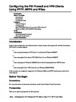
The IP290 Security Platform The IP290 is similar to the IP260 and IP265 appliances, but has some key differentiators that make this platform more desirable for larger network installations. The IP290 contains six onboard 10/100/1000-Mbps interfaces, and a PMC slot that allows for a two-port copper Gigabit Ethernet NIC or a two-port iber-optic Gigabit Ethernet NIC. Figure 1.6 shows the Nokia IP290 platform.
Figure 1.6 The Nokia IP290 Platform
13
14
Chapter1•NokiaSecuritySolutionsOverview
IP290 IPS The Nokia IP290 Intrusion Prevention with Sourceire, also referred to as Nokia IP290 IPS, is optimized for Sourceire 3D Sensor applications. Running Nokia IPSO-LX, a specialized Linux-based operating system, the Nokia IP290 IPS comes preinstalled with Sourceire Intrusion Prevention System (IPS) and Real-time Network Awareness (RNA). Both products can run simultaneously on the IP290 IPS platform. Nokia IP290 IPS appliances are ideally suited for growing companies and satellite ofices that want high-performance intrusion detection and protection. The small size of Nokia IP290 IPS appliances makes them attractive for installations that need to conserve space. Two Nokia IP290 IPS appliances can be rack-mounted in a 1U space if they are installed in a rackmountable shell, which can be ordered. Figure 1.7 shows two Nokia IP290 platforms in the rack-mountable shell.
Figure1.7Nokia IP290 Platforms in a Rack-Mountable Shell
IP390 The Nokia IP390 security platform is available as two distinct solution offerings, described in the following sections.
IP390 Security Platform The IP390 is a one rack–unit appliance that incorporates a serviceable slide-out tray into the chassis design and support for various network interface cards (NICs). The platform has
NokiaSecuritySolutionsOverview•Chapter1
four onboard 10/100/1000-Mbps interfaces and two PMC slots capable of supporting any combination of the following expansion cards: ■
One four-port copper 10/100 Ethernet card
■
One two-port copper Gigabit Ethernet (10/100/1000 Mbps) card
■
One two-port iber-optic Gigabit Ethernet card
The Nokia IPSO system is also stored in solid-state IDE compact lash memory. The IP390 appliance supports a single hard-disk drive, which provides 40GB of disk storage. You can use the hard-disk drive to store logs generated by the system, or applications installed on the system, or use one of the two PC-card slots, both of which support 1GB lash memory PC cards. Figure 1.8 shows the Nokia IP390 platform. The IP390 is an extension of the venerable Trooper platform that was developed to straddle the performance leap from the Pentium 3 to Pentium 4 processor architectures. The increase in processor power, along with the ratiication of AES, reduced the need for onboard encryption accelerators.
Figure 1.8 The Nokia IP390 Platform
Tools & Traps… Storing Check Point Log Messages on Flash-Based Platforms On flash-based platforms, you can save Check Point firewall log files locally by installing and configuring an optional disk (a hard disk or external flash-memory PC card). To store firewall logs on an optional disk, your platform must be running IPSO 4.1 Continued
15
16
Chapter1•NokiaSecuritySolutionsOverview
Build 025 or later. It also must be running a version of the Check Point firewall that supports local logging on a flash-based platform. At the time of this writing, the Check Point version that supports local logging is Check Point NGX R62 with a required hotfix installed. To install and configure an optional disk, the following steps must be performed: 1. If necessary, install the optional disk in the platform. 2. Log in to Nokia Network Voyager. 3. Navigate to the Optional Disk configuration page (Configuration | System Configuration | Optional Disk). 4. Select the Logs option for the device. 5. Click Apply. 6. Wait until you see a message indicating that you should reboot the system. 7. When the status message states the operation is complete, reboot the system. 8. When the system has rebooted, log in to Nokia Network Voyager. 9. Navigate to the System Logging configuration page (System Configuration | System Logging). 10. Select the option Logging To Optional Disk. 11. Click Apply and then click Save. On flash-based systems with Logging To Optional Disk enabled, the default behavior of the Check Point firewall is to normally log to a remote server and log locally to the optional disk only if the remote server fails. If the remote server becomes available again, the firewall stops logging locally and resumes logging to the remote server. If you want to log to a remote server and an optional disk, you must first perform the following steps in your Check Point SmartDashboard application: 1. Edit the appropriate gateway. 2. Go to Logs and Masters | Log Servers. 3. Select the option for saving logs locally. 4. Click OK. 5. Push the policy to the firewall.
IP390 IPS Similar to the IP290, the Nokia IP390 Intrusion Prevention with Sourceire, also referred to as Nokia IP390 IPS, is optimized for Sourceire 3D Sensor applications. Running Nokia IPSOLX, a specialized Linux-based operating system, the Nokia IP290 IPS comes preinstalled with Sourceire IPS and RNA. Both products can run simultaneously on the IP390 IPS platform.
NokiaSecuritySolutionsOverview•Chapter1
This highly versatile 1RU platform is designed for growing medium businesses, remote campuses, large branch ofices and securing internal network segments. The Nokia IPS PMC card slots support any combination of the following expansion cards: ■
One two-port copper Gigabit Ethernet (10/100/1000 Mbps) card
■
One two-port iber-optic Gigabit Ethernet card
■
One two-port fail open copper Gigabit Ethernet (10/100/1000 Mbps) card
■
One four-port fail open copper Gigabit Ethernet (10/100/1000 Mbps) card
■
One two-port fail open iber-optic Gigabit Ethernet card
IP560 The Nokia IP560 security platform is a mid-range multiport security platform that is ideally suited for the enterprise data center. It is a one rack–unit disk-based or lash-based appliance that incorporates a serviceable slide-out tray into the chassis design. In its base coniguration, the IP560 consists of a solid state IDE compact lash memory, a hard-disk drive in disk-based appliances, a 1GB system RAM, an encryption acceleration card to enhance VPN performance, and four PMC slots for NICs, including a single-slot PCMCIA PMC option slot in slot three and a four-port Ethernet 10/100/1000 interface in slot four.
NOTE In disk-based appliances, the IPSO operating system and Check Point application are stored on the hard drive, and the boot manager is stored in the flash memory. In flash-based appliances, the IPSO operating system, Check Point application, and boot manager are stored in the flash memory.
For lash-based appliances, you can purchase optional 2.5-inch hard-disk drives to use for logging. The IP560 security platform is designed to meet other mid- to high-end availability requirements, including port density for connections to redundant internal, external, DMZ, and management networks. As network devices, the IP560 appliance supports numerous IP-routing functions and protocols, including RIPv1/RIPv2, IGRP, OSPF and BGP4 for unicast trafic, and DVMRP for multicast trafic. The integrated router functionality eliminates the need for separate intranet and access routers in security applications. Figure 1.9 shows the Nokia IP560 platform.
17
18
Chapter1•NokiaSecuritySolutionsOverview
Figure1.9The Nokia IP560 Platform
IP690 The Nokia IP690 security platform is available as two distinct solution offerings, as described in the following sections.
The IP690 Security Platform The IP690 is a one rack–unit appliance that incorporates a serviceable slide-out tray into the chassis design and support for various NICs. The platform consists of a solid state IDE compact lash memory, a hard-disk drive in disk-based appliances, a 2GB system RAM, redundant hot-swappable AC power supplies, an encryption acceleration card to enhance VPN performance, and four PMC slots for NICs, including a single-slot PCMCIA PMC option slot in slot three, and a four-port Ethernet 10/100/1000 interface in slot four. Figure 1.10 shows the Nokia IP690 platform.
Figure 1.10 The Nokia IP690 Platform
The IP690 security platform is designed to meet other mid- to high-end availability requirements, including port density for connections to redundant internal, external, DMZ, and management networks.
NokiaSecuritySolutionsOverview•Chapter1
IP690 IPS The Nokia IP690 Intrusion Prevention with Sourceire, also referred to as Nokia IP690 IPS, is optimized for Sourceire 3D Sensor applications. Running Nokia IPSO-LX, a specialized Linux-based operating system, the Nokia IP690 IPS comes preinstalled with Sourceire IPS and RNA. Both products can run simultaneously on the IP690 IPS platform. Nokia IP690 IPS is a high-end multiport security platform that offers extensive lexibility to support the threat prevention needs of high-performance segments of the enterprise networks. Nokia IP690 IPS has four PMC slots for optional NICs, including a four-port fail open copper Gigabit Ethernet NIC, and can support as many as 16 Gigabit Ethernet ports. Nokia IP690 IPS also supports dual hot-swappable power supplies to provide maximum business continuity. It is a one rack–unit appliance that incorporates a serviceable slide-out tray into the chassis design.
IP1220 and IP1260 The Nokia IP1220 Security Platform is a mid-range security platform that is ideally suited for a smaller data center. The Nokia IP1260 Security Platform is a high-end multiport security platform that is ideally suited for the enterprise data center. Both IP1200 Series Security Platforms support an encryption accelerator card to further enhance VPN performance. The IP1200 Series is a two-rack unit appliance that incorporates a serviceable slide-out tray into the chassis design. The front panel of the IP1200 Series has two I/O slots that support hot-swapping operations. A PMC carrier is provided for the I/O slots. Each PMC carrier supports two PMC NICs for a total of four NICs. Figure 1.11 shows the Nokia IP1220 platform, while Figure 1.12 shows the Nokia IP1260 platform.
Figure 1.11 The Nokia IP1220 Platform
19
20
Chapter1•NokiaSecuritySolutionsOverview
Figure 1.12 The Nokia IP1260 Platform
The IP1220 requires IPSO 3.7 or later and ships with 512MB of system memory that is expandable to 1GB. The IP1260 requires IPSO 3.8 and later and ships with 1GB of system memory that is expandable to 2GB. Both appliances contain two storage device slots, two PCMCIA slots, a console port, a serial port, and a four-port Ethernet management interface. The PMC expansion slots are capable of supporting the following types of cards: ■
Four-port Ethernet (10 or 100 Mbps)
■
Dual-port Ethernet (10 or 100 Mbps)
■
Dual-port iber-optic Gigabit Ethernet
■
Dual-port copper Gigabit Ethernet (10/100/1000 Mbps)
■
Single-port ISDN S/T
■
Single-port V.35 or X.21
■
Single-port E1
■
Single-port T1
IP2255 Nokia IP2255 appliances are ideally suited to handle small packet sizes, short-lived sessions and short-lived connections, and to provide secure Internet connectivity. The appliances use accelerated data path (ADP) technology to deliver gigabit irewall and VPN forwarding performance when running Check Point VPN-1 enterprise applications. The ADP technology also allows the Nokia operating system and Check Point VPN-1 enterprise applications to accelerate other data link, network, and transport layer functions. The IP2255 is a three-rack unit (3U) appliance that incorporates a serviceable slide-out tray into the chassis design. Nokia IP2255 appliances are designed to meet high-end availability
NokiaSecuritySolutionsOverview•Chapter1
requirements and have port density for connections to redundant internal, external, DMZ, and management networks. Figure 1.13 shows the Nokia IP2255 platform.
Figure1.13The Nokia IP2255 Platform
The front panel of the Nokia IP2255 appliance supports four 10/100/1000 Ethernet management ports, four NIC slots (controlled by two Nokia ADP subsystems), one console port, one serial (AUX) port for a modem connection, and two PC-card slots that support compact-lash memory.
IP2450 The Nokia IP2450 is a high-end next-generation security appliance designed for the multiGigabit Ethernet throughput and port-density requirements of large enterprises and carriers. The IP2450 supports dual quad-core technology and is purpose-built to run Check Point VPN-1, Check Point VPN-1 UTM, and next-generation multithreaded enterprise security applications. The appliance is available as a disk-based or lash-based platform. In their base conigurations, the IP2450 disk-based appliance ships with at least one hard-disk drive, while the lash-based appliance ships with high-capacity compact lash memory. The IP2450 security platform is a two rack–unit appliance that incorporates a serviceable slide-out tray into the chassis design. The front panel of the IP2450 security platform has two I/O slots that support hot-swapping operations. A PMC carrier is provided for the I/O slots. Each PMC carrier supports two PMC NICs for a total of four NICs. The front panel of the IP2450 contains two storage device slots, one console port, one serial port, and one four-port Ethernet management interface. The network interfaces in the external PMC slot are designated for management, monitoring, and high-availability trafic. Figure 1.14 shows the Nokia IP2450 platform.
21
22
Chapter1•NokiaSecuritySolutionsOverview
Figure 1.14 The Nokia IP2450 Platform
The IP2450 security platform is designed to meet other mid- to high-end availability requirements, including port density for connections to redundant internal, external, DMZ, and management networks. In addition, the IP2450 security platform provides redundant power supplies and hot swapping from the storage and PMC NIC slots. The Nokia disk-based IP2450 appliance supports up to two hard-disk drives. The harddisk drives support hot swapping (when you use the Hot Swap button on the drive’s front panel), and an optional RAID-1 feature.
You Should Know… What Settings Do I Use for Console Connections? A standard mantra is drilled into your head during the first week of training at the Nokia Technical Assistance Center (TAC). That mantra is: “9600, 8, N, 1, None…9600, 8, N, 1, None …9600, 8, N, 1, None …9600, 8, N, 1, None …” What does this series of random numbers and letters mean? Well it is the standard console port settings required to interface with all Nokia IP Security Platforms using a console connection software package such as Microsoft HyperTerminal. If you do not use DHCP to perform the initial configuration of your Nokia appliance, you must use a serial console connection. After you perform the initial configuration, you no longer need the console connection. You can use any standard VT100-compatible terminal, a standard null modem cable, or a standard roll-over cable depending on the platform you are using. Continued
NokiaSecuritySolutionsOverview•Chapter1
You must configure your terminal-emulation program to use the following settings for the console: Bits per second: 9600 Data bits: 8 Parity: None Stop bits: 1 Flow control: None A null modem cable is an RS-232 serial cable where the transmit and receive lines are cross-linked. Mappings for a standard null modem cable can be found here: http://en.wikipedia.org/wiki/Null_modem The following IP Security Platforms use a standard null modem cable: IP40, IP45, IP110, IP120, IP130, IP260, IP265, IP330, IP350, IP355, IP380, IP385, IP530, IP650, IP710, IP740, IP1220, IP1260, IP2250, IP2255 Rollover cable (also known as Cisco console cable) is a type of null-modem cable that is most commonly used to connect a computer terminal to a router console port. This cable is typically flat (and has a light blue color) to help distinguish it from other types of network cabling. It gets the name rollover because the pin outs on one end are literally rolled over when RJ45 plugs are used at both ends. The following IP Security Platforms use a standard roll-over cable: IP60, IP290, IP390, IP560, IP690, IP2450
Introducing Additional Nokia Security Solutions Nokia has expanded its security solution offerings over the years and we thought it prudent to introduce them in this book. You may not have an immediate need for any of the following products today, but they greatly enhance your defensive posture, overall security, and ability to manage your existing Nokia infrastructure.
Nokia Integrated Firewall Nokia integrated irewalls include a specialized Nokia IPSO release, called IPSO-VN, which has its own irewall/VPN software solution. These irewalls feature layer 2, layer 3, and mixed networking modes, integrated virtual irewall capabilities, and hardware accelerated IPSec VPN solutions. A fully integrated Nokia Network Voyager Web UI manages all aspects of these security appliances and security policies. With optional disk or lash-based storage conigurations, Nokia integrated irewalls offer exceptional performance, consistent inline reliability, and simple implementation.
23
24
Chapter1•NokiaSecuritySolutionsOverview
NOTE Nokia integrated firewalls are only available in China and South Korea as of summer 2008.
At the time of this writing, the IP291, IP391, and IP561 platforms are capable of operating as Nokia integrated irewalls. Designed for small businesses, Nokia IP291 integrated irewall/VPN helps protect your environment with up to 1.5 Gbps of irewall throughput, 30,000 irewall connections per second, and 1 Gbps of AES256 VPN throughput. The Nokia IP391 with disk or lash-based storage conigurations is a 1RU security appliance providing multigigabit performance, four integrated 10/100/1000 Ethernet interfaces, and two expansion slots for supporting up to eight additional 10/100 Ethernet interfaces, or up to four additional gigabit Ethernet interfaces. It is capable of providing up to 3 Gbps of irewall throughput, 30,000 irewall connections per second, and 500 Mbps of AES256 VPN throughput. Designed for growing mid-size to large organizations, the Nokia IP561 integrated irewall/VPN appliance helps protect your environment with up to 6 Gbps of irewall throughput, 58,000 irewall connections per second, and 1.7 Gbps of AES256 VPN throughput. The IP561 offers disk or lash-based storage options and up to 16 Gigabit Ethernet ports.
NOTE More information about the Nokia Integrated Firewall solution can be found at: http://asia.nokia.com/A4895072.
Nokia IP VPN The Nokia IP VPN platform is a high-performance VPN gateway built for medium-sized enterprises that require secure connectivity between employees, customers, and partners. The platforms support site-to-site VPN tunnels and remote-access VPN connectivity. The IP VPN platform is an evolution of the VPN clustering technology inherited from the Nokia CryptoCluster product portfolio and does not require any third-party licensing like the Check Point bundled appliances.
NokiaSecuritySolutionsOverview•Chapter1
Each gateway, with the exception of the Nokia 5i, has identical features, including support for clustered routing, which allows for multiple platforms to participate in a load-balanced architecture to enhance performance, VPN functionality, irewall protection, and a fully integrated DHCP server. Several IP VPN platforms are available, including the 5i, 10i, 50i, 105i, and 500i. The Nokia 5i and Nokia 10i are not rack-mounted but designed rather for placement on a desk, table, or other lat surface. The 5i is meant for small ofices that need secure broadband connectivity. The gateway is equipped with three conigurable 10/100 Ethernet ports and a console port to connect to an external modem. The Nokia 5i is also equipped with a serial port for dial backup in the event of a network outage.
NOTE The Nokia Mobile VPN Client is designed for mobile phones running the Symbian operating system (Symbian OS). Once the mobile VPN application is launched, a connection is established and the mobile user is prompted for proof of identity using a token such as a SecurID password or a digital certificate. If authentication to the corporate VPN occurs successfully, a VPN tunnel is established between the mobile phone and the corporate network and all data traveling to and from the device is encrypted. To see if your Symbian-based phone is capable of running the Nokia Mobile VPN Client, check the list of supported phone models from the Nokia Mobile VPN page at: www.nokia.com/mobilevpn.
The Nokia 10i, 50i, 105i, and 500i platforms are equipped with Nokia patented IP Clustering to ensure high availability for VPN, irewall, routing, and DHCP servers. The trafic on the gateway is automatically optimized with Dynamic Load Balancing, Automatic Session Failover, and Zero-Downtime Upgrades for maximum uptime. Using the Nokia VPN Manager, IT administrators can centrally deploy, deliver, and update VPN policies and conigurations for gateways and clients. The 10i is meant for distributed large enterprises, small ofices, and remote ofices that require up to 80 Mbps of stateful irewall throughput and up to 50 VPN tunnels with 75 Mbps of throughput. Figure 1.15 shows the Nokia 5i and 10i IP VPN platform.
25
26
Chapter1•NokiaSecuritySolutionsOverview
Figure1.15The Nokia 5i and 10i IP VPN Platform
You Should Know… What Is Meta-Hop? Meta-Hop lets mobile users access corporate information from business-optimized devices, such as the Nokia 9500 Communicator and Nokia 9300. Users simply open an application and authenticate themselves. On the back-end, a VPN tunnel is created in accordance with corporate security policies. All of the data is secured all the way from the corporate network to the user’s device. Meta-Hop also includes self-learning and self-healing properties to help ensure that secure access to business application servers is maintained. When a new application server or subnet is added to a local network, Meta-Hop automatically distributes the availability of new resources to all gateways within a VPN deployment. This saves administrators from having to manually configure all gateways in a site-to-site VPN any time there is a change to the network. If a route between two locations in a VPN fails, Meta-Hop routes the VPN around the problem automatically without IT having to manually configure any special parameters to maintain the IPSec connections. As a result, users do not know there was a problem and IT saves maintenance time. A very detailed whitepaper entitled Nokia IP VPN Meta-Hop Basics can be found here: www.nokia.com/…/About_Nokia/Press/White_Papers/pdf_files/whitepaper_ metahopbasics_public_05apr01.pdf.
NokiaSecuritySolutionsOverview•Chapter1
The Nokia 50i is designed to meet the needs of medium-sized businesses and enterprise branch ofices requiring up to 300 Mbps of stateful irewall throughput and 500 tunnels at 156 Mbps throughput. The unique design of the gateway enables two Nokia 50i gateways to be rack-mounted side by side for easy clustering. Figure 1.16 shows the Nokia 50i IP VPN platform.
Figure 1.16 The Nokia 50i IP VPN Platform
The Nokia 105i VPN Gateway is a high-performance, fully integrated gateway. It manages wireless security issues for mid-sized enterprises, allowing mobile users to connect to business-critical resources. The 105i meets the wireless security needs of mid-sized companies that require up to 10,000 tunnels, 300 Mbps throughput, and lexible expansion options, including Gigabit-ethernet connectivity. Nokia 105i has diskless support and high MTBF components for excellent reliability. Figure 1.17 shows the Nokia 105i IP VPN platform.
Figure1.17The Nokia 105i IP VPN Platform
27
28
Chapter1•NokiaSecuritySolutionsOverview
NOTE Mean time between failures (MTBF) is the mean (average) time between failures of a system, and is often attributed to the useful life of the device.
The Nokia 500i VPN Gateway is a carrier-class high-performance gateway that manages wireless security issues for mobile and broadband operators and service providers. A single Nokia 500i gateway can support up to 100,000 remote access users and offers 1.5 Gbps of VPN throughput and 1.6 Gbps of irewall throughput. Figure 1.18 shows the Nokia 500i IP VPN platform.
Figure 1.18 The Nokia 500i IP VPN Platform
NOTE More information about the Nokia IP VPN solutions can be found at: www.nokiaforbusiness.com/nfb/find_a_product/browse_security.html.
Nokia Intrusion Prevention with Sourcefire The Nokia Intrusion Prevention solution combines Nokia IP security platforms with Sourceire Intrusion Sensor, Sourceire RNA Sensor, and Sourceire Defense Center software
NokiaSecuritySolutionsOverview•Chapter1
to offer a trusted intrusion detection and prevention solution for your environment. The solution is designed to meet the demands of enterprise customers, remote campuses, or large branch ofices monitoring network segments actively (inline) or passively, making it an optimal solution for internal security.
NOTE The OEM of the Sourcefire software by Nokia started in 2006. The OEM and distributor agreement can be found at: www.secinfo.com/dsvRq.v595.d.htm.
At the time of this writing, the IP290, IP390, IP690, and IP2450 platforms are capable of operating as Nokia Intrusion Prevention platforms. The Nokia IP290 Intrusion Prevention, operating as a 100-Mbps sensor, is designed for small to medium-sized businesses and branch ofices or remote sites. The Nokia IP390 is a high-performance appliance capable of running Sourceire Intrusion Sensor and Sourceire RNA Sensor software. It is designed to meet the demands of enterprise customers, remote campuses, or large branch ofices. With inline performance up to 1 Gbps, the Nokia IP690 Intrusion Prevention platform supports the threat prevention needs of high-performance segments of an enterprise network. With inline performance up to 4 Gbps, the Nokia IP2450 Intrusion Prevention with Sourceire platform supports the threat prevention needs of high-performance segments of a large business or service provider network.
NOTE More information about the Nokia Intrusion Prevention with Sourcefire solutions can be found at: www.nokiaforbusiness.com/nfb/find_a_product/browse_security.html.
Nokia Horizon Manager If you have one Nokia IP security platform deployed, then using the Network Voyager Web interface to manage your platform will probably be suficient. What happens, however,
29
30
Chapter1•NokiaSecuritySolutionsOverview
if you have 10, 50, or 100 Nokia IP security platforms dropped on your desk? Will manually performing an installation on each individual platform really be an eficient allocation of your time? Nokia Horizon Manager (NHM) was designed to act as a secure software image inventory and platform management solution to manage your Nokia IP security platforms. Using NHM, you can perform installations, upgrades, downgrades, application installations, and distribute licenses to multiple IP security platforms simultaneously. The server component of NHM was designed to run on Microsoft Windows 2003 Server, Sun Solaris 9, or Sun Solaris 10.You can, however, use Microsoft Windows XP Professional SP1 or later as a NHM client to manage the NHM server. Network managers can access NHM, with its remote secure GUI client, from anywhere to implement coniguration changes across multiple Nokia IP Security Platforms.
NOTE A multimedia presentation on Nokia Horizon Manager can be found at: http://europe.nokia.com/A4158074.
NHM has been around for quite a while, as you can see from author Andrew Hay’s early release certiicate of completion in Figure 1.19. It is generally deployed in large environments where common coniguration sets and backup policies are required for your Nokia deployment.
NokiaSecuritySolutionsOverview•Chapter1
Figure1.19A Nokia Horizon Manager Certificate
NOTE More information about the Nokia Horizon Manager software can be found at: www.nokiaforbusiness.com/nfb/find_a_product/browse_security.html.
31
32
Chapter1•NokiaSecuritySolutionsOverview
Summary The IPSO operating system, a fork of the FreeBSD operating system, is the core of the Nokia IP security platform. It was designed to be a secure and lean operating system so it could operate eficiently on smaller hardware. IPSO contains two powerful command-line editing utilities that can be used to conigure all settings for your IPSO-based security platform called ipsctl and CLISH. The Nokia Network Voyager Web-based interface lets you conigure your Nokia IP security platform using your Web browser.Voyager, as it is commonly referred to, can be used to conigure your Nokia IP security platform from the installation and throughout the life of your deployment. Depending on the size of your network, a Nokia IP security appliance exists that will help protect your network. The IP40, IP45, and IP60 platforms are suited for ROBO deployments. The IP130, IP260, IP265, IP290, and IP390 platforms are suited for growing companies and satellite ofices that want high-performance IP routing combined with the Check Point VPN-1/FireWall-1 enterprise security suite. The IP560, IP690, IP1220, IP1260, IP2255, and IP2450 platforms are suited for medium enterprise to large heavily traficked network nodes, such as core datacenter connection points. Nokia has expanded its security solution offerings over the years to include purpose-built irewall, VPN, intrusion prevention, and management solutions. Nokia integrated irewalls include a specialized Nokia IPSO release, called IPSO-VN, which has its own irewall/VPN software solution. The Nokia IP VPN platform is a high-performance VPN gateway built for medium-sized enterprises that require secure connectivity between employees, customers, and partners. The platforms support site-to-site VPN tunnels and remote-access VPN connectivity. The Nokia Intrusion Prevention solution combines Nokia IP security platforms with Sourceire Intrusion Sensor, Sourceire RNA Sensor, and Sourceire Defense Center software to offer a trusted intrusion detection and prevention solution for your environment. NHM was designed to act as a secure software image inventory and platform management solution to manage your Nokia IP security platforms. Using NHM, you can perform installations, upgrades, downgrades, application installations, and distribute licenses to multiple IP security platforms simultaneously.
Solutions Fast Track Introducing Nokia IPSO ˛ Nokia IPSO is a secure and lean operating system designed to operate as eficiently
as possible. ˛ IPSO contains two powerful command-line editing utilities—ipsctl and CLISH—
that can be used to conigure all settings for your IPSO-based security platform.
NokiaSecuritySolutionsOverview•Chapter1
˛ The Nokia Network Voyager Web-based interface lets you conigure your Nokia
IP security platform using your Web browser.
Introducing Nokia Firewall/VPN and UTM Appliances ˛ The IP40, IP45, and IP60 platforms are sold as an 8, 16, 32, and Unlimited host
licensed platform, which can be upgraded using a license upgrade at any time. ˛ Some appliances, such as the IP290, can be clustered into a rack-mountable shell to
save rack space and reduce clustering complexity. ˛ The standard terminal-emulation program settings for connecting to a Nokia IP
series appliance is 9600, 8, N, 1, None.
Introducing Additional Nokia Security Solutions ˛ Nokia integrated irewalls include a specialized Nokia IPSO release, called
IPSO-VN, which has its own irewall/VPN software solution. ˛ The Nokia IP VPN platform is a high-performance VPN gateway built for
medium-sized enterprises that require secure connectivity between employees, customers, and partners. ˛ The Nokia Intrusion Prevention solution combines Nokia IP security platforms
with Sourceire Intrusion Sensor, Sourceire RNA Sensor, and Sourceire Defense Center software to offer a trusted intrusion detection and prevention solution for your environment.
33
34
Chapter1•NokiaSecuritySolutionsOverview
Frequently Asked Questions Q: Isn’t IPSO really just FreeBSD? A: The original IPSO was a fork of the FreeBSD 2.2.6 operating system and has been changed so signiicantly over the years that you should only consider it a distant cousin of FreeBSD. A UNIX command, issued at the IPSO CLI, will usually work, but several commands are missing newer switches.
Q: Why would I use the CLI when I could just use the Voyager interface? A: Because IPSO is a UNIX-like operating system, using the IPSO CLISH allows you to execute commands from remote systems or using custom scripts/applications.
Q: Can I still get IBM RealSecure for Nokia IP security platforms? A: Unfortunately, no. IBM RealSecure has been discontinued and no further updates or revisions are being released.
Q: I bought a 16-user node IP40 platform, but I need it to support more users. What do I do? A: Luckily, the IP40, IP45, and IP60 platforms can be upgraded to a higher user node license at any time via a simple license upgrade purchase.
Q: What is Application Intelligence? A: Application Intelligence is a set of advanced capabilities that detects and prevents application-level attacks. It integrates network and application-level defense capabilities into Check Point products, thus delivering comprehensive attack protection and network security.
Q: My Nokia IP security platform supports lash-memory PC cards. What can I use them for? A: You can use the lash-memory PC card to store local system logs, Nokia IPSO images, and coniguration iles.
Q: What is the latest supported version of IPSO? A: At the time of this writing, the latest supported IPSO stream was IPSO 4.2. Q: Where can I get a Nokia integrated irewall? A: Unfortunately, at the time of this writing, the Nokia integrated irewall was only available in China and South Korea. The authors do not have any information on when this offering will be available outside of these two countries. Please contact your Nokia reseller for further information.
NokiaSecuritySolutionsOverview•Chapter1
Q: Can I use my phone to VPN into a Nokia IP VPN appliance? A: Yes. Using the Nokia Mobile VPN Client on your Symbian OS phone, you can establish a VPN tunnel between your mobile device and corporate network.
Q: If I can’t use IBM RealSecure as an intrusion detection/prevention sensor on Nokia IP security platforms, what can I use?
A: The IP290, IP390, IP690, and IP2450 are all capable of operating as a Nokia Intrusion Prevention platform with Sourceire Intrusion Sensor, Sourceire RNA Sensor, and Sourceire Defense Center software.
Q: When would I use Nokia Horizon Manager? A: There are several scenarios where you might require a management solution like NHM, but the most likely scenario is when you have ten or more Nokia IP security appliances and the management of these individual platforms becomes laborious. NHM was designed to act as a secure software image inventory and platform management solution to manage your Nokia IP security platforms. Using NHM, you can perform installations, upgrades, downgrades, application installations, and distribute licenses to multiple IP security platforms simultaneously.
35
This page intentionally left blank
Chapter 2
Nokia IPSO Overview
Solutions in this chapter: ■
Exploring the History of IPSO
■
Introducing Access and Security Features
■
Understanding Users and Groups
■
Learning the Directory Structure
■
Configuring IPSO
˛ Summary ˛ Solutions Fast Track ˛ Frequently Asked Questions 37
38
Chapter2•NokiaIPSOOverview
Introduction Josh Smith arrived on Thursday to provide an overview of the Nokia Security Solutions portfolio. Accompanying him was Shin Murashima, his most seasoned sales engineer, who knew everything about the Nokia appliances. After Josh provided an overview of the Nokia portfolio, he paused to see if Marty had any questions. “Well,” said Marty, “I tried to do as much research as possible on the platforms so we weren’t sitting here staring at each other when it came to the business requirements.” Josh smiled. It wasn’t often that his customers were as prepared to discuss implementation as Marty. “I igure we’re going to need to implement two, or more, appliances at the perimeter to share the load going in and out of our network. We’re also going to need to make sure that the operating system that they’re installed on is secure out-of-the-box and easy to administer.” Marty cleared his throat. “Let’s just say that I don’t want my security team spending days hardening the underlying platform before we implement these irewalls. Time is precious and I have a huge list of projects to complete.” Shin smiled and looked at Josh. “Shin, why don’t you start your presentation on the Nokia IPSO operating system that we ship with these Nokia IP Series Appliances?” Shin walked up to the white board, and to Marty’s surprise, started drawing a lowchart of the IPSO operating system from memory. “What no PowerPoint presentation?” Marty smirked. “Trust me,” Shin said without turning around, “you’ll understand everything about IPSO features by the time I’m done explaining it.” Marty sat back and watched Shin walk through the entire feature set of the IPSO operating system, including the history of IPSO, access and security features, the user, group, and directory structure, and inally a brief overview on how to conigure IPSO. Marty was impressed. He hated sitting in a conference room watching someone walk through a slide show. Whenever he had questions, he politely interrupted Shin, who expertly answered them. After Shin’s presentation was over, and Josh had completed his presentation as well, Marty and the two men went out for lunch. While waiting for their meals, Marty turned to Josh. “I really like the solution, but, as you can imagine, we need to put it through its paces in our lab.” Josh took a drink of water. “Sure thing, Marty. I’ll even throw in Shin to help you with the implementation in your lab.” Shin smiled. “Think of me as a free set of steak knives.” Marty laughed, almost spitting out his water. “Well, Shin,” Marty said, “You’re in for quite an adventure in our lab. When we test…we really test.” The waiter brought over their meals, placed Marty’s steak in front of him, and handed him a steak knife.
NokiaIPSOOverview•Chapter2
“It’s okay,” Marty smiled, “My colleague here has already brought me a steak knife.” The waiter, confused, set the steak knife down anyway and walked away. “I guess that went over his head,” Marty said laughing. Nokia designed its Nokia IP Appliance with several goals in mind: ■
To provide a stable and high-speed routing platform for integration into enterprise networks
■
To provide a modern stateful network irewall
■
To provide a secure platform out-of-the-box so administrators can rightfully spend their time looking after their networks and not have to worry about “hardening” their irewall platform operating system
These design goals combined to produce the Nokia IP Appliance. In the following sections, we discuss the history of the IPSO operating system and the Nokia Network Voyager interface. We will also cover what the products are based on and describe how Nokia has improved them over the years. Finally, we will discuss the basic layout of the IPSO ile system, as well as some of its features. The version of IPSO we cover in this book—and introduce in this chapter—is IPSO 4.2. This version has some new features compared with earlier releases that we discuss in detail in later chapters. This chapter concentrates on the IPSO security features and how the operating system is logically laid out.
Exploring the History of IPSO As you learned in Chapter 1, the problem of a fast and eficient routing appliance was already solved when, in December 1997, Nokia bought Ipsilon Networks, a California-based company that developed and sold high-speed switching products. Ipsilon also developed a Web-based management tool for its products that the company named the Network Voyager. Nokia took the Ipsilon product line as a base and integrated its own operating system, combined with the Check Point FireWall-1 product, into an appliance designed for high-speed packet forwarding and modern stateful irewalling. The operating system Nokia engineers developed to run on the appliance was named IPSO. The UNIX operating system had its origins at Bell Labs in 1969. Over the years, it evolved into many variants. One variant was termed 4.4BSD and was developed at the University of California at Berkeley. A portion of the core operating system source code base for 4.4BSD was made freely available and formed the basis for many modern UNIX or UNIX-like operating systems, among them FreeBSD.
39
40
Chapter2•NokiaIPSOOverview
NOTE See www.freebsd.org for more information on FreeBSD, which is still an ongoing and very active operating system project.
The networking code present in the Berkeley Software Distribution (BSD)-style UNIX variants has been developed continuously in an open fashion over the last 30 years and is some of the most stable and widely used in the world. FreeBSD version 2.2.6 was released in March 1998 and provided a solid basis for Nokia engineers to develop the IPSO operating system. IPSO has since diverged from the original FreeBSD code base, but it still remains a stable and eficient BSD-based networking platform at its core. Nokia has managed to trim down the original operating system by removing unnecessary binaries, hardening the operating system coniguration, and improving the core routing and networking functionality. Modern versions of IPSO are just under 40 MB when compressed, and approximately 120 MB uncompressed.
Understanding Specialized IPSO Releases Nokia IPSO is the all-encompassing term for the operating system that runs on Nokia IP Appliances. Several IPSO releases are available, however, that you may have heard of but were unsure of their purpose. These releases, known as IPSO LX and IPSO SX, were purpose-built IPSO releases designed to run Nokia applications that required a Linux operating system to function. Nokia IPSO LX was the irst release of a Linux-based IPSO from Nokia. It was deployed in 2002 on the now-defunct Message Protector and briely thereafter on a shortlived appliance version of the Nokia Access Mobilizer, which was acquired from Eizel. It had a partitioning scheme somewhat reminiscent of the traditional IPSO operating system, a LILO coniguration, a boot manager also somewhat inspired by IPSO, and a software package installer that made RPM packaging look more familiar to a Nokia IPSO administrator. It did not, however, include a full coniguration database or a Nokia Network Voyager Web interface, the two things that normally deine IPSO. IPSO SX is the current Linux-based IPSO from Nokia, and is used on Nokia appliances sold with Sourceire 3D. It includes a full Nokia Network Voyager and database implementation. The current Nokia Network Voyager 4.x look and feel, present in IPSO, was based on the interface implemented for IPSO SX.
NokiaIPSOOverview•Chapter2
NOTE More information on these specialized releases of IPSO can be found at: http://en.wikipedia.org/wiki/Nokia_IPSO.
Introducing Access and Security Features The primary purpose of a irewall is to protect a network segment, or segments, from unauthorized trafic as determined by your network security policy. A typical irewall deployment consists of two or more interfaces, with one interface connected to your trusted network and the other connected to the less trusted network. Figure 2.1 details a simple deployment that places your irewall between your corporate network and the Internet.
Figure2.1A Simple Firewall Deployment
41
42
Chapter2•NokiaIPSOOverview
NOTE Firewall terminology is usually very easy to relate to when compared to other security technologies. For example, a firewall with two active interfaces is typically referred to as a two-legged firewall. A firewall with three active interfaces is called a three-legged firewall.
Usually, the less trusted side of your irewall is the Internet, although this is not always the case. As with any network device that lives in such a critical network intersection, it must be installed and conigured with care. The following steps detail the actions typically followed when installing a irewall: 1. Install an operating system on your hardware of choice. You might have many chances to specially conigure the operating system during the installation, but most installations are automated and provide little choice along the way. You might have to add or remove hardware before the installation, and you might have to ind and conigure device drivers for your hardware during the installation. 2. Remove packages, networking options, and graphical user environments unless your operating system requires a graphical user interface. 3. Remove unnecessary network services, system binaries, games, and the like. 4. Conigure the remaining network services so they are restricted or conigured more securely. 5. Conigure network interfaces and test routing and connectivity. 6. Install and conigure your irewall software. 7. Install the testing and monitoring tools you use every day, which were not included with your operating system during initial installation.
NOTE The previous list details the how of installing a firewall but not the why. Before deciding to implement a firewall, you must first put together a plan that details the business requirements and the risks you plan to mitigate by implementing the firewall. This plan is beyond the scope of this book, because we primarily focus on the how.
The art of removing unnecessary packages and network services from an operating system and securely coniguring the remaining services is known as hardening. If not performed
NokiaIPSOOverview•Chapter2
properly, your system might become more vulnerable to attack then when you started. The hardening process is not something that can easily be conigured by the average user. Intimate knowledge of the operating system and services is required to properly secure the system, and care must be taken to ensure that no vulnerabilities are presented to potential attackers. Even when performed properly, the hardening process can be quite time consuming. Nokia realized that providing a hardened operating system out of the box would appeal to most time-starved administrators. They built their hardened operating system by starting with a baseline operating system installation without any services or applications and then added binaries, libraries, and network services necessary to function as an enterprise routing platform. We discuss the details of Nokia’s hardening in the following sections, and we talk about remote network access and the IPSO ile system structure. By the time you are done reading this chapter, you will have a good understanding of IPSO and how it is put together.
Using Remote Access Nokia IP Appliances have many of the standard remote and local access network protocols you would expect on a UNIX-based operating system, and each is discussed in the following sections. All available protocols leverage Transmission Control Protocol (TCP) for client/ server communications. Enabling any of the listed protocols means your Nokia IP Appliance will function as a listening server, waiting for inbound connections.
Understanding the Client/Server Model and Listening Sockets TCP forms the basis for many client/server-based communication protocols, for which reliability is paramount. A TCP connection can live in any of a dozen or so states, depending on whether the connection is being initiated, in progress, closing, or being reset. Four pieces of data are used to uniquely identify each connection: a source IP address, a destination IP address, a source port number, and a destination port number. Ports can be in the range 1 through 65535. Which port is assigned to which application is mostly standardized, at least for certain port ranges.
TIP You can view port assignments in the /etc/services file on your Nokia IP Appliance.
For example, suppose an SSH server with IP address 192.168.8.1 is listening for incoming connections on TCP port 22 (the default for SSH). A client makes a connection from
43
44
Chapter2•NokiaIPSOOverview
192.168.8.15 and gets assigned a random high port (ports greater than 1024) by the SSH client (33090). If a new connection is established from the same client host, it will be assigned a new port number and will be considered separate from the previous connection, even though the communications are from the same host. When a system service starts, it binds to a port number, creating a socket that listens for incoming connections destined for that port number. You can see the status of any current network servers and connections using the netstat -an command. The output of this command is shown next: ActiveInternetconnections(includingservers)
Proto Recv-QSend-Q LocalAddress ForeignAddress (state) tcp
0
tcp
0
ESTABLISHED
ESTABLISHED
tcp
0
0
*.22 *.*
0
192.168.8.15.33090 192.168.8.1.22
0
192.168.8.15.33667 192.168.8.1.22
LISTEN
The irst line tells you that an SSH server is listening for incoming connections on TCP port 22 on this host (or rather, something is listening for connections on TCP port 22). This is a useful debugging tool, especially when you want to know if a server is functioning properly and is listening for incoming connections. If you are using your Nokia IP Appliance as a irewall, you should see netstat results with additional services that you cannot immediately identify. Those ports are common control ports that Check Point FireWall-1 listens on by default. Examples of these ports are: tcp
0
0 *.256
*.*
LISTEN
tcp
0
0 *.261
*.*
LISTEN
tcp
0
tcp
0
tcp
0
tcp
0
0 *.259 0 *.262 0 *.264 0 *.265
*.* *.* *.* *.*
LISTEN LISTEN LISTEN LISTEN
NOTE AERAsec Network Services and Security GmbH maintain a detailed list of ports used by Check Point NGX at: www.fw-1.de/aerasec/ngx/ports-ngx.html. Please note this is not an official list, but is easy to quickly verify against.
NokiaIPSOOverview•Chapter2
Most of the services mentioned here, with the exception of SSH, have runtime coniguration settings in the /var/etc/inetd.conf ile. In most UNIX systems, this ile contains lists of network servers and how they should be run. In IPSO, however, this ile will only have an entry for the Telnet service by default, because all other services are disabled. If you disable the Telnet service in Nokia Network Voyager, this ile will contain only the following skeleton template: # ThisilewasAUTOMATICALLYGENERATED
# Generatedbyinetd_xlateonSunJun123:22:182008 #
# DONOTEDIT #
Notes from the Underground… Port Numbers A port is a special number in the header of a data packet. Ports are typically used to map data to a particular process running on a computer. The range of available ports is from 1 through 65535. This range is made up of well-known ports, registered port numbers, and dynamic and/or private ports. The Well Known Ports are assigned by the Internet Assigned Numbers Authority (IANA) and on most systems can only be used by system (or root) processes or by programs executed by privileged users. Ports are used in TCP to name the ends of logical connections, which carry long-term conversations. For the purpose of providing services to unknown callers, a service contact port is defined. To the extent possible, these same port assignments are used for UDP communications. This list specifies the port used by the server process as its contact port. The contact port is sometimes named the “well-known port.” The range for assigned ports managed by the IANA is 0-1023. The following is an example listing from the IANA list: Keyword
Decimal
Description
--------
--------
---------------
ftp-data
20/tcp
FileTransfer[DefaultData]
ftp
21/tcp
FileTransfer[Control]
The registered ports are listed by the IANA and on most systems can be used by ordinary user processes or programs executed by ordinary users. Ports are used by TCP to name the ends of logical connections, which carry long-term conversations. For the purpose of providing services to unknown callers, a service contact port is defined. Continued
45
46
Chapter2•NokiaIPSOOverview
To the extent possible, these same port assignments are used for UDP communications. The list specifies the port used by the server process as its contact port and IANA registers users of these ports as a convenience to the community. The registered ports are in the range 1024-49151. An example listing from the IANA list: Keyword
Decimal
Description
-------
-------
-----------
kazaa
1214/tcp
KAZAA
kazaa
1214/udp
KAZAA
The dynamic and/or private ports are those from 49152 through 65535 and are not associated with common services used openly on the Internet. No ports can be registered in this range. The IANA port list can be found at: www.iana.org/assignments/port-numbers. More information about the TCP protocol can be found in RFC793 located at: www.faqs.org/rfcs/rfc793.html. More information about the UDP protocol can be found in RFC768 at: www.faqs.org/rfcs/rfc768.html.
Using Telnet Telnet is a clear-text (non-encrypted) TCP-based remote login and command protocol. Nokia enables it by default in all its enterprise devices, but we recommend you disable Telnet before putting your irewall into production in favor of the Secure Shell (SSH) protocol. SSH is a secure replacement for Telnet (and FTP) that allows data to be exchanged using a secure channel. Many administrators still use Telnet on a daily basis because they are not aware that SSH clients are available for almost all UNIX and Windows platforms. If you must use Telnet, restrict it to a lab environment, but be aware of the security implications of using a clear-text remote login protocol. As an added measure of security, you can conigure Telnet so the one-time password scheme S/KEY is mandatory.
Using File Transfer Protocol (FTP) FTP is a way to transfer iles to or from a remote server. Like Telnet, FTP is a clear-text protocol and should be used only when necessary. Unlike Telnet, the FTP server is disabled
NokiaIPSOOverview•Chapter2
by default on new Nokia installations. FTP is commonly used as a server that allows anonymous uploads or downloads, where passwords are typically just e-mail addresses or left blank. The Nokia FTP server is not conigured to accept anonymous logins and by default only allows the admin user to log in. As with Telnet, be aware of who might be listening to your network trafic as you initiate an FTP session to your Nokia irewall as user admin, because your password will be visible on the wire. S/KEY logins can also be made mandatory for incoming FTP connections.
Tools & Traps… S/KEY S/KEY is a one-time password system developed for authentication to UNIX-like operating systems. Each password used in the system is usable only for one authentication. Passwords cannot be reused, which means that the sniffing of passwords to determine the password being used is futile. A password is generated as follows (the server being the authenticating server). 1. This step begins with a secret key w. ■
This secret can be provided by the user or can be generated by a computer. Either way, if this secret is disclosed, then the security of S/KEY is compromised.
2. H is a cryptographic hash function. 3. H is applied n times to w, thereby producing a hash chain of n one-time passwords (the passwords are the results of the cryptographic hash H). 4. The initial secret w is discarded. 5. The user is provided with the n passwords, printed out in reverse order. 6. The last n-1 passwords are discarded from the server. Only the first password, at the top of the user’s list, is stored on the server. Figure 2.2 visualizes this process. Continued
47
48
Chapter2•NokiaIPSOOverview
Figure 2.2 S/KEY Password Generation
For more information on S/KEY, please see http://en.wikipedia.org/wiki/S/Key.
Using Secure Shell (SSH) As previously stated, SSH is a secure replacement for Telnet and FTP. Starting with IPSO version 3.4, Nokia began shipping OpenSSH with their operating system. OpenSSH is a free and open-source implementation of the SSH protocol available anonymously from ftp://ftp. openbsd.org. The version of OpenSSH used by Nokia, 3.1p1, is disabled by default in all IPSO versions that support it. Free SSH clients exist for many operating systems, including Windows. Most UNIX operating systems also now ship with the OpenSSH client and server by default, so there is little reason not to use SSH. OpenSSH has some useful features, including local and remote port forwarding, X11 tunneling, strong encryption by default, and scp (secure copy) that make SSH an appealing replacement for Telnet and FTP.
NOTE One of the most popular free Windows-based SSH clients available is Putty. It can be downloaded from the project home page at: www.chiark.greenend.org.uk/∼sgtatham/putty/.
NokiaIPSOOverview•Chapter2
Using HTTP/HTTPS The Nokia Network Voyager coniguration interface is enabled by default on all IPSO releases and is conigured to be accessible over standard HTTP on TCP port 80. Nokia uses the open-source Apache HTTP Server to run the Nokia Network Voyager Web user interface. It is possible (and highly recommended) to reconigure Voyager to be only accessible using HTTPS, and you can also manually change the port number that Apache listens on. These coniguration options are thoroughly covered in Chapter 4.
WARNING Because IPSO uses third-party software for SSH and HTTP/HTTPS servers, you need to be aware that Nokia may not be as quick to adopt security fixes as the vendors of these software packages. It is a good idea to subscribe to the mailing lists provided by the OpenSSH and Apache projects to remain informed of any potential software vulnerabilities.
Gaining Console Access Finally, if you cannot, or will not, allow remote access to your Nokia device, all models come with at least one serial port conigured for local console access. Nokia provides the appropriate serial cables for your Nokia IP Appliance and are designed to work with their products. One cable is shipped with each device and if you need a replacement, standard null modem cables also work. The console port is conigured to work with any standard serial client, such as Hyperterm or Minicom, at 9600/8/N/1. You can also plug a modem into your Nokia device console port, allowing for out-of-band access over phone lines in emergencies.
Notes from the Underground… Using the AUX Port to Manage Another Device There may be an instance where you need to connect to another system’s serial port for console access for out-of-band management. Using the built-in auxiliary (AUX) port of your Nokia IP Appliance, you can connect to, and administer, the out-of-band system as needed. To do this, you must perform the following steps to change the settings of the AUX port: Continued
49
50
Chapter2•NokiaIPSOOverview
■
Step 1 Connect a console cable between your Nokia IP Appliance AUX port and the serial port of the out-of-band device you want to administer.
■
Step 2 Use the following command on your Nokia IP Appliance to connect a terminal session through the AUX port: nokia[admin]#tipcom2
■
Step 3 Perform the required administrative actions on your out-of-band device. To end the connection, use one of the following command combinations: nokia[admin]#~.
OR nokia[admin]#~^D
Using Other Security Features Nokia has made some other design decisions with IPSO that were directly related to security. The following is a list of the most visible features that emphasizes the hardened nature of IPSO: ■
The root partition is mounted read-only.
■
Sendmail is used to send mail only, through a relay server, and incoming mail is not accepted.
■
A DNS server is not installed.
■
Berkeley r commands (rlogin, rsh, rcp, rexec) are not present.
■
There is no X-Windows server or libraries.
■
No exportable ile systems (such as NFS) or Remote Procedure Call (RPC) services are installed.
■
No remote information services (inger, talk, or who) are installed.
■
Chargen, echo, and daytime are disabled by default.
■
There is no printing subsystem or server.
■
No mail or news servers (POP or IMAP) are installed.
■
Device access can be restricted to the serial console only.
■
There are no extra CGI programs other than those used by Voyager under admin access.
NokiaIPSOOverview•Chapter2 ■
IPSO Dynamic routing protocols all have strong authentication capabilities using keyed MD5.
■
The IPSO shadow password scheme uses MD5.
■
IP access lists and rate shaping can be conigured independently of Check Point FireWall-1 and can limit Denial-of-Service attacks.
Understanding Users and Groups The IPSO operating system has only one user enabled by default at system installation time: the admin user. This user has a user ID (UID) of 0, like standard UNIX root accounts, and has all the privileges of the root user. The password for the admin user is chosen during the initial system coniguration and must be used when the admin user logs in through Nokia Network Voyager, the console connection, or remotely using Telnet or SSH.
NOTE The root account is present in IPSO but is not used for administrative functions. To that end, it is disabled in favor of the admin user account.
Another user is created for you during installation: the monitor user. This account is designed to allow read-only administrator-level access to your Nokia IP Appliance. The password for the monitor user account is disabled by default, so you must enable it, using the admin user account, prior to its irst use. You can see several other users present in the /etc/master.passwd system password ile. These are bin, nobody, and daemon. These users are not meant or able to be used as login accounts. They are used by system processes that need to run at a reduced privilege level as opposed to processes that run with the permissions of UID 0. For example, the Apache HTTP Server (httpd) runs as though it were started by user nobody. You can see which processes run with the privileges of which user account by using ps aux at the command prompt. The following shows what part of that output looks like: pint[admin]#psaux
USER PID %CPU %MEM VSZ RSS TT STAT STARTED TIME COMMAND root
root
28586 0.0
23998 0.0
0.1 440
208
p0
1.1 1128 2788 ??
R+
Ss
5:15PM
0:00.06 ps-aux
Tue12AM 0:40.20 /bin/httpd -d/web
51
52
Chapter2•NokiaIPSOOverview nobody 24000 0.0
nobody 24001 0.0
nobody 24465 0.0
1.1 2108 2784 ??
1.1 2120 2692 ??
1.1 2148 2820 ??
I
I
I
Tue12AM 0:02.74 /bin/httpd -d/web
Tue12AM 0:02.67 /bin/httpd -d/web
Tue09PM 0:02.67 /bin/httpd -d/web
nobody 24468 0.0
1.1 2132 2800 ??
I
Tue09PM 0:01.78 /bin/httpd -d/web
root
0.0 0
DLs
1Jun08
root
28520 0.0
0
0.0
0.2 500
380
0
p0
??
Ss
4:22PM
0:00.20 -csh(csh)
0:03.25 (swapper)
Notice that all the Apache HTTP Server processes (/bin/httpd -d /web) run as user nobody. This is an important security feature. If someone were to gain remote access to your Nokia IP Appliance by exploiting the Apache HTTP Server running on it, after connecting they would not have admin (or root) level privileges. In fact, they would have to run a local exploit of some kind to gain root privileges after breaking into your system. The fact that Nokia has hardened IPSO by mounting the root partition as read-only and removing development tools and libraries makes inding or building a local root exploit into it very dificult. Other nonprivileged or administrative users can be created in IPSO versions 4.2. Deining multiple user accounts on your Nokia IP Appliances aids in change auditing and may even be required for certain government or industry compliance regulations. As part of Nokia’s operating system hardening process, any changes made by a user are recorded in the system log ile or syslog. This includes things like logging in, mounting or unmounting ile systems, password changes, and system security policy changes. Each new user you create, including new privileged users, has their own home directory, to further enable accountability. You should not have to change the Nokia group ile, /var/etc/group, unless you add an unprivileged user account to your Nokia IP Appliance. If you want that account to be able to switch to the admin user—for example su – admin—after the user has logged in, you must add the account to the wheel group. Chapter 5 discusses user and group management in greater detail.
Learning the Directory Structure The directory structure in the IPSO operating system is similar to many other UNIX operating systems. If you have any UNIX or Linux experience, you will feel right at home.
NokiaIPSOOverview•Chapter2
NOTE Refer to Appendix A if you need a UNIX refresher or introduction.
Some differences exist in the way Nokia has laid out the ile system. One of the major differences is that the root partition, where the kernel image and system binaries are stored, is mounted read-only by default. This means you will not be able to alter or create new iles on this partition unless you change how the partition is mounted. The admin user can remount the root partition with read/write permissions using the following command: pint[admin]#mount-uw/
When you are done making modiications, remount the root partition with read-only permissions using the following command: pint[admin]#mount–oro/
This was done to protect the root partition contents from accidental or malicious damage. It is harder for you, as an administrator, to make a mistake that prevents the system from booting if you must consciously make the root partition permissions read/write. This step should be unnecessary, however, because you can always place your own scripts and programs in the /opt directory, and nothing you could change in the root partition would be persistent across a reboot, anyway. The only time you might need to remount the root partition is when you are upgrading from an old version of IPSO and you are required to upgrade the boot manager. In that case, the new boot manager image ile must be placed in the /etc directory.
NOTE Boot manager upgrades do not happen very frequently when compared to older revisions of the IPSO operating system. You might never have to upgrade the boot manager on your Nokia IP Appliance.
The rest of the system partitions are mounted with read/write permissions, including /var, /opt, and /config. Table 2.1 shows the disk partitions created in a default IPSO 4.2 installation, along with their purposes and speciications. This layout is drawn from the system ile /etc/fstab.
53
54
Chapter2•NokiaIPSOOverview
Table2.1IPSO File System Details Name
Device
Type
Read/Write? FSCK?
Usage
/config
/dev/wd0a
ufs
YES
YES
swap /var
/dev/wd0b /dev/wd0d
swap ufs
N/A YES
NO YES
/opt
/dev/wd0e
ufs
YES
YES
/
/dev/wd0f
ufs
NO
YES, first
/proc
/proc
procfs
YES
NO
Global system configuration System swap space System logs and other variable process runtime data Optional or user added software Root partition; holds kernel images and system binaries Kernel configuration and runtime process data
The UFS ile system is a standard on most BSD UNIX versions, including IPSO. /proc holds runtime kernel and process data, although is generally not viewed or altered by users. Some system binaries draw data from the /proc ile system as they run. The name in the Device column is the system name given to the raw device that represents the particular disk partition. On your system, these names might be different from the ones listed in the table, depending on which model appliance you have. Device names for things like Ethernet cards and disk drives will be related to the device manufacturer or device class they belong to. In this case, the wd portion of the disk partition name indicates a Western Digital IDE hard drive. IDE drives have four slices, which are really what most people call a DOS partition. Each slice can contain a ile system, which can have any number of partitions. Nokia formats its disks with the entire drive occupying one slice, so you will not see a slice speciier in a device name as you do on Solaris or FreeBSD. The number 0 in wd0 means this is the irst disk. Disks are numbered starting at 0, so on a Nokia IP Appliance with two hard drives, they would be called wd0 and wd1, and the inal letter indicates the partition you are referring to in a given slice. The partition is simply a logical piece of a disk slice that refers to a part of the ile system installed on that slice. For example, the b partition on the irst hard drive is written wd0b and refers to the system swap space. The FSCK column of the table deserves some explanation. During a proper system shutdown, with the shutdown or halt commands, each partition or ile system is marked to show it was cleanly unmounted and so will not be checked for errors during system startup. If for some reason the system is not shut down cleanly, for example due to a power failure, each ile system will not have been properly unmounted and so will need to be checked for
NokiaIPSOOverview•Chapter2
errors. The program that does the checking is called fsck (for ile system check) and is run during the Nokia IP Appliance startup sequence before each partition is mounted. Most of the time, fsck will run and ix any errors it inds automatically, although every once in a while it needs manual attention. The root partition is always checked for errors irst because it must be mounted before system startup can continue.
Understanding Special Directories and Disk Space Several subdirectories in the IPSO ile system are worth mentioning. Table 2.2 outlines these directories and their purposes. An arrow (->) in the table means that the directory to the left of the arrow is a symbolic link to the directory on the right side of the arrow. $FWDIR refers to the environment variable that holds the absolute path to the FireWall-1 base directory, if the irewall is enabled.
Table 2.2 IPSO Special Purpose Directories Directory
Purpose
/web
Nokia Network Voyager Web pages and CGI scripts Temporary file space Holds crash dump files after a system crash Monitor user’s home directory Admin user’s home directory System configuration files System log files Firewall log files
/tmp -> /var/tmp2 /var/crash /var/monitor /var/admin /etc -> /var/etc /var/log $FWDIR/log -> /var/fw/log
You also might wonder how much disk space you have and how it is allocated per partition. IPSO is partitioned for you, and although the sizes of the partitions vary by model number, in general you will ind that the /var and /opt partitions have the most space available. The other partitions are really meant to be static in size after IPSO has been conigured. As a reference, the IP130 we are using as a test platform gives us the following when we run df –k (sizes in kilobytes): pint[admin]#df-k Filesystem /dev/wd0f
1K-blocks
598029
Used
121654
Avail
428533
Capacity
22%
Mountedon
/
55
56
Chapter2•NokiaIPSOOverview /dev/wd0a
/dev/wd0d /dev/wd0e
37556
167
34385
14732935
66923
13487378
4
4
0
procfs
2561196
46809
2309492
0%
0% 2%
100%
/conig
/var /opt
/proc
Keep in mind that newer models have bigger hard drives. You can see that /var has the most free space, which makes sense when you consider that /var holds irewall and system logs as well as temporary ile space. Nokia actually uses a set of formulas to determine disk partition sizes. Table 2.3 shows the formulas for any IPSO of version 3.4 or later.
Table 2.3 IPSO Partition Formulas Partition
Size and/or Formula
/config Swap
∼32MB (size of disk * 0.25) Note - with a max of 1 GB (size of disk - /config - swap) ((leftover * 2) / 7) Note - with a max of ∼600 MB (leftover / 7) (leftover - (/opt + /)
leftover space / /opt /var
NOTE With the introduction of IPSO 3.6 and Disk Mirroring, an additional 128 KB is set aside by the installation process. Please refer to Nokia Solution ID 1132425 for more information about how IPSO partitions the disks.
Dealing with Floppy and CD-ROM Drives Sometimes you will have to deal with loppy or CD-ROM drives based on the model of Nokia IP Appliance you are using. IPSO has support for mounting MS-DOS formatted loppy disks, but you irst need to create a mount point for the loppy. Do this with the mkdir /var/floppy command, then run the mount command: mount_msdos/dev/fd0/var/loppy
NokiaIPSOOverview•Chapter2
After the loppy has been mounted, you can cd into /var/floppy and access the iles on it with the usual commands (cp, mv, ls, and so on), just like a normal ile system directory. To unmount the loppy after it has been mounted, use the unmount command: umount/var/loppy
For CD-ROMs, after a CD has been put in the drive, you can use the following command to mount it: mount-tcd9660-oro/dev/wcd0c/cdrom
You must unmount the CD-ROM before you can eject it. To unmount the CD-ROM, use the following command: umount/cdrom
Make sure you move out of the loppy or CD-ROM mount point directories prior to unmounting either of those devices, or you will get an error indicating failure after running the unmount command.
Configuring IPSO The /config partition is where Nokia stores the /config/active global coniguration ile. This ile is a lat text ile that contains coniguration directives in a special format. It is actually a symbolic link to /config/db/initial, which is the real coniguration ile. The ile must be present and valid (in other words, not corrupted) at boot time for your Nokia device to get conigured; otherwise, the device will go into first-time boot mode and attempt to conigure itself using DHCP, or wait for you to conigure it through the serial console port. The following is what you might see in a small part of the /config/active ile: interface:eth-s2p4c0:ipaddr:192.168.0.2:mask24
monitor:monitord:group:ifthroughput:pthroughput:binding:ipsctl:interface: *:stats:ipacketst
ipsrd:vrrp:interface:eth-s2p2c0:virtualrouter:40:monitor:monif:eth-s1p3c0: priority10
ipsrd:vrrp:interface:eth-s1p4c0:virtualrouter:30:monitor:monif:eth-s2p2c0t process:sshd:path/usr/sbin
ipsrd:vrrp:interface:eth-s2p4c0:virtualrouter:60:monitor:monif:eth-s2p2c0: priority10
passwd:daemon:uid1
ipsrd:vrrp:interface:eth-s3p1c0:virtualrouter:80:advertiseinterval1
Because this ile is read at every system boot, and because IPSO reconigures itself according to the contents of this ile, altering this ile in some way is the only way to change things like interface IP addresses or add a static route. Prior to IPSO 3.6, Nokia Network
57
58
Chapter2•NokiaIPSOOverview
Voyager was meant to be the only interface that would allow you to update the system coniguration permanently. Nokia introduced CLISH, the command-line shell, in IPSO 3.6, and now any coniguration can be done using this command shell, along with Nokia Network Voyager. You can also make backups of past conigurations, as you would have made before a major coniguration change. You will see the old conigurations in /config/db, along with the active ile. Having global system coniguration localized to one ile is a security feature in that it makes it easy to restrict access to system coniguration and is much simpler than using many separate iles. Apart from daily system coniguration and maintenance issues, a common task for an administrator to perform is to run a custom startup script. If you ever need to run a script or executable ile at system startup, you can add your commands to the /var/etc/rc.local ile. IPSO will execute the rc.local script after all other startup and initialization has taken place. This method could be used, for example, to start some custom monitoring scripts you have written.
NokiaIPSOOverview•Chapter2
Summary All Nokia IP series enterprise appliances are based on the IPSO operating system, which was developed from a branch of the FreeBSD operating system, itself based on 4.4BSD UNIX. This basis makes for a very stable networking and routing platform. Given that most Nokia appliances are sold primarily as irewalls, Nokia made a substantial effort to harden IPSO and make it a more secure platform for irewall use. Some of the things Nokia did include shutting off unnecessary services, restricting system coniguration and user accounts, logging system access, and removing development tools and libraries. Nokia IPSO has evolved over the years to include specialized releases for new Nokia applications that could not, or rather should not, run on the standard IPSO release. These purpose-built versions of IPSO perform a specialized task and may not be needed based on your Nokia IP Appliance requirements. Your Nokia appliance can be accessed remotely via Telnet, FTP, HTTP/HTTPS, or SSH and locally through a serial console port. Only Telnet is enabled by default, but enabling or coniguring network access is easy using the Voyager interface. It is possible to change the port that the Apache Web server listens on, and you can restrict Voyager connections to HTTPS only. The IPSO admin user is the equivalent of the UNIX root user in terms of privilege and is the only user enabled by default in a new IPSO installation. A monitor user can be enabled to allow read-only access to the Nokia IP Appliance, and it is possible to add other privileged and unprivileged users after installation. New unprivileged users must be added to the wheel group to be able to su to the admin account. The IPSO ile system is logically just like any other UNIX ile system, but it features some changes that increase security. The IPSO root partition is mounted read-only, and changes to system settings and mount points are all logged using the syslog facility.
Solutions Fast Track Exploring the History of IPSO ˛ Nokia IPSO has its roots in FreeBSD 2.2.6. ˛ Nokia has trimmed down the original operating system by removing unnecessary
binaries, hardening the operating system coniguration, and improving the core routing and networking functionality. ˛ IPSO SX is Nokia’s current Linux-based IPSO, and is used on Nokia appliances
sold with Sourceire 3D.
59
60
Chapter2•NokiaIPSOOverview
Introducing Access and Security Features ˛ A typical irewall deployment consists of two or more interfaces, with one interface
connected to your trusted network and the other connected to the less trusted network. ˛ The version of OpenSSH used by Nokia, 3.1p1, is disabled by default in all IPSO
versions that support it. ˛ Because IPSO uses third-party software for their SSH and HTTP/HTTPS servers,
you need to be aware that Nokia may not be as quick to adopt security ixes as the vendors of these software packages.
Understanding Users and Groups ˛ The IPSO operating system has only one user enabled by default at system installa-
tion time: the admin user. ˛ Deining multiple user accounts on your Nokia IP Appliances aids in change
auditing and may even be required for certain government or industry compliance regulations. ˛ If you want to allow a user to switch to the admin user—for example,
su – admin—the user must be added to the wheel group.
Learning the Directory Structure ˛ You can mount the root (/) partition with read/write permissions using the mount
-uw / command. ˛ The UNIX program that is run during the Nokia IP Appliance startup to ix any
errors is called fsck. ˛ Partition sizes are determined by a set formula, as described in Table 2.3 in this
chapter.
Coniguring IPSO ˛ The global coniguration ile, which contains all system coniguration settings, is
named /config/active. ˛ Old coniguration iles are found in /config/db. ˛ To execute custom scripts or commands, use the /var/etc/rc.local ile.
NokiaIPSOOverview•Chapter2
Frequently Asked Questions Q: What operating system is IPSO based on? A: IPSO is based on FreeBSD 2.2.6. Q: Can’t I just put a newer version of FreeBSD on my Nokia IP Appliance? A: Nokia IPSO has been optimized and hardened speciically for Nokia IP Appliances. Trying to run another operating system on your appliance would not only void your warranty but may also introduce performance, security, and compatibility issues for your other software running on the system.
Q: Can I run Nokia IPSO SX with Check Point NGX? A: Nokia IPSO SX was designed speciically to support the Sourceire 3D product that was OEM by Nokia. It is not currently compatible with Check Point NGX and should not be installed if your plan is to install a Check Point irewall on your Nokia IP Appliance.
Q: What is the irst thing I need to do before placing a irewall in my network? A: Before even thinking about placing a piece of hardware or software into your network, you must irst determine the business requirements solved and risks protected by implementing the solution.
Q: Should I use Telnet or SSH to connect to the command line of my Nokia IP Appliance?
A: Unless you have a business requirement that states Telnet must be used, it is recommended that SSH become your standard remote access administration protocol. Not only does SSH provide strong encryption but it also lets you securely copy iles to and from your appliance using SCP.
Q: I have to use Telnet to administer my Nokia IP Appliance. Can I do anything to make it a stronger communications solution?
A: Although you will not be able to encrypt regular Telnet communications, you can implement S/KEY to increase the strength of your authentication process. S/KEY is a one-time password system developed for authentication to UNIX-like operating systems. Each password used in the system is usable only for one authentication.
61
62
Chapter2•NokiaIPSOOverview
Q: My security policy doesn’t allow remote access to my Nokia IP Appliance using Telnet or SSH. How can I administer my appliance from the command line?
A: If, for any reason, you cannot connect to your Nokia IP Appliance remotely, you can always connect a console cable between your appliance and another machine. This provides a direct connection to the serial port of your appliance for any of the required administrative tasks you would perform using a remote access protocol.
Q: Why can’t I log in as the root user? A: The root account is present in IPSO but is not used for administrative functions. To that end, it is disabled in favor of the admin user account.
Q: Why does the httpd server run using the nobody user? A: This is an important security feature. If someone were to gain remote access to your Nokia IP Appliance by exploiting the Apache HTTP Server running on it, once in they would not have admin (or root) level privileges.
Q: I work with three other co-workers who will need to administer my Nokia IP Appliance. Can we all use the default admin account?
A: Yes, but you probably should not. If each user in your group uses an individual adminlevel account, you can more accurately audit changes made to your appliance.
Q: Will changes I make to the root (/) partition persist after a reboot? A: No, they will not. Any changes you make to the root partition will be reverted back when you reboot your appliance.
Q: How can I check to see how much space is available on my Nokia IP Appliance? A: Using the df command, you can see how much space is used, available, where the partition is mounted, and other things.
Q: How can I igure out how much space is going to be allocated to my partitions before I install IPSO?
A: Using the simple calculations provided in Table 2.3, you can—if you know the size of the hard drive in your appliance—determine how much space is going to be allocated to each partition.
Q: How do I mount a CD-ROM on IPSO? A: You can use the following command to mount the CD-ROM on your system:
mount-tcd9660-oro/dev/wcd0c/cdrom
NokiaIPSOOverview•Chapter2
Q: Where are all of my IPSO conigurations stored? A: All IPSO coniguration settings are stored in the /config/active ile. This is a lat-text ile that, if removed, will default your IPSO installation back to the factory defaults.
Q: Where are my old conigurations stored? A: All old conigurations are stored in /config/db, along with the active ile. Q: Can I run custom scripts when my Nokia IP Appliance starts up? A: If you have a custom script, or require that a command run at startup, you can reference it in the /var/etc/rc.local ile. This will execute your script or command when the system inishes its boot sequence.
63
This page intentionally left blank
Chapter 3
Initial IPSO Configuration
Solutions in this chapter: ■
Preparing to Boot for the First Time
■
Installing IPSO
■
Performing the First-Time Boot Configuration
■
Continuing the Configuration
■
Upgrading to IPSO 4.2
˛ Summary ˛ Solutions Fast Track ˛ Frequently Asked Questions 65
66
Chapter3•InitialIPSOConiguration
Introduction Shin arrived the following Monday with several Nokia appliances. With the help of Marty and two members from his team—Ming Tsai and Mark Olyphant—Shin unpacked the appliances. Mark rack-mounted them and connected the required network cables based on the prepared network diagram. After everything was connected, Marty turned to Shin. “They’re all yours, Knifey.” Mark and Ming looked at each other and then at Marty. “I’ll explain later,” said Marty. Shin plugged the laptop that Marty had given him into the console port of the appliances and walked through the initial coniguration. He made sure to stop and explain each step and answered any questions that came up. Mark and Ming made sure to document the entire installation process in case they needed to reference it later. Within 30 minutes, the four appliances were racked, connected, and the initial coniguration had been performed. “Wow,” said Marty, “That was quick. Now what?” Shin disconnected the laptop. “Now,” Shin said, “We have to perform the more advanced coniguration steps using Nokia Network Voyager.”
Preparing to Boot for the First Time When you irst take your Nokia IP appliance out of the shipping box, mount it in your rack, connect the cables, and turn it on, you are not exactly inished with the installation process.
NOTE In some older models of Nokia IP appliances, the serial number is located on the bottom of the chassis. Before mounting the appliance, you should write down the serial number because it will be needed during the installation process. There is nothing worse than racking an appliance, only to realize you need to unrack it to obtain the serial number.
As the system boots, depending on the state you received your system in, you are prompted to enter some basic coniguration information before you can start coniguring the system more thoroughly. In some cases, the IPSO image provided on the system is far older than the currently supported version or, depending on where it was purchased, may contain residual coniguration data from the previous owner. In the latter scenario, you will probably want to perform a fresh or clean installation of the IPSO operating system.
InitialIPSOConfiguration•Chapter3
Workstation Configuration To prepare for the initial coniguration of your Nokia appliance, you need a workstation, laptop, or VT100-capable terminal that you can directly connect to the Nokia through a console cable or perhaps indirectly (through a hub or switch), or through a standard Ethernet connection. If you choose the DHCP method of auto coniguration, you need only a standard Ethernet connection. Until IPSO 3.5, a direct console connection was the only way to conigure a Nokia appliance out of the box. The DHCP client on the NSP makes this process somewhat easier now. In addition to proper cabling and network connections, you need a serial terminal emulator of some sort, such as Hyperterm (Windows) or Minicom (Linux or other UNIX platforms). Note that it is possible to do the entire Nokia base coniguration through a VT100 terminal directly connected to the console port. You just will not be able to use Nokia Network Voyager through a graphical Web browser. In that case, you can continue the initial coniguration through the command-line interface named CLISH.
Physical Connections Nokia supplies a DB-9 serial cable with all its devices. This cable allows for console connections from properly conigured clients. If you do not have one of the Nokia cables, you can use a standard null-modem cable for the serial connection. The local end of the serial cable plugs into one of your workstation serial ports, while the remote end plugs into your Nokia console port. The console port is always labeled Console and is usually on the front of the device for ease of use in rack-mounted installations. Your terminal emulator settings should match those shown here: ■
Bits/second (BPS): 9600
■
Data bits: 8
■
Parity: None
■
Stop bits: 1
■
Flow control: None
■
Terminal emulation: Auto, VT100, or VT102
If you want to continue the coniguration using Nokia Network Voyager and a graphical browser, you need an Ethernet cable. You can directly connect a crossover cable from your workstation to any Ethernet port on your Nokia device, or you can indirectly connect a straight-through cable from your workstation to a hub or switch and from there to the appliance over another straight-through cable.
67
68
Chapter3•InitialIPSOConiguration
Installing IPSO Performing a clean installation of IPSO is a relatively simple process. The installer conigures the system based on the selections you make during the process. The standard installation procedure is as follows: 1. Power on the appliance and enter the boot manager (Bootmgr). 2. Initiate the installation process. 3. Answer the coniguration questions when prompted. 4. Reboot the appliance when the initial installation is complete. 5. Continue with the initial coniguration of your appliance. Let’s walk through these steps.
Booting into the Boot Manager When the appliance is powered on, after the memory test completes, you will be presented with a menu that presents you with a boot manager (1 Bootmgr) option and an IPSO (2 IPSO) option. Entering 2 starts the standard boot process into the IPSO operating system. Because you want to perform a clean installation, you must enter the boot manager and launch the installation process. Do this by entering 1. 1Bootmgr 2IPSO
Default:1
Startingbootmgr
Loadingbootmanager.. Bootmanagerloaded.
Enteringautobootmode.
Typeanycharactertoentercommandmode. BOOTMGR[1]>
You are now presented with the BOOTMGR[1]> prompt. To begin the installation process, enter install. BOOTMGR[1]>install
The IPSO installer will warn you that you will be expected to enter information during the initial coniguration process, such as client IP address, netmask, system serial number, and so on. You will also be reminded that the clean installation will destroy any existing iles and data on your disk. To proceed with the clean installation, enter y.
InitialIPSOConfiguration•Chapter3
TIP If you get to this point and realize there is information on this appliance you wish to keep, now would be a good time to exit the installation by entering n. ###################IPSOFullInstallation#################### Youwillneedtosupplythefollowinginformation:
ClientIPaddress/netmask,FTPserverIPaddressandilename, systemserialnumber,andotherlicenseinformation.
ThisprocesswillDESTROYanyexistingilesanddataonyourdisk. ################################################################# Continue?(y/n)[n]y
TIP To accept the default value for a menu option, shown within the [ ] braces, press Enter.
Part of the installation process is entering the chassis serial number. This is very important in identifying your appliance should you ever need to call into Nokia for technical support. The serial number is typically located on the back of the appliance but has been known to be on the bottom in some of the older appliances.
NOTE Of course, you have already written down the serial number prior to racking the appliance, as per our tip earlier in the chapter, right?
Enter your serial number. MotherboardserialnumberisNONE. Thechassisserialnumbercanbefoundona
stickeronthebackoftheunitwiththeletters
69
70
Chapter3•InitialIPSOConiguration S/Ninfrontoftheserialnumber.
Pleaseentertheserialnumber:12345678 Pleaseanswerthefollowinglicensingquestions.
Depending on your requirements, an enhanced license can be purchased to support IGRP and BGP routing protocols. If you do not require these routing protocols, like most Nokia installations, you can enter n when presented with the IGRP and BGP questions. WillthisnodebeusingIGRP?[y]n WillthisnodebeusingBGP?[y]n
Because we are performing a clean installation, it does not make sense to pull the installation image from the disk you are looking to overwrite. What the installation script does allow you to do, however, is fetch the IPSO image from a remote FTP server. Depending on your FTP server coniguration, you can select from one of two options: You can install from an anonymous FTP server where no user credentials are required, by entering 1, or you can install from an FTP server that requires a username and password, by entering 2. Regardless of the option you select, you are prompted to enter an IP address for your Nokia IP appliance, the IP address of the FTP server, and the default gateway your communications will use for routing. The only additional entries that require user input, if using the second menu option, are the username and password ields. To simplify the installation steps, and based on what most customers use, we will continue with the anonymous FTP server method. When prompted to choose an installation method, enter 1 and then the IP addresses you want to use. Each IP address ield requires that you press Enter to move to the next option. 1.InstallfromanonymousFTPserver.
2.InstallfromFTPserverwithuserandpassword. Chooseaninstallationmethod(1-2):1
EnterIPaddressofthisclient(10.3.2.5/24):192.168.200.10/24 EnterIPaddressofFTPserver(0.0.0.0):192.168.200.50
EnterIPaddressofthedefaultgateway(0.0.0.0):192.168.200.1
After you have supplied the IP address and subnet mask information, you must select a physical interface to assign it to. Select the interface you wish to use for the FTP communications by typing the corresponding number and pressing Enter. Chooseaninterfacefromthefollowinglist: 1)eth1 2)eth2 3)eth3 4)eth4
Enteranumber[1-4]:4
InitialIPSOConfiguration•Chapter3
NOTE The interface list may appear differently on your Nokia since it depends entirely on the types of network interface cards (NICs) installed.
Select the speed of the chosen interface by entering the corresponding number. Chooseinterfacespeedfromthefollowinglist: 1)10Mbit/sec
2)100Mbit/sec
Enteranumber[1-2]:2
Select the duplex settings for the interface using h for half duplex or f for full duplex. The duplex settings of your interface will vary depending on the device it is connected to. Halforfullduplex?[h/f][h]f
NOTE Switching ports almost always defaults to full-duplex operation, unless there is a requirement for interoperability with devices that are strictly half duplex.
Now that your interface is conigured, you must provide the path to, and the name of, the IPSO installation package on the remote FTP server. Enter the full path to the IPSO installation package. If the installation package is located in the root directory of the FTP server you can press Enter or type the / character and press Enter. EnterpathtoipsoimageonFTPserver[/]:/
Accept the default IPSO installation package name by pressing Enter or typing the full package name and pressing Enter. EnteripsoimageilenameonFTPserver[ipso.tgz]:ipso.tgz
After the installation script connects to the FTP server, you have the option of telling it what to retrieve. You can retrieve all valid packages it inds on the server, retrieve the packages it inds one at a time and prompt you to accept or reject the package, or retrieve no additional packages and only install the IPSO operating system. Select your option by entering the associated menu number. 1.Retrieveallvalidpackages,withnofurtherprompting. 2.Retrievepackagesone-by-one,promptingforeach.
71
72
Chapter3•InitialIPSOConiguration 3.Retrievenopackages.
Enterchoice[1-3][1]:3
A inal conirmation screen lets you verify all of your coniguration settings before proceeding. Check this carefully to ensure you have not added any incorrect information. If you are happy with your coniguration settings, enter y to start the installation process. ClientIPaddress=192.168.200.10/24 ServerIPaddress=192.168.200.50
DefaultgatewayIPaddress=192.168.200.1
NetworkInterface=eth1,speed=100M,full-duplex Serverdownloadpath=[//] Packageinstalltype=none Mirrorsetcreation=no
Arethesevaluescorrect?[y]y
If the Nokia appliance is able to contact the FTP server and ind the IPSO installation package, you will see the installation process status messages as the various steps are completed. Downloadingcompressedtarile(s)from192.168.200.50 Hashmarkprintingon(1048576bytes/hashmark). Interactivemodeoff.
100% 36760KB 00:00ETA
Checkingvalidityofimage...done. Installingimage...done.
Imageversiontag: IPSO-4.2-BUILD069-10.27.2007-035617-1515. Checkingifbootmgrupgradeisneeded... Needtoupgradebootmgr.Proceeding.. Upgradingbootmgr...
newbootmgrsizeis2097152 oldbootmgrsizeis1474560 Savingoldbootmgr.
Installingnewbootmgr.
Verifyinginstallationofbootmgr.
When the installation completes, you will see an Installation Completed message and a inal instruction telling you to reset the system or press Enter to reboot. Installationcompleted. Resetsystemorhittoreboot.
Now that the installation is complete, you must perform the irst-time boot coniguration steps, which are described in the next section.
InitialIPSOConfiguration•Chapter3
NOTE Your boot loader might be updated as part of the IPSO installation.
Performing the First-Time Boot Configuration Now that the appliance has been clean installed, we can proceed with the irst-time boot coniguration settings. These settings will connect your Nokia appliance to your network and allow you to deine the administrative password for further coniguration.You can use two methods to perform the initial coniguration: ■
In an automated fashion by using the built-in dynamic host coniguration protocol (DHCP) client.
■
Manually by using a console (direct serial) connection.
Using DHCP to Configure the System If you have a DHCP server in your network, you can conigure it to provide your Nokia appliance with all host name, IP address, and default route information it requires for the initial coniguration. If using the DHCP coniguration method, please note that the default admin password will be set to password. On your DHCP server, conigure the minimum mappings for the following required items: ■
Host name for the appliance
■
Nokia appliance serial number
■
IP address for the appliance
NOTE The DHCP client accepts the lease time for the IP address that the server provides in IPSO 3.8 and later. Previously, the client accepted only IP address leases that were at least a year long.
73
74
Chapter3•InitialIPSOConiguration
The following provides an example of the DHCP coniguration information you may need on your DHCP server: ddns-update-stylead-hoc;
subnet192.168.200.0netmask255.255.255.0{ #defaultgateway
optionrouters192.168.200.1;
optionsubnet-mask255.255.255.0;
optiondomain-name-servers192.168.200.155;
rangedynamic-bootp192.168.200.10192.168.200.100; hostpint{
#serialnumberofthebox
optiondhcp-client-identiier“123456”; ixed-address192.168.200.10; optionhost-name“pint”; } }
The DHCP server must be on the same network as the Nokia platform, or the DHCP/ BOOTP relay must be conigured on the intermediate routers. Figure 3.1 shows a typical Nokia appliance placement in relation to the DHCP server.
Figure3.1Nokia Appliance Placement for DHCP Addressing
InitialIPSOConfiguration•Chapter3
Figure 3.2 shows a typical Nokia appliance placement when using a DHCP or BOOTP relay server.
Figure 3.2 Nokia Appliance Placement for DHCP Addressing via Relay
With the server-side coniguration completed, you must force the Nokia appliance to obtain the information provided by the DHCP server. With the network interface of your Nokia appliance connected to the network, turn the platform on and allow the DHCP client to receive its information.
NOTE This can take upwards of five to ten minutes to complete.
75
76
Chapter3•InitialIPSOConiguration
Configuring Manually with a Console Connection The irst thing you must do is provide a hostname for your Nokia appliance. Typically, this is a one-word name for the system so you can easily recognize the system when performing administrative tasks. Type your hostname and press Enter. You will also be prompted to conirm the setting of the hostname. Enter y to continue. Pleasechoosethehostnameforthissystem.Thisnamewillbeused
inmessagesandusuallycorrespondswithoneofthenetworkhostnames
forthesystem.Notethatonlyletters,numbers,dashes,anddots(.) arepermittedinahostname. Hostname?pint
Hostnamesetto“pint”,OK?[y]y
The admin user will require a password to authenticate you to the command line of the Nokia appliance and for Web-based administration using the Nokia Network Voyager interface. You will be asked to enter it again for validation. Enter the password you want to use. Pleaseenterpasswordforuseradmin:notpassword
Pleasere-enterpasswordforconirmation:notpassword
With the hostname and admin password set, you will be prompted to select your preferred coniguration method.You can conigure an interface and use Nokia Network Voyager to complete the coniguration (the recommended method), or you can conigure an interface by using the CLI. The easiest, and most popular, coniguration method is to conigure the appliance using the Nokia Network Voyager. Enter 1 to select this method. Youcanconigureyoursystemintwoways: 1)conigureaninterfaceanduseourWeb-basedVoyagerviaaremotebrowser 2)conigureaninterfacebyusingtheCLI Pleaseenterachoice[1-2,q]:1
Select an interface you would like to use to conigure your appliance by typing the associated menu option number and pressing Enter. Selectaninterfacefromthefollowingforconiguration: 1)eth1 2)eth2 3)eth3 4)eth4
5)quitthismenu Enterchoice[1-11]:4
InitialIPSOConfiguration•Chapter3
Type the IP address and mask length you want to use for this interface. Press Enter for each option after you have input the correct information. EntertheIPaddresstobeusedforeth4:192.168.200.10 Enterthemasklength:24
You are asked to conigure a default route for this interface to use, and to provide the IP address information for your default router. To conigure the default route, enter y. When asked to specify your default router, type the IP address of your default gateway and press Enter. Doyouwishtosetthedefaultroute[y]?y Enterthedefaultroutertousewitheth4:192.168.200.1
After specifying the IP address and default route information, you have the option to change the interface speed and duplex settings. Because this interface is conigured for 1000 mbs and full duplex, by default, you can enter n to accept the current settings. Thisinterfaceisconiguredas1000mbsbydefault.
Doyouwishtoconigurethisinterfaceforotherspeeds[n]?n
A inal conirmation screen lets you verify all of your coniguration settings before proceeding. Check this carefully to ensure you have not added any incorrect information. If you are happy with your coniguration settings, enter y. Youhaveenteredthefollowingparametersfortheeth4interface:
IPaddress:192.168.200.10
Defaultroute:192.168.200.1
masklength:24
Speed:1000M Duplex:full
Isthisinformationcorrect[y]?y
Optionally, you can conigure the virtual local area network (VLAN) settings for this interface. Typically, you will want to answer no to this question unless the interface needs to be part of the VLAN for security or routing reasons. Enter n to continue. DoyouwanttoconigureVlanforthisinterface[n]?n
YoumaynowconigureyourinterfaceswiththeWeb-basedVoyagerby typingintheIPaddress“192.168.200.10”ataremotebrowser.
At this point, you should be able to connect to your Nokia appliance using the Nokia Network Voyager Web interface with the browser of your choice. A inal optional setting is the changing of the default SNMP community string. Because this is easily performed within Nokia Network Voyager, along with more advanced SNMP coniguration settings, you can type n and press Enter to complete the initial coniguration. DoyouwanttochangeSNMPCommunitystring[n]?n
77
78
Chapter3•InitialIPSOConiguration
Notes from the Underground… Detecting an Installed Modem If you have a modem installed, then during the installation process you will see a message similar to the following: Modemdetectedon/dev/cuaa1. Enableloginsonthismodem[y,n]:
If you want to allow remote logins through the installed modem, you can configure the modem right now or after the initial configuration through the Nokia Network Voyager or IPSO CLI interfaces. If you choose to configure the modem for logins now, you are prompted to configure a country code for the modem. The list of valid country codes are displayed next for both Ositech Five of Clubs series modems: Country Codes for Ositech Five of Clubs Modem ■
22 - USA
■
20 - Canada
■
1 - Australia
■
2 - Belgium
■
3 - Denmark
■
4 - Finland
■
5 - France
■
6 - Germany
■
17 - Greece
■
99 - Iceland
■
7 - Ireland
■
8 - Italy
■
9 - Luxembourg
■
10 - The Netherlands
■
11 - Norway
■
12 - Portugal Continued
InitialIPSOConfiguration•Chapter3
■
13 - Spain
■
14 - Sweden
■
25 - Switzerland
■
16 - United Kingdom
Country Codes for Ositech Five of Clubs II Modem ■
B5 - USA
■
20 - Canada
■
09 - Australia
■
0F - Belgium
■
31 - Denmark
■
3C - Finland
■
3D - France
■
42 - Germany
■
46 - Greece
■
57 - Iceland
■
59 - Italy
■
69 - Luxembourg
■
7B - The Netherlands
■
82 - Norway
■
B8 - Portugal
■
A0 - Spain
■
A5 - Sweden
■
A6 - Switzerland
■
B4 - United Kingdom
Continuing the Configuration With the initial coniguration complete, you should now launch your Web browser and connect to Nokia Network Voyager. From this interface, which is covered in detail in Chapter 4, you can conigure the more advanced settings and change any of the initial installation settings you have already made.
79
80
Chapter3•InitialIPSOConiguration
NOTE Remember, the default administrative user name is admin.
If you would prefer to conigure the Nokia appliance using a remote access client, such as Telnet or SSH, you can. This method of coniguration becomes very helpful if the Nokia appliance is deployed in a remote location and only command-line access is provided for administrative access. When IPSO inishes the boot process, the SSH daemon is the only remote access service available. Telnet is disabled by default because it is a less secure remote access mechanism. To communicate with your Nokia system by using SSH, you must have an SSH client program installed on a workstation that has network connectivity to the Nokia appliance.
Tools & Traps… Using a Host Key After you perform the initial configuration, IPSO will automatically generate a host public and private key pair. You can install the public key on the workstations you will use to connect to the Nokia appliance. This allows the SSH client to verify it is really communicating with the Nokia appliance and not a system that is impersonating your appliance. The most secure way to transport the key is to use an out-of-band method, such as transporting the key on a floppy disk. This reduces the possibility that the key could be stolen in transit. If you are unable to transfer the public key to your workstation, a message appears when you first connect to your Nokia appliance using the SSH client. At this point, you are asked to accept the public key. If you choose to accept the key, the connection is established. This procedure is potentially less secure because the SSH client cannot be sure the host key is really being supplied by the Nokia appliance. If you decide to not accept the key, you will not be able to connect to the Nokia appliance. Continued
InitialIPSOConfiguration•Chapter3
More information about SSH can be found at: http://en.wikipedia.org/wiki/Secure_Shell More information about public-key cryptography can be found at: http://en.wikipedia.org/wiki/Public-key_cryptography
If you require that Telnet be enabled for remote access, you can enable the service using the Nokia Network Voyager or CLI interfaces.
NOTE Detailed Nokia Network Voyager configurations are covered in Chapter 4, and the CLISH interface is covered in Chapter 11.
To use Nokia Network Voyager to enable the Telnet service: 1. Log in to the platform by using Nokia Network Voyager. 2. In the Nokia Network Voyager navigation tree, expand Configuration | Security and Access | Network Access and Services. 3. Click Yes for the Allow TELNET Access ield. 4. Click Apply. 5. Click Save to make your change persistent across reboots. To use the CLI to enable the Telnet service: 1. Establish a console connection to the platform. 2. start the CLI by entering clish: pint[admin]#clish
3. Use the set command to enable Telnet: NokiaIP130:9>setnet-accesstelnetyes
4. Enter the save config command to make your changes persistent across reboots: NokiaIP130:10>saveconig
5. To exit CLISH, enter quit: NokiaIP130:11>quit
81
82
Chapter3•InitialIPSOConiguration
Upgrading to IPSO 4.2 You might already have a previous IPSO release installed on your Nokia platform and simply want to upgrade to IPSO 4.2. You can upgrade directly to Nokia IPSO 4.2 from the following IPSO versions: ■
3.7
■
3.7.1
■
3.8
■
3.8.1
■
3.9
■
4.0
■
4.0.1
■
4.1
Notes from the Underground… Words of Caution When Upgrading As with any software, there might be some caveats or warnings you should review before starting the upgrade process. Nokia IPSO is no exception and has some issues you should know about before proceeding with an upgrade.
UpgradingfromIPSO3.7.1andEarlier If you upgrade to IPSO 4.2 from IPSO 3.7, IPSO 3.7.1, or earlier and want to use disk mirroring, you must first install the 4.2 boot manager and then install IPSO 4.2 from the new boot manager. If you do not, you might receive messages that show the mirror set is 100 percent complete or that the sync process is complete when in fact the disks are still syncing. You do not need to follow this procedure if you upgrade to IPSO 4.2 from IPSO 3.8, 3.8.1, 3.9, 4.0, 4.0.1, or 4.1.
UpgradingfromIPSO4.1 Avoid using the IPSO boot manager to install IPSO 4.2 on a platform running IPSO 4.1 Build 016 or 019 if you installed the 4.1 build using the boot manager. If you attempt to upgrade in this way, the system might repeatedly panic and reboot. To upgrade these systems to IPSO 4.2, use Network Voyager, the CLI, or the newimage shell command. Continued
InitialIPSOConfiguration•Chapter3
Space Requirements You need at least 140MB of free disk space in your root partition to install an IPSO 4.2 image. To determine the available disk space, log in to the IPSO shell through a terminal or console connection and enter df -k. If the first number in the Avail column (which shows the available space in the root partition) is less than 140000Kbytes, you should make more space available by deleting the temporary files specified in the following command if they are present. (These files might not be present, depending on how the upgrades were done on your system.) Execute the following commands to delete the list of unwanted files: mount-uw/
rm-f/image/*/bootmgr/*.sav rm-f/image/*/bootmgr/*.tmp sync
mount-ur/
If you use the df command after you install IPSO 4.2 as a third image, you might see that the root partition is more than 100-percent full. If no errors were displayed while you installed IPSO 4.2, you can safely ignore this output from df. Other upgrade-specific issues are covered in greater detail in the Getting Started and Release Notes for IPSO 4.2 document available on the Nokia support site: http://support.nokia.com/home
There are several ways to copy the IPSO installation image used to upgrade your Nokia IPSO version to your Nokia appliance. You can: 1. Use the Nokia Network Voyager to fetch the IPSO image from a remote FTP server. 2. Use the Nokia Network Voyager to upload the IPSO image from a local workstation using HTTP. 3. Use an FTP client to push the IPSO image to the Nokia appliance (if the FTP server is enabled). 4. Use secure copy (SCP) to push the IPSO image to the Nokia appliance (if the SSH server is enabled). 5. Use secure copy (SCP) to pull the IPSO image to the Nokia appliance from another server. 6. Use a loppy or CD-ROM to copy the image to the Nokia appliance (if the appliance has a loppy or CD-ROM drive).
83
84
Chapter3•InitialIPSOConiguration
As you can see, there is no shortage of installation image transfer mechanisms. Upgrading the image using Nokia Network Voyager (options 1 and 2) is covered in detail in Chapter 4. If you decide to transfer the IPSO image manually (options 3, 4, 5, and 6) you can use the newimage command to upgrade from the CLI. The syntax of the newimage command is as follows: newimage[[-i|-llocalile][-b][-R|-T]][-r|-timagename]
Table 3.1 explains the command-line switches.
Table3.1 newimage Command-Line Switches Switch
Description
-b -i -l localfile -r imagename -t imagename -R -T -k -v
Force upgrade of bootmanager. Load a new image interactively. Extract the new image from an extant file. Specify imagename to run at the next boot. Specify imagename to run at the next test boot. Use a newly installed image to run at the next boot. Test boot using a newly installed image. Do not deactivate existing packages. Verbose ftp.
The test boot option -t imagename is a method to test the newly installed image when you reboot your Nokia appliance. If it fails to boot, your Nokia appliance reverts to the previous IPSO image the next time it is started. To add an IPSO image from the local ile system, use the following newimage syntax: pint[admin]#newimage-k-lipso.tgz
You should see a response similar to the following: ipso.tgzValidatingimage...done.
Versiontagstoredinimage:IPSO-4.2-BUILD029-releng-1515-01.05.2007-222742 Installingnewimage...done[example]
NOTE On some appliances, installing the image can take some time. The newimage command might display the message “Setting up new image…” for several minutes with no other sign of activity.
InitialIPSOConfiguration•Chapter3
You are then prompted to choose the image to load after the next reboot. At the prompt, reboot your platform. If for some reason the package is not present, you will see a message similar to the following when trying to run the newimage command: pint[admin]#newimage-k-lipso.tgz
tar:can’topenarchive/var/emhome/admin/ipso.tgz:Nosuchileordirectory tar:childreturnedstatus3
tar:VERSIONnotfoundinarchive
Noversionilein/var/emhome/admin/ipso.tgz.Possiblycorrupted.Exiting Jul2712:13:44pint[LOG_ERR]Upgrade:Noversionilein /var/emhome/admin/ipso.tgz.Possiblycorrupted.Exiting...
If the IPSO image is corrupt, you will see an image similar to the following when trying to run the newimage command: pint[admin]#newimage-k-lipso.tgz gzip:stdin:unexpectedendofile tar:childreturnedstatus1
tar:VERSIONnotfoundinarchive
Noversionilein/var/emhome/admin/ipso.tgz.Possiblycorrupted.Exiting
Jul2712:15:52pint[LOG_ERR]Upgrade:Noversionilein/var/emhome/admin/ipso. tgz.Possiblycorrupted.Exiting...
To verify the integrity of an IPSO image archive you can use the openssl command as follows: pint[admin]#opensslsha1ipso.tgz
You should see a response that displays the same SHA1 value that matches the SHA1 value shown at the Nokia support site. For example, you should see something like the following: SHA1(ipso.tgz)=390366ED8C53A9F1F516D2DC742331E7FE5A11C0
85
86
Chapter3•InitialIPSOConiguration
Summary To prepare for the initial coniguration of your Nokia appliance, you need a workstation, laptop, or VT100-capable terminal that you can directly connect to the Nokia using a console cable or perhaps indirectly (through a hub or switch) through a standard Ethernet connection. If you are coniguring your Nokia appliance using the DHCP method, you will only need a standard Ethernet connection. Nokia supplies a DB-9 serial cable with all its devices. This cable allows for console connections from properly conigured clients. If you do not have one of the Nokia cables, you can always use a standard null-modem cable for the serial connection. You can directly connect a crossover cable from your workstation to any Ethernet port on your Nokia device, or you can indirectly connect a straight-through cable from your workstation to a hub or switch and from there to the appliance over another straight-through cable. The standard installation procedure is a ive-step process.You must power on the appliance and enter the boot manager, initiate the installation process, answer the coniguration questions, reboot the appliance, and then continue with the initial coniguration steps. The two methods available to perform the initial coniguration carry out the procedure either in an automated fashion, by using the built-in DHCP client, or manually, by using a console (direct serial) connection. If you have a DHCP server in your network, you can conigure it to provide your Nokia appliance with a host name, an IP address, and the default route information it requires for the initial coniguration. If using the console connection coniguration method, you must provide a hostname, password, coniguration interface, interface IP address, interface netmask, and default router IP address. Optionally, can also specify interface coniguration settings, such as speed and duplex,VLAN settings for the coniguration interface, and a new SNMP Community string. When the initial coniguration is complete, you can continue with advanced conigurations using the command line, through SSH or Telnet, or using your Web browser and the Nokia Network Voyager interface. The SSH service is enabled, and the Telnet service is disabled, by default for security reasons after a new installation.You can, however, enable the Telnet service using the CLISH interface or Nokia Network Voyager. As with any software, there might be some caveats or warnings you should review before rushing into the upgrade process. Nokia IPSO is no exception and has some issues you should know about before proceeding with an upgrade. You can use the Nokia Network Voyager to upgrade the IPSO image or you can use the CLI. If you decide to transfer the IPSO image to your Nokia appliance manually, you can use the newimage command to upgrade from the CLI. On some appliances, installing the image can take some time. The newimage command might display the message “Setting up new image…” for several minutes with no other sign of activity.
InitialIPSOConfiguration•Chapter3
Solutions Fast Track Preparing to Boot for the First Time ˛ In some older models of Nokia IP appliances, the serial number is located on the
bottom of the chassis. Before mounting the appliance, you should write down the serial number since it will be needed during the installation process. ˛ A standard null-modem can be used for the serial connection to the console. ˛ If you want to continue the coniguration using Nokia Network Voyager and
a graphical browser, you need an Ethernet cable.
Installing IPSO ˛ The clean installation will destroy any existing iles and data on your disk. ˛ Depending on your requirements, an enhanced license can be purchased to support
IGRP and BGP routing protocols. ˛ The interface list may appear differently on your Nokia since it depends entirely on
the types of NIC installed.
Performing the First-Time Boot Coniguration ˛ If you have a DHCP server in your network, you can conigure it to provide your
Nokia appliance with a host name, an IP address, and the default route information it requires for the initial coniguration. ˛ The admin user requires a password to authenticate you to the command line of
the Nokia appliance and for Web-based administration using the Nokia Network Voyager interface. ˛ The easiest, and most popular, coniguration method is to conigure the appliance
using Nokia Network Voyager.
Continuing the Coniguration ˛ The default administrative user name is admin. ˛ After you perform the initial coniguration, IPSO will automatically generate a host
public- and private-key pair. ˛ Enable the Telnet service from the CLI using the set net-access telnet yes command
in CLISH.
87
88
Chapter3•InitialIPSOConiguration
Upgrading to IPSO 4.2 ˛ Use the newimage command to upgrade the IPSO image from the CLI. ˛ On some appliances, installing the image can take some time. The newimage
command might display the message “Setting up new image…” for several minutes with no other sign of activity. ˛ Verify the integrity of the IPSO image archive using the openssl command.
InitialIPSOConfiguration•Chapter3
Frequently Asked Questions Q: Where is my serial number located? A: This depends on the model of your appliance. Most of the time it is located on the back of the chassis but in older models it is located on the bottom of the chassis.
Q: I did not receive a console cable with my appliance. What do I do now? A: If you did not receive one of the Nokia cables, you can always use a standard null-modem (DB9) cable for the serial connection.
Q: What terminal emulation settings should I use for my console connection? A: Use the following: BPS - 9600, Data bits - 8, Parity - None, Stop bits - 1, Flow control - None, Terminal emulation - Auto, VT100, or VT102.
Q: How to I get into the boot manager? A: When the appliance is powered on, after the memory test completes, a menu will appear presenting you with a boot manager (1 Bootmgr) option. Use this option to gain entry to the boot manager.
Q: Will I still have my data after a clean installation? A: No. A clean installation will destroy any existing iles and data on your disk. Q: I’m at the Choose An Interface From The Following List part of the installation, but my interfaces appear different than those listed in the chapter.
A: The interface list may appear differently on your Nokia since it depends entirely on the types of NIC installed.
Q: Can I use my DHCP server to provide the necessary information to my Nokia appliance?
A: Yes. If you have a DHCP server in your network, you can conigure it to provide your Nokia appliance with the host name, IP address, and default route information it requires for the initial coniguration.
Q: I’m using the DHCP coniguration method but it is taking forever. How long should this take?
A: If using the DHCP coniguration method, expect it to take ive to ten minutes to complete.
89
90
Chapter3•InitialIPSOConiguration
Q: What is the preferred method for coniguring my Nokia appliance after the initial coniguration?
A: Due to its lexibility and ease of use, it is strongly recommended that you use Nokia Network Voyager to perform the additional conigurations on your Nokia appliance.
Q: I’ve just inished the installation but I cannot Telnet to the Nokia appliance. A: For security, the Telnet service is disabled after a new installation.You can, however, enable it through Nokia Network Voyager or by using the CLISH interface.
Q: Can I use SSH to connect to my Nokia appliance? A: Yes.You can use SSH to connect to your Nokia appliance. In fact, it is enabled by default when IPSO is installed.
Q: What is the default administrative username? A: The default administrative username is admin. The password used with this account is the same one you speciied during the installation process.
Q: How much space is required to install IPSO 4.2? A: You need at least 140MB of free disk space in your root partition to install an IPSO 4.2 image.
Q: When I try to install a new image, I receive the following error: tar:can’topenarchive/var/emhome/admin/ipso.tgz:Nosuchileordirectory tar:childreturnedstatus3
tar:VERSIONnotfoundinarchive
Noversionilein/var/emhome/admin/ipso.tgz.Possiblycorrupted.Exiting Jul2712:13:44pint[LOG_ERR]Upgrade:Noversionilein /var/emhome/admin/ipso.tgz.Possiblycorrupted.Exiting...
A: This is the error you typically receive when the IPSO image speciied is not present. Please check the location of your IPSO image and try the newimage command again.
InitialIPSOConfiguration•Chapter3
Q: I’ve veriied that the image is located in the correct directory but now I’ve received the following error: gzip:stdin:unexpectedendofile tar:childreturnedstatus1
tar:VERSIONnotfoundinarchive
Noversionilein/var/emhome/admin/ipso.tgz.Possiblycorrupted.Exiting
Jul2712:15:52pint[LOG_ERR]Upgrade:Noversionilein/var/emhome/admin/ ipso.tgz.Possiblycorrupted.Exiting...
A: This is likely the result of a corrupt IPSO image.Verify the SHA1 value generated by running the openssl md5 command against the IPSO image archive to the SHA1 value posted on the Nokia support site.
91
This page intentionally left blank
Chapter 4
Nokia Network Voyager
Solutions in this chapter: ■
Introducing Nokia Network Voyager
■
Configuring Nokia Network Voyager Access
■
Configuring a Basic System
■
Applying Security Tuning
■
Configuring System Options
■
Managing Packages
■
Configuring Static Routes
■
Configuring System Backup and Restore
■
Configuring System Logging
■
Scheduling cron Jobs
˛ Summary ˛ Solutions Fast Track ˛ Frequently Asked Questions 93
94
Chapter4•NokiaNetworkVoyager
Introduction “Nokia Network Voyager?” asked Mark. “What’s that?” Shin connected his laptop’s network cable to the management switch used to access the internal interface of each Nokia appliance. “The Nokia Network Voyager,” explained Shin, “Is the Web user interface front-end for the configuration and day-to-day administration of the Nokia appliances.” Shin brought up a Web browser and entered the IP address of the irst appliance in the address ield. “Using the Voyager interface, I can conigure every feature of this appliance.” Shin logged in using the administrator username and password he speciied during installation. “I can conigure basic system settings, install and manage additional software packages, back up and restore the system, and tune the security settings.” Shin moved throughout the interface, coniguring the system to the test speciications. Mark ensured that the checklist he had prepared was marked as completed as Shin moved through the various sections. Ming scribbled notes throughout the entire coniguration session as Marty looked over her shoulder. “Looks fairly easy to conigure,” Marty said. “It’s probably one of the easiest enterprise class systems to conigure and secure,” responded Shin. “No more messing around at the command line in coniguration iles to shut down unnecessary services, add/remove users, etc.” Marty liked that idea. He knew, from personal experience, that the more you had to conigure in coniguration iles, the higher the chance of administrative error. “I really like this user interface and I think our Ops guys are going to as well.”
Introducing Nokia Network Voyager Nokia Network Voyager is a Web-based interface that is used to manage your IPSO operating system on your Nokia appliance. The IPSO operating system software is included and is accessible using a Web browser from a client. The commands performed using Nokia Network Voyager can also be performed at the command-line interface (CLI), letting you use the interface you are most comfortable with. For information about the CLI, see Chapter 11.
Navigating the Interface Nokia Network Voyager access is role-based—meaning that after you have logged in, what you see and have access to depends on the role or roles assigned to you. All information appears in a navigation tree view, similar to Windows Explorer. If you do not have access to a system item, then the item does not appear in the navigation tree. Read-only access lets you access the page, but with the buttons disabled.
NokiaNetworkVoyager•Chapter4
NOTE Successful and unsuccessful user access attempts are logged in the /var/log/ messages file.
To open Nokia Network Voyager, perform the following steps: 1. On a computer with network access to the IPSO appliance, open a Web browser. 2. In the Address ield, enter the IP address of the initial interface of the IPSO appliance. You are prompted for a username and password. 3. If this is the irst login, enter the Admin username and password deined during the initial coniguration of the IPSO appliance. You can log in with or without an exclusive lock on coniguration changes. The Acquire Exclusive Coniguration Lock option is selected by default on the Login page. If the login dialog does not appear, there might not be a physical network connection between the host and your appliance, or there might be a network routing problem. Verify the appliance IP information and check all cable connections. When you are inished with your session, or if you would like to log in as another user, click Log Off at the top of the Network Voyager window.
NOTE If the Log Off link is not visible, then session management is disabled.
Using Coniguration Lock Only users with read/write access are able to log in using exclusive coniguration lock. If you log in with an exclusive coniguration lock, no other user can change the system coniguration. If you logged in with an exclusive coniguration lock and you close your Web browser without logging off, the lock remains in effect until someone overrides the lock or the session times out. Users with one or more read/write access privileges have coniguration locks when they log in, unless they deselect the Acquire Exclusive Coniguration Lock option. The read/write access is limited to administrator-assigned features even though the coniguration lock is in effect for all features.
95
96
Chapter4•NokiaNetworkVoyager
To log in with the exclusive coniguration lock, select Acquire Exclusive Configuration Lock on the Login page.
NOTE By enabling the exclusive configuration lock during log in, Nokia Network Voyager prevents any user from using the CLI to configure the system while your browser session is active.
To log in without the exclusive coniguration lock, deselect Acquire Exclusive Configuration Lock on the Login page. To override a coniguration lock, perform the following steps: 1. On the Log In page, click Log In With Advanced Options. 2. Verify that Acquire Exclusive Configuration Lock is selected. (This is the default selection.) 3. Select Override Locks Acquired by Other Users. 4. Type in your username and password. 5. Click Log In.
Navigating Nokia Network Voyager The interface has four frames of information. The top frame information is static and includes the Nokia appliance name, the current coniguration state, and the Log Off link. The Nokia appliance System directory appears on the left with possible items listed below. Clicking an item under the navigation tree returns the associated information in the upperright frame, while the lower-right frame contains buttons for the selected item. Under the System tab and above the navigation tree are two links: ■
Expand Tree This expands all items and subitems under System in the tree.
■
Collapse Tree This collapses all items and subitems under System in the tree.
In the system tree, the irst item listed is always Home. Clicking Home returns the basic system information for the Nokia appliance. Figure 4.1 shows an example of the Home page, while Table 4.1 shows the basic system information that appears on the Home page.
NokiaNetworkVoyager•Chapter4
Figure4.1The Nokia Network Voyager Home Page
Table4.1 Basic System Information Item
Description
Model Software Release Software Version Serial Number Current Time Uptime Physical Memory User
Device model of the Nokia appliance IPSO software release IPSO software version Serial number of the Nokia appliance GMT for when you clicked Home Duration of Nokia appliance uptime Physical memory on the Nokia appliance Current user login
97
98
Chapter4•NokiaNetworkVoyager
Understanding the Interface Buttons The standard buttons on the interface, if you have proper access, are explained in Table 4.2.
Table 4.2 Standard Interface Buttons Button
Description
Help
This appears in the top-right frame and provides help on the items for the current view. For example, if you clicked Change Password, the help information would apply to the settings for the Change Password feature. If you have changed any feature settings and do not want to keep the changes, clicking Reset changes the settings back to the original state. Applies the current page settings to the current (running) configuration file in memory. Saves the current configuration file to disk.
Reset
Apply Save
TIP If you only click Apply and do not click Save, the next time you reboot the appliance the changes revert back to the previous instance. If you enter information into any field for a feature and then click another feature in the list without applying or saving your changes, a dialog appears indicating you have not submitted your changes. You can click OK to abort the changes and leave the page or click Cancel to stay on the current page.
Understanding the Web Browser Functions You should not use the Back and Forward buttons of your Web browser while in Nokia Network Voyager. Because the browser caches the HTML page information, the latest page information might be lost when moving from page to page. To update the page information, you can use the Web browser reload or refresh button.
NokiaNetworkVoyager•Chapter4
Accessing Help Documentation In addition to the interface Help button, you can ind the Nokia Network Reference Guide for IPSO and the CLI Reference Guide as follows: ■
At the Nokia support site: https://support.nokia.com
■
On the software CD included with your Nokia appliance in the doc folder
Understanding Hardware and Software Information The asset summary page contains three tables, which are explained in Table 4.3.
Table4.3 Asset Summary Tables Table
Description
Hardware
Includes the chassis serial number, the amount of memory on the appliance, and information about the CPU, disks, BIOS, and motherboard Includes the FireWall version, license information, and information about the host, the policy, and the date when the FireWall policy was installed Lists the software and version release running on the system
FireWall Package Information Operating System
To view the asset summary for your system, complete the following steps: 1. Under System, expand Configuration and then expand Asset Information. 2. Click Asset Summary.
ConiguringNokia Network Voyager Access When you set up your system for the irst time, you must conigure the basic Nokia Network Voyager options and change your SSL/TLS certiicate from the default certiicate.
Configuring Basic Nokia Network Voyager Options Figure 4.2 shows the Network Voyager Options page. You can conigure the following options for Nokia Network Voyager access:
99
100 Chapter4•NokiaNetworkVoyager ■
Allow Network Voyager access (enabled by default)
■
Enable session management (enabled by default)
■
Specify a Network Voyager SSL/TLS port number
■
Require encryption
Figure 4.2 The Network Voyager Options Page
To conigure web access for Nokia Network Voyager, complete the following steps: 1. In the system tree, click Configuration | Security and Access | Voyager Web Access | Voyager Web Options. 2. To enable access, next to Allow Voyager web access, select Yes. (This option is selected by default.)
NokiaNetworkVoyager•Chapter4 101
WARNING If you uncheck the check box, you must use the CLI to access your IP security platform.
3. To enable cookie-based session management, next to Enable Cookie-Based Session Management, select Yes. 4. In the Session Timeout In Minutes ield, type the time interval for which a Nokia Network Voyager user is allowed to be logged in without activity. The default value is 20 minutes. If the user closes the browser without logging out, the exclusive coniguration lock remains in effect until the session time-out interval expires. 5. In the Voyager Port Number ield, type the port number to use for SSL/TLSsecure connections. The default is port 443. Using the default port lets users connect to Nokia Network Voyager without specifying a port number in the URL. If you change the port number, users must specify a port number in the URL—for example, https://hostname:/. 6. Under Require Encryption, select the appropriate encryption level for your security needs.
NOTE The encryption level you enter is the minimum level of encryption you require. You might want to use stronger encryption if your Web browser supports it.
7. Click Apply and then click Save.
Generating and Installing SSL/TLS Certificates To secure Nokia Network Voyager client connections to the IPSO system over the internet, IPSO uses the Secure Sockets Layer/Transport Layer Security (SSL/TLS) protocol. SSL/TLS, the industry standard for secure Web connections, gives you a secure way to connect to Nokia Network Voyager. Creating and keeping a unique private key a secret for your security platform is critical to preventing attacks that could compromise the platform security.
102 Chapter4•NokiaNetworkVoyager
When setting up your system for the irst time, change your SSL/TLS certiicate from the default certiicate. IPSO includes a default sample certiicate and private key in the /var/ etc/voyager_ssl_server.crt and /var/etc/voyager_ssl_server.key iles respectively. The certiicate and private key are for testing purposes only and do not provide a secure SSL/TLS connection. To create a secure connection using SSL/TLS, you must generate a certiicate, and the private key associated with the certiicate, over a trusted connection. Figure 4.3 shows the Generate SSL Certiicate (Request) page.
Figure 4.3 The Generate SSL Certificate (Request) Page
To generate an SSL/TLS certiicate and keys, complete the following steps: 1. In the system tree, click Configuration | Security and Access | Voyager Web Access | Generate Certificate for SSL. 2. Next to Private Key Size, select the option that meets your security needs.
NokiaNetworkVoyager•Chapter4 103
3. (Optional) In the Passphrase and Enter Passphrase Again ields, type a passphrase you will remember. The passphrase must be at least four characters long. If you specify a passphrase, you will have to enter the phrase later when installing your new key. 4. In the Country Name ield, type the two-letter code of the country in which you are located. 5. In the State Or Province Name ield, type the name of your state or province. 6. (Optional) In the Locality (Town) Name ield, type the name of your locality or town. 7. In the Organization Name ield, type the name of your company or organization. If you are requesting a certiicate from a certiicate authority, the certiicate authority might require the oficial legal name of your organization. 8. (Optional) In the Organizational Unit Name ield, type the name of your department or unit within your company or organization. 9. In the Common Name (FQDN) ield, type the common name that identiies exactly where the certiicate will go. The common name is most commonly the fully qualiied domain name (FQDN) for your platform—for example, www.ship. wwwidgets.com. If you are generating a certiicate signing request for a certiicate authority (CA), that CA might impose a different standard. 10. (Optional) In the Email Address ield, enter the e-mail address to use to contact the person responsible for this system or for its certiicate. 11. Next to What To Generate, select one of the following: ■
A certiicate signing request (CSR): Select this option if you are requesting a certiicate from a certiication authority. The request will be signed with a SHA-1 hash.
■
A self-signed X.509 certiicate: Select this option to create a certiicate you can use immediately, but that will not be validated by a certiication authority. The certiicate will be signed with a SHA-1 hash.
12. Click Apply. 13. If you generated a certiicate signing request, a screen appears that contains a certiicate request—New X.509 certiicate signing request—and its associated private key— New private key. ■
Send the New X.509 certiicate signing request to your certiication authority. Include the following lines:
104 Chapter4•NokiaNetworkVoyager -----BEGINCERTIFICATEREQUEST-----
and -----ENDCERTIFICATEREQUEST----■
Store the new private key that your certiication authority securely sends. Install the private key and the certiicate.
14. If you generated a self-signed certiicate, a screen appears that contains a certiicate (New X.509 Certiicate) and its associated private key. You must perform a cut-and-paste operation to move the certiicate and the private key to the Voyager SSL Certiicate page, as described in the following procedure. To install the SSL/TLS certiicate, complete the following steps: 1. In the system tree, click Configuration | Security and Access | Voyager Web Access | Install Certificate for SSL. 2. In the New Server Certificate box, paste the certiicate information. Include the following lines: -----BEGINCERTIFICATE-----
and -----ENDCERTIFICATE-----
3. In the Associated Private Key box, paste the private key information. Include the following lines: -----BEGINRSAPRIVATEKEY-----
and -----ENDRSAPRIVATEKEY-----
4. If you speciied a passphrase when you generated the certiicate, in the Passphrase ield, type the passphrase. 5. Click Apply.
NokiaNetworkVoyager•Chapter4 105
Tools & Traps… Troubleshooting SSL/TLS Configurations You might have trouble accessing Nokia Network Voyager if SSL/TLS is not configured correctly. If you have trouble accessing Network Voyager, try the following remedies. ■
Verify you are using the correct URL.
■
When you enable SSL/TLS, you must use https when you connect through your Web browser, unless the Redirect HTTP Requests to HTTPS option is enabled.
■
Verify you are using the correct PEM-encoded certificate and private key, and that they are installed properly with the dashed begin and end lines.
■
You can view the certificate and private key in the /var/etc/voyager_ ssl_server.crt and /var/etc/voyager_ssl_server.key files respectively.
■
Verify the HTTP daemon error message log.
■
You can find the messages in the following logs: /var/log/httpd_error_log /var/log/ssl_engine_log
The messages can help you troubleshoot problems and might contain important information you can use when contacting support.
Using Secure Shell (SSH) IPSO uses the SSH program to provide secure connections for the CLI. SSH lets you securely log in to another computer over a network, execute commands on a remote platform, and move iles from one platform to another. SSH provides a connection similar to Telnet or rlogin, except that the trafic is encrypted and both ends are authenticated. The Nokia SSH implementation supports SSHv1and SSHv2. Differences between SSHv1 and SSHv2 include which part of the packet is encrypted by the protocol and how each protocol authenticates. SSHv1 authenticates with server and host keys, while SSHv2 authenticates by only using host keys. Even though SSHv1 uses server and host-key authentication, SSHv2 is a faster, securer, and more portable protocol. In some cases, however, SSHv1 might be more suitable because of your client software or your need to use the authentication modes of the protocol.
106 Chapter4•NokiaNetworkVoyager
When it is properly used, SSH provides you with session protection from the following security threats: ■
DNS spooing
■
Interception of passwords
■
IP spooing
■
IP source routing
■
Man-in-the-middle attacks (SSHv2 only)
You should use SSH, instead of utilities like Telnet or rlogin that are not secure, to connect to the system. You can also tunnel HTTP over SSH to use Nokia Network Voyager to securely manage your platform. To use SSH, you must obtain an SSH client for the other end of the connection. SSH clients are available for several platforms.
Coniguring Initial SSH When you irst activate your system, SSH is already enabled. Host keys for your platform are also generated and installed. SSH automatically authenticates users who log in with the standard password login. No additional configuration is required unless you want users to be able to also use public-key authentication. To permit public-key authentication, you must first authorize the users’ client identity keys for this system. Figure 4.4 shows the SSH Configuration page.
NokiaNetworkVoyager•Chapter4 107
Figure 4.4 The SSH Configuration Page
To conigure SSH, complete the following steps: 1. In the system tree, click Configuration | Security and Access | SSH (Secure Shell) | SSH Configuration. 2. Under Enable/Disable SSH Service, click Yes. (The irst time you enable SSH it generates RSA v1, RSA v2, and DSA host keys. This process will take a few minutes.) 3. Click Apply. 4. Under Configure Server Access Control, specify whether the admin user can log in with SSH by selecting one of the following: ■
Yes The admin user can log in using SSH and can use password authentication to do it. (This is the default setting.)
■
No The admin user cannot log in.
■
Without Password The admin user can log in, but must use public-key authentication to do so.
108 Chapter4•NokiaNetworkVoyager
5. Click Apply. 6. (Optional) Under Configure Server Authentication Of Users, click Yes for each type of authentication to be used.You can authenticate SSH connections by using public keys (for RSA and DSA SSHv2), standard user and password information, rhosts iles, and RSA keys (for SSHv1). You can permit any combination of these methods. 7. Click Apply. 8. (Optional) Under Configure Server Protocol Details, click the version of SSH to be used. (The default is Both 1 and 2.) 9. (Optional) To generate an RSA v1 host key (use with SSHv1), under Generate New RSA v1 Host Key, select the key size from the size. (The options are listed in bits.) 10. Click Apply. 11. (Optional) To generate an RSA v2 host key (use with SSHv2), under Generate New RSA v2 Host Key, select the key size from the list. (The options are listed in bits.) 12. Click Apply. 13. (Optional) To generate a DSA host key (use with SSHv2), under Generate New DSA Host Key, select the key size from the list. The options are listed in bits, and the recommended value is 1024 bits. 14. Click Apply and then click Save.
NOTE When generating new keys, you might have to change the configurations of each client, or the clients might return errors. For more information, see your SSH client documentation.
NokiaNetworkVoyager•Chapter4 109
Configuring a Basic System When coniguring interfaces, you must know the IP address and netmask of each interface you plan on using.
Notes from the Underground… UsingtheIP2250andIP2255ManagementPorts The Ethernet management ports on the IP2250 and IP2255 appliances are designed specifically for appliance management, firewall synchronization traffic, IP cluster protocol traffic, and log server connections only. The management ports are not suitable for forwarding your production data traffic for several reasons. The major difference between these ports and the ADP (I/O) ports is that the Ethernet management ports use resources that are shared with the Nokia IPSO operating system (for example, main CPU, memory, and system PCI bus), while the ADP interfaces use separate processors for ingress (inbound) and egress (outbound) traffic, dedicated memory, and a separate PCI bus. ADP ports are designed to accelerate network traffic through the appliance. Synchronization traffic must, by design, be processed via the main CPU. Using the ADP ports for synchronization would cause all network traffic to go through the main CPU, creating a potential bottleneck, which could result in packet loss and in certain scenarios improper failover and degradation of performance. Using FireWall-1 synchronization and management traffic on the ADP (I/O) ports is also an inefficient way of configuring the appliance, since the synchronization and management traffic is to and from the appliance, not through the appliance.
Configuring Network Devices Nokia Network Voyager displays network devices as physical interfaces. Physical interfaces exist for each physical port on a network interface card (NIC) installed on the appliance. The interface names have the following form: -sp ■
The preix for the device type.
■
The slot number for the device on the appliance.
110 Chapter4•NokiaNetworkVoyager ■
The NIC port number. The irst port on a NIC is port one. A two-port Ethernet NIC in slot two is represented by two physical interfaces: eth-s2p1 and eth-s2p2.
Several interface names exist, which are explained in Table 4.4
Table 4.4 Prefix Interface Names Type
Prefix
Ethernet FDDI ATM Serial T1/E1 HSSI Token Ring ISDN Loopback
Eth Fddi Atm Ser Ser Ser Tok Isdn Loop0
You can use Nokia Network Voyager to set interface attributes, and each communications port has exactly one physical interface.
Coniguring Ethernet Interfaces You can conigure several parameters for each Ethernet interface, including: ■
Enable or disable the interface
■
Change the IP address of the interface
■
Change the speed and duplex mode
NokiaNetworkVoyager•Chapter4 111
Figure4.5The Interface Configuration Page
Figure 4.5 shows the Interface Coniguration page. The physical and logical interfaces have different coniguration parameters, which are explained in Table 4.5.
112 Chapter4•NokiaNetworkVoyager
Table4.5 Physical and Logical Interface Configuration Parameters Physical Interface Parameters Description
Logical Interface Parameters
Active
To enable the interface, select On or Off to disable the interface. These options appear on the Interface Configuration screen and the pages for each interface.
ARP Mirroring for HA
Link Trap
To enable or disable the linkup/ linkdown traps for the interface, select On or Off. For all physical interfaces, the default is On.
IP Address and Mask Length
Link Speed
Select 100 Mbit/sec Logical Name or 10 Mbit/sec. This setting must be the same for all hosts on the network to which the device connects.
Description If you enable Virtual Router Redundancy Protocol (VRRP) on this interface, specify whether it should learn the same ARP information as the master if it is on a backup router. Enabling this option can speed VRRP failovers because the new VRRP master does not need to learn the MAC addresses that correspond to its next hop IP address before it can forward traffic. You can add multiple IP addresses. Note: Do not change the IP address you use in your browser to access Nokia Network Voyager because you will no longer be able to access the IP security platform with Nokia Network Voyager. Specify a different name for the logical interface. Note: It is generally a good idea to not change the default logical name. Continued
NokiaNetworkVoyager•Chapter4 113
Table4.5 Continued. Physical and Logical Interface Configuration Parameters Physical Interface Parameters Description Duplex
Flow Control
Autoadvertise
Logical Interface Parameters
Comments Select Full or Half. This setting must be the same for all hosts on the network to which the device connects. To enable or disable flow control, select On or Off. Enabling flow control can reduce receiving-buffer overflows and therefore reduce the number of dropped packets. If you enable flow control, interfaces can send flowcontrol packets and respond to received packets. This option is not available for all Ethernet interfaces. To enable or disable autoadvertising, select On or Off. If set to On, the device advertises its configured speed and duplicity by using Ethernet negotiation.
Description Specify an optional comment to associate with the interface name.
Continued
114 Chapter4•NokiaNetworkVoyager
Table4.5 Continued. Physical and Logical Interface Configuration Parameters Physical Interface Parameters Description Link Recognition Delay
Logical Interface Parameters
Description
Specify how many seconds a link must be stable before the interface is declared up. The default is 6 and the range is 1–255.
To conigure an Ethernet interface, complete the following steps: 1. In a Web browser, open and log in to the Nokia Network Voyager interface. 2. In the system tree, click Configuration | Interface Configuration | Interfaces. 3. Click the physical interface to conigure. 4. Specify the coniguration parameters for speed and duplex mode. 5. Click Apply. 6. In the Logical Interfaces table, click the logical interface. 7. Specify the IP address and mask length. 8. Click Apply. (Each IP address and mask length are added to the table when you click Apply. The page refreshes with blank ields.) 9. (Optional) Change the logical interface name to something more meaningful by typing information into the Logical Name ield and then clicking Apply. 10. (Optional) To further deine the logical interfaces, add a comment in the Comment ield and then click Apply. 11. For the logical interface you conigured, click On. 12. Click Apply. The Ethernet interface will now be available for IP trafic and routing. 13. To permanently save your changes, click Save.
Coniguring IP Addresses You assign IP addresses to logical interfaces, which are created for the physical interface of a device, and then route to the IP address.
NokiaNetworkVoyager•Chapter4 115
Ethernet, FDDI, and Token Ring devices have one logical interface. You create a new logical interface every time you conigure an RFC1483 PVC for ATM devices. Serial, T1/E1, and HSSI devices have one logical interface when running PPP or Cisco HDLC. However, they have one logical interface for each PVC conigured on the port when running point-to-point Frame Relay. For point-to-point interfaces, you have the option of coniguring an unnumbered amount, while tunnels cannot be conigured as unnumbered interfaces. By default, logical interfaces are named after the physical interface they are created for. You can override the name if you want something more descriptive or familiar to you. Comments can also be associated with logical interfaces to further deine the network relationship. Default logical interface names have the form: -spc
The , , and values are the same as the corresponding physical interface, while is the logical interface channel number. The channel number is always zero for automatically created logical interfaces. The channel number for manually created logical interfaces is the identiier of the virtual circuit (VC) for which the interface is created, such as the Frame Relay DLCI. Table 4.6 outlines the supported logical interface channels on a physical interface.
Table 4.6 Logical Interface Channels Physical Interface
Logical Interface Cisco HDLC
PPP
Frame Relay
Serial (X.21 or V.35)
One (c0)
One (c0)
One per DLCI (c#)
T1/E1
One (c0)
One (c0)
HSSI
One (c0)
One (c0)
One per DLCI (c#) One per DLCI (c#)
Ethernet FDDI ATM
Token Ring ISDN
Default One (c0) One (c0) One per VCI (c#)
One (c0) One (c#)
116 Chapter4•NokiaNetworkVoyager
Examples: ■
Physical interface eth-s1p1 = logical interface eth-s1p1c0
■
PVCs 15 and 20 on an ATM NIC in slot 1 = logical interfaces atm-s1p1c15 and atm-s1p1c20
If a logical interface exists for a device, you can assign it an IP address. For Ethernet, FDDI, and token ring, you must indicate the IP address of the local interface and the length, in bits, of the subnet mask of the subnet to which the device connects. For multiple subnets on the same physical network, you can conigure more addresses and subnet masks on the single logical interface connected to that network. You do not have to create additional logical interfaces to run multiple subnets on a single physical network. For point-to-point media, you can assign IP addresses or conigure an unnumbered interface. If assigning IP addresses, you must specify the IP address of the local interface and the point-to-point interface of the remote system. Only one local or destination IP address pair can be added to a point-to-point logical interface. To assign IP address to multiple VCs, you must create a logical interface for each VC because IP subnets are not supported on point-to-point interfaces. Whenever an unnumbered interface generates a packet, it uses the interface address speciied by the user as the source address of the IP packet. Therefore, for a router to have an unnumbered interface, it must have at least one IP address assigned. The Nokia implementation of unnumbered interfaces does not support virtual links.
TIP IP address changes or interface deletion is not always reflected when you receive the firewall topology. If the changes do not appear, stop and restart the firewall.
To add an IP address to an interface, complete the following steps: 1. In a Web browser, open and log in to the Nokia Network Voyager interface. 2. In the system tree, click Configuration | Interface Configuration | Interfaces. 3. Click the logical interface to which you want to assign an IP address. 4. To make the interface active, next to Active, click On. 5. Specify the new IP address and mask length for your browser. (All netmasks conigured through Nokia Network Voyager are in aggregate or bit mask format.)
NokiaNetworkVoyager•Chapter4 117
6. (Optional) To make the interface easier to identify, change the logical name of the interface. 7. Click Apply. The changes will take effect immediately. 8. Click Save. (You must save your coniguration for the setting to be retained after a system reboot.) 9. To return to the previous interface coniguration page, click Up. You should now see your new interface in the table.
Applying Security Tuning The outlined conigurations are for speciic purposes. In most circumstances, you should not change any default settings.
Tuning the TCP/IP Stack Established TCP connections have a maximum segment size (MSS) at each end. The MSS setting is the value presented by your system. You can change this value to tune TCP performance by allowing your system to receive the largest possible segments without fragmentation. The MSS coniguration: ■
Is only applicable to TCP.
■
Sets the TCP MSS for packets generated and received by the system. If a remote terminating node has a higher MSS than the MSS conigured on your system, your system sends packets with the segment size conigured with this feature. For example, if you set the MSS to 512, but the remote system has 1024, then your system sends packets with a TCP segment size of 512.
■
Is only relevant to Check Point security servers or similar products requiring the Nokia appliance to terminate the connection.
Only the remote terminating node responds to the MSS value you set. In other words, intermediate nodes do not respond. Typically, however, intermediate nodes can handle 1500-byte MTUs. Your system presents the MSS value that you set, and the remote terminated notes respond by sending segments in packets that do not exceed your set value. The MSS presented by your system should be 40 bytes less than the smallest MTU between your system and the outgoing interface. The 40-byte difference allows for a 20-byte TCP header and a 20-byte IP header, which are included in the MTU. Figure 4.6 shows the Advanced System Tuning page.
118 Chapter4•NokiaNetworkVoyager
Figure 4.6 The Advanced System Tuning Page
To set the TCP MSS, complete the following steps: 1. In the system tree, click Configuration | System Configuration | Advanced System Tuning. 2. In the TCP Maximum Segment Size (MSS) ield, type your MSS value. The range is 512 to 1500 and the default value is 1024. If you enter a value out of the range, you will receive an out-of-range error. 3. Click Apply and then, to permanently save the value, click Save.
Controlling SecureXL You can enable or disable some SecureXL features in IPSO if Check Point NGX is installed on your system. These features are listed in the SecureXL TCP box, which appears on the Advanced System Tuning page of Nokia Network Voyager.
NokiaNetworkVoyager•Chapter4 119
Enabling Sequence Validation For enhanced security, IPSO supports the SecureXL sequence validation (TCP state detection version 2) functionality. This feature allows the irewall to stop exploits that make use of out-of-sequence TCP packets. To use sequence validation, enable it on SmartDashboard and in IPSO—for stand-alone systems and high-availability conigurations. This feature is disabled by default. 1. On the Advanced System Tuning page, click the button to enable sequence validation. 2. Enable sequence validation in SmartDashboard. 3. Push the new policy to the IPSO platform.
Setting Delayed Notiication and Auto-Expiry You can improve performance using delayed notiication and auto-expiry to reduce the amount of required communication between IPSO and the irewall. You can also reduce the amount of synchronization between the IP cluster members or VRRP groups, reducing overhead processing. By default, delayed notiication is enabled on stand-alone systems and it does not require coniguration in SmartDashboard. Delayed notiication is also enabled by default in highavailability conigurations (IP clusters or VRRP groups), but you also need to enable delayed synchronization (for each service) in SmartDashboard using the Advanced TCP Service Properties dialog box for the service, such as HTTP. Delayed synchronization is automatically disabled for any connections matching a rule that uses any of the logging, accounting, and worm catcher Check Point features. You can conigure delayed synchronization in high-availability conigurations so connections do not expire before a set time. For example, if you conigure HTTP trafic to be synchronized after 15 seconds, then HTTP connections expiring before this time are not synchronized to the other systems. If failover happens, the unsynchronized connections do not survive. Delayed notiication and synchronization are useful for systems that process many short-lived connections. Auto-expiry is enabled by default. This option improves performance by allowing IPSO to terminate certain connections.
Using the Router Alert IP Option The router alert IP option can be used to indicate if IPSO should strip the router alert IP option before passing packets to the irewall. The router alert IP option is typically enabled in IGMP packets.
120 Chapter4•NokiaNetworkVoyager
Using Optimize for Two-Port IP1260 The Optimize For Two-Port Ip1260 option can be used to optimize the performance of IP1260 Gigabit Ethernet interfaces when they forward unidirectional IDP trafic. Enabling this option does not optimize throughput for other trafic types or interfaces and is not available on the IP1220. This option only optimizes throughput if there are two Gigabit Ethernet interfaces installed on the platform.
WARNING Do not enable the Optimize For Two-Port IP1260 option if more than two Gigabit Ethernet interfaces are installed on the platform, because this can impair system performance.
Configuring System Options Under the system tree Coniguration section, several items for coniguration are located under the System Coniguration subsection. This section provides information about some items and the steps required to properly conigure each.
Configuring Banner and Login Messages On the login page, when a user connects to an IPSO system or logs out, the system displays the message “This system is for authorized use only” by default. On the Banner And MOTD Coniguration page, you can change or disable this message. You can also conigure a MOTD Message (Message of the Day) and an FTP welcome message. Figure 4.7 shows the layout of the Banner And MOTD Coniguration page.
NokiaNetworkVoyager•Chapter4 121
Figure4.7The Banner and MOTD Configuration Page
To conigure messages, complete the following steps: 1. In the system tree, click Configuration | System Configuration | Banner And MOTD. 2. Create or modify the messages. 3. Click Apply and then click Save.
Configuring Dynamic Host Configuration Protocol (DHCP) Nokia IPSO provides complete DHCP client and server capabilities for your Nokia appliance. DHCP enables you to conigure network parameters through a server to clients requiring the parameters to operate on the network. DHCP eliminates the need to manually conigure each client and reduces coniguration errors.
122 Chapter4•NokiaNetworkVoyager
The Nokia IPSO implementation of DHCP includes the following: ■
DHCP client enabling
■
DHCP client interface coniguration
■
Dynamic and ixed IP address allocation from the DHCP server
■
Automatic DNS server updates from the DHCP server
■
Support for VLAN clients
It also enables you to specify various client parameters, including the servers for different services, such as DNS, NTP, and SMTP. You can also conigure NetBIOS over TCP/IP, which includes identifying WINS and Datagram Distribution (DD) servers available to clients. Figure 4.8 shows the DHCP Coniguration page.
Figure 4.8 The DHCP Configuration Page
NokiaNetworkVoyager•Chapter4 123
WARNING If you enable the IPSO DHCP server, the Nokia appliance still receives and accepts DHCP requests even if there is a firewall rule blocking DHCP requests. If you enable the DHCP server, but do not want external DHCP requests to be accepted, enable DHCP on internal interfaces only.
To conigure DHCP client interfaces, complete the following steps: 1. In the system tree, click Configuration | System Configuration | DHCP. 2. Under DHCP Interface Configuration, click the link of the logical interface for coniguration. (The Ethernet interface must be enabled before you enable the client.) 3. (Optional) In the Client ID ield, enter a unique name. (The name is used in request packets instead of the interface MAC address.) 4. In the Timeout ield, enter a value in seconds. The default value is 60 seconds. 5. In the Retry ield, enter a value in seconds. The default value is 300 seconds. 6. In the Lease ield, enter a value in seconds for the length of time the IP address will be leased to the interface. 7. In the Reboot ield, enter a value in seconds for the client to reacquire an expired lease address before it attempts to discover a new address. 8. Click Apply and then click Save to make your changes permanent. To enable the DHCP client process, complete the following steps: 1. In the system tree, click Configuration | System Configuration | DHCP. 2. Under DHCP Interface Configuration, click Client for the logical interface for coniguration. 3. Under DHCP Client Configuration, click Enable. (The Ethernet interface must be enabled before you enable the client.) 4. In the Host Name ield, enter a host name. 5. Click Apply and then click Save. To conigure the DHCP server process, complete the following steps: 1. In the system tree, click Configuration | System Configuration | DHCP. 2. Under DHCP Interface Configuration, click Server for the logical interface for coniguration.
124 Chapter4•NokiaNetworkVoyager
3. Click Apply. 4. Under DHCP Server Coniguration, DHCP Server Subnet Coniguration, click Add a New Subnet Entry. 5. In the Subnet ield, enter the subnet address of the Ethernet interface conigured for the DHCP server process. 6. In the Mask Length ield, type in the mask length. 7. Under IP-Pool Configuration, type the IP address range in the Start and End ields. 8. Under System Setup Configuration, in the Router ield, type the IP address of the default router for clients. 9. In the DNS Servers ield, type in the DNS server used by clients to resolve domain names. 10. In the NTP Servers ield, type in the NTP servers in order of preference and separated by commas. 11. In the SMTP Servers ield, type in the SMTP servers, each separated by a comma. 12. If you conigured NetBIOS, under NET BIOS Configuration for Windows Client, complete the following steps: ■
In the Wins Server ield, type in the WINS available to clients.
■
In the DD Servers ield, type in the DD servers available to clients.
■
From the Node Type list, select the node type the client will conigure as.
■
In the Scope ield, type in the client scope.
13. Click Apply and then click Save. Optional ields for coniguration are explained in Table 4.7.
Table 4.7 Optional Fields Field
Description
Default Lease
This field contains the lease length, in seconds, for client IP addresses. This is only applied if clients do not require a specific lease time. The default value is 43,200 seconds. This field contains the maximum lease length, in seconds, for client IP addresses. This value is the longest lease the server will allow. The default value is 86,400 seconds.
Maximum Lease
Continued
NokiaNetworkVoyager•Chapter4 125
Table4.7 Continued. Optional Fields Field
Description
TFTP Server
This field contains the Trivial File Transfer Protocol (TFTP) for server clients. This field contains the file name of the boot file for diskless clients. This field contains additional configuration options. You must configure TFTP to use the Extensions Path option because clients will use TFTP to transfer the configuration options from the server. This field contains the root path where diskless clients mount a network file system (NFS). This field contains the domain name you want clients to use. This field contains the time offset for clients. This field contains the IP address or name of the swap server for diskless clients to use.
File Name Extensions Path
Root Filename Domain Time Offset Swap Server
To enable the DHCP server process, complete the following steps: 1. In the system tree, click Configuration | System Configuration | DHCP. 2. Under DHCP Interface Configuration, click Server for the logical interface for coniguration. 3. Click Apply. (You must conigure an Ethernet interface and specify the subnet address and mask length on which the interface is listening before enabling the DHCP Server Process.) 4. Under DHCP Server Configuration, next to DHCP Server Process, click Enable. 5. Click Apply and then click Save. To change the DHCP service, complete the following steps: 1. In the system tree, click Configuration | System Configuration | DHCP. 2. Under DHCP Interface Configuration, click the link of the logical interface for the coniguration. 3. Under DHCP Interface, click the service for which you want to conigure your appliance. 4. Click Apply and then click Save.
126 Chapter4•NokiaNetworkVoyager
To add DHCP address pools, perform the following steps: 1. In the system tree, click Configuration | System Configuration | DHCP. 2. Under DHCP Server Subnet Configuration, click the IP address link to which you want to add address ranges. 3. Under IP-Pool Configuration, in the Start and End ields, type the range of IP addresses that the server will assign to clients. (If you are coniguring a large number of VLANs, there might be a delay when assigning IP addresses to VLAN interfaces.) 4. Click Apply and then click Save.
TIP To enable or disable a DHCP address pool, on the DHCP page, next to the subnet IP address link, click Enable or Disable. Click Apply and then click Save to make the changes permanent.
To assign a ixed IP address to a client, complete the following steps: 1. In the system tree, click Configuration | System Configuration | DHCP. 2. Under Fixed-IP-Address Client Configuration, click Add A New Fixed-IP Entry. 3. Under New Fixed-IP Entry, in the Client ID ield, enter the client identiication, or in the Client MAC Address ield, enter the MAC address of the client. 4. In the IP Address ield, enter the IP address you want to assign to the client. 5. Under System Setup Configuration, in the Router ield enter the IP address of the default router for clients. 6. In the DNS Servers ield, enter the DNS server used by clients to resolve domain names. 7. In the NTP Servers ield, enter the NTP servers in order of preference and separated by commas. 8. In the SMTP Servers ield, enter the SMTP servers separated by commas. 9. If you conigured NetBIOS, under NET BIOS Configuration For Windows Client, complete the following steps:
NokiaNetworkVoyager•Chapter4 127 ■
In the Wins Server ield, enter the WINS available to clients.
■
In the DD Servers ield, enter the DD servers available to clients.
■
From the Node Type list, select the node type that the client will conigure as.
■
In the Scope ield, enter the client scope.
10. Click Apply and then click Save. Optional ields for coniguration are explained in Table 4.7.
Configuring DNS IPSO uses DNS to translate host names into IP addresses. To enable DNS lookups, you must specify the primary DNS server for your system. You can also specify secondary and tertiary DNS servers. The system consults the primary DNS server irst, then the secondary and inally the tertiary DNS servers if a failure or timeout occurs when resolving host names. 1. In the system tree, click Configuration | System Configuration | DNS. 2. In the Domain Name ield, enter the new domain name. 3. In the Primary Name Server ield, enter the IP address of the primary DNS server. 4. (Optional) In the Secondary Name Server and Tertiary Name Server ields, enter the IP addresses for the secondary and tertiary DNS servers. 5. Click Apply and then click Save.
Configuring Disk Mirroring The Nokia disk mirroring feature (RAID Level 1) protects against downtime in the event of a hard-disk failure on your Nokia appliance (for platforms that support the feature), but you must have a second hard disk drive installed on your appliance. Disk mirroring allows you to conigure a mirror set composed of a source hard disk drive and a mirror hard disk drive that uses Nokia Network Voyager. The source drive is where IPSO is installed. When coniguring a mirror set, the hard disk drives are synchronized (the source hard disk drive is fully copied to the mirror hard disk drive) and all new data written to the source drive is also written to the mirror hard disk drive. If the source hard disk drive fails, the mirror hard disk drive automatically replaces your source hard disk drive without an interruption of service on the Nokia appliance. The source and mirror hard disk drives can be warm-swapped on appliances other than the IP500 series, meaning you can replace a failed hard disk drive without shutting down your Nokia appliance. You can also monitor the status of a mirror set, the synchronization time, and the system log entries. Figure 4.9 shows the Disk Mirroring Coniguration page.
128 Chapter4•NokiaNetworkVoyager
Figure 4.9 The Disk Mirroring Configuration Page
To create a mirror set or enable disk mirroring, perform the following steps: 1. In the system tree, click Configuration | System Configuration | Disk Mirroring. 2. Under Mirror Set, select Create. (The source and mirror hard disk drives should have identical geometries.) 3. Click Apply. A message indicating that a mirror set was created appears. Numbers indicate which hard disk drive is the source and which is the mirror, and that mirror synchronization is in progress.
NOTE The synchronization percent value in the Mirror Set table indicates the percentage of synchronization zones that are copied from the source to the mirror disk. A zone is equivalent to contiguous disk sectors. When all zones are copied to the mirror disk, the synchronization percent value is 100. For a 20GB disk, the synchronization time is approximately 20 to 30 minutes.
NokiaNetworkVoyager•Chapter4 129
To delete or disable disk mirroring, on the Disk Mirroring page, next to the item for removal or deactivation, select Delete. Click Apply and then click Save to make the changes permanent.
NOTE You can only delete a mirror set that is 100-percent synchronized.
Configuring System Time Synchronized clock times are critical for several reasons, including distributed applications requiring time synchronization, analyzing event logs from different devices, ensuring cron jobs execute at the correct time, and making sure applications using system time to validate certiicates ind the correct time. For example, for audit logs, the timestamps on different network devices should be accurate to within a second of each other to correlate events across multiple devices. The current system time appears across the top of all Nokia Network Voyager pages. You can set the system time using any of these methods: ■
Set the date and time (manually)
■
Access a time server (once)
■
Conigure NTP to access time servers for continuing clock synchronization
You can also conigure rules for daylight savings time changes.
Setting System Time You can set the system time manually or by using a time server when you initially conigure the system.You might need to set the time again if you bring the system back up after it has been down for a while.You can also use the following procedure to specify the local time zone.
WARNING When you reset the system time, the routing table is reset and existing connections might be terminated.
130 Chapter4•NokiaNetworkVoyager
1. In the system tree, click Configuration | System Configuration | Time. 2. Under Set Time Zone, select the appropriate city. (By default, the time zone is set to GMT.) 3. (Optional) Under Manually Set Time And Date, enter the appropriate time and date values. 4. (Optional) Under Set Time And Date From Time Server Once Only, in the Time Server ield, enter the time server name. 5. Click Apply and then click Save.
Coniguring Daylight Savings Time IPSO allows you to create and conigure rules for daylight savings time (DST) changes. You can conigure multiple DST rules for each time zone. When creating a DST rule, you must specify if it is recurring or nonrecurring, according to the following deinitions: ■
Recurring (always occurs, with no deined stopping point). For example, the United States started using recurring daylight savings rules in 2007.
■
Nonrecurring (deined for a speciic period of time). For example, the United States used daylight savings rules that expired after 2006.
You can access DST settings by clicking the Timezone DST Rule Coniguration link on the Time Coniguration page.
Configuring Host Addresses Click Host Address under Configuration | System Configuration to perform any of the following tasks: ■
View the entries in the hosts table.
■
Add an entry to the list of hosts.
■
Modify the IP address of a host.
■
Delete a host entry.
You should add host addresses for systems that will communicate frequently with the system you are coniguring. Figure 4.10 shows the Host Address page.
NokiaNetworkVoyager•Chapter4 131
Figure 4.10 The Host Address Page
To add a static host entry using Nokia Network Voyager fields, complete the following steps: 1. In the system tree, click Configuration | System Configuration | Host Address. 2. In the Add New Host Name ield, enter the host name. 3. In the Add New IP Address ield, type the host IP address. 4. Click Apply and then click Save. To add a static host entry using the quick add method, perform the following steps: 1. In the system tree, click Configuration | System Configuration | Host Address. 2. Under Quick-add Hosts, enter host names and IP addresses using the following format (you can enter as many pairs as you want): hostname IP-address hostname IP-address 3. Click Apply. The new host name appears in the list of Current Host Address Assignments. 4. Click Save to make your changes permanent.
132 Chapter4•NokiaNetworkVoyager
To delete a static host, on the Host Address page, under the Enable column for the host name, select Off. Click Apply and then click Save to make the changes permanent.
Changing the Host Name You set the host name during the initial coniguration. The host name is also displayed in each page header. 1. In the system tree, click Configuration | System Configuration | Hostname. 2. In the Change It To ield, type the new host name. 3. Click Apply and then click Save.
Managing Packages Packages are ready-to-install software bundles for IPSO systems. Each package is installed as a subdirectory of the /opt directory. You can use Nokia Network Voyager to install, upgrade, and remove packages. Figure 4.11 shows the Install Package page.
Figure 4.11 The Install Package Page
NokiaNetworkVoyager•Chapter4 133
Installing and Enabling Packages You can use Nokia Network Voyager to enable, disable, and delete packages.You can also use Nokia Network Voyager to delete iles you no longer need to maintain on your local system.
Notes from the Underground… Restrictions for Flash-Based Platforms At a maximum, you can install two versions of Check Point VPN-1 Pro/Express on flashbased systems. If your platform runs Check Point NGX, the only supported Check Point packages are Check Point VPN-1 Pro/Express NGX R60 and Check Point CPinfo. If your platform runs NG with Application Intelligence (R55) for IPSO 3.8, the only packages you can install are: ■
Check Point VPN-1 NG with Application Intelligence (R55) for IPSO 3.8 (or later)
■
Check Point SVN Foundation NG with Application Intelligence (R55) for IPSO 3.8
■
Check Point Policy Server NG with Application Intelligence (R55) for IPSO 3.8
■
Check Point CPinfo NG with Application Intelligence (R55) for IPSO 3.8
To install packages, complete the following steps: 1. In the system tree, click Configuration | System Configuration | Packages | Install Package. 2. For an FTP transfer, complete the following steps: 1. Select FTP. 2. Enter the FTP information in the appropriate ields. (The FTP site can be the host name or IP address and the FTP dir is the directory containing the package on the FTP site.) 3. For an HTTP transfer, complete the following steps: 1. Select HTTP. 2. Click Browse.
134 Chapter4•NokiaNetworkVoyager
3. Navigate to and select the location of the package ile. 4. Click Open. 4. Click Apply. A list of iles ending with extensions TGZ, Z, and GZ from the speciied directory appear in the Site Listing ield. 5. Select a package to download. 6. Click Apply. The package is downloaded to the local Nokia IPSO system. After the download completes, the package appears in the Unpack New Packages ield. 7. Select the package and then click Apply. The package is unpacked into the local ile system. 8. Click Click Here to Install/Upgrade [File Name]. 9. (Optional) Click Yes to display all packages and then click Apply to display all installed packages. 10. (Optional) Click Yes next to Install and then click Apply to perform a irst-time installation. 11. (Optional) Under Choose One Of The Following Packages To Upgrade From, click the button for the package to upgrade. 12. Click Apply and then click Save. To enable or disable a package, complete the following steps: 1. In the system tree, click Configuration | System Configuration | Packages | Manage Packages. 2. Next to the package you want to enable or disable, click On or Off. 3. Click Apply and then click Save.
Deleting a Package To delete a package, on the Delete Packages page, next to the package you want to delete, click Delete. Click Apply and then click Save to make the changes permanent.
Configuring Static Routes Static routes are routes that you manually conigure in the routing table. They do not change and are not dynamic. Static routes cause packets addressed to the destination to take a speciied next hop. They enable you to add routes to destinations unknown by dynamic routing protocols and consist of the destination, type, and next-hop gateway parameters.
NokiaNetworkVoyager•Chapter4 135
Figure 4.12 shows the Static Routes page. Static routes can be one of the following types: ■
Normal A normal static route is one used to forward packets for a given destination in the direction indicated by the conigured router.
■
Black hole A black hole static route is a route that uses the loopback address as the next hop. This route discards packets that match the route for a given destination.
■
Reject A reject static route is a route that uses the loopback address as the next hop. This route discards packets that match the route for a given destination and sends an ICMP unreachable message back to the sender of the packet.
Figure 4.12 The Static Routes Page
To conigure a default or static route, complete the following steps: 1. In the system tree, click Configuration | Routing | Static Routes. 2. To enable a default route, click On in the Default ield, and then click Apply.
136 Chapter4•NokiaNetworkVoyager
3. To conigure a new static route, complete the following steps: 1. In the New Static Route ield, type the network preix. 2. In the Mask Length ield, type the mask length (number of bits). 3. In the Next Hop Type list, select the type of next hop the static route will take. 4. In the Gateway Type list, select the gateway type of the next hop router. (The Gateway Address speciies the IP address of the gateway to which forwarding packets for each static route are sent. This must be the address of a router that is directly connected to the system you are coniguring.)
NOTE Gateway Logical Name is valid only if the next-hop gateway is an unnumbered interface and you do not know the IP address of the gateway.
5. Click Apply. 4. In the Gateway ield, type the IP address of the default router. 5. Click Apply and then click Save. To add and conigure many static routes at the same time, complete the following steps: 1. In the system tree, click Configuration | Routing | Static Routes. 2. In the Quick-Add Next Hop Type list, select Normal, Reject, or Black hole. The default is Normal. 3. In the Quick-Add Static Routes ield, type an IP address, its mask length, and add one or more next-hop IP addresses for each static route you want to add. Use the following format: IP address/mask length next hop IP address. The IP addresses must be speciied in a dotted-quad format and the range for the mask length is 1 to 32. For example, to add a static route to 205.226. 10.0 with a mask length of 24 and next hops of 10.1.1.1 and 10.1.1.2, enter: 205.226.10.0/24 10.1.1.1 10.1.1.2 4. Press Enter after each entry you make for a static route.
NokiaNetworkVoyager•Chapter4 137
NOTE You cannot configure a logical interface through the Quick-Add Static Routes option.
5. Click Apply. The newly conigured additional static routes appear in the Static Route ield at the top of the Static Routes page.
NOTE The text box displays any entries that contain errors. Error messages appear at the top of the page.
6. Click Save.
Creating Backup Static Routes Static routes can become unavailable if the interface related to the currently conigured gateway is down. If this happens, you can use a backup static route instead. To implement backup static routes, you must prioritize them. The priority values range from 1 to 8, with 1 being the highest priority. If multiple gateways belong to the same priority, a multipath static route is installed. If a directly attached interface is down, all the gateways that belong to the interface are deleted from the list of next-hop selections.
Creating Aggregate Routes Route aggregation lets you take several speciic routes and combine them into one inclusive route. Route aggregation can reduce the number of routes a given protocol advertises. The aggregates are activated by contributing routes. For example, if a router has many interface routes subnetted from class C and is running Routing Information Protocol (RIP) 2 on another interface, the interface routes can be used to create an aggregate route (of the class C) that can then be redistributed into RIP. Creating an aggregate route reduces the number of routes advertised using RIP. An aggregate route is created by irst specifying the network address and mask length. Next, you must provide a set of contributing routes. A contributing route is deined when a source, such as a routing protocol, a static route, or an interface route, and a route ilter,
138 Chapter4•NokiaNetworkVoyager
or a preix, are speciied. An aggregate route can have many contributing routes, but at least one of the routes must be present to generate an aggregate. Aggregate routes are not used for packet forwarding by the originator of the aggregate route, only by the receiver. A router receiving a packet that does not match one of the component routes that led to the generation of an aggregate route responds with an ICMP network unreachable message. This message prevents packets for unknown component routes from following a default route into another network where they would be continually forwarded back to the border router until their TTL expires. Figure 4.13 shows the Route Aggregation page.
Figure 4.13 The Route Aggregation Page
1. In the system tree, click Configuration | Routing | Route Aggregation. 2. In the Prefix For New Aggregate ield, type the preix for the new contributing route.
NokiaNetworkVoyager•Chapter4 139
3. In the Mask Length ield, type the mask length (number of bits) and then click Apply. (The mask length is the preix length that matches the IP address to form an aggregate to a single routing table entry. By default, the aggregate route is on.) 4. Scroll through the New Contributing protocol list, click the protocol to use for the new aggregate route, and then click Apply. 5. (Optional) If you want to specify a preix, in the New Contributing Route From Protocol ield type the IP address and then click Apply. 6. To make your changes permanent, click Save.
TIP You can also remove aggregate routes on the Route Aggregation page. In the table for the aggregate route, click Off and then click Apply.
Defining Route Rank The route rank is an arbitrarily assigned value that the routing subsystem uses to order routes from different protocols to the same destination in a single routing database. Each route has only one rank associated with it, even though rank can be set in several locations in the coniguration. The route derives its rank from the most speciic route match among all conigurations. You cannot use the rank to control the selection of routes within a dynamic interior gateway protocol (IGP). This is accomplished automatically by the protocol and is based on the protocol metric. You can use the rank to select routes from the same external gateway protocol (EGP) learned from different peers or autonomous systems. The active route is the route installed into the kernel forwarding table by the routing subsystem. If the same route is contributed to by more than one protocol, the one with the lowest rank becomes the active route. Some protocols, such as Border Gateway Protocol (BGP) and aggregates, allow for routes with the same rank. To choose the active route in these cases, a separate tie breaker is used. This tie breaker is called LocalPref for BGP and weight for aggregates.
Assigning Ranks A default rank is assigned to each protocol. Rank values range from 0 to 255, with the lowest number indicating the most preferred route. Table 4.8 summarizes the default rank values.
140 Chapter4•NokiaNetworkVoyager
Table 4.8 Default Rank Values Preference
Default
Interface routes OSPF routes Static routes IGRP routes RIP routes Aggregate routes OSPF AS external routes BGP routes
0 10 60 80 100 130 150 170
NOTE You can set the route rank by clicking Configuration | Routing | Routing Options. Figure 4.14 shows the Routing Options page.
Figure 4.14 The Routing Options Page
NokiaNetworkVoyager•Chapter4 141
Configuring System Backup and Restore You can manually back up iles or you can conigure the system for scheduled backups. Nokia Network Voyager can also be used to manage your backup iles, including restoring from local iles, transferring and restoring backup iles on a remote server, and deleting backup iles stored on a local system. You can also view the Coniguration Summary under IPSO Coniguration for a list of backup iles. Figure 4.15 shows the Backup And Restore Coniguration page.
Figure4.15The Backup and Restore Configuration Page
Creating Backup Files By default, the backup ile contains information in the following directories: ■
coniguration (/conig)
■
cron (/var/cron)
142 Chapter4•NokiaNetworkVoyager ■
etc (/var/etc)
■
IPSec iles (/var/etc/IPSec)
NOTE Export versions of Nokia IPSO do not include IPSec files.
You also have the option to include the user home directories (/var/emhome) and log iles (/var/logs) in your backup ile. To manually create a backup ile, complete the following steps: 1. In the system tree, click Configuration | System Configuration | Backup And Restore. 2. In the Backup File Name ield, type a name for your backup ile. (If you do not provide a name, the backup ile is not created.) 3. Select any additional directories to include in the backup ile. ■
To back up home directories of all active users, select Backup Home Directories.
■
To include log iles, select Backup Log Files.
■
To include application package iles, select the corresponding package.
4. Click Apply and then click Save. To delete local backup iles, perform the following steps: 1. In the system tree, click Configuration | System Configuration | Backup and Restore. 2. Under Delete Backup File, next to the name of the backup iles for deletion, select Delete. 3. Click Apply and then click Save. The backup ile entry disappears. To conigure scheduled backups, perform the following steps: 1. In the system tree, click Configuration | System Configuration | Backup And Restore. 2. Under Scheduled Backup, in the Frequency list, select how often you want to perform a regular backup. The options are Daily, Weekly, or Monthly.
NokiaNetworkVoyager•Chapter4 143
3. Click Apply. Depending on the frequency you selected, more ields and options appear for completion. 4. In the Backup File Name ield, type a name for your backup ile. (If you do not provide a name, the backup ile is not created.) 5. Select any additional directories to include in the backup ile. ■
To back up home directories of all active users, select Backup Home Directories.
■
To include log iles, select Backup Log Files.
■
To include application package iles, select the corresponding package.
6. Click Apply and then click Save. To cancel scheduled backups, navigate to the Backup And Restore page. Under Scheduled Backup, in the Frequency list, select None. Click Apply and then click Save to make the changes permanent.
Transferring Backup Files You can transfer backup iles to remote servers or download the iles to the workstation running Nokia Network Voyager. Backup iles are removed from the system when you transfer the iles to a remote server. To conigure automatic transfers of archive iles to a remote server, complete the following steps: 1. In the system tree, click Configuration | System Configuration | Backup And Restore. 2. Under Automatic Transfer Of Archive Files, select the transfer protocol. (If you select FTP, verify that your server accepts anonymous FTP logins.)
WARNING The TFTP option does not work with TFTP servers running on many UNIXbased operating systems if the target directory on the remote system does not contain a file with the same name as the backup file being transferred.
3. In the Enter IP Address For Remote Machine ield, type the IP address of your remote server.
144 Chapter4•NokiaNetworkVoyager
4. (For the FTP protocol only) In the Enter FTP Directory ield, type the path and directory of the FTP server. 5. Click Apply and then click Save. To transfer backup iles manually, complete the following steps: 1. In the system tree, click Configuration | System Configuration | Backup And Restore. 2. Under Manual Transfer Of Archive Files, enter the following: ■
The IP address of the FTP server
■
The directory location for the saved backup ile
■
The user account for connecting to the FTP server
■
The password for connecting to the FTP server (You must change the password if you change the FTP server, directory, or user.)
NOTE The password is not stored in the database. Specify the password every time you want to transfer files to a remote server; even if using the same FTP server.
3. From the Manual Backup File or Scheduled Backup File lists, select the ile you want to transfer. 4. Click Save.
Restoring Files from Locally Stored Backup Files You can restore iles stored locally or on a remote server. When restoring iles from backup, the existing iles are overwritten. Before you can restore iles, you must make sure the following prerequisites are met: ■
Enough disk space is available (If you attempt a restore and not enough space is available, you can damage the operating system.)
NokiaNetworkVoyager•Chapter4 145 ■
Your system is running the same operating system version and same packages as the backup iles being restored. Running incompatible versions can cause problems with coniguration and data iles, which might not be immediately detected.
To restore iles, complete the following steps: 1. In the system tree, click Configuration | System Configuration | Backup And Restore. 2. If restoring locally, under Restore From Local, in the Manual Backup File or Scheduled Backup File lists, select the ile you want to restore. (Manually backed-up iles are located in the /var/backup directory, and scheduled backed-up iles are located in the /var/backup/sched directory.) 3. If restoring from a remote server using FTP, complete the following steps: 1. Click FTP and then enter the following: ■
The IP address of the FTP server
■
The directory location to save the backup ile
■
The user account for connecting to the FTP server
■
Password for connecting to the FTP server
2. Select the iles to restore. 4. If restoring from a remote server using HTTP, complete the following steps: 1. Click HTTP. 2. Click Browse. 3. Navigate to the server’s location and select the backup ile. 5. Click Apply and then click Reboot.
NOTE You must reboot your system after restoring from backed-up files.
146 Chapter4•NokiaNetworkVoyager
Tools & Traps… How Often Should I Test Backup/Restore? The correct answer is that this depends entirely upon the information security policy within your organization. A better answer is that you should be performing backup and restore tests as often as possible to ensure that your archived data can be restored in the event of a disaster. All too often an administrator will trust their backup mechanism only to find out, after an incident, breach, or system failure that they cannot restore their last full backup because it is corrupt or, even worse, missing. Always keep in mind the following considerations when planning for your backup and restore exercises: ■
Scope of Backups Do you need to back up everything or just key files?
■
Responsibility for Backups Who is responsible for managing the backups? Who ensures that the backups have completed successfully?
■
Backup Storage and Retrieval How much space is required to store the backup? Do you have enough space on your device to restore the backup?
■
Testing the Integrity of Backups How often are you validating the integrity of the backup? Will it work in a time of need?
A detailed backup and restore policy, which includes “dry runs” to test the integrity and accuracy of backups, should be included in any organization’s operations planning and disaster recovery exercises. More information about the back up and restoration of data can be found here: http://en.wikipedia.org/wiki/Backup.
Configuring System Logging System logging is conigured differently on lash-based (or diskless) systems and disk-based systems. Figure 4.16 shows the System Logging Coniguration page.
NokiaNetworkVoyager•Chapter4 147
Figure 4.16 The System Configuration Logging Page
Configuring Logging on Disk-Based Systems Disk-based systems automatically store IPSO log iles on the local hard disk.You can conigure system logging to send logging messages to a remote device or accept uniltered system log messages from remote devices.
WARNING Do not configure two devices to send system logging messages to each other directly or indirectly because it creates a forwarding loop, causing any system log message to be repeated indefinitely on both devices.
Logging to a Remote System Any log messages sent to remote devices are also stored in the local log directories. You can use remote system logging to send log messages to a device that is conigured for more secure storage, or to reduce the risk of losing log information if you max out the disk space on your IPSO appliance. You can also send all logs from multiple computers to one central
148 Chapter4•NokiaNetworkVoyager
log server, which could be conigured for high availability, and select the severity levels of messages to send to remote devices. To send syslog messages to a remote system, complete the following steps: 1. In the system tree, click Configuration | System Configuration | System Logging. 2. In the Add New Remote IP Address To Log To ield, type the host machine IP address where you want to send syslog messages. 3. Click Apply. 4. In the Added Security Level list, select at least one severity level. By specifying a particular severity level, all messages that are at least that severe are sent to the associated remote host. You can select Emergency, Alert, Critical, Error, Warning, Notice, Info, Debug, or All. If you choose more than one severity level, all messages that are least as severe as the lowest severity level are sent to the remote host.
NOTE You must select at least one severity level, otherwise the system will not send syslog messages to the remote host.
5. Click Apply. The name of each severity level appears in the Log At Or Above Severity ield. 6. To disable any of the severity levels, next to the severity level to delete, click No. 7. Click Apply and then click Save.
Accepting Log Messages You can enable your system to accept uniltered system log messages from remote devices. If you enable logging from remote systems, then system log packets are tagged with the host name of the sending device. The log packets are also logged as if the messages were generated locally. Network system log packets are ignored if logging from remote systems is disabled. To set the system to accept syslog messages from a remote system, complete the following steps: 1. In the system tree, click Configuration | System Configuration | System Logging. 2. Next to Accept Syslog Messages From Remote Machines, click Yes. 3. Click Apply and then click Save.
NokiaNetworkVoyager•Chapter4 149
WARNING It is not a good idea to make your Nokia appliance a syslog server because processing of remote syslog might impact the performance of more critical system processes.
Configuring Logging on Flash-Based Systems On lash-based (or diskless) systems, log iles do not persist across system reboots unless they are stored on an appropriate device. You can store log iles on either or both the remote log servers (primary and secondary) and an optional disk. If you want to use remote systems, you must conigure the systems to store the log iles. An optional disk can be an internal hard disk (on some systems) or an external lash memory card. The disk must be installed and conigured before you can use it. Log messages are stored temporarily in system memory and stored to remote log servers or an optional disk according to a schedule, which you can conigure. Log messages are stored in the following iles: ■
/tmp/tmessages (in memory) Stores most log messages temporarily.
■
/var/log/messages Stores most log messages when an optional disk is installed. When an optional disk is not installed, this directory links to the /tmp/tmessages directory.
NOTE Messages stored in http_error_log or httpd_access_log are stored in the messages files on flash-based systems of other platforms.
■
/var/log/wtmp Stores messages about shell logins and logouts. When an optional disk is installed, /var/log/wtmp is automatically stored on the drive.
Coniguring Logging to Remote Log Servers You must conigure remote systems before you can use them to store log iles. 1. In the system tree, click Configuration | System Configuration | System Logging.
150 Chapter4•NokiaNetworkVoyager
2. Next to Network Logging, click On. 3. Enter the IP address of the primary remote log server. Make sure the lash-based system has connectivity to the remote server. 4. If you want to use a secondary remote log server, enter the IP address. If the primary log server is unreachable, there is a several-minute delay before log messages are sent to the secondary server. The messages are stored in a buffer during this time and are sent when connectivity is established with the secondary server. 5. Set the threshold percentage for saving log messages to the remote server. Flashbased systems can hold 512 log messages in a speciic memory buffer. Use this coniguration option to control when the messages are saved to the remote server and the buffer is cleared. For example, assume that 50 is the threshold percentage. When there are 256 messages in the buffer, the messages are transferred to the remote server and the buffer is cleared. 6. Use the Flush Frequency option as an additional control for saving messages. When the Flush Frequency interval expires, log messages are transferred to the remote server, and the log buffer is cleared regardless of how many messages are in the buffer. 7. Click Apply and then click Save.
Coniguring Logging to an Optional Disk If an optional disk is installed and enabled, you can conigure the system to save log iles by selecting the option Logging To Optional Disk. If you enable local logging, log messages are saved in the /var/log/message and /var/log/wtmp directories on the memory card. The messages are saved to the optional disk according to the settings of the Threshold % and Flush Frequency options, and you can save log iles to a remote log server and an optional disk simultaneously. The system displays a console message if an optional disk is full and stops saving log messages to the device, but messages previously saved on the optional disk are not affected. If you have conigured the system to send messages to a remote log server, the system continues to send the messages.
NOTE If you use SNMP, the system sends SNMP traps when the flash memory file system is 90 and 95 percent full to alert you of the impending issue.
NokiaNetworkVoyager•Chapter4 151
You can delete log iles stored in PC card lash memory using the rm command to delete iles in the /var/log/ directory.
Configuring Audit Logs You enable and conigure the audit logs for both disk-based and lash-based systems in the same manner. To make speciic log messages more useful, you can conigure the system so messages about system coniguration changes are displayed in a textual format instead of the coniguration database bindings format. Examples that show log messages in the coniguration database style and in the textual format are outlined in Table 4.9.
Table 4.9 Log Message Formats Configuration Database Format
Textual Format
process:pm:coreaction t
PROCESS_CONFIG: Enabled system failure notification VRRP_CONFIG: Disabled VRRP Monitor Firewall State Deleted Monitored-Circuit Virtual Router with vrid 123
ipsrd:instance:default:vrp: nomonitorfw t mcvr:vrid:123
If you enable the Voyager Audit Log option, every time Apply or Save is clicked, the name of the user, the Network Voyager page, and the name of the clicked button are recorded in the log. The log records the actions regardless of whether the operation succeeds. For Nokia Network Voyager coniguration pages that do not include Apply and Save buttons, the log records the relevant action, such as clicking Reboot. To see the log, view the System Message Log page. To set the system coniguration audit log, complete the following steps: 1. In the system tree, click Configuration | System Configuration | System Logging. 2. In the System Configuration Audit Log area, select from the following: ■
Logging disabled The system writes minimal messages to the system log that a coniguration change was made, including the name of the host from which the change was made, and the name of the user who made the change.
■
Logging of transient changes The system writes messages to the system log every time a user applies a coniguration change to the running system.
152 Chapter4•NokiaNetworkVoyager
Transient changes only apply to the currently running system. Transient changes are equivalent to clicking Apply Only in Nokia Network Voyager. ■
Logging of transient and permanent changes The system writes messages to the system log every time a user applies a coniguration change to the running system or changes the coniguration iles. Permanent changes are changes that remain active after the system is rebooted. These changes are equivalent to clicking Save in Nokia Network Voyager after you apply a coniguration change.
3. Click Apply. If you are using a disk-based system, a Destination Log Filename text box appears after you enable the system coniguration auditlog. The box contains the name of the ile to which syslog messages for this feature are sent. The default is /var/log/messages. 4. To change the ile, in the Destination Log Filename ield, type the new ile name. (On lash-based systems, you cannot save the messages to another ile.)
NOTE The system configuration audit log setting is not saved in the configuration file. You must reset it after rebooting to enable logging again.
You must provide a destination ile name to view log messages in the Management Activity Log. The default destination ile logs messages in the standard system log ile. To access the Management Activity Log page, click Monitor on the Home page in Nokia Network Voyager and under System Logs, click the Management Activity Log link. To enable logging in textual format, complete the following steps: 1. In the system tree, click Configuration | System Configuration | System Logging. 2. Select the textual format option in the System Configuration Audit Log area. To set logging of all Nokia Network Voyager apply and save actions, complete the following steps: 1. In the system tree, click Configuration | System Configuration | System Logging. 2. In the Voyager Audit Log ield, select Enabled or Disabled. 3. Click Apply and then click Save.
NokiaNetworkVoyager•Chapter4 153
The Voyager Audit Log feature does not record any operations performed using the CLI. To log coniguration changes made using Nokia Network Voyager or the CLI, enable the system coniguration audit log. Conigure the system coniguration audit log to record transient and permanent coniguration changes. You can view the syslog messages to determine if only authorized users are making coniguration changes to the system.
Scheduling cron Jobs You can use Nokia Network Voyager to access the crontab ile and schedule regular jobs. The cron daemon executes jobs upon the dates and times you specify. Figure 4.17 shows the Job Scheduler page.
Figure4.17The Job Scheduler Page
To schedule jobs, complete the following steps: 1. In the system tree, click Configuration | System Configuration | Job Scheduler.
154 Chapter4•NokiaNetworkVoyager
2. In the Job Name ield, type a name for the job you want the cron daemon to execute. Use alphanumeric characters only, and do not include spaces. 3. In the Command ield, type the name of the command you want the cron daemon to execute. The command can be any UNIX command. 4. In the Timezone list, select Local or Universal. 5. In the Repeat list, select the frequency (Daily, Weekly, Monthly, or WildCard) that you want the job to execute. 6. Click Apply. 7. Under Execution Detail, specify when the job will execute. 8. To receive e-mails regarding your scheduled jobs, in the E-mail Address ield, type your e-mail address.
TIP Click Mail Relay to verify that a mail server is configured.
9. Click Apply. If your coniguration is successful, the job appears in the Scheduled Jobs table. 10. To make your changes permanent, click Save. To delete scheduled jobs, navigate to the Job Scheduler page. In the Scheduled Jobs table, next to the name of each job for deletion, select Delete. Click Apply and then click Save to make the changes permanent.
NokiaNetworkVoyager•Chapter4 155
Summary Nokia Network Voyager is a role-based application provided in a Web-based interface. You can use Nokia Network Voyager to manage your IPSO operating system on your Nokia appliance. The IPSO operating system software is included and is accessible using a Web browser from a client. All information appears in a navigation tree view, similar to Windows Explorer and is split across four frames. If you do not have access to a system item, then the item does not appear in the navigation tree. Read-only access gives you access to the page, but with the buttons disabled. Remember to not use the Back and Forward buttons of your Web browser while in Nokia Network Voyager because the browser caches the HTML page information and the latest page information might be lost when moving from page to page. When you set up your IPSO system for the irst time, conigure the basic Nokia Network Voyager options and change your SSL/TLS certiicate from the default certiicate. To secure Nokia Network Voyager client connections to the IPSO system over the Internet, IPSO uses the SSL/TLS protocol. When setting up your system for the irst time, change your SSL/TLS certiicate from the default certiicate. IPSO includes a default sample certiicate and private key in the /var/etc/voyager_ssl_server.crt and /var/etc/voyager_ssl_server.key iles, respectively. IPSO uses the SSH program to provide secure connections for the CLI. SSH allows you to securely log in to another computer over a network, execute commands on a remote platform, and move iles from one platform to another. When coniguring interfaces in Nokia Network Voyager, you must know the IP address and netmask of each interface. Nokia Network Voyager displays network devices as physical interfaces, and physical interfaces exist for each physical port on a NIC installed on the appliance. The interface names have the following form: -sp ■
The preix for the device type.
■
The slot number for the device on the appliance.
■
The NIC port number. The irst port on a NIC is port one.
When applying security tuning in Nokia Network Voyager, you can set the MSS value to tune TCP performance by allowing your system to receive the largest possible segments without fragmentation. For enhanced security, IPSO supports the SecureXL sequence validation (TCP state detection version 2) functionality. This feature allows the irewall to stop exploits that make use of out-of-sequence TCP packets. To use sequence validation, enable it on SmartDashboard and in IPSO—for stand-alone systems and high-availability conigurations. Remember, this feature is disabled by default. You can improve performance using delayed notiication and auto-expiry to reduce the amount of required communication between IPSO and the irewall. You can also reduce
156 Chapter4•NokiaNetworkVoyager
the amount of synchronization between the IP cluster members or VRRP groups, reducing overhead processing. Nokia Network Voyager provides GUI access to conigure several items for your Nokia appliance.You can create banner and login messages to provide informative responses to users, conigure DHCP to conigure network parameters to operate on the network, conigure DNS to translate host names into IP addresses, and conigure disk mirroring to protect against downtime in the event of a hard-disk failure. Other conigurable items include system time, host address, and host names. Using Nokia Network Voyager, you can install, upgrade, and remove IPSO packages. You can also use Nokia Network Voyager to enable, disable, and delete packages and to delete iles you no longer need to maintain on your local system. Static routes are also conigurable through Nokia Network Voyager. Static routes cause packets addressed to the destination to take a speciied next hop. They enable you to add routes to destinations unknown by dynamic routing protocols and consist of destination, type, and next-hop gateway. You can conigure one or more static routes and implement backup static routes. You also create aggregate routes to combine multiple static routes into one inclusive route, reducing the number of routes advertised by a given protocol. You can use a route rank, which is an arbitrarily assigned value that the routing subsystem uses to order routes from different protocols to the same destination in a single routing database, to select routes from the same EGP on autonomous systems. Nokia Network Voyager can also be used to manage your backup iles, including restoring from local iles, transferring and restoring backup iles on a remote server, and deleting backup iles stored on a local system. By default, the backup ile contains information in the following directories: ■
coniguration (/conig)
■
cron (/var/cron)
■
etc (/var/etc)
■
IPSec iles (/var/etc/IPSec)
You can restore iles stored locally or on a remote server. When restoring iles from backup, the existing iles are overwritten. Before you can restore iles, you must make sure there is enough disk space available on your system and that your system is running the same operating system version and packages as the backup iles being restored. In Nokia Network Voyager, you can conigure system logging to send logging messages to a remote device or accept uniltered system log messages from remote devices. You can use remote system logging to send log messages to a device that is conigured for more secure storage, or to reduce the risk of losing log information if you max out the disk space on your IPSO appliance. You can also send all logs from multiple computers to one central
NokiaNetworkVoyager•Chapter4 157
log server, which could be conigured for high availability, and select the severity levels of messages to send to remote devices. Finally, you can also use Nokia Network Voyager to access the crontab ile and schedule regular jobs, which lets you execute jobs at speciic dates and times.
Solutions Fast Track Introducing Nokia Network Voyager ˛ Nokia Network Voyager access is role-based, meaning that after you have logged in,
what you see and have access to depends on the role or roles assigned to you. ˛ All information appears in a navigation tree view, similar to Windows Explorer. ˛ If you do not have access to a system item, then the item does not appear in the
navigation tree. Read-only access gives you access to the page, but with the buttons disabled.
Coniguring Nokia Network Voyager Access ˛ When you set up your IPSO system for the irst time, conigure the basic Nokia
Network Voyager options and change your SSL/TLS certiicate from the default certiicate. ˛ To secure Nokia Network Voyager client connections to the IPSO system over the
internet, IPSO uses the SSL/TLS protocol. ˛ IPSO uses the SSH program to provide secure connections for the CLI, which
allows you to securely log in to another computer over a network, execute commands on a remote platform, and move iles from one platform to another.
Coniguring a Basic System ˛ When coniguring interfaces, you must know the IP address and netmask of each
interface. ˛ Nokia Network Voyager displays network devices as physical interfaces, and physical
interfaces exist for each physical port on a network interface card (NIC) installed on the appliance. ˛ You assign IP addresses to logical interfaces, which are created for the physical
interface of a device, and then route to the IP address.
158 Chapter4•NokiaNetworkVoyager
Applying Security Tuning ˛ Established TCP connections have a maximum segment size (MSS) at each end,
which you can change to tune TCP performance by allowing your system to receive the largest possible segments without fragmentation. ˛ You can enable or disable some SecureXL features in IPSO if Check Point NGX is
installed on your system. ˛ You can conigure delayed synchronization in high-availability conigurations so
connections do not expire before a set time.
Coniguring System Options ˛ Nokia IPSO provides complete DHCP client and server capabilities for your Nokia
appliance, which enables you to conigure network parameters through a server to clients requiring the parameters to operate on the network and eliminates the need to manually conigure each client and reduces coniguration errors. ˛ IPSO uses DNS to translate host names into IP addresses. ˛ Disk mirroring lets you conigure a mirror set composed of a source hard disk
drive and a mirror hard disk drive that uses Nokia Network Voyager.
Managing Packages ˛ Packages are ready-to-install software bundles for IPSO systems. ˛ Each package is installed as a subdirectory of the /opt directory. ˛ You can use Nokia Network Voyager to install, upgrade, and remove packages.
Coniguring Static Routes ˛ Static routes are routes that you manually conigure in the routing table. ˛ To implement backup static routes, you must prioritize them. ˛ Route aggregation allows you to take several speciic routes and combine them
into one inclusive route.
Coniguring System Backup and Restore ˛ You can manually back up iles or you can conigure the system for scheduled
backups.
NokiaNetworkVoyager•Chapter4 159
˛ Nokia Network Voyager can also be used to manage your backup iles, including
restoring from local iles, transferring and restoring backup iles on a remote server, and deleting backup iles stored on a local system. ˛ Backup iles are removed from the system when you transfer the iles to a remote
server.
Coniguring System Logging ˛ Disk-based systems automatically store IPSO log iles on the local hard disk. ˛ You can conigure system logging to send logging messages to a remote device or
accept uniltered system log messages from remote devices. ˛ You can enable your system to accept uniltered system log messages from remote
devices.
Scheduling cron Jobs ˛ You can use Nokia Network Voyager to access the crontab ile and schedule regular
jobs. ˛ The cron daemon executes jobs upon the dates and times you specify. ˛ The cron daemon can execute any UNIX command.
160 Chapter4•NokiaNetworkVoyager
Frequently Asked Questions Q: When I log in to Nokia Network Voyager, will I be able to manage everything on the appliance?
A: Nokia Network Voyager is role-based. Depending on the account you log in with, you might be able to manage all or only speciic items for the appliance.
Q: How can I determine what I have access to? A: If you do not have access to a system item, then the item does not appear in the navigation tree. Read-only access gives you access to the page, but with the buttons disabled.
Q: How can I prevent another user from making system changes while I am logged in to Nokia Network Voyager?
A: If you log in with an exclusive coniguration lock, no other user can change the system coniguration.
Q: I went back one Web page and my changes are gone. What happened? A: You should not use the Back and Forward buttons of your Web browser while in Nokia Network Voyager. Because the browser caches the HTML page information, the latest page information might be lost when moving from page to page. To update the page information, you can use the Web browser reload or refresh button.
Q: I am about to use my IPSO system for the irst time. Is there anything I should know? A: When you set up your IPSO system for the irst time, conigure the basic Nokia Network Voyager options and change your SSL/TLS certiicate from the default certiicate.
Q: What does IPSO use to secure client connections? A: To secure Nokia Network Voyager client connections to the IPSO system over the internet, IPSO uses the Secure Sockets Layer/Transport Layer Security (SSL/TLS) protocol.
Q: I cannot access the Nokia Network Voyager interface. What could the problem be? A: Verify you are using the correct URL, that you are using the correct PEM-encoded certiicate and private key, and that the certiicate and private key are installed properly with the dashed begin and end lines. Finally, verify the HTTP daemon error message log.
NokiaNetworkVoyager•Chapter4 161
Q: What do I need to know about an interface to be able to conigure it? A: When coniguring interfaces, you must know the IP address and netmask of each interface.
Q: What if I have multiple subnets on the same physical network? A: For multiple subnets on the same physical network, you can conigure more addresses and subnet masks on the single logical interface connected to that network. You do not have to create additional logical interfaces to run multiple subnets on a single physical network.
Q: How do I conigure point-to-point media? A: For point-to-point media, you can assign IP addresses or conigure an unnumbered interface. If assigning IP addresses, you must specify the IP address of the local interface and the point-to-point interface of the remote system.
Q: Do all nodes respond to the MSS value I set? A: Only the remote terminating node responds to the MSS value you set. In other words, intermediate nodes do not respond. Typically, however, intermediate nodes can handle 1500-byte MTUs.
Q: I have Check Point NGX installed. Can I manage the SecureXL features through Nokia Network Voyager?
A: Yes. You can enable or disable some SecureXL features in IPSO if Check Point NGX is installed on your system. These features are listed in the SecureXL TCP box, which appears on the Advanced System Tuning page of Nokia Network Voyager.
Q: Why would I use delayed notiication or auto-expiry? A: You can improve performance using delayed notiication and auto-expiry to reduce the amount of required communication between IPSO and the irewall. You can also reduce the amount of synchronization between the IP cluster members or VRRP groups, reducing overhead processing.
Q: I do not like the message “This system is for authorized use only.” Can I change it? A: Yes. This is considered the Banner message. It can be changed by clicking Configuration | System Configuration | Banner And MOTD.
162 Chapter4•NokiaNetworkVoyager
Q: Will the Nokia appliance still receive and accept DHCP requests if I have enabled the IPSO DCHP server?
A: If you enable the IPSO DHCP server, the Nokia appliance still receives and accepts DHCP requests even if there is a irewall rule blocking DHCP requests. If you enable the DHCP server, but do not want external DHCP requests to be accepted, enable DHCP on internal interfaces only.
Q: How can I enable DNS lookups? A: To enable DNS lookups, you must specify the primary DNS server for your system. You can also specify secondary and tertiary DNS servers. The system consults the primary DNS server irst, then the secondary, and inally the tertiary DNS servers if a failure or timeout occurs when resolving host names.
Q: I am concerned about downtime if the Nokia appliance encounters a hard-disk failure. Is there anything I can conigure to help minimize downtime?
A: The Nokia disk mirroring feature (RAID Level 1) protects against downtime in the event of a hard-disk failure on your Nokia appliance (for platforms that support the feature), but you must have a second hard disk drive installed on your appliance.
Q: I just installed the latest IPSO package. Where is it? A: Each package is installed as a subdirectory of the /opt directory. Q: I have been using my Nokia appliance for a while now and I know there are extra iles I should probably delete. What can I use to clean the system?
A: You can use Nokia Network Voyager to enable, disable, and delete packages.You can also use Nokia Network Voyager to delete iles you no longer need to maintain on your local system.
Q: What transfer method can I use to install the latest IPSO package? A: You can use FTP or HTTP. Q: Why would I indicate a static route as “reject”? A: A reject static route is a route that uses the loopback address as the next hop. This route discards packets that match the route for a given destination and sends an ICMP unreachable message back to the sender of the packet.
NokiaNetworkVoyager•Chapter4 163
Q: Can I use a backup static route? A: Yes. To implement backup static routes, you must prioritize them. The priority values range from 1 to 8, with 1 being the highest priority. If multiple gateways belong to the same priority, a multipath static route is installed. If a directly attached interface is down, all the gateways that belong to the interface are deleted from the list of next-hop selections.
Q: Is there anything I can do to reduce the number of multiple static routes deined? A: Route aggregation lets you take several speciic routes and combine them into one inclusive route. Route aggregation can reduce the number of routes that a given protocol advertises. The aggregates are activated by contributing routes.
Q: Can I conigure backing up and restoring through Nokia Network Voyager? A: Yes. Nokia Network Voyager can be used to manage your backup iles, including restoring from local iles, transferring and restoring backup iles on a remote server, and deleting backup iles stored on a local system.
Q: Can I delete local backup iles using Nokia Network Voyager? A: Yes.You can delete iles, by clicking Configuration | System Configuration | Backup And Restore. On the Backup And Restore Configuration page, under Delete Backup File, next to the name of the backup iles for deletion, select Delete
Q: Where can I transfer backup iles? A: You can transfer backup iles to remote servers or download the iles to the workstation running Nokia Network Voyager. Backup iles are removed from the system when you transfer the iles to a remote server.
Q: Is system logging handled the same for all system types? A: System logging is conigured differently on lash-based (or diskless) systems and disk-based systems.
Q: What can I do to back up and securely store remote system logs? A: You can use remote system logging to send log messages to a device that is conigured for more secure storage or to reduce the risk of losing log information if you max out the disk space on your IPSO appliance. You can also send all logs from multiple computers to one central log server, which could be conigured for high availability, and select the severity levels of messages to send to remote devices.
164 Chapter4•NokiaNetworkVoyager
Q: Is there anything I must do or know about before I can log iles to a remote system? A: You must conigure remote systems before you can use them to store log iles. Q: How can I conigure a job to run every Monday at 8 a.m.? A: You can use Nokia Network Voyager to access the crontab ile and schedule regular jobs. The cron daemon executes jobs upon the dates and times you specify.
Q: Which type of commands will the cron daemon run? A: The cron daemon will execute any UNIX command. Q: Can I specify a different time zone for the cron job? A: Yes.You can specify Local or Universal.
Chapter 5
Security and Access Configuration
Solutions in this chapter: ■
Managing Accounts and Passwords
■
Managing Groups and Access
■
Configuring Authentication, Authorization, and Accounting (AAA)
■
Configuring IPSO VPN
˛ Summary ˛ Solutions Fast Track ˛ Frequently Asked Questions 165
166 Chapter5•SecurityandAccessConiguration
Introduction Shin had conigured the irst system but, at Marty’s request, let Mark and Ming conigure the other appliances. “Wow,” said Mark after he inished his coniguration, “that was easy.” Ming nodded in agreement. “Now that we have the base system conigured, how do we manage the security and access settings?” Mark turned to Shin. “And how would we go about creating a site-tosite VPN tunnel between HQ and the remote ofices?” Marty looked at Mark with a surprised look on his face. “You’re not the only one who researches products before we install them Marty,” Mark said as he winked at Marty. “No problem,” said Shin. “I was just going to get into that. Let’s start with the user and group access conigurations and then move into the coniguration of VPN tunnels.” Shin paused. “That being said, you might want to use the Check Point VPN functionality, so I’ll show you how to conigure it in case you want to use the IPSO method instead.”
Managing Accounts and Passwords When you log in to Nokia Network Voyager, the features available in the navigation tree depend on the role or roles assigned to your user account. If the roles do not provide access to a feature, you will not see a link to the feature in the tree. If you have read-only access to a feature, you will see a link and be able to access the page, but the controls will be disabled.
Password and Account Management An important aspect when securing your Nokia network security platform is establishing user passwords and creating an effective password policy. Remember that having users create strong and unique passwords using a variety of character types and creating a password policy requiring users to change their passwords are often key factors to overall network security. When coniguring your platform with Nokia Network Voyager, you want to: ■
Enforce the creation of strong passwords
■
Force users to change passwords regularly
■
Track and prevent password reuse
■
Lock out users after failed login attempts
■
Lock out accounts that have been inactive for a period of time
The password policies you establish with password and account management are sharable across a cluster. The password and account management features do not apply to non-local users, whose login information and passwords are managed by authentication servers such as RADIUS servers. The features also do not apply to non-password authentication, such as the
SecurityandAccessConfiguration•Chapter5 167
public-key authentication supported by SSH. Figure 5.1 shows the Password And Account Management Controls page where you can modify the password length, complexity, and history requirements.
Figure 5.1 Password and Account Management Controls Page
Coniguring Password Strength To create an effective security policy, you must make sure users create strong and unique passwords. You can conigure a policy that requires strong passwords by making certain the passwords: ■
Are a certain length (the default minimum is six characters)
■
Use more than one character type (the default is three character types)
■
Are not palindromes (palindromes are words that can be read the same forward or backwards, such as refer or racecar)
Table 5.1 describes the available password strength options.
168 Chapter5•SecurityandAccessConiguration
Table 5.1 Password Strength Options Option
Description
Minimum password length
Specifies the minimum number of characters for a password. Default: 6 Range: 6 to 128 The minimum passphrase length for SNMPv3 USM users is always eight characters. If you set this option to fewer than eight characters, SNMP users will still be unable to create passphrases of fewer than eight characters. Password characters are divided into four types:
Password complexity
■ ■ ■ ■
Uppercase alphabetic (A to Z) Lowercase alphabetic (a to z) Digits (0 to 9) Special characters (everything else)
The options for complexity are: ■ ■
■
■
Check for palindromes
Don’t check: Disables complexity checking Require two character types: Requires that passwords are composed of two character types at minimum. For example, abcABC Require three character types: Requires that passwords are composed of three character types at minimum. For example, ab1ABC Require four character types: Requires that passwords are composed of four character types at a minimum. For example, ab1AB#
Default: Require three character types. Checks for passwords with characters that can be read the same when written left to right or right to left. This check is not case-sensitive, so racecar is still considered a palindrome. Default: On
SecurityandAccessConfiguration•Chapter5 169
In the system tree, click Configuration | Security And Access | Password And Account Management Controls to access the Password And Account Management screen. To set the minimum password length, complete the following steps: 1. Under Strong Passwords, in the Minimum Password Length ield, specify the length. 2. Click Apply and then click Save. To set the number of character types required in a password, complete the following steps: 1. Under Strong Passwords, select the number of character types you want to enforce in passwords. 2. Click Apply and then click Save. To conigure the palindrome check, complete the following steps: 1. Under Strong Passwords, next to Check For Passwords That Are Palindromes, click On. 2. Click Apply and then click Save.
Coniguring Password History Check Use the password history feature to check for password reuse in order to force users to create unique passwords every time they change their password. The number you specify in the history length is the number of previous passwords the feature checks against. The forced password change and password history features work together to make sure unique passwords are created at particular intervals. By default, the password history check feature is enabled. The password history check feature checks against all passwords, including the administrator and cluster administrators, but it does not apply to SNMPv3 user passphrases.
WARNING Be careful when using this feature on systems with IP clustering enabled because sometimes cluster administrators need to re-create cluster configurations and might want to reuse the original cluster administrator password when they do. By enabling this feature, they will not be able to reuse the password.
170 Chapter5•SecurityandAccessConiguration
The following are considerations you might want to be aware of when using this feature: ■
The password history ile for a user is only updated when the user successfully changes their password. For example, if you changed the history length from ten to ive, the number of passwords stored in the password history ile does not immediately change. The next time the user attempts to change their password, the new password is checked against all the passwords in the ile, regardless of how many are stored. After the password change succeeds, the password ile is updated to store only the ive most recent passwords.
■
A password is only stored in a user password history ile if the password history feature is enabled when the user creates the password.
■
The password history feature always checks the new password against the most recent password, regardless of whether the previous password is in the password history ile or not. For example, when a user changes a password for the irst time after the password history check is enabled, the previous password is still checked.
Table 5.2 explains the available password history options.
Table 5.2 Password History Options Option
Description
Check for reuse of passwords
Enables password history checking Default: On Specifies how many passwords are kept and checked against Default: 10
History length
You can change the Password and Account Management Controls by clicking Configuration | Security And Access | Password And Account Management Controls. Under Password History, verify that Check For Reuse Of Passwords is set to On. By default, it is on. In the History Length ield, type the number of history checks you want to perform on the password history. The default is 10 and the range is 1 to 1,000. Click Apply and then click Save.
Coniguring Mandatory Password Change Another important aspect when implementing a strong security policy is forcing users to change their passwords at regular intervals and to change to the administrator-assigned password to a unique password. Using Nokia Network Voyager, you can:
SecurityandAccessConfiguration•Chapter5 171 ■
Set user passwords to expire after a speciied number of days. ■
When a password expires, the user is forced to change the password the next time they log in. This feature works in conjunction with the password history check to force users to use new passwords at regular intervals.
■
Force a user to change their password immediately after an administrator has given the user a new password.
■
Force new users to change their password from their initial password when logging in the irst time.
■
Lock out users if they do not change expired passwords within a certain number of days after password expiration. ■
After a user is locked out, you can unlock the account using the User Management screen located under Configuration | Security And Access | Users. Figure 5.2 shows the User Management page.
Figure 5.2 The User Management Page
For mandatory password change to work, the password history checking and session management must be enabled. You can also force a user to change the password the next time they log in, independent of any policy you have set up using the Force Password
172 Chapter5•SecurityandAccessConiguration
Change option on the User Management page. Users with access to the User Management page can override a forced password change. Although the mandatory password change settings can be shared across a cluster, changes to local user passwords do not propagate over a cluster. Also, the cadmin user cannot be forced to change their password, which eliminates the risk of having different cadmin passwords on different cluster nodes complicating cluster management. This feature does not apply to SNMPv3 USM user passphrases. Table 5.3 describes the mandatory password change options.
Table 5.3 Mandatory Password Change Options Option
Description
Password expiration lifetime
Specifies the length of time, in days, between forced password changes. The value never disables the feature. Default: never Range: 1 to 1,827 days or never Specifies the number of days before a password expires that users start receiving a password expiration warning. Default: never Range: 1 to 366 days or never Locks users out after the specified number of days since the password expired. Use the value never to allow users an unlimited amount of time. Default: never Range 1 to 1, 827 days or never Forces users to change passwords at login after specific events. The options are:
Warn users before password expiration Lock out users after password expiration
Force users to change passwords at first login after
■
■
■
Don’t force password change: Disables this feature, but does not disable password expiration lifetime. User’s password is changed from “User Management”: Forces a user to change passwords after it has been set by the administrator in User Management. This applies to existing users and new users, but does not apply to passwords that have been changed by the user using the Change Current User’s Password page or because of forced change at login. First password change: Forces a new user to change passwords the first time they log in after the account has been created and the password set.
SecurityandAccessConfiguration•Chapter5 173
To conigure password expiration, complete the following steps: 1. In the system tree, click Configuration | Security And Access | Password And Account Management Controls. 2. Under Mandatory Password Change, in the Password Expiration Lifetime ield, type the number of days before a password expires. 3. In the Warn Users Before Password Expiration ield, type the number of days before expiry that the user will start receiving warnings. 4. In the Lock Out Users After Password Expiration ield, type the number of days after expiry that the account will lock. 5. Click Apply and then click Save. To conigure mandatory user password change, complete the following steps: 1. In the system tree, click Configuration | Security And Access | Password And Account Management Controls. 2. Under Mandatory Password Change, under Force Users To Change Passwords At First Login After, select an option that satisies your security needs. 3. Click Apply and then click Save.
Notes from the Underground… Denying Access After Failed Login Attempts You can lock out users for a specified number of failed login attempts. You can configure the length of time the user is locked out and the number of failed login attempts that trigger a lockout. A locked account can be unlocked in two ways: ■
The user issues no login attempts during the lockout period and then logs in successfully on the first attempt after the lockout period expires. If the user issues a login attempt during the lockout period, the lockout period is restarted, regardless of whether the attempt would have been successful. After the lockout period expires, if the user’s first attempt to log in is unsuccessful, the user is locked out again for the full period. Continued
174 Chapter5•SecurityandAccessConiguration
■
The administrator manually unlocks the account. When a user is locked out, a control appears in the user account information on the User Management page that allows you to manually unlock the account with a reason for the lockout.
This function leaves the system vulnerable to Denial-of-Service (DOS) attacks. An attacker can lock out an account by issuing the specified number of failed login attempts and then repeatedly issuing login attempts during the lockout period to extend the lockout indefinitely.
Table 5.4 describes the failed login attempt options.
Table5.4Failed Login Attempt Options Option
Description
Deny access after failed login attempts
Locks out users after a specified number of failed logins Default: off Sets the number of failed logins before a user is locked out Default: 10 Range: 2 to 1,000 Sets the duration a user is locked out after failed login attempts Default 1,200 seconds (20 minutes) Range: 60 to 604,800 seconds (7 days)
Maximum number of failed attempts allowed
Allow access again after time
To deny access after failed login attempts, complete the following steps: 1. In the system tree, click Configuration | Security And Access | Password And Account Management Controls. 2. Under Deny Access After Failed Login Attempts, next to Deny Access After Failed Login Attempts, select On. 3. In the Maximum Number Of Failed Login Attempts Allowed ield, type the allowable number of failed attempts. 4. In the Allow Access Again After Time ield, type the number of seconds for an account to be locked. 5. Click Apply and then click Save.
SecurityandAccessConfiguration•Chapter5 175
Denying Access to Unused Accounts You can deny access to accounts that have been inactive for a speciied length of time. An account is considered inactive when there has been no logins with the account. Account lockout for inactivity does not apply to the admin user or to users logging on to the serial console. Table 5.5 describes the available unused account options.
Table 5.5 Unused Account Options Option
Description
Deny access to unused accounts
Locks out user accounts after a specified period of inactivity Specifies the number of days an account can be inactive before it is locked out Default: 365 days Range: 30 to 1,827 days
Days of non-use before lockout
Changing Passwords Any user can change their password. Users with privileges to the Users feature can change passwords for any users, including the admin user.
WARNING Because users with read/write permissions to the Users feature can change all passwords, be careful when granting this type of access.
To change your password, complete the following steps: 1. In the system tree, click Configuration | Change Password. 2. In the Old Password ield, type your current password. 3. In the New Password and Confirm New Password ields, type your new password. 4. Click Apply and then click Save.
176 Chapter5•SecurityandAccessConiguration
To change another user’s password, complete the following steps: 1. Log in as a user with read/write permission to the Users feature.
NOTE Admin users or any user with read/write access to the Users feature can change a user password without providing the existing password.
2. In the system tree, click Configuration | Security And Access | Users. 3. Locate the username you want to change the password for. 4. In the username table, in the New Password and Verify New Password ields, type the new password. 5. Click Apply and then click Save.
Managing User Accounts You can use Nokia Network Voyager to add users to your IPSO system and to edit the user ID, group ID, home directory, and default shell for a user. You can also change user passwords and force users to change passwords on next log in. The following users are created by default and cannot be deleted. ■
admin This account has full read/write capabilities to all features accessible through Nokia Network Voyager and the CLI. This user has a User ID of 0, and therefore has all privileges of a root user.
■
monitor This account has read-only capabilities for all features in Nokia Network Voyager and the CLI. You must establish a password for monitor before the account can be used.
■
cadmin This account has full read/write capabilities to all features on every node of the cluster. This user only appears if clustering is conigured on your system.
When you create a new user, the user is given read-only privileges to the Nokia Network Voyager home page and CLI prompt. The user cannot access other Nokia Network Voyager pages or execute commands from the CLI prompt.
SecurityandAccessConfiguration•Chapter5 177
NOTE You can assign administrative privileges or any read/write roles without assigning a user ID of 0. If you assign a user ID of 0 to a user account, the user is equivalent to the Admin user and the roles assigned to that account cannot be modified.
Table 5.6 describes the attributes associated with each user account.
Table 5.6 User Account Attributes Attribute
Description
Name
This attribute is the name used to identify the user. The valid characters are alphanumeric characters, dash (_ ), and underscore (_). Range: 1 to 32 characters This is the unique ID number for the user account. The system does not allow the creation of a user with a duplicate user ID. Range: 0 to 65,535 Values 0 to 102 and 65,534 are reserved for system use. The admin user is UID 0, the monitor user is UID is 102, and the cadmin user is UID 101. This is the primary group for the user. The user can be assigned to other groups and the files and directories owned by the user are assigned the permissions of the user’s primary group. Range: 0 to 65,535 Values 0 to 10 are reserved for the predefined Wheel and Other groups respectively. GIDs 65,533 and 65,534 are also reserved. This is the full UNIX path name for the users log in directory. The home directory for all users must be in /var/emhome/. By default, all users except the admin user are assigned to the CLI shell (/etc/cli.sh).
User ID
Group ID
Home directory Shell
Continued
178 Chapter5•SecurityandAccessConiguration
Table 5.6 Continued. User Account Attributes Attribute
Description
Force Password Change
This attribute forces the user to set a new password on the next log in. The initial setting of this attribute reflects the global password management policy regarding forced password changes. If there is no global password policy or if the conditions of the password policy that forces a password change have not been met, then this attribute is set to No. If a policy is in place and the conditions that force a password change are met, this attribute is set to Yes. You can manually override this setting. The attribute is automatically reset to no when the user changes the password on the next log in. Note: If a mandatory password change is in effect for users when their passwords are set or changed by the administrator, the system automatically sets this option to yes after you successfully change a user password. This attribute unlocks the user account. This option only appears if the user is locked out. If the user is locked out because of an expired password and you unlock the account, the user is given the currently configured amount of time to change the expired password. If the user again fails to change the password before it expires, they will be locked out again. These attributes are used to change the password.
Locked Out; Unlock
New Password and Verify New Password
Adding and Deleting Users You can create regular users, with access to Nokia Network Voyager features and the CLI, and you can create SNMP users. SNMP users are only visible on the Manage SNMP Users page of Nokia Network Voyager. When adding a user with cluster permissions, the user is not automatically created on the other nodes of the cluster. You must log in to each node as a system admin user (cluster admin users do not have RBA access) to add this user to other nodes of the cluster. To add a user, complete the following steps: 1. In the system tree, click Configuration | Security And Access | Users. 2. Under Add New User, in the Username ield, type an alphanumeric username.
SecurityandAccessConfiguration•Chapter5 179
3. In the UID ield, type the user ID for the account. 4. In the Home Directory ield, type the home directory for the user. The format is /var/emhome/username. 5. Click Apply. 6. (Optional) Next to Force Password Change, select Yes.
TIP If you have a password management policy that forces all new users to change passwords on first login, then the Force Password Change attribute is automatically set to Yes after you click Apply.
7. In the New Password and Verify New Password ields, type the password for the account. 8. (Optional) Change the GID and Shell values. 9. Click Apply and then click Save. To remove a user, in the system tree, click Configuration | Security And Access | Users. Next to the username, select Off. Click Apply and then click Save.
NOTE When you remove a user, the user can no longer log in, but the user’s home directory is still on the system. You must use the UNIX shell to remove the user’s home directory. Also, because the user accounts for SNMP are maintained separately, you might also have to delete the SNMP account for the user—if it exists.
Managing S/Key S/Key is a one-time password system that you can enable to protect the password of the admin or monitor accounts when users connect through Telnet or FTP. You must irst enable S/Key and then enter an S/Key password. After you conigure the S/Key for a user, a sequence number and a seed appear before each Telnet or FTP password prompt. Enter these two items as arguments to the S/Key program running on a secure machine. After you enter these arguments and your S/Key secret key, the key program produces a password that you use only once to log in.
180 Chapter5•SecurityandAccessConiguration
1. In the system tree, click Configuration | Security And Access | Users. 2. Under S/Key Configuration, do the following: ■
To enable the Admin S/Key, under Admin S/Key, select Allowed.
■
To enable the Monitor S/Key, under Monitor S/Key, select Allowed.
3. Click Apply. (The current password and secret password ields appear for each account with S/Key enabled.) 4. Under Generate New S/Key, in the Current Standard Password ield, type the current password. 5. In the S/Key Secret Password and Verify S/Key Secret Password ields, type a new password. This must be four to eight alphanumeric characters long. Repeat step 4 for the other key if necessary. 6. Click Apply and then click Save.
Using S/Key To generate the S/Key one-time password (OTP), you must have an S/Key calculator on your platform. Many UNIX-derived and UNIX-like systems include the S/Key calculator command key and several GUI calculators include support for MD4 (S/Key) algorithms and MD5 (OPIE) algorithms. You should conigure MD5 calculators to use MD4 algorithms. The OTP is typically a string, or strings, containing a series of words. You must enter all the words in the valid string at the password prompt. 1. Open a Telnet or FTP client. 2. Log in to the irewall. 3. At the prompt, enter admin or monitor as a username. (The server returns an S/Key challenge, which contains the S/Key sequence number and seed— for example, 95 ma74213. The server also returns a prompt for a password.) 4. Copy the S/Key sequence number and seed into the S/Key calculator on your platform. 5. Copy the S/Key challenge into the S/Key calculator on your local platform. 6. Enter the S/Key Secret Password. The calculator returns the OTP for this session. 7. Copy the OTP into the Telnet or FTP session. To disable S/Key, in the system tree, click Configuration | Security And Access | Users. Under S/Key Coniguration, for the appropriate account, select Disabled. Click Apply and the sequence number and seed disappear. To make the changes permanent, click Save.
SecurityandAccessConfiguration•Chapter5 181
Managing Groups and Access You can deine and conigure groups with IPSO similarly to UNIX-based systems. This capability is retained under IPSO for advanced applications and for retaining compatibility with UNIX. You can view a list of existing groups, under Configuration | Security And Access | Groups In The Tree View. Figure 5.3 shows the Group Management page.
Figure 5.3 The Group Management Page
By default, two groups are created and cannot be deleted: ■
Other group By default, all users are assigned to the Other group. If you edit the primary group ID for a user to something other than the default, you can use the Edit Group page to add the user to the Other group. All users in the Users group might not appear in the list of current members because the list only shows users who are explicitly added, not users added by default.
■
Wheel group Controls which users have root access to the system. Users must be members of the wheel group to use the su command to log in as root.
182 Chapter5•SecurityandAccessConiguration
You can use groups for the following reasons: ■
To specify UNIX ile permissions. By default, all users are assigned to the Other group.
■
Use the Wheel group to control which users have root access to the system.
■
Control who can log in through SSH.
To add or edit a group, complete the following steps: 1. In the system tree, click Configuration | Security And Access | Groups. 2. In the Group Name ield, type a name for the group. (This must be less than eight characters long.) 3. In the GID ield, type a group ID number. (The group ID must be unique. Suggested values are between 101 and 65000.) 4. Click Apply. The new group information appears on the page. 5. To add a new member to a group, in the Add New Member ield, type the username and then click Apply. 6. To delete a member from the group, in the Delete Member list, select the username and then click Apply. 7. Click Save.
Managing Roles When you add a new user to Nokia Network Voyager, the user is given read-only privileges to the Nokia Network Voyager home page and the CLI prompt. The user, however, cannot access other Nokia Network Voyager pages or execute commands from the CLI prompt. For the user to gain more access, you must assign roles. Role-based administration (RBA) allows IPSO administrators to create and use separate roles. By using RBA, an administrator can allow users to access speciic features by including the features in a role and assigning the role to users. Each role can include a combination of administrative (read/write) access to some features, monitoring (read-only) access to other features, and no access to other features. This feature also provides improved auditing capabilities. To assign a set of access permissions to a user, create a role that speciies access levels to features you want to include, and then assign this role to the relevant user. You can also specify the access mechanisms (Nokia Network Voyager or CLI) available to the user when you assign a role. If your system is part of a cluster, you can create and assign roles that provide access to the entire cluster for the associated features. You can view a list of existing roles, under Configuration | Security And Access | Role Based Administration in the tree view. Figure 5.4 shows the Manage Roles page.
SecurityandAccessConfiguration•Chapter5 183
Figure5.4The Manage Roles Page
The following roles are predeined: ■
adminRole Gives the user read/write access to every feature on the system.
■
monitorRole Gives the user read-only access to every feature on the system.
■
clusterAdminRole Gives the user read/write access to every feature on every node in the cluster except for role-based administration. To conigure role-based administration, you must log in to each node of the cluster as an admin instead of the cluster admin.
When you create a new role, you can select only system access or cluster access features, but not a combination of both. Also a single user can only be assigned system or cluster roles, you cannot assign a system and a cluster role to the same user.
NOTE When you assign a user a role that has access to a feature, the user gains access to the configuration pages for that feature, but not the monitor pages. To provide access to the monitor pages, you must include the monitor privilege for the feature in the role definition.
184 Chapter5•SecurityandAccessConiguration
To add a role, complete the following steps: 1. In the system tree, click Configuration | Security And Access | Role Based Administration | Add Role. 2. In the Role Type list, select the appropriate type. Cluster only appears in the list if clustering is enabled. 3. In the Role Name ield, type a name for the role. (The name can be a combination of letters and numbers but must start with a letter.) 4. Under Select Features In Role, under Available Features, select the appropriate features requiring read/write access by clicking a feature, pressing Ctrl, and then clicking the remaining features in the list. 5. When all features are selected, click Add R/W ->. 6. For features requiring only read access, repeat step 4 (selecting features for read-only access), and then click Add R-O ->. 7. Click Apply and then click Save. To edit a role, complete the following steps: 1. In the system tree, click Configuration | Security and Access | Role Based Administration | Manage Roles. 2. Under Configured Roles, in the Roles column, click the role for editing. To add features: 1. In the section Select Features In Role, under Available Features, select the appropriate features requiring read/write access by clicking a feature, pressing Ctrl, and then clicking the remaining features in the list. 2. When all features are selected, click Add R/W ->. 3. For features requiring only read access, repeat step 4 (selecting features for read only access), and then click Add R-O ->. To remove features: 1. Under Read/Write Features, select the roles to remove and then click prompt, which is ready to accept commands. The help operator (?) can be used in the middle of a command string, to give context-sensitive help on the argument you just typed and what needs to follow. Some of the other nice features CLISH offers are tab completion of commands, command history perusal with the Up- and Down-arrow keys, basic command-line editing with the Right- and Left-arrow keys, and C-shell style history searches with the ! operator. Pressing Ctrl + u erases the current line, while pressing Ctrl + c aborts the current command. Quit or exit causes you to leave CLISH. To see the commands available from one of the main sections shown on the basic help screen, type the command and press Tab. You will see a list of valid command arguments that can follow whatever you just typed. For example, if you want to see what the show command has to offer, type show and press Tab. (Notice the More reminder at the bottom of the screen. It indicates there are more completion choices, which you can access by pressing the Spacebar.)
AdvancedSystemAdministrationandTroubleshooting•Chapter6 235
NOTE CLISH has multiple outputs: pretty, structured, and XML. If you are taking the output of CLISH commands as inputs into other programs, the structured and XML options may provide for cleaner parsing.
Using show Command Completions in CLISH If you press q, you are put back at the show command you just typed, with a trailing space added for whatever you want to type next.You only need to type just enough of the command or argument for it to be unique before pressing the Tab key again. Type fowar, press Tab, and then press Enter. When you press Tab, the phrase forwarding-table is completed for you. To get this command with the least amount of typing, you could have typed sho, pressed Tab, typed fo, pressed Tab, and then pressed Enter. CLISH also has the capability to execute just one or multiple commands from a ile in batch mode. To execute just one command, type clish –c “command” at a shell prompt. To execute more than one command, place the commands (one per line) in a text ile and execute them by typing clish –f filename.txt. The same ile can be loaded and executed from within CLISH by typing load commands filename.txt. Commands entered using CLISH are immediately applied to the running system, but they are not persistent across reboots. Any coniguration changes you make must be saved to be permanent—much like the Voyager apply and save semantics. To permanently save all your coniguration changes from within the interactive shell, type save config. To save your coniguration changes to a separate ile named configfile.txt, type save cfgfile configfile.txt. This will be a valid system coniguration ile and is saved in /conig/db with all the other system coniguration iles. This new coniguration ile is linked to /conig/active after it is saved, altering the active coniguration of your system. If you are using the one-off command form or the batch ile form of CLISH, add the switch –s to the command to force a coniguration save after the command or batch ile executes, as in clish –s –f commandfile.txt or clish –s –c “set vrrp accept-connections on”. In general, CLISH commands are formatted as operator feature argument(s), where operator is usually one of show, set, add, or delete. Yes or no arguments are generally speciied yes or no on the command line, similarly for on or off. If you know a feature name, using the word default for the argument always sets the system default value.
236 Chapter6•AdvancedSystemAdministrationandTroubleshooting
Tools & Traps… CLISH for Compliance Often firewalls are added to the environment one at a time, and installed manually. Using CLISH to script the common installation options required allows your Nokia appliances to be consistently baselined. Common options would be settings for Syslog destinations, SNMP trap destinations, backup schedules, alerting, and so on. Having a baseline for your firewalls also helps in troubleshooting should something like a breach or failure occur. Combining a common script with a firewall-specific CLISH script allows for rapid recovery if a Nokia needs to be replaced due to hardware failure. Running two CLISH scripts, instead of building the entire platform configuration by hand, can restore the previous configuration. This saves both time and unnecessary effort in the long run.
Troubleshooting When solving problems that eventually come up, it is nice to know that IPSO provides common tools you have access to on other platforms that can help you get enough information to solve problems yourself or at least assist your support provider in ixing the problem. Many of these commands are UNIX commands that we use together in the way they were intended, and some are creations of Nokia that allow you to gather information for them should the need arise.
Managing Logs The IPSO operating system provides several command-line utilities and many log iles that can be used to troubleshoot problems or monitor user or process behavior. Most of the log iles created and maintained by IPSO are in the /var/log directory, although some are in other subdirectories of /var. Check Point FireWall-1 logs are kept in the directory $FWDIR/log.
Searching and Displaying Log Files One of the contents of the /var/log directory contains the messages ile, this is the global system log to which programs send messages by default. The system program that controls these log messages is called syslog, and is conigured through the settings in /etc/syslog.conf. In addition to the messages ile are several compressed iles named messages.x.gz. These are
AdvancedSystemAdministrationandTroubleshooting•Chapter6 237
the compressed system log iles that have been archived as part of the log rotation process. messages.0.gz is the latest archive, followed by messages.1.gz, and so on. IPSO also rotates some other logs in /var/log, so look for this pattern in the /var/log directory and its subdirectories. The more command can be used to page through a text ile one screen at a time with the Spacebar, and you can combine gzip and more to display the compressed logs, without permanently decompressing the gzipped archive. Tail is useful to watch logs in real time, and grep is a powerful search tool. The following are some basic examples of using these commands:. ■
more /var/log/messages Pages through /var/log/messages one screen at a time
■
gzip –cd /var/log/messages.6.gz | more Decompresses /var/log/messages.6.gz and sends the output through a pipe to more.
■
tail –f /var/log/httpd_access_log Watches the HTTP access log in real time.
■
grep –E ‘\’ /var/log/messages Displays all the lines in / var/log/messages that contain the IP address 10.100.6.1. (The \< and \> character sequences are necessary so you do not match IP addresses such as 110.100.6.11).
■
grep –E –v ‘LOG_INFO|LOG_NOTICE’ /var/log/messages | more Prints all the lines in /var/log/messages that do not contain the strings LOG_INFO or LOG_NOTICE and pages through the output.
■
grep ‘LOG_CRIT’ /var/log/messages | grep –E –v ‘FW-1|ex_expire’ | more Displays all the lines in /var/log/messages that contain the string LOG_CRIT but do not contain the strings FW-1 or ex_expire and pages through the output.
■
fw log –nft Displays the irewall logs in real time.
■
fw log –nft | grep –i ‘icmp’ | grep –i ‘drop’ Displays in real time irewall log entries for the service icmp that are dropped by the irewall. (The -i tells the system to do a case-insensitive string match.)
■
fw log –nft | grep –E ‘\’ | grep –v ‘domain’ Shows all real-time irewall log entries containing the IP address 10.100.6.1 that are not DNS trafic.
Using tcpdump Log iles are great resources for troubleshooting your irewall, but frequently they do not contain the information needed to troubleshoot user problems. A common troubleshooting technique is to follow the packet through the irewall to make sure everything is behaving as expected. This requires tools that can see the packets, on IPSO this is tcpdump. It is a network sniffer that can be used to display packet information on any interface on the Nokia.
238 Chapter6•AdvancedSystemAdministrationandTroubleshooting
A simple example of tcpdump is to examine all the trafic the irewall sees on a network interface. The level of detail can be enhanced later if the default settings do not show enough information. The syntax for this command is tcpdump –i . For example, if the internal (physical) interface of the Nokia was named eth-s1p3, you would use tcpdump –i eth-s1p3 to see all the trafic coming across that interface. The easiest way to learn is to see some examples of tcpdump in use. Table 6.2 shows the most common tcpdump command-line arguments, whereas Table 6.3 shows some useful command sequences you can try yourself.
Table 6.2 tcpdump Command-Line Arguments Option
Meaning
-a -c -e -i -n
Converts numeric addresses to names. Stops after processing packets. Displays the Layer 2 header information. Listens on interface . Instructs to not convert numeric addresses to names. Prints less information. Reads packets from file , which was created with the –w option. Prints absolute, as opposed to relative, TCP sequence numbers. Various levels of output verbosity, in increasing order. Writes output to the binary file .
-q -r -S -v, -vv, -vvv -w
Table 6.3 tcpdump Examples This Command…
Will Capture…
tcpdump –i eth-s1p3 host 10.100.6.153 and not port 80
All the traffic to or from the host 10.100.6.153 that is not on port 80 over the interface eth-s1p3. All the TCP traffic to port 22 from the host 10.100.6.153 over the interface eth-s1p3.
tcpdump –i eth-s1p3 src host 10.100.6.153 and tcp dst port 22
Continued
AdvancedSystemAdministrationandTroubleshooting•Chapter6 239
Table 6.3 Continued. tcpdump Examples This Command…
Will Capture…
tcpdump –i eth- s1p3 –w vrrp.out proto vrrp
All the VRRP traffic across the interface eth-s1p3. This will be written to the binary file vrrp.out. All the data from the file vrrp.out, collected from the preceding. IKE key negotiation across the interface eth-s1p3.
tcpdump –i eth-s1p3 –r vrrp.out tcpdump –i eth- s1p3 udp port 500
WARNING Running tcpdump places your firewall at risk because it exposes IPSO to packets that would otherwise be blocked by Check Point. It is recommended that tcpdump is only run for short periods of time when the problem is occurring. If a longer packet capture is required, running commands such as fw monitor are better options.
NOTE In the commands described in Table 6.3, the output file generated by the –w switch is not a text file and can only be read by tcpdump or some other software written to parse the binary file format such as Wireshark for Windows.
Troubleshooting Flows Firewall flows are a feature Nokia added to the IPSO operating system to speciically work in conjunction with and increase the throughput for certain types of FireWall-1 trafic. To understand how lows work, we need to understand how IPSO and FireWall-1 normally work together to inspect and route packets at the kernel level. The traditional name for the path that packets take through the IPSO kernel is slowpath. First, a packet comes in through a network interface and gets a kernel route lookup at the device driver level. It is then passed up to the FireWall-1 kernel module, where it is checked against the connection table. If the packet is not in the table, it gets checked against the irewall
240 Chapter6•AdvancedSystemAdministrationandTroubleshooting
rule base. Assuming that the packet is part of an existing connection or is accepted by the rule base, it gets passed back down to the network interface device driver (now as an outbound packet), where it gets another route lookup. Then, the connection table/route lookup process is repeated again, before the packet is sent on to its destination. This means two connection table lookups and three routing table lookups for every packet. Nokia found that the bottleneck in this slowpath process was the connection table lookups, which are very slow compared with packet routing. In an attempt to increase FireWall-1 throughput, Nokia implemented what is essentially a copy of the connection table at the device driver level. In what Nokia terms flowpath, incoming packets now get a connection table lookup at the same time they get a routing table lookup from the network interface device driver. The connection table lookup is done with the cached copy, not the FireWall-1 copy. If the packet matches an established connection, it is immediately forwarded on to its destination. If the packet does not match a connection table entry, it is passed up to the FireWall-1 kernel module, where it continues with the slowpath process as normal. Changes to the FireWall-1 connection table (for example, for new connections) are immediately propagated to the cached copy so it is always up to date. This process results in a throughput increase for irewall trafic, with the best performance increase seen with small (64-byte) packets that are part of long-term existing connections (such as large FTP or SCP transfers). Nokia claims a four-fold increase in throughput in the best case, with performance gains decreasing as the packet size increases. A small amount of overhead is incurred when a new connection is established, because of the need to update the cached copy of the connection table, but this overhead is offset by the performance gains described, so throughput actually increases, even if only slightly, in almost all cases. Firewall lows have some limitations. Flows are not used at all for encrypted, ICMP, multicast, or authentication (security server) trafic. If you want to increase throughput of your VPN trafic, install a hardware accelerator. The combination of lows and a hardware VPN accelerator is the reason that Nokia’s IP series devices attain such high irewall throughput numbers (refer back to Chapter 1). Note that NAT and antispooing coniguration data is cached by lows. You can always check whether lows are enabled with the ipsofwd list command: hostname[admin]#ipsofwdlist
net:ip:forward:noforwarding=0
net:ip:forward:noforwarding_author=
net:ip:forward:switch_mode=lowpath net:ip:forwarding=1 hostname[admin]#
In this case, you can see that lows are enabled by looking at the net:ip:forward:switch_ mode line, shown in bold type. If lows were disabled, the word flowpath would be replaced by slowpath.
AdvancedSystemAdministrationandTroubleshooting•Chapter6 241
Using the Configuration Summary Tool (CST) The term cst refers to the command provided for you to assist Nokia or your support provider in troubleshooting, should the need arise. It is somewhat similar to Check Point cpinfo, but cst includes much more information. In fact, if the cpinfo command is found when the cst command is run, it includes the cpinfo output in the ile it generates. All you need to do to run the command is to enter cst when logged in as the admin user. After a while, the command completes and leaves a tarred gzipped ile named cst-hostnamemm.dd.yyyy-time.tar.gz in the admin home directory. The cst contains the following iles and directories along with many other commands: ■
A system summary ile
■
A dmesg output
■
A cpinfo output, if that command is present
■
The ipsctl.log ile, which tracks changes made through ipsctl
■
The contents of the /var/etc, /var/log, /var/crash, and /var/tmp directories
■
The contents of the /opt and /conig/db directories
This ile gives you or your support provider lots of information about your system coniguration and is generated when the irewall is having issues so the support provider can have a snapshot of the “broken” coniguration.
Understanding Memory and Processes It is useful when you are troubleshooting any system to have a good grasp of what the system processes are actually doing behind the scenes. This section covers some of what the IPSO system daemons do. Where appropriate, we discuss CLISH and how to display this information from a CLISH shell. The ps command gives you a useful snapshot of what is happening on your Nokia system, if it is used with the right arguments. The output of the ps -auxwm command displays statistics about all processes running on your Nokia device, in order of memory consumption. What do these processes do? Some, like csh, have obvious functions, but others, like /bin/ pm, are more mysterious. The following is a list of the most important processes you are likely to see running on your Nokia appliance. They are presented in alphabetical order by process name: ■
cron Executes scheduled commands as conigured per user in a crontab ile. The system crontab is in /etc/crontab.
■
csh The default command shell run when you log in to IPSO remotely or through a serial console.
242 Chapter6•AdvancedSystemAdministrationandTroubleshooting ■
fmd The Fault Management daemon.
■
getty Monitors serial ports for user logins.
■
httpd The Apache HTTP daemon as used by Voyager.
■
ifm Monitors all interfaces for changes and maintains consistency with /conig/active.
■
ifwd Monitors network interfaces for changes and reloads the irewall security policy so it enforces the policy on the new interfaces. Nokia recommends disabling this daemon on irewalls in its inal interface coniguration. This can be done through Voyager in the Check Point coniguration section. ifwd can be useful on systems with hot-swappable NICs, such as the Nokia 600 or 700 series devices.
■
inetd A daemon that listens for network connections for the servers it has enabled in its coniguration ile, /etc/inetd.conf. In a default Nokia installation, the only network server enabled is Telnet.
■
init The irst process started by the kernel after system boot. It starts all the getty processes that listen for console logins and also starts the inetd process that listens for network logins.
■
ipsrd The IPSO routing daemon. It modiies routing tables after dynamic routing protocol updates or static route changes.
■
monitord Collects real-time statistics on interfaces and routing.
■
pagedaemon Manages the movement of memory pages into and out of main memory.
■
pccard The PC Card Daemon. Handles the insertion and removal of PCMCIA cards.
■
pm A daemon that monitors certain critical processes and restarts them if they die.
■
rcm Controls the run level of a system (single- or multiuser).
■
snmpd A daemon that responds to queries through SNMP.
■
sshd-x Secure Shell daemon. Listens for incoming secure shell connections.
■
swapper Manages the system swap space.
■
syslogd Daemon that logs system messages.
■
update This daemon lushes ile system caches to disk periodically.
■
mdaemon Memory daemon. It manages virtual memory.
■
xpand Implements operating system changes to the global coniguration ile /conig/active.
AdvancedSystemAdministrationandTroubleshooting•Chapter6 243
Sometimes during testing or network troubleshooting, it is useful to have a historical view of process and memory data. If you need a synopsis of memory and swap space usage at any given moment, you can use the command vmstat –ism | more to get very detailed memory and swap statistics, including how much memory each process in your system is using. This form of vmstat is actually run as part of the cst command. Look at the vmstat output. If the MemUse or HighUse column is greater than the Limit column for any of the categories, you might need to upgrade your physical memory.
Tools & Traps… System Monitoring Over Time Tools like vmstat are best used to monitor the Nokia over time. Nokia has provided some scripts (see Vantive Resolutions ID: 1130911) that can be used to build a picture of the behavior of the firewall by appending the output of the command to a file. Running the command every 90 seconds will allow a picture to develop over time as to what is occurring on your appliance before the system becomes non-responsive. Download the memmon.csh.gz archive listed in the resolution ID, upload it to your Nokia Security Appliance, and then extract the archive using the following command: Nokia[admin]#gunzipmemmon.csh.gz
Make the script executable using the following command: Nokia[admin]#chmoda+xmemmon.csh
Execute script using the following syntax: Nokia[admin]#./memmon.csh
To stop the memmon script, use the Ctrl + C keyboard combination when you have collected enough statistics: Nokia[admin]#^C
Submit the output file to Nokia Support to help diagnose any problems you are experiencing.
244 Chapter6•AdvancedSystemAdministrationandTroubleshooting
Summary The IPSO boot manager is a valuable tool, knowledge of which is a large part of troubleshooting problems from boot failures to lost administrative passwords. The main function of boot manager is to load the IPSO kernel into main memory, and it does this if left to function unattended. If the boot sequence is interrupted, however, the boot manager gives you access to a rudimentary command shell, from which you can set and clear environment variables that control its function. The boot manager can be upgraded or reinstalled if the need arises. CLISH gives you the functionality of Voyager from a command shell. It can be used in shell mode to enter interactive commands, or it can be used in batch- or single-command mode. Changes to the global coniguration ile /conig/active can be made by saving your changes from the CLISH shell, much like the Save button in Voyager. It is possible for administrators to get exclusive access to the CLISH shell if they maintain a Nokia appliance with other administrators. Nokia appliances can provide high levels of irewall throughput when flows are enabled. The biggest performance gain is seen in long-lasting connections with small packet sizes, such as large FTP transfers. Flows are enabled by default in IPSO 3.3 and later and can be disabled if needed with the command ipsofwd slowpath. Troubleshooting problems can be made easier with the right command-line tools. Anything that can be seen or done from a GUI interface, such as Voyager or the Check Point log viewer, is also possible from the shell. Managing and searching log iles, in particular, beneits from the lexibility of tools like grep. If your disk runs out of space or you need to more closely examine a log ile, SSH (SCP) can be used to initiate secure unattended log ile transfers to remote hosts. Other tools IPSO offers to make your life as an administrator easier include cst, dmesg, ps, vmstat, and tcpdump. The cst command is used to collect detailed system data for troubleshooting by your support provider or Nokia, whereas dmesg will show you boot-time messages or frequent console errors. The commands ps and vmstat can be used to diagnose memory or swap space problems, and tcpdump provides for detailed network packet header analysis.
Solutions Fast Track Understanding the Boot Manager ˛ The boot manager is responsible for loading the operating system kernel into
memory. ˛ The Nokia boot manager can be kept in lash memory or on the hard drive ˛ Single-user mode can be accessed through the boot manager with the boot –s
command.
AdvancedSystemAdministrationandTroubleshooting•Chapter6 245
˛ You can change the operation of the boot manager by changing the value of
various environment variables with the setenv command. ˛ The set-defaults command sets all the environment variables back to their
default values. ˛ You might have to upgrade your boot manager prior to upgrading your
IPSO version. ˛ You can perform a factory-default installation using the install command.
Introducing CLISH ˛ CLISH has all the functionality of Nokia Network Voyager, from a command-line
interface. ˛ CLISH can be run in shell mode or batch mode or used to execute single
commands. ˛ CLISH provides context-sensitive help with the ? key and command completion
with the Tab key. ˛ Remember to save your coniguration changes with the –s lag or the save config
command. ˛ It is possible to block other administrators from making changes with CLISH with
the set config-lock on command.
Troubleshooting ˛ Most of the IPSO system log iles are kept in /var/log, except for irewall logs,
which are in /var/fw/log. ˛ IPSO rotates system logs monthly so they do not grow uncontrollably in size. ˛ grep, more, tail, and gzip can be used together to provide powerful log searching
capabilities. ˛ SCP can be used to automate the transfer of log iles in a secure way. ˛ It is possible to recover a lost admin password with the /etc/overpw command. ˛ tcpdump can be used to show detailed packet-level data moving across a network
interface. ˛ cst is used to generate a detailed system summary, which can be useful to your
support provider. ˛ The ps and vmstat commands can be used to troubleshoot memory or swap
space problems.
246 Chapter6•AdvancedSystemAdministrationandTroubleshooting
Frequently Asked Questions Q: When installing a new image from an anonymous FTP server, the image does not download. What should I do?
A: When using Boot Manager to install from an anonymous FTP server, Boot Manager uses the account name ftp instead of the usual anonymous. Make sure that the ftp account has the correct permissions.
Q: How can I ind out which version of Boot Manager is running? A: The boot manager version can be displayed in one of two ways. If the Nokia is currently booted, log in and run the command ipsctl -ax kern:bootmgr:revision. You can also boot the Nokia into boot manager and run the command printenv and look for the BOOTMGR version.
Q: How do I get into single-user mode? A: To get into single user mode, during the startup sequence, interrupt the boot sequence at the prompt Type any character to enter command mode while booting with the console cable attached. Press any key before the ive-second timeout to get to the boot manager prompt BOOTMGR[0]>. Enter boot –s. After the system boots, it will ask you to Enter pathname of shell or RETURN for sh:. Press Enter to get a command shell. When you have inished with the single-user commands, you can exit single-user mode by typing exit, or press Ctrl + D. Both methods exit and restart the system.
Q: What happened to the command lynx? A: When Nokia released IPSO 4.0 the text-based browser lynx was not included in the IPSO operating system because the new voyager interface was unable to be correctly displayed in the browser. CLISH is now the preferred method for making any changes to the IPSO coniguration using the command line.
Q: How do I set static routes in clish? A: The syntax for setting static routes in clish is: setstatic-routeip_preixnexthopgatewaygateway_address priorityon
So if the next hop to network 192.168.2.0/24 is 192.168.1.254, the command would appear as: setstatic-route192.168.2.0/24nexthopgatewayaddress192.168.1.254 priority1on
AdvancedSystemAdministrationandTroubleshooting•Chapter6 247
If the default gateway is 192.168.1.1, use the keyword default instead of ip_prefix: setstatic-routedefaultnexthopgatewayaddress192.168.1.1priority1on
Q: What’s the best way to make sure a set of commands is implemented at the same time? A: CLISH has an option to enter Transaction mode where the changes will only be applied if ALL the changes can be successfully applied. To enter Transaction mode, enter the command start transaction and at the prompt have the characters [XACT] added to it to indicate these commands are part of one transaction. Enter all commands that are part of the change and then exit Transaction mode by issuing the commit command. If there are problems with the commands entered in Transaction mode, you can roll back the changes.
Q: When rebooting the Nokia with a console cable monitoring boot, a fast-blinking cursor appears and nothing else. What should I do?
A: This commonly happens on IP130s when a carriage return is received before Boot Manager takes control of the boot sequence. When booting the IP130, make sure no keys are pressed until the boot manager prompt is displayed on screen.
Q: When booting, the error message “Bootmgr version is older than running kernel” appears. How can I resolve this error?
A: This is a bug that occurs on 100 and 300 series hardware and can be resolved by starting oot manager and issuing the command set-defaults.
Q: The Nokia hangs without creating any kernel panic information. What can I do about this?
A: Nokia has an option to force the kernel into debugging mode. Connect a console cable to the Nokia and issue a break key sequence (check your terminal emulator for the correct key combination), followed by the command ddb. This puts you in the serial debugging shell. Enable console logging and run the command ps and trace, then exit ddb by typing continue. Wait a few seconds and repeat the process. After at least three dumps of ps and trace information, enter the panic command. This forces a core ile to be written to disk. Upload the output of all of the trace and ps commands, along with the core ile, to your support provider for further debugging.
This page intentionally left blank
Chapter 7
Advanced Routing Configuration
Solutions in this chapter: ■
Introducing Dynamic Routing
■
Configuring RIP
■
Configuring OSPF
■
Configuring BGP
˛ Summary ˛ Solutions Fast Track ˛ Frequently Asked Questions 249
250 Chapter7•AdvancedRoutingConiguration
Introduction “What about dynamic routing protocols?” asked Ming. “Our entire network uses OSPF to distribute routes dynamically. Can our Nokia appliances participate in this?” Shin brought up the Routing menu within the Nokia Network Voyager interface. “Yes, from within this coniguration,” explained Shin, “you can conigure the dynamic routing conigurations for your appliances.” Shin clicked through the items. “If you’re using any external routing protocols, such as BGP, you can also conigure them within this section. We should probably set up all of our routing before we start working with the Check Point software. That way we know what types of trafic the irewall should be expected to pass.”
Introducing Dynamic Routing Firewalls deal with redundancy using a number of different methods. All of the methods center on the process of using a virtual IP address that is shared by all irewall members to receive all network trafic, and then from that virtual IP address the trafic is allocated to one of the members of the cluster. Redundancy in different parts of the network can also be obtained in this fashion, if two routers are doing HSRP, for example. But sometimes redundancy requires us to manipulate the routing tables of the irewall. For instance, two VPN devices can be added into the DMZ, and tunnels can move between these devices depending on the DNS. For the irewall to know which VPN device to send the correct trafic, we can use a dynamic routing protocol to keep the routing table on the irewall accurate. Some irewalls do not support dynamic routing protocols because certain people consider dynamic routing protocols to be insecure. This scenario can be resolved by re-architecting your irewall implementation to add a routing device between the irewall and the dynamic devices. Nokia appliances support a wide range of dynamic routing protocols, and Check Point irewalls are lexible enough to handle them once you have your spooing groups properly deined. Dynamic routing is typically a rare requirement for irewall implementations unless the customer has revenue-generating partners that require always-up connections via VPN or Frame Relay connections with backup links. This level of redundancy requires dynamic routing labs to be set up since the equipment that is in production cannot have routing errors in it.
Understanding RIP RIP, which stands for routing information protocol, is a commonly used interior gateway protocol (IGP). IGPs, as opposed to exterior gateway protocols (EGPs), distribute routing information within one autonomous system, such as your LAN. RIP is a distance-vector protocol, meaning it determines distance to other network devices by hop count. Hop count, which is stored in each TCP packet header, is simply the number of routers (or other devices, in some cases) a packet must traverse before reaching its inal destination. The distribution of routing information from one RIP router to another is accomplished when each RIP router sends its routing table to all neighboring routers. This transmission
AdvancedRoutingConfiguration•Chapter7 251
occurs on a regular interval, usually every 30 seconds, and whenever a router receives an update to its routing table. When a router receives an update from another router, it increments the hop count by one. It then adds the route to its routing table and sets the gateway to the router from which it received the update. The update is then broadcast to all neighboring routers. This process of route transmission continues from router to router until the network reaches a state of convergence, when all routers have been updated with the latest routes.
Tools & Traps… Redistributing RIP and OSPF When introducing routing protocols into your network, make sure all equipment is capable of using the same protocols. Some equipment only supports RIP or OSPF. It’s possible to redistribute one protocol with another but if all interior routing protocols are the same, the only time you will be required to redistribute routing protocols is when you need to transfer from an Interior Routing Protocol to an Exterior routing protocol—OSPF to BGP, for example.
To avoid routing loops, where a group of routers update each other continuously regarding the same route, RIP considers any hop count above 15 to be invalid, and a route with such a hop count will not be retransmitted. There are two versions of RIP: 1 and 2. RIP v2 provides several enhancements over v1, including authentication and additional amounts of information to be transferred per packet, such as subnet mask, which is not included in a RIP v1 packet.
WARNING RIP routers have a tendency to synchronize their broadcasts over time. This could cause issues if many routers are in the same broadcast domain. It is essential that time be spent planning how to implement any dynamic routing protocol.
Understanding OSPF OSPF, which stands for open shortest path first, is a more advanced interior gateway protocol than RIP, and that allows you to design a more sophisticated local network. OSPF works on the basis of dividing your network into areas. An area consists of network nodes and routers that can logically be grouped together.
252 Chapter7•AdvancedRoutingConiguration
Tools & Traps… OSPF Terminology When reading about OSPF, you’ll see many new acronyms and terms introduced. The following are some common ones: Area An OSPF administrative zone is one area. For example, the group of routers in a lab could be one area, and all of the production routers in the building another. Area border router (ABR) A router that connects one or more areas to the OSPF backbone. Autonomous system border router (ASBR) A router that is connected to one or more logical entities (AS), usually through an exterior routing protocol such as BGP. Autonomous system number (ASN) A number that defines all the devices as belonging to the same logical entity (usually the same company) Backbone (a.k.a., Area Zero) The area that all routing information travels through. The routing “spine”—all routers must connect to this backbone physically or via a virtual circuit. Backbone router A router that is part of the OSPF backbone. Internal router A router that only has information about one OSPF area. Stub area An area that does not receive any external routes except for the default gateway. Intra area routers are updated regularly. Not so stubby area (NSSA) A type of stub area that can import AS routes and forward them to the backbone, but that cannot receive external AS routes from the backbone. Types of routes: ■
Intra-area Has destinations within the same area.
■
Interarea Has destinations in other OSPF areas.
■
Autonomous system external (ASE) Has destinations external to the autonomous system (AS). These are the routes calculated from Type 5 LSAs.
■
NSSA ASE router Has destinations external to AS. These are the routes calculated from Type 7 LSAs.
AdvancedRoutingConfiguration•Chapter7 253
Unlike RIP, which is a distance-vector protocol, OSPF is a link-state protocol, which means it transmits information about the state of its links, or connections. These transmissions, called link-state advertisements (LSAs), are used to determine the short path from one router to another. This determination is accomplished via an algorithm called the shortest path first (SPF) algorithm, for which OSPF is named.
NOTE The Open in OSPF means that the source code used to write the protocol is freely accessible in the public domain.
OSPF routers routinely send LSAs to routers in the same area to provide information about state changes. Then, each router uses the LSAs it has received to generate a routing table based on the SPF algorithm. Due to the nature of OSPF, it is able to detect failed routers very quickly, which results in minimal network disruption in case of failure. A key advantage of OSPF over RIP is a signiicantly reduced amount of network trafic required to keep routing tables up-to-date. This is the case because routing information within each area is restricted to that area; routers in other areas do not receive these updates. In addition, if there are more than two routers in an area, one router is elected the designated router (DR), while another is elected the backup designated router (BDR), and only the active designated router transmits LSAs. This is possible because all routers within an area contain the same routing table, so it is not necessary for all of them to be transmitting updates.
Understanding BGP Border gateway protocol (BGP) is the most popular exterior gateway protocol (EGP) in use on the Internet today. As an EGP, BGP is used to transmit routing information between autonomous systems (ASs). This contrasts with RIP and OSPF, which are both generally used as IGPs and therefore only transmit routing information within an AS. An AS is simply a collection of network devices that are controlled by one network administrator or group. There is a common network and routing policy in place in an AS, and it is has controlled ingress and egress points where trafic lows to and from other ASs in a controllable fashion. Unlike RIP or OSPF, BGP does not transmit routing updates at any scheduled interval. Instead, BGP routers only transmit routing information to other routers when their routing table has changed. Initially, when a BGP router starts up, an entire routing table is transmitted to it, and this routing table contains information on
254 Chapter7•AdvancedRoutingConiguration
how to connect to literally every reachable network on the Internet. Then, the router receives incremental updates to this routing table as other BGP routers’ tables are updated. The metric used for BGP is not based on distance vector or link state. Instead, the metric is a number based on a variety of factors, such as speed, number of ASs traversed, stability, and other items. As a network administrator, you also have the ability to affect this metric through manual coniguration of your router so you can ine-tune route preference. Every BGP router has neighbors, which are simply other BGP routers that communicate with it. Communication sessions between neighbors can be internal, meaning the two routers are within the same AS, or external, meaning the two routers are in two different ASs.
WARNING BGP routing on the Internet is not something that should be taken lightly. BGP routing affects many systems, and if possible the configuration should be verified with your peer before changes are applied to production systems.
Understanding Other Supported Protocols Nokia supports many routing protocols, picking the right one for the right job is important. This is an overview of the other routing protocols.
IGRP Interior Gateway Routing Protocol (IGRP) was developed by Cisco to overcome problems with RIP in large networks. IGRP is a distance vector protocol, but uses multiple routing metrics (not just hop count) to determine the distance to the destination. IGRP provides features designed to enhance stability such as hold-downs, split horizons and poison-reverse updates. IGRP should only be used if your current environment is all IGRP and you do not want to introduce another routing protocol into it.
IGMP Internet Group Management Protocol (IGMP) is used to join Multicast sessions. When a multicast session is ongoing, members can join by sending IGMP messages to the router to participate in the multicast streams. IGMP v3 is deined in RFC 3376. If multicast trafic is being passed through your Nokia, enabling IGMP on the Nokia and downstream switches would allow eficient use of network bandwidth by allowing clients to subscribe and unsubscribe to multicasts.
AdvancedRoutingConfiguration•Chapter7 255
PIM Protocol Independent Multicast (PIM) is a family of routing protocols that assist many-tomany and many-to-one multicasting sessions. PIM is deined in RFC 4601 and RFC 3973. When combined with protocols like IGMP, PIM allows routers to communicate with one another to control multicast trafic.
DVMRP Distance Vector Multicasting Routing Protocol (DVMRP) is used to synchronize routes to transport multicast packets. DVMRP is deined in RFC 1075. The protocol is based on RIP but is used to transmit multicast session information. DVMRP looks ahead to the next hop to see if it really is the shortest path and will prune out excess multicast branches if possible.
Understanding Routing Options Use the Routing Options page to conigure a variety of miscellaneous options that affect how routing behaves on the Nokia. The Routing options page allows the setting of the following global properties: ■
Maximum Path Splits The default is the maximum value of 8. If you want the Nokia to allow less redundant paths for a destination, that can be set here.
■
Next Hop Selection Algorithm This option determines when the Nokia should perform a routing lookup for a packet. The default selection is source/destination hash which allows the Nokia to keep the same route for each TCP conversation based on the source IP, source port, destination IP, and destination port. The entire conversation will use the same network path for the duration of the conversation. Other options are Source Hash where only the source IP and source port are used, destination hash, which only uses the destination IP, and destination port and round robin. Round robin is not recommended because it may cause packets to arrive at their destination out of order.
■
Protocol Rank This allows the default priority of the routing protocols. By default, OSPF routes have a rank of 10, and RIP has a rank of 100 (from 1–255). The protocol with the lowest cost (rank + routing information) will determine the next hop for the speciic destination.
■
Trace Options By default, the Nokia will keep ten log iles (/var/log/ipsrd.log) each 1MB in size to assist in troubleshooting. If more data is required, the maximum number of iles or the size of each ile can be increased to provide the correct amount of logging for your situation.
256 Chapter7•AdvancedRoutingConiguration ■
Protocol Specific Logging When troubleshooting issues with a speciic protocol, you can select from the drop-down menu to log speciic parts of the protocol (such as OSPF’s “Hello” packets), or you can enable logging for “All” parts of the routing protocol.
NOTE Enabling logging on routing protocols options is suggested when performing dynamic routing troubleshooting and initial setup, and is disabled once normal operations have been tested. These logs can be referred to for understanding what the Nokia logs as normal operations. This is key when troubleshooting errors that occur after initial testing is completed.
Configuring RIP You can conigure RIP versions 1 and 2 from the Configuration | Routing | RIP section of the Nokia Network Voyager. After initially coniguring RIP, you may want to tune the RIP timers and route auto-summarization as it applies to your network. These coniguration steps are discussed next.
Stepping through the Initial RIP Configuration 1. In the system tree, click Configuration | Routing | RIP. 2. Click On for each interface you wish RIP to be enabled for and then click Apply. 3. Click 1 or 2 in the Version ield to select RIP 1 or RIP 2, respectively, for each interface. Then, click Apply. 4. (Optional) Enter a new cost in the Metric ield for each interface, and then click Apply. 5. (Optional) To conigure the interface to not accept updates, click the On radio button in the Accept updates ield, and then click Apply. 6. (Optional) If you want to conigure the interface to not send updates, click On in the Send updates ield, and then click Apply.
AdvancedRoutingConfiguration•Chapter7 257
NOTE If you selected RIP 2 for an interface, make sure that Multicast is turned on for that interface.
7. (Optional) If you selected RIP 2 for an interface, select the type of authentication scheme to use from the AuthType drop-down list, and then click Apply. For simple authentication, select Simple from the AuthType drop-down window. Enter the password in the Password edit box, and then click Apply. For MD5 authentication, select MD5 from the AuthType drop-down list. Enter the password in the MD5 key ield, and then click Apply.
TIP The password for the Simple AuthType must be from 1 to 16 characters long.
8. (Optional) If you selected MD5 as your authentication type and want to ensure interoperability with Cisco routers running RIP MD5 authentication, click YES in the Cisco Interoperability ield. The default is no, which means that RIP MD5 is set to conform to Nokia platforms. Click Apply. 9. To enable RIP on the virtual IP address associated with this interface, click On, and then click Apply. This option functions only if this router is a VRRP master. You must also conigure VRRP to accept connections to VRRP IPs.
NOTE You must use Monitored Circuit mode when configuring virtual IP support. Do not use VRRPv2 when configuring virtual IP support.
10. To make your changes permanent, click Save. Figure 7.1 shows the RIP coniguration section within Nokia Network Voyager.
258 Chapter7•AdvancedRoutingConiguration
Figure7.1The RIP Configuration Page
Configuring RIP Timers Coniguring RIP timers lets you vary the frequency with which updates are sent and when routes are expired. To conigure RIP timers: 1. In the system tree, click Configuration | Routing | RIP. 2. To modify the update interval, enter the new update interval in the Update Interval ield, and then click Apply. 3. To modify the expire interval, enter the new expire interval in the Expire Interval ield, and then click Apply. 4. To make your changes permanent, click Save.
NOTE By default, the update interval is set to 30 seconds, and the expire interval is set to 180 seconds.
AdvancedRoutingConfiguration•Chapter7 259
Configuring Auto-Summarization If using RIP version 1, auto-summarization lets you aggregate and redistribute non-classful routes.You can enable or disable auto-summarization from the Configuration | Routing | RIP menu using the On or Off radio buttons in the Auto-Summarization ield.
Configuring OSPF At irst glance, one might think that coniguring a dynamic routing protocol like OSPF need be a complicated process. Using the Nokia Network Voyager, however, makes this a relatively easy task to accomplish. You need follow only three steps to conigure OSPF on your Nokia appliance: 1. Specify a router ID. 2. Deine the OSPF areas and global settings. 3. Conigure each interface that participates in OSPF. Additionally, depending on your OSPF environment, virtual links may need to be conigured. All of these conigurations are detailed in the following sections.
Stepping through the Initial OSPF Configuration 1. In the system tree, click Configuration | Routing | OSPF. 2. Enter the router ID in the Router ID ield.
NOTE Although you do not need to use an IP address as the router ID, you must enter a dotted quad value ([0–255].[0–255].[0–255].[0–255]. Do not use 0.0.0.0 as a router ID.
3. If you want to deine additional OSPF areas besides the backbone area: 1.
Enter each name in the Add New OSPF Area ield and click Apply.
2.
Select an Area Type: Normal, Stub, or NSSA.
260 Chapter7•AdvancedRoutingConiguration
3.
If you select a stub area type, conigure the additional parameters that appear, as described in Table 7.1.
4.
If you select a NSSA area type, conigure the additional parameters that appear, as described in Table 7.2.
Table 7.1 Stub Area Parameters Parameter
Description
Cost for Default Route
Enter a cost for the default route to the stub area. Range: 1–16777215. Specifies if summary routes (summary link advertisements) are imported into the stub area or NSSA. Default: On.
Import Summary Routes
Table 7.2 NSSA (Not So Stubby Area) Parameters Parameter
Description
Translator Role
Specifies whether this NSSA border router will unconditionally translate Type-7 LSAs into Type-5 LSAs. When role is Always, Type-7 LSAs are translated into Type-5 LSAs regardless of the translator state of other NSSA border routers. When role is Candidate, this router participates in the translator election to determine if it will perform the translations duties. If this NSSA router is not a border router, then this option has no effect. Default: Candidate. Specifies how long in seconds this elected Type-7 translator will continue to perform its translator duties once it has determined that its translator status has been assumed by another NSSA border router. This field appears only if an area is defined as an NSSA with translator role as Candidate. Default: 40 seconds.
Translator Stability Interval
Continued
AdvancedRoutingConfiguration•Chapter7 261
Table 7.2 Continued. NSSA (Not So Stubby Area) Parameters Parameter
Description
Import Summary Routes
Specifies if summary routes (summary link advertisements) are imported into the stub area or NSSA. Default: On. Enter a cost associated with the default route to the NSSA. Specifies the route type associated with the Type-7 default route for an NSSA when routes from other protocols are redistributed into OSPF as ASEs. If a redistributed route already has a route type, this type is maintained. If summary routes are imported into an NSSA, only then is a Type-7 default route generated (otherwise, a Type-3 default route is created). This field appears only if an area is defined as an NSSA into which summary routes are imported. The route type can be either 1 or 2. A type 1 route is internal and its metric can be used directly by OSPF for comparison. A type 2 route is external and its metric cannot be used for comparison directly. Default: 1. Specifies if both Type-5 and Type-7 LSAs or only Type-7 LSAs will be originated by this router. This option will have an effect only if this router is an NSSA border router and this router is an AS border router. Default: On.
Cost for Default Route Default Route Type
Redistribution
Type 7 Address Ranges
An NSSA border router that performs translation duties translates Type-7 LSAs to Type-5 LSAs. An NSSA border router can be configured with Type- 7 address ranges. Use these ranges to reduce the number of Type-5 LSAs. Many separate Type-7 networks may fall into a single Type-7 address range. These Type-7 networks are aggregated, and a single Type-5 LSA is advertised. By definition, a Type-7 address range consists of a prefix and a mask length.
262 Chapter7•AdvancedRoutingConiguration
4. (Optional) For each area, you can add one or more address ranges if you want to reduce the number of routing entries that the area advertises into the backbone. 5. Conigure virtual links for any area that does not connect directly to the backbone area, as described in the “Coniguring Virtual Links” section. 6. Conigure the OSPF interfaces, as described in the “Coniguring OSPF Interfaces” section. Figure 7.2 shows the OSPF coniguration section within Nokia Network Voyager.
Figure 7.2 The OSPF Configuration Page
Configuring Virtual Links As mentioned in step 5 of the “Stepping through the Initial OSPF Coniguration” section, you must conigure a virtual link for any area that does not connect directly to the backbone area. You conigure the virtual link on both the ABR for the discontiguous area and another ABR that connects to the backbone. The virtual link acts like a point-to-point link.
AdvancedRoutingConfiguration•Chapter7 263
NOTE The routing protocol traffic that flows along the virtual link uses intra-area routing only.
1. Create an area that does not connect directly to the backbone area, and conigure an interface to be in that area. 2. In the Add A New Virtual Link ield, enter the router ID of the remote endpoint of the virtual link. 3. Select the transit area from the drop-down box. This is the area that connects both to the backbone and to the discontiguous area. Additional ields will appear. 4. Conigure the following parameters for the virtual link: 1.
Hello interval Length of time, in seconds, between hello packets that the router sends on the interface. For a given link, this ield must be the same on all routers, otherwise adjacencies do not form. The default hello interval value is 30 seconds.
2.
Dead interval Number of seconds after the router stops receiving hello packets that it declares the neighbor is down. For a given link, this value must be the same on all routers, or adjacencies do not form. The value must not be zero and must fall within the range of 1–65535. The default dead interval value is 120 seconds.
TIP Typically, the value of this field should be four times that of the hello interval.
3.
Retransmit interval Speciies the number of seconds between LSA retransmissions for adjacencies belonging to this interface. This value is also used when retransmitting database description and link state request packets. Set this value well above the expected round-trip delay between any two routers on the attached network. Be conservative when setting this value to prevent unnecessary retransmissions. Range: 1–65535 in number of seconds. The default retransmit interval value is ive seconds.
264 Chapter7•AdvancedRoutingConiguration
4.
Auth Type Type of authentication scheme to use for a given link. In general, routers on a given link must agree on the authentication coniguration to form neighbor adjacencies. This feature guarantees that routing information is accepted only from trusted routers. The available options are None, Simple, and MD5. The default auth type value is None.
5. If you selected MD5 for the auth type, you must also conigure the following parameters: 1.
Add MD5 Key If the Auth type selected is MD5, the Key ID and MD5 Secret ields appear. Specify the Key ID and its corresponding MD5 secret to conigure a new MD5 key.
NOTE If you configure multiple Key IDs, the Key ID with the highest value is used to authenticate outgoing packets. All keys can be used to authenticate incoming packets.
2.
Key ID The Key ID is included in the outgoing OSPF packets to enable the receivers to use the appropriate MD5 secret to authenticate the packet. The available Key ID range is 0–255.
3.
MD5 Secret The MD5 secret is included in encrypted form in outgoing packets to authenticate the packet.
6. Click Apply. 7. To make your changes permanent, click Save.
NOTE Repeat this procedure on both the ABR for the discontiguous area and an ABR that connects to the backbone area.
Configuring OSPF Interfaces Now that the virtual links are correctly deined, you must conigure your OSPF interfaces. To conigure an OSPF interface:
AdvancedRoutingConfiguration•Chapter7 265
1. Assign the appropriate area to each interface by selecting the OSPF area that this interface participates in from the Area list for the interface, and then click Apply.
NOTE The OSPF interface configuration parameters are displayed showing the default settings. If you want to accept the default settings for the interface, no further action is necessary.
2. (Optional) Change any coniguration parameters for the interface, described in Table 7.3, and then click Apply. 3. To make your changes permanent, click Save.
Table7.3 Configuration Parameters for OSPF Interfaces Parameter
Description
Area
The drop-down list displays all of the areas configured and enabled on your platform. An entry for the backbone area is displayed even if it is disabled. An OSPF area defines a group of routers running OSPF that have the complete topology information of the given area. OSPF areas use an area border router (ABR) to exchange information about routes. Routes for a given area are summarized into the backbone area for distribution into other non-backbone areas. An ABR must have at least two interfaces in at least two different areas. Specifies the length of time in seconds between hello packets that the router sends on this interface. For a given link, this value must be the same on all routers, or adjacencies do not form. Range: 1–65535 in seconds. Default: For broadcast interfaces, the default hello interval is 10 seconds. For point-to-point interfaces, the default hello interval is 30 seconds.
Hello interval
Continued
266 Chapter7•AdvancedRoutingConiguration
Table7.3 Continued. Configuration Parameters for OSPF Interfaces Parameter
Description
Dead interval
Specifies the number of seconds after the router stops receiving hello packets that it declares the neighbor is down. Typically, this value should be four times the hello interval. For a given link, this value must be the same on all routers, or adjacencies do not form. The value must not be 0. Range: 1–65535 in seconds. Default: For broadcast interfaces, the default dead interval is 40 seconds. For point-to-point interfaces, the default dead interval is 120 seconds. Specifies the number of seconds between LSA retransmissions for this interface. This value is also used when retransmitting database description and link state request packets. Set this value well above the expected round-trip delay between any two routers on the attached network. Be conservative when setting this value to prevent necessary retransmissions. Range: 1–65535 in seconds. Default: 5 seconds. Specifies the weight of a given path in a route. The higher the cost you configure, the less preferred the link as an OSPF route. For example, you can assign different relative costs to two interfaces to make one more preferred as a routing path. You can explicitly override this value in route redistribution. Range: 1–65535. Default: 1 second. Specifies the priority for becoming the designated router (DR) on this link. When two routers attached to a network both attempt to become a designated router, the one with the highest priority wins. If there is a current DR on the link, it remains the DR regardless of the configured priority. This feature prevents the DR from changing too often and applies only to a shared-media interface, such as Ethernet or FDDI. A DR is not elected on point-to-point type interfaces. A router with priority 0 is not eligible to become the DR. Range: 0–255. Default: 1 second.
Retransmit interval
OSPF cost
Election priority
Continued
AdvancedRoutingConfiguration•Chapter7 267
Table7.3 Continued. Configuration Parameters for OSPF Interface Parameter
Description
Passive mode
Specifies that the interface does not send hello packets, which means that the link does not form any adjacencies. This mode enables the network associated with the interface to be included in the intra-area route calculation rather than redistributing the network into OSPF and having it as an ASE. In passive mode, all interface configuration information, with the exception of the associated area and the cost, is ignored. Options are On or Off. Default: Off. Makes OSPF run only on the VRRP Virtual IP address associated with this interface. If this router is not a VRRP master, then OSPF will not run if this option is On. It will only run on the VRRP master. You must also configure VRRP to accept connections to VRRP IPs. Specifies which type of authentication scheme to use for a given link. Options are Null, Simple, and MD5.
Virtual address
Authorization type
Figure 7.3 shows the OSPF interface coniguration section within Nokia Network Voyager.
Figure7.3The OSPF Interface Configuration Page
268 Chapter7•AdvancedRoutingConiguration
Configuring Global Settings Your Nokia appliance also contains some global settings speciic to the way OSPF operates. In the system tree, click Configuration | Routing | OSPF and then scroll down to see the global settings. These settings are detailed in Table 7.4.
Table 7.4 Global Settings for OSPF Parameter
Description
RFC1583 Compatibility
The Nokia implementation of OSPF is based on RFC2178. If your implementation is running in an environment with OSPF implementations based on RFC1583 or earlier, enable RFC 1583 compatibility to ensure backwards compatibility. Specifies the time in seconds the system will wait to recalculate the OSPF routing table after a change in topology. Range: 1–60 seconds. Default: 2 seconds. Specifies the minimum time in seconds between recalculations of the OSPF routing table. Range: 1–60 seconds. Default: 5 seconds. Specifies a cost for routes redistributed into OSPF as ASEs. Any cost previously assigned to a redistributed route overrides this value. Specifies a route type for routes redistributed into OSPF as ASEs, unless these routes already have a type assigned. There are two types: ■ Type1external Used for routes imported into OSPF that are from IGPs whose metrics are directly comparable to OSPF metrics. When a routing decision is being made, OSPF adds the internal cost to the AS border router to the external metric. ■ Type 2 external Used for routes whose metrics are not comparable to OSPF internal metrics. In this case, only the external OSPF cost is used. In the event of ties, the least cost to an AS border router is used.
SPF Delay
SPF Hold
Default ASE Route Cost
Default ASE Route Type
AdvancedRoutingConfiguration•Chapter7 269
Figure 7.4 shows the OSPF global settings section within Nokia Network Voyager.
Figure 7.4 OSPF Global Settings
Notes from the Underground… How Do I Exchange Routes between RIP and OSPF? When a Nokia appliance needs to communicate with different routers via different routing protocols, a network administrator may need to “Redistribute” routes learned via one routing protocol into the routes advertised by the other routing protocol. The procedure is documented in the online documentation, but we will outline the steps and some of the issues that customers have experienced. Continued
270 Chapter7•AdvancedRoutingConiguration
The following example describes redistributing routes between the OSPF and RIP protocols. It assumes that RIP and OSPF are configured properly and that the Nokia device is exchanging routing information with neighboring routers. 1. In the system tree, click Configuration | Routing | Route Redistribution. 2. Under the heading Redistribute To OSPF External, select RIP. 3. Set All RIP Routes Into OSPF External to Accept, and then click Apply. Let’s take a break here since there are two concerns related to this configuration: ■
The Metric field will set the base OSPF Cost for the routes redistributed into OSPF domain. An in-depth discussion of OSPF Cost is outside the scope of this sidebar, but the value set in the Metric field will need to be coordinated with the configuration of other routers in the OSPF domain in order to assure that traffic flows through the network according to the network design. The network administrator should also remember that these redistributed routes will be handled as OSPF External routes, not as native OSPF routes. When designing the network topology and routing, it is therefore important to consider for each router in the design the effects of intra-protocol metric calculations as well as inter-protocol interactions guided by each router’s Protocol Rank, or similar, configuration.
■
An administrator can configure a complex policy for the redistribution of routes learned via RIP into the OSPF routing domain. Individual prefixes can be handled differently with a different metric value for each.
Now, back to the configuration steps: 4. On a different router in the OSPF domain, verify that the Nokia device is advertising the routes learned via RIP. 5. In the system tree, click Configuration | Routing | Route Redistribution. 6. Under the heading Redistribute To RIP select OSPF. 7. Set All OSPF Routes Into RIP to Accept and then click Apply. 8. On a different router in the RIP domain, verify that the Nokia device is advertising the routes learned via OSPF. Some of the routes learned through OSPF may be marked by the protocol as OSPF External routes. Such routes would not be redistributed into RIP with the preceding procedure. To redistribute OSPF External routes into the RIP domain, select OSPF External under the Redistribute To RIP heading. OSPF External redistribution is configured the same way as OSPF redistribution. Continued
AdvancedRoutingConfiguration•Chapter7 271
Also, consider the scenario where two high-availability Nokia appliances are learning OSPF External routes from an external OSPF domain and are both redistributing the information into an internal RIP domain. One of the Nokia devices will begin advertising routes first. By default, the Protocol Rank of RIP is lower to the Protocol Rank of OSPF External. This means that the second router will prefer the route learned via RIP from the first router rather than the actually closer route learned via OSPF. To correct this problem, set the Protocol Rank of OSPF External routes to a value lower than the rank of RIP routes.
Configuring BGP Before you can conigure BGP on a Nokia device, you must purchase a BGP license that lets you use this functionality. To install the license, open and log in to your Nokia Network Voyager interface. Click Configuration | System Configuration | Licenses and you will see a list of features that require licensing, including BGP. Enter the license key you obtained from Nokia under BGP, click Apply, and then Save. Then return to the main Coniguration screen, and you will notice that under Routing Coniguration, BGP now appears. Click BGP, and you will see the main BGP coniguration screen, as shown in Figure 7.5.
Figure 7.5 The BGP Configuration Page
272 Chapter7•AdvancedRoutingConiguration
Here, set the Router ID to a valid IP address you have conigured on your Nokia. This can be an address from any interface. Even better, you can conigure a loopback interface via the Interface Coniguration section (do not use 127.0.0.1—you will need to add another IP to the loopback interface that is routed to the Nokia), and use this loopback address as the router ID. The advantage to this approach is that even if one interface goes down, as long as the Nokia is still reachable via another interface, the loopback address should still respond. Next, set the Local Autonomous System to a valid AS number. To obtain an AS number, you can apply to an AS authority such as ARIN, or you have the option of using a private AS number. Private AS numbers, like private IP blocks, are reserved for internal use, so there is no risk of AS number conlict. Using a private AS assumes your service provider, with which you will establish a BGP session, has a public AS, which is what will actually be used to distribute your routes to the rest of the Internet. We will look at the advanced BGP options later, but irst let’s skip to the peer settings. Set the peer autonomous system number to the AS number of the BGP router with which you are peering or establishing a session. For peer group type, select Internal if the peer is within the same AS as your Nokia, or select External otherwise. The Description ield is a convenient place for you to enter a brief description of this peer. Now let’s go back and click Advanced BGP Options, which will bring you to the screen shown in Figure 7.6.
Figure 7.6 The Advanced BGP Options Page
AdvancedRoutingConfiguration•Chapter7 273
Here, you have the option to set up a number of interesting BGP features. Notice that you again have the option of setting your local autonomous system number. This field will already be populated if you entered and applied this information on the previous screen. Note that if you are using confederations, you should not set the AS number here. Next is the Confederations section. A BGP confederation is a method of reducing the need to have all routers within an AS connected to each other. That is, normally in order for BGP to function, all routers within an AS must connect to all other routers—this is referred to as a fully meshed configuration. With a confederation, routers within an AS are subdivided into additional ASs, and then all these sub-ASs are assigned to one confederation. All routers within a sub-AS are fully meshed, and each sub-AS has a connection to each sub-AS. Confederations are not visible to outside ASs—they are an internal function. To conigure a confederation, irst enter the confederation ID, which should be your AS number as it appears to your BGP peers. Number Of Loops Permitted In Aspath is simply a method of avoiding routing loops—if the local AS number appears more than the speciied number of times, the route in question is discarded. Routing Domain Identifier is the internal AS number that will be used within the confederation. Be sure this is different from the confederation ID set earlier. Finally, the Number Of Loops Permitted In Aspath option is, again, a method of avoiding routing loops, but this time it relates to the confederation ID. Next is the Route Relectors section. A BGP route relector is simply a BGP router that sends routes it learns from one internal BGP router to another internal BGP router—it relects routes from one to the other. This further reduces the need for fully meshed routers within an AS. The Cluster ID For Route Reflectors option is normally set to the router ID, unless you have a speciic reason to set it otherwise. Under Miscellaneous settings, the default MED is the default metric to be used for routes that will be transmitted to other BGP routers. The Gateway option adds the speciied default route to the routing table when the Nokia is connected to at least one other BGP router. Weighted Route Dampening instructs the Nokia to ignore route updates and not transmit route updates for routes that constantly move from being reachable to unreachable. Such a route is said to be flapping. The Communities option, when turned on, allows you to conigure options in groups rather than per individual peer. Next, we will look at the options available when you add an internal and external peer. Enter a peer autonomous system number, select External for peer group type, and click Apply. The peer group options appear, as shown in Figure 7.7.
274 Chapter7•AdvancedRoutingConiguration
Figure 7.7 The External BGP Group
Here, Outdelay is the number of seconds a route must remain in the routing table before your BGP router distributes it to its peers. Setting this option to a number higher than 0 is an effective way to prevent lapping routes from being redistributed to other routers. Local Address is an IP address on your Nokia that is on the same interface that connects to this peer. Peer IP Prefix To Allow is how you control what BGP routers within the remote AS can connect to your Nokia. For example, if you set the mask length here to 24, all routers within the subnet you speciied will be allowed to establish BGP sessions. You can also conigure peers individually by adding them under Add Remote Peer IP Address. Once you do this and click Apply, you will see the peer listed, along with its state, and have The ability to turn it off. Click the IP address of the peer, and you will see the peer coniguration screen, as shown in Figure 7.8.
AdvancedRoutingConfiguration•Chapter7 275
Figure 7.8 Peer Options
Here, MED Sent Out is the metric to be set for all routes sent to this peer. Accept MED from external peer determines whether your BGP router will accept metric settings from this peer. EBPG Multihop is an option that allows you to establish a peering session with a BGP router that is not directly connected to an interface on your Nokia. No Aggregator ID is an option used to prevent aggregate routes with different AS paths. There are two timers you can conigure: Holdtime, which speciies the number of seconds that can elapse with no activity over a BGP session before it is closed; and Keepalive, which sends a keepalive message to BGP peers at the interval you specify, and closes the connection if no response is received. Ignore First AS Hop instructs the Nokia to discard the irst AS number on routes it receives from this peer. This option is not normally used, but it can be useful in cases when your BGP peer is a router that you want to be transparent. Do Keepalives Always instructs the Nokia to always send keepalives, even if not required. This option is primarily included for compatibility with devices that always expect keepalives. In the Routes section, you can set the Nokia to either accept all or none of the incoming routes from this peer by default.Your local routing policy can then further determine what to do with incoming routes.
276 Chapter7•AdvancedRoutingConiguration
Setting the Passive option to On causes the Nokia to never try to initiate a BGP session with this peer. In this case, it simply waits for the peer to initiate a BGP session. AuthType can be set to MD5 in order to enable authentication with this peer, which is recommended if security is an issue. If this option is set to None, you should be conident of the security of network between your Nokia and the BGP peer you will be connecting to. If this network is not secure, someone could maliciously “break in” to your BGP session and inject unwanted and disruptive routes into the routing table of your Nokia. You can set a throttle count in order to limit the number of routing updates sent to this BGP peer at one time. Since routing updates can use a signiicant amount of bandwidth, it might be necessary to limit the number of updates sent at once, especially if you have a large number of peers. The Default Originate option determines whether a default route will be added to the routing table when there is at least one operational BGP peer. In the Logging section, you have the option to log both BGP peer transitions and warnings. The Trace options enable various debugging outputs that can be used to troubleshoot a BGP connection. After you have conigured all these options, click Apply and then return to the previous screen. Go back to the Advanced BGP Coniguration and you will see the options available for coniguring an internal peer group. Enter another AS number under Peer Autonomous System Number, and for Peer Group select Internal. You will see a variety of options, as shown in Figure 7.9.
Figure7.9Internal Peer Group Options
AdvancedRoutingConfiguration•Chapter7 277
Here you can set the protocols that will be redistributed into BGP, including IGP protocols, BGP, directly learned routes, RIP, static route entries, OSPF, and OSPF ase-type routes. This lets you control exactly how your various routing protocols and manual routes interact. Next, you can set which interfaces are to be used for this peer group. Restricting the group to only the interfaces on which the BGP peers will connect is recommended and is also a good security precaution. You can also set the MED, or metric, that is used for routes sent to this peer; the outdelay, the local address; and the allowed peer lists, just as with an external peer. A unique option for internal peers is Nexthopself, which transmits the Nokia’s own IP address to peers as the gateway to be installed in the routing tables of the peers. Now that we have gone through all the options available when coniguring the Nokia as a BGP router, you can click Apply and then Save, and you are ready to establish BGP sessions with other routers.
Notes from the Underground… WhatIsaBGPIdentiier? The BGP Identifier is a four-octet unsigned, non-zero integer that should be unique within an AS. The value of the BGP Identifier for a BGP speaker is determined on startup and is the same for every local interface and every BGP peer. If the BGP Identifier field of the OPEN message is zero, or if it is the same as the BGP Identifier of the local BGP speaker, and the message is from an internal peer, then the Error Subcode is set to Bad BGP Identifier. In addition to the OPEN message, the BGP Identifier is currently also used in the following areas: ■
In the AGGREGATOR attribute of a route where the combination of a BGP Identifier and an AS number uniquely identifies the BGP speaker that performs the route aggregation.
■
In the Route Reflection (in lieu of the Cluster-id) within an AS, where only the BGP Identifier of an internal neighbor may be propagated in the route reflection related attributes.
■
In the route selection, where the BGP Identifier is not used in comparing a route from an internal neighbor and a route from an external neighbor. In addition, routes from BGP speakers with identical BGP Identifiers have been dealt with (for example, parallel BGP sessions between two BGP speakers).
278 Chapter7•AdvancedRoutingConiguration
Summary Many organizations have simply not taken the opportunity to implement dynamic routing within their environment. They claim that dynamic routing protocols are insecure by default, or they simply do not have the understanding for such an implementation. In many cases, there is no need to enable dynamic routing on your irewall, but if the need arises, the Nokia IPSO operating system happens to support quite a few of them, including RIP, OSPF, and BGP. Routing Information Protocol (RIP) is an interior gateway protocol that utilizes distance vectors to calculate the most effective path to a destination. RIPv2 is recommended over RIPv1, unless your environment needs to support legacy equipment that simply does not support RIPv2. RIP is relatively simple to conigure and implement in any network, but time and understanding of the protocol is essential to a successful deployment. Open shortest path irst (OSPF) is another interior gateway protocol that utilizes link state to determine the best path to a destination. OSPF is by far the most popular dynamic routing protocol that overcomes many of the limitations of RIP, such as the ability to support variable length subnet masking. The deployment of OSPF should not be taken lightly since a simple coniguration issue can cause serious issues. Unlike RIP and OSPF, border gateway protocol (BGP) is an exterior gateway protocol that uses a patch vector protocol to calculate the best path to the destination. Many are not aware of this, but BGP is the core protocol of the Internet. This should give you a better understanding of the overall effectiveness of this protocol.
Solutions Fast Track Introducing Dynamic Routing ˛ RIP, which stands for routing information protocol, is a commonly used interior
gateway protocol (IGP). ˛ IGPs, as opposed to exterior gateway protocols (EGPs), distribute routing
information within one autonomous system, such as your LAN. ˛ OSPF works on the basis of dividing your network into areas. An area consists of
network nodes and routers that can logically be grouped together. ˛ Border gateway protocol (BGP) is the most popular exterior gateway protocol (EGP)
in use on the Internet today.
AdvancedRoutingConfiguration•Chapter7 279
Coniguring RIP ˛ Enable RIP on the interfaces that will participate in RIP routing. ˛ Use RIPv2. RIPv1 should only be used in conjunction with legacy systems. ˛ Choose to accept RIP updates from other routing equipment on the network. ˛ Set RIP updates via multicast or broadcast. Multicast is the default. ˛ Set RIP authentication if required.
Coniguring OSPF ˛ Identify the Nokia by assigning an OSPF router ID to the device. ˛ Assign an interface to the backbone. ˛ Verify that the hello interval, dead interval, and retransmit interval are consistent
with policy. ˛ Although not required, it’s recommended to set authentication. Enter a passphrase.
Coniguring BGP ˛ Identify the Nokia by assigning a Router ID to the device. ˛ Assign the local autonomous system. ˛ Assign a peer IP and whether or not the peer is internal or external. ˛ Conigure BGP inbound route ilters to accept trafic from BGP neighbors.
280 Chapter7•AdvancedRoutingConiguration
Frequently Asked Questions Q: Do I need a dynamic routing protocol? A: Dynamic routing protocols are only required when your routing table needs automatic updating based on a number of particular factors. If your routing table always remains the same, you might not need a dynamic routing protocol and can use static routes to direct trafic.
Q: Should I use RIP, OSPF, or BGP on my network? A: Each has its advantages. RIP is very simple to set up because it does not require much coniguration. If your network has a relatively small number of nodes, RIP is a good choice. With a larger number of network nodes, RIP might use up too much bandwidth, and so OSPF is a better choice since you can divide your network into areas and enjoy faster convergence. BGP is used as an external gateway protocol, so you would not usually use it within your local network, although that is also an option in some cases.
Q: With BGP, should I set up my routers in a fully meshed coniguration or use confederations or route relectors?
A: If your network is small enough, the simplest option is to fully mesh. However, as your network grows, you might ind it more dificult to do this, so you can move to a confederation or route relector setup. Confederations are best suited to networks that are easily subdivided into subgroups, whereas route relectors are more suited to a network that is in a tree type of formation.
Q: Should I use RIP v1 or RIP v2? A: If all devices on your network that are going to take part in RIP support RIP v2, that is the version you will want to use. The main advantage to RIP v2 over v1 is that v2 transmits subnet mask information with each update, so you are able to advertise networks of varying size.
Q: If I am using OSPF, how many devices should be in each area? A: There is no set limit or rule as to how many devices should be in each OSPF area. However, it is best to keep areas relatively small to cut down on unnecessary LSA communication between devices, which conserves bandwidth. More than 100 routers in an area are probably too many, and even that number could be a high limit in many cases, especially if bandwidth is at a premium. We fully acknowledge use of Chapter 09, “Advanced Routing Configuration,” from Nokia Network Security Solutions Handbook, 978-1-931836-70-8
Chapter 8
Configuring the Check Point NGX Firewall Solutions in this chapter: ■
Preparing for the Firewall Implementation
■
Configuring the Check Point NGX Firewall
■
Testing the Firewall Configuration
■
Upgrading the Firewall
˛ Summary ˛ Solutions Fast Track ˛ Frequently Asked Questions 281
282 Chapter8•ConiguringtheCheckPointNGXFirewall
Introduction “Now that we have the underlying platform conigured, let’s dive into the Check Point software portion of the irewall!” exclaimed Shin. “Ming, Marty tells me that you have some experience with Check Point?” “I used to administer four or ive Check Point irewalls at my previous company.” replied Ming. “We only had it installed on Windows and Solaris platforms though.” Shin smiled. “I think you’ll be pleasantly surprised how easy it is to install and conigure the software on IPSO.” Ming rolled her eyes. “That’d be nice for a change. Is it any different once it’s installed?” Shin shook his head. “No, it will look exactly the same from a irewall administration perspective.” Ming gave Marty a thumbs-up. “You know what that means Marty?” Ming asked him. “What’s that?” he said. Ming smiled. “It means I can use that training budget somewhere else.”
Preparing for the Firewall Implementation Nokia NSP devices run the pre-hardened IPSO operating system, which essentially means there is very little to do from an operating system hardening perspective. However, before installing a irewall on any operating system, it is extremely important to ensure that the operating system is routing packets accordingly, and that you have tested your DNS setup. From a Nokia perspective, you should set up Host Address Assignment, which is essentially the same as a hosts ile on a UNIX system. This will ensure that your interfaces are properly named and bound to the correct IP address. In some cases, depending on your Nokia platform and IPSO version, you might need to upgrade the boot manager. However, this is generally done automatically during the upgrade process. Ensure that you have the following ready before you begin coniguring Check Point NGX. How to conigure many of the steps outlined here has already been covered throughout the book, so we will briely look at the Check Point components that have not yet been covered. ■
Read the Release Notes available at http://support.nokia.com and www.checkpoint. com. You must have IPSO 3.9 or later installed to run Check Point NGX. Deciding to install NGX on an earlier version of IPSO 3.9 will cause issues, but more importantly, it is not supported by Check Point or Nokia. Should you wish to implement Check Point UTM features, you must install IPSO as a fresh install from boot manager rather than an upgrade. You also need to install the IPSO UTM package prior to the Check Point NGX R65 wrapper.
ConfiguringtheCheckPointNGXFirewall•Chapter8 283
NOTE A wrapper is an archive file that contains the application installation code for installation on your Nokia appliance.
■
Enable your network interface cards and conigure the appropriate speed and duplex. Speed and duplex settings have been known to cause serious degradation issues with any device that sits inline on a network. Make sure to triple check the interface settings on the irewall, as well as the switch or router in which they plug into. It is important to note that the Nokia interfaces support auto advertise only and not auto negotiate for speed and duplex.
■
Conigure the IP address and subnet mask on all network interface cards that will be participating in the implementation. It is important to point out that the default gateway should be set at this stage as well.
■
Make sure IP forwarding is enabled (ipsofwd on admin). This will ensure that your Nokia NSP is routing trafic. This is enabled by default when Check Point is not installed on the appliance.
■
Conigure Host Address Assignment.
■
At this point, your IP addresses, routes, and DNS settings have been entered into the Nokia NSP. You should now take a few minutes to test routing and DNS.
TIP Your Nokia appliance should be synchronized to an external NTP server to ensure that it operates and logs any issues encountered correctly.
■
Make sure you have at least 512MB of memory and 40MB of free disk space on / opt. Check Point UTM features require 1GB of memory installed on the Nokia NSP and are not supported on Flash or Hybrid systems.
■
Verify that your IPSO version is compatible with Check Point NGX (see Table 8.1).
■
Obtain Check Point NGX software packages and licenses from Check Point and Nokia support Web sites.
284 Chapter8•ConiguringtheCheckPointNGXFirewall
Table 8.1 Nokia Hardware/NGX Compatibility IPSO Version
NGX Compatibility
IPSO 3.9
NG AI R55, NGX R60, NGX R61, NGX R62, GX NGX, IPv6 Pack NGX R60 VPN-1 VSX NG AI Release 2.2N VPN-1 VSX NG AI Release 2.3N VPN-1 VSX NG AI Release 2.3N NGX R60, NGX R61, GX NGX, IPv6 Pack NGX R60, NGX R61 NGX R60, NGX R61, NGX R62, NGX R65 (FW Only), FW-1 GX 4.0 NGX R60 NGX R62, NGX R65 (FW & UTM), FW-1 GX 4.0
IPSO IPSO IPSO IPSO IPSO IPSO IPSO
3.9 3.9.90 3.9.91 3.9.92 4.0 4.0.1 4.1
IPSO 4.1 IPSO 4.2
Obtaining Licenses If you have already purchased Check Point, an account was created for you at http:// usercenter.checkpoint.com. The easiest way to obtain licenses is to visit http://usercenter. checkpoint.com where Check Point would have placed your newly purchased licenses. Check Point licenses and software cannot be provided by Nokia. You have two options to choose from when you license Check Point: Local and Central. The Local method would have you license each individual component of your Check Point infrastructure by the IP address of each speciic component. For example, your SmartCenter Server license would be licensed to the IP address of the SmartCenter Server, where the Enforcement Module license would be licensed to the Enforcement Module itself. Although this method is how Check Point historically licensed their products, it is currently not recommended, for a couple for reasons. If you were to change the IP address of an Enforcement Module, you would have to regenerate a license with the new IP address, and it is much more dificult to move a license from one module to another using this method. The Central method of licensing a Check Point irewall would have you bind all licenses to the IP address of the Smart Center Server. The nice thing about using central licenses is that you can change the IP address of an Enforcement Module without needing to replace the license, and you can easily move a license from one module to another. Although it is recommended to obtain your licenses before you install Check Point, you can always decide to use an evaluation license until you do so. Historically, you would need
ConfiguringtheCheckPointNGXFirewall•Chapter8 285
to contact Check Point or a Check Point Value Added Reseller (VAR) to obtain a 30-day license. Check Point now includes a 15-day evaluation license when installing their products.
Configuring Your Hostname A previous chapter has already listed the steps on coniguring your hostname and host address assignment, but we will briely cover it here again. If you decided to use the local licensing scheme from Check Point, it is best to know that unless you conigure your Hostname and Host Address Assignment properly, your license might fail to install. This can occur if you chose to license your Enforcement Module by its external IP address and generated the local license using the internal IP address. To add a new hostname or host address assignment, go to Hostname by logging in to Nokia Network Voyager and then navigate to System | Configuration | System Configuration | Hostname and System | Configuration | System Configuration | Host Address, respectively. In the Add New Hostname ield, type the fully qualiied domain name (FQDN) or the simple hostname. We will use the name cpngx. Click Apply, and then type in the IP address associated with cpngx. Click Save.
Configuring the Check Point NGX Firewall Now we will turn our attention to how we conigure a Check Point NGX irewall. After installing the package on your Nokia NSP, you must irst enable it through Nokia Network Voyager and run the initial cpconfig steps. It is during this initial coniguration that you must decide which sort of Check Point implementation you will proceed with. Check Point supports a couple of different installation options: Stand-alone or Distributed. In a stand-alone installation, the Check Point SmartCenter Server and Enforcement Module are installed on the same device. This installation is recommended for small/medium businesses, because having both Check Point components installed on the same NSP can seriously affect irewall performance. If choosing to proceed with a distributed installation, you would install the Enforcement Module on your NSP and the SmartCenter Server on a second Nokia NSP, Solaris system, or Windows server. This section walks you through each step of the initial coniguration screens and gives you some tips for disabling the default and initial policies, which might be problematic when you’re doing remote maintenance.
Installing the Package If you have just received a Nokia NSP from a distributor, you will most likely notice that Check Point has already been uploaded and installed on the device. Many times, it is not the latest irewall version, so it is recommended that you uninstall and delete the Check Point package that currently exists and reboot your Nokia NSP.
286 Chapter8•ConiguringtheCheckPointNGXFirewall
Continue by uploading the Check Point NGX wrapper to the Nokia NSP in the /opt/ packages directory after conirming that there are no existing packages left. The wrapper package is simply a .tgz ile that starts off by installing NGX (SVN Foundation and VPN-1 Pro/Express NGX). Here, we guide you through a package installation of NGX on a Nokia using the newpkg command. 1. Copy the wrapper ile to /opt/packages using Secure Copy (SCP). (The ilename will be something like IPSO_wrapper_R61.tgz. There is no need to untar the package.) 2. Navigate to the /opt/packages directory and type newpkg –i. 3. Select 4 and press Enter at the prompt for installation method. This sequence will install the package from the local ile system. 4. Next you will be prompted for the pathname to the package. Enter a single period (.) and press Enter. A single period or “dot” indicates the current working directory. 5. Now the install program will ind the Check Point NGX package and extract the necessary iles for installation. You will be prompted with four options—to install, upgrade, skip, or exit. Enter 1 to install. At this time, the packages bundled in the wrapper will be installed. When the process is complete, you will again see the IPSO prompt. You can verify that the packages have been installed by logging in to Voyager and viewing the Manage Installed Packages coniguration screen. Please note that it can take between 5 minutes to over 15, depending on the hardware platform you are using. Be patient. It will complete. 6. Now you need to log out and log back in to your IPSO session. This ensures that you get the new environment variables deined during the package installation. Without having these variables set, you cannot run cpconfig. 7. Run cpconfig. You can skip to the section on cpconfig later in this chapter (titled “Running cpconfig”) for more help with this coniguration tool. 8. Reboot your Nokia after running cpconfig by typing reboot.
Enabling the Package Check Point packages are enabled just like any other packages on IPSO. In NGX, you will not have to enable the VPN-1 Pro/Express NGX packages as you had to in the past. If you ind you need to enable the packages, you can do so from the Manage Installed Packages coniguration screen in Nokia Network Voyager. Follow these instructions to enable Check Point NGX VPN-1 Pro/Express NGX: 1. Log in to Nokia Network Voyager and click System Configuration. 2. Click Manage Installed Packages.
ConfiguringtheCheckPointNGXFirewall•Chapter8 287
3. Toggle the Check Point VPN-1 Pro/Express NGX package to On. 4. Click Apply. 5. Click Apply and then click Save. Disabling Check Point NGX is just as easy as enabling it, but in reverse. Simply toggle the Check Point VPN-1 Pro/Express NGX package to Off.
Understanding Environment and Path Historically, Check Point commands could not be executed if you did not have the correct environment variables deined on your operating system. Fortunately, with later versions of Check Point including NGX, these are conigured for you in the /var/etc/pm_proile ile. This proile is called from the .proile in your home directory, so whenever you log in you will always have the necessary environment set to run Check Point commands for installed packages. Many different environment variables are modiied when installing Check Point packages onto an operating system. For example, the CPDIR variable, which informs you of the location of the SVN Foundation, is modiied and so is the FWDIR variable, which contains the value of the base VPN-1 Pro/Express NGX installation directory. The FWDIR variable can also be used to easily change directories.
Understanding VPN-1 Pro/Express NGX Directory Structure Many subdirectories exist within the VPN-1 Pro/Express NGX package directories that are important to know and understand. Here are some of them: $FWDIR directories: ■
bin Binary iles and scripts such as the irewall binary fw, the irewall daemon binary fwd, the irewall management binary fwm, and the irewall stop and start scripts, fwstart and fwstop, respectively, are located in this directory.
■
boot Boot coniguration iles are stored here, including the compiled default ilter ile.
■
conf Coniguration iles, including objects, rules, and user databases are stored here.
■
database Database information is stored in this directory.
■
lib Library iles are stored in this directory.
■
log Log iles are stored in this directory. On Nokia devices, this is usually a symbolic link to /var/fw/log.
288 Chapter8•ConiguringtheCheckPointNGXFirewall ■
spool The SMTP Security Server default spool directory is located in this directory.
■
state State information speciic to the irewall is stored here.
■
tmp The Temporary directory where the daemon pid iles are located.
The conf directory stores many of the most important iles that make up the coniguration of the irewall. Within the conf directory, you will ind the objects_5_0.C ile, which holds all your FireWall-1 objects and services. Every object including network, host, irewall, and so on are stored in this ile. You will also ind the rulebases_5_0.fws ile contains your rule bases deined on the irewall, and the fwauth.NDB iles, which contain your user database. The objects_5_0.C and rulebases_5_0.fws can be edited in a text editor, although it is not recommended. The fwauth.NDB iles are in binary format and cannot be edited. The iles in the lib directory are also important. They are sometimes modiied when applying hotixes or service packs to the irewall. It is very rare that you would ever have to manually edit these iles. If you ind yourself in this situation, it is extremely important that every ile located in the lib directory be backed up. Firewall log iles are just as important as irewall coniguration iles with regard to applying appropriate maintenance and backup procedures. Within SmartDashboard, there are many ways you can ensure that log iles maintain a manageable size, but security server log iles such as a httpd.elg, aftpd.elg, and asmtpd.elg will continue to grow in the Nokia $FWDIR/log directory. Most of the iles that begin with fw. will also be part of the active log iles. Firewall state information is contained in the state directory. The information in this directory is updated whenever a policy is installed.
Understanding IP Forwarding as It Pertains to Firewall Policies To protect the network segment that resides behind the irewall, IP forwarding is disabled when the Nokia NSP is booting up. The Check Point irewall will control IP forwarding by enabling it after its services are started. The irewall also loads a default ilter during the boot process, which essentially denies all inbound trafic but allows outbound trafic. This ilter is loaded into the kernel before the interfaces of the Nokia are conigured. This ensures that there is never a time during the boot process that the machine is unprotected. Upon initial startup of a Check Point irewall, the initial default policy is applied to ensure that no other trafic can hit the irewall except SmartDashboard GUI trafic. ICMP trafic is also denied, which sometimes confuses irst-time users. The only other time the default policy is applied to the irewall is when it cannot fetch a policy from itself. If you ind yourself in a position where you cannot connect to the irewall with SmartDashboard, you can run the fw unloadlocal command. This command unloads the default policy for you
ConfiguringtheCheckPointNGXFirewall•Chapter8 289
but will not disable IP forwarding. The fw stat command is also beneicial since it displays the current policy that is loaded: cpngx[admin]#fwstat HOST
POLICY
DATE
localhostInitialPolicy18Jun200816:49:19:[>eth1c0]
The difference between running fwunloadlocal and cpstop is that IP forwarding will be disabled when running cpstop. If you wanted to know the current state of IP forwarding, you could simply run the ipsofwd list command. If forwarding is disabled, the value of net:ip:forwarding will be 0. A value of 1 would be set if it was enabled. The following are some brief descriptions of commands you can use to control these settings: ■
fwstop –default Kills all irewall processes and loads the default ilter.
■
fwstop –proc Stops all irewall processes but allows the policy to remain in the kernel for simple accept, drop, and reject inspection.
■
fwstart –f Starts FireWall-1 services.
■
control_bootsec –r Removes boot security.
■
control_bootsec –g Enables boot security.
■
fwboot bootconf Sets IP forwarding and conigures the default ilter.
■
comp_init_policy –u Disables the initial policy.
■
comp_init_policy –g Enables the initial policy.
Default ilters are stored in the $FWDIR.lib directory. Some of the iles you may ind there are the defaultilter.boot ile, which allows outbound communication originating from the irewall and broadcast trafic. Another example would be the defaultilter.ipso ile, which allows SSH, SSL, and inbound and outbound ICMP trafic originating from the irewall. There may be an instance where you want to change the default ilter your irewall is using. The steps here outline how you can change this behavior so your irewall will use the defaultilter.ipso ile: 1. SSH into your Nokia and navigate to the $FWDIR/lib directory. 2. Copy the defaultilter.ipso ile to $FWDIR/conf/defaultfilter.pf. 3. Run the fw defaultgen command. This will compile the defaultilter.pf ile. The output ile will be $FWDIR/state/default.bin. The following is an example of what you should see when running the fw defaultgen command: cpngx[admin]#fwdefaultgen Generatingdefaultilter defaultilter:
290 Chapter8•ConiguringtheCheckPointNGXFirewall CompiledOK.
Backingupdefault.binasdefault.bin.bak
4. Lastly, copy the $FWDIR/state/default.bin ile to the $FWDIR/boot directory.
Tools & Traps… Unload InitialPolicy Script You must be aware of the gotchas that occur when installing a firewall. There really is no difference when installing Check Point. If you run into a situation where you must upgrade a firewall remotely, you must be aware of the InitialPolicy filter that the firewall installs when booting for the first time. This filter blocks all access to the firewall. You can log in to the console and verify that the filter is loaded with the fw stat command: cpngx[admin]#fwstat HOST
POLICY
DATE
localhostInitialPolicy18Jun200816:49:19:[>eth1c0]
Console access to the firewall is recommended so that the following command can be issued if you happen to be caught in this situation: cpngx[admin]#fwunloadlocal UninstallingSecurityPolicyfromall.all@cpngx Done.
This command unloads the InitialPolicy filter so you can access the firewall.
Running cpconfig Most Nokia NSP devices have a version of VPN-1 Pro/Express NGX installed when you receive it. Although the irewall is installed, it has yet to be conigured. In order to conigure the installed irewall, you must irst run the cpconfig command. The cpconig options that are available to you will permit you to choose a deployment option such as Stand-alone or Distributed. cpconfig is also used to apply your license, and conigure administrators and GUI clients.
ConfiguringtheCheckPointNGXFirewall•Chapter8 291
cpconfig can be run from the command line via the console or a remote SSH or Telnet session. The irst time you run the cpconfig command, you will be prompted to read and accept the license agreement. The coniguration options could be a little different depending on your deployment option. Presented next are the cpconfig steps you need to take for a Stand-alone deployment: 1. Log in to your Nokia NSP through a console or remote SSH or Telnet session and run cpconfig. 2. Pressing Enter will let you read the license agreement. Pressing the Spacebar will continue scrolling through the license agreement until you reach the end. You must enter y to proceed. 3. It is time to choose your deployment option. In this case, we have chosen option 1, which will install Check Point Enterprise/Pro. 4. Choose option 1. The Stand-alone option will install the SmartCenter Server and Firewall onto the same Nokia NSP. See Figure 8.1.
Figure 8.1 Initial Configuration cpngx[admin]#cpconig WelcometoCheckPointConigurationProgram
=========================================================================== Pleasereadthefollowinglicenseagreement. Hit‘ENTER’tocontinue...
ThisEnd-userLicenseAgreement(the“Agreement”)isanagreementbetween you(boththeindividualinstallingtheProductandanylegalentityon
whosebehalfsuchindividualisacting)(hereinafter“You”or“Your”)and CheckPointSoftwareTechnologiesLtd.(hereinafter“CheckPoint”). Doyouacceptallthetermsofthislicenseagreement(y/n)?y Pleaseselectoneofthefollowingoptions:
CheckPointEnterprise/Pro-forheadquartersandbranchofices. CheckPointExpress-formedium-sizedbusinesses.
---------------------------------------------------------------------------(1)CheckPointEnterprise/Pro. (2)CheckPointExpress.
Enteryourselection(1-2/a-abort)[1]:1
292 Chapter8•ConiguringtheCheckPointNGXFirewall Selectinstallationtype: -------------------------
(1)StandAlone-installVPN-1ProGatewayandSmartCenterEnterprise.
(2)Distributed-installVPN-1ProGateway,SmartCenterand/orLogServer. Enteryourselection(1-2/a-abort)[1]:1 IPforwardingdisabled
HardeningOSSecurity:IPforwardingwillbedisabledduringboot. Generatingdefaultilter DefaultFilterinstalled HardeningOSSecurity:DefaultFilterwillbeappliedduringboot. Thisprogramwillguideyouthroughseveralstepswhereyou willdeineyourCheckPointproductsconiguration. Atanylatertime,youcanreconiguretheseparametersbyrunningcpconig
Understanding Licenses Check Point now asks whether you would like to add licenses to the irewall. In this case, we have deployed a Stand-alone Check Point irewall, so our license will be generated using the SmartCenter Server IP address. Follow the steps in Figure 8.2 to add a license during the cpconfig process: 1. Enter y when prompted to add a license. (In this step, you have the choice to add the license manually or fetch it from a ile. Choosing to fetch the license from a ile will prompt you for a ile name.) 2. To enter it manually, type in m. (Figure 8.3 displays how to install the license manually.) The license ields are as follows: ■
Host The IP address that was utilized when generating the license.
■
Date The date the license expires.
■
String The unique license string provided by Check Point to validate the license.
■
Features The features included with the license. For example, VPN, QoS, and so on.
3. Carefully enter the license in the ields for Host, Date, String, and Features and press Enter.
ConfiguringtheCheckPointNGXFirewall•Chapter8 293
Figure 8.2 Configuring Licenses ConiguringLicenses...
=======================
Host ExpirationSignature Features Note:TherecommendedwayofmanaginglicensesisusingSmartUpdate. cpconigcanbeusedtomanagelocallicensesonlyonthismachine. Doyouwanttoaddlicenses(y/n)[y]?y Doyouwanttoaddlicenses[M]anuallyor[F]etchfromile:m IPAddress:192.168.70.1
ExpirationDate:18Jul2008
SignatureKey:W2K7hu9g-cCrsCsVhp-GturZobaj-oVHiK8mYv SKU/Features:CPMP-EVAL-1-NGXCK-CP Licensewasaddedsuccessfully
Figure8.3Adding an Administrator ConiguringAdministrator...
============================
NoCheckPointproductsAdministratoriscurrently deinedforthisSmartCenterServer.
Doyouwanttoaddanadministrator(y/n)[y]? Administratorname:peter Password:
VerifyPassword: Administratorpeterwasaddedsuccessfullyandhas
Read/WritePermissionforallproductswithPermissiontoManageAdministrators
The next step in the cpconfig process is to add an administrator. A single administrator must be added at this point, but more administrators can be added at a later date. Figure 8.3 displays the steps involved to add your administrator.
294 Chapter8•ConiguringtheCheckPointNGXFirewall
NOTE If you chose a Distributed deployment and your Nokia has a single Enforcement Module installed, you will not be required to add an administrator. The administrator is used to access the SmartCenter Server.
Many organizations tend to use the username fwadmin. Although this is easy to remember, it can become an issue when multiple members of a security team begin managing the irewall. Using the same username denies the organization the ability to audit the tasks of the irewall administrators. It is important to know what the last changes were made to a irewall and who performed them. This becomes more and more important when several people are administering a irewall system. The following steps must be performed to conigure an administrator. ■
Administrator Name The name must be unique and is case-sensitive.
■
Password Passwords must be a minimum of four characters and are also case-sensitive.
■
Verify Password Repeat the same password just entered.
■
Permissions for all Management Clients (Read/[W]rite All, [R]ead Only All, [C]ustomized) The Customized option lets you create granular controls for speciic administrators of the irewall
■
Permission to manage administrators (Yes or No) Some users may need a higher level access than others. This option lets you permit speciic users to create other irewall administrator accounts.
If you select Read/[W]rite All or [R]ead Only All, your irewall administrator will have access to all the available GUI client features, with the ability to make changes and updates or view the coniguration and logs only. Customized access will allow you to specify irewall administrator access on a much more granular level. To do this, select Customized and conigure each of these options. Listed next are descriptions of some of the options you are presented with if you choose to set granular permissions on your irewall administrators. ■
SmartUpdate This GUI tool lets you manage licenses and update remote modules.
■
Check Point Users Database Allows you to manage users through the SmartDashboard.
ConfiguringtheCheckPointNGXFirewall•Chapter8 295 ■
LDAP Users Database Lets you manage LDAP users through SmartDashboard.
■
Security Policy Allows you to manage the Security Policy tab in the SmartDashboard.
■
QoS Policy Allows you to manage the QoS (FloodGate-1) bandwidth management policy in the SmartDashboard.
■
Monitoring Enables access to the Log Viewer, System Status, and Trafic Monitoring GUI clients.
Management Clients Management clients, otherwise known as GUI clients, are conigured on the irewall so an administrator who installs the SmartConsole application on their desktop will be permitted to connect to the irewall to make changes or view the current irewall coniguration.
NOTE The SmartConsole application is a group of GUIs that includes SmartDashboard, SmartView Tracker, SmartView Monitor, SmartUpdate, SmartLSM, and many others.
SmartConsole is installed on Windows, Solaris (X-Motif ), or Linux. These clients can be installed on as many desktops as you like, but they cannot connect to the SmartCenter Server until you enter the desktop IP address into cpconfig (see Figure 8.4). A single IP address, network range, or the keyword Any can be entered, but when irst running cpconfig you are not required to enter any GUI client IP addresses. This can be conigured at a later time.
Figure 8.4 Configuring Management Clients ConiguringGUIClients...
==========================
GUIClientsaretrustedhostsfromwhich
AdministratorsareallowedtologontothisSmartCenterServerusingWindows/ X-MotifGUI. NoGUIClientsdeined
DoyouwanttoaddaGUIClient(y/n)[y]?
YoucanaddGUIClientsusinganyofthefollowingformats:
296 Chapter8•ConiguringtheCheckPointNGXFirewall 1.IPaddress.
2.Machinename.
3.“Any”-AnyIPwithoutrestriction.
4.IP/Netmask-Arangeofaddresses,forexample192.168.10.0/255.255.255.0 5.Arangeofaddresses-forexample192.168.10.8-192.168.10.16 6.Wildcards(IPonly)-forexample192.168.10.*
PleaseenterthelistofhoststhatwillbeGUIClients.
EnterGUIClientoneperline,terminatingwithCTRL-DoryourEOF character. Any
10.1.1.0/255.255.255.0
Warning:EveryguiclientcanconnecttothisSmartCenterServer. Isthiscorrect(y/n)[y]?y
NOTE If you chose a Distributed deployment and your Nokia has a single Enforcement Module installed, you will not be required to add a management client. The management client is used to access the SmartCenter Server.
GUI client information entered into cpconfig must be on a one-per-line basis. You must press Enter at the end of each. When you have inished entering the information, press Ctrl + D to send an end-of-ile (EOF) control character to the program to continue. You are allowed to use wildcards in each GUI client host speciication as follows: ■
Any If you type in the word Any, you will allow anyone to connect without restriction. This practice is not recommended.
■
Asterisks You may use asterisks in the hostname, such as 10.10.20. , which means any host in the 10.10.20.0/24 network; .domainname.com means any hostname within the domainname.com domain. Unless this is a secured network, this practice is not recommended either.
■
Ranges You may use a dash (-) to represent a range of IP addresses, such as 10.1.1.100-10.1.1.1110.
Figure 8.5 presents an example of how management clients can be conigured using cpconfig. Coniguring a hostname of domain name is not recommended. This would require you to set up DNS on the irewall. Utilizing IP addresses does not rely on resolution and is currently recommended.
ConfiguringtheCheckPointNGXFirewall•Chapter8 297
Figure8.5Management Client Wildcards PleaseenterthelisthoststhatwillbeManagementclients.
EnterhostnameorIPaddress,oneperline,terminatingwithCTRL-Dor yourEOFcharacter.
10.1.1.100-10.1.1.110 10.1.1.115 10.10.10.*
theacademy.ca
Isthiscorrect(y/n)[y]?y
Figure 8.6 is a step that permits you to conigure group permissions for superuser individuals of the irewall. In many cases, you should choose not to create a group and leave the defaults intact.
Figure 8.6 Configuring Group Permissions ConiguringGroupPermissions...
================================
Pleasespecifygroupname[forsuper-usergroup]:
Nogrouppermissionswillbegranted.Isthisok(y/n)[y]?
Understanding Certiicate Authority Initialization Check Point includes its own Internal Certiicate Authority (ICA), which can be used to issue certiicates to trusted components within your irewall architecture.You can choose to issue certiicates to remote access VPN users and remote gateways where you want to establish a site-to-site VPN tunnel. The ICA is also used for Secure Internal Communication (SIC). At this point, you are presented with the Random Pool coniguration option.You are now asked to input random text until you hear a beep. The timing latency between your key presses will be used to generate cryptographic data, so it is recommended you enter the data at a random pace so some keystrokes are close together and others have a longer pause between them. The more random the key-press intervals, the more unlikely the input can be duplicated.
NOTE The Random Pool configuration screen is presented to you when an Enforcement Module has been installed. This way you can generate an internal certificate for SIC.
298 Chapter8•ConiguringtheCheckPointNGXFirewall
Figure 8.7 displays what you will see during the Random Pool coniguration. Upon completion, the internal CA must be initialized. This could take a minute depending on the processing power of your server. Figure 8.8 displays the messages you will receive on the console while coniguring the CA. Press Enter to initialize the CA.
Figure8.7Random Pool ConiguringRandomPool... =========================
Youarenowaskedtoperformashortrandomkeystrokesession. Therandomdatacollectedinthissessionwillbeusedin variouscryptographicoperations.
Pleaseenterrandomtextcontainingatleastsixdifferent
characters.Youwillseethe‘*’symbolafterkeystrokesthat aretoofastortoosimilartoprecedingkeystrokes.These keystrokeswillbeignored.
Pleasekeeptypinguntilyouhearthebeepandthebarisfull. [.......................] Thankyou.
Figure 8.8 Configuring Certificate Authority ConiguringCertiicateAuthority... ==================================
TheInternalCAwillnowbeinitialized withthefollowingname:cpngx
InitializingtheInternalCA...(maytakeseveralminutes) InternalCertiicateAuthoritycreatedsuccessfully Certiicatewascreatedsuccessfully
CertiicateAuthorityinitializationendedsuccessfully
TryingtocontactCertiicateAuthority.Itmighttakeawhile... cpngxwassuccessfullysettotheInternalCA Done
ConfiguringtheCheckPointNGXFirewall•Chapter8 299
WARNING Please make sure you choose the name carefully. Changing it shortly after the fact is simple enough to accomplish using the fwm sic_reset command, but it can become a nightmare if you decide to change it after a full VPN deployment.
The last step in the cpconfig process is the presentation of the SmartCenter Server ingerprint. This unique ingerprint is displayed to you when you irst log in to Check Point SmartDashboard. It is an easy veriication to ensure that the ingerprint being presented to you is the same as the ingerprint that was generated by the system when running cpconfig. If the ingerprint presented when you irst connect to the SmartCenter Server is different, you will receive a warning message and may choose to log in since something is amiss. The steps outlined are also displayed in Figure 8.9: You will be prompted on whether or not you would like to save the ingerprint to a ile by cpconfig, “Do you want to save it to a ile?” 1. Type y and press Enter. 2. Type a ilename and press Enter. The ile will be saved in the /opt/CPsuite-R61/ svn/conf directory. 3. Enter y to conirm.
Figure8.9Saving the Certificate Fingerprint ConiguringCertiicate’sFingerprint...
========================================
ThefollowingtextistheingerprintofthisSmartCenterServer: GONGHERSLIKEWACKJAILYOKESIGHLOSERAIDDARTMUFFFUME Doyouwanttosaveittoaile?(y/n)[n]?y Pleaseentertheilename[/opt/CPsuite-R61/svn/conf]:ingerprint.txt Theingerprintwillbesavedas/opt/CPsuite-R61/svn/conf/ingerprint.txt. Areyousure?(y/n)[n]?y
Theingerprintwassuccessfullysaved.
generatingINSPECTcodeforGUIClients initial_management: CompiledOK.
HardeningOSSecurity:Initialpolicywillbeapplieduntiltheirstpolicyis installed
300 Chapter8•ConiguringtheCheckPointNGXFirewall
Completing an Installation When the coniguration program ends, you are prompted to reboot the irewall, as shown in Figure 8.10. If you elect not to reboot, you will exit the installation and go back to a shell prompt. If you choose to reboot, the system is restarted immediately.
Figure8.10Installation Complete generatingINSPECTcodeforGUIClients initial_management: CompiledOK.
HardeningOSSecurity:Initialpolicywillbeapplied untiltheirstpolicyisinstalled
Inordertocompletetheinstallation youmustrebootthemachine.
Doyouwanttoreboot?(y/n)[y]?y
WARNING If you are remotely connected to this firewall, you will not have access after rebooting. The firewall loads a policy named InitialPolicy, which prevents all access after an install. See the sidebar “Unload InitialPolicy Script” for a workaround.
Getting Back to Coniguration All the steps we have so far taken to conigure the irewall using cpconfig can be reinitialized after rebooting the irewall by running the cpconfig command. For example, if you chose not to add a license when irst running cpconfig, you can easily add it later. The same applies for adding GUI clients, additional administrators, group permissions and many more. Each screen you ran through during the initial coniguration will now be listed as a menu item, as shown in Figure 8.11.
Figure 8.11 cpconfig cpngx[admin]#cpconig
Thisprogramwillletyoure-conigure
yourCheckPointproductsconiguration.
ConfiguringtheCheckPointNGXFirewall•Chapter8 301
ConigurationOptions:
---------------------(1)Licenses
(2)Administrator (3)GUIClients
(4)SNMPExtension
(5)GroupPermissions (6)PKCS#11Token (7)RandomPool
(8)CertiicateAuthority
(9)Certiicate’sFingerprint
(10)EnableCheckPointSecureXL
(11)AutomaticstartofCheckPointProducts (12)Exit Enteryourchoice(1-12):
You might notice some options in the menu that were not presented to you when cpconfig was irst initialized. The SNMP Extension option conigures the SNMP Extension. By default, the Check Point module SNMP daemon is disabled, but if you want to export SNMP MIBS to network monitors, you can use this option to enable SNMP. The PKCS#11 token lets you install an add-on card such as an accelerator card. Option 10 allows you to enable SecureXL, while option 11 gives you the ability to automatically start upon a reboot.
NOTE This menu will be slightly different if you decided to perform a distributed installation of the firewall.
When running cpconfig on an Enforcement Module, you will notice two different options: ■
Secure Internal Communication (SIC) Enables a one-time password that will be used for authentication between this enforcement module and the SmartCenter Server, as well as any other remote modules it might communicate with.
■
High Availability Lets you enable this enforcement module to participate in a Check Point High Availability (CPHA) coniguration with one or more other enforcement modules.
302 Chapter8•ConiguringtheCheckPointNGXFirewall
Testing the Firewall Configuration Now that the irewall has been installed and conigured, we can proceed in testing our deployment. In order to do so, we need to test basic administrative tasks. This is particularly important after we have performed an upgrade and the irewall continues to be active on the network. We will now test SmartDashboard access, as well as deining and installing a basic policy.
Testing SmartDashboard access To conigure a policy on a Check Point irewall, you must connect to the SmartCenter Server with SmartDashboard. Although the InitialPolicy is loaded, you should be able to connect to the irewall with SmartDashboard. If you cannot connect, you need to issue the fw unloadlocal command using the command line. You can run the management clients on the following operating systems: ■
Windows XP (Home or Professional)
■
Windows 2000 SP1-SP4 (Professional, Server, or Advanced Server)
■
Windows 2003 Server SP1 and SP2
■
Solaris 8, 9, and 10 (32 or 64 bit—note that running the GUI on Solaris requires a Motif license)
If you are using Windows, you can begin by clicking Start | Programs | Check Point SmartConsole NGX R61 | SmartDashboard. You will be presented with a login prompt like the one in Figure 8.12.
Figure 8.12 SmartDashboard Login
ConfiguringtheCheckPointNGXFirewall•Chapter8 303
Unless you have conigured your user with the ability to use a certiicate when logging in to the irewall, you will need your username, password, and the IP address of the SmartCenter Server to log in to the irewall. We have chosen to install a Stand-alone deployment of the Check Point irewall so the IP address to enter would most likely be the internal IP address of the Nokia NSP. If this is your irst attempt at connecting to the irewall you will be presented with the SmartCenter Server ingerprint. This should be the same ingerprint that was presented to you when running cpconfig. It is recommended you download the ingerprint.txt ile you saved during the initial cpconfig procedure and compare it to the ingerprint that the irewall is presenting to you. If it matches, click Approve to continue logging in to the SmartCenter Server.
NOTE Notice that you have the ability to check Demo Mode on the initial login screen. This gives the junior firewall administrator the ability to launch SmartDashboard and learn how to navigate the GUI and create objects without affecting the production firewall.
It is a rare occurrence that your SmartCenter Server ingerprint would change. Unless you reinstall the SmartCenter Server, you should never have to deal with it. As long as the ingerprint remains the same, you will not get a message after the irst acceptance. After successfully authenticating to the irewall and accepting the ingerprint, you will be presented with the window in Figure 8.13. Historically, you would need to request an evaluation license from Check Point or a Check Point VAR before being permitted to log in to the irewall. With later versions of Check Point, you are entitled to a 15-day evaluation license.
Figure8.13Check Point SmartDashboard
304 Chapter8•ConiguringtheCheckPointNGXFirewall
Initially, you will have a single object conigured to represent your irewall, which NGX creates for you during installation. See Figure 8.14.
Figure 8.14 Check Point SmartDashboard
Before creating rules and objects it is recommended you take a few minutes and review the settings on your Check Point Security Gateway object. To edit the irewall object, you can simply double-click it or click Manage in the main menu and select Network Objects. Highlight the irewall object and click Edit. Check to ensure that the IP address deined on the object is correct. You might also want to modify the Check Point products installed to include product options that the installation did not select for you. For example, you can select Anti-Virus, SmartView Monitor, and many others. See Figure 8.15.
ConfiguringtheCheckPointNGXFirewall•Chapter8 305
Figure8.15Check Point Gateway Object
NOTE If you have a distributed installation, you must create the firewall object for your Nokia. It will not be created for you as it was in our previous example.
306 Chapter8•ConiguringtheCheckPointNGXFirewall
You also want to verify that the Topology is conigured with the correct information about your irewall. The Topology is where you deine which interface the irewall should consider, external versus internal. It is here that you would also specify your anti-spooing settings. See Figure 8.16. When you are inished editing your irewall object, click OK.
Figure 8.16 The Topology Page
ConfiguringtheCheckPointNGXFirewall•Chapter8 307
After conirming that your Check Point Gateway object is conigured correctly, you can move forward and begin creating network objects, users, and node objects that you will use in your Security Policy. In Figure 8.17, we have created a simple “any, any, accept” rule to illustrate how a rule is created. It is not recommended you have this type of rule present on your irewall because it would not provide your network with any protection.
Figure8.17Check Point Rulebase
Click the Rules menu option and select Add Rule | Top. This will enter the default rule, any source, destination, or service to drop without logging. Right-click the Action cell and select Accept. Then, right-click the Track cell and select Log. Now choose the File menu and Save the policy. The policy is named Standard by default and is deined in Figure 8.17.
Pushing and Fetching Policy Pushing a policy to Check Point is an easy task. Click the Policy menu and choose Install. Your objects, rules, and users will be saved at this time. The irst time you install a policy you will receive a warning message. See Figure 8.18. Selecting the Don’t Show This Message Again box will ensure that the message is not presented to you every time you push a policy.
Figure 8.18 The Initial Policy Push Warning
308 Chapter8•ConiguringtheCheckPointNGXFirewall
This message simply informs you that there are Implicit rules that are deined through the Global Properties that cannot be conigured through the rulebase. Implicit rules are not visible in your Security Policy window. You can make these rules visible by selecting Implied Rules from the View menu. Next, you will receive a policy installation targets window where you need to select the irewall that will receive the policy (see Figure 8.19). If you manage multiple irewalls from the same SmartCenter Server they are all displayed in this window. Accept the default values and click OK to begin the installation process.
Figure8.19Policy Installation Targets
The SmartCenter Server will irst verify the rulebase for you. If you happened to create a rulebase where a rule higher up in the rulebase overlaps another, the SmartCenter Server returns an error notifying you of the issue. In this case, the policy is not installed on the irewall object and you are required to correct the issue before proceeding. If your rulebase is veriied with no discrepancies, an installation process status window will be displayed
ConfiguringtheCheckPointNGXFirewall•Chapter8 309
similar to the one in Figure 8.20. When the installation is done, the Close button will light up, and if the install was successful, the status changes to a green check mark. A red X indicates there were errors when pushing the policy.
Figure8.20Installation Process
If you receive warnings or errors on the installation, you can view these messages by clicking Show Warnings, as displayed in Figure 8.21. In Figure 8.21, notice that we received a warning that anti-spooing settings have not been clearly deined on the irewall object. Although the policy was successfully pushed to the Enforcement Module, we need to ensure that we revisit our irewall object and complete the coniguration.
310 Chapter8•ConiguringtheCheckPointNGXFirewall
Figure 8.21 Installation Succeeded, but with Warnings
A green checkmark indicates that the policy was pushed successfully.You can now continue to modify the rulebase as you wish. The following are a few different troubleshooting steps that can be utilized if your policy installation fails: ■
You irst want to verify that the irewall process is up and running. From the command line type ps –auxw | grep fw. If you receive a result, you can be sure that the irewall process is running.
■
Unloading the policy with the fw unloadlocal and reinstalling will sometimes do the trick.
■
Test connectivity by pinging the irewall from the SmartCenter Server.
ConfiguringtheCheckPointNGXFirewall•Chapter8 311
By default, when a Nokia NSP is rebooted, it automatically attempts to fetch a policy from the SmartCenter Server. If the SmartCenter cannot be reached, the Nokia NSP loads the last policy that was pushed to it.You can also have the Nokia NSP manually fetch a policy from the SmartCenter Server. To force this behavior, you must use the fw fetch command. Table 8.2 outlines the available switches for this command. The fw fetch localhost command manually loads the last policy installed on the Enforcement Module, while the fw fetch SmartCenterServer command instructs the Enforcement Module to fetch a policy from the SmartCenter Server. The SmartCenterServer keyword mentioned earlier is the name of the SmartCenter Server system, which is deined in the $FWDIR/conf/masters ile.
Table8.2 fw fetch Switches Switch
Description
-n
Fetches a policy from the SmartCenter Server and only loads the policy if it is different from the current policy loaded. Fetches a policy from the SmartCenter Server listed in . If no filename is specified, it uses the $FWDIR/ conf/masters file. Ignores the SIC information, such as SIC names.
-f
-i
Configuring & Implementing… Check Point NGX CLI Reference A Check Point Technical Reference Guide is available from the Check Point Web site. It is roughly 500 pages in length and outlines all of the different commands available on the firewall. The following are some of the commands you will frequently use when managing a Check Point NGX firewall: ■
cpstop Stops all Check Point products and the SVN Foundation.
■
cpstart Starts the SVN Foundation and all Check Point products.
■
cplicprint Prints the currently installed licenses to the console. Continued
312 Chapter8•ConiguringtheCheckPointNGXFirewall
■
cplic put This command will add a license to the firewall.
■
fw tab –t connections –s Lists the number of connections in the Check Point firewall connections table.
■
fw ver Displays the version of Check Point firewall. The –k switch will display the kernel version.
■
fw stat Lists the currently loaded policy, the date the policy was last installed, and the interface and direction the security policy is enforcing.
■
fw unloadlocal Unloads the current security policy so no policy is loaded. This command is very useful if you have lost access to the firewall or if you wish to troubleshoot.
■
fw load This can push a policy from command line to a remote module when run on a SmartCenter Server.
Upgrading the Firewall In this section, we are going to briely outline how you can upgrade a Check Point irewall installed on a Nokia NSP. The irst recommended step is to research your current Nokia IPSO version to ensure that the version of Check Point irewall you are upgrading to will be supported. Although many newer Check Point irewall versions will run on an older version of Nokia IPSO, it is simply not supported by Nokia or Check Point. So, before you get yourself into this situation, take a minute and download the latest IPSO/Check Point compatibility matrix from the Nokia support Web site. In most cases, you need to upgrade your version of IPSO to support the latest version of Check Point irewall. Before you do, take another minute to ensure that the Nokia hardware you own supports the latest IPSO/ Check Point irewall. After your research is complete, you can begin the actual upgrade. To ensure a successful upgrade with minimal complications, it is recommended you use the freely available pre-upgrade veriier tool from Check Point. The pre-upgrade veriier will analyze the current coniguration in the SmartCenter Server $FWDIR/conf directory to ensure it is compatible with the latest release of Check Point irewall. This tool is available as a download from the Check Point Web site, but it should be included in the latest media shipped by Check Point. 1. Place the pre-upgrade veriier package into the /var/admin directory. 2. Run gunzip to uncompress the ile. 3. Extract the ile with the command tar –xvf upgrade .
ConfiguringtheCheckPointNGXFirewall•Chapter8 313
4. Run the pre_upgrade_veriier with the following syntax: pre_upgrade_verifier –p SmartCenterPath –c CurrentVersion –t TargetVersion –f filename.txt 5. Look in the ilename.txt ile to determine what you might need to change before beginning the upgrade process.
Upgrading from NG AI R55 to NGX R62 The steps you take to upgrade your irewall will be slightly different depending on the deployment option you chose. If you are running a distributed deployment, you must upgrade the SmartCenter Server irst. The reason is because if you upgrade the Enforcement Module irst, you will not be able to manage it with a SmartCenter Server on a lower version. We will provide the instructions to upgrade a Stand-alone deployment where the SmartCenter Server and Enforcement Point are running on the same Nokia NSP. The irst thing you want to do is download a Nokia IPSO version that supports Check Point NGX. In this case, IPSO 3.9 or 4.1 will do for NGX R60-R62. If you decide to upgrade to NGX R65, you need to install IPSO 4.2 Build HF002. 1. Follow the steps in previous chapters with regard to upgrading an IPSO image. 2. Upload the NGX_R62_Wrapper.tgz package to the /opt/packages directory. 3. Run newpkg –i from the /opt/packages directory. 4. Option 4 installs the package from the local ilesystem. Choose option 4 and press Enter. 5. Enter a single dot (.) when asked to type the path to the ile, and then press Enter. 6. Choose option 2 and press Enter. This will upgrade the current Check Point irewall. 7. Select the correct displayed package, choose 1, and press Enter to continue. 8. Enter y to conirm that you want to upgrade the current package, then and press Enter to continue. You can follow the upgrade process by typing tail –f /var/log/messages. 9. When you arrive at a shell prompt, the upgrade has completed. You need to log out and log back in to the Nokia to obtain the latest environment variables. 10. Type exit and then log in again. 11. Run cpconfig so you can apply your new licenses. (Licenses can also be added later from SmartUpdate.) 12. Type reboot. The system installs the defaultilter policy. You need to push the policy to the irewall the irst time after the upgrade.
314 Chapter8•ConiguringtheCheckPointNGXFirewall
13. Install the Check Point NGX R62 SmartConsole onto your desktop and log in to your SmartCenter Server. 14. Accept the ingerprint and verify that your policy appears to be intact after the upgrade. 15. Select Install from the Policy menu to push a policy. 16. Test your irewall. Is it passing trafic inbound and outbound? Are your NATs working?
NOTE One of the most important steps to take when upgrading from NG AI to NGX is the upgrade of your licenses. Visit http://usercenter.checkpoint.com and regenerate your licenses as NGX. If your licenses are not properly generated, you will not be able to access your SmartCenter Server.
Upgrading from NGX R62 to NGX R65 Although there are some major enhancements to NGX in version R65, the upgrade procedure from NGX R62 is very simple. Begin the same way you started out with the NGX R62 upgrade—by running the pre-upgrade “veriier.” This ensures that you address any issues before performing the upgrade. After this is complete you can upgrade the irewall the same way as we described earlier—run the newpkg –i command and select option 2. When the upgrade has completed, log out, and then log back in to the Nokia NSP CLI and run cpconfig. Make any necessary changes and reboot the Nokia NSP. Install the latest SmartConsole on your desktop and connect to the SmartCenter Server. Proceed to push a policy.
ConfiguringtheCheckPointNGXFirewall•Chapter8 315
Summary It cannot be stressed enough that irewall administrators have the basic skills required to install, maintain, and upgrade your Nokia Check Point irewall environment. Having these skills will ensure that your Nokia Check Point irewall environment is properly conigured to thwart off any attacks targeted at your organization network. This chapter has provided the tools necessary to complete these tasks. When upgrading your Check Point Nokia irewall environment, research and preparation is the key. The steps required are simple enough to accomplish, but you must be aware of the compatibility issues that may arise from installing a Check Point version with a version of IPSO that is not supported. You need to irst obtain licenses, conigure a host’s entry, and possibly upgrade the IPSO image on your Nokia before you can begin installing or upgrading Check Point. Upon completion, you will need to run cpconfig. cpconfig is used to essentially initialize the Check Point irewall. After this step is done, you should log in to your SmartDashboard and push a policy to ensure that connectivity is established. If a policy push fails, you need to troubleshoot. Verify that the irewall is running. If it is running you can always try unloading the current policy from the irewall. This usually does the trick. Upgrading the irewall is an easy task, but many times you will need to upgrade Nokia IPSO to ensure that the latest version of Check Point can function on it. Begin by downloading the latest versions or IPSO and Check Point. Upgrade the IPSO irst and be sure to test your environment before proceeding with the Check Point upgrade. If all is well, proceed by upgrading Check Point and testing your environment again. It is recommended that a test script be written before you upgrade your environment. A test script is a list of steps you are going to take to ensure that your environment is functional. For example, does outbound connectivity work? What about inbound connectivity for publicly available servers such as e-mail, the Web, and ftp? Are remote access and site-tosite VPNs working? The importance of such a script should be stressed. Do not try and remember all that your environment offers. There will come a time that you forget your script only to discover on a Monday morning that e-mail is not working. Do not let yourself get caught in this situation.
Solutions Fast Track Preparing for the Firewall Implementation ˛ Read the release notes. ˛ Enable the Nokia NSP network cards, and conigure IP addresses and routing. ˛ Conigure Host Address Assignment and proceed to test routing and DNS.
316 Chapter8•ConiguringtheCheckPointNGXFirewall
˛ Verify Nokia IPSO and Check Point compatibility. ˛ Obtain Nokia IPSO and Check Point software packages and licenses.
Coniguring the Check Point NGX Firewall ˛ Install or upgrade the Nokia IPSO image. ˛ Install or upgrade the Check Point NGX package with newpkg –i. ˛ Enable the Check Point packages. In most cases, this is done for you by default. ˛ Run cpconfig to inish the Check Point FireWall-1 coniguration. ˛ Reboot your Nokia NSP afterwards.
Testing the Firewall Coniguration ˛ Install the appropriate SmartConsole package and log in to the SmartCenter Server
via SmartDashboard. ˛ Push a policy to your Enforcement Module. ˛ Fetch a policy from your SmartCenter Server.
Upgrading the Firewall ˛ Use the pre-upgrade veriier tools from the Check Point Web site to ensure that
any issues that may arise from the upgrade are mitigated before the upgrade. ˛ Upgrade the Nokia IPSO image and test your environment. ˛ Upgrade the Check Point irewall and test your environment.
ConfiguringtheCheckPointNGXFirewall•Chapter8 317
Frequently Asked Questions Q: After upgrading my irewall from NG AI R55 to NGX R62 I am no longer able to log in to SmartCenter Server. What could possibly be wrong?
A: Make sure you uninstalled your NG AI R55 GUI client from your desktop. Install the NGX R62 client and try again. You can also try issuing the fw unloadlocal command on the Enforcement Module.
Q: I just upgraded one of my Check Point NG AI R55 irewalls to NGX R62 running on IPSO 3.7. I am having intermittent issues with the irewall. What could possibly be wrong?
A: There is one glaring issue with your deployment. Check Point NGX is only supported on IPSO 3.9 and later.
Q: I am currently having issues connecting SmartDashboard to my NGX R62 irewall. Do you know why?
A: It’s recommended that you check to ensure that the fw process is up and running. Running cpstart will tell you whether or not the irewall was stopped. Also check to see if you are deined as a GUI client using cpconfig.
Q: I have installed Check Point in a distributed deployment, but I am not able to push a policy to the Enforcement Module. Why?
A: I would deinitely check connectivity by issuing a ping to the Enforcement Module. If this doesn’t work, you may want to check to ensure that Secure Internal Communications (SIC) is established. If not, this needs to be completed before you can push a policy to the Enforcement Module. If you have checked these settings, you can try to issue the fw unloadlocal command on the Enforcement Module and try again.
Q: What command can I use to quickly discover whether or not my Enforcement Module is enforcing the InitialPolicy?
A: I would run the fw stat command from the Enforcement Module CLI. This will display the currently installed policy on the irewall.
This page intentionally left blank
Chapter 9
System Monitoring
Solutions in this chapter: ■
Monitoring System Utilization
■
Monitoring Protocols
■
Monitoring System Health
■
Using the iclid Tool
˛ Summary ˛ Solutions Fast Track ˛ Frequently Asked Questions 319
320 Chapter9•SystemMonitoring
Introduction “How easy is it to diagnose process utilization and system health on the Nokia appliance?” asked Ming. “Good question,” Marty replied. “We’ve had issues in the past where our routing devices were less than willing to point us in the right direction for troubleshooting.” Shin clicked through the Nokia Network Voyager interface and ended up in the Monitor section. “From the Monitor section of the Nokia Network Voyager we can look at system utilization, health, logs, and even detailed routing protocol information,” explained Shin. “The Hardware Monitoring section will also give you information about the slots on the platform. In addition, you can use the iclid tool to obtain routing diagnostic information from the command line. iclid has been around for a while but it continues to be a great source of routing diagnostic information when you’re having issues.” Mark wrote furiously as Shin continued to explain the system monitoring features, but every time he was about to ask a question, Marty or Ming beat him to it. “I’m just going to sit here and let you guys hash it all out,” said Mark. “We’re obviously all on the same page when it comes to monitoring this appliance.”
Monitoring System Utilization You can use Nokia Network Voyager to monitor several aspects of your IP security platform to better maintain performance and security. For example, you can monitor state information for each interface, view the contents of IP routing tables, and generate reports on events such as throughput, bandwidth utilization, and link states over speciic periods of time.
Viewing System Utilization Statistics Use the system utilization statistics to monitor and tune the allocation of your system re-sources. For example, if the ile system capacity percentage increases, you should take action, such as deleting old IPSO images and packages or moving your log iles to a remote system. To view statistical information on system utilization, click CPU-Memory Live Utilization, Disk and Swap Space Utilization, or Process Utilization under System Utilization of the Monitor folder in the tree view. The CPU-Memory Live Utilization page shows system resources usage, including CPU and memory usage. This page retrieves the updated CPU and memory usage every 20 seconds. Figure 9.1 shows the CPU And Memory Utilization page in Nokia Network Voyager.
SystemMonitoring•Chapter9 321
Figure9.1The CPU and Memory Utilization Page
The CPU and Memory Utilization table summarizes your CPU usage (in KBs) and the System Load Average table summarizes the load averages, which are the number of processes in the system run queue averaged over the last 1, 5, and 15 minutes, respectively. Load averages that are high, such as over two in all three ields, indicate that the system is under continuous heavy load.
NOTE Free memory, which is memory available to the operating system, is defined as free and cache pages. The remainder is active memory, which is memory currently in use by the operating system.
322 Chapter9•SystemMonitoring
The Disk And Swap Space Utilization page, shown in Figure 9.2, shows system resources use, including disk and swap space use. This page retrieves the updated disk and swap space use every 20 seconds.
Figure 9.2 The Disk and Swap Space Utilization Page
For each ile system, you can monitor the number of kilobytes used and available, the percentage of disk space being used, the number of inodes used and free, and the location where it is mounted. The inode is the internal identiier for a ile, and a limited number are available in a partition. A system can run out of inodes before it runs out of disk space. For swap space, you can monitor the name of the device, total number of swap data blocks on the device, the number of used and free swap data blocks on the device, and the type of device.
SystemMonitoring•Chapter9 323
NOTE You should monitor the /config, /var, and /opt partitions because these store the configuration files, logs, and optional user software. Unlike read-only partitions, these can grow dynamically.
The Process Utilization page shows the status of processes. You must monitor and control processes to manage CPU and memory resources. Figure 9.3 shows the Process Utilization page.
Figure 9.3 The Process Utilization Page
This page retrieves the updated process status every 30 seconds. When you access this page, a table displays the ields described in Table 9.1 for each process.
324 Chapter9•SystemMonitoring
Table9.1 Process Utilization Fields Field
Description
User PID
User who initiated or executed the process. Identifier used by the kernel to uniquely identify the process. Percentage of CPU used by the process while active. This is a decaying average taken over a time period of up to the previous minute. Because the time base over which CPU utilization of the process is computed varies (processes might be very young), the sum of all CPU fields can exceed 100 percent. Percentage of real memory used by the process while active. Virtual size of the process in KBs (also called vsize). Real memory (resident set) size of the process in KBs. Wait channel (as a symbolic name). This is the event on which a process waits. Symbolic process state given as a sequence of letters. For example, R indicates a runnable process (R) that is a session leader (s). For more information, see the process status man page (man ps). Time the command started. Accumulated CPU time: user plus system (alias, cputime). Command and arguments.
%CPU
%Mem VSZ RSS WCHAN Stat
Started Time Command
Understanding IPSO Process Management When you are troubleshooting any system, it is helpful to understand the daemons, or system processes, operating in the background.
SystemMonitoring•Chapter9 325
Tools & Traps... Process Monitor The process monitor (PM) monitors critical Nokia IPSO processes. The PM is responsible for: ■
Starting and stopping the processes under its control
■
Automatically restarting the processes if they terminate abnormally
The Nokia IPSO processes that the PM monitors are listed in Table 9.2. Additionally, the PM might monitor application package processes, such as IFWD, FWD, and CPRID.
Table 9.2 Nokia IPSO Monitored Processes Process
Description
inetd
Internet daemon. This daemon helps manage Internet services on IPSO by monitoring port numbers and handling all requests for services. Routing daemon. This daemon is a user-level process that constructs a routing table for the associated kernel to use for packet forwarding. With a few exceptions, IPSRD completely controls the contents of the kernel forwarding table. This daemon factors out (and separately provides) functionality common to most protocol implementations. This daemon maintains and implements the routing policy through a database. Interface management daemon. This daemon sends and receives information to and from the kernel to verify the integrity of the interface configuration. Network time protocol daemon. This daemon sets and maintains a UNIX system time-of-day in compliance with Internet standard time servers. System monitor daemon. This daemon monitors system health, collects and stores statistical information, and displays the data on request.
ipsrd
ifm
xntpd
monitord
Continued
326 Chapter9•SystemMonitoring
Table 9.2 Continued. Nokia IPSO Monitored Processes Process
Description
httpd sshd xpand
Web server daemon. Secure shell daemon. Configuration daemon (also called configd). This daemon processes and validates all user configuration requests, updates the system configuration database, and calls other utilities to carry out the request. SNMP agent. Responds to queries via SNMP.
snmpd
The PM frequently checks the status of the processes it monitors and typically takes less than a second to notice if a process has abnormally terminated. If a process has terminated abnormally, the PM attempts to restart the process. If the process fails to start, the PM continues to attempt a restart at regular intervals, with each interval increasing by a factor of two (for example, 2 seconds, 4 seconds, 8 seconds, 16 seconds, and so on). If the PM fails to start the process after 900 seconds, it stops trying. Each unsuccessful attempt is logged in the system message log. The process monitoring behavior of the PM is not user conigurable.
Generating Monitor Reports You can generate reports of data collection events by clicking the link for the appropriate report under Monitor Reports in the tree view. The administrator can conigure how often the data is collected, whether each data collection event is enabled or disabled, and how many hours worth of collected data are stored on the system. Figure 9.4 here shows the Rate Shaping Report, and Table 9.3 describes the various monitoring reports available.
SystemMonitoring•Chapter9 327
Figure 9.4 The Rate Shaping Report Page
Table 9.3 Monitoring Reports Report
Description
Rate-Shaping
Shows specific bandwidth utilization. You can use traffic shaping to implement a specific policy that controls the way data is queued for transmission. Inclusion of number of packets delayed and bytes delayed is configurable by the administrator. By default, both are included. Shows historical throughput for each interface. You can often use this information to optimize network performance or troubleshoot issues of network traffic congestion. Inclusion of packet throughput, byte throughput, broadcast packets, and multicast packets for each interface is configurable by the administrator. By default, all are included.
Interface Throughput
Continued
328 Chapter9•SystemMonitoring
Table 9.3 Continued. Monitoring Reports Report
Description
Network Throughput
Similar to the interface throughput report, except that the query is based on the network address rather than the interface name.
Interface Link State
Shows information about the link state of each interface. The first sign of problems with interfaces is frequently seen in link errors. You can use this report to determine if an interface is experiencing problems or has been incorrectly configured. Shows historical CPU utilization data, including percentages of CPU time for each of the following:
CPU Utilization
■
User% Percentage of CPU time spent in user-level instructions
■
Nice% Percentage of CPU time spent in “Nice” processes
■
System% Percentage of CPU time spent in system-level instructions
■
Interrupt% Percentage of CPU time spent in servicing interrupts
Idle% Percentage of time CPU was idle Shows historical memory utilization, including: ■
Memory Utilization
■
Active Real Memory Kilobytes of real memory being used in a given time interval.
■
Free Real Memory Kilobytes of real memory free in a given time interval.
1. In the system tree, under Monitor | Reports, click the report type. 2. Under Select Report Type, select one of the following: ■
Hourly Hourly report with a one-hour display interval up to a maximum of seven days.
■
Daily Daily report with a one-day display interval up to a maximum of 35 days.
SystemMonitoring•Chapter9 329 ■
Weekly Weekly report with seven-day display interval up to a maximum of 52 weeks.
■
Monthly Monthly report with a one-month display interval up to a maximum of 60 months.
■
Detailed Search Select a speciic time period. These reports have a default data interval of one minute. The number of hours’ worth of data stored for detailed searches is conigured by the administrator.
3. For the Rate-Shaping Bandwidth report, select an aggregation class for which you want to display a report or select All Aggregates to display data for all conigured aggregation classes.
NOTE You must configure an aggregation class and associate it with an Access Control List for the name to appear as a choice in the Aggregation Class list.
4. For the Interface Throughput, Network Throughput, or Interface Link State reports, select All Logical or a speciic interface name from the Select Interface drop-down list. 5. Under Select Format, select Graphical View or Delimited Text. If you select Delimited Text, choose Semi-Colon(;), Comma(,), or Tab from the Delimiter list. The Graphical View option displays pie and graph charts, as well as those in table format. The Delimited Text option displays the report in a new page from which you can download the information. 6. Click Apply.
Monitoring System Logs The system logs links allow you to display updated system logs. The system logs are available under Monitor | System Logs in the tree view. To refresh the information in a log, reload the Web page. Figure 9.5 shows the System Message Log page under the System Logs folder.
330 Chapter9•SystemMonitoring
Figure9.5The System Message Log
System logs include the following: ■
■
System Message Log You can view the message log ile in its entirety or select search criteria to view speciic system log activity. Search criteria include: ■
Types of log activity Select one or more from All, Emergency, Alerts, Critical, Errors, Warnings, Notiications, Informational, or Debug Messages.
■
Month
■
Particular date You must also select a month to activate this option.
■
Keyword To make the keyword search case-sensitive, select Case Sensitive.
■
You can include certain zipped iles in your search by clicking the appropriate check box in the Include Zipped Files In Search section.
■
The system log also displays messages generated by the system coniguration audit log.
Web Server Access Log Shows information about accesses to the Nokia Network Voyager interface using HTTP or HTTPS. The messages include the IP address from which the local host did an http access to the system, user, date, time, and HTTP access command.
SystemMonitoring•Chapter9 331 ■
Web Server Error Log Shows error messages from the HTTPD Error Log File, including the date and time when the error occurred, transaction (the type of log message), location, and the contents of the log message.
■
User Login/Logout Activity Shows the login and logout activity for users. By default, the activity for all users is displayed. You can view activity for a particular user by selecting the username from the list.
■
Management Activity Log Shows the user login activity and details about changes made to the IPSO coniguration. The log includes a timestamp, the hostname or IP address from which the user logged in, and the conig entry, which displays the entry changed in the coniguration database.
NOTE You do not need to configure the Web Server Access log or the Web Server Error log.
Preventing Full Log Buffers and Related Console Messages When a signiicant amount of your trafic is using fast path for delay-critical real-time routing through the irewall, the console might display one of the following error messages: [LOG-CRIT]kernel:FW-1:LogBufferisfull
[LOG-CRIT]kernel:FW-1:lost500log/trapmessages
Tools & Traps… Kernel Module The kernel module maintains a buffer of waiting log messages that it forwards through fwd rough fwd to the management module. The buffer is circular, so that high logging volumes can cause buffer entries to be overwritten before they are sent to fwd. When this happens, the system log displays the following message: logrecordslost
332 Chapter9•SystemMonitoring
The lost records should have been recorded in the FW-1 log message ile (typically located in the $FWDIR/log directory). You can use one or both of the following solutions to resolve this issue: ■
■
Reducing the number of rules that are logged by: ■
Disabling as many accounting rules as possible
■
Changing as many long logging rules to short logging as possible
■
Eliminating logging entirely if it is practical to do so
Increasing the size of the kernel module buffer
Perform the following procedures using the modzap utility. The modzap utility provides a way to modify some variable values upon bootup. 1. Set the execute permissions by issuing a cpstop command. 2. To conirm you have suficient resources to increase the buffer size, issue the following command: modzap-n_fw_log_bufsize$FWDIR/boot/modules/fwmod.o0x200000
Where 0x200000 indicates a buffer size of 2MB, and the -n option causes modzap to check the value at the symbol reported. A console message is displayed conirming the change that will take place when you issue the modzap command in the next step. You can safely ignore this message.
NOTE If the message indicates that you have insufficient resources to accommodate a larger buffer size, take appropriate actions and try this procedure again.
3. After you verify that the change is appropriate, issue the same command without the -n option: modzap_fw_log_bufsize$FWDIR/boot/modules/fwmod.o0x200000
A conirmation message is displayed, which you can safely ignore. 4. Reboot the system. Because these console messages are also written to the FW-1 log message ile, Nokia recommends that you do the following to prevent depleting the disk space allocated for the FW-1 log message ile:
SystemMonitoring•Chapter9 333
1. Move your log iles from the system hard drive to a server. 2. Conigure the relocated iles by using the Check Point management client GUI (SmartDashboard) as follows: 1. Select the Check Point gateway object you are coniguring. 2. Under Gateway Object Configuration, select the Logs And Masters section and do the following: ■
Specify the amount of free disk space required for local logging.
■
Specify to stop logging when the free disk space drops below x MB and to start logging to a new ile.
When a new ile is being used, the previously used log iles are deleted until the required free disk space is restored.
Monitoring Protocols In Nokia Network Voyager, you can view cluster status and members as well as routing protocol information.
Viewing Cluster Status and Members You can view information about cluster status and members by clicking Clustering Monitor under Monitor in the tree view. This page summarizes information about a conigured IPSO cluster, including information about cluster status and load sharing among members of the cluster. The information summary is refreshed every 30 seconds. The Cluster Status table contains the information described in Table 9.4, and the Cluster Member table contains the information described in Table 9.5.
Table 9.4 The Cluster Status Table Field
Description
Cluster ID Cluster Uptime Number of Members
ID number of the cluster Time since the cluster was formed Current number of members in the cluster Number of interfaces where clustering is enabled Networks where clustering is enabled Cluster IP address on each network
Number of Interfaces Network Cluster IP Address
334 Chapter9•SystemMonitoring
Table9.5 Member Status Table Field
Description
Member ID IP Addr Hostname Platform OS Release
Node ID in the cluster Primary IP address of the member Node hostname Type of platform Operating system version that the node is running Node performance rating Time since the node joined the cluster Percentage of work load assigned to this node
Rating Time Since Join Work Assigned (%)
NOTE If your cluster is not initialized, the Cluster Monitor page contains a link to the Cluster Configuration page, which enables you to configure cluster parameters for this node. Figure 9.6 shows the Cluster Monitoring page when clustering has not been configured.
SystemMonitoring•Chapter9 335
Figure 9.6 The Cluster Monitoring Page
Viewing Routing Protocol Information You can view statistical information about routing protocols by clicking the appropriate link under Monitor | Routing Protocols. Figure 9.7 here shows the routing protocols available in Nokia Network Voyager.
336 Chapter9•SystemMonitoring
Figure9.7Routing Protocols
You can select from the following links: ■
OSPF Monitor
■
BGP Monitor
■
RIP Monitor
■
IGRP Monitor
■
VRRP Monitor
■
PIM Monitor
■
DVMRP Monitor
■
IGMP Monitor
To monitor routing protocol information for IPv6, you can select from the following links under Monitor | IPv6 Monitor:
SystemMonitoring•Chapter9 337 ■
OSPFv3 Monitor
■
RIPng Monitor
■
IPv6 VRRP Monitor
■
IPv6 Router Discovery Monitor
■
IPv6 Route Monitor
■
IPv6 Forwarding Table
Figure 9.8 shows the IPv6 monitoring options in Nokia Network Voyager.
Figure: 9.8 IPv6 Monitors
You can also view the following: ■
Kernal Forwarding Table To view the IP forwarding table that the kernel is using to make its forwarding decisions, click Forwarding Table under Monitor | Routing Protocols in the tree view. ■
For IPv6, click IPv6 Forwarding Table under Monitor | IPv6 Monitor.
338 Chapter9•SystemMonitoring
■
■
Route Settings To view the route settings for your system, click Route under Monitor | Routing Protocols in the tree view.
■
For IPv6, click IPv6 Route Monitor under Monitor | IPv6 Monitor.
Interface Settings To view the interface settings for your system, click Route under Monitor | Routing Protocols in the tree view.
Monitoring System Health The system health links let you display statistics to help you monitor the status of your IP security platform. To view this information, click the appropriate link under Monitor | System Health in the tree view. Table 9.6 describes the various system health checks, and Figure 9.9 shows the Useful System Statistics page in Nokia Network Voyager.
Table 9.6 System Health Checks System Health
Description
Useful System Statistics
Summarizes configuration information, including the following:
Interface Traffic Statistics
■
Active Routes The number of configured active routes.
■
Forwarded The number of forwarded packets.
■
VRRP Masters The number of configured VRRP masters.
■
Real Memory Used The percentage of the real memory being used.
■
Packets
Disk Capacity The percentage of the disk space being used. For each physical and logical interface, it shows the current state, input and output bytes, and input and output errors. For logical interfaces, it also shows the type of device or virtual circuit accessed through the logical interface (for example, Ethernet, ATM, or FDDI). This page includes a link to the Link Aggregation Statistics page, which displays information about link aggregation groups and the individual interfaces in the groups. Continued
SystemMonitoring•Chapter9 339
Table 9.6 Continued. System Health Checks System Health
Description
Interface Queue Statistics
Shows the current information for interface queues, including the following: ■
Logical Name The configured name of the queue.
■
Maximum Packets The configured maximum number of packets that can be buffered by this queue.
■
Packets Passed The number of packets sent from this queue to the physical interface.
■
Bytes Passed The number of bytes sent from this queue to the physical interface.
■
Packets Dropped The number of packets dropped at this queue due to lack of buffer space.
Bytes Dropped The number of bytes dropped at this queue due to lack of buffer space. Use this page to monitor SecureXL connections. This page retrieves the updated system statistics information every 15 seconds. The SecureXL Connection Statistics table summarizes information about connections, such as existing, added, and deleted connections handled by IPSO’s SecureXL and ADP, if present in the system. ■
SecureXL Connection Statistics
■
Existing The number of active connections.
■
Added The number of connections created in the last interval.
■
Deleted The number of connections torn down in the last interval.
340 Chapter9•SystemMonitoring
Figure 9.9 The Useful System Statistics Page
Monitoring Hardware Located under Monitor | Hardware Monitoring, you can monitor system statuses, slot status, ADP status, and cryptographic accelerator statistics. You can use the System Status page to monitor system characteristics such as temperature fan power and watchdog timer, as well as to retrieve information about power supplies. Status appears only for elements that are present in your system. Figure 9.10 shows the System Status page.
SystemMonitoring•Chapter9 341
Figure9.10The System Status Page
■
System Elements This table summarizes the status of the various sensors. The status will be green if no sensor indicates a fault, and red otherwise.
■
Watchdog Timer This table shows the state and activity of the watchdog timer.
■
Mode Speciies the action taken when the watchdog timer expires. If RESET, then a system wide reset will be issued. If NMI, an NMI is generated.
■
Tickles The System column shows the number of times the system tickled the watchdog timer.
■
Last Reboot This message identiies the last cause of machine reboot.
■
Temperature Sensors This table shows the state and activity of the temperature sensors. The columns specify the temperature sensor ID Number, Location, Status, Current Value, Temp Limit, and Temp Hyst, respectively, for each temperature sensor.
Use the Slot Status page to monitor the status of the I/O slots (PCI, CPCI, and so on) in your system.
342 Chapter9•SystemMonitoring
Use the ADP Status page to monitor ADP card status. This status information is updated every 30 seconds. ■
CPU Utilization The graph displays the utilization percentage for each processor core in the ADP subsystem. If multiple cores are utilized at the same percentage, only one indicator is shown for these cores. For example, if all the cores are utilized at 20 percent at a given time, the graph shows only one indicator at that time (at 20 percent).
■
Temperature Sensors The temperatures of the ADP card (indicated by the onboard sensor) and ADP network processor (NPU) are indicated by the arrows in each graph. Temperatures in the green range are normal, while red indicates the fault range.
The Cryptographic Hardware Acceleration Statistics page (shown in Figure 9.11) shows status information for the cryptographic hardware accelerator.
Figure9.11The Cryptographic Hardware Acceleration Statistics Page
SystemMonitoring•Chapter9 343 ■
■
■
Contexts A context is a Security Association. This provides a context for encrypting or decrypting data. There are generally two contexts created for one communications channel (one for each end of the channel). ■
Created context is a count of the contexts created since the last reboot.
■
Current context is a count of the contexts currently active on the device.
Packets The packet statistics keep a count of the data packets passing through the device. ■
Received is a count of the packets passed to the driver for processing.
■
Dropped is a count of the number of packets that could not be processed by the device.
■
Processed is a count of the packets successfully processed by the device.
Bytes The byte statistics keep a count of the data bytes passing through the device. ■
Received is a count of the number of data bytes received by the driver for processing.
■
Dropped is a count of the number of data bytes that could not be processed by the device.
■
Processed is a count of the number of data bytes successfully processed by the device.
NOTE Byte statistics may overflow quickly on a heavily utilized encrypted channel.
■
Errors The error statistics provide counts of errors associated with the device. ■
Received Digest errors are a count of the number of times that an invalid digest was encountered when a received message was processed.
■
Random Number errors are a count of the number of times a random number could not be generated.
■
Buffer Alignment errors are a count of the number of buffers passed to the device that were incorrectly aligned.
344 Chapter9•SystemMonitoring ■
Device errors are a count of the number of times that a device was not available to process a data message.
■
Memory errors are a count of the number of times that memory could not be allocated to process a data message.
■
Context errors are a count of the number of times that an invalid context was speciied to process a data message.
■
Packet Header errors are a count of the number of times that an mbuf did not have a valid header.
Using the iclid Tool You can obtain routing diagnostic information by establishing a remote access session on the IP security platform and running iclid (IPSRD command-line interface daemon). To display routing daemon status using iclid: 1. Create a Telnet session and log in to the irewall. 2. Enter iclid. The prompt changes (to ) to indicate that you can now enter iclid commands. Table 9.7 describes the iclid commands.
Table9.7 iclid Commands Command
Description
? or
Shows all possible command completions
help
Displays help information
quit or exit
Quits iclid and returns to the firewall shell
show
Shows formatted, categorized system information
Some commands might produce more output than can it on a single screen. iclid pages the output of such commands for you—meaning it stops the output after one screen and adds a MORE prompt to indicate there is more output. You can see the next screen of output by pressing any key except the q key. You can abort the command and any further output by typing q at the MORE prompt. If you do not enter anything after approximately 30 seconds, the system automatically pages to the next screen of information. You can
SystemMonitoring•Chapter9 345
temporarily suspend this automatic paging by pressing ctrl + S. However, when you resume scrolling (by pressing any key) you might lose a page of information. At any point in iclid, you can type ? to display possible command completions. You can also abbreviate commands when an abbreviation is not ambiguous. The help command takes as arguments iclid commands and top-level iclid categories. It displays a brief summary of what the speciied command displays. The show command provides many kinds of information, displayed in useful formats. Table 9.8 shows examples of the top-level iclid element that can be displayed by the show command as applied to each parameter, along with any selected categories and subcategories, and a description of the information the command displays.
Table 9.8 Top-Level iclid Elements Element
Category
Subcategory
Bgp Errors Groups Detailed Summary Memory Neighbor
advertise detailed
Paths Peers detailed summary
Description Provides a BGP summary A table of BGP errors A table of parameters and data for each BGP group Detailed statistics on BGP groups A summary of statistics on BGP groups Lists BGP memory parameters and statistics Shows BGP neighbor statistics Provides detailed information about BGP neighbors and is organized by neighbor address List of BGP paths Summary of information about peer firewalls Detailed information about each peer firewall Summary table about peer firewalls Continued
346 Chapter9•SystemMonitoring
Table 9.8 Continued. Top-Level iclid Elements Element
Category
Subcategory
Description
redistribution
to AS
Shows detailed redistribution data from BGP to the designated AS Shows detailed redistribution data to the designated AS from the specified protocol A table of peer parameters and statistics BGP summary BOOTP relay state of interfaces enabled for BOOT protocols BOOTP relay state of specified interface Summary of BOOTP relay requests, and replies received and made Summary of BOOTP relay requests received Summary of BOOTP relay requests made Summary of BOOTP relay replies made Summary of DVMRP state Interface-specific state of DVMRP for each DVMRPenabled interface State of DVMRP neighbor route Interface state of DVMRP neighbor parameters Shows state of DVMRP route parameters
to AS from Statistics
bootpgw
Summary Interface
Stats
rec req rep dvmrp Interface
neighbor routes Neighbors Route
Continued
SystemMonitoring•Chapter9 347
Table 9.8 Continued. Top-Level iclid Elements Element
Category
Subcategory
Stats
Statistical information about DVMRP packets sent and received, including an error summary receive
transmit
error igmp Groups
if stats
Interface Stats
inbound filter interface krt memory
Description
A summary of statistical information about received DVMRP packets A summary of statistical information about transmitted DVMRP packets A summary of DVMRP packets with errors State of IGMP State of the IGMP groups maintained for each network interface Summary of information about IGMP interface packets transmitted and received for each network interface IGMP settings for each network interface Statistical information about IGMP packets sent and received, as well as an error summary Lists inbound filters and data for all protocols Status and addresses of all configured interfaces Displays IPSRD core information Total memory usage in kilobytes Continued
348 Chapter9•SystemMonitoring
Table 9.8 Continued. Top-Level iclid Elements Element
ospf
Category
Subcategory
Detailed
Total memory use as well as memory use by each routing protocol Lists OSPF border routers and associated codes area Provides statistical data on OSPF database area database summary A database summary of the OSPF firewall router Statistical data on firewall link states and link connections asbr summary A summary of the OSPF firewall external Information on the OSPF external database summary Summary of the OSPF database checksum Statistical data on the OSPF checksum database network Data on the OSPF database network type Data on the state of firewall link parameters brief Provides basic data on OSPF errors Dd OSPF dd errors hello OSPF hello errors Ip OSPF interface protocol errors lsack OSPF ls acknowledge errors Lsr OSPF lsr errors Lsu OSPF lsu errors
border routers Database
Errors
Description
Continued
SystemMonitoring•Chapter9 349
Table 9.8 Continued. Top-Level iclid Elements Element
Category
Subcategory
Description
proto
OSPF protocol errors OSPF events and event occurrences Comprehensive presentation of detailed OSPF interface data Comprehensive list of OSPF interface statistics Lists OSPF neighbors and associated parameters Lists received and transmitted OSPF packets Lists inbound filter data for the specified protocol Lists redistributions from all sources to the designated protocol Lists redistributions from a specified protocol to another specified protocol Comprehensive list of redistributions to various protocols and autonomous systems, and includes detailed distribution data Comprehensive list of resource statistics Summary of information on the RIP routing process List of various RIP errors Statistics on various RIP packets transmitted and received Lists data on static and directly connected routes
Events Interface
detail
stats Neighbor Packets
inbound filter redistribution
redistribution from redistribution
resource rip Errors Packets
route
Continued
350 Chapter9•SystemMonitoring
Table 9.8 Continued. Top-Level iclid Elements Element
Category
Subcategory
Aggregate All aggregate bgp direct igrp ospf Rip static bgp aspath communities detailed metrics suppressed direct igrp inactive aggregate bgp direct igrp ospf rip static
Description Data on aggregate routes by code letter List of all routes and status data Data on all aggregate routes by code letter Data on BGP routes Data on direct routes Data on IGRP routes Data on OSPF routes Data on RIP routes Data on static routes Statistics on BGP routes List of parameters and status of BGP AS path Status of BGP communities Details of BGP routes Status of BGP metrics List and status of suppressed BGP routes Directly connected routes and their status Displays IGRP routes Inactive routes Inactive aggregate routes Inactive BGP routes Inactive direct routes Inactive IGRP routes Inactive OSPF routes Inactive RIP routes Inactive static routes Continued
SystemMonitoring•Chapter9 351
Table 9.8 Continued. Top-Level iclid Elements Element
Category
Subcategory
ospf rip static
Description OSPF route data Static route data Displays the number of routes for each protocol Displays the number of routes for each protocol Operating system version information VRRP state information VRRP interfaces and associated information VRRP transmission and reception statistics
summary version vrrp interface stats
Table 9.9 shows examples of the iclid show command.
Table 9.9 The iclid show Command iclid show command
Shows
show show show show show
OSPF summary information OSPF neighbor information All routes Only BGP routes that start with 127 All possible command completions for show b
ospf ospf neighbor (s o n) route route bgp 127 b?
352 Chapter9•SystemMonitoring
Summary Using Nokia Network Voyager, you can monitor several aspects of your IP security platform to better maintain performance and security. For example, you can monitor state information for each interface, view the contents of IP routing tables, and generate reports on events such as throughput, bandwidth utilization, and link states over speciic periods of time. You can use the system utilization statistics to monitor and tune the allocation of your system resources. For example, if the ile system capacity percentage increases, you should take action, such as deleting old IPSO images and packages or moving your log iles to a remote system. To view statistical information on system utilization, click CPU-Memory Live Utilization, Disk and Swap Space Utilization, or Process Utilization under System Utilization of the Monitor folder in the tree view. By clicking the link for the appropriate report under Monitor | Reports in the tree view, you can generate reports of data collection events. The administrator can conigure how often the data is collected, whether each data collection event is enabled or disabled, and how many hours worth of collected data are stored on the system. You can view information about cluster status and members, by clicking Clustering Monitor under Monitor in the tree view. This page summarizes information about a conigured IPSO cluster, including information about cluster status and load sharing among members of the cluster. You can also view statistical information about routing protocols by clicking the appropriate link under Monitor | Routing Protocols. The system health links let you display statistics to help you monitor the status of your IP security platform. To view this information, click the appropriate link under Monitor | System Health in the tree view. You can view the system health for Useful System Statistics, Interface Trafic Statistics, Interface Queue Statistics, and SecureXL Connection Statistics. Located under Monitor | Hardware Monitoring, you can monitor system statuses, slot status, ADP status, and cryptographic accelerator statistics. You can obtain routing diagnostic information by creating a telnet session on the IP security platform and running iclid. Some commands might produce more output than can it on a single screen; iclid pages the output of such commands for you—meaning it stops the output after one screen and adds a MORE prompt to indicate there is more output. You can see the next screen of output by pressing any key except the q key. You can abort the command and any further output by typing q at the MORE prompt. If you do not enter anything after approximately 30 seconds, the system automatically pages to the next screen of information.
SystemMonitoring•Chapter9 353
Solutions Fast Track Monitoring System Utilization ˛ Using Nokia Network Voyager, you can monitor several aspects of your IP security
platform to better maintain performance and security. ˛ Use the system utilization statistics to monitor and tune the allocation of your
system resources. ˛ The administrator can conigure how often the data is collected, whether each data
collection event is enabled or disabled, and how many hours’ worth of collected data are stored on the system.
Monitoring Protocols ˛ You can view information about cluster status and members by clicking Clustering
Monitor under Monitor in the tree view. ˛ If your cluster is not initialized, the Cluster Monitor page contains a link to the Cluster
Coniguration page, which enables you to conigure cluster parameters for this node. ˛ You can also view statistical information about routing protocols by clicking the
appropriate link under Monitor | Routing Protocols.
Monitoring System Health ˛ The system health links allow you to display statistics to help you monitor the
status of your IP security platform. ˛ You can view the system health for Useful System Statistics, Interface Trafic
Statistics, Interface Queue Statistics, and SecureXL Connection Statistics. ˛ Located under Monitor | Hardware Monitoring, you can monitor system statuses,
slot status, ADP status, and cryptographic accelerator statistics.
Using the iclid Tool ˛ You can obtain routing diagnostic information by creating a telnet session on the
IP security platform and running iclid. ˛ The help command takes as arguments iclid commands and top-level iclid
categories. It displays a brief summary of what the speciied command displays. ˛ The show command provides many kinds of information, displayed in useful
formats.
354 Chapter9•SystemMonitoring
Frequently Asked Questions Q: Where can I view statistical information on system use? A: To view statistical information on system utilization, click CPU-Memory Live Utilization, Disk and Swap Space Utilization, or Process Utilization under System Utilization of the Monitor folder in the tree view.
Q: How do I read the values in the System Load table? A: The System Load Average table summarizes the load averages, which are the number of processes in the system run queue averaged over the last 1, 5, and 15 minutes, respectively. Load averages that are high, such as over 2 in all three ields, indicate that the system is under continuous heavy load.
Q: Can I view speciic bandwidth utilization? A: Yes, by using the Rate-Shaping report.You can use trafic shaping to implement a speciic policy that controls the way data is queued for transmission.
Q: How can I view the IP forwarding table that the kernel is using to make its forwarding decisions?
A: Click Forwarding Table under Monitor | Routing Protocols in the tree view. Q: Can I monitor clusters? A: Yes.You must initialize the cluster irst, however. If your cluster is not initialized, the Cluster Monitor page contains a link to the Cluster Coniguration page that enables you to conigure cluster parameters for this node.
Q: How can I view the route settings for my system? A: To view the route settings for your system, click Route under Monitor | Routing Protocols in the tree view.
Q: How do I read the information on the SecureXL table? A: This page retrieves the updated system statistics information every 15 seconds. The SecureXL Connection Statistics table summarizes information about connections, such as existing, added, and deleted connections handled by IPSO’s SecureXL and ADP, if present in the system. The number of active connections is represented by Existing, while the number of connections created in the last interval is represented by Added, and the number of connections torn down in the last interval is represented by Deleted.
SystemMonitoring•Chapter9 355
Q: What type of information is reported on interface trafic? A: For each physical and logical interface, it shows the current state, input and output bytes, and input and output errors. For logical interfaces, it also shows the type of device or virtual circuit accessed through the logical interface (for example, Ethernet, ATM, or FDDI).
Q: What hardware information can I monitor? A: You can monitor system statuses, slot status, ADP status, and cryptographic accelerator statistics. You can also use the System Status page to monitor system characteristics such as temperature fan power and watchdog timer as well as to retrieve information about power supplies.
Q: What is iclid? A: You can use iclid to obtain routing diagnostic information in a telnet session on the IP security platform.
Q: Is there a man page for iclid? A: No. See Tables 9.7, 9.8, and 9.9 for iclid commands and elements. Q: The resulting output advanced a screen before I could inish reading the results. Can I go back?
A: No.You need to re-run the command. If you do not enter anything after approximately 30 seconds, the system automatically pages to the next screen of information. You can temporarily suspend this automatic paging by pressing ctrl + S, although when you resume scrolling (by pressing any key) you might lose a page of information.
This page intentionally left blank
Chapter 10
High Availability
Solutions in this chapter: ■
Understanding Check Point High Availability
■
Configuring the Nokia VRRP Implementation
■
Configuring the Nokia VRRP Monitored Circuit
■
Configuring Check Point Gateway Clusters to Use the Nokia VRRP
˛ Summary ˛ Solutions Fast Track ˛ Frequently Asked Questions 357
358 Chapter10•HighAvailability
Introduction “What about high availability?” asked Mark. “We’re going to want to have these irewalls deployed using an active-standby architecture in case of failure.” Shin moved to the High Availability section of the Coniguration menu. “From the High Availability section, you can conigure VRRP for active standby, or Nokia IP Clustering where both Nokia appliances share the load across multiple platforms,” replied Shin. “Since your requirement is for active-standby, we’ll walk through the coniguration of VRRP.” Mark and Ming took notes as Shin explained how to conigure the two Nokia appliances to interoperate using the VRRP protocol. Shin deined one system as the primary and the other as the backup. “This will ensure that if the primary Nokia appliance fails, the other Nokia appliance will take over as master and continue to pass the trafic,” explained Shin. “You know what this means, Mark?” Marty asked him. “What?” Mark said. “Not only has Ming saved me money on training but I may have just saved a bundle on overtime pay for you.” Ming laughed as Mark shot her an uneasy look. “Trust me, Mark,” Marty said with a smile. “Your wife and kids will appreciate having you home instead of running into the ofice at 2 a.m. to swap out a border irewall.” Mark smiled. “I guess I’ll have to get used to this sleep thing I’ve been hearing so much about.”
Understanding Check Point High Availability The major components of the high-availability solutions from Nokia are irewall synchronization and the handling of IP address failover. We will irst discuss the synchronization process of the irewall. As connections pass through a Check Point, the irewall is building a connections table of information to track the trafic. The connections table is what Check Point uses in their patented stateful inspection technology. If a session is permitted by the inspection engine of the kernel, all packets associated with the session are permitted through the irewall. This method of analyzing trafic is advantageous from a performance and scalability perspective, but can produce issues when dealing with a high-availability implementation. In this example, we assume that Peter connects to the Internet through the Check Point irewall from his corporate network, shown in Figure 10.1. 1. Check Point irewall A will inspect the outgoing packets. 2. It will log these connections into the connections table. If Check Point irewall A fails, then Check Point irewall B will take over.
HighAvailability•Chapter10 359
3. The Web server that we connect to will return the response to Peter’s initial connection to Check Point irewall A. When Check Point irewall B examines this connection, it will drop the packet because it has no prior record of the connection.
Figure 10.1 Dual Firewalls Without State Synchronization
S te p3
St
ep
2
Web Server
St
ep
1
Sync
Peter
Although in our irst example we had a failover irewall for any new connections, existing connections were dropped. This could cause serious repercussions in an environment where existing connections must be kept to transfer data. To accomplish this, we need to ensure that the irewalls share their connections table. Check Point accomplishes this with the state-synchronization protocol. We will perform the same test again, but this time using the state-synchronization protocol, shown in Figure 10.2. 1. Check Point A will inspect the outgoing packets. 2. It will log these connections into the connections table.
360 Chapter10•HighAvailability
3. Check Point irewall A will copy the new connection table entry to the Check Point irewall B connection table via the Check Point Synchronization protocol. 4. If Check Point irewall A fails, then Check Point irewall B will assume control over the existing connections from the Web server and forward them to user Peter.
Figure 10.2 Dual Firewalls With State Synchronization
p4 Ste
St
ep
2
Web Server
St
ep
1
Step 3 Sync
Peter
The second major component of a Nokia high-availability solution is IP failover. In our previous example, we discussed how Check Point irewall B would take over all existing and new connections if Check Point irewall A were to go ofline for some reason. For this to transparently and seamlessly take place, the IP address of the primary irewall would have to be passed to the backup irewall. See Figure 10.3.
HighAvailability•Chapter10 361
Figure 10.3 High Availability and IP Address Failover
Web Server
External .10
VIP .15
.20
Sync
.10
VIP .15 .20
Internal
Peter
Figure 10.3 shows the irewalls having two sets of addresses: one external IP address, typically allocated by your ISP, and an internal IP address. Check Point irewall A has been implemented with a .10 address, while Check Point B has a .20. The .15 address is a virtual IP address (VIP) and is shared by the two irewalls. For example, if Peter wanted to connect to Check Point irewall A, he could use the .10 IP address or the VIP, but only if Check Point irewall A was the master.
362 Chapter10•HighAvailability
VIPs are handled a little differently depending on whether you decide to implement Nokia VRRP or IP Clustering. The virtual address of the internal interfaces of the irewalls would be used as the default gateway for your user systems on the network, and the real IP addresses of the irewalls are mostly used for administration and maintenance.
Tools & Traps… Synchronization Networks When designing your network for highly available firewalls, you should use a separate network to handle the firewall synchronization traffic. This network should not be used on your existing network. It is also recommended that no other device be connected to the synchronization network. There simply is no need to have any additional traffic load on this network.
Configuring the Nokia VRRP Implementation Nokia currently supports two solutions to provide a highly available irewall: VRRP Monitored Circuit and IP Clustering. Both features are built into the IPSO operating system and take a minimal amount of time to conigure. First, we are going to discuss the more popular and widely used VRRP Monitored Circuit.
Understanding the VRRP Configuration When coniguring a Nokia for VRRP, you must designate a primary router and backup routers. The master router will be responsible for passing packets sent to the VIPs.
HighAvailability•Chapter10 363
Tools & Traps… Master Router The master router will pass packets that are sent to its VIP addresses, but by default, you will not be able to connect to the VIP addresses themselves. You must specifically permit these connections if you must connect to the firewall using the VIP address. If you are going to be configuring Nokia VRRP with VPNs, you need to enable the Accept Connections To VRRP IP option in Voyager. This step facilitates IKE key exchange between VPN endpoints.
If Check Point irewall A fails, then Check Point irewall B assumes the VIPs of the primary irewall and takes over any existing and new connections with no interruption to the users. Essentially, VRRP provides router resiliency in a statically routed environment without requiring coniguration of dynamic routing or router discovery protocols.
Understanding the VRRP Protocol To fully understand the VRRP protocol and how it handles failover, it is essential that we look at a few of the parameters within the protocol. Figure 10.4 presents the different ields in the VRRP Packet Header.
Figure 10.4 VRRP Packet Header
■
Version This ield speciies the VRRP protocol version that is being used. It cannot be altered within the IPSO operating system.
364 Chapter10•HighAvailability ■
Type A message type of 1 is used in this ield to designate the message type. This cannot be altered within the IPSO operating system.
■
Priority This ield is crucial during the election process to determine the state of a master and backup. The router with the highest priority conigured will be master.
■
IP Address Count Denotes the number of IP addresses contained in this VRRP advertisement. The IP address count ield is limited to 8 bits. This allows us to calculate the total number of virtual routers supported on one segment to 255. Considering this is calculated on a segment-by-segment basis, this should be adequate for any environment size.
■
Authentication Type VRRP supports three different authentication types, which are identiied in this ield, but Nokia currently only recognizes two of them.
■
Advertisement Interval This ield presents the time, in seconds, between VRRP advertisements. It only takes three missed advertisements for the backup to assume that the primary router is down and unavailable.
■
Checksum The checksum ield is a simple error checking mechanism.
■
IP addresses This ield will list all of the VIPs the master is currently using.
■
Authentication Data This ield is variable in length and may contain up to an eight-character alphanumeric string. If a VRRP advertisement is received with the incorrect authentication string, it is discarded and the incident logged in the /varlog/messages ile.
Implementing VRRP for XYZ Inc. Now that we understand how Nokia VRRP works, let’s run through how to implement it for an organization. As shown in Figure 10.3, XYZ has decided to implement Nokia VRRP to ensure that inbound and outbound connections are reliable at all times. Both irewalls are identical with regard to hardware speciications. The settings shown in Table 10.1 and 10.2 are made on each interface.
NOTE In this example, we are using the identical hardware for our Nokia VRRP implementation. This is not a requirement. You can configure Nokia VRRP with an IP380 and an IP150. Be advised that if your backup firewall cannot handle your traffic load and your primary fails, you might have problems. Investing in two firewalls that can handle your traffic load is recommended.
HighAvailability•Chapter10 365
Table 10.1 Internal Interfaces VRRP Settings
Nokia A
Nokia B
VRID Virtual Address Priority Hello Interval
10 10.1.1.225 100 1
10 10.1.1.225 95 1
Table 10.2 External Interfaces VRRP Settings
Nokia A
Nokia B
VRID Virtual Address Priority Hello Interval
20 222.222.222.1 100 1
20 222.222.222.1 95 1
These settings successfully satisfy the stated requirements. Two networks are running VRRP, one on the internal network and the other on the external network. Nokia A begins as the master because it has the higher priority. If Nokia B does not receive three consecutive advertisements, it thinks that the primary is down and assumes the position of master.
NOTE Nokia A assumes primary control when it comes back online, but this can now be preconfigured in Check Point SmartDashboard so that the firewall currently online resumes control even if the primary comes back online. Although not a requirement, most organizations implement their highly available firewalls to always switch control back to the primary firewall.
Understanding VRRP Monitored Circuits You might be wondering what happens when only an interface on the primary VRRP router goes down, but all other interfaces continue to be active. This would cause a problem because the backup router would assume control for the failed interface, but not for any other interface.
366 Chapter10•HighAvailability
To get around this issue, Nokia introduced the Monitored Circuits feature. This feature allows a irewall to monitor the link state of its interfaces so that if an interface fails, the priority in the advertisements of its other interfaces is degraded. In the previous example, if we were coniguring the internal interface of Nokia A, we would have it monitor the link status of its external interface. If the external interface goes down, the internal priority is affected. The external interface delta value is subtracted from the overall priority to yield a new priority. If you are still confused, we will look at the same example for XYZ Inc., but this time include some additional coniguration options such as delta values, which are an option with monitored circuits. It is extremely important to pay close attention to the delta values you choose when coniguring monitored circuits. The value you choose must degrade the primary router. For this example, we have two Nokia devices. Nokia A is the master for all three VRRP circuits, as outlined in Tables 10.3, 10.4, and 10.5. For each interface that the Nokia devices share, they must have the same backup IP address and VRID.
Table 10.3 VRRP Monitored Interface eth-s1p1c0 Settings eth-s1p1c0
Nokia A
Nokia B
VRID Virtual Address Priority Hello Interval Monitored Interfaces
10 10.1.1.225 100 1 eth-s1p2 eth-s1p3 20
10 10.1.1.225 95 1 eth-s1p2 eth-s1p3 20
Delta
Table 10.4 VRRP Monitored Interface eth-s1p3c0 Settings eth-s1p2c0
Nokia A
Nokia B
VRID Virtual Address Priority Hello Interval Monitored Interfaces
20 222.222.222.1 100 1 eth-s1p1 eth-s1p3 20
20 222.222.222.1 95 1 eth-s1p1 eth-s1p3 20
Delta
HighAvailability•Chapter10 367
Table 10.5 VRRP Monitored Interface eth-s1p3c0 Settings eth-s1p3c0
Nokia A
Nokia B
VRID Virtual Address Priority Hello Interval Monitored Interfaces
30 10.10.10.1 100 1 eth-s1p1 eth-s1p2 20
30 10.10.10.1 95 1 eth-s1p1 eth-s1p2 20
Delta
NOTE This configuration is classified as an active/passive or HA configuration. The only time that the backup firewall handles traffic in any direction is if the primary firewall goes down. This type of configuration is most common with organizations today. Nokia also supports IPSO Clustering, which checks if all of the highly available firewalls handle traffic and maintain a consistent load amongst them. This is a great feature but is not as common as an active/passive implementation.
With regard to priorities, you can essentially choose the value you like. Most implementations begin with priority 100 for the master. All other irewall priority settings should obviously be somewhere below the priority set for the master. The priority settings are set up so Nokia A is the master of all three addresses, but if any of the Nokia A interfaces fail, Nokia A fails over to Nokia B. In our example, the Nokia A base priority is 100, which is lowered to 80 if an interface goes down (100 – 20 = 80). Nokia B would then take over because it has a priority of 95, which is higher than the priority of 80.
Comparing VRRP v2 to Monitored Circuits Version 2 of VRRP is an older and less functional way of implementing VRRP. VRRPv2 does not use virtual addresses to provide failover capabilities. Instead, it uses dynamic routing protocols to advertise alternate routes to networks. The biggest disadvantage to using VRRPv2 is that, unless your irewall completely crashes and goes ofline, you stand to have serious issues with a complete failover. For example, if one network interface goes ofline when using VRRPv2, the other interfaces continue to advertise as master. This causes asymmetric routing issues that most irewalls do not like.
368 Chapter10•HighAvailability
Due to this issue with irewalls, speciically Check Point irewalls, Nokia no longer recommends VRRPv2 for customers who want to implement VRRP solutions. Using Monitored Circuits eliminates the asymmetric routing conditions.
Configuring the Nokia VRRP Monitored Circuit We have covered how to implement Nokia VRRP from a theoretical standpoint. We will now demonstrate how to implement this solution using the Nokia CLI and Network Voyager interface using the same example network from the previous section. We will work with two Nokia irewalls that are conigured with internal, external, and synchronization interfaces, respectively. The irst thing we need to do is conigure the Nokia irewalls individually. For example, network interfaces, DNS settings, routing, and so on. After this has been completed, we can conigure VRRP and then add both Nokia irewalls to a Check Point gateway cluster object. Here is a list of steps to follow: 1. Conigure all interfaces. 2. Synchronize the system time. 3. Add entries to the Host tables. 4. Conigure VRRP settings. 5. Conigure a Check Point gateway cluster.
Configuring All Interfaces Using Tables 10.3 and 10.4, we conigure our interfaces as shown in Figures 10.5 and 10.6.
Figure 10.5 The Nokia A Interface Configuration
HighAvailability•Chapter10 369
Figure 10.6 The Nokia B Interface Configuration
Synchronizing the Time Synchronizing the time is the most important step to remember when coniguring your highly available irewalls to properly failover. The Check Point synchronization protocol demands that the irewalls used in a gateway cluster object be no more than a few seconds in sync with each other. It is best to use a time server (NTP) for consistency.
NOTE The Nokia Security Platform (NSP) has an internal CMOS clock that can also be used. Considering that most hardware clocks tend to lag over time, this is not always a recommended solution. To ensure that the time on your firewalls is always maintained, it is recommended that NTP be configured. This way you can be sure that a proper failover will occur if the primary firewall crashes.
Configuring the Host Table Coniguring the host table is not required, but it is recommended by Nokia, which prefers that you conigure the hostname and IP address pair of each cluster member into the other host table. Coniguring the host table is simple and was covered earlier in the book.
Configuring VRRP Settings Using Voyager Setting the Voyager VRRP settings takes some getting used to. Like other parts of Nokia Network Voyager, the coniguration form changes dynamically as you ill in and apply settings.
370 Chapter10•HighAvailability
Before we start, we should make a table for our VRRP settings. We will use this table as a reference when we go into the coniguration pages (see Tables 10.6 and 10.7).
NOTE It is generally a good idea to make sure that firewall monitoring is off when configuring VRRP. This makes it easier to test the failover without the firewall configuration adding any complications.
Table 10.6 VRRP Monitored Circuit Internal Interface Settings Internal
Nokia A
Nokia B
VRID Virtual Address Priority Hello Interval Monitored Interfaces Delta
10 10.1.1.225 100 1 eth-s2p1 20
10 10.1.1.225 95 1 eth-s2p1 20
Table10.7 VRRP Monitored Circuit External Interface Settings External
Nokia A
Nokia B
VRID Virtual Address Priority Hello Interval Monitored Interfaces Deltas
20 222.222.222.1 100 1 eth-s1p1 20
20 222.222.222.1 95 1 eth-s1p1 20
We will conigure Nokia A irst: 1. In Nokia Network Voyager, go to Configuration | High Availability | VRRP. 2. Select Legacy VRRP Configuration and Monitored Circuit for the internal and external interfaces, as shown in Figure 10.7.
HighAvailability•Chapter10 371
Figure10.7Enabling Monitored Circuits
3. Click Apply. The Virtual Router ield will appear, as shown in Figure 10.8.
Figure 10.8 Creating a Virtual Router
4. Create the virtual router by entering the VRID ield (from Figure10.8) in the interface, and then click Apply. 5. Set the Backup Addresses, Priorities, and Hello Intervals for both interfaces, using the data from Figures 10.8 and 10.9, and apply your changes.
372 Chapter10•HighAvailability
Figure10.9Building a Nokia A VRRP Configuration
6. Under the internal interface, select the Monitor Interface list and choose the external interface. Insert the appropriate delta value. 7. Under the external interface, select the Monitor Interface list and choose the internal interface. Insert the appropriate delta value. 8. Click Apply.
HighAvailability•Chapter10 373
Figure 10.10 A Nokia A VRRP Configuration
NOTE Each interface can only be configured to monitor one interface at a time. You must select an interface from the list and click Apply. After the changes are applied, you can choose another interface to monitor. It is important to note that Nokia Network Voyager is dynamic, so you should not use the back button in the browser to retrace your steps. If you have misconfigured a setting, go back into the configuration screen by using the menu on the left.
The exact same steps must be followed to conigure Nokia B. When both irewalls are properly conigured, you can proceed to check the coniguration using the VRRP Monitor tab in Nokia Network Voyager.
374 Chapter10•HighAvailability
Tools and Traps … Additional VRRP Settings ■
Coldstart Delay This setting is used to ensure that a Nokia device does not automatically make itself master before the Check Point firewall has finished loading. Typically, 90 seconds is recommended in this field. This will give the Check Point firewall enough time to boot up.
■
Accept Connections To VRRP IPs This feature allows the Nokia to respond to packets directed to the VIP addresses.
Configuring Check Point Gateway Clusters to Use the Nokia VRRP Now that we have set up the Nokia for VRRP within the Nokia device, we need to turn our attention toward how to conigure the Check Point irewall for Nokia VRRP. Check Point currently supports its own high availability solution named Cluster XL. This feature must be disabled within Check Point if you plan on using Nokia VRRP. When implementing a solution such as this, you must ensure that Check Point is installed in a distributed fashion. For example, the gateways should be installed as enforcement points, and the SmartCenter Server must be installed on a separate server. When installing the enforcement points, you must run cpconfig from the command line and choose option 7: Enable Cluster Membership For This Gateway.
HighAvailability•Chapter10 375
In this section, we assume that the enforcement points are created within SmartDashboard and that SIC has been established. We must create a Gateway Cluster object to inalize the coniguration of Nokia VRRP.
Configuring a Gateway Cluster We must irst ensure that cluster membership has been enabled on both enforcement points by using the command line and typing cpconfig. This will present you with the menu shown in Figure 10.11. You must choose option 7. This will enable the cluster membership which is required.
Figure 10.11 Enabling Cluster Membership
You can then proceed to create a gateway cluster with one of the VIPs you are assigning to the cluster. You must be sure to disable the ClusterXL option from the Check Point Products pane of the Gateway Cluster Properties (see Figure 10.12).
376 Chapter10•HighAvailability
Figure 10.12 Creating a Gateway Cluster Object
The next step is to conigure the Gateway Cluster to support Nokia VRRP, as shown in Figure 10.13. You have the option to select High Availability or Load Sharing. The primary difference is that Load Sharing enables both irewalls at the same time to share the load. The Use State Synchronization option must also be selected.
HighAvailability•Chapter10 377
Figure 10.13 Enabling Nokia VRRP
You can now add the individual enforcement points to the Gateway Cluster object. Go to Cluster Members and click Add. From here, both enforcement points will be added (see Figure 10.14).
378 Chapter10•HighAvailability
Figure 10.14 Adding Gateways to the Cluster Object
The last step in coniguring your gateway cluster is to ensure that all of the VIPs are deined in the Topology of the Gateway Cluster object and to add a Synchronization network to the Topology. Select Topology and click Edit. As shown in Figure 10.15, you can add your VIPs and synchronization networks from here. When you have completed entering all of your settings, click OK.
HighAvailability•Chapter10 379
Figure 10.15 Gateway Cluster Topology
You have now successfully implemented a Nokia Check Point high-availability solution. To test your coniguration, you can use tcpdump to verify the trafic low across your synchronization network. It is also recommended to log in to the Check Point SmartView Tracker to verify that trafic between the cluster members is permitted.
380 Chapter10•HighAvailability
Summary In this chapter, we discussed the different high-availability options available with a Nokia. Although Nokia offers IP Clustering technology, the most popular high-availability mode when implementing a Nokia is active/passive. The Nokia IPSO operating system supports VRRPv2 and VRRP Monitored Circuits. Although VRRPv2 has its advantages, it is recommended that Monitored Circuits be used. With VRRPv2, if an interface on the irewall was to go down, there would be no way of sending the backup Nokia device a message stating the current status of the interface. This would cause the backup device to assume the master role for the fallen interface only. You can deinitely see the limitations. Monitored Circuits offer the feature of not only monitoring whether the irewall itself has crashed, but also if a network card has gone done. When implementing a high-availability solution, it is vital that the system clocks of both enforcement points are synchronized. The Check Point irewall is extremely sensitive in this manner. It is recommended that the enforcement points be within three seconds of each other. The best way to synchronize the time is to use NTP. This will ensure that the time is always consistent. The inal step in implementing a highly available irewall solution is to conigure the Check Point Gateway Cluster Object. Not only must you add the individual enforcement points to the object, but you must conigure the Topology with your VIP addresses and synchronization network. Do not forget to deselect the ClusterXL option on the Gateway Cluster Object, as well as enable Nokia VRRP as the high-availability method.
Solutions Fast Track Understanding Check Point High Availability ˛ Nokia offers a couple of different methods when implementing highly available
irewalls: active/passive and active/active. ˛ The use of VRRP in an active/passive coniguration is one of the most commonly
implemented methods of for Nokia Check Point irewalls. ˛ State synchronization ensures that an organization does not have asymmetric
routing problems with their highly available irewall implementation.
Coniguring the Nokia VRRP Implementation ˛ VRRP implementations have one master and a minimum of one backup router. ˛ The VRRP protocol is outlined in RFC proposed standard number 2338.
HighAvailability•Chapter10 381
˛ VRRP implementation chooses the router with the highest effective priority to be
the master. ˛ Monitored Circuits is an extension to VRRPv2 that allows an interface to monitor
other interfaces and effectively respond when an interface goes down. ˛ VRRPv2 is supported by Nokia but is no longer recommended.
Coniguring the Nokia VRRP Monitored Circuit ˛ Nokia Monitored Circuits can be conigured and monitored entirely through
Nokia Network Voyager. ˛ System clocks need to be synchronized for a successful implementation. ˛ Members can be entered into each other’s host tables, but it is not required.
Coniguring Check Point Gateway Clusters to Use the Nokia VRRP ˛ Clustering must be enabled on each enforcement point through the command line
using cpconfig. ˛ You must create a Gateway Cluster Object. ˛ The cluster object must contain all VIPs deined on the Nokia devices. ˛ You can add predeined enforcement points to the Gateway Cluster Object,
or create them at the same time you create the Gateway Cluster Object.
382 Chapter10•HighAvailability
Frequently Asked Questions Q: Can I conigure VRRP through Nokia CLISH? A: Yes. The set vrrp and set vrrp interface commands can be used to accomplish this task. CLISH also has the show vrrp summary or show vrrp interfaces commands that provide a wealth of information about the current status of your VRRP setup.
Q: Should I enable the ClusterXL option on my Gateway Cluster Object if I am using Nokia VRRP?
A: No. ClusterXL is a proprietary Check Point technology that interferes with a Nokia VRRP implementation.
Q: How many virtual routers does VRRP support on a network segment? A: VRRP currently supports up to 255 virtual routers on a network segment. Q: Should I use the VRRPv2 or Monitored Circuits option? A: Although Nokia supports VRRPv2, it is recommended that the Monitored Circuits option be used instead. VRRPv2 is a good solution only if the primary irewall crashes. If you were to lose a network card in your irewall, the backup irewall would assume master for that network card, but not the others.
Q: Which high-availability options does Nokia support? A: The Nokia supports VRRP and IPSO Clustering.VRRP is implemented as active/ passive, while IPSO Clustering is implemented as active/active.
Q: Which Check Point option assists organizations with asymmetric routing issues? A: The Check Point state synchronization ensures that asymmetric routing issues do not occur.
Q: Which IP address should I connect to in order to administer my Nokia VRRP implementation?
A: Considering that VIPs are virtual, it is best to connect to the real IP address of the irewalls in your high-availability implementation.
HighAvailability•Chapter10 383
Q: Will a Nokia Check Point VRRP implementation successfully failover existing connections?
A: Yes. The Check Point state synchronization ensures that the connections table is copied to the backup irewall.
Q: Does the priority set within the VRRP coniguration of a Nokia need to be 255? A: No. Although many would recommend that the value be set to 255, the priority can be any number you want.
Q: How do I enable cluster membership on my enforcement points? A: This setting is enabled on the command line by issuing cpconfig and choosing option 7. Q: Am I required to conigure each enforcement point’s host table? A: No. Although this is not a requirement, it makes administration a little easier because you can connect to the devices through the name and not the IP address.
Q: What is the reason for the Coldstart Delay VRRP setting? A: This setting is used to ensure that a Nokia device does not automatically make itself master before the Check Point irewall has inished loading.
This page intentionally left blank
Chapter 11
IPSO Command Interface Line Shell (CLISH) Solutions in this chapter: ■
Configuring Interfaces
■
Applying Security Tuning
■
Configuring System Options
■
Configuring Network Security and Access
■
Configuring Routing
˛ Summary ˛ Solutions Fast Track ˛ Frequently Asked Questions 385
386 Chapter11•IPSOCommandInterfaceLineShell(CLISH)
Introduction Marty walked over with a huge printout of a network diagram that detailed the current site architecture and the remote site locations. “One problem we’ll have,” explained Marty, “is that we’ll need to deploy some of these Nokia irewalls at our remote sites. Our current information security policy doesn’t allow us to connect over the public Internet using standard Web protocols for administration of border devices.” Mark rolled his eyes and Marty caught it out of the corner of his eye. “And,” Marty continued. “Even though some people, like Mark here, think we should be able to do this, our policy states we can’t.” Mark’s eyes went wide. He looked at Marty and felt his face go red. “What Marty is getting at,” said Ming, “is that we need an easy way to administer these systems remotely without using the Nokia Network Voyager interface.” “Can SSH be used?” asked Shin. “Sure can.” Marty replied. “Well,” continued Shin, “in that case, we can use the IPSO Command Line Interface Shell, more commonly known as CLISH, to conigure, monitor, and administer the system.” Mark’s eyes returned to the screen as Shin opened a SSH terminal session to the Nokia appliance. “Will SSH work for you, Mark?” Marty asked jokingly. “Sure will boss,” replied Mark. “You know I prefer the command line anyway.” This chapter will review some of the most important, and most commonly used IPSO command line interface (CLISH) commands. We will not cover every command and its associated switches, because this would be a book in itself. The CLI Reference Guide for Nokia IPSO 4.2, which is available for download from the Nokia support site, provides a thorough walkthrough of every possible CLISH command available and should be referenced if there is a coniguration option not explained in this chapter.
Configuring Interfaces When coniguring interfaces, you must know the IP address and netmask of each interface you plan to use. Physical interfaces exist for each physical port on a NIC installed on the appliance. The interface names have the following form: -sp ■
The preix for the device type.
■
The slot number for the device on the appliance.
■
The NIC port number. The irst port on a NIC is port one. A two-port Ethernet NIC in slot two is represented by two physical interfaces: eth-s2p1 and eth-s2p2.
IPSOCommandInterfaceLineShell(CLISH)•Chapter11 387
The various interface names are explained in Table 4.4 in Chapter 4.
Configuring Ethernet Interfaces You can conigure several parameters for each Ethernet interface, including: ■
Enable or disable the interface
■
Change the IP address of the interface
■
Change the speed and duplex mode
Before you assign IP address and subnet information to an interface, you must conigure the physical interface.
Coniguring the Physical Interface Use the following commands to conigure the settings for your physical Ethernet interfaces: setinterfacephys_if_name
speed duplex
auto-advertise link-recog-delay active
low-control
udld-enable
descriptor_size
The physical interface coniguration parameters are explained in Table 11.1.
Table11.1 Physical Interface Configuration Parameters Physical Interface Parameters speed duplex
auto-advertise
Description Specifies the speed, in megabits per second, at which your interface will operate. Default: 10M Specifies the duplex mode in which your interface will operate. Default: half Specifies whether your interface will advertise its speed and duplex setting using Ethernet autonegotiation. Default: on Continued
388 Chapter11•IPSOCommandInterfaceLineShell(CLISH)
Table 11.1 Continued. Physical Interface Configuration Parameters Physical Interface Parameters link-recog-delay
flow-control active status udld-enable
descriptor_size
Description Specifies how many seconds a link must be active before the system declares the interface is up. Default: 6 Specifies whether flow control is on. Default: on Specifies whether your physical interface is active. Default: on Shows whether your physical interface is active. Specifies whether to use the Cisco Unidirectional Link Detection (UDLD) protocol to improve detection of partial failures in fiber links. Default: off Specifies the number of descriptors available for Gigabit Ethernet interfaces. Default: 128
If you wanted to conigure and enable the eth-s3p1 interface to be 100M full duplex with auto-advertise enabled, you could use the following command: pint[admin]#clish
NokiaIP130:15>setinterfaceeth-s3p1speed100Mduplexfullauto-advertiseon activeon
Some parameters have special rules associated with them. For example, Gigabit Ethernet Interfaces cannot use the auto-advertise parameter, whereas the flow-control parameter is only valid for Gigabit Ethernet interfaces. Also, increasing the descriptor_size parameter allows the system to temporarily store more packets while waiting for the CPU to service them. The system uses one descriptor per packet unless it receives jumbo frames, in which case it uses multiple descriptors per packet. The acceptable values for the descriptor_size parameter are 128, 256, and 512.
NOTE An Ethernet frame larger than 1518 bytes is known as a “jumbo frame.”
IPSOCommandInterfaceLineShell(CLISH)•Chapter11 389
Coniguring the Logical Interface When a physical interface is installed, the system automatically creates a corresponding logical interface. Use the following commands to create and conigure your logical Ethernet interfaces: addinterface[vlanid]addressip_ address/ commentscomments
logical-namenew_log_if_name unit
enable|disable setinterfacelog_if_name
arp-mirroring
commentscomments vlanid
logical-namenew_log_if_name enable|disable MTU
The logical interface coniguration parameters are explained in Table 11.2.
Table 11.2 Logical Interface Configuration Parameters Logical Interface Parameters
Description
log_if_name | phys_if_name
If you want to configure the default logical interface, then specify the logical name associated with the physical interface. For example, the default logical interface name of eth-s3p1 would be eth-s3p1c0. If you want to add more logical interfaces, then specify the physical interface. Specifies the final digit of the logical name (for example, eth-s3p1c0). If you do not specify this parameter, then IPSO will use the next available number for the logical interface. If you are using VRRP on this interface, the arp-mirroring parameter, if enabled, tells the interface to learn the same ARP information as its master if it is on a backup router. This can speed up VRRP failovers because the newly promoted master would not need to learn the MAC address information for the next hop IP address.
unit
arp-mirroring
Continued
390 Chapter11•IPSOCommandInterfaceLineShell(CLISH)
Table 11.2 Continued. Logical Interface Configuration Parameters Logical Interface Parameters
Description
comments comments vlanid
Specifies comments pertaining to the interface. Specifies the virtual LAN that the logical interface is assigned to. You cannot assign a virtual LAN ID to the first logical interface for a given physical interface. Specifies the IP address and subnet mask length for the logical interface. Specifies a new logical name for the interface. Enables or disables the logical interface. Specifies the MTU for the interface. The value must be an integer. Default: 1500
address ip_address/ logical-name new_log_if_name enable | disable MTU
NOTE When adding a logical interface, you must specify a VLAN ID.
Perhaps you want to assign an IP address to your default logical interface on the eth-s3p1 physical interface. Using your 192.168.20.1 IP address and 255.255.255.0 subnet information, you could use the following command to conigure, and then enable, the interface: NokiaIP130:26>addinterfaceeth-s3p1c0address192.168.20.1/24enable
Maybe you want to add another logical interface on the same physical interface (eths3p1) with a new IP address and subnet (192.168.25.1/24) to participate in a VLAN deined on the connecting switch (VLAN 55). You could use the following command to add your additional interface (eth-s3p1c1): NokiaIP130:28>addinterfaceeth-s3p1vlanid55address192.168.25.1/24enable
If, for some reason, you discover you have added the interface to the wrong VLAN, you could use the following command to change the VLAN it is associated with: NokiaIP130:31>setinterfaceeth-s3p1c1vlanid56enable
IPSOCommandInterfaceLineShell(CLISH)•Chapter11 391
Showing Interface Conigurations Using the show interface command, you can view the interface conigurations on the appliance. The show commands work for the physical and logical interface conigurations. You can use the following parameters, which were described in Table 11.1, to determine physical interface related information: showinterfacephys_if_name speed
duplex
auto-advertise
link-recog-delay low-control status
udld-enable
For example, to see the current status of the eth-s3p1 interface, the following command would be used: NokiaIP130:40>showinterfaceeth-s3p1status InterfaceNameStatus eth-s3p1on
To see the speed of the interface, the following command would be used: NokiaIP130:39>showinterfaceeth-s3p1speed Name
Value
Speed
100M
NOTE You will not see the interface name listed as a result of the show interface phys_if_name speed command even though the results indicate you should. The speed listed is the speed of the interface that you specified in the command.
The following parameters, which were described in Table 11.2, can be used to determine logical interface related information: showinterfacelog_if_name
arp-mirroring
vlanid
MTU
comments
logical-name
392 Chapter11•IPSOCommandInterfaceLineShell(CLISH)
For example, to see the current VLAN information for the eth-s3p1c1 interface, the following command would be used: NokiaIP130:46>showinterfaceeth-s3p1c1vlanid Vlanid: 56
To see the MTU associated with the interface, the following command would be used: NokiaIP130:47>showinterfaceeth-s3p1c0MTU MTU:1500
You can also use the show interfaces command to list information about all interfaces on the platform. The show interfaces command displays the physical and logical names of all the installed interfaces (as well as other information). The following is a sample output from a Nokia IP130 appliance: NokiaIP130:49>showinterfaces PhysicalInterface Up
eth-s1p1
LogicalInterface
Active
Type
eth-s1p1c0 On
link_avail
Up
FastEthernet
IPAddress
Destination
192.168.200.10
PhysicalInterface Down
192.168.200.0/24
eth-s3p1
LogicalInterface
Active
Type
eth-s3p1c0
link_avail IPAddress
192.168.20.1 LogicalInterfaceeth-s3p1c1
VlanId56
link_availDown
On
Down
FastEthernet
Destination
192.168.20.0/24
ActiveOn
TypeFastEthernet IPAddress
192.168.25.1
Destination
192.168.25.0/24
IPSOCommandInterfaceLineShell(CLISH)•Chapter11 393
PhysicalInterface Up
LogicalInterface
Up
IPAddress
loop0 loop0c0 Up
Type
loopback
Destination
127.0.0.1
PhysicalInterface Down
LogicalInterface
Active
IPAddress
eth-s2p1 eth-s2p1c0 Off
Type
PhysicalInterface Up
Type PhysicalInterface Up
Type
Ethernet
Destination
pppoe0 pppoe Tunnels tunnel
Deleting a Logical Interface If you want to delete a logical interface, you can use the delete interface command to remove it from your IPSO coniguration. To delete a logical interface, use the following command: deleteinterfacelog_if_name
For example, to delete the eth-s3p1c1 interface, use the following: NokiaIP130:50>deleteinterfaceeth-s3p1c1
If you simply want to delete an IP address from the logical interface, the address parameter can be used. To delete the IP address of a logical interface (without deleting the logical interface itself), use the following command: deleteinterfacelog_if_nameaddressip_address
For example, to delete the IP address associated with eth-s3p1c0, use the following: NokiaIP130:51>deleteinterfaceeth-s3p1c0address192.168.20.1
If you delete all logical interfaces or all the IP addresses for an interface, the interface is no longer accessible over the network. If you delete all logical interfaces or all the IP addresses for all the connected interfaces, the IP system is no longer accessible over the network. If this occurs, restore network access to the system by connecting to it using a console connection and creating a logical interface for one of the connected physical interfaces.
394 Chapter11•IPSOCommandInterfaceLineShell(CLISH)
Applying Security Tuning The outlined conigurations are for speciic tuning purposes. In most circumstances, you should not change any default settings.
Controlling Sequence Validation Use the following command to enable and disable sequence validation: setadvanced-tuningtcp-optionssequence-validation
Use the following command to view whether sequence validation is enabled or disabled: showadvanced-tuningtcp-optionssequence-validation
Example: NokiaIP130:55>showadvanced-tuningtcp-optionssequence-validation SequenceValidationOff
Tuning the TCP/IP Stack Use the following command to set the TCP maximum segment size (MSS) for segments received by your local system: setadvanced-tuningtcp-iptcp-mss
NOTE The default value is 1024.
Use the following command to view the conigured TCP MSS value: showadvanced-tuningtcp-iptcp-mss
Example: NokiaIP130:56>showadvanced-tuningtcp-iptcp-mss TcpMSS1024
Using the Router Alert IP Option Use the following command to specify if IPSO should strip the router alert IP option before passing packets to the irewall: setadvanced-tuningip-optionsstripra
IPSOCommandInterfaceLineShell(CLISH)•Chapter11 395
NOTE The router alert IP option is commonly enabled in IGMP packets.
Use the following command to view the conigured setting: showadvanced-tuningip-optionsstripra
Optimizing IP1260 Ports You can use the following command to optimize the performance of the interfaces of twoport Gigabit Ethernet NICs in IP1260 platforms when the interfaces forward unidirectional UDP trafic: setadvanced-tuningethernet-options
Enabling this option does not optimize throughput for other types of trafic or other interfaces. This command is not available on the IP1220.
WARNING Do not enable this option if more than two Gigabit Ethernet interfaces are installed in the system. Doing so can impair system performance.
Configuring System Options Various system coniguration options can be managed from the CLI using CLISH. Before starting your coniguration of system services, it might be a good idea to take a look at what is currently conigured. Using the show summary command provides a detailed list of the current system coniguration options on your Nokia appliance. The coniguration summary provides details for the following sections: ■
IP interfaces
■
ARP
■
Trafic Management
■
Router Services
■
System
396 Chapter11•IPSOCommandInterfaceLineShell(CLISH) ■
Security and Access
■
IPSec
■
SNMP
■
Monitoring
■
Licenses
Are You Owned? Auditing Security and Access Configurations If you are tasked with performing an audit of an IPSO-based appliance, perhaps the best place to start is to see what the administrator has configured in the Configuration Security And Access section of the Configuration Summary output. Important information, such as password settings, configured users, AAA settings, and which basic services are enabled, are all contained within this section. A sample of some of this information is shown next: ConigurationSecurityandAccess User
Mode
SequenceNo.
Seed
admin
admin
n/a
n/a
monitor
monitor
n/a
n/a
User Uid Gid HomeDir. Shell DefaultPage Info Notes admin 0 10 /var/emhome/admin /bin/csh home Admin monitor 102 10 /var/emhome/monitor /etc/cli.sh home Monitor
Configuring the DHCP Server The irst thing you must do, before coniguring your DHCP server information, is enable the DHCP server service using the set dhcp service server command. This speciies that the server process will be conigured on your Nokia appliance. You must then set DHCP-related information, such as lease time, DNS information, and so on, that your Nokia appliance will use in its leased DHCP IP addresses. Using the add dhcp server command, you can conigure these options: adddhcpserversubnetip_addressnetmask routerip_address
default-lease
IPSOCommandInterfaceLineShell(CLISH)•Chapter11 397
max-lease domainname
dnsip_address ntpip_address
tftpname|ip_address winsip_address
ddserverip_address
note-type scopename zonename
swapname|ip_address
Table 11.3 explains the arguments that can be conigured using the add dhcp server command.
Table 11.3 DHCP Server Configuration Arguments Argument
Description
add dhcp server subnet ip_address netmask router ip_address default-lease
Specifies the subnet where the server will listen for DHCP messages from clients. Specifies the default route clients will use. Specifies the IP address lease time, in seconds, that clients will be given if clients do not request a specific lease time. The default is 43200 seconds. Specifies the maximum IP address lease time, in seconds, that clients will be given regardless of client requests. The default is 43200 seconds. Specifies the domain name clients will be given— for example, bob.theacademy.ca. Specifies, in order of precedents, the DNS servers for clients. Use commas to separate addresses. Specifies, in order of precedents, the NTP servers for clients. Use commas to separate addresses. Specifies the TFTP servers for clients. Use a valid IP address or a valid hostname. When configuring NetBIOS, specifies, in order of precedents, the WINS servers for clients. Use commas to separate addresses.
max-lease
domain name dns ip_address ntp ip_address tftp name | ip_address wins ip_address
Continued
398 Chapter11•IPSOCommandInterfaceLineShell(CLISH)
Table 11.3 Continued. DHCP Server Configuration Arguments Argument
Description
ddserver ip_address
When configuring NetBIOS, specifies, in order of precedents, the Datagram Distribution (DD) servers for clients. Use commas to separate addresses. When configuring NetBIOS, specifies the node type the client should use to designate itself. ■ B-node Only broadcast on the local network for NetBIOS resolution and advertising. ■ H-node Unicast to WINS servers. If this fails, broadcast. ■ M-node Broadcast on local network; unicast to WINS server. ■ P-node Only unicast to WINS server for NetBIOS resolution and advertising. When configuring NetBIOS, specifies the scope for the client. When configuring NetBIOS, specifies the zone for the client. Specifies the server that provides a swap space for clients. Use a valid IP address or valid hostname.
node-type
scope name zone name swap name | ip_address
With the DHCP server settings conigured, the inal step is to conigure the DHCP IP address scope. This deines the start and end IP address to be used for your DHCP IP address pool. Use the following commands to conigure the pool information: adddhcpserversubnetip_address
poolstartip_addressendip_address
NOTE The start and end addresses of the pool must belong to the subnet being configured.
IPSOCommandInterfaceLineShell(CLISH)•Chapter11 399
Configuring DNS To conigure the DNS server you wish your Nokia appliance to use, you must use the set dns command. This command, whose arguments are explained in Table 11.4, is invoked as follows: setdns
domainnamename
primaryip_address
secondaryip_address tertiaryip_address
Table11.4 DNS Configuration Arguments Argument
Description
domainname name
Specifies the name that is put at the end of all DNS searches if they fail. This name should be your local domain name and should begin with an alphabetic letter and may consist only of alphanumeric characters and hyphens. Example: theacademy.ca. Specifies the IP address of the first server to use when resolving hostnames. Specifies the IP address of the second server to use when resolving hostnames. Specifies the IP address of the server to use when resolving hostnames if the primary and secondary servers do not respond.
primary ip_address secondary ip_address tertiary ip_address
For example, if you wanted to conigure your Nokia appliance that is part of the acme. com domain to use 172.16.22.55 as its primary DNS server, you would use the following commands: NokiaIP130:4>setdnsdomainnameacme.com
NokiaIP130:5>setdnsprimary172.16.22.55
400 Chapter11•IPSOCommandInterfaceLineShell(CLISH)
Configuring Date and Time There are three ways to set the date and time on your Nokia appliance using CLISH. The irst is by using the set clock command. You can use one of the following two set clock commands to manually set the date and time: setclocktimemonthdateyear
setclocktimedatemonthyear
Table 11.5 describes the arguments for the set clock command.
Table11.5 set clock Configuration Arguments Argument
Description
Time
Specifies the time. Use the following format: hh:mm:ss. For example, 15:58:46. Specifies the month of the year. Enter one of the following: jan, feb, mar, apr, may, jun, jul, aug, sep, oct, nov, or dec. Specifies the date. Enter 1-31. Specifies the year. Enter a four-digit value.
Month
Day Year
The second, and perhaps more reliable method, is to perform a one-time synchronization with a NTP server. You can use the set date command, with the following arguments, to synchronize your Nokia appliance with a NTP server: setdate
once-from-ntpserver
timezone-cityvalue
day
hour
minute
second month year
IPSOCommandInterfaceLineShell(CLISH)•Chapter11 401
NOTE To display a complete list of timezone values, press Tab after timezone-city. The default value is Greenwich(GMT).
Table 11.6 describes the arguments for the set date command.
Table 11.6 set date Configuration Arguments Argument
Description
once-from ntpserver
timezone-city value
Specifies to set the local time by contacting the NTP server. Enter either the NTP server IP address or fully qualified domain name. Specifies a time based on the time zone of a particular place. The default is Greenwich Mean Time (GMT). Specifies which day of the month to use to set the initial time. Specifies which hour of the day to use to set the initial time. Specifies which minute of the hour to use to set the initial time. Specifies which second of the minute to use to set the initial time. Specifies which month of the year to use to set the initial time. Specifies which year to use to set the initial time. For example, enter 2008. The valid range is 1970–2037.
day hour minute Second month year
The third and most advisable method is to constantly synchronize your Nokia appliance with a NTP server. Use the following commands to specify other systems as network time protocol servers for your Nokia appliance: addntpserverip_addressversion[prefer]
Table 11.7 describes the arguments for the add ntp server command.
402 Chapter11•IPSOCommandInterfaceLineShell(CLISH)
Table11.7 add ntp server Configuration Arguments Argument
Description
server ip_address
Specifies the address of a time server from which this machine synchronizes its clock. The specified server does not synchronize its clock to the local clock of this system. Specifies which version of NTP to use when synchronizing with the specified system. Nokia recommends this be set to version 3, the most recent version. Specifies whether to select this system as the time source if more than one server or peer is available to another system that requests a time source. This setting is used as a tiebreaker. Default: no
version
prefer
WARNING You can configure your Nokia appliance as a DHCP server, but it is not recommended. We suggest you use a dedicated server to perform this function to ensure your Nokia appliance resources are free to perform more important tasks.
Backing Up and Restoring Files Just because you have your Nokia appliance in a remote location does not mean it cannot be part of your enterprise backup and restore plans. Using CLISH, you can manually back up your iles when needed, schedule backups to occur at regular intervals, and transfer the iles off of the appliance. By default, the backup ile contains all the coniguration (/conig), cron (/var/cron), etc (/var/etc), and IPSec iles (/var/etc/ipsec).
WARNING Versions of IPSO for export do not include IPSec files in the backup.
IPSOCommandInterfaceLineShell(CLISH)•Chapter11 403
Manually Backing Up Sometimes you need to make a backup of your Nokia appliance at a time outside of your regular backup schedule. You can initiate a manual backup of your appliance at any time using the following CLISH commands: setbackupmanual on
ilenamename
homedirs logiles
packagename
Table 11.8 describes the arguments for the set backup manual command.
Table 11.8 set backup manual Configuration Arguments Argument
Description
On Filename name
Specifies to perform a manual backup. Specifies the name of the file that includes all the backed-up files. You must specify this name to configure a manual backup. Specifies whether to include all home directories in the backup file. Default: off Specifies whether to include all log files in the backup file. Default: off Specifies whether to include all GPLC files in the backup file. Specifies whether to include a specific package file in the backup file. Package files are not automatically included in a backup file. Enter the filename for the package you want to include in the backup.
homedirs
logfiles
gplcfiles package name
NOTE The GNU Perl Compiler (GPLC) files are Perl files used by the Nokia Network Voyager backend. Unless you have changed these files, there is no reason to back them up.
404 Chapter11•IPSOCommandInterfaceLineShell(CLISH)
For example, to back up your system to a Nokia appliance to a ile named nokia_backup you would use the following commands: NokiaIP130:7>setbackupmanualilenamenokia_backup
NokiaIP130:9>setbackupmanualon backupsuccessful
NokiaIP130:10>quit
If the backup completes successfully, you will see a backup successful message, as shown in the output. All backups are stored in /var/backup/ by default. You can verify this by using the ls command: pint[admin]#ls-al/var/backup/ total46
drwxrwxr-x 4rootwheel 512Aug521:48.
drwxr-xr-x14rootwheel 512Aug521:48..
-rw-r--r-- 1rootwheel 181Aug521:48.htaccess
-rw-rw-r-- 1rootwheel41441Aug521:48nokia_backup_20080805.tgz drwxrwxr-x 2rootwheel 512Aug521:48pkg
drwxrwxr-x 2rootwheel 512Aug521:48sched
Note that the archive name starts with the name we speciied earlier and ends with a timestamp in the format YYYMMDD.tgz. This lets you differentiate between backup archives iles.
WARNING If you run two manual backups using the same name value, the second backup will overwrite the previously compiled backup.
Scheduling Backups You can also schedule backups to be run on a regular schedule using the add backup scheduled command. The archives produced by scheduled backups reside in the /var/backup/sched/ directory and are timestamped. addbackupscheduled ilenamename
dayofmonth minute
dayofweek hour
minute
IPSOCommandInterfaceLineShell(CLISH)•Chapter11 405
Table 11.9 describes the arguments for the add backup scheduled command.
Table11.9 add backup scheduled Configuration Arguments Argument
Description
filename name
Specifies the name of the file that includes all the backed up files. You must specify this name to configure a manual backup. Specifies which day of the month to schedule the backup. This option applies only to monthly scheduled backups. Specifies which day of the week to schedule the backup. This option applies only to weekly scheduled backups. Specifies which hour of the day to schedule the backup. Specifies which minute of the day to schedule the backup.
dayofmonth
dayofweek
hour minute
For example, to schedule your nokia_backup to occur on the 15th of every month at 1:00 a.m., use the following command: NokiaIP130:28>addbackupscheduledilenamenokia_andrewdayofmonth13hour1
If you need to change the scheduled backup, you must delete the existing scheduled backup and use the set backup scheduled command to conigure a new regularly scheduled backup.
NOTE Use the delete scheduled backup command to remove the scheduled backups on your Nokia appliance. setbackupscheduled on
ilenamename hour
minute
homedirs logiles
packagename
406 Chapter11•IPSOCommandInterfaceLineShell(CLISH)
Tools & Traps… Transferring Backup Files You can transfer backup files to a remote server manually or in an automated manner, but the automated mechanism is far more useful. To use the automated approach, configure a scheduled backup and then use the set backup auto-transfer command to automatically transfer the file off of your Nokia appliance. Thesetbackupauto-transfercommandhasthefollowingarguments: setbackupauto-transfer ipaddrip_address protocol
ftpftp-dirpath_name tftp
You must specify an IP address (ip_address) and a transfer protocol (ftp or tftp). If using FTP, you can specify a remote directory using the ftp-dir argument. Example: NokiaIP130:7>setbackupauto-transferipaddr192.168.200.10protocolftp ftp-dir/backups
If you enable automated transfers, your backup files are transferred to the remote server as soon as they are complete, assuming the server is reachable. If the remote server is not reachable, the system waits until the next backup occurs and tries again. After they have been successfully transferred, the backup files are deleted from your Nokia appliance.
Restoring Files from Locally Stored Backup Files To restore a previously compiled backup, the set restore command can be used, provided the backup is located on your Nokia appliance. setrestore
manualilename
scheduledilename
Before you run the set restore command, you must ensure that your backup is located in the /var/backup/ directory. Using the manual filename argument allows you to restore a manual backup, whereas the scheduled filename argument lets you schedule a restore from a scheduled backup.
IPSOCommandInterfaceLineShell(CLISH)•Chapter11 407
For example, suppose you want to restore the nokia_backup_20080805.tgz backup we compiled earlier. Because it is still located in the /var/backup/ directory, we can run the following command to restore our coniguration: NokiaIP130:32>setrestoremanualnokia_backup_20080805.tgz restoresuccessful
WARNING Restoring from a backup file overwrites your existing files. Also, make sure you have enough disk space available on your Nokia platform before restoring files. If you try to restore files and do not have enough disk space, you risk damaging the operating system.
Restoring Files from Backup Files Stored on a Remote Server You can also restore a previously compiled backup that resides on a remote server using the set restore remote command. setrestoreremote ilenamename
ftp-siteip_addr
ftp-dirpath_name
ftp-useruser_name
ftp-passwdpassword
NOTE Even though you can transfer your backups to a remote server using the TFTP protocol, you can only retrieve it using the FTP protocol.
Table 11.10 describes the arguments for the set restore remote command.
408 Chapter11•IPSOCommandInterfaceLineShell(CLISH)
Table11.10 set restore remote Configuration Arguments Argument
Description
filename name
Specifies to restore your files from the filename stored on the remote server. Specifies the IP address of the remote server on which the backup files are stored. Specifies the Unix path to the directory on which the backup files are stored. Specifies the name of the user account for connecting to the FTP site on which the backup files are stored. If a username is not set, enter anonymous. Specifies the password to use when connecting to the FTP site.
ftp-site ip_addr ftp-dir path_name ftp-user user_name
ftp-passwd password
NOTE The system must be running the same version of the operating system and the same packages as those of the backup files from which you restore files for both backup restore methods.
Configuring Network Security and Access This section describes the commands you can use to manage the security and access features of your Nokia appliance. We will also discuss the ability to add and change users and group membership conigurations.
Configuring Network Access and Services As with the Nokia Network Voyager interface, you can use CLISH to conigure network access to your Nokia appliance. Using the set net-access command, you can conigure ftp, tftp, Telnet, and Web access, as well as access through the onboard serial ports. The set net-access command has the following arguments, which are detailed in Table 11.11: setnet-access
ftp port
tftp
telnet
IPSOCommandInterfaceLineShell(CLISH)•Chapter11 409
admin-net-login cli-http
cli-https
com2-login
com3-login
com4-login
Table 11.11 set net-access Configuration Arguments Argument
Description
ftp
Enables or disables the FTP daemon. Default: no Specifies the port that the FTP daemon should be listening on for connections. Default: 21 Enables or disables the TFTP daemon. Default: no Enables or disables the telnet daemon. Specifies “admin” login for Telnet access to the platform. This will not affect admin connections through Voyager or FTP. Default: yes Enables or disables connectivity to the serial port ttyd1 com2 that may be connected to an external modem. Default: no Enables or disables connectivity to the serial port ttyd2 com3 that may be connected to an external modem. Default: no Enables or disables connectivity to the serial port ttyd3 com4 that may be connected to an external modem. Default: no
port
tftp telnet admin-net-login
com2-login
com3-login
com4-login
For example, if you wanted to enable the FTP daemon to listen on port 29, you would use the following command: NokiaIP130:47>setnet-accessftpyesport29
410 Chapter11•IPSOCommandInterfaceLineShell(CLISH)
NOTE The default port that the FTP daemon listens on is port 21.
Also, if you wanted to disable Telnet access, you would use the following command: NokiaIP130:48>setnet-accesstelnetno
You can use the set services command to enable or disable some common services such as echo, discard, chargen, daytime, and time. The set services command has the following arguments, which are detailed in Table 11.12: setservices
echo
discard chargen daytime time
Table 11.12 set services Configuration Arguments Argument
Description
echo
Enables or disables the echo service, which sends back any data received by the platform to the originating source. Default: no Enables or disables the discard service, which discards any data received by the platform. Default: no Enables or disables the chargen service, which sends back any data without regard to input. The data sent is a repeating sequence of printable characters. Default: no Enables or disables the daytime service, which sends the current date and time as a character string without regard to the input. Default: no Enables or disables the time service, which sends back the time, in seconds, since midnight January 1, 1900 the originating source. The value is sent as a binary number. Default: no
discard
chargen
daytime
time
IPSOCommandInterfaceLineShell(CLISH)•Chapter11 411
For example, if you wanted to enable the echo service, you would use the following command: NokiaIP130:52>setservicesechoon
As with other CLISH commands, you can use the show command to list the current coniguration settings. To verify which services are enabled, you can use the show services command, as follows: NokiaIP130:53> Service
showservices
Echo
On-Off on
Discard
off
Daytime
off
Chargen Time
off off
NOTE Typically, you will only enable these services if there is a good reason to. For most Nokia IPSO installations you will not need to tune these settings.
Managing Passwords and Account Management An important aspect when securing your Nokia network security platform is establishing user passwords and creating an effective password policy. Remember that having users create strong and unique passwords using a variety of character types and creating a password policy requiring users to change their passwords are often key factors to your overall network security. To change the password and account management coniguration, use the following commands: setpassword-controls
min-password-length complexity
palindrome-check
history-checking history-length
password-expiration
expiration-warning-days
expiration-lockout-days
force-change-when
412 Chapter11•IPSOCommandInterfaceLineShell(CLISH) deny-on-failenable
deny-on-failfailures-allowed deny-on-failallow-after deny-on-nonuseenable
deny-on-nonuseallowed-days
Table 11.13 describes the arguments for the set password-controls command.
Table 11.13 set restore remote Configuration Arguments Argument
Description
min-password length
Specifies the minimum number of characters of a password that is to be allowed for users or SNMP users. Does not apply to passwords that have already been set. Default: 6 Specifies how complex users must make their passwords. The following is a description of the values:
complexity
1. disables complexity checking. 2. requires that passwords are comprised of a minimum of two character types—for example, abcABC. 3. requires that passwords are comprised of a minimum of three character types—for example, ab1ABC. 4. requires that passwords are comprised of a minimum of four character types—for example, ab1AB#. palindrome-check
history-checking history-length
Default: 3 Checks for passwords that are read the same left to right or right to left, such as racecar or the phrase “straw warts”. Default: on Enables a check for passwords being reused. Default: on Specifies the number of past passwords that will be kept and checked against for reuse for each user. Default: 10 Continued
IPSOCommandInterfaceLineShell(CLISH)•Chapter11 413
Table 11.13 Continued. set restore remote Configuration Arguments Argument
Description
password-expiration
Specifies the number of days since the last password change before a user is required to set a new password. Default: never Specifies the number of days before a password expires that a user starts receiving warnings that the password is due to expire. Default: 7 Specifies the number of days after password expiration that a user is locked out if the user has not set a new password. Default: never Specifies whether to force users to change their passwords.
expiration-warning-days
expiration-lockout-days
force-change-when
■
■
■
deny-on-fail enable
deny-on-fail failuresallowed
no disables forcing a user to change an assigned password at login. password forces a user to change a password after an administrator sets it with the set user command or with the Network Voyager User Management page. The forced password change does not apply to passwords set by the user through a self-password change. first-password forces a new user to change their password from the initial password assigned by the administrator when the user account was created.
Default: no Locks out a user after a configurable number of failed logins. When you enable this feature, keep in mind that it leaves you open to a Denial-ofService attack by someone issuing unsuccessful login attempts. Default: off Sets the number of failed logins a user can have before being locked out. Default: 10 Continued
414 Chapter11•IPSOCommandInterfaceLineShell(CLISH)
Table 11.13 Continued. set restore remote Configuration Arguments Argument
Description
deny-on-fail allow-after
Sets the number of seconds a user must wait before being able to log in after being locked out because of failed logins. Default: 1200 Enables locking out users who have not logged in during a configurable amount of time. Default: off Sets the number of days after a user has last logged in before they are locked out. Default: 365
deny-on-nonuse enable deny-on-nonuse alloweddays
NOTE Password history checking does not apply to SNMP users.
Managing Users You can use CLISH to add new users and to set and change user passwords, user ID, group ID, home directory, and default shell. Use the add user command to add users to the Nokia appliance: adduserusername
uidhomedirunix_path_name
Using the uid and homedir parameters, you must manually deine the desired UID number and home directory path, respectively. For example, if you wanted to add a user named andrew, with a UID of 103 (the next available), and a home directory of /var/emhome/ andrew/, you could simply type: NokiaIP130:38>adduserandrewuid103homedir/var/emhome/andrew/
WARNINGMustsetpasswordforthisuserbeforetheycanlogin;use‘setuserUSER passwd’.
This will create the user andrew and set their home directory to /var/emhome/andrew/, as veriied by the ls command: pint[admin]#ls/var/emhome
admin andrew klhay monitorrouser rouser rwuser rwuser
IPSOCommandInterfaceLineShell(CLISH)•Chapter11 415
You can use the add user command to add new users, but you must use the set user command to set the password and allow the user to log on to the system. You can also use the set user command to change other values such as UID, GID, preferred shell, and so on. The available parameters are as follows and are described in Table 11.14. setuserusername passwd
newpasspasswd infostring
uid gid
homedirunix_path_name shellstring
force-password-change
lock-outoff
Table11.14 set user Configuration Arguments Argument
Description
user username
Specifies the new username or an existing username. The valid characters are alphanumeric characters, dash (-), and underscore (_ ). Range: 1–32 characters Starts a password change dialog. You will be asked to enter a new password for the user and then asked to verify it by reentering it. The password you enter will not be visible on the terminal. Specifies a new password for the user. Specifies a string describing the specified users. Specifies the particular user’s user ID, which is used to identify the user’s permissions. Specifies the ID for the primary group to which a user belongs. Specifies the user’s home directory, where the user is placed on login. Specifies the user’s shell, which is invoked when the user logs in. The default shell is /bin/csh.
Passwd
newpass passwd info string uid gid homedir unix_path_name shell string
Continued
416 Chapter11•IPSOCommandInterfaceLineShell(CLISH)
Table11.14 Continued. set user Configuration Arguments Argument
Description
force-passwordchange
On forces the user to change the password the next time they log in. Off overrides any condition forcing the user to change the password. Clears any lockout conditions that are present on the user account and allows the user to log in.
lock-out off
NOTE The home directory for all users must be in /var/emhome/.
Use the delete user command to delete any user you have added to your Nokia platform. Specify the user you wish to delete as follows: NokiaIP130:45>deleteuserandrew
Configuring Routing Using CLISH to conigure routing makes complex routing conigurations a relatively easy task. Static route conigurations can be performed with a few simple commands, as can dynamic routing protocol conigurations. Because there are many dynamic routing protocols to choose from, we will not walk through every protocol’s coniguration steps. Instead, we will show you how to create static routes and conigure OSPF, one of the most widely implemented dynamic routing protocols available.
Configuring Static Routes Coniguring a static route with CLISH is probably one of the most common tasks you will perform at the command line of a Nokia appliance. To create a static route, the set static-route command is used. setstatic-routeip_preix
nexthopgatewayaddressgateway_addresspriorityon nexthopgatewaylogicalgateway_addresspriorityon nexthopgatewayaddressgateway_addressoff nexthopgatewaylogicalgateway_addressoff nexthopreject
IPSOCommandInterfaceLineShell(CLISH)•Chapter11 417
nexthopblackhole off
rankdefault rank
Table 11.15 describes the arguments for the set static-route command.
Table11.15 set static-route Configuration Arguments Argument
Description
nexthop gateway address gateway_address priority on
Specifies the static route and the gateway address. The priority value determines the order in which the next hops are selected, and multiple next hops are defined with different priorities. Specifies the static route and the logical gateway. For a logical gateway, enter the interface name. For example, if your gateway is an unnumbered interface, use its logical interface as the gateway. Disables the gateway address only for the IP address configured as the endpoint of the static route from your system. This option does not delete the route itself. Disables the gateway only for the logical interface configured as the endpoint of the static route from your system. This option does not delete the route itself. Specifies for packets to be dropped rather than forwarded and for unreachable messages to be sent to the packet originators. Specifies for packets to be dropped rather than forwarded. Unlike the reject option, however, the blackhole option does not result in unreachable messages being sent to the packet originators. Deletes the specified static route and deletes any next hops associated with the route. Specifies the rank for the specified static route that the routing system uses to determine which route to use when there are routes from different protocols to the same destination. Specifies the rank for the specified static route that the routing system uses to determine which route to use when there are routes from different protocols to the same destination.
nexthop logical if_name priority on
nexthop gateway address gateway_address off
nexthop gateway logical if_name off nexthop reject
nexthop blackhole
Off rank default
rank
418 Chapter11•IPSOCommandInterfaceLineShell(CLISH)
Configuring OSPF You can use the following group of commands to set and view parameters for OSPF. To properly conigure your Nokia appliance, you will have to deine your OSPF areas and then conigure your OSPF interfaces.
NOTE OSPFv2 is used with IPv4, and OSPFv3 is used with IPv6. The commands for OSPFv3 are similar to those for OSPFv2, except that in place of ospf you enter ipv6 ospf3.
Deining OSPF Areas To conigure your OSPF areas, including backbone and stub areas, use the following commands: setospfarea
backbone setospfareaospf_area
stub
stubdefault-cost stubsummary
nssa
nssadefault-cost
nssadefault-metric-type
nssaimport-summary-routes
nssatranslator-role
nssatranslator-stability-interval
nssaredistribution
nssarangeip_addr[restrict]
Table 11.16 describes the arguments for the set ospf area commands.
IPSOCommandInterfaceLineShell(CLISH)•Chapter11 419
Table 11.16 set ospf area Configuration Arguments Argument
Description
backbone
Specifies whether to enable or disable the backbone area. By default, the backbone area is enabled. Specifies the area ID for a new OSPF area. Nokia recommends that you enter the area ID as a dotted quad, but you can use any integer as the area ID. The area ID 0.0.0.0 is reserved for the backbone. Specifies the area ID for a stub area. Stub areas are areas that do not have AS external routes. Specifies a default route into the stub area with the specified cost. Specifies the OSPF area as totally stubby, meaning it does not have any AS external routes and its area border routers do not advertise summary routes. Specifies the area ID for an NSSA. Specifies the cost associated with the default route to the NSSA. Specifies the type of metric. The default, type 1, is equivalent to the Default ASE Route Type on the OSPF Voyager page. A type 1 route is internal and its metric can be used directly by OSPF for comparison. A type 2 route is external and its metric cannot be used for comparison directly. Specifies if summary routes (summary link advertisements) are imported into the NSSA.
stub stub default-cost
stub summary
nssa nssa default-cost
nssa default-metrictype
nssa importsummaryroutes
nssa translator-role
nssa translatorstabilityinterval
nssa redistribution
nssa range ip_addr [restrict]
Specifies whether this NSSA border router will unconditionally translate Type-7 LSAs into Type-5 LSAs. Specifies how long in seconds this elected Type-7 translator will continue to perform its translator duties once it has determined that its translator status has been assumed by another NSSA border router. Default: 40 seconds Specifies if both Type-5 and Type-7 LSAs or only Type-7 LSAs will be originated by this NSSA border router. Specify the range of addresses to reduce the number of Type-5 LSAs for the NSSA border router. To prevent a specific prefix from being advertised, use the restrict argument.
420 Chapter11•IPSOCommandInterfaceLineShell(CLISH)
NOTE The backbone area cannot be a stub or NSSA area.
Coniguring OSPF Interfaces The following commands can be used to conigure a backbone and other areas, such as stub areas, for speciied interfaces. setospf
arearangeip_preix
arearangeip_preixrestrict stub-networkip_preix
stub-networkip_preixstub-network-cost
interfaceif_namearea interfaceif_namehello-interval interfaceif_namehello-intervaldefault
interfaceif_namedead-interval interfaceif_namedead-intervaldefault
interfaceif_nameretransmit-interval interfaceif_nameretransmit-intervaldefault
interfaceif_namecost
interfaceif_namepriority
interfaceif_namepassive
interfaceif_namevirtual-address
interfaceif_nameauthtypenone
interfaceif_namesimplepassword
interfaceif_namemd5keyauthorizationkeyidsecretmd5secret interfaceif_namemd5keyauthorizationkeyid
Table 11.17 describes the arguments for coniguring the OSPF interfaces.
IPSOCommandInterfaceLineShell(CLISH)•Chapter11 421
Table11.17 OSPF Interface Configuration Arguments Argument
Description
area range ip_prefix
Specifies the OSPF area to which the specified interface range belongs. Select an area from the areas already configured. Any area can be configured with any number of address ranges. These ranges are used to reduce the number of routing entries that a given area transmits to other areas. If a given prefix aggregates a number of more specific prefixes within an area, you can configure an address range that becomes the only prefix advertised to other areas. Specifies a stub network to which the specified interface range belongs. Configure a stub network to advertise reachability to prefixes that are not running OSPF. The advertised prefix appears as an OSPF internal route and is filtered at area borders with the OSPF area ranges. Specifies the OSPF area to which the specified interface belongs.
area range ip_prefix restrict
stub-network ip_prefix
stub-network ip_prefix stub-network-cost
interface if_name area
interface if_name hello-interval
interface if_name hello-interval default interface if_name dead-interval
interface if_name dead-interval default interface if_name retransmit-interval interface if_name retransmit-interval default
Specifies the interval, in seconds, between hello packets that the router sends on the specified interface. Specifies the default value for the hello interval, which is ten seconds. Specifies the number of seconds after which a router stops receiving hello packets that it declares the peer down. Specifies the default value for the dead interval, which is 40 seconds. Specifies the number of seconds between link state advertisement transmissions for adjacencies belonging to the specified interface. Specifies the default default for the retransmit interval, which is five seconds. Continued
422 Chapter11•IPSOCommandInterfaceLineShell(CLISH)
Table11.17 Continued. OSPF Interface Configuration Arguments Argument
Description
interface if_name cost Specifies the weight of the given path in a route. The higher the cost, the less preferred the link. Specifies the priority for becoming the desiginterface if_name priority nated router (DR) on the specified link.
Enabling this option puts the specified interinterface if_name passive are not sent from the interface. Putting an interface into passive mode means no adjacencies are formed on the link. Default: off interface if_name virtual-address Enables OSPF on the virtual IP address associ ated with this interface. This option functions only if this router is a VRRP master. You must also configure VRRP to accept connections to VRRP IPs. Default: off interface if_name authtype none Specifies not to use an authentication scheme for the specified interface. interface if_name authtype Specifies to use simple authentication for the simple password specified interface. Enter an ASCII string that is eight characters long. interface if_name authtype md5 Specifies to use MD5 authorization. Enter at least one key ID and its corresponding MD5 key authorization key id secret secret. If you configure multiple key IDs, the md5 secret largest key ID is used for authenticating outgoing packets.
Changing Global OSPF Settings Use the following commands to conigure settings that apply to all conigured OSPF areas, including the backbone and stub areas. setospf
rfc1583-compatibility
spf-delay
spf-delaydefault
spf-holdtime
IPSOCommandInterfaceLineShell(CLISH)•Chapter11 423
spf-holdtimedefault
default-ase-cost default-ase-type
Table 11.18 describes the arguments for changing global OSPF settings.
Table 11.18 Changing OSPF Global Settings Argument
Description
rfc1583-compatibility
The Nokia implementation of OSPF is based on RFC 2178, which fixed some looping problems in an earlier specification of OSPF. If your implementation runs in an environment with OSPF implementations based on RFC 1583 or earlier, enable this option, which is on by default. Setting compatibility with RFC 1583 ensures backward compatibility. Default: on Specifies the time, in seconds, to wait before recalculating the OSPF routing table after a change in the topology. Specifies an spf-delay time of two seconds. Specifies the minimum time, in seconds, between recalculations of the OSPF routing table. Specifies an spf-holdtime of five seconds. Specifies the cost assigned to routes from other protocols that are redistributed into OSPF as autonomous systems external. If the route has a cost already specified, that cost takes precedent. Default: 1 Specifies the type assigned to routes from other protocols that are redistributed into OSPF as autonomous systems external. If the route has a type already specified, that type takes precedent. Default: 1
spf-delay
spf-delay default spf-holdtime
spf-holdtime default Default-ase-cost
Default-ase-type
424 Chapter11•IPSOCommandInterfaceLineShell(CLISH)
Using Route Summary Commands The route summary commands show information about active, inactive, or both active/inactive routes on your system for the various routing protocols. You can use the show route command to show information for BGP, IGRP, and RIP protocols using the following arguments: showroute igrp rip
bgp inactive all
You can also use the show route command to show information about the OSPF routes on your system as well by using the following arguments: showroute ospf
inactiveospf allospf
Finally, you can use the show route command to show aggregate route information using the following arguments: showroute aggregate
inactiveaggregate allaggregate
Tools & Traps… Show Routing Daemon (IPSRD) Commands In addition to using the route summary commands, you can also poll the Ipsilon Routing Daemon (IPSRD) for information that could be used to troubleshoot routing issues. Use the following commands to view general information recorded by the IPSRD: showipsrd memory
Continued
IPSOCommandInterfaceLineShell(CLISH)•Chapter11 425 resources krt version
The memory argument displays the memory usage of the routing daemon. It shows information for each routing protocol running on the system, such as total memory usage, MFC- memory, core memory usage, and per-protocol memory usage breakdown. The resources argument displays system information such as total uptime, total user time, total system time, page faults, page reclaims, file system writes, file system reads, message writes, message reads, signals received, total swaps, voluntary context switches, and involuntary context switches. The krt argument displays statistical information about the messages sent and received on the raw sockets between the kernel and IPSRD. The version argument displays the IPSRD version, system start time, current time, and system uptime. The show ipsrd version command, and sample output, is as follows: NokiaIP130 :3>showipsrdversion Ipsrdversion:ipsrd-IPSO-4.2-BUILD081a03-04.14.2008-14:11:02 Startedat :SatJul2621:46:15GMT2008 Currenttime :MonAug0419:47:55GMT2008 Uptime :8days22hrs1min40secs
426 Chapter11•IPSOCommandInterfaceLineShell(CLISH)
Summary This chapter covered some of the more common CLISH coniguration commands you might ind yourself using on a day-to-day basis. We did not cover every command since a full walkthrough of every command can be found in the CLI Reference Guide for Nokia IPSO 4.2, which is available for download from the Nokia support site. When coniguring interfaces, you must know the IP address and netmask of each interface you plan on using. Physical interfaces exist for each physical port on a NIC installed on the appliance. Before you assign IP address and subnet information to an interface, you must conigure the physical interface. This is done using the set interface phys_if_name command. When a physical interface is installed, the system automatically creates a corresponding logical interface. The add/set interface command, and its arguments, can be used to create and conigure the logical interfaces on your Nokia appliance. Advanced tuning options are available from the CLISH interface, which lets you adjust the way your Nokia appliance handles sequence validation, MSS for TCP, and the stripping of the router alert IP option before passing packets to the irewall. Using the show summary command will provide a detailed list of the current system coniguration options on your Nokia appliance. The coniguration summary provides details for IP interfaces, ARP, Trafic Management, Router Services, System, Security and Access, IPSec, SNMP, Monitoring, and Licenses. Before coniguring your DHCP server information, you must enable the DHCP server service. You must then set DHCP-related information, such as lease time, DNS information, and so on, that your Nokia appliance will use in its leased DHCP IP addresses. With the DHCP server settings conigured, the inal step is to conigure the DHCP IP address scope. Set the time on your Nokia appliance manually by connecting to a NTP server for a one-time synchronization, or by constantly synchronizing to a NTP server. You can back up your Nokia appliance manually or by coniguring a scheduled backup. By default, the backup ile contains all the coniguration (/conig), cron (/var/cron), etc (/var/etc), and IPSec iles (/var/etc/ipsec). CLISH allows you to conigure ftp, tftp, Telnet, and Web access, as well as access through the onboard serial ports. You can also use the set services command to enable or disable common services such as echo, discard, chargen, daytime, and time. User and group management can also be performed using CLISH. Having users create strong and unique passwords using a variety of character types and creating a password policy requiring users to change their passwords are often key factors in your overall network security. Using CLISH to conigure routing makes complex routing conigurations a relatively easy task. Static route conigurations can be performed with a few simple commands, as can dynamic routing protocol conigurations. Coniguring a static route with CLISH is probably one of the most common tasks you will perform at the command line of a Nokia appliance.
IPSOCommandInterfaceLineShell(CLISH)•Chapter11 427
Solutions Fast Track Coniguring Interfaces ˛ When a physical interface is installed, the system automatically creates a corre-
sponding logical interface. ˛ Use the show interfaces command to list information about all interfaces on the
platform. ˛ Delete a logical interface from your IPSO coniguration by using the delete interface
command.
Applying Security Tuning ˛ To change the maximum segment size (MSS) for TCP, use the set advanced-tuning
tcp-ip tcp-mss command. ˛ To optimize the forwarding of unidirectional UDP trafic on IP1260 platforms,
use set advanced-tuning ethernet-options on. ˛ Do not enable the ethernet-options option if more than two Gigabit Ethernet inter-
faces are installed in the system. Doing so can impair system performance.
Coniguring System Options ˛ Using the show summary command will provide a detailed list of the current system
coniguration options on your Nokia appliance. ˛ Set the time on your Nokia appliance manually, by connecting to a NTP server for
a one-time-synchronization, or by constantly synchronizing to a NTP server. ˛ By default, the backup ile contains all the coniguration (/conig), cron (/var/
cron), etc (/var/etc), and IPSec iles (/var/etc/ipsec).
Coniguring Network Security and Access ˛ Using the set net-access command, you can conigure ftp, tftp, Telnet, and Web access,
as well as access via the onboard serial ports. ˛ Use the set services command to enable or disable some common services such as
echo, discard, chargen, daytime, and time. ˛ Use CLISH to add new users and to set and change user passwords, user IDs, group
IDs, home directories, and default shells.
428 Chapter11•IPSOCommandInterfaceLineShell(CLISH)
Coniguring Routing ˛ Coniguring a static route with CLISH, using the set static-route command, is proba-
bly one of the most common tasks you will perform at the command line of a Nokia appliance. ˛ OSPFv2 is used with IPv4, while OSPFv3 is used with IPv6. The commands for
OSPFv3 are similar to those for OSPFv2, except that in place of ospf you enter ipv6 ospf3. ˛ Use the show route command to show information for BGP, IGRP, and RIP
protocols.
IPSOCommandInterfaceLineShell(CLISH)•Chapter11 429
Frequently Asked Questions Q: Where can I get more information about CLISH commands? A: The CLI Reference Guide for Nokia IPSO 4.2, which is available for download from the Nokia support site, provides a thorough walkthrough of every possible CLISH command available.
Q: What is a jumbo frame? A: An Ethernet frame larger than 1,518 bytes is commonly known as a “jumbo frame.” This is because Ethernet was originally designed to handle frames of 1,518 bytes or less.
Q: When I create another logical interface, why does it ask me to specify a VLAN ID? A: This is because you already have at least one IP address assigned to this interface. If you need one interface to handle multiple IP addresses, you must assign a VLAN ID so the upstream switch knows to which logical interface to route the Ethernet frames.
Q: How can I increase the TCP MSS on my Nokia appliance? A: Using the set advanced-tuning tcp-ip tcp-mss command lets you tune the MSS for your appliance.
Q: What is the default MSS value? A: The default MSS value for TCP on your Nokia appliance is 1024. Q: Do I need to tune settings such as MSS and sequence validation? A: You generally will not need to modify these settings unless there is a requirement for an application installed on your Nokia appliance or an upstream device requires the change.
Q: Should I use the Nokia appliance as a DHCP server? A: This is entirely up to you. Keep in mind that the more services you enable on your Nokia appliance, the fewer system resources will be available for other critical system functions. If you plan on using this appliance as a core irewall at the edge of your network, you may want it to only worry about passing, and protecting, network trafic.
Q: Which date and time synchronization method should I use? A: It is recommended that you ensure that your Nokia appliance is continuously synchronizing with an internal NTP server. This ensures that your system logs are timestamped correctly in the event of an incident.
430 Chapter11•IPSOCommandInterfaceLineShell(CLISH)
Q: Should I keep my Nokia backups on the Nokia appliance? A: No, you should not. Should the Nokia suffer a catastrophic hardware failure, you will ind it extremely dificult, if not impossible, to retrieve the backup from the appliance. You should always create an extensive backup and restore policy that includes your Nokia appliances.
Q: Can I enable and disable network access via CLISH? A: Using the set net-access command, you can conigure ftp, tftp, Telnet, and Web access, as well as access through the onboard serial ports.
Q: I have changed the FTP daemon port using CLISH but now I cannot access the Nokia appliance using FTP.
A: Remember, if you are using irewall software on your Nokia appliance and have deined an explicit FTP rule, you must ensure it is allowing your newly conigured FTP daemon port. The default port for FTP is port 21 and your irewall may be blocking FTP access on other ports.
Q: What settings can I specify when I add a user using CLISH? A: You can use CLISH to add new users and to set and change user passwords, user IDs, group IDs, home directories, and default shells.
Q: What dynamic routing protocol should I use on my network? A: Unfortunately, this is not a straightforward question to answer. The decision can only be made after reviewing the business requirements and the capabilities of your current hardware.
Q: How can I create a static route using CLISH? A: You can create a static route using the set static-route command. Q: What are the differences between OSPFv2 and OSPFV3 commands? A: The commands for OSPFv3 are similar to those for OSPFv2, except that in place of ospf you enter ipv6 ospf3.
Appendix A
UNIX Basics
Solutions in this chapter: ■
Understanding Files and Directories
■
Understanding Users and Groups
■
Using the Shell and Basic Shell Utilities
■
Using vi
431
432 AppendixA•UNIXBasics
Introduction For readers who have little or no experience with UNIX, this appendix explains the basic concepts and commands to quickly get you up to speed with Nokia’s (or any UNIX, for that matter) command-line interface. This foundation will also help you when you read some of the chapters in this book. Here you will learn the basic form of the UNIX ile system, including how iles and directories are a part of that system. We make our examples Nokia-speciic where appropriate. You will also learn about the UNIX user and group permission concept and the commands that manipulate ile ownership and access permissions. We round out this appendix with some sections on shell usage and basic shell utility commands, and a section on vi editor basics.
Understanding Files and Directories When working with UNIX-based systems, you must understand the concept of iles and directories. This is no easy task, especially if you do not have a background or substantial training in UNIX or Linux. In this section, we look at the fundamentals you need to know to operate within the UNIX environment and demonstrate how to navigate through the ile and directory structure. Let’s begin with the basic concepts of the ile and directory system.
The UNIX Directory Hierarchy With UNIX, the main concept of understanding iles and directories is learning the hierarchical structure, which is based on a tree. Trees have roots on the bottom that go into the ground, and their branches stretch out at the top. The UNIX ile system hierarchy concept lips a tree upside down. Now the roots, which for UNIX are really one root, are on top and the branches reach down. Figure A.1 shows a simple diagram of the root with its branches lipped upside down.
UNIXBasics•AppendixA 433
Figure A.1 UNIX Hierarchical Structure
With Figure A.1 in mind, consider this concept from a more technical perspective. If you understand this concept, all you have to do is start naming your branches. The irst thing we have to name is the root itself. In Figure A.1, it is simply named root and is represented by a slash (/) when we use it in a command or pathname.
NOTE It is very important that you know the UNIX-based operating system is casesensitive and anything you type must be in the proper case. If you make a case-based mistake, your commands will not work. For example, the command ls gives you a directory listing when typed in lowercase, but when typed LS, a syntax error is returned.
With UNIX, data, disk, and program information are stored as iles organized within the tree. You cannot get far without knowing the location of what you need and how to ind it. Let’s now look at where everything is in the system and start giving the tree branches some logical names. In Figure A.2, you are shown the actual layout of the UNIX hierarchy, with the root at the top and the tree expanding down. For now, do not be concerned with what each branch represents; we will explain that in a moment. Familiarize yourself with the idea of how the hierarchy is laid out. You must remember this layout because when you log in to a UNIXbased system using the command line, you must know this information to quickly ind your way around.
434 AppendixA•UNIXBasics
Figure A.2 Viewing the UNIX-Based Hierarchy
NOTE This is not a complete listing of the directories available on a UNIX operating system. Instead, this is an example displaying some of the possible directories.
A directory is a special type of ile that contains information about other iles. You can also make directories within other directories, as long as you have the proper permissions to do so. This means that the layout you see in Figure A.2 can actually change and become very deep. For instance, in the home directory, User1 and User2 have their own home directories on
UNIXBasics•AppendixA 435
the system. What if you had more than just root, User1, and User2? What if you have 20 users? The point here is that you need to master the layout quickly or you could become lost or confused as the system grows.
NOTE There is no theoretical limit to the number of levels you have within your hierarchy. Therefore, if your directory is heavily populated, you will want to know the location of the root of the hierarchy and how to navigate from it as your starting point. The system can become very populated and quickly get very deep.
To add to the confusion, you must understand that when working with UNIX-based operating systems, everything appears as a file. A good example of this concept is when you want to look at running processes and system memory. This information is accessible through various iles in the ile system.
NOTE Depending on your terminal type, it might be possible to colorize your directory listing output. For example, you can color-code directory names to display in a different color than regular filenames. When you use your Nokia system, however, connecting from a console will not normally display colorized directory outputs. A good tip is to use ls –F, which makes directories stand out on any terminal by appending the directory name with a forward slash.
You might think that this information would be dificult to remember, but it really is not once you know what each directory contains. Table A.1 explains what each directory does and their most important features.
436 AppendixA•UNIXBasics
Table A.1 The UNIX Hierarchy in Detail Directory Name
Function
/ tmp
This is the system root directory. This directory is used for creating system temporary files. Many systems delete the contents of this directory during the boot process. This directory contains global system configuration files. This directory contains a majority of your system files and typically is broken down into the lib and bin directories. Program libraries and executable binaries are stored here. This directory is responsible for holding most of the volatile system information such as logs and print spooling that are constantly in a state of change. This directory holds system startup files and the kernel image. On some other systems, you might also see these files in /. This is the main directory that holds the user’s home directories. On Nokia systems, /var serves this purpose. This directory is responsible for holding system files and programs such as mount and fdisk. This directory contains many special files that allow access to physical devices such as your hard disk or diskette drive. This is the optional software directory.
etc usr
var
boot
home sbin dev
opt
Depending on which lavor of UNIX you are working with, you might ind other directories visible, but Table A.1 shows the most common directory layout you will encounter. Other directories you could see include /proc, which contain specialized runtime kernel information. The directory structure truly does depend on the lavor of UNIX/Linux/BSD you are using.
Basic Directory Commands Before working with a UNIX system, you must know some basic commands. Again, remember that everything is case-sensitive when working with UNIX. This is the biggest problem people face in learning UNIX basics. You have to be very conscious of the fact that a capital S is not the same as a lowercase s, for example. The case of a letter you use as a
UNIXBasics•AppendixA 437
command-line argument could mean very different things, depending on whether it is upper- or lowercase. UNIX commands will be easy to master if you have a command-line background (DOS, Cisco IOS, and so on), because it is only a matter of memorizing new commands and relating them to what you already know. Let’s take a look at some of the most common UNIX commands used to navigate the ile and directory system.
Command: cd The cd command is used to change directories. If you are familiar with the old DOS command, this command is easy to remember. Let’s look at the actual command syntax to change to the directory one level up. In this example, we look at the mild differences between working with UNIX and DOS. Open a UNIX session and log in. After logging in, try changing to the /home directory (which should be one level up) using the cd command. The syntax for this command is cd with a space and two dots following it. It looks like this: cd..
Remember that there is a space between the cd and the two dots. If you do not include the space, you will not execute the command, generating instead a syntax error. Here, you can see that when you try to use the cd command with the two dots directly adjacent to it, it results in an error and a suggestion. You can use the suggestion from the system to use the cd command with two dots placed correctly: rshimonski@BEAST:~>cd.. Error:Try:cd..
rshimonski@BEAST:~>cd.. rshimonski@BEAST:/home>
Command: pwd The pwd command is used to print the working or current directory. The pwd command is often mistakenly referred to as the primary working directory, but it really stands for print working directory. Use whatever mnemonic device helps you to remember the command. The commands are used as follows: Open a UNIX session and log in. After logging in and moving up one level with cd .., enter pwd at the prompt: rshimonski@BEAST:/home>pwd /home
rshimonski@BEAST:/home>
By using the pwd command, you have printed to the console the directory you are currently working within. This directory was included with the prompt, but if you were
438 AppendixA•UNIXBasics
unsure, you would use the pwd command to determine the directory. Not all UNIX prompts show you which directory you are currently in. Let’s get a little more creative and use the cd command with the pwd command. Change directories from /home to your current user (in our case, rshimonski) directory. Here is the syntax you would use: rshimonski@BEAST:/home>cd~ rshimonski@BEAST:~>pwd /home/rshimonski
rshimonski@BEAST:~>
The most important thing to remember here is that you are learning how to navigate through the hierarchy and to see where your place is within it.
Command: ls The ls command is also heavily used within the UNIX system. This command will probably become one of your most used commands when you work within the directory structure. The ls command lists ilenames, sizes, modiication and access times, and ile types for you. There are also many options you can use with it. When you use ls, the default sort order of the directory listing will be alphabetical by name. You can, however, use options like -t to change the sort order to list iles by time instead of by name. Table A.2 shows some of the more common options you will most likely use with the ls command:
TableA.2 ls Command Options Option
Description
−l
This option listing. This option This option name. This option
-a -t -d
provides for a longer listing or a full shows all files, even hidden ones. sorts the output by time instead of by lists only directories.
Note that you can use options together for more lexibility. In other words, you can use the –l and –d options together, as shown in the following commands: rshimonski@BEAST:~>ls-d .
rshimonski@BEAST:~>ls-ld
UNIXBasics•AppendixA 439
drwxr-xr-x 12rshimonsusers 1208Sep 213:37 . rshimonski@BEAST:~>
Working with and navigating around the directory structure and UNIX-based system hierarchy is not really that dificult. It just takes a little knowledge and patience. Now let’s look at the ile structure.
UNIX File Basics In this section, we look at the basics of UNIX-based iles and how to work with them. There are a few important things you should remember about working with the ile system. First, you should know that an inode is a data structure used by the ile system to uniquely represent a ile and its associated attributes. An inode contains the ile type (for example, plain ile, directory, symbolic link, or device ile); its owner, group, and public access permissions; the owner and group ID numbers; its size in bytes; the number of links (directory references) to the ile; and the last access and last modiication ile times. In addition, there is a list of data blocks claimed by the ile. It is critical that you understand the basics of an inode when learning the UNIX system. Other items to note are: ■
UNIX ile systems will support long ilenames (more than eight characters and typically much longer), and the ilenames are case-sensitive.
■
Only one ile system is allowed per disk partition, although one physical disk can have many different partitions and therefore many different ile systems on it.
■
Each ile system has its own inode table.
■
The ile system uses inodes to uniquely identify iles with the system.
■
Files are referenced internally by inode number, not names (although you see names in an ls output).
That’s it! This is the most important information you need to know about UNIX iles and how they are managed in your UNIX system.
Symbolic and Hard Links Before we work directly with the ile structure and look at what you can do with it, let’s examine links. Links are references to a ile or a directory and can be very useful. There are two link types: symbolic (sometimes called soft) and hard.You can use links for ilename aliasing purposes because sometimes ilenames can be hard to remember. The ln command creates hard or symbolic links. The following is the syntax of the ln command (your command-line options might be slightly different, depending on which lavor of UNIX you use): rshimonski@BEAST:~>ln--help
Usage:ln[OPTION]...TARGET[LINK_NAME]
440 AppendixA•UNIXBasics or: ln[OPTION]...TARGET...DIRECTORY
or: ln[OPTION]...--target-directory=DIRECTORYTARGET...
You can also remove a link or a ile with the rm command, as shown in this syntax: rshimonski@BEAST:~>rm--help
Usage:rm[OPTION]...FILE... Remove(unlink)theFILE(s).
Hard Links Hard links are used only on iles, not on directories, and are created using ln . When you create a hard link, both the source and target of the link must be provided and must be within the same ile system. A hard link always refers to the same inode number, so you can have many hard links to a ile, but each link really points to the same underlying inode. Use ls –i to see inode numbers.
Symbolic Links Symbolic links are created with the ln -s command. When you create a symbolic link, you create a link to the path of a source ile. In this case, the link has its own inode, so you can delete the link without deleting the ile it points to, much like a Windows shortcut.
Understanding Users and Groups After you now know how to connect to a UNIX system, you need to know how to log in, who to log in as, and what control over the system you have. Most of this information is not very dificult to understand, but it can be a little complicated due to the highly lexible use of the UNIX command line. Let’s take a look at all the basics you should know to work with users and groups on a UNIX-based system.
Users and Groups To log in to the system, you need a user account, which has its own password. The UNIX system employs user accounts to keep the system secure from unauthorized access. The user is authenticated to the system through a certain process: 1. You must irst be at the console of the system or use a remote access protocol such as SSH or Telnet. 2. After you connect to the system, you will be prompted with a banner: RedHatLinuxrelease6.2 Kernel2.4.12onani686 login:
UNIXBasics•AppendixA 441
3. When prompted, you can enter the user account you have conigured on the system. For example: rshimonski. 4. After you enter an account name, the system prompts for the password with the password banner. 5. If you enter the proper credentials, you are authenticated and gain access to the system. If you do not enter the proper credentials, you are prompted to reenter your username. After you are authenticated, you will see the prompt where you can begin working: RedHatLinuxrelease6.2 Kernel2.4.12onani686 login:rshimonski Password: bash$
That’s it! So what else is there to know? Now that you know how to log in to a system, you should be aware of the various levels of systems permissions you have, based on who you are logged in as. Now let’s look at the two basic types of users.
User Types When working with UNIX, remember that you can use different kinds of user accounts: privileged and unprivileged. There is the superuser account, also known as the root user (or the admin user, speciic to the Nokia platform), which is a privileged user. There are also normal users, which you create. Each user has their own varying levels of permissions and rights, often called unprivileged users. Frequently, administrators log on to the system with the superuser account. This habit is problematic in a security sense for several reasons: ■
Administrators get so used to using the root account that they make the password easy to log in with. The administrator usually picks a password that is quick to type and remember. This usually means it is also easy to crack with most automated password-cracking tools.
■
Administrators often use the root account over Telnet to connect to the server they want to administer, which makes the password susceptible to capture with any standard packet-capture device.
■
Because it is constantly used, the root password is not changed often enough, which opens up the possibility that the password can be gained through some form of social engineering (shoulder surfing, for example).
The list goes on, but you must remember that the root account is really a superuser account. It has more rights and permissions to the system than any normal account and it is
442 AppendixA•UNIXBasics
for this reason that you should not take its security lightly. Remember, a superuser has full access to the system and can damage it very easily. The recommended way to administer a system is to log in as an unprivileged user and use the su command to become root as necessary. As a Nokia administrator, you should also consider the following information. Nokia has parted from the long-standing security mantra not to log in directly as the root user. Nokia takes the view that you should have only one user on a system, and that user is admin with root privileges. Not having other users on a system prevents other users from logging in and gaining some privilege that they do not have. Both views have some merit, but we still recommend the su method, especially because Nokia has taken strong measures to prevent the types of local root exploits that would give unprivileged users root access.
UIDs and GIDs UID is the abbreviation for user identification or user ID. GID stands for group ID. When you log on, your account is given a numerical ID number that is known as the UID. The rule of thumb is, the lower the number, the more privileged the account. The superuser (root) has a UID of 0, where ordinary users typically have a UID higher than 100. More detailed information about UIDs and GIDs can be helpful in your overall understanding of the UNIX system. UIDs are uniquely indicated within the /etc/passwd ile. You can view this password ile by navigating to the /etc directory and using the vi editor on the ile.
NOTE In your Nokia box, you can view usernames and UIDs in the /etc/master. passwd file.
You will learn how to use the vi editor at the end of the appendix. To view the ile, issue the following commands: rshimonski@BEAST:/etc>vipasswd root:x:0:0:root:/root:/bin/bash bin:x:1:1:bin:/bin:/bin/bash
daemon:x:2:2:Daemon:/sbin:/bin/bash
lp:x:4:7:Printingdaemon:/var/spool/lpd:/bin/bash
The third ield in the previous ile view is the UID. So the bin user has UID 1. Also speciied in the system password ile are the user’s home directory and login shell—in this
UNIXBasics•AppendixA 443
case, /bin and /bin/bash. The GID is also indicated, but it is located within the ile /etc/ group. The following is the view of a standard group ile: rshimonski@BEAST:/etc>vigroup root:x:0:root
bin:x:1:root,bin,daemon daemon:x:2: sys:x:3: tty:x:5: disk:x:6: lp:x:7:
wwwadmin:x:8: kmem:x:9:
wheel:x:10:
mail:x:12:cyrus
The GID is the third ield in the previous ile view. Adding a user to a group is just a matter of appending the username to the appropriate line in /etc/group. In the preceding example, you can see that the users root, bin, and daemon are all members of the bin group, which has GID 1.
Wheel Group The wheel group is a group that exists for added security. Only users in the wheel group can execute commands such as su, or superuser, which we look at in the next section. Most standard UNIX systems already have this group added by default, so you only need to edit the group ile to add your username to the wheel group. Nokia systems do have the wheel group already created for you. To add a user to the wheel group, edit the /etc/group ile and add the username to the line that begins wheel:. This is not overly dificult, but remember that commas delimit the list of login names: 1. Open the /etc/group ile again with the vi command. (If you are having problems using vi, skip to the last section of the appendix to read up on how to use it.) You can now add the users to the wheel group as follows: rshimonski@BEAST:/etc>vigroup root:x:0:root
bin:x:1:root,bin,daemon daemon:x:2: sys:x:3: tty:x:5:
wheel:x:10:root,rshimonski
444 AppendixA•UNIXBasics
2. Now you can su to root using the user you just added to the wheel group in /etc/group: rshimonski@BEAST:/etc>su Password:
BEAST:/etc#
File Access Permissions When you look at the output of the ls –l command, you will see a group of letters or characters along the left side of your screen. The characters specify the type of ile and how it can be accessed: drwxr-xr-x 2 root root 2168 Aug31 15:40 bin
The irst letter, d, indicates that this ile is really a directory. The next nine characters specify the ile access rights. These rights are divided into three groups: owner, group, and world, for the owner of the ile, the primary group of the ile, and everyone else, in that order. Each group has three access specifiers, which can be present or not. These are read, write, and execute—the rwx you see in the example line. Any speciier that is not present is represented by a dash, which means that group of users does not have that access right. So the permissions string rwxr-xr-x means that the owner of the ile has read, write, and execute permissions, the members of its primary group have read and execute permissions, and everyone else has read and execute permissions (the last group of three, r-x). Some terminology you often see used is that each access speciier is a bit, so you can say “That ile has its execute bit set.” Table A.3 explains the various permissions when referred to regular iles or directories.
Table A.3 Permissions and Meanings Permission
Regular File
Directory
Read Write
Read permission Modify, rename, or delete permission
Directory list permission Create, rename, or delete permission
Execute
Execute permission
Permission to cd into directory
The ile owner and group are also in the ls –l output. In this case, we see that the bin directory is owned by the root user and groups, so only the root user has permission to list the contents of the bin directory, cd into it, or delete it. All other users can cd into the bin directory and list its contents, but they cannot modify it in any way.
UNIXBasics•AppendixA 445
File access speciiers are modiied using the chmod and chgrp commands. There is much more to learn regarding permissions, so refer to the man pages of your system for details.
setuid and setgid Binaries Executable iles in a UNIX system can sometimes assume the identity of their owner or primary group when they are executed. This is different from the way UNIX processes normally decide which access rights they have. Typically, a ile assumes the permissions of the user who executed it. Files that take on the permissions of their owner or group are termed set UID or set GID iles, respectively.You will often see them named simply setuid or setgid iles. An example will probably make this clearer. On my Linux workstation, the su binary looks like this when I enter ls –l /bin/su: -rwsr-xr-x 1root root23176 Apr 711:59su
Notice the s in the string -rwsr-xr-x. This letter means that this executable ile is setuid. When I run it as an unprivileged user, it would normally (if it were not setuid) take on the permissions and access rights of whomever I was logged in as. It instead assumes the permissions of the root user, because it is owned by root. Because su is designed to give unprivileged users root access (after entering the root password), this works nicely. There is a potential security problem here, though. A malicious user can sometimes take advantage of poor programming practices in setuid or setgid iles to obtain privileges that they would not normally have. This is what security professionals call an example of a local root exploit. For this reason, more modern or security-conscious Unices attempt to reduce the dependence on setuid or setgid iles, or at least audit the source code of binary iles, that must have these special permissions.
Using the Shell and Basic Shell Utilities This section looks at the fundamentals of a shell and how to use it. It also takes a look at some of the more common commands. The term shell is a UNIX term that stands for the user interface you use to interact with the system. The shell is also called the command interpreter. It is the layer of programming and the code with which you interact and is highly modiiable in a UNIX-based system. The shell can be considered the skin that surrounds the core of your operating system and interacts with it. There are many types of shells, but for now we take a look at one in particular: csh or C-shell, which is the default shell used by Nokia.
C-Shell The C-shell (csh) is a command interpreter with syntax similar to the C programming language. Because most UNIX gurus are (or were) C programmers, they feel right at home
446 AppendixA•UNIXBasics
with the advanced features of this shell. The C-Shell was created by Bill Joy at the University of California at Berkeley as an alternative to the original UNIX shell, the Bourne shell.
Command: mv The mv command is used to rename a ile or move it from one directory to another directory. You can do this by entering the following at the console prompt: mvile.txtdirectory/
This command moves the ile file.txt to the directory named directory.
Command: cp The cp command is simply used to copy iles: cpile.txtdir/
This command copies the ile file.txt to the dir directory.
Command: cat Using the cat command lets you look at, modify, or combine one or more iles in your UNIX system: catileA.txtileB.txt>ileC.txt
This command reads ileA.txt and ileB.txt and combines (concatenates) the iles to make ileC.txt.
Command: grep The grep command is used to ind text within a ile. In other words, if you grep for a term, UNIX searches for that term. For instance, if you are interested in inding every occurrence of index.html in a large number of iles in your current directory, you could grep for it: grep*‘index.html’
This command searches all the iles in the current directory for any reference of index.html and prints results to the console.
Command: more The more command displays blocks of text one screen at a time. The following command would begin displaying the ile ile.txt at line 4: more+4ile.txt
Press Spacebar to page through the ile on screen, and type q to quit.
UNIXBasics•AppendixA 447
Command: tail The tail command displays the last few lines of the ile given to it as an argument. Performing this command lists the last lines of the ile ile.txt: tailile.txt
The default number of lines to display is ten, but you can specify more lines using the -l switch.
Command: head The head command displays the irst ten lines in a ile given to it by default. The head –n command displays the irst n lines in a ile to the screen. The following example speciies that we want to see the irst 12 lines of the ile ile.txt: head-12ile.txt
Command: tar The tar program provides the ability to create tar archives and various other kinds of manipulation. For example, you can use tar on previously created archives to extract iles, to store additional iles, or to update or list iles that were already stored. Using tar to extract iles is quite a common occurrence: tarzxvfarchive.tgz
Using vi vi is a very lexible and powerful editor, but it can also be very confusing. The vi editor is invoked on the UNIX system console with the following command: rshimonski@BEAST:/etc>vi
vi is a modal editor, which means that it uses one mode for entering editor commands and another for actually editing text. You can always go back to command mode by pressing the Esc key. The vi editor lets you edit iles by using simple mnemonic keystroke combinations while in command mode. To get around in vi, you need to know a few basic commands. Here are some of the easiest to remember to get you started navigating and using the vi editor: ■
Arrow keys Moves the cursor. You can also use the h, k, j, and l keys if you are at a terminal that does not recognize arrow keys.
■
x Deletes a character.
■
dw Deletes a word.
448 AppendixA•UNIXBasics ■
dd Deletes a line.
■
u Undoes previous change.
■
yy and pp Useful to cut and paste lines.
■
Ctrl-u (page up) Ctrl-d (page down) Useful for screen movement.
■
H Moves to the top line of the screen.
■
L Moves to the last line on screen.
■
M Moves to the middle line on screen.
■
U Undo; used to restore the current line.
That’s it! With a little work and patience, you will be a UNIX pro in no time. The following are a few other commands you can use to exit your vi session: ■
ZZ Used to quit, after saving the current ile.
■
:wq Used to quit, after saving the current ile.
■
:q! Used to quit while making no changes.
NOTE For more information on UNIX commands, please see the Sysadmin’s Unixersal Translator (ROSETTA STONE) document at: http://bhami.com/rosetta.html You can also view the Manual page (UNIX) Wikipedia entry at: http://en.wikipedia.org/wiki/Manual_page_(UNIX)
We fully acknowledge use of Appendix A, “UNIX Basics,” from Nokia Network Security Solutions Handbook, 978-1-931836-70-8
Appendix B
Accessing Lab Videos
449
450 AppendixB•AccessingLabVideos
Introduction and System Requirements Many of the coniguration steps described throughout this book are available as instructional videos from The Academy Web site located at www.theacademy.ca. To view the video content you must be using a compatible Web browser and have the Adobe Flash Player plug-in installed. Compatible Web browsers include Internet Explorer, Firefox, and Safari.
Video Lab Instruction The irst step is to navigate to www.theacademy.ca and create an account. Registration is free but required to view the video content. The Academy home page is shown in Figure B.1.
Figure B.1 The Academy Home Page at www.theacademy.ca
AccessingLabVideos•AppendixB 451
To create an account, click the Video tab (see Figure B.2).
Figure B.2 The Academy Registration Page
After receiving your password, you can log in to the Video page and select the videos you would like to view. To view Nokia-speciic videos, select the Video Directory tab, Firewalls, and then Nokia. You can now navigate through every Nokia video on the site (see Figure B.3).
452 AppendixB•AccessingLabVideos
Figure B.3 The Academy Video Directory
If you have any questions or concerns, or require further information about The Academy, e-mail Peter Giannoulis at [email protected].
Index A academy home page, 450 academy registration page, 451 academy video directory, 452 add backup scheduled command, 404 add ntp server commands, 401 coniguration arguments, 402 add user command, 415 ADP subsystem, 342 Apache HTTP server, 52 Application intelligence deinition, 6 IP40 and IP45 platforms, 5 authentication, authorization, and accounting (AAA) coniguration authentication proile types, 192–193 coniguration page, 188–190 proile control types, 191 RADIUS users, 193–196 service module coniguration, 187 TACACS+ users, 196–200 autonomous systems (ASs), 253 B backup irewall, 364 Boot Manager, IPSO admin password, 233–234 command line interface shell (CLISH) CLISH basics, 234 for compliance, 236 show command, 235 commands, 229–231 deinition, 228 factory-default installation, 231–232 single user mode, 232–233 troubleshooting
coniguration summary tool (CST), 241 Firewall lows, 239–240 managing logs, 236–237 memory process, 241–23 tcpdump command, 237–239 user-deinable variables, 228–229 border gateway protocol (BGP) coniguration advanced options page, 272–273 coniguration page, 271 external group, 274 identiier, 277 internal peer group options, 276–277 peer options, 275–276 Buffer Alignment errors, 343 C C-shell (csh) C programming language, 445–447 UNIX commands, 446–447 using vi command, 447–448 changing OSPF global settings, 423 check point gateway clusters, 374–379 Check Point High Availability (CPHA) coniguration, 301 Check Point NGX irewalls, 282, 358–360 central method of licensing, 284, 292–295 coniguration of, 285 enabling package, procedure for, 286–287 implementing, procedure for, 282–284 installing package method for completing, 300 procedure for, 285–286 policies, 288–290 upgradation, 312–313 check point SmartDashboard, 365 command line interface shell (CLISH) 453
454
Index
Check Point NGX irewalls (Continued) CLISH basics, 234 for compliance, 236 show command, 235 coniguration summary tool (CST), 241 cpconfig command, 290 cpinfo command, 241 CPU-Memory Live Utilization, 320 cryptographic accelerator statistics, 340 D DHCP server coniguration arguments, 396–398 Nokia appliance coniguration, 402 disk and swap space utilization page, 322 DNS coniguration arguments, 399 dual irewalls, 359–360 dynamic routing protocols border gateway protocol (BGP) advanced options page, 272–273 coniguration page, 271 external group, 274 identiier, 277 internal peer group options, 276–277 peer options, 275–276 open shortest path irst (OSPF) coniguration page, 262 global settings, 268–269 initial settings, 259–262 interface coniguration, 265–267 NSSA (not so stubby area) parameters, 260–261 stub area parameters, 260 virtual links coniguration, 262–264 vs. routing information protocol, 269–271 other supported protocols distance vector multicasting routing protocol (DVMRP), 255
interior gateway routing protocol (IGRP), 254 internet group management protocol (IGMP), 254 protocol independent multicast (PIM), 255 routing information protocol (RIP) auto-summarization, 259 coniguration page, 257–258 initial setup, 256–257 timers coniguration, 258 routing options properties, 255–256 E encapsulation security payload (ESP), 201 end-of-ile (EOF) control character, 296 error statistics, 343 eth-s3p1 interface, conigure and enable, 388 ethernet interfaces coniguration, 387 Ethernet management ports, 109 exterior gateway protocols (EGPs), 250, 253 F ile access permissions, 444 iles backup, 402 irewall and VPN applications IP2255 appliances, 20–21 IP260 and IP265, 11–13 IP40 and IP45, 4–7 irewall synchronization trafic, 362 fsck command, 54–55 fully qualiied domain name (FQDN), 285 fw unloadlocal command, 288 FW–1 log message ile, 332 G gateway cluster, coniguration adding gateways to cluster object, 378 creating gateway cluster object, 376
Index
enabling cluster membership, 375 enabling Nokia VRRP, 377 gateway cluster topology, 379 global OSPF settings changing, 422–423 GNU perl compiler (GPLC) iles, 403 groups and access management assigning roles to users, 185–186 cluster administrator users, 186 group management page, 181 manage roles page, 183–185 Role-based administration (RBA), 183 GUI clients, 295 H hardware monitoring process for, 340–344 high-availability irewalls, Nokia components of irewall synchronization, 358 IP address failover, 360–361 VRRP monitored circuit and IP clustering, 362 hostname coniguration, 285 HTTPD error log ile, 331 I iclid (IPSRD command-line interface daemon) tool application of, 344 top-level elements for, 345–351 ICMP trafic, 288 IGMP packets, 395 IKE. See Internet key exchange instructional videos, academy Web site, 450 interfaces coniguration, IP address and netmask, 386–387 interior gateway protocol (IGP), 250 interior gateway routing protocol (IGRP), 254 Internal Certiicate Authority (ICA), 297
Internet Assigned Numbers Authority (IANA), 45–46 Internet group management protocol (IGMP), 254 Internet key exchange (IKE), 204 Intrusion prevention with Sourceire (IPS) IP2450, 21–22 IP290, 13–14 IP390, 14–17 IP690, 18–19 IP routing tables, 352 IPS. See Intrusion prevention with Sourceire ipsctl command, 3 IPSec (IP Security) protocol deinition, 200 local/remote address, 218–219 miscellaneous security settings, 219–220 parameters, 209 policy creation coniguration page, 210–215 deinition, 209 protocol navigation and key management Nokia Network Voyager, 207 security architecture, 204 using PKI, 205–206 transport mode and tunnel mode, 201–203 transport tunnel rule, 217–218 tunnel requirements, 207–208 tunnel rules, 215–217 ipsilon routing daemon (IPSRD), 424 IPSO Boot Manager Admin password, 233–234 command line interface shell (CLISH) CLISH basics, 234 for compliance, 236 show command, 235 commands, 229–231 deinition, 228
455
456
Index
IPSO Boot Manager (Continued) factory-default installation, 231–232 single user mode, 232–233 troubleshooting coniguration summary tool (CST), 241 Firewall lows, 239–240 managing logs, 236–237 memory process, 241–23 tcpdump command, 237–239 user-deinable variables, 228–229 IPSO clustering, 367 IPSO process management, 324–326 IPSO SX and IPSO LX, 40 ipsofwd slowpath command, 244 J jumbo frame, 388 K kernal forwarding table, 337–338 L Linux-based Nokia IPSO, 40–41 log buffers, 331 logical interface coniguration of, 389 coniguration parameters, 389–390 deleting, 393 IP address, 390 showing interface conigurations, 391–393 VLAN ID, 390 ls command options, 438 M management clients, 295–297 master router, 362–363 maximum segment size (MSS), 394 Meta-Hop, 26 monitor reports, 326–329 monitoring protocols
viewing cluster status and members, 333–335 viewing routing protocol information, 335–338 monitoring system health, 338–340 MSS (maximum segment size), 394 N newimage command and openssl command, 85 command-line switches, 84 Nokia Check Point irewall, 315 Nokia Horizon Manager (NHM) certiicate, 31 server components, 30 Nokia intrusion prevention platforms IP2450, 21–22 IP290, 13–14 IP390, 14–17 IP690, 18–19 Nokia IP security platforms irewall and VPN applications IP2255 appliances, 20–21 IP260 and IP265, 11–13 IP40 and IP45, 4–7 intrusion prevention with Sourceire (IPS) IP2450, 21–22 IP290, 13–14 IP390, 14–17 IP690, 18–19 IP1220 and IP1260, 19–20 IP130, 10–11 IP560, 17–18 IP60 appliance, 7–8 Nokia IP130 appliance, 392–393 Nokia IPSO command-line interface (CLI), 4 coniguration of, 57–58 directory structure
Index
ile system details, 54–55 loppy/CD-ROM drives, 56–57 partition formulas, 56 read/write permissions, 53 special purpose directories, 55–56 FreeBSD version 2.2.6, 40 history exploration of, 39–40 Linux-based IPSO, 40–41 operating system, 3 remote access features client/server model and listening sockets, 43–45 ile transfer protocol (FTP), 46–47 HTTP/HTTPS servers, 49 Secure Shell (SSH), 48 Telnet, 46 security features irewall deployment, 41–42 hardening process, 42–43 UNIX operating system, 39 users and groups, 51–52 Nokia IPSO coniguration boot coniguration performance DHCP server, 73–75 initial methods, 73 manual with console connection, 76–77 SSH daemon, 80 Telnet service, 81 initial boot preparation physical connection, 67 workstation coniguration, 67 installation and boot manager FTP server, 70–71 IGRP and BGP routing protocols, 70 standard procedures, 68 installed modem detection, 78–79 upgrading to IPSO 4.2 version earlier IPSO versions, 82 newimage command, 84–85 space requirements, 83
Nokia network security authentication, authorization, and accounting (AAA) authentication proile types, 192–193 coniguration page, 188–190 proile control types, 191 RADIUS users, 193–196 service module coniguration, 187 TACACS+ users, 196–200 changing password features, 175–176 groups and access management assigning roles to users, 185–186 cluster administrator users, 186 group management page, 181 manage roles page, 183–185 Role-based administration (RBA), 183 password and account management controls page, 167 failed login attempts, 174 mandatory password changes, 170–171 password history feature, 169–170 password strength, 167–169 unused account options, 175 user management page, 171–173 user account management adding/deleting users, 178–179 default options, 176–177 S/Key management, 179–180 user account attributes, 177–178 Nokia Network Voyager, 285, 320, 333, 352 coniguration Voyager access installing SSL/TLS certiicates, 101–105 options page, 99–101 Secure Shell (ssh), 105 coniguring system options banner and login messages, 120–121 DHCP coniguration, 121–127 disk mirroring features, 127–129 DNS coniguration, 127
457
458
Index
Nokia Network Voyager (Continued) host addresses coniguration, 130–132 optional ields, 124–125 system time coniguration, 129–130 navigation process basic system information, 97 coniguration lock option, 95–96 hardware/software details, 99 homepage, 96–97 interface navigation, 94–95 standard interface buttons, 98 Web browser functions, 98–99 network devices coniguration Ethernet interfaces, 110–111 IP address, 114–117 network interface card (NIC), 109–110 physical and logical interface parameters, 112–114 package management deleting, 134 installing and enabling, 133–134 scheduling cron daemon executes jobs, 153–154 security tuning settings router alert IP options, 119 SecureXL features, 118–119 TCP/IP stack, 117–118 two-port IP1260 option, 120 static routes coniguration aggregation, 137–139 backup creation, 137 home page, 135–137 route rank deinition, 139–140 system backup and restore coniguration backup creation, 141–143 home page, 141 restore iles, 144–145
transferring backup iles, 133–134 system logging coniguration audit logs coniguration, 151–153 disk-based systems, 147–149 lash-based systems, 149–150 Web-based interface, 94 Nokia secuirty solutions IP VPN platform 500i IP VPN platform, 28 50i and 105iIP VPN platforms, 27 5i and 10i IP VPN platforms, 25–26 Nokia Horizon Manager (NHM) certiicate, 31 server components, 30 Nokia integrated irewalls, 23–24 Nokia Intrusion Prevention with Sourceire, 28–29 Nokia VRRP monitored circuit coniguration process coniguring host table, 369 interface coniguration, 368–369 time synchronizing, 369 Voyager VRRP settings, 369–370 O open shortest path irst (OSPF) coniguration coniguration page, 262 global settings, 268–269 initial settings, 259–262 interface coniguration coniguration page, 267 parameters, 265–267 NSSA (not so stubby area) parameters, 260–261 stub area parameters, 260 virtual links coniguration, 262–264 vs. routing information protocol (RIP), 269–271 openssl command, 85
Index
OSPF interfaces coniguration, 418, 420 coniguration arguments, 421–422 P password and account management controls page, 167 failed login attempts, 174 mandatory password changes, 170–171 password history feature, 169–170 password strength, 167–169 unused account options, 175 user management page, 171–173 password and account management coniguration, 411–412 physical ethernet interfaces, 387–388 process utilization page, 323 ps command, 241 R RADIUS. See Remote Authentication Dial-In User Service Random Number errors, 343 Random Pool coniguration, 297 rate-shaping bandwidth, 329 Received Digest errors, 343 Remote Authentication Dial-In User Service (RADIUS) deinition, 193 non-local RADIUS users, 195–196 restoring iles, 402 route summary commands, using, 424 routing conigurations static route conigurations, 416–417 using CLISH, 416 routing information protocol (RIP) coniguration auto-summarization, 259 coniguration page, 257–258
initial setup, 256–257 timers coniguration, 258 S schedule backups, 404 Secure Internal Communication (SIC), 297, 301 Secure Shell (ssh), Nokia Network Voyager coniguration page, 106–108 security threats, 106 SSHv1 and SSHv2, 105 security and access coniguration, 396 security tuning controlling sequence validation, 394 optimizing IP1260 ports, 395 TCP/IP stack, tuning, 394 using router alert IP option, 394–395 set backup manual command, 403 set backup manual coniguration arguments, 405 set backup scheduled command, 405 set clock coniguration arguments, 400 set date command, 400 set date coniguration arguments, 401 set net-access coniguration arguments, 409 set ospf area coniguration arguments, 419 set restore command, 406–407 set restore remote coniguration arguments, 408, 412–414 set services command, 410 set services coniguration arguments, 410 set static-route coniguration arguments, 417 set user coniguration arguments, 415–416
459
460
Index
shell and basic shell utilities, UNIX-based system C-shell (csh), 445–447 using vi, 447–448 show interface command, 391–392 show route command, 424 show routing daemon (IPSRD) commands, 424–425 show services command, 411 SmartCenter Server, 284 SmartConsole application, 295 SmartDashboard GUI trafic, 288 SSL/TLS certiications generating, 102–104 installation, 104 troubleshooting, 105 synchronization networks, 362 system load average table, 321 system logs, 329–331 system utilization, 320–324
UNIX-based systems basic directory commands, 432, 436–439 UNIX commands, 437–438 UNIX ile basics, 439–440 user account management adding/deleting users, 178–179 default options, 176–177 S/Key management, 179–180 user account attributes, 177–178 user identiication, 442 users and groups, UNIX-based system ile access permissions, 444–445 process of, 440–441 setuid and setgid binaries, 445 UIDs and GIDs, 442–443 user types, 441–442 wheel group, 443–444 users management, 414–415
T TACACS+ coniguration, 196–198 Non-local TACACS+ users, 198–200 superuser access, 200 tcpdump command command sequences, 238–239 command-line arguments, 238 deinition, 237 transferring backup iles, 406
V Value Added Reseller (VAR), 285 video lab instruction, 450 virtual IP address (VIP), 361 virtual router creating, 371 VPN tunnel, 297 VPN–1 Pro/Express NGX installation directory, 287–288 VRRP coniguration, Nokia building interface, 372 designate primary router and backup routers, 362 external interfaces, 365 implementation for organization, 364 internal interfaces, 365 IP clustering, 358 monitored circuits feature, 365–366
U Uniied threat management (UTM) Nokia IP2450 appliance, 21–22 Nokia IP60 appliance, 7–8 UNIX directory hierarchy, 432–436 UNIX hierarchical structure, 433 UNIX operating system Nokia IPSO release, 39 S/KEY password, 47–48
Index
monitored circuit check coniguration, 373 enabling, 371 external interface settings, 370 internal interface settings, 370 monitored interface eth-s1p1c0 settings, 366 eth-s1p2c0 settings, 366 eth-s1p3c0 settings, 367
packet header, 363 protocol, 358 protocol parameters, 363–364 version 2 disadvantages, 367–368 W watchdog timer, 341 Web server access log, 330 wheel group, 443–444
461