Magnetics Design for Switching Power Supplies
174 111 8MB
English Pages [84]
Magnetics Design for Switching Power Supplies
Sec. 1 - Introduction & Basic Magnetics
Sec. 2 - Magnetic Core Characteristics
Sec. 3 - Windings
Sec. 4 - Power Transformer Design
Sec. 5 - Inductor & Flyback Transformer design
Reference Design Section
Magnetic Core Properties
Eddy Current Losses in Transformer Windings and Circuit Wiring
Magnetic Amplifier Control for Simple, Low-cost, Secondary Regulation
Recommend Papers


- Author / Uploaded
- Lloyd H. Dixon
File loading please wait...
Citation preview
Magnetics
Section
Design
for Switching LloydH. Dixon
Power
Supplies
1
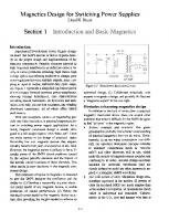
Introduction Experienced SwitchMode Power Supply designers know that SMPS success or failure depends heavily on the proper design and implementation of the magnetic components. Parasitic elements inherent in high frequency transformers or inductors cause a variety of circuit problems including: high losses, high voltage spikes necessitating snubbers or clamps, poor cross regulation between multiple outputs, noise coupling to input or output, restricted duty cycle range, etc. Figure I represents a simplified equivalent circuit
Figure 1-1 Transformer Equivalent Circuit
of a two-output forward converter power transformer, showing leakage inductances, core characteristics including mutual inductance, dc hysteresis and saturation, core eddy current loss resistance, and winding
optimized design, (3) Collaborate effectively with experts in magnetics design, and possibly (4) Become a "magnetics expert" in his own right. Obstacles to learning magnetics design In addition to the lack of instruction in practical magnetics mentioned above, there are several other problems that make it difficult for the SMPS designer to feel "at home" in the magnetics realm: .Archaic concepts and practices. Our great-
distributed capacitance, all of which affect SMPS performance. With rare exception, schools of engineering provide very little instruction in practical magnetics relevant to switching power supply applications. As a result, magnetic component design is usually delegated to a self-taught expert in this "black art". There are many aspects in the design of practical, manufacturable, low cost magnetic devices that unquestionably benefit from years of experience in this field.
grandparents probably had a better understanding of practical magnetics than we do today. Unfortunately, in an era when computation was difficult, our ancestors developed concepts intended to minimize computation (such as "circular mils") and other shortcuts, still in use, which make the subject of magnetics more complex and
However, the magnetics expert is unlikely to be sufficiently aware of the SMPS circuit problems caused by the various parasitic elements and the impact of the specific circuit locations of these elements. This often results in poor decisions in the magnetic com-
confusing to us today. Ancient design equations intended for sinusoidal waveforms (and not clearly defined as such) are often incorrectly applied to rectangular SMPS waveforms. .The CGS system of units. Magnetics design relationships expressed in the modem SI system of units (rationalized MKS) are much simpler than
ponent design. This collection of topics on magnetics is intended to give the SMPS designer the confidence and the ability to: (I) Develop a reasonably accurate electrical circuit model of any magnetic device, to enable prediction of circuit performance, (2) Relate the electrical circuit model to the magnetic device structure, thus providing the insight needed to achieve an
in the archaic CGS system. SI equations are much easier to understand and remember. Unfortunately, in the U.S., core and magnet wire data is
I-I
usually published in the old-fashioned CGS system, with dimensions often in inches, requiring data conversion to apply to the SI system. .Energy/time vs. power. Circuit designers are comfortable in the electrical realm of Volts and Amperes. On a Volt/Ampere plot, area represents power. Time is not directly involved. But on a plot of magnetic flux density, B, vs. field intensity, H, area represents energy. Time is always required to change flux density, because an energy change must take place. A change in flux density, dE, within a winding equates to the integral volt-seconds per turn across the winding (Faraday's Law). Time is definitely involved. This concept takes some getting used to. An appeal to suppliers of core materials and wire: Old-time magnetics designers in the U.S. are acclimated to the CGS system, and may prefer magnetics data expressed in Gauss and Oersteds. But newcomers to magnetics design, as well as experienced designers outside the U.S. prefer the interna-
Figure. 1-2 Field Around Conductor Pair
in opposite directions, i.e. a pair of wires connecting an electrical source to a load. The solid lines represent magnetic flux, while the dash lines represent an edge view of the magnetic field equipotential surfaces. Each wire has an individual field, symmetrical and radial, with field intensity diminishing in inverse proportion to the distance
tionally accepted SI system -Tesla and AmpereTurns. Also, cores and wire dimensional data should definitely be provided in metric units. Core losses are usually characterized as a function of frequency using sinusoidal current-driven waveforms. This is erroneous and misleading for high frequency SMPS applications. High frequency core losses are primarily caused by eddy currents, which depend on rate of flux change, not on frequency per se. (At a fixed switching frequency, higher VIN with
from the conductor. These two fields are of equal magnitude but opposite in polarity because the currents that generate the fields are in opposite directions. As shown in Fig. 1-2, the two fields, by superposition, reinforce each other in the region between the two wires, but elsewhere they tend to cancel, especially at a distance from the wires where the opposing field intensities become nearly equal. Figure 1-3 shows the field associated with a simple air cored winding. The individual fields from each wire combine to produce a highly concentrated and fairly linear field within the winding. Outside the winding, the field diverges and weakens. Although the stored energy density is high within the winding,
short duty cycle results in higher loss.) It would be most helpful if materials intended primarily for SMPS applications were characterized using rectangular voltage-driven waveforms, with examples shown of core loss and minor hysteresis loops under these conditions. Magnetic Field Relationships Understanding the rules that govern the magnetic field is extremely valuable in many aspects of
considerable energy is stored in the weaker field outside the winding because the volume extends to in-
switching power supply design, especially in minimizing parasitics in circuit wiring, as well as in magnetic device design. Figure 1-2 shows the field surrounding two parallel conductors, each carrying the same current but
finity. A magnetic field cannot be blocked by "insulating" it from its surroundings -magnetic "insulation" does not exist. However, the magnetic field can be short-circuited -by placing the coil of Fig 1-3 inside
1-2
.Flux lines are always nonnal to the magnetic field equipotential surfaces.At any location, flux density is always proportional to field intensity: B = .uH Conservation of energy: At any moment of time, the magnetic field and the current flow distribute themselves so as to minimize the energy taken from the source. If alternative current paths exist, current will initially flow in the path(s) resulting in minimum stored energy, but in the long term, the current flow redistributes so as to minimize YR loss. Reference (R2) has more on this subject. Transformation of Axes SMPS circuit designers are obviously interested in the electrical characteristics of the magnetic device as seen at the device terminals.
Figure. 1-3 Air-Core Solenoid
a box of high penneability magnetic material, which provides an easy path for the return flux, shielding the coil from the environment external to the box Important Magnetic Field Principles .The total magnetic field integrated around any closed path equals the total ampere-turns enclosed by that path (Ampere's Law) .Magnetic field equipotentials are surfaces, not lines. (Alternatively, field intensity can be represented as a vector nonnal to the surface.) .Magnetic field equipotential surfaces are bounded and terminated by the current which
Figure. 1-4
Transformation of Axes
Figure 1-4 shows how the horizontal and vertical axes scale factors can be altered so that the B-H characteristic (defining a core material) is translated into a 1\1vs. :F (mmf) characteristic (defining a specific core with magnetic area Ae and path length Re). Transforming the axes once again using Faraday's Law and Ampere's Law, the same curve now represents the equivalent electrical characteristics of that core when wound with N turns, fEdt vs. I. Note that the slope of the B-H characteristic is permeability, the slope of the 1\1vs. :F characteristic is
generates the field. They are not closed surfaces, as with electric field equipotentials. .Flux is in the fonn of lines, not surfaces. (Flux can also be represented as a vector.) .Flux lines are always closed loops -they never begin or end. In any arbitrary volume, the number of flux lines entering must equal the number leaving, regardless of the contents of that volume.
1-3
permeance, while the slope of the fEdt vs. I charac-
Ampere's Law
teristic is inductance.
SI:
Systems of Units The internationally accepted SI system of units
F
= ~Hd£
=NI
A-T
,.. H£
HzNI/f
(Systeme International d'Unites) is a rationalized system, in which permeability, ~ = ~o~ (~ is the
A-T/m(l)
absolute permeability of free space or nonmagnetic material = 47t°10-7;~ is the relative permeability of a F = f Hdl! = .47rNI "' HI!
magnetic material). In the unrationalized CGS system, ~ = 1, therefore ~ is omitted from CGS equations so that ~ = ~. But the rationalization constant ~ doesn't just disappear in the CGS system -instead, portions of this constant show up in all the CGS equations, complicating them and making them more difficult to intuitively grasp. In the SI system, all of the "garbage" is gathered into ~, thereby simplifying the SI equations. The equations below are given in both systems SI and CGS. It is suggested that beginners in magnetics design stick to the SI equations and ignore the CGS system until completely comfortable with the principles involved. Then, it may be helpful to use the CGS system when working with magnetics data ex-
H
"" .47rNI
1a can be used in most situations. Faraday's Law SI:
E
dcp
Magnetic
Parameters
FLUX DENSITY FIELD INTENSITY PERMEABILrrY (space) PERMEABILITY
dt
I and
B H 1!0
Conversion Factors SI CGS CGS to SI Tesla Gauss 10-4 A-T/m Oersted 1000/4" 4,,-10-7 1 4,,-10-7
d dl
-N
E =--XlO8 N
:
~I/>=
Edt N
Weber(2)
108
Edt
d=
Maxwell
(2a)
N
IJ,
(relative) AREA (Core Window)
A.,Aw
LENGTH (Core, Gap) TOT AL FLUX = JBdA
R"ig oil
TOTAL FIELD ~ jHdf
:1',mmf
RELUCTANCE = :1'/oil 1/~
~ p
INDUCTANCE=poN2
L
Heruy
(SI) ENERGY
w
Joule
PERMEANCE=
Oersteds(la)
/ f
Amperes Law states that the total magnetic force, .r, along a closed path is proportional to the ampereturns in a winding or windings linked to that path, i.e., that the path passes through. In the SI system, the units of magnetic force are expressed in ampereturns. When the field intensity H varies along the path, H must be integrated along the path length. Fortunately. the simplified form shown in Eq. 1 and
pressed in CGS units, rather than convert the units. Table
Gilberts
m m Weber A-T A-T/Wb
2 cm cm
Maxwell Gilbert Gb/Mx
Faraday's Law equates the flux rate of change through a winding to the volts/turn applied to the winding. Thus, the flux change is proportional to the integral volt-seconds per turn (directly equal in the SI system). Faraday's Law operates bilaterally -that is, if 2.5 volts/turn is applied to winding A, the flux through A will change by 2.5 Webers/second. If a second winding, B, is linked to all of the flux produced by winding A, then 2.5 Volts/turn will be in-
10-4 10-2 10-8 10/41[
IO9/47t 47t°lO-9
{Henry) Erg
10-7
Ampere's Law and Faraday's Law jointly govern the important relationship between the magnetic elements and the equivalent electrical circuit as seen
duced in B. Faraday's Law makes it clear that flux cannot change instantaneously. Any flux change requires time and usually a change in energy. Time is required to move along the or B axis, which is more obvious
across the windings.
1-4
netic system, as shown by the shaded area between A-B and the vertical axis. From B to C, magnetically stored energy is returned to the electrical circuit. The difference between the energy put in and taken out is hysteresis loss, the area between the two curves. At
considering the electrical equivalent scale dimensions are Volt-seconds. Note that all flux lines follow a closed loop path. flux lines have no beginning or end. Energy
C, the magnetically stored energy is zero. From C to D, energy is put into the system. From D back to A energy is returned to the electrical circuit. The area between the curves is loss. At A, the remaining stored energy is zero. A positive energy sign indicates energy put in; a
SI:
I.Edt
Joules
(3)
negative sign indicates energy returning to the external circuit. From A to B, voltage and current are both positive, so the energy sign is positive. Although the integrated Volt-seconds are negative at A, upward movement indicates positive voltage. From B to C, current is positive but voltage is negative (downward movement). Therefore the energy sign is negative. From C to D, current and voltage are both negative, hence positive energy. From D to A, negative current
CGS: w = fVoloHdB = fIoEdt010-'
Ergs
(3a)
Energy put into and removed from the magnetic system can be determined by integrating the area between the characteristic and the vertical axis (B, t/J, fEdt) on the energy plane. Energy must be integrated over time, which is a factor on the vertical axis, not
with positive voltage indicates returning energy.
the horizontal. It is much easier to understand this process by using the electrical equivalent axes, Volt-seconds and Amperes. Referring to Fig. 1-5, from point A to B, energy from the external circuit is put into the mag-
Permeability SI: .u = .UO.Ur
= B / H
Tesla/A-T/m
CGS: .u = .Ur = B / H
Gauss/Oersted
Penneability is a measure of a magnetic material -the amount of flux which a magnetic field can push through a unit volume of the material. Penneability is roughly analogous to conductivity in the electrical realm.
Figure 1-5 Energy Plane
1-5
(b)
(a) Figure
1-6-
Energy
Plane,
Sinusoidal
Voltage
(c) Drive
Examples
cluding parasitic inductances, such as shown in Fig.
Permeance, Reluctance
1-1. SI:
This will be discussed in a later section p =1/
!1{. = /.'!= BAIHf!
Inductance Webers/A-T
SI:
P=I/!I{.=~~.A/1!
Henrys (4)
CGS:
L=N2P=~~N2.A/£ P=l/!l(.=
CGS:
/:F= BAIH£
Maxwells/Gilbert
L = 47tIJ.rN2.A/£.10-9
P=l/!/{.=~.A!f!
Henrys (4a)
When the material characteristic, permeability, is applied to a magnetic element of specific area and
Inductance has the same value in the SI and cas systems. In the SI system, inductance is simply the
length, the result is permeance. In the SI system, permeance is equal to the inductance of a single turn. Reluctance, the reciprocal of permeance, is
permeance times the number of turns squared. At Home on the Energy Plane It is, of course, possible to plot any type of electrical device on the energy plane JEdt vs. I. Figure 1-6
analogous to resistance in an electrical circuit. (Don't push this analogy too far -reluctance is an energy storage element, whereas resistance is a dissipative element.) Reluctance and permeance can be defined for the entire magnetic device as seen from the electrical terminals, but it is most useful to define the reluctance of specific elements/regions within the device. This enables the construction of a reluctance model -a magnetic circuit diagram -which sheds
shows several different devices -inductors, capacitors, resistors -driven by a sinusoidal voltage waveform. Before looking at Figure 1-7 which shows the waveforms involved, try to identify the devices represented in Fig. 1-6. The answers:
considerable light on the performance of the device and how to improve it. From the reluctance model, using a duality process, a magnetic device can be translated into its equivalent electrical circuit, in-
Fig.1-6 (a) is an air core inductor, ideal and lossless. Current lags the applied voltage, but as shown in Fig. 1-7, the inductor current is in phase with JEdt plotted on the vertical axis of the energy
1-6
plane. As the wavefonn traverses from B to C, voltage and current are both positive -energy is put into the inductor. from C to D, current is positive but voltage is negative -the same energy previously stored is given back to the circuit. Fig.1-4 (b) is an ideal, lossless capacitor. Current leads the applied voltage and is therefore 180° out of phase with fEdt. From A to B, voltage and current are both positive -energy is put into the capacitor. From B to C, the same energy previously stored is returned to the circuit. Fig.l-6 (c) is a resistor. Current is in phase with applied voltage, therefore current leads fEdt by 90°. Since voltage and current are in phase, their signs are always the same. The energy sign is always positive -
E IR
fEdt
A
energy is always put into the resistor, never returned to the circuit. The entire area within the ellipse represents loss. Of course, Faraday's Law does not apply to a resistor or capacitor. Therefore the vertical fEdt scale for these devices cannot be translated into flux. Fig.1-6 (d) is an inductor with idealized metal alloy core with low frequency hysteresis, driven into
B
c
IL
Ic
saturation. A tape-wound Permalloy core driven at low frequency (no eddy currents) approaches this characteristic. The area within the characteristic is hysteresis loss. The only energy returned to the circuit is the area of the thin wedges above and below the characteristic. Only when the core saturates, taking on the characteristic of an air core, is any energy stored and returned. The dashed characteristic shows a minor hysteresis loop occurring with reduced drive, which does not take the core into saturation. Figure 1-7 Sinusoidal Voltage Drive
1-7
D
A
A,B,G,H
(a) Figure
1-8-
Rectangular
Voltage Drive
Examples
eddy currents) does not change shape radically when
Rectangular Voltage Drive Waveform Sinusoidal waveshapes are not relevant in most SMPS applications. Figure 1-8 shows the same de-
frequency or voltage or the waveshape are changed. But with a resistor, unlike the inductor, the energy plane plot expands in all directions as a function of voltage, the plot changes vertically inversely with frequency, and changes shape as a function of the
vices driven by a symmetrical rectangular voltage waveform (not including the capacitor, which would require an infinite current at the instantaneous voltage transitions). Figure 1-9 shows the corresponding
driving waveshape, as seen in the difference between Fig. 1-8 (b) and 1-6 (c). And no matter how many Volt-seconds are applied to the resistor, it will never saturate like the in-
waveforms. Fig.1-8 (a) is the same lossless air-core inductor as in 1-6 (a). Although the characteristic looks the
ductor in Fig.1-8 (c). Noting the striking similarity between the resistor characteristic of Fig. 1-8 (b) and the dash line unsaturated square-loop inductor characteristic of Fig. 1-8 (c), raises an interesting question: If inductance is defined as the slope on the plot of JEdt vs. I, then the resistor in (b ) is an inductor -it has infinite inductance along B to C and F to G, just like the unsatu-
same as with sinusoidal drive, Fig. 1-9 waveforms reveal that the characteristic dwells at its extremes during times of zero applied voltage. Fig.1-8 (b) The same resistor as in 1-6 (c) plots as a rectangle rather than an ellipse. The rectangular voltage and current waveforms exist at three distinct levels. From B to C, the voltage and current are both at a constant positive level, while JEdt slowly rises.
rated inductor in 1-8 (c). But if a resistor is defined as a device that does not store energy, only dissipates energy, then the in-
Thus, the current is constant while JEdt changes. From C to D, current suddenly collapses to zero, where it dwells until time E, because JEdt does not change while the voltage is zero. At time F, the cur-
ductor of Fig. 1-8 (c) is a resistor! ! Notes on the SMPS Environment Transformer Definition: A true transformer is a
rent suddenly changes to its constant negative level, where it remains while JEdt slowly drops toward G. Fig.1-8 (c) The same idealized metal-cored inductor as Fig.1-6 (d) exhibits the same shape on the
magnetic device with multiple windings whose purpose is not to store energy, but to transfer energy in-
different. In fact, with any practical inductor with magnetic
stantaneously from input to output(s). In addition, the windings are often electrically insulated to provide high voltage dc isolation between input and output. The turns ratio can be adjusted to obtain opti-
core, the low-frequency hysteresis loop (excluding
mum relationship between input and output voltages.
energy plane although the driving waveshape is quite
1-8
from the input in its mutual inductance during one portion of the switching period, then delivers energy to the output during a subsequent interval. Since the magnetic core material itself is incapable of storing significant energy, energy storage is accomplished in a non-magnetic gap(s) in series with the core.
F
C,D
Although mutual inductance is an essential element in a flyback transformer, leakage inductances remain undesired parasitic elements. Core Material Limitations: In dc applications, inductors are thought of as current operated devices. Even the smallest dc voltage will ultimately saturate the magnetic core, unless offset by the IR drop in the
G
E,F
winding. In high frequency SMPS applications, the major core material limitations are saturation and core losses, both of which depend upon flux swing. In these applications, transformer and inductor windings are usually driven with rectangular voltage waveforms derived from low impedance sources. Since the voltage, pulse width, and number of turns are quite accurately known, it is easy to apply Faraday's Law to determine the flux swing and appropriately limit it. In a ferrite core transformer, magnetizing current is
Il
difficult to determine accurately. It depends entirely on the core material characteristic which varies widely with temperature and with the flatness of the
Fig.
1-9
Rectangular
Voltage
mating surfaces of the core halves. Fortunately, the magnetizing current in a transformer is small enough to be of less concern than the flux swing. In an inductor or flyback transformer, the magnetizing current is vitally important, because it represents the energy storage required by the application. In this case, the magnetizing current can be calculated
Drive
A practical transformer does store some energy in mutual (magnetizing) inductance and leakage inductances, which degrade circuit performance in several
quite accurately using Ampere's Law, because it depends on the very predicable characteristics of the gap in series with the core, and the uncertain core contribution to energy storage is negligible.
important respects. These inductances are normally considered undesirable parasitics, whose minimization is one of the important goals of transformer de-
Points to Remember: .Magnetic field equipotentials are surfaces, bounded by the current generating the field.All flux lines form complete loops that never begin or end, normal to field equipotentials. .Flux change cannot occur instantaneously -time is required -an energy change occurs.
sign. Inductor Definition: An inductor is a device whose purpose is to store and release energy. A filter inductor uses this capability to smooth the current through it. A flyback transformer is actually an inductor with multiple windings. It stores energy taken
1-9
.Energy added and removed is quantified by integrating the area between the characteristic and .On
the vertical axis. the energy plane, upward movement in Quadrants I and IV or downward movement in Qll and QIll add energy to the device. Moving downward in QI and QIV , or upward in Qll and QIll returns
energy to the circuit. .The purpose of an inductor is to store energy. In a transformer, energy storage represents an undesired parasitic element. References "R-nurnbered" references are reprinted in the Reference Section at the back of this Manual. (1) T.G. Wilson, Sr., "Fundamentals Materials," APEC Tutorial Seminar, 1987
of Magnetic
(R2) "Eddy Current Losses in Transformer Windings and Circuit Wiring," Unitrode Seminar Manual SEM400, 1985
1-10
Section
2
Familiarity with the mechanisms underlying magnetic core behavior is essential to (a) optimize the magnetic device design, and (b) properly model its
Magnetic Core Materials This paper builds upon Reference (Rl ), titled "Magnetic Core Properties", taken from an earlier Unitrode seminar and reprinted in the Reference section at the back of this handbook. It discusses mag-
behavior in the circuit application. The Purpose of the Magnetic Core The fundamental purpose of any magnetic core is to provide an easy path for flux in order to facilitate flux linkage, or coupling, between two or more magnetic elements. It serves as a "magnetic bus bar" to connect a magnetic source to a magnetic "load". In a true transformer application, the magnetic source is the primary winding -ampere-turns and volts/turn. The magnetic "load" is the secondary winding (or windings). The flux through the core links the windings to each other. It also enables elec-
netic basics and the process of magnetization in ferromagnetic materials. This topic should be read before proceeding further. Metal Alloy Tape-Wound Cores Reference (Rl) focuses primarily upon the lowfrequency characteristics of metal alloy tape-wound cores. Using alloys such as Permalloy, these cores approach the ideal magnetic material characteristic square-loop with extremely high permeability (60,000), high saturation flux density (0.9 Tesla =
trical isolation between windings, and enables adaptation to different voltage levels by adjusting the turns ratio. Energy storage in a transformer core is an
9000 Gauss) and insignificant energy storage. Unfortunately, resistivity of these metal alloys is quite low. To minimize losses due to induced eddy currents, these cores are built up with very thin tape-
undesired parasitic element. With a high permeability core material, energy storage is minimal. In an inductor, the core provides the flux linkage
wound laminations. Tape-wound cores are used primarily at 50, 60,
path between the circuit winding and a non-magnetic gap, physically in series with the core. Virtually all of
and 400 Hz line frequencies. Disappointingly, they are generally unsuitable for transformer applications in SwitchMode Power Supplies. At today's SMPS frequencies (IOOkHz and up), eddy current losses are too great even with extremely thin l2.51J.m (.0005")
the energy is stored in the gap. High permeability ferrites, or magnetic metal alloys such as Permalloy, are incapable of storing significant energy. (The integrated area between the nearly vertical high permeability B-H characteristic and the vertical axis, repre-
tape thickness. However, in SMPS filter inductor applications, gapped tape-wound cores are sometimes used when the percent ripple current and associated flux swing is small enough to keep losses at an ac-
senting energy, is minuscule. ) A flyback transformer is actually an inductor with primary and secondary windings and a gap which stores the required energy. Like a simple inductor, the core provides the flux linkage path between the primary and the gap. The core also provides the linkage between the gap and the secondary winding(s) to subsequently deliver the energy to the secondary circuit. Like a transformer, the separate windings also enable electrical isolation between windings, and turns ratio
ceptable level. Tape-wound cores using the newer, lower loss amorphous metal alloys are used in SMPS applications up to lOO-200kHz, especially as magnetic amplifiers. Powdered Metal Cores Composite powdered-metal cores, such as powdered iron, Kool MIJ.@,and Perrnalloy powder cores do store considerable energy, and are therefore used in inductor and flyback transformer applications. However, energy is not stored in the very high permeability magnetic metal portions of the composite,
adaptation to different circuit voltages.
2-1
but in the non-magnetic regions between the magnetic particles -in the binder that holds the cores to-
include the power ferrite materials used in switching power supplies. NiZn ferrites have lower permeability and much higher resistivity, hence lower losses. They are used from 1 MHz to several hundred MHz. The permeability of power ferrite materials is in the range of 1500 to 3000 (relative). As shown in the
gether. Essentially, these composite cores store their energy in a non-magnetic gap that is distributed throughout the entire core. These cores are manufactured and categorized by their effective permeability (the permeability of a hypothetical homogeneous core material with the same characteristic as the actual
low frequency characteristic of Fig. 2-1, a ferrite core will store a small amount of energy, as shown by the
composite). Different effective permeabilities in the range of '=15 to ,=200 (relative) are achieved by vary-
areas between the hysteresis loop and the vertical axis. This undesired magnetizing energy must be subsequently dealt with in a snubber or clamp. Sometimes it can be put to good use in Zero Voltage Transition circuitry. The permeability is high enough to keep the magnetizing current at a generally acceptable level in transformer applications.
ing particle size and the amount of magnetically inert material in the composite mix. Composite powdered metal cores are not normally used in true transformer applications because their relatively low permeability results in high magnetizing current and energy storage -undesired in a transformer. At SMPS frequencies, powdered metal cores are quite lossy. Powdered iron is worst, Kool M~ is better, Permalloy is best. But in filter inductor or continuous mode flyback applications (where the inductive energy is stored in the non-magnetic regions within the composite core), if the percent M and flux swing are small enough, the losses may be low enough to permit the use of these composite materials. Rounding of the B-H characteristic (which will be discussed later) causes incremental inductance to decrease substantially as the DC operating point is raised. Typically, the inductance may be halved at an operating flux density of 0.4Tesla (4000 Gauss), only half way to saturation. The much greater saturation flux density BSATof the powdered metal cores compared to ferrite (0.8T vs. 0.3T) would permit a much smaller inductor as a
Figure. 2-1 Ferrite Core Characteristic
gapped ferrite for the same application, but at 100 kHz and above, this promise is seldom fulfilled be-
For inductor and tlyback transfonner applications, a gap is added in series with the core. This skews the characteristic, and provides the required
cause of the restrictions imposed by losses and rounding.
energy storage capability without the rounding observed in the powdered metal cores.
Ferrite Cores Ferrites are the most popular core materials used in SMPS applications. Ferrites are ceramic materials made by sintering a mixture of iron oxide with oxides or carbonates of either manganese and zinc or nickel and zinc. MnZn ferrites are used in applications up to lor 2 MHz and
The reasons for ferrite's popularity in SMPS applications are: lower cost and lower loss than the materials previously discussed. Ferrites are available in a wide variety of core shapes including low-profile and "planar" cores, to facilitate various needs. Two-
2-2
ceramic, the core is less robust than other materials,
are the first to saturate. Those portions of the magnetic particles that saturate first become nonmagnetic, making these paths less "easy". Incremental flux increase shifts to adjacent paths where
and may be unacceptable in a high shock military
the magnetic material has not yet saturated and where
environment. Saturation flux density in ferrite is much less than with the tape-wound or powdered metal cores: ==O.3T (3000Gauss) vs. ==O.8T.This might seem to be a dis-
the gap is somewhat wider. This process continues, effectively widening the incremental distributed gap
advantage, but saturation is not a real limitation at
served in the rounding of the B-H characteristic.
piece core sets allow the windings to be fabricated separately and subsequently assembled with the core. The main disadvantage of ferrite is that being a
as the flux increases. The incremental permeability (and inductance) is progressively reduced, as ob-
IOOkHz or above. In a transformer application, the maximum flux swing is restricted by losses to much less than BSAT. In inductor applications with a small percentage ripple resulting in low core losses, BSAT might become a limiting factor, but the lossier tapewound or powdered metal cores are usually still at a disadvantage. Rounding of the B- H Characteristic Ideal magnetic materials have a square loop characteristic with very high permeability and insignificant stored energy until finally driven into saturation. This is called a "sharp saturation" characteristic. A rounded, or "soft saturation" characteristic exhibits a gradual reduction of incremental permeability until finally the core is completely saturated. Reference (Rl) mentions that magnetic "hard spots" and inside
Figure. 2-2 --Easy Flux Path Between Particles
In powdered metal cores, this non-linear inductance characteristic is unavoidable, except by re-
comers will cause rounding of the B-H characteristic. Rounding effects in metal-alloy cores are gener-
stricting the maximum flux density to a small fraction of BSAT. In some filter inductor applications, the
ally quite trivial. However, in composite powdered metal cores, non-magnetic "gaps" exist between the
rounding effect, akin to a "swinging choke", might
discrete magnetic particles. Similar non-magnetic inclusions occur among the sintered particles in fer-
actually be desirable. In a ferrite core, the rounding effect is, if anything, beneficial. In a transformer application, normal operation with flux density limited by core losses, the rounding is not encountered, and even if it is, the re-
rite cores. These distributed non-magnetic regions cause significant rounding of the B-H characteristic. They also result in storing energy within the core. The particulate structure has two main effects: First, the distributed reluctance of these tiny "gaps" causes the flux and the flux change to be distributed across the entire core, rather than as a discrete flux change boundary moving from inside to
sult is a small increase in magnetizing current. In a situation where the flux "walks" toward saturation due to a volt-second imbalance on the transformer primary, the soft saturation characteristic provides a gradual magnetizing current increase to facilitate
outside as depicted in (Rl) for ungapped idealized
control of this problem. When a discrete gap is added to the ferrite core for energy storage in a filter inductor application, the rounding of the ferrite characteristic disappears -
metal alloy cores. Second, at low flux densities, flux tends to concentrate in the "easiest" paths (lowest reluctance) where the magnetic particles are in close proximity. As the flux density increases, these easy path areas
swamped by the linear high reluctance of the gap. The inductance characteristic becomes quite linear 2-3
until saturation is reached. If a non-linear inductance characteristic is desired, it can be accomplished with a tapered or stepped gap. Core
Limitations
in SMPS
BSAT.But with higher frequency and/or larger percent ripple current, core losses will dominate, and ferrite cores will outperform the others. In situations where powdered metal cores may be advantageous, bear in mind that the inductance may diminish an unacceptable amount at higher current levels due to the rounding effect discussed earlier. Flyback transformers are really inductors with multiple windings. There are some unique problems associated with the windings, but the core does not care how many windings exist -the core is aware only of the total ampere-turns and the volts/turn. When operated in the continuous current mode, with small M and at low enough frequency, the same considerations apply as for the simple inductor. In the
Applications
In high frequency SwitchMode power supplies, magnetic core characteristics usually impose different limitations in transformer, filter inductor, and flyback transformer applications. A true transformer is commonly used in buckderived circuits such as the forward converter, full bridge, half bridge, etc. Ideally, a transformer stores no energy, but transfers energy immediately from input to output. In a practical transformer, undesired stored energy does occur in parasitic leakage inductances (outside the core), and magnetizing inductance (within the core). Magnetizing inductance is minimized by using a gapless, high permeability core
discontinuous mode, the current swing (and flux swing) become very large, the core loss limitation applies, and gapped ferrite cores provide the best per-
material. At low frequencies, core saturation is usually the most important limitation. But at SMPS frequencies, usually IOOkHz or greater, core loss becomes the
formance. Transformer and inductor design is covered in detail in other sections of this manual.
cause ofhigh losses and because of low permeability. Tape-wound metal alloy cores have considerably higher core losses than ferrite cores. Tape-wound cores have higher BSATthan ferrite, but this is irrelevant because core loss severely restricts the flux
Core Saturation At SMPS switching frequencies, core saturation is almost never a limitation in transformer applications, although it often is in filter inductors or continuous mode flyback transformers. Flux Walking: Transformers operated in pushpull circuits do have a potential problem with core
swing. Tape-wound cores are considered for SMPS transformer applications only if their greater rugged-
saturation. A positive pulse applied to a winding causes a
ness is needed. A filter inductor must store energy during one portion of each switching period and return this energy to the circuit during another portion of the period, thus smoothing the current flow. The required energy must be stored in a non-magnetic gap -distributed in the case of a powdered metal core, and a discrete gap in series with a ferrite core or tape-
positive flux change proportional to the pulse voltseconds. In order to maintain a stable operating point on the B-H characteristic, the core must be "reset" by subsequently applying the exact same number of
most important limitation in transformer applications. Powdered metal cores are effectively ruled out be-
negative volt-seconds. In a single-ended application, such as a forward converter, the core "resets itself' by an inductive voltage reversal which self-terrninates when the magnetizing current returns to zero. In a push-pull application, the core is reset by the circuit, which applies sequential positive and negative pulses to the wind-
wound metal alloy core. If the switching frequency and the percentage of current ripple (which determines the flux swing) are both low enough, core losses will be low, and the inductor core may be limited by saturation. In this
ings. With the slightest asymmetry -inequality of either voltage or time -the positive and negative voltseconds do not completely cancel. As a result, the flux never quite returns to its starting point, and over a period of many cycles at the switching frequency,
situation, powdered metal cores or gapped tapewound cores may not only be feasible, they may outperform gapped ferrite cores because of their higher
2-4
the flux density "walks" into saturation. This problem is not a core limitation -any core would eventually reach saturation. This is a circuit problem, to which there are several circuit solutions which are beyond the scope of this paper. Core Loss Core loss is the most important core limitation in most SMPS applications. For acceptable losses, flux density swing AB must be restricted to much less than BSAT.This prevents the core fr