Information Support and Aircraft Flight Management (Springer Aerospace Technology) 9811600872, 9789811600876
This book presents materials on the implementation of modern technologies for aircraft information support and ground-ba
156 57 6MB
English Pages 159 [154] Year 2021
Introduction
Contents
Abbreviations
1 Implementation and Ways to Implement ADS-B in Russian Federation
1.1 The Implementation Options for ADS
1.2 Technical Implementation Means ADS-B
1.2.1 Principles of Construction of Systems of ADS-B ICAO
1.2.2 Multifunctional Channels of Systems ADS-B and Methods of Management
1.2.3 Ground Station VDL-4 Intended for the Operation of the System ADS-B
1.3 Russian Information System Based on ADS-B for the Flight of Aircraft in the Arctic and Far Eastern Regions
1.3.1 The Objectives and Main Approaches for the Development of Communication and Cooperation in the Arctic
1.3.2 The Variant of Construction of the System of the Arctic ADS-B. System Relay Information
1.3.3 Communications System of the Control Tower—Radar in Shortwave Range
1.4 Russian Information System for Aircraft Traffic Control in the Kuril Archipelago Area (RISATC KA)
1.4.1 The Objectives and Main Approaches to the Creation of Information System of RISATC KA
1.4.2 Questions of Technical Implementation of RISATC KA
1.5 The Extension of Possibilities of Application of Technology ADS-B in Information Systems of the Transport Complex of the Russian Federation
1.5.1 System ADS-B to Provide a Small Aircraft Flying in Uncontrolled Airspace
1.5.2 ADS-B in the System of Transport Logistics (STL) of Agricultural Production
1.5.3 Control a Swarm of Uncrewed Aerial Vehicles (UAVs) Using the Technology of ADS-B
1.6 The Program of Implementation Tools Broadcast Automatic Dependent Surveillance in the Russian Federation
References
2 Building a Better Computing Block for Devices of Civil Aviation on the Criterion of Reliability
2.1 Development of Methods of Calculation of Reliability Computing Block, Composed of Heterogeneous Elements
2.1.1 The General Approach to the Calculation of Reliability Computing Block
2.1.2 Review of Existing Civil Aviation Computing Blocks in the Example of the Aircraft “Sukhoi Superjet-100”
2.1.3 A Formal Approach to the Calculation of the Reliability Computing Block
2.1.4 The Method of Calculating the Reliability Computing Block, Taking into Account Different Types of Errors
2.2 Building a Better Computer System from Heterogeneous Elements According to the Proposed Criterion
2.2.1 Analysis of Different Approaches to the Choice of the Criterion to Build a Better System
2.2.2 Building the Best Computing Block from Different Types of Elements with Known Reliability Parameters
2.2.3 Building the Best Computing Block from Relay Elements with Possible Errors of the First and Second Kind
2.3 Build the Best Multifunctional Computing Block
2.3.1 The Construction Algorithm Selects the Best Computing Block Based on the Execution of Several Functions
2.3.2 Building a Better Computing Device for Modeling the Spatial Movement of the Helicopter
References
3 Ensuring the Reliability and Integrity of the Information Service of Aircraft at Various Stages and Under Various Flight Conditions
3.1 The Implementation of the Information Service of Aircraft Based on Satellite and Optical Systems, Designed “NPPF Spectr”
3.1.1 Monitoring Center of Satellite Constellations for Aviation Users
3.1.2 Local Monitoring and Correcting Station GBAS LKKS-A-2000
3.1.3 Certified Small Satellite Tracker
3.1.4 Aviation Satellite Optical Engine Precise Positioning the PILOT
3.1.5 Land and Flight Checks
3.1.6 Some Features of the Use of Satellite Navigation in Civil Aviation
3.2 Build an Algorithm to Identify Errors in Voice Radio Communication Radio Traffic
3.2.1 The Algorithm for Identifying Errors in the Radio Channel Based on the Use of the System of Reference Assessments
3.2.2 The Definition of Error When Detected Errors in a Radio Channel with Voice Exchange
References
Appendix A Software Implementation of the Method of Calculating the Reliability of Computing Block, Taking into Account Different Types of Errors
Appendix B The Program for the Selection of the Best Computing Systems from Heterogeneous Elements with a Known Probability of Failure
Appendix C The Program for Choosing the Best Computer System of the Relay Elements, with the Error Probability of the First and Second Kind
Appendix D The Certificate of State Registration of Computer Programs No. 2019665466. The Program of Choosing the Best System from Heterogeneous Elements on the Criterion of Reliability (PCS CR)
Appendix E The Program Selects the Best Computing Block Based on the Execution of Several Functions
Appendix F The Program is Building a Better Computing Device for Modeling the Spatial Movement of the Helicopter
Appendix G Specifications LKKS-A-2000
Appendix H Program Algorithm Identification of Errors with Voice Radio Communication Exchange
Appendix I The Program Algorithm for Definition of Errors First and Second Are Kind of the Detection Error in the Voice Mail
Recommend Papers


![Helicopter Flight Dynamics: Including a Treatment of Tiltrotor Aircraft (Aerospace Series) [3 ed.]
1119401054, 9781119401056](https://ebin.pub/img/200x200/helicopter-flight-dynamics-including-a-treatment-of-tiltrotor-aircraft-aerospace-series-3nbsped-1119401054-9781119401056.jpg)
![Flight Mechanics of High-Performance Aircraft (Cambridge Aerospace Series) [First Edition]
052134123X, 9780521341233](https://ebin.pub/img/200x200/flight-mechanics-of-high-performance-aircraft-cambridge-aerospace-series-first-edition-052134123x-9780521341233.jpg)


![Aircraft flight: a description of the physical principles of aircraft flight [4th ed]
9780273730989, 0273730983](https://ebin.pub/img/200x200/aircraft-flight-a-description-of-the-physical-principles-of-aircraft-flight-4th-ed-9780273730989-0273730983.jpg)


File loading please wait...
Citation preview
Springer Aerospace Technology
Oleg Ivanovich Zavalishin Anatoly Nikolaevich Korotonoshko Dmitry Alexandrovich Zatuchny Yury Grigorievich Shatrakov
Information Support and Aircraft Flight Management
Springer Aerospace Technology Series Editors Sergio De Rosa, DII, University of Naples Federico II, NAPOLI, Italy Yao Zheng, School of Aeronautics and Astronautics, Zhejiang University, Hangzhou, Zhejiang, China
The series explores the technology and the science related to the aircraft and spacecraft including concept, design, assembly, control and maintenance. The topics cover aircraft, missiles, space vehicles, aircraft engines and propulsion units. The volumes of the series present the fundamentals, the applications and the advances in all the fields related to aerospace engineering, including: • • • • • • • • • • • •
structural analysis, aerodynamics, aeroelasticity, aeroacoustics, flight mechanics and dynamics orbital maneuvers, avionics, systems design, materials technology, launch technology, payload and satellite technology, space industry, medicine and biology.
The series’ scope includes monographs, professional books, advanced textbooks, as well as selected contributions from specialized conferences and workshops. The volumes of the series are single-blind peer-reviewed. To submit a proposal or request further information, please contact: Mr. Pierpaolo Riva at [email protected] (Europe and Americas) Mr. Mengchu Huang at [email protected] (China) The series is indexed in Scopus and Compendex
More information about this series at http://www.springer.com/series/8613
Oleg Ivanovich Zavalishin · Anatoly Nikolaevich Korotonoshko · Dmitry Alexandrovich Zatuchny · Yury Grigorievich Shatrakov
Information Support and Aircraft Flight Management
Oleg Ivanovich Zavalishin Moscow, Russia
Anatoly Nikolaevich Korotonoshko Moscow, Russia
Dmitry Alexandrovich Zatuchny Moscow, Russia
Yury Grigorievich Shatrakov Saint Petersburg, Russia
ISSN 1869-1730 ISSN 1869-1749 (electronic) Springer Aerospace Technology ISBN 978-981-16-0087-6 ISBN 978-981-16-0088-3 (eBook) https://doi.org/10.1007/978-981-16-0088-3 © The Editor(s) (if applicable) and The Author(s), under exclusive license to Springer Nature Singapore Pte Ltd. 2021 This work is subject to copyright. All rights are solely and exclusively licensed by the Publisher, whether the whole or part of the material is concerned, specifically the rights of translation, reprinting, reuse of illustrations, recitation, broadcasting, reproduction on microfilms or in any other physical way, and transmission or information storage and retrieval, electronic adaptation, computer software, or by similar or dissimilar methodology now known or hereafter developed. The use of general descriptive names, registered names, trademarks, service marks, etc. in this publication does not imply, even in the absence of a specific statement, that such names are exempt from the relevant protective laws and regulations and therefore free for general use. The publisher, the authors and the editors are safe to assume that the advice and information in this book are believed to be true and accurate at the date of publication. Neither the publisher nor the authors or the editors give a warranty, expressed or implied, with respect to the material contained herein or for any errors or omissions that may have been made. The publisher remains neutral with regard to jurisdictional claims in published maps and institutional affiliations. This Springer imprint is published by the registered company Springer Nature Singapore Pte Ltd. The registered company address is: 152 Beach Road, #21-01/04 Gateway East, Singapore 189721, Singapore
Introduction
High-quality information support for aircraft (ACFT) is becoming crucial now. This is due to the continually increasing intensity of air traffic. Any interruption in obtaining navigation or any other information necessary to ensure the flight of the aircraft may lead to irreparable consequences. This applies not only to large airliners but also to small aircraft or helicopters, which often have to fly in areas with steep terrain or in poor visibility. Modern means of monitoring the flight of aircraft are less and less responsive to the modern needs of information support, both for the aircraft crew and ground services that are responsible for radio technical support of flights. The purpose of this book is to familiarize a wide range of aviation professionals with new methods and approaches to improving the quality of information support for aircraft, developed and implemented currently in the Russian Federation (RF). The first chapter of this monograph discusses issues related to the introduction of automatic dependent surveillance (ADS) in the Russian Federation. This promising technology has already been the subject of quite a lot of scientific papers published both in the Russian Federation and in other countries that are leaders in the global aviation market. At the same time, much attention was paid to the implementation of ADS in the form of systems such as 1090ES or VDL-4. In this chapter, attention focuses on the program of activities on implementation of ADS in Russia, as well as its implementation in the Arctic and Far Eastern regions and in areas such as agricultural aviation, or to control a swarm of unmanned aerial vehicles. The second chapter of this book presents algorithms for calculating the reliability of computing blocks used in civil aviation. It should be noted that the correct execution of a large number of computing operations within a minimum period depends on the composition of navigation and other relevant information that is transmitted via data transmission lines to ground air traffic control authorities or onboard the aircraft. In this case, algorithms are provided that are applicable not only to information support for massive aircraft flight but also to modeling the spatial movement of the helicopter. Although automatic dependent surveillance can become a severe means of information support or information exchange between all interested airspace users if it is fully implemented worldwide, it may not always meet the existing requirements for v
vi
Introduction
the integrity and reliability of transmitted messages. The long and fruitful work of Russian scientists from Spectr LLC, headed by General Director–General designer, O. I. Zavalishin, was devoted to solving this problem. The methods and algorithms developed by them were implemented and successfully operated in the form of local ground-based control and correction stations and the PILOT satellite-optical system. As well as a complex of ground and flight checks makes it possible to provide information support in civil aviation with integrity and reliability requirements that fully meet international standards for different regions and under different conditions. These new technical solutions are described in the third chapter of this book.
Contents
1 Implementation and Ways to Implement ADS-B in Russian Federation . . . . . . . . . . . . . . . . . . . . . . . . . . . . . . . . . . . . . . . . . . . . . . . . . . . . . 1.1 The Implementation Options for ADS . . . . . . . . . . . . . . . . . . . . . . . . . 1.2 Technical Implementation Means ADS-B . . . . . . . . . . . . . . . . . . . . . . 1.2.1 Principles of Construction of Systems of ADS-B ICAO . . . . 1.2.2 Multifunctional Channels of Systems ADS-B and Methods of Management . . . . . . . . . . . . . . . . . . . . . . . . . . 1.2.3 Ground Station VDL-4 Intended for the Operation of the System ADS-B . . . . . . . . . . . . . . . . . . . . . . . . . . . . . . . . . 1.3 Russian Information System Based on ADS-B for the Flight of Aircraft in the Arctic and Far Eastern Regions . . . . . . . . . . . . . . . . 1.3.1 The Objectives and Main Approaches for the Development of Communication and Cooperation in the Arctic . . . . . . . . . . . . . . . . . . . . . . . . . . 1.3.2 The Variant of Construction of the System of the Arctic ADS-B. System Relay Information . . . . . . . . . . 1.3.3 Communications System of the Control Tower—Radar in Shortwave Range . . . . . . . . . . . . . . . . . . . . . 1.4 Russian Information System for Aircraft Traffic Control in the Kuril Archipelago Area (RISATC KA) . . . . . . . . . . . . . . . . . . . 1.4.1 The Objectives and Main Approaches to the Creation of Information System of RISATC KA . . . . . . . . . . . . . . . . . . 1.4.2 Questions of Technical Implementation of RISATC KA . . . . . . . . . . . . . . . . . . . . . . . . . . . . . . . . . . . . . . . . . . . . . . . . 1.5 The Extension of Possibilities of Application of Technology ADS-B in Information Systems of the Transport Complex of the Russian Federation . . . . . . . . . . . . . . . . . . . . . . . . . . . . . . . . . . . . 1.5.1 System ADS-B to Provide a Small Aircraft Flying in Uncontrolled Airspace . . . . . . . . . . . . . . . . . . . . . . . . . . . . . . 1.5.2 ADS-B in the System of Transport Logistics (STL) of Agricultural Production . . . . . . . . . . . . . . . . . . . . . . . . . . . . .
1 1 4 4 7 9 15
15 18 24 27 27 28
30 30 33 vii
viii
Contents
1.5.3 Control a Swarm of Uncrewed Aerial Vehicles (UAVs) Using the Technology of ADS-B . . . . . . . . . . . . . . . . 1.6 The Program of Implementation Tools Broadcast Automatic Dependent Surveillance in the Russian Federation . . . . . . . . . . . . . . . References . . . . . . . . . . . . . . . . . . . . . . . . . . . . . . . . . . . . . . . . . . . . . . . . . . . . . 2 Building a Better Computing Block for Devices of Civil Aviation on the Criterion of Reliability . . . . . . . . . . . . . . . . . . . . . . . . . . . 2.1 Development of Methods of Calculation of Reliability Computing Block, Composed of Heterogeneous Elements . . . . . . . . 2.1.1 The General Approach to the Calculation of Reliability Computing Block . . . . . . . . . . . . . . . . . . . . . . . . . . . . . . . . . . . . 2.1.2 Review of Existing Civil Aviation Computing Blocks in the Example of the Aircraft “Sukhoi Superjet-100” . . . . . 2.1.3 A Formal Approach to the Calculation of the Reliability Computing Block . . . . . . . . . . . . . . . . . . . . . 2.1.4 The Method of Calculating the Reliability Computing Block, Taking into Account Different Types of Errors . . . . . 2.2 Building a Better Computer System from Heterogeneous Elements According to the Proposed Criterion . . . . . . . . . . . . . . . . . . 2.2.1 Analysis of Different Approaches to the Choice of the Criterion to Build a Better System . . . . . . . . . . . . . . . . 2.2.2 Building the Best Computing Block from Different Types of Elements with Known Reliability Parameters . . . . 2.2.3 Building the Best Computing Block from Relay Elements with Possible Errors of the First and Second Kind . . . . . . . . . . . . . . . . . . . . . . . . . . . . . . . . . . . . . . . . . . . . . . . 2.3 Build the Best Multifunctional Computing Block . . . . . . . . . . . . . . . 2.3.1 The Construction Algorithm Selects the Best Computing Block Based on the Execution of Several Functions . . . . . . . . . . . . . . . . . . . . . . . . . . . . . . . . . . . . . . . . . . . 2.3.2 Building a Better Computing Device for Modeling the Spatial Movement of the Helicopter . . . . . . . . . . . . . . . . . References . . . . . . . . . . . . . . . . . . . . . . . . . . . . . . . . . . . . . . . . . . . . . . . . . . . . . 3 Ensuring the Reliability and Integrity of the Information Service of Aircraft at Various Stages and Under Various Flight Conditions . . . . . . . . . . . . . . . . . . . . . . . . . . . . . . . . . . . . . . . . . . . . . . . . . . . . . 3.1 The Implementation of the Information Service of Aircraft Based on Satellite and Optical Systems, Designed “NPPF Spectr” . . . . . . . . . . . . . . . . . . . . . . . . . . . . . . . . . . . . . . . . . . . . . . . . . . . 3.1.1 Monitoring Center of Satellite Constellations for Aviation Users . . . . . . . . . . . . . . . . . . . . . . . . . . . . . . . . . . . . 3.1.2 Local Monitoring and Correcting Station GBAS LKKS-A-2000 . . . . . . . . . . . . . . . . . . . . . . . . . . . . . . . . . . . . . . . 3.1.3 Certified Small Satellite Tracker . . . . . . . . . . . . . . . . . . . . . . . .
39 43 54 57 57 57 59 61 67 70 70 70
76 79
79 83 86
87
87 89 90 93
Contents
3.1.4 Aviation Satellite Optical Engine Precise Positioning the PILOT . . . . . . . . . . . . . . . . . . . . . . . . . . . . . . . . . . . . . . . . . . 3.1.5 Land and Flight Checks . . . . . . . . . . . . . . . . . . . . . . . . . . . . . . . 3.1.6 Some Features of the Use of Satellite Navigation in Civil Aviation . . . . . . . . . . . . . . . . . . . . . . . . . . . . . . . . . . . . . 3.2 Build an Algorithm to Identify Errors in Voice Radio Communication Radio Traffic . . . . . . . . . . . . . . . . . . . . . . . . . . . . . . . . 3.2.1 The Algorithm for Identifying Errors in the Radio Channel Based on the Use of the System of Reference Assessments . . . . . . . . . . . . . . . . . . . . . . . . . . . . . . . . . . . . . . . . 3.2.2 The Definition of Error When Detected Errors in a Radio Channel with Voice Exchange . . . . . . . . . . . . . . . . References . . . . . . . . . . . . . . . . . . . . . . . . . . . . . . . . . . . . . . . . . . . . . . . . . . . . .
ix
96 96 98 100
100 103 106
Appendix A: Software Implementation of the Method of Calculating the Reliability of Computing Block, Taking into Account Different Types of Errors . . . . . . . . . . . 107 Appendix B: The Program for the Selection of the Best Computing Systems from Heterogeneous Elements with a Known Probability of Failure . . . . . . . . . . . . . . . . . . . . . . . . . . . . . . . . . 115 Appendix C: The Program for Choosing the Best Computer System of the Relay Elements, with the Error Probability of the First and Second Kind . . . . . . . . . . . . . . . . 119 Appendix D: The Certificate of State Registration of Computer Programs No. 2019665466. The Program of Choosing the Best System from Heterogeneous Elements on the Criterion of Reliability (PCS CR) . . . . . . . . . . . . . . . . 125 Appendix E: The Program Selects the Best Computing Block Based on the Execution of Several Functions . . . . . . . . . . . . 127 Appendix F: The Program is Building a Better Computing Device for Modeling the Spatial Movement of the Helicopter . . . . . 131 Appendix G: Specifications LKKS-A-2000 . . . . . . . . . . . . . . . . . . . . . . . . . . . 135 Appendix H: Program Algorithm Identification of Errors with Voice Radio Communication Exchange . . . . . . . . . . . . . 137 Appendix I: The Program Algorithm for Definition of Errors First and Second Are Kind of the Detection Error in the Voice Mail . . . . . . . . . . . . . . . . . . . . . . . . . . . . . . . . . . . . . . 143
Abbreviations
AA AAIM ACFT ACS, mm ADS ANI APNT APV ARAIM ARP AS ASMGCS AT ATC ATC ATM AW BMS CA CDC CNS/ATM CNTS CP RET CP CPDLC CS CTP DCMW
Airfield airspace Aircraft autonomous integrity monitoring Aircraft Automated control system in the millimeter range Automatic dependent surveillance (ADS-B) Aeronavigation information, Advanced position, navigation, timing Approach with Vertical Guidance Advanced Receiver Autonomous Integrity Monitoring Automatic radar position Airspace Advanced Surface Movement Guidance and Control System Air traffic control automation systems Air traffic control Air Traffic Management Automated workplace onboard multifunctional system Civil aviation Control dispatcher center Communication, Navigation, Surveillance/Air Traffic Management Coordinate and navigation temporary support Radio engineering control point towers Control point Controller Pilot Data Link Communications Complementary system Coordinate-temporary provision Decameter wave (decameter range) xi
xii
DGNSS DME DTL EDW EU ATM EU FAA FIS-B GA GBAS GLONASS GLS GNSS GNSS GPS IAC ICAO IFR ILS IMO Ins INS ITU LA LKKS LORAN-C LR MF MFW MLS NE AC NOTAM NPA NPPF Spectr OWP PR PSR RAIM RB REE RESSRN
Abbreviations
Differential Global Navigation Satellite System ICAO short-range navigation system Data transmission lines Experimental and designing work Unified air traffic management system European Union Federal Aviation Administration Flight information service broadcast General aviation Ground-Based Augmentation System Global navigation satellite system (Russia) GBAS Landing Systems Global navigation satellite system Global Navigation Satellite System Global Positioning System International Aviation Committee International Civil Aviation Organization Instrument Flight Rules Instrument Landing System International Maritime Organization Inertial navigation system Inertial Navigation System International Telecommunication Union Local airlines Local control and correction system Medium frequency ground navigation system Landing radar Medium frequency Medium frequency wave (or means of communication, depending on the context) Microwave landing system Navigation equipment of aircraft consumers Notice To Airmen Non-precision approaches Research and production company Spectr Operator’s workplace Primary radar Primary surveillance radar Receiver Autonomous Integrity Monitoring Radio beacon Radio-electronic equipment Radio engineering system for short-range navigation in Russia
Abbreviations
RF RISATC KA RNP SARPS SBAS SCFT SNS SRNS SSR STDMA Target detection range of the MARP The FIS and the CAS TIS-B UAS USW DTL USW DTL4 or VDL-4-USW VFR Z/C OBNS
xiii
Russian Federation Russian information system for aircraft traffic control in the Kuril Archipelago area Required navigation performance Standards and recommended practices Satellite-based augmentation system Spacecraft Satellite navigation system Satellite radio navigation system Secondary surveillance radar Self-organizing Time Division Multiple Access The target detection range of the meteorological automatic radar position The Federal intelligence service and the control airspace Traffic information service–broadcast Use of air space Ultra-shortwave data transmission line Data transmission line for civil aviation in ICAO standards (modification 4) Visual flight rules Zonal command onboard navigation system
Chapter 1
Implementation and Ways to Implement ADS-B in Russian Federation
1.1 The Implementation Options for ADS The rapid growth in the number of aircraft flights has led to the need to develop and implement a high-speed flexible and stable network aviation communication system, which is called automatic dependent surveillance—ADS-B. According to the definitions given by ICAO, ADN-B (automatic wide-broadcast dependent surveillance) is a function for an aircraft in the air or on the ground, or for other mobile objects on the ground operating within the ground traffic zone, which periodically transmits its state vector (horizontal and vertical position, horizontal and vertical speed) and other information. The ADN-B is automatic since it does not require any external stimulus; it is dependent since it relies on onboard navigation sources and onboard broadcast systems to provide surveillance information to other users. The aircraft or vehicle that is the source of the broadcast may or may not know which users are the receivers of the broadcast, any user, whether an aircraft or a ground user, within the range of this radio transmission, may decide to receive and process the ADN-B surveillance information. ADN-B provides more rational use of airspace, reduced ceiling/visibility restrictions, improved ground surveillance, and increased security through conflict management [1]. In ADS systems, each aircraft, in flight or an airport’s free maintenance facility, digitally broadcasts its coordinates, along with other necessary information received via GLONASS/GPS satellite navigation systems. Anyone who is interested in this information can obtain and use this information. In contrast to radar surveillance systems, which can only be used in ground-based aviation control points, the ADS allows us to organize monitoring of the air environment onboard any aircraft equipped with ADS equipment. ADS is one of the most critical applications of satellite navigation in aircraft safety systems. Based on this circumstance, the international organization of ICAO has developed and implemented appropriate organizational and technical standards © The Author(s), under exclusive license to Springer Nature Singapore Pte Ltd. 2021 O. I. Zavalishin et al., Information Support and Aircraft Flight Management, Springer Aerospace Technology, https://doi.org/10.1007/978-981-16-0088-3_1
1
2
1 Implementation and Ways to Implement ADS-B in Russian Federation
(SARPs) that regulate the implementation of gas station systems in aviation practice. These standards are based on the use of radiofrequency bands allocated by the International Electrotechnical Commission (IEC) for use in civil aviation, the so-called ARNS bands. Based on the allocated ARNS ranges, ICAO has developed standards for two ADS-B variants. The first of them uses for its operation the frequency of 1090 MHz and the types of signals received for secondary radar (SR) responders [2]. This option uses the “extended squitter” technology. This version of the ADS-B system is used in areas of high air traffic, regional and zonal ATC systems, and terminal areas of airports. Aircraft operating in these zones are usually equipped with SR responders, which significantly facilitates the implementation of the ADS-B system. For this option, the ICAO and RTCA have developed all the necessary SARPS and MOPS, and it is implemented without any legal restrictions. The second version of the ADS-B system is intended for areas with low air traffic intensity. In these areas, there are no shortage of ultra-short waves (USW) aviation communication channels, which is typical for high-traffic areas. The second version of the ICAO ADS-B system is based on the use of USW in the 108–137 MHz band. In this range, effective aviation communication protocols VDL (Very HighFrequency Data Link)—the implemented VDL-Mode-2 Protocol and the VDLMode-4 Protocol recommended for use in urgent cases [1, 3]—have been developed and operated. The VDL-Mode-4 digital link is a digital bit-oriented USW link capable of providing air-to-air and air-to-ground communications. This digital link supports time-critical applications and is useful for exchanging short, repetitive messages. The line is based on the Protocol of multiple access with a temporary division of channels. In this self-organizing system, the transmission time is divided into many time intervals. Each time interval is planned and reserved for transmission by user radio transponders within reach of each of them. This allows us to increase the efficiency of using the communication line and prevent simultaneous transmission from different users. The self-organizing collective access Protocol with time division of channels allows users to organize access to discrete-time segments without accessing the master control station. In the Russian Federation, several works were carried out on the implementation of ADS-B with the VDL-4 data transmission line, in particular in the polar regions on the Yamal Peninsula and the North-Western region of the country. In addition to the Russian Federation, the ADS-B variant with the VDL-4 DTL was used in Australia and Sweden. These countries were the leading developers of the relevant ICAO standards.
1.1 The Implementation Options for ADS
3
The most important goals for the implementation of ADS-B systems in the Russian Federation are [4]: – providing information to ATC systems for route flights, especially for flights in sparsely populated regions of Siberia and the Far East; – ensuring the control of airspace, control of unique flights, use in search and rescue operations; – providing information to ATC systems in busy airfield zones; – providing security in advanced ground traffic control systems on the surface of airports, including monitoring. Also, the world practice imposes several additional and more complex tasks on the ADS systems, in particular [5]: – support for advanced airfield operations in conditions of low visibility, such as “free flight flights,” one-time approaches to land on several lanes, control in the departure zone; – increasing crew awareness of the surrounding situation with the use of cabin displays, providing air-to-air surveillance, assistance in visual capture; – problems of conflict resolution from the ground and onboard aircraft; – tasks of ensuring collision avoidance with the ground, both on the ground and onboard, monitoring the exhibition of barometric altimeters; – tasks of creating a field of observation of flights in the lower airspace, General aviation flight control; – tasks for improving onboard collision warning systems. Of all this range of expanded tasks for civil aviation in the Russian Federation, the most urgent is the tasks of creating a field of observation for the lower airspace, improving safety in this flight zone, expanding the weather minimum, and the roundthe-clock operation of the fields. The solution to these problems makes it possible to create an ATC tool system for low-altitude flights with increased safety and expands the introduction of satellite technologies into air traffic safety systems. The system based on the VDL-4 DTL was chosen as one of the main ones for equipping the national airspace for the following principal reasons [1]: – development of USW air communication in the territory of the Russian Federation, the readiness of the system for perception and technical operation of the system; – the ability to significantly simplify avionics for a full class of aircraft and helicopters; – the ability to sharply lower the lower edge of the observation field and ATC, the ability to create an automatic monitoring system at small heights; – the non-relevance of the factor of possible lack of USW channels that prevent the introduction of VDL 4 in the United States and Western Europe in most of the territory of the Russian Federation and the Russian-controlled airspace; The realization and ways of integration of ADS-B in the Russian Federation are given in the following sections.
4
1 Implementation and Ways to Implement ADS-B in Russian Federation
1.2 Technical Implementation Means ADS-B 1.2.1 Principles of Construction of Systems of ADS-B ICAO An ADS is a method of observation in which an aircraft (or any other object) automatically provides information from its onboard systems to a specific (for a contract ADS) or any (for a radio ADS) consumer via a data link. In contract (or address) ADS-A surveillance, the automatic transmission of periodic messages from the aircraft (ACFT) begins after the connection with a specific ATC authority is initiated by the ACFT. The content of messages and the frequency of their updating is determined by this ATC authority in a contract or series of contracts with the aircraft established by it. The international technical standard for contract filling stations was developed in ICAO and published. Following this standard, the industry has carried out several developments for the implementation of contract gas stations, which resulted in the appearance of the FANS 1 and FANS-A avionics kits, which are currently used on aircraft of many airlines to provide flights over the Pacific Ocean [6]. More than 500 such or similar sets of onboard equipment have been installed. Concerning the tasks of flight control in the Russian Federation, the ADS-A system was developed to provide civil aircraft flights across the Arctic Ocean and in the Northern regions of Siberia and the Far East. This system is implemented in the centers of internal affairs of Magadan and Murmansk. Radio broadcasting, or broadcast automatic dependent surveillance (ADS-B), is a type of surveillance that allows for periodic (up to one message per second) transmission using a broadcast-type data link (without first establishing a contract). ATC systems transmit parameters such as coordinates, the aircraft identification index, and many others for use by any on-board and/or onboard user interested in this information. This capability improves awareness of the air situation both onboard the aircraft and on the ground, which allows for the surveillance function, as well as cooperative, “pilot-dispatcher” and “pilot-pilot,” air traffic organization. ADS-B is not limited to traditional functions associated with ground-based surveillance radar systems. It provides new capabilities, both onboard the aircraft and in air traffic control systems. Depending on the specific implementation, the ADS-B may include air-to-ground and air-to-air surveillance functions, as well as support some applications related to the interaction between aircraft and ground transport. ICAO has defined the following elements of the minimum set of information that should be transmitted by any object emitting ADS-B information [3]: – – – – –
object category, object identifier, latitude, longitude, altitude,
1.2 Technical Implementation Means ADS-B
5
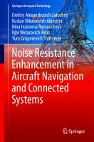
– aircraft identification code (if available), – an indicator of the quality of information. The ADS-B system allows the transfer of additional elements in the airspace (AS), where the ADS-B is supposed to be used over the air-to-ground data transmission line (DTL). It is currently determined that additional elements of the message will include. – earth vector containing the track angle, track speed, and vertical speed; – an air vector containing the course, instrument speed, or Mach number, and vertical speed; – the closest intent that contains the next route point and the specified height; – u-turn speed; – aircraft type. A diagram of the automatic dependent surveillance system following the ICAO concept is shown in Fig. 1.1. On the diagram, the numbers are indicated: 1. 2. 3. 4. 5. 6. 7.
GNSS signal receiver, USW signal transponder ADS-B (VDL-4), decameter radio waves signal transponder ADS-A (Rubin M), USW voice ground station, onboard GNSS signal receiver, onboard USW (decameter radio waves) transponder ADS-B (A), onboard USW voice communication station.
As can be seen from the above diagram, it includes equipment for both the ADS-B system and the corresponding equipment for the Arctic ADS-A system (items 3 and 6). The equipment of the ADS-B system based on the VDL-4 data transmission lines is currently developed and implemented in the ATC system. ADS-B, which uses VDL-4, supports the concept of the ICAO cellular monitoring and control structure, which is a single system solution of the CNS concept for all user groups during all flight phases [7]. In a cellular communication structure, each aircraft, ground station, or other user functions within a single communication cell. The concept of VDL-4 mode is illustrated in Fig. 1.2. As the figure shows, each user can communicate directly with any other user in the cell, and indirectly with users outside the cell. The implementation of the ADS-B based on USW data transmission lines mode 4 (VDL-4) provides a single system solution for all elements of the CNS concept (communication, navigation, observation) and all flight stages. The basis of both onboard and ground implementation of the ADS-B based on USW data transmission lines VDL-4 is a functional block—a transponder containing a satellite navigation receiver, a communication process, and a USW transceiver. The transponder provides both onboard and on the ground high-precision navigation information in differential mode, as well as globally synchronized time.
6
1 Implementation and Ways to Implement ADS-B in Russian Federation GPS/GLONASS navigation satellites
5
7
6
ACFT
4
1
2
3
ADS ground station
The ATC centre
Fig. 1.1 ICAO automatic dependent surveillance system
The USW data transmission lines VDL-4 is based on the method of self-organizing multi-station access with time-division self-organizing time division multiple access (STDMA) [1]. Its essence is as follows. Digital data is transmitted over a standard 25 kHz channel. The total time is divided into a large number of time slots, each of which can be used by the transponder for data transmission. At the same time, 4500 slots per minute are transmitted (the transmission time of each slot is 10–12 MS), which makes it possible to serve 750 aircraft or other objects at a 20 s rate of updating information. The principles developed by ICAO and the equipment created by the industry made it possible to create an ADS system using VDL-4 for data retransmission.
1.2 Technical Implementation Means ADS-B
7
Fig. 1.2 Time slots in VDL4 mode Timeslot 1
Timeslot 3 used by aircraft B
used by Slot 1 ACFT A aircraft A
Slot 3 ACFT B
1 2 3 4 5 6 7
Timeslot 2 used by ground station
Slot 2 ground station
1.2.2 Multifunctional Channels of Systems ADS-B and Methods of Management This section describes channel management and switching methods that could work in effective ADS-B systems that are needed to support services that use VDL-4. For ADS-B operations, en-route and uncontrolled airspace operations usually use global signal channels (GSCs), which cannot provide adequate performance in busy terminal areas and airports, and in this case, additional channels are needed to provide the required performance. Besides, additional channels may be required to support FIS-B type terrestrial broadcasting services and GRAS-type add-ons. Special procedures are required to switch between these different channels. The VDL-4 DTL uses multiple USW channels to provide dubbing, performance enhancement, and flexibility. The system can operate in principle without ground stations for air-to-air applications, but the presence of ground stations allows for additional functions and services. Ground stations can use regional (aerodrome zone) and local (airport) channels to further improve performance and support specific applications of ADS-B, such as providing parallel approaches, ground traffic (A-SMGCS), and ground-based broadcasting services such as FIS-B and GRAS. Visibility from another aircraft must be maintained when the observed ACFT switches its channels [8]. Accordingly, the VDL-4 line can support communication and navigation and surveillance functions. For example [1], • ADS-B, which provides messages to aircraft and ground vehicles of its coordinates, can be used for autonomous separation under the supervision of the ATC system; • Providing ATN functions supports two-way air-to-ground and ground-to-ground communication (for example, CPDLC and AOC); • In TIS-B services, ground-based radar information is transmitted by radio to non-equipped aircraft, which is vital during the transition period;
8
1 Implementation and Ways to Implement ADS-B in Russian Federation
• The FIS-B service is one of the ground-based applications of radio data transmission. The most likely use of the FIS-B service in the early stages of implementation is the Atis radio transmission of messages that provide information about the airfield and the weather; • In the GRAS system, ground data is transmitted by radio and provides local and regional GNSS augmentation services to ensure accurate navigation and surveillance. GRAS usually includes several ground stations, the combined area of which provides a ground-based regional extension service. Two Global signal channels (GSC1 and GSC2) that are located in the USW band (108–136, 975 MHz) should be used on an international basis (that is, everywhere). These channels are sufficient to provide air-to-air and air-to-ground communications of the ADS-B system in most regions and to allow the use of applications such as autonomous airborne separation under the supervision of the ATC system. Other services such as TIS-B, FIS-B, and GRAS can be supported on GSC if their bandwidth is sufficient. If not, additional channels must be assigned. Thus, the GSC channels that are distributed on aircraft and ground stations a priori provide: • ADS-B application; • possible applications not implemented by ADS-B; • transmission of channel management messages (including messages on channel assignment and switching). An aircraft equipped for ADS-B will transmit messages on both GSC channels, and its transmissions alternate between these two channels to ensure duplication and protect against interference and transmission of false messages. A 20 s transmission rate in each GSC at altitudes of 10,000 feet or higher results in an effective rate of receiving the ADS-B message onboard aircraft every 10 s. At altitudes below 10,000 feet, the rate of transmission increases to once every 10 s in each GSC, which gives the rate at which ADS-B messages are transmitted (and received by other users in the air and on the ground) once every 5 s. The transmission rate parameters can be changed by commands from the ground station every 10 s in non-GSC, regardless of the aircraft category and altitude. In the absence of ground stations, GSC transmissions will be self-organized (the so-called Autonomous method). In the Directive mode, the ground station commands users to transfer specific slots at a specific rate. Required Number of Channels A maximum of four USW channels will be sufficient [9] to provide ADS-B services in the most current and future scenarios of heavy-load airspace use: • GSC I and GSC II; • Local LSC1 and LSC2 channels.
1.2 Technical Implementation Means ADS-B
9
One of the LSC channels should be used to control ground traffic at the airport and to ensure the approach and climb after departure. LSC channels also transmit the position of vehicles on the runway and taxiways. In the conditions of possible air traffic in the Russian Arctic zone, it is mostly possible to limit ourselves to two global channels [10]: – GSC I—for air traffic control at altitudes above 3000 m; – GSC II—for controlling low-altitude traffic below 3000 m in separated areas of airspace. It follows from the above that the methods and standards developed by ICAO and the VDL-4 radio line equipment developed by the industry make it possible to design and implement an information management system for civil and unique aviation in the Arctic region of the Russian Federation. At the same time, the legal procedure for implementing such a system is entirely within the competence of the Federal aviation authorities of the Russian Federation.
1.2.3 Ground Station VDL-4 Intended for the Operation of the System ADS-B Developed in the Russian Federation, the ground station ADS-B “Pulsar-N” has the following main advantages: – High accuracy and reliability of the coordinate information provided by the satellite navigation system; – High frequency of updating coordinate information; – Low cost compared to the cost of a secondary radar; – Possibility of voice-free exchange of information «Board-earth»; – The possibility of rapid deployment as part of a mobile control tower in case of an urgent flight organization. The Station Consists of – – – –
Duplicated set of base station equipment; Set of USW and SNP antennas; Antenna-mast device (optional); Local control and correction station (optional).
The Functionality of the Station: – Receiving and decoding vehicle information in the format described in Manual on VHF Digital Link (VDL) Mode 4-Soc9816 AN/448 over the VHF DTL channel of mode 4 and transmitting it to the ATC system; – Transmission of radar data received from the ATC system on the location of objects not equipped with ADS transponders to the radio channel (TIS-B service);
10
1 Implementation and Ways to Implement ADS-B in Russian Federation
– Receiving differential corrections from the local control and correction station (LCS) with information about the integrity of GPS and GLONASS satellite systems following the Protocol for interfacing and transmitting them to the radio channel following the RTCM version 2.2 standard; – Receiving data using a control receiver, diagnostics of the state of channel controllers and DTL equipment, and disabling the failed DTL set; – Transmission of channel control commands to the DTL (distribution or determination of the discreteness of updating information) following the requirements of the ground station administrator or the commands of the ATC system; – Sending one-time commands from the ATC system via the data transmission line to and from the aircraft; – Broadcast of auxiliary information (meteorological information, technical and commercial information) on the radio channel; – Receiving data from the following types of information sources: ADS-B, ADSK (FANS-1, ATN network), radar (interface with the ATC system), vehicle monitoring systems; – Transmitting data about mobile objects to information consumers (engineer’s APM, ATC control room, ACARS APM, etc.); – Configuring the composition and frequency of data transmission for each information consumer; – Exchange of information with other ground stations over landlines; – Issuing information to the documentation system (digital tape recorder). Technical Characteristics of the Station: – Operating frequency range of USW radio communication mode 4—118– 137 MHz; – Radio channel width—25 kHz; – Number of radio channels of mode 4—up to four; – Maximum amount of information sent—up to 1 KB/s; – The maximum number of connected information sources—127 – The maximum number of connected information consumers—1024; – Interface with subsystems and external interacting systems via communication lines with the following interfaces—LAN Ethernet, RS-232/422/485; – The maximum switching time to the backup set—3 s; – Average recovery time—30 min. – Power Supply—220 V, 50 Hz; – Resource—100,000 h; – Service time—15 years.
1.2 Technical Implementation Means ADS-B
11
The ground station ADS-B NPP «Flight» The appointment and composition The station ADS-B NPP “Polet” is designed to provide • monitoring of the aircraft during air traffic control on highways and in the area of the airfield by issuing the ATM system with the information of the ADS-B received from the aircraft, • ATM centers with information from aircraft equipped with the ADS-B system, • aircraft information about the air situation received from the radar stations of ATM centers, • transmission of the amendments on the pseudorange, • monitoring the integrity of GNSS The set of equipment for the ground station of the ADS-B system includes • navigation subsystem with data integrity monitoring function (local control and correction station with built-in GLONASS/GPS reference receiver and antennas), • radio system (USW radio transmitter and radio receiver of VDB standard, USW radio station of the VDL-4 standard), which provides data reception and transmission; • data management subsystem (server); • backup power subsystem GS ADS is a part of the centers of the Unified air traffic management system of the Russian Federation Main technical characteristics The value of the alarm threshold for error in determining coordinates in differential mode, no more than 10 m The value of the pseudoranges alarm threshold for estimating the mean-square deviations and fluctuation components of the pseudoranges measurement error, no more than • GPS—0.4 m • GLONASS—0.8 m Probability of correct detection of exceeding the alarm threshold, not less than 0.98 Standard error of the reference receiver-computer, no more than • GPS—0.4 m • GLONASS—1.0 m Integrity, continuity, and time to issue a warning signal for precision approach procedures in category 1, no more than • integrity—(1–2) × 10−7 • continuity—(1–8)× 10−6 • the time until the warning signal is issued is 6 s Reference time—on the UTC GPS scale Electrical and mass-dimensional characteristics • power consumption, no more than—500 VA • power supply—AC 220 V, 50 Hz • standby power supply—up to 0.5 h • dimensions—1182 × 553 × 780 mm • weight—150 kg (continued)
12
1 Implementation and Ways to Implement ADS-B in Russian Federation
(continued) Main subsystems of the station The navigation subsystem is designed for • ensuring accurate approach and landing of aircraft based on GLONASS/GPS signals using differential mode in RNP 0.02/40 conditions (according to ICAO category I) • ensuring the integrity of the GNSS signal by the “certification requirements for LKKS” for category equipment according to AP-139 • navigation support for the onboard separation support function • maintaining the ADS-B mode in terms of generating and preparing for the transmission of messages containing differential pseudo-modal corrections and the rate of change of corrections when receiving signals from satellites located in the LBCN visibility zone • ensuring the required characteristics of accuracy, integrity, availability, and continuity of service at all stages of the aircraft flight and when moving around the airfield The navigation subsystem provides • monitoring the integrity of generated differential data • monitoring the integrity of the transmission and reception of messages transmitted over the radio channel • registration of messages transmitted over the radio channel, modes of operation, failures, and other malfunctions • performing specified functions with the required accuracy, integrity, continuity, and availability of differential information in the specified overlap zone for category one procedures and under specified application conditions The radio subsystem is designed for • receiving ADS-B messages from the aircraft and transmitting them to the ATM centers for further processing by automation tools and displaying them on the ATM dispatcher’s air situation indicator • periodic broadcast of data on differential edits and additional related information • periodic broadcast of ADS-B messages and information about the air situation from radar sources • periodic broadcast of landing data and differential correction data to ensure accurate category I landings • monitoring the integrity of the radio channel for transmitting and receiving messages The radio subsystem provides • receiving a signal from the LBCN ADS data management subsystem, fault-tolerant encoding, scrambling, signal conversion, modularization, and transmission in the USW range over a radio line with VDL-4 parameters • broadcasting the current coordinates and parameters of the aircraft flight via the air-to-ground DTL on the principles of self-organizing collective access with time division of STDMA and the use of discrete-time intervals by subscribers for transmitting information (by the standards of the ISAO VDL Mode 4 SARPs Annex 10, volume III) • data link synchronization • signal reception via VDL-4 in air-to-ground lines, demodulation, decoding, signal quality assessment, and signal transmission to the data management subsystem • collaboration with the AFD in the frequency range 108–137 MHz • built-in self-monitoring mode and an indication of serviceability (state) (continued)
1.2 Technical Implementation Means ADS-B
13
(continued) The data management subsystem is designed for • receiving coordinate information via VHF channel of mode 4 data transmission line from all air traffic participants • transmitting to the radio channel radar data on the location of objects not equipped with ADS-B equipment (TIS-B service) • transmitting information about the integrity of the satellite navigation signal and differential corrections to measurements in the GPS and GLONASS systems to the radio channel • receiving data from the control receiver, diagnostics of the status of channel controllers and DTL equipment, switching to the backup DTL block (in case of failure) • channel management in the area of responsibility of a specific ATM center, depending on the parameters of the structure of the airspace and the flight path of the aircraft • exchange of messages via the dispatcher-pilot communication line via the data transmission line • broadcasts on the radio channel of auxiliary information (meteorological, technical and commercial) The management subsystem provides • receiving and transmitting information over the radio channel • formation according to the requirements of the ATM system and the transmission of the necessary control commands over the data transmission channels • receiving corrective information from the navigation subsystem, as well as information about the readiness, integrity, and reliability of GPS and GLONASS satellite systems together and separately • exchange of information with the ATM system exchange of information with other ground stations over landlines • documenting information received over the radio channel and via communication lines with related LBCN ADS • generating, displaying, and documenting diagnostic information about the status of the management subsystem server and data transmission equipment
14
1 Implementation and Ways to Implement ADS-B in Russian Federation
VDL-4 land-based USW radio station The appointment and composition The radio station is designed for • receiving ADS-B messages from aircraft and transmitting them to ATM centers for further processing using automation and display of the air situation • periodic broadcast of data on differential edits and additional related information • periodic broadcast of ADS-B messages and information about the air situation from radar sources • periodic broadcast of landing data and differential correction data to ensure accurate category I landings • monitoring the integrity of the radio transmission and reception channel The radio station is used as a part of the land-based station of the ADS-B system as • USW transmitter—for receiving a signal from the LBCN data management subsystem, noise-tolerant encoding, scrambling, transformation, modulation, and transmission of a digital signal over the land-to-air line in VDL-4 formats • USW receiver—in the air-to-land lines for receiving a digital signal in the VDL-4 format, demodulating, decoding, evaluating the quality of the signal, and transmitting it to the LBCN data management subsystem The radio station provides: • radio reception and transmission of digital messages in USW radio channels • receiving messages from the LBCN data management subsystem for the next radio transmission • transmitting messages received over the radio channel to the LBCN data management subsystem • broadcasting information from the LBCN data management subsystem via the land-to-air data link • synchronization of the data line operation • self-monitoring and indication of serviceability (state) • transmitting to the radio channel radar data on the location of objects not equipped with ADS-B equipment (TIS-B service) • transmitting information about the integrity of the satellite navigation signal and differential corrections to measurements in the GPS and GLONASS systems to the radio channel • receiving data from the control receiver, diagnostics of the status of channel controllers and DTL equipment, switching to the backup DTL block (in case of failure) • channel management in the area of responsibility of a specific ATM center, depending on the parameters of the structure of the airspace and the flight path of the aircraft • exchange of messages via the dispatcher-pilot communication line via the data transmission line • broadcasts on the radio channel of auxiliary information (meteorological, technical and commercial) (continued)
1.2 Technical Implementation Means ADS-B
15
(continued) The appointment and composition Main technical characteristics Operating frequency range: • receiver—117.975–136.975 MHz • transmitter—108.000–136.975 MHz The frequency grid step is 25 kHz The modulation type is GFSK The channel access method is STDMA The output power of the transmitter emitter is 20 W (class a radio station) The data transfer rate in the radio channel is 19,200 bits/s The duration of the data packet is 10 MS The frequency adjustment time of the transmitter, no more than 100 MS Accuracy of time calculation sources: • secondary, no worse-3 microseconds • tertiary, no worse than 30 MS Phase acceleration of the carrier from the beginning of the synchronization sequence to the end of the data label, at least—300 Hz/s Interface via RS-232 and RS-485 interfaces Parameters of external influences (other than AFU): • ambient temperature +5 °C … +50 °C • relative humidity—up to 80% at a temperature of +25 °C • atmospheric pressure—up to 560 mm Hg Parameters of external influences on the AFD: • ambient temperature −50 °C … +50° C • high humidity—up to 98% at +25 °C • low atmospheric pressure—up to 560 mm Hg • air flow speed—up to 50 m/s • precipitation—rain, snow, dew, frost Power consumption—no more than 1000 VA Power—from AC 220 V 50 Hz Standby power supply—not less than 0.5 h Dimensions—1182 × 553 × 780 mm Weight—150 kg
1.3 Russian Information System Based on ADS-B for the Flight of Aircraft in the Arctic and Far Eastern Regions 1.3.1 The Objectives and Main Approaches for the Development of Communication and Cooperation in the Arctic In the Northern and Far Eastern regions of the Russian Federation, in addition to ADS-B, which is a possible source of coordinate information for equipped aircraft, a
16
1 Implementation and Ways to Implement ADS-B in Russian Federation
significant number of radars are placed that determine the current position of aircraft equipped with ADS-B. These radars are located in the command and control centers of civil aviation. Naturally, there is a problem of including primary and secondary radar data in the general information flow of the ADS-B system. This combination of information should be carried out over the USW radio channels used in the ADS-B [11, 12]. The flow rate of data transmitted by the radar is defined by the following characteristics: – a number followed by radar purposes – the amount of information each accompanied by a radar target, the pace of receiving information on the target. The number of tracked targets of a single radar station in the Arctic and Far Eastern regions can reach 10–20 with the rate of receiving (and transmitting) information once every 20–30 s. The amount of information for a single target (the number of message bits) does not exceed the amount of information reported by the aircraft in the AD-B operating mode. From these estimates, it follows that for the inclusion of a radar (primary or secondary) in the flow of information is that ADS-b should provide 10–20 time slots in 30-s framework, which is quite acceptable when creating arctic ADS in Russia. To use the VDL-4 line in the Arctic ADS system—in the Russian Federation, it is necessary [13, 14]: 1.
2.
3. 4.
5.
Select one or more (2–3) “global frequency channels” (GBC) for ground use. The allocation of these frequencies, according to the ICAO rules is the prerogative of national aviation administrations. The positions of the radar, you need to install onboard equipment sets VDL-4, which in addition to interfacing with USW receiver instrument air connection, it is necessary to provide interfacing with equipment information processing (EIP) radar. Provide for the development of a radar message ADS-B, unified in type with the message about the aircraft. Install VDL-4 N equipment at CP RET and CDC civil aviation facilities and ensure its interface (technical and informational) with the control automation equipment. Appropriate to include in the system item(s) relay the signal VDL.
In general, we can formulate the following main technical principles for creating a system for monitoring and communication of the Arctic ADS-B in the Russian Federation [15]: – one or more VDL-4 global channels are allocated in the ADS-B system, which is not used in the aviation system for communication with the aircraft. Multiple channels may be required if there are multiple contiguous control zones in areas;
1.3 Russian Information System Based on ADS-B for the Flight …
17
– the ADS-B system uses an independent method for selecting slots (time intervals) for transmitting the information. That allows flexible channel performance adjustment depending on the number of targets on each automated radar station; – the rate of message transmission can be adjusted within 10–60 s, which makes it possible to work without mutual interference and overlap of information when working simultaneously on 30–40 aircraft located in the same zone. Based on the above general principles, the diagram of radar equipment operating in the Arctic ADS-B system is shown below (Fig. 1.3). A radar station can solve the following tasks with such a set of equipment: – – – –
be managed with CP RET and CDC; transmit radar information (from radar); broadcast information received by the air ADS-B system from aircraft to the CP; transmit radar status information to the control station.
The primary element of the ground segment of the surveillance system is a VDL4 DTL receiver-transmitter, equipped with a modem, through which the ADS-B
3
8
7
1
2
4
5
6
1 - receiver of GNSS systems (GPS, GLONASS) 2 - onboard navigation data processor 3 - system for storing and entering radar data from radar 4 - USW information transmitter ADS-B, operating on the frequency of the global channel The FIS and the CAS 5 - USW receiver of information from CP 6 - USW receiver for receiving ADS-B information from aircraft 7 - USW communication antenna 8 - GNSS antenna Fig. 1.3 Diagram of radar equipment operating in the Arctic ADS-B system
18
1 Implementation and Ways to Implement ADS-B in Russian Federation
information is transmitted to the automation system of the CP RET or flight control center. In addition, the ADS-B equipment must include digital communication devices that receive information from the ADS-B information retransmitters that provide interfacing with radars located over the horizon. The functional diagram of the equipment of the CP RET i CDC control and monitoring of aviation flights at low altitudes is shown in Fig. 1.4. As can be seen from the figure, in order for the radar to work in the Arctic gas station system, it is necessary to have devices that receive SRVS signals, information storage devices, and devices which are responsible for transmitting ADS-B information.
1.3.2 The Variant of Construction of the System of the Arctic ADS-B. System Relay Information The range of the USW communication channel determines the range of receiving ADS information on the CP RET (CDC). At frequencies 108–136 MHz, this range is actually determined by the line-of-sight zone. The range of direct visibility is up to 57 km at the height of the antenna on the RET control station (CDC) 100 m and the height of the radar antenna 100 m. Therefore, in order to have a continuous field of communication CP-ARP at lower heights of antennas, it is necessary to organize the retransmission of information received by the radar on the CP RET or on the air traffic control CDP. The line-of-sight range for different location heights is shown in Table 1.1. The table shows that the range in the ADS—The FIS and the CAS system is determined by two main parameters—the height of the USW antenna rise of the receiver-transmitter on the CP and the height of the radar antenna location. When placing a USW receiver on radar in a low-lying area, the antenna height is usually 30–50 m. Accordingly, at altitude, the range of communication with the CP, which can place the antenna at altitudes up to 100–300 m, can be 50–80 km. If we need to have a more significant end section of communication, we must use signal repeaters. The possible range of CP-radar communication at different heights of USW antennas on the CP RET (CDC) and on the radar is shown in Table 1.1. When creating a relay system, constant stable communication and transfer of information between the CP and the radar are provided by a repeater placed on a particular tower. If the specified tower is part of a regional communication system, information can be transmitted between the tower and the control center via a dedicated (leased) telephone line in a general-purpose network. In this case, the tower is only equipped with the “Tower-radar” radio channel. Functional diagrams of ADS repeaters intended for use on The FIS and the CAS towers are shown in Figs. 1.5 and 1.6. They can be referred to as “USW-USW” and “USW-microwave” repeaters.
1.3 Russian Information System Based on ADS-B for the Flight …
19 1
1
2
3
4
7
7
7
5
6
7
8
9
10 11
1-USW communication antennas 2-USW ADS data receiver 3-radio relay station for communication with a nearby information repeater 4-receiver-transmitter of the ADS-B MF band system for receiving data from distant ARPS 5-output/input to standard telephone communication channels CP RET or CDС ATC 6-USW voice-over-air transmitter (only for civil aviation CDC)) 7-communication modems 8-connected CP RET processor (CDC) 9-CP RET automation equipment (CDC) 10-CDC voice communication hub 11-connected operator headsets Fig. 1.4 Functional scheme for receiving information on the CP RET (CDC) from the Arctic ADS-B system
As can be seen from Fig. 1.5, in order to operate a USW-USW repeater, it must consist of receivers and transmitters of information operating on four frequencies. As follows from Fig. 1.6, the “USW-microwave” repeater for placement on a television tower must include USW and microwave devices for receiving and transmitting data, as well as the power system of the repeater.
20
1 Implementation and Ways to Implement ADS-B in Russian Federation
Table 1.1 Communication range at different positions of the CP and radar antennas (km) Height of the CP antenna position
0
Height of the radar antenna above terrain level 30
100
30
19.52
39.04
55.22
63.24
81.45
99.34
100
35.7
55.22
71.4
79.42
97.53
115.52
148.58
150
43.72
63.24
79.42
87.44
105.03
123.54
156.6
300
61.83
81.35
97.53
105.55
123.66
141.65
174.71
1
2
7
150
300
3
4
5
6
500
1000 132.4
220V 50 Hz
1 - ADS information receiver on the f1 frequency 2 - USW ADS information transmitter on f2 frequency 3-4 - USW voice transmitter on f3 frequency 5-6 - USW voice transmitter on f4 frequency 7 - repeater power system Fig. 1.5 “USW-USW” repeater for placement on a television tower
Let us consider the design features of each of these two variants of repeaters. “USW-USW” repeater (Fig. 1.5) has the following features: for the implementation of a low-altitude gas station system, not one, but two frequency channels of aviation USW communication are required. At the same time, USW technology allows us to place only USW antennas on the high-altitude part, and move the entire hardware complex of the repeater to the room where the TV equipment is installed. That eliminates the need to supply electricity to the tower, but still requires specific changes in the reception and transmission equipment: – increase the power of the output stages of transmitters to compensate for losses in microwave cables; – apply active USW antennas to receive signals, i.e., add antenna amplifiers to the system with power supply via a coaxial cable. This solution also makes it possible to drastically reduce the requirements for reliability of the hardware complex by ensuring its ease of operation, as well as
1.3 Russian Information System Based on ADS-B for the Flight …
1
2
3
21
4
5 220V 50Hz
1 - USW receiver of ADS information 2-2 - channel microwave receiver-transmitter for data retransmission 3-4 - USW receiver-transmitter for voice aviation communications 5 - repeater power system Fig. 1.6 Combined “USW-microwave” repeater for placement on a television tower
the requirements for periodic maintenance. The technical implementation of the “USW-USW” repeater is well developed for implementation in the form of EDW. Further simplification of this option can be implemented if the tower area can access the dedicated telephone channels of the public communication system. The scheme of this option is shown in Fig. 1.7.
1
2
3
4
5
Logging in to the telephone system
1 - USW information receiver ADS 2 - ADS system modem 3-4 - USW voice transmitter and receiver 5 - the device for interfacing with a telephone voice channel Fig. 1.7 The simplest repeater «USW-standard telephone channel»
22
1 Implementation and Ways to Implement ADS-B in Russian Federation
This option does not require the use of additional USW channels, but can only be used if a reliable, fully redundant telephone line “CP RET-television tower” is provided. The “USW-microwave” version of the repeater (Fig. 1.6) requires a placement on the high-altitude part of the tower or the entire relay hardware complex or at least a microwave receiver-transmitter. The USW part of the complex can be implemented with the removal of only antenna nodes to the high-altitude part. This leads to increased requirements in terms of reliability and redundancy of the complex, as well as to certain difficulties in its maintenance and operation. The advantages of this option include more excellent reliability of communication between the CDC and the TV tower and a more accessible interface with dedicated TV channels that are output to the TV center. The technical implementation of the USW version uses existing equipment, while the microwave radio line requires the choice of design from existing radio relay facilities or the development of a particular radio line optimized for the repeater version. As can be seen from Fig. 1.7. to implement the simplest repeater «USW-standard telephone channel», you need a device for receiving ADS information, transmitting it invoice form, as well as a modem of the ADS system. The repeaters mentioned above can be used in areas with developed infrastructure, and the minimum conditions for their use are – availability of appropriate high-rise structures; – availability of a stable primary power supply network 220/380 V 50 Hz. Also, the facility must be equipped with a guaranteed power supply system for the repeater, which ensures operation for at least 15–20 min in the event of loss of the primary network voltage. ADS information repeaters intended for use in unpopulated or sparsely populated areas should be maintenance-free and have energy autonomy and should be used for relaying radio signals at frequencies that provide terrain circumference and can be placed on relocated 30-m towers and/or on dominant local hills. The basic block diagram of such a repeater is shown in Fig. 1.8. The standard USW ADS data receiver continuously receives the frequency of the global channel of the given area. When messages from observed aircraft appear, they are stored in the processor three until they are transmitted to the control point via the transmitter four. This transmitter operates on frequencies allocated to civil aviation in the DCMW range, or, for example, on one of the frequencies drive radio stations. The low-frequency range is chosen in order to ensure reliable communication between the control point and the repeater due to the earth’s surface circumference. Several repeaters of the same ATC area operate on the same frequency with time-sharing (STDMA method). The GNSS receiver is necessary for temporary coordination of the operation of several such repeaters of the ATC area, as well as in the case of using a mobile repeater that is quickly moved to a specific area to transmit the coordinates of its position.
1.3 Russian Information System Based on ADS-B for the Flight … 1
2
23
5
6
4
3
7
8
1 - USW communication antenna 2 - USW ADS data receiver 3 - temporary storage processor and approval of ADS messages 4 - MFW transmitter of the ADS message 5 - MFW transmitter antenna
6 - GNSS Receiver with an antenna to provide temporary synchronization of repeater transmissions 7 - autonomous power supply system 8 - weather station (temperature, humidity, wind strength and direction) Fig. 1.8 Basic block diagram of the ADS information repeater intended for use in unpopulated or sparsely populated areas
In general, the equipment of the ADS-A system, which is discussed below, can be used as a DCMW version of the repeater. As can be seen from Fig. 1.8, the necessary components of the block diagram of the ADS re-translator are USW devices for receiving data, devices for storing information, as well as a device that provides temporary synchronization of the repeater’s transmissions. A flow diagram of the control point that uses information from such unserved repeaters is shown in Fig. 1.9. Since all the area’s repeaters operate on the same radio frequency with a time difference and each repeater is assigned a fixed period determined by the number of repeaters, the radio station CP RET (CDC) can use a single receiver configured for this frequency of retransmission. In the absence of information from the ARP, each repeater transmits a control message confirming its operability after a certain fixed time. The main features of the relay system for non-populated areas are the following:
24
1 Implementation and Ways to Implement ADS-B in Russian Federation
3
4
2
2
1
1 - equipment for receiving and displaying information of the ADS 2 - modems for communication of radio stations with PU equipment 3 - VDL-4 DTL receiver with antenna 4 - repeater MFW channel receiver with antenna Fig. 1.9 Flow diagram of a control point that uses information from unattended repeaters
– the repeater must be maintenance-free (or periodically serviced) and, consequently, highly reliable in all operating conditions; – as a rule, the repeater must also be non-volatile, that is, it must have its renewable energy source; – it should be possible to place them on high terrain objects. The most challenging task of creating such a repeater is its energy dependence. According to preliminary studies, the average consumption of the repeater can be brought to the level of 30–40 W of electrical power. This figure is made up of the consumption of constantly working USW-ADS and GNSS receivers and the power of the microwave transmitter, which operates with a frequency of about 10 in the worst case. Summing up the technical feasibility of the proposed retransmission system for communication of the CP RET (CDC) with the ARP, we can say that it is sufficiently developed, has a high level of groundwork, and can be used in a promising Arctic communication system.
1.3.3 Communications System of the Control Tower—Radar in Shortwave Range As mentioned earlier, radio lines in the ADS-A range that operate beyond the line of sight (500 to 1000 km) can be used in the RET—radar communication system, especially for the part of the system that is located on the Islands of the Arctic ocean.
1.3 Russian Information System Based on ADS-B for the Flight …
25
For the ADS-A system and other types of aviation communication FSUE “NPP “Polet” developed the following hardware DCMW range: – aviation onboard radio station DCMW band “Yagut-324”; – the ground radio station of the aviation communication DCMW band. The Yagut-324 aviation onboard radio station is designed to provide two-way simplex telephone radio communication between civil aviation aircraft crews and ground-based air traffic control points and has the following functional capabilities: – work in the international dcmv data transmission network (in the HFDL networkHF Data Link, ARINC-635, 753, 634, DO-265, Annex 10 to the ICAO agreements (Volume 3, Part 1, Chapts. 2 and 11), HFDL Manual) in the interests of ATC and operational management of civil aviation airlines [3]; – high-speed data transmission over dcmv radio lines “Air-Ground”, “Ground-Air” (up to 1800 bits/s); – access to selective calling equipment; – operation of two stations on one antenna; – built-in monitoring system; – communication on the frequency family (in the HFDL network); – radio communication range up to 10 thousand km; – radio communication reliability is not worse than 0.95–0.99; – mode the scan receive; – automatic selection of the communication channel and registration on the selected channel; – adaptation of the radio line by frequency, data transfer rate, type of modulation and encoding, spatial separation of radio centers of the network; – multi-station access to the communication channel with a temporary division of subscribers (up to 26 aircraft on a single channel); – working in the unified time system; – interaction with onboard electronic equipment: the Brik communication control block, the onboard navigation system, the onboard positioning system, the data loader, the maintenance module, the radio control panel, etc. following GOST 18977-79 and RTM1495-75 with change 3 (ARINC429). The radio station provides the following technical parameters: Frequency range, MHz
2–29,9999
Frequency grid pitch, Hz
100
The required bandwidth of the channel, kHz
280
Telephony radiation classes
A3E/H3E, J3E
Telegraphy radiation classes
J2D
Peak power of the transmitter, W
400
The width of the transmitter’s signal spectrum level 6 dB, Hz
300–2700 (continued)
26
1 Implementation and Ways to Implement ADS-B in Russian Federation
(continued) Easing of the transmitter’s side radiation, no less, 43 dB Modulation of telegraphy
(M-FMN MI2;4;8)
Interference-resistant coding method: Code-limited roll-code coding
1/2 or 1/4
7 lengths with code speeds
1.8 or 4.2
Switching data at time intervals, with cyclical redundant coding (CRC)
16 bit
Method of admission
Reception “in general”
Probability of undetected error per bit, no more
10–6
Reliability of the unmistakable reception of the message package, no less
0.95 on the international DCMW channel model according to the F-520 ITU-R
Transmitter power, w
400—peak
Receiver sensitivity for radiation classes:
125—average
– J3E, J2D, mkV
1
– A3E, mkV
4
Time to set up the transmitter at any frequency (from memory), no more, with
8 (0.2)
Time to adjust the receiver at any frequency, with 0.1 Switching time to any frequency, msec