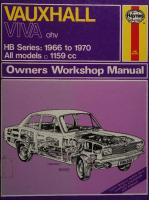
Haynes Vauxhall Viva HB Series: 1966 to 1970 All Models Owners Workshop Manual 0900550260, 9780900550263
“230p. : 28cm 'Models covered: 1159c.c. Saloon, Saloon De-Luxe, SL, September 1966 to October 1970; De-Luxe 90, SL
131 99 18MB
English Pages 236 Year 1987
Recommend Papers
- Author / Uploaded
- John H. Haynes
- D. H. Stead
- Similar Topics
- Technique
- Transportation: Cars, motorcycles
File loading please wait...
Citation preview
VAUXHALL VA om HB Series: 1966 to 1970 All models co 1159 cc
Ly
HN Withdrawn EDINBURGH CITY LIBRARIES Reference Department q THIS ANY
MENT. THE
BOOK
PRETEXT
MUST FROM
NOT THE
INFRINGEMENT OFFENDER
LIABLE
BE
REMOVED
REFERENCE
OF THIS TO
RULE
UNDER DEPART-
RENDERS
PROSECUTION.
Before leaving the Library readers must return the books to one of the attendants at the issue desk, or they will be held responsible for them. Readers are required to take care of the books. Writing or drawing with pen or pencil on any part of a book, or turning down the leaves, or cutting or mutilating them, will be treated as serious damage.
CoNVERSATION IN THE REFERENCE DEPARTMENT IS ANNOYING TO STUDENTS, AND IS NOT PERMITTED. Class.
:
Location.
:
Accession.
Vauxhall Viva HB Owners Workshop Manual by J H Haynes Associate Member
of the Guild of Motoring Writers
and D H Stead Models covered:
1159 cc Saloon, Saloon De-luxe, SL De-luxe 90, SL9O Estate cars (De-luxe, SL and 90)
September 1966 to October 1970. September 1966 to October 1970. June 1967 to October 1970
Does not cover automatic transmission
ISBN
©
900550
26
0O
Haynes Publishing Group 1971, 1980, 1987
ngcoe KL
All rights any form recording in writing
reserved. or by any or by any from the
No part of this book may be reproduced or transmitted in means, electronic or mechanical, including photocopying, information storage or retrieval system, without permission copyright holder.
Printed in England
026—1N2
Haynes Publishing Group Sparkford Nr Yeovil Somerset BA22 7JJ England Haynes Publications, Inc 861 Lawrence Drive Newbury Park California 91320 USA
E.CL
| EDINBURGH CITY LIBRARIES
Acknowledgements Thanks are due to Vauxhall Motors Limited, for assistance given in the supply of technical material and illustrations, and to the Champion Sparking Plug Company for the illustrations showing the spark plug conditions. The bodywork repair photographs used in this manual were provided by Lloyds Industries Limited who supply ‘Turtle Wax’, ‘Dupli-color Holts’, and other Holts range products. The help of Mr. R.T. Grainger and Mr. L. Tooze
the
must be specially acknowledged
the technical photographs; and that also of Col. F. T. Nicholson in helping to guide the text along. Although every care has been taken to ensure the correctnes¢ of data used, it must be borne in mind that alterations and design changes can occur within the production run of a model without specific reclassification. No liability can be accepted for damage, loss or injury caused by errors or omissions in the information given.
in the preparation of
Photographic Captions & Cross References The book is divided into twelve chapters. Each chapter is divided into numbered sections which are headed in bold type between horizontal lines. Each section consists of serially numbered paragraphs.
There
are
two types of illustration.
which are numbered sequence of occurrence
individual
caption
(1) Figures
according to Chapter and in that Chapter and having an
to each
figure.
(2) Photographs
which have a reference number in the bottom lefthand corner. All photographs apply to the chapter in
which they occur so that the reference figures pinpoint the pertinent section and paragraph numbers. Procedures,
2
once
described
in the text, are not
normally repeated. If it is necessary to refer to another
chapter the reference will be given in chapter number and section number thus:- Chapter 1/6. If it is considered necessary to refer to a particular
paragraph in another chapter the reference is ‘Chapter
1/6:5’. Cross references given without use of the word ‘Chapter’ apply to same chapter, e.g., chapter’. When the left mentioned it is as direction of travel.
sections and/or paragraphs in the ‘see Section 8’ means also ‘in this or right-hand side of a car is if one was looking in the forward
sydtaddor
V
8771304 NUE accaind frase tees
aesozyny
GANOILOSS M3IASO 3HL
ae —
VAIA8H
ONIMOHS S3HL
NOILISOd 4O 11V
YOrVW
SLNANOdWOOD
Introduction This owners workshop manual is intended for the owner of an HB series Vauxhall Viva, who, having acquired his car either new some years ago, or secondhand recently, does not wish to spend a fortune in keeping it in a safe, economical and good value condition. No one, however, particularly with all round commitments and interests wishes to spend all his leisure time in looking after his transport. This manual is designed therefore to enable the practically minded owner to maintain his car and at the same time show him the way to carry out most of the repairs that a car normally requires during its life as economically and quickly as possible. The modern trends in motor car design and production are towards the fitting of components which are renewed completely if they fail — the economics being that the cost of the time required to repair them is little less than the combined cost of labour and material needed to produce them in the first place. However, this trend has not yet moved things completely out of the owner’s control and many items such as starter motors, dynamos, fuel pumps, distributors, brake cylinders, and so on can be repaired for an expenditure of pence (new!) on parts where replacement would cost pounds Where a component is only obtainable as a complete unit, an owner should be quite able to install it correctly with the aid of this manual. Now that vehicles over three years old require annual safety checks the need to know where to look
4
for deterioration in the safety areas is impressed on the owner even more forcibly. Failure will result in loss of use and all the consequent inconvenience and expense. This manual enables the owner to examine the vehicle himself and so ensure its continued safety well before the date of inspection is due. For the more ambitious owner, this manual gives step by step details of all the other repairs and overhauls which we consider are within the capabilities of a practically minded person who is in possession of a reasonably comprehensive set of tools. With regard to the latter, this is one area where only good quality equipment will do. The authors also discourage the borrowing of tools except for certain special items which may only be used once in a blue moon. Certainly we would say that you should not be annoyed if someone should refuse to lend them. Appreciate how much they
cost if lost or damaged — apart from the fact that keen owners regard their tools as particularly personal belongings. Much of the work involved in looking after a car and carrying out repairs depends on accurate diagnosis in the first place. Where possible, therefore, a methodical and progressive way of diagnosis is presented. The time that can be wasted in hopping from one possible source of trouble to another, suggested at random quite often by self styled ‘experts’ must have been experienced by many people. It is best to say at the start therefore, ‘This could be one of several things—lets get the book out’.
Contents Page
Se
en
nn
a
ee
we |
Photographic captions & cross references
2
Introduction
4
Routine maintenance
6
earn. Sonam |. Focameniedicbacenic, ue
9
Lubrication chart Ordering spare parts
10
Chapter 1 Engine
11
Chapter 2 Cooling system
45
Chapter 3 Fuel system and carburation
54
Chapter 4 Ignition system
74
Chapter 5 Clutch and actuating mechanism
85
Chapter 6 Gearbox
93
Chapter 7 Propeller shaft and universal joints
110
Chapter 8 Rear axle
114
Chapter 9 Braking system
123
Chapter 10 Electrical system
145
Chapter 11 Suspension — dampers — steering
194
Chapter 12 Bodywork and underframe
a Safety first!
a
rayBe)
ee
et ee ee Index
ee 228
el 229
Routine Maintenance Maintenance should be looked upon as essential for ensuring safety, and desirable for the purpose of obtaining economy and performance from the car. By far the largest element of the maintenance routine is visual examination. Each chapter of the manual gives details of the routine maintenance requirements. In the summary given
500 miles
EVERY 500 mile intervals/weekly. ENGINE Check oil level in sump and top up as required. Check radiator coolant level and top up as required. Check battery electrolyte level and top up as required.
STEERING Check tyre pressures.
6
here the safety items are shown in bold type. These must be attended to regularly in the interests of preventing accidents and possible loss of life.
Neglect of other items results in unreliability, overall increased running costs and more rapid depreciation of the value of the car.
Examine tyres for wear and damage. Is the steering still smooth and accurate? Check hydraulic fluid reservoir level. If a significant drop is apparent examine system for leaks immediately. Is there any reduction in braking efficiency? Try an emergency stop. Is adjustment necessary?
LIGHTS Do all bulbs work at front and rear? Are headlamp beams correctly aligned?
Routine Maintenance safety items in particular are not performing correctly.
3,000 miles EVERY 3,000 mile intervals/4 monthly, or if indications
are that safety items in particular are not performing correctly.
ENGINE Fit new distributor contact points. Fit new spark plugs. Fit new carburetter air cleaner element
(or clean
washable variety). Flush out the cooling system.
ENGINE Drain sump of oil when hot and refill with fresh oil. Check fan belt tension and adjust as necessary. Check spark plug electrode gap.
CLUTCH
GEARBOX Check oil level and top up as required.
BACK AXLE
Check clutch cable for adjustment and for fraying : and operation.
Check oil level and top up as required.
STEERING Remove front wheel
STEERING Is there any free play between the steering wheel and road wheels? Examine all steering linkage rods, joints and bushes for signs of wear or damage.
BRAKES
bearings, flush, inspect and re-
pack with grease.
BODY FRAME Examine for rust where suspension is attached.
SUSPENSION
Examine pads and shoes to determine the amount of friction material remaining. Renew as necessary.
Grease front suspension arm ball joints.
BRAKES Renew servo unit air filter (disc brake models.)
6,000 miles EVERY 6,000 mile intervals/8 monthly, or if indications are that safety items in particular are not performing correctly.
24,000 miles
GEARBOX Drain and replenish oil.
ENGINE Renew oil filter element. Check valve clearances and adjust as necessary. Clean the fuel pump filter. Lubricate the distributor. Lubricate the generator rear end bush.
REAR AXLE Drain and replenish oil.
Non-Specified Intervals
STEERING Check front wheel hub bearings and adjust if necessary. Examine steering gear rubber boots for signs of
deterioration and/or oil leakage. BRAKES Examine all hydraulic pipes, cylinders and unions for signs of corrosion,
dents, chafing or any other form
of deterioration or leaks.
SUSPENSION Examine all suspension
mounting for signs of looseness or wear.
of components requires that they be cleaned. The same applies to the body of the car, inside and out, in order that deterioration due to rust or unknown damage may be detected. Certain ‘parts of the vehicle body frame if rusted badly, can result in its being declared unsafe, and it will not pass the annual test for roadworthiness.
EXHAUST SYSTEM
bushes and joints
12,000 miles
EVERY
CLEANING Examination
12,000 miles/annually, or if indications are that
An exhaust system must be leakproof and the noise level below a certain maximum. Excessive leaks may cause carbon monoxide fumes to enter the passenger compartment. Excessive noise constitutes a public nuisance. Both these defects may cause the vehicle to be kept off the road. Repair or replace defective sections when symptoms are apparent.
ese
cee
ses
eee
cee
see
“HO
apes6-n
ny
ee
ee
oo
eee
cee
.
eee
ce
ee
eco
see
ESET Lae acer)ates ake te
uinajonead =Aijaf + "+
ST0 bee
et ee oe
AjjeuoIIPpYY [OUIseD
,weWAJAA, j10 UeDd aq pasn0} ajed!sqQn} ‘JOOP 300q Pue ‘saBuiy pue ‘sy90} SJOAId*938
ene pri erry = ce oeoe fe oe ee Ae on
om
“pee& TA
JaUUOG
erehw
us A) nN Outlet pipe Drain tap Washer Overflow pipe Clip
—=
je)
c< Q
——.
Mounting strap 12. Mounting bolt 13. Washer 14. Filler cap 15. Top hose
16.
Bottom hose
17. 18.
Bottom hose (heater fitted) Hose clips
Chapter 2/Cooling System pk atcha teh hc
a
Re
pull it off the connector. 4. Remove the clip securing the bottom hose to the input side of the water pump (see photo) and pull the hose from the pump. 5. Remove the four bolts (two each side) which hold the radiator to the bodyframe. (See photo). 6. Lift the radiator complete with hoses from the car. (See phcio). 7. With the radiator removed from the car any leaks can be soldered up or repaired with a substance such as ‘Cataloy’. An unfortunate fault on some models is the fragile nature of the upper and lower radiator tank sections where the hose pipe unions are soldered in. With time they have been known to fracture due to the rocking motion of the flexibly mounted engine — or of course with rough handling when removing the flexible rubber hoses. If this occurs remove the radiator and resolder the joint running in a reinforcing fillet of solder. This reduces the flexibility of the thin tank material at the joint. Clean out the inside of the radiator by flushing as described in Section 4. When the radiator is out of the car it is well worthwhile to invert it for reverse flushing. Clean the exterior of the radiator by hosing down the matrix (honeycomb cooling material) with a strong water jet to clear away embedded dirt and insects which will impede the air flow. 8, If it is thought that the radiator may be partially blocked it is possible to test it. Five gallons of water poured through a 1% in. diameter pipe from a height of 2 feet above the filler cap should pass through the radiator in 22 seconds. If there are obvious indications of blockage a good proprietary chemical product such as ‘Radflush’ should be used to clear it. 9. Inspect the radiator hoses for cracks, internal or external perishing, and damage caused by overtightening of the securing clips. Replace the hoses as necessary. Examine the radiator hose securing clips and renew them if they are rusted or distorted. The drain taps should be renewed if leaking, but ensure the leak is not caused by a faulty washer behind the tap. If the tap is suspected try a new washer first to see if this clears the trouble.
10 Replacement
is a straightforward
reversal
of the
removal procedure.
7. Thermostat Removal, Testing & Replacement
aS
is
I
SEES
NE
one. 6. If the thermostat
is stuck open when cold, this will be apparent when removing it from the housing.
7. Replacing the thermostat is a reversal of the removal
procedure. Remember to use a new paper gasket between housing elbow and the thermostat. the thermostat Renew the thermostat elbow if it is badly eaten away.
Nag ee 2 a Se 8. Water Pump — Removal & Replacement ACN es ee 1. Partially drain the cooling system as described in Section 3. 2. Undo the clips which hold the hoses to the water pump and pull the hoses off.
3. Remove the fan belt (see Section 11). 4, Undo
the 6 bolts which hold the pump
body to the
cylinder
block.
away
and remove
Lift the water
pump
the gasket. 5. Replacement
is a straightforward reversal. of the removal sequence (see. photo). NOTE: The fan belt tension must be correct when all is reassembled. If the belt is too tight undue strain will be placed on the water pump and dynamo-bearings, and if the belt is too loose it will slip and wear rapidly as well as giving rise to low electrical output from the dynamo.
9. Water Pump — Dismantling & Reassembly All bracketed numbers refer to Fig.2.2. 1. Having removed the assembly from the engine complete with fan, remove the fan (17) and drive pulley (20)
by unscrewing the four bolts and washers (18 and 19). 2. In order to get at the seal (4) the rotor (6) must be drawn off the shaft. There is no satisfactory way of doing this other than by using a puller — preferably one with two split claws so that the strain can be put onto the rotor astride the vanes which are the strongest part (Fig.2.4). If the rotor is a particularly tight fit any other way of attempting to remove it will probably break it. 3. With the rotor off, the seal (4) can be withdrawn. Examine the seal seat on the body of the pump for damage or pitting. 4. \f the shaft/bearing assembly (2) needs to ke renewed (due to excessive play in the bearings) it can now be removed. First lift out the locking ring (3) and then
1. To remove the thermostat, partially drain the cooling
heat the body of the pump in water to 82°C (180°F).
system (4 pints is enough), loosen the upper radiator hose at the thermostat elbow end and pull it off the
The shaft can then be drifted out complete with flange (5) at the flange end of the body. When out press or drift off the flange. 5. Reassembly sequence is in the reverse order but care must be taken to fit everything back in certain positions. 6. If the shaft assembly «is being renewed, first of all press the flange on to the smaller end of the new shaft (identified by a groove close to the end, Fig.2.5). 7. Ensure that the flange boss is towards the end of the shaft and that the outer face of the flange is 3.46 in. (88 mm.) from the end of the body. (Fig.2.6). 8. Re-heat the pump body and install the shaft and bearing so that the groove in the bearing coincides with the groove in the body bore. Refit the locking ring. 9. Smear the face of the new seal with the recommended grease (and also around the body bore), and install the seal. 10 Press on the rotor (vanes inwards) so that the clearance between the flat face of the rotor and the
elbow. 2. Unscrew the two set bolts and spring washers from the thermostat housing and lift the housing and paper gasket away. (See photo). 3. Remove the thermostat (photo) and suspend it by a piece of string in a saucepan of cold water together with a thermometer. Neither the thermostat nor the thermometer should touch the bottom of the saucepan, to ensure a false reading is not given. 4. Heat the water, stirring it gently with the thermometer to ensure temperature uniformity, and note when
the thermostat begins to open. The temperature at which this should happen is given in the specifications on page 45. 5. Discard the thermostat if it opens too early. Continue heating the water until the thermostat is fully open. Then let it cool down naturally, If the thermostat will not open fully in boiling water, or does not close down as the water cools, then it must be exchanged for a new
48
pump
body
is .044 in. (1 mm).
(Fig.2.5).
gasket when replacing the pump on the block.
Fit a new
gw NULLA
\\
Pixs i
)
oy y
)
belt Fan
21
18. bolt19. mounting Fan Washer belt Fan 20. pulley
a
= 5a ccWwW ke
w
housing Thermostat washer 12. Star 9. Bolt11.Gasket 10.
Impeller
6. Gasket 7. flange Pulley 5.
shaft Impeller Pump body . 1 2. 3. Clip4. Seal
Chapter 2/Cooling System
10. Anti-Freeze Mixture
1. In circumstances where it is likely that the temperature will drop to below freezing it is essential that some of the water is drained and an adequate amount of ethylene glycol anti-freeze such as Bluecol added to the cooling system.
2. If Bluecol is not available any anti-freeze which conforms with specification B.S.3151 or B.S.3152 can be used. Never use an anti-freeze with an alcohol base as
evaporation is too high. 3. Bluecol anti-freeze with an anti-corrosion additive can be left in the cooling system for up to two years, but after six months it is advisable to have the specific gravity of the coolant checked at your local garage, and thereafter once every three months during winter. 4. Given below are the recommended percentage of solution (by volume) and quantities for the Viva, to give
frost protection at various temperature:%
Quantity
Safe limit
Solution
Pints/litres
C°
20 25 30 40 50
Lia Zia) 3% 4% 5%
cfc) {8} -18 O -23 -10 _ ~ — -
25 1.50 1.80 2.30 2.90
F°
Complete Protection
CQ
effort unless the pivot bolts are slackened only a little so that the dynamo is quite stiff to move. A lever between the dynamo and block can help and when the belt is tight lock up the brace nut and bolt first. y 5. Check that the tension is such that at a point midway between the dynamo pulley and pump pulley, the deflection is % in. with a 9 Ib. load on. (As far as you can push it with one finger). If in doubt it is better to be a
little slack than tight. Only slipping will occur
if it is
too slack. If too tight, damage can be caused by excessive strain on the pulley bearings. 6. When the adjustment is right tighten all the dynamo mounting bolts.
7. With a new
belt, check the tension
250 miles after
fitting.
8. Periodic checking of the belt tension is necessary and there is no hard and fast rule as to the most suitable interval, because fan belts do not necessarily stretch or wear to a pre-determined schedule. Assuming most owners check their own oil and water regularly it is suggested as a good habit to check the fan belt tension every time the bonnet goes up. It takes only a second.
|e
21 si We -14 6 -23 -10 -35 -31
11. Fan Belt — Removal, Replacement & Adjustment
1. If the fan belt is worn or has stretched unduly it should be replaced. The most usual reason for replacement is breakage in service and every wise motorist will carry a spare always.
2. Even though the belt may have broken and fallen off, go through the removal routine which is first of all to loosen the two dynamo pivot bolts and the nut on the adjusting link (brace), (Fig.2.7) and push the dynamo towards the engine. Take the old belt off the three pulleys. 3. Put a new belt over the pulleys. 4. The dynamo must now be used as a tensioner in effect, by pulling it away from the engine and locking it in the required position. This can call for some sustained
12. Water Temperature Rectification
Gauge
—
Fault
Diagnosis
&
1. If no reading is shown on the electrically operated water temperature gauge when the engine is hot and the ignition switched on, either the gauge, the sender unit, or the wiring in between is at fault. Alternatively No.2 fuse may have blown. 2. Check the fuse and, if satisfactory, pull off the wire from the sender unit in the cylinder head. Connect a lead containing a 12 volt 6 watt bulb (this is essential to prevent damage to the water temperature gauge coils) between the end of the wire and a good earth. 3. Switch on the ignition and check if the gauge is working. The needle should rise to the ‘H’ (hot) or 130°C mark which indicates that the sender unit must be renewed. To do this simply undo it and fit a replacement item. 4. If the sender unit is apparently working correctly, check the gauge and, if necessary, replace it. Details of how to remove the gauge are given in Chapter 10.
— ————
IJes a
fl
SP 1942
Fig.2.3. CROSS SECTION OF TWO TYPES OF THERMOSTAT A
51 inch (fully open)
1
FITTED B_ .48 inch (fully open)
Fig.2.5. CROSS SECTION OF WATER Shaft seal 2 Impeller Dimension
‘A’ = .44 inches.
Fig.2.4,
Photo
showing water pump impeller from shaft with an extractor.
being
PUMP Fig.2.6. CROSS SECTION Dimension
OF WATER PUMP
‘A’ = 3.46 inches.
removed
BRACE BOLT _ AND NUT
Fig.2.7.
Illustration to show the bolts to be slackened
in order to pivot the dynamo
fan belt (lower).
(upper) and the tensioner checking point of the
Fault Finding Chart — Cooling System a Symptom
?
Reason/s
TF Remedy
SS
Loss of coolant
Leak in system
Defective
Overheating
radiator
Examine all hoses, hose connections, drain taps and the radiator and heater for signs of leakage when the engine is cold, then when hot and under pressure. Tighten clips, renew hoses and repair radiator.
pressure
cap.
Examine cap for defective seal or spring and renew if necessary.
Overheating causing rapid evaporation due to excessive pressure in system forcing vapour past radiator cap. Blown cylinder head gasket causing excess pressure in cooling system forcing coolant past radiator cap overflow.
Check reasons for overheating.
Cracked block or head due to freezing.
Strip engine required.
Insufficient coolant in system.
Top up.
Water pump not turning properly due to slack fan belt.
Tighten fan belt.
Kinked or collapsed water hoses causing restriction to circulation of coolant.
Renew hose as required.
Faulty thermostat erly).
Fit new thermostat.
(not opening prop-
Engine out of tune. Blocked radiator externally.
either
Cylinder head gaskets coolant out of system.
Engine running too cool
internally
blown
or
forcing
Remove cylinder head for examination
and
examine.
Repair as
Check ignition setting and carburetter adjustments. Flush out cooling system and clean out cooling fins.
Remove head and renew gasket.
New engine not run-in.
Adjust engine speed until run-in.
Missing or faulty thermostat.
Fit new thermostat.
53
Chapter 3/Fuel System and Carburation Contents
Generali Descriptions
wm.
.macsda-chee
Routine Maintenance
=
eee
Semgis
ee
Stromberg
sien aeosne:
Level Setting..
150 CD Carburetter - Fuel Chamber Fuel
=o US
Air Filter Element -Removal A Servicies ety ee: Solex Carburetters - Description ... .. .4 Solex B30 PSE1-6 Carburetter - Removal iDremanthing & Reassembly... ... ... . pn tay Solex B30 PSE1- 6 Carpurerier -‘Replacement =ates 2 6
Stromberg 150 CD Citourettces Distant & Reassembly. ... ... po it y . Pee Om Fuel Tank- Romival & Replacements RM, ses ee AZ Euel.\PumpaRemovall somenas ce atteceae... oc -. 13 Fuel Pump- Dismantling ... ... . . 14
Solex B30 PSE1-6 Carburetter -Adjustment ASM WON Ca ewiaG enon cease be
... ... ... u ae co IAN
Fuel Pump- Inspection, Reassem bi Si eoieci nett, 15 Fuel Gauge Sender Unit -Fault Finding... ... ... ... .. 16
Stromberg 150 CD Carburetter -Description
... ... ... 8
Exhaust: Systempcomeneaes =eat
Stromberg 150 CD Carburetter - Adjustments...
...
eerie.
17
... 9
Specifications
a
a
Fuel Pump Makeran cityGee ett ttestt sarcsnists ietunsuieul cea Delivery pressure. # Diaphragm spring (ond hed compel to % ect
ane ee CMY.Da we ee 2% — 3% Ibs.in2 a8 erie 4% |bs. approx.
Carburetters - HB 22 Engines MAN Gis Sivas cuss ssnalaivss scam Meee ce & TL ee SOLO BS OIRSEI-6 RY Steams at se), onsig SugietaMeavire sotien ea Miben cack eee IX CCICHOIKE Air cleaner element Le cc oC ny! ee aa. Oe (GEUPZS Paper EleMentimumber....
Jive
WURVAVAVVY
HOLIMS $20Nis
t10 /8t
= te _
eee
OC|
6
QIONTIOS
Ge oe
sta
ar
5
/ OVO NI3BDBaim Wee 16 0 er 10/91/91 |sc] wwe /c10/6 2UHM L1Hs8 t10 9WG 3369 mm /Ji / O30 3mm Newnes awene
oh
=
/ M338
Nuves
=
HOLME
wOLNetws
/ 3N78
SoMa gC
/¥I a0
H
ieH 4 6 SASSI SSIES aa LSSSSSSSSASSSSY 4 H | ¢ H HH 4 U
66
ane 03u/ BHM / 3078
H
83134
3M /
H
BHM
wv
L
BuIHm
se
16
Wwo>
OVIINSOMIM
63209
ees MLS
£1016 or]|
ODSIIPISI Sw
paivyas
vt
e9 ) Baim
SG
O10/
a
=’
wowre
ae
/ 3078
FT
LF WwredHs uprvaue 1indwD A
20S
se|
PMT
to
z
[] fr
aa se oe
/er 210
BAY
A
| N33BD 197
ei
Ae
IF |
HLIMS
A
2110/6 Cr |
Y
/6e 210
g
MOUS
se se THO
1016 2C | O34/
gAg
/N33¥93078
ee 3 1] a
O1724
g
O10 m1/ 311MM Pi/ 010 NMOBG/NI9UD
g Z g4
cios
sc 4Z
—
/ t10 /0z 210
z ee
g g Y g gZ
of ez
a
—
a
o3a/ania|zr|
Fyne ONIN Corer
TID
oy
“i 5
16 t1I0 /6 210
OL IC 8 Ie
ve cest 6 6
weune Jiimm | Twn
eo
CC OL OF 1€ OF 12
ze CLOL
AV)
—_/
N33u9
(sae,
eee
V
ee
=
A, se
ce
ei
.
/ey t10 /ee 210


