Haynes Datsun/Nissan Bluebird 160B & 180B Owners Handbook & Servicing Guide 0856969389, 9780856969386
“146 pages : 24 cm Includes index”.
122 47 10MB
English Pages 160 Year 1984
Recommend Papers


File loading please wait...
Citation preview
ATSUN/NISSAN LUEBIRD 160B/180B WNERS HANDBOOK Servicing Guide
AUTHOR
CLASS
Miscsee-
og
M
TITLE WATS
Def
es SSA
BLAceieD
Vac
A
68466106
This book should be returned on or before the
Lancashire
County .@s
Council
latest date shown above to the library from _
Cy
which it was borrowed.
LIBRARY
HEADQUARTERS
Tas: CORPORATION ST. PRESTON PR1 2TB
WAU) ONIN 118
O55 332/228
Digitized by the Internet Archive in 2022 with funding from Kahle/Austin Foundation
https://archive.org/details/datsunnissanblueQ000mint
Datsun/Nissan Bluebird All Datsun/Nissan
Bluebird
160B &180B
models:
610, 810 and 910 Series Saloon, Coupe and Estate 159 brccaae 17 7Orec
Owner's Handbook/Servicing Guide by Matthew Minter
FGHI
68466106
Acknowledgements Thanks are due to the Nissan Motor Company Limited, of Japan, for the provision of technical information and certain illustrations used in this book. Thanks are also due to Tor View Garage of Glastonbury, and to Mead and Taylor of Mudford, Yeovil. Advice on spark plug conditions was given by the Champion Sparking Plug Company.
A book in the Haynes Guide Series.
Owner's
© Haynes Publishing Group
Handbook/Servicing
1984
Printed and published by the Haynes Group, Sparkford, Yeovil, Somerset BA22
ISBN O 85696
Publishing 7JJ
938 9
Although every care has been taken to ensure the correctness of data used, it must be borne in mind that alterations and design changes can occur within the production run of a model specific reclassification. No _ liability
without can be accepted for damage, loss or injury caused by 2 errors or omissions in the information given.
Contents What's
in it for You?
About this Handbook
The Bluebird
Family
Main production dates and changes
Road Test Data Performance figures from Autocar
In the Driving Seat Instruments,
10
controls, layout
Filling Station Facts
25
Garage forecourt guide to tyre pressures etc.
QUICK-CHECK
CHART
28
Fill-up data at-a-glance
In an Emergency Get-you-home
29
kit, wheel changing, towing, light bulb renewal
46
Save It! Cutting motoring costs — safely
Vital Statistics Technical
om
data on all models
Tools for the Job
58
Getting equipped — what to buy
Service Scene What
62
to do, when, and how to do it
Body Beautiful
103
Cleaning, renovating, repairing bodywork
The Personal Touch
109
Adding accessories
Troubleshooting
(CS)
Charts to help when things go wrong
Car Jargon Explained
i32
‘What are they talking about ...?’
Conversion
Factors
140
‘What's that in pounds per square inch ...?’
Index
142
Bluebird 180B Mk! Saloon
Bluebird 180B Mk II Saloon
Bluebird 180B Mk/! Coupe SSS
Bluebird 180B Mk // Estate
Bluebird 910 Series Estate
What's in it for You ? Whether you've bought this book yourself or had it given to you, the idea was probably the same in either case — to help you get the best out of your Bluebird and perhaps to make your motoring a bit less of a drain on your hard-earned cash at the same time. Garage labour charges can easily be several times your own hourly rate of pay, and usually form the main part of any servicing bill; we'll help you avoid them by carrying out the routine services yourself. Even if you don’t want to do the regular servicing, and prefer to leave it to your Nissan dealer, there are some things you should check regularly just to make
sure that your car's not a danger to you or to anyone else on the road; we tell you what they are. If you're about to start doing your own servicing (whether to cut costs or to be sure that it’s done properly) we think you'll find the procedures described give an easy-to-follow introduction to what can be a very satisfying way of spending a few hours of your spare time. We've included some tips that should save you money when buying replacement parts and even while you're driving; there’s a chapter on cleaning and renovating your car, and another on fitting accessories. Apart from the things every owner needs to know to deal with mishaps like a puncture or a blown bulb, we've put together some Troubleshooter Charts to cover the more likely of the problems that can crop up with even the most carefully maintained car sooner or later. There's also a set of conversion tables, a section explaining the sort of jargon used by experts (and notso-experts!) when talking about cars, and a comprehensive alphabetical index to help you find your way round the book.
If the bug gets you, and you're keen
to tackle
some of the more advanced repair jobs on your car, then you'll need one of the Haynes Owners Workshop Manuals for the Bluebird series - OWM 372 for the early models or OWM 957 for models from 1980. These books give a step-by-step guide to all the repair and overhaul tasks on these cars, with plenty of illustrations to make things even clearer.
The Bluebird
Family
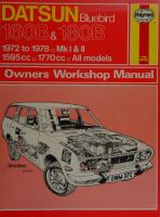
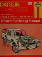
The Datsun Bluebird range was introduced to the UK in April 1972. Known also as the 160B (with 1595 cc engine) and 180B (1770 cc), and collectively referred to as the 610 Series, models available initially were the 160B Saloon SGXL, 180B Saloon SGXLS and 180B Coupe SSS. The 180B Estate joined the range early in 1973. Mechanically the cars were of conventional design, with the four-cylinder overhead cam engine driving the rear wheels via a four-speed manual gearbox. One unusual feature for a car of this type was the provision of independent suspension on the rear wheels as well as the front, though the Estate retained the less sophisticated ‘live’ rear axle. Automatic transmission was available as an extra on the Saloon and (briefly) on the Coupe. Certain styling changes to the front and rear of the cars occurred in November 1973, and at the same time the design of the instruments was improved. The Coupe gained a 5-speed gearbox and increased diameter wheels. Thereafter few changes were made until the end of the 610 Series early in USE The original Bluebird was superseded by the Mk Il models, officially known as the 810 Series. Mechanically there was little change from the preceding models, but the appearance of the cars was considerably changed both inside and out. From the driver's point of view the most significant improvement was probably in visibility, the new models having a lower waistline and slimmer window pillars. As before, the choice of models was limited to the Saloon in 160B or 180B guise, with Coupe and Estate versions of the 180B only. Rear wash/wipe was soon standard equipment on the Estate, while the Coupe retained its 5-speed gearbox and also
Datsun
160B/180B
April 1972 February 1973 November 1973 March
1977
April 1977 June 1977 December 1977 March 1980
May
1980
August 1982 January 1983 January 1984
boasted a wooden steering wheel. Automatic transmission was available only on Saloon models.
The Mk II Bluebird continued without significant changes until the spring of 1980, when the 910 Series took over. Styling changes this time were more dramatic, the new models having an almost European appearance. The old engine and transmission units were retained, but steering was changed from re-
circulating ball to rack-and-pinion.
Inside the car the
seat design was improved and the instrument panel layout had a more modern appearance. Weight savings compared with the earlier models, coupled
with lower wind resistance, gave improved performance. In 1982 minor trim changes were made, and the 5-speed gearbox became _ standard equipment on the 1.8GL Saloon and an option on the
Estate. The Datsun name gave way to Nissan in 1984. Here's a summary of the main production changes
in chronological
order:
Bluebird 610 Series introduced:
160B (1595 cc) Saloon SGXL,
180B (1770 cc) Saloon
SGXLS and Coupe SSS. Front ohc engine, rear drive, 4-speed gearbox; independent suspension all round 180B Estate introduced — as 180B Saloon but with live rear axle Styling and instrumentation changes. 5-speed gearbox and 14-inch wheels fitted to Coupe
180B Saloon and Coupe discontinued; Mk II (810 Series) Estate introduced 160B Saloon and 180B Mk | Estate discontinued 180B Mk II Saloon and Coupe introduced 160B Mk II Saloon introduced All Mk Il models discontinued 910 Series introduced: 1.6GL Saloon, 1.8GL Saloon, Coupe and Estate. Major changes to body and steering 5-speed gearbox standard on 1.8GL Saloon, optional on Estate Coupe discontinued Datsun
name
dropped
in favour of Nissan
6'VZ
af}ued
O/-O 09-0 Og—O Ov-O Q€-0
UOIE198/S00V7
aBuey O/ Og O¢€
‘(aunby
(ydw) paeds wnwixey|
uOo!dwINsSUOD
je (Bdw) uolduinsuos jan4 jan} ||248ACO
(Bdu)
sjuejsuod
(Saji) yUe} jan} |IN} UO ydw ydwi ydw
:(Spuosdeas)
ydwi ydwt ydw ydw ydw
ajlu 2 YWe1s Bulpueis
JeaB do} jewou ul yYdw O9-Ov
aie seinbiy esau] ‘uoissiuuad 1194} YIM e484 peonpoidas sie Ay] “paytul] ssaig WOdsues| Od] 4e90IN\V40 yuBuAdoo
SSL
ZOOL
L'6L
OLL G7l 88 €'9 TV
8 Zl 9°81 9EL 76 v9 ge
662 OLE TLV TLS
86 LOL BLL L°8 Gg ve
99€ €'0€ 9'°6E ggg WE
€Ol S1XDS uoOjes gO8L
Gsl
Lee LeOe 97 vy 6v 8 7Z
LOL Il MIN Yoo|eS gO8L
BOLT
abesany pieH afAls BulAlsig
wojj Uayxe} e}eG Se] peoYy
‘sjso] peoi suizebew seI0)N\Vy WOd} $JOR11X9 B1e 9194 peysijqnd sainBy eyt
ejNWO} ayy “SeiNBiy 1$9} ||219A0 pajonb ay} 0} siajo1 Bdw) apinb e sapiaoid }YyBl4 ay} UO d Hulpnjoul uoiduwinsuos Jayaq AjjuedyiuBis aAaiyoe ||!M S1BUMO Aue ‘Hulsey aouewope uos jen4 ‘pOUad 1$9} 41984} JOy BING UO!}dLUNSUOD |/218AO BU} S! ainBy Bdw ay, :uolduins
OOL uoojes 198°L
%OE+ Bdu = %{0la4aAas BulAlLig
%OCt
%OLt+ %0T+ Bdw %OL+ Asea abeiaAe suonspuod
PION
In the Driving Seat After that potted history of the Bluebird range, now let's take a look at some of the more important things you'll need to know from the driving seat. Fortunately, the manufacturers have laid most things out in a straightforward fashion and most experienced drivers will feel at home in a Bluebird from the word ‘go’. However, we're going to set out some information to enable you to get to know your Bluebird a little better if you've recently acquired it or are borrowing it from somebody else.
Instruments and warning lights
Tachometer (rev counter)
The accompanying illustrations give examples of the various instrument panel layouts which may be encountered. Most of the gauges and lights are selfexplanatory, but a few remarks on what they mean
When fitted, the tachometer shows engine speed in revs per minute (rpm). Never rev the engine so hard that the needle enters the red zone, and only allow it to enter the yellow zone briefly. If you're economyminded, keeping the engine revs around the area
and what you should do may not go amiss ...
Instrument panel layout — 610 Series (except Coupe)
Clock
5
Temperature gauge
11
Speedometer Direction indicator warning lights
6 7 8
No charge warning light Radio Clock reset knob
knob 12 Main beam warning light 713 Fuel gauge
Brake warning light
9 10
Mileometer (total) Mileometer (trip)
14
Trip mileometer reset
Oil pressure warning light
|
/nstrument panel layout — 610 Series (Coupe) Fuel gauge Oil pressure gauge Temperature gauge Clock Speedometer Direction indicator warning lights
Low fuel warning light Brake warning light Clock reset knob Mileometer (trip) Mileometer (tota/) Trip mileometer reset knob
13
Tachometer (rev
counter) 14 Main beam warning light 15 No charge warning light
|(|ae — —
PEEL
/nstrument panel layout — 810 Series (except Coupe)
Clock Radio No charge warning light
Oil pressure warning light Brake warning light
6
Direction indicator warning lights Speedometer
10 Main beam warning light 171 Trip mileometer reset knob
Mileometer (total) Mileometer (trip)
12 13
Temperature gauge Fuel gauge
ccm /nstrument panel layout — 810 Series (Coupe). LHD shown, RHD similar Direction indicator
6
Speedometer
im
warning lights
Tachometer (rev counter)
7 8 9
Mileometer (total) Mileometer (trip) Trip mileometer reset
12 Fuel gauge 13 Temperature gauge 14 Radio
No charge warning light Main beam warning light
knob Oil pressure gauge
75
10
Brake warning light
G@2®
GlOGk
Voltmeter
© -—————_}—__—__,
Instrument panel layout — 910 Series
Speedometer
Fuel gauge
Mileometer (total)
Tachometer
Mileometer (trip)
Voltmeter
Temperature gauge
Oil pressure gauge
IN THE where
maximum
torque
is
produced
(see
Vita/
Statistics) will give best results.
Fuel gauge with
The fuel gauge will only give an accurate reading the ignition on and the car standing on level
ground. It’s highly advisable to top up the tank before the fuel gauge reads empty — on some models this message is reinforced by a ‘low fuel’ warning light.
Temperature gauge During normal operation the temperature gauge needle should be somewhere in the centre section of the gauge, midway between ‘C’ and ‘H’. During hot weather or hard driving the needle may move closer to ‘H’ — this is OK, but if the needle actually enters the ‘H’ or red sector you should stop and check the
coolant level and fanbelt. Refer to Filling Station Facts and Service Scene for details, and remember to take precautions against scalding when checking the coolant level.
Oil pressure gauge or warning light lf your Bluebird has an oil pressure gauge, it should indicate between 2 and 5 kgf/cm? (28 and 70 lbf/in?) during normal running — maybe slightly less when the engine is hot and idling. If the reading drops much below this when you're driving, or if the needle flickers a lot, stop at once and check the oil level. If the level is low, top it up and resolve to keep a closer eye on it in future! If the level is OK but the oil pressure is still low (and the engine isn’t overheated) you should seek professional advice. Don’t drive the car with low oil pressure — serious engine damage can result, if it hasn't happened already. Where a warning light is fitted instead of a gauge, it should light up with the ignition on and the engine stopped, and go out as soon as the engine starts. It may flicker when the engine is hot and idling, but otherwise, if it comes on when driving, stop at once and check the oil level. Don’t drive the car with the oil pressure warning light on!
Vo/tmeter Only fitted to some Coupe models, the voltmeter should read between 11 and 15.5 volts (or stay out of the yellow and red zones) during normal running. Persistent low readings mean that you should check the fanbelt, alternator connections and battery electrolyte; if all these are in order, get a Nissan garage or car electrical specialist to check the battery and charging system. A low voltmeter reading while the engine is being started is normal.
DRIVING
SEAT
No charge warning light This warning light is fitted instead of a voltmeter on most models: it's coloured red and is marked ‘CHG’ or else bears a battery symbol. The light warns the driver that the alternator is not charging the battery. It should light up when
the ignition is turned
on before starting the engine, and go out as soon as the engine starts. It may come on or flicker when the engine is idling without anything being amiss, but if it lights up when you're driving, prepare for trouble. Stop as soon as you can and check the fanbelt and alternator connections. (See Service Scene for fanbelt renewal details.) If these are in order, get a Nissan garage or car electrical specialist to check the battery and charging system. You can get quite a long way on the juice in a healthy battery when it’s not being charged, provided you don't use the starter motor, lights or electrical accessories too much.
Brake
warning light
Another red light, the braking system warning light bears the legend ‘BRAKE’ or the international hieroglyphic of a circle in heavy brackets. The light serves two functions: it illuminates with the handbrake applied and the ignition on, thus testing the bulb and reminding the driver that the handbrake is on. If the light comes on when using the footbrake or during normal driving, stop as soon as you can in the circumstances and check the brake fluid level (see Service Scene). |f enough brake fluid has been lost to make the light come
on, this is probably due to a leak
in the brake hydraulic system which must obviously be seen to without delay. Because all Bluebird models have dual circuit brakes, you'll still have half the normal braking effort available, but don’t drive the car further than absolutely necessary in this state, and be prepared for stopping distances to be much greater than usual.
Other warning lights All models have direction indicator and headlight main beam warning lights. If the appropriate direction indicator warning light doesn’t flash when it should, check the indicator bulbs on that side. If both
direction indicator lights pack up at once, this suggests a faulty flasher unit or a blown fuse. The 910 Series Bluebirds also have warning lights to remind the driver that a door is open, the windscreen washer fluid is low, the choke is on, the battery fluid is low and that a stop/tail bulb has failed. These warning lights should come on for checking purposes whenever the ignition is on and the handbrake applied but the engine is not running. If they
come
on
when
the engine
is running
check
the 13
IN THE
DRIVING
SEAT
appropriate item. Pilot lights are provided for the rear foglamps, the heated rear window and the hazard warning switch. There's also a warning buzzer which will sound if the driver's door is opened with the ignition off and the lights on.
Switches and controls We'll assume clutch, brake and
that you know how to use the throttle pedals — otherwise it’s a
driving instructor you need, as well as this book! Let's start by considering the most important switch ...
/gnition/starter switch and steering lock On all models, this switch has five positions as shown in the illustration. Their functions are as follows: LOCK: The steering column is locked when the key is removed (and the key cannot be removed in
Direction indicator/ Control layout — 610 Series (typical)
dipswitch
Wiper/washer control Master lighting switch Bonnet release Hazard warning switch Heated rear window switch Throttle pedal Brake pedal Clutch pedal Choke contro/ Handbrake lever Tape player (optional) Gear lever Air vents Cigarette lighter Ashtray Glovebox Parcel shelf Air vent Radio
20
(G=-=
t
—— ma >
=
7
2 Sh
4 iS} 6 it 8 9 7
Contro/ layout — 810 Series (typical)
Glovebox Ashtray Heated rear window switch Radio Cigarette lighter Hazard warning switch
Wiper/washer control Horn button Key illumination light
Lighting control/ direction indicator switch Coin tray Air vent Bonnet release Throttle pedal Brake pedal Clutch pedal Choke control Air vents Handbrake lever Gear lever Parcel shelf
IN THE
DRIVING
SEAT
OLE
aR AAO
OIC:
OOD@D®”
Control layout — 910 Series (typical) 1
Air vent
2
Rear foglamp switch
3 4
Bonnet release Headlight washer switch
9
Steering wheel! tilt contro/
15 16
Hazard warning switch Radio
(not UK)
10
Foot ventilator
17
Cigarette lighter
Choke control Lighting control/ direction indicator switch Instrument light rheostat
11 /gnition/starter switch 12 Rear wash/wipe switch (Estate) 13 Windscreen wipe/wash switch
5 6
7
8
Remote mirror contro/
14
(not UK)
Heated rear window
switch
18 Heater controls 19 Ashtray 20 Air vent 21 Glovebox 22 Fuse box
ON: All electrical circuits are energised. This is the normal driving position. START: The starter motor is energised. The key will automatically spring back to the ‘ON’ position when it is released. It's well worth recording the serial numbers of the
ignition and door key(s) somewhere (outside the car!) so that you can obtain a replacement relatively easily in the event of loss.
Choke /gnition/starter switch and steering lock positions
any other position). If unlocking the steering proves difficult, move the steering wheel gently from side to side in order to relieve the tension on the steering lock. OFF: The steering is unlocked, but ignition and accessory circuits are dead. ACC: Electrical accessories are energised.
control and starting procedure
The choke control should be pulled out fully when starting a cold engine. (In very cold weather, pump the throttle pedal two or three times also.) Push the choke in to the halfway position as soon as the engine starts, then push it right home when the engine will run smoothly without choke. Leaving the choke out longer than necessary wastes fuel and can damage the engine. Some later models have an automatic choke, which means it’s no good looking for a choke control. With
a
cold
engine,
the
choke
must
be
‘set’
by
15
IN THE
DRIVING
SEAT
depressing the throttle pedal once and releasing it slowly. (In very cold weather, do this two or three times.) Operate the starter motor without touching the throttle pedal: once the engine is running, tap the pedal to reduce the fast idle speed. On all models, start a warm engine without choke and using one-quarter to one-half open throttle. If you flood
the engine
by too
many
attempts
at starting
with the choke, clear the flooding by slowly depressing the throttle pedal to the floor and holding it there while you operate the starter. Don’t pump the pedal or you'll make matters worse.
Lighting controls On 610
Series models there’s a master lighting
switch on the dashboard. With this switch pulled out, the operation of the lights is then controlled by the steering column stalk. With the stalk in the closest position to the dashboard, only the sidelights are illuminated. Moving the stalk towards the steering
wheel switches on the headlights; high and low beam settings are obtained by pulling the stalk further towards the steering wheel and then releasing it. This last operation will cause the headlights to come on for as long as the stalk is held if the master lighting switch is off. On later models the master lighting switch is located on the steering column right-hand stalk. Turning the switch forwards provides at the first position sidelights, at the second position headlights. Main beam is selected by pushing the stalk towards the dashboard, low beam by returning it to its middle position. Pulling the stalk towards the steering wheel against spring pressure causes the headlights to flash, regardless of the position of the master switch. Instrument panel illumination can be controlled on some models by means of a knob which increases or decreases the brightness of the panel lights. Rear foglamps, when fitted, have a separate switch which is wired so that the foglamps can only be used in conjunction with dipped headlamps. Don't forget to switch the foglamps off when the fog has cleared, or you will dazzle following traffic.
Windscreen
16
Lighting control — 610 Series A
Sidelights
B C
Headlights (high or low beam) Beam change or flash
ea
OFF
“| — & . PASSING
“s HIGH LOW ga o8 at
Lighting control — 810 and 910 Series. Use ‘passing’ position to flash headlights
ON a
Ka \
Rear foglamp switch (910 Series)
wipers and washer
The wiper/washer control is at the extreme righthand end of the dashboard on 610 Series models, and to the left of the steering column cowl on later models. The dashboard control must be pulled out to operate the wipers, successive positions giving intermittent (on some models), low speed and high speed operation. Twisting the knob clockwise operates the windscreen washer. The steering column controls must be twisted and pushed or pulled to achieve similar results. On Estate models the tailgate wash/wipe control
Wipe/wash control (610 Series) — pull for wipers, twist for washer
IN THE is of the pull-and-twist variety on the 810 Series; on the 910 Series there is a separate rocker switch for wiper and washer.
gm
movement
of the
steering
wheel
WASH
Hi Sy Wipe/wash control — 910 Series shown, 810 similar
switched on. Once set to signal a left or right turn, the stalk will stay in position until cancelled by hand or by sufficient
12 SEC.
ay
Loy
The direction indicators are operated by moving the steering column right-hand stalk upwards to signal a left turn, downwards to signal a right turn. The indicators only work when the ignition is
SEAT
4SEC. ¥ int &
Direction indicator switch
DRIVING
ON
in the
opposite direction. For lane changing on motorways it is sufficient to move the stalk just far enough to operate the indicators without latching into position; the stalk will then return to the neutral position when released.
=
LS
=
Hazard warning switch Located on the right-hand side of the dashboard on 610 Series models, and towards the centre of the dashboard on later models, the hazard warning switch will cause all four direction indicator lights to flash in unison. According to UK motoring law this facility can only be used when the vehicle is stationary, and is intended to warn other traffic that your car is immobilised in a hazardous position. Contrary to popular belief, use of the hazard warning lights does not entitle the driver to park on double yellow lines!
Heated rear window switch Located
next to the hazard warning
Hazard warning switch (910 Series shown)
SS)
switch, the
heated rear window switch supplies power to the heating element on the back window. This is very useful in damp or icy weather, but do remember to switch the heated rear window off when the window is clear — it consumes quite a lot of electrical power and could be a drain on the battery. For the same reason, don’t switch the heated rear window on when
Heated rear window switch
the engine isn’t running.
Horn The horn is sounded by pressing the button(s) located at the centre and/or on the spokes of the steering wheel.
Handbrake The handbrake may be of the familiar floormounted type, which is set by pulling the lever upwards, and released by pulling upwards slightly further and pressing the button on the end of the lever. The other type of handbrake control which may be found is the under-dash ‘umbrella handle’ lever: this is set by pulling the handle out, and released by
Handbrake lever — floor-mounted type
17
IN THE
DRIVING
TURN
SEAT
TO RELEASE
Rye
“4 SET
Handbrake
lever — under-dash type
pulling slightly further and turning the handle so that it points downwards.
On all models, a warning light reminds the driver is on.
Bp
that the handbrake
4-SPEED I Nal
Gear lever (manual transmission) The gearshift pattern varies according to model and year, as shown in the accompanying illustrations. Only engage reverse gear when the car is stationary.
2.4
i
2a
Automatic transmission Driving a Bluebird fitted with automatic transmission is pretty straightforward and the following tips will help you get the best from your transmission system. The engine can only be started with the control lever in either the P (park) or N (neutral) position. Before starting the engine ensure that the handbrake’s on, and once you've started the engine ensure that the footbrake’s on before you select a gear position. If the engine's cold and the choke’s in operation you'll feel a slight thump through the transmission as you engage R, D, 2 or 1. You'll also notice once you release the handbrake or footbrake that the car will tend to ‘creep’ — this is quite normal when the engine’s idling fast. Let's assume you're ready to move off; you've selected D and released the handbrake, now you only need to accelerate as normal and you're off. Gear changing will be automatic and according to road speed and throttle pedal position. If you want to overtake another vehicle and need increased acceleration, you simply floor the throttle pedal and the transmission will downshift and remain in this lower gear until you release the throttle pedal a little; then the transmission will change up again to the higher gear. Manual selection of the 2nd and 1st gears can be made when you want additional braking effort from the engine. Let's assume the transmission is in the D position and you select the 2nd gear position: the
18
transmission
will automatically change to 2nd gear.
Gearshift patterns — 910 Series. Direct changing between Sth and reverse is not possible
L.H.D.
R.H.D.
BUTTON
Automatic transmission selector positions. Button
must be depressed to make changes shown with solid arrows
Certain rules apply when doing this, and 2nd gear should never be selected at speeds over 65 mph (105 kph) or the transmission will be damaged.
Position 1 is intended to be selected from rest, when travelling on rough ground, or descending or ascending steep hills. If you select 1st gear when the
IN THE transmission is in D, an immediate change to 2nd gear will occur and 1st gear will be engaged at the controlled
gear change
Towing cars with automatic
distance
must
In all cases the transmission fluid must be up
place, it's necessary either to disconnect the shaft or to call for a ‘suspended tow’ with wheels clear of the ground. engine of an automatic transmission model
can only be started by using the vehicle's starter motor, and can’t be started by towing or pushing. In the event of a flat battery you'll have to use jump leads to get the car started — see /n an Emergency.
Heating and ventilation The heating and ventilation controls are pretty similar on all models, being of the slide type, sometimes with a rotary switch for the blower fan. The upper slide(s) control the distribution of air, the lower
(or lower left-hand) slide controls the air temperature, and the fan is controlled by the lower right-hand slide or the rotary switch. To obtain fresh air through the dashboard
on the top slide (and ‘FRESH’
vents,
on the
other top slide, if applicable). Open the vents of your choice and make sure the temperature control lever is set to ‘COLD’. Air at outside temperature will now be provided
at the vents
as you
OFF
TEMPERATURE
KNOB
FAN
KNOB
Heating and ventilating contro/s — 610 Series
ae
CONTROL LEVER FAN CONTROL Shore,
TEMP CONTROL
LEVER
Heating and ventilating controls — 810 Series
810 later
to the minimum mark on the dipstick. If the above conditions cannot be met, or a transmission fault is the reason for seeking a tow in
select ‘VENT’
PAIR
also be limited, to
approximately 6 miles (10 km) on 610 and Series vehicles, and to 20 miles (30 km) on
the first propeller the rear The
AIR KNOB
transmission
If the transmission is functioning correctly, the car can be towed with the selector lever in the ‘N’ position, but the speed must be limited to 20 mph (30
models.
SEAT
speed.
To prevent inadvertent gear changing, the button on the right-hand side of the selector lever must be pressed when engaging ‘R’ or ‘P’, and when changing from: DY to 2’. Positions ‘P’ and ‘R’ must only be selected when the car is stationary. In ‘P’ the transmission is locked up — rather like leaving a manual transmission car in gear — so this position should always be selected when parking unless violent movement of the car may occur (eg on a Car transporter). If you ever find yourself stuck in snow or sand, it may be possible to ‘rock’ the car free by engaging ‘R’ and ‘D’ alternately, with very light throttle applied. In this instance it is permissible to engage ‘R’ while the vehicle is rocking forwards. Position ‘2’ may be found useful for moving off on icy or slippery surfaces where the engagement of first gear might cause wheelspin.
kph). The towing
DRIVING
drive along.
Faster air
AIR CONTROL
a 00 8 00 0 8© a vent waar wor coro C5000 eee
CONTROL
INTAKE \ LEVER
LEVER
|
HoT
LEVER
Heating and ventilating controls — 910 Series
delivery (for slow driving or hot days) will be obtained by using the fan.
Moving the top slide to the ‘BI-LEVEL’
or ‘B/L’
position and commanding some heat from the lower slide enables you to maintain fresh air supplies at head level while heated air is discharged at foot level. Moving the top slide further towards ‘HEAT’ produces hot air at all outlets, while further movement to ‘DEF’ concentrates all the heater output on the windscreen. Close the vents for quick defrosting or demisting. At the risk of stating the obvious, it may be mentioned that the heater gets its heat from the engine, so it won't work very well until the engine has been running for a minute or two. The most rapid
19
IN THE
DRIVING
SEAT
heating will be obtained with the appropriate lever in the ‘RECIRC’ position, when the air already in the car is recirculated through the heater. This position can also be used for shutting out noxious fumes and unpleasant smells; otherwise, stick to the fresh air positions.
;
Seats and seat belts Front seats All front seats are adjustable fore and aft, either by moving the lever at the front of the seat sideways
or by moving the lever at the side of the seat upwards. Some pushing and pulling will then be needed to move the seat to the correct position. Release the lever when adjustment is correct and give a reasonable shove to make sure the seat is secure: if
Seat back adjustment lever — 610 and 810 Series
z
aN
Seat adjustment lever (fore and aft) -610 and 810 Series
Seat height adjustment lever — 610 and 810 Series
For Europe
REAR SEAT (For Europe)
Seat adjustments — 910 Series. Details may differ with model
1
Height adjustment
2
Fore and aft adjustment
3
Back adjustment
4
Seat back release (2-door
§
Lumbar support variation
models)
6
Headrest adjustment
IN THE it adjusts itself suddenly when you're driving, the consequences may be tragedy or farce. For the same reason, don't attempt any adjustment on the move. The angle of the seat back can be adjusted by
pulling the lever at the base of the seat back and pushing or pulling until the desired result is achieved. On two-door models, the same lever allows the seat back to be tilted forwards to allow rear seat passengers entry or exit. The height of the front of the seat can be adjusted by pulling the lever at the front next to the door. On some later models, the degree of lumbar support can be varied by means of a hand wheel at the base of the driver's seat.
DRIVING
SEAT
carried out in the same way as described for the front doors. On some models the rear doors can be ‘childproofed’ by moving the lever shown in the illustration to the ‘LOCK’ position — in this state the door can be opened from the outside but not from the inside.
Boot lid The boot lid is opened by inserting the key and turning it clockwise. It is locked simply by slamming it, so make sure the keys are out first. On later models
Rear seat (Estate mode/s) To fold the rear seat down on Estate models, first pull the cushion strap to fold the cushion forwards (except on 910 Series models). The seat back lock can then be released and the seat back folded down. When the cushion is folded forwards, make sure that the rod on the cushion engages with the hole in the seat back.
Seat belts Seat belts may be of the static or inertia reel type. The static belts must be adjusted to suit the wearer by adding or removing slack at the buckle. Adjustment is correct when you can pass your hand under the belt where it crosses your chest. Inertia reel belts are self-adjusting: the retractor unit winds in the belt when it is not in use, but otherwise permits free movement except when the belt is withdrawn rapidly
Childproofing lock lever on rear door
or during deceleration. Do not use anything other than soap and water to clean the seat belts. Renew belts which have become frayed or cut, or which have been subject to accident loads. Check the seat belt mounting points for security periodically.
Locks and latches Front doors Both front doors can be locked and unlocked from outside using the key. Turn the key towards the front of the car to lock the door. Locking from the inside is achieved by depressing the locking button (all models except Coupe) or pressing the locking lever inwards (Coupe). It is possible to lock the door when closing it by operating the locking button or lever, then holding the outside door handle in the raised position while slamming the door. Make sure the key has been removed from inside the car before attempting this!
Rear
doors
The rear doors cannot be locked or unlocked from
the outside.
Locking or unlocking from the inside is
Boot lid/tailgate (1) and fuel flap (2) release levers
21
IN THE
DRIVING
SEAT
a lever between the front seats releases the boot lock
when operated, unless the driver has disabled it by setting the boot lid lock in the ‘CANCEL’ position (see
illustration).
Tailgate The tailgate lock is similar to the front door lock. With the tailgate unlocked, push the latch button or lift the handle to open the tailgate. On later models the tailgate can also be opened from the driver's seat by pulling the release
lever.
Fuel filler flap Cancelling lever for boot lid release
The fuel filler flap can be opened by inserting the
key and turning it clockwise. On later models there's a release lever between the front seats, so the driver can open
raining.
the fuel filler from inside the car when
(Choose
a
filling
station
with
it’s
attendant
service to obtain the most benefit from this facility). Push the filler flap firmly to lock it.
Odds and ends Interior lights The
Bonnet
release
The bonnet release is located under the dashboard on the driver's side. Pull the release handle to open the bonnet as far as the safety catch will allow. Standing at the front of the car, locate the safety catch (roughly central under the front edge of the bonnet) and press its lever to release it with one hand while lifting the bonnet with the other. Raise the bonnet, unhook the prop and insert it in the hole
main
interior
light
has
a_ three-position
switch. In the ‘ON’ position the light is on; in the ‘OFF’ position the light is off; in the ‘DOOR’ position the light comes on when a front door is opened. (On later models the rear doors operate the light too.) On Estate models, the tailgate light is controlled by a two-position switch. In one switch position, the light comes on when the tailgate is opened. In the other switch position, the light is either permanently on (early models) or permanently off (later models).
provided.
When
closing the bonnet,
unhook
the prop and
stow it securely while supporting the bonnet with the
other hand. Lower the bonnet to its resting position, then close it by pressing down firmly.
Digital clock The digital clock fitted to 910 Series models will display the time when the ignition switch is in the ‘ON’ or ‘ACC’ position, or when the vehicle lights are
Bonnet opening sequence 1
Pull release knob
2
Release safety catch
3
Raise and prop bonnet
IN THE
INTERIOR
Ya SPOT LIGHT.
LIGHT
DRIVING
SEAT
“CS
Interior light switch positions
on. Pressing the select button once will change the display from hours and minutes to month and day (US style, with the month first — so 12:4 is the 4th of December and not the 12th of April). Pressing the select button a second time produces a minutes and seconds display; a third press returns the display to hours and minutes. The adjusting knob can be pushed, twisted clockwise or twisted anti-clockwise. With the display set to hours and minutes, twisting the knob clockwise advances the minutes display, twisting it anticlockwise advances the hours. Pushing the knob rounds the time off to the nearest hour — for example, if the time displayed is 10:27, pushing the knob will reset the display to 10:00. If the time displayed is (say) 11:48, pushing the knob will advance it to 12:00. To reset the month/day display, first select that display, then turn the adjusting knob clockwise to advance the days, anti-clockwise to advance the months. With minutes and seconds selected on the display, pushing the adjusting knob returns the display to zero.
RESEY@
mMONTH
iO)
OLY
@ MIN. H i)UR MIN.f SEC M 0 NTH DRY
QUARTZ Digital clock (910 Series) AM/PM
indicator
Display Select button
Adjusting AWN
knob
Steering wheel adjustment Another 910 Series feature: the lever below the steering column cowl can be pulled downwards to release the steering column, allowing a certain amount of up-and-down adjustment of the steering wheel to suit the driver's preference. Don’t attempt to
do this while driving along, and make sure the lever is pushed fully back into the locked position (upwards) when
UNLOCK
you've finished.
Sliding roof The electrically-operated sliding roof, when fitted, is controlled by two switches located between the
Steering wheel adjustment lever (910 Series only)
23
IN THE
DRIVING
SEAT
(te
TILT SWITCH
Fo = SLIDE SwiTcH > OPEN
ae
0
Sliding roof control switches
Manual operation of sliding roof
sun visors. The smaller switch causes the roof to open raises or lowers the rear
Should the powered operation of the roof fail while it is open, it may be closed manually by prising
end of the roof. When
out the cap (to the rear of the mirror stalk) and inserting the crank handle stored in the glovebox. Turn the handle anti-clockwise to close the roof.
or close; the larger switch
closing the sliding roof, note
that it will automatically stop four inches or so before the fully closed position: this is a safety feature to avoid amputating any protruding limbs. If all is clear, release the switch and press it again to complete the closing of the roof.
24
Gal
Don’t do this unless the motor has packed up, by the
way, since damage it.
unnecessary
manual
operation
may
Filling Station Facts Whatever else a motorist may choose to ignore when it comes to motoring, a regular visit to a garage for the replenishment of fuel will be necessary. During such visits the wise motorist will make basic checks to ensure that the engine oil and coolant levels are correct, and also that the tyre pressures are as specified (see the Quick Check Chart). These are items which can easily be overlooked, but which are nevertheless essential maintenance checks and affect the vehicle’s safety and reliability. As with most things, there’s a right and a wrong way to go about the various filling station checks and the following points should be borne in mind when you're carrying them out ...
Checking tyre pressures
puncture,
Garage tyre pressure gauges are notoriously inaccurate, and it’s not really surprising, the way people throw them in a heap on the floor after they've finished with them. This is somewhat disturbing since it's one of the few free services left to motorists and they even abuse that! If facilities exist to hang the line and gauge up then it's a good idea to hang them up out of the way so that the next user doesn’t come along and run over the gauge. Of course it isn’t always possible to check your pressures at the same garage, so it'll pay to carry a pocket tyre pressure gauge and by using this all the time you'll be certain about any pressure variations. When checking tyre pressures don’t forget to check the pressure in the spare. In the event of a
having two is really deflating! Remember that tyre pressures can only be checked accurately when the tyres are cold. Any tyre that’s travelled more than a mile or so will show a pressure increase of several pounds per square inch
Checking a tyre pressure
Tyre pressure information sticker is located on
(psi) a
one
flat tyre is a bit of a ‘let-down’,
but
— maybe more than 5 psi after a longer run. So
certain
amount
of
‘guestimation’
comes _ into
checking tyres if they're warm. Since the pressures won't increase for any reason other than heat the least you can do is to ensure that the pressures in the two front tyres are equal, bearing in mind that they may be a bit above those shown in the table. (The same applies to the two back tyres, but remember that their pressure may be different from the front).
Ht
ii
glovebox lid or on driver's door
25
FILLING
STATION
FACTS
If one tyre of a pair has a low pressure when hot, bring it up to the pressure of the other at the same end of the car; if they're both below the recommended cold pressure although warm, the safest thing to do is to bring them up to about 3 psi above it, to allow for cooling.
Topping up oil Whenever
you top up the oil level, always try to
use the same grade and brand; and do avoid using cheap oil — the initial saving will probably be lost in increased engine wear over a prolonged period — or perhaps a short one! When checking the oil level, ensure that the car's standing on level ground. Take out the dipstick, wipe it clean, then replace it fully. Pull it out again and note the oil level. Under no circumstances should the level be allowed to drop below the ‘L’ mark. If the oil level is at this mark, add at least one pint (half a litre will
do) to bring the level nearer to the ‘H’ mark. The oil filler cap is on top of the engine. Avoid overfilling, and mop
up any oil spilt. Incidentally, it's worth remembering that you won't get a true oil level reading until the engine has been stopped for a couple of minutes, when the oil in circulation will have trickled down into the sump (where the dipstick dips). Similarly, you won't see the full effects of topping up the oil reflected on the dipstick until the new oil has had time to run down through the engine. Make sure that the dipstick and oil filler cap are securely located when you've finished.
Checking coolant level If the engine is warm or hot, take extreme care when removing the radiator cap. If you can't wait for things to cool down, place a thick rag over the cap, then depress the cap and turn it anti-clockwise to the
Oil level should be between
Be
Fi
igs:
26 Topping up the engine oil
a Remove the radiator cap
‘L’ and ‘H’ marks
FILLING first stop. Wait until any hissing or escaping steam has stopped, then press the cap down again and turn it further anti-clockwise until it can be removed. Remember that coolant in a hot engine may be at or above the boiling point of water. With the radiator cap removed, the level of coolant in the radiator should be approximately 1 inch (25 mm) below the bottom of the filler neck. If it’s half an inch (13 mm) above or below this level there’s no cause for concern, but if the level is low you must top it up before proceeding. If a considerable amount of water is required to top up or you're continually adding water during the winter months, the antifreeze mixture will be diluted and made less effective. So if antifreeze is in use, topping up should be done with water/antifreeze mixture in the correct proportions. In an emergency, though, plain water is better than nothing!
Many garages now operate on a self-service basis so that the customers subjected to the intricacies of refuelling his or her own vehicle. Regulars to this type of establishment need no introduction to its methods of operation and can usually be seen going through the routine at high speed like well-oiled robots. To the newcomer, the operation of the various kinds of pump can at first be
FACTS
Distance from bottom of radiator filler to surface of coolant (between arrows) should be 1 inch (25 mm) approx
confusing,
Self-service garages
STATION
but don’t
panic!
Carefully
read each
in-
struction on the pump in turn before attempting to work it. When refuelling, insert the nozzle fully into
the car's filler tube and try to regulate the fuel flow at an even rate so that it’s not too fast. Most pumps now have an automatic anti flow-back valve fitted in them, which prevents any surplus petrol making a speedy
exit from the filler neck all over the unsuspecting operator. On completion, don’t forget to refit the petrol filler cap.
27
QUICK TYRE
PRESSURES
CHECK
CHART
Recommended
pressures
for cold tyres in
Ibt/in® (kgf/cm?) Tyre size and model
Front
165SR13 (all models) 165SR14 (610 & 810 Series) 165SR14 (910 Series) 185/70HR14 (810 Series) 185/70SR14 (910 Series) *Add 2 Ibf/in® (0.2 kgf/cm?) when fully laden
28 (2.0)
FUEL
OCTANE
FUEL TANK
88 minimum
CAPACITY
Saloon
(2-star)
and Coupe
12.1 gal (55 litres) 13.2 gal (60 litres) 13.7 gal (62 litres)
Series Series Series
ENGINE
28 (2.0) 28 (2.0) 26 (1.8)
RATING
All models
610 810 910
28 (2.0)
Estate
11.5 gal (52 litres) 12.1 gal (55 litres) 13.2 gal (60 litres)
OIL GRADE
Multigrade SAE 10W/50, 15W/50 or 20W/50 §
All models
Min. 90 octane
Min. 94 octane
Min. 97 octane
=© @© Fuel octane star rating symbols — use the correct grade for your model
In an Emergency Servicing tasks and intervals have fortunately become fewer over the years, and consequently what was at one time a weekly ‘rebuild’ has become for many an optimistic motorist the annual chore, and this only because the MOT test is coming up! Small wonder then that the occasional spot of bother or breakdown still occurs when the specified service checks and jobs are ignored, and this fact is even boasted about by many people. This does not of course apply to everybody. A lot of owners religiously check, service and clean their car at regular intervals. However, even the most carefully looked-after car will let you down some day. Punctures are still a common event, and although changing a wheel isn’t the major operation it used to be, it’s still not a pastime to be recommended, especially as it always seems to need doing on a cold wet night; and you won't feel any better with your spouse or mother-in-law looking on in scorn as you discover that the spare’s flat and you've no idea how the jack works. If you're not familiar with the jack supplied with your Bluebird, get acquainted with it — because one day you're going to need to use it!
Roll of insulating tape A torch, or extension light and lead with crocodile clips Ignition waterproofing spray A container of spare coolant and a hose bandage Fuses and spare light bulbs Breakdown warning triangle Tow-rope
Windscreen de-icer and scraper Hand cleaner and rags Your Haynes Handbook and/or shop Manual
Owner's
Work-
Spares and repairs kit The tool kit supplied with the car is the minimum necessary to change a wheel, and not much more, so should a breakdown occur, you may well be thankful for a basic tool and spare parts kit of your own. Obviously it’s not practical to motor around carrying vast quantities of spare parts and a full range of mechanic's tools, but a few of the items more likely to be needed, and easily used at the roadside, can get you out of a spot of bother. Apart from a selection of tools (these are discussed in Joo/s for the Job) the sort of things you should consider carrying are: Spark plug — correctly gapped and clean A length of HT lead sufficient to reach from the distributor to the furthest plug Water pump/alternator drivebelt Distributor rotor arm, set of points and condenser
A box like this is useful for keeping your emergency repairs kit together
29
IN AN EMERGENCY Of course, it’s possible to expand this list indefinitely; for example, you might prefer to have a set of spare coolant hoses instead of just a repair bandage, but obviously there has to be a compromise or you'll have no spare room in the boot! We'll mention here just three other items for emergency use which it might make you feel happier to have on board. The first is a ‘universal’ temporary fan belt which can be fitted without loosening any bolts, and which will enable you to get going again quickly in the event of a belt breakage, and to fit a proper replacement belt at your leisure. The second ‘get you home’ device is an ‘instant’ puncture repair in the form of an aerosol can. The nozzle is screwed on to the tyre valve, and releases sealant to seal the leak, together with gas to reinflate the tyre. It’s suitable for tubed or tubeless tyres, and will at the very least allow you to drive to a garage without getting your hands dirty. Our third suggestion is a temporary windscreen. If you've ever suffered a shattered windscreen, you'll know what a nightmare it can be trying to drive the car, especially in bad weather. If you haven't, take our word for it! One of the roll-up type of polyester temporary screens is quick and easy to fit, leaves
30
ie
we
An Instant Spare’ aerosol in use on a flat tyre
An emergency windscreen is fitted in seconds and can save untold discomfort
IN AN
EMERGENCY
driving unaffected, and wipers and washers can be used normally. When not in use its thin container stows
neatly in a corner of the boot or on the back
shelf. It's not often necessary to carry spare fuel in this country, but if you want to keep a gallon in the boot for emergencies, do use an approved purpose-made container. An old oil can is unsuitable on at least two counts: it’s liable to leak, which can be very dangerous, and it's difficult to pour without spilling.
Roadside
breakdowns
If you break down or have to stop in an inconvenient spot such as a narrow road or just round a bend, pull over as far as possible to the left of the road and switch on your hazard warning lights. If you carry a warning triangle, place this in the road about 50 yards to the rear of your car facing the following traffic. Where you're unable to repair the fault and have to walk for assistance, lock the car up and leave the sidelights on if dusk is falling. If you have children or a dog with you, keep them under close control and don’t let them run around and create an extra danger, Don’t leave young children in an unattended car . A breakdown on a motorway can be an alarming experience owing to the speed of other traffic. Pull the car on to the hard shoulder and switch on the hazard warning lights or sidelights. The 100-metre posts have arrows on them pointing the direction of the nearest emergency telephone which links you with the motorway police, who in turn will put you in touch with the AA or RAC if you’re a member. Return to your car as quickly as possible but keep well away from the carriageway. It may well be safer not to remain in the car while awaiting help, but in this case do get well away from the hard shoulder on to the verge or bank.
/f you want to carry emergency petrol, use an approved safety can of the type shown here. The detachable spout makes pouring easy, too
Jacking up and changing a wheel Whenever the car's to be jacked up (either to change a wheel or for any other purpose) the car must be parked on firm, flat ground. The jack supplied with the vehicle is intended only for raising the car in the event of a puncture to change the wheel. It shouldn't be used to lift the car to perform any major tasks underneath unless it’s further supported with chassis stands or blocks to make it secure. Before jacking up, make sure the handbrake’s firmly applied, engage first gear (or ‘P’ on automatics), and place blocks of some description each side of the wheel diagonally opposed to the one to be changed. The spare wheel, jack and wheelbrace are stowed in the boot on Saloon and Coupe models. You may have to release a retaining clamp (by turning it anticlockwise) to get the spare wheel out. On Estate
Spare wheel, jack and tool kit storage — 910 Series
31
IN AN
EMERGENCY
Removing the spare wheel — 810 Series Estate. Slacken bolt (large arrow) and move to one side
Removing the spare wheel — 610 Series Estate
models
the spare wheel
(small arrow)
is slung under the rear load
deck. It's released by slackening off the hanger, either by inserting the jack handle into the hole provided and turning as shown (610 Series), or by using the wheelbrace to undo the hanger bolt (later models). When the hanger has been slackened sufficiently, the wheel can be removed. The jack and wheelbrace on Estate models are stored under the front seats (610 and
810
Series) or behind
a panel on the left-hand
side of the load area (later models). On all models, a couple of wheel chocks were part of the original tool kit — use bricks, large stones or lumps of wood if the chocks are missing. Remove the wheel trim from the wheel in question by twisting and pulling it, or by using the flat end of the wheelbrace to lever it off. Slacken each wheel nut by using the wheelbrace to turn the nuts anticlockwise about half a turn. (If the wheel nuts are very tight, use your foot on the wheelbrace, or see if you can borrow a piece of pipe to extend its leverage — but be careful not to slip). Place the jack under the jacking point nearest the wheel to be changed. (On Estate models without rear jacking points, jack up under the rear spring behind the wheel). If the ground is soft, use a plank or stout piece of wood to spread the load under the foot of the jack. Wind the jack up by hand until it’s pressing lightly on the jacking point at the top and on the
Removing the spare wheel — 910 Series Estate
ground at the bottom, then pause to check that the
32
jack looks reasonably vertical and that its head is properly engaged. Carry on jacking up using the jack handle, keeping an eye on the attitude of the jack and the position of the car. If things start to look a bit unstable and you think the jack might slip, lower it, adjust its position and try again. With daylight showing between the bottom of the punctured tyre and the ground, remove the wheel nuts and lift the wheel off the studs. Try to keep your
hands and feet clear of the car while the wheel's off. Fit the spare wheel (transfer the centre cap from the old wheel first if applicable) and screw the wheel nuts on, tapered side towards the wheel. Tighten the wheel nuts in sequence finger tight at first, then nip them up with the wheelbrace. If aluminum wheels are fitted, make sure that the special nuts used with this
IN AN
ae
@) pown/
Jacking point locations on Saloon/Coupe (1) and Estate (2) models. Later Estate models have rear Jacking points similar to Saloon
EMERGENCY
type of wheel have entered the slots in the wheel — pulling the wheel back towards the nuts as you tighten them will help to ensure correct location. Lower the car to the ground and unhook the jack, then fully tighten the wheel nuts in criss-cross sequence. No need to stand on the spanner handle this time, just do them up as tight as you can by hand without straining unduly. Refit the wheel trim and put away the flat tyre and the rest of the kit. Secure the spare wheel hanger on Estate models. Check the pressure of the spare tyre if you’ve got your pressure gauge with you — if not, stop at the next garage and check the pressure there, especially if the tyre looks a bit soft. Don't forget to have the punctured tyre mended or replaced as soon as you can — it’s all too easy to put it off until the next puncture. Check the tightness of the wheel nuts after a few hundred miles — This is essential with aluminium wheels and highly advisable in any case.
Electrical failures Apart from simple bulb failure, which is dealt with later, electrical faults can be among the most difficult problems encountered by the motorist. If the
SS ee right
Spread the load under the foot of the jack
complete electrical system is dead, the cause must be either the battery itself or its connections. If it’s just one component or system that fails, the first place to look (after checking that a wire hasn't dropped off this item in question) is the fuse box. The fuse box is located behind a cover to the right
of the throttle pedal (610/810 Series) or below the steering column cowl (910 Series). The function of each fuse is described in a chart on the fuse box lid. Early type fuses are of the familiar glass tube pattern — you can recognise a blown fuse by the absence of an intact wire down the middle of the tube. Later
oy ee
Tighten the whee! nuts in the sequence shown
64
ak
agree
alee
—
Fuse box with cover removed (610/810 Series)
33
IN AN
EMERGENCY you are doing it is also easy to spend money on the wrong things!
Maintenance
of lights
Remember that a defective interior light can be not only dangerous but also illegal. Carrying spare bulbs will enable you to replace blown ones as they occur. A failed interior lamp or panel bulb may be just a nuisance but an exterior lamp could be a life or death matter.
SPARE
FUSE
Blade type fuses used on /ater models
models
have blade type fuses: the centre sections of
these fuses contain intact wire links when they're OK, and just a couple of stubs when they're blown. Hopefully you'll have some spare fuses of the correct rating. If the new fuse blows immediately, there's a short-circuit somewhere down the line — maybe caused by a wire chafing through, or maybe defect. Where one fuse serves you can find out which circuit switching on one component at fuse blows. a fuse, always use one of the same rating. Don’t be tempted to use a fuse of a higher rating, or bypass the fuse with silver foil or wire. Serious damage to components and wiring, or even fire, could result. If after investigating the fuses and wiring, the fault still persists, you would be well advised to consult a Nissan dealer or an auto-electrician. It is all too easy to rush into a programme of expensive component substitution, and unless you know what
Headlamp bulb renewal On 610 and 810 Series models, remove the front grille (12 screws) or the headlight trim (2 screws), then slacken the 3 screws which secure the headlight retaining ring. Be careful not to slacken the beam adjusting screws by mistake. Twist the ring clockwise and withdraw the ring and the headlight unit; unplug the electrical connector from the rear of the headlight. With the detachable bulb type of headlight, pull off the boot and turn the bulb holder anti-clockwise to remove it; with the sealed beam type, the complete
due to a component several components, the problem is in by a time until the new When renewing
34
Removing the headlight trim — later models
Front grille retaining screw locations (arrowed) on early models
Headlight trim removed
Loosening a headlight ring retaining screw
Exploded view of sealed beam type headlights
17
Retaining screw
4
Retaining ring
6
Beam adjusting screw
2
Sealed beam unit
5
Sealed beam unit
7
Mounting ring
3
Mounting ring
IN AN
EMERGENCY
assembly must be renewed. Observe any ‘TOP’ markings on bulb, boot or sealed beam unit when reassembling. On 910 Series models, access to the headlight
i
i Vertical adjustment ——_ 1-———
bulbs is gained from the engine compartment. Open and prop the bonnet, pull the electrical connector from the bulb and detach the rubber boot. Release the
bulb retainer by pushing it and twisting anticlockwise, then extract the bulb. Fit the new bulb in the reverse order, taking care not to touch the bulb glass with your fingers — clean it with meths if you do
Horizontal
adjustment
accidentally touch it, as grease from your fingers will
blacken the bulb in use. Observe the ‘TOP’ marking when refitting the boot. On all models, have your Nissan dealers adjust the headlight beam alignment if this seems to have been disturbed. In an emergency, adjust ‘by eye’ using the screws shown in the illustration.
Beam adjusting screws (arrowed) on non sealed beam headlights — pre 910 Series
4
On 910 Series cars, unplug the headlight connector ...
.. remove the rubber boot...
... release the bulb retainer ...
... and extract the bulb
IN AN
EMERGENCY
set a
Headlight beam horizontal alignment screw (arrowed) — 910 Series
Headlight beam vertical alignment screw (arrowed) — 910 Series
Front sidelight/direction indicator light bulb renewal On 610 and 810 Series models, remove the two securing screws and detach the lens. Push and twist the bulb to remove it. If corrosion has made the bulb stick in its holder, protect your fingers with a thick cloth or a leather glove; if you break the bulb glass, push a cork onto the stub and extract the remains of the bulb with that, or use a pair of pliers. Squirt some releasing fluid into the bulb holder if problems of this nature are experienced. Fit the new bulb, check for correct operation and refit the lens. The direction indicator bulb on 910 Series models is renewed in a similar fashion. Access to the sidelight bulb is gained from inside the engine compartment. Twist the bulb retainer anti-clockwise remove the bulb complete with holder.
to
ais Removing
eee
oe
se
the lens to change a front light bulb (610/810 Series)
Front sidelight bulb holder (910 Series, visible from the outside (910 Series)
37
IN AN
EMERGENCY
LOOSEN
Rear light bulb holders (arrowed) on 610 Series — twist and pull to remove
Rear light bulb access on 910 Series Saloon and Coupe
Removing a rear light lens securing screw (910 Series Estate)
Rear combination light bulb renewal On Saloon and Coupe models, open the boot and detach the light unit cover, if fitted (two clips or screws). According to the type of unit fitted, the bulbs and holders may be withdrawn with the cover or they may be removed individually by pulling and twisting in an anti-clockwise direction. The bulbs are of the usual bayonet pattern; the dual filament stop/tail bulbs have their pins offset so they cannot be fitted the wrong way round. The rear combination light bulbs on Estate models are accessible after removing the lens (two or
three screws).
Number plate light bulb renewal
38
If the number plate light unit lens has external fixing screws, the bulb can be extracted after removing the screws and the lens. Otherwise, access
Number plate light with external access. Remove lens
(2) to extract bulb (1)
IN AN
EMERGENCY
is from within the boot, either by removing the nuts or screws which retain the light unit (610 and 810 Series) or by turning the bulb holder anti-clockwise to remove it (910 Series).
Side marker light bulb renewal Remove the two lens retaining screws, take off the lens and extract the bulb. Fit a new bulb and secure the lens.
Rear foglamp bulb renewal (Estate) The rear foglamp on some Estate models is separate from the main rear light cluster. Remove the two lens retaining screws to change the bulb.
Interior light bulb renewal Renewal of all interior light bulbs is similar: the lens is removed, being careful not to break it, and the bulb is renewed. The curiously named ‘festoon’ type bulbs, with a metal cap at each end, can suffer from erratic performance if the spring contacts which
Number plate light bulb removal on 910 Series Saloon and Coupe
Number
plate light with access from boot. Remove screws
Beatie
wee
to detach lens cover and lens
§
oe
Number plate light on 910 Series Estate — remove the
SCreWS ...
Se:
... to extract the bulb
TU
SAT
i ok oe we deat ES
g
SSS
AA
ON i
Load area light with lens removed (Estate)
39
IN AN
EMERGENCY
retain them the contacts more firmly. Rather interior light
are not exerting enough pressure. Bend if necessary so that the bulb is gripped
than remove the lens from the front on 610 and 810 Series models, it may be easier to pull the front end of the light unit from the roof and pivot the unit downwards. Refer to the illustrations for further details of particular styles of interior light.
Instrument panel light bulb renewal Renewing an instrument panel light bulb isn’t a big job in itself, but getting at the back of the instrument panel can be a bit tedious. Disconnect the battery before starting work, then remove the steering column cowl (up to seven screws, according to model) and the instrument panel surround. The panel
securing screws can now be removed
and the panel
Interior light bulb renewal — 610/810 Series
Glovebox light bulb renewal — 910 Series Soe
40
. and lower the light unit
IN AN
EMERGENCY
Instrument panel withdrawn for access to bulbs — speedo cable has been disconnected
Auxiliary warning light panel showing bulb holder fitting
drawn forwards far enough to disconnect the electrical multi-plug(s) and the speedometer cable. Treat the instrument panel gently, it is expensive. Bulbs are removed from the printed circuit by twisting and pulling the bulb holders. If the bulb and holder can be separated, they are a simple push fit and the bulbs are of the ‘capless’ type; otherwise the bulb and holder will have to be renewed as an assembly. Refit in the reverse order to removal, making sure that the speedometer cable engages properly in the speedometer head and that the multi-plug(s) fit securely. Reconnect the battery and check for correct operation on completion.
outer and the pedal stopper bracket. (Look at the illustration if the names of half these parts mean
Cable
renewal
Not electrical cables, but mechanical. The items below may not qualify for emergency renewal in everyone's opinion, but it is certainly illegal not to have a working speedometer. A broken handbrake cable may inconvenience you greatly or very little, depending on where and how you drive, but again there is the legal aspect to consider. And you certainly won't get far without a throttle cable! Let’s consider the throttle cable first, as it’s the only one that can actually leave you stranded at the roadside ...
Throttle cable Actually only 910 Series models have throttle cables — earlier models have a rod linkage, which isn't likely to break. To renew a broken throttle cable, first unhook the cable from the carburettor end. Follow the cable back to the bulkhead and push the grommet into the car. Inside the car, unhook the cable end from the throttle pedal arm, free the nylon collar and remove the two nuts and bolts which secure the cable
nothing to you). Fit the new cable in the reverse order. Try not to bend or kink it. Use the adjusting nuts at the carburettor end of the cable to add or remove slack until there is about a sixteenth of an inch (1 or 2 mm) free play at the pedal. Tighten the locknut against the adjuster nut when adjustment is correct.
Choke
cable
You can manage temporarily without a choke cable by opening the bonnet when you wish to start a cold engine and imitating the action of the choke
cable by hand. Make sure that the choke is off before driving away, though. To renew a choke cable, first open the bonnet and disconnect the cable at the carburettor end. (The inner, or what's left of it, is secured by a screw clamp;
the outer is retained by a different kind of clamp, again secured by a screw. Try not to lose any bits.) On twin carburettor models, disconnect both choke cables. Follow the cable(s) back to the bulkhead and push the grommet into the car. Inside the car, pull out the choke control knob far enough to be able to grip its shaft with a pair of pliers. Push the knob and twist it anti-clockwise to remove it from the shaft. Undo the nut which secures the choke control to the instrument panel, disconnect the
warning light switch wires (when fitted) and withdraw the cable into the car. (A box or ring spanner may be best for undoing that nut. If you pull the free end of the cable into the car first, you can run the spanner up the cable to reach the nut.) Refit in the reverse order to removal. Take care
not to kink or twist the new cable, and make sure that 41
IN AN
EMERGENCY Accelerator wire Torsion shaft Y
i Plain apples
Torsion shaft
Je
S
Cotter pin——_m
Return spring
Pedal stopper bracket
42
Pedal arm bracket
9)
Torsion shaft
‘ie
support
Throttle cable carburettor end fitting (910 Series)
Choke
the warning light switch wires are correctly connected when applicable. (Treat this wiring harness with care, it is easily broken.) When fitting the cable at the carburettor end, first clamp the outer in
home and the choke lever at the carburettor is in the ‘OFF’ position before clamping the inner. Have an assistant operate the choke control while you inspect the carburettor end and make sure that everything is
position, then make
secure.
sure that the choke control is
cable connection
at carburettor end
IN AN
Handbrake
cable
There are two handbrake cables, one front and one rear. There are also various’ possible arrangements of these cables, depending on whether the car has independent rear suspension (Saloon and Coupe) or a solid rear axle (Estate), and on the type of handbrake control lever fitted. Refer to Service Scene for the relevant illustrations.
Front cable — under-dash control Remove the control lever (2 bolts inside the car, 2 nuts on the lower panel), remembering to disconnect the warning light switch. Free the cable from the control lever by removing the clevis pin — that’s
the
name
of that fiddly pin which
holds
the
cable to the lever. We'll be seeing more of them. Chock the front wheels, then raise and support the rear of the car. (Use ramps if you want, but the rear wheel will need to be free later for adjustment.) Unhook the return spring from the centre lever, then free the adjuster nut from the locknut, run both nuts off their thread and free the cable from the centre lever. Separate the cable from any clamps or guides
EMERGENCY
On 810 and 910 Series models, remove the rear brake drums as described in Service Scene then remove the brake shoes and disconnect the handbrake cable.
Reassemble in the reverse order to dismantling, then adjust the footbrake (if the brake drum came off) and the handbrake
as described
in Service Scene.
Rear cable — Estate Raise and securely support the rear of the vehicle. Disconnect
the return spring(s) and separate the rear
cable from the adjuster or from the centre lever. Extract the clevis pins from the brake operating levers and remove the cable. If the clevis pins are reluctant to move, apply some releasing fluid and leave them to soak for a while. Reassemble in the reverse order to dismantling. Adjust the handbrake as described in Service Scene.
Speedometer
cable
Disconnect the battery earth lead, then withdraw the instrument panel as described earlier for light bulb renewal. Unscrew the cable end fitting from the
and remove it. Refit in the reverse order, adjusting the cable as
speedometer — you may need a pair of pliers to get it started.
described in Service Scene before lowering the car to the ground.
Working under the car, follow the speedo cable down to its entry to the gearbox (towards the rear on the left-hand side). Undo the clamp bolt and extract the cable. If you can now extract all the fragments of inner cable, if the outer cable is in good condition and (big if) you can buy an inner cable alone, it’s possible to thread the new inner into position without removing the outer cable. Otherwise, press out the grommet which secures the cable in the bulkhead, remove the old cable and fit the new one, transferring the grommet to the new cable if a new one was not supplied. Avoid kinking the new cable, and route it avoiding sharp bends as far as possible. Secure the top and bottom ends of the cable, making sure that the ends of the inner cable engage properly with the drivegear and the speedo head. Refit the instrument panel and reconnect the battery.
Front cable — floor-mounted control Disconnect the battery earth lead, then remove the centre console, disconnecting any electrical leads as you do so. Disconnect the handbrake warning light switch connector, then unbolt the handbrake lever from the floor of the car. Chock the front wheels, then raise and securely support the rear of the car. Disconnect the front cable
from the adjuster (Estate models) or from the centre lever (Saloon and Coupe). Free the cable lockplate, separate the cable from any other clamps or guides and withdraw it into the car. Free the cable from the control lever by removing the clevis pin. Refit in the reverse order, adjusting the cable as described in Service Scene before lowering the car to the ground. Rear cable — Saloon and Coupe Raise and securely support the rear of the vehicle. Separate the two halves of the rear cable adjuster. Extract the cable lockplates and free the cable from any clips or guides. On 610 Series models, withdraw the clevis pins which secure the ends of the rear cable to the brake operating levers and remove the cable. (Those clevis pins will be terrible to move, in all probability. Give them a shot of releasing fluid and go for a cup of tea, then come back.)
Towing
and being towed
We're not talking about towing a caravan or trailer, for which you'll need a properly designed and fitted towbar with associated’wiring. What happens if you want to tow someone else’s disabled car to a
garage,
or
(perish
the
thought)
you
need
a tow
yourself? All Bluebird models have one or two towing eyes at the front of the vehicle, and the tow-rope should be attached to one of these when you're on the receiving end of a tow. Don’t leave too much rope between the two cars — 15 feet is the maximum allowed — but don’t have the rope too short either, otherwise the 43
IN AN
EMERGENCY driver of the towed car will be in for a worrying time. Place a sign in the rear window of the disabled vehicle to advertise the fact that it’s on tow. Switch on the ignition if possible so that brake lights and direction
Speedometer cable connection
at gearbox end
indicators
can
be used;
in any
event,
re-
member to unlock the steering! Remember also that brake servo assistance won't be available if the engine's not running. If your Bluebird is fitted with automatic transmission, don’t forget to observe the necessary precautions concerning towing speed and distance (see /n the Driving Seat). Have the driver of the towing car take up the slack in the tow-rope gently at first; thereafter it's up to the driver of the disabled car to maintain tension in the rope, or risk snatching and breakage. When your Bluebird is doing the towing, attach the tow-rope to one of the rear towing eyes (Saloon or Coupe) or round the rear spring shackle (Estate). As for the car you're towing, try to find a towing eye or a stout-looking frame member to attach the rope to — don’t try to tow a modern car by its bumper, and make sure the tow-rope is clear of suspension components and driveshafts.
If the purpose of towing is to start the engine of the car behind, you may be better advised to adopt the next procedure instead ...
Jump starting Jump starting is a way of starting a car which has a flat battery. It's safer than towing and much easier than pushing — it’s also the only possible way in the case of vehicles with automatic transmission. You'll need a set of jump leads and a well charged 12 volt battery, preferably in someone else’s car. Be aware that batteries are dangerous if abused, and stick to the following procedure. Position the two cars so that their batteries are close enough to each other to be reached by the jump leads. Don't allow the car bodies to touch, even
momentarily (eg when opening a door). Connect the jump leads in the following order, taking care not to let the clamps of the positive (red) lead touch other metal: (a)
Positive
(red or +) terminal of discharged
battery
Rear towing hook (Saloon and Coupe)
Rear towing point (arrowed) on Estate models without rear towing hook
IN AN (b)
Positive terminal of booster battery
(c)
Negative
(black
or —) terminal
of booster
*°
NEGATIVE
battery
(d)
Engine metalwork (eg lifting hook) with discharged battery
EMERGENCY
of car
With the connections made as described, make sure that the leads are clear of moving parts, then start the engine of the car with the good battery. Once that engine is ticking over smoothly, start the
engine of the disabled car. Wait until that engine too is running properly, then disconnect the jump leads in the reverse sequence to that used when fitting them.
18 in, MIN
DISCHARGED BATTERY
BOOSTER
Connect jump leads as shown in numerical sequence
45
Save
it!
Despite the reliability of modern cars, the continuous increase in power output combined with more miles per gallon, and the greater mileages between the necessary servicing procedures, motoring costs are still relatively high. This is mainly due to high production costs and regular increases in the price of fuel. Because of this, motoring for most people has to be achieved on a fairly tight budget, and it therefore follows that running costs should be carefully analysed and wherever possible, savings made. In this Chapter we cover several points which should help to reduce your daily motoring costs — or at least prevent them from increasing quite as fast as they might otherwise do, but at the same time without reducing the safety of your car.
Maintenance
and driving habits
The Bluebird is never going to be the most economical car on the road in terms of fuel consumption,
but
you
probably
guessed
that
before
you
bought one. In any case, there’s more to economy than saving petrol, but to take advantage of the car's potential durability and reliability, it's got to be properly maintained. Whether you do the servicing yourself or take the car to a Nissan dealer, the aim is the same — to enable the car to run efficiently and
safely. Don't skimp on servicing or postpone a major service, it’s false economy. With the engine in a good state of tune, the rest is up to you. Don’t race away from every set of traffic lights, or scream up the motorway with your right foot on the floor. You'll pay for such behaviour at the petrol pump in the short term, and maybe in frequent tyre and repair bills in the longer term! This is not to say that you should drive everywhere at 40 mph, but try exercising a little restraint in your use of the throttle. You can save a lot of fuel, and avoid wear and tear, without increasing your journey times very much.
Town driving is notoriously uneconomical. Try to
46
avoid rush hour traffic, and switch off your engine if the queue you're in looks like being stationary for half a minute or more. In lighter traffic, try to maintain a
steady progess rather than alternating between full throttle and heavy braking. Remember also that the engine uses most fuel (and suffers most wear) in the first mile or so after a cold start. If your motoring consists largely of short journeys, you're never going to achieve the economy possible on the open road.
Economy devices If we economy up with a Obviously produced
could believe everything published about devices, we'd be able to fit the lot and end car that would save more fuel than it used! this isn’t going to happen, and the evidence by the motoring magazines doesn’t lend
much weight to the various manufacturers’ arguments. If you're considering fitting any of these items (which range from manifold modifiers to spark boosters and fuel pressure regulators), it can only be assumed that your car isn't giving you the miles per gallon you originally expected when you bought it. Before you lash out with your hard earned cash, first check that the engine's in good condition and that the necessary adjustments have been made correctly. If you've recently had your engine reconditioned and are positive that it's adjusted correctly, and yet you still get poor consumption figures, it may be that the carburettor’s badly worn or damaged. Your money would therefore be far better spent on having the
SAVE
IT!
existing carburettor checked and reconditioned by a carburettor specialist or Nissan dealer than on a dubious gadget. The distributor and coil are likely trouble spots for poor economy. To get a complete check and diagnosis, take your car to a tuning specialist who has the necessary knowledge, and perhaps electronic diagnosis equipment, to pinpoint a trouble spot in a relatively short time, and you'll soon recover your outlay in cheaper running costs. You may also like to consider fitting electronic ignition. Electronic systems don't go ‘off tune’ nearly as quickly as the conventional contact breaker system. One ‘economy device’ (to use the term in its widest sense) which can repay its cost quite quickly is a vacuum or engine performance gauge, such as the ‘Milemiser’ from Smiths Industries. This enables a constant check to be kept on the engine's operating range and the idea is to keep the needle in the ‘good’ sector as much as possible — indicating optimum efficiency and therefore minimum fuel consumption. One of these devices will quickly reveal just how important your own right foot is in the fuel economy game!
Good cheap engine oils are available, but because it’s so difficult to find out which cheap ones are good, it’s safest to stay clear of them. There are plenty of good multigrade engine oils on the market and quite a few are available at sensible prices from supermarkets and the DIY motoring and accessory shops. Unless circumstances should force you to, don’t buy oil in pint or half-litre cans. This is the most expensive way of buying, particularly if it's from a filling station. The 5-litre (they used to be one gallon) cans are adequate for most purposes, and contain more than enough for an engine oil change; an extra can for topping-up between oil changes may be required, particularly if your pride and joy happens to
SMITHS
motoring shops, but bulk buying doesn’t normally apply because you never need to buy in any real quantity. As for greases, brake fluid, etc, you'll save a little at the motoring shops but again you'll never need large quantities — just make sure that you buy something that’s a good quality.
|on ©] = CONSUMPTION
by a couple of degrees,
but you've got the bother of
resetting it again later.
Lubricants and the like
be a bit of an oil burner. Oil is also available in larger drums (which can be fitted with a tap) sometimes at an even bigger price saving. A telephone call or visit to nearby wholesalers may well prove worthwhile. Antifreeze is always cheaper if you go to the
Additives Oil and fuel additives have been with us for a long time and no doubt will be around for many years to come. It’s pretty unlikely that there are any bad additives around, but there’s not a great deal of evidence to suggest that there are many good ones. The major oil manufacturers will tell you that their oils are adequate on their own, in which case you'll only need additives if the oil you’re using isn’t much good. A fuel additive of the upper cylinder lubricant type Smiths ‘Milemiser’, a useful aid to economical driving
Fuel Your car's designed to run on a particular grade of fuel (star rating). Don’t buy fuel that’s of a higher rating than this, because you're wasting your money. On the other hand, if you buy a lower rating fuel your engine performance (and probably your engine too) will suffer. If you are forced to buy inferior fuel, drive carefully until you can get the correct grade; in these circumstances it's also beneficial to retard the ignition
is generally accepted as a good thing, one of its main functions being to prevent carbon building up around the piston rings and ring grooves, which means that the piston rings can seal more effectively. The way in which a car is used, whether it is just a runabout which never gets really warm or spends most of its life on long runs, has a far greater influence than additives in determining engine life.
Insurance Like some
of
the
other
things
that
we've
47
SAVE
IT!
discussed, the service you're going to get from your insurance company will be related to the cost of the
found parts sold by specialists. A top quality battery may cost up to three times the price of the cheapest
cover obtained. A cheap policy's good until you need
one
to make a claim, and then the sort of snags you're going to come across are ‘How do | get hold of an accessor to inspect the damage?’, or ‘How will it affect my No Claim Bonus?’ There are one or two legitimate ways of reducing the policy premium, perhaps by insuring for ‘owner driver only’, ‘two named drivers’, or an agreement to pay an agreed amount (excess) of any claim. Many large companies have a discount scheme for their
Once again, price is related to quality, but isn’t necessarily directly proportional. A battery with a twelve month guarantee ought to last that long and a
employees
if they use
the same
insurance
company;
this also applies to bank and Civil Service employees. You may also get a better bargain by insuring through one of the Motoring Associations if you're a member.
What it all adds up to is: (1) Insure well; (2) See what you can get in the way of discounts; Find out exactly what you're covered for.
and
(3)
As you may know, all Bluebirds (except for 1972 models) are fitted with radial ply tyres as standard equipment. Although radial tyres aren't cheap, they're definitely superior to the crossply tyre in both road-
potential.
Don’t be tempted
to fit
crossply tyres to your Bluebird as a means of saving a few pounds — the handling of the car will probably be very poor if you do fit them. When purchasing tyres, try to shop around, you've probably got a few tyre specialists in your area who give good discounts
and free fitting service; and remember that your local garage or Nissan dealer may be the most expensive place to buy new tyres. Obviously it's best to purchase one of the well known brands of tyre, but in recent years quite a few names have appeared on the scene, some of which can offer favourable price reductions. If you're considering buying tyres of a lesser known brand name, try to first acquire some independent information as to their safety and reliability. Many suppliers give fair discounts on their tyres; some, on presentation of membership cards of certain
clubs and organisations, will reduce their price even more. Now let's just briefly consider how to make tyres last. First, keep them inflated properly (see Filling Station Facts for the correct pressures). Second, drive sensibly (ie no race-track starts or cornering). Third, make sure the wheels are balanced properly (a job for a garage or tyre specialist).
Batteries
48
little bit more, but batteries always seem to fail at embarrassing or inconvenient times so it’s worthwhile getting something a little bit better. Many of the accessory shops and tyre dealers sell good quality batteries with two or three year guarantees. Buy one of these — it'll be worthwhile in the long run and still cost quite a bit less than the dearest ones around. And if you look after it, it'll look after you, too. By the way, before you lash out on a new battery, make sure that it’s really a battery that you need — you'll feel pretty stupid if the trouble turns out to have been in the charging system!
Exhaust systems
Tyres
holding and wear
that'll fit your car.
Next to tyres, batteries
are the most
commonly
The systems
average car gets through several exhaust in the course of its life, the actual number depending on the sort of journeys for which the car's used (lots of short journeys will mean condensation remaining inside the exhaust system and helping it to
rust Out more quickly). The best place to go when your Bluebird needs a replacement exhaust (or maybe just part of the system) is one of the specialist ‘exhaust centres’ which have sprung up in recent years. They keep huge stocks to fit most mass-produced cars, and offer free fitting as well as discount prices on the parts themselves. You'll almost certainly show a worthwhile saving compared with getting your Nissan dealer to fit the exhaust (which will involve labour charges as well!). If you're planning to keep your car for several years it would certainly be worth thinking about an exhaust system made from stainless steel. It'll normally cost you considerably more than an ordinary mild steel replacement, but on the other hand should last the remainder of the car's life. If you're interested, talk it over with one of the exhaust specialists — they're usually stockists of the stainless steel kind too.
Roof racks The ever-faithful roof rack has proved a boon to so many motorists, for the extra holiday luggage, but
how often do you see cars being driven around with an empty have been caused by generally
roof rack still attached? Many estimates made of the increase in fuel consumption a roof rack, due to wind resistance, and the accepted figure is around 10%; with a
SAVE
IT!
loaded rack, this figure can be as high as 30%. The
Vehicle identification
moral, then, is obvious; don’t use a roof rack unless you have to, and always remove it when it’s not in
Before undertaking any service or repair tasks on your Bluebird we recommend that you read through the relevant instructions to see just what's involved and what parts are likely to need replacing. If you know in advance which items are to be renewed, they can be bought or ordered beforehand
use.
Buying spare parts Apart from the oils and greases which you're going to need, it won't be long before you have to buy a few bits and pieces to keep things running smoothly. Please do remember to clean up any parts which are traded in on an exchange basis and wherever possible, check that any replacement parts look the same as the old one, either by direct comparison, if this can be done, or by reference to any of the illustrations in the appropriate section of this book. Spare parts and accessories are available from many sources, but the following should act as a good guide when they're required:
Officially appointed garages Although Nissan dealers should be able to supply just about everything for your car, it’s generally true to say that the prices may be higher than you might pay for ‘pattern’ parts. However, buy only Nissan genuine parts if your car is still under warranty.
Other garages In recent years the big British car manufacturers have introduced a replacement parts scheme whereby they market parts for each other's cars under trade names such as Mopar, Unipart and Motorcraft. Though you'll pay the same sort of prices for any of these parts ranges, you may well find that your local BL or Ford dealer can supply you with guaranteed parts for your Bluebird and that can’t be a bad thing.
numbers
and thus save time and trouble.
It may
Accessory shops These are usually the best places to get items like contact breaker points, oil filters, brake pads, spark plugs, light bulbs, fanbelts, lubricants, touch-up paints etc — the very things you're going to need for the general servicing of the car. They also sell general accessories and charge lower prices but, what's equally important, they have convenient opening hours and can often be found not too far from home.
Motor factors Good factors will stock all the more important components of the engine, gearbox, suspension and braking systems, and often provide guaranteed parts on an exchange basis. They're particularly useful to the more advanced do-it-yourself motorist.
be of course
that the offending assembly will have to be dismantled before you can decide which parts need to be renewed. When ordering spare parts it's always helpful, and sometimes essential, to quote vehicle or component identification numbers. Make a note of the appropriate numbers now, in your diary or in the back of this book — then you can look smug and give the right answers when the storeman wants to know the chassis or engine number. The vehicle identification plate carries information such as the vehicle type number, engine type number and chassis number. On later models it also includes information such as maximum weight loadings and (most usefully) the paint colour code. It's located in the engine compartment, on the bulkhead below the windscreen. The chassis number is repeated on the bulkhead, stamped into the metal of the car itself. The engine number is stamped on the right-hand side of the cylinder block, below the spark plugs. Other units, such as the gearbox and back axle, have their own serial numbers stamped somewhere on the casing or on a metal tag — but you're unlikely to need to know these until your mechanical knowledge is at an advanced level!
MAX. HP APH WHEEL BASE ENGINE TYPE i CHASSIS NO. JPsio-
NISSAN MOTOR CO.,LTD. YOKOHAMA
JAPAN
ee
Vehicle identification plate — 910 Series
50
ng
eS:
y
om
¥
5
28
=
The engine number is stamped on the cylinder block
Vital Statistics You're bound to need some of the information below when you're doing routine servicing — the rest is for the sake of interest, and may at least enable you to hold your own against the saloon bar experts ...
ENGINE General Type
4-cylinder, 4-stroke, in-line overhead
Maker's designation Displacement: L16 L18 Bore x stroke: L16 L18 Firing order Maximum power output (typical):
L16 or L18 1595 cc (97.3 cu in) 1770 cc (108.0 cu in) 83.0 x 73.7 mm 85.0 x 78.0 mm
(3.268 x 2.902 (3.347 x 3.071
in) in)
1-3-4-2 (No 1 at front of car)
81 bhp (DIN) at 5600 rpm
L16
L18 (single carb) L18 (twin carb) Maximum torque (typical): L16
L18 (single carb) L18 (twin carb)
Lubrication Oil grade
cam
88 bhp (DIN) at 5600 rpm 90 bhp (DIN) at 5800 rpm 98 Ibf ft at 4000 rpm 98 Ibf ft at 3600 rpm 101 Ibf ft at 3800 rpm
system See Quick Check Chart
Oil capacity (drain and refill only): 610 and 810 Series 910 Series For filter change add Oil pressure (hot, at 2000 rpm)
3.8 litres (6.7 pints) approx 3.5 litres (6.2 pints) approx 0.5 litre (0.9 pint) approx
3.5 to 4.0 kgf/cm? (50 to 57 Ibf/in’)
Valve clearance (hot) 0.25 mm 0.30 mm
Inlet Exhaust
COOLING General
(0.010 in) (0.012 in)
SYSTEM
System type System capacity (including heater): 610 and 810 Series 910 Series
Thermo-syphon,
pump
assisted, pressurised
6.5 litres (11.5 pints) approx 6.8 litres (12.0 pints) approx
Is
hes
XY
eel
SSsean enecenees \ ANS
oR
aje)sz puiganjg e@ Jo Main Aemejng
=
dS
mi
|
VITAL STATISTICS
Thermostat Starts to open: Standard type Cold climate type Fully open: Standard type Cold climate type
Fanbelt
82°C 88°C
(180°F) (190°F)
87°C (189°F) 93°C (199°F)
tension
8 to 12 mm thumb
pressure
(0.3 to 0.5 in) deflection
under firm
at midpoint of longest run
FUEL SYSTEM General System
type
Rear-mounted fuel tank, mechanical fuel pump, twin choke downdraught carburettor or twin sidedraught carburettors
Fuel grade
See Quick Check Chart
Fuel tank capacity
See Quick Check Chart
Carburettor(s) Make and type: Saloon and Estate (single carb)
Coupe (twin carbs)
Nikki or Hitachi, twin choke downdraught
Hitachi sidedraught (SU type)
Idle speed Single carburettor models: Manual transmission Automatic transmission Twin carburettor models: Manual
(in ‘N’)
transmission
Automatic transmission
IGNITION
(in ‘N’)
600 650
rpm rpm
700
rpm
750
rpm
SYSTEM
General System
type
Firing order
12 volt, contact breaker and coil
1-3-4-2 (No 1 at front of car)
Spark plugs* Make
and type:
Single carburettor models
Champion N9Y or RN9Y, NGK BP5ES or BPR5ES, or
Twin
equivalent Champion N7Y or RN7Y, NGK equivalent
carburettor models
Electrode gap (all models)
0.8 to 0.9 mm
BP6ES or BPRGES, or
(0.032 to 0.035 in)
*Consult plug maker's literature for latest recommendations
Distributor Make Direction of rotation Contact breaker points gap Dwell angle (percentage)
Hitachi Anti-clockwise 0.45 to 0.55 mm (0.018 to 0.022 in) 49° to 55° (54% to 61%)
Ignition timing All models
(static or idle)
10°
BTDC
VITAL STATISTICS
CLUTCH General Single dry plate, diaphragm spring
Type Actuation Adjustment
MANUAL General
Hydraulic
Automatic
in use
GEARBOX
Type Synchromesh
4 or 5 forward gears and one reverse On all forward gears
Ratios
4-speed
5-speed
5-speed
3.382 2.013 esi: 1.000 3.365
(610/810) 3.382 2.013 (esi) 1.000 0.854 3.570
(910) 3.321 2077 1.308 1.000 0.833 3.382
1st 2nd 3rd
4th 5th Reverse
Lubrication Lubricant capacity:
4-speed 4-speed 5-speed 5-speed
(610 (910 (610 (810
and 810 Series) Series) Series) and 910 Series)
2.0 1.5 1.7 2.0
litres (3.5 pints) approx litres (2.6 pints) approx litres (3.0 pints) approx litres (3.5 pints) approx
Hypoid gear oil SAE 80EP
Lubricant type
(Castrol Hypoy Light or
equivalent)
AUTOMATIC
TRANSMISSION
General Make and type Number of speeds
JATCO Jatco 3N71B 3 forward
and 1 reverse
Ratios
2.458 1.458 1.000 2.182
1st 2nd 3rd Reverse
Lubrication Lubricant capacity Lubricant type
PROPELLER
5.5 litres (9.7 pints) approx Dexron® type ATF
SHAFT
Type
Tubular, single section with two
universal joints, or
twin section with centre bearing and three universal joints
REAR AXLE Type Saloon and Coupe
54 Estate
Differential carrier with swing-axle driveshafts Solid rear axle with integral differential
VITAL STATISTICS
Final drive ratio Saloon Estate Coupe
3 O0Ms SOO om Andi 3.900 or 4.111 AL AL,
Lubrication Lubricant capacity: 610 Series — Saloon and Coupe 610
Series — Estate
810 Series (all models) 910 Series — Saloon and Coupe 910 Series Estate Lubricant type (all models)
BRAKING General
0.9 litre (1.6 pints (approx) 1.3 litres (2.3 pints) approx 1.0 litre (1.8 pints) approx 1.0 litre (1.8 pints) approx 1.1 litres (1.9 pints) approx Hypoid gear oil SAE 9OEP (Castrol Hypoy B EP90 or equivalent)
SYSTEM Discs front, drums rear Hydraulic, servo-assisted Mechanical to rear wheels Automatic on all except 610 Series rear brakes
Type Actuation Handbrake Adjustment
Front (disc) brakes Pad lining thickness: New Wear limit Disc thickness wear 610 Series 810 910
9 to 10 mm (0.35 to 0.39 in) 2 mm (0.08 in) limit:
Series Series (ventilated disc)
8.4 mm (0.331 in) 10.5 mm (0.413 in)
16.0 mm
(0.630 in)
Rear (drum) brakes Shoe
lining thickness: New Wear limit Drum diameter refinishing limit
4.5 mm 1.5 mm
230 mm
(0.177 in) (0.059 in)
(9.055 in)
Handbrake Operating lever stroke: Under-dash
type
Centre lever type (810 Series) Centre lever type (910 Series) Adjustment for lining wear Adjustment for cable stretch
9 to 11 clicks 5 to 6 clicks 7 to 9 clicks Automatic with service brake adjustment In front or rear cable
Hydraulic system Dual circuit To DOT 3 (Castrol Girling Universal Brake and Clutch Fluid, or equivalent)
Type Fluid type
ELECTRICAL
SYSTEM
General System
type
Battery type
12 volt, negative earth, alternator
Lead acid
55
VITAL STATISTLCS
Alternator Make
and type:
610 and 810 Series 910 Series Output current (nominal, at 12V): LT130 LT150 LT160 LR150 Voltage regulator type: LT130, LT150 and LT160 LR150
Starter motor Make and type
Hitachi LT130, LT150 or LT160 Hitachi LR150 22 amps 37.5 amps 45 amps 50 amps Separate, electro-mechanical Integral, solid state
Hitachi S114 pre-engaged
Fuses The battery is protected by one or two fusible links Fuse box location Number of wires:
Behind
610 and 810 Series 910 Series Fuse ratings and circuits protected
10 14 Refer to fuse box lid
Bulbs (typical)
Wattage
Headlight: Twin, inner
Sits) Coe Hs)
Twin, outer Single (halogen) Sidelight Direction indicator Side repeater Number
plate illumination
5 ZA | 4or5 4or5
21/5
Reversing light Rear fog light Interior light Boot light Load area light (Estate) Instrument illumination
21 21 10 5 10 3.4
Rear suspension Saloon
Steering
Independent, (stabiliser) bar
MacPherson
struts
with
anti-roll
type
and Coupe
Estate
56
50/37.5 or 45/40 60/55
Stop/tail
SUSPENSION AND STEERING Front suspension type
panel to right of throttle pedal
Independent, coil springs and telescopic shock absorbers; anti-roll (stabiliser) bar fitted to some models Solid rear axle, leaf springs and telescopic shock absorbers
type
610 and 810 Series
Recirculating ball, nut and worm
910 Series
Rack-and-pinion
VITAL STATISTICS
WHEELS
AND
TYRES
Wheel! size 610 Series (except Coupe) 610 Series Coupe 810 Series 910
Series: Steel wheels Aluminium wheels
44J-13 41J-14 5J-14 5J-14 51JJ-14
Tyre size 160B up to October 1972 610 Series (except above and Coupe) 610 Series Coupe 810 Series 910 Series
6.45 x 13 165SR13 165SR14 165SR14 or 185/70HR14 165SR14 or 185/70SR14 Refer
Tyre pressures
to
Quick
Check
Chart
or
individual
vehicle
sticker
DIMENSIONS
AND
Overall dimensions
WEIGHTS Saloon
Coupe
Estate
Length: 610
Series
810
Series
910
Series
Width: 610
Series
810
Series
910
Series
4.215
m
4215)
mM
4.280
m
(13 ft 10 in) 4.260 m (13 ft 114 in) 4.350 m (14ft 34 in)
(13 ft 10 in) 4.260 m (13 ft 113 in) 4.360 m (14ft 32 in)
(14 ft OF in) 4.310 m (14 ft 12 in) 4.400 m (14 ft 54 in)
1.600 m (5 ft 3 in) 1.630 m (5 ft 4 1/6 in) 1.655 m (5 ft 5 1/6 in)
1.600 m (5 ft 3 in) 1.630 m (5 ft 4 1/6 in) 1.655 m (5 ft 5 1/6 in)
1.600 m (5 ft 3 in) 1.630 m (5 ft 4 1/6 in) 1.655 m (5 ft 5 1/6 in)
1.405 m (4 ft 74 in) 1.390 m (4 ft 62 in)
1.385 m (4 ft 64 in) 1.380 m (4 ft 64 in)
1.415 m (4 ft 72 in) 1.415 m (4 ft 72 in)
Height 610
Series
810
Series
910
Series
1.400 m
1.385 m
1.405 m
(4 ft 7 in)
(4 ft 64 in)
(4 ft 74 in)
Kerb weights (approx)
Saloon
Coupe
Estate
610
Series
810
Series
910
Series
1035 (2282 1055 (2326 1095 (2415
kg Ib) kg |b) kg Ib)
1060 (2337 1065 (2348 1100 (2426
kg lb) kg Ib) kg Ib)
1095 (2415 1100 (2426 1120 (2470
kg lb) kg lb) kg Ib)
57
Tools for the Job For anyone intending to tackle car servicing, a selection of good down-to-earth tools is a basic requirement. The initial outlay, even though it may appear to be something approaching the national defence budget, could well be less than the labour charges for one full service; on top of this, you should be paying less for the oil and replacement parts by getting them yourself so, provided you've two or three hours to spare, you must be on to a winner. The tools
supplied with the vehicle when new enable the owner to change a roadwheel, and a bit more besides — it's more than most car manufacturers give you. Tool kits have an uncanny knack of staying with the car's previous owner, though. Assuming that you're equipped
with
a jack and a wheelbrace,
it is
advisable to obtain at least a basic tool kit for carrying in the vehicle in order to be able to cope with minor adjustment and possibly breakdowns. This ‘basic’ kit
Feeler gauges
should comprise two screwdrivers (one crossheaded), a pair of pliers, a small or medium adjustable spanner, a spark plug spanner and a set of feeler gauges. A set of combination spanners (ring one end, open-ended the other) in metric sizes will complete the basic tool kit. A small but important point when buying tools is the quality. You don’t have to buy the very best in the shop but, on the other hand, the cheapest probably
aren't much good. Have a word with the manager or proprietor if you're in doubt; he or she will tell you what's good value for money. If you
intend
to
do
the
routine
service
and
Combination
ring/open-ended spanner
maintenance tasks on your Bluebird as_ well, additional tools will be required. It’s very difficult to tell you exactly what you're going to need, but the list below should be a help in building up a good tool kit. Combination spanners — 10 to 17 mm Adjustable spanner — 9 inch
metric
Spark plug spanner (with rubber insert) Engineer's hammer Spark plug gap adjustment tool Set of feeler gauges
58
Screwdriver — 4 in x 4 in dia (plain) Screwdriver — 4 in blade x { in dia (crosshead)
Double-ended ring spanner
TOOLS
FOR THE JOB
Pliers — 6 inch Junior hacksaw Tyre pump Tyre pressure gauge Oil filter strap wrench Oil can Fine emery cloth or oilstone
Wire brush (small) Funnel (medium size) Hydraulic jack or strong screw type Pair of axle stands (concrete or wooden blocks will do if you're careful about choosing them) Hose brush
Additionally you'll need suitable containers to drain the engine, gearbox and axle oils into, and also one that can be used to wash parts in. An old 1 gallon oil can will do to drain the oil into if you cut a suitable size hole in the side face. An old washing-up bowl’s ideal too, and can also be used to clean components in, Or you may prefer to buy a purpose-made oil drainer can like the one shown in our photo. Some non-fluffy
rags
will
also be required
to clean
parts
with and to mop-up the odd drop of oil spilt. If sawdust's available, keep some handy to soak up any major oil spillage. If you can buy, beg or borrow a boiler suit to work in, this will help to keep you clean and allows greater freedom of movement when working underneath the car. You will find that a pair of metal ramps is a very useful investment, providing an alternative to the jack or axle stands when you want to get at the underside of the car but don’t need to remove the wheel(s). Most ramps available give a lift of between 9 inches and 1 ft and you can, of course, drive either the front or back end of the car on to them — but you'll still need to engage a gear and chock the other two wheels for safety’s sake. Hopefully, your attempts at car servicing are going to show you that it can all be worthwhile, and having worked your way through the various jobs listed in the Service Schedules you'll be able to see that there are many others which can be done without becoming a mechanical wizard. For this purpose, Haynes publish two Owner's Workshop Manuals for the Bluebird models — one for the 610 and 810 Series, one for the 910 Series — which detail just about every operation that can conceivably be done on these cars. It'll mean buying a few more tools, but to hell with it — you're out to save yourself some money and get a good job done in the process.
If and when you do get to this stage, the next items to put on your tool kit shopping list are a good socket spanner set (} inch drive, and preferably including a ratchet, extension bar, universal joint and
Axle
stand
Stee/ ramp
59
TOOLS
FOR THE JOB
spark plug socket) and a torque wrench for use with the sockets. While we're talking about tools, it’s worth mentioning some of the tune-up aids that are on the market. A visit to a good motor accessory shop can be an enlightening experience, just to show you the sort of things available. Later in this book, you'll find a bit about ‘bolt-on goodies’, but all we'll concern ourselves with here are three items. Stroboscopic timing lamp: The most accurate way of checking your ignition timing (that’s the time at which the spark occurs) is with the engine running, and for this a stroboscopic (strobe) light is used. This is connected to No 1 spark plug lead and the beam is shone on to the timing marks. Any proprietary light is supplied with full connecting and operating instructions.
Dwell angle meter: This is used for measuring the period of time for which the distributor points remain closed during the ignition cycle of one cylinder, and provides a more accurate method of setting-up the ignition than can be done by simply setting the points gap. Dwell angle meters sometimes incorporate a tachometer (rev counter if you prefer), which can be useful for checking engine idle speed. Cylinder compression gauge: This is very useful for tracing the cause of a fall-off in engine performance. It consists of a pressure gauge and non-return valve, and is simply screwed into a spark plug hole while the engine is turned over on the starter. Two other useful items are a hydrometer, which is used for checking the specific gravity of the battery electrolyte
(this will tell you
if you
have
a dud
cell
which won't hold a charge), and a 12-volt lamp on an
A Drainer Can in use for oil changing
TOOLS extension lead with crocodile clips connected to the battery terminals.
which
can
FOR THE JOB
be
Care of your tools Having bought a reasonable set of tools and equipment, it’s the easiest thing in the world to abuse them. After use, always wipe off any dirt and grease using a clean, dry cloth before putting them away. Never leave them lying around after they've been used. A simple rack on the garage wall, for things you don't need to carry in the car, is a good idea. Keep all your spanners and the like in a metal box — you Can wrap some rags around them to stop them rattling if you’re going to carry them in the car. Any gauges and meters should be carefully put away so that they don't get damaged or rusty. Do take a little care over maintaining your tools too. Screwdriver blades, for example, inevitably lose their keen edges, and a little timely attention with a file won't go amiss.
A
12 volt test lamp is useful for tracing electrical faults
61
Service
Scene
H.12348
Here we are — this is where you save the money you paid for this book, not to mention all those tools. Believe it or not, there is also a good deal of satisfaction to be gained from servicing your own car, quite apart from any financial savings involved. As long as you're prepared to get your hands dirty and can spare a weekend for a major service, you're in business ...
62
The service intervals are something of a compromise. Obviously your Bluebird isn’t going to turn into a pumpkin the moment 6000 miles are up, just because you haven't changed the oil or checked the timing. If it's raining on the weekend you choose for your servicing, the weekend after will do, or the one after that. A few hundred miles late for a service doesn’t matter, but a few thousand does! There’s no need to do everything on the same day, either; the garage does it that way because you don’t want to be taking the car back and forth five times for one service, but if you prefer to split a major service into smaller packages and spread it over several weekends, that’s up to you. As you gain experience and confidence, the time taken to do a service will shorten dramatically. Try to have an experienced DIY mechanic available to check your work if you're unsure about a particular job, especially if the brakes are involved — and don’t rush into the most complicated job you can find if your
that a worn part won't put itself right and isn’t a thing to be lived with. Fix it as soon as you find it, even if it's not time for the next service. In this Chapter, we've tried to present the
previous experience is limited to checking the oil and
Safety
water! Some people may ask ‘why service the car at all? If it’s running all right, leave it alone’. This is an attitude inviting disaster. Servicing and inspection of the vehicle's main components at regular intervals is necessary to keep the car safe, to prolong its active life, and to maintain a sensible resale value. The old maxim of prevention rather than cure was never truer than in connection with car servicing. Whether it be casting your eagle eye over the general workings of the car or getting down to the service task in a
Accidents do happen, but 99% of them can be prevented by taking a little care. We're going to list a few points which should reduce any accident risk, and we'd like you to read through them before starting
workmanlike (or workwomanlike) fashion, it’s all going to be worthwhile in the long run. Remember
servicing
tasks
in a logical
way
to
minimize
the
amount of jacking up, etc, which may be a prelude to the actual job. The items listed are basically those recommended by the car manufacturers, but are supplemented by some additional ones which we think are well worth the extra trouble. If you've recently bought the car, the safest thing
is to go right through all the Service Schedules (not on the same day, of course!) unless you can really satisfy yourself that the previous owner was as
meticulous about things as you'd like to be. You'll see that we've included Spring and Autumn check-ups, too, just so that you can make sure your car's as fit as possible for the season ahead.
work — it could prove to be very worthwhile.
DO wipe up grease or oil from the floor if you spill any (and you will do, sooner or later). DO get someone to check regularly that everything's OK if you're likely to be spending some time underneath the car. DON'T use a file or similar tool without a handle. The tang can give you a nasty gash if something goes
wrong.
Lubrication Component
or system
Engine
chart Lubricant type or specification Multigrade engine oil
SAE
10W/50, 15W/50 or
20W/50 Cooling system
Ethylene glycol based antifreeze
Manual
Hypoid gear oil SAE
gearbox
80 EP
Automatic transmission
Dexron
Differential
Hypoid gear oil SAE
Brake and clutch hydraulic systems
Hydraulic fluid to DOT 3
Steering box
Hypoid gear oil SAE 90 EP
(not 910 Series)
® type ATF
90 EP
SERVICE
SCENE
DO make sure when you're using a spanner, that it's the right size for the nut and that it’s properly fitted before tightening or loosening. DO brush away any drilling swarf with an old paintbrush — never your fingers. DON’T allow battery acid or battery terminal corrosion to contact the skin or clothes. If it should happen, wash off immediately with plenty of cold running water. If you get acid in your eyes, wash them with plenty of water and then consult a doctor without
delay.
DON'T rush any job — that’s how mistakes are made. If you don’t think you'll finish the job in time, do it tomorrow, but try not to make this an excuse for forgetting about it. DO take care when pouring brake fluid. If it spills on the paintwork and isn’t removed immediately, it'll take the paint off. And wash your hands well afterwards as it’S poisonous.
DON’T
run the engine
in the garage
with the
doors closed. DON'T work in an inspection pit with the engine running — the fumes will tend to concentrate at the lowest point. DO keep long hair, sleeves, ties and the like well clear of any rotating parts when the engine’s running. DON'T grab hold of the ignition HT leads when the engine’s running — there’s just the possibility of an electric shock, particularly if the leads are dirty or wet. DO chock the rear wheels when jacking up the front of the car and vice versa. Where possible, also apply the handbrake and engage first or reverse gear. DON'T rely on the car jack when you're working underneath. Axle stands or wooden or concrete blocks should be used, but choose the points of support sensibly to prevent damaging anything. DO take adequate precautions against fire — don't overlook pilot lights and electrical appliances as possible sources of ignition. A fire extinguisher suitable for use on petrol and oil fires should be part of your workshop equipment. DON’T smoke or bring naked lights near the engine bay or under the car. DO seek professional medical advice if you are unfortunate enough to injure yourself.
from above. Depending on your experience and thought processes, you may have trouble in deciding the right direction to unscrew things you can feel but not see, or fastenings on the underside. Take your time if you're not sure.
WEEKLY, BEFORE A LONG JOURNEY, EVERY. 250 MILES
The following tools and materials may be needed: Engine oil, coolant mixture, distilled water, brake fluid, clean rag, tyre pressure gauge, funnel.
1
Unless otherwise stated, the terms ‘left’ and ‘right’ are applied as seen by someone sitting in the driver's seat, facing forwards. That is to say, it’s the car's left or right that’s described, which will not necessarily be the same as that of the person doing the work. Nuts and bolts are tightened in a clockwise direction and released in an anticlockwise direction.
64 This convention
applies when
viewing the fastener
Check engine oil See Filling Station Facts for the way to do it.
Once a week is not too often to check the engine oil, at least until you get used to the oil consumption rate of your Bluebird. (Remember that prolonged highspeed driving, eg on motorways, may increase the oil consumption quite a lot). Top up if necessary and mop up any spillage.
2
Check coolant level
Again, this has been covered in Filling Station Facts. Don't forget to take precautions against scalding if the engine has just been run.
3
Top up washer reservoir(s)
The windscreen washer reservoir is behind the battery on 810 and 910 Series models, or to the left of the radiator on 610 Series models. Top it up with clean water, plus a proprietary screen wash additive if you want. In winter you can add a little methylated spirit to stop the water freezing, or use a screen wash additive with antifreeze properties. Don’t use cooling system antifreeze in the washer reservoir — it'll ruin the wiper blades and stain the paintwork. On Estate models, there’s a separate tailgate washer reservoir behind the rear left-hand trim panel on pre-910 Series models; on later models the
windscreen washer washer as well.
4
Orientation
OR
reservoir
supplies
the
tailgate
Check brake fluid level
The brake fluid reservoir is on the right-hand side, up against the bulkhead. Early models have twin reservoirs with two lids; later models have a combined reservoir. Either way, the reservoir casings are translucent so you can see the fluid level(s) without taking off the lid. The level should always be above the MIN line. Top up if necessary with fresh brake fluid of the specified type — don’t top up beyond the MAX line. Mop up spilled fluid, it strips paintwork! Any sudden fall in brake fluid level, or the need for
PET
Underbonnet
Fe
Ree
eR
SO
FP
PEP
Oe
SS TT
Se
view of 910 Series Bluebird — air cleaner removed for clarity
Windscreen wiper motor Carburettor Suspension mounting Ignition coil Distributor
Radiator cap Battery Screen washer reservoir Fuel pump O Fuel filter
77 12
Oil filter Brake fluid reservoir
713 Clutch fluid reservoir 74 Oil filler cap
Tailgate washer reservoir (arrowed) on early Windscreen
washer reservoir
Estate models
SERVICE
SCENE
frequent topping-up, should be viewed with suspicion and a check made for leaks. A s/ow fall in level (as the disc pads wear) is normal.
5
Check clutch fluid level
The same considerations apply as for the brake fluid check, except that a fall in clutch fluid level is not normally encountered.
6
Check battery electrolyte /evel
Whenever the battery is to be inspected or topped up, keep any naked flames away from it and do not smoke when checking, as the gases given off by the battery are explosive! The latest Bluebird models may be fitted with a maintenance-free battery — this can’t be topped up, but has a ‘magic eye’ charge indicator which will appear blue in colour if the battery is OK, and colourless if it needs charging. If running the engine Or an overnight charge on a domestic battery charger fails to turn the indicator blue again, the battery is probably dead and you should consult your Nissan dealer or a battery specialist to see about a replacement. Conventional batteries may have a see-through casing, so you can check the electrolyte level without removing the cell covers, or you may have to remove the cell covers and shine a torch into the cell holes to check the level. The level should be between the lines marked on the outside of the case, or up to the bottom of the filler tubes — look for instructions on the battery case or cell cover if in doubt. Do not overfill, and mop up any spillage. If topping-up is necessary, use clean distilled or de-ionized water. The water you get from defrosting the fridge — melted frost not ice cubes — is probably OK for topping-up purposes too, or in an emergency boiled (and cooled) water is better than nothing.
INDICATOR INDICATOR
Remove
brake fluid reservoir cap to top up
Remove level
the plugs to check the battery electrolyte
SIGN
OK
Oss BLUE
oe COLORLESS CHARGING NECESSARY
Maintenance-free
battery charge indicator
SERVICE Don't make a habit of using boiled water, and don’t use straight tap water, or the battery may suffer. Having said all that, it must be admitted that modern car batteries don’t need topping up all that often. Some only need a drink on their birthday. As the battery gets older it's bound to use a bit more water, but if it seems to be forever in need of topping up, you should have the charging system looked at.
7
Inspect engine compartment
You've finished the under-bonnet checks, but just have a quick glance round and make sure everything's OK. Prod the fanbelt, squeeze the hoses, pick up any tools and rags and make sure you've put the caps back on the filler orifices. If you have a good mental picture of the engine bay in the normal running trim, it'll be much easier to spot developing faults as they
BLACK
BATTERY
SCENE
TRANSLUCENT BATTERY
OK:
Tf if js)
—— VOPR LEVEL —
“INDICATOR Battery electrolyte should be up to bottom
of filler
tube (left) or between lines (right)
occur.
8
Check
tyre pressures
Once more, as described in Filling Station Facts. If one particular tyre always wants pumping up a bit, suspect a slow puncture (which may not stay slow!) or a leaky valve. Worth consulting a tyre specialist in either case. Have a glance at the tyre treads and sidewalls while
you're
checking
the
pressures.
Any
LOCATION
MARK
WEAR INDICATOR
tyre
showing tread wear indicator ‘bars’ across the tread is overdue for renewal, and the same goes for tyres with damaged sidewalls.
9
Check lights, horn, wipers etc
Persuade your spouse, sibling or innocent bystander to check that the brake lights are working (ignition on) — it's easy enough to check the rest yourself. If any bulbs need renewing, refer to /n an Emergency for details. Check the washers and wipers for correct operation, the horn likewise; if you don't normally drive the car yourself, take it round the block to make sure that the brakes, clutch, gears and steering are all working. That's the end of the weekly checks. Easy enough, weren't they? A few weeks practice and you'll soon be ready for the next level of operation ...
EVERY 3000 MILES OR THREE WHICHEVER COMES FIRST
MONTHS,
The following tools and materials will be needed: Engine oil, sump drain plug spanner, oil drain pan, funnel.
1
Change engine oil
This operation is specified as a standard 3000mile item for 610 and 810 Series cars, but for 910 Series it's only supposed to be necessary at this
Tyre tread wear indicator ‘bars’ appear when tread is worn to 1.6 mm or less
interval if adverse conditions are the rule — such things as full-time trailer towing or mostly short trips. Your Nissan dealer will advise you if you're not sure whether or not you need to change the oil at this mileage. The engine should be hot when you drain the oil, so that any sludge or contaminants are in circulation. Take the car for a brisk run to warm it up if necessary, then park on level ground, switch off the engine and open the bonnet. Gather together your drain pan, drain plug spanner and maybe a bit of old carpet to lie on. Wipe clean around the sump drain plug — it’s at the back of the engine — and wriggle under the car into a position where you can wield the drain plug spanner without injuring yourself. Make sure the spanner is a good fit on the drain plug, then unscrew it (anti-clockwise) a quarter turn or so. It’s liable to be quite tight, so take care not to skin your knuckles or
bang your head when it comes free. Once you've got 67
SERVICE
SCENE
the plug free to turn, put down the spanner and slide the drain pan into position under the plug, then unscrew and remove the plug with your fingers. The oil will gush out with some force at first, and it will also be hot, so try not to get it up your sleeve. If you drop the drain plug into the drain pan, remember to retrieve it before disposing of the old oil! Come out from under the car and let the oil drain for at least 10 minutes. Remove the oil filler cap to speed up the draining process. Clean the drain plug and check that it's washer is in good condition — renew it if not. When draining is complete, slide the drain pan out of the way and refit the drain plug. You should be able to tighten it most of the way by hand, then finish off using the spanner — normal hand pressure will do, no need to brace your feet on the tyres. Take your gallon gan of fresh oil and pour the appropriate quantity in through the filler hole (see Vita/ Statistics), remembering to allow time for the oil to trickle down before checking the level on the dipstick. Stop when the level is up to the high mark on the dipstick, run the engine for a minute and then recheck. Mop up any spills and put the old oil into a can for disposal. You can’t just pour it down the drain, that’s illegal as well as anti-social. In most areas you can put the can out for the dustman, or your local garage may well have an arrangement for reclaiming old oil — some places will even pay you a few pence for it. Keep an eye on the sump drain plug for leaks for the next few trips; tighten the plug a little bit further
if it seems to be leaking.
Engine sump
drain plug
because it deteriorates with time as well as with use. While the oil is draining, renew the oil filter as foilows. Look at the engine and identify the oil filter: it’s that coloured canister on the right-hand side of the engine, just behind the dipstick. Make sure that the oil drain pan is underneath the filter, then fit your trusty, strap wrench or chain wrench round the filter and unscrew it (anti-clockwise). If you don't have a strap wrench you can always hammer a_ screwdriver through the filter and use that as a lever to get the filter turning, but it’s rather
a messy business because
the oil in the filter will spill everywhere puncture
EVERY 6000 MILES WHICHEVER COMES
OR SIX FIRST
MONTHS,
The following tools and materials will be needed: Engine oil, oil filter, gearbox oil or ATF, rear axle oil, copper-based anti-seize compound, petroleum jelly, fine abrasive paper; oil drain pan, funnel, strap wrench, fine file, feeler gauges, spark plug spanner, timing light (strobe), axle stands, brake adjusting spanner (610 Series only), sundry spanners and screwdrivers, rear axle filler plug key. The following tools are not essential, but should be used if available: Battery hydrometer,
dwell meter, tachometer.
The following items may not be needed, but should be held in reserve or be available locally: Fanbelt, brake pads.
17
Change engine oil and renew oil filter
Change the engine oil as described in the 3000mile Schedule. Even if your annual mileage is low, 68 you should change the engine oil at least twice a year
when
you
it.
Once you've got the filter turning, finish ing it by hand and lift it out. Hold it with the upwards to avoid spilling the oil in it. Wipe seat on the engine with a clean rag. Take
unscrewopen end the filter the new filter and smear its sealing ring with a little clean engine oil or grease. Make sure that the old sealing ring came away with the old filter — sometimes it
stays on the engine — then screw the new filter on. Tighten it by hand only: don’t use the strap wrench to tighten it, or you'll have a terrible job getting it off again. Unless there are specific tightening instructions on the filter, tighten it about half a turn beyond the point where the seal contacts the seat. Refit the drain plug and refill the engine with oil,
then run the engine for a couple of minutes and check for leaks at the drain plug and around the base of the filter. Tighten the filter a little bit further if leaks occur. Note that when you start the engine after fitting a new filter, the oil pressure light will take a few seconds to go out while the filter fills with oil: don’t rev the engine until the light is out. Note also that the
SERVICE
Oil filter (arrowed) is on right-hand side of engine
Using a proprietary tool to remove
SCENE
the oil filter
new filter will absorb a pint or so of oil, so check the oil level a few minutes after stopping the engine and
top up as necessary.
2
Top up carburettor dampers (Coupe only)
On top of each of the two carburettors on Coupe models is a screw cap. Unscrew one of the caps and pull out the rod that’s attached to it. There will probably be a sort of slurping noise and some resistance from the far end of the rod — that’s normal. Look at the rod as if it-were a dipstick. There are two lines on it, and there should be an oil tidemark somewhere between the upper and lower line. If the level is low, top up with clean engine oil. (Don't try to pour it straight out of the gallon can, it makes an awful mess). Only add a little bit of oil at a time, then check the level with the rod again, so as not to overfill. Screw the damper cap back on when the level is correct and tighten it by hand only. Repeat the operation on the other carburettor to complete. The need for regular topping up of the carburettor dampers should not be a cause for concern unless the oil is leaking everywhere, or there’s obviously some fault in the carburettors(s). Seek expert advice in either case.
3
Check fanbelt tension and condition The fanbelt, or drivebelt as it is more
correctly
known, lives at the front of the engine and drives the cooling fan, the water pump and the alternator. If the belt slips, the engine may overheat and the battery may not be adequately charged; if the belt actually breaks, the engine will overheat very quickly and the
battery won't be charged at all. Therefore the first thing to do is to inspect the fanbelt for fraying, cracks
Add
OK
Checking the carburettor damper oil level
or other damage. Also check that the belt is not touching the bottoms of the pulley grooves: you can tell if this is happening by the shiny appearance of the groove bottoms. Fit a new belt if you're at all dubious about the condition of the old one; it’s much better to do it at leisure rather than on the hard shoulder some rainy night. To fit a new belt, simply slacken the alternator pivot nut and bolt and the adjusting strap nut and bolt, then push the alternator towards the engine until the old belt is slack enough to be taken off the pulleys. Extract the old belt from around the fan blades, work the new belt into position and tension it as described below. If the fanbelt is fit for further service, check its
tension
by pressing it firmly at the midpoint of its 69
SERVICE
SCENE
longest run (between
the alternator and water pump
pulleys). There should be one-third to half an inch (8 to 12 mm) deflection under firm thumb pressure. If the belt is slack, adjust it as follows. Slacken the alternator pivot nut and bolt and the adjusting strap nut and bolt so that the alternator is just free to move, but not moving under its own weight. Pull the alternator away from the engine to increase the belt tension to the correct value, then tighten the adjusting strap nut and bolt followed by the pivot nut and boit. An assistant is useful here to hold the alternator in the right position while the nuts and bolts are being tightened. If you’re tempted to use a lever to move the alternator, only use a piece of
wood
(not a metal bar) and don’t use undue force —
the alternator is fairly fragile and definitely expensive! Recheck the tension of a new fanbelt after it has been in use for a hundred miles or so.
knuckles, plugs or probably with the in order
and don’t apply any sideways force to the you'll crack the porcelain part. You can unscrew them by hand after a turn or so spanner. Take them out and put them down so you know which plug came from which
cylinder.
Have a good look at each plug, particularly the firing end. Compare them with each other and with the pictures in our spark plug condition chart. You can
tell a lot about how your engine's feeling by looking at the plugs, especially when you know what healthy plugs look like. Black sooty plugs mean it’s time to change your air cleaner element, or maybe have the carburettor checked. Wet oily deposits on one or more plugs spell trouble sooner or later, and maybe a change of plug grade in the meantime. Ask an expert. Any one plug that looks very different from the rest is a suspicious sign. If the plugs from your engine are in reasonable condition and you want to clean and re-use them, the proper way of cleaning them is by abrasive blasting. Your local garage may do this for a small fee, in which case it’s probably easiest to have two sets of plugs, one set always clean and ready to be used. You can also buy abrasive cleaners for home use. Make sure all traces of abrasive are removed afterwards, either by blowing with compressed air or by washing with
petrol. Cleaning plugs with a wire brush is no longer recommended as it's liable to damage the insulator. Bend
Checking the fanbelt tension
4
Inspect spark plugs
The spark plugs are on the right-hand side of the engine. Before you take them out, though, label the spark plug leads 1 to 4 (No 1 at the front) using sticky tape, paint marks, bits of string or whatever takes your
fancy.
This
will save
a lot of head
scratching
later. Pull the plug caps off the plugs by pulling on the cap itself — don’t pull on the company with the cap. Blow
lead or it may or brush away
part any
foreign matter from around the plug seats: you don’t want grit or dead flies falling into the plug holes. Unscrew the plugs (anti-clockwise), using a 70 proper plug spanner to start them off. Watch your
the outer electrode
away
from the centre
one (carefully, so as not to damage the insulator) far enough to dress the centre electrode with a fine file until it's square. Blow the dust out, then bend the side electrode towards the centre one until a feeler gauge of thickness corresponding to the spark plug gap (see Vital Statistics) is a firm sliding fit between them. Do this to all the plugs, and clean up the top halves too if they're dirty. Attend to the contact breaker points now (item 5), and any other task that requires you to turn the engine by hand, then refit the spark plugs. A light smear of engine oil or grease on the threads of each plug will ensure easy removal next time. You should be able to screw the plugs nearly all the way home by hand — if not, the threads may be crossed, and you should remove the plug and try again. Don’t try to force a reluctant plug home with the spanner, or expensive damage may result. Tighten the plugs with the spark plug spanner no more than a quarter of a turn beyond the point where the plug sealing washer contacts its seat. Used plugs will need less than a quarter turn, since their sealing washers are already partly compressed. Refit the plug caps, using the marks made earlier for guidance in fitting the correct lead to each plug. Start the engine to make sure that you've got it right.
Checking plug gap with feeler
Altering the plug gap. Note use of
gauges
correct
tool
Spark plug maintenance
White deposits and damaged porcelain insulation indicating
Broken porcelain insulation due to bent central electrode
overheating
Excessive black deposits caused by over-rich mixture or wrong heat value
Electrodes burnt away due to wrong heat value or chronic pre-
ignition (pinking)
Mild white deposits and electrode burnt indicating too weak a fuel mixture
Spark plug electrode conditions
Plug in sound condition with light greyish brown deposits
SERVICE
SCENE
5 Inspect contact and distributor cap
breaker
points,
rotor arm
Unclip the two spring clips which secure the distributor cap. Lift the cap off the distributor. If you want to pull the HT leads out of the distributor cap to give more freedom of movement, make some identifying marks so that you can put them back in the same holes. Otherwise, pull one lead out at a time, clean out that curious powdery deposit from the socket and push the lead home again. Wipe inside and outside
the cap with a clean dry cloth, paying special attention to the fiddly bits between the HT lead towers. Renew the cap if it is cracked, if the metal segments inside are badly burnt, or if the carbon brush in the centre of the inside of the cap is badly worn. Wipe the HT leads and the top of the coil too. Pull the rotor arm off the distributor shaft — pull it straight and not at an angle, or you may crack it. Polish up the brass tip and track with fine abrasive paper. Renew the rotor arm if it is cracked or badly
Exploded view of distributor Shaft Bush and washer
Cam Centrifugal advance Spring
Rotor arm
weight
Baseplate Contact breaker points LT terminal and lead Vacuum unit
11 12 713 14
Condenser Distributor cap Carbon brush Mounting plate
SERVICE
SCENE
burnt. Prise the contact breaker points apart and inspect the point faces. There will almost certainly be a pip on
one face and a crater on the other. If there seems to be nothing but pip and crater, the points must be renewed. You can ignore a small pip and crater if you have access to a dwell meter, but to set the points gap with a feeler gauge you'll have to file off the pip,
which really means
removing the points first.
To remove the contact breaker points, slacken the screw which secures the LT lead to the side of the
points. Carefully pull off the lead. The connector is slotted so there is no need to remove the screw completely. Remove the two points securing screws, noting the earth lead secured under one of them. Don’t drop the screws into the engine bay or into the works of the distributor. Recover any washers from under the screw heads, noting their fitting sequence if there are two per screw. The points can now be lifted out for cleaning or renewal. Clean the point faces with a fine file. The pip must be removed, but there's no need to try to remove the crater. Clean the point faces with meths when you've finished filing — do this when fitting new points too, to
remove any grease or preservative. Fit the new or cleaned points to the distributor and lightly tighten the securing screws — don't forget the washers and the earth lead. Insert the LT lead connector and tighten its securing screw. The points gap must now be set. The first step when doing this is to turn the engine until the heel of the moving point is on the very highest point of one of the four cam lobes. You can turn the engine with a ring or socket spanner on the crankshaft pulley bolt, or (on manual transmission models) by jacking up one of the rear wheels, engaging top gear and turning the wheel. Whichever method you use, it will be easier if the spark plugs are removed. (You may even be able to turn the engine by pulling on the fan blades or fanbelt, but this practice is frowned on because strong-armed operators may break the fan or stretch
the belt). With the moving point heel on the high point of a lobe, try to insert a clean feeler blade of the correct thickness (see Vita/ Statistics) into the gap between the point faces. The blade should be a firm sliding fit, neither forcing the points apart nor rattling about in between them. Turn the adjuster screw if necessary to achieve the correct gap. The securing screws must be slightly slack when doing this, which is why you didn’t tighten them fully just now. Tighten them when adjustment is correct, then turn the engine to bring another cam lobe under the heel and recheck the gap. When you're satisfied that adjustment is correct, refit the rotor arm — it’s keyed so it can only be fitted
cam
Adjusting the points gap. Securing screws (arrowed) must be slackened slightly one way round — and the distributor cap. Make sure that the engine still runs: if not, maybe you've contaminated the point faces with oil. Clean them by drawing a clean scrap of card or stiff paper through them, and use a little meths if necessary. Also check that you've remembered to reconnect the LT lead and refit the rotor arm — we all make silly mistakes sometimes! You've not finished with the distributor yet — next job is ...
6
Check dwell angle
Setting the points gap with a feeler gauge as just described is a fairly hit-and-miss business: for best results you need to measure the dwell angle and maybe a further adjustment. Dwell angle is defined as
the angle, expressed in degrees, through which the 73
SERVICE
SCENE
distributor shaft turns between the instants of closure and opening of the contact breaker points during one ignition cycle. (The desired angle is given in Vita/ Statistics), To measure it you'll need a (moderately expensive) dwell meter. To increase the dwell angle you reduce the points gap, and vice versa. It’s a more accurate way of setting the points than just checking the gap because it avoids inaccuracies introduced by (say) the pip-and-crater we saw on the old points. If you can buy or borrow a dwell meter, use it in accordance with its maker's instructions. All meters connect to the distributor somehow, and the engine is then run at.idle or cranked on the starter, and the dwell angle is read from the meter. Alter the points gap as described above to bring the dwell angle to the specified value. If you can’t achieve the specified dwell angle without using a ridiculously small points gap, or if the reading on the meter fluctuates wildly, it may be that the distributor is badly worn. Seek expert advice if this is the case. Note also that if you're checking the dwell angle with the engine running, the distributor vacuum pipe should be disconnected and plugged with a small screw or something similar. Don’t worry too much if you don't have a dwell meter — just set the points as accurately as you can by the feeler gauge method.
7
Check ignition timing
Whenever the contact breaker points have been adjusted, the ignition timing must be checked and adjusted if necessary. Timing which is incorrect can have an adverse effect on fuel consumption and engine performance before any symptoms such as pinking or overheating are apparent to the driver. Find the timing marks: there’s a notch on the rim of the crankshaft pulley, and a scale with pointers and numbers to one side or other of the pulley. The numbers indicate degrees before top dead centre
(BTDC). Clean up the marks and highlight the notch and the mark you want (see Vita/ Statistics) with chalk or quick-drying white paint — typist’s correcting fluid is ideal. Warm up the engine so that it will idle smoothly, and make sure that the vacuum connected to the distributor.
hose
is
Connect your timing light (strobe) in accordance with its maker's instructions. All lights make some sort of connection to No 1 spark plug lead, either directly or with a magic clip; the brighter (and more expensive) lights also require a separate power supply, by connecting them either to the car battery or to mains electricity. The cheaper lights work well enough in subdued light — remember the dangers of running the engine in a closed garage if you're arranging a little temporary blackout.
With the strobe connected and its leads well out
Timing marks: here notch on pulley is aligned with O° (TDC) pointer
of the way of moving parts, start the engine and allow it to idle. Point the strobe at the timing marks: they will appear to be ‘frozen’, and if you're lucky the pulley notch will be in line with the specified number of degrees BTDC on the scale. If the notch appears to one side or the other of the desired point, the ignition
is said to be advanced (firing too early) or retarded (firing too late). This condition is corrected by slackening the clamp bolt at the base of the distributor and turning the distributor body slightly clockwise to advance the ignition timing, anti-clockwise to retard it. Slick operators will do this with the engine running, but until you get some practice it’s probably better to stop the engine, make a small adjustment and then check the results. Tighten the clamp bolt when the timing is correct. It's not possible to test the centrifugal and vacuum advance mechanisms accurately without a lot of expensive test equipment, but you can make sure that they're working by revving the engine to
about 2500 rpm and watching the timing marks show greater advance (more degrees BTDC) with increasing speed. Disconnecting the vacuum hose should give a smaller advance at this engine speed, though it probably won't have any effect at idle. Lots of ‘flutter’ of the timing marks, or jerky response to centrifugal or vacuum advance, may be due to wear in the distributor or in associated parts of the engine. Don’t rush out to buy a new distributor just because the marks jump around a bit. Get your Nissan dealer (or an engine tuning expert) to assess the situation for you if you think there’s enough wear to upset the engine performance. Disconnect the timing light and remake the
SERVICE original HT and you ve finished.
8
Check
vacuum
hose
connections
when
the idle speed and mixture
The engine must be warmed up before you check the idle speed, and all factors which can affect the speed (valve clearance, plug and point gaps, ignition timing) should be correct. The engine must also be in good mechanical condition if a steady idle is to be achieved, and the air filter element must be clean. Automatic transmission models must have the gear selector in position ‘N’. If the engine starts and runs well, and the idle is
smooth and at about the right speed, don’t touch the carburettor(s). The carburettor often gets a lot of ‘adjustment’ it neither needs nor deserves, probably because it’s easy to get at and has tempting looking adjusting screws here and there. Later models have ‘tamperproofing’ devices fitted to some of the adjusting screws. The object of this tamperproofing is to discourage (and to detect) adjustment by unqualified operators — that means you! In some EEC countries (though not yet in the UK) it’s against the law to remove tamperproof seals unless you have the necessary skills and equipment to adjust the carburet-
tor without increasing the levels of toxic exhaust gas emissions. If you insist on adjusting a carb, you'll need to buy a special forked from your local accessory shop in order screw through the slot in the cap. You'll
Idle speed adjusting screw
tamperproof screwdriver to turn the also be well
advised to buy a proprietary device such as Gunson’s
‘Colortune’ to tell you when the adjustment is correct. Coupe owners, who all have twin carburettors to cope with, should be more than twice as cautious about
making adjustments — it’s possible to get into a terrible muddle trying to balance adjustments on both carbs. The Haynes manual for your model of Bluebird contains full details of all carburettor adjustment and overhaul
procedures,
if you feel up to it.
If you decide that some adjustment to the idle speed is necessary, study the illustrations to locate the idle speed adjusting screw(s) for your car. Rev the engine a couple of times to clear excess fuel from the manifold. Turn the screw(s) to alter the idle speed: on most models, turning the screw clockwise increases the idle speed, but on later Coupe models the reverse is true. On earlier Coupe models with a separate screw for each carburettor, make the same adjustment on each screw, otherwise you'll upset the balance between the two carbs. Use a tachometer
Idle adjusting screws — single carb, early models 1
SCENE
2
Idle mixture adjusting screw
SERVICE
SCENE
Adjusting points — twin carburettors, early models ~
2 3
Throttle lever Balance screw Idle speed adjusting screw
4 5 6
Auxiliary shaft Fast idle adjusting screw Throttle shaft
7
Idle speed adjusting
8
screw (rear) Mixture adjusting nuts
(front)
(rev counter) if you've got one to set the idle speed accurately — otherwise use your common sense. A smooth tickover at this stage means that you
Idle speed (1) and mixture (2) adjusting screws — single carburettor, later models. Mixture screw is
76 tamperproofed
can proceed to the next item. A lumpy or irregular tickover suggests that the idle mixture needs adjusting. If you're prepared to tackle this yourself, refer to the illustrations again and locate the idle mixture adjusting screw. On _ single carburettor models, rev the engine, again a couple of times to clear the manifold, then turn the idle mixture adjusting screw in or out to achieve the fastest possible smooth tickover. It may be necessary to readjust the idle speed adjusting screw after this operation to bring the idle speed back within the specified limits. The mixture adjusting procedure on later Coupe models, with a _ single screw for idle mixture adjustment, is the same as just described for single carburettor models. Adjustment on earlier Coupe
SERVICESSCENE
C()
Adjusting points — twin carburettors, later models
71
Idle mixture adjusting
3
Idle speed adjusting screw
6
4
Tube
* Preset screws
2
screw Balance
5
Mixture adjusting nuts
touch
screw
models is made by turning the adjuster nuts at the base of each carburettor. This affects the mixture over the whole operating range of the engine, not just the idling mixture. Adjustment is really quite tricky, so you should leave it to your Nissan dealer or else have a mechanically knowledgeable friend show you the procedure. The carburettors are very similar to the SU carbs used on many BL vehicles, so they'll present no problems to anyone who can sort out BL twin carbs.
9
Clean and check battery
Once in a while it’s a good idea to undo the battery terminal clamps and disconnect the leads, just to make sure you can still get them off. Undo the
earth (negative) lead first, then the positive one. Don't use undue force to remove an obstinate clamp or you may snap off the terminal — try a gentle rocking and twisting motion, backed up by a little hot water. If the terminal posts and clamps are covered with ‘fungus’, this can be removed using an old toothbrush and a solution of sodium bicarbonate — a couple of
Springs — do not
teaspoons dissolved in half a pint of warm water is about right. Dip the clamps in this solution and brush it round the terminal posts, but don’t let any get into the cells. When you see how it fizzes on contact with the ‘fungus’ you'll realise that the latter is highly acid, so keep it off the skin, clothes and paintwork. Remove the battery from its tray if you can spare the time, and give the battery and the tray a wash. If corrosion is taking place (and it’s a favourite area for it) you'd better slap in some anti-rust primer or something similar. It's amazing how quickly a battery tray will rust, especially if acid spillage or leakage has occurred. Refit the battery and tighten its securing clamp — not too tight or you may crack the case. Reconnect the terminal clamps, first smearing them and the battery posts with petroleum jelly or a proprietary anti-corrosion compound. Connect the positive clamp first. Don’t overtighten the terminal clamps. Remember to reset the clock when you've finished.
If you
happen
to have
a battery
hydrometer
77
SERVICE
SCENE
around the place (and the battery is not of the sealed type) it’s probably worth taking specific gravity read-
ings from each cell. More important than the overall state of charge is a low reading in one cell, which may be the first indication of impending battery trouble. Take care not to drip acid over yourself or the car paintwork when you're using the hydrometer. Dry the top of the battery on completion and discard the rag or tissue which you use.
10
Check automatic transmission fluid The automatic
transmission fluid level dipstick is
on the right-hand side of the engine, towards the rear. The transmission must be at operating temperature when you check the level, so you may prefer to leave the check until after the road test at the end of the service. With the engine idling and ‘P’ selected, withdraw the dipstick and wipe it with a clean nonfluffy rag or clean tissue. Reinsert the diipstick, push it home and withdraw it again to read the fluid level. Top up if necessary mark on the dipstick, type. Topping up is bottle of ATF will
Automatic
transmission dipstick (arrowed) and markings
to bring the level up to the ‘H’ using fresh ATF of the specified done via the dipstick tube: the probably have a flexible pipe
attachment which will make this easy enough. Don’t overfill, and take great care not to introduce any dirt into the transmission — the smallest speck of dirt can have catastrophic effects. There should be no need to top up the transmission on a regular basis. Look for leaks if this is the case, and discuss their rectification with your Nissan dealer or an automatic transmission specialist.
11
Check steering box oil level (not
910 Series)
Foilow the steering column down through the engine bay. The steering box is on the lower end of the column. On its top plate you'll see a locknut and
_ &ae
_
pices
Check oil level in steering box by removing plug from
hole (arrowed)
adjusting screw — don’t touch these — and an ordinary bolt which is the filler/level the plug and unscrew it. Oil the bottom of the plug hole. check this, or else you can
plug. Wipe clean around should be present up to You may need a torch to use a matchstick to dip if necessary with manual
into the hole. Top up gearbox oil and refit the plug. Look for leaks if the need for topping up is frequent. 910 Series models have rack-and-pinion steering gear on which no provision is made for adding lubricant.
cracked or leaking hoses or wires with damaged insulation. Put a spot of oil or: the moving parts of the carburettor linkages: it may be helpful to have an assistant operate the throttle and choke controls while you watch to see what moves. Don’t forget to check the vacuum hoses which supply the brake servo, the distributor and (if applicable) the air cleaner vacuum
13
12 Inspect engine bay Make
a thorough
inspection
of all hoses,
pipes
and wiring in the engine bay. Check the tightness of hose clips with a screwdriver — don’t overtighten the wire type of hose clips though, they tend to bite
78 through
the
hose
if you
do.
Renew
or repair any
capsule.
Check hydraulic lines and hoses
The brake pipes and hoses are obviously the most important, though the clutch hydraulics should not be overlooked. You may need to have the appropriate end of the car raised in order to get underneath comfortably. Take a torch and follow the steel brake pipes down the length of the car, looking for rust and
SERVICE for stone damage. Inspect the flexible hoses for cracks, splits, bulges and leaks. Any visible deterioration justifies renewal. This is a dealer job, or maybe you can handle it with the help of the appropriate Haynes manual for the Bluebird.
14
Check manual gearbox oil level
Ideally the car should be sitting level for this check. It is easier with one side or end raised, but then you have to ‘guesstimate’ the effect of the car's angle on the oil level. Don’t go under the car when it is only supported by a jack. The gearbox filler/level plug is that square-headed thing on the left-hand side of the gearbox. Wipe clean the plug and the area around it, then find a spanner that fits the plug. Sometimes an adjustable spanner fits better than an open-ended spanner. Unscrew the plug and put it down somewhere clean and safe. The oil in the gearbox should be up to the level of the bottom of the plug hole. Poke a finger in to feel for the oil level if you want, but be careful, people have been known to get stuck! Top up if necessary with the specified grade of gear oil. Have your oil drain pan ready to catch any spills, since the usual procedure is to pump oil in from the squeezy bottle until it starts to flow back out of the plug hole, then let the surplus drip out before refitting the plug. In cold weather the oil will be easier to squeeze out of its bottle if you warm the bottle beforehand in hot water. Look for leaks if you have to top up the gearbox frequently. A small seepage of oil is nothing to worry about, but a substantial leak should be fixed without delay.
15
SCENE
i Filler plug
yf
BY
pa
a
i
Fill to this level
Manual gearbox filler/level plug (arrowed)
Fill to this level.
Differential filler/level plug (arrowed)
— Saloon
and
Coupe
Check differential oil level
The procedure for checking the differential oil level is the same as that described for the manual gearbox, except that the filler/level plug is located on
the rear face of the rear axle (Estate) or differential carrier (Saloon/Coupe). The head of this type of plug is recessed, so you'll need a square-headed key to undo it. If you have a socket set, you may find that one of the square drives from there will fit. Make sure you remove the filler/level plug and not the drain plug! (The drain plug is the lower of the two). Top up if necessary and refit the plug.
Fill to this level.
Differential filler/level plug (arrowed) — Estate
16 Check steering and suspension components Start off by checking the steering wheel free play (front wheels on the ground, steering unlocked). The official limit for free play is 35 mm, which works out at a bit less than an inch and a half. More than this indicates wear or damage somewhere in the steering mechanism or associated components. Wear in the
steering box can be adjusted to some extent on 610 and 810 Series models, but you'd better leave this to a dealer. Free play can also be caused by worn steering balljoints: you may be able to see where movement is taking place if you have an assistant work the steering wheel while you check the joints.
SERVICE
SCENE
View of front underside
Nom
3
Gearbox drain plug Clutch slave cylinder Steering rack gaiters
4
Steering balljoints
7
Sump
§
Anti-roll bar mountings
8
Exhaust pipe
6
Radiator drain plug
Raise and support the front of the car. Grip each front wheel at top and bottom and try to rock it: significant movement (more than a trace) means either that the bearing needs adjusting, or there's wear in a suspension balljoint. Spin the wheel and listen for rumbling or grinding, which are indicators of bearing wear. Under the car, check the condition of the anti-roll bar rubber bushes. Cracked or missing bushes should be renewed. Inspect the shock absorbers for leaks. Putting any of these things right is a job for your Nissan dealer or expert friend, or maybe for you with the Haynes manual for the Bluebird. Slip ahead
to the next
item
and
of a 910 Series Bluebird
sort the front
drain plug
brake pads out while you've got the front of the car in the air. (Have your assistant stand on the brake pedal so that you can undo the wheel nuts without lowering the car again). With the brake pads checked or renewed, lower the front of the car and tighten the wheel nuts, then raise and support the rear of the car. Remember to chock the front wheels. Dive underneath once more and inspect the rear shock absorbers, differential mountings and anti-roll bar bushes (Saloon and Coupe) or spring shackles (Estate). Check the exhaust system, prop shaft and rear brakes as described below, then come back here and lower the car to the ground. The last of the suspension checks is the cheerful
SERVICE
SCENE
{
( \
;
Eu
View of rear underside
Fuel tank Shock absorber (main)
Shock absorber (auxiliary) ROMs Brake
5 6 7
of a 910 Series Bluebird Estate
Fuel and brake pipe bracket Handbrake cable adjuster Propeller skaft flange
8 Silencer 9 Rear axle drain plug 70 Spare wheel
flexible hose
sounding bounce test. With all four wheels on the ground, push down hard on one corner of the car and
release it suddenly. The car should regain its original attitude in one or two movements — if it keeps bouncing up and down, or if there’s a creaking or groaning sound, the shock absorber on that corner is suspect. Repeat the test at each corner. Consult your Nissan dealer or local garage if you think that a shock absorber may be defective. Some garages have machine's for testing shock absorbers under more realistic conditions than that just described.
17 Inspect front brake pads Slacken the front wheel nuts, chock the back wheels and raise and support the front of the car. Remove the front wheels. The brake calipers are on the rear of the discs. With early type calipers you'll have to remove the anti-rattle clip to inspect the pads; later type calipers have an inspection hole provided so you can inspect the pads without any further dismantling.
Check
the thickness
The minimum
of the lining on each
allowable thickness
pad.
is given in Vita/ 81
SERVICE
SCENE
On early type single anti-rattle clip ...
Removing
cylinder
calipers,
remove
the
the inner pad
Statistics. \f any one pad is worn down to the minimum, all four must be renewed. Proceed as follows. In all cases, don’t touch the brake pedal while the pads are out. Single cylinder caliper — 610 and 810 Series With the anti-rattle clip removed, ease the caliper outwards slightly to allow the outer pad to be removed. Use long-nosed pliers or a self-gripping wrench to grip the pad and pull it out. Push the caliper back towards the centre of the car to free the inner pad and remove that. Depress the caliper piston into its bore with a piece of wood or a tyre lever, taking care not to damage the piston. The level of hydraulic fluid in the master cylinder will rise when you do this, so keep an eye on it to make sure it doesn’t overflow — syphon some out if necessary with an old poultry baster or 82 similar device, taking care not to spill any hydraulic
Depress
the piston into its bore
fluid on the paintwork. Clean dust and dirt from the caliper with a damp paintbrush or a piece of rag. Brake dust contains asbestos and must not be inhaled, so do not blow the dust out. Inspect the brake disc itself for excessive wear and damage. Light grooving is normal, but heavy scores or cracks probably mean that you need a new disc. A disc which has worn below the minimum allowable thickness (see Vita/ Statistics) must also be renewed. If the caliper shows signs of leaking hydraulic fluid, or seems to be sticking (indicated by
one pad wearing much faster than the other) then this must be sorted out without delay. These are all jobs for your dealer, or for you with (you guessed it) the Haynes manual for the Bluebird. Assuming everything's in order, coat the backs of the new pads with copper-based anti-seize or antisqueal compound. Transfer any shims from the backs
SERVICE of the old pads, if any were present, and refit the inner pad to the caliper. Pull or lever the caliper away from the centre of the car and fit the outer pad. Refit the anti-rattle clip, noting that it only fits one way up: there should be an arrow on it which points in the
direction of forward rotation of the wheel, ie upwards. Repeat the operations on the other side of the car, then proceed to the end of this item.
Twin cylinder caliper — 610 and 810 Series Remove the pads by first removing the two pins which secure them. These pins are held in place by wire clips; having removed the clips it may be possible simply to pull the pins out, but more probably you'll have to persuade them to move with the aid of a hammer and a thin metal bar. Don’t hit anything too hard or you may damage the caliper. With the pins removed, the anti-rattle clips can be withdrawn and the pads extracted. Lever each pad away from the disc slightly to make it easier to remove. Depress the caliper pistons into their bores, keeping an eye on the hydraulic fluid level in the master cylinder — see the remarks above in the operations described for the single cylinder caliper. Clean the caliper and inspect it and the disc, also as described above. Don’t push the pistons back any further than is necessary to accomodate the new pads, otherwise the piston seals may be damaged. Coat the backs of the new pads with copperbased anti-seize or anti-squeal compound. Transfer any shims from the backs of the old pads. Fit the new pads and the anti-rattle clips, and secure them with the pins and springs clips. Repeat the operations on the other side of the car, then proceed to the end of this item.
SCENE
Single cylinder caliper — 910 Series Unscrew and remove the upper pin bolt and pivot the cylinder body downwards. Remove the pad retainer springs and extract the pads and shims. Clean and inspect all components as described for the earlier type single cylinder caliper. Coat the backs of the new pads with copperbased anti-seize or anti-squeal compound. Fit the inner pad and shim and temporarily hinge the cylinder body down over it, then lever the cylinder body away
from the centre of the car, thus depressing the caliper piston. Lift the cylinder body upwards again, then fit the outer pad and shim. Fit the pad retaining springs. Hinge the cylinder body back into position and secure with the lower pin bolt. Repeat the operations on the other side of the car.
Ma. eo
On twin cylinder calipers, remove and the two pins (arrowed) ...
ae
the retaining clips
Z Luu ... to extract the pads
Pad inspection aperture on /ater type caliper
83
SERVICE
SCENE
Remove
the upper pin bolt and ...
This shim goes over the piston
All models Depress the brake pedal several times to bring the new pads up to the surface of the disc — this js important! Failure to do this now will result in a nasty sinking feeling when you get to the end of the drive and wish to stop. Refit the roadwheels, lower the car
to the ground and tighten the wheel nuts. Check the fluid level in the brake master cylinder and top up if necessary. If new pads have been fitted, try to use the brakes gently for the first hundred miles or so until they have bedded in.
18
Check propeller shaft
This job is easiest with the rear of the car raised and securely supported. Dive under the car with your 84 spanners to hand and check the tightness of the nuts
Be a
sh
Hi
aa
Checking the tightness of a propeller shaft flange bolt
SERVICE
SCENE
(if you've got a spanner which will fit). Take care not to burn yourself when doing this.
20 Adjust rear brakes (610 Series only)
Check the centre bearing bolts (arrowed) on twopiece shafts
With the rear of the car raised and supported so that the back wheels are clear of the ground, release the handbrake and make sure that the gearbox is in neutral. Crawl under the car and locate the brake adjusters — square-headed items, one per wheel, protruding from the top of the brake backplate. Give each adjuster a shot of penetrating oil or relaxing fluid before going any further, then stamp on the footbrake to centralise the shoes. Adjustment is carried out by turning the adjuster clockwise (viewed from the square head end) until the wheel cannot be moved, then backing it off (anti-
clockwise) uv” :; the wheel is just free to turn. A slight drag is permissible, but you should be able to rotate and bolts which secure the propeller shaft flange to the rear axle or differential flange. On two-piece shafts, check the security of the intermediate flange fastenings and the centre bearing retaining bolts too. Grasp each section of the shaft and attempt to twist it — there will be a certain amount of play attributable to the gearbox and differential, which doesn’t matter, but if any of the universal joints are worn they should be attended to without delay. If a universal joint is wearing out you'll get plenty of warning, usually in the form of clunks and rumbles working up to awful vibrations. In theory the individual joints can be renewed, but in practice this isn't always satisfactory because of the need to maintain perfect balance of the shaft. Discuss the options with your Nissan dealer if you think the propeller shaft is due for overhaul or renewal. Don’t come out from under the car yet — just get someone to hand you a torch so that you can ...
the wheel by hand without undue effort. The main problem which may be encountered is that the
adjuster doesn’t want to turn. It’s well worth investing in a proper brake adjusting spanner, which won't chew the square head up so quickly as an open-ender or (perish the thought) a self-gripping wrench. If the adjuster is stiff from disuse and corrosion, apply more releasing fluid and leave to soak for an hour or so. A
719 Check exhaust system Inspect the system
visually for holes, dents and
broken mountings. If the exhaust is cool enough, grasp it and attempt to move it. Rubber mountings and straps should permit some movement, bat not so much that the exhaust can touch adjacent components. Small leaks can be spotted mofe easily if you have the engine idling and an assistant holds a wad of cloth over the end of the exhaust pipe. Small holes or splits can be plugged temporarily with proprietary exhaust putty or an exhaust bandage, though such repairs are only makeshift. The long-term answer is to renew the exhaust system, either completely, or just the section concerned.
Check the tightness of the nuts and bolts which secure the exhaust downpipe to the manifold, and the nuts which secure the exhaust manifold to the engine
Rear brake adjusters (arrowed) — top, Saloon and Coupe; bottom, Estate
85
SERVICE
SCENE
back-and-forth motion with the spanner may then be effective in freeing the adjuster. Too much force will
Adjustment of the handbrake cables is carried out by means of a threaded adjuster. This adjuster may be
break off the square head, and you'll have to remove
located in the rear cable run (Saloon and Coupe), between the front and rear cables (Estate) or be part of the front cable’s attachment to the centre lever (Estate with under-dash handbrake lever). In all cases, adjustment is made by slackening the adjuster locknut and then turning the adjuster nut, or the adjuster itself, until the desired’~cable length is achieved. Tighten the locknut on completion and check that adjustment is correct. Oil the cable guides and pivots while you’re down there.
the brake shoes (12 000-mile Schedule) to fit a new adjuster. With the rear brakes adjusted on both sides of the car, leave the back wheels suspended and carry on 1OR
21
Check handbrake
adjustment
If it's not already jacked up, raise and support the rear of the car with the back wheels clear of the ground. Release the handbrake and make sure that the gearbox is in neutral. The back wheels should be free to turn. Apply the handbrake, counting the number of clicks needed to lock the back wheels. The correct number is given in Vita/ Statistics. Unless the brake shoes are badly worn, in which case you'll be noticing increased brake pedal travel as _ well, excessive travel of the handbrake lever must be due
to the cable(s) stretching.
22
Lubricate hinges, locks etc Out with the trusty oil can and lubricate all the door hinges and catches — don’t overdo it or you'll have complaints from your passengers about oil on their clothes. Remember the bonnet hinges and bonnet release mechanism, too. Don't try to lubricate the ignition/starter switch — oil and electricity don’t mix.
Handbrake Contro/ lever Brake warning switch Front cable Cable /lockplate
,
3
linkage: Estate with floor-mounted control 5 6 7
Centre lever Return spring Rear cable
8 9 10
Swing arm Cross rod Parking return spring
SERVICE SCENE
Handbrake linkage: Saloon or Coupe with under-dash control 7
Control stem
6
Control yoke
171 Rear cable adjuster
2 3
Control ratchet spring Control ratchet
7 8
Lever spring Control lever
12 Cable lockplates 73 Return spring
4 5
Control guide Control bracket
9 Front cable 70 Centre lever
Handbrake rear cable adjuster
14 Rear cable 75 Clevis
Handbrake cable adjuster (arrowed) at centre lever
87
SERVICE
23
SCENE
24
Check wiper blades Clean
the wiper blades with concentrated
wind-
screen washer solution, or warm water and washingup liquid. Renew the blades if their wiping edges are torn or ragged. To remove a wiper blade, push in the tab to free the dimple from the hole and pull off the blade. Fit the new blade by pushing the tab in until the dimple clicks into position. If the wipers still don’t clean the screen satisfactorily, despite renewing the blades, it may be that the wiper arms need to be renewed. The arms can be pulled off their splines after undoing the retaining nuts. Note the position of the arm before removal so that the new arm can be fitted in the same position. On Estate models, don’t overlook the rear wiper blade. You may not require such a high standard of clarity as you do for the windscreen, but it would be a shame if the wiper blade wore down to the point where it was scratching the glass.
Check seat belts
Check that the seat belts are not twisted or frayed, that the buckles work properly and that all attachment points are secure. With inertia reel belts, check that the belts are fully retracted when not in use, and that a sharp tug on the belt causes the retractor unit to lock. Testing of inertia reel belts under braking should be done during the road test.
25
Road test
At last, the moment of truth! Just double check that you've refilled the engine with oil and not left any filler plugs lying under the car, or anything else come to that. Get the worst of the muck off your hands and
clothes, so you don’t end up greasing the steering wheel or the upholstery. If you've been working on the brakes, do check that they’re working at an early stage in your test drive — preferably before you get onto the road! Thereafter, keep an eye on the gauges and warning lights (of course you always do) and see if you can detect any difference in the car's performance result of your attentions.
as a
On returning home, lift the bonnet and check the fluid levels one last time. The engine oil in particular may need topping up. Have a look for leaks, especially around the sump drain plug and the oil filter.
26
Relax
You've completed a major service, hopefully without too many skinned knuckles or unforeseen difficulties. It will all be much easier the second time around. If you keep a ‘car diary’, it’s worth noting any particular problems encountered, or areas to keep a close eye on next time. And speaking of next time ...
EVERY 12000 MILES OR 12 MONTHS, WHICHEVER COMES FIRST /n addition
to, or instead
of, the
work
previously
specified
The following additional
tools and materials will be
needed: Set of spark plugs, contact breaker points, two bolts 8 mm diameter x 1.25 pitch x 50 mm approx length.
The following items may not be needed, but should be held in reserve or be available locally: Valve cover gasket, set of rear brake shoes.
1
88 Remove
the nut to free the wiper arm
Check valve clearances
The engine needs to be hot to check the valve clearances accurately, so you may as well get cracking as soon as the oil is draining if you're doing everything in one go. You're also going to need to
SERVICE SCENE turn the engine by hand a few times, so you may like to remove the spark plugs. Remove the valve cover. This is the cover, on top of the engine, which has the oil filler cap in it. It’s secured by eight small bolts or screws: remove these and put them in a safe place, noting the location of any fuel hose or vacuum hose clips which may be secured by one or more of the bolts or screws.
Disconnect the plug leads and move them out of the way (remember to label them). Disconnect the ventilation hose from the top of the valve cover. If the air cleaner seems to be in the way, remove it by undoing the wing nut, unbolting its bracket and slackening the clamp which holds it to the carburettor. Place the air cleaner to one side, disconnecting any vacuum hoses and the hot air intake hose if necessary to provide enough movement.
With
the surrounding
Move
the spark plug leads clear of the valve cover
obstacles out of the way
Slacken air cleaner clamp by turning the key anticlockwise
Si Disconnecting
=
-
the air cleaner hot air intake hose
Lifting off the valve cover
89
SERVICE
SCENE
and the bolts or screws removed, lift off the valve cover. Rock it gently to break the joint if need be. Try not to damage the gasket — you can re-use it if it’s in good condition, though you should have a spare available in case. Put the cover somewhere safe and turn your attention to the valvegear. That shaft running the length of the engine, with eight eccentric lumps of metal on it, is the camshaft. (The bumps of metal are the cams). Turn the engine, as you did when setting the contact breaker points, until the lobe (the more pointed end) of No 2 cam is _ pointing somewhere above the horizontal, and the timing mark on the crankshaft pulley is in line with the ‘O’ pointer on the timing scale. No 1 piston is now at top dead
centre
(TDC) on the compression
but this time No 4 piston is on the compression stroke. (No 7 cam lobe will be pointing above the horizontal). Proceed to check the clearances on valves
No 4 (exhaust), 6 (inlet) and 7 (inlet) and 8 (exhaust), and adjust if necessary.
DQ ® © © wo
stroke — you can
double check this by removing the distributor cap and making sure that the tip of the rotor arm is pointing to No 1 spark plug lead segment. With the engine set as described, check the clearance between the cam base and the rocker arm
Adjust valves 1, 2, 3 and 5 with No 7 piston at TDC on compression; adjust valves 4, 6, 7 and 8 with No 4 piston at TDC on compression Intake valves — 2, 3, 6 and 7 Exhaust valves — 1, 4, 5 and 8
(the bit the cam presses on) for No 1 valve. This is an exhaust valve. The clearance is checked by sliding a feeler gauge of the specified thickness (see Vita/ Statistics) between the base of the cam and the rocker arm. The feeler gauge should be a firm sliding fit, neither loose nor tight. If adjustment is necessary, slacken the locknut on the pivot at the base of the rocker
arm,
and
use
another
spanner
to screw
the
pivot up or down until the clearance is correct. Hold the pivot still and tighten the locknut firmly, then recheck the clearance in case the pivot moved when you were tightening the locknut. When you've sorted out No 1 valve, don’t turn the engine but carry on to check the clearances on valves No 2, 3 and 5. Valves 2 and 3 are inlet valves, No 5 is an exhaust valve. Remember that the clearances are slightly different for inlet and exhaust valves. Having dealt with that first batch of valves, turn the crankshaft pulley one full turn (360°) clockwise so that the timing notch is again at the TDC position,
CG
me
Adjusting a valve clearance — schematic
90
i
‘a
es
lal
>
_
Adjusting a valve clearance — the real thing
SERVICE
3
When you've checked all the valve clearances and adjusted those that needed it, wipe clean inside the valve cover and check the gasket. If it’s torn, tired looking or obviously squashed flat, pick it off the cover and fit a new gasket. A smear of grease on both
when you're fitting it, and will act as a gasket sealant. Refit the valve cover, making sure that the gasket stays in place, and secure with the eight bolts or screws. Tighten the bolts or screws moderately in cross-cross sequence. Reconnect the ventilation hose to the valve cover, refit the air cleaner if you removed it and (when you've renewed the spark plugs) reconnect the HT leads. Check for oil leaks around the cover when the engine is next run.
tO.
4
the old spark plugs as described
Lubricate distributor
Distributor lubrication needs to be very sparing — if oil get onto the points it will stop them working efficiently, or at all. Apply two drops of clean engine oil to the centre of the distributor cam spindle, two further drops through a hole in the baseplate (where it will lubricate the centrifugal advance components) and one drop on the contact breaker pivot post. Wipe off any excess oil. A light smear of petroleum jelly on the rubbing surfaces of the distributor cam _ will complete the lubrication of the distributor for another
Renew spark plugs Remove
contact breaker points
As with the spark plugs, it’s false economy to use a set of points for more than 12 000 miles. The procedure for renewal is included in the 6000-mile Schedule. Do remember to clean the faces of new points with meths or petrol before fitting them, as sometimes they're contaminated with preservative grease. Before you put the lid back on the distributor, get out the oil can and the petroleum jelly and proceed
faces of the new gasket will help to keep it in position
2
Renew
in the
6000-mile Schedule and discard them — it’s false economy to use plugs for more than 12 O00 miles, even if they look OK. Check the electrode gaps of the new plugs before fitting them. There’s usually a little screwed adaptor rattling around in the packet with each plug: look at the old plugs to see if you need to fit this to the outer end of the plug, and if so, which way round. Before you actually fit the new plugs, turn your attention to the next item ...
year.
5
Check crankcase
ventilation components
The positive crankcase ventilation (PCV) components consist of a hose from the air cleaner to the
=>
Fresh air
ep
Blow-by gas
Flame arrester
Baffle plate Oil level gauge
Baffle plate &
Positive crankcase
SCENE
ventilation (PCV) components
SERVICE
SCENE
valve cover, a hose from the crankcase to the inlet manifold and a one-way valve in the inlet manifold. There is a flame trap in the hose to the valve cover and a steel net and baffle plate in the crankcase takeoff point. Maintenance consists of removing the hoses and cleaning them with compressed air. In the absence of an air line, poke a bit of rag through the hoses with a bamboo stick. Renew any hoses which are split, cracked or permanently blocked. Clean the flame trap in paraffin or petrel and shake it dry. Check the operation of the PCV valve by disconnecting the hose from it and running the engine at idle speed. A hissing noise should be heard from the valve, and vacuum should be felt if a finger is placed over the valve inlet. Renew the valve if this is not the case. If the PCV system is allowed to become blocked, pressure will build up inside the crankcase. The consequences of this can include high oil consumption and leaking oil seals. Split or broken hoses may result in a weak mixture giving an erratic idle. If the hoses seem frequently to be blocked with ‘mayonnaise’ (a creamy mixture of oil and water), it may be because the engine is not warming up properly. Check the thermostat and consider fitting a radiator blind if the thermostat is in order.
6
Inspect rear brake components
Check the front wheels, release the handbrake and select neutral. Slacken the rear wheel nuts, then raise and support the rear of the car and remove the rear wheels. On 610 Series models, back off the brake adjusters (screw them out from the backplate) by several turns. The brake drum may now pull straight off the wheel studs. In real life it will almost certainly be stuck tight. Don’t try to hammer it off, but instead screw two 8 mm diameter bolts into the holes in the brake drum provided by the considerate manufacturer. As you screw the bolts in, the brake drum will be forced off the wheel studs. Lift away the drum and clean inside it with a damp rag or an old paintbrush. The dust is asbestosbased and is a health hazard if inhaled, so do not blow it out. Similarly clean the accessible areas of the brake backplate, the brake shoes and associated components. Take care not to get oil, grease or any other contaminent on the friction surfaces of the brake shoes. Don't touch the brake pedal until the drum is refitted.
Measure the shoe lining thickness at its thinnest point. The minimum allowable thickness is given in Vital Statistics. |f any one lining is at or below the minimum thickness, all four rear brake shoes must be 92
renewed.
Linings which are contaminated with oil or
aoe
=
Rear brake components
with drum removed
hydraulic fluid must also be renewed, and the source of the contamination must be rectified. (If you find oil leaking inside one of the rear brake drums, or a wheel cylinder weeping hydraulic fluid, your best bet is to put everything back together and drive carefully to your Nissan dealer, who will be happy to discuss the necessary repairs — or get the Haynes manual for the
Bluebird and see what's involved in doing it yourself). To remove the brake shoes, first release the retainers from the anti-rattle springs and pins. Hold the pin steady from behind the backplate with one finger while you push the retainer inwards and twist it 90° with the other hand. Use pliers if you prefer. Pull the pin out from behind the backplate, recover the spring, spring seat and retainer, and put them all together in a safe place. Repeat the operations on the other pin.
Direction of rotation
4 Front of car
Spring seat Anti-rattle spring Retainer
@:
Lubricating point
Return spring
Self-adjusting rear brake components — Saloon and Coupe Stopper rele
pin
Spring seat Anti-rattle spring Retainer Direction of rotation
@ ; Lubricating point
Self-adjusting rear brake components — Estate
SERVICE
SCENE
Study the arrangement of the shoe return springs
and (where applicable) the adjuster strut. Make a sketch if you think you might forget where things go. Compare the new brake shoes with the old ones before dismantling further, just to make sure that the new shoes have the necessary holes in the right places. Summon up all your strength and pull one of the shoes away from its mountings towards the front or rear of the car. Bring the shoe towards you slightly and let the springs retract it towards the brake drum flange, taking care not to damage the wheel cylinder boot with the end of the shoe. Repeat with the other shoe, then remove both shoes with springs. On models with self-adjusting brakes, the adjuster strut will fall down when you remove the brake shoes. Free it from the handbrake cable if you wish to remove it for cleaning; in any event, make sure that its parts move freely and apply a smear of copped-based anti-seize compound to its threads and
moving parts. Back off (shorten) the strut by turning the adjuster wheel in the appropriate direction. Note that the adjusters are not interchangeable from side to side: the right-hand adjuster has a right-hand (normal) thread, while the left-hand adjuster has a left-hand thread. Inspect the brake drum before commencing reassembly. If the working (shiny) surface of the drum is deeply
grooved
or otherwise
badly worn,
the drum
should be reconditioned or renewed. (Light scoring is normal and can be ignored). A drum which is cracked or obviously no longer round must also be renewed. Transfer the return springs to the new shoes, unless they are badly stretched, in which case they should be renewed. Clean up the brake backplate and apply a little copper-based anti-seize compound to the shoe rubbing points and to the shoe end seating points. Hold the shoes apart to keep the springs in place, work them over the brake drum flange and then fit them one at a time to their locations on the backplate. This takes a certain amount of skill and strength and it is quite likely that your first attempts
will result in one or both springs flying off. By the time you've done both rear brakes you'll be an expert. On models with self-adjusting brakes you've also got to engage the adjuster strut with the shoes. Turn the adjuster wheel to expand the strut far enough to stop
it falling Lubricating points (arrowed) of se/f-adjuster mechanism
out
of
place,
and
make
sure
that
the
handbrake cable is securely connected. With the shoes in place, get them roughly centred relative to the backplate by tapping them lightly up or down. On manually adjusted brakes, back off the adjuster as far as possible. Refit the anti-rattle pins, spring seats, springs and retainers — more fun with flying springs. Fit the brake drum over the shoes. It won't be
keen to go over new shoes: adjust their positions slightly if necessary, and encourage the drum to go on
Brake shoe ——_
Lubricating points (arrowed) of rear brake components. Shoes must be removed for access to rubbing points on backplate
94
a
Refitting the brake shoes
SERVICE
SCENE
BRIER ESA aa
ae aead
‘
“
hae GOOG
ber 1TL
Pd
ae en Be
y ve ee
we ee
|
at
MU
SN
wad
yo nie
muy
ering
iS
a
Mowe
:
7
©
:
/)?
Sek
VSVhy
lft
Rear brake shoes installed and se/f-adjuster struts in
miu muy Bi
place
aw
by hitting it with the heel of your hand. Belting the drum on with a hammer is unsporting and should not be necessary. (Of course you remembered to remove those 8 mm bolts from the drum before trying to refit
BeRANT |
‘Feathering’ due to incorrect toe-in Over-inflation Under-inflation Si Qi Wear due to incorrect camber, worn wheel bearings and fast cornering
Refer to the next item, then refit the roadwheel adjust the brakes by operating the handbrake
several times (automatic adjusters) or as described in the 6000-mile Schedule (manual adjusters). Repeat the operations on the other side of the car, then lower the car to the ground and tighten the wheel nuts.
em
Prbsgiiniwg
Effect of incorrect wheel alignment, and other factors, on tyre wear
it.) and
7
ANNA AGATA Oa a (es ‘rg
Remember that new brake linings will take a while to bed in, so try to avoid heavy braking for the first hundred miles or so.
the front wheel alignment by striking a kerb or a pothole, and the subsequent tyre wear can be very rapid, so an annual alignment check is money well spent.
7
9
Rotate wheels if wished
If you want all your tyres to wear at the same rate, you can interchange the front and rear tyres at this mileage. Current thinking is that radial tyres should not be changed from side to side of the vehicle, only front to rear (and vice versa) on the same side. Where this leaves the spare wheel is not clear. Bear in mind that if you do adopt the practice of rotating the wheels, you're going to end up having to buy four tyres at once. For this reason alone it may be better to leave them where they are — then you'll probably only have to fork out for two tyres at a time. Mention of tyre wear leads naturally to the next item ...
8
Check front wheel alignment
Accurate wheel alignment checks require precision equipment and some skill in its use. Some tyre dealers will check wheel alignment free, or for a nominal charge — otherwise, take the car to a Nissan dealer and have it done there. It’s possible to upset
Renew brake fluid
Brake fluid is hygroscopic — that means it absorbs moisture from the air — so it’s a wise precaution to renew it periodically before the amount of water in the fluid reaches a level where it can start to attack the braking system components. This is another
dealer job, unless you want to buy a DIY pressure bleeding kit and follow the instructions with that. Alternatively, you can renew the fluid by bleeding the brakes in the traditional manner, for which you'll need
an assistant and the appropriate Workshop Manual.
Haynes
EVERY 24000 MILES OR TWO WHICHEVER COMES FIRST
Owner's
YEARS,
/n addition to, or instead of, the work previously specified The following additional materials will be needed:
Manual gearbox oil, rear axle oil, antifreeze, cleaner element, fuel filter, ignition condenser.
air
95
SERVICE
SCENE
The following tools are not essential, used if available:
but should be
Electrical multi-meter, grease gun with adaptors. The following items may not be needed, but should be held in reserve or be available locally:
Cooling system gasket, HT leads.
1
hoses and clips, thermostat
Lee i, @ 9 ek
eo"
Ww\i plug
and
Change manual gearbox oil
Changing gearbox oil is out of fashion these days — the oil is supposed to last for the life of the transmission, or is it the other way around? Oil is cheap compared with a new gearbox, so it makes sense to change it now. As usual with oil changes, have the car warmed up (by driving, not just running the engine) for faster and more efficient draining. Find the drain plug (at the bottom of the gearbox) and wipe clean around it. Use your axle filler plug key or a suitable spanner to slacken it, then get the drain pan into position and remove the drain plug. Remove the filler plug to speed up the draining. Let the gearbox drain for at least ten minutes. Clean the drain plug, refit and tighten it, then refill the gearbox through the filler/level plug hole until oil starts to drip out of the hole. Refit and tighten the filler/level plug when the dripping has stopped.
2
Manual gearbox drain plug (arrowed) — later models
Change rear axle or differential oil
Follow the same procedure as described above for the manual gearbox. On Estate models the drain plug is at the bottom of the centre of the axle casing; on Saloon and Coupe models it's just below the
filler/level plug. 3
Change coolant, renew hoses as necessary
Antifreeze doesn’t last for ever — in particular, its anti-corrosive properties deteriorate with time. Don't
Rear axle drain plug (arrowed) — Estate
* &
Differential drain plug (arrowed) — Saloon and Coupe
SERVICE attempt to drain the coolant while it is boiling hot — let the engine cool a little first. Place a drain pan of at least 12 pints (6.8 litres) capacity below the radiator drain cock. Remove the radiator cap (usual precautions), then open or remove the drain cock. Make sure that the heater controls are set to ‘HOT’. When the coolant has finished draining from the radiator, remove the cylinder block drain plug, which is located low down on the right-hand side on early models, or towards the rear on the lefthand side on later models. Allow the coolant to drain from the block. Flush any sediment from the cooling system by running water from a hose in through the radiator filler neck and allowing it to flow out of the drain holes until it emerges clean. Allow the system to drain again, then refit the cylinder block drain plug and close or refit the radiator drain cock. Make a critical inspection of the cooling system hoses and hose clips, not forgetting the heater hoses. Remember that you expect the hoses to last for another two years, and that new antifreeze will quickly find its way through any cracks. Now is also a good time to inspect the thermostat if its operation is in doubt. It lives in the bulge on the engine where the radiator top hose joins the cylinder head, and is accessible after disconnecting the top hose and removing the thermostat housing. The thermostat should be closed when cold, and should open by at least 8 mm (nearly a third of an inch) if placed in boiling water. Renew the thermostat if its operation is in doubt. Use a new gasket on the housing. When you are satisfied that all the cooling system components are in good condition, commence refilling with a couple of pints of clean water. (Soft water, eg clean rainwater, is best). Add the appropriate quantity of antifreeze: 30% concentration is usually enough in this country. You'll find full details of what concentration to use on the bottles of antifreeze. Finish topping up with more water, then
SCENE
Radiator drain plug
Removing
the cylinder block drain plug — 610/810
Series
es
Cylinder block drain plug (arrowed) — 910 Series Disconnect the top h ose for access to the thermostat housing
97
SERVICE
SCENE
refit the radiator cap and start the engine. Allow the engine to warm up, then switch it off and check the coolant level when it has cooled down. Check all hose joints for leaks; if new hoses have been fitted, check the tightness of the securing clips now and recheck them after a few hundred miles.
4
Renew
air cleaner element
This operation will be necessary more frequently, if most of your driving is done on dirt roads or across deserts. A dirty air cleaner element will cause loss of power and high fuel consumption; a torn or missing element will also cause power loss due to a weak mixture, and airborne grit and dust may damage the carburettor and the engine. To renew the round type of air cleaner element, unscrew the wing nut in the centre of the casing and lift off the lid. Lift out and discard the old element and wipe clean the inside of the casing, taking care not to sweep any debris into the carburettor throat. Fit the new element, either way up, and refit and secure the lid. The square type of air cleaner element is renewed in a similar fashion, but the lid of the casing is secured by screws. The element itself is marked ‘UP’ on the side which has to be fitted uppermost. Check the operation of the automatic temperature control on the air cleaner if your Bluebird is so equipped. (You can recognise the automatic control because of the vacuum hose running to a little metal canister on the air cleaner intake spout). Use a mirror to observe the position of the flap in the air cleaner intake spout. With the engine switched off, the flap should be horizontal, ie in the position where only cold air is admitted. With the engine running immediately after a cold start, the flap should move to an angle of about 45° so that mostly hot air is admitted. If the system doesn't seem to be working properly, check the condition and security of the vacuum hoses; if these are in order, consult your Nissan dealer.
5
98
Removing
the air filter element (round type)
Removing
the air filter element (square type). Note ‘UP’ marking
Schematic
diagram of automatic temperature contro/ air cleaner
Renew fuel filter
The fuel filter is a plastic or metal canister, clipped to the bulkhead or inner wing, in the fuel line between the fuel tank and the fuel pump. The filter cannot be cleaned but must be renewed at this mileage. Do not smoke, and extinguish all naked lights. Slacken the hose clips on the filter inlet and outlet hoses and have a tapered wooden plug (a pencil stub or similar) ready to plug the inlet hose. Pull off the hoses and plug the inlet hose, then unclip the oil filter and insert the new one. Fit the hoses and tighten the securing clips. Mop up any spilt fuel and check for leaks when the engine is next run.
SERVICE
SCENE
Resistance:
Less than 30,000 ohms Fuel filter is secured by a spring clip
6 Check denser
HT lead resistance
Measuring
and renew
con-
If you have access to an electrical multi-meter or ohmmeter, measure the resistance of each HT lead in turn. No lead should have a resistance of more than 30000 ohms. Bend and shake the leads while measuring the resistance in order to detect any intermittent breaks. Don’t worry if you don’t have a multi-meter — just renew any HT lead which is cracked or looks tired. It's a sensible precaution to renew the distributor condenser when you renew the points at this mileage. (Some people go so far as to renew the condenser every
time
they
renew
the
points).
Unscrew
/gnition condenser (arrowed) is mounted on the outside of the distributor
the
the resistance of an HT lead
condenser securing screw and disconnect the condenser lead from the contact breaker plate. Fit the
new condenser in the reverse order and tighten the screw. Keep the old condenser as a serviceable spare unless it was already suspected of malfunction.
7 Check brake servo vacuum hose and nonreturn valve Inspect the hose which runs from the _ inlet manifold to the brake servo. Renew the hose if it is cracked, frayed or broken. Start the engine and listen for air being sucked in through a crack in the hose or a damaged non-return valve. Renew the valve if it is suspect.
Brake servo non-return valve (arrowed) is mounted on bulkhead
99
SERVICE
8
SCENE
Grease rear driveshaft joints (not Estate)
Unless you can lay your hands on a grease gun, and are prepared to buy the necessary adaptor plug, you may as well leave this and the next item to your Nissan dealer. The driveshaft joints on 910 Series models are probably sealed anyway (tripod type joints) so they can’t be lubricated. On earlier models, a plug is removed from each joint, a grease gun adaptor is screwed in and grease is pumped into the joint. Remove the adaptor and refit the plugs when greasing is complete.
9
Grease front suspension lower balljoints
The same remarks apply as those made above: unless you plan to drive your Bluebird for hundreds of thousands of miles, it's not worth buying a grease gun for use once every two years. Have your Nissan dealer do this job or (if you've got a grease gun and can buy the adaptor) remove the plug from the bottom of each balljoint, screw in the adaptor and pump some multi-
purpose
grease
into the joint.
Remove
the adaptor
and refit the plugs on completion.
70 Inspect front renew and adjust
wheel
bearings,
repack
or
Another dealer job: a certain amount of experience is needed to decide whether the wheel bearings are fit for a further 24000 miles, and careless ‘adjustment’ can lead to rapid failure, with potentially disastrous consequences. Repacking with new grease is well worth while even if the old bearings are in good condition. Needless to say you'll find full details of the procedure involved in the Haynes Owner's Workshop Manuals for the Bluebird
range.
SEASONAL
SERVICING
If you carry out the procedure we've detailed so far, at more or less the prescribed intervals of mileage or time, then you'll have gone a long way towards getting the best of your Bluebird in terms both of performance and long life. That's the good news. The other kind is that there are always other areas, not dealt with in regular servicing schedules, where neglect can spell trouble. We reckon a bit of extra time spent on your car at
the beginning and end of the winter will be well repaid in terms of peace of mind and prevention of trouble. The suggested
attentions which follow have
therefore been divided into Spring and Autumn
sec-
tions — but there’s nothing to prevent you doing them more frequently if you like!
SPRING We've put this one first as it’s less depressing than Autumn — though there’s probably more work ee
*
2
involved!
3
Rear driveshaft lubricating plug (arrowed) — early type
Rear
100
driveshaft
lubricating
type
plugs
(arrowed)
— l/ater
Front suspension balljoint greasing plug (arrowed)
SERVICE
Air cleaner On the manually adjustable type of air cleaner, move the lever on the side of the spout from the
‘Winter’ to the ‘Summer’
position.
SCENE
from one end or one side, scrape or brush it away. The paraffin or solvent can be used where there's oil contamination. After all the brushing and scraping, a final wash down with the hose will remove the last of the dirt and mud. You can now check for leaks in the floor; if you find any, dry the area carefully, then use a mastic type sealer to plug the offending gap. Hollow sections of doors and bodywork can be sprayed or brush-painted with a rust-inhibitor to provide some extra protection.
If there are signs of the underseal breaking away, this
winTeR ™ SUMME
is a good opportunity to patch it up. Undersealing paint is available in spray cans or tins from accessory shops; one small point about putting the stuff on though, and that’s to make sure the area is clean and dry, otherwise you're wasting your time. While you're underneath, have a good look round for signs of rusting. Likely places are the body sills, floor panels and wings, and if you do find any rust have a word with the local Nissan agent or body repair shop before things get too bad.
Air cleaner Summer/Winter adjustment
Bodywork This too will have suffered from all the muck and
Underside
of car
In Spring, we venture to suggest, the owner's fancy lightly turns to thoughts of cleaning off all the accumulated muck of winter from underneath the car. Without a shadow of doubt, the best time to clean underneath the car is the worst time from the discomfort point of view — that is, when the car's been driven in the wet and all the dirt’s nicely softened up. So let's talk first about the easiest way out — steam cleaning or pressure washing. These are not DIY jobs, and can only be done at larger garages, usually those which undertake body repair jobs. You may feel this method’s unnecessarily expensive, but it's generally preferable to grovelling about underneath and getting filthy and uncomfortable doing it yourself. However, for the owner who really wants to do it by hand, here goes... You'll need paraffin or a water-soluble solvent, water (and preferably a hose), a wire brush, a scraper and a stiff bristle brush. To start with, jack the car up as high as possible, preferably at one side or one end. For your own
safety, blocks
support it on ramps or concrete/wooden and chock the wheels which are on the
ground. Unless all the wheels are raised, also apply the handbrake; and engage first or reverse gear, or ‘P’ on automatics. Now get underneath (you've put it off as long as you can!) and cover the brake discs and calipers with polythene bags to stop mud and water getting into them. Next loosen any encrusted dirt and, working
salt that’s around during the winter, and there’s no better time to wash it thoroughly and check for stone chips and rust spots. You're bound to find some, despite the regular washing you've given the car — or meant to — throughout the winter. Treat as for rusty scratches (see Body Beautiful). Check that door and sill drain holes are clear, too. After the touch-up paint has thoroughly hardened, it’s worth giving the car a good polish to prepare it for the long, hot summer ahead (well, there’s no harm in hoping). If you're feeling energetic you could do the interior as wel (Body Beautiful again) but the most important cleaning jobs are now done.
AUTUMN With
winter
on
the
way,
your
car's
electrical
system is going to take much more of a beating than it has during the last few months. Now — and not on a: dark night miles from anywhere in a snowstorm — is the time to check the vital components.
Lights Check operation Renew any failed necessary.
bulbs
or check
for faults
as
Wipers/washers These are going to get a lot of use, so check the wiper arms and blades. Top up the washer reservoir and check operation.
Radiator
antifreeze
mustn't
be
used
in
the 101
SERVICE
SCENE
screenwash system as it’s harmful to paintwork. Special additives can be obtained for the screenwash reservoir to prevent freezing up during winter.
Tyres
Cooling system
Useful aerosols
Check that the antifreeze solution in the engine cooling system is up to strength — you can buy an instrument rather like a battery hydrometer to do this yourself, or most garages will do the check for you. If you need to add antifreeze to bring the strength up to scratch, but the radiator is full, drain off the necessary quantity of coolant at the radiator drain tap.
When next at your local garage or accessory shop it's a good idea to get a can of ignition waterproofer, and you'll probably need a can of windscreen de-icer at your disposal sometime during the coming winter months. These items should be carried in the car so that they're always on hand when needed in damp or icy conditions. A lock de-icer spray is also a useful item to have in freezing weather, but don’t keep it inside the car!
Save
the
coolant
for re-use
if it's clean
always beef it up by adding some
—
you
can
more antifreeze to
Check tread and condition. Remember may well be driving in slippery conditions.
that you
it if necessary.
Bodywork
Air cleaner Move the lever back to the ‘Winter’ the manually adjustable air cleaner.
102
position on
Finally, if you've got the energy left, wash the car and polish it thoroughly to help protect the paint against the winter elements.
Body Beautiful If you've bought this book intending to do all the routine servicing of your car yourself, then you'll surely want to keep the bodywork and inside of the car looking good too. For anyone who doesn't, here’s how to do it
anyway
...
Some people regard car cleaning as one of the joyful aspects of ownership, others look on it as a tedious task and a necessary evil. If you fall into the latter category, then the best plan of action is to do a little each week, dividing the job into sections. In this way you'll at least maintain a reasonable standard of appearance and break up the monotony of the job. The really keen types won't only have the interior and bodywork dazzling, but will also keep the engine free of oil and dirt. Though you may be horrified at the idea, it's not a bad one when you think about it. For one thing, if you do carry out any repairs on the engine or surrounding components, the job will be made that much easier and more pleasant just because you'll keep yourself cleaner and be able to see what you're doing. Another point is that any oil or water leaks can easily be traced at an early stage and rectified before they get really serious. It is not suggested that the car be thoroughly washed and cleaned from all angles every weekend by the average owner, but rather more on a seasonal basis, combined with (say) the Spring and Autumn service checks. Other than this, all that will be required will be a quick weekly wash and leather of
the paintwork and a quick brushing-out of the interior. It's always a good idea to clean the interior first; this way you won't get the dust all over your nicely polished exterior — or the car's! Begin by removing all the contents, not forgetting the odds and ends in the pockets and glovebox. Then take out all the mats and carpets, which should be shaken and brushed, or better still vacuum-cleaned. If they need further cleaning this can be done with a carpet shampoo, but let them dry thoroughly before you put them back. Any underfelt should be taken out and shaken, too, but don’t try washing this or it may end up in rather more pieces than you started with. If the carpets should just happen to be in such a
bad state of decay that they don’t merit cleaning, why not get yourself a decent set of replacements? You can get kits tailored for your particular model from specialist firms, and they're quite reasonably priced. The inside of the car can now be cleaned with a brush and dustpan, or again preferably, a vacuumcleaner. If the flex on the Hoover won't stretch to the car (and the car won't squeeze through the front door!) it might be worth thinking about investigating in one of the small 12-volt hand vacuums which can be attached to your car battery — your accessory shop can probably show you one. Seat and trim materials can be wiped over with warm water containing a little washing-up liquid, but for best results (particularly if they're very dirty) use one of the proprietary upholstery cleaners, which are specially made fe~ the job. An old nail brush will help to remove ingrained marks, but don’t splash too much water about and do wipe the surfaces dry afterwards with a clean cloth, leaving the windows open to speed up drying. The carpets can be put back when they're quite dry, making sure they're properly fitted around the controls etc. You have to be careful about cleaning car windows, especially the windscreen, with some household products as these can leave a smeary film. Water containing a few drops of ammonia is probably best, but any stubborn marks and smears can be removed with methylated spirit; finish off with a chamois leather squeezed as dry as possible. Just in case you should think that’s it, there’s still the luggage area or boot to be dealt with. Take out that collection of junk that seems to have grown every time you open the tailgate or boot lid, and get busy with brush or vacuum cleaner again. While you're at it, if you must carry all that stuff around, now's the time to try and stow it so it doesn't rattle any more!
BODY
BEAUTIFUL
Now you can pause for a moment — make a wellearned cup of tea perhaps — and take a critical look at the interior. Are there any nicks or tears in the seats or other trim? Is the headlining drooping or peeling? Some excellent products can now be obtained for repairs such as these. One of the most useful is probably the vinyl repair kit, which comes in various colours and consists of a quantity of ‘liquid vinyl’ and some sheets of texturing material. The liquid’s applied to a split or hole in a plastic seat or piece of trim, smoothed like body filler, and allowed to set. It’s then blended into the surrounding area by selecting the best matching pattern from the graining material supplied, placing this over the repair and rubbing with a hot iron; the pattern’s then embossed into the repaired area. For larger splits or tears it may be necessary to cut a piece of matching material from somewhere that doesn’t show, apply some suitable adhesive to it and work it under the edges of the tear, pressing these together as neatly as possible once the glue has become tacky enough. Any loose headlining or trim can also be stuck in place — but make sure you get an adhesive that’s suitable for PVC or vinyl. The cropped nylon type of upholstery should be cleaned by brushing and then wiping over with a lightly dampened cloth. Once you've got the seats in a reasonable state of cleanliness and repair, why not consider seat covers? Like carpets, they're available from specialist firms to suit your car and are a worthwhile buy in view of the protection they give. If you use your car regularly and you've got the time and inclination, it should really be washed every week either by hand (preferably using a hosepipe) or by taking advantage of the local car-wash if there is one. Whichever method you choose (assuming you wash your car at all!) we don’t think we need tell you how to do it — but remember it’s never a good idea to just wipe over a very dirty car, whether wet or dry; you might as well sandpaper it! Two or three times a year (even once is better than not at all) a good silicone or wax polish can be used on the paintwork. We don’t know which of the many makes you'll use, so we can only recommend you to follow the makers’ instructions closely so that you do see a reward for your efforts. Chrome parts are best cleaned with a special chrome cleaner; ordinary metal polish will attack the finish. If the paint’s beginning to lose its gloss or colour, and ordinary polishing doesn’t seem to help, it will be worth considering the use of a polish with a mild ‘cutting’ action to remove what is, in effect, a surface layer of dead paint. Your friendly neighbourhood accessory shop man will advise on a suitable type. The remainder of this Chapter describes how to
keep your car's bodywork and paintwork in good condition by dealing with scratches and more major damage too, as they occur. A number of repair aids and materials are referred to, most of them essential if you're to achieve good results. They should all be available, together with free advice, from good motor accessory shops. Before repairing any paint or bodywork remember that the success of the work lies in the preparation.
Keeping paintwork up to scratch With superficial scratches (the sort other people seem to get) where they don’t penetrate down to the metal you'll be glad to hear that repair can be very simple. Lightly rub the area with a paintwork renovator or a fine cutting paste to remove any loose paint from the scratch and to clean off any polish. Rinse the area with plenty of clean water and allow to dry. Apply touch-up paint to the scratch using a fine brush, and continue to build up the paint by several applications, allowing each to dry, until it’s level with the surrounding area. Allow the new paint at least two weeks to harden (knitting or a crossword puzzle will help to pass the time) then use the paint renovator or cutting paste again to blend it into the original. Now a good polish can be used. When you've got a scratch that’s penetrated right through to the metal, causing rusting, you need a different technique. Use your Scout knife to remove any loose rust from the bottom of the scratch, then paint on a rust-inhibiting paint to prevent it from spreading. You'll probably now need to apply cellulose body stopper paste — use a rubber or nylon applicator or a knife, but don’t borrow
one from the
kitchen as you'll have a job cleaning it. The paste can be thinned down if necessary using cellulose thinners. Before it hardens, it’s a good idea to wrap a piece of smooth cotton rag round the end of your finger, dip it in thinners and quickly sweep it across the filled scratch. This ensures that the area’s very slightly hollowed and allows the paint to be built up to the correct level as described earlier.
Dealing with dents When your car's bodywork gets a deep depression, you'll probably have one too. But there’s no reason why even fairly large dents can’t be tackled successfully by the DIY owner, especially using the excellent body repair materials now available. So cheer up, and let's see what can be done. The first step is to try to pull the dented metal out to bring it more or less back to the original level. Don’t expect to make a perfect job of this — you won't; the metal has stretched and ‘work-hardened’ which makes it a virtually impossible job. Try to bring the level up to about 4 inch below the surrounding area;
BODY obviously, with shallow dents you can bypass this bit. If the underside of the dent can be got at, try hammering it out gently from behind, using a hammer with a wooden or plastic head. You'll need to hold a fairly heavy hardwood block on the outside of the dent; this absorbs the impact of the hammer blows and helps to stop the metal being dented in the opposite direction! If you've got a dent in a completely enclosed body section, or there’s something else preventing you from getting behind it, a different approach is needed. Try to screw up enough courage to drill several small holes through the metal in the dent, particularly in the deeper parts. Now screw in several self-tapping screws so that they get a good bite, and either pull on the heads with pliers or wrap some
heavy gauge steel wire round them and pull this. Brace yourself in case something gives suddenly or you may dent your own bodywork! Now to remove the paint from the damaged area. This is best done using a power drill and abrasive disc, but if you've got the time and energy you can use elbow-grease and abrasive paper. Don't forget to remove
the
paint
from
an
inch
or
so
of
the
surrounding good paintwork, too, so that everything blends in nicely. Now score the metal surface with a screwdriver or the tang of a file to provide a good key for the filler which you're going to have to apply. To finish off the repair, refer to the ‘Filling and Spraying’ section later on.
Rust holes and gashes If there’s any paint left on the affected area, remove it as described previously so that you can get a good idea of just how bad the problem is. If there’s
more rust or fresh air than good metal, now's the time to consider whether a replacement panel would be more appropriate; this is a body shop job, beyond the scope of this book. If things don’t seem that bad and you're prepared to have a go at doing the job yourself, remove all the fittings from the surrounding area except those which may help to give a good guide to what the shape
should be (eg headlamp shells). Now, get a hacksaw blade or a pair of snips and cut out all the loose and badly affected metal. Hammer the edges inwards so that you've got a recessed area to build up on. Wire brush the edges to remove any powdery rust, then paint over with a rust inhibitor; if you can
get to the back, do the same to that. You're now going to fill the hole with something, but unfortunately just anything won't do. The best bets are zinc gauze or aluminium tape. The gauze is probably the favourite for a large hole. Cut a piece slightly larger than the hole to be filled, then position it in the hole so that its edges are below the level of
the
surrounding
bodywork.
If necessary,
BEAUTIFUL hold
it in
place with a few blobs of filler paste. For small or narrow holes you can use the aluminium tape which is sold by the roll. Pull off a piece of trim to the approximate size and shape required. If there’s
backing
paper,
peel it off (it sticks better that way)
and place the tape over the hole; if necessary, pieces can be overlapped at the edges. Burnish down the
edges of the tape with a file handle or similar to make sure it’s firmly adhering to the metal. With the hole now blocked off, the affected area can be filled and sprayed as follows.
Filling and spraying Many types of body filler are available, but generally speaking those proprietary kits which contain filler paste (or a filler powder and resin liquid) and a separate hardener are best. You'll also need a flexible plastic or nylon applicator (usually supplied) for putting the mixture on with. Mix up a little of the filler on a piece of board or plastic (those plastic margarine tubs are ideal but do wash out all traces of the contents first!). Read the instructions carefully and don’t make up too much at one go. You'll find you have to work fairly fast or the mixture will begin to set, especially if you've been a bit generous with the hardener. Apply the paste to the prepared hole or dent more or less to the correct level and contour, but don't try to shape it once it’s become tacky or it'll pick up on the applicator. Layers should be built up at intervals until the final level's just proud of the surrounding bodywork. When the filler’s fully hardened, use a Surform plane or coarse file to remove the excess and obtain the final shape. Then follow with progressively finer grades of wet-or-dry abrasive paper starting with coarse, followed by medium, then fine (some manufacturers give ‘grit’ grade to their wet-or-dry paper —
40 is the coarsest, 400 the finest you will probably need). Always wrap the paper round a block if you're trying to get a flat surface, and keep it wet by rinsing in clean water, or the filler and paint will clog up the abrasive surface. At this point, the doctored area should be surrounded by a ring of bare metal, encircled by a feathered edge of good paintwork. Rinse it with plenty of clean water to get rid of all the paint and filler dust, and allow it to dry completely. If you're happy with the surface you've obtained then you're ready to apply some paint. First spray over the whole area with a light coat of grey primer. This will show up any surface imperfections which may need further treatment, and will also help you get the knack of spraying with an aerosol can before you
start on the colour coats. Rub down the surface again, 105
The procedure given with these photos is simplified; more comprehensive instructions will be found in the accompanying text. Typical rust damage is shown here, but the procedure for the repair of dents and gashes is similar.
The edges of a hole should be tapped inwards with a hammer to provide a hollow for the filler. Having done this, apply rust inhibitor to the
affected
area
(including
the
underside
where
First remove fittings from the immediate area and then remove loose rust and paint. A wire brush or abrasive disc mounted in a power drill is best, although the job can be done by hand. You need to be very thorough.
Before attempting to fill larger holes, block them off with suitable material. Metal tape can be used, but the picture shows a piece of aluminium gauze being sized up for use on this hole.
possible) and allow this to dry thoroughly.
When mixing the body filler, follow the manufacturers’ instructions very carefully. Mix thoroughly, don’t mix too much at one go, and don't make it up until you're ready to start filling modern fillers begin to harden very quickly!
106
The tape or gauze used for backing up a hole can be secured in position with a few small blobs of filler paste. [t's a good idea to mix a very small quantity for this purpose first.
After mixing the filler, apply it quickly with a flexible applicator, following the contours of the body. The filler should be built up in successive thin layers, the final one being just above the level of the surrounding bodywork.
A
fairly
coarse
file
or cutting
tool is best
for
removing excess filler and for achieving the initial contour. Care must be taken not to overdo the filing or youll hollow out the surface and have to fill it again!
ry A sanding block will now be needed; this can be made of wood as shown or a purpose-made rubber one can be purchased. Begin shaping the
. wet and-dry paper, keeping both the work area and the paper wet. Rubbing down is complete
is
‘feathered’
into
filler by using the block with progressively finer
surrounding painted areas,
as shown,
this final
grades of dry abrasive paper, followed by ...
stage is achieved with the finest grade paper.
when
the
filled
area
the
After thorough washing and drying, any necessary masking can be done and a coat of primer applied. Again, build this up with successive thin /ayers. Once the primer is dry it should be smoothed with very fine wet-and-dry paper.
thin layers. Later a mild cutting paste can be used to blend it with the surrounding paint. Finish off with a good quality polish.
107
BODY
BEAUTIFUL
and if necessary use a little body stopper, as described for minor scratches, to fill any small imperfections. Repeat this spray-and-level procedure until you're satisfied with the finish; then wash down again and allow to dry. The next stage is to apply the finishing coats, but first a word or two about the techniques involved. Paint spraying should be done in a warm, dry,
windless, dust-free atmosphere — conditions not very readily available to most of us! You may be able to approach them artificially if you've got a large indoor
workshop, but if you have to work outside you'll need to pick the day carefully. If you're working in your garage
you'll probably
floor by damping
need
to ‘lay’ the dust on the
it with water.
If the body repair's confined to a small patch, mask off the surrounding area to protect it from paint spray. Bodywork fitting (chrome strips, or door handles and the like) will need to be either masked or removed. If you're masking, use genuine masking
tape and plenty of newspaper
as necessary.
Before
starting to spray, shake the aerosol can thoroughly; then experiment on something (an old tin or similar will do — not the neighbours’ car) until you feel you can apply the paint smoothly. At the previous stage this wasn’t too important, but now you're trying to get the best possible finish. First cover the repair area with a thick coat of primer — not as one coat, but built up of several thin ones. When this is dry, using the finest wet-or-dry paper, rub down the surface until it's really smooth. Use plenty of water to keep the surface clean; when it's dry, spray on another primer coat and repeat the procedure.
Now for the top coat. Again the idea’s to build up the paint thickness by several thin coats. Have a test spray first as this is a different aerosol, then
commence spraying in the centre of the repair area. Using a circular motion, work gradually outwards towards the edges until the whole of the repair and about two inches of the surrounding paint is covered. Remove all the masking material 10 to 15 minutes
108
after you've finished spraying. Now you can start putting away all the bits and pieces because it'll need about two weeks for the paint to harden completely. After this time, using a paint renovator or a very fine cutting paste, blend the edges of the new paint into the original. Finally, apply a good wax or silicone polish, and hopefully you'll have a repair which is only noticeable by its absence!
Adding There
‘Pinstripes’ are
various
kinds
of self-adhesive
body
decor available for customising your car. Perhaps the neatest and most suitable of the ‘add-on’ variety are Pinstripes, and we've included these in this Chapter as they may appeal to the owner who wants a cheap and simple way to improve the appearance of his or her car. They're adhesive tapes which come in different widths and colours and as single or multistripes. Most have a backing paper which is peeled off as the stripe is applied. When applying any of these self-adhesive tapes, first make sure the paintwork’s clean by washing with warm water and a car shampoo or liquid detergent. Next clean up the surface with a very fine cutting paste or paintwork renovator, and wash down again. You can now apply the tape, but follow the directions carefully. Smooth it down with a clean rag and, if necessary, prick out any small air bubbles with a pin. Try not to stretch the stripes as you put them on because they'll shrink slightly anyway; and wrap the
ends round the panels so that they don’t pull away at the edges.
Upholstery painting If you think the upholstery or interior panelling of your car requires renovating, or maybe you want to improve the colour scheme or make it look more sporty, there are various colours of upholstery paint
available in accessory shops. You can also use the paint to cover up repairs, but make sure it’s a perfect match or you could make things look worse.
The
Personal Touch
On the subject of accessories it’s been said that, if someone
else makes it, the motorist will buy it. The ‘after-
market’ in extras and accessories has now grown to enormous proportions, you only need to browse through a car magazine or motor accessory shop to see what we mean. The problem for any motorist is to sort out the useful and practical items from what, at the other end of the scale, is some undoubted rubbish. The subject of accessories is so broad that in a Handbook like this we can only ‘touch the tip of the iceberg’ so we've tried to cover just a few of the more popular accessories and to include some tips on fitting where appropriate.
All good products will be supplied with general fitting instructions which may or may not require minor modifications to suit your Bluebird. If you're buying secondhand, of course, you may get no instructions at all. The guidelines given here are in no way intended to replace the manufacturers’ instructions, and if you're in doubt about fitting a particular item, they're the people to refer to. Note: A/ways disconnect the battery before commencing any work involving the electrical system. Fireworks are very pretty, but there’s a time and place for everything.
Auxiliary instruments It would be possible to write a complete book on auxiliary instruments and how to fit them but, as with other things, you'll normally get pretty good instructions when you buy them. Because there are so many instruments available, we're only going to consider battery condition indicators, oil pressure gauges,
tachometers and vacuum gauges. First of all, even before you've decided what instruments you're going to fit, you've got to think where to fit them. The dash panel of most Bluebird models doesn’t lend itself readily to fitting brackets and small extra panels. Some instruments such as tachometers can be ‘pod’ types which are surface mounted. Another answer may be a central console, which will not only allow you to mount instruments
but may have a radio installation compartment and/or a storage pocket. Some information on these is given later on. Sooner or later you're going to have to start
drilling cause
some any
holes
somewhere,
real headaches
but
this
if it's approached
needn't in the
right way. Make sure there's nothing behind the panel before even considering drilling a hole, and that there’s enough room to fit the instrument, switch, or whatever, in the space chosen. Any hole which will have a cable or capillary running through it must have a plastic
or
rubber
grommet
to prevent
the
metal
chafing through; these grommets can be obtained from DIY accessory or car electrical shops. When it comes to drilling larger holes for instruments, start off by centre-punching the middle of the area, then use compasses or dividers to mark the hole, allowing a little for clearance (standard instruments are 2 in/52 mm diameter). It's best to mark another hole inside the first hole, and drill around this line so that the centre part can readily be pushed out;
if you're using a ¢ in drill the inner circle will need to be < in inside the first circle marked. Finish the job off by carefully filing and deburring the hole. An alternative method of cutting large holes is to use a tank cutter of the type used by plumbers. Some of these, which resemble a circular hacksaw blade, can be purchased in a variety of diameters and will fit in an electric drill, so removing much of the hard work.
———.
&
ay
i
i
4
4]
fi 4 fi ie
i
7)
pe Rey ae
es
|
t
4
o& fe
fe
Sy
c jo} a a o
| HT]
So S As)
u o
an ax
%
a
SS
~
o
S
So YN
THE
PERSONAL
TOUCH
Battery condition indicator
pressure switch tapping, which is located just in front
The battery condition indicator’s simply a voltmeter, and as such must be connected to a good earth point on the body and to any _ suitable connection which is live when the ignition switch is ON. For convenience, this could be a wire attached to the ignition switch or fuse box. You don’t need heavy
of the dipstick. The existing warning light switch screws into one arm of the T, and the gauge sender or pipe union into the other arm. With the electrical type of gauge, connections must be made to an ignition-controlled live point, to the instrument lighting circuit and to earth, as well as to the sender unit itself. The mechanical type of gauge will only need the lighting and earth connections.
cables for the battery condition indicator, 14/0.30 mm (14/.012 in) should be OK, but make sure the earth polarity’s correct. (All Bluebird models, like most modern cars, have the negative terminal of the
battery earthed).
Tachometer
Oil pressure gauge
The tachometer (rev counter) is the one instrument that’s available in larger sizes than the others (80 mm instead of 52 mm, although the
Oil
pressure
gauges
may
have
an
electrical
sender unit, similar in appearance to the water temperature gauge sender, or a capillary tube which carries a thin column of oil up to the gauge head.
smaller
Either way, connection is made using a T-piece (usually supplied with the gauge) screwed into the oil
YAZAKI
size can be obtained). Most are positive or negative earth, but you must connect them up correctly. In case you should pick up a secondhand one, connections for the most common types are shown in the illustrations. Note that with the Smiths type, the
SMITHS
VEGLIA BORLETTI
COIL Connections Yazaki: Smiths:
Negative earth shown — reverse arrowed wires to change polarity Positive earth shown — the dotted connection must be removed tachometer
Veglia Borletti:
for three popular tachometers
is fitted
Negative earth shown — reverse arrowed wires to change polarity
when
the
THE
PERSONAL
TOUCH
distributor-to-coil
LT lead is removed; also note_the sleeve colours on the main white lead. Use a 14/0.30 mm (14/.012 in) cable size.
Vacuum gauge (performance gauge or fuel con-
sumption gauge) This is simply a suction (negative pressure) gauge which screws into a tapping on the inlet manifold, with a flexible pipe for the meter. Once you've got the
hang of using it, it can be very useful as an aid to economical driving. The only tricky bit about installation is making a tapping point in the manifold. You may be able to use a T-piece in the brake servo vacuum line (if your Bluebird has a servo); otherwise, get advice from your local garage or from the place where you buy the gauge.
Consoles Consoles come in all shapes, sizes and prices. Before buying, have a good look round to see what's on the market — that includes looking through the motoring DIY magazines. Some types extend back from the engine compartment wall or dash panel to behind the handbrake, the handbrake and gear levers coming up through the console base panel. You can get them with cut-outs for switches, radios and tape players, and for the standard 52 mm diameter circular instruments. Many types also have an ashtray or storage pocket, some also have an arm-rest; there's even a type that fits to the roof! They come in a variety of finishes — black leatherette, fibreglass, or woodgrain, and in various colours. Without a great deal of difficulty you should be able to get something that suits both your taste and your pocket. Fitting of consoles is usually straightforward, but you may need to drill a few holes which could lead to your buying some self-tapping screws as well. Before drilling, don’t forget to look what's on the other side of the panel, or your ‘extra’ could prove extra expensive!
Warning
devices
place of, the original car horn. If you have to connect into existing wiring, make sure the connections are
well made and, if these involve soldering, don’t forget to insulate any soldered joints.
Child safety seats and harnesses Much has been said in recent years about the use of seat belts for front seat passengers, and more recently there's been an increasing interest in the various special rear seats and harnesses now available for babies and younger children. It’s not
possible to give specific instructions for fitting these, because
there
are
so many
types around,
but what
you must be careful about is ensuring that you buy a BS|l-approved type. Most types have a pair of straps at the lower edge which need to be attached to the rear seat pan at the back of the squab, and a further pair of straps that fit over the back of the car seat for attachment to the floor or wheel arch. Take very careful note of the manufacturer's instructions; they require the anchorages to be a certain distance apart, and may also require reinforcing plates to be used. Before starting to drill holes for the mountings, make sure the underside or rear of the panel's clear of obstructions, pipes or any other components.
Lamps When auxiliary lamps are fitted, not only must you fit them in a suitable place on the car, but you must also meet certain legal requirements; where
these apply we've attempted to give some guidelines. Lighting regulations seem to change almost every year, so it may be worth checking with your local police or one of the motoring organisations to obtain up-to-date details.
Spot and front fog lamps It's illegal to mount these with the lower edge of the illuminating surface more than 1200 mm (47.24 in) from the ground. Any lamps that are mounted with
Air Horns
this lower edge /ess than 500 mm
Air horns are marketed by several companies as a DIY installation kit comprising the horns themselves, a compressor unit, a relay, plastic piping and electrical cable, What you've obviously got to do is mount the horns reasonably near the compressor, and the compressor reasonably near the relay, or the connections just won't reach. It’s normal for the manufacturers to specify a certain way up for the compressor to be
the ground may only be used in fog or falling snow. In conditions where the law requires headlamps to be used, eg at night on an unlit road, a sing/e lamp may be used only jn conjunction with the headlamps. In these conditions the lamps must always be mounted and used jn pairs (two fog, two spot or one of each) if they're to be used independently of the headlamps.
mounted, but there shouldn't be any other problems. You'll need to make sure that the electrical connections are as per the maker's instructions for
in) of the edge of the car. If they're used as spotlamps, they should conform to the normal anti-dazzle requirements, eg by wiring them so that they go out when the headlamps are dipped, or by angling them slightly downwards.
the relay and
compressor,
and. decide
whether
you
112 want to use the air horns in conjunction with, or in
(19.69 in) above
Their outer edges must be within 400 mm (15.75
THE
Fiamm
PERSONAL
TOUCH
Trio’ air horns
Choose the lamps carefully, and if possible match the lamp styles. There are many good types on sale, so if you're not sure what you want ask for advice. The actual mounting is not too difficult; they can either be fitted to a bumper bracket or attached by a separate bracket to the front grille. To prevent overloading of the existing wiring, a relay should be used (the Lucas 6RA type, part No 33213, is suitable). This is connected through the switch from the existing headlamp circuit to one of the relay ‘coil’ terminals, the other going to a good earth point. The lamp wires then go to one of the relay ‘contact’ terminals, with the other terminal being connected either to the battery or the battery connection at the starter solenoid, via a line fuse. The fuse rating will depend on the lamp manufacturers’ recommendations, but will probably be about 20 amps for a pair of lamps.
Rear foglamps These can be flush mounted on the boot lid or tailgate, or you can get bumper-mounted lamps which are perhaps easier to fit but also more vulnerable to damage. Under the Road Vehicle (Rear Fog Lamps) Re-
gulations
1978,
the fitting of at least one
rear113
THE
PERSONAL
TOUCH
foglamp became compulsory on cars manufactured on or after October, 1979 and first used on or after April 1, 1980. These same regulations lay down specific rules on the use and positioning of such lamps.
Either one or two lamps may be fitted. If only one is used, it must be on the centre line or to the offside of the car, and at /east 100 mm (3.94 in) from the nearest brake light. No rear foglamp is to be illuminated by the braking system of the car. The rear foglamp switch must have a warning light to indicate to the driver when the lamps are switched on, and this switch must be wired in such a way that the rear foglamp(s) cannot be used without either headlights, sidelights or front foglamps also being on. Any rear foglamp fitted to a car manufactured from October 1, 1979 must also bear the appropriate ‘E-mark’ signifying conformity with EEC standards. If your Car was manufactured prior to that date then you need not fit rear foglamps at all; but if you do (and it obviously makes sense to do so) they must comply with the above regulations concerning positioning and independence of the brake lights. Conditions requiring the use of rear foglamps obviously also call for headlamps and/or front foglamps. While front foglamps may be used only in fog or falling snow, rear foglamps are to be permitted in conditions of ‘poor visibility’ when only headlamps may be allowable at the front. It's suggested, therefore, that if you fit rear foglamps they’re wired using a relay, the actuating circuit of which is operated by the sidelight circuit (the supply of terminal ‘W1' in our relay diagram would come from a sidelight circuit connection). Do remember to switch off the rear foglamp when visibility improves again — otherwise you may be dazzling following drivers, and could theoretically even
be prosecuted.
time of writing it's not clear whether or not they are legal. If you want to fit high level brake lamps to your Bluebird, check with your local police or motoring organisation before you part with any cash. Various proprietary kits are available.
Anti-theft devices There are three main categories of car thieves — those people who want your car either as a complete item or for the major mechanical and body parts; those who are out for a joy-ride; and those who merely want the contents. With any type of thief it makes sense to do what you can to deter someone from wanting to get in; don’t leave valuables lying about, don’t leave the car unlocked and, if it’s parked at home, put it in a locked garage if possible. But, if a car thief decides he does want your particular car, statistically he’s got a pretty good chance of getting
it! All Bluebirds have a steering column lock which is a very effective protection against a car being driven away, but it still makes sense to have a good burglar alarm fitted. Many types are available, and many of these are wired into door courtesy light switches or hidden switches beneath seats. Other types are wired into the horn circuit, but separate horns and bells are available; the more
unconventional
it is (whilst still being reliable!) the
better. Don’t put hidden switches in the first place you think of — it might be the first place the thief thinks of too! Some anti-theft devices are activated by the movement caused through somebody trying to get into the car (and occasionally by an innocent passerby!). Some not only sound alarms, but also earth the ignition circuit; other devices simply mechanically
lock together the steering
wheel
and clutch pedal.
Have a look round the accessory shops and see what
suits
High level brake lamps
your
protection
These are a recent arrival on the scene and at the
A
car,
your
pocket
and
the
degree
slightly
different
approach
to
the
security
MAIN FEED FROM BATTERY VIA IN-LINE FUSE LUCAS 6RA RELAY
SUPPLY TO AUXILIARY
FUSED SUPPLY FROM DIPSWITCH OR AUXILIARY LAMP SWITCH
LAMPS
Connections for auxiliary lamps using a relay
114
of
required.
THE problem is taken by manufacturers of kits containing the materials necessary to etch the car's registration number permanently onto each piece of window glass. This may be an effective deterrent against theft with re-use in mind, but it’s no protection against the thief who only wants a joy-ride, or the professional who will strip the car of all its useful parts and leave
the body (and windows) dumped somewhere.
Radios and tape players A radio or tape player's an expensive item to buy, and will only give its best performance if fitted properly. It's useless to expect concert hall performance from a unit that’s suspended from the dash panel by string with its speaker resting on the back seat or parcel shelf! If you don’t wish to do the installation yourself there are many in-car entertainment specialists who can do the fitting for you. Make sure the unit purchased is the same polarity as the car (ie negative earth). Ensure that the units with adjustable polarity are correctly set before commencing installation. It's difficult to give specific information with regard to fitting, as final positioning of the radio/tape player, speakers and aerial is entirely a matter of personal preference. However, the following paragraphs give guidelines to follow, which are relevant to all installations.
PERSONAL
TOUCH
taller the aerial, the better the reception but there are limits to what's practicable. If you can, fit a fully retractable type — it saves an awful lot of problems with vandals and car wash equipment. When choosing a suitable spot for the aerial, remember the following points: (a) The aerial lead should be as short as possible (b) The aerial should be mounted as far away from the distributor and HT leads as possible (c) The part of the aerial which protrudes beneath the mounting point mustn't foul the roadwheels, or anything else (d) If possible the aerial should be positioned so that the lead doesn’t have to be routed through the engine compartment (e) The aerial should be mounted at a more-orless vertical angle
Radio interference suppression Books have been written on the subject, so we're not going to be able to tell you a lot in this small space. To reduce the possibility of your radio picking up unwanted interference, an in-line choke should be fitted in the feed wire and the set itself must be earthed really securely. The next step is to start connecting capacitors to reduce the amount of interference being generated by the different circuits of the car's electrics. The accompanying illustrations show the various generators and give capacitor values for the suppressors. When it comes to the
Radios
ignition HT leads, these are resistors which can either
Most radios are a standardised size of 7 inches wide, by 2 inches deep — this ensures that they'll fit into the radio aperture provided in the Bluebird. The following points should be borne in mind before deciding exactly where to fit the unit:
be uppermost-type plug caps or in-line suppressors; if you're already using resistive HT leads (those with the carbon fibre filling), they're already doing the job for you. These leads are standard equipment on the Bluebird, though some previous owner may have substituted plain copper leads — there is still some prejudice against resistive leads, which were less than totally reliable when introduced. It's unlikely that you'll experience severe interference problems with the Bluebird, since a radio and the necessary interference suppression components were part of the original equipment.
(a) (b)
(c)
(d)
(e)
The unit must be within easy reach of the driver wearing a seat belt. The unit mustn't be mounted close to an electric tachometer, the ignition switch and its wiring, or the flasher unit and associated wiring. The unit must be mounted within reach of the aerial lead, and in such a place that the aerial lead won't have to be routed near the components detailed in paragraph ‘b’. The unit shouldn't be positioned in a place where it might cause injury to the car occupants in an accident; for instance, under the dash panel above the driver's or passenger's legs. The unit must be fitted really securely.
The type of aerial, and where you're going to fit it, is a matter of personal preference. In general, the
Tape players Fitting
instructions
for
both
cartridge
and
cassette stereo tape players are the same and in general the same rules apply as when fitting a radio. Tape players aren't usually prone to electrical interference like radios — although it can occur — so positioning isn’t so critical. If possible the player should be mounted on an even keel. Also, it must be possible for a driver wearing a seat belt to reach the unit in order to change or turn over tapes.
KEEP THIS LEAD AS SHORT AS POSSIBLE
FUSE a
/
IN-LINE CHOKE (SEE TEXT) An in-line choke should be fitted in the feed wire as close to the unit as possible
LIVE
——>—O
0.2 5uf—0. Sf
O——_O
FUSE
TO IGNITION SWITCH
TO DISTRIBUTOR
SWITCH 37
(UR EITTED), ae aan
The correct way to suppress electric motors which are causing interference
TO CONTACT
BREAKER BOLT DOWN TO EARTH (CLEAN WELL FIRST)
LARGE TERMINAL
Se 1.Ouf-3.0uf HEAVY WIRE THIN WIRE
GENERATOR The correct way to connect
TERMINAL
a capacitor to the coil
(above) and the generator (right)
/gnition HT lead suppressors
Left: Resistive suppressor-type INTERNAL RESISTOR
SCREW IN FOR HT LEAD
Right: Resistive in-line suppressors
INTERNAL RESISTOR
TWIN SCREW -IN
1
2
plug caps
THE
Visibility aids Mirrors Recent EEC legislation has done wonders for the
looks
of
exterior
mirrors.
In
addition
to
being
functional, they now must have no projections to catch clothing or other cars, and must fold flat when struck. The result is a new wave of products in all shapes and sizes, some of which can be sprayed to match up with the existing car finish. All models are fitted from new with at least one exterior mirror on the driver's side, whilst some are fitted with a‘mirror on each side. If you are thinking of changing the standard mirrors for any reason, choose mirrors which you think will suit the car's styling and, having got them, select the mounting point carefully. You'll get a good idea of where the best place is by simply looking at other cars, but get someone to hold the mirror while you sit in the driving seat just to make sure you can see all you need to. Mark the position on the wing or door, and if you're fitting two mirrors do likewise on the other to make sure they're both in the same position. Check the hole size needed and, if you can, select a drill this size, plus, where applicable, a smaller one to make a pilot hole. If you haven't got the large drill required for most wing mirrors, you'll have to drill several small holes and file them out to the correct size. Don’t forget to remove any burrs from the hole afterwards, then paint on a little primer to cover the bare metal edges. When the primer’s dry you can fit the mirror following the maker's instructions, then angle it as necessary to get the best rear view.
PERSONAL
TOUCH
sagging when you sit in them) then you can of course have them rebuilt by an upholstery specialist. On the other hand you could think about replacing at least the driver's seat by one of the special ‘customising’ types available. To look at these you'll have to find an accessory shop stocking the more tated kind of goods.
motor sport orien-
Miscellaneous Electronic ignition Such systems are many and varied and widely advertised. The makers claim easier starting, better performance and lower fuel consumption as the main advantages, and on the whole these claims are substantiated in practice. However, before buying one of the available kits we suggest you stop and reflect whether your mileage and type of driving makes the expenditure worthwhile. Get other advice, preferably from someone who's fitted such a system to his own car. Consider too whether you're capable of installing it yourself, otherwise you'll have to pay for fitting as well. There are several types of electronic ignition — some retain the conventional contact-breaker in the car's distributor while others replace this by a magnetic triggering device. Even where the contact points are retained they're no longer likely to burn and therefore shouldn't need replacing so frequently — but
this doesn’t in itself amount to much of a saving.
Roof racks
Comfort Longer journeys can be much more pleasant if your car's comfortable to drive, and just a couple of suggestions on this theme may be welcome.
Sound reducing kits Very few cars have yet been produced in which the noise level, particularly at motorway speeds, is all that
could
be desired.
For economy
reasons,
most
manufacturers put only a certain amount of underfelt and sound-deadening material into their cars, and a further improvement can usually be made by fitting one of the proprietary kits. These are usually tailored to fit individual models, and consist of sections of feltlike material which are glued in place under carpets, inside hollow sections etc, in accordance with instructions. The material can also be bought in rolls for DIY cutting, using the carpets etc as templates.
Many an owner has had to resort to a luggage rack from time to time, even if it’s only for family holidays. The types available are very varied, but they normally rely on clips attached to the water drain channel above the doors. If you're buying, select a size that suits your requirements, making sure that it's not too wide for the roof! When fitting the roof rack, position it squarely on the roof, preferably towards the front rather than the rear. After it’s loaded, by the way, recheck the tension of the attachment bracket screws. Do not overload the roof rack. Too much weight on the top of the car can upset the handling to a dangerous extent. Don’t keep the roof rack on when it’s not wanted; it offers too much wind resistance and creates a surprising amount of noise (see Save /t/).
Dog/luggage guards Seats If your car seats are showing signs of old age (and just fitting new covers won't disguise the
Owners of the Estate versions of the Bluebird who either own a dog of carry large loads in the rear
of the vehicle will no doubt find one of these tubular 117
THE
PERSONAL
TOUCH
MAG
Universal dog/luggage guard
barriers beneficial. They're normally adjustable telescopically, both for height and width, and are fitted by clamping between roof and load deck immediately behind the rear seat to keep dog, luggage or whatever in its rightful place and possibly prevent injury to the front seat occupants in an emergency stop.
Mudflaps You're probably already aware that both front and rear wheel arches are fitted with mudflaps. These will not only protect your car's underside and paintwork from flying stones, but will also earn the thanks of following drivers owing to the reduction in spray during wet weather. Fitting’s straightforward and is
118
usually by means of clamping brackets or self-tapping
screws.
Specialist fitments We've now covered a lot of the main items likely to interest the average owner from the DIY fitting angle. Such things as towbars and sunshine or vinyl roofs, while practical or desirable, are beyond the scope both of this book and of the ordinary car owner. We therefore recommend that for any major accessory of this kind you consult the appropriate specialist who'll be able to give you an initial estimate of the cost as well as carrying out the work properly and safely.
Troubleshooting We've gone to great lengths in this book to provide as much information on your car as we think you'll need for satisfactory running and servicing. Hopefully, you won't need to use this section but there's always a possibility (rather than a probability!) that something will go wrong, and by reference to the
charts that follow you should be able to pinpoint the trouble even if you can’t actually fix it yourself. Before you even think about referring to the charts, though, it’s worth asking yourself ‘What was
the last thing done to the car?’ We're not insulting the standard of your work, just pointing out that it’s ever
so easy to knock a wire connector off when reaching for something deep in the engine bay, or to forget to tighten a loose clip when your assistant brings you a cup of tea.
The charts are broken down into the main systems of the car, and where there's a fairly straightforward remedy — the sort you can tackle yourself — bold type is used to highlight it. Further information on that particular item elsewhere in the book; component or system page. In some cases a
will normally be found look up the particular in the index to find the correct reference number will be found
(eg T1/1); by looking up this number in the accompanying cross-reference table, you'll find more information on that particular fault. When confronted with a fault, try to think calmly
and logically about the symptom(s), and you'll soon be able to work out what the fault can’t be! Check or substitute one item at a time, otherwise when you do clear the fault you may not know exactly what was causing it. The commonest cause of difficulty in starting, especially in winter, is a poor spark at the plugs combined with a slow cranking speed from the starter motor. Make sure that your battery's kept fully charged, that the HT leads, coil and distributor cap are clean and dry, and that all connections are clean
and tight. If all this is in order, then proceed with fault finding in other areas.
119
TROUBEESBOORERSE Starter motor doesn’t work when key is turned (no noise from motor)
= Battery problem
Flat battery (T1/1). Battery connection
loose
or corroded. Battery defective
Starter motor doesn’t work properly
es Other causes
Starter motor or solenoid switch faulty internally (71/3). Loose connection
to starter (T1/2). Automatic transmission selector not at ‘N’ or ‘P’. Automatic transmission inhibitor switch faulty
Turns engine very slowly
Battery flat (T1/1) or defective. Internal starter
motor fault (T1/3). Loose connection to starter (T1/2). Starter motor brushes badly worn or sticking. Battery connections loose or corroded
Spark plug lead(s) loose, disconnected, damp or faulty
(71/4). Spark plugs dirty, cracked or incorrectly gapped.
Distributor or coil cap damp, cracked or HT lead loose. Worn distributor cap electrodes. Coil or condenser
faulty (T1/5). Contact breaker points dirty or incorrectly set. Ignition timing incorrect
120
ENGINE — STARTING Starter motor turns engine normally but engine won't start
at Doesn't turn engine (just whirrs or clicks)
Works noisily or harshly
Other causes
Ignition system fault
Fuel system fault
Starter pinion teeth stripped. Starter internal fault
(T1/3) Le Pinion or flywheel teeth broken or worn
Starter motor retaining bolts
loose (11/7)
Air cleaner clogged. Valve clearances incorrect. Inlet manifold or gasket, or carburettor gasket, leaking. Brake servo hose leaking (T4/1). Engine seriously overheated (T1/8)
Fuel pump faulty
(T1/6). Fuel tank empty. Leak in fuel pump or fuel lines. Fuel lines blocked. Fuel filter blocked.
Carburettor float chamber fuel level incorrect. Carburettor incorrectly adjusted. Choke not operating correctly
121
TROUBLESHOOTER
2:
Lacks power
=n Ignition fault
Co
Fuel system fault
Other causes
Incorrect valve clearances. Low cylinder compression. Air cleaner clogged. Blown cylinder head gasket
Spark plugs dirty or incorrectly gapped. Contact breaker points dirty or incorrectly set.
Ignition timing incorrect. Distributor, vacuum unit or connecting hose faulty Overheating
l Insufficient water in cooling
system/leakage from system
(T1/8). Drivebelt slipping. Radiator blocked or grille obstructed
(T2/1). Water hose leaking, collapsed
or kinked (T2/2). Thermostat not operating properly. Exhaust system obstructed or damaged. Blown cylinder head gasket. Engine not yet
run-in (T2/3). Brakes binding. Oil level too low. Ignition timing incorrect.
Cracked cylinder block or head.
122
Other causes
Cracked cylinder block or head. Valves or valve seats badly pitted.
ENGINE — RUNNING Cuts out unexpectedly
a
— Ignition fault
system fault
Ignition fault
Fuel system fault
Water on ignition components
Tank empty. Fuel pump faulty
(71/4).
(T 1/6).
Coil or condenser faulty (T1/5). LT lead to coil or distributor discon-
Leak in fuel pump or fuel lines. Carburettor jet blocked.
nected (11/4). HT lead from coil
Fuel lines blocked Fuel filter blocked
loose or disconnected (T1/4)
Spark plug lead(s)
Fuel pump faulty
loose,
(T1/6).
disconnected, damp or faulty (71/4). Spark plugs dirty, cracked or incorrectly gapped.
Leak in fuel pump or fuel lines. Carburettor float chamber fuel level incorrect. Carburettor incor-
Distributor or coil
rectly adjusted.
cap damp, cracked or HT lead loose. Worn distributor cap electrodes. Coil or condenser faulty (71/5). Contact breaker points dirty or incorrectly set. Ignition timing incorrect
Choke not operating correctly Fuel filter blocked
123
TROUBLESHOOTER Judder/vibration
py On letting in clutch
3: Gearchange problems
rman cote When
running
Difficulty in engaging or changing gear
eaten Jumping out of gear
Engine/ transmission
Steering or
Gearchange
perished.
suspension fault
selector mechanism
Clutch friction
(Troubleshooter 5)
worn or damaged
mountings loose or
surfaces badly worn or oily. Release mechanism worn. Propeller shaft universal joints worn. Propeller shaft flange bolts loose. Driveshaft universal joints worn. Driveshaft flange bolts loose
Propeller shaft
flange bolts loose. Propeller shaft universal joints worn. Propeller shaft centre bearing
Synchromesh
defective.
mechanism
Driveshaft universal
damaged.
worn or
joints worn.
Clutch slave or
Driveshaft flange
master cylinder
bolts loose
seals defective indicated by fluid
leak Air in hydraulic fluid — needs bleeding
CLUTCH, GEARBOX AND FINAL DRIVE Irregular noises
From gearbox or back axle
From clutch
On depressing pedal
Release bearing dry, worn or damaged. Pedal pivot requires lubrication
On releasing pedal
Whining or grinding noise while running
Clutch driven plate distorted. Worn gearbox input shaft
Incorrect grade of oil in use. Gear teeth or shaft bearings badly worn or damaged
Crunching noises when changing
we
gear
NOTE: Owing to the complexity of an automatic transmission unit, any fault diagnosis should be entrusted to your local dealer, who will have the necessary specialised equipment to test the unit.
TROUBLESHOOTER
4:
Pedal operation
Excessive pedal
‘Springy’ feel or
‘Spongy’ feel
travel
high pedal pressure needed
Fluid level too low. Disc(s) badly distorted. Rear brakes need adjusting.
New pads or shoes not yet bedded in. Discs badly scored or distorted. Master cylinder bolts loose. Linings contaminated by dirt, oil, grease or fluid. Brake servo faulty
Brake shoes worn.
Self-adjusting mechanism faulty
Leaks in system
Air in system
(requires bleeding)
Caliper or wheel cylinder leaking. Master cylinder leaking. Brake line or hose leaking
or hose loose or damaged (T4/1)
TROUBLESHOOTER
5:
Steering feels light and
Steering wheel has too
Steering feels stiff and
vague
much free play
heavy
Tyre pressures too high. Wrong type of tyre being used
Suspension geometry or tracking wrong.
Steering balljoints or swivels badly worn.
Tyre pressures too low. Suspension
Bodyframe distorted
Steering gear needs adjusting. Steering column coupling loose
geometry wrong. Steering gear incorrectly adjusted. Steering column badly distorted. Steering gear in need of lubrication
BRAKES
SS Effect on car
Brakes
Car pulls to one side
Tyre pressures unequal. Linings contaminated with oil, grease or fluid. Brake caliper or disc loose. Pads or shoes incorrectly fitted. Differing types of linings fitted at each side. Suspension anchorages loose. Discs badly worn or distorted. Uneven
‘grab’ or
Brakes bind when released
wheel(s) lock
pedal
Contamination by dirt, oil, grease or fluid. Brake pressure regulating valve defective
Handbrake adjusted.
over-
Master cylinder pushrod out of adjustment. Vent hole in reservoir cap blocked. Master cylinder or caliper piston seized.
Over-adjustment
(rear brakes). Self-adjusting mechanism
faulty
adjustment (rear brakes)
STEERING/SUSPENSION Wobble/vibration from front wheels
Loose roadwheel boits. Damaged
wheel.
Wheels/tyres need balancing. Steering/
Car settles too low or leans to one side while stationary
Weak or broken springs.
Car leans over excessively when cornering
Worn shock absorbers. Low tyre pressures. Anti-roll bar mountings loose
suspension balljoints worn.
Hub bearings worn
127
TROUBEES Be
@OmEiao:
NOTE: This chart assumes that the battery installed in your car is in good condition and is of the correct specification, and that the terminal connections are clean and tight. A car used frequently for stop-start motoring or for short journeys (particularly in winter when lights, heater blower etc are likely to be in use) may need its battery recharged at intervals to keep it serviceable. If an electrical problem occurs, don't immediately suspect the starter or any other component without first checking that the battery is capable of supplying its demands.
Fuel gauge
Gives no reading
Horn
Registers ‘Full’ all the time
Works all the time
Cable between tank unit and gauge earthed Sender unit defective
Horn push earthed or stuck down. Cable from horn to
Doesn't work
horn push earthed
Tank empty! Cable between tank unit and gauge broken or disconnected. Gauge defective Sender unit defective
Z Cable or connection
loose, broken, corroded or disconnected. Fuse blown
A fault occurring in any other electrical equipment or accessory not specifically referred to can usually be traced to one of four main causes, ie blown fuse; loose or broken connection to power supply or earth; internal fault in the component concerned; defective relay (when applicable)
eLe(C Ru Kers: Lights
Charging circuit
Work erratically or
Don’t come on OR come on but go out
Give very poor light
flicker on and off
Battery flat (11/1). Bulb or filament broken. Light switch faulty
Light switch faulty
Lamps not earthing properly or corroded
(T6/1)
Bulbs or lenses dirty or reflectors dirty or corroded. Wrong bulbs installed
Battery discharges but ignition light works normally
Battery defective or electrolyte low. Battery terminals loose or corroded
Generator not charging properly. Short-circuit in electrical
system. Drivebelt slipping
Battery discharges and ignition light fails to go out
Drivebelt broken or slipping. Generator brushes worn or sticking Generator internal fault, probably in regulator diode assembly
YOLOU
9N1d Yds QV3H
[
HILYVILS
OL
wesBeip yina419 uonlubl jeaidA} vv
T HOLNaIYISIG
INIOd HAWS
4100 AYVWIYd = AWallVa
1 A
(Wow NOILINDI Ashi GNOD38 ( YOLSISAY
D m nn