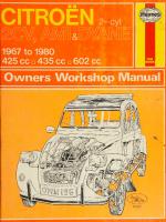
Haynes Citroën 2-Cylinder 2CV, AMI & Dyane Owners Workshop Manual 0856961965, 9780856961960
“182p. : 28 cm 1967 to 1980 Includes index Does not cover Visa”.
126 94 20MB
English Pages 188 Year 1981
Recommend Papers
File loading please wait...
Citation preview
a
vf lé aay
iiss
ll 7
ego|
atl
\yp | |
YJ Ze [=>
Digitized by the Internet Archive in 2022 with funding from Kahle/Austin Foundation
https://archive.org/details/citroen2cylinderOO00coom
Citroen
2-cylinder Owners Workshop Manual | M Coomber Models
covered
Citroén 2CV, Ami (except Super) and Dyane Does
ISBN
©
not cover
Visa
O 85696
196 5
Haynes Publishing Group 1981
All rights any form recording in writing
reserved. or by any or by any from the
res
No part of this book may be reproduced or transmitted in means, electronic or mechanical, including photocopying, information storage or retrieval system, without permission copyright holder.
Printed in England
®
HAYNES PUBLISHING GROUP SPARKFORD YEOVIL SOMERSET distributed in the USA by
HAYNES PUBLICATIONS INC 861 LAWRENCE DRIVE NEWBURY PARK CALIFORNIA 91320 USA
ENGLAND
Acknowledgements Thanks information
are due to Citroén Cars Ltd for the supply of technical and for the use of certain illustrations. John Richards of
the Citroén Car Club gave valuable specialist advice. The Champion Sparking Plug Company supplied the illustrations showing the various spark plug conditions. The bodywork repair photographs used in this manual were provided by Holt Lloyd Ltd, who supply ‘Turtle Wax’, ‘Dupli Colour Holts’ and other Holts range products. Castrol Limited
About
supplied the lubrication data. Thanks are also due to all those people at Sparkford who helped in the production of this manual, particularly Brian Horsfall and Les Brazier who carried out the mechanical work and took the photographs respectively, Flaydemouse who planned the layout of each page and Matthew Minter who edited the text.
this manual
[ts aim
paragraphs (or sub-sections), with decimal numbers following on from
The aim of this manual is to help you get the best value from your car. It can do so in several ways. It can help you decide what work must be done (even should you choose to get it done by a garage), provide information on routine maintenance and servicing, and give a logical course of action and diagnosis when random faults occur. However, it is hoped that you will use the manual by tackling the work yourself. On simpler jobs it may even be quicker than booking the car into a garage and going there twice to leave and collect it. Perhaps most important, a lot of money can be saved by avoiding the costs the garage must charge to cover its labour and overheads. The manual has drawings and descriptions to show the function of the various compoents so that their layout can be understood. Then
the Section they are in, eg 5.1, 5.2, 5.3 etc.
the tasks are described and photographed so that even a novice can do the work.
in a step-by-step sequence
It is freely illustrated, especially in those parts where there is a detailed sequence of operations to be carried out. There are two forms
of illustration: figures and photographs. The figures are numbered in sequence with decimal numbers, according to their position in the Chapter — eg Fig. 6.4 is the fourth drawing/illustration in Chapter 6. Photographs carry the same number (either individually or in related groups) as the Section or sub-section to which they relate. There is an alphabetical Index at the back of the manual as well as a contents list at the front. Each Chapter is also preceded by its own individual contents list.
References to the ‘left’ or ‘right’ of the vehicle are in the sense of a person in the driver's seat facing forwards. Unless otherwise stated, nuts and bolts are removed by turning
/ts arrangement
anti-clockwise, and tightened by turning clockwise. Whilst every care is taken to ensure that the information in this
The manual is divided into eleven Chapters, each covering a logical sub-division of the vehicle. The Chapters are each divided into Sections, numbered with single figures, eg 5; and the Sections into
manual is correct, no liability can be accepted by the authors or publishers for loss, damage or injury causéd by any errors in, or omissions from the information given.
Introduction
to the Citroen
Although the Citroén 2CV was first marketed in 1948, it was originally designed and the first prototypes produced in the late 1930s. The original ambition was cheap, go anywhere, practical family transport. The original power unit was a 375cc flat twin, but this was subsequently changed to 425 or 435cc and later 602cc. This apart, the model has changed very little over the years, having just the occasional facelift or refinement added, the basic concept remaining unchanged.
As well
as being
an
economical
vehicle,
the 2CV
has several
unique features which allow it reliability, good handling and a surprising amount of comfort for four people. The principal features are front wheel drive and independent front and rear suspension. Standard equipment also includes a facia gear change and a roll back sunshine roof, and on some models a 'trafficlutch’ is also fitted. This last mentioned device eliminates the need to use the clutch pedal in the lower gears below certain engine speeds and is most beneficial in heavy traffic, especially for a novice driver.
2CV
.
The engine is a very simple unit, being air-cooled from the large frant mounted
fan. Lubricant
to the valvegear
is supplied
via an oil
cooler and this enables the engine to be driven hard for prolonged periods without harm. All body panels are removable, being bolted in position, and this is essential in some operations to gain access to certain components. Other models derived from the 2CV include the Dyane 4 and 6 and the Ami 6 and 8. The Dyane is a refined version of the 2CV with a ‘hatchback’, whilst the Ami has a completely different body style but
is still distinctively Citroén. All versions have also been produced with a van body and the Ami was at one time available in Saloon or Estate form.
Over the many years of production, the 2CV and derivatives have proved to be among the most successful ‘economy’ vehicles ever made and when treated with a modicum of respect will serve very well.
Contents Page
Acknowledgements
2
About this manual
2
Introduction to the Citroén 2CV
2
Buying spare parts and vehicle identification numbers
z/
Tools and working facilities
8
Jacking and towing
10
Recommended
11
lubricants and fluids
Safety first
12
Routine maintenance
113
Fault diagnosis
US
Chapter
19
1 Engine
Chapter 2
Fuel and exhaust systems
48
Chapter 3 Ignition system
62
Chapter 4 Clutch
69
Chapter
5 Transmission
76
Chapter
6 Braking system
94
Chapter 7 Steering, wheels and tyres
115
Chapter 8 Front axle and front suspension
124
Chapter 9 Rear suspension and central suspension units CR as ee ee ee ee Chapter
10
ee
eee
eee
ee
Bodywork and fittings a ee a
Conversion factors a Index
134 ee 140
Electrical system
pa EEE Chapter 11 ee Be
ee
ee
Ee
ee Ee EE
eee
EEE
eee
eee 163 eee 178 eee 179
UQOAUD AD?
HOH
UgOdID !wiy 8
Citroén Dyane
Buying spare parts and vehicle
identification
numbers
Buying spare parts Spare parts are available from many sources, for example, Citroén garages, other garages and accessory shops, and motor factors. Our advice regarding spare parts is as follows. Officially appointed Citroén garages. This is the best source of parts which are peculiar to your car and otherwise not generally available (eg complete cylinder heads, internal gearbox components badges, interior trim etc). It is also the only place at which you should buy parts if your car is still under warranty; non-Citroén parts may invalidate the warranty. To be sure of obtaining the correct parts it will always be necessary to give the storeman your car's engine and chassis number, and if possible, to take the old part along for positive identification. Many parts are available under a factory exchange scheme; any parts returned should always be clean. It obviously makes good sense to go straight to the specialists on your car for this type of part for they are best equipped to supply you. Other garages and accessory shops. These are often very good places to buy material and components needed for the maintenance of your car, (eg oil filters, spark plugs, bulbs, belts, oils and grease, touchup paint, filler paste etc). They also sell general accessories, usually have convenient opening hours, charge lower prices and can often be found not far from home. Motor factors. Good factors stock all the more important components which wear out relatively quickly (eg clutch components, pistons and cylinders, valves, exhaust systems, brake pipes/seals and pads,
etc).
Motor
factors
will
often
provide
new
SAA, CITROEN Engine
number
plate
or reconditioned
components on a part exchange basis — this can save a considerable amount of money.
5. A. A. CITROEN
Vehicle identification numbers Modifications are a continuing and manufacture quite apart from major manuals and lists are compiled upon a vehicle numbers being essential for
unpublicised process in vehicle model changes. Spare parts numerical basis, the individual correct identification of the
component required. There are considerable specification differences between the models covered by this manual. Always use the correct Citroén model number when describing your car to a storeman.
The vehicle identification plate is located in the engine compartment. On the 2CV and Dyane models the plate is situated on the righthand side of the scuttle panel, or on the chassis under the right-hand driveshaft (photo). On the Ami it is under the gear lever control. The engine number plate on all models is on the engine housing on the right-hand side. The engine code is shown on this plate. A stamped identification number is also to be found on the platform under the front seat. The paint colour code appears on a disc attached to the scuttle panel.
13082423) ‘ ma ~soomat
SS
7
The vehicle identification
plate
Tools and working facilities Sockets (or box spanners) to cover range in previous list, and 3 in
/ntroduction
square drive 32 mm (14 in AF) and 44 mm
A selection of good tools is a fundamental requirement for anyone contemplating the maintenance and repair of a motor vehicle. For the owner who does not possess any, their purchase will prove a considerable expense, offsetting some of the savings made by doingit-yourself. However, provided that the tools purchased are of good quality, they will last for many years and prove an extremely worthwhile investment. To help the average owner to decide which tools are needed to carry out the various tasks detailed in this manual, we have compiled three lists of tools under the following headings: Maintenance and minor repair, Repair and overhaul, and Special. The newcomer to practical mechanics should start off with the Maintenance and minor repair tool kit and confine himself to the simpler jobs around the vehicle. Then, as his confidence and experience grow, he can undertake more difficult tasks, buying extra tools as, and when, they are needed. In this way, a Maintenance and minor repair tool kit can be built-up into a Repair and overhaul tool kit over a considerable period of time without any major cash outlays. The experienced do-ityourselfer will have a tool kit good enough for most repair and overhaul procedures and will add tools from the Specia/ category when he feels the expense is justified by the amount of use these tools
Reversible ratchet drive (for use with sockets) Extension piece,
Mole
Combination
Pliers - electricians side cutters Pliers - needle nosed Pliers - circlip (internal and external)
Cold chisel - + inch Scriber (this can be made by grinding the end of a broken hacksaw blade) Scraper (this can be made by flattening and sharpening one end of a piece of copper pipe) Centre punch Pin punch Hacksaw Valve grinding tool
Steel rule/straight edge Allen keys Selection of files Wire brush (large) Axle-stands Jack (strong scissor or hydraulic type)
and minor repair tool kit
spanners
- 8, 9, 10, 11, 12, 13, 14, 15 16 and
19
Adjustable spanner - 9 inch Spark plug spanner (with rubber insert) Spark plug gap adjustment too/ Set of fee/er gauges
Plug/points file Brake bleed nipple spanner
Screwdriver - 4 in long x % in dia (flat blade) Screwdriver - 4 in long x % in dia (cross blade) Combination pliers - 6 inch Hacksaw, junior Tyre pump
Special tools The tools in this list are those which are not used regularly, are expensive to buy, or which need to be used in accordance with their manufacturers’ instructions. Unless relatively difficult mechanical jobs are undertaken frequently, it will not be economic to buy many of these tools. Where this is the case, you could consider clubbing together with friends (or a motorists’ club) to make a joint purchase, or
borrowing the tools against a deposit from a local garage or tool hire specialist. The following list contains only those tools and instruments freely available to the public, and not those special tools produced by the vehicle manufacturer specifically for its dealer network. You will find occasional references to these manufacturers’ special tools in the text of this manual. Generally, an alternative method of doing the job without the vehicle manufacturers’ special tool is given. However, sometimes, there is no alternative to using them. Where this is the case and the relevant tool cannot be bought or borrowed you wilkhave
to entrust the work to a franchised garage.
Tyre pressure gauge Grease gun Oil can Fine emery cloth (1 sheet) Wire brush (small) Funnel (medium size)
Valve spring compressor Piston ring compressor Balljoint separator
(where
applicable)
Universal hub/bearing puller Impact screwdriver Micrometer and/or vernier gauge Dial gauge Stroboscopic timing light
Repair and overhaul tool kit These tools are virtually essential for anyone undertaking any major repairs to a motor vehicle, and are additional to those given in the Maintenance and minor repair \ist. Included in this list is a comprehensive set of sockets. Although these are expensive they will be found invaluable as they are so versatile - particularly if various
drives are included in the set. We recommend
plastic or rubber
Screwdriver - 2 in long x % in square (flat blade) Screwdriver - 14 in long x } in dia (cross blade) Screwdriver - 3 in long x 4 in dia (electricians)
publishers of this manual.
mm Box spanners — 8, 12, 14, (long) and 21 mm
- 8 inch
Screwdriver - 6 in long x % in dia (flat blade)
It is obviously not possible to cover the subject of tools fully here. For those who wish to learn more about tools and their use there is a book entitled How to Choose and Use Car Tools available from the
The tools given in this list should be considered as a minimum requirement if routine maintenance, servicing and minor repair operations are to be undertaken. We recommend the purchase of combination spanners (ring one end, open-ended the other); although more expensive than open-ended ones, they do give the advantages of both types of spanner.
wrench
Ball pein hammer Soft-faced hammer,
will be put to.
Maintenance
10 inch (for use with sockets)
Universal joint (for use with sockets) Torque wrench (for use with sockets)
Dwell angle meter/tachometer Universal electrical multi-meter Cylinder compression gauge
Lifting tackle (photo) Trolley jack Light with extension lead
the } in square-drive
type, as this can be used with most proprietary torque spanners. If you cannot afford a socket set, even bought piecemeal, then inexpensive tubular box wrenches are a useful alternative. The tools in this list will occasionally need to be supplemented by tools from the Special list.
Buying tools will
For practically all tools, a tool dealer is the best source since he have a very comprehensive range compared with the average
Tools and working facilities garage or accessory shop. Having said that, accessory shops often offer excellent quality tools at discount prices, so it pays to shop around. Remember, you don't have to buy the most expensive items on the shelf, but it is always advisable to steer clear of the very cheap tools. There are plenty of good tools around at reasonable prices, so ask the proprietor or manager of the shop for advice before making a purchase.
;
Care and maintenance
of tools
Having purchased a reasonable tool kit, it is necessary to keep the tools in a clean serviceable condition. After use, always wipe off any dirt, grease and metal particles using a clean, dry cloth, before putting the tools away. Never leave them lying around after they have been used. A simple tool rack on the garage or workshop wall, for items such as screwdrivers and pliers is a good idea. Store all normal spanners and sockets in a metal box. Any measuring instruments,
gauges,
meters, etc, must be carefully stored where they cannot be
damaged or become rusty. Take a little care when tools are used. Hammer heads inevitably become marked and screwdrivers lose the keen edge on their blades from time to time. A little timely attention with emery cloth or a file will soon restore items like this to a good serviceable finish.
Working facilities Not to be forgotten when discussing tools, is the workshop itself. lf anything more than routine maintenance is to be carried out, some form of suitable working area becomes essential. It is appreciated that many an owner mechanic is forced by circumstances to remove an engine or similar item, without the benefit of a garage or workshop. Having done this, any repairs should always be done under the cover of a roof. Wherever
possible, any dismantling
should
be done on a clean flat
workbench or table at a suitable working height. Any workbench needs a vise: one with a jaw opening of 4 in (100 mm) is suitable for most jobs. As mentioned previously, some clean dry storage space is also required for tools, as well as the lubricants, cleaning fluids, touch-up paints and so on which become necessary. Another item which may be required, and which has a much more general usage, is an electric drill with a chuck capacity of at least 3 in (8 mm). This, together with a good range of twist drills, is virtually essential for fitting accessories such as wing mirrors and reversing lights. Last, but not least, always keep a supply of old newspapers and clean, lint-free rags available, and try to keep any working area as clean
0.250
gap (in)
Spanner
Spanner
0.630 0.669 0.686 0.709 0.710 0.748 0.750 0.813 0.820 0.866 0.875 0.920 0.937 0.945 1.000 1.010 024 .063 .100 ZS 181 .200 .250 .260 .300 ESS .390 417 .438 .480 .500 OTS 614 .625 .670 .688 811 813 .860 O79 .969 =a ees es Ses ses ss ss oe es 3Sos
16 mm 17 mm
iS ° e) ) 2.050 DAMS) 2.362
as possible.
Jaw
Jaw gap (in)
size
3 in AF 18 mm
2 in Whitworth, % in BSF 19 mm
3 in AF 1g in AF % in Whitworth;
j=
=i
BSF
22 mm
8 + in Whitworth; % in BSF 1 in AF 3 in Whitworth; alan = BSF 26 mm 14, in AF; 27 mm in BSF 2 in Whitworth; 1% in AF 30 mm in Whitworth; 3 in BSF
11 in AF
32 mm
3 in Whitworth; % in BSF
1 in AF
8 in Whitworth; #2 in BSF 36 mm
1% in AF
4 in Whitworth; 1 in BSF
14 in AF
40 mm; #2 in Whitworth 41 mm
13 in AF
1 in Whitworth; 12 in BSF 1% in AF 46 mm
2 in AF 14. in Whitworth; 17 in BSF
12 in AF
50 mm
2 in AF 14 in Whitworth; 13 in BSF 55 mm 60 mm
size
+ in AF
0.276
7 mm
0.313 0.315 0.344 0.354 0.375 0.394 0.433 0.438 0.445 0.472 0.500 0.512
% in AF 8 mm x in AF; 2 in Whitworth 39 mm 2 in AF 10 mm 11 mm % in AF % in Whitworth; ¢ in BSF 12 mm + in AF 13 mm
0.525
4 in Whitworth; % in BSF
0.551 0.562 0.591
14 mm % in AF 15 mm
0.600
& in Whitworth; # in BSF
0.625
3 in AF
te. A Haltrac hoist and gan try in use during a typical engine removal sequence
Jacking and towing Before carrying out any servicing or repair operations, make sure that you know where to position the jack and axle stands. It is most important to use only the specified points in order to prevent accidents and damage to the vehicle itself. If the vehicle breaks down or becomes bogged down, frontmounted towing hooks are provided to which a tow rope may be attached. Although no rear tow hooks are fitted, a tow rope can be attached to the suspension arm on each side, but take care that the rope does not foul the body panels. Do not try to start vehicles equipped with a centrifugal clutch (trafficlutch) by towing — it can’t be done and damage may result. It should not be necessary anyway as a starting handle is provided. The jack supplied is designed only to enable you to change a wheel in the event of a puncture. It is not to be relied on to carry out any maintenance or repair tasks under the vehicle. Always support the vehicle on axle/chassis stands or suitable blocks whenever you have to work under the vehicle. Apply the handbrake and chock the wheels before jacking up the car to prevent it rolling off the jack when raised. Try to jack up on firm level ground whenever possible. The spare wheel is carried in the boot in the 2CV, whilst the Ami and Dyane models keep it in the engine compartment. Check the air pressure in the spare regularly. The wheelbrace also serves as the jack winding handle and the starting handle.
! ' | ' ' ' ' ' ! 1 ' ' ‘ 1
|
t ' ' | '
ess
&
N
S
| SERVO WGUAAAH 7,
Y
We
z
G Y Yialliyyy
q
GY
.
S|
ZY
Wager
a Y]
Yl
Ps
WEa.
lst Choke
2nd Choke
YG TK& Le
WYMh
Yy
Lg
SS
_* N SSS
lst Choke
Fig. 2.19 Sections through the Solex 26/35 CSIC/SCIC carburettor fitted from September 1972 (Sec 15)
16
1 2 3
Float Air correction jet Strangler
4 5
Pump injector Mixer tube
6
Air correction jet
Fuel tank — removal
7 8 9
Needle valve Pump unit diaphragm Float 10 Main jet 11 Throttle butterfly 712 Ball seat
and refitting
1 The fuel tank is located at the rear of the car and is removed from underneath the vehicle. 2 Disconnect the battery earth lead connection. 3 Unscrew the drain plug (if fitted) and empty any fuel left in the tank into a suitable container (not plastic). Fit a cover over the container and remove it to a safe place. 4 Raise and securely support the vehicle at the rear to gain access to the tank. 5 Remove the rear seat.
73 Pump cam 14 Main jet 15 Throttle butterfly 16 Throttle butterfly 17 Idle mixture control 78 Idle jet
79
Calibrated orifice
20
Choke
21 22
Calibrated orifice Diffusers
23 24
Choke Secondary air screw
6 Unclip the inspection cover (if fitted) from the floor above the fuel tank, then detach the fuel gauge sender unit wires and the pick-up tube hose. Later models do not have an inspection cover, so the hose and wires must be removed as the tank is lowered. 7 Working underneath the car, support the tank and unscrew the four retaining bolts, one each side and two at the front. 8 Carefully lower the tank and detach the filler pipe. 9 If the fuel tank is damaged or faulty do not attempt to repair it — renew it or have it repaired by a specialist. 10 Refit in the reverse order to removal. On completion refill the tank and check for leaks, especially around the hose connections.
Chapter 2 Fuel and exhaust systems
60
6
To dismantle the filter (Fig. 2.22), remove the lower cup retaining
screw and withdraw the filter from the pipe. 7. The plastic body can then be removed together with the washers which can be separated and washed in clean petrol. 8 Blow through the pipe and check that it is not blocked.
Refitting 9
Reassemble
in the reverse order of dismantling.
10 When the sender unit is refitted into the tank and the fuel line and all wires reconnected, switch on the ignition and check the fuel gauge level for accuracy. A slight adjustment can be made if necessary by removing the sender unit and bending the float wire. 11 Use a new gasket when refitting the sender unit. Run the engine and check for leaks before refitting the inspection cover and seat.
18
Fig. 2.20 Solex 26/35 carburettor main body with cover removed
(Sec 15) 73
Emulsion tube carrier
14 Slow running jet 715 Pump injector 16 Accelerator pump cover 17
17
18 Air correction jet 19 Pushrod 20 Dashpot bush 21 Primary main jet
Exhaust system — removal
1 The exhaust system comprises twin downpipes, one from each cylinder, which are attached via coupling flanges to a transverse expansion box. The expansion box is located between the two undershields and just to the rear of the gearbox. A separate pipe conveys the exhaust gases from the expansion box to the silencer and tailpipe, which are mounted vehicle.
Expansion
Secondary main jet
Fuel tank sender unit and tank filter — removal
and refitting
flexibly on the left-hand
1 Disconnect the battery earth connection. 2 Remove the rear seat and unclip the inspection floor above the fuel tank.
cover
from
the
3 The sender unit wires can now be disconnected, also the outlet tube hose. 4 Unscrew and remove the sender unit retaining screws and carefully lift the unit clear. It will have to be tilted during removal to allow the float to be extracted without distorting its connecting rod.
Fuel filter 5 The fuel tank filter unit is located on the base of the outlet tube within the tank. To remove and clean it the sender unit will have to be withdrawn as described above.
underside of the
box
2 To remove the expansion box, raise the bonnet, remove the spare wheel and detach the downpipe clamps on each side at their connecting flanges to the expansion box. 3 Detach the coupling collars retaining the heat exchangers to the inlet tube of the expansion box and then unscrew and remove the expansion box-to-gearbox mounting bolts (photo). Raise the front of the car and lower the expansion
Sender unit
and refitting
box to remove
from the vehicle.
4 Refitting is a reversal of the removal procedure, but ensure that the clutch cable is in contact with the guide clip to prevent it touching the expansion chamber. Do not fully tighten the respective retaining bolts and nuts until they are all assembled and the expansion box is correctly located. The coupling flanges can be smeared with an exhaust sealant to help prevent any possibility of a leakage when complete.
Connecting pipes and silencer 5 aise the bonnet and remove the spare wheel. 6 Unscrew and remove the half collars retaining the exhaust pipe to expansion box (photo). 7 Working underneath the vehicle, loosen the silencer/pipe clamps. To remove the tailpipe unit as well (which is usually advisable), remove
4 Fig. 2.21 Fuel gauge sender unit and fuel outlet pipe connection to
Fig. 2.22 Fuel gauge sender and filter unit (Sec 17)
tank (Sec 17) 8 9 70
Cover Outlet pipe Earth wire
11 12
Retaining screw Wire connector
1
Lower cup
2
Filter unit
3
Sealing ring
4
Outlet pipe
Chapter 2 Fuel and exhaust systems
18.3 The expansion box disconnected from the mountings each side of the transmission
18.6 Typical exhaust downpipe flange connection
the retaining bolts from the rear bumper clamp bracket and silencer hangers (photo). 8 Once the pipe and silencer assemblies are removed from vehicle they can be separated and renewed as required. 9 Refitting is a reversal of the removal process, but relocate
19
the the
61
18.7 The silencer pipe mounting hanger strap
bracket and
complete pipe/silencer assembly before retightening any of the retainer fastenings. Smear pipe joints with some exhaust sealant to help prevent any leakages, and finally tighten all clamps and fastenings after the engine has been brought to operating temperature.
the
Fault diagnosis — fuel and exhaust system
Unsatisfactory engine performance and excessive fuel consumption are not necessarily the fault of the fue/ system or carburettor. In fact they more commonly occur as a result of ignition faults. Before working on the fue/ system it is necessary to check the ignition system. Even though a fault may lie in the fuel system it will be difficult to trace unless the ignition is correct. The table below, therefore, assumes that the ignition system is in order.
Symptom Smells
Smell
of petrol when
of petrol when
Reason(s) engine is stopped
engine
is idling
Leaking fuel lines or unions Leaking fuel tank Leaking fuel line between
pump
and carburettor
Overflow of fuel from float chamber due to wrong ineffective
level setting
needle valve or punctured float
Excessive fuel consumption for reasons not covered by leaks or faults in other systems
Float level incorrect or float punctured Choke control not set correctly Worn needle valve Sticking needle valve
Difficult starting, uneven running, lack of power, cutting out
One or more jets blocked or restricted Float chamber fuel level too low or needle valve sticking Fuel pump not delivering sufficient fuel
Chapter 3 Ignition system Contents
Condenser (capacitor) — description, removal and refitting ............
6
==wearese 10 Fault diagnosis = CIA tHOMSY Ste MMeaever-cencesceetesvecstaereseeecexarenararter
Contact breaker Points — AGjUSEMEM teccccccccrcesecreserccenreverecscsoosss-eunsaraees Contact breaker points — removal and refitting Dwell angle — checking and adjUStMeNt.......cccceeeeeenenees Dynamic ignition timing — checking and adjustment...
4 5 3} 9
General description... ssoonennnnnnnnnnnnnannnnnanavasessssssssscs seeereeseeeeeeee Ignition cam and centrifugal weights — removal and refitting........ Terence Spark plugs and high tension (HT) lead.. OTE TC Tr Static ignition timing — checking and adjUStMENt..........sreeseereens
1 i 2 8
Specifications
en aneccetranieerdents SV SUOMI SCY (DC rere ereces nosso cra evn cet aes soeccasdecensvenstscecaytnercroms
Contact
breaker
and coil. No distributor,
cam
driven directly from
camshaft, centrifugal advance only
Spark plugs MakeamcatyDGn.ccscceccesetstesceectteceroeoscsahs cersncsspraneveocasostsnctasruccaretesursuatararen cere
EleCtrOde Gap ...cescssseccssesssscsssssscsscssescsceserensnenscscerensnersssesssnuscsccsosscsssesensarsasneess
Champion L85 (except Dyane 6 and Ami 8) or L87Y, AC42F, Marchal 35 or 34S, NGK B6HS, or equivalent 0.65 to 0.75 mm (0.026 to 0.030 in)
Coil Make and type: Git Ol Clee eae cra een teanecmaecenresestey seeovaeessiveesstdcncs satvieas suena eartsbarverecsesveand arsenessarts
Adjustment
Ducellier 2768 Ducellier 2769
data
Womtactebreake ngaprerrtrsccecctesrerecsrtsrvatisssscysecensceceers teeecucancamterateaty oveeteeapeesares Dwell angle (percentage): Up to February 1970 Febriuianyaiti9 7.0 s0 mimicevtevscasencsexcrevixecrrssevisvessestcustesivevavcedsstaces tavaieinscitetdaves Static ignition timing:
M2 ShandsM28/Jeonginescrscescerseectecers erties crseaeteereeseeecacmackesvetes« AUIMOTHONT OG GIS
victecpccctass ceeten csorcxgctes ac ccvacvante se scuxoecashersesedeaed¥envussereenradssas
0.40 to 0.45 mm
(0.016 to 0.018 in)
142° to 146° (78% to 81%) 106° to 112° (58% to 62%) 8° BTDC 122 BIDE
"w .
1.
General
description
In order that the engine can run correctly it is necessary for an electrical spark to ignite the fuel/air mixture in the combustion chamber at exactly the right moment in relation to engine speed and load. The ignition system is based on feeding low tension voltage from
the battery to the coil where it is converted to high tension voltage. The high tension voltage is powerful enough to jump the spark plug gap in the cylinders many times a second under high compression, providing that the system is in good condition and that all adjustments are
ignition system
at the specified
The tributor)
intervals.
points box (sometimes erroneously referred to as the disis mounted on the front of the crankcase, the points cam
being retained on the end of the camshaft by a circlip. Access to the
correct.
The
The high tension (HT or secondary) circuit consists of the coil secondary windings and the HT leads, one from each end of the secondary winding, to the plugs. There is no distributor as found on conventional 4-cylinder engines; instead each plug sparks both on the compression and on the exhaust stroke, and additionally one plug operates in reverse polarity, wear occurring at the side instead of at the centre electrode. For these reasons it is important to renew the plugs
is divided
into two circuits, low tension
and
high tension. The low tension circuit (sometimes known as the primary) consists of the battery, lead to the control box, lead to the ignition system, lead from the ignition switch to the low tension or primary coil windings
(terminal BAT), and the lead from the low tension coil windings (coil terminal DIST) to the contact breaker points and condenser attached to the points box.
points is only possible after removing the front grille panel and fan. This is not such a problem as may at first appear because the points operate in a more favourable environment than that found in a conventional distributor. They should only be disturbed if the ignition timing or dwell angle need adjusting. There is no vacuum-operated advance/retard mechanism used on these engines, ignition advance being undertaken entirely by centrifugal weights and springs.
Chapter 3 Ignition system
63
CONTACT BREAKER
BATTERY Sas ek
SECONDARY WINDING
Saad OSE
selon a een os id
SPARK
CONDENSER
PLUGS)
il
SECONDARY CURRENT DIRECTION FLOW
vy
Vv
