Fundamentals of Phonetics, II: Acoustical Models, Generating the Formants of the Vowel Phonemes 9783110811070, 9789027907158
197 74 8MB
English Pages 131 [140] Year 1970
ACKNOWLEDGEMENTS
CONTENTS
I. INTRODUCTION
II. PHYSIOLOGICAL CONSIDERATIONS
III. On the Definition of the Formants
IV. On Webster's Horn Equation
V. The General Circuit Parameters and the Formants of the Exponential Horn
VI. The Method of the Loss-Free Twin-Tube Resonator
VII. Vector Representation of the Twin-Tube Formants
VIII. Stationary Wave-Patterns in the Twin-Tube Resonator
IX. The Vowel Triangle as a Limiting Contour of the Formants of the Vocal Tract
X. Application of the Twin-Tube Method to the Vowel System of Dutch
XI. The Formants of Resonators Containing Exponential Horns
XII. The Twin-Tube Resonator with Front Diabolo as a Model for the Formants of Monolithic Diphthongs and Vowels in Running Speech
XIII. Appendix
INDEX
Recommend Papers
![Fundamentals of acoustical oceanography [1st ed.]
9780124875708, 012487570X](https://ebin.pub/img/200x200/fundamentals-of-acoustical-oceanography-1stnbsped-9780124875708-012487570x.jpg)


File loading please wait...
Citation preview
FUNDAMENTALS OF PHONETICS, II
JANUA LINGUARUM STUDIA MEMORIAE NICOLAI VAN WIJK DEDICATA edenda
curai
C. H. VAN SCHOONEVELD INDIANA
UNIVERSITY
SERIES M I N O R NR. XXVI/2
1970
MOUTON THE HAGUE • PARIS
FUNDAMENTALS OF PHONETICS II: Acoustical Models Generating the Formants of the Vowel Phonemes by
H. MOL UNIVERSITY OF AMSTERDAM
1970
MOUTON THE H A G U E * PARIS
© Copyright 1970 in The Netherlands. Mouton & Co. N.V., Publishers, The Hague. No part of this book may be translated or reproduced in any form, by print, photoprint, microfilm, or any other means, without written permission from the publishers.
LIBRARY OF CONGRESS CATALOG CARD NUMBER: 70-110954
Printed in The Netherlands by Mouton & Co., Printers, The Hague.
For Nancy and Laurence Batchelder
ACKNOWLEDGEMENTS
The author has to thank Mr. J. G. Blom, staff-member of the Institute of Phonetic Sciences of the University of Amsterdam, for carefully and, above all, critically reading the typescript and for making many valuable suggestions. Moreover, Mr. Blom is entitled to a special word of thanks for making the computerprograms presented in the Appendix. The author wishes to acknowledge his indebtedness to Miss N. Schokking, who prevented him from committing at least the most flagrant sins against the English language. The author wishes to express his thanks to his students, who urged him to develop methods for satisfying their scientific curiosity.
CONTENTS
Acknowledgements
7
I. Introduction
11
II. Physiological considerations
15
III. On the Definition of the Formants
19
IV. On Webster's Horn Equation
35
V. The General Circuit Parameters and the Formants of the Exponential Horn
43
VI. The Method of the Loss-Free Twin-Tube Resonator
52
VII. Vector Representation of the Twin-Tube Formants .
62
VIII. Stationary Wave-Patterns in the Twin-Tube Resonator
72
IX. The Vowel Triangle as a Limiting Contour of the Formants of the Vocal Tract
84
X. Application of the Twin-Tube Method to the Vowel System of Dutch
88
XI. The Formants of Resonators Containing Exponential Horns
97
XII. The Twin-Tube Resonator with Front Diabolo as a Model for the Formants of Monolithic Diphthongs and Vowels in Running Speech
Ill
XIII. Appendix
119
Index
130
I INTRODUCTION
In her review of Gerold Ungeheuer's Elemente einer akustischen Theorie der Vokalartikulation (Springer-Verlag 1962), Ilse Lehiste1 states: "The question might be asked whether, after the appearance of Fant's comprehensive volume 2 , it is at all possible to make a new and original contribution to the acoustic theory of vowel production". Frankly speaking, I do not like such discouraging statements and I am sure dr Fant does not like them either. Being an engineer myself, I greatly admire Fant's work and certainly appreciate its originality. Nevertheless, my approach to the problem of the prediction of the formant frequencies of the vowels is different from that of Fant. This monograph has been written with a purely linguistic purpose. In the Netherlands there exists a new generation of linguistic students and also a group of mature linguists who are no longer content with the traditional verbal labels of the phonemes. It is the duty of the physically and mathematically trained phonetician to provide these malcontents with a manageable concept of the relation between articulation and acoustics. More specifically for the vowels, there is a need for a workable model of the generation of the formant positions. Predictions of the formant positions based on a simple model need not necessarily bear the hall-mark of inaccuracy. By suitably choosing the values of its few parameters with an eye to the real shape of the vocal tract as seen in X-ray photographs, one can form 1 1
Language, Volume 39, Number 3 (1963). G. Fant, Acoustic theory of speech production (Mouton, The Hague 1961).
12
INTRODUCTION
fair estimations that compare favourably with the results of calculations of more pretentious models of the vocal tract. The model around which this monograph centres is called the lossfree twin-tube resonator. A formula producing the formants of the twin-tube resonator can be found in literature but we shall show in the following chapters that until now the possibilities of its graphical solution have not been sufficiently explored. Maybe the reason for this neglect is that the twin-tube was seen as a bad imitation of the vocal tract rather than as a good model of it. It can even be shown, as in Chapter VII, that Hellwag's vowel triangle, published as early as 1781, comes to the fore as a vector diagram of the first two formants as predicted by the twin-tube model. An acoustical model is, as a rule, representative of SOME properties only of a real vocal tract. Therefore it is always an approximation of the physical reality in the real vocal tract. Nevertheless, the calculation of the model must be taken seriously and its results must be checked as much as possible by measurements on 'hard ware' models, conveniently made of hard plastics. For not too high frequencies, a hard-walled tube with uniform cross-area may be treated as a one-dimensional problem, that is, plane waves may be supposed to be running to and fro in the tube following the direction of its axis. We found it necessary, however, to introduce in our models sections with non-uniform cross-area, such as diabolos, defined in this monograph as exponential twin-horns. One needs a manageable differential equation for describing the physical behaviour of such sections. Some authors, for instance Ungeheuer3, advocate the application of Webster's horn equation even to the complete vocal tract. We only succeeded in solving Webster's horn equation in special cases like, for instance, the exponential horn. As this was the horn we needed we were able to introduce it in a variant of the twin-tube model. To an outsider possessing a smattering of phonetics a formant 3
G. Ungeheuer, Elemente einer akustischen Theorie der (Springer-Verlag 1962).
Vokalartikulation
INTRODUCTION
13
may seem to be a comparatively problemless tangible thing, lying in waiting to be measured by a suitable method. Even in the phonetic sciences one runs the risk of being accused of riding a hobby-horse when one underlines the arbitrary nature of a formant definition. In spite of the (fortunate) fact that fundamentally different formant definitions often lead to frequencies in the same order of magnitude, in spite of the fact that contrasts between formant positions prove to be more important than absolute formant positions, we should not consider formant theory as a free-for-all for loose or arbitrary formulations. Definitions labelled as traditional or practical do not improve the clear comprehension of the mechanism of speech and hearing. Our ultimate scientific aim should be that clear comprehension. Chapter III should be considered as a first, faltering step towards this goal. This monograph is hopefully announced as a contribution to linguistics. However, its author is vividly aware of the fact that the average linguist will not be able to digest all physical and mathematical problems without the assistance of an acoustically trained physicist or engineer. Nevertheless, we do hope that the interested linguist will be able to appreciate the conclusions drawn from the calculations. This monograph is also meant for the acoustician who wishes to team up with linguists in phonetic research. He may be irritated somewhat by the elaborate treatment of what he considers as details or general knowledge. On the other hand, it is quite healthy for engineers and kindred spirits to come down to earth every now and then in order to realize how and if their mathematical concepts fit into the real mechanism of speech and hearing. To-day, phonetics is no longer a one-man science. Insight into the mechanism of speech and hearing can only be gained via a close co-operation between linguists, engineers, physicists, physiologists, psychologists, speech therapists, anthropologists and so on. Let us suppose, for a moment, that one wants to concentrate on articulat o r problems only, waiving all other aspects of phonetics for whatever reason. As long as the articulatory terms and descriptions have the character of real and effective articulation recipes they are very practicable: in the ideal case they permit us to realize in the
14
INTRODUCTION
long run the speech sounds of a language so that a native talker of that language is able to identify them correctly. Articulation recipes, however, only show HOW to produce a series of contrasting speech sounds, but do not explain WHY the listener is able to discriminate between them, though we know THAT he is able to do so. The aim of the phonetic sciences as a whole is to get an over-all picture, including production, transmission and sensory reception of the speech sounds. One is, of course, completely free to restrict oneself to empirically derived articulation recipes but in that case one shuts out a broad and interesting field, namely, acoustics and sensory reception. A very striking example of the one-sidedness of articulation recipes is met in audiology: the audiologist needs acoustic labels of the speech sounds and, moreover, he wants them in such a form that he can understand WHY a defective organ of hearing fails to discriminate between them.
II PHYSIOLOGICAL CONSIDERATIONS
In this short monograph a detailed treatment of the anatomy of the vocal tract would certainly be out of place. For greater description the reader is referred to the well-known text-books. This admittedly brief chapter is merely intended to persuade the reader to see the vocal tract as a slim tube extending from the vocal cords to the mouth opening. Though this view has a typically modern ring it dates back much further than is generally recognized. As early as in 1765 De Brosses describes the vocal tract as a tube that can be varied in diameter and that can be lengthened or shortened, see figure II.2. The modern motive for preferring to see the vocal tract as a slender tube stems from acoustic theory. If the total length of a tube is much larger than its diameter, its acoustic behaviour may be streamlined to such a degree that the calculation boils down to a onedimensional problem (see Chapter III). Figure II. 3 demonstrates the oblong shape of the vocal tract. The wall of the tube is for the larger part formed by the wall of the pharynx, the epiglottis, the tongue, the soft- and the hard palate, the teethridges (including the teeth) and the lips. The axial length I of the vocal tract is indicated by the dot-stripe line between the arrow-heads. As a rule the vocal tract is supposed to end at a point just outside the lips. In certain vowels, however, the vocal tract must be assumed to end at a point inside the mouth, even behind the teeth. During the production of the vowels the vocal folds (cords) are generally regarded as a hard wall bounding the vocal tract at the
16
PHYSIOLOGICAL CONSIDERATIONS
other end, in spite of the fact that they open and close rhythmically at an average rate of at least 150 times per second. As slow motion moving pictures of the larynx show, the just mentioned wall moves to and fro in the axial direction of the vocal tract, but we shall ignore the resultant length modulation. During phonation the larynx may be regarded as a machine-gun projectilling air puffs into the vocal tract. In normal voices the vocal folds open slowly whereas they close with a snap. It is this closing snap, this abrupt ending of the air puff that is able to excite the vocal tract to action in the form of powerful damped oscillations. As a rule the reaction to the slow onset of the puff is of no practical importance. ..
T.
I[)
J\ A
T.
,,
/ L _ _
t
Figure II. 1 Two examples of wave forms that are able to excite the vocal tract in a proper way.
The fact that the closing snap is the main source of excitation permits us to apply Heaviside's method to the vocal tract, see Chapter III. The time interval between two subsequent snaps may be called the REPETITION period T0. Formally speaking, there is no objection against calling F 0 = ^r
(II.D
the repetition frequency of the snaps. For periodic wave forms as shown in fig. II. 1, Ta and F0 are constants. For other wave forms Ta and F0 may vary from snap to snap. Confining ourselves to periodic wave forms, we mention
to V
L À
IL
€ A CI»
ipoîtrine peut fournir l'air. Les confonnei font les articulations de ce même foi* que l'on fait pi fier par on certain organe,, comme à travers d'une filiere , ce quF lui donne une forme. Cette forme fr donne en un feol mfbmt 5î ne peur être permanente. Que fi elle p.iroît Pétre darls quelques articulations fortes qu'on appelle tfprit* rudes , ce n'eft pins un fem clair êt diillruft ; ce n'eft qn'rm fixement fourd qu'on eft o&ligé d'appeîler dta nom confradr&oire de voyelle muette. Ainfi la voix & Ta confonne font comme la ma/tiere Si la- forme , la iûbftanc* & le mode. LTnfframent général de la voix, doit être crmiidéré comme un htyau long1 qui s'étend depuis le fond de fa gorge jufqu'au bord extérieur des levres. C e tuyau eft fucceptible d'être refferré félon nn diamètre pins grand ou moindre, d'être étendu cm 5?courci félon une lon-~ gueur plus grande ou moindre. Ainfi le* fimple fon qni en fort repré fente à Foxeifle l'état où on a tenu le tuyau e» y
Figure II.2 Photostatic reproduction of page 109 of: De Brosses, Traité de la formation méchanique des langues et des principes physiques de l'étymologie, Tom. I, nr 101 (Paris 1765).
PHYSIOLOGICAL CONSIDERATIONS
17
that more often than not T„ is called the fundamental period and F0 the fundamental frequency. The term: fundamental is a concession to Fourier analysis and refers to the possibility of developing the glottal wave into a Fourier series containing the fundamental frequency F0 and its harmonics 2 F„, 3 F0, 4 F0 etc. As we do not make use of this mathematical possibility in this monograph we only mention it for the sake of completeness.
Figure II.3 Semi-schematic representation of the anatomy of the vocal tract.
18
PHYSIOLOGICAL CONSIDERATIONS
Already one snap is sufficient to pursuade the vocal tract to produce its complete set of damped oscillations, in other words its formants, see Chapter III. Speaking in terms of information theory : all subsequent snaps are redundant as long as the vocal tract is kept in the same articulatory position. This statement is not weakened by the fact that, in order to arrive at a decision, the nervous system needs a time interval of several repetition periods. It is not necessary, and, in my opinion, it is even incorrect, to explain this timedelay as an inherent feature of a linear filter with a limited band width. The acoustic effect of lowering the soft palate during the production of a vowel is called nasalisation. In some languages nasalisation is a speech defect or just a mannerism. In other languages it is a phonemic tool. In this monograph we shall very briefly discuss nasalisation in Appendix § 1.
Ill ON THE DEFINITION OF THE FORMANTS
A browse through the literature on vowels of the past 100 years leads to the conclusion that the investigators have always intuitively felt that the interpretation of vowel sounds by a listener might be related to phenomena often loosely referred to as resonance, tuning, natural frequencies, amplified overtones, formants, zones of amplification, etc etc. In judging the scientific level of the early literature on vowels one must bear in mind the lack of physical tools and mathematical insight which was characteristic of many investigators of those days. In the course of time a great confusion of terms came into being. In 1928 Hermann Gutzmann1 still distinguishes between the FORMANT theory of L. Hermann and the OVERTONE theory of Helmholtz. In 1926 Carl Stumpf2, however, attaches a different meaning to the term "formant" originally coined by L. Hermann as the frequency of a damped oscillation set up in the vocal tract by an air puff emitted by the vocal cords. He applies it to a certain region of overtones. Much confusion has been caused by this deplorable generalisation. As it is not advisable to put the clock back the term formant in its present vagueness should be maintained in the hope that the authors of to-day will not fail to indicate what they mean by this term in their publications. Strictly speaking, an investigator who calculates the vibrations 1
H. Gutzmann, Physiobgie der Stimme und Sprache (Braunschweig 1928,
2 Auflage), p. 128. 1 C. Stumpf, Die Sprachlaute (Springer Verlag Berlin 1926), p. 63.
20
ON THE DEFINITION OF THE FORMANTS
of the vocal tract does not need to be primarily interested in perception. His first aim is to find the time course of the vibrations that leave the mouth during the production of vowel sounds. No doubt he does know that these time functions carry 'something' to the ear of the listener and that certain changes in that 'something', brought about by changes in the configuration of the vocal tract, convey a meaning to the listener, but for the time being this is not his problem yet. Nevertheless, he may hope that the mathematical equations describing the behaviour of the vocal tract allow him to define mathematical quantities (with the dimension of a frequency or a time) that are characteristic of a certain configuration or geometric changes of the tract. It may be expected that there will be more than one way to do so. When there is sound in the air the air pressure P at a certain location in space shows small variations denoted by p around its average value P„: P = P* + P
(III.l)
The variation p is called the sound pressure. It is a so-called scalar which means that it is completely given by only one number though that number depends on time and on the coordinates in space of the point where we measure the sound pressure. This dependence is mathematically indicated as follows: p=p(x,y,z,t)
(III.2)
where x, y and z are the three dimensions in space and t represents time. We say that p is a function of x, y, z and t. Also the density Q, defined as the mass of the air per unit of volume, displays a variation s around its average value Q0 : e =
£ + •*
(III.3)
The variation s is called the condensation. It can be proved that, for the usual small variations met in practice, p is proportional to s in the following way: p = c2 s
(III.4)
ON THE DEFINITION OF THE FORMANTS
21
where c is the well-known velocity with which sound travels in free space. For air of vocal tract temperature we take that velocity as high as 350 m/sec. In practice, because of formula (III.4), p only is mentioned, not in the least because it is easy to measure p by appropriate microphones. The vibrating air particles move to and fro around their positions of equilibrium. In doing so they cover very small distances and develop very low velocities. The so-called particle velocity v is defined as the distance an air particle travels during a very short time-interval, devided by that interval. Even in loud sounds v reaches peak values of less than 1 m/hour, a snail's pace considered to be paradoxical by many but nevertheless being correct. People without a physical background are inclined to mix up the particle velocity with the velocity of propagation c. One should bear in mind, however, that the particle velocity pertains to the transport of mass whereas the velocity of propagation describes the transport of energy which can take place at a much higher velocity. Generally speaking it is not sufficient to merely state the absolute value v of the particle velocity. The particle velocity is a vector which is a mathematical way of saying that it has a direction in space. The air particles move to and fro along the so-called streamlines. We need not, however, in this monograph, make an excursion into vector theory because the following simplifications eliminate the need for such an unwelcome digression. In order to facilitate the calculations the vocal tract which is virtually boomerang-shaped, is bent in such a way that its axis becomes a straight line which at the sime time may serve as our .x-axis. Moreover, the streamlines are supposed to be essentially parrallel to the x-axis so that only the velocity-component u in the direction of the x-axis has to be taken into account. The next simplification is to suppose that the particle velocity u is the same throughout a cross-area perpendicular to the axis. The same holds good for the sound pressure p. This means that u and p are functions only of x and t :
22
ON THE DEFINITION OF THE FORMANTS
sound pressure p=p(x,t) particle velocity u = u(x,t)
(III.5) (III.6)
By straightening the vocal tract and idealizing its streamlines we have strait-jacketed our problem into a one-dimensional problem. This method is followed by the majority of investigators. Nevertheless, we should not neglect the possibility that the damage inflicted on physical reality by the one-dimensional strait-jacket may render certain refinements in our calculations far-fetched if we accept the accuracy of the calculated formant frequencies as a criterion. On top of that comes a problem which is important to the linguist : with what accuracy does the mathematically defined formant frequency describe the physiological data the nervous system derives from the time-functions presented to the ear? An advantage of the one-dimensional approach is that the socalled volume velocity U can be defined in the following simple way: U= Su (III.7) where S is the area of the cross-section of the tube over which the particle velocity u is supposed to be constant with respect to x. As a matter of fact Webster's equation is based on the volume
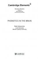
x>0 throat Figure in.l The vocal tract seen as an acoustic device that transforms a sound pressure p{o) and a volume velocity U(o) at the throat into a sound pressure p(/) and a volume velocity U(l) at the mouth opening.
ON THE DEFINITION OF THE FORMANTS
23
velocity in order to get the cross-area of the tube, which is a function of x: S = S(:c)
(III.8)
into the picture, that is the differential equation, at all. From now on our calculations will aim at the determination of sound pressure p and volume velocity U in the vocal tract, especially at the beginning and the end. Though the average layman will readily accept the loose formulation that the larynx produces a sound which is modified by the vocal tract in a way that is characteristic of the vowel under discussion, he might frown at the idea that in order to calculate that modification it is necessary to take into account two acoustic quantities, the familiar sound pressure and the less popular volume velocity. This necessity, forced on us by nature, has an advantage, however, because it places the vocal tract in the same class with the electric four-terminal networks the theory of which is already welldeveloped. In the calculation of electric networks the electric voltage as well as the electric current appear in the differential equations. It is very convenient to regard sound pressure and electric voltage as analogous quantities. The same can be said of volume velocity and electric current. We may even go so far as to denote analogous quantities by the same symbol, as is done in figure III.2,
X
direction of
transmission
Figure III.2 Equivalent electric four-terminal network of the vocal tract p. : input voltage, analogous to sound pressure at the throat Uc: input current, analogous to volume velocity at the throat Pi : output voltage, analogous to sound pressure at the mouth-opening U, : output current, analogous to volume velocity at the mouth-opening.
24
ON THE DEFINITION OF THE FORMANTS
where a passive electric four-terminal network is depicted with the application of acoustic symbols for the electric quantities. In that way the vocal tract comes to the fore in the disguise of an electric network. The analogy between figure 111.1 and figure III.2 is obvious. Electric circuit theory shows, that for sinusoidal oscillations, the following linear relations exist between the quantities at the input and the output: Po = A Pi + BUt
(III.9)
U0 = Cpl + DUl
(III. 10)
The coefficients A, B, C and D are called the general circuit parameters of the network. They depend on the configuration and on the values of the electric components of the network such as resistors, capacitors and solenoids. As a rule they are functions of frequency (remember we suppose sinusoidal vibrations!). In the vast majority of networks these components are so-called lumped, but they may also be distributed continuously as, for instance, in the telephone cable. The vocal tract is analogous to a cable: its acoustic 'components' are continuously distributed though we shall see that, for low frequencies, it may sometimes be regarded as being composed of lumped components. This is the case in the wellknown Helmholtz-resonances with which we shall deal later on. For the usual electric networks there is the following extra-relation between the general circuit parameters : AD-BC
= 1
(111.11)
In the language of network theory we say that the network obeys the reciprocity theorem but we shall not press this point here. The critical reader will notice that the extra-relation (III. 11) allows us to reduce the number of general circuit parameters to a mere three but for reasons of mathematical simplicity one always operates with four parameters, bearing in mind there is a useful relation between them. If we succeed in determining A, B, C and D for the vocal tract
ON THE DEFINITION OF THE FORMANTS
25
they can be expected to depend on frequency, on the way in which the cross-section varies with respect to x and on the total length of the tract. In order to definitely find the parameters we must first find a differential equation for the vocal tract, next solve it for sinusoidal vibrations, then calculate separately sound pressure and volume velocity and finally introduce the boundary conditions at both ends of the tube. Unfortunately the average linguistic reader does not possess the necessary mathematical background to perform or to understand the sketched procedure. It is a consoling thought, however, that only in special cases this procedure is mathematically possible even for the expert mathematician. In connection with the twin-tube resonator it will become necessary to calculate the general circuit parameters of a network consisting of two known four-terminal networks in tandem as is shown in figure III.3.
d i r e c t i o n of transmission
>
X
Figure III.3 Two four-terminal networks in tandem seen as one single, resultant network.
Each network has its own set of relations : P o ^ A ^ + B^z
(III. 12)
p2 = A2pt + B2Ul
(111.14)
U, = CtPi + D^t
(III. 13)
U2 = Ctft + DiUt
(III. 15)
26
ON THE DEFINITION OF THE FORMANTS
The calculation is based on the principle that the output volume velocity U2 of the first network is at the same time the input volume velocity of the second network. Furthermore the output sound pressure p2 of the first network is also the input sound pressure of the second network. It is possible to eliminate p2 and U2 from the equations (III. 12), (III. 13), (III. 14) and (III. 15). Omitting the mathematics we get: + B1D2)Ul p0 = ( A ^ + B^Jpt + iA^ U„ = (A2C, + C2Dt)Pl + (D,D2 + C ^ 2 ) ul
(111.16) (in. 17)
These expressions describe a new four-terminal network with the general circuit parameters: A= B= C= D=
A1A2 + B1C2 AiB2+BiD2 A2Ct + CaDi ZV^ + C A
(111.18) (III. 19) (111.20) (111.21)
Especially equation (111.21) will proove to be important for the calculation of the twin-tube model. Before going on, we must realize that the general circuit parameters as we have defined them, refer to the hypothetical case where a sinusoidal vibration is being transmitted through the vocal tract from the throat to the mouth. This situation certainly does not represent the actual mode of action of the throat which does not produce sinusoidal vibrations. Sinusoidal vibrations are introduced as mathematical tools for solving or simplifying the differential equations that govern the physical phenomena in question. Once the reaction of a network to a sinusoidal excitation has been determined, it is mathematically possible to predict the reaction of that network to an arbitrary time function. This possibility is based on the fact that, as a rule, an arbitrary time function may be considered as the sum of a, usually large, number of sinusoidal time functions with different frequencies. This step, back to reality, from the frequency concept to the actual excitation of the vocal tract, is more often than not, omitted. The consequences of this omission for the definition
27
ON THE DEFINITION OF THE FORMANTS
of the formants will be discussed in some detail in this chapter. We shall now return to and start from fig. III.2 which, as has been said already, refers to the hypothetical case where a sinusoidal vibration is transmitted through the vocal tract. As visualized in fig. III.4, the throat is treated as a sinusoidal electromotoric force e in series with an internal impedance 3 Z0. The mouth-opening is considered as a load-impedance Z,. Evidently and
Po = e—U0Z0
(Iir.22)
Pi = U,Z,
(111.23)
•
i
m !U.
O e*
; I
A B C
AD-BC = 1 vocal
throat
D
I
tract
3> 1
I
;
! mou(h
I ii
Figure III.4 The throat considered as a source of sinusoidal vibrations.
It is possible to calculate U, as well as U„ by combining (III.9), (III. 10), (111.22) and (111.23), which finally yields: e (III. 24) B + DZ0 + AZt + CZ.Z, V„ =
e AZ, + B Z0 + CZ, + D
(111.25)
In practically all calculations of the vocal tract one permits oneself the following, simplifying assumptions: * The (acoustic) impedance is defined here as the sound pressure divided by the volume velocity.
28
ON THE DEFINITION OF THE FORMANTS
Z,-*0
(111.26)
Z„~* oo
(1H.27)
and Equation (111.26) persuades us to consider the mouth-opening as a dead short circuit. Consequently the sound pressure pt = 0 (or at least very low), in other words there is always a pressure node in the mouth-opening. Equation (111.27) expresses the belief that for sinusoidal vibrations the internal impedance of the throat is very high and independent of frequency. By introducing (111.26) and (111.27) into (111.24) and (111.25) we simply get:
u, = ¿L
(IIL28)
and Uo = Y
(III.29)
Combination of (111.28) and (III.29) yields: U, = ^
(111.30)
Let us first precise the way in which the quantities in (111.30) depend on frequency. The driving volume velocity U0, determined by (111.29), has the same amplitude for all frequencies. The general circuit parameter D of the vocal tract does depend on frequency. It is, mathematically speaking, a complex quantity with, in general, a real and an imaginary part. In order to express the variation of D with the frequency (o — Infix, would be possible to write D = D(co), but in view of what follows later on in this chapter it is advisable to use the following notation: D = D(jco)
(111.31)
j
(ni.32)
with
ON THE DEFINITION OF THE FORMANTS
vocal
29
tract
Figure III.5 The vocal tract driven by a sinusoidal constant volume velocity U„ at the throat side and loaded by a short circuit (pressure node) at the mouth side.
From (III. 30) it is very clear that Ut varies with frequency (both in amplitude and phase) because D does so. The graph depicting |£/,|, that is the amplitude of Ut, as a function of co o r / i s known as the frequency response curve, an example of which is shown in fig. III.6. N
Figure III.6 Example of a frequency response curve. The frequency locations of the peaks are called the resonance frequencies and may be defined as the resonance FORMANTS.
As a rule the curve will show peaks (relative maxima). The frequency locations of these maxima (as well as those of the minima!) are given by the roots of the following equation: (111.33) The roots corresponding to the maxima are called the resonance frequencies (x>u co2, co3 etc {Fu F2, F3 etc). It is very tempting in-
30
ON THE DEFINITION OF THE FORMANTS
deed to define the resonance frequencies as the formant frequencies. In order to avoid confusion, the formants defined in this way, we shall call the resonance formants. The method of defining the formants as resonance frequencies is open to criticism. We might as well label this method as the sweep-frequency method because the throat is replaced by a constant volume velocity source U„ with a variable frequency. The way in which £/, at the (short circuited) mouth-side reacts to that source is used as a vehicle for defining the formant frequencies. In order to measure the resonance frequencies of a real talker it is necessary to remove his throat and to replace it by a small loudspeaker that produces a constant volume velocity. Most talkers would object against such a procedure. As a matter of fact Jw. van den Berg has actually (and very ably) applied the sweep-frequency method in a patient whose larynx had been removed by surgery, as is illustrated in fig. III.7. Now we have to accept the simple fact that a normal talker does not utilize a sweep-frequency method for conveying to a listener data on the shape of his vocal tract during the production of a vowel. His throat generates air-puffs instead. Even a spectrograph does not indicate resonance frequencies in its picture: it can at best depict spectral lines the frequencies of which are multiples of F0, the fundamental frequency of the vocal folds, corresponding to the number of air-puffs produced per second by the larynx. Relatively strong spectral lines may be defined as FILTER FORMANTS, however, but they do not coincide with the resonance formants. One might even doubt whether transmission theory with its etceteras is applicable to the vocal tract at all. Transmission theory was primarily created for the purpose of designing transmission links of which both the sending and receiving ends were available for measurement. At the sending end of the channel any type of signal could be expected. Transmission theory with its frequency concept provides a tool for predicting how an arbitrary signal will be distorted by the channel in question. It describes the channel, not the signal. The ear of the listener, backed by the nervous system, is not a
3/-5-M
Figure III.7 Replacement o f the surgically removed pathological throat o f a patient by a small loudspeaker producing a sinusoidal vibration. Taken f r o m : J. van den Berg, Physica van de stemvorming, met toepassingen, 1953, Diss. Groningen.
ON THE DEFINITION OF THE FORMANTS
31
transmission meter, it is a signal-detector, as it were caring very little for a process to which it has no access. It is not necessary, however, to throw overboard the routine of transmission theory, though I still believe that habit is often stronger than progress. By keeping intact the frequency concept, we can predict how a vocal tract will react to the application of a so-called step-function at the throat-side.
! v t(ime)
»-
Figure III.8 Applying a volume velocity step to the vocal tract at the throat-side. The volume velocities U0 and U, are no longer sinusoidal!
As shown in figure III.8, we suddenly make the (no longer sinusoidal!) volume velocity U0 jump from the value o to the value U0= V and see how the vocal tract reacts to that disturbance. This is called the method of Heaviside. Mathematically speaking, this method of driving the vocal tract by a step-function is as arbitrary as driving it by a sine function but we shall see that it leads to another formant definition that is more in harmony with the mode of action of the larynx. The Heaviside method, as it were parasitically, 'borrows' the concept of the general circuit parameter D(jco) from its competitor, the sweep-frequency method. By way of improvement, however, it replaces the purely imaginary variable jco by the complex variable P• JG)-*p (111.34) so that we get : D = D(p)
(111.35)
P = a +jb
(111.36)
with
32
ON THE DEFINITION OF THE FORMANTS
Taking (111.35) as a starting point we can make the following elaborations. For p = 0 we have D = D(0)
(111.37)
By differentiation we get : j j D ( p ) = D'(p),
(III. 38)
a matter of notation. Furthermore we define Pt = at+jb,
(111.39)
as one of the roots of D(p) = 0
(111.40)
Now the scene is set for the presentation of Heaviside's formula
which is claimed4 to describe the reaction of the vocal tract to the unit-impulse V. The right hand member of (111.41) shows a constant component (IIL42) W ) corresponding with a 'lift' of the sound curve and the, acoustically more interesting term
(I,I 43)
which represents the superposition of a number of so-called damped oscillations. Without losing ourselves in too many details we can state that the roots pt usually come in pairs and that, for instance a root />i = 4
fli+A
(111.44)
The proof of Heaviside's formula can be found in any good textbook on operational calculus.
33
ON THE DEFINITION OF THE FORMANTS
is accompanied by its conjugate Pi = a2 +jb2 = di—jbi
(ra.45)
Now its appears, that (111.43) produces sums like r.t
e 1 — e2 (111.46) 2j for which can be written when (111.44) and (111.45) are applied: e'^ie^'
-e-ibit)
(111.47)
or
e^'sin b ^
(111.48)
As calculations show that always a y < 0 this formula represents a damped oscillation as depicted in fig. IÏÏ.9,
variable quantity
tO me)
Figure ni.9 Graphic representation of a damped oscillation characterized by the frequency bi — 2Fi and the time constant a t . The frequency Ft betrays itself in the curve as the reciprocal of the time-interval 7\ (the period) between two subsequent zero-crossings with the same polarity. There are indications, that the nervous system of the listener is able to interpret in some way the interval
The frequency of this oscillation is given by i>! -- 2nFt
(111.49)
whereas the rate of decay is governed by the time-constant
1
34
ON THE DEFINITION OF THE FORMANTS
W e shall not, in this chapter, occupy ourselves with the timeconstant but concentrate ourselves on the frequency F x (or ¿»J instead. is called one of the NATURAL frequencies of the system because it represents the frequency of one of the collection of damped oscillations the system produces when left to itself, after it has been subjected to an initial shock-like disturbance. It is the frequency of a typical transient. As apparent from figure III.8 the natural frequency is directly visible as the reciprocal of the time-interval T1 between two subsequent zero-crossings with the same polarity. As early as in the nineteenth century L . Hermann 5 , one of the first to produce visible sound curves, drew attention to the damped oscillations so clearly discernible in the sound wave that leaves the mouth in real speech. These oscillations prove that the velocity puffs leaving the larynx must have a step-like ending (thereby betraying that the vocal cords close with a snap) which produces powerful damped oscillations in the vocal tract, and a much more gradual beginning which only generates weak oscillations. Therefore it is attractive to define the natural frequencies as formants, the NATURAL formants.
So at the moment we are faced with the choice between two possible definitions of the formants, the resonance formants and the natural formants. It is possible to keep this choice in the domain of mathematics. Both types have been derived from the same general circuit parameter D(joi) by subjecting it to different mathematical procedures as shown by (111.33) and (111.40). Strictly speaking both procedures are arbitrary though the definition of the natural formant is better adapted to the actual production of the vowels. W e need not stress the point here because later on we shall see that both definitions will coincide when all dissipation in the vocal tract is neglected, as is, f o r instance, done in the method of Webster to be described in the next chapter.
' L. Hermann, Phonophotographische Untersuchungen (Pfliigers Arch., 18891895).
IV ON WEBSTER'S HORN EQUATION
Though Webster's equation was originally created for the design of loudspeaker horns, it is very tempting indeed to try to apply it to the vocal tract. We shall briefly outline its derivation in order to expose the underlying simplifications. In Webster's method the rigorous three-dimensional mathematical treatment with the walls as a bounding surface is playfully avoided by incorporating the wall already in the condition of continuity which, as shown in figure IV. 1, is formulated via a onedimensional approximation.
U-»
-k-U+ë^dx
X
Figure IV. 1 A hard-walled tube with variable cross-area.
The tube is cut into slices with a thickness of dx. Then one calculates what happens within a slice during the short time-interval dt.
36
ON WEBSTER'S HORN EQUATION
During the interval dt the following mass has entered the slice through the surface S : (IV.l)
g.u.S.dt
where u is the particle velocity and Q the density (mass per unit of volume). During the same interval dt the following mass escapes from the slice through the surface S + e.(u
+ ^dx)(S
3S ^dx:
+ ^ dx) dt
(IV.2)
or, neglecting terms with (dx)2:
e [u.S.dt
+S-^-dxdt^
(IV.3)
By subtracting (IV.l) from (IV.3) we find that the slice has seemingly produced the mass: e
^ d x d t
(IV.4)
According to the principle of continuity no creation of mass is possible so that this mass has been delivered at the cost of the density Q in the slice. By decreasing its density the slice has contributed the following mass: (IV.5)
-Sdx^dt
By demanding that (IV.4) equals (IV.5) we get, after dividing both members by the product dx dt : S(Su) _
SQ
(IV.6)
This equation is the crux of Webster's method. The cross area S has been elegantly included in a differential quotient, in that way
37
ON WEBSTER'S HORN EQUATION
even giving rise to the volume velocity Su already defined in the foregoing chapter. We must not be blind, however, to the cost of elegance. It was necessary to suppose that the air particles entered and left the slice at right angles, leaving in mid-air how such a miracle might be accomplished by goings-on in the slice. In other words, we have tampered with the stream-lines.
Figure IV.2 Deriving the dynamic equation.
Figure IV.2 shows how a thin cylindrical slice with the volume Sdx and the mass gSdx can be thought as moving to and fro in the direction of the x-axis under influence of a force which is being furnished by the pressure difference between both surfaces S. The resultant force in the positive direction of x equals: (IV.7)
-SÖ/dx ox du at
The acceleration -=- given by this force to the mass of the cylinder is determined by - S
S
T -
«
6x
/ d x = ox
~
K
dt
eSdx% dt
(IV.8)
The appearance of a total derivative in the right-hand member of (1V.9) is not the result of a printing error. The dynamic law dictates a total derivative and is also restricted to movements along the stream-lines. Strictly speaking
38
ON WEBSTER'S HORN EQUATION du
_
Tt
~ J i
Su
Su +
(IV.10)
Jxu
but, for the small velocities met in phonetic problems, the second term in the right-hand member is always neglected so that we get du
Su
dt
St
(IV.ll)
Combination of (IV.9) and (IV. 11) yields Sp
Su 6
Sx
(IV. 12)
St
the equation of motion containing only partial derivatives, a property which is very convenient for the derivation of a manageable partial differential equation in p or u. For that purpose we also need p =
c2s
e =
Qo +
(III.4)
and (01.3)
s
Because we wish to consider the vocal tract as an acoustical fourterminal network it will appear to be advantageous to derive a partial differential equation in 9, the so-called velocity potential which is defined in the following way u
=
SO
(IV. 13)
5x
Also p can be derived from 6 as follows 56
(VI.14)
This formula can be proved by partially differentiating both members to x, which yields S p _ öx
_ „
ö20 ÖtÖX
öu =
-
Q
° J i
(IV. 15)
ON WEBSTER'S HORN EQUATION
39
Equation (IV. 15) is the same as (IV. 12) provided we replace Q by QB. The replacement of Q by Q„ when Q appears as a coefficient is a sacrifice we have to accept anyhow if we want to arrive at a manageable differential equation. By combining (IV.6), (III.4), (III.3), (IV. 13) and (IV. 14) we finally find: S26 dx2
1 526
15S56 +
S5xte~
°
This can be written as follows c V
2 where f =
— V J
4a>2
2
i=2
v
v(IV.23)
'
(IV.24)
TOC
2
4co
The role of v will become apparent when we study the complete solution for 6 as a function of x and t :
0(^,0 = ^ ! 6
+A26
(IV.25)
Vhere are two constants, A1 and A2, because there are also two roots of b that fulfil equation (IV.22). The second term of the right-hand member of (IV.25) represents a wave travelling in the positive direction of x at the speed v, in other words travelling from the throat to the mouth. The first term of the right-hand member represents a wave tra-
ON WEBSTER'S HORN EQUATION
41
veiling in the negative direction of x at the speed v, so from the mouth to the throat. mc As equation (IV.24) shows, however, for frequencies above the velocity v > c, which means that the waves travel at supersonic speeds! Needless to say that this state of affairs does not correspond to physical reality. Let us call this consequence of Webster's horn equation the SUPERSONIC PARADOX. tn c
For the frequency co = — the waves even travel at an infinite speed. Below that frequency the velocity v becomes imaginary and there is no wave propagation at all in the tube. There the exponential horn is supposed to have a cut-off frequency. We must, however, refer this cut-off frequency to the domain of science-fiction because in reality the vocal tract easily conducts the breathstream which represents the frequency 0. So we see, that Webster's equation leads to the supersonic paradox and is unduly breath-taking as well.
throat
mouth
Figure IV.3 The exponential horn The quantity m is called the flare of the horn.
42
ON WEBSTER'S HORN EQUATION
There is no reason, however, for discrediting Webster's equation on basis of the supersonic paradox and the paradoxical cut-off frequency. These two paradoxes are nothing but seeming problems : the decomposition of the stationary solution 6{x,t) into two travelling waves as revealed by formula (IV.25), is nothing but a mathematical feature. Physically speaking, there are no two independent waves that run in opposite directions at supersonic speeds; there is nothing but the stationary wave pattern! Interesting enough though, in a tube with constant cross-area, in other words with m = o, the mathematical waves 'travel' at the normal speed c, as shown by formula (IV.24). This seemingly normal behaviour lures our attention away from the fact, that even in that case there are no two independent travelling waves: physically speaking, there 'is' a stationary wave pattern. Though we shall not, in this monograph, calculate the conical horn, we point to the interesting and, at the same time, misleading fact, that in a conical horn the mathematical waves also travel at the speed c, in that way providing themselves with a physical 'alibi'. In the next chapter we shall, among other things, calculate the general circuit parameters of the exponential horn, at the same time presenting its formant formula.
V THE GENERAL CIRCUIT PARAMETERS A N D THE FORMANTS OF THE EXPONENTIAL H O R N
In the foregoing chapters we have seen that a manageable calculation of the vibrations in the vocal tract boils down to the calculation of a much simpler one-dimensional model. Such a model does not pretend to predict the real values of sound pressure, particle velocity and density in every corner of the vocal tract! Taking the formant frequencies of the model as a criterion for its worthwhileness, we should feel most satisfied when the formant positions predicted with the aid of the model are in fair agreement with those measured at the real vocal tract. One of the 'selling points' of a workable model is that variation of its parameters corresponds with demonstrable articulatory actions. A model becomes a caricature, however, when it exhibits properties that are physically untenable. In the case of the exponential horn Webster's equation only seemingly leads to physical nonsense: the supersonic paradox and the paradoxical cut-off frequency are nothing but mathematical pleasantries. Starting from the general horn equation: d20
1 dSde
dx2 +
Sdxdx
co2 +
c2
0= 0
(IV. 18)
we may, without actually solving it, derive some interesting properties as to the influence of growth of the vocal tract on the formant positions. Let us first consider the factor 1
dS=d_ -¡-InS dx
Sdx~
(V.l)
44
THE GENERAL CIRCUIT PARAMETERS
in formula (IV. 18). Suppose we multiply all cross-areas by the same factor a, then
This property gives rise to the law of proportional transversal growth: the formant positions of the tube do not change when all cross-areas are multiplied by the same factor, provided the boundary conditions do not depend on S. aS(x)
Figure V . l The two types of proportional growth.
In order to illustrate another type of proportional growth we introduce the new variable a given by X = Oil
(V. 3)
THE GENERAL CIRCUIT PARAMETERS
45
In that case the horn equation may be written as follows: d20
1 dS do
Ta2 +
co2l2
sTaTa
+
~?
™
0 = 0
Let us first of all define proportional axial growth. Suppose we have a tube, characterized by the index 1, the cross-area of which depends on x in the following way: 5 =
(V.5)
When we stretch this tube 1 so that all its axial dimensions are multiplied by the same factor, as is shown in figure V. 1 a new tube, tube 2, comes into being. The relation between the tubes 1 and 2 is given by SMh)
= S2(al2)
(V.6)
where a is identical for both tubes. For tube 1 we have the following horn equation: d20 da.2
£ da
UnSl
(al^d£
+
( ^ J
0
= O
(V.7)
For tube 2 we arrive at: d20 da2
In view of (V.6) it becomes clear that both tubes may be described by the same horn equation provided we drive them with different frequencies ft>x and co2 between which the following relation exists: g.
'
So
b2 -
(V.25)
b!
The following step will be to introduce (V.24) and (V.25) into (V.21), then to apply (V.19) and (V.20), next to put x = /, so that we finally find px and Ut as functions of p„ and U0. As a matter of fact we shall find nothing but the equations (V.17) and (V.18) with: A
(
S0
V
b2 -
.
bt
2
B - ' f ^ ^ f i>„
b2 -
Mi _
MI
D."*:"-^'1' b2 -
) (V.27)
bt