Full Auto Ruger 10/22 Conversion Manual 0879472618, 9780879472610
Full Auto Ruger 10/22 Conversion Manual. Desert Publications. 1982. Cleaned copy.
133 103
English Pages 24 Year 1982
Recommend Papers


File loading please wait...
Citation preview
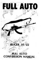
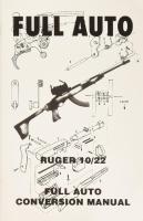
FULL AUTO Full Auto Conversion Of The Ruger 10-22
ft RUGER
Semi-Automatic
10/22
FULL AUTO CONVERSION MANUAL
Carbine
Full Auto Ruger 10/22 Full Auto
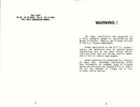
WARNING
Conversion Manual
!
The legal construction and possession of a fully automatic weapon is controlled by the Bureau of Alcohol, Tobacco, and Firearms division of the U.S. Treasury Department. Proper application to the B.A.T.F., authorization, and permission must be secured before
constructing
this
or
any
other
similar
Local and state laws vary and may restrict ship of this or similar type weapons.
device. owner-
Severe penalties are authorized for violators of these laws. Minuteman Publications offers this information for academic study of firearms design and disclaims any responsibility or liability for the improper or illegal use of this or other similar devices.
Table
Of
Contents
CONTENTS
PAGE
WmtrOductiOn:
sscsc ccseucctacasetanenvscvewer we 7
Chapter 1 Sequence
of Operation
Chapter 2 Parts To
Be
Chapter 3 Parts:-16
Be: Modified: .cci ccicvcncecs wens 19
Removed
.........sseeeeeeees 9 Semi-Automatic....... 17
Chapter 4 Parts To Be Manufactured PATES
LiSU
nse
............0005 29
e acc cceee bec ne eases
nn cle'sis(s cis 39
Introduction
the
data
The purpose of this manual and instructions necessary
required
for
conversion
10-22, semi-automatic fire automatic unit.
When
modified
the
weapon
of
operation
carbine,
to
the
retains
and
its
also
Ruger
10-22
weapons
the a
Ruger
selective
specifications
given,
semi-automatic
the
are
fully
selector
made
and has become one of the of its type in the world.
These
of
into
allows
functioning by moving the proper position.
The
is to provide manufacturing
its most
mode
automatic lever
debut
in
popular
logical
into
1964,
firearms
choices
for
automatic conversion because they have proven themselves to be well made, very rugged, maintain a relatively light weight, and are adaptable to many different sighting arrangements.
The
Ruger
to purchase,
to
many
economy.
run
in
condition
10-22
thereby
persons New
the used
approximately
is
an
economical
increasing
hampered
prices
$90.00
for
to
carbines
$45.00
its
by the
the
can
to $75.00.
struggling
standard
$110.00 be
weapon
availability carbine
range. purchased
Good for
Another distinct advantage of is that ammunition expenses are minimum when compared to various systems.
its
The power
.22 and
L.R. range,
mode, the 10-22 many applications.
cartridge but in the
is
a
The weapon is well construction and use.
configurations flexibility
are
for
Numerous
available for EATON SUPPLY,
high
MITCHELL 50 rd., and drum magazines provide
over
the standard
weapon
providing
Sequence
Operation
greater
A look through the accompanying drawings will give the exact orientation and relationship of the parts controlling the firing cycle.
use.
To achieve magazines
are
the Ruger 10-22. rd., CONDOR 25
The rd.,
THOMPSON style 50 rd., much greater flexibility
10 rd. magazine.
Of
for
adaptable to silencer Many various stock
capacity
use with INC. 25
is limited in fully automatic
formidable
available,
intended
the system held to a centerfire
positive
and
reliable
functioning,
the trigger group for the select-fire Ruger 10-22 was redesigned incorporating the basic design of the Belgian FN-FAL and West German HK-G3. battle rifle families. Both of these weapon systems and reliability. The
modified
are
legendary
in
still
retains
10-22
performance the
clos-
ed-bolt mode of operation. When firing the modified ing sequence of events occur:
(1)
weapon,
the
follow-
COCKING THE WEAPON
1. Assuming there is a loaded magazine in place, the user retracts the bolt handle (and bolt assembly) which rotates the hammer rearward. This
action
compresses
the
recoil
spring.
2. As the hammer almost completes its rearward rotation, the bottom of the hammer contacts the top of the disconnector which in turn pivots downward, releasing the sear to rotate upward into position against the hammer. The engagement between the hammer and sear is not yet set at this time because the hammer is fully rotated rearward. 3. During this same initial rearward movement of the bolt and hammer, the release lever and catch also move rearward slightly. The travel of these parts is limited by the ejector pin
which
is positioned
through
a slot
in the
the
‘burst’
notch.
4, When the bolt is fully retracted, released. Recoil spring tension then it forward.
it is propels
a
As live
the
bolt
cartridge
to chamber
it.
is from
moving the
forward, magazine
moved
slot machined in the bottom the bolt continues forward
the
release with roll out
(Both
the
catch
common
pin).
At
this
rearward)
lever
engagement positioned the catch
(2)
point,
makes
rotates
contact
with
of the motion,
forward.
Through
the catch by means of a laterally pin, the release lever rotates of engagement with the hammer.
and
release
the weapon
is
lever
ready
pivot
to
on
a
fire.
it
strips
and
begins
SEMI-AUTO FIRE
1. The position
weapon is now in a loaded and cocked as established in the sequence above.
2.
safety
The
position. modification
By
5. At this same instant, the hammer (released from contact with the bottom of the bolt) rotates forward slightly and securely engages the sear and catch, (both previously positioned) in their respective engagement notches.
6.
previously
a radiused bolt. As
release
lever. Both parts have independent § torsion springs which forces them to rotate rearward. The stationary arm of these springs locates against the ejector pin. As the bolt and hammer complete their rearward travel, the engagement surface of the catch is against the hammer ready
to engage
7. At a given point just before the bolt closes completely, the top of the release lever (having
moving
should
now
(The
safety
and
functions
the
of the sear is downward travel
safety provided when the
be
is to
to
the
unaltered
moved
in
identically
“OFF,”
the
as
"OFF"
this
before.
lower
lug
with clearance to enable trigger is depressed).
3. The selector lever must be positioned in the rearward, or “semi” position. In this position a lug on the bottom of the selector lever pivot will be positioned in a downward position and will limit the upward travel of the rear section of the trigger.
4.
Depress
sear
and
spring
The
during
the
the
the
bolt, the
moves
fired
from
striking
detonating
5.
trigger,
hammer
hammer, spring,
of
the
the
under rotates
firing
pin
cartridge.
on
resultant
rearward,
releasing
The
rear
acting
cartridge
thereby
engagement.
tension
forward
and
the
hammer
The
the
pressure
explosion
extracting
and
of
generated the
4.
with
the
hammer
(as
previously
the
(3)
and
sequence
then as
depress
it
again
to
resume
described.
FULL AUTO The
weapon
(as described 2.
The
in #2-2).
is
in
a
loaded
and
cocked
position
(as
described
depressed
of
the
trigger,
thereby
releasing
and
engagement
(as
cartridge
the
resulting
described
The trigger remains depressed as the 5. ejecting and extracting rearward, cycles fired case (as described in #2-5). The
rearward
release
lever
(as described
and
catch
have
in
in
bolt the
rotated
in #1-3).
7. At the rearmost travel of the bolt and hammer, the disconnector pivots downward and releases the sear to pivot upward. However, because further rotated has assembly trigger/sear the down than it did in the "semi" mode, the sear is not high enough to engage the hammer. The catch securely engages the hammer “burst notch,” thereby holding the hammer rearward as the bolt
begins 1.
depress
hammer-sear
detonation #2-4).
6. 7. Forward bolt travel performs the same functions as previously described. For another shot to be fired, the user must release the
trigger
Fully
the
6. As the bolt moves rearward, the release lever moves as previously explained. As the bolt completes rearward travel, the disconnector disengages the sear enabling it to be in position
be
can
position
this
in
trigger
further.
detonation,
ejecting
case.
for re-engagement described).
in be positioned must lever selector The 3. In this posithe forward or 'BURST' position. selector of the bottom the on lug the tion, lever pivot has rotated rearward enough to avoid contacting the upper, rear area of the trigger.
a live
forward
travel,
stripping
and
chambering
cartridge.
in #1-7).
safety
is
moved
N
"OFF"
8. At the instant before the bolt closes completely, the release lever contacts the bolt,
pivots forward and described in #1-7). to strike the firing tridge.
disengages the catch (as This allows the hammer pin and detonate the car-
13
This
cycle
is
repeated
until
the
trigger
is released. The sear can then rise, intercept the hammer, and interrupt the firing cycle.
SEMI-AUTO FUNCTIONING Selector is set at "SEMI". Bolt is in closed position.
Hammer
is cocked, lever
Release
Safety
*
and
sear engaged. catch
Moving will
pivoted
forward.
safety to "OFF" and depressing fire
FULL
trigger
weapon.
OPERATING
14
have
"ON".
SCALE
SEQ
ENCE DRWG.
NO.
[4
FULL-AUTO Selector is set Safety "OFF".
Weapon
at
FUNCTIONING
has fired and bolt
is moving
forward
recoil spring tension. Trigger is fully depressed, lowering low enough to not engage hammer.
Release catch
lever and catch is engaging
2
"BURST".
burst
have moved
the
under
sear
rearward
Parts
To Be Removed Semi-Auto
nose
and
notch.
Due the Ruger nate the
to
the
design
and
characteristics
10-22, it has been necessary use of the bolt lock, and
of
to elimibolt lock
spring. This
was
necessary
because
the
release
lever, release lever spring, catch, catch spring, and pivot pin occupy the space where these parts
originally are All sion.
When bolt contacts and trips the catch assembly, the hammer falls ridge.
OPERATING FULL
SCALE
release lever and to detonate cart-
SEQUENCE | DRWG
NO. 15
other
located. components
are
used
in
this
conver-
PARTS TO BE REMOVED FOR SELECT
FIRE
10-22 CONVERSION
3 Parts To Be
Modified
For select-fire conversion of the Ruger 10-22, minor modifications to six parts of the standard carbine is required. The modifications and purpose of each is described below. 1.
Receiver- Drawing # 1. The receiver requires drilled detents, as to securely
selector
44)
2.
1/16"
x
.030
deep
in such a manner position of the
lever.
Trigger Housing- Drawing # 2. The trigger housing requires that a 1/8" hole be drilled through the housing as indicated. This facilitates assembly of the catch/release lever assembly. Also, a 7/32" hole and 9/16" long x 1/8" wide slot is required as indicated to allow assembly of
3.
two
positioned locate the
the
Stock-
selector
Drawing
lever
assembly.
# 3.
The stock must be altered as shown to allow clearance for the selector lever assembly.
Bolt
#1 Lock Spring
#2 Bolt
Lock
19
Bolt-
Drawing
# 4.
The bolt requires a slot to be machined or cut into the bottom as indicated. This provides a contact surface and proper timing for contact with the release lever.
Trigger- Drawing # 5. he trigger requires to
the must
be
made
in
disconnector be
filed
further rotation The drawing can location. Also,
the
a
small
upper,
pin (as
rear
hole.
is epoxied in position in position indicated. This
cut
portion
near
The
indicated)
of the be used a small
clearance web to
1,050
1,000
area
provide
trigger assembly. as a template for .150 x .030 shim the slot at is necessary
limit the upward travel of the sear it disengages from the disconnector.
the to
when Selector
Hammer- Drawing # 6. A “BURST” notch is cut into the hammer as indicated. This engages the catch when assembled.
Drill deep
Positioning
1/16"
diameter
Detents x
RECEIVER —FA FULL
SCALE
DRWG_
NO.
|
.030
625
2.875
wh “I
125
———————}
=
fo
EF
1430 —e> a
A
me
a ei
NS
an
Ke
—
(9375)
>
:
: 562
Drill meter
.
trigger
Drill 7/32"hole (.2187) diameter through right trigger
le
FULL
housing
dia-
(for
housing only
Reretae
TRIGGER
(.125) a
R. Lever & Catch Pivot Pin)
Selector Assembly is installed in by aligning the lugs and slot and
SSer
1/8" hole
cowards
HOUSING
SCALE
Trigger Housing inserting. Sel-
Inlet stock Assembly.
90".
— FA,
DRWG
NO. 2
in
this
area
to provide
for
Selector
STOCK FULL
SCALE
| DRWE
NO.
3
i
Depth
150 |
of Slot =I
7
|
The
3
LW
700 RADIUS [R= 2.975. me
.200
Thickness
of
NOTE ON BOLTS bolt
design
for
the
Ruger
iged at some point. Below are each. For this modification, ised or
interchanged.
Old
Style
Bolt
New Style
Bolt
.080
Slot
SS Diagonally shaded area of underside of bolt.
represents
CTIVE
BOLT — FA, SEL FULL
the
DRWG.
SCALE 24
flat
surfaces
FIRE
NO
4 25
10-22
was
shown examples each bolt can
Epoxy
150 X 030 File
web
down
in
this
the
shim
in
this
area.
r
TRIGG | wu, ER soeFA
area.
.025
}
| pewo No 90°
ae’
—
750 =
~!
Burst
Notch
is to be ground
to the dimensions
Jp (125) PIVOT _PIN—CATCH REL. LEVER FULL SCALE | DRWG NO. 5
__ HAMMER FULL
FA
SCALE
DRWG._ 27
NO.
6
shown.
4 Parts
To
Be
Manufactured
The following are the new parts required for select-fire conversion of the Ruger 10-22. Materials for their construction are also included.
1.
Release The
Lever-
release
Drawing lever
# 7.
is
designed
to
be
made
from .050 thickness steel sheet metal. This part has a "tab" which is bent around almost double, providing a notch for location of the The
working arm of overall shape
using
the
drawing
the release lever spring. can be transferred by
as
a
template.
The dimen-
sioned areas should be as accurate as possible to ensure proper timing of hammer disengagement. 2.
Catch-
Drawing
piece shape
of of
The
catch
# 8.
shown
can
be
made
.050 sheet metal the proper width,
the profile to match x .510 roll pin is
by
bending
the drawing. A pressed through
sides of the catch as indicated. a longer pin through and then grind to
ed length.)
a
into a channel and then filing
3/32" both (Press finish-
Dimensioned
as
surfaces
possible
with
the
to
must
ensure
be
proper
as
accurate
engagement
hammer.
Spring-Release Lever- Drawing # 9. his torsion spring is to be made from .030 music wire or an equivalent. It can be easily made with a a 1/8" approximate
in a vise long piece
vise
as
for an of wire
grips.
shown
the
When
in
spring
the and
little practice. Use diameter rod clamped
arbor. Cut about a 3" and clamp both ends with the
drawing bend
the
approximate
is
achieved,
two
Cut spring arms to the as shown on the drawing.
curves
angle
release as
shown.
approximate
Spring-CatchSame as above
5.
Selector Lever- Drawing # 11. The selector lever can be made from .050 thickness steel spring stock, or banding (if available). If neither is available, stock catch
as used for is sufficient.
insert
To as
assemble shown
and
Drawing
the
release
lever
in
the
flare
the
3/16"
(.187)
flatten
the
x
.125
positions with the
assemble in place,
diameter
into
the or
the
chamfer in the lever after the two are in position. Use a piece of steel rod with a 1/8" hole in the center as a punch to flare the knob securely.
steel
lever,
firmly mating
indents in the receiver. To knob, either braze the knob
and
selector
# 13.
diameter x .040 “ball" the selector assembly by
# 10.
Selector Positioning Lug- Drawing # 12. This lug can be made of any available
stock.
Knob-
The selector knob can be made of the same material as the lug in # 7. The knob is knurled to provide a better grip. The .090
length
4,
Drawing in # 3.
Selector
.060
diameter against the lever. The chamfer in the lever will allow the lug to mushroom and be securely fixed in place.
i
Drill
375
‘
Li
|
iF
©
ty |. 275—> — i
le
|
i
|
: 050
4
(.0937)
catch
4s ‘ -h-i—
(es \
.300 pal
1/8"
ole
through
ee catch
{|
Fold tab over
~ Ly
to provide a notch for re-
; !
A ¥t
8
|
395 510
| i
{
lease lever spring.
| \
3/32"
diameter Roll
by .510 Pin
length
DRWG
NO,
|
CATCH
FULL
RELEASE LEVER FULL SCALE | DRWG
NO.
7
(Roll
Pin Location)
} 175
|
wee
3/32"
through
SCALE
8
er 187
a850
a
et SY
\—
Make springs from .030 springs to approximate
40
diameter music wire. shape as shown.
i
— PRING | FULL SCALE
| DRWG. NO. 9
Tt
3g 1875)
Form
|
70
Wa ( 125)
EAL
_~
|
|
Chamfer
surfaces -030
SELECTOR
as
950
| FULL
SCALE
500
735
(2/87) 045
~ | SPRING — CATCH SCALE
|
4
DRWG_NO_/O
x
x
indicated 45°
LEVER
125 —>| Pi;
1
\—140
FULL
050
DRWG. NO}!
SS
oe 300
n=
ime
SELECTOR POSITIONING LUG FULL SCALE DRWG_NO /2
ip
©)
RELEASE LEVER AND CATCH ASSEMBLY
Selector
arn
Whe
Lever
Lever Spring
Catch
Cee
nme
Release
Catch Spring
Pivot Pin-Release Lever
and
3
Catch
Assembly
~