Recent Advances in Civil Engineering: Select Proceedings of ERCAM 2021 (Lecture Notes in Civil Engineering, 265) 9811928355, 9789811928352
The book presents the select proceedings of the Third International Conference on Emerging Research in Civil, Aeronautic
158 25 5MB
English Pages 115 [114] Year 2022
Preface
Contents
About the Editors
Effect of CFRP Anchors in Strengthening of RC Beams Using Precast RC Segments Followed by CFRP Wrapping
1 Introduction
2 Methodology
2.1 Constant and Variable Parameters
2.2 Cross Section Details of Specimen
2.3 Schemes of Strengthening
2.4 Details of Specimens
3 Experimental Work
3.1 Data Required for Preparation of Specimens
3.2 Preparation of Specimens
3.3 Strengthening of Beams
3.4 Testing of Specimens
4 Results and Discussion
4.1 Ultimate Loads and Corresponding Deflections
4.2 Load-Displacement Behaviour of Specimens
4.3 Effect of CFRP Anchors
5 Conclusions
References
Workability Behaviour of Cement Mortar with Pond Ash as Fine Aggregates–Partial to Full Replacement
1 Introduction
1.1 Literature Study
2 Present Study
3 Materials and Properties
3.1 Cement
3.2 Water
3.3 Fine Aggregate
3.4 Admixture
3.5 Bricks or Masonry Units
4 Methodologies, Results of Various Tests and Discussion
4.1 Assessment of Properties of Cement Mortar
4.2 Properties of Fresh Mortar—Flow Table Test
4.3 Properties of Hardened Mortar—Compressive Strength
5 Conclusion
References
Studies on Development of Bamboo Reinforced Mud Panels using Locally Available Materials
1 Introduction
2 Methodology
3 Experimental Investigation
3.1 Characterization of Raw Materials
3.2 Sampling of Bamboo
3.3 Treatment for Bamboo
3.4 Soaking Treatment
3.5 Lime Water Treatment
3.6 Smoke Treatment
3.7 Preparation of Stabilized Soil
3.8 Casting of Bamboo Mud Roof Panel
4 Testing of Panel, Results and Discussions
4.1 Load and Flexural Strength Calculations
5 Conclusions
References
Structural Analysis of RC Buildings with Re-entrant Corners Using ETABS
1 Introduction
1.1 General
1.2 Types of Irregularities
1.3 Objectives
1.4 Methodology
2 Modeling and Analysis
2.1 Model Details
2.2 Loading Details
2.3 Modeling of RCC Frames
3 Result and Discussions
3.1 Equivalent Static Method
3.2 Response Spectrum Method
3.3 Time Period
4 Conclusions
References
Feasibility of Processed Recycled Coarse Aggregate and Fine Aggregate as Aggregates for High Strength Concrete
1 Introduction
1.1 Carbon Footprint
1.2 Sustainability
1.3 Construction and Demolition Waste
2 Literature Review
2.1 General
3 Objectives
4 Materials and Properties
4.1 Cement
4.2 Manufactured Sand (M-Sand)
4.3 Recycled Aggregates (RA)
4.4 Admixture
5 Mix Design
6 Methodology and Workability
6.1 Properties of Hardened Concrete
7 Discussions of Test Results
8 Discussions on Results
9 Conclusions
References
Finite Element Analysis of Shape Modified Compression Members Wrapped with CFRP
1 Introduction
2 Details of Experimental Work
3 Experimental Setup and Instrumentation
4 Finite Element Modelling
5 Parametric Study
6 Results and Discussion
6.1 Effect of Number of Layers
6.2 Effect of Eccentricity of Load on Ultimate Load Carrying Capacity
6.3 Effect of Aspect Ratio on Ultimate Load Carrying Capacity
6.4 Failure Modes of Specimens
7 Conclusions
References
Behaviour of RC Compressive Members Retrofitted with Micro-concrete and CFRP Wrapping
1 Introduction
1.1 Materials and Techniques
2 Effect of FRP Confinement on Compressive Member
3 Aim and Scope of Study
4 Experimental Study
4.1 Materials
4.2 Preparation of Test Specimens
4.3 Analytical Parametric Study
4.4 Finite Element Analysis
4.5 Non-linear Solution
4.6 Material Properties
4.7 Validation Process
5 Analytical Parametric Study
5.1 Ultimate Load and Ultimate Deformation
5.2 Load Deformation Behaviour for Proposed Technique
6 Stress-Strain Behaviour of Square Microconcrete Circle with CFRP
7 Conclusion
References
Recommend Papers


- Author / Uploaded
- G. Raghava (editor)
- Shamsher Bahadur Singh (editor)
- A. S. Sajith (editor)
File loading please wait...
Citation preview
Lecture Notes in Civil Engineering
G. Raghava Shamsher Bahadur Singh A. S. Sajith Editors
Recent Advances in Civil Engineering Select Proceedings of ERCAM 2021
Lecture Notes in Civil Engineering Volume 265
Series Editors Marco di Prisco, Politecnico di Milano, Milano, Italy Sheng-Hong Chen, School of Water Resources and Hydropower Engineering, Wuhan University, Wuhan, China Ioannis Vayas, Institute of Steel Structures, National Technical University of Athens, Athens, Greece Sanjay Kumar Shukla, School of Engineering, Edith Cowan University, Joondalup, WA, Australia Anuj Sharma, Iowa State University, Ames, IA, USA Nagesh Kumar, Department of Civil Engineering, Indian Institute of Science Bangalore, Bengaluru, Karnataka, India Chien Ming Wang, School of Civil Engineering, The University of Queensland, Brisbane, QLD, Australia
Lecture Notes in Civil Engineering (LNCE) publishes the latest developments in Civil Engineering - quickly, informally and in top quality. Though original research reported in proceedings and post-proceedings represents the core of LNCE, edited volumes of exceptionally high quality and interest may also be considered for publication. Volumes published in LNCE embrace all aspects and subfields of, as well as new challenges in, Civil Engineering. Topics in the series include: • • • • • • • • • • • • • • •
Construction and Structural Mechanics Building Materials Concrete, Steel and Timber Structures Geotechnical Engineering Earthquake Engineering Coastal Engineering Ocean and Offshore Engineering; Ships and Floating Structures Hydraulics, Hydrology and Water Resources Engineering Environmental Engineering and Sustainability Structural Health and Monitoring Surveying and Geographical Information Systems Indoor Environments Transportation and Traffic Risk Analysis Safety and Security
To submit a proposal or request further information, please contact the appropriate Springer Editor: – Pierpaolo Riva at [email protected] (Europe and Americas); – Swati Meherishi at [email protected] (Asia - except China, and Australia, New Zealand); – Wayne Hu at [email protected] (China). All books in the series now indexed by Scopus and EI Compendex database!
G. Raghava · Shamsher Bahadur Singh · A. S. Sajith Editors
Recent Advances in Civil Engineering Select Proceedings of ERCAM 2021
Editors G. Raghava Department of Civil Engineering Nitte Meenakshi Institute of Technology Bangalore, Karnataka, India
Shamsher Bahadur Singh Department of Civil Engineering Birla Institute of Technology and Science Pilani, Rajasthan, India
A. S. Sajith Department of Civil Engineering National Institute of Technology Calicut Kozhikode, Kerala, India
ISSN 2366-2557 ISSN 2366-2565 (electronic) Lecture Notes in Civil Engineering ISBN 978-981-19-2835-2 ISBN 978-981-19-2836-9 (eBook) https://doi.org/10.1007/978-981-19-2836-9 © The Editor(s) (if applicable) and The Author(s), under exclusive license to Springer Nature Singapore Pte Ltd. 2023 This work is subject to copyright. All rights are solely and exclusively licensed by the Publisher, whether the whole or part of the material is concerned, specifically the rights of translation, reprinting, reuse of illustrations, recitation, broadcasting, reproduction on microfilms or in any other physical way, and transmission or information storage and retrieval, electronic adaptation, computer software, or by similar or dissimilar methodology now known or hereafter developed. The use of general descriptive names, registered names, trademarks, service marks, etc. in this publication does not imply, even in the absence of a specific statement, that such names are exempt from the relevant protective laws and regulations and therefore free for general use. The publisher, the authors and the editors are safe to assume that the advice and information in this book are believed to be true and accurate at the date of publication. Neither the publisher nor the authors or the editors give a warranty, expressed or implied, with respect to the material contained herein or for any errors or omissions that may have been made. The publisher remains neutral with regard to jurisdictional claims in published maps and institutional affiliations. This Springer imprint is published by the registered company Springer Nature Singapore Pte Ltd. The registered company address is: 152 Beach Road, #21-01/04 Gateway East, Singapore 189721, Singapore
Preface
Today, multi-disciplinary Emerging Research has become vital in the development of a wide range of materials, technological processes and systems. The role of Civil, Aeronautical, and Mechanical Engineering in the country’s economy and societal evolution has long been demonstrated. Some of the areas that are drawing the attention of researchers, the world over, in developing a wide range of engineering technologies are Advanced Materials, Mechanics of Engineering Components, Engineering Structures and Systems, etc. The International Conference, ERCAM-2021, is envisaged to bring together specialists and practitioners from various Industries, R&D institutes, and academicians across the World, thereby providing a forum for exchange of knowledge on Emerging Research and recent trends in major sectors of materials, processes and systems pertaining to Civil, Aeronautical and Mechanical Engineering with multi-disciplinary approaches. The Third International Conference ERCAM-2021 focuses on various themes such as Materials, Mechanics, Structures, Systems and Sustainability and topics of interest for submission of research papers include all themes but are not limited only to these themes. The conference will bring together leading academician’s scientists, researchers and industry experts in the domains of interest from across the world. ERCAM-2021 has an active participation of University Putra Malaysia, Gazi University and North Dakota State University, Fargo, USA. This conference succeeded in providing a solid platform for researchers around the globe to share insights, experiences and various aspects of evolving technologies related to Civil, Aeronautical and Mechanical Engineering. Proceeding covers a wide range of topics which are relevant to the current needs of industry. All the papers received for the ERCAM-2021 conference on various aspects of focused areas were rigorously reviewed by an expert technical review committee that includes experts in the area from all over the world. The committee selected the best 60 papers for oral presentation in the conference. Here, we would like to express our gratitude to the authors for revising their papers to address the comments and suggestions by the reviewers.
v
vi
Preface
We are immensely grateful to all the organizers and members of the Program Committee for their diligent work, which ensured high-quality proceedings. We highly appreciate the guidance and support provided by the Management and faculty of Nitte Meenakshi Institute of Technology and Advisory Committee. We thank all our sponsors for their cooperation with us. We are thankful for the support of several colleagues in the academia and industry who volunteered to review papers and deliver plenary talk despite many challenges. ERCAM team expresses its gratitude towards Springer Nature, AIP publications, M/s USB Printers for their fruitful collaboration during the preparation of the proceedings. The proceedings of ERCAM-2021 are organized in a single volume. We hope that the ERCAM-2021 proceedings will serve as an important intellectual resource for Civil, Aeronautical and Mechanical Engineering researchers, pushing forward the boundaries of these fields and enabling better collaboration and exchange of ideas. Bengaluru, India Pilani, India Kozhikode, India
Dr. G. Raghava Prof. Shamsher Bahadur Singh Dr. A. S. Sajith
Contents
Effect of CFRP Anchors in Strengthening of RC Beams Using Precast RC Segments Followed by CFRP Wrapping . . . . . . . . . . . . . . . . . . . Md. Samiuddin, L. Manjunatha, H. Sharada Bai, H. R. Yashaswini, and R. K. Veeresh Kumar
1
Workability Behaviour of Cement Mortar with Pond Ash as Fine Aggregates–Partial to Full Replacement . . . . . . . . . . . . . . . . . . . . . . . . . . . . . . 15 Bharathi Ganesh, Jayesh Shrestha, Bishwombhar Prakash Pandit, Anish Chaulagain, and T. K. Jyothi Studies on Development of Bamboo Reinforced Mud Panels using Locally Available Materials . . . . . . . . . . . . . . . . . . . . . . . . . . . . . . . . . . . . . . . . . . 31 T. K. Jyothi, V. Kavitha, S. Raghunath, K. S. Jagadish, and Bharathi Ganesh Structural Analysis of RC Buildings with Re-entrant Corners Using ETABS . . . . . . . . . . . . . . . . . . . . . . . . . . . . . . . . . . . . . . . . . . . . . . . . . . . . . . . . . . . . 41 B. K. Narendra, K. S. Bhumika, H. K. Shivaprathap, and Deviprasad Feasibility of Processed Recycled Coarse Aggregate and Fine Aggregate as Aggregates for High Strength Concrete . . . . . . . . . . . . . . . . . . 51 G. Prathima, Bharathi Ganesh, Nagesh Puttaswamy, G. Srinivasa, Jayesh Shreshta, Bishwombhar Pandith, and R. Nagendra Finite Element Analysis of Shape Modified Compression Members Wrapped with CFRP . . . . . . . . . . . . . . . . . . . . . . . . . . . . . . . . . . . . . . . . . . . . . . . 65 L. Manjunatha, A. R. Raghuveer, B. V. Sachin, and H. Sharada Bai Behaviour of RC Compressive Members Retrofitted with Micro-concrete and CFRP Wrapping . . . . . . . . . . . . . . . . . . . . . . . . . . . . 87 Krishna Bahadur Paija Pun, Bharathi Ganesh, L. Manjunatha, K. J. Chandrika, C. Pavan Kumar, and H. Sharada Bai
vii
About the Editors
Dr. G. Raghava is working as a Professor in the Department of Civil Engineering at NITTE Meenakshi Institute of Technology, Bangalore since July 2019. Prior to that, he has served as a Chief Scientist at CSIR—Structural Engineering Research Centre, Chennai for a span of 34 years. At CSIR-SERC, he was involved in research and development in the areas of “fatigue and fracture behaviour of structural materials, components and structures”; “experimental investigations on large size structural components”; and R&D in in-house, sponsored and consultancy research projects including externally funded projects from public and private sector organisations/industry. From October 2006 to July 2017, he served as head of fatigue & Fracture Laboratory of CSIR-SERC and also supported the organisational management in various capacities. He completed his Ph.D. in Structural Engineering from Anna University, Guindy, Chennai in 1999. His Ph.D. thesis was “Corrosion fatigue behaviour of cathodically protected stiffened steel tubular T joints” and received the Best Ph.D. Thesis Award from the Corrosion Society of India. He completed his M.Tech. in Industrial Structures from NITK (KREC) Surathkal in 1984 and B.Tech. in Civil Engineering from Sri Jayachamarajendra College of Engineering Mysore in 1980. His areas of interest are: fatigue behaviour of structures and structural components, fatigue/corrosion fatigue in steel offshore structures and power plant structures, design of structures for fatigue loads, experimental investigations on static and fatigue behaviour of large size structural components, fatigue and fracture investigations on structural components under low temperature and elevated temperature and internal pressure. Dr. Raghava has published 165 technical papers in reputed journals and proceedings of conferences. He has received many awards and recognitions during his academic and professional career, including awards for his technical papers. He has participated in the XXIII Indian Scientific Expedition to Antarctica during December 2003 to April 2004 and carried out “Structural assessment of the second Indian Research Station ‘Maitri’ in Antarctica”. He was Chairman of the Technical Core Group for the construction of the third Indian Research Station ‘Bharati’ in East Antarctica. He is a member of several professional societies such as The Institution of Engineers (India), Indian Concrete Institute, Indian Society for Non-Destructive Testing, Computer Society of India, Indian Structural Integrity Society, Society for ix
x
About the Editors
Failure Analysis, Instrument Society of India, Indian Nuclear Society, Indian Society for Technical Education, Association of Consulting Civil Engineers, and Bamboo Society of India. Dr. Shamsher Bahadur Singh is Fellow of American Society of Civil Engineers (F.ASCE), Chartered Engineer (INDIA), and Fellow of Institution of Engineers (F.IE), and also holds a Professional Engineering (Civil) license from Michigan State, USA. Prof. Singh is recipient of several fellowships, e.g., Post-doctorate Fellowship from Lawrence Technological University USA, Quality Improvement Program (QIP) Fellowship at Indian Institute of Technology Kanpur, Research fellowship at Motilal Nehru Regional Engineering College Allahabad, as well as National Merit Scholarship from Regional Engineering College Warangal, and Integrated scholarship at schools. He has 235 publications to his credit which include more than 192 research papers, 6 books [two text books, one online book, and two edited books], 13 research reports and 19 book chapters, and 02 theses, and 3 Patents. Prof. Singh has executed 40 research and consultancy projects funded by various government and non-government organizations. He won a prestigious collaborative project in collaboration with IIT Delhi and sponsored by Defence Research and Development Organization (DRDO) for development of blast resistant containers. He also won US-2020 partnership award from US Department of State with collaborations from MSU, USA and IIT Delhi; was awarded a project from US-India Education Foundation, Fulbright Specialist Program to host US Specialist, at BITS Pilani, for academic year 2022; received the Best Academician of the Year -2020 award by the honourable Governor of Rajasthan, India; was selected as a member of Construction Industry Development Council Academy of Construction Engineering; was awarded Bharat Shiksha Gaurav Puraskar and Certificate of Excellence from KTK Outstanding Achievers and Education Foundation, New Delhi; won the Best Paper Awards from The Indian Concrete Journal in 2020 and ACEE2015, Penang Malaysia, in 2015 and was appointed as associate member of ACI 440 and ACI 423 committees. Prof. Singh has had an opportunity to teach in some of the best universities in India and USA such as MNNIT Allahabad, NIT Warangal, BITS Pilani, and Lawrence Technological University (LTU), Southfield, Michigan, USA. Currently, Prof. Singh is working as Senior Professor in the Department of Civil Engineering at Birla Institute of Technology and Science Pilani, Rajasthan, India. Other achievements, awards, and recognitions from across the globe of Prof. Singh can be seen on his personal website linked to BITS Pilani. Dr. A. S. Sajith is working as an Associate Professor in the Department of Civil Engineering at National Institute of Technology Calicut since 2002. He has completed his Ph.D. in Structural Engineering from National Institute of Technology Calicut; M.E. in Structural Engineering from PSG College of Technology, Coimbatore and B.Tech. in Civil Engineering from College of Engineering, Trivandrum. He has a vast range of interests in the field of engineering mechanics, engineering graphics, strength of materials, structural analysis, advanced structural mechanics, theory of plates and shells, advanced concrete design, structural dynamics and earthquake
About the Editors
xi
resistant design of structures. He has done extensive research in the areas of vibration control, structural dynamics and earthquake engineering. He has guided two Ph.D. scholars till date and seven are in the process of completing Ph.D. under him. He has guided more than 35 M.Tech. students under him. He has published more than 15 papers in peer-reviewed Journals. He has presented papers in National/International Conferences. He has provided consultancy for varous projects such as Site Survey and Functional Design of 7 bridges in Wynad District, Structural Design of 5 bridges in Wynad District, Construction of the first floor over the existing Isotope laboratory of CWRDM, Calicut, Site Survey and structural design of two bridges in Melady block panchayath, Calicut, Kerala, Banasura Sagar irrigation project—Assessment of strength of main canal of BSP, and to name a few.
Effect of CFRP Anchors in Strengthening of RC Beams Using Precast RC Segments Followed by CFRP Wrapping Md. Samiuddin, L. Manjunatha, H. Sharada Bai, H. R. Yashaswini, and R. K. Veeresh Kumar
Abstract The service life of reinforced concrete structures is decreasing day by day without serving its designed life. This is caused to a variety of factors, including structural deterioration, which renders the structure unsafe for users. Deterioration of structures may be caused due to change in use or functionality, adverse environmental effects and addition in loading on the structure due to vertical development. The demand for commercial and residential space is increasing drastically and due to high land value vertical development is the only option left with necessary precautions considered against the capacity of foundations. It is important for structural members to have adequate strength and deformation capacity for stable performance of structures during its entire life, hence repairing, retrofitting and upgrading the structure for enhanced load carrying capacity and displacement capacity is necessary. In present experimental study, newly cast reinforced concrete (RC) beams were strengthened by attaching RC precast segments and followed by carbon fibre reinforced polymer (CFRP) wrapping. Further to increase bonding between the CFRP and concrete, CFRP anchors were installed to anchor the CFRP wrapping layers on the surface of concrete beam. From the experimental investigation, it can be observed that the beams strengthened with the help of precast segments and CFRP wrapping show considerable increase in load carrying capacity. The CFRP anchors have increased the bond between CFRP wrapping and concrete surface. Keywords Strengthening · Precast segment · Carbon fibre reinforced polymer · Wrapping · Anchors · Ultimate load · Displacement and ductility
Md. Samiuddin (B) · L. Manjunatha · H. R. Yashaswini · R. K. V. Kumar Nitte Meenakshi Institute of Technology, Yelahanka, Bengaluru 560064, India e-mail: [email protected]; [email protected] L. Manjunatha e-mail: [email protected] H. S. Bai University Visveswaraya College of Engineering, Bengaluru 560064, India © The Author(s), under exclusive license to Springer Nature Singapore Pte Ltd. 2023 G. Raghava et al. (eds.), Recent Advances in Civil Engineering, Lecture Notes in Civil Engineering 265, https://doi.org/10.1007/978-981-19-2836-9_1
1
2
Md. Samiuddin et al.
1 Introduction For structures to work consistently, structural members must have sufficient strength and deformation capability. The early deterioration of concrete structures in the form of steel corrosion, cracking of concrete and spalling of concrete is another problem faced worldwide, which necessitates the repair and retrofitting. From various studies carried out in recent time, strengthening of RC beams by bonding RC plates is found effective [1]. RC beams when strengthened with fibre reinforced polymer (FRP) sheet wrappings prove to be efficient and do not contribute dead load to the structure [2]. The strengthening with CFRP shows higher strength compared to other types of FRPs [3, 4]. De-bonding of FRP and rupture of FRP were the two main failure types reported [5]. Use of FRP anchor proves to be effective in creating stiff anchorage to the FRP sheets with concrete and anchors provided in shear region found more efficient [6, 7]. The present paper focuses on the behaviour of flexural members retrofitted by an innovative method, i.e. bonding a precast reinforced concrete segment to the newly cast reinforced concrete beam and followed by CFRP wrapping. To assess the feasibility of this strengthening methodology, a detailed experimental investigation was planned and executed.
2 Methodology The beams retrofitted only with FRP wrapping can enhance the load carrying capacity to a certain limit with increasing amount of FRP up to which the beam cross section behaves as under reinforced section. After this limit, if the thickness of FRP increased the beam cross section would become over reinforced and which lead the beam to fail suddenly which is not recommended in civil engineering practices. Enhancement of the load carrying capacity of beam, maintaining the beam cross section as under reinforced is possible only if the depth of the beam is increased [1]. Hence in the present study the depth of the beam was increased by attaching RC precast segments, which increases the lever arm thereby enhancing the moment carrying capacity and also maintaining the section as under reinforced which shows ample warnings before collapse of the beam. In addition, CFRP wrapping was carried out in longitudinal direction only at the bottom and to arrest the debonding of precast segments from concrete surface, CFRP wrapping is carried out in U shape on outer surface of the beam to enhance the shear capacity of the beam [5]. To arrest the debonding of CFRP from the concrete surface manually designed CFRP anchors were provided [6, 7]. The beams were tested under four-point loading up to failure. The loads and corresponding displacements, failure loads and modes of failure were recorded. Results are compared between different schemes of retrofitting and control beam.
Effect of CFRP Anchors in Strengthening of RC Beams …
3
Table 1 Constant and variable parameters Particulars
Specification
Constant
Strength of concrete
35 MPa
✓
Size of beam
1700 × 150x150
✓
Adhesive for precast
Epoxy sealant
✓
Primer for FRP wrapping
Epoxy primer
✓
Wrapping material
CFRP (Carbon fibre reinforced polymer)
✓
Adhesive for CFRP
Nitowrap saturant
✓
Type of testing
Two point load flexure test
✓
Strength of precast segments
35 MPa
✓
Thickness of precast
50, 75 and 100 mm
Variable
✓
Anchorage
Manually prepared CFRP anchors
✓
CFRP fibre alignment
Horizontal, inclined and vertical
✓
Fig. 1 Cross section of specimen
2.1 Constant and Variable Parameters Constant and variable parameters considered in the experimental study are listed in Table 1.
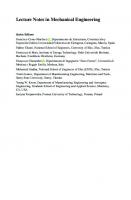
2.2 Cross Section Details of Specimen The cross section of specimen is as shown in Fig. 1. The cross-sectional view shows the dimensions of RC beam and precast segment with the specifications of reinforcement details.
2.3 Schemes of Strengthening The schemes of strengthening considered in this present experimental investigation are as follows which are discussed in detail.
4
Md. Samiuddin et al.
(a) Front view
(b) Side view
Fig. 2 Retrofitting scheme 1 (All dimensions are in mm)
Scheme 1 (S1)—One layer of CFRP, laterally wrapped on the RC beam as shown in Fig. 2. Scheme 2 (S2)—RC beam attached with precast segment using epoxy bonding material as shown in Fig. 3. Scheme 3 (S3)—RC beam attached with precast segment and CFRP wrapping only at the end region of beam to arrest sudden shear failure at the starting of precast segment. CFRP wrapping was carried out in two layers. In first layer, CFRP fibres were aligned along 45°, and in second layer, fibres were in longitudinal direction as shown in Fig. 4. Scheme 4 (S4)—In addition to details of Scheme 3, one layer of CFRP at the bottom surface in which fibres aligned in the longitudinal direction and another layer of CFRP strips of 75 mm wide at 75 mm clear spacing in which fibres aligned in lateral direction wrapped all round as shown in Fig. 5. Scheme 5 (S5)—In addition to details of Scheme 3, one layer of CFRP at the bottom surface in which fibres aligned in the longitudinal direction and another
(a) Front view
(b) Side view Fig. 3 Retrofitting scheme 2 (All dimensions are in mm)
Effect of CFRP Anchors in Strengthening of RC Beams …
5
(a) Front view
(b) Side view
Fig. 4 Retrofitting scheme 3 (All dimensions are in mm)
(a) Front view
(b) Side view
Fig. 5 Retrofitting scheme 4 (All dimensions are in mm)
layer of CFRP strips of 75 mm wide at 75 mm clear spacing in which fibres aligned in lateral direction wrapped in U shape. In this scheme, the anchorages of CFRP in the transverse direction were ensured by providing CFRP anchors [6, 7] as shown in Fig. 6.
2.4 Details of Specimens In the present study, the dimensions of the beams considered were 1700 × 150 × 150 mm and precast segments used were of length 1500 mm and width 150 mm with varying depths of 50, 75 and 100 mm. The number of layers of CFRP wraps,
6
Md. Samiuddin et al.
(a) Front view
(b) Side view Fig. 6 Retrofitting scheme 5 (All dimensions are in mm)
alignment and orientation of fibres, presence of CFRP, precast segment and anchorage are tabulated in Table 2. Table 2 Specimen specifications Specimen designation
Beam
Precast segment thickness (mm)
FRP layers H
V
Anchors I
B
CB
✓
–
✗
✗
✗
✗
✗
S1
✓
–
✗
✗
✗
✗
✗
S2-50
✓
50
✗
✗
✗
✗
✗
S2-75
✓
75
✗
✗
✗
✗
✗
S2-100
✓
100
✗
✗
✗
✗
✗
S3-50
✓
50
✓
✗
✓
✗
✗
S3-75
✓
75
✓
✗
✓
✗
✗
S3-100
✓
100
✓
✗
✓
✗
✗
S4-50
✓
50
✓
✓
✓
✓
✗
S4-75
✓
75
✓
✓
✓
✓
✗
S4-100
✓
100
✓
✓
✓
✓
✗
S5-50
✓
50
✓
✓
✓
✓
✓
S5-75
✓
75
✓
✓
✓
✓
✓
S5-100
✓
100
✓
✓
✓
✓
✓
H-Horizontal layer, V-Vertical layer, I-Inclined layer and B-Bottom layer
Effect of CFRP Anchors in Strengthening of RC Beams … Table 3 Working data
7
Particulars
Specification
No. of beams
14
No. of precast segments
12
Size of beam
1700 × 150 × 150 mm
Size of precast segments
1500 × 150 × (50 or 75 or 100 mm)
Concrete mix proportions
1:2.66:2.106
Water cement ratio
0.60
Grade of steel
Fe500
Main reinforcement
2 no. of 8 mm dia bars
Stirrups
2L-6 mm @ 150 c/c
Mix ratio of epoxy bonding material
1H:2R
Mix ratio of primer coat
1H:3R
Mix ratio of Nitowrap saturant 1H:2R Layers of CFRP fibre alignment
Horizontal, inclined and vertical
3 Experimental Work Experimental works carried out such as casting of beams, precast segments, attaching of precast segments, surface preparation, FRP wrapping, CFRP anchoring and testing of specimens are listed in the preceding sub-sections.
3.1 Data Required for Preparation of Specimens In Table 3, the design details of beam, concrete mix design, pre-defined manufacturers mix ratios for strengthening materials and layers of CFRP as per the methodology.
3.2 Preparation of Specimens As per the design mix proportion of 1:2.66:2.106 for w/c ratio of 0.60, materials were mixed and poured in the prepared formwork in which already prepared steel reinforcement cages were inserted with 15 mm cover to the reinforcement. The concrete is vibrated using needle vibrator, and the surface is finished using trowel. A total of 14 number of beams of dimension 1700 × 150 × 150 mm and 12 no of precast segments of length 1500 and 150 mm width and varying depth of 50, 75 and
8
Md. Samiuddin et al.
100 mm were cast. While casting the beams, three cubes of dimension 100 × 100 × 100 mm were also cast for every batch of concrete mixing.
3.3 Strengthening of Beams Strengthening of precast segments involves bonding of precast segments [1], CFRP wrapping and installation of CFRP anchors [6, 7].
3.3.1
Bonding of Precast Segments
After 28 days of curing, precast segments were attached to beams using epoxy adhesive. Before bounding precast segments, the surface of beams and precast segments was prepared by making grooves on the bottom face of beams and upper face of precast segments in the form of criss-cross for the better bonding of beam and precast segments and to act monolithically. Epoxy adhesive was applied to the bottom of the beam for a thickness of 3 mm and the precast segment was placed the same and pressed and held in position using specially designed clamps for an hour until the epoxy adhesive gets hardened (Fig. 7).
(a) Surface preparation
(b) Prepared surface
(c) Clamping of specimens
Fig. 7 Bounding of precast segments
Effect of CFRP Anchors in Strengthening of RC Beams …
(a) Application of CFRP
9
(b) CFRP wrapped specimens
Fig. 8 Application CFRP wrapping
3.3.2
CFRP Wrapping
Epoxy primer (EP103) was mixed thoroughly and applied on concrete surface as per the manufacture’s specification. After 24 h when the surface becomes tack-free epoxy saturant (Nitowrap 410) was applied, and the CFRP sheets were wrapped on the primed surface of the specimens as per the schemes of strengthening mentioned in methodology (Fig. 8).
3.3.3
Installation of CFRP Anchors
CFRP anchors were inserted into the drilled holes after CFRP wrapping was done at 50 mm from top of the beam into the vertical limbs of U strips as shown in Fig. 9. The CFRP anchors used are manually prepared anchors [6, 7], dimensions of anchors considered were of 10 mm in diameter, 30 mm of dowel length and a fan radius of 50 mm.
(a) Installation process Fig. 9 Installation CFRP anchors
(b) CFRP anchors installed specimens
10
Md. Samiuddin et al.
Fig. 10 Testing setup
3.4 Testing of Specimens Testing of the specimens was carried out in the loading frame with capacity of 2000 kN in the structural laboratory at Nitte Meenakshi Institute of Technology. The method of testing considered was two point load flexural test, in the test setup LVDTs were installed to measure the displacement of the specimen under one of the loading point that is 1/3rd distance from the support and at the centre of the span for measuring maximum deflection. The loads and corresponding deformations were recorded at every 0.1 s time interval using data acquisition system (Fig. 10).
4 Results and Discussion The test results of the specimens tested with two point load flexural test are discussed and the test data is presented in Table 4 and Figs. 11 and 12 for comparing the ultimate loads and ultimate deflections of different specimens and to determine the efficiency of the present method adopted for strengthening of reinforced concrete beams especially the effect of using CFRP anchors in proving the anchorage to CFRP flexural and shear wrapping.
4.1 Ultimate Loads and Corresponding Deflections The obtained test data of ultimate load carrying capacity, displacement at ultimate load and mode of failure observed were compared in the form of percentage increase in load carrying capacity and percentage change in displacement with respect to control beam, the same is presented in Table 4.
Effect of CFRP Anchors in Strengthening of RC Beams …
11
Table 4 Comparison of ultimate loads and ultimate deformation of the specimens tested Sl. No
Specimen designation
Load carrying capacity (kN)
Percentage Displacement increase in load (mm) carrying capacity (%)
Mode of failure
1
CB
26.1
–
37.99
Flexure
2
S1
53.4
104.59
25.88
Flexure
3
S2-50
53
103.06
7.51
Shear
4
S2-75
54.5
108.81
4.4
Shear
5
S2-100
50.7
94.25
1.77
Shear
6
S3-50
56.9
118
22.1
Flexure
7
S3-75
72.7
178.54
38.25
Flexure
8
S3-100
69.4
165.9
15.37
De-bonding and Flexure
9
S4-50
82.8
217.24
17.96
Shear and flexure
10
S4-75
82.7
216.85
17.35
Flexure
11
S4-100
98.1
275.86
18.53
Flexure
12
S5-50
83.4
219.54
16.92
Flexure
13
S5-75
79.7
205.36
13.68
Shear and flexure
14
S5-100
86.2
230.26
12.38
Shear and flexure
CB-Control Beam, S1-Scheme 1, S2-Scheme 2, S3-Scheme 3, S4-Scheme 4 and S5-Scheme 5 CB S1 S2-50 S2-75 S2-100 S3-50 S3-75 S3-100 S4-50 S4-75 S4-100 S5-50 S5-75 S5-100
100
Load(kN)
80 60 40 20 0 0
10
20
30
40
50
Displacement (mm) Fig. 11 Load versus displacement curve of specimens
From Table 4, it is observed the ultimate load carrying capacity of control beam is 26.1 kN. Beam wrapped with CFRP in scheme 1 showed 104.59% increase in ultimate load carrying capacity compared to control beam. When precast segment was attached to beam as per scheme 2, the ultimate load carrying capacity was increased
12
Md. Samiuddin et al.
Effect of CFRP Anchors
120
Load(kN)
100 80 60 S4-50 S4-75
40
S4-100 S5-50
20
S5-75 S5-100
0 0
5
10
15
20
25
30
Displacement (mm) Fig. 12 Load versus displacement curve for effect of anchors
by 108.81% in S2-75 specimen compared to control beam. S2 group specimens failed prematurely in shear at support due to stress concentration resulting due to sudden change in the cross. In order to arrest this shear failure, CFRP was bonded in this shear zone as mentioned in scheme 3 for S3-50, S3-75 and S3-100 specimens. From the test results of S3group specimens, the maximum increase in the load carrying capacity of 178.54% is observed for S3-75 specimen compared to control specimens. Hence due to end shear zone strengthening the load carrying capacity is increased from 108.81 to 178.54%. Hence this shear zone strengthening using CFRP is adopted in S4 and S5 group of specimens prior to flexural strengthening and shear strengthening of entire beams. Due to additional flexural and shear strengthening, S4 group specimens enhanced the load carrying capacity to 275.86%. Hence flexural and shear strengthening lead to the maximum enhancement of load carrying capacity from 178.54 to 275.86%. In practice, it is not possible to wrap the shear FRP all-round the beam as done in scheme 4 due to presence of slab on top of the beam; hence in scheme 5 this practical difficulty was overcome by providing shear FRP in U shape and anchoring of ends shear FRP was made sure by providing CFRP anchors. From the test results of S5 specimens, it is observed that maximum increase in the load carrying capacity is found to be 230.26%, which is 51.72% more than that of S3 group. Hence the method of use of CFRP anchors proved to be satisfactory in enhancing the load carrying capacity.
Effect of CFRP Anchors in Strengthening of RC Beams …
13
4.2 Load-Displacement Behaviour of Specimens Load versus displacement curves are plotted to study the behaviour of specimen with respect to loads and displacements corresponding to that load. The strengthening process was observed and studied from load versus displacement curves of all specimens by comparing it with that of control beam as shown in Fig. 11. Control beam (CB) shows maximum ductility in the form of displacement. Beams with precast segments (S2) show minimum displacement and higher loading capacity compared to control beam (CB). Beams with precast segments and shear CFRP (S3) show increased displacements and loading capacity compared to beams with precast segments only (S2). Beams strengthened with precast segments, shear CFRP, flexure CFRP and all-round wraps (S4) show further increase in load carrying capacity but reduced ductility in the form of displacement. Beams with precast segments, shear CFRP, flexural CFRP with “U” wraps anchored with CFRP anchors (S5) show similar behaviour compared to beams without CFRP anchors (S4).
4.3 Effect of CFRP Anchors From Table 4, the percentage increase in the load carrying of scheme 4 specimens is higher than that of scheme 5 with only “U” shear CFRP and CFRP anchors. The S4 specimens show enhancement of 217.24%, 216.85% and 275.86% with 50 mm, 75 mm and 100 mm precast segments, respectively, than that of S5 specimens found to be 219.54%, 205.36% and 230.26% with 50 mm, 75 mm and 100 mm precast segments, respectively. Here, in the present study, it can be noted that as the depth of precast segment increases the efficient of strengthening in S5 specimens decreases. Beams attached with precast segment with shear CFRP, flexural CFRP and “U” wrap with CFRP anchor arrangements (S5 group) show similar behaviour in load versus displacement curves.
5 Conclusions Based on the limited experimental investigation, the following conclusions can be drawn. 1.
2.
It was clearly observed that attaching a precast segment to existing beam helps in increasing the load carrying capacity up to 109%; this was due to increase in cross-sectional area of the specimen CFRP wrapping. The behaviour of beams attached with precast segments alone (S2 group) in load versus displacement curves shows sudden shear failure with a minimum displacement; this was due to premature shear failure at the point of sudden increase in the cross-sectional area which resulted in stress concentration.
14
Md. Samiuddin et al.
3.
Application of CFRP in shearing zone of the beams (S3 group) arrested the sudden shear failure due to stress concentration and increased load carrying capacity and displacement capacity of the beams. It was found that, the specimens wrapped with CFRP (S4 and S5 group), in shear as well as flexural sections show ductile behaviour with increased displacement and load carrying capacity compared to specimens without CFRP wrapping. The use of CFRP anchors proved to be satisfactory in enhancing the load carrying capacity, which has shown similar behaviour compared to beams (S4 group). It can be noted that as the depth of precast segment increases, the efficiency of strengthening using CFRP anchors decreases in S5 group of specimens (219.54, 205.36 and 230.26%), when compared with S4 group of specimens (217.24, 216.85 and 275.86%). Beams attached with precast segment with shear CFRP, flexural CFRP and “U” wrap with CFRP anchor arrangements (S5 group) show similar behaviour in load versus displacement curves
4.
5. 6.
7.
References 1. Demir A, Tekin M, Strengthening of reinforced concrete (RC) beams with prefabricated reinforced concrete (RC) plates. Sci Res Essays 6(21):4577–4586 2. Varastehpour H, Hamelin P (1997) Strengthening of concrete beams using fiber-reinforced plastics. Mater Struct 30:160–166 3. Raju A, Mathew LA (2013)Retrofitting of RC beams using FRP. Int J Eng Res Technol (IJERT) 2(1) 4. Norris T, Saadatmanesh H, Ehsani MR (1997) Shear and flexural strengthening of RC beams with carbon fiber sheets. J Struct Eng 123:903–911 5. Chena JF, Tengb JG (2003) Shear capacity of FRP-strengthened RC beams: FRP de-bonding. Construct. Build. Mater. 17:27–41 6. Smith ST, Hu S, Kim SJ, Seracino R (2011) FRP-strengthened RC slabs anchored with FRP anchors. Eng Struct 33:1075–1087 7. Brena SF, McGuirk GN (2013) Advances on the behavior characterization of FRP-anchored carbon fiber-reinforced polymer (CFRP) sheets used to strengthen concrete elements. Int J Concrete Struct Mater 7(1):3–16
Workability Behaviour of Cement Mortar with Pond Ash as Fine Aggregates–Partial to Full Replacement Bharathi Ganesh, Jayesh Shrestha, Bishwombhar Prakash Pandit, Anish Chaulagain, and T. K. Jyothi
Abstract Rapid urbanization has led to high consumption of natural river sand as an aggregate as well as higher generation of pond ash due to the high demand for energy. Pond ash, a waste generated in thermal power plants during the coal combustion process, is detrimental to the environment, directly or indirectly demanding a large area of land for disposal. The properties of pond ash, however, also make it suitable to serve as an alternative to river sand as fine aggregates in concretes and mortar. The use of pond ash as fine aggregates in mortar helps to solve two pressing problems at the same time without much risk. This paper focuses on investigation on fresh and hardened mortar with varied percentages of pond ash as natural aggregate in different cement: sand proportions. The properties are assessed as per the standard test procedures. Flow table test is conducted to assess the workability characteristics, while compressive strength test is conducted for its strength behaviour. The results show that the workability and compressive strength of the mixes are lesser for higher percentage of replacement and for leaner mix. This can be attributed to the shape of pond ash and higher fine aggregate content. The investigation showed that higher water content was necessary at higher replacement percentages of sand with pond ash, to contribute to increased workability, which may be the reason for decreased compressive strength. The bleeding of water on the flow table may be due to the higher water absorption of pond ash particles and lesser water retentivity at later point of time. The compressive strength, even after reduction is still in the range of requirements as per the standard set by the BIS. The flowability of mortar shows that B. Ganesh (B) · J. Shrestha · B. P. Pandit · A. Chaulagain Nitte Meenakshi Institute of Technology, Bangalore, Karnataka, India e-mail: [email protected] J. Shrestha e-mail: [email protected] B. P. Pandit e-mail: [email protected] A. Chaulagain e-mail: [email protected] T. K. Jyothi Government Engineering College, Ramanagar, Karnataka, India © The Author(s), under exclusive license to Springer Nature Singapore Pte Ltd. 2023 G. Raghava et al. (eds.), Recent Advances in Civil Engineering, Lecture Notes in Civil Engineering 265, https://doi.org/10.1007/978-981-19-2836-9_2
15
16
B. Ganesh et al.
the mortar mixes are workable at all levels of replacements of sand with pond ash. The investigation recommends using mortar for masonry works without compromise in its wet properties and also compressive strength. However, the study highlights the scope of future research to address the water absorption properties of porous particles of pond ash so as to use the pond ash in large scale for sustainable construction activities, solving problems of sand deficiency and problem of disposal of pond ash. Keywords Sustainability · Natural river sand · Pond ash · Workability · Compressive strength
1 Introduction Natural River Sand is the most consumed natural resource as fine aggregate. Scientists predict a grim shortage in the availability of natural resources and need for an alternative solution. It is estimated that around 50 billion tons of sand is used every year [1]. Much research is in progress to look for a better alternative as replacement materials for fine aggregates and coarse aggregates. Pond ash is a suitable material to serve as alternative fine aggregates to natural river sand [2]. However, their properties depend on various factors such as source of coal and its type, design of coal fired boilers, power plant operating parameters, performance of generating facilities and variation in disposal and storage method, and many other issues [3]. Pond Ash, a coarser particle mixture of dry fly ash and bottom ash, produced during the burning of coal in thermal power plants, is deposited in ash ponds, a structure built to dispose of coal combustion products. Ash ponds serve as a large landfill, to which pond ash is disposed by using gravity system [4]. The coarser fly ash is mixed with water and is disposed in the form of slurry to Ash Pond, an area of land created to pond ash. The water in ash pond consists of dissolved alkalies which are a part of fly ash, bottom ash, and pond ash [5]. The main constituents of fly ash or pond ash are metal oxides, sulphur, siliceous and aluminous materials, and the size of particles makes pond ashless pozzolanic. The ash thus produced, if carelessly disposed without treatment, can cause environmental risks, i.e., air pollution, surface water, and groundwater contamination, thus, demanding for its safe disposal methods. Construction of additional thermal power plants is expected to rise as it is still the cheapest source of electricity available in India for large-scale use. Hence, the quantity of pond ash produced is expected to increase accordingly. Present research recommends the use of pond ash in mortar, serving two purposes, the first being an alternative to a rapidly depleting natural resource, and the second being a viable option of safe disposal of pond ash, reducing the dependency of large area of land. The mortar, which makes up approximately 7% of typical masonry wall area [6], contributes majorly to the performance of structures. The fine aggregate constitutes about 85% of mortar volume. The mortar, a binder material, to make a masonry block, has to resist moisture and air penetration into the structure. Hence, understanding the
Workability Behaviour of Cement Mortar with Pond Ash as Fine Aggregates …
17
behaviour of mortar as a binding material plays an important role, especially when a new material like pond ash is recommended to be used as a replacement to natural river sand or manufactured sand as fine aggregate (FA).
1.1 Literature Study Sand is used as fine aggregate in mortars and concrete. Natural river sand is the most preferred choice as a fine aggregate material. River sand is becoming a scarce commodity; hence, exploring alternatives to it has become extremely important [2]. Pond ash, one such material, needs exploring possible potentials of utilization as an alternative to the natural river sand. Both fly ash and pond ash are by-products of Thermal Power Station. Fly ash has gained a lot of attention of the researchers for years. It resulted in the use of fly ash as cementitious material in cement manufacturing and in Ready Mix Concrete (RMC) because of its higher fineness, spherical nature of particles and also its pozolanicity. Presently, there is huge demand for fly ash, whereas the potentials of pond ash, a co-product of fly ash, have still not been recognized in the construction field and has led to the present investigation of use of pond ash (coarser fly ash) as fine aggregate in the masonry part of building construction as fine aggregates in mortar. The literature published on the application of pond ash as fine aggregate in masonry mortar was not available at the time of literature review when research was conducted.
2 Present Study This paper, further to the assessment of physical and chemical characteristics of materials and calculating the design mix as per IS 10262:2009 [7], presents the investigation carried out on the use of pond ash samples. The main objective of the research is to study the properties in fresh state and strength parameters of the mortar mixes of different grades at different replacement levels of sand by pond ash. Various tests are conducted for the same and their results are tabulated and discussed. The effect of incorporating pond ash as FA (partially and fully) on the properties of mortar in fresh and hardened state are evaluated and discussed.
3 Materials and Properties The summary of physical and chemical characteristics of various materials used for cement mortar such as cement, water, and fine aggregate (sand and pond ash) is presented in the following sections.
18
B. Ganesh et al.
3.1 Cement Ordinary Portland Cement—OPC 43 grade tested as per IS 4031:1968 (Reaff. 2005) [8], conforming to requirements as per IS 8112:2013 [9] is used as binder.
3.2 Water Clean potable water tested and conformed to the requirement as per IS 456:2000 (Reaff. 2005) [10] is used for preparing mortar.
3.3 Fine Aggregate Natural river sand (Table 1) and pond ash (Table 2) are used as fine aggregates in cement mortar. The Percentages of Replacement Levels (PRLs) of natural river sand Table 1 Properties of sand Sl. No
Properties of sand
Results As per IS 2386-3:1963 (Reaff. 2021) [ 11]
1
Specific gravity
2.62
2
Fineness modulus
3.23
3
Loose (Dry) bulk density kg/m3
1442.00
4
Rodded (Dry) bulk density kg/m3
1682.00
5
Moisture content
2.90%
6
Water absorption %
0.82%
7
Zone type
Zone II
Table 2 Properties of pond ash
Sl. No
Properties of pond ash
Results
1
Average specific gravity
2.02
2
Loose bulk density in kg/m3
921.0
3
Rodded bulk density in kg/m3
1048.0
4
Average moisture content (%) of pond ash
20.0%
5
Zone
Close to zone IV
6
Water absorption: by (a) Slump cone method (b) Frying pan method
10.0%** 20.6%**
**
procedure as in (Ranganath 1995; Pranesh 2008)
Workability Behaviour of Cement Mortar with Pond Ash as Fine Aggregates …
19
by pond ash are 0, 25, 50, 75, and 100. The properties of pond ash are summarized as follows.
3.3.1
Natural River Sand
Natural river sand tested as per IS 2386-3:1963 (Reaff. 2021) [11] conforming to specification IS 2116:1980 (Reaff. 2002) [12]. It exhibited specific gravity of 2.62 and fineness modulus of 3.23.
3.3.2
Pond Ash
Pond ash, a material used for investigation as fine aggregate in mortar, is collected from Thermal Power Station of Raichur (RTPS) as per the standard sampling procedure, with properties mentioned in Table 2, to replace sand up to 100% RL with an increment of 25% every time.
3.4 Admixture The chemical admixture used for the experimental work on cement mortar is a Mortar Plasticiser tested to comply with BS 4887-1:1986 [13] added as per the recommended dosage of 1.50–2.50 ml per kg of cement.
3.5 Bricks or Masonry Units The properties of brick as masonry unit are presented in Table 3.
4 Methodologies, Results of Various Tests and Discussion The sampling of brick as masonry unit, different tests conducted on brick samples, test procedures and their results are presented first, followed by grades of cement mortar. The cement mortar mix comprises cement and sand as fine aggregate in the proportions designated as richer cement mortar CH1 with cement and FA in proportion of 1:2 by volume, CH3 with cement and sand in proportion of 1:4 by volume and most commonly used cement mortar CM1 with cement and sand in proportion of 1:6 by volume. Mix proportions for cement mortar are based on volume batching. However, the volumes of cement and sand are converted to weight ratios based on their loose bulk
20
B. Ganesh et al.
Table 3 Properties of brick S.I. No
Properties of brick
Results
Sampling of bricks
Code of reference IS 5454:1978 (Reaff. 2010) [14]
1
Dimensionality test
Non-Modular Bricks
IS 1077:1992 (Reaff. 2002) [15]
2
Average size of bricks
(230 × 105 × 70.5)mm
IS 1077:1992 (Reaff. 2002) [15]
3
Dry density of brick
1.876 g/cc
IS 1077:1992 (Reaff. 2002) [15]
4
Water absorption
11.99%
IS 3495:1992-Parts 2 (Reaff. 2002) [16]
5
Initial rate of absorption
0.840 kg/m2 /min
IRA of (0.3–0.8) kg/m2 /min. as per ASTM C91 [17]
6
Compressive strength
4.90 N/mm2
IS 3495:1992 (Part- 1) (Reaff. 2002) [16]
7
Efflorescence nearly
Slight to moderate
IS 1077:1992 (Reaff. 2002) [15]
8
Modulus of elasticity
985.00 N/mm2
IS 3495:1992 (Reaff. 2002) [16]
densities in order to minimize the errors arising in volume batching while mixing the mortar. These converted proportions are used in the experiments. The sand content of cement mortar is replaced with pond ash as a fine aggregate at different PRLs of (0, 25, 50, 75, 100) by weight, to study the suitability of replacing sand with pond ash in mortar of different grades. The water–cement ratio required to satisfy the flow requirements without bleeding and segregation of mixes is arrived by conducting extensive trials. The mortar mix designation, PRLs of sand by pond ash, specimen designation of cement mortar prisms, masonry prisms, and water-cement ratio are presented in Table 4.
4.1 Assessment of Properties of Cement Mortar The details presented in the following sections are the procedures of tests carried out on fresh mortar for its workability and tests on cubes of cement mortar to determine their compressive strength are presented along with the inferences on results.
Workability Behaviour of Cement Mortar with Pond Ash as Fine Aggregates …
21
Table 4 Design mortar mix details Cement mortar in proportion of cement: sand by volume
Mortar mix designation
1:2
CH1
1:4
1:6
CH3
CM1
Replacement level of sand by pond ash in %
Mortar mix cement: sand: pond ash
Designation-mortar prisms
Water-cement (w/c) ratio
0.50
Sand
Pond Ash
100
0
1.0: 2.0: 0.0
CH1-0
75
25
1.0: 1.5: 0.5
CH1-25
50
50
1.0: 1.0: 1.0
CH1-50
25
75
1.0: 0.5: 1.5
CH1-75
0
100
1.0: 0.0: 2.0
CH1-100
100
0
1.0: 4.0: 0.0
CH3-0
75
25
1.0: 3.0: 1.0
CH3-25
50
50
1.0: 2.0: 2.0
CH3-50
25
75
1.0: 1.0: 3.0
CH3-75
0
100
1.0: 0.0: 4.0
CH3-100
100
0
1.0: 6.0: 0.0
CM1-0
75
25
1.0: 4.5: 1.5
CM1-25
50
50
1.0: 3.0: 3.0
CM1-50
25
75
1.0: 1.5: 4.5
CM1-75
0
100
1.0: 0.0: 6.0
CM1-100
0.70
0.85
4.2 Properties of Fresh Mortar—Flow Table Test Flow table test is conducted as per IS 2250:1981 (Reaff. 2000) [18]. The pond ash being a new material having high water absorption and low water retentivity is still in the research stage. The mortar mix is made using the materials and proportions mentioned in Table 4, to obtain a flow of 95–100% by extensive trials to produce mortar of required consistency without bleeding (Cl.8.2 of IS 2250:1981 (Reaff.
22
B. Ganesh et al.
Fig. 1 Flow measurement of mortar mixes showing slight bleeding
2000) [18]), against the codal requirement of 110–115% as per IS 2250:1981 (Reaff. 2000) [18] and 110 ± 5 as per ASTM C270 [19]. The flow of 95–100% is considered to prevent bleeding of mortar mixes that was observed (Fig. 1) while trying to achieve a flow of 110–115%. The flow table test is conducted for the entire mixes of Cement Mortar with pond ash as fine aggregate (PRCM) with PRLs of sand by Pond Ash of 0, 25, 50, 75, and 100% and Normal Cement Mortar (NCM) considered for the study. The cement mortar mixes are thoroughly, with water–cement ratio (w/c ratio) mentioned in Table 4. The top of the flow table is carefully wiped clean, dried and the flow mould is placed at the centre. A layer of mortar of about 25 mm in thickness is placed in the mould and tamped 20 times with the tamping rod with tamping pressure just sufficient to ensure uniform filling of the mould. The mould is then filled with mortar to overflow and tamped as specified for the first layer. The excess mortar is cut off to have a plane and levelled on top by drawing the straight edge of a trowel (held perpendicular to the mould) with a sawing motion across the top of the mould. The top of the table is wiped clean and dried, taking care to remove any water from around the edge of the flow mould. The mould is then lifted up from the mortar and the flow table is immediately dropped through a height of 12.5 mm, 25 times in 15 s. The flow is the resulting increase in average base diameter of the mortar mass, measured at least at four places at approximately equally spaced intervals expressed as a percentage of the original base diameter. The results of flow table test with water–cement ratio are presented in Table 5. During the mixing process of PRCM—(Pond Ash Replaced Cement Mortar) mixes, additional water is added to the mixes as correction for water absorption of pond ash, to get the required flow. The additional water added is recorded for each mix, and the modified w/c ratio is calculated (Table 6) to study the fresh behaviour of cement mortar mixes [20], and their water requirement when sand is replaced with pond ash. The behaviour of mixes in wet condition is observed carefully and recorded (Fig. 1). Additional water is added as water correction for water absorption of pond ash to the mortar mixes with pond ash [20]. The modified w/c ratio of PRCM due to additional water demand is recorded in Table 6, including its normalized value in
Workability Behaviour of Cement Mortar with Pond Ash as Fine Aggregates …
23
Table 5 Results of flow table test for different cement mortar mixes Mortar designation
CH1
CH3
CM1
Replacement level of sand by pond ash in %
Mortar mix cement: sand: pond ash
Designation of mix with pond ash
w/c ratio
Modified w/c ratio
Flow (%)
Remark
0.50
0.50
100
=100
Sand
P. A
100
0
1.0: 2.0: 0.0
CH1-0
75
25
1.0: 1.5: 0.5
CH1-25
0.70
96
>95
50
50
1.0: 1.0: 1.0
CH1-50
0.80
96
>95
25
75
1.0: 0.5: 1.5
CH1-75
1.00
94
95
50
50
1.0: 2.0: 2.0
CH3-50
1.50
97
>95
25
75
1.0: 1.0: 3.0
CH3-75
1.80
96
>95
0
100
1.0: 0.0: 4.0
CH3-100
2.10
90
95
75
25
1.0: 4.5: 1.5
CM1-25
1.60
93