Haynes Ford Capri II Owners Workshop Manual 0856965936, 9780856965937
“185 pages : 28 cm Originally published: 1977 Includes index”.
141 18 23MB
English Pages 196 Year 1981
Recommend Papers


- Author / Uploaded
- John H. Haynes
- Ian Coomber
- Similar Topics
- Technique
- Transportation: Cars, motorcycles
File loading please wait...
Citation preview
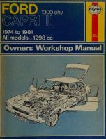
FORD
GARR
1300 ohv a
1974 to 1981 |All models 5 1298 cc
hayes
WL 0
URGH
q THIS BOOK MUST NOT BE REMOVED UNDER ANY PRETEXT FROM THE REFERENCE DEPARTMENT. INFRINGEMENT OF THIS RULE RENDERS THE OFFENDER LIABLE TO PROSECUTION. Before leaving the Library readers must return the books to one of the attendants at the issue desk, or they will be held responsible for them.
Readers are required to take care of the books. Writing or drawing with pen or pencil on any part of a book, or turning down the leaves, or cutting or mutilating them, will be treated as serious damage. { ConVERSATION IN THE REFERENCE DEPARTMENT IS ANNOYING TO STUDENTS, AND IS NOT PERMITTED. —
Ford
Capri || Owners Workshop Manual by J H Haynes Member of the Guild of Motoring Writers
and |MCoomber Models
covered:
Ford Capri I! 1300 1298 cc ohv Does not cover ohc engines
ISBN 0 85696 593 6 ©
Haynes Publishing Group 1977, 1981
All rights reserved. No part of this book may be reproduced or transmitted in any form or by any means, electronic or mechanical, including photocopying, recording or by any information storage or retrieval system, without permission
in writing from the copyright hiolde
Printed in England *
(338 12G 7994 4
.
HAYNES PUBLISHING GROUP SPARKFORD YEOVIL SOMERSET BA22 7JJ ENGLAND distributed in the USA by
HAYNES PUBLICATIONS INC 861 LAWRENCE DRIVE NEWBURY PARK CALIFORNIA 91320 USA
KLMNO E
¥ SSE
a PONT
a a
; EDINBURGH
4S
Acknowledgements
Its aim
IDS Yet |
The Section of Chapter 10 dealing with the suppression of radio interference, was originated by Mr |. P. Davey, and was first published in Motor magazine. Lastly, thanks are due to all of those people at Sparkford who helped in the production of this manual.
_,,, *
*.- + m%
e
The aim of this manual is to help you get the best value from your car. It can do so in several ways. It can help you decide what work must be done (even should you choose to get it done by a garage), provide information on routine maintenance and servicing, and give a logical
course of action and diagnosis when random faults occur. However, it is hoped that you will use the manual by tackling the work yourself. On simpler jobs it may even be quicker than booking the car into a garage and going there twice to leave and collect it. Perhaps most important, a lot of money can be saved by avoiding the costs the garage must charge to cover its labour and overheads. The manual has drawings and descriptions to show the function of the various components so that their layout can be understood. Then the tasks are described and photographed in a step-by-step sequence so that even a novice can do the work.
/ts arrangement The manual
305A
oes
Special thanks are due to the Ford Motor Company for the supply of technical information and certain illustrations. Castrol Limited provided lubrication data and the Champion Sparking Plug Company provided the spark plug illustrations. The bodywork repair photographs used in this manual were provided by Holt Lloyd Ltd. who supply ‘Turtle Wax’, ‘Dupli-color Holts’, and other Holts range products.
About this manual
CITY LIBRARIES
is divided
into thirteen Chapters, each covering a
logical sub-division of the vehicle. The Chapters are each divided into Sections, numbered with single figures, eg 5; and the Sections into paragraphs (or sub-sections) with decimal numbers following on from the Section they are in, eg 5.1, 5.2, 5.3 etc.
It is freely illustrated, especially in those parts where there is a
detailed sequence of operations to be carried out. There are two forms of illustration; figures and photographs. The figures are numbered in sequence with decimal numbers, according to their position in the Chapter — eg Fig. 6.4 is the fourth drawing/illustration in Chapter 6. Photographs carry the same number (either individually or in related groups) as the Section or sub-section to which they relate. There is an alphabetical index at the back of the manual as well as a contents list at the front. Each Chapter is also preceded by its own individual contents list. References to the ‘left’ or ‘right’ of the vehicle are in the sense of a person in the driver's seat facing forwards. Unless otherwise stated, nuts and bolts are removed by turning anti-clockwise, and tightened by turning clockwise. Vehicle manufacturers continually make changes to specifications and recommendations, and these, when notified, are incorporated into our manuals at the earliest opportunity.
Whilst every care is taken to ensure that the information in this
manual
is correct, no liability can be accepted by the authors or
Publishers for loss, damage or injury caused by any errors in, or omissions from, the information given.
Contents Page
Acknowledgements
2
About this manual
2
Introduction to the Capri I
4
Buying spare parts and vehicle identification numbers
6
7
Routine maintenance ee
a
Jacking and towing a a
a
es
eS
9
ee
Recommended lubricants and fluids a a a I
10 ee a
aE
11 ——
Tools and working facilities i
13
Chapter 1 Engine a!
40
Chapter 2 Cooling system
EEEEEEEEEE SEIESINSERnSENRSInNNE
nnn
a - Chapter 3 Carburation; fuel and exhaust systems SO
nnn ee
Chapter 4 Ignition system ee
46 EnEETbst:saaaE SaEEnnEAIET SuSE SSSI 57 67
Chapter 5 Clutch $$
71
Chapter 6 Gearbox ee ee D ee
84
Chapter 7 Propeller shaft ee e eee e ee e SR Chapter 8 Rear axle Se
cz
94
Chapter 9 Braking system ee eee ee >
eS
Chapter 10 Electrical system ee
ee
Chapter 11 Suspension and steering A eu
Ee
EE
106
SS 139
ee
aE aera
emma
Chapter 13 Supplement: Revisions and information on later models rE
aa 150
Chapter 12 Bodywork and fittings ee
167 ee
Conversion factors eee in
Index
86 aa
gg arian ans
181
182
Introduction to the Capri II
ee eS The Capri I! models were first introduced in the United Kingdom in February 1974, the 1.3 litre ohv version being the smallest in the range. The 1298 cc engine is basically the same as used on other Ford models and the mechanical layout is quite conventional.
Drive from the overhead valve engine is transmitted to the rear axle via a four-speed, all synchromesh gearbox and single piece propeller shaft. The front suspension is independent with MacPherson struts and an anti-roll bar. The rear suspension has semi-elliptic leaf springs with
telescopic shock absorbers and an anti-roll bar. The three door Coupe body is of all steel welded integral construction. Although the UK version is only 1 inch longer and 2% inches wider than the previous mode! Capri, the appearance of a larger car is obdtsined
by the sleeker lines which evolved with the restyling. This is even more apparent from the inside due to the increase in load space and opening
tailgate giving easier access to the luggage Compartm ent, A variety of optional extras is available, depending on the particular model and intended market.
=
| 5
cian
vio on — le
Ai) ges aa
1979 Ford Capri ll 1.3
Buying spare parts and vehicle identification numbers Buying spare parts Spare parts are available from many sources, for example: Ford garages, other garages and accessory shops, and motor factors. Our advice regarding spare part sources is as follows: Officially appointed Ford garages - This is the best source of parts which are peculiar to your car and are otherwise not generally available (eg. complete cylinder heads, internal gearbox components, badges interior trim etc). It is also the only place at which you should buy parts if your car is still under warranty - non-Ford components may invalidate the warranty. To be sure of obtaining the correct parts it will always be necessary to give the storeman your car's vehicle identification number, and if possible, to take the ‘old’ part along for positive identification. Remember that many parts are available on a factory exchange scheme - any parts returned should always be clean! It obviously makes good sense to go straight to the specialists on your car for this type of part for they are best equipped to supply you. Other garages and accessory shops - These are often very good places to buy materials and components needed for the maintenance of your car (eg. oil filters, spark plugs, bulbs, fanbelts, oils and greases, touch-up paint, filler paste, etc). They also sell general accessories, usually have convenient opening hours, charge lower prices and can often be found not far from home. Motor factors - Good factors will stock all of the more important
Typ Type
Version
components which wear out relatively quickly (eg. clutch components, pistons, valves, exhaust systems, brake cylinders/pipes/hoses/seals/shoes and pads etc). Motor factors will often provide new or reconditioned
components on a part exchange basis - this can save a considerable amount of money.
Vehicle identification numbers Although many individual parts, and in some cases sub-assemblies, fit a number of different models it is dangerous to assume that just because they look the same, they are the same. Differences are not always easy to detect except by serial numbers. Make sure therefore, that the appropriate identity number for the model cr sub-assembly is known and quoted when a spare part is ordered. The vehicle identification plate is mounted on the right-hand front wing (fender) apron or on the bonnet locking platform, and may be seen once the bonnet is open. Record the numbers from your car on the blank spaces of the accompanying illustration. You can then take the manual with you when buying parts; also the exploded drawings throughout the manual can be used to point out and identify the components required. In certain instances, reference is included in the text of this manual to a build code. The code letters are the last two of a six letter grouping in the Vehicle No. section of the vehicle identification plate.
Fahrgestell/Vehicle No.
Zul. Gesamtgew. Zul. Achslast Vorn Zul. Achslast hinten © Gross Vehicle Wgt.Petm. Axle Ld. Front Perm. Axle Ld. Rear
Lenk Drive
Motor Getr. Achse Engine Trans. Axle
Farbe Coxe) CoV g
Polst Trim
K.D. Ref.
Bremsen Brakes
BS.AU48:1965
Vi faa
ry
Routine maintenance Maintenance is essential for ensuring safety, and desirable for the purpose of getting the best in terms of performance and economy from your car. Over the years the need for periodic lubrication - oiling, greasing and so on - has been drastically reduced, if not totally eliminated. This has unfortunately tended to lead some owners to think that because no such action is required, components either no longer exist, or will last forever. This is a serious delusion. It follows therefore that the largest initial element of maintenance is visual examination and a general sense of awareness. This may lead to repairs or renewals, but should help to avoid roadside breakdowns. Although the maintenance instructions listed below are basically those recommended by the manufacturer, they are supplemented by additional service checks which, through practical experience, the author recommends should be carried out at the intervals suggested.
Brakes Check reservoir fluid level. If this has fallen noticeably, check for
EEE
At first 3000 miles (5000 km), and for vehicles which operate under continuous stop/start conditions every subsequent 3000 miles
Every 250 miles (400 km), weekly or before a long journey
Uitte 1
gee
eens TS
ee
Steering
Check tyre pressures (when cold), including the spare. Examine tyres for wear and damage. Check steering for smooth and accurate operation.
fluid leakage (photo). Check for satisfactory brake operation. Lights, wipers, horns, instruments Check operation of all lights.
Check operation of windscreen wipers and washers. Check that the horn operates. Check that all instruments and gauges are operating. Engine compartment
Check engine oil level; top-upif necessary (photo). Check radiator coolant level. Check battery electrolyte level.
(5000 km)
eh
ae
a
ee
et
Renew engine oil.
Renew engine oil filter at first 3000 miles (56000 km) (photo).
t Brake fluid reservoir - typical
The engine oil filter location
8
Routine maintenance
Check the disc brake pads for wear
Every 6000 miles (10000 km) or 6 months, whichever occurs first Renew engine oil and oil filter. Clean distributor points and reset gap. Lubricate distributor. Clean spark plugs and reset gaps. Clean all HT leads and top of ignition coil. Check ignition timing. Check valve clearances. Check tightness of inlet and exhaust manifold bolts. Check condition of exhaust system. Check condition and tension of the fanbelt. Lubricate accelerator linkage. Adjust engine idle speeds and mixture. Examine cooling system hoses and check for leaks.
Clean/tighten battery terminals. Check gearbox oil level. Check rear axle oil level. Check and top up if necessary the brake fluid reservoir. Check clutch adjustment. Check front brake pads for wear (photo).
Check rear brake linings for wear (photo).
Check the rear brake linings for wear
Check that all lights and indicators are in working order. Check the tightness of the alternator mounting bolts.
Every 12000 miles (20000 km) or 12 months, whichever occurs first Renew the contact breaker points. Renew spark plugs. Check condition of distributor cap and rotor.
Clean the positive crankcase ventilation (PCV) system.
Every 18000 miles (30000 km) or 18 months, whichever occurs first Check tightness of rear spring mountings. Change the air cleaner element. Check and tighten if required, the rear spring U-bolts to the correct torque.
Every 24000 miles (40000 km) or 2 years, whichever occurs first
Examine brake hoses for leaks and chafing. Check handbrake adjustment.
Check steering linkage for wear and damage, and condition of ball joint covers. Check front suspension linkage for wear and damage. Check front wheel toe-in. Check operation of all doors, catches and hinges. Lubricate as necessary. Check condition of seatbelts and operation of buckles and inertia reels. Check the tyre pressures and adjust if required. Inspect the general condition of tyre walls and treads. Check and top up the windscreen washer reservoirs.
Dismantle, lubricate and adjust front wheel bearings. Renew all rubber seals and hoses in braking system. Renew brake
fluid. Drain engine coolant. Renew antifreeze or inhibitor coolant mixture.
Every 36000 miles (60000 km) Clean the front wheel bearings, repack with grease and adjust. Drain and renew the hydraulic fluid - replace seals and hoses as required.
Jacking and towing Jacking points To change a wheel in an emergency, use the jack supplied with the vehicle. Ensure that the roadwheel nuts are released before jacking up the car and make sure that the arm of the jack is fully engaged with the body bracket and that the base of the jack is standing on a firm surface. The jack supplied with the vehicle is not suitable for use when raising the vehicle for maintenance or repair operations. For this work, use a trolley, hydraulic or screw type jack located under the front crossmember, bodyframe side-members or rear axle casing, as illustrated. Always supplement the jack with axle stands or blocks
before crawling beneath the car.
Towing points If your vehicle is being towed, make sure that the tow rope is attached to the front crossmember or, if the vehicle is so equipped, by the front towing eye on the crossmember. If you are towing another vehicle, attach the tow rope to the lower shock absorber mounting bracket beneath the axle tube or, if the vehicle is so equipped, by the rear towing eye beneath the bumper.
Attachment points for towing
Using the vehicle jack
(Above)
Front
(Below)
Rear
10
H.684/
Recommended Component or system
lubricants and fluids Lubrication type or specification
Castrol product
Castrol GTX
Engine (1)
Multigrade engine oil
Gearbox (2)
SAE 80EP gear oil
Castrol Hypoy Light
Rear axle (3)
SAE 9OEP gear oil
Castrol Hypoy B
Front wheel bearings (4)
Multi-purpose lithium based grease
Castrol LM grease
Steering gear (5)
SAE 90EP gear oil
Castrol Hypoy B
Brake master cylinder (6)
SAE J1703, DOT 3 or 4,
SAM-6C 9101-A (Amber) or ESEAM-6C 1001-A (Green)
Castrol Girling Universal Brake
and Clutch fluid
Note: The above are general recommendations only. Lubrication requirements vary from territory-to-territory and depend on vehicle usage. If in doubt, consult the operator’s handbook supplied with the vehicle, or your nearest dealer.
Tools and working facilities Introduction A selection of good tools is a fundamental requirement for anyone contemplating the maintenance and repair of a motor vehicle. For the owner who does not possess any, their purchase will prove a considerable expense, offsetting some of the savings made by doing-it-yourself. However, provided that the tools purchased are of good quality, they will last for many years and prove an extremely worthwhile
lists of tools under the following headings: Maintenance and minor repair; Repair and overhaul; and Special. The newcomer is practical mechanics should start off with the ‘Maintenance and minor repair’ tool kit and confine himself to the simpler jobs around the vehicle. Then, as his confidence and experience grows, he can undertake more difficult tasks, buying extra tools as, and when, they are needed. In this
way, a ‘Maintenance and minor repair’ tool kit can be built-up into a ‘Repair and overhaul’ tool kit over a considerable period of time without any major cash outlays. The experienced do-it-yourselfer will have a tool kit good enough for most repair and overhaul procedures and will add tools from the ‘Special’ category when he feels the expense is justified by the amount of use these tools will be put to. It is obviously not possible to cover the subject of tools fully here. For those who wish to learn more about tools and their use there is a book entitled ‘How to Choose and Use Car Tools’ available from the publishers of this manual.
Funnel (medium size)
Repair and overhaul tool kit These tools are virtually essential for anyone undertaking any major repairs to a motor vehicle, and are additional to those given in the Basic
list. Included in this list is a comprehensive set of sockets. Although these are expensive they will be found invaluable as they are so versatile - particularly if various drives are included in the set. We recommend the % in. square-drive type, as this can be used with most proprietary torque wrenches. If you cannot afford a socket set, even bought piecemeal, then inexpensive tubular box spanners are a useful alternative. The tools in this list will occasionally need to be supplemented by tools from the Special list.
Sockets (or box spanners) to cover range in previous list Reversible ratchet drive (for use with sockets)
Extension piece, 10 inch (for use with sockets) Universal joint (for use with sockets) Torque wrench (for use with sockets) ‘Mole’ wrench - 8 inch Ball pein hammer
Soft-faced hammer, plastic or rubber
Maintenance and minor repair tool kit The tools given in this list should be considered as a minimum requirement if routine maintenance, servicing and minor repair the purchase of
combination spanners (ring one end, open-ended the other); although more expensive than open ended ones, they do give the advantages of both types of spanner.
Combination spanners - 7/16, 1/2, 9/16, 5/8, 11/16, 3/4 in AF Combination spanners - 10, 11, 13, 14, 17 mm Adjustable spanner - 9 inch Engine sump/gearbox/rear axle drain plug key (where applicable)
Spark plug spanner (with rubber insert) Spark plug gap adjustment tool Set of feeler gauges Brake adjuster spanner (where applicable)
Brake bleed nipple spanner Screwdriver - 4 in. long x % in. dia. (plain)
Screwdriver - 4 in. long x % in. dia. (crosshead) Combination pliers - 6 in. Hacksaw, junior Tyre pump Tyre pressure gauge
Oil can
Fine emery cloth (1 sheet) Wire brush (small)
investment.
To help the average owner to decide which tools are needed to carry out the various tasks detailed in this manual, we have compiled three
operations are to be undertaken. We recommend
Grease gun (where applicable)
Screwdriver - 6 in. long x 5/16 in. dia. (plain) Screwdriver - 2 in long x 5/16 in. square (plain)
Screwdriver - 1% in. long x % in. dia. (crosshead) Screwdriver - 3 in. long x 1/8 in. dia. (electricians) Pliers - electricians side cutters Pliers - needle nosed Pliers - circlip (internal and external) Cold chisel - % inch Scriber (this can be made by grinding the end of a broken hacksaw
blade) Scraper (this can be made by flattening and sharpening one end of a
piece of copper pipe) Centre punch Pin punch Hacksaw Valve grinding tool
Steel rule/straight edge Allen keys Selection of files
Wire brush (large) Axle stands Jack (strong scissor or hydraulic type)
Tools and working facilities 12 e e e Special tools
The tools in this list are those which are not used regularly, are expensive to buy, or which need to be used in accordance with their
manufacturers instructions. Unless relatively difficult mechanical jobs are undertaken frequently, it will not be economic to buy many of these tools. Where this is the case, you could consider clubbing together
with friends (or a motorists club) to make a joint purchase, or
borrowing the tools against a deposit from a local garage or tool hire
specialist.
The following list contains only those tools and instruments freely available to the public, and not those special tools produced by the vehicle manufacturer specifically for its dealer network. You will find occasional references to these manufacturers special tools in the text of this manual. Generally, an alternative method of doing the job without the vehicle manufacturers special tool is given. However, sometimes there is no alternative to using them. Where this is the case and the relevant tool cannot be bought or borrowed you will have to
entrust the work to a franchised garage. Valve spring compressor Piston ring compressor Ball joint separator
more Another item which may be required, and which has a much 5/16 general usage, is an electric drill with a chuck capacity of at least
in. (8 mm). This, together with a good range of twist drills, is virtually
essential for fitting accessories such as wing mirrors and reversing lights. Last, but not least, always keep a supply of old newspapers and
clean, lint-free rags available, and try to keep any working area as clean as possible.
Spanner jaw gap comparison table Jaw gap (in)
% in AF
0.276
7mm
0.315 0.344 0.354
8mm 11/32 in AF; 1/8 in Whitworth 9mm
0.313
0.375
3/8 in AF
10 mm
0.433 0.438
11mm 7/16 in AF
0.445
3/16 in Whitworth; % in BSF
0.500
Impact screwdriver Micrometer and/or vernier gauge Carburettor flow balancing device (where applicable) Dial gauge Stroboscopic timing light
Dwell angle meter/tachometer Universal electrical multi-meter Cylinder compression gauge Lifting tackle Trolley jack Light with extension lead
Buying tools For practically all tools, a tool factor is the best source since he will have a very comprehensive range compared with the average garage or accessory shop. Having said that, accessory shops often offer excellent quality tools at discount prices, so it pays to shop around. Remember, you don’t have to buy the most expensive items on the shelf, but it is always advisable to steer clear of the very cheap tools. There are plenty of good tools around, at reasonable prices, so ask the proprietor or manager of the shop for advice before making a purchase.
Care and maintenance of tools Having purchased a reasonable tool kit, it is necessary to tools in a clean and serviceable condition. After use, always any dirt, grease and metal particles using a clean, dry cloth, putting the tools away. Never leave them lying around after
keep the wipe off before they have
been used. A simple tool rack on the garage or workshop wall, for items such as screwdrivers and pliers is a good idea. Store all normal spanners and sockets in a metal box. Any measuring instruments, gauges, meters, etc., must be carefully stored where they cannot be damaged or become
rusty.
5/16 in AF
0.394
0.472
Universal hub/bearing puller
Spanner size
0.250
12mm
% in AF
0.512
13 mm
0.525
% in Whitworth; 5/16 in BSF
0.551
14mm
0.562 0.591 0.600 0.625 0.630
9/16 in AF 15mm 5/16 in Whitworth; 3/8 in BSF 5/8 in AF 16 mm
0.669
17mm
0.686 0.709
11/16 in AF 18 mm
0.710 0.748 0.750 0.813
3/8 in Whitworth; 7/16 in BSF 19mm % in AF 13/16in AF
0.820
7/16 in Whitworth; % in BSF
0.866
22 mm
0.875
7/8 in AF
0.920 0.937
% in Whitworth; 9/16 ia BSF 15/16 in AF
0.945
24 mm
1.000 1.010
1in AF 9/16 in Whitworth; 5/8 in BSF
1.024
26 mm
1.063
1.1/16in AF; 27 mm
1.100
5/8 in Whitworth; 11/16 in BSF
1.125
1.1/8 in AF
1.181
30 mm
1.200
11/16 in Whitworth; % in BSF
1.250
1% in AF
1.260 1.300
32 mm % in Whitworth; 7/8 in BSF
1.313
1.5/16 in AF
become marked and screwdrivers lose the keen edge on their blades from
1.390
13/16 in Whitworth; 15/16 in BSF
time-to-time. A little timely attention with emery cloth or a file will
1.417
36 mm
1.438 1.480
1.7/16 in AF 7/8 in Whitworth; 1 in BSF
Take a little care when the tools are used. Hammer
heads inevitably
soon restore items like this to a good serviceable finish.
Working facilities Not to be forgotten when discussing tools, is the workshop itself; if anything more than routine maintenance
is to be carried out, some form
of suitable working area becomes essential. It is appreciated that many an owner mechanic is forced by circumstance to remove an engine or similar item, without the benefit of a garage or workshop. Having done this, any repairs should always be done under the cover of a roof. Wherever possible, any dismantling should be done on a clean flat
workbench or table at a suitable working height. Any workbench needs a vice; one with a jaw opening of 4 in (100 mm) is suitable for most jobs. As mentioned previously, some clean dry storage space is also required for tools, as well as the lubricants, cleaning fluids, touch-up paints and so on which soon become necessary.
1.500
1% in AF
1.575
40 mm; 15/16 in Whitworth
1.614
41 mm
1.625 1.670 1.688 1.811 1.813 1.860 1.875 1.969 2.000 2.050
1.5/8 in AF 1 in Whitworth; 1.1/8 in BSF 1.11/16in AF 46 mm 13/16in AF 1.1/8 in Whitworth; 1% in BSF 1.7/8 in AF 50 mm 2 in AF 1% in Whitworth; 1.3/8 in BSF
2.165
55 mm
2.362
60 mm
Chapter 1 Engine Contents
Big-end and main bearings -examination and renovation Camshaft and cam-followers- refitting , Camshaft and camshaft bearings -examination and Fenovation
26 41 29
General description Gudgeon pins - removal ... : Lubrication system - description
1 14 19
Camshaft and tappets -removal
11
Connecting rods -examination and renovation Crankcase ventilation system- description and servicing
Main bearings and crankshaft - removal
34 22
Crankshaft -examination and renovation Crankshaft and rear oilseal - refitting..
Major operations possible with engine in vehicle Major operations requiring engine removal
25 39
Method of engine removal Oil filter - removal
Cylinder bores - examination and ponovation: Cylinder head- decarbonising ... ane
4 20
27 36
Oil pump - removal and vernal Pistons and connecting rods
Cylinder head - removal and dismantling Cylinder head valves - refitting ... Distributor- refitting Engine- dismantling general ne Engine - initial start up after major overhaul .. Engine - installation with gearbox Engine - installation without gearbox ... Engine- removal.. Engine ancillary Somieanantee comovali Engine front mountings - removal and installation Engine installation - general te Engine reassembly - general
21 40
8 44 47 6 52
Pistons, connecting rods and big-end bearings- removal Piston rings -removal Rockers and rocker shaft- examination and renovation = Rocker arm/valve -adjustment...
51
Rocker shaft and pushrods - refitting ...
50 5 23 49 38
Rocker unit -dismantling Starter ring gear -examination and renovation! an Sump- removal Tappets (cam followers)- examination and renovation ae Timing chain tensioner - removal Timing chain tensioner and cover - refitting ...
Examination and renovation - general... Fault diagnosis - engine ... Final assembly 1 Flywheel - removal
24 53 48 16
: Timing cover, sprockets and chain - removal ... Timing sprockets and chain - examination and renovation Valves and valve seats - examination and renovation Valve guides - examination and renovation
Flywheel/sump/oil pump/crankshaft pulley - ening
43
7
17 2 3
ais Pistons and piston rings -examination and renovation
Specifications
Engine type
‘A’ (1.3 HC)
Firing order
P= 25433
Bore
3.118 in (80.98 mm)
Stroke
2.478 in (62.99 mm)
Swept volume ...
1298 cc
Compression ratio
SiOnat
Valve actuation
Pushrod and rocker arm
Camshaft position
In crankcase on right
Pressure @ starter speed
142 to 170 Ibf/in2 (10 to 12 kgf/cm?)
Mean working pressure
128 Ibf/in2 (9.0 kgf/cm?)
Idling speed
800 + 25 rpm
Maximum continuous speed
5800 rpm
Engine output (DIN)
42 KW (58 PS) (57 HP) @ 5500 rpm
Torque (DIN) ...
91 Nm (9.3 kgf m) (67 Ibf ft) @ 3000 rpm
28 13 15 32 46 45 9 35 172 33 18 42 wes ...
10 31 30 ey
14 Chapter 1/Engine EE
eee
Cylinder block Cast marking on cylinder block: & er
3s wes
ae ase
eae aes
a as
He a
see Me
wo
a
=
a
a
on;
ss
i
oe
Are
Fe
a
5
a
i
as
bite 1.3 litre Number of main Gearinias’
Cylinder liner bore Cylinder bore diameter:
A (standard)
Undersize -0.010 in (0.254 mm) Undersize - 0.020 in (0.508 mm) Undersize - 0.030 in (0.762 mm) Main bearing bore (in block): ae
ge
as
... ... ...
3.1869 to 3.1873 in (80.947 to 80.957 mm)
on
Da
to to to to
3.1877 3.1881 3.1885 3.1889
in in in in
(80.957 (80.967 (80.977 (80.987
to to to to
80.967 80.977 80.987 80.997
mm) mm) mm) mm)
3.1889 to 3.1893 in (80.997 to 81.007 mm) 1.056 to 1.058 in (26.822 to 26.873 mm) 2.126 to 2.128 in (54.013 to 54.044 mm)
2.116 to 2.118 in (53.759 to 53.790 mm) 2.106 to 2.108 in (53.505 to 53.536 mm) 2.096 to 2.098 in (53.251 to 53.282 mm)
fee
Camshaft bearing bore din block): Standard
3.311 to 3.314 in (84.112 to 84.175 mm)
3.1873 3.1877 3.1881 3.1885
7™mMm000 Bearing width Fitted main bearing shells, vertical internal diaructows
Standard Oversize
711M-6015-A-A 5
2.271 to 2.2715 in (57.683 to 57.696 mm) 2.286 to 2.2865 in (58.064 to 58.077 mm) 1.6885 to 1.6894
:
in (42.888 to 42.913 mm)
+ 0.020 in (+ 0.508 mm)
Oversize
Crankshaft Main bearing journal diameter: Standard ae
Undersize - 0. 010 in (0.254 iam) Undersize -0.020 in (0.508 mm) Undersize - 0.030 in (0.762 mm)
Se
2.125 to 2.126 in (53.983 to 54.003 mm)
yn ... ...
2.105 to 2.106 in (53.475 to 53.495 mm)
Crankshaft endfloat Length of main bearing shell Play in main journal bearing shell Crank pin diameter - Standard
Undersize Undersize Undersize Undersize
-
0.002 0.010 0.020 0.030
in in in in
(0.05 (0.25 (0.51 (0.76
mm) mm) mm) mm)
Undersize - 0.040 in (1.02 mm)
2.115 to 2.116 in (53.729 to 53.749 mm) 2.095 to 2.096 in 0.003 to 0.011 in 0.995 to 1.005 in 0.0004 to 0.0024 1.937 to 1.938 in 1.935 to 1.936 in
(53.221 to 53.241 mm) (0.075 to 0.280 mm) (25.273 to 25.527 mm) in (0.010 to 0.061 mm) (49.195 to 49.215 mm) (49.144 to 49.164 mm)
1.927 to 1.928 in (48.941 to 48.961 mm) 1.917 to 1.918 in (48.687 to 48.707 mm) 1.907 to 1.908 in (48.433 to 48.453 mm)
1.897 to 1.898 in (48.179 to 48.199 mm)
Camshaft Marking : Thickness of camshaft Fetaning nee. Cam lift: Inlet Exhaust 33
711
F-6250 cc
0.1760 in (4.470 mm) 0.236 in (5.985 mm) 0.232 in (5.894 mm)
Length of cams (eegveen’ heel and ae Inlet Exhaust Drive
1.303 in (33.087 mm) 1.312 in (33.326 mm)
Camshaft pearing diameter - Front, centre, rear Internal diameter of bearing bush - Front, centre, rear Camshaft endfloat
1.560 to 1.561 in (39.616 to 39.637 mm)
By chain with tensioning device
1.561 to 1.562 in (39.662 to 39.675 mm) 0.002 to 0.008 in (0.06 to 0.2 mm)
Pistons Piston diameter: Grade E - Standard Grade F :
...
Piston diameter (Oversize) Grade E Grade F Piston to bore Clesronee
Ring gap (fitted in block): Top Centre Bottom
;
3.1872 to 3.1876 in (80.954 to 80.964 mm) 3.1876 to 3.1880 in (80.964 to 80.974 mm)
0.003 in (0.064 mm) 3.1890 to 3.1901 in (81.018 to 81.028 mm) 3.1901 to 3.1904 in (81.028 to 81 .038 mm)
0.0009 to 0.0010
in (0.023 to 0.043 mm)
0.009 to 0.014 in (0.23 to 0.36 mm) 0.009 to 0.014 in (0.23 to 0.36 mm) 0.009 to 0.014 in (0.23 to 0.36 mm)
Gudgeon pins Length of gudgeon pin ... Pin diameter: 1 2
2.795 to 2.810 in (70.99 to 71.37 mm)
0.8119 to 0.8120 in (20.622 to 20.625 mm) 0.81 20 to 0.8121 in (20.625 to 20.627 mm)
Chapter 1/Engine er ee ae 3 4
FP Pe
as ae
aa ees
ne owe
oe way
as aid
Pin interference in piston at 21°C (70°F)
_...
Clearance in connecting rod at 21°C (70°F)
sas Sei
dee aa
are oe
a He
a”
a
sie
“oe
ee
ae
=
ee
eesss—s—‘“‘“
0.8121 to 0.8122 in (20.627 to 20.630 mm) 0.8122 to 0.8123 in (20.630 to 20.632 mm)
0.0001 to 0.0003 in (0.003 to 0.008 mm)
0.00015 to 0.0004 in (0.004 to 0.010 mm)
Connecting rods Bore diameter of big-end
ee
a
eee
si
a3
5
ae
2.0823 to 2.0831 in (52.89 to 52.91 mm)
oa aa Set
Bae +B mn
sas va Le
oa bes eae
ae ae we
ae ee ant
bes ee rae
0.8122 to 0.8123 in (20.629 to 20.632 mm) 0.8123 to 0.8124 in (20.632 to 20.634 mm) 0.8124 to 0.8125 in (20.634 to 20.637 mm)
Bore diameter of small end: White ... Red... Yellow
Blue...
wae Sia Na
aan A iy
ee
nee
Vertical internal Mamotar Standard saa
Undersize 0.002 Undersize -0.010 Undersize - 0.020 Undersize - 0.030 Undersize -0.040
in in in in in
(0.051 (0.254 (0.508 (0.762 (1.016
Pal mm) mm) mm) mm)
nee
tenes
es
0.8125 to 0.1826 in (20.637 to 20.640 mm)
ade
bits
Bae
a
a
“¥
ses ... ... ... ...
1.938 to 1.939 in (49.221
Los ce ee a ae
ae bee Ee ee aed
ee ": pi se ae
to 49.260 mm)
+e + ae oe a
ae oo =F = =
1.936 1.928 1.918 1.909 1.898
as
iS
aa
to to to to to
ae
ae
0.0002 to 0.003 in (0.006 to 0.064 mm)
aoe
a
ie
os
-.
A
Pe
“a
46°
Clearance- big-end journal to bearing
to to to to to
1.937 1.929 1.919 1.913 1.899
in in in in in
(49.170 (48.967 (48.713 (48.491 (48.205
49.208 49.005 48.751 48.592 48.243
mm) mm) mm) mm) mm)
Cylinder head Cast marking on cylinder head: 1.3 litre
ee
br
Valve seat angle in head
ees
cea
a
2
ee
ie
Stem bore, inlet and exhaust valves...
Bore for bushes
...
sg
Valves Valve clearances (cold): Inlet (Engine code J3) Inlet (other engine codes)
ave
cr
a
axe
ee
0.311
sae
me
er
ae
a
Se
Se
0.438 to 0.439 in (11.133 to 11.153 mm)
33 Be a
ss ae dee
= es os
ts bes st
ane = BS
ae a a
0.010 in (0.25 mm) 0.008 in (0.20 mm) 0.022 in (0.56 mm)
to 0.312 in (7.907 to 7.937 mm)
By
oe
abe ... oa
i =.
aes ie
as ae
a or
a ne
fe Pe;
ay ae
be és
oe ep
21° BTDC 55° ABDC
a2 es bi, Opens “3 Closes Valve springs (number of turns)
a ch ae
Er ne es,
i es an
cs bi ey
‘ee ise tr,
z on ie
70° BBDC 22° ATDC 3.75 to 5.75
¥ Cam follower diameter Clearance (cam follower to pink
Ae ie
ed re
a: a
ats sad
ae 7
ee oe
0.515 to 0.516 in (13.081 to 13.094 mm) 0.0005 to 0.0019 in (0.013 to 0.05 mm)
Inlet valves Length...
Exhaust Inlet valve:
Opens Closes Exhaust valve:
os
Valve head diameter: 1.3 litre age Valve stem diameter: Standard a
me
te
fe
ie
Pep
e
as
as
4.357 to 4.396 in (110.67 to 111.67 mm)
ee
ae
na
oP
cae
Bs
ae
ee
1.497 to 1.507 in (38.02 to 38.28 mm)
a
Oversize -0.003 in (0.076 a ae Oversize -0.015 in (0.381 mm)... Valve stem play in guide zd is
cae
Bee
we
a
Seu
a. ‘pes ee
0.3097 to 0.3104 in (7.868 to 7.886 mm)
ae oes ae
ne = vee
ai = set
cs oa Pp
0.3128 to 0.3135 in (7.945 to 7.962 mm) 0.3248 to 0.3255 in (8.249 to 8.267 mm) 0.0008 to 0.0027 in (0.02 to 0.068 mm)
we
0.33 in (8.38 mm)
ae
oe
pay
=
Ae
Ae
oa
Sez
Exhaust valves Length... see
Pr
Pa
os
ose
ia
68
Pa
ae
sue
‘ai
PA
ae
ais
a
Ae
1.234 to 1.244 in (31.34 to 31.59 mm) '
a tes _...
ae He ces
wah oe Ay oe
Ps +5 is se
ae a ii CAE
0.3089 to 0.3096 in (7.846 to 7.863 mm) 0.3119 to 0.3126 in (7.922 to 7.939 mm) 0.3239 to 0.3245 in (8.227 to 8.243 mm)
Valve lift ...
Valve cup diameter: 1.3 litre. ap Valve stem diameter: Standard a
HE
oe
“on
nee sae bee e
eee
a
oe
oes
sa
ey
ee
ae
0.325 in (8.25 mm)
sce
eh
see
oe
ay
ah
ae
e
HD oil
Oversize - 0.003 in (0.076 orn Oversize -0.015 in (0.381 mm) Valve stem play in guide Valve lift ...
Sis
4.345 to 4.365 in (110.36 to 110.87 mm)
0.0017 to 0.0036 in (0.043 to 0.091 mm)
Engine lubrication Oil type
...
oes
Viscosity:
re —12°9C
ri
a
ans
i
oF
ae
ae
_
SAE 5W/20
under O°C ss... =23°C to 432°C over —12°C ....
C(t... wy
a ro a
we Ae as
oe = os
a on ot
Lae Bes vf
a gs ie
ee Me os
SAE 5W/30 SAE 10W/30, SAE10W/40 or SAE 10W/50 SAE 20W/40 or SAE 20W/50
6
oF
As
ip
ton
eee
ae
ae
SS-M2C-9001AA
Ford specification
15
Chapter 1/Engine
16
6.5 pints (3.67 litres)
Initial capacity with filter
4.8 pints (2.75 litres) 5.7 pints (3.25 litres)
Oil change without filter change Oil change with filter change Minimum
oil pressure at:
700 rpm and 80°C
...
2000 rpm and 80°C Oil pressure warning light glows at Excess pressure valve opens at Oil pump play with external rotor casing
Gap internal/external rotor...
das
wae
ma
ae
oa
Axial play of external and internal rotor in relation to oil pump cover
Torque wrench settings Main bearing caps Connecting rod bolts Crankshaft belt pulley Camshaft chain sprocket Rear sealing ring carrier Flywheel ... Eee a oe Clutch thrust plate to flywheel Front crankcase cover Oil pump ... ea
as
Oil pump inlet pip Oil pump cover Rocker shaft Rocker cover Cylinder head:
(1) (2) (3)
an
ab Bs
a
Gas
ae
er
(4) after 10 to 20 minutes wait... : (5) after engine has warmed up (15 minutes at 1000 rpm) tighten up...
8.5 Ibf/in2 (0.6 kp/cm2) 21 Ibf/in2 (1.5 kp/cm2) 6 + 1.5 Ib f/in2 (0.4 + 0.1 kp/em2) 35 to 40 Ib f/in2 (2.46 to 2.81 kp/cm2) 0.0055 to 0.0105 in (0.1397 to 0.2667 mm) 0.002 to 0.005 in (0.0508 to 0.1270 mm) 0.001 to 0.0025 in (0.0254 to 0.0635 mm) Ib f ft 49 to 55 38 to 43 40 to 45 40 to 44 13 to 15
kg f m 6.8 to 7.6 5.3 to 5.9 5.5 to 6.2 5.5 to 6.1 Ae watoy2ul
50 to 56
6.8 to 7.6
13 to15 15to18 13 to15
1.7 to 2.1 1.5to 1.8 1.7 to 2.1
13 to 15 6 to9 18 to 22 2 to 3.6
A7EtOWZ
wy — wy SS
| Ss Sy Sy
Ts SZ
Fig. 4.13. The component parts of the distributor Cap Contact breaker assembly Base plate Vacuum unit Suppressor Distributor body DAKRWHYx
Body clamp plate Cylinder block seal
Bush (not serviced) Thrust washers
13 14 15 16 17 18
Mechanical advance springs Mechanical advance weights
Washer Washer Pin Gear
Chapter 4/Ignition system
62
Fig. 4.14. Distributor base plate - exploded view (Sec. 5)
Fig. 4.17. Withdrawing cam spindle (A) from distributor body
Fig. 4.16. Cam spindle assembly (Sec. 5) A B
Shaft Cam spindle
C D
Circlip Felt pad
note of the assembly, particularly which spring fits which post and the position of the advance springs. Then remove the advance springs. 15 Prise off the circlips from the governor weight pivot pins and take out the weights. 16 Dismantle the shaft by taking out the felt pad in the top of the spindle. Expand the exposed circlip and take it out. 17 Now mark which slot in the mechanical advance plate is occupied by the advance stop which stands up from the action plate, and lift off
the cam spindle (Fig. 4.17). 18 It is only necessary to remove the lower shaft and action plate if it is excessively worn. If this is the case, with a small punch drive out the
gear retaining pin and remove the gear with the two washers located above it. Withdraw the shaft from the distributor body and take off the two washers from below the action plate. The distributor is now completely dismantled. 19 Check the points, as described in Section 3. Check the distributor cap for signs of tracking, indicated by a thin black line between the segments. Renew the cap if any signs of tracking are found. 20 If the metal portion of the rotor arm is badly burned or loose, renew the arm. If only slightly burned, clean the end with a fine file. Check that the contact spring has adequate pressure and the bearing surface is clean and in good condition. 21 Check that the carbon brush in the distributor cap is unbroken and stands proud of its holder. 22 Examine the fly weights and pivots for wear and the advance springs for slackness. They can best be checked by comparing with new Parts. If they are slack they must be renewed. 23 Check the points assembly for fit on the breaker plate, and the cam spindle for wear. 24 Examine the fit of the lower shaft in the distributor body. If this is excessively worn, it will be necessary to fit a new assembly.
6
Distributor - reassembly and refitting
1
Reassembly is a reversal of dismantling but observe the following
points: 2 Apply a film of engine oil to the shaft and mechanical advance
assembly before fitting. 3 When fitting the lower shaft, first replace the thrust washers below the action plate before inserting into the distributor body. Next fit the wave washer and thrust washer at the lower end and replace the drive gear. Secure it with a new pin. 4 Assemble the upper and lower shaft with the advance stop in the correct slot (the one which was marked) in the mechanical advance plate. 5 After assembling the advance weights and springs check that they move freely without binding, then replace the advance stop tubing. 6 Before assembling the breaker plates, make sure that the three nylon bearing studs are properly located in their holes in the upper breaker plate, and that the small earth spring is fitted on the pivot post,
7 As you refit the upper breaker plate, pass the holding down spindle through the keyhole slot in the lower plate. 8 Hold the upper plate in position by refitting the wave washer, flat
washer and large circlip. 9
When all is assembled, remember to set the contact breaker gap to
0.025 inch (0.64 mm).
10 If a new gear or shaft is being fitted, it is necessary to drill
pin hole. Proceed as follows.
anew
11 Make a 0.015 inch (0.38 mm) thick forked shim to slide over the driveshaft (Fig. 4.19).. 12 Assemble the shaft, wave washer, thrust washer, shim and gear
wheel in position in the distributor body. 13 Hold the assembly in a large clamp such as a vice or carpenter' s clamp using only sufficient pressure to take up all end play. 14 There is a pilot hole in the new gear wheel for drilling the new hole. Set this pilot hole at 90° to the existing hole in an old shaft if the old
shaft is being re-used. Drill an 1/8 inch (3.18 mm) hole th rough both
gear and shaft. 15 Fit a new pin in the hole. Release the clamp and remove the shim. The shaft will now have the correct amount of clearance .
Chapter 4/Ignition system
63
A can Saar: By Fig. 4.18. Distributor shaft assembly (Sec. 6) A
B
Shaft
G-Th rust washer D_ Distributor body
Thrust washer
E F
Wave washer Washer
G H
Gear Pin
05) (0.38 mm)
Fig. 4.20. Slacken the distributor clamp pinch bolt (Sec. 6)
Fig. 4.19. Shaft endfloat adjustment plate (Sec. 6) 16 Hold the distributor above its crankcase opening so that the vacuum advance unit is pointing to the rear of the car and set the contact end of the rotor arm to align with No. 2 inlet port. Insert the distributor; as its driveshaft meshes with the camshaft gear the rotor will rotate slightly and take up a position of approximately 90° to the centre-line of the engine. 17 Fit the clamp plate retaining bolt to hold the assembly to the engine block and tighten it.
until the lamp just lights; this indicates that the points are just opening. 3. If the ignition timing is to be checked by stroboscope, the manufacturer’s instructions should be followed. Always remove the vacuum pipe from the distributor before testing by this method. 4 Since the ignition timing setting enables the firing point to be correctly related to the grade of fuel used, the fullest advantage of a change of grade from that recommended for the engine will only be attained by re-adjustment of the ignition setting.
18 Slacken the distributor clamp pinch bolt (Fig. 4.20). 19 Gently turn the distributor body until the contact breaker points are just opening when the rotor is pointing at the contact in the distributor cap which is connected to No. 1 spark plug. A convenient way is to put a mark on the outside of the distributor body in line with the terminal cover, so that it shows when the cover is removed. 20 If this position cannot easily be reached, check that the drive gear has meshed
on the correct tooth by lifting out the distributor once
more. If necessary rotate the driveshaft one tooth and try again. 21 Tighten the distributor body clamp enough to hold the distributor, but do not overtighten.
Cee 7
See
~
e
Ignition timing
—
——————————s
8
Spark plugs and HT leads
1 The correct functioning of the spark plugs is vital for the correct running and efficiency of the engine. 2 At intervals of 6,000 miles (9,600 km) the plugs should be removed, examined, cleaned, and if worn excessively, renewed. The condition of the spark plugs will also tell much about the overall! condition of the engine (see illustrations on page 65). 3. If the insulator nose of the spark plug is clean and white, with no deposits, this is indicative of a weak mixture, or too hot a plug. (A hot plug transfers heat away from the electrode slowly - a cold plug
transfers it away quickly). ee
ee
eee
1 The basic procedure for timing the ignition is fully described in the preceding Section. 2 The precise opening point of the contact breaker points can best be checked by connecting a test bulb between the distributor LT terminal and a good earth. Switch on the ignition and rotate the distributor
4 The plugs fitted as standard are Autolite as listed in the Specifications at the beginning of this Chapter. If the tip and insulator nose is covered with hard black looking deposits, then this is indicative that the mixture is too rich. Should the plug be black and oily, then it is likely that the engine is fairly worn, as well as the mixture being too rich.
Chapter 4/Ignition system
64
5 If the insulator nose is covered with light tan to greyish brown deposits, then the mixture is correct and it is likely that the engine is in good condition. 6 If there are any traces of long brown tapering stains on the outside of the white portion of the plug, then the plug will have to be renewed, as this shows that there is a faulty joint between the plug body and the insulator, and compression is being lost. 7 Plugs should be cleaned by a sand blasting machine, which will free them from carbon more thoroughly than cleaning by hand. The machine will also test the condition of the plugs under compression. Any plug that fails to spark at the recommended pressure should be renewed. 8 The spark plug gap is of considerable importance, as, if it is too large or too small, the size of the spark and its efficiency will be seriously impaired. The spark plug gap should be set to the figure given in the Specifications at the beginning of this Chapter. 9 To set it, measure the gap with a feeler gauge, and then bend open, or close, the outer plug electrode until the correct gap is achieved. The centre electrode should never be bent as this may crack the insulation
and cause plug failure if nothing worse. 10 When replacing the plugs, remember to replace the leads from the distributor in the correct firing order, which is 1, 2, 4, 3, No. 1 cylinder being the one nearest the radiator. No. 1 lead from the distributor runs from the one o’clock position when looking down on the distributor
cap, 2, 4 and 3 are anticlockwise from No. 1. (Fig. 4.21). 11 The plug leads require no routine attention other than being kept clean and wiped over regularly. At intervals of 6,000 miles (9,600 km), however, pull the leads off the plugs and distributor one at a time and make sure no water has found its way onto the connections.
Remove
any corrosion from the brass ends, wipe the collars on top of the distributor and refit the leads. 12 Every 10,000 to 12,000 miles (16,000 to 19,000 km) it is recommended that the spark plugs are renewed to maintain optimum engine performance. 13 Later vehicles are fitted with carbon cored HT leads. These should be removed from the spark plugs by gripping their crimped terminals. Provided the leads are not bent in a tight loop and compressed there is no reason why this type of lead should fail. A legend has arisen which blames this type of lead for all ignition faults and many owners replace them with the older copper cored type and install separate suppressors. In the majority of cases, it would be more profitable to establish the real cause of the trouble before going to the expense of new leads.
9
Fault diagnosis - ignition system
By far the majority of breakdowns and running troubies are caused by faults in the ignition system, either in the low tension or high tension circuit. There are two main symptoms indicating ignition faults. Either the engine will not start or fire, or the engine is difficult to start and misfires. If it is a regular misfire, ie. the engine is only running on two or three cylinders, the fault is almost sure to be in the secondary, or high tension, circuit. If the misfiring is intermittent, the fault could be in either the high or low tension circuits. If the car stops suddenly, or will not start at all, it is likely that the fault is in the low tension circuit. Loss of power and overheating, apart from faulty carburation settings, are normally due to faults in the distributor or incorrect ignition timing.
Engine fails to start 1 If the engine fails to start and the car was running normally when it was last used, first check there is fuel in the petrol tank. If the engine turns over normally on the starter motor and the battery is evidently well charged, then the fault may be in either the high or low tension circuits. First check the HT circuit. Note: if the battery is known to be fully charged; the ignition light comes on, and the starter motor fails to turn the engine, check the tightness of the leads on the battery terminals and the security of the earth lead to its connection on the body. It is quite common for the leads to have worked loose, even if they look and feel secure. If one of the battery terminal posts gets very hot when trying to work the starter motor, this is a sure indication of a faulty connection to that terminal.
2 One of the commonest reasons for bad starting is wet or damp spark plug leads and distributor. Remove the distributor cap. If condensation is visible internally dry the cap with a rag and wipe over the leads.
Fig. 4.21. The high tension plug leads to distributor layout in the firing
order (Sec. 8)
Replace the cap. 3. If the engine still fails to start, check that current is reaching the plugs by disconnecting each plug lead in turn at the spark plug and
holding the end of the cable about 3/16 inch (5 mm) away from the cylinder block. Spin the engine on the starter motor. 4 Sparking between the end of the cable and the block should be
fairly strong with a regular blue spark. (Hold the lead with rubber to avoid electric shocks). If current is reaching the plugs, then remove them, and clean and regap them. The engine should now start. 5 If there is no spark at the plug leads, take off the HT lead from the centre of the distributor cap and hold it to the block as before. Spin
the engine on the starter once more. A rapid succession of blue sparks between the end of the lead and the block indicates that the coil is in order and that the distributor cap is cracked, the rotor arm faulty or the carbon brush in the top of the distributor cap is not making good contact with the spring on the rotor arm. Possibly the points are in bad condition. Clean and reset them. 6 If there are no sparks from the end of the lead from the coil, check the connections at the coil end of the lead. If it is in order start checking the low tension circuit. 7 Use a 12 volt voltmeter or a 12 volt bulb and two lengths of wire. With the ignition switch on and the points open test between the low
tension wire to the coil (it is marked SW or +) and earth. No reading indicates a break in the supply from the ignition switch. Check the connections at the switch to see if any are loose. Refit them and the engine should run. A reading shows a faulty coil or condenser or broken lead between the coil and the distributor. 8 Take the condenser wire off the points assembly and with the points open, test between the moving point and earth. if there now is a reading, then the fault is in the condenser. Fit anew one and the fault will be cleared. 9 With no reading from the moving point to earth, take a reading
between earth and the CB or (—) terminal of the coil. A reading here indicates a broken wire which must be renewed between the coil and distributor. No reading confirms that the coil has failed and must be renewed. Remember to connect the condenser wire to the points assembly. For these tests it is sufficient to separate the contact breaker points with a piece of paper.
Engine misfires 1
If the engine misfires regularly, run it at a fast idling speed. Pull off
each of the plug caps in turn and listen to the note of the engine. Hold the plug cap in a dry cloth or with a rubber glove as additional protection against a shock from the HT supply.
2
No difference in engine running will be noticed when the lead from
the defective circuit is removed, Removing the lead from one of the good cylinders will accentuate the misfire. 3 Remove the plug lead from the end of the defective plug and hold it about 3/16 inch (5 mm) away from the block. Restart the engine. If the sparking is fairly strong and regular, the fault must lie in the spark plug. 4 The plug may be loose, the insulation may be cracked, or the points may have burnt away, giving too wide a gap for the spark to jump. Worse still, one of the points may have broken off. Either renew the
plug, or clean it, reset the gap, and then test it. 5 If there is no spark at the end of the plug lead, or if it is weak and
tun bail
Measuring plug gap. A feeler gauge of the correct size (see ignition system specifications) should have a slight ‘drag’ when
slid between the electrodes. Adjust gap if necessary
Normal. Grey-brown
deposits lightly coated core nose. Gap
o
;
:a
é
iis
Adjusting plug gap. The plug gap is adjusted by bending the earth electrode inwards, or outwards, as necessary until the
correct clearance is obtained. Note the use of the correct tool
Carbon fouling. Dry, black, sooty deposits. Will cause weak spark
increasing by around 0.001 in (0.025 mm) per 1000 miles (1600 km). Plugs ideally suited to engine and engine in good
and eventually misfire. Fault: over-rich fuel mixture. Check: carburettor mixture settings, float level and jet sizes; choke
condition
operation and cleanliness of air filter. Plugs can be re-used after
cleaning
Oil fouling. Wet, oily deposits. Will cause weak spark and eventually misfire. Fault: worn bores/piston rings or valve guides; sometimes occurs (temporarily) during running-in period. Plugs can be re-used after thorough cleaning
Overheating. Electrodes have glazed appearance, core nose very white - few deposits. Fault: plug overheating. Check: plug value, ignition timing, fuel octane rating (too low) and fuel mixture (too weak). Discard plugs and cure fault immediately wf
Electrode damage. Electrodes burned away; core nose has
burned, glazed appearance. Fault: initial pre-ignition. Check: as for ‘Overheating’ but may be more severe. Discard plugs and remedy fault before piston or valve damage occurs
a
Split core nose (may appear initially as a crack). Damage is self-
evident, but cracks will only show after cleaning. Fault: preignition or wrong gap-setting technique. Check: ignition timing, cooling system, fuel octane rating (too low) and fuel mixture (too weak). Discard plugs, rectify fault immediately
Chapter 4/Ignition system 66 a intermittent, check the ignition lead from the distributor to the plug. If the insulation is cracked or perished, renew the lead. Check the connections at the distributor cap. 6 If there is still no spark, examine the distributor cap carefully for
tracking. This can be recognised by a very thin black line running between two or more electrodes, or between an electrode and some other part of the distributor. These lines are paths which now conduct electricity across the cap, thus letting it run to earth. The only answer is a new distributor cap. 7 Apart from the ignition timing being incorrect, other causes of misfiring have already been dealt with under the Section dealing with
the failure of the engine to start. To recap, these are that:
a) The coil may be faulty giving an intermittent misfire. b) There may be a damaged wire or loose connection in the low tension circuit. c) The condenser may be short circuiting.
d) There may be a mechanical fault in the distributor (broken driving spindle or contact breaker spring).
8 If the ignition timing is too far retarded, it should be noted that the engine will tend to overheat, and there will be a quite noticeable drop in power. If the engine is overheating and the power is down and the ignition timing is correct, then the carburettor should be checked, as it
is likely that this is where the fault lies.
Chapter 5 Clutch For modifications, and information applicable to later models, see Supplement at end of manual Contents
Clutch adjustment Ar ss Clutch - inspection and overhau
Clutch pedal - removal and refitting be Clutch release bearing - removal and refitting Fault diagnosis - clutch ... General description
Clutch - refitting Clutch - removal e ms Clutch cable - removal and refitting
hy NwWofh
Specifications
Manufacturer
Borg and Beck or Laycock
Type
Single dry plate, diaphragm spring
Actuation
Cable
Diameter - driven plate (friction disc)
7.5 in (190.5 mm)
Clutch lining
Mintex H26
Lining thickness
0.13 in (3.25 mm)
Effective clutch lining area
Se
seb
ss
ee
40.7 in (26221 mm)
ose
Clutch plate spring pressure
847 Ib (385 kg)
Clutch pedal free-travel
0.87 + 0.16 in (22.0 + 4.0 mm)
Release bearing type ...
Sealed ball
Torque wrench settings
Ibf 12 22 31
Clutch pressure plate to flywheel bolts
Clutch housing to engine Clutch housing to transmission
1 General description eee ——————————E————— EEE The model covered by this manual is fitted with a 7.5 in (190.5 mm) clutch of either Borg and Beck or Laycock manufacture. The clutch assembly comprises a steel cover which is dowelled and bolted to the rear face of the flywheel and contains the pressure plate,
diaphragm spring and fulcrum rings. The clutch disc is free to slide along the splined gearbox first motion shaft and is held in position between the flywheel and the pressure plate by the pressure of the pressure plate spring. Friction lining material is riveted to the clutch disc and it has a spring cushioned hub to absorb transmission shocks and to help ensure a smooth takeoff. The circular diaphragm spring is mounted on shouldered pins and held in place in the cover by two fulcrum rings. The spring is also held to the pressure plate by three spring steel clips which are riveted in
position.
The clutch is actuated by a cable controlled by the clutch pedal.
bearing The clutch release mechanism consists of a release fork and
preswhich are in permanent contact with the release fingers on the sure plate. There should, therefore, never be any free play at the
disc is taken release fork. Wear of the friction material on the clutch
g. up by means of a cable adjuster on the clutch bellhousin
ft to 15 to 27 to 35
kgf m 1.66 to 2.07 3.0 to 3.7 4.2t0 4.8
Depressing the clutch pedal actuates the clutch release arm by means of the cable. The release arm pushes the release bearing forward to bear against the release fingers, so moving the centre of the diaphragm spring inward. The spring is sandwiched between two annular rings which act as fulcrum points. As the centre of the spring is pushed in, the outside of the spring is pushed out, so moving the pressure plate backward and disengaging the pressure plate from the clutch disc. When the clutch pedal is released, the diaphragm spring forces the pressure plate into contact with the friction linings on the clutch disc and at the same time pushes the clutch disc a fraction of an inch forward on its splines and engages with the flywheel. The clutch disc is now firmly sandwiched between the pressure plate and the flywheel and the drive taken-up.
ccm 2 Clutch - adjustment 2
1
Every 6000 miles (9600 km) the clutch pedal backlift (Fig. 5.2)
must be checked and adjusted, if necessary, to compensate for wear in
the friction linings. First, jack up the front of the car and support on axle stands or blocks. Then chock the rear wheels. 2 From underneath the car, slacken the locknut on the threaded portion of the outer cable at the clutch bellhousing.
0®© —
PRESSURE PLATE ASSEMBLY
THROWOUT BEARING
RELEASE: LEVER
GROMMET WASHER
CLUTCH DISC ASSEMBLY
PAD
FLYWHEEL
GEAR (FLYWHEEL)
ave TEC
GASKET
RELEASE SHIELD
LEVER
Fig. 5.1. The clutch assembly component parts
Fig. 5.2. peal pedal2 free MadClutch MURba:2 OlscA travela'nmiiOadjustment BACKLIFT B74 : C4On Heerat ‘A’ on the
Fiig. 5.3. The clutch removed from the flywheel (Sec. 3)
Chapter 5/Clutch Se er Sane tr e a
69
3 Check that the cable is not kinked or frayed, and then grasp the outer case of the cable and pull the cable forward to take up any free play in the cable.
4 Turn the adjusting nut down the adjuster thread until it contacts the cable bush in the bellhousing, then press the pedal to the floor several times to ensure all components are properly seated. 5 Reset the adjusting nut until there is a free backlift movement of
22.0 + 4.0 mm at the clutch pedal pad. Before checking the backlift push the pedal slowly down to the floor and, equally slowly, allow it to return to the ‘rest’ position. Allowing the pedal to spring back to the ‘rest’ position may not necessarily cause it to reach its normal ‘rest’ position. 6 If the pedal backlift movement is too small s/acken the adjusting
nut, if too great tighten the adjusting nut. When the adjustment is correct tighten the locknut without disturbing the adjusting nut, then recheck the backlift. 7 Lower the car and remove the jack and rear wheel chocks.
Fig. 5.4. Centralising the clutch driven plate (Sec. 5) 3
Clutch - removal
1 Remove the gearbox as described in Chapter 6, or alternatively the engine as described in Chapter 1. Although the removal of the gearbox
is the easier of the two methods, a considerable amount of working space is required beneath the car and ideally, ramps or an inspection pit should be used. However, provided that suitable jacks and supports
are available, and the car can be raised high enough in complete safety,
5
Clutch - refitting
1 It is important that no oil or grease gets on the clutch disc friction linings, or the pressure plate and flywheel faces. It is advisable to replace the clutch with clean hands and to wipe down the pressure plate and flywheel faces with a clean dry rag before reassembly begins. 2 Place the clutch disc against the flywheel, ensuring that it is the correct way round. The flywheel side of the clutch disc is smooth and the hub boss is longer on this side. If the disc is fitted the wrong way
then the gearbox can be removed without a pit or ramps. 2 Scribe a mating line from the clutch cover to the flywheel to ensure identical positioning on replacement and then remove the clutch assembly by unscrewing the six bolts holding the cover to the rear face of the flywheel. Unscrew the bolts diagonally half a turn ata time to prevent distortion of the cover flange. 3 With all the bolts and spring washers removed, lift the clutch assembly off the locating dowels. The clutch disc may fall out at this stage as it is not attached to either the clutch cover assembly or the flywheel.
and spring washers, and tighen them finger tight so that the clutch disc is gripped but can still be moved.
4
and gearbox are mated, the gearbox input shaft splines will pass through the splines in the centre of the driven plate hub. 5 Centralisation can be carried out quite easily by inserting a round
Clutch - inspection and overhaul
1 It is not practical to dismantle the pressure plate assembly. If a new clutch disc is being fitted it is false economy not to renew the release bearing at the same time. This will preclude having to replace it at a later date when wear on the clutch linings is very small. 2 If the pressure plate assembly requires renewal an exchange unit must be purchased. This will have been accurately set up and balanced to very fine limits.
3
Examine the clutch disc friction linings for wear and loose rivets
and the plate for rim distortion, cracks, broken hub springs, and worn splines. The surface of the friction linings may be highly glazed, but as long as the clutch material pattern can be clearly seen this is satis-
factory. Compare the amount of lining wear with a new clutch disc at the stores in your local garage, and if the linings are more than three quarters worn renew the disc. 4 tis always best to renew the clutch disc as an assembly to preclude further trouble, but, if it is wished to merely renew the linings, the rivets should be drilled out and not knocked out with a punch. The manufacturers do not advise that only the linings are renewed and personal experience dictates that it is far more satisfactory to renew the clutch disc complete than to try and economise by fitting only
new friction linings. 5
Check the machined faces of the flywheel and the pressure plate. If
either is grooved it should be machined until smooth or renewed. 6 If the pressure plate is cracked or split it is essential that an exchange unit is fitted, also if the pressure of the diaphragm spring is suspect. 7 Check the release bearing for smoothness of operation. There should be no harshness and no slackness in it. It should spin freely, bearing in mind it has been pre-packed with grease. If renewal is necessary, refer to Section 6. fly8 Check also that the clutch pilot bearing in the centre of the in wheel is serviceable. Further information on this will be found Chapter 1, Section 28.
round, it will be quite impossible to operate the clutch. 3 Refit the clutch cover assembly loosely on the dowel and ensure that the scribed marks on the flywheel cover align. Refit the six bolts
4
The clutch disc must now be centralised so that when the engine
bar or long screwdriver through the hole in the centre of the clutch, so that the end of the bar rests in the small hole in the end of the crankshaft containing the input shaft pilot bush. Ideally an old input shaft should be used. 6 Using the input shaft pilot bush as a fulcrum and moving the bar sideways or up and down, will move the clutch disc in whichever direction is necessary to achieve centralisation. 7 Centralisation is easily judged by removing the bar and moving the disc hub in relation to the hole in the centre of the clutch cover diaphragm spring. When the hub appears exactly in the centre of the hole all is correct. Alternatively the input shaft will fit the bush and centre of the clutch hub exactly obviating the need for visual alignment. 8 Tighten the clutch bolts firmly in a diagonal sequence to ensure that the cover plate is pulled down evenly and without distortion of the flange. Finally, tighten the bolts down to the specified torque.
6
Clutch release bearing - removal and refitting
1 With the gearbox and engine separated to provide access to the clutch, attention can be given to the release bearing located in the bellhousing, over the input shaft. 2
The release bearing is a relatively inexpensive but important compo-
nent and unless it is nearly new it is a mistake not to renew it during an overhaul of the clutch. 3 To remove the release bearing first pull off the release arm rubber gaiter. 4 The release arm and bearing assembly can then be withdrawn from the clutch housing. 5 To free the bearing from the release arm simply unhook it, and then with the aid of two blocks of wood and a vice press off the release
bearing from its hub. 6 Refitting is a reversal of removal, but lubricate the hub bore and release lever contact face with a little molybdenum disulphide grease.
Chapter 5/Clutch
70
7
Clutch cable - removal and refitting
1 Jack-up the front of the car and support securely under the front crossmember. 2 Release the locknut on the outer cable at the bellhousing and back the adjusting nut right off.
3 Pull back the rubber gaiter on the end of the release arm and unhook the cable end. 4
Where applicable remove the cowl trim from the instrument panel
(6 self-tapping screws). 5
Disconnect the clutch cable from the pedal by pushing the pin out
of the cable eye. The clutch cable can now be withdrawn.
6 Refitting the new cable is a reverse of the removal procedure, following which it will be necessary to adjust the pedal free-travel as described in Section 2. Apply a little general purpose grease to the cable end-fitting and clutch pedal pivot.
Fig. 5.5. Removing the release arm rubber gaiter, to unhook the clutch
cable (Sec. 7) 8
Clutch pedal - removal and refitting
1
Remove the cowl trim from the instrument panel (6 self-tapping
screws). 2
Carefully prise off the left-hand spring clip and washer from the
pedal pivot shaft. 3 Unhook the clutch pedal return spring. 4 Push the pedal shaft to the side to permit the pedal to be removed. 5 Disconnect the clutch cable from the pedal by pushing the pin out of the eye.
6
Remove the clutch pedal pivot bush.
7
Refitting is the reverse of the removal procedure, but a new spring
clip should be used on the pedal shaft for safety’s sake, and a little general purpose grease applied to the pedal pivot. Also, if there is wear in the pivot bush, a replacement should be fitted. On completion, adjust the pedal free-travel, as described in Section 2.
9
Fault diagnosis - clutch
under the heat of the clutch engagement, and in the process, gradually darken the linings. Excessive oil on the clutch will burn off leaving a carbon deposit which can cause quite bad slip, or fierceness, spin and judder. 4
If clutch slip is suspected, and confirmation of this condition
is
required, there are several tests which can be made. 5 With the engine in second or third gear and pulling lightly up a moderate incline, sudden depression of the accelerator pedal may
cause the engine to increase its speed without any increase in road speed. Easing off from the accelerator will then give a definite drop in engine speed without the car slowing. 6 In extreme cases of clutch slip the engine will race under normal acceleration conditions.
Clutch spin 1 Clutch spin, is a condition which occurs when the release arm travel is excessive, there is an obstruction in the clutch, either on the
primary gear splines, or in the operating lever itself, or the oil may have partially burnt off the clutch linings and have left a resinous deposit which is causing the clutch disc to stick to the pressure plate
There are four main faults to which the clutch and release mechanism are prone. They may occur by themselves, or in conjunction with any of the other faults. They are: clutch squeal, slip, spin and judder.
or flywheel. 2 The reason for clutch spin is that due to any, the faults just listed, the clutch pressure plate is freeing from the disc even with the clutch pedal 3 If clutch spin is suspected, the condition can
Clutch squeal - diagnosis and remedy
extreme difficulty in engaging first gear from rest, difficulty in changing gear, and very sudden take-up of the clutch drive at the fully depressed end of the clutch pedal travel as the clutch is released. 4 Check that the clutch cable is correctly adjusted and if in order,
1 If, on taking up the drive or when changing gear, the clutch squeals this is indicative of a badly worn clutch release bearing.
2 As well as regular wear due to normal use, wear of the clutch release bearing is r-uch accentuated if the clutch is ridden or held down for long periods in gear, with the engine running. To minimise wear of this component the car should always be taken out of gear at traffic lights and for similar hold ups. 3 The clutch release bearing is not an expensive item, but is difficult
to get at.
Clutch slip - diagnosis and remedy 1
Clutch slip is a self-evident condition which occurs when the clutch
disc is badly worn, oil or grease have got onto the flywheel or pressure plate faces, or the pressure plate itself is faulty. 2 The reason for clutch slip is that, due to one of the faults listed above, there is either insufficient pressure from the pressure plate, or
insufficient friction from the clutch disc to ensure a positive drive. 3 If small amounts of oil get onto the clutch, they will be burnt off
or a combination, of not completely fully depressed. be confirmed by
then the fault lies internally in the clutch. It will then be necessary to
remove the clutch for examination and to check the gearbox input shaft.
Clutch judder 1 Clutch judder is a self-evident condition which occurs when the gearbox or engine mountings are loose or too flexible, when there is oil on the faces of the clutch disc, or when the clutch pressure plate has been incorrectly adjusted during assembly. 2 The reason for clutch judder is that due to one of the faults just listed, the clutch pressure plate is not freeing smoothly from the disc,
and is snatching. 3 Clutch judder normally occurs when the clutch pedal is released in first or reverse gears, and the whole car shudders as it moves backward or forward.
Chapter 6 Gearbox For modifications, and information applicable to later models, see Supplement at end of manual Contents
Fault diagnosis - gearbox Gearbox - dismantling Gearbox - examination Gearbox - reassembly
bee
Gearbox - removal and refitting General description wat aes
ae
—
Input shaft - dismantling and reassembly
and renovation OO PW N
Mainshaft - dismantling and reassembly
Oo-eN
Specifications
4 forward, 1 reverse Helical, constant mesh
Number of gears ... Type of gears Gear ratios:
3.58 to 1 2.01 to 1 1.397 to 1 1.00 to 1 3.324 to 1
First Second Third Top Reverse Lubricant type
SAE 80 EP gear oil
5
Oil capacity tis eee Laygear cluster endfloat Layshaft diameter Thrust washer thickness
1 litre (1.75 pints) 0.006 to 0.018 in (0.15 to 0.45 mm) 0.68 in (17.3 mm)
Torque wrench settings
Ib f ft 31 to 35
kg fm 4.2 to 4.8
29 to 22 to 15 to 33 to 15to
3.9 to 4.8 S.Onorsa4, 2:1 to 225 4.5 to 4.9 Dal tOv2s9
0.061 to 0.063 in (1.55 to 1.60 mm)
Clutch bellhousing to transmission
Clutch bellhousing to engine: 2 top bolts Other bolts A Input shaft retainer bolts
Extension housing retaining bolts Transmission cover bolts
ITEEIEETIEEIE IESE EERIE EEE
1
General description
ee
ee
EE EE
The manually operated gearbox is equipped with four forward gears
and one reverse. All forward gears are engaged through blocker ring synchromesh units to obtain smooth, silent gearchanges. All forward gears on the mainshaft and input shaft are in constant mesh with their corresponding gears on the layshaft gear cluster and are helically cut to achieve quiet running. The layshaft reverse gear has straight-cut spur teeth and drives the
toothed 1st/2nd gear synchronizer hub on the mainshaft through an interposed sliding idler gear. Gears are engaged by a single selector rod and forks and control of the gears is from a floor mounted shift lever. Where close tolerances and limits are required during assembly of the gearbox, selective shims are used to eliminate excessive endfloat or backlash. This eliminates the need for using matched assemblies. nD
2 Gearbox - removal and refitting Ne 1 The gearbox can be removed either in unit with the engine or separately from underneath the car. If it is to be removed with the engine, first disconnect the engine and its attachments as described in Chapter 1, Section 5, paragraphs 1 to 20 and then paragraphs 5 to 12 of this Section. The engine and gearbox can then be removed from the car. An assistant will be required to help guide the engine and
35 27 18 36 18
gearbox through the surrounding body components and fittings. 2 \f the gearbox alone is to be removed from the car, it can be taken out from below leaving the engine in position. It will mean that a considerable amount of working room is required beneath the car, and ideally ramps or an inspection pit should be used. However, provided that suitable jacks and supports are available, the task can be accomplished without the need for sophisticated equipment. A cranked spanner may be required to enable the gearshift lever to be removed. 3 Disconnect the battery earth lead. 4 Disconnect the starter motor leads and remove the starter motor
(two bolts - refer to Chapter 10 if necessary). 5
|faparcel tray or centre console are fitted, remove these items
(refer to Chapter 12, if necessary). 6 Remove the gearlever gaiter(s), bend back the lock tab on the retainer and unscrew the retainer using a suitably cranked spanner.
Lift out the gearlever (photos). 7 Remove the propeller shaft, as described in Chapter 7. A polythene bag must be tied around the end of the gearbox to prevent loss of oil.
8
Pull back the rubber gaiter from the clutch release lever and slacken
the clutch cable adjuster so that the cable can be unhooked from the release lever. 9 Remove the leads from the reverse light switch, noting which way
they are fitted(photo). 10 Remove
the circlip retaining the speedometer drive on the gearbox
extension housing. 11 Temporarily take the gearbox weight with a trolley jack. Detach the
gearbox mounting from the body (4 bolts). If wished, the mounting
Chapter 6/Gearbox
72
2.6a The gaiter used where there is no console
sea Bis!
2 -6b The rubber gaiter
\S
7G,
2.6c Removing the gear lever
Fig. 6.2. The wooden block between the sump and front engine mounting (Sec. 2)
Fig. 6.3. Clutch housing guide bushes (arrowed) (Sec. 2) eS
may also be removed from the gearbox (photo). 12 Remove the single adaptor plate bolt and the six bolts at the
gearbox flange. 13 Lift the gearbox away from the engine a little then turn it through 90°. Insert a wooden block between the sump and the front engine mounting to prevent the engine from dropping, then withdraw the gearbox rearwards and downwards. 14 When refitting, ensure that the two clutch housing guide bushes are
fitted to the engine and that the clutch pilot bearing in the flywheel is fitted and is serviceable. Tie the clutch release lever to the clutch housing with a piece of wire or string to prevent the release lever from slipping out. 15 Apply a little general purpose grease to the gearbox input shaft splines, then install the gearbox using the reverse procedure to that used when removing it. 16 Prior to removing the car from the inspection pit, ramps or jacks, refill the gearbox with the correct grade and quantity of oil, and adjust the clutch free-play as described in Chapter 5.
3 Gearbox - dismantling SRS EE 1
I APL
RN
tS
Remove the clutch release bearing from the gearbox input shaft
(photo). 2
3
Then lift out the clutch release lever (photo).
Undo and remove the four bolts holding the bellhousing to the
gearbox (photo). 4 Detach the bellhousing from the gearbox (photo).
5 Place the gearbox on a suitable workbench with blocks available to use as supports while dismantling. 6 Referring to Fig. 6.4 undo the four bolts holding the gearbox top
cover (1) in place (photo A) and remove the cover (photo B). 7 Remove the spring (7) and detent ball (8). The ball can either be
removed using a magnet or a screwdriver with a blob of grease on the end. 8 Tip the gearbox over onto one side and drain the oil into a suitably
sized container. 9 Prise out the cup shaped speedometer drive cover (31) on the side
Chapter 6/Gearbox
73
3.3 Remove the bellhousing retaining bolts
3.4 Detach the bellhousing
3.9 Prise out the cap shaped retainer plug
3.6a Undo the bolts ...
3.6b ... and remove the top cover
3.10 Remove the speedometer gear
3.11 Drive out the rear extension cover
of the gearbox extension (photo). 10 From under this seal pull out the speedometer gear (30) (photo). To remove it, it may be necessary to tap it from the other end. 11 From where the gearlever enters the extension housing, drive out
the rear extension cover (23) (photo). 12 Using a small punch drive out the pin holding the selector boss to
the central rod (photo). 13 Now withdraw the selector rod (photo A) rearwards, at the same
time holding the selector boss and lock plate (photo B) to prevent them from falling into the gearbox.
14 To remove the selector forks, it is now necessary to push or drive be the two synchro hubs towards the front of the gearbox. This can done with a small punch or a screwdriver; now lift out the selector forks.
15 Turn now to the gearbox extension (21) and remove the bolts and
washers which hold it to the gearbox casing. then 16 Knock it slightly rearwards with a soft headed hammer and
rotate the whole extension until the cut-out on the extension face coincides with the rear end of the layshaft in the lower half of the gearbox casing. 17 Manufacture a metal rod to act as a dummy layshaft 6 13/16 in
(173 mm) long with a diameter of 0.68 in (17.3 mm). 18 Tap the layshaft rearwards with a drift until it is just clear of the front of the gearbox casing, then insert the dummy shaft and drive the layshaft out and allow the laygear cluster to drop out of mesh with the
mainshaft gears and into the bottom of the casing. 19 Withdraw the mainshaft and extension assembly from the gearbox casing, pushing the 3rd/top synchronizer hub forward slightly to obtain the necessary clearance. A small roller bearing should come away on the nose of the mainshaft, but if it is not there it will be found in its recess in the input shaft and should be removed and placed in a safe place if it is to be reused.
20 Moving to the front of the gearbox, remove the bolts retaining the
input shaft bearing retainer (26) and take it off the shaft.
SNM TO ONDD
qaysey
40}99/9§ SSO
QL Z|] 81 GL 07 1Z ZZ FZ 07 GZ 9Z LZ 87 GZ OF
Ajquiasse
31e/O
Aejas ule
SC pezeld0sse
3NUYIOT seayH sanaj qouy [10 /€28 FASE |!0 1£29S uolsuayx6uisnoy asianay 2461] YRMMS uoisua,x7Buisnoy 1ea4 49ND /!0 1£9S YSN uley) aalip sea Bulseag 4aujejas FASC |!10 1£298 sajaulopaads 1ea6 (uojuId) JaJaWOPIadS AAlIP 4aA09
1019a/a§ /1€4
pL
1eaD sana]
40199/AaS yIO/
EF]
//OY uid
40299/9S YIOJ
Ol
GI
Y4OJ
6ulsds 9a/ag 101 pes Juajap //€q PUugz/IS{ 1ea6 Ja/aS40} 404
Yp/psg 4eaB Ja/a810}
assanay Aejas uue
[1
jamog
ZL
SS xoqueayBulsedpue ‘sdas) € pue(Z 4an02
{joy uld
do,
sjied
a
ee
‘bi4 “p'g
>
74
Chapter 6/Gearbox
75
Z
3.13a Withdraw the selector rod ...
3.24 Remove the reverse idler shaft
21 Remove the large circlip now exposed and then tap, on the bearing outer race, to remove
it, and the input shaft, from inside the gearbox.
22 The laygear can now be withdrawn from the rear of the gearbox
together with its thrust washers (one at either end).
23 Remove the mainshaft assembly from the gearbox extension, by taking out the large circlip adjacent to the mainshaft bearing (12), Fig. 6.5, then tapping the rear of the shaft with a soft headed hammer. Do not discard this circlip at this stage as it is required for setting-up
during reassembly. 24 The reverse idler gear can be removed by screwing a suitable bolt aid into the end of the shaft and then levering the shaft out with the
2
Examine the gearwheels for excessive wear and chipping of the
teeth. Renew them as necessary.
3 Examine the layshaft for signs of wear, especially the areas upon which the laygear needle roller bearings operate. If a small ridge can be felt at either end of the shaft it will be necessary to renew it. 4 The four synchroniser rings are bound to be worn and it is false economy
not to renew them. New rings will improve the smoothness
and speed of the gearchange considerably.
5
The needle roller bearing (9) (Fig. 6.5) located between the nose
of the mainshaft and the annulus in the rear of the input shaft is also liable to wear, and should be renewed as a matter of course. 6 Examine the condition of the two ball bearing assemblies, one on
of two large open ended spanners (photo). thoroughly 25 The gearbox is now completely stripped and must be bottom of cleaned. If there are any metal chips and fragments in the found to be the gearbox casing it is obvious that several items will be should badly worn. The component parts of the gearbox and laygear assemblies be examined for wear. The input shaft and mainshaft Sections. should be broken down further as described in the following
the input shaft (7) and one on the mainshaft (12). Check them for
EE 4 Gearbox - examination and renovation ED
8
for 1 Carefully clean and then examine all the component parts machined to damage and fit, of slackness , distortion wear, general faces and threads.
noisy operation, looseness between the inner and outer races, and for general wear. Normally they should be renewed on a gearbox that is
being rebuilt. 7 \f either of the synchroniser units (2 and 5) are worn it will be necessary to buy a complete assembly as the parts are not sold individually.
Examine the ends of the selector forks where they rub against the
channels in the periphery of the synchroniser units. If possible compare
the selector forks with new units to help determine the wear that has
occurred. Renew them if worn. 9 If the bush bearing in the extension housing is badly worn it is best to take the extension to your local Ford garage to have the bearing
GC
p
&
| Z
pug 4eab
pig 4eab
6 sasiuosyoUAS qny puz/is{) (4ea6QL
9g
sasjuosyIUAS 49490/q Buys G9 sasiuosyoUAS qny yip/psg) (4ea6 Z=
qeysuleyy
ajpaan sajjos
buyseaq
1yeys3ndu; ujeul) anlip (4ea6
AMID 1eysinduy Bulseaq
‘bly -G‘9
pL
$=}
tt 2] 3s,
sueab ’sdag) “Eg “p 9
4ea6
sajawopaads WOM 4eaB
"eqiuaraq yeysuieyy bujseaqg
xoqueanszyeys pue
8
7}
GI g|
pue(Z
10
(24eysAe})
ajpaayy S4ajjO4s OZ) (440
sa0edgWiys
doorsbul4 yeyssazunog 4eab uses}
ZZ
=1Z
6 OZ
ASIaNAY Ja/Pl FJEYS
assanay sajpi 4eab
1yeyssaqUuNDD (242YsAe}) ISNIY, 4AOYSEM
76
Chapter 6/Gearbox pulled out and a new one fitted. 10 The oil seals in the extension housing and input shaft bearing retainer should be renewed as a matter of course. Drive out the old seal with the aid of a drift or broad screwdriver. It will be found that the seal comes out quite easily. 11 With a piece of wood to spread the load evenly, carefully tap the new seals into place ensuring that they enter the bore squarely. 12 The only point on the mainshaft that is likely to be worn is the nose where it enters the input shaft. However, examine it thoroughly
for any signs of scoring, picking up or flats, and if damage is apparent, renew it.
6
77
Mainshaft - dismantling and reassembly
1 The mainshaft has to be dismantled before some of the synchroniser rings can be inspected. For dismantling it is best to clamp the plain portion of the shaft between two pieces of wood in a vice. 2 From the forward end of the mainshaft pull off the caged roller
bearing (9) and the synchro ring (1) (Fig. 6.5). 3 With a pair of circlip pliers remove the circlip which holds the third/ fourth gear synchroniser hub in place.
4
Ease the hub (2) and third gear (3) forward by gentle leverage with
a pair of long nosed pliers.
5 5
Input shaft - dismantling and reassembly
1 The only reason for dismantling the input shaft is to fit a new ball bearing assembly, or, if the input shaft is being renewed and the old bearing is in excellent condition, then the fitting of a new shaft to an old bearing. 2 With a pair of expanding circlip pliers remove the small circlip which secures the bearing to the input shaft.
3 With asoft headed hammer gently tap the bearing forward and then remove it from the shaft. 4 When fitting the new bearing ensure that the groove cut in the outer periphery faces away from the gear. If the bearing is fitted the wrong way round it will not be possible to fit the large circlip which retains the bearing in the housing. 5 Using the jaws of a vice as a support behind the bearing, tap the bearing squarely into place by hitting the rear of the input shaft with asoft faced hammer. 6 Finally, refit the circlip which holds the bearing to the input shaft.
The hub (2) and synchro ring are then removed from the mainshaft.
6 Then slide off third gear. Nothing else can be removed from this end of the mainshaft because of the raised lip on the shaft. 7 Move to the other end of the mainshaft and remove the small circlip. Then slide off the speedometer drive (13), taking care not to lose the ball which locates in a groove in the gear and a small recess in the mainshaft. 8 Remove the circlip and then gently lever off the mainshaft large bearing (12) with the aid of two tyre levers as shown in the photo. 9 The bearing, followed by the oil scoop ring (15) can then be pulled
off. Follow these items by pulling off first gear (14) and the synchroniser ring. 10 With a pair of circlip pliers remove the circlip which retains the first and second gear synchroniser assembly in place. 11 The first and second gear synchroniser followed by second gear (4) are then slid off the mainshaft. The mainshaft is now completely dismantled. 12 If anew synchroniser assembly is being fitted it is necessary to take it to pieces first to clean off all the preservative. These instructions are
Fig. 6.6. Gearbox circlips: Nos. 2 and 3 are a selective fit (Sec. 6)
78
Chapter 6/Gearbox One spring must be put on anti-clockwise and one clockwise when
viewed from the side (see Fig. 6.8). When either side of the assembly is viewed face on, the direction of rotation of the springs should then appear the same.
16 Prior to ensure that Reassembly teeth facing
reassembling the mainshaft read paragraphs 22 and 24 to the correct thickness of selective circlips can be obtained. commences by refitting second gear (4) (Fig. 6.5), gear the raised lip, and its synchroniser ring on the rear portion
-of the mainshaft (photo). 17 Next slide on the first and second gear synchroniser assembly
(photo A) and ensure over the blocker bars on the mainshaft and reverse gear teeth cut
(5)
that the cut-outs in the synchroniser ring fit in. the synchroniser hub (photo B); that the marks hub are in line (where made), and that the on the synchroniser sleeve periphery are adjacent
to second gear.
18 Refit the circlip which holds the synchroniser hub in place (photo). 19 Then fit another synchroniser ring, again ensuring that the cut-outs in the ring fit over the blocker bars in the synchroniser hub. 20 Next slide on first gear (14) so that the synchronising cone portion lies inside the synchronising ring just fitted (photo). 21 Fit the oil scoop ring (15), large diameter facing the first gear
(photo). 22 If anew mainshaft bearing (12) or a new gearbox extension is being used it will now be necessary to select a new large circlip to eliminate endfloat of the mainshaft. To do this, first fit the original circlip in its groove in the gearbox extension and draw it outwards (ie. away from the rear of the extension). Now accurately measure the dimension from the base of the bearing housing to the outer edge of the circlip and record the figure. Also accurately measure the thickness of the bearing
outer track (Fig. 6.9) and subtract this figure from the depth already ° recorded. This will give the required circlip thickness to give zero endfloat. 23 Loosely fit the selected circlip, lubricate the bearing contact surfaces then press it onto the shaft. To press the bearing home, close the jaws
of a vice until they are not quite touching the mainshaft and with the bearing resting squarely against the side of the vice jaws, press the bearing on by tapping the end of the shaft with a soft headed hammer
(photo).
24 Refit the small circlip retaining the main bearing in place. This is also a selective circlip and must be such that all endfloat between the
Fig. 6.7. The synchro hub component parts (Sec. 6)
_
ese ievo
RY,
bearing inner track and the circlip edge is eliminated (photo). 25 Refit the small ball (11) (Fig. 6.5) that retains the speedometer drive, in its recess in the mainshaft (photo). 26 Slide on the speedometer drive (photo), noting that it can only be
fitted one way round as the groove in which the ball fits does not run
the whole length of the drive.
27 Now fit the circlip to retain the speedometer drive (photo). Assembly of this end of the mainshaft is now complete. 28 Moving to the short end of the mainshaft slide on third gear (3) so that the machined gear teeth lie adjacent to second gear, then slide
on the synchroniser ring (photo). 29 Fit the third and fourth gear synchroniser assembly (2) (photo),
again ensuring that the cut-outs on the ring line up with the blocker bars. 30 With a suitable piece of metal tube over the mainshaft , tap the
synchroniser fully home onto the mainshaft (photo).
31 Then fit the securing circlip in place (photo). Apart from the needle roller bearing which fits on the nose of the mainshaf t, this completes mainshaft reassembly.
Fig. 6.8. Relative positions of synchro spring clips (Sec. 6)
OS 7
Gearbox - reassembly
1
If removed, refit the reverse idler gear and selector lever in the
_—_—__-:::
also pertinent in instances where the outer sleeve has come off the hub
accidentally before dismantling. 13 To dismantle an assembly for cleaning slide the synchroni ser sleeve off the splined hub and clean all the preservative from the blocker bars,
spring rings, the hub itself and the sleeve.
14 Oil the components lightly and then fit the sleeve to the hub. Note the three slots in the hub and fit a blocker bar in each. 15 Fit the two springs, one on the front and One on the rear face of the inside of the synchroniser sleeve under the blocker bars with the
tagged end of each spring locating in the ‘U’ section of the same bar.
—————
gearbox, by tapping in the shaft (22) (Fig. 6.5). Once it is through the casing fit the gear wheel (21) so that its gear teeth are facing in towards
the main gearbox area. 2 Fit the reverse selector lever in the groove in the idler gear then drive the shaft home with a soft headed hamme r until it is flush with the gearbox casing. 3 Slide a spacer shim (17) into either end of the laygear (16), so that they abut the internal machined shoulders. 4 Smear thick grease on the laygear roller bearing surface and fit the
needle rollers (18) one at a time (photo), until all are in place. The grease
will hold the rollers in position. Build up the needle roller bearings in the other end of the laygear in a similar fashion. Note that
6.17a Slide on the first and second gear
6.17b ... and make sure that the ring tits over
synchroniser assembly ...
the blocker bars
6.23 Press the bearing home
6.24 Refit the main bearing selective circlip
6.25 Refit the speedometer drive retaining ball
6.26 Slide on the speedometer drive gear
sf
6.28 Slide on the third gear and synchroniser
6.29 Fit the third and fourth gear synchroniser
ring
assembly
7.4 Fit the laygear needle rollers
7.9 Fit the lay gear carefully
7.10a Slide in the input shaft assembly ...
7.10b ... and drive the bearing into place
Ce
ns Se
ae
cis «te ec
ll
Chapter 6/Gearbox ela il ih a a
there should be twenty at each end.
5
ee
a
the bolts (photo B).
Carefully slide in the dummy shaft used previously for driving out
14 Submerge the gearbox end of the extension housing in hot water for a few minutes, then mount it in a vice and slide in the mainshaft
the layshaft (photo). 7 Grease the two thrust washers (20) and position the larger of the
two in the front of the gearbox so that the tongues fit into the machined recesses. 8 Fit the smaller of the thrust washers to the rear of the gearbox in
81
oil drain hole is towards the bottom of the gearbox, and tighten down
Fit the external washer to each end of the laygear, taking care not
to dislodge the roller bearings (photo). 6
a
assembly (photo). Take care that the splines do not damage the oil seal. 15 Secure the mainshaft to the gearbox extension by locating the circlip already placed loosely behind the main bearing into its groove in the extension (photo A). Photo B shows the circlip correctly located.
12 Fit a new gasket to the input shaft bearing retainer and smear on
16 Fit a new gasket to the extension housing and then refit the small roller bearing on the nose of the mainshaft (photo). Lubricate the roller bearing with gearbox oil. 17 Slide the combined mainshaft and extension housing assembly into the rear of the gearbox (photo) and mate up the nose of the mainshaft with the rear of the input shaft. 18 Completely invert the gearbox so that the laygear falls into mesh with the mainshaft gears. 19 Turn the extension housing round until the cut-out on it coincides
some non-setting jointing compound (photo).
with the hole for the layshaft (photo). It may be necessary to trim the
13 Refit the retainer over the input shaft (photo A) ensuring that the
gasket.
the same way (photo).
9 Fit the laygear complete with dummy shaft in the bottom of the gearbox casing taking care not to dislodge the thrust washers (photo). 10 Now from inside the gearbox, slide in the input shaft assembly (8)
(photo A) and drive the bearing into place with a suitable drift (photo B).
11 Secure the bearing in position by refitting the circlip (6) (photo).
7.11 Fit the circlip to retain the bearing
7.12 Apply sealing compound to the input shaft bearing retainer
7.13b ... and tighten the bolts
7.14 Slide in the mainshaft assembly
7.15a Locate the circlip in the groove in the extension housing
TTT} 7.15b The circlip correctly located
7.16 Refit the mainshaft roller bearing
7.17 Slide the mainshaft and extension housing into the gearbox
Chapter 6/Gearbox
82
j
7.19 Turn the extension housing to align the cut out with the hole for the layshaft
ca.
Va
7.20 Push in the layshaft
7.21 Ensure that the cut out in the end of the layshaft is in the horizontal position
7.22 Secure the extension housing to the gearbox
forward
ae
7.24a Position the selector forks ready ...
20 Push the layshaft into its hole from the rear, thereby driving out
the dummy shaft at the same time (photo). 21 Tap the layshaft into position until its front end is flush with the gearbox casing and ensure that the cut-out on the rear end is in the horizontal position so it will fit into its recess in the extension housing
flange (photo).
22 Turn the gearbox the right way up again; correctly line up the
extension housing and secure it to the gearbox (photo). Apply a non-
setting jointing compound to the bolt threads before fitting them. 23 The selector forks cannot be replaced until the two synchroniser hubs are pushed by means of a screwdriver to their most forward
positions (photos A and B). 24 Now lower the selector forks into position (photo A): it will be
found that they will now drop in quite easily (photo B). Now return
the synchroniser hubs to their Original positions.
25 Slide the gearchange selector rail into place from the rear of the extension and as it comes into the gearbox housing slide onto it the selector boss and lock plate, having made sure that the plate locates in the cut-outs in the selector fork extension arms.
7.24b ... to lower in position
26 Push the selector rod through the boss and the selector forks until the pin holes on the boss and rod align. Tap the pin into place thereby securing the boss to the selector rod. During this Operation ensure that the cut-out on the gearbox end of the selector rail faces to the right. 27 Apply a small amount of non-setting jointing compound to the blanking plug and gently tap it into position in the rear of the extension housing behind the selector rod. Peen it with a centre punch in three or four places to retain it.
28 Insert the detent ball and spring (8 and 7 in Fig. 6.4). 29 Place a new gasket on the gearbox top cover plate, then refit the
top cover and tighten down its four retaining bolts. 30 Refit the speedometer drive gear in the extension, smear the edges of its retaining cover with non-setting jointing compound and tap the cover into place. 31 Refit the bellhousing onto the gearbox, apply a non-setting jointing compound to the bolt threads before fitting them.
32 Refit the clutch release fork and bearing. 33 The gearbox is now ready for refitting to the car.
Chapter 6/Gearbox
83
ee SSS SSS
8
SSS
SSS
SSS
Fault diagnosis - gearbox
GC
SSS
Symptom
SSS
esas
sss
sss
Reason/s
sss
sss
SSS
SSS
SSS SSS
Remedy
sss.
)
Weak or ineffective synchromesh
Synchronising cones worn, split or damaged
Baulk ring synchromesh dogs worn, or damaged Jumps out of gear
Excessive noise
Excessive difficulty in engaging gear
Dismantle and overhaul gearbox. Fit new gear wheels and synchronising cones. Dismantle and overhaul gearbox. Fit new baulk ring synchromesh.
Broken gearchange fork rod spring Gearbox coupling dogs badly worn Selector fork rod groove badly worn
Dismantle and replace spring.
Incorrect grade of oil in gearbox or oil level too low Bush or needle roller bearings worn or damaged Gear teeth excessively worn or damaged
Drain, refill or top up gearbox with correct grade of oil. Dismantle and overhaul gearbox. Renew
Dismantle gearbox. Fit new coupling dogs. Fit new selector fork rod.
Layshaft thrust washers worn allowing excessive end play
bearings. Dismantle, overhaul gearbox. Renew gear wheels. Dismantle and overhaul gearbox. Renew thrust washers.
Clutch cable adjustment incorrect
Adjust clutch cable correctly.
Chapter 7 Propeller shaft Contents Fault diagnosis - propeller shaft
General description:
os
At
+e
ze
eek
Fy |
(jasc
fee on eee,
Ste rs
re
ae
cee
|
Propeller shaft - removal and refitting
ee
are
by
ee
Universal joints: inspection... 9) a-
5.20)
can)
ae
eee
Bs
sx
sg
ie
ae
Ff
ee
Single section open shaft with two universal joints
Ibf ft
kgf m
eg
su
ee
sae
We
44 to 48
6.0 to 6.5
Specifications
Type...
ey
Torque wrench setting Propeller shaft to drive pinion flange ...
two yokes.
1
General description
The fore and aft movement of the rear axle is absorbed by a sliding spline located at the gearbox end. The yoke flange of the rear universal
On the Capri 1, 1300 cc models, the drive is transmitted from the gearbox to the rear axle by a single, finely balanced, tubular propeller shaft. A universal joint is fitted at each end of the propeller shaft and these allow for the vertical movement of the rear axle and any movement of the power unit on its rubber mountings. Each universal joint comprises a four legged centre spider, four needle roller bearings and
joint is fitted to the rear axle and is secured to the pinion flange by four bolts and lockwashers. The propeller shaft universal joints cannot be repaired on a do-ityourself basis since the joint spiders are located into the yoke in a position determined during electronic balancing. Therefore, when joint wear is detected, either a replacement propeller shaft must be obtained or the complete propeller shaft must be passed to a suitably equipped
Fig. 7.1. The single section propeller shaft unit
3
2.5 Removing the propeller shaft from the axle
eSSil
ee
2.7 Disengaging the propeller shaft from the gearbox
2
Chapter 7/Propeller shaft
85
ES
engineering workshop for repair. No special tools are required for the removal or replacement of the propeller shaft unit.
2 Propeller shaft - removal and refitting aa ee ee 1
eee
Jack-up the rear of the car, or position the rear of the car over a pit
8
Refitting the propeller shaft is the reversal of removal, but ensure
that the mating marks scratched on the propeller shaft and axle flanges line up. 9 When fitting the propeller drive shaft into the transmission extension take care not to damage the oil seal in the extension housing. 10 Tighten the rear axle drive pinion to the propeller shaft flange retaining bolts to the specified torque and always fit new lock washers. 11 Check the oil level in the gearbox and replace any that may have
or on a ramp.
leaked through the rear extension during the period the propeller
2 If the rear of the car is jacked-up, supplement the jack with support blocks so that danger is minimised, should the jack collapse.
shaft was removed.
3 If the rear wheels are off the ground, place the car in gear or put the handbrake on to ensure that the propeller shaft does not turn when an attempt is made to loosen the four bolts securing the propeller shaft to the rear axle companion flange. 4 The propeller shaft is carefully balanced to fine limits and it is important that it is replaced in exactly the same position it was in,
Prior to its removal. Scratch a mark on the propeller shaft and rear axle
3
Universal joints - inspection
1 Wear in the needle roller bearings is characterised by vibration in the transmission, ‘clonks’ on taking up the drive, and in extreme cases
5 Unscrew and remove the four lock bolts and securing washers which hold the flange on the propeller shaft to the flange on the rear axle
of lack of lubrication, metallic squeaking, and ultimately grating and shrieking sounds as the bearings break up. 2 It is easy to check if the needle roller bearings are worn with the propeller shaft in position, by trying to turn the shaft with one hand
(photo).
and holding the rear axle flange with the other, when the rear uni-
6 Push the shaft forward slightly to separate the two flanges to the rear, then lower the end of the shaft and pull it rearwards to disengage
versal is being checked. Check the front universal by holding the
flanges to ensure accurate mating when the time comes for refitting.
it from the gearbox mainshaft splines (photo). 7 Place a large can or tray under the rear of the gearbox extension to catch any oil which is likely to leak through the spline lubricating holes when the propeller shaft is removed.
4
front coupling in one hand and the prop in the other and turning in opposite directions. Any movement between the propeller shaft and
the front and the rear half couplings is indicative of considerable wear. If worn a replacement propeller shaft must be obtained, or the existing shaft overhauled by a suitably equipped engineering workshop.
Fault diagnosis - propeller shaft
ee
Symptom
Reason/s
ee
Vibration
Wear in sliding splines. Worn universal joint bearings. Propeller shaft out of balance. Distorted propeller shaft.
Knock or ‘clunk’ when taking up drive
Worn universal joint bearings. Worn rear axle drive pinion splines. Loose rear drive flange bolts. Excessive backlash in rear axle gears.
Roadwheel retaining nuts loose ee
—
—Ke—e
Chapter 8 Rear axle Contents
Differential - overhaul s es ia Differential carrier - removal and refitting... Fault diagnosis - rear axle
ne sks
Re
see
General description
6 CO 8
1
Halfshaft - removal and refitting
5
abe
Halfshaft bearing/oil seal - removal and refitting Pinion oil seal - removal and refitting ... Rear axle - removal and refitting
NON BW
Specifications
Axle designation
‘S' (Timken)
Type
Hypoid semi-floating detachable carrier differential
Ratio
4.125: 1
Lubricant capacity
2 Imp pints (1.14 litres - 2.4 US pints)
Lubricant type
SAE 90 EP oil
Backlash
0.005 to 0.007 in (0.127 to 0.178 mm)
Collapsible spacer width
1.917 to 1.925 in (48.7 to 48.9 mm)
Differential case bearing pre-load
0.008 to 0.010 in (0.20 to 0.25 mm)
Torque wrench settings Bearing cap to axle casing
46 to 51
6.2 to6.9
26 to 30 51 to 56 44 to 48
3.5 to 4.1 6.9 to 7.6 6.0 to 6.5
15 to 18
2.1 to 2.5
Ibf ft
:
Differential assembly to axle casing Crownwheel to differential case Drive pinion flange bolts ase aes Halfshaft retainer plate to axle flange
5 1
General description
The rear axle is of the hypoid semi-floating type and is located by semi-elliptic leaf springs in conjunction with a stabilizer bar. The rear axle - Ford designation ‘J’ type - has a completely detachable differential carrier. Special tools and gauges are required to overhaul the rear axle, and it is not therefore recommended that a person with limited facilities should undertake this task. However, for those who have the necessary equipment, the overhaul procedure is described in this Chapter. It is recommended that the differential unit is either renewed on an exchange basis, or the original unit taken to your dealer for reconditioning.
2
Rear axle - removal and refitting
1
Remove the rear wheel hub caps, if fitted, and loosen the wheel
kgf m
Release the handbrake and detach the cable from the rear axle
(Fig. 8.2).
6 Unscrew the union on the brake pipe at the junction on the rear axle (Fig. 8.3) and have handy either a jar to catch the hydraulic fluid or a plug to block the end of the Pipe. 7 Disconnect the stabiliser bar brackets.
8
Undo the self-locking nuts holding the shock absorbers to the spring
plates thus freeing their lower ends. It may be necessary to slightly raise the jack under the axle casing to successfully free the shock absorbers.
9
Unscrew the nuts from under the spring retaining plates. These
nuts screw onto the ends of the inverted ‘U’ bolts which retain the axle to the spring. Remove the ‘U’ bolts, bump stops and spring retaining plates. 10 The axle assembly will now be resting free on the centre jack and
can now be removed by lifting it through the space between the road spring and the bodyframe sidemember.
11 Reassembly is a direct reversal of the removal procedure, but note the following:
nuts.
2 Raise and support the rear of the body and the differential casing with blocks or jacks so that the rear wheels are clear of the ground. This is most easily done by placing a jack under the centre of the dif-
ferential, jacking up the axle and then fitting chocks under the
mounting points at the front of the rear springs to support the body. 3 Remove both rear wheels and place the wheel nuts in the hub caps
for safe keeping.
4 Mark the propeller shaft and differential drive flanges to ensure replacement in the same relative positions. Undo and remove the bolts
holding the two flanges together.
a)
The ‘U’ bolt nuts must be tightened down toa torque of 18 to 27 Ib f ft (2.5 to 3.6 kg f m), the brakes must be bled,
and the handbrake readjusted as described in Chapter 9. b) When refitting the propeller shaft to the pinion flange, ensure that the alignment marks correspond and use new lockwashers under the bolt heads. Tighten the bolts to the
c)
recommended torque of 44 to 48 Ib f ft (6.0 to 6.5 kg f m).
The shock absorber and stabilizer bar retaining nuts must only be tightened when the springs are under load. d) If the axle has been drained, top up with oil.
Chapter 8/Rear axle
87
Fig. 8.1. The rear axle unit - ‘J‘ type
Fig. 8.2. The handbrake ale and ue lever attached to the axle Sec. 2 3
Halfshaft - removal and refitting
1 Jack up the rear of the car and support the bodyframe and axle casing with blocks and axle stands. Chock the front wheels.
2
Remove the roadwheel and then unscrew the brake drum retaining
screw. Withdraw the brake drum, having first released the handbrake. 3. If the drum is tight, tap the drum from its location using a block of
wood or soft faced mallet. 4 Remove the four self-locking nuts retaining the bearing flange
Fig. 8.3. The brake hose connection (arrowed) (Sec. 2) plate to the endface of the axle housing. The nuts are accessible
through a hole in the halfshaft flange (Fig. 8.4).
5 If available, a slide hammer can be attached to the roadwheel studs and the halfshaft, complete with bearing/seal assembly, extracted
from the axle casing (Fig. 8.5).
6
Ifa slide hammer is not available, it is sometimes possible to
extract the halfshafts by attaching an old roadwheel to the hub and then striking two opposite points on the inner wheel rim
simultaneously. Another method of withdrawing the halfshaft is to use two or
Chapter 8/Rear axle 88 a shaft can be felt to engage with those of the differential gears. A little grease should be smeared onto the outer surface of the hub bearing in order to prevent future seizure by rust.
three bolts, fitted with nuts, placed between the halfshaft flange and the axle housing end flange. By evenly unscrewing the nuts fitted to the bolts, the effective length of the bolts will be increased and the halfshaft forced outwards. However, great care must be taken or damage can result. 7 Refitting is simply a matter of inserting the halfshaft into the housing and supporting it horizontally until the splines of the half-
4
Halfshaft bearing/oil seal - removal and refitting
1 Withdraw the halfshaft, as described in the preceding Section. 2 Secure the assembly in a vice, the jaws of which have been fitted with soft metal protectors. 3 Drill a hole in the bearing securing collar and then remove the collar by splitting it with a cold chisel. Take care not to damage the shaft during these operations. 4 Using a suitable press, draw off the combined bearing/oil seal. 5 To the halfshaft install the bearing retainer plate, the new bearing (seal side towards the differential) and a new bearing collar. Coat the bearing with a little lithium grease before refitting. 6 Apply pressure to the collar only, using a press or bearing puller, seat the components against the shoulder of the halfshaft flange. 7 Install the halfshaft, as described in the preceding Section.
ail
5
Differential carrier - removal and refitting
1 To remove the differential carrier assembly, drain the oil from the axle by removing the drain plug in the base of the banjo casing, (if
Fig. 8.5. Withdrawing an axle halfshaft using a slide hammer (Sec. 3) fitted), jack up the rear of the vehicle, remove both roadwheels and brake drums and then partially withdraw both halfshafts as described
in Section 3.
2
Disconnect the propeller shaft at the rear end, as described in
Chapter 7. 3
Undo the eight self-locking nuts holding the differential carrier
assembly to the axle casing. If an oil drain plug has not been fitted,
pull the assembly slightly forward and allow the oil to drainina
suitable tray or bowl. The carrier complete with the crownwhee !
can
now be lifted clear with the gasket. 4 Before refitting, carefully clean the mating surfaces of the carrier and the axle casing and always fit a new gasket. Refitting is then a direct reversal of the above instructions. The eight nuts retaining the
differential carrier assembly to the axle casing should be tightened to the specified torque. Top up the oil level with the specified grade and
quantity of oil.
he ee 6 Differential - overhaul Ee
Fig. 8.6. Drilling a hole in the bearing inner ri ng prior to splitting with a
cold chisel (Sec. 4)
ee
ee
Most Professional garages will prefer to renew the complete differential carrier assembly as a unit if it is worn, rather than dismantle the unit to renew any damaged or worn parts. To do the job correctly ‘according to the book’ requires the use of special and expensive tools which the majority of garages do not have.
Chapter 8/Rear axle
89
© ;
;
ov
Fig. 8.7. Always fit a new gasket (B), between the differential housing (A), and the axle casing (C) (Sec. 5)
Fig. 8.9. Sectional view of the differential unit (Sec. 6) A
Collapsible spacer
B
Shim
C
Adjusting nuts
Fig. 8.8. Identification marks on the bearing caps (Sec. 6) The primary object of these special tools is to enable the mesh of the crownwheel to the pinion to be very accurately set and thus ensure that noise is kept to a minimum. If any increase in noise cannot be tolerated (provided that the rear axie is not already noisy due to a defective part) then it is best to purchase an exchange built up differential unit. The differential assembly should be stripped as follows: 1 Remove the differential assembly from the rear axle, as described
a
in Section 5. 2 With the differential assembly on the bench begin dismantling the unit. 3 Undo and remove the bolts, spring washers and lock plates securing the adjustment cups to the bearing caps. 4 Release the tension on the bearing cap bolts and unscrew the differential bearing adjustment cups. Note from which side each cup originated and mark with a punch or scriber (Fig. 8.8). 5 Unscrew the bearing cap bolts and spring washers. Ensure that the
caps are marked so that they may be fitted in their original positions upon reassembly .
6 Pull off the caps and then lever out the differential unit complete with crownwheel and differential gears. 7 Recover the differential bearing outer tracks and inspect the bearings for wear or damage. If evident the bearings will have to be renewed. 8 Using a universal puller and suitable thrust block draw off the old
bearings. 9 Undo and remove the bolts and washers that secure the crownwheel to the differential cage. Mark the relative positions of the cage and crownwheel if new parts are not to be fitted and lift off the crownwheel. 10 Clamp the pinion flange in a vice and then undo the nut. Any damage caused to the edge of the flange by the vice should be carefully filed smooth. 11 With the nut removed pull off the splined pinion flange. Tap the to end of the pinion shaft with a soft faced mallet, if the flange appears
be 12 be 13
stuck. The pinion, complete with spacer and rear bearing cone, may now extracted from the rear of the housing. Using a drift, carefully tap out the pinion front bearing and oil
Fig. 8.10. Component parts of the differential (Sec. 6) seal.
14 Check the bearings for signs of wear and if evident the outer tracks must be removed using a suitable soft metal drift. 15 To dismantle the pinion assembly, detach the bearing spacer and remove the rear bearing cone using a universal puller. Recover any shims found between the rear bearing and pinion head. 16 Tap out the differential pinion shaft locking pin which is tapered at one end and must be pushed out from the crownwheel side of the case. 17 Push the differential pinion shaft out of the case and rotate the pinions around the differential gears, so that they may be extracted through the apertures in the case. Cupped thrust washers are fitted between the pinions and the case and may be extracted after the
pinions have been removed. 18 Remove the differential gears and thrust washers from the diferential case. 19 Wash all parts and wipe dry with a clean lint free cloth. 20 Again check all bearings for signs of wear or pitting and if evident a new set of bearings should be obtained. 21 Examine the teeth of the crownwheel and pinion for pitting, score marks, chipping and general wear. If a crownwheel and pinion is required a mated crownwheel and pinion must be fitted and under no circumstances may only one part of the two be renewed.
22 Inspect the differential pinions and side gears for signs of pitting,
score marks, chipping and general wear. Obtain new gears as necessary. 23 Inspect the thrust washers for signs of wear or deep scoring. Obtain
new thrust washers as necessary.
Axle casing Gasket Crown wheel Pinion gear shaft Side gear Casing NQO AWD» Halfshaft
Fig. 8.11. The component parts of the differential unit (Sec. 6) 8 Outer cup of taper roller bearing 14 9 Adjusting nut 15 10 Drive pinion flange 16 17 Oil seal 17 12 Inner cup with taper rollers 18 13 Outer cup of taper roller bearing 19
(9) Pinion gear Inner cup with taper rollers Drive pinion Differential housing Drive pinion collapsible spacer Drive pinion shim
Chapter 8/Rear axle
91
24 Once the pinion oil seal has been disturbed it must be discarded and a new one obtained. 25 Commence reassembly by lubricating the differential gear thrust washers and then positioning a flat washer on each differential side gear. The washers must be fitted with the grooved sides to the side
gears. Position the two gears in the case. 26 Position the cupped thrust washers on the machined faces in the case and retain in position with a smear of grease. 27 Locate the pinion gears in the case diametrically opposite each other and rotate the gears to move the pinion gears in line with the holes in the shaft. 28 Check that the thrust washers are still in place and push the spider shaft through the case, thrust washers and pinions. if the pinions do not line up they are not diametrically opposite each other, and should be extracted and repositioned. Measure the play of the gears, and, if necessary select new thrust washers to obtain 0.006 in (0.15 mm) play.
29 Insert the locking pin (tapered end first) and lightly peen the case to prevent the pin working out. 30 Examine the bearing journals on the differential case for burrs, and refit the differential bearing cones onto the differential case using a suitable diameter tubular drift. Make sure they are fitted the correct way round. 31 Examine the crownwheel and differential case for burrs, score marks and dirt. Clean as necessary and then refit the crownwheel. Take care to line up the bolt holes and any previously made marks if the
Fig. 8.12. Measuring the play of the side gears (Sec. 6)
= ie
Original parts are being refitted. 32 Refit the crownwheel to differential case securing bolts and tighten in a diagonal manner to the specified torque wrench setting. 33 Using a suitable diameter drift carefully drive the pinion bearing cups into position in the final drive housing. Make sure they are the correct way round. 34 Slide the shim onto the pinion shaft and locate behind the pinion head and then fit the inner cone and race of the rear bearing. It is quite satisfactory to drift the rear bearing on with a piece of tubing 12 to 14 inches long with sufficient internal diameter to just fit over the pinion shaft. With one end of the tube bearing against the race, tap the top
end of the tube with a hammer so driving the bearing squarely down the shaft and hard up against the underside of the thrust washer. 35 Slide a new collapsible type spacer over the pinion shaft and insert the assembly into the differential carrier. 36 Fit the pinion front bearing outer track and race, followed by a new pinion oil seal. 37 Fit the pinion drive flange and screw on the pinion self-locking nut
until a pinion endfloat exists of 0.12 mm). Tighten the nut only pinion turning torque after each torque gauge or a spring balance pinion drive flange. The correct Original bearings
Torque wrench
Pull on spring balance
between 0.002 and 0.005 in (0.05 and a fraction at a time and check the tightening, using either a suitable and length of cord wrapped round the pinion turning torque should be:
12 to 18 Ib f in
(5 to 8 kg)
20 to 26 Ib f in
(0.24 to 0.31 kgfm)
New bearings
Torque wrench Pull on spring balance
(0.14 to 0.216 kgfm)
12 to 18 Ib
20 to 26 Ib
Fig. 8.14. Fitting the collapsible spacer (Sec. 6)
(9 to 11 kg)
a new pinion 38 To the foregoing figures, add 3lb f in (0.035 kg f m) if oil seal has been fitted. flange quite 39 Throughout the nut tightening process, hold the pinion still with a suitable tool. to 4O If the pinion nut is overtightened, the nut cannot be unscrewed overbeen have will spacer pinion the as correct the adjustment
and a new compressed and the assembly will have to be dismantled collapsible type spacer fitted. refit the two 41 Fit the differential cage to the differential carrier and . bearing caps, locating them in their original positions screw in the two 42 Tighten the bearing cap bolts finger-tight and then adjustment cups. 43 It is now necessary to position the crownwheel
relative to the
with the probe pinion. If possible mount a dial indicator gauge, and e the backlash. resting on one of the teeth of the crownwheel determin ial assembly Backlash may be varied by moving the whole different setting is qbtained. using the two adjustment cups until the required recheck the backlash and bolts the 44 Tighten the bearing cap securing
} ae ‘ Fig. 8.15. Fitting an adjustable cup (Sec. 6)
Chapter 8/Rear axle
92
Correct tooth contact
Heavy contact at tooth toe, towards the centre. Move pinion away from crownwheel.
Heavy contact with toe, at tooth flank bottom. Move pinion away from crownwheel and crownwheel from pinion.
Heavy contact at tooth heel and towards the centre. Move pinion towards crownwheel.
&
2
Heavy contact on heel, at tooth face. Move pinion towards crownwheel and crownwheel towards pinion.
H. 1208
Fig. 8.16. Correct meshing of the crownwheel and pinion and repositioning guide for incorrect tooth meshing (Sec. 6) setting. 45 The best check the D-I-Y motorist can make to ascertain the correct meshing of the crownwheel and pinion is to smear a little engineer’s blue onto the crownwheel and then rotate the pinion. The contact
mark should appear right in the middle of the crownwheel teeth. If the
mark appears on the toe or the heel of the crownwheel teeth then the
crownwheel must be moved closer or further away. from the pinion. The various tooth patterns that may be obtained are illustrated
(Fig. 8.16).
46 When the correct meshing between the crownwheel and pinion has been obtained refit the adjustment cup lock plates, bolts and spring washers. 47 The differential unit can now be refitted to the axle casing.
7
Pinion oil seal - removal and replacement
1
Jack up the rear of the car and secure on stands both under the
eo eee
body frame and axle casing.
2 Remove the roadwheels and brake drums. 3 Disconnect the propeller shaft from the pinion drive flange (refer to Chapter 7, if necessary.) 4 Using either a spring balance and a length of cord wrapped round
the drive pinion or a torque wrench (Ib f in) check and record the turning torque of the pinion. 5 Hold the drive pinion quite still with a suitable tool and remove the pinion self-locking nut.
6 Remove the washer, drive flange and dust deflector, and then prise out the oil seal. Do not damage or lever against the pinion shaft splines, during this operation. 7 Tap in the new oil seal using a piece of tubing as a drift. Do not inadvertently knock the end of the pinion shaft.
8 Repeat the operations described 6, but ensuring that the final pinion that recorded before dismantling. 9 Refit the brake drums, propeller the car. 10 Finally check and top up the oil
in paragraphs 37 to 40 of Section turning torque figure agrees with
shaft and roadwheels and lower level in the axle if necessary,
Chapter 8/Rear axle 8
Fault diagnosis - rear axle
Symptom
Reason/s
Vibration
Worn axleshaft bearings. Loose drive flange bolts. Out of balance propeller shaft. Wheels require balancing.
Noise
Insufficient lubricant. Worn gears and differential components generally.
‘Clunk’ on acceleration or deceleration
Incorrect crownwheel and pinion mesh. Excessive backlash due to wear in crownwheel and pinion teeth. Worn axleshaft or differential side gear splines. Loose drive flange bolts. Worn drive pinion flange splines. Loose roadwheel nuts.
Oil leakage
Faulty pinion or axleshaft oil seals. May be caused by blocked axle housing breather.
93
Chapter 9 Braking system For modifications, and information applicable to later models, see Supplement at end of manual Contents
Bleeding the Drum brake Drum brake Drum brake
hydraulic system ... Pe backplate - removal and itunes shoes - inspection and renewal ard wheel cylinder - removal, inspection, servicing
and refitting Fault diagnosis- braking system Flexible hoses - inspection, removal and refitting Front brake caliper - removal and refitting Front brake caliper- servicing. Front disc pads - inspection ad renewal
Front disc (rotor) and hub - removal and refitting General description
Handbrake cable and rod (later models) - removal and refitting Handbrake cables (early models) - removal and refitting Mon
Handbrake control lever - removal and refitting
Handbrake (early models) - adjustment Handbrake (later models) - adjustment Master cylinder - removal and refitting Master cylinder- servicing Pressure differential valve- descripion and sewiniean Vacuum servo unit- description Vacuum servo unit - removal and refitting Vacuum servo unit - servicing . POnPWANHA
-N =
SS
Specifications nS
General System type
Dual line, hydraulic
Front brakes Rear brakes
Disc, self-adjusting
Drum, self-adjusting Self-adjusting, cable operated to rear wheels
Handbrake (parking brake)
Front brakes Disc diameter: Inner
...
5.5 in (139.7 mm) 9.5 in (241.3 mm)
Outer ... Disc thickness: Nominal
0.376 in (9.54 mm)
Disc run out (max. inehidina hub)
0.0019 in (0.05 mm)
Wheel cylinder diameter
Total swept brake area (two wheels).
1.89 in (48.1 mm) 182 in2 (1175 cm 2)
Rear brakes Drum diameter
Shoe width ap Wheel cylinder diameter Total swept area (two wheels).. Rear brake linings -minimum permissible aeknece iibonded iininee!
7.99 to 8.00 in (202.95 to 203.2 mm) 1.45 in (36.8 mm) 0.75 in (19.05 mm)
72.7 in2 (469 cm2)
1/32 in (0.03 in/0.8 mm)
Master cylinder diameter Without servo With servo
Servo boost ratio (where fitted)
0.70 in (17.78 mm) 0.81 in (20.64 mm)
...
4.3:1
Disc pads Material Minimum
noe permissible tiiekmescn
Torque wrench settings Caliper to front suspension unit Brake disc to hub Brake backplate to axle housing Hydraulic unions
Ferodo 2434F/1D 334
1/8 in (0.125 in/3.2 mm) Ib f ft 4.8 to 6.9
kg fm 35 to 50
4.2 to 4.7 2.1 to 2.5
30 to 34
0.7 to 1.0
15 to 18 5to7
17 16 18 14 15 10 13 19 20 21
Chapter 9/Braking system
1.
95
General description
Disc brakes are fitted to the front wheels and single leading shoe drum brakes at the rear. The mechanically operated handbrake works
on the rear wheels only. The brakes fitted to the front wheels are of the rotating disc and static caliper type, with one caliper per disc, each caliper containing two piston operated friction pads, which on application of the footbrake pinch the disc rotating between them. The front brakes are of the trailing caliper type to minimise the entry of water. Application of the footbrake creates hydraulic pressure in the master cylinder and fluid from the cylinder travels via steel and flexible pipes to the cylinders in each half of the calipers, thus pushing the pistons to which are attached the friction pads, into contact with either side of the disc. Two seals are fitted to the operating cylinders, the outer seal prevents moisture and dirt entering the cylinder, while the inner seal which is retained in a groove inside the cylinder, prevents fluid leakage. As the friction pads wear so the pistons move further out of the cylinders and the level of fluid in the hydraulic reservoir drops. Disc pad wear is therefore taken up automatically and eliminates the need for periodic adjustment by the owner. A floor mounted handbrake (parking brake) lever is located between the front seats. On early models, a single cable runs from the lever to a compensator mechanism on the back of the rear axle casing. From the compensator a single cable runs to the rear brake drums. As the rear brake shoes wear the handbrake cables operate a self adjusting mechanism in the rear brake drums thus doing away with the necessity for the owner to adjust the brakes on each rear wheel individually. On later models, a cable runs from the handbrake lever through an abutment bracket on the rear axle to the right-hand brake backplate. A transverse rod connects from the abutment to the left-hand brake backplate.
The dual line braking system has a separate hydraulic circuit for the front and rear brakes, so that if failure of the hydraulic system to the front or rear brakes should occur, half the braking system will still operate. In the event of a failure to the front or rear circuit, it is imperative that the fault be repaired at the earliest opportunity. Some models are fitted with a differential valve which, when a failure occurs, actuates a warning light located in the facia panel. Also fitted to some models is a servo unit. This reduces the effort required by the driver to operate the brakes under all operating conditions. eT
2
Front disc pads - inspection and renewal
r eee e ee 1 Apply the handbrake, remove the front wheel trim (where applicable), slacken the wheel nuts, jack up the front of the car and place on firmly based axle stands. Remove the front wheel. 2 Inspect the amount of friction material left on the pads. The pads must be renewed when the thickness of the friction material has been
reduced to a minimum of 1/8 inch (3 mm).
Should disc pad renewal
be necessary, always replace as a pair and do not interchange the pads
or discs. 3. If the fluid level in the master cylinder reservoir is high, when the pistons are moved into their respective bores to accommodate new pads the level could rise sufficiently for the fluid to overflow. Place absorbent cloth around the reservoir or syphon a little fluid out so preventing paintwork damage being caused by the hydraulic fluid. 4 Using a pair of long nosed pliers, extract the two small clips that
10 Refit the roadwheel and lower the car. Tighten the wheel nuts securely and replace the wheel trim. 11 To correctly seat the pistons pump the brake pedal several times and finally top up the hydraulic fluid level in the master cylinder reservoir as necessary.
3
Front brake caliper - removal and refitting
1 Apply the handbrake, remove the front wheel trim, slacken the wheel nuts, jack up the front of the car and place on firmly based axle stands. Remove the front wheel. 2 Wipe the top of the master cylinder reservoir and unscrew the cap. Place a piece of polythene sheet over the top of the reservoir and refit the cap. 3 Remove the disc pads, as described in Section 2. 4 If it is intended to fit new caliper pistons and/or seals, depress the brake pedal to bring the pistons into contact with the disc and assist subsequent removal of the pistons. 5 Wipe the area clean around the flexible hose bracket and detach the pipes as described in Section 11. Tape up the end of the pipe to stop the possibility of dirt ingress. 6 Using a screwdriver or chisel bend back the tabs on the locking plate and undo the two caliper body mounting bolts. Lift away the caliper
from its mounting flange on the suspension leg (Fig. 9.3). 7 Torefit the caliper, position it over the disc and move it until the mounting bolt holes are in line with the two front holes in the suspension leg mounting flange. 8 Fit the caliper retaining bolts through the two holes in anew locking plate and insert the bolts through the caliper body. Tighten the bolts to the specified torque wrench setting. 9 Using a screwdriver, pliers or chisel bend up the locking plate tabs so as to lock the bolts. 10 Remove the tape from the end of the flexible hydraulic pipe and reconnect it to the union on the hose bracket. Be careful not to cross the thread of the union nut during the initial turns. The union nut should be tightened securely using a spanner of short length.
hold the main retaining pins in place (photo).
11 Push the pistons into their respective bores so as to accommodate
5 Remove the main retaining pins which run through the caliper and the metal backing of the pads and the shims (Fig. 9.1). 6 The disc pads can now be removed from the caliper. If they prove difficult to remove by hand a pair of long nosed pliers can be used. 7 Carefully clean the recesses in the caliper in which the disc pads and shims lie, and the exposed faces of each piston, from all traces
the pads. Watch the level of hydraulic fluid in the master cylinder
of dirt or rust. 8
+
2.4 The main retaining pin clips (arrowed)
reservoir as it can overflow if too high whilst the pistons are being retracted. Place absorbent cloth around the reservoir or syphon a little fluid out so preventing paintwork damage.
12 Fit the pads, shims and tension springs, as described in Section 2. 13 Bleed the hydraulic system, as described in Section 12. Replace the roadwheel and lower the car.
Using apiece of wood carefully retract the pistons.
9 Place the tension springs on the disc pads and shims and locate in the caliper. Insert the main pad retaining pins making sure that the tangs of the tension springs are under the retaining pins. Secure the pins with the small wire clips (Fig. 9.2).
4
Front brake caliper - servicing
1
The pistons should be removed first. To do this, half withdraw one
96
Fig. 9.2. Fitting
brake pads and shims (Sec. 2)
Chapter 9/Braking system
KS || “B
13 With the piston half inserted into the cylinder bore fit the inner edge of the boot into the annular groove in the piston skirt. 14 Push the piston down the bore as far as it will go. Secure the rubber boot to the caliper with the circlip. 15 Repeat paragraphs 10 to 14 inclusive for the second piston. 16 The caliper is now ready for refitting. It is recommended that the hydraulic pipe end is temporarily plugged to stop any dirt entering whilst it is being refitted, before the pipe connection is made.
NAc Ke
5
Front disc (rotor) and hub - removal and refitting
Note: Brake discs (rotors) are fitted as matched pairs and should therefore never be renewed or reground as single items. 1 After jacking up the car and removing the front wheel, remove the caliper, as described in Section 3. 2 Tap off the dust cap from the centre of the hub. 3 Remove the split pin from the nut retainer and lift the retainer
Fig. 9.3. Brake caliper mounting bolts (Sec. 3) piston from its bore in the caliper body.
2
97
Carefully remove the securing circlip and extract the sealing boot
from its location in the lower part of the piston skirt. Completely remove the piston. 3 If difficulty is experienced in withdrawing the piston use a jet of compressed air or a foot pump to move it out of its bore.
away. 4 Unscrew the adjusting nut and lift away the thrust washer and outer tapered bearing. 5 Pull off the complete hub and disc assembly from the stub axle. 6 From the back of the hub assembly carefully prise out the grease seal and lift away the inner tapered bearing.
4 Remove the sealing bellows from its location in the annular ring which is machined in the cylinder bore. 5 Remove the piston sealing ring from the cylinder bore using a small screwdriver but do take care not to scratch the fine finish of the bore. 6 To remove the second piston repeat paragraphs 1 to 5 inclusive.
7 Carefully clean out the hub and wash the bearings with petrol making sure that no grease or oil is allowed to get onto the brake disc. 8 Should it be necessary to separate the disc from the hub for renewal
7 Itis important that the two halves of the caliper are not separated under any circumstances. If hydraulic fluid leaks are evident from the joint, the caliper must be renewed complete. 8 Thoroughly wash all parts in methylated spirits or clean hydraulic fluid. During reassembly new rubber seals must be fitted, these should be well lubricated with clean hydraulic fluid. 9 Inspect the pistons and bores for signs of wear, score marks or dam-
or regrinding, first bend back the locking tabs and undo the four securing bolts. With a scriber mark the relative positions of the hub and disc to ensure refitting in their original positions and separate the disc from the hub. 9 Thoroughly clean the disc and inspect for signs of deep scoring, cracks or excessive corrosion. If these are evident, the discs may be
reground but no more than a maximum total of 0.060 inch (1.524 mm) may be removed. It is however, desirable to fit new discs if at
age and, if evident, new parts should be obtained ready for fitting or a new caliper obtained. 10 To reassemble, fit one of the piston seals into the annular groove in the cylinder bore.
all possible.
10 To reassemble make quite sure that the mating faces of the disc and hub are very clean and place the disc on the hub, lining up any previously made marks. 11 Fit the four securing bolts and two new tab washers and tighten the bolts in a progressive and diagonal manner to the specified torque wrench setting. Bend up the locking tabs. 12 Work some grease well into the bearing, fully pack the bearing cages and rollers. Note: Leave the hub and grease seal empty to allow
11 Fit the rubber boot to the cylinder bore groove so that the lip is
turned outward. 12 Lubricate the seal and rubber boot with clean hydraulic fluid. Push the piston, crown first, through the rubber sealing bellows and then into the cylinder bore. Take care as it is easy for the piston to darnage the rubber boot.
BLEED SCREW
CG
CF
|
Se
MOUNTING BOLT LOCKING PLATE
ape
Le ya Sa ; (AOAA
©
Ay.) \BRAKE PAD eo)’ : / TENSION
BLEED SCREW PIN
CAP
CLIP
BOOT RETAINER
BRAKE
CYLINDER
RING
SEAL RING SEAL RING
BRAKE RETAINER
BRAKE
CYLINDER
PAD REPAIR
RING
PISTON
Fig. 9.4. Brake caliper - exploded view (Sec. 4)
KIT
PISTON
Chapter 9/Braking system 98 ee Ee 13 To reassemble the hub, first fit the inner bearing and then gently tap the grease seal into the hub. A new seal must always be fitted as, during removal, it was probably damaged or distorted. The lip must face inwards to the hub. 14 Replace the hub and disc assembly onto the stub axle and slide in the outer bearing and thrust washer. 15 Refit the adjusting nut and tighten it to a torque wrench setting of 27 |b f ft (3.7 kg f m) whilst rotating the hub and disc to ensure free movement and centralisation of the bearings. Slacken the nut
back by 90° which will give the required endfloat of 0.001 - 0.005 in (0.03 - 0.13 mm). Fit the nut retainer and a new split pin, but at this stage do not lock the split pin. 16 If adial indicator gauge is available, it is advisable to check the disc for run-out. The measurement should be taken as near to the edge of the worn yet smooth part of the disc as possible, and must not exceed
0.002 in (0.05 mm). If the figure obtained is found to be excessive, check the mating surfaces of the disc and hub for dirt or damage and check the bearing and cups for excessive wear or damage. 17 If adial indicator gauge is not available the run-out can be checked by means of a feeler gauge placed between the casting of the caliper and the disc. Establish a reasonably tight fit with the feeler gauge between the top of the casting and the disc and rotate the disc and hub. Any high or low spots will immediately become obvious by extra tightness or looseness of the fit of the feeler gauge. The amount of runout can be checked by adding or subtracting feeler gauges as necessary. 18 Once the disc run-out has been checked and found to be correct, bend the ends of the split pin back and replace the dust cap. 19 Reconnect the brake hydraulic pipe and bleed the brakes as described in Section 12 of this Chapter.
Drum brake shoes - inspection and renewal
After high mileages, it will be necessary to fit replacement shoes with new linings. Refitting new brake linings to shoes is not considered economic, or possible, without the use of special equipment. However, if the services of a local garage or workshop having brake relining equipment are available then there is no reason why the original shoes should not be relined successfully. Ensure that the correct specification linings are fitted to the shoes. 1 Chock the front wheels, jack up the rear of the car and place on firmly based axle stands. Remove the roadwheel. 2 Release the brake drum retaining screw, and using a soft-faced mallet on the outer circumference of the brake drum remove the
brake drum (photo). 3
The brake linings should be renewed if they are so worn that the
Ze
i
J
BRAKE BACKING PLATE
down to the minimum specified thickness. 4 Depress each shoe holding down spring and rotate the spring retaining washer through 90° to disengage it from the pin secured to the backplate. Lift away the washer and spring. 5 Ease each shoe from its location slot in the fixed pivot and then detach the other end of each shoe from the wheel cylinder.
6 Note which way round and into which holes in the shoes the two retracting springs fit and detach the retracting springs. 7 Lift away the two brake shoes and retracting springs. 8 If the shoes are to be left off for a while, place a warning on the steering wheel. Also place an elastic band round the wheel cylinder to stop the piston falling out. 9 Withdraw the ratchet wheel assembly from the wheel cylinder and rotate the wheel until it abuts the slot head bolt shoulder. If this is not done difficulty will arise in refitting the brake drum. 10 Thoroughly clean all traces of dust from the shoes, backplates and brake drums using a stiff brush. Brake dust can cause judder, or squeal and, therefore, it is important to clean out as described. It is not recommended that compressed air is used as it blows up dust which should not be inhaled. 11 Check that the piston is free in the cylinder, that the rubber dust covers are undamaged and in position, and that there are no hydraulic leaks. 12 Prior to reassembly smear a trace of brake grease on the shoe support pads, brake shoe pivots and on the ratchet wheel face and threads. 13 To reassemble first fit the retracting springs to the shoe webs in the same position as was noted during removal. 14 Fit the shoe assembly to the backplate by first positioning the rear shoe in its location on the fixed pivot and over the handbrake link. Follow this with the front shoe. 15 Secure each shoe to the backplate with the spring and dished washer, dish facing inwards, and turning through 90° to lock in position. Make sure that each shoe is firmly seated on the backplate.
16 Refit the brake drum and push it up the studs as far as it will go. Secure with the retaining screw.
17 The shoes must next be centralised by the brake pedal being depressed firmly several times. 18 Pull on and then release the handbrake several times to reset the
adjuster mechanism. It is important to note that with the ratchet wheel in the fully off adjustment position, it is possible for the index-
ing lever on the handbrake link to over-ride the ratchet and stay in this position. When operating the link lever it is necessary to ensure that it always returns to the fully off position each time. 19 Refit the roadwheel and lower the car. Road test to ensure correct operation of the brakes.
lane,
by
Baa
lo SHOE AND LINING ASSEMBLY
PARKING BRAKE (EVES HOLD DOWN SPRING AND
BRAKE CYLINDER ASSEMBLY
RETRACTING » SPRING DUST (BOOT)
eee
are fitted, they must be renewed when the lining material has worn
pea) a
HOLD DOWN
CYLINDER
COVER
pene
rivet heads are flush with the surface of the lining. If bonded linings
for subsequent expansion of the grease.
6
ee
SPRING AND WASHER
CYLINDER RETAINING
hsCle
SHOE AND UNING ASSEMBLY
Fig. 9.5. Rear brake assembly - exploded view (Sec. 6)
6.2 Rear brake with drum removed
8
Chapter 9/Braking system
7 Drum brake wheel cylinder - removal, inspection, servicing and refitting
on the left-hand rear brake is left-hand threaded. 18 When refitting is complete, bleed the braking system as described in Section 12.
1 Refer to Section 6 and remove the brake drum and shoes. Clean down the rear of the backplate using a stiff brush. Place a quantity of
8
rag under the backplate to catch any hydraulic fluid that may issue from the open pipe or wheel cylinder. 2 Wipe the top of the brake master cylinder reservoir and unscrew the cap. Place a piece of polythene sheet over the top of the reservoir and replace the cap, 3. Using an open ended spanner carefully unscrew the hydraulic pipe connection union at the rear of the wheel cylinder. To prevent dirt entering, tape over the end of the pipe. 4 Withdraw the split pin and clevis pin from the handbrake lever at the rear of the backplate. 5 Using a screwdriver carefully ease the rubber dust cover from the rear of the backplate and lift away. 6 Pull off the two ‘U’ shaped retainers holding the wheel cylinder to the backplate noting that the spring retainer is fitted from the handbrake link end of the wheel cylinder and the flat retainer from the other end, the flat retainer being located between the spring retainer and the wheel cylinder. 7 The wheel cylinder and handbrake link can now be removed from the brake backplate. 8 To dismantle the wheel cylinder first remove the small metal clip holding the rubber dust cap in place then prise off the dust cap. 9 Take the piston complete with its seal out of the cylinder bore and then withdraw the spring. Should the piston and seal prove difficult to remove gentle pressure will push it out of the bore. 10 Inspect the cylinder bore for score marks caused by impurities in hydraulic fluid. If any are found the cylinder and piston will require renewal together, as a replacement unit. 11 If the cylinder bore is sound thoroughly clean it out with fresh
Drum brake backplate - removal and refitting
1 To remove the backplate refer to Chapter 8 and remove the halfshaft. 2 Detach the handbrake cable from the handbrake relay lever on the backplate. 3 Wipe off the top of the master cylinder reservoir and unscrew the cap. Place a piece of polythene sheet over the top of the reservoir and replace the cap. 4 Using an open ended spanner, carefully unscrew the hydraulic pipe connection union to the rear of the wheel cylinder. To prevent dirt entering tape over the pipe ends. 5 The brake backplate may now be lifted away. 6 Refitting is the reverse sequence to removal. It will be necessary to bleed the brake hydraulic system, as described in Section 12.
9
Master cylinder - removal and refitting
1 Apply the handbrake and chock the front wheels. Drain the fluid from the master cylinder reservoir and master cylinder by attaching a plastic bleed tube to one of the front brake bleed screws. Undo the screw one turn and then pump the fluid out into a clean glass container by means of the brake pedal. Hold the brake pedal against the floor at the end of each stroke and tighten the bleed screw. When the pedal has returned to its normal position loosen the bleed screw and repeat the process. The above sequence should now be carried out on one of the rear brake bleed screws. 2 Wipe the area around the two union nuts on the side of the master cylinder body and using an open ended spanner undo the two union nuts. Tape over the ends of the pipes to stop dirt entering. 3 From inside the car remove the split pin and washer and push out the pin securing the master cylinder pushrod to the brake pedal. Undo and remove the two nuts and spring washers that secure the master cylinder to the bulkhead. Lift away the master cylinder and ensure that no hydraulic fluid is allowed to drip onto the paintwork. On models fitted with a servo it is only necessary to undo and remove the two nuts securing the master cylinder to the servo, after undoing the unions, 4 Refitting the master cylinder is the reverse sequence to removal. Always start the union nuts before finally tightening the master cylinder nuts. It will be necessary to bleed the complete hydraulic system: full details will be found in Section 12. 5 \f areplacement master cylinder is to be fitted, it will be necessary to lubricate the seals before fitting to the car as they have a protective coating when originally assembled. Remove the blanking plugs from the hydraulic pipe union seatings. Inject clean hydraulic fluid into the
hydraulic fluid. 12 The old rubber seal will probably be visibly worn or swollen. Detach it from the piston, smear a new rubber seal with hydraulic fluid and assemble it to the piston with the flat face of the seal next to the piston rear shoulder. 13 Reassembly is a direct reversal of the dismantling procedure. If the rubber dust cap appears to be worn or damaged it should also be renewed.
14 Before commencing refitting smear the area where the cylinder slides on the backplate and the brake shoe support pads, brake shoe pivots, ratchet wheel face and threads with brake grease. 15 Refitting is a straightforward reversal of the removal sequence but the following parts should be checked with extra care. 16 After fitting the rubber boot, check that the wheel cylinder can slide freely in the backplate and that the handbrake link operates the self-adjusting mechanism correctly. 17 It is important to note that the self-adjusting ratchet mechanism on the right-hand rear brake is right-hand threaded and the mechanism
CYLINDER
RETAINING
PLATE
BLEED SCREW CYLINDER
RETAINING
PISTON
RETURN
PISTON
PLATE
SPRING
gs,
PARKING Fig. 9.6. Withdrawing rear wheel cylinder
retaining plates (Sec. 7)
BOOT
BRAKE
LEVER
RETAINER Fig. 9.7. Component parts of the rear wheel cylinder (Sec. 7)
Chapter 9/Braking system 100 SS ee le s a master cylinder and operate the primary piston several times so that
the fluid spreads over all the internal working surfaces.
En
10 Master cylinder - servicing a it i
I
An
A
ES
If the master cylinder is to be dismantled after removal, proceed as follows:
1 The component parts are shown in Fig. 9.8. 2 Prior to dismantling wipe the exterior of the master cylinder clean. 3 Undo and remove the two screws and spring washers holding the reservoir to the master cylinder body. Lift away the reservoir. Using an Allen key, or wrench, unscrew the tipping valve nut and lift away the seal. Using a suitable diameter rod push the primary plunger down the bore, this operation will enable the tipping valve to be withdrawn. 4 Using a compressed air jet, very carefully applied to the rear outlet connection, blow out all the master cylinder internal components. Alternatively, shake out the parts. Take care that adequate precautions are taken to ensure all parts are caught as they emerge. 5 Separate the primary and secondary plungers from the intermediate spring. Use the fingers to remove the gland seal from the primary
Se
10 Examine the bores of the master cylinder carefully for any signs of scoring, ridges or corrosion. If there is any doubt as to the condition of the bore, then a new assembly must be obtained. 11 All components should be assembled wet by dipping in clean brake fluid. Using fingers only, fit new seals to the primary and secondary plungers ensuring that they are the correct way round. Place the dished washer with the dome against the underside of the valve seat. Hold it in position with the valve spacer ensuring that the legs face towards the valve seal. 12 Replace the plunger return spring centrally on the spacer, insert the thimble into the spring, and depress until the valve stem engages in the keyhole of the thimble. 13 Insert the reduced end of the plunger into the thimble until the thimble engages under the shoulder of the plunger, and press home the thimble leaf. Replace the intermediate spring between the primary and secondary plungers.
14 Check that the master cylinder bore is clean and smear with clean brake fluid. With the complete assembly suitably lubricated, carefully insert the assembly into the bore. Ease the lips of the piston seals into the bore taking care that they do not roll over. Push the assembly fully home. ; 16 Refit the tipping valve assembly and seal to the cylinder bore, and
8 Detach the valve spacer, taking care of the spring washer which will be found located under the valve head. 9 Thoroughly wash all parts in either methylated spirits or clean
tighten the securing nut to a torque wrench setting of 27 to 35 |b f ft (4.8 to 6.22 kg f m). 17 Using a clean screwdriver push the primary piston in and out checking that the recuperating valve opens when the screwdriver is withdrawn and closes again when it is pushed in. 18 Check the condition of the front and rear reservoir gaskets and if there is any doubt as to their condition they must be renewed. 19 Replace the hydraulic fluid reservoir and tighten the two retaining screws. 20 The master cylinder is now ready for refitting. Bleed the complete
approved hydraulic fluid and place in order ready for inspection.
hydraulic system and road test the car.
plunger.
6 The secondary plunger assembly should be separated by lifting the thimble leaf over the shouldered end of the plunger. Using the fingers, remove the seal from the secondary plunger. 7
Depress the secondary spring, allowing the valve stem to slide
through the keyhole in the thimble, thus releasing the tension on the spring.
yiioeeimy
Fig. 9.8. Component parts of the master cylinder (Sec. 10) Reservoir cap Cap seal Seal retainer Reservoir Sealing ring Tipping valve retainer
7 8 9 10 11 12
Tipping valve Circlip
Gasket Master cylinder body
Washer Screw
Seal ; Primary piston Spring
Spring Spring retainer Valve
Secondary piston Seal
Seal
Spring retainer
Chapter 9/Braking system
11 Flexible hose - inspection, removal and refitting
13 Pressure differential valve - description and servicing
1_ Inspect the condition of the flexible hydraulic hoses leading from under the front wings to the brackets on the front suspension units, and also the single hose on the rear axle casing. If they are swollen, damaged or chafed, they must be renewed. 2 Undo the locknuts at both ends of the flexible hoses and then hold-
ing the hexagon nut on the flexible hose steady undo the other union nut and remove the flexible hose and washer. 3 Refitting is a reversal of the removal procedure, but carefully check that all the securing brackets are in a sound condition and that the locknuts are tight.
12 Bleeding the hydraulic system 1 Removal of all the air from the hydraulic system is essential to the correct working of the braking system, and before undertaking this, examine the fluid reservoir cap to ensure that both vent holes, one on the exterior, on the top, and the second underneath inside the cap, but not in line, are clear, check the level of fluid and top-up if required. 2 Check all brake line unions and connections for possible seepage, and at the same time check the condition of the rubber hoses, which may be perished. 3. If the condition of the wheel cylinders is in doubt, check for poss-
ible signs of fluid leakage. 4 lf there is any possibility of incorrect fluid having been put into the system, drain all the fluid out and flush through with methylated spirits. Renew all piston seals and cups since these will be affected and could possibly fail under pressure.
5
This device is incorporated in the hydraulic circuit on some models.
It is a valve in which-a piston is kept ‘in balance’ when the hydraulic pressure in the independent front and rear circuits are equal. In the event of a drop in pressure in either circuit, the piston is displaced and makes an electrical contact to illuminate a warning light qn the instru-
ment panel. 1 To dismantle the valve, first disconnect the hydraulic pipes at their unions on the body. To prevent a loss of hydraulic fluid either place a piece of polythene under the cap of the master cylinder and screw it down tightly or plug the ends of the two pipes leading from the master cylinder. 2 Referring to Fig. 9.9, disconnect the wiring from the warning switch, 3 Undo the single bolt holding the assembly to the rear of the engine compartment and remove it from the car. 4 Todismantle the assembly start by undoing the end plug and discarding the gasket. 5 Unscrew the switch assembly from the top of the unit then push the piston out of the bore taking extreme care not to damage the bore during this operation. 6 Take the small seals from the piston followed by the sleeves. 7 Carefully examine the piston and bore for score marks, scratches or damage; if any are found the complete unit must be exchanged for anew one. Also check that the piston retaining clips are secure and undamaged. 8 Reassembly of the unit is the reverse of the removal procedure, ensuring that all parts are adequately lubricated with hydraulic brake fluid.
Gather together a clean jar, a 9 inch (230 mm) length of tubing
which fits tightly over the bleed nipples, and a tin of the correct brake
fluid. 6 Clean the dirt from around the front caliper bleed nipple which is furthest from the master cylinder. Fit one end of the tubing over the bleed nipple and put the other into the jar containing a little brake fluid. Ensure that this end remains immersed during the bleeding process. 7
101
Open the bleed valve with a spanner and then have an assistant
quickly depress the brake pedal. After slowly releasing the pedal, hold for a moment to allow the fluid to recoup in the master cylinder and then depress again. This will force air from the system. Continue until no air bubbles can be seen coming from the tube. At intervals make certain that the reservoir is kept topped up, otherwise air will enter at this point again. 8 Repeat this operation on the other front brake and the rear brakes (one bleed nipple only for the rear brakes). When completed, check the level of the fluid in the reservoir and then check the feel of the brake pedal, which should be firm and free from any ‘spongy’ action, which is normaliy associated with air in the system.
14 Handbrake (early models) - adjustment 1. Adjustment of the handbrake is normally automatically carried out by the action of the rear brake adjusters and the only periodical attention required is to lubricate the cable pivot points (Fig. 9.10). When new components have been fitted or where the handbrake cable has stretched, then the following operations should be carried out. 2 Chock the front wheels, jack up the rear of the car and support on firmly based axle stands. Release the handbrake. 3 Slide under the car and check that the primary cable follows its correct run and is correctly in its guide. The cable guides must be kept well greased at all times. 4 First adjust the effective length of the primary cable by slackening
the locknut on the end of the cable adjacent to the relay lever on the
rear axle (Fig. 9.11). 5
Adjust the nut until the primary cable has no slack in it and the
relay lever is just clear of the slot in the banjo casing. Retighten the locknut.
CASING
SLEEVE RETAINING CLIP WASHER
=~
i)
SEAL
ep RETAINING
:
PISTON } si ip NG Prin iN
WARNING SWITCH SLEEVE
BOLT
Fig. 9.9. Pressure differential valve - exploded view (Sec. 13)
Fig. 9.10. Handbrake cable layout and eda
(Sec. 14
points (early models)
Chapter 9/Braking system
102
16.3 The hooked end of the brake primary cable
following operations should be carried out. 2 Chock the front wheels, jack up the rear of the car and support on firmly based axle stands. Release the handbrake. 3 First ensure that the primary cable is properly located, then engage the keyed sleeve ‘A’ into the abutment slot ‘B’ (Fig. 9.13). 4 Turn the adjuster nut ‘C’ until all cable slack is eliminated, and a clearance of 0.039 to 0.059 in (1 to 1.5 mm) exists between the parking brake lever stop and the brake backplate. 5 Lower the car to the ground.
16 Handbrake cables (early models) - removal and refitting
Primary cable 1 Chock the front wheels, jack up the rear of the car and support on firmly based axle stands. Release the handbrake. 2 Working under the car unscrew and remove the nuts that secure the end of the primary cable to the relay lever located at the rear of the axle casing. 3 Detach the primary cable from the end of the handbrake lever by removing the split pin and withdrawing the clevis pin. Note: On some models the cable hooks onto the end of the handbrake lever (photo). 4 Detach the cable from its underbody guides and lift away. 5 Refitting the primary cable is the reverse sequence to removal but
the following additional points should be noted: a) Apply some grease to the cable guides and insert the cable.
Also lubricate the front clevis pin (if fitted). TRANSVERSE
b) Refer to Section
ROD
(,039" TO .059"")
14 and adjust the primary cable.
Transverse cable
Fig. 9.13. Handbrake assembly layout and adjustment points (later
models) (Sec. 15)
6 Slacken the locknut on the end of the transverse cable adjacent to the right-hand rear brake (Fig. 9.12). Check that the parking brake operating levers are in the fully ‘off’ position, that is back on their stops, and adjust the cable so that there is no slack. Check that the operating levers are still on their stops and tighten the locknut. 7 Lower the car to the ground.
eS
15 Handbrake (later models) - adjustment
eee 1 Adjustment of the handbrake is normally automatically carried out by the action of the rear brake adjusters. When new componen ts have been fitted or where the handbrake cable has stretched, then the
1 Chock the front wheels, jack up the front of the car and support on firmly based axle stands. Release the handbrake. 2 Working under the car remove the split pin and withdraw the clevis pin that secures the transverse cable to the left-hand backplate. 3 Detach the cable from the right-hand rear backplate by removing
the locknut and unscrewing the cable from the clevis.
4 Remove the split pin from the pulley pin, and withdraw the pulley pin. Lift away the little pulley wheel and transverse cable. 5 Refitting the transverse cable is the reverse sequence to removal but the following additional points should be noted:
a) Apply some grease to the pulley and pivot pin, the threaded end of the cable and the clevis pin. b) Adjust the transverse cable as described in Section 14.
-eeeo e oo ee 17 Handbrake cable and rod (later models) - removal and refitting -e—ooo eee
Primary cable 1
Chock the front wheels, jack up the rear of the car and support on
Chapter 9/Braking system firmly based axle stands. Release the handbrake. 2 Remove the spring clip and clevis pin connecting the handbrake cable to the handbrake lever. 3 Remove the spring clip and clevis pin from the right-hand rear brake lever, disconnect the cable. 4 Remove the handbrake cable-to-transverse rod retaining clip, then slide the cable clear of the rod bracket. 5 Slide the cable, adjusting nut and guide clear of the abutment bracket, and remove the assembly from the car. 6 Refitting is the reverse of the removal procedure. Apply a little general purpose grease to the rubbing and pivoting parts, then finally
check the adjustment (Section 15).
Transverse rod 7 Initially proceed as described in paragraphs 1 and 2. 8 Remove the spring retaining clip which secures the handbrake cable to the transverse rod, and slide the cable assembly clear. 9 Remove the spring clip and clevis pin, then disconnect the rod from the left-hand rear brake lever.
10 Slide the rod out of the bushing on the axle casing. 11 Refitting is the reverse of the removal procedure. Apply a little general purpose grease to the rubbing and pivoting parts, then finally
103
filter. 4 Under normal operating conditions the vacuum servo unit is very reliable and does not require overhaul except at very high mile-
ages. In this case it is far better to obtain a service exchange unit, rather than repair the original unit.
20 Vacuum servo unit - removal and refitting 1 Slacken the clip securing the vacuum hose to the servo unit; carefully draw the hose from its union. 2 Refer to Section 9 and remove the master cylinder.
3 Using a pair of pliers remove the spring clip in the end of the brake pedal to pushrod clevis pin. Lift away the clevis pin and the bushes. 4 Undo and remove the nuts and spring washers securing the servo
unit mounting bracket to the bulkhead. Lift away the servo unit and bracket. 5 Undo and remove the four nuts and spring washers that secure the bracket to the servo unit. 6 Refitting the servo unit is the reverse sequence to removal. It will be necessary to bleed the brake hydraulic system as described in
Section 12.
check the adjustment (Section 15). 21 Vacuum servo unit - servicmg
18 Handbrake control lever - removal and refitting 1
Chock the front wheels, jack up the rear of the car and support on
firmly based axle stands. Release the handbrake.
2 Working inside the car remove the carpeting from around the area of the handbrake lever. 3 Models fitted with a console: Refer to Chapter 12 and remove the console. ; 4 Remove the split pin and withdraw the clevis pin that connects the primary cable to the lower end of the handbrake lever; this protrudes
under the floor panels. Note: On some models the cable hooks onto
the end of the handbrake lever (photo 16.3). 5
Undo and remove the six self-tapping screws which secure the
handbrake lever rubber boot to the floor. Draw the rubber boot up the lever. 6 Undo and remove the two bolts that secure the handbrake lever assembly to the floor. Lift away the lever assembly.
7 Refitting the lever assembly is the reverse sequence to removal. The following additional points should be noted: a) Apply some grease to the primary cable clevis pin (if fitted). b) Adjust the primary cable as described in Sections 14 or 15. EERE
19 Vacuum servo unit - description Eee eee eee a 1 A vacuum servo unit is fitted into the brake hydraulic circuit in
Thoroughly clean the outside of the unit using a stiff brush and wipe with a non-fluffy rag. It cannot be too strongly emphasised that cleanliness is important when working on the servo. Before any attempt is made to dismantle, refer to Fig. 9.14 where it will be seen that two items of equipment are required. Firstly, a base plate must be made to enable the unit to be safely held in a vice. Secondly, a lever
must be made similar to the form shown. Without these items it is impossible to dismantle satisfactorily. To dismantle the unit proceed as follows:
1 Refer to Fig. 9.14 and, using a file or scriber make a line across the two halves of the unit to act as a datum for alignment. 2 Fit the previously made base plate into a firm vice and attach the unit to the plate using the master cylinder studs. 3 Use a piece of long rubber hose and connect one end to the connector on the engine inlet manifold and the other end to the non-return valve. Starting the engine will create a vacuum in the unit so drawing the two halves together. 5 Rotate the lever in an anticlockwise direction until the front shell indentations are in line with the recesses in the rim of the rear shell. Then press the lever assembly down firmly whilst an assistant stops the engine and quickly removes the vacuum pipe from the inlet manifold connector. Depress the operating rod so as to release the vacuum, whereupon the front and rear halves should part. If necessary, use a soft faced hammer and lightly tap the front half to break the bond. 6 Lift away the rear shell followed by the diaphragm return spring,
series with the master cylinder, to provide assistance to the driver when the brake pedal is depressed. This reduces the effort required by the driver to operate the brakes under all braking conditions.
2 The unit operates by vacuum obtained from the induction manifold and comprises basically a booster diaphragm and non-return valve. The servo unit and hydraulic master cylinder are connected together so that the servo unit piston rod acts as the master cylinder pushrod. The driver's braking effort is transmitted through another pushrod to the servo unit piston and its built-in control system. The servo unit piston does not fit tightly into the cylinder but has a strong diaphragm to keep its edges in constant contact with the cylinder
wall, so assuring an airtight seal between the two parts. The forward chamber is held under vacuum conditions created in the inlet manifold of the engine and, during periods when the brake pedal is not in use,
the controls open a passage to the rear chamber so placing it under vacuum conditions as well. When the brake pedal is depressed, the vacuum passage to the rear chamber is cut off and the chamber exposed to atmospheric pressure. The consequent rush of air pushes the the servo piston forward in the vacuum chamber and operates main pushrod to the master cylinder. all 3 The controls are designed so that assistance is given under conditions and, when the brakes are not required, vacuum
Fig. 9.14. Special tools required to dismantle servo unit (Sec. 21)
in the rear
air from chamber is established when the brake pedal is released. All through a small air the atmosphere entering the rear chamber is passed
7
Lever
2
Base plate
3 4
Scribe line Vacuum applied
Chapter 9/Braking system
104
@DPA
Fig. 9.15. Servo unit - component parts (Sec. 21) 7 Bolt 7 Dished washer 2 Seat assembly 8 Brake servo pushrod 3 Front shell 9 Reaction disc 4 Seal 10 Washer 5 Valve assembly 11 ~Filter 6 Pushrod assembly 12 Castellated washer the dust cap, end cap and the filter. Also withdraw the diaphragm. Press down the valve rod and shake out the valve retaining plate. Then separate the valve rod assembly from the diaphragm plate (Fig. 9.15). 7 Gently ease the spring washer from the diaphragm plate and withdraw the pushrod and reaction disc. 8 The seal and plate assembly in the end of the front shell are a press fit. It is recommended that, unless the seal is to be renewed, they be left in-situ. 9 Thoroughly clean all parts. Inspect them for signs of damage, stripped threads etc., and obtain new ones as necessary. All seals should be renewed and for this a ‘Major Repair Kit’ should be purchased. This! 't will also contain two separate greases which must be used as directed and not interchanged. 10 To reassemble, first smear the seal and bearing with Ford grease numbered ‘64949008 EM - 1C - 14’ and refit the rear shell positioning it such that the flat face of the seal is towards the bearing. Press into position and refit the retainer. 11 Lightly smear the disc and hydraulic pushrod with Ford grease number ‘64949008 EM - 1C - 14’. Refit the reaction disc and pushrod to the diaphragm plate and press in the large spring washer. The small spring washer supplied in the ‘Major Repair Kit’ is not required. It is important that the length of the pushrod is not altered in any way and any attempt to move the adjustment bolt will strip the threads. If a new hydraulic pushrod has been required, the length will have to be
reset. Details of this operation are given at the end of this Section.
12 Lightly smear the outer diameter of the diaphragm plate neck and the bearing surfaces of the valve plunger with Ford grease number ‘64949008 EM - 1C - 14’. Carefully fit the valve rod assembly into the neck of the diaphragm and fix with the retaining plate. 13 Fit the diaphragm into position and the non-return valve to the
front shell. Next smear the seal and plate assembly with Ford grease numbered ‘6494008 EM - 1C - 15’ and press into the front shell with the plate facing inwards. 14 Fit the front shell to the baseplate and the lever to the rear shell.
Reconnect the vacuum hose to the non-return valve and the connector on the engine inlet manifold. Position the diaphragm return spring in the front shell. Lightly smear the outer bead of the diaphragm with
Ford grease numbered ‘64949008 EM - 1C - 14’ and locate the
13
Stop key
14 15 16
Seal Piston guide Filter retainer
17 18
Dust cover Rear shell
19 20 271
Diaphragm Diaphragm plate Spring
Fig. 9.16. Pushrod setting (Sec. 21) A 7
2
Pushrod setting 0.011 - 0.016 in (0.28 - 0.40 mm) Vacuum applied
Pushrod against reaction disc
diaphragm assembly in the rear shell. Position the rear shell assembly On the return spring and line up the previously made scribe marks.
15 The assistant should start the engine. Watching one’s fingers very
carefully, press the two halves of the unit together and, using the lever tool, turn clockwise to lock the two halves together. Stop the engine
and disconnect the hose.
16 Press a new filter into the neck of the diaphragm plate, refit the end cap and position the dust cover onto the special lugs of the rear shell.
17 Hydraulic pushrod adjustment Only applies if a new pushrod has been fitted. It will be seen from Fig. 9.16 that there is a bolt screwed into the end of the pushrod. The amount of protrusion has to be adjusted in the following manner: Remove the bolt and coat the threaded portion with Loctite Grade B. Reconnect the vacuum hose
to the adaptor on the inlet valve and non-return valve. Start the engine
and screw the prepared bolt into the end of the pushrod. Adjust the
Chapter 9/Braking system position of the bolt head so that it is 0.011 to 0.016 inch (0.28 to 0.40 mm) below the face of the front shell as shown by dimension A
in Fig. 9.16. Leave the unit for a minimum of 24 hours to allow the Loctite to set hard. 18 Refit the servo unit to the car as described in the previous Section.
105
To test the servo unit for correct operation after overhaul first start the engine and run for a period of two minutes and then switch off. Wait for ten minutes and apply the footbrake very carefully, listening to hear the rush of air into the servo unit. This will indicate that vacuum was retained and, therefore, the unit is operating correctly.
22 Fault diagnosis - braking system a
Before diagnosing faults from the following chart, check that any braking irregularities are not caused by:
Uneven and incorrect tyre pressures. Incorrect ‘mix’ of radial and crossply tyres. Wear in the steering mechanism.
Defects in the suspension and dampers. Misalignment of the bodyframe. AAwWMx ———eeeeEe__
a
Symptom
Reason/s O_O
a
E_Eeees sc
Pedal travels a long way before the brakes operate
Brake shoes set too far from the drums (auto. adjusters seized).
Stopping ability poor, even though pedal pressure is firm
Linings, discs or drums badly worn or scored. One or more wheel hydraulic cylinders seized, resulting in some brake shoes not pressing against the drums (or pads against discs).
Brake linings contaminated with oil.
Wrong type of linings fitted (too hard). Brake shoes wrongly assembled. Servo unit not functioning.
Car veers to one side when the brakes are applied
Brake pads or linings on one side are contaminated with oil.
Hydraulic wheel cylinder(s) on one side partially or fully seized. A mixture of lining materials fitted between sides. Brake discs not matched. Unequal wear between sides caused by partially seized wheel cylinders.
Pedal feels spongy when the brakes are applied
Air is present in the hydraulic system.
Pedal feels springy when the brakes are applied
Brake linings not bedded into the drums (after fitting new ones). Master cylinder or brake backplate mounting bolts loose. Severe wear in brake drums causing distortion when brakes are applied. Discs out of true.
virtually non-operative
Leak in hydraulic system resulting in lack of pressure for operating wheel cylinders. If no signs of leakage are apparent the master cylinder internal seals are failing to sustain pressure.
Binding, juddering, overheating
One or a combination of reasons given in the foregoing Sections.
Pedal travels right down with little or no resistance and brakes are
Chapter 10 Electrical system For modifications, and information applicable to later models, see Supplement at end of manual Contents
Alternator - fault diagnosis and repair Alternator - general
Ke
,
ae
10 6
Alternator -removal and Fefitting
9
Light and windscreen wiper (front) switches - removal and refitting
58
Luggage compartment lamp - removal ‘and fering
57
24 60 61
Alternator - routine maintenance Alternator - special procedures
Fi : Alternator (Bosch) brushes - removal, inspection and Tefitting
7 8 12
Parking lamp bulb - removal and refitting Radios and tape players- fitting (genera!)
Alternator (Femsa) brushes - removal, inspection and refitting Alternator (Lucas) brushes - removal, inspection and refitting Battery -charging a Battery- electrolyte replenishment Battery - maintenance and inspection a Battery - removal and refitting Clock (console mounted) - removal and refitting
13 11 5 4 3 2 42
Rear lamp assembly - bulb renewal Rear lamp assembly - removal and refitting Rear window washer and wiper switches - removal and refitting Reversing light switch - removal and refitting Speedometer cable - renewal Starter motor - general description a ae ie Starter motor (Bosch pre-engaged) - dismantling, overhaul and
27 26 56 59 46 14
Door pillar switches - removal and refitting = Facia mounted heated rear window switch and wi aneeereer
50
reassembly Starter motor
21 117)
washer switch (front) - removal and refitting i Facia mounted heated rear window warning lamp bulb renewal
55
335 Front direction indicator assembly - removal ‘and refitting .ae Fuses General description Handbrake warning light bulb-‘renewal
54 62 45 25 40 1 53
Starter motor (inertia) - removal and refitting Starter motor (inertia)-testing on engine Starter motor (Lucas pre-engaged)- dismantling, overiail andl reassembly Starter motor (pre-engaged) - removal ‘and refitting & Starter motor (pre-engaged) - testing on engine Steering column lock - removal and refitting ... Steering column multi-function switch - removal and ‘refitting Windscreen washer nozzle (front) - removal and refitting
Hazard warning switch - removal and refitting Headlamp assembly - removal and refitting
43 22
Windscreen washer nozzle (rear) - removal and refitting Windscreen washer pump (front) - removal and refitting
18 49 oe 34 31 33
23 39 48 41
Windscreen Windscreen Windscreen Windscreen
30 38 35 37
Fault diagnosis- electrical eyeemn Flasher unit
Headlamp beam - alignment ee Horn - fault finding and rectification ... Ignition switch - removal and refitting Instrument cluster -removal and refitting
a a
is aes
ee ae
on
Instrument illumination and warning lamp bulbs (general) renewal oe “
52 47
Instrument voltage regulator - removal ‘and refitting Interior light -removal and refitting eis Licence plate (number plate) lamp assembly - removal and refitting es
—_—_—_—_—_—_—_———
eee
51 28
Radios and tape players -suppression of imterforence general)
Be ive ‘3 at ee ie (inertia) - dismantling, overhaul and reassembly
washer pump (rear) - removal and refitting wiper arms and blades - removal and refitting ... wiper mechanism - fault diagnosis and rectification wiper motor - dismantling and reassembly
Windscreen wiper motor and linkage (front) - removal and refitting refitting Windscreen wiper motor bush - ‘renewal
ev
System type
12 volt, negative earth
Battery type
Lead acid, 12 volt
Capacity (amp hour)
38
Starter motor (Lucas manufacture) M35J
5M90 4
4 a0
2M100 4
Carbon
Carbon
Carbon
0.374 in (9.5 mm) 16.94 oz (480 g)
0.354 in (9.0 mm) 30 oz (850 g)
0.374 in (9.5 mm) 16.94 oz (480 g)
1.34 in (34 mm)
—
Armature endfloat
0.004 to 0.012
0.003 in (0.075 mm) 0.004 to 0.012 in
0.004 to 0.012 in
Type of drive Number of pinion gear teeth Number of teeth on flywheel Direction of rotation
Solenoid 10 135 Clockwise
Minimum brush length Brush spring pressure
...
Commutator:
32 29 36
ree
Number of brushes Brush material
20 19
Windscreen wiper motor and linkage (rear) - removal ‘and
Specifications
Type
16 15
Minimum diameter ... Maximum out of round
(0.1 to 0.3 mm)
in
(0.1 to 0.3 mm) Solenoid 10 135 Clockwise
_
(0.1 to 0.3 mm) Solenoid 10 135 Clockwise
107
Chapter 10/Electrical system 2,600 12 690
2,400 12 820
2,500
740
900
940
2,730 1,090
2,590 1,100
3,325 1,270
EF 0.7 0.4 in (10 mm) 32 to 46 oz
GF 1.0 0.4 in (10 mm)
(900 to 1300 g)
(900 to 1300 g)
4
4
Carbon Y-31
Carbon Y26 x 28
1.291 in (32.8 mm) 0.012 in (0.3 mm) 0.004 to 0.012 in (0.1 to 0.3 mm) 2400 watts 12V
1.291 in (32.8 mm) 0.012 in (0.3 mm)
12V
12V
515 watts 540 watts Solenoid
515 watts 648 watts Solenoid
950 watts
10 135
10 135
9 121
Clockwise
Clockwise
Clockwise
Type
G1-28A
Output at 13. 5V and 6000 rom ainotinald
28 amp 0.2 to 0.21 ohms 4 to 4.4 ohms
K1-35A 35 amp 0.13 to 0.137 ohms 4 to 4.4 ohms
55 amp 0.01 to 0.017 ohms 4 to 4.4 ohms
0.197 in (5 mm)
0.197 in (5 mm)
0.197 in (5 mm)
13.7 to 14.5 volt
13.7 to 14.5 volt
13.7 to 14.5 volt
Maximum wattage draw (44 AH battery) Voltage Maximum output -S watts
880
Starter on test Maximum wattage draw no load @ 12V & Maximum wattage draw locked @ 7 volt supply @ terminals
ee
...
Wattage draw at 180 srl ‘20°C 44 AH battery
Starter motor
(Bosch manufacture)
Type be Minimum brush lenath ae Brush spring pressure Number of brushes Brush material Commutator: Minimum diameter . Maximum out of round Armature endfloat
Maximum power draw (on load) Voltage
:
Output (on load) Maximum power draw (off load) Type of drive Number of pinion gear feeth Number of flywheel ring gear teeth Direction of rotation
32 to 46 oz
Alternator (Bosch manufacture) Stator winding resistance per phase
Rotor winding resistance at 20°C (68°F) Minimum
protrusion of brushes in free position
Regulating voltage (model AD1) 4000 rpm, 3 to 7 amp load
Alternator (Femsa cafe
Minimum protrusion of brushes in free position
35
Regulating voltage (model GRK 12-16), 4000 rpm, 3 to 7 amp load Field relay closing voltage
Alternator (Lucas manufacture) Type
nominal
Stator winding resistance per phase...
Rotor winding resistance @ 20°C (68°F) Minimum protrusion of brushes in free position
Se
Regulating voltage (model 14TR), 4000 rpm, 3 to 7 amp load
Windscreen wipers Horn
Lucas 15 ACR 28 amp
Lucas 17 ACR 35 amp
0.198 + 0.01 ohms 3.27 ohms + 5% 0.2 in (5 mm)
0.133 + 0.007 ohms 3.201 ohms + 5% 0.2 in (5 mm)
14.2 to 14.6 volt
14.2 to 14.6 volt
4.0 in (102 mm) beep or projector
Type Current draw
4.5 to 5.0 amp
Bulb chart
45/40W
ki
55W 4w 4w 5wW 21W 21W 21W
Headlamp (SERN) Sidelights (front) Licence plate
Tail light ...
Reversing light
Stop light... Rear fog light
\
K1-55A
0.28 in (7 mm) 13.7 to 14.5 volt 2.0 to 2.8 volt
Two speed electric, self-parking
fan
Direction indicators (rent and coat
Solenoid
0.173 + 0.01 ohms 5.0 + 0.15 ohms
Rotor winding resistance at 20°C (68°F)
Headlamp
(0.1 to 0.3 mm) 2500 watts
32 amp
Output at 13.5V ead 6000 ferndnominah Stator winding resistance per phase
Type
0.004 to 0.012 in
ALD 12-32 or ALD 12-33
Type
Output @ 13. 5V ond 6000 rpm
Carbon
se
Interior lights Instrument panel nae light Instrument panel illumination ... For lamps not listed consult your Ford desler
21W
6W or 10W 2W or 2.6W 2W or 1.3W
108
OOP
Fuses
Chapter 10/Electrical system
ss
=
=
=
2
a
a
avi
ce
Main fusebox on engine compartment bulkhead on driver's side
Fuse and rating 1-16 amp
Circuits protected rece lighter, clock, interior
2-8 amp
Licence plate lights, instrument
ig
3-8 amp 4-8 amp
Fuses in dipper relay housing
panel illumination RH tail and sidelights
LH tail and sidelights
5-16 amp
Horn, blower motor
6-16 amp
Wiper motor, reversing lights
;
7-8 amp
Direction indicators, stoplights,
8-16 amp 9-16 amp 10-16 amp 10-16 amp
instrument cluster LH dipped headlamp RH dipped headlamp RH main beam LH main beam
12-8 amp
Within relay for heated rear screen
13-2 amp 14-8 amp 15-8 amp
Radio circuit (medium-slow blow) Within relay for driving lamps (RPO) Within relay for fog lamps (RPO)
Torque wrench settings
Ib f ft
kg f m
Alternator pulley nut Alternator mounting bolts Alternator mounting bracket Starter motor retaining bolts
25 15 20 20
Fuses mounted under facia
1
General description
Starter motor. The battery supplies a regulated amount of current for the ignition, lighting and other electrical circuits and provides a reserve of power when the current consumed by the electrical equipment exceeds that being produced by the alternator. The alternator has its own regulator which ensures a high output if
the batteryis in a low state of charge and the demand from the electrical equipment is high, and a low output if the battery is fully charged and there is little demand for the electrical equipment. When fitting electrical accessories to cars with a negative earth system, it is important, if they contain silicone diodes or transistors, that they are connected correctly; otherwise serious damage may result to the components concerned. Items such as radios, tape players, electric ignition systems, electric tachometer, automatic dipping etc, should all be checked for correct polarity. It is important that the battery positive lead is always disconnected if the battery is to be boost charged, and also if body repairs are to be carried out using electrical welding equipment - the alternator must be
_disconnected otherwise serious damage can be caused. Whenever the
battery has to be disconnected it must always be reconnected with the
negative terminal earthed.
ee
ee
2 Battery - removal and refitting ee 1 The battery is on a carrier fitted to the left-hand wing valance of the engine compartment. It should be removed once every three months for cleaning and testing. Disconnect the positive and then the negative leads from the battery terminals by undoing and removing the plated nuts and bolts. Note that two cables are attached to the positive
terminal. 2 Unscrew and remove the bolt, and plain washer that secures the battery clamp plate to the carrier. Lift away the clamp plate. Carefully lift the battery from its carrier holding it vertically to ensure that none of the electrolyte is spilled.
3
29 18 25 25
3.5 to 4.0 2altor.5 2.8 to 3.5 2.8 to 3.5
3 Battery - maintenance and inspection a
The major components of the 12 volt negative earth system comprise a battery, an alternator (driven from the crankshaft pulley), and a
SS ee
to to to to
Refitting is a direct reversal of this procedure. Note: Refit the
negative lead before the positive lead and smear the terminals with petroleum jelly to prevent corrosion. Never use Ordinary grease.
1 Normal weekly battery maintenance consists of checking the electrolyte level of each cell to ensure that the separators are covered
by %in (6 mm) of electrolyte. If the level has fallen top up the battery using distilled water only. Do not overfill. If a battery is overfilled or any electrolyte spilled, immediately wipe away and neutralize as electrolyte attacks and corrodes any metal it comes into contact with very rapidly. 2 If the battery has the Auto-fil device fitted, a special topping up sequence is required. The white balls in the Auto-fil battery are part of the automatic topping up device which ensures correct electrolyte level. The vent chamber should remain in position at all times except when topping up or taking specific gravity readings. If the electrolyte level in any of the cells is below the bottom of the filling tube top up as follows:
a) Lift off the vent chamber cover. b) With the battery level, pour distilled water into the trough untii all the filling tubes and trough are full. c) Immediately replace the cover to allow the water in the trough and tubes to flow into the cells. Each cell will automatically receive the correct amount of water.
3 As well as keeping the terminals clean and covered with petroleum jelly, the top of the battery, and especially the top of the cells, should be kept clean and dry. This helps prevent corrosion and ensures that the battery does not become Partially discharged by leakage through
dampness and dirt. 4 Once every three months remove the battery and inspect the battery securing bolts, the battery clamp plate, tray, and battery leads for corrosion (white fluffy deposits on the metal which are brittle to touch). If any corrosion is found, clean off the deposits with ammonia and paint over the clean metal with an anti-rust/anti-acid paint. 5 At the same time inspect the battery case for cracks. If a crack is found, clean and plug it with one of the proprietary compoun ds marketed for this purpose. If leakage through the crack has been excessive then it will be necessary to refill the appropri ate cell with fresh electrolyte as detailed later. Cracks are frequentl y caused to the top of the battery case by pouring in distilled water in the middle of
winter after instead of before arun. This gives the water no chance to dilute the electrolyte and so the former freezes and splits the battery
109
Chapter 10/Electrical system case. 6 If topping up the battery becomes excessive and the case has been inspected for cracks that could cause leakage, but none are found, the
power of the battery in 1 to 2 hours are not recommended as they can cause serious damage to the battery plates through over-heating. 5 While charging the battery, note that the temperature of the
battery is being overcharged and the voltage regulator will have to be
electrolyte should never exceed 100°F (37.8°C).
checked and reset. 7 With the battery on the bench at the three monthly interval check, measure the specific gravity with a hydrometer to determine the state
6
Alternator - general
of charge and condition of the electrolyte. There should be very little variation between the different cells and if a variation in excess of
0.025 is present it will be due to either:
The alternator may be of Lucas, Femsa or Bosch manufacture
according to the vehicle and production source (Fig. 10.1). The main advantage of the alternator over its predecessor, the
a)
Loss of electrolyte from the battery at sometime caused by spillage or a leak resulting in a drop in the specific gravity of the electrolyte, when the deficiency was replaced with distilled water instead of fresh electrolyte. b) An internal short circuit caused by buckling of the plates or a similar malady pointing to the likelihood of total battery failure in the near future.
8
The specific gravity of the electrolyte for fully charged conditions
at the electrolyte temperature indicated, is listed in Table A. The
specific gravity of a fully discharged battery at different temperatures of the electrolyte is given in Table B.
Table A Specific Gravity - Battery Fully Charged 1.268 at 100°F or 38°C electrolyte temperature
Driving slowly in heavy traffic with a dynamo invariably means no charge is reaching the battery. In similar conditions even with the wiper, heater, lights and perhaps radio switched on the alternator will ensure a charge reaches the battery.
7
Alternator - routine maintenance
1 The equipment has been designed for the minimum amount of maintenance in service, the only items subject to wear being the brushes and bearings. 2 Brushes should be examined after about 75,000 miles (120,000 km) and renewed if necessary. The bearings are prepacked with grease for life, and should not require further attention.
3
1.272 at 90°F or 32°C electrolyte temperature 1.276 at 80°F or 27°C electrolyte temperature 1.280 at 70°F
dynamo, lies in its ability to provide a high charge at low revolutions.
Check the fan belt every 3,000 miles (5,000 km) for correct adjust-
ment which should be 0.5 in (13 mm) total movement at the centre of the longest run between pulleys.
or 21°C electrolyte temperature
1.284 at 60°F or 16°C
electrolyte temperature 1.288 at 50°F or 10°C electrolyte temperature 1.292 at 40°F or 4°C electrolyte temperature 1.296 at 30°F or -1.5°C electrolyte temperature
8
Whenever the electrical system of the car is being attended to, and external means of starting the engine are used, there are certain precautions that must be taken otherwise serious and expensive damage
Table B Specific Gravity - Battery Fully Discharged 1.098 at 100° F or 38°C electrolyte temperature
can result. 1 Always make sure that the negative terminal of the battery is
1.102 at 90°F or 32°C electrolyte temperature 1.106 at 80°F or 27°C electrolyte temperature
earthed. If the terminal connections are accidentally reversed or if the battery has been reverse charged the alternator diodes will be damaged. 2 The output terminal on the alternator marked ‘BAT’ or ‘B+’ must
1.110 at 70°F or 21°C electrolyte temperature
1.114 1.118 1.122 1.126
at at at at
60°F 50°F 40°F 30°F
or or or or
16°C electrolyte temperature 10°C electrolyte temperature 4°C electrolyte temperature -1.5°C electrolyte temperature
a
4
Battery - electrolyte replenishment
Ee 1
Alternator - special procedures
never be earthed but should always be connected directly to the positive terminal of the battery.
3 aD
ee
If the battery is in a fully charged state and one of the cells
maintains a specific gravity reading which is 0.025 or more lower than the others, and a check of each cell has been made with a voltmeter to check for short circuits (a four to seven second test should give a steady reading of between 12 to 18 volts) then it is likely that electrolyte has been lost from the cell with the low reading. 2 Top up the cell with a solution of 1 part sulphuric acid to 2.5
Whenever the alternator is to be removed or when disconnecting
the terminals of the alternator circuit, always disconnect the earth terminal first. 4 The alternator must never be operated without the battery to
alternator cable connected. 5 If the battery is to be charged by external means always disconnect both battery cables before the external charger is connected. 6
Should it be necessary to use a booster charger or booster battery
parts of water. If the cell is already fully topped-up draw some electrolyte out of it with an hydrometer.
3
When mixing the sulphuric acid and water never add water to
water in a glass sulphuric acid - always pour the acid slowly onto the
container. If water is added to sulphuric acid it will explode. e and 4 Continue to top up the cell with the freshly made electrolyt
then recharge the battery and check the hydrometer readings. a
5
SSSSC‘t‘SCSN
Battery - charging
the battery, 1 In winter time, when heavy demand is placed upon t is such as starting from cold, and most of the electrical equipmen battery the have lly occasiona to idea good a is it continually in use, to 4 amps. fully charged from an external source at the rate of 3.5 further rise in 2 Continue to charge the battery at this rate until no specific gravity is noted over a four hour period. 1.5 amps can 3. Alternatively, a trickle charger charging at the rate of be safely used overnight.
4
restore the Specially rapid ‘boost’ charges which are claimed to
Fig. 10.1. The alternator recognition (Sec. 6) A
Bosch
B
Lucas
C
Femsa
Z
|
rcC((((
@
(¢
s01e1g)
Ajquiasse
Jojejnbay
4aynIay(apolp)yoed
g
GC
pb
‘BI4
aaligpua
6
L Buisnoy
seon7 GL 8
6ujseaq
‘zo eyL
puaaaligBuyseag
dijg bus pua
4JOIOY
uey
Aging
YOV pue LL
YOW
so;eUJaIJe
LL
OL
dig bus pua
dig bus
yuauodwiod squed ‘99S)(LL Buisnoy
F}
ZI
4aaor
aBINS
puz
U0I19a}010 apolp
110
Chapter 10/Electrical system to start the engine always double check that the negative cable is
connected to the negative terminal and the positive cable to positive terminal.
9
Alternator - removal and refitting
1 2
Disconnect the battery leads. Note the terminal connections at the rear of the alternator and dis-
assembly and renewing them. 6 With the brush holder moulding removed the slip rings on the face end of the rotor are exposed. These can be cleaned with a petrol soaked cloth and any signs of burning may be removed very carefully with fine glass paper. On no account should any other abrasive be used or any attempt at machining be made.
7
connect the plug or multi-pin connector. 3 Undo and remove the alternator adjustment arm bolt, slacken the
alternator mounting bolts and push the alternator engine. Lift away the fan belt from the pulley. 4 Remove the remaining two mounting bolts and alternator away from the car. 5 Take care not to knock or drop the alternator, cause irreparable damage. 6 Refitting the alternator is the reverse sequence
7
inward towards the
111
When the brushes are refitted they should slide smoothly in their
holders. Any sticking tendency may first be rectified by wiping with a petrol soaked cloth or, if this fails, by carefully polishing with a very fine file where any binding marks may appear. 8 Reassemble in the reverse order of dismantling. Ensure that leads which may have been connected to any of the screws are reconnected
correctly. Note: carefully lift the
a) If the charging system is suspect, first check the fan belt tension and condition - refer to Chapter 2, Section 9 for details. b) Check the battery - refer to Section 3 for details. c) With an alternator the ignition warning light control feed comes from the centre point of a pair of diodes in the
otherwise this can
to removal.
Adjust the fan belt so that it has a 0.5 in (13 mm) total movement
at the centre of the longest run between pulleys.
alternator via a control unit similar in appearance to an
indicator flasher unit. Should the warning light indicate lack of charge, check this unit and if suspect renew.
10 Alternator - fault diagnosis and repair
d) Should all the above prove satisfactory then proceed to check the alternator.
Due to the specialist knowledge and equipment required to test or
service an alternator it is recommended that if the performance is suspect the car be taken to an automobile electrician who will have the facilities for such work. Because of this recommendation, information is limited to the inspection and renewal of the brushes. Should the
12 Alternator (Bosch) brushes - removal, inspection and refitting
alternator not charge or the system be suspect the following points may be checked before seeking further assistance:
1 Undo and remove the two screws, spring and plain washers that secure the brush box to the rear of the end housing. Lift away the
1
2 3.
Check the fan belt tension, as described in Chapter 2, Section X. Check the battery, as described in Section 3. Check all electrical cable connections for cleanliness and security.
11 Alternator (Lucas) brushes - removal, inspection and refitting 1
Undo and remove the two screws and washers securing the end
cover. 2 To inspect the brushes correctly the brush holder mountings should be removed complete by undoing the retaining bolts and disconnecting the ‘Lucar’ connection to the diode plates. 3 With the brush holder moulding removed and the brush assemblies still in position check that they protrude from the face of the moulding
by at least 0.2 ins (6 mm). Also check that when depressed, the spring
pressure is 7 to 10 ozs, when the end of the brush is flush with the
face of the brush moulding. To be done with any accuracy this requires a push type spring gauge
4 Should either of the foregoing requirements not be fulfilled the brush assemblies should be renewed. 5
This can be done by simply removing the holding screws of each
brush box (Figs. 10.5 and 10.7). 2 Check that the carbon brushes are able to slide smoothly in their guides without any sign of binding. 3 Measure the length of the brushes, and if they have worn down to
0.35 in (9 mm) or less, they must be renewed. 4 Hold the brush wire with a pair of pliers and unsolder it from the brush box. Lift away the two brushes and springs. 5 Insert the new springs and brushes and check to make sure that they are free to move in their guides. If they bond, lightly polish the terminals with a very fine file. 6 Solder the brush wire ends to the brush box making sure that a good connection is made. 7 Whenever new brushes are fitted new springs should also be fitted. 8 Refitting the brush box is the reverse sequence to removal.
13 Alternator (Femsa) brushes - removal, inspection and refitting
A 1 2
ee ee ee eS eee ee Disconnect the single wire from the brush box (Figs. 10.6 and 10.8). Remove the retaining screw and withdraw the brush box.
3
Check that the carbon brushes are able to slide smoothly in their
guides without any sign of binding. 4
Measure the amount by which the brushes protrude from the brush
box. If this is less than 0.28 in (7 mm), renew the brushes.
;
(A) Fig. 10.3. Brush box retaining screws - Lucas alternator (Sec. 11)
fe i
(8)
Fig. 10.4. Brush gear — Lucas alternator (Sec. 11) B Brush assemblies A_ Brush box
Z ¢
1
4a9edS aaligpua
Bulsnoy
puaaaligBuisnoy
Aaing
uejy
Z ¢
uey
Gg Qg
Pp
dijg Bus pua djs burs pua
4010Y
“BI4 “G‘OL
“614
°9°Q|
6ujieaq 6uisnoy
alejdisniy,
dijg buis pua Bujseag 401e81§ Ajquasse
g
p
g 6
7
PSWIa4
YOSOg
OL jeuiwsal, YIO/G ysnigxoq
6uisnoy
LL ZI
Bulsnoy
Bulseag
saijnzay(apolp)yoed
EF] pl
4azedS
ISNIY]L
SJOYSEM
4azedS Aaingd
£1 vl
sBuls 4o10y aaliqpua
ais
dig sBulsn aaligpua
saijnzay(apolp)y2ed 101815 Ajquiasse
so}eUJaRe papojdxa MaIA ‘99S)(EL
OL LL ZL
ysnigxoqg
10}eUI1a}je papojdxa Maia 98S)(ZL
dig Burs pua
9g= G
£
Ol LL
|
112
Chapter 10/Electrical system
Fig. 10.8. Brush gear - Femsa alternator (Sec. 13)
Fig. 10.7. Bosch brush box (Sec. 12) A 5
Brushes
B_ Springs
C
Brush box
Refitting the brush box is a straightforward reversal of the removal
procedure.
14 Starter motor - general description
The starter motor fitted to the 1300 cc engine may be either of the inertia or pre-engaged type. The pre-engaged type is recognisable by the solenoid assembly mounted on the motor body. The principle of operation of the inertia type starter motor is as follows: When the ignition is switched on and the switch operated, current flows from the battery to the starter motor solenoid switch
which causes it to become energised. Its internal plunger moves inwards and closes an internal switch so allowing full starting current to flow from the battery to the starter motor. This causes a powerful magnetic field to be induced into the field coils which causes the armature to rotate. Mounted on helical spines is the drive pinion which, because of the sudden rotation of the armature, is thrown forward along the armature shaft and so into engagement with the flywheel ring gear. The engine crankshaft will then be rotated until the engine starts to operate on its own, and at this point, the drive pinion is thrown
A_
Brushes
B
Brush box
4 If the battery is fully charged, the wiring in order, and the switch working but the starter motor fails to operate, then it will have to be removed from the car for examination. Before this is done, however, ensure that the starter pinion has not jammed in mesh with the flywheel. Check by turning the square end of the armature shaft with a
spanner. This will free the pinion if it is stuck in engagement with the flywheel teeth.
16 Starter motor (inertia) - removal and refitting 1
Disconnect the positive and then the negative terminals from the
battery. Also disconnect the cable from the terminal motor end cover.
on the starter
2 Undo and remove the nuts, bolts and spring washers which secure the starter motor to the clutch and the flywheel housing. Lift the
starter motor away by manipulating the drive gear out from the ring gear area and then from the engine compartment. 3 Refitting is the reverse procedure to removal. Make sure that the starter motor cable, when secured in position by its terminal, does not touch any part of the body or power unit which could chafe the insulation.
out of mesh with the
flywheel ring gear. The method of engagement on the pre-engaged starter differs considerably in that the drive pinion is brought into mesh with the Starter ring gear before the main starter current is applied. When
113
the ignition is switched on, current flows from the battery to
17 Starter motor (inertia) - dismantling, overhaul and reassembly 1 With the starter motor placed on a bench or other suitable working area, loosen the screw on the cover band and slip the cover band off. With a piece of wire bent into the shape of a hook, lift back each of
the solenoid which is mounted on the top of the starter motor. The plunger in the solenoid moves inwards so causing a centrally pivoted engagement lever to move in such a manner that the forked end pushes the drive pinion into mesh with the starter ring gear. When the solenoid
the brush springs in turn and check the movement of the brushes in their holders by pulling on the flexible connectors. If the brushes are so worn that their faces do not rest against the commutator, or if the
reaches the end of its travel, it closes an internal contact and allows
ends of the brush leads are exposed on their working faces, they must
full starting current flow to the starter field coils. The armature is then able to rotate the crankshaft so starting the engine. A special one way clutch is fitted to the starter drive pinion so that when the engine just fires and starts to operate on its own, it does not drive the starter motor.
i
Naa
el
15 Starter motor (inertia) - testing on engine ee
so
ee
eS
If the starter motor fails to operate, then check the condition of 1 the battery by turning on the headlamps. If they glow brightly for several seconds and then gradually dim, the battery is in an uncharged condition.
2.
If the headlamps continue to glow brightly and it is obvious that
the battery is in good condition then check the tightness of the battery terminal to its connection on the body frame. Check the tightness of the connections at the relay switch and at the starter motor. Check the wiring with a voltmeter for breaks or shorts.
3. If the wiring is in order then check that the starter motor switch is operating. To do this, press the rubber covered button in the centre of
the relay switch under the bonnet. If it is working, the starter motor will be heard to ‘click’, as it tries to rotate. Alternatively, check it with a voltmeter.
be renewed. 2 \f any of the brushes tend to stick in their holders then wash them
with a petrol moistened cloth and, if necessary, lightly polish the sides of the brush with a very fine file until it moves quite freely in its holders. 3. If the surface of the commutator is dirty or blackened, clean it with a petrol dampened rag. Secure the starter motor in a vice and check it by connecting a heavy gauge cable between the starter motor terminal and a 12 volt battery. 4 Connect the cable from the other battery terminal to earth on the starter motor body. If the motor turns at high speed it is in good order. 5 lf the starter motor still fails to function or if it is wished to renew the brushes then it is necessary to further dismantle the motor. 6 Lift the brush springs with the wire hook, and lift all four brushes out of their holders one at a time.
7 the 8 and
Remove the terminal nuts and washers from the terminal post on commutator end bracket. Unscrew the two through bolts which hold the end plates together pull off the commutator end bracket. Also remove the driving end bracket which will come away complete with the armature. 9 At this stage, if the brushes are to be renewed, their flexible connectors must be unsoldered and the connectors of new brushes soldered in their place. Check that the new brushes move freely in their holders
as detailed above. If cleaning the commutator with petrol fails to &
Chapter 10/Electrical system
114
.—
y
Fig. 10.9. Lucas inertia starter motor (Sec. 17) 7 Armature 2 Pinion 3 Bendix
4 5 6
Spring Sleeve nut Drive end housing
remove all the burnt areas and spots, then wrap a piece of glass paper round the commutator and rotate the armature. 10 If the commutator is very badly worn, remove the drive gear as detailed below. Then mount the armature in a lathe and with the lathe turning at high speed, take a very fine cut out of the commutator and finish the surface by polishing with glass paper. Do not undercut the insulators between the commutator segments. 11 With the starter motor dismantled, test the four field coils for an
open circuit. Connect a 12 volt battery with a 12 volt bulb in one of the leads between the field terminal post and the tapping point of the field coils to which the brushes are connected. An open circuit is proved by the bulb not lighting. 12 If the bulb lights, it does not necessarily mean that the field coils are in order, as there is a possibility that one of the coils will be earthed to the starter yoke or pole shoes. To check this, remove the lead from the brush connector and place it against a clean portion of the starter yoke. If the bulb lights, the field coils are earthing. Renewal of the field coils calls for the use of a wheel operated screwdriver, a soldering iron, calking and riveting operations, and is beyond the scope of the majority of owners. The starter yoke should be taken to a reputable electrical engineering works for new field coils to be fitted. Alternatively purchase an exchange starter motor.
13 If the armature is damaged, this will be evident after visual inspection. Look for signs of burning, discolouration, and for conductors that have lifted away from the commutator.
14 With the starter motor stripped down, check the condition of the brushes. They should be renewed when they are sufficiently worn to allow visible side movement of the armature shaft. 15 The old bushes are simply driven out with a suitable drift and the new brushes inserted by the same method. As the brushes are of the phosphor bronze type it is essential that they are allowed to stand in
engine oil for at least 24 hours before fitment. Alternatively soak in
oil at 100°C (212°F) for 2 hours.
16 To dismantle the starter motor drive, first use a press to push the retainer clear of the circlip which can then be removed. Lift away the retainer and mainspring. 17 Slide the remaining parts with a rotary action off the armature shaft. 18 It is most important that the drive gear is completely free from oil, grease and dirt. With the drive gear removed, clean all parts thoroughly
7 8 9
Drive end bush Yoke Pole segments
10 711. 12
Field coils Brushes Commutator end housing
in paraffin. Under no circumstances oil the drive components. Lubrication of the drive components could easily cause the pinion to stick. 19 Reassembly of the starter motor drive is the reverse sequence to dismantling. Use a press to compress the spring and retainer sufficiently to allow a new circlip to be fitted in its groove on the shaft. Remove the drive from the press. 20 Reassembly of the starter motor is the reverse sequence to dismantling.
a 18 Starter motor (pre-engaged) - testing on engine Pe a 1 If the starter motor fails to operate, then check the condition of the battery by turning on the headlamps. If they glow brightly for several seconds and then gradually dim the battery is in an uncharged condition.
2 If the headlights continue to glow brightly and it is obvious that the battery is in good condition, then check the tightness of the battery wiring connections (and in particular the earth lead from the battery terminal to its connection on the body frame). If the positive terminal on the battery becomes hot when an attempt is made to operate the starter this is a sure sign of a poor connection on the battery terminal. To rectify, remove the terminal, clean the mating faces thoroughly and reconnect. Check the connections on the rear of the starter solenoid. Check the wiring with a voltmeter or test lamp for breaks or shorts. 3 Test the continuity of the solenoid windings by connecting a test lamp circuit comprising a 12 volt battery and low wattage bulb between the ‘STA’ terminal and the solenoid body. If the two windings are in order the lamp will light. Next connect the test lamp (fitted with a high wattage bulb) between the solenoid main terminals. Energise the solenoid by applying a 12 volt supply between the unmarked Lucar terminal and the solenoid body. The solenoid should be heard to Operate and the test bulb light. This indicates full closure of the solenoid contacts. 4 If the battery is fully charged, the wiring in order, the starter/ ignition switch working and the starter motor still fails to operate then it will have to be removed from the car for examination. Before this is done ensure that the starter motor pinion has not jammed in mesh with the flywheel by engaging a gear and rocking the car to and fro. This
Chapter 10/Electrical system
115
Fig. 10.10. Lucas pre-engaged starter motor (Sec. 20) 7 2 3
Commutator end housing Brush springs Solenoid assembly
4
Grommet
5
Pivot lever
6 7 8
9 10
Pivot pin retaining clip Drive end housing Drive end bush
Through bolt Field coil
should free the pinion if it is stuck in mesh with the flywheel teeth.
19 Starter motor (pre-engaged) - removal and refitting Removal
is basically identical to that for the inertia type starter
motor with the exception of the cables at the rear of the solenoid. Note these connections and then detach the cable terminal from the solenoid.
20 Starter moto;x (Lucas pre-engaged) - dismantling, overhaul and reassembly 1
Detach the heavy duty cable linking the solenoid ‘STA’ terminal to
the starter motor terminal by undoing and removing the securing nuts and washers. 2 Undo and remove the two nuts and spring washers securing the solenoid to the drive end bracket. 3 Carefully withdraw the solenoid coil unit from the drive end bracket. 4 Lift off the solenoid plunger and return spring from the engagement lever. 5 Remove the rubber sealing block from the drive end bracket.
6
Remove the retaining ring (spire nut) from the engagement lever
pivot pin and withdraw the pin. 7 Unscrew and remove the two drive end bracket securing nuts and spring washers and withdraw the bracket.
8 9
Lift away the engagement lever from the drive operating plate. Extract the split pin from the end of the armature and remove the
shim washers and thrust plate from the commutator end of the armature shaft. 10 Remove the armature together with its internal thrust washer. 11 Withdraw the thrust washer from the armature. 12 Undo and remove the two screws securing the commutator end bracket to the starter motor body yoke. 13 Carefully detach the end bracket from the yoke, at the same time disengaging the field brushes from the brush gear. Lift away the end
» bracket.
11 712 13 14
Yoke Brushes Insulator Commutator end bearing
15 16 17. 18 19
Armature assembly Drive plate and springs Pinion Thrust collar Ring
14 Move the thrust collar clear of the jump ring and then remove the jump ring. Withdraw the drive assembly from the armature shaft. 15 At this stage, if the brushes are to be renewed, their flexible connectors must be unsoldered and the connectors of the new brushes soldered in their place. Check that the new brushes move freely in
their holders as detailed above. If cleaning the commutator with petrol fails to remove all the burnt areas and spots, then wrap a piece of glass paper around the commutator and rotate the armature.
16 If the commutator is very badly worn, remove the drive gear. Then mount the armature in a lathe and, with the lathe turning at high speed, take a very fine cut out of the commutator and finish the surface by polishing with glass paper. Do not undercut the insulators between the commutator segments. 17 With the starter motor dismantled, test the four field coils for an
open circuit. Connect a 12 volt battery with a 12 volt bulb in one of the leads between the field terminal post and the tapping point of the field coils to which the brushes are connected. An open circuit is proved by the bulb not lighting. 18 If the bulb lights, it does not necessarily mean that the field coils are in order, as there is a possibility that one of the coils could be earthed to the starter yoke or pole shoes. To check this, remove the lead from the brush connector and place it against a clean portion of the starter yoke. If the bulb lights, the field coils are earthing. Renewal of the field coils calls for the use of a wheel operated screwdriver, a soldering iron, caulking and riveting operations, and is beyond the scope of the majority of owners. The starter yoke should be taken to a reputable electrical engineering works for new field coils to be fitted. Alternatively purchase an exchange Lucas starter motor. 19 If the armature is damaged this will be evident on inspection. Look for signs of burning, discolouration and for conductors that have lifted
away from the commutator. Reassembly is a straightforward reversal of the dismantling procedure. 20 If a bearing is worn so allowing excessive side play of the armature shaft, the bearing bush must be renewed. Drift out the old bush with a piece of suitable diameter rod, preferably with a shoulder on it to stop the bush collapsing. 21 Soak a new bush in engine oil for 24 hours or, if time does not
permit, heat in an oil bath at 100°C (212°F) for two hours prior to
Chapter 10/Electrical system
116
Fig. 10.11. Bosch pre-engaged starter motor (Sec. 21)
7 2
Solenoid assembly Packing ring
3
4
Switch contacts and cover Nut
5
Screw
6 7
Cover Washer
8 9 10
11
“‘U’ shoe Thrust washer Commutator end bearing Commutator end
housing 12 713
Brush plate Yoke
fitting. 22 As a new bush must not be reamed after fitting, it must be pressed
into position using a small mandrel of the same internal diameter as the bush and with a shoulder on it. Place the bush on the mandrel and press into position using a bench vice. 23 Using a test lamp and battery, test the continuity of the coil winding between terminal ‘STA’ and a good earth point on the solenoid body. If the lamp fails to light, the solenoid should be renewed. 24 To test the solenoid contacts for correct opening and closing, connect a 12 volt battery and a 60 watt test lamp between the main unmarked Lucar terminal and the ‘STA’ terminal. The lamp should not light. 25 Energise the solenoid with a separate 12 volt supply connected to the small unmarked Lucar terminal and a good earth on the solenoid body. 26 As the coil is energised the solenoid should be heard to Operate and the test lamp should light with full brilliance. 27 The contacts may only be renewed as a set (ie. moving and fixed contacts). The fixed contacts are part of the moulded cover. 28 To fit a new set of contacts, first undo and remove the moulded cover securing screws. 29 Unsolder the coil connections from the cover terminals. 30 Lift away the cover and moving contact assembly. 31 Fit a newcover and moving contact assembly, soldering the connections to the cover terminals. 32 Refit the moulded cover securing screws.
14 15
Drive end housing Screw
22 23
Lubrication pads Thrust washers
16 17 18 19 20 21
Bush Pivot pin Pivot lever Bolt Brush spring Brush
24 25 26 27 28 29
Armature assembly Packing rings Drive assembly Bush Stop ring Stop ring
|
33 Whilst the motor is apart, check the operation of the drive clutch. It must provide instantaneous take up of the drive in one direction and rotate easily and smoothly in the opposite direction. 34 Make sure that the drive moves freely on the armature shaft splines without binding or sticking. 35 Reassembly of the starter motor is the reverse sequence to dismantling. The following additional points should be noted:
a) When assembling the drive always use a new retaining ring (spire nut) to secure the engagement lever pivot pin.
b) Make sure that the internal thrust washer is fitted to the
commutator end of the armature shaft before the armature
is fitted. c) Make sure that the thrust washers and plate are assembled in the correct order and are prevented from rotating separately, by engaging the collar pin with the locking piece on the thrust plate.
—_—————
ee
eee
21 Starter motor (Bosch pre-engaged) - dismantling, overhaul and refitting
-—_—_——————— The procedure is similar to that described in the precedin g Section but refer to the illustration for detail differences in component design
(Fig. 10.11).
Chapter 10/Electrical system aa
117
ne
rr
22 Headlamp assembly - removal and refitting See ee ee 1
ee
eee
Disconnect the battery earth lead and remove the headlamp cover
23 Headlamp beam - alignment 1
The procedure given in this Section is satisfactory for most practical
plate (photo).
purposes, although it is not intended to replace the alignment procedure
2 Disengage the spring clip, then pull off the cap and multi-plug assembly (photo).
used by many dealers and motor factors who would use beam setting equipment.
3
2 Refer to Fig. 10.13 which shows a beam setting chart for righthand drive vehicles (for left-hand drive vehicles the chart is a mirror
Remove the headlamp bulb retaine
and bulb (photos).
4 Pull out the parking lamp bulb holder. 5 Remove the retaining screw and withdraw the headlamp assembly. If necessary, remove the adjusters and retaining clips from the lens and
reflector assembly (photo). 6
Refitting is the reverse of the removal procedure, but it is recom-
mended that beam alignment is checked and adjusted if necessary, as
described in Section 23.
image). 3
Position the vehicle on flat, level ground, 33 ft (10 m) from a wall
on which the aiming chart is to be fixed. A suitable chart can be drawn using white chalk on any convenient flat wall such as a garage wall or door. 4 Bounce the front of the vehicle to ensure that the suspension has settled and measure the height from the headlamp centre to the ground
(H). 5 Mark the centre of the front and rear windows (outside if a heated rear screen is fitted) using a soft wax crayon or masking tape and position the car at right-angles to the chart so that: a)
The vertical centre line and the window markings are exactly in line when viewed through the window and b) the horizontal line is at height ‘H-X’ above the ground.
6 Remove the headlamp cover plate and cover the right headlamp and switch on the main beam. 7 Adjust the horizontal alignment of the left-hand headlamp so that
the intersection of the horizontal and angled light pattern coincides with the vertical line on the aiming chart (Fig. 10.14). 8 Adjust the vertical alignment so that the light/dark intersection of the beam pattern coincides with the dotted line on the aiming board.
9
A
Bulb retainer
B
Repeat the procedure for the left headlamp.
10 On completion, switch off the headlamps and refit the cover plates.
Fig. 10.12. Headlamp assembly (Sec. 22) Bulb
or.
[liad 22.3b ... and bulb
22.5 The headlamp retaining screw
118
Fig. 10.13. Headlamp beam alignment chart (right-hand drive)
(Sec. 23) A
Distance between headlamp D
B
centres Light/dark boundary
C Dipped beam centre
Dipped beam pattern
from ground to centre Height H_ of headlamps
X 8in (20cm)
Fig. 10.14. Beam adjusting screws (Sec. 23) A_
Horizontal
™
oo 25.2 The front indicator lens removed
B
Fig. 10.15. Access to the direction indicator lamp lower screw (Sec. 25)
Vertical
il
Fig. 10.16. Rear lamp assembly retaining screws (Sec. 26)
Fig. 10.17. Rear lamp assembly removal
(Sec. 26)
Chapter 10/Electrical system rr
24 Parking lamp bulb - removal and refitting 1
Disconnect the battery earth lead and remove the headlamp cover
plate.
2
Pull out the parking lamp bulb holder from the rear of the headlamp
Remove the lamp lens (2 screws). Disconnect the wiring and attach a length of cord to the lamp
assembly lead to assist when installing so that the lead can be pulled through the body section. Remove the lamp body. 5 Refitting is the reverse of the removal procedure. 6 For access to the bulb only, remove the two crosshead screws and
take off the lens (photo).
assembly.
3 4
3 4
11
Remove the parking lamp bulb. Refitting is the reverse of the removal procedure.
29 Windscreen wiper motor and linkage (rear) - removal and refitting
25 Front direction indicator assembly - removal and refitting 1
Disconnect the battery earth lead and remove the headlamp cover
plate.
2
Remove the indicator lens (2 screws) and remove the bulb (photo).
3
Remove the reflector. The lower retaining screw is accessible by
inserting a screwdriver between the headlamp and reflector body.
Disconnect the wiring to permit the assembly to be withdrawn. 4 Refitting is the reverse of the removal procedure.
26 Rear lamps assembly - removal and refitting 1 2
Disconnect the battery earth lead. Open the tailgate, where applicable remove the tailgate trim panel,
and remove the rear lamp retaining screws (Fig. 10.16). 3 Carefully lever out the rear lamp assembly and disconnect the wiring. Take care that the paintwork is not damaged during this
operation (Fig. 10.17). 4
Clean off any caulking compound from the lamp body.
5
Installation is the reverse of the removal
procedure, but to ensure a
weather proof joint a caulking compound should be applied around the lamp body prior to its installation.
1
Disconnect the battery earth lead.
2 Remove the wiper arm and blade. 3 Open the tailgate, and remove the tailgate trim panel. 4 Disconnect the wiring at the wiper motor, noting the respective positions of the leads. 5 Remove the wiper spindle retaining nut and the three motor
bracket retaining screws. Remove the motor and linkage assembly from the tailgate. 6 Remove the drive spindle nut and the three retaining bolts to detach the motor from the bracket. 7 Remove the circlip at the wiper spindle end and detach the linkage from the bracket. 8 Refitting is the reverse of the removal procedure, adjustment of motor bracket being made before the bolts are finally tightened.
30 Windscreen washer pump (rear) - removal and refitting 1
2 3 to 4 5
Disconnect the battery earth lead.
Open the tailgate and remove the spare wheel cover. Remove the washer pipes and leads, noting their installed positions prevent mix-up when refitting. Remove the pump mounting screws and lift off the pump. Refitting is the reverse of the removal procedure.
27 Rear lamp assembly - bulb renewal Disconnect the battery earth lead. Remove the four lens retaining screws and take off the lens (photo). Remove and discard the bulbs as appropriate.
Refitting BRWN
is the reverse of the removal procedure.
31 Windscreen washer nozzle (rear) - removal and refitting 1 Open the tailgate, remove the weather strip and pull down the headlining for access to the washer nozzle. Remove the nozzle (Fig.
10.20). 2
28 Licence plate (number plate) lamp assembly - removal and refitting 1 2
Disconnect the battery earth lead. Open the tailgate, lift up the carpet and remove the spare wheel
cover.
Refitting is the reverse of the removal procedure.
32 Windscreen wiper motor and linkage (front) - removal and refitting 1
Disconnect the battery earth lead.
2
Remove the windscreen wiper arm and blades. (Refer to Section
We
* 27.2 The rear lamp assembly lens removed
28.6 Access to the number plate lamp bulb
©
120
(
palin
0.25 - 0.5 mfd
he
LIVE as:
CONTROL
Fig. 10.36. Method of suppressing gauges and their control units
KEEP THIS LEAD AS SHORT AS POSSIBLE
Pie
2 IN LINE CHOKE (SEE TEXT)
FUSE >
Fig. 10.37. An ‘in-line’ choke should be fitted into the live supply lead as close to the unit as possible
GAUGE FUEL/TEMPERATURE
LIVE
Chapter 10/Electrical system
129
—
‘clacking’ noise) then doctor all HT leads. At this stage it is advisable to check that the radio is well earthed, also the aerial, and to see that the aerial plug is pushed well into the set and that the radio is properly trimmed (see preceding Section). In addition check that the wire which supplies the power to the set is as short as possible and does not wander all over the car. At this stage it is a good idea to check that the fuse is of the correct rating. For most sets this will be about 1 to 2 amps. At this point the more usual causes of interference have been sup-
relatively easy but for a straight engine the results are not particularly good.
Now for the really impossible cases, here are a few tips to try out. Where metal comes into contact with metal, an electrical disturbance is caused which is why good clean connections are essential. To remove
interference due to overlapping or butting panels you must bridge the
join with a wide braided earth strap (like that from the frame to the engine/transmission). The most common moving parts that could create noise and should be strapped are, in order of importance:
pressed. If the problem still exists, a look at the causes of interference
may help to pinpoint the component generating the stray electrical discharges. The radio picks up electromagnetic waves in the air; now some are made by radio stations and other broadcasters and some, not wanted, are made by the car. The home made signals are produced by stray
electrical discharges floating around the car. Common
producers of
these signals are electric motors; ie, the windscreen wipers, electric screen washers, electric window winders, heater fan or an electric aerial, if fitted. Other sources of interference are electrical fuel pumps,
flashing turn signals, and instruments. The remedy for these cases is shown in Fig. 10.35 for an electric motor whose interference is not too bad and Fig. 10.36 for instrument suppression. Turn signals are not normally suppressed. In recent years, radio manufacturer’s have included in the line (live) of the radio, in addition to the fuse, an ‘inline’ choke. If your installation lacks one of these, put one in as shown in Fig. 10.37. All the foregoing components are available from radio shops or
a) b) c) d) e) f)
Silencer to frame. Exhaust pipe to engine block and frame. Air cleaner to frame. Front and rear bumpers to frame. Steering column to frame. Hood and trunk lids to frame.
g) Hood frame to frame on soft tops.
These faults are most pronounced when (1) the engine is idling, (2) labouring under load. Although the moving parts are already connected with nuts, bolts, etc, these do tend to rust and corrode, thus creating a high resistance interference source.
If you have a ‘ragged’ sounding pulse when mobile, this could be wheel or tyre static. This can be cured by buying some anti-static powder and sprinkling it liberally inside the tyres. If the interference takes the shape of a high pitched screeching noise that changes its note when the car is in motion and only comes now
accessory shops. For a transistor radio, a 2A choke should be adequate. If you have an electric clock fitted this should be suppressed by con-
and then, this could be related to the aerial, especially if it is of the
necting a 0.5 mfd capacitor directly across it as shown for a motor in Fig. 10.35.
pushing a small rubber ball on top of the aerial (yes, really) as this
If, after all this, you are still experiencing radio interference, first assess how bad it is, for the human ear can filter out unobtrusive unwanted noises quite easily. But if you are still adamant about eradicating the noise, then continue.
As a first step, a few ‘experts’ seem to favour a screen between the radio and the engine. This is OK as far as it goes, literally! - for the whole set is screened and if interference can get past that then a small
piece of aluminium is not going to stop it. A more sensible way of screening is to discover if interference is coming down the wires. First, take the live lead; interference can get between the set and the choke (hence the reason for keeping the wires short). One remedy here is to screen the wire and this is done by buying screened wire and fitting that. The loudspeaker lead could be screened also to prevent ‘pick-up’ getting back to the radio - although this is unlikely. Without doubt, the worst source of radio interference comes from the ignition HT leads, even if they have been suppressed. The ideal way of suppressing these is to slide screening tubes over the leads themselves. As this is impractical, we can place an aluminium shield over the majority of the lead areas. In a vee- or twin-cam engine, this is
telescopic or whip type. This source can be cured quite simply by breaks the electric field before it can form; but it would be much better to buy yourself a new aerial of a reputable brand. If, on the other hand, you are getting a loud rushing sound every time you brake, then this is brake static. This effect is most prominent on hot dry days and is cured only by fitting a special kit, which is quite expensive. In conclusion, it is pointed out that it is relatively easy, and therefore cheap to eliminate 95 per cent of all noises, but to eliminate the final 5 per cent is time and money consuming. It is up to the individual to decide if it is worth it. Please remember also, that you will not get concert hall performance from a cheap radio. Finally, at the beginning of this Section are mentioned tape players; these are not usually affected by interference but in a very bad case, the best remedies are the first three suggestions plus using a 3 - 5amp choke in the ‘live’ line and in incurable cases screen the live and speaker wires. Note: If your car is fitted with electronic ignition, then it is not
recommended that either the spark plug resistors or the ignition coil capacitor be fitted as these may damage the system. Most electronic ignition units have built-in suppression and should, therefore, not cause interference.
Fault diagnosis overleaf
130 be
Chapter 10/Electrical system
62 Fault diagnosis - electrical system a i
Symptom eee
OT igi
ges to it gh
ee
nD atl 2 iis Deen
No voltage at starter motor
ee
a
Reason/s | ~ Re
epee
eee
ee
Battery discharged. Battery defective internally. Battery terminal leads loose or earth lead not securely attached to body. Loose or broken connections in starter motor circuit. Starter motor switch or solenoid faulty.
Voltage at starter motor: faulty motor
Starter motor pinion jammed in mesh with flywheel gear ring. Starter brushes badly worn, sticking, or brush wires loose. Commutator dirty, worn or burnt. Starter motor armature faulty. Field coils earthed.
Electrical defects
Battery in discharged condition. Starter brushes badly worn, sticking, or brush wires loose. Loose wires in starter motor circuit.
Dirt or oil on drive gear
Starter motor pinion sticking on the screwed sleeve.
Mechanical damage
Pinion or flywheel gear teeth broken or worn.
Lack of attention or mechanical damage
Pinion or flywheel gear teeth broken or worn. Starter drive main spring broken. Starter motor retaining bolts loose.
Wear or damage
Battery defective internally. Electrolyte level too low or electrolyte too weak due to leakage. Plate separators no longer fully effective. Battery plates severely sulphated.
Insufficient current flow to keep battery charged
Fan belt slipping. Battery terminal connections loose or corroded. Alternator not charging properly. Short in lighting circuit causing continual battery drain. Regulator unit not working correctly.
Alternator not charging *
Fan belt loose and slipping, or broken. Brushes worn, sticking, broken or dirty.
Brush springs weak or broken.
* If all appears to be well but the alternator is still not charging, take the car to an automobile electrician for checking of the alternator and regulator Battery will not hold charge for more than a few days
Battery defective internally. Electrolyte level too low or electrolyte too weak due to leakage. Plate separators no longer fully effective. Battery plates severely sulphated.
Fan/alternator belt slipping. Battery terminal connections loose or corroded. Alternator not charging properly. Short in lighting circuit causing continual battery drain. Regulator unit not working correctly.
Ignition light fails to go out, battery runs flat in a few days
Fan belt loose and slipping or broken. Alternator faulty.
Failure of individual electrical equipment to function correctly is dealt with alphabetically, below Fuel gauge gives no reading
Fuel tank empty! Electric cable between tank sender unit and gauge earthed or loose. Fuel gauge case not earthed. Fuel gauge supply cable interrupted. Fuel gauge unit broken.
Fue! gauge registers full all the time
Electric cable between tank unit and gauge broken or disconnec ted.
Horn operates all the time
Horn push either earthed or stuck down. Horn cable to horn push earthed.
Horn fails to operate
Blown fuse. Cable or cable connection loose, broken or disconnected. Horn has an internal fault.
Chapter 10/Electrical system
Symptom
Reason/s
Horn emits intermittent or unsatisfactory noise
Cable connections loose. Horn incorrectly adjusted.
Lights do not come on
If engine not running, battery discharged. Light bulb filament burnt out or bulbs broken. Wire connections loose, disconnected or broken. Light switch shorting or otherwise faulty.
Lights come on but fade out
If engine not running battery discharged.
Lights give very poor illumination
Lamp glasses dirty. Reflector tarnished or dirty. Lamps badly out of adjustment. Incorrect bulb with too low wattage fitted. Existing bulbs old and badly discoloured.
131
Electrical wiring too thin not allowing full current to pass. Lights work erratically - flashing on and off, especially over bumps
Battery terminals or earth connections loose. Lights not earthing properly. Contacts in light switch faulty.
Wiper motor fails to work
Blown fuse. Wire connections loose, disconnected or broken. Brushes badly worn. Armature worn or faulty. Field coils faulty.
Wiper motor works very slowly and takes excessive current
Commutator dirty, greasy or burnt. Drive to spindles too bent or unlubricated. Drive spindle binding or damaged.
Armature bearings dry or unaligned. Armature badly worn or faulty.
Wiper motor works slowly and takes little current
Brushes badly worn. Commutator dirty, greasy or burnt. Armature badly worn or faulty.
Wiper motor works but wiper blades remain static
Linkage disengaged or faulty. Drive spindle damaged or worn. Wiper motor gearbox parts badly worn.
en
ee SLE EaEESEa EE
132
The following codes are applicable to all the circuit diagrams on pages 132 - 138 Wire codes
54-16
sw/gr-rt
25 C_____ -
2
Wire cross-section in mm2. Unmarked wires have 0.75 mm2
; cross-section
Wire colour code - secondary colours Wire colour code - main colour Wire number
Wiring colour
Code
Wiring colour
Code
Blue Brown
bl br
Pink Red
Yellow Grey Green
ge gr
Black Violet
rs rt sw
gn
White
vi ws
5 30/51
30 rt 16,0
0
12 [paren
50 sw 3,5
C4)
1
|
| 16 sw/ge 1,0
!
|
ee J
31 sw 16,0
rt 4,0 br
50 sw 2,5
15a 1.0 sw/ge -——?— —_L. +S
l
30 rt 16,0
50 sw
15 sw/ge 0,75
50-1sw2.5
¢
31-30 Ibr
« G
30-26 rt 2.5
30-26 rt 2,5 54.8 sw 1.0
ao
54-7 sw/bl 1.0
aes
Item
ze
Number
3
Ss
meet Sf
Coil
2 3 4 5 6 7 8 9
Distributor Starter Motor Ballast Resistance — Ignition Coil. Fuse Box Steering Lock Ignition Switch Battery Solenoid Starting Switch Starter Motor
10
|
hi Rhd
Item
1
Relay —
Automatic
Transmission
W
Inhibitor Switch — Automatic Transmission
12
Fuse Link Wire — British sourced
Start 3
6
Ignition 24>
Hy Lhd
Accessories 1 —~ Off
o
O ye |
og
My,
a \
y
=
—~s
~—
Standard Equipment
Ly
GL =
4“
Re
a 8
_
| sauossaooy
o6wo
2 uonu5}
we
s
2
2
uu g-8t
—
Frais
g
ms 2 g
1t £-0€
mS QI-pS
gH)
(sepoo Buisim 105 Ze, abed aes) sjinoaio Aseyjioue pue saedim ‘1903eaH “Ep OL “Bi4
=
8
Tex of
312193)/3
3aiy617 42619
ysey
120i
12189,
yalims dwg
samojg
42188}
yoiims
1aWwWIg
JOLOW
JaMo}g
YOMIMS
YoUiMS
Jalawoluaiog
abneg aniesadwaj salem 14617 Buiwiem ainssarg 110
MUA sapuag == aned jang abned ang 9 ob
dwe
Z sMm/3Q
1011U0D @INSSA1g [10
Ovuis
vS luawdinb3Z
JOLOW 19MO}G J21eaH
14617,
19z ae (a6uesO)
(ate IQ/I9 LE JOPUSS BNIeIedWAL
SM)ZL PS
)—_—_—_—_——_ /¥ Zi-vS
'
| IQ iC
iG «
AMS LES sq ALE
4 See ws YMG
£ oc 3 2
ee ——
lex}
MS 2 €G
MOPUIM
yoims bu1aaI1S 4907 uoriu6)
3911815 JOLOW wer)
137
SM/I9 OZ LE
6L-LE 26/39
|
zt
;
Gai)
-9)=
‘
eh Be
61-95 MS
CE-WSmeen AIMS SheT
‘Wor ee ae
4
Pend
Lesa 1-5 748
GE"¥S 14/5
SHEEN NS
98H
ea
FPE OA
=| Sa)
A
SOs
eee= Ra
ye
“614
“py'oOL
JejNBay
sjinz419
8
=
o
jeuOIIPpe 0} “614
=
Sg
B
ee
®
= 2
ie
YS INNS et
:
@ |
ECL
=
ee
ie
paler183y
asny
asny
MOPUIM
I824
araaigQI 404
anaaig yz 104
PAOPUIAA
War} POL
10199|a5
PAOPUIM
wary Bit
WeWoIny xOqQueed —
o1pey
139d1Q JOIOW —
(ere
Li
MOPUIM MOPUIN MOPUIM saysey dwing JOLOW J@2Y
Jedi
—YOIIMS 4eay—
18@8y—
P2Ie2HJay
SUONIIUVOD
YONeUIWNI}|
$UONI2UU0D
MOPUIM —
PAOPUIM
YDIMS —
sare dung
YoIIMS —
(=== Zl a —
2
es
g
|@ apai ©
WAISAS188y
PEIeryJ82Y
PaileaHJe2y MOPUIM — H} ayebyey vedweg
J2diNQ YseAA
Aciay —
sepia. mz
Cee
rt
>t 1
:
ZLLEIAP
;
sa '
a
nore
HZLE SM/10
——2
ler
=
46 06-8S
SM/1Q VZ-LE
26/19 6L-LE
19
Wess
SON
@ +}
26/16 8-859K 1616-85—~
46 9°85
96/46 91-8
.
m3 ay / no
Pia
bulsim (sepod
ey
ii
sagzrie z
{4
ozt
6LL
Bit
au
yas
Sit
pi
eu
Zt
tte
arebye, sedweg Hy Ou
49 vL-LE
Ta
a
°
901
801 601
201
1A/MS LEDS
2 emrorererary aon
Ep'OLaas) abed Ze] 40}
LL-S MS/IQ
aes LE-WS TAINS eles
nasi
2Pe
ReY,
ate
@
£-9S IAMS
cere
|
C]
a
g
e:ae
)
aT
Hy ]3 SER 9 29 ;
,
juawdindZ
juawdindZ
1q MS IEG
UONINpoOJd UOIZdO
Fa aes ey
cd |sD}
s
ae
puepueis
Gs) jevondOe21x3
&
12diM s010;W — view Awepeay weag iv014 saysem Gwng 1004 paieiadoYOIIMS — 4OdIM\ YSEM WOISAS owt) Aejay — 428d LOLOW 182 MOPUIM
sequin | wey
wea) zor £01 OL sol
138 Zale
6 19 LEG
AG
&@
Chapter 11 Suspension and steering For modifications, and information applicable to later models, see Supplement at end of manual Contents
—
Front coil spring - removal and refitting Front hub bearings - maintenance and adjustment Front hub - dismantling and bearing removal Front stabilizer bar - removal and refitting Front suspension strut - removal and refitting General description ie Rear leaf spring - removal, renewal of bushes and matinee Rear shock absorber - removal and refitting ...
refitting Steering gear- pajistnents Steering gear - dismantling, overhaul and Peecsemnbly” Steering gear - removal and refitting = Track control arm (suspension arm) - moral ‘and aicings i af ss ss se see MADO—-ADWNTN Wheels and tyres
ee
2
a
ee
9 15
Rear stabilizer bar - removal, renewal of bushes and refitting es Steering angles and front wheel alignment
Fault diagnosis - suspension and steering
Steering column - removal, dismantling, reassembly and
ee
14 12 13 at ee a ss aerate)
ee
ee
Specifications Oe
Ne
EE
Se
Front suspension Type
Independent, MacPherson strut Track control arms Stabilizer bar Hydraulic, telescopic, double-acting SM6C-1003-A 325 + 15 cc (0.18 Imp. pint, approx/0.22 US pint approx.) The spring rating varies according to the vehicle and intended
“i
Lateral control Longitudinal control Shock absorbers ... Fluid type Fluid capacity
Spring rating
market. When replacements are required, consult a Ford dealer for further information
Rear suspension Type
Semi-elliptic, leaf spring with rigid axle and stabilizer bar Hydraulic, telescopic, double-acting The spring rating varies according to the vehicle and intended market. When replacements are required, consult a Ford dealer for further information
43
Shock absorbers Spring rating
Steering gear Type
Rack and pinion
Me
5.08 in (129 mm)
Rack travel (tock: o 166k) Steering wheel turns (lock-to-lock)
Teeth on pinion (helical)
SAE 90 EP gear oil
Lubricant type Lubricant capacity
0.15 litre (0.25 Imp. pint/0.3 US pint)
Steering gear adjustment Pinion bearing shim thicknesses Rack slipper bearing shim thicknesses
Front wheel alignment (unladen) Castor angle
A
Max. difference (side to sida) Camber angle Max. difference, side to side Toe-in
Track (front)
Wheels L versions
Tyres Size
Pressures (600 - 134PR) X
3.36 5
Load up to 3 persons Load in excess of 3 persons
at
By shims
0.005, 0.007, 0.010, 0.090 in (0.127, 0.178, 0.254, 2.286 mm) 0.002, 0.005, 0.010, 0.015, 0.020 in (0.051, 0.127, 0.254, 0.381,
0.508 mm)
0° 0° 0° 1°
33’ to 1° 48’ 45’ 15’ to 1° 45’ 0’
0 to 0.28 in (0 to 7 mm) 53.3 in (1353 mm)
Pressed steel
600 - 134PR
or 185/70 HR13
Front
21 Ib/in? (1.5 kg/cm?) 24 Ib/in2 (1.7 kg/em2)
Rear
24 Ib/in? (187 kg/cm?) 30 Ib/in2 (2.1 kg/cm?)
Chapter 11/Suspension and steering a OE
140 eo
ieee
2 aaa
Load in excess of 3 persons Note 1: Note 2:
20 Ib/in2 (1.4 kg/cm2)
21 Ib/in? (1.5 kg/om?)
28 Ib/in2 (2.0 kg/cm2)
28 Ib/in=
(2.0 kg/cm)
For sustained high speeds consult the tyre manufacturer or a Ford dealer. Where there is a tyre chart on the inside of the glove compartment door, refer to this for recommended tyre pressures and loads.
Torque wrench settings
lb f ft
Suspension unit upper mounting bolts Spindle to top mount assembly* ee Track control arm ball stud nut oes Stabilizer bar attachment clamps** _... Stabilizer bar to track control arm nut**
Track Front Shock Shock
eee
a ae ae Pas sea
une te Te. ast Ses
control arm inner bushing** _... ee Fes suspension crossmember to body sidemember absorber to rear axle... ei ae oe absorber to floor assembly cas tie we
e A
Ree set a eRe rsa
eae wis a5 BY oe
ms 395 ap ee a
15 29 30 21 15
to to to to to
18 33 35 24.3 45
; be -1 to 4.2 to 2.9 to 2.1 to
46 45 = 3. ee
ie My oe eee
ae pe io es
eae a ov4 be
18 29 39 20
to to to to
22 37 46 24
2.5 to 3. 4.1 to 5.1 5.3 to 6.3 Poetfh€0 ochyr
Stabilizer bar to axle tube
ae
sis
ie
anh
ses
oe
Fed
29 to 37
Stabilizer bar to sidemember
...
A
ss
fs
is
ae
eas
26 to 30
4to5
3.5 to 4.1
Locknut on stabilizer bar end-piece... Spring U-bolts... As ie 5 Front of rear spring A ns a Rear of rear spring aie a a Steering arm to suspension unit ahs Steering gear to crossmember 3s Trackrod-end to steering arm ae: Coupling to pinion spline aes fF Universal joint to steering shaft spline Steering wheel to shaft mee fp
ia 3% at ora ine _ ate si a aes
As se saa Fo es aid ae se ae ee
a iis ae see ns eS ot mee as ie
ae eee ads i see ene eae ae 323 ste
ae es ae ass aes Pe Sa saa ae ie
29 to 37 18 to 27 26 to 30 8 to 10 30 to 34 15 to 18 18 to 22 12 to 15 17 to 22 20 to 25
Steering column tube to pedal box...
4to5 2.5 to 3.6 3.5 to 4.1 1.1 to 1.4 4.1 to 4.7 ZtOres 2.5 to 3.0 1.7 to 2.1 2.3 to 3.0 2.8 to 3.5
sas
ies
Pe
ts
es
15 to 18
1.7 to 2.1
* These are to be tightened with the wheels in the ‘straight-ahead’ position and the weight of the car resting on its wheels. by punching the nut into the slot using a 0.10 in (3 mm) diameter ball ended punch
They are to be locked
** These are to be tightened with the weight of the car resting on its wheels
ce de i 1
General description
ee
ee ee Each of the independent front suspension MacPherson strut units consists of a vertical strut enclosing a double acting damper surrounded by a coil spring. The upper end of each strut is secured to the top of the wing valance under the bonnet by rubber mountings. The wheel spindle carrying the brake assembly and wheel hub is forged integrally with the suspension unit foot. The steering arms are connected to each unit which is in turn connected to trackrods and then to the rack and pinion steering gear. The lower end of each suspension unit is located by a track control
arm. A stabilising torsion bar is fitted between the outer ends of each track control arm and secured at the front to mountings on the body front member. A rubber rebound stop is fitted inside each suspension unit thus preventing the spring becoming over-extended and jumping out of its mounting plates. Upward movement of the wheel is limited by the spring becoming fully compressed but this is damped by the addition of a rubber bump stop fitted around the suspension unit piston rod which comes into operation before the spring is fully compressed. Whenever repairs have been carried out on a suspension unit it is essential to check the wheel alignment as the lin kage could be altered which will affect the correct front wheel settings. Every time the car goes over a bump, vertical movement of a front Wheel pushes the damper body upwards against the combined resistance. of the coil spring and the damper piston. Hydraulic fluid in the damper is displaced and forced through the compression valve into the space between the inner and outer cylinder. On the downward movement of the suspension, the road spring forces the damper body downwards against the pressure of the hydraulic fluid which is forced back again through the rebound valve. In this way the natural oscillations of the spring are damped out and a comfortable ride
is obtained.
On the front uprights it is worth noting that there is a shroud inside
the coil spring which protects the machined surface of the piston rod
from road dirt. The steering gear is of the rack and pinion type and is located on the front crossmember by two ‘U’ shaped clamps. The pinion is connected
to the steering column by a flexible coupling.
a
a ee 2 Front hub bearings - maintenance and adjustment -.. SSS 1 At the interval given in the Routine Maintenance Section at the beginning of the manual, clean and re-pack the front wheel:bearings, then adjust them as described in the following paragraphs. 2 Apply the handbrake, jack up the front of the car and remove the roadwheels. 3 Disconnect the hydraulic brake at the union on the suspension unit and either plug the open ends of the pipes, or have a jar handy to catch the escaping fluid.
4 Bend back the locking tabs on the two bolts holding the brake caliper to the suspension unit, undo the bolts and remove the caliper. 5 By judicious tapping and levering remove the dust cap from the centre of the hub. 6 Remove the split pin from the nut retainer and undo the larger adjusting nut from the stub axle. 7 Withdraw the thrust washers and the outer tapered bearing. 8 Pull off the complete hub and disc assembly from the stub axle. 9 Carefully prise out the grease seal from the back of the hub assembly and remove the inner tapered bearing. 10 Carefully clean out the hub and wash the bearings with petrol
making sure that no grease or oil is allowed to get onto the brake disc. 11 Working the grease well into the bearings fully pack the bearing
cages and rollers with wheel bearing grease. Note: Leave the hub cavity half empty to allow for subsequent expansion of the grease. 12 To reassemble the hub assembly first fit the inner bearing and then gently tap the grease seal back into the hub. If the seal was at all damaged during removal a new one must be fitted. 13 Refit the hub and disc assembly on the stub axle and slide on the outer bearing and the thrust washer. 14 To adjust the bearings, first fully unscrew the hub nut. Then, using a
torque wrench, tighten the nut to 27 Ibf ft (3.7 kgf m) whilst rotating the hub.
15 Loosen the nut by two flats (120°). 16 Refit the nut retainer, a new split pin, and the dust cap. 17 Refit the caliper and connect up the hydraulic brake line. 18 Bleed the brakes as described in Chapter 9.
19 Refit the roadwheels and lower the car to the ground.
Chapter 11/Suspension and steering
141
Fig. 11.1. Major parts of the front suspension special tools, the most important of which is a set of adjustable spring
3.
Front hub - dismantling and bearing renewal
1 2
Remove the hub/disc assembly, as described in Section 2: Remove the oil seal and roller bearing races.
3. Using a brass drift or bearing puller, remove the bearing tracks from the ends of the hub.
4 |f the disc is to be renewed because of scoring or distortion (see the Chapter 9), bend down the lockplate tabs and unscrew and remove disc. and hub the connect bolts which
5
Reassembly is a reversal of removal but if all front wheel bearings
their are being renewed, take care not to mix up the bearings and tracks but keep them in their boxes until required as matched sets.
tighten all 6 Use new locking plates under the disc to hub bolts and bolts to specifications. in 7 Pack the bearings with grease and adjust them, as described Section 2.
ee 4 Front suspension strut - removal and refitting ee a eee ee ee ea Neen eee ee 1
aEEEEET EEE==aaue
one or two Itis difficult to work on the front suspension without
clips which is Ford tool No. P.5045 (Fig. 11.2). This tool or similar clips or compressors are vital and any attempt to dismantle the units without them may result in personal injury. 2 Get someone to sit on the wing of the car and with the spring partially compressed in this way, securely fit the spring clips. 3 Jack up the car and remove the roadwheel, then disconnect the brake pipe at the bracket on the suspension leg and plug the pipes or have a jar handy to catch the escaping hydraulic fluid. 4 Disconnect the trackrod from the steering arm (see Section 11, paragraph 4), thus leaving the steering arm attached to the suspension unit. 5 Remove
the outer end of the track control arm from the base of the suspension strut unit (for further information see Section 7). end 6 Working under the bonnet, undo the three bolts holding the top of the suspension strut to the side panel and lower the unit complete with the brake caliper away from the car. 7 Refitting is a direct reversal of the removal sequence but remember and also on to use a new split pin on the steering arm to track rod nut nut. unit suspension to arm the track control
to 8 The top suspension unit mounting bolts, the track control arm must all suspension strut nut, and the steering arm to trackrod end nut be tightened to the specified torque.
Chapter 11/Suspension and steering
sa
i)
SS eh
ATTACHMENT
wrnpe STABILIZER BAR
BUSHING
CLAMP CLAMP WASHER
TAB
INNER BUSHING
TRACK CONTROL ARM
INSULATOR
Fig. 11.2. Using a special tool to
compress a front spring (Secs. 4 and 5)
Fig. 11.3. The track control arm and stabilizing bar (Secs. 6 and 7) to renew both springs at the same time. When ordering a replacement spring be sure to quote your car’s serial number as well as the model, to ensure receiving the correct spring. 8 Before fitting a new spring it must be compressed with the adjustable restrainers and ensure that the clips are placed on the same number of coils, and in the same position as on the spring that has been removed. 9 Place the new spring over the piston and locate it on its bottom seat, then pull the piston up and fit the upper spring seat so that it locates correctly on the flats cut on the piston rod.
10 Fit the dished washer to the piston rod ensuring that the convex
5.14 Suspension unit cranked retainer - installed in position
side faces upwards. 11 Now fit the top mounting assembly. With the steering in the straightahead position, fit the cranked retainer so that the ear on the retainer faces inwards and is at 90° to the centre-line of the car. Later models have retainers which incorporate two ears. Screw the piston rod nut on, having previously applied Loctite or a similar compound to the threads. Do not fully tighten the piston nut at this stage. 12 If necessary pull the top end of the unit upward until it is possible to locate correctly the top mounting bracket and fit the three retaining bolts. These bolts must be tightened down to the specified torque. 13 Remove the spring clips, fit the roadwheel and lower the car to the ground. 14 Finally slacken off the piston rod nut, get an assistant to hold the upper spring seat to prevent it turning and retighten the nut to the
specified torque. Ensure that the cranked retainer faces inwards (ie.
towards the engine) (photo).
5
Front coil spring - removal and refitting
1 Get someone to sit on the front wing of the car and with the spring partially compressed in this way securely fit spring clips or a road-
spring compressor (see Fig. 11.2). 2
Jack up the front of the car, fit stands, and remove the roadwheel.
3 Working under the bonnet remove the piston nut and the cranked retainer. 4 Undo and remove the three bolts securing the top of the suspension unit to the side panel. 5 Push the piston rod downwards as far as it will go. It should now be
possible to remove the top mounting assembly, the dished washer and the upper spring seat from the top of the spring.
6
The spring can now be lifted off its bottom seat and removed over
the piston assembly.
7 If anew spring is being fitted check extremely carefully that it is of the same rating as the spring on the other side of the car. It is preferable
—_—_—_———
ee 6 Front stabilizer bar - removal and refitting eee
1 Jack up the front of the car, support the car on suitable stands and remove both front roadwheels. 2 Working under the car at the front, knock back the locking tabs on the four bolts securing the two front clamps that hold the stabilizer bar to the frame and then undo the four bolts and remove the clamps and
rubber insulators (Fig. 11.3).
3 Remove the split pins from the castellated nuts retaining the stabilizer bar to the track control arms then undo the nuts and pull off the large washers, carefully noting the way in which they are fitted. 4 Pull the stabilizer bar forward out of the two track control arms and remove from the car. 5 With the stabilizer bar out of the car remove the sleeve and large washer from each end of the bar again noting the correct fitting
Chapter 11/Suspension and steering
143
a
positions. 6
Reassembly
is a reversal of the above procedure, but new locking
tabs must be used on the front clamp bolts and new split pins on the castellated nuts. The nuts on the clamps and the castellated nuts on each end of the stabilizer bar must not be fully tightened down until the car is resting on its wheels. 7 Once the car is on its wheels the castellated nuts on the ends of the stabilizer bar should be tightened down to the specified torque and the new split pins fitted. The four clamp bolts on the front mounting points must be tightened down to the specified torque and the locking tabs knocked up.
7
Track control arm (suspension arm) - removal and refitting
1 Jack up the front of the car, support it on suitable stands and remove the front wheel. 2 Working under the car remove the split pin and unscrew the castellated nut that secures the track control arm to the stabilizer bar. 3 Lift away the large dished washer noting which way round it is fitted. 4 Remove the self-locking nut and flat washer from the track control arm pivot bolt. Release the inner end of the track control arm. 5 Withdraw the split pin and unscrew the nut securing the track control arm ball joint to the base of the suspension unit. Separate the joint using a ball joint separator or wedges. 6 To refit the track control arm first assemble the track control arm ball stud to the base of the suspension unit. 7 Refit the nut and tighten to the specified torque. Secure with a new split pin. 8 Place the track control arm so that it correctly locates over the stabilizer bar and then secure the inner end. 9 Slide the pivot bolt into position from the front and secure with the flat washer and a new self-locking nut. The nut must be to the rear. Tighten the nut to the specified torque when the car is on the ground. 10 Fit the dished washer to the end of the stabilizer bar making sure it is the correct way round and secure with the castellated nut. This must be tightened when the car is on the ground, to the specified torque. Lock the castellated nut with a new split pin. EEE NEIEERIE ee
8
Rear shock absorber - removal and refitting
1 Remove the back seat after having removed the two screws from the floor assembly crossmem ber. 2 Remove the screws securing the seat belt to the top of the ‘B’ pillar.
3.
Detach the ‘B’ pillar cover (2 screws). STABILIZER
4 Remove the top trim from the side window (4 5 Remove the two screws from the rocker panel pull off the door weatherstrip in the region of the 6 Take out the boot side trim (2 screws) and the
screws). at the rear end and side trim. carpet.
7 Remove the lining of the rear panel (5 screws) and of the side panel (10 screws) folding the rear seat forward for access. Note the position of the steel and rubber washers at the wheel arch
8
and axle mounting, then remove the shock absorber (Fig. 11.5).
9 Refitting is a direct reversal of the removal procedure, but ensure that the rubber and steel washers are correctly positioned (where these are showing signs of deterioration, replacement items should be used). Commence the refitting by first connecting the shock absorber at the axle and then extending it for fitting at the wheel arch end, and then reverse the above sequence to refit the panels.
9
Rear stabilizer bar - removal, renewal of bushes and refitting
1
Chock the front wheels to prevent the car moving, then jack up the
rear of the car for access to the rear axle and stabilizer bar mountings. 2 Using a multi-grip wrench or similar tool to hold the stabilizer bar towards the axle tube, remove the two bolts at each stabilizer bar-toaxle tube bracket. 3 Disconnect the nut and bolt at each end of the stabilizer bar where it is attached to the floor assembly. Twist the stabilizer bar to remove it from the side. 4 To renew a stabilizer bar mounting bush, remove the locknut at one end and unscrew the end piece. Remove the nut and withdraw both rubber bushes from the stabilizer bar. 5 Dip the new rubber bushes in glycerine or brake fluid, ensure that the stabilizer bar surface is clean and not scored, then slide on the bushes and refit the end piece. When fitted, the end piece should be
positioned as shown in Fig. 11.6 and the difference between the two sides must not be greater than 0.1 inch (2.5 mm). 6 If the bushes in the end pieces require renewal, it may be found more convenient to remove the end pieces from the stabilizer bar although this is not essential. The bushes can be pressed out using a suitable drift whilst the end piece is supported on a suitable diameter tube. Installation is straightforward, the new bushes being pressed in until the steel case on the outside of the bush is flush with the inside of the end piece. Note the position of the semi-circular recess in the bush as shown in Fig. 11.7. 7 When refitting the stabilizer bar it should be fitted at the floor end first with the washers and self-locking nuts loosely installed.
8
The bar is then fitted to the axle tube using a suitable tool to pull it
towards the axle. The brackets, clamps and rubber insulators should now be fitted and the bolts tightened to the specified torque.
BAR
Fig. 11.5. The rear shockabsorber
mountings (Sec. 8) STABILIZER BAR RETAINING CLAMPS
The rear suspension layout
144
Chapter 11/Suspension and steering
Fig. 11.7. The stabilizer bar rubber bush correctly positioned (Sec. 9) 9 Lower the vehicle to the ground and then load the vehicle so that the centre of the axle tube and the spring rear eye are on the same horizontal level (the weight required is approximately that of two adults). The nuts and bolts securing the stabilizer bar to the floor can now be torque tightened to the specified value.
10 Rear leaf spring - removal, renewal of bushes and refitting a ea ec kee Ce Sea 1 Chock the front wheels to prevent the car moving, then jack up the rear of the car and support it on suitable stands. To make the springs more accessible remove the roadwheels. 2 Then place a trolley jack underneath the differential housing to support the rear axle assembly when the springs are removed. Do not raise the jack under the differential housing so that the springs are flattened, but raise it just enough to take the full weight of the axle with the springs fully extended. 3 Undo the rear shackle nuts and remove the combined shackle bolt and plate assemblies. Then remove the rubber bushes.
Fig. 11.6. The installation of the stabilizer bar (Sec. 9) e
Ae
,
OSE
:
L 2D rarALO. 814 jati0.1 in)
4 Undo the nut from the front mounting and take out the bolt running through the mounting. 5 Undo the nuts on the ends of the four ‘U’ bolts and remove the ‘U’ bolts together with the attachment plate and rubber spring insulators.
STABILIZER BAR MOUNTING
“ik
REAR STABILIZER
SPRING
CLAMP
INSULATOR
Ss
SHACKLE
BUSHINGS
Fig. 11.8. Rear suspension - exploded view (Sec. 10) INSULATOR
RETAINER
—~+__ CENTER MOUNTING INSULATOR
Oey —@——————
No. SPRING
INSERT
BUSHING
1 SPRING
LEAF
(4)
—
SPRING PLATE
@
>=
ee
>) 9
Anke
No. 2 SPRING
LEAF
CLAMP LINER
Chapter 11/Suspension and steering 6 The rubber bushes can be pressed or driven out, and replacements fitted as described for the bushes in the stabilizer bar and end pieces in the previous Section. A little glycerine or brake fluid will allow the
bushes to be pressed in more easily. Note that the front bushes are 7/16
inch (11 mm) diameter and the rear bushes are 5/16 inch (8 mm) diameter. 7 Refitting the spring is the reverse of the removal procedure. The nuts on the ‘U’ bolts, spring front mounting and rear shackles must be torqued down to the figures given in the Specifications at the
6
Check that the steering gear is also in the straight-ahead position.
This can be done by ensuring that the distances between the ends of
both trackrods and the steering gear housing on both sides are the same. 7 Place the steering gear in its location on the crossmember and at the same time mate up the splines on the pinion with the splines in the clamp on the steering column flexible coupling.
beginning of this Chapter after the car has been lowered onto its wheels.
11 Steering gear - removal and refitting 1 Before starting this job, apply the handbrake and set the front wheels in the straight-ahead position. Then jack up the front of the car and place blocks under the wheels; lower the car slightly on the jack so that the trackrods are in a near horizontal position. 2 Remove the nut and bolt from the clamp at the front of the flexible coupling on the steering column. This clamp holds the coupling to the Pinion splines (photo). 3 Working on the front crossmember, knock back the locking tabs on the two nuts on each rack housing ‘U' clamp, undo the nut and remove
the locking tabs and clamps. 4
Remove
the split pins and castellated nuts from the ends of each
trackrod where they join the steering arms. Separate the trackrods from the steering arms using a ball joint separator or wedges and lower the steering gear downwards out of the car. 5 Before refitting the steering gear make sure that the wheels have remained in the straight-ahead position. Also check the condition of the mounting rubbers round the housing and if they appear worn or damaged,
145
renew them.
Fig. 11.9. Steering gear layout - left-hand drive shown
146
Fig. 11.10. Steering gear adjustment points (Sec. 11)
A B
i Toe ini adjustment Coupling shaft adjustment
C Rack Rac slipperr adjustment $
Pinion bearing adjustment
D
BOUT:
HOUSING END COVER
@—\—
waster
RACK ADJ BEARING oe OUST Te
BEARING
es
~~
OUTER
BEARING
INNER
BEARING
&))-——
0} RO
"en
SEAT
a WASHER
SPRING LOCK
NYLON SEAT
SOP
NUT
ns a SPRING
GEAR
PINION
WASHER
G7
INNER BEARING
OUTER BEARING — TIE ROD
(3) SHIMS
VARIABLE
(1) SHIM THICK
lo
BOLT —___&
Fig. 11.11. Steering gear - component parts (Sec. 13)
WASHER
Chapter 11/Suspension and steering
147
8 Refit the two ‘U’ clamps using new locking tabs under the bolts, tighten down the bolts to the specified torque. 9 Refit the trackrod ends into the steering arms, refit the castellated nuts and tighten them to the specified torque. Use new split pins to retain the nuts.
10 Tighten the clamp bolt on the steering column flexible coupling to the specified torque, having first made sure that the pinion is correctly
located in the splines. 11 Jack up the car, remove the blocks from under the wheels and lower the car to the ground. It is advisable at this stage to take the car
to your local dealer and have the tracking checked (see Section 15).
12 Steering gear - adjustments
1 For pinion Ideally surface people
7
the steering gear to function correctly, it is vital that the bearing pre-load and the rack slipper are accurately adjusted. this will require the use of a dial gauge and mounting block, a table, a torque gauge and a splined adaptor. It is felt that most will be able to suitably improvise using other equipment, but if
this cannot be done and the equipment listed is not available, the job should be entrusted to your local vehicle main dealer.
2
7
Fig. 11.12. Removing a track rod (Sec. 13)
A and B are special tools available for the purpose LOC K NUT
TRACK
ROD HOUSING
Tocarry out these adjustments, remove the steering gear from the
car as described in the previous Section. Mount the assembly in a soft jawed vice then remove the rack slipper cover plate, shim pack, gasket and spring. 3 Remove the pinion bearing cover plate, shim pack and gasket.
Pinion bearing preload 4 Place the shim pack and cover plate on the bearing, tighten the bolts then slacken them so that the cover plate touches the shim. The shim pack must comprise at least three shims, one of which must be 0.093 inch (2.35 mm), this being immediately against the cover plate. 5 Measure the cover plate-to-housing gap, and if outside the range
0.011 to 0.013 inch (0.28 to 0.33 mm) reduce the shim pack thickness (if the gap is too large) or increase it (if the gap is too small) until this gap is obtained. Remember that the 0.093 inch (2.35 mm) shim must remain immediately against the cover plate. 6 When the correct gap is obtained, remove the cover plate, install the gasket and refit the cover plate. Apply a sealer such as Loctite to the cover bolt threads, fit them and torque tighten to 6 to 8 Ib f ft (0.83
to 1.1 kg fm).
Rack slipper adjustment 7 Having set the pinion bearing preload slipper above the main body of the rack lock-to-lock by turning the pinion. Note 8 Prepare a shim pack which, including
measure the height of the as the rack is transversed from the height reading obtained. the thickness of the rack
slipper bearing gasket, is 0.002 to 0.006 inch (0.05 to 0.15 mm) thicker than the dimension noted in paragraph 7. 9 Fit the spring, gasket, shim pack and cover plate to the rack housing (gasket nearest housing). Apply a sealer such as Loctite to the cover bolt threads, fit them and torque tighten to 6 to 8 Ib f ft (0.83 to 1.1
kg fm).
10 Measure the torque required to turn the pinion throughout its range of travel. This should be 10 to 18 Ib f in (11.5 to 20.7 kg cm); if outside this range, faulty components, suspected.
lack of lubricant, etc., should be
Fig.
11.13. Tie rod (track rod or connecting rod) ball joint exploded
view (Sec. 13) wrenches are used take care that no parts are damaged (if parts are damaged, replacement items must be obtained).
Remove the rack slipper cover plate, shim pack, gasket and slipper. 5 Remove the pinion bearing preload cover plate, shim pack, gasket and lower bearing. 6 Using a screwdriver or similar tool, prise out the pinion oil seal. 7 Clean all dirt and paint from the pinion shaft then push the pinion out of the housing. 8 Take out the pinion upper bearing and washer. 9 Clean and inspect all the parts far damage and wear. Examine the bush in the end of the rack tube furthest from the pinion; if worn it can be pressed out and a replacement fitted. 10 Commence reassembly by fitting the pinion upper bearing and
4
washer into the housing. 11 Position the rack into the housing, and leave it in the central position. 12 Install the pinion, ensuring that after installation the flat is towards the right-hand side of the vehicle (irrespective of right or left-hand
drive vehicles).
13 Fit the pinion lower bearing cover plate and adjust the preload as described in the previous Section. 14 Assemble the rack slipper, spring, gasket, shim pack and cover plate, adjusting as described in the previous Section. 15 Lubricate the ball seats, balls and housings with SAE 90 EP gear oil. Screw the locknuts onto the ends of the steering rack.
16 Assemble the springs, washers, ball seats, trackrod ends and housing. Tighten the housings to obtain a rotational torque of 5 Ib f ft (0.7 kg fm) then lock them with the locknuts.
13 Steering gear - dismantling, overhaul and reassembly nn many Note: The procedure given may be beyond the capabilities of
any work di-y motorists. Read through the Section before commencing main and if not considered to be feasible, entrust the job to your local dealer. and 14 Remove and discard the wire retaining clips, remove the bellows drain the lubricant. the pins 2 Mount the steering gear in a soft-jawed vice and drill out nch the pins securing the trackrod housings to the locknuts. Centre-pu
before drilling then use a 4 mm
(5/32 inch or No. 22) drill but do not
drill too deeply. ball joints so 3 It is now necessary to unscrew the housings from the and springs that the trackrods, housings, locknuts, ball seats, washers
which can be removed. Ideally this requires the use of special tools ed grips or should be available from a main dealer but if improvis
Recheck the torque after
tightening the locknut.
4mm (5/32 17 Drill new holes (even if the old holes are in alignment), inch or No. 22 drill) diameter x 9 mm (0.38 inch) deep along the break
the lines between the housing and the locknut, approximately opposite spanner locating hole in the housing. retain 18 Fit new retaining pins and peen over the surrounding metal to them. the 19 Lightly grease the inside of the bellows where they will contact trackrods, install one bellow, ensuring that it locates in the trackrod until the groove; then fit anew retaining clip. Do not tighten the clip lock-in has been checked. the rack 20 Add the specified quantity of steering gear oil, operating
over its range of travel to assist the lubricant in flowing. Do not overfill.
21 Fit the other bellow, but do not tighten the (new) clip yet.
22 Check the pinion turning torque, as described in paragraph the previous Section.
10 of
148 ag
nt
te
pt
Chapter 11/Suspension and steering an ree el yk
14 Steering column - removal, dismantling, reassembly and refitting 1 Disconnect the battery earth lead. 2 Remove the upper and lower steering coupling clamp bolts, and tap the coupling shaft down the pinion shaft to disconnect the coupling shaft from the column.
3
Carefully prise out the motif from the centre of the steering wheel
and then unscrew the wheel retaining nut (photo). 4
Ensure that the roadwheels are in the straight-ahead position then
pull off the steering wheel. Do not damage the collapsible can. 5 Remove the direction indicator actuator cam. 6 Remove the steering column shroud (2 screws at the bottom, then
assemble the lower bearing (smaller diameter towards the column), spring, washer and circlip to the shaft. Push the assembly into the column to locate the bearing against the stops.
16 Press the upper bearing onto the column. 17 Secure the steering lock to the column and shear the bolts. 18 Use the steering lock to locate the shaft in the column, then fit the direction indicator actuating cam and steering wheel (check that the roadwheels are still in the ‘straight-ahead’ position). 19 Install the steering column grommet at the lower end. 20 Locate the column assembly and secure it with the two mounting bolts. 21 The remainder of refitting is the reverse of the removal procedure.
pull out at the top) and lower the dash panel trim.
7
Disconnect the direction indicator switch from the column
(two
bolts - see Fig. 11.14), 8 Disconnect the loom wiring from the ignition switch, noting the
15 Steering angles and front wheel alignment
respective wiring positions.
1 Accurate front wheel alignment is essential for good steering and tyre wear. Before considering the steering angle, check that the tyres
9
are correctly inflated, that the front wheels are not buckled, the hub
Remove the two steering column retaining bolts (see Fig. 11.15).
and pull the column assembly from the vehicle. Push the grommet out
of the floor pan. 10 Drill off the steering column lockbolt heads, or tap them round with a pin punch, then use suitable grips to pull out the bolt shanks. Remove the steering lock (refer to Chapter 10, if necessary). 11 Remove the circlip snapring, washer and spring from the lower end of the column. 12 Tap the lower end of the shaft with a soft-faced hammer to remove the shaft and bearing from the top of the column. 13 Using the shaft as a drift, tap the lower bearing out of the column. 14 Inspect all the parts for wear and damage, renewing if necessary. 15 Commence reassembly by positioning the shaft in the column, then
bearings are not worn or incorrectly adjusted and that the steering linkage is in good order, without slackness or wear at the joints. 2 Wheel alignment consists of four factors: Camber which is the angle at which the front wheels are set from the vertical when viewed from the front of the car. Positive camber is
the amount (in degrees) that the wheels are tilted outwards at the top from the vertical. Castor is the angle between the steering axis and a vertical line when viewed from each side of the car. Positive castor is when the steering axis is inclined rearwards. Steering axis inclination is the angle when viewed from the front of the car, between the vertical and an imaginary line drawn between the
Fig. 11.14. Retaining bolts for direction indicator switch (arrowed)
(Sec. 14)
COUPLING & UNIVERSAL JOINT ASSEMBLY
c
GROMMET
Ge
7 R
=
INDICATOR
ACTUATING CAM
\fase a LOWER BEARING BEARING PRE-LOAD SPRING Fig. 11.15. Retaining bolts for steering column (arrowed) (Sec. 14)
Fig. 11.16. The steering column assembly (Sec. 14)
Chapter 11/Suspension and steering upper and lower suspension strut pivots. Toe-in is the amount by which the distance between the front inside edges of the roadwheels (measured at hub height) is less than the distance measured between the rear inside edges. 3 The angles of camber, castor and steering axis are set in production and are not adjustable.
4 Front wheel alignment (toe-in) checks are best carried out with modern setting equipment but a reasonably accurate alternative is by means of the following procedure. 5 Place the car on level ground with the wheels in the ‘straight-ahead’ position.
6
Obtain or make a toe-in gauge. One may easily be made from a
length of rod or tubing, cranked to clear the sump or bellhousing and having a setscrew and locknut at one end. 7 With the gauge, measure the distance between the two inner wheel rims at hub height at the front of the wheel. 8 Rotate the roadwheel through 180° (half a turn) by pushing or pulling the car and then measure the distance again at hub height between the inner wheel rims at the rear of the roadwheel. This measurement should either be the same as the one just taken or greater
by not more than 0.28 inch (7 mm). 9
Where the toe-in is found to be incorrect slacken the locknuts on
each trackrod, also the flexible bellows clips and rotate each trackrod by an equal amount until the correct toe-in is obtained. Tighten the trackrod end locknuts while the ball joints are held in the centre of
their arcs of travel. It is imperative that the lengths of the trackrods are always equal otherwise the wheel angles on turns will be incorrect. If
new components have been fitted, set the roadwheels in the ‘straightahead’ position and also centralise the steering wheel. Now adjust the lengths. of the trackrods by turning them so that the trackrod end ball
149
joint studs will drop easily into the eyes of the steering arms. Measure
the distances between the centres of the ball joints and the grooves on the inner ends of the trackrods and adjust, if necessary so that they are equal. This is an initial setting only and precise adjustment must be carried out as described in earlier paragraphs of this Section.
16 Wheels and tyres 1 Check the tyre pressures weekly (when they are cold). 2 Frequently inspect the tyre walls and treads for damage and pick out any large stones which have become trapped in the tread pattern. 3. If the wheels and tyres have been balanced on the car then they should not be moved to a different axle position. If they have been balanced off the car then, in the interests of extending tread life, they can be moved between front and rear on the same side of the car and the spare incorporated in the rotational pattern. 4 Never mix tyres of different construction or very dissimilar tread patterns. 5 Always keep the roadwheels tightened to the specified torque and if the bolt holes become elongated or flattened, renew the wheel. 6 Occasionally, clean the inner faces of the roadwheels and if there is any sign of rust or corrosion, paint them with metal preservative paint.
Note: Corrosion on aluminium alloy wheels (non-standard), may be evidence of a more serious problem which could lead to wheel failure. If corrosion is evident, consult your Ford dealer for advice. 7 Before removing a roadwheel which has been balanced on the car, always mark one wheel stud and bolt hole so that the roadwheel may be refitted in the same relative position to maintain the balance.
17 Fault diagnosis - suspension and steering a
Before diagnosing faults from the following chart, check that any irregularities are not caused by: 1 Binding brakes 2 Incorrect ‘mix’ of radial and crossply tyres 3 Incorrect tyre pressures 4 Misalignment of the bodyframe i
Symptom
Reason/s
i
Steering wheel can be moved considerably before any sign of movement of the roadwheels is apparent
Wear in the steering linkage, gear and column coupling.
Vehicle difficult to steer in a consistent straight line - wandering
As above. Wheel alignment incorrect (indicated by excessive or uneven tyre
wear). Front wheel hub bearings loose or worn. Worn ball joints. Steering stiff and heavy
Incorrect wheel alignment (indicated by excessive or uneven tyre
wear). Excessive wear or seizure in one or more of the joints in the steering linkage or suspension. Excessive wear in the steering gear.
Wheel wobble and vibration
Roadwheels out of balance. Roadwheels buckled. Wheel alignment incorrect. Wear in the steering linkage, suspension ball joints or track control arm pivot. Broken front spring.
Excessive pitching and rolling on corners and during braking
Defective shock absorbers and/or broken spring.
Chapter 12 Bodywork and fittings For modifications, and information applicable to later models, see Supplement at end of manual Contents a ae Bonnet release cable - removal and refitting ... aus ae Bonnet - removal, refitting and adjustment... a He ae re Bumpers - removal and refitting Centre console - removal and refitting 5 A hee Demister nozzles - removal and refitting oar bts ae rar tt Door lock assembly - removal and refitting ... Door rattles - tracing and rectification aes 2 oe Door remote control handle - removal and refitting ‘e Door trim panel - removal and refitting oT is ae Door window frame - removal and refitting ... a be Door window glass - removal and refitting... a a Door window regulator assembly - removal and refitting... External door handle - removal and refitting a aa Face level vents (vent registers) - removal and refitting
Fault diagnosis - heating system
en24 £5725 ons eters = 838 aoe ky, a 12 waeds am 14 "e19 2e18 sat WLS oS)
a Heater water valve (heavy duty heater) - removal and refitting... se be = Instrument panel crash pad - removal and refitting we s re a Me Load space trim panel - removal and refitting Maintenance - bodywork and underframe : Maintenance - locks and hinges : Maintenance - upholstery and carpets 7 Maintenance - vinyl roof covering : Major body damage - repair ee Minor body damage - repair... at sic splaoinaies j 5 Opening rear quarter glass assembly - removal and refitting fa) 22 Radiator grille - removal and refitting one aes g Rear quarter trim panel - removal and refittin 3a = ramet Seatbelts - general x: fat +, i>: Mee Ay SHED
&.
+4839
Tailgate assembly - removal and refitting
=
oe
xo
..
40
Tailgate lock assembly - removal and refitting (including removal
Fuel filler flap - removal and refitting
ae
FOG
nde
ce
29
of the lock barrel)
General description on oa ee Heater assembly - removal and refitting
son se
Se fe
se ee
5 5:
td 36
Tailgate striker plate - removal and refitting Tailgate window glass - removal and refitting
“os
Heater assembly (standard and heavy duty) - dismantling and
reassembly we ws we Heater control - adjustments _ ... Heater controls - removal and refitting
“ os
ia
amt
Mes
&,
kh
}.
a
21896
e
ae
ey)
2: Sy
as ou
Jt einer
Window frame mouldings and door weatherstrips - removal and
ee vs
wee ns
oo vs
.. --
37 33
aie
bea
re
3
34
refitting ... ad , cee ss Windscreen - removal and refitting...
= Ee
A a
ss oe:
wach 4
oo 30
Specifications
Wheelbase
100.8 in (2559 mm)
Overall width
66.9 in (1698 mm)
Overall height ...
53 in (1357 mm)
Overall length With bumper overriders Without bumper overriders
1.
General description
The body is of a monocoque all-steel, welded construction with impact absorbing front and rear sections. The car has two side doors and a full-length lifting tailgate for easy access to the rear compartment. The side doors are fitted with antiburst locks and incorporate a key operated lock in each handle; window frames are adjustable for position. The tailgate hinges are bolted to the underside of the roof panel and to the tailgate itself. Gas-filled dampers support the tailgate in the open position; when closed it is fastened by a key-operated lock incorporating a release pushbutton. An automatic bonnet locking mechanism operates when the
170.9 in (4340 mm) 168.8 in (4288 mm) the forward edge and are operated from an ‘over-centre’ type latch. A padded facia crash panel is standard equipment together with deep pile wall-to-wall carpeting. Inertia reel seatbelts are fitted to all models. To prevent damage under minor impacts, rubber faced bumpers are used. All models are fitted with a heating and ventilating system which operates by ram air when the car is moving, or by a blower when stationary or for increased airflow. The heater is operated from a central control panel and airflow is directed to the windscreen or car interior according to the control lever settings.
SSFSFSSSSSSSSSSSSSSSSSSssFeFesesesessSsSse
h Maintenance - bodywork and underframe eeeeeSeSeSeSeSeSeeeeeeeSFSs‘(— iéé
bonnet is closed, a release lever being fitted at the edge of the instru-
2
ment panel on the driver’s side. The bonnet is hinged at the rear and is held in the open position by a support stay. Toughened safety glass is fitted to all windows, the windscreen having an additional ‘zone’ toughened band in front of the driver. In the event of the windscreen shattering this zone crazes into large sections to give a greater degree of visibility as a safety feature. An
as it is upon this that the secondhand value of the car will mainly
optional glass/plastic/glass laminated windscreen is available at extra
cost; this has the advantage of cracking only, to give an even greater degree of visibility in the event of accidental damage. The front door windows have a conventional winding mechanism. On certain variants,
frameless opening rear quarter windows are fitted. These are hinged at
1
The condition of your car's bodywork
is of considerable importance
depend. It is very much more difficult to repair neglected bodywork than to renew mechanical assemblies. The hidden portions of the body,
such as the wheel arches and the underframe and the engine compartment are equally important though obviously not requiring such
frequent attention as the immediately visible paintwork. 2 Once a year or every 12,000 miles (19,000 km), it is sound advice to visit your local main agent and have the underside of the body steam cleaned. This will take about 1% hours. All traces of dirt and oil will
Chapter 12/Bodywork and fittings
151
Fig. 12.1. Body sheet metal panels (Sec. 1) for rust, be removed and the underside can then be inspected carefully maladies. similar and wiring electrical frayed pipes, hydraulic damaged in the 3 At the same time the engine compartment should be cleaned then brush same manner. If steam cleaning facilities are not available
ent a water soluble cleanser over the whole engine and engine compartm accumulaan is there where in well it working h, paintbrus stiff with a but protect it tion of oil and dirt. Do not paint the ignition system
is with oily rags when the cleanser is washed off. As the cleanser leaving the washed away it will take with it all traces of oil and dirt, engine looking clean and bright. as underThe wheel arches should be given particular attention
4
thrown up from sealing can easily come away here and stones and dirt flake, and so the roadwheels can soon cause the paint to chip and
to the bare metal with allow rust to set in. If rust is found, clean down
and renew the wet or dry paper, paint on an anti-corrosive coating paintwork and undercoating. or when dirty. 5 The bodywork should be washed once a week wash the car down then and dirt the soften to car the wet ghly Thorou surplus dirt is not the If water. clean of plenty and with a soft sponge paint down as surely washed off very gently, in time it will wear the if this is available. Give the as wet or dry paper. It is best to use a hose chamois leather to soft a with dry then and down wash final car a spots. of on prevent the formati the road can be removed 6 Spots of tar and grease thrown up from
with a rag dampened with petrol. , if wished, give the 7 Once every six months, or every three months good wax polish. lfa bodywork and chromium trim a thoroughly clean any of the car’s chromium cleaner is used to remove rust or removes part of the chromium plated parts remember that it also plating so use sparingly. a T
L
3.
Maintenance - upholstery and carpets
vacuum clean the interior of 1 Remove the carpets and thoroughly ntly if necessary. freque more or months three the car every
2 Beat out the carpets and vacuum clean them if they are very dirty. If the headlining or upholstery is soiled apply an upholstery cleaner with a damp sponge and wipe off with a clean dry cloth.
EEEEEERESEESENEESEEEERTE
a 4 Maintenance - vinyl! roof covering eee eee Nee
eon EEEESESEERSESnn nnn
roof coverUnder no circumstances try to clean any external vinyl soap and ing with detergents, caustic soaps or spirit cleaners. Plain that may be water is all that is required with a soft brush to clean dirt of the car. ingrained. Wash the covering as frequently as the rest
a 5 Minor body damage - repair
ne ne
UEEEEEEEE ESE
See photo sequences on pages 158 and 159.
Repair of minor scratches in the car’s bodywork
e to the If the scratch is very superficial and does not penetrat rub the area of metal of the bodywork, repair is very simple. Lightly fine cutting paste, to the scratch with a paintwork renovator or a very the surrounding bodyclear to and scratch the from remove loose paint work of wax polish. Rinse the area with clean water. paintbrush; conApply touch-up paint to the scratch using a thin paint in the tinue to apply thin layers of paint until the surface of the
new paint scratch is level with the surrounding paintwork. Allow the ing paintat least two weeks to harden; then blend it into the surround k work by rubbing the paintwork in the scratch area with a paintwor wax polish. apply Finally paste. cutting fine very a or renovator to the metal of the Where the scratch has penetrated right through
technique is bodywork, causing the metal to rust, a different repair
of the scratch with required. Remove any loose rust from the bottom prevent the formation to paint ng inhibiti rust apply then e, a penknif applicator, fill the of rust in the future. Using a rubber or nylon this paste can be mixed scratch with bodystopper paste. If required,
Chapter 12/Bodywork and fittings
152 Seance
ee
with cellulose thinners to provide a very thin paste which is ideal for filling narrow scratches. Before the stopper paste in the scratch hardens, wrap a piece of smooth cotton rag around the top of a finger. Dip the finger in cellulose thinners and then quickly sweep it across the surface of the stopper paste in the scratch; this will ensure that the surface of the stopper paste is slightly hollowed. The scratch can now be painted over as described earlier in this Section.
Repair of dents in the car’s bodywork When deep denting of the car’s bodywork has taken place, the first task is to pull the dent out, until the affected bodywork almost attains its original shape. There is little point in trying to restore the original
shape completely, as the metal in the damaged area will have stretched on impact and cannot be reshaped fully to its original contour. It is better to bring the level of the dent up to the point which
is just
below the level of the surrounding bodywork. In cases where the dent is very shallow anyway, it is not worth trying to pull it out at all. If the underside of the dent is accessible, it can be hammered out gently from behind, using a mallet with a wooden or plastic head. Whilst doing this, hold a suitable block of wood firmly against the impact from the hammer blows and thus prevent a large area of bodywork from being ‘belled-out’. Should the dent be in a section of the bodywork which has a double skin or some other factor making it inaccessible from behind, a different technique is called for. Drill several small holes through the metal inside the dent area - particularly in the deeper sections.
Then screw long self-tapping screws into the holes just sufficiently for them to gain a good purchase in the metal. Now the dent can be pulled out by pulling on the protruding heads of the screws with a pair of pliers. The next stage of the repair is the removal of the paint from the damaged area, and from an inch or so of the surrounding ‘sound’ body-
work. This is accomplished most easily by using a wire brush or abrasive pad on a power drill, although it can be done just as effectively by hand using sheets of abrasive paper. To complete the preparations for filling, score the surface of the bare metal with a screwdriver or the tang of a file, or alternatively, drill small holes in the affected area. This will provide a really good ‘key’ for the filler paste. To complete the repair see the Section on filling and respraying.
Repair of rust holes or gashes in the car’s bodywork Remove all paint from the affected area and froman inch or soof the surrounding ‘sound’ bodywork, using an abrasive pad or a wire brush on a power drill. If these are not available a few sheets of abrasive paper will do the job just as effectively. With the paint removed you will be able to gauge the severity of the corrosion and therefore decide whether to replace the whole panel (if this is possible) or to repair the affected area. Replacement body panels are not as expensive as most people think and it is often quicker and more satisfactory to fit a new panel than to attempt to repair large areas of corrosion. Remove all fittings from the affected area except those which will act as a guide to the original shape of the damaged bodywork (eg headlamp shells etc.). Then, using tin snips or a hacksaw blade, remove all loose metal and any other metal badly affected by corrosion. Hammer the edges of the hole inwards in order to create a slight depression for the filler paste. Wire brush the affected area to remove the powdery rust from the
surface of the remaining metal. Paint the affected area with rust inhibiting paint; if the back of the rusted area is accessible treat this also.
this also, Before filling can take place it will be necessary to block the hole in some way. This can be achieved by the use of one of the following
materials: Zinc gauze or Aluminium
tape.
Zinc gauze is probably the best material to use for a large hole. Cut
a piece to the approximate size and shape of the hole to be filled, then
position it in the hole so that its edges are below the level of the surrounding bodywork. It can be retained in Position by several blobs
of filler paste around its periphery. Aluminium tape should be used for small or very narrow holes. Pull a piece off the roll and trim it to the approximate size and shape
required, then pull off the backing paper (if used) and stick the tape
over the hole; it can be overlapped if the thickness of one piece is insufficient. Burnish down the edges of the tape with the handle of a
screwdriver or similar, to ensure that the tape is securely attached to the metal underneath.
Bodywork repairs - filling and re-spraying Before using this Section, see the Sections on dent, deep scratch, rust hole, and gash repairs. Many types of bodyfiller are available, but generally speaking those proprietary kits which contain a tin of filler paste and a tube of resin hardener are best for this type of repair. A wide, flexible plastic or nylon applicator will be found invaluable for imparting a smooth and well contoured finish to the surface of the filler. Mix up a little filler on a clean piece of card or board — measure the hardener carefully (follow the maker's instructions on the pack) otherwise the filler will set too rapidly or too slowly. Using the applicator, apply the filler paste to the prepared area; draw the applicator across the surface of the filler to achieve the correct contour and to level the filler surface. As soon as a contour that approximates to the correct one is achieved, stop working the paste - if you carry on too long the paste will become sticky and begin to ‘pick-up’ on the applicator. Continue to add thin layers of filler paste at twenty-minute intervals until the level of the filler is just ‘proud’ of the surrounding bodywork. Once the filler has hardened, excess can be removed using a metal plane or file. From then on, progressively finer grades of abrasive paper should be used, starting with a 40 grade production paper and finishing with 400 grade ‘wet-or-dry’ paper. Always wrap the abrasive paper around a flat rubber, cork, or wooden block - otherwise the surface of the filler will not be completely flat. During the smoothing of the filler surface the ‘wet-or-dry’ paper should be periodically rinsed in water. This will ensure that a very smooth finish is imparted to the filler at the final stage. At this stage the ‘repair area’ should be surrounded by a ring of bare metal, which in turn should be encircled by the finely ‘feathered’ edge of the good paintwork. Rinse the repair area with clean water, until all of the dust produced by the rubbing-down operation is gone. Spray the whole repair area with a light coat of grey primer - this will show up any imperfections in the surface of the filler. Repair these imperfections with fresh filler paste or bodystopper, and once more smooth the surface with abrasive paper. If bodystopper is used, it can be mixed with cellulose thinners to form a really thin paste which is ideal for filling small holes. Repeat this spray and repair procedure until you are satisfied that the surface of the filler, and the feathered edge of the paintwork are perfect. Clean the repair area with clean water and allow to dry fully. The repair area is now ready for spraying. Paint spraying must be ‘carried Out in a warm, dry, windless and dust free atmosphere. This condition can be created artificially if you have access to a large indoor working area, but if you are forced to work in the open, you will have to choose your day very carefully. If you are working indoors,
dousing the floor in the work area with water will ‘lay’ the dust which
would otherwise be in the atmosphere. If the repair area is confined to one body panel, mask off the surrounding panels; this will help to minimise the effects of a slight mis-match in paint colours. Bodywork fittings (eg. chrome strips, door handles etc.), will also need to be masked off. Use genuine masking tape and several thicknesses of newspaper for the masking operation. Before commencing to spray, agitate the aerosol can thoroughly, then spray a test area (an old tin, or similar) until the technique is mastered. Cover the repair area with a thick coat of primer; the thickness should be built up using several thin layers of paint rather than one thick one. Using 400 grade ‘wet-or-dry’ paper, rub down the surface of the primer until it is really smooth. While doing this, the work atea should be thoroughly doused with water, and the ‘wet-or-
dry’ paper periodically rinsed in water. Allow to dry before spraying On More paint. Spray on the top coat, again building up the thickness by using several thin layers of paint. Start spraying in the centre of the repair area and then, using a circular motion, work outwards until the whole
repair area and about 2 inches of the surrounding original paintwork is covered. Remove all masking material 10 to 15 minutes after spray-
ing On the final coat of paint. Allow the new paint at least 2 weeks to harden fully; then, using a paintwork renovator or a very fine cutting paste, blend the edges of the new paint into the existing paintwork. Finally, apply wax polish.
Chapter 12/Bodywork and fittings
6
153
Major body damage - repair
1 Because the body is built on the monocoque principle and is integral with the underframe, major damage must be repaired by competent mechanics with the necessary welding and hydraulic straightening equipment.
2 \f the damage has been serious it is vital that the body is checked for correct alignment as otherwise the handling of the car will suffer and many other faults such as excessive tyre wear and wear in the transmission and steering may occur.
3
There is a special body jig which most large body repair shops have
and to ensure that all is correct it is important that this jig be used for all major repair work.
Fig. 12.2. Front bumper mounting (Sec. 8) 7
Maintenance - locks and hinges
A
Mounting bracket inner
Once every 6 months or 6,000 miles (10,000 km) the door, bonnet and tailgate hinges should be lubricated with a few drops of engine oil. Door striker plates can be given a thin smear of grease to reduce wear and ensure free movement.
Mounting bracket outer
& “
8
B
Se
=
Bumpers - removal and refitting
Front bumper 1
Initially disconnect the battery earth lead.
2 Remove the radiator cover which is retained by five screws. 3 Remove the four bumper retaining screws and lift away the bumper. 4 Refitting is the reverse of the removal procedure, but do not fully tighten the bolts until the bumper is correctly aligned.
Rear bumper 5 Open the tailgate, then remove the mat and the sub-floor. 6 Remove the jack and washer water reservoir (where applicable). 7 Remove two nuts, spring and flat washers at each end and lift away the bumper. 8 Refitting is the reverse of the removal procedure, but do not fully tighten the nuts until the bumper is correctly aligned.
Bumper trim strips 9 The bumper trim strips can be removed, and replacements fitted, by prising them out of, and pushing new ones into, the retaining grooves. The job is made a little easier if a soap and water solution is applied to the T-shaped retaining groove.
9
Radiator grille - removal and refitting
1 Initially disconnect the battery earth lead. 2 Remove the eight screws and washers and lift away the grille. 3. When refitting, ensure that the eight special nuts are correctly positioned on the front and lower crossmembers, then align and secure the bumper with the screws and washers. 4
Reconnect the battery earth lead.
Fig. 12.4. Windscreen removal (Sec. 10) 10 Windscreen - removal and refitting or 1 If you are unfortunate enough to have a windscreen shatter, replaceshould you wish to renew your present windscreen, fitting a to ment is one of the few jobs which the average owner is advised the leave to a professional but for the owner who wishes to attempt job himself the following instructions are given. 2 Cover the bonnet with a blanket or cloth to prevent accidental
as detailed damage and remove the windscreen wiper blades and arms in Chapter 10. pair of lightweight shoes and get into one of the front 3 Put ona and seats. With a piece of soft cloth between the soles of your shoes windthe windscreen glass, place both feet in one top corner of the
screen and push firmly. (See Fig. 12.4).
4
When the weatherstrip has freed itself from the body flange in that
area, repeat the process at frequent intervals along the top edge of the windscreen until, from outside the car, the glass and weatherstrip can
be removed together. An assistant will be required to lift the screen clear on removal from the body flange.
5 If you are having to replace your windscreen due to a shattered screen, remove all traces of sealing compound and broken glass from the weatherstrip and body flange. 6 Gently prise out the clip which covers the joint of the chromium finisher strip and pull the finisher strip out of the weatherstrip. Then remove the weatherstrip from the glass or, if it is still on the car (as in
Chapter 12/Bodywork
154
and fittings
the case of a shattered screen) remove it from the body flange. 7 To fit a new windscreen start by fitting the weatherstrip around the new windscreen glass. 8 Apply a suitable sealer to the weatherstrip to body groove. In this groove then fit a fine but strong piece of cord right the way round the groove allowing an overlap of about 6 in (15 cm) at the joint. 9 From outside the car place the windscreen in its correct position making sure that the loose end of the cord is inside the car. 10 With an assistant pressing firmly on the outside of the windscreen get into the car and slowly pull out the cord thus drawing the weather-
strip over the body flange. (See Fig. 12.5). 11 Apply a further layer of sealer to the underside of the rubber to glass groove from outside the car. 12 Replace the chromium finisher strip into its groove in the weatherstrip and replace the clip which covers its joint. 13 Carefully clean off any surplus sealer from the windscreen glass before it has a chance to harden and then replace the windscreen wiper arms and blades.
11 Tailgate window glass - removal and refitting 1 Where applicable, remove the window glass wiper arm and blade, and carefully disconnect the heater element connections. 2 Carefully prise out the mylar insert from the rubber moulding. 3 If possible, obtain help from an assistant and carefully use a blunt bladed screwdriver to push the weatherstrip lip along the upper transverse section under the tailgate aperture flange. When approximately two thirds of the weatherstrip lip has been treated in this manner, pressure should be applied to the glass from inside the car. The glass and weatherstrip can then be removed from the outside. 4 Clean the lip of the window aperture, and the glass and weatherstrip if they are to be used again. Do not use solvents such as petrol or white spirit on the weatherstrip as this may cause deterioration of the rubber. 5 When refitting, initially fit the weatherstrip to the glass then insert a drawcord
Fig. 12.5. Windscreen fitting (Sec. 10)
in the rubber-to-body groove so that the cord ends
emerge at the bottom centre with approximately 6 in (15 cm) of overlap. During this operation it may help to retain the weatherstrip to the glass by using short lengths of masking tape. 6 Apply a suitable sealer to the body flange. Position the glass and weatherstrip assembly to the body aperture and push up until the weatherstrip groove engages the top transverse flange of the body aperture. Ensure that the ends of the draw cord are inside the car, then get the assistant to push the window firmly at the base whilst one end of the draw cord is pulled from the weatherstrip groove. Ensure that the cord is pulled at right-angles to the flange (ie. towards the centre of the glass) and that pressure is always being applied on the outside of the glass in the vicinity of the point where the draw cord is being pulled. 7 When the glass is in position, remove any masking tape which may have been used then seal the weatherstrip to the glass. 8 Lubricate the mylar insert with a rubber lubricant and refit it. 9 Refit the wiper arm and blade (where applicable), and reconnect the heater element connections.
ee 12 Door rattles - tracing and rectification eee 1 The most common cause of door rattles is a misaligned, loose or worn striker plate. However, other causes may be:
a) Loose door or window winder handles. b) Loose or misaligned door lock components. c) Loose or worn remote control mechanism.
2
Fig. 12.7. Lock claw to striker clearance (Sec. 12)
It is quite possible for rattles to be the result of a combination of
the above faults so a careful examination should be made to determine the exact cause. 3 If it is found necessary to adjust the striker plate, close the door to the first of the two locking positions. Visually check the relative attitude of the striker outside edge to the lock support plate edge. The
edges ‘A’ and ‘B’ (Fig 12.6) should be parallel and can be checked
by shining a torch through the door gap from above and below the striker. 4 Also check the amount by which the door stands proud of the
adjacent panel. Adjust the striker plate as necessary to obtain a
dimension of 0.24 in (6 mm). 5
With the lock in the open position check the lock claw striker
clearance (dimension ‘A’ in Fig. 12.7). This should be 0.28 in
(7 mm) and can be checked by placing a small ball of plasticine or similar on the striker post and checking its height after gently closing the door. The striker plate can be repositioned verticall y to obtain this dimension but take care not to disturb any previous initial settings of the plate.
Chapter 12/Bodywork and fittings
155
5 Taking care that no damage to the panel or paintwork occurs, carefully prise the trim panel from the door panel. 6 When refitting, press in the panel so that it is secured by its clips. 7 Refit the lock button, then position the bezel on the door remote control housing, push the trim pad clear of the housing and push the bezel rearwards to secure. 8 Position the spacer over the armrest stud. Position the armrest to the door and push the stud to secure it. Secure the armrest with the
13 Door remote control handle - removal and refitting
1 Remove the door trim panel, as described in Section 14. 2 Push the remote control handle assembly towards the front of the car and pull it out of the opening in the door inner panel. 3 Lift the protective cap off the rear and twist the assembly to disengage it from the operating rod (photos). 4 Remove the protective cap from the operating rod (photo). 5 Refitting is the reverse of the removal procedure.
two screws.
9 Assemble the escutcheon over the winder shaft and install the winder so that when the window is closed the winder is in the lower vertical position. Secure the winder with the screw and refit the insert strip.
14 Door trim panel - removal and refitting 1 Carefully lift up and remove the window winder handle insert strip. 2 Remove the winder handle retaining screw and pull off the handle and escutcheon. 3 Remove the two armrest retaining screws, turn the armrest through 90° and pull out the top fixing. 4 Carefully prise out the remote control bezel and unscrew the private
1
Remove the door trim panel, as described in the previous Section.
2 3
Peel off the plastic sheet. Temporarily refit the winder handle and lower the window. Remove
lock button (photo).
the four gear plate fixing screws and the three pivot plate screws. HANDLE ASSEMBLY (OUTSIDE)
15 Door window regulator assembly - removal and refitting
go ROD
GROMMET DOOR
LOCK STRIKER PLATE
BUSHING
SCREW
ROD DOOR HANDLE ROD RELEASE CONTROL
ROD HANDLE
STRIKER ASSEMBLY
LOCK ASSEMBLY DOOR PANEL INNER
REMOTE CONTROL ROD
HANDLE ASSEMBLY (INSIDE)
13.3a Lift up the protective cap from the rear of the remote control handle ...
Fig. 12.8. Door handle assembly (Sec. 13)
13.3b ... and twist the assembly to disengage it from the operating rod
13.4 The remote control handle protective cap
Chapter 12/Bodywork and fittings
156
} ( INSERT
REGULATOR
ey HANDLE
Fig. 12.9. Door window regulator assembly (Sec. 15) 4 Draw the regulator assembly towards the rear of the door to disengage it from the runner at the base of the window.
5 Push the window glass up and use adhesive tape on each side of the glass and over the window frame to retain it. If it is to be left for any length of time, additionally use a wooden support. 6 Withdraw the regulator from the door. 7 Installation is the reverse of the removal procedure, alignment being obtained by adjusting the pivot plate as necessary.
ee
ee ee 16 Exterior door handle - removal and refitting a 1 2
ee
ee
eee
ee
Remove the door trim panel, as previously described. Pull back the plastic sheet behind the exterior handle then disconnect
the two connecting links from the door lock to the exterior handle. 3 Remove the two handle retaining bolts and withdraw the handle. 4 Installation is the reverse of the removal procedure but do not forget to install the bushes for the link rods. A little petroleum jelly on the rod ends will assist with their installation.
Fig. 12.11. The black (A), and white (B), door lock bushes (Sec. 17)
pa ee 17 Door lock assembly - removal and refitting aSi ee 1 Remove the door trim panel as previously described, and remove the plastic sheeting. 2 Remove the remote control handle and two window frame bolts. 3 Using a screwdriver, prise the clips from the exterior handle rod and detach the rods from the lock. 4 Remove the crosshead screws securing the lock to the shell and the plastic clips securing the remote control rod to the inner Panel. 5 Remove the lock from the door through the lower rear access aperture.
6 When refitting, insert the remote control rod through the door aperture ensuring that the rod lies against the door inner panel. Locate
the lock on the door shell, pushing the frame towards the outer panel to enable the lock to be correctly positioned on the rear shell. 7 Secure the lock with the three screws, and the remote control rod
to the inner panel with the two plastic clips. 8 Replace the exterior handle rods in their respective lock locations. Position the black bush ‘A’ and white bushes ‘B’ as shown in Fig. 12.11.
9
The remainder of refitting is the reverse of the removal procedure.
ee ees 18 Door window glass - removal and refitting -_eeoeo e o e 1 Remove the door trim panel, as previously described, then peel the plastic sheeting away from the door Panel apertures.
Chapter 12/Bodywork and fittings
157
2 Remove the door belt moulding/weatherstrip assembly (see Fig. 12:12). 3 Wind up the window glass then remove the pivot plate screws. Remove the four regulator gear plate securing screws, then disengage the studs and rollers of the regulator arms from the door glass channel
vertical leg past the moulding clip so that this also lies between the glass and the inner panel. 8 Spring the frame around the glass and secure it with the five bolts. 9 Pull the weatherstrip from the door aperture flange, then shut the
and carefully lift out the glass (Fig. 12.13). Allow the regulator to fall
flange (in and out) of 0.4 to 0.56 in (10 to 14 mm) and between the frame and the ‘A’ pillar (fore and aft) of 0.32 to 0.48 in (8 to 12 mm).
away, pivoting on the regulator handle shaft. 4 When refitting, initially insert a small block of wood in the bottom of the door assembly. Locate the glass in the door panel so that it is
resting on the wooden block. 5 Locate the studs and rollers of the regulator arm into the door glass channel then temporarily install the winder handle and turn it to align the gear plate with the panel fixings. Secure the plate to the inner panel. 6 Loosely assemble the pivot plate then wind up the glass and align it in the frame. Tighten the pivot plate screws. 7 The remainder of refitting is the reverse of the removal procedure.
19 Door window frame - removal and refitting
door and adjust the frame to obtain a gap between the frame and
Tighten the bolts. 10 The remainder of refitting is the reverse of the removal procedure.
20 Window frame mouldings and door weatherstrips - removal and refitting 1 Where applicable wind the window down to its fullest extent. Carefully prise the weatherstrip out of the groove in the door outer bright metal finish moulding. 2 When refitting, correctly position the weatherstrip over its groove. With the thumbs, carefully press the strip fully into the groove.
3. Wind the window up (where applicable) and check that the weatherstrip is correctly fitted.
1 Remove the door trim panel as previously described then pee! the plastic sheeting away from the lower door panel apertures.
2 Remove the door bolt moulding/weatherstrip assembly (see Fig. 12.12).
21 Rear quarter trim panel - removal and refitting
3 Lower the window glass, then peel back the lower front cover of the plastic sheeting and remove the reflector (where applicable) to gain
1 Remove the screws retaining the window quarter trim and lift away the trim. 2 Remove the ‘B’ pillar vertical trim and the seatbelt screw (where
access to the front and rear lower fixing bolts. 4 Remove the five bolts and frame seals to free the frame from the shell. Push the glass out of the frame at the rear of the door so that the frame lies between the glass and the outer panel. Repeat for the front of the door. 5 Pull the rear of the frame from the shell whilst guiding the front of the frame rearwards past the first door bolt moulding retaining clip to enable the frame to be lifted clear. 6 When refitting, insert the front of the frame so that the vertical leg lies to the rear of the first moulding clip. 7 Spring the rear of the frame into the shell so that the frame lies
applicable) (photo).
OSB
©
A
(, 4.5368
|
21.2 Removing the ’B’ pillar vertical trim
by Fig. 12.14. Window frame retaining bolts at A, B and as indicated
arrows (Sec. 19)
a
This sequence of photographs deals with the repair of the dent and scratch (above rear lamp) shown in this photo. The procedure will be similar for the repair of a hole. It should be noted that the procedures given here are simplified - more explicit instructions will be found in the text
—
™
In the case of a dent the first job - after removing surrounding trim - is to hammer out the dent where access is possible. This will minimise filling. Here, the large dent having been hammered out, the damaged area is being made slightly concave
ee
Now all paint must be removed from the damaged area, by rubbing with coarse abrasive paper. Alternatively, a wire brush or abrasive pad can be used in a power drill. Where the repair area meets good paintwork, the edge pf the paintwork should be ‘feathered’, using a finer grade of abrasive paper
Mix the body filler according to its manufacturer's instructions. In the case of corrosion damage, it will be necessary to block off any large holes before filling - this can be done with zinc
gauze or aluminium tape. Make sure the area is absolutely clean before ...
In the case of a hole caused by rusting, all damaged sheet-metal should be cut away before proceeding to this stage. Here, the damaged area is being treated with rust remover and inhibitor
before being filled
eee applying the filler. Filler should be applied with a flexible applicator, as shown, for best results: the wooden spatula being used for confined areas. Apply thin layers of filler at 20-minute intervals, until the surface of the filler is slightly proud of the surrounding bodywork
Initial shaping can be done with a Surform plane or Dreadnought file. Then, using progressively finer grades of wet-and-dry paper, wrapped around a sanding block, and copious amounts of clean water, rub-down the filler until really smooth and flat. Again, feather the edges of adjoining paintwork
The whole repair area can now be sprayed or brush-painted with primer. If spraying, ensure adjoining areas are protected from over-spray. Note that at least one-inch of the surrounding
Again, using plenty of water, rub down the primer.with a fine grade of wet-and-dry paper (400 grade is probably best) until it is really smooth and well blended into the surrounding paintwork. Any remaining imperfections can now be filled by carefully applied knifing stopper paste
When the stopper has hardened, rub-down the repair area again before applying the final coat of primer. Before rubbing-down this last coat of primer, ensure the repair area is blemish-free - use more stopper if necessary. To ensure that the surface of the primer is really smooth use some finishing compound
The top coat can now be applied. When working out of doors, pick a dry, warm and wind-free day. Ensure surrounding areas
After a period of about two-weeks, which the paint needs to harden fully, the surface of the repaired area can be ‘cut’ with a mild cutting compound prior to wax polishing. When carrying out bodywork repairs, remember that the quality of the finished job is proportional to the time and effort expended
are protected from over-spray. Agitate the aerosol thoroughly, then spray the centre of the repair area, working outwards with a circular motion. Apply the paint as several thin coats.
sound paintwork should be coated with primer. Primer has a ‘thick’ consistency, so will fill small imperfections
Chapter 12/Bodywork and fittings
60
ch
3
Remove the two screws (A in Fig. 12.15) and remove the rear seat
cushion. Where applicable, feed the seatbelt through the opening in the cushion. 4 Remove the three trim panel screws and applicable, remove the luggage compartment away the trim panel. 5 Installation is the reverse of the removal
and buckle assemblies the step plate. Also, where hook. Carefully prise procedure, but on
completion tighten the seatbelt bolt to a torque of 15 to 20 Ib f ft
(2.1 to 2.9 kg fm).
22 Opening rear quarter glass assembly - removal and refitting
1
Remove the trim covers from the ‘B’ panel and the quarter window
surround (trim). 2 Remove the two toggle retaining screws and remove the toggle from the rear ’C’ pillar. 3 Remove the window frame weatherstrip then drive out the toggleto-catch retaining pin, remove the toggle. 4 Refitting is the reverse of the removal procedure, but lubricate the ‘B’ pillar hinge pivots with a soap solution prior to fitting the glass assembly. Adjust the toggle or weatherstrip flange to achieve 0.32 to
0.39 in (8 to 10 mm) gap between the glass and the weatherstrip flange.
23 Load space trim panel - removal and refitting 1 2
Remove the rear quarter trim panel, as previously described. Pull the seat forward and remove the ten securing screws. It may also
be necessary to detach the back trim panel (five screws). 3 Remove the panel after removing the interior light connection and the seatback lock knob. 4 Refitting is the reverse of the removal procedure. Ensure that the sound deadening material is correctly positioned and that the trim panel does not foul the seat release hinge mechanism.
Fig. 12.16. Quarter window fixing screws (Sec. 22)
24 Bonnet (hood) release cable - removal and refitting 1 In the event of the release cable breaking it is possible to remove the radiator grille to operate the lock spring by hand. Grille removal is dealt with in Section 9, but since it is not possible to open the bonnet it will be found a little difficult (though not impossible) to gain access to the upper retaining screws. 2 To remove the release cable in normal circumstances, remove the radiator upper cowl panel. 3 From inside the car remove both the clevis pins and the spring, and disconnect the release cable from the control lever. 4 Slacken the cable adjuster clamp and release the cable from the hood lock spring. 5 Remove the cable retaining clips then pull the cable through the dashpanel to remove it. 6 Refitting of the cable is essentially the reverse of the removal procedure, adjusting, as necessary, to remove any cable slack. For further information on this refer to paragraph 6, of the following
Fig. 12.17. Load space trim panel fixing points (Sec. 23)
Section.
25 Bonnet (hood) - removal, refitting and adjustment 1 Open the bonnet to its fullest extent. Using a suitable implement scribe a line around the hinges. 2 Remove the two bolts and washers on each side securing the bonnet to its hinges. With assistance it can now be lifted off. 3 Refitting is a reversal of the removal procedure. However, before fully tightening the securing bolts, ensure that the hinges are aligned with the scribed marks. This will ensure correct alignment. 4 If it is found that the bonnet requires adjustment, this can be effected in the vertical plane by slackening the catch post locknut and screwing the catch post in or out. Fore-and-aft adjustment can be
effected by slackening the hinge bolts. 5 Adjustable bump rubbers are also provided, and these should be positioned as necessary to stop vibration but at the same time must allow the bonnet to be closed easily.
Fig. 12.18. Bonnet (hood) adjustment points (Sec. 25)
6
A_ Hinge
Adjustment of the bonnet locking spring can be made by slackening
B
Bumper rubber
C
Striker
Chapter 12/Bodywork and fittings
HINGE ASSEMBLY
16mm
BOLT PLATE
BOLT PLATE
STRIKER ASSEMBLY
161
FLAT WASHER
=
=
WP
SPRING
aimee
=
@.
WASHER
3
eerieee CLIP
RETAINING
WEATHERSTRIP
GROMMET HOOD
CLIP WEATHERSTRIP
HOOD RELEASE CONTROL
HOOD PROP
HOOD sumPeR
RELEASE CABLE
RETAINER
Fig. 12.19. Bonnet assembly - component parts (Sec. 25)
the cable clamp on the upper crossmember and sliding the outer cable
Fig. 12.21. The damper (strut) in-line connectors (Sec. 26)
through the clip as necessary. When correctly positioned, the hood lock spring/cable setting dimension should be as shown in Fig. 12.20. Tighten the clamp screw when the adjustment is satisfactory.
26 Tailgate assembly - removal and refitting 1
Open the tailgate and detach the inline connectors from the
damper(s) strut(s). 2 Detach each damper by removing the securing bolt at each end. 3 With help from an assistant, support the tailgate and remove it by removing the hinge bolts. 4 When installing, align the tailgate so that the edges are flush with the rear of the roof and the ’C’ pillar sides, and the gap between the tailgate
and the roof edge is 0.275 to 0.353 in (7 to 9 mm) - see Fig. 12.22. 5 Align the lower edges of the tailgate so that it is flush with the rear corners of the body with the striker plate in the upper central position. 6 Pads can be used beneath the ‘C’ pillar bumpers for alignment of the tailgate sides with the ‘C’ pillar slope. Note that the thick end of the bumper faces towards the front of the vehicle. 7 Oncompletion, refit the dampers. Assemble the spacer to the screw, then locate the screw and spacer through the pushrod end of the damper. Secure the damper to the ‘C’ pillar bracket, with the terminals facing rearwards. 8 Align the damper to the tailgate bracket and secure it with the remaining screw and spacer. Q9 Reconnect the electrical connections to the dampers.
SS 27 Tailgate lock assembly - removal and refitting (including removal of the lock barrel) [ee 1 Open the tailgate and remove the latch (three bolts and washers). 2 Remove the lock cylinder retaining nut, then turn the lock spider to detach it from the lock cylinder and outer panel. 3 Installation is the reverse of the removal procedure. done 4 fit is found necessary to remove the lock barrel, this can be
MATING
BUMPERS
eS
STRIKER PLATE
HINGE
after it has been removed by removing the circlip (snap-ring) from the
and barrel housing. The spring, barrel and spider can then be detached a replacement barrel fitted by reversing this procedure.
Fig. 12.23. Tailgate adjustment points (Secs. 26 and 28)
Chapter 12/Bodywork and fittings
162
WEATHERSTRIP
a
LATCH ASSEMBLY
q
mis
x
Fig. 12.24. Component parts of the
tailgate (Sec. 26)
o—-—_—£_— runt
28 Tailgate striker plate - removal and refitting
WASHER
a
SELF-TAPPING SCREW
1 Open the tailgate then carefully scribe a mark around the striker to facilitate refitting. 2 Remove the single bolt and washer and take off the striker plate. 3 Refitting is the reverse of the removal procedure, following which
INSTRUMENT PANEL PAD. VENT
SELFo TAPPING PeetSCREW
REGISTER
adjustment can be made if found necessary to obtain satisfactory
opening and closing of the tailgate.
SPEED NUTS
|
| | ASHTRAY
| caTew c
29 Fuel filler flap - removal and refitting
FLAT
auf
pouste
'
SPEEO NUT
| | spainc
=
.
GLOVE 80x FRAME
NuT
SELF-TAPPING SCREW
1
Remove the loadspace trim panel, as previously described.
SELF-TAPPING SCREWS
2 Remove the two screws indicated in Fig. 12.25 and lift away the filler flap. 3 Installation is the reverse of the removal procedure.
FuaT WASHERS
— GLove
STRIKER
SELF-TAPPING SCREWS ASHTRAY BUMPER
|
7
RIVET SELF.TAPPING SCREWS
30 Instrument panel crash pad - removal and refitting 1 Disconnect the battery earth lead. 2 Remove the steering column shroud retaining screws. Remove the lower half and release the upper half retaining lug from its spring clip by pulling sharply upwards. 3 Remove the instrument cluster, as described in Chapter 10. 4 Detach the flexible pipes from the dashpanel vents and defrosters. 5 Remove the left and right-hand ‘A’ pillar trims (2 screws each) also the grab handle if fitted. 6 Remove the instrument panel pad retaining screws and lift the pad
ASHTRAY DOOR LATCH
ASSEMBLY
LIGHT
GLOVE 80x LIGHT ASSEM@LY GLOVE
Box
Fig. 12.26. Instrument panel crash pad and glove box (Sec. 30) GEAR SHIFT BOOT
away. If appropriate, remove the dash panel vents and transfer them to the new instrument panel.
7 Installation is essentially the reverse of the removal procedure, but connect the flexible pipes to the vents and defrosters before the crash pad is fitted.
31 Centre console - removal and refitting 1
Lift the carpet from around the front of the console then push the
clock and bezel out of the housing. Disconnect the clock leads. 2 Remove the two screws at the rear end and two more from the clock end to release the console. 3 Remove the gear lever knob or T-handle. 4 Lift off the console. As applicable, remove the clock mounting plate
screws and/or gearshift lever boot.
5
Installation is the reverse of the removal procedure.
SWITCH hehe
ASSEMBLY
Lock Cynon!
TUNNEL BRACKETS
Fig. 12.27. Centre console (Sec. 31)
Chapter 12/Bodywork and fittings
163
32 Seatbelts - general
33 Heater controls - adjustment
1 All models are fitted with inertia ree! seatbelts for the front seats. Rear seatbelts of a similar type are also available. 2 Fig. 12.28 shows the floor mounted front seatbelt stalk. Removal of the basic type fixing is straightforward. 3 To remove the front seatbelt inertia reel, remove the rear quarter trim panel, as described in Section 21, then remove the three nuts from the anchor plate and lower the assembly through the aperture, whilst
1 Initially disconnect the battery earth lead, then remove the glove compartment by unscrewing 7 screws at the top and 2 nuts at the bottom. Also disconnect the glove compartment lighting leads. 2 Move the heater controls to a point 0.08 in (2 mm) from the end position, then remove both outer cable clips (see Figs. 12.31, 12.32
feeding the belt through the slot in the inner panel (photos).
are at the end of their travel and clamp the outer cables in this position
4
If the seatbelt fixings are removed, they should be torque tightened
to the following values on installation. (Note: This does not include the
inertia reel anchor plate):
26 to 31 Ib f ft (3.6 to 4.3 kg fm) 15 to 20 Ib f ft (2.1 to 2.9 kg fm)
Front stalks Other fixings
or 12.33 as appropriate). 3
Standard heater: Check that the distributor and regulator flap levers
(Fig. 12.31). 4 Heavy duty heater: Check that the distributor flap lever (Fig. 12.32) and water control lever (Fig. 12.33) are at the end of their travel and clamp the outer cables in this position.
5
Oncompletion, reconnect the glove compartment lighting leads,
then refit the glove compartment and reconnect the battery earth lead.
32.3b Feeding the belt through the slot in the inner panel
32.3c Lowering the inertia reel through the slot in the inner panel SEAT BELT ANCHOR BOLT
BELT AND HOUSING ASSEMBLY
FLAT WASHER
BOLT.
BOOT LOCATED OVER STEM & BUCKLE FOOT AFTER ASSEMBLY
FLAT WASHER
SUPPORT ASSEMBLY
WASHER
BELT AND TONGUE ASSEMBLY SEAT BELT ANCHOR BOLT VIEW OF REAR SEAT BELTS INSTALLED
Fig. 12.29. Rear seatbelt anchorage points (Sec. 32)
Fig. 12.31. Standard heater, control cable adjustment (Sec. 33)
Fig. 12.30. Removing the glove compartment (Sec. 33)
A
Distributor flap control lever
B
Regulator flap control lever
Chapter 12/Bodywork and fittings
164
Fig. 12.32. Heavy duty heater, control cable adjustment (Sec. 33) A
Distributor flap control lever
Fig. 12.33. Heavy duty heater water valve (Sec. 33) A_
Valve control lever
34 Heater controls - removal and refitting 1 Initially disconnect the battery earth lead. 2 Remove the steering column shroud (2 screws at the bottom, then pull out at the top). Lower the steering column (leaving the two bolts in position), sufficiently to allow the instrument cluster trim to be removed. 3 Disconnect the switch leads and remove the instrument cluster trim complete w‘th cowl trim (11 screws). Remove the instrument cluster
bezel (3 screws). 4
Using a large pair of pliers, break the heater control knobs and
remove the controls (4 screws). Do not disconnect the control cables at the heater. 5 Remove the heater control pane: (2 screws). Remove the blower switch and lighting leads. 6 Disconnect the cables from the heater controls. 7 Refitting is the reverse of the removal procedure, during which it will be necessary to adjust the cables, as described in the previous Section. Also it will be necessary to obtain replacement heater control knobs.
35 Heater water valve (heavy duty heater) - removal and refitting 1
Drain the engine coolant and disconnect the lower hose from the
radiator (refer to Chapter 2, if necessary). 2 Disconnect the three water hoses from the water valve (Fig. 12.34).
3
Remove the outer cable from the clip on the water valve bracket
then remove the assembly from the bulkhead (2 screws). 4 Twist the water valve to disconnect the cable from the operating
Fig. 12.36. Heat exchanger gasket and cover panel (Sec. 36)
36 Heater assembly - removal and refitting ee er a ee
remove any coolant remaining; alternatively place cloths and/or
newspapers beneath to absorb any spillage. 4 Remove the cover panel together with the heat exchanger-to-water
connection gasket from the bulkhead (2 screws) (Fig. 12.36).
5 Slacken the gearlever locknut then remove the gearlever. The locknut requires a special peg spanner available from Ford, but it is not
difficult to fabricate a tool which will do the job. 6 Remove the parcel tray (4 screws); where there is a centre console
this must be removed also (refer to Section 31).
lever. 5 Installation is the reverse of the removal procedure, during which
7
duty heater. On completion, refit the radiator hose and fill the cooling system, as described in Chapter 2.
8
adjustment should be made, as described in Section 33 for the heavy
ee
1 Initially disconnect the battery earth lead. 2 Drain the coolant, referring to Chapter 2, if necessary. 3 Disconnect the water hoses from the heater heat exchanger. If practicable, blow through the heat exchanger with compressed air to
Remove the steering column shroud (2 screws at the bottom, then
pull out at the top). Lower the steering column (leaving the two bolts
in position), sufficiently to allow the instrument cluster to be removed.
Remove the lower dash panel complete with cover panel (9 screws).
Remove the ashtray and cigarette lighter, and disconnect the switches.
Chapter 12/Bodywork and fittings 9 Remove the glove compartment by unscrewing the 7 screws at the top and 2 nuts at the bottom. Also disconnect the glove compartment _ lighting leads. 10 Disconnect the demister nozzle hoses together with their connections (1 screw each).
165
rearward for the water connection pipes to clear the bulkhead. Tilt the top of the heater upward and forward, and withdraw it sideways; remove the foam gasket also. 17 Refitting is the reverse of the removal procedure, during which it will be necessary to adjust the heater controls as described in Section
11 Disconnect the facia vent hoses from the heater. There are 2 on the
33. Do not forget to tighten the gearlever locknut. On completion fill
standard heater and 4 on the heavy duty heater.
the cooling system, as described in Chapter 2.
12 Remove the lower dash panel support stay (1 screw). 13 Disconnect the control cables from the heater, and the heater
blower leads.
37 Heater assembly (standard and heavy duty) - dismantling and
14 Remove the demister nozzles (refer to Section 38, if necessary). 15 Remove the windscreen wiper motor bracket from its mounting.
reassembly
16 Remove the 4 heater securing screws then pull the heater far enough
1
Fig. 12.37. Standard heater - component parts (Sec. 37) 4 as : Control valve
Motor assembly
7
8
Housing
Control! valve operating lever
9
Demister hose connection
Cover and bracket assembly Right-hand housing cover
ies istri
flap
10
Heat exchanger seal
717.
Plenum chamber cover
Standard heater: Remove clips ‘A’ and ‘B’ (Fig. 12.39) and remove
Fig. 12.38. Heavy duty heater - component parts (Sec. 37) ;
6
Plenum Se
Hot air supply to facia
7
Distributor
Housing
Hs pall alla emister hose connection cee
fap
g lea ollncsah fet
cover ‘
peak ae
eee
Heat exchanger seal
clips (Sec. 37) Fig. 12.39. Distributor flap (A) and regulator flap (B)
(Sec. 37) Fig. 12.40. The installed position of the blower motor
Chapter 12/Bodywork and fittings
166
the heater housing side cover complete with flaps (15 screws). the 2 Heavy duty heater: Remove clip ‘A’ (Fig. 12.39) and remove heater housing side cover complete with flaps (15 screws). 3 Remove the heat-exchanger and foam seal. 4 Prise off the circlip and remove the fan from the blower motor shaft. 5 Detach the blower motor from the support (3 nuts and bolts). 6 Reassembly is the reverse of the dismantling procedure. ep
38 Demister nozzles - removal and refitting
ne
a
eae
Passenger’s side 1
Remove the glove compartment by unscrewing the 7 screws at the
nt top and 2 nuts at the bottom. Also disconnect the glove compartme
lighting leads. 2
Withdraw the hose from the demister nozzle and remove the nozzle
(1 screw). 3
Installation is the reverse of the removal procedure.
Driver's side 4
Initially proceed as described in paragraphs 1, 2 and 3 of Section 34.
Additionally remove the ashtray and cigar lighter.
5
Remove the instrument cluster (4 screws), disconnecting the
speedometer drive cable and electrical connections. If there is any doubt about the position of any of the electrical connections, make a note of them first of all. 6 Withdraw the demister nozzle hose and remove the demister nozzle (1 screw), turning it upward and outward so that the inlet side of the nozzle can come out first from the instrument cluster opening. 7 Refitting is the reverse of the removal procedure.
Fig. 12.42. Heavy duty heater ducting (Secs. 39 and 40) 7 Remove the vent by unscrewing the 2 nuts which are accessible from the rear of the panel. 8 Installation is the reverse of the removal procedure.
ES
Ee
39 Face level vents (vent registers) - removal and refitting
40 Fault diagnosis - heating system
a
Passenger’s side
Symptom Insufficient heat
1 Remove the glove compartment by unscrewing 7 screws at the top and 2 nuts at the bottom. Also disconnect the glove compartment lighting leads.
2
cap. Faulty cooling system thermostat. Kink in heater hose. Faulty control lever or cable. Heat exchanger blocked. Blower fuse blown. Low engine coolant level.
Withdraw the hose(s) from the vent.
3 Remove the vent by unscrewing the 2 nuts which are accessible from the rear of the panel. 4 Installation is the reverse of the removal procedure.
Driver’s side 5 Initially proceed as described in paragraphs 1, 2 and 3 of Section 34. Additionally remove the 9 screws at the top of the instrument panel trim.
6
Withdraw the hose(s) from the vent.
Reason Faulty engine coolant reservoir
Inadequate defrosting or general heat circulation
Incorrect setting of deflector doors. Disconnected ducts. Carpet obstructing airflow outlet.
Chapter 13 Supplement: Revisions
on later models
and information
Contents
1 2 3
Introduction Specifications Sas Carburation Variable venturi (vv) eauuretton Sdeeripton Variable venturi (VV) carburettor — adjustment
Clutch...
(VV) carburettor — dismantling and reassembly (VV) carburettor — automatic choke adjustment (VV) carburettor automatic choke — removal (VV) carburettor — float level check (VV) carburettor — air valve adjustment
cvs
se
Release bearing — meditication ea ... Gearbox Speedometer arivescaie modification
system brake drum drum drum
aes ee ct ... modification - description brake shoes (modified)— inspection and renewal brake wheel cylinder — removal and refitting brake wheel cylinder — servicing
ONS
Handbrake — adjustment Brake pedal free height — checking
Variable venturi (VV) carburettor — air filter element renewal Variable venturi (VV) carburettor — removal and refitting Variable venturi Variable venturi Variable venturi and refitting Variable venturi Variable venturi
Braking Rear Rear Rear Rear
bors
ae
ae
a
eA
a
=
ae
hn
25
Fluid level warning indicator — description Teves (ATE) master cylinder — description oF +o ate Electrical system... Electrical relays = deronption Headlamps/sidelights — bulb renewal Front direction indicator lights — bulb renewal se Sin tee Suspension and steering... Steering wheel— Gescripfio0 aa = Bodywork and fittings ... Window regulator knob — FEGeeEAL,
A
as
Rest yat att
sa
on
scale
aD
an
i
ae
Gear lever — modification
ee LEE EEE SEES ne
1
Introduction
EEEEEE EEE EEE
With the exception of the modified braking system, this Supplement includes information which mainly applies to Series 3 models. The Series 3 was introduced in March 1978 and incorporated a fourheadlamp system, a front spoiler and larger rear light clusters. Mechanically the most significant innovation was the introduction
in November 1979 of the variable venturi (VV) carburettor which gave better performance and improved economy. In order to use the Supplement to the best advantage, it is suggested that reference is made to it before the main Chapters of the manual; this will ensure that any relevant information can be understood and incorporated into the procedures given in Chapters 1 to 12. Time and cost will therefore be saved and the particular job will be completed correctly.
nn — nn 2
TTT
Specifications
Te s given at the beginning of each Chapter The specifications listed here are revised or supplementary to the main specification
Carburation
Carburettor type iNovembe! 1979Bont Idle speed
eee
Ss
Idle CO % Operating fuel level
1.75+0.5
a
Diaphragm lever setting Gimension Choke gauging twist drill diameter Choke fast idle/pull-down twist drill diameter Air valve maximum opening
Ignition system Spark plugs Type (engine code J3) Distributor Static advance (engines with VV carburettor) Braking system
Brake pedal free height
Ford variable venturi (VV) 800 + 25 rpm
1.4 to 1.6 in (35 to 41 mm) from top of casting 0.47 in (12 mm)
0.135 in (3.4 mm) 0.177 in (4.5 mm)
0.9 in (23 mm)
AGR 12
10° BTDC
6.81 £0.40 in (173 + 10 mm)
168 a Electrical system Fuses ss
eS a
rae
Res
Chapter 13 Supplement Ee SE SS SSS
an
Main fusebox on engine compartment bulkhead
Fuse and rating
Circuits protected
1-16 amp
Interior light(s), hazard flasher, cigarette
2-
8amp
lighters, clock, horn, headlamp washers Number plate lights, glove compartment instrument panel illumination
3-
8amp
RH tail and sidelights
4- 8amp 5-16 amp 6 - 16 amp
Additional fuses located below headlamp relay
ee
SS
7- 8amp 8 - 16 amp 9-16 amp 10 - 16 amp 11-16 amp
light,
LH tail and sidelights Heater blower motor Reversing lights, wiper motors, screen wash systems Instrument cluster, stoplights LH dipped beam RH dipped beam RH main beam LH main beam
Suspension and steering Shock absorbers (front and rear) March 1978 on (except 1300 base)
Gas-pressurized, telescopic, double-acting
Torque wrench setting
Ibf ft 63 to 85 85 to 103
Wheel nuts/bolts — conical face
Wheel nuts/bolts — flat face
3
Carburation
Variable venturi 1
(VV) carburettor — description
As from November 1979 (build code WM) the variable venturi (VV)
carburettor is fitted in place of the Motorcraft fixed venturi carburettor. The new carburettor gives increased performance and improved fuel consumption largely due to better fuel atomisation and air/fuel control. 2 Unlike other types of variable venturi carburettors in current use, the Ford concept employs an air valve which is pivoted. The valve incorporates a tapered needle which is positioned in the main and secondary fuel jets to provide the correct amount of fuel in relation to the volume of air entering the engine. 3 The valve is actuated through a pivot and lever, by a diaphragm and spring which is in turn activated by the vacuum within the carburettor. This arrangment ensures that the correct air/fuel mixture is supplied to the engine during all operational conditions. 4 The carburettor incorporates a sonic idle system which operates in an identical manner to the system fitted to the fixed jet carburettor described in Chapter 3. 5 An indirect throttle control is fitted which is of the progressive cam and roller type. During initial throttle pedal movement the throttle valve movement is small but, as the pedal approaches maximum travel, the throttle valve movement increases. The arrangement aids economy, and enables the same carburettor to be fitted to other models in the
range. 6 Damping of the air valve to prevent a flat spot, is provided by a restrictor in the vacuum passage to the control diaphragm. When the throttle valve is opened quickly, the restrictor Prevents the air valve responding simultaneously which would otherwise provide a weak mixture temporarily. 7 Adiaphragm type accelerator pump is fitted, similar to that fitted to the fixed venturi carburettor. 8 The automatic choke is of the coolant sensitive, bi-metallic spring type, and incorporates its own variable needle jet. A vacuum choke pull-down system is employed whereby the choke is released under cruising conditions. 9 An anti-dieseling (anti-run-on) solenoid valve is fitted to cut off the idle mixture supply when the ignition is switched off. The solenoid plunger blocks off the sonic idle discharge tube.
kgf m 8.7 to 11.7 11.7 to 14.2
during manufacture. However, the plug can be prised free to adjust the CO level. It is preferable to use an exhaust gas analyser, but if not available adjust the screw to achieve the smoothest idle. Turn the screw clockwise to weaken the mixture and anti-clockwise to enrich it. It may be necessary to readjust the idle speed.
Variable venturi
(VV) carburettor — air filter element renewal
13 Unscrew the retaining screws and unclip the cover. If the main body comes free, disconnect the vacuum
hoses and ducting.
14 Remove the element and discard it (photo). 15 Wipe clean the air cleaner body, then insert the new element. 16 Refit the body and/or cover in reverse order, making sure that the gasket is correctly positioned on the top of the carburettor.
Variable venturi (VV) carburettor — removal and refitting 17 Remove the air cleaner as described unclip the cover.
in paragraph
13 but do not
18 Disconnect the wire to the anti-run-on solenoid. 19 Disconnect and plug the main fuel supply pipe. 20 Prise the clip from the carburettor end of the throttle cable, then compress the plastic clip to release the cable from the support (photos). 21 Pull off the distributor vacuum pipe at the carburettor. 22 With the cooling system cool, temporarily release the radiator
filler cap. Disconnect and plug the two hoses from the automatic choke housing after identifying them for position. 23 Remove the two nuts and washers and withdraw the carburetto r over the studs (photo). Remove the gasket from the inlet manifold.
Variable venture (VV) carburettor — adjustment
10 Run the engine until it reaches normal Operating temperat ure. 11 Two adjustments are necessary for normal maintenance; these are idle speed adjustment and mixture setting. The idle speed adjustment procedure is identical to that described in Chapter 3, but requires a tachometer to determine the correct idling speed as given in the Specifications section of this Supplement. 12 The mixture adjustment screw is ‘tamperproofed’ and it is not normally necessary to remove the plug as the adjustme nt is Preset
Fig. 13.1 Location of idle speed (A) and idle mixture (B) adjusting screws on the variable venturi carburettor (Sec 3)
Ss
\wv
CVRUNO!©A) e{ys) e(\W SN
TAN
es
choke Automatic D system jet Main C system
3) (Sec (VV) carburettor venturi variable Ford 13.2 Fig. Accelerator Bpump system idle Sonic A system
Chapter 13 Supplement 170 I 24 Refitting is a reversal of removal, but note the following additional points:
(a)
Clean the carburettor and manifold mating faces and always
(b) (c)
use a new gasket Do not overtighten the retaining nuts Discard the crimped type fuel hose clamp if fitted, and fit a worm drive clip
(d) Adjust the idle speed and mixture setting as described in paragraphs 10 to 12 inclusive
Variable venturi reassembly
(VV) carburettor — dismantling and
25 Clean the exterior of the carburettor with paraffin and wipe dry with a lint-free cloth. 26 Unscrew the seven screws and lift off the cover. Remove the gasket. 27 Drain the fuel from the float chamber. Prise the plug from the body and unscrew the metering needle from the air valve. 28 Remove the four screws and withdraw the main jet body from the
top of the carburettor together with the gasket (photo).
29 Invert the carburettor and remove the accelerator pump
30 Extract the float pivot pin, and remove the float and needle valve
needle (photo). 31 Remove
the four screws and withdraw
the control
diaphragm
housing, spring, and seat. 32 Pull back the diaphragm, prise out the C-clip, and lift out the
diaphragm assembly (photo). 33 Remove the three screws and withdraw the accelerator pump housing, spring, and diaphragm. 34 Note the cover-to-body alignment marks, then remove the screws
and withdraw the automatic choke cover, housing, and gasket (photo). 35 Unscrew the anti-run-on solenoid. The carburettor is now dismantled and the individual components can be cleaned and examined. Check each item for wear and damage, particularly linkages and moving parts. If the main and secondary jets are worn oval, renew the main jet body. Thoroughly check the diaphragm for splits or perishing. Make sure that the metering needle spring is correctly fitted. Obtain a kit of gaskets and diaphragms for fitting during reassembly. 36 Commence reassembly by locating the gasket face of the accelerator
Fig. 13.3 Exploded view of the Ford variable venturi (VV) carburettor (Sec 3) A B
C
Throttle spindle Mixture screw Bypass leak adjuster
D E
Float Needle valve
F
Main jet body
outlet
one-way valve ball and weight.
G H J
Air valve Meter needle Choke unit
K_ Bi-metal coil L Vacuum diaphragm M Accelerator pump diaphragm
3.20b Depress the clips (arrowed) to remove the throttle cable
A
er (Sec 3 t burettor h i 13. Fig. . BO gd Sea ROY OY ke PP Eee et Ono B Metering needle tamperproof plug Cover
3.23 Removing the carburettor
Fig. 13.5 Removing the metering needle (arrowed) (Sec 3)
3.28 Main jet body retaining screw locations (arrowed)
3.30 Needle valve and float (main jet body removed)
Fig. 13.6 Exploded view Coe ofsonane the carburet ane)tor control diaphrag phrag m A B C
Control diaphragm Air valve Pin
D
Clamp screws
E F G
Spring Cover Seat
i 13.7 Exploded view Fig. i of the carburettor accelerator pump Some p nents ioec 2) A Cover B Return spring C Diaphragm
173
Chapter 13 Supplement
Fig. 13.8 Lower view of variable venturi carburettor (Sec 3) A B
Air valve adjusting screws Sonic idle tube
C Solenoid D_ Solenoid plunger
NE we
0) Wo
4 >
Fig. 13.10 Correct location of carburettor top cover gasket (Sec 3). Note particularly points A and B
pump
diaphragm
on the housing, followed
by the spring and cover.
Insert and tighten the retaining screws. 37 Reconnect the control diaphragm assembly, ensuring that the double holes on one corner will align with those on the carburettor. 38 Locate the spring, seat, and cover over the diaphragm, then insert and tighten the retaining screws evenly in a diagonal sequence.
3.47 Locate bi-metal coil in middle slot of choke lever (arrowed)
39 If the mixture adjustment screw tamperproof plug is removed, lightly tighten the screw then back it off three full turns. 40 Insert the needle valve needle with the spring loaded ball toward
the float. Refit the float and pivot pin. 41 Insert the accelerator pump outlet one-way valve ball and weight into the discharge gallery. 42 Refit the main jet body with a new gasket, and tighten the retaining screws lightly in a diagonal sequence. Do not fully tighten the screws at this stage. 43 Slide the metering needle into the air valve and tighten it until the shoulder is aligned with the main jet body vertical face. Install the plug, using a liquid locking agent to secure it. 44 Open and close the air valve several times to centralise the main jet then, with the valve fully closed, tighten the main jet body screws in diagonal sequence. 45 Refit the top cover with a new gasket, and tighten the retaining screws evenly. 46 Refit the automatic choke housing using a new gasket, and tighten the retaining screws.
47 Engage the bi-metal coil in the cover with the middle slot in the
Fig. 13.11 Automatic choke alignment marks (Sec 3)
(see (photo). Align the cover-to-housing marks, and tighten the screws
A B C
gasket choke lever, as the cover is fitted to the housing with a new
x
Fig. 13.11). 48 The carburettor is now ready to be fitted to the engine.
Centre index Cut reference mark Cast raised mark (not to be used for alignment)
Chapter 13 Supplement
174
Variable venturi adjustment
(VV) carburettor — automatic choke
psc
Note: The following procedure assumes that the carburettor is fitted to the engine although the adjustment can be made during reassembly of the carburettor on the bench. 49 Remove the air cleaner. 50 Note the position of the alignment marks, then remove the screws and withdraw the automatic choke cover. 51 Prise the plug from the top of the carburettor behind the automatic choke housing. Look through the aperture and turn the automatic
choke lever until the drilling in the shaft is in alignment. Insert a 3.4 mm (0.135 in) diameter twist drill fully into the drilling. 52 Loosen the nut on the end of the choke shaft. Turn the choke lever clockwise to its stop, then retighten the nut. This is the choke mixture adjustment. 53 Remove the twist drill, then bend the pull-down lever slightly downwards to ensure that it does not restrict the vacuum piston movement. 54 Look through the top aperture again and turn the lever to align the
drilling. Insert a 4.5 mm Fig. 13.12 Location of choke adjustment aperture plug (arrowed)
(Sec 3)
(0.177 in) diameter twist drill fully into the
drilling, then push the vacuum piston down to the bottom of its travel whilst holding the choke lever in the fully clockwise position. Note that there must be a clearance between the choke lever and pull-down lever, then bend back the pull-down lever so that it just touches the choke lever. This is the choke fast idle/pull-down adjustment. 55 Remove the twist drill and fit a new plug to the top of the carburettor. 56 Refit the automatic choke cover with the previously noted marks
aligned (see Fig. 13.11), and the bi-metal spring engaged with the central slot. Tighten the screws evenly. 57 Refit the air cleaner.
Variable venturi and refitting
(VV) carburettor automatic choke — removal
58 Remove the air cleaner assembly. 59 With the engine cold, release the pressure in the cooling system by temporarily removing the radiator cap. Disconnect and plug the hoses from the automatic choke cover after identifying them for position. 60 Note the cover-to-body alignment marks, then remove the screws and withdraw the cover. 61 Remove the three screws and withdraw the housing and gasket. 62 Refitting is a reversal of removal, but adjust the choke as described in paragraphs 51 to 55. Make sure that the bi-metal spring engages with the central slot in the choke lever. Top up the cooling system if necessary.
Variable venturi Fig. 13.13 Adjusting the automatic choke mixture (Sec 3) A B C
Choke lever Twist drill Shaft nut
(VV) carburettor — float level check
63 If poor fuel consumption and difficult starting are experienced, the operating fuel level should be checked as follows. 64 Start the engine and run it at 3000 rpm for one minute, then switch off. 65 Remove the carburettor cover as previously described, and measure
the distance from the fuel to the top of the casting. If the distance is not as given in the Specifications, remove the float and check it for leakage. Renew it if necessary.
66 Refit the carburettor cover.
Variable venturi (VV) carburettor — air valve adjustment 67 Two adjustments are possible; these are the maximum air valve movement, and the air valve-to-diaphragm lever setting. 68 To check the air valve movement, first remove the carburettor and
withdraw the top cover as previously described. 69 With the air valve held fully open, measure the distance from the air valve to the main jet body. If this is not as given in the Specifications, remove the tamperproof plug and air valve stop screw, then coat the screw with a liquid locking agent and reinsert it to its correct position. 70 Fit a new plug and refit the carburettor. 71 To adjust the air valve-to-diaphragm lever setting, first remove the carburettor then dismantle the control diaphragm housing, spring, and diaphragm as previously described.
Fig. 13.14 Automatic choke housing retaining screws (arrowed) (Sec 3)
72 From under the carburettor loosen the two air valve screws. 73 Set the control diaphragm lever so that the distance from the housing mating face to the nearer edge of the diaphragm lever pin is as given in the Specifications. 74 Tighten the air valve screws and reassemble the control diaphragm housing components in reverse order.
Chapter 13 Supplement
Fig. 13.15 Air valve maximum
175
movement adjustment dimension X
(Sec 3) Fig. 13.18 Clutch release bearing types (Sec 4) A
Non self-centering
B
Self-centering
Fig. 13.16 Air valve maximum movement adjustment screw location (A)
(Sec 3)
Fig. 13.19 Cross-section of the modified gear lever (Sec 5)
Fig. 13.17 Air valve-to-diaphragm lever setting dimension X (Sec 3) D
Air valve screws
A_
Rubber strap
C
Tab washer
B
Damping bush
D
Metal cup
i
75 Refit the carburettor as previously described.
4
Clutch
Release bearing — modification
the 1 As from October 1977 the clutch release bearing fitted is of self-centering type as shown in Fig. 13.18. This type gives improved operation, particularly after the initial period of bedding-in.
2
If it is found that the original non-centering bearing is fitted during
the removal of the clutch, it should always be removed and discarded, and the modified type fitted.
5
Gearbox
i
Speedometer drivegear — modification 1 As from 1978 onwards, the speedometer drivegear shaft may be either of steel or plastic. Each type of shaft is fitted with its own type
of seal, and it is important that the correct seal is fitted. Damage to the shaft may occur if the wrong seal is fitted; therefore, when renewing the seal, always check with the supplier.
Gear lever — modification
as 2 As from August 1980, an improved gear lever assembly is fitted shown in Fig. 13.19. The modified lever can be identified by checking
176
Chapter 13 Supplement
the metal cup which fits over the rubber gaiter on the gear lever; if it does not incorporate inward protruding tabs, it is of the modified type. 3 If gear lever rattles are experienced, remove it as described in Chapter 6 and fit the modified components. 4 Lubricate the gear lever fork with grease, then refit it as described in Chapter 6. It will be necessary to select 3rd gear first.
6
Braking system
Rear brake modification — description 1
As from December 1974 (build code PG), a modified self-adjusting
rear brake was progressively fitted, which is actuated by operation of the foot brake in contrast to the previous arrangement which was actuated by the handbrake.
Rear drum brake shoes (modified) — inspection and renewal
Fig. 13.20 Exploded view of the modified rear brake (Sec 6)
2 Remove the hub cap, loosen off the wheel nuts, then securely jackup the car, and remove the roadwheel. Chock the front wheels and fully release the handbrake.
3
Lift off the drum. If necessary, lever out the handbrake lever
abutment stop on the rear of the backplate to fully release the brake shoes. 4 Remove the small holding down springs from each shoe by turning
the two small top washers through 90°. 5 Disengage the spring clip, and remove the clevis pin and washers securing the handbrake cable to the right-hand brake assembly at the handbrake actuating arm (on the left-hand brake assembly the handbrake rod must be disconnected from the lever). 6 The abutment stop must now be removed from the backplate. To remove the stop, remove the dust cover. 7 Carefully lever the brake shoes from their bottom guides and detach the lower return spring. Lever the leading shoe from the wheel cylinder slot and self-adjusting arm, disconnect the pull off spring and lift the shoe off the backplate. 8 Unlock the trailing shoe from the actuating lever, disconnect the pull off spring and lift the shoe off the backplate. Note that trailing/ leading shoe identification is simplified by the fact that the lining is riveted to the trailing shoe, and bonded to the leading shoe. 9 The brake linings should be examined and must be renewed if they are so worn that the rivet heads are flush with the surface of the lining. Bonded linings must be renewed when the material has worn down to
1 mm (0.04 in) at its thinnest point.
; ; Fig. 13.21 Abutment stop location on the modified rear brake (Sec 6)
A_ B
Handbrake cable Lever
C D
Abutment stop Rubber boot
10 Refitting the shoes is a direct reversal of the removal procedure, but great care must be taken to ensure that the return springs are correctly fitted and that the contact points shown in Fig. 13.22 are lightly greased. 11 Reset the self-adjusting mechanism by using a screwdriver to lever the serrated arm away from the wheel, at the same time pushing the serrated end of the arm towards the backplate to the limit of the serrations. 12 Adjust the brakes by applying the foot brake two or three times.
Rear drum brake wheel cylinder — removal and refitting Note: This procedure applies to the modified rear brake described in Paragraph 7. 13 Remove the brake drum and shoes as described in Paragraphs 2 to 8.
14 Remove the self-adjusting mechanism. Where a fluid level warning
switch is not fitted to the brake master cylinder reservoir, unscrew the cap and place a piece of polythene sheeting over the filler neck, then refit the cap.
15 Unscrew the hydraulic union(s) from the wheel cylinder and plug the pipe(s) to prevent leakage. Note that there are two unions on the right-hand side. 16 Unbolt and remove the wheel cylinder. 17 Refitting is a reversal of removal, but clean the mating faces of the wheel cylinder and backplate, and bleed the hydraulic system as described in Chapter 9.
Rear drum brake wheel cylinder — servicing Note: This procedure applies to the modified rear brake described in Paragraph 7. 18 Clean the exterior of the wheel cylinder. 19 Pull the rubber dust covers off the ends of the wheel cylinder. 20 Slide the piston assemblies, one from each end, out of the cylinder
Fig. 13.22 Grease points on modified rear brake (Sec 6)
and withdraw the spring from the cylinder bore. 21 Prise the seals from the pistons and then examine the Piston and bore for signs of scoring or excessive wear. If evident, renew the complete wheel cylinder. Discard the old seals and obtain a repair kit. 22 Dip the new inner seals in clean hydraulic fluid before fitting them to the pistons, and use the fingers only to manipulate them. Make sure that the tapered ends of the seals face outwards. 23 Insert the spring and Piston assemblies into the cylinder, then fit the new dust covers.
Chapter 13 Supplement
177
Fig. 13.23 Modified rear brake self-adjusting mechanism (Sec 6) A B
Shoe end of handbrake actuating lever Shoe-to-drum clearance X (brakes released)
C D
Movement of serrated adjuster to reset mechanism Actuating lever and handbrake cable
Fig. 13.24 Exploded view of the abutment stop (Sec 6)
Handbrake — adjustment Note: This procedure paragraph 7. 24 The handbrake is adjusting mechanism, necessary in the event
applies to the modified rear brake described in
normally adjusted automatically by the selfand this procedure will only therefore be of cable renewal or excessive stretch. 25 Chock the front wheels, then jack-up the rear of the car and support it on axle stands. Fully release the handbrake. 26 Check that the handbrake cable follows its correct run and is properly located in the guides. Make sure that there is no clearance between the lever abutment and the backplate on each rear brake. 27 Locate the cable adjuster on the underside of the floor pan. Using a screwdriver between the two shoulders, disengage the tapered adjusting nut from the keyed sleeve. Check that the keyed sleeve is engaged in the slot in the tunnel bracket. 28 Turn the adjusting nut to remove all slack; this is indicated by a
total clearance of 4.0 to 5.0 mm
(0.16 to 0.20 in) existing at the
handbrake actuating lever abutment points. It is in order for zero clearance to exist on one side and the maximum total clearance on the
other side, as both will equalise when the handbrake is operated.
Fig. 13.25 Modified brake rear wheel cylinder components (Sec 6) A_ B C D
Dust cover Seal Piston Spring
E F G
Wheel cylinder Bleed nipple Cap
29 Fully apply the handbrake, then release it to settle the mechanism. Check that the sum of the abutment clearances at each side totals between 3.0 and 4.5 mm (0.12 and 0.18 in); again it is in order for zero clearance to exist on one side. 30 The handbrake cable should not be tightened outside the above limits otherwise the self-adjusting mechanism will not operate correctly;
with this system it is in order for the handbrake lever to travel up to 10 notches before the rear brakes are fully applied.
Chapter 13 Supplement
178
HU662
Fig. 13.28 Brake pedal free height adjustment dimension X (Sec 6)
Fig. 13.26 Handbrake cable adjuster location on modified brake system
(Sec 6) A Adjusting nut B_ Screwdriver holding nut
C D
Keyed sleeve Bracket
and sleeve apart
Tr)
ja
7
PAE) )_))) Fass Sp ign
me
thn
(Eph
pi
LK
LE
Fig. 13.29 Cut-away section of the Teves (ATE) brake master cylinder
(Sec 6) A_ Secondary seal B Spacer
Fig. 13.27 Handbrake lever-to-abutment clearance A (Sec 6)
Brake pedal free height — checking 31 Chock the roadwheels and fully release the handbrake. 32 Using a pointed metal rod pressed through the carpet and sound deadener to the floor panel, measure the distance to the upper face of
the brake pedal (see Fig. 13.28). 33 If it is not within the limits given in the Specifications, check the pedal linkage and bushes for wear, and renew them as necessary. Make sure that the floor panel and brake pedal have not been damaged. If still not correct, there may be a fault in the master cylinder or vacuum servo.
Fluid level warning indicator — description
39 After a moderate period of use it is normal for a small accumulation of fluid to pass down the drain hole and stain the vacuum servo unit, but this does not indicate a faulty seal. Action should only be taken if droplets appear, in which case the master cylinder should be dismantled and overhauled, or renewed. 7 Electrical system ae a
Teves (ATE) master cylinder — description 37 Teves (ATE) master cylinders fitted to models manufactured from November 1978 on incorporate an additional seal in the mouth of the cylinder. The inner seal now retains the hydraulic fluid and the outer seal maintains vacuum in the vacuum servo. 38 The two seals are separated by a spacer which is vented to atmosphere by a small hole which also acts as a drain hole.
er
Electrical relays — description 1
As from February 1978 (build code UY), all electrical relays with
the exception of the heated rear window
through 180° to prevent water entry.
relay have been turned
2 When renewing relays on models manufactured before this date, take the opportunity to turn all the following relays through 180°:
34 As from October 1978 (build code UR), a fluid level warning indicator system is fitted, which consists of a float and switch assembly incorporated in the master cylinder reservoir cap; it is connected electrically to a warning light on the instrument panel. 35 The warning light is illuminated when the fluid level reaches the predetermined minimum level, as would occur if a leak was present in one of the hydraulic circuits. 36 The same warning light is also illuminated by the handbrake when on; therefore a check should be made that the handbrake is fully off before assuming that there is a hydraulic fluid leak.
C Vacuum seal D_ Drain hole
(a)
Wiper delay
(b)
Direction indicators
(c)
Fog lamps
Headlamps/sidelights — bulb renewal 3
For access to the headlamp assembly, first remove the retaining
screw and take off the cover from the inner wing panel. 4 Turn the electrical connector/cap anti-clockwise and remove it. 5 To remove the headlamp bulb, disengage the retaining clip and swivel it upwards. Withdraw the bulb from the reflector and detach the
cable plug. 6 When fitting the replacement headlamp bulb make sure that the glass envelope is not touched by the fingers; if necessary, use a clean cloth or tissue. Where the glass envelope has been touched by fingers, it can be cleaned with methylated spirit provided that the bulb has not been used. 7 To remove the sidelight bulb, pull the socket out of the reflector
then remove the bulb by depressing and turning it. 8 Refitting the bulbs is the reverse of the removal procedure .
Chapter 13 Supplement
179
Fig. 13.30 Relay mounting from February 1978 on (heated rear
window relay arrowed) (Sec 7)
Fig. 13.33 Steering wheel collapsible can (A) and column tube (B) (Sec 8) 9
Headlamp bulbs can be adjusted vertically and horizontally by
means of screws 1 and 2 (Fig. 13.31).
Front direction indicator lights — bulb renewal 10 Access to the bulbs is attained by reaching under the front bumper and turning the bulb socket anti-clockwise. Depress the bulb and turn it anti-clockwise to remove it from the socket. 11 Refitting is the reverse of the removal procedure.
8
Suspension and steering
Steering wheel — description 1. The steering wheel incorporates a collapsible can which is visible in photo 14.3, Chapter 11. Fig. 13.33 also illustrates the can. 2 The can is designed to collapse in the event of a front end impact, and it is important to realise that any damage to the can will impair its efficiency. 3 When removing the steering wheel, take care not to stretch or compress the convolutions of the can. If, on inspection, it is established that the can has been buckled or pressed from its original state, the steering wheel should be renewed at the earliest opportunity. Once distorted, it is not permissible to stretch or compress the can to its original dimension.
9
Bodywork and fittings
Window regulator knob — renewal
Fig. 13.31 Headlamp/sidelight bulb arrangement 1 2. 3 4
Vertical alignment adjuster Horizontal alignment adjuster Electrical connector/cap Retaining clip
5 6 7
Bulb (headlamp) Socket Bulb (sidelight)
1 Models manufactured from September 1977 on are fitted with a window regulator knob which is designed to break off when subjected to a moderate impact. If this occurs, the knob can be renewed as follows. 2 Remove the window regulator handle as described in Chapter 12. 3 Using a screwdriver, rotate the remaining plastic retainer anti-
clockwise by an eighth of a turn. 4 With the knob face down on a suitable tube of approximate internal diameter of 1.125 in (28 mm), press out the broken retainer and cap. Do not prise the cap out from the front.
180
Chapter 13 Supplement
Fig. 13.34 Modified window regulator knob components (Sec 9) A B
Cap Retainer
C D
Knob Arm
X Retainer diameter 5 The plastic retainer was manufactured in two diameters: 0.625 in (16 mm) up to late 1978, and 1.0 in (25.25 mm) from late 1978 on. If necessary, the larger diameter retainer can be used as a replacement for
the earlier type. 6 Reassemble and refit the knob in reverse order, noting that the retainer must be turned an eighth of a turn clockwise to lock it.
Conversion Length (distance) Inches (in)
factors
Feet (ft)
X X
25.4 0.305
= Millimetres (mm) = Metres (m)
X X
0.039 3.281
= Inches (in) = Feet (ft)
Miles
X
1.609
= Kilometres (km)
X
0.621
= Miles
= Cubic inches (cu in; in*)
Volume (capacity) Cubic inches (cu in; in?)
X 16.387
= Cubic centimetres (cc: cm’)
X
0.061
Imperial pints (Imp pt)
X
= Litres (I)
X
1.76
= Imperial pints (Imp pt)
Imperial quarts (Imp qt)
XS
—nitress (|)
X
0.88
= Imperial quarts (Imp qt)
Imperial quarts (Imp qt)
X
1.201
= US quarts (US qt)
X
0.833
= Imperial quarts (Imp qt)
US quarts (US qt)
X
0.946
= Litres (I)
X
1.057
= US quarts (US qt)
Imperial gallons (Imp gal)
X 4.546 = Litres (I)
X
0.22
= Imperial gallons (Imp gal)
X X
1.201 3.785
= US gallons (US gal} = Litres (I)
X X
0.833 0.264
= Imperial gallons (Imp gal) = US gallons (US gal)
X X
28.35 0.454
= Grams (g) = Kilograms (kg)
X X
0.035 2.205
= Ounces (oz) = Pounds (Ib)
X X X
0.278 4.448 0.1.
= Newtons (N) = Newtons (N) = Kilograms-force (kgf; kg)
X X X
3.6 0.225 9.81
= Ounces-force (ozf; oz) = Pounds-force (Ibf; |b) = Newtons (N)
X
0.070
= Kilograms-force
X
14.223
= Pounds-force
X
0.068
= Atmospheres
Pounds-force
per square
inch
xX
0.069
= Bars
X
14.5
= Pounds-force
per square inch
Pounds-force
per square inch
X
6.895
= Kilopascals (kPa)
X
0.145
= Pounds-force
per square inch
X
0.01
= Kilograms-force per square
X
98.1
X
1.152
X
0.868
X
0.113
= Kilograms-force centimetre (kgf cm; kg cm) = Newton metres (Nm)
X
8.85
X
0.083
= Pounds-force feet (Ibf ft; Ib ft)
X
12
Pounds-force feet (Ibf ft; Ib ft)
X
0.138
X
7.233
= Pounds-force feet (Ibf ft; Ib ft)
Pounds-force feet (Ibf ft; Ib ft) Newton metres (Nm)
X X
1.356 0.102
= Kilograms-force metres (kgf m; kg m) = Newton metres (Nm) = Kilograms-force metres
X X
0.738 9.804
= Pounds-force feet (Ibf ft; Ib ft) = Newton metres (Nm)
Imperial gallons (Imp gal) US gallons (US gal)
0.568
Mass (weight) Ounces (oz) Pounds (lb)
Force Ounces-force (ozf; 0z) Pounds-force (Ibf; !b) Newtons (N)
Pressure Pounds-force
per square inch
Pounds-force
per square inch
per square
centimetre (kgf/cm?; kg/cm?)
(psi; Ibf/in?; Ib/in?)
(atm)
(psi; Ibf/in?; Ib/in?) (psi; Ibf/in?; |b/in?) (psi; Ibf/in?; Ib/in?) Kilopascals (kPa)
(Ibf in; Ib in)
(hp)
Velocity (speed) Miles per hour (miles/hr; mph)
= Kilopascals (kPa)
= Pounds-force inches (Ibf in; Ib in) = Pounds-force inches (Ibf in; Ib in) = Pounds-force inches
(Ibf in; Ib in)
(W)
X 0.0013
= Horsepower
(hp)
745.7
= Watts
X
1.609
= Kilometres per hour (km/hr; kph)
X
0.621
= Miles per hour (miles/hr; mph)
X X
0.354 0.425
= Kilometres per litre (km/I) = Kilometres per litre (km/I)
X X
2.825 2.352
= Miles per gallon, Imperial (mpg) = Miles per gallon, US (mpg)
SZ
Degrees Fahrenheit (°F)
=n(CG xe ea)
Degrees Celsius
= (°F - 32)x §
Centigrade;
(psi; Ibf/in?; Ib/in?)
:
Temperature
(Degrees
(psi; Ibf/in?: Ib/in?)
X
Fuel consumption* Miles per gallon, Imperial (mpg) Miles per gallon, US (mpg)
(psi; Ibf/in?; Ib/in?)
(kgf m; kg m)
Power Horsepower
= Pounds-force per square inch
centimetre (kgf/cm?; kg/cm’)
Torque (moment of force) Pounds-force inches (Ibf in; Ib in) Pounds-force inches (Ibf in; Ib in) Pounds-force inches
X 14.696
per square inch
(psi; Ibf/in?; Ib/in?)
°C)
(mpg) to litres/100 kilometres (l/100km), */t is common practice to convert from miles per gallon 1/100 km = 235 where mpg (Imperial) x 1/100 km = 282 and mpg (US) x
Index A Accelerator cable — 52
pedal — 53 Alternator brushes — 111 fault diagnosis — 111
general information — 109 maintenance — 109 removal and refitting — 111 special procedures — 109 Air cleaner — 47 Antifreeze solution — 44
B Battery
charging — 109 electrolyte replenishment — 109 maintenance — 108 removal and refitting — 108 Big-end bearings removal — 23 renovation — 27 Bodywork centre console — 162 description — 150 doors — 154 to 157 face level vents — 166 instrument panel crash pad — 162 load space trim panel — 160 maintenance — 150, 151, 153 Opening rear quarter glass — 160 rear quarter trim panel — 157
repair major damage — 153 minor damage — 151 specifications — 150 tailgate lock — 161 removal and refitting — 161 striker plate — 162 window glass — 154
Bonnet — 160 Braking system bleeding the hydraulic system — 101 description — 94 drum brakes backplate — 99 shoes — 98
shoes (modified brake) — 176 wheel cylinder — 99 wheel cylinder (modified brake) — 176 fault diagnosis — 105 flexible hose — 101 fluid level warning indicator — 178 front disc brakes
caliper — 95 disc and hub — 97 pads — 95 handbrake
adjustment (early models) — 101
adjustment (modified brake) — 177 adjustment (models with modified rear brakes) — 177 cable and rod (later models) — 102 cables (early models) — 102 control lever — 103 master cylinder
description — Teves (ATE) — 178 removal and refitting — 99 servicing — 100 pedal free height checking — 178
pressure differential valve — 101 rear brake modification — 176 specifications — 94, 167 torque wrench settings — 94 vacuum servo unit — 103 Bumpers — 153
C Cam followers see Tappets Camshaft refitting — 33 removal — 22 renovation — 28 Carburation specifications — 46, 167 Carburettor description — 48, 168 Carburettor (motorcraft single venturi) accelerator pump adjustment — 51 choke plate pull-down adjustment — 51 cleaning — 49 fast idling adjustment — 52 float setting — 51 removal and refitting — 49 slow running adjustment — 52
Carburettor, variable venturi (VV) adjustment — 168 air filter element renewal — 168 air valve adjustment — 174 automatic choke adjustment — 174 removal and refitting — 174 description — 168 dismantling and reassembly — 170 float level check — 174 removal and refitting — 168 Circuit diagrams — 132 to 138 Clutch adjustment — 67 cable — 70 description — 67
fault diagnosis — 70 overhaul — 69 pedal — 70 refitting — 69 release bearing modification — 175 removal and refitting — 69 removal — 69 specifications — 67 torque wrench settings — 67 Condenser — 59 Connecting rods refitting — 30 removal — 23 renewal — 23 renovation — 29 Contact breaker points adjustment — 58 removal and refitting — 59 Conversion factors — 181 Cooling system description — 40
draining — 41 fault diagnosis — 45 filling — 41 flushing — 41 specifications — 40 torque wrench settings — 40 Crankcase ventilation system servicing — 26 Crankshaft refitting — 30 removal — 25 renovation — 27
Index Crankshaft pulley refitting — 34 Cylinder bores renovation — 28 Cylinder head decarbonising — 29 dismantling — 18 refitting — 34 removal — 18
D Decarbonising — 29 Distributor dismantling — 59 reassembly — 62
refitting — 36, 62 removal — 59 Doors exterior handle — 156 lock — 156 rattles — 154 remote control handle — 155 trim panel — 155 weatherstrips — 157 window frame — 157 frame mouldings — 157
glass — 156 regulating knob renewal — 179
E Electrical system
circuit diagrams — 132 to 138 clock —124 description — 108 door pillar switches — 125 fault diagnosis — 130 flasher unit — 124 front direction indicator — 119, 179
front light switches — 126 fuses — 123 handbrake warning light — 125 hazard warning switch — 124 headlamps — 117, 178 heated rear window switch — 125 warning light — 125 instrument cluster — 124 instrument voltage regulator — 124
instrumeni/warning lamp bulbs — 125 interior light — 125 licence plate lamp — 119 luggage compartment lamp — 126 parking lamp — 119 rear lamps — 119 rear window washer and wiper switch — 125 relays —178 reverse light switch — 126 specifications — 106, 167 speedometer cable — 124 steering column lock — 125 multi-function switch — 124 torque wrench settings — 108
windscreen washer (front) switch — 125
windscreen wiper (front) switch — 126 Engine ancillary components removal — 18 description — 17 dismantling — 18 fails to start —64 fault diagnosis — 37 final assembly — 36 front mountings — 26
183 ignition switch — 125 installation — 37 misfires — 64 operations possible with engine in car — 17 operations requiring engine removal — 17 reassembly — 30 removal — 17 renovation — 27 specifications — 13 start-up after overhaul — 37 torque wrench settings — 16 Exhaust system description — 53 muffler unit — 55 pipe unit — 55 resonator unit — 55
F
Fanbelt — 44 Flywheel
refitting — 34 removal — 24 Front suspension see Suspension, front Fuel filler cap — 162
Fuel gauge sender unit — 48 Fuel pump — 47 Fuel system description — 47
fault diagnosis — 56 specifications — 46, 167 torque wrench settings — 46 Fuel tank cleaning and repair — 48 filler pipe — 48 removal and refitting — 47 Fuses — 123
G Gearbox description — 71 dismantling — 72
fault diagnosis — 83 gear lever modification — 175 input shaft — 77 mainshaft — 77 reassembly — 78 removal and refitting — 71 renovation — 75 specifications — 71 speedometer drive gear modification — 175 torque wrench settings — 71 Gudgeon pins removal — 24
H Heater controls — 164 demister nozzles — 166 dismantling and reassembly — 165 fault diagnosis — 166
removal and refitting — 164 water valve (heavy duty heater) — 164
Hood — 160 Horn — 123 Hub bearings, front — 142
Ignition system description — 57
Index
184
Ss
fault diagnosis — 64 specifications — 57, 167 timing —63
Seatbelts — 163 Spare parts, buying —6 Spark plugs — 63
J
Speedometer cable — 124 Starter motor Bosch pre-engaged overhaul — 116
Jacking —9
description — 113
L Lamps — 117, 119, 125, 126, 178, 179 Lubrication chart — 10 Lubrication system — 25
M Main bearings removal — 25 renovation — 27 Maintenance, routine — 7
O Oil filter — 26 Oil pump overhaul — 26 refitting — 34
P
inertia overhaul — 113 removal and refitting — 113 testing on engine — 113 Lucas pre-engaged overhaul — 115 pre-engaged removal and refitting — 115 testing on engine — 114 Starter ring gear — 29 Steering angles and front wheel alignment — 148 column — 148 description — 140 fault diagnosis — 149 gear adjustments — 147 overhaul — 147 removal and refitting — 145 specifications — 139 torque wrench settings — 140 wheel — 179 Sump
refitting — 34 removal — 23 Suspension, front description — 140
Piston rings removal — 24
renovation — 28 Pistons refitting — 30
removal — 23 renovation — 28 Propeller shaft description — 84
fault diagnosis — 85 removal and refitting — 85 Pushrods refitting — 35
fault diagnosis — 149 hub bearings — 140 specifications — 139, 168 stabiliser bar — 142 torque wrench settings — 140 track control arm — 143 Suspension, rear description — 140 fault diagnosis — 149 leaf spring — 144 shock absorber — 143 specifications — 139, 168 stabiliser bar — 143 torque wrench settings — 140 Switches — 124, 125, 126
R Radiator — 41 Radiator grille — 153 Radio fitting — 126 suppression of interference — 127 Rear axle description — 86 differential — 88 differential carrier — 88 fault diagnosis — 93 halfshaft — 87
halfshaft bearing/oil seal — 88 Pinion oil seal — 92 removal and refitting — 86 specifications — 86
torque wrench settings — 86 Rear suspension see Suspension, rear
Rocker arm/valve adjustment — 35 Rocker shaft dismantling — 29 refitting —35 renovation — 29 Routine maintenance — 7
T Tailgate — 161, 162 Tape players
fitting — 126 suppression of interference — 127 Tappets refitting — 33 renewal — 22 renovation — 29 Temperature gauge — 44 Thermostat — 42 Timing chain tensioner
refitting — 23 removal — 25 Timing cover refitting — 33 removal — 20 Timing sprockets and chain renewal — 20 renovation — 29 Tools — 11
Index Towing — 9 Tyres general information
Vehicle identification numbers — 6 — 149
Pressures — 139 sizes — 139 U Universal joints inspection — 85 V
Valve guides renovation — 29 Valves adjustment — 35 refitting — 34 renovation — 29
W Water pump — 43 Wheels — 149 Windscreen — 153 Windscreen washer front — 121 rear — 119 Windscreen wiper arms and blades — 123 mechanism — 121 motor bush — 123 dismantling and reassembly — 123 motor and linkage removal and refitting — 119
185
at
;
eae se mm mee
ne
Aa
Case
ttm ee
ae
a
ee
ee
”
ee
har.
ngrteogin eM ihe
=
$
es
Tener trary ; , :
—
Wis
ira
.
;
ad
:
,
chat
£8,
is
er:
ama well ah fe a
| oa
+9 gn AE
wegesan iy
| —
Weems Moa table
|
ws
rer. - Jpg
e
PRT
OP! ol Yeas Te pier ribet ote aeld Snegrem
RE aati ihe
sunotte | eg
:
Pentre
eae er Ce ae
dec ;
ie!
«
Maeva Fe
wo
ha
Va ha
:
Se
7
4
or
T= 4a
;
|
ie
tet
Gre 1M
-
est
eins
Ree
Ngee
a ve
a
a
ti2
>t
;
eg
tke
-
0 Bead fe
af * pi 2
eae)
Sy
= 198
Faeyr co
ur
a
~—
35 “arn
ages
Delésehh Me"
OP
re
|
4
as eae a tied
ets Ty et:
solani wer 5 ee
ehry ay
—_s
qu
os
=? ’
ve°
~~ =
ina %
>
30 =
= Wy ew
“nr
Pa
a neuen, enn
SH Gare!
Ore
me te 7
-
.
re a
J t
7
V tC ~ 2S
-
~4
ry
a
HP vetwrened =aa
hs wld, ae
ire
aa) Acad
+t
SE Pr
of
ree
ya
Sy
—@)
a
ri I
Plier
~-
anh
— 63
Ua’
Te
-
ister de
sirw
Sen
arnetia
By
,
;
ae =>
ts
Wf utetg@orwe
Ay on A
kt
ay
Rae ri
i]
ewion
_
i é 7
:
er
hs
thes
a
o
cs
aN?
Peo
7
r