Haynes Dodge Ram 50/D-50 Pick-Ups & Raider 1979 thru 1993 Automotive Repair Manual [556] 1563920859, 9781563920851
“1 volume (various pagings) : 27 cm "Models covered: all Dodge D-50, Ram 50 and Raider models plus Plymouth Arrow
147 70 32MB
English Pages 380 Year 1993
Recommend Papers


![Haynes Dodge Pick-Ups 2009 thru 2012 Automotive Repair Manual [30043]
1620920077, 9781620920077](https://ebin.pub/img/200x200/haynes-dodge-pick-ups-2009-thru-2012-automotive-repair-manual-30043-1620920077-9781620920077.jpg)
![Haynes Dodge Pick-Ups 1994 thru 1998 Automotive Repair Manual [30041]
1563923254, 9781563923258](https://ebin.pub/img/200x200/haynes-dodge-pick-ups-1994-thru-1998-automotive-repair-manual-30041-1563923254-9781563923258.jpg)
![Haynes Volvo 240 Series 1976 thru 1993 Automotive Repair Manual [8 ed.]
1563921367, 9781563921360](https://ebin.pub/img/200x200/haynes-volvo-240-series-1976-thru-1993-automotive-repair-manual-8nbsped-1563921367-9781563921360.jpg)
![Haynes Hyundai Excel 1986 thru 1993 Automotive Repair Manual [1552]
1563920638, 9781563920639](https://ebin.pub/img/200x200/haynes-hyundai-excel-1986-thru-1993-automotive-repair-manual-1552-1563920638-9781563920639.jpg)
![Haynes Dodge Ram 50/D-50 Pick-Ups & Raider 1979 thru 1993 Automotive Repair Manual [556]
1563920859, 9781563920851](https://ebin.pub/img/200x200/haynes-dodge-ram-50-d-50-pick-ups-amp-raider-1979-thru-1993-automotive-repair-manual-556-1563920859-9781563920851.jpg)
- Author / Uploaded
- Robert Maddox
- Curt Choate
- John H. Haynes
- Similar Topics
- Technique
- Transportation: Cars, motorcycles
File loading please wait...
Citation preview
DODG E
/
RAM 50/D-50 PICK-UPS & RAIDER
Haynes) ®
/
1979 thru 1993 □ All gasoline engine models Also includes Plymouth Arrow models
Automotive Repair Manual
BOSTON PUBLIC LIBRARY
Chrysler Mini Pick-ups Automotive Repair Manual by Robert Maddox, Curt Choate and John H Haynes Member of the Guild of Motoring Writers
Models covered: All Dodge D-50, Ram 50 and Raider models plus Plymouth Arrow Pick-up 1979 through 1993 Does not include diesel engine information
Haynes Publishing Group Sparkford Nr Yeovil Somerset BA22 7JJ England
Haynes North America, Inc 861 Lawrence Drive Newbury Park California 91320 USA
Acknowledgements We are grateful to the Chrysler Motors Corporation for assistance with technical information, certain illustrations and vehicle pho¬ tos. The Champion Spark Plug Company supplied the illustra¬ tions of various spark plug conditions. Technical writers who contributed to this project include Larry Warren, Mike Stubblefield and Doug Nelson.
© Haynes North America, Inc.
1992,1993
With permission from J.H. Haynes & Co. Ltd.
A book in the Haynes Automotive Repair Manual Series Printed in the U.S.A. All rights reserved. No part of this book may be reproduced or trans¬ mitted in any form or by any means, electronic or mechanical, including photocopying, recording or by any information storage or retrieval system, without permission in writing from the copyright holder.
ISBN 1 56392 085 9 Library of Congress Catalog Card Number 93-79164
While every attempt is made to ensure that the information in this manual is correct, no liability can be accepted by the authors or pub¬ lishers for loss, damage or injury caused by any errors in, or omis¬ sions from, the information given. 92
-
376
Contents Introductory pages About this manual Introduction to the Dodge D-50/Ram 50 and Raider Vehicle identification numbers Buying parts Maintenance techniques, tools and working facilities Booster battery (jump) starting Jacking and towing Automotive chemicals and lubricants Safety first! Conversion factors Troubleshooting
0-5 0-5 0-6 0-8 0-8 0-15 0-16 0-17 0-18 0-19 0-20
Chapter 1 Tune-up and routine maintenance
1
1-1
itiitlltil
Chapter 2 Part A 2.0L (1979 thru 1982) and 2.6L four-cylinder engines
2A 2A-1
Chapter 2 Part B 2.0L (1983 thru 1989) and 2.4L four-cylinder engines
2B-1
2B
2C-1
2C
Chapter 2 Part C 3.0L V6 engine
2D
Chapter 2 Part D General engine overhaul procedures
2D-1
3
Chapter 3 Cooling, heating and air conditioning systems
3-1
Chapter 4 Fuel and exhaust systems
4
4-1
Chapter 5 Engine electrical systems
5
5-1
6
Chapter 6 Emissions control systems
6-1
Chapter 7 Part A Manual transmission
7A
7A-1
7B
Chapter 7 Part B Automatic transmission
7B-1
jggll!
Chapter 7 Part C Transfer case
7C-1
Chapter 8 Clutch and drivetrain
8-1
Chapter 9 Brakes
9
10-1
10
11-1
11 . §:
12-1
12
Chapter 11 Body
Chapter 12 Chassis electrical system
8
9-1
Chapter 10 Suspension and steering systems
7C
Wiring diagrams
12-10
Index
IND-1
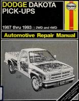
1987 Dodge Ram 50 pick-up
1989 Dodge Raider
About this manual Its purpose The purpose of this manual is to help you get the best value from your vehicle. It can do so in several ways. It can help you decide what work must be done, even if you choose to have it done by a dealer service department or a repair shop; it provides information and procedures for routine mainte¬ nance and servicing; and it offers diagnostic and repair procedures to fol¬ low when trouble occurs. We hope you use the manual to tackle the work yourself. For many simpler jobs, doing it yourself may be quicker than arranging an appoint¬ ment to get the vehicle into a shop and making the trips to leave it and pick it up. More importantly, a lot of money can be saved by avoiding the ex¬ pense the shop must pass on to you to cover its labor and overhead costs. An added benefit is the sense of satisfaction and accomplishment that you feel after doing the job yourself.
Using the manual The manual is divided into Chapters. Each Chapter is divided into
numbered Sections, which are headed in bold type between horizontal lines. Each Section consists of consecutively numbered paragraphs. At the beginning of each numbered Section you will be referred to any illustrations which apply to the procedures in that Section. The reference numbers used in illustration captions pinpoint the pertinent Section and the Step within that Section. That is, illustration 3.2 means the illustration refers to Section 3 and Step (or paragraph) 2 within that Section. Procedures, once described in the text, are not normally repeated. When it’s necessary to refer to another Chapter, the reference will be given as Chapter and Section number. Cross references given without use of the word “Chapter” apply to Sections and/or paragraphs in the same Chapter. For example, “see Section 8” means in the same Chapter. References to the left or right side of the vehicle assume you are sitting in the driver’s seat, facing forward. Even though we have prepared this manual with extreme care, neither the publisher nor the author can accept responsibility for any errors in, or omissions from, the information given.
NOTE A Note provides information necessary to properly complete a procedure or information which will make the procedure easier to understand.
CAUTION A Caution provides a special procedure or special steps which must be taken while completing the procedure where the
Caution is found. Not heeding a Caution can result in damage to the assembly being worked on.
WARNING A Warning provides a special procedure or special steps which must be taken while completing the procedure where the
Warning is found. Not heeding a Warning can result in personal injury.
Introduction to the Dodge D-50/Ram 50 and Raider Pick-up models are available in standard and extended cab body styles with short or long bed lengths. Raider models are available in twoor four-door body styles. Most four-cylinder engines are equipped with carburetors. Later fourcylinder and all V6 engines are equipped with port fuel injection. The engine drives the rear wheels through either a four or five-speed manual or three or four-speed automatic transmission via a dri veshaft and solid rear axle. A transfer case and driveshaft are used to drive the front differential and driveaxles on 4WD models. Thefront suspension features upper and lower control arms, shock ab¬
sorbers, coil springs (2WD models) or torsion bars (4WD models). The solid rear axle is suspended by leaf springs and shock absorbers on most models. Some later models use coil spring rear suspension with the axle located by trailing arms and a track rod. The steering box is mounted to the left of the engine and is connected to the steering arms by a series of rods. Power assist is standard on most later models. The brakes are disc at the front and drums at the rear, with power assist on most models.
Vehicle identification numbers Modifications are a continuing and unpublicized process in vehicle manufacturing. Since spare parts manuals and lists are compiled on a nu¬ merical basis, the individual vehicle numbers are essential to correctly identify the component required.
Chassis number The chassis number is stamped on the frame under the vehicle, near the right rear shock absorber
Engine identification number Vehicle Identification Number (VIN) This very important identification number is stamped on a plate at¬ tached to the left side of the dashboard, just inside the windshield on the driver’s side of the vehicle (see illustration). The VIN also appears on the Vehicle Certificate of Title and Registration. It contains information such as where and when the vehicle was manufactured, the model year and the body style.
The vehicle Identification Number (VIN) is visible from outside the vehicle through the driver’s side of the windshield
Location of the identification number on 2.0L and 2.4L four-cylinder engines
The engine ID number consists of two parts: a model number and a serial number. On four-cylinder engines, it is located on the right side of the engine in one of two places: 1) on a machined surface at the front cor¬ ner of the block, just below the number one spark plug (2.6L engine) or 2) at the lower right front corner of block (2.0L and 2.4L engine) (see illus¬ trations). On V6 engines, the ID number is located on a pad at the right side of the block (see illustration).
On 2.6L four-cylinder engines, the identification number is located on a machined surface at the right front corner of the block, just below the cylinder head
V6 engine ID number location
Vehicle identification numbers
0-7
Paint code identification plate This plate is located in the engine compartment, usually on the radiator support but also on the firewall (see illustration). It tells what color and type of paint was originally applied to the vehicle.
Safety Certification label The Safety Certification label is affixed to the left door pillar. The plate contains the name of the manufacturer, the month and year of production, the Gross Vehicle Weight Rating (GVWR) and the certification statement.
The paint code ID plate is usually located on the radiator support
Buying parts Replacement parts qre available from many sources, which generally fall into one of two categories - authorized dealer parts departments and independent retail auto parts stores. Our advice concerning these parts is as follows:
Retail auto parts stores: Good auto parts stores will stock frequently needed components which wear out relatively fast, such as clutch compo¬ nents, exhaust systems, brake parts, tune-up parts, etc. These stores of¬ ten supply new or reconditioned parts on an exchange basis, which can save a considerable amount of money. Discount auto parts stores are of¬ ten very good places to buy materials and parts needed for general vehicle maintenance such as oil, grease, filters, spark plugs, belts, touch-up paint, bulbs, etc. They also usually sell tools and general accessories, have con¬
venient hours, charge lower prices and can often be found not far from home.
Authorized dealer parts department: This is the best source for parts which are unique to the vehicle and not generally available else¬ where (such as major engine parts, transmission parts, trim pieces, etc.). Warranty information: If the vehicle is still covered under warranty, be sure that any replacement parts purchased - regardless of the source - do not invalidate the warranty! To be sure of obtaining the correct parts, have engine and chassis numbers available and, if possible, take the old parts along for positive identification.
Maintenance techniques, tools and working facilities Maintenance techniques There are a number of techniques involved in maintenance and repair that will be referred to throughout this manual. Application of these tech¬ niques will enable the home mechanic to be more efficient, better orga¬ nized and capable of performing the various tasks properly, which will ensure that the repair job is thorough and complete.
Fasteners Fasteners are nuts, bolts, studs and screws used to hold two or more parts together. There are a few things to keep in mind when working with fasteners. Almost all of them use a locking device of some type, either a lockwasher, locknut, locking tab or thread adhesive. All threaded fasten¬ ers should be clean and straight, with undamaged threads and undam¬ aged corners on the hex head where the wrench fits. Develop the habit of replacing all damaged nuts and bolts with new ones. Special locknuts
with nylon or fiber inserts can only be used once. If they are removed, they lose their locking ability and must be replaced with new ones. Rusted nuts and bolts should be treated with a penetrating fluid to ease removal and prevent breakage. Some mechanics use turpentine in a spout-type oil can, which works quite well. After applying the rust pene¬ trant, let it work for a few minutes before trying to loosen the nut or bolt. Badly rusted fasteners may have to be chiseled or sawed off or removed with a special nut breaker, available at tool stores. If a bolt or stud breaks off in an assembly, it can be drilled and removed with a special tool commonly available for this purpose. Most automotive machine shops can perform this task, as well as other repair procedures, such as the repair of threaded holes that have been stripped out. Flat washers and lockwashers, when removed from an assembly, should always be replaced exactly as removed. Replace any damaged washers with new ones. Never use a lockwasher on any soft metal surface (such as aluminum), thin sheet metal or plastic.
0- 9
Maintenance techniques, tools and working facilities Fastener sizes For a number of reasons, automobile manufacturers are making wider and wider use of metric fasteners. Therefore, it is important to be able to tell the difference between standard (sometimes called U.S. or SAE) and metric hardware, since they cannot be interchanged. All bolts, whether standard or metric, are sized according to diameter, thread pitch and length. For example, a standard 1/2-13x1 bolt is 1/2 inch in diameter, has 13 threads per inch and is 1 inch long. An M12 -1.75 x 25 metric bolt is 12 mm in diameter, has a thread pitch of 1.75 mm (the distance between threads) and is 25 mm long. The two bolts are nearly identical, and easily confused, but they are not interchangeable. In addition to the differences in diameter, thread pitch and length, met¬ ric and standard bolts can also be distinguished by examining the bolt heads. To begin with, the distance across the flats on a standard bolt head is measured in inches, while the same dimension on a metric bolt is sized in millimeters (the same is true for nuts). As a result, a standard wrench should not be used on a metric bolt and a metric wrench should
not be used on a standard bolt. Also, most standard bolts have slashes radiating out from the center of the head to denote the grade or strength of the bolt, which is an indication of the amount of torque that can be applied to it. The greater the number of slashes, the greater the strength of the bolt. Grades 0 through 5 are commonly used on automobiles. Metric bolts have a property class (grade) number, rather than a slash, molded into their heads to indicate bolt strength. In this case, the higher the num¬ ber, the stronger the bolt. Property class numbers 8.8, 9.8 and 10.9 are commonly used on automobiles. Strength markings can also be used to distinguish standard hex nuts from metric hex nuts. Many standard nuts have dots stamped into one side, while metric nuts are marked with a number. The greater the number of dots, or the higher the number, the greater the strength of the nut. Metric studs are also marked on their ends according to property class (grade). Larger studs are numbered (the same as metric bolts), while smaller studs carry a geometric code to denote grade.
Bolt strength markings (top - standard/SAE/USS; bottom - metric)
Grade
Identification
Class
Identification
Hex Nut Property Class 9
Hex Nut Grade 5
Arabic 9
3 Dots Hex Nut Property Class 10
Hex Nut Grade 8
6 Dots Standard hex nut strength markings
Arabicl 0 Metric hex nut strength markings
CLASS
CLASS
CLASS
10.9
9.8
8.8
Metric stud length markings
Maintenance techniques, tools and working facilities
0-10
It should be noted that many fasteners, especially Grades 0 through 2, have no distinguishing marks on them. When such is the case, the only way to determine whether it is standard or metric is to measure the thread pitch or compare it to a known fastener of the same size. Standard fasteners are often referred to as SAE, as opposed to metric. However, it should be noted that SAE technically refers to a non-metric fine thread fastener only. Coarse thread non-metric fasteners are referred to as USS sizes. Since fasteners of the same size (both standard and metric) may have different strength ratings, be sure to reinstall any bolts, studs or nuts re¬ moved from your vehicle in their original locations. Also, when replacing a fastener with a new one, make sure that the new one has a strength rat¬ ing equal to or greater than the original.
Tightening sequences and procedures Most threaded fasteners should be tightened to a specific torque value (torque is the twisting force applied to a threaded component such as a nut or bolt). Overtightening the fastener can weaken it and cause it to break, while undertightening can cause it to eventually come loose. Bolts, screws and studs, depending on the material they are made of and their thread diameters, have specific torque values, many of which are noted in the Specifications at the beginning of each Chapter. Be sure to follow the torque recommendations closely. For fasteners not assigned a specif¬ ic torque, a general torque value chart is presented here as a guide. These torque values are for dry (unlubricated) fasteners threaded into steel or cast iron (not aluminum). As was previously mentioned, the size and grade of a fastener determine the amount of torque that can
Metric thread sizes
Ft-lbs
Nm
M-6 . M-8 . M-10 . M-12 . M-14 .
6 to 9 14 to 21 28 to 40 50 to 71 80 to 140
9 to 1 2 19 to 28 38 to 54 68 to 96 109 to 154
5 to 8 12 to 18 22 to 33 25 to 35
7 to 1 0 17 to 24 30 to 44 34 to 47
6 to 9 12 to 18 14 to 20 22 to 32 27 to 38 40 to 55 40 to 60 55 to 80
9 to 1 2 17 to 24 19 to 27 30 to 43 37 to 51 55 to 74 55 to 81 75 to 108
Pipe thread sizes 1/8. 1/4. 3/8.
1/2.
U.S. thread sizes 1/4-20. 5/16-18. 5/16-24. 3/8-16. 3/8-24. 7/16-14. 7/16-20. 1/2-13.
Standard (SAE and USS) bolt dimensions/grade marks G L T D
Grade marks (bolt length) Length (in inches) Thread pitch (number of threads per inch) Nominal diameter (in inches)
Metric bolt dimensions/grade marks P L T D
Property class (bolt strength) Length (in millimeters) Thread pitch (distance between threads in millimeters) Diameter
Maintenance techniques, tools and working facilities safely be applied to it. The figures listed here are approximate for Grade 2 and Grade 3 fasteners. Higher grades can tolerate higher torque values. Fasteners laid out in a pattern, such as cylinder head bolts, oil pan bolts, differential cover bolts, etc., must be loosened or tightened in se¬ quence to avoid warping the component. This sequence will normally be shown in the appropriate Chapter. If a specific pattern is not given, the fol¬ lowing procedures can be used to prevent warping. Initially, the bolts or nuts should be assembled finger-tight only. Next, they should be tightened one full turn each, in a criss-cross or diagonal pattern. After each one has been tightened one full turn, return to the first one and tighten them all one-half turn, following the same pattern. Finally, tighten each of them one-quarter turn at a time until each fastener has been tightened to the proper torque. To loosen and remove the fasteners, the procedure would be reversed.
Component disassembly Component disassembly should be done with care and purpose to help ensure that the parts go back together properly. Always keep track of the sequence in which parts are removed. Make note of special charac¬ teristics or marks on parts that can be installed more than one way, such as a grooved thrust washer on a shaft. It is a good idea to lay the disas¬ sembled parts out on a clean surface in the order that they were removed. It may also be helpful to make sketches or take instant photos of compo¬ nents before removal. When removing fasteners from a component, keep track of their loca¬ tions. Sometimes threading a bolt back in a part, or putting the washers and nut back on a stud, can prevent mix-ups later. If nuts and bolts cannot be returned to their original locations, they should be kept in a compartmented box or a series of small boxes. A cupcake or muffin tin is ideal for this purpose, since each cavity can hold the bolts and nuts from a particu¬ lar area (i.e. oil pan bolts, valve cover bolts, engine mount bolts, etc.). A pan of this type is especially helpful when working on assemblies with very small parts, such as the carburetor, alternator, valve train or interior dash and trim pieces. The cavities can be marked with paint or tape to identify the contents. Whenever wiring looms, harnesses or connectors are separated, it is a good idea to identify the two halves with numbered pieces of masking tape so they can be easily reconnected.
Hose removal tips Warning: If the vehicle is equipped with air conditioning, do not discon¬ nect any of the A/C hoses without first having the system depressurized by a dealer service department or a service station. Hose removal precautions closely parallel gasket removal precau¬ tions. Avoid scratching or gouging the surface that the hose mates against or the connection may leak. This is especially true for radiator hoses. Be¬ cause of various chemical reactions, the rubber in hoses can bond itself to the metal spigot that the hose fits over. To remove a hose, first loosen the hose clamps that secure it to the spigot. Then, with slip-joint pliers, grab the hose at the clamp and rotate it around the spigot. Work it back and forth until it is completely free, then pull it off. Silicone or other lubri¬ cants will ease removal if they can be applied between the hose and the outside of the spigot. Apply the same lubricant to the inside of the hose and the outside of the spigot to simplify installation. As a last resort (and if the hose is to be replaced with a new one any¬ way), the rubber can be slit with a knife and the hose peeled from the spig¬ ot. If this must be done, be careful that the metal connection is not damaged. If a hose clamp is broken or damaged, do not reuse it. Wire-type clamps usually weaken with age, so it is a good idea to replace them with screw-type clamps whenever a hose is removed.
Tools A selection of good tools is a basic requirement for anyone who plans to maintain and repair his or her own vehicle. For the owner who has few tools, the initial investment might seem high, but when compared to the spiraling costs of professional auto maintenance and repair, it is a wise one.
Gasket sealing surfaces Throughout any vehicle, gaskets are used to seal the mating surfaces between two parts and keep lubricants, fluids, vacuum or pressure con¬ tained in an assembly. Many times these gaskets are coated with a liquid or paste-type gasket sealing compound before assembly. Age, heat and pressure can some¬ times cause the two parts to stick together so tightly that they are very diffi¬ cult to separate. Often, the assembly can be loosened by striking it with a soft-face hammer near the mating surfaces. A regular hammer can be used if a block of wood is placed between the hammer and the part. Do not hammer on cast parts or parts that could be easily damaged. With any particularly stubborn part, always recheck to make sure that every fasten¬ er has been removed. Avoid using a screwdriver or bar to pry apart an assembly, as they can easily mar the gasket sealing surfaces of the parts, which must remain smooth. If prying is absolutely necessary, use an old broom handle, but keep in mind that extra clean up will be necessary if the wood splinters. After the parts are separated, the old gasket must be carefully scraped off and the gasket surfaces cleaned. Stubborn gasket material can be soaked with rust penetrant or treated with a special chemical to soften it so it can be easily scraped off. A scraper can be fashioned from a piece of copper tubing by flattening and sharpening one end. Copper is recom¬ mended because it is usually softer than the surfaces to be scraped, which reduces the chance of gouging the part. Some gaskets can be removed with a wire brush, but regardless of the method used, the mating surfaces must be left clean and smooth. If for some reason the gasket surface is gouged, then a gasket sealer thick enough to fill scratches will have to be used during reassembly of the components. For most applications, a non-drying (or semi-drying) gasket sealer should be used.
0- 11
Dial indicator set
Maintenance techniques, tools and working facilities
0-12
Dial Caliper
Hand-operated vacuum pump
Timing light
Compression gauge with spark plug hole adapter
Damper/steering wheel puller
General purpose puller
Hydraulic lifter removal tool
Valve spring compressor
Valve spring compressor
Ridge reamer
Piston ring groove cleaning tool
Ring removal/installation tool
Maintenance techniques, tools and working facilities
0- 13
Ring compressor
Cylinder hone
Brake hold-down tool
Brake cylinder hone
Clutch plate alignment tool
Tap and die set
To help the owner decide which tools are needed to perform the tasks detailed in this manual, the following tool lists are offered: Maintenance
and minor repair, Repair/overhaul and Special. The newcomer to practical mechanics should start off with the maintenance and minor repair tool kit, which is adequate for the simpler jobs performed on a vehicle. Then, as confidence and experience grow, the owner can tackle more difficult tasks, buying additional tools as they are needed. Eventually the basic kit will be expanded into the repair and overhaul tool set. Over a period of time, the experienced do-it-yourselfer will assemble a tool set complete enough for most repair and overhaul pro¬ cedures and will add tools from the special category when it is felt that the expense is justified by the frequency of use.
Battery post and cable cleaning tool Oil filter wrench Funnel (medium size) Safety goggles Jackstands(2) Drain pan Note: If basic tune-ups are going to be part of routine maintenance, it will be necessary to purchase a good quality stroboscopic timing light and combination tachometer/dwell meter. Although they are included in the list of special tools, it is mentioned here because they are absolutely neces¬ sary for tuning most vehicles properly.
Maintenance and minor repair tool kit
Repair and overhaul tool set
The tools in this list should be considered the minimum required for performance of routine maintenance, servicing and minor repair work. We recommend the purchase of combination wrenches (box-end and open-end combined in one wrench). While more expensive than open end wrenches, they offer the advantages of both types of wrench.
These tools are essential for anyone who plans to perform major re¬ pairs and are in addition to those in the maintenance and minor repair tool kit. Included is a comprehensive set of sockets which, though expensive, are invaluable because of their versatility, especially when various exten¬ sions and drives are available. We recommend the 1 /2-inch drive over the 3/8-inch drive. Although the larger drive is bulky and more expensive, it has the capacity of accepting a very wide range of large sockets. Ideally, however, the mechanic should have a 3/8-inch drive set and a 1/2-inch drive set.
Combination wrench set (1/4-inch to 1 inch or 6 mm to 19 mm) Adjustable wrench, 8 inch Spark plug wrench with rubber insert Spark plug gap adjusting tool Feeler gauge set Brake bleeder wrench Standard screwdriver (5/16-inch x 6 inch) Phillips screwdriver (No. 2x6 inch) Combination pliers - 6 inch Hacksaw and assortment of blades Tire pressure gauge Grease gun Oil can Fine emery cloth Wire brush
Socket set(s) Reversible ratchet Extension -10 inch Universal joint Torque wrench (same size drive as sockets) Ball peen hammer - 8 ounce Soft-face hammer (plastic/rubber) Standard screwdriver (1/4-inch x 6 inch) Standard screwdriver (stubby - 5/16-inch) Phillips screwdriver (No. 3x8 inch) Phillips screwdriver (stubby - No. 2)
0-14
Maintenance techniques, tools and working facilities
Pliers - vise grip Pliers - lineman’s Pliers - needle nose Pliers - snap-ring (internal and external) Cold chisel - 1/2-inch Scribe Scraper (made from flattened copper tubing) Centerpunch Pin punches (1/16, 1/8, 3/16-inch) Steel rule/straightedge - 12 inch Allen wrench set (1/8 to 3/8-inch or 4 mm to 10 mm) A selection of files Wire brush (large) Jackstands (second set) Jack (scissor or hydraulic type) Note: Another tool which is often useful is an electric drill with a chuck ca¬ pacity of 3/8-inch and a set of good quality drill bits.
Special tools The tools in this list include those which are not used regularly, are ex¬ pensive to buy, or which need to be used in accordance with their man¬ ufacturer’s instructions. Unless these tools will be used frequently, it is not very economical to purchase many of them. A consideration would be to split the costand use between yourself and a friend or friends. In addition, most of these tools can be obtained from a tool rental shop on a temporary basis. This list primarily contains only those tools and instruments widely available to the public, and not those special tools produced by the vehicle manufacturer fordistribution to dealer service departments. Occasionally, references to the manufacturer’s special tools are included in the text of this manual. Generally, an alternative method of doing the job without the special tool is offered. However, sometimes there is no alternative to their use. Where this is the case, and the tool cannot be purchased or bor¬ rowed, the work should be turned over to the dealer service department or an automotive repair shop.
Valve spring compressor Piston ring groove cleaning tool Piston ring compressor Piston ring installation tool Cylinder compression gauge Cylinder ridge reamer Cylinder surfacing hone Cylinder bore gauge Micrometers and/or dial calipers Hydraulic lifter removal tool Balljoint separator Universal-type puller Impact screwdriver Dial indicator set Stroboscopic timing light (inductive pick-up) Hand operated vacuum/pressure pump Tachometer/dwell meter Universal electrical multimeter Cable hoist Brake spring removal and installation tools Floor jack
Buying tools For the do-it-yourselfer who is just starting to get involved in vehicle maintenance and repair, there are a number of options available when
purchasing tools. If maintenance and minor repair is the extent of the work to be done, the purchase of individual tools is satisfactory. If, on the other hand, extensive work is planned, it would be a good idea to purchase a modest tool set from one of the large retail chain stores. A set can usually be bought at a substantial savings over the individual tool prices, and they often come with a tool box. As additional tools are needed, add-on sets, individual tools and a larger tool box can be purchased to expand the tool selection. Building a tool set gradually allows the cost of the tools to be spread over a longer period of time and gives the mechanic the freedom to choose only those tools that will actually be used. Tool stores will often be the only source of some of the special tools that are needed, but regardless of where tools are bought, try to avoid cheap ones, especially when buying screwdrivers and sockets, because they won’t last very long. The expense involved in replacing cheap tools will eventually be greater than the initial cost of quality tools.
Care and maintenance of tools Good tools are expensive, so it makes sense to treat them with re¬ spect. Keep them clean and in usable condition and store them properly when not in use. Always wipe off any dirt, grease or metal chips before put¬ ting them away. Never leave tools lying around in the work area. Upon completion of a job, always check closely under the hood for tools that may have been left there so they won’t get lost during a test drive. Some tools, such as screwdrivers, pliers, wrenches and sockets, can be hung on a panel mounted on the garage or workshop wall, while others should be kept in a tool box or tray. Measuring instruments, gauges, me¬ ters, etc. must be carefully stored where they cannot be damaged by weather or impact from other tools. When tools are used with care and stored properly, they will last a very long time. Even with the best of care, though, tools will wear out if used frequently. When a tool is damaged or worn out, replace it. Subsequent jobs will be safer and more enjoyable if you do.
Working facilities Not to be overlooked when discussing tools is the workshop. If any¬ thing more than routine maintenance is to be carried out, some sort of suit¬ able work area is essential. It is understood, and appreciated, that many home mechanics do not have a good workshop or garage available, and end up removing an en¬ gine or doing major repairs outside. It is recommended, however, that the overhaul or repair be completed under the cover of a roof. A clean, flat workbench or table of comfortable working height is an ab¬ solute necessity. The workbench should be equipped with a vise that has a jaw opening of at least four inches. As mentioned previously, some clean, dry storage space is also re¬ quired for tools, as well as the lubricants, fluids, cleaning solvents, etc. which soon become necessary. Sometimes waste oil and fluids, drained from the engine or cooling system during normal maintenance or repairs, present a disposal prob¬ lem. To avoid pouring them on the ground or into a sewage system, pour the used fluids into large containers, seal them with caps and take them to an authorized disposal site or recycling center. Plastic jugs, such as old antifreeze containers, are ideal for this purpose. Always keep a supply of old newspapers and clean rags available. Old towels are excellent for mopping up spills. Many mechanics use rolls of paper towels for most work because they are readily available and dispos¬ able. To help keep the area underthe vehicle clean, a large cardboard box can be cut open and flattened to protect the garage or shop floor. Whenever working over a painted surface, such as when leaning over a fender to service something under the hood, always cover it with an old blanket or bedspread to protect the finish. Vinyl covered pads, made espe¬ cially for this purpose, are available at auto parts stores.
Booster battery (jump) starting Observe these precautions when using a booster battery to start a ve¬ hicle: a) Before connecting the booster battery, make sure the ignition switch is in the Off position. b) Turn off the lights, heater and other electrical loads. c) Your eyes should be shielded. Safety goggles are a good idea. d) Make sure the booster battery is the same voltage as the dead one in the vehicle. e) The two vehicles MUST NOT TOUCH each other! f) Make sure the transmission is in Neutral (manual) or Park (auto¬ matic). g) If the booster battery is not a maintenance-free type, remove the vent caps and lay a cloth over the vent holes. Connect the red jumper cable to the positive (+) terminals of each bat¬ tery. Connect one end of the black jumper cable to the negative (-) terminal of the booster battery. The other end of this cable should be connected to a good ground on the vehicle to be started, such as a bolt or bracket on the engine block (see illustration). Make sure the cable will not come into contact with the fan, drivebelts or other moving parts of the engine. Start the engine using the booster battery, then, with the engine run¬ ning at idle speed, disconnect the jumper cables in the reverse order of connection.
Make the booster battery cable connections in the numerical order shown (note that the negative cable of the booster battery is NOT attached to the negative terminal of the dead battery)
Jacking and towing Jacking The jack supplied with the vehicle should only be used for raising the vehicle when changing a tire or placing jackstands under the frame. Warn¬
Front
rRear-Wheel-Drive Truck
ing : Never work under the vehicle or start the engine while this jack is be¬ ing used as the only means of support. The vehicle should be on level ground with the hazard flashers on, the wheels blocked, the parking brake applied and the transmission in Park (automatic) or Reverse (manual). If a tire is being changed, loosen the lug nuts one-half turn and leave them in place until the wheel is raised off the ground. Place the jack under the vehicle suspension in the indicated posi¬ tion (see illustration). Operate the jack with a slow, smooth motion until the wheel is raised off the ground. Remove the lug nuts, pull off the wheel, install the spare and thread the lug nuts back on with the bevelled sides facing in. Tighten them snugly, but wait until the vehicle is lowered to tight¬ en them completely. Lower the vehicle, remove the jack and tighten the nuts (if loosened or removed) in a criss-cross pattern.
Four-Wheel-Drive Truck
Towing As a general rule, vehicles may be towed with all four wheels on the ground. If necessary, the front or rear wheels may be raised for towing. On vehicles with an automatic transmission, do not exceed 19 M PH or tow the vehicle farther than 19 miles (there are no speed or distance limitations on vehicles with a manual transmission). Equipment specifically designed for towing should be used and should be attached to the main structural members of the vehicle, not the bumper or brackets. Tow hooks are attached to the frame at both ends of the ve¬ hicle. However, they are for emergency use only and should not be used for highway towing. Stand clear of vehicles when using the tow hooks tow straps and chains may break, causing serious injury. Safety is a major consideration when towing and all applicable state and local laws must be obeyed. A safety chain must be used for all towing (in addition to the tow bar). While towing, the parking brake must be released, the transmission must be in Neutral and the transfer case (if equipped) must be in 2H. The steering must be unlocked (ignition switch in the Off position). If you’re towing a 4WD model with the front wheels on the ground, the front hubs must be unlocked. Remember that power steering and power brakes will not work with the engine off.
Jacking points
Automotive chemicals and lubricants A number of automotive chemicals and lubricants are available for use during vehicle maintenance and repair. They include a wide variety of products ranging from cleaning solvents and degreasers to lubricants and
Heat-sink grease is a special electrically non-conductive grease that is used for mounting electronic ignition modules where it is essential that heat is transferred away from the module.
protective sprays for rubber, plastic and vinyl.
Cleaners
Sealants
varnish and carbon. Most carburetor cleaners leave a dry-type lubricant film which will not harden or gum up. Because of this film it is not recom¬
RTV sealant is one of the most widely used gasket compounds. Made from silicone, RTV is air curing, it seals, bonds, waterproofs, fills surface irregularities, remains flexible, doesn’t shrink, is relatively easy to remove, and is used as a supplementary sealer with almost all low and medium
mended for use on electrical components.
temperature gaskets.
Carburetor cleaner and choke cleaner is a strong solvent for gum,
Brake system cleaner is used to remove grease and brake fluid from the brake system, where clean surfaces are absolutely necessary. It leaves no residue and often eliminates brake squeal caused by contami¬ nants.
Electrical cleaner removes oxidation, corrosion and carbon deposits from electrical contacts, restoring full current flow. It can also be used to clean spark plugs, carburetor jets, voltage regulators and other parts where an oil-free surface is desired.
Demoisturants remove water and moisture from electrical compo¬ nents such as alternators, voltage regulators, electrical connectors and fuse blocks. They are non-conductive, non-corrosive and non-flammable.
Degreasers are heavy-duty solvents used to remove grease from the outside of the engine and from chassis components. They can be sprayed or brushed on and, depending on the type, are rinsed off either with water or solvent.
Lubricants Motor oil is the lubricant formulated for use in engines. It normally con¬ tains a wide variety of additives to prevent corrosion and reduce foaming and wear. Motor oil comes in various weights (viscosity ratings) from 5 to 80. The recommended weight of the oil depends on the season, tempera¬ ture and the demands on the engine. Light oil is used in cold climates and under light load conditions. Heavy oil is used in hot climates and where high loads are encountered. Multi-viscosity oils are designed to have char¬ acteristics of both light and heavy oils and are available in a number of
Anaerobic sealant \s much like RTV in that it can be used either to seal gaskets or to form gaskets by itself. It remains flexible, is solvent resistant and fills surface imperfections. The difference between an anaerobic sea¬ lant and an RTV-type sealant is in the curing. RTV cures when exposed to air, while an anaerobic sealant cures only in the absence of air. This means that an anaerobic sealant cures only after the assembly of parts, sealing them together.
Thread and pipe sealant is used for sealing hydraulic and pneumatic fittings and vacuum lines. It is usually made from a Teflon compound, and comes in a spray, a paint-on liquid and as a wrap-around tape.
Chemicals Anti-seize compound prevents seizing, galling, cold welding, rust and corrosion in fasteners. High-temperature anti-seize, usually made with copper and graphite lubricants, is used for exhaust system and exhaust manifold bolts.
Anaerobic locking compounds are used to keep fasteners from vi¬ brating or working loose and cure only after installation, in the absence of air. Medium strength locking compound is used for small nuts, bolts and screws that may be removed later. High-strength locking compound is for large nuts, bolts and studs which aren’t removed on a regular basis. Oil additives range from viscosity index improvers to chemical treat¬ ments that claim to reduce internal engine friction. It should be noted that most oil manufacturers caution against using additives with their oils.
Chassis and wheel bearing grease is a heavy grease used where in¬ creased loads and friction are encountered, such as for wheel bearings,
Gas additives perform several functions, depending on their chemical makeup. They usually contain solvents that help dissolve gum and varnish that build up on carburetor, fuel injection and intake parts. They also serve to break down carbon deposits that form on the inside surfaces of the com¬ bustion chambers. Some additives contain upper cylinder lubricants for valves and piston rings, and others contain chemicals to remove conden¬
balljoints, tie-rod ends and universal joints.
sation from the gas tank.
weights from 5W-20 to 20W-50.
Gear oil is designed to be used in differentials, manual transmissions and other areas where high-temperature lubrication is required.
High-temperature wheel bearing grease is designed to withstand the extreme temperatures encountered by wheel bearings in disc brake equipped vehicles. It usually contains molybdenum disulfide (moly), which is a dry-type lubricant. White grease is a heavy grease for metal-to-metal applications where water is a problem. White grease stays soft under both low and high tem¬ peratures (usually from -100 to +190-degrees F), and will not wash off or dilute in the presence of water. Assembly lube is a special extreme pressure lubricant, usually con¬ taining moly, used to lubricate high-load parts (such as main and rod bear¬ ings and cam lobes) for initial start-up of a new engine. The assembly lube lubricates the parts without being squeezed out or washed away until the engine oiling system begins to function.
Silicone lubricants are used to protect rubber, plastic, vinyl and nylon parts.
Graphite lubricants are used where oils cannot be used due to con¬ tamination problems, such as in locks. The dry graphite will lubricate metal parts while remaining uncontaminated by dirt, water, oil or acids. It is elec¬ trically conductive and will not foul electrical contacts in locks such as the ignition switch.
Molypenetrants\ooser\ and lubricate frozen, rusted and corroded fas¬ teners and prevent future rusting or freezing.
Miscellaneous Brake fluid is specially formulated hydraulic fluid that can withstand the heat and pressure encountered in brake systems. Care must be taken so this fluid does not come in contact with painted surfaces or plastics. An opened container should always be resealed to prevent contamination by water or dirt.
Weatherstrip adhesive is used to bond weatherstripping around doors, windows and trunk lids. It is sometimes used to attach trim pieces. Undercoating is a petroleum-based, tar-like substance that is de¬ signed to protect metal surfaces on the underside of the vehicle from cor¬ rosion. It also acts as a sound-deadening agent by insulating the bottom of the vehicle.
Waxes and polishes are used to help protect painted and plated sur¬ faces from the weather. Different types of paint may require the use of dif¬ ferent types of wax and polish. Some polishes utilize a chemical or abrasive cleaner to help remove the top layer of oxidized (dull) paint on older vehicles. In recent years many non-wax polishes that contain a wide variety of chemicals such as polymers and silicones have been intro¬ duced. These non-wax polishes are usually easier to apply and last longer than conventional waxes and polishes.
Safety first! Regardless of how enthusiastic you may be about getting on with the job at hand, take the time to ensure that your safety is not jeopardized. A moment’s lack of attention can result in an accident, as can failure to ob¬ serve certain simple safety precautions. The possibility of an accident will always exist, and the following points should not be considered a compre¬ hensive list of all dangers. Rather, they are intended to make you aware of the risks and to encourage a safety conscious approach to all work you carry out on your vehicle.
Essential DOs and DON’Ts DON’T rely on a jack when working under the vehicle. Always use ap¬ proved jackstands to support the weight of the vehicle and place them un¬ der the recommended lift or support points. DON’T attempt to loosen extremely tight fasteners (i.e. wheel lug nuts) while the vehicle is on a jack - it may fall. DON’T start the engine without first making sure that the transmission is in Neutral (or Park where applicable) and the parking brake is set. DON’T remove the radiator cap from a hot cooling system - let it cool or cover it with a cloth and release the pressure gradually. DON’T attempt to drain the engine oil until you are sure it has cooled to the point that it will not burn you. DON’T touch any part of the engine or exhaust system until it has cooled sufficiently to avoid burns. DON’T siphon toxic liquids such as gasoline, antifreeze and brake fluid by mouth, or allow them to remain on your skin. DON’T inhale brake lining dust - it is potentially hazardous (see Asbestos below) DON’T allow spilled oil or grease to remain on the floor-wipe it up before someone slips on it. DON’T use loose fitting wrenches or other tools which may slip and cause injury. DON’T push on wrenches when loosening or tightening nuts or bolts. Al¬ ways try to pull the wrench toward you. If the situation calls for pushing the wrench away, push with an open hand to avoid scraped knuckles if the wrench should slip. DON’T attempt to lift a heavy component alone-get someone to help you. DON’T rush or take unsafe shortcuts to finish a job. DON’T allow children or animals in or around the vehicle while you are working on it. DO wear eye protection when using power tools such as a drill, sander, bench grinder, etc. and when working under a vehicle. DO keep loose clothing and long hair well out of the way of moving parts. DO make sure that any hoist used has a safe working load rating adequate for the job. DO get someone to check on you periodically when working alone on a vehicle. DO carry out work in a logical sequence and make sure that everything is correctly assembled and tightened. DO keep chemicals and fluids tightly capped and out of the reach of chil¬ dren and pets. DO remember that your vehicle’s safety affects that of yourself and others. If in doubt on any point, get professional advice.
Fire Remember at all times that gasoline is highly flammable. Never smoke or have any kind of open flame around when working on a vehicle. But the risk does not end there. A spark caused by an electrical short circuit, by two metal surfaces contacting each other, or even by static electricity built up in your body under certain conditions, can ignite gasoline vapors, which in a confined space are highly explosive. Do not, under any circum¬ stances, use gasoline for cleaning parts. Use an approved safety solvent. Always disconnect the battery ground (-) cable at the battery before working on any part of the fuel system or electrical system. Never risk spill¬ ing fuel on a hot engine or exhaust component. It is strongly recommended that a fire extinguisher suitable for use on fuel and electrical fires be kept handy in the garage or workshop at all times. Never try to extinguish a fuel or electrical fire with water.
Fumes Certain fumes are highly toxic and can quickly cause unconsciousness and even death if inhaled to any extent. Gasoline vapor falls into this cate¬ gory, as do the vapors from some cleaning solvents. Any draining or pour¬ ing of such volatile fluids should be done in a well ventilated area. When using cleaning fluids and solvents, read the instructions on the container carefully. Never use materials from unmarked containers. Never run the engine in an enclosed space, such as a garage. Exhaust fumes contain carbon monoxide, which is extremely poisonous. If you need to run the engine, always do so in the open air, or at least have the rear of the vehicle outside the work area. If you are fortunate enough to have the use of an inspection pit, never drain or pour gasoline and never run the engine while the vehicle is over the pit. The fumes, being heavier than air, will concentrate in the pit with possibly lethal results.
The battery Never create a spark or allow a bare light bulb near a battery. They nor¬ mally give off a certain amount of hydrogen gas, which is highly explosive. Always disconnect the battery ground (-) cable at the battery before working on the fuel or electrical systems. If possible, loosen the filier caps or cover when charging the battery from an external source (this does not apply to sealed or maintenance-free batteries). Do not charge at an excessive rate or the battery may burst. Take care when adding water to a non maintenance-free battery and when carrying a battery. The electrolyte, even when diluted, is very corro¬ sive and should not be allowed to contact clothing or skin. Always wear eye protection when cleaning the battery to prevent the caustic deposits from entering your eyes.
Household current When using an electric power tool, inspection light, etc., which oper¬ ates on household current, always make sure that the tool is correctly con¬ nected to its plug and that, where necessary, it is properly grounded. Do not use such items in damp conditions and, again, do not create a spark or apply excessive heat in the vicinity of fuel or fuel vapor.
Asbestos
Secondary ignition system voltage
Certain friction, insulating, sealing, and other products-such as brake linings, brake bands, clutch linings, torque converters, gaskets, etc. -con¬ tain asbestos. Extreme care must be taken to avoid inhalation of dust from such products, since it is hazardous to health. If in doubt, assume that they do contain asbestos.
A severe electric shock can result from touching certain parts of the ignition system (such as the spark plug wires) when the engine is running or being cranked, particularly if components are damp or the insulation is defective. In the case of an electronic ignition system, the secondary sys¬ tem voltage is much higher and could prove fatal.
Conversion factors Length (distance)
= Inches (in) = Feet (ft) = Miles
= Millimetres (mm) = Metres (m) = Kilometres (km)
X X X
0.0394 3.281 0.621
X 16.387 = Cubic centimetres (cc; cm3) X 0.568 = Litres (I) X 1.137 = Litres (I) X 1.201 = US quarts (US qt) X 0.946 = Litres (I) X 4.546 = Litres (I) X 1.201 = US gallons (US gal) X 3.785 = Litres (I)
X X X X X X X X
0.061 1.76 0.88 0.833 1.057 0.22 0.833 0.264
= = = = = = = =
X X
28.35 0.454
= Grams (g) = Kilograms (kg)
X X
0.035 2.205
= Ounces (oz) = Pounds (lb)
X X X
0.278 4.448 0.1
= Newtons (N) = Newtons (N) = Kilograms-force (kgf; kg)
X X X
3.6 0.225 9.81
= Ounces-force (ozf; oz) = Pounds-force (Ibf; lb) = Newtons (N)
inch
X
0.070
X
14.223
inch
X
0.068
= Kilograms-force per square centimetre (kgf/cm2; kg/cm2) = Atmospheres (atm)
X
14.696
inch
X
0.069
= Bars
X
14.5
inch
X
6.895
= Kilopascals (kPa)
X
0.145
X
0.01
= Kilograms-force per square centimetre (kgf/cm2; kg/cm2)
X
98.1
= Pounds-force per square (psi; lbf/in2; lb/in2) = Pounds-force per square (psi; lbf/in2; lb/in2) = Pounds-force per square (psi; lbf/in2; lb/in2) = Pounds-force per square (psi; lbf/in2; lb/in2) = Kilopascals (kPa)
inches
X
1.152
X
0.868
inches
X
0.113
= Kilograms-force centimetre (kgf cm; kg cm) = Newton metres (Nm)
X
8.85
inches
X
0.083
= Pounds-force feet (Ibf ft; lb ft)
X
12
feet (Ibf ft; lb ft)
X
0.138
X
7.233
Pounds-force feet (Ibf ft; lb ft) Newton metres (Nm)
X X
1.356 0.102
= Kilograms-force metres (kgf m; kg m) = Newton metres (Nm) = Kilograms-force metres (kgf m; kg m)
= Pounds-force (Ibf in; lb in) = Pounds-force (Ibf in; lb in) = Pounds-force (Ibf in; lb in) = Pounds-force
X X
0.738 9.804
= Pounds-force feet (Ibf ft; lb ft) = Newton metres (Nm)
X
745.7
= Watts (W)
X
0.0013
= Horsepower (hp)
X
1.609
ph) X = Kilometres per hour (km/hr; kph)
0.621 0.621
= Miles per hour (miles/hr; mph)
X X
0.354 0.425
= Kilometres per litre (km/I) = Kilometres per litre (km/I)
X X
2.825 2.352
= Miles per gallon. Imperial (mpg) = Miles per gallon, US (mpg)
X X X
Inches (in) Feet (ft) Miles
25.4 0.305 1.609
Volume (capacity) Cubic inches (cu in; in3) Imperial pints (Imp pt) Imperial quarts (Imp qt) Imperial quarts (Imp qt) US quarts (US qt) imperial gallons (Imp gal) Imperial gallons (Imp gal) US gallons (US gal)
Mass (weight) Ounces (oz) Pounds (lb)
Force Ounces-force (ozf; oz) Pounds-force (Ibf; lb) Newtons (N)
Pressure Pounds-force per square (psi; lbf/in2; lb/in2) Pounds-force per square (psi; lbf/in2; lb/in2) Pounds-force per square (psi; lbf/in2; lb/in2) Pounds-force per square (psi; lbf/in2; lb/in2) Kilopascals (kPa)
Torque (moment of force) Pounds-force (Ibf in; lb in) Pounds-force (Ibf in; lb in) Pounds-force (Ibf in; lb in) Pounds-force
Power Horsepower (hp)
Velocity (speed) Miles per hour (miles/hr; mph)
Fuel consumption* Miles per gallon, Imperial (mpg) Miles per gallon, US (mpg)
Temperature Degrees Fahrenheit
= (°C x 1.8) + 32
Cubic inches (cu in; in3) Imperial pints (Imp pt) Imperial quarts (Imp qt) Imperial quarts (Imp qt) US quarts (US qt) Imperial gallons (Imp gal) Imperial gallons (Imp gal) US gallons (US gal)
Degrees Celsius (Degrees Centigrade; °C)
•/, Is common prectice to convert from miles per gel,on Impglto litres/WO Kilometres It/lOOKml. where mpg (Imperial) x 1/100 km = 282 and mpg (US) x 1/100 km- 235
inch inch inch inch
inches inches inches feet (Ibf ft; lb ft)
= (°F - 32) x 0.56
Troubleshooting Contents
Symptom
Section
Engine and performance Alternator light fails to come on when key is turned on Alternator light stays on . Battery will not hold a charge . Engine backfires . Engine diesels (continues to run) after being turned off . . . Engine hard to start when cold. Engine hard to start when hot. Engine lacks power. Engine ‘lopes’ while idling or idles erratically . Engine misses at idle speed. Engine misses throughout driving speed range . Engine rotates but will not start. Engine stalls . Engine starts but stops immediately. Engine surges while holding accelerator steady. Engine will not rotate when attempting to start. Excessive fuel consumption. Excessively high idle speed . Excessive oil consumption . Fuel odor. Hesitation or stumble during acceleration. Low oil pressure . Miscellaneous engine noises . Pinging or knocking engine sounds when engine is under load. Starter motor noisy or engages roughly . Starter motor operates without turning engine .
... .
... . . . . . . . . ... . . . . . . . . . . . . ... . . . ... . . .
. . . . . . . . . .
... .
13 12 11 18 21 4 5 17 8 9 4 2 16 7 19 1 24 10 OQ PR 1R
. . . .
26
. . . .
6 3
Symptom
General shift mechanism problems. . Transmission slips, shifts rough, is noisy or has no drive in forward or Reverse gears . . Transmission will not downshift with the accelerator pedal pressed to the floor. .
Knocking sound when starting or shifting gears . . Noise - same when in drive as when vehicle is coasting . . . Noise when turning . Oil leaks . Vibration .
59 58 60 62 61
Rear axle and differential
Transfer case (4WD models) Difficult shifting . Gear jumping out of mesh. Noise.
Abnormal coolant loss. Corrosion . External coolant leakage. Internal coolant leakage . Overcooling. Overheating . Poor coolant circulation.
Clutch Clutch pedal stays on fjoor when disengaged . Clutch slips (engine speed increases with no increase in vehicle speed) . Fails to release (pedal pressed to the floor - shift lever does not move freely in and out of Reverse) . Grabbing (chattering) as clutch is engaged . Squeal or rumble with clutch disengaged (pedal depressed) Squeal or rumble with clutch engaged (pedal released)
...
39
...
35
... ... ... ...
34 36 38 37
Manual transmission Difficulty engaging gears. Noise occurs while shifting gears. Noisy in all gears. Noisy in Neutral with engine running . Noisy in one particular gear . Oil leaks . Slips out of gear .
...
46
...
40
Automatic transmission Engine will start in gears other than Park or Neutral. Fluid leakage.
...
50
49
53 52 54 56 55 57
Brakes
32
51
. . . . . .
Brake pedal feels spongy when depressed . . . Brake pedal pulsates during brake application . Brakes drag (indicated by sluggish engine performance or wheels being very hot after driving) . . . Excessive brake pedal travel . Excessive effort required to stop vehicle .... Noise (high-pitched squeal). Pedal travels to the floor with little resistance Rear brakes lock up under heavy brake application Rear brakes lock up under light brake application Vehicle pulls to one side during braking
...
48
Driveshaft Knock or clunk when transmission is under initial load (just after transmission is put into gear). Leaks at front of driveshaft . Metallic grating sound consistent with vehicle speed . Scraping noise. Vibration . Whining or whistling noise.
Cooling system 31 33 29 30 28
Section
......
63
69 72
. . . .
73 68 70 67 71 75 74 66
.
83
Suspension and steering Excessively stiff steering .... Excessive pitching and/or rolling around corners or during braking excessive play in steering . Excessive tire wear (not specific to one area) Excessive tire wear on inside edge Excessive tire wear on outside edge Lack of power assistance . . Miscellaneous noises ... Noisy power steering pump . . Shimmy, shake or vibration Steering effort not the same in both directions (power system) Steering wheel fails to return to straight-ahead position Tire tread worn in one place Vehicle pulls to one side . Wandering or general instability
Troubleshooting This Section provides an easy reference guide to the more common problems that may occur during the operation of your vehicle. Various symptoms and their probable causes are grouped under headings denot¬ ing components or systems, such as Engine, Cooling system, etc. They also refer to the Chapter and/or Section that deals with the problem. Remember thdt successful troubleshooting isn't a mysterious black art practiced only by professional mechanics, it’s simply the result of knowl¬ edge combined with an intelligent, systematic approach to a problem. Al¬ ways use a process of elimination starting with the simplest solution and working through to the most complex - and never overlook the obvious. Anyone can run the gas tank dry or leave the lights on overnight, so don’t assume that you’re exempt from such oversights. Finally, always establish a clear idea why a problem has occurred and take steps to ensure that it doesn’t happen again. If the electrical system fails because of a poor connection, check all other connections in the sys¬ tem to make sure they don’t fail as well. If a particular fuse continues to blow, find out why - don’t just go on replacing fuses. Remember, failure of a small component can often be indicative of potential failure or incor¬ rect functioning of a more important component or system.
12 13 14
0-21
Wet or damaged ignition components (Chapters 1 and 5). Worn, faulty or incorrectly gapped spark plugs (Chapter 1). Broken, loose or disconnected wires in the starting circuit (see pre¬
vious Section). 15 Loose distributor (changing ignition timing). Turn the distributor body as necessary to start the engine, then adjust the ignition timing as soon as possible (Chapter 1). 16 Broken, loose or disconnected wires at the ignition coil or faulty coil (Chapter 5). 17 Timing chain or belt failure or wear affecting valve timing (Chapter 2).
3 Starter motor operates without turning engine 1 2
Starter pinion sticking. Remove the starter (Chapter 5) and inspect. Starter pinion or flywheel/driveplate teeth worn or broken. Remove
the inspection cover and inspect.
4 Engine hard to start when cold
Engine and performance 1
Engine will not rotate when attempting to start
1 Battery terminal connections loose or corroded. Check the cable ter¬ minals at the battery; tighten cable clamp and/or clean off corrosion as necessary (see Chapter 1). 2 Battery discharged or faulty. If the cable ends are clean and tight on the battery posts, turn the key to the On position and switch on the head¬ lights or windshield wipers. If they won’t run, the battery is discharged. 3 Automatic transmission not engaged in park (P) or Neutral (N). 4 Broken, loose or disconnected wires in the starting circuit. Inspect all wires and connectors at the battery, starter solenoid and ignition switch (on steering column). 5 Starter motor pinion jammed in flywheel ring gear. If manual transmis¬ sion, place transmission in gear and rock the vehicle to manually turn the engine. Remove starter (Chapter 5) and inspect pinion and flywheel (Chapter 2) at earliest convenience. 6 Starter solenoid faulty (Chapter 5). 7 Starter motor faulty (Chapter 5). 8 Ignition switch faulty (Chapter 12). 9 Engine seized. Try to turn the crankshaft with a large socket and breaker bar on the pulley bolt.
2 Engine rotates but will not start 1 2
Fuel tank empty. Battery discharged (engine rotates slowly). Check the operation of
electrical components as described in previous Section. 3 Battery terminal connections loose or corroded. See previous Sec¬ tion. 4 Fuel not reaching carburetor or fuel injector. Check for clogged fuel filter or lines and defective fuel pump. Also make sure the tank vent lines aren’t clogged (Chapter 4). 5 Choke not operating properly (Chapter 1). 6 Faulty distributor components. Check the cap and rotor (Chapter 1). 7 Low cylinder compression. Check as described in Chapter 2. 8 Valve clearances not properly adjusted - Chapter 1 (four-cylinder en¬ gines). 9 Water in fuel. Drain tank and fill with new fuel. 10 Defective ignition coil (Chapter 5). 11 Dirty or clogged carburetor jets or fuel injector. Carburetor out of ad¬ justment. Check the float level (Chapter 4).
1 2
Battery discharged or low. Check as described in Chapter 1. Fuel not reaching the carburetor or fuel injectors. Check the fuel filter,
lines and fuel pump (Chapters 1 and 4). 3 Choke inoperative (Chapters 1 and 4). 4 Defective spark plugs (Chapter 1).
5 Engine hard to start when hot 1 Air filter dirty (Chapter 1). 2 Fuel not reaching carburetor or fuel injectors (see Section 4). Check for a vapor lock situation, brought about by clogged fuel tank vent lines. 3 Bad engine ground connection. 4 Choke sticking (Chapter 1). 5 Defective pick-up coil in distributor (Chapter 5). 6 Float level too high (Chapter 4).
6 Starter motor noisy or engages roughly 1 Pinion or flywheel/driveplate teeth worn or broken. Remove the in¬ spection cover on the left side of the engine and inspect. 2 Starter motor mounting bolts loose or missing.
7 Engine starts but stops immediately 1
Loose or damaged wire harness connections at distributor, coil or al¬
ternator. 2 Intake manifold vacuum leaks. Make sure all mounting bolts/nuts are tight and all vacuum hoses connected to the manifold are attached proper¬ ly and in good condition. 3 Insufficient fuel flow (see Chapter 4).
8 Engine lopes’ while idling or idles erratically 1 Vacuum leaks. Check mounting bolts at the intake manifold for tight¬ ness. Make sure that all vacuum hoses are connected and in good condi¬ tion. Use a stethoscope or a length of fuel hose held against your ear to listen for vacuum leaks while the engine is running. A hissing sound will be heard. A soapy water solution will also detect leaks. Check the intake manifold gasket surfaces.
0-22
Troubleshooting
2 Leaking EGR valve or plugged PCV valve (see Chapters 1 and 6). 3 Air filter clogged (Chapter 1). 4 Fuel pump not delivering sufficient fuel (Chapter 4). 5 Leaking head gasket. Perform a cylinder compression check (Chap¬ ter 2). 6 Timing chain or belt worn (Chapter 2). 7 Camshaft lobes worn (Chapter 2). 8 Valveclearanceoutofadjustment-Chapterl (four-cylinderengine). 9 Valves burned or otherwise leaking (Chapter 2). 10 Ignition timing out of adjustment (Chapter 1). 11 Ignition system not operating properly (Chapters 1 and 5). 12 Thermostatic air cleaner not operating properly (Chapter 1). 13 Choke not operating properly (Chapters 1 and 4). 14 Dirty or clogged injector(s). Carburetor dirty, clogged or out of adjust¬ ment. Check the float level (Chapter 4). 15 Idle speed out of adjustment (Chapter 1).
9 Engine misses at idle speed 1 Spark plugs faulty or not gapped properly (Chapter 1). 2 Faulty spark plug wires (Chapter 1). 3 Wet or damaged distributor components (Chapter 1). 4 Short circuits in ignition, coil or spark plug wires. 5 Sticking or faulty emissions systems (see Chapter 6). 6 Clogged fuel filter and/or foreign matter in fuel. Remove the fuel filter (Chapter 1) and inspect. 7 Vacuum leaks at intake manifold or hose connections. Check as de¬ scribed in Section 8. 8 Incorrect idle speed (Chapter 1) or idle mixture (Chapter 4). 9 Incorrect ignition timing (Chapter 1). 10 Low or uneven cylinder compression. Check as described in Chapter
2. 11 12
Choke not operating properly (Chapter 1). Clogged or dirty fuel injectors (Chapter 4).
10 Excessively high idle speed 1 Sticking throttle linkage (Chapter 4). 2 Choke opened excessively at idle (Chapter 4). 3 Idle speed incorrectly adjusted (Chapter 1). 4 Valve clearances incorrectly adjusted - Chapter 1 (four-cylinder en¬ gines).
11 Battery will not hold a charge 1 2 3 4 5 6
Alternator drivebelt defective or not adjusted properly (Chapter 1). Battery cables loose or corroded (Chapter 1). Alternator not charging properly (Chapter 5). Loose, broken or faulty wires in the charging circuit (Chapter 5). Short circuit causing a continuous drain on the battery. Battery defective internally.
2 3
14
1 2
13 1
Alternator light stays on Fault in alternator or charging circuit (Chapter 5). Alternator drivebelt defective or not properly adjusted (Chapter 1).
Alternator light fails to come on when key is turned on Faulty bulb (Chapter 12).
Engine misses throughout driving speed range
1 Fuel filter clogged and/or impurities in the fuel system. Check fuel fil¬ ter (Chapter 1) or clean system (Chapter 4). 2 Faulty or incorrectly gapped spark plugs (Chapter 1). 3 Incorrect ignition timing (Chapter 1). 4 Cracked distributor cap, disconnected distributor wires or damaged distributor components (Chapter 1). 5 Defective spark plug wires (Chapter 1). 6 Emissions system components faulty (Chapter 6). 7 Low or uneven cylinder compression pressures. Check as described in Chapter 2. 8 Weak or faulty ignition coil (Chapter 5). 9 Weak or faulty ignition system (Chapter 5). 10 Vacuum leaks at intake manifold or vacuum hoses (see Section 8). 11 Dirty or clogged carburetor or fuel injector (Chapter 4). 12 Leaky EGR valve (Chapter 6). 13 Carburetor out of adjustment (Chapter 4). 14 Idle speed out of adjustment (Chapter 1).
15 Hesitation or stumble during acceleration 1 2 3
Ignition timing incorrect (Chapter 1). Ignition system not operating properly (Chapter 5). Dirty or clogged carburetor or fuel injector (Chapter 4).
4 Lowfuel pressure. Check for proper operation of the fuel pump and for restrictions in the fuel filter and lines (Chapter 4). 5 Carburetor out of adjustment (Chapter 4).
16
Engine stalls
1 Idle speed incorrect (Chapter 1). 2 Fuel filter clogged and/or water and impurities in the fuel system (Chapter 1). 3 Choke not operating properly (Chapter 1). 4 Damaged or wet distributor cap and wires. 5 Emissions system components faulty (Chapter 6). 6 Faulty or incorrectly gapped spark plugs (Chapter 1). Also check the spark plug wires (Chapter 1). 7 Vacuum leak at the carburetor, intake manifold or vacuum hoses. Check as described in Section 8. 8
17 1
12
Defective alternator (Chapter 5). Fault in the printed circuit, dash wiring or bulb holder (Chapter 12).
Valve clearances incorrect - Chapter 1 (four-cylinder engine).
Engine lacks power Incorrect ignition timing (Chapter 1).
2 Excessive play in distributor shaft. At the same time check for faulty distributor cap, wires, etc. (Chapter 1). 3 4 5 6
Faulty or incorrectly gapped spark plugs (Chapter 1). Air filter dirty (Chapter 1). Faulty ignition coil (Chapter 5). Brakes binding (Chapters 1 and 10).
7
Automatic transmission fluid level incorrect, causing slippage (Chap-
8
Clutch slipping (Chapter 8).
9 Fuel filter clogged and/or impurities in the fuel system (Chapters 1 and 4).
Troubleshooting 10 EGR system not functioning properly (Chapter 6). 11 Use of sub-standard fuel. Fill tank with proper octane fuel. 12 Low or uneven cylinder compression pressures. Check as described in Chapter 2. 13 Air leak at carburetor or intake manifold (check as described in Sec¬ tion 8). 14 Dirty or clogged carburetor jets or malfunctioning choke (Chapters 1 and 4).
18 Engine backfires 1 2 3 4 5 6 7 8
EGR system not functioning properly (Chapter 6). Ignition timing incorrect (Chapter 1). Thermostatic air cleaner system not operating properly (Chapter 6). Vacuum leak (refer to Section 8). Valve clearances incorrect - Chapter 1 (four-cylinder engine). Damaged valve springs or sticking valves (Chapter 2). Intake air leak (see Section 8). Carburetor float level out of adjustment (Chapter 4).
19 Engine surges while holding accelerator steady 1 2
Intake air leak (see Section 8). Fuel pump not working properly (Chapter 4).
20 Pinging or knocking engine sounds when engine is under load 1 2 3 and 4
Incorrect grade of fuel. Fill tank with fuel of the proper octane rating. Ignition timing incorrect (Chapter 1). Carbon build-up in combustion chambers. Remove cylinder head(s) clean combustion chambers (Chapter 2). Incorrect spark plugs (Chapter 1).
21 Engine diesels (continues to run) after being turned off 1 Idle speed too high (Chapter 1). 2 Ignition timing incorrect (Chapter 1). 3 Incorrect spark plug heat range (Chapter 1). 4 Intake air leak (see Section 8). 5 Carbon build-up in combustion chambers. Remove the cylinder head(s) and clean the combustion chambers (Chapter 2). 6 Valves sticking (Chapter 2). 7 Valve clearances incorrect - Chapter 1 (four-cylinder engine). 8 EGR system not operating properly (Chapter 6). 9 Fuel shut-off system not operating properly (Chapter 6). 10 Check for causes of overheating (Section 27).
22 Low oil pressure 1 2 3 4 5 6
Improper grade of oil. Oil pump worn or damaged (Chapter 2). Engine overheating (refer to Section 27). Clogged oil filter (Chapter 1). Clogged oil strainer (Chapter 2). Oil pressure gauge not working properly (Chapter 2).
0-23
23 Excessive oil consumption 1 2 3 4 5 6 7 8 9 10 11 12 13
Loose oil drain plug. Loose bolts or damaged oil pan gasket (Chapter 2). Loose bolts or damaged front cover gasket (Chapter 2). Front or rear crankshaft oil seal leaking (Chapter 2). Loose bolts or damaged rocker arm cover gasket (Chapter 2). Loose oil filter (Chapter 1). Loose or damaged oil pressure switch (Chapter 2). Pistons and cylinders excessively worn (Chapter 2). Piston rings not installed correctly on pistons (Chapter 2). Worn or damaged piston rings (Chapter 2). Intake and/or exhaust valve oil seals worn or damaged (Chapter 2). Worn valve stems. Worn or damaged valves/guides (Chapter 2).
24 Excessive fuel consumption 1 Dirty or clogged air filter element (Chapter 1). 2 Incorrect ignition timing (Chapter 1). 3 Incorrect idle speed (Chapter 1). 4 Low tire pressure or incorrect tire size (Chapter 11). 5 Fuel leakage. Check all connections, lines and components in the fuel system (Chapter 4). 6 Choke not operating properly (Chapter 1). 7 Dirty or clogged carburetor jets or fuel injectors (Chapter 4).
25
Fuel odor
1 Fuel leakage. Check all connections, lines and components in thefuel system (Chapter 4). 2 Fuel tank overfilled. Fill only to automatic shut-off. 3 Charcoal canister filter in Evaporative Emissions Control system clogged (Chapter 1). 4 Vapor leaks from Evaporative Emissions Control system lines (Chap¬ ter 6).
26
Miscellaneous engine noises
1 A strong dull noise that becomes more rapid as the engine acceler¬ ates indicates worn or damaged crankshaft bearings or an unevenly worn crankshaft. To pinpoint the trouble spot, remove the spark plug wire from one plug at a time and crank the engine over. If the noise stops, the cylinder with the removed plug wire indicates the problem area. Replace the bear¬ ing and/or service or replace the crankshaft (Chapter 2). 2 A similar (yet slightly higher pitched) noise to the crankshaft knocking described in the previous paragraph, that becomes more rapid as the en¬ gine accelerates, indicates worn or damaged connecting rod bearings (Chapter 2). The procedure for locating the problem cylinder is the same as described in Paragraph 1. 3 An overlapping metallic noise that increases in intensity as the engine speed increases, yet diminishes as the engine warms up indicates abnor¬ mal piston and cylinder wear (Chapter 2). To locate the problem cylinder, use the procedure described in Paragraph 1. 4 A rapid clicking noise that becomes faster as the engine accelerates indicates a worn piston pin or piston pin hole. This sound will happen each time the piston hits the highest and lowest points in the stroke (Chapter 2). The procedure for locating the problem piston is described in Paragraph 1. 5 A metallic clicking noise coming from the water pump indicates worn or damaged water pump bearings or pump. Replace the water pump with a new one (Chapter 3).
0-24
Troubleshooting
6 A rapid tapping sound or clicking sound that becomes faster as the engine speed increases indicates "valve tapping" or improperly adjusted valve clearances. This can be identified by holding one end of a section of hose to your ear and placing the other end at different spots along the rock¬ er arm cover. The point where the sound is loudest indicates the problem valve. Adjust the valve clearance (Chapter 1). If the problem persists, you likely have a collapsed valve lifter or other damaged valve train compo¬ nent. Changing the engine oil and adding a high-viscosity oil treatment will sometimes cure a stuck lifter problem. If the problem still persists, the lift¬ ers and rocker arms must be removed for inspection (see Chapter 2). 7 A steady metallic rattling or rapping sound coming from the area of the timing chain cover indicates a worn, damaged or out-of-adjustment timing chain. Service or replace the chain and related components (Chapter 2).
Cooling system 27 Overheating 1 Insufficient coolant in system (Chapter 1). 2 Drivebelt defective or not adjusted properly (Chapter 1). 3 Radiator core blocked or radiator grille dirty or restricted (Chapter 3). 4 Thermostat faulty (Chapter 3). 5 Fan not functioning properly (Chapter 3). 6 Radiator cap not maintaining proper pressure. Have cap pressure tested by gas station or repair shop. 7 Ignition timing incorrect (Chapter 1). 8 Defective water pump (Chapter 3). 9 Improper grade of engine oil. 10 Inaccurate temperature gauge (Chapter 12).
28 Overcooling 1 2
Thermostat faulty (Chapter 3). Inaccurate temperature gauge (Chapter 12).
1 Leaking cylinder head gasket. Have the system pressure tested or re¬ move the cylinder head (Chapter 2) and inspect. 2 Crackedcylinderboreorcylinderhead. Dismantle engine and inspect (Chapter 2). 3 Loose cylinder head bolts (tighten as described in Chapter 2).
31 Abnormal coolant loss 1 Overfilling system (Chapter 1). 2 Coolant boiling away due to overheating (see causes in Section 27). 3 Internal or external leakage (see Sections 29 and 30). 4 Faulty radiator cap. Have the cap pressure tested. 5 Cooling system being pressurized by engine compression. This could be due to a cracked head or block or leaking head gasket(s).
32 Poor coolant circulation 1 Inoperative water pump. A quick test is to pinch the top radiator hose closed with your hand while the engine is idling, then release it. You should feel a surge of coolant if the pump is working properly (Chapter 3). 2 Restriction in cooling system. Drain, flush and refill the system (Chap¬ ter 1). If necessary, remove the radiator (Chapter 3) and have it reverse flushed or professionally cleaned. 3 Loose water pump drivebelt (Chapter 1). 4 Thermostat sticking (Chapter 3). 5 Insufficient coolant (Chapter 1).
33 Corrosion 1 Excessive impurities in the water. Soft, clean water is recommended. Distilled or rainwater is satisfactory. 2 Insufficient antifreeze solution (refer to Chapter 1 for the proper ratio of water to antifreeze). 3 Infrequent flushing and draining of system. Regular flushing of the cooling system should be carried out at the specified intervals as de¬ scribed in (Chapter 1).
29 External coolant leakage
Clutch 1 Deteriorated or damaged hoses. Loose clamps at hose connections (Chapter 1). 2 Water pump seals defective. If this is the case, water will drip from the weep hole in the water pump body (Chapter 3). 3 Leakage from radiator core or header tank. This will require the radia¬ tor to be professionally repaired (see Chapter 3 for removal procedures). 4 Engine drain plugs or water jacket freeze plugs leaking (see Chapters 1 and 2). 5 Leak from coolant temperature switch (Chapter 3). 6 Leak from damaged gaskets or small cracks (Chapter 2). 7 Damaged head gasket. This can be verified by checking the condition of the engine oil as noted in Section 30.
Note: All clutch related service information is located in Chapters, unless otherwise noted.
34 Fails to release (pedal pressed to the floor - shift lever does not move freely in and out of Reverse) 1
Freeplay incorrectly adjusted (see Chapter 1).
2 Clutch contaminated with oil. Remove clutch plate and inspect. 3 Clutch plate warped, distorted or otherwise damaged. 4 Diaphragm spring fatigued. Remove clutch cover/pressure plate as¬ sembly and inspect. 5 Broken, binding or damaged release cable or linkage (models with a cable-operated release system).
30 Internal coolant leakage Note: Internal coolant leaks can usually be detected by examining the oil. Check the dipstick and inside the rocker arm cover for water deposits and an oil consistency like that of a milkshake.
6 der, 7 8 9
Leakage of fluid from clutch hydraulic system. Inspect master cylin¬ operating cylinder and connecting lines. Air in clutch hydraulic system. Bleed the system. Insufficient pedal height. Check and adjust as necessary. Piston seal in operating cylinder deformed or damaged.
10
Lack of grease on pilot bearing.
Troubleshooting 35 Clutch slips (engine speed increases with no increase in vehicle speed) 1 Worn or oil.soaked clutch plate. 2 Clutch plate not broken in. It may take 30 or 40 normal starts tor a new clutch to seat. 3 Diaphragm spring weak or damaged. Remove clutch cover/pressure plate assembly and inspect. 4 Flywheel warped (Chapter 2). 5 Debris in master cylinder preventing the piston from returning to its normal position. 6 Clutch hydraulic line damaged. 7 Binding in the release mechanism.
0-25
2 Damaged main drive gear bearing. 3 Insufficient transmission oil (Chapter 1). 4 Transmission oil in poor condition. Drain and fill with proper grade oil. Check old oil for water and debris (Chapter 1). 5 Noise can be caused by variations in engine torque. Change the idle speed and see if noise disappears.
41 1 2
42
Noisy in all gears Any of the above causes, and/or: Worn or damaged output gear bearings or shaft.
Noisy in one particular gear
36 Grabbing (chattering) as clutch is engaged 1 Oil on clutch plate. Remove and inspect. Repair any leaks. 2 Worn or loose engine ortransmission mounts. They may move slight¬ ly when clutch is released. Inspect mounts and bolts. 3 Worn splines on transmission input shaft. Remove clutch compo¬ nents and inspect. 4 Warped pressure plate or flywheel. Remove clutch components and inspect. 5 Diaphragm spring fatigued. Remove clutch cover/pressure plate as¬ sembly and inspect. 6 Clutch linings hardened or warped. 7 Clutch lining rivets loose.
37 Squeal or rumble with clutch engaged (pedal released) 1 Improper pedal adjustment. Adjust pedal freeplay (Chapter 1). 2 Release bearing binding on transmission shaft. Remove clutch com¬ ponents and check bearing. Remove any burrs or nicks, clean and relubri¬ cate before reinstallation. 3 Pilot bushing worn or damaged. 4 Clutch rivets loose. 5 Clutch plate cracked. 6 Fatigued clutch plate torsion springs. Replace clutch plate.
38 Squeal or rumble with clutch disengaged (pedal depressed) 1 2
Worn or damaged release bearing. Worn or broken pressure plate diaphragm fingers.
39 Clutch pedal stays on floor when disengaged Binding linkage or release bearing. Inspect linkage or remove clutch components as necessary.
Manual transmission
1 2
43
Worn, damaged or chipped gear teeth. Worn or damaged synchronizer.
Slips out of gear
1 Transmission loose on clutch housing. 2 Stiff shift lever seal. 3 Shift linkage binding. 4 Broken or loose input gear bearing retainer. 5 Dirt between clutch lever and engine housing. 6 Worn linkage. 7 Damaged or worn check balls, fork rod ball grooves or check springs. 8 Worn mainshaft or countershaft bearings. 9 Loose engine mounts (Chapter 2). 10 Excessive gear end play. 11 Worn synchronizers.
44
Oil leaks
1 Excessive amount of lubricant in transmission (see Chapter 1 for cor¬ rect checking procedures). Drain lubricant as required. 2 Rear oil seal or speedometer oil seal damaged. 3 To pinpoint a leak, first remove all built-up dirt and grime from the transmission. Degreasing agents and/or steam cleaning will achieve this. With the underside clean, drive the vehicle at low speeds so the air flow will not blow the leak far from its source. Raise the vehicle and determine where the leak is located.
45 1 2
Difficulty engaging gears Clutch not releasing completely. Loose or damaged shift linkage. Make a thorough inspection, replac¬
ing parts as necessary. 3 Insufficient transmission oil (Chapter 1). 4 Transmission oil in poor condition. Drain and fill with proper grade oil. Check oil for water and debris (Chapter 1). 5 Worn or damaged striking rod. 6 Sticking or jamming gears.
Note: All manual transmission service information is located in Chapter 7, unless otherwise noted. 46 40 1
Noise occurs while shifting gears—
Noisy in Neutral with engine running Input shaft bearing worn.
1 2
Check for proper operation of the clutch (Chapter 8). Faulty synchronizer assemblies.
0-26
Troubleshooting
Automatic transmission
Driveshaft
Note: Due to the complexity of the automatic transmission, it's difficult for the home mechanic to properly diagnose and service. For problems other than the following, the vehicle should be taken to a reputable mechanic.
Note: Refer to Chapter 8, unless otherwise specified, for service informa¬ tion.
52 Leaks at front of driveshaft 47
Fluid leakage
1 Automatic transmission fluid is a deep red color, and fluid leaks should not be confused with engine oil which can easily be blown by air flow to the transmission. 2 To pinpoint a leak, first remove all built-up dirt and grime from the transmission. Degreasing agents and/or steam cleaning will achieve this. With the underside clean, drive the vehicle at low speeds so the airflow will not blow the leak far from its source. Raise the vehicle and determine where the leak is located. Common areas of leakage are: a) Fluid pan: tighten mounting bolts and/or replace pan gasket as nec¬ essary (Chapter 1). Some models have a drain plug; make sure it’s tight. b) Rear extension: tighten bolts and/or replace oil seal as necessary. c) Filler pipe: replace the rubber oil seal where pipe enters transmis¬ sion case. d) Transmission oil lines: tighten fittings where lines enter transmis¬ sion case and/or replace lines. e) Vent pipe: transmission overfilled and/or water in fluid (see check¬ ing procedures, Chapter 1). f) Speedometer connector: replace the O-ring where speedometer cable enters transmission case.
48
General shift mechanism problems
Chapter 7 deals with checking and adjusting the shift linkage on auto¬ matic transmissions. Common problems which may be caused by out of adjustment linkage are: a) Engine starting in gears other than P (park) or N (Neutral). b) Indicator pointing to a gear other than the one actually engaged. c) Vehicle moves with transmission in P (Park) position.
49
Transmission will not downshift with the accelerator pedal pressed to the floor
Chapter 7 deals with adjusting the TV linkage to enable the transmis¬ sion to downshift properly.
50
Engine will start in gears other than Park or Neutral
Chapter 7 deals with adjusting the Neutral start switch installed on au¬ tomatic transmissions.
51
Transmission slips, shifts rough, is noisy or has no drive in forward or Reverse gears
1 There are many probable causes for the above problems, but the home mechanic should concern himself only with one possibility; fluid lev¬ el. 2 Before taking the vehicle to a shop, check the fluid level and condition as described in Chapter 1. Add fluid, if necessary, or change the fluid and filter if needed. If problems persist, have a professional diagnose the transmission.
Defective transmission rear seal. See Chapter 7 for replacement pro¬ cedure. As this is done, check the splined yoke for burrs or roughness that could damage the new seal. Remove burrs with a fine file or whetstone.
53 Knock or clunk when transmission is under initial load (just after transmission is put into gear) 1 Loose or disconnected rear suspension components. Check all mounting bolts and bushings (Chapters 7 and 10). 2 Loose driveshaft bolts. Inspect all bolts and nuts and tighten them se¬ curely. 3 Worn or damaged universal joint bearings. Inspect the universal joints (Chapter 8). 4 Worn sleeve yoke and mainshaft spline.
54 Metallic grating sound consistent with vehicle speed Pronounced wear in the universal joint bearings. Replace U-joints or driveshafts, as necessary.
55
Vibration
Note: Before blaming the driveshaft, make sure the tires are perfectly bal¬ anced and perform the following test. 1 Install a tachometer inside the vehicle to monitor engine speed as the vehicle is driven. Drive the vehicle and note the engine speed at which the vibration (roughness) is most pronounced. Now shift the transmission to a different gear and bring the engine speed to the same point. 2 If the vibration occurs at the same engine speed (rpm) regardless of which gear the transmission is in, the driveshaft is NOT at fault since the driveshaft speed varies. 3 If the vibration decreases or is eliminated when the transmission is in a different gear at the same engine speed, refer to the following probable causes. 4 Bent or dented driveshaft. Inspect and replace as necessary. 5 Undercoating or built-up dirt, etc. on the driveshaft. Clean the shaft thoroughly. 6 Worn universal joint bearings. Replace the U-joints or driveshaft as necessary. 7 Driveshaft and/or companion flange out of balance. Check for miss¬ ing weights on the shaft. Remove driveshaft and reinstall 180-degrees from original position, then recheck. Plave the driveshaft balanced if prob¬ lem persists. 8 9 10
56
Loose driveshaft mounting bolts/nuts. Defective center bearing, if so equipped. Worn transmission rear bushing (Chapter 7).
Scraping noise
Make sure the dust cover on the sleeve yoke isn’t rubbing on the trans¬ mission extension housing.
Troubleshooting 57
Whining or whistling noise Defective center bearing, if so equipped.
Rear axle and differential Note: For differential servicing information, refer to Chapter 8, unless otherwise specified.
58
Noise - same when in drive as when vehicle is coasting
1 2 3 4 5
Road noise. No corrective action available. Tire noise. Inspect tires and check tire pressures (Chapter 1). Front wheel bearings loose, worn or damaged (Chapter 1). Insufficient differential oil (Chapter 1). Defective differential.
59
64 1 2
0-27
Difficult shifting Lack of oil. Internal wear, damage or incorrect adjustment.
65 Noise 1 2
Lack of oil in transfer case. Noise in 4H and 4L, but not in 2H indicates cause is in the front differ¬
ential or front axle. 3 Noise in 2H, 4H and 4L indicates cause is in rear differential or rear axle. 4 Noise in 2H and 4H but not in 4L, or in 4L only, indicates internal wear or damage in transfer case.
Knocking sound when starting or shifting gears
Brakes Defective or incorrectly adjusted differential.
60
Noise when turning Defective differential.
61
Vibration
See probable causes under Driveshaft. Proceed under the guidelines listed for the driveshaft. If the problem persists, check the rear wheel bear¬ ings by raising the rear of the vehicle and spinning the wheels by hand. Listen for evidence of rough (noisy) bearings. Remove and inspect (Chap¬ ter 8).
62 1 2 3
Note: Before assuming a brake problem exists, make sure the tires are in good condition and inflated properly, the front end alignment is correct and the vehicle is not loaded with weightinan unequal manner. All service pro¬ cedures for the brakes are included in Chapter 9, unless otherwise noted.
Oil leaks Pinion oil seal damaged (Chapter 8). Axleshaft oil seals damaged (Chapter 8). Differential cover leaking. Tighten mounting bolts or replace the gas¬
ket as required. 4 Loose filler or drain plug on differential (Chapter 1). 5 Clogged or damaged breather on differential.
66 Vehicle pulls to one side during braking 1 Defective, damaged or oil contaminated brake pad on one side. In¬ spect as descnoed in Chapter 1. Refer to Chapter 10 if replacement is re¬ quired. 2 Excessive wear of brake pad material or disc on one side. Inspect and repair as necessary. 3 Loose or disconnected front suspension components. Inspect and tighten all bolts securely (Chapters 1 and 11). 4 Defective caliper assembly. Remove caliper and inspect for stuck pis¬ ton 5 6 7
or damage. Scored or out of round rotor. Loose caliper mounting bolts. Incorrect wheel bearing adjustment.
67 Noise (high-pitched squeal) 1 Front brake pads worn out. This noise comes from the wear sensor rubbing against the disc. Replace pads with new ones immediately! 2 Glazed or contaminated pads. 3 Dirty or scored rotor. 4 Bent support plate.
Transfer case (4WD models) Note: Unless otherwise specified, refer to Chapter 7C for service and re¬ pair information.
63 1 2 3 4
Gear jumping out of mesh Incorrect control lever freeplay. Interference between the control lever and the console. Play or fatigue in the transfer case mounts. Internal wear or incorrect adjustments.
68 1
Excessive brake pedal travel Partial brake system failure. Inspect entire system (Chapter 1) and
correct as required. 2 Insufficient fluid in master cylinder. Check (Chapter 1) and add fluid bleed system if necessary. 3 Air in system. Bleed system. 4 Excessive lateral rotor play.
0-28 5
Troubleshooting
Brakes out of adjustment. Check the operation of the automatic ad¬
justers. 6 Defective proportioning valve. Replace valve and bleed system.
69 Brake pedal feels spongy when depressed 1 Air in brake lines. Bleed the brake system. 2 Deteriorated rubber brake hoses. Inspect all system hoses and lines. Replace parts as necessary. 3 Master cylinder mounting nuts loose. Inspect master cylinder bolts (nuts) and tighten them securely. 4 Master cylinder faulty. 5 Incorrect shoe or pad clearance. 6 Defective check valve. Replace valve and bleed system. 7 Clogged reservoir cap vent hole. 8 Deformed rubber brake lines. 9 Soft or swollen caliper seals. 10 Poor quality brake fluid. Bleed entire system and fill with new ap¬ proved fluid.
5 6
Brake pads or shoes worn out. Piston cups in master cylinder or caliper assembly deformed. Over¬
haul master cylinder. 7 Rotor not within specifications (Section 72). 8 Parking brake assembly will not release. 9 Clogged brake lines. 10 Wheel bearings out of adjustment (Chapter 1). 11 Brake pedal height improperly adjusted. 12 Wheel cylinder needs overhaul. 13 Improper shoe to drum clearance. Adjust as necessary.
74 Rear brakes lock up under light brake application
1 2
Tire pressures too high. Tires excessively worn (Chapter 1).
75 Rear brakes lock up under heavy brake application 70 Excessive effort required to stop vehicle 1 Power brake booster not operating properly. 2 Excessively worn linings or pads. Check and replace if necessary. 3 One or more caliper pistons seized or sticking. Inspect and rebuild as required. 4 Brake pads or linings contaminated with oil or grease. Inspect and re¬ place as required. 5 New pads or linings installed and not yet seated. It’ll take a while for the new material to seat against the rotor or drum. 6 Worn or damaged master cylinder or caliper assemblies. Check par¬ ticularly for frozen pistons. 7 Also see causes listed under Section 69.
71 Pedal travels to the floor with little resistance
1 Tire pressures too high. 2 Tires excessively worn (Chapter 1). 3 Front brake pads contaminated with oil, mud or water. Clean or re¬ place the pads. 4 Front brake pads excessively worn. 5 Defective master cylinder or caliper assembly.
Suspension and steering Note: All service procedures for the suspension and steering systems are included In Chapter 10, unless otherwise noted.
Little or no fluid in the master cylinder reservoir caused by leaking cali¬ per piston(s) or loose, damaged or disconnected brake lines. Inspect en¬ tire system and repair as necessary.
76 Vehicle pulls to one side
72 Brake pedal pulsates during brake application 1 Wheel bearings damaged, worn or out of adjustment (Chapter 1). 2 Caliper not sliding properly due to improper installation or obstruc¬ tions. Remove and inspect. 3 Rotor not within specifications. Remove the rotor and check for ex¬ cessive lateral runout and parallelism. Have the rotors resurfaced or re¬ place them with new ones. Also make sure that all rotors are the same thickness. 4 Out of round rear brake drums. Remove the drums and have them turned or replace them with new ones.
73 Brakes drag (indicated by sluggish engine performance or wheels being very hot after driving) 1 Output rod adjustment incorrect at the brake pedal. 2 Obstructed master cylinder compensator. Disassemble master cylin¬ der and clean. 3 4
Master cylinder piston seized in bore. Overhaul master cylinder. Caliper assembly in need of overhaul.
1 2 3 4 5 6 7
Tire pressures uneven (Chapter 1). Defective tire (Chapter 1). Excessive wear in suspension or steering components (Chapter 1). Wheel alignment incorrect. Front brakes dragging. Inspect as described in Section 73. Wheel bearings improperly adjusted (Chapter 1 or 8). Wheel lug nuts loose.
77 Shimmy, shake or vibration
1 Tire or wheel out of balance or out of round. Have them balanced on the vehicle. 3 Shock absorbers and/or suspension components worn or damaged. Check for worn bushings in the upper and lower links. 4 Wheel lug nuts loose. 5 Incorrect tire pressures. 6 Excessively worn or damaged tire. 7 Loosely mounted steering gear housing. 8 Steering gear improperly adjusted.
Troubleshooting 9 10 11
78
1 2 3
79 1 2 3 4 5 6 7 8 9
80
Loose, worn or damaged steering components. Damaged idler arm. Worn balljoint.
Excessive pitching and/or rolling around corners or during braking Defective shock absorbers. Replace as a set. Broken or weak leaf springs and/or suspension components. Worn or damaged stabilizer bar or bushings.
Wandering or general instability Improper tire pressures. Worn or damaged upper and lower link or tension rod bushings. Incorrect front end alignment. Worn or damaged steering linkage or suspension components. Improperly adjusted steering gear. Out of balance wheels. Loose wheel lug nuts. Worn rear shock absorbers. Fatigued or damaged rear leaf springs.
Excessively stiff steering
1 Lack of lubricant in power steering fluid reservoir, where appropriate (Chapter 1). 2 Incorrect tire pressures (Chapter 1). 3 Lack of lubrication at balljoints (Chapter 1). 4 Front end out of alignment. 5 Steering gear out of adjustment or lacking lubrication. 6 Improperly adjusted wheel bearings. 7 Worn or damaged steering gear. 8 Interference of steering column with turn signal switch. 9 Low tire pressures. 10 Worn or damaged balljoints. 11 Worn or damaged steering linkage. 12 See also Section 79.
81 1 2 3 4 5 6
82
Excessive play in steering Loose wheel bearings (Chapter 1 or 8). Excessive wear in suspension bushings (Chapter 1) Steering gear improperly adjusted. Incorrect wheel alignment. Steering gear mounting bolts loose. Worn steering linkage.
83 1 2 3 4 5 6 7 8 9
84
1 2
85 1 2 3 4 5
86
Steering wheel fails to return to straight-ahead position Incorrect front end alignment. Tire pressures low. Steering gears improperly engaged. Steering column out of alignment. Worn or damaged balljoint. Worn or damaged steering linkage. Improperly lubricated idler arm. Insufficient oil in steering gear. Lack of fluid in power steering pump.
Steering effort not the same in both directions (power system) Leaks in steering gear. Clogged fluid passage in steering gear.
Noisy power steering pump Insufficient oil in pump. Clogged hoses or oil filter in pump. Loose pulley. Improperly adjusted drivebelt (Chapter 1). Defective pump.
Miscellaneous noises
1 Improper tire pressures. 2 Insufficiently lubricated balljoint or steering linkage. 3 Loose or worn steering gear, steering linkage or suspension compo¬ nents. 4 Defective shock absorber. 5 Defective wheel bearing. 6 Worn or damaged suspension bushings. 7 Damaged leaf spring. 8 Loose wheel lug nuts. 9 Worn or damaged rear axleshaft spline. 10 Worn or damaged rear shock absorber mounting bushing. 11 Incorrect rear axle end play. 12 See also causes of noises at the rear axle and driveshaft.
87 1 2 3 4
Excessive tire wear (not specific to one area) Incorrect tire pressures. Tires out of balance. Have them balanced on the vehicle. Wheels damaged. Inspect and replace as necessary. Suspension or steering components worn (Chapter 1).
Lack of power assistance
Steering pump drivebelt faulty or not adjusted properly (Chapter 1). QQ Excessive tire wear on outside edge Fluid level low (Chapter 1)._ Hoses or pipes restricting the flow. Inspect and replace parts as necessary 1 Incorrect tire pressure. 1 2 3 4 5
Air in power steering system. Bleed system. Defective power steering pump.
0-29
2 3
Excessive speed in turns. Front end alignment incorrect (excessive toe-in).
0-30 89 1 2 3
Excessive tire wear on inside edge Incorrect tire pressure. Front end alignment incorrect (toe-out). Loose or damaged steering components (Chapter 1).
Troubleshooting 90
Tire tread worn in one place
1 2
Tires out of balance. Flave them balanced on the vehicle. Damaged or buckled wheel. Inspect and replace if necessary.
3
Defective tire.
Chapter 1
Tune-up and routine maintenance
Contents Accelerator linkage check and lubrication . Air filter replacement . Automatic transmission fluid and filter change. Automatic transmission fluid level check . Battery check, maintenance and charging . Brake check . Brake pedal height and freeplay check and adjustment .
12 29 38 5 8 23 31
Carburetor choke check . Carburetor/throttle body mounting nut/bolt torque check . Chassis lubrication . Clutch pedal height and freeplay check and adjustment .
33 28 16 19
Cooling system check . 9 Cooling system servicing (draining, flushing and refilling) . 40 Cylinder compression check . See Chapter 2A Differential lubricant change . 37 Differential lubricant level check . 22 Distributor advance mechanism check . See Chapter 6 Drivebelt check, adjustment and replacement . 26 Emissions maintenance reminder light resetting . 48 Engine oil and filter change . 13 Evaporative emissions system check . 32 Exhaust Gas Recirculation (EGR) system check . 45 Exhaust system check . Fluid level checks. Front wheel bearing check, repack and adjustment (2WD models only) ... Fuel filter replacement . Fuel system check .
Idle speed check and adjustment (carbureted models only) . 34 Ignition timing check and adjustment . 44 Introduction . 1 Maintenance schedule . 2 Manual transmission lubricant change . 36 Manual transmission lubricant level check . 20 Oxygen sensor replacement . 47 Positive Crankcase Ventilation (PCV) system check . 41 Power steering fluid level check . 6 Seat belt check. 27 Solenoid valve air filter replacement (1985 through 1989 models) . 46 Spark plug replacement . 42 Spark plug wire, distributor cap and rotor check and replacement . 43 Suspension and steering check . 17 Thermostatic air cleaner check (carbureted models) . 25 Timing belt replacement (V6 and 1984 and later 2.0L and 2.4L four-cylinder models only). See Chapter 2A Tire and tire pressure checks . 7 Tire rotation . 14 Transfer case lubricant change (4WD models). 35 Transfer case lubricant level check (4WD models). 21 Tune-up general information .*. 3 Underhood hose check and replacement. 11 Valve clearance check and adjustment (four-cylinder engines only) . 15 Wiper blade inspection and replacement . 10
1 -2
Chapter 1
Tune-up and routine maintenance
Specifications
Recommended lubricants and fluids* Engine oil Type . Viscosity . Capacity (with new oil filter) 2.OL engine. 2.4L engine. 2.6L engine. V6 engine .
API SG See accompanying chart 4.0 4.0 5.0 4.5
qts qts qts qts
ENGINE OIL VISCOSITY For best fuel economy and cold starting, select the lowest SAE viscosity grade oil for the expected temperature range * SAE 5W-20 not recommended for sustained high speed vehicle operation.
Automatic transmission fluid . Manual transmission lubricant . Differential lubricant . Transfer case lubricant . Power steering fluid type . Brake fluid type. Clutch fluid type . Coolant
Dexron II ATF SAE 80/90W GL-5 gear lubricant SAE 80/90W GL-5 gear lubricant SAE 80/90W GL-5 gear lubricant Dexron II ATF DOT 3 brake fluid DOT 3 brake fluid
Type . Capacity (approximate) 1986 and earlier . 1987 through 1989 . 1990-on . Chassis grease . Hood and door hinges .
50/50 mixture of ethylene glycol-based antifreeze and water 9 qts 8 qts 6.4 qts NLGI no. 2 chassis grease Engine oil
* All capacities approximate. Add as necessary to bring to appropriate level.
Tune-up information Firing order Four-cylinder engine ... V6 engine . Cylinder numbers/locations . Spark plug type and gap* Type 2.0L and 2.4L engines 2.6L engine . V6 engine .
1-3-4-2 1-2-3-4-5-6 See Chapter 2
NGK BPR6ES-11, BP6ES-11 NGK BPR5ES-11, BP5ES-11 NGK BPR5ES-11, BP5ES-11
Chapter 1
Tune-up and routine maintenance
Gap US . Canada .... Ignition timing* 2.0L engine 1986 and earlier 1987-on . 2.6L engine 1989 and earlier 1990-on 2.4L engine V6 engine
1-3
0.39 to 0.43 in 0.28 to 0.31 in
5- to 7-degrees BTDC 8- to 10-degrees BTDC 5855-
to to to to
7-degrees BTDC 10-degrees BTDC 7-degrees BTDC 7-degrees BTDC
'Refer to the Vehicle Emission Control Information label in the engine compartment: use the information there if it differs from that listed here
Valve clearances (engine hot)* Intake . Exhaust. Jet valve 1983 and earlier . 1984-on .
0.006 in 0.010 in 0.006 in 0.010 in
*See the chart in Chapter 2D, Section 1, to determine if the valves are adjustable.
Clutch Pedal freeplay Cable-operated clutch . Hydraulic clutch . Pedal height 2.0L, 2.4L and V6 engines . 2.6L engine . Cable freeplay (measured at firewall) .
3/4 in 5/8 in 6 1/2 in 7 in 15/64 in
Brakes Parking brake adjustment Umbrella-type handle . Lever-type handle . Pedal height .
16 to 17 clicks 4 to 6 clicks 6 1/2 to 7 in
Pedal freeplay 1986 and earlier . 1987-on .
13/32 to 9/16 in 1/8 to 5/16 in
Brake lining wear limit
3/64 in
.
Torque specifications
Ft-lbs (unless otherwise indicated)
Automatic transmission pan bolts . Spark plugs . Engine oil drain plug . Valve cover bolts . Manual transmission check/fill and drain plugs Differential check/fill and drain plugs . Transfer case check/fill and drain plugs. Oxygen sensor. Wheel lug nuts .
11 to 14 to 96 to 96 to 22 to 29 to 14 to 30 to 80 to
1
Introduction
This Chapter is designed to help the home mechanic maintain the Chrysler mini-pickups and Dodge Raider with the goals of maximum per¬ formance, economy, safety and reliability in mind. Included is a master maintenance schedule (page 1-7), followed by procedures dealing specifically with every item on the schedule. Visual checks, adjustments, component replacement and other helpful items are included. Refer to the accompanying illustrations of the engine compart¬ ment and the under side of the vehicle for the locations of various compo¬ nents. Servicing your vehicle in accordance with the planned mileage/time maintenance schedule and the step-by-step procedures should result in maximum reliability and extend the life of your vehicle. Keep in mind that it’s a comprehensive plan - maintaining some items but not others at the specified intervals will not produce the same results.
14 22 120 in-lbs 120 in-lbs 25 43 29 37 95
As you perform routine maintenance procedures, you’ll find that many can, and should, be grouped together because of the nature of the proce¬ dures or because of the proximity of two otherwise unrelated components or systems. For example, if the vehicle is raised for chassis lubrication, you should inspect the exhaust, suspension, steering and fuel systems while you’re under the vehicle. When you’re rotating the tires, it makes good sense to check the brakes since the wheels are already removed. Finally, let’s sup¬ pose you have to borrow or rent a torque wrench. Even if you only need it to tighten the spark plugs, you might as well check the torque of as many critical fasteners as time allows. The first step in this maintenance program is to prepare yourself before the actual work begins. Read through all the procedures you’re planning to do, then gather up all the parts and tools needed. If it looks like you might run into problems during a particular job, seek advice from a mechanic or experienced do-it-yourselfer.
1 -4
Chapter 1
Tune-up and routine maintenance
E
I03
CO CO
£ T3 3
Q)
to
c: .o CO
v
.
03
.SS q5 •9 -c
E To O to
c
o
§
£
03
C ■£
2 2 §a u o ^
Uj
C\J
U) c 0)
to
c\i CD
c 0) c
o
Q.
E o o c
75 o Q. .>%
-Q 6 03 to to to
I
£ CO
CD
co
o -C
3 3
.*c
03 Q. c: S2 Q) > C
!
•2? c S £ Q
03 -C CO ^19
16 17 19 20 21 22 23 24 25 26 27 28 29 30 31 32
Fuel high pressure hose connection Fuel injector harness Delivery pipe Heater hose Electrical connectors Thermostat housing Gasket Thermostat Distributor Air intake plenum bracket Intake manifold bracket Intake manifold Intake manifold gasket Thermo switch (automatic transmission models only) Coolant temperature sensor Coolant temperature gauge unit Coolant temperature switch (air-conditioned models)
5 Disconnect the fuel lines from the carburetor and cap the fittings to prevent leakage (see Chapter 4). 6 Disconnect the throttle cable from the carburetor (see Chapter 4). 7 Detach the cable which runs from the carburetor to the transmission (automatic transmission models only) and the cruise control cable, on ve¬ hicles so equipped. 8 Unbolt the intake manifold and remove it from the engine (see illus¬ tration). If it sticks, tap the manifold with a soft-face hammer. Caution: Do
not pry between gasket sealing surfaces or tap on the carburetor.
Fuel-injected models Refer to illustration 11.15 9 Remove the air intake hose (see Chapter 4). 10 Clearly label and disconnect all hoses, wires, brackets and emission lines which run to the fuel injection system and intake manifold. 11 Remove the distributor (see Chapter 5) and the accelerator cable(s) (see Chapter 4). 12 Remove the bolts that retain the air intake plenum to the intake man¬ ifold (see Chapter 4). Remove the plenum. 13 Remove the bolts that hold the fuel rail to the intake manifold then re¬ move the fuel rail (see Chapter 4). 14 Raise the vehicle and support it securely on jackstands. 15 Remove the bolts that retain the lower intake manifold bracket to the engine (see illustration). 16 Unbolt the intake manifold and remove it from the engine. If it sticks, tap the manifold with a soft-face hammer or carefully pry it from the head. Caution: Do not pry between gasket sealing surfaces.
Installation 17
Thoroughly clean the manifold and cylinder head mating surfaces, re-
12.3 Working under the vehicle, apply penetrating oil to the threads and remove the nuts (arrows) - note that one is hidden from view moving all traces of gasket material. 18 Install the manifold, using a new gasket. Tighten the nuts in several stages, working from the center out, until the torque listed in this Chapter’s Specifications is reached. 19 20
Reinstall the remaining parts in the reverse order of removal. Add coolant, run the engine and check for leaks and proper operation.
Chapter 2 Part B
12.7
12
2.0L(1983 thru 1989) and 2.4L four-cylinder engines
Remove the bolts from the heat shield (arrows) (2.0L engine shown)
Exhaust manifold - removal and installation
Warning: Allowthe engine to cool completely before beginning this proce¬ dure.
Removal Refer to illustrations 12.3, 12.7 and 12.8 1 Disconnect the negative cable from the battery. 2 Set the parking brake and block the rear wheels. Raise the vehicle and support it securely on jackstands. 3 Working from under the vehicle, remove the nuts that secure the ex¬ haust system to the bottom of the exhaust manifold (see illustration). Ap¬ ply penetrating oil to the threads to make removal easier. 4 On carbureted engines, remove the air cleaner assembly (see Chap¬ ter 4). 5 6
Unplug the oxygen sensor wire (see chapter 6). If equipped with an secondary air system, apply penetrating oil and
12.8
2B - 13
Remove the exhaust manifold mounting nuts (arrows) (2.0L engine shown)
unscrew the flare nuts on the air injection tube. Remove the tube from the manifold. 7 Remove the three bolts that secure the heat shield (see illustration) to the exhaust manifold. Lift the heat shield off. 8 Apply penetrating oil to the threads and remove the exhaust manifold mounting nuts (see illustration), brackets and emission components. 9 Slip the manifold off the studs and remove it from the enqine compart¬ ment.
Installation Refer to illustration 12.8 10 Clean and inspect all threaded fasteners and repair as necessary. 11 Remove any traces of gasket material from the mating surfaces and inspect them for wear and cracks. 12 Place a new gasket over the studs (see illustration), install the man¬ ifold and tighten the nuts in several stages, working from the center out, to the torque listed in this Chapter's Specifications.
12.12
Exhaust manifold mounting details 1 2 3 4 5
Heat shield Gasket Oxygen sensor Exhaust manifold Exhaust manifold gasket
2B-14
Chapter 2 Part B
2.0L (1983 thru 1989) and 2.4L four-cylinder engines make sure the belt does not lose tension after the camshaft sprocket has been detached from the camshaft. 9 Remove the valve cover (see Section 4). 10 Using an 8 mm Allen head socket, loosen the cylinder head bolts, 1/4-turn at a time, in the sequence shown (see illustration) until they can be removed by hand. 11 Carefully lift the cylinder head straight up and place it on wood blocks to prevent damage to the sealing surfaces. If the head sticks to the engine block, dislodge it by placing a block of wood against the head casting and tapping the wood with a hammer or by prying the head with a prybar placed carefully on a casting protrusion (see illustration). Cylinder head disas¬ sembly and inspection procedures are covered in Chapter 2, Part D. It’s a good idea to have the head checked for warpage, even if you’re just re¬
Intake
/
o
o
o
4
6
9
2
8
>0
o
o
placing the gasket. 12 Remove all traces of old gasket material from the block and head (see illustration). Do not allow anything to fall into the engine. Clean and in¬ spect all threaded fasteners and be sure the threaded holes in the block
7]
are clean and dry.
5
Installation
3
Refer to illustrations 13.13 and 13.14
13.10 Cylinder head bolt LOOSENING sequence 13 14
Reinstall the remaining parts in the reverse order of removal. Run the engine and check for exhaust leaks.
13
Cylinder head - removal and installation
Caution: Allow the engine to cool completely before following this proce¬ dure.
Removal Refer to illustrations 13.10, 13.11 and 13.12 1 tion 2 3
Place a new gasket and the cylinder head in position. Note: Position the identification mark facing up and at the front of the engine block (see illustration). 13
Exhaust
Position the number one piston at Top Dead Center (TDC) (see Sec¬ 3). Disconnect the negative cable from the battery. Drain the cooling system and remove the spark plugs (see Chapter
14 The cylinder head bolts should be tightened in several stages follow¬ ing the proper sequence (see illustration) to the torque listed in this Chapter’s Specifications. 15 Reinstall the timing belt (see Section 8). 16 Reinstall the remaining parts in the reverse order of removal. 17 Be sure to refill the cooling system and check all fluid levels. Rotate the crankshaft clockwise slowly by hand through two complete revolu¬ tions. Recheck the camshaft timing marks (see Section 8). 18 Start the engine and set the ignition timing (see Chapter 1). Run the engine until normal operating temperature is reached. Check for leaks and proper operation. Shut off the engine. Remove the valve cover and retigh¬ ten the cylinder head bolts, unless the gasket manufacturer states other¬ wise. Recheck the valve adjustment if the engine is not equipped with hydraulic lash adjusters.
14 Oil pan - removal and installation
1)4 5 6 7 8
Remove the intake manifold (see Section 11). Remove the exhaust manifold (see Section 12). Remove the distributor (see Chapter 5), including the cap and wires. On carbureted models, remove the fuel pump (see Chapter 4). Remove the timing belt (see Section 8). Note: On some models it is
possible to remove the cylinder head without removing the timing belt. Hang the sprocket with a piece of wire attached to the hood of the vehicle -
Refer to illustration 14.7
Removal 1 2 3 and
Disconnect the negative cable from the battery. Raise the vehicle and support it securely on jackstands. Remove the splash pan under the engine, then remove the dipstick drain the engine oil (see Chapter 1).
IDENTIFICATION MARK
13.11 Pry on an area of the cylinder head that won’t be damaged when pressure is applied
13.12 Use a gasket scraper to remove all traces of the old gasket
13.13 The identification mark should face up and be positioned next to the camshaft sprocket
Chapter 2 Part B
2.0L (1983 thru 1989) and 2.4L four-cylinder engines
2B - 15
Timing belt side
13.14
Cylinder head bolt TIGHTENING sequence
14.7 If the oil pan was sealed with RTV sealant only, apply RTV sealant in the groove and to the inside of the bolt holes
15.4 1 2 3 4 5 6 7 8 9 10 11 12
4
Unbolt the exhaust pipe from the exhaust manifold (see illustra¬
Exploded view of the oil pump and related components Oil pressure switch Oil filter Oil filter bracket Relief plunger Relief spring Gasket Relief plug Plug cap Bolt O-ring Silent Shaft oil seal Crankshaft front oil seal
13 14 15 16 17 18 19 20 21 22 23 24
Gasket Oil seal Front case Oil pump drive gear Oil pump driven gear Oil pump cover Gasket Right Silent Shaft Left Silent Shaft Silent Shaft front bearing Right Silent Shaft rear bearing Left Silent Shaft rear bearing
clearance for the oil pan, remove the engine mounts and raise the engine a few inches.
8 Place the oil pan into position and install the bolts finger tight. Working side-to-side from the center out, tighten the bolts to the torque listed in this Chapter’s Specifications. 9 Reinstall the remaining parts in the reverse order of removal. 10 Refill the crankcase with the proper quantity and grade of oil (see Chapter 1) and run the engine, checking for leaks. Road test the vehicle and check for leaks again.
6 Thoroughly clean the oil pan and sealing surfaces. Remove all traces of old gasket material. Check the oil pan sealing surface for distortion. Straighten or replace as necessary.
15
tion 12.3). 5 Remove the bolts and lower the oil pan from the vehicle. If the pan is stuck, tap it with a soft-face hammer or place a block of wood against the pan and tap the wood with a hammer. Note: If necessary, for additional
Oil pump - removal, inspection and installation
Installation 7 If the oil pan was sealed with RTV sealant only (no gasket), apply a 4 mm bead of RTV sealant to the oil pan flange (see illustration). If you are using a gasket, apply a thin coat of RTV sealant to the oil pan flange and affix the gasket.
Removal Refer to illustration 15.4 1 2
Remove the timing belt and crankshaft sprocket (see Section 8). Remove the oil pan (see Section 14).
2B-16
15.10c
Chapter 2 Part B
2.0L (1983 thru 1989) and 2.4L four-cylinder engines
Measure the side clearance (endplay) using a straightedge and feeler gauge
3 Unbolt the oil pickup tube (screen) from the bottom of the pump hous¬ ing. 4 Remove the pressure relief plug, spring and plunger (see illustra¬
tion). 5 Remove the timing belt tensioner (see Section 8). 6 Remove the oil pump-to-block bolts noting the different lengths and locations of the bolts. Carefully separate the front case from the engine. 7 Detach the cover from the rear of the case (see illustration 15.4) and remove the inner and outer oil pump gears. 8 Remove the crankshaft oil seal from the front case (see Section 9).
Inspection
15.10d
Install the gears with the marks aligned and facing out
13 Using a new gasket, position the pump on the engine. Install the bolts in their proper locations, according to length. Tighten the bolts to the torque listed in this Chapter’s Specifications. 14 Reinstall the remaining parts in the reverse order of removal. 15 Add oil, start the engine and check for oil pressure and leaks.
16 Flywheel/driveplate - removal and installation This procedure is essentially the same for all engines. Refer to Chapter 2 Part A, Section 17, and follow the procedure outlined there.
Refer to illustrations 15.10a, 15.10b, 15.10c and 15.10d 9 Clean all parts thoroughly and remove all traces of old gasket material from the sealing surfaces. Visually inspect all parts for wear, cracks and other damage. Replace parts as necessary. 10 Install the oil pump outer and inner gears and measure the clearances (see illustrations). Compare the clearances to the values listed in this Chapter’s Specifications. Measure the free length of the pressure relief spring and compare the measurement to this Chapter’s Specifications. Replace parts as necessary. Pack the pump cavity with petroleum jelly and install the cover. Tighten the bolts to the torque listed in this Chapter's Specifications. Note: Be sure to install the gears with the mating marks in
the correct place (see illustration).
Installation 11 12
Install a new crankshaft front oil seal (see Section 9). Install the pressure relief valve components and tighten the plug se¬
curely.
17 Rear main oil seal - replacement This procedure is essentially the same for all engines. Refer to Chapter 2 Part A, Section 18, and follow the procedure outlined there.
18 Engine mounts - check and replacement 1 Engine mounts seldom require attention, but broken or deteriorated mounts should be replaced immediately or the added strain placed on the driveline components may cause damage or wear.
Check 2 During the check, the engine must be raised slightly to remove the weight from the mounts.
Chapter 2 Part B
2.0L (1983 thru 1989) and 2.4L four-cylinder engines
18.8a 1 2
1 2 3
Front insulator Insulator stopper Heat protector
Front insulator Insulator stopper
4 5 6
2B-17
Engine mount details (typical 2WD model) 3 4
Heat protector Number 2 crossmember
Number 2 crossmember Heat protector Rear insulator
7 8 9
5
Rear insulator
Stopper Transfer mounting bracket Transfer support insulator
10 11
Plate assembly Transfer support bracket
3 Raise the vehicle and support it securely on jackstands, then position a jack under the engine oil pan. Place a large block of wood between the jack head and the oil pan, then carefully raise the engine just enough to take the weight off the mounts. Warning: DO NOT place any part of your
the center. Check that the rod on the front mount is not bent. 5 Check for relative movement between the mount plates and the en¬ gine or frame (use a large screwdriver or pry bar to attempt to move the mounts). If movement is noted, lower the engine and tighten the mount
body under the engine when it’s supported only by a jack!
fasteners. 6 Rubber preservative may be applied to the mounts to slow deteriora¬
4 Check the mounts to see if the rubber is cracked, hardened or sepa¬ rated from the metal backing. Sometimes the rubber will split right down
tion.
2B-18
Chapter 2 Part B
2.0L (1983 thru 1989) and 2.4L four-cylinder engines Replacement Refer to illustrations 18.8a, 18.8b and 18.8c 7 Disconnect the negative battery cable from the battery, then raise the vehicle and support it securely on jackstands (if not already done). 8 Remove the fasteners and detach the mount from the frame and en¬ gine (see illustrations). Do not disconnect more than one mount at a time, except during engine removal. 9 Installation is the reverse of removal. Use thread locking compound on the mount bolts and be sure to tighten them securely.
18.8c
Be sure to align the locating boss and hole in the engine mount
Chapter 2 Part C 3.0L V6 engine Contents Camshaft oil seal - replacement . 12 Camshaft and bearing surfaces - inspection . 16 Camshaft - removal and installation . 15 Crankshaft front oil seal - replacement . 11 Crankshaft pulley/vibration damper - removal and installation . 9 Cylinder compression check . See Chapter 2D Cylinder head(s) - removal and installation . 14 Drivebelt check, adjustment and replacement . See Chapter 1 Engine mounts - check and replacement . 21 Engine oil and filter change . See Chapter 1 Engine overhaul - general information . See Chapter 2D Engine - removal and installation . See Chapter 2D Exhaust manifolds - removal and installation . 8 Flywheel/driveplate - removal and installation . 19 General information
.
Intake manifold - removal and installation . 7 Hydraulic lash adjusters- removal, inspection and installation . 6 Oil pan - removal and installation . 17 Oil pump - removal, inspection and installation . 18 Rear main oil seal - replacement . 20 Repair operations possible with the engine in the vehicle . 2 Rocker arm components - removal and installation . 5 Spark plug replacement . See Chapter 1 Thermostat replacement . See Chapter 3 Timing belt - removal, installation and adjustment . 10 Top Dead Center (TDC) for number one piston - locating . 3 Valve covers - removal and installation . 4 Valve spring, retainer and seals - replacement . 13 Water pump - removal and installation . See Chapter 3
1
Specifications
General Displacement . Bore . Stroke . Compression ratio . Firing order. Cylinder numbers (front to rear) Right (passenger’s side) . Left (driver’s side) .
181 cubic inches (3.0 liters) 3.587 inch 2.992 inch 8.85:1 1-2-3-4-5-6 1- 3-5 2- 4-6
Camshaft and related components Camshaft runout limit . Lobe height . Lobe wear limit .
0.004 inch 1.624 inch 0.02 inch
2C-2
Chapter 2 Part C
3.0L V6 engine
Oil pump Case-to-outer rotor clearance . Rotor end clearance. Case-to-inner rotor clearance (maximum wear limit) .
0.004 to 0.007 inch 0.0015 to 0.0035 inch 0.006 inch
Torque specifications
Ft-lbs (unless otherwise indicated)
Rocker arm shaft bolts . Intake manifold nuts/bolts . Distributor drive adapter bolts . Engine mounts (see illustration 21.1) Stopper bolts . Front insulator bolts . Rear insulator-to-crossmember bolts . Heat shield bolts. Transfer support bracket bolts . Exhaust manifold nuts . Exhaust manifold heat shield bolts . Exhaust pipe-to-manifold bolts. Crankshaft vibration damper-to-crankshaft bolt Camshaft sprocket bolt . Timing belt cover bolts (see illustration 10.13) A (M6 X 20) . B (M6 X 55) . C (M6 X 25) . D (M6 X 10) . Timing belt tensioner locking nut or bolt . Cylinder head bolts . Flywheel/driveplate mounting bolts* . Oil pan mounting bolts . Oil pump assembly mounting bolts . Oil pump relief plug . Oil pick-up tube-to-pump bolts . Oil pump cover bolts . Valve cover bolts .
180 in-lbs 168 in-lbs 132 in-lbs 29
22 40 108 in-lbs 18 180 in-lbs 132 in-lbs 25
112 70 115 115 115 115
in-lbs in-lbs in-lbs in-lbs
20 70 72 to 80 72 in-lbs 120 in-lbs 36 180 in-lbs 120 in-lbs 84 in-lbs
* Apply a thread locking compound to the threads prior to installation
1
General information
This Part of Chapter 2 is devoted to in-vehicle repair procedures for the 3.0L V6 engine. All information concerning engine removal and instal¬ lation and engine block and cylinder head overhaul can be found in Part D of this Chapter. The following repair procedures are based on the assumption that the engine is installed in the vehicle. If the engine has been removed from the vehicle and mounted on a stand, many of the steps outlined in this Part of Chapter 2 will not apply. The Specifications included in this Part of Chapter 2 apply only to the procedures contained in this Part. Part D of Chapter 2 contains the Specifi¬ cations necessary for cylinder head and engine block rebuilding. The 60-degree V6 has a cast iron block and aluminum heads with a camshaft in each head. The block has thin walled sections for light weight. A “cradle frame" main bearing casting - the main bearing caps are cast as a unit, with a bridge, or truss, connecting them - supports the cast duc¬ tile iron crankshaft. Both camshafts are driven off the crankshaft by a cog belt. A spring loaded tensioner, adjusted by an eccentric type locknut, maintains belt tension. Each camshaft actuates two valves per cylinder through hydrau¬ lic lash adjusters and shaft-mounted forged aluminum rocker arms. Each cast aluminum three-ring piston has two compression rings and a three-piece oil control ring. The piston pins are pressed into forged steel connecting rods. The flat-topped pistons produce a 8.85:1 compression ratio. The distributor (or crank angle sensor), which is mounted on the drivebelt end of the front cylinder head, is driven by a helical gear on the cam¬
shaft. The water pump, which is bolted to the timing belt end of the block, is driven off the crankshaft by a drivebelt and pulley. The gear type oil pump is mounted in the oil pump case and attached to the timing belt cov¬ er. It is driven by the crankshaft. From the oil pump, oil travels through the filter to the main oil gallery, from which it is routed either directly to the main bearings, crankshaft, con¬ necting rod bearings and pistons and cylinder walls or to the cylinder heads.
2
Repair operations possible with the engine in the vehicle
Many major repair operations can be accomplished without removing the engine from the vehicle. Clean the engine compartment and the exterior of the engine with some type of degreaser before any work is done. It will make the job easier and help keep dirt out of the internal areas of the engine. Depending on the components involved, it may be helpful to remove the hood to improve access to the engine as repairs are performed (refer to Chapter 11 if necessary). Cover the fenders to prevent damage to the paint. Special pads are available, but an old bedspread or blanket will also work. If vacuum, exhaust, oil or coolant leaks develop, indicating a need for gasket or seal replacement, the repairs can generally be made with the engine in the vehicle. The intake and exhaust manifold gaskets, oil pan gasket, camshaft and crankshaft oil seals and cylinder head gaskets are all accessible with the engine in place.
Chapter 2 Part C
3.0L V6 engine
2C-3
4.3 An exploded view of the left side valve cover, rocker arm assembly and cylinder head 19 20 21 22 23 24 25 26 27 28 29 30 31 32 33
Spark plug wire connections (nos. 2, 4 and 6) Distributor EGR pipe EGR gasket Heat protector Air intake plenum bracket Bracket Exhaust manifold Gasket Valve cover Valve cover gasket Air intake plenum gasket rear Cylinder head Cylinder head gasket Timing belt rear cover
Exterior engine components, such as the intake and exhaust man¬ ifolds, the oil pan (and the oil pump), the water pump, the starter motor, the alternator, the distributor and the fuel system components can be re¬ moved for repair with the engine in place. Since the cylinder heads can be removed without pulling the engine, camshaft and valve component servicing can also be accomplished with the engine in the vehicle. Replacement of the timing belt and sprockets is also possible with the engine in the vehicle. In extreme cases caused by a lack of necessary equipment, repair or replacement of piston rings, pistons, connecting rods and rod bearings is possible with the engine in the vehicle. However, this practice is not rec¬ ommended because of the cleaning and preparation work that must be done to the components involved.
3 Top Dead Center (TDC) for number one piston - locating This procedure is essentially the same for all engines. Refer to Chap¬ ter 2, Part A, Section 3 and follow the procedure outlined there.
4 Valve covers - removal and installation Refer to illustrations 4.3, 4.8 and 4.16
Removal 1 2
Relieve the fuel system pressure (see Chapter 4). Disconnect the negative cable from the battery.
Left side cover 3 4 with 5 6 7
Remove the breather hose from the valve cover (see illustration). Remove the spark plug wires from the spark plugs. Mark them clearly pieces of masking tape to prevent confusion during installation. Remove air intake plenum (see Chapter 4). Remove the valve cover bolts and washers. Detach the valve cover. Caution: If the cover is stuck to the head,
bump one end with a block of wood and a hammer to jar it loose. If that doesn 't work, try to slip a flexible putty knife between the head and cover to break the gasket seal. Don’t pry at the cover-to-head joint or damage to the sealing surfaces may occur (leading to oil leaks in the future).
Chapter 2 Part C
2C-4
4.8 1 2 3 4
An exploded view of the right side valve cover, rocker arm assembly and cylinder head
Alternator connectors Alternator cover Alternator Spark plug wire connections (nos. 1, 3 and 5)
5 6 7 8 9
Heat shield Engine removal bracket Alternator bracket Exhaust manifold Oil level gauge guide
Right side cover 8 9 10 for 11 12
3.0L V6 engine
Remove the breather hose from the cover (see illustration). Tag and detach the spark plug wires. Disconnect the electrical connectors and vacuum hoses necessary removal. Label and move the wiring and hoses aside. Remove the air cleaner assembly (see Chapter 4). Remove the air intake plenum (see Chapter 4).
10 11 12 13 14
Gasket O-ring Bolt Valve cover Valve cover gasket
15 16 17 18
Cylinder head assembly Cylinder head gasket Camshaft sprocket Alternator bracket
13 Remove the valve cover bolts and washers and lift off the valve cover. Read the Caution in Step 7.
Installation 14 The mating surfaces of each cylinder head and valve cover must be perfectly clean when the covers are installed. Use a gasket scraper to re¬ move all traces of sealant and old gasket material, then clean the mating
Chapter 2 Part C surfaces with lacquer thinner or acetone. If there’s sealant or oil on the mating surfaces when the cover is installed, oil leaks may develop. 15 If necessary, clean the mounting screw threads with a die to remove any corrosion and restore damaged threads. Make sure the threaded holes in the head are clean - run a tap into them to remove corrosion and restore damaged threads. 16 The gaskets should be mated to the covers before the covers are in¬ stalled. Apply a bead of RTV sealant to the cover in the areas indicated (see illustration), then position the gasket inside the cover and allow the sealant to set up so the gasket adheres to the cover. If the sealant isn’t allowed to set, the gasket may fall out of the cover as it’s installed on the engine. 17 Carefully position the cover on the head and install the bolts. 18 Tighten the bolts in three or four steps to the torque listed in this Chap¬ ter’s Specifications. 19 The remaining installation steps are the reverse of removal. 20 Start the engine and check carefully for oil leaks as the engine warms up-
5.2
5
2C-5
3.0L V6 engine agent location
4.16 It’s not necessary to use RTV gasket sealer on the inside of the gasket if the gasket is a tight fit and does not budge once it is installed inside the valve cover - it is necessary to apply RTV to the edges (arrows) on the outside of the gasket where it mates with the camshaft seals
An exploded view of the rocker arm assembly
Rocker arm components - removal and installation
NOTCH
Refer to illustrations 5.2, 5.4 and 5.5 1 Position the engine at TDC compression for the number 1 cylinder (see Section 3). Remove the valve cover (see Section 4). 2 Loosen the rocker arm shaft bolts (see illustration) in two or three stages, working your way from the ends toward the middle of the shafts.
Caution: Some of the valves will be open when you loosen the rocker arm shaft bolts and the rocker arm shafts will be under a certain amount of valve spring pressure. Therefore, the bolts must be loosened gradually. Loosening a bolt all at once near a rocker arm under spring pressure could bend or break the rocker arm shaft. 3 Prior to removal, scribe or paint identifying marks on the rockers to ensure they will be installed in their original locations. 4 Remove the bolts and lift off the rocker arm shaft assemblies one at a time. Lay them down on a nearby workbench in the same relationship to each other that they’re in when installed. They must be reinstalled on the same cylinder head. Note the location of the stamped bearing cap number and the position of the notches (see illustration).
5.4
Check each bearing cap stamped numeral and the position of the notches to aid in correct assembly
Chapter 2 Part C
2C-6
3.0L V6 engine
ARROW MARK (BEARING CAP)
ARROW MARK (BEARING CAP)
5.5 The
arrows on the bearing caps should point in the same direction as the arrows on the cylinder heads
6.1 When performing the freeplay test, make sure the adjuster that is being tested has the corresponding camshaft lobe pointing away from the rocker arm (closed valve)
7 Intake manifold - removal and installation
Removal Refer to illustration 7.13
HYDRAULIC LASH ADJUSTER
6.4
The hydraulic lash adjusters are precision units installed in the machined openings in the rocker arm assemblies
5 Installation is the reverse of the removal procedure. Note: Be sure the
arrows stamped into the cylinder head and the bearing caps (see i I lustra¬ tion) are pointing in the same direction. Tighten the rocker arm shaft bolts, in several steps, to the torque listed in this Chapter’s Specifications. Work from the ends of the shafts toward the middle.
6 Hydraulic lash adjusters - check, removal and installation
Check Refer to illustration 6.1 1 Check the hydraulic lash adjusters for freeplay by inserting a small wire through the air bleed hole in the rocker arm while lightly pushing the check ball down (see illustration). 2 While lightly holding the check ball down, move the rocker arm up and down to check for freeplay. There should be a small amount of movement. If there is no freeplay, replace the adjuster with a new unit.
Removal Refer to illustration 6.4 3 Remove the valve cover(s) (see Section 4) and the rocker arm shaft components (see Section 5). 4 Pull the hydraulic lash adjuster(s) out of the rocker arm(s) (see illus¬
tration). Note: Be sure to label each rocker arm and adjuster and place them in a partitioned box or something suitable to keep them from getting mixed with each other. 5
Installation is the reverse of removal.
1 Relieve the fuel system pressure (see Chapter 4). 2 Disconnect the cable from the negative terminal of the battery. 3 Drain the cooling system (don’t forget to drain the cylinder block) (see Chapter 1). 4 Remove the air cleaner-to-throttle body inlet hose (see Chapter 4). 5 Remove the spark plug wires and distributor cap. Be sure to mark the spark plug wires for proper reinstallation (see Chapter 1). 6 Remove the throttle cable and transaxle kickdown linkage (see Chap¬ ter 4 and 7B). 7 Remove the Idle Speed Control (ISC) motor and throttle position sen¬ sor (TPS) electrical connectors from the throttle body. 8 Remove the EGR tube flange from the air intake plenum. 9 Label and detach any vacuum lines from the throttle body. 10 Detach the fuel lines from the fuel rail (see Chapter 4). 11 Remove the throttle body, air intake plenum and the fuel injectors (see Chapter 4). 12 Label and remove any remaining hoses, wires or cables attached to the intake manifold or its components. 13 Loosen the manifold mounting bolts/nuts in 1 /4-turn increments until they can be removed by hand. Loosen the outer bolts first, then the inner bolts (see illustration). 14 The manifold will probably be stuck to the cylinder heads and force may be required to break the gasket seal Caution: Don 1 pry between the
manifold and the heads or damage to the gasket sealing surfaces may oc¬ cur, leading to vacuum leaks.
Installation Note: The mating surfaces of the cylinder heads and manifold must be perfectly clean when the manifold is installed. Gasket removal solvents in aerosol cans are available at most auto parts stores and may be helpful when removing old gasket material that's stuck to the heads and manifold (since they're made of aluminum, aggressive scraping can cause dam¬ age). Be sure to follow the directions printed on the container. 15 Use a gasket scraper to remove all traces of sealant and old gasket material, then clean the mating surfaces with lacquer thinner or acetone. If there’s old sealant or oil on the mating surfaces when the manifold is in¬ stalled, oil or vacuum leaks may develop. Use a vacuum cleaner to re¬ move any material that falls into the intake ports in the heads.
Chapter 2 Part C
2C-7
3.0L V6 engine
2C
7.13
22 23 24 25 26
Fuel inlet connection Fuel return hose Vacuum hose Fuel injector harness Fuel rail and injectors
27 28 29 30
Vacuum hose and pipe assembly Temperature sending unit connector Coolant temperature switch connector (air conditioning) Coolant temperature sensor connector
16 Use a tap of the correct size to chase the threads in the bolt holes, then use compressed air (if available) to remove the debris from the holes.
joints.
17 Position the gaskets on the cylinder heads. No sealant is required; however, follow the instructions included with the new gaskets. 18 Make sure all intake port openings, coolant passage holes and bolt
8
kets. 20 Install the nuts/bolts and tighten them to the torque listed in this Chap¬ ter’s Specifications starting with the inner bolts and working your way to the outer bolts. Work up to the final torque in two steps.
41 42 43 44 45
Thermo switch connector (automatic transmission) Upper hose Water by-pass hose Heater pipe hose Gasket Intake manifold Intake manifold gasket Thermostat housing Gasket Thermostat Coolant temperature switch Coolant temperature sensor Thermo switch (automatic transmission) Coolant temperature sending unit Thermo valve assembly
21 Install the air intake plenum (see Chapter 4). 22 The remaining installation steps are the reverse of removal. Start the engine and check carefully for oil and coolant leaks at the intake manifold
Warning: Wear safety glasses ora face shield to protect your eyes when using compressed air!
holes are aligned correctly. 19 Carefully set the manifold in place. Be careful not to disturb the gas¬
An exploded view of the intake manifold and related components
Exhaust manifolds - removal and installation
Refer to illustration 8.3 Note: The engine must be completely cool when this procedure is done. 1
Disconnect the negative cable from the battery. Raise the vehicle and
support it securely on jackstands.
2C-8
8.3 An exploded view of the exhaust manifolds and related components 1 Oxygen sensor 2 Front exhaust pipe (left) 3 Front exhaust pipe (right) 4 Gasket 5 Air duct 6 Heat shield 7 11 Engine removal bracket Alternator bracket 8 12 9 Exhaust manifold 13 10 14 Gasket
Chapter 2 Part C
EGR tube EGR gasket Heat shield Air intake plenum bracket
15 16 17
3.0L V6 engine
Bracket Exhaust manifold Gasket
2 Spray penetrating oil on the exhaust manifold fasteners and allow it to soak in. Disconnect the oxygen sensor electrical connector. 3 Remove the bolts and nuts that retain the front exhaust pipes to the manifolds (see illustration) and lower the pipes. 4 Remove the bolts and detach the EGR tube from the left manifold. 5 Remove the nuts retaining the heat shield(s) to the manifold(s) near the cylinder head and slip it off the mounting studs (see illustration 8.3). 6 Remove the nuts that retain the manifold to the cylinder head and lift the exhaust manifold off. 7 Carefully inspect the manifolds and fasteners for cracks and damage. 8 Use a scraper to remove all traces of old gasket material and carbon deposits from the manifold and cylinder head mating surfaces. If the gas¬ ket was leaking, have the manifold checked for warpage at an automotive machine shop and resurfaced if necessary. 9 Position new gaskets over the cylinder head studs. Note: If the new
11 Working from the center out, tighten the nuts to the torque listed in this Chapter’s Specifications in three or four equal steps. 12 Reinstall the remaining parts in the reverse order of removal. Use new gaskets when connecting the exhaust pipes. 13 Run the engine and check for exhaust leaks.
gasket is marked, install the gasket with the numbers 1 -3-5 on the top onto the right cylinder head and install the gasket with the numbers 2-4-6 onto the left cylinder head.
4 Remove the bolts that retain the pulley to the vibration damper. Re¬ move the pulley from the engine.
10
Install the manifold and thread the mounting nuts into place.
9
Crankshaft pulley/vibration damper - removal and installation
Removal 1
Disconnect the negative cable from the battery.
2 3
Raise the front of the vehicle and support it securely on jackstands. Remove the drivebelts (see Chapter 1).
5 Wrap a cloth around the vibration damper to protect the belt surface and attach a chain wrench to the pulley. Hold the crankshaft from turning
Chapter 2 Part C
10.9
1 2 3 4 5 6 7 8 9 10 11 12 13 14 15 16
3.0L V6 engine
2C-9
An exploded view of the timing belt, covers and related components Upper radiator hose Radiator upper shroud Cooling fan clutch assembly Air conditioning drivebelt Power steering drivebelt Alternator drivebelt Cooling fan pulley Power steering pump Power steering pump bracket Power steering pump mounting bracket Belt tensioner bracket Air conditioning compressor Air conditioning compressor bracket and idler pulley Cooling fan bracket assembly Upper timing belt cover (right side) Upper timing belt cover (left side)
17 18 19 20 21 22 23 24
Lower timing belt cover GasketK GasketJ GasketN Gasket O GasketJ Gasket P Gasket H
and use a socket wrench to loosen the bolt. 6 Install a special tool (vibration damper/steering wheel puller) to the damper and slowly draw the vibration damper off.
25 26 27 28 29 30
Crankshaft pulley Front flange Timing belt tensioner bolt Timing belt Tensioner spring Timing belt tensioner
10 Timing belt - removal, installation and adjustment
Removal
Installation
Refer to illustration 10.9, 10.13 and 10.14
7
1 Disconnect the cable from the negative terminal of the battery. 2 If equipped, unbolt the cruise control servo and set it aside, without disconnecting the wires or cables. 3 Drain the coolant from the system (see Chapter 1) and remove the coolant reservoir (see Chapter 3). 4 Remove the radiator shroud and the radiator (see Chapter 3). 5 Raise the front of the vehicle and support it securely on jackstands. 6 Remove the splash pan from under the engine.
Lightly lubricate the seal contact surface with engine oil and position it on the nose of the crankshaft. Align the key way in the pulley with the key in the crankshaft and push the pulley into place by hand. If necessary, tap lightly on the damper using a block of wood and a hammer. 8 Prevent the crankshaft from turning as described in Step 5, then in¬ stall the bolt and tighten it to the torque listed in this Chapter’s Specifica¬ tions. 9 Reinstall the remaining parts in the reverse order of removal.
2C-10
Chapter 2 Part C
3.0L V6 engine and crankshaft sprocket flange. Note: Don’t allow the crankshaft to rotate
during removal of the pulley. If the crankshaft moves, the number one pis¬ ton will no longer be at TDC. 13
Remove the bolts securing the timing belt upper and lower covers
(see illustration). Note the various type and sizes of bolts by recording a diagram or making specific notes while the timing belt cover is being re¬ moved. The bolts must be reinstalled in their original locations. 14 Confirm that the number one piston is still at TDC on the compression stroke by verifying that the timing marks on all three timing belt sprockets are aligned with their respective stationary timing marks (see illustra¬
tion). 15 Relieve tension on the timing belt by loosening the nut or bolt on the timing belt tensioner (see illustration 10.14). 16 Check to see that the timing belt is marked with an arrow as to which side faces out. If there isn’t a mark, paint one on (only if the same belt will be reinstalled). Slide the timing belt off the sprockets. Check the condition of the tensioner.
Installation Refer to illustrations 10.17a and 10.17b 10.13
Be sure to mark each bolt with the correct size and location for proper reassembly
7 Remove the cooling fan and clutch assembly (see Chapter 3). 8 Position the number one piston at TDC on the compression stroke (see Section 3). Remove the spark plugs (see Chapter 1). 9 Remove the drivebelts (see Chapter 1) (see illustration). 10 Remove the power steering pump (see Chapter 10) without discon¬ necting the lines. Also remove the power steering pump bracket and the belt tensioner bracket. 11 Remove the air conditioning compressor (see Chapter 3), bracket and idler pulley (see illustration 10.9). Do not disconnect the refrigerant lines from the compressor. Remove the cooling fan bracket assembly. 12 Remove the crankshaft pulley (see Section 9), the vibration damper
17 Prepare to install the timing belt by prying the tensioner away from the spring to the end of the adjustment slot (see illustration), then temporarily tightening the locking nut or bolt. Make sure the tensioner spring is posi¬ tioned properly (see illustration). 18 Install the belt on the crankshaft sprocket first, and simultaneously keep the belt tight on the tension side (see illustration 10.14). 19 Install the belt on the left camshaft sprocket and then onto the water pump pulley and finally the right camshaft sprocket and timing belt ten¬ sioner. Be careful not to nudge the camshaft sprocket(s) or crankshaft gear off the timing marks. Install the timing belt with the directional arrow pointing away from the engine. 20 Align the factory-made white lines on the timing belt with the punch mark on each of the camshaft sprockets and the crankshaft sprocket. Make sure all three sets of timing marks are properly aligned (see illustra¬
tion 10.14). Note: Be sure to install the crankshaft sprocket flange onto the crankshaft sprocket (see illustration 10.9).
Chapter 2 Part C
10.17a
Temporarily tighten the tensioner after moving it to the end of the slot
11.4 If the sprocket is stuck, drill and tap two holes and remove it with a bolt-type puller
21 Loosen the tensioner nut or bolt and let the tensioner assembly spring toward the belt - the spring tension will automatically apply the proper amount of tension to the belt. Tighten the tensioner nut or bolt to the torque listed in this Chapter’s Specifications while keeping the tensioner steady with your hand. 22 Slowly turn the crankshaft clockwise two full revolutions, returning the number one piston to TDC on the compression stroke. Caution: If exces¬ sive resistance is felt wile turning the crankshaft, it's an indication that the
pistons are coming into contact with the valves. Go back over the proce¬ dure to correct the situation before proceeding. 23 Check to be sure all timing marks are still aligned (see illustration 10.14). Check the deflection of the timing belt by observing the force the tensioner pulley applies to the timing belt. If the belt seems loose, replace the tensioner spring. 24 Install the various components removed during disassembly, refer¬ ring to the appropriate Sections as necessary.
Crankshaft front oil seal - replacement
Refer to illustrations 11.4, 11.7, 11.8a and 11.8b 1
10.17b
Disconnect the negative cable from the battery.
2C-11
Correct spring position on the tensioner
11.7 Apply a film of grease to the lips of the new seal before installing it (if you apply a small amount of grease to the outer edge, it will be easier to push into the bore
Adjustment
11
3.0L V6 engine
11.8a Fabricate a seal installation tool from a piece of pipe and a large washer...
2 Remove the drivebelts (see Chapter 1), crankshaft pulley and timing belt (see Sections 9 and 10). 3 Wedge two screwdrivers behind the crankshaft sprocket. Carefully pry the sprocket off the crankshaft. Some timing belt sprockets can be pried off easily with screwdrivers. Others are more difficult to remove be¬ cause corrosion fuses them onto the nose of the crankshaft. If the pulley on your engine is difficult to pry off, don’t damage the oil pump with the screwdrivers. 4 If the sprocket won’t come loose, drill and tap two holes into the face of the sprocket and use a bolt-type puller to slip it off the crankshaft (see il¬ lustration). Caution: Do not reuse a drilled sprocket - replace it. 5 Turn the bolt of the puller until the pulley comes off. Remove the timing belt plate. 6 Carefully pry the oil seal out with a screwdriver or seal removal tool. Don’t scratch or nick the crankshaft in the process! 7 Before installation, apply a coat of multi-purpose grease to the inside of the seal (see illustration). 8 Fabricate a seal installation tool with a short length of pipe of equal or slightly smaller outside diameter than the seal itself. File the end of the pipe that will bear down on the seal until it's free of sharp edges. You’ll also need a large washer, slightly larger in diameter than the pipe, on which the bolt head can seat (see illustration). Install the oil seal by pressing it into position with the seal installation tool (see illustration). When you
2C-12
Chapter 2 Part C
3.0L V6 engine 5 Carefully remove the old oil seal with a screwdriver (see illustration). Don't nick or scratch the camshaft in the process. Refer to Steps 6,7 and 8 in Section 11. The same seal installation tool used for the crankshaft seal can be used for both camshaft seals. 6 Install the sprocket. Make sure the R or L mark faces out! The side of the sprocket with the deep recess must face the engine, which means the shallow recess must face out. 7 Insert a screwdriver through the top hole in the camshaft sprocket to lock it in place while you tighten the bolt to the torque listed in this Chap¬ ter’s Specifications. 8 Installation of the remaining components is the reverse of removal.
13 Valve spring, retainer and seals - replacement This procedure is essentially the same as for the 2.0/2.6 liter four-cy¬ linder engines. Refer to Part A, Section 6 and follow the procedure outlined there.
11.8b ... to push the seal into the bore - the pipe must bear against the outer edge of the seal as the bolt is tightened
14 Cylinder head(s) - removal and installation Note: Allow the engine to cool completely before beginning this proce¬ dure.
Removal 1 Position the engine at TDC on the compression stroke for the num¬ ber 1 cylinder (see Section 3). Drain the engine coolant (see Chapter 1). 2 Remove the timing belt cover, timing belt, camshaft sprockets and camshafts (see Sections 10, 12 and 15). 3 Remove the intake manifold (see Section 7). 4 Remove the rocker arm components (see Section 5) and hydraulic lash adjusters (see Section 6). 5 Remove the exhaust manifold(s) as described in Section 8. Note: If
desired, each manifold may remain attached to the cylinder head until af¬ ter the head is removed from the engine. However, the manifold must still be disconnected from the exhaust system.
Left (driver’s side) cylinder head 6
12.5
The oil seal on the rear camshaft is located inside the distributor drive adaptor
see and feel the seal stop moving, don’t turn the bolt any more or you’ll damage the seal. 9 Slide the timing belt plate onto the nose of the crankshaft. 10 Make sure the Woodruff key is in place in the crankshaft. 11 Apply a thin coat of assembly lube to the inside of the timing belt sprocket and slide it onto the crankshaft. 12 Installation of the remaining components is the reverse of removal. Be sure to refer to Section 10 for the timing belt installation and adjustment procedure. Tighten all bolts to the torque values listed in this Chapter’s Specifications.
12 Camshaft oil seal - replacement Refer to illustration 12.5 Note: The 3. OL engine is equipped with two camshaft oil seals on the front as well as two camshaft oil plugs on the rear of the engine.
Remove the distributor (crank angle sensor) (see Chapter 5).
7 Remove the air conditioning compressor from the bracket without dis¬ connecting any hoses (see Chapter 3) and set it aside. It may be helpful to secure the compressor to the vehicle with rope or wire to make sure it doesn't hang by its hoses. 8
Remove the air conditioning compressor bracket (see Chapter 3).
Right (passenger’s side) cylinder head 9 Detach the heater hoses and brackets from the rear of the head. 10 Remove the air cleaner housing from the engine compartment (see Chapter 4). 11 Remove the alternator and bracket from the cylinder head (see Chap¬ ter 5).
Both sides Refer to illustration 14.12 12 Loosen the cylinder head bolts with a 10 mm hex drive tool in 1 /4-turn increments until they can be removed by hand. Be sure to follow the proper numerical sequence (see illustration). 13 Head bolts must be reinstalled in their original locations. To keep them from getting mixed up, store them in cardboard holders marked to indicate the bolt pattern. Mark the holders L (left) and R (right) and indicate the tim¬ ing belt end of the engine.
1 Disconnect the negative battery cable from the battery. 2 Remove the drivebelts (see Chapter 1), crankshaft pulley (see Sec¬ tion 9) and timing belt (see Section 10).
14 Lift the head off the block. If resistance is felt, dislodge the head by striking it with a wood block and hammer. If prying is required, pry only on a casting protrusion - be very careful not to damage the head or block! 15 If necessary, remove the camshaft(s) as described in Section 15.
3 Insert a screwdriver through a hole in the camshaft sprocket to lock it in place while loosening the mounting bolt.
Installation
4
Once the bolt is out, the sprocket can be removed by hand. Note: If
you’re removing both camshaft sprockets, don't mix them up. Mark each sprocket with either an R (for Right) or L (for Left).
Refer to illustration 14.23 16 Remove all traces of old gasket material from the cylinder heads and the engine block. The mating surfaces of the cylinder heads and block
Chapter 2 Part C
3.0L V6 engine
2C-13
m
^4
8
10 mm
o
ALLEN HEX CYLINDER HEAD BOLT AND WASHER
TIMING BELT END
8) 1
14.12
Cylinder head bolt removal sequence
must be perfectly clean when the heads are installed. 17 Use a gasket scraper to remove all traces of carbon and old gasket material, then clean the mating surfaces with lacquer thinner or acetone. If there’s oil on the mating surfaces when the heads are installed, the gas¬ kets may not seal correctly and leaks may develop. Use a vacuum cleaner to remove any debris that falls into the cylinders. 18 Check the block and head mating surfaces for nicks, deep scratches and other damage. If damage is slight, it can be removed with a file - if it’s excessive, machining may be the only alternative. 19 Use a tap of the correct size to chase the threads in the head bolt holes. Mount each bolt in a vise and run a die down the threads to remove corrosion and restore the threads. Dirt, corrosion, sealant and damaged threads will affect torque readings. Ensure that the threaded holes in the block are clean and dry. 20 Position the new gaskets over the dowel pins on the block. 21 Carefully position the heads on the block without disturbing the gas¬ kets. 22 Lightly oil the threads and install the bolts in their original locations. Tighten them finger tight. 23 Follow the recommended sequence and tighten the bolts in three steps to the torque listed in this Chapter’s Specifications (see illustra¬
tion). 24 The remaining installation steps are the reverse of removal. 25 Add coolant and change the engine oil and filter (see Chapter 1), then start the engine and check carefully for oil and coolant leaks.
15
Camshaft(s) - removal and installation
Removal 1 Position the engine at TDC on the compression stroke for the number 1 cylinder (see Section 3). Remove the timing belt and camshaft sprockets (see Sections 10 and 12). Note: If you’re only removing one camshaft and
you want to save time by not removing and installing the timing belt and re-timing the engine, you can unfasten the camshaft sprocket and sus¬ pend it out of the way - with the belt still attached -by a piece of rope. Be sure the rope keeps firm tension on the belt so the belt won't become dis¬ engaged from any of the sprockets. 2 If you’re removing the left (driver’s side) cylinder head, remove the bolts and gently pry off the distributor drive adapter (see illustration
12.5). 3 Remove the rocker arm assembly (see Section 5). 4 Carefully pry the camshaft plugs from the rear section of the cylinder head. Don’t scratch or nick the camshaft in the process! 5 Carefully lift the camshaft from the cylinder head. Inspect the cam¬ shaft as described in Section 16.
14.23
16.2
ms
8
1014
Cylinder head bolt tightening sequence
A dial indicator and V-blocks are needed to check camshaft runout
Installation 6 Lubricate the camshaft bearing journals and lobes with moly-base grease or engine assembly lube, then install it carefully in the head. Don’t scratch the bearing surfaces with the cam lobes! 7 Install the distributor drive adapter retaining bolts and tighten them to the torque listed in this Chapter’s Specifications. 8 Check to make sure the mark on the crankshaft sprocket is still aligned with its mark on the oil pump. Slide the camshaft sprockets onto the camshafts and align the marks on the sprockets with their correspond¬ ing marks on the cylinder heads. 9 The remaining steps are the reverse of the removal procedure.
16
Camshaft and bearing surfaces - inspection
Refer to illustrations 16.2 and 16.3 1 Visually check the camshaft bearing surfaces for pitting, score marks, galling and abnormal wear. If the bearing surfaces are damaged, the head will have to be replaced. 2 Check camshaft runout by placing the camshaft between two Vblocks and set up a dial indicator on the center journal (see illustration). Zero the dial indicator. Turn the camshaft slowly and note the total indica¬ tor reading. Record your readings and compare them with the specified runout in this Chapter. If the measured runout exceeds the runout speci¬ fied in this Chapter, replace the camshaft.
2C-14
Chapter 2 Part C
3.0L V6 engine 3mm DIAMETER OF RTV
17.14 16.3
SEALANT MUST NOT BE FORCED OUT FROM
The bead of RTV sealant should not interfere with the holes for the oil pan bolts
Measuring cam lobe height with a micrometer L = 55 (2 1/8 IN.)
3 Check the camshaft lobe height by measuring each lobe with a mi¬ crometer (see illustration). Compare the measurement to the cam lobe height specified in this Chapter. Then subtract the measured cam lobe height from the specified height to compute wear on the cam lobes. Com¬ pare it to the specified wear limit. If it’s greater than the specified wear limit, replace the camshaft. 4 Inspect the contact and sliding surfaces of each hydraulic lash adjust¬ er for scoring or damage (see Section 6). Replace any defective parts. 5 Check the rocker arms and shafts for abnormal wear, pits, galling, score marks and rough spots. Don’t attempt to restore rocker arms by grinding the pad surfaces. Replace any defective parts.
17
Oil pan - removal and installation
Removal 1 2 3 4 5
Disconnect the negative cable from the battery. Raise the vehicle and support it securely on jackstands. Remove the under-vehicle splash pan. Drain the engine oil and install a new oil filter (see Chapter 1). Unbolt the exhaust pipe from the exhaust manifolds (see Section 8).
6 Supporttheengine/transmissionsecurelywithahoistfromaboveora jack under the bellhousing. Protect the bellhousing by placing a wood block on the jack pad. Warning: Be absolutely certain the engine/trans¬
mission is securely supported! DO NOT place any part of your body under the engine/transmission — it could crush you if the jack or hoist fails! 7 Unbolt the engine mounts (see Section 21). Raise the engine/trans¬ mission assembly to provide clearance for oil pan removal. 8 Remove the oil pan bolts. 9 Detach the oil pan. Don’t pry between the pan and block or damage to the sealing surfaces may result and oil leaks could develop. If the pan is stuck, dislodge it with a hammer and a block of wood. 10 Use a gasket scraper to remove all traces of old gasket material and sealant from the block and pan. Clean the mating surfaces with lacquer
18.3
Be sure to mark the position of each bolt to aid in installation
thinner or acetone. 11
Unbolt the oil pick-up tube and screen assembly.
Installation Refer to illustrations 17.14 and 17.15 12 Replace the gasket on the flange of the oil pick-up tube and reinstall the tube. Tighten the pick-up tube bolts to the torque listed in this Chapter's Specifications. 13 Ensure that the threaded holes in the block are clean (use a tap to re¬ move any sealant or corrosion from the threads). 14 Apply a small amount of RTV sealant (or equivalent) to the oil pumpto-block and rear seal retainer-to-block junctions (see illustration) and apply a thin continuous bead along the circumference of the oil pan flange. Note: Allow the sealant to “set-up" (slightly harden) before installing the
gasket. 15 Install the oil pan and tighten the bolts in three or four steps following the sequence shown (see illustration) to the torque listed in this Chap¬ ter’s Specifications. 16 The remaining installation steps are the reverse of removal. 17 Allow at least 30 minutes for the sealant to dry. Fill the crankcase with oil (see Chapter 1), start the engine and check for oil pressure and leaks.
18 Oil pump - removal, inspection and installation
Removal Refer to illustration 18.3 1 Remove the timing belt and the crankshaft sprocket (see Sections 10 and 11). Remove the oil pan and pick-up tube (see Section 17). 2 Unbolt the power steering pump (see Chapter 10) without disconnect¬ ing the hoses. Remove the power steering pump bracket.
Chapter 2 Part C
2C-15
3.0L V6 engine
An exploded view of the oil pump 1 2 3 4 5 6 7 8 9 10 11 12 13 14 15 16 17 18 19
Crankshaft sprocket Oil pressure switch Oil filter Oil filter bracket Oil filter bracket gasket Drain plug Drain plug gasket Oil pan Oil screen Oil screen gasket Plug Reliefspring Relief plunger Front oil seal Oil pump case Oil pump gasket Oil pump cover Oil pump outer rotor Oil pump inner rotor
0.04 TO 0.09 mm (0.0015 TO 0.0035 INCH)
18.1 Oa
3
Checking case-to-outer rotor clearance with a feeler gauge
Remove the oil pump-to-engine block bolts from the front of the en¬
gine (see illustration). 4 Use a block of wood and a hammer to break the oil pump loose. 5 Pull out on the oil pump to remove it from the engine block. 6 Use a scraper to remove old gasket material and sealant from the oil pump and engine block mating surfaces. Clean the mating surfaces with lacquer thinner or acetone.
Inspection Refer to illustrations 18.7, 18.10a, 18.10b and 18.10c 7
Remove the screws holding the rear cover to the oil pump (see illus¬
18.10b
Checking rotor end clearance with a straightedge and a feeler gauge
10 Check the following clearances (see illustrations) and compare the measurements to the clearances listed in this Chapter's Specifications:
Case-to-outer rotor Rotor end clearance Case-to-inner rotor If any of the clearances are excessive, replace the entire oil pump as¬ sembly. 11 Pack the cavities of the oil pump with petroleum jelly to prime it. As¬ semble the oil pump and tighten the screws to the torque listed in this Chapter’s Specifications. Install the oil pressure relief valve, spring and washer, then tighten the oil pressure relief valve plug to the torque listed in this Chapter’s Specifications.
tration). 8
Clean all components with solvent, then inspect them for wear and
damage. 9 Remove the oil pressure relief valve plug, washer, spring and valve (plunger). Check the oil pressure relief valve sliding surface and valve spring. If either the spring or the valve is damaged, they must be replaced as a set.
Installation 12 Apply a thin film of RTV sealant to the new oil pump gasket. 13 Installation is the reverse of the removal procedure. Align the flats on the crankshaft with the flats in the inner rotor of the oil pump. Tighten all fasteners to the torque values listed in this Chapter's Specifications.
2C-16
Chapter 2 Part C
3.0L V6 engine 19 Flywheel/driveplate - removal and installation
INNER ROTOR
This procedure is essentially the same for all engines. Refer to Part A and follow the procedure outlined there, but use the bolt torque listed in this Chapter’s Specifications.
CASE
•MEASURE
A 20 Rear main oil seal - replacement This procedure is essentially the same for all engines. Refer to Part A and follow the procedure outlined there.
MEASURE ”B' 21 Engine mounts - check and replacement
18.10c
21.1 1 2 3
Refer to illustration 21.1
Check for excessive clearance between the case and inner rotor
Front insulator Stopper Heat shield
This procedure is essentially the same for all engines. See Part A of this Chapter and follow the procedure outlined there, but use the torque values listed in this Chapter’s Specifications. Use the accompanying ex¬ ploded view for reference (see illustration).
An exploded view of the engine mounts (4WD Raider shown, others similar) 4 5 6
Number 2 crossmember Heat shield Rear insulator
7 8 g
Stopper Transfer mounting bracket Transfer support insulator
10 11
Plate assembly Transfer support bracket
Chapter 2 Part D General engine overhaul procedures Contents Crankshaft-inspection . Crankshaft - installation and main bearing oil clearance check . Crankshaft - removal . Cylinder compression check . Cylinder head - cleaning and inspection . Cylinder head-disassembly . Cylinder head - reassembly . Cylinder honing . Engine block-cleaning . Engine block - inspection . Engine overhaul-disassembly sequence. Engine overhaul-general information . Engine overhaul - reassembly sequence .
18 22 13 3 9 8 11 16 14 15 7 2 20
Engine rebuilding alternatives . Engine - removal and installation . Engine removal - methods and precautions . General information . Initial start-up and break-in after overhaul . Main and connecting rod bearings - inspection . Pistons and connecting rods - inspection . Pistons and connecting rods - installation and rod bearing oil clearance check. Pistons and connecting rods - removal . Piston rings - installation . Rear main oil seal - installation . Valves - servicing.
Specifications
2.0L (1979 through 1982) and 2.6L engines General Displacement 2.0L . 2.6L . Bore 2.0L . 2.6L . Stroke 2.0L . 2.6L . Cylinder compression pressure Oil pressure (at 3000 rpm) . . .
121.7 cubic inches 155.9 cubic inches 3.31 inches 3.59 inches 3.54 inches 3.86 inches 130 to 150 psi at 250 rpm 25 to 90 psi
6 5 4 1 25 19 17 24 12 21 23 10
2D-2
Chapter 2 Part D
General engine overhaul procedures
2.0L (1979 through 1982) and 2.6L engines (continued) Engine block Cylinder taper limit . Cylinder out-of-round limit .
0.0008 inch 0.0008 inch
Pistons and rings Piston diameter 2.0L . 2.6L . Piston ring side clearance Top compression ring Standard . Service limit . Second compression ring Standard . Service limit . Piston ring end gap 1979 through 1986 models Top compression ring Standard . Service limit . Second compression ring Standard . Service limit . Oil ring Standard . Service limit . 1987 on Top compression ring Standard . Service limit . Second compression ring Standard . Service limit . Oil ring Standard . Service limit .
3.3071 inches 3.5866 inches
0.0024 to 0.0035 inch 0.006 inch 0.0008 to 0.0024 inch 0.0039 inch
0.010 to 0.018 inch 0.039 inch 0.010 to 0.018 inch 0.039 inch 0.0078 to 0.0350 inch 0.059 inch
0.0118 to 0.0177 inch 0.031 inch 0.0098 to 0.0157 inch 0.031 inch 0.0118 to 0.0315 inch 0.039 inch
Crankshaft and connecting rods Endplay Standard. Main bearing journal Diameter 1986 2.6L engines only . All others . Taper limit 1979 through 1986 models . 1987 on . Out-of-round limit 1979 through 1986 models . 1987 on . Connecting rod journal Diameter 1986 (2.6L engines only) . All others . Taper limit 1979 through 1986 models . 1987 on . Out-of-round limit 1979 through 1986 models . 1987 on . Main bearing oil clearance 1979 through 1982 engines Standard . Service limit . 1983 on Standard . Service limit .
0.002 to 0.007 in (0.05 to 0.18 mm)
2.2440 inches 2.3622 inches 0.0004 inch 0.0002 inch 0.0004 inch 0.0006 inch
1.772 inch 2.086 inches 0.0004 inch 0.0002 inch 0.0004 inch 0.0006 inch
0.0008 to 0.0028 inch 0.004 inch 0.0008 to 0.0020 inch 0.004 inch
Chapter 2 Part D
General engine overhaul procedures
Connecting rod bearing oil clearance 1979 through 1982 engines Standard . Service limit . 1983 on
0.0008 to 0.0028 inch 0.004 inch
Standard . Service limit . Connecting rod endplay (side clearance) .
0.0008 to 0.0020 inch 0.004 inch 0.004 to 0.010 inch
Camshaft Endplay
.
0.004 to 0.008 inch
Silent shafts 1979 through 1982 models Front bearing journal diameter . Front bearing oil clearance. Rear bearing journal diameter . Rear bearing oil clearance . 1983 through 1986 models Front bearing journal diameter . Front bearing oil clearance. Rear bearing journal diameter . Rear bearing oil clearance . 1987 and later models Right silent shaft Front bearing journal diameter . Front bearing oil clearance . Rear bearing journal diameter . Rear bearing oil clearance . Left silent shaft Front bearing journal diameter . Front bearing oil clearance . Rear bearing journal diameter . Rear bearing oil clearance .
0.906 inch 0.0008 to 0.0024 inch 1.693 inch 0.0020 to 0.0035 inch 0.906 inch 0.0008 to 0.0024 inch 1.693 inch 0.0024 to 0.0039 inch
0.830 inch Not available 1.693 inch 0.0039 to 0.0053 inch 0.906 inch 0.0008 to 0.0024 inch 1.693 inch 0.0039 to 0.0053 inch
Cylinder head and valves Head warpage limit . Valve seat angle . Valve face angle. Valve margin width Intake Standard . Service limit . Exhaust Standard . Service limit (1979 through 1986) . Service limit (1987 on) . Valve stem-to-guide clearance Intake Standard . Service limit . Exhaust Standard . Service limit .
0.004 inch 45-degrees 45-degrees
0.047 inch 0.028 inch 0.079 inch 0.039 inch 0.059 inch
0.0012 to 0.0024 inch 0.004 inch 0.0020 to 0.0035 inch 0.006 inch
Valve spring free length 1979 through 1984 Standard . Service limit .
1 -869 inch 1.479 inch
1985 on Standard . Service limit .
1-961 inch 1.922 inch
Valve spring installed height Standard . Service limit .
1 -690 inch 1 -629 inch
Jet valve Stem diameter . Seat angle . Spring free length . Spring pressure .
0.1693 inch 45-degrees 1.165 inch 7.7 lbs. at 0.846 inch
2D-3
2D-4
Chapter 2 Part D
General engine overhaul procedures
2.0L (1979 through 1982) and 2.6L engines (continued) Torque specifications*
Ft-lbs
Jet valve assembly . Main bearing cap bolts . Connecting rod bearing cap nuts .
14 58 34
* Note: Refer to Part A for additional torque specifications.
2.0L (1983 through 1989) and 2.4L engines General Displacement 2.0L . 2.4L . Bore 2.0L . 2.4L . Stroke 2.0L . 2.4L . Cylinder compression pressure . Oil pressure (at 3000 rpm) .
121.9 cubic inches 143.4 cubic inches 3.35 inches 3.41 inches 3.46 inches 3.94 inches 130 to 150 psi at 250 rpm 25 to 90 psi
Cylinder head and valves Cylinder head warpage Standard. Service limit . Valve margin width Intake Standard . Service limit . Exhaust Standard . Service limit . Valve stem diameter (intake and exhaust) . Valve stem-to-guide clearance 1987 only Intake Standard . Service limit . Exhaust Standard . Service limit . All others Intake
0.002 inch 0.008 inch
0.047 inch 0.028 inch 0.079 inch 0.059 inch 0.3100 inch
0.0012 to 0.0020 inch Not available 0.0020 to 0.0031 inch Not available
Standard . Service limit . Exhaust
0.0012 to 0.0024 inch 0.004 inch
Standard . Service limit . Valve spring Out-of-square limit . Pressure . Installed height . Free length 1983 and 1984 Standard . Service limit . 1985 on
0.0020 to 0.0035 inch 0.006 inch
Standard . Service limit . Jet valves Stem diameter 1987 and 1988 . All others . Face/seat angle 1987 and 1988 . All others .
3-degrees 72 lbs 1.591 inch
1.870 inch Not available 1.960 inch 1.921 inch
0.1693 inch Not available 45-degrees Not available
Chapter 2 Part D
General engine overhaul procedures
Spring Free length 1987 and 1988 . All others. Load 1987 and 1988 . All others' .
1.165 inch Not available 7.7 lbs at 0.846 inch Not available
Crankshaft and connecting rods Connecting rod journal 1983 through 1987 Diameter . Out-of-round/taper limits. Bearing oil clearance . 1988 on Diameter. Out-of-round . Taper limits . Bearing oil clearance . Connecting rod endplay (side clearance) . Main bearing journal 1983 through 1987 Diameter . Out-of-round limits/taper limits . Bearing oil clearance . 1988 on Diameter. Out-of-round limits . Taper limit . Bearing oil clearance . Crankshaft endplay .
1.7720 inch 0.0004 inch 0.0008 to 0.0020 inch 1.7720 inch 0.0006 inch 0.0002 inch 0.0006 to 0.0020 inch 0.004 to 0.010 inch
2.2440 inches 0.0004 inch 0.0008 to 0.0020 inch 2.2440 inches 0.0006 inch 0.0002 inch 0.0008 to 0.0020 inch 0.002 to 0.007 inch
Engine block Bore diameter (nominal) 2.0L engines. 2.4L engines. Cylinder out-of-round/taper limits .
3.346 inches 3.406 inches 0.0008 inch
Pistons and rings Piston diameter (nominal)* 2.0L . 2.4L .
3.346 inches 3.406 inches
Piston-to-bore clearance 2.0L . 2.4L .
0.0004 to 0.0012 inch 0.0008 to 0.0016 inch
Piston ring end gap 1983 and 1984 Number 1 (top) compression ring Standard . Service limit . Number 2 compression ring Standard . Service limit .
0.010 to 0.018 inch Not available 0.008 to 0.016 inch Not available
Oil ring Standard . Service limit .
0.008 to 0.020 inch Not available
1985 and 1986 Number 1 compression ring Standard .
0.010 to 0.018 inch
Service limit . Number 2 compression ring Standard . Service limit
.
Oil ring Standard . Service limit . 1987 on Number 1 compression ring Standard . Service limit
.
Not available 0.008 to 0.016 inch Not available 0.008 to 0.028 inch Not available
0.010 to 0.016 inch 0.031 inch
2D-5
2D-6
Chapter 2 Part D
General engine overhaul procedures
2.0L (1983 through 1989) and 2.4L engines Piston ring end gap (1987 on) Number 2 compression ring (2.0L only) Standard . Service limit . Number 2 compression ring (2.4L only) Standard . Service limit . Oil ring Standard . Service limit . Piston ring side clearance 1983 through 1986 No. 1 (top) compression ring Standard . Service limit . No. 2 compression ring Standard . Service limit . 1987 on No. 1 (top) compression ring Standard . Service limit . No. 2 compression ring Standard . Service limit .
0.008 to 0.014 inch 0.031 inch 0.008 to 0.016 inch 0.031 inch 0.008 to 0.028 inch 0.039 inch
0.002 to 0.004 inch Not available 0.001 to 0.002 inch Not available
0.0012 to 0.0028 inch 0.004 inch 0.0008 to 0.0024 inch 0.004 inch
* Measured 5/64-inch up from bottom of skirt
Silent shafts Right silent shaft Front bearing journal diameter . Front bearing oil clearance 1987 only . All others . Rear bearing journal diameter . Rear bearing oil clearance 1987 only . All others . Left silent shaft Front bearing journal diameter . Front bearing oil clearance 1983 through 1986 . 1987 only . All others . Rear bearing journal diameter . Rear bearing oil clearance 1987 only . All others .
1.650 inch 0.0031 to 0.0043 inch 0.0008 to 0.0024 inch 1.610 inch 0.0043 to 0.0055 inch 0.0020 to 0.0036 inch 0.728 inch 0.0008 to 0.0020 inch 0.0008 to 0.0021 inch 0.0008 to 0.0024 inch 1.610 inch 0.0043 to 0.0055 inch 0.0020 to 0.0036 inch
Torque specifications*
Ft-lbs
Main bearing cap bolts . Connecting rod cap nuts . Jet valve .
37 to 39 37 to 38 13 to 16
* Note: Refer to Part B for additional torque specifications.
3.0L engines General Displacement . Bore . Stroke . Cylinder compression pressure Oil pressure .
181 cubic inches 3.587 inches 2.992 inches 119 at 250 rpm Not available
Engine block Bore diameter . Cylinder taper limit . Cylinder out-of-round limit . . .
3.586 to 3.587 inches 0.0008 inch 0.0008 inch
Chapter 2 Part D
General engine overhaul procedures
Pistons and rings Piston diameter . Piston ring side clearance Top compression ring
3.587 inches
Standard . Service limit,. Second compression ring
0.0012 to 0.0035 inch 0.004 inch
Standard . Service limit . Piston ring end gap Top compression ring
0.0008 to 0.0024 inch 0.004 inch
Standard . Service limit . Second compression ring
0.0118 to 0.0177 inch 0.031 inch
Standard . Service limit . Oil ring
0.0098 to 0.0157 inch 0.031 inch
Standard . Service limit .
0.0079 to 0.0276 inch 0.040 inch
Crankshaft and connecting rods Endplay Standard. Service limit . Main bearing journal
0.002 to 0.010 inch 0.012 inch
Diameter. Taper limit . Out-of-round limit . Connecting rod journal Diameter. Taper limit. Out-of-round limit . Main bearing oil clearance . Connecting rod bearing oil clearance . Connecting rod endplay (side clearance) Standard . Service limit .
2.361 to 2.362 inches 0.0002 inch 0.001 inch 1.968 to 1.969 inch 0.0002 inch 0.001 inch 0.0008 to 0.0019 inch 0.0006 to 0.0018 inch 0.004 to 0.010 inch 0.016 inch
Cylinder head and valves Head warpage limit . Valve seat angle. Valve face angle. Valve margin width Intake Standard . Service limit . Exhaust Standard . Service limit . Valve stem-to-guide clearance Intake Standard . Service limit . Exhaust Standard . Service limit . Valve spring free length Standard. Service limit . Valve spring installed height Standard. Service limit . Valve stem diameter Intake . Exhaust .
0.002 inch 45-degrees 45-degrees
0.047 inch 0.027 inch 0.079 inch 0.059 inch
0.0012 to 0.0024 inch 0.004 inch 0.0020 to 0.0035 inch 0.006 inch 1.988 inch 1 -949 inch 1 -591 inch 1.630 inch 0.313 to 0.314 inch 0.312 to 0.313 inch
Torque specifications*
Ft-lbs
Main bearing cap bolts . Connecting rod bearing cap nuts .
60 34
* Note: Refer to Part C for additional torque specifications.
2D-7
Chapter 2 Part D
2D-8
General engine overhaul procedures
Four cylinder and V-6 engines Model
Engine number (Displacement)
Valve type
Pick-up 1979 through 1982 G52B. .2.0L . . . Adjustable w/Jet valve 4G52 . .2.0L (Canada). . Adjustable wo/Jet valve G54B . .2.6L . . . Adjustable w/Jet valve 4G54
. .2.6L (Canada). . Adjustable wo/Jet valve
Pick-up 1983 and later G63B. .2.0L (1983 and 1984) . . . . Adjustable w/Jet valve G63B. . 2.01.(1985 on) . . . . Hydraulic w/Jet valve 4G63. .2.0L (Canada). . Adjustable wo/Jet G54B. .2.6L (1983 and 1984) . . . . Adjustable w/Jet G54B. .2.6L (1985 on) . . . . Hydraulic w/Jet 4G54. .2.6L (Canada). . . . Hydraulic w/Jet 4G64. .2.4L 6G72. .3.0L
valve valve valve
2.4a Remove the oil pressure sending unit (switch) and install a pressure gauge in its place (2.6L engine shown, 2.0L engine similar)
valve
. . . Hydraulic wo/Jet valve . . . Hydraulic wo/Jet valve
Raider 6G72. .3.0L G54B. .2.6L
. . . Hydraulic wo/Jet valve . . . . Hydraulic w/Jet valve
2 1.4
Engine overhaul - general information
Engine Identification Chart Refer to illustrations 2.4a, 2.4b and 2.4c
1
General information
Included in this portion of Chapter 2 are the general overhaul proce¬ dures for the cylinder head(s) and internal engine components. The information ranges from advice concerning preparation for an overhaul and the purchase of replacement parts to detailed, step-by-step procedures covering removal and installation of internal engine compo¬ nents and the inspection of parts. The following Sections have been written based on the assumption the engine has been removed from the vehicle. For information concerning in-vehicle engine repair, as well as removal and installation of the external components necessary for the overhaul, see Part A (2.0L [1979 through 1982] and 2.6L engines), Part B (2.0L [1983 through 1989] and 2.4L en¬ gines) or Part C (3.0L V6 engine) of this Chapter. The Specifications included in this Part are only those necessary for the inspection and overhaul procedures which follow. Refer to Parts A, B and C for additional Specifications.
2.4b
Location of the oil pressure sending unit on 2.4L engines
It's not always easy to determine when, or if, an engine should be com¬ pletely overhauled, as a number of factors must be considered. High mileage isn’t necessarily an indication an overhaul is needed, while low mileage doesn’t preclude the need for an overhaul. Frequency of servicing is probably the most important consideration. An engine that's had regular and frequent oil and filter changes, as well as other required maintenance, will most likely give many thousands of miles of reliable ser¬ vice. Conversely, a neglected engine may require an overhaul very early in its life. Excessive oil consumption is an indication that piston rings, valve seals and/or valve guides are in need of attention. Make sure oil leaks aren’t responsible before deciding the rings and/or guides are bad. Per¬ form a cylinder compression check to determine the extent of the work re¬ quired (see Section 3). Remove the oil pressure sending unit and check the oil pressure with a gauge installed in its place (see illustrations). Compare the results to this Chapter’s Specifications. As a general rule, engines should have ten psi oil pressure for every 1,000 rpm’s. If the pressure is extremely low, the bearings and/or oil pump are probably worn out.
2.4c
Location of the oil pressure sending unit on 3.0L engines
Chapter 2 Part D
General engine overhaul procedures
Loss of power, rough running, knocking or metallic engine noises, ex¬ cessive valve train noise and high fuel consumption rates may also point to the need for an overhaul, especially if they're all present at the same time. If a complete tune-up doesn’t remedy the situation, major mechani¬ cal work is the only solution. An engine overhaul involves restoring the internal parts to the specifi¬ cations of a new engine. During an overhaul, the piston rings are replaced and the cylinder walls are reconditioned (rebored and/or honed). If a re¬ bore is done by an automotive machine shop, new oversize pistons will also be installed. The main bearings, connecting rod bearings and cam¬ shaft bearings are generally replaced with new ones and, if necessary, the crankshaft may be reground to restore the journals. Generally, the valves are serviced as well, since they’re usually in less-than-perfect condition at this point. While the engine is being overhauled, other components, such as the starter and alternator, can be rebuilt as well. The end result should be a like-new engine that will give many trouble free miles. Note:
Critical cooling system components such as the hoses, drivebelts, ther¬ mostat and water pump MUS T be replaced with new parts when an engine is overhauled. The radiator should be checked carefully to ensure it isn’t clogged or leaking (see Chapter 3). Also, we don't recommend overhaul¬ ing the oil pump - always install a new one when an engine is rebuilt. Before beginning the engine overhaul, read through the entire proce¬ dure to familiarize yourself with the scope and requirements of the job. Overhauling an engine isn’t particularly difficult, if you follow all of the in¬ structions carefully, have the necessary tools and equipment and pay close attention to all specifications; however, it can be time consuming. Plan on the vehicle being tied up for a minimum of two weeks, especially if parts must be taken to an automotive machine shop for repair or recondi¬ tioning. Check on availability of parts and make sure any necessary spe¬ cial tools and equipment are obtained in advance. Most work can be done with typical hand tools, although a number of precision measuring tools are required for inspecting parts to determine if they must be replaced. Of¬ ten an automotive machine shop will handle the inspection of parts and offer advice concerning reconditioning and replacement. Note: Always
wait until the engine has been completely disassembled and all compo¬ nents, especially the engine block, have been inspected before deciding what service and repair operations must be performed by an automotive machine shop. Since the block’s condition will be the major factor to con¬ sider when determining whether to overhaul the original engine or buy a rebuilt one, never purchase parts or have machine work done on other components until the block has been thoroughly inspected. As a general rule, time is the primary cost of an overhaul, so it doesn’t pay to install worn or substandard parts. As a final note, to ensure maximum life and minimum trouble from a rebuilt engine, everything must be assembled with care in a spotlessly clean environment.
2D-9
Low compression on the first stroke, followed by gradually increasing pressure on successive strokes, indicates worn piston rings. A low com¬ pression reading on the first stroke, which doesn’t build up during succes¬ sive strokes, indicates leaking valves or a blown head gasket (a cracked head could also be the cause). Deposits on the undersides of the valve heads can also cause low compression. Record the highest gauge read¬ ing obtained. 8 Repeat the procedure for the remaining cylinders and compare the results to this Chapter’s Specifications. 9 If the readings are below normal, add some engine oil (about three squirts from a plunger-type oil can) to each cylinder, through the spark plug hole, and repeat the test. 10 If the compression increases after the oil is added, the piston rings are definitely worn. If the compression doesn’t increase significantly, the leak¬ age is occurring at the valves or head gasket. Leakage past the valves may be caused by burned valve seats and/or faces or warped, cracked or bent valves. 11 If two adjacent cylinders have equally low compression, there’s a strong possibility the head gasket between them is blown. The appear¬ ance of coolant in the combustion chambers or the crankcase would verify this condition. 12 If one cylinder is about 20-percent lower than the others, and the en¬ gine has a slightly rough idle, a worn exhaust lobe on the camshaft could be the cause. 13 If the compression is unusually high, the combustion chambers are probably coated with carbon deposits. If that’s the case, the cylinder head(s) should be removed and decarbonized. 14 If compression is way down or varies greatly between cylinders, it would be a good idea to have a leak-down test performed by an automo¬ tive repair shop. This test will pinpoint exactly where the leakage is occur¬ ring and how severe it is.
4 Engine removal - methods and precautions If you’ve decided the engine must be removed for overhaul or major repair work, several preliminary steps should be taken. Locating a suitable place to work is extremely important. Adequate work space, along with storage space for the vehicle, will be needed. If a shop or garage isn’t available, at the very least a flat, level, clean work sur¬ face made of concrete or asphalt is required. Cleaning the engine compartment and engine before beginning the re¬ moval procedure will help keep tools clean and organized. An engine hoist or A-frame will also be necessary. Make sure the equipment is rated in excess of the combined weight of the engine and its
3 Cylinder compression check Refer to illustration 3.6 1 A compression check will tell you what mechanical condition the up¬ per end (pistons, rings, valves, head gaskets) of the engine is in. Specifi¬ cally, it can tell you if the compression is down due to leakage caused by worn piston rings, defective valves and seats or a blown head gasket.
Note: The engine must be at normal operating temperature and the bat¬ tery must be fully charged for this check. 2 Begin by cleaning the area around the spark plugs before you remove them. Compressed air should be used, if available, otherwise a small brush or even a bicycle tire pump will work. The idea is to prevent dirt from getting into the cylinders as the compression check is being done. 3 Remove all of the spark plugs from the engine (see Chapter 1). 4 Block the throttle wide open. 5 Disable the fuel system by removing the fuel pump fuse (see Chap¬ ter 4). 6 Install the compression gauge in the number one spark plug hole (see
illustration). 7 Crank the engine over at least seven compression strokes and watch the gauge. The compression should build up quickly in a healthy engine.
3.6 A compression gauge with a threaded fitting for the spark plug hole is preferred over the type that requires hand pressure to maintain the seal
2D-10
Chapter 2 Part D
General engine overhaul procedures
accessories. Safety is of primary importance, considering the potential hazards involved in lifting the engine out of the vehicle. If the engine is being removed by a novice, a helper should be avail¬ able. Advice and aid from someone more experienced would also be help¬ ful. There are many instances when one person cannot simultaneously perform all of the operations required when lifting the engine out of the ve¬ hicle. Plan the operation ahead of time. Arrange for or obtain all of the tools and equipment you’ll need prior to beginning the job. Some of the equip¬ ment necessary to perform engine removal and installation safely and with relative ease are (in addition to an engine hoist) a heavy duty floor jack, complete sets of wrenches and sockets as described in the front of this manual, wooden blocks and plenty of rags and cleaning solvent for mop¬ ping up spilled oil, coolant and gasoline. If the hoist must be rented, be sure to arrange for it in advance and perform all of the operations possible without it beforehand. This will save you money and time. Plan for the vehicle to be out of use for quite a while. A machine shop will be required to perform some of the work which the do-it-yourselfer can’t accomplish without special equipment. These shops often have a busy schedule, so it would be a good idea to consult them before removing the engine in order to accurately estimate the amount of time required to rebuild or repair components that may need work. Always be extremely careful when removing and installing the engine. Serious injury can result from careless actions. Plan ahead, take your time and ajob of this nature, although major, can be accomplished successful¬ ly-
5 Engine - removal and installation Refer to illustration 5.5 Warning: Gasoline is extremely flammable, so take extra precautions when you work on any part of the fuel system. Don't smoke or allow open flames or bare light bulbs near the work area, and don't work in a garage where a natural gas-type appliance (such as a water heater or clothes dry¬ er) with a pilot light is present. If you spill any fuel on your skin, rinse it off immediately with soap and water. When you perform any kind of work on the fuel system, wear safety glasses and have a Class B type fire extin¬ guisher on hand. Also, the airconditioning system is underhigh pressurehave a dealer service department or service station discharge the system before disconnecting any of the hoses or fittings. Note: Read through the following steps carefully and familiarize yourself with the procedure before beginning work.
Removal 1 On air conditioned models only, have the air conditioning system dis¬ charged by a dealer service department or service station. 2 Refer to Chapter 4 and relieve the fuel system pressure, then discon¬ nect the negative cable from the battery. 3 Cover the fenders and cowl and remove the hood (see Chapter 11). Special pads are available to protect the fenders, but an old bedspread or blanket will also work. 4 Remove the air cleaner assembly (see Chapter 4). 5 Label the vacuum lines, emissions system hoses, electrical connec¬ tors, ground straps and fuel lines to ensure correct reinstallation, then de¬ tach them. Pieces of masking tape with numbers or letters written on them work well (see illustration). If there's any possibility of confusion, make a sketch of the engine compartment and clearly label the lines, hoses and wires. 6 Raise the vehicle and support it securely on jackstands. Drain the cooling system (see Chapter 1). 7 Label and detach all coolant hoses from the engine. 8 Remove the coolant reservoir, cooling fan, shroud and radiator (see Chapter 3). 9 Remove the drivebelt(s) and idler, if equipped (see Chapter 1). 10 Disconnect the fuel lines running from the engine to the chassis (see Chapter 4). Plug or cap all open fittings/lines. 11 Disconnect the throttle linkage (and TV linkage/cruise control cable, if equipped) from the engine (see Chapters 4 and 7).
12 Unbolt the power steering pump and set it aside (see Chapter 10). Leave the lines/hoses attached and make sure the pump is kept in an up¬ right position in the engine compartment. 13 Unbolt the air conditioning compressor (see Chapter 3) and set it aside. Do not disconnect the hoses. 14 Drain the engine oil and remove the filter (see Chapter 1). 15 Remove the starter and the alternator (see Chapter 5). 16 Check for clearance and remove the brake master cylinder, if neces¬ sary, to allow clearance for the engine (see Chapter 9). 17 Disconnect the exhaust system from the engine (see Chapter 4). 18 If the vehicle is equipped with an automatictransmission, remove the torque converter bolts (see Chapter 7, Part B). Do not remove any of the transmission-to-engine mounting bolts. 19 Support the transmission with a jack. Position a block of wood on the jack head to prevent damage to the transmission. 20 Attach an engine sling or a length of chain to the lifting brackets on the engine. 21 Roll the hoist into position and connect the sling to it. Take up the slack in the sling or chain, but don’t lift the engine. Warning: DO NOT place any
part of your body under the engine when it’s supported only by a hoist or other lifting device. 22 Remove the driveshaft(s) (see Chapter 8). 23 Remove the engine mount-to-chassis bolts. Refer to the appropriate Chapter (2A, 2B or 2C) for the complete illustrations of the engine mounts. 24 Remove the engine-to-transmission bellhousing bolts. 25 Recheck to be sure nothing is still connecting the engine to the trans¬ mission. Disconnect anything still remaining. 26 Raise the engine slightly to disengage the mounts. Also, slightly raise the jack supporting the transmission. Move the engine forward, disengag¬ ing it from the transmission. If the vehicle is equipped with a manual trans¬ mission, be sure the clutch pressure plate is clear of the transmission input shaft. If the vehicle is equipped with an automatictransmission, make sure the torque converter stays with the transmission and doesn’t stick to the driveplate. Slowly raise the engine out of the vehicle. Check carefully to make sure nothing is hanging up as the hoist is raised. 27 Once the engine assembly is out of the vehicle, be sure the torque converter (automatic transmission) stays in place (clamp a pair of visegrips to the housing to keep the converter from sliding out). 28 Lower the engine to the ground and support it with blocks of wood. Remove the clutch and flywheel or driveplate and mount the engine on an engine stand.
Installation 29 Check the engine and transmission mounts. If they’re worn or dam¬ aged, replace them. 30 If you’re working on a manual transmission equipped vehicle, install the clutch and pressure plate (see Chapter 7). Now is a good time to install a new clutch. Apply a dab of high-temperature grease to the input shaft.
5.5
Label each wire before unplugging the connector
Chapter 2 Part D
General engine overhaul procedures
2D -11
31 Carefully lower the engine into the engine compartment and mate it to the transmission. Caution: DO NOT use the bellhousing bolts to force the transmission and engine together. If you're working on an automatic trans¬ mission equipped vehicle, take great care when installing the torque con¬ verter, following the procedure outlined in Chapter 7B. Line up the holes in the engine mounts with the holes in the frame and install the bolts, tighten¬ ing them securely.
Oil filter Engine mounts Clutch and flywheel/driveplate Note: When removing the external components from the engine, pay close attention to details that may be helpful or important during installa¬ tion. Note the installed position of gaskets, seals, spacers, pins, brackets, washers, bolts and other small items.
32 Add coolant, oil, power steering and transmission fluid as needed. If the brake master cylinder was removed, bleed the brakes (see Chapter 9). Recheck the fluid level and test the brakes. 33 Run the engine and check for leaks and proper operation of all acces¬ sories, then install the hood and test drive the vehicle. 34 If the air conditioning system was discharged, have it evacuated, re¬ charged and leak tested by the shop that discharged it.
4 If you’re obtaining a short block, which consists of the engine block, crankshaft, pistons and connecting rods all assembled, then the cylinder head(s), oil pan and oil pump will have to be removed as well. See Engine rebuilding alternatives for additional information regarding the different possibilities to be considered. 5 If you’re planning a complete overhaul, the engine must be disas¬ sembled and the internal components removed in the following general or¬ der (see illustrations on following page):
6
Engine rebuilding alternatives
The home mechanic is faced with a number of options when perform¬ ing an engine overhaul. The decision to replace the engine block, piston/ connecting rod assemblies and crankshaft depends on a number of factors, with the number one consideration being the condition of the block. Other considerations are cost, access to machine shop facilities, parts availability, time required to complete the project and the extent of prior mechanical experience. Some of the rebuilding alternatives include: Individual parts - If the inspection procedures reveal the engine block and most engine components are in reusable condition, purchasing indi¬ vidual parts may be the most economical alternative. The block, crank¬ shaft and piston/connecting rod assemblies should all be inspected carefully. Even if the block shows little wear, the cylinder bores should be surface honed. Short block - A short block consists of an engine block with a crank¬ shaft and piston/connecting rod assemblies already installed. All new bearings are incorporated and all clearances will be correct. The existing camshaft, valve train components, cylinder head(s) and external parts can be bolted to the short block with little or no machine shop work necessary. Long block - A long block consists of a short block plus an oil pump, oil pan, cylinder head(s), valve cover(s), camshaft and valve train compo¬ nents, timing sprockets and chain and timing chain cover. All components are installed with new bearings, seals and gaskets incorporated through¬ out. The installation of manifolds and external parts is all that’s necessary. Give careful thought to which alternative is best for you and discuss the situation with local automotive machine shops, auto parts dealers and experienced rebuilders before ordering or purchasing replacement parts.
7
Engine overhaul - disassembly sequence
Refer to illustrations 7.5a, 7.5b and 7.5c 1 It’s much easier to disassemble and work on the engine if it’s mounted on a portable engine stand. A stand can often be rented quite cheaply from an equipment rental yard. Before it’s mounted on a stand, the flywheel/driveplate should be removed from the engine. 2 If a stand isn’t available, it’s possible to disassemble the engine with it blocked up on the floor. Be extra careful not to tip or drop the engine when working without a stand. 3 If you’re going to obtain a rebuilt engine, all external components must come off first, to be transferred to the replacement engine, just as they will if you’re doing a complete engine overhaul yourself. These in¬ clude:
Alternator and brackets Emissions control components Ignition coil/module assembly, spark plug wires and spark plugs Thermostat and housing cover Water pump Carburetor/EFI components Intake/exhaust manifolds
2.0L (1979 through 1982) and 2.6L engines Valve cover Cylinder head and camshaft Timing chain housing Silent shaft chain and sprockets Timing chain and sprockets Oil pan Oil pump Piston/connecting rod assemblies Rear main oil seal housing Crankshaft and main bearings 2.0L (1983 on) and 2.4L engines Valve cover Intake/exhaust manifolds Rocker arm assembly Hydraulic lash adjusters (if equipped) Camshaft Timing belt cover Timing belt and sprockets Cylinder head Oil pan Oil pump Piston/connecting rod assemblies Crankshaft and main bearings 3.0L V6 engine Valve covers Exhaust manifolds Rocker arm assemblies and camshafts Rocker arms Intake manifold Timing belt cover Timing belt and sprockets Cylinder heads Oil pan Oil pump Piston/connecting rod assemblies Rear main oil seal housing Crankshaft and main bearings 6 Before beginning the disassembly and overhaul procedures, make sure the following items are available. Also, refer to Engine overhaul reassembly sequence for a list of tools and materials needed for engine reassembly.
Common hand tools Small cardboard boxes or plastic bags for storing parts Gasket scraper Ridge reamer Vibration damper puller Micrometers Telescoping gauges Dial indicator set Valve spring compressor Cylinder surfacing hone Piston ring groove cleaning tool
2D-12
Chapter 2 Part D
General engine overhaul procedures
©
% 7.5a
Exploded view of the cylinder block and internal engine components (2.6L engine)
Electric drill motor Tap and die set Wire brushes Oil gallery brushes Cleaning solvent
8
Cylinder head - disassembly
Refer to illustrations 8.2, 8.3 and 8.4 Note: New and rebuilt cylinder heads are commonly available for most en¬
gines at dealerships and auto parts stores. Due to the fact that some spe¬ cialized tools are necessary for the disassembly and inspection procedures, and replacement parts aren’t always readily available, it may be more practical and economical for the home mechanic to purchase re¬ placement head(s) rather than taking the time to disassemble, inspect and recondition the original(s). 1 Cylinder head disassembly involves removal of the intake and ex¬ haust valves and related components. The rocker arm assemblies and camshaft(s) must be removed before beginning the cylinder head disas¬ sembly procedure (see Part A, B or C of this Chapter). Label the parts or store them separately so they can be reinstalled in their original locations.
Chapter 2 Part D
General engine overhaul procedures
2D -13
i
7.5b
1 2 3 4 5 6 7
Exploded view of the cylinder block and internal engine components (2.4L engine)
Flywheel (manual transmission) Pilot bearing Adapter plate Driveplate (automatic transmission) Crankshaft adapter Rear plate Bell housing cover
GASKET
OIL PUMP ASSEMBLY
*L = 25
7.5c Exploded view of the internal engine components (3.0L engine)
*L = LENGTH IN mm
MAIN BEARING MONOBLOCK CAP
8 9 10 11 12 13 14 15
Oil seal case Gasket Oil separator Rear main oil seal Bearing cap Lower bearing Crankshaft Upper bearing
2D
2D-14
Chapter 2 Part D
General engine overhaul procedures
8.2 A small plastic bag, with an appropriate label, can be used to store the valve train components so they can be kept together and reinstalled in the original location 2 Before the valves are removed, arrange to label and store them, along with their related components, so they can be kept separate and re¬ installed in their original locations (see illustration). 3 Compress the springs on the first valve with a spring compressor and remove the keepers (see illustration). Carefully release the valve spring compressor and remove the retainer, the spring and the spring seat (if used). 4 Pull the valve out of the head, then remove the oil seal from the guide. If the valve binds in the guide (won’t pull through), push it back into the head and deburr the area around the keeper groove with a fine file or whet¬ stone (see illustration). 5 Repeattheprocedurefortheremainingvalves. Remembertokeepall the parts for each valve together so they can be reinstalled in the same locations. 6 Once the valves and related components have been removed and stored in an organized manner, the head should be thoroughly cleaned and inspected. If a complete engine overhaul is being done, finish the en¬ gine disassembly procedures before beginning the cylinder head cleaning and inspection process.
9
8.4 If the valve won’t pull through the guide, deburr the edge of the stem end and the area around the top of the keeper groove with a file or whetstone
Cylinder head - cleaning and inspection
1 Thorough cleaning of the cylinder head(s) and related valve train components, followed by a detailed inspection, will enable you to decide how much valve service work must be done during the engine overhaul.
Note: Iftheengine was severely overheated, the cylinder head is probably warped.
Cleaning 2 Scrape all traces of old gasket material and sealant off the head gas¬ ket, intake manifold and exhaust manifold mating surfaces. Be very care¬ ful not to gouge the cylinder head. Special gasket removal solvents that soften gaskets and make removal much easier are available at auto parts stores. 3 Remove all built-up scale from the coolant passages. 4 Run a stiff wire brush through the various holes to remove deposits that may have formed in them. 5 Run an appropriate size tap into each of the threaded holes to remove corrosion and thread sealant that may be present. If compressed air is available, use it to clear the holes of debris produced by this operation.
may prove very useful when cleaning cylinder heads and valve train com¬ ponents. They 're very caustic and should be used with caution. Be sure to follow the instructions on the container. 8 Clean the rocker arms and bearing caps with solvent and dry them thoroughly (don’t mix them up during the cleaning process). Compressed air will speed the drying process and can be used to clean out the oil pas¬ sages. 9 Clean all the valve springs, spring seats, keepers and retainers with solvent and dry them thoroughly. Do the components from one valve at a time to avoid mixing up the parts. 10 Scrape off any heavy deposits that may have formed on the valves, then use a motorized wire brush to remove deposits from the valve heads and stems. Again, make sure the valves don't get mixed up.
Inspection Refer to illustrations 9.12, 9.14, 9.15, 9.16,9.17, and 9.18 Note: Be sure to perform all of the following inspection procedures before concluding machine shop work is required. Make a list of the items that need attention.
Warning: Wear eye protection when using compressed air!
Cylinder head
6 Clean the camshaft bearing cap bolt threads with a wire brush. 7 Clean the cylinder head with solvent and dry it thoroughly. Com¬ pressed air will speed the drying process and ensure that all holes and re¬ cessed areas are clean. Note: Decarbonizing chemicals are available and
11 Inspect the head very carefully for cracks, evidence of coolant leak¬ age and other damage. If cracks are found, check with an automotive ma¬ chine shop concerning repair. If repair isn’t possible, a new cylinder head should be obtained.
Chapter 2 Part D
k
General engine overhaul procedures
9.12 Check the cylinder head gasket surface for warpage by trying to slip a feeler gauge under the straightedge (see this Chapter’s Specifications for the maximum warpage allowed and use a feeler gauge of that thickness)
2D -15
9.14 A dial indicator can be used to determine the valve stem-to-guide clearance (move the valve stem as indicated by the arrows) VALVE MARGIN WIDTH
9.15 Check for valve wear at the points shown here 1 2 3
Valve tip Keeper groove Stem (least worn area)
4 5 6
9.16 The margin width on each valve must be as specified (if no margin exists, the valve cannot be reused)
Stem (most worn area) Valve face Margin
12 Using a straightedge and feeler gauge, check the head gasket mating surface for warpage (see illustration). If the warpage exceeds the limit in this Chapter’s Specifications, it can be resurfaced at an automotive ma¬ chine shop. Note: If the V6 engine heads are resurfaced, the intake man¬
ifold flanges will also require machining. 13 Examine the valve seats in each of the combustion chambers. If they’re pitted, cracked or burned, the head will require valve service that’s beyond the scope of the home mechanic. 14 Check the valve stem-to-guide clearance by measuring the lateral movement of the valve stem with a dial indicator attached securely to the head (see illustration). The valve must be in the guide and approximately 1/16-inch off the seat. The total valve stem movement indicated by the gauge needle must be divided by two to obtain the actual clearance. After this is done, if there’s still some doubt regarding the condition of the valve guides, they should be checked by an automotive machine shop (the cost should be minimal).
Valves 15 Carefully inspect each valve face for uneven wear, deformation, cracks, pits and burned areas. Check the valve stem for scuffing and gall¬ ing and the neck for cracks. Rotate the valve and check for any obvious indication that it's bent. Look for pits and excessive wear on the end of the
9.17 Measure the free length of each valve spring with a dial or vernier caliper stem. The presence of any of these conditions (see illustration) indicates the need for valve service by an automotive machine shop. 16 Measure the margin width on each valve (see illustration). Any valve with a margin narrower than specified in this Chapter will have to be re¬ placed with a new one.
Valve components 17 Check each valve spring for wear (on the ends) and pits. Measure the free length and compare it to this Chapter’s Specifications (see illustra-
2D - 16
9.18
Chapter 2 Part D
Check each valve spring for squareness
General engine overhaul procedures
11.4 Make sure the valve stem seals are installed evenly and carefully to avoid damage
tion). Any springs that are shorter than specified have sagged and shouldn’t be reused. The tension of all springs should be checked with a special fixture before deciding they’re suitable for use in a rebuilt engine (take the springs to an automotive machine shop for this check). 18 Stand each spring on a flat surface and check it for squareness (see illustration). If any of the springs are distorted or sagged, replace all of them with new parts. 19 Check the spring retainers and keepers for obvious wear and cracks. Any questionable parts should be replaced with new ones, as extensive damage will occur if they fail during engine operation. 20 If the inspection process indicates the valve components are in gen¬ erally poor condition and worn beyond the limits specified, which is usually the case in an engine that's being overhauled, reassemble the valves in the cylinder head and refer to Section 11 for valve servicing recommenda¬ tions.
10
Valves - servicing
1 Because of the complex nature of the job and the special tools and equipment needed, servicing of the valves, the valve seats and the valve guides, commonly known as a valve job, should be done by a professional. 2 The home mechanic can remove and disassemble the head, do the initial cleaning and inspection, then reassemble and deliver it to a dealer service department or an automotive machine shop for the actual service work. Doing the inspection will enable you to see what condition the head and valvetrain components are in and will ensure that you know what work and new parts are required when dealing with an automotive machine shop. 3 The dealer service department, or automotive machine shop, will re¬ move the valves and springs, recondition or replace the valves and valve seats, recondition the valve guides, check and replace the valve springs, rotators, spring retainers and keepers (as necessary), replace the valve seals with new ones, reassemble the valve components and make sure the installed spring height is correct. The cylinder head gasket surface will also be resurfaced if it’s warped. 4 Afterthe valve job has been performed by a professional, the head will be in like new condition. When the head is returned, be sure to clean it again before installation on the engine to remove any metal particles and abrasive grit that may still be present from the valve service or head resur¬ facing operations. Use compressed air, if available, to blow out all the oil holes and passages.
11
pair shop for valve servicing, make sure it’s clean before beginning reas¬ sembly. 2 If the head was sent out for valve servicing, the valves and related components will already be in place. Begin the reassembly procedure with Step 8. 3 Install the spring seats or valve rotators (if equipped) before the valve seals. 4 Install new seals on each of the valve guides. Using a hammer and a deep socket or seal installation tool, gently tap each seal into place until it’s completely seated on the guide (see illustration). Don't twist or cock the seals during installation or they won’t seal properly on the valve stems. 5 Beginning at one end of the head, lubricate and install the first valve. Apply moly-base grease or clean engine oil to the valve stem. 6 Position the valve springs (and shims, if used) over the valves. Com¬ press the springs with a valve spring compressor and carefully install the keepers in the groove, then slowly release the compressor and make sure the keepers seat properly. Apply a small dab of grease to each keeper to hold it in place if necessary (see illustration). 7 Repeat the procedure for the remaining valves. Be sure to return the components to their original locations - don’t mix them up! 8 Check the installed valve spring height with a ruler graduated in 1/32-inch increments or a dial caliper. If the head was sent out for service work, the installed height should be correct (but don’t automatically as¬ sume it is). The measurement is taken from the top of each spring seat to the bottom of the retainer (see illustration). If the height is greater than listed in this Chapter’s Specifications, shims can be added under the springs to correct it. Caution: Do not, under any circumstances, shim the
Cylinder head - reassembly
Refer to illustrations 11.4, 11.6, 11.8, 11.9 and 11.12 1
11.6 Apply a small dab of grease to each keeper as shown here before installation - it’ll hold them in place on the valve stem as the spring is released
Regardless of whether or not the head was sent to an automotive re¬
11.8 Be sure to check the valve spring installed height (the distance from the top of the seat/shims to the top of the spring)
Chapter 2 Part D
11.9
General engine overhaul procedures
A special tool is available for jet valve stem seal replacement
springs to the point where the installed height is less than specified. 9 If the engine is equipped with jet valves (refer to the chart in Sec¬ tion 1), install new valve stem seals and O-rings onto each assembly. Us¬ ing the special tool, drive the jet valve stem seal into place on the valve body (see illustration). If the special tool isn’t available, a deep socket of the appropriate size can be used if you’re careful. Do not reuse the old seals and don’t try to install the seals with any other type of tool. 10 Apply engine oil to the jet valve stem when installing it in the valve body. Take care not to damage the valve stem seal lip. Make sure the jet valve stem slides smoothly in the body. 11 Compress the spring with special tool and install it together with the valve spring retainer. Install the retainer lock. Be careful not to damage the valve stem seal with the bottom of the retainer. 12 Install a new O-ring in the jet valve body groove and apply a thin coat of engine oil to it (see illustration). Apply oil to the threads and seat as well. 13 Reinstall the jet valves and tighten them to the specified torque. 14 Apply moly-base grease to the rocker arm faces, the camshaft and the rocker shafts, then install the camshaft, rocker arms and shafts (refer to Part A). 15 Install the camshafts, hydraulic lash adjusters and rocker arm assem¬ blies onto the head. 16 Apply moly-base grease to the rocker arm faces and the pivot balls, then install the rocker arm assembly on the cylinder head.
12
Pistons and connecting rods - removal
Refer to illustrations 12.1, 12.3 and 12.6 Note: Prior to removing the piston/connecting rod assemblies, remove the
12.1 A ridge reamer is required to remove the ridge from the top of each cylinder - do this before removing the pistons!
2D -17
12.12 Be sure to use new O-rings when reinstalling the jet valves and apply engine oil to the O-rings, threads and seat area (arrows)
cylinder head(s), the oil pan and the oil pump by referring to the appropri¬ ate Sections in Parts A, B or C of Chapter 2. 1 Use your fingernail to feel if a ridge has formed at the upper limit of ring travel (about 1 /4-inch down from the top of each cylinder). If carbon depos¬ its or cylinder wear have produced ridges, they must be completely re¬ moved with a special tool (see illustration). Follow the manufacturer’s instructions provided with the tool. Failure to remove the ridges before at¬ tempting to remove the piston/connecting rod assemblies may result in piston breakage. 2 After the cylinder ridges have been removed, turn the engine upsidedown so the crankshaft is facing up. 3 Before the connecting rods are removed, check the endplay with feel¬ er gauges. Slide them between the first connecting rod and the crankshaft 2D throw until the play is removed (see illustration). The endplay is equal to the thickness of the feeler gauge(s). If the endplay exceeds the service limit, new connecting rods will be required. If new rods (or a new crank¬ shaft) are installed, the endplay may fall under the minimum listed in this Chapter’s Specifications (if it does, the rods will have to be machined to restore it - consult an automotive machine shop for advice if necessary). Repeat the procedure for the remaining connecting rods. 4 Check the connecting rods and caps for identification marks. If they aren't plainly marked, use a small center punch to make the appropriate number of indentations on each rod and cap (1,2,3, etc., depending on the engine type and cylinder they’re associated with). 5 Loosen each of the connecting rod cap nuts 1/2-turn at a time until they can be removed by hand. Remove the number one connecting rod cap and bearing insert. Don’t drop the bearing insert out of the cap. 6 Slip a short length of plastic or rubber hose over each connecting rod cap bolt to protect the crankshaft journal and cylinder wall as the piston is removed (see illustration).
12.3 Check the connecting rod side clearance with a feeler gauge as shown
12.6 To prevent damage to the crankshaft journals and cylinder walls, slip sections of rubber or plastic hose over the rod bolts before removing the pistons
2D -18
13.1
Chapter 2 Part D
General engine overhaul procedures
Checking crankshaft endplay with a dial indicator
13.3
Checking crankshaft endplay with a feeler gauge
Arrow mark indicating front of engine
13.4b
The main bearing cap numerals (arrows) are easily visible on the 2.4L engine
4* FRONT OF ENGINE
13.4a Use a center punch or number stamping dies to mark the main bearing caps to ensure installation in their original locations on the block (make the punch marks near one of the bolt heads) 7 Remove the bearing insert and push the connecting rod/piston as¬ sembly out through the top of the engine. Use a wooden or plastic hammer handle to push on the upper bearing surface in the connecting rod. If resis¬ tance is felt, double-check to make sure all of the ridge was removed from the cylinder. 8 Repeat the procedure for the remaining cylinders. 9 After removal, reassemble the connecting rod caps and bearing in¬ serts in their respective connecting rods and install the cap nuts finger tight. Leaving the old bearing inserts in place until reassembly will help prevent the connecting rod bearing surfaces from being accidentally nicked or gouged.
13.4c
The main bearing caps on the 2.6L have arrows that point to the front of the engine
10 Don’t separate the pistons from the connecting rods (see Section 17 for additional information).
13
Crankshaft - removal
Refer to illustrations 13.1, 13.3, 13.4a, 13.4b and 13.4c Note: The crankshaft can be removed only after the engine has been re¬ moved from the vehicle. It's assumed the flywheel or driveplate, crank¬ shaft balancer/vibration damper, timing chain or belt, oil pan, oil pump and piston/connecting rod assemblies have already been removed. The rear main oil seal housing must be unbolted and separated from the block be¬ fore proceeding with crankshaft removal.
1 Before the crankshaft is removed, check the endplay. Mount a dial in¬ dicator with the stem in line with the crankshaft and touching one of the crank throws (see illustration). 2 Push the crankshaft all the way to the rear and zero the dial indicator. Next, pry the crankshaft to the front as far as possible and check the read¬ ing on the dial indicator. The distance it moves is the endplay. If it’s greater than specified in this Chapter, check the crankshaft thrust surfaces for wear. If no wear is evident, new main bearings should correct the endplay. 3 If a dial indicator isn't available, feeler gauges can be used. Gently pry or push the crankshaft all the way to the front of the engine. Slip feeler gauges between the crankshaft and the front face of the thrust main bear¬ ing to determine the clearance (see illustration).
Chapter 2 Part D
r.
14.4
General engine overhaul procedures
The core plugs should be removed with a puller - if they’re driven into the block, they may be impossible to retrieve
2D -19
14.8 All bolt holes in the block - particularly the main bearing cap and head bolt holes - should be cleaned and restored with a tap (be sure to remove debris from the holes after this is done) engine block. Be very careful not to nick or gouge the gasket sealing sur¬ faces. 3 Remove all of the covers and threaded oil gallery plugs from the block. The plugs are usually very tight - they may have to be drilled out and the holes retapped. Use new plugs when the engine is reassembled. 4 Drill a small hole in the center of each core plug and pull them out with an auto body type dent puller (see illustration). Caution: The coreplugs
(also known as freeze or soft plugs) may be difficult or impossible to re¬ trieve if they’re driven into the block coolant passages. 5 If the engine is extremely dirty, it should be taken to an automotive ma¬ chine shop to be steam cleaned or hot tanked. 6 Afterthe block is returned, clean all oil holes and oil galleries one more time. Brushes specifically designed for this purpose are available at most auto parts stores. Flush the passages with warm water until the water runs clear, dry the block thoroughly and wipe all machined surfaces with a light, rust preventive oil. If you have access to compressed air, use it to speed the drying process and blow out all the oil holes and galleries. Warning:
Wear eye protection when using compressed air! 14.10
A large socket on an extension can be used to drive the new core plugs into the bores
4 Check the main bearing caps to see if they’re marked to indicate their locations. They should be numbered consecutively from the front of the engine to the rear. If they aren’t, mark them with number stamping dies or a center punch (see illustrations). Main bearing caps generally have a cast-in arrow, which points to the front of the engine (see illustration). Loosen the main bearing cap bolts 1 /4-turn at a time each, until they can be removed by hand. Note if any stud bolts are used and make sure they’re returned to their original locations when the crankshaft is reinstalled. 5 Gently tap the caps with a soft-face hammer, then separate them from the engine block. If necessary, use the bolts as levers to remove the caps. Try not to drop the bearing inserts if they come out with the caps. 6 Carefully lift the crankshaft out of the engine. It may be a good idea to have an assistant available, since the crankshaft is quite heavy. With the bearing inserts in place in the engine block and main bearing caps, return the caps to their respective locations on the engine block and tighten the bolts finger tight.
14
7 If the block isn’t extremely dirty or sludged up, you can do an adequate cleaning job with hot soapy water and a stiff brush. Take plenty of time and do a thorough job. Regardless of the cleaning method used, be sure to clean all oil holes and galleries very thoroughly, dry the block completely and coat all machined surfaces with light oil. 8 The threaded holes in the block must be clean to ensure accurate torque readings during reassembly. Run the proper size tap into each of the holes to remove rust, corrosion, thread sealant or sludge and restore damaged threads (see illustration). If possible, use compressed air to clear the holes of debris produced by this operation. Now is a good time to clean the threads on the head bolts and the main bearing cap bolts as well. 9 Reinstall the main bearing caps and tighten the bolts finger tight. 10 After coating the sealing surfaces of the new core plugs with Permatex no. 2 sealant, install them in the engine block (see illustration). Make sure they’re driven in straight and seated properly or leakage could result. Special tools are available for this purpose, but a large socket, with an out¬ side diameter that will just slip into the core plug, a 1/2-inch drive extension and a hammer will work just as well. 11 Apply non-hardening sealant (such as Permatex no. 2 or Teflon pipe sealant) to the new oil gallery plugs and thread them into the holes in the block. Make sure they’re tightened securely. 12 If the engine isn’t going to be reassembled right away, cover it with a large plastic trash bag to keep it clean.
Engine block - cleaning
Refer to illustrations 14.4, 14.8 and 14.10
15
Engine block - inspection
1 Remove the main bearing caps and separate the bearing inserts from the caps and the engine block. Tag the bearings, indicating which cylinder they were removed from and whether they were in the cap or the block,
Refer to illustrations 15.4a, 15.4b and 15.4c
then set them aside. 2 Using a gasket scraper, remove all traces of gasket material from the
1 Before the block is inspected, it should be cleaned as described in Section 14.
2D-20
15.4a
Chapter 2 Part D
General engine overhaul procedures
15.4b The ability to “feel” when the telescoping gauge is at the correct point will be developed over time, so work slowly and repeat the check until you’re satisfied the bore measurement is accurate
Measure the diameter of each cylinder just under the wear ridge (A), at the center (B) and at the bottom (C)
15.4c
The gauge is then measured with a micrometer to determine the bore size
2 Visually check the block for cracks, rust and corrosion. Look for stripped threads in the threaded holes. It’s also a good idea to have the block checked for hidden cracks by an automotive machine shop that has the special equipment to do this type of work. If defects are found, have the block repaired, if possible, or replaced. 3 Check the cylinder bores for scuffing and scoring. 4 Measure the diameter of each cylinder at the top (just under the ridge area), center and bottom of the cylinder bore, parallel to the crankshaft axis (see illustrations). Note: These measurements should not be made
16.3a
A “bottle brush” hone will produce better results if you’ve never honed cylinders before
round or tapered beyond the limits given in this Chapter’s Specifications, have the engine block rebored and honed at an automotive machine shop. If a rebore is done, oversize pistons and rings will be required. 12 If the cylinders are in reasonably good condition and not worn to the outside of the limits, and if the piston-to-cylinder clearances can be main¬ tained properly, they don’t have to be rebored. Honing is all that’s neces¬ sary (see Section 16).
with the bare block mounted on an engine stand -the cylinders will be dis¬ torted and the measurements will be inaccurate. 5 Next, measure each cylinder’s diameter at the same three locations across the crankshaft axis. Compare the results to this Chapter's Specifi¬ cations. 6 If the required precision measuring tools aren’t available, the pistonto-cylinder clearances can be obtained, though not quite as accurately, using feeler gauge stock. Feeler gauge stock comes in 12-inch lengths and various thicknesses and is generally available at auto parts stores. 7 To check the clearance, select a feeler gauge and slip it into the cylin¬ der along with the matching piston. The piston must be positioned exactly as it normally would be. The feeler gauge must be between the piston and cylinder on one of the thrust faces (90-degrees to the piston pin bore). 8 The piston should slip through the cylinder (with the feeler gauge in place) with moderate pressure. 9 If it falls through or slides through easily, the clearance is excessive and a new piston will be required. If the piston binds at the lower end of the cylinder and is loose toward the top, the cylinder is tapered. If tight spots are encountered as the piston/feeler gauge is rotated in the cylinder, the cylinder is out-of-round. 10 Repeat the procedure for the remaining pistons and cylinders. 11 If the cylinder walls are badly scuffed or scored, or if they’re out-of¬
16
Cylinder honing
Refer to illustrations 16.3a and 16.3b 1 Prior to engine reassembly, the cylinder bores must be honed so the new piston rings will seat correctly and provide the best possible combus¬ tion chamber seal. Note: If you don't have the tools or don’t want to tackle
the honing operation, most automotive machine shops will do it for a rea¬ sonable fee. 2 Before honing the cylinders, install the main bearing caps and tighten the bolts to the specified torque. 3 Two types of cylinder hones are commonly available - the flex hone or bottle brush type and the more traditional surfacing hone with springloaded stones. Both will do the job, but for the less experienced mechanic the bottle brush" hone will probably be easier to use. You’ll also need some honing oil (kerosene will work if honing oil isn’t available), rags and an electric drill motor. Proceed as follows: a) Mount the hone in the drill motor, compress the stones and slip it into the first cylinder (see illustration). Be sure to wear safety goggles or a face shield!
Chapter 2 Part D
16.3b The cylinder hone should leave a smooth, crosshatch pattern with the lines intersecting at approximately a 60-degree angle
17.2
General engine overhaul procedures
Use a special tool to remove the piston rings from the piston
2D-21
17.4a The piston ring grooves can be cleaned with a special tool, as shown here,...
6 After rinsing, dry the block and apply a coat of light rust preventive oil to all machined surfaces. Wrap the block in a plastic trash bag to keep it clean and set it aside until reassembly.
17
Pistons and connecting rods - inspection
Refer to illustrations 17.2, 17.4a, 17,4b, 17.10 and 17.11 1 Before the inspection process can be carried out, the piston/connect¬ ing rod assemblies must be cleaned and the original piston rings removed from the pistons. Note: Always use new piston rings when the engine is
reassembled. 2 Using a piston ring installation tool (see illustration), carefully re¬ move the rings from the pistons. Be careful not to nick or gouge the pistons
17.4b
... or a section of a broken ring
b) Lubricate the cylinder with plenty of honing oil, turn on the drill and move the hone up-and-down in the cylinder at a pace that will pro¬ duce a fine crosshatch pattern on the cylinder walls. Ideally, the crosshatch lines should intersect at approximately a 60-degree angle (see illustration). Be sure to use plenty of lubricant and don’t take off any more material than is absolutely necessary to produce the desired finish. Note: Piston ring manufacturers may specify a
in the process. 3 Scrape all traces of carbon from the top of the piston. A hand held wire brush or a piece of fine emery cloth can be used once the majority of the deposits have been scraped away. Do not, under any circumstances, use a wire brush mounted in a drill motor to remove deposits from the pistons. The piston material is soft and may be eroded away by the wire brush. 4 Use a piston ring groove cleaning tool to remove carbon deposits from the ring grooves. If a tool isn’t available, a piece broken off the old ring will do the job. Be very careful to remove only the carbon deposits - don’t remove any metal and do not nick or scratch the sides of the ring grooves
(see illustrations).
smaller crosshatch angle than the traditional 60-degrees - read and follow any instructions included with the new rings.
5 Once the deposits have been removed, clean the piston/rod assem¬ blies with solvent and dry them with compressed air (if available). Warn¬
c) Don’t withdraw the hone from the cylinder while it’s running. In¬ stead, shut off the drill and continue moving the hone up-and-down in the cylinder until it comes to a complete stop, then compress the stones and withdraw the hone. If you're using a “bottle brush type hone, stop the drill motor, then turn the chuck in the normal direction of rotation while withdrawing the hone from the cylinder. d) Wipe the oil out of the cylinder and repeat the procedure for the re¬
ing: Wear eye protection. Make sure the oil return holes in the back sides of the ring grooves are clear.
maining cylinders. 4 After the honing job is complete, chamfer the top edges of the cylinder bores with a small file so the rings won’t catch when the pistons are in¬ stalled. Be very careful not to nick the cylinder walls with the end of the file. 5 The entire engine block must be washed again very thoroughly with warm, soapy water to remove all traces of the abrasive grit produced dur¬ ing the honing operation. Note: The bores can be considered clean when a lint-free white cloth - dampened with clean engine oil- used to wipe them
out doesn’t pick up any more honing residue, which will show up as gray areas on the cloth. Be sure to run a brush through all oil holes and galleries and flush them with running water.
6 If the pistons and cylinder walls aren't damaged or worn excessively, and if the engine block isn’t rebored, new pistons won’t be necessary. Nor¬ mal piston wear appears as even vertical wear on the piston thrust sur¬ faces and slight looseness of the top ring in its groove. New piston rings, however, should always be used when an engine is rebuilt. 7 Carefully inspect each piston for cracks around the skirt, at the pin bosses and at the ring lands. 8 Look for scoring and scuffing on the thrust faces of the skirt, holes in the piston crown and burned areas at the edge of the crown. If the skirt is scored or scuffed, the engine may have been suffering from overheating and/or abnormal combustion, which caused excessively high operating temperatures. The cooling and lubrication systems should be checked thoroughly. A hole in the piston crown is an indication that abnormal com¬ bustion (preignition) was occurring. Burned areas at the edge of the piston crown are usually evidence of spark knock (detonation). If any of the above problems exist, the causes must be corrected or the damage will
2D-22
Chapter 2 Part D
17.10 Check the ring side clearance with a feeler gauge at several points around the groove
General engine overhaul procedures
17.11 Measure the piston diameter at a 90-degree angle to the piston pin and in line with it
occur again. The causes may include intake air leaks, incorrect fuel/air mixture, low octane fuel, ignition timing and EGR system malfunctions. 9 Corrosion of the piston, in the form of small pits, indicates coolant is leaking into the combustion chamber and/or the crankcase. Again, the cause must be corrected or the problem may persist in the rebuilt engine. 10 Measure the piston ring side clearance by laying a new piston ring in each ring groove and slipping afeeler gauge in beside it (see illustration). Check the clearance at three or four locations around each groove. Be sure to use the correct ring for each groove - they are different. If the side clearance is greater than specified in this Chapter, new pistons will have to be used. 11 Check the piston-to-bore clearance by measuring the bore (see Sec¬ tion 15) and the piston diameter. Make sure the pistons and bores are cor¬ rectly matched. Measure the piston across the skirt, at a 90-degree angle to the piston pin (see illustration) below the axis of the piston pin. 12 Subtract the piston diameter from the bore diameter to obtain the clearance. If it’s greater than listed in this Chapter’s Specifications, the block will have to be rebored and new pistons and rings installed. 13 Check the piston-to-rod clearance by twisting the piston and rod in op¬ posite directions. Any noticeable play indicates excessive wear, which must be corrected. The piston/connecting rod assemblies should be taken to an automotive machine shop to have the pistons and rods resized and new pins installed. 14 If the pistons must be removed from the connecting rods for any rea¬ son, they should be taken to an automotive machine shop. While they are there have the connecting rods checked for bend and twist, since automo¬ tive machine shops have special equipment for this purpose. Note: Un¬
less new pistons and/or connecting rods must be installed, do not
18.2
Use a wire or stiff plastic bristle brush to clean the oil passages in the crankshaft
18.1
The oil holes should be chamfered so sharp edges don’t gouge or scratch the new bearings
disassemble the pistons and connecting rods. 15 Check the connecting rods for cracks and other damage. Temporarily remove the rod caps, lift out the old bearing inserts, wipe the rod and cap bearing surfaces clean and inspect them for nicks, gouges and scratches. After checking the rods, replace the old bearings, slip the caps into place and tighten the nuts finger tight. Note: If the engine is being rebuilt be¬
cause of a connecting rod knock, be sure to install new rods.
18
Crankshaft-inspection
Refer to illustrations 18.1, 18.2, 18.4, 18.6 and 18.8 1 Remove all burrs from the crankshaft oil holes with a stone, file or scraper (see illustration). 2 Clean the crankshaft with solvent and dry it with compressed air (if available). Warning: Wear eye protection when using compressed air. Be
sure to clean the oil holes with a stiff brush (see illustration) and flush them with solvent. 3 Check the main and connecting rod bearing journals for uneven wear, scoring, pits and cracks. 4 Rub a penny across each journal several times (see illustration). If a journal picks up copper from the penny, it’s too rough and must be re¬ ground. 5 Check the rest of the crankshaft for cracks and other damage. It should be magnafluxed to reveal hidden cracks — an automotive machine shop will handle the procedure. 6 Using a micrometer, measure the diameter of the main and connect¬ ing rod journals and compare the results to this Chapter’s Specifications
18.4 Rubbing a penny lengthwise on each journal will reveal its condition - if copper rubs off and is embedded in the crankshaft, the journals should be reground
Chapter 2 Part D
18.6
2D-23
General engine overhaul procedures
Measure the diameter of each crankshaft journal at several points to detect taper and out-of-round conditions
18.8 If the seals have worn grooves in the crankshaft journals, or if the seal contact surfaces are nicked or scratched, the new seals will leak
(see illustration). By measuring the diameter at a number of points around each journal’s circumference, you’ll be able to determine whether or not the journal is out-of-round. Take the measurement at each end of the journal, near the crank throws, to determine if the journal is tapered. 7 If the crankshaft journals are damaged, tapered, out-of-round or worn beyond the limits given in the Specifications, have the crankshaft re¬ ground by an automotive machine shop. Be sure to use the correct size bearing inserts if the crankshaft is reconditioned. 8 Check the oil seal journals at each end of the crankshaft for wear and damage. If the seal has worn a groove in the journal, or if it’s nicked or scratched (see illustration), the new seal may leak when the engine is reassembled. In some cases, an automotive machine shop may be able to repair the journal by pressing on a thin sleeve. If repair isn’t feasible, a new or different crankshaft should be installed. 9 Refer to Section 19 and examine the main and rod bearing inserts.
19
Main and connecting rod bearings - inspection
Refer to illustration 19.1 1 Even though the main and connecting rod bearings should be re¬ placed with new ones during the engine overhaul, the old bearings should be retained for close examination, as they may reveal valuable informa¬ tion about the condition of the engine (see illustration). 2 Bearing failure occurs because of lack of lubrication, the presence of dirt or other foreign particles, overloading the engine and corrosion. Re¬ gardless of the cause of bearing failure, it must be corrected before the engine is reassembled to prevent it from happening again. 3 When examining the bearings, remove them from the engine block, the main bearing caps, the connecting rods and the rod caps and lay them out on a clean surface in the same general position as their location in the engine. This will enable you to match any bearing problems with the corre¬ sponding crankshaft journal. 4 Dirt and other foreign particles get into the engine in a variety of ways. It may be left in the engine during assembly, or it may pass through filters or the PCV system. It may get into the oil, and from there into the bearings. Metal chips from machining operations and normal engine wear are often present. Abrasives are sometimes left in engine components after recon¬ ditioning, especially when parts aren’t thoroughly cleaned using the prop¬ er cleaning methods. Whatever the source, these foreign objects often end up embedded in the soft bearing material and are easily recognized. Large particles won't embed in the bearing and will score or gouge the bearing and journal. The best prevention for this cause of bearing failure is to clean all parts thoroughly and keep everything spotlessly clean during engine assembly. Frequent and regular engine oil and filter changes are also recommended.
SECTIONS FATIGUE FAILURE
IMPROPER SEATING
INTO BEARING MATERIAL SCRATCHED BY DIRT
WIPED OUT LACK OF OIL
FROM ENTIRE SURFACE TAPERED JOURNAL
19.1
RADIUS RIDE
Typical bearing failures
5 Lack of lubrication (or lubrication breakdown) has a number of interre¬ lated causes. Excessive heat (which thins the oil), overloading (which squeezes the oil from the bearing face) and oil leakage or throw off (from excessive bearing clearances, worn oil pump or high engine speeds) all contribute to lubrication breakdown. Blocked oil passages, which usually are the result of misaligned oil holes in a bearing shell, will also oil starve a bearing and destroy it. When lack of lubrication is the cause of bearing fail¬ ure, the bearing material is wiped or extruded from the steel backing of the bearing. Temperatures may increase to the point where the steel backing turns blue from overheating. 6 Driving habits can have a definite effect on bearing life. Full throttle,
2D-24
Chapter 2 Part D
General engine overhaul procedures
21.3 When checking piston ring end gap, the ring must be square in the cylinder bore (this is done by pushing the ring down with the top of a piston as shown)
21.4
With the ring square in the cylinder, measure the end gap with a feeler gauge
low speed operation (lugging the engine) puts very high loads on bearings, which tends to squeeze out the oil film. These loads cause the bearings to flex, which produces fine cracks in the bearing face (fatigue failure). Even¬ tually the bearing material will loosen in pieces and tear away from the steel backing. Short trip driving leads to corrosion of bearings because in¬ sufficient engine heat is produced to drive off the condensed water and corrosive gases. These products collect in the engine oil, forming acid and sludge. As the oil is carried to the engine bearings, the acid attacks and corrodes the bearing material. 7 Incorrect bearing installation during engine assembly will lead to bearing failure as well. Tight fitting bearings leave insufficient oil clearance and will result in oil starvation. Dirt or foreign particles trapped behind a bearing insert result in high spots on the bearing which lead to failure.
20
Engine overhaul - reassembly sequence
1 Before beginning engine reassembly, make sure you have all the nec¬ essary new parts, gaskets and seals as well as the following items on hand:
Common hand tools Torque wrench (1/2-inch drive) Piston ring installation tool Piston ring compressor Vibration damper installation tool Short lengths of rubber or plastic hose to fit over connecting rod bolts Plastigage Feeler gauges Fine-tooth file New engine oil Engine assembly lube or moly-base grease Gasket sealant Thread locking compound 2 In order to save time and avoid problems, engine reassembly must be done in the following general order:
2.0L (1979 through 1982) and 2.6L engines Crankshaft and main bearings Rear main oil seal housing Piston/connecting rod assemblies Oil pump Oil pan Timing chain housing Timing chain and sprockets Silent shaft chain and sprockets Intake and exhaust manifolds Cylinder head, camshaft and rocker arms
21.5 If the end gap is too small, clamp a file in a vise and file the ring ends (from the outside in only) to enlarge the gap slightly Valve cover Flywheel/driveplate 2.0L (1983 on) and 2.4L. engines Crankshaft and main bearings Rear main oil seal housing Piston/connecting rod assemblies Oil pump Timing belt and sprockets Timing belt cover Oil pan Cylinder head, camshaft and rocker arms Intake/exhaust manifolds Valve cover Engine rear plate (if equipped) Flywheel/driveplate 3.0L V6 engine Crankshaft and main bearings Rear main oil seal housing Piston/connecting rod assemblies Oil pump Oil pan Timing belt cover Timing belt and sprockets Cylinder heads, camshafts and rocker arms Intake and exhaust manifolds Valve covers Flywheel/driveplate
Chapter 2 Part D
21,9a
General engine overhaul procedures
Installing the spacer/expander in the oil control ring groove
21.9b
2D-25
DO NOT use a piston ring installation tool when installing the oil ring side rails
Again, double-check to make sure you have the correct rings for the en¬
21
Piston rings - installation
Refer to illustrations 21.3, 21.4, 21.5, 21.9a, 21.9b, 21.11 and 21.12 1 Before installing the new piston rings, the ring end gaps must be checked. It's assumed the piston ring side clearance has been checked and verified correct (see Section 17). 2 Lay out the piston/connecting rod assemblies and the new ring sets so the ring sets will be matched with the same piston and cylinder during the end gap measurement and engine assembly. 3 Insert the top (number one) ring into the first cylinder and square it up with the cylinder walls by pushing it in with the top of the piston (see illus¬ tration). The ring should be near the bottom of the cylinder, at the lower limit of ring travel. 4 To measure the end gap, slip feeler gauges between the ends of the ring until a gauge equal to the gap width is found (see illustration). The feeler gauge should slide between the ring ends with a slight amount of drag. Compare the measurement to this Chapter’s Specifications. If the gap is larger or smaller than specified, double-check to make sure you have the correct rings before proceeding. 5 If the gap is too small, it must be enlarged or the ring ends may come in contact with each other during engine operation, which can cause serious engine damage. The end gap can be increased by filing the ring ends very carefully with a fine file. Mount the file in a vise equipped with soft jaws, slip the ring over the file with the ends contacting the file teeth and slowly move the ring to remove material from the ends. When performing this opera¬ tion, file only from the outside in (see illustration). 6 Excess end gap isn’t critical unless it’s greater than 0.040-inch.
gine. 7 Repeat the procedure for each ring that will be installed in the first cyl¬ inder and for each ring in the remaining cylinders. Remember to keep rings, pistons and cylinders matched up. 8 Once the ring end gaps have been checked/corrected, the rings can be installed on the pistons. 9 The oil control ring (lowest one on the piston) is usually installed first. It’s composed of three separate components. Slip the spacer/expander into the groove (see illustration). If an anti-rotation tang is used, make sure it’s inserted into the drilled hole in the ring groove. Next, install the lower side rail. Don’t use a piston ring installation tool on the oil ring side rails, as they may be damaged. Instead, place one end of the side rail into the groove between the spacer/expander and the ring land, hold it firmly in place and slide a finger around the piston while pushing the rail into the groove (see illustration). Next, install the upper side rail in the same man¬ ner. 10 After the three oil ring components have been installed, check to make sure both the upper and lower side rails can be turned smoothly in the ring groove. 11 The number two (middle) ring is installed next. It’s usually stamped with a mark, which must face up, toward the top of the piston (see illustra¬
tion). Note: Always follow the instructions printed on the ring package or box - different manufacturers may require different approaches. Don’t mix up the top and middle rings, as they have different cross sections. 12 Use a piston ring installation tool and make sure the identification mark is facing the top of the piston, then slip the ring into the middle groove on the piston (see illustration). Don’t expand the ring any more than nec¬ essary to slide it over the piston.
Size and maker marks
■y//A , A Barrel ////
80°C (176°F)
7
40°C (104°F)
A-13
0.5—0.7V
Ignition switch OFF -»■ ON
9—1IV
Idling
0-1V
Idle up control solenoid valve
Ignition switch OFF -* ON
0-0.6V
B-3
Enrichment solenoid valve (ESV)
Ignition switch OFF -*• ON
11—13V
B-5
A/C cut relay
Ignition switch and A/C switch OFF ON
Accelerator closed
0—0.6V
B-6
Accelerator wide opened
11—15V
A-5
Power supply for sensor
Ignition switch OFF ->■ ON
4-5.5V
A-3
Secondary air control solenoid valve
Ignition switch OFF -> ON
Coolant temp. 30—40°C (86—104°F)
0—0.6V
B-4
Coolant temp. Less than 30°C (86°F) or more than 40°C (104°F)
11—13V
Check item
Condition
Check meter reading when normal
Terminal number of computer
Jet mixture solenoid valve (JSV)
Ignition switch OFF ->■ ON
11—13V
B-l
Idling
2-10V
Idle up control solenoid valve
2000 rpm with A/C switch ON
13—15V
B-3
Ignition pulse
Idling
5-7V
A-10
Power supply for back-up
Idling
13—15V
A-9
Deceleration solenoid valve (DSV)
Idling
0—0.6V
B-2
Quick deceleration from 4000 rpm to idling with “P” or “N" position
Momentarily 13—15V
Oxygen sensor
Keep 1300 rpm after warming up
0-1V $ Flashing 2.7V
A-l
Enrichment solenoid valve (ESV)
Idling after warming up
12—15V
B-5
Quick acceleration from idling to 4000 rpm with “P” or “N” position
Momentarily approx. 5V
Idling after warming up
11—13V
Quick deceleration from 2000 rpm to idling with “P” or “N” position
Momentarily 0—0.6V
Secondary air control solenoid valve
13.16a
FBC control unit voltage check table
B-4
Chapter 6 Connector B
13.16b
Emissions control systems
6-23
Connector A
FBC control unit connector terminal guide
13.23
Solenoid valve terminal guide
Pole 1
System check (ECU input/output signals) Refer to illustrations 13.16a and 13.16b 16 The FBC system can be checked with a voltmeter by referring to the accompanying terminal identification guide and FBC control unit voltage check table (see illustrations). The component is listed in the left column and the desired voltmeter reading is indicated in the second column from the right. Attach one voltmeter lead to the computer terminal indicated and the other lead to a good ground when making the check. Be sure to ob¬ serve the conditions indicated in the chart.
Throttle opener check (air-conditioned models only) 17
Check the vacuum hoses and throttle opener control solenoid har¬
ness for correct installation. 18 Disconnect the vacuum hose from the fitting on the throttle opener and attach a hand-type vacuum pump to the fitting with a length of hose. 19 Start and run the engine at idle, then apply a vacuum of 11.8 in-Hg (300mm-Hg) minimum with the pump. The engine speed should increase. If it doesn’t, replace the throttle opener with a new one.
23 Using an ohmmeter, check the resistance between the Deceleration (DSV), Enrichment (ESV) and Jet Mixture (JSV) solenoid valve terminals (see illustration). It should be 49.7 ohms. 24 Check the resistance between the Bowl Vent Valve (BVV) terminal and ground. It should be 80 ohms. 25 If a valve is defective, it must be unscrewed from the carburetor and replaced with a new one.
Throttle position sensor check Refer to illustration 13.26 26 Unplug the throttle position sensor connector and check the resis¬ tance between terminals two and three (see illustration) with an ohmme¬ ter. When the throttle is closed, it should be approximately 1.2 K-ohms. 27 As the throttle is opened, the resistance should increase smoothly un¬ til it is approximately 4.9 K-ohms when the throttle is wide open. 28 If the sensor is defective, it should be replaced with a new one and adjusted by a dealer service department.
Intake air temperature sensor check Refer to illustration 13.29
opener solenoid valve. 21 Using an ohmmeter, check the resistance between the solenoid valve
29 The intake air temperature sensor is mounted on the bottom of the air cleaner housing (see illustration). Unplug the wiring harness connector and check the resistance between the sensor terminals. 30 It should be 2.45 K-ohms at 68-degrees F. If it is considerably larger or smallerthan specified, the sensor is open or short-circuited and should be
terminals (it should be approximately 40 ohms).
replaced with a new one.
Solenoid valve check
Coolant temperature sensor check
Refer to illustration 13.23
31 If some means of monitoring the coolant temperature is available, the sensor can be checked in place by measuring the resistance between the sensor terminal and sensor body with an ohmmeter.
Throttle opener solenoid valve check 20
22
With the ignition switch off, disconnect the wires from the throttle
With the ignition switch off, disconnect the wire harness from the sole¬
noid valve.
6-24
Chapter 6 *1 Oxygen sensor *2 Air-flow sensor *3 Intake air temperature sensor *4 Engine coolant temperature sensor *5 Throttle position sensor *6 Idle position switch *7 No.1 cylinder top dead center sensor *8 Crank angle sensor *9 Motor position sensor
Emissions control systems
10 Barometric pressure sensor • Ignition switch - ST • Power supply • Vehicle-speed sensor • Air conditioner switch • Inhibitor switch
☆ 1 Injector ☆2 Idle speed control servo ☆3 Purge control solenoid valve • Fuel pump control (control relay) • Air conditioner power relay • Ignition timing control • Self-diagnosis output • Malfunction indicator light
Engine control unit
Idle position switch Throttle position sensor
Air filter
(For auto, air-con)
Canister
OFF o) Crank angle 1 sensor 0
Air temperature sensor Fuel tank -»— =
I
pressure regulator
"
tyj No. 1 cylinder top dead center Distributor I sensor
' t
Fuel pump
PCV valve
Vacuum hose color G: Green L: Light blue R: Red Y: Yellow
1) Fuel injector
Oxygen sensor
^^
Thermo valve
Catalytic converter
Engine coolant temperature sensor
14.1a
Multi-Point Injection (MPI) system (2.4L Federal and Canadian models)
*1 Oxygen sensor *2 Air-flow sensor *3 Intake air temperature sensor *4 Engine coolant temperature sensor *5 Throttle position sensor *6 Idle position switch *7 No.1 cylinder top dead center sensor *8 Crank angle sensor *9 Motor position sensor
10 Barometric pressure sensor 11 EGR temperature sensor • Ignition switch - ST • Power supply • Vehicle-speed sensor • Air conditioner switch • Inhibitor switch
Air filter
/
T/
(For auto, air-con)/ OFF ON n Purge control solenoid valve
Air-flow sensor
I
ISC servo
Air temperature sensor Fuel tank —— =
☆ 1 Injector ☆2 Idle speed control servo ☆3 Purge control solenoid valve ☆4 EGR control solenoid valve • Fuel pump control (control relay) • Air conditioner power relay • Ignition timing control • Self-diagnosis output • Malfunction indicator light
Engine control unit
Throttle position sensor .
Air inlet |
PCV: Positive Crankcase Ventilation ISC: Idle Speed Control
p^☆21 -
S-^Fuel '"r" JJpressure Xcregulator PCV valve
gt
I Crank angle *81 sensor
No. 1 cylinder _ top dead center *4 Distributor I sensor EGR control solenoid valve
A) Fuel injector •^-☆1 Oxygen sensor EGR temperature sensor
*1 Engine coolant temperature sensor
Catalytic converter
14.1b
Vacuum hose color G: Green L: Light blue R: Red Y: Yellow
r£V:,?,0SLtive Crankcase Ventilation IBL: Idle Speed Control
Multi-Point Injection (MPI) system (2.4L California models)
Chapter 6 *1 *2 *3 *4 *5 *6
Oxygen sensor Air-flow sensor Intake air temperature sensor Engine coolant temperature sensor Throttle position switch Idle position switch *7 Top dead center sensor *8 Crank angle sensor *9 Barometric pressure sensor
Emissions control systems
• • • • • •
Ignition switch - ST Ignition switch-IG, Power supply Vehicle-speed sensor Air conditioner switch Power steering oil pressure switch • Inhibitor switch
c=0
Engine control unit
6-25
• 1 Injector ★2 Idle speed control servo ★3 Purge control solenoid valve • Fuel pump control (control relay) • Air conditioner power relay • Ignition timing control • Self-diagnosis circuit • Malfunction indicator light
Canister
Fast idle air valve Idle speed control servo Air flow sensor /with barometric\ 2 ^pressure sensory
Air inlet
Intake air temperature sensor 8 Crank angle sensor 7 Top dead center sensor
Vacuum hose color B: Black L: Light blue R: Red
Engine coolant temperature sensor
Catalytic converter
14.1c
Multi-Point Injection (MPI) system (3.0L Federal and Canadian models)
32 At 68-degrees F, the resistance should be 2.45 K-ohms. At 176-de¬ grees F (coolant temperature), the resistance should be 296 ohms. 33 If the coolant temperature cannot be monitored closely, drain the cooling system (Chapter 1, remove the sensor and heat the end in a pan of water to the specified temperatures, then take the resistance readings. If this is done, make sure the sensor body is at least 1 /8-inch away from the water surface. 34 When reinstalling the sensor, use sealant on the threads and tighten it to the torque listed in this Chapter’s Specifications.
Vacuum switch check 35 The vacuum switch is mounted on the right side of the firewall. 36 Unplug the wiring harness connector and attach the leads of an ohmmeter or self-powered test light to the switch terminals. No continuity should be indicated. 37 Disconnect the vacuum hose from the switch fitting and attach a hand-held vacuum pump to the fitting with a section of hose. 38 Apply a vacuum of 10.2 in-Hg (260 mm-Hg) or more and make sure continuity is indicated. Release the vacuum and verify that continuity is in¬ terrupted. 39 If the switch fails the check, replace it with a new one.
14
Multi-Point Injection (MPI) system
Refer to illustrations 14.1a, 14.1b, 14.1c, 14. Id, 14.3a and 14.3b 1 A multi-point injection (MPI) system is used on all 1990 and later mod¬ els. MPI is a computerized engine management system which controls all emission, fuel and ignition functions. The fuel control functions of the MPI system are covered in Chapter 4. The information in this Section concerns the electronic control unit (ECU), the information sensors it uses to moni¬ tor the MPI system and the emission devices it uses to adjust the system
(see illustrations). 2 The ECU is the “brain" of the MPI system. Its sophisticated network of information sensors monitor engine operation and transmit digital voltage signals to the ECU. The ECU analyzes this data, compares it to the “map” (program) stored in its memory and fine-tunes variables such as ignition timing, spark advance, fuel injector pulse width and idle speed by read¬ justing various devices such as the fuel injectors, the idle speed control servo, the purge control solenoid valve, etc. The result is an always correct air-fuel ratio under all driving conditions that lowers exhaust emissions and maintains good driveability.
Chapter 6
6-26 *1 Oxygen sensor *2 Air flow sensor *3 Intake air temperature sensor *4 Engine coolant temperature sensor *5 Throttle position sensor *6 Idle position switch *7 Top dead center sensor *8 Crank angle sensor *9 Barometric pressure sensor *10 EGR temperature sensor
Emissions control systems
• • • • • •
Ignition switch - ST Ignition switch - IG-, Power supply Vehicle speed sensor Air conditioner switch Power steering oil pressure switch • inhibitor switch
•=C>
Engine control unit
• 1 Injector ★2 Idle speed control servo ★3 Purge control solenoid valve ★4 EGR control solenoid valve • Fuel pump control (control relay) • Air conditioner power relay • Ignition timing control • Self-diagnosis output • Malfunction indicator light
Canister Fast idle air valve ON or
THa
(W a1
fO
O
CD
O
cd
Ignition switch
(J
c
O
m
20.2
S
Tail/position/license plate lights
81—1
s
20.1
Charging circuit
s
1 is O
CD
12-11
Chassis electrical system
20.4
Turn signal/hazard flasher circuit (1 of 2)
Chapter 12
0
0
B3
53
3 O
U) ■D
CD
0) I 3 O -Q w
o CN
12
a-si
12-12
Chapter 12
Chassis electrical system
'5
o 5 2 g> Q. o
cn CD
d CSI
CM
o CM
3 O
O > ™ CD
Air conditioner circuit (1of2)
20,8b
Air conditioner circuit (2 ot 2)
conditioner switch
Chapter 12
20.8a
Thermostat --
12-14 Chassis electrical system
©
H
Chapter 12
12-15
Chassis electrical system
‘5
o k— o a> CO