Cisco - Cisco 7100, Cisco 7200 and Cisco 7500 Configuration Guidelines 1108
337 89 1MB
English Pages 57 Year 1998
Recommend Papers


- Similar Topics
- Computers
- System Administration
File loading please wait...
Citation preview
1108 0987_05F9_c3
1
© 1999, Cisco Systems, Inc.
Cisco 7100, 7200, and 7500 Configuration Guidelines Session 1108
1108 0987_05F9_c3
© 1999, Cisco Systems, Inc.
Copyright © 1998, Cisco Systems, Inc. All rights reserved. Printed in USA. Presentation_ID.scr
2
1
Agenda Hardware Configuration • System Architecture • Components and Options • Configuration Guidelines Cisco 7200 PCI Bus Loading and Balancing Cisco 7500 CyBus Loading Cisco 7500 VIP2 and Port Adapters 1108 0987_05F9_c3
3
© 1999, Cisco Systems, Inc.
Agenda (Cont.) Software Configuration • Boot Sequence • Flash Memory Operations • Switching Modes • Interfaces and IDBs
1108 0987_05F9_c3
© 1999, Cisco Systems, Inc.
Copyright © 1998, Cisco Systems, Inc. All rights reserved. Printed in USA. Presentation_ID.scr
4
2
Hardware Configuration Cisco 7200, 7100, and 7500
1108 0987_05F9_c3
5
© 1999, Cisco Systems, Inc.
Cisco 7200
1108 0987_05F9_c3
© 1999, Cisco Systems, Inc.
Copyright © 1998, Cisco Systems, Inc. All rights reserved. Printed in USA. Presentation_ID.scr
6
3
Cisco 7200 Hardware Architecture
Dual Power Supplies Network Processing Engine Mid-plane Port Adapters I/O Controller
1108 0987_05F9_c3
7
© 1999, Cisco Systems, Inc.
Cisco 7200 Bus Architecture
Network Processing Engine
Si Si
PCI
NPE100 NPE150 NPE200 NPE300
PCI
PCI
FE Port Adapters
1108 0987_05F9_c3
© 1999, Cisco Systems, Inc.
Copyright © 1998, Cisco Systems, Inc. All rights reserved. Printed in USA. Presentation_ID.scr
8
4
Cisco 7200 (NPE200/150/100) Internal Architecture Secondary Cache SRAM
CPU
CPU Bus
(CPU Board)
Con/Aux NVRAM Flash
DRAM
ROM
Fast Pkt SRAM
I/O Bus System Controller
(NPE 150 / 200)
(I/O Board) PCI MB0
(Mid-Plane Board) PA-5
PB
PB
PB
PA-6
PB
FE
PCMCIA-2
PB PA-3
PB
PB
PA-4
PA-1
PB
PB
PA-2
PCI MB1 1108 0987_05F9_c3
PCMCIA-1
PB
PCI MB2
9
© 1999, Cisco Systems, Inc.
Cisco 7200 (NPE200/150) Data Path Secondary Cache SRAM
CPU
CPU Bus
(CPU Board)
Con/Aux NVRAM Flash
DRAM
ROM
Fast Pkt SRAM
I/O Bus System Controller
(NPE 150 / 200)
(I/O Board) PCI MB0
(Mid-Plane Board) PA-5
PB
PB PB
PA-6
PB PB
PA-3
PB
PB
PA-4
PA-1
PB
PB
PA-2
PCI MB1 1108 0987_05F9_c3
PCI MB2
FE
PCMCIA-1 PCMCIA-2
PB
Inbound Data to SRAM
© 1999, Cisco Systems, Inc.
Copyright © 1998, Cisco Systems, Inc. All rights reserved. Printed in USA. Presentation_ID.scr
10
5
Cisco 7200 (NPE200/150/100) Data Path Secondary Cache SRAM
CPU
CPU Bus
(CPU Board)
Con/Aux NVRAM Flash
DRAM
ROM
Fast Pkt SRAM
I/O Bus System Controller
(NPE 150 / 200)
(I/O Board) PCI MB0
(Mid-Plane Board) PA-5
PB
PB
PB
PA-6
PB
FE
PCMCIA-2
PB PA-3
PB
PB
PA-4
PA-1
PB
PB
PA-2
PCI MB1 1108 0987_05F9_c3
PCI MB2
PCMCIA-1
PB
Inbound Data to DRAM 11
© 1999, Cisco Systems, Inc.
Cisco 7200 (NPE200/150) Data Path Secondary Cache SRAM
CPU
CPU Bus
(CPU Board)
Con/Aux NVRAM Flash
DRAM
ROM
Fast Pkt SRAM
I/O Bus System Controller
(NPE 150 / 200)
(I/O Board) PCI MB0
(Mid-Plane Board) PA-5
PB
PB PB
PA-6
PB PB
PA-3
PB
PB
PA-4
PA-1
PB
PB
PA-2
PCI MB1 1108 0987_05F9_c3
PCI MB2
FE
PCMCIA-1 PCMCIA-2
PB
Outbound Data from SRAM
© 1999, Cisco Systems, Inc.
Copyright © 1998, Cisco Systems, Inc. All rights reserved. Printed in USA. Presentation_ID.scr
12
6
Cisco 7200 (NPE200/150/100) Data Path Secondary Cache SRAM
CPU
CPU Bus
(CPU Board)
Con/Aux NVRAM Flash
DRAM
ROM
Fast Pkt SRAM
I/O Bus System Controller
(NPE 150 / 200)
(I/O Board) PCI MB0
(Mid-Plane Board) PA-5
PB
PB
PB
PA-6
FE
PB
PCMCIA-2
PB PA-3
PB
PB
PA-4
PA-1
PB
PB
PA-2
PCI MB1 1108 0987_05F9_c3
PCI MB2
PCMCIA-1
PB
Outbound Data from DRAM 13
© 1999, Cisco Systems, Inc.
Cisco 7200VXR (NPE300) Internal Architecture CPU R7000
System Controller
SDRAM (32 MB)
Tertiary Cache SRAM
System Controller
SDRAM (32-256 MB)
Con/Aux NVRAM Flash ROM
I/O Bus (I/O Board)
CPU Bus PB
PB
PB
PCI MB0 (Mid-Plane Board) PA-5
PB
PB
PA-6
(CPU Board)
FE
PCMCIA-1 PCMCIA-2
PA-3
PB
PB
PA-4
PA-1
PB
PB
PA-2
PCI MB1 1108 0987_05F9_c3
PCI MB2
© 1999, Cisco Systems, Inc.
Copyright © 1998, Cisco Systems, Inc. All rights reserved. Printed in USA. Presentation_ID.scr
14
7
Cisco 7200VXR (NPE300) Data Path CPU R7000
System Controller
SDRAM (32 MB)
Tertiary Cache SRAM
System Controller
SDRAM (32-256 MB)
Con/Aux NVRAM Flash ROM
I/O Bus (I/O Board)
CPU Bus PB
PB
PB
PCI MB0 (Mid-Plane Board) PA-5
PB
PB
PA-6
(CPU Board)
FE
PCMCIA-1 PCMCIA-2
PA-3
PB
PB
PA-4
PA-1
PB
PB
PA-2
PCI MB1 1108 0987_05F9_c3
Inbound Data
PCI MB2
15
© 1999, Cisco Systems, Inc.
Cisco 7200VXR (NPE300) Data Path CPU R7000
System Controller
SDRAM (32 MB)
Tertiary Cache SRAM
System Controller
SDRAM (32-256 MB)
Con/Aux NVRAM Flash ROM
I/O Bus (I/O Board)
CPU Bus PB
PB
PB
PCI MB0 (Mid-Plane Board) PA-5
PB
PB
PA-6
(CPU Board)
FE
PCMCIA-1 PCMCIA-2
PA-3
PB
PB
PA-4
PA-1
PB
PB
PA-2
PCI MB1 1108 0987_05F9_c3
PCI MB2
© 1999, Cisco Systems, Inc.
Copyright © 1998, Cisco Systems, Inc. All rights reserved. Printed in USA. Presentation_ID.scr
Outbound Data 16
8
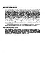
7200VXR Multiservice Interchange • Built-in TDM buses and switching capabilities integrated into the midplane • Each PA slot has two full-duplex 8.192-Mbps TDM streams, and each stream has 128 DS0 channels (128 x 64 Kbps = 8.192 Mbps) • Switching among all 12 streams at DS0 level done by Multiservice Interchange (MIX) on the midplane, no NPE processing involved • TDM capabilities available with all NPE models 1108 0987_05F9_c3
17
© 1999, Cisco Systems, Inc.
Multiservice Interchange Network Processing Engine
Multiservice Interchange (MIX)
PCI
Cisco 7200VXR
MIX Interconnects PCI
PCI
100BaseT
• Multiservice Interchange (MIX) integrated into 7200 VXR Switches DS0 time slots between up to 12 MIX interconnects Based on time division multiplexing (TDM) technology
• Two bi-directional 8.192Mbps MIX interconnects to each port adapter slot (128 DS0 channels per stream) 1108 0987_05F9_c3
© 1999, Cisco Systems, Inc.
Copyright © 1998, Cisco Systems, Inc. All rights reserved. Printed in USA. Presentation_ID.scr
18
9
Cisco 7200 Components • • • • • • • 1108 0987_05F9_c3
Chassis Power supply NPE Memory Software I/O controller Port adapters 19
© 1999, Cisco Systems, Inc.
Cisco 7200 Chassis • Cisco 7206 and 7206VXR—six slots • Cisco 7204 and 7204VXR—four slots • Cisco 7202—two slots • Each slot takes a port adapter • Same port adapters are used on all Cisco 7xxx routers (a few PAs are not supported on all models) 1108 0987_05F9_c3
© 1999, Cisco Systems, Inc.
Copyright © 1998, Cisco Systems, Inc. All rights reserved. Printed in USA. Presentation_ID.scr
20
10
Cisco 7200 Power Supply
• Single AC • Single DC • Dual AC (load-shared redundant) • Dual DC (load-shared redundant) • Not AC and DC on same chassis 1108 0987_05F9_c3
21
© 1999, Cisco Systems, Inc.
Cisco 7200 NPE
Model
Processor
CPU Clock Rate
NPE100
RISC 4700
150 MHz
None
NPE150
RISC 4700
150 MHz
1 MB SRAM
NPE200
RISC 5000
200 MHz
4 MB SRAM
NPE300
RISC 7000
262.5 MHz
32 MB SDRAM
1108 0987_05F9_c3
© 1999, Cisco Systems, Inc.
Copyright © 1998, Cisco Systems, Inc. All rights reserved. Printed in USA. Presentation_ID.scr
Fast Packet Memory
22
11
7200 Chassis and NPE
Cisco 7206VXR
NPE 300/200/150/100
Cisco 7206VXR
NPE 300/200/150/100
Cisco 7206
NPE 200/150/100
Cisco 7204
NPE 200/150/100
Cisco 7202
NPE 150
1108 0987_05F9_c3
23
© 1999, Cisco Systems, Inc.
Cisco 7200 Memory • DRAM options: 32, 64, 128, 256 MB (256 MB is for NPE300 only) • Flash SIMM: 4 MB • Flash memory card: 8, 16, 20 MB • Flash disk: 40, 110 MB • Two PCMCIA slots • Default DRAM is 32 MB 1108 0987_05F9_c3
© 1999, Cisco Systems, Inc.
Copyright © 1998, Cisco Systems, Inc. All rights reserved. Printed in USA. Presentation_ID.scr
24
12
Cisco 7200 Software Feature Sets • Enterprise • Enterprise with APPN • Desktop and IBM • IP routing (11.2+) • Encryption options to above (IPSec DES, 3DES) • Firewall option to above 1108 0987_05F9_c3
25
© 1999, Cisco Systems, Inc.
Cisco 7200 Software Feature Licenses
• WAN Packet Protocols PLUS ATM, FR, SMDS, X.25, NetFlow
• Interdomain Routing/Tag Switching BGP, EGP, Tag Switching
1108 0987_05F9_c3
© 1999, Cisco Systems, Inc.
Copyright © 1998, Cisco Systems, Inc. All rights reserved. Printed in USA. Presentation_ID.scr
26
13
Cisco 7200 I/O Controller • Standard Console port Aux port Two PCMCIA slots
• Optional Embedded Fast Ethernet interface with both RJ45 and MII connector, full duplex 1108 0987_05F9_c3
27
© 1999, Cisco Systems, Inc.
Cisco 7200 Port Adapters LAN 1 Fast Ethernet (TX/FX) 2 Fast Ethernet (TX/FX) 4 and 8 Ethernet (10BaseT) 5 Ethernet (10BaseFL) 4 Token Ring (HDX/FDX) 1 FDDI (HDX and FDX) 1 100VG 1 ATM OC3 EtherSwitch (12E/2FE)
WAN 4 and 8 Serial 4 E1 G.703 1 and 2 HSSI 1 and 2 T3/E3 4 and 8 BRI 1 ATM-CES 1 ATM T3/E3
1 Multichannel T3/E3 1 Channelized T3 4 and 8 Multichannel T1/E1 2 PRI/Channelized T1/E1 1 Packet-Over-SONET 1 Channel (ESCON, Parallel)
L3 Services Encryption Compression Encr + Comp 1108 0987_05F9_c3
© 1999, Cisco Systems, Inc.
Copyright © 1998, Cisco Systems, Inc. All rights reserved. Printed in USA. Presentation_ID.scr
28
14
Cisco 7200 Port Adapters LAN One-port Fast Ethernet 100Base (TX, FX, VG) Two-port Fast Ethernet 100Base (TX, FX) Four- and eight-port Ethernet 10BaseT Five-port Ethernet 10BaseFL Fourteen-port (12E/2FE) EtherSwitch (Cisco 7200 only) • Four-port Token Ring (HDX, FDX) • One-port FDDI (HDX, FDX; SM, MM) • One-port ATM (OC3; SM, MM) • • • • •
1108 0987_05F9_c3
29
© 1999, Cisco Systems, Inc.
Cisco 7200 Port Adapters WAN • Four- and eight-port serial • Two-port serial (JT2) (Cisco 7500 only) • One- and two-port HS serial (T3, E3) • One- and two-port HSSI • One-port Packet-Over-SONET • Eight-port BRI (S/T) (Cisco 7200 only) • Four-port BRI (U) (Cisco 7200 only) 1108 0987_05F9_c3
© 1999, Cisco Systems, Inc.
Copyright © 1998, Cisco Systems, Inc. All rights reserved. Printed in USA. Presentation_ID.scr
30
15
Cisco 7200 Port Adapters WAN (Cont.) • Two-port channelized/PRI (T1, E1) • One-port channelized (T3 + 4 DSX1 breakouts) • Four- and eight-port multichannel (T1, E1, DSX1) • One-port multichannel (T3, E3) • One-port ATM CES (OC3, DS3) (Cisco 7200 only) • One-port enhanced ATM (OC3, DS3, E3; SM, MM) • One-port Channel (ESCON, parallel) (Cisco 7200 only) 1108 0987_05F9_c3
31
© 1999, Cisco Systems, Inc.
Channelized vs. Multichannel
Model
DS1 DS0 Channels Channels
PRI Support
Full DS0
Int’f Type
C T1/E1
No
Yes
Yes
Yes
DSX1
MC-T1/E1
Yes
Yes
Yes
No
T1/E1
CT3
Yes
No
No
No
T3
MC-T3/E3
Yes
Yes
Yes
No
T3/E3
1108 0987_05F9_c3
© 1999, Cisco Systems, Inc.
Copyright © 1998, Cisco Systems, Inc. All rights reserved. Printed in USA. Presentation_ID.scr
32
16
Cisco 7200 Service Adapters
• Compression (CSA) • Encryption (ESA) • Integrated (ISA)
1108 0987_05F9_c3
© 1999, Cisco Systems, Inc.
33
Cisco 7200VXR and Port Adapters
• Following port adapters are not supported in Cisco 7200VXR: PA-F-xx, PA-F/FD-xx, PA-4R, PA-4R-FDX, PA-CT3/4T1, PA-2CT1/PRI, PA-2CE1/PRI, SA-COMP
• Following port adapters require specific minimum hardware revision levels: PA-4E, PA-8E, PA-5EFL, PA-H, PA-2H, PA-A3-xx, PA-8T-232, PA-8T-V35, PA-8T-X21 (Upgrade program available)
• See www.cisco.com/warp/public/770/fn3028_02221999.html for more details
1108 0987_05F9_c3
© 1999, Cisco Systems, Inc.
Copyright © 1998, Cisco Systems, Inc. All rights reserved. Printed in USA. Presentation_ID.scr
34
17
Cisco 7200 PA Slot Numbering
Slot 5
Slot 6
Slot 3
Slot 4
Slot 1
Slot 2
Slot 0 (I/O FE)
1108 0987_05F9_c3
© 1999, Cisco Systems, Inc.
35
Cisco 7200 PA Classification • Low-BW PAs: All T1’s, all E1’s, PRI, BRI, CSA, 1-port parallel channel
• Medium-BW PAs: All 10Base Ethernets, Token Ring (HDX), ESA
• High-BW PAs: Those not listed above 1108 0987_05F9_c3
© 1999, Cisco Systems, Inc.
Copyright © 1998, Cisco Systems, Inc. All rights reserved. Printed in USA. Presentation_ID.scr
36
18
Cisco 7200 PA Configuration Guidelines • For NPE150 and NPE200 Three or fewer high BW PAs Five or fewer high and medium BW PAs
• For NPE100: Two or fewer high BW PAs Four or fewer high and medium BW PAs 1108 0987_05F9_c3
© 1999, Cisco Systems, Inc.
37
Cisco 7200 PA Configuration Guidelines • I/O FE counted as one high BW PA • All PAs counted regardless of configuration status • Only one ATM CES PA supported per chassis (this is a double-wide PA and it uses PCI Bus 2) • EtherSwitch PA is double-wide and automatically picks the less loaded (BW) PCI Bus at boot time 1108 0987_05F9_c3
© 1999, Cisco Systems, Inc.
Copyright © 1998, Cisco Systems, Inc. All rights reserved. Printed in USA. Presentation_ID.scr
38
19
NPE300 Port Adapter Configurations • Use BW points (~aggregate interface BW) for each PA: 300: PA-xx-OC3, PA-12E/2FE, PA-2FEISL
90: All single-DS3/E3 PA’s (serial, MC, ATM)
200: PA-FE, PA-2H
80: PA-8E
180: PA-2T3, PA-2E3
60: PA-4R, CSA, ESA
120: PA-4R-FDX/DTR
50: PA-5E
100: PA-1H, PA-1C-E4
40: PA-4E 0: All low-BW PA’s
• Each PCI bus can support 600 BW points • Don’t forget I/O FE on bus 1 1108 0987_05F9_c3
© 1999, Cisco Systems, Inc.
39
Cisco 7200 Bus Balancing • PA load should be balanced between two PCI buses to optimize performance • Configure PAs as follows Sort PAs in descending order of bandwidth Fill in slot 2, slot 1, slot 4, slot 3, slot 6, slot 5 Adjust for better balancing as appropriate
• I/O FE uses Bus 1 1108 0987_05F9_c3
© 1999, Cisco Systems, Inc.
Copyright © 1998, Cisco Systems, Inc. All rights reserved. Printed in USA. Presentation_ID.scr
40
20
Cisco 7200 NPE200/150 Configuration Examples Serial
Serial
Ethernet
Ethernet
HSSI** HSSI
ATM (OC3)* (OC3) *
Slot 0 (I/O FE* FE*)
1108 0987_05F9_c3
41
© 1999, Cisco Systems, Inc.
Cisco 7200 NPE200/150 Configuration Examples (Cont.) Ethernet
Serial
FDDI** FDDI
Serial
ATM CES* CES* Slot 0 (No I/O FE)
1108 0987_05F9_c3
© 1999, Cisco Systems, Inc.
Copyright © 1998, Cisco Systems, Inc. All rights reserved. Printed in USA. Presentation_ID.scr
42
21
Cisco 7200 NPE 300 Configuration Examples 8E
MC-8T
MC-T3
FE
2T3
A3-OC3 I/O FE
Bus1 = 200 + 180 + 90 + 80 = 550 Bus2 = 300 + 200 + 0 = 500
1108 0987_05F9_c3
43
© 1999, Cisco Systems, Inc.
Cisco 7200 NPE300 Configuration Examples (Cont.) FE
2H
POS
A3-OC3 A2-T3
No I/O FE Bus1 = 300 + 200 = 500 Bus2 = 90 + 300 + 200 = 590
1108 0987_05F9_c3
© 1999, Cisco Systems, Inc.
Copyright © 1998, Cisco Systems, Inc. All rights reserved. Printed in USA. Presentation_ID.scr
44
22
Cisco 7200 NPE300 Configuration Examples (Cont.) FE
T3
POS
FE
EtherSwitch No I/O FE Bus1 = 300 + 200 = 500 Bus2 = 300 + 200 + 90 = 590
1108 0987_05F9_c3
45
© 1999, Cisco Systems, Inc.
Cisco 7100
1108 0987_05F9_c3
© 1999, Cisco Systems, Inc.
Copyright © 1998, Cisco Systems, Inc. All rights reserved. Printed in USA. Presentation_ID.scr
46
23
Cisco 7100 Internal Architecture CPU
System Controller
SDRAM (64 MB)
System Controller
SDRAM (64-256 MB)
Con/Aux NVRAM Flash ROM
Cache SRAM
FE
(Cisco 7120 Only)
PA
PB
PB
SM
PB
PB
WAN-1
PB
PB
PCI 0 1108 0987_05F9_c3
I/O Bus
PA
(Cisco 7140 Only)
FE
(10/100 TX)
PCMCIA-1 PCMCIA-2
WAN-2 (Cisco 7140 Only)
PCI 1
47
© 1999, Cisco Systems, Inc.
Cisco 7100 Factory Options
Model
Power Supply
Cisco 7120
Single AC
Cisco 7140
Dual AC
Fixed WAN Interface Options
Fixed LAN
PA Slot
SM Slot
1-Port ATM-OC3 Dual 1-Port ATM T3 or E3 10/100 1-Port T3 or E3 FE 4-Port T1 or E1
1
1
2-Port ATM-OC3 Dual 2-Port ATM T3 or E3 10/100 2-Port T3 or E3 FE
1
1
PA slot supports one port adapter SM slot supports one service module (ISM) 1108 0987_05F9_c3
© 1999, Cisco Systems, Inc.
Copyright © 1998, Cisco Systems, Inc. All rights reserved. Printed in USA. Presentation_ID.scr
48
24
Cisco 7100 Memory • SDRAM options: 64, 128, 192, 256 MB • Flash SIMM: 8 MB • Flash memory card: 8, 16, 20 MB • Flash disk: 40, 110 MB • Two PCMCIA slots • Default SDRAM is 64 MB 1108 0987_05F9_c3
© 1999, Cisco Systems, Inc.
49
Cisco 7100 PA Support • All Cisco 7200 PA’s except: Channelized PA’s Multichannel PA’s Packet-Over SONET PA FDDI PA’s IBM Channel PA Dual-wide PA’s (PA-A2 and PA-12E/2FE) CSA, ESA, PA-100VG 1108 0987_05F9_c3
© 1999, Cisco Systems, Inc.
Copyright © 1998, Cisco Systems, Inc. All rights reserved. Printed in USA. Presentation_ID.scr
50
25
Cisco 7100 Software Feature Sets
• Enterprise • IP • Encryption options to above (IPSec DES, 3DES) • Firewall option to above 1108 0987_05F9_c3
51
© 1999, Cisco Systems, Inc.
Cisco 7100 Bus Balancing (Slot 0) (Cisco 7120 PA Only) (Slot 3) SM
PB
PB
PA
(Cisco 7140 Only)
(Slot 4) PB
PB
PB
PB
FE
FE
(10/100 TX)
PCMCIA-1 PCMCIA-2
(Slot 5) WAN-1 (Slot 1)
PCI 0
PCI 1
WAN-2 (Cisco 7140 Only) (Slot 2)
• In Cisco 7140, use WAN-1 as primary
1108 0987_05F9_c3
© 1999, Cisco Systems, Inc.
Copyright © 1998, Cisco Systems, Inc. All rights reserved. Printed in USA. Presentation_ID.scr
52
26
Cisco 7500
• Architecture • Components and Options • Distributed switching • System bus bandwidth • VIP2 and port adapters 1108 0987_05F9_c3
53
© 1999, Cisco Systems, Inc.
Cisco 7500 System Architecture Route Switch Processors Si Si
IP
Si Si
VIP IP
1108 0987_05F9_c3
VIP
© 1999, Cisco Systems, Inc.
Copyright © 1998, Cisco Systems, Inc. All rights reserved. Printed in USA. Presentation_ID.scr
VIP
54
27
Common Port Adapters
Route Switch Processors Si
Network Processing Engine
Si
Si
PCI PCI
IP
FE
VIP IP
1108 0987_05F9_c3
PCI
VIP
VIP
Port Adapters
© 1999, Cisco Systems, Inc.
55
Cisco 7500 Components • Chassis and power supply • CPU • Memory • Software • VIP2 • Port adapters • Interface processors 1108 0987_05F9_c3
© 1999, Cisco Systems, Inc.
Copyright © 1998, Cisco Systems, Inc. All rights reserved. Printed in USA. Presentation_ID.scr
56
28
Cisco 7500 Chassis
1108 0987_05F9_c3
Model
RSP
CyBus
Power Supply
# of xIP Slots
Cisco 7505
Single
Single
Single
4
Cisco 7507
Single/ Dual
Dual
Single/ Dual
5
Cisco 7513
Single/ Dual
Dual
Single/ Dual
11
Cisco 7576
Single(x2)
Dual (x2)
Single/ Dual
11
57
© 1999, Cisco Systems, Inc.
1108 0987_05F9_c3
Cybus 3 Cybus 2
4 5 6
Cybus 3 Cybus 2
1 2 3
Cybus 2
Cybus 1
0
RSP A RSP B
Cybus 0 Cybus 1 Cybus 0
Cybus 0
Cybus 0
Cisco 7576 Chassis Slots
7 8 9 10 11 12
© 1999, Cisco Systems, Inc.
Copyright © 1998, Cisco Systems, Inc. All rights reserved. Printed in USA. Presentation_ID.scr
58
29
Cisco 7500 CPU
• RSP1—for Cisco 7505 only • RSP2—for Cisco 7507 and 7513 • RSP4—for Cisco 7505, 7507, 7513, and 7576
1108 0987_05F9_c3
© 1999, Cisco Systems, Inc.
59
Cisco 7500 Memory (Per RSP) • DRAM options: 32, 64, 128, 256 MB (for RSP4 only) • Flash SIMM: 8 MB • Flash memory card: 8, 16, 20 MB • Flash disk: 40, 110 MB • Two PCMCIA slots • Default DRAM is 32 MB 1108 0987_05F9_c3
© 1999, Cisco Systems, Inc.
Copyright © 1998, Cisco Systems, Inc. All rights reserved. Printed in USA. Presentation_ID.scr
60
30
Cisco 7500 Software Feature Sets
• Enterprise • Enterprise with APPN • Desktop and IBM • IP routing • Encryption options to above (IPSec DES, 3DES) 1108 0987_05F9_c3
61
© 1999, Cisco Systems, Inc.
Cisco 7500 Software Feature Licenses
• WAN Packet Protocols PLUS ATM, FR, SMDS, X.25, NetFlow
• Interdomain Routing/Tag Switching BGP, EGP, Tag Switching
1108 0987_05F9_c3
© 1999, Cisco Systems, Inc.
Copyright © 1998, Cisco Systems, Inc. All rights reserved. Printed in USA. Presentation_ID.scr
62
31
Cisco 7500 Versatile Interface Processor
Route Switch Processors Switch Processor Si
CY B U S
Si
Packet Memory
IP
Port Adapter
P C I
Port Adapter
VIP IP
1108 0987_05F9_c3
P C I
VIP
VIP
63
© 1999, Cisco Systems, Inc.
VIP2 Options Switch Processor CY B U S Packet Memory
P C I
Port Adapter
P C I
Port Adapter
Mother Board Options
1108 0987_05F9_c3
Product
SRAM
DRAM
Dist Sw Dist Svcs
VIP2-15
1 MB
8 MB
No
No
VIP2-40
2 MB
32 MB
Yes
Yes
VIP2-50
4/8 MB
32–128 MB
Yes
Yes
© 1999, Cisco Systems, Inc.
Copyright © 1998, Cisco Systems, Inc. All rights reserved. Printed in USA. Presentation_ID.scr
64
32
Cisco 7500 Port Adapters • Fast Ethernet, Ethernet • FDDI, Token Ring • POS, ATM • Serial • Channelized, multichannel • PRI • CSA, ESA, ISA 1108 0987_05F9_c3
© 1999, Cisco Systems, Inc.
65
Cisco 7500 Interface Processors
• Early IPs: EIP, TRIP, FIP, HIP, FSIP, AIP, MIP, CIP2, FEIP
• New IPs (VIP2-based, fixedconfiguration): POSIP, CT3IP, FEIP2, GE 1108 0987_05F9_c3
© 1999, Cisco Systems, Inc.
Copyright © 1998, Cisco Systems, Inc. All rights reserved. Printed in USA. Presentation_ID.scr
66
33
VIP2 Distributed Switching Route Switch Processors Master RSP
Slave RSP
Si Si
Si Si
Pkt.Mem
IP
Pkt.Mem
VIP IP
1108 0987_05F9_c3
VIP
VIP
© 1999, Cisco Systems, Inc.
67
Cisco 7500 System Bus Bandwidth • Cisco 7507, Cisco 7513, and “half-7576” Dual CyBus 1066 Mbps each, total 2 Gbps
• Cisco 7505 Single CyBus at 1066 Mbps
• RSP7000 (and Cisco 7000/7010) Single CxBus at 533 Mbps 1108 0987_05F9_c3
© 1999, Cisco Systems, Inc.
Copyright © 1998, Cisco Systems, Inc. All rights reserved. Printed in USA. Presentation_ID.scr
68
34
Cisco 7500 IP/VIP Classification
• Cy mode All VIPs and VIP-based IPs, CIP, FEIP Use CyBus at 1066 Mbps
• Cx mode All other IPs Use CyBus at 533 Mbps 1108 0987_05F9_c3
© 1999, Cisco Systems, Inc.
69
Cy Mode and Cx Mode on CyBus Cx Mode One bit per clock cycle, bus bandwidth is 533 Mbps
Cy Mode Two bits per clock cycle, same basic clock rate as Cx, total bus bandwidth becomes 1066 Mbps (Two “Cy clock cycles” = One “Cx clock cycle”)
1108 0987_05F9_c3
© 1999, Cisco Systems, Inc.
Copyright © 1998, Cisco Systems, Inc. All rights reserved. Printed in USA. Presentation_ID.scr
70
35
Cy Mode and Cx Mode Bandwidth Consumption
• CyBus bandwidth is 1066 Mbps in Cy mode • Cx mode uses two “Cy clock cycles” per bit • Cx card takes up twice as much CyBus capacity as Cy card 1108 0987_05F9_c3
© 1999, Cisco Systems, Inc.
71
Cisco 7500 Bus Bandwidth • Each VIP/IP requires bandwidth from the bus • Aggregate bandwidth requirement should not exceed bus capacity Over-subscription Bus overhead Interface utilization
• Two CyBuses are independent • Balance between the two buses 1108 0987_05F9_c3
© 1999, Cisco Systems, Inc.
Copyright © 1998, Cisco Systems, Inc. All rights reserved. Printed in USA. Presentation_ID.scr
72
36
Cisco 7500 Bus Bandwidth Calculation ( IP_BW X %IP_Util )
Bus_BW X %Bus_Util
gives ( IP_BW X %IP_Util ) %Bus_Util
Bus_BW
• Define the fraction term as: Interface Bus Bandwidth Factor (IBBF)
• Pre-calculate IBBF for each interface 1108 0987_05F9_c3
© 1999, Cisco Systems, Inc.
73
Cisco 7500 IBBF Assumptions • 75% utilization for all channelized interfaces (MIP, CIP, CT3, CT1, CE1) • 75% utilization for all ATM interfaces • 100% utilization for all other interfaces • 80% utilization on system buses • These are very conservative assumptions 1108 0987_05F9_c3
© 1999, Cisco Systems, Inc.
Copyright © 1998, Cisco Systems, Inc. All rights reserved. Printed in USA. Presentation_ID.scr
74
37
Cisco 7500 IBBF Examples • EIP6 Total IP BW = 60 Mbps, %IP_Util = 100% IBBF-Cx = (60 x 100)/(80) = 75 Since EIP is Cx, IBBF-Cy = 150
• CT3IP Total IP BW = 45 x 2 = 90 Mbps, %IP_Util = 75% IBBF-Cx = (90 x 75)/(80) = 84 Since CT3IP is Cy, IBBF-Cy = 84 1108 0987_05F9_c3
75
© 1999, Cisco Systems, Inc.
IBBF Table—Part 1 IP
1108 0987_05F9_c3
Cx or Cy
IBBF-Cx
IBBF-Cy
EIP-2
Cx
25
50
EIP-4
Cx
50
100
EIP-6
Cx
75
150
TRIP-2
Cx
40
80
TRIP-4
Cx
80
160
FIP
Cx
125
250
© 1999, Cisco Systems, Inc.
Copyright © 1998, Cisco Systems, Inc. All rights reserved. Printed in USA. Presentation_ID.scr
76
38
IBBF Table—Part 2 IP
1108 0987_05F9_c3
Cx or Cy
IBBF-Cx
IBBF-Cy
HIP
Cx
113
226
FSIP-4
Cx
20
40
FSIP-8
Cx
40
80
AIP-DS3
Cx
84
168
AIP-TAXI
Cx
188
376
AIP-OC3
Cx
291
582
MIP-1
Cx
4
8
MIP-2
Cx
8
16
77
© 1999, Cisco Systems, Inc.
IBBF Table—Part 3 IP
1108 0987_05F9_c3
Cx or Cy
IBBF-Cx
IBBF-Cy
FEIP-1
Cy
250
250
FEIP-2
Cy
291
291
CIP-1
Cy
113
113
CIP-2
Cy
150
150
© 1999, Cisco Systems, Inc.
Copyright © 1998, Cisco Systems, Inc. All rights reserved. Printed in USA. Presentation_ID.scr
78
39
IBBF Table—Part 4 IP
1108 0987_05F9_c3
Cx or Cy
IBBF-Cx
IBBF-Cy
POSIP
Cy
388
388
CT3IP
Cy
84
84
FEIP2
Cy
500
500
FEIP
Cy
500
500
79
© 1999, Cisco Systems, Inc.
IBBF Table—Part 5 PA
Cx or Cy
IBBF-Cx
IBBF-Cy
PA-FE (FDX)
Cy
250
250
PA-FE (HDX)
Cy
125
125
PA-100VG
Cy
125
125
PA-FDDI
Cy
125
125
PA-FDDI/FD
Cy
250
250
PA-ATM (OC3)
Cy
291
291
PA-ATM (DS3)
Cy
84
84
VIP2-Limit
Cy
500
500
Note: VIP2 card bandwidth cap at 400, which gives IBBF cap at 500 1108 0987_05F9_c3
© 1999, Cisco Systems, Inc.
Copyright © 1998, Cisco Systems, Inc. All rights reserved. Printed in USA. Presentation_ID.scr
80
40
IBBF Table—Part 6 PA
Cx or Cy
IBBF-Cx
IBBF-Cy
PA-8E
Cy
100
100
PA-4E
Cy
50
50
PA-5EFL
Cy
63
63
PA-4R
Cy
80
80
PA-4R/FD
Cy
160
160
VIP2-Limit
Cy
500
500
Note: VIP2 card bandwidth cap at 400, which gives IBBF cap at 500 1108 0987_05F9_c3
81
© 1999, Cisco Systems, Inc.
IBBF Table—Part 7 PA
Cx or Cy
IBBF-Cx
IBBF-Cy
PA-2H, 2T3
Cy
225
225
PA-H, T3
Cy
113
113
PA-2E3
Cy
170
170
PA-E3
Cy
85
85
PA-MC-T3
Cy
84
84
PA-MC-E3
Cy
64
64
PA-2JT2
Cy
32
32
VIP2-Limit
Cy
500
500
Note: VIP2 card bandwidth cap at 400, which gives IBBF cap at 500 1108 0987_05F9_c3
© 1999, Cisco Systems, Inc.
Copyright © 1998, Cisco Systems, Inc. All rights reserved. Printed in USA. Presentation_ID.scr
82
41
IBBF Table—Part 8 PA
Cx or Cy
IBBF-Cx
IBBF-Cy
PA-8T
Cy
40
40
PA-4T
Cy
20
20
PA-MC-8T1
Cy
23
23
PA-MC-4T1
Cy
12
12
PA-MC-8DSX1
Cy
23
23
PA-MC-8E1
Cy
30
30
PA-2CT1
Cy
6
6
PA-2CE1
Cy
8
8
CSA
Cy
IBBF x 2
IBBF x 2
VIP2-Limit
Cy
500
500
Note: VIP2 card bandwidth cap at 400, which gives IBBF cap at 500 1108 0987_05F9_c3
83
© 1999, Cisco Systems, Inc.
How To Use IBBF • Use IBBF-Cy values for CyBus systems (75xx), and IBBF-Cx values for CxBus systems (RSP7000 and 70x0) • To verify a given configuration, sum up corresponding IBBFs for each bus, and check that it is within limit (1066 for CyBus and 533 for CxBus) plus oversubscription allowance • Balance between two buses where appropriate 1108 0987_05F9_c3
© 1999, Cisco Systems, Inc.
Copyright © 1998, Cisco Systems, Inc. All rights reserved. Printed in USA. Presentation_ID.scr
84
42
Cisco 7500 IBBF Considerations • Conservative assumptions (i.e., worstcase scenarios) are used as a start • Real-world networks are not 100% utilized (queuing delay) • Bi-directional links are usually asymmetrically loaded • Backup links • Full-duplex/half-duplex • Over-subscription is possible 1108 0987_05F9_c3
© 1999, Cisco Systems, Inc.
85
Cisco 7500 Bus Over-Subscription • IBBF approach assumes worst case • Real-world traffic volume is limited by true utilization, asymmetric flow, etc. • Favorable factors for over-subscription Low utilization Full-duplex serial links Large number of interfaces
• No fixed rules for over-subscription 1108 0987_05F9_c3
© 1999, Cisco Systems, Inc.
Copyright © 1998, Cisco Systems, Inc. All rights reserved. Printed in USA. Presentation_ID.scr
86
43
Cisco 7500 VIP2 Block Diagram VIP2 Capacity Areas:
CyBus CyBus Interface
CPU and DRAM
Pkt Memory Controller
SRAM
PCI Bridge
PCI Bridge
Port Adapter
Port Adapter
Kpps
Packet Bus Primary PCI Bus
SRAM Bandwidth
Secondary PCI Buses
1108 0987_05F9_c3
87
© 1999, Cisco Systems, Inc.
VIP2 Configuration SRAM Capacity Consideration • Particles and descriptors allocated out of SRAM for each PA • Number of particles varies with PA • Particle size depends on PA-pair and VIP2 model (amount of SRAM) • A hard limit 1108 0987_05F9_c3
© 1999, Cisco Systems, Inc.
Copyright © 1998, Cisco Systems, Inc. All rights reserved. Printed in USA. Presentation_ID.scr
88
44
VIP2 Configuration PCI Bandwidth Consideration • Electrical bandwidth is 800 Mbps, but data throughput is about 400 Mbps • Overhead due to bus arbitration and non-data traffic, varies by PA • Effective data throughput on PCI bus determines PA-pair support • Not as hard a limit as SRAM capacity 1108 0987_05F9_c3
89
© 1999, Cisco Systems, Inc.
VIP2 Configuration Switching Capacity Consideration • VIP2-40 (VIP2-50) distributed switching at 65 Kpps (100 Kpps) • VIP2 forwarding to RSP at 135 Kpps • Forwarding puts load on RSP • Estimate Kpps load from each PA • A softer limit than SRAM and PCI BW 1108 0987_05F9_c3
© 1999, Cisco Systems, Inc.
Copyright © 1998, Cisco Systems, Inc. All rights reserved. Printed in USA. Presentation_ID.scr
90
45
VIP2 Configuration Current Guidelines • ATM OC3 PA requires a dedicated VIP2 (except PA-A3-OC3 on VIP2-50) • PA-A3 not supported on VIP2-15 • CSA and ESA require VIP2-40 or VIP2-50 • 4R paired with 8T require VIP2-40 or VIP2-50 • VIP2-50 supports all existing PAs except 100VG and TR 1108 0987_05F9_c3
91
© 1999, Cisco Systems, Inc.
Software Configuration
1108 0987_05F9_c3
© 1999, Cisco Systems, Inc.
Copyright © 1998, Cisco Systems, Inc. All rights reserved. Printed in USA. Presentation_ID.scr
92
46
Software Configurations
• Boot sequence • Flash memory operations • Switching modes • Interfaces and IDBs
1108 0987_05F9_c3
93
© 1999, Cisco Systems, Inc.
Boot Sequence • ROM monitor Wakes up the CPU Finds and loads “boot loader”
• Boot loader Brings up all hardware components Finds and loads or net boots system image No routing
• System image 1108 0987_05F9_c3
© 1999, Cisco Systems, Inc.
Copyright © 1998, Cisco Systems, Inc. All rights reserved. Printed in USA. Presentation_ID.scr
94
47
Basic Boot Configurations boot bootldr bootflash:rsp-boot-mz.111-25.CC boot system flash slot0:rsp-jv-mz.111-25.CC
• Boot loader image should be current with respect to hardware components • Good practice: use the same release of boot loader image as system image 1108 0987_05F9_c3
© 1999, Cisco Systems, Inc.
95
Flash Memory Operations • cd device: Changes current device Flash Card: device = slot0, slot1 Flash Disk: device = disk0, disk1
• pwd Shows current working device
• dir [/all | /deleted] [device:] Shows device contents 1108 0987_05F9_c3
© 1999, Cisco Systems, Inc.
Copyright © 1998, Cisco Systems, Inc. All rights reserved. Printed in USA. Presentation_ID.scr
96
48
More Flash Memory Operations • delete [device:]filename Removes file from directory File still in flash memory (shown by dir/deleted)
• undelete [device:] index (flash card only) Returns file (specified by index#) to directory Will not work when there are filename conflicts
• squeeze [device:] (flash card only) Permanently removes file and frees up space 1108 0987_05F9_c3
© 1999, Cisco Systems, Inc.
97
Cisco 7200 Switching Modes
• Process switching Packets copied to system memory Handled at process level
• All other switching Packets switched in fast packet memory Handled at interrupt level 1108 0987_05F9_c3
© 1999, Cisco Systems, Inc.
Copyright © 1998, Cisco Systems, Inc. All rights reserved. Printed in USA. Presentation_ID.scr
98
49
Cisco 7200 Switching Modes • Process Switching—process level • Fast Switching—uses fast switching cache • Optimum Switching—improved search algorithm and data caching • NetFlow Switching—NetFlow cache identifies data flows and maintains flow statistics • Cisco Express Forwarding (CEF)—forwarding information based on routing table instead of cache built from demand • Tag Switching—based on tags and TDP 1108 0987_05F9_c3
© 1999, Cisco Systems, Inc.
99
Cisco 7500 Switching Modes
• RSP-based switching—Process, Fast, Optimum, NetFlow, CEF, Tag • VIP distributed switching—Optimum, NetFlow, CEF, Tag
1108 0987_05F9_c3
© 1999, Cisco Systems, Inc.
Copyright © 1998, Cisco Systems, Inc. All rights reserved. Printed in USA. Presentation_ID.scr
100
50
Switching Configuration Commands—Fast/Opt/Flow
• ip route-cache • ip route-cache [optimum | flow] • ip route-cache distributed • These are interface config commands
1108 0987_05F9_c3
© 1999, Cisco Systems, Inc.
101
Switching Configuration Commands—CEF • CEF switching is configured with global configuration commands ip cef switching ip cef distributed switching (Cisco 7500 only)
• CEF global command will enable CEF on all supported interfaces 1108 0987_05F9_c3
© 1999, Cisco Systems, Inc.
Copyright © 1998, Cisco Systems, Inc. All rights reserved. Printed in USA. Presentation_ID.scr
102
51
Switching Configuration Commands—Tag • Tag Switching requires CEF • Tag Switching global configuration command tag-switching advertise-tags
• Tag Switching interface configuration command tag-switching ip 1108 0987_05F9_c3
© 1999, Cisco Systems, Inc.
103
Which Switching Mode Is in Effect?
• Inbound packets entering the same interface can be switched by different modes • Switching mode of a packet is determined by switching config at both its input and its output interface 1108 0987_05F9_c3
© 1999, Cisco Systems, Inc.
Copyright © 1998, Cisco Systems, Inc. All rights reserved. Printed in USA. Presentation_ID.scr
104
52
Switching Configuration Matrix Input Interface
Output Interface
Sw Mode
ip route-cache cef
- any -
cef
- any except CEF -
no ip route-cache
process
no ip route-cache
ip route-cache
fast
no ip route-cache
ip route-cache opt/flow/cef
fast
ip route-cache
ip route-cache
fast
ip route-cache
ip route-cache opt/flow/cef
fast
ip route-cache opt/flow
ip route-cache
opt/flow
ip route-cache opt/flow
ip route-cache opt/flow/cef
opt/flow
1108 0987_05F9_c3
105
© 1999, Cisco Systems, Inc.
Interfaces and IDB
• Interface descriptor block (IDB) Software data structure Stores configuration and status of all interfaces
• Software IDB • Hardware IDB 1108 0987_05F9_c3
© 1999, Cisco Systems, Inc.
Copyright © 1998, Cisco Systems, Inc. All rights reserved. Printed in USA. Presentation_ID.scr
106
53
IDB Allocation • Non-channelized cards One H/W IDB and one S/W IDB per physical port • Channelized cards One H/W IDB and one S/W IDB per channel • Subinterfaces One S/W IDB per subinterface • Example: FR interface with 10 subinterfaces 11 IDBs 1108 0987_05F9_c3
© 1999, Cisco Systems, Inc.
107
Interface Scalability in Cisco 7xxx • Aggregation scalability has been significantly enhanced in 12.0: 750+ interfaces 1200+ subinterfaces (FR)
• 300 S/W IDBs per chassis supported in 11.1 and 11.2
1108 0987_05F9_c3
• All physical interfaces take up IDBs, regardless of configuration and status © 1999, Cisco Systems, Inc.
Copyright © 1998, Cisco Systems, Inc. All rights reserved. Printed in USA. Presentation_ID.scr
108
54
Subinterfaces and IDB • Subinterfaces take up IDBs • Subinterfaces add routing overhead • For ATM and FR: An interface or subinterface can terminate multiple PVCs Usually there is no need to configure a subinterface for each PVC A PVC does not necessarily use up an IDB 1108 0987_05F9_c3
© 1999, Cisco Systems, Inc.
109
Summary— Hardware Configuration • Cisco 7100 “Fixed” configuration and PA support • Cisco 7200 Number of high-BW and medium-BW PAs PCI bus loading and balancing • Cisco 7500 System bus loading CyBus balancing in dual-bus systems PA configuration (pairing) on VIP2 cards 1108 0987_05F9_c3
© 1999, Cisco Systems, Inc.
Copyright © 1998, Cisco Systems, Inc. All rights reserved. Printed in USA. Presentation_ID.scr
110
55
Summary— Software Configuration • Commands and features specific to Cisco 7xxx platform operations • Networkers sessions available on topics such as EIGRP, OSPF, BGP, security, VPN, QoS, and others (Session# 3xx) • Network design clinics 1108 0987_05F9_c3
111
© 1999, Cisco Systems, Inc.
Please Complete Your Evaluation Form Session 1108
1108 0987_05F9_c3
© 1999, Cisco Systems, Inc.
Copyright © 1998, Cisco Systems, Inc. All rights reserved. Printed in USA. Presentation_ID.scr
112
56
1108 0987_05F9_c3
© 1999, Cisco Systems, Inc.
Copyright © 1998, Cisco Systems, Inc. All rights reserved. Printed in USA. Presentation_ID.scr
113
57