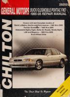
Chilton's General Motors Buick, Oldsmobile, Pontiac FWD 1985-05 Repair Manual 156392627X, 9781563926273
“1 v. (various pagings) : 28 cm Rev. ed. of: Chilton's General Motors Bonneville/Eighty Eight/Le Sabre / editor, C
145 6 35MB
English Pages 356 Year 2006
Recommend Papers
![Haynes Buick, Oldsmobile & Pontiac FWD Models 1985 thru 2002 Automotive Repair Manual [19020]
156392479X, 9781563924798](https://ebin.pub/img/200x200/haynes-buick-oldsmobile-amp-pontiac-fwd-models-1985-thru-2002-automotive-repair-manual-19020-156392479x-9781563924798.jpg)
![Haynes Buick, Oldsmobile & Pontiac Full-Size FWD Models 1985 thru 1995 Automotive Repair Manual [8595]
1563921677, 9781563921674](https://ebin.pub/img/200x200/haynes-buick-oldsmobile-amp-pontiac-full-size-fwd-models-1985-thru-1995-automotive-repair-manual-8595-1563921677-9781563921674.jpg)
![Haynes Buick, Oldsmobile, Pontiac Full-Size Models 1970 thru 1990 Automotive Repair Manual [1551]
1850106630, 9781850106630](https://ebin.pub/img/200x200/haynes-buick-oldsmobile-pontiac-full-size-models-1970-thru-1990-automotive-repair-manual-1551-1850106630-9781850106630.jpg)
![Haynes General Motors Chevrolet Cavalier & Pontiac Sunfire Automotive Repair Manual [38016]
156392403X, 9781563924033](https://ebin.pub/img/200x200/haynes-general-motors-chevrolet-cavalier-amp-pontiac-sunfire-automotive-repair-manual-38016-156392403x-9781563924033.jpg)

![Haynes Buick, Oldsmobile & Pontiac Full-Size Models 1985 thru 2000 Automotive Repair Manual [19020]
1563923874, 9781563923876](https://ebin.pub/img/200x200/haynes-buick-oldsmobile-amp-pontiac-full-size-models-1985-thru-2000-automotive-repair-manual-19020-1563923874-9781563923876.jpg)
![Haynes Buick, Olds & Pontiac Full-Size FWD Models 1985 thru 1990 Automotive Repair Manual [1627]
1850106274, 9781850106272](https://ebin.pub/img/200x200/haynes-buick-olds-amp-pontiac-full-size-fwd-models-1985-thru-1990-automotive-repair-manual-1627-1850106274-9781850106272.jpg)
- Author / Uploaded
- Mike Stubblefield
- Chrstime L. Sheeky
- Similar Topics
- Technique
- Transportation: Cars, motorcycles
File loading please wait...
Citation preview
§ BUICK/OLDSMOBILE/PONTIAC FID. ? 1985-05 REPAIR MANUAL‘ Covers U.S? and Canadian models of Buick LeSabre, Electra and-Park Avenue— 1985 thru 2005 Pontiac Bonneiflle — 1985 thru 2005 Oldsmobile Eighty Eight, Delta 88, Royale, Ninety Eight, LSS and Regency - 1985 thru 2002 Front Wheel Drive
{
The Ferst Step)IeR
Digitized by the Internet Archive in 2022 with funding from Kahle/Austin Foundation
https://archive.org/details/chiltonsgeneralmOO0Oshee
GENERAL MOTOR
3
iH BUICK/OLDSMOBILE/PONTIAC FWD
1985-05 REPAIR MANUAL VIDS
Covers u.s\at 1
Leal?
Ste
hk
odes
Wed
Ca dian models of
Buick LeSabre, Electra and Park Avenue - joy 1985 thru 2005 Pontiac Bonneville - 1985 thru 2005 Oldsmobile Eighty Eight, Delta 88, Royale, Ninety Eight, LLS and Regency - 1985 thru 2002 Front Wheel Drive Does not cover diesel engine and related information, supercharger information, rear-wheel drive models or V8 models
by Christine L.Sheeky, S.A.E. and Mike Stubblefield”
Pesses FAVRE Qs iia COTW
AViomotive £ Books
PUBLISHED BY HAYNES NORTH AMERICA. Inc.
AUTOMOTIVE peg Se AgSScLATION MEMBEI Manufactured in USA ©1998, 2006 Haynes North America, Inc. ISBN-13: 978-1-56392-627-3 ISBN-10: 1-56392-627-X Library of Congress Control Number: 2006934953
. MSE TPA ABCD
Haynes Publishing Group Sparkford Nr Yeovil Somerset BA22 7JJ England Haynes North America, Inc 861 Lawrence Drive Newbury Park California 91320 USA
Chilton is a registered trademark of W.G. Nichols, Inc., and has been licensed to Haynes North America, Inc.
SKOKIE PUBLIC LIBRARY
2007
Contents About this manual — 0-5 Introduction to the Buick, Oldsmobile
=e
Bees ;
= +
INTR 0 DUCTORY PAGES °
=
Anti-theft audio systems — 0-16 Jacking and towing — 0-17
~~ and wie full-size, front-wheel
Automotive chemicals and lubricants — 0-18
~. — drive models — 0-5
Conversion factors — 0-19
“Vehicle identification iufmbers- 0-6 §«Buying parts—0-7 ~ Maintenance techniques, tools and working facilities — 0-7 Booster battery (jump) starting — 0-15
Fraction/decimal/millimeter equivalents — 0-20 Safety first! — 0-21 Troubleshooting — 0-22
TUNE-UP AND ROUTINE MAINTENANCE - 1-1
ENGINES — 2A-1 GENERAL ENGINE OVERHAUL PROCEDURES - 2B-1
COOLING, HEATING AND AIR CONDITIONING SYSTEMS - 3-1
FUEL AND EXHAUST SYSTEMS -— 4-1
ENGINE ELECTRICAL SYSTEMS - 5-1
EMISSIONS AND ENGINE CONTROL SYSTEMS - 6-1
AUTOMATIC TRANSMISSION — 7-1
DRIVEAXLES - 8-1
BRAKES -— 9-1
SUSPENSION AND STEERING SYSTEMS -— 10-1
BODY- 11-1
CHASSIS ELECTRICAL SYSTEM — 12-1 WIRING DIAGRAMS -— 12-22
GLOSSARY
GLOSSARY - GL-1
— IND-1 MASTER INDEX
|
_ MASTER INDEX
—
Mechanic, author and photographer with Oldsmobile Delta 88
ACKNOWLEDGEMENTS. Wiring diagrams provided exclusively for the publisher by Valley Forge Technical Information Services. Technical writers who contributed to this project include Jon La Course, Jeff Killingsworth and Ken Freund. All rights reserved. No part of this book may be reproduced or transmitted in any form or by any means, electronic or mechanical, including photocopying, recording or by any information storage or retrieval system, without permission in writing from the copyright holder.
While every attempt is made to ensure that the information in this manual is correct, no liability can be accepted by the authors or publishers for loss, damage or injury caused by any errors in, or omissions from, the information given.
06-352
INTRODUCTION a
ae
Rg
SEA
SIT DS
II
PES
BLE BEI IS SEE SESS SPSE BOTT TR
DiS
SSE
PYF EY OT
8
0-5
RI
About this manual
ITS PURPOSE The purpose of this manual is to help you get the best value from your vehicle. It can do so in several ways. It can help you decide what work must be done, even if you choose to have it done by a dealer service department or a repair shop; it provides information and procedures for routine maintenance and servicing; and it offers diagnostic and repair procedures to follow when trouble occurs. We hope you use the manual to tackle the work yourself. For many simpler jobs, doing it yourself may be quicker than arranging an appointment to get the vehicle into a shop and making the trips to leave it and pick it up. More importantly, a lot of money can be saved by avoiding the expense the shop must pass on to you to cover its labor and overhead costs. An added benefit is the sense of satisfaction and accomplishment that you feel after doing the job yourself.
USING THE MANUAL The manual is divided into Chapters. Each Chapter is divided into
numbered Sections. Each Section consists of consecutively numbered paragraphs. At the beginning of each numbered Section you will be referred to any illustrations which apply to the procedures in that Section. The reference numbers used in illustration captions pinpoint the pertinent Section and the Step within that Section. That is, illustration 3.2 means the illustration refers to Section 3 and Step (or paragraph) 2 within that Section. Procedures, once described in the text, are not normally repeated. When it's necessary to.refer to another Chapter, the reference will be given as Chapter and Section number. Cross references given without use of the word “Chapter” apply to Sections and/or paragraphs in the same Chapter. For example, “see Section 8” means in the same Chapter. References to the left or right side of the vehicle assume you are sitting in the driver's seat, facing forward. Even though we have prepared this manual with extreme care, neither the publisher nor the author can accept responsibility for any errors in, or omissions from, the information given.
NOTE A Note provides information necessary to properly complete a procedure or information which will make the procedure easier to understand.
4% CAUTION
©
A Caution provides a special procedure or special steps which must be taken while completing the procedure where the Caution is found. Not heeding a Caution can result in damage to the assembly being worked on.
WARNING A Warning provides a special procedure or special steps which must be taken while completing the procedure where the Warning is found. Not heeding a Warning can result in personal injury.
Introduction to the Buick, Oldsmobile and Pontiac full-size, front-wheel drive models’ The full-size General Motors models covered by this manual are front engine/front-wheel drive “C” and “H” body vehicles only. Most are four-door sedans, although some two-door models are available. All models are powered by a transversely mounted V6 engine which drives the front wheels through an automatic transaxle and independent driveaxles.
Independent suspension, featuring coil springs and struts or shock absorbers, is used at all four wheels. The rack and pinion steering unit is mounted behind the engine. The brakes are disc at the front and drums or discs at the rear, with power assist standard.
0-6 EE
VEHICLE IDENTIFICATION NUMBERS ee
Se
SR
AD
gE
TA
SL
Vehicle Identification Numbers Modifications are a continuing and unpublicized part of vehicle manufacturing. Since spare parts manuals and lists are compiled on a numerical basis, the individual vehicle numbers are essential to correctly identify the component required.
tion such as where and when the vehicle was manufactured, the model year and the body style.
VEHICLE IDENTIFICATION NUMBER (VIN)
The Vehicle Certification Plate (VC label) is affixed to the rear of the left front door. The plate contains the name of the manufacturer, the month and year of production, the Gross Vehicle Weight Rating (GVWR) and the certification statement.
This very important identification number is stamped on a plate attached to the left side of the dashboard and is visible through the driver's side of the windshield (see illustration). The VIN also appears on the Vehicle Certificate of Title and Registration. It contains informa-
VEHICLE CERTIFICATION PLATE
BODY IDENTIFICATION PLATE The body identification plate is located in the engine compartment on the upper surface of the radiator support. Like the VIN, it contains valuable information concerning the production of the vehicle, as well as information on the options with which it is equipped. This plate is especially useful for matching the color and type of paint for repair work.
ENGINE IDENTIFICATION NUMBER The engine ID number is located on a pad at the drivebelt (right) end of the engine block, adjacent to the water pump or on the front surface of the block at the transaxle (left) end, adjacent to the starter (see illustration).
SERVICE PARTS IDENTIFICATION LABEL The vehicle Identification Number (VIN) is on a plate attached to the top of the dashboard on the driver’s side of the vehicle - it can be seen through the windshield
This label is located inside the trunk (see illustration). It lists the VIN number, wheelbase, paint number, options and other information specific to your vehicle. Always refer to this label when ordering parts.
S Sy \
N FRONT OF VEHICLE
The the the the
engine identification number is in one of two places, at right end of the block adjacent to the water pump, or on front side of the block near the starter - on later models, numbers are in both locations
The service parts identification label is located on the inside of the trunk lid or under the spare tire (2005 Bonneville models)
VINS, BUYING PARTS, MAINTENANCE TECHNIQUES
0-7
TRANSAXLE IDENTIFICATION NUMBER The transaxle identification number is located on the right rear side of the transaxle (see illustration).
VEHICLE EMISSIONS CONTROL INFORMATION LABEL The Vehicle Emissions Control Information label is under the hood, often attached to the left shock tower (see Chapter 6 for more information and an illustration of the label).
The transaxle identification number is on the right rear side of the transaxle
Buying parts Replacement parts are available from many sources, which generally fall into one of two categories - authorized dealer parts departments and independent retail auto parts stores. Our advice concerning these parts is as follows: Retail auto parts stores: Good auto parts stores will stock frequently needed components which wear out relatively fast, such as clutch components, exhaust systems, brake parts, tune-up parts, etc. These stores often supply new or reconditioned parts on an exchange basis, which can save a considerable amount of money. Discount auto parts stores are often very good places to buy materials and parts needed for general vehicle maintenance such as oil, grease, filters, spark plugs, belts, touch-up paint, bulbs, etc. They also usually sell
tools and general accessories, have convenient hours, charge lower prices and can often be found not far from home. Authorized dealer parts department: This is the best source for parts which are unique to the vehicle and not generally available elsewhere (such as major engine parts, transmission parts, trim pieces, etc.). Warranty information: If the vehicle is still covered under warranty, be sure that any replacement parts purchased - regardless of the source - do not invalidate the warranty! To be sure of obtaining the correct parts, have engine and chassis numbers available and, if possible, take the old parts along for positive identification.
Maintenance techniques, tools and working. facilities
MAINTENANCE TECHNIQUES There are a number of techniques involved in maintenance and repair that will be referred to throughout this manual. Application of these techniques will enable the home mechanic to be more efficient, better organized and capable of performing the various tasks properly, which will ensure that the repair job is thorough and complete.
Fasteners Fasteners are nuts, bolts, studs and screws used to hold two or more parts together. There are a few things to keep in mind when work-
ing with fasteners. Almost all of them use a locking device of some type, either a lockwasher, locknut, locking tab or thread adhesive. All threaded fasteners should be clean and straight, with undamaged threads and undamaged corners on the hex head where the wrench fits. Develop the habit of replacing all damaged nuts and bolts with new ones. Special locknuts with nylon or fiber inserts can only be used once. If they are removed, they lose their locking ability and must be replaced with new ones. Rusted nuts and bolts should be treated with a penetrating fluid to ease removal and prevent breakage. Some mechanics use turpentine in a spout-type oil can, which works quite well. After applying the rust
penetrant, let it work for a few minutes before trying to loosen the nut
0-8 MAINTENANCE TECHNIQUES, TOOLS AND WORKING FACILITIES
Grade 8
Grade 1 or 2
Bolt strength marking (standard/SAE/USS; bottom - metric)
Grade
identification
Grade
S
Identification ar
Hex Nut Property Class 9
Hex Nut Grade 5
Arabic 9
Hex Nut
Property Class 10
Class
10.9 6 Dots
Standard hex nut strength markings
9.8
8.8
Arabic 10
Metric hex nut strength markings
or bolt. Badly rusted fasteners may have to be chiseled or sawed off or removed with a special nut breaker, available at tool stores. If a bolt or stud breaks off in an assembly, it can be drilled and removed with a special tool commonly available for this purpose. Most automotive machine shops can perform this task, as well as other repair procedures, such as the repair of threaded holes that have been stripped out. Flat washers and lockwashers, when removed from an assembly, should always be replaced exactly as removed. Replace any damaged washers with new ones. Never use a lockwasher on any soft metal surface (such as aluminum), thin sheet metal or plastic.
Fastener sizes For a number of reasons, automobile manufacturers are making wider and wider use of metric fasteners. Therefore, it is important to be able to tell the difference between standard (sometimes called U.S. or SAE) and metric hardware, since they cannot be interchanged. All bolts, whether standard or metric, are sized according to diameter, thread pitch and length. For example, a standard 1/2 - 13 x 1 bolt is 1/2 inch in diameter, has 13 threads per inch and is 1 inch long. An M12 - 1.75 x 25 metric bolt is 12 mm in diameter, has a thread pitch of 1.75 mm (the distance between threads) and is 25 mm long. The two bolts are nearly identical, and easily confused, but they
Metric stud strength markings
are not interchangeable. In addition to the differences in diameter, thread pitch and length, metric and standard bolts can also be distinguished by examining the bolt heads. To begin with, the distance across the flats on a standard bolt head is measured in inches, while the same dimension on a metric bolt is sized in millimeters (the same is true for nuts). As a result, a standard wrench should not be used on a metric bolt and a metric wrench should not be used on a standard bolt. Also, most standard bolts have slashes radiating out from the center of the head to denote the grade or strength of the bolt, which is an indication of the amount of torque that can be applied to it. The greater the number of slashes, the greater the strength of the bolt. Grades 0 through 5 are commonly used on automobiles. Metric bolts have a property class (grade) number, rather than a slash, molded into their heads to indicate bolt strength. In this case, the higher the number, the stronger the bolt. Property class numbers 8.8, 9.8 and 10.9 are commonly used on automobiles. Strength markings can also be used to distinguish standard hex nuts from metric hex nuts. Many standard nuts have dots stamped into one side, while metric nuts are marked with a number. The greater the number of dots, or the higher the number, the greater the strength of the nut. Metric studs are also marked on their ends according to property Class (grade). Larger studs are numbered (the same as metric bolts), while smaller studs carry a geometric code to denote grade.
MAINTENANCE TECHNIQUES, TOOLS AND WORKING FACILITIES
0-9
a
_Metric thread sizes
Lp
pee
a
2
Ft-Ibs
Nm
ee Be eee shee, pre) Se RRA S
6 to 9 14 to 21 28 to 40 50 to 71 80 to 140
9 to 12 19 to 28 38 to 54 68 to 96 109 to 154
sont eAiad cede canes meets:
5 to 8 12 to 18 22 to 33 25 to 35
7 to 10 17 to 24 30 to 44 34 to 47
ess
6 to 9 12 to 18 14 to 20 22 to 32 27 to 38 40 to 55 40 to 60 55 to 80
9 to 12 17 to 24 19 to 27 30 to 43 37 to 51 55 to 74 55 to 81 75 to 108
ree | Bee ale tee FEI oy
Standard (SAE and USS) bolt dimensions/grade marks
Metric bolt dimensions/grade marks
G Grade marks (bolt strength) L _ Length (in inches) T — Thread pitch (number of threads per inch) D Nominal diameter (in inches)
P — Property class (bolt strength) L Length (in millimeters) T — Thread pitch (distance between threads in millimeters) D Diameter
It should be noted that many fasteners, especially Grades 0 through 2, have no distinguishing marks on them. When such is the case, the only way to determine whether it is standard or metric is to measure the thread pitch or compare it to a known fastener of the same size. Standard fasteners are often referred to as SAE, as opposed to metric. However, it should be noted that SAE technically refers to a nonmetric fine thread fastener only. Coarse thread non-metric fasteners are referred to as USS sizes. Since fasteners of the same size (both standard and metric) may have different strength ratings, be sure to reinstall any bolts, studs or nuts removed from your vehicle in their original locations. Also, when replacing a fastener with a new one, make sure that the new one has a strength rating equal to or greater than the original.
Tightening sequences and procedures Most threaded fasteners should be tightened to a specific torque value (torque is the twisting force applied to a threaded component such as a nut or bolt). Overtightening the fastener can weaken it and cause it to break, while undertightening can cause it to eventually come loose. Bolts, screws and studs, depending on the material they are made of and their thread diameters, have specific torque values, many of which are noted in the Specifications at the end of each Chapter. Be sure to follow the torque recommendations closely. For fasteners not assigned a specific torque, a general torque value chart is presented here as a guide. These torque values are for dry (unlubricated) fasteners threaded into steel or cast iron (not aluminum). As was previously mentioned, the size and grade of a fastener determine the amount of torque that can
0-10
MAINTENANCE TECHNIQUES, TOOLS AND WORKING FACILITIES
Micrometer set
Safely be applied to it. The figures listed here are approximate for Grade 2 and Grade 3 fasteners. Higher grades can tolerate higher torque values. Fasteners laid out in a pattern, such as cylinder head bolts, oil pan bolts, differential cover bolts, etc., must be loosened or tightened in sequence to avoid warping the component. This sequence will normally be shown in the appropriate Chapter. If a specific pattern is not given, the following procedures can be used to prevent warping. Initially, the bolts or nuts should be assembled finger-tight only. Next, they should be tightened one full turn each, in a criss-cross or diagonal pattern. After each one has been tightened one full turn, return to the first one and tighten them all one-half turn, following the same pattern. Finally, tighten each of them one-quarter turn at a time until each fastener has been tightened to the proper torque. To loosen and remove the fasteners, the procedure would be reversed.
Component disassembly Component disassembly should be done with care and purpose to help ensure that the parts go back together properly. Always keep track of the sequence in which parts are removed. Make note of special characteristics or marks on parts that can be installed more than one way, such as a grooved thrust washer on a shaft. It is a good idea to lay the disassembled parts out on a clean surface in the order that they were removed. It may also be helpful to make sketches or take instant photos of components before removal. When removing fasteners from a component, keep track of their locations. Sometimes threading a bolt back in a part, or putting the washers and nut back on a stud, can prevent mix-ups later. If nuts and bolts cannot be returned to their original locations, they should be kept in a compartmented box or a series of small boxes. A cupcake or muffin tin is ideal for this purpose, since each cavity can hold the bolts and nuts from a particular area (i.e. oil pan bolts, valve cover bolts, engine mount bolts, etc.). A pan of this type is especially helpful when working on assemblies with very small parts, such as the carburetor, alternator, valve train or interior dash and trim pieces. The cavities can be marked with paint or tape to identify the contents. Whenever wiring looms, harnesses or connectors are separated, it is a good idea to identify the two halves with numbered pieces of masking tape so they can be easily reconnected.
Dial indicator set
Gasket sealing surfaces Throughout any vehicle, gaskets are used to seal the mating surfaces between two parts and keep lubricants, fluids, vacuum or pressure contained in an assembly. Many times these gaskets are coated with a liquid or paste-type gasket sealing compound before assembly. Age, heat and pressure can sometimes cause the two parts to stick together so tightly that they are very difficult to separate. Often, the assembly can be loosened by striking it with a soft-face hammer near the mating surfaces. A regular hammer can be used if a block of wood is placed between the hammer and the part. Do not hammer on cast parts or parts that could be easily damaged. With any particularly stubborn part, always recheck to make sure that every fastener has been removed. Avoid using a screwdriver or bar to pry apart an assembly, as they can easily mar the gasket sealing surfaces of the parts, which must remain smooth. If prying is absolutely necessary, use an old broom handle, but keep in mind that extra clean up will be necessary if the wood splinters. After the parts are separated, the old gasket must be carefully scraped off and the gasket surfaces cleaned. Stubborn gasket material can be soaked with rust penetrant or treated with a special chemical to Soften it so it can be easily scraped off.
steste CAUTION: Never use gasket removal solutions or caustic chemicals on plastic or other composite components. EE
TR
SINE I ERE NC,TEE EA TS
TET
IT AE
FEIT
TS
TT
ET
A scraper can be fashioned from a piece of copper tubing by flattening and sharpening one end. Copper is recommended because it is usually softer than the surfaces to be scraped, which reduces the chance of gouging the part. Some gaskets can be removed with a wire brush, but regardless of the method used, the mating surfaces must be left clean and smooth. If for some reason the gasket surface is gouged, then a gasket sealer thick enough to fill scratches will have to be used during reassembly of the components. For most applications, a non-drying (or semi-drying) gasket sealer should be used.
MAINTENANCE TECHNIQUES, TOOLS AND WORKING FACILITIES
0-11
‘Dial caliper
Timing light
Hose removal tips
a ick WARNING: If the vehicle is equipped with air conditioning, do not disconnect any of the A/C hoses without first having the system depressurized by a dealer service department or a service station.
Hose removal precautions closely parallel gasket removal precautions. Avoid scratching or gouging the surface that the hose mates against or the connection may leak. This is especially true for radiator hoses. Because of various chemical reactions, the rubber in hoses can bond itself to the metal spigot that the hose fits over. To remove a hose, first loosen the hose clamps that secure it to the spigot. Then, with slip-joint pliers, grab the hose at the clamp and rotate it around the spigot. Work it back and forth until it is completely free, then pull it off. Silicone or other lubricants will ease removal if they can be applied between the hose and the outside of the spigot. Apply the same lubricant to the inside of the hose and the outside of the spigot to simplify installation. As a last resort (and if the hose is to be replaced with a new one anyway), the rubber can be slit with a knife and the hose peeled from the spigot. If this must be done, be careful that the metal connection is not damaged.
Compression gauge with spark plug hole adapter
If a hose clamp is broken or damaged, do not reuse it. Wire-type clamps usually weaken with age, so it is a good idea to replace them with screw-type clamps whenever a hose is removed.
TOOLS A selection of good tools is a basic requirement for anyone who plans to maintain and repair his or her own vehicle. For the owner who has few tools, the initial investment might seem high, but when compared to the spiraling costs of professional auto maintenance and repair, it is a wise one. To help the owner decide which tools are needed to perform the tasks detailed in this manual, the following tool lists are offered: Maintenance and minor repair, Repair/overhaul and Special. The newcomer to practical mechanics should start off with the maintenance and minor repair tool kit, which is adequate for the simpler jobs performed on a vehicle. Then, as confidence and experience grow, the owner can tackle more difficult tasks, buying additional tools as they are needed. Eventually the basic kit will be expanded into the repair and overhaul tool set. Over a period of time, the experienced doit-yourselfer will assemble a tool set complete enough for most repair and overhaul procedures and will add tools from the special category when it is felt that the expense is justified by the frequency of use.
0-12
MAINTENANCE TECHNIQUES, TOOLS AND WORKING FACILITIES
Hydraulic lifter removal tool
Valve spring compressor
Valve spring compressor
Maintenance and minor repair tool kit The tools in this list should be considered the minimum required for performance of routine maintenance, servicing and minor repair work. We recommend the purchase of combination wrenches (box-end and open-end combined in one wrench). While more expensive than open end wrenches, they offer the advantages of both types of wrench. Combination wrench set (1/4-inch to 1 inch or 6mm to 19 mm) Adjustable wrench, 8 inch Spark plug wrench with rubber insert Spark plug gap adjusting tool Feeler gauge set Brake bleeder wrench Standard screwdriver (5/16-inch x 6 inch) Phillips screwdriver (No. 2 x 6 inch) Combination pliers - 6 inch Hacksaw and assortment of blades Tire pressure gauge Grease gun Oil can Fine emery cloth Wire brush Battery post and cable cleaning tool Oil filter wrench Funnel (medium size) Safety goggles Jackstands (2) Drain pan
Ridge reamer
e>Note: If basic tune-ups are going to be part of routine maintenance, it will be necessary to purchase a good quality stroboscopic timing light and combination tachometer/dwell meter. Although they are included in the list of special tools, it is mentioned here because they are absolutely necessary for tuning most vehicles properly.
Repair and overhaul tool set These tools are essential for anyone who plans to perform major repairs and are in addition to those in the maintenance and minor repair tool kit. Included is a comprehensive set of sockets which, though expensive, are invaluable because of their versatility, especially when various extensions and drives are available. We recommend the 1/2-inch drive over the 3/8-inch drive. Although the larger drive is bulky and more expensive, it has the capacity of accepting a very wide range of large sockets. Ideally, however, the mechanic should have a 3/8-inch drive set and a 1/2-inch drive set. Socket set(s) Reversible ratchet Extension - 10 inch Universal joint Torque wrench (same size drive as sockets) Ball peen hammer - 8 ounce Soft-face hammer (plastic/rubber) Standard screwdriver (1/4-inch x 6 inch) Standard screwdriver (stubby - 5/16-inch) Phillips screwdriver (No. 3 x 8 inch) Phillips screwdriver (stubby - No. 2) Pliers - vise grip
MAINTENANCE TECHNIQUES, TOOLS AND WORKING FACILITIES
Piston ring groove cleaning tool
Ring compressor
0-13
Ring removal/installation tool
Cylinder hone
Pliers - lineman’s Pliers - needle nose Pliers - snap-ring (internal and external) Cold chisel - 1/2-inch Scribe Scraper (made from flattened copper tubing) Centerpunch Pin punches (1/16, 1/8, 3/16-inch) Steel rule/straightedge - 12 inch Allen wrench set (1/8 to 3/8-inch or 4mm to 10 mm) A selection of files Wire brush (large) Jackstands (second set) Jack (scissor or hydraulic type) Note: Another tool which is often useful is an electric drill with
a chuck capacity of 3/8-inch and a set of good quality drill bits.
Special tools The tools in this list include those which are not used regularly, are expensive to buy, or which need to be used in accordance with their manufacturer's instructions. Unless these tools will be used frequently, it is not very economical to purchase many of them. A consideration would be to split the cost and use between yourself and a friend or friends. In addition, most of these tools can be obtained from a tool rental shop on a temporary basis. This list primarily contains only those tools and instruments widely available to the public, and not those special tools produced by the vehicle manufacturer for distribution to dealer service depart-
Brake hold-down spring tool
ments. Occasionally, references to the manufacturer's special tools are included in the text of this manual. Generally, an alternative method of doing the job without the special tool is offered. However, sometimes there is no alternative to their use. Where this is the case, and the tool cannot be purchased or borrowed, the work should be turned over to the dealer service department or an automotive repair shop. Valve spring compressor Piston ring groove cleaning tool Piston ring compressor Piston ring installation tool Cylinder compression gauge Cylinder ridge reamer Cylinder surfacing hone Cylinder bore gauge Micrometers and/or dial calipers Hydraulic lifter removal tool Balljoint separator Universal-type puller Impact screwdriver
Dial indicator set Stroboscopic timing light (inductive pick-up) Hand operated vacuum/pressure pump Tachometer/dwell meter Universal electrical multimeter
Cable hoist Brake spring removal and installation tools Floor jack
0-14 MAINTENANCE TECHNIQUES, TOOLS AND WORKING FACILITIES
Torque angle gauge
Clutch plate alignment tool
Care and maintenance of tools Good tools are expensive, so it makes sense to treat them with respect. Keep them clean and in usable condition and store them properly when not in use. Always wipe off any dirt, grease or metal chips before putting them away. Never leave tools lying around in the work area. Upon completion of a job, always check closely under the hood for tools that may have been left there so they won't get lost during a test drive. Some tools, such as screwdrivers, pliers, wrenches and sockets, can be hung on a panel mounted on the garage or workshop wall, while others should be kept in a tool box or tray. Measuring instruments, gauges, meters, etc. must be carefully stored where they cannot be damaged by weather or impact from other tools. When tools are used with care and stored properly, they will last a very long time. Even with the best of care, though, tools will wear out if used frequently. When a tool is damaged or worn out, replace it. Subsequent jobs will be safer and more enjoyable if you do.
Tap and die set Buying tools For the do-it-yourselfer who is just starting to get involved in vehicle maintenance and repair, there are a number of options available when purchasing tools. If maintenance and minor repair is the extent of the work to be done, the purchase of individual tools is satisfactory. If, on the other hand, extensive work is planned, it would be a good idea to purchase a modest tool set from one of the large retail chain stores. A set can usually be bought at a substantial savings over the individual tool prices, and they often come with a tool box. As additional tools are needed, add-on sets, individual tools and a larger tool box can be purchased to expand the tool selection. Building a tool set gradually allows the cost of the tools to be spread over a longer period of time and gives the mechanic the freedom to choose only those tools that will actually be used. Tool stores will often be the only source of some of the special tools that are needed, but regardless of where tools are bought, try to avoid cheap ones, especially when buying screwdrivers and sockets, because they won't last very long. The expense involved in replacing cheap tools will eventually be greater than the initial cost of quality tools.
HOW TO REPAIR DAMAGED THREADS Sometimes, the internal threads of a nut or bolt hole can become stripped, usually from overtightening. Stripping threads is an all-toocommon occurrence, especially when working with aluminum parts, because aluminum is so soft that it easily strips out. Usually, external or internal threads are only partially stripped. After they've been cleaned up with a tap or die, they'll still work. Sometimes, however, threads are badly damaged. When this happens, you've got three choices: 1) Drill and tap the hole to the next suitable oversize and install a larger diameter bolt, screw or stud. 2) Drill and tap the hole to accept a threaded plug, then drill and tap the plug to the original screw size. You can also buy a plug already threaded to the original size. Then you simply drill a hole to the specified size, then run the threaded plug into the hole with a bolt and jam nut. Once the plug is fully seated, remove the jam nut and bolt. 3) The third method uses a patented thread repair kit like Heli-Coil or Slimsert. These easy-to-use kits are designed to repair damaged threads in straight-through holes and blind holes. Both are " available as kits which can handle a variety of sizes and thread
BOOSTER BATTERY (JUMP) STARTING a
aS
PTI
OI MDE
TE
RIS
LSS
TSF
patterns. Drill the hole, then tap it with the special included tap. Install the Heli-Coil and the hole is back to its original diameter and thread pitch. Regardless of which method you use, be sure to proceed calmly and carefully. A little impatience or carelessness during one of these relatively simple procedures can ruin your whole day's work and cost you a bundle if you wreck an expensive part.
WORKING FACILITIES Not to be overlooked when discussing tools is the workshop. If anything more than routine maintenance is to be carried out, some sort of suitable work area is essential. It is understood, and appreciated, that many home mechanics do not have a good workshop or garage available, and end up removing an engine or doing major repairs outside. It is recommended, however, that the overhaul or repair be completed under the cover of a roof. A clean, flat workbench or table of comfortable working height is an absolute necessity. The workbench should be equipped with a vise that
ETAEA
STR
a
Es
Ue
ee
0-15 gee
has a jaw opening of at least four inches. As mentioned previously, some clean, dry storage space is also required for tools, as well as the lubricants, fluids, cleaning solvents, etc. which soon become necessary. Sometimes waste oil and fluids, drained from the engine or cooling system during normal maintenance or repairs, present a disposal problem. To avoid pouring them on the ground or into a sewage system, pour the used fluids into large containers, seal them with caps and take them to an authorized disposal site or recycling center. Plastic jugs, such as old antifreeze containers, are ideal for this purpose. Always keep a supply of old newspapers and clean rags available. Old towels are excellent for mopping up spills. Many mechanics use rolls of paper towels for most work because they are readily available and disposable. To help keep the area under the vehicle clean, a large cardboard box can be cut open and flattened to protect the garage or shop floor. Whenever working over a painted surface, such as when leaning over a fender to service something under the hood, always cover it with an old blanket or bedspread to protect the finish. Vinyl covered pads, made especially for this purpose, are available at auto parts stores.
Booster battery (jump) starting Observe these precautions when using a booster battery to start a vehicle: a) Before connecting the booster battery, make sure the ignition switch is in the Off position. b) Turn off the lights, heater and other electrical loads. c) Your eyes should be shielded. Safety goggles are a good idea. d) Make sure the booster battery is the same voltage as the dead one in the vehicle. €) The two vehicles MUST NOT TOUCH each other! f) Make sure the transaxle is in Neutral (manual) or Park (automatic). g) If the booster battery is not a maintenance-free type, remove the vent caps and lay a cloth over the vent holes. Connect the red jumper cable to the positive (+) terminals of each battery (see illustration). Connect one end of the black jumper cable to the negative (-) terminal of the booster battery. The other end of this cable should be connected to a good ground on the vehicle to be started, such as a bolt or bracket on the body. Start the engine using the booster battery, then, with the engine running at idle speed, disconnect the jumper cables in the reverse order of connection.
Dead battery
Booster battery
OO0000
00-3 HAYNES
Make the booster battery cable connections in the numerical order shown (note that the negative cable of the booster battery is NOT attached to the negative terminal of the dead battery)
0-16 ANTI-THEFT AUDIO SYSTEMS Anti-theft audio systems
GENERAL INFORMATION 1 Some models are equipped with an anti-theft audio system which includes an anti-theft feature that will render the stereo inoperative if stolen. If the power source to the stereo is disconnected with the anti-theft feature activated, the stereo must be “unlocked” using the appropriate secret code to become operative again. Even if the power is immediately reconnected, the stereo will not function. If your vehicle is equipped with this anti-theft system, do not disconnect the battery, remove the stereo or disconnect related components unless you have disabled the anti-theft feature first. In order to deactivate this feature you must know the secret code. 2 Refer to your owner's manual for more complete information on your particular audio system and it’s anti-theft feature. If you loose or forget your code, contact your local dealer service department.
DISABLING THE ANTI-THEFT FEATURE
|
Delco LOC Ii system Note: This system uses a six digit code.
3 With the ignition ON and the stereo OFF, press the stereo’s 1 and 4 buttons at the same time for five seconds. The display will show SEC, indicating the unit is in the secure mode (anti-theft feature activated). 4 Press the SET button. The display will show “000.” 5 Press the SEEK right or SEEK left arrows as required to display the first digit of the secret code. 6 Press the SCAN button to make the next two digits of your code appear. On 1992 and 1993 models, rotate the TUNE knob to display your code. 7 Press the BAND knob, “000” will be displayed. 8 Repeat steps 5 and 6 to enter the last three digits of your code. 9 Press the BAND knob. If the display shows “——-” the anti-theft feature has been deactivated. If SEC is displayed, the code entered was incorrect and the anti-theft feature is still enabled.
THEFTLOCK system Note: This system uses a three or four digit code.
10 In order to successfully deactivate the anti-theft feature, pause no more than fifteen seconds between each step. 11 With the ignition ON and the stereo OFF, press the stereo’s 1 and 4 buttons at the same time until the display shows SEC, indicating the unit is in the secure mode (anti-theft feature activated). 12 Press the MN button. The display will show “000.” 13 Press the MN button again to display the LAST two digits of your code.
14 Next, press the HR button to display the FIRST one or two digits of your code appear. 15 Press the AM-FM button. If the display shows “—-” the antitheft feature has been deactivated. If SEC is displayed, the code entered was incorrect and the anti-theft feature is still enabled.
UNLOCKING THE STEREO AFTER A POWER LOSS Delco LOC II system 16 If the anti-theft feature was not deactivated before a power interruption occurred, when power is restored to the stereo LOC will appear on the display. In order to successfully unlock the anti-theft feature, pause no more than fifteen seconds between each step. 17 With the ignition ON and the stereo OFF, press the SET button. ~ The display will show “000.” 18 Press the SEEK right or SEEK left arrows as required to display the first digit of the secret code. 19 Press the SCAN button to make the next two digits of your code appear. On 1992 and 1993 models, rotate the TUNE knob to display your code. 20 Press the BAND knob, “000” will be displayed. 21 Repeat steps 18 and 19 to enter the last three digits of your code. 22 Press the BAND knob. If the display shows the time (hours and minutes) the anti-theft feature has been successfully deactivated and the stereo will function. If SEC is displayed, the code entered was incorrect and the anti-theft feature is still enabled.
THEFTLOCK system 23 If the anti-theft feature was not deactivated before a power interruption occurred, when power is restored to the stereo LOC will appear on the display. In order to successfully unlock the anti-theft feature, pause no more than fifteen seconds between each step. 24 With the ignition ON and the stereo OFF, press the MN button. The display will show “000.” 25 Press the MN button again to display the LAST two digits of your code. 26 Next, press the HR button to display the FIRST one or two digits of your code appear. 27 Press the AM-FM button. If the display shows “SEC” the antitheft feature has been successfully deactivated and the stereo will function. If you enter the wrong code eight times, the display will show “INOP.” If this occurs, the ignition must remain in the ON position for one hour before you can try to unlock the stereo again. Then on the next try, you will only get three chances to unlock the system before the display shows “INOP.”
JACKING AND TOWING
0-17
| Jacking and towing
JACKING +t WARNING: The jack supplied with the vehicle should only be used for raising the vehicle when changing a tire or placing jackstands under the frame. Never work under the vehicle or start the evans while the jack is being used as the only means of support.
The vehicle must be on a level surface with the wheels blocked and the transaxle in Park. Apply the parking brake if the front of the vehicle must be raised. Make sure no one is in the vehicle as it's being raised with the jack. Remove the jack, lug nut wrench and spare tire (if needed) from the vehicle. If a tire is being replaced, use the lug wrench to remove the wheel cover:
Wheel covers may have sharp edges - be very careful not to cut yourself.
Loosen the lug nuts one-half turn, but leave them in place until the tire is raised off the ground. Position the jack under the vehicle at the indicated jacking point. There's a front and rear jacking point on each side of the vehicle (see illustrations). On later models, the proper location is marked with the word “Jack.” Turn the jack handle clockwise until the tire clears the ground.
Location of the rocker panel flange notches used for jack placement
Remove the lug nuts, pull the tire off and replace it with the spare. Replace the lug nuts with the beveled edges facing in and tighten them snugly. Don’t attempt to tighten them completely until the vehicle is lowered or it could slip off the jack. Turn the jack handle counterclockwise to lower the vehicle. Remove the jack and tighten the lug nuts in a criss-cross pattern. If possible, tighten the nuts with a torque wrench (see Chapter 1 for the torque figures). If you don’t have access to a torque wrench, have the nuts checked by a service station or repair shop as soon as possible. Stow the tire, jack and wrench and unblock the wheels.
TOWING As a general rule, these vehicles should be towed with the front (drive) wheels off the ground. You may tow the vehicle with the front wheels on the ground for distances up to 500 miles provided speed does not exceed 55 mph. These vehicles should not be towed with all four wheels on the ground. Be sure to release the parking brake. If the vehicle is being towed with the front wheels on the ground, place the transaxle in Neutral. Also, the ignition key must be in the ACC position, since the steering lock mechanism isn’t strong enough to hold the front wheels straight while towing. Equipment specifically designed for towing should be used. It must be attached to the main structural members of the vehicle, not the bumpers or brackets. Safety is a major consideration when towing and all applicable state and local laws must be obeyed. A safety chain must be used at all times. Remember that power steering and brakes won't work with the engine off.
Make sure the head of the jack securely engages with the rocker panel flange
0-18 AUTOMOTIVE CHEMICALS AND LUBRICANTS Automotive chemicals and lubricants A number of automotive chemicals and lubricants are available for use ~ during vehicle maintenance and repair. They include a wide variety of products ranging from cleaning solvents and degreasers to lubricants and protective sprays for rubber, plastic and vinyl.
CLEANERS Carburetor cleaner and choke cleaner is a strong solvent for gum, varnish and carbon. Most carburetor cleaners leave a dry-type lubricant film which will not harden or gum up. Because of this film it is not recommended for use on electrical components. Brake system cleaner is used to remove brake dust, grease and brake fluid from the brake system, where clean surfaces are absolutely necessary. It leaves no residue and often eliminates brake squeal caused by contaminants. Electrical cleaner removes oxidation, corrosion and carbon deposits from electrical contacts, restoring full current flow. It can also be used to clean spark plugs, carburetor jets, voltage regulators and other parts where an oil-free surface is desired. Demoisturants remove water and moisture from electrical components such as alternators, voltage regulators, electrical connectors and fuse blocks. They are non-conductive and non-corrosive. Degreasers are heavy-duty solvents used to remove grease from the outside of the engine and from chassis components. They can be sprayed or brushed on and, depending on the type, are rinsed off either with water or solvent.
LUBRICANTS Motor oil is the lubricant formulated for use in engines. It normally contains a wide variety of additives to prevent corrosion and reduce foaming and wear. Motor oil comes in various weights (viscosity ratings) from 0 to 50. The recommended weight of the oil depends on the season, temperature and the demands on the engine. Light oil is used in cold climates and under light load conditions. Heavy oil is used in hot climates and where high loads are encountered. Multi-viscosity oils are designed to have characteristics of both light and heavy oils and are available in a number of weights from 5W-20 to 20W-50. Gear oil is designed to be used in differentials, manual transmissions and other areas where high-temperature lubrication is required. Chassis and wheel bearing grease is a heavy grease used where increased loads and friction are encountered, such as for wheel bearings, balljoints, tie-rod ends and universal joints. High-temperature wheel bearing grease \s designed to withstand the extreme temperatures encountered by wheel bearings in disc brake equipped vehicles. It usually contains molybdenum disulfide (moly), which is a dry-type lubricant. White grease is a heavy grease for metal-to-metal applications where water is a problem. White grease stays soft under both low and high temperatures (usually from -100 to +190-degrees F), and will not wash off or dilute in the presence of water. Assembly lube is a special extreme pressure lubricant, usually containing moly, used to lubricate high-load parts (such as main and rod bearings and cam lobes) for initial start-up of a new engine. The assembly lube lubricates the parts without being squeezed out or washed away until the engine oiling system begins to function. Silicone lubricants are used to protect rubber, plastic, vinyl and nylon parts. ' Graphite lubricants are used where oils cannot be used due to contamination problems, such as in locks. The dry graphite will lubricate metal parts while remaining uncontaminated by dirt, water, oil or acids. It is electrically conductive and will not foul electrical contacts in locks such as the ignition switch. Moly penetrants loosen and lubricate frozen, rusted and corroded fasteners and prevent future rusting or freezing.
Heat-sink grease is a special electrically non-conductive grease that is used for mounting electronic ignition modules where it is essential that heat is transferred away from the module.
SEALANTS RTV sealant is one of the most widely used gasket compounds. Made from silicone, RTV is air curing, it seals, bonds, waterproofs, fills surface irregularities, remains flexible, doesn’t shrink, is relatively easy to remove, and is used as a supplementary sealer with almost all low and medium temperature gaskets. Anaerobic sealant is much like RTV in that it can be used either to seal gaskets or to form gaskets by itself. It remains flexible, is solvent resistant and fills surface imperfections. The difference between an anaerobic sealant and an RTV-type sealant is in the curing. RTV cures when exposed to air, while an anaerobic sealant cures only in the absence of air. This means that an anaerobic sealant cures only after the assembly of parts, sealing them together. Thread and pipe sealant is used for sealing hydraulic and pneumatic fittings and vacuum lines. It is usually made from a Teflon compound, and comes in a spray, a paint-on liquid and as a wrap-around tape.
CHEMICALS Anti-seize compound prevents seizing, galling, cold welding, rust and corrosion in fasteners. High-temperature anti-seize, usually made with copper and graphite lubricants, is used for exhaust system and exhaust manifold bolts. Anaerobic locking compounds are used to keep fasteners from vibrating or working loose and cure only after installation, in the absence of air. Medium strength locking compound is used for small nuts, bolts and screws that may be removed later. High-strength locking compound is for large nuts, bolts and studs which aren't removed on a regular basis. Oil additives range from viscosity index improvers to chemical treatments that claim to reduce internal engine friction. It should be noted that most oil manufacturers caution against using additives with their oils. Gas additives perform several functions, depending on their chemical makeup. They usually contain solvents that help dissolve gum and varnish that build up on carburetor, fuel injection and intake parts. They also serve to break down carbon deposits that form on the inside surfaces of the combustion chambers. Some additives contain upper cylinder lubricants for valves and piston rings, and others contain chemicals to remove condensation from the gas tank.
MISCELLANEOUS Brake fluid is specially formulated hydraulic fluid that can withstand the heat and pressure encountered in brake systems. Care must be taken so this fluid does not come in contact with painted surfaces or plastics. An opened container should always be resealed to prevent contamination by water or dirt. Weatherstrip adhesive is used to bond weatherstripping around doors, windows and trunk lids. It is sometimes used to attach trim pieces. Undercoating is a petroleum-based, tar-like substance that is designed to protect metal surfaces on the underside of the vehicle from corrosion. It also acts as a sound-deadening agent by insulating the bottom of the vehicle. Waxes and polishes are used to help protect painted and plated surfaces from the weather. Different types of paint may require the use of different types of wax and polish. Some polishes utilize a chemical or abrasive cleaner to help remove the top layer of oxidized (dull) paint on older vehicles. In recent years many non-wax polishes that contain a wide variety of chemicals such as polymers and silicones have been introduced. These non-wax polishes are usually easier to apply and last longer than conventional waxes and polishes.
|
CONVERSION FACTORS 0-19
LENGTH (distance) Inches (in)
X
Feet (ft)
xX 0.305
25.4
=Meters
Miles
X
= Kilometers (km)
1.609
=Millimeters
(mm)
(m)
X
0.0394
xX
3.281
=Inches (in)
= Feet (ft)
X
0.621
= Miles
VOLUME (capacity) Cubic inches (cu in; in*)
16.387 = Cubic centimeters (cc; cm’)
0.061
=Cubic inches (cu in; in*)
Imperial pints (imp pt) Imperial quarts (Imp qt) Imperial quarts (Imp qt) US quarts (US qt) Imperial gallons (Imp gal) Imperial gallons (Imp gal) US gallons (US gal)
0.568
=Liters (I)
1.137
= Liters (I)
1.201 0.946 4.546
=US quarts (US at) = Liters (I) = Liters (I)
1.76 0.88 0.833 1.057 0.22
= Imperial pints (Imp pt) Imperial quarts (Imp qt) Imperial quarts (Imp qt) =US quarts (US gt) = Imperial gallons (Imp gal)
0.833
=Imperial gallons (Imp gal)
0.264
=US gallons (US gal)
0.035 2.205
=Ounces (oz) = Pounds (lb)
(N) (N)
3.6 0.225
= Ounces-force (ozf; 0z) =Pounds-force (Ibf; Ib)
= Kilograms-force (kgf; kg)
9.81
1.201 KK 3.785 xx
=US gallons (US gal) = Liters (I)
KK x
MASS (weight) Ounces (oz) Pounds (Ib)
X X
=*
28.35 0.454
=Grams (g) =Kilograms (kg)
FORCE
;
Ounces-force (ozf; oz) Pounds-force (Ibf; Ib)
Newtons
' :
= Newtons = Newtons
(N)
= Newtons (N)
PRESSURE Pounds-force per square inch
}
= Kilograms-force per square
(psi; Ibf/in?; Ib/in?)
14.223
= Pounds-force per square inch
14.696
= Pounds-force per square inch
14.5
= Pounds-force per square inch
centimeter (kgf/cm?; kg/cm?)
Pounds-force per square inch
;
= Atmospheres
'
= Bars
;
= Kilopascals (kPa)
(psi; Ibf/in?; Ib/in?)
(atm)
(psi; Ibf/in?; Ib/in?)
(psi; Ibf/in?; Ib/in?)
Pounds-force per square inch
(psi; Ibf/in?; Ib/in?)
(psi; Ibf/in?; Ib/in?)
Pounds-force per square inch
0.145
= Pounds-force
(psi; Ibf/in?; Ib/in?)
per square inch
(psi; Ibf/in?; tb/in?)
Kilopascals (kPa)
‘
= Kilograms-force per square
98.1
centimeter (kgf/cm?; kg/cm?)
= Kilopascals (kPa)
TORQUE (moment of force) Pounds-force (Ibf in; Ib in) Pounds-force (Ibf in; Ib in) Pounds-force (Ibf in; Ib in) Pounds-force
inches
;
= Kilograms-force centimeter (kgf cm; kg cm)
= Pounds-force inches (Ibf in; Ib in)
inches
E
= Newton meters (Nm)
inches
.
= Pounds-force feet (Ibf ft; Ib ft)
feet (Ibf ft; Ib ft)
;
= Kilograms-force meters
= Pounds-force inches (Ibf in; Ib in) = Pounds-force inches (Ibf in; Ib in) = Pounds-force feet (Ibf ft; Ib ft)
12
7.233
(kgf m; kg m) Pounds-force feet (Ibf ft; Ib ft)
;
= Newton
Newton meters (Nm)
y
= Kilograms-force meters (kgf m; kg m)
meters (Nm)
0.738
9.804
=Newton meters (Nm)
= Kilopascals (kPa) = Millimeters mercury (mm Hg)
0.2961 0.0894
= Inches mercury =Inches mercury
0.0013.
=Horsepower
0.621
= Miles per hour (miles/hr; mph)
VACUUM :
Inches mercury (in. Hg) Inches mercury (in. Hg)
‘
| =Pounds-force
feet (Ibf ft; Ib ft)
POWER Horsepower (hp)
X
745.7
=Watts
(W)
X
(hp)
X
1.609
= Kilometers per hour (km/hr; kph) X
Miles per gallon, Imperial (mpg)
X
X
2.825
=Miles per gallon, Imperial (mpg)
X
0.354 0.425
= Kilometers per liter (km/I)
Miles per gallon, US (mpg)
= Kilometers per liter (km/\)
X
2.352
=Miles per gallon, US (mpg)
VELOCITY (speed) Miles per hour (miles/hr; mph)
FUEL CONSUMPTION “
TEMPERATURE Degrees Fahrenheit
=
(°C x 1.8) + 32
Degrees Celsius (Degrees Centigrade; °C)
*/t is common practice to convert from miles per gallon (mpg) to liters/100 kilometers (i/100km),
where mpg (Imperial) x 1/100 km = 282 and mpg (US) x 1/100 km = 235
= (°F - 32) x 0.56
0-20
FRACTION/DECIMAL/MILLIMETER EQUIVALENTS
DECIMALS to MILLIMETERS Decimal
Decimal
FRACTIONS to DECIMALS to MILLIMETERS Fraction
1/64 1/32 3/64
| Decimal
0.0156 0.0312 0.0469
mm 0.3969 0.7938 1.1906
Fraction | Decimal 0.5156 33/64 0.5312 17/32 0.5469 35/64 ©
mm 13.0969 13.4938 13.8906
12.7000 12.9540 13.2080 13.4620 13.7160 13.9700 14.2240 14.4780 14.7320 14.9860
1/16
0.0625
1.5875
9/16
0.5625
14.2875
5/64 3/32
0.0781 0.0938
1.9844 2.3812
37/64 19/32
0.5781 0.5938
0.6094
14.6844 15.0812
| 15.4781
0.7620 1.0160 1.2700 1.5240
15.2400 15.4940
1/8
0.1250
3.1750
5/8
0.6250
15.8750
1.7780
16.0020
2.0320
16.2560
2.2860
16.5100 16.7640
9/64 5/32 11/64
0.1406 0.1562 0.1719
3.5719 3.9688 4.3656
41/64 21/32 43/64
0.6406 0.6562 0.6719
16.2719 16.6688 17.0656
3/16
0.1875
4.7625
11/16
0.6875 | 17.4625
13/64
0.2031
5.1594
45/64
0.7031 | 17.8594
0.0254 0.0508 0.0762 0.1016 0.1270 0.1524 0.1778 0.2032 0.2286
0.2540 0.5080
2.5400
2.7940 3.0480
7164
0.1094
2.7781
39/64
15.7480
17.0180
Lee:
3.3020
3.5560 3.8100
4.0640 4.3180
17.7800 18.0340
4.5720
18.2880 18.5420
4.8260
5.0800 5.3340 5.5880
5.8420 6.0960 6.3500 6.6040 6.8580 7.1120 7.3660 7.6200 7.8740 8.1280 8.3820 8.6360 8.8900 9.1440 9.3980 9 6520 9.9060 10.1600 10.4140 10.6680 10.9220 11.1760 11.4300 11.6840 11.9380 12.1920 12.4460
by 15/64
0.2188 0.2344
5.5562 5.9531
23/32 47/64
18.7960 19.0500 19.3040
1/4
0.2500
6.3500
19.5580
17/64
0.2656
0.2812 0.2969
7.1438 7.5406
5/16
19.8120 20.0660 20.3200 20.5740 21.8280 21.0820 21.3360 21.5900 21.8440 22.0980 22.3520 22.6060
22.8600 23.1140 23.3680 23.6220 23.8760 24.1300 24.3840 24.6380 24.8920 25.1460 25.4000
0.7188 0.7344
18.2562 18.6531
3/4
0.7500
19.0500
6.7469
49/64
0.7656
0.7812 0.7969
19.4469
19.8438 | 20.2406
0.3125
7.9375
13/16
0.8125
20.6375
21/64 11/32 23/64
0.3281 0.3438 0.3594
8.3344 8.7312 9.1281
53/64 27/32 55/64
0.8281 0.8438 0.8594
21.0344 21.4312 21.8281
3/8
0.3750
9.5250
7/8
0.8750
22.2250
25/64 13/32 27/64
0.3906 0.4062 0.4219
9.9219 10.3188 10.7156
57/64 29/32 59/64
0.8906 0.9062 0.9219
22.6219 23.0188 23.4156
0.4375
11.1125
0.9375
23.8125
0.4531 0.4688 0.4844
11.5094 11.9062 12:3031
0.9531 0.9688 0.9844
24.2094 24.6062 25.0031
0.5000
12.7000
1.0000
25.4000
9/32 19/64
25/32 51/64
SAFETY FIRST 0-21 SS
ET
BeESP
PTI STEMI
RTPOISE
ED FITTS
Regardless of how enthusiastic you may be about getting on with the job at hand, take the time to ensure that your safety is not jeopardized. A moment's lack of attention can result in an accident, as can failure to observe certain simple safety precautions. The possibility of an accident will always exist, and the following points should not be considered a comprehensive list of all dangers. Rather, they are intended to make you aware of the risks and to encourage a safety conscious approach to all work you carry out on your vehicle.
ESSENTIAL DOS AND DON'TS DON’T rely on a jack when working under the vehicle. Always use approved jackstands to support the weight of the vehicle and place them under the recommended lift or support points. DON’T attempt to loosen extremely tight fasteners (i.e. wheel lug nuts) while the vehicle is on a jack - it may fall. DON’T start the engine without first making sure that the transmission is in Neutral (or Park where applicable) and the parking brake is set.
EFF
A
SE
ee
ee
eee
pe eee
eg
FIRE Remember at all times that gasoline is highly flammable. Never smoke or have any kind of open flame around when working on a vehicle. But the risk does not end there. A spark caused by an electrical short circuit, by two metal surfaces contacting each other, or even by static electricity built up in your body under certain conditions, can ignite gasoline vapors, which in a confined space are highly explosive. Do not, under any circumstances, use gasoline for cleaning parts. Use an approved safety solvent. Always disconnect the battery ground (-) cable at the battery before working on any part of the fuel system or electrical system. Never risk spilling fuel on a hot engine or exhaust component. It is strongly recommended that a fire extinguisher suitable for use on fuel and electrical fires be kept handy in the garage or workshop at all times. Never try to extinguish a fuel or electrical fire with water.
FUMES
DON’T allow spilled oil or grease to remain on the floor - wipe it up before someone slips on it.
Certain fumes are highly toxic and can quickly cause unconsciousness and even death if inhaled to any extent. Gasoline vapor falls into this category, as do the vapors from some cleaning solvents. Any draining or pouring of such volatile fluids should be done in a well ventilated area. When using cleaning fluids and solvents, read the instructions on the container carefully. Never use materials from unmarked containers. Never run the engine in an enclosed space, such as a garage. Exhaust fumes contain carbon monoxide, which is extremely poisonous. If you need to run the engine, always do so in the open air, or at least have the rear of the vehicle outside the work area. If you are fortunate enough to have the use of an inspection pit, never drain or pour gasoline and never run the engine while the vehicle is over the pit. The fumes, being heavier than air, will concentrate in the pit with possibly lethal results.
DON’T use loose fitting wrenches or other tools which may slip and cause injury.
THE BATTERY
DON’T remove the radiator cap from a hot cooling system - let it cool or cover it with a cloth and release the pressure gradually. DON’T attempt to drain the engine oil until you are sure it has cooled to the point that it will not burn you. DON’T touch any part of the engine or exhaust system until it has cooled sufficiently to avoid burns.
DON’T siphon toxic liquids such as gasoline, antifreeze and brake fluid by mouth, or allow them to remain on your skin. DON’T inhale brake lining dust - it is potentially hazardous (see Asbestos below).
DON’T push on wrenches when loosening or tightening nuts or bolts. Always try to pull the wrench toward you. If the situation calls for pushing the wrench away, push with an open hand to avoid scraped knuckles if the wrench should slip. DON’T attempt to lift a heavy component alone - get someone to help you. DON’T rush or take unsafe shortcuts to finish a job. DON’T allow children or animals in or around the vehicle while you are working on it. DO wear eye protection when using power tools such as a drill, sander, bench grinder, etc. and when working under a vehicle.
DO keep loose clothing and long hair well out of the way of moving parts. DO make sure that any hoist used has a safe working load rating adequate for the job. DO get someone to check on you periodically when working alone on a vehicle.
DO carry out work in a logical sequence and make sure that everything is correctly assembled and tightened. DO keep chemicals and fluids tightly capped and out of the reach of children and pets. DO remember that your vehicle's safety affects that of yourself and others. If in doubt on any point, get professional advice.
ASBESTOS Certain friction, insulating, sealing, and other products - such as brake linings, brake bands, clutch linings, torque converters, gaskets, etc. - may contain asbestos. Extreme care must be taken to avoid inhalation of dust from such products, since it is hazardous to health. If in doubt, assume that they do contain asbestos.
Never create a spark or allow a bare light bulb near a battery. They normally give off a certain amount of hydrogen gas, which is highly explosive. Always disconnect the battery ground (-) cable at the battery before working on the fuel or electrical systems. lf possible, loosen the filler caps or cover when charging the battery from an external source (this does not apply to sealed or maintenance-free batteries). Do not charge at an excessive rate or the battery may burst. Take care when adding water to a non maintenance-free battery and when carrying a battery. The electrolyte, even when diluted, is very corrosive and should not be allowed to contact clothing or skin. Always wear eye protection when cleaning the battery to prevent the caustic deposits from entering your eyes.
HOUSEHOLD CURRENT When using an electric power tool, inspection light, etc., which operates on household current, always make sure that the tool is correctly connected to its plug and that, where necessary, it is properly grounded. Do not use such items in damp conditions and, again, do not create a spark or apply excessive heat in the vicinity of fuel or fuel vapor.
SECONDARY IGNITION SYSTEM VOLTAGE A severe electric shock can result from touching certain parts of the ignition system (such as the spark plug wires) when the engine is running or being cranked, particularly if components are damp or the insulation is defective. In the case of an electronic ignition system, the secondary system voltage is much higher and could prove fatal.
0-22 TROUBLESHOOTING a
en
Troubleshooting
ST
ASS
a
SO
|
CONTENTS Section
Symptom
Engine and performance Engine will not rotate when attempting to start Engine rotates but will not start Engine hard to start when cold Engine hard to start when hot Starter motor noisy or excessively rough in engagement Engine starts but stops immediately Oil puddle under engine Engine lopes while idling or idles erratically — OOnNOnFPwMrm Engine misses at idle speed 10 Engine misses throughout driving speed range 11 Engine stumbles on acceleration 12 Engine surges while holding accelerator steady 13 Engine stalls 14 Engine lacks power 15 Engine backfires 16 Pinging or knocking engine sounds during acceleration or uphill 17 Engine runs with oil pressure light on 18 Engine diesels (continues to run) after switching off
Engine electrical system 19 20 21
Battery will not hold a charge Voltage warning light fails to go out Voltage warning light fails to come on when key is turned on
Fuel system 22 23
Excessive fuel consumption Fuel leakage and/or fuel odor
Cooling system 24 25 26 2/7 28 29
Overheating Overcooling External coolant leakage Internal coolant leakage Coolant loss Poor coolant circulation
Automatic transaxle 30 31 32
Fluid leakage Transaxle fluid brown or has a burned smell General shift mechanism problems
This section provides an easy reference guide to the more common problems which may occur during the operation of your vehicle. Various symptoms and their possible causes are grouped under headings denoting components or systems, such as Engine, Cooling system, etc. They also refer to the Chapter and/or Section that deals with the problem. Remember that successful troubleshooting isn’t a mysterious “black art” practiced only by professional mechanics. It's simply the result of knowledge combined with an intelligent, systematic approach to a problem. Always use a process of elimination, starting with the simplest solution and working through to the most complex - and never over-
Section
33 34 35
Symptom
Transaxle will not downshift with accelerator pedal pressed to the floor Engine will start in gears other than Park or Neutral Transaxle slips, shifts roughly, is noisy or has no drive in forward or reverse gears
Driveaxles 36 — Clicking noise in turns 37 Knock or clunk when accelerating after coasting 38 Shudder or vibration during acceleration
Brakes 39 40 41 42 43 44 45 46 47 48
Vehicle pulls to one side during braking Noise (high-pitched squeal when the brakes are applied) Brake roughness or chatter (pedal pulsates) Excessive pedal effort required to stop vehicle Excessive brake pedal travel Dragging brakes Grabbing or uneven braking action Brake pedal feels spongy when depressed Brake pedal travels to the floor with little resistance Parking brake does not hold
Suspension and steering systems 49 Vehicle pulls to one side 50 Abnormal or excessive tire wear 51 Wheel makes a “thumping” noise 52. Shimmy, shake or vibration 53 Hard steering 54 — Steering wheel does not return to center position correctly 55 Abnormal noise at the front end 56 Wander or poor steering stability 57 Erratic steering when braking 58 Excessive pitching and/or rolling around corners or during braking 59 Suspension bottoms 60 Cupped tires 61 Excessive tire wear on outside edge 62 Excessive tire wear on inside edge 63 Tire tread worn in one place 64 Excessive play or looseness in steering system 65 Rattling or clicking noise in rack and pinion
look the obvious. Anyone can run the gas tank dry or leave the lights on overnight, so don’t assume that you're exempt from such oversights. Finally, always establish a clear idea why a problem has occurred and take steps to ensure that it doesn’t happen again. If the electrical system fails because of a poor connection, check all other connections in the system to make sure they don't fail as well. If a particular fuse continues to blow, find out why - don't just go on replacing fuses. Remember, failure of a small component can often be indicative of potential failure or incorrect functioning of a more important component or system.
TROUBLESHOOTING a
a
PD
IS
PN
SRI) BT
ENGINE AND PERFORMANCE 1
Engine will not rotate when attempting to start
1 Battery terminal connections loose or corroded (Chapter 1). 2 Battery discharged or faulty (Chapter 1). 3 Automatic transaxle not completely engaged in Park (Chapter 7). 4 Broken, loose or disconnected wiring in the starting circuit (Chapters 5 and 12). Starter motor pinion jammed in flywheel ring gear (Chapter 5). Starter solenoid faulty (Chapter 5). Starter motor faulty (Chapter 5). Ignition switch faulty (Chapter 12). OoconNDON Starter pinion or driveplate teeth worn or broken (Chapter 5).
Engine rotates but will not start
Ld
1 Fuel tank empty. 2 Battery discharged (engine rotates slowly) (Chapter 5). 3 Battery terminal connections loose or corroded (Chapter 1). 4 Leaking fuel injector(s), fuel pump, pgessure regulator, etc. (Chapter 4). 5 Fuel not reaching fuel injection system (Chapter 4). 6 Ignition components damp or damaged (Chapter 5). 7 Worn, faulty or incorrectly gapped spark plugs (Chapter 1). 8 Broken, loose or disconnected wiring in the starting circuit (Chapter 5). 9 Damaged or failed crankshaft or camshaft position sensor (Chapter 6). 10 Broken, loose or disconnected wires at the ignition coil(s) or faulty coil(s) (Chapter 5).
Engine hard to start when cold
oe
1 Battery discharged or low (Chapter 1). 2 Fuel system malfunctioning (Chapter 4). 3 Injector(s) leaking (Chapter 4). >.
Engine hard to start when hot
1 Air filter clogged (Chapter 1). 2 Fuel not reaching the fuel injection system (Chapter 4). 3 Corroded battery connections, especially ground (Chapter 1). oi
Starter motor noisy or excessively rough in engagement
~ 1 Pinion or driveplate gear teeth worn or broken (Chapter 5). 2 Starter motor mounting bolts loose or missing (Chapter 5).
SY
REE FEIT
7
Engine starts but stops immediately
1 Loose or faulty electrical connections at coil pack or alternator (Chapter 5). 2 Insufficient fuel reaching the fuel injectors (Chapter 4).
3 Vacuum leak at the gasket between the intake manifold/plenum and throttle body (Chapters 1 and 4). 4 Restricted exhaust system (most likely the catalytic converter) (Chapters 4 and 6).
AS
ET
en
a
ES
0-23 Re
mae
‘Oil puddle under engine
1 Oil pan gasket and/or oil pan drain bolt seal leaking (Chapters 1 and 2). 2 Oil pressure sending unit leaking (Chapter 2). 3 Rocker arm cover gaskets leaking (Chapter 2). 4 Engine oil seals leaking (Chapter 2). 5 Timing cover sealant or sealing flange leaking (Chapter 2).
8
Engine lopes while idling or idles erratically
Vacuum leakage (Chapter 4). Leaking EGR valve or plugged PCV valve (Chapters 1 and 6). Air filter clogged (Chapter 1). — wp Fuel pump not delivering sufficient fuel to the fuel injection system (Chapter 4). 5 Leaking head gasket (Chapter 2). 6 Timing chain and/or gears worn (Chapter 2). 7 Camshaft lobes worn (Chapter 2).
9
Engine misses at idle speed 1 2 3 4 5
10
Spark plugs worn or not gapped properly (Chapter 1). Faulty spark plug wires (Chapter 1). Vacuum leaks (Chapters 1 and 4). Incorrect ignition timing (Chapter 5). Uneven or low compression (Chapter 2).
Engine misses throughout driving speed range
1 Fuel filter clogged and/or impurities in the fuel system (Chapters 1 and 4). Low fuel output at the injector (Chapter 4). Faulty or incorrectly gapped spark plugs (Chapter 1). Incorrect ignition timing (Chapter 5). Leaking spark plug wires (Chapter 1). Faulty emission system components (Chapter 6). Low or uneven cylinder compression pressures (Chapter 2). Weak or faulty ignition system (Chapter 5). Oo OI ES NP CG S ON Vacuum leak in fuel injection system, intake manifold or vacuum hoses (Chapter 4).
11
Engine stumbles on acceleration Spark plugs fouled (Chapter 1). Fuel injection system needs adjustment or repair (Chapter 4). Fuel filter clogged (Chapter 1). Incorrect ignition timing (Chapter 5). Intake manifold air leak (Chapter 4). wre ne —
12
6
EY SC
Engine surges while holding accelerator steady
Intake air leak (Chapter 4). Fuel pump faulty (Chapter 4). Loose fuel injector harness connections (Chapter 4). Defective ECM (Chapter 6). — wr >
13
Engine stalls 1 Idle speed incorrect (Chapters 1 and 4).
0-24 TROUBLESHOOTING 2 Fuel filter clogged and/or water and impurities in the fuel system (Chapters 1 and 4). 3 Ignition components damp or damaged (Chapter 5). 4 Faulty emissions system components (Chapter 6). 5 Faulty or incorrectly gapped spark plugs (Chapter 1). 6 Faulty spark plug wires (Chapter 1). 7 Vacuum leak in the fuel injection system, intake manifold or vacuum hoses (Chapter 4).
14
Engine lacks power
Incorrect ignition timing (Chapter 5). Faulty or incorrectly gapped spark plugs (Chapter 1). Fuel injection system malfunctioning (Chapter 4). Faulty coil(s) (Chapter 5). . Brakes binding (Chapter 1). Automatic transaxle fluid level incorrect (Chapter 1). — WN NOOH Fuel filter clogged and/or impurities in the fuel system (Chapter 1). 8 Emission control system not functioning properly (Chapter 6). 9 Low or uneven cylinder compression pressures (Chapter 2). 10 Restricted exhaust system (most likely the catalytic converter (Chapters 4 and 6).
15
19
Battery will not hold a charge
Alternator drivebelt defective or not adjusted properly (Chapter 1). Battery terminals loose or corroded (Chapter 1). Alternator not charging properly (Chapter 5). Loose, broken or faulty wiring in the charging circuit (Chapter 5). Short in vehicle wiring (Chapters 5 and 12). Internally defective battery (Chapters 1 and 5). — wr monk
20 Voltage warning light fails to go out 1 Faulty alternator or charging circuit (Chapter 5). 2 Alternator drivebelt defective or out of adjustment (Chapter 1). 3 Alternator voltage regulator inoperative (Chapter 5).
21 Voltage warning light fails to come on when key is turned on 1 Warning light bulb defective (Chapter 12). 2 Fault in the printed circuit, dash wiring or bulb holder (Chapter 12).
Engine backfires
1 Emissions system not functioning properly (Chapter 6). 2 Ignition timing incorrect (Chapter 5). 3 Faulty secondary ignition system (Chapter 5). 4 Fuel injection system malfunctioning (Chapter 4). 5 Vacuum leak at fuel injectors, intake manifold or vacuum hoses (Chapter 4). 6 Valves sticking (Chapter 2).
16
FUEL SYSTEM 22
Excessive fuel consumption 1 2 3 4 5
Pinging or knocking engine sounds during acceleration or uphill
Incorrect grade of fuel. Ignition timing incorrect (Chapter 5). Fuel injection system malfunctioning Chapter 4). Improper or damaged spark plugs or wires (Chapter 1). Worn or damaged ignition components (Chapter 5). Faulty emissions system (Chapter 6), — WP HP NOON Vacuum leak (Chapter 4).
17
Engine runs with oil pressure light on 1 2 3 4 5 6
18
ENGINE ELECTRICAL SYSTEM
Low oil level (Chapter 1), Idle rpm below specification (Chapter 1). Short in wiring circuit (Chapter 12). Faulty oil pressure sender (Chapter 2). Oil viscosity too low or oil diluted. Worn engine bearings and/or oil pump (Chapter 2).
Engine diesels (continues to run) after switching off 1 Idle speed too high (Chapters 1 and 4). 2 Excessive engine operating temperature (Chapter 3). 3 Hot spots and/or carbon deposits in the combustion chamber(s).
23
Dirty or clogged air filter element (Chapter 1). Incorrectly set ignition timing (Chapter 5). Emissions system not functioning properly (Chapter 6). Fuel injection system malfunctioning (Chapter 4). Low tire pressure or incorrect tire size (Chapter 1).
Fuel leakage and/or fuel odor
1 Leak ina fuel feed or vent line (Chapter 4). 2 Tank overfilled. 3 Evaporative emissions control canister filter clogged (Chapters 1 and 6). 4 Fuel injector internal parts excessively worn (Chapter 4).
COOLING SYSTEM 24
Overheating
Insufficient coolant in system (Chapter 1). Water pump drivebelt defective or out of adjustment (Chapter 1). Radiator core blocked or grille restricted (Chapter 3). Thermostat faulty (Chapter 3). Electric cooling fan blades broken or cracked (Chapter 3). Radiator cap not maintaining proper pressure (Chapter 3). HBPWP NOOO Ignition timing incorrect (Chapter 5).
TROUBLESHOOTING 0-25 25
Overcooling
31
| ak (opening temperature too low) or faulty thermostat (Chapter 3).
26
External coolant leakage
Deteriorated/damaged hoses or loose clamps (Chapters 1 and 3). Water pump seal defective (Chapters 1 and 3). Leakage from radiator core or header tank (Chapter 3). — wr Engine drain or water jacket core plugs leaking (Chapter 2).
27
Internal coolant leakage 1 Leaking cylinder head gasket (Chapter 2). 2 Cracked cylinder bore or cylinder head (Chapter 2).
28
Coolant loss ©
1 Too much coolant in system (Chapter 1). Coolant boiling away because of overheating (Chapter 3). Internal or external leakage (Chapter 3). Ww => Pm Faulty radiator cap (Chapter 3).
29
Poor coolant circulation
Inoperative water pump (Chapter 3). Restriction in cooling system (Chapters 1 and 3). Water pump drivebelt defective or out of adjustment (Chapter 1). — SwnrMm Thermostat sticking (Chapter 3).
AUTOMATIC TRANSAXLE Note: Due to the complexity of the automatic transaxle, it’s difficult for the home mechanic to properly diagnose and service this component. For problems other than the following, the vehicle should be taken to a dealer service department or a transmission shop.
Transaxle overheated. Change fluid (Chapter 1).
32
Fluid leakage
1 Automatic transmission fluid is a deep red color. Fluid leaks should not be confused with engine oil, which can easily be blown by airflow to the transaxle. 2 To pinpoint a leak, first remove all built-up dirt and grime from the transaxle housing with degreasing agents and/or steam cleaning. Drive the vehicle at low speeds so air flow will not blow the leak far from its source. Raise the vehicle and determine where the leak is coming from. Common areas of leakage are: a) Pan (Chapters 7 and 7) b) Filler pipe (Chapter 7) c) Fluid cooler lines (Chapter 7) d) Speedometer gear or sensor (Chapter 7)
General shift mechanism problems
1 Chapter 7 deals with checking and adjusting the shift linkage on automatic transaxles. Common problems which may be attributed to a poorly adjusted linkage are: a) Engine starting in gears other than Park or Neutral. b) Indicator on shifter pointing to a gear other than the one actually being used. Cc) Vehicle moves when in Park. 2 Refer to Chapter 7 for the shift linkage adjustment procedure.
33 Transaxle will not downshift with accelerator pedal pressed to the floor Throttle valve (TV) cable out of adjustment (Chapter 7).
34
Engine will start in gears other than Park or Neutral Starter safety switch malfunctioning (Chapter 7).
35 Transaxle slips, shifts roughly, is noisy or has no drive in forward or reverse gears There are many probable causes for the above problems, but the home mechanic should be concerned with only one possibility - fluid level. Before taking the vehicle to a repair shop, check the level and condition of the fluid as described in Chapter 1. Correct the fluid level as necessary or change the fluid and filter if needed. If the problem persists, have a professional diagnose the probable cause.
DRIVEAXLES 36
30
Transaxle fluid brown or has a burned smell
Clicking noise in turns
Worn or damaged outer CV joint. Check for cut or damaged boots (Chapter 1). Repair as necessary (Chapter 8).
37
Knock or clunk when accelerating after coasting
Worn-or damaged outer CV joint. Check for cut or damaged boots (Chapter 1). Repair as necessary (Chapter 8).
38
Shudder or vibration during acceleration
1 Excessive inner CV joint angle. Check and correct as necessary (Chapter 8). 2 Worn or damaged CV joints. Repair or replace as necessary (Chapter 8). 3 Sticking inner joint assembly. Correct or replace as necessary (Chapter 8).
0-26 TROUBLESHOOTING a
Ra
Re
TS
BRAKES
45
39
40
Incorrect tire pressures (Chapter 1). Front end out of line (have the front end aligned). Unmatched tires on same axle. Restricted brake lines or hoses (Chapter 9). Malfunctioning brake assembly (Chapter 9). Loose suspension parts (Chapter 10). Loose brake calipers (Chapter 9).
Noise (high-pitched squeal when the brakes are applied)
Front disc brake pads worn out. The noise comes from the wear sensor rubbing against the disc. Replace pads with new ones immediately (Chapter 9).
41
Brake roughness or chatter (pedal pulsates)
Excessive pedal effort required to stop vehicle
1 Malfunctioning power brake booster (Chapter 9). 2 Partial system failure (Chapter 9). 3 Excessively worn pads or shoes (Chapter 9). 4 One or more caliper pistons or wheel cylinders seized or sticking (Chapter 9). 5 Brake pads or shoes contaminated with oil or grease (Chapter 9). 6 New pads or shoes installed and not yet seated. It will take a while for the new material to seat.
43
47
48
1 Master cylinder pistons not returning correctly (Chapter 9). 2 Restricted brakes lines or hoses (Chapters 1 and 9). 3 Incorrect parking brake adjustment (Chapter 9).
Parking brake does not hold Parking brake linkage improperly adjusted (Chapter 9).
SUSPENSION AND STEERING SYSTEMS Note: Before attempting to diagnose the suspension and steering systems, perform the following preliminary checks:
a) Check the tire pressures and look for uneven wear. b) Check the steering universal joints or coupling from the column to the steering gear for loose fasteners and wear. c) Check the front and rear suspension and the steering gear assembly for loose and damaged parts. d) Look for out-of-round or out-of-balance tires, bent rims and loose and/or rough wheel bearings.
49
Vehicle pulls to one side 1 2 3 4
50
91
Mismatched or uneven tires (Chapter 10). Broken or sagging springs (Chapter 10). Wheel alignment incorrect (Chapter 10). Front brakes dragging (Chapter 9).
Abnormal or excessive tire wear 1 2 3 4 5 6
Excessive brake pedal travel
Dragging brakes
Brake pedal travels to the floor with little resistance
Little or no fluid in the master cylinder reservoir caused by leaking caliper or wheel cylinder pistons, loose, damaged or disconnected brake lines (Chapter 9).
1 Partial brake system failure (Chapter 9). 2 Insufficient fluid in master cylinder (Chapters 1 and 9). 3 Air trapped in system (Chapters 1 and 9),
44
Brake pedal feels spongy when depressed 1 Air in hydraulic lines (Chapter 9). 2 Master cylinder mounting bolts loose (Chapter 9). 3 Master cylinder defective (Chapter 9).
1 Excessive front brake disc lateral runout (Chapter 9). 2 Parallelism not within specifications (Chapter 9). 3 Uneven pad wear caused by caliper not sliding due to improper clearance or dirt (Chapter 9). 4 Defective brake disc (Chapter 9). 5 Rear brake drum out-of-round.
42
a
Grabbing or uneven braking action
46
Vehicle pulls to one side during braking 1 2 3 4 5 6 7
AO
1 Malfunction of proportioner valves (Chapter 9). 2 Malfunction of power brake booster unit (Chapter 9). 3 Binding brake pedal mechanism (Chapter 9).
e>Note: Before assuming that a brake problem exists, make sure: a) The tires are in good condition and properly inflated (Chapter 1). b) The front end alignment is correct (Chapter 10). c) The vehicle isn't loaded with weight in an unequal manner.
I
PE
Front wheel alignment incorrect (Chapter 10). Sagging or broken springs (Chapter 10). Tire out-of-balance (Chapter 10). Worn shock absorber (Chapter 10). Overloaded vehicle. Tires not rotated regularly.
=Wheel makes a “thumping” noise 1 Blister or bump on tire (Chapter 1). 2 Improper shock absorber action (Chapter 10).
TROUBLESHOOTING ANSE
52.
RINT MA HIPS ASABE
GEE
TN GEE
ESRI
RT
PRESU THIS
Shimmy, shake or vibration
EF NS
98
Tire or wheel out-of-balance or out-of-round (Chapter 10). Loose or worn wheel bearings (Chapter 10). Worn tie-rod ends (Chapter 10). Worn balljoints (Chapter 10). Excessive wheel runout (Chapter 10). — onrwnrm Blister or bump on tire (Chapter 1).
53
Hard steering
1 Lack of lubrication at balljoints, tie-rod ends and steering gear assembly (Chapter 10). 2 Front wheel alignment incorrect (Chapter 10). 3 Low tire pressure (Chapter 1).
54
55
Lack of lubrication at balljoints and tie-rod ends (Chapter 10). Binding in steering column (Chapter 10). Defective rack-and-pinion assembly (Chapter 10). Front wheel alignment problem (Chapter 10). Abnormal noise at the front end
Lack of lubrication at balljoints and tie-rod ends (Chapter 1). Loose upper strut mount (Chapter 10). Worn tie-rod ends (Chapter 10). Loose stabilizer bar (Chapter 10). Loose wheel lug nuts (Chapter 1). Loose suspension bolts (Chapter 10). — wh r om
56
Wander or poor steering stability
1 Mismatched or uneven tires (Chapter 10). Lack of lubrication at balljoints or tie-rod ends (Chapters 1 and 10). Worn shock absorbers (Chapter 10). Loose stabilizer bar (Chapter 10). Broken or sagging springs (Chapter 10). Front wheel alignment incorrect (Chapter 10). DW OH Worn steering gear clamp bushings (Chapter 10). ND
SI RE ST RT AT
SE
EIR
re
TT TET
0-27
ATAPI
Excessive pitching and/or rolling around corners or during braking 1 2 3 4
59
Loose stabilizer bar (Chapter 10). Worn shock absorbers or mounts (Chapter 10). Broken or sagging springs (Chapter 10). Overloaded vehicle.
Suspension bottoms 1 Overloaded vehicle. 2 Worn shock absorbers (Chapter 10). 3 Incorrect, broken or sagging springs (Chapter 10).
60
Cupped tires 1 2 3 4 5
Steering wheel does not return to center position correctly 1 2 3 4
EN
Front wheel alignment incorrect (Chapter 10). Worn shock absorbers (Chapter 10). Wheel bearings worn (Chapters 8 and 10). Excessive tire or wheel runout (Chapter 10). Worn balljoints (Chapter 10).
61
Excessive tire wear on outside edge
1 2 3 Have 4
Inflation pressures incorrect (Chapter 1). Excessive speed in turns. Wheel alignment incorrect (excessive toe-in or positive camber). professionally aligned. Suspension arm bent or twisted (Chapter 10).
62
Excessive tire wear on inside edge
1 2 ber). 3
Inflation pressures incorrect (Chapter 1). Wheel alignment incorrect (toe-out or excessive negative camHave professionally aligned. Loose or damaged steering components (Chapter 10).
2
57
Erratic steering when braking Wheel bearings worn (Chapters 8 and 10). Broken or sagging springs (Chapter 10). Leaking wheel cylinder or caliper (Chapter 9). Warped rotors or brake drums (Chapter 9). Worn steering gear clamp bushings (Chapter 10). ne wr —
63
Tire tread worn in one place 1 Tires out-of-balance. 2 Damaged or buckled wheel. Inspect and replace if necessary. 3 Defective tire (Chapter 1).
64
Excessive play or looseness in steering system 1 Wheel bearings worn (Chapter 10). 2 Tie-rod end loose or worn (Chapter 10). 3 Steering gear loose (Chapter 10).
65
Rattling or clicking noise in rack and pinion Steering gear clamps loose (Chapter 10).
0-28 TROUBLESHOOTING Notes
Section
Introduction Maintenance schedule Tune-up general information Fluid level checks Tire and tire pressure checks Automatic transaxle fluid level check Power steering fluid level check Battery check and maintenance Cooling system check Underhood hose check and replacement Windshield wiper blade inspection and replacement Engine oil and filter change Chassis lubrication Driveaxle boot check Suspension and steering check Exhaust system check Tire rotation Brake check Fuel system check Air filter replacement Drivebelt check, adjustment and replacement Seat belt check Neutral start switch check Seatback latch check (two-door models only) Spare tire and jack check Fuel filter replacement Automatic transaxle fluid and filter change Cooling system servicing (draining, flushing and refilling) Positive Crankcase Ventilation (PCV) valve check and replacement Evaporative emissions control system check Exhaust Gas Recirculation (EGR) system check Spark plug replacement Spark plug wire check and replacement Distributor cap and rotor check and replacement Ignition timing check and adjustment (1985 models only)
I Ne Ve A\} Bi)WT N:
MAINTENANCE
1-2 TUNE-UP AND ROUTINE MAINTENANCE 1
Introduction
e»Note: On models equipped with the Delco Loc II audio system, be sure the lockout feature is turned off before performing any procedure which requires disconnecting the battery.
This Chapter is designed to help home mechanics maintain their vehicles with the goals of maximum performance, economy, safety and reliability in mind. Included is a master maintenance schedule, followed by procedures dealing specifically with each item on the schedule. Visual checks, adjustments, component replacement and other helpful items are included. Refer to the accompanying illustrations of the engine compartment and the underside of the vehicle for the locations of various components. Servicing your vehicle in accordance with the mileage/time maintenance schedule and the step-by-step procedures will result in a planned maintenance program that should produce a long and reliable service life. Keep in mind that it's a comprehensive plan, so maintaining some items but not others at the specified intervals will not produce the
same results. As you service your vehicle, you'll discover that many of the procedures can - and should - be grouped together because of the nature of the particular procedure you're performing or because of the close proximity of two otherwise unrelated components to one another. For example, if the vehicle is raised, you should inspect the exhaust, Suspension, steering and fuel systems while you're under the vehicle. When you're rotating the tires, it makes good sense to check the brakes since the wheels are already removed. Finally, let's suppose you have to borrow or rent a torque wrench. Even if you only need it to tighten the spark plugs, you might as well check the torque of as many critical fasteners as time allows. The first step in this maintenance program is to prepare yourself before the actual work begins. Read through all the procedures you're planning to do, then gather up all the parts and tools needed. If it looks like you might run into problems during a particular job, seek advice from a mechanic or an experienced do-it-yourselfer.
Fee a Td
Typical engine compartment component layout (earlier model shown) 1 2 3 4
Power steering fluid dipstick Coolant reservoir Alternator Radiator cap
5 EGR valve 6 — Engine oil filter cap 7 — Engine oil dipstick 8 — Aircleaner assembly
9 10 11. 12
Battery Windshield washer fluid reservoir Brake fluid reservoir Automatic transaxle fluid dipstick
TUNE-UP AND ROUTINE MAINTENANCE
Typical front underside components 1 2
CVjoint boot Automatic transaxle
3 4
Exhaust pipe Engine oil filter
5 — Engine oil drain plug 6 Disc brake caliper
7 8
Balljoint Tie-rod end
Typical rear underside component layout 1 2
Fuel tank Fuel tank filler hose and pipe
3 4
Parking brake cable Moffler
5 Toe-link end lube fitting 6 — Balljoint lube fitting
1-3
1-4 TUNE-UP AND ROUTINE MAINTENANCE 2
General Motors Full-size FWD car Maintenance Schedule
The following maintenance intervals are based on the assumption that the vehicle owner will be doing the maintenance or service work, as opposed to having a dealer service department do the work. Although the time/mileage intervals are loosely based on factory recommendations, most have been shortened to ensure, for example, that such items as lubricants and fluids are checked/changed at intervals that promote maximum engine/driveline service life. Also, subject to the preference of the individual owner interested in keeping his or her vehicle in peak condition at all times, and with the vehicle's ultimate resale in mind, many of the maintenance procedures may be performed more often than recommended in the following schedule. We encourage such owner
initiative. When the vehicle is new it should be serviced initially by a factory authorized dealer service department to protect the factory warranty. In many cases the initial maintenance check is done at no cost to the owner (check with your dealer service department for more information).
EVERY 250 MILES OR WEEKLY, WHICHEVER COMES FIRST Check Check Check Check Check
the the the the the
engine oil level (Section 4) engine coolant level (Section 4) windshield washer fluid level (Section 4) brake fluid level (Section 4) tires and tire pressures (Section 5)
EVERY 3000 MILES OR 3 MONTHS, WHICHEVER COMES FIRST All items listed above plus: Check the automatic transaxle fluid level (Section 6)* Check the power steering fluid level (Section 7)* Check the cooling system (Section 9) Change the engine oil and filter (Section 12)*
EVERY 7500 MILES OR 6 MONTHS, WHICHEVER COMES FIRST Check and service the battery (Section 8) Inspect and replace, if necessary, all underhood hoses (Section 10) Inspect and replace, if necessary, the windshield wiper blades (Section 11) Rotate the tires (Section 17). Inspect and replace the air filter if necessary (Section 20)*
EVERY 15,000 MILES OR 12 MONTHS, WHICHEVER COMES FIRST All items listed above plus: Lubricate the chassis components (Section 13)
Check the driveaxle boots (Section 14) Inspect the suspension and steering components (Section 15) Inspect the exhaust system (Section 16) Check the brakes (Section 18)* Inspect the fuel system (Section 19)
Inspect the air filter (Section 20) Check the engine drivebelts (Section 21) Check the seat belts (Section 22) Check the neutral start switch (Section 23) Check the seatback latch (Section 24) Check the spare tire and jack (Section 25)
EVERY 30,000 MILES OR 24 MONTHS, WHICHEVER COMES FIRST All items listed above plus:
Replace the air filter (Section 20) Replace the fuel filter (Section 26) Change the automatic transaxle fluid (Section 27)** Service the cooling system (drain, flush and refill) (green-colored ethylene glycol anti-freeze only) (Section 28) Inspect and replace, if necessary, the PCV valve (Section 29) Inspect the evaporative emissions control system (Section 30) Check the EGR system (Section 31) Replace the spark plugs (conventional [non-platinum] spark plugs) (Section 32) Inspect the spark plug wires (Section 33) Inspect the distributor cap and rotor (1985 models only) (Section 34) Check and adjust, if necessary, the ignition timing (1985 models only) (Section 35) Replace the cabin air filter (later models, Section 36)
EVERY 60,000 MILES OR 48 MONTHS, WHICHEVER COMES FIRST Check and replace if necessary the oxygen sensor (Chapter 6)
EVERY 100,000 MILES OR 5 YEARS, WHICHEVER COMES FIRST Service the cooling system (drain, flush and refill) (orange-colored “DEX-COOL” silicate-free coolant only) (Section 28) Replace the spark plugs (platinum-tipped spark plugs) (Section 32) * This item is affected by “severe” operating conditions as described below. If the vehicle is operated under severe condi-
tions, perform all maintenance indicated with an asterisk (*) at 3000 mile/3 month intervals. Severe conditions are indicated if the vehicle is operated mainly . . . In dusty areas While towing a trailer When allowed to idle for extended periods and/or at low speeds when outside temperatures remain below freezing and most trips are less than four miles long
™ If operated under one or more of the following conditions, change the automatic transaxle fluid every 15,000 miles. In heavy city traffic where the outside temperature regularly reaches 90-degrees F or higher In hilly or mountainous terrain Frequent trailer pulling
TUNE-UP AND ROUTINE MAINTENANCE
1-5
MINOR TUNE-UP The term tune-up is used in this manual to represent a combination of individual operations rather than one specific procedure. If, from the time the vehicle is new, the routine maintenance schedule is followed closely and frequent checks are made of fluid levels and high wear items, as suggested throughout this manual, the engine will be kept in relatively good running condition and the need for additional work will be minimized. More likely than not, however, there will be times when the engine - is running poorly due to lack of regular maintenance. This is even more likely if a used vehicle, which has not received regular and frequent maintenance checks, is purchased. In such cases, an engine tune-up will be needed outside of the regular routine maintenance intervals. The first step in any tune-up or diagnostic procedure to help correct a poor running engine is.a cylinder compression check. A compression check (see Chapter 2, Part B) will help determine the condition of internal engine components and should be used as a guide for tune-up and repair procedures. If, for instance, a compression check indicates serious internal engine wear, a conventional tune-up won't improve the performance of the engine and would be a waste of time and money. Because of its importance, the compression check should be done by someone with the right equipment and the knowledge to use it properly. The following procedures are those most often needed to bring a generally poor running engine back into a proper state of tune.
4
Fluid level checks.
Check all engine related fluids (Section 4) Clean, inspect and test the battery (Section 8) Check the cooling system (Section 9) Check all underhood hoses (Section 10) Check the air filter (Section 20) Check the drivebelt (Section 21) Check the PCV valve (Section 29) Replace the spark plugs (Section 32) Inspect the spark plug wires (Section 33) Inspect the distributor cap and rotor (1985 models only) (Section 34) Check and adjust, if necessary, the ignition timing (1985 models only) (Section 35)
MAJOR TUNE-UP All items listed under Minor tune-up plus... . Check the fuel system (Section 19) Replace the air filter (Section 20) Check the EGR system (Section 31) Check the ignition system (Section 33 and Chapter 5) Check the charging system (Chapter 5) Replace the spark plug wires (Section 33) Replace the distributor cap and rotor (1985 models only) (Section 34)
|
->Note: The following are fluid level checks to be done on a 250 mile or weekly basis. Additional fluid level checks can be found in specific maintenance procedures which follow. Regardless of intervals, be alert to fluid leaks under the vehicle which would indicate a problem to be corrected immediately.
1 Fluids are an essential part of the lubrication, cooling, brake and windshield washer systems. Because the fluids gradually become depleted and/or contaminated during normal operation of the vehicle, they must be periodically replenished. See Recommended lubricants and fluids at the end of this Chapter before adding fluid to any of the following components. ->Note: The vehicle must be on level ground when fluid levels are checked.
4.2 On most models, the engine oil dipstick is clearly marked “ENGINE OIL” (arrow), as is the oil filler cap, which threads into the rocker arm cover (arrow) - on later models the filler cap is at the right side of the valve cover
ENGINE OIL > Refer to illustrations 4.2 and 4.4
2 The engine oil level is checked with a dipstick (see illustration). The dipstick extends through a metal tube down into the oil pan. 3 The oil level should be checked before the vehicle has been driven, or about 15 minutes after the engine has been shut off. If the oil is checked immediately after driving the vehicle, some of the oil will remain in the upper part of the engine, resulting in an inaccurate reading on the dipstick. 4 Pull the dipstick from the tube and wipe all the oil from the end with a clean rag or paper towel. Insert the clean dipstick all the way
4.4 The oil level should be in the cross-hatched area - if it’s below the ADD line, add enough oil to bring the level into the cross-hatched area
1-6 TUNE-UP AND ROUTINE MAINTENANCE back into the tube and pull it out again. Note the oil at the end of the dipstick. Add oil as necessary to keep the level above the ADD mark in the cross-hatched area of the dipstick (see illustration). 5 Do not overfill the engine by adding too much oil since this may result in oil fouled spark plugs, oil leaks or oil seal failures. 6 Oil is added to the engine after removing a twist off cap located on the rocker arm cover (see illustration 4.2). An oil can spout or funnel may help to reduce spills. 7 Checking the oil level is an important preventive maintenance step. A consistently low oil level indicates oil leakage through damaged seals, defective gaskets or past worn rings or valve guides. If the oil looks milky in color or has water droplets in it, the cylinder head gasket may be blown or the head or block may be cracked. The engine should be checked immediately. The condition of the oil should also be checked. Whenever you check the oil level, slide your thumb and index finger up the dipstick before wiping off the oil. If you see small dirt or metal particles clinging to the dipstick, the oil should be changed (Section 12).
ENGINE COOLANT > Refer to illustration 4.9
ok WARNING: Do not allow antifreeze to come in contact with your skin or painted surfaces of the vehicle. Flush contaminated areas immediately with plenty of water. Do not store new coolant or leave old coolant lying around where it’s accessible to children or pets - they’re attracted by its sweet smell. Ingestion of even a small amount of coolant can be fatal! Wipe up garage floor and drip pan coolant spills immediately. Keep antifreeze containers covered and repair leaks in the cooling system immediately.
ck CAUTION: Never mix green-colored ethylene glycol anti-freeze and orangecolored “DEX-COOL” silicate-free coolant because doing so will destroy the efficiency of the “DEX-COOL” coolant which is designed to last for 100,000 miles or five years.
8 All vehicles covered by this manual are equipped with a pressurized coolant recovery system. A plastic coolant reservoir located in the right front corner of the engine compartment (in the right rear corner of the engine compartment on later models) is connected by a hose to the radiator filler neck. If the engine overheats, coolant escapes through a valve in the radiator cap and travels through the hose into the reservoir. As the engine cools, the coolant is automatically drawn back into the cooling system to maintain the correct level. 9 The coolant level in the reservoir should be checked regularly.
SOR WARNING: Do not remove the radiator cap to check the coolant level when the engine is warm.
The level in the reservoir varies with the temperature of the engine. When the engine is cold, the coolant level should be at or slightly above the FULL COLD mark on the reservoir. Once the engine has warmed up, the level should be at or near the FULL HOT mark (see illustration). If it isn’t, allow the engine to cool, then unscrew the cap from the reservoir and add a 50/50 mixture of ethylene glycol based green colored antifreeze or orange colored “DEX-COOL” and water (see
4.9 The coolant level must be maintained between the FULL HOT and ADD marks on the reservoir
Caution above). The coolant and windshield washer reservoirs are similar-looking, so be sure to add the correct fluids; the caps are clearly marked. 10 Drive the vehicle and recheck the coolant level. If only a small amount of coolant is required to bring the system up to the proper level, water can be used. However, repeated additions of water will dilute the antifreeze and water solution. In order to maintain the proper ratio of antifreeze and water, always top up the coolant level with the correct mixture. An empty plastic milk jug or bleach bottle makes an excellent container for mixing coolant. Do not use rust inhibitors or additives. 11 If the coolant level drops consistently, there may be a leak in the system. Inspect the radiator, hoses, filler cap, drain plugs and water pump (see Section 9). If no leaks are noted, have the radiator cap pressure tested by a service station. 12 If you have to remove the radiator cap, wait until the engine has cooled completely, then wrap a thick cloth around the cap and turn it to the first stop. If coolant or steam escapes, let the engine cool down longer, then remove the cap. 13 Check the condition of the coolant as well. It should be relatively Clear. If it is brown or rust colored, the system should be drained, flushed and refilled. Even if the coolant appears to be normal, the corrosion inhibitors wear out, so it must be replaced at the specified intervals.
WINDSHIELD WASHER FLUID > Refer to illustration 4.14
14 Fluid for the windshield washer system is located in a plastic reservoir on the right side of the engine compartment (see illustration). On 2002 and later models, the reservoir is located close to the radiator, and only the filler cap is visible from above. In milder climates, plain water can be used in the reservoir, but it should be kept no more than twothirds full to allow for expansion if the water freezes. In colder climates, use windshield washer system antifreeze, available at any auto parts store, to lower the freezing point of the fluid. Mix the antifreeze with water in accordance with the manufacturer's directions on the container.
2, CAUTION: Do not use cooling system antifreeze - it will damage the vehicle’s paint. ETE
TTL TST LER
AY EC
TS
TT a
ES
a
a
TS
TUNE-UP AND ROUTINE MAINTENANCE
1-7
4.14 The reservoir for the windshield washer is located on the right side of the engine compartment (fluid is added after removing the top - how often you use the washers will dictate how often you need to check the reservoir)
15 To help prevent icing in cold weather, warm the windshield with the defroster before using the washer.
BATTERY ELECTROLYTE 16 All vehicles covered by this manual are equipped with a battery which is permanently sealed (except for vent holes) and has no filler caps. Water does not have to be added to these batteries at any time.
BRAKE FLUID > Refer to illustration 4.18
17 The brake master cylinder is mounted on the front of the power booster-unit in the engine compartment. 18 On anti-lock brake reservoirs, unscrew the cap and make sure the fluid level is even with the bottom of the filler neck slot. On translucent white plastic reservoirs, the fluid inside is readily visible (see illustration). If a low level is indicated, be sure to clean the reservoir cap, to prevent contamination of the brake system, before removing it. 19 When adding fluid, pour it carefully into the reservoir to avoid Spilling it on surrounding painted surfaces. Be sure the specified fluid is used, since mixing different types of brake fluid can cause damage to the system. See Recommended lubricants and fluids at the end of this Chapter or your owner's manual.
5
4.18 The fluid level inside the white plastic brake reservoir is easily checked through the inspection windows (when adding fluid, grasp the tabs and rotate the cover up as shown)
“i WARNING: Brake fluid can harm your eyes and damage painted surfaces, so use extreme caution when handling or pouring it. Do not use brake fluid that has been standing open or is more than one year old. Brake fluid absorbs moisture from the air. Excess moisture can cause a dangerous loss of braking effectiveness.
20 At this time the fluid and master cylinder can be inspected for contamination. The system should be drained and refilled if deposits, dirt particles or contamination are seen in the fluid. 21 After filling the reservoir to the proper level, make sure the cap is on tight to prevent fluid leakage. 22 The brake fluid level in the master cylinder will drop slightly as the pads and the brake shoes at each wheel wear down during normal operation. If the master cylinder requires repeated replenishing to keep it at the proper level, this is an indication of leakage in the brake system, which should be corrected immediately. Check all brake lines and connections (see Section 18 for more information). 23 If, when checking the master cylinder fluid level, you discover one or both reservoirs empty or nearly empty, the brake system should be bled (see Chapter 9) and the cause of the fluid loss found.
Tire and tire pressure checks
> Refer to illustrations 5.2, 5.3, 5.4a, 5.4b and 5.8
1 Periodic inspection of the tires may spare you the inconvenience of being stranded with a flat tire. It can also provide you with vital information regarding possible problems in the steering and suspension systems before major damage occurs. 2 The original tires on this vehicle are equipped with 1/2-inch side bands that appear when tread depth reaches 1/16-inch, but they don't appear until the tires are worn out. Tread wear can be monitored with a simple, inexpensive device known as a tread depth indicator (see illustration). 3 Note any abnormal tread wear (see illustration). Tread pattern
5.2 Use a tire tread depth indicator to monitor tire wear - they are available at auto parts stores and service stations and cost very little
1-8 TUNE-UP AND ROUTINE MAINTENANCE
OVERINFLATION CUPPING Cupping may be caused by: © Underinflation and/or mechanical irregularities such as out-of-balance condition of wheel and/or tire, and bent or damaged wheel. ® Loose or worn steering tie-rod or steering idler arm. @ Loose, damaged or worn front suspension parts.
INCORRECT TOE-IN OR EXTREME CAMBER
FEATHERING DUE TO MISALIGNMENT
5.3 This chart will help you determine the condition of the tires, the probable cause(s) of abnormal wear and the corrective action necessary
irregularities such as cupping, flat spots and more wear on one side than the other are indications of front end alignment and/or balance problems. If any of these conditions are noted, take the vehicle to a tire shop or service station to correct the problem. 4 Look closely for cuts, punctures and embedded nails or tacks. Sometimes a tire will hold air pressure for a short time or leak down very slowly after a nail has embedded itself in the tread. If a slow leak persists, check the valve stem core to make sure it’s tight (see
5.4a Ifa tire loses air on a steady basis, check the valve core first to make sure it’s snug (special inexpensive wrenches are commonly available at auto parts stores)
illustration). Examine the tread for an object that may have embedded itself in the tire or for a “plug” that may have begun to leak (radial tire punctures are repaired with a plug that's installed in a puncture). If a puncture is suspected, it can be easily verified by spraying a solution of soapy water onto the suspected area (see illustration). The soapy solution will bubble if there's a leak. Unless the puncture is unusually large, a tire shop or service station can usually repair the tire. 5 Carefully inspect the inner sidewall of each tire for evidence of
5.4b If the valve core is tight, raise the corner of the vehicle with the low tire and spray a soapy water solution onto the tread as the tire is turned slowly - leaks will cause small bubbles to appear
TUNE-UP AND ROUTINE MAINTENANCE I
a
RIO
III
2NET
EY SBSI
A
PE
PB
TIGER
brake fluid. If you see any, inspect the brakes immediately. 6 Correct air pressure adds miles to the lifespan of the tires, improves mileage and enhances overall ride quality. Tire pressure cannot be accurately estimated by looking at a tire, especially if it’s a radial. A tire pressure gauge is essential. Keep an accurate gauge in the vehicle. The pressure gauges attached to the nozzles of air hoses at gas stations are often inaccurate. 7 Always check tire pressure when the tires are cold. Cold, in this case, means the vehicle has not been driven over a mile in the three hours preceding a tire pressure check. A pressure rise of four to eight pounds is not uncommon once the tires are warm. 8 Unscrew the valve cap protruding from the wheel or hubcap and _ push the gauge firmly onto the valve stem (see illustration). Note the reading on the gauge and compare the figure to the recommended tire pressure shown on the label attached to the rear edge of the driver's door. Be sure to reinstall the valve cap to keep dirt and moisture out of the valve stem mechanism. Check all four tires and, if necessary, add enough air to bring them up to the recommended pressure. 9 Don't forget to keep the spare tire inflated to the specified pressure (refer to your owner's manual or the tire sidewall).
6
GEAENS
PO NA EEG
ECP
a
9
Ra
I
1-9 PST
ETS
5.8 To extend the life of the tires, check the air pressure at least once a week with an accurate gauge (don’t forget the spare!)
Automatic transaxle fluid level check
> Refer to illustrations 6.3 and 6.6
1 The automatic transaxle fluid level should be carefully maintained. Low fluid level can lead to slipping or loss of drive, while overfilling can cause foaming and loss of fluid. 2 With the parking brake set, start the engine, then move the shift lever through all the gear ranges, ending in Park. The fluid level must be checked with the vehicle level and the engine running at idle. Note: Incorrect fluid level readings will result if the vehicle has just been driven at high speeds for an extended period, in hot weather in city traffic, or if it has been pulling a trailer. If any of these conditions apply, wait until the fluid has cooled (about 30 minutes). 3 With the transaxle at normal operating temperature, remove the dipstick from the filler tube. The dipstick is located at the rear of the
6.3 The automatic transaxle fluid dipstick is clearly marked (“TRANS FLUID”) and is located at the rear of the engine compartment
engine compartment (see illustration). 4 Carefully touch the fluid at the end of the dipstick to determine if the fluid is cool, warm or hot. Wipe the fluid from the dipstick with a clean rag and push it back into the filler tube until the cap seats. 5 Pull the dipstick out again and note the fluid level.
6 If the fluid felt cool, the level should be about 1/8-to-3/8 inch below the “ADD 1 PT” mark (see illustration). If it felt warm, the level should be close to the “ADD 1 PT” mark. If the fluid was hot, the level should be within the cross-hatched area. If additional fluid is required, pour it directly into the tube using a funnel. It takes about one pint to raise the level from the ADD mark to the upper edge of the crosshatched area with a hot transaxle, so add the fluid a little at a time and keep checking the level until it's correct. 7 The condition of the fluid should also be checked along with the level. If the fluid at the end of the dipstick is a dark reddish-brown color, or if the fluid has a burned smell, the fluid should be changed. lf you're in doubt about the condition of the fluid, purchase some new fluid and compare the two for color and smell.
6.6 The automatic transaxle fluid level must be maintained within the cross-hatched area of the dipstick
1-10
TUNE-UP AND ROUTINE MAINTENANCE
> Refer to illustrations 7.2 and 7.6
1 The power steering system relies on fluid which may, over a period of time, require replenishing. 2 The fluid reservoir for the power steering pump is located behind the radiator near the front (drivebelt end) of the engine (see illustration). On 2003 and later models, it’s located at the rear of the engine compartment on the passenger side. 3 For the check, the front wheels should be pointed straight ahead and the engine should be off. 4 Use a clean rag to wipe off the reservoir cap and the area around the cap. This will help prevent any foreign matter from entering the reservoir during the check.
7.2 The power steering fluid reservoir is located near the front (drivebelt end) of the engine; turn the cap clockwise for removal
8
Battery check and maintenance
5 Twist off the cap and check the temperature of the fluid at the end of the dipstick with your finger. 6 Wipe off the fluid with a clean rag, reinsert it, then withdraw it and read the fluid level. The level should be at the HOT mark if the fluid was hot to the touch (see illustration). It should be at the COLD mark if the fluid was cool to the touch. Note that on some models the marks (FULL HOT and COLD) are on opposite sides of the dipstick. At no time should the fluid level drop below the ADD mark. 7 \f additional fluid is required, pour the specified type directly into the reservoir, using a funnel to prevent spills. 8 If the reservoir requires frequent fluid additions, all power steering hoses, hose connections, the power steering pump and the rack and pinion assembly should be carefully checked for leaks.
7.6 The marks on the power steering fluid dipstick indicate the safe fluid level range
_.
> Refer to illustration 8.1
ok WARNING: Certain precautions must be followed when checking and servicing the battery. Hydrogen gas, which is highly flammable, is always present in the battery cells, so keep lighted tobacco and all other open flames and sparks away from the battery. The electrolyte inside the battery is actually dilute sulfuric acid, which will cause injury if splashed on your skin or in your eyes. It will also ruin clothes and painted surfaces. When removing the battery cables, always detach the negative cable first and hook it up last!
1 Battery maintenance is an important procedure which will help ensure you aren't stranded because of a dead battery. Several tools are required for this procedure (see illustration). 2 A sealed battery is standard equipment on all vehicles covered
by this manual. Although this type of battery has many advantages over the older, capped cell type, and never requires the addition of water, it should still be routinely maintained according to the procedure which follows. 3 The battery is located on the right side of the engine compartment.
e*Note: On 2000 and later models, the battery is located under the rear seat cushion. The exterior of the battery should be inspected periodically for damage such as a cracked case or cover. 4 Check the tightness of the battery cable bolts to ensure good electrical connections and check the entire length of each cable for cracks and frayed conductors. 5 If corrosion (visible as white, fluffy deposits) is evident, remove the cables from the terminals, clean them with a battery brush and reinstall the cables. Corrosion can be kept to a minimum by using special treated fiber washers available at auto parts stores or by apply-
TUNE-UP AND ROUTINE MAINTENANCE
1-11
8.1 Tools and materials required for battery maintenance Face shield/safety goggles - When removing corrosion with a brush, the acidic particles can easily fly up into your eyes Rubber gloves - Another safety item to consider when servicing the battery - remember that's acid inside the battery! Battery terminal/cable cleaner - This wire brush cleaning tool will remove all traces of corrosion from the battery posts and cable clamps Treated felt washers - Placing one of these on each post, directly under the cable clamps, will help prevent corrosion Baking soda - A solution of baking soda and water can be used to neutralize corrosion Petroleum jelly - A layer of this on the battery posts will help prevent corrosion
ing a layer of petroleum jelly to the terminals and cables after they are assembled. 6 Make sure that the battery tray is in good condition and the holddown clamp bolt is tight. If the battery is removed from the tray, make sure no parts remain in the bottom of the tray when the battery is reinstalled. When reinstalling the hold-down clamp bolt, do not overtighten it.
9
Cooling system check
» Refer to iilustration 9.4
2
7 Corrosion on the hold-down components, battery case and surrounding areas can be removed with a solution of water and baking soda. Thoroughly rinse all cleaned areas with plain water. 8 Any metal parts of the vehicle damaged by corrosion should be covered with a zinc-based primer then painted. 9 Further information on the battery, charging and jump starting can be found in Chapter 5 and at the front of this manual.
CAUTION:
Never mix green-colored ethylene glycol anti-freeze and orangecolored “DEX-COOL” silicate-free coolant because doing so will destroy the efficiency of the “DEX-COOL” coolant which is designed to last for 100,000 miles or five years. TL EE PLE LE EINE LT
EL
I
LS
LE TEES,
1 Many major engine failures can be attributed to a faulty cooling system. The cooling system also cools the transaxle fluid and plays an important role in prolonging transaxle life.
2 The cooling system should be checked with the engine cold. Do this before the vehicle is driven for the day or after the engine has been shut off for at least three hours. 3 Remove the radiator cap by turning it to the left until it reaches a stop. If you hear any hissing sounds (indicating there is still pressure in the system), wait until it stops. Now press down on the cap with the palm of your hand and continue turning to the left until the cap can be removed. Thoroughly clean the cap, inside and out, with clean water. Also clean the filler neck on the radiator. All traces of corrosion should be removed. The coolant inside the radiator should be relatively transparent, If it is rust colored, the system should be drained and refilled (see Section 28). If the coolant level is not up to the top, add additional antifreeze/coolant mixture (see Section 4).
1-12 TUNE-UP AND ROUTINE MAINTENANCE 5SS
a
RN
I
a
Check for a chafed area that
could fail prematurely.
Check for a soft area indicating
the hose has deteriorated inside.
Overtightening the clamp on a hardened hose will damage the hose and cause a leak.
Check each hose for swelling and oil-soaked ends. Cracks and breaks can be located by squeezing the hose.
4 Carefully check the large upper and lower radiator hoses along with any smaller diameter heater hoses which run from the engine to the firewall. Inspect each hose along its entire length, replacing any hose which is cracked, swollen or shows signs of deterioration. Cracks may become more apparent if the hose is squeezed (see illustration). 5 Make sure all hose connections are tight. A leak in the cooling system will usually show up as white or rust colored deposits on the areas adjoining the leak. If wire-type clamps are used at the ends of the hoses, it may be wise to replace them with more secure screw-type clamps. 6 Use compressed air or a soft brush to remove bugs, leaves, etc. from the front of the radiator or air conditioning condenser. Be careful not to damage the delicate cooling fins or cut yourself on them. 7 Every other inspection, or at the first indication of cooling system problems, have the cap and system pressure tested. If you don’t have a pressure tester, most gas stations and repair shops will do this for a minimal charge.
9.4 Hoses, like drivebelts, have a habit of failing at the worst possible time - to prevent the inconvenience of a blown radiator or heater hose, inspect them carefully as shown here
10 Underhood hose check and replacement
GENERAL
VACUUM HOSES
sok CAUTION: Replacement of air conditioning hoses must be left to a dealer service department or air conditioning shop that has the equipment to depressurize the system safely. Never remove air conditioning components or hoses until the system has been depressurized.
1 High temperatures under the hood can cause the deterioration of the rubber and plastic hoses used for engine, accessory and emission systems operation. Periodic inspection should be made for cracks, loose clamps, material hardening and leaks. Information specific to the cooling system hoses can be found in Section 9. 2 Some, but not all, hoses are secured to the fittings with clamps. Where clamps are used, check to be sure they haven't lost their tension, allowing the hose to leak. If clamps aren't used, make sure the hose hasn't expanded and/or hardened where it slips over the fitting, allowing it to leak.
3 It's quite common for vacuum hoses, especially those in the emissions system, to be color coded or identified by colored stripes molded into each hose. Various systems require hoses with different wall thicknesses, collapse resistance and temperature resistance. When replacing hoses, be sure the new ones are made of the same material. 4 Often the only effective way to check a hose is to remove it completely from the vehicle. If more than one hose is removed, be sure to label the hoses and fittings to ensure correct installation. 5 When checking vacuum hoses, be sure to include any plastic T-fittings in the check. Inspect the fittings for cracks and the hose where it fits over the fitting for distortion, which could cause leakage. 6 Asmall piece of vacuum hose (1/4-inch inside diameter) can be used as a stethoscope to detect vacuum leaks. Hold one end of the hose to your ear and probe around vacuum hoses and fittings, listening for the “hissing” sound characteristic of a vacuum leak.
TUNE-UP AND ROUTINE MAINTENANCE When probing with the vacuum hose stethoscope, be careful not to allow your body or the hose to come into contact with moving engine components such as the drivebelt, cooling fan, etc.
FUEL HOSE There are certain precautions which must be taken when inspecting or servicing fuel system components. Work in a well ventilated area and do not allow open flames (cigarettes, appliance pilot lights, etc.) or bare light bulbs near the work area. Mop up any spills immediately and do not store fuel soaked rags where they could ignite. The fuel system is under pressure, so if any fuel lines must be disconnected, the pressure in the system must be relieved first (see Chapter 4 for more information).
7 Check all rubber fuel lines for deterioration and chafing. Check especially for cracks in areas where the hose bends and just before fittings, such as where a hose attaches to the fuel filter and fuel injection unit.
1-13
8 High quality fuel line, usually identified by the word Fluroelastomer printed on the hose, should be used for fuel line replacement. Never, under any circumstances, use unreinforced vacuum line, clear plastic tubing or water hose for fuel lines. 9 Spring-type clamps are commonly used on fuel lines. These clamps often lose their tension over a period of time, and can be “sprung” during the removal process. As a result spring-type clamps be replaced with screw-type clamps whenever a hose is replaced.
METAL LINES 10 Sections of steel tubing often used for fuel line between the fuel pump and fuel injection unit. Check carefully for cracks, kinks and flat spots in the line. 11 If a section of metal fuel line must be replaced, only seamless steel tubing should be used, since copper and aluminum tubing do not have the strength necessary to withstand normal engine vibration. 12 Check the metal brake lines where they enter the master cylinder and brake proportioning unit (if used) for cracks in the lines and loose fittings. Any sign of brake fluid leakage calls for an immediate thorough inspection of the brake system.
11 Windshield wiper blade inspection and replacement » Refer to illustrations 11.5a, 11.5b, 11.5c and 11.7
1 The windshield wiper and blade assembly should be inspected periodically for damage, loose components and cracked or worn blade elements. 2 Road film can build up on the wiper blades and affect their efficiency, so they should be washed regularly with a mild detergent solution. 3 The action of the wiping mechanism can loosen the bolts, nuts and fasteners, so they should be checked and tightened, as necessary, at the same time the wiper blades are checked. 4 |fthe wiper blade elements (sometimes called inserts) are cracked, worn or warped, they should be replaced with new ones. 5 On most models, it will be necessary to remove the wiper blade assembly from the wiper arm by inserting a small screwdriver into the opening and gently prying on the spring while pulling on the blade
11.5a On most models, use a small screwdriver to gently pry on the spring at the center of the wiper arm...
11.5b ... while pulling the blade assembly away from the arm
11.5c On other models it will be necessary to press on the release tab, then push the blade assembly down and out of the hook in the arm
1-14 TUNE-UP AND ROUTINE MAINTENANCE
11.7 The rubber element is retained in the blade by small clips - the metal backing of the rubber element can be compressed at one end with pliers, allowing the element to slide out of the clips
to release it (see illustrations). On other models, it will be necessary to push in on the button of the wiper blade assembly clip and remove the blade assembly from the wiper arm. Carefully withdraw the blade assembly from the wiper arm 6 With the blade removed from the vehicle, you can remove the rubber element from the blade. 7 Using pliers, pinch the metal backing of the element (see illustration), then slide the element out of the blade assembly. 8 Compare the new element with the old for length, design, etc. 9 Slide the new element into place. It will automatically lock at the correct location. 10 Reinstall the blade assembly on the arm, wet the windshield glass and test for proper operation.
12 Engine oil and filter change > Refer to illustrations 12.3, 12.9, 12.14 and 12.18
1 Frequent oil changes are the most important preventive maintenance procedures that can be done by the home mechanic. As engine oil ages, it becomes diluted and contaminated, which leads to premature engine wear. 2 Although some sources recommend oil filter changes every other oil change, we feel that the minimal cost of an oil filter and the relative ease with which it is installed dictate that a new filter be used every time the oil is changed. 3 Gather together all necessary tools and materials before yest ning the procedure (see illustration). 4 In addition, you should have plenty of clean rags and newspapers handy to mop up any spills. Access to the underside of the vehicle is greatly improved if the vehicle can be lifted on a hoist, driven onto ramps or supported by jackstands.
ck. WARNING: Do not work under a vehicle which is supported only by a bumper, hydraulic or scissors-type jack.
12.3 These tools are required when changing the engine oil and filter 1 2
3. 4 5
6
Drain pan - It should be fairly shallow in depth, but wide to prevent spills Rubber gloves - When removing the drain plug and filter, you will get oil on your hands (the gloves will prevent burns) Breaker bar - Sometimes the oil drain plug is tight, and a long breaker bar is needed to loosen it Socket - To be used with the breaker bar or a ratchet (must be the correct size to fit the drain plug - six-point preferred) Filter wrench - This is a metal band-type wrench, which requires clearance around the filter to be effective ‘Filter wrench - This type fits on the bottom of the filter and can be turned with a ratchet or breaker bar (different-size wrenches are available for different types of filters)
5 If this is your first oil change, get under the vehicle and familiarize yourself with the locations of the oil drain plug and the oil filter. The engine and exhaust components will be warm during the actual work, SO note how they are situated to avoid touching them when working under the vehicle. 6 Warm the engine to normal operating temperature. If the new oil or any tools are needed, use this warm-up time to gather everything necessary for the job. The correct type of oil for your application can be found in Recommended lubricants and fluids at the end of this Chapter. 7 With the engine oil warm (warm engine oil will drain better and more built-up sludge will be removed with the oil), raise and support the vehicle. Make sure it's safely supported. 8 Move all necessary tools, rags and newspapers under the vehicle. Position the drain pan under the drain plug. Keep in mind that the oil will initially flow from the pan with some force, so place the pan accordingly.
TUNE-UP AND ROUTINE MAINTENANCE
1-15
12.9 The engine oil drain plug is located at the rear of the oil pan - it’s usually very tight, so use a box-end wrench to avoid rounding off the hex
12.14 The oil filter is usually on very tight as well and will require a special wrench for removal - DO NOT use the wrench to tighten the new filter!
9 Being careful not to touch any of the hot exhaust components, remove the drain plug at the bottom of the oil pan (see illustration). Depending on how hot the oil is, you may want to wear gloves while unscrewing the plug the final few turns. 10 Allow the old oil to drain into the pan. It may be necessary to move the pan farther under the engine as the oil flow slows to a trickle. 11 After all the oil has drained, wipe off the drain plug with a clean rag. Small metal particles may cling to the plug which would immediately contaminate the new oil. 12 Clean the area around the drain plug opening and reinstall the plug. Tighten the plug securely with the wrench. If a torque wrench is available, use it to tighten the plug. 13. Move the drain pan into position under the oil filter. 14 Use the filter wrench to loosen the oil filter (see illustration). Chain or metal band filter wrenches may distort the filter canister, but this is of no concern as the filter will be discarded anyway. 15 Completely unscrew the old filter. Be careful - it's full of oil. Empty the oil inside the filter into the drain pan. 16 Compare the old filter with the new one to make sure they are the same type. 17 Use a clean rag to remove all oil, dirt and sludge from the area where the oil filter mounts on the engine. Check the old filter to make sure the rubber gasket isn’t stuck to the engine. If the gasket is stuck to the engine (use a flashlight if necessary), remove it. 18 Apply a light coat of oil to the rubber gasket on the new oil filter (see illustration). Open a container of oil and partially fill the oil filter with fresh oil. Oil pressure will not build in the engine until the oil pump has filled the filter with oil, so partially filling it at this time will reduce the amount of time the engine runs with no oil pressure. 19 Attach the new filter to the engine, following the tightening directions printed on the filter canister or box. Most filter manufacturers recommend against using a filter wrench due to the possibility of overtightening and damage to the seal. 20 Remove all tools, rags, etc. from under the vehicle, being careful not to spill the oil in the drain pan, then lower the vehicle. 21 Move to the engine compartment and locate the oil filler cap. 22 Pour the fresh oil through the filler opening. A funnel can be used.
23 Pour three quarts of fresh oil into the engine. Wait a few minutes to allow the oil to drain into the pan, then check the level on the dipstick (see Section 4 if necessary). If the oil level is above the ADD mark, start the engine and allow the new oil to circulate. 24 Run the engine for only about a minute and then shut it off. Immediately look under the vehicle and check for leaks at the oil pan drain plug and around the oil filter. If either is leaking, tighten with a bit more force. 25 With the new oil circulated and the filter now completely full, recheck the level on the dipstick and add more oil as necessary. 26 During the first few trips after an oil change, make it a point to check frequently for leaks and proper oil level. 27 The old oil drained from the engine cannot be reused in its present state and should be disposed of. Oil reclamation centers, auto repair shops and gas stations will normally accept the oil, which can be refined and used again. After the oil has cooled it can be drained into a container (capped plastic jugs, topped bottles, milk cartons, etc.) for transport to a disposal site.
12.18 Lubricate the oil filter gasket with clean engine oil before installing the filter on the engine
1-16 TUNE-UP AND ROUTINE MAINTENANCE 13 Chassis lubrication
:
> Refer to illustrations 13.1 and 13.6
1 Refer to Recommended lubricants and fluids at the end of this Chapter to obtain the necessary lubricants. You'll also need a grease gun (see illustration). Occasionally plugs will be installed rather than grease fittings. If so, grease fittings will have to be purchased and installed. 2 Look under the vehicle and see if grease fittings or plugs are installed in the balljoints and tie-rod ends. If there are plugs, remove them and buy grease fittings, which will thread into the component. A dealer or auto parts store will be able to supply the correct fittings. Straight, as well as angled, fittings are available. 3 For easier access under the vehicle, raise it with a jack and place jackstands under the frame. Make sure it’s securely supported by the stands. If the wheels are being removed at this interval for rotation or brake inspection, loosen the lug nuts slightly while the vehicle is still on the ground. 4 Before beginning, force a little grease out of the nozzle to remove any dirt from the end of the gun. Wipe the nozzle clean with a rag. 5 With the grease gun and plenty of clean rags, crawl under the vehicle and begin lubricating the components (see the under-vehicle
photos at the beginning of this Chapter). 6 Wipe off the grease fitting and push the nozzle firmly over it (see illustration). Squeeze the trigger on the grease gun to force grease into the component. The balljoints and tie-rod ends should be lubricated until each rubber seal is firm to the touch. Do not pump too much grease into the fitting or it could rupture the seal. If the grease escapes around the grease gun nozzle, the fitting is clogged or the nozzle isn't completely seated on the fitting. Resecure the gun nozzle to the fitting and try again. If necessary, replace the fitting witha newone. ~ 7 Wipe the excess grease off the components and the grease fitting. Repeat the procedure for the remaining fittings. 8 Lubricate the shift linkage with a little multi-purpose grease. While you are under the vehicle, clean and lubricate the parking brake cable along with the cable guides and levers. This can be done by smearing some of the chassis grease onto the cable and its related parts with your fingers. 9 Open the hood and smear a little chassis grease on the hood latch mechanism. Have an assistant pull the hood release lever from inside the vehicle as you lubricate the cable at the latch. 10 Lubricate all the hinges (door, hood, etc.) with engine oil. 11 The key lock cylinders can be lubricated with spray-on graphite or silicone lubricant, which is available at auto parts stores.
st CAUTION: The manufacturer doesn’t recommend using oil in black plastic lock cylinders - it could damage them by washing out the factory-applied lubricant.
12 Lubricate the door weatherstripping with silicone spray. This will reduce chafing and retard wear.
13.1 Materials required for chassis and body lubrication 1
2 3 4
Engine oil - Light engine oil in a can like this can be used for door and hood hinges Graphite spray - Used to lubricate lock cylinders Grease - Grease, in a variety of types and weights, is available for use in a grease gun. Check the Specifications for your requirements Grease gun - A common grease gun, shown here with a detachable hose and nozzle, is needed for chassis lubrication. After use, clean it thoroughly
13.6 After cleaning the grease fitting, push the gun nozzle firmly into place and pump the grease into the component (usually about two pumps will be sufficient)
TUNE-UP AND ROUTINE MAINTENANCE
1-17
» Refer to illustration 14.2
1 The driveaxle boots are very important because they prevent dirt, water and foreign material from entering and damaging the constant velocity (CV) joints. 2 Inspect the boots for tears and cracks as well as loose clamps (see illustration). If there is any evidence of cracks or leaking lubricant, they must be replaced as described in Chapter 8.
14.2 Push on the driveaxle boots to check for cracks
15 Suspension and steering check 1 Raise the front of the vehicle periodically and visually check the suspension and steering components for wear. 2 Be alert for excessive play in the steering wheel before the front wheels react, excessive Sway around corners, body movement over rough roads and binding at some point as the steering wheel is turned. If you notice any of the above symptoms, the steering and suspension systems should be checked. 3 Support the vehicle on jackstands placed under the frame rails. Because of the work to be done, make sure the vehicle cannot fall off the stands. 4 Check the front wheel hub nuts and make sure they are securely
; locked in place. 5 Working under the vehicle, check for loose bolts, broken or disconnected parts and deteriorated rubber bushings on all suspension and steering components. Look for grease or fluid leaking from the steering assembly. Check the power steering hoses and connections for leaks. 6 Have an assistant turn the steering wheel from side-to-side and check the steering components for free movement, chafing and binding. If the steering doesn't react with the movement of the steering wheel, try to determine where the slack is located.
16 Exhaust system check 1 With the engine cold (at least three hours after the vehicle has been driven), check the complete exhaust system from the engine to the end of the tailpipe. Ideally, the inspection should be done with the vehicle on a hoist to permit unrestricted access. If a hoist is not available, raise the vehicle and support it securely on jackstands. 2 Check the exhaust pipes and connections for evidence of leaks, severe corrosion and damage. Make sure that all brackets and hangers are in good condition and tight. 3 Atthe same time, inspect the underside of the body for holes, corrosion, open seams, etc. which may allow exhaust gases to enter the
interior. Seal all body openings with silicone or body putty. 4 Rattles and other noises can often be traced to the exhaust system, especially the mounts and hangers. Try to move the pipes, muffler and catalytic converter. If the components can come in contact with the body or suspension parts, secure the exhaust system with new mounts. 5 Check the running condition of the engine by inspecting inside the end of the tailpipe. The exhaust deposits here are an indication of engine state-of-tune. If the pipe is black and sooty or coated with white deposits, the engine is in need of a tune-up, including a thorough fuel system inspection and adjustment.
1-18 TUNE-UP AND ROUTINE MAINTENANCE
» Refer to illustration 17.2
1 The tires should be rotated at the specified intervals and whenever uneven wear is noticed. 2 Front wheel drive vehicles require a special tire rotation pattern (see illustration). 3 Refer to the information in Jacking and towing at the front of this manual for the proper procedures to follow when raising the vehicle and changing a tire. If the brakes are going to be checked, don't apply the parking brake as stated. Make sure the tires are blocked to prevent the vehicle from rolling as it’s raised. 4 The entire vehicle should be raised at the same time. This can be done on a hoist or by jacking up each corner and then lowering the vehicle onto jackstands placed under the frame rails. Always use four jackstands and make sure the vehicle is safely supported. 5 After rotation, check and adjust the tire pressures as necessary and be sure to check the lug nut tightness.
. i asi iiaree
RADIAL TIRE ROTATION
18 Brake check Note: For detailed photographs of the brake system, refer to Chapter 9.
2: WARNING: Veal
Brake system dust is hazardous to your health. DO NOT blow it out with compressed air or inhale it. An approved filtering mask should be worn whenever working on the brakes. DO NOT use gasoline or solvents to remove the dust. Use brake system cleaner or denatured alcohol only. 1 In addition to the specified intervals, the brakes should be inspected every time the wheels are removed or whenever a defect is suspected. Loosen the wheel lug nuts, then raise the vehicle and place it securely on jackstands. Remove the wheels (see Jacking and towing at the front of this manual, if necessary).
18.3 The brake pad wear indicator (arrow) will contact the
DISC BRAKES
disc and make a squealing noise when the pad is worn » Refer to illustrations 18.3 and 18.5
2 Front disc brakes are standard equipment on all vehicles covered by this manual, while rear disc brakes are optional equipment on 1997 and later models. Extensive rotor damage can occur if the pads are not replaced when needed. 3 The disc brake pads have built-in wear indicators which make a high-pitched squealing or cricket-like warning sound when the pads are worn (see illustration).
*¢ CAUTION: Expensive rotor damage can result if the pads are not replaced soon after the wear indicators start squealing. reenter nema erated
18.5 Look through the opening in the front of the caliper to check the brake pads (arrows) - the pad lining, which rubs against the disc, can also be inspected by looking through each end of the caliper
4 The disc brake calipers, which contain the pads, are visible once the wheels have been removed. There is an outer pad and an inner pad in each caliper. All pads should be inspected. 5 Each caliper has an opening to inspect the pads (see illustration).
TUNE-UP AND ROUTINE MAINTENANCE
* 18.11 Knock out the access hole cover in the brake drum, push the self-adjusting lever aside and turn the star wheel
If the pad material has worn to about 1/8-inch thick or less, the pads should be replaced. 6 If you're unsure about the exact thickness of the remaining lining material, remove the pads for further inspection or replacement (refer to Chapter 9). 7 Before installing the wheels, check for leakage and/or damage at the brake hoses and connections. Replace the hose or fittings as necessary, referring to Chapter 9. 8 Check the condition of the brake rotor. Look for score marks, deep scratches and overheated areas (they will appear blue or discolored). If damage or wear is noted, the rotor can be removed and resurfaced by an automotive machine shop or replaced with a new one. Refer to Chapter 9 for more detailed inspection and repair procedures.
DRUM BRAKES _ » Refer to illustrations 18.11 and 18.12 9 Using ascribe or chalk, mark the drum and hub so the drum can be reinstalled in the same position on the hub. 10 Remove and discard the retaining clip (if equipped) and pull the brake drum off the hub and brake assembly. If this proves difficult, make sure the parking brake is released, then squirt some penetrating oil around the center hub area. Allow the oil to soak in and try to pull the drum off again. 11 Ifthe drum still cannot be pulled off, the brake shoes will have to be adjusted in. This is done by first removing the cover in the brake drum. Pull the self-adjusting lever off the star wheel and use a small screwdriver to turn the wheel, which will move the shoes away from the drum (see illustration). With the drum removed, clean the brake assembly with brake system cleaner (see Warning above).
1-19
18.12 Measure the depth of the rivet hole (arrow), to determine the thickness of remaining brake shoe material
12 Note the thickness of the lining material on the brake shoes. If the material is worn to within 1/16-inch of the recessed rivets or metal backing, the shoes should be replaced (see illustration). The shoes should also be replaced if they are cracked, glazed, (shiny surface) or contaminated with brake fluid. 13 Check to make sure all the brake assembly springs are connected and in good condition. 14 Check the brake components for signs of fluid leakage. Carefully pry back the rubber cups on the wheel cylinder, located at the top of the backing plate. Any leakage is an indication that the wheel cylinders should be replaced or overhauled immediately (Chapter 9). Also check the hoses and connections for signs of leakage. 15 Wipe the inside of the drum with a clean rag and brake cleaner or denatured alcohol. 16 Check the inside of the drum for cracks, scoring, deep scratches and hard spots, which will appear as small discolored areas. If imperfections cannot be removed with sandpaper or emery cloth, the drum must be taken to a machine shop for resurfacing. 17 After the inspection process is complete, and if all the components are in good condition, reinstall the brake drums. Install the wheels and lower the vehicle to the ground.
PARKING BRAKE 18 The parking brake is operated by a hand lever and locks the rear brakes. The easiest, and perhaps most obvious, method of periodically checking the operation of the parking brake assembly is to park the vehicle on a steep hill with the parking brake set and the transaxle in Neutral (be sure to stay in the vehicle while performing this check.) If the parking brake cannot prevent the vehicle from rolling, it is in need of adjustment (see Chapter 9).
1-20 TUNE-UP AND ROUTINE MAINTENANCE 19 Fuel system check
Certain precautions must be taken when inspecting or servicing fuel system components. Work in a well ventilated area and don’t allow open flames (cigarettes, appliance pilot lights, etc.) near the work area. Mop up spills immediately and do not store fuel soaked rags where they could ignite. The fuel system is under pressure - nothing should be disconnected until the pressure is relieved (see Chapter 4).
1 The fuel system is most easily checked with the vehicle raised on a hoist so the components underneath the vehicle are readily. visible and accessible. 2 Ifthe smell of gasoline is noticed while driving or after the vehicle has been in the sun, the system should be thoroughly inspected immediately. 3 Remove the gas tank cap and check for damage, corrosion and an unbroken sealing imprint on the gasket. Replace the cap with a new one if necessary.
4 With the vehicle raised, inspect the gas tank and filler neck for punctures, cracks and other damage. The connection between the filler neck and tank is especially critical. Sometimes a rubber filler neck will leak duetoloose clamps or deteriorated rubber, problems a home mechanic can usually rectify.
Do not, under any circumstances, try to repair a fuel tank yourself (except rubber components). A welding torch or any open flame can easily cause the fuel vapors to explode if the proper precautions are not taken.
5 Carefully check all rubber hoses and metal lines leading away from the fuel tank. Check for loose connections, deteriorated hoses, crimped lines and other damage. Follow the lines to the front of the vehicle, carefully inspecting them all the way. Repair or replace damaged sections as necessary.
20 Air filter replacement > Refer to illustrations 20.2a and 20.2b
1 At the specified intervals, the air filter should be replaced with a new one. The air filter housing is located on the left (driver's side) of the engine compartment. 2 On 1985 through 1991 models, remove the screws, lift the top cover off and withdraw the air filter (see illustration). 3 On 1992 through 1997 models, loosen the hose clamp and unhook the rear air intake duct from the throttle body. Remove the wing screws or release the clips, then remove the rear of the cover. Withdraw the air filter. 4 Qn 1998 through 2000 models, disconnect the electrical connector from the intake temperature sensor. Loosen the hose clamp and unhook the air intake duct from the throttle body. Remove the screws, then remove the front air intake duct from the housing. Withdraw the air
20.2a On 1985 through 1991 models, remove the air cleaner cover screws (arrows) and detach the cover (two screws are located on the side, not visible in this photo)...
filter. On 2001 and later models, just release the clips on the air cleaner cover, push the cover and the intake hose back toward the engine to compress the hose and remove the air filter. 5 While the filter housing cover is off, be careful not to drop anything down into the air duct or air filter assembly. 6 Wipe out the inside of the air filter housing with a clean rag. 7 Place a new air filter in the air filter housing. Make sure it seats properly in the bottom of the housing. 8 On 1985 through 1991 models, install the cover and tighten the SCTeWS. 9 On 1992 through 1997, install the cover and clips or tighten the screws. Install the rear air intake duct onto the throttle body and tighten the hose clamp securely. 10 On 1998 and later models, install the front air intake duct onto the housing and tighten the screws. Install the air intake duct onto the throttle body and tighten the hose clamp securely. Connect the electrical connector onto the intake temperature sensor.
20.2b ... then pull the air filter element out of the housing
TUNE-UP AND ROUTINE MAINTENANCE. 1-21 AER
SSS
SEE
STR
TORTI
UDO
OTE
AT
TR
TSR
EO
PL
VY
SGT
i
DNS
a
IY
TIN
SEEN
LS
21 Drivebelt check, adjustment and replacement
1985 MODELS » Refer to illustrations 21.3 and 21.4
1 The drivebelts, or V-belts as they are often called, are located at the front of the engine and play an important role in the overall operation of the vehicle and its components. Due to their function and material make-up, the belts are prone to failure after a period of time and should be inspected and adjusted periodically to prevent major engine damage. 2 The number of belts used on a particular vehicle depends on the accessories installed. Drivebelts are used to turn the alternator, power steering pump, water pump and air-conditioning compressor. Depending on the pulley arrangement, more than one of these components
may be driven by a single belt. 3 With the engine off, open the hood and locate the various belts at the front of the engine. Using your fingers (and a flashlight, if necessary), move along the belts checking for cracks and separation of the belt plies. Also check for fraying and glazing, which gives the belt a shiny appearance. Both sides of the belt should be inspected (see illus-
tration). 4 The tension of each belt is checked by pushing on the belt at a distance halfway between the pulleys. Push firmly with your thumb and see how much the belt deflects. If the distance between pulley center to pulley center is between 7 and 11 inches, the belt should deflect 1/4 inch. If the belt travels between pulleys 12 to 16 inches apart, the belt should deflect 1/2 inch (see illustration). 5 If it is necessary to adjust the belt tension, either to make the belt tighter or looser, it is done by moving the belt driven accessory on its mounting brackets. 6 For each component there will be an adjusting bolt and a pivot bolt. Both bolts must be loosened slightly to enable you to move the component.
FRAYING -
7 After the two bolts have been loosened, move the component away from engine to tighten the belt or toward the engine to loosen the belt. Hold the accessory in position and check the belt tension. If it is correct, tighten the two bolts until just snug, then recheck the tension. If the tension is correct, tighten the bolts securely. 8 It will often be necessary to use some sort of prybar to move the accessory while the belt is adjusted. If this must be done to gain the proper leverage, be very careful not to damage the component being moved or the part being pried against.
1986 AND LATER MODELS > Refer to illustrations 21.10, 21.12, 21.13, and 21.15
9 Asingle serpentine drivebelt is located at the front of the engine and plays an important role in the overall operation of the engine and its components. Due to its function and material make up, the belt is prone to wear and should be periodically inspected. The serpentine belt drives the alternator, power steering pump, water pump and air conditioning compressor (if equipped).
.
BELT DEFLECTION
{ STRAIGHT EDGE
TENSILE BREAK
? ris
MA MAKE SURE RULER IS | ile we PERPENDICULAR TO STRAIGHT EDGE§
21.3 Here are some of the more common problems associated with drivebelts (check the belts carefully to prevent an untimely breakdown)
21.4 Drivebelt tension can be checked with a straightedge and ruler
1-22 TUNE-UP AND ROUTINE MAINTENANCE ACCEPTABLE
Cracks Running Across "V" Portions of Belt
ey was
21.12 The belt tension indicator must be between the maximum and minimum marks Minimum tension Belt tension indicator pointer Maximum tension
Missing Two or More Adjacent Ribs 1/2" or longer
UNACCEPTABLE
Cracks Running Parallel to "V" Portions of Belt
21.10 Check the belt for signs of wear like these - if the belt looks worn, replace it
10 With the engine off, open the hood and use your fingers (and a flashlight, if necessary), to move along the belt checking for cracks and separation of the belt plies. Also check for fraying and glazing, which gives the belt a shiny appearance. Both sides of the belt should be inspected, which means you will have to twist the belt to check the underside (see illustration). 11 Check the ribs on the underside of the belt. They should all be the same depth, with none of the surface uneven.
21.13 Rotate the tensioner counterclockwise to release tension on the drivebelt
12 The tension of the belt is checked visually. Locate the belt tensioner at the front of the engine under the power steering pump on the right (passenger) side, then find the tensioner operating marks (see illustration) located on the side of the tensioner. If the indicator mark is outside of the operating range, the belt should be replaced. 13 To replace the belt, rotate the tensioner counterclockwise to release belt tension (see illustration). The tensioner will swing down once the tension of the belt is released. 14 Remove the belt from the auxiliary components and carefully release the tensioner. ->Note: On models with an engine mount at the front of the engine, it is necessary to support the engine and remove the front engine mount before removing the belt (see Chapter 2A).
15 Route the new belt over the various pulleys, again rotating the tensioner to allow the belt to be installed, then release the belt tensioner.
e»Note: Most models have a drivebelt routing decal on the upper radiator panel to help during drivebelt installation (see illustration).
21.15 Most models have a drivebelt routing decal on the upper radiator panel
TUNE-UP AND ROUTINE MAINTENANCE
1-23
22 Seat belt check li Check the seat belts, buckles, latch plates and guide loops for
impact, yet allow free movement during normal driving. Make sure the
obvious damage and signs of wear. 2 See if the seat belt reminder light comes on when the key is turned to the Run or Start position. A chime should also sound. 3 The seat belts are designed to lock up during a sudden stop or
retractors return the belt against your chest while driving and rewind the belt fully when the buckle is unlatched. 4 |f any of the above checks reveal problems with the seat belt system, replace parts as necessary.
23 Neutral start switch check
tk WARNING:
:
: : During the following checks there’s a chance the vehicle could lunge forward, possibly causing damage or injuries. Allow
1 Try to start the engine in each gear. The engine should crank only in Park or Neutral. 2 Make sure the steering column lock allows the key to go into the
plenty of room around the vehicle, apply the parking brake and
Lock position only when the shift lever is in Park.
hold down the regular brake pedal during the checks.
"
3 The ignition key should come out only in the Lock position.
24 Seathack latch check (two-door models only) 1 It's important to periodically check the seatback latch mechanism to prevent the seatback from moving forward during a sudden stop or an accident. 2 Grasping the top of the seat, attempt to tilt it forward. It should tilt
25 Spare tire and jack check
only when the latch on the rear of the seat is pulled up. Note that there is a certain amount of free play built into the latch mechanism. 3 When returned to the upright position, the seatback should latch securely.
|
1 Periodically checking the security and condition of the spare tire and jack will help to familiarize you with the procedures necessary for emergency tire replacement and also ensure that no components work loose during normal vehicle operation. 2 Following the instructions in your owner's manual or under Jacking and towing near the front of this manual, remove the spare tire and jack.
26 Fuel filter replacement
a
=
3 Using a reliable air pressure gauge, check the pressure in the spare tire. It should be kept at the pressure marked on the tire sidewall. 4 Make sure the jack operates freely and all components are undamaged. 3 When finished, make sure the wing nuts hold the jack and tire securely in place.
um
|
> Refer to illustrations 26.3 and 26.4
ct WARNING: © Gasoline is extremely flammable, so extra precautions must be taken when working on any part of the fuel system. Don’t smoke or allow open flames or unshielded light bulbs in or near the work area. Also, don’t work in a garage where a gas appliance (clothes dryer or water heater) is present. Have a fire extinguisher rated for gasoline fires handy and know how to use it!
1985 THROUGH 1992 MODELS 1 Relieve the fuel system pressure (see Chapter 4). 2 Raise the vehicle and support it securely on jackstands. 3 Unscrew the fuel line-to-fuel filter fittings (see illustration). Use a back-up wrench to keep from twisting the line.
26.3 To remove the fuel filter, use two wrenches to unscrew the fuel line fittings from both ends of the filter
1-24 TUNE-UP AND ROUTINE MAINTENANCE 4 Remove the filter from the clip (see illustration). 5 Snap the new filter securely into the clip. Make sure the arrow on the filter points toward the engine. 6 Reattach the fuel lines to the filter, using new O-ring seals. ->Note: The fuel line and/or filter must be replaced with new ones if they are scratched or damaged during installation.
7 Start the engine and check for fuel leaks.
~~ 1993 AND LATER MODELS 8 Relieve the fuel system pressure (see Chapter 4). 9 Raise the vehicle and support it securely on jackstands. 10 Twist the connector 1/4 turn in each direction to loosen any debris within the connector, then blow out the debris from the connector. Squeeze the plastic tabs on the male end of the connector and pull the connector apart. Repeat for the other connector. ->Note: Some models are equipped with two quick connect fittings at each end of the fuel filter, while other models have one screw-in fitting (like earlier models) and one quick connect fitting. On models with screw-in type fittings refer to illustration 26.3 and unscrew the fuel line fitting.
11 Remove the filter mounting bolt, unhook the tab from the receptacle in the frame and remove the filter. 12 Wipe off the male end of both connectors, then apply a drop of Clean engine oil onto the fuel filter male connectors where they are inserted into the female connector. Position the new filter so the arrow
26.4 Fuel filter mounting details A
Fuel line fittings
B
Mounting clip
on the filter points toward the engine. 13 Insert the fuel line female connectors onto the fuel filter's male connectors and push them on until the plastic tabs snap and lock into place. 14 Pull on the female end of each connector to make sure it is securely locked into place. 15 Move the filter into place and install the bolt. 16 Start the engine and check for fuel leaks.
27 Automatic transaxle fluid and filter change » Refer to illustration 27.11
1 At the specified time intervals, the transaxle fluid should be drained and replaced. Since the fluid will remain hot long after driving, perform this procedure only after everything has cooled down completely. 2 Before beginning work, purchase the specified transaxle fluid (see Recommended lubricants and fluids at the end of this Chapter) and a new filter. 3 Other tools necessary for this job include jackstands to support the vehicle in a raised position, a drain pan capable of holding severat quarts, newspapers and clean rags. 4 Raise and support the vehicle on jackstands. 5 With a drain pan in place, remove the front and side oil pan mounting bolts. 6 Loosen the rear pan bolts approximately four turns. 7 Carefully pry the transaxle oil pan loose with a screwdriver, allowing the fluid to drain. 8 Remove the remaining bolts, pan and gasket. Carefully clean the gasket surface of the transaxle to remove all traces of the old gasket and sealant. 9 Drain the fluid from the transaxle oi! pan, clean the pan with solvent and dry it with compressed air.
Install the seal with the smaller diameter end going in first. 12 Make sure the gasket surface on the transaxle oil pan is clean, then install a new gasket. Put the pan in place against the transaxle and install the bolts. Working around the pan, tighten each bolt a little at a time until the final torque figure is reached. 13 Lower the vehicle and add about seven quarts of the specified type of automatic transaxle fluid through the filler tube (see Section 6). 14 With the shift lever in Park and the parking brake set, run the engine at a fast idle, but don't race it. 15 Move the shift lever through each gear and back to Park. Check the fluid level. You'll probably have to add about a pint of fluid. 16 Check under the vehicle for leaks during the first few trips.
21: WARNING: Wear eye protection. Be careful not to lose the magnet.
10 Remove the filter from the mount inside the transaxle. 11 Install the new filter and O-ring or seal (see illustration). Apply a light coat of petroleum jelly (Vaseline) to the seal prior to installation.
27.11 Be sure to install a new transaxle filter pick-up tube seal
TUNE-UP AND ROUTINE MAINTENANCE a
a
a
OR
ENTS
a PR
TE
SR TSN RY
BL RB
eh
APA
ST
te
SS
RT
PR
RN
1-25 RR
TR
28 Cooling system servicing (draining, flushing and refilling) > Refer to illustrations 28.6a, 28.6b and 28.6c
+
WARNING:
Make sure the engine is completely cool before performing this procedure.
+2 CAUTION:
.
Never mix green-colored ethylene glycol anti-freeze and orangecolored “DEX-COOL” silicate-free coolant because doing so will destroy the efficiency of the “DEX-COOL” coolant which is designed to last for 100,000 miles or five years. SS
SR
ESE
CS
PE
PORES
te ST
TSR
1 Periodically, the cooling system should be drained, flushed and refilled to replenish the antifreeze mixture and prevent formation of rust and corrosion, which can impair the performance of the cooling system and cause engine damage. 2 Atthe same time the cooling system is serviced, all hoses and the radiator cap should be inspected and replaced if defective (see Section 9). 3 Since antifreeze is a corrosive and poisonous solution, be careful not to spill any of the coolant mixture on the vehicle’s paint or your skin. If this happens, rinse it off immediately with plenty of clean water. Consult local authorities about the dumping of antifreeze before draining the cooling system. In many areas, reclamation centers have been set up to collect automobile oil and drained antifreeze/water mixtures, rather than allowing them to be added to the sewage system. 4 With the engine cold, remove the radiator cap. 5 Move a large container under the radiator to catch the coolant as it's drained. 6 Drain the radiator by unscrewing the petcock (see illustration) at the bottom on the left side. If it's corroded and can’t be turned easily, or if the radiator isn’t equipped with a petcock, disconnect the lower radiator hose to allow the coolant to drain. Be careful not to get antifreeze on your skin or in your eyes.
8 Place a garden hose in the radiator filler neck and flush the system until the water runs clear at all drain points. 9 In severe cases of contamination or clogging of the radiator, remove it (see Chapter 3) and reverse flush it. This involves inserting the hose in the bottom radiator outlet to allow the water to run against the normal flow, draining through the top. A radiator repair shop should be consulted if further cleaning or repair is necessary. 10 When the coolant is regularly drained and the system refilled with the correct antifreeze/water mixture, there should be no need to use chemical cleaners or descalers. 11 To refill the system, reconnect the radiator hoses and install the reservoir and the overflow hose. 12 Fill the radiator with the recommended mixture of antifreeze and water (see Section 4) to the base of the filler neck and then add more coolant to the reservoir until it reaches the lower mark. 13 With the radiator cap still removed, start the engine and run it until normal operating temperature is reached. With the engine idling, add additional coolant to the radiator and the reservoir. Install the radiator and reservoir caps. 14 Keep a close watch on the coolant level and the cooling system hoses during the first few miles of driving. Tighten the hose clamps and/or add more coolant as necessary. The coolant level should be at the FULL HOT mark with the engine at normal operating temperature.
Note: To drain the engine block, remove the front and rear drain plugs (see illustrations). 7 Disconnect the hose from the coolant reservoir and remove the reservoir. Flush it out with clean water.
28.6b The front engine block drain plug (arrow) is located
adjacent to the starter
28.6a The radiator petcock (arrow) is located at the left lower corner of the radiator (viewed from below)
28.6c The rear engine block drain plug (arrow) is located near the middle of the block
1-26 TUNE-UP AND ROUTINE MAINTENANCE 29 Positive Crankcase Ventilation (PCV) valve check and replacement
1985 THROUGH 1991 MODELS > Refer to illustration 29.1
1 With the engine idling at normal operating temperature, pull the valve (with hose attached) out of the rubber grommet in the rocker arm cover or intake manifold (see illustration). 2 Place your finger over the end of the valve. If there is no vacuum at the valve, check for a plugged hose, manifold port, or the valve itself. Replace any plugged or deteriorated hoses. 3 Turn off the engine and shake the PCV valve, listening for a rattle. If the valve doesn’t rattle, replace it with a new one. 4 To replace the valve, pull it out of the end of the hose, noting its installed position and direction. 5 When purchasing a replacement PCV valve, make sure it's for your particular vehicle, model year and engine size. Compare the old
valve with the new one to make sure they are the same. 6 Push the valve into the end of the hose until it's seated. 7 Inspect the rubber grommet for damage and replace it with a new one if necessary. 8 Push the PCV valve and hose securely into position in the rocker arm cover or intake manifold.
1992 AND 1993 MODELS » Refer to illustration 29.10
9 The PCV valve on these models is located in the intake manifold under a cover. Remove the three bolts and detach the cover. 10 Use needle-nose pliers to withdraw the PCV valve and spring from the manifold (see illustration). Be careful not to lose the O-ring at the end of the valve. 11 Shake the PCV valve, listening for a rattle. If the valve doesn’t rattle, replace it with a new one. Make sure the new PCV valve is for your particular vehicle, model year and engine size. Compare the old valve with the new one to make sure they are the same. 12 Insert the new O-ring, PCV valve and spring into position and install the cover (be sure to use a new gasket) and bolts, tightening the bolts securely.
1994 AND LATER MODELS > Refer to illustrations 29.14, 29.15 and 29.16
29.1 The PCV valve plugs into the rocker arm cover or intake manifold; pull it out, then feel for suction at the end of the valve and shake it, listening for a clicking sound
29.10 Use needle-nose pliers to remove the PCV and spring from the cavity in the intake manifold
13 Remove the sight shield from the fuel rail and intake manifold. On 2001 and later models, also remove the heat shield from the PCV valve. 14 Disconnect the electrical connector from the MAP sensor (see illustration). 15 Press the PCV valve cover down and rotate it 1/4 of a turn counterclockwise (See illustration). Slowly lift the cover, the upper O-ring and the spring from the housing.
29.14 The PCV valve on 1996 and later engines is located at the front of the intake manifold below the MAP
sensor (arrow)
29.15 Press down on the PCV valve access cover, rotate it counterclockwise then pull up to remove it (be sure to check the O-ring
and replace it if necessary)
TUNE-UP AND ROUTINE MAINTENANCE
1-27
16 Remove the PCV valve and the lower O-ring from the intake manifold (see illustration). 17 Shake the valve, listening for a rattle. If the valve doesn’t rattle, replace it with a new one. Make sure the new valve is for your particular vehicle, model year and engine size. Compare the old valve with the new one to make sure they are the same. 18 Insert a new O-ring, valve and spring into position and install the cover. Rotate the cover clockwise and lock the cover in place.
29.16 Remove the PCV valve and the lower O-ring from the intake manifold
30 Evaporative emissions control system check » Refer to illustration 30.2
1 The function of the evaporative emissions control system is to draw fuel vapors from the gas tank and fuel system, store them in a charcoal canister and then burn them during normal engine operation. 2 The most common symptom of a fault in the evaporative emissions system is a strong fuel odor in the engine compartment. If a fuel odor is detected, inspect the charcoal canister, located at the front of the engine compartment (see illustration). Check the canister and all hoses for damage and deterioration. 3 The evaporative emissions control system is explained in more detail in Chapter 6.
TERM HHERREESE?
30.2 The charcoal canister is located at the left (driver's side) front corner of the engine compartment (shown with air duct removed for clarity
31 Exhaust Gas Recirculation (EGR) system check | CONVENTIONAL EGR VALVES » Refer to illustrations 31.2a and 31.2b e>Note: The following procedure applies only to models equipped with conventional-type EGR valves. Some models are equipped with a newer digital or linear EGR valve that does not have a diaphragm (see Chapter 6).
1 The EGR valve is located on the intake manifold. Most of the time, when a problem develops in the emissions system, it's due to a stuck or corroded EGR valve. 2 With the engine cold to prevent burns, reach under the valve and push on the diaphragm (see illustrations). Using moderate pressure, you should be able to move the diaphragm. 31.2a Some EGR valves have plastic covers which you can pull off with your fingers
1-28 TUNE-UP AND ROUTINE MAINTENANCE 3 Ifthe diaphragm doesn’t move or moves only with much effort, replace the EGR valve with a new one. If in doubt about the condition of the valve, compare the free movement with a new valve.
ELECTRONIC EGR VALVES 4 On these models, the EGR valve base is made of powdered metal, which should not be cleaned with abrasives, scrapers or solvents. 5 Test the pintle by depressing it with a piece of wood wrapped in soft cloth and replace the EGR valve if the pintle is either sticky or moves roughly. 6 Clean the end of the pintle only with a moist, soft cloth. Check for diagnostic trouble codes with a scan tool. 7 Refer to Chapter 6 for more information on the EGR system.
31.2b The diaphragm, reached from under the EGR valve, should move easily with finger pressure
32 Spark plug replacement
:
» Refer to illustrations 32.2, 32.5a, 32.5b, 32.6, 32.9 and 32.10
1 Three spark plugs are located at the front and three at the rear (firewall) side of the engine. 2 In most cases, the tools necessary for spark plug replacement included a spark plug socket which fits onto a ratchet (spark plug sockets are padded inside to prevent damage to the porcelain insulators on the new plugs), various extensions and a gap gauge to check and adjust the gaps on the new plugs (see illustration). A special plug wire removal tool is available for separating the wire boots from the spark
plugs, but it isn’t absolutely necessary. A torque wrench should be used to tighten the new plugs. Because the aluminum cylinder heads used on these models are easily damaged, allow the engine to cool before removing or installing the spark plugs. 3 The best approach when replacing the spark plugs is to purchase the new ones in advance, adjust them to the proper gap and replace the plugs one at a time. When buying the new spark plugs, be sure to obtain the correct plug type for your particular engine. The plug type can be found on the Emission Control Information label located under the hood and on the reference chart at the store where you buy the plugs. If differences exist between the plug specified on the emissions label and other sources, assume the emissions label is correct. 4 Allow the engine to cool completely before attempting to remove any of the plugs. While you are waiting for the engine to cool, check the new plugs for defects and adjust the gaps. 5 The gap is checked by inserting the proper thickness gauge
32.2 Tools required for changing spark plugs 1 2 3 4
5
Spark plug socket - This will have special padding inside to protect the spark plug’s porcelain insulator Torque wrench - Although not mandatory, using this tool is the best way to ensure the plugs are tightened properly Ratchet - Standard hand too! to fit the spark plug socket Extension - Depending on model and accessories, you may need special extensions and universal joints to reach one or more of the plugs Spark plug gap gauge - This gauge for checking the gap comes in a variety of styles. Make sure the gap for your engine is included
32.5a Spark plug manufacturers recommend using a wiretype gauge when checking the gap - if the wire does not slide between the electrodes with a slight drag, adjustment is required
TUNE-UP AND ROUTINE MAINTENANCE
————ee
1-29
TWIST AND PULL
32.6 When removing the spark plug wires, pull only on the boot and twist it back-and-forth - don’t pull on the wire
found, the plug should not be used). 6 With the engine cool, remove the spark plug wire from one spark plug. Pull only on the boot at the end of the wire - do not pull on the wire (see illustration). A plug wire removal tool should be used if available. 7 If compressed air is available, use it to blow any dirt or foreign material away from the spark plug hole. A common bicycle pump will also work. The idea here is to eliminate the possibility of debris falling into the cylinder as the spark plug is removed. 8 Place the spark plug socket over the plug and remove it from the engine by turning it in a counterclockwise direction. 9 Compare the spark plug to those shown in this illustration to get an indication of the general running condition of the engine.
32.5b To change the gap, bend the side electrode only, as indicated by the arrows, and be very careful not to crack or chip the porcelain insulator surrounding the center electrode
between the electrodes at the tip of the plug (see illustration). The gap between the electrodes should be the same as the one specified on the Emissions Control Information label. The wire should just slide between the electrodes with a slight amount of drag. If the gap is incorrect, use the adjuster on the gauge body to bend the curved side electrode slightly until the proper gap is obtained (see illustration). If the side electrode is not exactly over the center electrode, bend it with the adjuster until it is. Check for cracks in the porcelain insulator (if any are
A normally worn spark plug should have light tan or gray deposits on the firing tip.
A carbon
fouled
plug, identified by soft , sooty, black deposits, may indicate an improperly tuned
vehicle.
Check
the
air cleaner, iqniand tion components engi ne control system,
This
spark
plug
has
been left in the engine too long, as evidenced by the extreme gap- Plugs with such an extreme gap
can
cause
mis-
firing and stumbling accompanied by a noticeable lack of power.
32.9 Inspect the spark plug to determine engine running conditions
A physically damaged spark pluq may be evidence of severe detonation in that cylinder. Watch that cylinder carefully between services, as a continued detonation will not only damage the plug, but could also damage the engine
An oil fouled spark plug indicates an engine
with
worn
piston rings and/or bad valve seals allowing excessive oil to enter the chamber,
A bridged or almost bridged spark plug,
identified
by a build-
up between the electrodes caused by excessive carbon or Oil build-up on the plug.
1-30 =TUNE-UP AND ROUTINE MAINTENANCE
32.10 A length of snug-fitting rubber hose will save time and prevent damaged threads when installing the spark plugs
10 Thread one of the new plugs into the hole until you can no longer turn it with your fingers, then tighten it with a torque wrench (if available) or the ratchet. It might be a good idea to slip a short length of rubber hose over the end of the plug to use as a tool to thread it into place (see illustration). The hose will grip the plug well enough to turn it, but will start to slip if the plug begins to cross-thread in the hole this will prevent damaged threads and the accompanying repair costs. 11 Before pushing the spark plug wire onto the end of the plug, inspect it following the procedures outlined in Section 33. 12 Attach the plug wire to the new spark plug, again using a twisting motion on the boot until it's seated on the spark plug. 13 Repeat the procedure for the remaining spark plugs, replacing them one at a time to prevent mixing up the spark plug wires.
33. Spark plug wire check.and replacement. 1 The spark plug wires should be checked at the recommended intervals and whenever new spark plugs are installed in the engine. 2 The wires should be inspected one at a time to prevent mixing up the order, which is essential for proper engine operation. 3 Disconnect the plug wire from the spark plug. To do this, grab the rubber boot, twist slightly and pull the wire off. Do not pull on the wire itself, only on the rubber boot. 4 Check inside the boot for corrosion, which will look like a white crusty powder. Push the wire and boot back onto the end of the spark plug. It should be a tight fit on the plug. If it isn’t, remove the wire and use pliers to carefully crimp the metal connector inside the boot until it fits securely on the end of the spark plug. 5 Using a clean rag, wipe the entire length of the wire to remove
any built-up dirt and grease. Once the wire is clean, check for burns, cracks and other damage. Do not bend the wire excessively or pull the wire lengthwise - the conductor inside might break. 6 Disconnect the wire from the coil or distributor. Again, pull only on the rubber boot. Check for corrosion and a tight fit in the same manner as the spark plug end. Replace the wire at the coil or distributor. 7 Check the remaining spark plug wires one at a time, making sure they are securely fastened at the ignition coil or distributor and the spark plug when the check is complete. 8 If new spark plug wires are required, purchase a set for your specific engine model. Wire sets are available pre-cut, with the rubber boots already installed. Remove and replace the wires one at a time to avoid mix-ups in the firing order.
34 Distributor cap and rotor-check and replacement (1985 models only) > Refer to illustration 34.3
1 At the distributor cap, disconnect the electrical connector to the coil. 2 Remove the distributor cap by placing a screwdriver on the slotted head of each latch, press down and turn each latch 90 degrees to release the hook. When ail the latches are disengaged, separate the cap from the distributor with the spark plug wires still attached. 3 Inspect the cap for cracks and other damage. Closely examine the terminals on the inside of the cap for excessive corrosion (see illustration). Slight pitting is normal. Deposits on the terminals may be removed with a small file. 4 The rotor is visible, with the cap removed, at the top of the distributor shaft. Remove the two retaining screws and remove the rotor. 5 Inspect the rotor for cracks and other damage. Carefully check the condition of the rotor tip and the metal contact at the top of the rotor for excessive burning or pitting. Check the top of the rotor for carbon tracks, replace the rotor if carbon tracks are visible. 6 Install the rotor (either new or original). Note that the slot in the rotor engages the tab on the distributor shaft when the rotor is properly seated. Tighten the screws securely, 7 \fanew cap is being installed, release the locking tabs to the spark plug wire retaining ring and remove the ring with the wires attached (this will prevent mixing the wires). If the ring is missing, or the wires have been previously replaced with a type that does not attach
. .
to the ring, make sure you label the wires and mark the cap before removing so they can be reinstalled in their original locations. Transfer the ignition coil to the new cap (see Chapter 5). 8 Install the cap to the distributor. Note that the tab on the cap engages the slot in the distributor housing when the cap is properly seated. Engage the latches, by pushing down and rotating 90 degrees. Connect the electrical connector to the coil.
34.3 Inspect the distributor cap for cracks and carbon tracks and the terminals (arrow) for corrosion and damage
TUNE-UP AND ROUTINE MAINTENANCE
1-31
35 Ignition timing check and adjustment (1985 models only) > Refer to illustration 35.2 e>Note: It is imperative that the procedures included on the Vehicle Emission Control Information label be followed when adjusting the ignition timing. The label will include all information concerning preliminary steps to be performed before adjusting the timing as well as the timing specifications.
1 Locate the VECI label under the hood and read through and perform the preliminary instructions. 2 Locate the timing scale, near the crankshaft pulley, and the notch _ on the crankshaft pulley (see illustration). Clean the timing scale and mark the notch with a dab of white paint. 3 Cennect the pick-up lead of the timing light to the number one spark plug wire and the power leads to the battery, according to the manufacturer's instructions. 4 Start the engine and allow it to reach normal operating temperature. Aim the timing lightatthe timing scale and note at what point on the scale the notch is lined up with. The numbers on the scale represent degrees of advance (BTDC) or retard (ATDC), with the zero representing TDC. ; F Hliy ORAS Ra men BEDE botract pant Sue) ils specifications on the VECI label, Loosen the distributor hold-down bolt
slightly, and while watching the scale rotate the distributor until the notch lines up with the correct mark.
36 Cabin air filter
35.2 The ignition timing scale (arrow) is located at the front of the engine 6 Tighten the distributor hold-down bolt and recheck the timing. 7 Tuned tha ehaine rémove the diirind lohitand aun the ending
seo
st ie
g 1g
een
g
)
1 Refer to Chapter 11 and remove the right-hand sound panel from below the instrument panel. 2 The cabin air filter is located above the blower motor, in the air inlet panel.
3 Lift the access cover over the filter and withdraw the old filter. 4 Installation is the reverse of the removal procedure. Install the new filter with the same side UP as on the old filter.
1-32 TUNE-UP AND ROUTINE MAINTENANCE Specifications Recommended lubricants and fluids e>Note: Listed here are manufacturer recommendations at the time this manual was written. Manufacturers occasionally upgrade their fluid and lubricant specifications, so check with your local auto parts store for current recommendations.
Engine oil Type Viscosity Automatic transaxle fluid Engine coolant
API grade SG, SH, SG/CD or SH/CD multigrade and fuel efficient oil See accompanying chart Dexron II, Dexron IIE or Dexron Ill ATF* 50/50 mixture of water and the specified ethylene glycol-based (green color) antifreeze or “DEX-COOL,” silicate-free (orange-color) coolant - DO NOT mix the two types (refer to Sections 4, 9 and 28) Delco Supreme II or DOT 3 fluid GM power steering fluid or equivalent NLGI #2 multi-purpose chassis grease
Brake fluid Power steering fluid Chassis lubrication
* On 2003 through 2005 models, look for “Approved for the H Specification” on the label.
Capacities* Engine oil (with filter change) Fuel tank Cooling system Automatic transaxle (filter change and refill) 1985 through 1996 1997 and later
4.0 to 4.5 gts 18.0 to 19.5 gals 10 to 13.0 gts (depending on cooling system option)
6 qts 74 qts
* All capacities approximate. Add as necessary to bring to the appropriate level.
HOT WEATHER
For best fuel economy and cold starting, select the lowest SAE viscosity grade oil for the expected temperature range SAE 10W-30
LOOK FOR ONE OF THESE LABELS SAE 5W-30
COLD WEATHER
TUNE-UP AND ROUTINE MAINTENANCE BS
BD
IIE
DTI
BEY
Ignition system | Firing order
‘
ELE INE LE CI
PEG
SI BIE: SRBEST
AIS
STEEDS TR
BS
ETE RE EP
1-6-5-4-3-2
Cylinder locations Left (front) bank Right (rear) bank Spark plug type and gap* 1985 1986 and 1987 1988 1989 through 1991 1992 and 1993 1994 and 1995 1996 through 2002 2003 through 2005 Ignition timing 1985.
1-3-5 2-4-6 AC R44TS8 or equivalent @ 0.080 inch AC R4A4LTS or equivalent @ 0.045 inch AC R44LTS6 or equivalent @ 0.060 inch AC R45LTS6 or equivalent @ 0.060 inch AC 41-600** or equivalent @ 0.060 inch AC 41-601** or equivalent @ 0.060 inch AC41-921 or equivalent @ 0.060 inch AC41-101 or equivalent @ 0.060 inch
Refer to Vehicle Emission Control Information label in the engine compartment Non-adjustable
1986 and later
* Refer to the Vehicle Emission Control Information label in the engine compartment and follow the information on the label if it differs from that shown here. ** Platinum type spark plugs
1985 3.8L 1986 to 1988 3.8L
1986 to 1988 3.8L
Typel
Type Il
Cylinder location and coil terminal identification diagrams
General Brake pad wear limit Brake shoe wear limit Radiator cap pressure rating
Torque specifications Spark plugs Through 2001 2002 through 2005 Engine oil drain plug Automatic transaxle oil pan bolts Wheel lug nuts
1/8 in 1/16 in 15 psi
Ft-Ibs (unless otherwise indicated) 20 132 in-lbs 20 to 25 96 to 120 in-Ibs 100
1-33
SOSIGE AIST
EEE
1-34 TUNE-UP AND ROUTINE MAINTENANCE Notes
Section
General information Repair operations possible with the engine in the vehicle Top Dead Center (TDC) for number one piston - locating Rocker arm covers - removal and installation Rocker arms and pushrods - removal, inspection and installation Valve springs, retainers and seals - replacement Intake manifold - removal and installation Valve lifters - removal, inspection and installation Exhaust manifolds - removal and installation Cylinder heads - removal and installation Vibration damper - removal and installation Crankshaft front oil seal - replacement Timing chain cover - removal and installation Oil filter adapter and pressure regulator valve - removal and installation (1986 and later models only) Oil pump - removal, inspection and installation Timing chain and sprockets - removal and installation Oil pan - removal and installation Oil pump pickup tube and screen assembly - removal and installation Driveplate - removal and installation Crankshaft rear oil seal - replacement Rear main oil seal carrier (VIN K engine) - removal and installation Engine mount - check and replacement Reference to other Chapters Camshaft, balance shaft and bearings - removal, inspection and installation - See Chapter 2B Cylinder compression check - See Chapter 2B Drivebelt check, adjustment and replacement - See Chapter 1 . Engine oil and filter change - See Chapter 1 Engine overhaul - general information - See Chapter 2B Engine - removal and installation - See Chapter 2B Spark plug replacement - See Chapter 1 Water pump - removal and installation - See Chapter 3
BNE | \FS
2A-2 RET
1
ENGINES STI
RN
GY
CE
RET
pL
a
RR
pe
a
If the vehicle is equipped with a Delco Loc II or Theftlock audio ‘system, make sure you have the correct activation code before disconnecting the battery. See the information at the front of this manual for the radio re-activation procedure.
This Part of Chapter 2 is devoted to in-vehicle repair procedures for the 3.0 and 3.8 liter V6 engines. Some 3.8 liter engines (VIN code C, K and L) are equipped with a balance shaft; they will be referred to as “3800” engines to avoid confusion with the non-balance shaft equipped
IR
A
I
OE DO
OT
3.8 liter engines. Information concerning camshaft, balance shaft and engine removal and installation, as well as engine block and cylinder head overhaul, is in Part B of this Chapter. The following repair procedures are based on the assumption the engine is installed in the vehicle. If the engine has been removed from the vehicle and mounted on a stand, many of the steps included in this Part of Chapter 2 will not apply. The Specifications included in this Part of Chapter 2 apply only to the procedures in this Part. The Specifications necessary for rebuilding the block and cylinder heads are found in Part B.
Repair operations possible with the engine in the vehicle
Many major repair operations can be accomplished without removing the engine from the vehicle. Clean the engine compartment and the exterior of the engine with some type of pressure washer before any work is done. A clean engine will make the job easier and will help keep dirt out of the internal areas of the engine. Depending on the components involved, it may be a good idea to remove the hood to improve access to the engine as repairs are performed (refer to Chapter 11 if necessary). If vacuum, exhaust, oil or coolant leaks develop, indicating a need for gasket or seal replacement, the repairs can generally be made with the engine in the vehicle. The intake and exhaust manifold gaskets, oil pan gasket and cylinder head gaskets are all accessible with the engine in place.
3
SS
General information
>: CAUTION:
2
HT
.
Exterior engine components such as the intake and exhaust manifolds, the oil pan, the oil pump, the water pump, the starter motor, the alternator and the fuel injection system can be removed for repair with the engine in place. The timing chain and sprockets can also be replaced with the engine in the vehicle, but the camshaft (and balance shaft, if equipped) cannot be removed with the engine in place. Since the cylinder heads can be removed without pulling the engine, valve component servicing can also be accomplished with the engine in the vehicle. In extreme cases caused by a lack of necessary equipment, repair or replacement of piston rings, pistons, connecting rods and rod bearings is possible with the engine in the vehicle. However, this practice is not recommended because of the cleaning and preparation work that must be done to the components involved.
Top Dead Center (TDC) for number one piston - locating
> Refer to illustrations 3.6 and 3.8
1 Top Dead Center (TDC) is the highest point in the cylinder that each piston reaches as it travels up-and-down when the crankshaft turns. Each piston reaches TDC on the compression stroke and again on the exhaust stroke, but TDC generally refers to piston position on the compression stroke. 2 Positioning the piston(s) at TDC is an essential part of certain procedures such as timing chain/sprocket removal and camshaft removal. 3 Before beginning this procedure, be sure to place the transaxle in Park, apply the parking brake and block the rear wheels. Raise the front of the vehicle and support it securely on jackstands. 4 Remove the spark plugs (see Chapter 1). 5 When looking at the drivebelt end of the engine, normal crankshaft rotation is clockwise. In order to bring any piston to TDC, the crankshaft must be turned with a socket and ratchet attached to the bolt threaded into the center of the vibration damper on the crankshaft.
e*Note: See the cylinder numbering diagram in the specifications for this Chapter.
7 When the piston approaches TDC, air pressure will be felt at the spark plug hole. Instruct your assistant to turn the crankshaft slowly.
MODELS WITH DISTRIBUTORLESS (C31) IGNITION 6 Have an assistant turn the crankshaft with a socket and ratchet as described above while you hold a finger over the number one spark plug hole (see illustration).
3.6 Hold a finger over the spark plug opening until you feel air escaping...
ENGINES 8 Insert a plastic pen into the spark plug hole (see illustration). As the piston rises the pen will be pushed out. Note the point where the pen stops moving out - this is TDC.
2A-3
9 After the number one piston has been positioned at TDC on the compression stroke, TDC for any of the remaining pistons can be located by repeating the procedure described above and following the firing order.
MODELS WITH DISTRIBUTOR (HEI) IGNITION ~ 10 Make a mark on the distributor housing directly below the number one spark plug wire terminal on the distributor cap. e>Note: The terminal numbers are usually marked on the spark plug wires, near the distributor. Remove the distributor cap.
3.8 ... then insert a soft plastic pen into the hole to detect piston movement
4
11 Turn the crankshaft with a socket and ratchet (see Step 5) until the line on the vibration damper is aligned with the zero mark on the timing scale. 12 The rotor should now be pointing directly at the mark on the distributor housing. If it isn’t, the piston is at TDC on the exhaust stroke - to get the piston on the compression stroke, turn the crankshaft one complete turn (360-degrees) clockwise. When the rotor is pointing at the number one spark plug wire terminal in the distributor cap (which is indicated by the mark on the housing) and the ignition timing marks are aligned, the number one piston is at TDC on the compression stroke.
Rocker arm covers - removal and installation
» Refer to illustrations 4.2, 4.3 and 4.4
~ 4 0n3800 engines, remove the acoustic cover over the top of the intake plenum. On 1996 and later models it will be necessary to twist out the oil filler tube from the front valve cover, pull up the front of the
FRONT COVER REMOVAL 1 Disconnect the negative battery cable from the battery.
>
CAUTION:
If the vehicle is equipped with a Delco Loc II or Theftlock audio system, make sure you have the correct activation code before disconnecting the battery. See the information at the front cf this manual for the radio re-activation procedure.
2 Remove the spark plug wires from the spark plugs and remove the harness cover (see illustration). Number each wire before removal to ensure correct reinstallation. 3 Remove the PCV tube (see illustration) from the cover (except 3800 engine).
ENGINE
OIL
4.3 Rocker arm cover mounting details - early models 1
PCV tube
2.
Mounting nuts
4.4 Remove the acoustic engine cover from the top of the plenum - on 1996 and later models, it will be necessary to twist out the oil filler neck first, then pull the cover up and forward to remove it
2A-4 RE
ENGINES pe
acoustic cover and pull it forward (towards the radiator) to release it from the bracket at the rear of the plenum (see illustration). On some model years it may also be necessary to remove the drivebelt (see Chapter 1) and the alternator brace. 5 Remove the rocker arm cover mounting bolts/nuts. 6 Detach the rocker arm cover. ->Note: If the cover sticks to the cylinder head, use a soft-face hammer to dislodge it.
REAR COVER REMOVAL 7 Disconnect the negative battery cable from the battery.
2 CAUTION:. | If the vehicle is equipped with a Delco Loc II or Theftlock audio system, make sure you have the correct activation code before disconnecting the battery. See the information at the front of this manual for the radio re-activation procedure.
8 Remove the spark plug wires from the spark plugs and remove the wire holder. Be sure each wire is labeled before removal to ensure correct reinstallation. 9 Remove the serpentine drivebelt (see Chapter 1). 10 Remove the power steering pump, if necessary (see Chapter 10).
3.0 and 3.8 liter engines 11 Remove the ignition coil assembly (see Chapter 5). 12 Remove the drivebelt tensioner. 13 Remove the alternator, if necessary (see Chapter 5). 14 Remove the engine lift bracket and rear alternator brace. 15 Drain the coolant (see Chapter 1) and remove the throttle body coolant hoses.
3800 engines
;
16 Remove the acoustic engine cover (see Step 4) and the cover bracket from the rear exhaust manifold. Remove the EGR pipe, valve and adapter (see Chapter 6). On some models it will also be necessary to remove the air injection pipe and valve assembly from above the rear rocker arm cover. On 2001 and later models, disconnect and set aside the vacuum hose from the power brake booster.
All engines 17 Remove the rocker arm cover mounting bolts/nuts. 18 Detach the rocker arm cover. ->Note: If the cover sticks to the cylinder head, use a soft-face hammer to dislodge it.
INSTALLATION 19 The mating surfaces of the cylinder head and rocker arm cover must be perfectly clean when the covers are installed. Use a gasket scraper to remove all traces of sealant or old gasket, then clean the mating surfaces with lacquer thinner or acetone (if there’s sealant or oil on the mating surfaces when the cover is installed, oil leaks may develop). The rocker arm covers are made of aluminum, so be extra careful not to nick or gouge the mating surfaces with the scraper. 20 On 3800 engines, apply thread locking compound to the bolt threads before installing the cover. On all models, place the rocker arm cover and new gasket in position on the cylinder head. On 3800 engines, install the mounting bolts. On earlier models, install the new rubber grommets, cover washers and the mounting nuts. 21 Tighten the bolts/nuts in several steps to the torque listed in this Chapter's specifications. 22 Complete the installation by reversing the removal procedure. Be sure to add coolant if it was drained. 23 Start the engine and check for oil leaks at the rocker arm coverto-head joints.
‘5 Rocker arms and pushrods - removal, inspection and installation » Refer to illustrations 5.2a, 5.2b, 5.3, 5.4 and 5.6
e»Note: Store each set of rocker components separately in a marked plastic bag to ensure that they’re installed in their original locations.
5.2a Loosen the three rocker arm shaft bolts (arrows) and remove the rocker arms and shaft as an assembly
1 Refer to Section 4 and detach the rocker arm covers from the cylinder heads. 2 On models with rocker arm shafts, loosen the three bolts on each shaft a little at a time, working from the center out (see illustration). Keep track of the rocker arm positions, since they must be returned to the same locations (see illustrations).
5.2b Remove the rocker arm retainers only if you have to inspect the shaft - the plastic retainers will probably break, so make sure you have new ones on hand
ENGINES
BH
iG
2A-5
ANON
5.2¢ Reinstall the rockers (numbered with paint before removal) to the shaft in their original sequence e>Note: If the rocker assembly is being removed for access to other components (such as pushrod or cylinder head removal), do not remove the nylon retainers. Normal engine operation hardens the nylon to the point that the retainers will break when removed. Don’t break them off unless you need to remove the rocker arms from the shaft.
3 On Vin K engines, loosen the rocker arm pivot bolts one at a time and detach the rocker arms and bolts. 4 On Vin C and VIN L engines, loosen the rocker arm pivot bolts one at a time and detach the rocker arms, bolts, pivots and pivot retainers (see illustration). 5 If necessary, remove the pushrod guide from the cylinder head. 6 Remove the pushrods and store them separately to make sure they don’t get mixed up during installation (see illustration).
INSPECTION 7 Check each rocker arm for wear, cracks and other damage, especially where the pushrods and valve stems contact the rocker arm. _ 8 Check the pivot seat in each rocker arm and the pivot faces. Look for galling, stress cracks and unusual wear patterns. If the rocker arms are worn or damaged, replace them with new ones and install new pivots or shafts as well. Note: On 2001 and later models, there is single, one-piece pedestal for all the rocker arms, rather than separate pedestals for each rocker arm.
9 Make sure the hole at the pushrod end of each rocker arm is open. 10 Inspect the pushrods for cracks and excessive wear at the ends. Roll each pushrod across a piece of plate glass to see if it's bent (if it wobbles, it’s bent).
INSTALLATION 11 Lubricate the lower end of each pushrod with clean engine oil or moly-base grease and install them in their original locations. Make sure each pushrod seats completely in the lifter socket.
5.6 If more than one pushrod is being removed, store them in a perforated cardboard box to prevent mix-ups during installation - note the label indicating the front of the engine
12 Apply moly-base grease to the ends of the valve stems, the upper ends of the pushrods and to the pivot faces to prevent damage to the mating surfaces before engine oil pressure builds up. 13 If removed, install the pushrod guide onto the cylinder head. 14 Coat the rocker arm pivot bolt threads with a non-hardening thread locking compound. 15 On models with rocker arm shafts, tighten the three bolts on each shaft a little at a time, working from the center out until the torque listed in this Chapter’s Specifications is reached. 16 On Vin K engines, install the rocker arms and bolts. On Vin C and VIN L engines, install the rocker arms, the pivot retainers, pivots, and bolts. Tighten the bolts to the torque listed in this Chapter’s specifications. 17 Install the rocker arm covers (see Section 4).
2A-6 a
6
ENGINES ES
SA
AEE
LR TSA
GU
SNE
2
EE
RYE
LIE
IE TY ERE ED:
TT
ETT
Valve springs, retainers and seals - replacement
» Refer to illustrations 6.4, 6.8, 6.14 and 6.17
connect an air hose from a compressed air source to it. Most auto parts Stores can supply the air hose adapter.
e>Note: Broken valve springs and defective valve stem seals can be replaced without removing the cylinder heads. Two special tools and a compressed air source are normally required to perform this operation, so read through this Section carefully and rent or buy the tools before beginning the job. If compressed air is not available, a length of nylon rope can be used to keep the valves from falling into the cylinder during this procedure.
->Note: Many cylinder compression gauges utilize a screw-in fitting that may work with your air hose quick-disconnect fitting.
1 Refer to Section 4 and remove the rocker arm cover from the affected cylinder head. If all of the valve stem seals are being replaced, remove both rocker arm covers. 2 Remove the spark plug from the cylinder that has the defective component. If all of the valve stem seals are being replaced, all of the spark plugs should be removed. 3 Turn the crankshaft until the piston in the affected cylinder is at Top Dead Center on the compression stroke (refer to Section 3 for instructions). If you're replacing all of the valve stem seals, begin with cylinder number one and work on the valves for one cylinder at a time. Move from cylinder-to-cylinder following the firing order sequence (16§-5-4-3-2). 4 Thread an adapter into the spark plug hole (see illustration) and
5 Remove the bolt, pivot and rocker arm for the valve with the defective part and pull out the pushrod (see Section 5). If all of the valve stem seals are being replaced, all of the rocker arms and pushrods should be removed. 6 Apply compressed air to the cylinder. The valves should be held in place by the air pressure. If the valve faces or seats are in poor condition, leaks may prevent the air pressure from retaining the valves - refer to the alternative procedure below. 7 \f you don't have access to compressed air, an alternative method can be used. Position the piston at a point approximately 45-degrees before TDC on the compression stroke, then feed a long piece of nylon rope through the spark plug hole until it fills the combustion chamber. Be sure to leave the end of the rope hanging out of the engine so it can be removed easily. Use a large breaker bar and socket to rotate the crankshaft in the normal direction of rotation until slight resistance is felt. 8 Stuff shop rags into the cylinder head holes above and below the valves to prevent parts and tools from falling into the engine, then use a valve spring compressor to compress the spring. Remove the keepers with small needle-nose pliers or a magnet (see illustration). ->Note: A couple of different types of tools are available for compressing the valve springs with the head in place. One type grips the lower spring coils and presses on the retainer as the knob is turned, while the other type, shown here, utilizes the rocker arm bolt for leverage. Both types work very well, although the lever type is usually less expensive.
9 Remove the spring retainer and valve spring, then remove the guide seal.
6.4 This is what the air hose adapter that threads into the spark plug hole looks like - they’re commonly available from auto parts stores
->Note 1: If air pressure fails to hold the valve in the closed position during this operation, the valve face or seat is probably damaged. If so, the cylinder head will have to be removed for additional repair operations. e>Note 2: 3.0 and 3.8 liter engines have umbrella or positive type valve seals on the intake valves and O-ring type valve seals on the exhaust valves.
10 Wrap a rubber band or tape around the top of the valve stem so the valve won't fall into the combustion chamber, then release the air pressure. ->Note: If a rope was used instead of air pressure, turn the crankshaft slightly in the direction opposite normal rotation.
6.8 After compressing the valve spring, remove the keepers with a magnet (as shown here) or small needle-nose pliers
11 Inspect the valve stem for damage. Rotate the valve in the guide and check the end for eccentric movement, which would indicate that the valve is bent. 12 Move the valve up-and-down in the guide and make sure it doesn't bind. If the valve stem binds, either the valve is bent or the guide is damaged. In either case, the head will have to be removed for repair. 13 Reapply air pressure to the cylinder to retain the valve in the closed position, then remove the tape or rubber band from the valve stem. If a rope was used instead of air pressure, rotate the crankshaft in the normal direction of rotation until slight resistance is felt. 14 Lubricate the valve stem with clean engine oil and install a new valve guide seal. Using a hammer and a deep socket or seal installation
ENGINES LS
a
a
RS
SSI
ISA
TE
TDR
DETR
SET
PIS
ST
ERT
SE
2A-7 eS
6.17 Apply a small dab of grease to each keeper as shown here before installation - it will hold them in place on the valve stem as the spring is released
6.14 Valve seals can be installed with an appropriate-size deep socket - tap them down until they seat on the valve guide
tool, gently tap the seal into place until it's completely seated on the guide (see illustration). 15 Install the spring in position over the valve. 16 Install the valve spring retainer and compress the valve spring. 17 Position the keepers in the upper groove. Apply a small dab of grease to the inside of each keeper to hold it in place if necessary (see
7
illustration). Remove the pressure from the spring tool and make sure the keepers are seated. 18 Disconnect the air hose and remove the adapter from the spark plug hole. If a rope was used in place of air pressure, pull it out of the cylinder. : 19 Install the rocker arm(s) and pushrod(s). 20 Install the spark plug(s) and connect the wire(s). 21 Refer to Section 4 and install the rocker arm cover(s). 22 Start and run the engine, then check for oil leaks and unusual sounds coming from the rocker arm cover area.
Intake-manifold - removal and installation
> Refer to illustrations 7.6, 7.10, 7.12, 7.13, 7.14, 7.31, 7.32, 7.36a and 7.36b
REMOVAL (ONE-PIECE MANIFOLD) 1 Relieve the fuel system pressure (see Chapteg 4). 2 Disconnect the negative battery cable from the battery.
ck CAUTION: If the vehicle is equipped with a Delco Loc II or Theftlock audio system, make sure you have the correct activation code before disconnecting the battery. See the information at the front of this manual for the radio re-activation procedure.
7.6 Pinch the tabs (arrows) together with pliers to detach the cables from the bracket
3 Remove the air intake duct, the mass airflow sensor and the throttle body (see Chapter 4). 4 Remove the power steering pump-to-manifold brace. 5 Remove the fuel injectors (see Chapter 4). 6 Remove the contro! cables from their brackets (see illustration). 7 Remove the drivebelt (see Chapter 1). 8 Disconnect and remove the alternator and brackets (see Chapter 5), 9 Drain the cooling system (see Chapter 1). 10 Disconnect the coolant tubes and hoses at the manifold (see illustration).
7.10 Remove the hoses (arrows) and tubes from the intake manifold (3.8 liter shown, others similar)
2A-8
ENGINES
7.12 Unplug the electrical connectors (arrows) and move the harness aside
7.13 Intake manifold mounting bolt locations (arrows) (one-piece manifold shown)
11 Remove the ignition module assembly or distributor cap and spark plug wires (see Chapters 1 and 5). 12 Label and disconnect the fuel and vacuum lines and electrical wires at the manifold (see illustration). When disconnecting fuel line fittings, be prepared to catch some fuel, then cap the fittings to prevent contamination. 13 Remove the manifold mounting bolts (see illustration). ->Note: On 3.0 and 3.8 liter models, one bolt requires a Torx T-50 drive bit.
14 Separate the manifold from the engine (see illustration). Do not pry between the manifold and heads, as damage to the gasket sealing surfaces may result. If you're installing a new manifold, transfer all fittings and sensors to the new manifold.
REMOVAL (TWO-PIECE MANIFOLD) e>Note: On VIN L engines, it is not necessary to disassemble the upper intake plenum from the lower intake manifold unless the gasket is damaged and requires replacement. On VIN K engines, it is necessary to first remove the upper manifold prior to removing the lower manifold.
15 Relieve the fuel system pressure (see Chapter 4). 16 Disconnect the negative battery cable from the battery.
+c CAUTION: If the vehicle is equipped with a Delco Loc Il or Theftlock audio system, make sure you have the correct activation code before disconnecting the battery. See the information at the front of this manual for the radio re-activation procedure.
17 Remove the engine cover/fuel injector sight shield and the air intake duct. 18 Disconnect the spark plug wires from the engine and set them aside. 19 Remove the fuel rail and injector assembly (see Chapter 4). 20 Remove the exhaust heat shield. On later models, remove the heat shield over the wiring harness. 21 Remove the ignition coil/module assembly (see Chapter 5). 22 Disconnect all hoses from the manifold assembly. Remove the MAP sensor and the PCV valve (see Chapter 1). 23 Disconnect the throttle cable and remove the cable bracket from
7.14 Carefully pry up on a casting boss - don’t pry between gasket surfaces
the cylinder head. 24 Remove the drivebelt (see Chapter 1). 25 Remove the drivebelt tensioner. 26 Disconnect and remove the alternator and brackets (see Chapter 5), 27 Drain the cooling system (see Chapter 1). 28 Disconnect the coolant hoses and tubes at the manifold. When disconnecting fuel line fittings, be prepared to catch some fuel, then cap the fittings to prevent contamination. 29 Remove the EGR valve outlet pipe. 30 On VIN L engines, perform the following: a) Remove the manifold assembly mounting bolts. b) Separate the manifold assembly from the engine. Do not pry between the manifold and heads, as damage to the gasket sealing surfaces may result. Ifyou're installing a new manifold assembly, transfer all fittings and sensors to the new manifold assembly,
2k. CAUTION: On VIN K engines, do not try to remove the lower manifold without first removing the upper manifold as there are two additional lower manifold mounting bolts located under the upper manifold. STENT
ST 0ST
TRS TEE
ER MT RN
TT PTT
A SR
PS
RT
ES
ENGINES
2A-9
7.32 Remove all traces if gasket material, but don’t gouge the soft aluminum
7.31 Remove the mounting bolts (not seen in this view) for the intake plenum (arrow) - there are 3 bolts at the front of the plenum, 3 on the rear, one stud and one bolt at the throttle body end and two bolts at the timing chain end
31 On VIN K engines, perform the following: a) Remove the upper intake plenum mounting bolts (see illustration). b) Separate the upper manifold from the lower manifold. Do not pry between the upper and lower manifolds, as damage to the gasket sealing surfaces may result. c) Remove lower intake manifold mounting bolts. d) Separate the lower manifold from the engine. Do not pry between the manifold and heads, as damage to the gasket sealing surfaces may result. Ifyou're installing new manifolds, transfer all fittings and sensors to the new manifold assembly.
INSTALLATION ->Note: The mating surfaces of the cylinder heads, block and manifold must be perfectly clean when the manifold is installed.
Gasket removal solvents in aerosol cans are available at most auto parts stores and may be helpful when removing old gasket material that’s stuck to the heads and manifold (since the manifold is made of aluminum, aggressive scraping can cause damage). Be sure to follow the directions printed on the container.
32 Use a gasket scraper to remove all traces of sealant and old gasket material (see illustration), then clean the mating surfaces with lacquer thinner or acetone. If there’s old sealant or oil on the mating surfaces when the manifold is installed, oil or vacuum leaks may develop. Use a vacuum cleaner to remove any gasket material that falls ’ into the intake ports or the lifter valley. 33 Use a tap of the correct size to chase the threads in the bolt holes, then use compressed air (if available) to remove the debris from the holes.
sath As
ele a ol 04 Note: Exhaust system fasteners are frequently difficult to remove - they get frozen in place because of the heating/cooling cycle to which they’re constantly exposed. To ease removal,
» Refer to illustrations 9.4 and 9.8
1 Disconnect the negative battery cable.
2A-12
ENGINES
9.4 The exhaust manifolds are bolted to the crossover
9.8 Front exhaust manifold mounting bolt locations
pipe (arrows)
ek CAUTION: If the vehicle is equipped with a Delco Loc II or Theftlock audio system, make sure you have the correct activation code before disconnecting the battery. See the information at the front of this manual for the radio re-activation procedure.
2 Remove the cooling fan for access (see Chapter 3). 3 Remove the mass airflow sensor, air duct and crankcase ventilation pipe, if necessary (see Chapter 4). 4 Unbolt the manifold from the crossover pipe (see illustration). 5 Remove the dipstick tube hold-down nut and wiggle the dipstick tube out of the block. 6 Detach the spark plug wires from the front spark plugs (see Chapter 1). 7 Remove the heat shield, if equipped. On 2003 and later models, remove the engine lift bracket. 8 Unbolt and remove the exhaust manifold (see illustration).
REMOVAL - REAR MANIFOLD > Refer to illustration 9.23
9 Disconnect the negative battery cable.
2% CAUTION: if the vehicle is equipped with a Delco Loc II or Theftlock audio system, make sure you have the correct activation code before disconnecting the battery. See the information at the front of this manual for the radio re-activation procedure.
Note: On 2003 and later models, the only Steps applicable are 12 and 13, then remove the engine lift bracket and the sight shield bracket.
10 Drain the coolant from the radiator (see Chapter 1). 11 Remove the mass airflow sensor, air duct and crankcase ventilation pipe, if necessary (see Chapter 4). 12 Remove the two nuts attaching the crossover pipe to the rear exhaust manifold. 13 Disconnect the spark plug wires from the rear spark plugs (see Chapter 1).
9.23 Rear exhaust manifold mounting bolt locations
14 Remove the EGR pipe and transaxle dipstick tube if it's in the way (see Chapters 6 and 7). 15 Unbolt the power steering pump (some models) without removing the hoses and hold it to one side with wire (see Chapter 10). 16 Remove the ignition module bracket nuts and studs (except 3800). On 3800 models, detach the alternator support bracket. Refer to Chapter 5 as necessary, 17 Remove the heater hoses and coolant tube brackets and tubing above the exhaust manifold. 18 Remove the manifold heat shield, if equipped. On 2002 and later models, move the AIR pipe and valve, then remove the power brake booster heatshield. 19 Detach the IAC wiring from the throttle body. 20 Set the parking brake, block the rear wheels and raise the front of the vehicle, supporting it securely on jackstands. 21 Working under the vehicle, remove the two exhaust pipe-tomanifold bolts. 22 Disconnect the oxygen sensor wire (the sensor is threaded into the manifold), then lower the vehicle. 23 Remove the six bolts and detach the manifold from the head (see illustration).
INSTALLATION 24 Clean the mating surfaces of the manifold and cylinder head to remove all traces of old gasket material, then check the manifold for
ENGINES NET
OE
SIRS ERED TRIS SETI
FS
PT
YP
EE
warpage and cracks. If the manifold gasket was blown, take the manifold to an automotive machine shop for resurfacing. 25 Place the manifold in position with a new gasket and install the bolts finger tight. 26 Starting in the middle and working out toward the ends, tighten
PO EGBEN
I
ST RSLS
PE
De
VE
2A-13 ST SR
the mounting bolts a little at a time until all of them are at the specified torque. 27 Install the remaining components in the reverse order of removal. 28 Start the engine and check for exhaust leaks between the manifold and cylinder head and between the manifold and exhaust pipe.
-10 Cylinder heads - removal and installation > Refer to illustrations 10.3a, 10.3b, 10.3c, 10.3d, 10.9, 10.10, 10.13, 10.16 and 10.19
e>Note:.Most of these engines require updated torque-to-yield cylinder head bolts as a replacement. Consult with a dealer parts department for information.
REMOVAL 1 Disconnect the negative battery cable at the battery.
kt CAUTION:
If the vehicle is equipped with a Delco Loc Il or Theftlock audio system, make sure you have the correct activation code before disconnecting the battery. See the information at the front of this manual for the radio re-activation procedure.
2 Disconnect the spark plug wires and remove the spark plugs (see Chapter 1). Be sure to label the plug wires to simplify reinstallation. 3 Remove the nuts/bolts holding the brackets to the head (see illustrations). 4 Disconnect all wires and hoses from the cylinder head(s). Be sure to label them to simplify reinstallation. 5 Remove the intake manifold as described in Section 7.
10.3b Remove the nut from the exhaust support bracket (3.8 liter shown)
10.3a The alternator bracket is attached to the cylinder head with two nuts or bolts (arrows)
10.3c On some models the air conditioner compressor bracket is attached to the cylinder head with one Torx T-50 bolt (arrow)
10.3d Drivebelt tensioner bolt locations (arrows) (typical)
2A-14
ENGINES
10.10 Pry carefully - don’t force a tool between the gasket surfaces
10.9 Cylinder head bolt LOOSENING sequence
6 Detach the exhaust manifold(s) from the cylinder head(s) being removed (see Section 9). 7 Remove the rocker arm cover(s) (see Section 4). 8 Remove the rocker arms and pushrods (see Section 5). 9 Loosen the head bolts in 1/4-turn increments until they can be removed by hand. Work from bolt-to-bolt as shown (see illustration). 10 Lift the head off the engine. If resistance is felt, don’t pry between the head and block as damage to the mating surfaces will result. Recheck for head bolts that may have been overlooked, then use a hammer and block of wood to tap the head and break the gasket seal. Be careful because there are locating dowels in the block which position each head. As a last resort, pry each head up at the rear corner only and be careful not to damage anything (see illustration). After removal, place the head on blocks of wood to prevent damage to the gasket surfaces. 11 Refer to Chapter 2, Part B, for cylinder head disassembly, inspection and valve service procedures.
INSTALLATION 12 The mating surfaces of the cylinder heads and block must be perfectly clean when the heads are installed.
10.13 Carefully remove all traces of old gasket material
13 Use a gasket scraper to remove all traces of carbon and old gasket material (see illustration), then clean the mating surfaces with lacquer thinner or acetone. If there's oil on the mating surfaces when the heads are installed, the gaskets may not seal correctly and leaks may develop. When working on the block, it’s a good idea to cover the lifter valley with shop rags to keep debris out of the engine. Use a shop rag or vacuum cleaner to remove any debris that falls into the cylinders. 14 Check the block and head mating surfaces for nicks, deep scratches and other damage. If damage is slight, it can be removed with a file; if it's excessive, machining may be the only alternative. 15 Use a tap of the correct size to chase the threads in the head bolt holes. Dirt, corrosion, sealant and damaged threads will affect torque readings. 16 Position the new gaskets over the dowel pins in the block. If Steel gaskets are used, apply the proper type of gasket sealant. Install “non-retorquing” type gaskets dry (no sealant), unless the manufacturer states otherwise. Most gaskets are marked UP or TOP (see illustration) because they must be installed a certain way. ->Note: On later models, both gaskets have an arrow that should point to the timing chain end of the engine, and the right-side gasket also has an “R” marking.
17 Carefully position the heads on the block without disturbing the gaskets. 18 Use NEW head bolts - don't reinstall the old ones - and apply Teflon pipe sealant to the threads and the undersides of the bolt heads.
10.16 Look for gasket marks (arrow) to ensure correct installation
ENGINES
2A-15
19 Tighten the bolts as directed-in this Chapter’s specifications in the sequence shown (see illustration). This must be done in three steps, following the sequence each time.
“4 CAUTION: On 1986 through 1988 models, if you reach 60 ft-Ibs. at any time during the final two steps, stop immediately - DO NOT complete the balance of the 90-degree turn. Go on to the next bolt in the sequence. SE
SR
IN
SR
ES
RS
CS DE
_ 20 The remaining installation steps are the reverse of removal. 21 Change the oil and filter (see Chapter 1). 10.19 Cylinder head bolt TIGHTENING sequence
11 Vibration damper - removal and installation > Refer to illustrations 11.7a, 11.7b and 11.9
+2 CAUTION: The vibration damper is serviced as an assembly. Do not attempt to separate the pulley from the balancer hub.
1 Disconnect the negative cable from the battery.
22 CAUTION: If the vehicle is equipped with a Delco Loc Il or Theftlock audio system, make sure you have the correct activation code before ‘disconnecting the battery. See the information at the front of this manual for the radio re-activation procedure.
Raise the vehicle and support it securely on jackstands. Remove the right front wheel. Remove the right front fender inner splash shield. Remove the drivebelt (see Chapter 1). © & OO NOD Remove the lower bellhousing cover plate and position a large screwdriver in the ring gear teeth (see illustration) to keep the crankshaft from turning while an assistant removes the crankshaft balancer bolt (see illustration). The bolt is normally quite tight, so use a large breaker bar and a six-point socket. 8 The damper should pull off the crankshaft by hand. Leave the Woodruff key in place in the end of the crankshaft.
> CAUTION: Be careful not to damage the crankshaft position sensor or its shield during damper removal/installation.
2 Loosen the lug nuts on the right front wheel.
11.7a Wedge a large screwdriver in the ring gear teeth
11.7b Remove the bolt in the center of the hub (arrow)
2A-16
ENGINES
11.9 Be sure to align the keyway (arrow) with the key in the crankshaft
9 Installation is the reverse of removal. Align the keyway with the key (see illustration) and avoid bending the metal tabs. Be sure to apply moly-base grease to the seal contact surface on the back side of the damper (if it isn’t lubricated, the seal lip could be damaged and oil leakage would result). 10 Apply sealant to the threads and tighten the crankshaft bolt to the torque listed in this Chapter’s Specifications. 11 Reinstall the remaining components in the reverse order of removal.
12 Crankshaft front oil seal - replacement > Refer to illustrations 12.2 and 12.5
1 Remove the vibration damper (see Section 11). If there’s a groove worn into the seal contact surface on the vibration damper, sleeves are available that fit over the groove, restoring the contact surface to likenew condition. These sleeves are sometimes included with the seal kit. Check with your parts supplier for details. 2 Pry the old oil seal out with a seal removal tool or a screwdriver (see illustration). Be very careful not to nick or otherwise damage the crankshaft in the process. 3 Apply a thin coat of RTV sealant to the outer edge of the new
12.2 Pry out the old seal with a seal removal tool (shown here) or a screwdriver
seal. Lubricate the seal lip with clean engine oil. 4 Place the seal squarely in position in the bore and press it into place with a seal driver. Make sure the seal enters the bore squarely and seats completely. 5 If the special tool is unavailable, carefully guide the seal into place with a large socket or piece of pipe and a hammer (see illustration). The outer diameter of the socket or pipe should be the same size as the seal outer diameter. 6 Install the vibration damper (see Section 11). 7 Reinstall the remaining parts in the reverse order of removal. 8 Start the engine and check for oil leaks at the seal.
12.5 Gently drive the new seal into place with a hammer and large socket
13 Timing chain cover - removal and installation » Refer to illustrations 13.9, 13.10, 13.11 and 13.12
->Note: A special tool for aligning the crankshaft position sensor is required to complete this procedure on models equipped with distributorless ignition systems - read through all steps before beginning.
1 Disconnect the negative battery cable from the battery.
+ CAUTION: If the vehicle is equipped with a Delco Loc II or Theftlock audio system, make sure you have the correct activation code before disconnecting the battery. See the information at the front of this manual for the radio re-activation procedure. alent
ENGINES
13.9 Timing chain cover bolt locations (arrows)
2A-17
13.10 On 1990 and earlier models, remove the camshaft button and spring from the end of the camshaft and inspect it for wear and damage
2 Set the parking brake and put the transmission in Park. Raise the front of the vehicle and support it securely on jackstands. Remove the splash shield from the right inner fender. On 2001 and later models, support the engine from below and remove the right engine mount (see Section 22). 3 Drain the oil and coolant (see Chapter 1). On later models remove the passenger side engine mount. 4 Remove the coolant hoses from the timing chain cover. 5 Remove the large (8 mm) water pump-to-block bolts, leaving the smaller (6 mm) diameter bolts in place. ->Note: The timing cover may be removed with the water pump still attached to it.
6 Remove the vibration damper (see Section 11). 7 Unplug the connectors from the oil pressure, camshaft and crankshaft sensors on distributorless ignition models or remove the distributor, if equipped (see Chapter 5). Also remove the crankshaft ~ sensor shield if equipped. 8 Remove the oil pan (see Section 17). Note: This Step is only necessary if the oil pan gasket is swollen or broken where it meets the bottom of the timing cover. If the gasket appears intact, upon cover removal, it can be cleaned and coated with a thin layer of RTV sealant when the cover is reinstalled.
9 Remove the timing chain cover-to-engine block bolts (see illustration). Note that several of the bolts also secure the crankshaft sensor. Lift the sensor off when removing these bolts. 10 Separate the cover from the front of the engine. On 1990 and earlier models, remove the camshaft thrust spring and button that controls camshaft endplay (see illustration). If they are missing, look for them in the oil pan. 11 Use a gasket scraper to remove all traces of old gasket material and sealant from the cover and engine block (see illustration). The cover is made of aluminum, so be careful not to nick or gouge it. Clean the gasket sealing surfaces with lacquer thinner or acetone. 12 On 1990 and earlier models, check the camshaft thrust surface in the cover for excessive wear (see illustration). If it's worn, a new cover will be required (see the Note at the beginning of this Section). 13 On 1986 and later models, the oil pump cover must be removed and the cavity packed with petroleum jelly as described in Section 15 before the cover is installed.
13.12 If the camshaft thrust surface (arrow) on the cover is worn a new cover must be installed (1990 and earlier models)
14 Apply a thin layer of RTV sealant to both sides of the new gasket, then position the gasket on the engine block (the dowel pins should keep it in place). Make sure the spring and button are in place in the end of the camshaft (hold them in place with grease), then attach the
2A-18 RBS
ENGINES
ES
R
e
R
EA
cover to the engine. The oil pump drive must engage with the crankshaft or distributor gear. 15 Apply Teflon pipe sealant to the bolt threads, then install them
finger tight. Install the crankshaft sensor, but leave the bolts finger tight until Step 16. Follow a criss-cross pattern when tightening the other bolts and work up to the torque listed in this Chapter’s specifications in
three steps to avoid warping the cover.
16 Position the crankshaft sensor on the timing chain cover. A special tool is available for this purpose - check with your local auto
parts store. If the tool is not available, temporarily install the vibration damper and adjust the position of the sensor so it straddles the vanes
E,
on the back of the damper, with equal spacing on either side of the vane, then tighten the bolts securely.
Refer to illustrations 14.3, 14.4 and 14.6
1 Remove the oil filter (see Chapter 1). 2 Remove the timing chain cover (see Section 13). 3 Remove the four bolts holding the oil filter adapter to the timing chain cover (see illustration). The cover is spring loaded, so remove the bolts while keeping pressure on the cover, then release the spring pressure carefully. 4 Remove the pressure regulator valve and spring (see illustration). Use a gasket scraper to remove all traces of the old gasket. 5 Clean all parts with solvent and dry them with compressed air (if available).
Wear eye protection. Check for wear, score marks and valve binding. 14.3 Removing the oil filter adapter
6 Installation is the reverse of removal. Be sure to use a new gasket.
+ CAUTION:
:
:
7 Tighten the bolts to the torque listed in this Chapter’s Specifica-
tions.
8 Run the engine and check for oil leaks.
lf a new timing chain cover is being installed on the engine, make sure the oil pressure relief valve supplied with the new cover is used. If the old style relief valve is installed in a new cover, oil pressure problems will result (see illustration).
14.4 Remove the pressure regulator
valve and spring, then check the valve for wear and damage 14.6 If the timing chain cover is replaced with a new one, be sure to use the correct pressure relief valve - an early valve will not work in a later timing chain cover! Early model shown; later models use a solid valve
ENGINES
2A-19
15 Oil pump - removal, inspection and installation
1985-MODELS Removal 1 Remove the oil filter. 2 Remove the oil pump cover-to-timing chain cover attaching bolts. 3 Lift off the cover, oil pump drive gear and driven gears as an assembly. 4 Do not attempt to remove the oil filter bypass valve and spring - they are staked in place.
‘Inspection 5 Clean all the components thoroughly in solvent. 6 Inspect all components for wear or scoring. 7 Temporarily install the oil pump gears back into the body and measure the gear lash and side clearance. Place a straight edge across the gears and pump body and measure the end clearance. 8 Compare the measurements to the specifications, replacing any worn or damaged components. e>Note: Considering that a malfunctioning oil pump will cause sever engine damage, we recommend replacing the oil pump gears, cover and hody if there’s any doubt to their condition.
Installation 9 Pack the pump body with petroleum jelly and install the gears forcing the petroleum jelly into every cavity. Failure to do so could cause the pump to lose its prime when the engine is started, resulting in engine damage from lack of oil pressure. 10 Install the pump cover, using a new gasket. Install the oil filter and add clean oil to the engine as necessary.
1986 AND LATER MODELS
15.14 The oil pump cover is attached to the inside of the timing chain cover - a T-30 Torx driver is required for removal of the screws
14 Remove the oil pump cover-to-timing chain cover bolts (see illustration). 15 Lift out the cover and oil pump gears as an assembly.
Inspection 16 Clean the parts with solvent and dry them with compressed air (if available).
Wear eye protection!
Removal 11 Remove the oil filter (see Chapter 1). 12 Remove the oil filter adapter, pressure regulator valve and spring (see Section 14), 13 Remove the timing chain cover (see Section 13).
17 Inspect all components for wear and score marks. Replace any worn out or damaged parts. 18 Refer to Section 14 for bypass valve information. 19 Reinstall the gears in the timing chain cover. 20 Measure the outer gear-to-housing clearance with a feeler gauge (see illustration). 21 Measure the inner gear-to-outer gear clearance at several points (see illustration). 22 Use a dial indicator or straightedge and feeler gauges to measure
15.20 Measuring the outer gear-to-housing clearance with a feeler gauge
15.21 Measuring the inner gear-to-outer gear clearance with a feeler gauge
» Refer to illustrations 15.14, 15.20 and 15.21
2A-20
ENGINES
the gear end clearance (distance from the gear to the gasket surface of the cover). 23 Check for pump cover warpage by laying a precision straightedge across the cover and trying to slip a feeler gauge between the cover and straightedge. 24 Compare the measurements to this Chapter's Specifications. Replace all worn or damaged components with new ones.
Installation
.
25 Remove the gears and pack the pump cavity with petroleum jelly.
26 Install the gears - make sure petroleum jelly is forced into every cavity. Failure to do so could cause the pump to lose its prime when the engine is started, causing damage from lack of oil pressure. 27 Install the pump cover, using a new gasket. 28 Install the pressure regulator spring and valve. 29 Install the timing chain cover. 30 Install the oil filter and check the oil level. Start and run the engine and check for correct oil pressure, then look carefully for oil leaks at the timing chain cover.
16 Timing chain and sprockets - removal and installation » Refer to illustrations 16.1, 16.3, 16.4, 16.5a, 16.5b and 16.6
REMOVAL 1 Remove the timing chain cover (see Section 13), then slide the shim off the nose of the crankshaft (see illustration). 2 The timing chain should be replaced with a new one if the total free play midway between the sprockets exceeds one inch. Failure to replace the timing chain may result in erratic engine performance, loss of power and lowered fuel mileage. 3 Temporarily install the vibration damper bolt and turn the crankshaft clockwise to align the timing marks on the crankshaft and cam-
shaft sprockets directly opposite each other (see illustration). 4 Remove the timing chain damper. ->Note: On some earlier models it will be necessary to detach the spring and rotate the damper out of the way (see illustration). On all other models simply remove the damper bolt to detach it from the block.
16.3 The marks on the crankshaft and camshaft sprockets (arrows) must be aligned adjacent to each other as shown here (the mark on the camshaft sprocket is a dimple - the one on the crankshaft sprocket is a raised dot)
16.1 The shim has a notch in it to fit over the key in the crankshaft
16.4 Carefully release the spring with needle-nose pliers
16.5a Earlier models use two bolts (arrow) to retain the camshaft sprocket while later models use a single bolt to retain the sprocket.
ENGINES EYES
SSR
DAA TPIS
ITI
ET
SIRT
DA
aT
SNC
SEA EST PODS
EE
SIRT
SPA TE EN
a
a
2A-21
PS
5 Remove the camshaft sprocket bolts (see illustrations). Try not to turn the camshaft in the process (if you do, realign the timing marks after the bolts are loosened). 6 Alternately pull the camshaft sprocket and then the crankshaft sprocket forward and remove the sprockets and timing chain as an assembly (see illustration). 7 On 3800 engines, inspect the balance shaft drive and driven gears for wear and damage. 8 Clean the timing chain components with solvent and dry them with compressed air (if available).
+ WARNING: - Wear eye protection. 9 Inspect the components for wear and damage. Look for teeth that are deformed, chipped, pitted, polished or discolored.
16.5b On 3.0 and 3.8 liter engines, the camshaft position sensor is activated by a small magnet held in place by a special copper-colored bolt - note its location for correct installation later
INSTALLATION Note: If the crankshaft has been disturbed, install the sprocket temporarily and turn the crankshaft until the mark on the crankshaft sprocket is exactly at the top. If the camshaft was disturbed, install the sprocket temporarily and turn the camshaft until the timing mark is at the bottom, opposite the mark on the crankshaft sprocket (see illustration 16.3).
16.6 Guide the chain and sprockets off as an assembly
10 Assemble the timing chain on the sprockets, then slide the sprocket and chain assembly onto the shafts with the timing marks aligned as shown in illustration 16.3. Note: On 3800 engines, make sure the timing marks on the balance shaft gears are aligned before installing the camshaft timing chain sprocket. Alignment of the balance shaft gears is covered in Chapter 2B.
11 Install the camshaft sprocket bolt(s) and tighten them to the torque listed in this Chapter's specifications. 12 Attach the timing chain damper assembly to the block and install the spring.
13 Install the camshaft thrust button and spring. Hold it in place with grease. 14 Lubricate the chain and sprocket with clean engine oil and install the timing chain cover (see Section 13).
17 Oil pan - removal and installation » Refer to illustration 17.4 1 Disconnect the cable from the negative battery terminal.
>
and the pan or damage to the sealing surfaces may result and oil leaks may develop. Instead, tap the pan with a soft-face hammer to break the gasket seal.
CAUTION:
If the vehicle is equipped with a Delco Loc II or Theftlock audio system, make sure you have the correct activation code before disconnecting the battery. See the information at the front of this manual for the radio re-activation procedure.
SS ——————————————————_———
2 Raise the vehicle and place it securely on jackstands. Drain the engine oil and replace the oil filter (refer to Chapter 1 if necessary). 3 Remove the driveplate inspection cover and starter, if necessary for access (refer to Chapter 5). On 1992 and later models, disconnect the electrical connector from the oil lever sensor. On 2001 and later models, support the engine from above with an engine support fixture or crane, then remove the right engine mount and bracket (see Section 22). 4 Remove the oil pan mounting bolts (see illustration) and carefully separate the oil pan from the block. Don't pry between the block
17.4 The oil pan bolts (arrows) are located around the perimeter of the oil pan (viewed from below)
2A-22 I
ENGINES TREE
ETT
TL
TNE
ML
5 Clean the pan with solvent and remove all old sealant and gasket material from the block and pan mating surfaces. Clean the mating surfaces with lacquer thinner or acetone and make sure the bolt holes in the block are clear. Check the oil pan flange for distortion, particularly around the bolt holes. If necessary, place the pan on a block of wood and use a hammer to flatten and restore the gasket surface. 6 Always use a new gasket whenever the oil pan is installed.
SL
TE
EE A
7 Place the oil pan in position on the block and install the bolts. 8 After the bolts are installed, tighten them to the torque listed in this Chapter’s specifications. Starting at the center, follow a criss-cross pattern and work up to the final torque in three steps. 9 The remaining steps are the reverse of the removal procedure. 10 Refill the engine with oil. Run the engine until normal operating temperature is reached and check for leaks.
18 Oil pump pickup tube and screen assembly - removal and installation » Refer to illustration 18.2
1 Remove the oil pan (see Section 17). 2 Unbolt the oil pump pickup tube and screen assembly and detach it from the engine (see illustration). 3 Clean the screen and housing assembly with solvent and dry it with compressed air, if available.
Wear eye protection.
4 |fthe oil screen is damaged or has metal chips in it, replace it. An abundance of metal chips indicates a major engine problem which must be corrected. 5 Make sure the mating surfaces of the pipe flange and the engine
block are clean and free of nicks and install the screen assembly with a new gasket.
6 Install the oil pan (see Section 17).
:
18.2 Remove the bolts and lower the pickup tube and
screen assembly
7 Be sure to refill the engine with oil before starting it.
19 Driveplate - removal and installation » Refer to illustration 19.2
1 Refer to Chapter 7 and remove the transaxle. 2 Place a prybar or large screwdriver through a hole in the driveplate to keep the crankshaft from turning, then remove the mounting bolts (see illustration). 3 Pull straight back on the driveplate to detach it from the crankshaft. Inspect the driveplate for cracks and chipped teeth. Replace it if it's damaged. 4 Reinstall the driveplate. The holes in the driveplate are staggered to ensure correct positioning on the crankshaft. Use non-hardening thread locking compound on the bolt threads and tighten them to the specified torque in a criss-cross pattern. 5 Reinstall the transaxle (see Chapter 7).
19.2 Place a prybar or large screwdriver through one of the holes in the driveplate to keep the crankshaft from turning as
the bolts are loosened/tightened
ENGINES SS
Te
TIE
ETT
NESSIE SSS GS
BV
SDS
aS
BPA
OST
EE
I
2A-23 a
20 Crankshaft rear oil seal - replacement
1985 THROUGH 1990 MODELS > Refer to illustrations 20.3a, 20.3b, 20.10 and 20.13
5/16" x 17/64"
Note: Braided fabric seals inserted into grooves in the engine block and main bearing cap are used to seal against oil leakage around the crankshaft. The upper rear main bearing oil seal can be replaced only with the crankshaft removed (Chapter 2, Part B) but it can be repaired with the crankshaft in place. Two piece rubber seals are available from aftermarket suppliers.
1 Remove the oil pan (see Section 17). 2 Remove the rear main bearing cap. 3 Using a special tool (available at most auto parts stores, or you can fabricate one yourself), drive the upper seal gently back into the groove in the engine block, packing it tightly. It will pack in to a depth of between 1/4-inch and 3/4-inch (see illustrations). 4 Repeat the procedure on the other end of the seal. 5 Measure how far the seal was driven up in the groove on each side and add 1/16-inch. Remove the old seal from the main bearing cap. 6 Use the main bearing cap as a fixture and cut two pieces of the old seal to the predetermined lengths. 7 Using the packing tool, work the short pieces of the previously cut seal into the engine block groove. Lubricate the seal with oil to ease installation. 8 Remove the guide tool. 9 Place a new seal in the main bearing cap groove with both ends projecting an equal amount above the parting surface of the cap. 10 Use the handle of a hammer or similar tool to force the seal into the groove until it projects no more than 1/16-inch. Cut the ends of the seal flush with the surface of the cap with a single-edge razor blade (see illustration). 11 Soak the neoprene seals which fit into the side grooves in the bearing cap in light oil or Kerosene for one or two minutes. 12 Install the neoprene seals in the groove between the bearing cap and the block. The seals are slightly undersize and swell in the presence of heat and oil. They are slightly longer than the groove in the bearing cap and must be cut to fit. 13 Apply a small amount of RTV sealant to the joint where the bearing cap meets the block to help eliminate oil leakage. A very thin coat is all that’s necessary (see illustration).
20.3a Grind a piece of 1/2-inch diameter brass or aluminum rod to these dimensions as a rear seal driver
20.3b Packing the seal into the engine block groove with the special tool
14 Install the main bearing cap on the block. Force the seals up into the bearing cap with a blunt instrument to be sure of a good seal at the upper parting line. Install the bolts and tighten them to the torque listed in the Chapter 2B specifications. 15 Install the oil pan.
NEOPRENE COMPOSITION SEAL
20.10 Use the handle of a hammer
(or other smooth, round object) to install the rear main bearing cap oil seal
APPLY SEALER TO THESE TWO AREAS
20.13 Sealant must be applied to the main bearing cap parting line
2A-24
ENGINES
I IT R Be Ny R SS
1991 AND LATER VIN C AND VIN L MODELS » Refer to illustration 20.18
16 Remove the transaxle (see Chapter 7). 17 Remove the driveplate (see Section 19).
18 Using a thin screwdriver or seal removal tool, carefully remove
I I
the oil seal from the engine block (see illustration). Be very careful not to damage the crankshaft surface while prying the seal out. 19 Clean the bore in the block and the seal contact surface on the crankshaft. Check the seal contact surface on the crankshaft for scratches and nicks that could damage the new seal lip and cause oil leaks - if the crankshaft is damaged, the only alternative is a new or different crankshaft. Inspect the seal bore for nicks and scratches. Carefully smooth it with a fine file if necessary, but don’t nick the crankshaft in the process. 20 A special tool, available at some auto parts stores, is recommended to install the new oil seal. Lubricate the lips of the seal with clean engine oil. Slide the seal onto the mandril until the dust lip bottoms squarely against the collar of the tool. -> Note: If the special tool isn’t available, carefully work the seal lip over the crankshaft and tap it into place with a hammer and punch.
20.18 Carefully pry the old oil seal out
21 Align the dowel pin on the tool with the dowel pin hole in the crankshaft and attach the tool to the crankshaft by hand-tightening the bolts. 22 Turn the tool handle until the collar bottoms against the case, seating the seal. 23 Loosen the tool handle and remove the bolts. Remove the tool. 24 Check the seal and make sure it's seated squarely in the bore. 25 Install the driveplate (see Section 19). 26 Install the transaxle (see Chapter 7).
21 Rear main oil seal carrier (VIN K engine) - removal and installation + CAUTION: On 2001 and later models, use no lubricant on the oil seal during installation, and do not touch the seal lip or it may be damaged. New seals are marked “this side out” on one side. e»Note: The rear main oil seal carrier on these engines does not have to be removed for oil seal replacement. Rear main oil seal replacement is the same as on all other models.
REMOVAL 1 2 3 4
Remove the oil pan (see Section 17). Remove the driveplate (see Section 19). Remove the rear main oil seal carrier mounting bolts. Separate the rear main oil seal carrier from the engine.
INSTALLATION seo CAUTION: Correct alignment of the rear main oil seal carrier to the back surface of the engine is critical to make sure the rear main oil seal and oil pan seal correctly.
->Note: The rear main seal carrier on these engines does not have to be removed for oil seal replacement. Rear main seal replacement is the same procedure as for earlier engines, except that the seal is pressed into the carrier, not the block.
5 If still in place, remove the rear main oil seal from the carrier and install a new one. 6 Install the rear main oil seal carrier and mounting bolts. The lips of the oil seal should center the carrier, but the alignment of the carrier must be checked. Tighten the bolts to the torque listed in this Chapter's specifications. 7 Place a straightedge on the cylinder block oil pan mating surface and the rear main oil seal carrier flange. Place a feeler gauge between the straightedge and the sealing surfaces and make sure there is no more than a 0.004-inch step, either high or low, between the two parts. If out of specification, reposition the carrier and measure again. 8 Install the driveplate (see Section 19). 9 Install the oil pan (see Section 17).
ENGINES a
I
EE
ESE
IIE ITE ER EPEC
GIT CIETL
IPE IE
TET
ABET TEED TOF IE RAE STS
AES
CRE
2A-25 TAR
22 Engine mount - check and replacement > Refer to illustration 22.4
ck WARNING: A special engine support fixture is available to support the engine during repair operations. These fixtures are available from rental yards. Improper lifting methods or devices are hazardous and could result in severe injury or death. DO NOT place any part of your body under the engine/transaxle when it’s supported only by a jack. Failure of the lifting device could result in serious injury or death. e>Note: See Chapter 7 for transaxle mount information.
1 Engine mounts seldom require attention, but broken or deteriorated mounts should be replaced immediately or the added strain placed on the driveline components may cause damage or wear.
CHECK 2 During the check, the engine must be raised slightly to remove the weight from the mounts.
3 Raise the vehicle and support it securely on jackstands, then position a jack under the engine oil pan. Place a large block of wood between the jack head and the oil pan, then carefully raise the engine just enough to take the weight off the mounts.
st WARNING: DO NOT place any part of your body under the engine when it’s supported only by a jack!
4 Check the mounts to see if the rubber is cracked, hardened or separated from the metal plates (see illustration). Sometimes the rubber will split right down the center. 5 Check for relative movement between the mount plates and the engine or frame (use a large screwdriver or prybar to attempt to move the mounts). If movement is noted, lower the engine and tighten the mount fasteners. 6 Rubber preservative may be applied to the mounts to slow deterioration.
REPLACEMENT 7 Disconnect the negative battery cable from the battery, then raise the vehicle and support it securely on jackstands (if not already done).
ik CAUTION: | If the vehicle is equipped with a Delco Loc II or Theftlock audio system, make sure you have the correct activation code before disconnecting the battery. See the information at the front of this manual for the radio re-activation precedure.
8 Raise the engine slightly with a jack or hoist. Install an engine Support as described in the Warning above. Remove the fasteners and detach the mount from the frame bracket. 9 Remove the mount-to-block bracket bolts/nuts and detach the mount.
22.4 Broken engine mount (removed from vehicle for clarity)
10 Installation is the reverse of removal. Use thread locking compound on the threads and be sure to tighten everything securely.
2A-26 Sa
ENGINES Se
Se
oR
Specifications General Cylinder numbers (drivebelt end-to-transaxle end) Front bank (radiator side) Rear bank Firing order
1-3-5 2-4-6 1-6-5-4-3-2
36
1986 to 1988 3.8L Typel
25 41
1986 to 1988 3.8L Type I
Cylinder location and coil terminal identification diagrams
Valve lifters 0.8420 to 0.8427 in 0.0008 to 0.0025 in
Diameter Lifter-to-bore clearance
Oil pump 1985 models Gear lash Side clearance End clearance 1986 and later models Outer gear-to-housing clearance Inner gear-to-outer gear clearance Gear end clearance Pump cover warpage limit
Torque specifications
0.0015 to 0.003 0.003 to 0.005 0.002 to 0.006 0.008 0.006 0.001 0.002
to 0.015 in in to 0.0035 in in
_ Ft-Ibs (unless otherwise indicated)
Camshaft sprocket bolts 1985 through 1987
1988 through 1991 1992 Step Step 1993 and Step Step
one two later one two
20 26 74 Turn an additional 105-degrees 74 Turn an additional 90-degrees
ENGINES SSS
Torque specifications
SS
Se
Ft-Ibs:(unless otherwise indicated)
Cylinder head bolts 1985 1986 through 1988 Step one Step two Step three 1989 and 1990 Step one Step two Step three 1991 through 1995 Step one Step two Step three 1996 and 1997 Step one Step two Step three
80* 25 Turn an additional 90-degrees Turn an additional 90-degrees 35 Turn an additional 130-degrees Turn an additional 30-degrees 35 Turn an additional 130-degrees Turn the center four bolts an additional 30-degrees 37 Turn an additional 130-degrees Turn the center four bolts an additional 30-degrees
1998 through 2000 Step one Step two Step three 2001 and later
Si Turn an additional 120-degrees Turn the center four bolts an additional 30-degrees
Step 1 Step 2 Driveplate-to-crankshaft bolts 1985 through 1991 1992 and later Step one Step two Exhaust manifold-to-cylinder head bolts 1985 and 1986 1987 1988 through 1990 1991 through 1995
1996 and later
.
37 Turn an additional 120 degrees
60 132 in-lbs Turn an additional 50-degrees 25 37 44 38 22
Intake manifold-to-cylinder head bolts/nuts
1985 and 1986 1987 1988 through 1990 1991 through 1995 1996 and later Intake manifold, upper to lower bolts 1994 and earlier 1995 and later Oil pan bolts 1985 through 1987 1988 and later
47 32 120 in-|bs 96 in-lbs 132 in-lbs
132 in-lbs 89 in-lbs 96 in-lbs 120 to 125 in-Ibs
2A-27
2A-28
ENGINES TL
ge
2
Torque specifications
A
SL
Ft-Ibs (unless otherwise indicated)
Oil filter adapter-to-timing chain cover bolts 1986 1987 through 1997 1988 and later Step one Step two Oil pump cover-to-timing chain cover bolts Oil pump pickup tube and screen assembly bolts 1995 and earlier 1996 and later Rear main oil seal corner bolts Rocker arm cover nuts/bolts Rocker arm pivot bolts 1985 1986 and 1987 1988 through 1992 1993 and 1994 Step one Step two 1995 and later Step one Step two Timing chain cover bolts 1995 and earlier 1996 through 1997 Step one Step two 1998 and later Step one Step two Vibration damper-to-crankshaft bolt 1985 and 1986 1987 through 1990 1991 Step one Step two 1992 and later Step one Step two
30 24 132 in-lbs Turn an additional 50-degrees 96 to 98 in-lbs 96 in-Ibs 132 in-lbs 22 88 in-Ibs
30 43 28 18 Turn an additional 70-degrees 132 in-lbs Turn an additional 90-degrees
22 11 Turn an additional 40-degrees
15 Turn an additional 40-degrees
200 219 105 Turn an additional 56-degrees 110 Turn an additional 76-degrees
* GM recommends using replacement torque-to-yield cylinder head bolts. Follow the torque angle specifications for 1986 through 1988 models when using these updated head bolts.
Section
Engine overhaul - general information Oil pressure - check Cylinder compression check Vacuum gauge diagnostic checks Engine - removal and installation Engine rebuilding alternatives Engine overhaul - disassembly sequence
Cylinder head - disassembly Cylinder head - cleaning and inspection Valves - servicing Cylinder head - reassembly Camshaft, balance shaft and bearings - removal and inspection Pistons and connecting rods - removal Crankshaft - removal Engine block - cleaning Engine block - inspection Cylinder honing Pistons and connecting rods - inspection
Crankshaft - inspection Main and connecting rod bearings - inspection Engine overhaul - reassembly sequence Piston rings - installation Crankshaft - installation and main bearing oil clearance check Camshaft and balance shaft - installation
Crankshaft rear oil seal - installation Pistons and connecting rods - installation and rod bearing oil clearance check Initial start-up and break-in after overhaul
GENERAL ENGINE ~QVERFAUL PROCEDURES
2B-2
GENERAL ENGINE OVERHAUL PROCEDURES
SEP
1
TE
EE
Engine overhaul - general information
->Note: On models equipped with the Delco Loc II audio system, be sure the lockout feature is turned off before performing any procedure which requires disconnecting the battery.
Included in this portion of Chapter 2 are the general overhaul procedures for the cylinder heads and internal engine components. The information ranges from advice concerning preparation for an overhaul and the purchase of replacement parts to detailed, step-bystep procedures covering removal and installation of internal engine components and the inspection of parts. The following Sections have been written based on the assumption the engine has been removed from the vehicle. For information concerning in-vehicle engine repair, as well as removal and installation of the external components necessary for the overhaul, see Part A of this Chapter and Section 7 of this Part. The Specifications included in this Part are only those necessary for the inspection and overhaul procedures which follow. Refer to Part A for additional Specifications. It's not always easy to determine when, or if, an engine should be completely overhauled, as a number of factors must be considered. High mileage isn’t necessarily an indication an overhaul is needed, while low mileage doesn't preclude the need for an overhaul. Frequency of servicing is probably the most important consideration. An engine that’s had regular and frequent oil and filter changes, as well as other required maintenance, will most likely give many thousands of miles of reliable service. Conversely, a neglected engine may require an overhaul very early in its life. Excessive oil consumption is an indication that the piston rings, valve seals and/or valve guides are in need of attention. Make sure oil leaks aren't responsible before deciding the rings and/or guides are bad. Perform a cylinder compression check to determine the extent of the work required (see Section 3). Remove the oil pressure sending unit and check the oil pressure with a gauge installed in its place (see Section 2). Compare the results to this Chapter’s Specifications. As a general rule, engines should have ten psi oil pressure for every 1,000 rpm. If the pressure is extremely low, the bearings and/or oil pump are probably worn out. Loss of power, rough running, knocking or metallic engine noises, excessive valve train noise and high fuel consumption rates may also point to the need for an overhaul, especially if they’re all present at the same time. If a complete tune-up doesn't remedy the situation, major mechanical work is the only solution. An engine overhaul involves restoring the internal parts to the specifications of a new engine. During an overhaul, the piston rings
2
SE
are replaced and the cylinder walls are reconditioned (rebored and/or honed). If a rebore is done by an automotive machine shop, new oversize pistons will also be installed. The main bearings, connecting rod bearings and camshaft bearings are generally replaced with new ones and, if necessary, the crankshaft may be reground to restore the journals. Generally, the valves are serviced as well, since they're usually in less-than-perfect condition at this point. While the engine is being overhauled, other components, such as the starter and alternator, can be rebuilt as well. The end result should be a like new engine that will give many trouble free miles. Note: Critical cooling system components such as the hoses, drivebelts, thermostat and water pump MUST be replaced with new parts when an engine is overhauled. The radiator should be checked carefully to ensure it isn’t clogged or leaking (see Chapter 3). Also, we don’t recommend overhauling the oil pump - always install a new one when an engine is rebuilt.
Before beginning the engine overhaul, read through the entire procedure to familiarize yourself with the scope and requirements of the job. Overhauling an engine isn’t particularly difficult, if you follow all of the instructions carefully, have the necessary tools and equipment and pay Close attention to all specifications; however, it can be time consuming. Plan on the vehicle being tied up for a minimum of two weeks, especially if parts must be taken to an automotive machine shop for repair or reconditioning. Check on availability of parts and make sure any necessary special tools and equipment are obtained in advance. Most work can be done with typical hand tools, although a number of precision measuring tools are required for inspecting parts to determine if they must be replaced. Often an automotive machine shop will handle the inspection of parts and offer advice concerning reconditioning and replacement. »>Note: Always wait until the engine has been completely disassembled and all components, especially the engine block, have been inspected before deciding what service and repair operations must be performed by an automotive machine shop. Since the block’s condition will be the major factor to consider when determining whether to overhaul the original engine or buy a rebuilt one, never purchase parts or have machine work done on other components until the block has been thoroughly inspected. As a general rule, time is the primary cost of an overhaul, so it doesn’t pay to install worn or substandard parts. As a final note, to ensure maximum life and minimum trouble from
a rebuilt engine, everything must be assembled with care in a spotlessly clean environment.
Oil pressure check
» Refer to illustrations 2.2 and 2.3
1 Low engine oil pressure can be a sign of an engine in need of rebuilding. A “low oil pressure” indicator (often called an “idiot light”) is not a test of the oiling system. Such indicators only come on when the oil pressure is dangerously low. Even a factory oil pressure gauge in the instrument panel is only a relative indication, although much better for driver information than a warning light. A better test is with a
mechanical (not electrical) oil pressure gauge. When used in conjunction with an accurate tachometer, an engine's oil pressure performance can be compared to factory Specifications for that year and model. 2 Locate the oil pressure sending unit (see illustration). 3 Remove the oil pressure sending unit and install a fitting which will allow you to directly connect your hand-held, mechanical oil presSure gauge (see illustration). Use Teflon tape or sealant on the threads of the adapter and the fitting on the end of your gauge’s hose.
GENERAL ENGINE OVERHAUL PROCEDURES
2B-3
2.2 The oil pressure sending unit is located on top of the oil filter housing (arrow)~ remove the sending unit. . .
2.3 ... and install a gauge to check the engine oil pressure
4 Connect an accurate tachometer to the engine, according to the tachometer manufacturer's instructions. 5 Check the oil pressure with the engine running (normal operat-
ing temperature) at the specified engine speed, and compare it to this Chapter’s Specifications. If it's extremely low, the bearings and/or oil pump are probably worn out.
3
Cylinder compression check
> Refer to illustration 3.6 1 Acompression check will tell you what mechanical condition the upper end (pistons, rings, valves, head gaskets) of the engine is in. Specifically, it can tell you if the compression is down due to leakage caused by worn piston rings, defective valves and seats or a blown head gasket. Note: The engine must be at normal operating temperature and the battery must be fully charged for this check.
2 Begin by cleaning the area around the spark plugs before you remove them. Compressed air should be used, if available, otherwise a small brush or even a bicycle tire pump will work. The idea is to prevent dirt from getting into the cylinders as the compression check is being done. 3 Remove all of the spark plugs from the engine (see Chapter 1). 4 Block the throttle wide open. 5 Disable the fuel and ignition systems by removing the ECM _ fuse and the IGN or C3! fuse (see Chapter 6). As an added precaution, detach the electrical connector from the coil pack (see Chapter 5). 6 Install the compression gauge in the number one spark plug hole (see illustration). 7 Crank the engine over at least seven compression strokes and watch the gauge. The compression should build up quickly in a healthy engine. Low compression on the first stroke, followed by gradually increasing pressure on successive strokes, indicates worn piston rings. A low compression reading on the first stroke, which doesn't build up during successive strokes, indicates leaking valves or a blown head gasket (a cracked head could also be the cause). Deposits on the undersides of the valve heads can also cause low compression. Record the highest gauge reading obtained. 8 Repeat the procedure for the remaining cylinders and compare the results to this Chapter’s Specifications. 9 If the readings are below normal, add some engine oil (about
3.6 A compression gauge with a threaded fitting for the spark plug hole is preferred over the type that requires hand pressure to maintain the seal
three squirts from a plunger-type oil can) to each cylinder, through the spark plug hole, and repeat the test. 10 If the compression increases after the oil is added, the piston rings are definitely worn. If the compression doesn't increase significantly, the leakage is occurring at the valves or head gasket. Leakage past the valves may be caused by burned valve seats and/or faces or warped, cracked or bent valves. 11 If two adjacent cylinders have equally low compression, there's a strong possibility the head gasket between them is blown. The appearance of coolant in the combustion chambers or the crankcase would verify this condition. 12 If one cylinder is about 20 percent lower than the others, and the
2B-4 SS
TT
GENERAL ENGINE OVERHAUL PROCEDURES TT
ET
I
EL
IEA
ED
EY TST
engine has a slightly rough idle, a worn exhaust lobe on the camshaft could be the cause. 13 If the compression is unusually high, the combustion chambers are probably coated with carbon deposits. If that’s the case, the cylinder heads should be removed and decarbonized. 14 If compression is way down or varies greatly between cylinders,
4
Vacuum gauge diagnostic checks
TE
2
TS
LS
ES ER
RT
ELE
it would be a good idea to have a leak-down test performed by an automotive repair shop. This test will pinpoint exactly where the leakage is occurring and how severe it is. 15 Install the ECM fuse and drive the vehicle to restore the block learn memory.
—
> Refer to illustration 4.5
1 A vacuum gauge provides valuable information about what is going on in the engine at a low cost. You can check for worn rings or cylinder walls, leaking head or intake manifold gaskets, vacuum leaks in the intake manifold, restricted exhaust, stuck or burned valves, weak valve springs, improper valve timing, and ignition problems. Vacuum gauge readings are easy to misinterpret, however, so they should be used in conjunction with other tests to confirm the diagnosis. 2 Both the absolute readings and the rate of needle movement are
Large fluctuation
DD
important for accurate interpretation. Most gauges measure vacuum in inches of mercury (in-Hg). The following references to vacuum assume the diagnosis is being performed at sea level. As elevation increases (or atmospheric pressure decreases), the reading will decrease. For every 1,000 foot increase in elevation above approximately 2000 feet, the gauge readings will decrease about one inch of mercury. 3 Connect the vacuum gauge directly to intake manifold vacuum, not to ported (throttle body) vacuum. Be sure no hoses are left disconnected during the test or false readings will result.
Slow fluctuation 24065-2b-3.5 HAYNES
4.5 Typical vacuum gauge diagnostic readings
GENERAL ENGINE OVERHAUL PROCEDURES
2B-5
See
Note: Do not disconnect engine sensors or vacuum solenoids to connect the vacuum gauge. Disconnected engine control components can affect engine operation and produce abnormal vacuum gauge readings.
4 Before you begin the test, warm the engine up completely. Block the wheels and set the parking brake. With the transmission in Park, Start the engine and allow it to run at normal idle speed.
+k WARNING: | Carefully inspect the fan blades for cracks or damage before starting the engine. Keep your hands and the vacuum gauge clear of the fan and do not stand in front of the vehicle or in line with the fan when the engine is running.
5 Read the vacuum gauge; an average, healthy engine should normally produce about 17 to 22 inches of vacuum with a fairly steady Qauge needleat idle. Refer to the following vacuum gauge readings and what they indicate about the engine's condition (see illustration). 6 A low steady reading usually indicates a leaking intake manifold gasket. this could be at one of the cylinder heads, between the upper and lower manifolds, or at the throttle body. Other possible causes are a leaky vacuum hose or incorrect camshaft timing. 7 If the reading is 3 to 8 inches below normal and it fluctuates at that low reading, suspect an intake manifold gasket leak at an intake port or a faulty fuel injector. 8 If the needle regularly drops about two to four inches at a steady rate, the valves are probably leaking. Perform a compression check or
9
leakdown test to confirm this. 9 An irregular drop or downward flicker of the needle can be caused by a sticking valve or an ignition misfire. Perform a compression check or leakdown test and inspect the spark plugs to identify the faulty cylinder. 10 A rapid needle vibration of about four inches at idle combined with exhaust smoke indicates worn valve guides. Perform a leakdown test to confirm this. If the rapid vibration occurs with an increase in engine speed, check for a leaking intake manifold gasket or head gasket, weak valve springs, burned valves, or ignition misfire. 11 A slight fluctuation - one inch up and down - may mean ignition problems. Check all the usual tune-up items and, if necessary, run the engine on an ignition analyzer. 12 If there is a large fluctuation, perform a compression or leakdown test to look for a weak or dead cylinder or a blown head gasket. 13 If the needle moves slowly through a wide range, check for a clogged PCV system or intake manifold gasket leaks. 14 Check for a slow return of the gauge to a normal idle reading after revving the engine by quickly snapping the throttle open until the engine reaches about 2,500 rpm and let it shut. Normally the reading should drop to near zero, rise about 5 inches above normal idle reading, and then return to the previous idle reading. If the vacuum returns slowly and doesn't peak when the throttle is snapped shut, the rings may be worn. If there is a long delay, look for a restricted exhaust system (often the muffler or catalytic converter). One way to check this is to temporarily disconnect the exhaust ahead of the suspected part and repeat the test.
Engine - removal and installation
Gasoline is extremely flammable, so take extra precautions when disconnecting any part of the fuel system. Don’t smoke or allow open flames or bare light bulbs in or near the work area and don’t work in a garage where a gas appliance (such as a clothes dryer or water heater) is installed. Since gasoline is carcinogenic, wear fuel-resistant gloves whenever working on the fuel system. If you spill gasoline on your skin, rinse it off immediately. Have a fire extinguisher rated for gasoline fires handy and know how to use it! Also, the air conditioning system is under high pressure - have a dealer service department or service station discharge the system before disconnecting any of the hoses or fittings.
e»Note: Read through the following steps carefully and familiarize yourself with the procedure before beginning work.
ENGINE REMOVAL - METHODS AND PRECAUTIONS If you've decided the engine must be removed for overhaul or major repair work, several preliminary steps should be taken. Locating-a suitable place to work is extremely important. Adequate work space, along with storage space for the vehicle, will be needed. If a shop or garage isn’t available, at the very least a flat, level, clean work surface made of concrete or asphalt is required. Cleaning the engine compartment and engine before beginning the removal procedure will help keep tools clean and organized. An engine hoist or A-frame will also be necessary. Make sure the
equipment is rated in excess of the combined weight of the engine and transaxle. Safety is of primary importance, considering the potential hazards involved in lifting the engine out of the vehicle. If the engine isbeing removed by a novice, a helper should be available. Advice and aid from someone more experienced would also be helpful. There are many instances when one person cannot simultaneously perform all of the operations required when lifting the engine out of the vehicle. Plan the operation ahead of time. Arrange for or obtain all of the tools and equipment you'll need prior to beginning the job. Some of the equipment necessary to perform engine removal and installation safely and with relative ease are (in addition to an engine hoist) a heavy duty floor jack, complete sets of wrenches and sockets as described in the front of this manual, wooden blocks and plenty of rags and cleaning solvent for mopping up spilled oil, coolant and gasoline. If the hoist must be rented, be sure to arrange for it in advance and perform all of the operations possible without it beforehand. This will save you money and time. Plan for the vehicle to be out of use for quite a while. A machine shop will be required to perform some of the work which the do-ityourselfer can’t accomplish without special equipment. These shops often have a busy schedule, so it would be a good idea to consult them before removing the engine in order to accurately estimate the amount of time required to rebuild or repair components that may need work. Always be extremely careful when removing and installing the engine. Serious injury can result from careless actions. Plan ahead, take your time and a job of this nature, although major, can be accomplished successfully.
2B-6
GENERAL ENGINE OVERHAUL PROCEDURES
5.4 Label each wire before unplugging the connector
5.11 Unbolt the power steering pump and move it aside, then use wire or rope to hold it in place
REMOVAL > Refer to illustrations 5.4, 5.11, 5.12, 5.15, 5.19, 5.24a and 5.24b
1 Refer to Chapter 4 and relieve the fuel system pressure, then disconnect the negative cable from the battery.
ok CAUTION: If the vehicle is equipped with a Delco Loc I! or Theftlock audio system, make sure you have the correct activation code before disconnecting the battery. See the information at the front of this manual for the radio re-activation procedure.
5.12 Unbolt the compressor and set it aside without disconnecting the hoses
partment and clearly label the lines, hoses and wires. 5 Raise the vehicle and support it securely on jackstands. Drain the cooling system (see Chapter 1). 6 Label and detach all coolant hoses from the engine. 7 Remove the windshield washer reservoir, cooling fan(s) and radiator (see Chapter 3). 8 Remove the drivebelt (see Chapter 1). 9 Disconnect the fuel lines running from the engine to the chassis (see Chapter 4). Plug or cap all open fittings/lines. 10 Disconnect the throttle linkage (and TV linkage/speed control cable, if equipped) from the engine (see Chapters 4 and 7). 11 Unbolt the power steering pump and set it aside (see Chapter 10). Leave the lines/hoses attached and make sure the pump is kept in an upright position in the engine compartment (see illustration). Note: On some models, you may have to detach the pump.
2 Cover the fenders and cowl and remove the hood (see Chapter 11). Special pads are available to protect the fenders, but an old bedspread or blanket will also work. 3 Remove the air cleaner assembly and mass airflow sensor (see Chapter 4). 4 Remove the plastic firewall cover. Label the vacuum lines, emissions system hoses, wiring connectors, ground straps and fuel lines to ensure correct reinstallation, then detach them. Pieces of masking tape with numbers or letters written on them work well (see illustration). If there's any possibility of confusion, make a sketch of the engine com-
ee a
12 Unbolt the air conditioning compressor (see Chapter 3) and set it aside; do not disconnect the hoses (see illustration). 13 Drain the engine oil and remove the filter (see Chapter 1). 14 Remove the starter and the alternator (see Chapter 5). On 2001 and later engines, unbolt the cruise control module from the firewall and set it aside. 15 On earlier models, disconnect the engine shock absorber (see illustration),
iim:
5.15 Remove the engine shock absorber through bolt (arrow)
5.19 Attach the chain or hoist cable to the engine brackets (arrows)
GENERAL ENGINE OVERHAUL PROCEDURES
2B-7
5.24a Raise the engine enough to clear the mounts, then separate it from the transaxle
16 Disconnect the exhaust system from the engine (see Chapter 4). 17 Support the transaxle with a jack. Position a block of wood on the jack head to prevent damage to the transaxle. 18 Attach an engine sling or a length of chain to the lifting brackets on the engine. 19 Roll the hoist into position and connect the sling to it (see illustration). Take up the slack in the sling or chain, but don't lift the engine.
DO NOT place any part of your body under the engine when it’s supported only by a hoist or other lifting device.
20 Refer to Chapter 7 and remove the torque converter-to-driveplate fasteners. 21 Remove the transaxle-to-engine block bolts. Refer to Chapter 7. 22 Remove the engine mount-to-chassis bolts/nuts. 23 Recheck to be sure nothing is still connecting the engine to the vehicle. Disconnect anything still remaining. 24 Raise the engine slightly to disengage the mounts. Carefully separate the engine from the transaxle. Be sure the torque converter stays in place (clamp a pair of vise-grips to the housing to keep the converter from sliding out). Slowly raise the engine out of the vehicle (see illustrations). Check carefully to make sure nothing is hanging up as the hoist is raised. 25 Remove the driveplate and mount the engine on an engine stand.
INSTALLATION 26 Check the engine and transaxle mounts. If they're worn or damaged, replace them.
5.24b Lift the engine off the mounts and guide it carefully around any obstacles, as an assistant raises the hoist, until it clears the front of the vehicle
*+ CAUTION: DO NOT use the transaxle-to-engine bolts to force the transaxle and engine together. Take great care when installing the torque converter, following the procedure outlined in Chapter 7.
28 Carefully lower the engine into the engine compartment - make sure the mounts line up. Reinstall the remaining components in the reverse order of removal. Double-check to make sure everything is hooked up right. 29 Add coolant, oil, power steering and transmission fluid as
needed. 30 Run the engine and check for leaks and proper operation of all accessories, then install the hood and test drive the vehicle.
2B-8 ae
6
GENERAL ENGINE OVERHAUL PROCEDURES aE
RT
SEP
I EE
TODS ET GT
EE
a
Engine rebuilding alternatives —
The home mechanic is faced with a number of options when performing an engine overhaul. The decision to replace the engine block, piston/connecting rod assemblies and crankshaft depends on a number of factors, with the number one consideration being the condition of the block. Other considerations are cost, access to machine shop facilities, parts availability, time required to complete the project and the extent of prior mechanical experience. Some of the rebuilding alternatives include: Individual parts - If the inspection procedures reveal the engine block and most engine components are in reusable condition, purchasing individual parts may be the most economical alternative. The block, crankshaft and piston/connecting rod assemblies should all be inspected carefully. Even if the block shows little wear, the cylinder bores should be surface honed. Short biock - A short block consists of an engine block with a crankshaft and piston/connecting rod assemblies already installed. All new bearings are incorporated and all clearances will be correct. The existing camshaft, valve train components, cylinder heads and external parts can be bolted to the short block with little or no machine shop work necessary.
7.3a Engine - drivebelt end (typical)
Long block - A long block consists of a short block plus an oil pump, oil pan, cylinder heads, rocker arm covers, camshaft and valve train components, timing sprockets and chain and timing chain cover. All components are installed with new bearings, seals and gaskets incorporated throughout. The installation of manifolds and external parts is all that’s necessary. Give careful thought to which alternative is best for you and discuss the situation with local automotive machine shops, auto parts dealers and experienced rebuilders before ordering or purchasing replacement parts. Low mileage used engines - Some auto recycling companies offer low mileage used engines, which can be a very cost-effective way to get your vehicle up and running again. These engines often come from vehicles that have been totaled in accidents. A low mileage used engine may also have a warranty like the newly remanufactured engines. Give careful thought to which alternative is best for you and discuss the situation with local automotive machine shops, auto parts dealers and experienced rebuilders before ordering or purchasing replacement parts.
GENERAL ENGINE OVERHAUL PROCEDURES a
7.
IE II
NSPEST Ta
NE SR EIT CDN LOG,
EOI
OT
IE
SRR
ESP
TT
SS
RTS
2B-9 SE
ES
TD
Engine overhaul - disassembly sequence
» Refer to illustrations 7.3a, 7:3b and 7.3c
1_ Its much easier to disassemble and work on the engine if it’s mounted on a portable engine stand. A stand can often be rented quite cheaply from an equipment rental yard. Before it's mounted on a stand, the flywheel/driveplate should be removed from the engine. 2 \|fastand isn't available, it's possible to disassemble the engine with it blocked up on the floor. Be extra careful not to tip or drop the engine when working without a stand. 3 If you're going to obtain a rebuilt engine, all external components (see illustrations) must come off first, to be transferred to the replacement engine, just as they will if you're doing a complete engine over‘haul yourself. These include: Alternator and brackets Emissions control components Ignition coil/module assembly, spark plugwires and spark plugs Thermostat and housing cover
7.3b Engine - radiator side (typical)
Water pump EFI components Intake/exhaust manifolds Oil filter Engine mounts Driveplate Engine rear plate (ifequipped) ->Note: When removing the external components from the engine, pay close attention to details that may be helpful or important during installation. Note the installed position of gaskets, seals, spacers, pins, brackets, washers, bolts and other small items.
4 If you're obtaining a short block, which consists of the engine block, crankshaft, pistons and connecting rods all assembled, then the cylinder heads, oil pan and oil pump will have to be removed as well. See Engine rebuilding alternatives for additional information regarding the different possibilities to be considered.
2B-10
GENERAL ENGINE OVERHAUL PROCEDURES
eS
7.3c Engine - firewall side (typical)
5 If you're planning a complete overhaul, the engine must be disassembled and the internal components removed in the following general order: Rocker arm covers Intake and exhaust manifolds Rocker arms and pushrods Valve lifters Cylinder heads Timing chain cover and oil pump Timing chain and sprockets Camshaft Balance shaft (3800 engine only) Oil pan Piston/connecting rod assemblies Crankshaft and main bearings
6 Before beginning the disassembly and overhaul procedures, make sure the following items are available. Also, refer to Engine overhaul - reassembly sequence for a list of tools and materials needed for
engine reassembly. Common hand tools Small cardboard boxes or plastic bags for storing parts Gasket scraper Ridge reamer Vibration damper puller Micrometers Telescoping gauges Dial indicator set Valve spring compressor Cylinder surfacing hone Piston ring groove cleaning tool Electric drill motor Tap and die set
Wire brushes Oil gallery brushes Cleaning solvent
HS an
GENERAL ENGINE OVERHAUL PROCEDURES LS
8
LS
TTY
DAR
SS
87
RSE
PST
RTE
UA
SESE
IS
TIE
ET
2B-11 ERE
Cylinder head - disassembly
» Refer to illustrations 8.2, 8:3 and 8.4
Note: New and rebuilt cylinder heads are commonly available for most engines at dealerships and auto parts stores. Due to the fact that some specialized tools are necessary for the disassembly and inspection procedures, and replacement parts aren’t always readily available, it may be more practical and economical for the home mechanic to purchase replacement heads rather than taking the time to disassemble, inspect and _fecondition the originals.
1 Cylinder head disassembly involves removal of the intake and exhaust valves and related components. Remove the rocker arm bolts, ~ pivots and rocker arms from the cylinder heads. Label the parts or store them separately so they can be reinstalled in their original locations. 2 Before the valves are removed, arrange to label and store them, along with their related components, so they can be kept separate and reinstalled in their original locations (see illustration).
8.2 Asmall plastic bag, with an appropriate label, can be used to store the valve train components so they can be kept together and reinstalled in the original position
3 Compress the springs on the first valve with a spring compressor and remove the keepers (see illustration). Carefully release the valve spring compressor and remove the retainer, the spring and the spring seat (if used). 4 Pull the valve out of the head, then remove the oil seal from the guide. If the valve binds in the guide (won't pull through), push it back into the head and deburr the area around the keeper groove with a fine file or whetstone (see illustration). 5 Repeat the procedure for the remaining valves. Remember to keep all the parts for each valve together so they can be reinstalled in the same locations. 6 Once the valves and related components have been removed and stored in an organized manner, the head should be thoroughly cleaned and inspected. If a complete engine overhaul is being done, finish the engine disassembly procedures before beginning the cylinder head cleaning and inspection process.
8.3 Use a valve spring compressor to compress the spring, then remove the keepers from the valve stem with a magnet or small needle-nose pliers
8.4 If the valve won’t pull through the guide, deburr the edge of the stem end and the area around the top of the keeper groove with a file or whetstone
9 . Cylinder head - cleaning and inspection 1 Thorough cleaning of the cylinder heads and related valve train components, followed by a detailed inspection, will enable you to decide how much valve service work must be done during the engine overhaul. ->Note: If the engine was severely overheated, the cylinder head is probably warped (see Step 12).
5 Run an appropriate size tap into each of the threaded holes to remove corrosion and thread sealant that may be present. If compressed air is available, use it to clear the holes of debris produced by this operation.
CLEANING
Wear eye protection when using compressed air!
2 Scrape all traces of old gasket material and sealant off the head gasket, intake manifold and exhaust manifold mating surfaces. Be very careful not to gouge the cylinder head. Special gasket removal solvents that soften gaskets and make removal much easier are available at auto parts stores. 3 Remove all built up scale from the coolant passages. 4 Run astiff wire brush through the various holes to remove deposits that may have formed in them.
6 Clean the rocker arm pivot stud threads with a wire brush. 7 Clean the cylinder head with solvent and dry it thoroughly. Compressed air will speed the drying process and ensure that all holes and recessed areas are clean.
sit WARNING:
e>Note: Decarbonizing chemicals are available and may prove very useful when cleaning cylinder heads and valve train components. They’re very caustic and should be used with caution. Be sure to follow the instructions on the container.
2B-12 EB
Ne
GENERAL ENGINE OVERHAUL PROCEDURES LER
PT
PT
9.12 Check the cylinder head gasket surface for warpage by trying to slip a feeler gauge under the straightedge (see this Chapter’s Specifications for the maximum warpage allowed and use a feeler gauge ofthat thickness)
8 Clean the rocker arms, pivots, bolts and pushrods with solvent and dry them thoroughly (don’t mix them up during the cleaning process). Compressed air will speed the drying process and can be used to clean out the oil passages. 9 Clean all the valve springs, spring seats, rotators, keepers and retainers with solvent and dry them thoroughly. Do the components from one valve at a time to avoid mixing up the parts. 10 Scrape off any heavy deposits that may have formed on the valves, then use a motorized wire brush to remove deposits from the valve heads and stems. Again, make sure the valves don’t get mixed up.
INSPECTION > Refer to illustrations 9.12, 9.14, 9.15, 9.16, 9.17 and 9.18
ET
SE
IE YTS
TE
EI
Eo
a
9.14 A dial indicator can be used to determine the valve stem-to-guide clearance (move the valve stem as indicated by the arrows)
clearance. After this is done, if there’s still some doubt regarding the condition of the valve guides, they should be checked by an automotive machine shop (the cost should be minimal).
VALVES 15 Carefully inspect each valve face for uneven wear, deformation, cracks, pits and burned areas. Check the valve stem for scuffing and galling and the neck for cracks. Rotate the valve and check for any obvious indication that it's bent. Look for pits and excessive wear on the end of the stem. The presence of any of these conditions (see illustration) indicates the need for valve service by an automotive machine shop. 16 Measure the margin width on each valve (see illustration). Any valve with a margin narrower than specified in this Chapter will have to be replaced with a new one.
->Note: Be sure to perform all of the following inspection procedures before concluding machine shop work is required. Make a ~ list of the items that need attention.
VALVE STEM TIP
CYLINDER HEAD 11 Inspect the head very carefully for cracks, evidence of coolant leakage and other damage. If cracks are found, check with an automotive machine shop concerning repair. If repair isn’t possible, a new cylinder head should be obtained. 12 Using a straightedge and feeler gauge, check the head gasket mating surface for warpage (see illustration). If the warpage exceeds the limit in this Chapter’s Specifications, it can be resurfaced at an automotive machine shop. ->Note: If the heads are resurfaced, the intake manifold flanges will also require machining.
13 Examine the valve seats in each of the combustion chambers. If they're pitted, cracked or burned, the head will require valve service that's beyond the scope of the home mechanic. 14 Check the valve stem-to-guide clearance by measuring the lateral movement of the valve stem with a dial indicator attached securely to the head (see illustration). The valve must be in the guide and approximately 1/16-inch off the seat. The total valve stem movement indicated by the gauge needle must be divided by two to obtain the actual
VALVE SPRING RETAINER LOCK GROOVES STEM
EXHAUST VALVE
MARGIN
INTAKE VALVE
9.15 Check for valve wear at the points shown here
GENERAL ENGINE OVERHAUL PROCEDURES
9.16 The margin width on each valve must be as specified (if no margin exists, the valve cannot be reused)
9.17 Measure the free length of each valve spring with a dial or vernier caliper
VALVE COMPONENTS 17 Check each valve spring for wear (on the ends) and pits. Measure the free length and compare it to this Chapter's Specifications (see illustration). Any springs that are shorter than specified have sagged and shouldn't be reused. The tension of all springs should be checked with a special fixture before deciding they're suitable for use in a rebuilt engine (take the springs to an automotive machine shop for this check). 18 Stand each spring on a flat surface and check it for squareness (see illustration). If any of the springs are distorted or sagged, replace all of them with new parts. 19 Check the spring retainers and keepers for obvious wear and cracks. Any questionable parts should be replaced with new ones, as extensive damage will occur if they fail during engine operation.
ROCKER ARM COMPONENTS 20 Check the rocker arm faces (the areas that contact the
2B-13
9.18 Check each valve spring for squareness
pushrod ends and valve stems) for pits, wear, galling, score marks and rough spots. Check the rocker arm pivot contact areas and pivots as well. Look for cracks in each rocker arm and bolt. 21 Inspect the pushrod ends for scuffing and excessive wear. Roi! each pushrod on a flat surface, like a piece of plate glass, to determine if it's bent. 22 Check the rocker arm bolt holes in the cylinder heads for damaged threads. 23 Any damaged or excessively worn parts must be replaced with new ones.
ALL COMPONENTS 24 If the inspection process indicates the valve components are in generally poor condition and worn beyond the limits specified, which is uSually the case in an engine that’s being overhauled, reassemble the valves in the cylinder head and refer to Section 10 for valve servicing recommendations.
10 Valves - servicing 1 Because of the complex nature of the job and the special tools and equipment needed, servicing of the valves, the valve seats and the valve guides, commonly known as a valve job, should be done by a professional. 2 The home mechanic can remove and disassemble the head, do the initial cleaning and inspection, then reassemble and deliver it to a dealer service department or an automotive machine shop for the actual service work. Doing the inspection will enable you to see what condition the head and valvetrain components are in and will ensure that you know what work and new parts are required when dealing with an automotive machine shop. 3 The dealer service department, or automotive machine shop, will
remove the valves and springs, recondition or replace the valves and valve seats, recondition the valve guides, check and replace the valve springs, rotators, spring retainers and keepers (as necessary), replace the valve seals with new ones, reassemble the valve components and make sure the installed spring height is correct. The cylinder head gasket surface will also be resurfaced if it's warped. 4 After the valve job has been performed by a professional, the head will be in like new condition. When the head is returned, be sure to clean it again before installation on the engine to remove any metal particles and abrasive grit that may still be present from the valve service or head resurfacing operations. Use compressed air, if available, to blow out all the oil holes and passages.
2B-14
GENERAL ENGINE OVERHAUL PROCEDURES
SS ST Rp
11 Cylinder head - reassembly > Refer to illustrations 11.4 and 11.6
1 Regardless of whether or not the head was sent to an automotive repair shop for valve servicing, make sure it's clean before beginning reassembly. 2 Ifthe head was sent out for valve servicing, the valves and related components will already be in place. Begin the reassembly procedure with Step 8. 3 Install the spring seats before the valve seals. 4 Install new seals on each of the valve guides. e>Note: 3.0 and 3.8 liter engines have seals only on the intake valves. Using a hammer and a deep socket or seal installation tool, gently tap each seal into place until it’s completely seated on the guide (see illustration). Don’t twist or cock the seals during installation or they won’t seal properly on the valve stems.
5 Beginning at one end of the head, lubricate and install the first valve. Apply moly-base grease or clean engine oil to the valve stem. 6 Position the valve springs (and shims, if used) over the valves. Compress the springs with a valve spring compressor and carefully install the keepers in the groove, then slowly release the compressor and make sure the keepers seat properly. Apply a small dab of grease to
11.4 Make sure the new valve stem seals are seated against the tops of the valve guides
each keeper to hold it in place if necessary (see illustration). 7 Repeat the procedure for the remaining valves. Be sure to return the components to their original locations - don’t mix them up! 8 Check the installed valve spring height with a ruler graduated in 1/32-inch increments or a dial caliper. If the head was sent out for service work, the installed height should be correct (but don’t automatically assume it is). The measurement is taken from the top of each spring seat, rotator or top shim to the bottom of the retainer. If the height is greater than specified in this Chapter, shims can be added under the springs to correct it.
>t CAUTION: Do not, under any circumstances, shim the springs to the point where the installed height is less than specified.
9 Apply moly-base grease to the rocker arm faces and the pivots, then install the rocker arms and pivots on the cylinder heads. Tighten the bolts finger-tight.
11.6 Apply a small dab of grease to each keeper as shown here before installation - it'll hold them in place on the valve stem as the spring is released
12 Camshaft, balance shaft and bearings - removal and inspection e>Note: Since there isn’t enough room to remove the camshaft with the engine in the vehicle, the engine must be out of the vehicle and mounted on a stand for this procedure.
CAMSHAFT LOBE LIFT CHECK With cylinder head installed » Refer to illustration 12.3 1 In order to determine the extent of cam lobe wear, the lobe lift should be checked prior to camshaft removal. Refer to Part A and
remove the rocker arm covers. 2 Position the number one piston at TDC on the compression stroke (see Part A), 3 Beginning with the number one cylinder valves, mount a dial indicator on the engine and position the plunger against the top surface of the first rocker arm. The plunger should be directly above and in line with the pushrod (see illustration). 4 Zero the dial indicator, then very slowly turn the crankshaft in the normal direction of rotation (clockwise) until the indicator needle stops and begins to move in the opposite direction. The point at which it Stops indicates maximum cam lobe lift.
GENERAL ENGINE OVERHAUL PROCEDURES
2B-15
5 Record this figure for future reference, then reposition the piston at TDC on the compression stroke.
6 Move the dial indicator to the remaining number one cylinder rocker. arm and repeat the check. Be sure to record the results for each valve. 7 Repeat the check for the remaining valves. Since each piston must be at TDC on the compression stroke for this procedure, work from cylinder-to-cylinder following the firing ofder sequence. 8 After the check is complete, compare the results to this Chapters Specifications. If camshaft lobe lift is less than specified, cam lobe wear has occurred and a new camshaft should be installed.
With cylinder head removed » Refer to illustration 12.9
9 If the cylinder heads have already been removed, an alternate 12.3 When checking the camshaft lobe lift, the dial indicator plunger must be positioned directly above and in-line with the pushrod
method of lobe measurement can be used. Remove the camshaft as described below. Using a micrometer, measure the lobe at its highest
point. Then measure the base circle perpendicular (90-degrees) to the lobe (see illustration). Do this for each lobe and record the results. 10 Subtract the base circle measurement from the lobe height. The difference is the lobe tift. See Step 8 above.
REMOVAL > Refer to iliustrations 12.11, 12.12 and 12.13
A
38005-2E-9.9 HAYNES
12.9 To verify camshaft lobe lift, measure the major (A)
and minor (B) diameters of each lobe with a micrometer
11 Refer to the appropriate Sections in Part A and remove the timing chain and sprockets, lifters and pushrods. On 3800 engines, detach the balance shaft drive gear from the end of the camshaft and remove the camshaft thrust plate-to-block bolts (see illustration). 12 Thread long bolts into the camshaft sprocket bolt holes to use as a handle when removing the camshaft from the block (see illustration). 13 Carefully pull the camshaft out. Support the cam near the block so the lobes don't nick or gouge the bearings as it's withdrawn (see illustration). ->Note: The balance shaft (3800 engine only) requires special tools for removal and installation. If the bearings are bad, have
the shaft assembly replaced by an automotive machine shop (see step 19).
or vernier caliper - subtract each minor diameter from the major diameter to arrive at the lobe lift
12.11 Remove the retaining bolts and the camshaft thrust plate
12.12 Thread long bolts into the sprocket bolt holes to use as a handle when removing and installing the camshaft
12.13 Support the camshaft near the block to avoid damaging the bearings
2B-16 FERRED SU RSS
GENERAL ENGINE OVERHAUL PROCEDURES yy
Ur
A
ay
en
RS
STS
I
IE TT
I
I
aT TT
TEE
INSPECTION » Refer to iliustration 12.15 14 After the camshaft has been removed from the engine, cleaned with solvent and dried, inspect the bearing journals for uneven wear, pitting and evidence of seizure. If the journals are damaged, the bearing inserts in the block are probably damaged as well. Both the camshaft and bearings will have to be replaced. 15 Measure the bearing journals with a micrometer (see illustration) to determine if they're excessively worn or out-of-round. 16 Check the camshaft lobes for heat discoloration, score marks, chipped areas, pitting and uneven wear. If the lobes are in good condition and if the lobe lift measurements are as specified, the camshaft can be reused. 17 Check the bearings in the block for wear and damage. Look for galling, pitting and discolored areas. 18 The inside diameter of each bearing can be determined with a small hole gauge and outside micrometer or an inside micrometer. Subtract the camshaft bearing journal diameter(s) from the corresponding bearing inside diameter(s) to obtain the bearing oil clearance. If it’s excessive, new bearings will be required regardless of the condition of the originals. 19 Balance shaft and camshaft bearing replacement requires spe-
12.15 The camshaft bearing journal diameters are checked to pinpoint excessive wear and out-of-round conditions
cial tools and expertise that place it outside the scope of the home mechanic. Take the block to an automotive machine shop to ensure the job is done correctly. 20 Balance shaft gear installation and timing is covered in Section 24.
“43° Pistons and connecting-rods - removal » Refer to illustrations 13.1, 13.3, 13.4 and 13.6
e>Note: Prior tc removing the piston/connecting rod assemblies, remove the cylinder heads, the oil pan and the oil pump by referring to the appropriate Sections in Part A of Chapier 2.
1 Use your fingernail to feel if a ridge has formed at the upper limit of ring travel (about 1/4-inch down from the top of each cylinder). If carbon deposits or cylinder wear have produced ridges, they must be completely removed with a special tool (see illustration). Follow the manufacturer's instructions provided with the tool. Failure to remove the ridges before attempting to remove the piston/connecting rod assemblies may result in piston breakage.
13.1 A ridge reamer is required to remove the ridge from the top of each cylinder - do this before removing the pistons
2 After the cylinder ridges have been removed, turn the engine upside-down so the crankshaft is facing up. 3 Before the connecting rods are removed, check the endplay with feeler gauges. Slide them between the first connecting rod and the crankshaft throw until the play is removed (see illustration). The endplay is equal to the thickness of the feeler gauge(s). If the endplay exceeds the service limit, new connecting rods will be required. If new rods (or a new crankshaft) are installed, the endplay may fall under the minimum specified in this Chapter (if it does, the rods will have to be machined to restore it - consult an automotive machine shop for advice if necessary). Repeat the procedure for the remaining connecting rods. 4 Check the connecting rods and caps for identification marks. If
13.3 Check the connecting rod endplay with a feeler gauge as shown
13.4 Mark the caps with a center punch
GENERAL ENGINE OVERHAUL PROCEDURES
13.6 To prevent damage to the crankshaft journals and cylinder walls, slip sections of rubber or plastic hose over
the rod bolts before removing the pistons
2B-17
they aren't plainly marked, use a small center punch (see illustration) to make the appropriate number of indentations on each rod and cap (1, 2, 3, etc., depending on the cylinder they're associated with). 5 Loosen each of the connecting rod cap nuts 1/2-turn at a time until they can be removed by hand. Remove the number one connecting rod cap and bearing insert. Don’t drop the bearing insert out of the cap. 6 Slip a short length of plastic or rubber hose over each connecting rod cap bolt to protect the crankshaft journal and cylinder wall as the piston is removed (see illustration). 7 Remove the bearing insert and push the connecting rod/piston assembly out through the top of the engine. Use a wooden or plastic hammer handle to push on the upper bearing surface in the connecting rod. If resistance is felt, double-check to make sure all of the ridge was removed from the cylinder. 8 Repeat the procedure for the remaining cylinders. 9 After removal, reassemble the connecting rod caps and bearing inserts in their respective connecting rods and install the cap nuts finger tight. Leaving the old bearing inserts in place until reassembly will help prevent the connecting rod bearing surfaces from being accidentally nicked or gouged. 10 Don't separate the pistons from the connecting rods (see Section 18 for additional information).
14 Crankshaft - removal » Refer to illustrations 14.1, 14.3, 14.4a, 14.4b and 14.4c
->Note: The crankshaft can be removed only after the engine has been removed from the vehicle. It’s assumed the driveplate, vibration damper, timing chain, oil pan, oil pump and piston/ connecting rod assemblies have already been removed.
1 Before the crankshaft is removed, check the endplay. Mount a dial indicator with the stem in line with the crankshaft and just touching one of the crank throws (see illustration). 2 Push the crankshaft all the way to the rear and zero the dial indicator. Next, pry the crankshaft to the front as far as possible and check the reading on the dial indicator. The distance it moves is the endplay.
14.1 Check crankshaft endplay with a dial indicator. . .
If it's greater than specified in this Chapter, check the crankshaft thrust Surfaces for wear. If no wear is evident, new main bearings should correct the endplay. 3 Ifa dial indicator isn't available, feeler gauges can be used. Gently pry or push the crankshaft all the way to the front of the engine. Slip feeler gauges between the crankshaft and the front face of the thrust main bearing to determine the clearance (see illustration). 4 On VIN K engines, loosen, then remove, the side bolts securing the main bearing caps to the sides of the cylinder block. 5 Check the main bearing caps to see if they're marked to indicate their locations. They should be numbered consecutively from the front of the engine to the rear. If they aren't, mark them with number stamping dies or a center punch (see illustrations). Main bearing caps gener-
14.3 ...orslip feeler gauge between the crankshaft and main bearing (number two) thrust surfaces - the endplay is equal to the feeler gauge thickness
2B-18 a
GL
GENERAL ENGINE OVERHAUL PROCEDURES TSS
A
ER
REE
EE RI
ally have a cast-in arrow, which points to the front of the engine (see illustration). Loosen the main bearing cap bolts 1/4-turn at a time each, until they can be removed by hand. Note if any stud bolts are used and make sure they're returned to their original locations when the crankshaft is reinstalled. 6 Gently tap the caps with a soft-face hammer, then separate them from the engine block. If necessary, use the bolts as levers to remove
14.5a Use a center punch or number stamping dies to mark the main bearing caps to ensure installation in their original locations on the block - make the punch marks near one of the bolt heads
BTS SE
a
ET
the caps. Try not to drop the bearing inserts if they come out with the caps. 7 Carefully lift the crankshaft out of the engine. It may be a good idea to have an assistant available, since the crankshaft is quite heavy. With the bearing inserts in place in the engine block and main bearing caps, return the caps to their respective locations on the engine block and tighten the bolts finger tight.
14.5b Mark the caps in order from the front of the engine to the rear (one mark for the front cap, two for the second one and so on)
14.5c The arrow on the main bearing cap indicates the front of the engine
15 Engine block - cleaning » Refer to illustrations 15.4a, 15.4b, 15.8 and 15.10
1 Remove the main bearing caps and separate the bearing inserts from the caps and the engine block. Tag the bearings, indicating which cylinder they were removed from and whether they were in the cap or the block, then set them aside. 2 Using a gasket scraper, remove all traces of gasket material from the engine block. Be very careful not to nick or gouge the gasket seal-
15.4a A hammer and large punch can be used to knock the core plugs sideways in their bores
ing surfaces. 3 Remove all of the covers and threaded oil gallery plugs from the block. The plugs are usually very tight - they may have to be drilled out and the holes retapped. Use new plugs when the engine is reassembled. 4 Remove the core plugs from the engine block. To do this, knock one side of the plugs into the block with a hammer and punch, then grasp them with large pliers and pull them out (see illustrations).
15.4b Pull the core plugs from the block with pliers
GENERAL ENGINE OVERHAUL PROCEDURES
15.8 Clean and restore all threaded holes in the block especially the main bearing cap and head bolt holes with a tap (be sure to remove debris from the holes when you’re done) ~
5 If the engine is extremely dirty, it should be taken to an automotive machine shop to be steam cleaned or hot tanked. 6 After the block is returned, clean all oil holes and oil galleries one more time. Brushes specifically designed for this purpose are available at most auto parts stores. Flush the passages with warm water until the water runs clear, dry the block thoroughly and wipe all machined surfaces with a light, rust preventive oil. If you have access to compressed air, use it to speed the drying process and blow out all the oil holes and galleries.
Wear eye protection when using compressed air!
7 Ifthe block isn’t extremely dirty or sludged up, you can do an adequate cleaning job with hot soapy water and a stiff brush. Take plenty of time and do a thorough job. Regardless of the cleaning method used, be sure to clean all oi! holes and galleries very thoroughly, dry the block completely and coat all machined surfaces with
™
16 Engine block - inspection » Refer to illustrations 16.4a, 16.4b and 16.4c
->Note: The manufacturer recommends checking the block deck and transaxle mounting bolt hole bosses for warpage and the main bearing bore concentricity and alignment. Since special measuring tools are needed, the checks should be done by an automotive machine shop.
1 Before the block is inspected, it should be cleaned as described in Section 15. 2 Visually check the block for cracks, rust and corrosion. Look for stripped threads in the threaded holes. It's also a good idea to have the
2B-19
15.10 A large socket on an extension can be used to drive the new core plugs into the bores
light oil. 8 The threaded holes in the block must be clean to ensure accurate torque readings during reassembly. Run the proper size tap into each of the holes to remove rust, corrosion, thread sealant or sludge and restore damaged threads (see illustration). If possible, use compressed air to clear the holes of debris produced by this operation. Now is a good time to clean the threads on the head bolts and the main bearing cap bolts as well. 9 Reinstall the main bearing caps and tighten the bolts finger tight. 10 After coating the sealing surfaces of the new core plugs with a hard-setting sealant (such as Permatex no. 1), install them in the engine block (see illustration). Make sure they’re driven in straight and seated properly or leakage could result. Special tools are available for this purpose, but a large socket, with an outside diameter that will just slip into the core plug, a 1/2-inch drive extension and a hammer will work just as well. 11 Apply non-hardening sealant (such as Permatex no. 2 or Teflon pipe sealant) to the new oil gallery plugs and thread them into the holes in the block. Make sure they're tightened securely. 12 If the engine isn’t going to be reassembled right away, cover it with a large plastic trash bag to keep it clean.
Set block checked for hidden cracks by an automotive machine shop that has the special equipment to do this type of work. If defects are found, have the block repaired, if possible, or replaced. 3 Check the cylinder bores for scuffing and scoring. 4 Measure the diameter of each cylinder at the top (just under the ridge area), center and bottom of the cylinder bore, parallel to the crankshaft axis (see illustrations). e>Note: These measurements should not be made with the bare block mounted on an engine stand - the cylinders will be distorted and the measurements will be inaccurate.
2B-20
20-02 HAYNES’
16.4b The ability to “feel” when the telescoping gauge is at the correct point will be developed over time, so work slowly and repeat the check until you’re satisfied the bore measurement is accurate
16.4a Measure the diameter of each cylinder at a right angle to the engine centerline (A), and parallel to the engine centerline (B) - out-of-round is the difference between A and B; taper is the difference between the diameter at the top of the cylinder and the diameter at the bottom of the cylinder
5 Next, measure each cylinder's diameter at the same three locations across the crankshaft axis. Compare the results to this Chapter’s Specifications. 6 If the required precision measuring tools aren't available, the piston-to-cylinder clearances can be obtained, though not quite as accurately, using feeler gauge stock. Feeler gauge stock comes in 12inch lengths and various thicknesses and is generally available at auto
parts stores. 7 Tocheck the clearance, select a feeler gauge and slip it into the cylinder along with the matching piston. The piston must be positioned exactly as it normally would be. The feeler gauge must be between the piston and cylinder on one of the thrust faces (90-degrees to the piston pin bore). 8 The piston should slip through the cylinder (with the feeler gauge in place) with moderate pressure. 9 If it falls through or slides through easily, the clearance is excessive and a new piston will be required. If the piston binds at the lower end of the cylinder and is loose toward the top, the cylinder is tapered. If tight spots are encountered as the piston/feeler gauge is rotated in the cylinder, the cylinder is out-of-round. 10 Repeat the procedure for the remaining pistons and cylinders. 11 If the cylinder walls are badly scuffed or scored, or if they're
16.4c The gauge is then measured with a micrometer to determine the bore size
out-of-round or tapered beyond the limits given in this Chapters Specifications, have the engine block rebored and honed at an automotive machine shop. If a rebore is done, oversize pistons and rings will be required. 12 If the cylinders are in reasonably good condition and not worn to the outside of the limits, and if the piston-to-cylinder clearances can be maintained properly, they don’t have to be rebored. Honing is all that’s necessary (see Section 17).
GENERAL ENGINE OVERHAUL PROCEDURES SORTER
TNT
DTT
TEED
SSP MBB TAS
II WB SD
SI
GI NTH
NT EB
HDT
SS
ee
i TN
2B-21 Rn
ERENT
17. Cylinder honing » Refer to illustrations 17.3a and 17.3b 1 Prior to engine reassembly, the cylinder bores must be honed so the new piston rings will seat correctly and provide the best possible combustion chamber seal. e>Note: If you don’t have the tools or don’t want to tackle the honing operation, most automotive machine shops will do it for a reasonable fee.
2 Before honing the cylinders, install the main bearing caps and tighten the bolts to the specified torque. 3 Two types of cylinder hones are commonly available - the flex hone or “bottle brush” type and the more traditional surfacing hone with spring-loaded stones. Both will do the job, but for the less experienced mechanic the “bottle brush” hone will probably be easier to use. You'll also need some honing oil (kerosene will work if honing oil isn’t available), rags and an electric drill motor. Proceed as follows: a) Mount the hone in the drill motor, compress the stones and slip it into the first cylinder (see illustration). Be sure to wear safety goggles or a face shield! b) Lubricate the cylinder with plenty of honing oil, turn on the drill and move the hone up-and-down in the cylinder at a pace that will produce a fine crosshatch pattern on the cylinder walls. Ideally, the crosshatch lines should intersect at approximately a 45degree angle (see illustration). Be sure to use plenty of lubricant and dont take off any more material than is absolutely necessary to produce the desired finish. : Note: Piston ring manufacturers may specify a different crosshatch angle - read and follow any instructions included with the new rings.
c) Don't withdraw the hone from the cylinder while it’s running. Instead, shut off the drill and continue moving the hone up-anddown in the cylinder until it comes to a complete stop, then compress the stones and withdraw the hone. Ifyou're using a “bottle brush” type hone, stop the drill motor, then turn the chuck in the normal direction of rotation while withdrawing the hone from the cylinder. d) Wipe the oil out of the cylinder and repeat the procedure for the remaining cylinders. 4 After the honing job is complete, chamfer the top edges of the
cylinder bores with a small file so the rings won't catch when the pistons are installed. Be very careful not to nick the cylinder walls with the end of the file. 5 The entire engine block must be washed again very thoroughly with warm, soapy water to remove all traces of the abrasive grit produced during the honing operation. e>Note: The bores can be considered clean when a lint-free white cloth - dampened with clean engine oil - used to wipe them out doesn’t pick up any more honing residue, which will show up as gray areas on the cloth. Be sure to run a brush through all oil holes and galleries and flush them with running water.
6 After rinsing, dry the block and apply a coat of light rust preventive oil to all machined surfaces. Wrap the block in a plastic trash bag to keep it clean and set it aside until reassembly.
O-AC HAYNES
17.3a A “bottle brush” hone is the easiest type of cylinder hone to use
17.3b The cylinder hone should leave a smooth, crosshatch pattern with the lines intersecting at approximately a 60-degree angle
2B-22
GENERAL ENGINE OVERHAUL PROCEDURES
18 Pistons and connecting rods - inspection » Refer to illustrations 18.4a, 18.4b, 18.10 and 18.11
1. Before the inspection process can be carried out, the piston/connecting rod assemblies must be cleaned and the original piston rings removed from the pistons. e>Note: Always use new piston rings when the engine is reassembled. 2 Using a piston ring installation tool, carefully remove the rings from the pistons. Be careful not to nick or gouge the pistons in the pro-
cess. 3 Scrape all traces of carbon from the top of the piston. A hand held wire brush or a piece of fine emery cloth can be used once the majority of the deposits have been scraped away. Do not, under any circumstances, use a wire brush mounted in a drill motor to remove deposits from the pistons. The piston material is soft and may be eroded away by the wire brush. 4 Use a piston ring groove cleaning tool to remove carbon deposits from the ring grooves. If a tool isn’t available, a piece broken off the old ring will do the job. Be very careful to remove only the carbon deposits - don’t remove any metal and do not nick or scratch the sides of the ring grooves (see illustrations). 5 Once the deposits have been removed, clean the piston/rod assemblies with solvent and dry them with compressed air (if available).
Wear eye protection. Make sure the oil return holes in the back sides of the ring grooves are clear.
6 If the pistons and cylinder walls aren't damaged or worn excessively, and if the engine block isn’t rebored, new pistons won't be necessary. Normal piston wear appears as even vertical wear on the piston thrust surfaces and slight looseness of the top ring in its groove. New piston rings, however, should always be used when an engine is rebuilt. 7 Carefully inspect each piston for cracks around the skirt, at the pin bosses and at the ring lands. 8 Look for scoring and scuffing on the thrust faces of the skirt, holes in the piston crown and burned areas at the edge of the crown. If
18.4b ...orasection ofa broken ring
18.4a The piston ring grooves can be cleaned with a special tool, as shown here...
the skirt is scored or scuffed, the engine may have been suffering from overheating and/or abnormal combustion, which caused excessively high operating temperatures. The cooling and lubrication systems should be checked thoroughly. A hole in the piston crown is an indication that abnormal combustion (preignition) was occurring. Burned areas at the edge of the piston crown are usually evidence of spark knock (detonation). If any of the above problems exist, the causes must be corrected or the damage will occur again. The causes may include intake air leaks, incorrect fuel/air mixture, low octane fuel, ignition timing and EGR system malfunctions. 9 Corrosion of the piston, in the form of small pits, indicates coolant is leaking into the combustion chamber and/or the crankcase. Again, the cause must be corrected or the problem may persist in the rebuilt engine. 10 Measure the piston ring side clearance by laying a new piston ring in each ring groove and slipping a feeler gauge in beside it (see illustration). Check the clearance at three or four locations around each groove. Be sure to use the correct ring for each groove - they are different. If the side clearance is greater than specified in this Chapter, new pistons will have to be used.
18.10 Check the ring side clearance with a feeler gauge at several points around the groove
18.11 Measure the piston diameter at a 90-degree angle to the piston pin and in line with it
GENERAL ENGINE OVERHAUL PROCEDURES a
a
EI
NEI
EE IT STE
FATT
ES TT
11 Check the piston-to-bore clearance by measuring the bore (see Section 16) and the piston diameter. Make sure the pistons and bores are correctly matched. Measure the piston across the skirt, at a 90degree angle to the piston pin (see illustration). The measurement must be taken at a specific point, depending on the engine type, to be accurate. a) The piston diameter on 3800 engines (with balance shaft) is measured directly in line with the piston pin centerline. b) 3.0 and 3.8 liter engine pistons are measured 3/4-inch (19 mm) below the center of the piston pin. 12 Subtract the piston diameter from the bore diameter to obtain the clearance. If it's greater than specified, the block will have to be rebored and new pistons and rings installed. 13 Check the piston-to-rod clearance by twisting the piston and rod in opposite directions. Any noticeable play indicates excessive wear, which.must be corrected. The piston/connecting rod assemblies should
19 Crankshaft - inspection
I
PE
TO
DEES TOSI FS FY ATC IE
SE
EES
2B-23 SY
be taken to an automotive machine shop to have the pistons and rods resized and new pins installed. 14 If the pistons must be removed from the connecting rods for any reason, they should be taken to an automotive machine shop. While they are there have the connecting rods checked for bend and twist, since automotive machine shops have special equipment for this purpose. Note: Unless new pistons and/or connecting rods must be installed, do not disassemble the pistons and connecting rods.
15 Check the connecting rods for cracks and other damage. Temporarily remove the rod caps, lift out the old bearing inserts, wipe the rod and cap bearing surfaces clean and inspect them for nicks, gouges and scratches. After checking the rods, replace the old bearings, slip the caps into place and tighten the nuts finger tight. ->Note: If the engine is being rebuilt because of a connecting rod knock, be sure to install new rods.
~~
> Refer to illustrations 19.1, 19.2, 19.4, 19.6 and 19.8
1 Remove all burrs from the crankshaft oil holes with a stone, file or scraper (see illustration). 2 Clean the crankshaft with solvent and dry it with compressed air (if available).
Wear eye protection when using compressed air. Be sure to clean the oil holes with a stiff brush (see illustration) and flush them with solvent.
3 Check the main and connecting rod bearing journals for uneven wear, scoring, pits and cracks. 4 Rub a penny across each journal several times (see illustration). lf a journal picks up copper from the penny, it’s too rough and must be reground.
19.2 Use a wire or stiff plastic bristle brush to clean the oil passages in the crankshaft
19.1 The oil holes should be chamfered so sharp edges don’t gouge or scratch the new bearings
19.4 Rubbing a penny lengthwise on each journal will reveal its condition - if copper rubs off and is embedded in the crankshaft, the journals should be reground
ENGINE BEARING ANALYSIS
Aluminum bearing embedded with glass beads
Babbitt bearing ;
embedded with debris from machinings
tab ae
Overplated copper alloy
Microscopic detail
a
of debris
Damaged lining caused
|
i
ass beads
ae ;
Excessive oil
clearance is
Result of a lower half assembled as an upper - blocking the oil flow
Polished and oil-stained backs area result ofa poor fit in the
housing bore
bearing gouged by cast iron debris
by dirt left on the bearing back
ei
: : Microscopic detail of gouges
indicated by a short contact arc
Ac Result of a wrong
reversed: or’ ” shifted cap
Damage from excessive idling which resulted in an oil film unable to support the load imposed
ie
ine
Damaged upper connecting rod bearings caused by engine lugging; the lower main bearings (not shown) were similarly affected
ratte
-
:
The damage shown in these upper and lower connecting rod bearings was caused by engine operation at a higher-thanrated speed under load
At poorly finished crankshaft caused F he equally spaced scoring shown
iM ayared hows bore caused the damage along one edge of this pair
A warped crankshaft caused this pattern of severe wear in the center, diminishing toward the ends
A bent connecting rod led to the damage in the “V” pattern
Microscopic detail of corrosion
Corrosion is an acid attack on the bearing lining generally caused by inadequate maintenance, extremely hot or cold operation, or interior oils or fuels
ai
Result of dry start: The bearings on the left, farthest from the oil pump, show more damage Microscopic detail of cavitation
Example of cavitation - a surface erosion caused by pressure changes in the oil film
Result of a low oil supply or oil starvation
Severe wear as a result of inadequate oil clearance
Damage from excessive thrust or insufficient axial clearance
© 1986 Federal-Mogul Corporation Copy and photographs courtesy of Federal Mogul Corporation
Bearing affected by oil dilution caused by excessive blow-by ora rich mixture
2B-26
GENERAL ENGINE OVERHAUL PROCEDURES
19.6 Measure the diameter of each crankshaft journal at several points to detect taper and out-of-round conditions 5 Check the rest of the crankshaft for cracks and other damage. It should be magnafluxed to reveal hidden cracks - an automotive machine shop will handle the procedure. 6 Using a micrometer, measure the diameter of the main and connecting rod journals and compare the results to this Chapter's Specifications (see illustration). By measuring the diameter at a number of points around each journal's circumference, you'll be able to determine whether or not the journal is out-of-round. Take the measurement at each end of the journal, near the crank throws, to determine if the journal is tapered. 7 Ifthe crankshaft journals are damaged, tapered, out-of-round or worn beyond the limits given in the Specifications, have the crankshaft
20
19.8 If the seals have worn grooves in the crankshaft journals, or if the seal contact surfaces are nicked or scratched, the new seals will leak
reground by an automotive machine shop. Be sure to use the correct size bearing inserts if the crankshaft is reconditioned. 8 Check the oil seal journals at each end of the crankshaft for wear and damage. If the seal has worn a groove in the journal, or if it's nicked or scratched (see illustration), the new seal may leak when the engine is reassembled. In some cases, an automotive machine shop may be able to repair the journal by pressing on a thin sleeve. If repair isn't feasible, a new or different crankshaft should be installed. 9 Refer to Section 20 and examine the main and rod bearing inserts.
Main and connecting rod bearings - inspection
» Refer to illustration 20.1
1 Even though the main and connecting rod bearings should be replaced with new ones during the engine overhaul, the old bearings should be retained for close examination, as they may reveal valuable information about the condition of the engine (see illustration). 2 Bearing failure occurs because of lack of lubrication, the presence of dirt or other foreign particles, overloading the engine and corrosion. Regardless of the cause of bearing failure, it must be corrected before the engine is reassembled to prevent it from happening again. 3 When examining the bearings, remove them from the engine block, the main bearing caps, the connecting rods and the rod caps and lay them out on a clean surface in the same general position as their location in the engine. This will enable you to match any bearing problems with the corresponding crankshaft journal. 4 Dirt and other foreign particles get into the engine in a variety of ways. It may be left in the engine during assembly, or it may pass through filters or the PCV system. It may get into the oil, and from there into the bearings. Metal chips from machining operations and normal engine wear are often present. Abrasives are sometimes left in engine components after reconditioning, especially when parts aren't thoroughly cleaned using the proper cleaning methods. Whatever the source, these foreign objects often end up embedded in the soft bearing material and are easily recognized. Large particles won't embed in the bearing and will score or gouge the bearing and journal. The best pre-
BRIGHT (POLISHED) SECTIONS
IMPROPER SEATING
DIRT IMBEDDED
OVERLAY
’ INTO BEARING MATERIAL |
WIPED OUT
SCRATCHED BY DIRT
LACK OF OIL
eaneoe era, aie
3
)
a“
ee
OVERLAY GONE
*
a.
FROM ENTIRE SURFACE EXCESSIVE WEAR
20.1 Typical bearing failures
RADIUS RIDE
TAPERED JOURNAL
GENERAL ENGINE OVERHAUL PROCEDURES Na
ST
SAE
RESTS
NSO
SS
PIB
vention for this cause of bearing failure is to clean all parts thoroughly and keep everything spotlessly clean during engine assembly. Frequent and regular engine oil and filter changes are also recommended. 9 Lack of lubrication (or lubrication breakdown) has a number of interrelated causes. Excessive heat (which thins the oil), overloading (which squeezes the oil from the bearing face) and oil leakage or throw off (from excessive bearing clearances, worn oil pump or high engine speeds) all contribute to lubrication breakdown. Blocked oil passages, which usually are the result of misaligned oil holes in a bearing shell, will also oil starve a bearing and destroy it. When lack of lubrication is the cause of bearing failure, the bearing material is wiped or extruded from the steel backing of the bearing. Temperatures may increase to the point where the steel backing turns blue from overheating. 6 Driving habits can have a definite effect on bearing life. Full
EST
AISA
A
Sp
2B-27 RS
REET
throttle, low speed operation (lugging the engine) puts very high loads on bearings, which tends to squeeze out the oil film. These loads cause the bearings to flex, which produces fine cracks in the bearing face (fatigue failure). Eventually the bearing material will loosen in pieces and tear away from the steel backing. Short trip driving leads to corrosion of bearings because insufficient engine heat is produced to drive off the condensed water and corrosive gases. These products collect in the engine oil, forming acid and sludge. As the oil is carried to the engine bearings, the acid attacks and corrodes the bearing material. 7 Incorrect bearing installation during engine assembly will lead to bearing failure as well. Tight fitting bearings leave insufficient oil clearance and will result in oil starvation. Dirt or foreign particles trapped behind a bearing insert result in high spots on the bearing which lead to failure.
21 Engine overhaul - reassembly sequence 1 Before beginning engine reassembly, make sure you have all the necessary new parts, gaskets and seals as well as the following items on hand:
Common hand tools Torque wrench (1/2-inch drive) Piston ring installation tool Piston ring compressor Vibration damper installation tool Short lengths of rubber or plastic hose to fit over connecting rod bolts Plastigage Feeler gauges Fine-tooth file New engine oil Engine assembly lube or moly-base grease Gasket sealant Thread locking compound
22 Piston rings -installation
_
2 In order to save time and avoid problems, engine reassembly must be done in the following general order: Crankshaft and'main bearings Piston/connecting rod assemblies Balance shaft (3800 engine only) Camshaft Timing chain and sprockets Timing chain cover and oil pump Oil pan Cylinder heads Valve lifters Rocker arms and pushrods Intake and exhaust manifolds Rocker arm covers
:
.
» Refer to illustrations 22.3, 22.4, 22.5, 22.9a, 22.9b and 22.12
1 Before installing the new piston rings, the ring end gaps must be checked. It's assumed the piston ring side clearance has been checked and verified correct (see Section 18). 2 Lay out the piston/connecting rod assemblies and the new ring sets so the ring sets will be matched with the same piston and cylinder during the end gap measurement and engine assembly. 3 Insert the top (number one) ring into the first cylinder and square it up with the cylinder walls by pushing it in with the top of the piston (see illustration). The ring should be near the bottom of the cylinder, at the lower limit of ring travel. 4 To measure the end gap, slip feeler gauges between the ends of the ring until a gauge equal to the gap width is found (see illustration). The feeler gauge should slide between the ring ends with a slight amount of drag. Compare the measurement to this Chapter’s Specifications. If the gap is larger or smaller than specified, double-check to make sure you have the correct rings before proceeding. 5 If the gap is too small, it must be enlarged or the ring ends may come in contact with each other during engine operation, which can
22.3 When checking piston ring end gap, the ring must be square in the cylinder bore (this is done by pushing the ring down with the top of a piston as shown)
2B-28
GENERAL ENGINE OVERHAUL PROCEDURES
22.4 With the ring square in the cylinder, measure the end gap with a feeler gauge
22.5 If the end gap is too small, clamp a file in a vise and file the ring ends (from the outside in only) to enlarge the gap slightly
cause serious engine damage. The end gap can be increased by filing the ring ends very carefully with a fine file. Mount the file in a vise equipped with soft jaws, slip the ring over the file with the ends contacting the file teeth and slowly move the ring to remove material from the ends. When performing this operation, file only from the outside in (see illustration). 6 Excess end gap isn't critical unless it’s greater than 0.040-inch. Again, double-check to make sure you have the correct rings for the engine. 7 Repeat the procedure for each ring that will be installed in the first cylinder and for each ring in the remaining cylinders. Remember to keep rings, pistons and cylinders matched up. 8 Once the ring end gaps have been checked/corrected, the rings can be installed on the pistons. 9 The oil control ring (lowest one on the piston) is usually installed first. It's composed of three separate components. Slip the spacer/expander into the groove (see illustration). If an anti-rotation tang is used, make sure it’s inserted into the drilled hole in the ring groove. Next, install the lower side rail. Don’t use a piston ring installation tool on the oil ring side rails, as they may be damaged. Instead, place one end of the side rail into the groove between the spacer/
22.9b DO NOT use a piston ring installation tool when installing the oil ring side rails
22.9a Installing the spacer/expander in the oil control ring groove
expander and the ring land, hold it firmly in place and slide a finger around the piston while pushing the rail into the groove (see illustration). Next, install the upper side rail in the same manner. 10 After the three oil ring components have been installed, check to make sure both the upper and lower side rails can be turned smoothly in the ring. groove. 11 The number two (middle) ring is installed next. It's usually stamped with a mark, which must face up, toward the top of the piston. o> Note: Always follow the instructions printed on the ring package or box - different manufacturers may require different approaches. Don’t mix up the top and middle rings, as they have different cross sections. 12 Use a piston ring installation tool and make sure the identification mark is facing the top of the piston, then slip the ring into the middle groove on the piston (see illustration). Don’t expand the ring any more than necessary to slide it over the piston. 13 Install the number one (top) ring in the same manner. Make sure the mark is facing up. Be careful not to confuse the number one and number two rings. 14 Repeat the procedure for the remaining pistons and rings.
22.12 Installing the compression rings with a ring expander - the mark (arrow) must face up
GENERAL ENGINE OVERHAUL PROCEDURES Sa
I
RSI
ET
ER
(NSIS
EU
TSS NTS ER Ns
cee eek
a
2B-29 gp
ES
23 Crankshaft - installation and main bearing oil clearance check
» Refer to illustrations 23.11 and 23.15 1 Crankshaft installation is the first step in engine reassembly. It's assumed at this point that the engine block and crankshaft have been — cleaned, inspected and repaired or reconditioned. 2 Position the engine with the bottom facing up. 3 Remove the main bearing cap bolts and lift out the caps. Lay them out in the proper order to ensure correct installation. 4 If they're still in place, remove the original bearing inserts from the block and the main bearing caps. Wipe the bearing surfaces of the block and caps with a clean, lint-free cloth. They must be kept spot-
lessly clean.
MAIN BEARING OIL CLEARANCE CHECK e>Note: Don’t touch the faces of the new bearing inserts with your fingers. Oil and acids from your skin can etch the bearings.
5 Clean the back sides of the new main bearing inserts and lay one in each main bearing saddle in the block. If one of the bearing inserts from each set has a large groove in it, make sure the grooved insert is installed in the block. Lay the other bearing from each set in the corresponding main bearing cap. Make sure the tab on the bearing insert fits into the recess in the block or cap.
teste CAUTION: The oil holes in the block must line up with the oil holes in the bearing inserts. Do not hammer the bearing into place and don’t nick or gouge the bearing faces. No lubrication should be used at this time.
6 The flanged thrust bearing must be installed in the number two cap and saddle (counting from the front of the engine). 7 Clean the faces of the bearings in the block and the crankshaft main bearing journals with a clean, lint-free cloth. 8 Check or clean the oil holes in the crankshaft, as any dirt here can go only one way - straight through the new bearings. 9 Once you're certain the crankshaft is clean, carefully lay it in
position in the main bearings. 10 Before the crankshaft can be permanently installed, the main bearing oil clearance must be checked. 11 Cut several pieces of the appropriate size Plastigage (they should be slightly shorter than the width of the main bearings) and place one piece on each crankshaft main bearing journal, parallel with the journal axis (see illustration). 12 Clean the faces of the bearings in the caps and install the caps in their original locations (don’t mix them up) with the arrows pointing toward the front of the engine. Don't disturb the Plastigage. Gently tap the caps into place with a soft-face hammer. 13 Starting with the center main and working out toward the ends, tighten the main bearing cap bolts to the torque figure listed in this Chapter's Specifications. Don’t rotate the crankshaft at any time during this operation. 14 Remove the bolts and carefully lift off the main bearing caps. Keep them in order. Don't disturb the Plastigage or rotate the crankshaft. If any of the main bearing caps are difficult to remove, tap them gently from side-to-side with a soft-face hammer to loosen them. 15 Compare the width of the crushed Plastigage on each journal to the scale printed on the Plastigage envelope to obtain the main bearing oil clearance (see illustration). Check the Specifications to make sure it's correct. 16 If the clearance is not as specified, the bearing inserts may be the wrong size (which means different ones will be required). Before deciding different inserts are needed, make sure no dirt or oil was between the bearing inserts and the caps or block when the clearance was measured. If the Plastigage was wider at one end than the other, the journal may be tapered (refer to Section 20). 17 Carefully scrape all traces of the Plastigage material off the main bearing journals and/or the bearing faces. Use your fingernail or the edge of a credit card - don’t nick or scratch the bearing faces.
FINAL CRANKSHAFT INSTALLATION 18 Carefully lift the crankshaft out of the engine. 19 Clean the bearing faces in the block, then apply a thin, uniform layer of moly-base grease or engine assembly lube to each of the bear-
HON!
- OL y00" HOd (3N18) F-SdH 3Sn 200° HO4 (GSH) b-HdH 3Sn
HON! pee Ol
23.11 Lay the Plastigage strips (arrow) on the main bearing journals, parallel to the crankshaft centerline
23.15 Measuring the width of the crushed Plastigage to determine the rod bearing oil clearance (be sure to use the correct scale - standard and metric ones are included)
GLOSSARY— Backlash - The amount of play between two parts. Usually refers to how much one gear can be moved back and forth without moving gear with which its meshed. Bearing Caps - The caps held in place by nuts or bolts which, in turn, hold the bearing surface. This space is for lubricating oil to enter. Bearing clearance - The amount of space left between shaft and bearing surface. This space is for lubricating oil to enter.
Bearing crush - The additional height which is purposely manufactured into each bearing half to ensure complete contact of the bearing back with the housing bore when the engine is assembled. Bearing knock - The noise created by movement of a part in a loose or worn bearing. Blueprinting - Dismantling an engine and reassembling it to EXACT specifications. Bore - An engine cylinder, or any cylindrical hole; also used to describe the process of enlarging or accurately refinishing a hole with a cutting tool, as to bore an engine cylinder. The bore size is the diameter of the hole. Boring - Renewing the cylinders by cutting them out to a specified size. A boring bar is used to make the cut.
Deburring - Removing the burrs (rough edges or areas) from a bearing. Deglazer - A tool, rotated by an electric motor, used to remove glaze from cylinder walls so a new set of rings will seat.
Endplay - The amount of lengthwise movement between two parts. As applied to a crankshaft, the distance that the crankshaft can move forward and back in the cylinder
Face - A machinist’s term that refers to removing metal from the end of a shaft or the face of a larger part, such as a flywheel. Fatigue - A breakdown of material through a large number of loading and unloading cycles. The first signs are cracks followed shortly by breaks. Feeler gauge - A thin strip of hardened steel, ground to an exact thickness, used to check clearances between parts. Free height - The unloaded length or height of a spring.
Bottom end - A term which refers collectively to the engine block, crankshaft, main bearings and the big ends of the connecting rods.
Freeplay - The looseness in a linkage, or an assembly of parts, between the initial application of force and actual movement. Usually perceived as slop or slight delay.
Break-in - The period of operation between installation of new or rebuilt parts and time in which parts are worn to the correct fit. Driving at reduced and varying speed for a specified mileage to permit parts to wear to the correct fit.
Freeze plug - See Core plug.
Bushing - A one-piece sleeve placed in a bore to serve as a bearing surface for shaft, piston pin, etc. Usually replaceable.
Gallery - A large passage in the block that forms a reservoir for engine oil pressure.
Camshaft - The shaft in the engine, on which a Series of lobes are located for operating the valve mechanisms. The camshaft is driven by gears or sprockets and a timing chain. Usually referred to simply as the cam. Carbon - Hard, or soft, black deposits found in combustion chamber, on plugs, under rings, on and under valve heads. Cast iron - An alloy of iron and more than two percent carbon, used for engine blocks and heads because it’s relatively inexpensive and easy to mold into complex shapes.
Chamfer - To bevel across (or a bevel on) the sharp edge of an object.
Glaze - The very smooth, glassy finish that develops on cylinder walls while an engine is in service.
Heli-Coil - A rethreading device used when threads are worn or damaged. The device is installed in a retapped hole to reduce the thread size to the original size.
Installed height - The spring’s measured length or height, as installed on the cylinder head. Installed height is measured from the spring seat to the underside of the _ Spring retainer.
Chase - Jo repair damaged threads with a tap or die. Combustion chamber - The space between the piston and the cylinder head, with the piston at top dead center, in which air-fuel mixture is burned. Compression ratio - The relationship between cylinder volume (clearance volume) when the piston is at top dead center and cylinder volume when the piston is at bottom dead center.
Connecting rod - The rod that connects the crank on the crankshaft with the piston. Sometimes called a con rod.
Journal - The surface of a rotating shaft which turns in a bearing,
Keeper - The split lock that holds the valve spring retainer in position on the valve stem.
Connecting rod cap - The part of the connecting rod assembly that attaches the rod to the crankpin.
Key - A small piece of metal inserted into matching grooves machined into two parts fitted together - such as a gear pressed onto a shaft - which prevents slippage between the two parts.
Core plug - Soft metal plug used to plug the casting holes or the coolant passages in the block,
Knock - The heavy metallic engine sound, produced in the combustion chamber as a result of abnormal combustion - usually detonation. Knock is usually caused by a
Crankcase - The lower part of the engine in which the crankshaft rotates; includes the lower section of the cylinder block and the oil pan.
loose or worn bearing. Also referred to as detonation, pinging and spark knock. Connecting rod or main bearing knocks are created by too much oil clearance or insufficient lubrication.
f
Crank kit - A reground or reconditioned crankshaft and new main and connecting rod bearings. Crankpin - The part of a crankshaft to which a connecting rod is attached. Crankshaft - The main rotating member, or shaft, running the length of the crankcase, with offset throws to which the connecting rods are attached; changes the reciprocating motion of the pistons into rotating motion. Cylinder sleeve - A replaceable sleeve, or liner, pressed into the cylinder block to form the cylinder bore.
Lands - The portions of metal between the piston ring grooves.
Lapping the valves - Grinding a valve face and its seat together with lapping compound. Lash - The amount of free motion in a gear train, between gears, or in a mechanical assembly, that occurs before movement can begin. Usually refers to the lash in a valve train.
Lifter - The part that rides against the cam to transfer motion to the rest of the valve train. ee ;
Machining - The process of using a machine to remove metal from a metal part. _ Main bearings - The plain, or babbitt, bearings that support the crankshaft. Main bearing caps - The cast iron caps, bolted to the bottom of the block, that support the main bearings. —
Ring job - The process of reconditioning the cylinders and installing new rings. Runout - Wobble. The amount a shaft rotates out-of-true.
Saddle - The upper main bearing seat. Scored - Scratched or grooved, as a cylinder wall may be scored by abrasive particles moved up and down by the piston rings. Scuffing - A type of wear in which there’s a transfer of material between partsmoving against each other; shows up as pits or grooves in the mating surfaces. Seat - The surface upon which another part rests or seats. For example, the valve seat
0.D. - Outside diameter. Oil gallery - A pipe or drilled passageway in the engine used to carry engine oil from “one area to another.
Oil ring - The lower ring, or rings, of a piston; designed to prevent excessive amounts of oil from working up the cylinder walls and into the combustion chamber. Also called an oil-control ring. Oil seal - A seal which keeps oil from leaking out of a compartment. Usually refers to a dynamic seal around a rotating shaft or other moving part. O-ring - A type of sealing ring made of a special rubberlike material; in use, the Ofing is compressed into a groove to provide the sealing action. Overhaul - To completely disassemble a unit, clean and inspect all parts, reassemble it with the original or new parts and make all adjustments necessary for proper operation.
is the matched surface upon which the valve face rests. Also used to refer to wearing into a good fit; for example, piston rings seat after a few miles of driving. Short block - An engine block complete with crankshaft and piston and, usually, camshaft assemblies. Static balance - The balance of an. object while it’s stationary. Step - The wear on the lower portion of a ring land caused by excessive side and backclearance. The height of the step indicates the ring's extra side clearance and the length of the step projecting from the back wall of the groove represents the ring’s back clearance.
Stroke - The distance the piston moves when traveling from top dead center to bottom dead center, or from bottom dead center to top dead center. Stud - A metal rod with threads on both ends.
Tang - A lip on the end of a plain bearing used to align the bearing during assembly. Pilot bearing - A small bearing installed in the center of the flywheel (or the rear end of the crankshaft) to support the front end of the input shaft of the transmission. Pip mark - A little dot or indentation which indicates the top side of a compression
ring. Piston - The cylindrical part, attached to the connecting rod, that moves up and down in the cylinder as the crankshaft rotates. When the fuel charge is fired, the piston transfers the force of the explosion to the connecting rod, then to the crankshaft.
Piston pin (or wrist pin) - The cylindrical and usually hollow steel pin that passes through the piston. The piston pin fastens the piston to the upper end of the connect-
ing rod. Piston ring - The split ring fitted to the groove in a piston. The ring contacts the sides -of the ring groove and also rubs against the cylinder wall, thus sealing space between piston and wall: There are two types of rings: Compression rings seal the compression pressure in the combustion chamber; oil rings scrape excessive oil off the cylinder wall.
Piston ring groove - The slots or grooves cut in piston heads to hold piston rings in position. Piston skirt - The portion of the piston below the rings and the piston pin hole.
Plastigage - A thin strip of plastic thread, available in different sizes, used for measuring clearances. For example, a strip of plastigage is laid across a bearing journal and mashed as parts are assembled. Then parts are disassembled and the width of the strip is measured to determine clearance between journal and bearing. Commonly used to measure crankshaft main-bearing and connecting rod bearing clearances.
Tap - To cut threads in a hole. Also refers to the fluted tool used to cut threads. Taper - A gradual reduction in the width of a shaft or hole; in an engine cylinder, taper usually takes the form of uneven wear, more pronounced at the top than at the bottom. Throws - The offset portions of the crankshaft to which the connecting rods are affixed. Thrust bearing - The main bearing that has thrust faces to prevent excessive endplay, or forward and backward movement of the crankshaft. Thrust washer - A bronze or hardened steel washer placed between two moving parts. The washer prevents longitudinal movement and provides a bearing surface for thrust surfaces of parts.
Tolerance - The amount of variation permitted from an exact size of measurement. Actual amount from smallest acceptable dimension to largest acceptable dimension.
Umbrella - An oil deflector placed near the valve tip to throw oil from the valve stem area. Undercut - A machined groove below the normal surface. Undersize bearings - Smaller diameter bearings used with re-ground crankshaft journals.
Valve grinding - Refacing a valve in a valve-refacing machine.
Press-fit - A tight fit between two parts that requires pressure to force the parts together. Also referred to as drive, or force, fit.
Valve train - The valve-operating mechanism of an engine; includes all components from the camshaft to the valve.
Prussian blue - A blue pigment; in solution, useful in determining the area of contact between two surfaces. Prussian blue is commonly used to determine the width and location of the contact area between the valye face and the valve seat.
Vibration damper - A cylindrical weight attached to the front of the crankshaft to minimize torsional vibration (the twist-untwist actions of the crankshaft caused by the cylinder firing impulses). Also called a harmonic balancer.
Race (bearing) - The inner or outer ring that provides a contact surface for balls or rollers in bearing. Ream - Jo size, enlarge or smooth a hole by using a round cutting tool with fluted edges.
Water jacket - The spaces around the cylinders, between the inner and outer shells of the cylinder block or head, through which coolant circulates,
Web - A supporting structure across a cavity. Woodruff key - A key with a radiused backside (viewed from the side).
2B-32 ERS
GENERAL ENGINE OVERHAUL PROCEDURES
SESE
ZT
a
ing surfaces. Be sure to coat the thrust faces as well as the journal face
of the thrust bearing. Install the rear oil seal (1990 and earlier models only) (see Section 25). 20 Make sure the crankshaft journals are clean, then lay the crankshaft back in place in the block. 21 Clean the faces of the bearings in the caps, then apply lubricant to them. 22 Install the caps in their original locations with the arrows pointing toward the front of the engine. Tap the caps into place with a softface hammer. 23 Install the bolts. 24 Tighten all except the thrust bearing cap bolts to the specified torque (work from the center out and approach the final torque in three steps). 25 Tighten the thrust bearing cap bolts to 10-to-12 ft-lbs.
I
PST
FE
TEE
TE
aD
26 Tap the ends of the crankshaft forward and backward with a lead or brass hammer to line up the main bearing and crankshaft thrust surfaces. ; 27 Retighten all main bearing cap bolts to the torque specified in this Chapter, starting with the center main and working out toward the ends. 28 On 1995 VIN K and all 1996 and later engines, install the side bolts securing the main bearing caps to the sides of the cylinder block. Tighten to the torque listed in this Chapter’s Specifications. 29 Rotate the crankshaft a number of times by hand to check for any obvious binding. 30 The final step is to check the crankshaft endplay with feeler gauges or a dial indicator as described in Section 14. The endplay should be correct if the crankshaft thrust faces aren’t worn or damaged and new bearings have been installed.
24 Camshaft and balance shaft-installation: : » Refer to illustrations 24.1 and 24.6
CAMSHAFT 1 Lubricate the camshaft bearing journals and cam lobes with moly-base grease or engine assembly lube (see illustration). 2 Slide the camshaft into the engine. Support the cam near the block and be careful! not to scrape or nick the bearings. Install the thrust plate and tighten the bolts to the torque listed in the Part A Specifications. 3 Refer to Part A for further instructions and complete the installation of the timing chain, sprockets and lifters.
24.1 Be sure to prelube the camshaft bearing journals and lobes before installation
BALANCE SHAFT (3800 ENGINE ONLY) 4 |f the balance shaft timing was disturbed during engine repair, turn the camshaft so that with the camshaft sprocket temporarily installed, the timing mark is straight down. 5 With the camshaft sprocket and the camshaft gear removed, turn the balance shaft so the timing mark on the gear points straight down. 6 Align the marks on the balance shaft gear and the camshaft gear (see illustration) by turning the balance shaft. 7 Install the timing chain and sprockets (see Part A).
24.6 Align the marks on the gears as shown here (3800 engine only)
GENERAL ENGINE OVERHAUL PROCEDURES
2B-33
25 Crankshaft rear oil seal - installation
1985 THROUGH 1990 MODELS » Refer to illustrations 25.1, 25.2, 25.3a, 25.3b, 25.4 and 25.7
e>Note: The crankshaft rear oil seal must be in place prior to crankshaft installation.
1 Lay one seal section on edge in the seal groove in the block and push it into place with your thumbs. Both ends of the seal should extend out of the block slightly (see illustration). 2 Seat it in the groove by rolling a large socket or piece of bar stock along the entire length of the seal (see illustration). As an alter“Native, roll the seal very carefully into place with a wooden hammer handle. 3 Once the seal is completely seated in the groove, trim off the excess on the ends with a single edge razor blade or razor knife (see illustrations). The seal ends must be flush with the block-to-cap mat-
ing surfaces. Make sure the cut is clean so no seal fibers get caught between the block and cap. 4 Repeat the entire procedure to install the other half of the seal in the bearing cap. Apply a thin film of assembly lube or moly-base grease to the edge of the seal where it contacts the crankshaft (see illustration). 5 Soak the bearing cap side seals in kerosene or light oil prior to installation. They swell in the presence of oil and heat. The seals are slightly longer than the bearing cap grooves and must be cut to length, 6 Lightly coat the crankshaft journal with assembly lube or molybase grease, then refer to Section 23 and install the crankshaft. 7 During final installation of the crankshaft (after the main bearing oil clearances have been checked with Plastigage), apply a thin, even coat of anaerobic gasket sealant to the parting surfaces of the bearing cap or block (see illustration). Don’t get any sealant on the bearing or seal faces.
25.1 When correctly installed, the ends of the seal should extend out of the block slightly
25.2 Set the seal in the groove, but don’t depress it below the bearing surface (the seal must contact the crankshaft journal)
25.3a Trim the seal ends flush with the block...
25.3b ... but leave the inner edge (arrow) protruding slightly
25.4 Lubricate the seal with assembly lube or moly-base grease
25.7 When applying sealant, be sure it gets into each corner and onto the vertical cap-to-block mating surfaces or oil leaks will result
2B-34 2ere
GENERAL ENGINE OVERHAUL PROCEDURES a
TS
8 Install the cap, bearing and oil seal assembly and tighten the cap bolts to the torque listed in this Chapter’s specifications. 9 After the cap is bolted in place, insert the side seals into the grooves and make sure they're seated. As an alternative, you can inject RTV sealant into the grooves.
1991 AND LATER MODELS 10 These models use a one-piece, lip type seal. The crankshaft must be in place and the main bearing caps installed before the seal is installed. See Chapter 2, Part A for the replacement procedure. On later models, the seal is installed in the seal retainer (either on or off the engine) not in the engine block.
26 Pistons and connecting rods - installation and rod bearing oil clearance.check
—
» Refer to illustrations 26.5, 26.9, 26.11, 26.13 and 26.17
1 Before installing the piston/connecting rod assemblies, the cylinder walls must be perfectly clean, the top edge of each cylinder must be chamfered, and the crankshaft must be in place. 2 Remove the cap from the end of the number one connecting rod (check the marks made during removal). Remove the original bearing inserts and wipe the bearing surfaces of the connecting rod and cap with a clean, lint-free cloth. They must be kept spotlessly clean.
ENGINE FRONT
PISTON TOP VIEW
CONNECTING ROD BEARING OIL CLEARANCE CHECK Note: Don’t touch the faces of the new bearing inserts with your fingers. Oil and acids from your skin can etch the bearings.
3 Clean the back side of the new upper bearing insert, then lay it in place in the connecting rod. Make sure the tab on the bearing fits into the recess in the rod. Don’t hammer the bearing insert into place and be very careful not to nick or gouge the bearing face. Don't lubricate the bearing at this time. 4 Clean the back side of the other bearing insert and install it in the rod cap. Again, make sure the tab on the bearing fits into the recess in the cap, and don't apply any lubricant. It’s critically important that the mating surfaces of the bearing and connecting rod are perfectly clean and oil free when they're assembled. 5 Stagger the piston ring gaps around the piston (see illustration). 6 Slip a section of plastic or rubber hose over each connecting rod cap bolt. 7 Lubricate the piston and rings with clean engine oil and attach a piston ring compressor to the piston. Leave the skirt protruding about
26.9 The notch or arrow on each piston must face the front (timing chain) end of the engine as the pistons are installed
24071-2C-27.5A HAYNES)
26.5 Ring end gap positions A B C D
Oil ring side rail gaps Second compression ring gap Oil ring spacer gap position in-between marks Top compression ring gap
1/4-inch to guide the piston into the cylinder. The rings must be compressed until they’re flush with the piston. 8 Rotate the crankshaft until the number one connecting rod journal is at BDC (bottom dead center) and apply a coat of engine oil to the cylinder walls. 9 With the mark or notch on top of the piston (see illustration) facing the front of the engine, gently insert the piston/connecting rod
26.11 Drive the piston gently into the cylinder bore with the end of a wooden or plastic hammer handle
26.13 Lay the Plastigage strips on each rod bearing journal, parallel to the crankshaft centerline
GENERAL ENGINE OVERHAUL PROCEDURES
2B-35
16 Remove the nuts and detach the rod cap, being very careful not to disturb the Plastigage. 17 Compare the width of the crushed Plastigage to the scale printed on the Plastigage envelope to obtain the oil clearance (see illustration). Compare it to this Chapter’s Specifications to make sure the clearance is correct. 18 If the clearance is not as specified, the bearing inserts may be the wrong size (which means different ones will be required). Before deciding different inserts are needed, make sure no dirt or oil was between the bearing inserts and the connecting rod or cap when the clearance was measured. Also, recheck the journal diameter. If the Plastigage was wider at one end than the other, the journal may be tapered (refer to Section 19).
FINAL CONNECTING ROD INSTALLATION 26.17 Measuring the width of the crushed Plastigage to determine the rod bearing oil clearance (be sure to use the correct scale - standard and metric ones are included)
assembly into the number one cylinder bore and rest the bottom edge of the ring compressor on the engine block. 10 Tap the top edge of the ring compressor to make sure it's contacting the block around its entire circumference. 11 Gently tap on the top of the piston with the end of a wooden or plastic hammer handle (see illustration) while guiding the end of the connecting rod into place on the crankshaft journal. The piston rings may try to pop out of the ring compressor just before entering the cylinder bore, so keep some downward pressure on the ring compressor. Work slowly, and if any resistance is felt as the piston enters the cylinder, stop immediately. Find out what's hanging up and fix it before proceeding. Do not, for any reason, force the piston into the cylinder - you might break a ring and/or the piston. 12 Once the piston/connecting rod assembly is installed, the connecting rod bearing oil clearance must be checked before the rod cap is permanently bolted in place. 13 Cut a piece of the appropriate size Plastigage slightly shorter than the width of the connecting rod bearing and lay it in place on the number one connecting rod journal, parallel with the journal axis (see illustration). 14 Clean the connecting rod cap bearing face, remove the protective hoses from the connecting rod bolts and install the rod cap. Make sure the mating mark on the cap is on the same side as the mark on the connecting rod. 15 Install the nuts and tighten them to the torque listed in this Chapter’s Specifications. Work up to it in three steps. »>Note: Use a thin-wall socket to avoid erroneous torque readings that can result if the socket is wedged between the rod cap and nut. If the socket tends to wedge itself between the nut and the cap, lift up on it slightly until it no longer contacts the cap. Do not rotate the crankshaft at any time during this operation.
19 Carefully scrape all traces of the Plastigage material off the rod journal and/or bearing face. Be very careful not to scratch the bearing - use your fingernail or the edge of a credit card. 20 Make sure the bearing faces are perfectly clean, then apply a uniform layer of clean moly-base grease or engine assembly lube to both of them. You'll have to push the piston into the cylinder to expose the face of the bearing insert in the connecting rod - be sure to slip the protective hoses over the rod bolts first. 21 Slide the connecting rod back into place on the journal, remove the protective hoses from the rod cap bolts, install the rod cap and tighten the nuts to the torque specified in this Chapter. Again, work up to the torque in three steps. 22 Repeat the entire procedure for the remaining pistons/connecting rods. 23 The important points to remember are . .. a) Keep the back sides of the bearing inserts and the insides of the connecting rods and caps perfectly clean when assembling them. b) Make sure you have the correct piston/rod assembly for each cylinder. c) The arrow or mark on the piston must face the front (timing chain end) of the engine. d) Lubricate the cylinder walls with clean oil. €) Lubricate the bearing faces when installing the rod caps after the oil clearance has been checked. 24 After all the piston/connecting rod assemblies have been properly installed, rotate the crankshaft a number of times by hand to check for any obvious binding. 25 As a final step, the connecting rod endplay must be checked. Refer to Section 13 for this procedure. 26 Compare the measured endplay to this Chapter’s Specifications to make sure it’s correct. If it was correct before disassembly and the original crankshaft and rods were reinstalled, it should still be right. If new rods or a new crankshaft were installed, the endplay may be inadequate. If so, the rods will have to be removed and taken to an automotive machine shop for resizing.
2B-36
GENERAL ENGINE OVERHAUL PROCEDURES
27 Initial start-up and break-in after overhaul +
5 After the engine starts, it should be allowed to warm up to normal operating temperature. While the engine is warming up, make a thorough check for fuel, oil and coolant leaks. 6 Shut the engine off and recheck the engine oil and coolant levels. 7 Drive the vehicle to an area with minimum traffic, accelerate at full throttle from 30 to 50 mph, then allow the vehicle to slow to 30 mph with the throttle closed. Repeat the procedure 10 or 12 times. This will load the piston rings and cause them to seat properly against the cylinder walls. Check again for oil and coolant leaks. 8 Drive the vehicle gently for the first 500 miles (no sustained high speeds) and keep a constant check on the oil level. It's not unusual for an engine to use oil during the break-in period. 9 At approximately 500 to 600 miles, change the oil and filter. 10 For the next few hundred miles, drive the vehicle normally. Don't pamper it or abuse it. 11 After 2000 miles, change the oil and filter again and consider the engine broken in.
WARNING:
Have a fire extinguisher handy when starting the engine for the first time.
1 Once the engine has been installed in the vehicle, double-check the oil and coolant levels. 2 With the spark plugs out of the engine and the ECM fuse removed, crank the engine until oil pressure registers on the gauge or the light goes out. 3 Install the spark plugs, hook up the plug wires and install the ECM fuse. 4 Start the engine. It may take a few moments for the fuel system to build up pressure, but the engine should start without a great deal of effort. ->Note: If the engine keeps backfiring, recheck the valve timing and spark plug wires.
Specifications
=.
General Displacement Engine VIN codes E or L (1987 and earlier) Engine VIN code B and 3 Engine VIN code C* Engine VIN code L* (1991 through 1994) Engine VIN code K* (1995 and later) * Equipped with balance shaft Cylinder compression pressure Oil pressure (minimum) 1998 and earlier 1999 and later
181 231 231 231 231
cubic cubic cubic cubic cubic
inches inches inches inches inches
(3.0L) (3.8L) (3.8L) (3800) (3800)
Lowest reading cylinder must be 70% of highest reading cylinder (100 psi minimum)
37 psi @ 2,400 rpm 60 psi @ 1850 rpm
Cylinder head Warpage limit Maximum allowable cut
0.0035 inch 0.010 in
Valves and related components Minimum recommended valve margin Intake valve
Seat angle
0.025 in
45-degrees
Stem diameter
Models through 2004 2005 models
0.3412 to 0.3401 in 0.3129 to 0.3136 in
GENERAL ENGINE OVERHAUL PROCEDURES A
aE
PT
PS
PR
NIE
NSE
TITS
Stem-to-guide clearance Models through 2001 2002-and later Exhaust valve Seat angle Stem diameter Stem-to-guide clearance Models through 2001 2002 and later Valve spring installed height Valve spring free length
BE
TEI
II
0.0015 to 0.0035 in 0.0012 to 0.0028 in 45-degrees 0.3412 to 0.3401 in
0.0015 to 0.0032 in 0.0014 to 0.0029 in 1.690 to 1.727 in 1.960 to 1.981 inch
a
Cylinder bore -
Diameter Maximum taper/out-of-round
3.800 in 0.001 in
Crankshaft and connecting rods Connecting rod journal, Diameter Bearing oil clearance Maximum taper/out-of-round Connecting rod side clearance (end play) 1997 and earlier 1998 and later Main bearing journal Diameter Bearing oil clearance Maximum taper/out-of-round Crankshaft end play (at thrust bearing)
2.2487 to 2.2499 in 0.0005 to 0.0026 in 0.0003 in 0.003 to 0.015 in 0.004 to 0.020 in 2.4988 to 2.4998 in 0.0009 to 0.0018 in 0.0003 in 0.003 to 0.011 in
Pistons and rings Piston-to-bore clearance (new) Piston ring end gap Compression rings Top ring Second ring 1997 and earlier 1998 and later Oil ring 1997 and earlier 1998 and later Piston ring side clearance Compression rings 1997 and earlier 1998 and later Oil ring 1997 and earlier 1998 and later
0.0004 to 0.0022 in
0.010 to 0.020 in 0.010 to 0.020 in 0.023 to 0.033 in 0.015 to 0.055 in 0.010 to 0.030 in
0.003 to 0.005 in 0.0013 to 0.0031 in 0.0035 in 0.0009 to 0.0079 in
I
BE
GE
NTT
NG NILE BE
BE
2B-37 TS
TO
2B-38 en
GENERAL ENGINE OVERHAUL PROCEDURES 2
a
ES
SS
Camshaft Camshaft lobe lift Intake 1997 and earlier Exhaust Models through 2001 2002 and later models Bearing journal diameter 1997 and earlier 1998 and later Bearing oil clearance 1997 and earlier No. 1 journal
0.250 in
0.255 in 0.258 in 1.785 to 1.786 in 1.8448 to 1.8462 in
0.0005 to 0.0025 in
All others
0.0005 to 0.0035 in
1998 and later
0.0016 to 0.0047 in
Torque specifications*
Ft-Ibs (unless otherwise indicated)
Main bearing cap bolts 1985 through 1987 1988 through 1990 1991 through 1995 (except VIN K) Step one Step two 1995 VIN K, all 1996 and later models Step 1 Step 2 Step 3 Step 4 Step 5
100 90 26 Turn an additional 50-degrees 52 Loosen one complete turn (360-degrees) 15 30 Tighten in three steps, 35 + 35 + 40-degrees, for a total
of 110 degrees Main bearing side bolts (1995 VIN K, all 1996 and later models) Step one 132 in-Ibs Step two Turn an additional 45-degrees Connecting rod nuts or bolts 1985 through 1991 43 1992 and later Step one 20 Step two Turn an additional 50-degrees Balance shaft gear bolt Models through 2000 Step 1 14
Step 2 2001 and later models Step 1 Step 2 Balance shaft retainer bolts Models through 2004 2005 models
Rotate an additional 35-degrees 16 Rotate an additional 70-degrees 26 22
* Note: Refer to Part A for additional torque specifications.
Section
General information Antifreeze - general information Thermostat - check and replacement Engine cooling fans - check and replacement Radiator - removal and installation Coolant reservoir - removal and installation
Water pump - check Water pump - removal and installation Coolant temperature sending unit - check and replacement Heater and air conditioner blower motor - removal and installation Heater core - removal and installation Heater and air conditioner control assembly - removal and installation Air conditioning system - check and maintenance Air conditioner accumulator - removal and installation Air conditioner compressor - removal and installation Air conditioner condenser - removal and installation Reference to other Chapters Coolant level check - See Chapter 1 Cooling system check - See Chapter 1 Cooling system servicing (draining, flushing and refilling) - See Chapter 1
COOLING, HEATING ANDAR CONDITIONING
- SYSTENIS
3-2 COOLING, HEATING AND AIR CONDITIONING SYSTEMS
Refer to illustration 6.3
1 Remove the battery (see Chapter 5).
> CAUTION: If the vehicle is equipped with a Delco Loc II or Theftlock audio system, make sure you have the correct activation code before disconnecting the battery. See the information at the front of this manual for the radio re-activation procedure.
2 Disconnect the radiator overflow hose from the top of the radiator. 3 Remove the mounting bolts(s) and nuts (see illustration) and lift the coolant reservoir from the vehicle. 4 Installation is the reverse of removal. 6.3 Remove the mounting bolt (arrow) to detach the coolant reservoir
7?
Water pump - check
:
eae
» Refer to illustrations 7.4 and 7.5 1 A failure in the water pump can cause serious engine damage due to overheating. 2 There are three ways to check the operation of the water pump while it’s installed on the engine. If the pump is defective, it should be replaced with a new or rebuilt unit. 3 With the engine running at normal operating temperature, Squeeze the upper radiator hose. If the water pump is working properly, a pressure surge should be felt as the hose is released.
4 Water pumps are equipped with weep or vent holes. If a failure occurs in the pump seal, coolant will leak from the hole (see illustration). In most cases you'll need a flashlight and mirror to find the hole on the under side of the water pump to check for leaks. 5 If the water pump shaft bearings fail there may be a howling sound coming from the drivebelt area while the engine is running. Shaft wear can be felt if the water pump pulley is rocked up-and-down (see illustration). Don’t mistake drivebelt slippage, which causes a squealing sound, for water pump bearing failure.
ok WARNING: Keep your hands away from the fan blades!
7.4 Ifthe pump is leaking, stains will form below the shaft (arrow) - pump removed for clarity
7.5 Rock the pulley back-and-forth to check for bearing play
COOLING, HEATING AND AIR CONDITIONING SYSTEMS SR
8
eB
SA
TE
PTET
SEIT PST LIT I
IT TNS
OFS
INP
NC
OR ERE SSSI
RS
ee
3-7
ee
Water pump - removal and installation
> Refer to illustrations 8.4, 8.5 and 8.8
Be
WARNING:
Wait until the engine is completely cool before beginning this procedure. e»Note: It may be necessary to raise the engine to allow for pump removal (see Chapter 2A, Section 22).
1 Disconnect the negative battery cable from the battery.
Note: On some models it may be necessary to remove a long bolt through an access hole in the frame rail.
6 Clean the fastener threads and any threaded holes in the engine to remove corrosion and sealant. 7 Compare the new pump to the old one to make sure they're identical. 8 Remove all traces of old gasket material from the engine with a gasket scraper (see illustration).
8.5 Locations of the water pump mounting bolts (typical)
8.4 Loosen the water pump pulley bolts with the drivebelt in place
9 Clean the engine and water pump mating surfaces with lacquer thinner or acetone. 10 Apply a thin coat of RTV sealant to the engine side of the new gasket. 11 Apply a thin layer of RTV sealant to the gasket mating surface of the new pump, then carefully mate the gasket and the pump. Slip a couple of bolts through the pump mounting holes to hold the gasket in place. 12 Carefully attach the pump and gasket to the engine and start the bolts finger tight. 13 Tighten the bolts in 1/4-turn increments to the torque figure listed in this Chapter’s Specifications. Start with all the short bolts, then tighten the longer bolts. Don't overtighten them or the pump may be distorted. 14 Reinstall all parts removed for access to the pump. Tighten the pulley bolts to the torque listed in this Chapter’s Specifications. 15 Refill the cooling system (see Chapter 1). Run the engine and check for leaks.
8.8 Remove all traces of old gasket material with a scraper
3-8 COOLING, HEATING AND AIR CONDITIONING SYSTEMS 9
Coolant temperature sending unit - check and replacement
> Refer to illustration 9.1
tte WARNING: Wait until the engine is completely cool before beginning this procedure.
1 The coolant temperature indicator system is composed of a light or temperature gauge mounted in the instrument panel and a coolant temperature sending unit mounted on the engine (see illustration). Most vehicles have more than one sending unit, but the one used for the indicator system has only one wire. On 2002 and later models, the CTS is located at the side of the manifold, just below the thermostat housing. 2 If the light or gauge indicates the engine is overheating, check the coolant level in the system and then make sure the wiring between the light or gauge and the sending unit is secure and all fuses are intact. 3 When the ignition switch is turned on and the starter motor is turning, the indicator light (if equipped) should be on (overheated engine indication). 4 Ifthe light isn’t on, the bulb may be burned out, the ignition switch may be faulty or the circuit may be open. Test the circuit by grounding the wire to the sending unit while the ignition is on (engine not running for safety). If the gauge now deflects full scale or the light comes on, replace the sending unit. 5 As soon as the engine starts, the light should go out and remain out unless the engine overheats. Failure of the light to go out may be due to a grounded wire between the light and the sending unit, a defective sending unit or a faulty ignition switch. Check the coolant to make
9.1 On 3.0 and 3.8 liter engines, the coolant temperature sending unit is located at the drivebelt end of the intake manifold (arrow) (on 3800 engines, it’s located on the other end)
sure it's the proper type. Plain water may have too low a boiling point to activate the sending unit. 6 If the sending unit must be replaced, simply unscrew it from the engine and install the replacement. Use a light coat of sealant on the threads. Make sure the engine is cool before removing the defective sending unit. There will be some coolant loss as the unit is removed, SO be prepared to catch it. Check the level after the replacement has been installed.
10 Heater and air conditioner blower motor - removal and installation » Refer to illustrations 10.2a, 10.2b, 10.3 and 10.6
1 Disconnect the cable from the negative battery terminal.
2k CAUTION: If the vehicle is equipped with a Delco Loc II or Theftlock audio system, make sure you have the correct activation code before disconnecting the battery. See the information at the front of this manual for the radio re-activation procedure.
1999 AND EARLIER 2 Working in the engine compartment, remove the plastic firewall cover (see illustrations). 3 Disconnect the electrical connector from the blower motor (see illustration). 4 Detach the blower motor cooling tube.
10.2a This nut...
COOLING, HEATING AND AIR CONDITIONING SYSTEMS
3-9
10.2b ... and this one secure the firewall cover
10.3 Detach the wiring harness clip and remove the mounting screws around the perimeter of the blower later models have only 3 retaining screws
5 Remove the blower motor mounting bolts and separate the motor/fan assembly from the housing. ->Note: On some models it may be necessary to remove the rear rocker arm cover for access (see Chapter 2A).
6 Remove the retaining nut and slide the fan off the motor shaft (see illustration). 7 Installation is the reverse of the removal procedure.
2000 AND LATER 8 Working in the passenger compartment, remove the right sound insulator panel from below the glove box, then remove the glove box (see Chapter 11). 9 Peel back the carpeting slightly and remove dash intregration module bracket retaining screws. On models through 2002, position the dash integration module aside without unplugging the electrical connectors to allow access to the blower motor. Position the dash integration module aside without unplugging the electrical connections to allow access the blower motor. 10 Disconnect the electrical connector from the blower motor. 11 Remove the blower motor mounting screws and separate the motor/fan assembly from the housing.
11
Heater core - removal and installation
eS
st: CAUTION:
» Refer to illustration 11.5
>
WARNING:
Some models covered by this manual are equipped with an airbag system. Always disable the airbag system before working in the vicinity of the impact sensors, steering column or instrument panel to avoid the possibility of accidental deployment of the airbag(s), which could cause personal injury. See Chapter 12 for the airbag disarming procedure. a
10.6 Remove the nut (arrow) and slip the fan off the motor shaft
IT
EET
TIT
BE ETT EL
TT A a TT TL INT IR
I
TEN
1 Disconnect the battery cables (negative cable first, then the positive one).
If the vehicle is equipped with a Delco Loc II or Theftlock audio system, make sure you have the correct activation code before disconnecting the battery. See the information at the front of this manual for the radio re-activation procedure.
2 Raise the front of the vehicle and support it securely on jackstands. Apply the parking brake and block the rear wheels to keep the vehicle from rolling off the jackstands. 3 Drain the cooling system (see Chapter 1). 4 Remove the drain hose from the bottom of the heater case.
3-10
COOLING, HEATING AND AIR CONDITIONING SYSTEMS
5 Working in the engine compartment, disconnect the heater hoses at the firewall (see illustration). 6 Remove the right sound insulator and steering column trim cover. 7 Disassemble the dash as necessary for access (see Chapter 11). Remove the heater outlet duct and glove box. 8 Remove the heater core cover. Pull straight back to avoid breaking the drain tube. 9 Remove the heater core clamps and remove the heater core. 10 Installation is the reverse of removal.
11.5 The heater hoses connect to the heater core in the right (passenger’s) side of the engine compartment at the firewall - remove the plastic firewall cover for access
12: Heater and air conditioner control assembly:- removal and installation. > Refer to illustrations 12.2, 12.3, 12.4 and 12.5
2 WARNING: Some models covered by this manual are equipped with an airbag system. Always disable the airbag system before working in the vicinity of the impact sensors, steering column or instrument panel to avoid the possibility of accidental deployment of the airbag(s), which could cause personal injury. See Chapter 12 for the airbag disarming procedure.
e>Note: Removal of the heater core is a difficult procedure for the home mechanic. Since it requires removal of the entire instrument panel and the cowl support structure behind the instrument panel. There are numerous electrical connectors and fasteners involved, some of which can be difficult to access, and we recommend that you have considerable mechanical experience before performing a heater core replacement.
1 Disconnect the negative battery cable from the battery.
2k CAUTION: If the vehicle is equipped with a Delco Loc II or Theftlock audio system, make sure you have the correct activation code before disconnecting the battery. See the information at the front of this manual for the radio re-activation procedure. 2 Remove the trim panel from around the heater and air conditioner control (see illustration). 3 Remove the two screws on each side of the heater and air conditioner control assembly (See illustration). 4 Pull the contro! out of the dash far enough to label the various wires and/or vacuum hoses. e>Note: Do not disconnect the individual vacuum lines - disconloci vacuum connector (if equipped) as a unit (see illustration).
5 On manually controlled units, carefully pry the cable housing and cable retaining clips off with a small screwdriver (see illustration). 6 Installation is the reverse of removal.
esate oe
ore MAX NORM
12.2 Remove the trim panel screws (arrows) and detach the panel (typical)
Retreo VENT HEATER.
.
We. OCF
12.3 Remove the screws on both sides of the heater and air conditioner control (arrows) (typical)
COOLING, HEATING AND AIR CONDITIONING SYSTEMS
12.4 Unplug the electrical and vacuum connectors from the back of the control panel - be sure to unplug the entire vacuum connector, not the individual hoses (typical manual control shown) ;
3-11
12.5 On manual systems, two mounting clips (arrows) attach the temperature control cable and cable housing to the heater and air conditioner control assembly (typical manual control shown)
13 Air conditioning system - check and maintenance
The air conditioning system is under high pressure. DO NOT loosen any hose or line fittings or remove any components until after the system has been discharged by a dealer service department or service station. Always wear eye protection when disconnecting air conditioning system fittings.
Note 1: The air conditioning system on 1994 and later models uses the non-ozone depleting refrigerant, referred to as R-134a. The R-134a refrigerant and its lubricating oil are not compatible with the R-12 system and under no circumstances should the two different types of refrigerant and lubricating oil be intermixed. If mixed, it could result in costly compressor failure due to improper lubrication.
Note 2: Because of recent Federal regulations proposed by the Environmental Protection Agency, R-12 refrigerant is no longer available to the do-it-yourselfer. Note 3: Kits are available in many auto parts stores or at dealerships that can be used to convert your system from R-12 to R-134A refrigerant. The conversion is not difficult and usually _ includes all new O-rings, a new accumulator and fittings that go over your R-12 service ports to convert them to the R-134A type.
1 The following maintenance checks should be performed on a regular basis to ensure the air conditioner continues to operate at peak efficiency. a) Check the compressor drivebelt. If its worn or deteriorated, replace it (see Chapter 1). b) Check the system hoses. Look for cracks, bubbles, hard spots and deterioration. Inspect the hoses and all fittings for oil bubbles
and seepage. If there’s any evidence of wear, damage or leaks, replace the hose(s). Cc) Inspect the condenser fins for leaves, bugs and other debris. Use a “fin comb” or compressed air to clean the condenser. d) Make sure the system has the correct refrigerant charge.
2 \t's a. good idea to operate the system for about 10 minutes at least once a month, particularly during the winter. Long term non-use can cause hardening, and subsequent failure, of the seals. 3 Because of the complexity of the air conditioning system and the special equipment necessary to service it, in-depth troubleshooting and repairs are not included in this manual (refer to the Haynes Automotive Heating & Air Conditioning manual). However, simple checks and component replacement procedures are provided in this Chapter. 4 The mest common cause of poor cooling is simply a low system refrigerant charge. If a noticeable loss of cool air output occurs, one of the following quick checks may help you determine if the refrigerant level is low. 5 Warm the engine up to normal operating temperature. 6 Place the air conditioning temperature selector at the coldest setting and put the blower at the highest setting. Open the doors (to make sure the air conditioning system doesn’t cycle off as soon as it cools the passenger compartment). 7 With the compressor engaged - the compressor clutch will make an audible click and the center of the clutch will rotate - feel the orifice tube located adjacent to the accumulator. 8 If asignificant temperature drop is noticed, the refrigerant level is probably okay. Further inspection of the system is beyond the scope of the home mechanic and should be left to a professional. 9 fhe inlet line has frost accumulation or feels cooler than the accumulator surface, the refrigerant charge is low and the system must be charged. Take the vehicle to a qualified shop.
3-12
COOLING, HEATING AND AIR CONDITIONING SYSTEMS
14 Air conditioner accumulator - removal and installation > Refer to illustrations 14.4 and 14.6
+
WARNING:
The air conditioning system is under high pressure. DO NOT loosen any hose or line fittings or remove any components until after the system has been discharged by a dealer service department or service station. Always wear eye protection when disconnecting air conditioning system fittings.
1 Have the system discharged (see Warning above). 2 Disconnect the negative battery cable from the battery. On 2001 and later models, remove the nut securing the positive battery cable to the underhood fuse/relay box.
sok CAUTION: If the vehicle is equipped with a Delco Loc II or Theftlock audio system, make sure you have the correct activation code before disconnecting the battery. See the information at the front of this manual for the radio re-activation procedure. 3 Remove the accumulator cover if equipped. 4 Disconnect the refrigerant lines from the accumulator (see illustration). Use a back-up wrench to prevent twisting the tubing. 5 Plug the open fittings to prevent entry of dirt and moisture. 6 Loosen the mounting bracket bolt (see illustration) and remove the accumulator. 7 Ifanew accumulator is being installed, remove the Schrader valve and pour the existing oil out into a measuring cup, noting the amount. Add the correct type of fresh refrigerant oil to the new accumu-
14.4 The accumulator is located on the passenger side of the engine compartment (1999 and earlier shown, 2000 and later models similar) 1
Refrigerant line fittings
2
Charging port
lator, equal to the amount removed from the old unit, plus the following amount: a) 1985 through 1993 models: plus one ounce of fresh 525 viscos‘ity refrigerant oil. b) 1994 and later models: plus one ounce of polyalkaline glycol (PAG) refrigerant oil. 8 Installation is the reverse of removal. 9 Have the system evacuated, recharged and leak tested by the shop that discharged it.
14.6 Location of the accumulator bracket bolt (arrow)
15 Air conditioner compressor - removal and installation > Refer to illustration 15.6
ste WARNING: © The air conditioning system is under high pressure. DO NOT loosen any hose or line fittings or remove any components until after the system has been discharged by a dealer service department or service station. Always wear eye protection when disconnecting air conditioning system fittings.
e>Note: The accumulator (see Section 14) should be replaced whenever the compressor is replaced.
1 Have the system discharged (see Warning above). 2 Disconnect the negative battery cable from the battery.
> CAUTION: If the vehicle is equipped with a Delco Loc Il or Theftlock audio system, make sure you have the correct activation code before disconnecting the battery. See the information at the front of this manual for the radio re-activation procedure. TT
3 Set the parking brake and block the rear wheels. Raise the front of the vehicle and support it securely on jackstands. 4 Remove the right lower splash shield. Also remove the inner fenderwell liner. 5 Refer to Chapter 1, and remove the drivebelt. 6 Disconnect the compressor clutch wiring (see illustration). / Disconnect the refrigerant lines from the rear of the compressor.
COOLING, HEATING AND AIR CONDITIONING SYSTEMS
3-13
Plug the open fittings to prevent entry of dirt and moisture. 8 Unbolt the compressor from the mounting brackets and lift it out of the vehicle. 9 If anew compressor is being installed, follow the directions with the compressor regarding the draining of excess oil prior to installation. 10 The clutch may have to be transferred from the original to the new compressor. 11 Installation is the reverse of removal. Replace all O-rings with new ones specifically made for A/C system use and lubricate them with refrigerant oil. 12 Have the system evacuated, recharged and leak tested by the shop that discharged it.
15.6 Disconnect the compressor clutch wiring (arrow)
16 Air conditioner condenser - removal and installation » Refer to illustrations 16.4 and 16.6
+
WARNING 1:
The air conditioning system is under high pressure. DO NOT loosen any hose or line fittings or remove any components until after the system has been discharged by a dealer service department or service station. Always wear eye protection when disconnecting air conditioning system fittings.
Note: The two condenser-to-radiator bolts are a special
2001 AND LATER MODELS
length, and only these bolts should be used in this application.
12 Remove the cover/seal over the top of the radiator. 13 Refer to Chapter 12 and remove the headlight housings.
18 Installation is the reverse of the removal procedure.
Specifications
:
General Cooling system capacity Radiator cap pressure rating Thermostat rating Drivebelt tension
Torque specifications Thermostat cover bolts Water pump mounting bolts Long bolts Short bolts Water pump pulley bolts
See See 195 See
Chapter Chapter degrees Chapter
1 1 F 1
Ft-Ibs (unless otherwise indicated)
15 to 20 22 to 29 96 to 132 in-lbs 108 to 132 in-Ibs
Section
General information Fuel pressure relief procedure Fuel pump/fuel pressure - testing Fuel lines and fittings - repair and replacement Fuel tank - removal and installation Fuel tank cleaning and repair - general information Fuel pump - removal and installation Air filter housing - removal and installation Fuel injection system - general information Fuel injection system - check Port Fuel Injection (PFI) - component removal and installation Accelerator cable - removal and installation Exhaust system - removal and installation Reference to other Chapters Air filter replacement - See Chapter 1 Exhaust system check - See Chapter 1 Fuel filter replacement - See Chapter 1
“havao — EXHAUST
4-2 FUEL AND EXHAUST SYSTEMS a
1
General information
> CAUTION: If the vehicle is equipped with a Delco Loc Il or Theftlock audio system, make sure you have the correct activation code before disconnecting the battery. See the information at the front of this manual for the radio re-activation procedure.
The fuel system consists of a fuel tank, an electric fuel pump, a fuel pump relay, an air cleaner assembly and a Port Fuel Injection (PFI) system. The PFI system is used on all V6 engines.
PORT FUEL INJECTION (PFI) SYSTEM The PFI system utilizes six injectors, one for each cylinder. Each one has an electric solenoid that controls the amount of fuel injected. Fuel pressure at each injector is kept at a constant pressure by a pressure regulator, which returns excess fuel to the fuel tank. One injector is installed above each intake port. The throttle body serves only to control the amount of air passing into the system. Because each cylinder is equipped with an injector mounted immediately adjacent to the intake valve, much better control of the fuel/air mixture ratio is possible. Later models are equipped with an improved fuel injection system called SMPI, which stands for Sequential Multi-port Injection.
_2
Fuel pressure relief procedure
sick WARNING: Gasoline is extremely flammable, so take extra precautions when you work on any part of the fuel system. Don’t smoke or allow open flames or bare light bulbs near the work area, and don’t work in a garage where a gas-type appliance (such as a water heater or a clothes dryer) is present. Since gasoline is carcinogenic, wear latex gloves when there’s a possibility of being exposed to fuel, and, if you spili any fuel on your skin, rinse it off immediately with soap and water. Mop up any spills immediately and do not store fuel-soaked rags where they could ignite. The fuel system is under constant pressure, so, if any fuel lines are to be disconnected, the fuel pressure in the system must be relieved first. When you perform any kind of work on the fuel system, wear safety glasses and have a Class B type fire extinguisher on hand.
e>Note: After the fuel pressure has been relieved, it’s a good idea to use a shop towel around any fuel connection to absorb any residual fuel that may spray when servicing the fuel system.
1 Before servicing any fuel system component, you must relieve the fuel pressure to minimize the risk of fire or personal injury. 2 Remove the cap from the gas tank - this will relieve any pressure built up in the tank.
FUEL PUMP AND LINES Fuel is circulated from the fuel tank to the fuel injection system, and back to the fuel tank, through a pair of metal lines running along the underside of the vehicle. An electric fuel pump is attached to the fuel sending unit inside the fuel tank. To reduce the likelinood of vapor lock, a vapor return system routes all vapors and hot fuel back to the fuel tank through a separate return line.
EXHAUST SYSTEM The exhaust system includes an exhaust manifold fitted with an exhaust oxygen sensor, a catalytic converter, an exhaust pipe, and a tri-flow muffler. Later models have more than one oxygen sensor in the system. The catalytic converter is an emission control device added to the exhaust system to reduce pollutants. A single-bed converter design is used in combination with a three-way (reduction) catalyst. Refer to Chapter 6 for more information regarding the catalytic converter.
Bet
yi
3 On early models, remove the fuse marked FP (Fuel Pump) from the fuse block. On later models, the fuel pump fuse is located in the relay center on the right hand side of instrument panel (see Chapter 12). 4 Crank the engine over. It will start and run until the fuel supply remaining in the fuel lines is used. When the engine stops, engage the Starter again for another three seconds to assure that any remaining pressure is dissipated. 5 With the ignition turned to Off, replace the fuel pump fuse. Disconnect the negative battery cable terminal to avoid any accidental fuel discharge if a attempt is made to start the engine.
tt CAUTION: * If the vehicle is equipped with a Delco Loc II or Theftlock audio system, make sure you have the correct activation code before disconnecting the battery. See the information at the front of this manual for the radio re-activation procedure. Unless this procedure is followed before servicing fuel lines or connections, fuel spray (and possible injury) may occur. ioonneneneneeninieenesimenieeenn
nL
6 Reconnect the negative battery cable.
nee
FUEL AND EXHAUST SYSTEMS LE
ENE
OED GD SP TT
SE RA
ETE
SES BT
I
AI
SS
A
OTE ST OS
4-3
RB
3 . Fuel pump/fuel pressure - testing
Gasoline is extremely flammable, so extra precautions must be taken when working on any part of the fuel system. See the Warning in Section 2. SS
Sra
Re
1
a
->Note: In order to perform the fuel pressure test, you will have to obtain a fuel pressure gauge and adapter set for the fuel injection system being tested.
PRELIMINARY INSPECTION 1 If the fuel system fails to deliver the proper amount of fuel, or any fuel at all, to the fuel injection system, inspect it as follows. 2 Always make certain that there is fuel in the tank. 3 With the engine running, inspect for leaks at the threaded fittings at both ends of the fuel line (see Chapter 1). Tighten any loose connections. Inspect all hoses for flattening or kinks which would restrict the flow of fuel.
PRESSURE CHECK > Refer to illustration 3.5
4 Relieve the fuel system pressure (see Section 2). 5 Install a fuel pressure gauge at the Schrader valve on the fuel rail (see illustration). __.6[urn the ignition switch on with the air conditioning off. The fuel. Note: Refer to Chapter 12 for additional wiring schematics that detail the fuel pump relay and circuit.
11 If you rite a problem with the fuelpump, verify the Pu a
“izes the system Ifthe pump does not turn on (makes no sound) with the ignition switch in the ON position, check the fuel pump fuse (see Chapter 12 for fuse locations). If the fuse is blown, replace the fuse and |~ see if the pump works. If the pump now works, check for a short in the circuit between the fuel pump relay and the fuel pump. 12 If the pump still does not work, check the fuel pump relay circuit. With the help of an assistant cycle the ignition key ON and OFF (engine not running), while checking for battery voltage at the relay connector. There should be battery voltage at one terminal at all times and battery voltage at another terminal for several seconds after the ignition switch is turned On. If battery voltage does not exist, check the circuit from the PCM to the relay.
3.13 On early models, the fuel pump relay is located on the firewall - on later models, the fuel pump relay is located in the engine compartment fuse box
4-4 FUEL AND EXHAUST SYSTEMS ->Note 1: If oil pressure drops below the specified pressure level, the oil pressure switch will act as a fuel pressure cut-off device. Be sure to check the oil pressure switch and circuit in the event of a difficult problem diagnosing the fuel pump circuit (refer to the wiring diagrams at the end of Chapter 12). ->Note 2: The theft deterrent system (if equipped) is equipped with a fuel enable circuit. If this system is malfunctioning it will not allow the PCM to signal the fuel pump relay or the engine to crank over. Be sure to check the theft deterrent system and Circuit in the event of a difficult problem diagnosing the fuel pump circuit.
4
13 If battery voltage exists, check the relay (see Chapter 12) or replace the relay with a known good relay and retest (see illustration). If necessary, have the relay checked by a qualified automotive electrical specialist. 14 If the fuel pump does not activate, check for power to the fuel pump at the fuel tank. Access to the fuel pump is difficult, but it is possible to check for battery voltage at the electrical connector near the tank. If voltage is present at the fuel pump connector, replace the fuel
pump.
Fuel lines and fittings - repair and replacement
» Refer to illustrations 4.12, 4.18 and 4.19
Gasoline is extremely flammable, so extra precautions must. be taken when working on any part of the fuel system. See the Warning in Section 2.
1 Always relieve the fuel pressure before servicing fuel lines or fittings (see Section 2). 2 The fuel feed and return lines extend from the in-tank fuel pump to the engine compartment. The lines are secured to the underbody with clip and screw assemblies. Both fuel feed lines must be occasionally inspected for leaks, kinks and dents. 3 If evidence of dirt is found in the system or fuel filter during disassembly, the line should be disconnected and blown out. Check the fuel strainer on the fuel gauge sending unit (see Section 7) for damage and deterioration.
STEEL TUBING 4 |f replacement of a fuel line or emission line is called for, use - welded steel tubing meeting the manufacturer's specifications. 5 Don't use copper or aluminum tubing to replace steel tubing. These materials cannot withstand normal vehicle vibration. 6 Because fuel lines used on fuel injected vehicles are under high pressure, they require special consideration. 7 Most fuel lines have threaded fittings with O-rings. Any time the fittings are loosened to service or replace components, make sure that: a) A back-up wrench is used while loosening and tightening the fittings. b) Check all O-rings for cuts, cracks and deterioration. Replace any that appear worn or damaged. Cc) If the lines are replaced, always use original equipment parts, or parts that meet the manufacturer's standards.
FLEXIBLE HOSE 8 When rubber hose is used to replace a metal line, use reinforced, fuel resistant hose with the word “Fluoroelastomer” imprinted on it (or hose meeting the same standards). Hose(s) not clearly marked like this
4.12 The fuel feed (A), fuel return (B) and vapor return (C) lines at the fuel tank
could fail prematurely and could fail to meet Federal emission standards. Hose inside diameter must match line outside diameter. Plastic hoses on later models should only be replaced with genuine factory parts.
9 Don't use flexible hose within four inches of any part of the: exhaust system or within ten inches of the catalytic converter. Metal lines and flexible hoses must never be allowed to chafe against the frame. A minimum of 1/4-inch clearance must be maintained around a line or hose to prevent contact with the frame.
REMOVAL AND INSTALLATION 10 The following procedure and accompanying illustrations are typiCal for vehicles covered by this manual. 11 Relieve the fuel pressure, if not already done (see Section 2). 12 Disconnect the fuel feed, return or vapor line at the fuel tank (see illustration). 13 Detach the bracket from the rear crossmember. 14 Detach the bracket from the rear end of the left frame member, just in front of the left rear wheel. 15 Detach the three brackets from the left frame member.
FUEL AND EXHAUST SYSTEMS
4-5
4.18 Typical fuel feed and return line threaded fittings in the left side of the engine compartment
16 Detach the bracket from the left front end of the left frame member, just behind the left front wheel. 17 Detach the bracket from the lower left rear corner of the engine compartment. 18 Detach the threaded fitting(s) that attach the metal lines to the engine compartment fuel hoses (see illustration). Later models use quick-disconnect fittings, which are released by squeezing the plastic tabs and pulling the fitting apart. 19 Installation is the reverse of removal. Be sure to use new O-rings at the fittings (see illustration).
REPAIR 20 In repairable areas, cut a piece of fuel hose four inches longer than the portion of the line removed. If more than a six inch length of line is removed, use a combination of steel line and hose so hose lengths won't be more than ten inches. Always follow the same routing as the original line. 21 Cut the ends of the line with a tube cutter. Using the first step of a double flaring tool, form a bead on the end of both line sections. If the line is too corroded to withstand bead operation without damage, the line should be replaced. 22 Use a screw type hose clamp. Slide the clamp onto the line and push the hose on. Tighten the clamps on each side of the repair. 23 Secure the lines properly to the frame to prevent chafing.
Quick-disconnect fittings » Refer to illustration 4.25 24 Twist the connector 1/4 turn in each direction to loosen any debris within the connector, then blow out the debris from the connector.
TaN
Tana
> ROLLNYS fee
4.25 Some models are equipped with fuel lines that can be disconnected by pinching the tabs and separating each connector A — Fuel return line
B
Fuel feed line
25 Squeeze the plastic tabs on the male end of the connector and pull it apart (see illustration). 26 Wipe off the male end of the connector, then apply a drop of clean engine oil onto the fuel line male connector where it is inserted into the female connector. 27 Insert the female connector onto the male connector and push it on until the plastic tabs snap and lock into place. 28 Pull on the female end of the connector to make sure it is securely locked into place.
4-6 FUEL AND EXHAUST SYSTEMS 5
Fuel tank - removal and installation
» Refer to illustrations 5.6 and 5.8
Gasoline is extremely flammable, so extra precautions must be taken when working on any part of the fuel system. See the Warning in Section 2.
1 Relieve the fuel pressure (see Section 2). 2 Detach the cable from the negative terminal of the battery.
“kt CAUTION: If the vehicle is equipped with a Delco Loc II or Theftlock audio system, make sure you have the correct activation code before disconnecting the battery. See the information at the front of this manual for the radio re-activation procedure.
3 If the tank is full or nearly full, either drain it into an approved gasoline container or drive the vehicle to use up the gas. 4 Raise the vehicle and place it securely on jackstands. 5 Loosen the exhaust heat shield at the rear, then remove the exhaust pipe hanger and lower the exhaust pipe down. On 2001 and later models, Refer to Chapter 10 and unbolt and remove the rear suspension support assembly to allow fuel tank removal. 6 Disconnect the fuel feed and return lines, the vapor return line and the filler neck and vent tubes (see illustration). Disconnect the electrical connector at the fuel pump/sending unit. 7 Support the fuel tank with a floor jack. 8 Disconnect both fuel tank retaining straps (see illustration) then lower the tank enough to disconnect the wires and ground strap from the fuel pump/fuel gauge sending unit. 9 If there’s any fuel left in the tank, siphon it out at the fuel filler neck. 10 Remove the tank from the vehicle. 11 Installation is the reverse of removal.
5.6 The vapor (A), return (B) and fuel feed (C) lines 5.8 Location of the fuel tank mounting strap bolts
6
Fuel tank cleaning and repair - general information
1 All repairs to the fuel tank or filler neck should be done by an experienced professional - the job is potentially dangerous! Even after cleaning and flushing of the fuel system, explosive fumes can remain and ignite during repair of the tank.
2 Ifthe fuel tank is removed from the vehicle, it shouldn't be stored in an area where sparks or open flames could ignite the fumes coming out of it. Be especially careful inside a garage where a gas-type appliance is located, because it could cause an explosion.
FUEL AND EXHAUST SYSTEMS
4-7
nS
7
Fuel pump - removal and installation
> Refer to illustrations 7.5, 7.6a, 7.6b, 7.8, 7.9a and 7.9b
2
WARNING:
Gasoline is extremely flammable, so take extra precautions lees you yo on any part of the fuel system. See the Warning in Section 2. \
1 Relieve the fuel system pressure (see Section 2). 2 Disconnect the cable from the negative battery terminal.
On models equipped with a Delco Loc I! or Theftlock audio system, be sure the lockout feature is turned off before performing any procedure which requires disconnecting the battery.
3 The fuel pump/sending unit assembly is located inside the fuel tank on all models covered by this manual. On 1999 and earlier models, it will be necessary to remove the fuel tank from the vehicle to access the fuel pump (see Section 5). On 2000 and later models,
7.5 Use a brass punch to tap the lock-ring counterclockwise until the tabs align the recessed areas of the fuel tank
7.6b When removing the fuel pump module on 2000 and later models, have an approved container and shop rags available to catch fuel as the module is tilted out of the fuel tank
remove the finish panels from the trunk and detach the fuel pump access cover from the trunk floor. Also disconnect the electrical connectors and the fuel lines from the fuel pump module assembly. 4 The fuel pump/sending unit assembly is held in place by a cam lock ring mechanism consisting of an inner ring with three locking cams and a fixed outer ring with three retaining tangs. 5 To unlock the fuel pump/sending unit assembly, turn the inner ring counterclockwise until the locking cams are free of the retaining tangs (see illustration). 6 Lift the fuel pump/sending unit assembly out of the tank (see illustrations).
CAUTION: The fuel level float and sending unit are delicate. Don’t bump them during removal or the accuracy of the sending unit may be affected.
7 Inspect the condition of the O-ring around the opening of the tank. If itis dried, cracked or deteriorated, replace it. 8 Remove the strainer from the lower end of the fuel pump (see illustration). If it’s dirty, remove it, clean it with solvent and blow it out
7.6a Carefully angle the fuel pump assembly out of the fuel tank
7.8 Inspect the fuel strainer for dirt; if it’s too dirty to be cleaned, carefully pry the fuel strainer from the inlet pipe
4-8 FUEL AND EXHAUST SYSTEMS
7.9a On 1999 and earlier models, lift the tab to release the electrical connector from the fuel pump...
with compressed air. If it's too dirty to be cleaned, replace it. 9 On 1999 and earlier models (except 1997 and later Park Avenue), disconnect the electrical connector from the fuel pump and separate the fuel pump from the bracket (see illustrations). Installation of a new fuel pump is the reverse of removal. 10 On 1997 and later Park Avenue and all 200 and later models, the fuel pump is not serviced separately from the module assembly. In the event of failure, the complete module must be replaced. Transfer the fuel pressure sensor and the fuel level sending unit to the new fuel pump module assembly. 11 Position a new rubber O-ring around the opening in the fuel tank and guide the fuel pump/sending unit assembly into the tank.
8
7.9b ... then remove the fuel pump from the bracket
sk CAUTION: Do not fold or bend the fuel strainer during pump installation or fuel flow will be restricted. TREE
ALI
ETS SSS
TEE
TP
ee
RE
RR
12 Turn the inner lock ring clockwise until the locking cams are fully engaged by the retaining tangs. e>Note: Since you’ve installed a new O-ring, it may be necessary to push down on the inner lock ring until the locking cams slide under the retaining tangs. 13 On 1999 and earlier models, install the fuel tank (see Section 5). On 2000 and later models, install the fuel pump access cover and the trunk finishing panels.
Air filter housing assembly - removal and installation
1985 THROUGH 1991 MODELS > Refer to illustrations 8.2 and 8.4 1 Detach the cable from the negative terminal of the battery.
-k: CAUTION: If the vehicle is equipped with a Delco Loc II or Theftlock audio system, make sure you have the correct activation code before disconnecting the battery. See the information at the front of this manual for the radio re-activation procedure.
2 Unplug the electrical connector and unclamp the air duct from the Mass Air Flow (MAF) sensor, and remove the MAF sensor from the vehicle (see illustration). 3 Remove the air filter element (see Chapter 1). 4 Remove the air filter housing bolts and nuts (see illustration). 5 Installation is the reverse of removal.
1992 AND LATER MODELS 6 Detach the cable from the negative terminal of the battery.
*k¢ CAUTION: 8.2 To remove the Mass Air Flow (MAF) sensor, unplug the electrical connectors (A), then loosen the hose clamps (B) (1985 through 1991 models)
If the vehicle is equipped with a Delco Loc I! or Theftlock audio system, make sure you have the correct activation code before
disconnecting the battery. See the information at the front of this manual for the radio re-activation procedure. ata iinnY
FUEL AND EXHAUST SYSTEMS
4-9
7 Remove the air filter element from the air cleaner housing (see Chapter 1). 8 Disconnect the electrical connector from the Intake Air Temperature (IAT) sensor. -»Note: On earlier models, the IAT sensor is mounted in the air cleaner housing. On later models the IAT sensor is mounted in the air intake duct.
8.4 To remove the air cleaner housing, remove the nuts and bolts (arrows) and slide the assembly off the upper studs (1985 through 1991 models)
9
9 Detach the air intake duct from the throttle body, then remove upper air filter cover and the air intake duct as an assembly from the engine compartment. 10 On 1992 through 1999 models, remove the screws securing the lower air cleaner housing to the chassis and remove it from the engine compartment. 11 On 2000 and later models, release two clips and remove the PCM from the lower air cleaner housing without disconnecting the electrical connectors and position it aside. Pry the lower air cleaner housing out from the rubber retaining grommets and remove it from the engine compartment. 12 Installation is the reverse of removal.
Fuel injection system - general information
» Refer to illustrations 9.4 and 9.5
Electronic fuel injection provides optimum fuel/air mixture ratios at all stages of combustion and offers immediate throttle response characteristics. It also enables the engine to run at the leanest possible fuel/air mixture ratio, reducing exhaust gas emissions. These vehicles are fitted with a Port Fuel Injection (PFI) system. This system is controlled by an Electronic Control Module (ECM), which monitors engine performance and adjusts the air/fuel mixture accordingly. An electric fuel pump located in the fuel tank with the fuel gauge sending unit pumps fuel to the fuel injection system through the fuel feed line and an in-line fuel filter. A pressure regulator keeps fuel available at a constant pressure. Fuel in excess of injector needs is returned
to the fuel tank by a separate line. The throttle body (see illustration) has a throttle valve to control the amount of air delivered to the engine. The Throttle Position Sensor (TPS) and Idle Air Control (IAC) valves are located on the throttle body. The fuel rail is mounted on the top of the engine. It distributes fuel to the individual injectors (see illustration). Fuel is delivered to the input end of the rail by the fuel lines goes through the rail and then to the pressure regulator. The regulator keeps the pressure to the injectors at a constant level. The remaining fuel is returned to the fuel tank.
9.5 Typical PFI fuel rail assembly (VIN L shown)
9.4 Typical PFI throttle body assembly
A Fuel rail B _ Fuel pressure regulator C Fuel injectors
D_
Fuel injector harness electrical connector
4-10 meee
FUEL AND EXHAUST SYSTEMS ss
Sg
cc
se
cc
10 Fuel injection system- check
Gasoline is extremely flammable, so extra precautions must be taken when working on any part of the fuel system. See the Warning in Section 2. Note: The following procedure is based on the assumption that the fuel pump and fuel pressure are normal (see Section 3).
1 Check the ground wire connections on the intake manifold for tightness. Check all wiring harness connectors that are related to the system. Loose connectors and poor grounds can cause many problems that resemble more serious malfunctions. 2 Check to see that the battery is fully charged; as the control unit and sensors depend on an accurate supply voltage in order to properly meter the fuel. 3 Check the air filter element - a dirty or partially blocked filter will
severely impede performance and economy (see Chapter 1). 4 |fa blown fuse is found, replace it and see if it blows again. If it does, search for a grounded wire in the harness to the fuel pump. 5 Check the air intake duct from the air mass sensor to the intake manifold for leaks, which will result in an excessively lean mixture. Also check the condition of all of the vacuum hoses connected to the intake manifold. 6 Remove the air intake duct from the throttle body and check for dirt, carbon or other residue build-up. If it's dirty, clean it with carburetor cleaner and a toothbrush. 7 With the engine running, place a screwdriver against each injector, one at a time, and listen through the handle for a clicking sound, indicating operation. 8 The remainder of the system checks should be left to a dealer service department or other qualified repair shop, as there is a chance that the control unit may be damaged if not performed properly.
11: Port Fuel Injection (PFI) - component removal and installation +0 WARNING1: Gasoline is extremely flammable, so extra precautions must be taken when working on any part of the fuel system. See the Warning in Section 2.
sk WARNING 2: — Before servicing an injector, fuel rail or pressure regulator, always relieve the fuel pressure in the fuel system to minimize the risk of fire and injury. After servicing the system, always cycle the ignition on and off several times (wait 10 seconds between cycles) and check the system for leaks.
IDLE AIR CONTROL (IAC) VALVE > Refer to illustrations 11.2, 11.3 and 11.7
1 Detach the cable from the negative terminal of the battery.
*¢ CAUTION: If the vehicle is equipped with a Delco Loc Il or Theftlock audio system, make sure you have the correct activation code before disconnecting the battery. See the information at the front of this manual for the radio re-activation procedure.
2 Unplug the electrical connector from the IAC valve assembly (see illustration). 3 On early models, unscrew the IAC valve assembly from the idle
11.3 On early
models, to remove
11.2 There are two electrical connectors plugged into the throttle body - the IAC valve (A) and the TPS switch (B). The connector below the throttle body is for the knock sensor (C)
the IAC valve from the throttle body, use a large adjustable wrench - if there is thread locking compound on the threads and you are going to install the same IAC, don’t remove the thread compound
FUEL AND EXHAUST SYSTEMS
11.7 Distance A should be less than 1-1/8 inch - if it isn’t, determine which kind of IAC valve you have and adjust it accordingly
ait/vacuum signal housing assembly (see illustration). Remove the IAC valve assembly gasket and discard it.
“2 CAUTION: Do not remove any thread locking compound from the threads.
4 On later models, remove the two screws securing the IAC valve to the throttle body assembly. Remove the IAC valve assembly O-ring and discard it. 5 Clean the gasket mounting surface of the idle air/vacuum signal housing assembly to ensure a good seal.
>: CAUTION: The IAC valve assembly itself is an electrical component, and must not be soaked in any liquid cleaner or solvent, as damage may result.
6 Before installing the IAC valve assembly, the position of the pintle must be checked. If the pintle is extended too far, damage to the assembly may occur. 7 Measure the distance from the gasket mounting surface of the IAC valve assembly to the tip of the pintle (see illustration). 8 If the distance is greater than 1-1/8-inch, reduce it as follows: a) If the IAC valve assembly has a collar around its electrical connector end, use firm hand pressure on the pintle to retract it (a slight side-to-side motion may help). b) If the IAC valve assembly has no collar, compress the pintle retaining spring toward the body of the IAC valve and try to turn the pintle clockwise. If the pintle will turn, continue turning it until the 1-1/8-inch dimension is reached. Return the spring to its original position with the straight part of the spring end lined up with the flat surface under the pintle head. If the pintle will not turn, use firm hand pressure to retract it. 9 Installation is the reverse of removal. On early models be sure to use a new gasket and tighten the IAC valve securely. On later models, install a new O-ring and tighten the screws securely. e>Note: No adjustment is made to the IAC valve assembly after reinstallation. IAC valve setting is controlled by the ECM when the vehicle is driven.
4-11
11.14 To detach the throttle body from the plenum/intake manifold assembly, remove these two nuts (arrows)
THROTTLE BODY » Refer to illustrations 11.14 and 11.15 10 Detach the cable from the negative terminal of the battery.
tk CAUTION: If the vehicle is equipped with a Delco Loc !! or Theftlock audio system, make sure you have the correct activation code before disconnecting the battery. See the information at the front of this manual for the radio re-activation procedure.
11 Remove the duct between the air cleaner housing and the throttle body (see Section 8). 12 Unplug the IAC, the TPS and the knock sensor electrical connectors (see illustration 11.2). On 1995 and later models, disconnect the vacuum hoses and unplug the MAF sensor electrical connector. 13 Detach the accelerator cable and, if equipped, the cruise control cables. Detach the cables from the bracket (see Section 12). 14 Remove the throttle body mounting nuts or bolts (see illustration) and separate the throttle body from the plenum/intake manifold assembly. ; 15 Turn the throttle body until its underside is exposed, loosen both hose clamps and detach the coolant hoses (models so equipped) (see illustration).
11.15 You can’t see the two coolant hoses attached to the throttle body until you unbolt the throttle body from the plenum and turn it over
4-12
FUEL AND EXHAUST SYSTEMS
11.21 If you plan to install the same TPS switch, be sure to make an alignment between the plastic TPS switch body and the aluminum throttle body casting
11.23 The TPS lever (A) must mate with the TPS drive lever (B) when you attach the TPS switch to the throttle body
11.22 On some models, you’ll need a Torx bit or screwdriver to remove the TPS retaining screws
16 Remove all old gasket material from the mating surfaces of the throttle body and the plenum. 17 Installation is the reverse of removal. Be sure to use a new gasket and tighten the throttle body mounting nuts or bolts to the specified torque.
THROTTLE POSITION SENSOR (TPS) > Refer to illustrations 11.21, 11.22 and 11.23
18 Detach the cable from the negative terminal of the battery.
*< CAUTION: If the vehicle is equipped with a Delco Loc Il or Theftlock audio system, make sure you have the correct activation code before disconnecting the battery. See the information at the front of this manual for the radio re-activation procedure.
19 Unplug the connector from the TPS switch (see illustration 11.2).
20 If the TPS switch on your vehicle is located on the side of the throttle body, proceed to the next Step. If the switch is attached to the underside of the throttle body (like the one shown in this book), remove the throttle body (see Steps 10 through 16), then proceed to the next Step. 21 If you intend to install the same TPS switch, scribe or paint an alignment mark between the TPS and the throttle body (see illustration). lf you are installing a new switch, you will have to take your vehicle to a dealer service department or automotive repair shop to make the final adjustment. A digital voltmeter or scan tool is needed to make these adjustments. 22 Using a Phillips or Torx screwdriver or bit (see illustration), remove the TPS switch. 23 Installation is the reverse of removal. Be sure to install the TPS switch onto the throttle body with the throttle valve in the closed position. Make sure that the TPS lever lines up with the TPS drive lever on the throttle shaft (see illustration). 24 |f you had to remove the throttle body to get at the TPS, install the throttle body at this time (see Steps 10 through 17).
FUEL PRESSURE REGULATOR Note: The pressure regulator is factory adjusted and is not serviceable. Do not attempt to remove the regulator from the fuel rail unless you intend to replace it with a new unit.
Bolt mounted > Refer to illustrations 11.27 and 11.28
20 Relieve the fuel pressure (see Section 2), 26 Detach the cable from the negative terminal of the battery.
+
11.27 To remove the fuel pressure regulator from the fuel rail, detach the vacuum hose (A), unscrew the fuel return line threaded fitting (B) and remove the bracket mounting bolts
(C) (bolt mounted)
CAUTION:
If the vehicle is equipped with a Delco Loc II or Theftlock audio system, make sure you have the correct activation code before disconnecting the battery. See the information at the front of this manual for the radio re-activation procedure. LLL
LT
TE
Te
ET
a
27 Detach the vacuum line from the top of the pressure regulator (see illustration),
FUEL AND EXHAUST SYSTEMS
11.28 Use a backup wrench when disconnecting the fuel return line threaded fittings at the pressure regulator (bolt mounted)
4-13
11.35 On later models remove the
snap ring (arrow) from the top of the fuel pressure regulator
28 Unscrew the fuel return line from the fuel pressure regulator. Be sure to use a back-up wrench (see illustration). 29 Remove the pressure regulator bracket mounting bolts and remove the-regulator. 30 Installation is the reverse of removal.
lator and remove the regulator and O-rings. 37 Insert a clean shop cloth into the opening in the fuel rail to prevent the entry of foreign material. 38 Installation is the reverse of removal. Install new O-rings and apply a light coat of engine oil to them prior to installation.
Snap-ring mounted
FUEL RAIL ASSEMBLY
> Refer to illustration 11.35
31 Relieve the fuel pressure (See Section 2). 32 Detach the cable from the negative terminal of the battery.
+ CAUTION: If the vehicle is equipped with a Delco Loc Il or Theftlock audio system, make sure you have the correct activation code before disconnecting the battery. See the information at the front of this manual for the radio re-activation procedure.
33 Detach the vacuum line from the side of the pressure regulator. 34 Clean all dirt from the top of the regulator next to the snap ring or Circlip. 35 On models secured with a snap-ring or circlip, use a scribe, a narrow screwdriver or a pair of snap ring pliers to remove the snap ring (see illustration). 36 Wrap a shop cloth around the regulator, carefully twist the regu-
11.40a To detach the fuel injector wiring harness from the engine compartment wiring harness, slide the locking tab sideways with a small screwdriver...
> Refer to illustrations 11.40a, 11.40b, 11.41, 11.43 and 11.45
->Note: There are three different configurations of fuel rails used among the various models and years. Although they visually appear different, removal and installation of the fuel rail assembly is similar for all models.
39 Remove the acoustic engine cover/fuel injector sight shield from above the intake manifold if equipped (see Chapter 2A). Detach the vacuum hose from the pressure regulator (see illustration 11.27 and 11.35). Also position aside any spark plug wires that would interfere with the removal of the fuel rail. 40 On earlier models, it is easier to unplug the fuel rail wiring harness connector and remove the wiring harness with the fuel rail (see illustrations). On later models, label and unplug the electrical connectors at the fuel injectors (see illustration 11.50). 41 On earlier models, with hex fittings, use a back-up wrench and unscrew the fuel feed and return lines from the fuel rail (see illustration).
11.40b ... then release the locking tab on top of the plug and pull the two halves of the connector apart
11.41 Use a back-up wrench when detaching the fuel feed line from the fuel rail assembly (hex fitting only)
4-14
FUEL AND EXHAUST SYSTEMS
11.43 Fuel rail mounting bolts (B) (early models shown, later models similar) - on earlier models it will be necessary to remove the alternator bracket (A)
11.45 Use a gentle side-to-side rocking motion while pulling straight up to release the injectors from their bores in the intake manifold
before removing the fuel rail — 42 On later models, with quick-connect fittings, use the special disconnect tools (see Section 4) to disconnect the fuel feed and return lines from the fuel rail 43 On earlier models, remove the alternator support bracket nut, if equipped (see illustration). Unscrew the alternator through bolt and remove the bracket. 44 Remove the four fuel rail assembly mounting bolts (see illustration 11.43). 45 Using a gentle rocking motion, remove the fuel rail and fuel injector assembly (see illustration). 46 Installation is the reverse of removal.
FUEL INJECTORS > Refer to illustrations 11.49, 11.50, 11.51, 11.52 and 11.53
Note: When purchasing new injectors, bring the old injector with you and match the part numbers and date code on the old one (stamped on the injector) to the replacement injectors.
47 Relieve the fuel pressure (See Section 2). 48 Detach the cable from the negative terminal of the battery.
11.49 If you plan to remove more than one injector, it’s a good idea to clearly label them to prevent mix-ups during reassembly
sok CAUTION: If the vehicle is equipped with a Delco Loc Il or Theftlock audio system, make sure you have the correct activation code before disconnecting the battery. See the information at the front of this manual for the radio re-activation procedure.
49 If you intend to service/replace more than one injector on a cylinder bank, it’s a good idea to label the injectors to prevent mix-ups of the electrical leads at reassembly (see illustration). 50 To unplug the electrical connectors from the injectors you are going to service/replace, push in the connector wire retaining clip with your index finger (see illustration) and pull on the plug. 51 Pop off the fuel injector spring clip(s) with a small screwdriver (see illustration). 52 Using a gentle side-to-side wiggling motion, pull the injector from the fuel rail (see illustration). Use care when removing injectors to prevent damage to the electrical connector pins on the injector and the nozzle. Repeat the above Steps for each injector you wish to service or replace. 53 Even if you intend to reinstall the old injectors, be sure to remove
11.50 To unplug the electrical connectors from the injectors, push the wire retaining clip in and pull the connector straight up
FUEL AND EXHAUST SYSTEMS
11.51. To detach an injector from the fuel rail assembly, pop off the spring clip with a small screwdriver . .
11.52 ... then pull on the injector while rocking it until the upper O-ring breaks loose from the fuel rail
the O-rings from both ends of each injector with a small screwdriver (see illustration) and install new ones. Coat the O-rings with a little engine oil and install them on the new injectors. If you are installing
4-15
11.53 If you plan to reuse the same injector, always remove the old 0rings with a small screwdriver and install new O-rings
new injectors, they must also be fitted with new O-rings lubricated with a little engine oil. 54 Installation is the reverse of removal.
12 Accelerator cable - removal and installation » Refer to illustrations 12.3, 12.4, 12.5 and 12.7
1 Disconnect the cable from the negative terminal of the battery.
+
CAUTION:
;
2 The accelerator cable will be retained to the throttle linkage by either a retaining clip or a plastic cable retainer. 3 To remove the retaining clip, use a small screwdriver to pop the retaining clip off the post on the throttle lever arm and remove the cable
end (see illustration).
If the vehicle is equipped with a Delco Loc II or Theftlock audio system, make sure you have the correct activation code before
4 To remove the plastic cable retainer, push the cable end forward and lift up to detach the cable from the post on the throttle lever arm
disconnecting the battery. See the information at the front of
(see illustration).
this manual for the radio re-activation procedure.
12.3 Use a small screwdriver to pop the clip off the post on the throttle arm
erin
.
5 To detach the accelerator cable and, if equipped, cruise control
12.4 To remove the plastic cable retainer, push the cable end forward and lift up to detach the cable from the post
4-16
FUEL AND EXHAUST SYSTEMS
12.5 The throttle and cruise control cable retainer can be detached from the cable bracket by squeezing the locking tabs on the top and bottom of the retainer with a pair of needle-nose pliers
cables from the cable support bracket, use a pair of needle-nose pliers to squeeze the locking tabs on the top and bottom of the cable retainer (see illustration), then pull the cable assembly through the bracket. 6 Carefully study the routing of the cable before proceeding. On later models, remove the fasteners and push in on the tabs to remove the driver's side knee bolster (panel below the steering column) for access.
12.7 The accelerator cable at the pedal - once the cable is detached at the throttle body end, pull this end toward you and slide it out of the slot in the pedal
7 Working inside the vehicle, pull the cable toward you and detach it from the accelerator pedal (see illustrations). 8 Follow the cable with your hand until you locate the locking cable retainer on the passenger compartment side of the firewall. Again, with a pair of needle-nose pliers, squeeze the locking tabs of the retainer together and push the retainer through the firewall.
13 Exhaust system - removal andinstallation > Refer to illustrations 13.3 and 13.4
ck CAUTION:
—
DO NOT attempt to work on any part of the exhaust system until the entire system has completely cooled. Be especially careful around the catalytic converter, where the highest temperatures are generated.
1 Disconnect the cable from the negative terminal of the battery.
> CAUTION: If the vehicle is equipped with a Delco Loc Il or Theftlock audio system, make sure you have the correct activation code before disconnecting the battery. See the information at the front of this manual for the radio re-activation procedure.
2 Raise the vehicle and support it securely on jackstands. 3 After applying some penetrating oil and letting it soak in, disconnect the exhaust pipe from the exhaust manifold flange by removing the two bolts (see illustration).
13.4 To detach this rubber block type hanger from the exhaust pipe, remove the
large bolt
13.3 The exhaust pipe-to-exhaust manifold flange bolts make sure you don’t lose the springs when removing these bolts
FUEL AND EXHAUST SYSTEMS 4 Remove the bolt from the rubber exhaust pipe hanger just in front of the fuel tank (see illustration). 5
Remove the bolt and detach the hanger from the forward end of
the muffler. 6 Remove the bolt and detach the hanger from the rear end of the muffler.
=m
7 Remove the exhaust pipe, catalytic converter and muffler as an assembly. e>Note: These components cannot be separated without a cut-
ting torch. If you need to replace any of these parts, take the entire assembly to a dealer service department, service station or muffler shop for further service.
Specifications Fuel pressure - ignition on and engine off 1985 and 1986 (all)
37 to 43 psi
1987 through 1995 1995 through 1997 1998 and later”
40 to 43 psi 40 to 47 psi 48 to 55 psi
ear
Torque specifications PFI throttle body mounting nuts or bolts 1997 and earlier 1998 and later
4-17
Ft-lbs (unless otherwise indicated) 120 to 180 in-lbs 89 in-Ibs
4-18
FUEL AND EXHAUST SYSTEMS Notes
Section
Oo ate OT OD. (Noe J
Ignition system - general information Battery - removal and installation Battery - emergency jump starting Battery cables - check and replacement Ignition system - check HE! distributor (1985 models only) - removal and installation HEI coil and ignition module (1985 models only) - removal and installation Distributorless ignition coil and module (1986 and later models) removal and installation Charging system - general information and precautions
10 11 12 13 14 15 16
ANE Ne
Charging system - check
|
Alternator - removal and installation Alternator brushes - replacement Starting system - general information and precautions Starter motor - testing in vehicle | Starter motor - removal and installation Starter solenoid - removal and installation
Reference to other Chapters Battery check and maintenance - See Chapter 1 Drivebelt check, adjustment and replacement - See Chapter 1 Spark plug replacement - See Chapter 1
|
c
|
SYSTEMS
z ELECTR (Al
;
9-2 ENGINE ELECTRICAL SYSTEMS ma
1
SU
SS
7
Ignition system - general information
Because of the very high voltage generated by the ignition system, extreme care should be taken whenever an operation involving ignition components is performed. This not only includes the distributor, coil(s), module and spark plug wires, but related items that are connected to the system as well.
> CAUTION: If the vehicle is equipped with a Delco Loc I! or Theftlock audio system, make sure you have the correct activation code before disconnecting the battery. See the information at the front of this manual for the radio re-activation procedure.
The 1985 models are equipped with a High Energy Ignition (HEI) system, consisting of an ignition switch, battery, coil, primary (low tension) and secondary (high tension) circuits, a distributor and spark plugs. The 1986 and later models are equipped with a distributorless ignition system (C3l).
HIGH ENERGY IGNITION (HEI) SYSTEM HEI equipped vehicles use a special HEI distributor with Electronic Spark Timing (EST). The HEI distributor combines all the ignition components into one unit with the ignition coil integrated into the distributor cap. All spark timing changes are controlled by the Electronic Control Module (ECM), which monitors data from various engine sensors, computes the desired spark timing and signals the distributor to change timing accordingly. No vacuum or mechanical advance is used.
ELECTRONIC SPARK CONTROL (ESC) Some engines are equipped with Electronic Spark Control (ESC). This system uses a knock sensor and a ESC module in conjunction with the ECM to control spark timing. Thus allowing the engine to maintain maximum spark advance without spark knock. Driveability and fuel economy are improved with this system.
2
PS
COMPUTER CONTROLLED COIL IGNITION (C31) SYSTEM =>Note: Since 1992, the ignition system is no longer referred to as the C3l system by GM. All ignition systems and components operate in the same manner. The only change is the Electronic Control Module (ECM) is now being referred to as the Ignition
Control Module (ICM). This system, known as the computer controlled coil ignition (C31) system, consists of the ECM, ignition module, ignition coils, a “Hall effect” cam, a crank sensor, a cam sensor and the connecting wires. On 3.0L V6 applications, the crank and cam sensor functions are combined into one dual sensor called a combination sensor, which is mounted at the vibration damper. Two types of module/coil assemblies are commonly used. They can be distinguished by the configuration of their coil towers: Type | module/coil assemblies have evenly spaced towers, with three on either side; Type II's have all six towers (two per coil) placed on one side. The wiring harness and sensors, however, are interchangeable between either type. The C3l system uses a “waste spark” method of spark distribution. Each cylinder is paired with its companion cylinder, i.e. 1-4, 5-2, 3-6. The spark occurs simultaneously in the cylinder coming up on compression and the cylinder coming up on exhaust. The cylinder, on exhaust, requires very little of the available voltage to fire the spark plug. The remaining high voltage can then be used, as required, by the cylinder on compression. The spark distribution is accomplished by a signal from the crank sensor, which is used by the ignition module to determine the proper time to trigger the next ignition coil. This signal is also processed by the C31 module into the reference signal used by the ECM. The C3l system uses the electronic spark timing (EST) signal from the crankshaft to control spark timing. Timing is controlled by the ECM using the following inputs: Crankshaft position Engine speed (rpm) Engine temperature Amount of air entering the intake (Mass air flow sensor)
Battery - removal and installation
» Refer to illustration 2.3
>t WARNING: Hydrogen gas is produced by the battery, so keep open flames and lighted cigarettes away from it at all times. Always wear eye protection when working around a battery. Rinse off spilled electrolyte immediately with large amounts of water.
1 On 1999 and earlier models, the battery is located at the right or left front corner of the engine compartment. On 2000 and later models, the battery is located under the rear seat.
REMOVAL 2 On 1999 and earlier models, disconnect both cables from the
battery terminals. On 2000 and later models, remove the rear seat (see Chapter 10), then disconnect both cables from the battery terminals.
3 WARNING: Always disconnect the negative cable first and hook it up last or the battery may be shorted by the tool being used to loosen the cable clamps.
et CAUTION: If the vehicle is equipped with a Delco Loc II or Theftlock audio system, make sure you have the correct activation code before disconnecting the battery. See the information at the front of this manual for the radio re-activation procedure. eerie ee
!
’
ENGINE ELECTRICAL SYSTEMS
5-3
3 Remove the hold-down clamp (see illustration) from the battery carrier. On 2001and later models, pull up and remove the battery vent panel and tube.
4 Carefully lift the battery out of the carrier.
+2 WARNING:
2.3 The battery is retained by a hold-down clamp, secured by a single bolt (arrow)
Always keep the battery in an upright position to reduce the possibility of electrolyte spills. If you spill electrolyte on yourself or the vehicle, rinse it off immediately with plenty of water.
9 If you're installing a new battery, make sure you get one that's identical (same dimensions, amperage rating, cold cranking rating, etc.).
INSTALLATION
6 Set the battery in position in the carrier. Don’t tilt it. 7 Install the hold-down clamp and bolt. The bolt should be snug, but overtightening it may damage the battery case. 8 Install both battery cables - positive first, then negative.
e>Note: The battery carrier and hold-down clamp should be clean and free from corrosion before installing the battery. Make certain there are no parts in the carrier before installing the battery.
3
«Note: The battery terminals and cable ends should be cleaned if necessary (see Chapter 1).
Battery - emergency jump starting Refer to the Booster battery (jump) starting procedure at the front of this manual.
4
Battery cables - check and replacement
|
> Refer to illustration 4.1
1 Periodically inspect the entire length of each battery cable for damage, cracked or burned insulation and corrosion (see illustration). Poor battery cable connections can cause starting problems and decreased engine performance. 2 Check the cable-to-terminal connections at the ends of the cables for cracks, loose wire strands and corrosion. The presence of white, fluffy deposits under the insulation at the cable terminal connection is a sign the cable is corroded and should be replaced. Check the terminals for distortion, missing mounting bolts or nuts and corrosion. 3 When removing the cables, always disconnect the negative cable first and hook it up last or the battery may be shorted by the tool used to loosen the cable clamps. Even if only the positive cable is being replaced, be sure to disconnect the negative cable from the battery first (see Chapter 1 for additional information related to battery cable
_femoval).
Terminal end corrosion or damage.
Chafed insulation or exposed wires.
2 CAUTION: If the vehicle is equipped with a Delco Loc II or Theftlock audio system, make sure you have the correct activation code before disconnecting the battery. See the information at the front of this manual for the radio re-activation procedure.
Burned or melted insulation.
SL
4 Disconnect the old cables from the battery, then trace each of them to their opposite ends and detach them from the starter solenoid and ground terminals. Note the routing of each cable to ensure correct installation. 5 If you're replacing either or both cables, take the old ones with
4.1 Typical battery cable problems
0-4 ENGINE ELECTRICAL SYSTEMS EGRET
es
ge
i
RN
you when buying the new ones - the replacements must be identical. Cables have characteristics that make them easy to identify: Positive cables are normally red and larger in diameter. Ground cables are normally black and smaller in diameter. 6 Clean the threads of the solenoid or ground connection with a wire brush to remove rust and corrosion. Apply a light coat of petro-
a
a
leum jelly to the threads to prevent future corrosion. 7 Attach the cable to the solenoid or ground connection and tighten the mounting nut/bolt securely. . 8 Before connecting a new cable to the battery, make sure it reaches the battery post without having to be stretched. 9 Connect the positive cable first, followed by the negative cable.
5 Ignition system - check » Refer to illustrations 5.1 and 5.6
i
WARNING:
Because of the very high voltage generated by the ignition system, extreme care should be taken whenever an operation is performed involving ignition components. This not only includes the coil(s), control module and spark plug wires, but related items connected to the system as well, such as the plug connections, tachometer and any test equipment.
1 If the engine turns over but won't start, disconnect a spark plug
5.1 To use a spark plug tester, simply disconnect a spark plug wire, attach the wire to the tester, clip the tester to a convenient ground and operate the starter - if there’s enough power to fire the plug, sparks will be visible between the electrode tip and the tester body
6
wire from any spark plug and attach a calibrated ignition tester (available at most auto parts stores) (see illustration). 2 Crank the engine and watch for a well defined bright blue spark at the tester. If spark occurs, sufficient voltage is reaching the plug to fire it. However, the plugs may be fouled, so remove them and check as described in Chapter 1. Repeat the check with the spark tester at the remaining plug wires to verify that the wires, distributor cap and rotor (if equipped), or coil(s) are OK. 3 On HEI systems, if no spark or intermittent spark occurs, remove the distributor cap and check the cap and rotor as described in Chapters 4 Onall models, if no spark occurs, check the spark plug wires and the wire connections at the coil(s). Check for voltage to the coil. Make any necessary repairs, then repeat the test again.
5.6 Use an ohmmeter to check the resistance of each plug wire - it should be less than 30,000 ohms
HEI distributor (1985 models only) - removal and installation
REMOVAL 1 Disconnect the cable from the negative battery terminal.
“kk CAUTION: If the vehicle is equipped with a Delco Loc Il or Theftlock audio system, make sure you have the correct activation code before disconnecting the battery. See the information at the front of this manual for the radio re-activation procedure.
2 Disconnect the electrical connectors at the distributor cap coil terminals. 3 Remove the distributor cap (see Chapter 1). 4 Mark the distributor housing at the point where the rotor tip is aligned. Also mark the relationship of the distributor to the engine block at the base of the distributor. 9 Remove the distributor hold-down bolt and clamp and lift the distributor straight up and out of the engine.
ENGINE ELECTRICAL SYSTEMS EE
IE
SLED MII
SET
TIT
ESTE
BL IETTT ENE IE A ET LIRA
=k: CAUTION: Do not turn the crankshaft while the distributor is removed from the engine. If the crankshaft is turned, the alignment marks you made previously will be meaningless and the engine and distributor will have to be re-timed. AE RS I SE
RN
EE
Et
oy
INSTALLATION 6 Clean the distributor-to-engine block mounting area and install a new gasket or O-ring. 7 If the crankshaft was not turned while the distributor was removed, insert it into the engine in exactly the same position in which ‘it was removed. It will be necessary to start the rotor slightly off the mark when installing the distributor so that as the gears mesh it ends up properly aligned. Also, it may be necessary to slightly turn the oil pump driveshaft before the distributor is installed (this can be done
7
A
EI
PIE IIE PRA
EEEEO
EEE NT
SEES
EER ERE AS
5-5 EE
ATES
with a long screwdriver) to enable the distributor shaft to properly engage the oil pump drive shaft when the distributor is seated. 8 If it was necessary to turn the crankshaft while the distributor was removed, position the engine with number one cylinder on TDC (see Chapter 2A). Install the distributor with the rotor aligned to the point where the number one spark plug wire is located (temporarily install the distributor cap to determine the number one plug wire location and mark the housing). Again, it's necessary to start the rotor slightly off the mark and adjust the oil pump driveshaft alignment as described in _ Step 7. 9 Once the distributor is installed, be sure it is properly seated against the block (no gap between the distributor housing flange and the block) and that the rotor is pointing exactly at your alignment mark. If not, remove the distributor and try again, meshing the gears in a different position. 10 The remainder of installation is the reverse of removal. Check and adjust the timing as described in Chapter 1.
HEl coil and ignition module (1985 models only) - removal and installation -
COIL
IGNITION MODULE
» Refer to illustration 7.3
» Refer to illustration 7.6
1 Remove the distributor cap (see Chapter 1). 2 Remove the screws and the coil cover on top of the distributor
cap. 3 Remove the coil retaining screws. With a pair of needle-nose pliers pull the electrical connectors out of the cap and lift the coil off the cap (see illustration). 4 Installation is the reverse of removal. Install a new carbon button and gasket if the coil is being replaced.
7.3 To separate the coil from the distributor cap, clearly mark the wires, detach the coil ground wire and push the leads from the underside of the connectors
5 Remove the distributor cap and rotor (see Chapter 1). 6 Remove the ignition module screws, disconnect the electrical connectors and lift the module from the distributor housing (see illustration). 7 Installation is the reverse of removal. Be sure to coat the base of the module with a thin layer of silicone grease (usually included with a new module) before installation. ->Note: This grease is necessary for proper operation of the module - if the grease is not applied, the module will overheat and fail.
7.6 To detach the ignition module from the HEI distributor, remove the two mounting screws and unplug the connector from the terminals
5-6 ENGINE ELECTRICAL SYSTEMS a
(SSR
8
Distributorless ignition coil and module (1986 and later models) - removal and installation
ALL MODELS
3 Unbolt and unplug the electrical connector at the-module (see illustration).
> Refer to illustration 8.3
1986 AND 1987 MODELS
1 Detach the cable from the negative terminal of the battery. » Refer to illustration 8.5
3k CAUTION: If the vehicle is equipped with a Delco Loc II or Theftlock audio © system, make sure you have the correct activation code before disconnecting the battery. See the information at the front of this manual for the radio re-activation procedure.
2 Clearly label, then disconnect, all six spark plug wires from the coil.
4 Detach the vacuum lines and the electrical connector from the EGR valve solenoid on the left end of the coil/module assembly (see Chapter 6 if necessary). 5 Remove the front bracket leg mounting nut from the stud on the intake manifold (next to the EGR valve) and the two rear bracket nuts from the studs protruding from the exhaust manifold side of the rear cylinder head (see illustration). 6 Remove the coil/module and support bracket assembly.
1988 AND LATER MODELS 7 Remove the mounting nuts from the bracket on the front of the valve cover and detach the assembly from the vehicle.
ALL MODELS » Refer to illustration 8.9
8 Using a Torx screwdriver or bit, remove the coil-to-module SCIeWS. 9 Separate the coil pack from the module (see illustration). Label, then detach, the wires from the spade terminals on the underside of the coils. 10 Unbolt the module from the support bracket. 11 Installation is the reverse of removal. Be sure to attach the wires 8.3 Unbolt and unplug the connector from the C31 ignition coil/module assembly
8.5 The ignition coil/module mounting bracket has slots
(arrows) that fit over three studs (1986 and 1987 models)
of the new module to the coil assembly spade terminals in exactly the same locations from which they were removed.
8.9 After removing the screws that hold the coil and module assemblies together, label and detach the wires from the module
ENGINE ELECTRICAL SYSTEMS ST
9
ELE
NE ED REY SO NGI PSSESE EIST
PEI BDTEI
PSOE GRR
FS SPOT
ESTO
RB YS
ST eg
Sa
5-7
EE
Charging system - general information and precautions
_ #>Note: On models equipped with the Delco Loc II audio system, be sure the lockout feature is turned off before performing any procedure which requires disconnecting the battery.
The charging system consists of a belt-driven alternator with an integral voltage regulator and the battery. These components work together to supply electrical power for the ignition system, the lights and all accessories. There are two types of alternators used. Earlier vehicles have the - SI type and later models are equipped with the CS type. There are two types of CS alternators in use: The CS-130 and the CS-144. All types have a conventional pulley and fan. To determine which type of alternator is installed on a vehicle, look at the fasteners employed to attach the two halves of the alternator housing. All CS models have rivets or special bolts instead of screws. CS alternators are rebuildable once the rivets are drilled out. However, we don't recommend this practice. For all intents and purposes, CS types should be considered non-serviceable and, if defective, exchanged as cores for new or rebuilt units. The purpose of the voltage regulator is to limit the alternator’s voltage to a preset value. This prevents power surges, circuit overloads,
etc., during peak voltage output. On all models with which this manual is concerned, the voltage regulator is mounted inside the alternator housing. The charging system doesn't ordinarily require periodic main-
tenance. However, the drivebelt, battery and wires and connections should be inspected at the intervals outlined in Chapter 1. The dashboard warning light should come on when the ignition key is turned to Start, then go off immediately. If it stays on or comes on when the engine is running, a charging system problem has occurred (see Section 8). Be very careful when making electrical circuit connections to a vehicle equipped with an alternator and note the following: a) When reconnecting wires to the alternator from the battery, be sure to note the polarity. b) Before using arc welding equipment to repair any part of the vehicle, disconnect the wires from the alternator and the battery terminals. Cc) Never start the engine with a battery charger connected. d) Always disconnect both battery leads before using a battery charger. €) The alternator is turned by an engine drivebelt which could cause serious injury ifyour hands, hair or clothes become entangled in it with the engine running. f) Because the alternator is connected directly to the battery, it could arc or cause a fire if overloaded or shorted out. g) Wrap a plastic bag over the alternator and secure it with rubber bands before steam cleaning the engine.
10 Charging system - check » Refer to illustration 10.5
1 lfamalfunction occurs in the charging circuit, don’t automatically assume the alternator is causing the problem. First check the following items: a) Check the drivebelt tension and condition (see Chapter 1). Replace it if its worn or deteriorated. b) Make sure the alternator mounting and adjustment bolts are tight. c) Inspect the alternator wiring harness and the connectors at the alternator. They must be in good condition and tight. d) Check the fusible link (if equipped) located between the starter solenoid and alternator. If it's burned, determine the cause, repair the circuit and replace the link (the engine won't start and/or the accessories won't work if the fusible link blows). Sometimes a fusible link may look good, but still be bad. If in doubt, remove it and check it for continuity. e) Start the engine and check the alternator for abnormal noises (a shrieking or squealing sound indicates a bad bearing). f) Check the specific gravity of the battery electrolyte. If it’s low, charge the battery (doesn't apply to maintenance free batteries). g) Make sure the battery is fully charged (one bad cell in a battery can cause overcharging by the alternator). h) Disconnect the battery cables (negative first, then positive).
Inspect the battery posts and cable clamps for corrosion. Clean them thoroughly if necessary (see Chapter 1). Reconnect the cable to the positive terminal. i) With the key off, connect a test light between the negative battery post and the disconnected negative cable clamp. 1) If the test light doesn't come on, reattach the clamp and proceed to the next Step. 2) If the test light comes on, there's a short (drain) in the electrical system of the vehicle. The short must be repaired before the charging system can be checked. 3) Disconnect the alternator wiring harness. (a) If the light goes out, the alternator is bad. (b) If the light stays on, pull each fuse until the light goes out (this will tell you which component is shorted). 2 Using a voltmeter, check the battery voltage with the engine off. If should be approximately 12-volts. 3 Start the engine and check the battery voltage again. It should now be approximately 14-to-15 volts. 4 Locate the test hole in the back of the alternator. e>Note: If there is no test hole, the vehicle is equipped with a newer CS type alternator. Further testing of this type of alternator must be done by a service station, dealer service department or auto electric shop.
5-8 ENGINE ELECTRICAL SYSTEMS 5 Ground the tab inside the hole by inserting a screwdriver blade into the hole and touching the tab and the case at the same time (see
END FRAME HOLE,
illustration).
*k: CAUTION: Don’t run the engine with the tab grounded any longer than necessary to obtain a voltmeter reading. If the alternator is charging, it’s running unregulated during the test. This condition may overload the electrical system and cause damage to the components.
6 The reading on the voltmeter should be 15-volts or higher with the tab grounded in the test hole. 7 Ifthe voltmeter indicates low battery voltage, the alternator is faulty and should be replaced with a new one (see Section 11). 8 If the voltage reading is 15-volts or higher and a no charge condition exists, the regulator or field circuit is the problem. Remove the alternator (see Section 9) and have it checked by a service station, . dealer service department or auto electric shop.
11 Alternator - removal and installation
—
10.5 To full field the alternator, ground the tab located inside the test hole on the end frame (backside) of the alternator by inserting a screwdriver blade into the hole and touching the tab and the case at the same time
|
» Refer to illustration 11.2
1 Detach the cable from the negative terminal of the battery.
+t CAUTION: If the vehicle is equipped with a Delco Loc II or Theftlock audio system, make sure you have the correct activation code before disconnecting the battery. See the information at the front of this manual for the radio re-activation procedure.
2 Detach the electrical connectors from the alternator (see illustration). On 2001 and later models, remove the bolt and nut securing the alternator brace to the alternator and the intake manifold. 3 Loosen the alternator mounting bolts and detach the drivebelt (see Chapter 1). 4 Remove the bolts and separate the alternator from the engine. 5 If you're replacing the alternator, take the old one with you when purchasing the new one. Make sure the new/rebuilt unit is identical to the old alternator. Look at the terminals - they should be the same in number, size and location as the terminals on the old alternator. Finally, look at the identification numbers - they'll be stamped into the housing or printed on a tag attached to the housing. Make sure the numbers are the same on both alternators. 6 Many new/rebuilt alternators DO NOT have a pulley installed, so
11.2 Remove the alternator electrical connectors
you may have to switch the pulley from the old one to the new/rebuilt one. When buying an alternator, find out the shop's policy regarding pulleys - some shops will perform this service free of charge. 7 Installation is the reverse of removal. 8 Check the charging voltage to verify proper operation of the alternator (see Section 8).
ENGINE ELECTRICAL SYSTEMS
5-9
12 Alternator brushes - replacement » Refer to illustrations 12.3, 12.4, 12.5, 12.6, 12.7, 12.9a and 12.9b
e>Note: The following procedure applies only to SI type alternators. CS types have riveted housings or special bolts and shouldn’t be disassembled.
_
1 Remove the alternator from the vehicle (see Section 11). 2 Scribe or paint marks on the front and rear frame housings of the alternator to facilitate reassembly. 3 Remove the four through-bolts holding the front and rear end frames together, then separate the drive end frame from the rectifier end frame (see illustration). 4 Remove the bolts holding the stator to the rear end frame and separate the stator from the end frame (see illustration). 5 Remove the nuts attaching the diode trio to the rectifier bridge and remove the diode trio (see illustration). 6 Remove the screws attaching the resistor (not used on all models) and brush holder to the end frame and remove the brush holder (see illustration).
7 Remove the brushes from the brush holder by slipping the brush retainer off the brush holder (see illustration). 8 Remove the springs from the brush holder.
12.3 Inside a typical SI alternator
;
A B
Brush holder ee boa ae
Creator
D 2
Sead ieoh ;ay -2
F
Rectifier bridge
12.4 After removing the bolts holding the stator assembly to the end frame, remove the stator
12.5 Remove the nuts attaching the diode trio to the rectifier bridge and remove the trio
12.6 After removing the screws that attach the brush holder and the resistor (if equipped) to the end frame, remove the brush holder
12.7 Slip the brush retainer off the brush holder and remove the brushes (arrow)
5-10
ENGINE ELECTRICAL SYSTEMS
12.9a To hold the brushes in place during reassembly, insert a paper clip through the hole in the end frame nearest to the rotor shaft
9 Installation is the reverse of the removal procedure, noting the following: When installing the brushes in the brush holder, install the brush closest to the end frame first. Slip a paper clip through the rear of
12.9b With the paper clip in place, carefully lower the rectifier end frame over the drive end frame
the end frame to hold both brushes in place while reassembly is completed (see illustrations). The paper clip should not be removed until the front and rear end frames have been bolted together.
13 Starting system - general information and precautions e>Note: On models equipped with the Delco Loc II audio system, be sure the lockout feature is turned off before performing any procedure which requires disconnecting the battery.
The sole function of the starting system is to turn over the engine quickly enough to allow it to start. The starting system consists of the battery, the starter motor, the starter solenoid and the wires connecting them. The solenoid is mounted directly on the starter motor. The solenoid/starter motor assembly is installed on the lower part of the engine, next to the transmission bellhousing. When the ignition key is turned to the Start position, the starter solenoid is actuated through the starter control circuit. The starter solenoid then connects the battery to the starter. The battery supplies the electrical energy to the starter motor, which does the actual work of
cranking the engine. The starter on a vehicle equipped with an automatic transaxle can only be operated when the selector lever is in Park or Neutral. Always observe the following precautions when working on the starting system: a) Excessive cranking of the starter motor can overheat it and cause serious damage. Never operate the starter motor for more than 15 seconds at a time without pausing to allow it to cool for at least two minutes. b) The starter is connected directly to the battery and could are or cause a fire if mishandled, overloaded or shorted out. Cc) Always detach the cable from the negative terminal of the battery before working on the starting system.
14 Starter motor - testing in vehicle e>Note: Before diagnosing starter problems, make sure the battery is fully charged.
1 If the starter motor doesn’t turn at all when the switch is operated, make sure the shift lever is in Neutral or Park. 2 Make sure the battery is charged and all cables, both at the battery and starter solenoid terminals, are clean and secure. 3. If the starter motor spins but the engine isn’t cranking, the overrunning clutch in the starter motor is slipping and the starter motor must be replaced.
4 If, when the switch is actuated, the starter motor doesn’t operate at all but the solenoid clicks, then the problem lies with either the battery, the main solenoid contacts or the starter motor itself (or the engine is seized). 9 If the solenoid plunger can’t be heard when the switch is actuated, the battery is bad, the fusible link is burned (the circuit is open) or the solenoid itself is defective. 6 To check the solenoid, connect a jumper lead between the battery (+) and the ignition switch wire terminal (the small terminal) on the
ENGINE ELECTRICAL SYSTEMS solenoid. If the starter motor now operates, the solenoid is okay and the problem is in the ignition switch, neutral start switch or the wiring. 7 If the starter motor still doesn’t operate, remove the starter/solenoid assembly for disassembly, testing and repair. 8 Ifthe starter motor cranks the engine at an abnormally slow speed, first make sure the battery is charged and all terminal connections are clean and tight. If the engine is partially seized, or has the wrong viscosity oil in it, it'll crank slowly. 9 Run the engine until normal operating temperature is reached, then disable the ignition system by unplugging the module (distributor~ less ignition models) or unplugging the primary wires from the dis-
15 Starter motor - removal and installation
5-11
tributor (models with a distributor). 10 Connect a voltmeter positive lead to the positive battery post and connect the negative lead to the negative post. 11 Crank the engine and take the voltmeter readings as soon as a steady figure is indicated. DO NOT allow the starter motor to turn for more than 15 seconds at a time. A reading of 9-volts or more, with the starter motor turning at normal cranking speed, is normal. If the reading is 9-volts or more but the cranking speed is slow, the motor is faulty. If the reading is less than 9-volts and the cranking speed is slow, the solenoid contacts are probably burned, the starter motor is bad, the battery is discharged or there's a bad connection.
|
>< CAUTION:
» Refer to illustrations 15.3 and 15.4 »>Note: On some vehicles, it may be necessary to remove the exhaust pipe(s) or frame crossmember to gain access to the Starter motor. In extreme cases it may even be necessary to unbolt the mounts and raise the engine slightly to get the starter out.
1 Detach the cable from the negative terminal of the battery.
If the vehicle is equipped with a Delco Loc Il or Theftlock audio system, make sure you have the correct activation code before disconnecting the battery. See the information at the front of this manual for the radio re-activation procedure.
2 Raise the front of the vehicle and support it securely on jackstands. Apply the parking brake and block the rear wheels to keep the vehicle from rolling off the jackstands. On 2001 and later models, remove the torque converter cover (see Chapter 7). 3 Working under the vehicle, clearly label, then disconnect the wires from the terminals on the starter motor and solenoid (see illustration). 4 Remove the mounting bolts and detach the starter (see illustration). Note the locations of the spacer shims (if used) - they must be reinstalled in the same positions. 5 Installation is the reverse of removal.
15.3 There are three terminals on the end of the typical starter solenoid
A _ Battery terminal B Switch terminal (S)
C
Motor terminal (M) 15.4 Location of the starter mounting bolts (on some models it may be necessary to raise the engine slightly for access)
9-12 SESE
Re
ENGINE ELECTRICAL SYSTEMS en ee
pa
RS
A
AES
STE
SC
16 Starter solenoid - removal and installation » Refer to illustration 16.5
1 Disconnect the cable from the negative terminal of the battery.
3° CAUTION: If the vehicle is equipped with a Delco Loc II or Theftlock audio system, make sure you have the correct activation code before
disconnecting the battery. See the information at the front of this manual for the radio re-activation procedure.
2 Remove the starter motor (see Section 15). 3 Disconnect the strap from the solenoid to the starter motor terminal. 4 Remove the screws that secure the solenoid to the starter mctor. 5 Twist the solenoid in a clockwise direction to disengage the flange from the starter body (see illustration). 6 Installation is the reverse of removal.
16.5 To remove the solenoid housing from the starter motor, remove the screws and turn it clockwise
Section
1 2 3
General information Self-diagnosis system and trouble codes Electronic Control Module (ECM)/Programmable Read Only Memory (PROM)/CALPAK/MEM-CAL/Powertrain Control Module 4 —_\Information sensors 5 Oxygen sensor - replacement 6 — Electronic Spark Timing (EST) 7 Electronic Spark Control (ESC) system 8 Exhaust Gas Recirculation (EGR) system 9 Evaporative Emission Control System (EECS) 10 Positive Crankcase Ventilation (PCV) system 11 ‘Transaxle Converter Clutch (TCC) 12 Catalytic converter Reference to other Chapters Air filter replacement - See Chapter 1 Evaporative Emission Control System check - See Chapter 1 Exhaust Gas Recirculation (EGR) system check - See Chapter 1 Exhaust system check - See Chapter 1
EMISSIONS AND ENGINE
CONTROL SYSTENS
6-2 EMISSIONS AND ENGINE CONTROL SYSTEMS
To prevent pollution of the atmosphere from incompletely burned and evaporating gases, and to maintain good driveability and fuel economy, a number of emission control devices are incorporated. They include the: Fuel control system
Electronic Spark Timing (EST) Electronic Spark Control (ESC) system Exhaust Gas Recirculation (EGR) system Evaporative Emission Control System (EECS) Positive Crankcase Ventilation (PCV) system Transaxle Converter Clutch (TCC) Catalytic converter All of these systems are linked, directly or indirectly, to the engine
control/self-diagnosis system. The Sections in this Chapter include general descriptions, checking procedures within the scope of the home mechanic and component replacement procedures (when possible) for each of the systems listed above. Before assuming an emissions control system is malfunctioning, check the fuel and ignition systems carefully. The diagnosis of some emission control devices requires specialized tools, equipment and training. If checking and servicing become too difficult or if a procedure is beyond the scope of your skills, consult a dealer service department.
2
Remember, the most frequent cause of emissions problems is simply a loose or broken vacuum hose or wire, so always check the hose and wiring connections first. This doesn’t mean, however, that emission control systems are particularly difficult to maintain and repair. You can quickly and easily perform many checks and do most (if not all) of the regular maintenance at home with common tune-up and hand tools. e>Note: Because of a Federally mandated extended warranty which covers the emission control system components, check with your dealer about warranty coverage before working on any emissions-related systems. Once the warranty has expired, you may wish to perform some of the component checks and/or replacement procedures in this Chapter to save money.
Pay close attention to any special precautions outlined in this Chapter. It should be noted that the illustrations of the various systems may not exactly match the system installed on your vehicle because of changes made by the manufacturer during production or from year-toyear. A Vehicle Emissions Control Information label is located in the engine compartment. This label contains important emissions specifications and ignition timing procedures, as well as a vacuum hose schematic and emissions components identification guide. When servicing the engine or emissions systems, the VECI label in your particular vehicle should always be checked for up-to-date information.
Self-diagnosis system and trouble codes
e>Note: 1994 and later models require a special SCAN tool to access the trouble codes - have the vehicle diagnosed by a dealer service department or other qualified automotive repair facility if the proper SCAN tool is not available. 1994 and later models utilize five-digit trouble codes. These “generic” trouble codes listed in the following table do not include the manufacturer’s specific trouble codes. Consult a dealer service department or other qualified repair shop for additional information.
DIAGNOSTIC TOOL INFORMATION » Refer to illustrations 2.1, 2.2 and 2.4
1 A digital multi-meter is a necessary tool for checking fuel injection and emission related components (see illustration). A digital volt-ohmmeter is preferred over the older style analog multi-meter for several reasons. The analog multi-meter cannot display the volts-ohms Or amps measurement in hundredths and thousanaths increments. When working with electronic circuits which are often very low voltage, this accurate reading is most important. Another good reason for the digital multi-meter is its high impedance circuit. The digital multimeter is equipped with a high resistance internal circuitry (10 million ohms). Because a voltmeter is hooked up in parallel with the circuit when testing, it is vital that none of the voltage being measured should be allowed to travel the parallel path set up by the meter itself. This dilemma does not show itself when measuring larger amounts of voltage (9 to 12 volt circuits) but if you are measuring a low voltage circuit such as the oxygen sensor signal voltage, a fraction of a volt may be a significant amount when diagnosing a problem. 2 Hand-held scanners are the most powerful and versatile tools for
2.1 Digital multi-meters can be used for testing all types of circuits; because of their high impedance, they are much more accurate than analog meters for measuring millivolts in low-voltage computer circuits
analyzing engine management systems used on later model vehicles (see illustration). Early model scanners handle codes and some diagnostics for many OBD | systems. Each brand scan tool must be examined carefully to match the year, make and model of the vehicle you are working on. Often interchangeable cartridges are available to access the particular manufacturer; Ford, GM, Chrysler, etc.). Some manufacturers will specify by continent: Asia, Europe, USA, etc. Seek the advice of your local auto parts retailer.
EMISSIONS AND ENGINE CONTROL SYSTEMS
6-8
2.4 Trouble code tools simplify the task of extracting the trouble codes
2.2 Scanners like the Actron Scantool and the AutoXray XP240 are powerful diagnostic aids - programmed with comprehensive diagnostic information, they can tell you just about anything you want to know about your engine management system:
3 With the arrival of the federally mandated emission control system (OBD II), specially-designed scan tools were developed and are now available at tool and auto parts stores for home-mechanic use. 4 Another type of code reader is available at parts stores (see illustration). These tools simplify the procedure for extracting codes from the engine management computer by simply “plugging in” to the diagnostic connector on the vehicle wiring harness and are much less expensive (however, they will not work on models that require the use of a scan tool to extract codes).
GENERAL DESCRIPTION 5 The electronically controlled fuel and emissions system is linked with many other related engine management systems. It consists mainly of sensors, output actuators and an Electronic Control Module (ECM) or Powertrain Control Module (PCM) (see Section 1). Completing the system are various other components which respond to commands
from the ECM/PCM. 6 In many ways, this system can be compared to the central nervous system in the human-body. The sensors (nerve endings) constantly gather information and send this data to the ECM/PCM (brain), which processes the data and, if necessary, sends out a command for some type of vehicle change (limbs). 7 Here's a specific example of how one portion of this system operates: An oxygen sensor, mounted in the exhaust manifold and protruding into the exhaust gas stream, constantly monitors the oxygen content of the exhaust gas as it travels through the exhaust pipe. If the percent-
age of oxygen in the exhaust gas is incorrect, an electrical signal is sent to the ECM/PCM. The ECM/PCM takes this information, processes it and then sends a command to the fuel injectors, telling it to change the fuel/air mixture. To be effective, all this happens in a fraction of a second, and it goes on continuously while the engine is running. The end result is a fuel/air mixture which is constantly kept at a predetermined ratio, regardless of driving conditions.
OBTAINING TROUBLE CODES > Refer to illustrations 2.11a and 2.11b
8 One might think that a system which uses exotic electrical sensors and is controlled by an on-board computer would be difficult to diagnose. This is not necessarily the case. 9 The On Board Diagnostic (OBD) system has a built-in self-diagnostic system, which indicates a problem by turning on a malfunction indicator light on the instrument panel when a fault has been detected. e>Note: Since some of the trouble codes do not set the CHECK ENGINE or SERVICE ENGINE SOON light, it is a good idea to access the OBD system and look for any trouble codes that may have been recorded and need tending.
10 Perhaps more importantly, the ECM/PCM will recognize this fault, in a particular system monitored by one of the various information sensors, and store it in its memory in the form of a trouble code. Although the trouble code cannot reveal the exact cause of the malfunction, it greatly facilitates diagnosis as you or a dealer mechanic can “tap into” the ECM/PCM’s memory and be directed to the problem area. 11 To retrieve this information from the ECM on 1993 and earlier models, you must use a short jumper wire to ground a diagnostic terminal. The terminal is part of an electrical connector called the Assembly Line Data Link (ALDL) (see illustrations). The ALDL is located under dashboard. On some models a small rectangular plate is used to cover
OE
[GPHP IT KILIM, 38005-6-2.11a HAYNES
2.11a The 12-pin Assembly Line Data Link (ALDL) terminal identification A B
Ground Diagnostic TEST terminal (ifequipped)
2.11b The 16 pin Data Link Connector (DLC) found on models equipped with OBD II
6-4 EMISSIONS AND ENGINE CONTROL SYSTEMS Typical component locations
3 Exhaust Gas Recirculation
(EGR) valve
4 Evaporative emissions control canister
5 Oxygen sensor
EMISSIONS AND ENGINE CONTROL SYSTEMS
6 Positive Crankcase Ventilation
7 EGR solenoid (upper arrow)
8 Electronic Spark Control (ESC)
(PCV) valve
16 Fuel pressure regulator (lower arrow)
knock sensor
14 Vehicle Emission Control Information (VECI) label
15 Electronic Spark Control (ESC) module
6-5
6-6 EMISSIONS AND ENGINE CONTROL SYSTEMS the connector and must be pried off to provide access to the terminals. With the electrical connector exposed, push one end of the jumper wire into the diagnostic TEST terminal and the other end into the GROUND terminal.
cable and wait at least 30 seconds before plugging it back in. If the vehicle you are working on does not have this connector, disconnect the cable from the negative terminal of the battery for at least 30 seconds.
e>Note: Some models with a 12-pin diagnostic connector may
not have a terminal B present in the connector. On these models a scan tool is required to access trouble codes.
12 On 1994 and later models, a scan tool must be connected to the Assembly Line Data Link (ALDL). The scan tool is a hand held digital computer scanner that interfaces with the on-board computer. The scan tool is a very powerful tool: it not only reads the trouble codes but also displays the actual operating conditions of the sensors and actuators. Scan tools are expensive, but they are necessary to accurately diagnose a modern computerized fuel-injected engine. Scan tools are available from auto parts stores and specialty tool companies. 13 It should be noted that the self-diagnosis feature built into this system does not detect all possible faults. If you suspect a problem with the On Board Diagnostic (OBD) system, but the CHECK ENGINE or SERVICE ENGINE SOON light has not come on and no trouble codes have been stored, and performing the checks described in Section 4 doesn’t pinpoint a problem, take the vehicle to a dealer service depap-—~ i ment or other qualified repair shop for diagnosis. 14 Furthermore, when diagnosing an engine performance, fuel economy or exhaust emissions problem (which is not accompanied by a CHECK ENGINE or SERVICE ENGINE SOON light) do not automatically assume the fault lies in this system. Perform all standard troubleshooting procedures, as indicated elsewhere in this manual, before turning to the On Board Diagnostic (OBD) system. 15 Finally, since this is an electronic system, you should have a basic knowledge of automotive electronics before attempting any diagnosis. Damage to the ECM/PCM, Programmable Read Only Memory (PROM) calibration unit or related components can easily occur if care is not exercised.
CLEARING TROUBLE CODES 16 To clear the trouble codes from the ECM’s memory on a 1993 or earlier model, unplug the ECM electrical pigtail at the positive battery
¢ CAUTION 1: To prevent damage to the ECM, the ignition switch must be turned OFF when disconnecting or connecting power to the ECM.
>: CAUTION 2: If the vehicle is equipped with a Delco Loc il audio system, make sure you have the correct activation code before disconnecting the battery. See the information at the front of this manual for the radio reactivation procedure.
17 To clear the codes from the ECM/PCM memory on 1994 and later models, install the SCAN tool, scroll the menu for the function that describes “CLEARING CODES” and follow the prescribed method for that particular SCAN tool or momentarily remove the PCM/IGN fuse from the fuse box for 30 seconds. Clearing codes may also be accomplished by removing the fusible link (main power fuse) located near the battery positive terminal (see Chapter 12) or by disconnecting the cable from the positive terminal (+) of the battery.
*< CAUTION: If the vehicle is equipped with a Delco Loc I! audio system, make sure you have the correct activation code before disconnecting the battery. See the information at the front of this manual for the radio reactivation procedure.
18 Disconnecting the power to the ECM/PCM to clear the memory can be an important diagnostic tool, especially on intermittent problems. -> Note: Not all codes apply to all models.
2-digit trouble codes Code
Code definition
12
Diagnostic mode
13
Oxygen sensor or circuit
14
Coolant sensor or circuit/high temperature indicated
15
Coolant sensor or circuit/low temperature indicated
16
System voltage out of range
19
Crankshaft position sensor or circuit
2]
Throttle Position Sensor (TPS) or circuit - voltage high
22
Throttle Position Sensor (TPS) or circuit - voltage low
3 Code
| Code definition
23
Mixture Control (M/C) solenoid or circuit (carbureted models)
23
Manifold Air Temperature (MAT) sensor or circuit (1990 and earlier models)
23
Intake Air Temperature (IAT) sensor circuit (fuel-injected models)
24
Vehicle Speed Sensor (VSS) or circuit
25
Manifold Air Temperature (MAT) sensor or circuit - high temperature indicated (1990 and earlier models)
25
Intake Air Temperature (IAT) sensor or circuit - high temperature indicated (1991 and later models)
EMISSIONS AND ENGINE CONTROL SYSTEMS Code
Code definition
Oxygen sensor circuit or ECM
26
Quad Driver module circuit
Fuel lean monitor (2.2L engine)
27
Quad Driver module circuit
Oxygen sensor signal faulty (possible contaminated sensor)
28
Quad Driver module circuit
29
Quad Driver module circuit
31
Park/Neutral Position (PNP) switch circuit
a2
BARO sensor or circuit (carbureted models)
32
EGR circuit (fuel-injected models)
33
Manifold Absolute Pressure (MAP) sensor signal voltage high
33
Mass Air Flow (MAF) sensor or circuit - excessive airflow indicated
6-7
Transaxle gear switch signal circuits
34
Manifold Absolute Pressure (MAP) sensor signal voltage low
34
Mass Air Flow (MAF) sensor signal - low airflow indicated
35
Idle Speed Control (ISC) switch or circuit (shorted) (carbureted models)
35
Idle Air Control (IAC) valve or circuit
38
Brake switch circuit
39
Torque Converter Clutch (TCC) circuit
4]
No distributor signals to ECM, or faulty ignition module (carbureted models)
4]
Cylinder select error - MEM-CAL or ECM problem (fuel-injected models)
41
Cam sensor circuit (3.8L engine)
42
Bypass or Electronic Spark Timing (EST) circuit
43
Low voltage at ECM terminal L (carbureted models)
43
Knock sensor circuit
44
Oxygen sensor or circuit - lean exhaust detected
45
Oxygen sensor or circuit - rich exhaust detected
46
Power steering pressure switch circuit
48
Misfire diagnosis
51
PROM, MEM-CAL or ECM problem
52
CALPAK or ECM problem
53
EGR fault (carbureted models only)
53
- System over-voltage (ECM over 17.7 volts)
54
Mixture Control (M/C) solenoid or circuit (carbureted models)
54
Fuel pump circuit (1986 and later models)
Manifold Absolute Pressure (MAP) sensor voltage high (low vacuum detected) Manifold Absolute Pressure (MAP) sensor voltage low (high vacuum detected) Air conditioning pressure sensor or circuit
9-digit trouble codes Code
resi
Code definition
P0016
Crankshaft position/camshaft position, bank 1, sensor A correlation
P0030
H02S heater control circuit (bank 1, sensor 1)
P0036
HO2S heater control circuit (bank 1 sensor 2)
P0050
HO2S heater control circuit (bank 2, sensor 1)
P0101
Mass air flow or volume air flow circuit, range or performance problem
P0102
Mass air flow or volume air flow circuit, low input
P0103
Mass air flow or volume air flow circuit, high input
P0106
Manifold absolute pressure or barometric pressure circuit, range or performance problem
P0107
Manifold absolute pressure or barometric pressure circuit, low input
P0108
Manifold absolute pressure or barometric pressure circuit, high input
P0112
Intake air temperature circuit, low input
P0113
Intake air temperature circuit, high input
P0116
Engine coolant temperature circuit range/performance problem
Code
Code definition
P0117
Engine coolant temperature circuit, low input
P0118
Engine coolant temperature circuit, high input
P0121
Throttle position or pedal position sensor/switch circuit, range or performance problem
P0122
Throttle position or pedal position sensor/switch circuit, low input
6-8 EMISSIONS AND ENGINE CONTROL SYSTEMS 5-digit trouble codes (continued) Code definition P0123
Throttle position or pedal position sensor/switch circuit, high input
Code
Code definition
P0203
Injector circuit malfunction - cylinder no. 3
P0204
Injector circuit malfunction - cylinder no. 4
P0205
Injector circuit malfunction - cylinder no. 5
P0206
Injector circuit malfunction - cylinder no. 6
P0125
Insufficient coolant temperature for closed loop fuel control
P0207
Injector circuit malfunction - cylinder no. 7
P0128
Coolant thermostat (coolant temperature below thermostat regulating temperature)
P0208
Injector circuit malfunction - cylinder no. 8
P0130
02 sensor circuit malfunction (bank 1, sensor 1)
P0218
Transmission overheating condition
P0131
O2sensor circuit, low voltage (bank 1, sensor 1)
P0230
Fuel pump primary circuit malfunction
PQ132
02 sensor circuit, high voltage (bank 1, sensor 1)
P0243
Turbocharger wastegate solenoid A malfunction
P0133
02 sensor circuit, slow response (bank 1, sensor 1)
P0300
Random/multiple cylinder misfire detected
P0134
02 sensor circuit - no activity detected (bank 1, sensor 1)
P0301
Cylinder no. 1 misfire detected
P0135
2 sensor heater circuit malfunction (bank 1, sensor 1)
P0302
Cylinder no. 2 misfire detected
P0136
02 sensor circuit malfunction (bank 1, sensor 2)
P0303
Cylinder no. 3 misfire detected
P0137
02 sensor circuit, low voltage (bank 1, sensor 2)
P0304
Cylinder no. 4 misfire detected
P0138
02 sensor circuit, high voltage (bank 1, sensor 2)
P0305
Cylinder no. 5 misfire detected
P0139
02 sensor circuit, slow response (bank 1, sensor 2)
P0306
Cylinder no. 6 misfire detected
P0140
02 sensor circuit - no activity detected (bank 1, sensor 2)
P0315
Crankshaft position system - variation not learned
P0141
02 sensor heater circuit malfunction (bank 1, sensor 2)
P0321
P0150
02 sensor circuit malfunction (bank 2, sensor 1)
P0151
O2sensor circuit, low voltage (bank 2, sensor 1)
P0152
02 sensor circuit, high voltage (bank 2, sensor 1)
P0153
2 sensor circuit, slow response (bank 2, sensor 1)
P0154
2 sensor circuit - no activity detected (bank 2, sensor 1)
P0155
2 sensor heater circuit malfunction (bank 2, sensor 1)
P0171
System too lean (bank 1)
P0172
System too rich (bank 1)
P0173
Fuel trim malfunction (bank 2)
P0174
System too lean (bank 2)
P0175
System too rich (bank 2)
P0191
Fuel rail pressure sensor circuit, range or performance problem
P0192
Fuel rail pressure sensor circuit, low input
P0193
Fuel rail pressure sensor circuit, high input
P0201
Injector circuit malfunction - cylinder no. 1
P0202
Injector circuit malfunction - cylinder no. 2
Crankshaft position (CKP) sensor/engine speed (RPM) sensor - range or performance problem
P0325
Knock sensor no. 1 circuit malfunction (bank 1 or single sensor)
P0326
Knock sensor no. 1 circuit, range or performance problem (bank 1 or single sensor)
P0327
Knock sensor no. 1 circuit, low input (bank 1 or single sensor)
P0332
Knock sensor no. 2 circuit, low input (bank 2)
P0335
Crankshaft position sensor A circuit malfunction
P0336
Crankshaft position sensor A circuit - range or performance problem
P0340
Camshaft position sensor “A”, circuit malfunction (bank 1)
P0341
Camshaft position sensor “A”, circuit - range or performance problem
P0342
Camshaft position sensor “A”, circuit - low input
P0351
Ignition coil A primary or secondary circuit malfunction
P0352
Ignition coil B primary or secondary circuit malfunction
P0353
Ignition coil C primary or secondary circuit malfunction
EMISSIONS AND ENGINE CONTROL SYSTEMS Code
Code definition
P0354
Ignition coil D primary or secondary circuit malfunction
P0355
Ignition coil E primary or secondary circuit malfunction
Code
Code definition
P0356
Ignition coil F primary or secondary circuit malfunction
P0357
Ignition coil G primary or secondary circuit malfunction
P0358
Ignition coil H primary or secondary circuit malfunction
P0385
Crankshaft position sensor B circuit malfunction
P0386
Crankshaft position sensor B circuit, range or performance problem
P0401
Exhaust gas recirculation, insufficient flow detected
P0402
Exhaust gas recirculation, excessive flow detected
P0403
Exhaust gas recirculation circuit malfunction
P0404
Exhaust gas recirculation circuit, range or performance problem
Code
Code definition
P0455
Evaporative emission (EVAP) control system leak detected (no purge flow or large leak)
P0461
Fuel level sensor circuit, range or performance problem
P0462
Fuel level sensor circuit, low input
P0463
Fuel level sensor circuit, high input
P0480
Cooling fan no. 1, control circuit malfunction
P0481
Cooling fan no. 2, control circuit malfunction
P0496
Evaporative emission system - high purge flow
P0502
Vehicle speed sensor circuit, low input
P0503
Vehicle speed sensor circuit, Intermittent, erratic or high input
P0506
Idle control system, rom lower than expected
P0507
Idle control system, rpm higher than expected
P0520
Engine oil pressure sensor/switch circuit malfunction
P0522
Engine oil pressure sensor/switch circuit, low voltage
P0405
Exhaust gas recirculation valve position sensor A circuit low
P0523
Engine oil pressure sensor/switch circuit, high voltage
P0406
Exhaust gas recirculation valve position sensor A circuit high
P0530
A/C refrigerant pressure sensor, circuit malfunction
P0410
Secondary air injection system malfunction
P0532
A/C refrigerant pressure sensor, low input
P0412
Secondary air injection system switching valve A, circuit malfunction
P0533
A/C refrigerant pressure sensor, high input
P0560
System voltage malfunction
P0418
Secondary air injection system, relay A
P0561
System voltage unstable
P0562
System voltage low
P0563
System voltage high
P0574
Cruise control system - vehicle speed too high
P0600
Serial communication link malfunction
circuit malfunction
P0420
Catalyst system efficiency below threshold (bank 1)
P0440
Evaporative emission control system malfunction
P0441
Evaporative emission control system, incorrect purge flow
6-9
P0442
Evaporative emission control system, small leak detected
P0601
Internal control module, memory check sum error
P0443
Evaporative emission control system, purge control valve circuit malfunction
P0602
Control module, programming error
P0603
Internal control module, keep alive memory (KAM) error
P0446
Evaporative emission control system, vent control circuit malfunction
P0604
Internal control module, random access memory (RAM) error
P0449
Evaporative emission control system, vent valve/solenoid circuit malfunction
P0605
Internal control module, read only memory (ROM) error
P0452
Evaporative emission control system, pressure sensor low input
P0606
PCM processor fault
P0607
Control module performance
P0615
Starter relay - circuit malfunction
P0620
Generator control circuit malfunction
P0621
Generator lamp L, control circuit malfunction
P0453 ~ Evaporative emission control system, pressure sensor high input
P0454
Evaporative emission control system, pressure sensor intermittent
6-10
EMISSIONS AND ENGINE CONTROL SYSTEMS
5-digit trouble codes (continued) Code
Code definition
Code
Code definition
P0724
Torque converter/brake switch B circuit, high
P0730
Incorrect gear ratio
P0740
Torque converter clutch, circuit malfunction
P0741
Torque converter clutch, circuit performance or stuck in off position
P0622
Generator lamp F, control circuit malfunction
P0628
Fuel pump control - circuit low
P0629
Fuel pump control - circuit high
P0641
Sensor reference voltage A - circuit open
P0742
Torque converter clutch circuit, stuck in on position
P0645
A/C clutch relay control circuit
P0748
Pressure control solenoid, electrical problem
Code
Code definition
P0751
P0650
Malfunction indicator lamp (MIL), control circuit malfunction
Shift solenoid A, performance problem or stuck in off position
P0752 . Shift solenoid A, stuck in on position
P0651
Sensor reference voltage B - circuit open
P0753
Shift solenoid A, electrical problem
P0703
Torque converter/brake switch B, circuit malfunction
P0755
Shift solenoid B malfunction
P0705
Transmission range sensor, circuit malfunction (PRNDL input)
P0756
Shift solenoid B, performance problem or stuck in off position
P0706
Transmission range sensor circuit, range or performance problem
P0757
Shift solenoid B, stuck in on position
P0711
Transmission fluid temperature sensor circuit, range or performance problem
P0758
Shift solenoid B, electrical problem
P0856
Traction control input signal - malfunction
P0712
Transmission fluid temperature sensor circuit, low input
P0897
Transmission fluid deteriorated
P0713
Transmission fluid temperature sensor circuit, high input
P0973
Shift solenoid SS) A - control circuit low
P0716
Input/turbine speed sensor circuit, range or performance problem
P0974
Shift solenoid SS) A - control circuit high
P0976
Shift solenoid SS) B - control circuit low
P0717
Input/turbine speed sensor circuit, no signal
P0977 P0719
Torque converter/brake switch B, circuit low
Shift solenoid rene) es ee |SS) B - control circuit high
3
Electronic Control Module (ECM)/Programmable Read Only Memory (PROM)/CALPAK/MEM-CAL/Powertrain Control Module
ECM REPLACEMENT > Refer to illustrations 3.1 and 3.5
1 If you are replacing the ECM, check the service number on the new and old ECM to verify that they are the same (see illustration). 2 The Electronic Control Module (ECM) is located under the right hand side of the instrument panel. 3 Disconnect the negative battery cable from the battery.
+ CAUTION: If the vehicle is equipped with a Delco Loc Il or Theftlock audio system, make sure you have the correct activation code before disconnecting the battery. See the information at the front of this manual for the radio re-activation procedure. LLL
TE
SETS
LD
ST
TT
A
4 Remove the right sound insulator panel. o Remove the retaining bolts (see illustration) and carefully slide the ECM out far enough to unplug the electrical connector. 6 Unplug both electrical connectors from the ECM.
EMISSIONS AND ENGINE CONTROL SYSTEMS
3.1 Make sure that the service numbers on the ECM and the PROM are the same - otherwise, depending on what you are replacing, you could end up with the wrong ECM or PROM
+
CAUTION:
The ignition switch must be turned off when pulling out or plugging in the connectors to prevent damage to the ECM. 7 Installation is the reverse of removal.
PROM » Refer to illustration 3.8
8 To allow one model of ECM to be used for many different vehicles, a device called a PROM (Programmable Read Only Memory) is used (see illustration). The PROM is located inside the ECM and contains information on the vehicle's weight, engine, transaxle, axle ratio, etc. One ECM part number can be used by many GM vehicles but the PROM is very specific and must be used only in the vehicle for which it was designed. For this reason, it’s essential to check the latest parts book and Service Bulletin information for the correct part number when replacing a PROM. An ECM purchased at a dealer doesn't come with a PROM. The PROM from the old ECM must be carefully removed and installed in the new ECM.
3.8 A typical PROM (arrow) installed in an ECM
6-11
3.5 To remove the Electronic Control Module (ECM) from the vehicle, remove the mounting bolts and slide it out far enough to unplug the electrical connectors
CALPAK 9 A device known as a CALPAK (see illustration 3.8) is used to allow fuel delivery if other parts of the ECM are damaged. The CALPAK has an access door in the ECM and replacement is the same as described for the PROM.
MEM-CAL (1985 through 1993 models) 10 The MEM-CAL contains the functions of the PROM, CALPAK and ESC module used on later models. Like the PROM, it contains the calibrations needed for a specific vehicle as well as the back-up fuel control circuitry required if the rest of the ECM is damaged or defective.
PROM, CALPAK OR MEM-CAL REPLACEMENT » Refer to illustrations 3.13, 3.14 and 3.15
11 If you are replacing the PROM, CALPAK or MEM-CAL unit, check to make sure that the service numbers match on both the old and new parts. 12 Remove the access cover from the ECM/PCM.
13 Carefully grasp the PROM carrier at the ends (see illustration).
3.13 Grasp the PROM carrier at the ends and gently rock it and pull up until it is unplugged from the socket
6-12
EMISSIONS AND ENGINE CONTROL SYSTEMS
3.14 Note how the notch in the PROM is matched up with the smaller notch in the carrier
Gently rock the carrier from end-to-end while pulling up firmly. The PROM carrier and PROM should lift off the PROM socket easily. 14 Note the reference end of the PROM carrier (see illustration) before setting it aside. 15 Position the carrier assembly squarely over the PROM socket with the small notched end of the carrier aligned with the small notch in the socket at the pin 1 end. Press on the carrier until it seats firmly in the socket (see illustration). 16 If the PROM is new, make sure the notch in the PROM is matched to the small notch in the carrier (see illustration 3.14).
4k CAUTION: = * If the PROM is installed backwards and the ignition switch is turned on, the PROM will be destroyed.
3.15 Press only on the ends of the PROM carrier - pressure on the area in between could result in bent or broken pins or damage to the PROM
e>Note 2: The powertrain control module on 1996 and later models performs basically the same function as the electronic control module used on previous model years, but it is not equipped with a replaceable PROM unit. If you replace the PCM on these models, the new unit will not be programmed. It must be programmed by the dealer for your specific year and model vehicle. 20 If you are replacing the PCM, check the service number on the new and old PCM to verify that they are the same. 21 The PCM is located in the front left-hand corner of the engine compartment. 22 Turn the ignition switch to the OFF position. 23 Detach the cable from the negative terminal of the battery.
“kk CAUTION: 17 Attach the access cover to the ECM and tighten the screw(s). 18 Install the ECM. 19 Start the engine and enter the diagnostic mode (see Section 2). If no trouble codes occur, the PROM is correctly installed.
if the vehicle is equipped with a Delco Loc II or Theftlock audio system, make sure you have the correct activation code before disconnecting the battery. See the information at the front of this manual for the radio re-activation procedure.
POWERTRAIN CONTROL MODULE (PCM) REPLACEMENT (1996 AND LATER MODELS)
24 Remove the air filter top cover and the air intake duct from the engine compartment. 29 On 1996 through 1999 models (except 1997 Park Avenue models), either unscrew the wing nuts or release the three hooks and remove the top cover from the PCM. Carefully pull the PCM unit up and out of the mounting bracket, then disconnect the electrical connectors. On 1997 Park Avenue and all 2000 and later models, release the two clips and carefully pull the PCM unit up and out of the lower air cleaner housing, then disconnect the electrical connectors. 26 Installation is the reverse of removal.
SeCRUTIONS (Sp The negative battery cable must be disconnected when pulling out or plugging in the connectors to prevent damage to the PCM.
=>Note 1: If the PCM is going to be replaced on 1996 and 1997 models, remove the knock sensor module and reinstall it on the new PCM.
EMISSIONS AND ENGINE CONTROL SYSTEMS 4
6-13
Information sensors
=>Note 1: See the component location illustrations at the front of this Chapter for the location of the following information sensors. e>Note 2: After performing any checking procedure to any of the information sensors, be sure to clear the ECM of all trouble codes as described in Section 2.
2
CAUTION:
If the vehicle is equipped with a Delco Loc II audio system, make sure you have the correct activation code before disconnecting the battery. See the information at the front of this manual for the radio re-activation procedure.
ENGINE COOLANT TEMPERATURE SENSOR 4.2 A typical engine coolant temperature sensor (1) electrical connector (2) has a locking tab (3) that must be released to unplug the connector
» Refer to illustrations 4.2 and 4.3
General description and check 1 The coolant sensor is a thermistor (a resistor which varies the value of its voltage output in accordance with temperature changes). A failure in the coolant sensor circuit should set a trouble code (see Section 2). This would indicate a failure in the coolant temperature circuit, so the appropriate solution to the problem will be either repair of a wire or replacement of the sensor. The sensor can also be checked with an ohmmeter, by measuring its resistance when cold, then warming up the engine and taking another measurement. If the difference in resistance readings is not approximately 500 ohms, the sensor is probably bad.
3 Before installing the new sensor, wrap the threads with Teflon sealing tape to prevent leakage and thread corrosion (see illustration). 4 Installation is the reverse of removal.
MANIFOLD ABSOLUTE PRESSURE (MAP) SENSOR » Refer to illustrations 4.5 and 4.7
Replacement 2 To remove the sensor, release the locking tab (see illustration), unplug the electrical connector, then carefully unscrew the sensor.
+2 CAUTION: _
.
.
Ce
Handle the coolant sensor with care. Damage to this sensor will affect the operation of the entire fuel injection system.
General description 5 The Manifold Absolute Pressure (MAP) sensor (see illustration) monitors the intake manifold pressure changes resulting from changes in engine load and speed and converts the information into a voltage output. The ECM uses the MAP sensor to control fuel delivery and ignition timing.
4.5 Typical MAP sensor installation details
4.3 To prevent coolant leakage, be sure to wrap the temperature sensor threads with Teflon tape before installation
1 2
MAP sensor Mounting screws
3 4
Vacuum line Electrical connector
6-14
EMISSIONS AND ENGINE CONTROL SYSTEMS
4.7 On 1996 and later engines squeeze the clips and disengage the MAP sensor from the PCV
4.10 Removing an IAT sensor from the air cleaner housing (air cleaner removed from engine for clarity)
valve housing
(typical)
Check 6 A failure in the MAP sensor circuit should set a trouble code (see Section 2), but the operation of the sensor can also be checked using a high-impedance digital voltmeter. Unplug the electrical connector from the sensor and, using jumper wires, connect terminals A and C (the two outside terminals) to their corresponding terminals in the electrical connector. Connect the positive lead of the voltmeter to terminal B (the center terminal) of the sensor and the negative lead to ground. With the ignition On (engine not running) the voltage reading should be about 4.5 to 5 volts. Start the engine and let it warm up. The reading should now be different from the original reading, and should fluctuate with changes in engine rpm. If it doesn't, check the vacuum hose for breaks “or blockage. If the hose is OK, the sensor is probably bad.
Replacement 7 To replace the sensor, detach the vacuum hose, unplug the electrical connector and remove the mounting screws (see illustration). Installation is the reverse of removal. Make sure the seal is in place and in good condition before reinstalling the MAP sensor.
4.12a Typical Mass Airflow (MAF) sensor installation details (early models)
Replacement 10 To remove a MAT/IAT sensor, unplug the electrical connector and remove the sensor with a wrench (see illustration). 11 Installation is the reverse of removal.
MASS AIR FLOW (MAF) SENSOR » Refer to illustration 4.12a and 4.12b
General description 12 The Mass Air Flow (MAF) sensor, which is located in a housing between the air cleaner housing and the intake duct (see illustration), measures the amount of air entering the engine. On 2001 and later models, the MAF sensor is attached to the throttle body (see illustration). The ECM uses this information to control fuel delivery. A large quantity of air indicates acceleration, while a small quantity indicates deceleration or idle.
MANIFOLD AIR TEMPERATURE (MAT) SENSOR OR INTAKE AIR TEMPERATURE (IAT) SENSOR » Refer to illustration 4.10
General description 8 This sensor, located in the intake manifold air cleaner housing or air duct, is a thermistor (a resistor which changes the value of its voltage output as the temperature changes). The ECM uses the this signal to delay EGR until the manifold air temperature reaches 40-degrees F.
M))) ———
ornate
— —
WAY
Check ,
9 A failure in the MAT/IAT sensor circuit should set either a trouble code (see Section 2). The sensor can also be checked with an ohmmeter, by measuring its resistance when cold, then warming it up (a hair dryer can be used for this) and taking another measurement. If the difference in resistance readings is not approximately 500 ohms, the sensor is probably bad.
ay
Sk may
CO
;
4.12b Typical Mass Airflow (MAF) sensor installation details (late models)
EMISSIONS AND ENGINE CONTROL SYSTEMS. SE
SEES
SSS
SZ PAT
BT
ES
IS
Check 13 If the sensor fails, a trouble code should set (see Section 2). A quick check of the sensor can also be made by tapping the flat portion of the sensor body with a screwdriver handle as the engine is running. If the engine stumbles or dies, the sensor is faulty.
Replacement 14 To replace the MAF sensor, unplug the electrical connector, loosen the clamps and detach the sensor from the air ducts. 15 Installation is the reverse of removal.
OXYGEN SENSOR General description 16 The oxygen sensor is mounted in the exhaust system where it can monitor the oxygen content of the exhaust gas stream. By monitoring the voltage output of the oxygen sensor, the ECM will know what fuel mixture command to give the mixture contro! solenoid (carbureted models) or fuel injector(s). Later models have at least two oxygen sensors, one before the converter (in the exhaust manifold) and one after the converter. The PCM compares the two readings to determine converter efficiency. 17 The oxygen sensor produces no voltage when it's below its normal operating temperature of about 600-degrees F. During this initial period before warm-up, the ECM operates in open loop mode. 18 If the engine reaches normal operating temperature and/or has been running for two or more minutes, and if the oxygen sensor is producing a steady signal voltage between 0.35 and 0.55-volt, even tough the TPS indicates the engine isn’t at idle, the ECM will set a trouble code. 19 A delay of two minutes or more between engine start-up and normal operation or the sensor, followed by a low voltage signal or a short in the sensor circuit, will cause the ECM to set a code, indicating lean exhaust. If a high voltage signal occurs, the ECM will set a code indicating rich exhaust. 20 When any of the above codes occur, the ECM operates in the open loop mode - that is it controls fuel delivery in accordance with a programmed default value instead of feedback information from the oxygen sensor.
SSE
SE
SEC SNS
NS
SSSR
6-15 EEO
TEN
1,000 millivolts (0.1 and 1.0 volts). If the meter reading doesn’t fluctuate, the sensor is probably bad (although a fuel system problem could be the cause),
Replacement 24 Refer to Section 5 for the oxygen sensor replacement procedure.
THROTTLE POSITION SENSOR (TPS) 25 The Throttle Position Sensor (TPS) is located on the TBI unit or throttle body. 26 By monitoring the output voltage from the TPS, the ECM can . determine fuel delivery based on throttle valve angle (driver demand). A broken or loose TPS can cause intermittent bursts of fuel from the injector and an unstable idle because the ECM thinks the throttle is moving. 27 Aproblem in any of the TPS circuits will set a trouble code (see Section 2). Once a trouble code is set, the ECM will use an artificial default value for TPS and some vehicle performance will return. 28 Checking and replacement procedures for the TPS are contained in Chapter 4.
PARK/NEUTRAL (P/N) SWITCH 29 The Park/Neutral (P/N) switch, located on the rear upper part of the automatic transaxle, indicates to the ECM when the transaxle is in Park or Neutral. This information is used for Transaxle Converter Clutch (TCC), Exhaust Gas Recirculation (EGR) and Idle Air Control (IAC) valve operation.
kt CAUTION: The vehicle should not be driven with the Park/Neutral switch disconnected because idle quality will be adversely affected and a false trouble code may be set.
30 For more information regarding the P/N switch, which is part of the Neutral start and back-up light switch assembly, see Chapter 7B.
AIR CONDITIONING (A/C) ON SIGNAL
Check 21 An open in the oxygen sensor circuit should set a code indicating a faulty sensor or circuit. A low voltage in the circuit should set a code indicating lean exhaust. A high voltage in the circuit should set a code indicating rich exhaust. These codes may also be set as a result of fuel system problems. 22 The sensor can also be checked with a high-impedance digital * voltmeter. Warm up the engine to normal operating temperature, then turn the engine off. Unplug the oxygen sensor electrical connector and connect the positive probe of the voltmeter to the sensor side of the connector.
31 This signal tells the ECM the A/C selector switch is in the On position and the high side low pressure switch is closed. The ECM uses this information to turn on the A/C and adjust the idle speed when the air conditioning system is working. If this signal isn't available to the ECM, idle may be rough, especially when the A/C compressor cycles. 32 If a trouble code related to the A/C On signal is set, check the circuit between the pressure switch and the ECM for an open or shorted condition.
VEHICLE SPEED SENSOR (VSS)
Refer to illustration 4.33
General description and check 33 The Vehicle Speed Sensor (VSS) sends a pulsing voltage signal to the ECM, which the ECM converts to miles per hour. This sensor is used by the ECM to control the operation of the Torque Converter Clutch (TCC) system, as well as the speedometer/odometer. If a code
6-16
EMISSIONS AND ENGINE CONTROL SYSTEMS
related to a faulty Vehicle Speed Sensor or circuit is set, remove the sensor and check for voltage fluctuations with a voltmeter while the drive gear is turned (see illustration). If a voltage fluctuation greater than 0.5-volts AC is not generated, replace the sensor.
Replacement 34 Disconnect the electrical connector. 35 Remove the VSS mounting bolt and remove the sensor from the transaxle case. 36 Installation is the reverse of removal, but be sure to use a new O-ring and lubricate it with clean automatic transmission fluid before installation.
CRANKSHAFT POSITION SENSOR General description and check 37 The crankshaft position sensor sends a signal to the ECM to tell it both engine rpm and crankshaft position (see illustration 6.2a). A failure in this sensor or circuit should set a trouble code and usually will cause a no-start condition. Other symptoms include an occasional stumble at idle or stalling, usually after normal operating temperature has been reached. The vanes on the rear of the crankshaft balancer/ vibration damper can also become damaged, which will affect the operation of the sensor (and in some cases may even damage the sensor physically).
Replacement 38 Refer to Chapter 2A and remove the vibration damper. 39 Unplug the electrical connector, remove the bolts and detach the sensor from the timing chain cover. AQ Position the crankshaft sensor on the timing chain cover and install the bolts, but don’t tighten them yet. The sensor will have to be aligned before the bolts are tightened. A special tool is available for this purpose - check with your local auto parts store. If the tool is not available, temporarily install the vibration damper and adjust the position of the sensor so it straddles the vanes on the back of the damper, with equal spacing on either side of the vane, then tighten the bolts securely.
2
CAUTION:
If this is not done, the sensor may contact the vanes on the damper, which will break the sensor and damage the vibration damper.
CAMSHAFT POSITION SENSOR General description and check 41 The camshaft position sensor is located in the timing chain cover, on early models it's above the CKS on the left side of the timing cover, and on 2001 and later models it’s on the right side of the timing
4.33 Connect the probes of a voltmeter directly to the VSS and observe A/C voltage fluctuations as the drive gear is rotated
cover (see illustration 6.2b). As the camshaft turns, a magnet on the camshaft activates the sensor as it passes by. This signal is used by the computer to synchronize the fuel injection system with the opening of the intake valves. In the event that the reference signal is lost or interrupted, the engine will usually not start. A trouble code should set in the event of a cam sensor or circuit malfunction. If a faulty sensor or circuit is indicated, always check the magnet on the camshaft sprocket before replacing the sensor or tracing the circuit for an open or shorted condition. This can be done by removing the sensor and turning the crankshaft with a large breaker bar and socket, looking through the sensor mounting hole for the presence of the magnet.
Replacement 42 Disconnect the cable from the negative terminal of the battery.
> CAUTION: If the vehicle is equipped with a Delco Loc Ii audio system, make sure you have the correct activation code before disconnecting the battery. See the information at the front of this manual for the radio re-activation procedure.
43 Unplug the electrical connector from the sensor, remove the sensor mounting bolt and pull the sensor out of the timing chain cover. e>Note: On 2001 and later models, remove the coolant reservoir first for access (see Chapter 3). 44 Installation is the reverse of removal, but be sure to use a new O-ring and lubricate it with clean engine oil before installation.
EMISSIONS AND ENGINE CONTROL SYSTEMS 0.
6-17
Oxygen sensor - replacement
> Refer to illustration 5.3
4k CAUTION:
~
=>Note 1: On 1994 and later models, the oxygen sensor is referred to as the Heated Oxygen Sensor (HO2S). The sensor is the same, only the name has changed. e>Note 2: Because it’s installed in the exhaust manifold or pipe, which contracts when cool, the oxygen sensor may be very difficult to loosen when the engine is cold. Rather than risk damage to the sensor (assuming you're planning to reuse it in another manifold or pipe), start and run the engine for a minute or two, then shut it off. Be careful not to burn yourself during the following procedure.
1 Disconnect the cable from the negative terminal of the battery.
If the vehicle is equipped with a Delco Loc Il or Theftlock audio system, make sure you have the correct activation code before disconnecting the battery. See the information at the front of this manual for the radio re-activation procedure.
2 Raise the vehicle and support it securely on jackstands. 3 Carefully disconnect the electrical connector (see illustration). 4 Note the position of the silicone boot, if equipped, and carefully unscrew the sensor from the exhaust manifold. A special socket is available at auto parts store for removing oxygen sensors.
*k:¢ CAUTION: Excessive force may damage the threads. 5.3 A typical electrical connector for an oxygen sensor pigtail lead - if you have trouble finding the connector, locate the sensor first, then trace the pigtail lead to the connector
5 Anti-seize compound must be used on the threads of the sensor to facilitate future removal. The threads of a new sensor will already be coated with it, but if an old sensor is removed and reinstalled, recoat the threads.
-k CAUTION: Do not get any anti-seize on the tip of the sensor or it will be ruined. 6 Installation is the reverse of removal.
6
Electronic Spark Timing (EST)
> Refer to illustrations 6.2a and 6.2b
1 To provide improved engine performance, fuel economy and contro! of exhaust emissions, the Electronic Control Module (ECM) controls spark advance (ignition timing) with the Electronic Spark Timing (EST) system. 2 The ECM receives a reference pulse from the crankshaft sensor, which indicates both engine rpm and crankshaft position (see illustra-
6.2a A typical crankshaft sensor (arrow)
tion). The ECM also receives a reference pulse from the camshaft sensor (see illustration), which indicates the position of the number one piston on the power stroke. The ECM then determines the proper spark advance for the engine operating conditions and sends an EST pulse to the ignition module. A fault in the EST system will usually set a trouble code.
6.2b A typical camshaft sensor, located near the water pump (arrow)
6-18 av
7
EMISSIONS AND ENGINE CONTROL SYSTEMS SP
Sr
A
AE
LDS
Electronic Spark Control (ESC) system
» Refer to illustration. 7.3
GENERAL DESCRIPTION 1 Irregular octane levels in modern gasoline can cause detonation in an engine. Detonation is sometimes referred to as “spark knock.” 2 The Electronic Spark Control (ESC) system is designed to retard spark timing up to 20-degrees to reduce spark knock in the engine. This allows the engine to use maximum spark advance to improve driveability and fuel economy. 3 The ESC knock sensor, which is located on the upper left end of the block under the throttle body (see illustration), sends a voltage signal of 8 to 10-volts to the ECM when no spark knock is occurring and the ECM provides normal advance. When the knock sensor detects abnormal vibration (spark knock), the ESC module turns off the circuit to the ECM. The ECM then retards the timing until spark knock is eliminated.
4 Failure of the ESC knock sensor signal or loss of ground at the ESC module will cause the signal to the ECM to remain high. This condition will result in the ECM controlling the EST as if no spark knock is occurring. Therefore, no retard will occur and spark knock may become severe under heavy engine load conditions. At this point, the ECM will set a trouble code (see Section 2). 5 Loss of the ESC signal to the ECM will cause the ECM to constantly retard EST. This will result in sluggish performance and also cause the ECM to set a trouble code.
KNOCK SENSOR REPLACEMENT 6 Detach the cable from the negative terminal of the battery.
ck CAUTION: If the vehicle is equipped with a Delco Loc II or Theftlock audio system, make sure you have the correct activation code before disconnecting the battery. See the information at the front of this manual for the radio re-activation procedure. e>Note: On 2001 and later models, there are two knock sensors located down low on the block, one on each side of the engine.
7 Disconnect the wiring harness connector from the ESC sensor. 8 Remove the ESC sensor from the block. On models with blockmounted knock sensors, drain the cooling system before removal - the knock sensors are threaded into the block water jacket. 9 Installation is the reverse of the removal procedure.
+t CAUTION:
7.3 The Electronic Spark Control (ESC) knock sensor (arrow) is located on top of the block, underneath the throttle body
Do not use Teflon tape or any kind of sealant on the threads of the knock sensors. The sensors already have a factory coating and any further coating will make the sensors less responsive.
,
8 Exhaust Gas Recirculation (EGR) system
GENERAL DESCRIPTION
the ECM. The digital EGR valve is electrically controlled directly by the ECM.
1 The Exhaust Gas Recirculation (EGR) system is used to lower NOx (oxides of nitrogen) emission levels caused by high combustion temperatures. It does this by decreasing combustion temperature. The main element of the system is the EGR valve, which feeds small amounts of exhaust gas back into the combustion chamber. 2 The EGR valve is usually open during warm engine operation and anytime the engine is running above idle speed. The amount of gas recirculated is controlled by variations in vacuum and exhaust back pressure. 3 There are two types of EGR valves: a conventional EGR valve and a digital EGR valve. The conventional EGR valve is controlled by manifold vacuum, through an EGR solenoid valve, which is controlled by
Digital EGR valve > Refer to illustration 8.5
e>Note: On 1994 and later models, the Digital EGR valve is replaced with a Linear EGR valve. The new type of valve operates similarly to the older version except the exhaust flow is controlled through a single orifice instead of three as on the digital EGR valve. Both types of valves perform the same function within the exhaust gas recirculation system.
4 The digital EGR valve feeds small amounts of exhaust gas back into the intake manifold, which then flows into the combustion chamber.
EMISSIONS AND ENGINE CONTROL SYSTEMS
8.5 Typical linear EGR valve assembly A
Electrical connector
B
Mounting bolts
5 The digital EGR valve is designed to accurately supply exhaust gasses to the engine, independent of intake manifold vacuum. The valve controls EGR flow from the exhaust to the intake manifold through three orifices, which increment in size, to produce seven combinations. When a solenoid in the valve is energized, an armature, with an attached shaft and swivel pintle, is lifted, opening the orifice. The flow accuracy is dependent on metering orifice size only, which results in improved control (see illustration). 6 The digital EGR valve is opened by the ECM, grounding each solenoid circuit. This activates the solenoid, raises the pintle, and allows exhaust gas flow into the intake manifold. The exhaust gas then moves with the air/fuel mixture into the combustion chamber.
Conventional EGR valve > Refer to illustration 8.7
7 This valve is controlled by a flexible diaphragm which is spring loaded to hold the valve closed. Ported vacuum applied to the top side of the diaphragm overcomes the spring pressure and opens the valve in the exhaust gas port (see illustration). 8 The EGR vacuum control has a vacuum solenoid that uses pulse width modulation. This means the ECM turns the solenoid on and off many times a second and varies the amount of On time (the pulse width) to vary the amount of exhaust gas recirculated. 9 A diagnostic switch is part of the control and monitors vacuum to the EGR valve. This switch will trigger a Service Engine Soon light and set a trouble code in the event of a vacuum circuit failure.
‘CHECK Conventional EGR valve 10 Disconnect the EGR solenoid vacuum harness. Rotate the harness and reinstall only the EGR valve side. Install a vacuum pump with a gauge on the manifold side of the EGR solenoid. Turn the ignition to On (engine stopped). Apply vacuum. Observe the EGR valve - it shouldn't move. 11 If the valve moves, disconnect the EGR solenoid electrical connector and repeat the test. If the valve still moves, replace the solenoid. 12 If the valve doesn’t move, ground the diagnostic terminal and repeat the test. If the valve still doesn’t move, replace the EGR valve.
6-19
8.7 Here’s a typical conventional EGR valve, mounted on the firewall side of the intake manifold
13 If the valve moves, start the engine. Lift up on the EGR valve diaphragm and note the idle speed. 14 If there's no change in the idle, remove the EGR valve and check the passages for blockage. If the passages aren't plugged, replace the EGR valve. 15 Due to the complexity and the interrelationship with the ECM, any further checks should be left to a dealer service department.
Digital EGR valve 16 A special “scan” tool is needed to check this valve. Take the vehicle to a dealer service department.
COMPONENT REPLACEMENT EGR valve 17 Disconnect the vacuum hose or electrical connector from the EGR valve. 18 Remove the fasteners securing the EGR valve to the intake manifold. 19 Separate the EGR valve from the engine. 20 In some cases, a conventional EGR valve and the passages in the intake manifold or adapter can be cleaned, and the old EGR valve can be returned to service (see below). 21 Using a scraper, remove all traces of old gasket material from the EGR valve (if it will be reused) and the manifold or adapter. Be careful not to gouge the delicate aluminum surfaces on the manifold or adapter. 22 Install the EGR valve, with a new gasket, on the intake manifold or adapter. 23 Installation is the reverse of removal.
EGR control solenoid (conventional systems only) » Refer to illustration 8.25 24 Disconnect the negative battery cable.
7
CAUTION:
If the vehicle is equipped with a Delco Loc II or Theftlock audio system, make sure you have the correct activation code before disconnecting the battery. See the information at the front of this manual for the radio re-activation procedure.
6-20
EMISSIONS AND ENGINE CONTROL SYSTEMS
25 Unplug the solenoid electrical connector, then clearly label and remove the vacuum hoses (see illustration). 26 Remove the mounting nut and the solenoid. 27 Installation is the reverse of removal.
EGR VALVE CLEANING +2 CAUTION: On digital and linear EGR valves, never wash the valve in solvents or degreaser - both agents will permanently damage the solenoids in the armature assembly. Sandblasting is also not recommended because it will affect the sealing ability of the swivel pintle seals.
28 Sometimes, a conventional EGR valve can be returned to service after cleaning it and the EGR passages in the manifold or adapter. 29 Inspect the valve pintle(s) for deposits. 30 Depress the valve diaphragm and check for deposits around the valve seat area. 31 Use a wire brush to carefully clean deposits from the pintle.
CAUTION: On 2001 and later models, do not use abrasives, wire brushes or scrapers on the pintle or the valve mounting surface. Wipe the pintle clean with a soft cloth only.
9
8.25 A typical EGR control solenoid assembly
32 Remove any deposits from the valve outlet with a screwdriver. 33 If EGR passages in the intake manifold have an excessive buildup of deposits, the passages should be cleaned. Care should be taken to ensure that all loose particles are completely removed to prevent them from clogging the EGR valve or from being ingested into the engine. => Note: It’s a good idea to place a rag in the passage opening to keep debris from entering while cleaning the manifold.
Evaporative Emission Control System (EECS)
GENERAL DESCRIPTION 1 This system is designed to trap and store fuel vapors that evaporate from the fuel tank, throttle body and intake manifold. 2 The Evaporative Emission Control System (EECS) consists of a charcoal-filled canister and the lines connecting the canister to the fuel tank, ported vacuum and intake manifold vacuum. 3 Fuel vapors are transferred from the fuel tank, throttle body and intake manifold to a canister where they're stored when the engine isn't running. When the engine is running, the fuel vapors are purged from the canister by intake air flow and consumed in the normal combustion process. 4 Onsome engines, the ECM operates a solenoid valve (located on top of the canister) which controls vacuum to the purge valve in the charcoal canister. Under cold engine or idle conditions, the solenoid is turned on by the ECM, which closes the valve and blocks vacuum to the canister purge valve. The ECM turns off the solenoid valve and allows purge when the engine is warm.
aged vapor or control hoses. 7 Inspect each hose attached to the canister for kinks, leaks and cracks along its entire length. Repair or replace as necessary. 8 Inspect the canister. If it's cracked or damaged, replace it. 9 Look for fuel leaking from the bottom of the canister. If fuel is leaking, replace the canister and check the hoses and hose routing. 10 On models so equipped, check the filter at the bottom of the canister. If it's dirty, plugged or damaged, replace it (see illustration). 11 Any further testing should be left to a dealer service department.
CHECK > Refer to illustration 9.10
5 Poor idle, stalling and poor driveability can be caused by an inoperative purge valve, a damaged canister, split or cracked hoses or hoses connected to the wrong tubes. 6 Evidence of fuel loss or fuel odor can be caused by liquid fuel leaking from fuel lines, a cracked or damaged canister, an inoperative purge valve or disconnected, misrouted, kinked, deteriorated or dam-
9.10 To replace the filter in the bottom of the canister, simply remove it and install another one
EMISSIONS AND ENGINE CONTROL SYSTEMS SL
SS
TA
EN
SPU
ISD
SS
PS
IIE
SAT
6-21 eres
CHARCOAL CANISTER REPLACEMENT > Refer to illustration 9.13
12 Detach the cable from the negative terminal of the battery.
> CAUTION: If the vehicle is equipped with a Delco Loc II or Theftlock audio system, make sure you have the correct activation code before disconnecting the battery. See the information at the front of _ this manual for the radio re-activation procedure. RR
a
SR
So
ES
Note: On early models the canister is up front in the engine compartment, and on 2001 and later models it’s at the rear of the vehicle, near the fuel tank.
13 Unplug the solenoid electrical connector - if equipped (see illustration). 14 Clearly label, then detach the vacuum hoses. 15 Remove the canister, mounting bolt and lift it out of the vehicle. 16 Installation is the reverse of removal.
9.13 A top view of the charcoal canister showing the solenoid electrical connector and the canister mounting bolt (arrows)
10 Positive Crankcase Ventilation (PCV) system 1 The Positive Crankcase Ventilation (PCV) system reduces hydrocarbon emissions by scavenging crankcase vapors. It does this by circulating fresh air from the air cleaner through the crankcase, where it mixes with blow-by gases and is then rerouted through a PCV valve to the intake manifold. 2 The main components of the PCV system are the PCV valve, a
fresh ait filtered inlet and the vacuum hoses connecting these two com-
3 To maintain idle quality, the PCV valve restricts the flow when the intake manifold vacuum is high. If abnormal operating conditions arise, the system is designed to allow excessive amounts of blow-by gases to flow back through the crankcase vent tube into the air cleaner to be consumed by normal combustion. 4 Checking and replacement of the PCV valve is covered in Chapter 1.
ponents with the engine and the EECS system.
11 Transaxle Converter Clutch (TCC)
GENERAL DESCRIPTION 1 The Transaxle Converter Clutch (TCC) uses a solenoid-operated valve in the automatic transaxle to mechanically couple the engine ’ flywheel to the output shaft of the transmission through the torque converter. This reduces the slippage losses in the converter, reducing emissions because engine rpm at any given speed is reduced. It also increases fuel economy. 2 For the converter clutch to operate properly, two conditions must be met: -a) The engine must be warmed up before the clutch can apply. The engine coolant temperature sensor (see Section 4) tells the ECM when the engine is at normal operating temperature. b) The vehicle must be traveling at the necessary minimum speed to raise the pressure to the level necessary to apply the valve. If the hydraulic pressure is correct, the ECM signals the solenoid to apply the converter clutch.
3 After the converter clutch applies, the ECM uses the information from the TPS to release the clutch when the vehicle is accelerating or decelerating at a certain rate. 4 Another switch used in the TCC circuit is a brake switch, which opens the power supply to the TCC solenoid when the brake is applied. 5 A Third gear switch is placed in series on the battery side of the TCC solenoid to prevent TCC application until the transmission is in Third gear.
CHECKING 6 If the converter clutch is applied at all times, the engine will stall immediately, just like a manual transaxle with the clutch applied. 7 If the converter clutch doesn't apply, fuel economy may be lower than expected. If the Vehicle Speed Sensor (VSS) (See Section 4) fails, the TCC will not apply. 8 A TCC-equipped transaxle has different operating characteristics than an automatic transaxle without TCC. If you detect a “chuggle” or
6-22
EMISSIONS AND ENGINE CONTROL SYSTEMS
“surge” condition, perform the following check. 9 Install a tachometer. 10 Drive the vehicle until normal gperating temperature is reached, then maintain a 50 to 55 mph speed. 11 Lightly touch the brake pedal and check it for a slight bumpy sensation, indicating the TCC is releasing. A slight increase in rpm
should also be noted. 12 Release the brake and check for reapplication of the converter clutch and a slight decrease in engine rpm. 13 If the TCC fails to perform satisfactorily during this test, take the vehicle to a dealer service department to have the TCC serviced.
12 Catalytic converter
GENERAL DESCRIPTION 1 The catalytic converter is an emission control device added to the exhaust system to reduce pollutants from the exhaust gas stream. A single-bed converter design is used in combination with a three-way (reduction) catalyst. The catalytic coating on the three-way catalyst contains platinum and rhodium, which lowers the levels of oxides of nitrogen (NOx) as well as hydrocarbons (HC) and carbon monoxide (CO).
CHECKING 2 The test equipment for a catalytic converter is expensive and highly sophisticated. If you suspect the converter is malfunctioning, take it to a dealer service department or authorized emissions inspection facility for diagnosis and repair. On models with upstream and downstream oxygen sensors, a faulty converter will set a diagnostic trouble code. 3 Whenever the vehicle is raised for servicing of underbody com-
ponents, check the converter for leaks, corrosion and other damage. If damage is discovered, the converter should be replaced. 4 Because the converter is welded to the exhaust system, converter replacement requires removal of the exhaust pipe assembly (see Chapter 4). Take the vehicle, or the exhaust pipe system, to a dealer service department or a muffler shop. 5 Although catalytic converters don’t break too often, they do become plugged. The easiest way to check for a restricted converter is to use a vacuum gauge to diagnose the effect of a blocked exhaust on intake vacuum. a) Open the throttle until the engine speed is about 2000 RPM. b) Release the throttle quickly. c) If there is no restriction, the gauge will quickly drop to not more than 2 in Hg or more above its normal reading. d) If the gauge does not show 5 in Hg or more above its normal reading, or seems to momentarily hover around its highest reading for a moment before it returns, the exhaust system, or the converter, is plugged (or an exhaust pipe is bent or dented or the core inside the muffler has shifted).
Section
1 2 3.
General information Diagnosis - general Throttle valve (TV) cable (1985 through 1991 models) replacement and adjustment Neutral start switch - replacement and adjustment Automatic transaxle shift cable - replacement and adjustment Automatic transaxle park/lock cable - removal and installation) Transaxle differential seals - replacement Automatic transaxle - removal and installation S&S ONO Reference to other Chapters Automatic transaxle fluid and filter change - See Chapter 1 Automatic transaxle fluid level check - See Chapter 1
AUTO iATIC
Neutral start switch check - See Chapter 1
TRANSAXLE
7-2 AUTOMATIC TRANSAXLE PRA
1
Se
ea
a
ce
A
ASS
SET
I
BI
I
ET
General information
*¢ CAUTION: If the vehicle is equipped with a Delco Loc II or Theftlock audio system, make sure you have the correct activation code before disconnecting the battery. See the information at the front of this manual for the radio re-activation procedure.
Due to the complexity of the clutches and the hydraulic control system, and because of the special tools and expertise required to perform an automatic transaxle overhaul, it should not be undertaken by the
home mechanic. Therefore, the procedures in this Chapter are limited to general diagnosis, routine maintenance, adjustment and transaxle removal and installation.
If the transaxle requires major repair work, it should be left to a dealer service department or an automotive or transmission repair shop. You can, however, remove and install the transaxle yourself and save the expense, even if the repair work is done by a transmission shop. Replacement and adjustment procedures the home mechanic can perform include those involving the throttle valve (TV) cable (1985 through 1991 models) and the shift linkage.
++ CAUTION: Never tow a disabled vehicle with an automatic transaxle at speeds greater than 35 mph or distances over 50 miles.
2: Diagnosis - general 1 Automatic transaxle malfunctions may be caused by a number of conditions, such as poor engine performance, improper adjustments, hydraulic malfunctions and mechanical problems. 2 The first check should be of the transaxle fluid level and condition. Refer to Chapter 1 for more information. Unless the fluid and filter have been recently changed, drain the fluid and replace the filter (also in Chapter 1). 3 Road test the vehicle and drive in all the various selective ranges, noting discrepancies in operation. 4 Verify that the engine isn’t at fault. If the engine hasn't had a tuneup recently, refer to Chapter 1 and make sure all engine components
are functioning properly. 5 On 1985 through 1991 models, check the adjustment of the throttle valve (TV) cable (see Section 3). 6 Check the condition of all vacuum and electrical lines and fittings at the transaxle, or leading to it. 7 Check for proper adjustment of the shift control cable (see Section 5). On 1995 and later models, use a scan tool to check for transmission diagnostic trouble codes. 8 If at this point a problem remains, there is one final check before the transaxle is removed for overhaul. The vehicle should be taken to a shop for a line pressure check.
Underside view of the automatic transaxle
7 2
Transaxle pan Right driveaxle
3 4
Left driveaxle Rear mount
5
Front mount (obscured by lower crossmember)
AUTOMATIC TRANSAXLE. 7-3 3
Throttle valve (TV) cable (1985 through 1991 models) -
e>Note: On 1992 and later models, the 4T60-E and 4165-E electronic controlled transmission is not equipped with the Throttle Valve (TV) cable assembly. The 4160 transmission functions that are controlled by the TV cable are controlled electronically in the 4T60-E and 4T65-E transmissions.
REPLACEMENT _ » Refer to illustrations 3.2, 3.3, 3.5 and 3.6
1 Detach the cable from the negative battery terminal.
gi CAUTION: If the vehicle is equipped with a Delco Loc II or Theftlock audio system, make sure you have the correct activation code before disconnecting the battery. See the information at the front of this manual for the radio re-activation procedure.
3.2 To detach the TV cable from the throttle lever pin, grasp it firmly, move it forward and lift up
3.5 Remove the TV cable bolt (arrow) and pull up on the cable until it’s out of the transmission
replacement and adjustment .
2 Disconnect the TV cable from the throttle lever by grasping the connector, pulling it forward to disconnect it and then lifting up and off the lever pin (see illustration). 3 Disconnect the TV cable housing from the bracket by compress-ing the tangs and pushing the housing back through the bracket (see illustration). 4 Disconnect any clips or straps retaining the cable to the transaxle. 5 Remove the bolt retaining the cable to the transaxle (see illustration). 6 Pull up on the cover until the end of the cable can be seen, then disconnect it from the transaxle TV link (see illustration). Remove the cable from the vehicle. 7 To install the cable, connect it to the transaxle TV link and install the bolt. Tighten the bolt to the specified torque and push the cover securely over the cable. Route the cable to the top of the engine, push the housing through the bracket until it clicks into place, place the connector over the throttle lever pin and pull back to lock it. Secure the cable with any retaining clips or straps.
3.3 Use needle-nose pliers to compress the TV cable tangs, then push the housing back through the bracket
3.6 Hold the transaxle TV link and slide the cable link off the pin
7-4 AUTOMATIC TRANSAXLE
3.9a To adjust the TV cable, press down on the re-adjust tab, move the slider back against the fitting until it stops, release the re-adjust tab and rotate the throttle lever toward the wide open position until you hear an audible click
ADJUSTMENT > Refer to illustrations 3.9a and 3.9b 8 9 (away 10 11
4
The engine MUST NOT be running during this adjustment. Depress the re-adjust tab and push the slider through the fitting from the throttle lever) as far as it will go (see illustrations). Release the re-adjust tab. Manually turn the throttle lever to the “wide open throttle” posi-
3.9b Details of the TV cable adjuster assembly A
IV cable
B C
Locking lugs Release tab
D E
Cable casing Slider
tion until the re-adjust tab makes an audible click, then release the throttle lever. The cable is now adjusted. ->Note: Don’t use excessive force at the throttle lever to adjust the TV cable. If great effort is required to adjust the cable, disconnect the cable at the transaxle end and check for free operation. If it’s still difficult, replace the cable. If it’s now free, suspect a bent TV link in the transaxle or a problem with the throttle lever. 12 Reattach the cable to the negative battery terminal.
Neutral start switch - replacement and adjustment |
REPLACEMENT
eee
| ?
iar
cav
> Refer to illustrations 4.2, 4.4 and 4.5
ee
W
1 Disconnect the negative cable from the battery.
tt CAUTION:
|
If the vehicle is equipped with a Delco Loc II or Theftlock audio system, make sure you have the correct activation code before disconnecting the battery. See the information at the front of this manual for the radio re-activation procedure.
e>Note: On 2001 and later models, the neutral start function is performed by an internal mode switch (IMS). It is not serviceable by the home mechanic, but a problem in the IMS will set a diagnostic trouble code. 2 Remove the cruise control servo assembly (see illustration). 3 Shift the transaxle into Neutral. 4 Disconnect the shift linkage (see illustration).
4.2 You'll need to remove the cruise control servo assembly to get at the neutral start switch: detach the vacuum hoses, remove the bracket nuts (arrows) and hang the cruise control servo assembly out of the way with a piece of wire
AUTOMATIC TRANSAXLE
4.4 Detach the cable from the shift lever by prying it off with a screwdriver
5 Trace the wire harness from the neutral start switch to the connector (see illustration) and unplug it. 6 Remove the bolts (see illustration 4.9) and detach the switch. 7 To install the switch, line up the flats on the shift shaft with the flats in the switch and lower the switch onto the shaft. 8 Install the bolts. If the switch is new and the shaft hasn’t been moved, tighten the bolts. If the switch requires adjustment, leave the bolts loose and follow the adjustment procedure below. The remainder of installation is the reverse of removal.
5
7-5
4.5 Unplug the electrical connector from the neutral start switch
ADJUSTMENT 9 Insert a 3/32-inch drill bit into the gauge hole in the side of the switch. 10 Rotate the switch until the drill bit can be felt dropping into the switch, indicating that it's now in the Neutral position. Tighten the switch bolts. 11 Install the cruise control assembly. 12 Connect the negative battery cable and verify that the engine will start only in Neutral or Park.
Automatic transaxle.shift cable - replacement and adjustment
1 Disconnect the negative cable from the battery.
2k CAUTION: If the vehicle is equipped with a Delco Loc Il or Theftlock audio system, make sure you have the correct activation code before disconnecting the battery. See the information at the front of this manual for the radio re-activation procedure.
REPLACEMENT Floor shift > Refer to illustrations 5.4a, 5.4b and 5.6
2 Working in the engine compartment, disconnect the shift cable from the transaxle lever (see illustration 4.4). 3 Remove the console between the seats (see Chapter 11). 4 Disconnect the shift cable from the shift lever and bracket (see illustrations).
5.4a To detach the cable at the shift control assembly, pull © off the clip with needle-nose pliers. . .
7-6 AUTOMATIC TRANSAXLE
5.4b ... and pry the cable off the lever pin with a screwdriver (single-post type floor shift shown, dual-type similar)
5 Remove the right and left side sound insulators from the under dash portion of the console, then pull back the carpet for access to the cable (see Chapter 11). 6 Working in the engine compartment, detach the cable from the transaxle bracket (see illustration). On later models, disconnect the cable end by pulling up a clip at the bracket end. 7 Trace the cable up to the firewall grommet. Remove the screws from the grommet retainer, detach the grommet and retainer from the firewall and pull the cable assembly through the firewall. 8 Installation is the reverse of removal. After installation, adjust the cable as described below.
Column shift 9 Working in the engine compartment, disconnect the cable from the transaxle lever and bracket (see illustrations 4.4 and 5.6). 10 Working in the passenger compartment, remove the left sound
6
5.6 To detach the shift cable from the transaxle bracket, grasp the housing (arrow) firmly, cock it to one side and pull - though you can’t see them in the photo, there’s a tang on each side of the housing - the two tangs locate the housing in a square hole in the bracket, so when you rock the housing to one side, one of the tangs comes free (bracket design identical for column shift models)
insulator located under the dash (see Chapter 12). 11 Disconnect the cable bracket on the steering column and detach the cable from the column shift lever. 12 Dislodge the grommet in the firewall and withdraw the cable from the vehicle. 13 Installation is the reverse of removal. After installation, adjust the cable as described below.
ADJUSTMENT 14 Place the shift lever and the transaxle lever in Neutral, then push the locking tab on the shift cable to automatically adjust the cable. 15 Reconnect the negative battery cable.
Automatic transaxle park/lock cable - removal and installation
Note: Some early column shift models don’t have a park/lock cable.
REMOVAL Floor shift models 1 Disconnect the negative cable from the battery.
sok CAUTION: If the vehicle is equipped with a Delco Loc Ii or Theftlock audio
system, make sure you have the correct activation code before disconnecting the battery. See the information at the front of this manual for the radio re-activation procedure.
2 Remove the console (see Chapter 11). 3 Place the shift lever in Park and the ignition switch in the Run position. 4 Insert a screwdriver blade into the slot in the ignition switch inhibitor, depress the cable latch and detach the cable. 5 Push the cable connector lock button (located at the shift control base) to the up position and detach the cable from the park lock lever pin. Depress the two cable connector latches and remove the cable from the shift control base. 6 Remove the cable clips.
INSTALLATION 7 Make sure the cable lock button is in the up position and the shift lever is in Park. Snap the cable connector into the shift control base.
AUTOMATIC TRANSAXLE a
a
IE
I PTI SITSET EIN ST ES A PII
8 With the ignition key in the Run position (this is very important), snap the cable into the inhibitor housing. Do not attempt to insert the cable with the key in any other position. 9 Turn the ignition key to the Lock position. 10 Snap the end of the cable onto the shifter park/lock pin. | ” Push the nose of the cable connector forward to remove the slack. 12 With no load on the connector nose, snap down the cable connector lock button. 13 Check the operation of the park/lock cable as follows. a) With the shift lever in Park and the key in Lock, make sure the shift lever cannot be moved to another position and the key can be removed. b) With the key in Run and the shift lever in Neutral, make sure the key cannot be turned to Lock. 14 ILit operates as described above, the park/lock cable system is properly adjusted. 15 If the park/lock system doesn’t operate as described, return the cable connector lock to the up position and repeat the adjustment procedure. Push the cable connector down and recheck the operation.
7
TB
EN BODIES
eS
EST
Sg
Sie
Le, Ge
7-7 TE
Column shift models 16 Remove the driver's side lower sound panel from below the instrument panel, then remove the steering column covers (see Chapter
11). 17 Later models have an electronic shift lock actuator at the base of the steering column that is connected to the shift-lock system only with a wire harness, not a cable. 18 Disconnect the electrical connector at the base of the actuator. With a flat-bladed tool, pry the actuator from the steering column to remove it. 19 Installation of the shift lock actuator is the reverse of the removal procedure. 20 To adjust the actuator after installation, pull out the plastic tab on the side of the adjuster block. 21 By squeezing the sides of the adjuster block, you can slide it away from the shift lock solenoid. 22 Put the column shift lever into the Park position, then push the tab back into the adjuster block.
Transaxle differential seals - replacement
> Refer to illustrations 7.3 and 7.6
1 Raise the vehicle and support it securely on jackstands. 2 Remove the driveaxle(s) (see Chapter 8). 3 Use ahammer and chisel to pry up the outer lip of the seal to dislodge it so it can be pried out of the housing (see illustration). 4 Compare the new seal to the old one to make sure they're the same.
7.3 Dislodge the metal-type differential seal by working around the outer edge with a chisel and hammer
5 Coat the lips of the new seal with transmission fluid. 6 Place the new seal in position and tap it into the bore with a hammer and a large socket or a piece of pipe that's the same diameter as the outside edge of the seal (see illustration). 7 Reinstall the various components in the reverse order of removal.
7.6 Tap the new seal into place with a large socket and hammer - use a socket with a diameter slightly smaller than the outside diameter of the seal itself
7-8 AUTOMATIC TRANSAXLE 8
Automatic transaxle - removal and installation
> Refer to illustrations 8.4, 8.6, 8.7, 8.8, 8.9, 8.10, 8.14, 8.15, 8.16, 8.18, 8.19, 8.20a, 8.20b, 8.21, 8.22, 8.23a, 8.23b, 8.23¢, 8.23d, 8.24a, 8.24b, 8.25, 8.26, 8.27, 8.28 and 8.29
REMOVAL 1 Detach the cable from the negative battery terminal. 2 Unplug the connector at the Mass Air Flow (MAF) sensor, loosen the hose clamps at the air intake duct and remove the duct and the MAF sensor as an assembly (see Chapter 4). 3 On 1985 through 1991 models, detach the TV cable from the throttle body linkage and the transaxle (see Section 3). 4 If the vehicle has cruise control, detach the cruise control cable from the throttle body, detach the vacuum hoses at the servo, remove the servo mounting bracket bolts (see illustration 4.2), unplug the servo electrical connector (see illustration) and remove the servo assembly. 5 Detach the shift control linkage from the mounting bracket on the transaxle and the lever at the manual shaft (see Section 5). 6 Unplug the wiring connectors at the neutral start
8.6 Unplug the wiring connector from the torque converter clutch
8.4 After you’ve detached the cruise control cable from the throttle body, detached the vacuum hoses from the cruise control servo and removed the servo mounting bracket bolts, unplug the electrical connector and remove the servo assembly
8.7 Unplug the vacuum hose at the vacuum modulator
8.9 Remove the upper transaxle-to-engine bolts (arrows)
8.8 Remove the dipstick tube bracket bolt and detach the dipstick tube assembly
8.10 Attach an engine support fixture or hoist - be sure to load the support fixture by raising the engine slightly to relieve tension on the frame and mounts
AUTOMATIC TRANSAXLE
8.14 Unplug the vehicle speed sensor connector (arrow)
8.15 Unscrew and detach the oil cooler lines (arrows) from the transaxle
switch (see illustration 4.5) and the torque converter clutch (see illustration). On later models; unclip the wiring harness from the bracket on the transmission. 7 Unplug the vacuum hose at the vacuum modulator on earlier models (see illustration). 8 Remove the dipstick tube bracket bolt (see illustration) and
8.19 Remove the right front engine mount-to-frame nuts (arrows)
7-9
8.16 Detach this wire harness clip from the lower crossmember
remove the dipstick tube assembly. Plug the hole to prevent leakage. 9 Remove the upper transaxle-to-engine bolts (see illustration). 10 Attach an engine support fixture or hoist (see illustration). Be sure to “load” the support fixture by raising the engine slightly to relieve tension on the frame and mounts. 11 Loosen the wheel lug nuts. 12 Raise the vehicle and place it securely on jackstands. 13 Remove both the front wheels. 14 Unplug the vehicle speed sensor (See illustration). 15 Detach the oil cooler lines from the transaxle and plug them (see illustration). 16 Detach the wire harness clip from the lower crossmember (see illustration). 17 Remove both driveaxles (see Chapter 8). 18 Remove the left front transaxle mount (see illustration). 19 Remove the right front engine mount-to-frame nuts (see illustration). 20 Remove the left rear transaxle mount-to-transaxle bolts (see illustration). Then remove the left rear transaxle mount-to-frame nuts (see illustration) and remove the mount. 21 Remove the right rear transaxle mount (see illustration). Unclip the power steering lines from the subframe. 22 Place a transaxle stand, or a floor jack, in position under the transaxle (see illustration). If you’re using a floor jack, be sure to place a
8.20a Remove the left rear transaxle mount-to-transaxle bolts (arrows) . .
8.20b ... then remove the left rear transaxle mount-to-frame
nuts (arrows)
7-10 AUTOMATIC TRANSAXLE
8.21 Remove the right rear transaxle mount (arrows) wooden board between the jack and the transaxle to protect the transaxle pan. =>Note: Wale to Chapter 10 and loosen the steering-shaft pinch
bolt, then unbolt the steering rack from the subframe and wire the rack to the vehicle. Disconnect the tie-rod ends at the steering knuckles and separate the lower balljoints.
8.23a Remove the two right front engine subframe bolis. . .
8.22 Place a transaxle stand or floor jack in position under the transaxle pan - if you’re using a floor jack, be sure to put a board between the jack and the transaxle to protect the pan 23 Remove the engine subframe bolts (see illustrations). There are
three bolts at the right front of the subframe and four bolts at the left rear (one of the four rear bolts is also a stabilizer bar clamp attaching bolts).
8.23b ... then remove the four left rear subframe bolts - the lower left bolt is on the wheel well side. . .
8.23d ... and the two upper bolts, which can also be accessed through the wheel well, are on top of the corner of the subframe assembly (one of them is also a bushing clamp bolt for the stabilizer bar)
8.23c ... the lower right bolt is on the engine compartment side ...
8.24a Remove the cover (arrow)
aur
AUTOMATIC TRANSAXLE LS
EE De
BITSD
8.24b ... then remove the front left frame=to-body bolt
SS,
I
TE SOT ST
ES
SR
I
8.25 Remove the subframe assembly - this assembly is fairly heavy, so you may want assistance
24 Remove the front left frame-to-body attaching bolt (see illustrations). : 25 Remove the subframe assembly (see illustration). 26 Remove the torque converter access cover (see illustration). 27 Mark the converter-to-driveplate relationship to ensure proper reassembly (see illustration). 28 Remove the driveplate-to-converter bolts (see illustration). 29 Remove the two lower transaxle-to-engine fasteners (see illustration). ->Note: One of them is located between the transaxle case and the engine block and is installed in the opposite direction from the other fasteners.
30 Make a final check that all wiring, cables, etc. which could interfere with transaxle removal are disconnected or moved out of the way. 31 To separate the transaxle from the engine, pry the bellhousing away very carefully with a large screwdriver or pry bar. Secure the torque converter to the transaxle so it won't fall out of the bellhousing during removal. 32 Carefully lower the transaxle assembly from the vehicle. _ Make sure you don’t damage the driveaxle shaft seals or any hoses, lines or wiring, during removal.
8.27 Mark the converter-todriveplate relationship
SNS BEN
IT
I SR
TNS COS
ES
7-11 eR
8.26 Remove the torque converter access cover
INSTALLATION 33 Inspect the driveplate for missing weights, cracks, corrosion and damaged or broken starter gear teeth. Refer to Chapter 2 if the driveplate must be replaced. 34 If the engine rear main oil seal is leaking, refer to Chapter 2 for the replacement procedure. 35 Inspect all hoses, cables and wires that connect to the transaxle for damage and repair or replace them as necessary. 36 Whenever the transaxle is removed for overhaul or replacement of the torque converter, pump or case, make sure you flush the transaxle oil cooler lines prior to installation. 37 Make sure the torque converter hub is fully engaged in the oil pump. 38 Place the transaxle on a transaxle stand or a floor jack and raise it into position. 39 Install the lower transaxle-to-engine bolts and tighten them to the specified torque. 40 Install the rear transaxle mount bolts and tighten them securely. 41 Install the subframe assembly.
8.28 Remove the driveplate-toconverter bolts - wedge a large screwdriver or prybar between the bellhousing and the driveplate teeth to prevent the crankshaft from turning
8.29 Remove the lower transaxleto-engine stud nut (arrow) - a bolt (not visible in this photo) is located between the transaxle case and the engine block and is installed in the opposite direction
7-12 AUTOMATIC TRANSAXLE ->Note: When installing the subframe assembly, be sure to align the studs for the front engine and transaxle mounts.
52 Lower the vehicle and tighten the lug nuts to the torque specified in Chapter 1.
42 Install the front transaxle mount and front engine mount bolts. 43 Install the torque converter bolts. 44 Install the torque converter access cover.
53 Install the upper transaxle-to-engine bolts and tighten securely. 54 Remove the engine support fixture. 55 Install the dipstick tube assembly.
45 Attach the oil cooler lines to the transaxle and tighten them
56 On 1985 through 1991 models, attach the TV cable to the
transaxle (See Section 3). 57 Attach the shift cable to the shift lever (see Section 5). 58 Attach the starter safety switch and torque converter clutch elec-
securely. 46 Attach the vehicle speed sensor connector. 47 Install the driveaxles (see Chapter 8).
48 Attach the balljoint to the steering knuckle (see Chapter 10).
trical connectors.
49 Attach the stabilizer bar link bolt to the control arm (see Chap-
59 Attach the vacuum modulator hose. 60 Install the cruise control servo assembly.
ter 10).
50 Attach the outer tie-rods to the steering knuckles (see Chap-
61 Install the air intake duct (see Chapter 4).
62 Attach the cable to the negative battery terminal.
ter 10).
51 Install the wheels and hand tighten the lug nuts.
63 Start the engine and check for leaks.
Specifications Torque specifications
Ft-Ibs (unless otherwise indicated)
TV cable bolt Transaxle-to-engine block bolts AT60-E AT65E Models through 2000 2001 and later Front left frame-to-body attachment bolt Frame-to-body bolts, 2001 and later Driveplate-to-converter bolts Right rear transaxle mount Nuts Bolts Left transaxle mount bolts Models through 2000 2001 and later Bolts
46
Upper nut and lower bolt/nut
37
Right front transaxle mount-to-transaxle nuts Models through 2000 2001 and later
72 in-lbs
55 83 55 74 141 46 30 40 30
30
Bracket bolts Lower nut Upper nut Left front transaxle mount
42 52 59
Nuts Bolts Strut bracket-to-transaxle bolt(s) 4T60-E AT65E Models through 2000
30 40
2001 and later
46 4] 48
Section 1 2
3
General information Driveaxles - removal and installation
Driveaxle boot - replacement Reference to other Chapters
-Driveaxle boot check - See Chapter 1
= DAWEANLES
8-2 DRIVEAXLES am
a
1
I
RT
General information
i CAUTION: If the vehicle is equipped with a Delco Loc Il or Theftlock audio system, make sure you have the correct activation code before disconnecting the battery. See the information at the front of this manual for the radio re-activation procedure. Power is transmitted from the transaxle to the front wheels by two driveaxles, which consist of splined axleshafts with constant velocity (CV) joints at each end. There are two types of inner CV joints used. On certain models a double-offset design using ball bearings with an inner and outer race is used to allow angular, as well as axial movement. The other CV joint used is a tri-pot design, with a spider bearing assembly
and housing. To determine which CV joint is used on your vehicle, look
2
TD
at the housing - the tri-pot housing will have three major: indentations in it. All outer CV joints are the double-offset type, and allow angular, but not axial, movement. The CV joints are protected by rubber boots, which are retained by clamps so the joints are protected from water and dirt. The boots should be inspected periodically (see Chapter 1). Damaged CV joint boots must be replaced immediately or the joints can be damaged. Boot replacement involves removing the driveaxles (see Section 2). It's a good idea to disassemble, clean, inspect and repack the CV joint whenever replacing a CV joint boot to make sure the joint isn’t contaminated with moisture or dirt, which would cause premature failure of the CV joint. The most common symptom of worn or damaged CV joints, besides lubricant leaks, are a clicking noise in turns, a clunk when accelerating from a coasting condition or vibration at highway speeds.
Driveaxles - removal and installation
» Refer to illustrations 2.2, 2.5a, 2.5b, 2.6 and 2.8
REMOVAL 1 Remove the wheel cover and loosen the hub nut. Loosen the driveaxle/hub nut 1/2-turn. Loosen the wheel lug nuts, raise the front of the vehicle and support it securely on jackstands. Apply the parking brake and block the rear wheels to keep the vehicle from rolling off the jackstands. Remove the front wheel. 2 Remove the driveaxle/hub nut. To prevent the hub from turning, insert a screwdriver through the caliper and into a rotor cooling vane, then remove the nut (see illustration). 3 Remove the brake caliper and disc and support the caliper out of the way with a piece of wire (see Chapter 9). 4 Remove the control arm-to-steering knuckle balljoint stud nut and separate the lower arm from the steering knuckle (see Chapter 10 if necessary). 5 Push the driveaxle out of the hub with a puller, then support the outer end of the driveaxle with a piece of wire to prevent damage to the inner CV joint (see illustrations). 6 Carefully pry the inner end of the driveaxle out of the transaxle,
2.5a A two-jaw puller works well for pushing the stub axle out of the hub
2.2 Aprybar will hold the hub stationary while loosening the driveaxle/hub nut
using a large prybar positioned between the transaxle housing and the CV joint housing (see illustration). 7 Support the CV joints and carefully remove the driveaxle from the vehicle.
2.5b Support the driveaxle with a piece of wire after it has been freed from the hub - don’t let it hang unsupported or the CV joint could be damaged
DRIVEAXLES
2.6 Use a large prybar positioned as shown to “pop” the inner CV joint out of the transaxle - it may be necessary to tap the prybar with a hammer if the driveaxle is stuck
INSTALLATION 8 Lubricate the differential seal with multi-purpose grease, raise the driveaxle into position while supporting the CV joints and insert the splined end of the inner CV joint into the differential side gear. Seat the shaft in the side gear by positioning the end of a screwdriver in the groove in the CV joint and tapping it into position with a hammer (see illustration). 9 Apply a light coat of multi-purpose grease to the outer CV joint splines, pull out on the strut/steering knuckle assembly and install the stub axle in the hub.
3.
8-3
2.8 A large punch or screwdriver, positioned in the groove on the CV joint housing, can be used to seat the joint in the transaxle
10 Insert the control arm balljoint stud into the steering knuckle and tighten the nut. Be sure to use a new cotter pin (refer to Chapter 10). 11 Install the brake disc and caliper (see Chapter 9 if necessary). 12 Install the driveaxle/hub nut. Lock the disc so it can’t turn, using a screwdriver or punch inserted through the caliper into a disc cooling vane, and tighten the driveaxle/hub nut securely. 13 Grasp the inner CV joint housing (not the driveaxle) and pull out to make sure the axle has seated securely in the transaxle. 14 Install the wheel and lug nuts and lower the vehicle. 15 Tighten the driveaxle/hub nut to the torque listed in this Chapters Specifications. Tighten the wheel lug nuts to the torque listed in the Chapter 1 Specifications, then install the wheel cover.
Driveaxle boot - replacement
=> Note: If the CV joint boots must be replaced, explore all options before beginning the job. Complete rebuilt driveaxles are available on an exchange basis, which eliminates much time and work. Whichever route you choose to take, check on the cost and availability of parts before disassembling the vehicle.
1 Remove the driveaxle (see Section 2). 2 Place the driveaxle in a vise lined with rags to avoid damage to the axleshaft. Check the CV joint for excessive play in the radial direction, which indicates worn parts. Check for smooth operation throughout the full range of motion for each CV joint. If a boot is torn, disassemble the joint, clean the components and inspect for damage due to loss of lubrication and possible contamination by foreign matter.
INNER CV JOINT » Refer to illustrations 3.3a through 3.3w Note: Some models use a “ball-and-cage” type inner CV joint instead of the usual tri-pot design. Aside from a wire retainer ring which must be removed before the ball-and-cage assembly can be removed from the CV joint housing, this unit is similar in construction to the outer CV joint, which is covered in the sequence beginning with illustration 3.4a. Also, 1993 through
3.3a Cut off the boot retaining clamps, using wire cutters or a chisel and hammer 1996 models have a “bearing block” type spider assembly.
3 To replace the inner boot, refer to the accompanying illustrations (see illustrations 3.3a through 3.3w).
8-4 DRIVEAXLES 5separ
A
—
SE
3.3b Slide the housing off the spider assembly
3.3¢ On models with a ball-and-cage inner joint, pry out the wire ring
3.3d Slide the boot towards the center of the driveaxle
bearing retainer with a screwdriver
3.3e Spread the ends of the stop-ring apart and slide it towards the center
3.3f Slide the spider (or ball-andcage) assembly back to expose the
3.3g Carefully tap the spider (or balland-cage) off the axleshaft
of the shaft
retaining ring and pry off the ring
with a brass punch
3.3h When you slide the spider off the driveaxle, hold the bearings in place with your hand; even better, use tape or a cloth wrapped around the spider bearing assembly to retain them
3.3i Slide the stop-ring and the boot off the axleshaft
3.3] Clean all of the old grease out of the housing and spider assembly, then remove each bearing, one at time
DRIVEAXLES
3.3k On models with needle bearings, carefully disassemble each section of the spider assembly, clean the needle bearings with solvent and inspect the rollers, spider cross, bearings and housing for scoring, pitting and other signs of abnormal wear
8-5
3.31 Apply CV joint grease to hold the needle bearings in place and slide the bearing over them - on 1993 through 1996 models, install the bearing blocks onto the posts of the spider, then turn them 90-degrees to lock them in place
3.3m Wrap the axleshaft splines with tape to avoid damaging the boot, then slide the small clamp and boot onto the axleshaft
3.3n Remove the tape and slide the stop-ring onto the axleshaft, past the groove in which it seats
3.30 Install the spider assembly with the recess in the counterbore facing the end of the driveaxle
3.3p On ball-and-cage type inner joints, the small-diameter side of the cage must face the center of the axleshaft
3.3q Use a screwdriver to install the retaining ring, then slide the spider (or ball-and cage) assembly against it and install the stop-ring in its groove
3.3r Pack the housing with half of the grease furnished with the new boot and place the remainder in the boot
8-6 DRIVEAXLES
3.3s With the retaining clamps in place (but not tightened), install the joint housing; on 1993 through 1996 models, hold the bearing blocks in alignment so they can be inserted into the joint housing without cocking to the side
3.3t Seat the boot in the housing and axle seal grooves - a small screwdriver can make the job easier (make sure the boot isn’t dimpled, stretched or out of shape)
3.3v Equalize the pressure inside the boot by inserting a dull screwdriver between the boot and the outer race .. . 3.3u Adjust the length of the joint to the dimension listed in this Chapter’s Specifications
OUTER CV JOINT
» Refer to illustrations 3.4a through 3.4t
4 Refer to the accompanying illustrations and perform the outer CV joint boot replacement procedure (see illustrations 3.4a through 3.4t).
3.4a Cut off the band retaining the boot to the shaft, then slide the boot toward the center of the shaft
3.3w ... then secure the boot clamps with special pliers (available at auto parts stores)
DRIVEAXLES
3.4b On models with a retaining ring, tap around the circumference of the retaining ring to remove it from the housing
3.4c¢ Remove the snap-ring, slide the joint off the shaft and remove the old boot
3.4d Press down on the inner race far enough to allow a ball bearing to be removed - if it’s difficult to tilt, gently tap the cage and inner race with a brass punch and hammer
3.4e Pry the balls out of the cage, one at a time
8-7
3.4f Tilt the inner race and cage 90-degrees, then align the windows
3.49 Align the inner race lands with the cage window and rotate the inner
3.4h After cleaning the components with solvent, check the inner race
in the cage (A) with the lands of the housing (B) and rotate the inner race up and out ofthe outer race
race out of the cage
lands and grooves for pitting and score marks
8-8 DRIVEAXLES
3.4i Check the cage for cracks, pitting and score marks shiny spots are normal and don’t affect operation
3.4j With the race and cage tilted at 90-degrees, lower the assembly into the housing
3.4k Rotate the assembly by gently tapping with a hammer and brass punch, then...
3.41 ... press the balls into the cage windows, repeating until all of the balls are installed
3.4m Use needle-nose pliers to lower a new snap-ring into the groove...
3.4n ... then seat it into the groove with snap-ring pliers
DRIVEAXLES 8-9
3.40 Apply grease through the splined hole, then insert a wooden dowel (with a diameter slightly less than that of the axle) through the splined hole and push down - the dowel wiil force the grease into the joint - repeat until the bearing is completely packed
3.4q ... the level is up to the end of the axle
3.4s Seat the inner end of the boot in the groove and install the retaining clamp, then do the same on the other end of
the boot - equalize the pressure in the boot (see illustration 3.3v), then tighten the boot clamps with the special tool (see illustration 3.3w)
3.4p Install the small clamp and the boot on the driveaxle and apply grease to the inside of the axle boot until...
3.4r Position the CV joint assembiy on the driveaxle, aligning the splines, then use a soft-face hammer to drive the joint onto the driveaxle until the snap-ring is seated in the groove
;
Prick
3.4t On models with a retaining ring, carefully tap around the circumference of the retaining ring to install it on the housing
8-10
DRIVEAXLES
Specifications Driveaxles Inner CV joint standard length (dimension A in illustration 3.3u) 1990 and earlier models 1991 and later models
Torque specifications
5-1/16 inch 4-29/32 inch
Ft-Ibs
Driveaxle/hub nut
1985 through 1990 1991 1992 through 1997 1998 and later
Wheel lug nuts
180 192 107 118
See Chapter 1
Section
General information Disc brake pads - replacement Disc brake caliper - removal, overhaul and installation Brake rotor (disc) - inspection, removal and installation Rear brake shoes - inspection and replacement Rear wheel cylinder - removal, overhaul and installation Master cylinder - removal, overhaul and installation Oo OD COon™~N P Sw Brake hoses and lines - inspection and replacement — Brake system bleeding Parking brake - adjustment ec Parking brake cables - removal and installation aah IS eet Power brake booster - inspection, removal and installation Brake light switch - removal, installation and adjustment Anti-lock Brake System (ABS) - general information cw Pr & ot at —_—
Reference to other Chapters Brake check - See Chapter 1
BRAKES
9-2 BRAKES a
ESAS
re
epee
pr
ee
1 General information i
TS ET
I
ee
|
CAUTION:
If the vehicle is equipped with a Delco Loc II or Theftlock audio system, make sure you have the correct activation code before disconnecting the battery. See the information at the front of this manual for the radio re-activation procedure.
All vehicles covered by this manual are equipped with hydraulically operated front and rear brake systems. The front brakes are disc type, and the rear brakes are either drum or disc type. Two types of rear drum brakes are used - anchor plate (duo servo) and leading/trailing. All brakes are self-adjusting. Disc brakes automatically compensate for pad wear, while the drum brakes incorporate an adjustment mechanism which is activated as the brakes are applied when the vehicle is driven in reverse (duo servo) or whenever the brake is actuated (leading/trailing). The hydraulic system consists of two separate circuits, split diagonally. The master cylinder has separate reservoirs for the two circuits; in the event of a leak or failure in one hydraulic circuit, the other circuit
|
EOS
ISN
TE SSE
BEL
PT
SD
ES
EE
| will remain operative. A visual warning of circuit failure, induced by low fluid level, is given by a warning light activated by a fluid level switch in the master cylinder reservoir. The parking brake mechanically operates the rear brakes only. It's activated by a pedal mounted under the driver's side of the dash. The power brake booster, located in the engine compartment on the firewall, uses engine manifold vacuum and atmospheric pressure to provide assistance to the hydraulically operated brakes. After completing any operation involving the disassembly of any part of the brake system, always test drive the vehicle to check for proper braking performance before resuming normal driving. Test the brakes while driving on a clean, dry, flat surface. Conditions other than these can lead to inaccurate test results. Test the brakes at various speeds with both light and heavy pedal pressure. The vehicle should stop evenly without pulling to one side or the other. Avoid locking the brakes because this slides the tires and diminishes braking efficiency and control. Tires, vehicle load and front end alignment are factors which also affect braking performance.
2. Disc brake pads - replacement 2
WARNING:
Disc brake pads must be replaced on both front or rear wheels at the same time - never replace the pads on only one wheel. Also, the dust created by the brake system is harmful to your health. Never blow it out with compressed air and don’t inhale any of it. An approved filtering mask should be worn when working on the brakes. Do not, under any circumstances, use petroleum-based solvents to clean brake parts. Use brake cleaner or denatured alcohol only!
1999 AND EARLIER MODELS Front Removal » Refer to illustrations 2.6, 2.7, 2.9 and 2.10
1 Remove and discard two-thirds of the brake fluid from the master cylinder. 2 Loosen the wheel lug nuts. 3 Raise the vehicle and support it securely on jackstands. 4 Remove the wheel and reinstall two lug nuts to hold the disc in position. 5 Clean the caliper, disc and other components with brake system cleaner before beginning any brake work. This should remove traces of potentially hazardous brake dust. Collect the drippings in a plastic container.
2.6 A large C-clamp can be used to compress the piston into the caliper for removal
6 Use a large C-clamp over the caliper to push the piston back into the body of the caliper (see illustration). 7 Remove the caliper mounting bolts (see illustration). 8 Pull the caliper straight up and off, but do not allow it to hang by the brake hose. Hang it by a length of wire if necessary. 9 Unclip the inner pad from the piston (see illustration). 10 Remove the outer pad from the caliper (see illustration). If necesSary, use a screwdriver to pry up on the retaining spring of the outer pad while sliding it out of the caliper.
BRAKES
2.7 On most models, a Torx bit must be used to remove the two caliper mounting bolts (arrows)
2.9 Remove the inner pad by snapping it out of the piston in the direction shown (arrow)
Installation
9-3
2.10 To remove the outer pad, pry off the retaining clip on the back of the pad with a screwdriver
the caliper for corrosion. Also peel back the piston dust boot and check
p2.14b Referandto illustrations 2.11a, 2.11b, 2.12a, 2.12b, 2.13, 2.14a, 2.15
__'0¥12fluidCoatleakage and corrosion (see illustrations). the back of the new brake pads with an anti-squeal
11 Check the caliper bolts and bushings for damage and, on 1996 and earlier models, the contact surfaces at the top and bottom edges of
pound. Install the new inner and outer pads into the caliper (see illustrations). 13 If the boots for the caliper mounting bolts need replacing (1997
2.11a Inspect the caliper bolts and bushings (A) for damage and the contact surfaces (B) for corrosion
com-
2.11b Carefully peel back the edge of the piston boot and check for corrosion and leaking fluid
2.12a Snap the inner pad retainer spring into the new pad in
the direction shown (arrow) (on later models the clip is not detachable from the pad)
2.12b Place the pads in position and snap the inner pad into place in the piston
9-4 BRAKES
2.13 If the boots need replacing, pry them out (1997 and later models)
2.14a Lubricate the lower steering knuckle contact surface with a small amount of white lithium-base grease
through 1999 models only), pry them out with a small screwdriver (See illustration). 14 On 1996 and earlier models, lubricate the upper and lower contact surfaces on the steering knuckle with high-temperature brake grease (see illustrations). Install the caliper over the disc. Lubricate the sleeves of the mounting bolts with high-temperature grease, install them and tighten to the torque listed in this Chapter’s Specifications. 15 On 1997 through 1999 models, install the caliper over the disc and align the bolt holes. The rubber boots should be between the caliper and the mounting bracket. Lubricate the entire length of the mounting bolts with a thin film of high-temperature grease (see illustration). Install and tighten the caliper mounting bolts to the torque listed in this Chapter’s Specifications. Lower the vehicle. Fill the reservoir with the recommended fluid (see Chapter 1) and pump the brake pedal several times to bring the pads into contact with discs. Road test the vehicle carefully before returning it to normal service. Rear Removal and installation
16 Removal and installation of the rear disc brake pads on 1999 and earlier models is the same procedure as described for 2000 models (see Step 17).
2.15 Lubricate the caliper mounting bolts before inserting and tightening them to Specifications
2.14b Apply a light coat of white lithium-base grease to the upper steering knuckle-to-caliper contact surface
2000 AND LATER MODELS (FRONT OR REAR) Removal 17 Remove and discard two-thirds of the brake fluid from the reservoir. 18 Loosen the wheel lug nuts, raise the vehicle and support it securely on jackstands. Remove the wheels. 19 Install two lug nuts to retain the disc when the caliper is removed. 20 On rear disc brakes, remove the bolt and washer attaching the cable support bracket to the caliper body, which allows enough cable slack to permit the caliper body to rotate enough for pad replacement. It isn’t necessary to detach the cable or the brake hose. 21 On front or rear disc brakes, remove the lower caliper bolt, then pivot the caliper up. Use a piece of mechanic's wire to hold the caliper in the Up position so it doesn’t put tension on the flexible brake hose. 22 Remove the pads and anti-rattle clips from the caliper mounting bracket.
Installation > Refer to illustrations 2.23, 2.25a, 2.25b, 2.25¢ and 2.25d
23 On rear disc brakes, use a two-pin spanner or a pair of needle-
2.23 On rear disc brakes, use a pair of needle-nose pliers, with the tips engaged with the cutouts in the piston face, to turn the piston into the cylinder bore
BRAKES
2.25a Install the upper antirattle-clip...
2.25b ... and the lower anti-rattle clip in the caliper mounting bracket - make sure they’re both fully seated
9-5
2.25¢ Install the inner pad...
through the caliper mounting bolt holes. 24 On front or rear disc brakes, use a small screwdriver, gently lift one edge of the piston boot to release any trapped air; the boot should lay flat. 25 Apply a coating of anti-squeal compound to the backing plates of the new pads. Install the anti-rattle clips and the pads in the caliper (see illustrations). e>Note: The pad with the wear sensor is the outer pad.
26 Pivot the caliper assembly down over the disc. Lubricate the caliper mounting bolt with high-temperature grease and install it, tightening it to the torque listed in this Chapter’s Specifications.
CAUTION: Make sure the projection on the backing plate of the inner pad fits into the cutout in the face of the piston.
2.25d .. . and the outer pad in the caliper mounting bracket, then swing the caliper down into place. Install the caliper mounting bolt and tighten it to the torque listed in this Chapter’s Specifications
nose pliers, turn the piston to retract it into the caliper bore (see illustration). Turn the piston as necessary so that a line drawn through the Slots in the piston face would be exactly perpendicular to a line drawn
3.
27 The remainder of reassembly is the opposite of disassembly.
Before driving the vehicle, pump the brakes several times to seat the pads against the disc. Road test the vehicle carefully before returning it to normal service.
Disc brake caliper - removal, overhaul and installation
> Refer to illustrations 3.9, 3.10, 3.11, 3.12, 3.15, 3.16, 3.17, 3.18 and 3.23
ik WARNING: Dust created by the brake system is harmful to your health. Never blow it out with compressed air and don’t inhale any of it. An approved filtering mask should be worn when working on the brakes. Do not, under any circumstances, use petroleum-based solvents to clean brake parts. Use brake system cleaner only.
e>Note: If an overhaul is indicated (usually because of fluid leakage) explore all options before beginning the job. New and factory rebuilt calipers are available on an exchange basis, which makes this job quite easy. If you decide to rebuild the calipers, make sure rebuild kits are available before proceed-
1 Remove the cover from the brake fluid reservoir, siphon off twothirds of the fluid into a container and discard it.
9-6 BRAKES
3.9 With the caliper padded to catch the piston, use compressed air to force the piston out of the bore - DO NOT position your hands or fingers between the piston and caliper!
3.10 Carefully pry the dust boot out of the housing, taking care not to scratch the bore surface
2 Loosen the wheel lug nuts, raise the front of the vehicle and support it securely on jackstands. Apply the parking brake and block the rear wheels to keep the vehicle from rolling off the jackstands. Remove the front wheels. 3 Reinstall two lug nuts on each rotor, flat side against the rotor, to hold them in place. 4 Bottom the piston in the caliper bore. This is accomplished by pushing on the caliper, although it may be necessary to carefully use a flat pry bar or a large C-clamp. 5 Remove the brake hose inlet fitting bolt and disconnect the fitting. Have a rag handy to catch spilled fluid and wrap a plastic bag tightly around the end of the hose to prevent fluid loss and contamination. 6 On 1999 and earlier models, use a no. 50 Torx bit, remove the two mounting bolts and detach the caliper from the vehicle (refer to Section 2 if necessary). On 2000 and later models, use the proper size wrench to loosen the caliper mounting bolts and detach the caliper from the vehicle.
3.11 To avoid damage to the caliper bore or seal groove, remove the seal with a plastic or wooden tool (a pencil will do the job)
Never place your fingers in front of the piston in an attempt to catch or protect it when applying compressed air - serious injury could result.
10 Carefully pry the dust boot out of the caliper bore (see illustration). 11 Using a wood or plastic tool, remove the piston seal from the
OVERHAUL Front (1999 and earlier models) ->Note: This procedure applies to front calipers on 1999 and earlier models only. Overhauling a rear caliper is extremely difficult without the right tools. Furthermore, by the time a rear caliper requires overhaul, the parking brake actuator screw has probably become corroded (which would necessitate replacement of the caliper). If the caliper is leaking or malfunctioning, we recommend that you replace it with a new or rebuilt unit.
7 Refer to Section 2 and remove the brake pads from the caliper. 8 Clean the exterior of the caliper with brake system cleaner. 38015-9-3.8a HAYNES}
+ WARNING: DO NOT use gasoline, kerosene or petroleum-based cleaning solvents. Place the caliper on a clean workbench.
9 Position a wood block or several shop rags in the caliper as a cushion, then use compressed air to remove the piston from the bore (see illustration). Use only enough air pressure to ease the piston out. If it's blown out, even with the cushion in place, it may be damaged.
3.12 Exploded view of the disc brake caliper 1 Mounting bolt 2 Sleeve 3 Bushing 4 Inner pad 5 Outer pad 6 — Wear sensor
7 8 9 10 11 12.
Pad retainer (later models only) Dust boot Piston _ Piston seal Bleeder screw Caliper housing
BRAKES
3.15 Position the seal in the caliper bore ~make sure it isn’t twisted
3.16 Install the new dust boot in the piston groove with the folds toward the open end of the piston
groove in the caliper bore (see illustration). Metal tools may damage the bore. : 12 Remove the caliper bleeder valve, then remove and discard the Sleeves and bushings from the caliper ears. Discard all rubber parts (see illustration). 13 Clean the remaining parts with brake cleaner or denatured alcohol, then blow them dry with compressed air. 14 Carefully examine the piston for scratches, nicks, burrs and loss of plating. If surface defects are noted, a new piston will be needed. Check the caliper bore in a similar way. Light polishing with crocus cloth is permissible to remove light corrosion and stains. Discard the mounting bolts if they're corroded or damaged. 15 When reassembling the caliper, lubricate the piston bore and seal with clean brake fluid. Position the seal in the caliper bore groove (see illustration). 16 Lubricate the piston with clean brake fluid, then install a new boot in the piston groove with the fold toward the open end of the piston (see illustration). 17 Insert the piston squarely into the caliper bore, then apply force to bottom the piston in the bore (see illustration). 18 Position the dust boot in the caliper counterbore, then use a
3.18 Use a seal driver to seal the boot in the caliper housing counterbore - if a seal driver isn’t available, carefully tap around the outer edge of the boot with a punch until it’s seated
9-7
3.17 Push the piston squarely into the caliper bore
punch to drive it into position (see illustration). Make sure the boot is evenly installed below the caliper face. 19 Install the bleeder valve. 20 Install new bushings in the mounting bolt holes and fill the area between the bushings with silicone grease (supplied with the rebuild kit). Push the sleeves into the mounting bolt holes.
INSTALLATION 21 Inspect the mounting bolts for corrosion. Use new ones if the Originals are pitted. 22 Place the caliper in position over the rotor and mounting bracket, install the bolts and tighten them to the torque figure listed in this Chapter’s Specifications. 23 Check to make sure the clearance between the caliper and the bracket stops is between 0.005 and 0.012-inch (see illustration). 24 Install the brake hose-to-caliper bolt, using new copper washers, then tighten the bolt to the torque listed in this Chapter's Specifications. Bleed the brakes (see Section 9). 25 Install the wheels and lower the vehicle. 26 After the job has been completed, firmly depress the brake pedal a few times to bring the pads into contact with the rotor.
3.23 Measure the clearance between the caliper and bracket stops at the top and bottom
9-8 BRAKES ry
RS
4
ga rg
eR
ep
aa
NS
US
ESS
IE TE
SO SL
TE
a
Brake rotor (disc) - inspection, removal and installation
> Refer to illustrations 4.2, 4.3, 4.4a, 4.4b, 4.5a and 4.5b
INSPECTION 1 Loosen the wheel lug nuts, raise the front of the vehicle and sup-
port it securely on jackstands. Apply the parking brake and block the rear wheels to keep the vehicle from rolling off the jackstands. Remove the wheel and install two lug nuts to hold the rotor in place.
2 Remove the brake caliper as outlined in Section 3. You don't have to disconnect the brake hose. After removing the caliper bolts, suspend the caliper out of the way with a piece of wire - DO NOT let it hang by
the hose (see illustration). 3 Visually inspect the rotor surface for score marks and other damage. Light scratches and shallow grooves are normal and may not be detrimental to brake operation, but deep score marks - over 0.015-inch (0.38 mm) deep - require rotor removal and refinishing by an automotive machine shop. Be sure to check both sides of the rotor
4.2 Suspend the caliper with a piece of wire whenever it’s necessary to reposition it - DO NOT let it hang by the brake hose!
4.4a Check for runout with a dial indicator - mount it with the indicator
needie about 1/2-inch from the outer edge
(see illustration). If pulsating has been felt during application of the brakes, suspect excessive rotor runout. 4 To check rotor runout, mount a dial indicator with the stem resting at a point about 1/2-inch from the outer edge of the rotor (see illustration). Set the indicator to zero and turn the rotor. The indicator reading should not exceed the specified allowable runout limit. If it does, the rotor should be refinished by an automotive machine shop. e>Note: The rotors should be resurfaced, regardless of the dial indicator reading, to impart a smooth finish and ensure perfectly flat brake pad surfaces (which will eliminate pedal pulsations. At the very least, if you don’t have the rotors resurfaced, remove the glaze with sandpaper or emery cloth using a swirling motion (see illustration). 5 Never machine the rotor to a thickness less than the specified minimum allowable refinish thickness. The minimum wear (or discard) thickness is cast into the inside of the rotor (See illustration). The rotor thickness can be checked with a micrometer (see illustration).
4.3 The brake pads on this vehicle were obviously neglected as they wore down completely and cut deep grooves into the rotor - wear this severe will require replacement of the rotor
4.4b If you don’t have the rotors machined, at the very least be sure to break the glaze on the rotor surface with sandpaper or emery cloth
4.5a The minimum wear (or discard) thickness (arrow) is cast into the inside of the rotor
BRAKES SLE
RE SY
PU
ORS
TIP
TT EE I
SVT
TS UR
I
SS
SS
SS
SETS
St
9-9
SS
REMOVAL 6 Remove the two lug nuts that were put on to hold the rotor in place and remove the rotor from the hub.
INSTALLATION
4.5b Measure the thickness of the rotor at several points with a micrometer
9
7 Place the rotor in position over the threaded studs. 8 Install the caliper and brake pad assembly over the rotor and position it on the steering knuckle (refer to Section 3 for the caliper installation procedure, if necessary). Tighten the caliper bolts to the torque listed in this Chapters Specifications. 9 Install the wheel, then lower the vehicle to the ground. Depress the brake pedal a few times to bring the brake pads into contact with the rotor. Bleeding of the system won't be necessary unless the brake hose was disconnected from the caliper. Check the operation of the brakes carefully before driving the vehicle in traffic.
Rear brake shoes - inspection and replacement
sk WARNING: Drum brake shoes must be replaced on both rear wheels at the same time - never replace the shoes on only one wheel. Also, the dust created by the brake system is harmful to your health. Never blow it out with compressed air and don’t inhale any of it.
An approved filtering mask should be worn when working on the brakes. Do not, under any circumstances, use petroleum-based solvents to clean brake parts. Use brake cleaner or denatured alcohol only!
WARNING: DO NOT, under any circumstances, use petroleum-based solvents to clean brake parts.
15 Inspect the master cylinder piston bore for corrosion and score marks. If any corrosion or damage in the bore is evident, replace the master cylinder body - don’t use abrasives to try to clean it up. 16 Remove the old seals from the secondary piston assembly and install the new seals with the cup lips facing out (see illustration).
7.11 Press down on the piston and remove the primary piston lock ring
7.12 Remove the primary piston assembly
BRAKES
7.16 The secondary piston seals must be installed with the lips facing out as shown
7.19a The primary piston seal must be installed with the lip facing away from the piston
7.19d insert the spring retainer into the spring
7.18 Install the secondary piston assembly
7.19b Install the seal guard over the seal
17 Attach the spring retainer to the secondary piston assembly. 18 Lubricate the cylinder bore with clean brake fluid and install the spring and secondary piston assembly (see illustration).
9-21
7.19¢ Place the primary piston. spring in position
19 Disassemble the primary piston assembly, noting the locations of the parts, then lubricate the new seals with clean brake fluid and install them on the piston (see illustrations).
7.19e Insert the spring retaining bolt through the retainer and spring and thread it into the piston
7.19f Install the O-ring on the piston
9-22
BRAKES
20 Install the primary piston assembly in the cylinder bore (see illustration), depress it and install the lock ring. 21 Inspect the proportioner valves for corrosion and score marks. Replace them if necessary. 22 Lubricate the new O-rings and proportioner valve seals with the silicone grease supplied with the rebuild kit (if no silicone grease is available, use clean brake fluid). Also lubricate the stem of the proportioner valve pistons. 23 Install the new seals on the proportioner valve pistons with the seal lips facing toward the cap assembly. 24 Install the proportioner valve pistons and seals in the master cylinder body. 25 Install the springs in the master cylinder body. . 26 Install the new O-rings in their respective grooves in the proportioner valve cap assemblies. 27 Install the proportioner valve caps in the master cylinder and tighten them to the specified torque. 28 Inspect the reservoir for cracks and distortion. If any damage is evident, replace it. 29 Lubricate the new reservoir O-rings with clean brake fluid and press them into their respective grooves in the master cylinder body. Make sure they're properly seated. 30 Lubricate the reservoir fittings with clean brake fluid and install the reservoir on the master cylinder body by pressing it straight down. On 2000 and later models, tap the reservoir retaining pins in place with a hammer and punch. 31. Inspect the reservoir diaphragm and cover for cracks and deformation. Replace any damaged parts with new ones and attach the diaphragm to the cover. ->Note: Whenever the master cylinder is removed, the complete hydraulic system must be bled. The time required to bleed the system can be reduced if the master cylinder is filled with fluid and bench bled (refer to Steps 32 through 35) before it’s installed on the vehicle.
32 Insert threaded plugs of the correct size into the brake line outlet holes and fill the reservoirs with brake fluid. The master cylinder should be supported so brake fluid won't spill during the bench bleeding procedure. 33 Loosen one plug at a time and push the piston assembly into the bore to force air from the master cylinder. To prevent air from being drawn back in, the appropriate plug must be replaced before allowing the piston to return to its original position. 34 Stroke the piston three or four times for each outlet to ensure that
8
7.20 Insert the primary piston assembly into the body
all air has been expelled. 35 Since high pressure isn’t involved in the bench bleeding procedure, there is an alternative to the removal and replacement of the plugs with each stroke of the piston assembly. Before pushing in on the piston assembly, remove one of the plugs completely. Before releasing the piston, however, instead of replacing the plug, simply put your finger tightly over the hole to keep air from being drawn back into the master cylinder. Wait several seconds for the brake fluid to be drawn from the reservoir into the piston bore, then repeat the procedure. When you push down on the piston it'll force your finger off the hole, allowing the air inside to be expelled. When only brake fluid is being ejected from the hole, replace the plug and go on to the other port. 36 Refill the master cylinder reservoirs and install the diaphragm and cover assembly. ->Note: The reservoirs should only be filled to the top of the reservoir divider to prevent overflowing when the cover is installed.
INSTALLATION 37 Carefully install the master cylinder by reversing the removal Steps, then bleed the brakes at each wheel (see Section 9).
Brake hoses and lines - inspection and replacement
» Refer to illustrations 8.2 and 8.11
1 About every six months, raise the vehicle and support it securely on jackstands, then check the flexible hoses that connect the steel brake lines to the front and rear brake assemblies. Look for cracks, chafing of the outer cover, leaks, blisters and other damage. The hoses are important and vulnerable parts of the brake system and the inspection should be thorough. A light and mirror will be helpful to see into restricted areas. If a hose exhibits any of the above conditions, replace it with a new one.
FRONT BRAKE HOSE 2 Using a back-up wrench, disconnect the brake line from the hose fitting, being careful not to bend the frame bracket or brake line (see illustration). 3 Use pliers to remove the U-clip from the female fitting at the bracket, then remove the hose from the bracket. 4 Atthe caliper end of the hose, remove the bolt from the fitting block, then remove the hose and the copper gaskets on either side of the fitting block.
BRAKES
8.2 Using a back-up wrench on the flexible hose side of the
fitting (A), loosen the tube nut (B) with a flare nut wrench and remove the U-clip (C) from thehose fitting 5. When installing the hose, always use new copper gaskets on either side of the fitting block and lubricate all bolt threads with clean brake fluid before installation. 6 With the fitting flange engaged with the caliper locating ledge, attach the hose to the caliper. 7 Without twisting the hose, install the female fitting in the hose bracket. It'll fit the bracket in only one position. 8 Install the U-clip retaining the female fitting to the frame bracket. 9 Using a back-up wrench, attach the brake line to the hose fitting. 10 When the brake hose installation is complete, there shouldn’t be any kinks in the hose. Make sure the hose doesn’t contact any part of the suspension. Check it by turning the wheels to the extreme left and right positions. If the hose makes contact, remove the hose and correct the installation as necessary.
REAR BRAKE HOSE 11 Using a back-up wrench, if necessary, disconnect the hose at both ends, being careful not to bend the bracket or steel lines (see illustration). 12 Remove the two U-clips with pliers and separate the female fit-
tings from the brackets.
9-23
8.11 To loosen the rear brake hose/line fitting, simply loosen the nut and pull the clip off the bracket
14 Without twisting the hose, install the female ends in the frame brackets. It'll fit the bracket in only one position. 15 Install the U-clips retaining the female end to the bracket. 16 Using a back-up wrench, attach the steel line fittings to the female fittings. Again, be careful not to bend the bracket or steel line. 17 Make sure the hose installation didn’t loosen the frame bracket. Tighten the bracket if necessary. 18 Fill the master cylinder reservoir and bleed the system (refer to Section 9).
METAL BRAKE LINES 19 When replacing brake lines, be sure to buy the correct replacement parts. Don’t use copper or any other tubing for brake lines. 20 Auto parts stores and brake supply houses carry various lengths of prefabricated brake line. These sections can be bent with a tubing bender. 21 When installing the new line, make sure it's securely supported in the brackets with plenty of clearance between moving or hot compo-
nents. 22 After installation, check the master cylinder fluid level and add fluid as necessary. Bleed the brake system as outlined in the next Section and test the brakes carefully before driving the vehicle in traffic.
13 Unbolt the hose retaining clip and remove the hose.
9
Brake system bleeding
» Refer to illustration 9.8
sot WARNING: Wear eye protection when bleeding the brake system. If you get fluid in your eyes, rinse them immediately with water and seek medical attention.
->Note: Bleeding the brakes is necessary to remove air that manages to find its way into the system when its been opened during removal and installation of a hose, line, caliper or master cylinder.
1 It'll probably be necessary to bleed the system at all four brakes if air has entered the system due to low fluid level, or if the brake lines have been disconnected at the master cylinder. 2 |fa brake line was disconnected at only one wheel, then only that caliper or wheel cylinder must be bled. 3 \fabrake line is disconnected at a fitting located between the master cylinder and any of the brakes, that part of the system served by the disconnected line must be bled. 4 Remove any residual vacuum from the power brake booster by applying the brake several times with the engine off. 5 Remove the master cylinder reservoir cover and fill the reservoir with brake fluid. Reinstall the cover.
9-24 eS
ec
BRAKES cp
oe
RE
ES
I SS
a
Note: Check the fluid level often during the bleeding procedure and add fluid as necessary to prevent the level from falling low enough to allow air bubbles into the master cylinder.
6 Have an assistant on hand, as well as a supply of new brake fluid, an empty, clear plastic container, a length of plastic, rubber or viny! tubing to fit over the bleeder valve and a wrench to open and close the bleeder valve. 7 Beginning at the right rear wheel, loosen the bleeder valve slightly, then tighten it to a point where it’s snug but can still be loosened quickly and easily. 8 Place one end of the tubing over the bleeder valve and submerge the other end in brake fluid in the container (see illustration). 9 Have your assistant pump the brakes slowly a few times to get pressure in the system, then hold the pedal down firmly. 10 While the pedal is held down, open the bleeder valve just enough to allow fluid to flow out of the valve. Watch for air bubbles to exit the submerged end of the tube. When the fluid slows after a couple of seconds, close the valve and have your assistant release the pedal. 11 Repeat Steps 9 and 10 until no more air is seen leaving the tube, then tighten the bleeder valve and proceed to the left rear wheel, the right front wheel and the left front wheel, in that order, and perform the same procedure. Be sure to check the fluid in the master cylinder reservoir frequently. 12 Never use old brake fluid. It contains moisture which can boil, rendering the brakes useless. 13 Refill the master cylinder with fluid at the end of the operation. 14 Check the operation of the brakes. The pedal should feel firm when depressed. If necessary, repeat the entire procedure.
9.8 When bleeding the brakes, a hose is connected to the bleeder valve at the caliper (or wheel cylinder) and then submerged in brake fluid - air will be seen as bubbles in the container or in the tube (all air must be expelled before continuing to the next wheel)
Don’t operate the vehicle if you’re in doubt about the effectiveness of the brake system.
10 Parking brake - adjustment -»Note: On later models with rear disc brakes, the parking brake cables operate the rear calipers directly. There is no adjustment at the caliper - the parking brake pedal in the vehicle automatically adjusts the parking brake system.
VEHICLES WITH ANCHOR PLATE (DUO-SERVO) TYPE REAR BRAKES » Refer to illustration 10.5
1 Adjust the brakes (see Step 10 in Section 5). 2 Apply the parking brake pedal exactly three ratchet clicks. 3 Raise the vehicle and support it securely on jackstands. 4 Before adjusting the parking brake, make sure the equalizer nut groove is lubricated with multi-purpose grease. 5 Tighten the adjusting nut (see illustration) until the right rear wheel can barely be turned backwards with two hands, but locks when turned forward. 6 Release the parking brake pedal and check to make sure the rear wheels turn freely in both directions. 7 Lower the vehicle.
10.5 With a pair of locking pliers clamped to the end of the threaded rod to hold it still, turn the adjusting nut until the right rear wheel can just barely be turned backwards but not forward
BRAKES SA
A
AESE
AS EP
SM EPPS TLE TSETSN
PS AAP
TI
PS
TR
II TIE
OE
VEHICLES WITH LEADING/TRAILING TYPE REAR BRAKES
TEN EEO
RT SS
e>Note: The drill bit must be perpendicular (at a right angle) to the backing plate.
15 Release the parking brake and verify that both wheels rotate freely. 16 Replace the access hole plug. 17 Lower the vehicle.
11 Parking brake cables - removal and installation 1 Detach the cable from the negative battery terminal.
> CAUTION: If the vehicle is equipped with a Delco Loc Il or Theftlock audio system, make sure you have the correct activation code before disconnecting the battery. See the information at the front of this manual for the radio re-activation procedure.
2 If you're going to remove or replace a rear cable, loosen the wheel lug nuts. 3 Raise the vehicle and place it securely on jackstands.
11.4 The parking brake cable equalizer is located on the left side of the rear suspension crossmember
9-29
PE
10.14 Turn the parking brake cable adjuster until you can insert a 1/8-inch drill bit through the access hole in the backing plate and between the parking brake lever and the trailing brake shoe (drum removed for clarity)
» Refer to illustration 10.14
8 Adjust the brakes (see Step 10 in Section 5). a Apply and release the parking brake six times to ten ratchet Clicks. 10 Check the parking brake pedal assembly for full release by turning the ignition to On and noting whether the Brake warning light is off. If it's on even though the brake appears to be released, operate the pedal release lever and pull down on the front parking brake cable to remove slack from the assembly. Check both rear wheels to make sure _ they still turn freely. 11 Apply the parking brake to four clicks. 12 Raise the vehicle and place it securely on jackstands. 13 Remove the access hole plug. 14 Adjust the parking brake cable until you can insert a 1/8-inch drill bit - but not a 1/4-inch bit - through the access hole into the space between the shoe web and the parking brake (see illustration).
TG GR
;
FRONT CABLE > Refer to illustrations 11.4, 11.5 and 11.6
4 body 5 front 6 7 from 8
Locate the equalizer assembly along the left side of the under(see illustration). Loosen the equalizer assembly (see illustration) and detach the cable. Remove the nut from the front cable (see illustration). Working inside the vehicle, detach the cable housing and cable the parking brake lever assembly. Installation is the reverse of removal.
11.5 To disconnect the front or intermediate cable from the equalizer assembly, simply loosen the threaded adjuster until the cables are slack
9-26
BRAKES
11.6 Before the front cable will slide through the floor, you'll have to unscrew this nut from the underbody
11.10 To detach the intermediate cable from this mounting bracket, pinch the tabs on the cable housing
11.11a To detach the intermediate cable from the underbody, detach this guide ...
with a pair of pliers
INTERMEDIATE CABLE a
10 Detach the intermediate cable housing from the bracket (see illustration).
and 11.12b
(see illustrations). 12 Disconnect the intermediate and right rear cables (see illustration), then disconnect the intermediate cable from the left rear cable (see illustration). 13 Installation is the reverse of removal.
» Refer to illustrations 11.10, 11.114, 11.11b, 11.124
9 Disconnect the intermediate cable from the forward equalizer assembly (see illustration 11.5).
11 Detach the intermediate cable guide and clip from the underbody
LEFT REAR CABLE » Refer to illustrations 11.18 and 11.19
->Note: On later models with rear disc brakes, the cable housing attaches to a bracket on the caliper. install the cable, lift the cable eye from the slot on then squeeze the tabs at the bracket until the cable be removed from the bracket.
parking brake To remove or the caliper, housing can
14 Back off the equalizer nut until cable tension is eliminated (see illustration 11.5). 15 Remove the left rear wheel. 16 Remove the left brake drum (see Section 5). 11.11b ... and detach this cable clip
11.12a Disconnect the intermediate and right rearcables ...
11.12b ... then disconnect the intermediate cable from the left rear cable
BRAKES
11.18 To detach the cable from the rear drum brake assembly, pinch the tabs on the housing with a pair of pliers and slide it through the hole in the brake backing plate
9-27
11.19 To remove the left rear cable from the underbody, detach this cable clip
nect the left rear cable from the intermediate cable (see illustrations 11.12a and 11.12b). 21 Installation is the reverse of removal.
RIGHT REAR CABLE » Refer to illustration 11.27
11.27 To remove the right rear cable from the underbody, pinch the tabs on this housing (not visible in this photo, they’re on the other side of the housing bracket) with a pair of pliers and slide the housing and cable out of the bracket
17 Remove the left rear brake shoe and the parking brake lever as an assembly and detach the cable from the lever (see Section 5). 18 Detach the cable fitting from the backing plate (see illustration). 19 Detach the cable bracket (see illustration). 20 Disconnect the intermediate and right rear cables, then discon-
22 Back off the equalizer nut until cable tension is eliminated (see illustration 11.5). 23 Remove the right rear wheel. 24 Remove the right brake drum (see Section 5). 25 Remove the right front brake shoe and the parking brake lever as an assembly and detach the cable from the lever (see Section 5). 26 Detach the cable fitting from the backing plate (see illustration 11.18). 27 Detach the right rear cable housing from the underbody (see illustration). 28 Disconnect the intermediate and right rear cables, then disconnect the left rear cable from the intermediate cable (see illustrations 11.12a and 11.12b). 29 Installation is the reverse of removal.
ALL CABLES 30 On drum brake models, be sure to adjust the parking brake cable after installation (see Section 10).
9-28
BRAKES
12 Power brake booster - inspection, removal and installation > Refer to illustration 12.6
Some models covered by this manual are equipped with airbags. Always put the steering wheel in the straight-ahead position, place the ignition switch in the Lock position and disable the airbag system before working in the vicinity of the impact sensors, steering column or instrument panel to avoid the possibility of accidental deployment of the airbag(s), which could cause personal injury (see Chapter 12 for the airbag disarming procedure).
tt CAUTION: If the vehicle is equipped with a Delco Loc II or Theftlock audio system, make sure you have the correct activation code before disconnecting the battery. See the information at the front of the manual for re-activation.
1 The power brake booster unit requires no special maintenance apart from periodic inspection of the vacuum hose and the case. Early models have an in-line filter which should be inspected periodically and replaced if clogged or damaged. 2 Dismantling of the power unit requires special tools and is not ordinarily done by the home mechanic. If a problem develops, install a new or factory rebuilt unit. 3 On later models, remove the fuel-injection sight shield and also disconnect the battery. Remove the nuts attaching the master cylinder to the booster (see Section 7) and carefully pull the master cylinder forward until it clears the mounting studs. Be careful to avoid bending or kinking the brake lines. 4 Disconnect the vacuum hose where it attaches to the power brake booster. On 2001 and later models, disconnect the accelerator cable and tie it aside, disconnect the EGR valve electrical connector and posi-
12.6 Remove the retaining clip and slide the power brake pushrod (A) off the brake pedal pin, then remove the boosterto-firewall nuts (B)
tion the wiring harness out of the way, then unbolt the cruise control module from the firewall and set it aside. 5 From the passenger compartment, disconnect the power brake pushrod from the top of the brake pedal. 6 Also from this location, remove the nuts attaching the booster to the firewall (see illustration). 7 Carefully lift the booster unit away from the firewall and out of the engine compartment. 8 To install the booster, place it in position and tighten the mounting nuts. Reconnect the brake pedal. 9 Install the master cylinder and vacuum hose. 10 Carefully test the operation of the brakes before driving the vehicle in traffic.
13 Brake light switch - removal, installation and adjustment
REMOVAL > Refer to illustration 13.3
1 The brake light switch is located on a bracket at the top of the brake pedal. The switch activates the brake lights at the rear of the vehicle when the pedal is depressed. 2 Remove the under dash cover and disconnect the wiring to the courtesy light in the panel. 3 Locate the switch at the top of the brake pedal (see illustration). If the vehicle is equipped with cruise control, there will be another switch very similar in appearance. The brake light switch is the one towards the end of the bracket. 4 Disconnect the negative battery cable from the battery.
13.3 The brake light switch (arrow) is located to the right of the steering column at the end of the mounting bracket
BRAKES A
RE
YE
IE ERIE
EE OT I
MN LNB
IBS LEE FCT
ESO
ck CAUTION: If the vehicle is equipped with a Delco Loc II or Theftlock audio system, make sure you have the correct activation code before disconnecting the battery. See the information at the front of this manual for the radio re-activation procedure. a
SE
I
(VSS
ee
SS
EIS ES GSES oI
EE BED ARIES SA SS SNE
ee
9-29
pe
clip. Note that audible clicks will be heard as this is done. 8 Pull the brake pedal all the way to the rear, against the pedal stop until the clicking sounds can no longer be heard. This action will automatically move the switch the proper amount and no further adjustment will be required.
ek CAUTION:
5 Detach the wiring connectors at the brake light switch. 6 Depress the brake pedal and pull the switch out of the clip. The Switch appears to be threaded, but it’s designed to be pushed into and out of the clip, not turned.
Don’t apply excessive force during this adjustment procedure, as power booster damage may result.
INSTALLATION AND ADJUSTMENT
9 Connect the wiring at the switch and the battery. Make sure the brake lights are functioning properly.
‘
7 With the brake pedal depressed, push the new switch into the
14 Anti-lock Brake System (ABS) and Traction Control System (TCS) - general information This system is available as an option. It is designed to reduce lost traction during heavy braking or on slippery surfaces. The system is similar to the non-ABS system except for the Electronic Brake Control . Module (EBCM) and related wiring, speed sensors and the Brake Pressure Modulator Valve (BPMV). Anti-lock braking occurs only when a wheel is about to lock up (lose traction). Input signals from the wheel speed sensors to the computer are used to determine when a wheel is about to lose traction during braking. Hydraulic pressure will be reduced for the wheel about to lose traction. Some models are also equipped with a Traction Control System
(TCS). This system uses the ABS speed sensors to monitor the speed of the drive wheels. If the computer senses one of the drive wheels spinning significantly faster than the other, the computer, through the ABS system, will apply brake pressure to the more rapidly spinning wheel. This allow torque to be transferred to the wheel with the most traction. Due to the special tools required and the extremely involved diagnostic procedures, all diagnosis and service to either of these systems must be performed by a dealer service department or other qualified repair shop.
‘Specifications _ General See Chapter 1
Brake fluid type
Disc brakes Brake. pad lining minimum thickness Disc thickness* 1985 through 1991 Standard Minimum thickness after resurfacing Discard thickness* 1992 and later
See Chapter 1
1.043 in 0.972 in 0.957 in
Front
Standard Minimum thickness after resurfacing Discard thickness*
1.276 in
Standard Minimum thickness after resurfacing Discard thickness*
0.433 in
1.224 in 1.209 in
Rear
0.423 in 0.374 in
9-30 Be
eh
BRAKES Sp
em
PPT
a
I
Disc brakes (continued) Disc runout 1985 through 1993 1994 and later Disc thickness variation limit Caliper-to-bracket stop clearance
0.004 in 0.002 in 0.0005 in 0.005 to 0.012 in
“Refer to marks cast into the disc (they supersede information printed here)
Drum brakes Brake shoe lining minimum thickness Drum diameter Standard Service limit 1985 through 1993 1994 and later Discard diameter* Drum out-of-round limit
See Chapter 1 8.860 in 8.880 8.920 8.909 0.006
in in in in
*Refer to marks cast into the drum (they supersede information printed here)
Torque Specifications Caliper mounting bolts Front 1996 and earlier models 1997 and later models Rear Caliper bracket bolts Brake hose-to-caliper bolt Master cylinder-to-booster nuts Proportioner valve caps Booster-to-pedal bracket nuts 1996 and earlier models 1997 through 2000 2001 and later Wheel lug nuts
Ft-Ibs
38 63 20 Noe 33 20 20 15 15 17 See Chapter 1
A
~ Section
General information Front stabilizer bar and bushings - removal and installation Balljoint - check and replacement Control arm - removal and installation Front strut and spring assembly - removal, inspection and installation Strut cartridge (1996 and earlier models) - replacement Front hub and wheel bearing assembly - removal and installation Steering knuckle and hub - removal and installation Rear stabilizer bar - removal and installation Rear strut - removal and installation Rear springs and insulators - removal and installation Rear hub and wheel bearing assembly - removal and installation Rear suspension adjustment link - removal and installation Rear control arm and suspension support subframe - removal and installation
~SUSPENSION. . AND STEERING 2 oS PAV je ee Wiale Bee SS ANIEIIN |
Steering system - general information Tie-rod ends - removal and installation
ert aes . ee
:
Steering gear - removal and installation
rs
Hes
Steering gear boots - replacement Power steering pump - removal and installation
Power steering system - bleeding Steering wheel - removal and installation Wheel studs - replacement Wheels and tires - general information Wheel alignment - general information Reference to other Chapters Chassis lubrication - See Chapter 1 Power steering fluid level check - See Chapter 1 Suspension and steering check - See Chapter 1 Tire and tire pressure checks - See Chapter 1 Tire rotation - See Chapter 1
10-2
SUSPENSION AND STEERING SYSTEMS
1.1 Front suspension components
1
Control arm
2
Stabilizer bar
3
Outer tie-rod
4
Balljoint
ae,
1.2a Rear suspension components
1 — Stabilizer bar
9
Control arm
3
Suspension adjustment links
SUSPENSION AND STEERING SYSTEMS SSS
1.
SSS SSS
SSS
ivi
10-3 SS
General information
» Refer to illustrations 1.1, 1.2a and 1.2b
kk WARNING: Whenever any of the suspension or steering fasteners are loosened or removed, they must be inspected and, if necessary, replaced with new ones of the same part number or of original equipment quality and design. Torque specifications must be followed for proper reassembly and component retention. Never attempt to heat or straighten any suspension or steering components. Instead, replace any bent or damaged part with a new “one.
gx
CAUTION:
If the véhicle is equipped with a Delco Loc II or Theftlock audio system, make sure you have the correct activation code before disconnecting the battery. See the information at the front of this manual for the radio re-activation procedure.
The front suspension is a combination strut and spring design. The steering knuckles are located by lower control arms which are mounted to longitudinally positioned, removable frame members. The lower end of the steering knuckle pivots on a balljoint riveted to the control arm. The balljoint is fastened to the steering knuckle with a castellated nut. The control arms are connected by a stabilizer bar, which reduces body lean during cornering (see illustration). The rear suspension is fully independent with each suspension knuckle supported by a lower control arm, coil spring and strut. A stabilizer bar minimizes body roll. Each control arm is equipped with a suspension adjustment link to provide for toe adjustment and to minimize alignment variation with suspension movement. The rear control arm is attached to the suspension knuckle through a balljoint to reduce friction.
2.
1.2b Details of the rear suspension assembly
i 2
Stet Coil spring
3 4
Toe adjustment link Control arm
On 2001 and later models, the rear suspension components attach to a Suspension support assembly or subframe, which is attached to the body. The power rack-and-pinion steering system is located behind the engine/transaxle assembly on the firewall and actuates the tie-rods, which transmit steering inputs to the steering knuckles. The steering column is connected to the steering gear through an insulated coupler. The steering column is designed to collapse in the event of an accident. e»Note: These vehicles have a combination of standard and metric fasteners on the various suspension and steering components, so it would be a good idea to have both types of tools available when beginning work.
Front stabilizer bar and bushings - removal and installation
» Refer to illustrations 2.2 and 2.3
REMOVAL _
1 Loosen the lug nuts on both front wheels, raise the front of the vehicle and support it securely on jackstands. Apply the parking brake and block the rear wheels to keep the vehicle from rolling off the jackstands. Remove the front wheels. 2 Remove the stabilizer bar-to-control arm bolts. Note how the link bushings, spacers and washers are arranged (see illustration). 3 Remove the stabilizer bar bushing clamp bolts (see illustration). 4 Detach the tie-rods (only the left tie-rod needs to be disconnected on 2000 and later models) from the steering knuckles (see Section 16). 5 sia the exhaust pipe from the vehicle (see Chapter 4). 6 Turn the right strut to the right. 2.2 The stabilizer bar link has washers, rubber bushings and spacers to connect the stabilizer bar to the control arm
10-4 SUSPENSION AND STEERING SYSTEMS 7 Slide the bar over the right steering knuckle (the left steering knuckle on 2000 and later models), then pull down until the bar clears the frame. 8 Inspect the bushings for wear and damage and replace them if necessary.
INSTALLATION 9 Guide the bar through the wheel well, over the suspension supports and into position. 10 Loosely install the bushings and clamps. 11 Center the bar in the vehicle and install the stabilizer bar-tocontrol arm bolts, spacers, bushings and washers. Tighten all of the fasteners to the torque figures listed in this Chapter's Specifications at this time. 12 Install the wheels and lower the vehicle. Tighten the lug nuts to the torque specified.
2.3 Remove the two bolts from each stabilizer bar
bushing clamps (arrow)
3 Balljoint - check and replacement » Refer to illustrations 3.3a, 3.3b and 3.11
CHECK 1 Raise the front of the vehicle and support it securely on jackstands. Apply the parking brake and block the rear wheels to keep the vehicle from rolling off the jackstands. 2 Visually inspect the rubber seal for damage, deterioration and leaking grease. If any of these conditions are noticed, the balljoint should be replaced. 3 Place a large prybar under the balljoint and attempt to push the balljoint up. Next, position the prybar between the steering knuckle and control arm and pry down (see illustrations). If any movement is seen or felt during either of these checks, a worn out balljoint is indicated. 4 Have an assistant grasp the tire at the top and bottom and move the top of the tire in-and-out. Touch the balljoint stud castellated nut. lf any looseness is felt, suspect a worn out balljoint stud or a widened
3.3a Check for movement between the balljoint and steering knuckle (arrow) when prying up
hole in the steering knuckle boss. If the latter problem exists, the steering knuckle should be replaced as well as the balljoint. 5 Separate the control arm from the steering knuckle (see Section 4). Using your fingers (don’t use pliers), try to twist the stud in the socket. If the stud turns, replace the balljoint.
REPLACEMENT 6 Loosen the wheel lug nuts, raise the front of the vehicle and support it securely on jackstands. Apply the parking brake and block the rear wheels to keep the vehicle from rolling off the jackstands. Remove the wheel. 7 Separate the control arm from the steering knuckle (see Section 4). Temporarily insert the balljoint stud back into the steering knuckle (loosely). This will ease balljoint removal after Step 9 has been performed, as well as hold the assembly stationary while drilling out the rivets.
3.3b With the prybar positioned between the steering knuckle boss and the balljoint, pry down and check for play in the balljoint - if there’s any play, replace the balljoint
SUSPENSION AND STEERING SYSTEMS 10-5
3.11 Replacement balljoint details (typical) - be sure to tighten the bolts to the torque specified on the instruction sheet 7 2 3.
Replacement balljoint Bolt Grease fitting
4 5 6
Nut Castle nut Cotter pin
4
Control arm - removal and installation
» Refer to illustrations 4.3, 4.4 and 4.5
8 Using a 1/8-inch drill bit, drill a pilot hole into the center of each balljoint-to-control arm rivet. Be careful not to damage the CV joint boot in the process. 9 Using a 1/2-inch drill bit, drill the head off each rivet. Work slowly and carefully to avoid deforming the holes in the control arm. 10 Loosen (but don’t remove) the stabilizer bar-to-control arm nut. Pull the control arm and balljoint down to remove the balljoint stud from the steering knuckle, then dislodge the balljoint from the control arm. 11 Position the new balljoint on the control arm and install the bolts (supplied in the balljoint kit) from the top of the control arm (see illustration). Tighten the bolts to the torque specified in the new balljoint instruction sheet. 12 Insert the balljoint into the steering knuckle, install the castellated nut, tighten it to the torque listed in this Chapter’s Specifications and install a new cotter pin. It may be necessary to tighten the nut some to align the cotter pin hole with an opening in the nut, which is acceptable. Never loosen the castellated nut to allow cotter pin insertion. 13 Tighten the stabilizer bar-to-control arm nut to the torque listed in this Chapter’s Specifications. 14 Install the wheel, lower the vehicle and tighten the lug nuts to the torque listed in the Chapter 1 Specifications.
4 Using a large prybar positioned between the control arm and Steering knuckle, “pop” the balljoint out of the knuckle (see illustration).
REMOVAL +: CAUTION: 1 Loosen the wheel lug nuts, raise the front of the vehicle and support it securely on jackstands. Apply the parking brake and block the rear wheels to keep the vehicle from rolling off the jackstands. Remove the wheel. 2 If only one control arm is being removed, disconnect only that end of the stabilizer bar. If both control arms are being removed, disconnect both ends (see Section 2 if necessary). 3 Remove the balljoint stud-to-steering knuckle castellated nut and cotter pin (see illustration).
4.3 Remove the cotter pin and castellated nut (arrow) from the balljoint stud
When removing the balljoint from the knuckle, be careful not to overexiend the inner CV joint or it may be damaged. If the balljoint stud won’t come out, try striking the steering knuckle boss with a hammer. If that doesn’t work, use a “picklefork” type balljoint separator, but note that the use of this tool will almost surely damage the balljoint boot.
4.4 Pry the balljoint out of the steering knuckle - if it’s stubborn and won’t come out, strike the steering knuckle boss on both sides (arrow) simultaneously with two hammers, then try again
10-6 SUSPENSION AND STEERING SYSTEMS INSTALLATION 7 Position the control arm in the suspension support and install the pivot bolts. Do not tighten them completely at this time. 8 Insert the balljoint stud into the steering knuckle boss, install the castellated nut and tighten it to the torque listed in this Chapter's Specifications. If necessary, tighten the nut a little more if the cotter pin hole doesn't line up with an opening on the nut. Install a new cotter pin. 9 Install the stabilizer bar-to-control arm bolt, spacer, bushings and washers and tighten the nut:to the torque listed in this Chapter’s Specifications. 10 Using a floor jack, raise the outer end of the control arm to simulate normal ride height, then tighten the control arm pivot bolts to the torque listed in this Chapter’s Specifications. 4.5 Remove the control arm pivot bolts
5 Remove the two control arm pivot bolts and detach the control arm (see illustration). 6 The control arm bushings are replaceable, but special tools and expertise are necessary to do the job. Carefully inspect the bushings for hardening, excessive wear and cracks. If they appear to be worn or deteriorated, take the control arm to a dealer service department or repair shop.
5
If the bolts aren’t tightened with the control arm raised to simulate normal ride height, control arm bushing damage may occur.
11 Install the wheel and lower the vehicle. Tighten the lug nuts to the torque listed in the Chapter 1 Specifications.
Front strut and spring assembly - removal, inspection and installation
REMOVAL > Refer to illustrations 5.2, 5.4a, 5.4b, 5.6 and 5.7
1 Loosen the wheel lug nuts, raise the front of the vehicle and support it securely on jackstands. Apply the parking brake and block the rear wheels to keep the vehicle from rolling off the jackstands. Remove the wheel. 2 Remove the brake line bracket from the strut (see illustration). 3. If the vehicle is equipped with anti-lock brakes, disconnect the front sensors. On later models, remove the ABS harness and bracket
5.2 Detach the front brake line
bracket (arrow) from the strut
from the strut first. If the vehicle is equipped with the computer command ride (CCR), disconnect the CCR electrical connector from the front strut. 4 Using white paint or a scribe, mark the strut-to-steering knuckle relationship and make a line around the strut-to-steering knuckle nuts (see illustration). Also mark the relationship of the upper strut mounting studs to the body (see illustration). 5 Separate the tie-rod end from the steering arm as described in Section 16.
6 Remove the strut-to-knuckle nuts (see illustration) and knock the bolts out with a soft-face hammer.
9.4a Mark the strut-to-steering knuckle relationship and draw a line around the nuts with paint or a scribe
5.4b Before you remove the three strut-to-shock tower nuts (arrows), be sure to mark their relationship to the body
SUSPENSION AND STEERING SYSTEMS. 10-7 7 Separate the strut from the steering knuckle (see illustration). Be careful not to overextend the inner CV joint or stretch the brake hose. 8 Have an assistant support the strut assembly. Remove the three strut-to-shock tower nuts. Remove the assembly out through the fenderwell.
INSPECTION 9 Check the strut body for leaking fluid, dents, cracks and other obvious damage which would warrant repair or replacement. 10 Check the coil spring for chips and cracks in the spring coating (this will cause premature spring failure due to corrosion). Inspect the spring seat for hardening, cracks and general deterioration. 11 If wear or damage is evident, proceed to Section 6 for the strut disassembly procedure. 5.6 Remove the strut-to-knuckle nuts and bolts - the bolts are splined and must be driven out with a brass, lead or plastic hammer
INSTALLATION 12 Install the strut. Once the three studs protrude from the shock tower, install the nuts so the strut won't fall back through. This may require an assistant, since the strut is quite heavy and awkward. Be sure to align the marks you made on disassembly. 13 Slide the steering knuckle into the strut flange and insert the two bolts. They should be positioned with the flats situated horizontally. Install the nuts, align the marks and tighten the nuts to the torque listed in this Chapter’s Specifications. 14 Install the tie-rod end to the steering knuckle and tighten the castellated nut to the specified torque. Install a new cotter pin. If the cotter pin won't pass through, tighten the nut a little more, but just enough to align the hole in the stud with a castellation on the nut (don't loosen the nut). 15 Install the wheel, lower the vehicle and tighten the lug nuts to the torque listed in the Chapter 1 Specifications. 16 Tighten the three upper mounting nuts to the specified torque. 17 Have the front end alignment checked and, if necessary, adjusted.
5.7 Push in on the strut while pulling out on the top of the brake rotor to separate the knuckle and strut
©
6
Strut cartridge (1996 and earlier models) - replacement
> Refer to illustrations 6.4, 6.5a, 6.5b, 6.6, 6.7, 6.15a and 6.15b
->Note: Strut cartridges are available for most 1996 and earlier models. However, rebuilt strut assemblies (some complete with springs) are available on an exchange basis which eliminates much time and work. Whichever route you choose to take, check on the cost and availability of parts before disassembling anything. 1 Ifthe struts exhibit the telltale signs of wear (leaking fluid, loss of dampening capability) the strut cartridges can be replaced.
Disassembling a strut is a dangerous job. Be very careful and follow the instructions closely or serious injury may result. Use only a high-quality spring compressor and carefully follow the manufacturer’s instructions furnished with the tool. After removing the coil spring from the strut assembly, set it aside in a safe, isolated area.
2 Remove the strut and spring assembly following the procedure described in Section 5. Mount the strut assembly in a vise.
10-8 SUSPENSION AND STEERING SYSTEMS
6.5b ... and the upper spring seat and insulator from the damper shaft
6.4 After the spring has been compressed, remove the damper
shaft nut
6.6 Remove the compressed spring
assembly - be EXTREMELY CAREFUL when handling the spring!
6.7 Using a tubing cutter, cut the end cap off the strut body at the groove (arrow)
Cushion the vise jaws with rags or blocks of wood. 3 Following the tool manufacturer's instructions, install the spring compressor (which can be obtained at most auto parts stores or equipment yards on a daily rental basis) on the spring and compress it sufficiently to relieve all pressure from the spring seat. This can be verified by wiggling the spring seat. 4 Loosen the damper shaft nut while using a socket wrench on the shaft hex to prevent it from turning (see illustration). 5 Lift the bearing cap, upper spring seat and upper insulator off the damper shaft (see illustrations). Inspect the bearing in the spring seat for smooth operation and replace it if necessary. 6 Carefully remove the compressed spring assembly (see illustration) and set it in a safe place.
6.15a Install the upper spring seat with the flat (arrow) facing the steering knuckle flange
9 Place the strut back in the vise and lightly file around the inner edge of the opening to eliminate any burrs that may have resulted from the cutting operation. Be careful not to damage the internal threads in the strut body.
Don’t position your head near the end of the spring!
7 Locate the groove cut in the strut reservoir tube, 3/4-inch from the top of the tube (see illustration). Using a tubing cutter, cut around the groove until the reservoir tube is severed. Lift out the piston rod assembly with the cylinder and end cap. Discard these items. 8 Remove the strut reservoir tube from the vise and pour the damper fluid into an approved oil container.
6.15b The bearing cap must also be positioned with the flat (arrow) facing the knuckle flange
SUSPENSION AND STEERING SYSTEMS A
eA
RY
EE
SD
SOE TTL GE ITT
SRI EI
IID
CS
10 Thread the cartridge retaining nut into the reservoir tube, as Straight as possible, to establish a clean path in the existing threads. Remove the nut. 11 Insert the replacement strut‘cartridge into the reservoir tube and turn it until you feel the pads on the bottom of the cartridge seat in the depressions at the bottom of the reservoir tube. 12 Slide the nut over the cartridge and thread it into the tube, tightening it to the torque specified in the kit instructions. 13 Stroke the damper shaft up-and-down a few times to verify proper operation.
7.
ITI
SI
SO
IGE
ISIE AG
A AT
TR
le
ee
10-9 a ee econ
14 Extend the damper shaft all the way and hold it in place with a clothes pin at the bottom of the rod. 15 Assemble the strut beginning with the lower spring insulator and spring, then the upper spring insulator, spring seat and bearing cap. Position the spring seat and bearing cap with the flats facing the steering knuckle flange (see illustrations). 16 Install the damper shaft nut and tighten it securely. Remove the clothes pin from the damper shaft. 17 Install the strut and spring assembly as outlined in Section 5.
Front hub and wheel bearing assembly - removal and installation
> Refer to illustrations 7.6, 7.7, 7.8, 7.9 and 7.10
->Note: The front hub and wheel bearing assembly is sealedfor-life and must be replaced as a unit.
1 Remove the hubcap or wheel cover and loosen the driveaxle/hub nut. Loosen the wheel lug nuts, raise the front of the vehicle and support it securely on jackstands placed under the frame. Apply the parking brake and block the rear wheels to keep the vehicle from rolling off the jackstands. Remove the wheel. 2 Disconnect the stabilizer bar from the control arm (see Section 2 if necessary). On models with ABS brakes, disconnect the wheel speed sensor and release the ABS harness clip at the brake dust shield. 3 Remove the balljoint-to-steering knuckle nut and separate the control arm from the knuckle (see Section 4). 4 Remove the caliper from the steering knuckle and hang it out of the way with a piece of wire (see Chapter 9). 5 Pull the rotor off the hub and remove the driveaxle (see Chapter 8 if necessary). 6 Using ano. 55 Torx bit, remove the three hub retaining bolts through the opening in the flange (see illustration). ->Note: On 2001 and later models, the bolts are removed from behind the knuckle, not the front. 7 Wiggle the hub and bearing assembly back-and-forth and pull it out-of the steering knuckle, along with the rotor shield (see illustration). 8 If the hub and bearing assembly is being replaced with a new
7.7 Pull the hub and bearing assembly and the rotor shield out of the steering knuckle
7.6 Ano. 55 Torx bit is required to remove the hub bolts - DO NOT use an Allen wrench or the bolts will be damaged
one, it's a good idea to replace the dust seal in the back of the steering knuckle. Pry it out of the knuckle with a screwdriver (see illustration). 9 Drive the new dust seal into the knuckle with a large socket or a seal driver and a hammer (see illustration). Try not to cock the seal in the bore.
7.8 Pry the seal out of the knuckle with a screwdriver
7.9 Using a large socket, drive the new seal into place
10-10
SUSPENSION AND STEERING SYSTEMS
10 Install a new O-ring around the rear of the bearing and push it up against the bearing flange (see illustration). 11 Clean the mating surfaces on the steering knuckle, bearing flange and knuckle bore. Lubricate the outside diameter of the bearing and the seal lips with high-temperature grease and insert the hub and bearing into the steering knuckle. Position the rotor shield and install the three bolts, tightening them to the torque listed in this Chapter’s Specifications. 12 Install the driveaxle (see Chapter 8). 13 Attach the control arm to the steering knuckle (see Section 4). 14 Reconnect the stabilizer bar to the control arm (see Section 2). 15 Install the brake rotor and caliper (see Chapter 9). 16 Install the driveaxle/hub nut and tighten it securely. Prevent the axle from turning by inserting a screwdriver through the caliper and into a rotor cooling vane. 17 Install the wheel, lower the vehicle and tighten the lug nuts to the torque listed in the Chapter 1 Specifications. 18 Tighten the driveaxle/hub nut to the torque listed in the Chapter 8 Specifications.
8
7.10 Install a new O-ring (arrow) on the wheel bearing assembly
Steering knuckle and hub - removal and installation
REMOVAL
with a soft-face hammer. Remove the steering knuckle assembly from the strut.
1 Remove the hubcap or wheel cover and loosen the driveaxle/hub nut. Loosen the wheel lug nuts, raise the front of the vehicle and support it securely on jackstands. Apply the parking brake and block the rear wheels to keep the vehicle from rolling off the jackstands. Remove
INSTALLATION
the wheel. 2 Remove the driveaxle/hub nut. Insert a screwdriver through the caliper and into a rotor cooling vane to prevent the driveaxle from turn-
ing. 3 Remove the caliper and suspend it out of the way with a piece of wire. Lift the rotor off the hub. 4 Mark the position of the two strut-to-knuckle nuts and remove them (see illustration 5.4a). Don’t drive out the bolts at this time. 5 Separate the control arm balljoint from the steering knuckle (see Section 4 if necessary). 6 Attach a puller to the hub flange and push the driveaxle out of the hub (see Chapter 8). Hang the driveaxle with a piece of wire to prevent damage to the inner CV joint. 7 Support the knuckle and drive out the two strut-to-knuckle bolts
9
8 Position the knuckle in the strut and insert the two splined bolts, with the flats on the bolt heads in the horizontal position. Tap the bolts into place and install the nuts, but don’t tighten them at this time. 9 Install the driveaxle in the hub. 10 Connect the control arm to the steering knuckle and tighten the castellated nut to the torque listed in this Chapter's Specifications. Install a new cotter pin. 11 Align the strut-to-knuckle nuts with the previously applied marks and tighten them to the specified torque. 12 Install the brake rotor and caliper. 13 Tighten the driveaxle/hub nut securely. 14 Install the wheel, lower the vehicle and tighten the lug nuts to the torque listed in the Chapter 1 Specifications. 15 Tighten the driveaxle/hub nut to the torque specified in Chapter 8. 16 Have the front end alignment checked and, if necessary, adjusted.
Rear stabilizer bar - removal and installation
> Refer to illustrations 9.5, 9.6a and 9.6b
1 Loosen the rear wheel lug nuts. 2 Raise the rear of the vehicle and place it securely on jackstands.
3 Block the front wheels. 4 Remove the rear wheels. On 2000 and later models, remove the electronic level control sensor from the rear control arm and position it aside. 5 Detach the stabilizer bar link bolt assemblies from the knuckle brackets on 1999 and earlier models (see illustration) or from the rear control arm on 2000 and later models.
6 On 1999 and earlier models, if you're replacing the stabilizer bar and/or the lower bushing from the hanger clamp only, remove the pinch bolt from each hanger clamp (see illustration), bend the end of the clamp open and remove the stabilizer bar and bushings. If you plan to reinstall the same bar or replace both bushings, simply remove the upper bolt from the hanger clamp (see illustration) and leave the hanger attached to the stabilizer bar. 7 On 2000 and later models, simply remove the clamp bolt and detach the stabilizer bar from the vehicle. 8 Installation is the reverse of removal. Tighten the fasteners to the torque values listed in this Chapter’s Specifications.
SUSPENSION AND STEERING SYSTEMS
9.5 To detach the rear stabilizer bar link balt assembly from the knuckle, simply remove the nut on the upper end (arrow) and tap the link bolt out - don’t lose any of the bushings
9.6a If you’re replacing the rear stabilizer bar and/or lower bushing, remove this bolton each hanger clamp, bend the clamp open and remove the bar
10-11
9.6b If you’re going to reinstall the same stabilizer bar or replace both bushings, simply remove the upper hanger clamp bolt and leave the clamp attached to the bar during removal
or washers
10 Rear strut/shock absorber - removal and installation > Refer to illustrations 10.2, 10.9 and 10.10
1 Remove the rear speaker assembly (see Chapter 12). 2 Remove the trunk side cover (see illustration). 3 Loosen the rear wheel lug nuts. 4 Raise the rear of the vehicle and support it securely on jackstands placed under the frame. 5 Block the front wheels. 6 Remove the rear wheels. 7 If the vehicle is equipped with electronic level control (ELC), remove the ELC air tube from the strut/shock absorber air tube fitting. If the vehicle is equipped with the computer command ride (CCR), dis-
10.2 Remove the trunk side cover
connect the CCR electrical connector from the strut. rtthe control joint with a floor
hie
Soa
eC
|
NT a NOU er eee
9 Remove the strut/shock absorber upper mounting nuts from inside the trunk (see illustration). On some models this may require removing a plastic cover to access the upper retaining nuts. 10 Remove the nuts, bolts and washers from the knuckle or rear control arm (see illustration). 11 Remove the strut/shock absorber. 12 Installation is the reverse of removal. Tighten the fasteners to the torque values listed in this Chapter’s Specifications.
10.9 Remove the strut upper mounting nuts (arrows)
~
10.10 On 1999 and earlier models, remove the nuts and pull out the bolts (arrows) from the knuckle - don’t lose the washers
10-12
SUSPENSION AND STEERING SYSTEMS
11 Rear springs and insulators - removal and installation > Refer to illustration 11.9
1 Loosen the rear wheel lug nuts. 2 Raise the rear of the vehicle and support it securely on jackstands placed under the frame. Make sure the jackstands aren't under the control arms. 3 Block the front wheels. 4 Remove the rear wheels. 5 Detach the parking brake cable retaining clip from the contro! arm if necessary. 6 If the vehicle is equipped with electronic level control (ELC), detach the ELC height sensor link from the control arm. 7 Detach the rear stabilizer bar (see Section 9). 8 Detach the suspension adjustment link (see Section 13). 9 Place a floor jack under the spring pocket of the control arm (see illustration). Raise the jack just enough to remove tension from the control arm. 10 Place a chain around the spring and through the control arm as a Safety measure. Bolt the chain together, but make sure there is enough slack in it to allow the spring to fully extend. 11 On 1999 and earlier models, remove the strut-to-knuckle bolts and detach the strut from the knuckle (see Section 10). On 2000 and later models, remove the bolts securing the shock to the control arm. 12 Slowly lower the jack to relieve tension on the control arm. When all compression is removed from the spring, remove the safety chain,
11.9 Support the outer end of the control arm with a floor jack or a jackstand - place a chain through the spring and the control arm to prevent the chain from flying off when the control arm is lowered
spring and insulators. 13 Installation is the reverse of removal. Tighten the fasteners to the torque values listed in this Chapter’s Specifications.
12 Rear hub and wheel bearing assembly - removal and installation > Refer to illustration 12.6
e»Note: The rear hub and bearing assembly is sealed for life and must be replaced as a unit.
1 Loosen the rear wheel lug nuts. 2 Raise the rear of the vehicle and support it securely on jackstands placed under the frame. 3 Block the front wheels. 4 Remove the rear wheel. 5 Remove the brake drum or disc (see Chapter 9). 6 To remove the hub and bearing assembly, you'll need to rotate the stud flange to align one of its holes with each of the four mounting flange Torx bolts (see illustration). When the last bolt is removed, support the backing plate assembly, remove the hub and bearing assembly and reinstall two of the bolts finger tight. This will prevent the brake line from being strained under the weight of the backing plate. 7 Installation is the reverse of removal. Be sure tighten the bolts to the torque listed in this Chapter’s Specifications.
12.6 To remove the rear hub and wheel bearing assembly, rotate the stud flange until one of its holes is aligned with each of the four flange mounting Torx bolts (the brake shoe assembly is shown removed for clarity)
13. Rear suspension adjustment link - removal and installation » Refer to illustrations 13.5 and 13.7
1 2 3 4
Loosen the rear wheel lug nuts. Raise the vehicle and place it securely on jackstands. Block the front wheels. Remove the wheel.
5 Remove the cotter pin and nut from the outer end of the adjustment link (see illustration). 6 Separate the suspension adjustment link from the knuckle on 1999 and earlier models or from the control arm on 2000 and later models with a puller (see illustration 16.2b).
SUSPENSION AND STEERING SYSTEMS
13.7 To detach the inner end of the suspension adjustment link from the control arm, remove this nut (arrow) - don’t lose the washer and spacer
13.5 Remove the cotter pin and nut (arrow) from the suspension adjustment link stud
7 Todetach the inner end of the link on 1999 and earlier models, remove the retaining nut, washer and spacer (see illustration). To
detach the the inner end of the link on 2000 models, remove the nut, the adjustment cam washer and the adjustment cam bolt. 8 Remove the suspension adjustment link from the control arm on
10-13
1999 and earlier models or from the chassis on 2000 and later models. 9 Installation is the reverse of removal. Tighten the fasteners to the torque values listed in this Chapter’s Specifications, and use a new cotter pin.
14 Rear control arm and suspension support subframe - removal and installation
CONTROL ARMS > Refer to illustration 14.9 ->Note: Replacement of the bushings in the rear control arms requires a number of special tools. Balljoint replacement on 1999 and earlier models is difficult if special tools are not available. If the bushing or balljoint must be replaced, take the control arm to a dealer service department.
1 Loosen the rear wheel lug nuts. 2 Raise the rear of the vehicle and support it securely on jackstands placed under the frame. 3 Block the front wheels. 4 Remove the electronic level control (ELC) height sensor link, if equipped, from the control arm.
5 Remove the parking brake cable retaining clip from the control arm if equipped. 6 Remove the suspension adjustment link from the control arm (see Section 13). 7 Remove the coil spring (see Section 11). 8 To separate the knuckle from the balljoint stud on 1999 and earlier models, refer to Section 4 (the procedure for splitting the rear knuckle and ballstud is identical to the procedure for splitting a front knuckle and stud). 9 Remove the control arm pivot bolts (see illustration). e>Note: On 2001 and later models, you must jower the rear suspension subframe to remove the control arms.
10 Remove the control arm from the vehicle. 11 Installation is the reverse of removal. Tighten the fasteners to the torque values listed in this Chapter’s Specifications.
REAR SUSPENSION SUBFRAME 12 Raise and support the vehicle on sturdy jackstands and remove the rear wheels. 13 Disconnect the ride-height link (if equipped with ride control) and remove the exhaust system (see Chapter 4). 14 Refer to Chapter 9 and disconnect the rear parking brake cables, disconnect the ABS electrical connectors and remove the brake discs. 15 With a wide jack (like a transmission jack) supporting the rear suspension subframe, remove the coil springs. Unbolt the rear struts from the control arms and lower the control arms with a jack as far as they will go. Use a long prybar to pry the bottom end of the coil springs from the control arm and remove the rubber isolators. 16 Remove the subframe-to-body bolts and lower the assembly. 17 Installation is the reverse of the removal procedure. 14.9 Remove the rear control arm pivot bolts (arrow)
10-14
SUSPENSION AND STEERING SYSTEMS
15 Steering system- general information +
WARNING:
Whenever any of the steering fasteners are removed, they must be inspected and, if necessary, replaced with new ones of the same part number or of original equipment quality and design. Torque specifications must be followed for proper reassembly and component retention. Never attempt to heat or straighten any suspension or steering components. Instead, replace any bent or damaged part with a new one.
All vehicles covered by this manual have power rack-and-pinion steering systems. The components making up the system are the steering wheel, steering column, rack-and-pinion assembly, tie-rods and tierod ends. The power steering system has a belt-driven pump to provide hydraulic pressure. In the power steering system, the motion of turning the steering wheel is transferred through the column to the pinion shaft in the rack-and-pinion assembly. Teeth on the pinion shaft are meshed with teeth on the rack, so when the shaft is turned, the rack is moved left or
right in the housing. A rotary control valve in the rack-and-pinion unit directs hydraulic fluid under pressure from the power steering pump to either side of the integral rack piston, which is connected to the rack, thereby reducing manual steering force. Depending on which side of the piston this hydraulic pressure is applied to, the rack will be forced either left or right, which moves the tie-rods, etc. If the power steering system loses hydraulic pressure it will still function manually, though with increased effort. The steering column is a collapsible, energy-absorbing type, designed to compress in the event of a front end collision to minimize injury to the driver. The column also houses the ignition switch lock, key warning buzzer, turn signal controls, headlight dimmer control and windshield wiper controls. The ignition and steering wheel can both be locked while the vehicle is parked. Due to the column's collapsible design, it’s important that only the specified screws, bolts and nuts be used as designated and that they're tightened to the specified torque. Other precautions particular to this design are noted in appropriate Sections.
16 Tie-rod ends - removal and installation » Refer to illustrations 16.2a, 16.2b and 16.3
when reassembled. 4 Unscrew the tie-rod end from the tie-rod.
REMOVAL
INSTALLATION
1 Loosen the wheel lug nuts, raise the front of the vehicle and support it securely on jackstands. Apply the parking brake and block the rear wheels to keep the vehicle from rolling off the jackstands. Remove the wheel. 2 Remove the cotter pin and castellated nut from the tie-rod, then disconnect the tie-rod from the steering knuckle arm with a puller (see illustrations). one 3 Mark the relationship of the tie-rod end to the threaded adjuster (see illustration). This will ensure the toe-in setting is restored
16.2a Remove the cotter pin and castellated nut from the tie-rod end stud...
5 Thread the tie-rod end onto the tie-rod'to the marked position and connect the tie-rod end to the steering arm. Install the castellated nut and tighten it to the torque listed in this Chapter’s Specifications. Install a new cotter pin.
6. Install the wheel. Lower the vehicle and tighten the lug nuts to the torque.listed in the Chapter 1 Specifications. 7 Have the front end steering geometry checked and, if necessary, adjusted.
16.2b ... then separate the tie-rod end from the steering knuckle arm with a two-jaw puller - DO NOT pound on the stud!
16.3 Using white paint, mark the relationship of the tie-rod end and the threaded adjuster
SUSPENSION AND STEERING SYSTEMS
10-15
17. Steering gear - removal and installation » Refer to illustrations 17.5, 17.11, 17.12a and 17.12b
ak WARNING: On models equipped with an airbag, shaft is not turned while the steering bag system could become damaged. turning, place the ignition key in the seat belt through the steering wheel
make sure the steering gear is removed or the airTo prevent the shaft from LOCK position or thread the and clip it into place.
1 Detach the cable from the negative battery terminal.
j #2 CAUTION: If the vehicle is equipped with a Delco Loc II or Theftlock audio system, make sure you have the correct activation code before disconnecting the battery. See the information at the front of this manual for the radio re-activation procedure.
2 3 4 ahead 5
Loosen the wheel lug nuts. Raise the vehicle and place it securely on jackstands. Remove the wheels. Lock the steering column in the straightposition. Remove the pinch bolt at the steering gear (see illustration). On
2001 and later models, remove the steering gear heat shield. 6 Unplug the compressor cutout switch wire. 7 Detach the power steering line fittings from the steering gear. 8 Detach the tie-rod ends from the steering knuckle (see Section 16). 9 Support the engine/transaxle assembly with a floor jack. Put a block of wood between the jack and the pan to prevent damage. e>Note: Steps els. On these the subframe disconnecting
9 through 11 do not apply to 2001 and later modmodels, the steering gear may be unbolted from and drawn out through the left wheelwell, after the left stabilizer bar link.
10 Loosen - but do not remove - the two front subframe mounting bolts (see Section 8, Chapter 7). 11 Remove the four rear subframe-to-body bolts (see illustration). 12 Remove the two mounting bolts from the left side of the steering gear assembly and the four bolts from the two clamps on the right (see illustrations). 13 Lower the subframe about three inches. 14 Slide the steering gear assembly out the left wheel well to remove it. 15 Installation is the reverse of removal. Tighten the fasteners to the torque values listed in this Chapter and in Chapter 7.
17.5 Remove the pinch bolt from the end of the steering column and unplug the compressor cutout switch wire (arrows)
17.11 Remove the two subframe-to-body mounting bolts (arrows) at each rear corner of the subframe
17.12a Remove the two mounting bolts (arrows) from the left end of the rack-and-pinion assembly
17.12b Remove the two bolts from each of the clamps (arrows) on the right end of the rack-and-pinion assembly
10-16
SUSPENSION AND STEERING SYSTEMS
18 Steering gear boots - replacement 1 Remove the steering gear from the vehicle (see Section 17). 2 Detach the tie-rod ends from the steering gear (see Section 16). 3 Cut off both boot clamps and discard them. 4 Slide the old boots off (they can be pulled off the ends of the vent cross tube). 5 Before installing the new boots, wrap the threads and serrations on the ends of the steering rods with a layer of tape so the small ends
. of the 6 7 8 9 10 11
new boots aren't damaged. Slide the new boots on. Loosely install the clamps. Push the boots onto both ends of the vent tube. Tighten the clamps. Install the tie-rods (see Section 16). Install the steering gear assembly.
19 Power steering pump - removal and installation » Refer to illustrations 19.3 and 19.4
REMOVAL 1 Disconnect the cable from the negative battery terminal.
+
CAUTION:
If the vehicle is equipped with a Delco Loc Il or Theftlock audio system, make sure you have the correct activation code before disconnecting the battery. See the information at the front of this manual for the radio re-activation procedure.
2 Remove the pump drivebelt (see Chapter 1). On 2001 and later models, remove the coolant recovery tank (see Chapter 3).
19.3 Remove the power steering pump mounting bolts (one is shown with a socket on it and the other one is indicated by an arrow)
3 Remove the pump mounting bolts and detach the pump from the engine (see illustration). 4 Detach the return line from the pump (see illustration), and drain the fluid in the line. 5 Disconnect the pressure line from the pump (see illustration 19.4).
INSTALLATION 6 Installation is the reverse of removal. ->Note: It’s a good idea to attach (but not tighten) the hoses to the pump before installing it in its bracket. 7 Fill the reservoir with the recommended fluid and bleed the system, following the procedure described in the next Section.
19.4 Detach the power steering pump return line (1), drain the contents into a container, then disconnect the pressure line (2)
SUSPENSION AND STEERING SYSTEMS SE
ER
IIE
IIE eT
SPIT SI
BS
OS
OI
PGS
BT RE
ST IF
IO ST
SIS
EI
EE I
10-17 RE EIT
SAAT
20 Power steering system - bleeding 1 Following any operation in-which the power steering fluid lines have been disconnected, the power steering system must be bled to remove air and obtain proper steering performance. 2 With the front wheels turned all the way to the left, check the power steering fluid level and, if low, add fluid until it reaches the Cold mark on the dipstick. 3 Start the engine and allow it to run at fast idle. Recheck the fluid level and add more if necessary to reach the Cold mark on the dipstick. 4 Bled the system by turning the wheels from side-to-side, without hitting the stops. This will work the air out of the system. Don't allow
the reservoir to run out of fluid. 5 When the air is worked out of the system, return the wheels to the straight ahead position and leave the engine running for several minutes before shutting it off. Recheck the fluid level. 6 Road test the vehicle to be sure the steering system is functioning normally with no noise. 7 Recheck the fluid level to be sure it’s up to the Hot mark on the dipstick while the engine is at normal operating temperature. Add fluid if necessary.
21 Steering wheel - removal and installation » Refer to illustrations 21.3a, 21.3b, 21.4a, 21.4b, 21.5a, 21.5b, 21.6, 21.7, 21.8 and 21.9
ste. WARNING: Some models covered by this manual are equipped with airbags. Always turn the steering wheel to the straight-ahead position, place the ignition switch in the Lock position and disable the airbag system before working in the vicinity of the impact sensors, steering column or instrument panel to avoid the possibility of accidental deployment of the airbag(s), which could cause personal injury (see Chapter 12 for the airbag disarming procedure).
2 On models without an airbag, remove the two screws from the backside of the steering wheel and detach the horn pad from the steering wheel. 3 On 1996 and earlier airbag-equipped models, use a no. 30 Torx bit to remove the screws that secure the airbag module to the steering wheel (see illustration). On 1997 and later models, insert a flat-bladed screwdriver through each of the openings in the back of the steering wheel, one at a time, and twist it to disengage the retaining spring from the module retaining pins (see illustration). 4 Lift the airbag module carefully away from the steering wheel and
2k CAUTION: © If the vehicle is equipped with a Delco Loc II or Theftlock audio system, make sure you have the correct activation code before disconnecting the battery. See the information at the front of this manual for the radio re-activation procedure. a
eT
IF
ET
EE
LES II ES BI
ES
IT LEI
LEAF sPRING
4 QD hs
Ss
NOTCHED PIN
IEEEEY
1 Park the vehicle with the wheels pointing straight ahead. Disconnect the cable from the negative terminal of the battery. On airbagequipped models, also disconnect the positive terminal, then wait two minutes before proceeding.
4071-10-16.5 HAYNES
21.3a Use a Torx bit to remove the airbag module screws from behind the steering wheel (1996 and earlier models)
21.3b To detach the airbag module from the steering wheel on 1997 and later models, insert a screwdriver into each of the four holes in the backside of the steering wheel and pry each leaf spring aside to release it from its notched pin
10-18
SUSPENSION AND STEERING SYSTEMS
21.4a Use a small screwdriver to release the plastic locking clip (arrow) from the airbag module connector. . .
21.4b ... then squeeze the tab and separate the airbag connector
21.5a Remove the steering wheel nut retainer, if equipped
disconnect the yellow airbag electrical connector. This is a two-part disconnection, as there is a plastic clip that must be removed before the connector can be disconnected (see illustrations). Remove the module.
WARNING: When carrying the airbag module, keep the driver’s side of it away from your body, and when you set it down (in an isolated area), have the driver’s side facing up.
5 Remove the steering wheel nut retainer (if equipped) and the steering wheel nut (see illustrations). 6 Mark the relationship of the steering wheel to the shaft (see illustration). 7 Install a steering wheel puller (available at most auto parts Stores) and turn the center bolt until the wheel is free (see illustration). 8 Remove the puller and disconnect the horn and ground connector (see illustration). On later models with steering-wheel mounted switches, disconnect the electrical connector. Remove the steering wheel.
21.6 Mark the relationship of the steering wheel to thesteering shaft
21.7 A steering wheel puller threads into two holes in the steering wheel - tightening the center bolt removes the wheel
21.8 Disconnect the horn and ground wire connector
SUSPENSION AND STEERING SYSTEMS
10-19
SeeWARNING On airbag-equipped models, don’t allow the steering shaft to turn with the steering wheei removed. If the shaft turns, the air-
bag SIR coil assembly (a ribbon-like mechanism which allows electrical current to flow to the airbag module regardless of steering wheel angle) will become uncentered and may break when the vehicle is returned to service.
SS
EEE
ETT ALRITE
SS
ITE BETA ETRE
SEA
A
ITE
EI
en
re
9 Installation is the reverse of removal. On airbag-equipped models, before the steering wheel is installed,.make sure the SIR coil is centered (see illustration). If it isn’t, see Chapter 12, Section 24 for the centering procedure. Connect the airbag connector to the back of the airbag module just as it was before steering wheel removal, with the - plastic locking device in place. Be sure to tighten the steering wheel nut and airbag screws (if equipped) to the torque listed in this Chapter’s Specifications. 10 If equipped with an airbag, refer to Chapter 12 for the airbag enabling procedure.
21.9 When properly aligned, the airbag coil will be centered with the marks aligned (in the circle here) and the tab fitted between the projections on the top of the steering column (arrow)
22 Wheel studs - replacement » Refer to illustrations 22.3 and 22.4 é , e>Note: This procedure applies to both the front and rear wheel woth 1 Remove the hub and wheel bearing assembly (see Section 7 or 12). 2 Install a lug nut part way onto the stud being replaced.
;
ess tool to push the stud out of the flange
mt sete 1 Hub flange 2 Lug nuton stud
/
3.
Press tool
3 Push the stud out of the hub flange with a press tool (see illustration). 4 Insert the new stud into the hub flange from the back side and install four flat washers and a lug nut on the stud (see illustration). 5 Tighten the lug nut until the stud is seated in the flange. 6 Reinstall the hub and wheel bearing assembly.
22.4 Install four washers and a lug nut on the stud, then
tighten the nut to draw the stud into place
1
Hub flange
2.
Spacer/washers
10-20
SUSPENSION AND STEERING SYSTEMS
23 Wheels and tires - general information » Refer to illustration 23.1
All vehicles covered by this manual are equipped with metric-size fiberglass or steel belted radial tires (see illustration). The use of other size or type tires may affect the ride and handling of the vehicle. Don’t mix different types of tires, such as radials and bias belted, on the same vehicle, since handling may be seriously affected. Tires should be replaced in pairs on the same axle, but if only one tire is being replaced, be sure it’s the same size, structure and tread design as the other. Because tire pressure affects handling and wear, the tire pressures should be checked at least once a month or before any extended trips (see Chapter 1). Wheels must be replaced if they're bent, dented, leak air, have elongated bolt holes, are heavily rusted, out of vertical symmetry or if the lug nuts won't stay tight. Wheel repairs by welding or peening aren't recommended. Tire and wheel balance is important to the overall handling, braking and performance of the vehicle. Unbalanced wheels can adversely affect handling and ride characteristics as well as tire life. Whenever a tire is installed on a wheel, the tire and wheel should be balanced by a shop with the proper equipment.
METRIC TIRE SIZES va‘ 1 TIRE TYPE
P-PASSENGER T-TEMPORARY ea
ANR Tig
ASPECT RATIO (SECTION HEIGHT)
RIM DIAMETER
eg
(SECTION WIDTH) 70 75 CONST! eC UON TYPE SECTION WIDTH 80 R-RAD
gma
Bg
geBELTED
D-DIAGONAL (BIAS)
SECTION HEIGHT
23.1 Metric tire size code
-24 Wheel alignment-general information: » Refer to illustration 24.1
Wheel alignment refers to the adjustments made to the wheels so they're in proper angular relationship to the suspension and the ground. Wheels that are out of proper alignment not only affect steering control, but also increase tire wear. Camber, caster and toe-in are adjustable on the front end (see illustration). On the rear, toe-in and camber are the only adjustments possible. Getting the proper wheel alignment is a very exacting process, one in which complicated and expensive machines are necessary to perform the job properly. Because of this, you should have a technician with the proper equipment perform these tasks. We will, however, attempt to give you a basic idea of what's involved with front end alignment so you can better understand the process and deal intelligently with the shop that does the work.
Toe-in is the turning in of the wheels. The purpose of a toe specification is to ensure parallel rolling of the wheels. In a vehicle with zero toe-in, the distance between the front edges of the wheels will be the same as the distance between the rear edges of the wheels. The actual amount of toe-in is normally only a fraction of an inch. On the front wheels, toe-in adjustment is controlled by the tie-rod end position on the inner tie-rod; on the rear wheels, toe-in is controlled by the tie-rod end position on the suspension adjustment link. Incorrect toe-in will cause the tires to wear improperly by making them scrub against the road surface. Camber is the tilting of the wheels from the vertical when viewed from the front or rear of the vehicle. When the wheels tilt out at the top, the camber is said to be positive (+). When the wheels tilt in at the top the camber is negative (-). The amount of tilt is measured in degrees
SUSPENSION AND STEERING SYSTEMS
from the vertical and this measurement is called the camber angle. This angle affects the amount of tire tread which contacts the road and compensates for changes in the suspension geometry when the vehicle is cornering or traveling over an undulating surface. Camber is adjusted by loosening the strut-to-knuckle bolts/nuts and altering the relationship between the strut and knuckle. Caster is the tilting of the top of the front steering axis from the vertical. A tilt toward the rear is positive caster and a tilt toward the front is negative caster. Caster is adjustable on the front end by elongating the holes for the strut upper mounting studs and moving the top of the strut towards the front or rear of the vehicle, as necessary. Caster is not
Centerline
of
Vehicle
ss :
CAMBER ANGLE (FRONT VIEW) iin:
D |
adjustable on the rear of these vehicles.
Centerline of Ball Joint Axis
TOE-IN (TOP VIEW) 24.1 Front end alignment details
A minus B = C (degrees camber) D = caster (expressed in degrees) E minus F = toe-in (measured in inches) G = toe-in (expressed in degrees)
Specifications ‘Torque specifications
10-21
Ft-Ibs (unless otherwise indicated)
Front suspension Balljoint mounting nuts Balljoint-to-steering knuckle nut Brake line bracket bolt
50 88 in-Ibs (plus an additional 2/3-turn) 156 in-Ibs
Control arm Front mounting nut Rear mounting nut (2000 and earlier models) Rear mounting bolt (2001 and later models) Hub retaining bolts Stabilizer bar bushing bolt/nut
140 90 117 70 156 in-Ibs
10-22 a
eg
SUSPENSION AND STEERING SYSTEMS 2 SA
RR
TT
RT
LT
Torque specifications
A
PNR
Ft-Ibs (unless otherwise indicated)
Stabilizer bar mounting bracket bolts Steering knuckle-to-strut assembly bolts 1985 through 1990 1991 1992 and later Strut assembly upper mounting nuts Models through 2000 2001 and later Tie-rod end nut Models through 2000 2001 and later
Rear suspension Adjustment link-to-knuckle Adjustment link-to-chassis 2000 and later Adjustment link-to-control 1999 and earlier 2000 and later Balljoint stud nuts Control arm pivot nuts Control arm pivot bolts 1999 and earlier 2000 and later Hub and bearing assembly
AI
A
nut bolts
3f 144 180 140
18 35 35 35 to 52
33
55 arm nut
63 38 22 85
bolts
125 78 52
Rear suspension Stabilizer bar bushing assembly nut Stabilizer bar bushing pinch bolt Stabilizer bar clamp bolt 2000 and later Stabilizer bar link nut Stabilizer bar mounting bracket bolt Shock-to-lower control arm 2000 and later Upper shock mounting nut Strut-to-knuckle nuts (1999 and earlier) Strut tower mounting nuts Suspension support (2001 and later) Bolts to bracket
37 37
Assembly-to-body bolts, front Assembly-to-body bolts, rear
141 191
Steering Airbag module screws Steering gear shaft pinch bolt Outer tie-rod jam nut Steering wheel nut Tie-rod end castellated nut Steering gear mounting bolts Wheel lug nuts
24 156 in-Ibs 156 in-lbs 18 15 144 18
63
27 in-Ibs 35 30 30 35 68 See Chapter 1
IE
NTT
ES
TE
EE
a TE
Section
General information Maintenance - body Maintenance - upholstery and carpets Vinyl trim - maintenance Body repair - minor damage Body repair - major damage Maintenance - hinges and locks — WP HB ON COND Windshield and fixed glass - replacement oO Hood - removal and installation Hood latch cable - replacement Front fender liner - removal and installation Front fender - removal and installation Radiator grille - removal and installation Door trim panel - removal and installation Door lock assembly - removal and installation Door window glass - removal and installation Door glass regulator - removal and installation Door handles - removal and installation cheHPWH ecole Mek tani eee ae am Vahey eek Rock OnN OO O&O —DN Door lock cylinder - removal and installation Door lock striker - removal and installation Door - removal and installation Trunk lid - removal and installation Trunk lock cylinder - removal and installation Trunk latch and striker - removal and installation Rear lens assembly - removal and installation Console - removal and installation Seats - removal and installation Outside mirror - removal and installation SDHL SIS ND RSBROM TE RS “RNO9 IONS O&O — LP WwW CONDO
11-2 1
BODY
General information
2k CAUTION: If the vehicle is equipped with a Delco Loc Il or Theftlock audio system, make sure you have the correct activation code before disconnecting the battery. See the information at the front of
this manual for the radio reactivation procedure.
These models are two or four-door sedans. The vehicle is a “unibody” type, which means the body is designed to provide vehicle rigid-
2
Maintenance- body|
1 The condition of the body is very important, because the value of the vehicle is dependent on it. Its much more difficult to repair a neglected or damaged body than it is to repair mechanical components. The hidden areas of the body, such as the fender wells and the engine compartment, are equally important, although they obviously don't require as frequent attention as the rest of the body. 2 Once a year, or every 12,000 miles, it's a good idea to have the underside of the body steam cleaned. All traces of dirt and oil will be removed and the underside can then be inspected carefully for rust, damaged brake lines, frayed electrical wiring, damaged cables and other problems. The front suspension components should be greased after completion of this job. 3 At the same time, clean the engine and the engine compartment with a water soluble degreaser.
3
2 If the upholstery is soiled, apply upholstery cleaner with a damp sponge and wipe it off with a clean, dry cloth.
Vinyl trim - maintenance
Vinyl trim should not be cleaned with detergents, caustic soaps or petroleum-based cleaners. Plain soap and water or a mild vinyl cleaner is best for stains. Test a small area for color fastness. Bubbles under
5
4 The fenderwells should be given particular attention, as undercoating can peel away and stones and dirt thrown up by the tires can cause the paint to chip and flake, allowing rust to set in. If rust is found, clean down to the bare metal and apply an anti-rust paint. 5 The body should be washed as needed. Wet the vehicle thoroughly to soften the dirt, then wash it down with a soft sponge and plenty of clean soapy water. If the surplus dirt isn't washed off very carefully, it will in time wear down the paint. 6 Spots of tar or asphalt coating thrown up from the road should be removed with a cloth soaked in solvent. 7 Once every six months, wax the body thoroughly. If a chrome cleaner is used to remove rust from any of the vehicle's plated parts, remember that the cleaner also removes part of the chrome, so use it sparingly.
Maintenance - upholstery and carpets
1 Every three months remove the carpets or mats and clean the interior of the vehicle (more frequently if necessary). Vacuum the upholstery and carpets to remove loose dirt and dust.
4
ity So a Separate frame isn’t necessary. Body maintenance is an important part of the retention of the vehicle’s market value. It’s far less costly to handle small problems before they grow into larger ones. Major body components which are particularly vulnerable in accidents are removable. These include the hood, front fenders, grille, doors, trunk lid and tail light assembly. It's often cheaper and less time consuming to replace an entire panel than it is to attempt a restoration of the old one. However, this must be decided on a case-by-case basis.
the vinyl can be eliminated by piercing them with a pin and then working the air out.
Body repair - minor damage.
> See photo sequence
REPAIR OF MINOR SCRATCHES 1 If the scratch is superficial and does not penetrate to the metal of the body, repair is very simple. Lightly rub the scratched area with a fine rubbing compound to remove loose paint and built up wax. Rinse the area with clean water.
2 Apply touch-up paint to the scratch, using a small brush. Continue to apply thin layers of paint until the surface of the paint in the scratch is level with the surrounding paint. Allow the new paint at least two weeks to harden, then blend it into the surrounding paint by rubbing with a very fine rubbing compound. Finally, apply a coat of wax to the scratch area. 3 If the scratch has penetrated the paint and exposed the metal of the body, causing the metal to rust, a different repair technique is
BODY SP
SSE
DT
EEE
SS TR LAE
SN
required. Remove all loose rust from the bottom of the scratch with a pocket knife, then apply rust inhibiting paint to prevent the formation of rust in the future. Using a rubber or nylon applicator, coat the scratched area with glaze-type filler. If required, the filler can be mixed with thinner to provide a very thin paste, which is ideal for filling narrow scratches. Before the glaze filler in the scratch hardens, wrap a piece of smooth cotton cloth around the tip of a finger. Dip the cloth in thinner and then quickly wipe it along the surface of the scratch. This will ensure that the surface of the filler is slightly hollow. The scratch can now be painted over as described earlier in this section.
REPAIR OF DENTS 4 When repairing dents, the first job is to pull the dent out until the ’ affected area is as close as possible to its original shape. There is no point in trying to restore the original shape completely as the metal in the damaged area will have stretched on impact and cannot be restored to its original contours. It is better to bring the level of the dent up to a point which is about 1/8-inch below the level of the surrounding metal. In cases where the dent is very shallow, it is not worth trying to pull it
out at all. 5 If the back side of the dent is accessible, it can be hammered out gently from behind using a soft-face hammer. While doing this, hold a block of wood firmly against the opposite side of the metal to absorb the hammer blows and prevent the metal from being stretched. 6 Ifthe dent is in a section of the body which has double layers, or some other factor makes it inaccessible from behind, a different technique is required. Drill several small holes through the metal inside the damaged area, particularly in the deeper sections. Screw long, self tapping screws into the holes just enough for them to get a good grip in the metal. Now the dent can be pulled out by pulling on the protruding heads of the screws with locking pliers. 7 The next stage of repair is the removal of paint from the damaged area and from an inch or so of the surrounding metal. This is easily done with a wire brush or sanding disk in a drill motor, although it can be done just as effectively by hand with sandpaper. To complete the preparation for filling, score the surface of the bare metal with a screwdriver or the tang of a file or drill small holes in the affected area. This - will provide a good grip for the filler material. To complete the repair, see the Section on filling and painting.
REPAIR OF RUST HOLES OR GASHES 8 Remove all paint from the affected area and from an inch or so of the surrounding metal using a sanding disk or wire brush mounted in a drill motor. If these are not available, a few sheets of sandpaper will do the job just as effectively. 9 With the paint removed, you will be able to determine the severity of the corrosion and decide whether to replace the whole panel, if possible, or repair the affected area. New body panels are not as expensive as most people think and it is often quicker to install a new panel than to repair large areas of rust. 10 Remove all trim pieces from the affected area except those which will act as a guide to the original shape of the damaged body, such as headlight shells, etc. Using metal snips or a hacksaw blade, remove all loose metal and any other metal that is badly affected by rust. Hammer the edges of the hole inward to create a slight depression for the filler material. 11 Wire brush the affected area to remove the powdery rust from the surface of the metal. If the back of the rusted area is accessible, treat it with rust-inhibiting paint.
II
9
TS
OF
GE
PLE
TET
EN
11-3 ER
12 Before filling is done, block the hole in some way. This can be done with sheet metal riveted or screwed into place, or by stuffing the hole with wire mesh. 13 Once the hole is blocked off, the affected area can be filled and painted. See the following sub-section on filling and painting.
FILLING AND PAINTING 14 Many types of body fillers are available, but generally speaking, body repair kits which contain filler paste and a tube of resin hardener are best for this type of repair work. A wide, flexible plastic or nylon applicator will be necessary for imparting a smooth and contoured finish to the surface of the filler material. Mix up a small amount of filler on a clean piece of wood or cardboard (use the hardener sparingly). Follow the manufacturer's instructions on the package, otherwise the filler will set incorrectly. 15 Using the applicator, apply the filler paste to the prepared area. Draw the applicator across the surface of the filler to achieve the desired contour and to level the filler surface. As soon as a contour that approximates the original one is achieved, stop working the paste. If you continue, the paste will begin to stick to the applicator. Continue to add thin layers of paste at 20-minute intervals until the level of the filler is just above the surrounding metal. 16 Once the filler has hardened, the excess can be removed with a body file. From then on, progressively finer grades of sandpaper should be used, starting with a 180-grit paper and finishing with 600-grit wet-or-dry paper. Always wrap the sandpaper around a flat rubber or wooden block, otherwise the surface of the filler will not be completely flat. During the sanding of the filler surface, the wet-or-dry paper should be periodically rinsed in water. This will ensure that a very smooth finish is produced in the final stage. 17 At this point, the repair area should be surrounded by a ring of bare metal, which in turn should be encircled by the finely feathered edge of good paint. Rinse the repair area with clean water until all of the dust produced by the sanding operation is gone. 18 Spray the entire area with a light coat of primer. This will reveal any imperfections in the surface of the filler. Repair the imperfections with fresh filler paste or glaze filler and once more smooth the surface with sandpaper. Repeat this spray-and-repair procedure until you are Satisfied that the surface of the filler and the feathered edge of the paint are perfect. Rinse the area with clean water and allow it to dry completely. 19 The repair area is now ready for painting. Spray painting must be carried out in a warm, dry, windless and dust free atmosphere. These conditions can be created if you have access to a large indoor work area, but if you are forced to work in the open, you will have to pick the day very carefully. If you are working indoors, dousing the floor in the work area with water will help settle the dust which would otherwise be in the air. If the repair area is confined to one body panel, mask off the surrounding panels. This will help minimize the effects of a slight mismatch in paint color. Trim pieces such as chrome strips, door handles, etc., will also need to be masked off or removed. Use masking tape and several thicknesses of newspaper for the masking operations. 20 Before spraying, shake the paint can thoroughly, then spray a test area until the spray painting technique is mastered. Cover the repair area with a thick coat of primer. The thickness should be built up using several thin layers of primer rather than one thick one. Using 600-grit wet-or-dry sandpaper, rub down the surface of the primer until it is very smooth. While doing this, the work area should be thoroughly rinsed with water and the wet-or-dry sandpaper periodically rinsed as well. Allow the primer to dry before spraying additional coats.
These photos illustrate a method of repairing simple dents. They are intended to supplement Body repair - minor damage in this Chapter and should not be used as the sole instructions for body repair on these vehicles.
1 If you can’t access the hammer out the dent, pull dent puller. In the deepest crease line, drill or punch
backside of the body panel to it out with a slide-hammer-type portion of the dent or along the hole(s) at least one inch apart...
2 ... then screw the slide-hammer into the hole and operate it. Tap with a hammer near the edge of the dent to help ‘pop’ the metal back to its original shape. When you’re finished, the dent area should be close to its original contour and about 1/8inch below the surface of the surrounding metal
3 Using coarse-grit sandpaper, remove the paint down to the bare metal. Hand sanding works fine, but the disc sander shown here makes the job faster. Use finer (about 320-grit) sandpaper to feather-edge the paint at least one inch around the dent area
4 When the paint is removed, touch will probably be more helpful than sight for telling if the metal is straight. Hammer down the high spots or raise the low spots as necessary. Clean the repair area with wax/silicone remover
5 Following label instructions, mix up a batch of plastic filler and hardener. The ratio of filler to hardener is critical, and, if you mix it incorrectly, it will either not cure properly or cure
6 Working quickly so the filler doesn’t harden, use a plastic applicator to press the body filler firmly into the metal, assuring it bonds completely. Work the filler until it matches the original
too quickly (you won’t have time to file and sand it into shape)
contour and is slightly above the surrounding metal
7 Let the filler harden until you can just dent it with your fingernail. Use a body file or Surform tool (shown here) to rough-shape the filler
9 You shouldn’t be able from the filler to the bare old paint. As soon as the the dust and mask off the
to feel any ridge at the transition metal or from the bare metal to the repair is flat and uniform, remove adjacent panels or trim pieces
11 The primer will help reveal imperfections or scratches. Fill these with glazing compound. Follow the label instructions and sand it with 360 or 400-grit sandpaper until it’s smooth. Repeat the glazing, sanding and respraying until the primer reveals a perfectly smooth surface
8 Use coarse-grit sandpaper and a sanding board or block to work the filler down until it’s smooth and even. Work down to finer grits of sandpaper - always using a board or block ending up with 360 or 400 grit
10 Apply several layers of primer to the area. Don’t spray the primer on too heavy, so it sags or runs, and make sure each coat is dry before you spray on the next one. A professionaltype spray gun is being used here, but aerosol spray primer is available inexpensively from auto parts stores
12. Finish sand the primer with very fine sandpaper (400 or 600-grit) to remove the primer overspray. Clean the area with water and allow it to dry. Use a tack rag to remove any dust, then apply the finish coat. Don’t attempt to rub out or wax the repair area until the paint has dried completely (at least two weeks)
11-6
BODY
21 Spray on the top coat, again building up the thickness by using several thin layers of paint. Begin spraying in the center of the repair area and then, using a circular motion, work out until the whole repair area and about two inches of the surrounding original paint is covered.
6
Body repair - major damage
1 Major damage must be repaired by an auto body/frame repair shop with the necessary welding and hydraulic straightening equipment. 2 If the damage has been serious, it is vital that the structure be checked for proper alignment or the vehicle’s handling characteristics may be adversely affected. Other problems, such as excessive tire wear and wear in the driveline and steering may occur.
7
plates should also be given a thin coat of white lithium-base grease to reduce wear and ensure free movement.
Windshield and fixed glass - replacement
1 Replacement of the windshield and fixed glass requires the use of special fast-setting adhesive/caulk materials. These operations should be left to a dealer or a shop specializing in glass work.
9
3 Due to the fact that all of the major body components (hood, fenders, etc.) are separate and replaceable units, any seriously damaged components should be replaced rather than repaired. Sometimes these components can be found in a wrecking yard that specializes in used vehicle components, often at considerable savings over the cost of new parts.
Maintenance - hinges and locks
Every 3000 miles or three months, the door, hood and trunk lid hinges should be lubricated with a few drops of oil. The door striker
8
Remove all masking material 10 to 15 minutes after spraying on the final coat of paint. Allow the new paint at least two weeks to harden, then use a very fine rubbing compound to blend the edges of the new paint into the existing paint. Finally, apply a coat of wax.
2 Windshield-mounted rear view mirror support removal is also best left to experts, as the bond to the glass also requires special tools and adhesives.
Hood - removal and installation
» Refer to illustrations 9.1 and 9.2
| Use rags or pads to protect the windshield from the rear of the hood (see illustration). 2 Scribe or draw alignment marks around the hinge bolts (see illustration).
9.1 Pad the back corners of the hood with rags so the windshield won't be damaged it the hood accidentally swings to the rear
3 On models so equipped, detach the assist strut and unplug the hood lamp connector.
4 Remove the bolts and, with the help of an assistant, detach the hood from the vehicle. 5 Installation is the reverse of removal
9.2 Use scribe or felt-tip pen to mark the hood bolt positions
BODY ECE
PE
0
RI
CIA
NE
ST
TE
SS
SMT
LCE
11-7
OR
10 Hood latch cable - replacement > Refer to illustrations 10.1, 10.3 and 10.4
ik WARNING: Some models covered by this manual are equipped with an airbag system. Always disable the airbag system before working in the vicinity of the impact sensors, steering column or instrument panel to avoid the possibility of accidental deployment of the airbag(s), which could cause personal injury. See Chapter 12 for the airbag disarming procedure.
1 Inthe passenger compartment, remove the latch handle retaining screws and detach the handle (see illustration).
10.1 Remove the two screws with a Phillips screwdriver
2 Remove the radiator upper panel (see Chapter 3). 3 Inthe engine compartment, remove the cable retainer from the bracket (see illustration). 4 Spread the clip with a screwdriver and detach the end of the cable from the latch (see illustration). 5 Connect a piece of string or thin wire of suitable length to the end of the wire to the cable and pull the cable through into the passenger compartment. On 2001 and later models, remove the left fenderwell | liner and front fascia end cap to access the clips along the cable's path. 6 Connect the string or wire to the new cable and pull it back into the engine compartment. Connect the new cable to the latch release in the driver's kick panel. 7 Connect the cable and install the latch screws and trim panel.
10.3 The hood latch cable retainer can be detached from the bracket by squeezing the locking tab with a pair of needle-nose pliers
10.4 Pry the clip back and lift the cable up to detach it (arrow)
11 Front fender liner - removal andinstallation » Refer to illustrations 11.2, 11.4 and 11.6
> WARNING: Some models covered by this manual are equipped with an ’ airbag system. Always disable the airbag system before working in the vicinity of the impact sensors, steering column or instrument panel to avoid the possibility of accidental deployment of the airbag(s), which could cause personal injury. See Chapter 12 for the airbag disarming procedure.
1 Raise the vehicle, support it securely on jackstands and remove the front wheel. 2 The fender liner is held in place with special plastic retainers or screws. To remove the plastic retainers, use wire cutters or a similar tool to pry the heads of the retainers out of the retainer bodies to release them (see illustration). Pry the heads out, do not cut them off to remove them.
11.2 Pry the head out of the retainer body - do not cut he head off
11-8
BODY
11.4 Grasp the fender liner and pull it out of the fender
3 Once all of the retainers are released, remove them from the fender liner. 4 Detach the liner and remove it from the vehicle (see illustration).
11.6 Push the head of the retainer into the body until it locks in place
5 To install, place the liner in position and align the retainer holes. 6 Install the screws or retainers and push the heads in to securely lock them in place (see illustration).
12 Front fender - removal and installation » Refer to illustration 12.4
3 WARNING: Some models covered by this manual are equipped with an airbag system. Always disable the airbag system before working in the vicinity of the impact sensors, steering column or instrument panel to avoid the possibility of accidental deployment of the airbag(s), which could cause personal injury. See Chapter 12 for the airbag disarming procedure.
1 Raise the front of the vehicle, support it securely on jackstands and remove the front wheel. 2 Remove the front fender liner (see Section 11). 3 Onsome models, it may be necessary to remove the grille and headlight assembly (see Section 13). On 2001 and later models, remove the rocker panel trim for access to two lower fender mounting bolts.
4 Remove the retaining bolts and detach the fender from the vehicle
(see illustration). 5 To install, place the fender in place and install the retaining bolts. Tighten the bolts securely. 6 The remainder of installation is the reverse of removal.
12.4 Location of the front fender mounting bolts (arrows)
BODY
11-9
13. Radiator grille - removal and installation » Refer to illustration 13.3
+k WARNING: Some models covered by this manual are equipped with an airbag system. Always disable the airbag system before working in the vicinity of the impact sensors, steering column or instrument panel to avoid the possibility of accidental deployment of the airbag(s), which could cause personal injury. See Chapter 12 for the airbag disarming procedure. NE
EE
RSE
SESE
BI
TE
TIS
Sh SFT
SR
ST
1 Open the hood. 2 Onsome models, it will be necessary to remove the headlight trim panel. 3 Remove the grille retaining screws (see illustration). On 2001 and later models, the grille is retained by five nuts accessed on the radiator side of the grille. 4 Rotate the top of the grille out and lift it from the vehicle.
5 Installation is the reverse of removal.
13.3 The radiator grille is held in place by Torx
head screws (arrows)
14 Door trim panel - removal and installation » Refer to illustrations 14.1, 14.4 and 14.7
1 Remove door glass regulator handle (if equipped) (see Section 17), and the visible door panel screws from the door trim panel (see illustration). On 2001 and later models, remove the triangular trim panel that covers the small “tweeter” speaker, then release the pin at the top, lift the panel straight up and disconnect the electrical connector. 2 Onmodels with a passive seat belt system, remove the lower arm
14.1 Typical door panel screw locations (some screws are concealed under panels, courtesy lights and straps)
rest trim panel and the seat belt escutcheon and retainer. 3 Remove the reflector(s) from the rear end of the trim panel. 4 Remove the electrical switch panel and unplug the connectors
(see illustration). 5 Remove the screws from the arm rest. 6 Remove the door handle cover assembly by removing the screw(s).
14.4 To remove the switch panel, pry it up gently
11-10
BODY
7 Pry around the outer circumference of the door panel with a trim panel tool, prybar or screwdriver to disengage the clips (see illustration). 8 Grasp the door trim panel securely and lift up to disengage it from the door upper edge. 2 9 Carefully peel the water shield from the door for access to the inner door components. Take care not to tear the water shield as it must be reinstalled. 10 Installation is the reverse of removal.
14.7 Pry around the door panel with a trim panel tool or a screwdriver (pry only in the area of the plastic clips, or the panel could be damaged)
15 Door lock assembly - removal and installation > Refer to illustration 15.2
1 With the window glass in the full up position, remove the door
trim panel and water shield (see Section 14). 2 Remove the lock assembly-to-door bolts (see illustration). 3 Working through the large access hole, position the lock as necessary to disengage the rods. The rods are attached by plastic or pressed metal clips. On 2001 and later models, remove one bolt at the front door-glass run channel and move the channel enough to remove the lock assembly. 4 Jo install, place the assembly in the door and connect the lock rods. 5 Guide the lock into position and install the bolts, tightening them securely. 6 Install the water shield and door trim panel.
15.2 Remove the lock retaining bolts (arrows) from the end of the door, then detach the actuating rods and pull the lock through the access hole
16 Door window glass - removal and installation 1 With the window glass in the full up position, remove the door trim panel and water shield (see Section 14).
EARLY MODELS Front door » Refer to illustration 16.3
2 Remove the trim panel retainer and sealer strip. 3 Remove the rubber stop bumper, screws and front run channel (see illustration). 4 Lower the glass halfway, slide the window regulator guide block off the sash channel and tilt the glass outboard of the door frame to remove it. 5 Jo install, insert the glass into the door and engage the regulator guide block to the sash channel. Engage the rear guide clip on the glass to the rear run channel weatherstrip. 6 Raise the glass to the half way up position and install the front run channel bolts finger tight. Engage the front clip on the glass in the front run channel and tighten the bolts securely. Install the rubber stop bumper 7 The remainder of installation is the reverse of removal.
16.3 Locations of the front door glass run channel bolts (arrows)
BODY SE
A
AT
TE
5 IS
Ts
Rear door
SS
RT
SY
BE
SO et
11-11
SE
LATE MODELS
8 Remove the sash screws while supporting the glass. 9 Disengage the glass and lower it to the bottom of the door. 10 Remove the vent glass assembly. 11 Lift the glass from the door. 12 To install, insert the glass into the door and connect the channel, making sure to engage the glass guide securely to the channel. 13 The remainder of installation is the reverse of removal.
14 Remove the inner weatherstrip. Secure the window glass in the up position with strong adhesive tape fastened to the glass and wrapped over the door frame. 15 Loosen the regulator to window clamp bolts three to four turns and lower the window regulator. 16 Remove the tape then lower the glass in the door. Remove the window by tilting it forward and out of the door. 17 Installation is the reverse of the removal
17 Door glass regulator - removal and installation » Refer to illustrations 17.2a and 17.2b 1 On power window equipped models, disconnect the negative cable at the battery.
2 CAUTION: If the vehicle is equipped with a Delco Loc II or Theftlock audio system, make sure you have the correct activation code before disconnecting the battery. See the information at the front of this manual for the radio re-activation procedure.
2 On manual window glass regulator models, remove the handle by pressing the bearing plate and door trim panel in and, with a piece of hooked wire, pulling off the spring clip (see illustration). A special tool is available for this purpose (see illustration) but its use is not essential. With the clip removed, take off the handle and the bearing plate. 3 With the window glass in the full up position, remove the door trim panel and water shield (see Section 14). 4 Secure the window glass in the up position with strong adhesive tape fastened to the glass and wrapped over the door frame.
EARLY MODELS Removal 5 Punch out the center pins of the rivets that secure the window regulator and drill the heads of the rivets off with a 1/4-inch drill bit.
6 On power window equipped models, unplug the electrical connector. 7 Remove the retaining rivets or bolts and move.the regulator until it is disengaged from the sash channel. Lift the regulator from the door. 8 The window motor on models with power windows can be replaced if necessary. This involves drilling out the rivets securing the motor to the regulator frame. The new motor should come with screws and nuts for attaching the motor to the regulator.
kk WARNING: The regulator arms are under extreme pressure and can cause serious injury if the motor is removed without locking the sector gear to the regulator frame. This can be done by inserting a bolt through one of the holes in the regulator frame and sector gear, then fastening it in place with a nut.
Installation 9 Place the regulator in position in the door and engage it in the sash channel. 10 Secure the regulator to the door using 3/16-inch rivets and a rivet tool. 11 Install the bolts and tighten them securely. 12 Plug in the electrical connector (if equipped). 13 Install the water shield, door trim panel and window regulator handle. Connect the negative battery cable.
LATE MODELS
2k CAUTION: Be careful not to enlarge the holes in the door sheetmetal.
17.2a If your vehicle is
equipped with manual windows, use a hooked tool to remove the window crank retaining clip...
14 With the glass taped in the Up position in the door, loosen each
17.2b ...oruse a special removal tool like this one, available at most auto parts stores
11-12
BODY
ea
eg
RR
glass-to-regulator bolt three to four turns, then lower the regulator mechanism to the 3/4 down position. 15 Disconnect the electrical connection from the window motor.
16 Remove the window regulator bolts and remove the regulator from the door. 17 Installation is the reverse of the removal
18 Door handles - removal and installation 1 With the window glass in the full up position, remove the door trim panel and water shield (see Section 14).
INSIDE HANDLE
OUTSIDE HANDLE
» Refer to illustration 18.5
FE
See ey ee
ef,
4 Disconnect the rod from the handle. On 2001 and later models,
» Refer to illustration 18.2
2 Unclip the remote rod from the handle with a small screwdriver, remove the nuts and lift the handle off (see illustration). 3 Installation is the reverse of removal.
remove the door’s electronic module and set it aside. 5 Punch out the center pins of the rivets that secure the window
‘
regulator and drill the rivets out with a 3/16-inch drill bit (see illustration). On later models, the handle is secured by bolts, not rivets. 6 Lift the handle from the door.
7 To install, place the handle in position and secure it to the door, using 3/16-inch rivets and a rivet tool. 8 The remainder of installation is the reverse of removal.
18.2 Detach the rod from the handle, then remove
the nuts (arrows)
18.5 The inside door handle is retained by rivets (arrows)
19 Door lock cylinder - removal and installation » Refer to illustration 19.2
1 With the window glass in the full up position, remove the door trim panel and water shield (see Section 14). 2 Disconnect the rod from the lock cylinder (see illustration). 3 Use a screwdriver to pry the retainer off and withdraw the lock
, : s
cylinder from the door. 4 Installation is the reverse of removal.
_# Tee
8 )
ae
3 ee
dite wa
g
19.2 After removing the clip (A) and
"|
detaching the lock rod, the retaining clip (B) can be pried off to remove the lock cylinder
BODY SE
RE ST IS SSRI FIRE BPE TY CEG
SF TET
I
EON
pT
Teg
So SO
Se a
en
oe
11-13 rm
20 Door lock striker - removal and installation » Refer to illustration 20.2
1 Mark the position of the striker bolt on the door pillar. 2 It will be necessary to use a large Torx bit to fit the star-shaped recess in the striker bolt head. Unscrew the bolt and remove it (see illustration). 3 To install, screw the lock striker bolt into the tapped cage plate in the door pillar and tighten it finger tight at the marked position. Close the door until the lock almost contacts the striker; the striker should be ~ positioned in the center of the lock opening. If not, move the striker up or down, as necessary. Note: When the door closes, the striker should not cause the door to lift or drop.
The striker should not be used to compensate for poor door alignment. If the rear of the door is too high or too low, adjust the door at the hinges then readjust the striker). Be sure to tighten the striker bolt securely. 20.2 Use a Torx bit to loosen the striker bolt
21 Door - removal and installation 1 Remove the door trim panel and water shield. 2 Unplug any wiring connectors. 3 Open the door all the way and support it on a floor jack or blocks covered with cloth or pads to prevent damage to the paint. ; 4 Scribe around the hinges to ensure correct realignment
PS
| during installation. 5 Remove the bolts and nuts retaining the hinges to the door and with the help of an assistant lift the door away. 6 Install the door by reversing the removal procedure. After obtaining the proper adjustment, tighten the nuts and bolts securely.
ameeGuorlencmnscilenon
» Refer to illustration 22.2
1 Open the trunk lid and unplug any electrical connectors and disconnect the solenoid (if equipped). 2 Scribe or mark around the heads of the retaining bolts to mark their locations for ease of reinstallation (see illustration). 3 With an assistant supporting the trunk lid, remove the bolts. Lift the trunk lid from the vehicle. 4 Installation is the reverse of removal.
22.2 Mark the position of the trunk lid bolts with a scribe or a felt-tip pen before removing them
11-14 ae
I
BODY TP
ST
ET ES
I
IE
TE
NL
EE
I
Ta
LT
23 Trunk lock cylinder - removal and installation » Refer to illustration 23.2
1 Open the trunk lid. 2 Onearly models, pry the retaining clip off and withdraw the lock cylinder from the vehicle. Some retaining clips will be secured with a rivet which must be drilled out with a 5/32-inch drill bit (see illustration). To install, place the lock cylinder in place and secure it with the retaining clip. Install a new rivet. 3 On later models it will be necessary to remove the trim panel from the outside of the trunk lid, then detach the cable from the lock cylinder (if equipped) and remove the retaining nuts. To remove the trunk outer trim panel, which also holds the taillights/backup lights, remove the trunk inner trim panel to access the nuts securing the outer panel to the trunklid. 23.2 Drill out the rivet, then pry the retaining clip out with a screwdriver
24 Trunk latch and striker - removal and installation » Refer to illustrations 24.1 and 24.2
1 Remove the electric release solenoid (if equipped) and unbolt and remove the latch and (if equipped) the ajar switch (see illustration). 2 Remove the retaining nut and lift off the striker (See illustration). 3 Installation is the reverse of removal.
24.2 The trunk latch striker is retained by one nut
24.1 The trunk latch is secured by two bolts
a
BODY
11-15
Lm
> Refer to illustrations 25.2a and 25.2b
1 Open the trunk lid. 2 Unscrew the plastic wing nuts, pull the lens assembly out and
25.2a Unscrew the plastic retaining wing nuts and...
lean it back (see illustrations). Disconnect the bulb holders (Chapter 12) and lift the assembly from the vehicle. 3 Installation is the reverse of removal.
25.2b .. . remove the lens assembly from the body of the vehicle
26 Console - removal and installation ok WARNING: Some models covered by this manual are equipped with an airbag system. Always disable the airbag system before working in the vicinity of the impact sensors, steering column or instrument panel to avoid the possibility of accidental deployment of the airbag(s), which could cause personal injury. See Chapter 12 for the airbag disarming procedure.
1 Disconnect the negative cable at the battery.
ek CAUTION: If the vehicle is equipped with a Delco Loc II or Theftlock audio system, make sure you have the correct activation code before disconnecting the battery. See the information at the front of this manual for the radio re-activation procedure.
2 Remove the retaining clip from the shift handle and pull the handle or knob off the shift lever (see Chapter 7). 3 Remove the insert compartments. 4 Remove the console trim plates. 5 Remove the mounting bolts and pull the console up. On 2001 and later models, move the seats forward to access the rear bolts (on each lower side of the console), then move the seat rearward to access the lower front console bolts. 6 Lift the console up for access and unplug the electrical connectors. 7 Some or all of the retaining clips will probably come out during removal, So be sure to reinstall them prior to console installation. 8 Installation is the reverse of removal.
27 =Seats - removal and installation FRONT SEAT
electrical connector. Lift the seat from the vehicle. 6 Installation is the reverse of removal.
1 Move the seat all the way forward. 2 Remove the seat track covers and pull the carpet away from the adjuster and retaining nuts. 3 Remove the seat adjuster-to-floor panel retaining nuts. 4 Move the seat all the way to the rear. 5 Remove the front seat retaining nuts. On power seats, unplug the
REAR SEAT 7 Remove the seat cushion retaining bolts, detach the seat cushion and remove it from the vehicle. 8 Installation is the reverse of removal.
11-16
BODY
28 Outside mirror - removal and installation > Refer to illustration 28.3
1 2 3 (see 4
Remove the door trim panel (see Section 14). On power mirrors, unplug the electrical connector. Remove the two nuts and one bolt and lift off the mirror assembly illustration). Installation is the reverse of removal.
28.3 Remove the mirror retaining nuts and bolt (arrows)
Section General information Electrical troubleshooting - general information Fuses - general information Fusible links - general information Circuit breakers - general information | Relays - general information and testing Turn signal/hazard flashers - check and replacement ON &D CON WP B — Multi-function/turn signal lever (1996 and earlier models only) replacement 9 Multi-function/turn signal switch assembly - replacement 10 — Ignition switch/key lock cylinder - replacement 11 Headlight switch - replacement 12 Headlight - removal and installation 13 Headlights - adjustment 14 Bulb replacement
15
Radio and speakers - removal and installation
16 17
Radio antenna - removal and installation Instrument cluster - removal and installation
18
Rear window defogger - check and repair
19
Windshield wiper motor/washer pump - removal and installation Horn - check and replacement Cruise control system - description and check Power window system - description and check Power door lock system - description and check Airbag - general information and precautions Wiring diagrams - general information
20 21 22 23 24 25
Reference to other Chapters Automatic starter safety switch check - See Chapter 1 Door glass regulator - removal and installation - See Chapter 11 ‘Door lock assembly - removal and installation - See Chapter 11 Outside mirror - removal and installation - See Chapter 11 Starter safety switch - check and replacement - See Chapter 8
CHASS IS
ELECTRIC AL
SYSTEM
12-2 A
1
CHASSIS ELECTRICAL SYSTEM PS
LAO
He
STS
RTOS
TPT
TY
General information
The electrical system is a 12-volt, negative ground type. Power for the lights and all electrical accessories is supplied by a lead/acid-type battery which is charged by the alternator. This Chapter covers repair and service procedures for the various electrical components not associated with the engine. Information on the battery, alternator, ignition system and starter motor can be found in Chapter 5. It should be noted that when portions of the electrical system are serviced, the negative battery cable should be disconnected from the battery to prevent electrical shorts and/or fires.
2
REE
kk CAUTION: If the vehicle is equipped with a Delco Loc Il or Theftlock audio system, make sure you have the correct activation code before disconnecting the battery. See the information at the front of this manual for the radio re-activation procedure. SPEDE
RR GA SPA
RE
SS
AS
IT
Electrical troubleshooting - general information
A typical electrical circuit consists of an electrical component, any switches, relays, motors, fuses, fusible links or circuit breakers related to that component and the wiring and connectors that link the component to both the battery and the chassis. To help you pinpoint an electrical circuit problem, wiring diagrams are included at the end of this book. Before tackling any troublesome electrical circuit, first study the appropriate wiring diagrams to get a complete understanding of what makes up that individual circuit. Trouble spots, for instance, can often be narrowed down by noting if other components related to the circuit are operating properly. If several components or circuits fail at one time, chances are the problem is in a fuse or ground connection, because several circuits are often routed through the same fuse and ground connections. Electrical problems usually stem from simple causes, such as loose or corroded connections, a blown fuse, a melted fusible link or a bad relay. Visually inspect the condition of all fuses, wires and connections in a problem circuit before troubleshooting it. lf testing instruments are going to be utilized, use the diagrams to plan ahead of time where you will make the necessary connections in order to accurately pinpoint the trouble spot. The basic tools needed for electrical troubleshooting include a circuit tester or voltmeter (a 12-volt bulb with a set of test leads can also be used), a continuity tester, which includes a bulb, battery and set of test leads, and a jumper wire, preferably with a circuit breaker incorporated, which can be used to bypass electrical components. Before attempting to locate a problem with test instruments, use the wiring diagram(s) to decide where to make the connections.
free. Continue checking the rest of the circuit in the same fashion. When you reach a point at which no voltage is present, the problem lies between that point and the last test point with voltage. Most of the time the problem can be traced to a loose connection. Note: Keep in mind that some circuits receive voltage only when the ignition key is in the Accessory or Run position.
VOLTAGE CHECKS
A continuity check is done to determine if there are any breaks in a circuit - if it is passing electricity properly. With the circuit off (no power in the circuit), a self-powered continuity tester can be used to check the circuit. Connect the test leads to both ends of the circuit (or to the “power” end and a good ground), and if the test light comes on the circuit is passing current properly. If the light doesn’t come on, there is a break somewhere in the circuit. The same procedure can be used to test a switch, by connecting the continuity tester to the switch terminals. When the switch is turned On, the test light should come on.
Voltage checks should be performed if a circuit is not functioning properly. Connect one lead of a circuit tester to either the negative battery terminal or a known good ground. Connect the other lead to a connector in the circuit being tested, preferably nearest to the battery or fuse. If the bulb of the tester lights, voltage is present, which means that the part of the circuit between the connector and the battery is problem
FINDING A SHORT One method of finding shorts in a circuit is to remove the fuse and connect a test light or voltmeter in its place to the fuse terminals. There should be no voltage present in the circuit. Move the wiring harness from side-to-side while watching the test light. If the bulb goes on, there is a short to ground somewhere in that area, probably where the insulation has rubbed through. The same test can be performed on each component in the circuit, even a switch.
GROUND CHECK Perform a ground test to check whether a component is properly grounded. Disconnect the battery and connect one lead of a self-powered test light, known as a continuity tester, to a Known good ground. Connect the other lead to the wire or ground connection being tested. lf the bulb goes on, the ground is good. If the bulb does not go on, the ground is not good.
CONTINUITY CHECK
CHASSIS ELECTRICAL SYSTEM SS
LS
TTT
I
TSB
SETS 2
IE 2
DSSS
FINDING AN OPEN CIRCUIT When diagnosing for possible open circuits, it is often difficult to locate them by sight because oxidation or terminal misalignment are hidden by the connectors. Merely wiggling a connector on a sensor or in the wiring harness may correct the open circuit condition. Remember this when an open circuit is indicated when troubleshooting a circuit. Intermittent problems may also be caused by oxidized or loose connections.
3. Fuses - general information — > Refer to illustrations 3.1 and 3.3
The electrical circuits of the vehicle are protected by a combination of fuses, circuit breakers and fusible links. The interior fuse block is located under the instrument panel on the left side of the dashboard (see illustration). Most models also have one or more fuse/relay blocks in the engine compartment, Later models may also have fuse/relay blocks under the right side of the instrument panel and in the trunk compartment behind the rear seat. On 2003 and later models, the rear fuse panel is located under the rear seat cushion, on the left side of the vehicle. Each of the fuses is designed to protect a specific circuit, as identified on the fuse cover. Spare fuses and a special removal tool are included in the fuse box cover. Miniaturized fuses are employed in the fuse blocks. These compact fuses, with blade terminal design, allow fingertip removal and replacement. If an electrical component fails, always check the fuse first. The
3.1 Here’s a typical fuse box located in the left side of the dashboard behind a small protective panel
I
TS
SOS
RO
12-3 aT
Electrical troubleshooting is simple if you keep in mind that all electrical circuits are basically electricity running from the battery, through the wires, switches, relays, fuses and fusible links to each electrical component (light bulb, motor, etc.) and to ground, from which it is passed back to the battery. Any electrical problem is an interruption in the flow of electricity to and from the battery. For more information about electrical troubleshooting, refer to the Haynes Automotive Electrical Manual.
at best way to check the fuses is with a test light. Check for power at the exposed terminal tips of each fuse. If power is present at one side of the fuse but not the other, the fuse is blown. A blown fuse can also be identified by visually inspecting it (see illustration). Fuses are replaced by simply pulling out the old one and pushing in the new one. Be sure to replace blown fuses with the correct type. Fuses of different ratings are physically interchangeable, but only fuses of the proper rating should be used. Replacing a fuse with one of a higher or lower value than specified is not recommended. Each electrical circuit needs a specific amount of protection. The amperage value of each fuse is molded into the fuse body. If the replacement fuse immediately fails, don’t replace it again until the cause of the problem is isolated and corrected. In most cases, this will be a short circuit in the wiring caused by a broken or deteriorated wire.
3.3 When a fuse blows, the element between the terminals melts - the fuse on the left is blown, the fuse on the right is good
12-4 Smet
4
CHASSIS ELECTRICAL SYSTEM
yt pee gag ee
sic
ST
a
ITS
a
Fusible links - general information
Some circuits are protected by fusible links. The links are used in circuits which are not ordinarily fused, such as the ignition circuit. Although the fusible links appear to be a heavier gauge than the wire they are protecting, the appearance is due to the thick insulation. All fusible links are several wire gauges smaller than the wire they are designed to protect. Fusible links cannot be repaired, but a new link of the same size wire can be put in its place. The procedure is as follows: a) Disconnect the negative cable from the battery.
ki CAUTION:
b) Disconnect the fusible link from the wiring harness. c) Cut the damaged fusible link out of the wiring just behind the connector. d) Strip the insulation back approximately 1/2-inch. e) Position the connector on the new fusible link and crimp it into place. f) Use rosin core solder at each end of the new link to obtain a good solder joint. g) Use plenty of electrical tape around the soldered joint. No wires should be exposed. h) Connect the battery ground cable. Test the circuit for proper operation.
If the vehicle is equipped with a Delco Loc II or Theftlock audio system, make sure you have the correct activation code before disconnecting the battery. See the information at the front of this manual for the radio re-activation procedure.
5
Circuit breakers - general information
~ Circuit breakers protect components such as power windows, power door locks and headlights. Some circuit breakers are located in the fuse box. On some models the circuit breaker resets itself automatically, so an electrical overload in a circuit breaker protected system will cause
6
the circuit to fail momentarily, then come back on. If the circuit doesn’t come back on, check it immediately. Once the condition is corrected, the circuit breaker will resume its normal function. Some circuit breakers must be reset manually.
Relays - general information and testing
> Refer to illustrations 6.1a, 6.1b, 6.1¢ and 6.4
GENERAL INFORMATION 1 Several electrical accessories in the vehicle, such as the fuel injection system, horns, starter, and fog lamps use relays to transmit the electrical signal to the component. Relays use a low-current cir-
cuit (the control circuit) to open and close a high-current circuit (the power circuit). If the relay is defective, that component will not operate properly. The various relays are mounted in the instrument panel, on the firewall and possibly several other locations throughout the vehicle, depending on the year and model of vehicle (see illustrations). On later Models, most relays are mounted in the underhood fuse/relay panel or the rear fuse/relay panel. If a faulty relay is suspected, it can be removed and tested using the procedure below. Defective relays must be replaced as a unit.
TESTING
6.1a These relays (arrows) on the firewall are typical of the relays you'll find throughout this vehicle
2 It's best to refer to the wiring diagram for the circuit to determine the proper hook-ups for the relay you're testing. However, if you're not able to determine the correct hook-up from the wiring diagrams, you may be able to determine the test hook-ups from the information that follows. 3 On most relays, two of the terminals are the relay’s control circuit (they connect to the relay coil which, when energized, closes the large contacts to complete the circuit). The other terminals are the power circuit (they are connected together within the relay when the controlcircuit coil is energized), 4 Some relays are marked as an aid to help you determine which terminals are the control circuit and which are the power circuit (see illustration). If the relay isn’t marked, check for continuity between the terminals of the relay; the terminals with continuity between them are the ones for the control circuit (this assumes that the control
CHASSIS ELECTRICAL SYSTEM
Control
%
circuits p=
6.1b A typical horn relay, located near the steering column
6.1c A typical array of relays mounted on the heater module programmer
Circuit coil is operational). The other terminals are the power circuit. 5 Connect a fused jumper wire between one of the two control cirCuit terminals and the positive battery terminal. Connect another jumper wire between the other control circuit terminal and ground. When the connections are made, the relay should click. On some relays, polarity
7
12-5
:
6.4 Most relays are marked on the outside to easily identify the control circuit and power circuits
may be critical, so, if the relay doesn’t click, try swapping the jumper wires on the control circuit terminals. 6 With the jumper wires connected, check for continuity between the power circuit terminals as indicated by the markings on the relay. 7 Ifthe relay fails any of the above tests, replace it.
Turn signal/hazard flashers - check and replacement
> Refer to illustration 7.5
1 Small canister-shaped flasher units are incorporated into the electrical circuits for the directional signals and hazard warning lights. 2 When the units are functioning properly, an audible click can be heard with the circuit in operation. If the turn signals fail on one side only and the flasher unit cannot be heard, a faulty bulb is indicated. 3 If the turn signal fails on both sides, the problem may be due to a blown fuse, faulty flasher or a broken or loose connection. If the fuse has blown, check the wiring for a short before installing a new fuse. 4 The hazard warning lights are checked in the same way. 5 The hazard warning flasher is located in the convenience center _ adjacent to the fuse block under the dash on early models. On later models (up to 1996) it's mounted on the right side of the steering column and retained by a spring clip (see illustration). On 1997 through 1999 models the turn signal and hazard flashers are combined into a single module, located behind the left side of the instrument panel, adjacent to the lower steering column carrier. On 2000 and later models, the hazard/turn signal flasher is an integral part of the hazard switch and if defective the entire hazard switch assembly must be replaced. 6 The turn signal flasher on early models is located behind the instrument panel, clipped to the left side of the steering column brace. On later models it's mounted on the left side under-dash panel, retained
7.5 A typical hazard flasher unit, mounted on the steering column brace
by a spring clip, or near the fuse block. 7 When replacing either of the flasher units, be sure to buy a replacement of the same capacity. Compare the new flasher to the old one before installing it.
12-6 RETESET
8
2S
CHASSIS ELECTRICAL SYSTEM ge
Yk
aR
Multi-function/turn signal lever (1996 and earlier models only) - replacement
> Refer to illustrations 8.3 and 8.5
22, WARNING: Some models covered by this manual are equipped with an — airbag system. Always disable the airbag system before working in the vicinity of the impact sensors, steering column or instrument panel to avoid the possibility of accidental deployment of the airbag(s), which could cause personal injury. See Section 24 for the airbag disarming procedure.
1 Detach the cable from the negative terminal of the battery.
2
RN
a
CAUTION:
2 The sound insulators under the instrument panel must be removed to gain access to the multi-function/turn signal lever pigtail connector. 3 Locate the multi-function lever electrical connector (see illustration) and unplug it. 4 Attach a suitable length of wire to the pigtail to pull the pigtail back through on installation. 5 Pull the lever straight out through the steering column (see illustration). 6 Pull the pigtail lead up through the steering column. Detach the wire from the pigtail lead and attach it to the lead of the new lever. 7 Carefully thread the new connector and lead back through the steering column. 8 The remainder of installation is the reverse of removal.
If the vehicle is equipped with a Delco Loc II or Theftlock audio system, make sure you have the correct activation code before disconnecting the battery. See the information at the front of this manual for the radio re-activation procedure.
8.3 Before you pull off the multi-function switch lever, be sure to unplug the pigtail connector under the dash
-9
8.5 To detach the multi-function switch lever, simply grasp it firmly and pull it straight off
Multi-function/turn signal switch assembly - replacement
sick WARNING: Some models covered by this manual are equipped with an airbag system. Always disable the airbag system before working in the vicinity of the impact sensors, steering column or instrument panel to avoid the possibility of accidental deployment of the airbag(s), which could cause personal injury. See Section 24 for the airbag disarming procedure.
1 Detach the cable from the negative terminal of the battery.
+0 CAUTION: lf the vehicle is equipped with a Delco Loc II or Theftlock audio system, make sure you have the correct activation code before disconnecting the battery. See the information at the front of this manual for the radio re-activation procedure.
2 Remove the steering wheel (see Chapter 10).
1996 AND EARLIER MODELS » Refer to illustrations 9.3a, 9.3b, 9.4a, 9.4b, 9.5, 9.6, 9.7, 9.8 and 9.10
3 Depress the shaft lock plate and cover, then remove the retaining clip (see illustration). Remove the plate and cover (see illustration). 4 Remove the canceling cam and the spring (see illustrations). 5 Remove the hazard flasher button (see illustration). 6 Remove the switch lever screw (see illustration) and remove the lever. 7 Remove the three turn signal switch screws (see illustration). 8 Remove the sound insulator and unplug the multi-function switch connector (see illustration). 9 Pull the turn signal switch wire harness up through the steering
column until there is sufficient slack to remove the turn signal switch. 10 Pull the turn signal switch out (see illustration). 11 Installation is the reverse of removal.
CHASSIS ELECTRICAL SYSTEM
9.3a Depress the shaft lock piate and cover (you may need
9.3b
12-7
...and remove the shaft lock and cover
a special tool like the one shown), then remove the retaining clip from the steering shaft with a small screwdriver. . .
9.4a Remove the canceling cam assembly...
9.4b ... and the spring
9.6 Remove the multi-function/turn signal lever screw
9.5 To detach the hazard flasher button from the steering column, simply remove the retaining screw in the middle of the button
9.7 Remove the multi-function/turn signal switch assembly mounting screws (arrows)
12-8
CHASSIS ELECTRICAL SYSTEM
9.8 Unplug the multi-function switch connector under the dash
9.10 Pull the switch lead through the steering column and remove the switch assembly
1997 AND LATER MODELS » Refer to illustration 9.14 e>Note: Some 1997 and later vehicles are equipped with the earlier style steering columns. On these models refer to the 1996 and earlier procedures.
12 Remove the airbag and steering wheel (see Chapter 10). Remove the snap-ring and slide the airbag coil off the steering shaft. Depress
9.14 Remove the turn signal retaining screws (arrow points to the screw facing back; there’s another screw at the top of the switch)
the lock plate, remove the snap-ring and remove the lock plate.
13 Remove the steering column covers. 14 Remove the Torx screws, unplug the electrical connector and detach the switch from the column (see illustration). Disconnect the turn signal connectors from the larger bulkhead connector. 15 Installation is the reverse of the removal procedure. When installing the airbag coil, make sure it is centered (see Chapter 10, Section 21).
10 Ignition switch/key lock cylinder - replacement
Some models covered by this manual are equipped with an airbag system. Always disable the airbag system before working in the vicinity of the impact sensors, steering column or instrument panel to avoid the possibility of accidental deployment of the airbag(s), which could cause personal injury. See Section 24 for the airbag disarming procedure.
10.2 Remove the key warning buzzer switch (if you can’t get it out with your fingers, use a paper clip to pry it out)
1 Disconnect the cable from the negative terminal of the battery.
2 CAUTION: If the vehicle is equipped with a Delco Loc II or Theftlock audio system, make sure you have the correct activation code before disconnecting the battery. See the information at the front of this manual for the radio re-activation procedure.
1996 AND EARLIER MODELS
3 Remove the lock retaining screw (see illustration). 4 Turn the ignition switch to the Run position and pull it out (see illustration). 5 Installation is the reverse of removal.
> Refer to illustrations 10.2, 10.3 and 10.4
1997 AND LATER MODELS
2 Remove the multi-function/turn signal switch assembly (see Section 9). Remove the key warning buzzer switch (see illustration). The easiest way to get the buzzer switch out is to use a paper clip to pry it out. e>Note: Don’t lose the small retainer clip that holds the buzzer switch in place. This clip must be installed in exactly the same position it is in the accompanying illustration.
> Refer to illustration 10.8
e>Note: Some 1997 and later vehicles are equipped with the earlier style steering columns. On these models refer to the 1996 and earlier procedures.
6 Remove the steering wheel (see Chapter 10).
CHASSIS ELECTRICAL SYSTEM
10.3 Remove the lock retaining screw
10.4 Turn the ignition switch to the Run position and pull the lock out
7 Remove the steering column covers. 8 With the ignition switch in the Start position, insert a 3/16-inch _ Allen wrench into the hole in the top of the casting, press the release pin, rotate the key to the Run position and pull the lock cylinder out (see illustration).
12-9
10.8 Use a 3/16-inch Allen wrench (arrow) to press the lock cylinder release pin
Note: On 2001 and later models, lift the upper steering column trim cover enough to use the short (right-angle) end of an Allen wrench to push down the pin. On 2001 and later Bonnevitle models, remove the radio and access the pin through the radio opening in the instrument panel.
9 Installation is the reverse of the removal procedure.
11 Headlight switch - replacement > Refer to illustrations 11.3a and 11.3b
1 Detach the cable from the negative terminal of the battery.
22 CAUTION: alos
If the vehicle is equipped with a Delco Loc Il or Theftlock audio system, make sure you have the correct activation code before disconnecting the battery. See the information at the front of this manual for the radio re-activation procedure.
11.3a After you’ve removed the dash trim plate, remove the headlight switch mounting screws (arrows) . . .
2 Onmodels with switches in the instrument cluster, detach the instrument cluster bezel from the instrument panel, then remove the headlight switch from the bezel by prying out the tabs. 3 Onearly models, remove the dash trim plate. Unscrew the headlight switch assembly and pull it out from the dash (see illustrations). On 2001 and later models, pry the switch bezel (left of the instrument cluster) out and release the clips to remove the switch. 4 Installation is the reverse of removal.
11.3b ... and simply pull the switch assembly straight out of the dash (the switch assemblies on the models covered by this manual are modular plug-in types - there are no wires or connectors)
12-10
CHASSIS ELECTRICAL SYSTEM
12 Headlight - removal and installation
SEALED BEAM » Refer to illustrations 12.1, 12.2 and 12.3
1 Remove the headlight bezel retaining screws (see illustration). On some models you'll need to unplug the connector for the turn signal bulb. 2 Remove the headlight mounting screws (see illustration) and tilt the headlight assembly forward. 3 Unplug the electrical connector (see illustration) and remove the headlight. 4 Installation is the reverse of removal.
COMPOSITE HEADLIGHT > Refer to illustrations 12.6, 12.7 and 12.8
tote WARNING:
-
Halogen gas filled bulbs are under pressure and may shatter if the surface is scratched or the bulb is dropped. Wear eye protection and handle the bulbs carefully, grasping only the base whenever possible. Do not touch the surface of the bulb with your fingers because the oil from your skin could cause it to overheat and fail prematurely. If you do touch the bulb surface, clean it with rubbing alcohol.
12.1 Remove the headlight bezel retaining screws (arrows) (Oldsmobile shown, other models similar)
12.3 Unplug the electrical connector and remove the headlight (Oldsmobile shown, other models similar)
12.2 Remove the headlight retaining screws (arrows) (Oldsmobile shown, other models similar)
Bi5 = TUL: a Vii) &
12.6 Detach the electrical connector from the rear of headlight
bulb assembly 12.7 Rotate the headlight bulb retaining ring counterclockwise and pull the bulb assembly out of the housing - when installing the new bulb, don’t touch the surface, but clean it with rubbing alcohol if you do
CHASSIS ELECTRICAL SYSTEM 12-11 SIO
SEN PP
SIS
TD
TT
TT
I
DE
29
TE
HE
GE SLI IS
8
EE
A
CL SIO ELE DET
TE
5 Open the hood. 6 Disconnect the electrical connector from the bulb assembly (see illustration). 7 Rotate the headlight bulb retaining ring counterclockwise as viewed from the rear (see illustration). 8 Withdraw the bulb assembly and retaining ring from the headlight housing. Note: On some later models it may be necessary to remove the headlight housing screws and pull the housing outward to access the headlight bulbs. On 2000 and later models, the bulbs can be accessed easily on the driver’s side, but the headlight _ housing must be removed for access on the passenger side (see illustration).
9 Without touching the glass with your bare fingers, insert the new bulb assembly into the headlight housing, install and tighten the retain‘ing ring. 10 Plug in the electrical connector. Test headlight operation, then Close the hood.
12.8 On some later models the headlight bulbs (arrows) can only be accessed after the headlight housing is removed
13 Headlights - adjustment > Refer to illustration 13.1a, 13.1b and 13.3 ->Note 1: The headlights must be aimed correctly. If adjusted incorrectly they could blind the driver of an oncoming vehicle and cause a serious accident or seriously reduce your ability to see the road. The headlights should be checked for proper aim every 12 months and any time a new headlight is installed or front end body work is performed. It should be emphasized that the following procedure is only an interim step which will provide temporary adjustment until the headlights can be adjusted by a properly equipped shop.
13.1a Vertical and horizontal headlight adjustment screws (arrows) (sealed beam type)
e>Note 2: Some later models have a bubble-type level on the back of the headlight housing. On these models, simply park on a level surface and adjust the horizontal aiming screw until the: bubble is at the “O” mark. The vertical aiming should then be performed with the following “screen” method.
1 Headlights have two adjusting screws. Models with sealed-beam headlights have one on the top controlling up-and-down movement and one on the side controlling left-and-right movement (see jllustration). Models with composite headlights (the kind with replaceable halogen bulbs) also have two adjusting screws - one on the outer end of the
13.1b The headlight vertical adjustment screw is located at the top of the headlight (arrow) and the horizontal screw(s) is on the side of the headlight (arrows) - a Torx-head tool will be required for making headlight adjustments (composite headlight type)
12-12
CHASSIS ELECTRICAL SYSTEM ©
headlight housing (controlling horizontal aim) and one in the top center of the housing controlling vertical aim) (see illustration). 2 There are several methods of adjusting the headlights. The simplest method requires a blank wall 25-feet in frontofthe vehicle and a level floor. 3 Position masking tape vertically on the wall in reference to the vehicle centerline and the centerlines of both headlights (see illustration). 4 Position a horizontal tape line in reference to the centerline of all the headlights. e>Note: It may be easier to position the tape on the wall with the vehicle parked only a few inches away.
5 Adjustment should be made with the vehicle sitting level, the gas tank half-full and no unusually heavy load in the vehicle. 6 Starting with the low beam adjustment, position the high intensity zone so it’s two inches below the horizontal line and two inches to the right of the headlight vertical line. Adjustment is made by turning the top adjusting screw clockwise to raise the beam and counterclockwise to lower the beam. The adjusting screw on the side should be used in the same manner to move the beam left or right. 7 With the high beams on, the high intensity zone should be vertically centered with the exact center just below the horizontal line. ->Note: It may not be possible to position the headlight aim
Wei)
Centerline
exactly for both high and low beams. If a compromise must be made, keep in mind that the low beams are the most used and have the greatest effect on driver safety.
8 Have the headlights adjusted by a dealer service department or service station at the earliest opportunity.
13.3 Headlight aiming details
14 Bulb replacement 6 Refer to illustrations 14.2a, 14.2b, 14.3a, 14.3b and 14.3c
1 The lenses of many lights are held in place by screws, which makes it a simple procedure to gain access to the bulbs. 2 Onsome lights, the lenses are held in place by tabs. Simply pop them off with your fingers or pry them off with a small screwdriver (see illustrations). On 2001 and later models, remove the headlight
14.2a To remove a typical dome light bulb, pry off the lens with a small screwdriver. . .
housing to access the park/turn signal bulbs. 3 Several types of bulbs are used (see illustrations). Some are removed by pushing in and turning counterclockwise; others can simply be pulled straight out of the socket. 4 To gain access to the instrument panel lights, the instrument cluster will have to be removed first (see Section 17).
14.2b ... then pull the bulb straight out
14.3a To remove the holder for the rear brake/turn signal bulb from the tail light lens assembly, remove the lens retaining screw (arrow)
CHASSIS ELECTRICAL SYSTEM
14.3b Turn the holder counterclockwise and pull it out, then push down on the bulb, turn it counterclockwise and remove it from the holder (Oldsmobile shown, others similar)
12-13
14.3c To replace an instrument cluster bulb, remove the
instrument cluster (see Section 17), then twist the holder counterclockwise, pull it out of the cluster and pull the bulb straight out of the holder
15 Radio and speakers - removal and installation
RADIO Some models covered by this manual are equipped with an airbag system. Always disable the airbag system before working in the vicinity of the impact sensors, steering column or instrument panel to avoid the possibility of accidental deployment of the airbag(s), which could cause personal injury. See Section 24 for the airbag disarming procedure.
1 Detach the cable from the negative terminal of the battery prior to performing any of the following procedures.
+k CAUTION:
» Refer to illustrations 15.4 and 15.5
2 Carefully pry off the trim plate (see illustrations). 3 On earlier models, remove the knobs and heater control switches. On later models, use a flat-bladed tool to release the two clips on each side of the radio, then pull the radio out. 4 Remove the radio mounting screws (see illustration). 5 Pull the radio out of the dash and unplug the antenna, speaker, power and ground connectors from the radio (see illustration). 6 Installation is the reverse of removal.
SPEAKERS
if the vehicle is equipped with a Delco Loc II or Theftlock audio system, make sure you have the correct activation code before disconnecting the battery. See the information at the front of this manual for the radio re-activation procedure.
é
-
(Dele) é yOLune
AUTO DNR
TUNE” —
PWR LOUD
-
eee
-—
Dashboard speakers 7 Pry off the speaker cover.
=
ae
AUTO REVERSE
LO f) EJECT J
#
SEARCH
TAPE
€
15.4 Remove the radio assembly mounting screws (arrows)
15.5 Pull the radio out from the dash and unplug the antenna and all electrical connectors
12-14
CHASSIS ELECTRICAL SYSTEM
ERUESAE DESSERT
a
8 Remove the speaker mounting screws. 9 Lift the speaker out of its enclosure, unplug the electrical connector and remove the speaker. 10 Installation is the reverse of removal.
Rear speakers 11 Open the trunk lid and locate the speakers - they're affixed to the
A
EE
underside of the package tray. 12 Remove the speaker enclosure retaining clips or screws and
lower the enclosure to the trunk floor. 13 Remove the speaker mounting screws and remove the speaker from the enclosure. 14 Unplug the speaker electrical connector. 15 Installation is the reverse of removal.
16 ‘Radio antenn - remova a l andinstallation > Refer to illustration 16.5
steste WARNING:
i:
Some models covered by this manual are equipped with an airbag system. Always disable the airbag system before working in the vicinity of the impact sensors, steering column or instrument panel to avoid the possibility of accidental deployment of the airbag(s), which could cause personal injury. See Section 24 for the airbag disarming procedure.
e>Note: On 2001 and later models, the antenna and its electronic module are mounted in the roof. Since access to these components involves removing all or part of the interior headliner, it is recommended that cable and/or module replacement be done by a dealership or qualified shop.
tion 15). If the antenna is rear mounted, unplug it from the body harness. . 5 Remove the antenna upper nut (See illustration). 6 Remove the antenna bracket screws. 7 Pull the antenna assembly up slightly to separate it, but don’t remove it. 8 Wrap the lead with wire so it can be threaded back to it's proper location. 9 Remove the antenna assembly and the old grommet or bezel. 10 Install a new grommet or bezel. 11 Feed the new lead through the grommet or bezel and carefully thread it through with the wire. 12 The remainder of installation is the reverse of removal.
1 Detach the cable from the negative battery terminal.
sek CAUTION: If the vehicle is equipped with a Delco Loc II or Theftlock audio system, make sure you have the correct activation code before disconnecting the battery. See the information at the front of this manual for the radio re-activation procedure.
2 Ifthe antenna is mounted in the fender, remove the screws and clips and pull out the inner fender liner. If the antenna is rear mounted, remove the right side trunk liner. 3 Remove the sound insulator from underneath the right side of the dash (see Section 7). 4 Unplug the antenna leads from the relay and radio (see Sec-
16.5 The antenna base retaining nut can be removed using a pair of snap-ring pliers or similar tool
17 Anstrument cluster -removal and installation » Refer to illustrations 17.3, 17.4 and 17.6
:¢ WARNING: «|
3
Pres
E
SF
vat
NE
re
year
’
Some models covered by this manual are equipped with an airbag system. Always disable the airbag system before working in the vicinity of the impact sensors, steering column or instrument panel to avoid the possibility of accidental deployment of the airbag(s), which could cause personal injury. See Sectiony, 24 for the airbag disarming procedure.
e>Note 1: Vehicles covered by this manual are equipped with either a standard gauge or digital instrument cluster. They may also have a trip calculator or driver information display center next to the cluster. Installation of all instrument clusters is basically the same.
e>Note 2: On 2001 and later models, the end caps and upper portion of the instrument panel must be removed to access the cluster bezel and cluster, and this procedure is not recommended for the home mechanic.
1 Detach the cable from the negative battery terminal.
CHASSIS ELECTRICAL SYSTEM
12-15
17.4 Remove the cluster trim plate
kk CAUTION: If the vehicle is equipped with a Delco Loc Il or Theftlock audio system, make sure you have the correct activation code before disconnecting the battery. See the information at the front of this manual for the radio re-activation procedure. SESS
17.6 Remove the instrument cluster (on newer units, the connectors are the plug-in type; on older models, you’ll have to unplug the leads before you can detach the cluster from the dash)
SIRS
FIT
FEY ED
ELIS STEELCASE TE DIE eS
ET
TS EE
2 Remove all screws from the trim plate around the cluster. 3 If the gear indicator window is integral with the instrument cluster, remove the sound insulator under the dash and detach the gear indicator wire (see illustration). 4 Move the gear selector lever to “1” (manual Low) and carefully remove the cluster trim plate (see illustration). 5 Remove the mounting screws from the cluster. 6 Pull the cluster out of the dash (see illustration). e>Note: If the cluster is on an older model, it may not have modular plug-in boards on back like newer units - so you'll have to unplug the connectors on back.
7 Installation is the reverse of removal. Don't forget to attach the gear indicator wire.
18 Rear window defogger - check and repair » Refer to illustrations 18.4 and 18.9
1 This option consists of a rear window with a number of horizontal elements baked into the glass surface during the glass forming operation. 2 Small breaks in the element can be successfully repaired without removing the rear window. 3 To test the grids for proper operation, start the engine and turn on the system. 4 Ground one lead of a test light and carefully touch the other lead to each element line (see illustration). 5 The brilliance of the test light should increase as the lead is moved across the element. If the test light glows brightly at both ends of the lines, check for a loose ground wire. All of the lines should be checked in at least two places.
ES
18.4 When measuring the voltage at the rear window defogger grid, wrap a piece of aluminum foil around the negative probe of the voltmeter and press the foil against the wire with your finger
12-16
CHASSIS ELECTRICAL SYSTEM
6 To repair a break ina line, it is recommended that a repair kit specifically for this purpose be purchased from your local auto parts store. Included in the repair kit will be a decal, a container of silver plastic and hardener, a mixing stick and instructions. 7 To repair a break, first turn off the system and allow it to de-energize for a few minutes. 8 Lightly buff the element area with fine steel wool, then clean it thoroughly with rubbing alcohol. 9 Use the decal supplied in the repair kit or apply strips of electrician’s tape above and below the area to be repaired (see illustration). The space between the pieces of tape should be the same width as the existing lines. This can be checked from outside the vehicle. Press the
tape tightly against the glass to prevent seepage. 10 Mix the hardener and silver plastic thoroughly. 11 Using the wood spatula, apply the silver plastic mixture between the pieces of tape, overlapping the undamaged area slightly on either end. 12 Carefully remove the decal or tape and apply a constant stream of hot air directly to the repaired area. A heat gun set at 500 to 700 degrees Fahrenheit is recommended. Hold the gun one inch from the glass for two minutes.
18.9 Tousea
i
—
i
; ie
defogger repair kit, apply masking tape to the inside of
—
z a:
. =
|
|
;
the window at the damaged area, then brush on the special conductive coating
13 If the new element appears off color, tincture of iodine can be used to clean the repair and bring it back to the proper color. This mixture should not remain on the repair for more than 30 seconds. 14 Although the defogger is now fully operational, the repaired area should not be disturbed for at least 24 hours.
19 Windshield wiper motor/washer pump - removal and installation » Refer to illustrations 19.2, 19.5, 19.6, 19.7a, 19.7b, 19.8, 19.9, 19.13a and 19.13b es
2 Unplug the electrical connectors from the motor and the pump (see illustration). 3 Detach the windshield washer fluid hoses from the washer pump.
is located in the windshield washer reservoir. To replace the pump on 1987 and later models, first drain the reservoir then remove the reservoir, replace the pump and re-install the reservoir.
the wiper blade. 5 Pry off the windshield wiper arm cap over the nut and remove the nut (see illustration). 6 Using a small battery post puller or similar tool, remove the left windshield wiper blade assembly. If you don’t have a battery post puller, pry the blade off with a screwdriver (see illustration).
e>Note: The windshield washer pump on 1987 and later models
1 Detach the cable from the negative terminal of the battery. aleste
k—__———__——» CONTROL FUEL
INJ
#1
FUEL
INJ
#2
FUEL FUEL FUEL FUEL
INJ INJ INJ INJ
43 #4 45 46
3RD
GEAR
LT_GRN PNK RED WHT VEE
OR
BLK/LT
BLU
jee aSSE OK_GRN
IN
|
GROUND | ena PPL_OR BLK/PPL OXYGEN SENSOR IN | ) | 4TH GEAR IN |
OPENS IN 3RO GEAR
(mate 2 OXYGEN
LT BLU
-
SENSOR
| |
OPENS IN | 4TH GEAR |
|
i
| 1
1 OPENS IN | 2ND GEAR | ea aes eed
| BLK
/WHT
| | |
VEHICLE SPEED SENSOR (VSS)
| | | MAF SENSOR IN | ! IGNITION i IDLE SPD PWR STEER SW | PARK/NEUTRAL IN | | | | | | | | | | | | | | |
GEAR
| COOL
FAN
RLY
CTRL-LO
MALFUNCTION FUEL
PUMP
INO
CTRL
RELAY
CTRL
PULSES/MI
VSS
OUT
4000
PULSES/MI
VSS
OUT
POWERTRAIN
CONTROL
YEL
MODULE
‘
oe HOT IN RUN, BULB TEST OR START Baek ae WL ad FUSE
ae
16
LT BLU/
: I TRANSAXLE ' Position
J SWITCH
HOT IN RUN, BULB TEST OR START [= a Ce FUSE j CENTER
| FUSE
|
ad
IDLE SPEED POWER steering PRESSURE |PN ° SWITCH OK
WHT
BLU
+ (EXCEPT
LT_GRN/BLK
MASS AIR FLOW (MAF) SENSOR
ORG
i
SPD | j_——tT GRNZBLK OK _GRN SPD Vpep |
4000
TRANSAXLE SWITCHES
PNK/BLK
vss
COOL FAN RLY CTRL-HI
|
e
2ND GEAR IN
GROUND GROUND GROUND GROUND vss
i
Coot ant FAN
instrument TT CLUSTER |
PARK AVENUE) i eye INFORMATION | INDICATOR
(PARK
CENTER
AVENUE) Le
|
I \
— —— J
RELAYS
OK _GRN/WHT te BLK/WHT
FUEL PUMP PRIME
(PCM)
See
(
GRY
CONN GRY
OK GRN
RED
FT ~ 1 ComMPUTER |
| i
| COMMAND
| RIDE(CCR) CONTROLLER
ai
[~~ TINSTRUMENT | | CLUSTER
| Hi se
Engine control system - 1988 through 1993 models (1 of 2)
OK GRN
[~~ 1 Passive | | RESTRAINT TIMER |
Ly
MODULE
FUEL PUMP RELAY (POSITION N)
CHASSIS ELECTRICAL SYSTEM
HOT
IN RUN,
aan es res a aie i TT NEUTRAL | | SAFETY { | BACKUP Looe ae a AS SWITCH
BULB
TEST,
OR
START
i FUSE
5
12-29
RELAY. | CENTER
PNK/BLK
Gis
ec
oe
VAPOR j
Ses
| TRANSAXLE POS SW IN By | TRANSAXLE POS SW IN A } | TRANSAXLE POS SW IN C | ! | TRANSAXLE POS SW PAR IN| | | i VAP CANST PURGE SOL CTRL|! | BRAKE SWITCH IN! i} | ! | ! i | | | | | | ! | i | | | | | GRY EGR SOLENOID CTRL | | LT BLU/ORG | PWR STEERING PRESS SW IN | | | | TCC CONTROL | pANZBLK | i} | SHIFT A SOL CTRL | pmtELZBLK | SHIFT 8 SOL crt ! = = i} Voc Pw SOL ctr !yetLGRN Ug ! VISCOUS CONV CLUTCH CTRL RAN TEEX | | |
BRAKES
APPLIED
Ny
SOLENOID
| |
EGR
2 SOL
CONTROL
EGR
3 SOL CONTROL
| |
SHIFT A SOL
"1 TRANSAXLE
EXHAUST GAS
POWER STEERING
RECIRCU-—
PRESSURE
LATION (EGR)
1
1 ! |
!
kb _¢ I | | | |
TAN/BLK
|
1 1
AUTOMATIC TRANSAXLE BLY OR
4 SPARK
{ \
—
| | ecr 3 sepia Be PL a) EXHAUST GAS RECIRCULATION
!t
TACHOMETER
© wut
(INSTRUMENT Sie a oa CLUSTER) ‘
BLK/RED
eA
LT BLU/BLK
LT_BLU/BLK
PPL/WHT
PPL/WHT
| BYPASS CONTROL | }—— oo
TAN/BLK
WHT
BUFFER/
AMPLIFIER
WHT
EST CONTROL OUT | }———
| | |
PLUGS
|
|
|
VISCOUS
CONVERTER
|
y
12
PWM
__|
OK GRN
RED |pee
REF LO IN SIGNAL IN HI
voc
sa:
| y“
REF PULSE IN HIy
SHIFT 8 SOL
|
(EGR) MODULE
CRANKSHAFT
ae
| CONVERTER T [Rent
SWITCH
SOLENOID
| 1
| |
SWITCH
YEL/BLK
|
i |
BRAKE
PPL
EGR 1 SOL CONTROL [pe | |
VCC /ANTILOCK
/ | ANTILOCK BRAKE 4) SWITCH
ae
CAM SIGNAL REF IN |
Petr sknae Sake
WeBUFFER/ AMPLIFIER
| |
10
] |
OK
BLU/WHT
LT
BLU/WHT
VOLTS
SENSOR
GROUND
|
| |
5 VOLTS
| !
ELECTRONIC
IGNITION
(E1) MODULE
@
|
1 |
KNOCK SENSOR IN | —_CX-BLU I
|
L
REF
TP SENSOR IN ECT SENSOR IN) IAT SENSOR IN | }— SENSOR RETURN |nnn
| |
we
ee
ee
ee
J
POWERTRAIN CONTROL MODULE (PCM)
WHT/ BLK
F BLK | YEL
OK |BLK |GRY
HALL EFFECT SENSOR
KNOCK SENSOR
INTAKE AIR ENGINE TEMPERATURE COOLANT SENSOR TEMP SENSOR
Engine control system - 1988 through 1993 models (2 of 2)
GRY/ RED
THROTTLE POSITION SENSOR
CAMSHAFT POSITION SENSOR
HALL EFFECT SENSOR
CRANKSHAFT POSITION SENSOR
|
|
thes +
or
Nua
JTDIH3A Q33dS 4343ng
SNINOILIGNOD
yIv
yg/Nyd 19
eS
OND
4aisn1o YOSNIS
Sdl iNdNi
FULOMHL NOILISOd
ION OuvL3ay LNdNi
Ta) /NYOD | 8|
1ISNO 39nd THLd
a) /NYD 1HM
Talo
7/49 a3u
cal
|
NOILINOI HOLIMS
NNY
S501 440
S3NIL
/LHM ONO}
Se ees
TV
a
BA
ONO
vid 1S3L
/038 | a
a8
NO!
/NVL 8
‘NOY
ONINIL
INdiNO INdNI
TIN GNI
42078!
3Sn3L
ae
| | | | j3¥|
NSW yaismo
\
=
ging
435n3
==
YOLNEIMLSIC
IMdNIr
GOW 4YVdSSIG SSVdA8 ONINIL 3S1Nd
WiId3S vivd
YOLI3NNOD
LOH NI 1uvV1S 1S3L YO
DINOYLIII HYVdS
WIRE
18
11Vv
JINGON
ionYaAlNG
SSW uIV Mons] YOSN3S
LYVLS
301 uly 1O¥LNODJAWA
al]
|
LOH lV
90S Alvis
ADO) e oe ST
SINO¥19313 YOLVINDIYy
lo
/mea
(AYA3)3ATWA HM
/ma |
n
18
e [=
7 ANA
WOANSVA
dA3L
8] P&P wa |o ma
ANAL
13d
1009 INdNi
ISINYD LN3WNYLSNI TO¥LNOD Y31SNID
Hiv
Idd
HO.LIMS uv39
LND 4907 Hip AI3Y i 4v39)—s LAAN THLD LNdNI AMNdNt
/NSD
/NSD BA YO /13A HO}
QION310S
js
TOULNOD
3aNdwOL 43La3ANO9 HOLATD GION310S
SILVNOLNY JIXVSNVUL
YILSINVD 39und
3snju x0078!
yOLO3arNI
dd
HOLIMS
LHM
fe— ibe3sn
HOLIMS
10
dd
3yVvus
/\dd
1aViS
IN3NNULSNI
3YNSS3Nd
NVL
3unssaud
uaonas
WoL
|LHM V3aA
—=
ws
MOONX YOSN3S
1S31 YO
|
J
LHM
IN
.
4OSN3S
Nd /
LOH NI "NNY 81N8 1S3LYO 18V1S
yO3HO 3NION3 j_4Hon
INdNI
LHM
ya /7134 Je
N39AKO
Nd /
LOH Ni “NNY g1ne 1831 YO 1uvis
91 a
/NVL | /038
WeVdS SINOY19373
LOH Ni 'NNY ng 1S31 ¥O 4aVIS
} voz
ANdNI
JINGON JOYLNOD
LOH Ni *NNY §1N@ 1S3L YO davis
12- 30 CHASSIS ELECTRICAL SYSTEM
>INd
,
YOSNGS
N3DAKO
YOSNIS
yv39L |¥y010373S
‘NNY ging LOH Ni
aulGuy 196} pue J3)|J28 S|apow jo.uod waysks -
CHASSIS ELECTRICAL SYSTEM
/NYNL OYVZVH HOLIMS ATSN3SSY
1HON HOLIMS
12 31
pBOLVSIGNI LIN3WNYLSNI NYAL 431SM9 ---—
NUNL/ INOUS
HY
AY
4HON
sBiouelh
ging
Tavis Mant nfs
10H 1v Tv
SIWil
ScAwAdy
| YaHSW14
H1
NUNL/ Wd
H)
LOH NI
1831 YO ay
4NOY¥S
'NNY
LNOY4
4HOINe j
tHON
annaa(e
asnd
+
y3aLsnio r--y—
SaWit TV
18 LHONOGV3H
yanAIG HOLIMS
SJapow Ja1pea pue / gL - yN9I19 Hurjyhry 101194x3
TOYLNODGY¥vO8
ve * piso. /_ @ ASIN}
i}
LeWuVd/GV3H
iH
381d1
Linoaia |
Nadia Y3HSVM
HOLIMS |
FINGOW
Y3SHSVM Y3WIL
yoor1s
7831
4OLON Y3dIM
Vv
dNV10V3H
‘
TV
ee
|
|
‘
31vLS
H
LOH Lv
e
se oy
anos
/ 1NdNl HS¥M
Dea (ia
vsz & | $354 & |
NNY JOV YO
|
LOH NI
woore!
ee Taney
|
Typical windshield wiper/washer system (Buick/Pontiac)
GNNO¥S i
12-47
CHASSIS ELECTRICAL SYSTEM
4O1ON Aw134 B3HSVM30010
/ Y3HSVM 43d YadiM S3ZHSVM VOULNOD
x9078!
SeEllaS ilies ene
|
———
NYS
jeaidAy
pjolyspuim
soysem/sodim wayshs (SpjQ)
AYD Wa]
IOV YO LOH NI
Vp
NNY
AVBW3SSV
|
12-48
CHASSIS ELECTRICAL SYSTEM
HOT
IN RUN
12-49
HEATER AND A/C CONTROL ASSEMBLY
HOT IN RUN
IGNITION BLOWER M1 FEEDCTRL BLOWER RELAY SELECTBLOWER MODE M2
ILLUMINATION INPUT DIM VF GROUNDBLOWER HI GNDTEMP CTRL TEMP CTRL DEF-A/C VALVE CTRL O/S CTRL RECIRC AIR CTRL HEAT
BLK
4 {——t
ORG
YEL
INTERIOR LIGHTS SYSTEM
A/C REQUEST HEAT REQUEST O/S AIR /RECIRC DEFROST A/C REQ
HOT AT ALL TIMES oy Se cTRIGHT FUSE |UNDERHOOD | jFUSE |(oy % Sean 30 stock
A/C SOLENOID SWITCH ASSEMBLY
[aiewers A/C TEMPERATURE VALVE ACTUATOR
A/C HIGH PRESSURE CUT-OUT SWITCH
HIGH SPEED BLOWER RELAY
BLOWER RESISTOR ASSEMBLY a
a ‘|
| MOTOR
BLOWER
PRESSURE CYCLING SWITCH
HOT IN RUN, BULB TEST OR START oy = AREA. FUSE | CENTER 15A
J
|
= a
‘| 2
IN RUNN/P.
A/C COMPRESSOR CONTROL RELAY
FUSE FUSE 5C BLOCK ioa |
FUSE 4
A/C COMPRESSOR CLUTCH DIODE
BRN LOW SPEED COOLANT FAN RELAY
HIGH SPEED COOLANT FAN RELAY
5 A/C REQUEST,
|COMPRESSOR CTRL OK G | FAN RELAY CTRL | FAN RELAY CTRL} | _-PRESSURE SW !
|
SENSOR
e
INPUT |}CEL
SENSOR RETURNI)ELK
RED/BLK
POWERTRAIN CONTROL MODULE
A/C REFRIGERANT PRESSURE FAN SWITCH
[tel
ENGINE COOLANT TEMPERATURE SENSOR
Air conditioning system - 1991 and later models
el a
|UNDERHOOD jFUse BLOCK
40A
LEFT COOLANT FAN MOTOR
LT
BLU
o
2
12-50
CHASSIS ELECTRICAL SYSTEM
HOT
TP
A
a
ra
HEATER—A/C CONTROL ASSEMBLY
IN RUN
MODE
BLOWER
SWITCH
EE
FN
SWITCH
HOT
AT
ALL
TIMES
FUSIBLE LINK B a
V6
A/C
HIGH
VIN
3
BLU/WHT DK
PRESSURE
CUT-OUT
SWITCH
BLU/WHT DK
BLOWER RESISTORS
[o)
a
BLOWER RELAY
HOT IN RUN, BULB TEST OR START
{
Tee [esol RELAY: | 4$FUSE | CENTER
Ley
L
3
PNK/BLK V6 VIN
V6 C _,~_VIN_
pu
a o ‘| BLOWER MOTOR
3
A/C
A/C
aux] IDLE SPEED POWER STEERING PRESSURE SWITCH
PRESSURE CYCLING SWITCH
COMPRESSOR CLUTCH
COMPRESSOR CLUTCH
DIODE
4 = a a»
OR_LT BLU/ORG Se =
V6 V6 VIN C = a a a
VIN
3
ae
A/C
HICH
PRESSURE
CUT-OUT SWITCH
PNK/BLK OR BLU/ ORG BLK
A/C COMPRESSOR CONTROL RELAY
2
HOT
AT
HOT.IN _RUN ay eee ae FUSE |FUSE |
ALL
TIMES
FUSIBLE LINK
E
| L BRN GRN/BLK LT
IDLE
SPEED
INPUT
A/C REQUEST COMPRESSOR CONTROL COOLING FAN CTRL COOLING FAN CTRL DIAGNOSTIC INPUT INPUT
FAN
LT_GRN/BLK
DK GRN
BLK /RED
)
—
W
aA
ASSEMBLY
LINE
DIAGNOSTIC
ed
ENGINENDATA
SENSORS
ELECTRONIC CONTROL MODULE
LINK
H
HIGH SPEED COOLANT FAN RELAY
RELAY
LT GRN/BLK
LT_GRN/BLK
| SENSOR
LOW SPEED COOLANT
LT BLU/ ORG
BLK/PNK
GRN/BLK
si
°
COOLANT FAN RESISTOR
BLK/PNK TY @ 8uK/PNK /
RED/BLK A/C
COOLANT FAN PRESSURE SWITCH
Air conditioning system - 1990 and earlier models
LT
AUXILIARY COOLANT FAN RELAY
AUXILIARY COOLANT FAN
viva r
DINOYLOI13/M
ae
NYB
1
ma= ya
9YO
11
WIG
Y3MOd
IWNOIS
T3N¥d
VNNJLNVY
AINdNI
4HON
vy
yy
0335
wads
yyadS
Yds
Yds BY 1g
YMd
iV8
NOLLINDS!
ANdNI
NO
Y3MOd
SLHON
iNdNI
AINdNI
VNN3LNY
Wixvod
iNdNi
nevo
5
(spjo/sejuod) Wn9419 Opes jeaidAy
3
viva
anos
3Nn
AINO
‘ip aa
_{ ———__— NYO WO
TEST 3NI7 ATaW3SSV¥ (Nn
4Y31V3H
TOYLNOD
THM/ Idd
YO
$ a 89M d—
940 YO 134
I
AINO DINOYL9313/M
qWwixvoo nevo
a ger
430
3 nae ca
eea
—— SiHON
940
n
A
JN ATaN3SSY a
TW3A
ONIONS =
POVAN
aoumgh
N
YOINSINI
J
WIISAS
!
TO¥LNOD
Y3LV3H 4--eeeeerhr
DULSONDVIO mo-OMEN
e
ERIE
i
ONV
Tie, ahr Ane SE etl 3Ssnstt 3sn4 % | voz vol |
ava
LNGNI} O1OVY
NBS
MYVd YO GV3H NI HOLIMS LHOM LOH
ae Seine aa 3sn4vi voz
SEER!
YINV3adS
uv3u
2404100 M3IWVaAdS
yuva! GV3H
LHS
S3NIL iv LOH
1Y Lyi UmdS
LHOIW
w3anV3dS
LHS 1437
YOOd
) nud fi
is
TW
Nus
(Sy
1437 w3addN
1NO¥J
¥3NVAdS
LNOUI
LNOYNI
YIAV3IdS
Y3NV3dS
INOY4
Y3NV3dS
INOS LHON
yaAV3dS iNOYd Ld)
AV@NISSVY
o/¥
NNY YO 99V¥ Ni LOH
(899)
YNN3LNY
YOOd
w3ddN LHS
ICT) FINGOW [We apne
XO
]
CHASSIS ELECTRICAL SYSTEM 12-52
WYVIW73910A
(yo1ng) ynouj ospes yeaydAy
SSS
DOE
SETTER
TBO TT
SEEPS
DEGENERES
I
EI
GLOSSARY
GL-1
a
RE
Pe
AIR/FUEL RATIO: The ratio of air-to-gasoline by weight in the fuel mixture drawn into the engine.
BEARING: A friction reducing, supportive device usually located between a stationary part and a moving part.
AIR INJECTION: One method of reducing harmful exhaust emissions by injecting air into each of the exhaust ports of an engine. The fresh air entering the hot exhaust manifold causes any remaining fuel to be burned before it can exit the tailpipe.
BIMETAL TEMPERATURE SENSOR: Any sensor or switch made of two dissimilar types of metal that bend when heated or cooled due to the different expansion rates of the alloys. These types of sensors usually function as an on/off switch.
ALTERNATOR: A device used for converting mechanical energy into electrical energy.
BLOWBY: Combustion gases, composed of water vapor and unburned fuel, that leak past the piston rings into the crankcase during normal engine operation. These gases are removed by the PCV system to prevent the buildup of harmful acids in the crankcase.
‘AMMETER: An instrument, calibrated in amperes, used to measure the flow of an electrical current in a circuit. Ammeters are always connected in series with the circuit being tested. AMPERE: The rate of flow of electrical current present when one volt of electrical pressure is applied against one ohm of electrical resistance.
ANALOG COMPUTER: Any microprocessor that uses similar (analogous) electrical signals to make its calculations. ARMATURE: A laminated, soft iron core wrapped by a wire that converts electrical energy to mechanical energy as in a motor or relay. When rotated in a magnetic field, it changes mechanical energy into electrical energy as in a generator.
ATMOSPHERIC PRESSURE: The pressure on the Earth’s surface caused by the weight of the air in the atmosphere. At sea level, this pressure is 14.7 psi at 32°F (101 kPa at 0°C). ATOMIZATION: The breaking down of a liquid into a fine mist that can be suspended in air.
AXIAL PLAY: Movement parallel to a shaft or bearing bore. BACKFIRE: The sudden combustion of gases in the intake or exhaust system that results in a loud explosion.
BACKLASH: The clearance or play between two parts, such as meshed gears. BACKPRESSURE: Restrictions in the exhaust system that slow the exit of exhaust gases from the combustion chamber. BAKELITE: A heat resistant, plastic insulator material commonly used in printed circuit boards and transistorized components.
BRAKE PAD: A brake shoe and lining assembly used with disc brakes. BRAKE SHOE: The backing for the brake lining. The term is, however, usually applied to the assembly of the brake backing and lining. BUSHING: A liner, usually removable, for a bearing; an anti-friction liner used in place of a bearing.
CALIPER: A hydraulically activated device in a disc brake system, which is mounted straddling the brake rotor (disc). The caliper contains at least one piston and two brake pads. Hydraulic pressure on the piston(s) forces the pads against the rotor. CAMSHAFT: A shaft in the engine on which are the lobes (cams) which operate the valves. The camshaft is driven by the crankshaft, via a belt, chain or gears, at one half the crankshaft speed. CAPACITOR: A device which stores an electrical charge.
CARBON MONOXIDE (CO): A colorless, odorless gas given off as a normal byproduct of combustion. It is poisonous and extremely dangerous in confined areas, building up slowly to toxic levels without warning if adequate ventilation is not available. CARBURETOR: A device, usually mounted on the intake manifold of an engine, which mixes the air and fuel in the proper proportion to allow even combustion. CATALYTIC CONVERTER: A device installed in the exhaust system, like a muffler, that converts harmful byproducts of combustion into carbon dioxide and water vapor by means of a heat-producing chemical reaction.
BALL BEARING: A bearing made up of hardened inner and outer races between which hardened steel balls roll.
BALLAST RESISTOR: A resistor in the primary ignition circuit that lowers voltage after the engine is started to reduce wear on ignition components.
CENTRIFUGAL ADVANCE: A mechanical method of advancing the spark timing by using flyweights in the distributor that react to centrifugal force generated by the distributor shaft rotation.
GL-2 (eee
GLOSSARY See
pa
Se
AR
I
I
TES TB
7 FT BE
CHOKE: A device, usually a moveable valve, placed in the intake path of a carburetor to restrict the flow of air.
CYLINDER HEAD: The detachable portion of the engine, usually fastened to the top of the cylinder block and containing all or most of the combustion chambers. On overhead valve engines, it contains the valves and their operating parts. On overhead cam engines, it contains the camshaft as well.
CIRCUIT: Any unbroken path through which an electrical current
DEAD CENTER: The extreme top or bottom of the piston stroke.
CHECK VALVE: Any one-way valve installed to permit the flow of air, fuel or vacuum in one direction only.
can flow. Also used to describe fuel flow in some instances.
CIRCUIT BREAKER: A switch which protects an electrical circuit from overload by opening the circuit when the current flow exceeds a predetermined level. Some circuit breakers must be reset manually, while most reset automatically. COIL (IGNITION): A transformer in the ignition circuit which steps up the voltage provided to the spark plugs. COMBINATION MANIFOLD: An assembly which includes both the intake and exhaust manifolds in one casting. COMBINATION VALVE: A device used in some fuel systems that routes fuel vapors to a charcoal storage canister instead of venting them into the atmosphere. The valve relieves fuel tank pressure and allows fresh air into the tank as the fuel level drops to prevent a vapor lock situation. COMPRESSION RATIO: The comparison of the total volume of the cylinder and combustion chamber with the piston at BDC and the piston at TDC. CONDENSER: 1. An electrical device which acts to store an electrical charge, preventing voltage surges. 2. A radiator-like device in the air conditioning system in which refrigerant gas condenses into a liguid, giving off heat. CONDUCTOR: Any material through which an electrical current can be transmitted easily. CONTINUITY: Continuous or complete circuit. Can be checked with an ohmmeter.
COUNTERSHAFT: An intermediate shaft which is rotated by a mainshaft and transmits, in turn, that rotation to a working part. CRANKCASE: The lower part of an engine in which the crankshaft and related parts operate.
DETONATION: An unwanted explosion of the air/fuel mixture in the combustion chamber caused by excess heat and compression, advanced timing, or an overly lean mixture. Also referred to as
DIAPHRAGM: A thin, flexible wall separating two cavities, such as in a vacuum advance unit. DIESELING: A condition in which hot spots in the combustion chamber cause the engine to run on after the key is turned off.
DIFFERENTIAL: A geared assembly which allows the transmission of motion between drive axles, giving one axle the ability to turn faster than the other. DIODE: An electrical device that will allow current to flow in one
direction only.
DISC BRAKE: A hydraulic braking assembly consisting of a brake disc, or rotor, mounted on an axle, and a caliper assembly containing, usually two brake pads which are activated by hydraulic pressure. The pads are forced against the sides of the disc, creating
friction which slows the vehicle. DISTRIBUTOR: A mechanically driven device on an engine which is responsible for electrically firing the spark plug at a predetermined point of the piston stroke. DOWEL PIN: A pin, inserted in mating holes in two different parts allowing those parts to maintain a fixed relationship. DRUM BRAKE: A braking system which consists of two brake shoes and one or two wheel cylinders, mounted on a fixed backing plate, and a brake drum, mounted on an axle, which revolves around the assembly. DWELL: The rate, measured in degrees of shaft rotation, at which an electrical circuit cycles on and off.
CRANKSHAFT: The main driving shaft of an engine which receives reciprocating motion from the pistons and converts it to rotary motion.
ELECTRONIC CONTROL UNIT (ECU): Ignition module, module, amplifier or igniter. See Module for definition.
CYLINDER: !n an engine, the round hole in the engine block in which the piston(s) ride.
ELECTRONIC IGNITION: A system in which the timing and firing of the spark plugs is controlled by an electronic control unit, usually called a module. These systems have no points or condenser.
CYLINDER BLOCK: The main structural member of an engine in which is found the cylinders, crankshaft and other principal parts.
END-PLAY:
The measured amount of axial movement in a shaft.
GLOSSARY EE
hE)
PSD VE
ISS
ES
NTSSSI SEASRES
90CSU
ENGINE: A device that converts heat into mechanical energy. EXHAUST MANIFOLD: A set of cast passages or pipes which conduct exhaust gases from the-engine.
FEELER GAUGE: A blade, usually metal, or precisely predetermined thickness, used to measure the clearance between two parts. FIRING ORDER: The order in which combustion occurs in the cylinders of an engine. Also the order in which spark is distributed - to the plugs by the distributor. FLOODING: The presence of too much fuel in the intake manifold _and combustion chamber which prevents the air/fue! mixture from firing, thereby causing a no-start situation.
NES
8
GPS
AEB
ESTATE
OIA
i
OSETSS
RES
GL-3 NET Be
a
INDUCTION: A means of transferring electrical energy in the form of a magnetic field. Principle used in the ignition coil to increase voltage.
INJECTOR: A device which receives metered fuel under relatively low pressure and is activated to inject the fuel into the engine under relatively high pressure at a predetermined time. INPUT SHAFT: The shaft to which torque is applied, usually carrying the driving gear or gears. INTAKE MANIFOLD: A casting of passages or pipes used to conduct air or a fuel/air mixture to the cylinders. JOURNAL:
The bearing surface within which a shaft operates.
KEY: A small block usually fitted in a notch between a shaft and a hub to prevent slippage of the two parts.
FLYWHEEL: A disc shaped part bolted to the rear end of the crankshaft. Around the outer perimeter is affixed the ring gear. The Starter drive engages the ring gear, turning the flywheel, which rotates the crankshaft, imparting the initial starting motion to the engine.
the cylinders to an inlet or outlet source.
FOOT POUND (ft. Ibs. or sometimes, ft.lb.): The amount of energy or work needed to raise an item weighing one pound, a distance of one foot.
MANIFOLD VACUUM: Low pressure in an engine intake manifold formed just below the throttle plates. Manifold vacuum is highest at idle and drops under acceleration.
FUSE: A protective device in a circuit which prevents circuit overload by breaking the circuit when a specific amperage is present. The device is constructed around a strip or wire of a lower amperage rating than the circuit it is designed to protect. When an amperage higher than that stamped on the fuse is present in the circuit, the strip or wire melts, opening the circuit.
MASTER CYLINDER: The primary fluid pressurizing device in a hydraulic system. In automotive use, it is found in brake and hydraulic clutch systems and is pedal activated, either directly or, in a power brake system, through the power booster.
GEAR RATIO: The ratio between the number of teeth on meshing gears. - GENERATOR: A device which converts mechanical energy into electrical energy.
HEAT RANGE: The measure of a spark plug’s ability to dissipate heat from its firing end. The higher the heat range, the hotter the plug fires. HUB: The center part of a wheel or gear.
HYDROCARBON (HC): Any chemical compound made up of hydrogen and carbon. A major pollutant formed by the engine as a byproduct of combustion.
HYDROMETER: ity of a solution.
An instrument used to measure the specific grav-
INCH POUND (inch Ibs.; sometimes in.!b. or in. Ibs.): One twelfth of a foot pound.
MANIFOLD: A casting of passages or set of pipes which connect
MODULE: Electronic control unit, amplifier or igniter of solid state or integrated design which controls the current flow in the ignition primary circuit based on input from the pick-up coil. When the module opens the primary circuit, high secondary voltage Is induced in the coil. NEEDLE BEARING: A bearing which consists of a number (usually a large number) of long, thin rollers. OHM: (Q) The unit used to measure the resistance of conductorto-electrical flow. One ohm is the amount of resistance that limits current flow to one ampere in a Circuit with one volt of pressure. OHMMETER: An instrument used for measuring the resistance, in ohms, in an electrical circuit.
OUTPUT SHAFT: The shaft which transmits torque from a device, such as a transmission. OVERDRIVE: A gear assembly which produces more shaft revolutions than that transmitted to it.
OVERHEAD CAMSHAFT (OHC): An engine configuration in which the camshaft is mounted on top of the cylinder head and operates the valve either directly or by means of rocker arms.
GL-4
GLOSSARY
S RT a B Rp
OVERHEAD VALVE (OHV): An engine configuration in which all of the valves are located in the cylinder head and the camshaft is located in the cylinder block. The camshaft operates the valves via lifters and pushrods.
OXIDES OF NITROGEN (NOx): Chemical compounds of nitrogen produced as a byproduct of combustion. They combine with hydrocarbons to produce smog. OXYGEN SENSOR: Use with the feedback system to sense the presence of oxygen in the exhaust gas and signal the computer which can reference the voltage signal to an air/fuel ratio.
a
ROTOR: 1. The disc-shaped part of a disc brake assembly, upon which the brake pads bear; also called, brake disc. 2. The device mounted atop the distributor shaft, which passes current to the distributor cap tower contacts. :
SECONDARY CIRCUIT: The high voltage side of the ignition system, usually above 20,000 volts. The secondary includes the ignition coil, coil wire, distributor cap and rotor, spark plug wires and spark plugs. SENDING UNIT: A mechanical, electrical, hydraulic or electromagnetic device which transmits information to a gauge.
PISTON RING: An open-ended ring with fits into a groove on the outer diameter of the piston. Its chief function is to form a seal between the piston and cylinder wall. Most automotive pistons have three rings: two for compression sealing; one for oil sealing.
SENSOR: Any device designed to measure engine operating conditions or ambient pressures and temperatures. Usually electronic in nature and designed to send a voltage signal to an on-board computer, some sensors may operate as a simple on/off switch or they may provide a variable voltage signal (like a potentiometer) as conditions or measured parameters change.
PRELOAD: A predetermined load placed on a bearing during assembly or by adjustment.
SHIM: Spacers of precise, predetermined thickness used between parts to establish a proper working relationship.
PRIMARY CIRCUIT: the low voltage side of the ignition system which consists of the ignition switch, ballast resistor or resistance wire, bypass, coil, electronic contro! unit and pick-up coil as well as the connecting wires and harnesses.
SLAVE CYLINDER: |n automotive use, a device in the hydraulic clutch system which is activated by hydraulic force, disengaging the clutch.
PINION: The smaller of two meshing gears.
PRESS FIT: The mating of two parts under pressure, due to the inner diameter of one being smaller than the outer diameter of the other, or vice versa; an interference fit. RACE: The surface on the inner or outer ring of a bearing on which the balls, needles or rollers move.
REGULATOR: A device which maintains the amperage and/or voltage levels of a circuit at predetermined values.
SOLENOID: A coil used to produce a magnetic field, the effect of which is to produce work. SPARK PLUG: A device screwed into the combustion chamber of a spark ignition engine. The basic construction is a conductive core inside of a ceramic insulator, mounted in an outer conductive base. An electrical charge from the spark plug wire travels along the conductive core and jumps a preset air gap to a grounding point or points at the end of the conductive base. The resultant spark ignites the fuel/air mixture in the combustion chamber.
RELAY: A switch which automatically opens and/or closes a circuit.
SPLINES: Ridges machined or cast onto the outer diameter of a shaft or inner diameter of a bore to enable parts to mate without rotation.
RESISTANCE: The opposition to the flow of current through a circuit or electrical device, and is measured in ohms. Resistance is equal to the voltage divided by the amperage.
TACHOMETER: A device used to measure the rotary speed of an engine, shaft, gear, etc., usually in rotations per minute.
RESISTOR: A device, usually made of wire, which offers a preset amount of resistance in an electrical circuit.
THERMOSTAT: A valve, located in the cooling system of an engine, which is closed when cold and opens gradually in response to engine heating, controlling the temperature of the
RING GEAR: The name given to a ring-shaped gear attached to a differential case, or affixed to a flywheel or as part of a planetary gear set.
ROLLER BEARING: A bearing made up of hardened inner and outer races between which hardened steel rollers move.
coolant and rate of coolant flow.
TOP DEAD CENTER (TDC): The point at which the piston reaches the top of its travel on the compression stroke.
TORQUE:
The twisting force applied to an object.
TORQUE CONVERTER: A turbine used to transmit power from a
GLOSSARY driving member to a driven member via hydraulic action, providing changes in drive ratio and torque. In automotive use, it links the driveplate at the rear of the engine to the automatic transmission. TRANSDUCER: A device used to change a force into an electrical signal. TRANSISTOR: A semi-conductor component which can be actuated by a small voltage to perform an electrical switching function. TUNE-UP: A regular maintenance function, usually associated with the replacement and adjustment of parts and components in the electrical and fuel systems of a vehicle for the purpose of attaining optimum performance. TURBOCHARGER: An exhaust driven pump which compresses intake air and forces it into the combustion chambers at higher than atmospheric pressures. The increased air pressure allows more fuel to be burned and results in increased horsepower being produced.
VACUUM ADVANCE: A device which advances the ignition timing in response to increased engine vacuum.
GL-5
VACUUM GAUGE: An instrument used to measure the presence of vacuum in a chamber. VALVE: A device which control the pressure, direction of flow or rate of flow of a liquid or gas. VALVE CLEARANCE: The measured gap between the end of the valve stem and the rocker arm, cam lobe or follower that activates the valve.
VISCOSITY: The rating of a liquid’s internal resistance to flow. VOLTMETER: An instrument used for measuring electrical force in units called volts. Voltmeters are always connected parallel with the circuit being tested. WHEEL CYLINDER: Found in the automotive drum brake assembly, it is a device, actuated by hydraulic pressure, which, through internal pistons, pushes the brake shoes outward against the drums.
GL-6
GLOSSARY NOTES
A. ABOUT THIS MANUAL, 0-5 ACCELERATOR CABLE, REMOVAL AND INSTALLATION, 4-15 ACKNOWLEDGEMENTS, 0-4 AIR CONDITIONER accumulator, removal and installation, 3-12 compressor, removal and installation, 3-12 condenser, removal and installation, 3-13 AIR CONDITIONING SYSTEM, CHECK AND MAINTENANCE, 3-11 AIR FILTER housing assembly, removal and installation, 4-8 replacement, 1-20 AIRBAG, GENERAL INFORMATION AND PRECAUTIONS, 12-19 ALIGNMENT, GENERAL INFORMATION, 10-20 ALTERNATOR brushes, replacement, 5-9 removal and installation, 5-8 : ANTENNA, REMOVAL AND INSTALLATION, 12-14 ANTIFREEZE, GENERAL INFORMATION, 3-2 ANTI-LOCK BRAKE SYSTEM (ABS) AND TRACTION CONTROL SYSTEM (TCS), GENERAL INFORMATION, 9-29 ANTI-THEFT AUDIO SYSTEMS, 0-16 AUTOMATIC TRANSAXLE, 7-1 THROUGH 7-12 diagnosis, general, 7-2 ’ differential seals, replacement, 7-7 fluid and filter change, 1-24 fluid level check, 1-9 general information, 7-2 neutral start switch, replacement and adjustment, 7-4 park/lock cable, removal and installation, 7-6 removal and installation, 7-8
shift cable, replacement and adjustment, 7-5 Throttle Valve (TV) cable (1985 through 1991 models), replacement and adjustment, 7-3 AUTOMOTIVE CHEMICALS AND LUBRICANTS, 0-18
~ MASTER INDEX
IND-2
MASTER INDEX
BALLJOINT, CHECK AND REPLACEMENT, 10-4 BATTERY cables, check and replacement, 5-3 check and maintenance, 1-10 emergency jump starting, 0-15
removal and installation, 5-2 BODY, 11-1 THROUGH 11-16 console, removal and installation, 11-15 door glass regulator, removal and installation, 11-11 handles, removal and installation, 11-12 lock assembly, removal and installation, 11-10
lock cylinder, removal and installation, 11-12 lock striker, removal and installation, 11-13 removal, installation and adjustment, 11-13 trim panel, removal and installation, 11-9 window glass, removal and installation, 11-10
front fender liner, removal and installation, 11-7 front fender, removal and installation, 11-8 general information, 11-2 hinges and locks, maintenance, 11-6 hood latch cable, replacement, 11-7 hood, removal and installation, 11-6 maintenance, 11-2 outside mirror, removal and installation, 11-16 radiator grille, removal and installation, 11-9 rear lens assembly, removal and installation, 11-15 repair major damage, 11-6 minor damage, 11-2
Seats, removal and installation, 11-15 trunk latch and striker, removal and installation, 11-14 lid, removal, installation and adjustment, 11-13 lock cylinder, removal and installation, 11-14 upholstery and carpets, maintenance, 11-2 vinyl trim, maintenance, 11-2 windshield and fixed glass, replacement, 11-6 BOOSTER BATTERY (JUMP) STARTING, 0-15 BRAKE ROTOR (DISC), INSPECTION, REMOVAL AND INSTALLATION, 9-8 BRAKES, 9-1 THROUGH 9-30 Anti-lock Brake System (ABS) and Traction Control System (TCS), general information, 9-29 brake light switch, removal, installation and adjustment, 9-28
brake rotor (disc), inspection, removal and installation, 9-8 brake shoes, rear, inspection and replacement, 9-9 check, 1-18 disc brake caliper, removal, overhaul and installation, 9-5 pads, replacement, 9-2 general information, 9-2 hoses and lines, inspection and replacement, 9-22 master cylinder, removal, overhaul and installation, 9-19 parking brake adjustment, 9-24 cables, removal and installation, 9-25 power brake booster, inspection, removal and installation, 9-28 system bleeding, 9-23 wheel cylinder, rear, removal, overhaul and installation, 9-18
BULB REPLACEMENT, 12-12 BUYING PARTS, 0-7
C CAMSHAFT AND BALANCE SHAFT, INSTALLATION, 2B-28 CAMSHAFT, BALANCE SHAFT AND BEARINGS, REMOVAL AND INSPECTION, 2B-14 CATALYTIC CONVERTER, 6-22 CHARCOAL CANISTER REPLACEMENT, 6-21 CHARGING SYSTEM check, 5-7 general information and precautions, 5-7 CHASSIS ELECTRICAL SYSTEM, 12-1 THROUGH 12-52 airbag, general information and precautions, 12-19 bulb replacement, 12-12 circuit breakers, general information, 12-4 cruise control system, description and check, 12-18 door lock system, power, description and check, 12-19 electrical troubleshooting, general information, 12-2 fuses, general information, 12-3 fusible links, general information, 12-4 general information, 12-2 headlight(s) adjustment, 12-11 removal and installation, 12-10 switch, replacement, 12-9 horn, check and replacement, 12-18
MASTER INDEX ignition switch/key lock cylinder, replacement, 12-8 instrument cluster, removal and installation, 12-14 multi-function/turn signal lever (1996 and earlier models only), replacement, 12-6 multi-function/turn signal switch assembly, replacement, 12-6 radio and speakers, removal and installation, 12-13 antenna, removal and installation, 12-14 relays, general information and testing, 12-4 turn signal/hazard flashers, check and replacement, 12-5 window defogger, rear, check and repair, 12-15 ~ window system, power, description and check, 12-18 windshield wiper motor/washer pump, removal and installation, 12-16 wiring diagrams, general information, 12-21 CHASSIS LUBRICATION, 1-16 CIRCUIT BREAKERS, GENERAL INFORMATION, 12-4 CONSOLE, REMOVAL AND INSTALLATION, 11-15 CONTROL ARM, REMOVAL AND INSTALLATION front, 10-5 rear, 10-13 CONVERSION FACTORS, 0-19 COOLANT reservoir, removal and installation, 3-6 temperature sending unit, check and replacement, 3-8 COOLING SYSTEM check, 1-11
servicing (draining, flushing and refilling), 1-25 _ COOLING, HEATING AND AIR CONDITIONING SYSTEMS, 3-1 THROUGH 3-14: accumulator, removal and installation, 3-12 air conditioning system, check and maintenance, 3-11 antifreeze, general information, 3-2 compressor, removal and installation, 3-12 condenser, removal and installation, 3-13 coolant reservoir, removal and installation, 3-6
~ coolant temperature sending unit, check and replacement, 3-8 engine cooling fans, check and replacement, 3-4 general information, 3-2 heater and air conditioner blower motor, removal and installation, 3-8 control assembly, removal and installation, 3-10 heater core, removal and installation, 3-9 radiator, removal and installation, 3-5 thermostat, check and replacement, 3-3
IND-3
water pump
check, 3-6 removal and installation, 3-7 CRANKSHAFT front oil seal, replacement, 2A-16 inspection, 2B-23 installation and main bearing oil clearance check, 2B-27 rear oil seal installation, 2B-29 replacement, 2A-23 removal, 2B-17 CRUISE CONTROL SYSTEM, DESCRIPTION AND CHECK, 12-18 CYLINDER COMPRESSION CHECK, 2B-3 CYLINDER HEAD cleaning and inspection, 2B-11 disassembly, 2B-11 reassembly, 2B-14 removal and installation, 2A-13 CYLINDER HONING, 2B-21
D DISC BRAKE caliper, removal, overhaul and installation, 9-5 pads, replacement, 9-2 DISTRIBUTOR CAP AND ROTOR CHECK AND REPLACEMENT (1985 MODELS ONLY), 1-30 DISTRIBUTORLESS IGNITION COIL AND MODULE (1986 AND LATER MODELS), REMOVAL AND INSTALLATION, 5-6 DOOR glass regulator, removal and installation, 11-11 handles, removal and installation, 11-12 lock assembly, removal and installation, 11-10
cylinder, removal and installation, 11-12 striker, removal and installation, 11-13 system, power, description and check, 12-19 removal, installation and adjustment, 11-13 window glass, removal and installation, 11-10 DOOR TRIM PANEL, REMOVAL AND INSTALLATION, 11-9 DRIVEAXLE BOOT CHECK, 1-17 DRIVEAXLES, 8-1 THROUGH 8-10 boot, replacement, 8-3 removal and installation, 8-2
IND-4 DEE
MASTER INDEX Ss
ro
DRIVEBELT CHECK, ADJUSTMENT AND REPLACEMENT, 1-21 DRIVEPLATE, REMOVAL AND INSTALLATION, 2A-22
E ELECTRICAL TROUBLESHOOTING, GENERAL INFORMATION, 12-2 ELECTRONIC CONTROL MODULE (ECM)/ PROGRAMMABLE READ ONLY MEMORY (PROM)/CALPAK/MEM-CAL/POWERTRAIN CONTROL MODULE, 6-10 ELECTRONIC SPARK CONTROL (ESC) SYSTEM, 6-18 ELECTRONIC SPARK TIMING (EST), 6-17 EMISSIONS AND ENGINE CONTROL SYSTEMS, 6-1 THROUGH 6-22 catalytic converter, 6-22 charcoal canister replacement, 6-21 Electronic Control Module (ECM)/Programmable Read Only Memory (PROM)/CALPAK/MEM-CAL/Powertrain Control Module, 6-10 Electronic Spark Control (ESC) system, 6-18 Electronic Spark Timing (EST), 6-17 Evaporative Emission Control System (EECS), 6-20 Exhaust Gas Recirculation (EGR) system, 6-18 general information, 6-2 information sensors, 6-13 camshaft position sensor, 6-16 crankshaft position sensor, 6-16 engine coolant temperature sensor, 6-13 Manifold Absolute Pressure (MAP) sensor, 6-13 Manifold Air Temperature (MAT) sensor or Intake Air Temperature (IAT) sensor, 6-14 oxygen sensor, 6-15 Park/Neutral (P/N) switch, 6-15 Throttle Position Sensor (TPS), 6-15 Vehicle Speed Sensor (VSS), 6-15 knock sensor replacement, 6-18 oxygen sensor, replacement, 6-17 Positive Crankcase Ventilation (PCV) system, 6-21 Self-diagnosis system and trouble codes, 6-2
Transaxle Converter Clutch (TCC), 6-21 ENGINE COOLING FANS, CHECK AND REPLACEMENT, 3-4 ENGINE ELECTRICAL SYSTEMS, 5-1 THROUGH 5-12
TT
PT
a
alternator brushes, replacement, 5-9 removal and installation, 5-8 battery cables, check and replacement, 5-3 emergency jump starting, 5-3 removal and installation, 5-2 charging system check, 5-7 general information and precautions, 5-7 distributorless ignition coil and module (1986 and later models), removal and installation, 5-6 HEI coil and ignition module (1985 models only), removal and installation, 5-5 HEI distributor (1985 models only), removal and installation, 5-4 ignition system check, 5-4 general information, 5-2 starter motor removal and installation, 5-11 testing in vehicle, 5-10 Starter solenoid, removal and installation, 5-12 Starting system, general information and precautions, 5-10 ENGINE OIL AND FILTER CHANGE, 1-14 ENGINES, 2A-1 THROUGH 2A-28 crankshaft front oil seal, replacement, 2A-16 crankshaft rear oil seal, replacement, 2A-23 cylinder heads, removal and installation, 2A-13 driveplate, removal and installation, 2A-22 exhaust manifolds, removal and installation, 2A-11 general information, 2A-2 intake manifold, removal and installation, 2A-7 mount, check and replacement, 2A-25 oil filter adapter and pressure regulator valve, removal and installation (1986 and later models only), 2A-18 oil pan, removal and installation, 2A-21 oil pump pickup tube and screen assembly, removal and installation, 2A-22 removal, inspection and installation, 2A-19 rear main oil seal carrier (VIN K engine), removal and installation, 2A-24 repair operations possible with the engine in the vehicle, 2A-2 rocker arm covers, removal and installation, 2A-3 rocker arms and pushrods, removal, inspection and installation, 2A-4
MASTER INDEX aS
ESM
POTS
BE
AT SE
SOI
STA
SPT
SA
timing chain and sprockets, removal and installation, 2A-20
timing chain cover, removal and installation, 2A-16 Top Dead Center (TDC) for number one piston,
locating, 2A-2
valve lifters, removal, inspection and installation, 2A-10 valve springs, retainers and seals, replacement, 2A-6 vibration damper, removal and installation, 2A-15 GENERAL ENGINE OVERHAUL PROCEDURES, ah THROUGH 2B-34 Cleaning, 2B-18 inspection, 2B-19 camshaft and balance shaft, installation, 2B-28
balance shaft and bearings, removal and
inspection, 2B-14 crankshaft
inspection, 2B-23 installation and main bearing oil clearance check, 2B-27
A EP IS
SATIS
RSE
A
SYSTEM, 6-18 EXHAUST GAS RECIRCULATION (EGR) SYSTEM
CHECK, 1-27
fa
FLUID LEVEL CHECKS, 1-5 automatic transaxle, 1-9 battery electrolyte, 1-7
brake fluid, 1-7 engine coolant, 1-6 engine oil, 1-5
power steering, 1-10 windshield washer fluid, 1-6
cleaning and inspection, 2B-11 disassembly, 2B-11 reassembly, 2B-14 cylinder honing, 2B-21 engine overhaul disassembly sequence, 2B-9 reassembly sequence, 2B-25 engine rebuilding alternatives, 2B-8 engine, removal and installation, 2B-5 initial start-up and break-in after overhaul, 2B-32 main and connecting rod bearings, inspection, 2B-24 oil pressure check, 2B-2 piston rings, installation, 2B-25 pistons and connecting rods inspection, 2B-22
installation and rod bearing oil clearance check, 2B-30 removal, 2B-16 vacuum gauge diagnostic checks, 2B-4 valves, servicing, 2B-13 EVAPORATIVE EMISSION CONTROL SYSTEM (EECS), 6-20 EVAPORATIVE EMISSIONS CONTROL SYSTEM CHECK, 1-27
4
EXHAUST MANIFOLDS, REMOVAL AND INSTALLATION, 2A-11 EXHAUST SYSTEM check, 1-17 removal and installation, 4-16
ear oil seal, installation, 2B-29 cylinder head
IND-5
TT
EXHAUST GAS RECIRCULATION (EGR)
removal, 2B-27
cylinder compression check, 2B-3
PS
FRACTION/DECIMAL/MILLIMETER EQUIVALENTS, 0-20
FRONT FENDER LINER, REMOVAL AND INSTALLATION, 11-7 FRONT FENDER, REMOVAL AND INSTALLATION, 11-8 FUEL AND EXHAUST SYSTEMS, 4-1 THROUGH 4-18 accelerator cable, removal and installation, 4-15 air filter housing assembly, removal and installation, 4-8 exhaust system, removal and installation, 4-16 filter replacement, 1-23 fuel injection system check, 4-10 general information, 4-9 fuel pressure relief procedure, 4-2 general information, 4-2
lines and fittings, repair and replacement, 4-4 Port Fuel Injection (PFI), component removal and installation, 4-10 pump, removal and installation, 4-7 pump/fuel pressure, testing, 4-3 tank cleaning and repair, general information, 4-6 FUEL INJECTION SYSTEM check, 4-10 general information, 4-9
IND-6
MASTER INDEX
FUEL SYSTEM CHECK, 1-20 FUSES, GENERAL INFORMATION, 12-3 FUSIBLE LINKS, GENERAL INFORMATION, 12-4
G GEAR BOOTS, STEERING, REPLACEMENT, 10-16 GEAR, STEERING, REMOVAL AND INSTALLATION, 10-15 GENERAL ENGINE OVERHAUL PROCEDURES, 2B-1 THROUGH 2B-34 block cleaning, 2B-18 inspection, 2B-19 camshaft and balance shaft, installation, 2B-28 balance shaft and bearings, removal and inspection, 2B-14 crankshaft inspection, 2B-23 installation and main bearing oil clearance check, 2B-27 rear oil seal, installation, 2B-29 removal, 2B-17 cylinder compression check, 2B-3 cylinder head cleaning and inspection, 2B-11 disassembly, 2B-11 reassembly, 2B-14 cylinder honing, 2B-21 engine overhaul disassembly sequence, 2B-9 general information, 2B-2 reassembly sequence, 2B-25 engine rebuilding alternatives, 2B-8 engine, removal and installation, 2B-5 initial start-up and break-in after overhaul, 2B-32 main and connecting rod bearings, inspection, 2B-24 oil pressure check, 2B-2 piston rings, installation, 2B-25 pistons and connecting rods inspection, 2B-22 installation and rod bearing oil clearance check, 2B-30 removal, 2B-16 vacuum gauge diagnostic checks, 2B-4 valves, servicing, 2B-13
H HEADLIGHT(S) adjustment, 12-11 removal and installation, 12-10 switch, replacement, 12-9 HEATER AND AIR CONDITIONER blower motor, removal and installation, 3-8 control assembly, removal and installation, 3-10 HEATER CORE, REMOVAL AND INSTALLATION, 3-9 HEI COIL AND IGNITION MODULE (1985 MODELS ONLY), REMOVAL AND INSTALLATION, 5-5 HEI DISTRIBUTOR (1985 MODELS ONLY), REMOVAL AND INSTALLATION, 5-4 HINGES AND LOCKS, MAINTENANCE, 11-6 HOOD latch cabie, replacement, 11-7 removal and installation, 11-6 HORN, CHECK AND REPLACEMENT, 12-18 HUB AND WHEEL BEARING ASSEMBLY, REMOVAL AND INSTALLATION front, 10-9 rear, 10-12
IGNITION SWITCH/KEY LOCK CYLINDER, REPLACEMENT, 12-8 IGNITION SYSTEM check, 5-4 general information, 5-2 IGNITION TIMING CHECK AND ADJUSTMENT (1985 MODELS ONLY), 1-31 INFORMATION SENSORS, 6-13 camshaft position sensor, 6-16 crankshaft position sensor, 6-16 engine coolant temperature sensor, 6-13 Manifold Absolute Pressure (MAP) sensor, 6-13 Manifold Air Temperature (MAT) sensor or Intake Air
Temperature (IAT) sensor, 6-14 oxygen sensor, 6-15 Park/Neutral (P/N) switch, 6-15
Throttle Position Sensor (TPS), 6-15 Vehicle Speed Sensor (VSS), 6-15 INITIAL START-UP AND BREAK-IN AFTER OVERHAUL, 2B-32
MASTER INDEX
IND-7
SSS
INSTRUMENT CLUSTER, REMOVAL AND INSTALLATION, 12-14 INTAKE MANIFOLD, REMOVAL AND INSTALLATION, 2A-7 INTRODUCTION TO THE BUICK, OLDSMOBILE AND PONTIAC FULL-SIZE, FRONT-WHEEL DRIVE MODELS, 0-5
J - JACKING AND TOWING, 0-17
K KNOCK SENSOR, REPLACEMENT, 6-18
L LENS ASSEMBLY, REAR, REMOVAL AND INSTALLATION, 11-15
MAIN AND CONNECTING ROD BEARINGS, INSPECTION, 2B-24 _ MAINTENANCE schedule, 1-4 techniques, tools and working facilities, 0-7
MASTER CYLINDER, REMOVAL, OVERHAUL AND INSTALLATION, 9-19 MOUNT, ENGINE, CHECK AND REPLACEMENT, 2A-25 - MULTI-FUNCTION/TURN SIGNAL lever (1996 and earlier models only), replacement, 12-6 switch assembly, replacement, 12-6
NEUTRAL START SWITCH check, 1-23 replacement and adjustment, 7-4
0 OIL FILTER ADAPTER AND PRESSURE REGULATOR VALVE, REMOVAL AND INSTALLATION (1986 AND LATER MODELS ONLY), 2A-18 OIL PAN, REMOVAL AND INSTALLATION, 2A-21 OIL PRESSURE CHECK, 2B-2 OIL PUMP pickup tube and screen assembly, removal and installation, 2A-22 removal, inspection and installation, 2A-19 OUTSIDE MIRROR, REMOVAL AND INSTALLATION, 11-16 OXYGEN SENSOR, REPLACEMENT, 6-17
he PARKING BRAKE adjustment, 9-24 cables, removal and installation, 9-25 PISTON RINGS, INSTALLATION, 2B-25 PISTONS AND CONNECTING RODS inspection, 2B-22 installation and rod bearing oil clearance check, 2B-30 removal, 2B-16 PORT FUEL INJECTION (PFI), COMPONENT REMOVAL AND INSTALLATION, 4-10 POSITIVE CRANKCASE VENTILATION (PCV) system, 6-21 valve check and replacement, 1-26 POWER BRAKE BOOSTER, INSPECTION, REMOVAL AND INSTALLATION, 9-28 POWER STEERING fluid level check, 1-10 pump, removal and installation, 10-16 system, bleeding, 10-17
R RADIATOR grille, removal and installation, 11-9 removal and installation, 3-5 RADIO AND SPEAKERS, REMOVAL AND INSTALLATION, 12-13 REAR BRAKE SHOES, INSPECTION AND REPLACEMENT, 9-7
IND-8
MASTER INDEX
REAR MAIN OIL SEAL CARRIER (VIN K ENGINE), REMOVAL AND INSTALLATION, 2A-24 RELAYS, GENERAL INFORMATION AND TESTING, 12-4 REPAIR OPERATIONS POSSIBLE WITH THE ENGINE IN THE VEHICLE, 2A-2 ROCKER ARM COVERS, REMOVAL AND INSTALLATION, 2A-3 ROCKER ARMS AND PUSHRODS, REMOVAL, INSPECTION AND INSTALLATION, 2A-4
S SAFETY FIRST!, 0-21 SEAT BELT CHECK, 1-28 SEATBACK LATCH CHECK (TWO-DOOR MODELS ONLY), 1-23 SEATS, REMOVAL AND INSTALLATION, 11-15 SPARE TIRE AND JACK CHECK, 1-23
SPARK PLUG replacement, 1-28 wire check and replacement, 1-30 SPRINGS AND INSULATORS, REAR, REMOVAL AND INSTALLATION, 10-12 STABILIZER BAR AND BUSHINGS, REMOVAL AND INSTALLATION front, 10-3 rear, 10-10 STARTER MOTOR removal and installation, 5-11 testing in vehicle, 5-10 STARTER SOLENOID, REMOVAL AND INSTALLATION, 5-12 STARTING SYSTEM, GENERAL INFORMATION AND PRECAUTIONS, 5-10 STEERING KNUCKLE AND HUB, REMOVAL AND INSTALLATION, 10-10 STEERING SYSTEM alignment, general information, 10-20 gear boots, replacement, 10-16 gear, removal and installation, 10-15 general information, 10-14 power steering pump, removal and installation, 10-16 system, bleeding, 10-17 steering wheel, removal and installation, 10-17 tie-rod ends, removal and installation, 10-14
wheel studs, replacement, 10-19 wheels and tires, general information, 10-20 STEERING WHEEL, REMOVAL AND INSTALLATION, 10-17 STRUT and spring assembly, front, removal, inspection and installation, 10-6 cartridge, replacement, 10-7 rear, removal and installation, 10-11 SUSPENSION ADJUSTMENT LINK (REAR), REMOVAL AND INSTALLATION, 10-12 SUSPENSION AND STEERING CHECK, 1-17 SUSPENSION AND STEERING SYSTEMS, 10-1 THROUGH 10-22 SUSPENSION SYSTEM balljoint, check and replacement, 10-4 control arm, removal and installation front, 10-5 rear, 10-13 hub and wheel bearing assembly, removal and installation front, 10-9 rear, 10-12 springs and insulators, rear, removal and installation, 10-12
stabilizer bar and bushings, removal and installation front, 10-3 rear, 10-10 steering knuckle and hub, removal and installation, 10-10 strut and spring assembly, front, removal, inspection and installation, 10-6 cartridge, replacement, 10-7 rear, removal and installation, 10-11 Suspension adjustment link, rear, removal and installation, 10-12
T THERMOSTAT, CHECK AND REPLACEMENT, 3-3 THROTTLE VALVE (TV) CABLE (1985 THROUGH 1991 MODELS), REPLACEMENT AND ADJUSTMENT, 7-3 TIE-ROD ENDS, REMOVAL AND INSTALLATION, 10-14 TIMING CHAIN and sprockets, removal and installation, 2A-20 cover, removal and installation, 2A-16 TIRE AND TIRE PRESSURE CHECKS, 1-7
MASTER INDEX TIRE ROTATION, 1-18 TOOLS, 0-7 TOP DEAD CENTER (TDC) FOR NUMBER ONE PISTON, LOCATING, 2A-2 TRANSAXLE, AUTOMATIC, 7-1 THROUGH 7-12 diagnosis, general, 7-2 differential seals, replacement, 7-7 fluid and filter change, 1-24
~ fluid level check, 1-9 general information, 7-2 neutral start switch, replacement and adjustment, 7-4 -_park/lock cable, removal and installation, 7-6 removal and installation, 7-8 shift cable, replacement and adjustment, 7-5 Throttle Valve (TV) cable (1985 through 1991 models), replacement and adjustment, 7-3 TRANSAXLE CONVERTER CLUTCH (TCC), 6-21 TROUBLESHOOTING, 0-22 TRUNK latch and striker, removal and installation, 11-14 lid, removal, installation and adjustment, 11-13 lock cylinder, removal and installation, 11-14 TUNE-UP AND ROUTINE MAINTENANCE, 1-1 THROUGH 1-34 TUNE-UP GENERAL INFORMATION, 1-5 major tune-up, 1-5 minor tune-up, 1-5 TURN SIGNAL/HAZARD FLASHERS, CHECK AND REPLACEMENT, 12-5
U UNDERHOOD HOSE CHECK AND REPLACEMENT, 1-12 UPHOLSTERY AND CARPETS, MAINTENANCE, 11-2
IND-9
V VACUUM GAUGE DIAGNOSTIC CHECKS, 2B-4 VALVE LIFTERS, REMOVAL, INSPECTION AND INSTALLATION, 2A-10 VALVE SPRINGS, RETAINERS AND SEALS, REPLACEMENT, 2A-6 VALVES, SERVICING, 2B-13 VEHICLE IDENTIFICATION NUMBERS, 0-6 VIBRATION DAMPER, REMOVAL AND INSTALLATION, 2A-15 VINYL TRIM, MAINTENANCE, 11-2
W WATER PUMP check, 3-6 removal and installation, 3-7 WHEEL CYLINDER, REAR, REMOVAL, OVERHAUL AND INSTALLATION, 9-18 WHEEL STUDS, REPLACEMENT, 10-19 WHEELS AND TIRES, GENERAL INFORMATION, 10-20 WINDOW defogger, rear, check and repair,.12-15 system, power, description and check, 12-16 WINDSHIELD AND FIXED GLASS, REPLACEMENT, 11-6 WINDSHIELD WIPER blade inspection and replacement, 1-13 motor/washer pump, removal and installation, 12-16 WIRING DIAGRAMS, GENERAL INFORMATION, 12-21 WORKING FACILITIES, 0-7
IND-10
MASTER INDEX Notes
Public Library
aes BLE F&
esa TAAL Ee Uri Tikal WET J
That
...For The Do-It-Yourselfer Total Car cal are is the most complete, step-by-step automotive atair manué you'll ever use. All repair duresar eno ee y detailed shecificat exploded views, and photographs.
Here are iust a few of the items in this manual that make your repair jobs easier:
Exparided index to quickly locate information
}\ General Information ‘Routine * 4 aintenance & Tune-Up Engine & ‘Engine Overhaul ‘Driveability & \ Emission Controls Trouble:Codes &
Diagnostics Fuel System ¢Chassis Electrical -Drive,
- Troublesheoting charts - A glossary to identify those unfamiiiar terms From the sitt plest repair prow | is |
nn) Vall=> COMpIex
Repair
Train Pe \
aS
& Steering ‘Brakes Body ||*Glossary
Nv
Does not cover diesel engine and related information, supercharger
information, rear-wheel drive
) n w
models or V8 models
799-2870
ISBN-13: 978-1-56392-627-3 ISBN
~
1-56352-b27-X
90000