U.S. Rifle Caliber .30 M1 - FM 23-5
FM 23-5 Basic field manual : U.S. Rifle, Caliber .30, M1, 1951-10. "The rifle must be kept clean and free from di
149 38 7MB
English Pages 545 Year 1951
Recommend Papers


![M16A1 and M16A2 Rifle Marksmanship - FM 23-9 [FM 23-9 ed.]](https://ebin.pub/img/200x200/m16a1-and-m16a2-rifle-marksmanship-fm-23-9-fm-23-9nbsped.jpg)


File loading please wait...
Citation preview
MHI
TMENT
Copy 3 FIELD
OF
THE
MANUAL
MENT OF THE AIR TECHNICAL
A
3
VF 22 gO
ORDER
U.S.RIFLE CALIBER .30, M1
DEPARTMENTS OF THE ARMY AND THE AIR FORCE October 1951
FM 23-5/ TO 39A -SAC-ll This manual supersedes FM 23-5, 30 July 1943, including C1, 21 March 1944; C2, 1 December 1944; C3, 24 November 1948; Paragraph 3, Training Circular No. 9, Department of the Army, 6 July 1949; Paragraph9, Training Circular No. 10, Department of the Army, 20 July 1949; and Training Circular No. 5, Department of the Army, 4 April 1950.
U. S. RIFLE CALIBER .30, M1
United States Government Printing Office Washington: 1951 .
DEPARTMENTS OF THE ARMY AND THE AIR FORCE WASHINGTON 25, D. C., 2 October, 1951
FM 23-5/TO 39A-5AC-11, is published for the information and guidance of all concerned. [AG 474.1 (8 Jun 51) ]1 BY ORDER OF THE SECRETARIES THE AIR FORCE:
OF THE ARMY AND
OFFICIAL: WM. E. BERGIN Major General, USA The Adjutant General
J. LAWTON COLLINS Chief of Staff United States Army
OFFICIAL:
HOYT S. VANDENBERG Chief of Staff United States Air Force
K. E. THIEBAUD Colonel, USAF Air Adjutant General DISTRIBUTION:
Army: Tech Svc (1); Arm & Svc Bd (2); AFF (40); AA Comd (2); OS Maj Comd (20) except FECOM (200); Base Comd (10); MDW (10); Log Comd (5); A (25); CHQ (10); D (5); B (3); R 2,5,7,17 (5); Bn 2,3,5,6,7,9,10,11,17, 19,44 (5); C 5, 7,17,57 (20), 2,6,44 (15), 3,9,10,11,19 (10); Sch (5) except USMA (50); PMS&T (2); ARMA (1); Mil Mis (1). For explanation of distribution formula, see SR 310-90-1.
ii
CONTENTS CHAPTER 1. 2.
INTRODUCTION ............................
ParagraphsPage 1-4 2
MECHANICAL TRAINING
5-24 25-32 33-44
9 57 72
45-47 48-57
82 83
58-60 61-70
102 115
CHAPTER 3.
MARKSMANSHIP TRAINING
Section I. II.
General ........................... 71-73 Preparatory marksmanship 74-138 training ............................ Courses .................................. 139-147 Range firing .................-...... 148-151 Subjects common to instruction and record firing........ 152-162 .................. 163-180 Instruction firing 181-187 Record firing ..-...................... 188-198 Pit operation ..................... Equipment and targets ........ 199-200 Small-bore firing .................. 201-203
126
Section I. II. III. IV. V. VI. VII.
III. IV. V. VI. VII. VIII. IX. X.
Disassembly and assembly .... How the rifle works.............. Operation ...............-................ Immediate action and stoppages .................................. Care and cleaning.................. Spare parts, appendages, and accessories ................-. .................... Ammunition ......
CHAPTER 4.
MARKSMANSHIP, MOVING GROUND AND AERIAL TARGETS
Section I. II. III. IV.
General ...... :........................... Moving personnel .................. Moving vehicles .................... Aerial target .........................
127 253 274 280 284 297 307 314 318
204-206 207-208 209-210 211-212
322 323 325 328
CHAPTER 5.
TECHNIQUE OF FIRE OF THE RIFLE SQUAD
Section I. II.
General .................................... 213 Range determination .......... 214-217
331 331 Hil
ParagraphsPage
III. IV. V. VI. VII.
Rifle and automatic rifle fire and its effect ...................... Fire commands ...................... Application of fire by the rifle squad .......................... Landscape target firing........ Field target firing ..................
337 344
228-234 235-240 241-247
355 368 378
CHAPTER 6.
ADVICE TO INSTRUCTORS
Section I. II.
General .................................... 248-253 387 Subject schedules and training notes for rifle marksmanship training .............. 254-289 390 Subject schedule and training notes for familiarization rifle marksmanship training .............................. 290-297 414 Mechanical training ............ 298-302 419 Preparatory training .......... 303-319 422 Transition and moving target firing ............................ 320-326 455 Technique of fire ..................327-337 467 Landscape target firing........ 338-341 478 Field target firing ............. .. 342-345 479 Training aids ........................ 346-349 491
III.
IV. V. VI. VII. VIII. IX. X. CHAPTER 7. APPENDIX
I. II.
SAFETY PRECAUTIONS ...................
350-353
500
REFERENCES .................................
..............
507
DESTRUCTION OF ORDNANCE MATRIEL . ................................. ..............
509
..............
512
INDEX ........................................
iv
218-223 224-227
This manual supersedes FM 23-5, 30 July 1943, including C1 21 March 1944; C2, 1 December 1944; C3, 24 November 1948; paragraph 3, Training Circular No. 9, Department of the Army, 6 July 1949; paragraph 9, Training Circular No. 10, Department of the Army, 20 July 1949; and Training Circular No. 5, Department of the Army, 4 April 1950.
CHAPTER 1 INTRODUCTION 1. PURPOSE AND SCOPE
The purpose of this manual is to teach you how to fire your rifle correctly and how to take care of it, both in the field and in garrison. By mastering the material in this manual, you can help yourself to become a good rifleman and a better member of your team-the rifle squad. 2.
IMPORTANCE OF RIFLE TRAINING
a. The rifle is the basic weapon of the United States Army. Although you use it to shoot at a bull's eye (fig. 1) today, your target tomorrow may be the enemy. For that reason there is no part of shooting that is about right. In combat, you either HIT or you MISS, and your own life as well as the lives of other men of your unit may depend on your skill as a rifleman. b. On the battlefield your target is almost always a moving one and it may be very hard to see. Learning how to hit your battlefield target is the most important part of your training.
Figure 1. Bull's-eye-Enemy.
Naturally, your training starts with the rifle itself (fig. 2). First you learn how it works, how to care for it, and what it can do. Next you learn how to fire at a fixed target on the range. Your last step is firing under battlefield conditions. c. The rifle marksmanship training that you will be given is battle-tested and thorough. If you learn and practice the right shooting habits, you will become a good shot. As a rifleman, you must strive to be an expert. Do not be satisfied to qualify only as a marksman. 2
1I:
.
Z
o
I-
-
Ir
U)LU~~U
i
0
m
m
c
(
3~~~~~~~~~~>I
3.
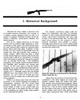
DESCRIPTION OF THE RIFLE
a. The U. S. rifle, caliber .30, M1 is a clip-fed, gas-operated, air-cooled, semiautomatic shoulder weapon. This mean that you insert into the receiver a metal clip containing a maximum of eight rounds; that the power needed to load and cock the rifle for each succeeding round comes from the expanding gases of the previous round; that the air cools the barrel; and that the rifle fires one round each time you squeeze the trigger. b. The rifle has a fixed (immovable) front sight and a movable rear sight that can be moved up or down and right or left. Thus, you can adjust the sight for long or short ranges or to take care of a wind that might otherwise blow the bullet off its course to the target. At ranges over 500 yards, a battlefield target is hard for the average rifleman to hit. Therefore, 500 yards is
LAN GROOVE
E
Figure 3. The bacrrel of the rifle. 4
considered the maximum effective range, even though the rifle is accurate at much greater ranges. c. After examining your rifle to make sure that it is not loaded, look down the bore (fig. 3). The ribs that stand out between the grooves in the bore are called the lands. The grooves and lands are called rifling. This rifling makes the bullet rotate during its flight toward the target. This rotation prevents the bullet from tumbling in flight and causes it to follow a uniform course to the target. The grooves and lands make one complete turn in 10 inches of barrel length. d. You will want to know the following facts about your rifle: Weight, without bayonet............ 9.5 pounds Weight, with bayonet.................. 10.5 pounds Length, without bayonet.....- . 43.6 inches Length, with bayonet...........-.... 53.4 inches Trigger pull, minimum................ 4.5 pounds Trigger pull, maximum............. 7.5 pounds Barrel: Length ....................................... 24 inches Approximate normal chamber pressure .................. 50,000 lbs. per square inch Sight radius (distance from front sight to rear sight)...- 27.9 inches Rifling: Number of grooves................ 4 Uniform, right hand, Twist............-........ one turn in 10 inches 5
4.
FIRE POWER
When you squeeze the trigger, the round is fired, the empty case is ejected, the hammer is cocked, a new round is inserted into the chamber, and the rifle is made ready to fire again-all in about one eight-hundredth of a minute. This fast mechanical action allows you, or a group of riflemen, to deliver a large number of aimed shots in a very short time on any target within effective range.
CHAPTER 2 MECHANICAL TRAINING Section I. DISASSEMBLY AND ASSEMBLY 5.
TRAINING
Your rifle is only as good as the care you give it. Rust and dirt cause more wear than actual firing. The officers and noncommissioned officers of your unit will teach you how to take the rifle apart, how to clean it, and how to put it together. This is commonly called field stripping. In training, feel free to ask the instructor questions on any point that you do not understand. 6.
CARE OF THE RIFLE
Your rifle has been designed so that it may be taken apart and put together easily. No force is needed if you strip it correctly. As you remove the parts (fig. 4) from the rifle, lay them on a clean flat surface such as a table or shelter half in the same order that you remove them. This keeps you from losing any parts and helps you to assemble your rifle because you replace the parts in reverse order. 7.
NOMENCLATURE
You will learn the names of the parts of your rifle during your instruction in field stripping. As your instructor names the parts, repeat them to yourself, and name each part as you remove 7
F, ;
Fa
-
31
A
Ft5
Pa
P~z_
z~~~~~~~~~~~g
S 5
J~~~~~~~~~~~~~~~4
i
8
~-.
c
B~~0
___
-rs
it and as you replace it. You will find that the parts generally are named for the job they perform. For example, the trigger guard actually guards the trigger so that your hands or some other object will not accidentally brush against the trigger and trip it. 8.
DISASSEMBLY
a. You will be permitted to disassemble only certain parts of your rifle, not because the disassembly of some of the parts is beyond your ability to learn, but because constant disassembly causes extra wear. Also, some parts of your rifle require special tools for disassembly. b. Study the following chart. The left hand column shows those parts that you may disassemble alone. The right hand column shows those parts that only ordnance personnel may disassemble. The center columns indicate those parts that you may remove when supervised.
Disassembly supervised by Disassembly authorized
Individual soldier Noncommissioned officer or artificer
INTO THREE MAIN GROUPS ---------X BARREL AND RECEIVER GROUP --X Except: Gas cylinder ---------............ (See note below.) Gas cylinder lock-- __ X Clip latch and pin ----. ....... X
Rear sightSlide from follower_-__-___- -------Accelerator from the -operating rod catch -......................... Front sight STOCK GROUP-NX TRIGGER
Commissioned officer
Ordnance personnel
X X X
X --
X X X
X
HOUSING
GROUP -.. Except: Sear from trigger -.............
X
...X
--X
Note.. After extensive range firing, field exercises, prolonged exposure to inclement weather, or immersion in water (particularly salt water), the gas cylinder may be removed for cleaning. The removal, care and cleaning, and the replacement of the gas cylinder is made under the direct Supervision of an officer.
9.
FIELD STRIPPING
You must learn the steps of field stripping so well that you can do them in the dark. You can field strip your rifle by using only the combination tool or a dummy cartridge. Learn to know the combination tool, because you will use it many 10
0
L0 4
·Zls~&
cr ~
W
0
K
1
times. In combat, you may use a live round if the combination tool is not available. Caution: When using a live round, use only the tip of the bullet. 10.
METHOD OF DISASSEMBLY
Follow the step-by-step explanation in disassembling the rifle. It is disassembled into the three main groups first (fig. 5). After this, the barrel and receiver group and the trigger housing group are disassembled further. 11.
THE THREE MAIN GROUPS-
a. The three main groups are the trigger housing group, the barrel and receiver group, and the stock group. b. To disassemble the rifle into the three main groups, grasp it with the left hand so that the base of the trigger housing is included in your grip. Place the rifle butt against your left thigh, sights to the left. With the thumb and forefinger of your right hand, pull downward and outward on the trigger guard. Swing the trigger guard out as far as it will go. Lift out the trigger housing group (fig. 6). c. With your left hand, grasp the rear of the receiver and raise the stock. With your right hand, give a downward blow, grasping the small of the stock. This will separate the two groups. (fig. 7). 12
o~~~~~~~~~
Figure 6. Removing the trigger housing group. 13
Figure 7. Separating the barrel and receiver group from the stock group.
12.
BARREL AND RECEIVER GROUP
a. Place the barrel and receiver group on the table with the sights down, muzzle pointing to the left. Locate the follower rod. With the thumb and forefinger of your left hand, grasp the follower rod and disengage it from the follower arm by moving it toward the muzzle. You may have to lift up on the follower assembly. Remove the follower rod and operating rod spring by withdrawing them to the right (fig. 8). Do not separate these parts. b. Using the drift of your combination tool, or the point of a dummy cartridge, push out the follower arm pin from the far side of the receiver toward your body (fig. 9). 14
r
b, u I 2, o "ci
t "J o x
b o, :$d c lr'c3 ,O
i,o i 13: S
h
s i oa 3 cr,
15
Zs A 16~~~~~~~~~~~~~a
lo
e
.tD
Ok
To A>
C)
B
1~~~~~~~1
17
o,
tr 1~~~~~~~~~~~~~~~~~~~~~~~~~~~~~T
17
Be
'-4 4~~~~~~~~~~~~~~~~~~~~~~~~~~~~~~~~~~~~''
:;i : _
L--l WW
181
OPERATING ROD
FORWARD EDGE OF WINDAGE KNOB
:
Figure 12. Removing the operating rod. 19
c. Grasp the bullet guide, follower arm, and the operating rod catch assembly, and lift them out of the receiver together (fig. 10). Separate and arrange these parts from left to right in the following order: follower arm, operating rod catch assembly, and bullet guide. d. Reach down into the receiver and lift out the follower assembly (fig. 11). Do not separate the slide from the follower. e. Turn the barrel and receiver group over so that the sights are up, muzzle pointing away from you. With your left hand, raise the rear of the group. With the right hand, pull the operating rod to the rear until the rear of the handle is directly under the forward edge of the windage knob. Grasp the handle with the thumb and forefinger of the right hand.; and with an upward and outward pressure, disengage the guide lug of the operating rod through its dismount notch on the receiver. Remove the operating rod (fig. 12). Note. The operating rod has been intentionally bent. Do not attempt to straighten it.
f. Grasp the bolt by the operating lug and, while sliding it from rear to front, lift it upward and outward to the right front with a slight rotating motion (fig. 13). g: Hold the bolt in your left hand with the operating lug to the right so that the little finger is under the tang of the firing pin and the thumb is over the ejector. This is important because the ejector may fly out and become lost if you do not hold it with your thumb. Insert the screwdriver 20
Figure 13. Removing the bolt.
blade of the combination tool between the extractor and the lower cartridge seat flange. Twist the screwdriver blade against the extractor and unseat it (fig. 14). The ejector will snap up against your left thumb. Remove the extractor and the extractor spring and plunger. Lift out the ejector and ejector spring. Do not separate the ejector 21
LOWER CARTRiDGE
SEAT FLANGE EJECTOR
EXTRACTOR EXTRACTOR PLUNGER AND SPRING UPPER CARTRIDGE ' SEAT FLANGE
.(UNDER Figure 14.
THUMB
Unseating the extractor.
from its spring nor the extractor plunger from its spring (fig. 15). h. Remove the firing pin from the rear of the bolt (fig. 16). i. In figure 17, you see the parts of the. barrel and receiver group that you have disassembled in the order in which they should be laid out. 13.
REAR SIGHT (fig. 18)
a. You may disassemble the rear sight only when supervised by a commissioned. officer. To disassemble it, place the barrel and receiver group on a flat surface so that the sights are up. Lower the aperture as far as it will go. Check the read22
t ok |~~~~~~~ _
E
i ~~~~~~~i-,/w
ffi
___~~~EC
> §
9~~EJTRt AND SP0
0
AN
.tNG i
S
Figure 15. Removing the ejector and spring. 23
SOLT
!·:
.·
VlB-
-
FIRING PIN
Figure 16. Removing the firing pin.
24
OPERATING ROD FOLLOWER ARM PIN
'
asl I i
PERAthiNord s SPRINGi
plac
t
h
FOLLOWER ARM
EXTRACTOR
it
er
ear
j6 OPERATING ROD CATCHASSEMBLY
sight
.
PIN
eleRvting |ECTOR EJQ~i)
AND
SPRING
EXTRACTOR SPRING AND PLUNDER
XOLLUDWER ROD
Figure 17. Parts of the barrel and receiver group in their order of disassembly.
ing on the rear sight elevating knob and write it down. You will need this reading when you replace the rear sight elevating knob. b. Place the barrel and receiver group on its right side, muzzle to the left. Using the combination tool, remove the rear sight elevating knob screw and the elevating knob. Turn the barrel and receiver group on its left side. The rear sight locking nut can be removed with a pair of pliers. Note. The elevating pinion has been counterbored on the threaded end to permit spreading after assembly. Frequent disassembly will cause stripping of the threads 25
z
o
}-
z·
Z
# Y *
#
>
00 0*
S
0
.
:e
0
wmx O w
> S
t
Z
Figure 18. Parts of the rear sight. 26
O
on the pinion; the rear sight, therefore, is disassembled only to replace parts or to clean it after use in very bad weather such as a heavy rain, sand and dust storms, or submersion in salt water.
Unscrew and remove the rear sight locking nut. Unscrew and remove the windage knob, taking care that the rear sight nut lock and spring, which are inside the windage knob, do not become lost. Tap the windage knob lightly to remove the nut lock and spring. Turn the barrel and receiver group-so that the sights are up, the muzzle pointing to the front. Pull out the rear sight elevating pinion from the left side of the receiver. Pull the aperture up about one-half inch. Place your right thumb under the top of the aperture and push forward and upward to remove the aperture cover and base. Separate the rear sight cover from the rear sight base. c. The new modified rear sight eliminates the cross bar on the rear sight locking nut and the counterbored end of the pinion (fig. 19). The modified sight may be disassembled'as follows: Run the aperture all the way down and record the reading, as you will use this reading, when assembling the sight. Hold the elevating knob and unscrew the nut in the center of the windage knob with the forked end of the combination tool or the rim of a cartridge. You can loosen this nut but you cannot remove it, so there is no danger of losing it. Withdraw the elevating knob to the left, removing the elevating knob assembly, including the pinion shaft, elevating knob and screw, and other parts, all of which are made into one piece and cannot be separated. (Like the rear 27
Io 03 '4:D
~
fw~
"
%~~~~~~~~~~~
a: -
0 28
7d I
L
4:
P
o~~
2:~~~~~~~~~~~~~~~~~~r ;.
i U)~~ o
~ ~
~
Lu
28~
!
~
~
U)2
_..
sight nut, the elevating knob screw can be unscrewed until it is loose, but it cannot be removed.) Unscrew the windage knob until it can be removed. The aperture, base, and cover are removed as already described for the other type sight. 14.
CLIP LATCH
You may disassemble the clip latch only when supervised. To disassemble it, place the receiver on its right side with the muzzle pointing to the left (fig. 20). With the thumb of your left hand, depress the clip latch. This relieves the tension. of the clip latch spring. Using the point of a bullet or the drift of your combination tool, push forward on the clip latch pin and unseat it. Remove it by withdrawing it with your finger tips. Lift out the clip latch with the clip latch spring attached. Place the parts on a smooth surface in the order that you remove them. 15.
TRIGGER HOUSING GROUP
a. You may disassemble the trigger housing group only when supervised. To disassemble it, close and latch the trigger guard. Squeeze the trigger, allowing the hammer to go forward. Hold the trigger housing group with the first finger of the right hand on the trigger and the thumb against the sear. Place the front of the trigger housing against a firm surface. Squeeze the trigger with your finger and push forward on the sear with the thumb. At the same time, using 29
:~~~~~ am'~~~~~
i~~~ 30~~~~~~~~~~~~~~~~~~~~l
the drift of the combination tool or the tip of a dummy cartridge, push out the trigger pin from left to right (fig. 21). Slowly release the pressure with your finger and thumb. This allows the hammer spring to expand. b. Lift out the trigger assembly. Remove and separate the hammer spring plunger, hammer spring, and the hammer spring housing (fig. 22). c. Using the combination tool or a dummy round, push out the hammer pin from left to right. Move the hammer a little to the rear and lift it out (fig. 23).
TRIGGER PIN
Figure 21. Removing the trigger pin. 31
RIGGER ASSEMbLY T
H"AMMsR RGS
HAMMER SPRING AND PLUNGER
Figure22. Removing the trigger assembly, hammer spring housing, hammer spring, and hammer spring plunger.
!:AMME
R PIN
Figure 23. Removing the hammer pin and hammer. 32
d. Unlatch the trigger guard. Lay the trigger housing on its right side. With the drift of your combination tool, or the point of a bullet, push out the stud of the safety from its hole. Remove the safety by lifting it from its slot in the base of the trigger housing (fig. 24). SAFETY STUD
Figure 24. Unseating the safety.
e. Hold the rear of the trigger housing with your left hand and the trigger guard with your right hand. Swing the trigger guard down into the opened position. Slide the trigger guard to the rear until the wings of the trigger guard are alined with the safety stud hole. Rotate the trigger guard to the right and upward with your 33
right hand until the hammer stop inside of the right wing clears the base of the trigger housing. Remove the trigger guard (fig. 25).
SAFETY STUD HOLE
TRIGGER WING HOLE
\
/
0i7
BTRIGGER GUARD
Figure 25. Removing the trigger guard.
f. Lay the trigger housing on its right side. Insert the point of a bullet or the screw driver blade of the combination tool in the hole by the loop of the clip ejector. Push downward on the clip ejector and unseat it (fig. 26). 16.
GAS CYLINDER
a. Using the screw driver blade of your combination tool, unscrew and remove the gas cylinder lock screw (fig. 27) with valve assembly. If you are supervised, you may now unscrew and remove the gas cylinder lock (fig. 28). 34
0s
~
0 x
r~~~~
.
0jEo SS
I~~~
~i
:If
i.
_.
.0000
ff
a i:
0
"
35
b. Do not remove the gas cylinder except when necessary. Before removing the gas cylinder, be sure that the operating rod has been removed. To remove the gas cylinder, tap lightly toward the muzzle on the bayonet stud with a piece of wood or similar soft object until the gas cylinder is loosened. Remove the gas cylinder (fig. 29). Be careful that the splines are not burred or dam-
Figure 27. Removing the gas cylinder lock screw with valve assembly. 36
Figure 28. Removing the gas cylinder lock. aged. Do not remove the front sight or make any attempt to adjust the front sight. Note. On rifles With gas cylinders that have been modified by a cut that extends from the front sight base dovetail downward to the lower splines, it is necessary to loosen the front sight screw before attempting to remove the gas cylinder. Otherwise, the barrel and gas cylinder may be damaged. 17.
ASSEMBLING
Your rifle and its component groups are assembled in the reverse order of their disassembly; 37
Figure 29. Removing the gas cylinder.
for this reason you lay out the parts in the order that you remove them. 18.
REPLACING THE GAS CYLINDER, GAS CYLINDER LOCK, AND THE GAS CYLINDER LOCK SCREW
a. Place the gas cylinder over the barrel. Make sure that the splines are alined with their grooves. 38
Replace the gas cylinder as far as it will move easily. If tapping is necessary, tap lightly on the bayonet stud with a piece of wood. b. Engage the threads of the gas cylinder lock with those on the barrel and screw it on by hand until it is finger tight (do not -use a tool). If the lock is not aligned with the gas cylinder, do not force it, but unscrew it until it is alined. c. Replace the gas cylinder lock screw. Tighten '-by using the screw driver blade of your combination tool. Keep this screw tight at all times, because a loose gas cylinder lock screw may prevent your rifle from firing semiautomatically. 19.
TRIGGER HOUSING GROUP
a. Hold the trigger housing in your right hand, with the left side down and the rear end to the right. Place the clip ejector in position in the trigger housing with the short arm toward your body and the tip of the long arm in its slot in front of the trigger housing. The loop of the clip ejector is positioned on top of its stud on the left side of the trigger housing. With your right thumb, hold the loop of the clip ejector on top of this stud. With the forefinger of your left hand, hold the long arm up in its slot on the front of the trigger housing. Place the tip of your left thumb between the long arm and the base of the trigger housing and move the long arm toward your body, at the same time exerting pressure downward. The long arm of the clip ejector will snap into the notch on the base of the trigger housing (fig. 30). 39
Figure 30. Replacing the clip ejector. b. To replace the trigger guard, hold the trigger housing as shown in figure 25. Place the wings of the trigger guard astride the base of the trigger housing so that the hammer stop, on the inside of the right wing, clears the base. Turn the trigger guard down and to the left until the holes in the wings are under the safety stud hole. Slide the trigger guard forward until the holes in the wings are alined with the hammer pin hole. c. Insert the finger piece of the safety through its slot in the base of the trigger housing. To reseat the safety stud in its hole in the trigger housing, force the safety down against the pressure of the short arm of the clip ejector. Push the finger piece of the safety forward. d. Insert the hammer loosely in position, holding it halfway between the cocked and fired position. Be sure that the hammer toe clears the hammer stop on the right wing of the trigger guard. Aline the hammer pin holes in the hammer with the holes in the trigger housing and trigger guard. 40
Be sure that the trigger guard is not latched. Insert the hammer pin from the right side. Move the hammer to the fired position. Close and latch the trigger guard. e. Place the trigger housing group on the table with the base down and the rear end to the right. Assemble the hammer spring housing, hammer spring, and hammer spring plunger into one unit. Place the plunger in its seat on the hammer. Make sure that the open side of the hammer spring housing is toward the safety. (This is important because failure to do this prevents the
i
.
.
l:
Figure 81. Replacement of the trigger assembly, hammer spring housing, hammer spring, and hammer spring plunger. 41
safety from being used; also the sear will not function.) Hold these assembled parts in a raised position with the thumb and fingers of your left hand. With your right hand, insert the trigger into the trigger slot so that the notch at the curved rear surface of the finger piece bears against the rear of the slot in the trigger housing. Place the wings of the hammer spring housing astride the sear pin. With your right forefinger on the trigger and the right thumb against the sear, apply pressure forward against the sear and at the same time squeeze the trigger. Hold the parts in this position and insert the trigger pin as far as its~head only (fig. 31). f. To seat the head of the trigger pin, hold the trigger housing group as shown in figure 32. Note the direction the pin must be moved to be seated. By applying pressure with the thumb and fingers,
Figure 32. Seating the trigger pin. 42
aline the head of the trigger pin with the trigger pin holes. Seat the trigger pin by pressing on its head with the left thumb. 20.
CLIP LATCH
Place the clip latch with the clip latch spring attached in position on the left side of the receiver and start replacing the clip latch pin from the front. Press in on the thumb piece of the clip latch to relieve the tension of the clip latch spring, and push the clip latch pin fully home. If the pin head is not fully seated, it will damage the stock. 21.
REAR SIGHT
a. Assemble the rear sight cover and rear sight base into one unit. Place the rear lip of the sight cover in its slot at the rear end of the sight bracket. Press down against the front part of the sight cover, seating it in its slot in the front end of the sight bracket. Insert the aperture in its slot in the rear sight base. Slide the aperture to its lowest position. Holding the rear sight base forward against the rear sight cover, insert the elevating pinion through the left side of the receiver, taking care that it meshes with the teeth of the aperture. Insert the windage knob into the right side of the receiver. Move the sight base to the left until the index line shows at the left edge of the windage gage. Screw the windage knob into the rear sight base until the zero mark on the rear sight base is aligned with the center 43
line of the windage scale on the receiver. Lay the rifle on its left side. Place the rear sight nut lock spring and nut lock in position in the windage knob around the threaded end of the elevating pinion, taking care that the flat cut on the elevating pinion is alined with the flat portion of the nut lock. Screw the rear sight nut onto the elevating pinion until the desired tension is obtained on both the elevating knob and the windage knob. When this nut is tightened too much, the elevating and windage knobs become locked and cannot be turned. Lower the aperture as far as it will go by turning the elevating pinion.. Replace the elevating knob and rotate it to the reading that was noted before the part was disassembled. Holding it in this position, replace the elevating knob screw. In tightening the elavating knob screw, run the aperture up to its highest position and set the screw as tightly as possible. Now run the sight down and recheck the knob reading. Be careful when starting the rear sight locking nut on the pinion so that you do not damage the threads. If you can remove the rear sight locking nut without using pliers or a small wrench, the end of the pinion should be respread, using the punch that is provided for this purpose. A very light tap of a hammer is enough to expand the end of the shaft. The company armorer artificer is authorized to do this. b. To assemble the modified rear sight, first replace the base, cover, and aperture as described for the other sight. Screw the windage knob in until it takes hold and draws the base to the 44
center position on the windage gage. Insert the elevating knob and pinion shaft from the left, meshing the pinion with the teeth on the aperture. The flat portion of the elevating pinion shaft must pass through a D-shaped hole in the lock which is located inside the windage knob assembly adjacent to the slotted rear sight nut. With the aperture all the way down, adjust the elevating pinion until the, recorded setting (before disassembly) is on the rear sight. Screw in the rear sight nut with the forked end of the combination tool. Screw it in as far as it will go, then turn it back a fraction of a turn until any change on the rear sight clicks distinctly; the assembly is then completed. 22.
BARREL AND RECEIVER GROUP
a. To assemble the bolt, you may use the extractor seating device on the combination tool, the soft leaded end of the chamber cleaning brush, or the point of a dummy or live cartridge. When the extractor seating device is used properly, the extractor and ejector may be seated very easily. However, because some men have difficulty in learning how to use this device and because you must be able to assemble the bolt without the combination tool, two methods will be described. (1) First method. Insert the firing pin in the bolt, making sure that the tang of the firing pin enters its slot in the rear of the bolt. Grasp the bolt in your left hand with the face of the bolt upward and the operating lug to the right. Re45
TO THE RIGHT
Figure 33. Assembling the bolt, first method.
place the ejector and the ejector spring into the bolt with the ejector spring down. Turn the ejector so that the cut is toward the operating lug of the bolt. Replace the extractor spring and plunger (spring first) into their hole in the bolt. Put the stud of the extractor into its hole in the bolt. With your left thumb press lightly on the extractor so that it 46
begins to ride over the extractor plunger. Grasp the chamber cleaning brush in your right hand with a firm grip. Use the tip of the brush the same way that you use a stick, a nail, the base or tip of a dummy round, or the tip of a live round. Caution: Do not use the primer end
of a live round. Using the soft leaded tip of the cleaning brush, depress the ejector into the face of the bolt,(fig. 33). With the thumb of the left hand, push the extractor into the bolt until it is fully seated. (2) Second method. (Using the extractor seating device of the combination tool.) Replace the firing pin, ejector and spring, extractor plunger and spring, and the extractor as described in the PRESSDOWN
PLACE DRIFT OF COMBINATIONTOOL IN LEFT GROOVE IN BOLT
RIGHT LOCNG
OPERATING
.LUG
LEFT LOCKING LUG EXTRACTOR
Figure 34. Assembling the bolt, second method. 47
preceding paragraph. Place the drift of the combination tool in the left groove of the bolt and hold the combination tool at a right angle to the locking and operating lugs of the bolt as shown in figure 34. Press downward on the combination tool until the ejector is forced into the face of the bolt then, with your left thumb, press inward on the extractor, seating it. Caution: In either method when assembling the bolt, be careful to keep your face away from over the bolt because the ejector might fly out from under the tool that you are using. b. To replace the bolt (fig. 13), hold the barrel and receiver with the sights up and the muzzle pointing away from you. Hold the bolt by the operating lug so that the front end of the bolt is PUSH DOWN
Figure 34-Continued. 48
slightly above and to the right of its extreme forward position in the receiver. Insert the rear end in its bearing on the bridge of the receiver. Rotate the bolt in a counterclockwise direction as far as necessary to permit the tang of the firing pin to clear the top of the bridge. Guide the left locking lug of the bolt into its groove on the left side of the receiver. Lower the right locking lug on its bearing and slide the bolt to its rearmost position. c. Place the barrel and receiver in front of you so that the sights are up and the muzzle is pointing to the front. Tilt the barrel and receiver to the left, then, holding the operating rod at the handle, place the head of the piston into the gas cylinder about three-eighths of an inch. Adjust the operating rod so that the recess in the hump fits over the operating lug of the bolt (fig. 35). While applying pressure downward and inward on the handle, move the operating rod forward until the guide lug is engaged in its groove. Move the bolt forward until it is closed. d. Turn the barrel and receiver group so that 'the sights are down. With the follower slide down, replace the follower assembly so that its guide ribs fit into their grooves in the receiver, the square hole in the follower to the rear. The slide will now rest against the bolt. e. With your left hand, replace the bullet guide (fig. 36) so that the shoulders of the bullet guide fit into their slots in the receiver and so that the hole in the toe of the bullet guide is in alinement with the holes in the receiver. 49
OPERATING LUG HUMP OF j
6t
OPERATING ROD
Figure 35. Replacing the operating rod.
50
RONT EDGE OF
Ni
Figure 35-Continued.
BULLET GUIDE
r
Figure 36. Replacing the bullet guide.
f. With your right hand, swing up the lower part of the bullet guide slightly. With the left hand, insert the long rear arm of the operating rod catch assembly through the clearance cut in the bullet guide. Make sure that the rear of the long arm is underneath the front stud of the clip latch which projects into the receiver (fig. 37). Lower the bullet guide into place. To test for correct assembly, press down on the front arms of the operating rod catch. When released, they should spring back into place. g. Replace the follower arm by passing its studded end through the bullet guide and inserting the studs in the grooves in the follower (fig. 52
OPERATING ROD CATCH ASsMBLY
Figure 37. Replacing the operating rod catch assembly.
38). Place the forked end of the follower arm astride the toe of the bullet guide. Aline the holes in the operating rod catch, follower arm, and bullet guide with those in the receiver. Replace the follower arm pin. h. Insert the operating rod spring into the operating rod. Grasp the follower rod with the fingers of your left hand. Make sure that the hump of the follower rod is toward the barrel. Push toward the muzzle, compressing the operating rod spring, and hook the claws of the follower rod with the front studs of the follower arm (fig. 39). You may have to raise the follower assembly 53
F3LLOWER ARM
lOLLOWER ASSEMBLY
Figure 38. Replacing the follower arm.
a little to do this. Check to see that the hump of the follower rod is in the slot between the forward arms of the operating rod catch assembly. The straight part of the follower rod will then be parallel to the barrel. 23.
ASSEMBLING THE THREE MAIN GROUPS
a. With the barrel and receiver group on the table, sights down, pick up the stock group and locate the U-shaped flange of the stock ferrule. 54
FOLLOWER ARM
FOLLOWER
ROD
Figure 39. Replacing the follower rod and operating rod spring.
U" SHAPED FLANGE
LOWER BAND
Figure 40. Replacing the stock on the barrel and receiver group. 55
Hold the stock so that the sling is up. Engage this U-shaped flange into the lower band, then lower the stock group down onto the barrel and receiver group (fig. 40). b. Unlatch and open the trigger guard; keeping the base of the trigger housing level, place it straight down into the receiver, making sure that the locking lugs on the trigger guard enter the recesses in the receiver (fig. 41). Close and latch the trigger guard.
LOCKING RECESS
LOCUNG LUG
Figure 41. Replacing the trigger housing group.
24.
TO TEST FOR CORRECT ASSEMBLY
To test the assembly of your rifle, pull the operating rod to its rearmost position. The bolt should stay open. -Close the bolt and snap the safety to its locked position. Squeeze the trigger. The hammer should not fall. Push the safety forward and squeeze the trigger. The hammer should fall; 56
Section II. HOW THE RIFLE WORKS 25.
GENERAL
a. By taking your rifle apart and putting it together, you have become familiar with its parts. Next, you must learn how these parts function. If you understand how your rifle works, you will be able to clear any stoppages that may occur. This knowledge will also give you confidence in your rifle and will enable you to keep it in working order. b. Each time a cartridge is fired, many parts inside the rifle work in a given order. This is known as the cycle of functioning. This cycle is almost the same in all semiautomatic weapons. c. To help you understand the cycle of functioning, it is broken down into eight basic steps. Keep in mind that more than one step may be occurring at the same time. The steps are listed below in the order that they begin. (1) Feeding-moving the cartridge into the path of the bolt. (2) Chambering-moving the cartridge into the chamber. (3) Locking-locking the bolt in the receiver. (4) Firing--driving the firing pin forward to strike the primer cap, which sets off the cartridge. (5) Unlocking-unlocking the bolt from the receiver. (6) Extraction-pulling the empty cartridge case from the chamber. 57
(7) Ejection-throwing the empty cartridge case from the rifle. (8) Cocking-pushing the hammer into the cocked position. .26.
FUNCTION OF THE TRIGGER HOUSING GROUP
a. As the rifle begins to function when you squeeze the trigger, you first learn how the trigger housing group works. (1) Remove the trigger housing group (fig. 42). Close and latch the trigger guard and cock the hammer. The hammer is held in the cocked position by the trigger lugs which are engaged with the hammer hooks. Hold your left thumb over the hammer and slowly squeeze the trigger. Notice how the trigger lugs move forward, releasing the hammer hooks. The hammer is forced forward by the expanding hammer spring (fig. 43). This happens each time the trigger is squeezed if you release your finger from the trigger after each shot is fired. (2) However, there must also be a way of stopping the hammer from going forward even if you keep your finger pressed on the trigger after each shot. This is done by the sear, which catches on the rear hammer hooks. Now squeeze the trigger and hold it to the rear. Cock the hammer slowly and see how the sear catches on the rear hammer hooks and 58
a:
I0
.
{
w
i
0
m
e
59
400
ix
- Zi
v--
59
Ul
'
~~
~
L~~~~~~~~~
E
l~ LI
So "III
~~~~~~~~~~
.W
.U~I
41
.,'~~~~~~~~~~~~~~~~r
60~~~~~~~~~~~~~~
-
60
. - .
_.
..
_..
._
holds the hammer back. Slowly release the trigger. As you do this, the sear will release the rear hammer hooks. Now the hammer hooks catch on the trigger lugs and hold the hammer in the cocked position. This combination holds the hammer to the rear each time a round is fired. b. As you apply pressure on the trigger, it moves to the rear. This movement is divided into a slack portion and a squeeze portion. Cock the hammer and squeeze the trigger lightly and notice that it moves easily until the sear touches the rear hammer hooks. This movement, until the sear contacts the rear hammer hooks, is called the slack. Increased pressure is required to move the trigger from the time the sear contacts the rear hammer hooks until the trigger lugs release the hammer hooks. This second movement of the trigger which requires heavier pressure is called the squeeze. c. To see how the safety works, cock the hammer and push the finger piece of the safety to the rear or safe position. As you push the safety to the rear, you force the hook of the safety over the safety lug on the hammer. This locks the hammer in the cocked position. Notice that the hammer hooks are below, and not engaged with, the trigger lugs. Squeeze the trigger. The hammer cannot fall. Notice also that the trigger stop of the safety now blocks the left trigger lug, preventing the trigger from being moved. This is an automatic safety feature designed to block the 61
trigger in the event of a broken hook on the safety. d. A safety feature has been built into the rifle to prevent it from being fired unless the bolt is in its locked position. This is done by the action of the bolt camming lug on the hammer against the cocking cam of the bolt. Place the rear of the bolt against the hammer; notice how the bolt camming lug fits into the cocking cam of the bolt. Note that if the bolt is not completely rotated to the right into the locked position, the bolt camming lug will not fit in the cocking cam and that the hammer will not hit the tang of the firing pin. If the bolt is not fully locked and the hammer moves forward, the bolt camming lug will rotate the bolt to the right. This locks the bolt before the hammer can hit the tang of the firing pin. During unlocking, the instant the bolt starts to rotate to the left, the hammer is pushed away from the tang of the firing pin by the action of the cocking cam against the bolt camming lug. e. Another important part of the trigger housing group is the clip ejector. By placing an empty clip in the trigger housing group, you can see the action of the clip ejector in ejecting the empty clip. 27.
FUNCTIONING OF THE RIFLE
The action of the working parts as a full clip of ammunition is loaded into the rifle and during the functioning cycle is divided into four phases with certain steps occurring in each phase. You must remember that some of these actions are 62
going on at the same time; they are listed below in the order in which they start. a. The first phase is the ACTION ON LOADING A FULL CLIP. (1) Movement of the follower, follower arm, and follower rod. (2) Action of the accelerator and operating rod catch assembly. (3) Action of the clip latch. b. The second phase is the ACTION DURING THE FORWARD MOVEMENT OF THE OPERATING ROD. (1) Chambering. (2) Locking. (3) Alinement of the firing pin. (4) Termination of the forward movement. c. The third phase is the ACTION DURING THE REARWARD MOVEMENT OF THE OPERATING ROD. (1) Action of the gas. (2) Action of the operating rod and spring. (3) Unlocking. (4) Withdrawal of the firing pin. (5) Extraction. (6) Ejection. (7) Cocking. (8) Feeding. (9) Termination of the rearward movement. d. The fourth phase is the ACTION FOLLOWING THE FIRING OF THE. LAST ROUND. (1) Action of the follower, follower arm, and follower rod. 63
(2) Action of the operating rod catch assembly. (3) Action of the clip latch. (4) Ejection of the empty clip. 28.
STARTING POSITION
a. In paragraph 26 you learned how the trigger, the safety, the hammer, and the clip ejector do their work. Now you are ready to learn what happens when a clip of ammunition is placed in the receiver. b. Place the barrel and receiver group in front of you and pull the operating rod handle all the way to' the rear. Notice that the bolt stays open when no ammunition is in the rifle, that is, unless you purposely let it go forward on an empty chamber. The parts are now in position for you to load a full clip into the receiver (fig. 44). c. Study the relationship of the parts to each other. The operating rod and bolt are in the rearmost position. The follower is all the way up in the receiver, because the compressed operating rod spring is exerting pressure through the follower rod and follower arm, against the follower. The hump of the follower rod is touching the 450 camming surface of the operating rod catch,
pushing it toward the barrel and engaging its undercut hook with the hooks on the operating rod. This keeps the bolt and operating rod to the rear against the pressure of the compressed operating rod spring. The rear stud of the clip latch is pulled back into its slot in the receiver, and the clip latch spring is compressed because of 64
10W
,u,
'Ow
wu~~~~w
I-ol..,
0
Im
to·
L0
'Z 'C,WXF
ZL
Z,
~~
~
LW
Y
o". 3.~~~
W.
~
~
~
~
u
az I
:'t 3E OW
oa~~~~~~~~~~h
Cm o 3: m
YIU
~
~
W>.
~~~~
2
hi 0ca
IOU
omu"WA. 5
;
ZW,
rd
Z (CWW
X r.L l
a
ni 00.
x~~~~~~~~~~~~~~~
wai
cr~~~~~~~~
65
pressure exerted on the front stud of the clip latch by the long rear arm of the operating rod catch assembly. 29.
ACTION ON LOADING A FULL CLIP
a. Movement of the Follower, Follower Arm, and Follower Rod. By placing a full clip on top of the follower and pressing down on the clip, the follower is depressed. This action moves the follower arm down, rotating around the follower arm pin. Since the follower arm is connected to the follower rod, it pushes the follower rod toward the muzzle, moving the hump of the follower rod away from the 450 camming surface of
the operating rod catch. b. Action of the Accelerator and Operating Rod Catch Assembly. As the follower reaches its lowest point in the receiver, the square shoulder of the follower arm contacts the rear lip of the accelerator, forcing it toward the barrel. Between its lip and the point where it is fastened by its pin to the operating rod catch, the accelerator bears on and pivots about the toe of the bullet guide. Thus as the lip of the accelerator is forced toward the barrel, the operating rod catch is forced away from the barrel. The undercut hook of the operating rod catch is disengaged from the hooks of the operating rod, letting the bolt and operating rod go forward under the action of the expanding operating rod spring., The accelerator plays no other part in functioning except when loading a full clip of ammunition as just described. c. Action of the Clip Latch. As the forward end of the operating rod catch moves downward 66
and away from the barrel, the long rear arm of the catch moves upward and away from the front stud of the clip latch. This allows the clip latch spring to expand and force the rear stud of the clip latch into the notch of the clip. The rear stud of the clip latch holds the clip in the receiver against the action of the compressed clip ejector. The operating rod catch is held away from the barrel by the front stud of the clip latch which is continually pushing upward against the long rear arm. This allows the bolt to move freely back and forth until the last round is fired (fig. 45). Load a clip of dummy rounds in the receiver several times and carefully notice how each part works. 30.
ACTION DURING THE FORWARD MOVEMENT OF THE OPERATING ROD
a. The Clip is Now in Place. Pull the operating rod all the way to the rear and hold it there. (If dummy rounds are not available for this study, allow the operating rod to go forward a short distance until the operating rod catch no longer holds it to the rear.) The compressed operating rod spring provides the force for the forward movement. b. Chambering. As the operating rod and bolt, pushed by the compressed operating rod spring, move forward, the bolt strips off the top round in the clip and shoves it into the chamber. When the bolt reaches its forward position, the rim of the cartridge is gripped by the extractor, and the base of the cartridge forces the ejector into the bolt, thus compressing the ejector spring. 67
OZUW
O~U
. V o.'~ S~ i~~ ~ii... ·
d
-C ~~~~~i-
~l*,-~
~
~
n~I
W
;** U~~~~~~~~~~~~~~~~3
o.~~~~~~~~~~~~~5 0Z
OWI
175
(8) The butt of the rifle is held in the pocket of the right shoulder by the tension of the sling. (9) The right arm is blocked by the right knee. (10) The grip on the small of the stock, the position of the trigger finger, and. the spot weld between the cheek and thumb are the same as in the other positions. 98.
ERRORS IN THE SITTING POSITION
Errors found frequently in the sitting position and the method of correcting them area. Tips of Elbows Resting on Top of Knees (Point-to-PointContact). This error results in an unstable support for the rifle. It places the body in a position which is too erect. Each shot will destroy the position. To correct this error, the firer lowers his knees, bends his body well forward at the waist, and makes contact between the left upper arm and the left shinbone. He blocks the right elbow in front of the right knee. b. Knees Farther Apart Than the Feet. This error causes muscular strain rather than relaxation. This error may have been caused by one of the following faults: (1) Placing the feet too close together. To correct this, the firer lowers his legs and spreads his feet farther apart, then completes the position. (2) Turning the toes outward, which throws the knees outward. To correct this, the 176
firer turns the toes inward slightly and puts the weight of the rifle down on the shinbone instead of outward. c. Toes Pointing Up. This usually indicates muscular tension. To correct this, the man relaxes his leg muscles. d. Left Elbow not Under the Rifle. To correct this, the firer moves his feet 5 or 6 inches to the right. e. Improper Grip. To correct this, the firer removes the rifle butt from his shoulder and moves his hand so that the rifle is in the V and resting on the heel of his hand. 99.
ALTERNATE SITTING POSITIONS
a. Cross-Legged Position (fig. 74). In this position the firer sits with the left leg crossed over the right leg. His feet are drawn up close to the body so that the outer part of the calf of each leg rests on the inside of the opposite foot. The back of the upper arms are supported against the shinbones and are very nearly at right angles to them. The rest of this position is the same as for the normal sitting position. b. Cross-Ankled Position (fig. 75). (1) In this position the left ankle is crossed over the right ankle, the legs extended well away from the body. Here, as in the cross-legged position, the upper arms are supported by the shins. The rest of this position is the same as the normal sitting position. 177
~
w~~~~~~"
0
>
uJ
wa z
0 w
z
_1 w
I
I
z ir
·
I.-t
.2
~~>n;t
a.
w
ralo 0 t 5rze-
t)
a
O
> Z~~~~~~~~~~~v
wos -)
~1
tzo >~C)
0
0.
0-.
C
cOPa
0
o'
o-
9
"-'
.
O
o0
+
,~
i9
0
o
3
0
3
.
~~~~~ca ~~~~~~4to44-40C3
45"" omE-~~~~1~0 .004 s~~~~~~
0
.-
~~~0 ~
3
estimating ranges by eye, you will find it necessary to make allowances for variables like light, weather, and the terrain. Your understanding of the factors shown in table II will help to make your estimates more accurate. d. In Training, Several Men Should Work Together. When there are differences in estimates, you should determine the reasons for the differences. By adding the estimates of several men together and dividing the result by the number of men, the average obtained will be more accurate than a single estimate. Even in combat when time and circumstances permit, average estimates should be obtained. 217.
OBSERVATION OF FIRE
Accurate range determination can be made by observing the strike of tracer or ball ammunition. This method can be used if your presence is known to the enemy or if surprise is not important. An observer is necessary because it is difficult for a firer to follow his own tracer -and pick up the strike 'of his own shot. The procedure follows: a. The firer estimates the range by eye, sets the rear sight of his rifle for that range, and fires. b. The observer follows the path of the tracer or picks up the strike of the bullet. c. The observer gives the firer the correction for the sight setting (up or down) in clicks of elevation necessary to hit the point.of aim (target). 336
d. The firer makes the sight change and continues to fire and make corrections until a hit on the target is, observed. e. The final sight setting to hit the target (with consideration to the zero of the rifle) indicates the range to the target. The firer announces the range by voice or signal. Section III. 218.
RIFLE AND AUTOMATIC RIFLE FIRE AND ITS EFFECT
GENERAL
The second step in the technique of rifle fire training is rifle and automatic rifle fire and its effect. A knowledge of what the bullet does while it is in flight and an understanding of the effects of your fire on the enemy help you to use your rifle so that its fire is most effective. A study of the terms, principles, and illustrations given in this section will enable you to understand how to use your rifle to the best advantage in combat. 219.
TRAJECTORY
a. Trajectory is the path of a bullet in its flight through the air. The bullet of M2 armorpiercing ammunition leaves the muzzle of your rifle at 2800 feet per second (muzzle velocity). At this great speed, the trajectory is almost flat at short ranges. However, as the range increases, the height of the trajectory increases (fig. 105). b. The space between the rifle and the target, in which the trajectory does not rise above a man of average height, is called the danger space (fig. 337
I~ a
8~~~
00. WO~~~~~~O
wU
..
0
I
.~~~~~~~~~~~~~~~~.
·
[
w--a
z o~~-o
0
a 0
x
I :;'
w
0o
0 ~8
L
a w
w
o ~~~~IA
a~li')W
338
0-
U. * 0
~ ~ ~~
4
,.,0 in
0,
C) D
U.0
w~
'1
to
Z
o
~~~~~o
ai
-
W d~ ~
00~ 8~u0C) 0 I
I
cJ
z
105). A bullet fired from the rifle or automatic rifle at ground level (prone position) and at a target 750 yards away will not rise more than 68 inches above the ground, providing the ground is level or slopes uniformly. A man of average height standing on the gun-target line would be hit by the bullet; therefore, the entire 750 yards is danger space. At ranges greater than 750 yards, only parts of the space between the gun and the target will be danger space because the trajectory' of the bullet will rise above the head of a man of average height. 220.
CONE OF FIRE
Each bullet fired from the M1 rifle or the automatic rifle follows a slightly different path or trajectory through the air. The small differences in trajectories are caused by slight variations in aiming, holding, squeezing, the powder charges, or the wind and atmosphere. As the bullets leave the muzzle of the weapon, their trajectories form a cone shaped figure known as the cone of fire (fig. 106). 221.
BEATEN ZONE
The area on the ground in which the bullets of the cone of fire strike is called the beaten zone. The cone of fire striking a horizontal target forms a beaten zone which is long and narrow in shape. Because of the variation in the degree of flatness of trajectories at different ranges, the beaten zones on horizontal targets vary in length from 100 yards at long ranges to 400 yards at 339
Figure 106. The cone of fire.
short ranges. The slope of the ground affects the size and shape of the beaten zone. Rising ground shortens the beaten zone; ground sloping downward at an angle less than the curve of the trajectories lengthens it. Ground that falls off at an angle greater than the fall of the bullets will not be hit and is said to be in defilade. 222.
CLASSES OF FIRE
Rifle and automatic rifle fire is classified both with respect to the target (direction) and with respect to the ground. a. Fire with respect to the target (fig. 107) is-
(1) Frontalfire when it is delivered at right. angles to the front of a target. (2) Flanking fire when it is delivered against the flank of a target. (3) Oblique fire when it is delivered so that the long axis of the beaten zone is at an oblique to the long axis of the target. (4) Enfilade fire when it is-delivered so that the long axis of the beaten zone coin340
FLANKING a
ENFILADE FRONTAL
ONLY % BLIQUE
Figure 107. Classes of fire with respect to the target (direction).
cides or nearly coincides with the long axis of the target. Enfilade fire may be either flanking or frontal. b. Fire with respect to the ground is(1) Grazing when the bullets do not rise above the height of a man standing. Rifle and automatic rifle fire from the prone position may provide grazing fire at ranges up to 750 yards over level or uniformly sloping ground. (2) Plunging when the bullets strike the ground at a high angle, so that the danger space is practically confined to the beaten zone and the length of the beaten zone is materially shortened (fig. 108). Fire at longer ranges becomes increas341
\ ??,i' \'~t ~"/'3,?/
I·
~,
'1
\ ';,: f,)
:
342,~
I
~~~1//.:1,.' ill ~~~~~~~~~~cl \
/
il
,
/'
~IR \?kr: ~
.
W'"
;
T,,l !~~~si~ It
~d
I'4~~~~~'
ft~~~~~r
342
;
.
ingly plunging because the angle of fall of the bullets becomes greater. Fire from high ground to a target on low ground may be plunging fire. Firing into abruptly rising ground will result in plunging fire at the point of impact. (3) Overhead when it is delivered over the heads of friendly troops. Rifle and automatic rifle fire is considered safe when the ground offers protection to the friendly troops to the front or if they are in position at a sufficient distance below the line of fire. Its use in any particular case depends on necessity and good judgment. 223.
EFFECT OF RIFLE AND AUTOMATIC RIFLE FIRE
a. The most decisive results from rifle and automatic rifle fire are obtained when your squad is close to the enemy. Your unit will use cover and concealment offered by the terrain and will take advantage of the supporting fires of machine guns, mortars, and artillery to advance as near to the enemy as possible before opening fire. Normally, you should not open fire at ranges greater than 500 yards, which is the maximum effective range of your rifle. b. Under favorable conditions, the automatic rifle may be used against enemy groups or enemy areas at ranges between 500 yards and 1,000 yards. 343
c. The automatic rifle can be used effectively against a sniper concealed in a tree by firing a sustained burst, sweeping up and down the tree. d. The fire of the rifle squad can be effective against appropriate vehicle and aerial targets as discussed in paragraph 204-212. e. Enemy positions are likely to be. concealed and difficult to locate exactly. However, the area in which the enemy is located can usually be determined by the sound of his firing. Men may distribute continuous fire in width and depth to cover an entire area, causing the enemy to keep his head down and making his fire ineffective. When covering an area by fire, each rifleman should aim each shot at a likely firing position: a bush, a rock, a stump, a patch of grass, or a fold in the ground. f. Ricochets are effective if they strike a man shortly after glancing from the ground. Therefore, if there is a question whether to fire short of the target or over it, fire short. Section IV. 'FIRE COMMANDS 224.
IMPORTANCE AND PURPOSE
To be effective, the collective fire of your squad must neutralize the enemy's fire. Enemy troops will be trained in the use of cover and concealment. Therefore, your targets will be indistinct, rarely exposed, and often invisible to the naked eye. When a target is discovered, leaders and squad members must clearly define its location and nature. Squad members must be trained to 344
identify the target area quickly and accurately and to place a heavy volume of fire on it even though no enemy personnel are visible. A small point target like an enemy sniper might be assigned to only one or two riflemen, while a target of considerable width like an enemy skirmish line requires the combined fire of the entire squad. The rifle squad leader, having made a decision to fire on a target, gives certain instructions as to how the target is to be engaged. These instructions form the fire command by which he directs and controls the fire of his squad. 225.
ELEMENTS
A fire command contains six basic elements that are always announced or implied. Fire commands for all weapons follow a similar order and include similar elements. Only essential elements are included. The six elements areAlert. Direction. Target description. Range. Target assignment. Fire control. a. Alert. This element brings the unit to a state of readiness to receive further information. It may also tell who is to fire. Usually it is the command SQUAD; it may be the command AR or RIFLEMEN. However, the leader may alert only a few individuals by calling to them by name or by number. 345
2
(~~~ \w.
34&
6,~~~~~~~~~~~~~~~~~~~~~~~~5
I~~~~~~~~~~~~~~I ,-q
cl~~~~~~~~~~~~4
346
346~~~~~~~~0
*,
I
b. Direction. (1) The direction element tells you which way to look to see the target. This may be given in one, or in a combination, of the following ways: (a) Orally. General directions to the target may be given orally and should tell the relationship between the target and the unit as it is deployed. Figure 109 shows the general directions which may be expressed as FRONT, RIGHT FRONT, LEFT FRONT, RIGHT FLANK, LEFT FLANK, RIGHT REAR, LEFT REAR, REAR. (b) Pointing. Direction may be shown by pointing with the arm or the rifle. When you desire to show directions to individuals, the following methods may be used: 1. Use the arm to point toward the target so that a rifleman standing behind you can look over your shoulder and along your arm and index finger to establish a correct line of sight. 2. To use the rifle to point, put it to your shoulder, cant it to the right, and aim at the target. Move your head to the left without disturbing the rifle so that the men to the rear can move up and look through the rear sight to observe the same sight picture and locate the target. 3. Time permitting, use a rifle rest. A 347
bayonet stuck into the ground at an angle, a log, or a tree crotch will keep the rifle in place. Once sighted on the target, a number of men can take position behind the weapon and locate the target. The automatic rifle with its bipod can be effectively used in this manner. 4. Tracer ammunition is a quick and sure method of indicating the direction to an indistinct target and is most accurate for pinpointing the flanks of an obscure linear target. When possible, the general direction is given orally to direct the squad's attention to the desired area, for example, FRONT-WATCH MY TRACER (fire 1st round)-RIGHT FLANK (fire 2d round)-LEFT FLANK Firing tracer ammunition to designate targets has limitations. It may disclose your position, and in any event, will make known your presence and lessen the surprise effect of a sudden burst of fire on the enemy position. (2) Reference points. (a) To help the member of the squad locate invisible or indistinct targets, the 348
squad leader may use reference points to give the direction to the target. He selects a reference point that is near the target and one which is easy to recognize. Example--Bridge,
stone house,
church steeple, windmill. (b) Terrain features may also be used as reference points. You should be familiar with the names of common terrain features such as--crossroads, road junction, road fork, cut, fill, draw, ravine, bluff, hill, ridge crest, military crest, skyline. (FM 21-25.) (c) When using a reference point, use the word REFERENCE in describing the reference point and the word TARGET in describing the tArget. This is done to show the difference between the two objects. ExampleFRONT REFERENCE: BUSHY PINE IN DRAW SNIPER IN TARGET: FIRST BUSH TO THE RIGHT LEFT FRONT REFERENCE: MOUND OF DIRT IN BARNYARD AT A LESSER RANGE 349
TARGET:
MACHINE GUN
FRONT REFERENCE: ROAD JUNCTION; TO THE RIGHT OF ROAD JUNCTION, CORNER OF ORCHARD TARGET: MACHINE GUN. (d) In using a reference point always give the direction to the reference point and the range to the target. (e) Sometimes a target can best be located by using successive reference points. For exampleLEFT FRONT REFERENCE: STONE HOUSE. RIGHT OF STONE HOUSE, SMALL BARN. TARGET: MACHINE GUN IN FIRST HAYSTACK RIGHT OF BARN (3) Finger Measurement. (a) Distances across your front, known as lateral distances, are difficult to esti350
mate in terms of feet or *yards. To measure the distance right or left of a reference point to a target or to measure the width of a target from one flank to another, finger measurements may be used. (b) The method of using finger measurements is as follows: 1. Hold your hand at arms length, palm to the rear, index finger pointing upward. 2. Close one eye. 3. Sight along the sides of the finger so that one edge is on the reference point or starting point. Note where the sight over the other side of the finger strikes the ground or target. This is the measurement for one finger. 4. For two-finger measurement, hold up the index and middle finger. For three-finger measurement, hold up three fingers, etc. (c) Examples of use of finger measurements-REFERENCE: LONE PINE TREE RIGHT ONE FINGER TARGET: MAC HI N E GUN IN SMALL BUSH 351
REFERENCE: CROSS ROAD TARGET: L I N E OF RIFLEMEN EXTENDING FROM CROSSROAD RIGHT THREE FINGERS c. Target Description. The third element of the fire command is a brief and accurate description of the target. You may have a target that extends in depth, or you may have a point, linear, oblique target. Examples of such target descriptions are-SNIPER, MACHINE GUN, LINE OF RIFLEMEN, COLUMN OF RIFLEMEN, TRUCK, MORTAR POSITION. d. Range. Range, given in yards, tells you how far to look to see the target. It also gives you the information you need to set your sight or to adjust your point of aim with the battle sight. The word RANGE will not be used; it is expressed merely as ONE SEVEN FIVE, TWO FIVE ZERO, or THREE HUNDRED. e. Target Assignment. The assignment element tells who is to fire on the target. Frequently, the who has been announced in the alert element. If this is the case, the target assignment element will be omitted. It is not necessary to repeat information already announced. When the leader intends to alert the entire squad, but plans to use only part of the squad's fire on a target, the target assignment element is included. Examples of 352
target assignments-RIFLEMEN; AR; JONES AND SMITH; or NOS. 3 AND 4. f. Fire Control. The fire control element consists of a command or signal to open fire. If surprise fire is not required, the command COMMENCE FIRING normally is given without a pause as the last element of the fire command. If the leader wants all his weapons to open fire at once in order to obtain the maximum surprise and shock effect, he prefaces the command or signal to commence firing by the words, AT MY COMMAND or AT MY SIGNAL. When all the men are ready, the leader gives the command or signal: COMMENCE FIRING. Examples-AR, ONE MAGAZINE, COMMENCE FIRING; AR, ONE MAGAZINE, SHORT BURSTS, COMMENCE FIRING; SQUAD, ONE CLIP, AT MY SIGNAL-(Signal, COMMENCE FIRING). 226.
SIGNALS
Since oral commands are likely to be difficult to be heard on the battlefield, it is essential that the squad fully understand all appropriate signals. These signals must be used constantly in training. Improvised signals may be arranged for use under special situations. Signals applicable to fire commands are described in FM 7-10. 227.
EXAMPLES
Examples of complete fire commands follow: a. In this example, the leader desires to place the fire of his entire squad on an easily recognized target. 353
SQUAD FRONT TROOPS FOUR HUNDRED COMMENCE FIRING b. In this example the leader desires to designate the target to his entire squad, but wants only the automatic rifle team to engage it. Because the target is indistinct, he uses a reference point. SQUAD FRONT REFERENCE: RED BARN, RIGHT TWO FINGERS TARGET: MACHINE GUN FOUR FIVE ZERO AR COMMENCE FIRING c. In this example it is assumed that the squad is engaging a target and the squad leader desires to shift the fire of his riflemen to a new target. He does not interrupt the firing of the AR team. RIFLEMEN LEFT FLANK REFERENCE: ROAD JUNCTION TARGET: RIFLEMEN; EXTENDING RIGHT THREE FINGERS THREE FIVE ZERO COMMENCE FIRING 354
Section V. 228.
APPLICATION OF FIRE BY THE RIFLE SQUAD
ORGANIZATION OF RIFLE SQUAD
a. The rifle squad consists of a squad leader, No. 1; five riflemen, Nos. 2, 3, 4, 5, and 6; an automatic rifleman, No. 7; an assistant automatic rifleman, No. 8; and an assistant squad leader, No. 9. The automatic rifleman and his assistant, Nos. 7 and 8, are referred to as the AR team. b. The squad leader is responsible for the discipline, training, control, and conduct of his squad. His squad is trained to use and care for its weapons and equipment, to move and fight efficiently as individuals, and to function effectively as part of the fighting team. c. The assistant squad leader performs duties assigned by the squad leader and takes command of the squad in his absence. The assistant squad leader usually controls the automatic rifle team. 229.
TACTICAL EMPLOYMENT
a. Application of Fire for the Attack. The squad has two general means of action-fire and movement. Fire, movement, assault fire, and close-in fighting are combined in the attack by the squad. The squad and smaller groups must be trained to place a large volume of accurate fire upon visible enemy targets, probable enemy locations, and indistinct or concealed targets such as enemy machine guns or small groups of enemy soldiers. The squad and smaller groups must be trained to apply fire quickly on the order or signal of its leader and, in appropriate circum355
stances, to apply it without an order. The squad leader's primary job during a fire fight is to place effective fire of his squad on the target. In doing this, he keeps in mind the fire power of the automatic rifle team which he uses to place automatic fire on suitable enemy targets such as surprise targets, crew served weapons, or automatic weapons and to support the advance of the other members of his squad. He selects positions for the automatic rifleman from which he can deliver effective fire on any target holding up the remainder of the squad and from which the automatic rifle can fire across the entire squad front. He usually selects a position with the best field of fire; however, tactical or terrain considerations may require that fields of fire be given secondary consideration. b. Application of Fire for the Defense. In the defense, the fire of a small rifle unit such as a squad is delivered by small groups and individuals from positions which they must hold. Each soldier's firing position is selected so that he has a good field of fire. and can take advantage of cover and concealment. The rifle unit can also be used to place grazing fire along predetermined lines to stop an assault. These lines are called final protective lines (FPL). In defensive situations, the possibility of such use should be considered in selecting positions for the riflemen. c. Application of Fire by the Automatic Rifle Team. (1) The automatic rifleman and his assistant work together as a team and alternate 356
duties during training so that each knows all the duties of the other. (2) The automatic rifleman performs the following duties during a fire fight: (a) Receives orders from his squad leader or the assistant squad leader. (b) Takes position and fires on designated targets and other targets that present themselves. (c) Watches for ways to help the advance of the squad by the use of the firepower of his weapon. (3) The assistant automatic rifleman performs the following duties during a fire fight: (a) Selects a position where he can assist the automatic rifleman. (b) Aids the automatic rifleman in adjusting his fire on the target. (c) Transmits orders or signals from the squad leader or assistant squad leader to the automatic rifleman. (d) Watches for new targets. (e) Helps the automatic rifleman to reduce stoppages. (f) Replaces the automatic rifleman if he becomes a casualty. (g) Helps to carry ammunition for the automatic rifle. (h) Participates in the fire fight with his rifle when necessary. 357
230.
METHODS OF APPLYING SQUAD FIRE
a. In combat, the size and nature of a target may call for the fire power of the entire squad or only certain parts of it or of the entire platoon. Fire may be directed at a point or distributed along a line or over an area. b. Concentrated fire is a term applied to a heavy volume of fire directed at a single point. It is used for knocking out machine guns, other automatic weapons, or enemy concentrations. c. Distributed fire is a term applied to fire distributed in width so that a wide target can be effectively covered. The rifle squad uses the following method of fire distribution: (1) Each rifleman fires his first shot on that portion of the target corresponding generally to his position in the squad (or platoon, if the platoon fires as a unit). He then distributes his remaining shots to the right and left of his first shot, covering that part of the target where he can deliver accurate fire without changing his position. The portion of the target which each rifleman can cover will depend on the range to the target and on his firing position. In some cases, each rifleman will be able to cover the entire target with accurate fire. Fire is not limited to points known to contain an enemy, but is also directed to points which may hide an enemy, a bush, around a tree, a fold in the ground. The flank riflemen are taught to fire beyond 358
the flanks of the target as designated to insure that both flanks are covered or that the fires of more than one squad overlap. Fire is distributed in this way without command (fig. 110). (2) The automatic rifleman distributes his fire over the entire target area, or on any specific target where his fire will best support the advance of the squad. (3) Should other targets appear while the squad (or platoon) is employing this method of fire distribution, the squad (or platoon) leader announces necessary changes in the target assignment. d. Area fire is fire that is distributed in depth as well as width. It is effective in smothering and neutralizing an area. In area fire, each rifleman distributes his fire laterally in the same manner as in distributed fire. In addition, he must distribute his fire in depth. The automatic rifleman distributes his fire at likely targets over *the entire area (fig. 111). e. Assault fire is the violent and heavy fire by assault elements as they close on the enemy at close range. Its purpose is not only to kill or wound the enemy but also to terrify and demoralize him. It keeps the enemy deep in his hole where the shock effect of the supporting fires put himhugging the ground with his weapon idle-or it forces him into a .hurried and disorderly retreat. When assaulting troops reach the assault position, usually from 100 to 150 yards, they are deployed as skirmishers and advance at a rapid walk 359
I
T- -
·360
g
C.4
Ii
/i~ III
a t4 ( IH-
Ii-
4
&
N I
Y.
)I~~~~~~~~~~~~~~~~~~~~~~~~~Z 36X
~~~~~~~~ZW R
to
bi.~~~~~~~~~~~~~6
toward the objective. The riflemen, with bayonets fixed, deliver a heavy volume of fire, firing every two or three steps from either the shoulder or hip. The automatic rifleman carries the automatic rifle slung over his left shoulder and delivers fire from the hip or crouch position. The assistant automatic rifleman does not fire but assists the automatic rifleman. The squad leader and assistant squad leader seldom: fire but take positions in rear of the squad to enforce the continuity of fires and to control the alinement of the men.. 231.
RATE OF FIRE
The maximum rate at which any rifleman should fire the M1 rifle is determined by his ability to align the sights and squeeze off accurate shots. To exceed this rate is a waste of ammunition. The first few rounds, particularly in the case of surprise fire, should be delivered at the maximum rate in order to pin the enemy to the ground. Thereafter, it should be slowed down to a rate which is just sufficient to maintain fire superiority. This conserves ammunition and allows for adjustment of the fire by the squad leader. 232.
FIRE DISCIPLINE
a. Fire discipline is the efficiency with which troops deliver effective fire on designated targets at the commands of their leader. Fire discipline in the rifle squad is achieved through training in the use of weapons and the exact execution of 362
orders. It requires skill in sight setting, aiming, and trigger squeeze, and close attention to the squad leader and assistant squad leader for signals or orders. Training in fire discipline cannot be completed during the brief period devoted to technique of fire; it starts with the soldier's first drill and continues throughout his military career. b. Fire discipline also includes the correct response of each member of a unit to emergencies and surprise targets. If the leader becomes a casualty, it is essential that one of the group assume leadership and carry out the assigned mission or that-he attach the group to the nearest organized unit. A soldier separated from his squad fights on his own initiative only when he has reason to believe that his singlehanded effort will accomplish some important result; otherwise, he reports to the nearest leader at once. This type of discipline is the result of interchanging squad positions and responsibilities during training. 233.
FIRE CONTROL
a. Fire control is the name applied to all operations connected with the planning, preparation, and actual application of fire on a target. The degree of fire control exercised may vary from carefully thought out plans and arrangements to a simple signal by the squad (or platoon) leader. The assistant squad leader assists the squad leader in maintaining control. b. During a fire fight, a squad leader takes a 363
position where he can best control his squad. At times the squad leader moves from man to man and personally directs each man's fire to make sure that everyone is firing on the correct target. On orders from his platoon leader, or on his own initiative, he shifts the fire of all or part of his squad to new targets. c. The irregular formations used for an advance will make control by the squad leader difficult at times. Under these conditions, fire must be opened and maintained on the initiative of individual riflemen as circumstances require. However, the squad leader should seek to gain full control of the fire of his men at the first opportunity. d. When the platoon is used as the fire unit, the method of fire distribution is basically the same as that used by the squad. The platoon objective (target) is broken down into areas of squad responsibility. The fire of the weapons squad of the platoon is used in much the same manner as the fire of the AR team is used within the rifle squad in that its fire is used to cover all of the platoon target area. The platoon leader controls the fire of the platoon by signals to or direct contact with the squad leaders. 234.
LOW VISIBILITY FIRING
a. During night or periods of low visibility and when there is a shortage of automatic weapons, the rifle can be used to deliver fixed grazing fire by using rests for the rifle. 364
b. When the rifle is to be used for this purpose, the following must be done in daylight. (1) Rests are made from any material available for the front hand guard and stock at a point immediately in front of the trigger guard (fig. 112). (2) The rifle is placed on the rests and zeroed to hit the desired point. The rests are adjusted so that when the rifle is placed in them it will be pointing in the desired direction and will hold the rifle at the desired elevation. c. To fire from the rest, the rifleman places his rifle on the rest and takes a prone position with his right shoulder firmly against the butt, his left hand pressing down firmly on the front hand guard, his right hand at the small of the stock. He can deliver fire along the final protective line or at the point target as rapidly as he can manipulate the trigger. He must hold the rifle in the rest in the exact position in which it was held when it was sighted in. d. By using additional notched stakes, the firer can sight his rifle for use against more than onq point (fig. 113). e. The automatic rifle can be used in a similar manner by use of the bipod and a rest for the trigger guard. f. For training purposes, firing should be done at night or the rifleman should be blindfolded. This gives him practice in handling the rifle by feel rather than by sight. 365
,.;...i,.- ,C3 -
i.
:~3:
' . ,~
As
.i6
i3
6i
.E
'~_~'~~ ~ ~ '.'1,,, ~' :~~,~r' I~ ,~ir.-~;L.
366~~O~~l·.
~~~~~~366~g
.a
[,dI: ~
Xi I· i,;
,
Ae
'.
h~
'4'
', *, t,,
t:
·
Section VI. 235.
LANDSCAPE TARGET FIRING
SCOPE AND ADVANTAGES
a. Landscape target firing is conducted on a 1,000-inch range, firing at panels which contain a picture of a landscape as it might appear to a squad in combat. b. After you have been trained in the first four steps of the technique of rifle fire, you are ready for training in landscape target firing. c. Some advantages of landscape target firing are(1) It permits close supervision of all members of the firing unit. (2) It clearly and quickly demonstrates the application and effect of fire. (3) Advantageous training can be accomplished in a limited area and without the need of personnel to operate targets, telephones, etc. (4) It can be conducted indoors when lack of outdoor facilities or when weather conditions make this desirable. d. Landscape target firing should not be considered a substitute for field target firing but rather a step before and in preparation for fieldtarget firing. Before engaging in field target firing, each squad should receive training in landscape target firing. 236.
DESCRIPTION OF LANDSCAPE TARGET
a. General. A landscape target, which is a panoramic picture of a landscape, is drawn so 368
>
=
_
'I~~~
lb
---i·'-
·
g '1·---;. ~I i6 U
r~~~~~~~r
369
that all or nearly all of the features are recognizable at a distance of 1,000 inches. The standard-target is the series A target of five sheets in black and white. b. Range Indicators. To designate the targets, assumed ranges are used on landscape targets. Small cards painted with appropriate numbers representing yards of range are tacked along one or both edges of a series of panels (fig. 114). The firer must remember that the range announced is a simulated range designation and that the zero sight setting on his rifle must not be changed. c. Direction Indicators. To provide the direction element in oral fire commands, small cards on which are painted "front," "right front," "left front," "right flank," "left flank" are tacked above the appropriate panels of the landscape series (fig. 114). 237.
WEAPONS TO BE USED
Indoor firing at landscape targets should be conducted with caliber .22 rifles. The M1 rifle, the automatic rifle, or the caliber .22 rifle may be used on an outdoor range. 238.
ZEROING OF RIFLES
a. Rifles used in landscape target firing exercises are zeroed for 1,000 inches. A blank target with a row of eight 1-inch-square black pasters is used for this purpose. The black pasters are placed 6 inches from, and parallel to, the bottom of the blank panel (fig. 114). Beneath the zero370
ing panel are numbers which correspond to the firers' positions on the firing line (9-7-8-5-3-24-6, indicating a squad deployed with the AR team to the left). Other types of deployment may be used. b. The procedure follows: (1) Rifle sights are blacked. (2) The squad is deployed on the firing line in the same order that the numbers appear on the zero panel; the squad leader takes his position behind the squad. (3) The instructor requires each rifleman to set his sights at 200 yards elevation and zero windage, or at zero elevation and zero windage for the caliber .22 rifles. The sight setting for the automatic rifle is minimum elevation and zero windage. (4) For an aiming point, each man is assigned a 'spotter. (5) Three rounds are issued to each man on the firing point. These rounds are loaded and fired singly, at the command of the instructor, or are loaded as a partial clip of three rounds (par. 39). (6) At the command THREE ROUNDS, COMMENCE FIRING, each man fires three shots at his paster. (7) The instructor commands - CEASE FIRING, UNLOAD, CLEAR RIFLES. The squad leader checks to see that the rifles are clear (par. 42). (8) The instructor and the squad leader in371
spect the target and, judging from the location of the center of impact of the shot group, give each man the necessary correction for his next shot. They give the correction in terms of clicks. At 1,000 inches, one click of windage or elevation will move the strike of the bullet one-fourth inch. (9) The firing continues as outlined above until each rifle is zeroed. The firing of three shot groups should be sufficient to determine the zero. 239.
SCORING AND SCORING DEVICES
a. Point Targets. (1) A suitable template for scoring point targets can be constructed from celluloid, cardboard, or similar material.. The inner rectangle of the template should be 21/2 inches high by 2 inches wide, while the outer rectangle should be 5 inches high by 4 inches wide. The template is shown in the insert -on figure 115. (It has been found that in firing at a point target at a range of 1,000 inches, 75 percent of the rounds fired will normally hit this target in an area that can be covered by a 4-inch x 5-inch rectangle. At the same time, it was found that 50 percent of the total rounds will hit in an area that can' be covered by a 2-inch x 21/½-inch rectangle.) The inner rectangular area is known as the 372
50 percent zone. The outer rectangular area is known as the 75 percent zone. Each hit in the 50 percent zone counts 2 points. Each hit in the 75 percent zone counts 1 point. Hits cutting or touching the line count where they have the most value. (2) The template is placed on the panel with the center of the target exactly centered within the 50 percent zone, and the scoring space is then lightly outlined in pencil. Do not make the marks plain enough to be seen from the firing point. Marking is done before the problems are fired to avoid any tendency to place the template on the shot group so as to receive the maximum score (fig. 115). (3) All problems are fired on the basis of 50 rounds per problem. Possible score for any problem is 100. One point target may be designated for the AR team (25 rounds) and a separate point target for the rifleman (25 rounds). b. Linear Targets. (1) .The template for scoring linear targets can also be constructed of material similar to that recommended for the point target template. Here, as with point targets, the template outline should be drawn in very lightly before the problem is fired. The insert on figure 116 shows a drawing of the template outline. The 50 percent zone consists of 373
V~~~~~~~~~~~ -
~~~~ ~
a
f
,-.....
'~.
·
~~~~~~~~.., ,..
.
*'1/Y, l.?\
?
"
~~~
~~
·
,
L
..,~, pi! 7
,:', "
IX
LCr ii~~~~~~~~~~~~~~~~~~~~~~~~~~~~~~'~
374~~~~~~~~~~~~~~~~~~~s~
f.; ; II·
P.9
I,
i,
':~''
f7
375
two lines drawn 21/2 inches apart parallel to the longer axis of the target. Two additional lines, similarly drawn 5 inches apart above and below the 50 percent zone, constitute the 75 percent zone. Because riflemen and automatic riflemen are taught to distribute their fire beyond the known flanks of the enemy, the template is extended one inch beyond each flank of the target to give additional scoring space for proper fire distribution. The entire area is divided into ten equal parts regardless of the length of the target. These parts are known as distribution spaces (fig. 116). (2) Fifty rounds are fired per problem and a problem is scored as follows: Each hit in the 50 percent zone counts 2 points; each hit in the 75 percent zone counts 1 point. The value of each fire distribution space hit at least 3 times is 10 points. (a) No more than 5 hits in any fire distribution space may be counted in the score. (b) The distribution score plus the score for hits divided by 2 is the score for the problem. A total of 100 is a perfect score. 240.
PROCEDURE FOR CONDUCTING PROBLEMS
The following procedure is used for conducting firing exercises: 376
a. All members of the squad except the squad leader face to the rear. b. The instructor takes the squad leader to the panels and points out the target to him. They return to the firing line; the squad leader takes charge of the squad and has the men resume their firing positions. c. The squad leader gives the command LOAD, and then gives his complete oral fire command. For the first one or two problems it is advisable for the squad leader to give his fire commands without having the rifles loaded. After giving his fire command, the squad leader questions the individual members of the squad as to where they are going to aim their various shots. By doing this the squad leader can find out if every member understands the fire command and the correct method of fire distribution. d. The squad engages the target with fire. e. The squad leader commands CEASE FIRING, UNLOAD, CLEAR RIFLES and checks to see that all rifles are clear. f. The squad leader holds a critique immediately after each problem is fired. This score is recorded and posted for comparison and competition with the scores of other squads. g. Suggested distribution of ammunition is as follows: (1) When the automatic rifle is used, five rounds are issued to each member of the squad except No. 7 who gets 15 rounds (3 magazines of five rounds each). (2) When no automatic rifle is used, five 377
rounds are issued to each of the riflemen, nine rounds to No. 7, eight rounds each to Nos. 8 and 9. Section VII. 241.
FIELD TARGET FIRING
SCOPE OF TRAINING
The training in this phase is similar to that which you received in landscape target firing but with the added features of the use of cover and concealment, range determination, firing the rifle and the automatic rifle with live ammunition at field targets at unknown ranges, and fire control under more difficult conditions. Training must be progressive. You will first be given an opportunity to fire at targets that are more or less exposed, followed by fire at targets which are concealed from view but exposed to fire. 242.
GENERAL CONSIDERATIONS
a. Progressive Training. Training in moving from an approach march formation or a covered area to firing positions is included under the field target firing phase of training for the following purposes: (1) To teach the soldier the use of cover and concealment and how to select firing positions. (2) To combine the technique of applying and controlling collective fire with patrolling and other related subjects. b. Firing Positions and Representation of the Enemy. In battle, no unit, friend or enemy, deploys with troops evenly abreast and at regular 378
intervals apart. The selection of individual and group positions is governed by the field of fire, cover or concealment while firing, covered routes of approach to those positions, fire, control, and the nature of the target. Therefore, in field target training, squad (platoon) firing positions and targets representing the enemy should conform to irregular battle formations. c. Use of Cover. (1) The use of available cover is important because the man who neglects the use of cover will unnecessarily disclose his or his squad's position. (2) The individual use of cover and concealment is taught in FM 21-75. The principles outlined in that manual should be followed during training in firing at field targets. (3) In seeking covered and concealed firing positions, you must avoid those places which mask the fire of others or where your fire may be dangerous to other men of your unit. Also, if it is likely that the enemy will see you when you are moving into position, seek a covered or concealed route of approach which will permit you to fire from an undisclosed position. d. Marksmanship Training Applied. (1) The principles of rifle and automatic rifle marksmanship training are followed in field target firing. (2) These principles should be applied in firing at field targets and in combat in a common sense way. It should be appre379
ciated that the conditions encountered in combat situations will differ from those found on the target range. In firing at field targets and in battle, the soldier takes advantage of trees, rocks, or any other rest which will make his fire more accurate. The positions prescribed in rifle marksmanship training are used whenever the ground will permit, but on rough ground it is often necessary to modify them in order to get a comfortable and steady position. To simulate actual battle conditions, some of the firing should be conducted with bayonets fixed' and with grenade launchers attached. e. Use of the Battle Sight. The battle sight is a sight setting of 300 yards. It is used on targets from 0 to 400 yards when you do not have time to make sight changes. Normally, keep the 300yard setting on your sight because you can use it for any combat firing emergency. 243.
CONDUCT OF EXERCISES
Exercises for firing at field targets should be suitable to the actual terrain upon which they are conducted. They should be repeated until all men have demonstrated their proficiency in firing. Some of the exercises should be fired with the gas mask adjusted. Hand and arm signals should be used frequently to control the action of the squad and for fire control. 380
a. Each exercise should be started when the unit (squad or platoon) is(1) Already deployed in a firing position; or (2) Halted in approach march formation or in a place of concealment with its security element present in the formation, the unit either acting alone or as part of a larger force; or (3) Advancing in approach march formation with its own security. b. Positions should be assumed as follows: (1) When the squads are halted with the security element present, and when practicable, squad leaders conduct their squads forward by covered and concealed routes and send the riflemen and the automatic rifleman to their firing positions by individual routes. Each man must try to occupy his firing position without exposing himself. (2) When the squad is advancing with the security element out, the security element is held up by either simulated or assumed enemy fire. The squad leader then deploys his squad in a suitable firing position on line with the security element. This will prevent having to withdraw the security element before the squad can open fire; 244.. CRITIQUE OF EXERCISES
On completion of each firing exercise, the instructor conducts a critique. A suggested list of 381
items to be covered during the critique follows: a. Purpose of the problem. b. Orders of the squad leader. (1) Instructions in preparation for actioncheck of equipment, ammunition, duties of individuals, and special instructions. (2) Orders for the action. (3) Fire command (initial). (4) Fire commands (subsequent). c. Approach and occupation of the firing position. (1) Method. (2) Time taken (if time is a factor). (3) Deployment. d. Actions of individuals. (1) Use of cover and concealment. (2) Attention to orders. (3) Looking to the leader for signals. (4) Individual initiative. e. Rate of fire. (1) Initially rapid to pin the enemy to the ground. (2) Controlled to conserve ammunition while retaining maximum effective fire on the enemy. f. Fire control. (1) Position. (a) Initial position of the squad leader. (b) Initial- position of the assistant squad leader. (c) Movement of leaders during firing. (2) Methods used. 382
(a) (b) (c) (d)-
Signals. Oral orders. Use of assistant squad leader. Time required to shift fire to new targets. (3) Distribution of fire. (4) Adjustment of fire. (5) Teamwork developed. g. Effect of fire. (1) Were all targets fired on? (2) Were all targets hit? (3) Score. Note. Only those items are discussed which apply to the exercise being critiqued.
245.
TYPES OF EXERCISES
a. Exercise No. 1. (1) Purpose. Practice in fire commands, application of the fire of a squad in position, fire control, and individual concealment in the occupation of a firing position. (2) Method. The enemy is represented by one group of targets exposed to fire but partially concealed from view. The targets are indicated to the squad leader who formulates and issues his fire command. The members of the squad engage the targets and cease fire on command or signal from the squad leader. b. Exercise No. 2. (1) Purpose. To give practice in deployment, individual concealment in the occupation 383
of the firing position, issuance of fire commands, application of the fire of a rifle squad on a linear target, fire control, and engagement of a surprise target. (2) Method. Silhouette targets representing a deployed enemy squad are partially concealed from view but exposed to fire. Initially, the squad is in a concealed position behind the firing positions. The squad leader (or a member of the security element) is shown the linear target. He then conducts the squad forward and disposes it in a concealed firing position. The squad leader gives his oral fire command and has the squad engage the target with fire. A surprise target representing an enemy machine gun appears shortly after the squad has engaged the linear target. The squad leader shifts a part of his squad fire to this surprise target. c. Exercise No. 3. (1) Purpose. To give practice in having a target designated by the security element with tracer ammunition and to give practice in approaching and assuming a squad firing position. (2) Method. The squad is in the approach march with the security element well forward. When the security element reaches the firing position, they are fired on by an enemy group about 400 yards 384
to their front (burst of fire from a machine gun in a pit near the targets). They determine the range by firing on the target with tracers. The squad leader directs the remaining members of his squad into- appropriate firing positions. The security element designates the target with tracer ammunition and the squad engages the target. When selecting and occupying their position, and when moving up, all men give special attention to the use of cover and concealment. 246.
ADDITIONAL EXERCISES
Suggested subject matter for additional problems is listed below: a. A situation to show the action of the security element, squad leader, and other members of the squad when the security element discovers a group of the enemy without being seen themselves. b. A situation which requires the leader to use his automatic rifle team while keeping his riflemen under cover initially. c. A situation which initially requires the use of either a part or all of the riflemen and which, later in the exercise, requires the use of the automatic rifle team against a surprise target. 247.
RELATED TRAINING
Depending on the -availability of time, range facilities, and ammunition, field target firing exercises should be -extended to include tactical situa385
tions requiring actions and orders of platoon, squad, and assistant squad leaders. This type of training is referred to as combat training exercises. At the end of this training period; higher commanders conduct platoon combat proficiency tests to determine the proficiency of rifle platoons.
386
CHAPTER 6 ADVICE TO INSTRUCTORS Section I. GENERAL 248.
PURPOSE
The material contained in this chapter is advisory and should be considered as a guide only. It is not meant to limit your imagination, initiative, or the scope of your instruction. 249.
ASSISTIANT INSTRUCTORS
Train in advance as many noncommissioned officers and selected privates as are necessary to meet your requirements for use as demonstrators and assistant instructors. Rehearse these men carefully in the duties they are to perform so that when they present a demonstration it is correct in every detail and gives a clear picture of the work under discussion. 250.
SUBJECT SCHEDULES
To aid in the individual training phase, a subject schedule for a course in rifle marksmanship training is shown in paragraphs 254-255, 282, 290, and 291. This schedule is based on the desirable number of training hours for a rifle course. Use it as a guide in preparing lesson plans. Conditions may require a longer or shorter period to complete the training. When time is available, 387
more training should be added to the subject schedule. This will help develop efficient and fully trained riflemen. When suggested references, equipment, and training aids are not available, improvise or substitute the best that are available. For men not assigned to a rifle unit, a familiarization subject schedule with accompanying training notes is included in this chapter. All references in the training schedule, unless otherwise noted, may be found in this manual. 251.
TRAINING NOTES AND TRAINING PROGRAMS
a. To supplement the subject schedules and to provide the detailed procedure to be followed for each period, training notes are included. During training, reinforce your lectures with demonstrations. Teach at a speed that enables the men to grasp clearly the material presented. Allot most of the, training time to applying the principles brought out in the lectures and demonstrations. For this practical work, organize the unit into small groups and place an assistant instructor in charge of each group. b. The training program included in this section meets the requirements for training riflemen quickly and thoroughly in the basic essentials of rifle marksmanship. Use this program as a guide. When additional, training hours are available, the program may be expanded to more adequately train the soldiers. For training purposes, an hour is considered to be 50 minutes except for range firing, when an hour is 60 minutes. 388
252.
ALLOTMENT OF TRAINING HOURS RIFLE MARKSMANSHIP COURSE
FOR A
a. Mechanical training ...................... 6 hours b. Preparatory marksmanship training ........... -........ .......... 24 hours c. Range firing: (1) Instruction firing, 1,000-inch.... 6 hours (2) Instruction firing, known-distance - ....................................... 16 hours (3) Record firing, known-distance.. 8 hours (4) Preliminary transition firing.. 6 hours (5) Transition instruction and record firing .............. .................. 12 hours Total .................. 253.
.................... 78 hours
ALLOTMENT OF TRAINING HOURS FOR A FAMILIARIZATION RIFLE MARKSMANSHIP COURSE
a. Mechanical training...................-... b. Preparatory marksmanship training ..........-............... ... c. Range firing .......................-............ Total .....................................-.
2 hours 2 hours 4 hours 8 hours
389
~o
Eo
~ h .g, xd Z~~~~~~~~~~~c ~'
~
bB M W ~~~~~~ 4 4A
,~3
c
00:
i~d m
0 '~
C
m
md
: I
x L :~~, "~,
C
v,
r
oItrm
.o ,
C4
c4
390
ol
r coa,
"u3*D .
..
6
'
.
t
¢
-cE
E
m
¢
~_ ~: t
,, &
~o-.'5
m
.t
o
E,, ~=E. .
,
'
V om
'O
0
S
^
C)C'
co
Cl Cl
~C)
~-
a,
~o-
CC
~~ ~ ~
Cl, C
C
CI
C)
Q~ - I
C)C))
.C)
CC)
-C
,'B O
a
~~~~~~~~3 ~~~~~~~~~~ ~ -eb~h -o e $
O
Cd
to~~~~~~~~~~~U
C
a
d agC)
p.-
~
~
U "3~~~~~~~~~~T
Q-
o
"~~~~~~~~~~~~~ .-'~ '~
E-4
~
j,
~4 4m ~_..
.~ .~
c
r o
4
.
~ ~:~-~~~~~~~
~ 'j~loZ 'c_
C.S ;14
bl
Ce
CS
Ix
E
bo~~
~~~~~~~~J
" C~~~~~~~~~~~~~~~~~~~C
n
LO
392
r~I
r r-"
~c'b
0
ce bl)O
0 Go
~..
.
'
c
O
-a
E,
*
'
Mi
R
,
C
q
8o
*oo
M
.
'IO
C
C
X
C
nQ s
3,
rC
E:
'
038 0a
_4
oO . NOO s bD~~~~~~~~~~~~e
C
¢
., ''
n 'B~~~~~~~~~~~9
393
aV
.
i
a
C1
E
e -o
_O
3
4
z0
I
U)
7>O
n
-C
T
T
C '-" _)
0)
z
E
E
t
re
0Y
C
4
C
.
0
CC
a
:
O
.
CC
CI
-4
*-~
4
o0
Ci
~ s
..CC
.9o
,
, a
a
b1
:
0 r.-,Ou0
.9 :In
a·-a a·
-
In
CO
=
o
- .,
394~~
394
-a
,O
~0
C~~o d
d:°E
d
Z
0
amO
edSo~
o
C', X;
g m
bc
i
__
;
'
~'~; "'
I S
't
::
P
w
O
oA
·'
~ ~~.
PI
~ a
, ,~~~~~~~~~~~~~r ga
,~~~~~~~~c 4
U,~~~~~~~~~~
4-.
v,
0
I
U,
re~~~~~~~~0 OD
r4
4~~~~~~~~~~~~~~2
Q
o
~~~~~~~~
C
d~~~~2
UJ~-I-
-- -
;-1 ..
+
AS
0
iL 4
430
...
-e-
4.t
1-
I.
1
(3) Lanes or aisles are provided so that the assistant instructors may move freely in supervising the work and so that the .men may move from the bleachers to their numbered positions on the circles. (4) Several sustained fire targets can be operated simultaneously by connecting them with a draw rope. (5) The public address system, if available, is located around the control and demonstration stand so that announcements can be heard by everyone on the field. 310.
LECTURE AND DEMONSTRATIONS
At the beginning of each step of instruction, it is desirable to give a short explanation to assembled groups, undergoing preparatory rifle training. These talks should be made by selected officers who are expert shots or at least experienced riflemen. 311.
SIGHTING AND AIMING.
The class is assembled where all can hear the instructor and see the demonstrations. a: Equipment. The following equipment should be provided: 1 sighting bar complete. 1 sighting device (M15). 1 rifle rest. 1 rifle. 1 small sighting disk. 1 small box with paper, pencil, and thumb tacks. 431
Material for blacking sights. 1 enlarged model of sight pictures. 1 blackboard with chalk, or chart. b. Orientation. The following subjects are covered in the first conference as an orientation for sighting and aiming exercises. Use these points as a basis for your conference. This in no way limits your initiative or the scope of your conference. (1) Value of knowing how to shoot. (a) The rifle is the basic arm of the infantry. (b) Every infantryman must know how to fire the rifle. (c) If you know that you can hit the enemy, you will have confidence in your rifle. (d) As you gain skill in the use of your rifle, the efficiency of the infantry increases. (e) Firing the rifle is good sport and is a challenge to every man. (f) YOUR LIFE MAY, AND PROBABLY WILL, DEPEND ON YOUR ABILITY TO SHOOT TO KILL. (2) Objects of target practice. (a) To teach the men to use good shooting habits instinctively. (b) To show the men how to teach others. (c) To train future instructors. (3) Training to shoot well. (a) Good firing requires. coordination of your mind and body. 432
(b) Any man who is physically fit can be taught to shoot well. (c) Shooting requires no inborn talent, just the desire to shoot and to do well in what you undertake. (4) Coach and pupil method. (a) Each man will act as a coach and a pupil. (b') A good coach, who demands perfection, will usually teach his pupil to shoot well. (c) Coaching is an important duty and everyone should do his best to be a good coach. (d) Coaching is continuous. (5) Importance of accuracy. Impress the men with the need for carefulness and accuracy in performing each step of the preparatory exercises; emphasize the fact that good shooting habits result from precision acquired in preparatory marksmanship training. (6) Progress chart. Explain that a progress chart will be kept on each man to measure his ability to use the rifle. The marking system should be explained by using a blackboard or chart. (7) Examination of men on preparatory work. Explain that each man will be examined on all preparatory marksmanship steps before going on the range. c. Sighting and aiming exercises. (1) Sight alinement. Show by use of the 433
(2)
(3) (4)
(5) (6)
(7)
(8)
434
model sight picture, or by use of a blackboard, the correct sight alinement. Explain its importance. Sight picture. By adding the bull's-eye to the sight alinement, the sight picture is completed. Show this by using the model sight picture device or a blackboard. Coach and pupil training. Show how the men will be organized into coach and pupil teams. First sighting and aiming exercise. Explain the purpose of this exercise and give a demonstration to show how it is conducted. Blacking the sights. Explain why the sights should be blacked and demonstrate how to do it. Second sighting and aiming exercise. After the men are qualified in the first exercise, explain and demonstrate the second sighting and aiming exercise. Third sighting and aiming exercise. Assuming that the. men know the second exercise, explain and demonstrate the thirid sighting and aiming exercise. At this stage of the training, the shot groups will show you the progress that the men are making. Attitude of instructor and assistants. If the instructor and his assistants are interested, enthusiastic, and energetic, the men will be the same. If the instructor and his assistants are inattentive, care-
less, and bored, the men will be the same, and the scores will reflect this attitude. (9) Suggestions. Before concluding each portion of the lecture, the instructor will ask if there are any questions. If no questions are asked, he should have several questions to ask members of the class. He requires all leaders to keep the progress charts up to date. The work should be organized so that the men are kept busy at all times. Allow ample time for your assistant instructors and coaches to make corrections. The men should be allowed a 10-minute break during each hour. Short periods of calisthenics involving stretching provide relief from possible tedium and also condition men for position exercises. Do not hesitate to reassemble the class to point out or demonstrate the most frequent errors noted and to emphasize or clarify important points. Before the class is dismissed; it should be given information and study references about the period of instruction for the next day. 312.
POSITIONS
a. General. The class is assembled where all can hear and see the instructor and demonstrations. b. Equipment. The following equipment should be provided for this lecture and demonstration: 435
1 rifle with sling. 1 stake or box with 1,000-inch target. c. Orientation. The instructor explains that the steps in preparatory marksmanship training include all instructional matters covered during the preceding classes and that each of the essentials of.good shooting should be learned thoroughly and should be practiced repeatedly. Men who assume poor positions for firing are seldom good shots. A good shot's firing positions will not vary much from the prescribed positions. Instruction in firing positions includes correct aiming and breathing but does not include trigger squeeze. (1) Holding the breath. The instructor explains, demonstrates, and has the men practice the correct manner of holding the breath. The instructor then explains how a coach, by watching the pupil's back, should observe whether his pupil is breathing. (2) Position of the thumb and cheek. The instructor explains that the thumb is not placed along the right side of the stock because this makes it difficult to grasp the small of the stock securely and awkward to apply pressure straight to the rear when squeezing the trigger. By placing the thumb over the small of the stock or on top of it with the cheelk resting on top of the thumb (spot weld), the following advantages are obtained: (a) The eye can be placed at the same 436
distance from the peep sight for each shot. (b) The small of the stock can be more easily grasped. (c) Pressure can be applied on the trigger, straight to the rear, more easily and uniformly. (3) Position of the trigger finger. The position of the forefinger on the trigger will depend upon the conformation of the firer's hand. No part of the finger should bear against the stock. This insures that all pressure, when exerted, will be applied straight to the rear. (4) Progress charts. Leaders are reminded that the progress chart of their men will be kept up to date and that each man should have a mark for each of the items shown that have been covered in his training. (5) Relaxation and bone support. The instructor explains that complete muscular relaxation and bone support is the goal to be attained in taking all positions. He should show with each exercise how a man may test any position for naturalness and relaxation. This method is as follows: have him take what he believes to be a correct position with his sights aligned on the target correctly; have him close his eyes and consciously relax his muscles for 5 or 6 seconds; 437
have him open his eyes and again look through his sights. If his position is correct, his sight picture will still be correct or very nearly so. Otherwise, the position is faulty and should be corrected by moving the whole body and repeating the entire process until a correct position has been attained. (6) Coach. The instructor explains and demonstrates that in each position the coach should take a position from which he can observe the pupil's trigger finger and the eyes. d. Prone Position. (1) Explain and demonstrate the correct prone position, calling attention to the elements'which go toward making a correct position-gun sling properly adjusted, body at the correct angle, legs spread apart, position of the butt plate on the shoulder, position of the hands on the rifle, position of the cheek against the stock and on top of the right thumb, and position of the elbows. Stress the fact that when pupils take a position they should always aim at a target. (2) Demonstrate the errors which most frequently occur in taking the prone position and show the methods for correcting them. (3) Show how the work is organized, using the coach and pupil method, so that every man is kept busy. 438
e. Squatting, Sitting, Kneeling, Standing, and Crouch Positions. Explain and demonstrate these positions in the same manner described above for the prone position. f. Aerial Target Position. Explain and demonstrate this position in the same manner described above for prone position. g. Instructor'sProcedure. After each position has been explained and demonstrated, send the class to their designated positions on the preparatory field for practical work. 313.
TRIGGER SQUEEZE
a. General. Read paragraph 105. Explain that there is only one correct method of squeezing the trigger-a firm initial pressure which is constantly increased so that the rifleman does not know when the explosion will take place. Emphasize the fact that this method of squeezing the trigger produces the best results and must be applied in both slow and sustained fire. b. Accuracy. Regardless of how well a man may have been instructed in the sighting and aiming exercises and in position exercises, if he fails to squeeze the trigger correctly, he will not shoot well. Consequently, the instructor should demonstrate that, in the final analysis, the accuracy of rifle fire-all other things being satisfactory--depends upon correct trigger squeeze. c. Improper Trigger Squeeze. To demonstrate how improper trigger squeeze affects the shot, place the rifle on a table and tell the men to assume that it is pointing at a target 500 yards 439
away and that the rifle is in a machine rest that runs on a track parallel to the line of targets. Tell the men to assume that you have fired a shot that hits the left edge of the 20-inch bull's-eye; then move the rifle 20 inches to the right. Call attention to the fact that the rear and front sights move the same distance and in the same direction. Explain why a shot fired from this position will hit the right edge of the bull's-eye. Move the rifle backward and forward between these two positions, commenting. that the front and rear sights move the same distance in the same direction. Explain why a shot fired while the rifle is moving will hit in the bull's-eye. Now move the butt of the rifle while holding it at the stock ferrule swivel. Point out that this causes the muzzle to move in the opposite direction and explain why it would cause a shot to miss the target. Reemphasize that a shot hits the target when the whole rifle is moved parallel to the line of sight but misses the target when one end is moved in one direction while the other end remains stationary or moves in the opposite direction. The man who moves his shoulder forward' into the butt of the rifle to catch the recoil or moves his shoulder back to lessen the recoil will have a bad shot because he is actually pivoting the rifle about a point. Breathing will cause the same result. As the man inhales, the shoulders and butt end of the rifle rise and the muzzle end of the rifle is lowered. The shot will be low. A firer prevents these errors by holding his breath while he aims, applies correct trigger squeeze, and follows through. 440
d. Aim and Hold. Any man can easily learn to hold a good aim for 15 to 20 seconds, which is a much longer period than is necessary to squeeze off a well-aimed shot. Require the men to practice holding the aim for a short period of time to develop steadiness. e. Coach Squeezing the Trigger. When the coach squeezes the trigger for the pupil, the fact that the shot is almost invariably a good one proves that poor shooting is caused principally by errors in the trigger squeeze. By watching the firer's back, the coach knows when the rifleman has stopped breathing and is aiming. During such time, the coach presses steadily on the trigger. Demonstrate how this is done. f. When the Rifle is Fired Before the Man is Ready. Often a man who has been doing poor shooting will state upon firing a shot, "I cannot call that shot. I didn't know it was going off." Almost invariably these shots are well placed. His poor shots have been caused by getting set for them. g. Follow-Through. Explain the meaning of following through (par. 107) and why it is important. h. Calling the Shot. Explain the meaning of calling the shot (par. 106) and why this is done. i. Application. Demonstrate the duties of the coach during practical work involving trigger squeeze. Do this by calling attention to each of the checks that the coach must make on the firer. Practice trigger squeeze in all positions. Each coach should assure himself that his pupil under441
stands how to squeeze the trigger properly. He does this by placing his own finger on the trigger. The pupil then applies the squeeze on the coach's finger. The M2 aiming device should be used during these periods. j. Instructor'sProcedure. See paragraph 108. Do not let the practical work lag; keep the men busy. Explain that it requires a lot of practice to train the muscles to do the right thing. In order to have the training progress satisfactorily,. do not hesitate to assemble the group to emphasize certain points and to make necessary corrections. 314.
SUSTAINED FIRE
a. Equipment. The following equipment is required for this lecture and demonstration: 1 rifle with sling. 1 clip fitted with wooden block to be inserted into the receiver. 2 clips of dummy rounds. 1 stake or box with 1,000-inch target. b. Sustained Fire Exercises. The following subjects should be included in the discussion: (1) Superiority of fire in battle depends on the ability to deliver sustained and accurate fire on the enemy. Both the amount and accuracy of fire are obtained by careful training and practice. (2) Trigger squeeze is applied the same in sustained fire as in slow fire. (3) Explain the advantages of keeping the eye on the target. Time is not lost and 442
the chance of firing on the wrong target is eliminated. In combat the target must be kept in sight and not become lost. (4) Emphasize that accuracy of performance for each shot is of primary importance in the sustained fire exercises. Speed is secondary and will increase with experience. The coach should never urge his pupil to increase his rate of fire at a sacrifice of accuracy. (5) Explain that a certain time is allotted for each part of sustained fire-10 seconds to take the position and fire the first round, 10 seconds to reload and fire the second round, then 4 seconds for each remaining round. A cushion of 2 seconds is provided, making a total of 50 seconds. c. Taking Positions Rapidly. Explain and demonstrate the method of going into each position rapidly and firing the first shot. The time prescribed in sustained fire for assuming the prone, kneeling, sitting, and squatting positions and firing the first round is 10 seconds. Send the class to the preparatory field for practice in taking all positions rapidly. A time greater than 10 seconds may be used to begin with. d. Reloading in all Positions. Explain and demonstrate loading and unloading in all positions. To practice reloading, the clip of dummy rounds should be placed in the third pocket of the cartridge belt. Explain the duties of the coach in all positions. 443
e. First Exercise (Cadence). (1) Explain what is meant by cadence in firing and the necessity for it. (2) Explain that the starting cadence for beginners is 5 seconds, and that as skill increases, it is reduced to 4 seconds. A cadence of 4 seconds is the ideal time to fire each round. (3) Demonstrate the use of the clip with the wooden block in it. Have the coach demonstrate how to cock the rifle during the cadence exercise. [. Second Exercise. (1) Demonstrate the exercise in all positions, pointing out the use of the clip with the wooden block and the manner in which the coach cocks the rifle. (2) Reemphasize the fact that exactness in performance is the goal and that speed is of secondary importance. g. Third Exercise. (1) Explain that -in this exercise the pupil is required to fire nine dummy rounds at the sustained fire cadence, going from standing to the prescribed position and reloading from the belt. (2) Demonstrate the exercise in each position, pointing out the duties of the coach. (3) Emphasize the fact that smoothness and accuracy are more important than speed. h. Conclusion. Following the explanation and demonstration of each exercise, send the class to 444
the preparatory field for practical work in each of the sustained fire exercises as prescribed in paragraph 119. 315.
SIGHT CHANGES, EFFECT OF THE WIND, AND USE OF THE SCORE CARD
a. Equipment. The following equipment is needed for this lecture and demonstration: 1 blackboard, chalk, and eraser. 1 enlarged chart of the score card (painted or drawn on a blackboard). 1 A and B target with necessary spotters. (Each man should have his rifle, score card, and pencil.) b.
Sight Changes. (1) Explain that elevation and deflection is measured in clicks. Explain approximately how far a click will move the strike of the bullet for each 100 yards. Require the men to work various problems involving application of this rule. (2) Explain the dimensions of the A and B targets. (3) Explain how wind affects the flight of the bullet and the methods of determining the direction and velocity of the wind. Work several examples on the blackboard. Require the men to work several of these problems. RV (4) Explain the wind formula -.
Work
10 445
several examples and then give the men several problems to solve. c. Zero of the Rifle.
(1) Explain what is meant by the zero of a rifle. (2) Explain that rifles differ and that each man must find the zero of his own rifle. d. Use of the Score Card.
(1) Explain the score card. (2) Using the score card, an A target, and spotters, solve a problem to determine the zero of a rifle at 100, 200, and 300 yards when no wind is blowing. Now determine the zero of the rifle at these ranges when a wind is blowing. (3) Using the score card, B target, and spotters, determine the zero of a rifle at 500 yards. 316.
EXAMINATION BEFORE RANGE FIRING
a. If each step of the instruction in the preparatory marksmanship training has been presented carefully and thoroughly, all men should be well qualified by the time the examination is given. Progress charts based on daily observation or preliminary examinations should have been kept on each man and should be studied continually to determine those men who are weak in the various phases of marksmanship. These men should receive additional instruction. (1) Time of holding the examination. The
examination should not require an ex446
cessive amount of time. It should be held well in advance of range firing to permit additional instruction to be given to those men who are found unsatisfactory in any phase of training. (2) Preparation.The questions and answers (par. 138) covering the preparatory training should 'serve as a guide to instructors while conducting this examination. The examination outline by these questions and answers should supplement rather than take the place of practical tests during the various phases of instruction. All required equipment should be assembled and set up prior to the time of the examination. (3) Plan of conducting the examination. The following is an efficient plan for giving the examination that covers each step of preparatory marksmanship training (fig. 98). (a) Designate enough qualified noncommissioned officers to act as examiners. (b) Lay out stations to cover the examination in the following steps: Sighting and aiming. Positions (one station for each position). Trigger squeeze. Sustained fire. Sight changes. Wind estimations and corrections. Use of the score card. 447
(c) Assign examiners to each station to insure prompt and thorough examinations. Duplicate stations will save time. (4) Supervision. The leaders move from station to station and, by questioning, assure themselves that examinations are given as prescribed. Names of men who are found to be deficient in any phase of instruction are noted by the examiners on a slip of paper. The names are turned over to the platoon leader, who arranges for the necessary additional training. b. The following check list may be reproduced and used in examining each soldier. The officer or noncommissioned officer conducting each step of the examination enters the appropriate rating. -__st__ Inf. Company -- D -Name -------- John, F. A.......... Rank__Pvt. 2d -Platoon.---------1st ----Squad Examination
Subject
Sat.
Reexaminat'n
Unsat.
Sat.
1V
Mechanical training
X
X
2
Functioning
X
X
3
Care and cleaning
X
4
Sighting bar
X
5
Shot group exercises
X
448
Unsat.
Examination Subject
Sat.
6
Loop sling
7
Prone position
X
8
Squatting position
X
9
KneelSitting
x
positions
10
HIasty sling
11
Standing)
Crouch
Reexaminat'n
Unsat.
Sat.
X
X
X
X
Unsat.
X .,.
f positions
12
Trigger squeeze
X
X
13
1st sustained fire exercise (cadence)
X
X
14
Taking prone position rapidly
X
X
15
Taking squatting position rapidly
X
16
Taking kneeling position rapidly
X
17
2d sustained fire exercise
X
18
3d sustained fire exercise (with dummy rounds)
X
X
19
Immediate action
X
X
20
Stoppages
X
X
21
Effect of wind and sight changes
X
X
22
Score card
X 449
317.
RANGE FIRING
a. The range work should be organized so that each man loses only a minimum of his firing time. Long periods of inactivity while awaiting a turn on the firing line should be avoided. To do this(1) Six men per target are about the maximum and three men per target the minimum for efficient handling. (2) When four orders are designated on each target, the double coaching system may be employed. This system' is particularly desirable because all men are kept busy and get additional practice (dry firing). b. To organize the range for this system, divide the class into groups of four men each; each group constitutes four orders. At the commencement of firing, order No. 1 fires from the right side of the numbered stake or firing point, coached by order No. 3. On the left side of the numbered stake, No. 2 is dry firing, coached by No. 4. No. 1 sets the pace; that is, he fires the course using the allotted time as directed and as it fits his particular needs. No. 2 keeps pace with No. 1, dry firing in each position until No. 1 has but two shots left in his last position. At this point, No. 1 informs No. 2 that he has but two shots remaining, whereupon No. 2 adjusts his sling for the first firing position, ready to commence firing when No. 1 has finished. At the completion of his firing,. No. 1 clears his rifle (No. 2 begins his firing). An officer or noncommissioned officer in450
spects the rifle. No. 1 then returns from the firing line and deposits his equipment. No. 3 gets his rifle, comes up and begins dry firing on the right of the stake while No. 2 is firing on the left. No. 1 coaches No. 3. No. 4 coaches No. 2. This procedure is continued until the four orders have completed all firing. This procedure keeps each man of a four-man group busy all of the time. The double coaching system may be used in both slow and sustained fire. c. Subject to ammunition allowances, the following range firing has been found to produce uniformly excellent results when. the full allowance of time is devoted to this phase of training. (1) Firing is begun by a group consisting of approximately half of each organization. This group is made up of those men 'found to be best qualified as a result of the examination on preparatory work and those known to be good shots. The men who are not included 'in this first group make up all fatigue details and undergo additional preparatory train-ing. (2) After the first group, except those few who have not been firing well, completes its instruction firing, they then fire for record. After these men have completed record firing, they then perform fatigue duties. (3) When the first group has completed firing, the second group, made up of those 451
who have not fired and those who were rejected from the first group, begin instruction firing. (4) When the second group completes instruction firing, those who have been firing well and who have a very good chance to qualify, fire for record. (5) During the remainder of the allotted time, officers and noncommissioned officers concentrate their efforts on the men who were not considered ready to fire for record with the second group. This last group must complete firing for record by the end of the allotted time for range firing. d. When range facilities are limited so the entire organization cannot fire at one time without having more than four, or at most, six men per target, the same general scheme as that outlined above may be applied. (1) Firing is begun with all of the men of the unit taking part. (2) At the completion of instruction firing, all men who have been firing well fire for record. (3) The instructors concentrate on the remainder of the organization for the rest of the allotted time. e. Another system may be used whereby units the size of a company are broken down and the double coaching system is used. The company is organized into three groups. Each group, con452
sisting of about one-third of the company, takes its turn in one of the three stages. Preparatory training. Range firing. Pit detail and interior fatigue tasks of the company. This reduces the groups to a size that permits four orders per target on the range and further insures that men actually in the process of training can devote their entire time and attention to that training. f. In preliminary range firing, a time limit of 11/2 minutes per shot may be allowed each rifleman. This time limit will not affect the good shots and may be of help to the poor shots. It will prevent waste of time by some men and will help the unskilled rifleman to fire his shots without becoming fatigued. 318.
AMMUNITION
The best ammunition available should be reserved for record firing, and the men should have a chance to make their sight settings with that ammunition before record firing begins. Ammunition of different lot numbers should not be mixed. 319.
RANGE PROCEDURE
When taking a unit on the range for its first firing, a period of instruction on range procedure should be conducted. a. The following equipment is required for the lecture demonstration: 453
1 rifle with sling. Material for blacking the sights. Dummy cartridges. b. The following subjects should be discussed prior to instruction firing. (1) Preparatorywork applied. Range firing is carried on practically the same as a trigger squeeze exercise, except that live ammunition is used. (2) Spotters. Explain the use of spotters. (3) Disks. Explain value, color, and use of disks. (4) Duties of the coach. Explain and demonstrate the duties of the coach while on the firing line. Demonstrate the position of the coach in each position. Officers and noncommissioned officers supervise and assist the men who are acting as coaches and personally coach pupils who are having difficulty. (5) Dummy cartridges. Explain and demonstrate the use of dummy rounds during range firing. (6) Trigger squeeze. Explain that if the pupil has not fired a slow fire shot in 10 seconds after he has begun to hold his breath and started his trigger squeeze, his coach should require him to release the pressure on the trigger, look away from the target, breathe, and then start over again. Shots' which take a long time to get off are seldom good. 454
(7) Use of telephones. Explain how the telephone operator, the rifleman, noncommissioned officers, and officer in charge of the firing use the telephone. (8) Shot group. Explain what is meant by shooting for a group and how this grouping of shots is an indication of correct and expert shooting ability. (9) Accuracy before speed. Explain that sustained fire is identical to slow fire in all respects except for the fact that the time interval between successive shots is reduced and that all shots should be fired within a given time limit. Section VI.
320.
TRANSITION AND MOVING TARGET FIRING
PREPARATION
a. All men must complete the known-distance qualification firing before they are trained in transition firing and in the technique of engaging moving targets. b. The officer in charge of instruction must be sure that there are enough officers and noncommissioned officers assigned as assistants and that demonstration groups are trained and available before the initial period of instruction. He must make and check arrangements for ranges, target and pit equipment, and communication to have them available for rehearsals and instruction. 455
321.
TRANSITION FIRING
Transition firing is designed to bridge the gap between known-distance firing and field target firing. Individual combat marksmanship is developed by requiring the firer to search for indistinct targets, to estimate ranges, and to place accurate fire on targets within a limited time. The initial step in transition firing is instruction in the theory and use of the battle sight. It includes the use of an aiming point on targets within 400 yards and the application of leads in firing at moving men (par. 208).' Three phases of transition firing (tables VI, VII, and VIII) are prescribed for riflemen in the standard qualification course. 322.
TABLE VI, PRELIMINARY INSTRUCTION
a. Instruction for firing on a silhouette target, using an aiming point, is given on the knowndistance range in much the same manner as for known-distance firing. The target is made locally by pasting two paper E 'kneeling silhouette targets (ORD Stock No. L001-60-06874) 18 inches apart and equidistant from the center of the target panel on a blank target frame. Approximately in the center of the left silhouette, paste or stencil an aiming point at least 8 inches in diameter. A sheet of white letter size paper (8" x 101/2") serves very well with the lower edge 16 inches above the bottom of the silhouette (fig. 122). b. All firing for table VI is done with the 300456
/ _0
29 1/2"1
7 /2" I
V2"
7 191/2"-'
SILHOUETTE
-*NO.1 NO2_
-
18"
19 I/2
Figure 122. Target used for instruction firing on an aiming point (table VI).
yard battle sight setting. Firing is begun on the 300-yard line. Two shot groups of three rounds each are fired on the left silhouette, using the aiming point to confirm the battle sight and to familiarize the firer with the point of aim. Targets are pulled and spotted after each group is fired. One shot group of three rounds and five single rounds are then fired at the right silhouette. When firing on the right silhouette, the firer is taught to aim at the center of mass (the common 457
aiming point) using the 300-yard battle sight'setting. Targets are pulled and spotted after the shot group of three rounds is fired and after each of the five single rounds is fired. Similarly, firing is done at 200 yards and at 400 yards to provide practice- in engaging field type silhouette targets using the battle sight setting. c. Table VI. should be fired at least once and the riflemen should demonstrate proficiency in the use of the battle sight before progressing to tables VII and VIII. d. While'table VI is being fired, give rear area instruction to small groups for firing tables VII and VIII. For example, have the groups practice taking combat firing positions, using mockups of the target positions used in firing table VII. Have them practicethe crouch'position and alertness while simulating the engagement of surprise targets while advancing. 323.
TABLE VII, TRANSITION FIRING
A field target range of the type shown in figure 123 is used for firing table VII. Ranges may vary slightly to fit local terrain conditions. Except for lane 6, no range will be over 400 yards long. (A range for automatic rifle transition firing may be superimposed on the first six lanes of the rifletransition range using :the same pits and communications. Three'additional pits in lanes 3 and 4 will be necessary:if -this is done.) a. Conduct of Fire. (1) Sights. All firing except on the target 458
in lane 6 is done with the battle sight. Use of the loop sling is prohibited, but firers should be encouraged to use the 500-
Ii
400--
A
1 CONTROL POINT
A
2 CONTROL POSNT
A
5 3 CONTROL POINT
NOTE' PLACETHE500-YARDTARGET IN LANE6 ADJACENT I TO THEMOVING TARGETLANETO FACILITATE SUPER- T IMPOSING THE BARTRANSITION COURSE ON THE FIRST 6 LANES OF THE RIFLE TRANSITIONCOURSE.
1
.A
4 CONTROL POINT
CONTROL POINT
LEGEND: SNG LE"E" SLHOUETTE MOVING TARGET-ONE SILHOUETTE "S' TARGET
Figure 123. Layout for a rifle transition range for firing table VII. 459
hasty sling when the position permits. When firing from the window, the firer should not expose himself, but should engage the target from a position well back from the sill. (2) Targets. E silhouette.targets are used in all lanes except lane 6. A 6 x 6 foot B target is used for lane 6; this target represents the front of a motor vehicle. The moving targets in lane 5 traverse right and left for 30 feet. The direction of movement differs for each of the two targets fired on by the same man.(3) Ammunition. The firer is limited to four rounds of ammunition on each lane. Except for lane 6, a maximum of two rounds may be used on the first target to appear in each lane. b. Procedure for Firing. (1) Control. Firing is controlled by an officer who, is assisted by a noncommissioned officer (scorer) at each firing point. Each set of two lanes has a control point (telephone) operator who controls the raising or lowering of the targets by verbal messages to the pit operators. (2) Scorers. The noncommissioned officers (scorers): (a) Designate the limits of the firing lane. (b) Signal the control point operator for targets to be exposed, observe the tar460
gets for hits, and record the scores. The control point operator tells him the number of hits made in lane 6. (c) Are constantly on the alert to insure that safety precautions are carried out and, on orders of the officer in charge, check weapons for clearance. (3) Suggested method of range control. (a) The men are detailed to firing orders of 10 men each and they line up behind the firing points on each lane. On command of the officer in charge, each firer in the first order examines his rifle to see that it is ready for firing, checks his battle sight setting, moves to the firing point, and assumes the position required for the lane on which he is to fire. (b) On a ready signal from the scorers, the officer in charge commands: LOCK, FOUR ROUNDS, LOAD READY ON THE RIGHT? READY ON THE LEFT? READY ON THE FIRING LINE COMMENCE FIRING At the command COMMENCE FIRING, the control operators display either of the two targets in their lanes. To require the firer to search for the targets, the sequence of their exposure in each lane should not be fixed. (c) Each target is exposed for 1 minute 461
unless it is hit. When the target appears, the firer fires on it. If he does not get a hit with his first shot, he fires one more round. As soon as the target is hit, the pit operator twirls the target, withdraws it immediately, and the second target is, exposed. If the firer fails to hit the first target, it is withdrawn after it is exposed for 1 minute and the second target is then exposed for 1 minute or until it is hit. The timing is done by the control operators. (d) In lane 6, the firer estimates the range, sets the elevation on the rear sight, and has one minute in which to fire four rounds at the B target. As the target represents the front of a motor vehicle, the pit operator scores all hits within the three ring and reports them to the control point operator. (e) After completing a lane, each firer moves to the right to the next position except the man on lane No. 10, who moves left to lane No. 1. This procedure is repeated until each man has fired on all 10 lanes. Movement is made on command of the officer in charge and only after all weapons have been cleared. When the first order has fired on all ten points, the second order is rotated through the course. Table 462
VIII can be run concurrently with table VII and other training may be done in the rear areas at the same time. 324.
TABLE VIII, TRANSITION (QUICK) FIRING
A field target range of the type shown in figure 124 is used for firing table VIII. The number of lanes is determined by local terrain and safety conditions. (This layout with minor modifications also accommodates the transition (quick) firing range requirements for the automatic rifle (FM 23-15).) a. Target Operation. (1) Targets between phase lines are exposed in sequence on the signal of the control officer. Signals should not be visible or audible to the firer. (2) Phase lines are placed after targets D and G to permit the firer to reload and to aid in the enforcement of safety precautions. A single E silhouette represents an enemy rifleman and is exposed for 3 seconds. A double silhouette represents an enemy automatic rifle team and is exposed for 4 seconds. A triple silhouette represents an enemy machine gun and is exposed for 5 seconds. b. Firing Procedure. (1) At the starting line a control. officer orders the firer to lock and load 8 rounds, and to take the prone position. 463
40 YDS
3O
TS
POIT
GSBEYOND
Z
30 YDS
E
NOTES:
I. TARGETS MAY BE OPERATED BY INDIVIDUAL PULL ROPES OR FROM A CENTRAL BOX. AVERAGE TIME PER FREIS B MINUTES 3. FIRER MUST BE REOUIRED TO ENGAGETARGETS IMMEDIATELYAFITER CROSSING EACH PHASE LINE.
30
-
PHASE LIRE
D
C 30
YS
A
I
ID ,
520
PHASELINE
30 YDS
L
25 YS STARTING LINE
TART I
ST PHASE LINE
.Figure 124. Rifle transition course for table VIII.
Two additional 8 round clips are carried in the firer's belt. (2) On signal from the control officer, the firer rises, unlocks his rifle, and ad464
vances down the lane on the alert. As the targets are exposed, the firer fires one round at each individual silhouette. He may fire from the standing position or from the hip (crouch position) and he is required to move forward after engaging each target. (3) The control officer or noncommissioned officer accompanies the firer through the course to insure control, to enforce safety precautions, and to critique the firer upon completion. They are followed closely by a scorer who records the hits and pastes the bullet holes. 325.
ALTERNATE TRANSITION FIRING COURSE
At installations where facilities are not available for firing transition tables VII and VIII for the standard qualification course, an alternate course may be used. This course may be adapted to existing transition ranges and should conform to tables VII and VIII as nearly as possible. 326.
MARKSMANSHIP-MOVING VEHICLES
While there is no prescribed marksmanship course for engaging moving vehicles, this type of training should not be overlooked. This training can be done best with small groups in rear areas concurrently with other range firing. The officer responsible for training in combat marksmanship, through initiative and ingenuity, can set up a number of exercises that will provide profitable instruction. For example: 465
CLOTH
ITAE 2CA FRONT VIEW OF TARGET TARGET
FRAME
5' -'1
-
I _ ------ __
_
------._
EDGE COVERED WITH SHEET METAL ELEVATION
|
OF BASE
,r -CLOTH
k
Figure 125. Ground-towed target.
466
a. Vehicles moving at predetermined speeds at various angles in relation to the position of the group may be used to provide practical work in estimating speed and in judging leads. b. Practice in aiming and leading can also be obtained by tracking vehicles in the traffic along the roads near the training area. c. Moving target firing is valuable training when time and facilities permit. (1) A sled target, with a low center of gravity, of the type shown in figure 125 can be constructed of scrap material and can be towed over rough ground. (2) To tow this target with a vehicle, use 500 yards of half-inch rope. The pulley seen in figure 130 is a channel wheel bolted to a wooden or metal base which is firmly staked down. A knot is made in the tow rope 10 to 12 feet from the target. This will hit the wheel and throw the rope off the pulley, causing the direction of the target to change. A schematic layout for a moving target range is shown in figure 126. Section VII. 327.
TECHNIQUE OF FIRE
GENERAL
The instructor should secure equipment, inspect ranges, and detail and train his assistants, including demonstration units, before the first period of instruction. Instructors should use their initiative in arranging additional exercises 467
TARGET
oo\
PULLEY
10
PULLEY
PULLEY
FIRING LINE TRUCK Figure 126. Setup for towed target firing.
to apply the fundamentals and methods that follow. Explain to the students how the exercises are used to illustrate the technique of fire. 328.
RANGE DETERMINATION
a. To train men to estimate range, particularly by eye, the 100-yard unit of measure must be established in their minds. Their attention is called first to measured units laid out in the bar468
racks and training areas. During marches and field exercises they are given practice in estimating ranges to prominent terrain features such as buildings, trees, and road intersections. In a similar manner, they are taught to observe the appearance of objects at known distances. b. Plan for a number of range estimation areas as shown in figure 127. When facilities permit, these areas should be near other training locations so that practice in range estimation can be conducted along with other training.
Figure 127. Diagram of an area used for teaching the application of the 100-yard unit of measure (schematic). 469
c. The range estimation cards shown in figures 1280 and 1280. are used in the initial instruction to provide a record of progressive proficiency. Squad leaders are required to check their men and give individual attention to those men found to be below standard. If the soldier can recognize-an error and if he understands why an error is made, he will learn to make the necessary allowance for factors of light, weather, and terrain. RANGE ESTIMATION CARD
F(...
Name ..
Squad
..2...
.e