The art and science of RS-485
727 74 60KB
English Pages 8
Recommend Papers


File loading please wait...
Citation preview
FEATURE ARTICLE BOB PERRIN
The Art and Science of RS-485
RS-485 has been around for a while and has quite a range of applications, but that doesn’t stop some people from doing it wrong. If you’re not too fond of homework, pay attention because Bob is going to share his notes on the RS-485 standard and explain what it takes to successfully implement an RS-485 network.
2
July 1999
w
hen you hear the phrase "multidrop network," RS-485 is probably the first thing that comes to mind. RS-485 has been around as an accepted standard since 1983 and is used in everything from pointof-sale equipment to factory-floor automation. Often a system integrator or even a software engineer is given the task of assembling the RS-485 network. The reasoning is usually something like, "RS-485 is just a twisted pair of wires. How hard can that be to hook up?" The answer is, “Harder than you may think.” I've seen good engineers install unreliable RS-485 networks. There are usually two reasons why this happens. The first is a false assumption that the folks who wrote the RS-485 standard worked out all the details and tradeoffs so all that's left to do is string a couple of wires between each node. The second reason is ignorance of what the standard covers.
CIRCUIT CELLAR® ONLINE
ARM YOURSELF Before jumping headlong into any endeavor, it’s a good idea to research your topic, and RS-485 is no different. Before sinking thousands of dollars into a network, get a hold of the documents listed in the references section and study them well. Two documents that aren’t free are the standard and the application guidelines for the standard. The full name of the RS-485 standard currently is TIA/EIA-485-A. The last revision was March 3, 1998. The Telecommunications Industry Association (TIA), in association with the Electronic Industries Alliance (EIA), also publishes a telecommunications systems bulletin (TSB89) entitled Application Guidelines for TIA/EIA-485-A. The standard is 17 pages long and only defines the characteristics of the line drivers and receivers. Nothing is said about transmission lines and network topology. Three of the 17 pages comprise Annex A, which is an informative addendum to the standard but is not considered by the TIA/EIA to be part of the standard. Annex A offers only the briefest of guidelines regarding application of RS-485 devices. TSB89 is 23 pages long and is dedicated to explaining how to apply the devices defined in TIA/EIA-485A to a physical network. Reading these two documents will rapidly cure anyone of blind faith in the RS-485 standard. Having the documents available for reference is handy when evaluating physical parts and performance tradeoffs in real applications.
RS-485 101 Before delving into the nitty gritty, let's first examine some general characteristics of a network built with drivers and receivers compliant with TIA/EIA-485-A. RS-485 is a half-duplex multidrop network, which means that multiple transmitters and receivers may reside on the line. Only one transmitter may be active at any given time. TIA/EIA-485-A says nothing www.circuitcellar.com
RS-485 driver
Vo
Vob
Voa
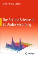
Figure 1—The relationship between VOA, VOB, and VO is carefully spelled out in TIA/EIA-485-A.
about the communications protocol to be used on the network. The software engineer has the liberty to implement whatever type of network protocol is deemed applicable for the current project. RS-485 transmission lines are differential in nature. There are two wires—A and B. The driver generates complementary voltages on A and B. Figure 1 shows how EIA-485A defines VOA, VOB, and VO. When VOA is low, VOB is high; when VOA is high, VOB is low. Most physical parts also have the ability to tristate both A and B. Signals A and B are complementary, but this doesn’t imply that one signal is a current return for the other. RS-485 is not a current loop.
The drivers and receivers must share a common ground. This is why “two-wire network” is a misnomer when applied to RS-485. More on this later. Receivers are designed to respond to the difference between A and B. VO is the differential voltage. Receivers must be sensitive to a 200-mV difference between VOA and VOB. Anything less than 200 mV is indeterminate. RS-485 can support networks up to 5000’ long and bit rates of up to 10 Mbps. Data rate must be traded off against cable length [1]. Figure 2 shows a graph fairly typical of the bit rates and line lengths you can expect. Performance will vary depending on cable type, termination, drivers and receivers used, EMI coupled into the system, and the physical geometry of the network. TIA/EIA-485-A defines a unit load (UL) and declares that an RS485 driver must be able to drive 32 ULs. The standard’s authors anticipated that device manufacturers would implement receivers and transceivers (with the driver in the high-Z state) to present a single UL load to the line.
The natural conclusion and often-repeated myth is that an RS485 network can only support 32 nodes. This is not true. Device manufacturers now sell 1/4 UL transceivers (DS1487) and even 1/8 UL parts (MAX1482). Assuming each node presents 1/8 UL to the transmission line, an RS485–compliant network may sport as many as 256 nodes (32 UL × 8 UL/node = 256 nodes). By using repeaters, multiple networks can be chained together to accommodate virtually an unlimited number of nodes. The propagation delays will become significant for large networks with multiple repeaters and long transmission lines, and the data rate may become unacceptably low. Some drivers are designed to have slow edge times. These are often referred to as slew-rate limited drivers. Slow edges have reduced high-frequency components associated with them. Longer edge times permit the use of longer cables and reduce the amount of EMI emitted by the network. Now that we have a general understanding of what an RS-485 network is, let’s examine some common pitfalls.
GETTING GROUNDED 100 mbps
10 mbps
1 mbps
Data rate 100 kbps
10 kbps
1 kbps
10
100
1k
5k
10k
Length of cable in feet
Figure 2—Trading data rate for cable length is the unfortunate consequence of finite propagation delay on the transmission line. www.circuitcellar.com
CIRCUIT CELLAR® ONLINE
Probably the least-understood issue associated with building robust RS-485 networks is proper grounding. Even though there are a number of good references on the topic, grounding seems to be misunderstood by many people [2, 3]. The common mode voltage (Vcm) is usually the parameter to be most concerned about. Figure 3 shows how Vcm is defined. TIA/EIA-485-A states, “Common-mode voltage (Vcm) is the sum of ground potential difference, generator (driver) offset voltage and longitudinally coupled noise voltage.” Vnoise is coupled identically onto both wires. The result is usually referred to as common-mode noise. If a twisted pair is used, a useful simplification is to model Vnoise as common mode. July 1999
3
Vnoise Voa
–
Vob
–
+
Vnoise +
+ – VGPD
1 Vos =
2
Voa + Vob 2
Vcm = Vos + Vnoise + VGPD
Figure 3—Common-mode voltage at the receiver depends on three parameters, two of which (Vnoise and VGPD) require attention by the engineer.
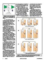
VGPD is the parameter that seems to cause the most problems. The problem stems from the oversimplification that ground is a perfect conductor capable of absorbing infinite energy, which is far from the truth [4, 5]. Earth ground potentials from circuit to circuit in an industrial installation can vary several volts under normal conditions. These voltage potentials most often stem from current leaking from equipment into the ground system. However, during electrical activity (lightning, etc.), potentials between grounds in different parts of a building can momentarily reach tens or hundreds of volts depending on the geometry of the electric fields. Potentials between grounds in different buildings can even reach thousands or hundreds of thousands of volts [5]. The practical ramification of this is that earth ground is a poor choice for referencing signal grounds on distributed network nodes. The best method for controlling VGPD is to simply run a third wire for the purpose of referencing local signal grounds. Figure 4a illustrates this process. A less desirable but commonly used method for referencing local signal grounds is illustrated in Figure 4b. This method provides a higher impedance connection between nodes, which means local grounds may drift farther apart than with the scheme in Figure 4a. However, if 4
July 1999
the local supplies are not isolated or if ground loops are a concern, you can use the current-limiting mechanism shown in Figure 4b. Figure 4c shows another variation of the scheme shown in Figure 4b. Earth ground is used as the third wire. VGPD between nodes will vary as the earth ground potential varies across the network installation. The common-mode voltage allowable between drivers and receivers on an RS-485 network is +12 to –7 V. This setup provides 7 V
A
a)
B
of protection from each rail (assuming a 5-V system). If the earth ground system in Figure 4c only varies a few volts under normal conditions, then the network will function fine. The problem comes when a voltage transient appears on the earth ground circuit, which might happen because ESD is discharged into the earth ground near a node. Or it may happen because lightning strikes nearby (perhaps half a mile away). Whatever the cause, VGPD
A
B
A
B
RS-485
RS-485
RS-485
Electronics
Electronics
Electronics
V1
+
V2
+
–
Node 1
V3
+
–
1
–
2 Node 2
3 Node 3
Third wire to reference local signal grounds
A
b)
B
A
B
A
B
RS-485
RS-485
RS-485
Electronics
Electronics
Electronics
+
V1
+
–
V2
+
–
1
V3
–
2
3
Fuse
Fuse
Fuse
100
100
100
Third wire to reference local signal grounds
A
c)
B
A
B
A
B
RS-485
RS-485
RS-485
Electronics
Electronics
Electronics
+
V1
+
–
V2
+
–
1
V3
–
2
3
Fuse
Fuse
Fuse
100
100
100
E
E
E
Earth ground is a noisy and potentially high impedance method for referencing local signal grounds.
Figure 4a—A dedicated conductor to reference signal grounds is the best method of controlling VGPD. b—The 100-ohm resistors limit current but allow larger VGPDs to develop. c—As a last resort, earth ground can be used to reference signal grounds. CIRCUIT CELLAR® ONLINE
www.circuitcellar.com
between earth grounds on a network will occur on a daily or weekly basis. When the common-mode voltage on a node drifts beyond the allowable Vcm of +12 to –7 V, the node is no longer guaranteed to function. In fact, the drivers and receivers in the node may be subject to damage. It’s up to the designer to protect the node from common-mode voltages beyond the silicon’s rating. One useful part for this is a transient voltage suppressor (TVS). As I understand it, TranZorb is a registered trademark of General Semiconductor referring only to their line of TVSs. The widespread use of “TranZorb” to refer to all TVSs is a tribute to General Semiconductor’s early dominance in the market. TVSs are silicon-based devices that utilize the nondestructive mechanism of avalanche breakdown to clamp high voltages. TVSs can be thought of as two back-to-back zener diodes that can momentarily dissipate hundreds or thousands of watts without ill effect. Unlike metal oxide varistors (MOVs) and fuses, TVSs are not sacrificial components. With proper circuit design, TVSs can protect RS485 networks indefinitely from momentary over-voltages.
SHIELDING There is some debate over the value of a shield in RS-485 cable. The only cable that Belden Wire and Cable officially recommends for RS485 (Belden 9841-9844) comes with a shield, like it or not. Likewise, Alpha Wire only recommends a shielded cable (Alpha 6222-6230) for use with RS-485 networks. After talking with engineers at both Alpha and Belden, I concluded that they recommend shielded cables because a shielded cable will work for virtually all applications. Better to have a shield and not need it than to get a network wired and find you need a shield but don’t have it. That’s all well and good if you sell cable or have lots of someone else’s money to spend. Back in the www.circuitcellar.com
real world, the tradeoffs of price versus performance must be considered. Shielded cable is often more expensive than unshielded cable and can be more difficult to physically work with. RS-485 receivers have excellent common-mode rejection characteristics. By using twisted pair, all but the weirdest noise sources will be similarly coupled to each conductor. The differential nature of TIA/EIA485-A receivers makes them operate remarkably well with horrible levels of common-mode noise on the network cables. If your network cabling is run in a conduit or cable trays (as long as the data cable is separate from AC power cables), shielded network cable probably isn’t a great concern. However, if you have network cables stapled to rafters, slung under conveyer belts, or terminated on an RS-485 box that monitors the temperature in a weld shop, shielded cable is for you. If data integrity is of utmost importance, you’re going to want to consider shielded cable. For example, if a serious corruption of packets or the network latency associated with straightening out the message stream would cause loss of product, shielded cable can be cheap insurance. The most interesting application
of shielded cable that I’ve heard about is an RS-485 network buried in a golf course. The network consists of buried sensors that detect the impact of golf balls on the course. The system had difficulty with network nodes being damaged by nearby lightning events. Once a shielded network cable was installed and earth grounded on each end, the failure rate dropped to an acceptable level. If your network is likely to be subjected to high-intensity fields, consider a shielded network cable. Assuming you have a shield, the next question is, “What do I do with it?” To keep within the breadth of this article, the answer is, “It depends on the type of fields to which your network cable is being subjected.” Henry Ott’s book, Noise Reduction Techniques in Electronic Systems is a bible for engineers dealing with EMI/RFI issues [6]. I highly recommend this text to answer the question in detail.
TOPOLOGY If the signals on the network are slow, the bit edges are long, and the cable runs are short, topology is not an issue. But, the question of network topology will crop up from time to time. As soon as transmission-line effects begin to show up, there is only one simple topology for manag-
Backbone with stubs (workable)
Backbone with stars or clusters (avoid)
Star network (avoid)
Daisy chain (best)
Ring (avoid)
Figure 5—Many common network topologies exist, but the daisy chain is the most reliable for RS-485 networks.. CIRCUIT CELLAR® ONLINE
July 1999
5
ing them. Figure 5 shows several network topologies. Only the daisy chain is easy to manage reflections on. This is not to say, for example, that it’s impossible to implement a star configuration with RS-485 devices. Keeping reflections under control in a star topology is more art than science in a practical network. The best way to ensure a robust and reliable RS-485 network is to build it around a daisy-chain configuration. There are several rules of thumb to follow when predicting if the line is long enough to be a transmission line. One common rule states that transmission-line effects will begin to occur when the signal rise time is less than 4× the one-way propagation delay of the cable [7]. Most twisted-pair have a propagation speed of 66–77% of the speed of light. Cable manufacturers publish this specification for their network cables. By knowing the approximate length of the network cable, the one-way propagation can be computed by knowing that PropTime equals CableLength divided by PropSpeed.
The resistor should have the same value as the characteristic impedance (Zo) of the transmission line. Cable manufacturers publish Zo for their network cables. The larger the Zo, the less power Rp (which is equal to Zo) must dissipate as heat. The most common RS-485 twisted pairs have a Zo of 100–120 ohms. Category 5 (CAT-5) cable offers a 100-ohm Zo, typically has four pairs, and is widely available. The Belden RS-485 cables (98419844) have a Zo of 120 ohms. Alpha Wire cables (Alpha 6222-6230) have a Zo of 100 ohms. The third termination technique is a bidirectional termination, which offers excellent signal integrity. With this technique, the line drivers can be anywhere on the network. The disadvantage is power consumption. This technique is probably the most reliable RS-485 termination technique.
The fourth and most dubious technique is called AC termination. The idea is to use the capacitor as a DC blocking element to reduce power consumption. In practice, I have never seen this technique do anything except butcher signal integrity. The National Semiconductor application note describes a design methodology for this type of termination [7]. I’m willing to believe this technique is useful in some applications, but I’m also pretty sure a fair degree of tweaking is required to get this system to function reliably. The last subject related to termination is what to do with unused conductors in a data cable. Unused conductors will self-resonate and couple noise into the data wires. If the unused cables are left open, they will resonate at all sorts of strange frequencies. If they are grounded at one end, they will resonate at L/2. If they are grounded
D/R
D/R
TERMINATION Assuming the network cable is long enough for transmission-line effects to arise, what termination technique should be used to mitigate reflections? There are quite a few termination methods available. National Semiconductor has published a 10-page application note that describes seven distinct techniques [7]. The four techniques that I will review are shown in Figure 6. Unterminated networks are low power, low cost, and simple to build. The disadvantage, of course, is that data rates must be quite slow or cable length must be short for the network to operate reliably. A parallel termination offers excellent data rates but is limited to networks that only have one driver. The driver must be located on one end of the network and the termination resistor must be located on the far end. 6
July 1999
D/R
D/R
Unterminated
D
R
Rp*
*RP = Zo R
R
Parallel Termination
D/R
Rp*
Rp*
D/R
*RP = Zo D/R
D/R
Bidirectional termination
RT
D
CT AC termination
R
RT, CT see reference [7]
Figure 6—Several termination methods are widely used on RS-485 networks
CIRCUIT CELLAR® ONLINE
www.circuitcellar.com
at both ends, they resonate at L/4. The best method for minimizing energy on an unused conductor is to dissipate the energy as heat. In short, terminate both ends of the unused conductor to ground with resistors (a bidirectional termination). The resistors should be equal to the characteristic impedance of the line. IDLE-STATE BIASING An article on RS-485 wouldn’t be complete without mentioning idlestate biasing, also called failsafe biasing. Once again, National Semiconductor and John Goldie have the seminal treatise on the subject, and I would encourage you to refer to this existing work for analytical details [8]. RS-485 networks with multiple transmitters on the same communication channel rely on the line drivers to tristate when not talking. This arrangement allows the two conductors in the transmission line to float, which can cause the line receivers listening to the network to register false data. TIA/EIA-485-A purposely leaves the region of less than 200 mV of differential voltage as an undefined state. To get around this situation, two resistors are often used to pull one line high while the other line is pulled low. This process is referred to as idle-state biasing because the line is said to be idle when it is not being actively driven by a transmitter. The impact of the idle-state bias resistors on line termination must be considered, as should their physical location in the network. Depending on the application, it may be better to use a series of high-valued resistors distributed across many nodes than two smaller-valued resistors placed at the end of the line. Another situation to consider is what happens when power goes down to a node with idle-state bias resistors installed. And likewise, what effect on the network’s idle state is there when a node with failsafe biasing is removed from the www.circuitcellar.com
network? These issues and more are adequately addressed by Goldie [8]. TRANSIENTS ESD and capacitively or inductively coupled transients are a fact of life often overlooked when designing communication networks. Recently, I was part of an investigative team of engineers sent to a customer’s site to assist in determining why 200–400 of their 4000 RS485 nodes were going down daily. The problem turned out to be transient voltages on the data lines. The network had a mix of RS485–based equipment on it. Several different manufacturers supplied the various pieces of equipment. The failures were mostly isolated to RS485 receiver chips but were not isolated to just our equipment. The failures had existed at a nuisance level for several years. Then late last year, the customer experienced a drastic increase in failure rates. By the time we were called, 10% of their nodes were going down each day. Over the last few years, several network consultants had been brought in to address the network failures. None of them met with much success. By the time we arrived, the failure rate was at a catastrophic level. The customer had done almost everything by the book. The network cabling was commercial CAT-5. The network topology was straightforward. The lines were adequately terminated. Each node had a power supply isolated from earth ground. The network cable had a wire dedicated to connecting signal grounds between nodes. Each individual network consisted of 50–150 nodes and each node used a 1-UL receiver. Although this violated TIA/EIA-485-A, an oscilloscope verified that the transmission lines were carrying nice clean square waves of reasonable magnitude and offsets. And besides, the receiver chips were blowing, not the transmitters. Most of the receiver chips were CIRCUIT CELLAR® ONLINE
dual or quad devices. Autopsies performed on the damaged chips revealed that often only one receiver on the chip was blown; the others were usually functional. After a while, it was clear that transient voltages were finding their way onto the data lines. We were not able to identify any single source or to nail down any single coupling mechanism. Even if we were, the facility was fixed and we probably couldn’t have altered the system to mitigate the source(s) or coupling mechanisms. We had to devise a method of eliminating the problem at the board level. First, we had to find a method of mimicking the symptoms in the lab. To accomplish this, we used a Shaffner NSG-435 ESD gun to simulate transient events on the transmission lines. After building a small network in the lab and discharging energy into the data lines directly, we found that the most common receiver in the customer’s system, a TI 75175 quad receiver, was always destroyed with a single 2-kV air-gap discharge into either or both data lines. We saw one part fail as low as 1 kV. The most common threshold seemed to be 1.4–1.7 kV. It’s interesting to note that a 1-kV air gap discharge is right on the edge of human perception. This means the receiver chips could be destroyed by ESD that may not even be noticeable to a human technician. We tried two TVS schemes with the existing receivers. Both increased the ability of the receivers to tolerated transient events. Figure 7a shows the simplest and most effective method. The circuit in Figure 7a seemed to protect the 75175s to about 8 kV. The tradeoff for good transient voltage protection is a fairly high capacitive loading. The TranZorbs used had an open-circuit capacitance of 500 pF. Figure 7b shows our second experiment, which only protected the 75175s to about 4 kV. The circuit uses a bridge with a low capacitance (about 13 pF) in series July 1999
7
with the TranZorbs. This is a fairly common circuit used to protect highspeed data lines. Our experiments were done in haste, and although we maintained as much laboratory discipline as we could muster, further experiments should be run before the above thresholds of 4 and 8 kV are accepted as gospel. However, the results are certainly valid in a qualitative sense. Both TVS schemes provided significant improvement in the ability of the TI 75175 to withstand transient voltage events. Our last experiment involved a Maxim part, the MAX3095. The datasheet for this part claims a ±15kV protection using IEC1000-4-2 airgap discharge, ±8 kV using IEC1000-4-2 contact discharge, and ±15 kV using the Human Body Model. Even though the Maxim part has only been out about a year, availability is good. Using our ESD gun, we methodically zapped the Maxim part but were unable to destroy or even notably degrade the performance of any of the MAX3095 parts we tested. In a last ditch 4:30 A.M. attempt to get a failure point for the Maxim data set, we hammered one of the parts with 50 shots of 16.5-kV air-gap discharges. The NiCad battery pack on our ESD gun ran down, but the MAX3095 didn’t even blink. We only had a small group of five sacrificial Maxim chips. So, once again, the limited sample set puts the quantitative value of our data in the dubious column at best. However, it is clear qualitatively that the MAX3095 is a rugged little part. Maxim is infamous for long lead times, super-high prices, and lackluster customer support, but I’ve never heard of Maxim lying on a datasheet. I’m not a fan of Maxim’s aloof manner of doing business, but I do believe their datasheets and I’m totally sold on this little receiver. Maxim has parts with high ESD ratings that are pin compatible with the widely used MC1488 and MC1489 parts for RS-232 applica8
July 1999
tions, as well as other ESD-hardened interface parts. In the end, we recommended trading out the TI 75175 for the MAX3095. These two parts are not pin-for-pin compatible in all applications, but for our customer’s equipment, the MAX3095 dropped right into the existing 75175 sockets and fired up. The MAX3095 is a 1/4 UL part, which meant that we were also reducing the load on the network by 4×. The longest runs of 150 nodes were still slightly above the TIA/EIA485-A allowable limit of 32 ULs (150/4- ~38). After installing the Maxim parts, the signal levels on all the transmission lines improved significantly. At the time of this writing, our customer has over eight million machine hours on the MAX3095s and not a single failure of the Maxim parts. This was as close to a silver bullet as I’ve ever seen. Only time will tell if the MAX3095s will weaken with age and have to be placed on a preventative maintenance schedule, but it doesn’t look
like that will be the case. I learned one other interesting lesson from this trip. Beware the local customs. The customer’s maintenance crew was fairly sharp. Years ago, the technicians learned that the most delicate part was the receiver chip, so they adopted the custom of carrying tubes of these parts around and replacing the parts in situ. This facility was one of the worst imaginable environments for ESD. Humidity was 10–17%. The crews were required to wear polyester uniforms and most of the facility was carpeted. The maintenance personnel were not trained in basic ESD precautions. In the process of replacing damaged ICs, they were damaging the new ICs they were installing. Furthermore, the technicians would handle bare network cable during the repair, which meant they would discharge static electricity into the transmission, damaging other nodes on the network. Remember our lab tests where the TI 75175 failed at level of ESD that
Vcc
SMBJ18CA L1
20
L2
20
L3
20
75175 R
SMBJ18CA 20
To data network
L4
SMBJ18CA L1, L2, L3, L4 = Ferrite bead
Vcc L1
20
L3
30.1
75175 Bridge DF02S –
R
L2
20
+
To data network
L4
30.1
SMBJ14CA
SMBJ14CA L1, L2, L3, L4 = Ferrite bead
Figure 7a—TVSs directly on the data line provide the highest level of protection and the highest capacitive loading of the transmission line. b—This is common circuit for protecting high-speed data lines. CIRCUIT CELLAR® ONLINE
www.circuitcellar.com
was barely perceptible to humans? Also, cable contractors were often employed by the facility. These contractors would install or modify network cable to suit the needs of the facility’s ever-changing geometry. The contractors were handling bare network cable, with hundreds of nodes connected, and using no ESD protocol. Our customer has since trained their maintenance personnel in proper ESD protocol. As a matter of contract, outside cable consultants are required to undergo the same ESD training and exercises as the in-house staff. These procedures have significantly contributed to the reduction of failures.
REVIEW TIME RS-485 is not difficult, but any workhorse requires care and feeding. Before starting your RS-485 project, arm yourself with the TIA/ EIA-485-A and TSB-89 documents. While designing, rely on the many examples others have published in articles and application notes. Keep an eye out for nonnetwork-related problems like ESD, power-supply noise, and ground bounce. The currents switched at the drivers can be quite high. Also watch out for new parts like the MAX3095. They may be just what the doctor ordered for your future designs. Engineering is simply keeping track of details and making tradeoffs. RS-485 is no different. We’re lucky because most of the really ugly tradeoffs have been made by the standards. But you probably don’t have to worry about having your job phased out as there are still plenty of other details left to keep track of.
www.circuitcellar.com
Bob Perrin spends his days designing general-purpose Cprogrammable embedded controllers and troubleshooting customer system-level problems for Z-World (www.zworld.com). Over the last ten years, Bob has designed instrumentation for agronomy, soil physics, and water activity research. He was also the lead design engineer for an intrinsically safe line of workstations for use in explosive gas and particulate environments (class 1, divisions 1 and 2). For more articles by Bob, visit his online library at www.engineerbob.com.
REFERENCES [1] J. Goldie, Ten Ways to Bulletproof RS-485 Interfaces, National Semiconductor, App note AN-1057, 1996. [2] Robust DataComm, Grounding and RS-422/485 (No Free Lunch!), Robust DataComm, App note 5, 1997. [3] R. Morrison, Grounding and Shielding Techniques in Instrumentation, 3d ed., Wiley and Sons, New York, NY, 1986. [4] R. Morrison, Solving Interference Problems in Electronics, Wiley and Sons, New York, NY, 1995. [5] Robust DataComm, Surge Management, Robust DataComm, App note 18, 1997.
SOURCES RS-485 cable Alpha Wire Co. (800) 522-5742 (908) 985-8000 Fax: (908) 925-6923 www.alphawire.com Belden Wire and Cable Co. (800) 235-3361 (765) 983-5200 Fax: (765) 983-5294 www.belden.com TransZorb General Semiconductor (516) 847-3113 Fax: (516) 847-3236 www.gensemi.com MAX3095 Maxim Integrated Products (408) 737-7600 Fax: (408) 737-7194 www.maxim-ic.com NSG-435 ESD gun Schaffner EMC, Inc. (973) 379-7778 www.schaffner.com TI 75175 Texas Instruments, Inc. (800) 477-8924, x4500 (972) 995-2011 Fax: (972) 995-4360 www.ti.com
[6] H.W. Ott, Noise Reduction Techniques in Electronic Systems, 2d ed., Wiley and Sons, New York, NY, 1988.
TIA/EIA-485-A, TSB89-Application guidelines for TIA/EIA485-A Global Engineering Documents (800) 854-7179 (303) 397-7956 Fax: (303) 397-2740 global.ihs.com
[7] J. Vo, A Comparison of Differential Termination Techniques, National Semiconductor, App note AN-903, 1993.
National Semiconductor (408) 721-5000 Fax: (408) 739-9803 www.national.com
[8] J. Goldie, Failsafe Biasing of Differential Buses, National Semiconductor, App Note AN847, 1992.
Robust DataComm, Inc. (612) 628-0533 www.robustdc.com
CIRCUIT CELLAR® ONLINE
July 1999
9