SD Card Projects Using the PIC Microcontroller 185617719X, 9781856177191, 9780080961262
PIC Microcontrollers are a favorite in industry and with hobbyists. These microcontrollers are versatile, simple, and lo
318 26 5MB
English Pages 571 Year 2010
Recommend Papers


File loading please wait...
Citation preview
SD Card Projects Using the PIC Microcontroller
This page intentionally left blank
SD Card Projects Using the PIC Microcontroller Dogan Ibrahim
AMSTERDAM•BOSTON•HEIDELBERG•LONDON NEWYORK•OXFORD•PARIS•SANDIEGO SANFRANCISCO•SINGAPORE•SYDNEY•TOKYO NewnesisanimprintofElsevier
NewnesisanimprintofElsevier 30CorporateDrive,Suite400,Burlington,MA01803,USA TheBoulevard,LangfordLane,Kidlington,Oxford,OX51GB,UK © 2010 Elsevier Ltd. All rights reserved. Nopartofthispublicationmaybereproducedortransmittedinanyformorbyanymeans,electronicor mechanical,includingphotocopying,recording,oranyinformationstorageandretrievalsystem,without permissioninwritingfromthePublisher.Detailsonhowtoseekpermission,furtherinformationaboutthe Publisher’spermissionspoliciesandourarrangementswithorganizationssuchastheCopyrightClearanceCenter andtheCopyrightLicensingAgency,canbefoundatourWebsite,www.elsevier.com/permissions. ThisbookandtheindividualcontributionscontainedinitareprotectedundercopyrightbythePublisher(other thanasmaybenotedherein). Notices Knowledgeandbestpracticeinthisieldareconstantlychanging.Asnewresearchandexperiencebroadenour understanding,changesinresearchmethods,professionalpractices,ormedicaltreatmentmaybecomenecessary. Practitionersandresearchersmustalwaysrelyontheirownexperienceandknowledgeinevaluatingandusing anyinformation,methods,compounds,orexperimentsdescribedherein.Inusingsuchinformationormethods theyshouldbemindfuloftheirownsafetyandthesafetyofothers,includingpartiesforwhomtheyhavea professionalresponsibility. Tothefullestextentofthelaw,neitherthePublishernortheauthors,contributors,oreditorsassumeanyliability foranyinjuryand/ordamagetopersonsorpropertyasamatterofproductsliability,negligenceorotherwise,or fromanyuseoroperationofanymethods,products,instructions,orideascontainedinthematerialherein. Library of Congress Cataloging-in-Publication Data Ibrahim,Dogan. SDcardprojectsusingthePICmicrocontroller/DoganIbrahim. p.cm. Includesbibliographicalreferencesandindex. ISBN978-1-85617-719-1(alk.paper) 1.Microcontrollers—Programming.2.Programmablecontrollers.3.Computerstoragedevices.I.Title. TJ223.P76.I2752010 004.16—dc22 2009041498 British Library Cataloguing-in-Publication Data AcataloguerecordforthisbookisavailablefromtheBritishLibrary. ForinformationonallNewnespublications, visitourWebsite,www.elsevierdirect.com PrintedintheUnitedStatesofAmerica 101112987654321
Typeset by:diacriTech,Chennai,India
Copyright Exceptions Thefollowingmaterialhasbeenreproducedwiththekindpermissionoftherespective copyrightholders.Nofurtherreprintsorreproductionsmaybemadewithoutthepriorwritten consentoftherespectivecopyrightholders: Figures2.1–2.11,2.23–2.37,2.39,2.42–2.56,4.63,4.64,5.2–5.4,5.12,5.19,5.22,5.23, 7.1–7.3andTable2.2aretakenfromMicrochipTechnologyInc.DataSheetsPIC18FXX2 (DS39564C)andPIC18F2455/2550/4455/4550(DS39632D). MDDlibraryfunctionsinChapter8aretakenfromMicrochipApplicationNoteAN1045 (DS01045B),“ImplementingFileI/OFunctionsUsingMicrochip’sMemoryDiskDriveFile SystemLibrary.” Figure5.5istakenfromtheWebsiteofBAJILabs. Figures5.6–5.8aretakenfromtheWebsiteofShuanShizuEnt.Co.,Ltd. Figures5.9,5.14,and5.20aretakenfromtheWebsiteofCustomComputerServicesInc. Figures5.10and5.21aretakenfromtheWebsiteofMikroElektronikaLtd. Figure5.11istakenfromtheWebsiteofFuturlec. Figure5.13istakenfromtheWebsiteofForestElectronics. Figure5.24istakenfromtheWebsiteofSmartCommunicationsLtd. Figure5.25istakenfromtheWebsiteofRFSolutions. Figure5.26istakenfromtheWebsiteofPhyton. Figures5.1,5.14,and5.15aretakenfromtheWebsiteofmicroEngineeringLabsInc. Figures5.16and5.17aretakenfromtheWebsiteofKandaSystems. Figure5.18istakenfromtheWebsiteofBrunningSoftware. Figure5.30(partno:FL/IDL800.UK)istakenfromtheWebsiteofFliteElectronics InternationalLtd. v
vi
Copyright Exceptions
SDcardregisterdeinitionsinChapter3aretakenfromSandiskCorporation“SDCard ProductManual,Rev.1.9,”Documentno:80-13-00169,2003. AppendixesAandDaretakenfromtheWebsiteofMotorolaSemiconductorsInc. AppendixBistakenfromtheWebsiteofTexasInstrumentsInc. AppendixCistakenfromtheWebsiteofNationalSemiconductorCorporation. ThanksisduetoMicrochipLtdfortheirtechnicalsupportandpermissiontoincludeMPLAB IDE,MDDlibrary,andStudentVersionoftheMPLABC18compilerontheWebsitethat accompaniesthisbook. PIC®,PICSTART®,andMPLAB®areallregisteredtrademarksofMicrochipTechnologyInc.
Contents Preface .............................................................................................................xix About the Web Site.......................................................................................... xxiii Chapter 1: Microcontroller Systems .......................................................................1 1.1 Introduction.................................................................................................................. 1 1.2 MicrocontrollerSystems.............................................................................................. 1 1.2.1 RandomAccessMemory................................................................................. 4 1.2.2 ReadOnlyMemory.......................................................................................... 5 1.2.3 ProgrammableReadOnlyMemory................................................................. 5 1.2.4 ErasableProgrammableReadOnlyMemory................................................... 5 1.2.5 ElectricallyErasableProgrammableReadOnlyMemory............................... 5 1.2.6 FlashEEPROM................................................................................................ 6 1.3 MicrocontrollerFeatures.............................................................................................. 6 1.3.1 Buses................................................................................................................ 6 1.3.2 SupplyVoltage................................................................................................. 6 1.3.3 TheClock......................................................................................................... 7 1.3.4 Timers............................................................................................................... 7 1.3.5 Watchdog.......................................................................................................... 7 1.3.6 ResetInput........................................................................................................ 8 1.3.7 Interrupts.......................................................................................................... 8 1.3.8 Brown-OutDetector......................................................................................... 8 1.3.9 A/DConverter.................................................................................................. 8 1.3.10 SerialI/O........................................................................................................ 9 1.3.11 EEPROMDataMemory................................................................................. 9 1.3.12 LCDDrivers................................................................................................. 10 1.3.13 AnalogComparator...................................................................................... 10 1.3.14 Real-TimeClock.......................................................................................... 10 1.3.15 SleepMode................................................................................................... 10 1.3.16 Power-onReset............................................................................................. 10 1.3.17 Low-PowerOperation.................................................................................. 10 1.3.18 CurrentSink/SourceCapability................................................................... 11 1.3.19 USBInterface............................................................................................... 11 1.3.20 MotorControlInterface................................................................................ 11
vii
viii
Contents 1.3.21 ControllerAreaNetworkInterface............................................................... 11 1.3.22 EthernetInterface......................................................................................... 11 1.3.23 ZigBeeInterface........................................................................................... 11 1.4 MicrocontrollerArchitectures.................................................................................... 11 1.4.1 ReducedInstructionSetComputerandComplexInstruction SetComputer.................................................................................................. 12 1.5 ChoosingaPICMicrocontroller................................................................................ 12 1.6 NumberSystems......................................................................................................... 13 1.6.1 DecimalNumberSystem............................................................................... 13 1.6.2 BinaryNumberSystem.................................................................................. 13 1.6.3 OctalNumberSystem.................................................................................... 14 1.6.4 HexadecimalNumberSystem........................................................................ 14 1.7 ConvertingBinaryNumbersintoDecimal................................................................. 14 1.8 ConvertingDecimalNumbersintoBinary................................................................. 16 1.9 ConvertingBinaryNumbersintoHexadecimal......................................................... 18 1.10 ConvertingHexadecimalNumbersintoBinary....................................................... 19 1.11 ConvertingHexadecimalNumbersintoDecimal..................................................... 20 1.12 ConvertingDecimalNumbersintoHexadecimal..................................................... 21 1.13 ConvertingOctalNumbersintoDecimal................................................................. 21 1.14 ConvertingDecimalNumbersintoOctal................................................................. 22 1.15 ConvertingOctalNumbersintoBinary.................................................................... 24 1.16 ConvertingBinaryNumbersintoOctal.................................................................... 24 1.17 NegativeNumbers.................................................................................................... 25 1.18 AddingBinaryNumbers.......................................................................................... 26 1.19 SubtractingBinaryNumbers.................................................................................... 27 1.20 MultiplicationofBinaryNumbers........................................................................... 28 1.21 DivisionofBinaryNumbers.................................................................................... 29 1.22 FloatingPointNumbers............................................................................................ 30 1.23 ConvertingaFloatingPointNumberintoDecimal.................................................. 31 1.23.1 NormalizingtheFloatingPointNumbers.................................................... 32 1.23.2 ConvertingaDecimalNumberintoFloatingPoint...................................... 33 1.23.3 MultiplicationandDivisionofFloating PointNumbers.............................................................................................. 34 1.23.4 AdditionandSubtractionofFloatingPointNumbers.................................. 35 1.24 Binary-CodedDecimalNumbers............................................................................. 36 1.25 Summary.................................................................................................................. 38 1.26 Exercises................................................................................................................... 38
Chapter 2: PIC18F Microcontroller Series ............................................................41 2.1 PIC18FXX2Architecture........................................................................................... 44 2.1.1 ProgramMemoryOrganization...................................................................... 47 2.1.2 DataMemoryOrganization............................................................................ 49 2.1.3 TheConigurationRegisters........................................................................... 49 2.1.4 ThePowerSupply.......................................................................................... 50 2.1.5 TheReset........................................................................................................ 53
Contents
ix
2.1.6 TheClockSources......................................................................................... 57 2.1.7 WatchdogTimer............................................................................................. 62 2.1.8 ParallelI/OPorts............................................................................................ 63 2.1.9 Timers............................................................................................................. 69 2.1.10 Capture/Compare/PWMModules................................................................ 77 2.1.11 PulseWidthModulationModule................................................................. 80 2.1.12 Analog-to-DigitalConverterModule........................................................... 84 2.1.13 Interrupts...................................................................................................... 91 2.2 Summary.................................................................................................................. 103 2.3 Exercises................................................................................................................... 103
Chapter 3: Memory Cards ................................................................................107 3.1 MemoryCardTypes................................................................................................. 107 3.2 SmartMediaCard.................................................................................................... 108 3.3 MultimediaCard....................................................................................................... 109 3.4 CompactFlashCard................................................................................................. 110 3.5 MemoryStickCard.................................................................................................. 111 3.6 Microdrive................................................................................................................ 112 3.7 xDCard.................................................................................................................... 112 3.8 SecureDigitalCard.................................................................................................. 113 3.8.1 StandardSDCards....................................................................................... 113 3.8.2 High-CapacitySDCards.............................................................................. 115 3.9 MemoryCardReaders.............................................................................................. 116 3.10 MemoryCardPhysicalProperties.......................................................................... 117 3.11 MemoryCardTechnicalProperties........................................................................ 117 3.12 DetailedSDCardStructure.................................................................................... 118 3.12.1 SDCardPinConiguration........................................................................ 118 3.12.2 SDCardInterface....................................................................................... 119 3.13 SDCardInternalRegisters..................................................................................... 122 3.13.1 OCRRegister............................................................................................. 123 3.13.2 CIDRegister............................................................................................... 123 3.13.3 CSDRegister.............................................................................................. 125 3.13.4 RCARegister............................................................................................. 130 3.13.5 DSRRegister.............................................................................................. 130 3.13.6 SCRRegister.............................................................................................. 131 3.13.7 SDStatusRegister...................................................................................... 131 3.14 CalculatingtheSDCardCapacity.......................................................................... 131 3.15 SDCardSPIBusProtocol...................................................................................... 132 3.15.1 DataRead................................................................................................... 132 3.15.2 DataWrite.................................................................................................. 132 3.15.3 ResponseTokens........................................................................................ 133 3.16 DataTokens............................................................................................................ 134 3.17 CardResetState..................................................................................................... 135 3.18 Summary................................................................................................................ 135 3.19 Exercises................................................................................................................. 136
x
Contents
Chapter 4: Programming with the MPLAB C18 Compiler ....................................137 4.1 CProgrammingLanguagesforPIC18Microcontrollers......................................... 137 4.2 MPLABC18Compiler............................................................................................ 138 4.2.1 InstallingtheMPLABC18Compiler.......................................................... 138 4.3 AnExampleProgram............................................................................................... 143 4.3.1 BuildingtheProject...................................................................................... 143 4.3.2 SimulatingtheProject.................................................................................. 147 4.4 FlashingLEDExample............................................................................................ 150 4.4.1 BuildingandSimulatingtheProject............................................................ 150 4.5 StructureoftheMPLABC18Compiler................................................................... 152 4.5.1 Comments..................................................................................................... 152 4.5.2 TerminatingProgramStatements................................................................. 154 4.5.3 WhiteSpaces................................................................................................ 154 4.5.4 CaseSensitivity............................................................................................ 154 4.5.5 VariableNames............................................................................................ 155 4.5.6 VariableTypes.............................................................................................. 155 4.5.7 Constants...................................................................................................... 157 4.5.8 EscapeSequences......................................................................................... 159 4.5.9 StaticVariables............................................................................................. 160 4.5.10 ExternalVariables...................................................................................... 160 4.5.11 VolatileVariables........................................................................................ 160 4.5.12 EnumeratedVariables................................................................................. 160 4.5.13 Arrays......................................................................................................... 161 4.5.14 Pointers....................................................................................................... 162 4.5.15 Structures.................................................................................................... 164 4.5.16 Unions........................................................................................................ 167 4.5.17 OperatorsinC............................................................................................ 168 4.5.18 ModifyingtheFlowofControl.................................................................. 178 4.5.19 IterationStatements.................................................................................... 181 4.5.20 MixingC18withAssemblyLanguageStatements.................................... 187 4.6 PICMicrocontrollerI/OPortProgramming............................................................ 188 4.7 ProgrammingExamples........................................................................................... 189 4.8 Functions.................................................................................................................. 193 4.8.1 FunctionPrototypes...................................................................................... 198 4.8.2 PassingArraystoFunctions......................................................................... 199 4.8.3 PassingVariablesbyReferencetoFunctions............................................... 204 4.8.4 StaticFunctionVariables.............................................................................. 204 4.9 MPLABC18LibraryFunctions............................................................................... 206 4.9.1 DelayFunctions............................................................................................ 207 4.9.2 CharacterClassiicationFunctions............................................................... 211 4.9.3 DataConversionFunctions.......................................................................... 213 4.9.4 MemoryandStringManipulationFunctions............................................... 213 4.9.5 ResetFunctions............................................................................................ 216 4.9.6 CharacterOutputFunctions......................................................................... 218
Contents
xi
4.9.7 MathLibraryFunctions................................................................................ 222 4.9.8 LCDFunctions............................................................................................. 225 4.9.9 SoftwareCAN2510Functions..................................................................... 239 4.9.10 SoftwareI2CBusFunctions....................................................................... 239 4.9.11 SoftwareSPIBusFunctions....................................................................... 239 4.9.12 SoftwareUARTFunctions......................................................................... 239 4.9.13 HardwareAnalog-to-Digital(A/D)ConverterFunctions.......................... 245 4.9.14 HardwareInputCaptureFunctions............................................................ 247 4.9.15 HardwareI2CFunctions............................................................................. 247 4.9.16 HardwareI/OPortFunctions..................................................................... 247 4.9.17 HardwareMicrowireFunctions.................................................................. 247 4.9.18 HardwarePulseWidthModulationFunctions........................................... 247 4.9.19 HardwareSPIFunctions............................................................................. 248 4.9.20 HardwareTimerFunctions......................................................................... 248 4.9.21 HardwareUSARTFunctions...................................................................... 249 4.10 Summary................................................................................................................ 252 4.11 Exercises................................................................................................................. 253
Chapter 5: PIC18 Microcontroller Development Tools .........................................257 5.1 SoftwareDevelopmentTools................................................................................... 257 5.1.1 TextEditors.................................................................................................. 258 5.1.2 AssemblersandCompilers........................................................................... 258 5.1.3 Simulators..................................................................................................... 259 5.1.4 High-LevelLanguageSimulators................................................................. 259 5.1.5 IntegratedDevelopmentEnvironments........................................................ 260 5.2 HardwareDevelopmentTools.................................................................................. 260 5.2.1 DevelopmentBoards.................................................................................... 260 5.2.2 DeviceProgrammers.................................................................................... 274 5.2.3 In-CircuitDebuggers.................................................................................... 276 5.2.4 In-CircuitEmulators..................................................................................... 280 5.2.5 Breadboards.................................................................................................. 283 5.3 UsingtheMPLABICD3In-CircuitDebugger....................................................... 285 5.3.1 TheDebuggingProcess................................................................................ 288 5.3.2 TheMPLABICD3TestInterfaceBoard.................................................... 289 5.3.3 ProgrammingwiththeMPLABICD3Debugger........................................ 289 5.3.4 MPLABICD3DebuggingExampleI......................................................... 292 5.3.5 MPLABICD3DebuggingExampleII........................................................ 293 5.3.6 MPLABICD3DebuggingExampleIII...................................................... 294 5.4 Summary.................................................................................................................. 296 5.5 Exercises................................................................................................................... 296
Chapter 6: PIC18 Microcontroller MPLAB C18-Based Simple Projects .................299 6.1 ProgramDescriptionLanguage................................................................................ 299 6.1.1 START-END................................................................................................. 300 6.1.2 Sequencing................................................................................................... 300
xii
Contents 6.1.3 IF-THEN-ELSE-ENDIF.............................................................................. 301 6.1.4 DO-ENDDO................................................................................................. 301 6.1.5 REPEAT-UNTIL.......................................................................................... 303 6.2 Project1–ChasingLEDs........................................................................................ 304 6.2.1 ProjectDescription....................................................................................... 304 6.2.2 ProjectHardware.......................................................................................... 305 6.2.3 ProjectPDL.................................................................................................. 306 6.2.4 ProjectProgram............................................................................................ 306 6.2.5 FurtherDevelopment.................................................................................... 306 6.3 Project2–LEDDice............................................................................................... 308 6.3.1 ProjectDescription....................................................................................... 308 6.3.2 ProjectHardware.......................................................................................... 308 6.3.3 ProjectPDL.................................................................................................. 310 6.3.4 ProjectProgram............................................................................................ 310 6.3.5 UsingaPseudorandomNumberGenerator.................................................. 311 6.4 Project3–Two-DiceProject................................................................................... 314 6.4.1 ProjectDescription....................................................................................... 314 6.4.2 ProjectHardware.......................................................................................... 315 6.4.3 ProjectPDL.................................................................................................. 316 6.4.4 ProjectProgram............................................................................................ 316 6.5 Project4–TwoDiceProject–FewerI/OPins........................................................ 318 6.5.1 ProjectDescription....................................................................................... 318 6.5.2 ProjectHardware.......................................................................................... 319 6.5.3 ProjectPDL.................................................................................................. 321 6.5.4 ProjectProgram............................................................................................ 321 6.5.5 ModifyingtheProgram................................................................................ 322 6.6 Project5–Seven-SegmentLEDCounter................................................................ 326 6.6.1 ProjectDescription....................................................................................... 326 6.6.2 ProjectHardware.......................................................................................... 328 6.6.3 ProjectPDL.................................................................................................. 330 6.6.4 ProjectProgram............................................................................................ 330 6.6.5 ModiiedProgram........................................................................................ 332 6.7 Project6–Two-DigitMultiplexedSeven-SegmentLED........................................ 333 6.7.1 ProjectDescription....................................................................................... 333 6.7.2 ProjectHardware.......................................................................................... 335 6.7.3 ProjectPDL.................................................................................................. 335 6.7.4 ProjectProgram............................................................................................ 337 6.8 Project7–Two-DigitMultiplexedSeven-SegmentLEDCounterWith TimerInterrupt......................................................................................................... 338 6.8.1 ProjectDescription....................................................................................... 338 6.8.2 ProjectHardware.......................................................................................... 341 6.8.3 ProjectPDL.................................................................................................. 341 6.8.4 ProjectProgram............................................................................................ 341 6.8.5 ModifyingtheProgram................................................................................ 345
Contents
xiii
6.9 Project8–Four-DigitMultiplexedSeven-SegmentLEDCounterWith TimerInterrupt......................................................................................................... 347 6.9.1 ProjectDescription....................................................................................... 347 6.9.2 ProjectHardware.......................................................................................... 347 6.9.3 ProjectPDL.................................................................................................. 348 6.9.4 ProjectProgram............................................................................................ 348 6.9.5 ModifyingtheProgram................................................................................ 352 6.9.6 UsingMPLABC18CompilerTimerLibraryRoutines............................... 352 6.10 Summary................................................................................................................ 359 6.11 Exercises................................................................................................................. 359
Chapter 7: Serial Peripheral Interface Bus Operation ..........................................361 7.1 TheMasterSynchronousSerialPortModule.......................................................... 361 7.2 MSSPinSPIMode................................................................................................... 361 7.3 SPIModeRegisters.................................................................................................. 362 7.3.1 SSPSTAT...................................................................................................... 363 7.3.2 SSPCON1..................................................................................................... 364 7.4 OperationinSPIMode............................................................................................. 365 7.4.1 ConigurationofMSSPforSPIMasterMode............................................. 365 7.5 SPIBusMPLABC18LibraryFunctions................................................................. 367 7.5.1 CloseSPI....................................................................................................... 368 7.5.2 DataRdySPI.................................................................................................. 368 7.5.3 getcSPI......................................................................................................... 368 7.5.4 getsSPI.......................................................................................................... 368 7.5.5 OpenSPI....................................................................................................... 368 7.5.6 putcSPI......................................................................................................... 369 7.5.7 putsSPI......................................................................................................... 369 7.5.8 ReadSPI........................................................................................................ 369 7.5.9 WriteSPI....................................................................................................... 369 7.6 ExampleofanSPIBusProject................................................................................ 369 7.6.1 TC72TemperatureSensor............................................................................ 370 7.6.2 TheCircuitDiagram..................................................................................... 374 7.6.3 TheProgram................................................................................................. 374 7.6.4 DisplayingNegativeTemperatures.............................................................. 381 7.6.5 DisplayingtheFractionalPart...................................................................... 382 7.7 Summary.................................................................................................................. 393 7.8 Exercises................................................................................................................... 393
Chapter 8: MPLAB C18 SD Card Functions and Procedures ................................395 8.1 InstallationoftheMDDLibrary.............................................................................. 395 8.2 MDDLibraryFunctions........................................................................................... 396 8.2.1 FileandDiskManipulationFunctions......................................................... 396 8.2.2 LibraryOptions............................................................................................ 396 8.2.3 MemoryUsage............................................................................................. 398 8.2.4 LibrarySetup................................................................................................ 399
xiv
Contents 8.3 SequenceofFunctionCalls...................................................................................... 400 8.3.1 ReadingfromanExistingFile..................................................................... 400 8.3.2 WritingOntoanExistingFile...................................................................... 401 8.3.3 DeletinganExistingFile.............................................................................. 401 8.4 DetailedFunctionCalls............................................................................................ 401 8.4.1 FSInit............................................................................................................ 401 8.4.2 FSfopen........................................................................................................ 402 8.4.3 FSfopenpgm................................................................................................. 402 8.4.4 FSfclose........................................................................................................ 403 8.4.5 FSfeof........................................................................................................... 403 8.4.6 FSfread......................................................................................................... 404 8.4.7 FSfwrite........................................................................................................ 404 8.4.8 FSremove...................................................................................................... 405 8.4.9 FSremovepgm.............................................................................................. 405 8.4.10 FSrewind.................................................................................................... 405 8.4.11 FSmkdir...................................................................................................... 405 8.4.12 FSrmdir....................................................................................................... 406 8.4.13 FSchdir....................................................................................................... 406 8.4.14 FSformat..................................................................................................... 407 8.4.15 FSrename.................................................................................................... 407 8.4.16 FindFirst..................................................................................................... 408 8.4.17 FindFirstpgm.............................................................................................. 409 8.4.18 FindNext..................................................................................................... 410 8.4.19 SetClockVars.............................................................................................. 410 8.4.20 FSfprintf..................................................................................................... 410 8.5 Summary.................................................................................................................. 411 8.6 Exercises................................................................................................................... 411
Chapter 9: Secure Digital Card Projects .............................................................413 9.1 CreatinganMPLABC18Template......................................................................... 417 9.1.1 SettingtheConigurationFiles..................................................................... 424 9.1.2 TheMemoryModel..................................................................................... 426 9.2 PROJECT1–WritingaShortTextMessagetoanSDCard................................... 427 9.2.1 Description................................................................................................... 427 9.2.2 Aim............................................................................................................... 427 9.2.3 BlockDiagram............................................................................................. 428 9.2.4 CircuitDiagram............................................................................................ 428 9.2.5 OperationoftheProject............................................................................... 429 9.2.6 ProgramCode............................................................................................... 429 9.2.7 DescriptionoftheProgramCode................................................................. 430 9.2.8 SuggestionsforFutureWork........................................................................ 433 9.3 PROJECT2–TimeStampingaFile........................................................................ 433 9.3.1 Description................................................................................................... 433 9.3.2 Aim............................................................................................................... 434 9.3.3 BlockDiagram............................................................................................. 434
Contents
xv
9.3.4 CircuitDiagram............................................................................................ 434 9.3.5 OperationoftheProject............................................................................... 434 9.3.6 ProgramCode............................................................................................... 434 9.3.7 DescriptionoftheProgramCode................................................................. 434 9.3.8 SuggestionsforFutureWork........................................................................ 434 9.4 PROJECT3–FormattingaCard............................................................................. 436 9.4.1 Description................................................................................................... 436 9.4.2 Aim............................................................................................................... 436 9.4.3 BlockDiagram............................................................................................. 437 9.4.4 CircuitDiagram............................................................................................ 437 9.4.5 OperationoftheProject............................................................................... 437 9.4.6 ProgramCode............................................................................................... 437 9.4.7 DescriptionoftheProgramCode................................................................. 438 9.4.8 SuggestionsforFutureWork........................................................................ 438 9.5 PROJECT4–DeletingaFile.................................................................................. 439 9.5.1 Description................................................................................................... 439 9.5.2 Aim............................................................................................................... 439 9.5.3 BlockDiagram............................................................................................. 439 9.5.4 CircuitDiagram............................................................................................ 439 9.5.5 OperationoftheProject............................................................................... 439 9.5.6 ProgramCode............................................................................................... 439 9.5.7 DescriptionoftheProgramCode................................................................. 439 9.5.8 SuggestionsforFutureWork........................................................................ 441 9.6 PROJECT5–RenamingaFile................................................................................ 441 9.6.1 Description................................................................................................... 441 9.6.2 Aim............................................................................................................... 441 9.6.3 BlockDiagram............................................................................................. 441 9.6.4 CircuitDiagram............................................................................................ 441 9.6.5 OperationoftheProject............................................................................... 441 9.6.6 ProgramCode............................................................................................... 442 9.6.7 DescriptionoftheProgramCode................................................................. 442 9.6.8 SuggestionsforFutureWork........................................................................ 443 9.7 PROJECT6–CreatingaDirectory......................................................................... 443 9.7.1 Description................................................................................................... 443 9.7.2 Aim............................................................................................................... 444 9.7.3 BlockDiagram............................................................................................. 444 9.7.4 CircuitDiagram............................................................................................ 444 9.7.5 OperationoftheProject............................................................................... 444 9.7.6 ProgramCode............................................................................................... 444 9.7.7 DescriptionoftheProgramCode................................................................. 444 9.7.8 SuggestionsforFutureWork........................................................................ 444 9.8 PROJECT7–CreateaDirectoryandaFile............................................................ 446 9.8.1 Description................................................................................................... 446 9.8.2 Aim............................................................................................................... 446 9.8.3 BlockDiagram............................................................................................. 446
xvi
Contents 9.8.4 CircuitDiagram............................................................................................ 446 9.8.5 OperationoftheProject............................................................................... 446 9.8.6 ProgramCode............................................................................................... 446 9.8.7 DescriptionoftheProgramCode................................................................. 446 9.8.8 SuggestionsforFutureWork........................................................................ 448 9.9 PROJECT8–FileCopying..................................................................................... 448 9.9.1 Description................................................................................................... 448 9.9.2 Aim............................................................................................................... 448 9.9.3 BlockDiagram............................................................................................. 449 9.9.4 CircuitDiagram............................................................................................ 449 9.9.5 OperationoftheProject............................................................................... 449 9.9.6 ProgramCode............................................................................................... 449 9.9.7 DescriptionoftheProgramCode................................................................. 449 9.9.8 SuggestionsforFutureWork........................................................................ 449 9.10 PROJECT9–DisplayingFileonaPC.................................................................. 451 9.10.1 Description................................................................................................. 451 9.10.2 Aim............................................................................................................. 451 9.10.3 BlockDiagram........................................................................................... 451 9.10.4 CircuitDiagram.......................................................................................... 452 9.10.5 OperationoftheProject............................................................................. 453 9.10.6 TheProgramCode..................................................................................... 453 9.10.7 DescriptionoftheProgramCode............................................................... 453 9.10.8 SuggestionsforFutureWork...................................................................... 457 9.11 PROJECT10–ReadingaFilenamefromthePCandDisplayingtheFile........... 458 9.11.1 Description................................................................................................. 458 9.11.2 Aim............................................................................................................. 459 9.11.3 BlockDiagram........................................................................................... 459 9.11.4 CircuitDiagram.......................................................................................... 459 9.11.5 OperationoftheProject............................................................................. 459 9.11.6 ProgramCode............................................................................................. 459 9.11.7 DescriptionoftheProgramCode............................................................... 459 9.11.8 SuggestionsforFutureWork...................................................................... 463 9.12 PROJECT11–LookingforaFile......................................................................... 463 9.12.1 Description................................................................................................. 463 9.12.2 Aim............................................................................................................. 463 9.12.3 BlockDiagram........................................................................................... 463 9.12.4 CircuitDiagram.......................................................................................... 463 9.12.5 OperationoftheProject............................................................................. 463 9.12.6 ProgramCode............................................................................................. 464 9.12.7 DescriptionoftheProgramCode............................................................... 464 9.12.8 SuggestionsforFutureWork...................................................................... 467 9.13 PROJECT12–LookingforaNumberofFileswithaGivenFileExtension....... 467 9.13.1 Description................................................................................................. 467 9.13.2 Aim............................................................................................................. 467 9.13.3 BlockDiagram........................................................................................... 468
Contents
xvii
9.13.4 CircuitDiagram.......................................................................................... 468 9.13.5 OperationoftheProject............................................................................. 468 9.13.6 ProgramCode............................................................................................. 468 9.13.7 DescriptionoftheProgramCode............................................................... 468 9.13.8 SuggestionsforFutureWork...................................................................... 472 9.14 PROJECT13–DisplayingtheAttributesofaFile................................................ 472 9.14.1 Description................................................................................................. 472 9.14.2 Aim............................................................................................................. 473 9.14.3 BlockDiagram........................................................................................... 473 9.14.4 CircuitDiagram.......................................................................................... 473 9.14.5 OperationoftheProject............................................................................. 473 9.14.6 ProgramCode............................................................................................. 473 9.14.7 DescriptionoftheProgramCode............................................................... 473 9.14.8 SuggestionsforFutureWork...................................................................... 477 9.15 PROJECT14–SDCardFileHandling................................................................. 477 9.15.1 Description................................................................................................. 477 9.15.2 Aim............................................................................................................. 478 9.15.3 BlockDiagram........................................................................................... 478 9.15.4 CircuitDiagram.......................................................................................... 478 9.15.5 OperationoftheProject............................................................................. 478 9.15.6 ProgramCode............................................................................................. 478 9.15.7 DescriptionoftheProgramCode............................................................... 478 9.15.8 SuggestionsforFutureWork...................................................................... 488 9.16 PROJECT15–MENU-BasedSDCardFileHandling......................................... 490 9.16.1 Description................................................................................................. 490 9.16.2 Aim............................................................................................................. 490 9.16.3 BlockDiagram........................................................................................... 490 9.16.4 CircuitDiagram.......................................................................................... 490 9.16.5 OperationoftheProject............................................................................. 490 9.16.6 ProgramCode............................................................................................. 491 9.16.7 DescriptionoftheProgramCode............................................................... 491 9.16.8 SuggestionsforFutureWork...................................................................... 502 9.17 PROJECT16–DigitalDataLoggingtoSDcard.................................................. 502 9.17.1 Description................................................................................................. 502 9.17.2 Aim............................................................................................................. 503 9.17.3 BlockDiagram........................................................................................... 503 9.17.4 CircuitDiagram.......................................................................................... 503 9.17.5 OperationoftheProject............................................................................. 503 9.17.6 ProgramCode............................................................................................. 503 9.17.7 DescriptionoftheProgramCode............................................................... 503 9.17.8 SuggestionsforFutureWork...................................................................... 504 9.18 PROJECT17–TemperatureDataLogging........................................................... 507 9.18.1 Description................................................................................................. 507 9.18.2 Aim............................................................................................................. 507 9.18.3 BlockDiagram........................................................................................... 507
xviii
Contents 9.18.4 CircuitDiagram.......................................................................................... 507 9.18.5 OperationoftheProject............................................................................. 509 9.18.6 ProgramCode............................................................................................. 509 9.18.7 DescriptionoftheProgramCode............................................................... 509 9.18.8 SuggestionsforFutureWork...................................................................... 515 9.19 PROJECT18–TemperatureandPressureDataLoggingwith Real-TimeClock.................................................................................................... 515 9.19.1 Description................................................................................................. 515 9.19.2 Aim............................................................................................................. 515 9.19.3 BlockDiagram........................................................................................... 515 9.19.4 CircuitDiagram.......................................................................................... 516 9.19.5 OperationoftheProject............................................................................. 516 9.19.6 ProgramCode............................................................................................. 516 9.19.7 DescriptionoftheProgramCode............................................................... 516 9.19.8 SuggestionsforFutureWork...................................................................... 529
Appendix A–MC33269 Data Sheet ..................................................................531 Appendix B–MAX232 Data Sheet ....................................................................533 Appendix C–LM35 Data Sheet .........................................................................535 Appendix D–MPX4115A Data Sheet ................................................................537 Index ..............................................................................................................539
Preface Amicrocontrollerisasingle-chipmicroprocessorsystemthatcontainsdataandprogram memory,serialandparallelinput–output,timers,andexternalandinternalinterrupts,all integratedintoasinglechipthatcanbepurchasedforaslittleas$2.00.Approximately40% ofmicrocontrollerapplicationsareinoficeautomation,suchasPCs,laserprinters,fax machines,intelligenttelephones,andsoforth.Approximatelyone-thirdofmicrocontrollers arefoundinconsumerelectronicgoods.ProductslikeCDplayers,hi-iequipment,video games,washingmachines,cookers,etc.,fallintothiscategory.Thecommunicationsmarket, automotivemarket,andmilitarysharetherestoftheapplicationareas. Flashmemorycardsarehigh-capacitynonvolatileread-writetypesemiconductormemoriesusedinmanydomestic,commercial,andindustrialapplications.Forexample,portable electronicdeviceslikedigitalcameras,videorecorders,MP3players,GPSreceivers,laptop computers,andmanymoredomesticandoficeproductsusesomeformoflashmemory cards.Currently,therearemanytypesoflashmemorycards.Someofthepopularcardsare securedigital(SD)card,compactlashcard,memorystickcard,smartmediacard,andsoon. ThisbookisaboutSDmemorycards;itgivesthebasicworkingtheoryofthecardsand describeshowtheycanbeusedinPICmicrocontroller-basedelectronicprojects.Eighteen fullytestedandworkingprojectsaregiveninthebooktoshowhowSDcardscanbeusedfor storinglargeamountsofdata. Thisbookhasbeenwrittenwiththeassumptionthatthereaderhastakenacourseondigital logicdesignandhasbeenexposedtowritingprogramsusingatleastonehigh-levelprogramminglanguage.KnowledgeoftheCprogramminglanguagewillbeuseful.Inaddition, familiaritywithatleastonememberofthePIC16Fseriesofmicrocontrollerswillbean advantage.Knowledgeofassemblylanguageprogrammingisnotrequiredbecauseallthe projectsinthebookarebasedonClanguage. Chapter1presentsthebasicfeaturesofmicrocontrollersystems.Italsointroducestheimportanttopicofnumbersystemsanddescribeshowtoconvertagivennumberfromonebaseinto anotherbase.
xix
xx
Preface
Chapter2providesareviewofthePIC18Fseriesofmicrocontrollers.Thevariousfeaturesof thesemicrocontrollersaredescribedindetail. Chapter3providesbriefdetailsaboutcommonlyusedmemorycards.SDcardsarecurrently themostwidelyusedmemorycards.Thetechnicaldetailsandcommunicationmethodsof thesecardsaredescribedinthechapter. Chapter4beginswithashorttutorialonClanguageandthenexaminesthefeaturesofthe MPLABC18compilerusedinalloftheprojectsinthisbook.Afullyworkingstudentversion ofthecompilerisalsogivenontheWebsitethataccompaniesthisbook. Chapter4alsocoverstheadvancedfeaturesoftheMPLABC18language.Topicslikebuilt-in functions,simulators,andlibrariesarediscussed,alongwithworkingexamples. Chapter5exploresthevarioussoftwareandhardwaredevelopmenttoolsforthePIC18series ofmicrocontrollersandgivesexamplesofvariouscommerciallyavailabledevelopment kits.Inaddition,developmenttoolslikesimulators,emulators,andin-circuitdebuggersare described,withexamples. Chapter6providessomesimpleprojectsusingthePIC18seriesofmicrocontrollersandthe MPLABC18languagecompiler.AlltheprojectsinthechapterarebasedonthePIC18F seriesofmicrocontrollers,andalltheprojectshavebeentestedandareworking.Thechapter shouldbeusefulforthosewhoarenewtoPICmicrocontrollersandforthosewhowantto extendtheirknowledgeofprogrammingthePIC18Fseriesofmicrocontrollersusingthe MPLABC18compiler. Chapter7isaboutthePICmicrocontrollerSPIbusinterface.SDcardsareusuallyusedin SPIbusmode,andthischaptershouldprovideaninvaluableintroductiontotheSPIbusand itsprogrammingusingtheMPLABC18compiler. Inthisbook,theMicrochipSDcardfunctionlibrary,knownasthememorydiskdrive(MDD) library,isusedinallSDcard–basedprojects.Chapter8givesthedetailsoftheMDDfunctionsanddescribeshowtheycanbeusedinprojectstocreateilesontheSDcardandhowto readandwritetheseiles. Chapter9provides18workingandfullytestedSDcard–basedmicrocontrollerprojects. Theblockdiagram,circuitdiagram,fullprogramlisting,anddescriptionofeachprogramare givenforeachproject.TheprojectsincludesimpletopicslikecreatingilesonanSDcard, formattingacard,andreadingandwritingtothecard.Inaddition,SDcard–basedcomplex data-loggingprojectsaregiven,whereambienttemperatureandpressurearereadandstored ontheSDcardwithreal-timestamping.Thedatacanthenbeexportedintoaspreadsheet program,suchasExcel,andthechangeinthetemperatureorpressurecanbeanalyzed statisticallyorplottedagainsttime.
Preface
xxi
TheWebsiteaccompanyingthisbookcontainsalltheprogramsourceilesandHEXilesof theprojectsdescribedinthebook.Inaddition,acopyofthestudentversionofMPLABC18 compilerisincludedontheWebsite. Prof.Dr.DoganIbrahim September,2009
This page intentionally left blank
About the Web Site TheWebsiteaccompanyingthisbookcontainsthefollowingfoldersandiles: MPLAB IDE:
MPLABIDEsoftwarepackage
C18:
StudentversionoftheMPLABC18compiler
MDD:
MicrochipMDDFileI/OSystemLibrary
FIGURES:
Figuresusedinthisbook(.TIFFand.JPG)
FIGURES-BMP: Figuresusedinthisbook(.BMP) TABLES:
Tablesusedinthisbook
PROGRAMS:
Alistofprogramsusedinthisbook(.Cand.HEX)
DRAWINGS:
Circuitdiagramsusedinthisbook(.DSN)
xxiii
This page intentionally left blank
CHAPTE R 1
Microcontroller Systems 1.1 Introduction Thetermmicrocontrollerormicrocomputerisusedtodescribeasystemthatincludesa minimumofamicroprocessor,programmemory,datamemory,andinput–output(I/O). Somemicrocontrollersystemsincludeadditionalcomponents,suchastimers,counters, analog-to-digital(A/D)converters,andsoon.Thus,amicrocontrollersystemcanbe anythingfromalargecomputerhavingharddisks,loppydisks,andprinterstoasingle-chip embeddedcontroller. Inthisbook,wearegoingtoconsideronlythetypeofmicrocontrollersthatconsistofa singlesiliconchip.Suchmicrocontrollersystemsarealsoknownasembedded controllers,andtheyareusedinoficeequipmentlikePCs,printers,scanners,copymachines, digitaltelephones,faxmachines,andsoundrecorders.Microcontrollersarealsoused inhouseholdgoods,suchasmicrowaveovens,TVremotecontrolunits,cookers,hi-i equipment,CDplayers,personalcomputers,andfridges.Manymicrocontrollersareavailableinthemarket.Inthisbook,weshalllookatprogrammingandsystemdesignusing theprogrammableinterfacecontroller(PIC)seriesofmicrocontrollersmanufacturedby MicrochipTechnologyInc.
1.2 Microcontroller Systems Amicrocontrollerisasingle-chipcomputer.Microsuggeststhatthedeviceissmalland controllersuggeststhatthedevicecanbeusedincontrolapplications.Anothertermusedfor microcontrollersisembedded controller,becausemostofthemicrocontrollersarebuiltinto (orembeddedin)thedevicestheycontrol.Forexample,microcontrollerswithdedicatedprogramsareusedinwashingmachinestocontrolthewashingcycles. Amicroprocessordiffersfromamicrocontrollerinmanyways.Themaindifferenceis thatamicroprocessorrequiresseveralotherexternalcomponentsforitsoperation,suchas programmemoryanddatamemory,I/Odevices,andanexternalclockcircuit.Ingeneral,a microprocessor-basedsystemusuallyconsistsofseveralsupportingchipsinterconnectedand operatingtogether.Thepowerconsumptionandthecostofamicroprocessor-basedsystem are,thus,usuallyhigh.Amicrocontrollerontheotherhandhasallthesupportchipsincorporatedinsidethesamechip.Allmicrocontrollersoperateonasetofinstructions(ortheuser © 2010 Elsevier Ltd. All rights reserved. D.O.I.: 10.1016/B978-1-85617-719-1.00005-1
1
2
Chapter 1
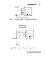
program)storedintheirmemory.Amicrocontrollerfetchestheinstructionsfromitsprogram memoryonebyone,decodestheseinstructions,andthencarriesouttherequiredoperations. Microcontrollershavetraditionallybeenprogrammedusingtheassemblylanguageofthe targetdevice.Althoughassemblylanguageisfast,ithasseveraldisadvantages.Anassembly programconsistsofmnemonics,anditisdificulttolearnandmaintainaprogramwritten usingassemblylanguage.Also,microcontrollersmanufacturedbydifferentirmshavedifferentassemblylanguages,andtheuserisrequiredtolearnanewlanguageeverytimea newmicrocontrolleristobeused.Microcontrollerscanalsobeprogrammedusingoneof thetraditionalhigh-levellanguages,suchasBasic,Pascal,orC.Theadvantageofhigh-level languageisthatitismucheasiertolearnthananassembler.Also,verylargeandcomplex programscaneasilybedevelopedusingahigh-levellanguage.Forexample,itisrathera complextasktomultiplytwoloatingpointnumbersusingassemblylanguage.Thesimilar operation,however,ismucheasierandconsistsofasinglestatementinahigh-levellanguage. Inthisbook,weshallbelearningtheprogrammingofPICmicrocontrollersusingthepopular C18high-levelCprogramminglanguagedevelopedbyMicrochipInc. Ingeneral,asinglechipisallthatisrequiredtohavearunningmicrocontrollersystem.Inpracticalapplications,additionalcomponentsmayberequiredtoallowamicrocomputertointerfacetoitsenvironment.WiththeadventofthePICfamilyofmicrocontrollers,thedevelopment timeofacomplexelectronicprojecthasbeenreducedfrommanydaystoseveralhours. Basically,amicrocomputerexecutesauserprogramthatisloadedinitsprogrammemory. Underthecontrolofthisprogram,dataisreceivedfromexternaldevices(inputs),manipulated,andthensenttoexternaldevices(outputs).Forexample,inasimplemicrocontrollerbasedtemperaturedataloggingsystem,thetemperatureisreadbythemicrocomputerusing atemperaturesensor.ThemicrocomputerthensavesthetemperaturedataonanSDcard atpredeinedintervals.Figure1.1showstheblockdiagramofoursimpletemperaturedata loggingsystem. ThesystemshowninFigure1.1isaverysimpliiedtemperaturedataloggersystem.In amoresophisticatedsystem,wemayhaveakeypadtosettheloggingintervalandan
Microcontroller Input Temperature sensor
Output
SD Card
Figure 1.1: Microcontroller-Based Temperature Data Logger System
www.newnespress.com
Microcontroller Systems Microcontroller
3
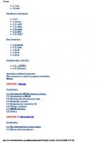
LCD
Output
Input Temperature sensor
Output
SD Card
Input
Keypad
Figure 1.2: Temperature Data Logger System with a Keypad and LCD
LCDtodisplaythecurrenttemperature.Figure1.2showstheblockdiagramofthismore sophisticatedtemperaturedataloggersystem. Wecanmakeourdesignevenmoresophisticated(seeFigure1.3)byaddingareal-timeclock chip(RTC)toprovidetheabsolutedateandtimeinformationsothatthedatacanbesaved withdateandtimestamping.Also,thetemperaturereadingscanbesenttoaPCeverysecond forarchivingandfurtherprocessing.Forexample,agraphofthetemperaturechangecanbe
LCD Input Temperature sensor
RTC
Output
Microcontroller Input Input
Output
SD Card
Output
PC
Keypad
Figure 1.3: More Sophisticated Temperature Data Logger
www.newnespress.com
4
Chapter 1
plottedonthePC.Asyoucansee,becausethemicrocontrollersareprogrammable,itisvery easytomaketheinalsystemassimpleorascomplicatedaswelike. Amicrocontrollerisaverypowerfulelectronicdevicethatallowsadesignertocreate sophisticatedI/Odatamanipulationunderprogramcontrol.Microcontrollersareclassiied bythenumberofbitstheyprocess.Eight-bitmicrocontrollersarethemostpopularonesand areusedinmostmicrocontroller-basedmonitoringandcontrolapplications.Microcontrollers of16and32bitsaremuchmorepowerfulbutusuallymoreexpensiveandnotrequired inmanysmall-to-medium-size,general-purposeapplicationswheremicrocontrollersare generallyused. Thesimplestmicrocontrollerarchitectureconsistsofamicroprocessor,programanddata memory,andI/Ocircuitry.Themicroprocessoritselfconsistsofacentralprocessingunit (CPU)andthecontrolunit(CU).TheCPUisthebrainofthemicroprocessor,whereallthe arithmeticandlogicoperationsareperformed.TheCUcontrolstheinternaloperationsofthe microprocessorandsendsoutcontrolsignalstootherpartsofthemicroprocessortocarryout therequiredinstructions. Memoryisanimportantpartofamicrocontrollersystem.Dependinguponthetype used,wecanclassifymemoryintotwogroups:programmemoryanddatamemory. Programmemorystorestheapplicationprogramwrittenbytheprogrammerandisusually nonvolatile;i.e.,dataisnotlostaftertheremovalofpower.Datamemoryiswherethe temporarydatausedinaprogramisstoredandisusuallyvolatile;i.e.,dataislostafterthe removalofpower. Therearebasicallysixtypesofmemory,assummarizedbelow.
1.2.1 Random Access Memory Randomaccessmemory(RAM)isageneral-purposememorythatusuallystoresthe userdatainaprogram.RAMisvolatileinthesensethatitcannotretaindatainthe absenceofpower;i.e.,dataislostaftertheremovalofpower.TheRAMinasystemis eitherstaticRAM(SRAM)ordynamicRAM(DRAM).TheSRAMsarefast,withaccess timeintherangeofafewnanoseconds,whichmakesthemidealmemorychipsincomputerapplications.DRAMsareslowerandbecausetheyarecapacitorbasedtheyrequire refreshingeveryseveralmilliseconds.DRAMshavetheadvantagethattheirpower consumptionislessthanthatofSRAMs.Mostmicrocontrollershavesomeamountof internalRAM,commonly256bytes,althoughsomemicrocontrollershavemoreandsome haveless.Forexample,thePIC18F452microcontrollerhas1536bytesofRAM,which shouldbeenoughformostmicrocontroller-basedapplications.Inmostmicrocontroller systems,itispossibletoextendtheamountofRAMbyaddingexternalmemorychipsif desired. www.newnespress.com
Microcontroller Systems
5
1.2.2 Read Only Memory Readonlymemory(ROM)isatypeofmemorythatusuallyholdstheapplicationprogram orixeduserdata.ROMisnonvolatile.IfpowerisremovedfromROMandthenreapplied, theoriginaldatawillstillbethere.ROMsareprogrammedatthefactoryduringthemanufacturingprocessandtheircontentcannotbechangedbytheuser.ROMsareonlyusefulif youhavedevelopedamicrocontroller-basedapplicationandwishtoorderseveralthousand microcontrollerchipspreprogrammedwiththisprogram.
1.2.3 Programmable Read Only Memory Programmablereadonlymemory(PROM)isatypeofROMthatcanbeprogrammedinthe ield,oftenbytheenduser,usingadevicecalledaPROMprogrammer.PROMisusedto storeanapplicationprogramorconstantdata.OnceaPROMhasbeenprogrammed,itscontentscannotbechangedagain.PROMsareusuallyusedinlowproductionapplicationswhere onlyseveralsuchmemoriesarerequired.
1.2.4 Erasable Programmable Read Only Memory Erasableprogrammablereadonlymemory(EPROM)issimilartoROM,buttheEPROM canbeprogrammedusingasuitableprogrammingdevice.EPROMshaveasmallclearglass windowontopofthechipwherethedatacanbeerasedunderstrongultravioletlight.Once thememoryisprogrammed,thewindowshouldbecoveredwithdarktapetopreventaccidentalerasureofthedata.AnEPROMmustbeerasedbeforeitcanbereprogrammed.Many developmentversionsofmicrocontrollersaremanufacturedwithEPROMswheretheuser programcanbestored.Thesememoriesareerasedandreprogrammeduntiltheuserissatisiedwiththeprogram.SomeversionsofEPROMs,knownasonetimeprogrammable(OTP) EPROMs,canbeprogrammedusingasuitableprogrammerdevice,butthesememories cannotbeerased.OTPmemoriescostmuchlessthanEPROMs.OTPisusefulafteraproject hasbeendevelopedcompletely,anditisrequiredtomakemanycopiesoftheinalprogram memory.
1.2.5 Electrically Erasable Programmable Read Only Memory Electricallyerasableprogrammablereadonlymemory(EEPROM)isanonvolatilememory. Thesememoriescanbeerasedandcanalsobereprogrammedusingsuitableprogramming devices.EEPROMsareusedtosaveconstantdata,suchasconigurationinformation,maximumandminimumvaluesofameasurement,andidentiicationdata.Somemicrocontrollers havebuilt-inEEPROMs.Forexample,PIC18F452containsa256-byteEEPROMwhereeach bytecanbeprogrammedanderaseddirectlybyapplicationssoftware.EEPROMsareusually veryslow.ThecostofanEEPROMchipismuchhigherthanthatofanEPROMchip. www.newnespress.com
6
Chapter 1
1.2.6 Flash EEPROM FlashEEPROMisanotherversionofEEPROMtypememory.Thismemoryhasbecome popularinmicrocontrollerapplicationsandisusedtostoretheuserprogram.FlashEEPROM isnonvolatileandisusuallyveryfast.Thedatacanbeerasedandthenreprogrammedusinga suitableprogrammingdevice.Somemicrocontrollershaveonly1KoflashEEPROM,while someothershave32Kormore.ThePIC18F452microcontrollerhas32KBoflashmemory.
1.3 Microcontroller Features Microcontrollersfromdifferentmanufacturershavedifferentarchitecturesanddifferent capabilities.Somemaysuitaparticularapplicationwhileothersmaybetotallyunsuitable forthesameapplication.Someofthehardwarefeaturesofmicrocontrollersingeneralare describedinthissection.
1.3.1 Buses Theconnectionsbetweenvariousblocksofacomputersystemarecalledbuses.Abusisa commonsetofwiresthatcarryaspeciictypeofinformation.Ingeneral,everycomputer systemhasthreebuses:addressbus,databus,andcontrolbus. Anaddressbuscarriestheaddressinformationinacomputersystem.Itisaunidirectionalbus having16bitsinsmallcomputersystemsand32ormorebitsinlargersystems.Anaddress bususuallycarriesthememoryaddressesfromtheCPUtothememorychips.Thisbusisalso usedtocarrytheI/Oaddressesinmanycomputersystems. Adatabuscarriesthedatainacomputersystem.Itisabidirectionalbushaving8bitsin smallsystemsand14,16,32,orevenmorebitsinlargersystems.Adatabuscarriesthe memorydatafromtheCPUtothememorychips.Inaddition,dataiscarriedtootherpartsof acomputerviathedatabus. Thecontrolbusisusuallyasmallerbusandisusedtoprovidecontrolsignalstomostparts ofacomputersystem.Forexample,memoryreadandwritecontrolsignalsarecarriedbythe controlbus.
1.3.2 Supply Voltage Mostmicrocontrollersoperatewiththestandardlogicvoltageof+5V.Some microcontrollerscanoperateataslowas+2.7Vandsomewilltolerate+6Vwithoutany problems.Youshouldcheckthemanufacturers’datasheetsabouttheallowedlimitsof thepowersupplyvoltage.Forexample,PIC18F452microcontrollerscanoperatewitha powersupply+2to+5.5V. www.newnespress.com
Microcontroller Systems
7
Avoltageregulatorcircuitisusuallyusedtoobtaintherequiredpowersupplyvoltagewhen thedeviceistobeoperatedfromamainsadaptororbatteries.Forexample,a5-Vregulatoris requiredifthemicrocontrolleristobeoperatedusinga9-Vbattery.
1.3.3 The Clock Allmicrocontrollersrequireaclock(oranoscillator)tooperate.Theclockisusuallyprovidedbyconnectingexternaltimingdevicestothemicrocontroller.Mostmicrocontrollers willgenerateclocksignalswhenacrystalandtwosmallcapacitorsareconnected.Some willoperatewithresonatorsorexternalresistor-capacitorpair.Somemicrocontrollershave built-intimingcircuitsandtheydonotrequireanyexternaltimingcomponents.Iftheapplicationisnottimesensitive,thenexternalorinternal(ifavailable)resistor-capacitortiming componentsshouldbeusedtolowerthecosts. Aninstructionisexecutedbyfetchingitfromthememoryandthendecodingit.Thisusually takesseveralclockcyclesandisknownastheinstruction cycle.InPICmicrocontrollers, aninstructioncycletakesfourclockperiods.Thus,themicrocontrollerisactuallyoperated ataclockrate,whichisaquarteroftheactualoscillatorfrequency.Forexample,inaPIC microcontrolleroperatingat4-MHzclock,theinstructioncycletimeisonly1µs(frequencyof 1MHz).ThePIC18Fseriesofmicrocontrollerscanoperatewithclockfrequenciesupto40MHz.
1.3.4 Timers Timersareimportantpartsofanymicrocontroller.Atimerisbasicallyacounter,whichis driveneitherbyanexternalclockpulseorbytheinternaloscillatorofthemicrocontroller. Atimercanbe8or16bitswide.Datacanbeloadedintoatimerunderprogramcontrol andthetimercanbestoppedorstartedbyprogramcontrol.Mosttimerscanbeconigured togenerateaninterruptwhentheyreachacertaincount(usuallywhentheyoverlow).The interruptcanbeusedbytheuserprogramtocarryoutaccuratetiming-relatedoperations insidethemicrocontroller.ThePIC18Fseriesofmicrocontrollershaveatleastthreetimers. Forexample,thePIC18F452microcontrollerhasthreebuilt-intimers. Somemicrocontrollersoffercaptureandcomparefacilitieswhereatimervaluecanberead whenanexternaleventoccursorthetimervaluecanbecomparedtoapresetvalueandan interruptgeneratedwhenthisvalueisreached.MostPIC18Fmicrocontrollershaveatleast twocaptureandcomparemodules.
1.3.5 Watchdog Mostmicrocontrollershaveatleastonewatchdogfacility.Thewatchdogisbasicallyatimer thatisnormallyrefreshedbytheuserprogram,andaresetoccursiftheprogramfailsto refreshthewatchdog.Thewatchdogtimerisusedtodetectseriousproblemsinprograms, www.newnespress.com
8
Chapter 1
suchastheprogrambeinginanendlessloop.Awatchdogisasafetyfeaturethatprevents runawaysoftwareandstopsthemicrocontrollerfromexecutingmeaninglessandunwanted code.Watchdogfacilitiesarecommonlyusedinreal-timesystemswhereitisrequiredto regularlycheckthesuccessfulterminationofoneormoreactivities.
1.3.6 Reset Input Aresetinputisusedtoresetamicrocontrollerexternally.Resettingputsthemicrocontroller intoaknownstatesuchthattheprogramexecutionstartsusuallyfromaddress0oftheprogrammemory.Anexternalresetactionisusuallyachievedbyconnectingapush-buttonswitch totheresetinputsuchthatthemicrocontrollercanberesetwhentheswitchispressed.
1.3.7 Interrupts Interruptsareveryimportantconceptsinmicrocontrollers.Aninterruptcausesthemicrocontrollertorespondtoexternalandinternal(e.g.,atimer)eventsveryquickly.Whenaninterruptoccurs,themicrocontrollerleavesitsnormallowofprogramexecutionandjumpstoa specialpartoftheprogramknownastheinterruptserviceroutine(ISR).Theprogramcode insidetheISRisexecutedanduponreturnfromtheISRtheprogramresumesitsnormallow ofexecution. TheISRstartsfromaixedaddressoftheprogrammemory.Thisaddressisknownastheinterrupt vector address.Somemicrocontrollerswithmulti-interruptfeatureshavejustoneinterrupt vectoraddress,whilesomeothershaveuniqueinterruptvectoraddresses,oneforeachinterrupt source.Interruptscanbenestedsuchthatanewinterruptcansuspendtheexecutionofanother interrupt.Anotherimportantfeatureofamicrocontrollerwithmulti-interruptcapabilityisthat differentinterruptsourcescanbegivendifferentlevelsofpriority.Forexample,thePIC18F seriesofmicrocontrollershavelow-priorityandhigh-priorityinterruptlevels.
1.3.8 Brown-Out Detector Brown-outdetectorsarealsocommoninmanymicrocontrollers,andtheyresetamicrocontrollerifthesupplyvoltagefallsbelowanominalvalue.Brown-outdetectorsaresafety features,andtheycanbeemployedtopreventunpredictableoperationatlowvoltages, especiallytoprotectthecontentsofEEPROMtypememoriesifthesupplyvoltagefalls.
1.3.9 A/D Converter AnA/Dconverterisusedtoconvertananalogsignallikevoltagetodigitalformsothat itcanbereadandprocessedbyamicrocontroller.Somemicrocontrollershavebuilt-in A/Dconverters.ItisalsopossibletoconnectanexternalA/Dconvertertoanytypeof www.newnespress.com
Microcontroller Systems
9
microcontroller.A/Dconvertersareusually8–10bitshaving256–1024quantizationlevels. MostPICmicrocontrollerswithA/DfeatureshavemultiplexedA/Dconverterswheremore thanoneanaloginputchannelisprovided.Forexample,thePIC18F452microcontrollerhas 10-bit,8-channelA/Dconverters. TheA/Dconversionprocessmustbestartedbytheuserprogramanditmaytakeseveral hundredsofmicrosecondsforaconversiontocomplete.A/Dconvertersusuallygenerate interruptswhenaconversioniscompletesothattheuserprogramcanreadtheconverted dataquickly. A/Dconvertersareveryusefulincontrolandmonitoringapplicationsbecausemostsensors (e.g.,temperaturesensor,pressuresensor,andforcesensor)produceanalogoutputvoltages thatcannotbereadbyamicrocontrollerwithoutanA/Dconverter.
1.3.10 Serial I/O Serialcommunication(alsocalledRS232communication)enablesamicrocontroller tocommunicatewithotherdevicesusingtheserialRS232communicationprotocol. Forexample,amicrocontrollercanbeconnectedtoanothermicrocontrollerortoaPC andexchangedatausingtheserialcommunicationprotocol.Somemicrocontrollers havebuilt-inhardwarecalleduniversalsynchronous-asynchronousreceiver-transmitter (USART)toimplementaserialcommunicationinterface.Thebaudrateandthedata formatcanusuallybeselectedbytheuserprogram.IfserialI/Ohardwareisnotprovided, itiseasytodevelopsoftwaretoimplementtheserialdatacommunicationusinganyI/O pinofamicrocontroller.ThePIC18Fseriesofmicrocontrollershavebuilt-inUSART modules. Somemicrocontrollers(e.g.,PIC18Fseries)incorporateaserialperipheralinterface(SPI) oranintegratedinterconnect(I2C)hardwarebusinterface.Theseenableamicrocontrollerto interfacetoothercompatibledeviceseasily.
1.3.11 EEPROM Data Memory EEPROMtypedatamemoryisalsoverycommoninmanymicrocontrollers.Theadvantage ofanEEPROMisthattheprogrammercanstorenonvolatiledatainsuchamemoryandcan alsochangethisdatawheneverrequired.Forexample,inatemperaturemonitoringapplication,themaximumandtheminimumtemperaturereadingscanbestoredinanEEPROM. Then,ifthepowersupplyisremovedforwhateverreason,thevaluesofthelatestreadings willstillbeavailableintheEEPROM.ThePIC18F452microcontrollerhas256bytesof EEPROM.Someothermembersofthefamilyhavemore(e.g.,PIC18F6680has1024bytes) EEPROMs. www.newnespress.com
10
Chapter 1
1.3.12 LCD Drivers LCDdriversenableamicrocontrollertobeconnectedtoanexternalLCDdisplaydirectly.These driversarenotcommonbecausemostofthefunctionstheyprovidecanbeimplementedinthe software.Forexample,thePIC18F6490microcontrollerhasabuilt-inLCDdrivermodule.
1.3.13 Analog Comparator Analogcomparatorsareusedwhereitisrequiredtocomparetwoanalogvoltages.Although thesecircuitsareimplementedinmosthigh-endPICmicrocontrollers,theyarenotcommon inothermicrocontrollers.ThePIC18Fseriesofmicrocontrollershavebuilt-inanalogcomparatormodules.
1.3.14 Real-Time Clock Real-timeclock(RTC)enablesamicrocontrollertohaveabsolutedateandtimeinformation continuously.Built-inreal-timeclocksarenotcommoninmostmicrocontrollersbecause theycaneasilybeimplementedbyeitherusingadedicatedRTCorbywritingaprogram.
1.3.15 Sleep Mode Somemicrocontrollers(e.g.,PIC)offerbuilt-insleepmodeswhereexecutingthisinstruction putsthemicrocontrollerintoamodewheretheinternaloscillatorisstoppedandthepower consumptionisreducedtoanextremelylowlevel.Themainreasonforusingthesleepmode istoconservethebatterypowerwhenthemicrocontrollerisnotdoinganythinguseful.The microcontrollerusuallywakesupfromthesleepmodebyexternalresetorbyawatchdog time-out.
1.3.16 Power-on Reset Somemicrocontrollers(e.g.,PIC)havebuilt-inpower-onresetcircuits,whichkeepthemicrocontrollerinresetstateuntilalltheinternalcircuitryhasbeeninitialized.Thisfeatureisvery usefulasitstartsthemicrocontrollerfromaknownstateonpower-up.Anexternalresetcan alsobeprovidedwherethemicrocontrollercanberesetwhenanexternalbuttonispressed.
1.3.17 Low-Power Operation Low-poweroperationisespeciallyimportantinportableapplicationswherethemicrocontrollerbasedequipmentisoperatedfrombatteries.Somemicrocontrollers(e.g.,PIC)canoperate withlessthan2mAata5-Vsupplyandapproximately15μAata3-Vsupply.Someother microcontrollers,especiallymicroprocessor-basedsystemswheretherecouldbeseveralchips, mayconsumeseveralhundredmilliamperesorevenmore. www.newnespress.com
Microcontroller Systems
11
1.3.18 Current Sink/Source Capability Thisisimportantifthemicrocontrolleristobeconnectedtoanexternaldevicethatmaydraw largecurrentforitsoperation.PICmicrocontrollerscansourceandsink25mAofcurrent fromeachoutputportpin.Thiscurrentisusuallysuficienttodrivelight-emittingdiodes (LEDs),smalllamps,buzzers,smallrelays,etc.Thecurrentcapabilitycanbeincreasedby connectingexternaltransistorswitchingcircuitsorrelaystotheoutputportpins.
1.3.19 USB Interface USBiscurrentlyaverypopularcomputerinterfacespeciicationusedtoconnectvarious peripheraldevicestocomputersandmicrocontrollers.SomePICmicrocontrollers providebuilt-inUSBmodules.Forexample,PIC18F2X50hasbuilt-inUSBinterface capabilities.
1.3.20 Motor Control Interface SomePICmicrocontrollers(e.g.,PIC18F2X31)providemotorcontrolinterface.
1.3.21 Controller Area Network Interface Controllerareanetwork(CAN)busisaverypopularbussystemusedmainlyinautomation applications.SomePIC18Fseriesofmicrocontrollers(e.g.,PIC18F4680)provideCANinterfacecapabilities.
1.3.22 Ethernet Interface SomePICmicrocontrollers(e.g.,PIC18F97J60)provideEthernetinterfacecapabilities.Such microcontrollerscaneasilybeusedinnetwork-basedapplications.
1.3.23 ZigBee Interface ZigBeeisaninterfacesimilartoBluetoothandisusedinlow-costwirelesshomeautomation applications.SomePIC18FseriesofmicrocontrollersprovideZigBeeinterfacecapabilities, makingthedesignofsuchwirelesssystemsveryeasy.
1.4 Microcontroller Architectures Usuallytwotypesofarchitectureareusedinmicrocontrollers(seeFigure1.4):Von Neumann architectureandHarvard architecture.VonNeumannarchitectureisusedbyalarge percentageofmicrocontrollers,whereallmemoryspaceisonthesamebusandinstruction anddatausethesamebus.IntheHarvardarchitecture(usedbythePICmicrocontrollers), www.newnespress.com
12
Chapter 1
Program memory
CPU
Data memory
(a) Von Neumann architecture
CPU
Program memory
(b) Harvard architecture
Figure 1.4: Von Neumann and Harvard Architectures
codeanddataareonseparatebuses,andthisallowsthecodeanddatatobefetchedsimultaneously,resultinginanimprovedperformance.
1.4.1 Reduced Instruction Set Computer and Complex Instruction Set Computer Reducedinstructionsetcomputer(RISC)andcomplexinstructionsetcomputer(CISC)refer totheinstructionsetofamicrocontroller.Inan8-bitRISCmicrocontroller,datais8bits widebuttheinstructionwordsaremorethan8bitswide(usually12,14,or16bits),andthe instructionsoccupyonewordintheprogrammemory.Thus,theinstructionsarefetchedand executedinonecycle,resultinginanimprovedperformance. InaCISCmicrocontroller,bothdataandinstructionsare8bitswide.CISCmicrocontrollers usuallyhaveover200instructions.Dataandcodeareonthesamebusandcannotbefetched simultaneously.
1.5 Choosing a PIC Microcontroller Choosingamicrocontrollerforanapplicationrequirestakingintoaccountthefollowing factors: •
Microcontrollerspeed
•
ThenumberofI/Opinsrequired
•
Theperipheraldevicesrequired(e.g.,USARTandA/Dconverter)
•
Thememorysize(RAM,lash,EEPROM,etc.)
•
Powerconsumption
•
Physicalsize
www.newnespress.com
Microcontroller Systems
13
1.6 Number Systems Theeficientuseofamicroprocessororamicrocontrollerrequiresaworkingknowledgeof binary,decimal,andhexadecimalnumberingsystems.Thissectionprovidesabackgroundfor thosewhoareunfamiliarwiththesenumberingsystemsandwhodonotknowhowtoconvert fromonenumbersystemtoanotherone. Numbersystemsareclassiiedaccordingtotheirbases.Thenumberingsystemusedin everydaylifeisbase10orthedecimalnumbersystem.Themostcommonlyusednumbering systeminmicroprocessorandmicrocontrollerapplicationsisbase16orhexadecimal.In addition,base2(binary)orbase8(octal)numbersystemsarealsoused.
1.6.1 Decimal Number System Asyouallknow,thenumbersinthissystemare0,1,2,3,4,5,6,7,8,and9.Wecanusethe subscript10toindicatethatanumberisindecimalformat.Forexample,wecanshowthe decimalnumber235as23510. Ingeneral,adecimalnumberisrepresentedasfollows: an ×10n + an−1 ×10n−1 + an−2 ×10n−2 +… +a0 ×100
Forexample,decimalnumber82510canbeshownasfollows: 82510 =8×10² +2×101 +5×100
Similarly,decimalnumber2610canbeshownasfollows: 2610 =2×101 +6×100
or 335910 =3 ×10³ +3 ×10² +5×101 +9×100
1.6.2 Binary Number System Inthebinarynumbersystem,therearetwonumbers:0and1.Wecanusethesubscript2to indicatethatanumberisinbinaryformat.Forexample,wecanshowbinarynumber1011 as10112. Ingeneral,abinarynumberisrepresentedasfollows: an ×2n +an−1 ×2n−1 +an−2 ×2n−2 +… +a0 ×20
Forexample,binarynumber11102canbeshownasfollows: 11102 =1×23 +1×22 +1×21 +0 ×20
www.newnespress.com
14
Chapter 1
Similarly,binarynumber100011102canbeshownasfollows: 100011102 =1×27 +0 ×26 +0 ×25 +0 ×24 +1×23 +1×22 +1×21 +0 ×20
1.6.3 Octal Number System Intheoctalnumbersystem,thevalidnumbersare0,1,2,3,4,5,6,and7.Wecanusethe subscript8toindicatethatanumberisinoctalformat.Forexample,wecanshowoctal number23as238. Ingeneral,anoctalnumberisrepresentedasfollows: an ×8n +an−1 ×8n−1 +an−2 ×8n−2 +… +a0 ×80
Forexample,octalnumber2378canbeshownasfollows: 2378 =2×82 +3 ×81 +7×80
Similarly,octalnumber17778canbeshownasfollows: 17778 =1×83 +7×82 +7×81 +7×80
1.6.4 Hexadecimal Number System Inthehexadecimalnumbersystem,thevalidnumbersare0,1,2,3,4,5,6,7,8,9, A,B,C,D,E,andF.Wecanusethesubscript16orHtoindicatethatanumberis inh exadecimalformat.Forexample,wecanshowhexadecimalnumber1Fas1F 16 oras1F H. Ingeneral,ahexadecimalnumberisrepresentedasfollows: an ×16n +an−1 ×16n−1 +an−2 ×16n−2 +… +a0 ×160
Forexample,hexadecimalnumber2AC16canbeshownasfollows: 2AC16 =2×162 +10×161 +12×160
Similarly,hexadecimalnumber3FFE16canbeshownasfollows: 3FFE16 =3 ×163 +15×162 +15×161 +14×160
1.7 Converting Binary Numbers into Decimal Toconvertabinarynumberintodecimal,writethenumberasthesumofthepowersof2.
www.newnespress.com
Microcontroller Systems ■ Example
15
1.1
Convert binary number 10112 into decimal.
Solution Write the number as the sum of the powers of 2: 10112 =1 ×23 +0 ×22 +1 ×21 +1 ×20 =8 +0 +2 +1 =11
or
10112 = 1110.
■ Example
1.2
Convert binary number 110011102 into decimal.
Solution Write the number as the sum of the powers of 2: 110011102 =1 ×27 +1 ×26 +0 ×25 +0 ×24 +1 ×23 +1 ×22 +1 ×21 +0 ×20 =128 +64 +0 +0 +8 +4 +2 +0 =206
or
110011102 = 20610.
Table1.1showsthebinaryequivalentofdecimalnumbersfrom0to31.
Table 1.1: Binary Equivalent of Decimal Numbers Decimal
Binary
Decimal
Binary
0 1 2 3 4
00000000 00000001 00000010 00000011 00000100
16 17 18 19 20
00010000 00010001 00010010 00010011 00010100
—cont’d
www.newnespress.com
16
Chapter 1 Table 1.1: Binary Equivalent of Decimal Numbers —cont’d Decimal
Binary
Decimal
Binary
5 6 7 8 9 10 11 12 13 14 15
00000101 00000110 00000111 00001000 00001001 00001010 00001011 00001100 00001101 00001110 00001111
21 22 23 24 25 26 27 28 29 30 31
00010101 00010110 00010111 00011000 00011001 00011010 00011011 00011100 00011101 00011110 00011111
1.8 Converting Decimal Numbers into Binary Toconvertadecimalnumberintobinary,dividethenumberrepeatedlyby2andtakethe remainders.Theirstremainderistheleastsigniicantdigit(LSD)andthelastremainderis themostsigniicantdigit(MSD). ■ Example
1.3
Convert decimal number 2810 into binary.
Solution Divide the number by 2 repeatedly and take the remainders: 28/2 → 14
Remainder 0
14/2 → 7
Remainder 0
7/2 → 3
Remainder 1
3/2 → 1
Remainder 1
1/2 → 0
Remeinder 1
The required binary number is 111002.
www.newnespress.com
(LSD)
(MSD)
Microcontroller Systems ■ Example
17
1.4
Convert decimal number 6510 into binary.
Solution Divide the number by 2 repeatedly and take the remainders: 65/2 → 32
Remainder 1
32/2 → 16
Remainder 0
16/2 → 8
Remainder 0
8/2 → 4
Remainder 0
4/2 → 2
Remainder 0
2/2 → 1
Remainder 0
1/2 → 0
Remainder 1
(LSD)
(MSD)
The required binary number is 10000012.
■ Example
1.5
Convert decimal number 12210 into binary.
Solution Divide the number by 2 repeatedly and take the remainders: 122/2 → 61 Remainder 0
(LSD)
61/2 → 30 Remainder 1 30/2 → 15 Remainder 0 15/2 → 7
Remainder 1
7/2 → 3
Remainder 1
3/2 → 1
Remainder 1
1/2 → 0
Remainder 1
(MSD)
The required binary number is 11110102.
www.newnespress.com
18
Chapter 1
1.9 Converting Binary Numbers into Hexadecimal Toconvertabinarynumberintohexadecimal,arrangethenumberingroupsoffourand indthehexadecimalequivalentofeachgroup.Ifthenumbercannotbedividedexactlyinto groupsoffour,insertzeroestotheleft-handsideofthenumber. ■ Example
1.6
Convert binary number 100111112 into hexadecimal.
Solution First, divide the number into groups of four and then find the hexadecimal equivalent of each group: 10011111 =1001 1111 9
F
The required hexadecimal number is 9F16. ■ Example
1.7
Convert binary number 11101111000011102 into hexadecimal.
Solution First, divide the number into groups of four and then find the equivalent of each group: 1110111100001110 =1110 1111 0000 1110 E
F
0
E
The required hexadecimal number is EF0E16. ■ Example
1.8
Convert binary number 1111102 into hexadecimal.
Solution Because the number cannot be divided exactly into groups of four, we have to insert zeroes to the left of the number: 111110 =0011 1110 3
The required hexadecimal number is 3E16. www.newnespress.com
E
Microcontroller Systems
19
Table1.2showsthehexadecimalequivalentofdecimalnumbers0to31. Table 1.2: Hexadecimal Equivalent of Decimal Numbers Decimal
Hexadecimal
Decimal
Hexadecimal
0 1 2 3 4 5 6 7 8 9 10 11 12 13 14 15
0 1 2 3 4 5 6 7 8 9 A B C D E F
16 17 18 19 20 21 22 23 24 25 26 27 28 29 30 31
10 11 12 13 14 15 16 17 18 19 1A 1B 1C 1D 1E 1F
1.10 Converting Hexadecimal Numbers into Binary Toconvertahexadecimalnumberintobinary,writethe4-bitbinaryequivalentofeach hexadecimaldigit.
■ Example
1.9
Convert hexadecimal number A916 into binary.
Solution Writing the binary equivalent of each hexadecimal digit A =10102 9 =10012
The required binary number is 101010012. www.newnespress.com
20
Chapter 1
■ Example
1.10
Convert hexadecimal number FE3C16 into binary.
Solution Writing the binary equivalent of each hexadecimal digit F =11112 E =11102 3 =00112 C =11002
The required binary number is 11111110001111002.
1.11 Converting Hexadecimal Numbers into Decimal Toconvertahexadecimalnumberintodecimal,wehavetocalculatethesumofthepowersof 16ofthenumber. ■ Example
1.11
Convert hexadecimal number 2AC16 into decimal.
Solution Calculating the sum of the powers of 16 of the number: 2AC16 =2 ×162 +10 ×161 +12 ×160 =512 +160 +12 =684
The required decimal number is 68410. ■ Example
1.12
Convert hexadecimal number EE16 into decimal.
Solution Calculating the sum of the powers of 16 of the number EE16 =14 ×161 +14 ×160 =224 +14 =238
The required decimal number is 23810. www.newnespress.com
Microcontroller Systems
21
1.12 Converting Decimal Numbers into Hexadecimal Toconvertadecimalnumberintohexadecimal,dividethenumberrepeatedlyby16andtake theremainders.TheirstremainderistheLSDandthelastremainderistheMSD.
■ Example
1.13
Convert decimal number 23810 into hexadecimal.
Solution Dividing the number repeatedly by 16 238/16 → 14
Remainder 14 (E)
(LSD)
14/16 → 0
Remainder 14 (E)
(MSD)
The required hexadecimal number is EE16.
■ Example
1.14
Convert decimal number 68410 into hexadecimal.
Solution Dividing the number repeatedly by 16 684/16 → 42 Remainder 12 (C) 42/16 → 2 2/16 → 0
(LSD)
Remainder 10 (A) Remainder 2
(MSD)
The required hexadecimal number is 2AC16.
1.13 Converting Octal Numbers into Decimal Toconvertanoctalnumberintodecimal,calculatethesumofthepowersof8ofthe number. www.newnespress.com
22
Chapter 1
■ Example
1.15
Convert octal number 158 into decimal.
Solution Calculating the sum of the powers of 8 of the number 158 =1 ×81 +5 ×80 =8 +5 =13
The required decimal number is 1310. ■ Example
1.16
Convert octal number 2378 into decimal.
Solution Calculating the sum of the powers of 8 of the number 2378 =2 ×82 +3 ×81 +7 ×80 =128 +24 +7 =159
The required decimal number is 15910.
1.14 Converting Decimal Numbers into Octal Toconvertadecimalnumberintooctal,dividethenumberrepeatedlyby8andtakethe remainders.TheirstremainderistheLSDandthelastremainderistheMSD. ■ Example
1.17
Convert decimal number 15910 into octal.
Solution Dividing the number repeatedly by 8 www.newnespress.com
Microcontroller Systems 159/8 → 19
Remainder 7
19/8 → 2
Remainder 3
2/8 → 0
Remainder 2
23
(LSD)
(MSD)
The required octal number is 2378. ■ Example
1.18
Convert decimal number 46010 into octal.
Solution Dividing the number repeatedly by 8 460/8 → 57
Remainder 4
57/8 → 7
Remainder 1
7/8 → 0
Remainder 7
(LSD)
(MSD)
The required octal number is 7148. Table1.3showstheoctalequivalentofdecimalnumbers0–31. Table 1.3: Octal Equivalent of Decimal Numbers Decimal
Octal
Decimal
Octal
0 1 2 3 4 5 6 7 8 9 10 11 12 13 14 15
0 1 2 3 4 5 6 7 10 11 12 13 14 15 16 17
16 17 18 19 20 21 22 23 24 25 26 27 28 29 30 31
20 21 22 23 24 25 26 27 30 31 32 33 34 35 36 37
www.newnespress.com
24
Chapter 1
1.15 Converting Octal Numbers into Binary Toconvertanoctalnumberintobinary,writethe3-bitbinaryequivalentofeachoctaldigit. ■ Example
1.19
Convert octal number 1778 into binary.
Solution Write the binary equivalent of each octal digit: 1 =0012 7 = 1112 7 = 1112
The required binary number is 0011111112. ■ Example
1.20
Convert octal number 758 into binary.
Solution Write the binary equivalent of each octal digit: 7 = 1112 5 = 1012
The required binary number is 1111012.
1.16 Converting Binary Numbers into Octal Toconvertabinarynumberintooctal,arrangethenumberingroupsofthreeandwritethe octalequivalentofeachdigit. ■ Example
1.21
Convert binary number 1101110012 into octal.
Solution Arranging in groups of three 110111001 = 110 111 001 6
The required octal number is 6718. www.newnespress.com
7
1
Microcontroller Systems
25
1.17 Negative Numbers Themostsigniicantbitofabinarynumberisusuallyusedasthesignbit.Byconvention,for positivenumbersthisbitis0andfornegativenumbersthisbitis1.Table1.4showsthe4-bitpositive andnegativenumbers.Thelargestpositiveandnegativenumbersare+7and−8,respectively. Toconvertapositivenumberintonegative,takethecomplementofthenumberandadd1. Thisprocessisalsocalledthe2’scomplementofthenumber. ■ Example
1.22
Write decimal number −6 as a 4-bit number.
Solution First, write the number as a positive number, then find the complement and add 1: 0110
+6
1001
complement
1 add 1 _____ 1010 which is −6
Table 1.4: Four-Bit Positive and Negative Numbers Binary Numbers
Decimal Equivalent
0111
+7
0110
+6
0101
+5
0100
+4
0011
+3
0010
+2
0001 0000 1111
+1 0
1110
−2
1101
−3
1100
−4
1011
−5
1010
−6
1001
−7
1000
−8
−1
www.newnespress.com
26
Chapter 1
■ Example
1.23
Write decimal number −25 as an 8-bit number.
Solution First, write the number as a positive number, then find the complement and add 1: 00011001 +25 11100110
complement
1 add 1 _________ 11100111 which is −25
1.18 Adding Binary Numbers Theadditionofbinarynumbersissimilartotheadditionofdecimalnumbers.Numbersin eachcolumnareaddedtogetherwithapossiblecarryfromapreviouscolumn.Theprimitive additionoperationsareasfollows: 0 +0 =0 0 +1=1 1+0 =1 1+1=10 generateacarrybit 1+1+1=11 generateacarrybit
Someexamplesaregivenbelow. ■ Example
1.24
Find the sum of binary numbers 011 and 110.
Solution We can add these numbers as in the addition of decimal numbers: 011
First column:
+ 110 Second column: _____ 1001 Third column:
www.newnespress.com
1 +0 =1 1 +1 =0 and a carry bit 1 +1 =10
Microcontroller Systems ■ Example
27
1.25
Find the sum of binary numbers 01000011 and 00100010.
Solution We can add these numbers as in the addition of decimal numbers: 01000011
First column:
1 +0 =1
+ 00100010 Second column: 1 +1 =10 ___________ 0 +carry =1 01100101 Third column: Fourth column:
0 +0 =0
Fifth column:
0 +0 =0
Sixth column:
0 +1 =1
Seventh column: 1 +0 =1 Eighth column:
0 +0 =0
1.19 Subtracting Binary Numbers Tosubtracttwobinarynumbers,convertthenumbertobesubtractedintonegativeandthen addthetwonumbers.
■ Example
1.26
Subtract binary number 0010 from 0110.
Solution First, let’s convert the number to be subtracted into negative: 0010 number to be subtracted 1101 complement 1 add 1 ____ 1110
www.newnespress.com
28
Chapter 1
Now, add the two numbers: 0110 + 1110 _______ 0100
Because we are using 4 bits only, we cannot show the carry bit.
1.20 Multiplication of Binary Numbers Multiplicationoftwobinarynumbersissameasthemultiplicationofdecimalnumbers.The fourpossibilitiesareasfollows: 0 ×0 =0 0 ×1= 0 1×0 =0 1×1=1
Someexamplesaregivenbelow.
■ Example
1.27
Multiply the two binary numbers 0110 and 0010.
Solution Multiplying the numbers 0110 0010 ____ 0000 0110 0000 0000 ______ 001100 or 1100
In this example, 4 bits are needed to show the final result. www.newnespress.com
Microcontroller Systems ■ Example
29
1.28
Multiply binary numbers 1001 and 1010.
Solution Multiplying the numbers 1001 1010 _____ 0000 1001 0000 1001 _______ 1011010
In this example, 7 bits are required to show the final result.
1.21 Division of Binary Numbers Thedivisionofbinarynumbersissimilartothedivisionofdecimalnumbers.Anexampleis givenbelow. ■ Example
1.29
Divide binary number 1110 by binary number 10.
Solution Dividing the numbers 111 10 1110 10 __ 11 10 __ 10 10 __ 00
gives the result 1112. www.newnespress.com
30
Chapter 1
1.22 Floating Point Numbers Floatingpointnumbersareusedtorepresentnonintegerfractionalnumbersandareusedin mostengineeringandtechnicalcalculations,forexample,3.256,2.1,and0.0036.Themost commonlyusedloatingpointstandardistheIEEEstandard.Accordingtothisstandard,loating pointnumbersarerepresentedwith32bits(singleprecision)or64bits(doubleprecision). Inthissection,wewilllookattheformatof32-bitloatingpointnumbersonlyandseehow mathematicaloperationscanbeperformedwithsuchnumbers. AccordingtotheIEEEstandard,32-bitloatingpointnumbersarerepresentedasfollows:
31 30
23 22
0
X XXXXXXXX XXXXXXXXXXXXXXXXXXXXXXX
↑
↑
↑
sign
exponent
mantissa
Themostsigniicantbitindicatessignofthenumber,where0indicatespositiveand1 indicatesnegative. The8-bitexponentshowsthepowerofthenumber.Tomakethecalculationseasy,thesignof theexponentisnotshown,butinsteadexcess128numberingsystemisused.Thus,toindthe realexponent,wehavetosubtract127fromthegivenexponent.Forexample,ifthemantissa is“10000000,”therealvalueofthemantissais128−127=1. Themantissais23bitswideandrepresentstheincreasingnegativepowersof2.Forexample, ifweassumethatthemantissais“1110000000000000000000,”thevalueofthismantissais calculatedasfollows:2−1 +2−2 +2−3 =7/8. Thedecimalequivalentofaloatingpointnumbercanbecalculatedusingthefollowing formula:
Number=(−1)s2e −1271⋅ f,
wheres =0forpositivenumbers,1fornegativenumbers, e =exponent(between0and255),and f =mantissa.
Asshownintheaboveformula,thereisahidden“1”beforethemantissa;i.e.,mantissais shownas“1·f.” Thelargestandthesmallestnumbersin32-bitloatingpointformatareasfollows:
www.newnespress.com
Microcontroller Systems
Thelargestnumber
0 11111110 11111111111111111111111
31
Thisnumberis(2−2−23)2127ordecimal3.403×1038.Thenumberskeeptheirprecisionupto sixdigitsafterthedecimalpoint.
Thesmallestnumber
0 00000001 00000000000000000000000
Thisnumberis2−126ordecimal1.175×10−38.
1.23 Converting a Floating Point Number into Decimal Toconvertagivenloatingpointnumberintodecimal,wehavetoindthemantissaandthe exponentofthenumberandthenconvertintodecimalasshownabove. Someexamplesaregivenhere.
■ Example
1.30
Find the decimal equivalent of the floating point number given below: 0 10000001 10000000000000000000000
Solution Here, sign = positive exponent = 129 − 127 =2 mantissa = 2−1 = 0.5
The decimal equivalent of this number is +1.5 × 22 = +6.0.
www.newnespress.com
32
Chapter 1
■ Example
1.31
Find the decimal equivalent of the floating point number given below: 0 10000010 11000000000000000000
Solution In this example, sign =positive exponent =130 − 127 =3 mantissa =2−1 +2−2 =0.75
The decimal equivalent of the number is +1.75 × 23 = 14.0.
1.23.1 Normalizing the Floating Point Numbers Floatingpointnumbersareusuallyshowninnormalizedform.Anormalizednumberhasonly onedigitbeforethedecimalpoint(ahiddennumber1isassumedbeforethedecimalpoint). Tonormalizeagivenloatingpointnumber,wehavetomovethedecimalpointrepetitively onedigittotheleftandthenincreasetheexponentaftereachmove. Someexamplesaregivenbelow. ■ Example
1.32
Normalize the floating point number 123.56.
Solution If we write the number with a single digit before the decimal point, we get 1.2356 ×10² ■ Example
1.33
Normalize the binary number 1011.12.
Solution If we write the number with a single digit before the decimal point, we get 1.0111 × 23
www.newnespress.com
Microcontroller Systems
33
1.23.2 Converting a Decimal Number into Floating Point Toconvertagivendecimalnumberintoloatingpoint,wehavetocarryoutthefollowingsteps: •
Writethenumberinbinary
•
Normalizethenumber
•
Findthemantissaandtheexponent
•
Writethenumberasaloatingpointnumber
Someexamplesaregivenbelow. ■ Example
1.34
Convert decimal number 2.2510 into floating point.
Solution Writing the number in binary 2.2510 = 10 .012
Normalizing the number, 10.012 = 1.0012 ×21
Here, s = 0, e − 127 = 1 or e = 128, and f = 00100000000000000000000. (Remember that a number 1 is assumed on the left-hand side, even though it is not shown in the calculation.) We can now write the required floating point number as follows: s 0
e 10000000
f (1)001 0000 0000 0000 0000 0000
or the required 32-bit floating point number is 01000000000100000000000000000000 ■ Example
1.35
Convert the decimal number 134.062510 into floating point.
Solution Writing the number in binary 134.062510 =10000110.0001
www.newnespress.com
34
Chapter 1
Normalizing the number 10000110.0001 = 1.00001100001 ×27
Here, s = 0, e − 127 = 7 or e = 134, and f = 00001100001000000000000 We can now write the required floating point number as follows: s 0
e 10000110
f (1)00001100001000000000000
or the required 32-bit floating point number is 01000011000001100001000000000000
1.23.3 Multiplication and Division of Floating Point Numbers Themultiplicationanddivisionofloatingpointnumbersisrathereasyandthestepsare givenbelow: •
Add(orsubtract)theexponentsofthenumbers
•
Multiply(ordivide)themantissaofthenumbers
•
Correcttheexponent
•
Normalizethenumber
ThesignoftheresultistheEXORofthesignsofthetwonumbers. Becausetheexponentisprocessedtwiceinthecalculations,wehavetosubtract127fromthe exponent. Anexampleisgivenbelowtoshowthemultiplicationoftwoloatingpointnumbers. ■ Example
1.36
Show the decimal numbers 0.510 and 0.7510 in floating point and then calculate the multiplication of these numbers.
Solution We can convert the numbers into floating point as follows: 0.510 =1.0000 × 2−1
Here, s = 0, e − 127 = −1 or e = 126 and f = 0000 or 0.510 = 0 01110110 (1)000 0000 0000 0000 0000 0000
www.newnespress.com
Microcontroller Systems
35
Similarly, 0.7510 =1.1000 × 2−1
Here, s = 0, e = 126, and f = 1000 or 0.7510 = 0 01110110 (1)100 0000 0000 0000 0000 0000
Multiplying the mantissas, we get “(1)100 0000 0000 0000 0000 0000.” The sum of the exponents is 126 + 126 = 252. Subtracting 127 from the mantissa, we obtain 252 − 127 = 125. The EXOR of the signs of the numbers is 0. Thus, the result can be shown in floating point as follows: 0
01111101
(1)100 0000 0000 0000 0000 0000
The above number is equivalent to decimal 0.375 (0.5 × 0.75 = 0.375), which is the correct result.
1.23.4 Addition and Subtraction of Floating Point Numbers Theexponentsofloatingpointnumbersmustbethesamebeforetheycanbeaddedor subtracted.Thestepstoaddorsubtractloatingpointnumbersisasfollows: •
Shiftthesmallernumbertotherightuntiltheexponentsofbothnumbersarethesame. Incrementtheexponentofthesmallernumberaftereachshift.
•
Add(orsubtract)themantissaofeachnumberasanintegercalculation,without consideringthedecimalpoints.
•
Normalizetheobtainedresult.
Anexampleisgivenbelow. ■ Example
1.37
Show decimal numbers 0.510 and 0.7510 in floating point and then calculate the sum of these numbers.
Solution As shown in Example 1.36, we can convert the numbers into floating point as follows: 0.510 = 0 01110110
(1)000 0000 0000 0000 0000 0000
Similarly, 0.7510 = 0 01110110 (1)100 0000 0000 0000 0000 0000
www.newnespress.com
36
Chapter 1
Because the exponents of both numbers are the same, there is no need to shift the smaller number. If we add the mantissa of the numbers without considering the decimal points, we get (1)000 0000 0000 0000 0000 0000 (1)100 0000 0000 0000 0000 0000 _________________________________ + (10)100 0000 0000 0000 0000 0000
To normalize the number, we can shift it right by one digit and then increment its exponent. The resulting number is 0 01111111 (1)010 0000 0000 0000 0000 0000
The above floating point number is equal to decimal number 1.25, which is the sum of decimal numbers 0.5 and 0.75. To convert floating point numbers into decimal and decimal numbers into floating point, the freely available program given in the following Web site can be used: http://www.babbage.cs.qc.edu/IEEE-754/Decimal.html
1.24 Binary-Coded Decimal Numbers Binary-codeddecimal(BCD)numbersareusuallyusedindisplaysystemslikeLCDsand seven-segmentdisplaystoshownumericvalues.BCDdataisstoredineitherpackedor unpackedforms.PackedBCDdataisstoredastwodigitsperbyteandunpackedBCDdata isstoredasonedigitperbyte.UnpackedBCDdataisusuallyreturnedfromakeypadora keyboard.ThepackedBCDismorefrequentlyused,andthisistheformatdescribedinthe remainderofthissection. InpackedBCD,eachdigitisa4-bitnumberfrom0to9.Asanexample,Table1.5showsthe packedBCDnumbersbetween0and20. Table 1.5: Packed BCD Numbers Between 0 and 20 Decimal
BCD
Binary
0
0000
0000
1
0001
0001
2
0010
0010
3
0011
0011
4
0100
0100
5
0101
0101
www.newnespress.com
Microcontroller Systems
37
Table 1.5: Packed BCD Numbers Between 0 and 20 —cont’d
■ Example
Decimal
BCD
Binary
6
0110
0110
7
0111
0111
8
1000
1000
9
1001
1001
10
0001 0000
1010
11
0001 0001
1011
12
0001 0010
100
13
0001 0011
1101
14
0001 0100
1110
15
0001 0101
1111
16
0001 0110
1 0000
17
0001 0111
1 0001
18
0001 1000
1 0010
19
0001 1001
1 0011
20
0010 0000
1 0100
1.38
Write the decimal number 295 as a packed BCD number.
Solution Writing the 4-bit binary equivalent of each digit 2 = 00102
9 = 10012
5 =01012
The required packed BCD number is 0010 1001 01012.
■ Example
1.39
Write the decimal equivalent of packed BCD number 1001 1001 0110 00012.
Solution Writing the decimal equivalent of each 4-bit group, we get the decimal number 9961.
www.newnespress.com
38
Chapter 1
1.25 Summary Thischapterhasgivenanintroductiontothemicroprocessorandmicrocontrollersystems. Thebasicbuildingblocksofmicrocontrollershavebeendescribedbriely.Thechapterhas alsoprovidedanintroductiontovariousnumbersystems,andhasdescribedhowtoconvert agivennumberfromonebaseintoanotherbase.Theimportanttopicsofloatingpoint numbersandloatingpointarithmetichavealsobeendescribedwithexamples.
1.26 Exercises 1. Whatisamicrocontroller?Whatisamicroprocessor?Explainthemaindifferences betweenamicroprocessorandamicrocontroller. 2. Givesomeexampleapplicationsofmicrocontrollersaroundyou. 3. WherewouldyouuseanEPROM? 4. WherewouldyouuseaRAM? 5. Explainwhattypesofmemoryareusuallyusedinmicrocontrollers. 6. WhatisanI/Oport? 7. WhatisanA/Dconverter?Giveanexampleofuseofthisconverter. 8. Explainwhyawatchdogtimercouldbeusefulinareal-timesystem. 9. WhatisserialI/O?Wherewouldyouuseserialcommunication? 10. Whyisthecurrentsinking/sourcingimportantinthespeciicationofanoutputportpin? 11. Whatisaninterrupt?Explainwhathappenswhenaninterruptisrecognizedbya microcontroller. 12. Whyisbrown-outdetectionimportantinreal-timesystems? 13. ExplainthedifferencesbetweenaRISC-basedmicrocontrollerandaCISC-based microcontroller.WhattypeofmicrocontrollerisPIC? 14. Convertthefollowingdecimalnumbersintobinary: a) 23 b)128 c) 255 e) 120 f) 32000 g) 160 15. Convertthefollowingbinarynumbersintodecimal: a) 1111 b)0110 c) 11110000 d) 00001111 e) 10101010 f) 10000000
www.newnespress.com
d) 1023 h) 250
Microcontroller Systems 16. Convertthefollowingoctalnumbersintodecimal: a) 177 b)762 c) 777 e) 1777 f) 655 g) 177777
d) 123 h) 207
17. Convertthefollowingdecimalnumbersintooctal: a) 255 b)1024 c) 129 e) 4096 f) 256 g) 180
d) 2450 h) 4096
18. Convertthefollowinghexadecimalnumbersintodecimal: a) AA b)EF c) 1FF e) 1AA f) FEF g) F0
d) FFFF h) CC
19. Convertthefollowingbinarynumbersintohexadecimal: a) 0101 b)11111111 c) 1111 e) 1110 f) 10011111 g) 1001
d) 1010 h) 1100
20. Convertthefollowingbinarynumbersintooctal: a) 111000 b)000111 c) 1111111 e) 110001 f) 11111111 g) 1000001
d) 010111 h) 110000
21. Convertthefollowingoctalnumbersintobinary: a) 177 b)7777 c) 555 e) 1777777 f) 55571 g) 171
d) 111 h) 1777
22. Convertthefollowinghexadecimalnumbersintooctal: a) AA b)FF c) FFFF e) CC f) EE g) EEFF
d) 1AC h) AB
23. Convertthefollowingoctalnumbersintohexadecimal: a) 177 b)777 c) 123 e) 1111 f) 17777777 g) 349
d) 23 h) 17
24. Convertthefollowingdecimalnumbersintoloatingpoint: a) 23.45 b)1.25 c) 45.86
d) 0.56
39
25. Convertthefollowingdecimalnumbersintoloatingpointandthencalculatetheirsum: 0.255and1.75 26. Convertthefollowingdecimalnumbersintoloatingpointandthencalculatetheir product: 2.125and3.75 27. ConvertthefollowingdecimalnumbersintopackedBCD: a) 128 b)970 c) 900
d) 125
www.newnespress.com
40
Chapter 1
28. ConvertthefollowingdecimalnumbersintounpackedBCD: a) 128 b)970 c) 900 29.ConvertthefollowingpackedBCDnumbersintodecimal: a) 01100011 b)01110100 c) 00010111
www.newnespress.com
d) 125
CHAPTE R 2
PIC18F Microcontroller Series ThePIC16seriesofmicrocontrollershavebeenaroundformanyyears.Althoughtheyareexcellent general-purposemicrocontrollers,theyhavecertainlimitations.Forexample,theprogramand datamemorycapacitiesarelimited,thestackissmall,andtheinterruptstructureisprimitive–all interruptsourcessharethesameinterruptvector.ThePIC16seriesofmicrocontrollersalsodonot providedirectsupportforadvancedperipheralinterfaces,suchasUSBandCANbus,anditisrather complextointerfacetosuchdeviceseasily.Theinstructionsetofthesemicrocontrollersisalso limited.Forexample,therearenoinstructionsformultiplicationordivisionandbranchingisrather simpleandismadeoutofacombinationofskipandgotoinstructions.MicrochipInc.hasdeveloped thePIC18seriesofmicrocontrollersforhigh-pin-count,high-density,andcomplexapplications. Figure2.1showsthecurrentPICmicrocontrollerfamilyofproducts.Atthelowestendofthe family,wehavethePIC10microcontrollers,operatingatapproximately5MIPSandwithsmall formfactors,lessmemory,andalowcost.ThenwehavethePIC12andPIC16seriesofmicrocontrollerswithmidrangearchitectures,5–8MIPSoperatingperformance,andreasonablesize ofmemory.ThemicrocontrollersofthePIC18familyareadvancedhigh-performancedevices, with10–16MIPS,andofferalargeamountofmemorywithvariouson-chipperipheralsupport modules.AsshowninFigure2.1,thehigherendofthefamilyconsistsof16-bitdevices,such asthePIC24andthedsPIC,and32-bitdevices,suchasthedsPIC33andthePIC32series. ThePIC18microcontrollerfamilyconsistsofthreearchitectures:thestandardPIC18Fseries, thePIC18Jseries,andthePIC18Kseries.PIC18Jseriesare10–12MIPS,low-voltage,highperformancemicrocontrollerswithintegratedUSB,Ethernet,orLCD.PIC18Kseriesare 16MIPS,high-performance,andlow-powerdevices. Inthisbook,weshallbeusingthestandardPIC18Fseriesofmicrocontrollers.ThePIC18F microcontrollerscanbeusedincost-eficientsolutionsforgeneral-purposeapplications writteninC,usingareal-timeoperatingsystem(RTOS),andrequirecomplexcommunicationprotocolstack,suchasTCP/IP,CAN,USB,orZigBee.PIC18Fdevicesprovidelash programmemoryinsizesfrom8to128KBanddatamemoryfrom256to4KB,operatingat 2.0–5.0VatspeedsfromDCto40MHz. ThebasicfeaturesofthePIC18Fseriesofmicrocontrollersareasfollows: •
77instructions
•
PIC16sourcecodecompatible
© 2010 Elsevier Ltd. All rights reserved. D.O.I.: 10.1016/B978-1-85617-719-1.00006-3
41
42
Chapter 2
Figure 2.1: PIC Microcontroller Family
•
Programmemoryaddressingupto2MB
•
Datamemoryaddressingupto4KB
•
DCto40-MHzoperation
•
8×8hardwaremultiplier
•
Interruptprioritylevels
•
16-bitwideinstructions,8-bitwidedatapath
•
Uptotwo8-bittimer/counters
•
Uptothree16-bittimer/counters
•
Uptofourexternalinterrupts
•
High-current(25mA)sink/sourcecapability
•
Uptoivecapture/compare/pulsewidthmodulation(PWM)modules
•
Mastersynchronousserialportmodule(serialperipheralinterface[SPI]andI2Cmodes)
•
Uptotwouniversalsynchronous-asynchronousreceiver-transmitter(USART)modules
•
Parallelslaveport(PSP)
•
Fast10-bitanalog-to-digital(A/D)converter
www.newnespress.com
PIC18F Microcontroller Series •
Programmablelow-voltagedetection(LVD)module
•
Power-onreset(POR),power-uptimer(PWRT),andoscillatorstart-uptimer(OST)
•
Watchdogtimer(WDT)withon-chipRCoscillator
•
In-circuitprogramming
43
Inaddition,somemicrocontrollersinthefamilyofferthefollowingspecialfeatures: •
DirectCAN2.0Bbusinterface
•
DirectUSB2.0businterface
•
DirectLCDcontrolinterface
•
TCP/IPinterface
•
ZigBeeinterface
•
Directmotorcontrolinterface
TherearemanydevicesinthePIC18Ffamily,andmostofthemaresourcecompatible witheachother.Table2.1givesthecharacteristicsofsomeofthepopulardevicesinthis family.Inthischapter,thePIC18FXX2microcontrollersarechosenfordetailedstudy.Most oftheothermicrocontrollersinthefamilyhavesimilararchitectures.
Table 2.1: The 18FXX2 Microcontroller Family Feature
PIC18F242
PIC18F252
PIC18F442
Program memory (bytes) Data memory (bytes)
PIC18F452
16K
32K
16K
32K
768
1536
768
1536
EEPROM (bytes)
256
256
256
256
I/O Ports
A,B,C
A,B,C
A,B,C,D,E
A,B,C,D,E
Timers
4
4
4
4
Interrupt sources
17
17
18
18
Capture/compare/PWM
2
2
2
2
Serial communication
MSSP USART
MSSP USART
MSSP USART
MSSP USART
A/D converter (10 bits)
5 channels
5 channels
8 channels
8 channels
Low-voltage detect
Yes
Yes
Yes
Yes
Brown-out reset
Yes
Yes
Yes
Yes
Packages
28-pin DIP 28-pin SOIC
28-pin DIP 28-pin SOIC
40-pin DIP 44-pin PLCC 44-pin TQFP
40-pin DIP 44-pin PLCC 44-pin TQFP
www.newnespress.com
44
Chapter 2
MostreadersmaybefamiliarwiththeprogrammingandapplicationsofthePIC16Fseries. BeforegoingintodetailedinformationonthePIC18Fseries,itisworthwhiletolookatthe similaritiesofPIC16FandPIC18FandthenewfeaturesofthePIC18Fseries. SimilaritiesofPIC16FandPIC18Fareasfollows: •
Similarpackagesandpinouts
•
Similarnamesandfunctionsofspecialfunctionregisters(SFRs)
•
Similarperipheraldevices
•
SubsetofPIC18Finstructionset
•
Similardevelopmenttools
NewfeaturesofthePIC18Fseriesareasfollows: •
Numberofinstructionsdoubled
•
16-bitinstructionword
•
Hardware8×8multiplier
•
Moreexternalinterrupts
•
Priority-basedinterrupts
•
Enhancedstatusregister
•
Increasedprogramanddatamemorysize
•
Biggerstack
•
Phase-lockedloop(PLL)clockgenerator
•
Enhancedinput–output(I/O)portarchitecture
•
Setofconigurationregisters
•
Higherspeedofoperation
•
Lower-poweroperation
2.1 PIC18FXX2 Architecture AsshowninTable2.1,thePIC18FXX2seriesconsistsoffourdevices.PIC18F2X2microcontrollersare28-pindevices,andPIC18F4X2microcontrollersare40-pindevices.The architecturesofbothgroupsarealmostidenticalexceptthatthelargerdeviceshavemoreI/O portsandmoreA/Dconverterchannels.Inthissection,weshallbelookingatthearchitecture www.newnespress.com
PIC18F Microcontroller Series
45
ofthePIC18F452microcontrollersindetail.ThearchitecturesofotherstandardPIC18F seriesmicrocontrollersareverysimilar,andtheknowledgegainedinthissectionshouldbe enoughtounderstandtheoperationofotherPIC18Fseriesmicrocontrollers. ThepinconigurationofthePIC18F452microcontroller(DIPpackage)isshownin Figure2.2.Thisisa40-pinmicrocontrollerhousedinaDILpackageandhasapin conigurationsimilartothatofthepopularPIC16F877. Figure2.3showstheinternalblockdiagramofthePIC18F452microcontrollers.TheCPU isatthecenterofthediagramandconsistsofan8-bitALU,an8-bitworkingaccumulator register(WREG),andan8×8hardwaremultiplier.Thehigherbyteandthelowerbyteofa multiplicationarestoredintwo8-bitregisterscalledPRODHandPRODL,respectively. Theprogramcounterandtheprogrammemoryareshownatthetopleftcornerofthediagram.Programmemoryaddressesconsistof21bitsandarecapableofaccessing2MBof programmemorylocations.PIC18F452hasonly32KBofprogrammemory,whichrequires only15bits;thus,theremainingsixaddressbitsareredundantandnotused.Atablepointer providesaccesstotablesandtothedatastoredintheprogrammemory.Theprogrammemory containsa31-levelstack,whichisnormallyusedtostoretheinterruptandsubroutinereturn addresses. Thedatamemorycanbeseenatthetopcentralpartofthediagram.Thedatamemoryaddress busis12bitswideandiscapableofaccessing4KBofdatamemorylocations.Asweshall studylater,thedatamemoryconsistsoftheSFRandthegeneral-purposeregisters(GPR),all organizedinbanks. MCLR/VPP RA0/AN0 RA1/AN1 RA2/AN2/VREF2 RA3/AN3/VREF1 RA4/T0CKI RA5/AN4/SS/LVDIN RE0/RD/AN5 RE1/WR/AN6 RE2/CS/AN7 VDD VSS OSC1/CLKI OSC2/CLKO/RA6 RC0/T1OSO/T1CKI RC1/T1OSI/CCP2* RC2/CCP1 RC3/SCK/SCL RD0/PSP0 RD1/PSP1
1 2 3 4 5 6 7 8 9 10 11 12 13 14 15 16 17 18 19 20
PIC18F442 PIC18F452
40 39 38 37 36 35 34 33 32 31 30 29 28 27 26 25 24 23 22 21
RB7/PGD RB6/PGC RB5/PGM RB4 RB3/CCP2* RB2/INT2 RB1/INT1 RB0/INT0 VDD VSS RD7/PSP7 RD6/PSP6 RD5/PSP5 RD4/PSP4 RC7/RX/DT RC6/TX/CK RC5/SDO RC4/SDI/SDA RD3/PSP3 RD2/PSP2
*RB3 is the alternate pin for the CCP2 pin multiplexing.
Figure 2.2: PIC18F452 Microcontroller DIP Pin Configuration
www.newnespress.com
46
Chapter 2 Data Bus,8. PORT A 21
Table pointer 8
21
RA0/AN0 RA1/AN1 RA2/AN2/VREF2 RA3/AN3/VREF1 RA4/T0CKI RA5/AN4/SS/LVDIN RA6
Data latch 8
Data RAM (up to 4 K address reach)
8
inc/dec logic
Address latch 21
Address latch Program memory (up to 2 MB)
PCLATU PCLATH
PCU PCH PCL Program counter
Data latch
12
Address,12. PORT B 4 BSR
31-level stack
16
(2)
Decode Table latch
4
12
RB0/INT0 RB1/INT1 RB2/INT2 RB3/CCP2(1) RB4 RB5/PGM RB6/PCG RB7/PGD
Bank 0, F
FSR0 FSR1 FSR2
12
inc/dec logic
8 PORT C
ROM latch
RC0/T1OSO/T1CKI RC1/T1OSI/CCP2(1) RC2/CCP1 RC3/SCK/SCL RC4/SDI/SDA RC5/SDO RC6/TX/CK RC7/RX/DT
Instruction register 8
Instruction decode and control OSC2/CLKO OSC1/CLKI
T1OSCI T1OSCO
PRODH PRODL 3
Timing generation
Power-up timer Oscillator start-up timer Power-on reset
4X PLL
Precision voltage reference MCLR
Watchdog timer
838 Multiply 8
BIT OP 8
WREG 8
PORT D RD0/PSP0 RD1/PSP1 RD2/PSP2 RD3/PSP3 RD4/PSP4 RD5/PSP5 RD6/PSP6 RD7/PSP7
8
8 ALU,8.
Brown-out reset
8
PORT E
Low-voltage programming
RE0/AN5/RD
In-circuit debugger
VDD, VSS
RE1/AN6/WR RE2/AN7/CS
Timer 0
Timer 1
Timer 2
Timer 3
CCP1
CCP2
Master synchronous serial port
Addressable USART
A/D converter
Parallel slave port
Data EEPROM
Note (1): Optional multiplexing of CCP2 input/output with RB3 is enabled by selection of configuration bit.
Figure 2.3: Block Diagram of the PIC18F452 Microcontroller
www.newnespress.com
PIC18F Microcontroller Series
47
Thebottompartofthediagramshowsthetimers/counters,capture/compare/PWMregisters, USART,A/Dconverter,andtheEEPROMdatamemory.PIC18F452consistsof •
Fourcounters/timers
•
Twocapture/compare/PWMmodules
•
Twoserialcommunicationmodules
•
Eight10-bitA/Dconverterchannels
•
256-byteEEPROM
Theoscillatorcircuitislocatedattheleft-handsideofthediagram.Thiscircuitconsistsof •
PWRT
•
OST
•
POR
•
WDT
•
Brown-outreset(BOR)
•
Low-voltageprogramming
•
In-circuitdebugger(ICD)
•
PLLcircuit
•
Timinggenerationcircuit
ThePLLisnewtothePIC18Fseries,anditprovidestheoptionofmultiplyingtheoscillator frequencytospeeduptheoveralloperation.TheWDTcanbeusedtoforcearestartof themicrocontrollerintheeventofaprogramcrash.TheICDisusefulduringprogram development,anditcanbeusedtoreturndiagnosticdata,includingtheregistervalues,asthe microcontrollerisexecutingaprogram. TheI/Oportsarelocatedattheright-handsideofthediagram.PIC18F452consistsofive parallelportsnamedPORTA,PORTB,PORTC,PORTD,andPORTE.Mostportpinshave multiplefunctions.Forexample,PORTApinscanbeusedaseitherparallelI/Ooranalog inputs.PORTBpinscanbeusedaseitherparallelI/Oorinterruptinputs.
2.1.1 Program Memory Organization TheprogrammemorymapisshowninFigure2.4.EachPIC18Fmemberhasa21-bit programcounterandhenceiscapableofaddressing2MBofmemoryspace.Usermemory spaceonthePIC18F452microcontrolleris00000Hto7FFFH.Accessinganonexistent www.newnespress.com
48
Chapter 2 PC,20:0. CALL, RCALL, RETURN RETFIE, RETLW
21
Stack level 1 Stack level 31 Reset vector
0000h
High-priority interrupt vector 0008h
On-chip program memory
7FFFh 8000h
User memory space
Low-priority interrupt vector 0018h
Read ‘0’
1FFFFFh 200000h
Figure 2.4: Program Memory Map of PIC18F452
memorylocation(8000Hto1FFFFFH)willcauseareadofall0s.Theresetvectorwherethe programstartsafteraresetisataddress0000H.Addresses0008Hand0018Harereserved forthevectorsofhigh-priorityandlow-priorityinterrupts,respectively,andinterruptservice routinesmustbewrittentostartatoneoftheselocations. ThePIC18Fmicrocontrollerhasa31-entrystackthatisusedtoholdthereturnaddresses forsubroutinecallsandinterruptprocessing.Thestackisnotapartoftheprogramora datamemoryspace.Thestackiscontrolledbya5-bitstackpointer,whichisinitialized to00000afterareset.Duringasubroutinecall(orinterrupt),thestackpointerisirst incremented,andthememorylocationpointedtobythestackpointeriswrittenusing thecontentsoftheprogramcounter.Duringareturnfromasubroutinecall(orinterrupt), thememorylocationpointedtobythestackpointerisdecremented.Theprojectsinthis www.newnespress.com
PIC18F Microcontroller Series
49
bookarebasedonClanguage.Subroutineandinterruptcall/returnoperationsarehandled automaticallybytheClanguagecompiler,andthustheiroperationisnotdescribedherein detail. Programmemoryisaddressedinbytesandinstructionsarestoredas2or4bytesinprogram memory.Theleastsigniicantbyteofaninstructionwordisalwaysstoredinanevenaddress oftheprogrammemory. Aninstructioncycleconsistsoffourcycles:Afetchcyclebeginswiththeprogramcounter incrementinginQ1.Intheexecutioncycle,thefetchedinstructionislatchedintotheinstructionregisterincycleQ1.ThisinstructionisthendecodedandexecutedduringtheQ2,Q3, andQ4cycles.AdatamemorylocationisreadduringQ2andwrittenduringQ4.
2.1.2 Data Memory Organization Thedatamemorymapofthe18F452microcontrollerisshowninFigure2.5.Thedata memoryaddressbusis12bits,withthecapabilityofaddressingupto4MB.Thememoryin generalconsistsof16banks,eachof256bytes.PIC18F452has1536bytesofdatamemory (6banks×256byteseach)occupyingthelowerendofthedatamemory.Bankswitchingis doneautomaticallywhenusingahigh-levellanguagecompiler,andthustheuserneednot worryaboutselectingmemorybanksduringprogramming. Thespecialfunctionregister(SFR)occupiestheupperhalfofthetopmemorybank.SFR containsregistersthatcontroltheoperationsofthemicrocontroller,suchastheperipheral devices,timers/counters,A/Dconverter,interrupts,USART,andsoon.Figure2.6showsthe SFRregistersofthePIC18F452microcontroller.
2.1.3 The Configuration Registers ThePIC18F452microcontrollershaveasetofconigurationregisters(PIC16serieshadonly oneconigurationregister).Conigurationregistersareprogrammedduringtheprogramming ofthelashprogrammemorybytheprogrammingdevice.Theseregistersareshownin Table2.2.ThedescriptionsoftheseregistersaregiveninTable2.3.Someoftheimportant conigurationregistersaredescribedinthissectionindetail. CONFIG1H Thisconigurationregisterisataddress300001Handisusedtoselectthemicrocontroller clocksources.ThebitpatternsareshowninFigure2.7. CONFIG2L Thisconigurationregisterisataddress300002Handisusedtoselectthebrown-outvoltage bits.ThebitpatternsareshowninFigure2.8. www.newnespress.com
50
Chapter 2 BSR,3:0.
Data memory map
= 0000
00h
Access RAM
FFh 00h
GPR
Bank 0 = 0001
GPR
Bank 1 FFh 00h
= 0010
1FFh 200h GPR
Bank 2
2FFh 300h
FFh 00h
= 0011
GPR
Bank 3 FFh = 0100
= 0101
000h 07Fh 080h 0FFh 100h
Bank 4
3FFh 400h GPR
00h Bank 5
Bank 6 to Bank 14
Unused Read ‘00h’
00h
Unused
FFh
SFR
Bank 15
EFFh F00h F7Fh F80h FFFh
00h
7Fh Access RAM high 80h (SFR’s) FFh
5FFh 600h
= 0110
= 1111
Access RAM low
GPR FFh
= 1110
Access bank
4FFh 500h
When a 5 0, the BSR is ignored and the Access Bank is used. The first 128 bytes are general-purpose RAM (from Bank 0). The second 128 bytes are special function registers (from Bank 15).
When a 5 1, the BSR is used to specify the RAM location that the instruction uses.
Figure 2.5: The PIC18F452 Data Memory Map
CONFIG2H Thisconigurationregisterisataddress300003Handisusedtoselectthewatchdog operations.ThebitpatternsareshowninFigure2.9.
2.1.4 The Power Supply ThepowersupplyrequirementsofthePIC18F452microcontrollerareshowninFigure2.10. AsshowninFigure2.11,PIC18F452canoperatewithsupplyvoltageof4.2–5.5Vatthe fullspeedof40MHz.Thelower-powerversionofPIC18LF452canoperateat2.0–5.5V. www.newnespress.com
PIC18F Microcontroller Series Address
Name
Address
FFFh
TOSU
FDFh
Name INDF2(3)
Address
Address
Name
FBFh
CCPR1H
Name
F9Fh
IPR1
FBEh
CCPR1L CCP1CON CCPR2H
F9Eh
PIR1
F9Dh
PIE1
FFEh
TOSH
FDEh
POSTINC2(3)
FFDh
TOSL
FDDh
POSTDEC2(3)
FBDh
FFCh
STKPTR
FDCh
PREINC2(3)
FBCh
FFBh
PCLATU
FDBh
FBBh
CCPR2L
F9Bh
FFAh
PCLATH
FDAh
PLUSW2(3) FSR2H
FBAh
CCP2CON
F9Ah
FF9h
PCL
FD9h
FSR2L
FB9h
F99h
FF8h
TBLPTRU
FD8h
STATUS
FB8h
F98h
FF7h
TBLPTRH
FD7h
TMR0H
FB7h
F97h
FF6h
TBLPTRL
FD6h
TMR0L
FB6h
F96h
TRISE(2)
FF5h
TABLAT
FD5h
T0CON
FB5h
F95h
FF4h
FD4h
F94h
FF3h
PRODH PRODL
TRISD(2) TRISC
FD3h
OSCCON
FB3h
TMR3H
F93h
TRISB
FF2h
INTCON
FD2h
LVDCON
FB2h
TMR3L
F92h
TRISA
FF1h
INTCON2
FD1h
WDTCON
FB1h
T3CON
F91h
FF0h
INTCON3
FD0h
RCON
FB0h
FEFh
INDF0(3)
FCFh
TMR1H
FAFh
SPBRG
F8Fh
FB4h
F9Ch
F90h
FEEh
POSTINC0(3)
FCEh
TMR1L
FAEh
RCREG
F8Eh
FEDh
POSTDEC0(3)
FCDh
T1CON
FADh
TXREG
F8Dh
LATE(2)
FECh
FCCh
TMR2
FACh
TXSTA
F8Ch
FEBh
PREINC0(3) PLUSW0(3)
FCBh
PR2
FABh
RCSTA
F8Bh
LATD(2) LATC
FEAh
FSR0H
FCAh
T2CON
FAAh
F8Ah
LATB
FE9h
FSR0L
FC9h
SSPBUF
FA9h
EEADR
F89h
LATA
FE8h
WREG
FC8h
SSPADD
FA8h
EEDATA
F88h
FE7h
INDF1(3)
FC7h
SSPSTAT
FA7h
EECON2
F87h
FE6h
POSTINC1(3)
FC6h
SSPCON1
FA6h
EECON1
F86h
FE5h
POSTDEC1(3)
FC5h
SSPCON2
FA5h
F85h
FE4h
PREINC1(3) PLUSW1(3)
FC4h
ADRESH
FA4h
F84h
PORTE(2)
FC3h
ADRESL
FA3h
F83h
FC2h
ADCONO
FA2h
IPR2
F82h
FE1h
FSR1H FSR1L
PORTD(2) PORTC
FC1h
ADCON1
FA1h
PIR2
F81h
PORTB
FE0h
BSR
FC0h
FA0h
PIE2
F80h
PORTA
FE3h FE2h
51
(1): Unimplemented registers are read as '0' (2): This register is not available on PIC18F2X2 devices (3): This is not a physical register
Figure 2.6: The PIC18F452 SFR Registers
Atlowervoltages,themaximumclockfrequencyis4MHzandrisesto40MHzat4.2V. TheRAMdataretentionvoltageisspeciiedas1.5V,andtheRAMdatawillbelostifthe powersupplyvoltagebecomeslowerthanthisvalue.Inpractice,mostmicrocontrollerbasedsystemsareoperatedwithasingle+5Vsupply,whichisderivedfromasuitable voltageregulator. www.newnespress.com
www.newnespress.com
CONFIG2L
CONFIG2H
CONFIG3H
CONFIG4L
CONFIG5L
CONFIG5H
CONFIG6L
CONFIG6H
CONFIG7L
CONFIG7H
DEVID1
DEVID2
300002h
300003h
300005h
300006h
300008h
300009h
30000Ah
30000Bh
30000Ch
30000Dh
3FFFFEh
3FFFFFh
DEV10
DEV2
–
–
WRTD
–
CPD
–
DEBUG
–
–
–
–
Bit 7
Shaded cells are unimplemented, read as “0.”
CONFIG1H
300001h
File Name
DEV9
DEV1
EBTRB
–
WRTB
–
CPB
DEV8
DEV0
–
–
WRTC
–
–
–
–
– –
–
–
–
OSCSEN
Bit 5
–
–
–
–
Bit 6
DEV7
REV4
–
–
–
–
–
–
–
–
–
–
–
Bit 4
DEV6
REV3
–
EBTR3
–
WRT3
–
CP3
–
–
WDTPS2
BORV1
–
Bit 3
DEV5
REV2
–
EBTR2
–
WRT2
–
CP2
LVP
–
WDTPS1
BORV0
FOSC2
Bit 2
DEV4
REV1
–
EBTR1
–
WRT1
–
CP1
–
–
WDTPS0
BOREN
FOSC1
Bit 1
Table 2.2: PIC18F452 Configuration Registers
DEV3
REV0
–
EBTR0
–
WRT0
–
CP0
STVREN
CCP2MX
WDTEN
PWRTEN
FOSC0
Bit 0
0000 0100
(1)
-1-- ----
---- 1111
111- ----
---- 1111
11-- ----
---- 1111
1--- -1-1
---- ---1
---- 1111
---- 1111
--1- -111
Default/ Unprogrammed Value
52 Chapter 2
PIC18F Microcontroller Series
53
Table 2.3: PIC18F452 Configuration Register Descriptions Configuration Bits
Description
OSCSEN
Clock source switching enable
FOSC2:FOSC0
Oscillator modes
BORV1:BORV0
Brown-out reset voltage
BOREN
Brown-out reset enable
PWRTEN
Power-up timer enable
WDTPS2:WDTPS0
Watchdog timer postscale select
WDTEN
Watchdog timer enable
CCP2MX
CCP2 multiplex
DEBUG
Debug enable
LVP
Low-voltage program enable
STVREN
Stack full/underflow reset enable
CP3:CP0
Code protection
CPD
EEPROM code protection
CPB
Boot block code protection
WRT3:WRT0
Program memory write protection
WRTD
EPROM write protection
WRTB
Boot block write protection
WRTC
Configuration register write protection
EBTR3:EBTR0
Table read protection
EBTRB
Boot block table read protection
DEV2:DEV0
Device ID bits (001 = 18F452)
REV4:REV0
Revision ID bits
DEV10:DEV3
Device ID bits
2.1.5 The Reset Theresetactionputsthemicrocontrollerintoaknownstate.ResettingaPIC18Fmicrocontrollerstartstheexecutionoftheprogramfromaddress0000Hoftheprogrammemory.The microcontrollercanberesetduringoneofthefollowingoperations: •
POR
•
MCLRreset www.newnespress.com
54
Chapter 2 U-0
U-0
R/P-1
U-0
U-0
R/P-1
R/P-1
R/P-1
—
—
OSCSEN
—
—
FOSC2
FOSC1
FOSC0
bit 7
bit 0
bit 7–6
Unimplemented: Read as ‘0’
bit 5
OSCSEN: Oscillator system clock switch enable bit 1 = Oscillator system clock switch option is disabled (main oscillator is source) 0 = Oscillator system clock switch option is enabled (oscillator switching is enabled)
bit 4–3
Unimplemented: Read as ‘0’
bit 2–0
FOSC2:FOSC0: Oscillator selection bits 111 = RC oscillator w/OSC2 configured as RA6 110 = HS oscillator with PLL enabled/Clock frequency = (4 × FOSC) 101 = EC oscillator w/OSC2 configured as RA6 100 =EC oscillator w/OSC2 configured as divide-by-4 clock output 011 = RC oscillator 010 = HS oscillator 001 = XT oscillator 000 = LP oscillator
Figure 2.7: CONFIG1H Register Bits
U-0
U-0
U-0
U-0
R/P-1
R/P-1
R/P-1
R/P-1
—
—
—
—
BORV1
BORV0
BOREN
PWRTEN
bit 7
bit 0
bit 7–4
Unimplemented: Read as '0'
bit 3–2
BORV1:BORV0: Brown-out reset voltage bits 11 = VBOR set to 2.5 V 10 = VBOR set to 2.7 V 01 = VBOR set to 4.2 V 00 = VBOR set to 4.5 V
bit 1
BOREN: Brown-out reset enable bit 1 = Brown-out reset enabled 0 = Brown-out reset disabled
bit 0
PWRTEN: Power-up timer enable bit 1 = PWRT disabled 0 = PWRT enabled
Figure 2.8: CONFIG2L Register Bits
•
WDTreset
•
BOR
•
Resetinstruction
•
Stackfullreset
•
Stackunderlowreset
www.newnespress.com
PIC18F Microcontroller Series U-0
U-0
U-0
U-0
R/P-1
R/P-1
R/P-1
R/P-1
—
—
—
—
WDTPS2
WDTPS1
WDTPS0
WDTEN
bit 7
55
bit 0
bit 7–4
Unimplemented: Read as ‘0’
bit 3–1
WDTPS2: WDTPS0: Watchdog timer postscale select bits 111 = 1:128 110 = 1:64 101 = 1:32 100 = 1:16 011 = 1:8 010 = 1:4 001 = 1:2 000 = 1:1
bit 0
WDTEN: Watchdog timer enable bit 1 = WDT enabled 0 = WDT disabled (control is placed on the SWDTEN bit)
Figure 2.9: CONFIG2H Register Bits
Figure 2.10: The PIC8F452 Power Supply Parameters
www.newnespress.com
56
Chapter 2 6.0 V 5.5 V 5.0 V PIC18LFXXX
Voltage
4.5 V
4.2 V
4.0 V 3.5 V 3.0 V 2.5 V 2.0 V
40 MHz
4 MHz Frequency
Figure 2.11: Operation of PIC18LF452 at Different Voltages 15 V
10 K MCLR
PIC18FXXX
Figure 2.12: Typical Reset Circuit
Generally,twotypesofresetsarecommonlyused:PORandexternalresetusingthe MCLRpin. Power-On Reset ThePORisgeneratedautomaticallywhenpowersupplyvoltageisappliedtothechip.The MCLRpinshouldbetiedtothesupplyvoltagedirectlyorpreferablythrougha10-Kresistor. Figure2.12showsatypicalresetcircuit. Forapplicationswheretherisetimeofthevoltageisslow,itisrecommendedtouseadiode, acapacitor,andaseriesresistor,asshowninFigure2.13.
www.newnespress.com
PIC18F Microcontroller Series
57
15 V
D
10 K 100 MCLR C PIC18FXXX
Figure 2.13: Reset Circuit for Slow Increasing Voltages
15 V
10 K MCLR Reset PIC18FXXX
Figure 2.14: External Reset Circuit
Insomeapplications,itmayberequiredtoresetthemicrocontrollerexternallybypressinga button.Figure2.14showsthecircuitthatcanbeusedtoresetthemicrocontrollerexternally. Normally,theMCLRinputisatlogic1.WhentheResetbuttonispressed,thispingoesto logic0andresetsthemicrocontroller.
2.1.6 The Clock Sources ThePIC18F452microcontrollercanbeoperatedfromanexternalcrystaloraceramicresonatorconnectedtotheOSC1andOSC2pinsofthemicrocontroller.Inaddition,anexternal resistorandcapacitor,externalclocksource,andinsomemodels,internaloscillatorscan
www.newnespress.com
58
Chapter 2
beusedtoprovideclockpulsestothemicrocontroller.Thereareeightclocksourcesonthe PIC18F452microcontroller,selectedbytheconigurationregisterCONFIG1H.Theseare •
Low-powercrystal(LP)
•
Crystalorceramicresonator(XT)
•
High-speedcrystalorceramicresonator(HS)
•
High-speedcrystalorceramicresonatorwithPLL(HSPLL)
•
Externalresistor/capacitorwithFOSC/4outputonOSC2(RC)
•
Externalresistor/capacitorwithI/OonOSC2(portRA6)(RCIO)
•
ExternalclockwithFOSC/4onOSC2(EC)
•
ExternalclockwithI/OonOSC2(portRA6)(ECIO)
Crystal or Ceramic Resonator Operation Theirstmodeusesanexternalcrystaloraceramicresonator,whichisconnectedtothe OSC1andOSC2pins.Forapplicationswherethetimingaccuracyisimportant,crystalshould beused.Ifacrystalisused,aparallelresonantcrystalmustbechosenbecauseseriesresonant crystalsdonotoscillatewhenthesystemisirstpowered. Figure2.15showshowacrystalisconnectedtothemicrocontroller.Thecapacitorvalues dependonthemodeofthecrystalandtheselectedfrequency.Table2.4givestherecommended values.Forexample,fora4-MHzcrystalfrequency,15-pFcapacitorscanbeused.Higher capacitancenotonlyincreasestheoscillatorstabilitybutalsoincreasesthestart-uptime. Resonatorsshouldbeusedinlow-costapplications,wherehigh-accuracytimingisnot required.Figure2.16showshowaresonatorisconnectedtothemicrocontroller.
PIC18FXXX
OSC1
C1
OSC2
XTAL
C2
Figure 2.15: Using a Crystal as the Clock Input
www.newnespress.com
PIC18F Microcontroller Series
59
Table 2.4 Capacitor Values Mode
Frequency
C1,C2 (pF)
LP
32 kHz
33
200 kHz
15
200 kHz
22–68
1.0 MHz
15
4.0 MHz
15
4.0 MHz
15
8.0 MHz
15–33
20.0 MHz
15–33
25.0 MHz
15–33
XT
HS
PIC18FXXX
OSC1
OSC2
Resonator
Figure 2.16: Using a Resonator as the Clock Input
LPoscillatormodeshouldbeselectedinapplicationsinwhichtheclockfrequencyisupto 200kHz.XTmodeshouldbeselectedforupto4MHz,andthehigh-speedHSmodeshould beselectedinapplicationswheretheclockfrequencyisbetween4and25MHz. AnexternalclocksourcemayalsobeconnectedtotheOSC1pinintheLP,XT,andHS modes,asshowninFigure2.17. External Clock Operation AnexternalclocksourcecanbeconnectedtotheOSC1inputofthemicrocontrollerinEC andECIOmodes.Nooscillatorstart-uptimeisrequiredafteraPOR.Figure2.18showsthe operationwithexternalclockinECmode.TimingpulseswithfrequencyFOSC/4areavailable ontheOSC2pin.Thesepulsescanbeusedfortestpurposesortoprovideclocktoexternal sources. www.newnespress.com
60
Chapter 2
PIC18F452
External clock
OSC1 OSC2
Figure 2.17: Connecting an External Clock in LP, XT, or HS Modes
PIC18F452 External clock
Fosc/4
OSC1
OSC2
Figure 2.18: External Clock in EC Mode
PIC18F452
External clock
RA6
OSC1
OSC2
Figure 2.19: External Clock in ECIO Mode
TheECIOmodeissimilartotheECmode,exceptthattheOSC2pincanbeusedasa general-purposedigitalI/Opin.AsshowninFigure2.19,thispinbecomesbit6ofPORTA, i.e.,pinRA6. Resistor/Capacitor Operation Therearemanyapplicationswhereaccuratetimingisnotrequired.Insuchapplications,we canuseanexternalresistorandacapacitortoprovideclockpulses.Theclockfrequency isafunctionoftheresistor,capacitor,powersupplyvoltage,andtemperature.Theclock frequencyisnotaccurateandcanvaryfromunittounitduetomanufacturingandcomponent www.newnespress.com
PIC18F Microcontroller Series
61
tolerances.Table2.5givestheapproximateclockfrequencywithvariousresistorand capacitorcombinations.Acloseapproximationoftheclockfrequencyis1/(4.2RC),whereR shouldbebetween3and10KandCshouldbegreaterthan20pF. InRCmode,theoscillatorfrequencydividedby4(FOSC/4)isavailableonpinOSC2ofthe microcontroller.Figure2.20showstheoperationataclockfrequencyofapproximately 2MHz,whereR =3.9KandC =30pF.Inthisapplication,theclockfrequencyattheoutput ofOSC2is2MHz/4=500KHz. TheRCIOmodeissimilartotheRCmode,exceptthattheOSC2pincanbeusedasa general-purposedigitalI/Opin.AsshowninFigure2.21,thispinbecomesbit6ofPORTA. i.e.,pinRA6. Crystal or Resonator with PLL Oneoftheproblemswhenhigh-frequencycrystalsorresonatorsareusediselectromagnetic interference.APLLcircuitthatcanbeenabledtomultiplytheclockfrequencybyfouris provided.Thus,foracrystalclockfrequencyof10MHz,theinternaloperationfrequencywill
Table 2.5: Clock Frequency with RC C (pF)
R (K)
Frequency (MHz)
22
3.3
3.3
4.7
2.3
10
1.08
3.3
2.4
4.7
1.7
10
0.793
30
VDD
3.9 K
PIC18F452 OSC1
30 pF
500 kHz
OSC2
Figure 2.20: 2-MHz Clock in RC Mode
www.newnespress.com
62
Chapter 2 VDD
3.9 K
PIC18F452 OSC1
30 pF
RA6
OSC2
Figure 2.21: 2-MHz Clock in RCIO Mode
bemultipliedto40MHz.ThePLLmodeisenabledwhentheoscillatorconigurationbitsare programmedforHSmode. Internal Clock SomePIC18Ffamilymembershaveinternalclockmodes(PIC18F452hasnointernalclock mode).Inthismode,OSC1andOSC2pinsareavailableforgeneral-purposeI/O(RA6and RA7)orasFOSC/4andRA7.Internalclockcanbefrom31KHzto8MHzandisselectedby registersOSCCONandOSCTUNE.Figure2.22showsthebitsofinternalclockcontrol registers. Clock Switching Itispossibletoswitchtheclockfromthemainoscillatortoalow-frequencyclocksource.For example,theclockcanbeallowedtorunfastforperiodsofintenseactivityandslowerwhen thereislessactivity.InthePIC18F452microcontroller,thisiscontrolledbybitSCSofthe OSCCONregister.Insomeoftheotherfamilymembersthatalsosupportinternalclock,the clockswitchingiscontrolledbybitsSCS0andSCS1ofOSCCON.Itisimportanttoensure thatduringclockswitching,unwantedglitchesdonotoccurintheclocksignal.The18Ffamily containscircuitrytoensureerror-freeswitchingfromonefrequencytoanotherfrequency.
2.1.7 Watchdog Timer InPIC18Ffamilymembers,theWDTisafree-runningon-chipRC-basedoscillator,andit doesnotrequireanyexternalcomponents.WhentheWDTtimesout,adeviceresetisgenerated.IfthedeviceisintheSLEEPmode,theWDTtime-outwillwakeupthedeviceand continuewithnormaloperation. Thewatchdogisenabled/disabledbybitSWDTENofregisterWDTCON.Setting SWDTEN=1enablestheWDT,andclearingthisbitturnsofftheWDT.Onthe www.newnespress.com
PIC18F Microcontroller Series
63
OSCCON register IDLEN
IRCF2
IRCF1
IRCF0
OSTS
IDLEN
0 1
Run mode enabled Idle mode enabled
IRCF2:IRCF0
000 001 010 011 100 101 110 111
31 KHz 125 KHz 250 KHz 500 KHz 1 MHz 2 MHz 4 MHz 8 MHz
OSTS
0 1
Oscillator start-up timer running Oscillator start-up timer expired
IOFS
0 1
Internal oscillator unstable Internal oscillator stable
SCSI:SCS0
00 01 10 11
Primary oscillator Timer 1 oscillator Internal oscillator Internal oscillator
I0FS
SCSI
SCS0
T2
T1
T0
OSCTUNE register X
X
T5
XX011111
Maximum frequency
XX000001 XX000000 XX111111
Center frequency
XX100000
Minimum frequency
T4
T3
Figure 2.22: Internal Clock Control Registers
PIC18F452microcontroller,an8-bitpostscalerisusedtomultiplythebasictime-outperiod from1to128inpowersof2.Thispostscaleriscontrolledfromconigurationregister CONFIG2H.ThetypicalbasicWDTtime-outperiodis18msforapostscalervalueof1.
2.1.8 Parallel I/O Ports Theparallelportsofthe18FfamilyareverysimilartothoseofthePIC16series.Thenumber ofI/OportsandportpinsvariesdependingonthePIC18Ffamilymemberused,butall versionshaveatleastPORTAandPORTB.ThepinsofaportarelabeledasRPn,whereP is www.newnespress.com
64
Chapter 2
theportletterandnistheportbitnumber.Forexample,PORTApinsarelabeledRA0to RA7,PORTBpinsarelabeledRB0toRB7,andsoon. Whenworkingwithaport,wemaywantto •
Setportdirection
•
Setanoutputvalue
•
Readaninputvalue
•
Setanoutputvalueandthenreadbacktheoutputvalue
TheirstthreeoperationsarethesamebetweenthePIC16andthePIC18Fseries.Insome applications,wemaywanttosendavaluetotheportandthenreadbackthevaluejustsent. InthePIC16series,thereisaweaknessintheportdesignandthevaluereadfromaportmay bedifferentfromthevaluejustwrittentoit.Thisisbecausethereadingistheactualportbit pinvalue,andthisvaluecouldbechangedbyexternaldevicesconnectedtotheportpin.In thePIC18Fseries,alatchregister(e.g.,LATAforPORTA)isintroducedtotheI/Oportsto holdtheactualvaluesenttoaportpin.Fromtheport,thelatchedvalueisread,whichisnot affectedbyanyexternaldevices. Inthissection,weshallbelookingatthegeneralstructureofI/Oports. PORTA InPIC18F452microcontroller,PORTAis7bitswideandportpinsaresharedwithother functions.Table2.6showsthePORTApinfunctions. ThearchitectureofPORTAisshowninFigure2.23.Therearethreeregistersassociatedwith PORTA: •
Portdataregister–PORTA
•
Portdirectionregister–TRISA
•
Portlatchregister–LATA
PORTAisthenameoftheportdataregister.TheTRISAregisterdeinesthedirectionof PORTApins,wherealogic1inabitpositiondeinesthepinasaninputpin,anda0ina bitpositiondeinesitasanoutputpin.LATAistheoutputlatchregister,whichsharesthe samedatalatchasPORTA.Writingtooneisequivalenttowritingtotheotheroneaswell. ButreadingfromLATAactivatesthebufferatthetopofthediagram,andthevalueheldin PORTA/LATAdatalatchistransferredtothedatabus,independentofthestateoftheactual outputpinofthemicrocontroller.
www.newnespress.com
PIC18F Microcontroller Series
65
Table 2.6: PIC18F452 PORTA Pin Functions Pin
Description
RA0/AN0 RA0
Digital I/O
AN0
Analog input 0
RA1/AN1 RA1
Digital I/O
AN1
Analog input 1
RA2/AN2/VREF− RA2
Digital I/O
AN2
Analog input 2
VREF−
A/D reference voltage (low) input
RA3/AN3/VREF+ RA3
Digital I/O
AN3
Analog input 3
VREF+
A/D reference voltage (high) input
RA4/T0CKI RA4
Digital I/O
T0CKI
Timer 0 external clock input
RA5/AN4/SS/LVDIN RA5
Digital I/O
AN4
Analog input 4
SS
SPI Slave Select input
RA6
Digital I/O
Bits0through3and5ofPORTAarealsousedasanaloginputs.Afteradevicereset,these pinsareprogrammedasanaloginputs,andRA4andRA6areconiguredasdigitalinputs. ToprogramtheanaloginputsasdigitalI/O,theADCON1register(A/Dregister)mustbe programmedaccordingly.Writing7toADCON1coniguresallPORTApinsasdigitalI/O. TheRA4pinismultiplexedwiththeTimer0clockinput(T0CKI).ThisisaSchmitttrigger inputandanopendrainoutput. RA6canbeusedasageneral-purposeI/Opin,orastheOSC2clockinput,orasaclock outputprovidingFOSC/4clockpulses.
www.newnespress.com
66
Chapter 2
RD LATA
Data bus WR LATA or PORTA
D
Q VDD
CK
Q
P
Data latch D
WR TRISA
CK
N
Q
I/O pin(1)
VSS Analog input mode
Q
TRIS latch
RD TRISA Q
D
TTL input buffer
EN RD PORTA SS Input (RA5 only) To A/D converter and LVD modules
Note (1): I/O pins have protection diodes to VDD and VSS.
Figure 2.23: PIC18F452 PORTA RA0–RA3 and RA5 Pins
PORTB InthePIC18F452microcontroller,PORTBisan8-bitbidirectionalportsharedwithinterrupt pinsandserialdeviceprogrammingpins.Table2.7givesthePORTBbitfunctions. PORTBiscontrolledbyregisters,andtheyareasfollows: •
Portdataregister–PORTB
•
Portdirectionregister–TRISB
•
Portlatchregister–LATB
ThegeneraloperationofPORTBissimilartothatofPORTA.Figure2.24showsthearchitecture ofPORTB.Eachportpinhasaweakinternalpull-up,whichcanbeenabledbyclearingbitRBPU www.newnespress.com
PIC18F Microcontroller Series
67
Table 2.7: PIC18F452 PORTB Pin Functions Pin
Description
RB0/INT0 RB0
Digital I/O
INT0
External interrupt 0
RB1/INT1 RB1
Digital I/O
INT1
External interrupt 1
RB2/INT2 RB2
Digital I/O
INT2
External interrupt 2
RB3/CCP2 RB3
Digital I/O
CCP2
Capture 2 input, Compare 2 and PWM2 output
RB4
Digital I/O, Interrupt on change pin
RB5/PGM RB5
Digital I/O, Interrupt on change pin
PGM
Low-voltage ICSP programming pin
RB6/PGC RB6
Digital I/O, Interrupt on change pin
PGC
In-circuit debugger and ICSP programming pin
RB7/PGD RB7
Digital I/O, Interrupt on change pin
PGD
In-circuit debugger and ICSP programming pin
ofregisterINTCON2.Thesepull-upsaredisabledonaPORandwhentheportpinisconigured asanoutput.OnPOR,PORTBpinsareconiguredasdigitalinputs.Internalpull-upsallowinput devices,suchasswitches,tobeconnectedtoPORTBpinswithouttheuseofexternalpull-up resistors.Thissavescostbecauseofthereducedcomponentcountandlesswiringrequirements. PortpinsRB4–RB7canbeusedasinterruptonchangeinputs,wherebyachangeonanyof pins4–7causesaninterruptlagtobeset.TheinterruptenableandlagbitsRBIEandRBIF areinregisterINTCON. PORTC, D, E, and Beyond InadditiontoPORTAandPORTB,PIC18F452has8-bitbidirectionalportsPORTCand PORTD,and3-bitPORTE.Eachporthasitsowndataregister(e.g.,PORTC),datadirection register(e.g.,TRISC),anddatalatchregister(e.g.,LATC).Thegeneraloperationofthese portsissimilartoPORTA. www.newnespress.com
68
Chapter 2 VDD RBPU(2) P Data bus WR LATB or PORTB
WR TRISB
Weak pull-up
Data latch D Q I/O pin(1) CK TRIS latch D Q TTL input buffer
CK
ST buffer
RD TRISB
RD LATB
Latch Q
Set RBIF
D EN
RD PORTB
Q
D
From other RB7:RB4 pins RB7:RB5 in serial programming mode
EN
Q1
RD PORTB Q3
Note (1): I/O pins have diode protection to VDD and VSS. (2): To enable weak pull-ups, set the appropriate TRIS bit(s) and clear the RBPU bit (INTCON2).
Figure 2.24: PIC18F452 PORTB RB4–RB7 Pins
InthePIC18F452microcontroller,PORTCismultiplexedwithseveralperipheralfunctions, asshowninTable2.8.OnaPOR,PORTCpinsareconiguredasdigitalinputs. InthePIC18F452microcontroller,PORTDhasSchmittTriggerinputbuffers.OnaPOR, PORTDisconiguredasdigitalinputs.PORTDcanbeconiguredasan8-bitPSP (i.e.,microprocessorport)bysettingbit4oftheTRISEregister.Table2.9showsfunctionsof PORTDpins. InthePIC18F452microcontroller,PORTEisonly3bitswide.AsshowninTable2.10,port pinsaresharedwithanaloginputsandparallelslaveportread/writecontrolbits.OnaPOR, PORTEpinsareconiguredasanaloginputs,andregisterADCON1mustbeprogrammedto changethesepinstodigitalI/O. www.newnespress.com
PIC18F Microcontroller Series
69
Table 2.8: PIC18F452 PORTC Pin Functions Pin
Description
RC0/T1OSO/T1CKI RC0
Digital I/O
T1OSO
Timer 1 oscillator output
T1CKI
Timer 1/Timer 3 external clock input
RC1/T1OSI/CCP2 RC1
Digital I/O
T1OSI
Timer 1 oscillator input
CCP2
Capture 2 input, Compare 2 and PWM2 output
RC2/CCP1 RC2
Digital I/O
CCP1
Capture 1 input, Compare 1 and PWM1 output
RC3/SCK/SCL RC3
Digital I/O
SCK
Synchronous serial clock input/output for SPI
SCL
Synchronous serial clock input/output for I2C
RC4/SDI/SDA RC4
Digital I/O
SDI
SPI data input
SDA
I2C data I/O
RC5/SDO RC5
Digital I/O
SDO
SPI data output
RC6/TX/CK RC6
Digital I/O
TX
USART transmit pin
CK
USART synchronous clock pin
RC7/RX/DT RC7
Digital I/O
RX
USART receive pin
DT
USART synchronous data pin
2.1.9 Timers ThePIC18F452microcontrollerhasfourprogrammabletimers,whichcanbeusedinmany tasks,suchasgeneratingtimingsignals,causinginterruptstobegeneratedatspeciictime intervals,measuringfrequencyandtimeintervals,andsoon. www.newnespress.com
70
Chapter 2 Table 2.9: PIC18F452 PORTD Pin Functions Pin RD0/PSP0 RD0 PSP0 RD1/PSP1 RD1 PSP1 RD2/PSP2 RD2 PSP2 RD3/PSP3 RD3 PSP3 RD4/PSP4 RD4 PSP4 RD5/PSP5 RD5 PSP5 RD6/PSP6 RD6 PSP6 RD7/PSP7 RD7 PSP7
Description Digital I/O Parallel Slave Port bit 0 Digital I/O Parallel Slave Port bit 1 Digital I/O Parallel Slave Port bit 2 Digital I/O Parallel Slave Port bit 3 Digital I/O Parallel Slave Port bit 4 Digital I/O Parallel Slave Port bit 5 Digital I/O Parallel Slave Port bit 6 Digital I/O Parallel Slave Port bit 7
Table 2.10: PIC18F452 PORTE Pin Functions Pin RE0/RD/AN5 RE0 RD AN5 RE1/WR/AN6 RE1 WR AN6 RE2/CS/AN7 RE2 CS AN7
www.newnespress.com
Description Digital I/O Parallel Slave Port read control pin Analog input 5 Digital I/O Parallel Slave Port write control pin Analog input 6 Digital I/O Parallel Slave Port CS Analog input 7
PIC18F Microcontroller Series
71
ThissectionintroducesthetimersavailableinthePIC18F452microcontroller. Timer 0 Timer0issimilartoTimer0ofthePIC16series,exceptthatitcanoperateeitherin8-bitor in16-bitmode.Timer0hasthefollowingbasicfeatures: •
8-bitor16-bitoperation
•
8-bitprogrammableprescaler
•
Externalorinternalclocksource
•
Interruptgenerationonoverlow
Timer0controlregisterisT0CONandisshowninFigure2.25.Thelower6bitsofthis registerhavesimilarfunctionstothePIC16seriesOPTIONregister.Thetop2bitsareusedto selectthe8/16-bitmodeofoperationandtoenable/disablethetimer. R/W-1
R/W-1
R/W-1
R/W-1
R/W-1
R/W-1
R/W-1
R/W-1
TMR0ON
T08BIT
T0CS
T0SE
PSA
TOPS2
TOPS1
TOPSO
bit 7 bit 7
bit 0
TMR0ON: Timer 0 on / off control 1 = Enables Timer 0 0 = Stops Timer 0
bit 6
T08BIT: Timer 0 8-bit/16-bit control bit 1 = Timer 0 is configured as an 8-bit timer/counter 0 = Timer 0 is configured as a 16-bit timer/counter
bit 5
T0CS: Timer 0 clock source select bit 1 = Transition on T0CKI pin 0 = Internal instruction cycle clock (CLKO)
bit 4
T0SE: Timer 0 source edge select bit 1 = Increment on high-to-low transition on T0CKI pin 0 = Increment on low-to-high transition on T0CKI pin
bit 3
PSA: Timer 0 prescaler assignment bit 1 = Timer 0 prescaler is NOT assigned. Timer 0 clock input bypasses prescaler. 0 = Timer 0 prescaler is assigned. Timer 0 clock input comes from prescaler output.
bit 2–0
T0PS2:T0PS0: Timer 0 prescaler select bits 111 = 1:256 prescale value 110 = 1:128 prescale value 101 = 1:64 prescale value 100 = 1:32 prescale value 011 = 1:16 prescale value 010 = 1:8 prescale value 001 = 1:4 prescale value 000 = 1:2 prescale value
Figure 2.25: Timer 0 Control Register, T0CON
www.newnespress.com
72
Chapter 2
Timer0canbeoperatedeitherasatimerorasacounter.TimermodeisselectedbyclearingtheT0CSbit,andinthismode,theclocktothetimerisderivedfromFOSC/4.Counter modeisselectedbysettingtheT0CSbit,andinthismode,Timer0isincrementedon therisingorfallingedgeofinputRA4/T0CKI.BitT0SEofT0CONselectstheedge triggeringmode. An8-bitprescalercanbeusedtochangetherateofthetimerclockbyafactorofupto256. TheprescalerisselectedbybitsPSAandT0PS2:T0PS0ofregisterT0CON. 8-Bit Mode
Figure2.26showsTimer0in8-bitmode.Thefollowingoperationsarenormallycarriedout inatimerapplication: •
ClearT0CStoselectclockFOSC/4.
•
UsebitsT0PS2:T0PS0toselectasuitableprescalervalue.
•
ClearPSAtoselecttheprescaler.
•
LoadtimerregisterTMR0L.
•
OptionallyenableTimer0interrupts.
•
Thetimerwillcountup,andaninterruptwillbegeneratedwhenthetimervalue overlowsfromFFHto00Hinan8-bitmode(orfromFFFFHto0000Hin16-bitmode).
ByloadingavalueintotheTMR0register,wecancontrolthecountuntilanoverlowoccurs. Theformulagivenbelowcanbeusedtocalculatethetimeitwilltakeforthetimertooverlow(ortogenerateaninterrupt)giventheoscillatorperiod,thevalueloadedintothetimer, andtheprescalervalue: Overlowtime=4× TOSC ×Prescaler×(256−TMR0)
(2.1)
whereOverlowtimeisinµs,TOSCistheoscillatorperiodinµs,Prescaleristheprescaler value,andTMR0isthevalueloadedintoTMR0register. Data bus FOSC/4
0
8 1
1 RA4/T0CKI pin
Programmable prescaler
0
T0SE
Sync with internal clocks
TMR0L
(2 TCY delay)
3
PSA T0PS2, T0PS1, T0PS0 T0CS
Figure 2.26: Timer 0 in an 8-bit Mode
www.newnespress.com
Set interrupt flag bit TMR0IF on overflow
PIC18F Microcontroller Series
73
Forexample,assumethatweareusinga4-MHzcrystalandtheprescalerischosenas1:8by settingbitsPS2:PS0to“010.”Inaddition,assumethatthevalueloadedintothetimerregister TMR0isdecimal100.Theoverlowtimeisthengivenby 4-MHzclockhasaperiod,T=1/f=0.25µs.
Usingtheaboveformula, Overlowtime=4×0.25×8×(256−100)=1248µs.
Thus,thetimerwilloverlowafter1.248ms,andatimerinterruptwillbegeneratedifthe timerinterruptandglobalinterruptsareenabled. WhatwenormallywantistoknowwhatvaluetoloadintotheTMR0registerforarequired overlowtime.Thiscanbecalculatedbymodifyingequation(2.1)asfollows: TMR0 =256−(Overlowtime)/(4×TOSC ×Prescaler).
(2.2)
Forexample,assumethatwewantaninterrupttobegeneratedafter500µsandtheclock andtheprescalervaluesaresameasmentionedabove.ThevaluetobeloadedintotheTMR0 registercanbecalculatedusing(2.2)as TMR0 =256−500/(4×0.25×8)=193.5.
ThenearestnumberwecanloadintoTMR0registeris193. 16-Bit Mode
Timer0in16-bitmodeisshowninFigure2.27.Here,twotimerregistersnamedTMR0L andTMR0areusedtostorethe16-bittimervalue.Thelow-byteTMR0Lisdirectlyloadablefromthedatabus.Thehigh-byteTMR0canbeloadedthroughabuffercalledTMR0H. DuringareadofTMR0L,thehighbyteofthetimer(TMR0)isalsoloadedintoTMR0H,and thus,all16bitsofthetimervaluecanberead.Thus,toreadthe16-bittimervalue,wehave toirstreadTMR0LandthenreadTMR0Hinalaterinstruction.Similarly,duringawriteto TMR0L,thehighbyteofthetimerisalsoupdatedwiththecontentsofTMR0H,allowingall 16bitstobewrittentothetimer.Thus,towritetothetimer,theprogramshouldirstwrite therequiredhigherbytetoTMR0H.WhenthelowerbyteiswrittentoTMR0L,thevalue storedinTMR0HisautomaticallytransferredtoTMR0,thuscausingall16bitstobewritten tothetimer. Timer 1 Timer1ofthePIC18F452isa16-bittimercontrolledbyregisterT1CON,asshowninFigure 2.28.Figure2.29showstheinternalstructureofTimer1. Timer1canbeoperatedeitherasatimerorasacounter.WhenbitTMR1CSofregister T1CONislow,clockFOSC/4isselectedforthetimer.WhenTMR1CSishigh,module www.newnespress.com
74
Chapter 2 0
FOSC/4
1 1 Programmable prescaler
T0CKI pin T0SE
0
Sync with internal clocks
TMR0L
TMR0 High byte 8
(2 Tcy delay)
3
Set interrupt flag bit TMR0IF on overflow Read TMR0L
T0PS2, T0PS1, T0PS0 T0CS PSA
Write TMR0L 8
8 TMR0H 8 Data bus,7:0.
Figure 2.27: Timer 0 in a 16-bit Mode
R/W-0
U-0
RD16
—
R/W-0
R/W-0
R/W-0
R/W-0
T1CKPS1 T1CKPS0 T1OSCEN T1SYNC
R/W-0
R/W-0
TMR1CS
TMR1ON
bit 7 bit 7
bit 0
RD16: 16-bit read/write mode enable bit 1 = Enables register read/write of Timer 1 in one 16-bit operation 0 = Enables register read/write of Timer 1 in two 8-bit operations
bit 6
Unimplemented: Read as '0'
bit 5–4
T1CKPS1:T1CKPS0: Timer 1 input clock prescale select bits 11 = 1:8 prescale value 10 = 1:4 prescale value 01 = 1:2 prescale value 00 = 1:8 prescale value
bit 3
T1OSCEN: Timer 1 oscillator enable bit 1 = Timer 1 oscillator is enabled 0 = Timer 1 oscillator is enabled The oscillator inverter and feedback resistor are turned off to eliminate power drain.
bit 2
T1SYNC: Timer 1 external clock input synchronization select bit when TMR1CS = 1: 1 = Do not synchronize external clock input 0 = Synchronize external clock input when TMR1CS = 0: This bit is ignored. Timer 1 uses the internal clock when TMR1CS = 0.
bit 1
TMR1CS: Timer 1 clock source select bit 1 = External clock from pin RC0/T1OSO/T13CKI (on the rising edge) 0 = Internal clock (Fosc/4)
bit 0
TMR1ON: Timer 1 on bit 1 = Enables Timer 1 0 = Stops Timer 1
Figure 2.28: Timer 1 Control Register, T1CON
www.newnespress.com
PIC18F Microcontroller Series CCP special event trigger
TMR1IF overflow interrupt flag bit
TMR1 TMR1H
1
T1OSC T1OSCEN Enable oscillator
T1OSI
Synchronized clock input
0
CLR TMR1L TMR1ON on/off
T1CKI/T1OSO
75
T1SYNC
1
Synchronize
Prescaler 1, 2, 4, 8
Fosc/4 internal clock
det
0 2 T1CKPS1:T1CKPS0
SLEEP input
TMR1CS
Figure 2.29: Internal Structure of Timer 1
operatesasacounterclockedfrominputT1OSI.Acrystaloscillatorcircuit,enabledfrom bitT1OSCENofT1CON,isbuiltbetweenpinsT1OSIandT1OSO,whereacrystalupto 200KHzcanbeconnectedbetweenthesepins.Thisoscillatorisprimarilyintendedfora 32-KHzcrystaloperationinreal-timeclockapplications.AprescalerisusedinTimer1, whichcanchangethetimingrateasafactorof1,2,4,or8. Timer1canbeconiguredsothattheread/writecanbeperformedeitherina16-bitmode orintwo8-bitmodes.BitRD16ofregisterT1CONcontrolsthemode.WhenRD16islow, timer'sreadandwriteareperformedastwo8-bitoperations.WhenRD16ishigh,thetimer's readandwriteoperationsareasinTimer016-bitmode.Thatis,abufferisusedbetweenthe timerregisterandthedatabus(seeFigure2.30). IftheTimer1interruptsareenabled,aninterruptwillbegeneratedwhenthetimervaluerolls overfromFFFFHto0000H. Timer 2 Timer2isan8-bittimerwiththefollowingfeatures: •
8-bittimer(TMR2)
•
8-bitperiodregister(PR2)
•
Programmableprescaler
•
Programmablepostscaler
•
InterruptwhenTM2matchesPR2
www.newnespress.com
76
Chapter 2 Data bus 8 TMR1H 8
8 Write TMR1L
CCP special event trigger
Read TMR1L TMR1IF overflow interrupt flag bit
8
TMR1 CLR
Timer 1 high byte
TMR1L 1 TMR1ON on/off
T1OSC T13CKI/T1OSO
1 T1OSCEN enable oscillator
T1OSI
Synchronized clock input
0
FOSC/4 internal clock
T1SYNC Prescaler 1, 2, 4, 8
Synchronize det
0 2 TMR1CS T1CKPS1:T1CKPS0
SLEEP Input
Figure 2.30: Timer 1 in a 16-bit Mode U-0 —
R/W-0
R/W-0
R/W-0
R/W-0
R/W-0
bit 7 Unimplemented: Read as '0'
bit 6–3
TOUTPS3:TOUTPS0: Timer 2 output postscale select bits
bit 2
R/W-0 bit 0
bit 7
R/W-0
TOUTPS3 TOUTPS2 TOUTPS1 TOUTPS0 TMR2ON T2CKPS1 T2CKPS0
0000 = 1:1 postscale 0001 = 1:2 postscale • • • 1111 = 1:16 postscale TMR2ON: Timer 2 on bit 1 = Timer 2 is on 0 = Timer 2 is off
bit 1–0
T2CKPS1:T2CKPS0: Timer 2 clock prescale select bits 00 = Prescaler is 1 01 = Prescaler is 4 1x = Prescaler is 16
Figure 2.31: Timer 2 Control Register, T2CON
Timer2iscontrolledfromregisterT2CON,asshowninFigure2.31.BitsT2CKPS1: T2CKPS0settheprescalerforascalingof1,4,and16.BitsTOUTPS3:TOUTPS0setthe postscalerforascalingof1:1to1:16.Thetimercanbeturnedonoroffbysettingorclearing bitTMR2ON. www.newnespress.com
PIC18F Microcontroller Series TMR2 output
FOSC/4
Prescaler 1:1, 1:4, 1:16 2
TMR2
Sets flag bit TMR2IF
RESET
Comparator EQ
T2CKPS1:T2CKPS0
77
Postscaler 1:1 to 1:16 4
PR2
TOUTPS3:TOUTPS0
Figure 2.32: Timer 2 Block Diagram
TheblockdiagramofTimer2isshowninFigure2.32.Timer2canbeusedforthePWM modeoftheCCPmodule.TheoutputofTimer2canbeselectedbytheSSPmoduleasa baudclockusingsoftware.Timer2increasesfrom00HuntilitmatchesPR2andsetsthe interruptlag.Itthenresetsto00Honthenextcycle. Timer 3 ThestructureandoperationofTimer3arethesameasforTimer1,havingregistersTMR3H andTMR3L.ThistimeriscontrolledfromregisterT3CON,asshowninFigure2.33. TheblockdiagramofTimer3isshowninFigure2.34.
2.1.10 Capture/Compare/PWM Modules InthePIC18F452microcontroller,therearetwoCapture/Compare/PWM(CCP) modules,andtheyworkwithTimers1,2,and3tocaptureandcompareandforPWM operations.Eachmodulehastwo8-bitregisters.Module1registersareCCPR1Land CCPR1H,andmodule2registersareCCPR2LandCCPR2H.Together,eachregister pairforma16-bitregisterandcanbeusedtocapture,compare,orgeneratewaveforms withaspecifieddutycycle.Module1iscontrolledbyregisterCCP1CON,andmodule 2iscontrolledbyCCP2CON.Figure2.35showsthebitallocationsoftheCCPcontrol registers. Capture Mode Incapturemode,theregistersoperatelikeastopwatch,andwhenaneventoccurs,thetimeof theeventisrecorded,andtheclockcontinuesrunning(inastopwatch,thewatchstopswhen theeventtimeisrecorded). www.newnespress.com
78
Chapter 2 R/W-0
R/W-0
RD 16
T3CCP2
R/W-0
R/W-0
T3CKPS1 T3CKPS0
R/W-0
R/W-0
R/W-0
R/W-0
T3CCP1
T3SYNC
TMR3CS
TMR3ON
bit 7 bit 7
bit 0
RD16: 16-bit read/write mode enable bit 1 = Enables register read/write of Timer 3 in one 16-bit operation 1 = Enables register read/write of Timer 3 in two 8-bit operations
bit 6 and 3 T3CCP2:T3CCP1: Timer 3 and Timer 1 to CCPx enable bits 1x = Timer 3 is the clock source for compare/capture CCP modules 01 = Timer 3 is the clock source for compare/capture of CCP2, Timer 1 is the clock source for compare/capture of CCP1 00 = Timer 1 is the clock source for compare/capture CCP modules bit 5–4
T3CKPS1:T3CKPS0: Timer 3 input clock prescale select bits 11 = 1:8 prescale value 10 = 1:4 prescale value 01 = 1:2 prescale value 00 = 1:1 prescale value
bit 2
T3SYNC: Timer 3 external clock input synchronization control bit (Not usable if the system clock comes from Timer 1/Timer 3) When TMR3CS = 1: 1 = Do not synchronize external clock input 0 = Synchronize external clock input When TMR3CS = 0: This bit is ignored. Timer 3 uses the internal clock when TMR3CS = 0.
bit 1
TMR3CS: Timer 3 clock source select bit 1 = External clock input from Timer 1 oscillator or T1CK1 (on the rising edge after the first falling edge) 0 = Internal clock (Fosc/4)
bit 0
TMR3ON: Timer 3 on bit 1 = Enables Timer 3 0 = Stops Timer 3
Figure 2.33: Timer 3 Control Register, T3CON
Figure2.36showsthecapturemodeofoperation.Here,CCP1willbeconsidered,butthe operationofCCP2isidentical,withtheregisterandportnameschangeaccordingly.Inthis mode,CCPR1H:CCPR1Lcapturesthe16-bitvalueoftheTMR1orTMR3registerswhen aneventoccursonpinRC2/CCP1(pinRC2/CCP1mustbeconiguredasaninputpinusing TRISC).Anexternalsignalcanbeprescaledby4or16.Theeventisselectedbycontrolbits CCP1M3:CCP1M0,andaneventcanbeselectedtobeoneofthefollowing: •
Everyfallingedge
•
Everyrisingedge
•
Everyfourthrisingedge
•
Everysixteenthrisingedge
www.newnespress.com
PIC18F Microcontroller Series CCP special trigger T3CCPx
TMR3IF overflow interrupt flag bit
TMR3L
1 TMR3ON on/off
T3SYNC
(3)
T1OSC
T1OSI
Synchronized clock input
0
CLR TMR3H
T1OSO/ T13CKI
79
1 T1OSCEN enable oscillator
FOSC/4 internal clock
Prescaler 1, 2, 4, 8
Synchronize det
0 2 TMR3CS
SLEEP input
T3CKPS1:T3CKPS0
Figure 2.34: Block Diagram of Timer 3
Ifthecaptureinterruptisenabled,theoccurrenceofaneventcausesaninterrupttobegeneratedinsoftware.IfanothercaptureoccursbeforethevalueinregisterCCPR1isread,theold capturedvalueisoverwrittenbythenewcapturedvalue. EitherofTimers1or3canbeusedincapturemode,andthesetimersmustberunningin timermodeorinSynchronizedCountermodeselectedbyregisterT3CON. Compare Mode Incomparemode,adigitalcomparatorisusedtocomparethevalueofTimer1orTimer3 withthevalueina16-bitregisterpair,andwhenamatchoccurs,theoutputstateofapinis changed.Figure2.37showstheblockdiagramofcomparemodeofoperation. Here,onlymoduleCCP1isconsidered,buttheoperationofmoduleCCP2isidentical. Thevalueof16-bitregisterpairCCPR1H:CCPR1Liscontinuouslycomparedagainstthe Timer1orTimer3value.Whenamatchoccurs,thestateoftheRC2/CCP1pinischanged dependingontheprogrammingofbitsCCP1M2:CCP1M0ofregisterCCP1CON.The followingchangescanbeprogrammed: •
ForceRC2/CCP1high
•
ForceRC2/CCP1low
•
ToggleRC2/CCP1pin(low-to-highorhigh-to-low)
•
Generateinterruptwhenamatchoccurs
•
Nochange www.newnespress.com
80
Chapter 2 U-0
U-0
R/W-0
R/W-0
—
—
DC ×B1
DC ×B0
R/W-0
R/W-0
R/W-0
R/W-0
CCP ×M3 CCP ×M2 CCP ×M1 CCP ×M0
bit 7 bit 7–6 bit 5–4
bit 0
Unimplemented: Read as ‘0’ DC × B1:DC×B0: PWM duty cycle bit 1 and bit 0 Capture mode: Unused Compare mode: Unused PWM mode: These bits are the two LSbs (bit 1 and bit 0) of the 10-bit PWM duty cycle. The upper eight bits (DC ×9:DC ×2) of the duty cycle are found in CCPRxL.
bit 3–0
CCP × M3: CCP × M0: CCPx mode select bits 0000 = Capture/compare/PWM disabled (resets CCPx module) 0001 = Reserved 0010 = Compare mode, toggle output on match (CCPxIF bit is set) 0011 = Reserved 0100 = Capture mode, every falling edge 0101 = Capture mode, every rising edge 0110 = Capture mode, every 4th rising edge 0111 = Capture mode, every 16th rising edge 1000 = Compare mode, Initialize CCP pin Low, on compare match force CCP pin High (CCPIF bit is set) 1001 = Compare mode, Initialize CCP pin High, on compare match force CCP pin Low (CCPIF bit is set) 1010 = Compare mode, Generate software interrupt on compare match (CCPIF bit is set, CCP pin is unaffected) 1011 = Compare mode, Trigger special event (CCPIF bit is set) 11xx = PWM mode
Figure 2.35: CCPxCON Register Bit Allocations
Timer1orTimer3mustberunninginTimermodeorinSynchronizedCountermode selectedbyregisterT3CON.
2.1.11 Pulse Width Modulation Module ThePulseWidthModulation(PWM)modeproducesaPWMoutputat10-bitresolution. APWMoutputisbasicallyasquarewaveformwithaspeciiedperiodanddutycycle. Figure2.38showsatypicalPWMwaveform. Figure2.39showsthePWMmoduleblockdiagram.ThemoduleiscontrolledbyTimer2. ThePWMperiodisgivenby
www.newnespress.com
PWM period =(PR2+1)× TMR2PS ×4× TOSC
(2.3)
PIC18F Microcontroller Series TMR3H
81
TMR3L
Set flag bit CCP1IF TMR3 Enable
T3CCP2
Prescaler ÷ 1, 4, 16 CCP1 pin
CCPR1H and Edge Detect
Q’s
CCPR1L
TMR1 Enable
T3CCP2
TMR1H
TMR1L
TMR3H
TMR3L
CCP1CON Set flag bit CCP2IF T3CCP1 T3CCP2
TMR3 Enable
Prescaler ÷ 1, 4, 16 CCP2 pin
CCPR2H
CCPR2L
TMR1
and Edge Detect
Enable T3CCP2 T3CCP1
TMR1H
TMR1L
CCP2CON Q’s
Figure 2.36: Capture Mode of Operation
Special event trigger Set flag bit CCP1IF CCPR1H CCPR1L Q RC2/CCP1 pin
S R
TRISC Output enable
Output logic
Comparator
Match
0
T3CCP2
CCP1CON Mode select
TMR1H
1
TMR1L
TMR3H
TMR3L
Special event trigger
Set flag bit CCP2IF
Q RC1/CCP2 pin TRISC Output enable
S R
Output logic
T3CCP1 T3CCP2
0
1
Comparator Match CCPR2H CCPR2L
CCP2CON Mode select
Figure 2.37: Compare Mode of Operation
www.newnespress.com
82
Chapter 2 Period
Duty cycle
Figure 2.38: Typical PWM Waveform
Duty cycle registers
CCP1CON
CCPR1L
CCPR1H (Slave)
Comparator
R
Q RC2/CCP1
TMR2 S Comparator PR2
TRISC Clear timer, CCP1 pin and latch DC
Figure 2.39: PWM Module Block Diagram
or PWM period −1, PR2= TMR2PS ×4× TOSC
(2.4)
wherePR2isthevalueloadedintoTimer2register,TMR2PSistheTimer2prescalervalue, TOSCistheclockoscillatorperiod(seconds). ThePWMfrequencyisdeinedas1/(PWMperiod). TheresolutionofthePWMdutycycleis10bits.ThePWMdutycycleisselectedbywriting theeightmostsigniicantbitsintotheCCPR1Lregisterandthetwoleastsigniicantbitsinto bits4and5ofCCP1CONregister.Thedutycycle(inseconds)isgivenby
PWM duty cycle =(CCPR1L:CCP1CON)× TMR2PS × TOSC
(2.5)
or
www.newnespress.com
PWM duty cycle CCPR1L:CCP1CON = TMR2PS × TOSC
(2.6)
PIC18F Microcontroller Series
83
ThestepstoconigurethePWMareasfollows: •
Specifytherequiredperiodanddutycycle.
•
ChooseavalueforTimer2prescaler(TMR2PS).
•
CalculatethevaluetobewrittenintoPR2registerusingequation(2.2).
•
alculatethevaluetobeloadedintoCCPR1LandCCP1CONregistersusing C equation(2.6).
•
Clearthebit2ofTRISCtomakeCCP1pinanoutputpin.
•
ConiguretheCCP1moduleforPWMoperationusingregisterCCP1CON.
AnexampleisgivenbelowtoshowhowthePWMcanbesetup. ■ Example
2.1
It is required to generate PWM pulses from pin CCP1 of a PIC18F452 microcontroller. The required pulse period is 44 µs, and the required duty cycle is 50%. Assuming that the microcontroller operates with a 4-MHz crystal, calculate the values to be loaded into various registers.
Solution Using a 4-MHz crystal, calculate TOSC = 1/4 = 0.25 ×10⁻⁶. The required PWM duty cycle is 44/2 = 22 µs. From equation (2.4), assuming a timer prescaler factor of 4, we have PWM period −1 PR2 = TMR2PS × 4×T OSC
or
44 ×10−6 −1 =10, i.e., 0AH PR2 = 4 × 4 × 0.25 × 10−6
and from equation (2.6) PWM duty cycle CCPR1L:CCP1CON = TMR2PS× T OSC
or 22 × 10 CCPR1L:CCP1CON = = 22. −6 −6
4 × 0.25 ×10 But the equivalent of number 22 in 10-bit binary is 00 00010110.
www.newnespress.com
84
Chapter 2
Therefore, the value to be loaded into bits 4 and 5 of CCP1CON is 00. Bits 2 and 3 of CCP1CON must be set to high for PWM operation. Therefore, CCP1CON must be set to bit pattern (“X” is don’t care): XX001100 Considering the don’t care entries as 0, we can set CCP1CON to hexadecimal 0CH. The value to be loaded into CCPR1L is 00010110, i.e., hexadecimal number 16H. The required steps are summarized below. • Load Timer 2 with prescaler of 4, i.e., load T2CON with 00000101, which is 05H. • Load 0AH into PR2. • Load 16H into CCPR1L. • Load 0 into TRISC (make CCP1 pin output). • Load 0CH into CCP1CON. One period of the generated PWM waveform is shown in Figure 2.40.
2.1.12 Analog-to-Digital Converter Module AnA/Dconverterisanotherimportantperipheralcomponentofamicrocontroller.TheA/Dconvertsananaloginputvoltageintoadigitalnumbersothatitcanbeprocessedbyamicrocontroller oranyotherdigitalsystem.TherearemanyA/Dchipsavailableinthemarket,andanembedded designershouldunderstandthecharacteristicsofsuchchipssothatthechipscanbeusedeficiently. A/Dconverterscanbeclassiiedintotwotypesasfarastheinputandoutputvoltageare concerned.Theseareunipolarandbipolar.UnipolarA/Dconvertersacceptunipolarinput voltagesintherange0to+V,andbipolarA/Dconvertersacceptbipolarinputvoltagesinthe range±V.Bipolarconvertersarefrequentlyusedinsignalprocessingapplications,wherethe signalsbynaturearebipolar.Unipolarconvertersareusuallycheaper,andtheyareusedin manycontrolandinstrumentationapplications. Figure2.41showsthetypicalstepsinvolvedinreadingandconvertingananalogsignalinto digitalform.Thisisalsoknownastheprocessofsignal conditioning.Signalsreceivedfrom sensorsusuallyneedtobeprocessedbeforebeingfedtoanA/Dconverter.Theprocessing 44 ms
22 ms
22 ms
Figure 2.40: Generated PWM Waveform
www.newnespress.com
PIC18F Microcontroller Series
Scaling
Filter
Sample & hold
Mux.
85
A/D converter
Analog signal
Figure 2.41: Signal Conditioning and A/D Conversion Process
usuallyconsistsofscalingthesignaltothecorrectvalue.Unwantedsignalcomponentsare thenremovedbyilteringthesignalusingclassicalilters(e.g.,low-passilter).Theinal processingstagebeforefeedingthesignaltoanA/Dconverteristopassthesignalthrougha sample-and-holddevice.Thisisparticularlyimportantforfastreal-timesignalswhosevalue maybechangingbetweenthesamplinginstants.Asample-and-holddeviceensuresthatthe signalstaysataconstantvalueduringtheactualconversionprocess.Inmanyapplications,it isusuallyrequiredtohavemorethanoneA/D,andthisisnormallydonebyusingananalog multiplexerattheinputoftheA/D.Themultiplexerselectsonlyonesignalatanytimeand presentsthissignaltotheactualA/Dconverter.AnA/Dconverterusuallyhasasingleanalog inputandadigitalparalleloutput.Theconversionprocessisasfollows: •
ApplytheprocessedsignaltotheA/Dinput.
•
Starttheconversion.
•
Waituntilconversioniscomplete.
•
Readtheconverteddigitaldata.
TheA/Dconversionstartsbytriggeringtheconverter.Dependingonthespeedofthe converter,theactualconversionprocesscantakeseveralmicroseconds.Attheendofthe conversion,theconvertereitherraisesalagorgeneratesaninterrupttoindicatethatthe conversioniscomplete.Theconvertedparalleloutputdatacanthenbereadbythedigital deviceconnectedtotheA/Dconverter. MostPIC18Ffamilymemberscontaina10-bitA/Dconverter.Ifthevoltagereferenceis chosentobe+5V,thevoltagestepvalueis 5V =0.00489V ( 1023 )
or 4.89mV.
Therefore,forexample,iftheinputvoltageis1.0V,theconverterwillgenerateadigital outputof1.0/0.00489=205decimal.Similarly,iftheinputvoltageis3.0V,theconverterwill generate3.0/0.00489=613. www.newnespress.com
86
Chapter 2
TheA/DconverterusedbythePIC18F452microcontrollerhaseightchannels,called AN0–AN7,andthesechannelsaresharedbythePORTAandPORTEpins.Figure2.42shows theblockdiagramoftheA/Dconverter. TheA/Dconverterhasfourregisters.RegistersADRESHandADRESLstorethehigher andlowerresultsoftheconversion,respectively.RegisterADCON0,showninFigure2.43, controlstheoperationoftheA/Dmodule,suchasselectingtheconversionclock(together withregisterADCON1),selectinganinputchannel,startingaconversion,andpowering-up andshutting-downtheA/Dconverter. TheADCON1register(seeFigure2.44)isusedforselectingtheconversionformat,coniguringtheA/Dchannelsforanaloginput,selectingthereferencevoltage,andselectingthe conversionclock(togetherwithADCON0). TheA/DconversionstartsbysettingtheGO/DONEbitofADCON0.Whentheconversion iscomplete,the2bitsoftheconverteddataarewrittenintoregisterADRESH,andthe remaining8bitsarewrittenintoregisterADRESL.Atthesametime,theGO/DONEbit isclearedtoindicatetheendofconversion.Ifrequired,interruptscanbeenabledsothata softwareinterruptisgeneratedwhentheconversioniscomplete.
CHS 111 110 101
AN7 AN6 AN5
100 AN4
VAIN
011
(Input voltage)
AN3 010
10-bit converter A/D
AN1
PCFG VDD
000 AN0
VREF1 Reference voltage
VREF2
VSS
Figure 2.42 Block Diagram of the PIC18F452 A/D Converter
www.newnespress.com
AN2
001
PIC18F Microcontroller Series
87
ThestepsincarryingoutanA/Dconversionarelistedbelow. •
UseADCON1toconigurerequiredchannelsasanalogandconigurethereference voltage.
•
SettheTRISAorTRISEbitssothattherequiredchannelisaninputport.
•
UseADCON0toselecttherequiredanaloginputchannel.
R/W-0
R/W-0
R/W-0
R/W-0
R/W-0
R/W-0
U-0
R/W-0
ADCS1
ADCS0
CHS2
CHS1
CHS0
GO/DONE
—
ADON
bit 7 bit 7–6
bit 0
ADCS1:ADCS0: A/D conversion clock select bits ADCON1
bit 5–3
ADCON0
Clock Conversion
0
00
FOSC/2
0
01
FOSC/8
0
10
Fosc/32
0
11
FRC (clock derived from the internal A/D RC oscillator)
1
00
FOSC/4
1
01
FOSC/16
1
10
FOSC/64
1
11
FRC (clock derived from the internal A/D RC oscillator)
CHS2:CHS0: Analog channel select bits 000 = channel 0, (AN0) 001 = channel 1, (AN1) 010 = channel 2, (AN2) 011 = channel 3, (AN3) 100 = channel 4, (AN4) 101 = channel 5, (AN5) 110 = channel 6, (AN6) 111 = channel 7, (AN7) Note: The PIC18F2×2 devices do not implement the full eight A/D channels; the unimplemented selections are reserved. Do not select any unimplemented channel.
bit 2 bit 1
GO/DONE: A/D conversion status bit Unimplemented: Read as '0' When ADON = 1: 1 = A/D conversion in progress (setting this bit starts the A/D conversion, which is automatically cleared by hardware when the A/D conversion is complete) 0 = A/D conversion not in progress
bit 0
ADON: A/D on bit 1 = A/D converter module is powered up 0 = A/D converter module is shut off and consumes no operating current
Figure 2.43: ADCON0 Register
www.newnespress.com
88
Chapter 2 R/W-0
R/W-0
U-0
U-0
R/W-0
R/W-0
R/W-0
R/W-0
ADFM
ADCS2
—
—
PCFG3
PCFG2
PCFG1
PCFG0
bit 7
bit 0
bit 7
ADFM: A/D result format select bit 1 = Right justified. Six (6) most significant bits of ADRESH are read as '0'. 0 = Left justified. Six (6) least significant bits of ADRESL are read as '0'.
bit 6
ADCS2: A/D conversion clock select bit ADCON1
ADCON0
0
00
Clock Conversion FOSC/2
0
01
FOSC/8
0
10
FOSC/32
0
11
FRC (clock derived from the internal A/D RC oscillator)
1
00
FOSC/4
1
01
FOSC/16
1
10
FOSC/64
1
11
FRC (clock derived from the internal A/D RC oscillator)
bit 5–4
Unimplemented: Read as '0'
bit 3–0
PCFG3:PCFG0: A/D port configuration control bits PCFG AN7 AN6
AN5 AN4
AN3
AN2
AN1 AN0
VREF+
VREF-
C/R
0000
A
A
A
A
A
A
A
A
VDD
Vss
8/0
0001
A
A
A
A
VREF+
A
A
A
AN3
Vss
7/1
0010
D
D
D
A
A
A
A
A
VDD
Vss
5/0
0011
D
D
D
A
VREF+
A
A
A
AN3
Vss
4/1
0100
D
D
D
D
A
D
A
A
VDD
Vss
3/0
0101
D
D
D
D
VREF+
D
A
A
AN3
Vss
2/1
D
D
D
D
—
—
0/0
A
A
AN3
AN2
6/2
A
A
VDD
Vss
6/0
011x
D
D
D
D
1000
A
A
A
A
1001
D
D
A
A
VREF+ VREF− A
A A
1010
D
D
A
A
VREF+
1011
D
D
A
A
VREF+ VREF−
A
A
AN3
Vss
5/1
A
A
AN3
AN2
4/2
1100
D
D
D
A
VREF+ VREF−
A
A
AN3
AN2
3/2
1101
D
D
D
D
VREF+ VREF−
A
A
AN3
AN2
2/2
D
A
VDD
Vss
1/0
D
A
AN3
AN2
1/2
1110
D
D
D
D
1111
D
D
D
D
A = Analog input
D
D
VREF+ VREF−
D = Digital I/O
Figure 2.44: ADCON1 Register
www.newnespress.com
PIC18F Microcontroller Series
89
•
UseADCON0andADCON1toselecttheconversionclock.
•
UseADCON0toturnontheA/Dmodule.
•
ConiguretheA/Dinterrupt(ifdesired).
•
SetGO/DONEbittostartconversion.
•
WaituntilGO/DONEbitisclearedoruntilaconversioncompleteinterruptisgenerated.
•
ReadtheconverteddatafromADRESHandADRESL.
•
Repeatabovestepsasrequired.
ForcorrectA/Dconversion,theA/Dconversionclockmustbeselectedtoensureaminimum bitconversiontimeof1.6µs.Table2.11givestherecommendedA/Dclocksourcesforthe chosenmicrocontrolleroperatingfrequency.Forexample,ifthemicrocontrollerisoperatedat a10-MHzclock,theA/DclocksourceshouldbeselectedasFOSC/16orhigher(e.g.,FOSC/32). BitADFMofregisterADCON1controlsformatofaconversion.WhenADFMiscleared, the10-bitresultisleftjustiied(seeFigure2.45)andlower6bitsofADRESLareclearedto zero.WhenADFMissetto1,theresultisrightjustiiedandtheupper6bitsofADRESHare clearedtozero.Thisisthecommonlyusedmode,and,here,ADRESLcontainsthelow-order 8bits,andbits0and1ofADRESHcontaintheupper2bitsofthe10-bitresult. Analog Input Model and the Acquisition Time AnunderstandingoftheA/DanaloginputmodelisnecessarytointerfacetheA/Dtoexternal devices.Figure2.46showstheanaloginputmodeloftheA/D.Ontheleft-handsideofthe diagram,weseetheanaloginputvoltageVAINandthesourceresistanceRS.Itisrecommended thatthesourceresistancenotbegreaterthan2.5K.Theanalogsignalisappliedtothepin labeledANx.Thereisasmallcapacitance(5pF)andaleakagecurrenttothegroundof
Table 2.11: A/D Conversion Clock Selection A/D Clock Source Operation
ADCS2:ADCS0
Maximum Microcontroller Frequency
2 TOSC 4 TOSC 8 TOSC 16 TOSC 32 TOSC 64 TOSC RC
000 100 001 101 010 110 011
1.25 MHz 2.50 MHz 5.0 MHz 10.0 MHz 20.0 MHz 40.0 MHz –
www.newnespress.com
90
Chapter 2 10-bit result
ADFM 5 1
7
ADFM 5 0
2107
0
7
0765
0 0000 00
0000 00
ADRESH
ADRESL
ADRESH
10-bit result
ADRESL
10-bit result
Right justified
Left justified
Figure 2.45: Formatting the A/D Conversion Result
VDD
Sampling switch
VT 5 0.6 V Rs
VAIN
ANx
RIC # 1K
CPIN 5 pF
VT 5 0.6 V
SS
RSS
I LEAKAGE 6 500 nA
CHOLD 5 120 pF VSS
Legend: CPIN 5 input capacitance VT 5 threshold voltage I LEAKAGE 5 leakage current at the pin due to various junctions 5 interconnect resistance RIC 5 sampling switch SS 5 sample/hold capacitance (from DAC) CHOLD
6V 5V VDD 4 V 3V 2V
5 6 7 8 9 10 11 Sampling switch (KV)
Figure 2.46: Analog Input Model of the A/D Converter
approximately500nA.RICistheinterconnectresistance,whichhasavalueoflessthan1K. ThesamplingprocessisshownwithswitchSS,havingaresistanceRSSwhosevaluedepends onthevoltageasshowninthesmallgraphinthebottomofFigure2.46.ThevalueofRSS is approximately7Kat5Vofsupplyvoltage. www.newnespress.com
PIC18F Microcontroller Series
91
TheA/Dconverterisbasedonaswitchedcapacitorprinciple,andcapacitorCHOLDshownin Figure2.46mustbechargedfullybeforethestartofaconversion.Thisisa120-pFcapacitor, whichisdisconnectedfromtheinputpinoncetheconversionisstarted. Theacquisitiontimecanbecalculatedbyusingequation(2.7)fromMicrochipInc.: TACQ =Ampliiersettlingtime+Holdingcapacitorchargingtime+temperaturecoeficient.
(2.7)
Theampliiersettlingtimeisspeciiedasaixed2µs.Thetemperaturecoeficientisonly applicableifthetemperatureisabove25°C,anditisspeciiedas Temperaturecoeficient=(Temperature−25°C)(0.05µs/°C).
(2.8)
Equation(2.8)showsthattheeffectofthetemperatureisverysmall,creatinganapproximately 0.5-µsdelayforevery10°Cabove25°C.Thus,assumingaworkingenvironmentbetween 25and35°C,themaximumdelayduetotemperaturewillbe0.5µs,whichcanbeneglected formostpracticalapplications. TheholdingcapacitorchargingtimeisspeciiedbyMicrochipInc.as Holdingcapacitorchargingtime=−(120pF)(1K+ RSS +RS)Ln(1/2048).
(2.9)
AssumingthatRSS =7KandRS =2.5K,equation(2.9)givestheholdingcapacitorcharging timeas9.6µs. Theacquisitiontimeisthencalculatedas TACQ =2+9.6+0.5=12.1µs.
Afull10-bitconversiontakes12A/Dcycles,andeachA/Dcycleisspeciiedtobeaminimum of1.6µs.Thus,thefastestconversiontimeis19.2µs.Additionofthistothebestpossible acquisitiontimegivesthetotaltimetocompleteaconversiontobe19.2+12.1=31.3µs. Whenaconversioniscomplete,itisspeciiedthattheconvertershouldwaitfortwoconversion periodsbeforestartinganewconversion.Thiscorrespondsto2×1.6=3.2µs.Additionof thistothebestpossibleconversiontimeof31.3µsgivesthecompleteconversiontimetobe 34.5µs.AssumingthattheA/Dconverteristobeusedsuccessivelyandignoringthesoftware overheads,thisimpliesamaximumsamplingfrequencyofapproximately29KHz.
2.1.13 Interrupts AninterruptisanexternalorinternaleventthatrequirestheCPUtostopnormalprogram executionandthenexecuteaprogramcoderelatedtotheeventcausingtheinterrupt. Interruptscanbegeneratedinternally(bysomeeventinsidethechip)orexternally(bysome externalevent).AnexampleofaninternalinterruptisatimeroverlowingortheA/Dcompletingaconversion.AnexampleofanexternalinterruptisanI/Opinchangingstate. www.newnespress.com
92
Chapter 2
Interruptscanbeusefulinmanyapplicationsandsomeareasfollows: •
Time critical applications:ApplicationsthatrequireimmediateattentionoftheCPUcanuse interrupts.Forexample,emergencyevents,suchaspowerfailureorireinaplant,mayrequire theCPUtoshutdownthesystemimmediatelyinanorderlymanner.Usinganexternalinterrupt insuchapplicationswillforcetheCPUtostopwhateveritisdoingandtakeimmediateaction.
•
Performing routine tasks:TherearemanyapplicationsthatrequiretheCPUtoperform routinework.Forexample,itmayberequiredtocheckthestateofaperipheraldevice exactlyateverymillisecond.Bycreatingatimerinterruptwiththerequiredscheduling time,theCPUcanbedivertedfromnormalprogramexecution,andthestateofthe peripheralcanbecheckedexactlyatrequiredtimes.
•
Task switching in multitasking applications:Inmultitaskingapplications,eachtaskmay begivenainitetimetoexecuteitscode.Interruptmechanismscanbeusedtostopatask ifmoretimeisconsumedthanallocatedforit.
•
To service peripheral devices quickly:Insomeapplications,wemayhavetowaitforthe completionofatask,suchasthecompletionoftheA/Dconversion.Thiscanbedoneby continuouslycheckingthecompletionlagoftheA/Dconverter.Amoreelegantsolution wouldbetoenabletheA/DcompletioninterruptsothattheCPUisforcedtoreadthe converteddataassoonasitbecomesavailable.
ThePIC18F452microcontrollerhascoreandperipheralinterruptsources.Thecoreinterrupt sourcesareasfollows: •
Externaledge-triggeredinterruptonINT0,INT1,andINT2pins
•
PORTBpinschangeinterrupts(anyoneofRB4–RB7pinschangingstate)
•
Timer0overlowinterrupt
ThePIC18F452peripheralinterruptsourcesareasfollows: •
PSPread/writeinterrupt
•
A/Dconversioncompleteinterrupt
•
USARTreceiveinterrupt
•
USARTtransmitinterrupt
•
Synchronousserialportinterrupt
•
CCP1interrupt
•
TMR1overlowinterrupt
www.newnespress.com
PIC18F Microcontroller Series •
TMR2overlowinterrupt
•
Comparatorinterrupt
•
EEPROM/FLASHwriteinterrupt
•
Buscollisioninterrupt
•
Low-voltagedetectinterrupt
•
Timer3overlowinterrupt
•
CCP2interrupt
93
InterruptsinthePIC18Ffamilycanbedividedintotwogroups:ahigh-prioritygroup andalow-prioritygroup.Applicationsthatrequiremoreattentioncanbeplacedinthe high-prioritygroup.Ahigh-priorityinterruptcanstopalow-priorityinterruptinprogress andgainaccesstotheCPU.High-priorityinterruptscannotbestoppedbylow-priority interrupts.Iftheapplicationdoesnotneedtosetprioritiesforinterrupts,theusercan choosetodisablethepriorityschemesothatallinterruptsareatthesameprioritylevel. High-priorityinterruptsarevectoredtoaddress00008Handlow-priorityonestoaddress 000018Hoftheprogrammemory.Normally,auserprogramcode(interruptservice routine[ISR])shouldbeattheinterruptvectoraddresstoservicetheinterruptingdevice. InthePIC18F452microcontroller,thereare10registersthatcontrolinterruptoperations. Theseregistersareasfollows: •
RCON
•
INTCON
•
INTCON2
•
INTCON3
•
PIR1,PIR2
•
PIE1,PIE2
•
IPR1,IPR2
Eachinterruptsource(exceptINT0)has3bitstocontrolitsoperation.Thesebitsare •
Alagbittoindicatewhetheraninterrupthasoccurred.ThisbithasanameendinginIF.
•
Aninterruptenablebittoenableordisabletheinterruptsource.Thisbithasaname endinginIE.
•
Aprioritybittoselecthighorlowpriority.ThisbithasanameendinginIP. www.newnespress.com
94
Chapter 2 R/W-0
U-0
U-0
R/W-1
R-1
R-1
R/W-0
R/W-0
IPEN
—
—
RI
TO
PD
POR
BOR
bit 7
bit 0
bit 7
IPEN: Interrupt priority enable bit 1 = Enable priority levels on interrupts 0 = Disable priority levels on interrupts (16CXXX compatibility mode)
bit 6–5
Unimplemented: Read as '0'
bit 4
RI: Reset instruction flag bit
bit 3
TO: Watchdog time-out flag bit
bit 2
PD: Power-down detection flag bit
bit 1
POR: Power-on reset status bit
bit 0
BOR: Brown-out reset operation
Figure 2.47: RCON Register Bits
RCON Register ThetopbitoftheRCONregister,calledIPEN,isusedtoenabletheinterruptpriorityscheme. WhenIPEN=0,interruptprioritylevelsaredisabled,andthemicrocontrollerinterrupt structureissimilartothePIC16series.WhenIPEN=1,interruptprioritylevelsareenabled. Figure2.47showsthebitsofregisterRCON. Enabling/Disabling Interrupts – No Priority Structure WhentheIPENbitiscleared,thepriorityfeatureisdisabled.Allinterruptsbranchtoaddress 00008Hoftheprogrammemory.Inthismode,bitPEIEofregisterINTCONenables/disables allperipheralinterruptsources.Similarly,bitGIEofINTCONenables/disablesallinterrupt sources.Figure2.48showsthebitsofregisterINTCON. ForaninterrupttobeacceptedbytheCPU,thefollowingconditionsmustbesatisied: •
Interruptenablebitoftheinterruptsourcemustbeenabled.Forexample,iftheinterrupt sourceisanexternalinterruptpinINT0,thenbitINT0IEofregisterINTCONmust besetto1.
•
Theinterruptlagoftheinterruptsourcemustbecleared.Forexample,iftheinterrupt sourceisanexternalinterruptpinINT0,thenbitINT0IFofregisterINTCONmustbe clearedto0.
•
Peripheralinterruptenable/disablebitPEIEofINTCONmustbesetto1iftheinterrupt sourceisaperipheral.
•
Globalinterruptenable/disablebitGIEofINTCONmustbesetto1.
www.newnespress.com
PIC18F Microcontroller Series R/W-0
R/W-0
GIE/GIEH PEIE/GIEL
R/W-0
R/W-0
R/W-0
R/W-0
R/W-0
R/W-x
TMR0IE
INT0IE
RBIE
TMR0IF
INT0IF
RBIF
bit 7 bit 7
95
bit 0
GIE/GIEH: Global interrupt enable bit When IPEN = 0: 1 = Enables all unmasked interrupts 0 = Disables all interrupts When IPEN = 1: 1 = Enables all high-priority interrupts 0 = Disables all interrupts
bit 6
PEIE/GIEL: Peripheral interrupt enable bit When IPEN = 0: 1 = Enables all unmasked peripheral interrupts 0 = Disables all peripheral interrupts When IPEN = 1: 1 = Enables all low-priority peripheral interrupts 0 = Disables all low-priority peripheral interrupts
bit 5
TMR0IE: TMR0 overflow interrupt enable bit 1 = Enables the TMR0 overflow interrupt 0 = Disables the TMR0 overflow interrupt
bit 4
INT0IE: INT0 external interrupt enable bit 1 = Enables the INT0 external interrupt 1 = Disables the INT0 external interrupt
bit 3
RBIE: RB port change interrupt enable bit 1 = Enables the RB port change interrupt 0 = Disables the RB port change interrupt
bit 2
TMR0IF: TMR0 overflow interrupt flag bit 1 = TMR0 register has overflowed (must be cleared in software) 0 = TMR0 register did not overflow
bit 1
INT0IF: INT0 external interrupt flag bit 1 = The INT0 external interrupt occurred (must be cleared in software) 0 = The INT0 external interrupt did not occur
bit 0
RBIF: RB port change interrupt flag bit 1 = At least one of the RB7:RB4 pins changed state (must be cleared in software) 0 = None of the RB7:RB4 pins has changed state Note:
A mismatch condition will continue to set this bit. Reading PORTB will end the mismatch condition and allow the bit to be cleared.
Figure 2.48: INTCON Register Bits
Foranexternalinterruptsource,wenormallyhavetodefinewhethertheinterrupt shouldoccuronthelow-to-highorhigh-to-lowtransitionoftheinterruptsource.For example,forINT0interrupts,thisisdonebysetting/clearingbitINTEDG0ofregister INTCON2. Whenaninterruptoccurs,theCPUstopsitsnormallowofexecution,pushesthe returnaddressontothestack,andjumpstoaddress00008Hintheprogrammemory, www.newnespress.com
96
Chapter 2
wheretheuserinterruptserviceroutineprogramresides.Onceintheinterruptservice routine,theglobalinterruptenablebit(GIE)isclearedtodisablefurtherinterrupts. Whenmultipleinterruptsourcesareenabled,thesourceoftheinterruptcanbe determinedbypollingtheinterruptlagbits.Theinterruptlagbitsmustbecleared insoftwarebeforere-enablinginterruptstoavoidrecursiveinterrupts.Onreturnfrom theinterruptserviceroutine,theglobalinterruptbitGIEissetautomaticallybythe software. Enabling/Disabling Interrupts – Priority Structure WhentheIPENbitissetto1,thepriorityfeatureisenabledandinterruptsaregrouped intolow-priorityinterruptsandhigh-priorityinterrupts.Low-priorityinterruptsbranch toaddress00008H,andhigh-priorityinterruptsbranchtoaddress000018Hofthe programmemory.Settingtheprioritybitmakestheinterruptsourceahigh-priority interrupt,andclearingthisbitmakestheinterruptsourcealow-priorityinterrupt. SettingtheGIEHbitofINTCONenablesallhigh-priorityinterruptsthathavethe prioritybitset.Similarly,settingGIELofINTCONenablesalllow-priorityinterrupts (prioritybitcleared). Forahigh-priorityinterrupttobeacceptedbytheCPU,thefollowingconditionsmustbe satisied: •
Interruptenablebitoftheinterruptsourcemustbeenabled.Forexample,iftheinterrupt sourceisanexternalinterruptpinINT1,thenbitINT1IEofregisterINTCON3mustbe setto1.
•
Theinterruptlagoftheinterruptsourcemustbecleared.Forexample,iftheinterrupt sourceisanexternalinterruptpinINT1,thenbitINT1IFofregisterINTCON3mustbe clearedto0.
•
Theprioritybitmustbesetto1.Forexample,iftheinterruptsourceisanexternal interruptINT1,thenbitINT1PofregisterINTCON3mustbesetto1.
•
Globalinterruptenable/disablebitGIEHofINTCONmustbesetto1.
Foralow-priorityinterrupttobeacceptedbytheCPU,thefollowingconditionsmustbe satisied: •
Interruptenablebitoftheinterruptsourcemustbeenabled.Forexample,iftheinterrupt sourceisanexternalinterruptpinINT1,thenbitINT1IEofregisterINTCON3mustbe setto1.
www.newnespress.com
PIC18F Microcontroller Series
97
Table 2.12: PIC18F452 Interrupt Bits and Registers Interrupt Source
Flag Bit
Enable Bit
Priority Bit
INT0 external INT1 external INT2 external RB port change TMR0 overflow TMR1 overflow TMR2 match PR2 TMR3 overflow A/D complete CCP1 CCP2 USART RCV USART TX Parallel slave port Sync serial port Low-voltage detect Bus collision EEPROM/FLASH write
INT0IF INT1IF INT2IF RBIF TMR0IF TMR1IF TMR2IF TMR3IF ADIF CCP1IF CCP2IF RCIF TXIF PSPIF SSPIF LVDIF BCLIF EEIF
INT0IE INT1IE INT2IE RBIE TMR0IE TMR1IE TMR2IE TMR3IE ADIE CCP1IE CCP2IE RCIE TXIE PSPIE SSPIE LVDIE BCLIE EEIE
– INTI1P INT2IP RBIP TMR0IP TMR1IP TMR2IP TMR3IP ADIP CCP1IP CCP2IP RCIP TXIP PSPIP SSPIP LVDIP BCLIP EEIP
•
Theinterruptlagoftheinterruptsourcemustbecleared.Forexample,iftheinterrupt sourceisanexternalinterruptpinINT1,thenbitINT1IFofregisterINTCON3mustbe clearedto0.
•
Theprioritybitmustbeclearedto0.Forexample,iftheinterruptsourceisanexternal interruptINT1,thenbitINT1PofregisterINTCON3mustbeclearedto0.
•
Low-priorityinterruptsmustbeenabledbysettingbitGIELofINTCONto1.
•
Globalinterruptenable/disablebitGIEHofINTCONmustbesetto1.
Table2.12givesalistingofPIC18F452microcontrollerinterruptbitnamesandregister namesforeveryinterruptsource. Figures2.49to2.56showthebitdeinitionsofinterruptregistersINTCON2,INTCON3, PIR1,PIR2,PIE1,PIE2,IPR1,andIPR2. SomeexamplesaregiveninthissectiontoillustratehowtheCPUcanbeprogrammedforan interrupt.
www.newnespress.com
98
Chapter 2 R/W-1
R/W-1
R/W-1
R/W-1
U-0
R/W-1
U-0
R/W-1
RBPU
INTEDG0
INTEDG1
INTEDG2
—
TMR0IP
—
RBIP
bit 7 bit 7
bit 6
bit 5
bit 4
bit 3 bit 2
bit 1 bit 0
bit 0
RBPU: PORTB Pull-up enable bit 1 = All PORTB pull-ups are disabled 0 = PORTB pull-ups are enabled by individual port latch values INTEDG0: External interrupt0 edge select bit 1 = Interrupt on the rising edge 0 = Interrupt on the falling edge INTEDG1: External interrupt1 edge select bit 1 = Interrupt on the rising edge 0 = Interrupt on the falling edge INTEDG2: External interrupt2 edge select bit 1 = Interrupt on the rising edge 0 = Interrupt on the falling edge Unimplemented: Read as '0' TMR0IP: TMR0 overflow interrupt priority bit 1 = High priority 0 = Low priority Unimplemented: Read as '0' RBIP: RB port change interrupt priority bit 1 = High priority 0 = Low priority
Figure 2.49: INTCON2 Bit Definitions R/W-1
R/W-1
U-0
R/W-0
R/W-0
U-0
R/W-0
R/W-0
INT2IP
INT1IP
—
INT2IE
INT1IE
—
INT2IF
INT1IF
bit 7 bit 7
bit 6
bit 5 bit 4
bit 3
bit 2 bit 1
bit 0
bit 0
INT2IP: INT2 external interrupt priority bit 1 = High priority 0 = Low priority INT1IP: INT1 external interrupt priority bit 1 = High priority 0 = Low priority Unimplemented: Read as '0' INT2IE: INT2 external interrupt enable bit 1 = Enables the INT2 external interrupt 0 = Disables the INT2 external interrupt INT1IE: INT1 external interrupt enable bit 1 = Enables the INT1 external interrupt 0 = Disables the INT1 external interrupt Unimplemented: Read as '0' INT2IF: INT2 external interrupt flag bit 1 = The INT2 external interrupt occurred (must be cleared in software) 0 = The INT2 external interrupt did not occur INT1IF: INT1 external interrupt flag bit 1 = The INT1 external interrupt occurred (must be cleared in software) 0 = The INT1 external interrupt did not occur
Figure 2.50: INTCON3 Bit Definitions
www.newnespress.com
PIC18F Microcontroller Series R/W-0
R/W-0
R-0
R-0
R/W-0
R/W-0
R/W-0
R/W-0
PSPIF(1)
ADIF
RCIF
TXIF
SSPIF
CCP1IF
TMR2IF
TMR1IF
bit 7 bit 7
bit 6
bit 5
bit 4
bit 3
bit 2
bit 1
bit 0
99
bit 0 (1)
PSPIF : Parallel slave port read/write interrupt flag bit 1 = A read or a write operation has taken place (must be cleared in software) 0 = No read or write has occurred ADIF: A/D converter interrupt flag bit 1 = An A/D conversion completed (must be cleared in software) 0 = The A/D conversion is not complete RCIF: USART receive interrupt flag bit 1 = The USART receive buffer, RCREG, is full (cleared when RCREG is read) 0 = The USART receive buffer is empty TXIF: USART transmit interrupt flag bit 1 = The USART transmit buffer, TXREG is empty (cleared when TXREG is written) 0 = The USART transmit buffer is full SSPIF: Master synchronous serial port interrupt flag bit 1 = The transmission/reception is complete (must be cleared in software) 0 = Waiting to transmit/receive CCP1IF: CCP1 interrupt flag bit Capture mode: 1 = A TMR1 register capture occurred (must be cleared in software) 0 = No TMR1 register capture occurred Compare mode: 1 = A TMR1 register compare match occurred (must be cleared in software) 0 = No TMR1 register compare match occurred PWM mode: Unused in this mode TMR2IF: TMR2 to PR2 match interrupt flag bit 1 = TMR2 to PR2 match occurred (must be cleared in software) 0 = No TMR2 to PR2 match occurred TMR1IF: TMR1 overflow interrupt flag bit 1 = TMR1 register overflowed (must be cleared in software) 0 = TMR1 register did not overflow Note (1): Bit reserved on the PIC18F2x2 devices.
Figure 2.51: PIR1 Bit Definitions ■ Example
2.2
Set up INT1 as a falling-edge triggered interrupt input having low priority.
Solution The following bits should be set up before the INT1 falling-edge triggered interrupts can be accepted by the CPU in low-priority mode: • Enable priority structure. Set IPEN = 1
www.newnespress.com
100
Chapter 2
• Make INT1 an input pin. Set TRISB = 1 • Set INT1 interrupts for falling edge. SET INTEDG1 = 0 • Enable INT1 interrupts. Set INT1IE = 1 • Enable low priority. Set INT1IP = 0 • Clear INT1 flag. Set INT1IF = 0 • Enable low-priority interrupts. Set GIEL = 1 • Enable all interrupts. Set GIEH = 1 When an interrupt occurs, the CPU jumps to address 00008H in the program memory to execute the user program at the interrupt service routine.
U-0
U-0
U-0
R/W-0
R/W-0
R/W-0
R/W-0
R/W-0
—
—
—
EEIF
BCLIF
LVDIF
TMR3IF
CCP2IF
bit 7 bit 7–5 bit 4
bit 3
bit 2
bit 1
bit 0
bit 0
Unimplemented: Read as '0' EEIF: Data EEPROM/FLASH write operation interrupt flag bit 1 = The write operation is complete (must be cleared in software) 0 = The write operation is not complete, or has not been started BCLIF: Bus collision interrupt flag bit 1 = A bus collision occurred (must be cleared in software) 0 = No bus collision occurred LVDIF: Low-voltage detect interrupt flag bit 1 = A low-voltage condition occurred (must be cleared in software) 0 = The device voltage is above the low-voltage detect trip point TMR3IF: TMR3 overflow interrupt flag bit 1 = TMR3 register overflowed (must be cleared in software) 0 = TMR3 register did not overflow CCP2IF: CCP2 interrupt flag bit Capture mode: 1 = A TMR1 register capture occurred (must be cleared in software) 0 = No TMR1 register capture occurred Compare mode: 1 = A TMR1 register compare match occurred (must be cleared in software) 0 = No TMR1 register compare match occurred PWM mode: Unused in this mode
Figure 2.52: PIR2 Bit Definitions
www.newnespress.com
PIC18F Microcontroller Series R/W-0 (1)
PSPIE
R/W-0
R/W-0
R/W-0
R/W-0
R/W-0
R/W-0
R/W-0
ADIE
RCIE
TXIE
SSPIE
CCP1IE
TMR2IE
TMR1IE
bit 7 bit 7
bit 6
bit 5
bit 4
bit 3
bit 2
bit 1
bit 0
101
bit 0
PSPIE(1): Parallel slave port read/write interrupt enable bit 1 = Enables the PSP read/write interrupt 0 = Disables the PSP read/write interrupt ADIE: A/D converter interrupt enable bit 1 = Enables the A/D interrupt 0 = Disables the A/D interrupt RCIE: USART receive interrupt enable bit 1 = Enables the USART receive interrupt 0 = Disables the USART receive interrupt TXIE: USART transmit interrupt enable bit 1 = Enables the USART transmit interrupt 0 = Disables the USART transmit interrupt SSPIE: Master synchronous serial port interrupt enable bit 1 = Enables the MSSP interrupt 0 = Disables the MSSP interrupt CCP1IE: CCP1 interrupt enable bit 1 = Enables the CCP1 interrupt 0 = Disables the CCP1 interrupt TMR2IE: TMR2 to PR2 match interrupt enable bit 1 = Enables the TMR2 to PR2 match interrupt 0 = Disables the TMR2 to PR2 match interrupt TMR1IE: TMR1 overflow interrupt enable bit 1 = Enables the TMR1 overflow interrupt 0 = Disables the TMR1 overflow interrupt Note (1): Bit reserved on the PIC18F2x2 devices.
Figure 2.53: PIE1 Bit Definitions U-0
U-0
U-0
R/W-0
R/W-0
R/W-0
R/W-0
R/W-0
—
—
—
EEIE
BCLIE
LVDIE
TMR3IE
CCP2IE
bit 7
bit 0
bit 7–5
Unimplemented: Read as '0'
bit 4
EEIE: Data EEPROM/FLASH write operation interrupt enable bit 1 = Enabled 0 = Disabled BCLIE: Bus collision interrupt enable bit 1 = Enabled 0 = Disabled LVDIE: Low-voltage detect interrupt enable bit 1 = Enabled 0 = Disabled TMR3IE: TMR3 overflow interrupt enable bit 1 = Enables the TMR3 overflow interrupt 0 = Disables the TMR3 overflow interrupt CCP2IE: CCP2 interrupt enable bit 1 = Enables the CCP2 interrupt 0 = Disables the CCP2 interrupt
bit 3
bit 2
bit 1
bit 0
Figure 2.54: PIE2 Bit Definitions
www.newnespress.com
102
Chapter 2 R/W-1
R/W-1
R/W-1
R/W-1
R/W-1
R/W-1
R/W-1
R/W-1
PSPIP(1)
ADIP
RCIP
TXIP
SSPIP
CCP1IP
TMR2IP
TMR1IP
bit 7 bit 7
bit 6
bit 5
bit 4
bit 3
bit 2
bit 1
bit 0
bit 0 (1)
PSPIP : Parallel slave port read/write interrupt priority bit 1 = High priority 0 = Low priority ADIP: A/D converter interrupt priority bit 1 = High priority 0 = Low priority RCIP: USART receive interrupt priority bit 1 = High priority 0 = Low priority TXIP: USART transmit interrupt priority bit 1 = High priority 0 = Low priority SSPIP: Master synchronous serial port interrupt priority bit 1 = High priority 0 = Low priority CCP1IP: CCP1 interrupt priority bit 1 = High priority 0 = Low priority TMR2IP: TMR2 to PR2 match interrupt priority bit 1 = High priority 0 = Low priority TMR1IP: TMR1 overflow interrupt priority bit 1 = High priority 0 = Low priority Note (1): Bit reserved on the PIC18F2x2 devices.
Figure 2.55: IPR1 Bit Definitions U-0
U-0
U-0
R/W-1
R/W-1
R/W-1
R/W-1
R/W-1
—
—
—
EEIP
BCLIP
LVDIP
TMR3IP
CCP2IP
bit 7
bit 0
bit 7–5
Unimplemented: Read as '0'
bit 4
EEIP: Data EEPROM/FLASH write operation interrupt priority bit 1 = High priority 0 = Low priority BCLIP: Bus collision interrupt priority bit 1 = High priority 0 = Low priority LVDIP: Low-voltage detect interrupt priority bit 1 = High priority 0 = Low priority TMR3IP: TMR3 overflow interrupt priority bit 1 = High priority 0 = Low priority CCP2IP: CCP2 interrupt priority bit 1 = High priority 0 = Low priority
bit 3
bit 2
bit 1
bit 0
Figure 2.56: IPR2 Bit Definitions
www.newnespress.com
PIC18F Microcontroller Series ■ Example
103
2.3
Set up INT1 as a rising-edge triggered interrupt input having high priority.
Solution The following bits should be set up before the INT1 rising-edge triggered interrupts can be accepted by the CPU in the high-priority mode: • Enable priority structure. Set IPEN = 1 • Make INT1 an input pin. Set TRISB = 1 • Set INT1 interrupts for rising edge. SET INTEDG1 = 1 • Enable INT1 interrupts. Set INT1IE = 1 • Enable high priority. Set INT1IP = 1 • Clear INT1 flag. Set INT1IF = 0 • Enable all interrupts. Set GIEH = 1 When an interrupt occurs, the CPU jumps to address 000018H of the program memory to execute the user program at the interrupt service routine.
2.2 Summary ThischapterhasdescribedthearchitectureofthePIC18Ffamilyofmicrocontrollers. PIC18F452wasconsideredasatypicalexamplemicrocontrollerinthefamily.Someother membersofthefamily,suchasthePIC18F242,havesmallerpincountsandlessfunctionality.Inaddition,someothermembersofthefamily,suchasthePIC18F6680,havelargerpin countsandmorefunctionality. VariousimportantpartsandperipheralcircuitsofthePIC18Fserieshavebeendescribed, includingthedatamemory,programmemory,clockcircuits,resetcircuits,WDT,general-purpose timers,captureandcomparemodule,PWMmodule,A/Dconverter,andtheinterruptstructure.
2.3 Exercises 1. DescribethedatamemorystructureofthePIC18F452microcontroller.Whatisabank? Howmanybanksarethere? 2. Explainthedifferencesbetweenageneral-purposeregister(GPR)andaspecialfunction register(SFR). www.newnespress.com
104
Chapter 2
3. ExplainthevariouswaysthatthePIC18Fmicrocontrollercanbereset.Drawacircuit diagramtoshowhowanexternalpush-buttonswitchcanbeusedtoresetthemicrocontroller. 4. DescribethevariousclocksourcesthatcanbeusedtoprovideclocktoaPIC18F452 microcontroller.Drawacircuitdiagramtoshowhowa10-MHzcrystalcanbeconnected tothemicrocontroller. 5. DrawacircuitdiagramtoshowhowaresonatorcanbeconnectedtoaPIC18F microcontroller. 6. Inanontime-criticalapplication,itisrequiredtoprovideclocktoaPIC18F452 microcontrollerusinganexternalresistorandacapacitor.Drawacircuitdiagramtoshowhow thiscanbedoneandindthecomponentvaluesiftherequiredclockfrequencyis5MHz. 7. ExplainhowanexternalclockcanbeusedtoprovideclockpulsestoaPIC18F microcontroller. 8. WhataretheregistersofPORTA?Explaintheoperationoftheportbydrawingtheport blockdiagram. 9. ItisrequiredtosettheWDTtoprovideautomaticresetevery0.5s.Describehowthis canbedoneandlisttheappropriateregisterbits. 10. ItisrequiredtogeneratePWMpulsesfrompinCCP1ofaPIC18F452microcontroller. Therequiredpulseperiodis100µs,andtherequireddutycycleis50%.Assumingthat themicrocontrolleroperateswitha4-MHzcrystal,calculatethevaluestobeloadedinto variousregisters. 11. ItisrequiredtogeneratePWMpulsesfrompinCCP1ofaPIC18F452microcontroller. Therequiredpulsefrequencyis40KHz,andtherequireddutycycleis50%.Assuming thatthemicrocontrolleroperateswitha4-MHzcrystal,calculatethevaluestobeloaded intovariousregisters. 12. AnLM35DZtypeanalogtemperaturesensorisconnectedtoanalogportAN0ofa PIC18F452microcontroller.Thesensorprovidesananalogoutputvoltageproportionalto thetemperature,i.e.,Vo=10mV/°C.Showthestepsrequiredtoreadthetemperature. 13. Explainthedifferencesbetweenapriorityinterruptandanonpriorityinterrupt. 14. ShowthestepsrequiredtosetupINT2asafalling-edgetriggeredinterruptinputhaving lowpriority.Whatistheinterruptvectoraddress? 15. ShowthestepsrequiredtosetupbothINT1andINT2asfalling-edgetriggeredinterrupt inputshavinglowpriorities.
www.newnespress.com
PIC18F Microcontroller Series
105
16. ShowthestepsrequiredtosetupINT1asfalling-edgetriggeredandINT2asrising-edge triggeredinterruptinputshavinghighpriorities.Explainhowyoucanindthesourceof theinterruptwhenaninterruptoccurs. 17. ShowthestepsrequiredtosetupTimer0togeneratehigh-priorityinterruptsevery millisecond.Whatistheinterruptvectoraddress? 18. Inanapplication,theCPUregistershavebeenconiguredtoacceptinterruptsfrom externalsourcesINT0,INT1,andINT2.Aninterrupthasbeendetected.Explainhowyou canindthesourceoftheinterrupt.
www.newnespress.com
This page intentionally left blank
CHAPTE R 3
Memory Cards 3.1 Memory Card Types Amemorycard(alsocalledalashmemorycard)isasolid-stateelectronicdatastorage device.FirstinventedbyToshibainthe1980s,memorycardssavethestoreddataevenafter thememorydeviceisdisconnectedfromitspowersource.Thisabilitytoretaindataisthekey forlashmemorycardapplications,forexample,indigitalcameras,wherethesavedpictures arenotlostafterthememorycardisremovedfromthecamera. Nowadays,memorycardsareusedinconsumerelectronicsandindustrialapplications. Inconsumerdevices,weseetheuseofmemorycardsinapplicationslike •
Personalcomputers
•
Digitalcameras
•
Mobile phones
•
Videocameras
•
Notebookcomputers
•
Globalpositioningsystems
•
MP3players
•
Personaldigitalassistants
Inindustrialapplications,weseetheuseofmemorycardsin •
Embeddedcomputers
•
Networkingproducts
•
Militarysystems
•
Communicationdevices
•
Medicalproducts
© 2010 Elsevier Ltd. All rights reserved. D.O.I.: 10.1016/B978-1-85617-719-1.00007-5
107
108
Chapter 3
•
Securitysystems
•
Handheldscanners
Memorycardsarebasedontwotechnologies:NORtechnologyandNANDt echnology. NORtechnologyprovideshigh-speedrandomaccesscapabilities,wheredataas smallasasinglebytecanberetrieved.NORtechnology-basedmemorycardsare oftenfoundinmobilephones,personaldigitalassistants,andcomputers.NAND t echnologywasinventedaftertheNORtechnology,anditallowssequentialaccessto thedatainsinglepagesbutcannotretrievesinglebytesofdatalikeNORflash.NAND t echnology-basedmemorycardsarecommonlyfoundindigitalcameras,mobile phones,audioandvideodevices,andotherdeviceswherethedataiswrittenandread sequentially. Therearemanydifferenttypesofmemorycardsavailableinthemarket.Someofthemost commonlyknownmemorycardsare •
Smartmedia(SM)card
•
Multimediacard(MMC)
•
Compactlash(CF)card
•
Memorystick(MS)card
•
Microdrive
•
xDcard
•
Securedigital(SD)card
Thespeciicationsanddetailsofeachcardaresummarizedinthefollowingsections.
3.2 Smart Media Card TheSMcardwasirstdevelopedin1995byToshibaandwasalsocalledtheSolidState FloppyDiscCard(SSFDC).TheSMcardconsistsofasingleNANDlashchipembeddedin athinplasticcard,anditisthethinnestcardofall.Figure3.1showsatypicalSMcard.The dimensionsofthecardare45.0×37.0×0.76mm,anditweighsonly1.8g.Thecardconsists ofalatelectrodeterminalwith22pins. TheSMcardwasmainlyusedinFujiandOlympuscameras,whereithadapproximately 50%ofthememorycardsharein2001.Thecapacitiesofthesecardsrangedfrom0.5to 128MB,andthedatatransferratewasapproximately2MB/s.SMcardsstartedhaving problemsascameraresolutionincreasedconsiderablyandcardsgreaterthan128MBwere
www.newnespress.com
Memory Card
109
Figure 3.1: Smart Media Card
Figure 3.2: Multimedia Card
notavailable.SMcardsweredesignedtooperateateither3.3or5V,andasmallnotched cornerwasusedtoprotect3.3-Vcardsfrombeinginsertedinto5-Vreaders. SMcardsincorporatedacopyprotectionmechanismknownasthe“ID,”whichgaveevery cardauniqueidentiicationnumberforusewithcopyprotectionsystems. SMcardsarenolongermanufactured,andFujiilmandOlympusbothswitchedtoxDcards. Now,nodevicesaredesignedtouseSMcards,but128-MBcardsforolddevicescanstillbe obtainedfrommemorycardsuppliers.
3.3 Multimedia Card MMCswereirstdevelopedinthelate1970sbyIntgenixandSanDisk.Thesecardswere initiallyusedinmobilephoneandpagerdevices,buttodaytheyarecommonlyusedinmany otherelectronicdevices.MMCsarebackwardcompatiblewithSDcards,andtheycanbe pluggedintoSDcardslots.ThereverseisnotpossiblebecauseSDcardsarethicker (2.1mm)andwillnotitintoMMCslots.Figure3.2isapictureofatypicalMMC.Thecard dimensionsare24.0×32.0×1.4mmandithas8pins. TheMMCoperatingvoltageis3.3V,andthedatatransferrateisapproximately2.5MB/s. MMCsareavailablewithcapacitiesupto4GB.TheolderMMCshavebeenreplacedby newmultimediamobilecards.ThesecardsofferhigherperformancethanolderMMCs,and theyofferlowerworkingvoltages(1.8–3.3V)toreducepowerconsumptioninportable devices.
www.newnespress.com
110
Chapter 3
3.4 Compact Flash Card CFcardswereirstdevelopedin1994bySanDisk.Thesearethecardsofferingthehighest capacities,from2MBto100GB.Today,CFcardsareusedinexpensiveprofessionaldigital camerasandotherprofessionalmassstoragedevices.Low-capacitycards(upto2GB)use theFAT16ilingsystem,andcardswithcapacitieshigherthan2GBusetheFAT32iling system. TherearetwoversionsofCFcards:TypeIandTypeII.Theonlyphysicaldifferencebetween thetwotypesisthatTypeIIcardsarethickerthanTypeIcards.TypeIcarddimensionsare 43.0×36.0×3.3mmandTypeIIcardsare43.0×36.0×5.0mm.Bothcardshave50pins. TheTypeIinterfacecansupplyupto70mAtothecard,andtheTypeIIinterfacecansupply upto500mA.Thecardoperatingvoltageis3.3or5V.Figure3.3showsatypicalCFcard. TherearefourspeedsofCFcards:aStandardCF,aCFHighSpeed(CF2.0withadata transferrateof16MB/s),afasterCF3.0withadatatransferrateof66MB/s,andthefastest CF4.0standardwithadatatransferrateof133MB/s.AfutureversionoftheCFcards, knownasCFast,willbebasedontheSerialATAbuswithanexpectedspeedof300MB/s. Thememorycardspeedisusuallyspeciiedusingthe“x”rating.Thisisthespeedoftheirst audioCD-ROM,whichwas150KB/s.Forexample,acardwithaspeedof10xcorresponds toadatatransferrateof10×150KB/s=1.5MB/s.Table3.1listssomeofthecommonly usedspeedratingsinmemorycards. TheadvantagesofCFcardsareasfollows: •
CFcardsareruggedandmoredurablethanothertypesofcards,andtheycanwithstand morephysicaldamagethanothercards.
•
CFcardsareavailableatveryhighstoragecapacities.
•
CFcardsoperateathighspeeds.
•
CFcardsarecompatiblewiththeIDE/ATAhard-diskstandards,andthustheycanbe usedinmanyembeddedsystemstoreplaceharddisks.
Besidestheadvantages,theCFcardshavesomedisadvantages,suchaslackofamechanical writeprotectionswitchornotch,anditslargedimensionsincomparisonwithothercards limititsuseinslimdevices.
Figure 3.3: Compact Flash Card
www.newnespress.com
Memory Card
111
Table 3.1: Memory Card Speed Ratings Speed Rating
Speed (MB/s)
6x 32x 40x 66x 100x 133x 150x 200x 266x 300x
0.9 4.8 6.0 10.0 15.0 20.0 22.5 30.0 40.0 45.0
Figure 3.4: Memory Stick Card
3.5 Memory Stick Card TheMScardswereirstdevelopedbySonyin1998.AlthoughtheoriginalMSwasonly 128MB,thelargestcapacitycurrentlyavailableis16GB.Figure3.4showsatypical MScard. TheoriginalMS,althoughitisnotmanufacturedanymore,isapproximatelythesizeand thicknessofastickofchewinggum.MShasnowbeenreplacedwithMemoryStickPRO, MemoryStickDuo,andMemoryStickPRO-HG. MemoryStickPROwasintroducedin2003asajointeffortbetweenSonyandSanDisk,and itallowsagreaterstoragecapacityandfasteriletransferratethantheoriginalMS. MemoryStickDuowasdevelopedasaresultoftheneedforsmallerandfastermemory cards.ItissmallerthanthestandardMScard,butanadapterallowsittobeusedinoriginal MSapplications. MemoryStickPRO-HGwasdevelopedbySonyandSanDisktogetherin2006.Thedata transferspeedofthiscardis60MB/s,whichexceedsthespeedsofallpreviousmemorycards andisapproximatelythreetimesfasterthantheMemoryStickPROcards. www.newnespress.com
112
Chapter 3
3.6 Microdrive MicrodriveisbasicallyaharddiskdesignedtoitintoaTypeIICFcardsizeenclosure. AlthoughthesizeofamicrodriveissameasthatofaCFcard,itspowerconsumptionis muchhigherthanlashmemoriesandthereforecannotbeusedinlow-powerapplications. Thecapacityofmicrodrivesis8GBormore.Figure3.5showsatypicalmicrodrive. Thephysicaldimensionsofmicrodrivesare42.8×36.4×5.0mm,andtheyweigh approximately16g.TheirstmicrodrivewasdevelopedbyIBMin1999withacapacityof 170and340MB.Soonafter,thecapacitywasincreasedtogreaterthan2GBintheyear2003 byHitachi.Microdriveswithacapacityof8GBwereintroducedin2008byHitachiand Seagate. Theadvantageofmicrodrivesisthattheyallowmorewritecyclesthanthememorycards. Inaddition,microdrivesarebetterathandlingpowerlossinthemiddleofwriting.Oneofthe disadvantagesofmicrodrivesisthattheydonotsurviveifdroppedfromaheightof1.2m. Inaddition,theirtransferspeedsarearound5MB/s,whichislowerthanmostofthepresent dayhigh-endmemorycards.Inaddition,theyarenotdesignedtooperateathighaltitudes, andtheirpowerconsumptionishighcomparedwithmemorycards.
3.7 xD Card xDstandsforextremeDigital,andthesecardsaremainlyusedindigitalcameras,digital voicerecorders,andMP3players.xDcardsweredevelopedbyOlympusandFujiilmin 2002andthenmanufacturedbyToshibaCorporationandSamsungElectronics.Figure3.6 isapictureofatypicalxDcard.xDcardsareavailableinthreetypes:TypeM,TypeH,and Type M+.
Figure 3.5: Microdrive
Figure 3.6: xD Card
www.newnespress.com
Memory Card
113
TypeMcardsweredevelopedin2005andareavailableincapacitiesupto2GB.Theread andwritespeedsofthesecardsare4and2.5MB/s,respectively. TypeHxDcardswereirstreleasedin2005havetheadvantageofahigherdatatransfer speed.Thesecardsarealsoavailableincapacitiesupto2GBwithreadandwritespeeds of5and4MB/s,respectively.Unfortunately,theproductionofTypeHcardshasnowbeen discontinuedduetotheirhighproductioncosts. Type M+xDcardswereirstreleasedin2008,andtheircapacitiesareupto2GB.These cardsarethefastestxDcards,withreadandwritespeedsof6and3/75MB/s,respectively. TheadvantageofxDcardsisthattheyarefasterthanSMcards,MMCs,andMScards.In addition,theirsmallsizemakesthemattractiveinportablelow-powerapplications.Some ofthedisadvantagesofxDcardsaretheirhighercost,biggersizethansomeothermemory cards(suchasmicroSD),andthefactthattheyareproprietarytoFujiilmandOlympus.This meansthatthereisnopubliclyavailabledocumentationontheirdesignandimplementation.
3.8 Secure Digital Card SDcardsareprobablythemostwidelyusedmemorycardstoday.TheSDcardwasoriginally developedbyMatsushita,SanDisk,andToshibain2000.SDcardsnowadaysausedinmany portabledevices,suchasdigitalcameras,mobilephones,PDAs,handheldcomputers,video recorders,GPSreceivers,videogameconsoles,andsoon. StandardSDcardsareavailablewithcapacitiesfrom4MBto4GB.Recently,anewtype ofSDcardcalledthehigh-capacitySDcard(SDHC)hasbeendevelopedwithcapacities rangingfrom4to32GB.IthasbeenannouncedthatanewspeciicationcalledeXtended Capacity(SDXC)willallowcapacitiestoreach2TB. SDcardsarebasedonMMC,buttheyhaveanumberofdifferences:SDcardsarephysically thickerthanMMCsandwouldnotitintoMMCslots.TheMMC,ontheotherhand,canbe easilyinsertedintoSDcardslots.Inaddition,SDcardsareshapedasymmetricallytoprevent thembeinginsertedupsidedown,whereasanMMCwouldgoineitherdirection,althoughit willnotmakecontactifinsertedupsidedown.Inaddition,theinternalregisterstructuresof thetwotypesofcardsarenotthesame.
3.8.1 Standard SD Cards SDcardsareavailableinthreedifferentsizes:normalSD,miniSD,andmicroSD.Figure3.7 showsthethreetypesofSDcards. NormalSDcardshavethedimensions24.0×32.0×2.1mmandaweightof2g. Awrite-protectswitchisprovidedonthecardtostopaccidentaldeletionofthecontentsof www.newnespress.com
Chapter 3
32.0 mm
114
21.5 mm
24.0 mm
11.0 mm
20.0 mm
15.0 mm
Figure 3.7: SD Cards
thecard.Thedatatransferspeedisapproximately15–20MB/s.NormalSDcardsoperateat 2.7–3.6Vandhave9pins. miniSDcardswereirstreleasedin2003.Theyhavethedimensions20.0×21.5×1.4mm andaweightof1g.Awrite-protectswitchisnotprovidedonthecard.Thedatatransfer speedisapproximately15MB/s.miniSDcardsoperateat2.7–3.6Vandhave11pins. miniSDcardsareavailableincapacitiesrangingfrom16MBto8GB. microSDcardswerereleasedin2008,andtheyhavethedimensions11.0×15.0× 1.0mmandaweightof0.5g.AsintheminiSDcards,nowrite-protectswitchisprovided onthecard.ThedatatransferrateandthecardoperatingvoltagesaresameasinminiSD cards,andtheyhave8pins.microSDcardsareavailableincapacitiesrangingfrom64MB to4GB. StandardSDcardsareavailableuptoacapacityof2GB.Table3.2showsacomparisonofall threestandardSDcards.miniSDandmicroSDcardscanbeusedwithadaptersinnormalSD cardapplications.Figure3.8showsatypicalminiSDcardadapter. www.newnespress.com
Memory Card
115
Table 3.2: Comparison of Standard SD Cards Property
SD
miniSD
microSD
Width Length Thickness Weight Operating voltage No. of pins
24 mm 32 mm 2.1 mm 2g 2.7–3.6 V 9
20 mm 21.5 mm 1.4 mm 1g 2.7–3.6 V 11
11 mm 15 mm 1 mm 0.5 g 2.7–3.6 V 8
Figure 3.8: miniSD Card Adapter
StandardSDcards(upto2GB)areusuallyshippedwiththeFAT16ilesystempreloaded onthecard.
3.8.2 High-Capacity SD Cards SecureDigitalSDHCwasreleasedin2006andisanextensionofthestandardSDcard format.SDHCcardsprovidecapacitiesf2GBupto32GB.Itisimportanttorealizethat althoughtheSDHCcardshavethesamephysicaldimensionsasthestandardSDcards,they usedifferentprotocolsandassuchwillonlyworkinSDHC-compatibledevicesandnotin standardSDcardapplications.SDHCcardsshouldnotbeusedinstandardSDcompatible devices.StandardSDcardsare,however,forwardcompatiblewithSDHChostdevices, makingstandardSDcardscompatiblewithbothSDandSDHChostdevices. SDHCcardsoffer •
Largerdatacapacities
•
Largernumberofiles
•
FAT32ilingsystem(insteadoftheFAT16)
•
Higherdatatransferrates
•
Contentprotectionforrecordablemedia(CPRM)copyrightprotection
•
StandardSDcardphysicalsizecompatibility www.newnespress.com
116
Chapter 3
Figure 3.9: Class 6 SDHC Card
Figure 3.10: A Typical Memory Card Reader
SDHCcardshaveSpeedClassRatingsdeinedbytheSDAssociation.Thedeinedclassesare •
Class2:datatransferrate2MB/s
•
Class4:datatransferrate4MB/s
•
Class6:datatransferrate6MB/s
TheSpeedClassRatingofacardislabeledonthecard.Figure3.9showsatypicalClass6 SDHCcard.SDHCcardsareidentiiedwiththeletters“HC”labeledonthecardasalogo. SDHCcardsarenormallyshippedwiththeFAT32ilingsystempreloadedonthecard.These cardsareusedinapplicationsrequiringhighcapacities,suchasvideorecorders,MP3players, andgenerallarge-volumedatastorage,andbyusersingeneralwhowanthigherperformance fromtheirhigh-enddigitaldevices. LikestandardSDcards,SDHCcardscomeinthreetypes:normalSDHC,miniSDHC,and microSDHC.
3.9 Memory Card Readers Memorycardreadersareusuallyintheformofsmalldeviceswithmanydifferenttypesofsockets compatiblewithvariousmemorycards.Figure3.10showsatypicalmemorycardreader.Thecard readerisnormallyconnectedtotheUSBportofthePC,andmostcardreadersacceptmostofthe popularcardsavailableonthemarket.OldcardreadersarebasedontheUSB1.1speciication with12Mb/s,whereasnewcardreadersarebasedontheUSB2.0speciication,withamaximum datatransferrateof480Mb/s.Whenamemorycardisinsertedintoit,thedeviceautomatically detectsthecardandassignsadrivelettertotheslotwherethecardisinserted.Dataonthecardcan bereadasilesorilescanbecopiedtothecardusingthestandardWindowsExplorerfunctions. www.newnespress.com
Memory Card
117
3.10 Memory Card Physical Properties Table3.3givesacomparisonofthephysicalpropertiesofcommonlyusedmemorycards. Ascanbeseenfromthetable,themicroSDcardhasthesmallestformfactor.
3.11 Memory Card Technical Properties Table3.4givesacomparisonofthetechnicalpropertiesofcommonlyusedmemorycards.
Table 3.3: Physical Properties of Memory Cards Card
Width (mm)
Length (mm)
Thickness (mm)
Weight (g)
CF – Type I CF – Type II SM MMC RS-MMC MMC-micro MS MS PRO Duo SD miniSD microSD xD
43.0 43.0 37.0 24.0 24.0 14.0 21.5 20.0 24.0 20.0 15.0 25.0
36.0 36.0 45.0 32.0 16.0 12.0 50.0 31.0 32.0 21.5 11.0 20.0
3.3 5.0 0.76 1.4 1.4 1.1 2.8 1.6 2.1 1.4 1.0 1.78
3.3 5.0 2.0 1.3 1.3 1.0 4.0 2.0 2.0 0.5 0.27 2.8
Table 3.4: Technical Properties of Memory Cards Card
Max Capacity (2009)
Max Write Speed (MB/s)
Max Read Speed (MB/s)
Operating Voltage (V)
Pin Count
CF – Type I CF – Type II SM MMC RS-MMC MMC micro MS MS PRO Duo SD miniSD microSD SDHC
32 GB 32 GB 128 MB 4 GB 2 GB 2 GB 128 MB 16 GB 4 GB 4 GB 4 GB 64 GB
133 133 20 52 52 40 160 160 150 100 100 48
133 133 20 52 52 40 160 160 150 100 100 48
3.5 and 5.0 3.3 and 5.0 3.3 and 5.0 3.3 3.3 3.3 3.3 3.3 3.3 3.3 3.3 3.3
50 50 22 7 7 13 10 10 9 11 8 9
www.newnespress.com
118
Chapter 3
3.12 Detailed SD Card Structure AsthetopicofthisbookisSDcards,theinternalstructureandtheuseofthesecardsinPIC microcontroller-basedsystemswillbedescribedinthissection.
3.12.1 SD Card Pin Configuration Figure3.11showsthepinconigurationofastandardSDcard.Thecardhasninepins,as shownintheigure,andawrite-protectswitchtoenable/disablewritingontothecard. AstandardSDcardcanbeoperatedintwomodes:theSD Bus modeandtheSPI Bus mode. SDBusmodeisthenativeoperatingmodeofthecard,andallthepinsareusedinthismode. Dataistransferredusingfourpins(D0–D3),aclock(CLK)pin,andacommandline(CMD). Datacanbetransferredfromthecardtothehostorviceversaoverthefourdatalines. Figure3.12showstheSDcardconnectioninSDBusmode. SPIBusmodeisthemorecommonlyusedmode,anditallowsdatatobetransferred ontwolines(DOandDI)inserialformatusingachipselect(CS)andaCLKline.The SPImodeiseasiertouse,butithasthedisadvantageofreducedperformancecompared withtheSDmodeofoperation.Figure3.13showstheSDcardconnectionsinSPImode. SDcardpinshavedifferentmeaningsdependinguponthemodeofoperation.Table3.5shows thepinassignmentswhenthecardisoperatedinSDBusandSPIBusmodes. TheprojectsinthisbookarebasedontheoperationsintheSPIBusmode.Thefollowingpins areusedinSPIBusmode: •
Chipselect – Pin1
•
Datain
– Pin2
•
Clock
– Pin5
•
Dataout
– Pin7
1 2 3 4 5 6 7 8 9
Figure 3.11: Standard SD Card Pin Configuration
www.newnespress.com
Memory Card
119
Vdd CLK D0-D3
SD card
CMD
D0-D3 SD card
Microcontroller CMD
D0-D3 SD card CMD Vss
Figure 3.12: SD Card in SD Bus Mode
Inaddition,pin4mustbeconnectedtothesupplyvoltage,andpins3and6mustbe connectedtothesupplyground.
3.12.2 SD Card Interface BeforewecanuseanSDcardinanelectroniccircuit,wehavetoknowtheinterfacesignal levels.Table3.6showstheinput–outputvoltagelevelsofthestandardSDcards. AccordingtoTable3.6, Minimumlogic1outputvoltage,VOH=2.475V www.newnespress.com
120
Chapter 3 Vdd
D0, D1, CLK SD card CS
D0, D1, CLK SD card
Microcontroller CS
D0, D1, CLK SD card CS Vss
Figure 3.13: SD Card in SPI Bus Mode Table 3.5: SD Card Pin Assignments Pin No
Name
SD Mode
SPI Mode
1 2 3 4 5 6 7 8 9
CD/DAT3 CMD Vss Vdd CLK Vss DAT0 DAT1 DAT2
Card detect/Data line Command response Ground Supply voltage Clock Ground Data line Data line Data line
Chip select Data in Ground Supply voltage Clock Ground Data out Reserved Reserved
www.newnespress.com
Memory Card
121
Table 3.6: SD Card Input–Output Voltage Levels Symbol
Minimum
Logic 1 output voltage
VOH
Maximum
0.75 × Vdd
Logic 0 output voltage
VOL
Logic 1 input voltage
VIH
0.625 × Vdd
Vdd + 0.3
Logic 0 input voltage
VIL
Vss − 0.3
0.25 × Vdd
0.125 × Vdd
Maximumlogic0outputvoltage,VOL=0.4125V Minimumrequiredlogic1inputvoltage,VIH=2.0625V Maximumlogic1inputvoltage=3.6V Maximumrequiredlogic0inputvoltage,VIL=0.825V WhenconnectedtoaPICmicrocontroller,theoutputvoltage(2.475V)ofthe SDcardisenoughtodrivetheinputcircuitofthemicrocontroller.Thetypicallogic 1outputvoltageofaPICmicrocontrollerpinis4.3V,andthisistoohighwhen appliedasaninputtoamicrocontrollerpin,wherethemaximumvoltageshouldnot exceed3.6V.Asaresultofthis,itisrequiredtouseresistorsattheinputsofthe SDcardtolowertheinputvoltage.Figure3.14showsatypicalSDcardinterface toaPICmicrocontroller.Inthisfigure,2.2-and3.3-Kresistorsareusedasa potentialdividercircuittolowertheSDcardinputvoltagetoapproximately2.48V, asshownbelow. SDcardinputvoltage=4.3V×3.3K/(2.2K+3.3K)=2.48V.
InFigure3.14,theSDcardisconnectedtoPORTCpinsofthemicrocontrolleras follows: SD Card Pin
Microcontroller Pin
CS
RC2
CLK
RC3
DO
RC4
DI
RC5
ThisistherecommendedconnectionbecauseitusestheSPIBusportpinsofthe microcontroller(RC3,RC4,andRC5).
www.newnespress.com
122
Chapter 3
PIC
Vdd SD card
1 3.6 V 2.2 K CS 5 CLK 7 DO 2.2 K Vss DI 2
2.48 V RC2 RC3 RC4 RC5
3,6 3.3 K
3.3 K
Figure 3.14: PIC Microcontroller SD Card Interface
SDcardssupport“hot”insertionofthecard,i.e.,thecardcanbeinsertedintothecircuit withoutpoweringdownthehost.Thisisusuallyachievedthroughthecardconnector. Connectormanufacturersusuallyprovidesocketsthathavepowerpinslongenoughtopower thecardbeforeanycontactismadewiththeotherpins. AfeatureofmostSDcardsistheautomaticentryandexitfromsleepmode.Afteran operation,cardsusuallyenterasleepmodetoconservepower-in,ifnomorecommandsare receivedwithin5ms.Althoughthehostdoesnotneedtodoanythingforthistohappen,it isrecommendedthatthehostshuttheclockgeneration.Anycommandsenttothecardwill forceittoexitfromthesleepmode. SDcardscanconsumeupto100–200mAwhilereadingorwritingontothecard.This isusuallyahighcurrent,andanappropriatevoltageregulatorcapableofsupplyingthe requiredcurrentmustbeusedinthedesign.Thecardconsumesapproximately150µA in sleepmode.
3.13 SD Card Internal Registers TheoperationsofSDcardsarecontrolledbyanumberofinternalregisters.Someregisters are16bitswide,someare32bitswide,andsomeare128bitswide.Table3.7givesalistof alltheregisters. Detailedinformationonthefunctionsandbitdeinitionsofalltheregisterscanbefound intheproductmanualsofcardmanufacturers(e.g.,SanDisk Secure Digital Card, Product Manual, Document no: 80-13-00169, 2003).Thedetailsoftheimportantregistersandtheir bitdeinitionsaregiveninthissection. www.newnespress.com
Memory Card
123
Table 3.7: SD Card Registers Register
Width (Bits)
Description
OCR CID CSD RCA DSR SCR Status
32 128 128 16 16 64 512
Operation condition Card information Card specific information Relative card address Driver stage register Special features Status bits
3.13.1 OCR Register TheOCRregisteris32bitswide,anditdescribestheoperatingvoltagerangeandstatusbits inthepowersupply.Table3.8showsthebitdeinitionsoftheOCRregister.Insummary, •
Bits0–3arereserved
•
Bits4–23describetheSDcardvoltage
•
Bits24–30arereserved
•
Bit31isthepower-upbusystatusbit.Thisbitissetto“1”afterthepower-up initializationofthecardhasbeencompleted.
TheinitialvalueoftheOCRregisterisusuallysettobinaryvalue: “*0000000111111111000000000000000,”whichcorrespondsto2.7–3.6Voperation(OCR bits15–23arealllogic1).Bit“*”indicatesthebusystatusofthecardatpower-up.
3.13.2 CID Register Thisisa128-bitregisterthatcontainsthecardidentiicationinformationspeciictocard manufacturers.Table3.9showsthebitdeinitionsoftheCIDregister.Insummary, •
Bit0isreservedandisalways“1.”
•
CRC:Bits1–7areCRCbits.
•
MDT:Bits8–19arethemanufacturingdate.
•
•
Bits8–11aretheMonthield(01h=January).
•
Bits12–19aretheYearield(00h=2000).
•
Bits20–23arereserved(all“0”s).
PSN:Bits24–55aretheserialnumber(unsignedinteger). www.newnespress.com
124
Chapter 3 Table 3.8: OCR Register Bit Definitions OCR Bit
Card Voltage
Initial Value
31
Card busy bit
30–24 23 22 21 20 19 18 17 16 15 14 13 12 11 10 9 8 7 6 5 4 3–0
Reserved 3.6–3.5 3.5–3.4 3.4–3.3 3.3–3.2 3.2–3.1 3.1–3.0 3.0–2.9 2.9–2.8 2.8–2.7 2.7–2.6 2.6–2.5 2.5–2.4 2.4–2.3 2.3–2.2 2.2–2.1 2.1–2.2 2.0–1.9 1.9–1.8 1.8–1.7 1.7–1.6 Reserved
“0” = busy, “1” = ready All “0”s 1 1 1 1 1 1 1 1 1 0 0 0 0 0 0 0 0 0 0 0 All “0”s
Table 3.9: CID Register Bit Definitions Field
Width
Bit Position
Description
MID OID PNM PRV PSN — MDT CRC —
8 16 40 8 32 4 12 7 1
127–120 119–104 103–64 63–56 55–24 23–20 19–8 7–1 0
Manufacturer’s ID Card OEM Product code Product revision Serial number 0 Manufacturing date Checksum 1
www.newnespress.com
Memory Card •
PRV:Bits56–63aretheProductRevisionofthecard.
•
PNM:Bits64–103arethe5-ASCII-characterProductCode,forexample,
•
•
•
SD064is64MBcard.
•
SD128is128MBcard.
•
SD256is256MBcard.
125
OID:Bits104–119arethecardOEM,allocatedbytheSDCardAssociation,forexample, •
TMindicatesToshiba.
•
SDindicatesSanDisk.
MID:Bits120–127aretheManufacturer’sID,forexample, •
02hindicatesToshiba.
•
03hindicatesSanDisk.
Asanexample,theToshiba64-MBcardhasthefollowinginitialvaluesinits128-bitCID register(inhexadecimal,“*”dependsonthecard,and“#”dependsonvaluesonthecard): MID: 02 OID: 544D PNM: 5344303634 PRV: ** PSN: ******** 0 MDT: *** CRC: ##
3.13.3 CSD Register CSDisthe128-bitCardSpeciicDataregisterthatcontainsinformationrequiredtoaccess thedataonthecard.SomeieldsoftheCSDregisterarereadonly,whereassomeotherields arewriteable.Table3.10showsbitdeinitionsoftheCSDregister.Insummary, •
CSD_STRUCTURE:Bits126–127aretheCSDstructureversionnumber.
•
Bits120–125arereserved(all“0”).
www.newnespress.com
126
Chapter 3 Table 3.10: CSD Register Bit Definitions Field
Description
Width
Bits
*Value
Code
CSD_STRUCTURE — TAAC NSAC TRAN_SPEED CCC READ_BL_LEN READ_BL_PARTIAL WRITE_BLK_MISALIGN READ_BLK_MISALIGN DSR_IMP — C_SIZE VDD_R_CURR_MIN VDD_R_CURR_MAX VDD_W_CURR_MIN VDD_W_CURR_MAX
CSD structure
2 6 8 8 8 12 4 1 1 1 1 2 12 3 3 3 3
127–126 125–120 119–112 111–104 103–96 95–84 83–80 79–79 78–78 77–77 76–76 75–74 73–62 61–59 58–56 55–53 52–50
1.0 — 10 ms 0 25 MHz All 512 bytes Yes No No No — 899 100 mA 80 mA 100 mA 80 mA
00b 000000b 00001111b 00000000b 00110010b 1F5h 1001h 1b 0b 0b 0b 00b 383h 111b 110b 111b 110b
3 1 7 7
49–47 46–46 45–39 38–32
011b 1b 0011111b 1111111b
31–31 30–29 28–26 28–26 25–22 21–21 20–16 15–15 14–14
32 Yes 32 blocks 128 sectors Yes — X16 X4 512 bytes No — 0 Not original Not protected Not protected HD w/ partition —
C_SIZE_MULT ERASE_BLK_EN SECTOR_SIZE WP_GRP_SIZE
Data read access time Data read access time Max data transfer rate Command classes Max read block length Partial read blocks allowed Write block misalignment Read block misalignment DSR implemented Reserved Device size Max. Read current at Vdd min Max. Read current at Vdd max Max. Write current at Vdd min Max. Write current at Vdd max Device size multiplier Erase single block enable Erase sector size Write protect group size
WP_GRP_ENABLE — R2W_FACTOR
Write protect group enable Reserved Write speed factor
WRITE_BL_LEN WRITE_BL_PARTIAL — FILE_FORMAT_GRP COPY
Max write block length Partial write allowed Reserved File format group Copy flag
1 2 3 3 4 1 5 1 1
PERM_WRITE_PROTECT
Permanent write protection
1
13–13
TMP_WRITE_PROTECT
Temporary write protection
1
12–12
FILE_FORMAT
File format
2
11–10
—
Reserved
2
9–8
www.newnespress.com
1b 00b 100b 010b 1001b 0b 00000b 0b 0b 0b 0b 00b 00b
Memory Card
127
Table 3.10: CSD Register Bit Definitions —cont’d Field
Description
Width
Bits
*Value
Code
CRC —
CRC Always 1
7 1
7–1 0–0
— —
1b
*values are based on a 16 MB SanDisk card.
•
TAAC:Bits112–119deinetheasynchronouspartofthereadaccesstimeofthecard. Thebitsaredecodedasfollows: TAAC bit 2–0 6–3 7
Code Timeunit. 0 =1ns,1=10ns,2=100ns,3=1μs,4=10μs,5=100μs Timevalue. 0 =Reserved,1=1.0,2=1.2,3=1.3,4=1.5,5=2.0,6=2.5, 7=3.0,8=3.5,9=4.0,A=4.5,B=5.0,C=5.5,D=6.0, E =7.0,F=8.0 Reserved
•
NSAC:Bits104–111deinetheworstcasefortheclock-dependentfactorofthedata accesstime.Theunitis100clockcycles.ThetotalaccesstimeisequaltoTAACplus NSAC.
•
TRAN_SPEED:Bits96–103deinethemaximumdatatransferrate.Thebitsare decodedasfollows: TRAN_SPEED bit 2–0 6–3 7
•
Code TransferRateUnit. 0 =100kb/s,1=1Mb/s,2=10Mb/s,3=100Mb/s, 4–7=Reserved TimeValue. 0 =Reserved,1=1.0,2=1.2,3=1.3,4=1.5,5=2.0,6=2.5, 7=3.0,8=3.5,9=4.0,A=4.5,B=5.0,C=5.5,D=6.0, E =7.0,F=8.0 Reserved
CCC:Bits84–95deinethecommandclassesthataresupportedbythecard.Thebit deinitionsareasfollows: CCC bit 0 1
Supported card command class Class0 Class1 www.newnespress.com
128
Chapter 3
… 11 •
… Class11
READ_BL_LEN:Bits80–83deinethemaximumreaddatablocklength,whichis equalto2READ_BL_LEN.Thedatablocklengthisspeciiedasfollows: READ_BL_LEN 0–8 9 … 10 12–15
Block Length Reserved 29 =512bytes … 211 =2048bytes Reserved
•
Bit79isalways“1.”
•
WRITE_BLK_MISALIGN:Bit78deineswhetherthedatablocktobewrittenbyone commandcanbespreadovermorethanonephysicalblock: WRITE_BLK_MISALIGN 0 1
•
Access Block boundary write Notallowed Allowed
READ_BLK_MISALIGN:Bit77deineswhetherthedatablocktobereadbyone commandcanbespreadovermorethanonephysicalblock: READ_BLK_MISALIGN 0 1
Access Block boundary read Notallowed Allowed
•
DSR_IMP:Bit76,ifset,adriverstageregister(DSR)isimplemented.
•
Bits74–75arereserved.
•
C_SIZE:Bits62–73deinetheuser’sdatacardcapacityasfollows: Memorycapacity=BLOCKNR*BLOCK_LEN,
where BLOCKNR=(C_SIZE+1)*MULT MULT=2C_SIZ_MULT+2 ifC_SIZE_MULT Project WizardandselectdevicetypePIC18F452asinFigure4.9.
•
AsshowninFigure4.10,selectActive Toolsuite to be Microchip C18 Toolsuite.Make surethattheToolsuiteContentspointtothecorrectLocation: MPASMassembler MPLINKobject
www.newnespress.com
– –
C:\MCC18\mpasm\mpasmwin.exe C:\MCC18\bin\mplink.exe
Programming with the MPLAB C18 Compiler
145
Figure 4.10: Select a Language Toolsuite
Figure 4.11: Select a Project Folder Name
MLABC18Ccompiler MPLIBlibrarian
– –
C:\MCC18\bin\mcc18.exe C:\MCC18\bin\mplib.exe
•
Selectafolder,asshowninFigure4.11,tostoretheprojectiles.Inthisexample,the folderisgiventhenameMYCandisunderthetopdirectory,i.e.,C:\MYC.Alsochoose anamefortheproject.Inthisexample,thenameFIRST-PROGischosen.
•
SelectileC:\MYC\FIRST.CandclickAddtoaddtotheprojectfolder. www.newnespress.com
146
Chapter 4
Figure 4.12: Adding Files to the Project
•
SelectlinkerscriptileC:\MCC18\lkr\18f452.lkrandclickAddtoaddtotheproject folder(seeFigure4.12).
•
ClickFinishtocompletetheprojectcreation.
•
Beforecompilingtheproject,theprojectsettingsshouldbeveriied.SelectProject -> Build Options -> Project
•
SelectInclude Search Path in Show directories forandclickNew.Enterc:\mcc18\hand clickApply(seeFigure4.13).
•
SelectLibrary Search Path in Show directories forandclickNew.Enterc:\mcc18\lib andclickApplyandthenOK(seeFigure4.14).
•
Wearenowreadytobuildtheproject.Select Project -> Build All.Iftherearenoerrors, youshouldseetheformdisplayedinFigure4.15.
Afterasuccessfulbuild,thefollowingilesarecreatedforthisproject(seealsoFigure4.16) inprojectfolderC:\MYC: First.c First.o FIRST-PROG.cof FIRST-PROG.hex FIRST-PROG.map FIRST-PROG.mcp FIRST-PROG.mcw
www.newnespress.com
Source C program Object program created Object cof file Program HEX file Program map file Project definition file Project work file
Programming with the MPLAB C18 Compiler
147
Figure 4.13: The Include Search Path
ProgramHEXile(FIRST-PROG.hex)istheileloadedintotheprogrammemoryofthe targetmicrocontroller.
4.3.2 Simulating the Project TheCprogramwehavewrittencanbetestedusingtheMPLABsimulator.Thestepsare givenbelow: •
Selectthedebugger(asshowninFigure4.17)byclickingDebugger -> Select Tool -> MPLAB SIM
•
SelectDebugger -> SettingsandclickonUart IOtabandEnable Uart IO.Setthe Output to WindowandclickOKasshowninFigure4.18.
•
YoucanseethedebugtoolbarinFigure4.19.
•
StartthesimulatorbyclickingtheRuniconinthedebugtoolbar.Theprogramwillrun andyoucanseetheoutputinFigure4.20.
•
StoptheprogrambyclickingtheHaltbuttoninthedebuggermenu. www.newnespress.com
148
Chapter 4
Figure 4.14: The Library Search Path
Figure 4.15: Project Built Successfully
www.newnespress.com
Programming with the MPLAB C18 Compiler
149
Figure 4.16: Files Created in Project Folder
Figure 4.17: Select the Debugger
Figure 4.18: Set the Simulator
www.newnespress.com
150
Chapter 4
Figure 4.19: Debug Toolbar
Figure 4.20: Program Output
4.4 Flashing LED Example AnotherexampleisgiveninthissectiontoshowsomeotheraspectsoftheMPLAB simulator.Inthisexample,itisassumedthateightLEDsareconnectedtoPORTBofthe microcontrollerandtheseLEDslashastheprogramruns.Donotworryifyoudonot understandtheprogram,astheC18programmingdetailswillbegiveninthenextsection.
4.4.1 Building and Simulating the Project BuildtheprojectasdescribedinSection4.3.YourCprogramforthisexamplewillbeas showninFigure4.21. •
SelectthedebuggerasinSection4.3.
•
ClickView -> WatchandindPORTBintheirstlist-box,asshowninFigure4.22.Click Add SFRtoaddPORTBtothewatchwindow.WecannowseetheoutputofPORTBas theprogramisrunning.
•
StepthroughtheprogrambypressingF7keyrepeatedly;aftertheinitialstart-upcode, youcanseethecursorsteppingthroughtheprogram.Atthesametime,youcanseethe valueofPORTBchangingfrom00to0xFFandsoon,asshowninFigure4.23.
www.newnespress.com
Programming with the MPLAB C18 Compiler
151
Figure 4.21: The C Program of the Example
Figure 4.22: Set the Watch Window
Figure 4.23: PORTB Changes in the Watch Window
www.newnespress.com
152
Chapter 4
4.5 Structure of the MPLAB C18 Compiler ThebasicstructureofaMPLABC18programisshowninFigure4.24.Atthebeginningof theprogram,weusuallyhavecommentsthatdescribewhattheprogramisallabout,thename oftheprogramile,programversionnumber,theauthoroftheprogram,thedatetheprogram wascreated,andalistofmodiicationswithdates. Thenwehavethedevice-speciicheaderilesdeclaredusingstatementslike #include .Theheaderileincludesthenamesofvariousspecialfunctionregistersusedin theprogram.Wecanthenoptionallydeclaretheothersourceilestobeincludedinourmain program,usingthe#includestatement,followedbytheilenames. Thesymbolsusedintheprogramcanthenbedeclaredusingthe#definestatements.Thenext statementisusuallyacompilerdirectivecalled#pragma config,whichisusedtoselectthe clocksource,enable/disablethewatchdogtimer,andsetotherconigurationbits. Wecanthendeineanyglobalvariableusedintheprogram.Theseglobalvariablescanbe accessedfromanypartofthemainprogramoritsfunctionsorprocedures. Thefunctionsandproceduresusedintheprogramarethendeclaredoneaftertheother. Weinallyhavethecodeofthemainprogram,startingwiththestatementvoid main (void) andthenthebodyoftheprogramiscontainedwithinapairofcurlybrackets: void main (void) { ………….. ………….. }
Body of the main program
Theprogramalwaysstartstoexecutefromthemainprogram. ThefollowingsectionsgivedetailsoftheC18languagetopics.
4.5.1 Comments Commentsareusedbyprogrammerstoclarifytheoperationoftheprogramora programmingstatement.Commentlinesareignoredandarenotcompiledbythecompiler. TwotypesofcommentscanbeusedinC18programs:longcomments,extendingseveral lines,andshortcommentsoccupyingonlyasingleline.Commentlinesareusuallyusedat thebeginningofaprogramtodescribebrielytheoperationoftheprogram,thenameofthe author,theprogramilename,thedatetheprogramwaswritten,andalistofversionnumbers withthemodiicationsineachversion.AsshowninFigure4.24,commentscanalsobeused afterstatementstodescribetheoperationsperformedbythestatements.Awell-commented programisimportantforthemaintenanceand,thus,forthefuturelifetimeofaprogram.
www.newnespress.com
Programming with the MPLAB C18 Compiler
153
/* This is a comment line which describes the program File: Version: Author: Date:
Example.c 1.0 Dogan Ibrahim March, 2009
List of Modifications: */ /* Include Files */ #include #include … ….. /* Symbol Definitions */ #define MAX 100 #define … ….
#pragma config WDTEN = OFF /* Global Variables */ int x,y,z,….. char a, b, c,…… ….. /* Function Declarations */ int Func(char r) { …………. …………. return … } …. ….
/* Start of MAIN Program */ void main(void) { ………….. ………….. ………….. ………….. }
Figure 4.24: Structure of a C18 Program
www.newnespress.com
154
Chapter 4
Ingeneral,anyprogrammerwillinditeasiertomodifyand/orupdateawell-commented program. AsshowninFigure4.24,longcommentsstartwithcharacters“/*”andterminatewith characters“*/”.Similarly,shortcommentsstartwithcharacters“//”;theycanonlyoccupy onelineandthereisnoneedtoterminateshortcomments.
4.5.2 Terminating Program Statements InClanguage,allprogramstatementsmustbeterminatedwiththesemicolon(“;”)character, otherwiseacompilererrorwillbegenerated: j = 5; j=5
// correct // error
4.5.3 White Spaces Whitespacesarespaces,blanks,tabs,andnew-linecharacters.Allwhitespacesareignored bytheCcompiler.Thus,thefollowingthreesequencesareallidentical: int i;
char j;
or int i; char j; or int i; char j;
Similarly,thefollowingsequencesareidentical: i = j + 2; or i=j + 2;
4.5.4 Case Sensitivity TheClanguageiscasesensitiveandvariableswithlowercasenamesaredifferentfromthose withuppercasenames.Thus,thefollowingvariablesarealldifferentandtheyrepresent differentlocationsinmemory: total TOTAL Total ToTal total totaL
www.newnespress.com
Programming with the MPLAB C18 Compiler
155
4.5.5 Variable Names InClanguage,variablenamescanbeginwithanalphabeticalcharacterorwithanunderscore. Inessence,variablenamescanbeanyofthecharactersa–zandA–Z,thedigits0–9,andthe underscorecharacter“_”.Eachvariablenameshouldbeuniquewithintheirst31charactersof itsname.Variablenamescancontainuppercaseandlowercasecharacters,andnumericcharacters canbeusedinsideavariablename.Examplesofvalidvariablenamesareasfollows: Sum count sum100 counter il UserName _myName
Somenamesarereservedforthecompileritself,andtheycannotbeusedasvariablenamesin ourprograms.Somereservednamesareasfollows: int char loat static for while switch long do if else struct union break
4.5.6 Variable Types C18languagesupportsthevariabletypesshowninTable4.1.Examplesofvariablesaregiven inthissection. unsigned char:Theseare8-bitunsignedvariableswitharange0–255.Inthefollowing example,two8-bitvariablesnamedtotalandsumarecreatedandsumisassigneda decimalvalue150: unsigned char total, sum; sum = 150;
Table 4.1: C18 Variable Types Types
Size (bits)
Range
char
8
−128 to +127
signed char unsigned char int unsigned int short unsigned short short long unsigned short long long unsigned long float
8 8 16 16 16 16 24 24 32 32 32
−128 to +127 0 to 255
double
32
−32 768 to +32 767 0 to 65 535 −32 768 to +32 767 0 to 65 535 −8 388 608 to +8 388 607 0 to 16 777 215 −2 147 483 648 to +2 147 483 647 0 to 4 294 967 295 ±1.17549E-38 to ±6.80565E38 ±1.17549E-38 to ±6.80565E38
www.newnespress.com
156
Chapter 4
Variablescanbeassignedvaluesduringtheirdeclaration.Thus,theabovestatementscanalso bewrittenas: unsigned char total, sum = 150;
charorsigned char:Theseare8-bitsignedcharactervariablesrangingfrom−128to+127.In thefollowingexample,asigned8-bitvariablenamedcounteriscreatedwithavalueof−50: signed char counter = −50;
or, char counter = −50;
or, unsigned char counter; counter = −50;
intorshort:Theseare16-bitsignedvariablesrangingfrom−32768to+32767.Inthe followingexample,asignedintegernamedBigiscreatedandassignedthevalue32000: int Big = 32000;
or short Big; Big = 32000;
unsigned intorunsigned short:Theseare16-bitunsignedvariableswitharange0–65535. Inthefollowingexample,anunsigned16-bitvariablenamedcountiscreatedandis assignedvalue12000: unsigned int count = 12000;
or unsigned short count = 12000;
short long:Thesevariablesaresignedand24bitslongrangingfrom−8388608to +8388607.Anexampleisgivenbelow: short long LargeNumber; short long Big = −50000;
or short long BigNo; BigNo = −25000;
unsigned short long:Theseare24-bitunsignedvariableshavingtherange0–16777215.An exampleisgivenbelow: unsigned short long VeryLargeNumber;
www.newnespress.com
Programming with the MPLAB C18 Compiler
157
long:Theseare32-bitsignednumbersusedinarithmeticoperationswherelargeinteger numbersarerequired.Therangeoflongnumbersis−2147483648to+2147483647. Inthefollowingexample,variableCountisassignedthevalue2000250500 long Count = 2000250500;
unsigned long:Theseintegernumbersare32bitswideandunsigned.Therangeis0to +4294967295.Inthefollowingexample,variableTotalisassignedavalue 3250900290. unsigned long Total = 3250900290;
floatordouble:TheseareloatingpointvariablesimplementedusingMicrochipAN575 32-bitformat,whichisIEEE754compliant.Floatingpointnumbersrangefrom ±1.17549E-38to±6.80565E38.Inthefollowingexample,aloatingpointvariable namedareaiscreatedandisassignedavalue12.235 float area; area = 12.235;
4.5.7 Constants Constantsrepresentixedvalues(numericorcharacter)inprogramsthatcannotbechanged.ConstantsarestoredinthelashprogrammemoryofthePICmicrocontroller;thus,thevaluableand limitedRAMisnotwasted.InC18,constantscanbeinteger,loatingpoint,character,string,or enumeratedtypes.Itisimportantthatvaluesmustbeassignedtoconstantswhentheyaredeclared. Integer Constants Integerconstantscanbedecimal,hexadecimal,octal,orbinary.Thedatatypeofaconstantis derivedbythecompilerfromitsvalue.However,sufixescanbeusedtochangethetypeofa constant. FromTable4.1,wecanseethatintegervariablescanbe8,16,24,or32bitwide.In C18language,Constantsaredeclaredusingthekeywordconst rom,andtheyarestoredin thelashprogram memoryofthePICmicrocontroller,thusnotwastinganyvaluableRAM space(itisimportanttonotethatinmostClanguagesconstantsaredeclaredusingthekey wordconstonly).Inthefollowingexample,constantintegerMAXisdeclaredas100andis storedinthelashprogrammemoryofthePICmicrocontroller: const rom int MAX = 100;
Hexadecimalconstantsstartwiththecharacters0xandmaycontainnumericdata0–9 andhexadecimalcharactersA–F.Inthefollowingexample,constantTOTALisgiventhe hexadecimalvalueFF: const rom int TOTAL = 0xFF;
www.newnespress.com
158
Chapter 4
Octalconstantshaveazeroatthebeginningofthenumberandmaycontainnumericdata 0–7.Inthefollowingexample,constantCNTisgivenanoctalvalue17: const rom int CNT = 017;
Binaryconstantnumbersstartwith0bandmaycontainonly0or1.Inthefollowingexample, aconstantnamedMinisdeclaredhavingthebinaryvalue“11110000”: const rom int Min = 0b11110000
Floating Point Constants Floatingpointconstantnumbershaveintegerparts,adot,fractionalpart,andanoptionaleor Efollowedbyasignedintegerexponent.Inthefollowingexample,aconstantnamedTEMP isdeclaredhavingthefractionalvalue37.50: const rom TEMP = 37.50
or const rom TEMP = 3.750E1
Character Constants Acharacterconstantisacharacterenclosedinasinglequote.Inthefollowingexample,a constantnamedFirst_Alphaisdeclaredhavingthecharactervalue“A”: const rom char First_Alpha = 'A';
Character Array Constants Acharacterarrayconsistsofanumberofcharactersstoredsequentiallyinavariable.In thefollowingexample,acharacterarraynamedProductisdeclaredstoringthecharacters COMPUTER: const rom char Product[ ] = {'C', 'O', 'M', 'P', 'U', 'T', 'E', 'R'};
Notethatitisnotnecessarytodeclarethesizeofthearrayasthisisautomaticallycalculated bythecompiler.Theabovestatementcouldalsobewrittenasfollowstoshowthatthecharacterarrayconsistsofeightcharacters: const rom char Product[8] = {'C', 'O', 'M', 'P', 'U', 'T', 'E', 'R'};
String Constants Stringconstantsareixedsequencesofcharactersstoredinthelashmemoryofthemicrocontroller.Thestringmustbeginwithadoublequotecharacter(“)andalsoterminatewitha doublequotecharacter.Thecompilerautomaticallyinsertsanullcharacterasaterminator. Anexamplestringconstantis const rom char x = "This is an example string constant";
www.newnespress.com
Programming with the MPLAB C18 Compiler
159
Astringconstantcanbeextendedacrossalineboundaryusingabackslash character(“\”): const rom char x = "This is first part \ and this is second part"
Theabovestringconstantdeclarationissameas const rom char x = "This is first part and this is second part"
Enumerated Constants Enumerationconstantsareintegertype,andtheyareusedtomakeaprogrameasiertofollow. Inthefollowingexample,thecolorsconstantstoresthenamesofcolors.Theirstelementis giventhevalue0bydefaultbutitcanbechangedifdesired: const rom enum colors {black, brown, red, orange, yellow, green, blue, gray, white};
whereblackisassigned0,brownisassigned1,redisassigned2,andsoon. or const rom enum days {Monday = 1, Tuesday, Wednesday, Thursday, Friday, Saturday};
whereMondayisassigned1,Tuesdayisassigned2,Wednesdayisassigned3, andsoon.
4.5.8 Escape Sequences EscapessequencesareusedtorepresentnonprintableASCIIcharacters.Table4.2shows someofthecommonlyusedescapesequencesandtheirrepresentationinClanguage. Forexample,thecharactercombination“\n”representsthenew-linecharacter.AnASCII charactercanalsoberepresentedbyspecifyingitshexadecimalcodeafterabackslash.For example,thenew-linecharactercanalsoberepresentedas“\x0A.”
Table 4.2: Some of the Commonly Used Escape Sequences Escape Sequences
Hex Values
Characters
\a \b \t \n \v \f \r \xH
0x07 0x08 0x09 0x0A 0x0B 0x0C 0x0D
BEL (bell) BS (backspace) HT (horizontal tab) LF (line feed) VT (vertical feed) FF (form feed) CR (carriage return) String of hex digits
www.newnespress.com
160
Chapter 4
4.5.9 Static Variables Staticvariablesarelocalvariablesusuallyusedinfunctionswhenitisrequiredtopreserve thelastvalueofavariablebetweensuccessivecallstothefunction.Asshownbelow,static variablesaredeclaredusingthekeywordstatic: static unsigned char count;
4.5.10 External Variables Usingthekeywordexternbeforeavariablenamedeclaresthatvariableasexternal.Thiskeyword indicatestothecompilerthatthevariableisdeclaredelsewhereinaseparatesourcecodemodule. Inthefollowingexample,variablessum1andsum2aredeclaredasexternalunsignedinteger: extern int sum1, sum2;
4.5.11 Volatile Variables Volatilevariablesareimportant,especiallyininterrupt-basedprogramsandininput–output (I/O)routines.Usingthekeywordvolatileindicatesthatthevalueofavariablemaychange duringthelifetimeoftheprogram,independentfromthenormallowoftheprogram.Variables declaredasvolatilearenotoptimizedbythecompilersincetheirvaluescanchangeatany unexpectedtime.Inthefollowingexample,variableLedisdeclaredasvolatileunsignedchar: volatile unsigned char Led;
4.5.12 Enumerated Variables Enumeratedvariablesareusedtomakeaprogrammorereadable.Inanenumeratedvariable,alistofitemsisspeciiedandthevalueoftheirstitemissetto0,thenextitemisset to1,andsoon.Inthefollowingexample,typeWeekisdeclaredasanenumeratedlistand MON=0,TUE=1,WED=2,andsoon: enum Week {MON, TUE, WED, THU, FRI, SAT, SUN};
Itispossibletochangethevaluesoftheelementsinanenumeratedlist.Inthefollowing example,black=2,blue=3,red=4,andsoon. enum colors {black = 2, blue, red, white, gray};
Similarly,inthefollowingexample,black=2,blue=3,red=8,andgray=9: enum colors {black = 2, blue, red = 8, gray};
Variablesoftypeenumerationcanbedeclaredbyspecifyingthemafterthelistofitems.For example,todeclarevariableMy_WeekofenumeratedtypeWeek,usethefollowingstatement: enum Week {MON, TUE, WED, THU, FRI, SAT, SUN} My_Week;
www.newnespress.com
Programming with the MPLAB C18 Compiler
161
Now,wecanusevariableMy_Weekinourprograms: My_Week = WED
// assign 2 to My_Week
My_Week = 2
// same as above
or AfterdeiningtheenumerationtypeWeek,wecandeclarevariablesThis_Weekand Next_WeekoftypeWeekas enum Week This_Week, Next_Week;
4.5.13 Arrays Arraysareusedtostorerelateditemstogetherandsequentiallyinthesameblockofmemory andunderaspeciiedname.Anarrayisdeclaredbyspecifyingitstype,name,andthe numberofelementsitwillstore.Forexample, unsigned int Total[5];
createsanarrayoftypeunsignedint,withnameTotalandhasiveelements.Theirstelement ofanarrayisindexedwith0.Thus,intheaboveexample,Total[0]referstotheirstelement ofthisarrayandTotal[4]referstothelastelement.Thearraytotalisstoredinmemoryinive consecutivelocationsasfollows: Total[0] Total[1] Total[2] Total[3] Total[4]
Datacanbestoredinthearraybyspecifyingthearraynameandindex.Forexample,tostore 25inthesecondelementofthearray,wehavetowrite Total[1] = 25;
Similarly,thecontentsofanarraycanbereadbyspecifyingthearraynameandits index.Forexample,tocopythethirdarrayelementtoavariablecalledtemp,wehaveto write Temp = Total[2];
Thecontentsofanarraycanbeinitializedduringthedeclarationofthearraybyassigning asequenceofcommadelimitedvaluestothearray.Anexampleisgivenbelowwherearray monthshas12elementsandmonths[0]=31,months[1]=28,andsoon.: unsigned char months[12] = {31,28,31,30,31,30,31,31,30,31,30,31};
www.newnespress.com
162
Chapter 4
Theabovearraycanalsobedeclaredwithoutspecifyingthesizeofthearray: unsigned char months[ ] = {31,28,31,30,31,30,31,31,30,31,30,31};
Characterarrayscanbedeclaredsimilarly.Inthefollowingexample,acharacterarraynamed Hex_Lettersisdeclaredwithsixelements: unsigned char Hex_Letters[ ] = {'A', 'B', 'C', 'D', 'E', 'F'};
Stringsarecharacterarrayswithanullterminator.Stringscaneitherbedeclaredbyenclosing thestringindoublequotesorbyspecifyingeachcharacterofthearraywithinsinglequotes andcanthenbeterminatedwithanullcharacter.Inthefollowingexample,thetwostring declarationsareidenticalandbothoccupyivelocationsinmemory: unsigned char Mystring[ ] = "COMP";
and unsigned char Mystring[ ] = {'C', 'O', 'M', 'P', '\0'};
InCprogramminglanguage,wecanalsodeclarearrayswithmultipledimensions.Onedimensionalarraysareusuallycalledvectorsandtwo-dimensionalarraysarecalledmatrices. Atwo-dimensionalarrayisdeclaredbyspecifyingthedatatypeofthearray,arrayname, andthesizeofeachdimension.Inthefollowingexample,atwo-dimensionalarraynamedP havingthreerowsandfourcolumnsiscreated.Altogetherthearrayhas12elements.Theirst elementofthearrayisP[0][0]andthelastelementisP[2][3].Thestructureofthisarrayis shownbelow: P[0][0] P[1][0] P[2][0]
P[0][1] P[1][1] P[2][1]
P[0][2] P[1][2] P[2][2]
P[0][3] P[1][3] P[2][3]
Elementsofamultidimensionalarraycanbespeciiedduringthedeclarationofthearray. Inthefollowingexample,two-dimensionalarrayQhastworowsandtwocolumnsandits diagonalelementsaresettooneandnondiagonalelementsareclearedtozero: unsigned char Q[2][2] = { {1,0}, {0,1} };
4.5.14 Pointers PointersareanimportantpartoftheClanguageandtheyholdthememoryaddressesof variables.Pointersaredeclaredsameasanyothervariablesbutwiththecharacter(“*”) beforethevariablename.Ingeneral,pointerscanbecreatedtopointto(orholdtheaddresses of)charactervariables,integervariables,longvariables,loatingpointvariables,ortheycan pointtofunctions. www.newnespress.com
Programming with the MPLAB C18 Compiler
163
Inthefollowingexample,anunsignedcharacterpointernamedpntisdeclared: unsigned char *pnt;
Whenanewpointeriscreated,itscontentisinitiallyunspeciiedanditdoesnotholdthe addressofanyvariable.Wecanassigntheaddressofavariabletoapointerusingthe(“&”) character: pnt = &Count;
NowpntholdstheaddressofvariableCount.VariableCountcanbesettoavalueusingthe character(“*”)beforeitspointer.Forexample,Countcanbesetto10usingitspointer: *pnt = 10;
// Count = 10
whichissameas Count = 10;
// Count = 10
orthevalueofCountcanbecopiedtovariableCntusingitspointer: Cnt = *pnt;
// Cnt = Count
Array Pointers InClanguage,thenameofanarrayisalsoapointertothearray.Thus,forthearray unsigned int Total[10];
ThenameTotalisalsoapointertothisarrayanditholdstheaddressoftheirstelementof thearray.Thus,thefollowingtwostatementsareequal: Total[2] = 0;
and *( Total + 2) = 0;
Also,thefollowingstatementistrue: &Total[ j ] = Total + j
InClanguage,wecanperformpointerarithmeticthatmayinvolvethefollowing: •
Comparingtwopointers
•
Addingorsubtractingapointerandanintegervalue
•
Subtractingtwopointers
•
Assigningonepointertoanotherone
•
Comparingapointertonull
www.newnespress.com
164
Chapter 4
Forexample,letusassumethatpointerPissettoholdtheaddressofarrayelementZ[2] P = &Z[2]; Wecannowclearelements2and3ofarrayZasinthefollowingtwoexamples.Thetwo
examplesareidenticalexceptthatintheirstexamplepointerPholdstheaddressofZ[3]atthe endofthestatementsanditholdstheaddressofZ[2]attheendofthesecondsetofstatements: *P = 0; P = P + 1; *P = 0;
// Z[2] = 0 // P now points to element 3 of Z // Z[3] = 0
*P = 0; *( P + 1) = 0;
// Z[2] = 0 // Z[3] = 0
or
Apointercanbeassignedtoanotherpointer.Anexampleisgivenbelowwherebothvariables CntandTotaresetto10usingtwodifferentpointers: unsigned int *i, *j; unsigned int Cnt, Tot; i = &Cnt; *i = 10; j = i; Tot = *j;
// declare 2 pointers // declare two variables // i points to Cnt // Cnt = 10 // copy pointer i to pointer j // Tot = 10
Incrementing Pointers Itisimportanttorealizethatwhenapointerisincremented,itisscaledbythesizeofthe objectitpointsto.Forexample,ifthepointerisoftypelong,thenincrementingthepointer willincrementitsvalueby4sincealongis4byteslong.Anexampleisgivenbelowwhere alongarraycalledwisdeclaredwiththreeelementsandtheneachelementisclearedtozero usingpointers.Noticethatthestatementp = p +1incrementsthevalueofpby4andnotby1: long w[5] = {1, 2, 3}; long p;
// Declare array w // Declare a long pointer
p = w; *p = 0; p = p + 1; *p = 0; p = p + 1; *p = 0;
// Point to array w // Clear first element to 0 // Point to next element // Clear second element to 0 // Point to next element // Clear third element to zero
4.5.15 Structures Structurescanbeusedtocollectrelateditemsassingleobjects.Unlikearrays,themembers ofstructurescanbeamixtureofanydatatype.Forexample,astructurecanbecreatedto storethepersonaldetails(name,surname,age,dateofbirth,etc.)ofastudent. www.newnespress.com
Programming with the MPLAB C18 Compiler
165
Astructureiscreatedusingthekeywordstruct,followedbyastructurename,andalistof memberdeclarations.Optionally,variablesofthesametypeasthestructurecanbedeclared attheendofthestructure. ThefollowingexampledeclaresastructurenamedPerson: struct Person { unsigned char name[20]; unsigned char surname[20]; unsigned char nationality[20]; unsigned char age; }
Declaringastructuredoesnotoccupyanyspaceinmemory,butthecompilercreatesa templatedescribingthenamesandtypesofthedataobjectsormemberelementsthatwill eventuallybestoredwithinsuchastructurevariable.Itisonlywhenvariablesofthesame typeasthestructurearecreated,thenthesevariablesoccupyspaceinmemory.Wecandeclare variablesofthesametypeasthestructurebygivingthenameofthestructureandthename ofthevariable.Forexample,twovariablesMeandYouoftypePersoncanbecreatedbythe statement: struct Person Me, You;
VariablesoftypePersoncanalsobecreatedduringthedeclarationofthestructureasshownbelow: struct Person { unsigned char name[20]; unsigned char surname[20]; unsigned char nationality[20]; unsigned char age; } Me, You;
Wecanassignvaluestomembersofastructurebyspecifyingthenameofthestructure,followedbyadot(“.”),andthenameofthemember.Inthefollowingexample,theageofstructure variableMeissetto25andvariableMisassignedtothevalueofageinstructurevariableYou. Me.age = 25; M = You.age;
Structurememberscanbeinitializedduringthedeclarationofthestructure.Inthefollowing example,theradiusandheightofstructureCylinderareinitializedto1.2and2.5,respectively. struct Cylinder { float radius; float height; } MyCylinder = {1.2, 2.5};
www.newnespress.com
166
Chapter 4
Valuescanalsobesettomembersofastructureusingpointersbydeiningthevariabletypes aspointers.Forexample,ifTheCylinderisdeinedasapointertostructureCylinder,then wecanwrite struct Cylinder { float radius; float height; } *TheCylinder; TheCylinder -> radius = 1.2; TheCylinder -> height = 2.5;
Thesizeofastructureisthenumberofbytescontainedwithinthestructure.Wecanusethe sizeofoperatortogetthesizeofastructure.Consideringtheaboveexample, sizeof(MyCylinder)
returns8,sinceeachloatvariableoccupies4bytesinmemory. Bitieldscanbedeinedusingstructures.Withbitields,wecanassignidentiierstobits ofavariable.Forexample,toidentifybits0,1,2,and3ofavariableasLowNibbleandto identifytheremaining4bitsasHighNibble,wecanwrite struct { LowNibble: 4; HighNibble: 4; } MyVariable;
WecanthenaccessthenibblesofvariableMyVariableas MyVariable.LowNibble = 12; MyVariable.HighNibble = 8;
InClanguage,wecanusethetypedefstatementstocreatenewtypesofvariables.For example,anewstructuredatatypenamedRegcanbecreatedasfollows: typedef struct { unsigned char name[20]; unsigned char surname[20]; unsigned age; } Reg;
VariablesoftypeRegcanthenbecreatedinexactlythesamewayascreatinganyothertypes ofvariables.Inthefollowingexample,variablesMyReg,Reg1,andReg2arecreatedfrom datatypeReg: Reg MyReg, Reg1, Reg2;
www.newnespress.com
Programming with the MPLAB C18 Compiler
167
Thecontentsofonestructurecanbecopiedtoanotherstructureprovidedthatbothstructures havebeenderivedfromthesametemplate.Inthefollowingexample,twostructurevariables P1andP2ofsametypehavebeencreatedandP2iscopiedtoP1: struct Person { unsigned char name[20]; unsigned char surname[20]; unsigned int age; unsigned int height; unsigned weight; } struct Person P1, P2; …………………… …………………… P2 = P1;
4.5.16 Unions Unionsareusedtooverlayvariables.Aunionissimilartoastructure,anditisevendeined inasimilarmanner;botharebasedontemplatesandtheirmembersareaccessedusingthe“.” or“->”operators.Thedifferenceofaunionisthatallvariablesinaunionoccupythesame memoryarea.Inotherwords,allmemberelementsofaunionsharethesamecommonstorage.Anexampleforuniondeclarationisgivenbelow: union flags { unsigned char x; unsigned int y; } P;
Inthisexample,variablesxandyoccupythesamememoryarea,andthesizeofthisunion is2byteslong,whichisthesizeofthebiggestmemberoftheunion.Whenvariabley is loadedwitha2-bytevalue,variablexwillhavethesamevalueasthelowbyteofy.Inthe followingexample,yisloadedwith16-bithexadecimalvalue0xAEFAandxisloaded with0xFA: P.y = 0xAEFA;
Thesizeofaunionisthesize(numberofbytes)ofitslargestmember.Thus, thestatement sizeof(P)
returns2.
www.newnespress.com
168
Chapter 4
Theaboveunioncouldalsohavebeendeclaredas union flags { unsigned char x; unsigned int y; } union flags P;
4.5.17 Operators in C Operatorsareappliedtovariablesandotherobjectsinexpressions,andtheycausesomeconditionsorsomecomputationstooccur. C18languagesupportsthefollowingoperators: •
Arithmeticoperators
•
Logicaloperators
•
Bitwiseoperators
•
Conditionaloperators
•
Assignmentoperators
•
Relationaloperators
•
Preprocessoroperators
Arithmetic Operators Arithmeticoperatorsareusedinarithmeticcomputations.Arithmeticoperatorsassociate fromlefttoright,andtheyreturnnumericalresults.AlistoftheC18arithmeticoperatorsis giveninTable4.3. Table 4.3: C18 Arithmetic Operators Operators
www.newnespress.com
Operations
+
Addition
− * / % ++
Subtraction Multiplication Division Remainder (integer division) Autoincrement
−−
Autodecrement
Programming with the MPLAB C18 Compiler
169
Exampleforuseofarithmeticoperatorsisgivenbelow: /* Adding two integers */ 5 + 12
// equals 17
/* Subtracting two integers */ 120 − 5 10 − 15
// equals 115 // equals −5
/* Dividing two integers */ 5/3 12 / 3
// equals 1 // equals 4
/* Multiplying two integers */ 3 * 12
// equals 36
/* Adding two floating point numbers */ 3.1 + 2.4
// equals 5.5
/* Multiplying two floating point numbers */ 2.5 * 5.0
// equals 12.5
/* Dividing two floating point numbers */ 25.0 / 4.0
// equals 6.25
/* Remainder (not for float) */ 7%3
// equals 1
/* Post-increment operator */ j = 4; k = j++;
// k = 4, j = 5
/* Pre-increment operator */ j = 4; k = ++j;
// k = 5, j = 5
/* Post-decrement operator */ j = 12; k = j−−;
// k = 12, j = 11
/* Pre-decrement operator */ j = 12; k = −−j;
// k = 11, j = 11
Relational Operators Relationaloperatorsareusedincomparisons.IftheexpressionevaluatestoTRUE,1is returnedotherwise0isreturned.
www.newnespress.com
170
Chapter 4
Allrelationaloperatorsassociatefromlefttoright,andalistofmikroCrelationaloperatorsis giveninTable4.4. Exampleforuseofrelationaloperatorsisgivenbelow: x = 10 x>8 x = = 10 x < 100 x > 20 x != 10 x >= 10 x 0 && x < 10 x > 0 || x < 10
// returns 1 // returns 1
Table 4.4: C18 Relational Operators Operators
Operations
==
Equal to
!=
Not equal to
>
Greater than
=
Greater than or equal to
=0 && x =0 && x < 5
171
// return 1 // returns 0
a = 10; b = 20; c = 30; d = 40; a > b && c > d b > a && d > c a > b || d > c
// returns 0 // returns 1 // returns 1
Bitwise Operators Bitwiseoperatorsareusedtomodifythebitsofavariable.AlistoftheC18bitwiseoperators isgiveninTable4.6. BitwiseANDreturns1ifbothbitsare1,elseitreturns0. BitwiseORreturns0ifbothbitsare0,otherwiseitreturns1. BitwiseXORreturns1ifbothbitsarecomplementary,otherwiseitreturns0. Bitwisecomplementinvertseachbit. Bitwiseshiftleftandshiftrightmovethebitstotheleftorright,respectively. Exampleforuseofbitwiseoperatorsisgivenbelow: i.
0xFA & 0xEE returns 0xEA 0xFA: 1111 1010 0xEE: 1110 1110 --------------------0xEA: 1110 1010
ii.
0x01 | 0xFE returns 0xFF 0x08: 0000 0001 0xFE: 1111 1110 --------------------0xFE: 1111 1111
Table 4.6: C18 bitwise operators Operators
Operations
& | ^ ~ >
Bitwise AND Bitwise OR Bitwise EXOR Bitwise complement Shift left Shift right
www.newnespress.com
172 iii.
Chapter 4 0xAA ^ 0x1F returns 0xB5 0xAA: 1010 1010 0x1F : 0001 1111 --------------------0xB5: 1011 0101
iv.
~0xAA returns 0x55 0xAA: 1010 1010 ~ : 0101 0101 -------------------0x55: 0101 0101
v.
0x14 >> 1 returns 0x08 (shift 0x14 right by 1 digit) 0x14: 0001 0100 >>1 : 0000 1010 --------------------0x0A: 0000 1010
vi.
0x14 >> 2 returns 0x05 (shift 0x14 right by 2 digits) 0x14: 0001 0100 >> 2: 0000 0101 --------------------0x05: 0000 0101
vii.
0x235A MAX) { P++; Cnt = P; Sum = Sum + Cnt; } else P−−;
Intheaboveexample,ifxisgreaterthanMAX,thenthethreestatementswithinthecurly bracketsareexecuted,otherwisethestatementP−−isexecuted. www.newnespress.com
Programming with the MPLAB C18 Compiler
179
Anotherexampleusingtheifstatementisgivenbelow: if(x > 0 && x < 10) { Total += Sum; Sum++; } else { Total = 0; Sum = 0; }
switch Statement
The switchstatementisusedwhenthereareanumberofconditions,anddifferentoperations areperformedwhenaconditionistrue.Thesyntaxoftheswitchstatementis switch (condition) { case condition1: Statements; break; case condition2: Statements; break; ………………… ………………… case conditionn: Statements; break; default: Statements; }
The switchstatementfunctionsasfollows:First,theconditionisevaluated.Thecondition isthencomparedtocondition1,andifamatchisfound,statementsinthatcaseblockare evaluatedandcontroljumpsoutsidetheswitchstatementwhenthebreakkeywordis encountered.Ifamatchisnotfound,conditioniscomparedtocondition2,andifamatchis found,statementsinthatcaseblockareevaluatedandcontroljumpsoutsidetheswitchstatementsandsoon.Thedefaultisoptionalandstatementsfollowingdefaultareevaluatedifthe conditiondoesnotmatchtoanyoftheconditionsspeciiedafterthecasekeywords. Inthefollowingexample,thevalueofvariableCntisevaluated.IfCnt =1,Aissetto1,if Cnt =10,Bissetto1,andifCnt =100,Cissetto1.IfCntisnotequalto1,10,or100, then Dissetto1: switch (Cnt) {
www.newnespress.com
180
Chapter 4 case 1: A = 1; break; case 10: B = 1; break; case 100: C = 1; break; default: D = 1;
}
BecausewhitespacesareignoredinClanguage,wecouldalsowritetheabovecodeas switch (Cnt) { case 1: case 10: case 100: default: }
■ Example
A = 1; break; B = 1; break; C = 1; break; D = 1;
4.1
In an experiment, the relationship between X and Y values are found to be X
Y
1 2 3 4 5
3.2 2.5 8.9 1.2 12.9
Write a switch statement that will return the Y value, given the X value.
Solution The required switch statement is switch ( X ) { case 1: Y = 3.2; break; case 2: Y = 2.5;
www.newnespress.com
Programming with the MPLAB C18 Compiler
181
break; case 3: Y = 8.9; break; case 4: Y = 1.2; break; case 5: Y = 12.9; }
4.5.19 Iteration Statements Iterationstatementsenableustoperformloopsinourprograms,wherepartofacodeis repeatedrequirednumberoftimes.InC18language,therearefourwaysthatiterationcanbe performed,andwewilllookateachonewithexamples: •
Usingforstatement
•
Usingwhilestatement
•
Usingdostatement
•
Usinggotostatement
for Statement Thesyntaxoftheforstatementis for(initial expression; condition expression; increment expression) { Statements; }
The initial expressionsetsthestartingvariableoftheloop,andthisvariableiscompared against the condition expressionbeforeanentrytotheloop.Statementsinsidetheloopare executedrepeatedly,andaftereachiteration,thevalueofincrement expressionisincremented.Theiterationcontinuesuntilthecondition expressionbecomesfalse.Anendless loopisformedifthecondition expressionisalwaystrue. Thefollowingexampleshowshowaloopcanbesetuptoexecute10times.Inthisexample,variable istartsfrom0andincrementsby1attheendofeachiteration.Theloopterminateswheni = 10inwhichcasetheconditioni Select Tool -> MPLAB ICD 3. • Select Project -> Build Configuration -> Debug. • Select Project -> Build All to rebuild the project in Debug mode. • Select Debugger -> Program to load the code into the target microcontroller. • Press F7 key several times until the C code is displayed in the debug window. • Press F7 to single-step through the program. • Set the values of PORTD to be displayed during the debugging. Select View -> Watch. Select PORTD and click Add SFR to add PORTD to the watch window (see Figure 5.36). • When the debug cursor (green arrow) is on the Delay10KTCYx function, press F8 to skip to the next instruction without displaying the contents of this function.
www.newnespress.com
PIC18 Microcontroller Development Tools
293
Figure 5.36: The Debug Watch Window
• Press F7 to execute the PORTD = 0xFF instruction (the LEDs will turn ON). • When the cursor is again on the Delay10KTCYx function, press F8 to skip to the next instruction without displaying the contents of this function. • Repeat the above sequence as required. To run the program without single-stepping, press F5 to halt the program, press F6 to reset, and then press F9 to run continuously.
5.3.5 MPLAB ICD 3 Debugging Example II Thisexamplewillshowhowbreakpointscanbeusedwiththedebugger. ■ Example
5.3
Repeat Example 5.2, but set a breakpoint after the LEDs are turned ON and run the program up to this breakpoint.
Solution The circuit diagram and the program listing are as in Figures 5.34 and 5.35, respectively. The required steps are as follows: • Select the MPLAB ICD 3 debugger. Debugger -> Select Tool -> MPLAB ICD 3. • Select Project -> Build Configuration -> Debug. • Select Project -> Build All to rebuild the project in Debug mode.
www.newnespress.com
294
Chapter 5
• Select Debugger -> Program to load the code into the target microcontroller. • Set breakpoint at the delay instruction just after the LEDs are turned ON (after the PORTD = 0xFF instruction). To do this, place the cursor on the second DelayKTCYx(250) instruction and right click the mouse. Select Set Breakpoint. A red character “B” will be inserted onto the left-hand side of the code to indicate the breakpoint (see Figure 5.37). • Run the program by pressing F9. The program will run until the second DelayKTCYx(250) instruction is encountered and then will halt with the green arrow pointing to the breakpoint. At this point, all the LEDs will turn ON. • Press F5 to halt the program.
5.3.6 MPLAB ICD 3 Debugging Example III Thisexamplewillshowhowmorethanonebreakpointcanbeusedwiththedebugger. ■ Example
5.4
Repeat Example 5.3, but set two breakpoints, one before turning the LEDs ON and another after turning the LEDs ON, so that when F9 is pressed to run the program, the states of the LEDs alternate.
Figure 5.37: Setting a Breakpoint
www.newnespress.com
PIC18 Microcontroller Development Tools
295
Solution • The circuit diagram and the program listing are as in Figures 5.34 and 5.35, respectively. The required steps are • Select the MPLAB ICD 3 debugger. Debugger -> Select Tool -> MPLAB ICD 3. • Select Project -> Build Configuration -> Debug. • Select Project -> Build All to rebuild the project in Debug mode. • Select Debugger -> Program to load the code into the target microcontroller. • Set two breakpoints, one at each delay instruction. To do this, place the cursor on the first DelayKTCYx(250) instruction and right click the mouse. Select Set Breakpoint. A red character “B” will be inserted into the left-hand side of the code to indicate the breakpoint. Then, place the cursor on the second DelayKTCYx(250) instruction and right click the mouse. Select Set Breakpoint. A red character “B” will be inserted into the left-hand side of the code to indicate the breakpoint (see Figure 5.38). • Press F9 to run the program. The LEDs will be OFF. Press F9 again, the LEDs will be ON, and repeat as necessary.
Figure 5.38: Setting Two Breakpoints
www.newnespress.com
296
Chapter 5
5.4 Summary ThischapterhasdescribedthePICmicrocontrollersoftwareandhardwaredevelopmenttools. Itshowsthatsoftwaretoolsliketexteditors,assemblers,compilers,andsimulatorsmaybe requiredforsystemdevelopment.Therequiredhardwaretoolsincludedevelopmentboards/ kits,programmingdevices,ICDs,orICEs.Inthisbook,theMPLABC18compilerisusedin theexamplesandprojects. StepsindevelopingandtestingMPLABC18-basedCprogramsaregiveninthechapter withandwithoutahardwareICD.Inaddition,examplesofusingthePICDEM18Explorer developmentboardareshownwiththeMPLABICD3ICD.
5.5 Exercises 1. Describevariousphasesofthemicrocontroller-basedsystemdevelopmentcycle. 2. Giveabriefdescriptionofthemicrocontrollerdevelopmenttools. 3. Explaintheadvantagesanddisadvantagesofassemblersandcompilers. 4. Explainwhyasimulatorcanbeausefultoolduringthedevelopmentofa microcontroller-basedproduct. 5. Explainindetailwhatadeviceprogrammeris.Giveafewexamplesofdevice programmersforthePIC18seriesofmicrocontrollers. 6. Describebrielythedifferencesbetweenin-circuitdebuggersandin-circuitemulators. Listtheadvantagesanddisadvantagesofeachtypeofdebuggingtool. 7. EnterthefollowingprogramintotheMPLABIDE,compiletheprogram,andcorrect syntaxerrorsandanyothererrorsyoumighthave.Then,usingtheMPLABIDE, simulatetheoperationoftheprogrambysingle-steppingthroughthecodeandobserve thevaluesofvariousvariablesduringthesimulation. /*============================================ A SIMPLE LED PROJECT This program flashes the eight LEDs connected to PORTC of a PIC18F452 microcontroller. ============================================*/ void main() { TRISC = 0;
www.newnespress.com
//PORTC is output
PIC18 Microcontroller Development Tools
297
do { PORTC = 0xFF; PORTC = 0; } while(1);
//Turn ON LEDs on PORTC //Turn OFF LEDs on PORTC //Endless loop
}
8. DescribethestepsnecessarytousetheMPLABICD3in-circuitdebugger. 9. ThefollowingCprogramcontainssomedeliberatelyintroducederrors.Compilethe programtoindtheseerrorsandcorrecttheerrors. void main() { unsigned char i,j,k i = 10; j = i + 1; for(i = 0; i < 10; i++) { Sum = Sum + i; j++ } } }
10. ThefollowingCprogramcontainssomedeliberatelyintroducederrors.Compilethe programtoindtheseerrorsandcorrecttheerrors. int add(int a, int b) { result = a + b } void main() { int p,q; p = 12; q = 10; z = add(p, q) z++; for(i = 0; i < z; i++)p++ } }
www.newnespress.com
This page intentionally left blank
CHAPTE R 6
PIC18 Microcontroller MPLAB C18-Based Simple Projects Inthischapter,weshallbelookingatthedesignofsimplePIC18microcontroller-based projectsusingtheMPLABC18language.Here,theideaistofamiliarizeourselveswith thebasicinterfacingtechniquesandalsotolearnhowtousethevariousmicrocontroller peripheralregisters.WeshallbelookingatthedesignofprojectsusingLEDs,push-button switches,keyboards,LEDarrays,sounddevices,etc.,andweshallbedevelopingprograms inClanguageusingtheMPLABC18language.Thehardwarewillbedesignedonalowcostbreadboard,butdevelopmentkitssuchasthePICDEMPIC18ExplorerDevelopment board,BIGPIC5,orotherscanbeusedfortheprojects.Weshallbestartingwithverysimple projectsandthenmovingtomorecomplexones.Itisrecommendedthatthereaderfollowthe projectsintheordergiveninthebook.Thefollowingwillbegivenforeachproject: •
Circuitdiagram
•
Descriptionofthehardware
•
Algorithmdescription
•
Programlisting
•
Descriptionoftheprogram
•
Suggestionsforfurtherdevelopment
Aprogram’salgorithmcanbedescribedusingmanydifferentgraphicalortext-based methods.Someofthecommonlyusedmethodsarelowdiagram,structurechart,and programdescriptionlanguage(PDL).Inthisbook,weshallbeusingPDL,whichisbasically thedescriptionofthelowofcontrolinaprogramusingsimpleEnglish-likecommandsor keywords.
6.1 Program Description Language APDLisafree-formatEnglish-liketext,whichdescribesthelowofcontrolinaprogram. PDLisnotaprogramminglanguage,butitisatoolthathelpstheprogrammertothinkabout thelogicoftheprogrambeforetheprogramhasbeendeveloped.CommonlyusedPDL keywordsaredescribedbelow. © 2010 Elsevier Ltd. All rights reserved. D.O.I.: 10.1016/B978-1-85617-719-1.00010-5
299
300
Chapter 6
START
END
Figure 6.1: START-END in Flow Diagram
6.1.1 START-END EveryPDLprogramdescription(orsubprogram)shouldstartwithaSTARTkeywordand terminatewithanENDkeyword.ThekeywordsinaPDLcodeshouldbehighlightedinbold tomakethecodemoreclear.Itisalsoagoodpracticetoindentprogramstatementsbetween PDLkeywordsinordertoenhancethereadabilityofthecode. ■ Example START …… …… END
The flow-diagram representation of the START-END construct is shown in Figure 6.1.
6.1.2 Sequencing Fornormalsequencinginaprogram,writethestatementsasshortEnglishtextasifyouare describingtheprogram. ■ Example Turn ON the LED Wait 1 second Turn OFF the LED
The flow-diagram representation of the SEQUENCING construct is shown in Figure 6.2.
www.newnespress.com
PIC18 Microcontroller MPLAB C18-Based Simple Projects
301
Turn ON the LED
Wait 1 second
Turn OFF the LED
Figure 6.2: SEQUENCING in Flow Diagram
6.1.3 IF-THEN-ELSE-ENDIF UseIF,THEN,ELSE,andENDIFkeywordstodescribethelowofcontrolinyourprogram.
■ Example IF switch = 1 THEN Turn ON LED 1 ELSE Turn ON LED 2 Start the motor ENDIF
The flow-diagram representation of the IF-THEN-ELSE-ENDIF construct is shown in Figure 6.3.
6.1.4 DO-ENDDO UseDOandENDDOkeywordstoshowiterationinyourPDLcode.
■ Example
To create an unconditional loop in a program, we can write Turn ON LED
DO 10 times
www.newnespress.com
302
Chapter 6
No
Switch 5 1 ?
Yes
Turn ON LED 2
Start the motor
Turn ON LED 1
Figure 6.3: IF-THEN-ELSE-ENDIF in Flow Diagram
Set clock to 1 Wait for 10 ms Set clock to 0 ENDDO
The flow-diagram representation of the DO-ENDDO construct is shown in Figure 6.4.
AvariationoftheDO-ENDDOconstructistouseotherkeywordssuchasDO-FOREVER, DO-UNTIL,etc.,asshowninthefollowingexamples. ■ Example
To create a conditional loop in a program, we can write Turn OFF buzzer IF switch = 1 THEN DO UNTIL Port 1 = 1 Turn ON LED Wait for 10 ms Read Port 1 ENDDO ENDIF
www.newnespress.com
PIC18 Microcontroller MPLAB C18-Based Simple Projects
303
or the following construct can be used when an endless loop is required: DO FOREVER Read data from Port 1 Send data to Port 2 Wait for 1 s ENDDO
6.1.5 REPEAT-UNTIL Thisisanothercontrolconstruct,whichcanbeusedinPDLcodes.Anexampleisgiven below,wheretheprogramwaitsuntilaswitchvalueisequalto1.
J50
Turn ON LED
Set clock to 1
Wait for 10 ms
Set clock to 0
J5J11
Yes
J , 10 ?
No
Figure 6.4: DO-ENDDO in Flow Diagram
www.newnespress.com
304
Chapter 6
Turn ON buzzer
Read switch value
No
Switch 5 1 ?
Yes
Figure 6.5: REPEAT-UNTIL in Flow Diagram
■ Example REPEAT Turn ON buzzer Read switch value UNTIL switch = 1
Note that the REPEAT-UNTIL loop is always executed at least once and more than once if the condition at the end of the loop is not met. The flow-diagram representation of the REPEAT-UNTIL construct is shown in Figure 6.5.
6.2 Project 1 – Chasing LEDs 6.2.1 Project Description Inthisproject,eightLEDsareconnectedtoPORTCofaPIC18F452-typemicrocontroller, andthemicrocontrollerisoperatedfroma4-MHzresonator.Whenpowerisappliedtothe microcontroller(orwhenthemicrocontrollerisreset),theLEDsturnONalternatelyinan anticlockwisemanner,whereonlyoneLEDisONatanytime.A1-sdelayisusedbetween eachoutputsothattheLEDscanbeseenturningONandOFF.
www.newnespress.com
PIC18 Microcontroller MPLAB C18-Based Simple Projects
305
15 V
11
4.7 K
32
VDD
RC0 1
MCLR RC1
RESET RC2 RC3
PIC 18F452
RC4 RC5 RC6
31 VSS 12
OSC1 13
RC7
15 290 16 290 17 290 18 290 23 290 24 290 25 290 26 290
OSC2 14 4 MHz resonator
Figure 6.6: Circuit Diagram of the Project
6.2.2 Project Hardware ThecircuitdiagramoftheprojectisshowninFigure6.6.LEDsareconnectedtoPORTCin current-sourcingmodewitheight290-resistors.A4-MHzresonatorisconnectedbetween theOSC1andOSC2pins.Inaddition,anexternalReset-pushbuttonisconnectedtothe MCLRinputtoresetthemicrocontrollerwhenrequired.
www.newnespress.com
306
Chapter 6 START Configure PORT C pins as output Initialise J = 1 DO FOREVER Set PORT C = J Shift left J by 1 digit IF J = 0 THEN J=1 ENDIF Wait 1 second ENDDO END
Figure 6.7: PDL of the Project
6.2.3 Project PDL ThePDLofthisprojectisverysimpleandisgiveninFigure6.7.
6.2.4 Project Program TheprogramisnamedasLED1.C,andtheprogramlistingisgiveninFigure6.8.Atthe beginningoftheprogram,variableJisdeclaredasanunsignedcharacterandissetto1so thatwhenJissenttoPORTC,theirstLEDwillturnON.PORTCpinsarethenconigured asoutputsbysettingTRISC=0.Themainprogramisinanendlessforloop,wherethe LEDsareturnedONandOFFinananticlockwisemannertogivethechasingeffect. VariableJisshiftedleftandsenttoPORTCtoturntheLEDsONandOFFasrequired.The programcheckscontinuouslysothatwhenLED7isturnedON,thenextLEDtobeturned ONisLED0. TheprogramcanbecompiledusingtheMPLABC18compiler.TheHEXile(LED1.HEX) shouldbeloadedtothePIC18F452microcontrollerusingeitheranin-circuitdebuggerora programmingdevice. Figure6.9showsthesameprogramwiththe1-sdelayconiguredasauserfunctionand calledasOne_Second_Delay.ThemodiiedprogramiscalledLED2.C.
6.2.5 Further Development TheprojectcanbemodiiedsothattheLEDschaseeachotherinbothdirections.For example,iftheLEDsaremovinginananticlockwisedirection,thedirectioncanbechanged sothat,whenLEDRB7isON,thenextLEDtoturnONisRB6;whenRB6isON,thenext LEDisRB5;andsoon.TheLEDlashingratecouldalsobemodiiedtogiveadifferent effecttotheproject. www.newnespress.com
PIC18 Microcontroller MPLAB C18-Based Simple Projects
307
/*********************************************************************************************************************************************** CHASING LEDS ============ In this project, 8 LEDs are connected to PORT C of a PIC18F452 microcontroller and the microcontroller is operated from a 4-MHz resonator. The program turns on the LEDs in an anticlockwise manner with a one-second delay between each output. The net result is that the LEDs seem to be chasing each other. Programmer: Dogan Ibrahim File: LED1.C Version: 1.0 Date: June, 2009 ***********************************************************************************************************************************************/ #include #include #pragma config WDT = OFF, OSC = XT void main(void) { unsigned char J = 1; TRISC = 0;
// Configure PORT C as output
for(;;) {
// Endless loop PORTC = J; Delay10KTCYx(100); J = J = 10) { Dig = Cnt / 10; Dig = Dig % 10; PORTC = Display(Dig); DIGIT3 = 1; } break;
// 3rd digit // Send to PORT C // Enable Digit 3
case 3: Dig = Cnt % 10; PORTC = Display(Dig); DIGIT4 = 1; break;
// 4th digit // Send to PORT C // Enable Digit 4
} Flag++; if(Flag == 4)Flag = 0; }
//
Figure 6.46: Cont’d
www.newnespress.com
358
Chapter 6
// This function generates 1 second delay // void One_Second_Delay( ) { Delay10KTCYx(100); }
// // This function finds the bit pattern to be sent to the port to display a number // on the 7-segment LED. The number is passed in the argument list of the function. // unsigned char Display(unsigned char no) { unsigned char Pattern; unsigned char SEGMENT[ ] = {0x3F,0x06,0x5B,0x4F,0x66,0x6D,0x7D, 0x07,0x7F,0x6F}; Pattern = SEGMENT[no]; return (Pattern);
// Pattern to return
}
// // Start of MAIN Program. configure PORT B and PORT C as outputs. In addition, // configure TMR0 to interrupt at every 5ms // void main(void) { TRISC = 0; // PORT C are outputs TRISB = 0; // RB0, RB1 are outputs DIGIT1 = 0; DIGIT2 = 0; DIGIT3 = 0; DIGIT4 = 0;
// Disable digit 1 // Disable digit 2 // Disable digit 3 // Disable digit 4
// // Configure timer TMR0 // OpenTimer0(TIMER_INT_ON & T0_8BIT & T0_SOURCE_INT & T0_PS_1_32); WriteTimer0(100); INTCON = 0xA0; // Enable interrupts One_Second_Delay( ); for(;;) { Cnt++; if(Cnt == 10000) Cnt = 0; One_Second_Delay( ); }
// Endless loop // Increment Cnt // Count between 0 and 9999 // Wait 1 second
}
Figure 6.46: Cont’d
www.newnespress.com
PIC18 Microcontroller MPLAB C18-Based Simple Projects
359
Thisfunctionhasbeencalledwiththefollowingarguments: Enabletimerinterrupts. Usetimerin8-bitmode. Useinternalclocksourceforthetimer. Use1:32prescalervalue. ThetimerisloadedbycallingfunctionWriteTimer0andspecifyingthetimervalueasthe argument. WriteTimer0(100);
6.10 Summary Inthischapter,workingexamplesofmicrocontrollerCprogramsdevelopedusingthe MPLABC18compileraregiven.Theseexamplesshouldbeveryusefultoreaderswhoare newtoprogrammingthePICmicrocontrollersusingtheClanguage.
6.11 Exercises 1. ItisrequiredtoconnecteightLEDstoPORTBofaPIC18F452-typemicrocontroller. Drawthecircuitdiagramoftheprojectassumingthatthemicrocontrolleristobe operatedfroma4-MHzcrystal.WriteaCprogramtoturnONtheodd-numberedLEDs (i.e.,LEDsconnectedtoRB1,RB3,RB5,andRB7). 2. EightLEDsareconnectedtoamicrocontrollerasinExercise1.WriteaCprogramto turntheLEDsONandOFFeveryminute.UseC18delayroutinesinyourprogram. 3. EightLEDsareconnectedtoamicrocontrollerasinExercise1.WriteaCprogramusing TMR0interruptstoturntheLEDsONandOFFevery500ms. 4. Itisrequiredtotestatwo-inputNANDgateusingamicrocontroller.Assumethatthe inputsoftheNANDgateareconnectedtoportsRB0andRB1,andtheoutputis connectedtoportRB2.Inaddition,anLEDisconnectedtoportRB7.Drawthecircuit diagramoftheprojectandalsowriteaCprogramtotestthegate.Ifthegateisfaulty, turnONtheLED,otherwisetheLEDshouldremainOFF. 5. RepeatExercise4,butthistime,writeaCprogramtotestaNORgate. 6. WriteaCprogramtouseTMR0ina16-bitmodeandgeneratetimerinterruptsat1-s intervals.AssumethatanLEDisconnectedtoportRB7ofthemicrocontrollerandturn thisLEDONandOFFevery5s.
www.newnespress.com
This page intentionally left blank
CHAPTE R 7
Serial Peripheral Interface Bus Operation AsdescribedinChapter3,thesecuredigital(SD)cardwillbeusedinserialperipheral interface(SPI)busmode.BeforelookingattheMPLABC18SDcardfunctionsandsubprograms,itisworthwhiletoseehowthePIC18microcontrollerscanbeconiguredand usedinSPImode.WithagoodunderstandingoftheoperationoftheSPIbus,theSDcard functionsandsubprogramscaneasilybemodiiedifrequired. Inthischapter,theconigurationandoperationofthePIC18microcontrollersinSPImode willbedescribedandthenanMPLABC18-basedexamplewillbegiventoshowhowthe microcontrollerscanbeprogrammedandusedforSPIoperationusingarealexternaldevice.
7.1 The Master Synchronous Serial Port Module Themastersynchronousserialport(MSSP)moduleisaserialinterfacemoduleonthe PIC18seriesofmicrocontrollersusedforcommunicatingwithotherserialdevices,suchas EEPROMs,displaydrivers,A/Dconverters,D/Aconverters,andsoon. TheMSSPmodulecanoperateinoneoftwomodes: •
SPI
•
Inter-integratedcircuit(I2C)
BothSPIandI2Careserialbusprotocolstandards.TheSPIprotocolwasinitiallydeveloped andproposedbyMotorolaforuseinmicroprocessor-andmicrocontroller-basedinterfaceapplications.InasystemthatusestheSPIbus,onedeviceactsasthemasterandotherdevicesactas slaves.Themasterinitiatesacommunicationandalsoprovidesclockpulsestotheslavedevices. TheI2Cisatwo-wirebusandwasinitiallydevelopedbyPhilipsforuseinlow-speed microprocessor-basedcommunicationapplications. Inthischapter,weshallbelookingattheoperationoftheMSSPmoduleinSPImode.
7.2 MSSP in SPI Mode TheSPImodeallows8bitsofdatatobetransmittedsynchronouslyandreceived simultaneously.Inmastermode,thedeviceusesthreesignals,andinslavemode,afourth signalisused.Inthischapter,weshallbelookingathowtousetheMSSPmoduleinmaster © 2010 Elsevier Ltd. All rights reserved. D.O.I.: 10.1016/B978-1-85617-719-1.00011-7
361
362
Chapter 7 Internal data bus Read
Write SSPBUF reg
RC4/SDI/SDA SSPSR reg RC5/SDO
bit 0
RA5/SS/AN4
SSControl enable
Shift clock
Edge select 2 Clock select
RC3/SCK/ SCL/LVDIN
SSPM3:SSPM0 SMP:CKE 4 TMR2 output 2 2 Edge select Prescaler TOSC 4, 16, 64 Data to TX/RX in SSPSR TRIS bit
Figure 7.1: MSSP Module in SPI Mode
modeonlybecauseinamicrocontrollerandSDcardcommunication,themicrocontroller operatesasanSPImasterdeviceandtheSDcardoperatesasanSPIslavedevice. Inmastermode,thefollowingmicrocontrollerpinsareused: •
Serialdataout(SDO)–PinRC5
•
Serialdatain(SDI) –PinRC4
•
Serialclock(SCK)
–PinRC3
Figure7.1showstheblockdiagramoftheMSSPmodulewhenoperatinginSPImode.
7.3 SPI Mode Registers TheMSSPmodulehasfourregisterswhenoperatinginSPImode: •
MSSPcontrolregister(SSPCON1)
•
MSSPstatusregister(SSPSTAT)
www.newnespress.com
Serial Peripheral Interface Bus Operation •
Serialreceive/transmitbufferregister(SSPBUF)
•
MSSPshiftregister(notaccessiblebytheprogrammer)
363
7.3.1 SSPSTAT SSPSTATisthestatusregister,withthe lower6bitsreadonlyandthe upper2bitsread/ write.Figure7.2showsthebitdeinitionsofthisregister.Onlybits0,6,and7arerelated tooperationinSPImode.Bit7(SMP)allowstheusertoselecttheinputdatasampletime. WhenSMP=0,inputdataissampledatthemiddleofdataoutputtime,andwhenSMP=1, thesamplingisdoneattheend.Bit6(CKE)allowstheusertoselectthetransmitclock
R/W-0
R/W-0
R-0
R-0
R-0
R-0
R-0
R-0
SMP
CKE
D/A
P
S
R/W
UA
BF
bit 7
bit 0
bit 7
SMP: Sample bit SPI Master mode: 1 = Input data sampled at end of data output time 0 = Input data sampled at middle of data output time SPI Slave mode: SMP must be cleared when SPI is used in slave mode
bit 6
CKE: SPI clock edge select When CKP = 0: 1 = Data transmitted on the rising edge of SCK 0 = Data transmitted on the falling edge of SCK When CKP = 1: 1 = Data transmitted on the falling edge of SCK 0 = Data transmitted on the rising edge of SCK
bit 5
D/A: Data address bit Used in I2C mode only
bit 4
P: STOP bit Used in I2C mode only. This bit is cleared when the MSSP module is disabled, SSPEN is cleared.
bit 3
S: START bit Used in I2C mode only
bit 2
R/W: Read write bit information Used in I2C mode only
bit 1
UA: Update address Used in I2C mode only
bit 0
BF: Buffer full status bit (receive mode only) 1 = Recevie complete, SSPBUF is full 0 = Receive not complete, SSPBUF is empty Legend: R = Readable bit -n = Value at POR
W = Writable bit ‘I’ = Bit is set
U = Unimplemented bit, read as ‘0’ ‘0’ = Bit is cleared × = Bit is unknown
Figure 7.2: SSPSTAT Register Bit Configuration
www.newnespress.com
364
Chapter 7
edge.WhenCKE=0,transmitoccursontransitionfromidletoactiveclockstate,and whenCKE=1,transmitoccursontransitionfromactivetoidleclockstate.Bit0(BF)is thebufferfullstatusbit.WhenBF=1,receiveiscomplete(i.e.,SSPBUFisfull),andwhen BF=0,receiveisnotcomplete(i.e.,SSPBUFisempty).
7.3.2 SSPCON1 SSPCON1isthecontrolregister(seeFigure7.3)usedtoenabletheSPImodeandtoset theclockpolarity(CP)andtheclockfrequency.Inaddition,thetransmitcollisiondetection (bit7)andthereceiveoverlowdetection(bit6)areindicatedbythisregister.
R/W-0
R/W-0
R-0
R-0
R-0
R-0
R-0
R-0
SMP
CKE
D/A
P
S
R/W
UA
BF
bit 7
bit 0
bit 7
SMP: Sample bit SPI Master mode: 1 = Input data sampled at end of data output time 0 = Input data sampled at middle of data output time SPI Slave mode: SMP must be cleared when SPI is used in slave mode
bit 6
CKE: SPI clock edge select When CKP = 0: 1 = Data transmitted on the rising edge of SCK 0 = Data transmitted on the falling edge of SCK When CKP = 1: 1 = Data transmitted on the falling edge of SCK 0 = Data transmitted on the rising edge of SCK
bit 5
D/A: Data address bit Used in I2C mode only
bit 4
P: STOP bit Used in I2C mode only. This bit is cleared when the MSSP module is disabled, SSPEN is cleared.
bit 3
S: START bit Used in I2C mode only
bit 2
R/W: Read write bit information Used in I2C mode only
bit 1
UA: Update address Used in I2C mode only
bit 0
BF: Buffer full status bit (receive mode only) 1 = Receive complete, SSPBUF is full 0 = Receive not complete, SSPBUF is empty Legend: R = Readable bit -n = Value at POR
W = Writable bit ‘I’ = Bit is set
U = Unimplemented bit, read as ‘0’ ‘0’ = Bit is cleared × = Bit is unknown
Figure 7.3: SSPCON1 Register Bit Configuration
www.newnespress.com
Serial Peripheral Interface Bus Operation
365
7.4 Operation in SPI Mode Figure7.4showsasimpliiedblockdiagramwithamasterandaslavedevicecommunicating overtheSPIbus.TheSDO(pinRC5)outputofthemasterdeviceisconnectedtotheSDI (pinRC4)inputoftheslavedevice,andtheSDIinputofthemasterdeviceisconnectedtothe SDOoutputoftheslavedevice.TheclockSCK(pinRC3)isderivedbythemasterdevice. Thedatacommunicationisasfollows: Sending Data to the Slave:Tosenddatafromthemastertotheslave,themasterwritesthe databyteintoitsSSPBUFregister.ThisbyteisalsowrittenautomaticallyintotheSSPSR registerofthemaster.AssoonasabyteiswrittenintotheSSPBUFregister,eightclock pulsesaresentoutfromthemasterSCKpinandatthesametime,thedatabitsaresent outfromthemasterSSPSRintotheslaveSSPSR,i.e.,thecontentsofmasterandslave SSPSRregistersareswapped.Attheendofthisdatatransmission,theSSPIFlag(PIR1 register)andtheBFlag(SSPSTAT)willbesettoshowthatthetransmissioniscomplete. CareshouldbetakennottowriteanewbyteintoSSPBUFbeforethecurrentbyteis shiftedout,otherwiseanoverlowerrorwilloccur(indicatedbybit7ofSSPCON1). Receiving Data From the Slave:Toreceivedatafromtheslavedevice,themasterhas towritea“dummy”byteintoitsSSPBUFregistertostarttheclockpulsesthathave tobesentoutfromthemaster.ThereceiveddataisthenclockedintoSSPSRofthe master,bit-by-bit.Whenthecompleteeightbitsarereceived,thebyteistransferredto theSSPBUFregisterandlagsSSPIFandBFareset.Itisinterestingtonotethatthe receiveddataisdouble-buffered.
7.4.1 Configuration of MSSP for SPI Master Mode ThefollowingMSSPparametersforthemasterdevicemustbesetupbeforetheSPIcommunicationcantakeplacesuccessfully: •
Setdataclockrate
•
Setclockedgemode
SDO
Master
Slave
SSPBUF
SSPBUF
SSPSR
SDI
SDO
SSPSR
SDI
SCK
Figure 7.4: A Master and a Slave Device on the SPI Bus
www.newnespress.com
366
Chapter 7
•
Clearbit5ofTRISC(i.e.,SDO=RC5isoutput)
•
Clearbit3ofTRISC(i.e.,SCK=RC3isoutput)
•
EnabletheSPImode
NotethattheSDIpin(pinRC4)directionisautomaticallycontrolledbytheSPImodule. Data Clock Rate Theclockisderivedbythemaster,andtheclockrateisuserprogrammabletooneofthe followingvaluesviatheSSPCON1registerbits0–3(seeFigure7.3): •
Fosc/4
•
Fosc/16
•
Fosc/64
•
Timer2output/2
Clock Edge Mode TheclockedgeisuserprogrammableviaregisterSSPCON1(bit4),andtheusercaneither settheclockedgeasidle highoridle low.Intheidlehighmode,theclockishighwhenthe deviceisnottransmitting,andintheidlelowmode,theclockislowwhenthedeviceisnot transmitting.Datacanbetransmittedeitherattherisingoratthefallingedgeoftheclock. TheCKEbitofSSPSTAT(bit6)isusedtoselecttheclockedge. Enabling the SPI Mode Bit5ofSSPCON1mustbesettoenabletheSPImode.ToreconiguretheSPIparameters, thisbitmustbecleared,SPImodeconigured,andthentheSSPENbitsetbackto1. TheexamplegivenbelowdemonstrateshowtosettheSPIparameters. ■ Example
7.1
It is required to operate the MSSP device of a PIC microcontroller in SPI mode. The data should be shifted on the rising edge of the clock, and the SCK signal must be idle low. The required data rate is at least 1 Mbps. Assume that the microcontroller clock rate is 16 MHz and the input data is to be sampled at the middle of data output time. What should be the settings of the MSSP registers?
Solution Register SSPCON1 should be set as follows: • Clear bits 6 and 7 of SSPCON1 (i.e., no collision detect and no overflow). www.newnespress.com
Serial Peripheral Interface Bus Operation
367
• Clear bits 4 to 0 to select idle low for the clock. • Set bits 0 through 3 to 0000 or 0001 to select the clock rate to Fosc/4 (i.e., 16/4 = 4 Mbps data rate) or Fosc/16 (i.e., 16/16 = 1 Mbps). • Set bit 5 to enable the SPI mode. Thus, register SSPCON1 should be set to the following bit pattern: 00 1 0 0000 i.e., 0 ×20 Register SSPSTAT should be set as follows: • Clear bit 7 to sample the input data at the middle of data output time. • Clear bit 6 to 0 to transmit the data on the rising edge (low-to-high) of the SCK clock. • Bits 5 through 0 are not used in the SPI mode. Thus, register SSPSTAT should be set to the following bit pattern: 0 0 0 00000 i.e., 0 ×00
7.5 SPI Bus MPLAB C18 Library Functions MPLABC18compilerprovidesusefullibraryfunctionsforprogrammingtheMSSPmodule inSPImode.TheselibraryfunctionsareshowninTable7.1(seetheMicrochipdocument MPLAB C18 C Compiler Librariesformoredetails). Theheaderilespi.hmustbeincludedatthebeginningoftheC18programstousethese f unctions.Theavailablefunctionsarebrielydescribedbelow. Table 7.1: MPLAB C18 SPI Library Functions Functions
Descriptions
CloseSPI
Disable the SPI module Determine whether a data byte is available on the SPI bus Read a byte from the SPI bus Read a string from the SPI bus Initialize the SPI module Write a byte to the SPI bus Write a string to the SPI bus Read a byte from the SPI bus Write a byte to the SPI bus
DataRdySPI getcSPI getsSPI OpenSPI putcSPI putsSPI ReadSPI WriteSPI
www.newnespress.com
368
Chapter 7
7.5.1 CloseSPI Description: Example code:
ThisfunctiondisablestheSPImodule. closeSPI();
7.5.2 DataRdySPI Description:
Example code:
hisfunctiondetermineswhethertheSPIbuffercontainsdata. T 0isreturnedifthereisnodataintheSSPBUFregister,and1is returnedifnewdataisavailableintheSSPBUFregister. While(DataRdySPI());
7.5.3 getcSPI Description: Example code:
ThisfunctionreadsabytefromtheSPIbus. d=getcSPI();
7.5.4 getsSPI Description: Example code:
ThisfunctionreadsastringfromtheSPIbus.Thenumberof characterstoreadmustbespeciiedinthefunctionargument. getsSPI(dat,10);
7.5.5 OpenSPI Description: Example code:
hisfunctioninitializestheSPImoduleforSPIbus T communications. OpenSPI(SPI_FOSC_4,MODE_00,SMPEND);
TheirstargumentistheSCKclockrate,anditcanhavethefollowingvalues: SPI_FOSC_4 SPI_FOSC_16 SPI_FOSC_64 SPI_FOSC_TMR2 SLV_SSON SLV_SSOFF
MasterclockrateisFosc/4 MasterclockrateisFosc/16 MasterclockrateisFosc/64 MasterclockrateisTMR2output/2 (usedinslavemodeonly) (usedinslavemodeonly)
Thesecondparameterspeciiestheclockedge,anditcantakeoneofthefollowingvalues: MODE_00 MODE_01 www.newnespress.com
Clockisidlelow,transmitonrisingedge Clockisidlelow,transmitonfallingedge
Serial Peripheral Interface Bus Operation MODE_10 MODE_11
369
Clockisidlehigh,transmitonfallingedge Clockisidlehigh,transmitonrisingedge
Thelastparameteristheinputdatasamplingtime,anditcantakeoneofthefollowingvalues: SMPEND SMPMID
Inputdatasampleattheendofdataout Inputdatasampleatmiddleofdataout
7.5.6 putcSPI Description: Example code:
ThisfunctionwritesabytetotheSPIbus.Thefunctionreturns0 ifthereisnocollisionand1ifacollisionhasoccurred. stat =putcSPI(data);
7.5.7 putsSPI Description: Example code:
ThisfunctionwritesastringtotheSPIbus. unsignedchartest[]=“SPIbus”;putsSPI(test);
7.5.8 ReadSPI Description: Example code:
ThisfunctionreadsabytefromtheSPIbus.Thefunctionissame asgetcSPI. x=readSPI();
7.5.9 WriteSPI Description: Example code:
ThisfunctionwritesabytetotheSPIbus.Thefunctionissameas theputcSPI. stat =writeSPI(‘c’);
7.6 Example of an SPI Bus Project Inthissection,anexampleofanSPIbusprojectisgiventoshowhowtheSPIbuscanbe usedtocommunicatewithanSPIbusdevice.Inthisexample,aTC72-typeintegratedcircuit digitaltemperaturesensorchipisusedtoreadtheambienttemperatureandthendisplayonan LCDeverysecond. Figure7.5showstheblockdiagramoftheproject.ThetemperaturesensorTC72isconnected totheSPIbuspinsofaPIC18F452-typemicrocontroller.Inaddition,themicrocontrolleris connectedtoastandardLCDdevicetodisplaythetemperature. ThespeciicationsandoperationoftheTC72temperaturesensoraredescribedbelowindetail. www.newnespress.com
370
Chapter 7
TC72
SPI
LCD
PIC18F452
Temperature sensor
Figure 7.5: Block Diagram of the Project
1 NC
VDD 8
2 CE
NC 7
3 SCK
SDI 6
4 GND
SDO 5
TC72
Figure 7.6: TC72 Pin Configuration
7.6.1 TC72 Temperature Sensor TheTC72isanSPIbus–compatibledigitaltemperaturesensorICthatiscapableofreading temperaturesfrom−55to+125°C. Thedevicehasthefollowingfeatures: •
SPIbuscompatible
•
10-bitresolutionwith0.25°C/bit
•
±2°Caccuracyfrom−40to+85°C
•
2.65–5.5Voperatingvoltage
•
250-μAtypicaloperatingcurrent
•
1-μAshutdownoperatingcurrent
•
Continuousandone-shot(OS)operatingmodes
ThepinconigurationofTC72isshowninFigure7.6.ThedeviceisconnectedtoanSPIbus viastandardSPIbuspinsSDI,SDO,andSCK.PinCEisthechip-enablepinandisusedto selectaparticulardeviceinmultipleTC72applications.CEmustbelogic1forthedeviceto beenabled.Thedeviceisdisabled(outputintri-statemode)whenCEislogic0. TheTC72canoperateeitherinone-shot (OS)modeorincontinuousmode.InOSmode,the temperatureisreadafterarequestissenttoreadthetemperature.Inthecontinuousmode,the devicemeasuresthetemperatureapproximatelyevery150ms. www.newnespress.com
Serial Peripheral Interface Bus Operation
371
Temperaturedataisrepresentedin10-bittwo’scomplementformatwitharesolutionof 0.25°C/bit.Theconverteddataisavailableintwo8-bitregisters.TheMSBregisterstoresthe decimalpartofthetemperature,whereastheLSBregisterstoresthefractionalpart.Only bits6and7ofthisregisterareused.Theformatoftheseregistersisshownbelow: MSB: S 26 25 24 23 22 21 20 LSB: 2−1 2−2 0 0 0 0 0 0
whereSisthesignbit.Anexampleisgivenbelow. ■ Example
7.2
The MSB and LSB settings of a TC72 are as follows: MSB: 00101011 LSB: 10000000 Find the reading of the temperature.
Solution The temperature is found to be MSB =25 +23 +21 +20 =43 LSB =2−1 =0.5 Thus, the temperature is 43.5°C. Table 7.2 shows the sample temperature output data of the TC72 sensor. Table 7.2: TC72 Temperature Output Data Temperature (°C)
Binary (MSB/LSB)
Hex
+125
0111 1101/0000 0000
7D00
+74.5
0100 1010/1000 0000
4A80
+25
0001 1001/0000 0000
1900
+1.5
0000 0001/1000 0000
0180
+0.5
0000 0000/1000 0000
0080
+0.25 0 −0.25
0000 0000/0100 0000 0000 0000/0000 0000 1111 1111/1100 0000
0040 0000 FFC0
−0.5
1111 1111/1000 0000
FF80
−13.25
1111 0010/1100 0000
F2C0
−25
1110 0111/0000 0000
E700
−55
1100 1001/0000 0000
C900
www.newnespress.com
372
Chapter 7
TC72 Read/Write Operations TheSDIinputwritesdataintoTC72’scontrolregister,whereasSDOoutputsthetemperature datafromthedevice.TheTC72canoperateusingeithertherisingorthefallingedgeofthe clock(SCK).TheclockidlestateisdetectedwhentheCEsignalgoeshigh.Asshownin Figure7.7,theCPdetermineswhetherthedataistransmittedontherisingoronthefalling clockedge. Themaximumclockfrequency(SCK)ofTC72isspeciiedas7.5MHz.Datatransferconsistsofanaddressbyte,followedbyoneormoredatabytes.Themostsigniicantbit(A7)of theaddressbytedetermineswhetherareadorawriteoperationwilloccur.IfA7=0,oneor morereadcycleswilloccur,otherwise,ifA7=1,oneormorewritecycleswilloccur.The multibytereadoperationwillstartbywritingontothehighestdesiredregisterandthenby readingfromhightolowaddresses.Forexample,thetemperaturehigh-byteaddresscanbe sentwithA7=0andthentheresultinghigh-byte,low-byte,andcontrolregistercanberead aslongastheCEpinisheldactive(CE=1). Theproceduretoreadatemperaturefromthedeviceisasfollows: •
ConigurethemicrocontrollerSPIbusfortherequiredclockrateandclockedge.
•
EnableTC72bysettingCE=1.
•
Sendtemperatureresulthigh-bytereadaddress(0×02)totheTC72(seeTable7.3).
•
Writea“dummy”byteintothe SSPBUFregistertostarteightpulsestobesentoutfrom theSCKpinandthenreadthetemperatureresulthighbyte.
•
Writea“dummy”byteintoSSPBUFregistertostarteightpulsestobesentoutfromthe SCKpinandthenreadthetemperaturelowbyte.
•
SetCE=0todisabletheTC72sothatanewdatatransfercanbegin.
Internal Registers of the TC72 AsshowninTable7.3,theTC72hasfourinternalregisters:Controlregister,LSBtemperatureregister,MSBtemperatureregister,andManufacturer’sIDregister. CP 5 1
CP 5 0 CE
SCK Data shift on the rising edge
Data shift on the falling edge
Figure 7.7: Serial Clock Polarity
www.newnespress.com
Serial Peripheral Interface Bus Operation
373
Table 7.3: TC72 Internal Registers Register
Read Address
Write Address
Control
0 × 00
Bit 7
Bit 6
Bit 5
Bit 4
Bit 3
Bit 2
Bit 1
Bit 0
0
0
0
OS
0
1
0
SHDN
LSB temperature
0 × 01
0 × 80 N/A
T1
T0
0
0
0
0
0
0
MSB temperature
0 × 02
N/A
T9
T8
T7
T6
T5
T4
T3
T2
Manufacturer’s ID
0 × 03
N/A
0
1
0
1
0
1
0
0
Table 7.4: Selecting the Mode of Operation Operating Mode
One Shot
Shutdown (SHDN)
Continuous Shutdown One shot
X 0 1
0 1 1
Control Register TheControlregisterisareadandwriteregisterusedtoselectthemodeofoperationasshutdown,continuous,orOS.Theaddressofthisregisteris0×00whenreadingand0×80when writingontothedevice.Table7.4showshowdifferentmodesareselected.Atpower-up,the shutdownbit(SHDN)issetto1sothatthedeviceisinshutdownmodeatstart-up,andthe deviceisusedinthismodetominimizepowerconsumption. AtemperatureconversionisinitiatedbyawriteoperationtotheControlregistertoselect eitherthecontinuousmodeortheOSmode.Thetemperaturedatawillbeavailablein theMSBandLSBregistersafterapproximately150msofthewriteoperation.TheOS modeperformsasingletemperaturemeasurement,afterwhichtimethedevicereturns totheshutdownmode.Incontinuousmode,newtemperaturedataisavailableat159-ms intervals. LSB and MSB Registers The LSBandMSBregistersareread-onlyregistersthatcontainthe10-bitmeasuredtemperaturedata.TheaddressoftheMSBregisteris0×02andthat of theLSBregisteris0×01. Manufacturer’s ID TheManufacturer’sIDisaread-onlyregisterwithaddress0×03.Thisregisteridentiies thedeviceasatemperaturesensor,returning0×054. www.newnespress.com
374
Chapter 7
7.6.2 The Circuit Diagram ThecircuitdiagramoftheprojectisshowninFigure7.8.TheTC72temperaturesensor isconnectedtotheSPIbuspinsofaPIC18F452microcontroller,whichisoperated froma4-MHzcrystal.TheCEpinoftheTC72iscontrolledfrompinRC0ofthe microcontroller.AnLCDisconnectedtoPORTBofthemicrocontrollerinthe defaultconiguration,i.e.,theconnectionbetweentheTC72,LCD,andmicrocontrollerisas follows: Microcontroller
LCD
RB0 RB1 RB2 RB3 RB4 RB5 RB6
D4 D5 D6 D7 E R/S RW
Microcontroller
TC72
RC0 RC3 RC4 RC5
CE SCK SDO SDI
Theoperationoftheprojectisverysimple.Themicrocontrollersendscontrolcommandstothe TC72sensortoinitiatethetemperatureconversionseverysecond.Thetemperaturedataisthen readanddisplayedontheLCD.
7.6.3 The Program TheprogramlistingoftheprojectisshowninFigure7.9.Theprogramreadsthe temperaturefromtheTC72sensoranddisplaysit ontheLCDeverysecond.Inthisversion oftheprogram,onlythepositivetemperaturesandonlytheintegerpartare displayed. Theprogramconsistsofanumberoffunctions.Atthebeginningoftheprogram, somedeinitionsaremadetomaketheprogrammorereadable.TheLCDdelay routinesDelayFor18TCY,DelayPORXLCD,andDelayXLCDarethengivenfora4-MHz clockrate.Twofurtherdelayroutinesarealsousedintheprogram:Delay200 ms createsadelayof200msandisusedduringtheTC72temperatureconversionroutine. One_Second_Delaycreatesa1-sdelayandisusedtoreadanddisplaythetemperature everysecond. www.newnespress.com
Serial Peripheral Interface Bus Operation
375
15 V 11 32 10 K
VDD 1
8 VDD CE 2 3 SCK 6 TC72 SDI 5 SDO GND 4
2
MCLR
15 RC0 18 RC3 (SCK) 24 RC5 (SDO) 23 RC4 (SDI) PIC 18F452
RB6 RB5 RB4 RB0 RB1 RB2 RB3
25 24 23 15 16 17 18
5 4 6 11 12 13 14
3
VDD VEE R/W RS E LCD D4 D5 D6 VSS D7 1
Temperature sensor 12 31 Vss
OSC1 13
OSC2 14 4 MHz resonator
Figure 7.8: Circuit Diagram of the Project /******************************************************************************************************************************** SPI BUS–BASED DIGITAL THERMOMETER ================================ In this project, a TC72-type SPI bus–based temperature sensor IC is used. The IC is connected to the SPI bus pins of a PIC18F452 type microcontroller (i.e., to pins RC3 = SCK, RC4 = SDI, and RC5 = SDO) and the microcontroller is operated from a 4-MHz resonator. In addition, PORT B pins of the microcontroller are connected to a standard LCD. The microcontroller reads the temperature every second and displays on the LCD as a positive number (fractional part of the temperature and negative temperatures are not displayed in this version of the program). An example display is: 23
Author: Dogan Ibrahim Date: July 2009 File: TC72-1.C ********************************************************************************************************************************/ #include #include #include #include #include
Figure 7.9: Program Listing of the Project
www.newnespress.com
376
Chapter 7 #pragma config WDT = OFF, OSC = XT, LVP = OFF #define CE PORTCbits.RC0 #define CLR_LCD 1 #define HOME_LCD 2 #define Ready SSPSTATbits.BF unsigned char LSB, MSB; int result; // // LCD Delays // void DelayFor18TCY(void) { Nop( ); Nop( ); Nop( ); Nop( ); Nop( ); Nop( ); Nop( ); Nop( ); Nop( ); Nop( ); Nop( ); Nop( ); Nop( ); Nop( ); return; }
// 18 cycle delay
void DelayPORXLCD(void) { Delay1KTCYx(15); }
// 15ms Delay
void DelayXLCD(void) { Delay1KTCYx(5); }
// 5ms Delay
// // This function generates 200ms delay for the TC72 conversion // void Delay200ms(void) { Delay1KTCYx(200); }
// // This function generates 1 second delay // void One_Second_Delay(void) { Delay10KTCYx(100); }
Figure 7.9: Cont’d
www.newnespress.com
Serial Peripheral Interface Bus Operation // // Clear LCD and home cursor // void Clr_LCD(void) { while(BusyXLCD( )); WriteCmdXLCD(CLR_LCD); while(BusyXLCD( )); WriteCmdXLCD(HOME_LCD); }
377
// Clear LCD // Wait until ready // Home the cursor
// // Initialize the LCD, clear and home the cursor // void Init_LCD(void) { OpenXLCD(FOUR_BIT & LINE_5X7); Clr_LCD( ); }
// 8 bit, 5x7 character // Clear LCD and home cursor
// // Initialize the SPI bus // void Init_SPI(void) { OpenSPI(SPI_FOSC_4, MODE_01, SMPEND); }
// SPI clk = 1MHz
// // This function sends a control byte to the TC72 and waits until the // transfer is complete // void Send_To_TC72(unsigned char cmd) { SSPBUF = cmd; // Send control to TC72 while(!Ready); // Wait until data is shifted out }
// // This function reads the temperature from the TC72 sensor // // Temperature data is read as follows: // // 1. Enable TC72 (CE=1, for single byte write) // 2. Send Address 0x80 (A7=1) // 3. Clear BF flag // 4. Send One-Shot command (Control = 0001 0001) // 5. Disable TC72 (CE=0, end of single byte write) // 6. Clear BF flag // 7. Wait at least 150ms for temperature to be available
Figure 7.9: Cont’d
www.newnespress.com
378
Chapter 7 // 8. Enable TC72 (CE=1, for multiple data transfer) // 9. Send Read MSB command (Read address=0x02) // 10. Clear BF flag // 11. Send dummy output to start clock and read data (Send 0x00) // 12. Read high temperature into variable MSB // 13. Send dummy output to start clock and read data (Send 0x00) // 14. Read low temperature into variable LSB // 15. Disable TC72 data transfer (CE=0) // 16. Copy high result into variable “result” void Read_Temperature(void) { char dummy; CE = 1; Send_To_TC72(0x80); dummy = SSPBUF; Send_To_TC72(0x11); CE = 0; dummy = SSPBUF; Delay200ms( ); CE = 1; Send_To_TC72(0x02); dummy = SSPBUF; Send_To_TC72(0x00); MSB = SSPBUF; Send_To_TC72(0x00); LSB = SSPBUF; CE = 0; result = MSB;
// Enable TC72 // Send control write with A7=1 // Clear BF flag // Set for one-shot operation // Disable TC72 // Clear BF flag // Wait 200ms for conversion // Enable TC72 // Read MSB temperature address // Clear BF flag // Read temperature high byte // save temperature and clear BF // Read temperature low byte // Save temperature and clear BF // Disable TC72
}
// // This function formats the temperature for displaying on the LCD. // The temperature is read as a byte. We have to convert it to a string // to display on the LCD. // // Only the positive MSB is displayed in this version of the program // void Format_Temperature(char *tmp) { itoa(result,tmp); // Convert integer to ASCII }
// // This function clears the LCD, homes the cursor and then displays the // temperature on the LCD // void Display_Temperature(char *d) { Clr_LCD( ); // Clear LCD and home cursor putsXLCD(d); }
Figure 7.9: Cont’d
www.newnespress.com
Serial Peripheral Interface Bus Operation
379
/* ============ START OF MAIN PROGRAM =================== */ // // Start of MAIN Program. Display a message on the LCD and then // display the temperature every second // void main(void) { char msg[ ] = “Temperature...”; char tmp[3]; TRISC = 0; TRISB = 0;
// Configure RC0 (CE) as output // PORT B are outputs
One_Second_Delay( ); // // Initialize the LCD // Init_LCD( ); // // Display a message on the LCD // putsXLCD(msg); // // Wait 2 seconds before starting // One_Second_Delay( ); One_Second_Delay( ); // // Clear the LCD and home cursor // Clr_LCD( ); // // Initialize the SPI bus // Init_SPI( );
/* =============== ENDLESS PROGRAM LOOP ================= */ // // Endless loop. Inside this loop read the TC72 temperature, display on the LCD, // wait for 1 second and repeat the process // for(;;) // Endless loop { Read_Temperature( ); // Read the TC72 temperature Format_Temperature(tmp); // Format the data for display Display_Temperature(tmp); // Display the temperature One_Second_Delay( ); // Wait 1 second } }
Figure 7.9: Cont’d
www.newnespress.com
380
Chapter 7
Someotherfunctionsusedintheprogramareasfollows: Clr_LCD:ThisfunctionclearstheLCDscreenandhomesthecursor. Init_LCD:ThisfunctioninitializestheLCDto4-bitoperationwith5×7characters.The functionalsocallsClr_LCDtocleartheLCDscreenandhomethecursor. Init_SPI:ThisfunctioninitializesthemicrocontrollerSPIbusto
Clockrate:Fosc/4(i.e.,1MHz) Clockidlelow,shiftdataonclockfallingedge Inputdatasampleatendofdataout. Send_To_TC72:ThisfunctionloadsabytetoSPIregisterSSPBUFandthenwaitsuntilthe
dataisshiftedout. Read_Temperature:ThisfunctioncommunicateswiththeTC72sensortoreadthe
temperature.Thefollowingoperationsareperformedbythisfunction:
1. EnablesTC72(CE=1,forsingle-bytewrite).
2. SendsAddress0×80(A7=1).
3. ClearsBFlag.
4. SendsOScommand(Control=00010001).
5. DisablesTC72(CE=0,endofsingle-bytewrite).
6. ClearsBFlag.
7. Waitsatleastfor150msforthetemperaturetobeavailable.
8. EnablesTC72(CE=1formultipledatatransfer).
9. SendsReadMSBcommand(Readaddress= 0 ×02).
10. ClearsBFlag.
11. Sendsdummyoutputtostartclockandreaddata(Send0×00).
12. ReadshightemperatureintovariableMSB.
13. Sendsdummyoutputtostartclockandreaddata(Send0×00).
14. ReadslowtemperatureintovariableLSB.
15. DisablesTC72datatransfer(CE=0).
16. Copieshighresultintovariable“result.”
www.newnespress.com
Serial Peripheral Interface Bus Operation
381
Format_Temperature:ThisfunctionconvertstheintegertemperatureintoASCIIstring sothatitcanbedisplayedontheLCD. Display_Temperature:ThisfunctioncallstoClr_LCDtocleartheLCDscreenand homesthecursor.ThetemperatureisthendisplayedcallingfunctionputsXLCD. Main Program:Atthebeginningofthemainprogram,theportdirectionsare conigured,LCDisinitialized,themessage“Temperature…”issenttotheLCD,andthe microcontrollerSPIbusisinitialized.Theprogramthenentersanendlessloop,wherethe followingfunctionsarecalledinsidethisloop:
Read_Temperature();
Format_Temperature(tmp);
Display_Temperature(tmp);
One_Second_Delay();
7.6.4 Displaying Negative Temperatures TheprogramgiveninFigure7.9displaysonlythepositivetemperatures.Negative temperaturesarestoredinTC72intwo’scomplementformat.Ifbit8oftheMSBbyteisset, thetemperatureisnegativeandtwo’scomplementshouldbetakentoindthecorrecttemperature.Forexample,iftheMSBandLSBbytesare“11100111/10000000,”thecorrect temperatureis 11100111/10000000->thecomplementis00011000/01111111 Adding“1”toindthetwo’scomplementgives00011000/10000000, i.e.,thetemperatureis“−24.5°C.” Similarly,iftheMSBandLSBbytesare“11100111/00000000,”thecorrecttemperatureis 11100111/00000000->thecomplementis00011000/11111111 Adding“1”toindthetwo’scomplementgives00011001/00000000, i.e.,thetemperatureis“−25°C.” ThemodiiedprogramisshowninFigure7.10.Inthisprogram,bothnegativeandpositive temperaturesaredisplayed,andthesign“−”isinsertedbeforethenegativetemperatures.The temperatureisdisplayedintheintegerformatwithnofractionalpartinthisversionofthe program. Inthisversionoftheprogram,the Format_Temperaturefunctionismodifiedsuchthat ifthetemperatureisnegative,thetwo’scomplementistaken,thesignbitisinserted, www.newnespress.com
382
Chapter 7
andthenthevalueisshiftedrightbyeightdigitsandconvertedintoanASCIIstring forthedisplay.
7.6.5 Displaying the Fractional Part TheprograminFigure7.10displaysboththepositiveandnegativetemperatures,butitdoes notdisplaythefractionalpartofthetemperature.ThemodiiedprogramgiveninFigure7.11 displaysthefractionalpartaswell.Themainprogramisbasicallythesameasthatin Figure7.10,butfunctionFormat_Temperatureismodiied.Inthenewprogram,theLSB byteoftheconverteddataistakenintoconsiderationandthefractionalpartisdisplayedas “0.00,”“0.25,”“0.50,”or“0.75.”ThetwomostsigniicantbitsoftheLSBbyteareshifted rightby6bits.Thefractionalpartthentakesoneofthefollowingvalues: Two-Shifted LSB Bits
Fractional Part
00 01 10 11
0.00 0.25 0.50 0.75
/********************************************************************************************************************************** SPI BUS–BASED DIGITAL THERMOMETER ================================ In this project, a TC72 type SPI bus–based temperature sensor IC is used. The IC is connected to the SPI bus pins of a PIC18F452-type microcontroller (i.e., to pins RC3 = SCK, RC4 = SDI, and RC5 = SDO) and the microcontroller is operated from a 4-MHz resonator. In addition, PORT B pins of the microcontroller are connected to a standard LCD. The microcontroller reads the temperature every second and displays it on the LCD as a positive or negative number (fractional part of the temperature is not displayed in this version of the program). An example display is: -25
Author: Dogan Ibrahim Date: July 2009 File: TC72-2.C *********************************************************************************************************************************/
Figure 7.10: Modified Program to Display Negative Temperatures
www.newnespress.com
Serial Peripheral Interface Bus Operation
383
#include #include #include #include #include #pragma config WDT = OFF, OSC = XT, LVP = OFF #define CE PORTCbits.RC0 #define CLR_LCD 1 #define HOME_LCD 2 #define Ready SSPSTATbits.BF unsigned char LSB, MSB; unsigned int result; // // LCD Delays // void DelayFor18TCY(void) { Nop( ); Nop( ); Nop( ); Nop( ); Nop( ); Nop( ); Nop( ); Nop( ); Nop( ); Nop( ); Nop( ); Nop( ); Nop( ); Nop( ); return; }
// 18 cycle delay
void DelayPORXLCD(void) { Delay1KTCYx(15); }
// 15ms Delay
void DelayXLCD(void) { Delay1KTCYx(5); }
// 5ms Delay
// // This function generates 200ms delay for the TC72 conversion // void Delay200ms(void) { Delay1KTCYx(200); }
Figure 7.10: Cont’d
www.newnespress.com
384
Chapter 7 // // This function generates 1 second delay // void One_Second_Delay(void) { Delay10KTCYx(100); }
// // Clear LCD and home cursor // void Clr_LCD(void) { while(BusyXLCD( )); WriteCmdXLCD(CLR_LCD); while(BusyXLCD( )); WriteCmdXLCD(HOME_LCD); }
// Clear LCD // Wait until ready // Home the cursor
// // Initialize the LCD, clear and home the cursor // void Init_LCD(void) { OpenXLCD(FOUR_BIT & LINE_5X7); Clr_LCD( ); }
// // Initialize the SPI bus // void Init_SPI(void) { OpenSPI(SPI_FOSC_4, MODE_01, SMPEND); }
// 8 bit, 5x7 character // Clear LCD, home cursor
// SPI clk = 1MHz
// // This function sends a control byte to the TC72 and waits until the // transfer is complete // void Send_To_TC72(unsigned char cmd) { SSPBUF = cmd; // Send control to TC72 while(!Ready); // Wait until shifted out }
// // This function reads the temperature from the TC72 sensor
Figure 7.10: Cont’d
www.newnespress.com
Serial Peripheral Interface Bus Operation
385
// // Temperature data is read as follows: // // 1. Enable TC72 (CE=1, for single byte write) // 2. Send Address 0x80 (A7=1) // 3. Clear BF flag // 4. Send One-Shot command (Control = 0001 0001) // 5. Disable TC72 (CE=0, end of single byte write) // 6. Clear BF flag // 7. Wait at leat 150ms for temperature to be available // 8. Enable TC72 (CE=1, for multiple data transfer) // 9. Send Read MSB command (Read address=0x02) // 10. Clear BF flag // 11. Send dummy output to start clock and read data (Send 0x00) // 12. Read high temperature into variable MSB // 13. Send dummy output to start clock and read data (Send 0x00) // 14. Read low temperature into variable LSB // 15. Disable TC72 data transfer (CE=0) // 16. Copy high result into variable “result” void Read_Temperature(void) { char dummy; CE = 1; Send_To_TC72(0x80); dummy = SSPBUF; Send_To_TC72(0x11); CE = 0; dummy = SSPBUF; Delay200ms( ); CE = 1; Send_To_TC72(0x02); dummy = SSPBUF; Send_To_TC72(0x00); MSB = SSPBUF; Send_To_TC72(0x00); LSB = SSPBUF; CE = 0; result = MSB*256 + LSB;
// Enable TC72 // Send control with A7=1 // Clear BF flag // Set for one-shot operation // Disable TC72 // Clear BF flag // Wait 200ms for conversion // Enable TC72 // Read MSB temperature address // Clear BF flag // Read temperature high byte // Save temperature and clear BF // Read temperature low byte // Save temperature and clear BF // Disable TC72 // The complete temperature
}
// // This function formats the temperature for displaying on the LCD. // The temperature is read as a byte. We have to convert it to a string // to display on the LCD. // // Positive and negative temperatures are displayed in this version of the program // void Format_Temperature(char *tmp) { if(result & 0x8000) // If negative { result = ~result; // Take complement
Figure 7.10: Cont’d
www.newnespress.com
386
Chapter 7 result++; result >>= 8; *tmp++ = ‘-’;
// Take 2’s complement // Get integer part // Insert “-” sign
result >>= 8;
// Get integer part
} else { } itoa(result,tmp);
// Convert integer to ASCII
}
// // This function clears the LCD, homes the cursor and then displays the // temperature on the LCD // void Display_Temperature(char *d) { Clr_LCD( ); // Clear LCD and home cursor putsXLCD(d); }
/* ========================== START OF MAIN PROGRAM ========================== */ // // Start of MAIN Program. Display a message on the LCD and then // display the temperature every second // void main(void) { char msg[ ] = “Temperature...”; char tmp[4]; TRISC = 0; TRISB = 0;
// Configure RC0 (CE) as output // PORT B are outputs
One_Second_Delay( ); // // Initialize the LCD // Init_LCD( ); // // Display a message on the LCD // putsXLCD(msg); // // Wait 2 seconds before starting // One_Second_Delay( ); One_Second_Delay( ); // // Clear the LCD and home cursor
Figure 7.10: Cont’d
www.newnespress.com
Serial Peripheral Interface Bus Operation
387
// Clr_LCD( ); // // Initialize the SPI bus // Init_SPI( ); /* ========================== ENDLESS PROGRAM LOOP ========================== */ // // Endless loop. Inside this loop, read the TC72 temperature, display on the LCD, // wait for 1 second and repeat the process // for(;;) // Endless loop { Read_Temperature( ); // Read the TC72 temperature Format_Temperature(tmp); // Format the data for display Display_Temperature(tmp); // Display the temperature One_Second_Delay( ); // Wait 1 second } }
Figure 7.10: Cont’d /****************************************************************************************************************************************** SPI BUS–BASED DIGITAL THERMOMETER ================================ In this project, a TC72-type SPI bus–based temperature sensor IC is used. The IC is connected to the SPI bus pins of a PIC18F452-type microcontroller (i.e., to pins RC3 = SCK, RC4 = SDI, and RC5 = SDO) and the microcontroller is operated from a 4-MHz resonator. In addition, PORT B pins of the microcontroller are connected to a standard LCD. The microcontroller reads the temperature every second and displays it on the LCD as a positive or negative number. The fractional part of the temperature is displayed as 2 digits in this version of the program. An example display is: -25.75
Author: Dogan Ibrahim Date: July 2009 File: TC72-3.C ******************************************************************************************************************************************/ #include #include #include #include #include
Figure 7.11: Modified Program to Display Fractional Part as Well
www.newnespress.com
388
Chapter 7
#pragma config WDT = OFF, OSC = XT, LVP = OFF #define CE PORTCbits.RC0 #define CLR_LCD 1 #define HOME_LCD 2 #define Ready SSPSTATbits.BF unsigned char LSB, MSB; unsigned int result, int_part, fract_part; // // LCD Delays // void DelayFor18TCY(void) { Nop( ); Nop( ); Nop( ); Nop( ); Nop( ); Nop( ); Nop( ); Nop( ); Nop( ); Nop( ); Nop( ); Nop( ); Nop( ); Nop( ); return; }
// 18 cycle delay
void DelayPORXLCD(void) { Delay1KTCYx(15); }
// 15ms Delay
void DelayXLCD(void) { Delay1KTCYx(5); }
// 5ms Delay
// // This function generates 200ms delay for the TC72 conversion // void Delay200ms(void) { Delay1KTCYx(200); }
// // This function generates 1 second delay // void One_Second_Delay(void) { Delay10KTCYx(100); }
Figure 7.11: Cont’d
www.newnespress.com
Serial Peripheral Interface Bus Operation // // Clear LCD and home cursor // void Clr_LCD(void) { while(BusyXLCD( )); WriteCmdXLCD(CLR_LCD); while(BusyXLCD( )); WriteCmdXLCD(HOME_LCD); }
389
// Clear LCD // Wait until ready // Home the cursor
// // Initialize the LCD, clear and home the cursor // void Init_LCD(void) { OpenXLCD(FOUR_BIT & LINE_5X7); Clr_LCD( ); }
// // Initialize the SPI bus // void Init_SPI(void) { OpenSPI(SPI_FOSC_4, MODE_01, SMPEND); }
// // This function sends a control byte to the TC72 and waits until the // transfer is complete // void Send_To_TC72(unsigned char cmd) { SSPBUF = cmd; while(!Ready); }
// 8 bit, 5x7 character // Clear LCD, home cursor
// SPI clk = 1MHz
// Send control to TC72 // Wait until data is shifted out
// // This function reads the temperature from the TC72 sensor // // Temperature data is read as follows: // // 1. Enable TC72 (CE=1, for single byte write) // 2. Send Address 0x80 (A7=1) // 3. Clear BF flag // 4. Send One-Shot command (Control = 0001 0001) // 5. Disable TC72 (CE=0, end of single byte write)
Figure 7.11: Cont’d
www.newnespress.com
390
Chapter 7
// 6. Clear BF flag // 7. Wait at leat 150ms for temperature to be available // 8. Enable TC72 (CE=1, for multiple data transfer) // 9. Send Read MSB command (Read address=0x02) // 10. Clear BF flag // 11. Send dummy output to start clock and read data (Send 0x00) // 12. Read high temperature into variable MSB // 13. Send dummy output to start clock and read data (Send 0x00) // 14. Read low temperature into variable LSB // 15. Disable TC72 data transfer (CE=0) // 16. Copy high result into variable “result” void Read_Temperature(void) { char dummy; CE = 1; Send_To_TC72(0x80); dummy = SSPBUF; Send_To_TC72(0x11); CE = 0; dummy = SSPBUF; Delay200ms( ); CE = 1; Send_To_TC72(0x02); dummy = SSPBUF; Send_To_TC72(0x00); MSB = SSPBUF; Send_To_TC72(0x00); LSB = SSPBUF; CE = 0; result = MSB*256 + LSB;
// Enable TC72 // Send control write with A7=1 // Clear BF flag // Set for one-shot operation // Disable TC72 // Clear BF flag // Wait 200ms for conversion // Enable TC72 // Read MSB temperature address // Clear BF flag // Read temperature high byte // Save temperature and clear BF // Read temperature low byte // Save temperature and clear BF // Disable TC72 // The complete temperature
}
// // This function formats the temperature for displaying on the LCD. // The temperature is read as a byte. We have to convert it to a string // to display on the LCD. // // Positive and negative temperatures are displayed in this version of the program // void Format_Temperature(char *tmp) { if(result & 0x8000) // If negative { result = ~result; // Take complement result++; // Take 2’s complement int_part = result >> 8; // Get integer part *tmp++ = ‘-’; // Insert “-” sign } else { int_part = result >> 8; // Get integer part }
Figure 7.11: Cont’d
www.newnespress.com
Serial Peripheral Interface Bus Operation // // Convert integer part to ASCII string // itoa(int_part,tmp);
391
// Convert integer to ASCII
// // Now find the fractional part. First we must find the end of the string “tmp” // and then append the fractional part to it // while(*tmp !=‘\0’)tmp++; // find end of string “tmp” // // Now add the fractional part as “.00”, “.25”, “.50”, or “.75” // fract_part = result &0x00C0; // fractional part fract_part = fract_part >> 6; // fract is between 0-3 switch(fract_part) { case 1: // Fractional part = 0.25 *tmp++ = ‘.’; // decimal point *tmp++ = ‘2’; // “2” *tmp++ = ‘5’; // “5” break; case 2: // Fractional part = 0.50 *tmp++ = ‘.’; // decimal point *tmp++ = ‘5’; // “5” *tmp++ = ‘0’; // “0” break; case 3: // Fractional part = 0.75 *tmp++ = ‘.’; // decimal point *tmp++ = ‘7’; // “7” *tmp++ = ‘5’; // “5” break; case 0: // Fractional part = 0.00 *tmp++ = ‘.’; // decimal point *tmp++ = ‘0’; // “0” *tmp++ = ‘0’; // “0” break; } *tmp++ = ‘\0’; // Null terminator }
// // This function clears the LCD, homes the cursor and then displays the // temperature on the LCD // void Display_Temperature(char *d) { Clr_LCD( ); putsXLCD(d); }
// Clear LCD and home cursor
Figure 7.11: Cont’d
www.newnespress.com
392
Chapter 7
/* ================ START OF MAIN PROGRAM ================ */ // // Start of MAIN Program. Display a message on the LCD and then display the // temperature every second // void main(void) { char msg[ ] = “Temperature...”; char tmp[8]; TRISC = 0; TRISB = 0;
// Configure RC0 (CE) as output // PORT B are outputs
One_Second_Delay( ); // // Initialize the LCD // Init_LCD( ); // // Display a message on the LCD // putsXLCD(msg); // // Wait 2 seconds before starting // One_Second_Delay( ); One_Second_Delay( ); // // Clear the LCD and home cursor // Clr_LCD( ); // // Initialize the SPI bus // Init_SPI( ); /* ============================ ENDLESS PROGRAM LOOP============================ */ // // Endless loop. Inside this loop, read the TC72 temperature, display on the LCD, // wait for 1 second and repeat the process // for(;;) // Endless loop { Read_Temperature( ); // Read the TC72 temperature Format_Temperature(tmp); // Format the data for display Display_Temperature(tmp); // Display the temperature One_Second_Delay( ); // Wait 1 second } }
Figure 7.11: Cont’d
www.newnespress.com
Serial Peripheral Interface Bus Operation
393
7.7 Summary Inthischapter,thepropertiesoftheSPIbusandhowitcanbeusedinthePICmicrocontroller circuitsaredescribed.AnexampleisgiventoshowhowtheSPIbuscanbeusedtoreadthe temperaturefromanSPIbus–compatibletemperaturesensordevice.
7.8 Exercises 1. WhataretheoperatingmodesoftheMSSPmodule? 2. WhichpinsareusedintheSPImode?Describethefunctionofeachpin. 3. DescribetheSPImoderegistersindetail.HowcantheMSSPbeconiguredtooperatein SPImode? 4. Explainindetail,bydrawingadiagram,howdatacanbesentandreceivedbyamaster SPIdevice. 5. ItisrequiredtooperatetheMSSPdeviceofaPICmicrocontrollerinSPImode.The datashouldbeshiftedonrisingedgeoftheclockandtheSCKsignalmustbeidlelow. Therequireddatarateisatleast2Mbps.Assumethatthemicrocontrollerclockrate is32MHzandtheinputdataistobesampledatthemiddleofdataoutputtime.What shouldbethesettingsoftheMSSPregisters? 6. DescribewhichMPLABC18libraryfunctionscanbeusedtoreadandwritetoanSPI device. 7. TheMSBandLSBregistersofaTC72sensorcontainthefollowingbits.Whatisthe temperaturereading? MSB:00111101 LSB:11000000 8. ModifytheprogramgiveninFigure7.9todisplaythetemperatureasa2-digitinteger numberbetween0and99onapairofseven-segmentdisplays.
www.newnespress.com
This page intentionally left blank
CHAPTE R 8
MPLAB C18 SD Card Functions and Procedures Readingandwritingontosecuredigital(SD)cardsisacomplexprocessandrequiresthe developmentofanumberofrathercomplexfunctionsandprocedurestohandlethecardI/O operationscorrectly. Fortunately,MicrochipInc.providesalibraryofileI/Ofunctionsforimplementingthecard ileoperations.Thislibraryisnamed“MicrochipMDDFilesystem,”whereMDDstandsfor “memorydiskdrive.”ThelibrarycanbedownloadedfreeofchargefromtheMicrochipWeb site.ThelibraryisbasedontheISO/IEC9293speciicationsandsupportstheMPLABC18 andMPLABC30compilers.Thelibrarycanbeusedfor •
FAT16andFAT32ilesystems.FAT16isanearlierilesystemusuallyfoundin MSDOS-basedsystemsandearlyWindowssystems.ThecurrentWindowsoperating systems(e.g.,WindowsXP)supportbothFAT16andFAT32ilesystems.SDcards(and multimediacards)upto2GBusetheFAT16standardilingsystem.TheFAT32iling systemisusedforhigher-capacitySDcards,usuallybetween2GBand2TB.
•
TheMDDlibrarysupportsSDcards,compactlashcards,andUSBthumbdrives.
Inthisbook,weshallbelookingathowtoinstalltheMDDlibraryandhowtousethelibrary functionsandproceduresinthePIC18seriesofmicrocontrollers,usingtheMPLABC18 compiler(furtherinformationabouttheMDDlibrarycanbeobtainedfromtheMicrochip applicationnoteAN1045,Documentno:DS01045B,entitled“ImplementingFileI/OFunctionsUsingMicrochip’sMemoryDiskDriveFileSystemLibrary.”)
8.1 Installation of the MDD Library Thecurrentversion(atthetimeofwritingthisbook)oftheMicrochipMDDlibraryhasthe ilename“MicrochipMDDFileSystem1.2.1Installer.exe.”Thelibrarycanbeinstalledby thefollowingsteps: •
DownloadthelibraryfromMicrochipWebsite
•
Double-clicktheileandfollowtheinstructionstoload
© 2010 Elsevier Ltd. All rights reserved. D.O.I.: 10.1016/B978-1-85617-719-1.00012-9
395
396 •
Chapter 8
TheMDDlibrarycreatesadirectorycalled“MicrochipSolutions”underthe“C:\” root directory.Thefollowingdirectoriesarecreatedandilesarecopiedtothe“Microchip Solutions”directory: Directory:“MDDFileSystem-SDCard”containsdemonstrationprogramsforthePIC18, PIC24,andPIC32microcontrollers. Directory:“MDDFileSystem-SDDataLogger”containsanexampleSDcarddata loggingapplication. Directory:“Microchip”containsvariouscommoniles,helpiles,includeiles,and documentationiles.
8.2 MDD Library Functions 8.2.1 File and Disk Manipulation Functions TheMDDlibraryprovidesalargenumberof“FileandDiskManipulation”functionsthat canbecalledandusedfromMPLABC18programs.Thefunctionscanbeplacedunderthe followinggroups: •
Initializeacard
•
Open/create/close/delete/locate/renameaileonthecard
•
Read/writetoanopenedile
•
Create/delete/change/renameadirectoryonthecard
•
Formatacard
•
Setilecreationandmodiicationdateandtime
ThesummaryofeachfunctionisgivenbrielyinTables8.1–8.6.
8.2.2 Library Options AnumberofoptionsareavailableintheMDDlibrary.Theseoptionsareenabledordisabled byuncommentingorcommentingthem,respectively,inincludeileFSconfig.h.TheavailableoptionsaregiveninTable8.7.
Table 8.1: Initialize a Card Function
www.newnespress.com
Functions
Descriptions
FSInit
Initialize the card
MPLAB C18 SD Card Functions and Procedures
397
Table 8.2: Open/Create/Close/Delete/Locate/Rename Functions Functions
Descriptions
FSfopen/FSfopenpgm
Opens an existing file for reading or for appending at the end of the file or creates a new file for writing.
FSfclose
Updates and closes a file. The file time-stamping information is also updated
FSRemove/FSremovepgm
Deletes a file
FSrename
Changes the name of a file
FindFirst/FindFirstpgm
Locates a file in the current directory that matches the specified name and attributes
FindNext
Locates the next file in the current directory that matches the name and attributes specified earlier
…pgm versions are to be used with the PIC18 microcontrollers where the arguments are specified in ROM.
Table 8.3: Read/Write Functions Functions
Descriptions
FSfread
Reads data from an open file to a buffer
FSfwrite
Writes data from a buffer onto an open file
FSftell
Returns the current position in a file
FSfprintf
Writes a formatted string onto a file
Table 8.4: Create/Delete/Change/Rename Directory Functions
Descriptions
FSmkdir
Creates a new subdirectory in the current woking directory
FSrmdir
Deletes the specified directory
FSchdir
Changes the current working directory
FSrename
Changes the name of a directory
FSgetcwd
Returns name of the current working directory
Table 8.5: Format a Card Function
Description
FSformat
Formats a card
Table 8.6: File Time-Stamping Function Function
Description
SetClockVars
Sets the date and time that will be applied to files when they are created or modified
www.newnespress.com
398
Chapter 8 Table 8.7: MDD Library Options (in File FSconfig.h) Library Options
Descriptions
ALLOW_WRITES
Enables write functions to write onto the card
ALLOWS_DIRS
Enables directory functions (writes must be enabled)
ALLOW_FORMATS
Enables card formatting function (writes must be enabled)
ALLOW_FILESEARCH
Enables file and directory search
ALLOW_PGMFUNCTIONS
Enables pgm functions for getting parameters from the ROM
ALLOW_FSFPRINTF
Enables Fsfprintf function (writes must be enabled)
SUPPORT_FAT32
Enables FAT32 functionality
Table 8.8: MPLAB C18 Memory Usage with MDD Library Functions Included
Program Memory (Bytes) Data Memory (Bytes)
Read-only mode (basic)
11099
2121
File search enabled
+2098
+0
Write enabled
+7488
+0
Format enabled
+2314
+0
Directories enabled
+8380
+90
pgm functions enabled
+288
+0
FSfprintf enabled
+2758
+0
FAT32 support enabled
+407
+4
8.2.3 Memory Usage TheMPLABC18programmemoryandthedatamemoryusagewiththeMDDlibraryfunctionswhentheMPLABC18compilerisusedareshowninTable8.8.Notethat512bytesof dataareusedforthedatabuffer,andanadditional512bytesareusedfortheileallocation tablebuffer.Theamountofrequiredmemoryalsodependsonthenumberofilesopenedata time.InTable8.8,itisassumedthattwoilesareopened.Theirstrowshowstheminimum memoryrequirements,andadditionalmemorywillberequiredwhenanyofthesubsequent rowfunctionalityisenabled. www.newnespress.com
MPLAB C18 SD Card Functions and Procedures
399
8.2.4 Library Setup Thereareanumberofheaderilesthatshouldbecustomizedbeforecompilingaproject(see Chapter9fordetails).Theseilesandthetypeofcustomizationthatcanbedonearegiven below(itisassumedthatwewillbeusingdynamicmemoryallocationintheilingsystem): •
FileFSConfig.hcanbemodiiedtochange 1. Themaximumnumberofilesopenatanytime(thedefaultis2) 2. FATsectorsize(thedefaultis512bytes) 3. Libraryoptions.Thedefaultsare(commenttheonesnotrequiredtosavecodespace): ALLOW_FILESEARCH ALLOW_WRITES ALLOW_DIRS ALLOW_PGMFUNCTIONS SUPPORT_FAT32 USERDEFINEDCLOCK
•
FileHardwareProfile.hcanbemodiied 1. tochangesystemclock(thedefaultis4MHz) 2. toenableSD-SPIinterface.Thedefaultis USE_SD_INTERFACE_WITH_SPI 3. todeineSDcardinterfacepins.Thedefaultsare SD chip select (SD_CS)
-> RB3
SD card detect (SD_CD)
-> RB4
SD write enable (SD_WE)
-> RA4
SPI clock (SPICLOCKPORT) -> RC3 SPI input (SPIINPORT)
-> RC4
SPI output (SPIOUTPORT)
-> RC5
(Ifanyoftheaboveischanged,thenthecorrespondingTRISregistersmustalsobe changedaccordingly.) www.newnespress.com
400
Chapter 8
4. ConiguremainSPIcontrolregisters.Thedefaultsare SPICON1
-> SSP1CON1
SPISTAT
-> SSP1STAT
SPIBUF
-> SSP1BUF
SPISTAT_RBF
-> SSP1STATbits.BF
SPICON1bits
-> SSP1CON1bits
SPISTATbits
-> SSP1STATbits
SPI_INTERRUPT_FLAG
-> PIR1bits.SSPIF
SPIENABLE
-> SPICON1bits.SSPEN
•
MakesurethatalltheI/OpinsusedintheSDcardinterfaceareconiguredasdigitalI/O (andnotasanalogI/O)
•
Modifythelinkeriletoincludea512-bytesectionofRAMtoactasabufferforileread andwriteoperations.Inaddition,createasectioninthelinkercalleddataBuffer that mapstothisRAM.
•
Modifythelinkeriletoincludea512-bytesectionofRAMtoactasabufferforreadand writeofFAT.Inaddition,createasectioninthelinkercalledFATBufferthatmapsto thisRAM.
•
Selecttheappropriatemicrocontrollerdeinitionileatthebeginningofyourprogram.
8.3 Sequence of Function Calls Thesequenceoffunctioncallstoreadorwritedataontoaileortodeleteanexistingileis giveninthissection.
8.3.1 Reading from an Existing File Thestepstoopenanexistingileandreadfromitare CallFSInittoinitializethecardandSPIbus CallFSfopenorFSfopenpgmtoopentheexistingileinreadmode CallFSfreadtoreaddatafromtheile CallFSfclosetoclosetheile The FSreadfunctioncanbecalledasmanytimesasrequired. www.newnespress.com
MPLAB C18 SD Card Functions and Procedures
401
8.3.2 Writing Onto an Existing File Thestepstoopenanexistingileandappenddatatoitare CallFSInittoinitializethecardandSPIbus CallFSfopenorFSfopenpgmtoopentheexistingileinappendmode CallFSwritetowritedataontotheile CallFSfclosetoclosetheile The FSwritefunctioncanbecalledasmanytimesasrequired.
8.3.3 Deleting an Existing File Thestepstodeleteanexistingileare CallFSInittoinitializethecardandSPIbus CallFSfopenorFSfopenpgmtoopentheexistingileinwritemode CallFSremove or FSremovepgmtodeletetheile CallFSfclosetoclosetheile
8.4 Detailed Function Calls ThissectiongivesadetaileddescriptionoftheMicrochipileanddiskmanipulationfunctions (furtherinformationcanbeobtainedfromtheMicrochipApplicationNote:AN1045,Documentno:DS01045B).Thefunctionsreturnanditstypicaluseareshownwithasimplecallto eachfunction.Thefunctionsaregivenintheorderoftypicaluse,i.e.,initializing,opening, reading,writing,deleting,renaming,directories,andsoon.
8.4.1 FSInit ThisfunctioninitializestheSPIbusandmountstheSDcard,anditmustbecalledbeforeany otherMDDfunctionsarecalled.Thefunctionreturnsanintegerstatus.Ifthecardisdetected andthecardisformattedwithFAT12/FAT16orFAT32,thenTRUEisreturned,otherwisea FALSEisreturned. Thefollowingexampleshowshowthisfunctioncanbecalled: if(FSInit( ) == FALSE) // // Failed to initialize
www.newnespress.com
402
Chapter 8
Thelow-levelfunctionMediaIsPresent()canbeusedtocheckwhetherornotthecardis present.Ifthecardisremoved,FSInitmustbecalledagaintoremountthecard.
8.4.2 FSfopen ThisfunctionopensaileontheSDcardandassociatesailestructurewithit.Thefunction hastwoparameters:theilenameandthemode. TheilenamemustbeNULLterminatedandmustbelessthaneightcharacters,followed byadot“.”andathree-characterile-extensionname.TheilenamemustbestoredinRAM memory;thus,itshouldbedeclaredasacharacterstring. ThemodeisaNULL-terminatedone-characterstringthatspeciiesthemodeofaccess.The modemustbestoredinRAMmemory.Someofthevalidmodesare
r
Read-only
w
Write (a new file is created if it already exists)
w+
Create a new file (read and writes are enabled)
a
Append (if the file exists, any writing will be appended to the end of the file. If the file does not exist, a new file will be created)
ThefunctionreturnsailestructureoraNULLiftheilecouldnotbeopened. Thefollowingexampleshowshowthisfunctioncanbecalledtoopenanewilecalled “MYFILE.DAT”: FSFILE * MyFile; char FileName[11] = “MYFILE.DAT”; char FileMode[2] = “w+”; MyFile = FSfopen(Filename, FileMode);
8.4.3 FSfopenpgm ThisfunctionopensaileontheSDcardandassociatesailestructurewithit.Thefunction hastwoparameters:theilenameandthemode. TheilenamemustbeNULLterminatedandmustbelessthaneightcharacters,followed byadot“.”andathree-characterile-extensionname.TheilenamemustbestoredinROM memory;thus,theilenamecanbeentereddirectlyasastringinthefunction.
www.newnespress.com
MPLAB C18 SD Card Functions and Procedures
403
ThemodeisaNULL-terminatedone-characterstringthatspeciiesthemodeofaccess.The modemustbestoredintheROMmemory.Validmodesare r
Read-only
w
Write (a new file is created if it already exists)
w+
Create a new file (read and writes are enabled)
a
Append (if the file exists, any writing will be appended to the end of the File. If the file does not exist, a new file will be created)
ThefunctionreturnsailestructureoraNULLiftheilecouldnotbeopened. Thefollowingexampleshowshowthisfunctioncanbecalledtoopenanewilecalled “MYFILE.DAT”: FSFILE * MyFile; MyFile = FSfopenpgm(“MYFILE.DAT”, “w+”);
8.4.4 FSfclose Thisfunctioniscalledtocloseanopenedile.Thefunctionreturnsaninteger0iftheile isclosedsuccessfullyora−1(EOF)iftheilefailedtoclose.Apointertotheopenedile (obtainedfromapreviouscalltoFSopen)mustbespeciiedastheargument. Thefollowingexampleshowshowanopenedilecanbeclosed: if(FSfclose(MyFile) == 0) // // File closed successfully
8.4.5 FSfeof Thisfunctiondetectswhetherend-of-ileisreachedwhilereadingfromaile.Apointertothe openedilemustbespeciiedastheargument.Thefunctionreturnsaninteger1(EOF)ifthe end-of-ileisreached,otherwise0isreturned.Apointertotheopenedilemustbespeciied astheargument. Thefollowingexampleshowshowtheend-of-ilecanbedetected: if(FSfeof(MyFile) == EOF) // // end-of-file detected
www.newnespress.com
404
Chapter 8
8.4.6 FSfread Thisfunctionreadsnbytesofdata,eachoflengthsizebytesfromtheopenedileandcopies thedatatothebufferpointedtobythebufferpointer. Thefollowingparametersarerequired: pntr Pointer to the buffer that is to hold the data size
Length of each item (bytes)
n
Number of items to read
ptr
Pointer to the opened file
Thetotalnumberofbytesreadisactuallyn*size. Thefunctionreturnsthenumberofitemsreadora0ifthereisanerrorintransferringn*sizebytes. Thefollowingexampleshowshow20packetsofsize10byteseachcanbereadandtransferredtoabufferpointedtobypntr: count = FSfread(pntr, 10, 20, MyFile);
Intheaboveexample,ifthetransferissuccessful,countstoresthetotalnumberofitems actuallyreadfromthecard.Thepossibilitiesare: count == 0 count < 20 count == 20
// no data was read from the card // could not read 20 packets (EOF, or other error) // all 20 packets have been read
8.4.7 FSfwrite Thisfunctionwritesnbytesofdata,eachoflengthsizebytes,fromabufferpointedtoby pntrtoapreviouslyopenedile. Thefollowingparametersarerequired: pntr Pointer to the buffer where data is to be written size
Length of each item (bytes)
n
Number of items to read
ptr
Pointer to the opened file
Thetotalnumberofbytesreadisactuallyn*size. Thefunctionreturnsthenumberofitemsreador0ifthereisanerrorintransferringn*sizebytes. www.newnespress.com
MPLAB C18 SD Card Functions and Procedures
405
Thefollowingexampleshowshow20packetsofsize10byteseachcanbewrittenfroma bufferpointedtobypntrtothecard: count = FSfwrite(pntr, 10, 20, MyFile);
Intheaboveexample,ifthetransferissuccessful,countstoresthetotalnumberofitems actuallywrittentothecard.Thepossibilitiesare count == 0 count < 20 count == 20
// no data was written to the card // could not write 20 packets // all 20 packets have been written
8.4.8 FSremove Thisfunctiondeletesailefromthecurrentdirectory.TheilenamemustbespeciiedintheRAM. Thefunctionreturns0ifthedeletionissuccessfulor−1onfailure. Thefollowingexampleshowshowtheilenamed“MYFILE.DAT”canbedeleted: char FileName[12] = “MYFILE.DAT”; if(FSremove(FileName) == 0) // // file deleted successfully
8.4.9 FSremovepgm Thisfunctiondeletesailefromthecurrentdirectory.Theilenamemustbespeciiedinthe ROM,i.e.,theilenamecanbedirectlyenteredasastringtothefunction. Thefunctionreturns0ifthedeletionissuccessful,or−1onfailure. Thefollowingexampleshowshowtheilenamed“MYFILE.DAT”canbedeleted: if(FSremovepgm(“MYFILE.DAT”) == 0) // // file deleted successfully
8.4.10 FSrewind Thisfunctionsetstheilepointertothebeginningoftheile.Theilestructureopenedearlier mustbespeciiedasanargumenttothefunction.Thefunctiondoesnotreturnanything. Atypicalcalltothisfunctionis FSrewind(MyFile);
8.4.11 FSmkdir Thisfunctioncreatesadirectorywherethedirectorypathstringmustbepassedasanargument tothefunction.DirectorynamesmustbeeightASCIIcharactersorlessandmustbedelimited www.newnespress.com
406
Chapter 8
bythebackslashcharacter“\”.ThestandardMSDOS“dot”formattingisused,whereadot“.” accessesthecurrentdirectoryandtwodots“..”accessthepreviousdirectory.Adirectoryinthe “rootdirectory”iscreatedbyspecifyingabackslash“\”beforethedirectoryname. Ifthedirectorycreationissuccessful,0isreturned,otherwise−1isreturned. Inthefollowingexample,adirectorycalled“COUNTS”willbecreatedinthecurrent directory: char DirPath[ ] = “\COUNTS”; if(!FSmkdir(DirPath)) // // directory created successfully
8.4.12 FSrmdir Thisfunctiondeletesadirectorywherethedirectorypathstringmustbepassedasanargument tothefunction.DirectorynamesmustbeeightASCIIcharactersorlessandmustbedelimited bythebackslashcharacter“\”.ThestandardMSDOS“dot”formattingisused,whereadot“.” accessesthecurrentdirectoryandtwodots“..”accessthepreviousdirectory.Adirectoryinthe “rootdirectory”isaccessedbyspecifyingabackslash“\”beforethedirectoryname. Thefunctionrequirestwoarguments:thedirectorypathnameandthemode.Ifthemodeis TRUE,allsubdirectoriesandileswillbedeleted.IfthemodeisFALSE,thedirectorywillbe deletedonlyifitisempty. Thefunctionreturns0onsuccessand−1ifitfailstodeletethedirectory. Inthefollowingexample,thedirectorycalled“COUNTS”inthecurrentdirectorywillbe deleted.Inaddition,alltheileswithinthisdirectorywillalsobedeleted: char DirPath[ ] = “\COUNTS”; if(FSrmdir(DirPath, TRUE) == 0) // // directory and all its files deleted successfully
8.4.13 FSchdir Thisfunctionchangesthecurrentdefaultdirectory.DirectorynamesmustbeeightASCII charactersorlessandmustbedelimitedbythebackslashcharacter“\”.ThestandardMSDOS “dot”formattingisused,whereadot“.”accessesthecurrentdirectoryandtwodots“..” accessthepreviousdirectory.Adirectoryinthe“rootdirectory”isaccessedbyspecifyinga backslash“\”beforethedirectoryname. Thepathofthedirectorytobechangedtomustbespeciiedasanargumenttothefunction. Thefunctionreturns0onsuccessand−1ifitfailstochangethedefaultworkingdirectory. www.newnespress.com
MPLAB C18 SD Card Functions and Procedures
407
Inthefollowingexample,theworkingdirectoryischangedto“NUMBERS”: char NewDir[ ] = “\NUMBERS”; if(FSchdir(NewDir == 0) // // directory changed successfully
8.4.14 FSformat ThisfunctiondeletestheFATandrootdirectoryofacard.Anewbootsectorwillbecreated ifrequired.ThefunctiononlysupportsFAT16formatting. Thefunctionhasthreearguments: 0 erases the FAT and root directory mode
1 creates a new master boot sector (MBR must be present)
serno
Serial number to write into the new boot sector
volume
Volume ID of the card (up to eight characters)
Thefunctionreturns0iftheformattingissuccessful,otherwise−1isreturned. Inthefollowingexample,anSDcardisformattedandanewbootsectoriscreated.Thecard volumenameissetto“LOGS,”andthecardserialnumberissettohexadecimal0x11223344: char CardVol[ ] = “LOGS”; if(FSformat(1, 0x11223344, CardVol) == 0) // // card formatted successfully
8.4.15 FSrename Thisfunctionchangesthenameofaileoradirectory.Thenewilenameandthenameofthe iletobechangedmustbespeciiedasargumentstothefunction.IfaNULLispassedasa pointer,thenthenameofthecurrentworkingdirectorywillbechanged. Thefunctionreturns0iftheilenameischanged,otherwise−1isreturned. Inthefollowingexample,thenameoftheilepointedtobystructureptrwillbechangedto “NEW.DAT”: FSFILE *ptr; if(FSrename(“NEW.DAT”, ptr) == 0) // // filename changed successfully
www.newnespress.com
408
Chapter 8
8.4.16 FindFirst Thisfunctionindstheirstileinthecurrentdirectorythatmatchesthespeciiedilename andileattributecriteriapassedinthearguments. Thefunctionhasthreearguments:
filename
The filename that must match (see Table 8.9)
attr
The file attribute that must match (see Table 8.10)
rec
Pointer to a structure of type SearchRec that will contain the file information if the file is found (see Table 8.11)
Thefunctionreturns0ifamatchisfound,otherwise−1isreturned.
Table 8.9: Filename Formats Format
Description
*.*
Any file or directory
FILE.EXT
File with name FILE.EXT
FILE.*
Any file with name FILE and any extension
*.EXT
Any file with any name and extension EXT
*
Any directory
DIRS
Directory names DIRS
Table 8.10: File Attributes (Can Be Logically OR’ed)
www.newnespress.com
Attribute
Description
ATTR_READ_ONLY
Files with read-only attribute
ATTR_HIDDEN
Hidden files
ATTR_SYSTEM
System files
ATTR_VOLUME
File may be a volume label
ATTR_DIRECTORY
File may be a directory
ATTR_ARCHIVE
File with archive attribute
ATTR_MASK
File with any attribute
MPLAB C18 SD Card Functions and Procedures
409
Table 8.11: The SearchRec Structure Member
Function
Char filename
Name of the file (NULL terminated)
Unsigned char attributes
File attributes
Unsigned long size
Size of files (bytes)
Unsigned long time-stamp
File creation date and time: 31:25 Year (0 = 1980, 1 = 1981,....) 24–21 Month (1 = Jan, 2 = Feb,...) 20:16 Day (1–31) 15:11 Hours (0–23) 10:05 Minutes (0–59) 04:00 Seconds/2 (0–29)
Unsigned int entry
Internal use only
Char search name
Internal use only
Unsigned char search attr
Internal use only
Unsigned int cwd clus
Internal use only
Unsigned char initialized
Internal use only
Inthefollowingexample,ilesstartingwith“MY”andhavingextensions“.TXT”are searchedinthecurrentdirectory.Theattributeieldissettohiddenorsystemiles: SearchRec MyFile; unsigned char attr = ATTR_HIDDEN | ATTR_SYSTEM; char FileName[ ] = “MY*.TXT”; if(FindFirst(FileName, attr, &MyFile) == 0) // // file match found
Notethatafterailematchisfound,wecangetinformationabouttheileusingthefunction SearchRec.Forexample,thefullnameoftheilecanbeobtainedusingMyFile.filenameor theilesizecanbeobtainedusingMyFile.size.
8.4.17 FindFirstpgm ThisfunctionisverysimilartoFindFirst,exceptthattheilenamemustbespeciiedinROM. Inthefollowingexample,ilesstartingwith“MY”andhavingextensions“.TXT”are searchedinthecurrentdirectory.Theattributeissettohiddenorsystemiles: SearchRec MyFile; unsigned char attr = ATTR_HIDDEN | ATTR_SYSTEM; if(FindFirst(“MY*.TXT”, attr, &MyFile) == 0) // // file match found
www.newnespress.com
410
Chapter 8
8.4.18 FindNext ThisfunctionmatchesthenextileinthecurrentdirectorytotheilenameandattributecriteriaspeciiedbythelastcalltoFindirst(orFindFirstpgm). ThepointertoaSearchRecstructuremustbespeciiedasanargument.Thefunctionreturns0 ifamatchisfound,otherwise−1isreturned. Inthefollowingexample,asecondmatchisfoundtoapreviouslyspeciiedilenameand attributecriteria(here,itisassumedthataFindFirstfunctioncallwasmadeearlier): if(FindNext(&MyFile) == 0) // // second match is found
8.4.19 SetClockVars Thisfunctionisusedwhentheuser-deinedClockmodeisselected,andthefunctionsetsthe timingvariablesusedtosetilecreationandmodiicationtimes. Thefollowingargumentsmustbespeciiedwhenthefunctioniscalled: Year
The current year (1980–2107)
Month
The current month (1–12)
Day
The current day (1–31)
Hour
The current hour (0–23)
Minute
The current minute (0–59)
Second
The current second (0–59)
Thefunctionreturns0onsuccessand−1ifoneormoreparametersareinvalid. Intheexamplegivenbelow,thedateandtimearesettoJuly10,2009,11:30:10A.M. if(SetClockVars(2009, 7, 10, 11, 30, 10) == 0) // // date and time set successfully
8.4.20 FSfprintf Thisfunctionwritesaformattedstringtoaileopenedonacard.Thefunctionissimilartothe standardfprintfstatement.Theirstargumentisapointertotheile,thesecondargumentisthe stringtowriteto(mustbespeciiedinROM),andtheotherargumentsaretheformatspeciiers. Thefunctionreturnsthenumberofbyteswrittenonsuccessor−1ifthewritefailed. www.newnespress.com
MPLAB C18 SD Card Functions and Procedures
411
Theformatspeciiersaresimilartothatusedinstandardfprintfstatementsandarenormally writteninthefollowingorder: Flagcharacters,ieldwidth,ieldprecision,sizespeciication,andconversionspeciiers. FurtherdetailsonformatspeciierscanbeobtainedfromtheMicrochipApplicationnote: AN1045(Implementing File I/O Functions Using Microchip’s Memory Disk Drive File System Library). Anexampleisgivenbelow: FSfprintf(ptr, "Binary number=%#16b", 0x1eff);
Theoutputwillbe: Binary number=0b0001111011111111
8.5 Summary Inthischapter,theMDDfunctionsavailableforreadingandwritingontoSDcardsusingthe MPLABC18compileraredescribed.TheuseofSDcardsinmicrocontroller-basedprojects ishighlysimpliiedwhenthesefunctionsareused.
8.6 Exercises 1.ExplainthestepsrequiredtoreadandwriteontoanSDcardusingtheMDDlibrary functions. 2. Assumethatatextilecalled“DATA.TXT”existsonanSDcard.Itisrequiredtocreatea newilecalled“NEW.TXT”onthecardandcopytheirst100bytesfrom“DATA.TXT” to“NEW.TXT.”Showthestepsrequiredtoperformthisoperation. 3. Itisrequiredtoindouthowmanyileswithextensions“.TXT”arethereinthecurrent defaultworkingdirectoryofanSDcard.Showthestepsrequiredtoperformthis operation. 4. Assumethatailecalled“MONTHLY.DAT”existsonanSDcard.Showthesteps requiredtochangethenameofthisileto“MONTH2.DAT.” 5. ShowthestepsrequiredtodeleteaileonanSDcard. 6. Showthestepsrequiredtoindouthowmanyileswithnames“TEMP”therearein the workingdefaultdirectoryofanSDcardandshowhowthisnumbercanbedisplayedon anLCD. 7. Itisrequiredtoindthenamesandsizesofalltheilesinthecurrentworkingdirectoryof anSDcard.ShowhowthisinformationcanbefoundandstoredinabufferinRAM. www.newnespress.com
412
Chapter 8
8. Assumethatatextilecalled“MYDATA.TXT”existsinthecurrentdirectory.Showthe stepsrequiredtocreateanewdirectorycalledNEWDinthecurrentdirectory,andalso showhowtheilecanbecopiedtothisnewdirectory. 9. Showthestepsrequiredtodeleteadirectorycalled“DIRS”andallofitscontents. Assumethatthisdirectoryisinthecurrentworkingdirectory. 10. Itisrequiredtoindoutthenumberofilesinthecurrentdirectorywiththesystem attribute.Showthestepsrequiredtoperformthisoperation,andalsoshowhowthe numberfoundcanbedisplayedonanLCD. 11. ShowthestepsrequiredtoformatandcreateanewbootsectoronanSDcard.Givethe volumename“MYSD”andserialnumber0x87654321totheformattedcard. 12. ItisrequiredtodeletealltheilesinthecurrentdirectoryofanSDcard.Showthesteps requiredtoperformthisoperation. 13. ExplainwhathappenswhenanSDcardisremovedfromitssocket.Howcanweindout whetherornotthecardismounted?
www.newnespress.com
CHAPTE R 9
Secure Digital Card Projects ThedetailsoftheMicrochipmemorydiskdrive(MDD)library,whichconsistofalarge numberofMPLABC18compiler–compatiblefunctionsthatcanbeusedinsecuredigital (SD)card-basedprojects,aregiveninChapter8. Inthischapter,weshallbelookingathowthesefunctionscanactuallybeusedinpractical projects.Themanysimple-to-complexprojectsgiveninthischaptershowhowSD card-basedprojectscanbebuiltandhowanSDcardcanbeusedasalargeexternalstorage medium. Theprojectshavebeenorganizedbyincreasinglevelofcomplexity.Thus,itisadvisedthatthe readerstartfromProject1andthenmovetomorecomplexprojectsasexperienceisgained. Thefollowinginformationisgivenforeachproject: •
Descriptionoftheproject
•
Aimoftheproject
•
Blockdiagramoftheproject
•
Circuitdiagramoftheproject
•
Operationoftheproject
•
Programcodeoftheproject
•
Descriptionoftheprogramcode
•
Suggestionsforfuturework
TheprojectscanbebuiltusingmostofthecommerciallyavailablePIC18microcontroller developmentboards.Alternatively,completeprojectscanbebuiltonabreadboardofsuitable size.Itisrecommendedtouseanexternal+5-Vpowersupplytoprovidepowertothemicrocontrollerandtheassociatedcircuitryusedintheprojects.Alternatively,a9-Vbatteryanda 7805type+5-Vregulatorcanbeusedtosupplypowertotheprojects. Inthisbook,thePICDEMPIC18Explorerdemonstrationboard(seeFigure9.1)isused fortheprojects.AsdescribedinChapter5,thisdevelopmentboardhasbeenspeciically
© 2010 Elsevier Ltd. All rights reserved. D.O.I.: 10.1016/B978-1-85617-719-1.00013-0
413
414
Chapter 9
Figure 9.1: PICDEM PIC18 Explorer Demonstration Board
designedforPIC18-basedapplications.TheboardincorporatesaPIC18F8722-type microcontrolleroperatingwitha10-MHzclock.Theboardhasthefollowingfeatures: •
Connectorforexternaldaughterboards(e.g.,SDcardboard)
•
LCDdisplay
•
EightLEDs
•
Analogtemperaturesensor
•
Push-buttonswitches
•
RS232socketforserialcommunications
•
Externalresetbutton
•
Potentiometerforanaloginputs
www.newnespress.com
Secure Digital Card Projects
415
Figure 9.2: PICtail Daughter Board for SD and MMC Cards
•
In-circuit-debuggerconnector
•
Headerpinstousedifferentprocessors
AMicrochipdaughterSDcardboard(knownasthePICtaildaughterboardforSDand MMCCards,seeFigure9.2)isusedastheSDcardinterface.Thisboarddirectlyplugsinto thePICDEMPIC18Explorerboard(seeFigure9.3)andprovidesSDcardinterfacetothe demonstrationboard.(Notethatthereareminordesignfaultswiththevoltage-levelconversioncircuitryonsomeofthePICtaildaughterboardsforSDandMMCCards.Youcanget aroundtheseproblemsbyprovidinga3.3-Vsupplyforthedaughterboarddirectlyfromthe PICDEMExplorerboard.Cutshortthepowersupplypinofthedaughterboardconnectorand connectthispintothe+3.3-VtestpointonthePICDEMExplorerboard.) TheSDcarddaughterboardhasanon-boardpositive-regulatedchargepumpDC/DC converterchip(MCP1253)usedtoconvertthe+5-Vsupplyto+3.3VrequiredfortheSD
www.newnespress.com
416
Chapter 9
Figure 9.3: The Daughter Board Plugs onto the PICDEM Board
card.Inaddition,theboardhasbufferstoprovidecorrectvoltagesfortheSDcardinputs. SevenjumpersareprovidedontheboardtoselecttheSDcardsignalinterface.Thefollowing jumpersshouldbeselected: Jumpers
Descriptions
JPI Pin 1-2
SCK connected to RC3
JP2 Pin 1-2
SDI connected to RC4
JP3 Pin 1-2
SDO connected to RC5
JP4 Pin 2-3 (default)
Card detect to RB4 (not used)
JP5 Pin 2-3 (default)
Write protect to RA4 (not used)
JP6 Pin 2-3 (default)
CS connected to RB3
JP7 Pin 2-3 (default)
Shutdown (not used)
Thedefaultjumperpositionsareconnectedbycircuittracksontheboard,andthesetracks shouldbecuttochangethejumperpositionsifdifferentconnectionsaredesired.Signals “carddetect,”“writeprotect,”and“shutdown”arenotusedinthisbook,andthejumper settingscanbeleftastheyare. www.newnespress.com
Secure Digital Card Projects
417
Beforestartingtheprogramming,makesurethatyouhaveasuitableprogrammingdevice thatcanprogramthePIC18seriesofmicrocontrollers.Inaddition,youwillrequireacopyof theMPLABC18compilerandacopyoftheMicrochipMDDlibrary.Inthisbook,theICD3 in-circuit-debuggerdeviceisusedtoprogramthePICDEMExplorerboard.
9.1 Creating an MPLAB C18 Template Inthissection,weshallbecreatinganMPLABC18templatethatcanbeusedinallofour SDcardprojects.ThetemplatewillbebasedonusingthePIC18F8722microcontrollerwith theMDDlibrary.Thestepsaregivenbelow: •
StarttheMPLABandselectProject->ProjectWizard(seeFigure9.4)
•
ClickNextandselecttheprocessortypeasPIC18F8722(seeFigure9.5)
•
ClickNext.SelectMicrochipC18Toolsuite.Makesurethatthetoolsuitecomponents pointtothecorrectdirectories(seeFigure9.6): MPASMassembler(mpasmwin.exe)->C:\MCC18\mpasm\mpasmwin.exe MPLINKObjectLinker(mplink.exe)->C:\MCC18\bin\mplink.exe MPLABC18CCompiler(mcc18.exe)->C:\MCC18\bin\mcc18.exe MPLIBLibrarian(mplib.exe)->C:\MCC18\bin\mplib.exe
Figure 9.4: Start the Project Wizard
www.newnespress.com
418
Chapter 9
Figure 9.5: Select the Processor Type
Figure 9.6: Check the C18 Toolsuite Components
www.newnespress.com
Secure Digital Card Projects
419
•
ClickNext.CreateanewprojectcalledSD_CARD_PROJECTSindirectoryC:\ MicrochipSolutions\MDDFileSystem-SDCard.Thatis,enterC:\MicrochipSolutions\ MDDFileSystem-SDCard\SD_CARD_PROJECTS(seeFigure9.7).Youcanclickthe Browsetoindthedirectory,andthenentertheilenameandclickSavebutton.Click Nexttocreatetheprojectile.
•
OpentheNotepadandcreateatextilecalledFIRST.C.SavethisileindirectoryC:\ MicrochipSolutions\MDDFileSystem-SDCard.Thiswillbeyourtemplatesourceile. ThecontentsofthisileshouldbeasshowninFigure9.8.
•
ClickNext.Clickthefollowingilesontheleft-handsideandclickAddtoaddthemto theproject(seeFigure9.9): C:\MicrochipSolutions\Microchip\MDDFileSystem\FSIO.c C:\MicrochipSolutions\Microchip\MDDFileSystem\SD-SPI.c C:\MicrochipSolutions\Microchip\PIC18salloc\salloc.c C:\MicrochipSolutions\Microchip\Include\Compiler.h C:\MicrochipSolutions\Microchip\Include\GenericTypeDefs.h C:\MicrochipSolutions\MDDFileSystem-SDCard\Pic18f\FSconig.h
Figure 9.7: Create a New Project SD_CARD_PROJECTS
www.newnespress.com
420
Chapter 9 /********************************************************************************************************** PROJECT TO WRITE SHORT TEXT TO AN SD CARD ========================================= In these projects, a PIC18F8722-type microcontroller is used. The microcontroller is operated with a 10-MHz crystal. An SD card is connected to the microcontroller as follows: SD card CS CLK DO DI
microcontroller RB3 RC3 RC4 RC5
The program uses the Microchip MDD library functions to read and write to the SD card. *************************** Insert other comments here ****************************
Author: Dogan Ibrahim Date: July 2009 File: write filename here **********************************************************************************************************/ #include #include
#pragma config WDT = OFF, OSC = HSPLL, LVP = OFF #pragma config MCLRE = ON, CCP2MX = PORTC, MODE = MC
/* =================== START OF MAIN PROGRAM =================== */ // // Start of MAIN Program // void main(void) { // // Initialize the SD card routines // FSInit( ); // // Other code here // }
Figure 9.8: Template Source File
www.newnespress.com
Secure Digital Card Projects
421
Figure 9.9: Adding Files to the Project
C:\MicrochipSolutions\MDDFileSystem-SDCard\Pic18f\HardwareProile.h C:\MicrochipSolutions\Microchip\Include\MDDFileSystem\FSDefs.h C:\MicrochipSolutions\Microchip\Include\MDDFileSystem\SD-SPI.h C:\MicrochipSolutions\Microchip\Include\MDDFileSystem\FSIO.h C:\MicrochipSolutions\Microchip\Include\PIC18salloc\salloc.h •
ClickNext.ClickFinishtocomplete(seeFigure9.10)
•
SpecifytheMDDheaderincludeilesintheproject.ClickProject->BuildOptions-> Project(seeFigure9.11)
•
SelectIncludeSearchPathinShowdirectoriesfortextboxandenterthefollowing directorynames(clickNewbeforeenteringanewsetofdata),seeFigure9.12: C:\mcc18\h .\Pic18f ..\Microchip\Include ..\Microchip\Include\MDD File System . ..\Microchip\Include\PIC18 salloc ..\Microchip\PIC18 salloc
www.newnespress.com
422
Chapter 9
Figure 9.10: Click Finish to complete
Figure 9.11: Open the Project Folder
www.newnespress.com
Secure Digital Card Projects
423
Figure 9.12: Enter the Include Search Path
•
SelectLibrarySearchPathinShowdirectoriesfortextbox;clickNewandenterthe followingdirectoryname(seeFigure9.13): C:\mcc18\lib
•
ClickOK.ClickFile->SaveWorkspaceandthenFile->ExittoexitfromMPLABafter savingit.
Thecompilerlinkerilemustbemodiiedtoincludea512-bytesectionforthedataread-write andalsoa512-bytesectionfortheFATallocation.Thisisdonebyeditingthelinkerile 18f8722.lkrinfolderc:\mcc18\lkrandaddinglinesforadataBufferandanFATBuffer.In addition,itisrequiredtoaddasectionnamed_SRAM_ALLOC_HEAPtothelinkerile. ThemodiiedlinkerileisshowninFigure9.14. Wecannowverifyifeverythinghasbeensetupcorrectly. •
RestartMPLAB.SelectProject->OpenandselectSD_CARD_PROJECTS.ClickOpen. Double-clickonprogramileFIRST.C.Theprojectileshouldnowopen.
•
CompiletheprogrambyclickingBuildAll.Theprogramshouldcompileandlinkwith noerrors. www.newnespress.com
424
Chapter 9
Figure 9.13: Enter the Library Search Path
9.1.1 Setting the Configuration Files Itisnownecessarytocustomizesomeoftheheaderilesforourrequirements.You shouldmakethefollowingmodiicationswhenusingthePICDEMPIC18Explorer demonstrationboardwiththePICtailSDcarddaughterboard(youarerecommendedto makecopiesoftheoriginalilesbeforemodifyingthem,incaseyoueverwanttoreturn tothem): •
ModifytheileC:\MicrochipSolutions\MDDFileSystem-SDCard\Pic18f\FSconig.h andenablethefollowingdeines: 1. #define FS_MAX_FILES_OPEN 2 2. #define MEDIA_SECTOR_SIZE 512 3. #define ALLOW_FILESEARCH #define ALLOW_WRITES
www.newnespress.com
Secure Digital Card Projects
425
// File: 18f8722.lkr // Sample linker script for the PIC18F8722 processor LIBPATH . FILES c018i.o FILES clib.lib FILES p18f8722.lib CODEPAGE CODEPAGE CODEPAGE CODEPAGE CODEPAGE
NAME=page NAME=idlocs NAME=config NAME=devid NAME=eedata
START=0x0 START=0x200000 START=0x300000 START=0x3FFFFE START=0xF00000
ACCESSBANK DATABANK DATABANK DATABANK DATABANK DATABANK DATABANK DATABANK DATABANK DATABANK DATABANK DATABANK DATABANK //DATABANK //DATABANK DATABANK ACCESSBANK
NAME=accessram NAME=gpr0 NAME=gpr1 NAME=gpr2 NAME=gpr3 NAME=gpr4 NAME=gpr5 NAME=gpr6 NAME=buffer1 NAME=buffer2 NAME=gpr7 NAME=gpr8 NAME=gpr9 NAME=gpr9 NAME=gpr10 NAME=gpr11 NAME=accesssfr
START=0x0 START=0x60 START=0x100 START=0x200 START=0x300 START=0x400 START=0x500 START=0x600 START=0x700 START=0x900 START=0xB00 START=0xC00 START=0xD00 START=0xE00 START=0xF00 START=0xF00 START=0xF60
SECTION SECTION SECTION SECTION
NAME=CONFIG NAME=_SRAM_ALLOC_HEAP NAME=dataBuffer NAME=FATBuffer
END=0x1FFFF END=0x200007 END=0x30000D END=0x3FFFFF END=0xF003FF END=0x5F END=0xFF END=0x1FF END=0x2FF END=0x3FF END=0x4FF END=0x5FF END=0x6FF END=0x8FF END=0xAFF END=0xBFF END=0xCFF END=0xEFF END=0xEFF END=0xFFF END=0xF5F END=0xFFF
PROTECTED PROTECTED PROTECTED PROTECTED
PROTECTED PROTECTED
PROTECTED
ROM=config RAM=gpr7 RAM=buffer1 RAM=buffer2
STACK SIZE=0x200 RAM=gpr9
Figure 9.14: Modified 18f8722.lnk Linker File #define ALLOW_DIRS #define ALLOW_PGMFUNCTIONS 4. #define USERDEFINEDCLOCK 5. Make sure that the file object allocation is dynamic. i.e. #if 1
•
ModifytheileC:\MicrochipSolutions\MDDFileSystem-SDCard\Pic18f\ HardwareProile.handsetthefollowingoptions(noticethatthesystemclockis10MHz,
www.newnespress.com
426
Chapter 9
buttheconigurationoptionOSC=HSPLLisusedtomultiplytheclockbyafactorof four,anditshouldbesetto40MHz): 1. Setclockrateto40MHz: #define GetSystemClock( ) 40000000
2. EnableSD-SPIinterface. #define USE_SD_INTERFACE_WITH_SPI
3. DeineSDcardinterfacepinsandSPIbuspinstobeused: #define SD_CS #define SD_CS_TRIS #define SD_CD #define SD_CD_TRIS #define SD_WE #define SD_WE_TRIS
PORTBBits.RB3 TRISBBits.TRISB3 PORTBBits.RB4 TRISBBits.TRISB4 PORTABits.RA4 TRISABits.TRISA4
#define SPICON1 #define SPISTAT #define SPIBUF #define SPISTAT_RBF #define SPICON1bits #define SPISTATbits
SSP1CON1 SSP1STAT SSP1BUF SSP1STATbits.BF SSP1CON1bits SSP1STATbits
#define SPICLOCK #define SPIIN #define SPIOUT
TRISCbits.TRISC3 TRISCbits.TRISC4 TRISCbits.TRISC5
#define SPICLOCKLAT #define SPIINLAT #define SPIOUTLAT
LATCbits.LATC3 LATCbits.LATC4 LATCbits.LATC5
#define SPICLOCKPORT #define SPIINPORT #define SPIOUTPORT
PORTCbits.RC3 PORTCbits.RC4 PORTCbits.RC5
9.1.2 The Memory Model Thememorymodelshouldnowbeselectedcorrectly.SelectProject -> Build Option -> Project;thenclicktheMPLAB C18tabandselectMemory Model in Categories.Setthe followingoptions(seeFigure9.15): CodeModel:Largecodemodel DataModel:Largedatamodel www.newnespress.com
Secure Digital Card Projects
427
Figure 9.15: Setting the Memory Model
StackModel:Multibankmodel Wearenowreadytodevelopprojectsusingthecreatedtemplateileandtheworkingenvironment.
9.2 PROJECT 1 – Writing a Short Text Message to an SD Card 9.2.1 Description Inthisproject,ailecalled“MESSAGE.TXT”iscreatedonanSDcardandthefollowing shorttextmessageiswrittentothisile: “ThisisaTEXTmessage”
9.2.2 Aim Theaimofthisprojectistofamiliarizethereaderwiththeminimumhardwarerequired tobuildanSDcard-basedproject.Inaddition,theconigurationoftheMDDlibraryand theMPLABC18compileraredescribedsothatthereadercancompileandbuildthebasic softwareforanSDcard-basedproject.Withtheknowledgegainedinthisproject,thereader shouldbeabletomovetomorecomplexSDcard-basedprojects. www.newnespress.com
428
Chapter 9
PIC microcontroller
SD card
Figure 9.16: Block Diagram of the Project
9.2.3 Block Diagram TheblockdiagramoftheprojectisshowninFigure9.16.Thehardwaresetupisverysimple. Basically,themicrocontrollerI/OportsareconnectedtoanSDcardusingacardholder.
9.2.4 Circuit Diagram ThecompletecircuitdiagramoftheprojectisshowninFigure9.17.Intheactualimplementation,thePICDEMExplorerdemonstrationboardisusedtogetherwiththePICtailSDcard daughterboard.ThecircuitgiveninFigure9.17canbebuiltonabreadboardifyoudonot havethePICDEMdemonstrationboardortheSDcarddaughterboard. ThecircuitisbuiltaroundaPIC18F8722-typemicrocontrolleroperatedfroma10-MHz crystal.TheMCLRinputisconnectedtoanexternalpush-buttonswitchforexternalresetof themicrocontroller. TheinterfacebetweenthemicrocontrollerandtheSDcardpinsisasfollows.(Thecard adapteronthePICtaildaughterboardprovidestwoadditionalsignals:carddetect[CD]and writeenable[WE].) SD Card Pins
Microcontroller Pins
CS CLK DO DI
RB3 RC3 RC4 RC5
ThemaximumallowableinputvoltageattheinputsofanSDcardis+3.6V.Thevoltage attheoutputsofthemicrocontrollerisabout+4.3V,whichistoohighfortheinputs(CS, DO,CLK)oftheSDcard.Asaresult,potentialdividerresistorsareusedtolowerthe voltagetoacceptablelevels(onthePICDEMboard,buffersareusedtolowerthevoltage levels).Withthe2.2-and3.3-Kresistors,thevoltageattheinputsoftheSDcardwillbe SDcardinputvoltage=4.3V×3.3K/(2.2K+3.3K)=2.48V
www.newnespress.com
Secure Digital Card Projects
429
15 V
12 25 32 48 71 10 K
Vdd 9
MCLR
Reset MC 33269 3.3 V DT-3.3
PIC 18F8722
1 10 mF 4
SD card
VDD 1 CS 5 CLK DO 7 VSS DI 2
2.2 K
2.2 K
55 RB3 44 RC3 45 RC4
70 51 Vss
46 RC5
26 11
3,6 OSC1 3.3 K
3.3 K
49
10 MHz
OSC2 50
22 pF
22 pF
Figure 9.17: Circuit Diagram of the Project
InFigure9.17,the+3.3-VpowerfortheSDcardisderivedfromaMC33269DT-3.3type regulator(seeFigure9.18)poweredfromthe+5-Vpower.(OnthePICtailSDcarddaughter board,anMCP1253typeDC/DCconverterisusedtoprovidethe+3.3-Vsupplyforthe SDcard.)
9.2.5 Operation of the Project Theoperationoftheprojectisverysimpleandcanbedescribedbytheprogramdescription language(PDL)giveninFigure9.19.
9.2.6 Program Code Theprogramcode(ileWRITE1.C)isshowninFigure9.20. www.newnespress.com
430
Chapter 9 DT Suffix Plastic Package Case 369A (DPAK) 1 3
1
2
3
1. Gnd/Adj 2. Vout 3. Vin ST Suffix Plastic Package Case 318E (SOT–223)
(Top view) 1 3
Figure 9.18: The MC33269DT3-3 Regulator
BEGIN Initialize the SD card Create file “MESSAGE.TXT” Write text message to the file Close the file END
Figure 9.19: Operation of the Project
9.2.7 Description of the Program Code Atthebeginningoftheprogram,ilepointerMyFileisdeclaredandthetexttobewritten tothecardisassignedtocharacterarraytxt.TheMDDilesystemisinitializedbycalling functionFSInit,andilecalledMESSAGE.TXTisopenedontheSDcardusingfunction callFSfopenpgm.ThetextmessageisthenwrittentotheilebycallingfunctionFSfwrite. Finally,theileisclosedbycallingfunctionFSfclose. TheprogramgiveninFigure9.20works,butthereisnoindicationastowhetherornot allthefunctioncallsreturnedsuccessorastowhentheprogramisterminatedandthe SDcardremoved.Theprogramcanbemademoreuserfriendlybytestingthereturn ofeachfunctioncallforsuccess.Inaddition,anLEDcanbeconnectedtotheRD0 pinofthemicrocontroller,andthisLEDcanbeturnedONtoindicatethesuccessful terminationoftheprogram.Themodifiedprogramlisting(fileWRITE2.C)isshownin Figure9.21.
www.newnespress.com
Secure Digital Card Projects
431
/*************************************************************************************************** PROJECT TO WRITE SHORT TEXT TO AN SD CARD ====================================== In these projects, a PIC18F8722-type microcontroller is used. The microcontroller is operated with a 10-MHz crystal. An SD card is connected to the microcontroller as follows: SD card CS CLK DO DI
microcontroller RB3 RC3 RC4 RC5
The program uses the Microchip MDD library functions to read and write to the SD card.
Author: Dogan Ibrahim Date: July 2009 File: WRITE1.C ***************************************************************************************************/ #include #include #pragma config WDT = OFF, OSC = HSPLL, LVP = OFF #pragma config MCLRE = ON, CCP2MX = PORTC, MODE = MC /* ================= START OF MAIN PROGRAM ================= */ // // Start of MAIN Program // void main(void) { FSFILE *MyFile; unsigned char txt[ ]="This is a TEXT message"; // // Initialize the SD card routines // FSInit( ); // // Create a new file called MESSAGE.TXT // MyFile = FSfopenpgm("MESSAGE.TXT", "w+"); // // Write message to the file // FSfwrite(txt, 1, 22, MyFile); //
Figure 9.20: The Program Code
www.newnespress.com
432
Chapter 9 // Close the file // FSfclose(MyFile); while(1); }
Figure 9.20: Cont’d
/*************************************************************************************************** PROJECT TO WRITE SHORT TEXT TO AN SD CARD ====================================== In these projects, a PIC18F8722-type microcontroller is used. The microcontroller is operated with a 10-MHz crystal. An SD card is connected to the microcontroller as follows: SD card CS CLK DO DI
microcontroller RB3 RC3 RC4 RC5
The program uses the Microchip MDD library functions to read and write to the SD card. In this version of the program an LED is connected to port RD0 and the LED is turned ON when the program is terminated successfully.
Author: Dogan Ibrahim Date: July 2009 File: WRITE2.C ***************************************************************************************************/ #include #include #pragma config WDT = OFF, OSC = HSPLL, LVP = OFF #pragma config MCLRE = ON, CCP2MX = PORTC, MODE = MC #define LED PORTDbits.RD0 #define ON 1 #define OFF 0 /* ================ START OF MAIN PROGRAM ================ */ // // Start of MAIN Program //
Figure 9.21: Modified Program Code
www.newnespress.com
Secure Digital Card Projects
433
void main(void) { FSFILE *MyFile; unsigned char txt[ ]="This is a TEXT message"; TRISD = 0; PORTD = 0; // // Initialize the SD card routines // while(!FSInit( )); // // Create a new file called MESSAGE.TXT // MyFile = FSfopenpgm("MESSAGE.TXT", "w+"); if(MyFile == NULL)while(1); // // Write message to the file // if(FSfwrite((void *)txt, 1, 22, MyFile) != 22)while(1); // // Close the file // if(FSfclose(MyFile) != 0)while(1); // // Success. Turn ON the LED // LED = ON; while(1); }
Figure 9.21: Cont’d
9.2.8 Suggestions for Future Work TheprogramsgiveninFigures9.20and9.21canbeimprovedusingseveralLEDstoindicate thecauseoftheerroriftheprogramdoesnotterminate.Alternatively,anLCDcanbeusedto showthestatusoftheprogramandthecauseofanyerrors.
9.3 PROJECT 2 – Time Stamping a File 9.3.1 Description Inthisproject,ailecalledTIME.TXTiscreatedandthefollowingtextiswrittenintotheile: Thedateis10-July-2009,timeis10:12:05. TheilecreationdateissettoJuly10,2009,time10:12:05. TurnONtheLEDconnectedtoportRD0whentheprogramterminates. www.newnespress.com
434
Chapter 9
9.3.2 Aim Theaimofthisprojectistoshowhowthecreation(ormodification)dateofafilecan beset.
9.3.3 Block Diagram TheblockdiagramofthisprojectisasinFigure9.16.
9.3.4 Circuit Diagram ThecircuitdiagramofthisprojectisthesameasinFigure9.17.
9.3.5 Operation of the Project TheoperationoftheprojectisshowninFigure9.22.
9.3.6 Program Code Theprogramcode(ileWRITE3.C)isshowninFigure9.23.
9.3.7 Description of the Program Code TheprogramissimilartotheprogramgiveninProject1exceptthatthefunction SetClockVarsiscalledinthisprogramtosettheilecreationdateandtime.Figure9.24 showsthecarddirectorylisting(obtainedonaPC)withileTEXT.TXThavingthecreation dateof10/07/200910:12.
9.3.8 Suggestions for Future Work TheprogramgiveninFigure9.23canbeextendedbyopeningseveralileswithdifferent creationdates. BEGIN Turn OFF the LED Initialize the SD card Set date to 10th July 2009, time 10:12:05 Create file "MESSAGE.TXT" Write text message to the file Close the file Turn ON the LED END
Figure 9.22: Operation of the Project
www.newnespress.com
Secure Digital Card Projects
435
/*************************************************************************************************** PROJECT TO TIME STAMP A FILE ========================= In these projects, a PIC18F8722-type microcontroller is used. The microcontroller is operated with a 10-MHz crystal. An SD card is connected to the microcontroller as follows: SD card CS CLK DO DI
microcontroller RB3 RC3 RC4 RC5
The program uses the Microchip MDD library functions to read and write to the SD card. In this program a new file called TIME.TXT is created and its creation date is set to 10th of July 2009, 10:12:05
Author: Dogan Ibrahim Date: July 2009 File: WRITE3.C **************************************************************************************************/ #include #include #pragma config WDT = OFF, OSC = HSPLL,LVP = OFF #pragma config MCLRE = ON,CCP2MX = PORTC, MODE = MC #define LED PORTDbits.RD0 #define ON 1 #define OFF 0 /* ================= START OF MAIN PROGRAM ================ */ // // Start of MAIN Program // void main(void) { FSFILE *MyFile; unsigned char txt[ ]="The date is 10-July-2009, time is 10:12:05"; TRISD = 0; PORTD = 0; // // Initialize the SD card routines // while(!FSInit( )); //
Figure 9.23: Program Code
www.newnespress.com
436
Chapter 9 // Set the date and time values // SetClockVars(2009, 7, 10, 10, 12, 5); // // Create a new file called MESSAGE.TXT // MyFile = FSfopenpgm("TIME.TXT", "w+"); // // Write message to the file // FSfwrite(txt, 1, 42, MyFile); // // Close the file // FSfclose(MyFile); // // Success. Turn ON the LED // LED = ON; while(1); }
Figure 9.23: Cont’d
Figure 9.24: Directory Listing of the SD Card
9.4 PROJECT 3 – Formatting a Card 9.4.1 Description Inthisproject,anSDcardisformattedwiththevolumenameMYSDCRDandtheserial numberissettohexadecimal0x11223344.AnLEDconnectedtoportRD0isturnedONto indicatetheendofformatting.
9.4.2 Aim TheaimofthisprojectistoshowhowanSDcardcanbeformattedwithagivenvolume nameandserialnumberusingtheMDDlibraryfunctions. www.newnespress.com
Secure Digital Card Projects
437
9.4.3 Block Diagram TheblockdiagramofthisprojectisasinFigure9.16.
9.4.4 Circuit Diagram ThecircuitdiagramofthisprojectisthesameasinFigure9.17.
9.4.5 Operation of the Project TheoperationoftheprojectisshowninFigure9.25.
9.4.6 Program Code TheprogramcodeisshowninFigure9.26. BEGIN Turn OFF the LED Format the card Turn ON the LED END
Figure 9.25: Operation of the Project /*************************************************************************************************** PROJECT TO FORMAT A CARD ======================= In these projects, a PIC18F8722-type microcontroller is used. The microcontroller is operated with a 10-MHz crystal. An SD card is connected to the microcontroller as follows: SD card CS CLK DO DI
microcontroller RB3 RC3 RC4 RC5
The program uses the Microchip MDD library functions to read and write to the SD card. This program formats a file to volume name MYSDCRD. A new boot-sector is also created on the card.
Author: Date:
Dogan Ibrahim July 2009
Figure 9.26: The Program Code
www.newnespress.com
438
Chapter 9 File: FORMAT.C **************************************************************************************************/ #include #include #pragma config WDT = OFF, OSC = HSPLL,LVP = OFF #pragma config MCLRE = ON,CCP2MX = PORTC, MODE = MC #define LED PORTDbits.RD0 #define ON 1 #define OFF 0 /* =============== START OF MAIN PROGRAM ================== */ // // Start of MAIN Program // void main(void) { char VolName[ ] = "MYSDCRD"; TRISD = 0; PORTD = 0; // // Format the card // FSformat(0, 0x11223344, VolName); // // Success. Turn ON the LED // LED = ON; while(1); }
Figure 9.26: Cont’d
9.4.7 Description of the Program Code TheprogramsimplycallsfunctionFSformattoformatthecard.Noticethattheentries #deineALLOW_FORMATS,#deineALLOW_DIRS,and#deineALLOW_WRITESmust beenabledinconigurationileFSconig.h
9.4.8 Suggestions for Future Work Tryformattingdifferentcardswithdifferentvolumenames.
www.newnespress.com
Secure Digital Card Projects
439
9.5 PROJECT 4 – Deleting a File 9.5.1 Description Inthisproject,ailecalledTEMP.TXTthatwascreatedearlierontheSDcardisdeleted.An LEDconnectedtoportRD0isturnedONtoindicatetheendoftheprogram.
9.5.2 Aim TheaimofthisprojectistoshowhowailecanbedeletedusingtheMDDlibrary functions.
9.5.3 Block Diagram TheblockdiagramofthisprojectisasinFigure9.16.
9.5.4 Circuit Diagram ThecircuitdiagramofthisprojectisthesameasinFigure9.17.
9.5.5 Operation of the Project TheoperationoftheprojectisshowninFigure9.27.
9.5.6 Program Code TheprogramcodeisshowninFigure9.28.
9.5.7 Description of the Program Code Theprogram(DELETE.C)simplycallsthefunctionFSInittoinitializetheMDDlibraryand thencallsthefunctionFSremovepgmtodeletetheile.
BEGIN Turn OFF the LED Initialise the MDD library Delete the file Turn ON the LED END
Figure 9.27: Operation of the Project
www.newnespress.com
440
Chapter 9 /************************************************************************************************** PROJECT TO DELETE A FILE ====================== In these projects, a PIC18F8722-type microcontroller is used. The microcontroller is operated with a 10-MHz crystal. An SD card is connected to the microcontroller as follows: SD card CS CLK DO DI
microcontroller RB3 RC3 RC4 RC5
The program uses the Microchip MDD library functions to read and write to the SD card. This program deletes file called TEMP.TXT
Author: Dogan Ibrahim Date: July 2009 File: DELETE.C **************************************************************************************************/ #include #include #pragma config WDT = OFF, OSC = HSPLL,LVP = OFF #pragma config MCLRE = ON,CCP2MX = PORTC, MODE = MC #define LED PORTDbits.RD0 #define ON 1 #define OFF 0 /* =============== START OF MAIN PROGRAM =================== */ // // Start of MAIN Program // void main(void) { TRISD = 0; PORTD = 0; // // Initialize MDD library // while(!FSInit( )); // // Delete the file //
Figure 9.28: The Program Code
www.newnespress.com
Secure Digital Card Projects
441
if(FSremovepgm("TEMP.TXT") != 0)while(1); // // Success. Turn ON the LED // LED = ON; while(1); }
Figure 9.28: Cont’d
9.5.8 Suggestions for Future Work Trycreatingtwoiles,checkthecarddirectoryonaPC,thendeleteoneoftheilesandcheck thedirectoryagaintomakesurethatthecorrectileisdeleted.
9.6 PROJECT 5 – Renaming a File 9.6.1 Description Inthisproject,ailecalledTEMP.TXTiscreatedontheSDcardandthenthenameofthis ileischangedtoMYTEMP.TXT.
9.6.2 Aim TheaimofthisprojectistoshowhowailecanberenamedusingtheMDDlibrary functions.
9.6.3 Block Diagram TheblockdiagramofthisprojectisasinFigure9.16.
9.6.4 Circuit Diagram ThecircuitdiagramofthisprojectisthesameasinFigure9.17.
9.6.5 Operation of the Project TheoperationoftheprojectisshowninFigure9.29.
www.newnespress.com
442
Chapter 9
9.6.6 Program Code TheprogramcodeisshowninFigure9.30.
9.6.7 Description of the Program Code Theprogram(RENAME.C)irstcreatesailecalledTEMP.TXTandthencallsthefunction FSrenamepgmtochangethenameofthisiletoMYTEMP.TXT.Notethattheilemustbe closedbeforeitsnamecanbechanged.
BEGIN Turn OFF the LED Initialise the MDD library Create a file Close the file Rename the file Turn ON the LED END
Figure 9.29: Operation of the Project
/**************************************************************************************************** RENAME A FILE ============ In these projects, a PIC18F8722-type microcontroller is used. The microcontroller is operated with a 10-MHz crystal. An SD card is connected to the microcontroller as follows: SD card CS CLK DO DI
microcontroller RB3 RC3 RC4 RC5
The program uses the Microchip MDD library functions to read and write to the SD card. In this project a file named TEMP.TXT is created, then the name of the file is changed to MYTEMP.TXT. Author: Dogan Ibrahim Date: July 2009 File: RENAME.C ***************************************************************************************************/
Figure 9.30: The Program Code
www.newnespress.com
Secure Digital Card Projects
443
#include #include #pragma config WDT = OFF, OSC = HSPLL,LVP = OFF #pragma config MCLRE = ON,CCP2MX = PORTC, MODE = MC
/* ================= START OF MAIN PROGRAM ================= */ // // Start of MAIN Program // void main(void) { FSFILE * MyFile; // // Initialize MDD library // while(!FSInit( )); // // Create file TEMP.TXT // MyFile =FSfopenpgm("TEMP.TXT", "w+"); // // Close the file // FSfclose(MyFile); // // Rename the file to MYTEMP.TXT // FSrenamepgm("MYTEMP.TXT", MyFile); while(1); }
Figure 9.30: Cont’d
9.6.8 Suggestions for Future Work Trycreatingtwoiles,checkthecarddirectoryonaPC,thendeleteoneoftheilesand renametheotherile,andcheckthedirectoryagaintomakesurethatthecorrectilesare deletedandrenamed.
9.7 PROJECT 6 – Creating a Directory 9.7.1 Description Inthisproject,adirectorycalledMYDATAiscreatedinthecurrentdirectory. www.newnespress.com
444
Chapter 9
9.7.2 Aim TheaimofthisprojectistoshowhowadirectorycanbecreatedusingtheMDDlibrary functions.
9.7.3 Block Diagram TheblockdiagramofthisprojectisasinFigure9.16.
9.7.4 Circuit Diagram ThecircuitdiagramofthisprojectisthesameasinFigure9.17.
9.7.5 Operation of the Project TheoperationoftheprojectisshowninFigure9.31.
9.7.6 Program Code TheprogramcodeisshowninFigure9.32.
9.7.7 Description of the Program Code Theprogram(DIR1.C)initializestheMDDlibraryandcallsthefunctionFSmkdirtocreatea directorywithinthedefaultworkingdirectory.
9.7.8 Suggestions for Future Work CreatetwodirectoriescalledDATA1andDATA2inthecurrentworkingdirectory.Then, createadirectorycalledDATA1-1insidetheirstdirectory.Checkthecarddirectory usingaPC.
BEGIN Initialise the MDD library Create a directory END
Figure 9.31: Operation of the Project
www.newnespress.com
Secure Digital Card Projects
445
/**************************************************************************************************** CREATE A DIRECTORY ================= In these projects, a PIC18F8722-type microcontroller is used. The microcontroller is operated with a 10-MHz crystal. An SD card is connected to the microcontroller as follows: SD card CS CLK DO DI
microcontroller RB3 RC3 RC4 RC5
The program uses the Microchip MDD library functions to read and write to the SD card. In this project a directory called MYDATA is created within the current default working directory Author: Dogan Ibrahim Date: July 2009 File: DIR1.C **************************************************************************************************/ #include #include #pragma config WDT = OFF, OSC = HSPLL,LVP = OFF #pragma config MCLRE = ON,CCP2MX = PORTC, MODE = MC
/* ================= START OF MAIN PROGRAM ================= */ // // Start of MAIN Program // void main(void) { char DirPath[ ] = "\MYDATA"; // // Initialize MDD library // while(!FSInit( )); // // Create directory MYDATA within the current working directory // FSmkdir(DirPath); while(1); }
Figure 9.32: The Program Code
www.newnespress.com
446
Chapter 9
9.8 PROJECT 7 – Create a Directory and a File 9.8.1 Description Inthisproject,adirectorycalledMYDATAiscreatedinthecurrentdirectoryandthenaile calledRESULTS.DATiscreatedinsidethisdirectory.Thefollowingnumbersarewritten insidethisile:24,45,22,10,28,30.
9.8.2 Aim Theaimofthisprojectistoshowhowadirectoryandaileinsidethisdirectorycanbe createdusingtheMDDlibraryfunctions.
9.8.3 Block Diagram TheblockdiagramofthisprojectisasinFigure9.16.
9.8.4 Circuit Diagram ThecircuitdiagramofthisprojectisthesameasinFigure9.17.
9.8.5 Operation of the Project TheoperationoftheprojectisshowninFigure9.33.
9.8.6 Program Code TheprogramcodeisshowninFigure9.34.
9.8.7 Description of the Program Code Theprogram(DIR2.C)initializestheMDDlibraryandcallsthefunctionFSmkdirtocreatea directoryMYDATAwithinthedefaultworkingdirectory.ThenthefunctionFSchdirisused tochangetheworkingdirectorytoMYDATA.TheileRESULTS.DATisthencreatedinside BEGIN Initialise the MDD library Create a directory Create a file inside this directory Write numbers inside the file Close the file END
Figure 9.33: Operation of the Project
www.newnespress.com
Secure Digital Card Projects
447
/***************************************************************************************************** CREATE A DIRECTORY AND A FILE ========================== In these projects, a PIC18F8722-type microcontroller is used. The microcontroller is operated with a 10-MHz crystal. An SD card is connected to the microcontroller as follows: SD card CS CLK DO DI
microcontroller RB3 RC3 RC4 RC5
The program uses the Microchip MDD library functions to read and write to the SD card. In this project a directory called MYDATA is created within the current default working directory and then a file called RESULTS.DAT is created inside this directory. Some numbers are then written into this file Author: Dogan Ibrahim Date: July 2009 File: DIR2.C *****************************************************************************************************/ #include #include #pragma config WDT = OFF, OSC = HSPLL,LVP = OFF #pragma config MCLRE = ON,CCP2MX = PORTC, MODE = MC
/* ================ START OF MAIN PROGRAM ================== */ // // Start of MAIN Program // void main(void) { FSFILE * MyFile; char DirPath[ ] = "\MYDATA"; char txt[ ] = "24, 45, 22,10, 28, 30"; // // Initialize MDD library // while(!FSInit( )); // // Create directory MYDATA within the current working directory // FSmkdir(DirPath);
Figure 9.34: The Program Code
www.newnespress.com
448
Chapter 9 // // Change default working directory to MYDATA // FSchdir(DirPath); // // Create a file in this directory // MyFile = FSfopenpgm("RESULTS.DAT", "w+"); // // Write numbers into this file // FSfwrite((void *)txt, 1, 17, MyFile); // // Close the file // FSfclose(MyFile); while(1); }
Figure 9.34: Cont’d
thisdirectoryandtherequirednumbersarewrittentothisile.Thecontentsofthecardcanbe veriiedusingaPCtolistthecarddirectory.
9.8.8 Suggestions for Future Work CreateadirectorycalledMYTEXTinsidethecurrentdefaultdirectory.Then,createtwo ilesinsidethisdirectoryandwritesometexttoboththeiles.Verifythecarddirectoryand contentsoftheilesusingaPC.
9.9 PROJECT 8 – File Copying 9.9.1 Description Inthisproject,thecontentsofailearecopiedtoanotherile.ThesourceilecalledSRC. TXTisloadedwithsometextusingaPC.Thecontentsofthisilearethencopiedtoaile calledDST.TXT.Thesuccessofthecopyoperationisveriiedbyreadingthedestinationile onaPC.
9.9.2 Aim TheaimofthisprojectistoshowhowmultipleilescanbehandledusingtheMDDlibrary. Inaddition,thestepstoreadandwritetoacardaredescribedinthisproject.
www.newnespress.com
Secure Digital Card Projects
449
9.9.3 Block Diagram TheblockdiagramofthisprojectisasinFigure9.16.
9.9.4 Circuit Diagram ThecircuitdiagramofthisprojectisthesameasinFigure9.17.
9.9.5 Operation of the Project TheoperationoftheprojectisshowninFigure9.35.
9.9.6 Program Code Theprogramcode(COPY.C)isshowninFigure9.36.
9.9.7 Description of the Program Code AfterinitializingtheMDDlibrary,ileSRC.TXTisopenedinreadmodeandileDST.TXT iscreatedasanewile.Thenawhileloopisformedandthestatementsinsidethisloopare executeduntiltheendofthesourceileisreached.Insidethisloop,10itemsof1byteeach areread(othersizescouldalsobeused).VariableReadCntactuallystoresthenumberof bytesreadfromSRC.TXT.ThedataisthenwrittentoileDST.TXT.Boththesourceandthe destinationilesareclosedattheendofthecopyoperation.
9.9.8 Suggestions for Future Work ModifytheprogramgiveninFigure9.36tocopyaileusingdifferentnumbersofitemsand differentlengthsforeachitem.
BEGIN Initialise the MDD library Open source file Open destination file WHILE not end of source file Read from source file Write to destination file WEND Close source file Close destination file END
Figure 9.35: Operation of the Project
www.newnespress.com
450
Chapter 9 /****************************************************************************************************** FILE COPY ======== In these projects, a PIC18F8722-type microcontroller is used. The microcontroller is operated with a 10-MHz crystal. An SD card is connected to the microcontroller as follows: SD card CS CLK DO DI
microcontroller RB3 RC3 RC4 RC5
The program uses the Microchip MDD library functions to read and write to the SD card. In this project a file called SRC.TXT is copied to another file called DST.TXT. It is assumed that SRC.TXT had some text data in it before the copy operation.
Author: Dogan Ibrahim Date: July 2009 File: COPY.C *****************************************************************************************************/ #include #include #pragma config WDT = OFF, OSC = HSPLL,LVP = OFF #pragma config MCLRE = ON,CCP2MX = PORTC, MODE = MC
/* ================== START OF MAIN PROGRAM ================== */ // // Start of MAIN Program // void main(void) { FSFILE *MySrcFile, *MyDstFile; char bufr[10]; char ReadCnt; // // Initialize MDD library // while(!FSInit( )); // // Open the source file // MySrcFile = FSfopenpgm("SRC.TXT", "r");
Figure 9.36: The Program Code
www.newnespress.com
Secure Digital Card Projects
451
// // Create the destination file // MyDstFile = FSfopenpgm("DST.TXT", "w+"); // // Read from SRC.TXT and write to DST.TXT until the end-of-file // while(FSfeof(MySrcFile) == 0) { ReadCnt = FSfread((void *)bufr,1, 10, MySrcFile); FSfwrite((void *)bufr, 1, ReadCnt, MyDstFile); } // // Close the files // FSfclose(MySrcFile); FSfclose(MyDstFile); while(1); }
Figure 9.36: Cont’d
9.10 PROJECT 9 – Displaying File on a PC 9.10.1 Description Inthisproject,thecontentsofailearedisplayedonaPCconnectedtothe microcontroller.Beforestartingtheproject,ailecalledMYTEST.TXTiscreatedon theSDcardusingaPCandthisileisloadedwithsometext.Thecardisthenconnected tothemicrocontroller,theileisopenedanditscontentsaredisplayedonthePC screen.Themessage“Displayingtheile…”issenttothePCbeforedisplayingcontents oftheile.
9.10.2 Aim Theaimofthisprojectistoshowhowtheserialportofthemicrocontrollercanbeconnected toaPCandhowthecontentsofailecanbedisplayedonthePCscreenusingtheMDD libraryfunctions.
9.10.3 Block Diagram TheblockdiagramofthisprojectisasinFigure9.37.
www.newnespress.com
452
Chapter 9
SD card
PIC microcontroller
PC
Figure 9.37: Block Diagram of the Project
�5 V 1 �F
12 25 32 48 71 10 K
Vdd 9
MCLR
TXD 37
MC 33269 3.3 V DT-3.3 �
VSS DI 2
16 1 3 VCC C1� C1�
2 V� 14 11 DIN1 DOUT1 RIN1 13 12 ROUT1 38 RXD 6 V� MAX232 Gnd C2� C2� PIC 5 1 �F 15 4 18F8722
Reset
10 �F 4 VDD 1 CS 5 CLK SD card 7 DO
1 �F
2.2 K 55
70 51 26 Vss 11
RB3 44 RC3 45 RC4 2.2 K 46 RC5
1 6 2 7 3 8 4 9 5
To PC serial port
1 �F
3,6 OSC1 3.3 K
3.3 K
49
OSC2
10 MHz 50
22 pF
22 pF
Figure 9.38: Circuit Diagram of the Project
9.10.4 Circuit Diagram ThecircuitdiagramoftheprojectisshowninFigure9.38.Asintheotherprojectsinthis book,thePICDEMPIC18ExplorerboardandthePICtailSDcarddaughterboardareused inthisproject,butthecircuitcaneasilybebuiltonabreadboardifdesired(theRS232port jumperJ13shouldbesetasdescribedintheExplorerDemonstrationboardifthisboard isusedforRS232communication).PIC18F8722containstwoUART-typeserialhardwaremodules.Inthisproject,UART1(pinRX1=RC7andTX1=RC6)isusedforserial www.newnespress.com
Secure Digital Card Projects
453
communicationandisconnectedtoaMAX232-typelevelconverterchip.Thischipconverts the 0 to +5-VTTLleveloutputvoltageofthemicrocontrollerto±12-VRS232levelsandalso the ±12VRS232levelsto0to+5Vrequiredforthemicrocontrollerinputs.TheMAX232is connectedtotheserialportofaPCviaa9-pinD-typeconnector. TherearetwotypesofRS232connector:9-pinand25-pin.Therequiredpinsineachtypeare asfollows: Pins
Signals 9-pin
2 3 5
Transmit (TX) Receive (RX) Ground (GND) 25-pin
2 3 7
Transmit (TX) Receive (RX) Ground (GND)
9.10.5 Operation of the Project TheoperationoftheprojectisshowninFigure9.39.
9.10.6 The Program Code Theprogramcode(RS232.C)isshowninFigure9.40.
9.10.7 Description of the Program Code Atthebeginningoftheprogram,theUSARTmoduleisinitializedbycallingtheC18 libraryfunctionOpen1USART(sincetherearetwoUSARTmodulesonthePIC18F8722 microcontroller,wehavetospecifywhichmoduleweshallbeusing).Serialportinterrupts aredisabled,USARTissettoasynchronousmode,andthebaud-rateclockissettolow BEGIN Initialize USART module Initialize the MDD library Open file on SD card WHILE not end of source file Read from source file Send to USART WEND Close file Close USART END
Figure 9.39: Operation of the Project
www.newnespress.com
454
Chapter 9 /******************************************************************************************************** SEND FILE CONTENTS TO THE PC ========================== In these projects, a PIC18F8722-type microcontroller is used. The microcontroller is operated with a 10-MHz crystal. An SD card is connected to the microcontroller as follows: SD card CS CLK DO DI
microcontroller RB3 RC3 RC4 RC5
The program uses the Microchip MDD library functions to read and write to the SD card. In this project the microcontroller is connected to a PC via a MAX232-type level converter chip. USART 1 hardware module of the microcontroller is used for serial communication. The pin configuration of the RS232 connector is as follows: Pin 2 Pin 3 Pin 3
TX RX GND
The communication is established using the C18 USART library functions. The USART is configured as follows: 4800 Baud 8 data bits No parity 1 stop bit In this project a text file called MYTEST.TXT is opened on the SD card and the contents of this file are displayed on the PC.
Author: Dogan Ibrahim Date: August 2009 File: RS232.C ********************************************************************************************************/ #include #include #include #pragma config WDT = OFF, OSC = HSPLL, LVP = OFF #pragma config MCLRE = ON, CCP2MX = PORTC, MODE = MC
Figure 9.40: The Program Code
www.newnespress.com
Secure Digital Card Projects
455
/* ==================START OF MAIN PROGRAM ================= */ // // Start of MAIN Program // void main(void) { FSFILE *MySrcFile; char bufr[1]; // // Initialize the USART // Open1USART( USART_TX_INT_OFF & USART_RX_INT_OFF & USART_ASYNCH_MODE & USART_EIGHT_BIT & USART_CONT_RX & USART_BRGH_LOW, 129); // // Send a message to the PC // while(Busy1USART( )); putrs1USART(" Displaying the file...\n\r"); // // Initialize MDD library // while(!FSInit( )); // // Open the source file // MySrcFile = FSfopenpgm("MYTEST.TXT", "r"); // // Read from the file and send to the PC until the end-of-file // while(FSfeof(MySrcFile) == 0) { FSfread((void *)bufr,1, 1, MySrcFile); while(Busy1USART( )); putc1USART(bufr[0]); } // // Close the file // FSfclose(MySrcFile); // // Close USART // Close1USART( ); while(1); }
Figure 9.40: Cont’d
www.newnespress.com
456
Chapter 9
speed.Inthisproject,theserialcommunicationbaudrateissetto4800.Thelastargument ofopenUSART(spbrg)setsthebaudrateaccordingtotheformula: Baudrate=Fosc/(64×(spbrg+1)),
whereFoscisthemicrocontrolleroperatingclockfrequency.Here,thevalueofspbrgis calculatedas spbrg=Fosc/(64×baudrate)−1
giving spbrg=40×106/(64×4800)−1=129
Thenthemessage“Displayingtheile…,”followedbythecharacterscarriage-returnandline feedaresenttothePC.FileMYTEST.TXTisthenopenedinreadmodeontheSDcard.A whileloopisformedthatexecutesaslongastheendofileisnotdetected.Insidethisloop, abyteisreadfromtheileusingthefunctionFSfreadandthisbyteissenttotheUSARTby callingthefunctionputc1USART.NotethatweshouldmakesurethattheUSARTisreadyto receiveacharacterbeforewesendthenextcharacter.Afterallthedataintheileissent,the ileisclosedandtheUSARTisdisabledbyclosingit. Theoperationoftheprogramcanbetestedusingaserialcommunicationsprogramonthe PC,suchastheHyperTerminal.Thestepsinusingthisprogramaregivenbelow: •
StarttheHyperTerminalprogrambyselectingitfromStart->Programs-> Accessories->Communications->HyperTerminal
•
Enteranamefortheconnection(e.g.,TEST)andclickOK(seeFigure9.41)
Figure 9.41: Create a New Serial Connection
www.newnespress.com
Secure Digital Card Projects
457
Figure 9.42: Select the Serial Port Number
•
Selecttheserialportthemicrocontrollerisconnectedto.Inthisexample,COM2isused, asshowninFigure9.42.(IfyouarenotsurewhichserialportsareavailableinyourPC, checktheDeviceManagerinControlPanel.MostmodernPCsdonothaveanyserial portsandyoumayhavetouseaserialtoUSBconnectordevicetoprovideserialportsto yourPC.)ClickOK.
•
Selecttheserialportparametersas(seeFigure9.43) Bits per second: Data bits: Parity: Stop bits: Flow control:
4800 8 None 1 None
ClickApplyandOK. •
InserttheSDcardintoitsholderandmakesurethatthereisailecalledMYTEST.TXT onthecard.
•
PresstheResetbutton.ThecontentsoftheileshouldbedisplayedonthePC(seethe exampleinFigure9.44).
9.10.8 Suggestions for Future Work WriteaprogramtoreadailenamefromthePCandthenopenthisileontheSDcardand displayitscontentsonthePCscreen. www.newnespress.com
458
Chapter 9
Figure 9.43: Select the Serial Port Parameters
Figure 9.44: Example PC Display
9.11 PROJECT 10 – Reading a Filename from the PC and Displaying the File 9.11.1 Description Inthisproject,thenameofaileisreceivedfromthePCandthencontentsofthisileare displayedonthePC.Beforestartingtheproject,itisassumedthatailecalledMYTEST. TXTexistsontheSDcard.ThefollowingmessageisdisplayedonthePCscreenbythe www.newnespress.com
Secure Digital Card Projects
459
microcontroller(theilenamestringisterminatedwhentheEnterkeyispressedonthePC keyboard): EntertheFilename:
9.11.2 Aim TheaimofthisprojectistoshowhowastringofdatacanbereceivedfromaPCandhowa ilecanbeopenedontheSDcardanditscontentsdisplayedonthePCscreen.
9.11.3 Block Diagram TheblockdiagramofthisprojectisasinFigure9.37.
9.11.4 Circuit Diagram ThecircuitdiagramofthisprojectisasinFigure9.38.
9.11.5 Operation of the Project TheoperationoftheprojectisshowninFigure9.45.
9.11.6 Program Code Theprogramcode(RS232-2.C)isshowninFigure9.46.
9.11.7 Description of the Program Code TheUSARTmoduleisinitializedatthebeginningoftheprogram(asintheearlierproject) bycallingtoC18libraryfunctionOpen1USART(sincetherearetwoUSARTmoduleson thePIC18F8722microcontroller,wehavetospecifywhichmoduleweshallbeusing). BEGIN Initialize USART module Initialize the MDD library Display a heading message Read the filename Open the file on SD card WHILE not end of source file Read from the file Send to USART WEND Close the file Close USART END
Figure 9.45: Operation of the Project
www.newnespress.com
460
Chapter 9
Serialportinterruptsaredisabled,USARTissettoasynchronousmode,thebaud-rateclock issettolowspeed,andthebaudrateissetto4800.Themessage“EntertheFilename:” isdisplayedonthePCscreenandtheuserisrequestedtoenterthenameoftheile.The ilenameisstoredinacharacterarraycalledFileName.Thisarrayisterminatedwitha NULLcharacterasthefunctionFSfopenrequiresthenametobeaNULL-terminatedstring. TherequiredtextileisthenopenedontheSDcardanditscontentsaredisplayedonthePC screenasintheearlierproject. Figure9.47showsatypicaloutputfromtheproject. /********************************************************************************************************** READ FILENAME AND SEND FILE CONTENTS TO THE PC =========================================== In these projects, a PIC18F8722-type microcontroller is used. The microcontroller is operated with a 10-MHz crystal. An SD card is connected to the microcontroller as follows: SD card CS CLK DO DI
microcontroller RB3 RC3 RC4 RC5
The program uses the Microchip MDD library functions to read and write to the SD card. In this project the microcontroller is connected to a PC via a MAX232-type level converter chip. USART 1 hardware module of the microcontroller is used for serial communication. The pin configuration of the RS232 connector is as follows: Pin 2 Pin 3 Pin 3
TX RX GND
The communication is established using the C18 USART library functions. The USART is configured as follows: 4800 Baud 8 data bits No parity 1 stop bit In this project the filename is read from the PC keyboard and the content of the file is displayed on the PC screen (it is assumed that the requested file exists on the SD card).
Figure 9.46: The Program Code
www.newnespress.com
Secure Digital Card Projects
461
Author: Dogan Ibrahim Date: August 2009 File: RS232-2.C ************************************************************************************************************************* #include #include #include #pragma config WDT = OFF, OSC = HSPLL, LVP = OFF #pragma config MCLRE = ON, CCP2MX = PORTC, MODE = MC
/* =================== START OF MAIN PROGRAM =================== */ // // Start of MAIN Program // void main(void) { FSFILE *MySrcFile; char bufr[1]; char FileName[20]; char FileLen = 0, itm = 0; char mode[2] = "r"; // // Initialize the USART // Open1USART(USART_TX_INT_OFF & USART_RX_INT_OFF & USART_ASYNCH_MODE & USART_EIGHT_BIT & USART_CONT_RX & USART_BRGH_LOW, 129); // // Send a message to the PC // while(Busy1USART( )); putrs1USART(" Enter the Filename:"); // // Read the filename (until the Enter key is pressed) // while(itm != 0x0D) { while(!DataRdy1USART( )); itm = getc1USART( ); putc1USART(itm); FileName[FileLen] = itm; FileLen++; } // // Terminate the Filename with a NULL character //
Figure 9.46: Cont’d
www.newnespress.com
462
Chapter 9 FileLen--; FileName[FileLen] = '\0'; // // Insert a new line // putrs1USART("\n\r"); // // Initialize MDD library // while(!FSInit( )); // // Open the file // MySrcFile = FSfopen(FileName, mode); // // Read from the file and send to the PC until the end-of-file // while(FSfeof(MySrcFile) == 0) { FSfread((void *)bufr,1, 1, MySrcFile); while(Busy1USART( )); putc1USART(bufr[0]); } // // Close the file // FSfclose(MySrcFile); // // Close USART // Close1USART( ); while(1); }
Figure 9.46: Cont’d
Figure 9.47: Example PC Display
www.newnespress.com
Secure Digital Card Projects
463
9.11.8 Suggestions for Future Work StoreseveralilesontheSDcardwiththeextension“.DAT.”Writeaprogramtoreadaile namefromthekeyboardwithouttheileextension.Appendtheextension“.DAT”totheile nameanddisplaythecontentsoftheileonthePCscreen.
9.12 PROJECT 11 – Looking for a File 9.12.1 Description Inthisproject,thecurrentdirectoryissearchedforagivenilenamewithanyattributevalue. ThenameoftheiletobesearchedisenteredfromthePCkeyboardasinProject10.Ifthe ileisnotfound,themessageNOTFOUNDisdisplayed;iftheileisfound,thesizeofthe ileisdisplayedinbytesonthePCscreen.
9.12.2 Aim Theaimofthisprojectistoshowhowailecanbesearchedinthecurrentdirectoryusingthe MDDlibraryfunctions.
9.12.3 Block Diagram TheblockdiagramofthisprojectisasinFigure9.37.
9.12.4 Circuit Diagram ThecircuitdiagramofthisprojectisasinFigure9.38.
9.12.5 Operation of the Project TheoperationoftheprojectisshowninFigure9.48. BEGIN Initialize USART module Initialize the MDD library Read the filename Search for the file in current directory IF file not found Display NOT FOUND ELSE Display size of the file ENDIF Close USART END
Figure 9.48: Operation of the Project
www.newnespress.com
464
Chapter 9
9.12.6 Program Code Theprogramcode(FIND.C)isshowninFigure9.49.
9.12.7 Description of the Program Code Atthebeginningoftheprogram,variableAttributeissettoATTR_MASKsothattheile attributeisnotconsideredwhileindingthespeciiedile.Asinthepreviousproject,the USARTmoduleisinitializedbycallingtoC18libraryfunctionOpen1USART(sincethere aretwoUSARTmodulesonthePIC18F8722microcontroller,wehavetospecifywhich
/******************************************************************************************************** LOOK FOR A FILE IN CURRENT DIRECTORY ================================= In these projects, a PIC18F8722-type microcontroller is used. The microcontroller is operated with a 10-MHz crystal. An SD card is connected to the microcontroller as follows: SD card CS CLK DO DI
microcontroller RB3 RC3 RC4 RC5
The program uses the Microchip MDD library functions to read and write to the SD card. In this project the microcontroller is connected to a PC via a MAX232-type level converter chip. USART 1 hardware module of the microcontroller is used for serial communication. The pin configuration of the RS232 connector is as follows: Pin 2 Pin 3 Pin 3
TX RX GND
The communication is established using the C18 USART library functions. The USART is configured as follows: 4800 Baud 8 data bits No parity 1 stop bit
Figure 9.49: The Program Code
www.newnespress.com
Secure Digital Card Projects
465
In this project a given file is searched in the current default directory and the message NOT FOUND is displayed if the file is not found; otherwise, the size of the file is displayed on the PC screen.
Author: Dogan Ibrahim Date: August 2009 File: FIND.C *******************************************************************************************************/ #include #include #include #include #pragma config WDT = OFF, OSC = HSPLL,LVP = OFF #pragma config MCLRE = ON,CCP2MX = PORTC, MODE = MC
/* ================= START OF MAIN PROGRAM ================== */ // // Start of MAIN Program // void main(void) { FSFILE *MySrcFile; SearchRec File; char bufr[1]; char FileName[20]; char FileLen = 0, itm = 0; unsigned char Attribute = ATTR_MASK; unsigned long FileSize; unsigned char FileSizeStr[10]; // // Initialize the USART // Open1USART(USART_TX_INT_OFF & USART_RX_INT_OFF & USART_ASYNCH_MODE & USART_EIGHT_BIT & USART_CONT_RX & USART_BRGH_LOW, 129); // // Send a message to the PC // while(Busy1USART( )); putrs1USART(" Enter the Filename:"); // // Read the filename (until the Enter key is pressed) //
Figure 9.49: Cont’d
www.newnespress.com
466
Chapter 9 while(itm != 0x0D) { while(!DataRdy1USART( )); itm = getc1USART( ); putc1USART(itm); FileName[FileLen] = itm; FileLen++; } // // Terminate the Filename with a NULL character // FileLen−−; FileName[FileLen] = '\0'; // // Insert a new line // putrs1USART("\n\r"); // // Initialize MDD library // while(!FSInit( )); // // Look for the file // if(FindFirst(FileName, Attribute, &File) != 0) putrs1USART("NOT FOUND"); else { FileSize = File.filesize; ltoa(FileSize, ( void*)FileSizeStr); puts1USART((void *)FileSizeStr); } // // Close USART // Close1USART( ); while(1); }
Figure 9.49: Cont’d
moduleweshallbeusing).Serialportinterruptsaredisabled,USARTissettoasynchronous mode,thebaud-rateclockissettolowspeed,andthebaudrateissetto4800.Themessage “EntertheFilename:”isdisplayedonthePCscreen,andtheuserisrequestedtoenterthe nameoftheile.TheilenameisstoredinacharacterarraycalledFileNameandisterminated withaNULLcharacter. TheMDDlibraryfunctionFindFirstiscalledtosearchforthespeciiedileinthecurrentdefaultdirectory.Iftheileisnotfound,thefunctionreturnsanonzerovalueand themessage“NOTFOUND”isdisplayedonthePCscreen.Iftheileisfound,itssizeis www.newnespress.com
Secure Digital Card Projects
467
Figure 9.50: Example PC Display
extractedfromthefilesizememberofstructureSearchRec.Theilesizeisalongvariable; itisconvertedintoastringusingtheC18libraryfunctionltoaandisstoredincharacter arrayFileSizeStr.USARTfunctionputs1USARTisthencalledtodisplaytheilesize (inbytes). Figure9.50showsatypicaloutputfromtheprojectwherethesizeoftheilewas112bytes.
9.12.8 Suggestions for Future Work WriteaprogramtolookforaileontheSDcard,andiftheileisfound,displaythecreation dateoftheile;otherwise,displayamessage“NOTFOUND”onthePCscreen.
9.13 PROJECT 12 – Looking for a Number of Files with a Given File Extension 9.13.1 Description Inthisproject,aileextensionisgivenandthenalltheilesinthecurrentdirectorywiththe givenextensionnamearefoundandlistedonthePCscreen.Ifnoilesarefound,themessage “NOSUCHFILES”isdisplayed.Forexample,iftheileextensionisspeciiedas *.TXT, thenalltheileshavingextensions“TXT”willbesearchedforinthecurrentdirectory.
9.13.2 Aim Theaimofthisprojectistoshowhowmultipleilescanbesearchedinthecurrentdirectory usingtheMDDlibraryfunctions. www.newnespress.com
468
Chapter 9
9.13.3 Block Diagram TheblockdiagramofthisprojectisasinFigure9.37.
9.13.4 Circuit Diagram ThecircuitdiagramofthisprojectisasinFigure9.38.
9.13.5 Operation of the Project TheoperationoftheprojectisshowninFigure9.51.
9.13.6 Program Code Theprogramcode(FINDEXT.C)isshowninFigure9.52.
9.13.7 Description of the Program Code Atthebeginningoftheprogram,variableAttributeissettoATTR_MASKsothattheile attributeisnotconsideredwhileindingthespeciiediles.Asinthepreviousproject,the USARTmoduleisinitializedbycallingtoC18libraryfunctionOpen1USART(sincethere aretwoUSARTmodulesonthePIC18F8722microcontroller,wehavetospecifywhich moduleweshallbeusing).Serialportinterruptsaredisabled,USARTissettoasynchronous mode,thebaud-rateclockissettolowspeed,andthebaudrateissetto4800.Themessage “EntertheFileextension:”isdisplayedonthePCscreenandtheuserisrequestedtoenterthe ileextensionname.TheileextensionisstoredinacharacterarraycalledFileNameandis terminatedwithaNULLcharacter. TheMDDlibraryfunctionFindFirstiscalledtosearchforthespeciiedileinthecurrent defaultdirectory.Iftheileisnotfound,thefunctionreturnsanonzerovalueandthemessage “NOSUCHFILES”isdisplayedonthePCscreen.Ifaileisfoundmatchingthespeciied BEGIN Initialize USART module Initialize the MDD library Read the file extension Search for all files with the given extension IF file not found Display NO SUCH FILES ELSE Display names of all found files ENDIF Close USART END
Figure 9.51: Operation of the Project
www.newnespress.com
Secure Digital Card Projects
469
/************************************************************************************************************ LOOK FOR A NUMBER OF FILES WITH A GIVEN EXTENSION ============================================= In these projects, a PIC18F8722-type microcontroller is used. The microcontroller is operated with a 10-MHz crystal. An SD card is connected to the microcontroller as follows: SD card CS CLK DO DI
microcontroller RB3 RC3 RC4 RC5
The program uses the Microchip MDD library functions to read and write to the SD card. In this project the microcontroller is connected to a PC via a MAX232-type level converter chip. The USART 1 hardware module of the microcontroller is used for serial communication. The pin configuration of the RS232 connector is as follows: Pin 2 Pin 3 Pin 3
TX RX GND
The communication is established using the C18 USART library functions. The USART is configured as follows: 4800 Baud 8 data bits No parity 1 stop bit In this project a file extension is given and then names of all the files in the current directory having the given extension are displayed. If there are no files with the given extension then message NO SUCH FILES is displayed. For example, the following file specification: *.TXT displays all the files having extensions "TXT"
Author: Dogan Ibrahim Date: August 2009 File: FINDEXT.C ************************************************************************************************************* #include #include #include #include
Figure 9.52: The Program Code
www.newnespress.com
470
Chapter 9 #pragma config WDT = OFF, OSC = HSPLL,LVP = OFF #pragma config MCLRE = ON,CCP2MX = PORTC, MODE = MC
/* =============== START OF MAIN PROGRAM ================ */ // // Start of MAIN Program // void main(void) { FSFILE *MySrcFile; SearchRec File; char bufr[1]; char FileName[12]; char FileLen = 0, itm = 0; unsigned char Attribute = ATTR_MASK; char Flag = 0; // // Initialize the USART // Open1USART(USART_TX_INT_OFF & USART_RX_INT_OFF & USART_ASYNCH_MODE & USART_EIGHT_BIT & USART_CONT_RX & USART_BRGH_LOW, 129); // // Send a message to the PC // while(Busy1USART( )); putrs1USART(" Enter the File extension: "); // // Read the filename (until the Enter key is pressed) // while(itm != 0x0D) { while(!DataRdy1USART( )); itm = getc1USART( ); putc1USART(itm); FileName[FileLen] = itm; FileLen++; } // // Terminate the Filename with a NULL character // FileLen--; FileName[FileLen] = '\0'; // // Insert a new line // putrs1USART("\n\r");
Figure 9.52: Cont’d
www.newnespress.com
Secure Digital Card Projects
471
// // Initialize MDD library // while(!FSInit( )); // // Look for the files with given extension // if(FindFirst(FileName, Attribute, &File) != 0) putrs1USART("NO SUCH FILES"); else { puts1USART(File.filename); putrs1USART("\n\r"); while(Flag == 0) { if(FindNext(&File) != 0) Flag = 1; else { puts1USART(File.filename); putrs1USART("\n\r"); } } } // // Close USART // Close1USART( ); while(1); }
Figure 9.52: Cont’d
extensionname,thenthefullnameofthisileisextractedfromthefilenamememberof structureSearchRecandtheilenameisdisplayedonthePCscreenusingUSARTfunction puts1USART.TheMDDfunctionFindNextisthencalledinawhilelooptocheckifthere areanymoreileswiththespeciiedextensionname.ThereturnoffunctionFindNextiszero ifanotherileisfound,andthenameofthefoundileisdisplayed,followedbyanew-line character.Whentherearenomoreilesmatchingthespeciiedextensionname,thenfunction FindNextreturnsanonzerovalueandthevariableFlagissetto1toterminatethewhileloop. Figure9.53showsatypicaloutputfromtheproject.Inthisexample,therearesixilesonthe SDcardwiththefollowingnames: TEST1.TXT TEST2.TXT
www.newnespress.com
472
Chapter 9
Figure 9.53: Example PC Display
TEST3.TXT TEST4.TXT TEST5.DAT TEST6.DAT Onlytheileswithextensions“TXT”aredisplayed. Notethattheprogramgiveninthisprojectcanbeusedtolookforothertypesofiles.Some examplesaregivenbelow: *.* *.ext File.* *
All files in the current directory Files with extension “ext” Files with name “File” Any directory
9.13.8 Suggestions for Future Work Writeaprogramtolookforaileinthecurrentdirectoryandinallthesubdirectoriesofthe SDcard.
9.14 PROJECT 13 – Displaying the Attributes of a File 9.14.1 Description Inthisproject,ailenameisreadfromthePCkeyboardandthenthespeciiedileis searchedontheSDcardandtheattributesoftheilearedisplayedonthePCscreen.Ifthe iledoesnotexist,thenthemessage“NOSUCHFILE”isdisplayed. www.newnespress.com
Secure Digital Card Projects
473
9.14.2 Aim Theaimofthisprojectistoshowhowtheattributesofagivenilecanbedetermined.
9.14.3 Block Diagram TheblockdiagramofthisprojectisasinFigure9.37.
9.14.4 Circuit Diagram ThecircuitdiagramofthisprojectisasinFigure9.38.
9.14.5 Operation of the Project TheoperationoftheprojectisshowninFigure9.54.
9.14.6 Program Code Theprogramcode(ATTR.C)isshowninFigure9.55.
9.14.7 Description of the Program Code Atthebeginningoftheprogram,thevariableAttributeissettoATTR_MASKsothattheile attributeisnotconsideredwhileindingthespeciiedile.Asinthepreviousproject,the USARTmoduleisinitializedbycallingtoC18libraryfunctionOpen1USART(sincethere aretwoUSARTmodulesonthePIC18F8722microcontroller,wehavetospecifywhich moduleweshallbeusing).Serialportinterruptsaredisabled,USARTissettoasynchronous mode,thebaud-rateclockissettolowspeed,andthebaudrateissetto4800.Themessage “EntertheFilename:”isdisplayedonthePCscreenandtheuserisrequestedtoentertheile name.TheilenameisstoredinacharacterarraycalledFileNameandisterminatedwitha NULLcharacter. BEGIN Initialize USART module Initialize the MDD library Read the filename Search for the file IF file not found Display NO SUCH FILE ELSE Display attributes of the file ENDIF Close USART END
Figure 9.54: Operation of the Project
www.newnespress.com
474
Chapter 9 /********************************************************************************************************************* DISPLAY ATTRIBUTES OF A FILE ======================== In these projects, a PIC18F8722-type microcontroller is used. The microcontroller is operated with a 10-MHz crystal. An SD card is connected to the microcontroller as follows: SD card CS CLK DO DI
microcontroller RB3 RC3 RC4 RC5
The program uses the Microchip MDD library functions to read and write to the SD card. In this project the microcontroller is connected to a PC via a MAX232-type level converter chip. The USART 1 hardware module of the microcontroller is used for serial communication. The pin configuration of the RS232 connector is as follows: Pin 2 Pin 3 Pin 3
TX RX GND
The communication is established using the C18 USART library functions. The USART is configured as follows: 4800 Baud 8 data bits No parity 1 stop bit In this project a file name is read from the PC keyboard and then the attributes of this file are found and displayed on the PC screen.
Author: Dogan Ibrahim Date: August 2009 File: ATTR.C *********************************************************************************************************************/ #include #include #include #include #pragma config WDT = OFF, OSC = HSPLL,LVP = OFF #pragma config MCLRE = ON,CCP2MX = PORTC, MODE = MC
Figure 9.55: The Program Code
www.newnespress.com
Secure Digital Card Projects
475
/* ================ START OF MAIN PROGRAM ================ */ // // Start of MAIN Program // void main(void) { SearchRec File; char bufr[1]; char FileName[12]; char FileLen = 0, itm = 0; unsigned char Attribute = ATTR_MASK; unsigned char Attributes; // // Initialize the USART // Open1USART(USART_TX_INT_OFF & USART_RX_INT_OFF & USART_ASYNCH_MODE & USART_EIGHT_BIT & USART_CONT_RX & USART_BRGH_LOW, 129); // // Send a message to the PC // while(Busy1USART( )); putrs1USART(" Enter the Filename: "); // // Read the filename (until the Enter key is pressed) // while(itm != 0x0D) { while(!DataRdy1USART( )); itm = getc1USART( ); putc1USART(itm); FileName[FileLen] = itm; FileLen++; } // // Terminate the Filename with a NULL character // FileLen−−; FileName[FileLen] = '\0'; // // Insert a new line // putrs1USART("\n\r"); // // Initialize MDD library
Figure 9.55: Cont’d
www.newnespress.com
476
Chapter 9 // while(!FSInit( )); // // Look for the files with given extension // if(FindFirst(FileName, Attribute, &File) != 0) putrs1USART("NO SUCH FILES"); else { Attributes = File.attributes; if(Attributes & 0x01)putrs1USART("Read-only file\n\r"); if(Attributes & 0x02)putrs1USART("Hidden file\n\r"); if(Attributes & 0x04)putrs1USART("System file\n\r"); if(Attributes & 0x08)putrs1USART("Volume label\n\r"); if(Attributes & 0x20)putrs1USART("Archived File\n\r"); } // // Close USART // Close1USART( ); while(1); }
Figure 9.55: Cont’d
Figure 9.56: Example for PC Display
TheMDDlibraryfunctionFindFirstiscalledtosearchforthespeciiedileinthecurrent defaultdirectory.Iftheileisnotfound,thefunctionreturnsanonzerovalueandthe message“NOSUCHFILE”isdisplayedonthePCscreen.Ifaileisfoundmatchingthe speciiedextensionname,thentheattributesofthisileisextractedfromtheattributes memberofstructureSearchRecandtheattributesoftheilearedisplayedonthePC screen. Figure9.56showstypicaloutputfromtheproject.Inthisexample,theileTEST1.TXThad read-only,archive,andhiddenattributesset.
www.newnespress.com
Secure Digital Card Projects
477
9.14.8 Suggestions for Future Work Writeaprogramtodisplayalistofalltheilesinthecurrentdefaultworkingdirectorywith theirsizesandattributes.
9.15 PROJECT 14 – SD Card File Handling 9.15.1 Description Inthisproject,aprogramisdevelopedtohandleanumberofSDcardoperations.Thefollowing operationsareperformed: CD DEL DIR FORM HELP MD RD REN TYPE COPY
Change directory Delete a file Directory listing Format SD card Help on these commands Create a directory Delete a directory Rename a file Display the contents of a file Copy a file
Thecommandmodeisidentiiedbycharacter“$”whereanyoftheabovecommandscan beentered.Afterenteringacommand,theusershouldpresstheEnterkeyandthenenter theappropriatecommandoption.Thefollowingcommandoptionsareavailableforeach command: CD Enterdirectoryname: DEL Enterilename: DIR FORM Entervolumename: HELP MD Enterdirectoryname:
www.newnespress.com
478
Chapter 9
RD Enterdirectoryname: REN Sourceilename: Destinationilename: TYPE Enterilename: COPY Sourceilename: Destinationilename:
9.15.2 Aim Theaimofthisprojectistoshowhowseveralile-handlingoperationscanbeperformed inaprogram.
9.15.3 Block Diagram TheblockdiagramofthisprojectisasinFigure9.37.
9.15.4 Circuit Diagram ThecircuitdiagramofthisprojectisasinFigure9.38.
9.15.5 Operation of the Project TheoperationoftheprojectisshowninFigure9.57.
9.15.6 Program Code Theprogramcode(FILES.C)isshowninFigure9.58.
9.15.7 Description of the Program Code Thefollowingfunctionsareusedintheprogram: Read_Filename:Thisfunctionreadstheilename,directoryname,orthevolumenamefrom thekeyboard.Theargumentspeciiesthetextstringtobedisplayedbeforeaccepting theuserinput.ThefunctionisterminatedwhentheEnterkeyispressedandaNULL characterisaddedtotheendofthename. www.newnespress.com
Secure Digital Card Projects
479
Read_SrcDst:Thisfunctionreadsthesourceilenameandthedestinationilenamein commandsCopyandRename. Asinthepreviousproject,atthebeginningoftheprogram,theUSARTmoduleisinitialized bycallingtoC18libraryfunctionOpen1USART(sincetherearetwoUSARTmodulesonthe PIC18F8722microcontroller,wehavetospecifywhichmoduleweshallbeusing).Serialport interruptsaredisabled,USARTissettoasynchronousmode,thebaud-rateclockissettolow speed,andthebaudrateissetto4800.
BEGIN Initialize USART module Initialize the MDD library DO FOREVER Display command mode ("$") Get a command IF Command = CD Get directory name Change to given directory ELSE IF Command = DEL Get filename Delete filename ELSE IF Command = DIR Display directory listing ELSE IF Command = HELP Display list of commands ELSE IF Command = MD Get directory name Create new directory ELSE IF Command = RD Get directory name Delete directory ELSE IF Command = TYPE Get filename Display file ELSE IF Command = FORM Get volume name Format SD card ELSE IF Command = REN Get source filename Get destination filename Rename file ELSE IF Command = COPY Get source filename Get destination filename Copy file END IF ENDDO Close USART END
Figure 9.57: Operation of the Project
www.newnespress.com
480
Chapter 9 /************************************************************************************************* SD CARD FILE HANDLING COMMANDS ============================= In these projects, a PIC18F8722-type microcontroller is used. The microcontroller is operated with a 10-MHz crystal. An SD card is connected to the microcontroller as follows: SD card CS CLK DO DI
microcontroller RB3 RC3 RC4 RC5
The program uses the Microchip MDD library functions to read and write to the SD card. In this project the microcontroller is connected to a PC via a MAX232-type level converter chip. The USART 1 hardware module of the microcontroller is used for serial communication. The pin configuration of the RS232 connector is as follows: Pin 2 Pin 3 Pin 3
TX RX GND
The communication is established using the C18 USART library functions. The USART is configured as follows: 4800 Baud 8 data bits No parity 1 stop bit In this project various commands are provided for handling file operations on an SD card. The following commands are provided: CD DEL DIR FORM HELP MD RD REN TYPE COPY
change directory delete a file directory listing format SD card help on these commands create a directory delete directory rename a file display contents of a file copy a file
The command mode is identified with a $ character and the command should be entered after the command mode. The following command tails are available: CD Enter Directory name:
Figure 9.58: The Program Code
www.newnespress.com
Secure Digital Card Projects
481
DEL Enter Filename: DIR FORM Enter Volume name HELP MD Enter Directory name: RD Enter Directory name: REN Source Filename: Destination Filename: TYPE Enter Filename: COPY Source Filename: Destination Filename:
Author: Dogan Ibrahim Date: August 2009 File: FILES.C ***************************************************************************************/ #include #include #include #include #include #pragma config WDT = OFF, OSC = HSPLL,LVP = OFF #pragma config MCLRE = ON,CCP2MX = PORTC, MODE = MC SearchRec File; char bufr[10]; char FileName[13]; char SourceFileName[12]; char DestinationFileName[12]; char DirectoryName[12]; char FileLen = 0, itm; unsigned char Attribute = ATTR_MASK; // // Read a filename //
Figure 9.58: Cont’d
www.newnespress.com
482
Chapter 9 void Read_Filename(const rom char *msg) { itm = 0; FileLen = 0; putrs1USART(msg); while(itm != 0x0D) { while(!DataRdy1USART( )); itm = getc1USART( ); putc1USART(itm); FileName[FileLen] = itm; FileLen++; } // // Terminate the Filename with a NULL character // FileLen--; FileName[FileLen] = '\0'; }
// // Read source filename and destination filename // void Read_SrcDst(void) { char i = 0; Read_Filename(" Enter source filename: "); for(i=0; i