Pyrochlore Oxides: Structure, Properties, and Potential in Photocatalytic Applications (Green Chemistry and Sustainable Technology) 3031467639, 9783031467639
This book presents an in-depth exploration of complex metal oxides, focusing on their applications in photocatalysis and
133 35 9MB
English Pages 239 [234] Year 2023
Preface
Contents
Contributors
1 Structural Type of α-Pyrochlore Oxides
1.1 General Characteristics and Features of the Crystal Structure
1.2 Series of α-Pyrochlores with Composition A23+M24+O7
1.2.1 Series of α-Pyrochlores with Composition A22+M25+O7
1.2.2 Compounds A2M2O6 with Defect α-Pyrochlore Structure
References
2 Structural Type of β-Pyrochlore Oxides AM2O6
2.1 General Characteristics and Features of the Crystal Structure
2.2 Series of β-Pyrochlores with Composition A+M5+xM6+2–xO6
2.3 Series of β-Pyrochlores with Composition A+M0.54+M1.56+O6
2.4 Series of β-Pyrochlores with Composition A+M0.333+M1.676+O6, A+M0.252+M1.756+O6 and CsLi0.2W1.8O6
References
3 Theoretical Foundations of Photocatalysis
3.1 General Remarks on Photocatalysis
3.2 Historical Background of Photocatalysis
3.3 Fundamentals of Photocatalysis
3.4 Parameters for Evaluating Photocatalytic Activity
3.5 Reactive Oxygen Species Formed During Photocatalysis
3.6 The Most Common Photocatalysts
3.7 Strategies for Enhancing Photocatalytic Activity
References
4 Application of Compounds with Pyrochlore Structure in Photocatalysis
4.1 Photocatalytic Degradation of Organics Substances in the Presence of Pyrochlores
4.1.1 Effect of Operational Parameters on Photocatalytic Degradation of Organics in the Presence of Complex Oxides
4.1.2 α-Pyrochlore Oxides with A2M2O7 Composition for Degradation of Organic Pollutants
4.1.3 Defect α- and β-Pyrochlore Oxides for Degradation of Organic Pollutants
4.1.4 Mechanism of Photocatalytic Degradation of Organics in the Presence of Pyrochlore Oxides
4.1.5 A Short Overview
4.2 Photocatalytic Water Splitting on Pyrochlore Oxides
4.2.1 Fundamentals of Water Splitting
4.2.2 α-Pyrochlore Oxides with A2M2O7 Composition for Water Splitting
4.2.3 Defect α- and β-Pyrochlore Oxides for Water Splitting
4.2.4 A Short Overview
4.3 Perspectives of Pyrochlore Oxides for Photocatalytic CO2 Reduction
References
5 Synthesis of Composites Based on Natural and Synthetic Polymers as Precursors for Medical Materials in the Presence of β-Pyrochlore Oxides
5.1 Natural Polymers for Composites Synthesis with Synthetic Polymers for the Production of Biomedical Materials
5.1.1 Collagen as a Component of New Composite Materials
5.1.2 Polysaccharides as Components of Polymer Composites
5.2 Promising Initiators for Radical Polymerization and Grafting onto Polymers
5.2.1 Peroxides and Azo-Initiators
5.2.2 Redox Systems for Grafting onto Polymers
5.3 Synthesis of Medical Materials Based on Natural Polymers by Grafting Synthetic Polymers in the Presence of β-Pyrochlore Oxides
5.3.1 Photocatalytic Radical Polymerization of MMA in the Presence RbTe1.5W0.5O6
5.3.2 Radical Graft Copolymerization of Alkyl Methacrylates with Fish Collagen in the Presence of the RbTe1.5W0.5O6 Photocatalyst
5.3.3 A Short Overview
References
6 Antimicrobial Effect of Nano- and Sub-micron Particles of Metal Oxides with β-Pyrochlore Structure
6.1 Antimicrobial Activity of Nano- and Sub-micron Particles of Metal Oxides
6.2 Mechanism of Biocidal Action of Metal Oxide Microparticles
6.2.1 Mechanism of Action in Dark Conditions
6.2.2 Mechanism of Action under Light Irradiation (Antimicrobial Effect of Particles as a Result of Photocatalysis)
6.3 Antifungal Activity of Compounds with β-Pyrochlore Structure
6.4 Antibacterial Activity of Compounds with β-Pyrochlore Structure
6.5 Effect of Different Factors on the Antimicrobial Activity of Metal Oxides
References
7 Methods for Preparation of Pyrochlore Oxides and Their Effect on the Photocatalytic Activity
7.1 Solid-State Reaction (SSR)
7.2 Sol–Gel (SG) Method
7.3 Hydrothermal (HT) Method
References
Recommend Papers


- Author / Uploaded
- Diana G. Fukina (editor)
- Artem S. Belousov (editor)
- Evgeny V. Suleimanov (editor)
File loading please wait...
Citation preview
Green Chemistry and Sustainable Technology
Diana G. Fukina Artem S. Belousov Evgeny V. Suleimanov Editors
Pyrochlore Oxides Structure, Properties, and Potential in Photocatalytic Applications
Green Chemistry and Sustainable Technology Series Editors Liang-Nian He, State Key Lab of Elemento-Organic Chemistry, Nankai University, Tianjin, China Pietro Tundo, Department of Environmental Sciences, Informatics and Statistics, Ca’ Foscari University of Venice, Venice, Italy Z. Conrad Zhang, Dalian Institute of Chemical Physics, Chinese Academy of Sciences, Dalian, China
Aims and Scope The series Green Chemistry and Sustainable Technology aims to present cutting-edge research and important advances in green chemistry, green chemical engineering and sustainable industrial technology. The scope of coverage includes (but is not limited to): – Environmentally benign chemical synthesis and processes (green catalysis, green solvents and reagents, atom-economy synthetic methods etc.) – Green chemicals and energy produced from renewable resources (biomass, carbon dioxide etc.) – Novel materials and technologies for energy production and storage (bio-fuels and bioenergies, hydrogen, fuel cells, solar cells, lithium-ion batteries etc.) – Green chemical engineering processes (process integration, materials diversity, energy saving, waste minimization, efficient separation processes etc.) – Green technologies for environmental sustainability (carbon dioxide capture, waste and harmful chemicals treatment, pollution prevention, environmental redemption etc.) The series Green Chemistry and Sustainable Technology is intended to provide an accessible reference resource for postgraduate students, academic researchers and industrial professionals who are interested in green chemistry and technologies for sustainable development.
Diana G. Fukina · Artem S. Belousov · Evgeny V. Suleimanov Editors
Pyrochlore Oxides Structure, Properties, and Potential in Photocatalytic Applications
Editors Diana G. Fukina Chemistry Department Lobachevsky State University of Nizhny Novgorod Nizhny Novgorod, Russia
Artem S. Belousov Chemistry Department Lobachevsky State University of Nizhny Novgorod Nizhny Novgorod, Russia
Evgeny V. Suleimanov Chemistry Department Lobachevsky State University of Nizhny Novgorod Nizhny Novgorod, Russia
ISSN 2196-6982 ISSN 2196-6990 (electronic) Green Chemistry and Sustainable Technology ISBN 978-3-031-46763-9 ISBN 978-3-031-46764-6 (eBook) https://doi.org/10.1007/978-3-031-46764-6 The translation was done with the help of an artificial intelligence machine translation tool. A subsequent human revision was done primarily in terms of content. © The Editor(s) (if applicable) and The Author(s), under exclusive license to Springer Nature Switzerland AG 2024 This work is subject to copyright. All rights are solely and exclusively licensed by the Publisher, whether the whole or part of the material is concerned, specifically the rights of translation, reprinting, reuse of illustrations, recitation, broadcasting, reproduction on microfilms or in any other physical way, and transmission or information storage and retrieval, electronic adaptation, computer software, or by similar or dissimilar methodology now known or hereafter developed. The use of general descriptive names, registered names, trademarks, service marks, etc. in this publication does not imply, even in the absence of a specific statement, that such names are exempt from the relevant protective laws and regulations and therefore free for general use. The publisher, the authors, and the editors are safe to assume that the advice and information in this book are believed to be true and accurate at the date of publication. Neither the publisher nor the authors or the editors give a warranty, expressed or implied, with respect to the material contained herein or for any errors or omissions that may have been made. The publisher remains neutral with regard to jurisdictional claims in published maps and institutional affiliations. This Springer imprint is published by the registered company Springer Nature Switzerland AG The registered company address is: Gewerbestrasse 11, 6330 Cham, Switzerland Paper in this product is recyclable.
Preface
Complex metal oxides as a class of inorganic compounds are of great interest for research due to their various practically important properties: piezoelectric, catalytic, optical, ionic and electronic conductivity, which makes them promising materials for use as capacitors, superconductors, semiconductors, in piezoelectric devices, etc. [1–3]. Among such complex oxides are distinguished several most representative series of compounds based on stable structural types of minerals: perovskite, fluorite, pyrochlore, corundum, rutile, etc. The crystal structure of such compounds is built from a polyhedral metal-oxygen framework, in the cavities of which low-charge cations are located. Thus, researchers, by changing the elemental composition while maintaining the general crystal structure, control various useful physical properties of compounds. There are a significant number of review works on compounds of the listed structural types; however, the majority of them are devoted to a perovskite structure. At the same time, no less scientific interest is represented by the structural type of the mineral pyrochlore (Ca,Na)2 Nb2 O6 F [4]. The structure of the ideal α-pyrochlore has stoichiometry AM2 X6 X’ (A—large low-charge cation, M—small high-charge cation, X—ions O2– and OH– , F– , or H2 O molecules, X’—weakly bound ions). When the number of X’ anions decreases, defective α-pyrochlores are formed with the general formula A2–x B2 X6 X’1–y . The last member of this series is called β-pyrochlore with the general formula AB2 X6 . Active research of these compounds began around the 1970s. In a review paper [5] from 1983, the structure and properties of α-pyrochlores A2 3+ M2 4+ O7 , A2 2+ M2 5+ O7 and A2 M2 O6 are discussed in detail, while there is almost no information about a series of structures AM2 O6 , although the question related to their symmetry features remains open. It is generally considered that the structure of oxygen-containing βpyrochlore is mainly characterized by cubic symmetry, but recently there have been studies showing the possibility of their crystallization in other symmetries. In modern review papers, there is also almost no information about the synthesis and structural features of β-pyrochlores, and the topics of discussion are magneticspin effects and photocatalytic properties [6–8], changes in the structure A2 M2 O7 under high pressure and radiation conditions [9], the possibility of using compounds v
vi
Preface
A2 M2 O7 for immobilization of actinides [10], as well as structural interrelationships between fluorite and pyrochlore types [11]. It is partly due to the fact that the M position can be occupied by transition metals with a variable oxidation state, and in the A position can be rare earth elements (Ln) or elements with lone electron pair. Thus, the electrical properties of pyrochlores vary widely from dielectric to semiconductor and even metallic conductivity, in addition, in some cases, superconductivity has been found. Many pyrochlore compounds, which contain elements A and M in the highest oxidation state, show interesting dielectric, piezo- and ferroelectric properties. In cases where a 3d-transition element is presented in the M position and/or a rare earth element is in the A position, magnetic properties are observed ranging from simple paramagnetic to ferro- or antiferromagnetic (at 77 K and below). Many of the pyrochlores oxide (where X = O2– ) are excellent refractory materials. Some pyrochlores containing Ln demonstrate fluorescent and phosphorescent properties and can be considered as materials for lasers. Currently, the topic of photocatalytic water splitting to produce environmentally friendly fuel—hydrogen, as well as the decomposition of organic pollutants that enter the environment with wastewater or emissions into the atmosphere—attracting the attention of scientists around the world. As research shows, some compounds with pyrochlore structure exhibit photocatalytic activity and even act as promising objects for photocatalysis. For example, the authors [12] showed that water decomposition is more efficient using cubic pyrochlore AgSbO3 , compared to WO3 . In a series of complex oxides with various crystal structures from perovskite KTaO3 to pyrochlore K2 Ta2 O6 , the best photocatalytic ability to decompose water is shown by the pyrochlore phase due to its optimal electronic structure and particle size. Among the phases with the β-pyrochlore structure, photocatalytic water splitting can be caused by compounds AI MV WO6 (AI = K, Rb, Cs; MV = Nb, Ta) [13], and the organic compounds decomposition –CsTeMoO6 , RbTe1.5 W0.5 O6 , (Rb/Cs)NbTeO6 [14, 15]. In addition, the use of photocatalysis appears attractive for obtaining biomedical materials based on natural polymers [16]. The main advantage of such materials is the unique combination of properties of their components, assembled into a certain structure. One of the most important consumers of such materials is regenerative medicine, associated with stimulating cellular/tissue regeneration. It represents a new stage in the evolutionary development of medical technologies, emerged at the intersection of medicine, biology, physics, chemistry. It allows us to call this branch of medicine an interdisciplinary type of scientific-practical activity, using modern achievements of each scientific branch. The use of the active hydroxyl radical, formed during photocatalysis, for obtaining new polymeric materials attracts attention for a number of reasons: the possibility of carrying out the process at room temperature, the absence of organic initiators fragments and so on. It is well known, that radical polymerization is the most convenient way to obtain polymeric materials. Photocatalytic radical polymerization at low temperatures with the participation of the active hydroxyl radical is best known for titanium oxide [17, 18]. Number of works are devoted to similar
Preface
vii
studies of obtaining composites for 3D printing of biomedical materials [19], or along with controlled copolymerization by the mechanism of reversible chain transfer attachment-fragmentation for synthesis of block copolymers of acrylic monomers with a certain composition [20]. Despite this, there are not so many works on complex oxides compared to research on binary oxides and compositions based on them. Another application of photocatalytic materials is related to their antimicrobial and antifungal properties. It is known that various industrial materials and products made from them under operating conditions and long-term storage can undergo microbiological damage and destruction. The main agents of biodamage are mycelial fungi and to a lesser extent bacteria [21–23]. Traditionally in most cases for protection of various industrial materials and products made from them (paints, varnishes, polymers, etc.) organic origin biocides are used (aldehydes, alcohols, phenols, nitrogen heterocycles, guanidine, etc.) [24, 25]. Considering the high adaptive capabilities of microorganisms to the impact of various chemical factors, researchers to increase the bio-protection effectiveness of industrial materials require to carry out search and implementation of new biocidal compounds. It usually entails an increase in economic costs, or the concentrations of existing protective means, which can negatively affect the deterioration of technological characteristics of materials, as well as increase the environmental load on the environment during their disposal [26, 27]. Recently in the literature metal oxides (such as ZnO, TiO2 , WO3 and others) in the form of nano- and microparticles are considered as protection from biodamage due to exhibiting antimicrobial properties [28]. Interest in the application of such oxides and their modifications is that they destroy biological membranes, disrupt the structure and functioning of proteins, DNA, ATP, etc., and can possess photocatalytic activity, which enhances their antimicrobial effect. The most widely studied among them are nanoparticles of binary oxides WO3 , TiO2 , Al2 O3 , ZnO. Their action is based on the ability to generate active forms of oxygen (AFO) under the light irradiation, which can inhibit the activity of microorganisms [29–31]. The antimicrobial action of photocatalytically active microparticles depends on a number of factors: particle size, their concentration and morphology, band gap, light source intensity, nature of the metals, and type of biological object. According to [32, 33], nanoparticles of TiO2 , ZnO and other binary oxides, and their photocatalytically active modifications are only active in the UV range or close to the visible light. The UV range accounts for only about 5–9% in the sunlight spectrum (100–400 nm), while the main intensity corresponds to 350–400 nm. Compounds that absorb light with a wavelength of less than 400 nm work inefficiently under the sunlight and require a separate radiation source at the absorption wavelength. In this regard, it is relevant to search for new oxides that exhibit photocatalytic activity under visible light radiation, thus complex oxides attract the most attention.
viii
Preface
Over the past years, a lot of experimental material about preparation conditions and the crystal structure of pyrochlore compounds have been obtained. In particular, the authors of the monograph began studying pyrochlores in 1985, and particular interest has been attracted to β-pyrochlores. Thus, the authors accumulated the extensive material. New representatives of this series have been obtained, their crystal structure has been determined, their optical properties have been studied by experimental and quantum-chemical methods, and the results have been published in articles in leading scientific journals. In addition, the team of authors has been studying the photocatalytic activity of synthesized pyrochlore compounds for several years, so new results have also been obtained in this direction. The combination of the obtained results with known literature data allows a systematic presentation of the current state of this topic. Thus, the monograph reviews the current state of available information about the compositions, structural features, properties and application of compounds—analogs of the mineral pyrochlore, as well as the criteria for the stability of this structural type. In addition, the investigations of compounds with a β-pyrochlore structure for carrying out radical processes to obtain composites based on natural and synthetic polymers, which are of interest for regenerative medicine, as well as antimicrobial and antifungal materials, are presented. The authors express deep gratitude to the laboratories of high-purity substances technology, inorganic materials, petrochemistry and microbiological analysis of the Institute of Chemistry, Lobachevsky State University, for their assistance in carrying out and writing the works, which allowed a systematic analysis of knowledge about pyrochlore compounds and their photocatalytic properties. A number of studies were carried out with the financial support of the Ministry of Science and Higher Education of the Russian Federation (state task FSWR-2023-0024) and using the equipment of the Collective Usage Center “New Materials and Resource-saving Technologies” (Lobachevsky State University, Nizhny Novgorod). The XPS studies were conducted at the Resource and Educational Center “Physics of Solid State Nanostructures” (Lobachevsky State University, Nizhny Novgorod) and the Resource Center “Physical Methods of Surface Investigation” (Saint-Petersburg State University). The Xray single crystal diffraction analysis was conducted at the Collective Usage Center of the Razuvaev Institute of Organometallic Chemistry of the Russian Academy of Sciences (Nizhny Novgorod). All the editors of this book are earnestly thankful to all our contributors who have given their valuable time to write the Chapters of their expertise. Without their contribution, it would have been difficult to accomplish the book, and we are also thankful to all the scientists, researchers, students, and teachers who have made significant contribution to the development of new materials for photocatalytic applications. We would also like to express our deepest gratitude to the Springer Nature editorial team,
Preface
ix
in particular to Dr. Zachary Evenson and Mr. Yogesh Padmanaban, without whose participation and attention this book would not have been possible. Nizhny Novgorod, Russia
Diana G. Fukina Artem S. Belousov Evgeny V. Suleimanov
References 1. Liu ZG, Ouyang JH, Sun KN. Electrical Conductivity Improvement of Nd2 Ce2 O7 Ceramic Co-doped with G2 O3 and ZrO2 . FuelCells. 2011;11(2):153–157. 2. Wang J, Zhang F, Lian J, Ewing RC, Becker U. Nuclear waste disposal—pyrochlore A2B2O7: Nuclear waste form for the immobilization of plutonium and “minor” actinides. ActaMater. 2011;95(11):5949–71. 3. Mallat T, Baiker A. Oxidation of Alcohols with Molecular Oxygen on Solid Catalysts. ChemRev. 2004;104:3037−58. 4. Atencio D, Andrade MB, Christy AG, Gier´e R, Kartashov PM. The Pyrochlore Supergroup of Minerals: Nomenclature. The Canadian Mineralogist. 2010;48(3):673–98. https://doi.org/ 10.3749/canmin.48.3.673. 5. Subramanian MA, Aravamudan G, Subba Rao GV. Oxide Pyrochlores—a review. Prog Solid St Chem. 1983;15:55–143. 6. Gardner JS, Gingras MJP, Greedan JE. Magnetic pyrochlore oxides. Rev Mod Phys. 2010;83:53–107. 7. Jitta RR, Gundeboina R, Veldurthi NK, Guje R, Muga V. Defect pyrochlore oxides: as photocatalyst materials for environmental and energy applications—a review. J Chem Technol Biotechnol. 2015;90:1937–48. 8. Kumar Gupta N, Viltres H, Sandeep Rao K, Achary SN. Pyrochlores Ceramics: Properties, Processing, and Applications. Elsiver; 2022. doi:https://doi.org/10.1016/B978-0-323-904834.00010-6. 9. Lang M, Zhang F, Zhang J. Review of A2 B2 O7 pyrochlore response to irradiation and pressure. Nucl Instr Meth Phys Res B. 2010;268:2951–9. 10. Ewing RC, Weber WJ, Lian J. Nuclear waste disposal—pyrochlore A2 B2 O7 : Nuclear waste form for the immobilization of plutonium and “minor” actinides. J Appl Phys. 2004;95(11):5949–71. 11. Trump BA, Koohpayeh SM, Livi KJT. Universal geometric frustration in pyrochlores. Nat Commun. 2018;9:1–10. 12. Kako T, Kikugawa N, Ye J. Photocatalytic activities of AgSbO3 under visible light irradiation. Catal Today. 2002;131:197–202 13. Ikeda S, Itani T, Nango K, Matsumura M. Overall water splitting on tungsten-based photocatalysts with defect pyrochlore structure Cat Let. 2004;98(4):229–33. 14. Fukina DG, Koryagin AV, Koroleva AV, Zhizhin EV, Suleimanov EV, Kirillova NI. Photocatalytic properties of β-pyrochlore RbTe1.5 W0.5 O6 under visible-light irradiation. J Solid State Chem. 2021;300:122235. 15. Fukina DG, Koryagin AV, Koroleva AV, Zhizhin EV, Suleimanov EV, Volkova NS, et al. The role of surface and electronic structure features of the CsTeMoO6 β-pyrochlore compound during the photooxidation dyes process. J Solid State Chem. 2022;308:122939. 16. Dichiarante V, Strada A, Bergamaschi G. Photochemistry of transition metal complexes. In book: Photochemistry. 2021. 17. Lobry E, Bah AS, Vidal L. Colloidal and supported TiO2: toward nonextractable and recyclable photocatalysts for radical polymerizations in aqueous dispersed media. Macromol Chem Phys. 2016;217:2321−9
x
Preface
18. Zhang Y, Xu Y, Simon-Masseron A, Lalevee J. Radical photoinitiation with LEDs and applications in the 3D printing of composites. Chemical Society Reviews. 2021;50(6):3824–41. 19. Luo X, Zhao S, Chen Y, Zhang L, Tan J. Switching between thermal initiation and photoinitiation redirects RAFT-mediated polymerization-induced self-assembly. Macromolecules. 2021;54:2948–59. 20. Semenycheva L, Chasova V, Matkivskaya J, Fukina D, Koryagin A, Belaya T, et al. Features of Polymerization of Methyl Methacrylate using a Photocatalyst—the Complex Oxide RbTe1.5 W0.5 O6 . J Inorg Organomet Polym. 2021;31:3572–83. 21. Shtilman MI. Polymeric fungicides. Vysokomolek Soed Series B, in Russian. 1999;41(8):1363–76. 22. Folino A, Karageorgiou A, Calabrò PS. Biodegradation of Wasted Bioplastics in Natural and Industrial Environments: A Review Sustainability. 2020;12(15):6030. 23. Shah AA, Hasan F, Hameed A, Ahmed S. Biological degradation of plastics: A comprehensive review. Biotechnology Advances. 2008;26(3):246–65. doi: https://doi.org/10.1016/j.bio techadv.2007.12.005. 24. Mamaeva NU, Velikova TD, Lissitzka TB. Protecting oil and watercolor paints from biodamage. Izvestiya SpBGTI(TU), in Russian. 2018(46):88–92. 25. Plakunov VK, Gannenes AV, Martyanov SV, Zhurina MV. Biocorrosion of Synthetic Plastics: Degradation Mechanisms and Methods of Protection. Microbiology, in Russian. 2020;89(6):631–45. 26. Kablov VF, Kostin VE, Sokolova NA. Environmentally friendly antifouling coatings based on fluoroplast. Izvestiya of the Samara Scientific Center of the Russian Academy of Sciences, In Russian. 2010;12(1–8):2129–32. 27. Mazanik NV. Modern bioprotective agents for wood. Izvestiya BGTU, in Russian. 2011(2):181–4. 28. Meleshko AA, Afinogenova AG, Afinogenov GE, and others. Antibacterial inorganic agents: effectiveness of using multicomponent systems. Russian Journal of Infection and Immunity. 2020;10(4):639. 29. Svetlakova AV, Sanchez Mendez M, Tuchina ES. Study of the photocatalytic antimicrobial activity of nanocomposites based on TiO2 –Al2 O3 under the action of LED radiation (405 nm) on staphylococci. Optics and spectroscopy. 2021;129(6):736–40. 30. Khataee AR, Kasiri MB. Photocatalytic degradation of organic dyes in the presence of nanostructured titanium dioxide: Influence of the chemical structure of dyes. Journal of Molecular Catalysis A: Chemical. 2010;328:8–26. 31. Kołodziejczak-Radzimska A, Jesionowski T. Zinc Oxide—From Synthesis to Application: A Review Materials. 2014;7(4):2833–81. 32. Liu J, Wang Y, Ma J, al. e. A review on bidirectional analogies between the photocatalysis and antibacterial properties of ZnO J Alloys Compd. 2019;783:898. 33. Prakash J, Krishna SBN, Kumar P. Recent Advances on Metal Oxide Based NanoPhotocatalysts as Potential Antibacterial and Antiviral Agents Catalysts. 2022;12:1047–76.
Contents
1 Structural Type of α-Pyrochlore Oxides . . . . . . . . . . . . . . . . . . . . . . . . . . D. G. Fukina and E. V. Suleimanov
1
2 Structural Type of β-Pyrochlore Oxides AM2 O6 . . . . . . . . . . . . . . . . . . . D. G. Fukina and E. V. Suleimanov
37
3 Theoretical Foundations of Photocatalysis . . . . . . . . . . . . . . . . . . . . . . . . A. S. Belousov
61
4 Application of Compounds with Pyrochlore Structure in Photocatalysis . . . . . . . . . . . . . . . . . . . . . . . . . . . . . . . . . . . . . . . . . . . . . . . A. S. Belousov and D. G. Fukina
97
5 Synthesis of Composites Based on Natural and Synthetic Polymers as Precursors for Medical Materials in the Presence of β-Pyrochlore Oxides . . . . . . . . . . . . . . . . . . . . . . . . . . . . . . . . . . . . . . . . . . 147 L. L. Semenycheva, V. O. Chasova, and N. B. Valetova 6 Antimicrobial Effect of Nano- and Sub-micron Particles of Metal Oxides with β-Pyrochlore Structure . . . . . . . . . . . . . . . . . . . . . . 191 V. F. Smirnov, O. N. Smirnova, N. A. Anikina, and A. Yu. Shishkin 7 Methods for Preparation of Pyrochlore Oxides and Their Effect on the Photocatalytic Activity . . . . . . . . . . . . . . . . . . . . . . . . . . . . . 213 A. S. Belousov
xi
Contributors
N. A. Anikina Lobachevsky State University of Nizhny Novgorod, Nizhny Novgorod, Russia A. S. Belousov Lobachevsky State University of Nizhny Novgorod, Nizhny Novgorod, Russia V. O. Chasova Lobachevsky State University of Nizhny Novgorod, Nizhny Novgorod, Russia D. G. Fukina Lobachevsky State University of Nizhny Novgorod, Nizhny Novgorod, Russia L. L. Semenycheva Lobachevsky State University of Nizhny Novgorod, Nizhny Novgorod, Russia A. Yu. Shishkin Lobachevsky State University of Nizhny Novgorod, Nizhny Novgorod, Russia V. F. Smirnov Lobachevsky State University of Nizhny Novgorod, Nizhny Novgorod, Russia O. N. Smirnova Lobachevsky State University of Nizhny Novgorod, Nizhny Novgorod, Russia E. V. Suleimanov Lobachevsky State University of Nizhny Novgorod, Nizhny Novgorod, Russia N. B. Valetova Lobachevsky State University of Nizhny Novgorod, Nizhny Novgorod, Russia
xiii
Chapter 1
Structural Type of α-Pyrochlore Oxides D. G. Fukina
and E. V. Suleimanov
1.1 General Characteristics and Features of the Crystal Structure The structure of the ideal α-pyrochlore with stoichiometry A2 M2 X6 X' (A—large low-charge cation of alkali, alkaline earth, or rare earth elements), M—a small highcharge cation capable of octahedral coordination (p- or d-elements), X—ions O2– and OH– , F– , or molecules H2 O, X' —ions weakly bound to M) has a cubic symmetry with the space group Fd3m (Z = 8). Due to the wide variety of elemental compositions of compounds of this structural type, the main objects of description in the monograph are oxygen-containing pyrochlores with the general formula A2 M2 O6 O' . The structure contains two types of coordination polyhedra—around atoms in positions A and M. The cation A is usually characterized by an ionic radius of about 1 Å and has eight O atoms in the near environment. Such an environment has the form of a scalenohedron (distorted cube). The cation in position M has a smaller size (ionic radius about 0.6 Å) and six O atoms in the near coordination sphere, which forms a trigonal antiprism (distorted octahedron). Fulfillment conditions for simultaneous realization in the structure of pyrochlore of the correct octahedral and cubic environment for atoms M and A, respectively, is impossible (Fig. 1.1). In real structures, either distortion of one polyhedra or both is observed. Since there are four non-equivalent atoms in the structure of α-pyrochlore, four crystallographic settings are possible for describing coordinates. The most common is the description in which the cation M is located at the origin of coordinates. Such a structure of α-pyrochlore has only one variable parameter—the coordinate x of the O atom, which is refined by X-ray or neutron diffraction methods (Table 1.1). In the
D. G. Fukina (B) · E. V. Suleimanov Lobachevsky State University of Nizhny Novgorod, Gagarin Avenue 23, Nizhny Novgorod 603950, Russia e-mail: [email protected] © The Author(s), under exclusive license to Springer Nature Switzerland AG 2024 D. G. Fukina et al. (eds.), Pyrochlore Oxides, Green Chemistry and Sustainable Technology, https://doi.org/10.1007/978-3-031-46764-6_1
1
2
D. G. Fukina and E. V. Suleimanov
Fig. 1.1 A and M positions in α-pyrochlore structure at x = 0.3125 ([MO6 ]—ideal octahedron) (a) and x = 0.375 ([AO8 ]—ideal cube) (b)
case of forming a correct octahedral environment for M x equals 0.3125, and in the case of cubic for A − x = 0.375. There are several approaches to describing the structure of α-pyrochlore, which arise due to changes in the shape of coordination polyhedra around cations A and M depending on the value of the oxygen parameter x: 1. Representation based on comparison with the fluorite structure (AO2 , cubic, 3m) [2, 3]: cations A and M form a face-centered cubic packing, and anions are located in the tetrahedral voids of the cationic sublattice (Fig. 1.2). In the fluorite (CaF2 ) structure the sublattice of Ca atoms is characterized by facecentered cubic symmetry, and fluorine atoms are located in tetrahedral positions. Cations A and M are ordered in alternating rows [110] in each plane [001]. It leads to three types of tetrahedral interstices for anions: positions 48f with two nearest neighbors A and two neighbors M, positions 8a with four close neighbors M and positions 8b with four close neighbors A. In the α-pyrochlore structure, positions 8a are vacant, because the formula unit of α-pyrochlore A2 M2 O7 corresponds to four CaF2 . The four M atoms adjacent to this anionic vacancy tend to electrostatic shielding from each other due to displacements of each anion in position 48f from the center of its tetrahedral interstice towards the two neighboring cations M [3]. Anions 48f, Table 1.1 Atomic coordinates of α-pyrochlore, when the M atom is located at the origin of coordinates (0; 0; 0) [1] Atom
Wyckoff positions
Symmetry
Coordinates
A
16d
3m(D3d )
(½, ½, ½); (½, ¼, ¼); (¼, ½, ¼); (¼, ¼, ½)
M
16c
3m(D3d )
(0, 0, 0); (0, ¼, ¼); (¼, 0, ¼); (¼, ¼, 0)
O
48f
mm(C2v )
(x, 1/8, 1/8); (x, , 7/8, 7/8); (¼ − x, 1/8, 1,8); (¾ + x,7/8, 7/8); (1/8, x, 1/8); (7/8, x, , 7/8); (1/8, ¼–x, 1/8); (7/8, ¾ + x, 7/8); (1/8, 1/8, x); (7/8, 7/8, x); (1/8, 1/8, ¼–x); (7/8, 7/8, ¾ + x)
O'
8b
43m(Td )
(3/8, 3/8, 3/8); (5/8, 5/8, 5/8)
1 Structural Type of α-Pyrochlore Oxides
3
Fig. 1.2 The structure changes during phase transition for La0.5 Zr0.5 O1.75 (fluorite) → La2 Zr2 O7 (α-pyrochlore) (a) and the X-ray diffraction patterns of α-pyrochlore and fluorite structures (b) [4]
4
D. G. Fukina and E. V. Suleimanov
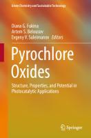
initially located at x = 0.375, shift to position x = 0.3125, where ions M are in octahedra sharing vertices along the [110] direction. It increases the M–M–M angle along these rows from 109°28' to approximately 132°. Anions 8b (X' ) remain equidistant from the four nearest A cations. These 8b anions together with the 16d cations form a sublattice, isostructural to one of the two interpenetrating networks of the anticristobalite structure (Cu2 O). The above description applies only to α-pyrochlores with a value of x around 0.375 or with a high x value, characterized by compounds having a cation with a large ionic radius in the M position (for example, Zr4+ ). Some of these compounds undergo “α-pyrochlore-defective fluorite” phase transition. This type of transition never occurs in the α-pyrochlore structure, containing smaller M cations. However, for most compounds the value of x lies significantly below this area [5]. 2. Representation as linked tetrahedra M4 and A4 O' (anticristobalite type) [5, 6]: the structure consists of two interpenetrating networks of tetrahedra. Four M cations occupy the corners of a regular tetrahedron with a void in the center (Fig. 1.3), oxygen atoms are outside the M4 tetrahedra, which form a three-dimensional sequence, observed in the cristobalite structure SiO2 (space group Fd3m). The network formed by the tetrahedra can be designated as M4/2 O6 ; it is pierced by a network of A2 O' , resembling the anticristobalite structure Cu2 O. The M cations are located at the intersection of two tetrahedra and are located in the center of distorted O octahedra (3m or d3d symmetry). The deformation of the octahedra depends on the 48f parameter x: at x = 0.3125 the octahedra are regular, while at x /= 0.3125 the octahedra are compressed or stretched along the 3rd order axis. The above description explains the high symmetry (Fd3m) of the α-pyrochlore structure. The rigidity of the structure framework is due to the interpenetration of two tetrahedral networks, formed by A and M cations. The A–A and M–M distances, equal and constant throughout the structure, do not depend on the parameter x of oxygen in 48f. The authors previously [6] listed the advantages of such a description of the α-pyrochlore structure: (1) The model gives more importance to the 8b position, containing the anion O' , which undergoes sp3 -hybridization, and the coordination is a regular tetrahedron A4 O' . (2) It can be expected that distortions of the general cubic symmetry in the αpyrochlore structure will be similar to those observed in various polymorphic modifications of SiO2 . (3) When the 16d position (A cation) is occupied by d10 -ions, such as Hg2+ , Cd2+ , Ag+ , which often undergo sp3 -hybridization, the A–OX' bond is stronger than the A–O bond, and an increase in the A–O distance is observed, which gives low x values (x ~ 0.3125). If the strength of the A–O' bond is even higher, then the regular octahedral environment can expand along the 3rd axis, which will lead to a decrease in the x value (x < 0.3125). For instance, in the case of Cd2 Re2 O7 [7] x is 0.309, which is lower than for the regular octahedra.
1 Structural Type of α-Pyrochlore Oxides
5
Fig. 1.3 Two tetrahedral groups M4 and A4 O' in A2 M2 O6 O' α-pyrochlore structure
However, this description is associated with a difficulty, in that it inadequately explains the formation of defective pyrochlores of the general formulas of AM2 O6 and A2 M2 O7–x (is a vacancy). Calculations of the energy structure depending on x-parameter of oxygen 48f were carried out in the works [8, 9] in order to obtain a general idea of the α-pyrochlore structure stability. These results of semi-quantitative calculations generally agree well with experimental observations:
6
D. G. Fukina and E. V. Suleimanov
(1) The electrostatic energy of the M2 O6 network is always more negative than that of the A2 O' network, indicating that the former is more stable. (2) The interaction energy between grids is only 2–3% of the total electrostatic energy of the system. (3) For all values of x, the electrostatic energy of pyrochlores with A1+ and M6+ is more negative than that of other types with Am+ and Mn+ . However, αpyrochlores with A1+ and M6+ do not exist due to the absence of cations with suitable ionic radii. For values of x close to 0.3125, pyrochlores with A2+ and M5+ should be more stable than those with A3+ and M4+ or A4+ and M3+ , which, indeed, has been established experimentally. (4) In the case of α-pyrochlores with A3+ and M4+ the structure is definitely more stable at x < 0.36 compared to the defective fluorite structure. For x = 0.36, the α-pyrochlore structure can also exist, but it can easily be transformed into the defective fluorite structure. For instance, there is a transition from pyrochlore to defective fluorite in Ln2 Zr2 O7 , where x increases from La to Gd. The transition of α-pyrochlore to defective fluorite in some of these zirconates (La–Gd) also occurs depending on the temperature. In the case of α-pyrochlores with A4+ and M3+ calculations show that the structure can be stable at x > 0.35 [10]. 3. Representation of the α-pyrochlore structure as linked structural units M2 O6 and A2 O' (the most commonly used interpretation of the structure) (Fig. 1.4) [6]: in the structure of each α-pyrochlore, the M atom is surrounded by six O anions, which form an octahedral environment. The MO6 octahedra are connected to each other through vertices. Each A cation is surrounded by six O atoms and two O' atoms, with the A–O' bond length usually significantly less than A– O. Therefore, it is customary to consider the structure as a three-dimensional octahedral M2 O6 framework, through which the A2 O' channels pass. The A atoms form a tetrahedron, the center of which is occupied by O' atoms, and the A–O' –A angle is 109°28' . In the (MO3 )2 network, M is located in a distorted octahedral coordination, while the O anion is in a linear coordination. The octahedra become more regular when x approaches 0.3125, and any deviation from this value is a measure of distortion in the octahedral network. The closest contact between the two networks occurs between the A cations of A2 O' network and the oxygen atoms of the M2 O6 network. However, these inter-network distances are always significantly larger than any intra-network distances. The two-network representation of the α-pyrochlore structure is more appropriate compared to the others, as it agrees with the presence of AM2 O6 and A2 M2 O7–x x (is vacancy) “defective pyrochlores”, since here the octahedral network MO6 forms the “skeleton” of the structure and is preserved when vacancies occur. Given that, most x values of α-pyrochlores are close to the limit value of 0.3125, this description may well be suitable for most compounds. The main disadvantage of this model is that it apparently does not take into account the importance of the A and O' ion’s nature. It predicts the formation of the α-pyrochlore structure regardless of the A ion
1 Structural Type of α-Pyrochlore Oxides
7
Fig. 1.4 Eight unit cells of A2 M2 O6 O' α-pyrochlore structure, built by two networks M2 O6 and A2 O'
nature, which is incorrect, for example, Cd2 Nb2 O7 crystallizes in the α-pyrochlore structure, while Ca2 Nb2 O7 and Sr2 Nb2 O7 do not. Many compounds with the α-pyrochlore structure undergo phase transitions, during which the structural type is preserved. However, various distortions of structural blocks occur, leading to a decrease in symmetry from the classical cubic centrosymmetric with the space group Fd3m. With certain combinations of cations in A and M positions, only such distorted α-pyrochlore structures can be observed. Among the most common types of distortions, one can distinguish tetragonal, rhombohedral and monoclinic. In the tetragonal distortion (Fig. 1.5), the typical grouping of the α-pyrochlore structure (a ring of six [MO6 ] octahedra) is no longer observed within one unit cell, but several. This building block is found in four unit cells during the Fd3m → I 4m2 transition in Cd2 Re2 O7 [11, 12]. In this case, the decrease in symmetry is associated with the disordering of oxygen atoms and their displacement from their "ideal" positions 48f and 8b, while the metal atoms do not shift. It leads to a distortion of the octahedral environment of the M
8
D. G. Fukina and E. V. Suleimanov
Fig. 1.5 Tetragonal distortion of Cd2 Re2 O7 α-pyrochlore structure after phase transitions (a) and the X-ray diffraction patterns of each modifications (b) [11]
1 Structural Type of α-Pyrochlore Oxides
Fig. 1.5 (continued)
9
10
D. G. Fukina and E. V. Suleimanov
atom: the lower the symmetry of the space group within the tetragonal system, the more pronounced such distortion (Fig. 1.5: Cd2 Re2 O7 Fd3m ↔ I 4m2 ↔ I 41 22). As it can be seen from Fig. 1.6, monoclinic and orthorhombic distortion of the α-pyrochlore structure can be observed by the example of phase transitions in the Bi2 Sn2 O7 compound: Cc(α-form, monoclinic) → Aba2(β-form, orthorhombic) → Fd3m (γ-form, cubic) (Fig. 1.6) [13]. In this case, not only the distortion of the octahedral environment around the Sn atom in the M position is observed, but also its displacement relative to its “ideal” position 16c, which leads to the appearance of Sn atoms of different types. In some cases, instead of the α-pyrochlore phase, when the distortion of structural blocks is large and there is a mismatch in the values of the radii of cations in the A and M positions, a related weberite phase is formed [14]. For instance, antimonates A2 Sb2 O7 (A = Ca, Pb, Sr) belong to this structural type [15]. The weberite structural type has the general formula of A2 M2 O7 and a structural motif similar to α-pyrochlore (Fig. 1.7); it crystallizes in the orthorhombic system with the space group I mma. The main difference between the structures is that in the case of weberite not all octahedra [MO6 ] are connected to each other, meaning a full three-dimensional framework like in α-pyrochlore is not formed. In the weberite structure, there are several nonequivalent cation M positions (4b, 4c), and the octahedral environment is distorted, as the oxygen atoms are also shifted relative to positions in α-pyrochlore
Fig. 1.6 Monoclinic and orthorhombic distortion of Bi2 Sn2 O7 α-pyrochlore structure after phase transitions (a) and the X-ray diffraction patterns of each modifications (b) [13]
1 Structural Type of α-Pyrochlore Oxides
11
Fig. 1.6 (continued)
(4e, 8h, 16j). Cations in the A position in the weberite structure are also in two nonequivalent positions, with one of them forming a highly distorted oxygen cubic environment (4a), and the second position and its environment fully correspond to the similar in α-pyrochlore (4b). X-ray diffraction patterns of distorted types of α-pyrochlore structure (Fig. 1.5b, 1.6, 1.7b) become more complex as the symmetry of the structure decreases, which is associated with an increase in nonequivalent positions of atoms A and M and,
12
D. G. Fukina and E. V. Suleimanov
Fig. 1.7 Structure motif of Cd2 Re2 O7 α-pyrochlore [11] and Ca2 Sb2 O7 veberite [49] (a) and the X-ray diffraction patterns (b) [16]
1 Structural Type of α-Pyrochlore Oxides
13
accordingly, crystallographic reflection planes. Whereas with a slight decrease in symmetry (as in the case of Cd2 Re2 O7 , I 4m2) to the series of reflections of the space group Fd3m a small number of low-intensity additional peaks are added, which complicates the indexing procedure and requires thorough X-ray studies.
1.2 Series of α-Pyrochlores with Composition A2 3+ M2 4+ O7 A large number of known oxides with the α-pyrochlore structure belong to the type A2 3+ M2 4+ O7 . It is due to the fact that many cations A3+ and M4+ have a suitable ionic radius for the formation of an octahedral framework. Ion A3+ can be represented by a rare earth element, Sc, Y, Bi, Tl or In, while M4+ can be a transition metal or any of the elements of group IVa of the Mendeleev table. Table 1.2 shows a stability field diagram for A2 3+ M2 4+ O7 α-pyrochlores, obtained by plotting the radius of the atom in position A (eightfold coordination) against the radius of the cation in position M (sixfold coordination) based on Shannon’s data for ionic radii [17]. It is known that the relative ionic radii or their rA3+ /rM4+ ratio and the oxygen parameter (x) define the area of formation and stability of α-pyrochlore oxide. Such compounds can be formed in the rA3+ /rM4+ area from 1.46 to 1.80 (rGd/rZr = 1.46, rSm/rTl = 1.78) at normal pressure. It was shown [18, 19] that the parameter rA3+ /rM4+ can be increased up to 2.3 for α-pyrochlores of germanates and silicates under high pressure and temperature conditions. However, it should be noted that in some cases for the synthesis of some A2 3+ M2 4+ O7 α-pyrochlores might require high pressures, even if rA3+ /rM4+ is in the range of 1.40–1.55. It can be explained by differences in compressibility between oxygen ions and atoms in A and M positions, i.e., it may require the application of pressure to force the smaller M ion into the structure with sixfold coordination or the larger A ion into eightfold coordination (for example, In3+ in In2 Ge2 O7 ). In some cases, redox thermodynamic parameters determine the formation of A2 3+ M2 4+ O7 α-pyrochlores, as evidenced by the absence of α-pyrochlores Ln2 M2 O7 with M = W4+ and Re4+ [20, 21], despite the fact that the criteria of ionic size, rA3+ /rM4+ and charge neutrality criteria are satisfied to form these structures at normal pressure. The Ce role in the formation of the α-pyrochlore structure can be emphasized. The only α-pyrochlores, where cerium is in A position, are Ce2 M2 O7 (M = Ti, Zr and Sn) [22, 23]. Despite this, cerium in the oxidation state Ce4+ is capable of occupying the M position in A2 M2 O7 , for example in Sm2 Ce2 O7–δ [24]. However, not for all Ln will the conditions of ion size ratio with Ce4+ for forming the α-pyrochlore structure be met and, for example La2 Ce2 O7 , crystallizes in the structural type of defective fluorite [25]. All possible compositions of α-pyrochlores A2 3+ M2 4+ O7 are conveniently divided into groups by which element occupies the M position:
CP
Sm
0.625
CP
CP
CP
CP
CP
–
CP
CP
CP
CP
CP
CP
CP
–
–
–
–
–
–
–
0.69
0.62
0,625
0.63
0.605
0.53
0.65
0.615
0.71
0.72
0.775
0.6
0.645
0.58
0.68
0.4
0.53
0.55
0.63
0.66
Sn
Ru
Ir
Os
Ti
Ge
Mo
Pd
Hf
Zr
Pb
Rh
Tc
V
Nb
Si
Mn
Cr
Re
W
M
Pt
3+
0.96
A
r, Å
4+
–
–
–
–
–
–
–
–
–
CP
CP
CP
CP
CP
CP
CP
CP
CP
CP
CP
CP
0.98
Gd
–
–
CP
CP
–
–
P
–
–
DF
DF
CP
CP
CP
CP
CP
CP
CP
CP
CP
1.02
Y
–
–
–
–
–
–
–
–
–
CP +P
CP +P
–
P
CP
–
DF
–
DF
CP
CP
CP
CP
CP
CP
CP
CP
CP
0.89
Er
CP
–
–
–
–
DF
CP
CP
CP
CP
CP
CP
CP
CP
CP
0.88
Tm
–
–
–
–
–
–
–
–
–
CP
CP
CP
–
CP
–
CP
CP
CP
CP
CP
CP
0.95
Eu
–
–
–
–
–
CP +P
CP
–
–
–
–
DF
–
CP
CP
CP
CP
CP
CP
CP
CP
0.86
Lu
–
–
–
–
–
–
CP
–
–
–
–
DF
CP
CP
CP
CP
CP
CP
CP
CP
CP
0.87
Yb
–
–
–
–
–
–
P
CP
–
DF
–
DF
CP
CP
CP
CP
CP
CP
CP
CP
CP
0.91
Dy
–
–
–
–
–
–
P
–
–
DF
–
CP
CP
CP
CP
CP
CP
CP
CP
CP
CP
0.92
Tb
–
–
–
–
–
–
P
–
–
DF
–
DF
CP
CP
CP
CP
CP
CP
CP
CP
CP
0.90
Ho
–
–
CP
CP
–
–
–
–
CP
–
–
-
–
CP
–
CP
CP
CP*
–
CP
0.98
Tl
–
–
–
–
–
–
–
–
–
CP
CP
CP
–
–
–
–
CP
CP
CP
CP
CP
0.97
Pm
–
–
–
–
–
–
–
–
–
CP
CP
CP
–
–
–
–
CP
CP
CP
CP
CP
0.98
Nd
–
–
–
–
–
–
–
–
–
CP
CP
CP
–
–
–
–
CP
CP
CP
CP
CP
0.99
Pr
–
–
–
–
–
–
–
–
CP*
–
–
–
–
–
–
CP*
CP*
CP*
CP*
CP*
CP
1.17
Bi
–
–
–
–
CP
–
–
–
CP
–
–
–
CP
–
CP
DF
–
–
–
–
CP
0.87
Sc
–
–
–
–
CP
–
–
–
–
–
–
–
CP
–
CP
–
–
–
–
–
CP
0.92
In
–
–
–
–
–
–
–
–
–
CP
CP
CP
–
–
–
–
–
–
–
CP
–
1.03
La
–
–
–
–
–
–
–
–
–
–
CP
–
–
–
–
CP
–
–
–
CP
–
1.01
Ce
Table 1.2 The formation field of α-pyrochlores in the series A2 3+ M2 4+ O7 (P—perovskite, DF—defective fluorite, CP—cubic α-pyrochlore Fd3m, CP*—αpyrochlore with reduced symmetry or non-stoichiometry)
14 D. G. Fukina and E. V. Suleimanov
1 Structural Type of α-Pyrochlore Oxides
15
1. Metals of group IVb (Ti, Zr, Hf) The most studied and stable compounds with the classic cubic structure of αpyrochlore A2 3+ M2 4+ O7 are phases where the M position is occupied by metals from group IVb (Ti, Zr, Hf). Titanate compounds are known for almost all Ln3+ Ln2 Ti2 O7 (Ln = Sm–Lu and Y) [26–28]. The parameters of the unit cell in the Ln2 Ti2 O7 series systematically decrease with the decrease in the Ln3+ ion radius. However, when Ln = La, Ce, Pr, and Nd, crystallization in the α-pyrochlore structure does not occur, as the values of rA3+ /rM4+ exclude their formation. Solid solutions (Lu1– x Scx )2 Ti2 O7 , (Y1–x Bi)2 Ti2 O7 and Ln2 (Ti1–x Mx )2 O7 with M = Ge and Zr crystallize in the αpyrochlore structure when the rA3+ /rM4+ values are satisfied for a particular x [27]. Neutron diffraction study of Sc2 Ti2 O7 showed that the compound has a defective fluorite structure [29], and Bi2 Ti2 O7 is a defective α-pyrochlore, which is isostructural with Bi2 Sn2 O7 [27]. Compounds with the α-pyrochlore structure A2 Ti2 O7 , A = In, Cr, and Mn were not obtained, as the atoms of Cr and Mn are too small to occupy the A position [27]. The existence of an ordered orthorhombic structure of In2 Ti2 O7 α-pyrochlore is predicted by theoretical calculation. Zirconate α-pyrochlores Ln2 Zr2 O7 (Ln = La–Gd) are easily obtained and have a classic cubic structure [30, 31]. They are stable at room temperature, but at high temperature (>1500 °C) an order–disorder type phase transition is observed: α-pyrochlore-defective fluorite structure [32, 33]. Compounds Ln2 Hf2 O7 (Ln = La–Dy) are easily formed and have an ordered αpyrochlore structure, and when Ln = Dy–Lu and Y, the compounds have a disordered fluorite structure [34, 35]. Moreover, for all Ln = La–Dy, a “pyrochlore-fluorite” phase transition is observed. 2. Group Vb metals (V, Nb, Ta) When the M position is occupied by atoms from group Vb (V, Nb, Ta), the possibilities for phase formation of α-pyrochlore structure decrease. Among α-pyrochlores based on vanadium, Ln2 V2 O7 (Ln = Tm, Yb, Lu and their solid solutions), their physical properties have been studied in the works [36, 37]. Unsuccessful attempts to obtain α-pyrochlores with Ln = Tb–Er, Y are likely related to the greater stability of their compounds with V3+ and V5+ with the perovskite LnVO3 and zircon LnVO4 structure [38, 39]. All obtained vanadate powders of α-pyrochlores have a black color and are stable under normal conditions (25°C), but decompose at 350–400 °C. In the works [40, 41] the possibility of the presence of V3+ in some compounds (Lu1–x Ax )2 V2 O7 with A = Sc, Y is emphasized. Compounds with the α-pyrochlore structure based on Nb can be obtained only under harsh conditions, Ln2 Nb2 O7 compounds (Ln = Er, Tm, and Lu) were synthesized from Ln2 O3 and NbO2 by arc melting [1]. However, it was always found that LnNbO4 is present as a second phase in significant amounts. Annealing at 1000 °C for a week in vacuum only led to an increase in the LnNbO4 impurity content. Thus, it turns out that the phases Ln2 Nb2 O7 form in a narrow (high) temperature range and are
16
D. G. Fukina and E. V. Suleimanov
metastable. In the case of an octahedral framework based on tantalum, compounds with the α-pyrochlore structure form and are stable only at high pressures and have a complex composition with oxygen defects (K, Ln)2 Ta2 O7–y (Ln = Gd, Y, Lu), which ensures the formation of the phase [42, 43]. 3. Group VIb metals (Cr, Mo, W) The most numerous family of compounds with the α-pyrochlore structure is formed in the case of M = Mo, while in the case of Cr the α-pyrochlore phase is found only for A = Tl, Y under conditions of high oxygen pressure and high temperature (>1100 °C) [44]. All compounds, except Y2 Cr2 O7 , were obtained in pure form. The thallium analogue of dichromate thallium has the formula Tl2 + Cr2 6+ O7 and is not α-pyrochlore. Also, in the case of M = W, α-pyrochlores were not obtained. Molybdate α-pyrochlores are formed for a wide range of A cations - Ln2 Mo2 O7 (Ln = Sm–Lu, Y), and their physical properties have been particularly investigated [45, 46]. Compounds with Ln = La–Pr do not exist, and Nd2 Mo2 O7 were obtained only as an impurity phase. However, it has been shown that (Nd1–x Lnx )2 Mo2 O7 (Ln = Er and Yb; x = 0.4–0.05) solid solutions have been synthesized, and already 10 mol. % Yb can stabilize the cubic α-pyrochlore with Ln = Nd. The powders of the compounds are black in color and are stable in air and to moisture, but decompose when heated to T > 500 °C. Among these compounds, Ln2 Mo2 O7 attracts the greatest interest due to their magnetic properties. It can be explained on the basis of the one-electron energy band diagram proposed in the work [45]. Considering the α-pyrochlore structure as interpenetrating networks, where a strong bond between the M2 O6 and A2 O' networks is observed, it can be seen that the hybridized orbitals eg , s and p of the metal in the M position will combine with O6 s- and p-orbitals, forming bonding (valence zone) and loosening (conduction zone) states (σ and σ*). Since atom A is linearly coordinated with two nearby oxygen atoms (O' ), an s–p-bonding is assumed, which will also lead to the corresponding σ and σ* states. Orbitals t2g of the M metal will form corresponding π- and π*-states. The π* states in most cases remain localized, but can form a narrow conduction zone, when M is a 4d- or 5d-transition metal. Spin–orbital interaction or trigonal distortion can lift the degeneracy of π*-states and give two sublevels or bands (π*a and π*b). The remaining two p-orbitals of A atom will combine with O6 s- and p-orbitals, giving A-Oσ and σ* levels, where each of them can contain eight (2 × 4) electrons (including spin). In Ln2 Mo2 O7 compounds, the Ln–O σ* level is empty and a total of 60 electrons are distributed in the valence band and localized levels [(2 × 3) + (2 × 6) + (7 × 6)]. Two Mo-4d electrons at the M–O π*a level generate pure spin magnetic moments (for example, Y2 Mo2 O7 ) and thermal excitation of these electrons to the Ln–Oσ* level (or to the M–O π*b level) leads to semiconducting behavior, which is indeed observed experimentally. In addition, the activation energy should be a measure of the “band gap” (Δ) and should increase as the size of the unit cell and the Ln–Mo distance in Ln2 Mo2 O7 decrease. The “band gap” decreases to zero for Ln = Sm or Nd, which leads to semi-metallic or metallic behavior. Similarly, the observed properties of Ln2 V2 O7 can be explained. In cases where A = Bi, the “lone pair”
1 Structural Type of α-Pyrochlore Oxides
17
will occupy the Bi–Oσ* level, leading to a half-filled conduction band and metallic behavior. It is indeed observed in the phases Bi2 Ru2 O7 and Bi2 Os2 O7 . However, it should be noted that the one-electron band model is empirical and explains the observed physical properties of α-pyrochlores qualitatively. 4. Group VIIb metals (Mn, Tc, Re) A rather limited number of compounds lead to the formation of the α-pyrochlore structure when the M position is occupied by atoms of group VIIb. α-Pyrochlores A2 M2 O7 based on Mn were obtained only for A = Tl, In, Y, Ho, Yb [47, 48]. Such compounds are characterized by classic cubic symmetry, however, the authors observed ferroelectric ordering in the structure at high temperatures due to the presence of a small amount of Mn3+ and spin interaction between Mn3+ and Mn4+ . Compounds with the α-pyrochlore structure based on Tc were obtained for compositions Ln2 Tc2 O7 (Ln = Pr, Nd, Sm, Gd, Dy, Er, Lu) and were studied in detail as matrices for the immobilization of radioactive waste for 99 Tc [49] A detailed study of the electronic structure, as well as the prediction of the compound formation with A = Ce–Pm, Tb, Ho, Tm is described in the work [50]. For rhenium, the composition (Pr, Nd)2 Re2 O7 (OH) is known, which, however, does not belong to the pyrochlore structural type [51]. 5. Group VIIIb metals (Ru, Rh, Pd, Os, Ir, Pt) In the case of metals from group VIIIb, rather wide conditions of α-pyrochlore phase formation are observed for Ru, Rh, Pd, Os, Ir, and Pt. α-Pyrochlores based on ruthenium are characterized by classical cubic symmetry for compositions A2 Ru2 O7 with A = Pr–Lu, Y, Bi, and Tl, whereas for A = Ln a perovskite structure with orthorhombic symmetry is formed [52–57]. Ln2 Ru2 O7 and some solid solutions by position A (Nd, Bi, Gd, Bi, etc.) are stoichiometric, whereas in pure Bi- and Tl-containing α-pyrochlores, slight non-stoichiometry by oxygen can be observed at low temperatures, which leads to the ordering of the structure and changes in electronic behavior [58]. The observed electrical and magnetic properties of α-pyrochlores based on ruthenium are well explained using the one-electron MO energy band diagram. The semiconductor behavior of Ln2 Ru2 O7 and Tl2 Ru2 O7 can be easily predicted, as the Ln–O σ* level is empty. In Bi2 Ru2 O7 this level (Bi–O σ*) is half-filled (with a pair of 6s2 electrons), which leads to metallic behavior. Stoichiometric α-pyrochlores based on Rh were only obtained for (Y, Lu)2 Rh2 O7 under high pressure and high temperature conditions and are characterized by cubic symmetry [59, 60]. The classical α-pyrochlore Bi2 Rh2 O7 is characterized by oxygen deficiency (δ = 0.2), however, when the synthesis conditions are changed (under high pressure), the perovskite BiRhO3 is formed [61]. Similar to α-pyrochlores with Rh, compounds with palladium Ln2 Pd2 O7 (Ln = Sm, Gd–Yb, Y, Sc, and In) can only be obtained under high pressure and temperature conditions (65 kbar, 1000 °C) [62].
18
D. G. Fukina and E. V. Suleimanov
Compounds with the cubic α-pyrochlore structure in the case of Os are formed quite easily and are stable Ln2 Os2 O7 (Ln = Pr–Lu, Y, Bi, and Tl) [63, 64]. αPyrochlores Ln2 Ir2 O7 (Ln = Pr–Lu, Y, Bi, and Tl) are characterized by classical symmetry and undergo a phase transition “metal–insulator” at T < 150 K [65, 66]. Compounds A2 Pt2 O7 (A = Pr–Lu, Y, Sc, In, Tl and Bi) are obtained under high temperature and pressure (700 °C; 3 kbar; presence of KClO 3 at 1100 °C). They exhibit magnetic properties at low temperatures, for example, when Ln = Dy the compound is a spin ice [62, 67, 68]. Powders of compounds A2 Pt2 O7 are stable up to 1000 °C when heated in air, except for A = In (decomposition at 860 °C) or Tl (decomposition at 1025 °C), as shown by DTA and TGA studies. 6. Metals of IVa, Va, VIa, VIIa and VIIIa groups In the case of main subgroup metals of groups IV, V, VI, VII and VIII, the formation of compounds with the structure of α-pyrochlore is possible only for IVa (Si, Ge, Sn and Pb). Moreover, such phases tend to form various polymorphic modifications, among which the classical cubic is the least stable under normal conditions. Silicon-based α-pyrochlores were obtained only for compositions A2 Si2 O7 with A = In, Sc and are stable under high pressure of 120 kbar [19]. Sc2 Si2 O7 has the smallest value of the unit cell parameter among compounds with the α-pyrochlore structure. For A = Ln, disilicates Ln2 Si2 O7 (Ln = Er, Ho, Tm, Yb) are known [69], however, they have monoclinic symmetry. Cubic germanate α-pyrochlores A2 Ge2 O7 (A = Gd–Lu, Y, Sc, In and Tl) were obtained using high pressure methods (65 kbar, up to 1200 °C) [18]. Phases with Ln = Gd, Ho and Dy attract attention due to their magnetic properties [70–73]. In the case of A = In, two polymorphic modifications may exist: monoclinic and cubic, however, quantum-chemical calculation method shows that the first one is more stable [74]. Compounds A2 Sn2 O7 (Ln = La–Lu, Y) have a cubic α-pyrochlore structure and are well studied in the literature [75, 76]. Phases with A = Sc and Tl were not obtained, and in the case of In, monoclinic and cubic modifications were found, however, the monoclinic structure is more stable under normal conditions [74]. The cubic structure of α-pyrochlore Bi2 Sn2 O7 is formed, but at room temperature the compound is characterized by monoclinic symmetry (α-form) and during phase transformations upon heating it changes to orthorhombic (β-form above 100 °C) and cubic (γ-form above 680 °C) [13]. The phase transition α–β is the first order, and the transition β–γ— the second order. Impurities and partial replacement of Bi in position A always lead to the stabilization of the β-form at room temperature [77]. Bi2 Sn2 O7 decomposes at T > 1200 °C. The crystal chemical data for Ln2 Sn2 O7 show that the shape of the oxygen octahedron is determined by the x-parameter of oxygen (48f), which has a value of 5/16 (0.3125) for a regular octahedron. As the size of the Ln ion increases, the ionic environment of Sn4+ becomes more symmetrical (i.e., approaches the regular coordination, as the x parameter decreases) [78]. All known phases with Pb crystallize in the classic cubic symmetry of αpyrochlore. The formation of La2 Pb2 O7 is possible at a pressure of 1 atm [29], and
1 Structural Type of α-Pyrochlore Oxides
19
for a series of Ln2 Pb2 O7 (Ln = La–Gd)—at high pressures (3 kbar, 700 °C) [79], while Bi2 Pb2 O7 forms under mild hydrothermal conditions [80]. In the case of Ln = Tb–Er, Y, phases with a defective fluorite structure are formed [81]. Compounds of α-pyrochlores are not stable above 300 °C and lose oxygen. For several decades, the study of compounds with the α-pyrochlore structure have been carried out by not only using X-ray analysis but also the IR spectroscopy. It can be noted that their main feature is the presence of a broad band with a maximum absorption in the range of 600–400 cm–1 , on which a fine structure is observed in the areas of 350–200 and 200–100 cm–1 . The observed infrared bands of all αpyrochlores are characterized by similar features: the band at 500–600 cm–1 is the most intense, followed by ~450 cm–1 and ~400 cm–1 with slightly less or equal intensity. The intensity of all other peaks does not exceed 30% of the intensity of the main three bands. Apparently, the position of the band maxima is influenced by the radius of the A3+ ion, the mass of the A element, and the presence of the A element in group IIIa or IIIb (Ln). Vibrational spectra are used to demonstrate that compounds have a cubic αpyrochlore structure and to establish the boundary of existence of this structural type. For example, the IR spectra of Ln2 Ti2 O7 for Ln = La–Nd, which do not crystallize in the α-pyrochlore structure, differ significantly in the number and position of bands and general features from the IR spectra of the α-pyrochlores [36, 40, 82]. For example, Fig. 1.8 shows the IR spectra of a series of solid solutions Y2 Sn2−x Zrx O7 , where the α-pyrochlore structure is formed at x < 1.2, and the fluorite one is at x > 1.2 [83]. For compounds Ln2 Zr2 O7 (Ln = La–Gd) the IR and Raman spectra (600–50 cm–1 ) are noticeably simplified due to the broadening of some peaks and the disappearance
Fig. 1.8 IR spectra of Y2 Sn2−x Zrx O7 solid solutions [83]
20
D. G. Fukina and E. V. Suleimanov
of weak bands from La to Gd [33, 82, 84, 85]. It is a direct consequence of the decrease in the stability of the α-pyrochlore structure, expressed in the reduction of their homogeneity area both in composition and in temperature. Since the spectral characteristics of the disordered fluorite phase differ from the α-pyrochlore phase, studies unequivocally indicate the boundary of existence of the α-pyrochlore phase in Ln2 Zr2 O7 for different Ln and depending on the temperature for Gd2 Zr2 O7 . The IR spectra of Ln2 Ru2 O7 in the range of 700–50 cm–1 have the shape typical for α-pyrochlore. However, in some cases, there are nine observed bands instead of the predicted seven. A noticeable increase in the splitting of absorption bands may indicate some local distortion of the oxygen polyhedron around the A3+ ion in the structure [86]. 7. Solid solutions A2 3+ M2 4+ O7 with substitution at positions A and M According to the unit cell electroneutrality, there is a possibility of replacing the A cation in α-pyrochlore A2 3+ M2 4+ O7 with ion pairs (A3 + , A1 3+ ), (A2+ , A4+ ) or (A+ , A5+ ). Suitable combinations are (alkali element, rare earth element), (alkaline earth element, group IVa, b element) or (alkali element, group V element), which also satisfy the criteria of the ionic radius ratio. However, it should be noted that the alkali metal (Li, Na) tends to volatilize under high-temperature reaction conditions and can stabilize phases with a deficit of metals and anions under these conditions. As examples of the cubic α-pyrochlores formation with substitutions at position A, a large number of different bismuth-containing compounds can be presented (Bi1−x Lix )2−d Ti2 O7−3d/2 [87], Bi1.6 Mg0.2 Ti2 O6.6 , Bi1.6 Sc0.4 Ti2 O7 , Bi1.6 Cu0.2 Ti2 O6.6 [88], Bi2 Ti1.5 M0.5 O7 (M = Mg, Ca, Sr, Ba) [89], Ln2−x Bix Ti2 O7 Ln = La–Lu and Y [90], Bi1.6 Crx Ti2 O6.4+1.5x (0.016 ≤ x ≤ 0.16) [91], Bi1.6 Zn0.2 Ti2 O7−δ , Bi1.6 Co0.23 Ti2 O7−δ and Bi1.6 Mg0.4 Cu0.4 Nb1.6 O7−δ [92]. However, there are cases of lowering the symmetry of the structure, for example (Bi1–x Gax )2–d Ti2 O7−3d/2 (cubic, F41 32) [93]. The synthesis of such mixed α-pyrochlores by the solid-state method has shown the possibility of phase formation in some cases, as in addition to the criterion of ionic radius, differences in charge, electronic configuration, and polarizability of cations play a role in stabilizing the cubic α-pyrochlore structure. The substitution of an atom in the M position is possible within a wide range of different atoms, which leads to the formation of a large number of new compounds. For the structural series A2 3+ M2 4+ O7 , it is known that pairs of ions such as (M3+ M'5+ ), (M2/3 2+ M' 4/3 5+ ) and (M4/3 5+ W2/3 6+ ) can be placed in the M position. Many new phases retain the classical cubic symmetry: Bi1.4 (Mg1−x Nix )0.7 Ta1.4 O6.3 , Bi2 (Zn1/3 Ta2/3 )2 O7 , (Bi3/2 Zn1/2 )(Zn1/2 Ta3/2 )O7 [94, 95], Bi2 (MM' )O7 , M = Cr, Fe, Sc, In; M' = Nb, Ta and Sb [96–98], Ln' 2 (Ln' Sb)O7 (Ln = or /= Ln' = La–Lu, Y) [99, 100], Ln2 (ScNb)O7 (Ln = La, Nd, Sm [101]), Bi2 (M2/3 2+ M' 4/3 5+ )O7 , M = Mg, Ni, M' = Nb, Ta [97, 98] and Ln2 (V4/3 W2/3 )O7 , Ln = Gd–Lu, Y [102]. However, phases the Ln2 (Ln' M)O7 (M = Nb, Ta) and Ln2 (Fe4/3 W2/3 )O7 , Ln = Gd–Yb, Y, crystallize in an orthorhombic or defective fluorite structure [101]. Solid solutions of the Er2 (V1−x Fex )4/3 W2/3 O7 are easily formed at all x, and at x > 0.2 a transition from cubic to orthorhombic symmetry occurs [103].
1 Structural Type of α-Pyrochlore Oxides
21
In addition, there is information about mixed α-pyrochlores with the composition of (A2+ A'3+ )(M4+ M'5+ )O7 (A2+ = Ca, Sr, Ba, Cd, Pb; A'3+ = La, Sm, Bi; M4+ = Tl, Zr, Hf, Sn; M'5+ = Nb, Ta) [104–106]. However, the α-pyrochlore phase is almost not observed for cations A2+ = Ba and M5+ = Ta, as they are more likely to lead to the fluorite structure formation. In addition, phases with a cubic α-pyrochlore structure were found among the compositions (CdLn)(TiNb)O7 (Ln = La–Lu) [1], (A2+ A'3+ )(TiSb)O7 (A2+ = Zn, Cd, Pb; A'3+ = La–Eu, Bi) [1], (A1+ Ln3+ )(Zr4+ Mo6+ )O7 (A = Li, Na; Ln = La, Sm) [97], (Cd2+ Ln3+ )(M3+ W6+ )O7 (Ln = Gd–Lu, Y, Bi; M = V, Cr, Mn and Fe) [1, 102]. It can be seen that the possibilities for the formation of α-pyrochlores are very extensive, which is associated with high stability and elemental capacity of the structural type. However, it should be taken into account that during the synthesis of α-pyrochlores, the presence of volatile elements (Li, Na, Cd, Pb, Mo) can lead to non-stoichiometry between the cation and anion, and the presence of polyvalent elements (Fe, Mn, Mo and Nb) can change the charge balance and lead either to non-stoichiometry, or to distortion of the cubic structure of α-pyrochlore. In this regard, for clear determination of the features of the α-pyrochlore crystal structure, growing single crystals and refining the structure by X-ray diffraction analysis should be implemented.
1.2.1 Series of α-Pyrochlores with Composition A2 2+ M2 5+ O7 The α-pyrochlore crystal structure can also be formed in a series of compositions with the general formula A2 2+ M2 5+ O7 , however, there are much fewer such compounds compared to A2 3+ M2 4+ O7 . It is due to the fact that there are fewer cations A2+ and M5+ suitable in size and characteristics for the corresponding coordination than A3+ and M4+ cations. In all known α-pyrochlores A2 2+ M2 5+ O7 the cation A2+ is Cd, Hg, Ca, Pb, Sn or Mn, and M5+ is V, Nb, Ru, Rh, Ta, Re, Os, Ir, U or Sb. In addition, V5+ hardly forms the α-pyrochlore structure under normal conditions, as it rarely has a coordination higher than five in oxide compounds. For stabilizing it in an octahedral environment, synthesis methods at high pressure are used, as a result it was possible to obtain A2 V2 O7 phases with A = Cd, Hg. In many cases, when M is a noble metal, non-stoichiometric (oxygen-deficient) phases are obtained. Studies show that in Sncontaining compounds, in addition to Sn2+ in the A-position, Sn4+ can be present in the M-position. Table 1.3 presents a stability field diagram for a series of compounds A2 3+ M2 4+ O7 [107]. The largest and smallest ions in the A2+ position are Pb2+ (r(VIII) = 1.29 Å) and Mn2+ (r(VIII) = 0.96 Å), respectively, while in the M5+ position, the ion size range is from U5+ (0.76 Å) to V5+ (0.54 Å). The ratio of ionic radii r(A2+ )/r(M5+ ) ranges from 1.4 to 2.2. The dependence of the A2+ ionic radius (r (VIII)) on the lattice parameter or the unit cell volume shows linear behavior for this M5+ ion (for example, Nb, Ta, and Sb), indicating the predominant effect of ion size in the α-pyrochlores formation.
22
D. G. Fukina and E. V. Suleimanov
Table 1.3 The formation area of α-pyrochlores with the general formula A2 2+ M2 5+ O7 (CP is cubic α-pyrochlore Fd3m, CP* is distorted cubic or nonstoichiometric α-pyrochlore, MP is a monoclinically distorted structure of α-pyrochlore, OP is orthorhombic distorted structure of α pyrochlore) A2+
Pb
Cd
Ca
Hg
Sn
Sr
Mn
M5+
r, Å
1.29
1.1
1.12
1.14
1.23
1.26
0.96
0.9
Sb
0.6
CP*
CP*
CP
CP
-
-
CP
CP
Ta
0.64
CP*
CP
CP
CP
CP*
-
-
-
Os
0.575
CP*
CP*
CP*
CP
-
CP*
-
-
Nb
0.64
CP*
CP
-
CP
CP*
-
-
-
U
0.76
OP
CP
CP
-
-
-
-
-
Ir
0.57
CP*
CP
CP
-
-
-
-
-
V
0.54
-
MP
-
MP
-
-
-
-
Re
0.58
CP*
CP
-
-
-
-
-
-
Ru
0.565
CP*
CP
-
-
-
-
-
-
Rh
0.55
CP*
-
-
-
-
-
-
-
Pt
0.57
CP*
-
-
-
-
-
-
-
Co
When position A is occupied by metals of group IIa, b, the greatest stability and diversity of A–M cations combinations is observed for Cd and Ca. The compositions Ca2 Nb2 O7 and Ca2 Ta2 O7 form with the classic cubic αpyrochlore structure [107, 108], while Ca2 Sb2 O7 can exist in modifications of αpyrochlore and weberite. The high-temperature solid-phase reaction always gives the weberite phase (or their mixture), while the low-temperature reaction ( 700°C. According to the authors [109] small amounts of F, replacing O, can stabilize the structure of α-pyrochlore. The compounds Ca2 Sb2 O6.5 F and Ca1.56 Sb2 O6.37 F0.44 are stable up to 1000°C, and no phase transition is detected. Analogues with the cubic α-pyrochlore structure based on Sr were obtained only for the mixed composition (SrLi)Ta2 O6 F [1], while the compound Sr2 Sb2 O7 crystallizes in the structure of weberite and does not transform into α-pyrochlore. Os-based α-pyrochlores are well studied, ant it has shown the formation possibility of both stoichiometric cubic α-pyrochlore Ca2 Os2 O7 by a direct reaction from oxides and the orthorhombic phase Ca2 Os2 O7 obtained by decomposition of perovskite CaOsO3 [110–112]. Such a non-cubic α-pyrochlore, when heated above 855 °C, loses oxygen from the lattice, forming a non-stoichiometric phase Ca2 Os2 O7−δ (0.1 < δ < 0.6) with a cubic α-pyrochlore structure. Moreover, under high-pressure conditions, non-stoichiometric cubic α-pyrochlore Ca1.7 Os2 O7 is formed from oxides [113]. In the case of Sr, only an oxygen-deficient α-pyrochlore structure is observed Sr2 Os2 O6.4 , which is stable up to 1070 °C [114]. Based on DTA, TGA, and other studies, it is suggested that Os does not exist in the oxidation state 5 + in the compound, and the compound formula can be written as Sr2 Os4+ 2−δ Os6+ δ O6.0+δ
1 Structural Type of α-Pyrochlore Oxides
23
at 0.2 < δ < 0.6. Moreover, Ca-contaning cubic α-pyrochlore with composition of Ca2 Ir2 O7 is also known [113]. In contrast to phases with A = Ca and Sr, when the position is occupied by Cd and Hg atoms, the formation of α-pyrochlores based on vanadium Cd2 V2 O7 and Hg2 V2 O7 , as well as the solid solutions Cd2–x Ax V2 O7 (A = In, Tl) and Cd2 V2–x Nbx O7 , become possible [115–117]. The α-pyrochlore structure for the compositions Cd2 V2 O7 and Hg2 V2 O7 has a monoclinic distortion. The compound is likely non-stoichiometric or contains V4+ . When heated in air at 400 °C for 2 h, it transitions to a more stable modification, which does not have the pyrochlore structure, with a decrease in density by 18.5%. Despite this Cd2–x Ax V2 O7 (A = In, Tl) and Cd2 V2–x Nbx O7 solid solutions show an increase in symmetry from monoclinic to tetragonal or cubic upon heating. Cadmium niobate Cd2 Nb2 O7 has a classic cubic structure and is the most studied compound of A2 2+ M2 5+ O7 α-pyrochlores [118, 119], as it exhibits ferroelectric properties at low temperatures [120] and undergoes a ferroelectric phase transition [121, 122]. Replacing Cd into Pb, Ca, Sr, (Na1/2 Bi1/2 ) [118] leads to the solid solutions’ formation in a limited range of compositions (20% for Ca and 90% for Pb). Using high pressure of 58 kbar and 1100 °C during synthesis [123, 124] it is possible to increase the proportion of Cd substitution with Mg, Mn, Fe, Co, Ni, Cu, and Zn to ~ 0.5, while at atmospheric pressure the degree of substitution is less than 2 atom. %. Since these elements have an ionic radius smaller than Cd2+ , α-pyrochlores are formed with orthorhombic or triclinic symmetry rather than cubic. The Cd2 Nb2–x Mx O7 solid solutions with M = V, Ta, Sb, or Ti4+ (and Bi3+ for Cd) [118, 123, 124] are formed over the entire x range for Ta, while other elements lead to the α-pyrochlore only in a limited range. The work [125] showed the possibility of replacing part of the oxygen with sulfur in Cd2 Nb2 O7 while maintaining the α-pyrochlore phase. The area of formation of solid solutions Cd2 Nb2 O7–x Sx is wide 0 < x < 1, it was also possible to obtain a series of solutions Cd2–x Znx Nb2 O6 S for x < 1.60 in the case of A = Zn and for x < 0.4 in the case of A = Mn, Fe, Co, Ni, and Cu [126]. Detailed structural, dielectric, DTA, dilatometric, and SHG studies of Cd2 Nb2 O6 S [96] showed that the phase at room temperature is tetragonal. However, after heating, it undergoes orthorhombic distortion at 379 K and becomes a ferroelectric (γ-phase), which transforms to tetragonal at 457 K (β-phase), but retains ferroelectric properties. At 555 K, a cubic α-pyrochlore (α) phase is obtained, which is paraelectric. The δ → γ transition is accompanied by a rather large change in enthalpy, while for the other two transitions (γ → β, β → α) the thermal effect is an order of magnitude smaller. Phases of F-substituted α-pyrochlores Cd2 Nb2 O7 are also stabilized Cd2 NbMO6 F (M = Ti, Zr, Hf, Ge, Sn), Cd2 (Nb/Ta)MO5 F2 (M3+ = A1, Cr, Ga, Fe and Sc) [1] and Cd2 Ti2 O5 F2 [127], except for the composition with M = Zr or Hf, which possesses a deformed orthorhombic structure. In the Cd2 Nb2–2x M4+ 2x O7–x F2x (M4+ = Ge, Sn, Ti, and Zr) the formation of solid solutions was found for Ge and Sn in the range 0 < x < 0.5, and for Zr at 0 < x < 0.875. In the region 0.25 < x < 0.55 orthorhombic distortion of cubic α-pyrochlore is observed due to the ordered distribution of Nb and Zr in the (111) planes of the unit cell [128].
24
D. G. Fukina and E. V. Suleimanov
The structural analogue of Cd2 Nb2 O7 with Ta also forms with cubic symmetry, a complete series of solid solutions Cd2 (Nbx Ta1–x )2 O7 and is characterized by similar physical properties [129–131]. The Cd2 Ru2 O7 , Cd2 Re2 O7 , Cd2 Ir2 O7 and Cd2 Os2 O7 phases also crystallize with the classic cubic α-pyrochlore structure, and only the Os-containing compound is characterized by a small oxygen non-stoichiometry [113, 132, 133]. The compound Cd2 Re2 O7 undergoes a phase transition below 200 K (Fd3m → I 4m2), with the low-temperature modification exhibiting superconductivity [134–137]. The osmiumcontaining phase also has a low-temperature “conductor–insulator” phase transition below 227 K and has a mercury-containing analogue Hg2 Os2 O7 [138–140]. The compound Cd2 Sb2 O7 can exist in two crystallographic modifications: cubic α-pyrochlore and orthorhombic weberite. The structure of weberite is less dense, so the application of pressure (65 kbar, 700°C) causes the transformation of weberite into α-pyrochlore [107, 141, 142]. However, both forms can be realized at atmospheric pressure and are thermally stable. The α-pyrochlore phase Cd1.9 Sb2 O6.9 is non-stoichiometric and contains some amount of Sb3+ . It decomposes around 1100°C into stoichiometric weberite Cd2 Sb2 O7 . In the series of compounds A2 Sb2 O7 [107] the stability region of the α-pyrochlore phase has been studied and it has been found that this is influenced by the effective size of the A ion and the covalency of the A-O bond. Large cations (or mixed cations, Ca, Sr, (NaLa) etc.) and small values of electronegativity favor the weberite structure, while the opposite leads to the α-pyrochlore structure. Substituted phases of the Cd2–x Bix (Sb2–x Tix )O7 type, 0.50 < x < 1.55, Cd2 Sb2–2x M2x O7–2x F2x with M = Ti (x < 1.0), Sn (x < 0.55), Ge (x < 0.4), and Zr ( x < 0.6) and Cd2 SbHfO6 F were also obtained with the cubic α-pyrochlore structure [1]. Hg-containing analogs Hg2 M2 O7 with M = Nb, Ta and Sb crystallize with the classic cubic α-pyrochlore structure [5]. A slight non-stoichiometry appears in all compounds, which is confirmed by differences in color and cell sizes for a given composition. Fluorine-substituted Hg-containing α-pyrochlores, Hg2 M2+ F6 (O/S) with M = Mg, Mn, Co, Ni, Cu, Zn, have cubic symmetry, are stable in air, nonhygroscopic, but decompose at 800 °C [143]. Structural refinement according to XRD data of compounds showed that O or S occupy the O' position in the A2 M2 O6 O' lattice. In addition, the position A in A2 2+ M2 5+ X7 can be occupied by atoms of Sn, Pb, Mn, Co, Ni. Sn-containing niobates and tantalates crystallize in the cubic α-pyrochlore structure and are characterized by compositional non-stoichiometry [107], while the compound Sn2 Sb2 O7 does not form the α-pyrochlore structure. Studies of compounds Sn2 M2 O7 (M = Nb, Ta) revealed several interesting aspects [144]. First, both cationic and anionic vacancies are usually formed in the unit cell, and Sn2+ is partially oxidized to Sn4+ ; the general formula can be written as Sn2+ 2–x (M5+ 2–y Sn4+ y )O7–x–0.5y (M = Nb, Ta). The values of x and y may not coincide and vary within 0.48–0.10. The case of ideal stoichiometry, when x and y are
1 Structural Type of α-Pyrochlore Oxides
25
zero, is not realized in practice. It is likely related to the Sn2+ oxidation under hightemperature synthesis conditions (~ 900 °C), and after the Sn4+ formation, it includes Nb or Ta, and does not occupy Sn2+ position because of the ions’ size. Secondly, the determined structure by X-ray diffraction analysis showed that for the composition (M = Ta, x = 0.24, y = 0.44) Sn2+ is displaced from the position 3m (center of inversion) by 0.38 ± 0.24 Å. Thus, these phases do not belong to the centrosymmetric space group Fd3m of the ideal α-pyrochlore structure. Confirmatory data were obtained by detecting SHG signals for many phases containing Nb and Ta. It is now known that, Pb compounds, as well as Sn-containing α-pyrochlores, are non-stoichiometric, can contain a significant amount of Pb4+ ions in the structure, however they are characterized by cubic symmetry [107, 145]. The general formula can be written as Pb2+ 2 (Pb4+ x M5+ 2–x )O7–0.5x or Pb2+ 2–x M2 O7–x (M = Nb, Ta, Sb) [1]. For Pb in the A position stoichiometric phases Pb2 M2 O7 (M = Nb, Sb, and U) can be formed [1, 118], however, all of them demonstrate orthorhombic distortion (except M = U, which has a cubic structure). It can be expected, as Pb2+ has lone electron pair, which can lead to a significant deviation from the centrosymmetric space group Fd3m. Most α-pyrochlores of metals M = Tc, Ru, Rh, Re, Os, Ir, and Pt are characterized by non-stoichiometry and the presence of Pb in two oxidation states (Pb4+ and Pb2+ ). Pb2 Rh2 O7 is stoichiometric, however it is an α-pyrochlore of another Pb4+ 2 Rh3+ 2 O7 composition. In the phases Pb2 M2 O7–δ (δ < 1.0, M – noble metal) with O deficiency, the defect phase of α-pyrochlore is stabilized to a greater extent than the perovskite structure due to the lone electron pair Pb [3]. It is possible that the M site may contain some amount of Pb4+ , and the phases may possess vacancies in the A and O' positions, similarly to the case of Sn2+ -containing α-pyrochlores. Compounds with the α-pyrochlore structure Pb2 M2 O7–δ (M = Tc, δ = 1.0 [20]; M = Ir, Ru, and Re, δ < 1.0 [3]; M = Os, δ < 1.0 [112]) were obtained under normal pressure, and many of them, including substances with M = Rh and Pt, are formed under high pressure conditions. The Mn2 Sb2 O7 phase, depending on the synthesis, can be formed with the classic cubic α-pyrochlore structure or the monoclinic one [107, 146, 147]. As in the case with Ca2 Sb2 O7 , the inclusion of F stabilizes the structure in Mn2 Sb2 O7 [109]. Structural analogs for A = Co and Ni have also been obtained in cubic symmetry [148]. In the structure of α-pyrochlore A2 2+ M2 5+ O7 , pairs of ions (A2+ A2+' ) and (A+ A3+ ) can occupy the position A. However, among such compounds (Na+ , Ln3+ )Sb2 O7 , Ln = La–Dy, and (A2+ A'2+ )Sb2 O7 with (CaCd), (SrCd), (CaPb), and (CaSr), many form the weberite structure [1]. Although such pairs of ions (M4+ M6+' ), (M3+ 2/3 M6+ 1/3 ' ) and (M2+ 1/2 M6+ 3/2 ' ) can be placed in the M position, among the compositions Cd2 (M4+ W6+ )O7 (M = Ti, Zr, Sn), Cd2 (M3+ 2/3 W6+ 1/3 )O7 (M = Al, Sc, Y, Mn, Fe), Cd2 (M2+ 1/2 W6+ 3/2 )O7 (M = Mg, Zn, Cd, Ni) are formed, only A2 (TiW)O7 with A = Cd, Sn and Pb possess cubic α-pyrochlore structure [1].
26
D. G. Fukina and E. V. Suleimanov
1.2.2 Compounds A2 M2 O6 with Defect α-Pyrochlore Structure As mentioned earlier, the structure of α-pyrochlore A2 M2 O6 O' allows for vacancies in the A and O' positions with the formation of A2 M2 O6 (AMO3 ) and AM2 O6 ' or A2 M2 O5 O' (AM2 O6 ) phases. Moreover, compounds with the general formula A2 M2 O6 are classified as defective α-pyrochlore, and those with the formula AM2 O6 are assigned to the β-pyrochlore. In the A2 M2 O6 structure (Fig. 1.9), A can be any element in oxidation states 1+, 2+ or 3+ (including Tl+ and Ag+ ), and M can be an element in oxidation state 3+, 4+ or 5+, and the O' position is vacant. In addition, substitution in the M and O positions can give compounds of the A2 (MM' )O6 and (Ax M2 Ox F1–x )2 types. The M2 O6 network, formed by common angles of MO6 octahedra, is quite rigid and stable. However, due to the atypical stereochemical relationship between positions 16d and 8b in the structure of αpyrochlore, and also because the number of A ions is less than the number of available sites for filling in A2 M2 O6 , A ions are highly mobile, despite the large ionic radius (especially in the case of monovalent elements Cs, Tl, Ag). Thus, H2 O molecules or H3 O+ and NH4+ ions can be placed in A position with the α-pyrochlore structure preserved. Also, the structure of defective α-pyrochlore can be characterized by reduced symmetry. However, the reduction is often observed within the framework of cubic symmetry (mainly up to the space group F43m). Comparison of the X-ray diffraction patterns (Fig. 1.9b) of α-pyrochlore and defective α-pyrochlore with Fd3m shows that the last one exhibits all the same reflections and only their relative intensity changes. A relatively small number of A2 M2 O6 compounds form the α-pyrochlore structure instead of the usual perovskite structure. It occurs when A and M ions are highly polarized, and A-O and/or M–O bonds are strongly covalent [8]. Crystal data for known phases are given in Table 1.4. Stoichiometric compositions A2 M2 O6 with the α-pyrochlore structure have Tl2 M2 O6 (M = Nb, Ta and U), Pb2 Tc2 O6 , Bi2 M2 O6 (M = Sc, Ni, Co, Y) [20, 149–151]. In antimonates A2 Sb2 O6 (A = Ag, Tl, K) Sb is simultaneously in oxidation states 3 + and 5 + [141, 151, 152]. Detailed structural analysis of antimonates containing Tl and K [153, 154] showed that while A ions occupy positions 32e, Sb3+ ions occupy the 96g positions rather than the 16d positions. The compositions A2 Ta2 O6 (A = Na, K) are of great interest due to the formation possibility of both the defective α-pyrochlore structure and the perovskite structure (ATaO3 ), depending on the synthesis conditions [155]. Defective α-pyrochlores with cubic symmetry Pb2 GaNbO6 , Pb2 CrTaO6 , Cd2 ScTaO6 , Cd2 MnTaO6 , Cd2 CrNbO6 , Cd2 SbNbO6 etc., substituted at the M position, are also known. Although in the case of most other atom’s combinations in the A and M positions, perovskite structure is formed [149, 156–158].
1 Structural Type of α-Pyrochlore Oxides
27
Fig. 1.9 Crystal structure of defect α-pyrochlore Na2 Ta2 O6 (a) and the X-ray diffraction patterns of α-pyrochlores A2 M2 O7 and A2 M2 O6 (b)
28
D. G. Fukina and E. V. Suleimanov
Table 1.4 Formation region of defective α-pyrochlores in the A2 M2 O6 (CP—cubic α-pyrochlore, CP*—non-stoichiometric α-pyrochlore, P—perovskite, A2 M2 O7 —classical α-pyrochlore)
K+
Ag +
Pb2+
Na+
Cd2+
1.29
1.18 1.23
1.14 0.96 1.54 1.1
0.64
-
CP
CP
CP* A2М2О7 CP
A2М2О7
5+
0.6
-
CP
CP
CP
A2М2О7 -
-
5+
0.64
-
CP
CP
P
A2М2О7 P
A2М2О7
3+
0.545 CP
-
-
-
-
-
-
0.56
-
-
-
-
-
-
Nb Co
Ni3+
CP
4+
0.645 -
-
-
-
CP
-
-
3+
0.745 CP
-
-
-
-
-
-
5+
0.76
-
CP
-
-
-
-
A2М2О7
3+
0.9
CP
-
-
-
-
-
-
Sc U Y
Tl+
r, Å
Sb
Tc
Bi 3+
5+
M Ta
A
References 1. Subramanian MA, Aravamudan G, Subba Rao GV (1983) Oxide pyrochlores—a review. Prog Solid St Chem 15:55–143 2. Aleshin E, Roy R (1962) Crystal Chemistry of Pyrochlore. J Am Ceram Soc 45:18–25 3. Longo JM, Raccah PM, Goodenough JB (1962) Pb2 M2 O7−x (M = Ru, Ir, Re) — Preparation and properties of oxygen deficient pyrochlores. Mat Res Bull 4(3):191–202 4. Radha AV, Ushakov SV, Navrotsky A (2009) Thermochemistry of lanthanum zirconate pyrochlore. J Mater Res 24(11):3350–3357. https://doi.org/10.1557/jmr.2009.0401 5. Sleight AW (1968) New ternary oxides of mercury with the pyrochlore structure. Inorg Chem 7(9):1704–1708 6. Pannetier J, Lucas J (1970) Nouvelle description de la structure pyrochlore le compose Cd2 Nb2 O6 S. Mat Res Bull 5(9):797–805 7. Donohue PC, Longo JM, Rosenstein RD, Katz L (1965) The preparation and structure of cadmium rhenium oxide, Cd2 Re2 O7 . Inorg Chem 4:1152 8. Pannetier J (1973) Energie electrostatique des reseaux pyrochlore. J Phys Chem Solids 34(4):583–589 9. Barker WW, White PS, Knop O (1976) Pyrochlores. X. Madelungenergies of pyrochlores and defect fluorites. Can J Chem 54:2316 10. Sleight AM (1971) High pressure synthesis of platinum metal pyrochlores of the type Pb2 M2 O6-d . Mat Res Bull 6(8):775 11. Kapcia KJ, Reedyk M, Hajialamdari M (2020) Discovery of a low-temperature orthorhombic phase of the Cd2 Re2 O7 superconductor. Phys Rev Res 2:033108 12. Ohgushi K, Yamaura J, Ichihara M (2011) Structural and electronic properties of pyrochloretype A2 Re2 O7 (A = Ca, Cd, and Pb). Phys Rev B 83:125103–125108 13. Lewis JW, Payne JL, Evans IR, Stokes HT, Campbell BJ, Evans JSO (2016) An exhaustive symmetry approach to structure determination: phase transitions in Bi2 Sn2 O7 . J Am Chem Soc 138(25):8031–8042. https://doi.org/10.1021/jacs.6b04947 14. Weberite: Mineral Information and Data. https://www.mindat.org/min-4253.html: Mindat.org (1993)
1 Structural Type of α-Pyrochlore Oxides
29
15. Knop O, Demazeau G, Hagenmuller P (1980) Pyrochlores. XI. High-pressure studies of the antimonates A2Sb2O7 (A = Ca, Sr, Cd) and preparation of the weberite Sr2Bi2O7. Can J Chem 58(21):2221–4. https://doi.org/10.1139/v80-357 16. Chelazzi L, Boffa Ballaran T, Nestola F, Bindi L, Bonazzi P (2011) High-pressure behavior of the synthetic Ca2 Sb2 O7 weberite-type compound. Solid State Sci 13(5):1092–1095. https:// doi.org/10.1016/j.solidstatesciences.2011.01.013 17. Shannon RD (1976) Revised Effective Ionic Radii and Systematic Studies of Interatomie Distances in Halides and Chaleogenides. Acta Crystallogr A, 751–67 18. Shannon RD, Sleight AW (1968) Synthesis of new high-pressure pyrochlore phases. Inorg Chem 7:1649 19. Reid AF, Li C, Ringwood AE (1977) High-pressure silicate pyrochlores, Sc2 Si2 O7 and In2 Si2 O7 . J Solid State Chem 20(3):219–226 20. Muller O, White WB, Roy R (1964) Crystal chemistry of some technetium-containing oxides. J Inorg Nucl Chem 26(12):2075–2086 21. McCarthy GJ (1972) Crystal chemistry and subsolidus phase relations in the system Eu-W-O. Mat Res Bull. 5(2):200–206 22. Benton O (2020) Ground state phase diagram of dipolar-octupolar pyrochlores. Phys Rev B 102:104408 23. Surblé S, Heathman S, Raison PE, Bouëxière D, Popa K, Caciuffo R (2010) Pressureinduced structural transition in Ln2 Zr2 O7 (Ln = Ce, Nd, Gd) pyrochlores. Phys Chem Miner 37(10):761–767. https://doi.org/10.1007/s00269-010-0374-3 24. Eurenius KE, Ahlberg E, Knee CS (2011) Role of B-site ion on proton conduction in acceptordoped Sm2 B2 O(7−δ) (B = Ti, Sn, Zr and Ce) pyrochlores and C-type compounds. Dalton Trans 40(15):3946–3954. https://doi.org/10.1039/c0dt01347a 25. Brisse F, Knop O (1967) Pyrochlores. II. An investigation of La2 Ce2 O7 by neutron diffraction. Can J Chem 45(6):609–14. https://doi.org/10.1139/v67-101 26. Brixner LH (1964) Preparation and properties of the Ln2 Ti2 O7 -type rare earth titanate. Inorg Chem 3(7):1065–1067 27. Knop O, Brisse F, Castelliz L (1969) Pyrochlores. V. Thermoanalytic, X-Ray, Neutron, Infrared, and Dielectric Studies of A2 Ti2 O7 Titanates. Can J Chem 47:971–90. https://doi. org/10.1139/v69-155 28. Menushenkov AP, Popov VV, Gaynanov BR, Ivanov AA (2019) Local disorder in Ln2 Ti2 O7 (Ln= Gd, Tb, Dy) pyrochlores. JETP Lett 109(8):529–535 29. Brisse F (1967) Halifax, Canada: Dalhousie Univ. 30. Torres-Rodriguez J, Gutierrez-Cano V, Menelaou M, Kaštyl J, Cihláˇr J, Tkachenko S et al (2019) Rare-earth zirconate Ln2 Zr2 O7 (Ln: La, Nd, Gd, and Dy) powders, xerogels, and aerogels: preparation, structure, and properties. Inorg Chem 58(21):14467–14477. https:// doi.org/10.1021/acs.inorgchem.9b01965 31. Feng J, Xiao B, Zhou R, Pan W (2012) Thermal expansions of Ln2 Zr2 O7 (Ln = La, Nd, Sm, and Gd) pyrochlore. J Appl Phys 111(10):103535. https://doi.org/10.1063/1.4722174 32. Chiu C-W, Kao H-CI, Sheu H-S, Lee Y-H (2010) Phase transition and the thermal activated ordering of the ions with pyrochlore phase in Ln2Zr2O7 (Ln = Sm, Eu). J Chin Chem Soc 57(4B):925–31. https://doi.org/10.1002/jccs.201000128 33. Michel D, Jorba MPy, Collongues R (1976) Study by Raman spectroscopy of orderdisorder phenomena occurring in some binary oxides with fluorite-related structures. J Raman Spectrosc 5:163–80 34. Popov VV, Menushenkov AP, Yaroslavtsev AA, Zubavichus YV, Gaynanov BR, Yastrebtsev AA et al (2016) Fluorite-pyrochlore phase transition in nanostructured Ln2 Hf2 O7 (Ln = La-Lu). J Alloy Compd 689:669–679. https://doi.org/10.1016/j.jallcom.2016.08.019 35. Popov VV, Menushenkov AP, Yastrebtsev AA, Zubavichus YV (2016) La2 Hf2 O7 crystal and local structure changes on the fluorite—pyrochlore phase transition. J Phys: Conf Ser 747:012043. https://doi.org/10.1088/1742-6596/747/1/012043 36. Shin-ike T, Adachi G, Shiokawa J (1977) On the pyrochlore type Ln2 V2 O7 (Ln: Rare-earth elements). Mat Res Bull. 12(12):1149–1154
30
D. G. Fukina and E. V. Suleimanov
37. Belan BH (1985) Izyqenie fazovyx pavnoveciH v cictemax okcid vanadiR (III) okcid PZ϶. Mockva: Univepcitet Dpyҗby Hapodov 38. Saha D, Mahapatra S, Guru Row TN (2009) Synthesis, structure and photocatalytic activity in orthorhombic perovskites LnVO3 and Ln1−x Tix VO3 (Ln=Ce, Pr, Nd). Ind Eng Chem Res 48(16):7489–7497 39. Hu J, Wang Q (2014) New synthesis for a group of tetragonal LnVO4 and their luminescent properties. Mater Lett 120:20–22. https://doi.org/10.1016/j.matlet.2014.01.020 40. Soderholm L, Greedan JE (1979) Ferromagnetic semiconductors: Magnetic properties of the pyrochlores, (Yx Lu1−x )2 V2 O7 and (Scx Lu1−x )2 V2 O7 . Mater Res Bull 14(11):1449–1455. https://doi.org/10.1016/0025-5408(79)90088-6 41. Greedan JE (1979) Preparation and crystal chemistry of some rare earth vanadium (IV) pyrochlores (RE)2V2O7; RE = Lu, Yb, Tm, Lu1−xYx, Lu1−xScx. Mater Res Bull 14(1):13–19. https://doi.org/10.1016/0025-5408(79)90225-3 42. Zhang FX, Lang M, Zhang JM, Ewing RC, Nyman M (2011) Structural changes of (K, Gd)2 Ta2 O7 pyrochlore at high pressure. J Solid State Chem 184(9):2329–2332. https://doi. org/10.1016/j.jssc.2011.06.040 43. Lu F, Shen Y, Dong Z, Wang G, Zhang F, Ewing RC, et al (2014) Ion beam irradiation-induced amorphization of nano-sized Kx Lny Ta2 O7-v tantalate pyrochlore. Front Energy Res 2. https:// doi.org/10.3389/fenrg.2014.00048 44. Fujinaka H, Kinomura N, Koizumi M, Miyamoto Y, Kume S (1979) Syntheses and physical properties of pyrochlore-type A2 B2 O7 (A=Tl, Y; B = Cr, Mn). Mater Res Bull 14(9):1133– 1137. https://doi.org/10.1016/0025-5408(79)90207-1 45. Subramanian MA, Aravamudan G, Subba Rao GV (1980) Electrical properties of Ln2 Mo2 O7 pyrochlores (Ln=Sm, Yb, Y). Mater Res Bull 15(10):1401–1408. https://doi.org/10.1016/ 0025-5408(80)90094-X 46. Manthiram A, Gopalakrishnan J (1980) Flourite-related Ln2 MO2 O7 Oxides in the Ln2 O3 – MoO2 System. IJCA 1042–1045 47. Greedan Je Fau - Raju NP, Raju Np Fau - Maignan A, Maignan A Fau - Simon C, Simon C Fau - Pedersen JS, Pedersen Js Fau - Niraimathi AM, Niraimathi Am Fau - Gmelin E, et al. Frustrated pyrochlore oxides, Y2 Mn2 O7 , Ho2 Mn2 O7 , and Yb2 Mn2 O7 : Bulk magnetism and magnetic microstructure. (0163-1829 (Print)). 48. Raju NP, Greedan JE, Subramanian MA (1994) Magnetic, electrical, and small-angle neutronscattering studies of possible long-range order in the pyrochlores Tl2 Mn2 O7 and In2 Mn2 O7 . Phys Rev B 49(2):1086–1091. https://doi.org/10.1103/PhysRevB.49.1086 49. Hartmann T, Alaniz A, Poineau F, Weck PF, Valdez JA, Tang M et al (2011) Structure studies on lanthanide technetium pyrochlores as prospective host phases to immobilize 99technetium and fission lanthanides from effluents of reprocessed used nuclear fuels. J Nucl Mater 411(1):60– 71. https://doi.org/10.1016/j.jnucmat.2011.01.033 50. Weck PF, Kim E, Poineau F, Rodriguez EE, Sattelberger AP, Czerwinski KR (2010) Structural and electronic trends in rare-earth technetate pyrochlores. Dalton Trans 39(31):7207–7210. https://doi.org/10.1039/C0DT00212G 51. Kolambage MTK, McMillen CD, McGuire MA, Sanjeewa LD, Ivey K, Wen Y et al (2019) Hydrothermal synthesis of lanthanide rhenium oxides: Structures and magnetism of Ln2 Re2 O7 (OH) (Ln = Pr, Nd) and Ln4 Re2 O11 (Ln = Eu, Tb). J Solid State Chem 275:149–158. https://doi.org/10.1016/j.jssc.2019.03.008 52. Yao L, Wang D, Peng WX, Hu W, Yuan H, Feng S (2011) Hydrothermal synthesis and characterization of rare-earth ruthenate pyrochlore compounds R2 Ru2 O7 (R = Pr3+ , Sm3+ Ho3+ ). Sci China Chem 54:941–946 53. Saito Y, Yokota K, Yoshihara K, Saito M, Kuwano J, Shiroishi H (2007) Oxygen reduction electrode properties of pyrochlores Ln2Ru2O7-δ (Ln=Pr, Nd, Sm) in aqueous solutions. Key Eng Mater 350:167–170. https://doi.org/10.4028/www.scientific.net/KEM.350.167 54. Pawar RA, Nikumbh AK, Bhange DS, Karale NJ, Nighot DV, Khanvilkar MB (2017) Chemical synthesis and characterization of nano-sized rare-earth ruthenium pyrochlore compounds Ln2 Ru2 O7 (Ln = rare earth). Bull Mater Sci 40(7):1335–1345. https://doi.org/10.1007/s12 034-017-1491-0
1 Structural Type of α-Pyrochlore Oxides
31
ˇ 55. Rehák B, Horˇcic K, Frumar M, Koudelka L (1984) Preparation and electrical conductivity of Bi2 Ru2 O7 single crystals. J Cryst Growth 68(2):647–649. https://doi.org/10.1016/0022-024 8(84)90472-X 56. Hsu WY, Kasowski RV, Miller T, Chiang TC (1988) Band structure of metallic pyrochlore ruthenates Bi2 Ru2 O7 and Pb2 Ru2 O6.5 . Appl Phys Lett 52(10):792–4. https://doi.org/10.1063/ 1.99286 57. Lee S, Park Jg Fau - Adroja DT, Adroja Dt Fau-Khomskii D, Khomskii D Fau - Streltsov S, Streltsov S Fau - McEwen KA, McEwen Ka Fau-Sakai H, et al (2006) Spin gap in Tl2 Ru2 O7 and the possible formation of Haldane chains in three-dimensional crystals. (1476–1122 (Print)) 58. Takeda T, Kanno R, Kawamoto Y, Takano M, Izumi F, W. Sleight A, et al (1999) Structureproperty relationships in pyrochlores: low-temperature structures of Tl2 Ru2 O7-δ (δ = 0.00 and 0.05). J Mater Chem 9(1):215–22. https://doi.org/10.1039/A805664A 59. Hallas AM, Sharma AZ, Mauws C, Chen Q, Zhou HD, Ding C, et al (2019) Coexistence of metallic and nonmetallic properties in the pyrochlore Lu2Rh2O7. Npj Quantum Mater 4(1):9. https://doi.org/10.1038/s41535-019-0148-1. 60. Luke G, Tachibana M, Zhou H, Mauws C, Sharma A, Hallas A, et al (2019) High pressure synthesis and characterization of the new Jeff=1/2 pyrochlores A2 Rh2 O7 (A = Y, Lu). Abstracts of Papers of the American Chemical Society 61. Longo JM, Raccah PM, Kafalas JA, Pierce JW (1972) Preparation and structure of a pyrochlore and perovskite in the BiRhO3+x system. Mater Res Bull 7(2):137–146. https://doi.org/10. 1016/0025-5408(72)90270-X 62. Sleight AW (1968) New ternary oxides of tetravalent platinum and palladium with the pyrochlore structure. Mater Res Bull 3(8):699–704. https://doi.org/10.1016/0025-540 8(68)90120-7 63. Shaplygin IS, Lazarev VB (1973) Ln2 Os2 O7 —a new family of pyrochlores. Mat Res Bull 8:761–766 64. Converse ES, Li J, Haskel D, LaBarre PG, Ramirez AP, Subramanian MA (2020) Os4+ instability in the pyrochlore structure: Tl2–x Bix Os2 O7–y . Inorg Chem 59(2):1227–1233. https:// doi.org/10.1021/acs.inorgchem.9b02939 65. Matsuhira K, Wakeshima M, Hinatsu Y, Takagi S (2011) Metal-insulator transitions in pyrochlore oxides Ln2 Ir2 O7 . J Phys Soc Jpn 80(9):094701. https://doi.org/10.1143/JPSJ.80. 094701 66. Matsuhira K, Tokunaga M, Wakeshima M, Hinatsu Y, Takagi S (2013) Giant magnetoresistance effect in the metal-insulator transition of pyrochlore oxide Nd2 Ir2 O7 . J Phys Soc Jpn 82:023706 67. Cui Q, Cai Y-Q, Li X, Dun Z-L, Sun P-J, Zhou J-S et al (2020) High pressure synthesis and characterization of the pyrochlore Dy2 Pt2 O7 : a new spin ice material*. Chin Phys B 29(4):047502. https://doi.org/10.1088/1674-1056/ab7b58 68. Gutiérrez-Llorente A, Joress H, Woll A, Holtz ME, Ward MJ, Sullivan MC et al (2015) Epitaxial crystals of Bi2 Pt2 O7 pyrochlore through the transformation of δ-Bi2 O3 fluorite. APL Mater 3(3):036105. https://doi.org/10.1063/1.4908103 69. Ciomaga Hatnean M, Petrenko OA, Lees MR, Orton TE, Balakrishnan G (2020) Optical floating zone crystal growth of rare-earth disilicates, R2 Si2 O7 (R = Er, Ho, and Tm). Cryst Growth Des 20(10):6636–6648. https://doi.org/10.1021/acs.cgd.0c00792 70. Hallas AM, Paddison JAM, Silverstein HJ, Goodwin AL, Stewart JR, Wildes AR et al (2012) Statics and dynamics of the highly correlated spin ice Ho2 Ge2 O7 . Phys Rev B 86(13):134431. https://doi.org/10.1103/PhysRevB.86.134431 71. Zhou HD, Cheng JG, Hallas AM, Wiebe CR, Li G, Balicas L et al (2012) Chemical pressure effects on pyrochlore spin ice. Phys Rev Lett 108(20):207206. https://doi.org/10.1103/Phy sRevLett.108.207206 72. Zhou HD, Bramwell ST, Cheng JG, Wiebe CR, Li G, Balicas L et al (2011) High pressure route to generate magnetic monopole dimers in spin ice. Nat Commun 2(1):478. https://doi. org/10.1038/ncomms1483
32
D. G. Fukina and E. V. Suleimanov
73. Li X, Cai YQ, Cui Q, Lin CJ, Dun ZL, Matsubayashi K et al (2016) Long-range magnetic order in the Heisenberg pyrochlore antiferromagnets Gd2 Pt2 O7 and Gd2 Ge2 O7 synthesized under high pressure. Phys Rev B 94(21):214429. https://doi.org/10.1103/PhysRevB.94.214429 74. Karazhanov SZ, Ravindran P, Grossner U (2011) First-principles study on electronic structure, phase stability, and optical properties of In2X2O7 (X C, Si, Ge or Sn). Thin Solid Films 519(19):6561–6567. https://doi.org/10.1016/j.tsf.2011.04.221 75. Turner KM, Tracy CL, Mao WL, Ewing RC (2017) Lanthanide stannate pyrochlores (Ln2 Sn2 O7 ; Ln = Nd, Gd, Er) at high pressure. J Phys: Condens Matter 29(50):504005. https://doi.org/10.1088/1361-648x/aa9960 76. Kong L, Karatchevtseva I, Blackford MG, Scales N, Triani G (2013) Aqueous chemical synthesis of Ln2 Sn2 O7 pyrochlore-structured ceramics. J Am Ceram Soc 96:2994–3000 77. Xu W, Zhou G, Fang J, Liu Z, Chen Y, Cen C (2013) Synthesis and Characterization of pyrochlore Bi2 Sn2 O7 doping with praseodymium by hydrothermal method and its photocatalytic activity study. Int J Photoenergy 2013:234806. https://doi.org/10.1155/2013/ 234806 78. Calage Y, Pannetier J (1977) Electric field gradients in pyrochlore compounds. J Phys Chem Solids 38(7):711–718. https://doi.org/10.1016/0022-3697(77)90062-2 79. Hallas AM, Arevalo-Lopez AM, Sharma AZ, Munsie T, Attfield JP, Wiebe CR et al (2015) Magnetic frustration in lead pyrochlores. Phys Rev B 91(10):104417. https://doi.org/10.1103/ PhysRevB.91.104417 80. Mao Y, Li G, Sun Y, Feng S (2000) Hydrothermal synthesis and characterization of Bi2 Pb2 O7 with pyrochlore structure. J Solid State Chem 149(2):314–319. https://doi.org/10.1006/jssc. 1999.8532 81. Miller SF, Billing DG (2017) A mild synthetic route to A2 3+ Pb2 4+ O7 -type mixed metal oxides. Inorg Nano-Met Chem 47(10):1424–1428. https://doi.org/10.1080/24701556.2017.1326140 82. Gundovin NV, Spiridonov FM, Komissarova LN, Petrov KI (1975) Russ J Inorg Chem 20:325 83. de los Reyes M, Whittle KR, Zhang Z, Ashbrook SE, Mitchell MR, Jang L-Y, et al (2013) The pyrochlore to defect fluorite phase transition in Y2 Sn2−x Zrx O7 . RSC Adv 3(15):5090–5099. https://doi.org/10.1039/C3RA22704A 84. Vandenborre NT, Husson E, Brusset H (1981) Analyse en coordonnées normales des composés A2 IIIB2 IVO7 (A = La, Nd; B = Zr, Hf) de structure pyrochlore. Spectrochim Acta, Part A 37(2):113–118. https://doi.org/10.1016/0584-8539(81)80096-7 85. Klee WE, Weitz G (1969) Infrared spectra of ordered and disordered pyrochlore-type compounds in the series RE2 Ti2 O7 , RE2 Zr2 O7 and RE2 Hf2 O7 . J Inorg Nucl Chem 31(8):2367–2372. https://doi.org/10.1016/0022-1902(69)80566-X 86. Kochergina LL, Fomichev VV, Antomova EE, Petrov KI (1978) Russ J Inorg Chem 24:824 87. Lelievre J, Marchet P (2018) Structure and properties of Bi2 Ti2 O7 pyrochlore type phase stabilized by lithium. J Alloy Compd 732:178–186. https://doi.org/10.1016/j.jallcom.2017. 10.128 88. Krasnov AG, Piir IV, Koroleva MS, Sekushin NA, Ryabkov YI, Piskaykina MM, et al (2017) The conductivity and ionic transport of doped bismuth titanate pyrochlore Bi1.6 Mx Ti2 O7−δ (M – Mg, Sc, Cu). Solid State Ionics 302:118–125. https://doi.org/10.1016/j.ssi.2016.12.019 89. Krasnov AG, Shein IR, Piir IV, Ryabkov YI (2018) Bismuth titanate pyrochlores doped by alkaline earth elements: first-principles calculations and experimental study. Solid State Ionics 317:183–189. https://doi.org/10.1016/j.ssi.2018.01.022 90. Bamberger CE, Dunn HW, Begun GM, Landry SA (1985) Substitutional solid solutions of bismuth-containing lanthanide dititanates, Ln2−xBixTi2O7. J Solid State Chem 58(1):114– 118. https://doi.org/10.1016/0022-4596(85)90274-9 91. Koroleva MS, Piir IV, Ryabkov YI, Korolev DA, Chezhina NV (2013) Synthesis and properties of chromium-containing bismuth titanates with the pyrochlore structure. Russ Chem Bull 62(2):408–411. https://doi.org/10.1007/s11172-013-0054-9 92. Sadykov VA, Koroleva MS, Piir IV, Chezhina NV, Korolev DA, Skriabin PI et al (2018) Structural and transport properties of doped bismuth titanates and niobates. Solid State Ionics 315:33–39. https://doi.org/10.1016/j.ssi.2017.12.008
1 Structural Type of α-Pyrochlore Oxides
33
93. Yamane H, Yagi R, Yamada T (2020) Pyrochlore-type oxide solid solutions: (Bi1−xGax)2−dTi2O7−3d/2. Journal of Materials Chemistry C. 8(2):663–671. https://doi. org/10.1039/C9TC06074J 94. Zhuk NA, Krzhizhanovskaya MG, Sekushin NA, Kharton VV, Koroleva AV, Nekipelov SV et al (2021) Novel Ni-doped bismuth-magnesium tantalate pyrochlores: structural and electrical properties, thermal expansion, X-ray photoelectron spectroscopy, and near-edge X-ray absorption fine structure spectra. ACS Omega 6(36):23262–23273. https://doi.org/10.1021/ acsomega.1c02969 95. Youn H-J, Sogabe T, Randall CA, Shrout TR, Lanagan MT (2001) Phase relations and dielectric properties in the Bi2 O3 –ZnO–Ta2 O5 system. J Am Ceram Soc 84(11):2557–2562. https:// doi.org/10.1111/j.1151-2916.2001.tb01053.x 96. Bernard D, Pannetier J, Lucas J (1978) Ferroelectric and antiferroelectric materials with pyrochlore structure. Ferroelectrics 21(1):429–431. https://doi.org/10.1080/001501978082 37288 97. Golovshchikova GI, Isupov VA, Tutov AG (1973) Sov Phys Solid State 14:2539 98. Smolenskii GA, Isupov VA, Golovshchikova GI (1976) SSSR Neorg Mater 12:297 99. Nath DK (1970) Synthesis of rare earth antimonate pyrochlores and cathodoluminescence of europium(3+) in 3Gd2 O3 .Sb2 O5 . Inorg Chem 9(12):2714–2718. https://doi.org/10.1021/ic5 0094a019 100. Faurie JP, Boulon G, Delaigue MC (1976) Elaboration et etude structurale des antimoniates de terres rares Ln2 Ln' SbO7 (Ln, Ln' = Lu, Y, Gd, ou Ga) a l’aide de la sonde ponctuelle Eu3+ . J Solid State Chem 17(1):7–14. https://doi.org/10.1016/0022-4596(76)90195-X 101. Allpress JG, Rossell HJ (1979) Fluorite-related phases Ln3 MO7 , Ln = rare earth, Y, or Sc, M = Nb, Sb, or Ta. I. Crystal chemistry. J Solid State Chem 27(1):105–114. https://doi.org/ 10.1016/0022-4596(79)90149-X 102. Aravamudan G (1979) Synthesis and electrical properties of Ln2 (V4/3 W2/3 )O7 pyrochlores. Mater Res Bull, 1457–1461 103. Subramanian MA, Aravamùdan G, Subba Rao GV (1980) Solid state studies on rare earth mixed oxide pyrochlores Er2 (V1–x Fex )4/3 W2/3 O7 . Bull Mater Sci 2:201–206 104. Subramanian MA, Sleight AW (1993) Chapter 107 Rare earth pyrochlores. In: Handbook on the physics and chemistry of rare earths. Elsevier, p 225–248 105. Belyaev IN, Sharmova AG (1975) Izv Akad Nauk SSSR. Neorg Mater 11:269 106. Belyaev IN, Sholokhovich ML, Kkhan N (1978) Russ J Inorg Chem 23:269 107. Brisse F, Stewart DJ, Seldl V, Knop O (1972) Pyrochlores. VIII. Studies of some 2–5 Pyrochlores and Related Compounds and Minerals’. Can J Chem 50:3648 108. Zhang L, Fu H, Zhang C, Zhu Y (2008) Effects of Ta5+ substitution on the structure and photocatalytic behavior of the Ca2 Nb2 O7 photocatalyst. J Phys Chem C 112(8):3126–3133. https://doi.org/10.1021/jp074092r 109. Aia MA, Mooney RW, Hoffman CWW (1963) An X-ray study of pyrochlore fluoantimonates of calcium, cadmium, and manganese. J Electrochem Soc 110(10):1048. https://doi.org/10. 1149/1.2425581 110. Chamberland BL (1978) Solid state preparations and reactions of ternary alkalineearth osmium oxides. Mater Res Bull 13(12):1273–1280. https://doi.org/10.1016/0025-540 8(78)90117-4 111. Shaplygin IS, Lazarev VB (1977) Thermal stability of osmium mixed oxides I. CaOsO3 decomposition products: A new orthorhombic phase Ca2Os2O7. Thermochim Acta 20(3):381–385. https://doi.org/10.1016/0040-6031(77)85092-2 112. Sarkozy RF, Chamberland BL (1973) The preparation of several new ternary oxides of osmium. Mater Res Bull 8(12):1351–1359. https://doi.org/10.1016/0025-5408(73)90019-6 113. Sleight AW (1974) New ternary oxides of Re, Os, Ir and Pt with cubic crystal structures. Mater Res Bull 9(9):1177–1184. https://doi.org/10.1016/0025-5408(74)90035-X 114. Shaplygin IS, Lazarev VB (1979) Thermal stability of osmium mixed oxides. III. SrOsO3 decomposition products: a new defect pyrochlore Sr2 Os2 O6.4±0.2 . Thermochim Act 33:225–9. https://doi.org/10.1016/0040-6031(79)87045-8.
34
D. G. Fukina and E. V. Suleimanov
115. Sleight AW (1974) Synthesis of high pressure Cd2 V2 O7 and related compositions. Mater Res Bull 9(9):1185–1190. https://doi.org/10.1016/0025-5408(74)90036-1 116. Sleight AW (1972) High pressure preparation of Hg2 V2 O7 . Mater Res Bull 7(8):827–830. https://doi.org/10.1016/0025-5408(72)90132-8 117. Cook WR, Jaffe H (1952) Ferroelectricity in oxides of fluorite structure. Phys Rev 88(6):1426. https://doi.org/10.1103/PhysRev.88.1426 118. Jona F, Shirane G, Pepinsky R (1955) Dielectric, X-Ray, and optical study of ferroelectric Cd2 Nb2 O7 and related compounds. Phys Rev 98(4):903–909. https://doi.org/10.1103/Phy sRev.98.903 119. Nyman H, Andersson S, Hyde BG, O’Keeffe M (1978) The pyrochlore structure and its relatives. J Solid State Chem 26(2):123–131. https://doi.org/10.1016/0022-4596(78)90142-1 120. Kolpakova NN, Szczepanska L, Shul’pina IL, Wiesner M, Piskunowicz P (1997) Superstructure and thermal hysteresis effects at Tcurie in Cd2 Nb2 O7 pyrochlore. Ferroelectrics 190(1):173–178. https://doi.org/10.1080/00150199708014112 121. Buixaderas E, Kamba S, Petzelt J, Savinov M, Kolpakova NN (2001) Phase transitions sequence in pyrochlore Cd2 Nb2 O7 studied by IR reflectivity. Eur Phys J B-Condens Matter Complex Syst. 19(1):9–16. https://doi.org/10.1007/s100510170344 122. Shirane G, Pepinsky R (1953) Dielectric properties and phase transitions of Cd2 Nb2 O7 and Pb2 Nb2 O7 . Phys Rev 92(2):504. https://doi.org/10.1103/PhysRev.92.504. 123. Jeanne G, Desgardin G, Raveau B (1974) Synthese et evolution structurale de nouveaux pyrochlores au bismuth. Mater Res Bull 9(10):1321–1331. https://doi.org/10.1016/0025-540 8(74)90054-3 124. Jeanne G, Desgardin G, Allais G, Raveau B (1975) Etude des propriétés ferroélectriques de quelques oxydes ternaires de type pyrochlore. J Solid State Chem 15(2):193–202. https://doi. org/10.1016/0022-4596(75)90246-7 125. Laurita G, Hickox-Young D, Husremovic S, Li J, Sleight AW, Macaluso R et al (2019) Covalency-driven structural evolution in the polar pyrochlore series Cd2 Nb2 O7–x Sx . Chem Mater 31(18):7626–7637. https://doi.org/10.1021/acs.chemmater.9b02466 126. Bernard D, Pannetier J, Moisan JY, Lucas J (1973) Influence des substitutions sur les transitions de phases de pyrochlores derivées de Cd2 Nb2 O6 S. J Solid State Chem 8(1):31–36. https://doi.org/10.1016/0022-4596(73)90016-9 127. Sugai T, Wada M (1979) Single crystal growth and some properties of Cd2 Ti2 O5 F2 and CdTiO3 . Jpn J Appl Phys 18(9):1709–1715. https://doi.org/10.1143/jjap.18.1709 128. Calage Y, Pannetier J, Lucas J (1971) Evolution structurale de quelques solutions solides oxyfluorées de structure pyrochlore. J Solid State Chem 3(3):425–428. https://doi.org/10. 1016/0022-4596(71)90080-6 129. Sleight AW, Bierlein JD (1976) Phase transition in Cd2 Ta2 O7 and the Cd2 Nb2−x Tax O7 series. Solid State Commun 18(1):163–166. https://doi.org/10.1016/0038-1098(76)91425-3 130. Fischer M, Malcherek T, Bismayer U, Blaha P, Schwarz K (2008) Structure and stability of Cd2 Nb2 O7 and Cd2 Ta2 O7 explored by ab initio calculations. Phys Rev B 78(1):014108. https://doi.org/10.1103/PhysRevB.78.014108 131. Yang H, Liu X, Zhou Z, Guo L (2013) Preparation of a novel Cd2 Ta2 O7 photocatalyst and its photocatalytic activity in water splitting. Catal Commun 31:71–75. https://doi.org/10.1016/j. catcom.2012.11.014 132. Wang R, Sleight AW (1998) Synthesis and characterization of Cd2 Ru2 O7 . Mater Res Bull 33(7):1005–1007. https://doi.org/10.1016/S0025-5408(98)00082-8 133. Dai J, Yin Y, Wang X, Shen X, Liu Z, Ye X et al (2018) Pentavalent iridium pyrochlore Cd2 Ir2 O7 : a prototype material system for competing crystalline field and spin-orbit coupling. Phys Rev B 97(8):085103. https://doi.org/10.1103/PhysRevB.97.085103 134. Yamaura J-I, Hiroi Z (2002) Low temperature symmetry of pyrochlore oxide Cd2 Re2 O7 . J Phys Soc Jpn 71(11):2598–2600. https://doi.org/10.1143/JPSJ.71.2598 135. Hiroi Z, Yamaura J-i, Kobayashi TC, Matsubayashi Y, Hirai D (2017) Pyrochlore oxide superconductor Cd2 Re2 O7 revisited. J Phys Soc Jpn 87(2):024702. https://doi.org/10.7566/ JPSJ.87.024702.
1 Structural Type of α-Pyrochlore Oxides
35
136. Jin R, He J, McCall S, Alexander CS, Drymiotis F, Mandrus D (2001) Superconductivity in the correlated pyrochlore Cd2 Re2 O7 . Phys Rev B 64(18):180503. https://doi.org/10.1103/ PhysRevB.64.180503 137. Hanawa M, Muraoka Y, Tayama T, Sakakibara T, Yamaura J, Hiroi Z (2001) Superconductivity at 1 K in Cd2 Re2 O7 . Phys Rev Lett 87(18):187001. https://doi.org/10.1103/PhysRevLett.87. 187001 138. Kataoka K, Hirai D, Koda A, Kadono R, Honda T, Hiroi Z (2022) Pyrochlore oxide Hg2 Os2 O7 on verge of metal–insulator boundary. J Phys: Condens Matter 34(13):135602. https://doi.org/ 10.1088/1361-648x/ac4936 139. Feng Y, Wang Y, Silevitch DM, Cooper SE, Mandrus D, Lee PA et al (2021) A continuous metal-insulator transition driven by spin correlations. Nat Commun 12(1):2779. https://doi. org/10.1038/s41467-021-23039-6 140. Yamaura J, Ohsumi H, Sugimoto K, Tsutsui S, Yoda Y, Takeshita S et al (2012) Phase transition and magnetic structure of pyrochlore oxide Cd2 Os2 O7 . J Phys: Conf Ser 391:012112. https:// doi.org/10.1088/1742-6596/391/1/012112 141. Laurita G, Vielma J, Winter F, Berthelot R, Largeteau A, Pöttgen R et al (2014) From Ag2 Sb2 O6 to Cd2 Sb2 O7 : Investigations on an anion-deficient to ideal pyrochlore solid solution. J Solid State Chem 210(1):65–73. https://doi.org/10.1016/j.jssc.2013.11.007 142. Irfan M, Hussain S, Khan SA, Goumri-Said S, Azam S (2018) Optoelectronic structure and related transport properties of Ag2 Sb2 O6 and Cd2 Sb2 O7 . J Electron Mater 47(2):1481–1489. https://doi.org/10.1007/s11664-017-5939-1 143. Bernard D, Pannetier J, Lucas J (1975) Hg2M2F6S et Hg2 M2 F6 O: Deux nouvelles familles de pyrochlores contenant du mercure et des métaux M de transition divalents. J Solid State Chem 14(4):328–334. https://doi.org/10.1016/0022-4596(75)90051-1 144. Birchall T, Sleight AW (1975) Nonstoichiometric phases in the Sn-Nb-O and Sn-Ta-O systems having pyrochlore-related structures. J Solid State Chem 13(1):118–130. https://doi.org/10. 1016/0022-4596(75)90089-4 145. Marchetti A, Saniz R, Krishnan D, Rabbachin L, Nuyts G, De Meyer S et al (2020) Unraveling the role of lattice substitutions on the stabilization of the intrinsically unstable Pb2 Sb2 O7 pyrochlore: explaining the lightfastness of lead pyroantimonate artists’ pigments. Chem Mater 32(7):2863–2873. https://doi.org/10.1021/acs.chemmater.9b04821 146. Peets DC, Sim H, Avdeev M (2017) Optimizing the preparation of monoclinic and pyrochlore Mn2 Sb2 O7 . J Phys: Conf Ser 807:042002. https://doi.org/10.1088/1742-6596/807/4/042002 147. Peets DC, Sim H, Avdeev M, Par J-G (2016) 3d-electron Heisenberg pyrochlore Mn2 Sb2 O7 . Phys Rev B 94(17):174431 148. Zhou HD, Wiebe CR, Janik JA, Vogt B, Harter A, Dalal NS et al (2010) Spin glass transitions in the absence of chemical disorder for the pyrochlores A2 Sb2 O7 (A=Mn Co, Ni). J Solid State Chem 183(4):890–894. https://doi.org/10.1016/j.jssc.2010.01.025 149. Nikiforov LG, Ivanova VV, Venevtsev YN, Zhdanov GS (1968) New pyrochlores containing lead and bismuth. Inorg Mater 4:319–325 150. Ramadass N, Palanisamy T, Gopalakrishnan J, Aravamudan G, Sastri MVC (1975) Some ABO3 oxides with defect pyrochlore structure. Solid State Commun 17(4):545–547. https:// doi.org/10.1016/0038-1098(75)90498-6 151. Stewart DJ, Knop O (1970) Pyrochlores. VI. Preparative chemistry of sodium and silver antimonates and related compounds. Can J Chem 48(8):1323–32. https://doi.org/10.1139/ v70-217 152. Sleight AW (1969) AgSbO3 : Chemical characterization and structural considerations. Mater Res Bull 4(6):377–380. https://doi.org/10.1016/0025-5408(69)90094-4 153. Piffard Y, Tournoux M (1979) Structure du pyrochlore, Tl0.51 SbIII0.71 SbV2 O6.32 . Acta Cryst B 35:1450–1452 154. Piffard Y, Dion M, Tournoux M (1978) Structure cristalline du pyrochlore, K0,51 SbIII0,67 SbV2 O6,26 . Acta Cryst B. 34:366–368 155. Matsunami M, Hashizume T, Saiki A (2015) Ion-exchange reaction of A-site In A2 Ta2 O6 pyrochlore crystal structure. Arch Metall Mater. (No 2 June). https://doi.org/10.1515/amm2015-0234
36
D. G. Fukina and E. V. Suleimanov
156. Venevtsev YN, Politova ED, Zhdanov GS (1974) Tellurium containing ferroelectrics: X-ray data, dielectric properties, phase transitions. Ferroelectrics 8(1):489–490. https://doi.org/10. 1080/00150197408234136 157. Venevtsev YN, Lyubimov VN, Ivanova VV, Zhdanov GS (1972) Perovskite type seignettomagnets. J Phys Colloques 33(C2):C2-255-C2-6 158. Demurov DG, Venevtsev YN (1971) Synthesis, X-ray analysis, and study of the dielectric properties of new cadmium-containing perovskites and pyrochlores. Sov Phys Crystallograp 16:133–135
Chapter 2
Structural Type of β-Pyrochlore Oxides AM2 O6 D. G. Fukina
and E. V. Suleimanov
2.1 General Characteristics and Features of the Crystal Structure When the α-pyrochlore structure loses weakly bound anions O’, a series of defective pyrochlores with the general formula A2-x M2 O6 O’1–y with ionic vacancies in A and X’ positions are formed. The last member of this defective pyrochlores is called βpyrochlore with the general formula AM2 O6 . It loses all X’ ions and half of A ions, so its formula can be represented as AM2 O6 relative to the α-pyrochlore structure. The A position in this case is occupied by monovalent cations, therefore to maintain the electroneutrality of the unit cell of A+ M2 O6 , the M position is occupied by atoms with different valence, for example, Nb5+ /Ta5+ /Sb5+ and W6+ /Mo6+ /Te6+ . If their physical characteristics, such as ionic radius and electronegativity, are close, then β-pyrochlore AM2 O6 retains the ideal β-pyrochlore structure—a cubic centrosymmetric structure with Fd3m. In addition, atoms in the A position also determine the stability of the β-pyrochlore structure type. Thus, in the series of alkali elements, the ability to form a β-pyrochlore structure decreases with a decrease in the cation radius. In some cases, for atoms Na or Li, β-pyrochlore can only be obtained by using ion exchange reactions [1]. For both α- and β-pyrochlore structures, all atoms are in general positions, except for the oxygen atom in position 48f. Figure 2.1 shows a displacement of atoms in crystallographic positions with the loss of all O(1) atoms (in position 8a) and half of the A cations in the structure A2 M2 O7 . Thus, the remaining half of the A cations move from position 16c to position 8b, which is empty in the structure A2 M2 O7 , and the M cations shift from 16d to 16c. Therefore, in the structure AM2 O6 positions 16d and 8a become vacant. D. G. Fukina (B) · E. V. Suleimanov Lobachevsky State University of Nizhny, Nizhny Novgorod, Gagarin Avenue 23, Novgorod 603950, Russia e-mail: [email protected] © The Author(s), under exclusive license to Springer Nature Switzerland AG 2024 D. G. Fukina et al. (eds.), Pyrochlore Oxides, Green Chemistry and Sustainable Technology, https://doi.org/10.1007/978-3-031-46764-6_2
37
38
D. G. Fukina and E. V. Suleimanov
Fig. 2.1 Structure relations between A2 M2 O7 and A2 M2 O6
Simultaneously, the oxygen atoms O(2) in the structure A2 M2 O7 and O(1) in the structure AM2 O6 are located in the same crystallographic position 48f (Table 2.1). Phases AI M2 O6 with a β-pyrochlore structure are traditionally represented analogously to the α-pyrochlore structure as a three-dimensional framework, constructed from octahedra [MO6 ], where A+ cations are located in the cavities (Fig. 2.2). The classical ideal β-pyrochlore structure is described within the cubic symmetry Fd3m,
2 Structural Type of β-Pyrochlore Oxides AM2 O6
39
Table 2.1 Atomic coordinates of the CsNbWO6 compound (corresponding to the standard coordinates setting of the β-pyrochlore AM2 O6 ) [2] Atom
Occupancy
Multiplicity, Wyckoff position
x
y
z
Cs
1
8b
0.375
0.375
0.375
Nb
0.5
16c
0
0
0
W
0.5
16c
0
0
0
O(1)
1
48f
0.307
0.125
0.125
and the classical stoichiometry is the ratio of cations MV and MVI equal to 1:1, which is associated with the most extensive group of obtained compounds. However, the occupation of the M position by atoms, which have significantly different physical characteristics, leads not only to distortions of octahedral groups [MO6 ], but also to a decrease in the structure symmetry. Often, the decrease in symmetry is associated only with minor movements of atoms, and only X-ray singe-crystal diffraction analysis in combination with the measurement of second harmonic generation (SHG) allows to define the crystal structure and the space group of the compound. Crystallization of β-pyrochlores in low-symmetry modifications in most cases is accompanied by the disappearance of the inversion center, which leads to the emergence of symmetry-dependent physical properties, such
Fig. 2.2 The unit cell of cubic β-pyrochlore structure A2 M2 O6 , represented as three-dimensional octahedral framework [M2 O6 ]
40
D. G. Fukina and E. V. Suleimanov
as ferroelectric and nonlinear-optical. At the same time, the loss of the inversion center can occur with the preservation of the cubic structure (transition to the subgroups (F23, F41 32, Fd3, F43m [3]) of the Fd3m group): Pb2 Ir2 O7–x (cubic symmetry, F43m) [4], KOs2 O6 (cubic symmetry, F43m) [5], NH4 NbWO6 (cubic symmetry, F43m) [6]); or with a change in symmetry to tetragonal: CsCuCuF6 (I41 /amd) [7], Rb0.91 Nb0.96 W1.04 O5.98 (I 42d) [8], orthorhombic: CsNiNiF6 (Imma) [9], NH4 CoAlF6 (Pnma) [10], Rb0.95 Nb1.375 Mo0.625 O5.79 (Pnma) [11] or monoclinic symmetry: KCuCrF6 (P21 /c) [12]. Oxygen-containing β-pyrochlores are less often characterized by symmetry below tetragonal and there are only a few such examples. In the series of β-pyrochlores CsTe2 O6–x [13–15] depending on the value x the symmetry of the compound changes, including to orthorhombic and trigonal. The compound CsTaWO6 with the structure of β-pyrochlore undergoes a phase transition Fd3m → Pnma (cubic → orthorhombic) under increasing pressure [16]. Also, our research group previously obtained a series of solid solutions Rb0.95 Nbx Mo2–x O6.475–0.5x (x = 1.31–1.625) with orthorhombic symmetry [11]. It should be noted that in addition to lowering symmetry, some phases with the βpyrochlore structure are characterized by a more complex elemental composition in the M position. Using the commonly accepted model for describing the β-pyrochlore structure, it is difficult to identify the reasons leading to non-standard stoichiometry in the M position (Rb8 Nb11 Mo5 O46.5 [11]), the formation of oxygen defects (CsTe2 O5.8 [15]) or changes in the symmetry of the unit cell, which can be described by not only to cubic, but also to tetragonal, orthorhombic, trigonal and monoclinic symmetry. Therefore, to formalize changings of symmetry and stoichiometry, it is convenient to divide the unit cell of the A+ M2 O6 β-pyrochlore structure into two segments— layered and interlayer (Fig. 2.3 a). In this case, among the 16 M atoms in one unit cell, 12 will belong to the layer, and 4 will have an interlayer position, while one standard unit cell of β-pyrochlore with cubic symmetry Fd3m, Z = 8 corresponds to only 16 atoms (A8 M16 O48 ). In general, the structure will consist of layers, perpendicular to the [111] direction, constructed from Z octahedra, which are connected into a three-dimensional framework through the vertices of X octahedra. These layers are shifted from each − → other by the vector N , which is determined by the dimensions of the “interlayer” octahedron (Fig. 2.3b). Therefore, the general formula can be written as A+ 8 X4 Z12 O48 , where X and Z are different crystallographic positions (interlayer and layered, respectively), which can be occupied by different or the same atoms. Since atoms in positions X and Z can have different oxidation states, the electroneutrality of the elementary cell is achieved by changing the content of oxygen atoms (appearance of oxygen vacancies). Thus, one formula unit of the β-pyrochlore structure can be written as A+ X0.5 Z1.5 O6–y . A similar model of describing β-pyrochlore within the framework of comparison with the layered structure of tungsten bronze was first presented in 1971 [18], but did not develop further (Fig. 2.4). Similarly to the tungsten bronze structure, β-pyrochlore consists of layers, formed by six octahedra [MO6 ], arranged perpendicular to the [111] axis. In the case of the
2 Structural Type of β-Pyrochlore Oxides AM2 O6
41
Fig. 2.3 The unit cell of cubic β-pyrochlore A2 M2 O6 represented as a layered structure (a) [17]. − → Displacement vector N of layers relative to each other in the β-pyrochlore layer model for different projections (interlayer octahedral are highlighted) (b)
tungsten bronze structure, the layers are connected to each other through the vertices of the octahedra and are not shifted from each other. In the case of the β-pyrochlore structure, additional octahedra [MO6 ] are located between the layers. Such octahedra are connected through three vertices with each layer, between which they are located. Thus, it leads to the formation of the structural unit [M2 O6 ]n . Layers of connected − → rings of 6 octahedra are displaced from each other by the vector V (Fig. 2.4a, b). The X-ray powder diffraction patterns of related structures of β-pyrochlore CsNbWO6 [2] and tungsten bronze CsCr1/3 W8/3 O9 [19] also have a common similarity (Fig. 2.4c). In summary, it can be said that the layered model allows us to consider the structure of β-pyrochlore as non-cubic with non-standard stoichiometry. This model as a special case also describes the cubic β-pyrochlore, where positions X and Z will be crystallographically indistinguishable. For example, the formula A+ M5+ M6+ O6 can be represented as A+ (M5+ 0.25 M6+ 0.25 )(M5+ 0.75 M6+ 0.75 )O6 , where ordering of M5+ and M6+ atoms in different positions does not occur, they can equally likely occupy both layers and interlayer space. It is typical for structures, where both atoms M5+ and M6+ are capable of forming a stable octahedral environment.
42
D. G. Fukina and E. V. Suleimanov
Fig. 2.4 The layer of tungsten bronze structure with displacement vector for layer of β-pyrochlore structure (a); two layers of β-pyrochlore structure, connected by [MO6 ] octahedra (b) [18]; comparison of the X-ray diffraction patterns of CsNbWO6 β-pyrochlore [2] and CsCr1/3 W8/3 O9 tungsten bronze [19] (c)
2 Structural Type of β-Pyrochlore Oxides AM2 O6
43
This method of redistributing positions 4–12 in the structure of βpyrochlore explains the emergence of complex stoichiometry in the pyrochlorelike structures previously obtained in the world and in our scientific group: Rb0.95 Nbx Mo2–x O6.475–0.5x (x = 1.31–1.625), Rb0.75 Ta1.375 Mo0.625 O5.69 , K8 V6 Te10 O49 , Rb8 V7 Te9 O48.5 , Cs8 V6 Te10 O49 (formulas are given for the unit cell, Z = 8) [20], CsTe2 O6 and CsTe2 O5.75 [15]. Thus, the change in stoichiometry of compounds with the β-pyrochlore structure is associated with the inequivalent M positions in A+ M2 O6 , and the decrease in symmetry begins with the selective occupation of X and Z positions of the model A+ X0.5 Z1.5 O6–y (or A8 X4 Z12 O48–y for the unit cell, Z = 8). To maintain the threedimensional framework of the structure, the position M (A+ M2 O6 ) must be fully or almost fully occupied by atoms capable of stable octahedral coordination (Nb5+ , Ta5+ , W6+ , Te6+ ). The remaining part is occupied by atoms, prone to the formation of distorted octahedral coordination or to a smaller coordination number (Mo6+ , V5+ ). It explains not only the presence of non-stoichiometry, but also its quantitative characteristics. The number of Mo6+ , V5+ and Te4+ atoms in the above structures β-pyrochlore changes near 4, which corresponds to the number of X positions in the unit cell. At this point, a large number of phases with the β-pyrochlore structure have been obtained and studied (Table 2.2). If you calculate the average radius r avg of the cation in the position M of βpyrochlore AM2 O6 , taking into account the stoichiometry of cations occupying this position, and arrange the existing phases in descending order of r avg , then the phases of β-pyrochlore can be conditionally divided into several areas: 1. the range of values r avg ~ 0.58–0.6 Å, where β-pyrochlore phases for cations from Cs to Na have been prepared by solid-state synthesis; 2. the range r avg < 0.58 Å, where β-pyrochlore phases predominantly for cations from Cs to K have been prepared by solid-state synthesis; 3. the range r avg > 0.6 Å, where β-pyrochlore phases predominantly for cations from Cs to K(Rb) have been prepared by solid-state synthesis. It should be noted that the area of the structural type stability depends not only on cations in the M position, but also on cations in the A position. Thus, the solidstate synthesis mainly allows to prepare β-pyrochlore structures for K, Rb, and Cscontaining compounds, whereas a lot of structures containing Li and Na, as well as K, are obtained by the hydrothermal synthesis method. Moreover, in most cases, β-pyrochlore structure compounds containing Li and Na do not form.
44
D. G. Fukina and E. V. Suleimanov
Table 2.2 Generalized information about the studied phases with the structure of β-pyrochlore (SCXRD—single crystal X-ray diffraction analysis, XRD—X-ray diffraction analysis, ND—neutron diffraction, *—synthesis was carried out by ion exchange) Existence r avg , Å regions of the β-pyrochlore phase Region of β-pyrochlores with different symmetry and stoichiometry
Li
Na
K
Rb
Cs
Cations in M site
0.674
SC-XRD SC-XRD Te4+ –Te6+ –Mo6+
0.67
SC-XRD SC-XRD Te4+ –Te6+ –W6+
0.66
SC-XRD SC-XRD Te4+ :Te6+ /= 1:1
0.63
ND
ND
Zr4+ :W6+ /= 1:1
0.628
ND
ND
Hf4+ :W6+ /= 1:1
0.615(Cs)/ 0.624(Rb)
XRD
XRD
XRD
SC-XRD Nb5+ –Mo6+
0.615
XRD
XRD
XRD
SC-XRD Ta5+ –Mo6+
0.62 Region of β-pyrochlores 0.62 with cubic 0.601 Fd3m 0.6
XRD* XRD* SC-XRD SC-XRD SC-XRD Nb5+ :W6+ = 1:1 XRD* XRD* SC-XRD SC-XRD SC-XRD Ta5+ :W6+ = 1:1 ND
ND
ND
Ti4+ :W6+ /= 1:1
XRD
XRD
XRD
Nb5+ :Te6+ = 1:1
0.6
XRD* XRD* XRD
XRD
XRD
Sb5+ :W6+ = 1:1
0.6
XRD
XRD
XRD
Ta5+ :Te6+ = 1:1
XRD
XRD
Sb5+ :Mo6+ = 1:1
XRD
XRD
XRD
Sb5+ :Te6+ = 1:1
ND
ND
ND
Ti4+ :Te6+ /= 1:1
XRD
V5+ :W6+ = 1:1
XRD
0.595 0.58 Region of 0.571 β-pyrochlores 0.57 with different stoichiometry 0.565 0.55
XRD
–
–
–
–
–
V5+ –Mo6+
XRD
XRD
XRD
V5+ :Te6+ /= 1:1
2.2 Series of β-Pyrochlores with Composition A+ M5+ x M6+ 2–x O6 The most studied β-pyrochlores is a group of compounds with the general formula A+ M5+ M6+ O6 , which belongs to the central area of Table 6 with r average ~ 0.58–0.6 Å. It is known, the most stable combination of atoms in M position of AM2 O6 is cations in oxidation states 5+ (V5+ , Nb5+ , Ta5+ , Sb5+ ) and 6+ (Mo6+ , W6+ , Te6+ ) with similar ionic radii and electronegativities. Thus, it leads to the formation of a large number of compounds with the structure of defective β-pyrochlore AM2 O6 . Such compounds occupy the most studied area of Table 6 and are characterized by cubic symmetry with space group Fd3m. They include well-studied compounds A+ M5+ WO6 (A+ = Li, Na, K, Rb, Cs; M5+ = Nb, Ta, Sb), A+ M5+ TeO6 (A+ = Na, K, Rb, Cs; M5+ = Nb, Ta, Sb) [18, 21, 22], where the hexavalent cation is represented
2 Structural Type of β-Pyrochlore Oxides AM2 O6
45
by ions W6+ (r = 0.6 Å) or Te6+ (r = 0.56 Å), which are capable of forming a stable octahedral environment. In addition, this area includes the combination of Sb–Mo atoms. The authors [23] report on the synthesis of compounds with the structure of β-pyrochlore ASbMoO6 (A+ = Rb, Cs). However, according to the indicated synthesis scheme, we were unable to reproduce the samples. The X-ray diffraction patterns of the calcination product of a mixture of antimony (V), molybdenum (VI) and alkali metal nitrates contain characteristic for the structure of β-pyrochlore. However, the presence of impurity peaks was detected and not indicated in possible symmetry settings of pyrochlore. Also, the maximum intensity of the “β-pyrochlore” lines was achieved at the composition of the sample A+ 2 O·2Sb2 O5 , that is, in the absence of molybdenum. Although the average radius of the Sb–Mo pair corresponds r average = 0.58–0.6 Å, in Table 6 the area of the β-pyrochlore structure formation for this combination is only noted formally. Above and below the area with an average radius r avg of the cation in position M ~ 0.6 Å, there are phases that have been studied significantly less. The deviation of cubic symmetry is observed among them. Moreover, in some cases, such β-pyrochlores are characterized by a stoichiometry of the cation in position M, different from the classical one. Thus, most molybdenum-containing β-pyrochlores are located in areas with altered symmetry and stoichiometry. It is due to the fact that a more typical coordination environment for the Mo6+ cation r = 0.59 Å compared to W6+ is the square pyramid [MoO5 ] and tetrahedron [MoO4 ] [24]. Currently, several molybdenumcontaining phases A+ M5+ MoO6 (A+ = Rb, Cs; M5+ = Sb, Nb, Ta) with a β-pyrochlore structure are known [11, 20, 23]. The authors [25] mention the production of ceramics based on β-pyrochlores AI MV MoO6 (AI = Na, K, Cs; MV = Nb, Ta), however, not all phases could be reproduced using the described synthesis methods. The structure study of the single crystals CsM5+ MoO6 (M5+ = Nb, Ta) showed that the compounds belong to the structural type of defective β-pyrochlore and can be determined in two cubic space groups—centrosymmetric Fd3m and noncentrosymmetric F43m with relatively low R-factor values, which is slightly less for F43m. Thus, to clarify the space group of CsM5+ MoO6 (M5+ = Nb, Ta), an additional investigation was carried out in order to check the presence of an inversion center in the structure by studying nonlinear optical properties. It was established [26–28], that CsM5+ MoO6 (M5+ = Nb, Ta) has the second harmonic generation (SHG) signal, and therefore belongs to the non-centrosymmetric F43m. The decrease in symmetry is associated only with the partly disordering of the oxygen environment of Nb and Mo atoms, while the metal atoms themselves practically do not shift from their ideal positions. These substances undergo phase transition F43m ↔ Fd3m above 400 °C. Several low-intensity reflections, belonged to F43m hk0 (h, k = 2n) and h00 (h = 2n) disappear, and the remaining reflections on the X-ray diffraction pattern are indexed in Fd3m [29]. Figure 2.5 shows the X-ray diffraction pattern of the compound CsNbMoO6 . It can be seen that only the presence of a weak reflection
46
D. G. Fukina and E. V. Suleimanov
Fig. 2.5 The X-ray diffraction patterns of CsNbMoO6 β-pyrochlore at room temperature (a) and change of reflections (133) and (420) intensities during heating up to phase transition (b) [11]
(420) indicates its belonging to F43m, whereas other intense reflections are indexed in Fd3m. The authors [11] have shown that many β-pyrochlores undergo a similar phase transition, where the non-centrosymmetric space group changes to a centrosymmetric one upon heating the crystals. Based on the transition temperature, the compounds can be divided into two groups. The first includes β-pyrochlores with a phase transition temperature below room temperature, and at 25 °C they exist as centrosymmetric phases. These include tungstates AI NbWO6 (AI = NH4 , Rb, Cs, Tl) and AI TaWO6 (AI = Tl, Rb). The second group of compounds undergoes a phase transition at heating above 100 °C, and at room temperature they exist as non-centrosymmetric phases. Such compounds are of great interest because the absence of an inversion center is a factor determining the presence of some useful physical properties: ferroelectric (KOs2 O6 [5]), nonlinearoptical (NH4 NbWO6 [6], CsM5+ MoO6 (M5+ = Nb, Ta) [26, 27]). Also, previously in our research group [11, 20, 28] it was shown that rubidiumcontaining phases of β-pyrochlore based on the octahedral framework [(Nb/ Ta)MoO6 ] possess altered stoichiometry and orthorhombic symmetry (space group Pnma): Rb0.95 Nbx Mo2–x O6.475–0.5x (x = 1.31–1.625), Rb0.75 Ta1.375 Mo0.625 O5.69 . Such structures are oxygen-deficient, that is stabilized by Mo6+ atoms, which lose oxygen in the environment and form a more stable configuration for them [Mo6+ O5 ] (Fig. 2.6a). On the X-ray diffraction pattern of the orthorhombic β-pyrochlore phase, splitting of the (022), (113), (115), and (044) reflections is observed compared to cubic symmetry and space group Fd3m (Fig. 2.6b). The chemical formulas of the obtained solid solutions Rb0.95 Nbx Mo2–x O6.475–0.5x (x = 1.31–1.625) with orthorhombic symmetry can be written as AX0.5 Z1.5 O6–y : Rb(Mo0.375 Nb0.125 )Nb1.5 O5.66 , Rb(Mo0.438 Nb0.062 )Nb1.501 O5.70 , Rb(Mo0.5 )Nb1.5 O5.73 , RbMo0.5 (Mo0.63 Nb1.438 )O5.76 , RbMo0.5 (Mo0.125 Nb1.375 )O5.78 , RbMo0.5 (Mo0.188 Nb1.313 )O5.82 . It is noticed that in the range x = 1.56–1.63 the interlayer position is occupied by a small amount of Nb5+ atoms, and conversely, in
2 Structural Type of β-Pyrochlore Oxides AM2 O6
47
Fig. 2.6 The unit cell and structure fragment of Rb0.95 Nb1.375 Mo0.625 O5.79 β-pyrochlore (a); comparison of the X-ray diffraction patterns for β-pyrochlores in Fd3m i Pnma space groups (b) [11]
48
D. G. Fukina and E. V. Suleimanov
Fig. 2.7 The dependence of unit cell parameters (a) and volume (b) on the composition of Rb0.95 Nbx Mo2–x O6.475–0.5x (x = 1.31–1.625) solid solutions [11]
the range x = 1.31–1.44 the amount of molybdenum is greater than the number of interlayer positions. Therefore, it is partially located in the layers of the structure. Such statistical occupancy by Nb and Mo atoms of the same position approaches the symmetry of the structure to cubic and can cause difficulties in indexing the X-ray diffraction pattern. Also, the point x = 1.5 has the number of molybdenum and niobium atoms, which match the number of non-equivalent positions, and can cause an increase in symmetry to tetragonal or pseudotetragonal. In the area of solid solutions around x = 1.5, indeed, there is a convergence of the unit cell parameters a and b, as well as a decrease in the value of the parameter c (Fig. 2.7). Thus, the disorder of M5+ and M6+ atoms in positions X and Z is preserved, when the symmetry reduction occurs only within cubic symmetry. For example, in the case of the Cs(Nb/Ta)MoO6 octahedral framework [(Nb5+ /Ta5+ )/Mo6+ ] is characterized by the presence of geometric distortions, however, Nb and Mo atoms do not order in the X and Z positions, as in the case of Rb0.95 Nbx Mo2–x O6.475–0.5x (x = 1.31– 1.625). Large Cs atoms stabilize the crystal structure, and the symmetry reduction occurs only within the cubic symmetry to the space group F43m, associated with the displacement of O atoms from the 48f position (space group Fd3m). In the series A+ VM6+ O6 (A+ = K, Rb, Cs; M6+ = W, Mo, Te) only the structures of compounds A+ VTeO6–x (A+ = K, Rb, Cs) have been investigated. The unit cell parameters of the CsVTeO6 were established by the X-ray single crystal diffraction analysis [30], while K and Rb-containing analogs have altered stoichiometry K8 V6 Te10 O49 and Rb8 V7 Te9 O48.5 and were studied by the X-ray powder diffraction analysis [20]. It should be noted that in the case of β-pyrochlores K8 V6 Te10 O49 , Rb8 V7 Te9 O48.5, and Cs8 V6 Te10 O49 [20] the oxygen content is calculated taking into account the highest oxidation states of the elements. However, as our research shows, the formation of oxygen vacancies is likely both due to the transition of Te6+ → Te4+ with the formation of polyhedra [Te4+ O5 ], and due to the formation by V5+ atoms of more stable coordination polyhedra [V5+ O5 ]. In addition, our research group has obtained phases of cubic β-pyrochlore (Fd3m) with compositions (Rb/ Cs)V3+ 0.125 V5+ 0.625 Te6+ 1.25 O6 , where the valence states of atoms were determined by the method of X-ray photoelectron spectroscopy [31]. Apparently, Te6+ forms a
2 Structural Type of β-Pyrochlore Oxides AM2 O6
49
more stable octahedral environment, which allow the structure preservation, while part of the vanadium is reduced. Moreover, oxygen vacancies with such a ratio of V and Te atoms in the structure will no longer be observed. Also in the Te–V system, compounds (Na, K)VTeO5 (orthorhombic Pnma) are known, however they do not belong to the β-pyrochlore structure [32]. The greater stability of the pairs V5+ –Te6+ compared to V5+ –W6+ and V5+ –Mo6+ , is probably related to the proximity of their ionic radii, which determines the possibility of forming an octahedral framework. In the case of the combination V5+ –W6+ at the moment only one representative of β-pyrochlore CsVWO6 is known, and the structure was refined by the X-ray single-crystal diffraction analysis [2]. Despite the fact that the combination of cations V5+ –Mo6+ in the M position gives an average radius, falling within the above ranges, β-pyrochlore phases were not detected [33]. Probably, this combination is unstable due to a greater tendency to form a square-pyramidal or tetrahedral coordination environment, which leads to the destabilization of the octahedral framework of the β-pyrochlore structure.
2.3 Series of β-Pyrochlores with Composition A+ M0.5 4+ M1.5 6+ O6 A combination of +4 and +6 cations in the M position of the AM2 O6 β-pyrochlore structure rarely realizes, because the physical parameters of such atoms usually differ more than for M5+ and M6+ . Thus, it leads to more noticeable and serious distortions of the crystal structure. In such compounds, the ratio of cations in the M position often deviates from 1:1 due to retaining the unit cell electroneutrality. For example, previously the structures of such β-pyrochlores AM4+ 0.5 M6+ 1.5 O6 (A = K, Rb, Cs, Tl; M4+ = Ti, Zr, Hf, Ge, Rh; M6+ = W, Te) were obtained and studied in [34–36]. These compounds have cubic symmetry with Fd3m, probably because the cations W6+ /Te6+ (r(W6+ ) = 0.6 Å, r(Te6+ ) = 0.56) and Ti4+ /Zr4+ /Hf4+ (r(Ti4+ ) = 0.605 Å, r(Zr4+ ) = 0.72 Å, r(Hf4+ ) = 0.71 Å, r(Ge4+ ) = 0.53 Å, r(Rh4+ ) = 0.6 Å) have close ionic radii and form a stable octahedral environment. Thus, the β-pyrochlore structure is stabilized, and there is no ordering by X and Z positions. A particular case of such cation distribution is the occupation of the M position with the same element, but in different oxidation states (+4 and +6). For example, Te4+ and Te6+ cations can simultaneously occupy the M position in A+ M2 O6 , as shown in the β-pyrochlores CsTe2 O6–x (x = 0–1.5) [14, 15]. The β-pyrochlore CsTe0.5 4+ Te1.5 6+ O6 with trigonal symmetry and space group R3m [15] is formed at x = 0. The tellurium atoms Te(1) and Te(2) are ordered in different crystallographic positions 9e and 18g in the structure. Analysis of bond lengths shows that position 18g is occupied by Te6+ atoms (Te(2)-O 1.890(3)–1.9370(14) Å), and position 9e—by Te4+ (Te(1)-O 2.107(4) Å). The ratio of Te6+ :Te4+ = 3:1 corresponds to the ratio of layered and interlayer positions of tellurium atoms in the unit cell. Thus, tellurium Te6+ atoms in position 18g form layers, and tellurium Te4+ atoms
50
D. G. Fukina and E. V. Suleimanov
in position 9e are located between the layers as octahedra [Te4+ O6 ] and connect the layers into a three-dimensional framework (Fig. 2.8a). At x = 0.2, the compound becomes CsTe0.5 4+ (Te1.3 6+ Te0.2 4+ )O5.8 , and the symmetry changes to the classical for β-pyrochlore—cubic with space group Fd3m [13]. There is only one crystallographic position for Te atoms—octahedral position 16c (Fig. 2.8a). Thus, a decrease in the occupancy of the oxygen atom position in the trigonal structure CsTe2 O6-x leads to an increase in the symmetry of the structure to cubic and disordering of Te6+ and Te4+ atoms. At the same time, part of Te6+ reduces to Te4+ due to the appearance of oxygen vacancies. The oxygen vacancies stabilize the β-pyrochlore structure, as Te4+ has a lone electron pair and forms more stable defective octahedra [Te4+ O5 ]. The oxygen atom vacancy most likely occurs between a pair of bonded Te4+ atoms, which, losing one common oxygen, form groups [Te4 O10 ] (Fig. 2.8a). Further reduction of oxygen content to x = 0.25 leads to a change in symmetry to orthorhombic and ordering of Te(1) and Te(2)/Te(3) atoms at positions 4a and 4c, as well as an increase in the number of Te4+ atoms: CsTe0.5 4+ (Te1.25 6+ Te0.25 4+ )O5.75 (Pnma) [13]. It leads to the formation of ordered chains of octahedra [Te4+ O6 ] and defective octahedra [Te4+ O5 ], passing through the layers (Fig. 2.8a). The CsTe0.5 4+ (Te0.35 6+ Te1.15 4+ )O4.85 structure retains orthorhombic symmetry at x = 1.15, but the Te4+ content increases and the symmetry of the space group decreases to Pna21 (Fig. 2.8a) [15]. Despite the preservation of the general motif of the βpyrochlore structure, the tellurium Te4+ atoms amount becomes significant and leads to a significant loss of some oxygen. The ordering of Te6+ and Te4+ atoms in layers and chains disappears, and 8 non-equivalent positions of tellurium atoms appear. The tendency to form oxygen vacancies in the β-pyrochlore structure continues up to x = 1.5: CsTe2 4+ O4.5 (tetragonal symmetry, space group I 42d) [14], where all tellurium atoms have an oxidation state of Te4+ and the framework consists of linked tetrahedra [TeO4 ] (Fig. 2.8b). Further, the formation of the β-pyrochlore structure becomes unfavorable, as the number of oxygen atoms becomes insufficient to build a stable polyhedral three-dimensional framework. In the case of replacing Cs with Rb, a single pyrochlore-like structure Rb4 Te8 O23 (orthorhombic symmetry, space group Pna21 ) [37], fully isostructural to Cs4 Te8 O23 [14], forms. The size of rubidium atoms is smaller and the octahedral framework of the β-pyrochlore structure, built on Te atoms in two oxidation states, becomes unstable, so some of octahedra [TeO6 ] are replaced by square pyramids [TeO5 ]. Therefore, the phase Rb4 Te8 O23 was synthesized earlier only by the hydrothermal method, which allows obtaining the compound under mild conditions. It was not possible to obtain this compound by the solid-state method in either the cubic or rhombohedral form. When in the crystal structure of β-pyrochlore CsTe0.5 4+ Te1.5 6+ O6 with trigonal symmetry, part of Te6+ is replaced by atoms W6+ , structural changes occur similar to the loss of part of oxygen atoms (x = 0.2) [17, 38, 39]. When 0 < x < 0.125 the structure of β-pyrochlore, apparently, is not stable and a mixture of phases CsTe2 O4.5 and CsTe0.5 4+ (Te1.5–x 6+ Wx )O6 is formed. In the range x = 0.13–0.55 compounds CsTe0.5 4+ (Te1.5–x 6+ Wx )O6 crystallize in cubic Fd3m symmetry, which is confirmed
2 Structural Type of β-Pyrochlore Oxides AM2 O6
51
Fig. 2.8 Crystal structure and structure groups of CsTe2 O6–x in trigonal, cubic, orthorhombic symmetry with Pnma and Pna21 (a); the unit cell of CsTe1.5 4+ O4.5 (b) [13–15]
52
D. G. Fukina and E. V. Suleimanov
Fig. 2.8 (continued)
by X-ray diffraction analysis. The replacement of Te part with W leads to the disorder of atoms Te6+ , W6+ and Te4+ in the 16c position of cubic Fd3m, which is the similar to the loss of oxygen atoms with the formation of cubic β-pyrochlore CsTe2 O5.8 . However, the W presence does not lead to oxygen vacancies appearance and redistribution oxidation states between Te4+ and Te6+ . Probably, it is due to the larger size of atoms W6+ compared to Te6+ , which form stronger chemical bonds with oxygen atoms. In the range of x = 0.55–1.5 (CsTe0.5 4+ (Te0.95 6+ W0.55 6+ )O6 ) a mixture of βpyrochlore phase and compound Cs2 TeW3 O12 is formed [40]. The formula of the additional phase can be written as CsTe0.5 4+ W1.5 6+ O6 . It can be seen that this compound is formally a point of the series CsTe0.5 4+ (Te1.5-x 6+ Wx )O6 at x = 1.5, when all Te6+ is replaced by W6+ . The crystal structure Cs2 TeW3 O12 does not belong to the β-pyrochlore structure type, however, it has similarity with it (Fig. 2.9). The structure of Cs2 TeW3 O12 is layered, each layer consists of rings of 6 octahedra [W6+ O6 ] and has a form similar to the layer structure of β-pyrochlore. Each ring on one side is connected to 3 blocks [Te4+ O3 ], which represent a tetrahedron, where one oxygen position is occupied by lone electron pair of Te4+ . In the interlayer space, only atoms Cs+ , connecting the layers together, are located. Probably, the increase in the number of large atoms W6+ in the rings of octahedra [W6+ /Te6+ O6 ] in the β-pyrochlore CsTe0.5 4+ (Te1.5–x 6+ Wx )O6 leads to geometric changes and an increase in the distance between layers. At a critical amount of tungsten, the distance between these layers becomes large enough, and atoms Te4+ in the interlayer space move away from one of the layers at a distance, where formation of chemical bonds becomes impossible (~3 Å). Since atoms Te4+ are capable of stable tetrahedral coordination, the structure does not destroy, but transitions to a more stable configuration. Thus, the octahedra [Te4+ O6 ], which connected the layers into a three-dimensional framework of β-pyrochlore, are destroyed. A structure similar to the tungsten bronze arises, however, its layers are shifted relative to each other by − → the vector N , as in the case of the β-pyrochlore structure. In the case when atoms Te6+ are replaced by Mo6+ , a similar disordering of atoms Te4+ , Te6+ and Mo6+ in one position in the structure of CsTe2 O6 occurs. Atoms Mo6+ also stabilize the oxygen environment, and oxygen vacancies do not
2 Structural Type of β-Pyrochlore Oxides AM2 O6
53
Fig. 2.9 Crystal structure and interlayer group of Cs2 TeW3 O12 [40]
arise. Solid solutions of β-pyrochlores with cubic symmetry and space group Fd3m CsTe 0.5 4+ (Te1.5–x 6+ Mox )O6 (x = 0.875–1.06) is formed. However the range of x is narrower, than for W-containing analogies, which, probably, is related to less stability of Mo6+ octahedra compared to W6+ . At x < 0.875 the formation of the β-pyrochlore structure does not occur [17]. At x > 1.06 a series of solid solutions CsTe0.5 4+ (Te1.5–x 6+ Mox )O6 is also interrupted. However, at x ~ 1.5 the phase of Cs2 TeMo3 O12 (hexagonal, P63 ) is formed, that is isostructural to the compound Cs2 TeW3 O12 , and corresponds to the composition of solid solutions at x = 1.5: CsTe0.5 4+ Mo1.5 6+ O6 [41]. Thus, at a certain amount of molybdenum atoms in the structure, the presence of Te6+ atoms in layers becomes a destabilizing factor. The structure preservation is possible only with the complete replacement of Te6+ with Mo6+ , which leads to geometric changes and the destruction of interlayer octahedra [Te4+ O6 ] with the formation of pyramids [Te4+ O3 ], connected only with one layer. Structural changes in the solid solutions RbTe0.5 4+ (Te1.5–x 6+ Wx )O6 (x = 0.25– 0.63) and RbTe0.5 4+ (Te1.5–x 6+ Mox )O6 (x = 0.5–0.75) have a similar nature, however, they are significantly influenced by the nature of the cation A+ . Since the β-pyrochlore structure can be considered as layered, the more evenly the positive charge is distributed in the “interlayer” space (ions A+ polarize the layers weakly), the more stable structure should be formed. When transitioning from Cs+ to Rb+ , the atom size decreases while maintaining the charge, therefore, Cs+ ions polarize “layers” less, than Rb+ . At the same time, Li+ , Na+ and K+ ions polarize “layers” more strongly than Cs+ and Rb+ , therefore compounds with a β-pyrochlore structure in their case
54
D. G. Fukina and E. V. Suleimanov
are rarely formed by the solid-state reaction, and sometimes they can be obtained only by ion exchange. The octahedral framework [Te4+ /Te6+ O6/5 ] of the compound 4+ 6+ 4+ RbTe0.5 (Te1.25 Te0.25 )O5.75 [37] is not stable enough due to the loss of some oxygen atoms and a high content of large atoms Te4+ . However, the replacement of some Te6+ with W6+ or Mo6+ stabilizes the oxygen environment of the octahedral framework, compensates for the polarizing ability of Rb+ , and leads to the Te4+ /Te6+ /W6+ or Te4+ /Te6+ /Mo6+ atoms disorder in one crystallographic position. Thus, the solid solutions RbTe0.5 4+ (Te1.5–x 6+ Wx )O6 (x = 0.25–0.63) and RbTe0.5 4+ (Te1.5–x 6+ Mox )O6 (x = 0.5–0.75) crystallize in the cubic symmetry with space group Fd3m, as shown by X-ray diffraction analysis. When x < 0.25 and x < 0.5 for RbTe0.5 4+ (Te1.5–x 6+ Wx )O6 and RbTe0.5 4+ (Te1.5–x 6+ Mox )O6 , respectively, the β-pyrochlore structure does not form [17]. In the case of x > 0.625, the solid solutions RbTe0.5 4+ (Te1.5–x 6+ Wx )O6 (x = 0.25– 0.63) also terminates. At x ~ 1.5 a ternary compound Rb2 TeW3 O12 (trigonal, space group P31 c) forms [40], which corresponds to the point x = 1.5 of the solid solutions RbTe0.5 4+ (Te1.5–x 6+ Wx )O6 (x = 0.25–0.63), and is also a structural analogue of CsTe0.5 4+ (W/Mo)1.5 6+ O6 . In the case of RbTe0.5 4+ (Te1.5–x 6+ Mox )O6 (x = 0.5–0.75) a similar compound at x = 1.5 does not form. Apparently, the size of the rubidium atoms and their polarizing ability in combination with a less stable octahedral framework of [Mo6+ O6 ] destabilizes the structure. It explains the fact that at x > 0.75 in solid solutions RbTe0.5 4+ (Te1.5–x 6+ Mox )O6 (x = 0.5–0.75) an amorphous phase is formed [17]. By the hydrothermal synthesis method, the authors [42] obtained a ternary compound Rb4 Mo6 Te2 O24 ·6H2 O (monoclinic, P21 /c), which has the stoichiometry at x = 1.5. However, its crystal structure significantly differs from the β-pyrochlore and the analogue CsTe0.5 4+ Mo1.5 6+ O6 . Figure 2.10 summarizes and clearly presents the changes in the crystal structure that occur with the variating of the W/Mo content in the obtained solid solutions RbTe0.5 4+ (Te1.5–x 6+ Wx )O6 (x = 0.25–0.63), CsTe0.5 4+ (Te1.5–x 6+ Wx )O6 (x = 0.13– 0.55), RbTe0.5 4+ (Te1.5–x 6+ Mox )O6 (x = 0.5–0.75) and CsTe0.5 4+ (Te1.5–x 6+ Mox )O6 (x = 0.875–1.06). When changing x in these systems, the number of Te4+ atoms remains the same and corresponds to the number of interlayer positions of the β-pyrochlore structure. Therefore, it can be assumed that the Te4+ atoms in the cubic β-pyrochlores we obtained also selectively occupy the interlayer position. Considering the structural transformations on the example of systems CsTe2 O6–x (x = 0–1.5) and CsTe4+ 0.5 (MVI x Te6+ 1.5–x )O6 (x = 0–1.5, MVI = Mo, W), using the layered model A+ X0.5 Z1.5 O6–y (X—layer positions, Z—interlayer positions), allows to represent the chain of transformations of the β-pyrochlore crystal structure and the ordering of atoms by positions, as well as to explain the violation of stoichiometry even in cubic Te-containing β-pyrochlores withFd3m. Thus, the crystallochemical analysis of compounds showed that the structural type of β-pyrochlore is stable within a wide range of composition changes in positions A and M (AM2 O6 ). The occupation of the octahedral framework by atoms with
2 Structural Type of β-Pyrochlore Oxides AM2 O6
55
Fig. 2.10 Structure changes in A+ Te4+ 0.5 (M6+ x Te6+ 1.5–x )O6–x (A+ = Rb, Cs; M6+ = Mo, W) solid solutions [17]
different size and physical characteristics gradually leads to a series of sequential distortions of the crystal structure of the ideal β-pyrochlore: (1) displacement of oxygen atoms from the general position 48f to the special 192i, 96h, 96g, and 32e; (2) the symmetry reduction of the space group within the cubic system; (3) change of the cubic system to less symmetrical ones, accompanied by the appearance of ordered chains of octahedra built by the atoms of different types. At any stage of distortion, serious changes in the stoichiometric composition and the appearance of oxygen vacancies can be observed, if this is required for the stabilization of the β-pyrochlore structure. This type of distortion is most characteristic for structures, which contain atoms capable of square-pyramidal or tetrahedral coordination, as this compensates for the stress due to the formation of oxygen defects. Using the layered representation AI X0.5 Z1.5 O6–y , changes in the symmetry of the β-pyrochlore structure can be represented as AI (X + Z)O6-y (cubic, where positions X and Z are crystallographically indistinguishable) → AI X0.5 Z1.5 O6–y (non-cubic).
2.4 Series of β-Pyrochlores with Composition A+ M0.33 3+ M1.67 6+ O6 , A+ M0.25 2+ M1.75 6+ O6 and CsLi0.2 W1.8 O6 Information about such β-pyrochlores is relatively scarce. The largest family of compounds among them is the series A+ M0.33 3+ M1.67 6+ O6 , where the M position is partially occupied by atoms in oxidation states 3+ and 6+. Known representatives of this series crystallize in the classical cubic symmetry with Fd3m, they include
56
D. G. Fukina and E. V. Suleimanov
Fig. 2.11 Schematic diagram of 5s state in electron structure of Cs M0.33 3+ Te1.67 O6 [44]
a large group CsM0.33 3+ Te1.67 O6 (M = Al, Cr, Mn, Fe, Co, Ga, Sc, In, Tl, Lu, Yb, Tm, Er, Ho), CsM0.33 W1.67 O6 (M = Cr, Fe, Sc, Y, G) [43, 44]. It can be noted that the unit cell parameters of such compounds are noticeably smaller than those of the classical β-pyrochlores. The presence in the β-pyrochlore structure of elements in the oxidation state 3+ strongly affects the electronic structure due to the increase of occupied 5s states, change of their energy relative to the conduction band, and increase of electron mobility on these 5s levels. The authors [43, 44] found that the compounds CsM0.33 3+ Te1.67 O6 (M = Al, Cr, Mn, Fe, Co, Ga, Sc, In, Tl, Lu, Yb, Tm, Er, Ho) exhibit electrical conductivity at room temperature. The conductivity in such compounds compared to β-pyrochlores AM5+ M6+ O6 and AM0.5 4+ M1.5 6+ O6 , increases due to the reduction in the unit cell size and the mixing of the M3+ 5s state with Te 5s (Fig. 2.11). The smaller size of the unit cell decreases the stabilization of 5s electrons, captured by the conduction band. Whereas the size of the crystal lattice increases, they fall into a deep "trap" and conductivity at room temperature is no longer observed. When the M position is occupied by atoms with an oxidation state of 2+, the β-pyrochlore structure can also form, but only a few compositions are known in the literature CsM0.25 2+ Te1.75 O6 (M = Mg, Zn, Ni, Mn, Co, Cu) [45, 46]. All of them are characterized by a classic cubic symmetry with space group Fd3m. As in the case of A+ M0.33 3+ M1.67 6+ O6 , the main interest in their production was associated with the possibility of the electronic structure control. It has been shown that the presence in the crystal structure of cations with partially filled d-sublevels (Ni2+ , Mn2+ , Co2+ , Cu2+ ) allows reducing the width of the band gap to ~2 eV, that is, shifting it from UV to the visible range of light. Nowadays only one compound with β-pyrochlore structure AM2 O6 , where the M position is occupied by a monovalent cation—Cs(Li0.2 Te1.8 )O6 , was found [45, 46]. This compound is formed under solid-state synthesis conditions above 800 °C
2 Structural Type of β-Pyrochlore Oxides AM2 O6
57
and is characterized by classic cubic symmetry with space group Fd3m. At lower temperatures, the CsLiWO4 phase is more stable.
References 1. Knyazev AV, Chernorukov NG, Kuznetsova NYu (2011) Crystal-chemical systematics of compounds MI BV WO6 (MI –H3 O, Li, Na, K, Rb, Cs, Tl; BV –V, Nb, Sb, Ta). Vestnik UNN, in Russian 3(1):102–5 2. Babel D, Pausewang G, Viebahn W (1967) Die struktur einiger fluoride, oxide und oxid-fluoride AMe2 X6 : der RbNiCrF6 . Z Naturforsch B 22:1219–1220 3. Kovalev OV (1960) Sov Phys Solid State 2(6):1105–1106 4. Hirata Y, Kakajima M, Nomura Y (2013) Mechanism of enhanced optical second-harmonic generation in the conducting pyrochlore-type Pb2 Ir2 O7-x oxide compound. Phys Rev Let 110:187402–187406 5. Schuck G, Kazakov SM, Rogacki K (2006) Crystal growth, structure, and superconducting properties of the beta-pyrochlore KOs2 O6 . Phys Rev B 73:144506–144514 6. Perottoni CA, Haines J, Jornada JAH (1998) Crystal structure and phase transition in the defect pyrochlore NH4 WO6 . J Solid State Chem 141:537–545 7. Wingefeld G, Hoppe R (1984) Über KCuAIF6 . Z Anorg Allg Chem 516(9):223–228 8. Komornicka D, Wołcyrz M, Pietraszko A (2015) Modal disorder and phase transition in Rb0.91 Nb0.96 W1.04 O5.98 . Interpretation of X-ray diffuse scattering using the group theory approach. J Solid State Chem 230:325–36 9. Fleischer T, Hoppe R (1982) Zur Kenntnis der RbNiCrF6 -familie (1,2,3): neue fluoride A(I)M(II)M(III)F6 (A(I) = Cs, Rb; M(II) = Mg, Ni, Cu, Zn; M(II) = Al, V, Fe Co, Ni). J Fluorine Chem 19:529–552 10. Subramanian MA, Marshall WJ, Harlow RL (1996) NH4 CoAlF6 : a pyrochlore-related phase existing in both ordered and disordered forms. Mat Res Bull 31:585–591 11. Fukina DG, Suleimanov EV, Boryakov AV, Zubkov SY, Usanov DA, Borisov EV et al (2020) Solid solutions Rb0.95 Nbx Mo2−x O6.475−0.5x (x = 1.31−1.625) with orthorhombic β-pyrochlore structure: thermal behavior and electronic structure of β-pyrochlores compounds based on [Nb(Ta)/Mo] octahedral framework. Inorg Chem 59:14118–33 12. Kissel D, Hoppe R (1988) Zur kristallstruktur von KCuCrF6 . Z Anorg Allg Chem 557:161–170 13. Siritanon T, Li J, Stalick JK, Macaluso RT, Sleight AW, Subramanian MA (2011) CsTe2 O6-x : novel mixed-valence tellurium oxides with framework-deficient pyrochlore-related structure. Inorg Chem 50:8494–501 14. Loopstra BO, Goubitz K (1986) The structures of four caesium tellurates. Acta Cryst C 42:520– 523 15. Siritanon T (2012) Structure-property relationships in oxides containing tellurium. Oregon State University, USA, Oregon, p 216 16. Zhang FX, Tracy CL, Shamblin J, Palomares RI, Lang M, Park S et al (2016) Pressure-induced phase transitions of b-type pyrochlore CsTaWO6 . RSC Adv 6:94287–94293 17. Fukina DG, Suleimanov EV, Boryakov AV, Zubkov SY, Koryagin AV, Volkova NS et al (2021) Structure analysis and electronic properties of ATe4+ 0.5 Te6+ 1.5-x M6+ x O6 (A = Rb, Cs, M6+ = Mo, W) solid solutions with β-pyrochlore structure. J Solid State Chem 293:121787 18. Darriet B, Rat M, Galy J (1971) Sur quelques nouveaux pyrochlores des systemes MTO3 -WO3 et MTO3 -TeO3 (M = K, Rb, Cs, Tl; T = Nb, Ta). Mat Res Bull 6:1305–1315 19. Ivanov SA, Sahu JR, Voronkova VI, Mathieu R, Nordblad P (2015) Structure and magnetism in hexagonal tungsten bronze metal oxides AM1/3 W8/3 O9 (A–K, Rb, Cs; M–Cr, Fe). Solid State Sci 40:44–49. https://doi.org/10.1016/j.solidstatesciences.2014.12.012 20. CyleHmanov EB, Qepnopykov HG, Golybev AB (2004) Cintez i iccledovanie novyx ppedctaviteleH ctpyktypnogo tipa defektnogo pipoxlopa. җHX 49(3):357
58
D. G. Fukina and E. V. Suleimanov
21. Chernorukov NG, Egorov NP, Suleymanov EV (1993) Study of complex oxides of composition CsBV CVI O6 . Russ J Inorg Chem 38(2):197–199 22. Chernorukov NG, Egorov NP, Suleimanov EV (1989) Thermochemistry of the A(II)(B(V)UO(6))(2) center dot nH2 O compounds (A(II) = Mg, Ca, Sr, Ba; B(V) = P, As): the enthalpies of formation, dehydration, and ion exchange. Russ J Inorg Chem 34:2995–2997 23. Castro A, Rasines I, Sanchez-Martos MC (1987) Novel deficient pyrochlores A(MoSb)O6 (A = Rb, Cs). J Mat Sc Lett 6:1001–1003 24. Greenwood NN, Earnshaw A (2008) Chemistry of elements. Binom, Moscow 25. Kar T (2019) Studies on structural and dielectric properties of defect pyrochlore-type ABMoO6 ceramics. Pramana Res 9(5):964–969 26. Fukina DG, Suleimanov EV, Yavetskiy RP, Fukin GK, Boryakov AV (2016) Single crystal structure and SHG of defect pyrochlores CsBMoO6 (B = Nb, Ta). J Solid State Chem 41:64–69 27. Fukina DG, Suleimanov EV, Fukin GK, Boryakov AV, Titaev DN (2016) Crystal structure of CsNbMoO6 . Russ J Inorg Chem 61:803–808 28. Fukina DG (2020) Synthesis, structure and properties of new compounds with the structure of β-pyrochlore A8 (X4 Z12 )O48 . Faculty of Chemistry: Lobachevsky State University 29. Hahn T (ed) (2005) International tables for crystallography, 5th ed. Springer, Denmark 30. Hong YS, Darriet J, Yoon JB, Choy JH (1999) X-ray absorption near edge structure and Xray diffraction studies of new cubic CsVTeO5 and CsVTeO6 compounds. Jpn J Appl Phys 38:1506–9 31. Fukina DG, Shotina VA, Boryakov AV, Telegin SV, Volkova NS, Koroleva AV et al (2023) Narrow band gap compounds with β-pyrochlore structure in the A2 O-V2 O5 -2TeO3 (A = Rb, Cs) system. Eur J Inorg Chem, e202200766. https://doi.org/10.1002/ejic.202200766 32. Rozier P, Vendier L, Galy J (2002) KVTeO5 and a redetermination of the Na homologue. Acta Crystallogr C 58:i111–i113 33. Darriet B, Galy J (1973) Une nouvelle structure ii tunnels: Kx Vx Mo1-x OJ (x = 0.13). J Solid State Chem 8:189–94 34. Whittle KR, Lumpkin GR, Ashbrook SE (2006) Neutron diffraction and MAS NMR of Cesium Tungstate defect pyrochlores. J Solid State Chem 179:512–521 35. Castro A, Rasines I, Turrillas XM (1989) Synthesis, X-ray diffraction study, and ionic conductivity of new AB2 O6 pyrochlores. J Solid State Chem 80:227–234 36. Siritanon T, Sleight AW, Subramanian MA (2011) Single crystal growth and structure refinements of CsMx Te2-x O6 (M = Al, Ga, Ge, In) pyrochlores. Mat Res Bull 46:820–822 37. Minimol MP, Vidyasagar K (2005) Syntheses and structural characterization of new mixedvalent tellurium oxides, A4 [Te5 6+ Te3 4+ ]O23 (A = Rb and K). Inorg Chem 44(25):9369–73 38. Fukina DG, Suleimanov EV, Fukin GK, Boryakov AV, Protasova SG, Ionov AM et al (2019) Crystal structure and thermal behavior of pyrochlores CsTeMoO6 and RbTe1.25 Mo0.75 O6 . J Solid State Chem 272:47–54 39. Fukina DG, Suleimanov EV, Fukin GK, Boryakov AV, Zubkov SY, Istomin LA (2020) Crystal structure features of the mixed-valence tellurium β-pyrochlores: CsTe1.625 W0.375 O6 and RbTe1.5 W0.5 O6 . J Solid State Chem 286:121276 40. Goodey J, Ok KM, Broussard J, Hofmann C, Escobedo FV, Halasyamani PS (2003) Syntheses, structures, and second-harmonic generating properties in new quaternary tellurites: A2 TeW3 O12 (A = K, Rb, or Cs). J Solid State Chem 175:3–12 41. Zhang J, Tao X, Sun Y (2011) Top-seeded solution growth, morphology, and properties of a polar crystal Cs2 TeMo3 O12 . Cryst Growth Des 11:1863–1868 42. Vidyavathy B, Vidyasagar K (1998) Low-temperature syntheses and characterization of novel layered tellurites, A2 Mo3 TeO12 (A = NH4 , Cs), and “Zero-Dimensional” tellurites, A4 Mo6 Te2 O24 *6H2 O (A = Rb, K). Inorg Chem 37:4764–74 43. Zhao D, Zhao J, Fan Y, Ma Z, Zhang R, Liu B (2018) Synthesis, crystal structure and luminescent properties of a new pyrochlore type tungstate CsGa0.333 W1.667 O6 . Physica B Condens 539:97–100 44. Siritanon T, Laurita G, Macaluso RT, Millican JN, Sleight AW, Subramanian MA (2009) First observation of electronic conductivity in mixed-valence tellurium oxides. Chem Mater 21:5572–5574
2 Structural Type of β-Pyrochlore Oxides AM2 O6
59
45. Weiß M (2021) Optimisation of the photocatalytic activity of defect-pyrochlores, especially in visible light. Fakultät für Biologie, Chemie und Geowissenschaften der Universität Bayreuth. Universität Bayreuth, Bayreuth, p 180 46. Weiss M, Hoerner G, Weber B, Marschall R (2022) The elemental multifariousness of the defect-pyrochlore crystal structure and application in photocatalytic hydrogen generation. Energy Technol 10:2100302
Chapter 3
Theoretical Foundations of Photocatalysis A. S. Belousov
3.1 General Remarks on Photocatalysis The technological progress of the twentieth-twenty-first centuries has caused serious problems: the depletion of traditional non-renewable sources (oil, gas, coal) as well as environmental problems, primarily related to the greenhouse effect. These problems need to be solved by developing new renewable raw materials and energy sources, developing waste-free technologies, and using environmentally friendly types of fuels [1]. One of the Twelve Principles of Green Chemistry, which was formulated in 1998 by P. T. Anastas and J. C. Warner in the book “Green Chemistry: Theory and Practice” [2], declares: “catalytic reagents (as selective as possible) are superior to stoichiometric reagent.” This approach to the implementation of chemical transformations includes the use of a full range of catalytic materials, reducing the energy barrier of the reaction [3]. At the same time, one of the most promising areas of research nowadays is the development of highly active heterogeneous photocatalysts for industrially important processes: water and air purification from organic substances; hydrogen evolution; oxidation of organic substrates (hydrocarbons and alcohols); reduction of CO2 with the production of methane, methanol, formic acid; biomass conversion; polymerization, etc. The study of the photocatalysis and the development of new effective photocatalytic systems can lead to solving problems associated with the need to replace non-renewable raw materials and energy sources with renewable ones, as well as significantly advance in reducing the concentration of carbon dioxide in the atmosphere by capturing and further transforming it into value-added products. From a practical point of view, the most important aspect in the development of heterogeneous photocatalysts is their ability to effectively absorb solar irradiation. A. S. Belousov (B) Lobachevsky State University of Nizhny Novgorod, Gagarin Avenue 23, Nizhny Novgorod 603950, Russia e-mail: [email protected] © The Author(s), under exclusive license to Springer Nature Switzerland AG 2024 D. G. Fukina et al. (eds.), Pyrochlore Oxides, Green Chemistry and Sustainable Technology, https://doi.org/10.1007/978-3-031-46764-6_3
61
62
A. S. Belousov
At present, titanium dioxide is the most studied and popular photocatalytic material for many industrially important processes. Despite the fact that titanium dioxide has found practical application in water [4, 5] and air [6] purification, as well as for creating self-cleaning coatings [7], it belongs to wide-band-gap semiconductors (WBGSs) with the band gap (E g ) of 3.0–3.4 eV, which makes it possible to use only the ultraviolet (UV) region to initiate photocatalytic processes. solar energy that reaches the ground has around 5% UV light; the remaining energy is almost evenly divided between the visible and infrared light [8, 9]. Thus, for effective use of solar energy, the development of new active photocatalysts capable to absorb visible light irradiation as well as methods for shifting the photosensitivity of catalysts into the visible region are important directions in the theory and practice of heterogeneous photocatalysis. It is important to note that significant progress in photocatalysis is accompanied by the emergence of new and new scientific schools, the geography of which is the entire civilized world. An aspiration to comprehend the problem of photocatalytic action of solid materials reflects humanity’s desire for more rational use of those natural resources that it possesses. Heterogeneous photocatalysis is an interdisciplinary field of science, arising at the intersection of photochemistry, heterogeneous catalysis, as well as, to a large extent, physics, and solid state chemistry. At the current stage of science development, photocatalysis is defined as “a change in the rate of chemical reactions or their generating under the action of light in the presence of the substances (photocatalysts) that absorb light quanta and are involved in the chemical transformations of the reaction participants, repeatedly coming with them into intermediate interactions and regenerating their chemical composition after each cycle of such interactions” [10, 11]. A photocatalytic process in general form can be written as follows: A + K + hν → B + K
(3.1)
A necessary condition for attributing a process to photocatalyzed is the unchanged chemical composition of the catalyst K at the end of the cycle of transformations, which distinguishes photocatalytic reactions from photochemical ones. The need for a clear distinction between the concepts of “photocatalysis” and “photochemistry” is due to the fact that light quanta are irreversibly consumed during the reaction, i.e., light cannot be considered as a catalyst/photocatalyst [12].
3.2 Historical Background of Photocatalysis The term “photocatalysis” first appeared in the scientific community in several publications in 1911. For instance, Eibner described a method for decolorizing solutions containing Prussian blue under the light in the presence of zinc oxide [13]. Simultaneously, it was established that uranyl salts UO2 2+ are capable to photocatalyze the
3 Theoretical Foundations of Photocatalysis
63
decomposition of oxalic acid [14, 15], and later in 1921, the synthesis of formaldehyde from CO2 and H2 O catalyzed by uranium salts and iron hydroxides was investigated [16]. The discovery of the photosensitivity of ZnO led to further research into the activity of this semiconductor material in various reactions, including the reduction of Ag+ to Ag0 [17]. In 1929, Kaidel first reported on the photocatalytic decomposition of aniline dyes in the presence of titanium dioxide [18]. Later, it was suggested that the presence of oxygen and UV irradiation could lead to the formation of active particles on the surface, which take direct part in the dyes decomposition [19]. In the 1930s, it was established that not only ZnO can photocatalyze the reduction of Ag+ to Ag0 , but also other oxides and hydroxides, such as Al2 O3 , Al(OH)3 , Y2 O3 , La2 O3 , Sm2 O3 , Er2 O3 , CeO2 , ZrO2 , TiO2 , Ti(OH)4 , Nb2 O5 , Bi2 O3 , WO3 , CdO [20]. However, the lack of practical application of the results was the main factor that led to a loss of interest in this topic for several decades. Only in the 1960s, V. N. Filimonov presented the results of the photocatalytic oxidation of isopropanol over ZnO and TiO2 [21]. It was shown that isopropanol is oxidized to acetone by molecular oxygen under UV irradiation. Similar results were obtained in parallel by Japanese researchers [22, 23]. In the 1970s, researchers’ attention to the search for new alternative sources of raw materials and energy, including their production and processing using photocatalysis, increased significantly. The reason for this interest was the oil crisis of 1973, when all Arab members of the Organization of the Petroleum Exporting Countries (OPEC), as well as Egypt and Syria, announced that they would not supply oil to certain countries (UK, Canada, Netherlands, USA, Japan) for political reasons [24]. During such a complex economic and political situation in the world, Japanese scientists Fujishima and Honda published a paper [25], in which they reported the production of hydrogen by water splitting on a TiO2 photoelectrode. This research, which has more than 25,000 citations as of 2023, is rightfully considered the most important in the theory and practice of heterogeneous photocatalysis, as it showed not only the possibility of obtaining energy resources from cheap and environmentally friendly raw materials, but also established the possibility of using sunlight to initiate water splitting, and also led to the emergence of numerous developments in the field of water and air purification, hydrogen evolution, and organics transformation. Later, it was found that the incorporation of Pt atoms in the structure of semiconductors favorably affects their photocatalytic activity in water splitting [26]. Pt/TiO2 materials were also studied in the following decade as photocatalysts for hydrogen evolution from ethanol aqueous solutions [27]. It was shown that the main products of the reaction were methane and acetaldehyde in addition to H2 . Moreover, in the 1980s, it was reported that perovskites (e.g., strontium titanate SrTiO3 ) with impregnated Pt also have the ability to act as photocatalysts for water splitting [28]. Thus, photocatalysis science, which has a history of more than a century, has accumulated a huge amount of knowledge over this period due to several equivalent aspects. Firstly, humanity has been continuously striving to find new renewable energy sources since the beginning of the XX century, which can replace traditional ones based on fossil kysources. In this regard, the use of solar energy to stimulate chemical processes appears to be one of the most promising approaches. As early as 1912, it was predicted that methods using available and renewable solar energy
64
A. S. Belousov
instead of harmful reagents would rapidly develop [29]. Research dedicated to the development of photocatalytic materials for the effective degradation of pollutants and the synthesis of important chemical products is at the forefront of chemical science today. Secondly, the study of photocatalysis is interdisciplinary, so the laws valid for each of the above-mentioned disciplines are also valid for photocatalytic transformations, thereby forming an understanding of the phenomena considered in this book.
3.3 Fundamentals of Photocatalysis The mechanism of reactions involving a solid photocatalytic material includes several important stages, which are represented by Eqs. (3.2)–(3.4) and shown in Fig. 3.1. The energy spectrum of electrons in a solid consists of separate allowed energy bands—conduction band (CB) and valence band (VB), which are separated by “forbidden energy” zones also known as band gap [32, 33]. Thus, the band gap of a material is defined as the difference in energy of the bottom of the conduction band and the top of the valence band (Fig. 3.1). When light is absorbed, the energy of which exceeds the width of the band gap of a photosensitive material (semiconductor, SC), an electron (e– ) may pass from the VB to the CB, thereby generating a hole (vacancy, h+ ) in the VB (Eq. 3.2). Since in an ideal SC all states of the valence band are filled, and all states of the conduction band are free, the transfer occurs exactly in the direction shown in Fig. 3.1. The electron, after entering the excitation zone, becomes mobile and has significant reduction potential. In general, the electron can be considered as a strong reducing agent. The resulting hole is also quite mobile and is an oxidant [33]. After the separation of Fig. 3.1 Simplified mechanism of heterogeneous photocatalysis [30]
3 Theoretical Foundations of Photocatalysis
65
the electron and hole, either the electron is transferred back to the VB, leading to the regeneration of the semiconductor (Eq. 3.3), or the electron–hole pair enters into redox reactions with molecules adsorbed on the surface (Eq. 3.4): ) ( − SC + hν → SC ∗ h+ VB + eCB
(3.2)
) ( − SC ∗ h+ VB + eCB → SC + hν/heat
(3.3)
( ) − • − • + SC ∗ h+ VB + eCB + A + C → SC + A + C
(3.4)
The possibility of reactions (3.2)–(3.4) being carried out is determined by the mutual arrangement of the corresponding redox potentials and the boundaries of the forbidden zone [34]. The photocatalytic process can only occur when the electron acceptor (A/• A– ) has a reduction potential lower than the lower boundary of the conduction band, and the electron donor (C/• C+ ), oxidized by the excited photocatalyst, must have energy higher than the upper boundary of the valence band as shown in Fig. 3.2 using CO2 reduction as an example. In addition to the mutual arrangement of the corresponding redox potentials and the boundaries of the forbidden zone, a critically important factor is the wavelength (Fig. 3.3). The wavelength should be such that the energy of the photon exceeds the band gap (h is Planck’s constant, ν is the frequency of the photon, c is the speed of light): hν =
hc > Eg λ
(3.5)
Fig. 3.2 Energy diagram of CO2 reduction process and the band gap for some semiconductors (redox potentials are indicated according to [35–37]
66
A. S. Belousov
Fig. 3.3 Comparison of light intensity and wavelength of different light sources
Currently, the development of highly active photocatalytic materials capable of effectively absorbing visible radiation is one of the most complex, but no less important and relevant tasks in the theory and practice of heterogeneous photocatalysis. It should be noted that the influence of the forbidden zone width on the photocatalytic activity of the material is not unambiguous. Thus, the width of the forbidden zone determines the action spectrum of the sensitizer: the smaller the value of E g the longer the wavelength it is capable of absorbing, as shown in Fig. 3.3. It can be seen that materials with E g E g [38]. The third aspect, determining the planning of synthesis using a heterogeneous semiconductor photocatalyst, is considered to be the conversion of temporary charge separation into an irreversible and selective chemical reaction. The desired course of the photocatalytic process is to prevent the recombination of the electron–hole pair and the transfer of the electron (hole) across the solid–liquid or solid–gas interface and subsequent redox reactions.
3 Theoretical Foundations of Photocatalysis
67
3.4 Parameters for Evaluating Photocatalytic Activity The main parameter for evaluation of the activity of photocatalysts in various processes is considered to be the specific activity ((mol of product)·h–1 ·gcat –1 ): A=
n , t · m cat
(3.6)
where n is the amount of product formed, mol; t is the reaction time, h; mcat is the photocatalyst amount. However, due to the dependence of the product formation rate on the light nature and intensity supplied to the system, the use of this parameter is not entirely correct. It seems appropriate to compare the specific activity of photocatalysts, which are tested under the same conditions. The problem of a correct quantitative description of the action of photocatalytic material is described in detail in the IUPAC recommendations [39], where it is indicated that special attention should be paid to such parameters as the turnover number (TON), quantum yield, and action spectrum. The turnover number of the catalyst is determined by the Eq. (3.7): TON =
number of reacted molecules number of active catalyst centers
(3.7)
However, it is often unknown what the active centers of the photocatalyst represent, so the total number of atoms in the photocatalyst is used in the denominator of Eq. (3.7). The quantum yield, which is found using the number of photons falling on the system, in accordance with the IUPAC recommendations, is commonly referred to as quantum efficiency (QE) [39] and is calculated by the following Equation: QE =
number of reacted (or released) molecules . number of photons that fell on the system
(3.8)
The action spectrum of the photocatalyst is the dependence of the chemical photoresponse (quantum yield) on the wavelength or energy. Analysis of this parameter is necessary to assess the photosensitivity of the material to different wavelength ranges, especially to visible light. However, it is known that many processes can occur in the presence (and even without) catalysts and in the dark, so to distinguish between dark and light stages when studying photocatalytic reactions, it is necessary to conduct “blank” experiments, i.e., without a photocatalyst and light.
68
A. S. Belousov
3.5 Reactive Oxygen Species Formed During Photocatalysis Reactive oxygen species (ROS) include oxygen ions, free radicals (small molecules with exceptional reactivity due to the presence of an unpaired electron) and peroxides of both inorganic and organic nature [31, 40]. Four main ROS are distinguished, which can form and undergo further transformations during the photocatalytic process: superoxide radical • O2 – , hydrogen peroxide H2 O2 , singlet oxygen 1 O2 and hydroxyl radical • OH. It should be noted that the reaction mixture may also contain and generate organic peroxide radicals ROO• , nitrosyl radical • NO and ozone O3 . The formation and detection of the last three ROS mainly depend on the type of photocatalytic reaction and its conditions. Superoxide radical • O2 – . It is formed by the reduction of molecular oxygen by conduction-band electrons: O2 + e− →• O− 2
(3.9)
The amount of superoxide radical formed is linearly dependent on the number of generated electrons, which was confirmed by the electron paramagnetic resonance (EPR) method at 77 K for various TiO2 powders [41]. Moreover, the rate of • O2 – formation significantly varies for different phases of titanium dioxide. Thus, it was shown that the use of rutile leads to the formation of superoxide as the main product in an aqueous medium containing 2-propanol [42]. On the contrary, in the presence of anatase the main ROS is hydrogen peroxide, which is explained by the higher photocatalytic activity of anatase powders. In turn, the higher activity of TiO2 (anatase) may be due to a higher density of surface defects, which depends on the powder preparation method. Another important factor affecting the rate of • O2 – formation is the size of the powder particles, with an increase in the number of which the amount of generated superoxide radical increases [43]. The formation of superoxide was also noted in the presence of other semiconductors [44, 45]. Another route of the • O2 – formation is the disproportionation of hydrogen peroxide: + H2 O2 + h+ →• O− 2 + 2H
(3.10)
Further transformation involving superoxide radical includes its disproportionation with the formation of H2 O2 . The hydroperoxyl radical • O2 H, the protonated form of • O2 – , is formed as a result of reaction (3.12): •
+ • O− 2 + H → O2 H
(3.11)
The superoxide radical exhibits relatively low activity when interacting with organic or inorganic molecules in an aqueous environment. However, • O2 – is characterized by strong nucleophilic properties in aprotic organic solvents. Thus, it is
3 Theoretical Foundations of Photocatalysis
69
capable of actively interacting with alkyl halides to form dialkyl peroxides by the nucleophilic bimolecular substitution SN 2 mechanism [46]: • − RX +• O− 2 → RO2 + X ;
(3.12)
− RO•2 +• O− 2 → RO2 + O2 ;
(3.13)
− RO− 2 + RX → ROOR + X
(3.14)
Hydrogen peroxide H 2 O2 . Among the detected ROS, hydrogen peroxide is the most stable compound. There are two ways of accumulating H2 O2 in the reaction mixture. The first route involves the two-electron reduction of O2 with the intermediate formation of superoxide radical by reaction (3.9). At this point, the further transformation of • O2 – can proceed either due to its disproportionation by reaction (3.11) or by reaction (3.16): •
+ − O− 2 + 2H + e → H2 O2
(3.15)
Another mechanism for the formation of hydrogen peroxide under photocatalytic conditions involves the oxidation of water by valence-band holes to hydroxyl radicals • OH (3.17) with their subsequent dimerization (3.18): H2 O + h+ →• OH + H+ ;
(3.16)
2• OH → H2 O2
(3.17)
The process of hydrogen peroxide formation by the dimerization of hydroxyl radicals was experimentally confirmed by adding an • OH absorber under anaerobic conditions, which led to a decrease in the amount of generated H2 O2 [47]. The formed hydrogen peroxide can then be disproportionate with the formation of molecular oxygen and water: 2H2 O2 → O2 + 2H2 O
(3.18)
Moreover, despite the relative stability of H2 O2 , it can be oxidized under photocatalytic conditions according to reaction (3.10) with the generation of • O2 – , significantly increasing with the increase in hydrogen peroxide concentration in the reaction mass for both anatase and rutile [48, 49]. However, for reaction (3.20) involving hydrogen peroxide, the amount of generated hydroxyl radicals in the presence of TiO 2 depends on its phase: H2 O2 + e− →• OH + OH−
(3.19)
70
A. S. Belousov
Thus, in the presence of anatase, a decrease in the amount of • OH was noted with an increase in the concentration of H2 O2 , while for rutile, the trend of increasing accumulation of hydroxyl radicals during the photocatalytic process was maintained [49]. The formed hydroxyl radicals can interact with hydrogen peroxide according to reaction (3.21): + H2 O2 +• OH →• O− 2 + H2 O + H
(3.20)
Further transformation of hydrogen peroxide occurs according to the Haber–Weiss reaction (3.22), where hydroxyl radical is generated: • − H2 O2 +• O− 2 → OH + O2 + OH
(3.21)
This reaction proceeds quite slowly, but is catalyzed by iron ions: in the first stage, Fe3+ is reduced by the superoxide radical to form Fe2+ , which then interacts with H2 O2 in the Fenton reaction, generating • OH [50]. Singlet oxygen 1 O2 . Apparently, singlet oxygen was first detected under heterogeneous photocatalysis conditions in [51] using 1,2-dimethylcyclohexane as a chemical trap when irradiating powders of silicon, aluminum, and magnesium oxides. Later, singlet oxygen was detected based on the observation of oxygen phosphorescence at a wavelength of 1270 nm when irradiating TiO2 in an aqueous suspension [52]. The authors also put forward the assumption that this active form of oxygen is formed during the oxidation of superoxide radical by valence-band holes: •
+ 1 O− 2 + h → O2
(3.22)
This mechanism was subsequently confirmed using various titanium dioxide powders, with no observed dependence of the singlet oxygen formation rate during photocatalysis on the crystalline phase of TiO2 : anatase and rutile provided comparable efficiency of 1 O2 production [53]. It was also noted that singlet oxygen exhibits high reactivity toward some organic compounds, for example, olefins and amines [54]. Hydroxyl radical • OH. It is characterized by the highest reactivity of all ROS, capable of interacting with most organic molecules and is considered the most effective oxidant not only for the degradation of organic compounds [40], but also for other photocatalytic processes [55]. The hydroxyl radicals can be formed on the surface of a metal oxide by photocatalytic oxidation of H2 O by valence-band holes: OH− + h+ →• OH
(3.23)
Moreover, according to modern concepts, on the surface of metal oxides, including TiO2 , there are two types of hydroxyl groups: terminal, coordinated with one Ti atom (Fig. 3.4, marked in blue), and bridging, coordinated with two Ti atoms (Fig. 3.4, marked in red) [56].
3 Theoretical Foundations of Photocatalysis
71
Fig. 3.4 Surface structure of titanium dioxide [57]
Terminal OH groups have basic (electron-donating) properties, and bridging hydroxyl groups have acidic (electron-accepting) properties [58]. For terminal and bridging hydroxyl groups, the equilibria described by reactions (3.25) and (3.26) are valid: ≡ Ti−OH + H+ ⇌ ≡ Ti−OH+ 2;
(3.24)
Ti−O− −Ti + H+ ⇌ [Ti−OH−Ti]
(3.25)
At the same time, reaction (3.25) can be written in another form, when there is a dissociation of adsorbed water on the surface of titanium dioxide: ≡ Ti−OH ⇌ ≡ Ti+ + OH−
(3.26)
Other ROS involved in photocatalytic processes (ROO• , • NO and O3 ). The ROO• radicals are formed during the photocatalytic organic transformations. Examples of these radicals are • CH2 OH, • CH(OH)CH3 , • C(CH3 )2 OH, • CH3 and • CH2 COOH, which are formed during the oxidation of methanol, ethanol, isopropanol and acetic acid, respectively [59]. In the first stage of the ROO• formation, the oxidation of the organic molecule RH occurs by valence-band holes followed by the interaction of the formed radicals with oxygen: RH + h+ → R• + H+ ;
(3.27)
R• + O2 → ROO•
(3.28)
The nitrosyl radical • NO along with nitrogen dioxide (IV), volatile organic compounds, surface ozone, lead, carbon monoxide, sulfur oxides and dust particles are among harmful emissions. In the air, it slowly oxidizes to NO2 :
72
A. S. Belousov
2• NO + O2 → 2NO2
(3.29)
Removal of • NO from the air using photocatalysis is one of the most important methods of purification. This reaction is used as a standard ISO 22197 test method [60]. In the process of removing nitric oxide (II) it is sequentially oxidized to HNO2 , NO2 and HNO3 , for instance, according to the following scheme [61]: •
NO +• OH → HNO2 ;
(3.30)
HNO2 +• OH → NO2 + H2 O;
(3.31)
+ NO2 +• OH → HNO3 ⇌ NO− 3 + H
(3.32)
Ozone O 3 is a strong oxidant, much more reactive than molecular oxygen. In the oxidation reactions of organic compounds involving ozone, organic and hydroxyl radicals are formed [55]: RH + O3 → R• +• OH + O2
(3.33)
Ozone is more prone to reduction by conduction-band electrons compared to molecular oxygen, and the product of its reduction can undergo rapid decomposition to form • OH [62]:
•
O3 + e− →• O− 3;
(3.34)
+ • O− 3 + H → OH + O2
(3.35)
3.6 The Most Common Photocatalysts Over the century-long history of photocatalysis, a vast number of diverse photocatalytic systems have been proposed. Nowadays, a research trend is the development of visible light-responsive photocatalysts. Titanium dioxide. Currently, the most common type of semiconductor photocatalysts are inexpensive transition metal oxides, among which titanium dioxide is the most studied. The widespread use of this material is also associated with its low toxicity, high efficiency, and stability [63, 64]. It is well known that in its pure form in nature, TiO2 occurs as rutile, anatase, and brookite minerals (the first two have a tetragonal structure, and the latter has a rhombic symmetry). Despite obvious achievements in the field of photocatalysis using titanium dioxide, the most significant limitation of TiO2 is its large band gap value for different crystalline phases
3 Theoretical Foundations of Photocatalysis
73
(anatase—3.2 eV, rutile—3.0 eV, brookite—3.4 eV), which makes it possible to use only the UV region to initiate photocatalytic processes [65–67]. One of the most interesting ways to increase the sensitivity of TiO2 to visible light is its surface modification by doping with metals such as Cu, Ni, Pt, Pd [68]; Au, Ag [69]; Ce [70]. Despite a significant increase in the activity of titanium dioxide in visible light, this procedure often leads to the leaching of the metal from the TiO2 surface and, as a result, deactivation of the photocatalyst. Deactivation in the case of using doped titanium dioxide can also be associated with the phenomenon of photocorrosion [71]. In addition, these photocatalytic materials are much more expensive compared to pure titanium dioxide due to the use of noble metals in some cases. To address issues related to the sensitivity of TiO2 to visible light, as well as to obtain cost-effective materials, an interesting method is doping with non-metals [72, 73]. Other metal oxides. In addition to TiO2 , there is great interest in photocatalysis in using such oxides as ZnO [74], CeO2 [75], CuO [76], SnO2 [77], WO3 [78], Al2 O3 [79], Fe2 O3 [80]. Typically, metal oxides, by analogy with titanium dioxide, can be classified as wide-band-gap semiconductors, which makes them mostly ineffective for absorbing visible light. However, there are methods for their modification (e.g., doping), the development and optimization of which can lead to the use of solar energy to initiate chemical transformations. The main advantages of photocatalysts based on metal oxides are their relatively low cost, ease of production, and stability [81]. Chalcogenides. Transition metal sulfides, especially CdS and ZnS, have been used for photocatalytic transformations for several decades [82]. Thus, cadmium sulfide is characterized by a band gap of 2.45 eV and, accordingly, is capable to absorb visible light with a wavelength of up to 520 nm [83]. This value of E g , in turn, makes CdS one of the most commonly used semiconductor photocatalysts. Graphitic carbon nitride. This material, possessing semiconductor properties (E g = 2.7 eV), attracts researchers’ attention due to its pronounced photocatalytic and luminescent properties, which may be promising for practical use [84]. Like graphite, g-C3 N4 consists of layers of multi-atomic thickness, held together by van der Waals forces (Fig. 3.5). Significant interest in the material is also due to the simplicity of its synthesis by thermal treatment of organic compounds with a high nitrogen content: melamine [86], cyanamide [87], dicyandiamide [88], urea [89] and other precursors [90]. Graphitic carbon nitride was first described and studied as a photocatalyst in 2009 in water splitting [91]. Since then, a significant number of applications of this material in photocatalysis have been proposed, in particular for the degradation of organic pollutants in water [92], reduction of CO2 [93] and aromatic nitro compounds [94], oxidation of alcohols [95] and hydrocarbons [96]. However, unmodified g-C3 N4 is characterized by a number of disadvantages that limit its application in photocatalytic processes, namely relatively low sensitivity to visible light and rapid recombination of electron–hole pairs, reducing its activity. The photocatalytic activity of graphitic carbon nitride can be improved by doping with metals (Fe, Ag, Co, Mn) or non-metals (O, B, S, P, F). Another important approach to
74
A. S. Belousov
Fig. 3.5 Structure of graphitic carbon nitride and methods for its preparation. Reprinted with permission from Ref. [85]. Copyright 2020 Elsevier
modify g-C3 N4 is to obtain hybrids with other semiconductors (TiO2 , CdS, Bi2 WO6 ) [97]. Metal–organic frameworks. Metal–organic frameworks (MOFs) represent a relatively new class of porous materials and have a modular structure, which results in a huge variety of possible structures [98, 99]. According to IUPAC terminology [100], MOFs are a coordination network with organic ligands, containing voids (pores). Due to the similarity of some textural and adsorption characteristics (three-dimensional framework, high degrees of crystallinity and porosity) of zeolites and MOFs, the latter are often referred to as zeolite-like materials [101]. The composition of MOFs can be divided into two main components: secondary structural components (clusters or metal ions) and organic molecules that connect them to each other, forming porous structures. The combination of organic and inorganic structural elements in the MOF molecule allows for the creation of materials with unique properties. The ability to vary the porosity of the structure, topology, and elemental composition has made MOFs promising materials in recent years for: (a) (b) (c) (d)
the separation and purification of gases [102, 103]; the adsorption and storage of various gases [101, 104]; targeted drug delivery, including for cancer therapy [105, 106]; creating a variety of catalysts, including photocatalysts, as they have the band gap value from 1.0 to 5.5 eV due to the structural nature of metal clusters and organic linkers [107].
Currently, a whole range of different methods for obtaining metal–organic frameworks is described, including traditional solvothermal and non-solvothermal synthesis, as well as microwave, electrochemical, mechanochemical, and sonochemical methods. For the application of synthesized materials in heterogeneous catalysis and photocatalysis, the post-synthetic purification stage is a critically important step, as impurities can mimic the activity of the structure and significantly reduce adsorption capacity. The purification of the obtained structures is usually carried out by
3 Theoretical Foundations of Photocatalysis
75
treating them with a solvent. The choice of the solvent also greatly influences the formation of MOFs. During the synthesis of MOF-5, it was noted that the addition of triethylamine accelerates the reaction of terephthalic acid (organic linker) with zinc nitrate due to an increase in pH, which promotes the deprotonation of the acid [108]. In addition, the sources of active metallic centers also have a decisive influence during the solvothermal synthesis of MOF-5 and HKUST-1 [109]. It was found that the use of zinc and copper acetates leads to the formation of smaller crystals, which can be explained by changes in the rate of nucleation during crystallization. In general, the most common method of synthesis of MOFs is the traditional method. Non-solvothermal synthesis occurs below the boiling point of the solvent in open vessels at atmospheric pressure and does not require complex and expensive equipment. The classic scheme of this method includes the choice of salt (source of metal), organic linker, and solvent, selection of pH and temperature values, which allow to achieve the maximum yield of MOFs. This method has been used to synthesize many structures, including MOF-5 [108] and MOF-177 [110]. However, in most cases non-solvothermal synthesis does not provide high yields of MOFs, which leads to the widespread use of the solvothermal method, which occurs at the boiling point of the solvent or above it in autoclaves at elevated pressure. Solvothermal synthesis allows to achieve higher yields of MOFs and better crystallinity of the product. The advantages of this method also include the ability to fully control the synthesis conditions over a long period, which ultimately leads to the reproducibility of the chosen methodology [98]. For instance, the most thermally stable MOF UiO-67 (decomposition temperature—540 °C) is successfully synthesized by the solvothermal method using a solution of ZrCl4 and terephthalic acid in N,N-dimethylformamide [111]. The main disadvantage of MOFs is their relatively low thermal stability compared to other known catalytic systems [98], although there are materials stable at temperatures up to 500 °C [112]. On the other hand, this disadvantage is not critical for photocatalytic processes, since they can occur under mild conditions (temperature up to 30 °C, atmospheric pressure). During photocatalysis, each metallic cluster in MOF can act as a quantum dot, where electrons and holes are generated, and the organic linker plays the role of a light-harvesting “antenna”. This effect has led to a rapid increase in publications dedicated to the application of MOFs in photocatalysis (water splitting, water purification from pollutants and synthesis of organic substances). A key driver of researchers’ interest in these materials is also the launch of their mass production by MOF Technologies and Numat Technologies in 2013– 2016 [113, 114]. At present, the number of MOF manufacturers has significantly increased (Table 3.1). In addition, many MOFs are characterized by a smaller band gap compared to classic semiconductors (Table 3.2), and the creation of hybrid materials allows to obtain a narrow-band-gap material or provides effective charge separation [114]. Complex oxides. Among complex oxides, perovskite oxides and pyrochlore oxides have gained the most commonly used as photocatalysts. The classification, structure, and properties of pyrochlore oxides are described in detail in Chaps. 1 and 2.
76
A. S. Belousov
Table 3.1 List of industrially produced MOFs [101, 113] Acronym
Trademark
Manufacturer
Potential applications
Al(OH)-Fumarate
Porolite A1 Basolite™ A520
MOF Technologies BASF
Catalysis, natural gas desulfurization, gas storage and separation
HKUST-1 Cu-BTC MOF-199
Basolite™ C300 Porolite C1 CuBTC
BASF MOF Technologies Strem Chemicals, Framergy, American Elements
Adsorption and purification of natural gas, gas storage and separation
Fe-BTC
Basolite™ F300
BASF
Catalysis, capture of volatile organic compounds, removal of dyes from wastewater
MOF-74 M-CPO-27
Porolite M7, Porolite D7, Porolite N7, Porolite C7,
MOF Technologies
CO2 capture and storage, natural gas desulfurization, gas storage and separation, industrial wastewater treatment
MIL-100(Fe)
KRICT F100
STREM
Catalysis, gas storage and separation, targeted drug delivery, optical devices
MOF-177
Basolite™ Z377
BASF
Adsorption of gases and volatile organic compounds
Zr-MOF
UiO-66
ProfMOF
Catalysis, CO2 adsorption
ZIF-8
Basolite™ Z1200 Porolite Z8 ZIF-8
BASF MOF Technologies Strem Chemicals
Storage and separation of gases and volatile organic compounds, natural gas desulfurization
ZIF-67
ZIF-67 Porolite D6
American Elements MOF Technologies
Industrial wastewater treatment, natural gas desulfurization, gas storage and separation
The active use of perovskites in photocatalysis began in the late 1980s when the ability of niobate K4 Nb6 O17 to decompose water under UV light with a quantum efficiency of 3.5%, surpassing all known analogs at that time [130]. The high activity of this complex oxide was explained by the layered structure, which subsequently became a driver for active research of photocatalytic properties of other layered perovskite oxides [1, 131]. Among the main disadvantages of both pyrochlores and perovskites, the following can be highlighted: 1. Many synthesized materials have the wide band gap (Table 3.3), which causes them to absorb light only in the ultraviolet region.
3 Theoretical Foundations of Photocatalysis
77
Table 3.2 Band gap value and application of some semiconductors Photocatalyst
E g (eV)
Application
Ref.
Degradation of Rhodamine B
[115]
Metal oxides TiO2 (anatase)
3.34
C-TiO2
3.20
N-TiO2
3.03
WO3
2.70
Oxidation of benzyl alcohol
[116]
ZnO
3.20
CO2 reduction
[117]
CeO2
3.10
Degradation of Rose Bengal
[118]
Ag/CeO2
2.80
Chalcogenides CdS
2.15
Degradation of methylene blue
[119]
SnS
1.60
Oxidation of benzyl alcohol
[120]
2.77
Oxidation of benzyl alcohol
[120]
Graphitic carbon nitride g-C3 N4 Complex oxides Bi2 WO6
2.82
Degradation of Rhodamine B
[121]
SrTiO3
3.45
CO2 reduction
[122]
Degradation of methylene blue
[123]
Cr-SrTiO3
3.35
CsTeMoO6
2.02
RbTe1.5 W0.5 O6
2.51
MOFs MIL-125-NH2
2.56
CO2 reduction
[124]
MIL-125-NH2 /TiO2
2.70
Oxidation of cyclohexane
[125]
Oxidation of toluene
[126]
Degradation of Rhodamine B
[127]
UiO-66
4.12
Fe-UiO-66
3.02
UiO-66-NH2
2.65
Ce-UiO-66-NH2
2.09
Oxidation of benzyl alcohol
[128]
ZIF-67
1.96
Reduction of 4-nitrophenol
[129]
ZIF-67@MIL-125-NH2
1.79
2. Complex oxides with E g 1) or rhombohedral and orthorhombic (t < 1) [132, 186]. At the same time, for pyrochlore oxides, there is no single empirical relationship, similar to the Goldschmidt factor, for calculating their stability, since they have a strong tendency to disorder [187]. The absence of this criterion complicates the task of developing substituted pyrochlores, since it becomes difficult to predict their stability during cationic doping. On the other hand, several attempts have been made to develop an equation for calculating the tolerance factor of pyrochlores. One of such models was proposed by Isupov in 1958 based on the assumption that MO6 octahedra in the pyrochlore structure have a regular shape [188]. The equation for calculating the empirical factor in this case is as follows: t = 0.866(r A + r O )/(r B + r O ). As it turned out a few years later, Isupov’s formula is valid only for a small part of compounds with the pyrochlore structure. Therefore, later new data on tolerance factors began to appear. It was proposed t-factors for compounds with A2 M2 O7 structures [189, 190], Ln2−x Cax ScMO7−δ (Ln = La, Sm, Ho, Yb; M = Nb, Ta; x = 0, 0.05, 0.1) [191] and Ln2– x Dx M2 O7–δ (Ln = La–Lu; M = Sn, Ti, Zr, Hf; D = Sr, Ca, Mg; x = 0, 0.1) [192]. Despite the uncertainty with the formula for establishing
84
A. S. Belousov
the tolerance factor of pyrochlores, in recent years, A- and M-substituted compounds with both A2 M2 O7 and AM2 O6 structures have been successfully synthesized, which showed higher efficiency in various photocatalytic reactions than their unsubstituted analogs. As a rule, substitution into the A position for complex oxides proceeds much easier than into the M position, which is located in a stable MO6 octahedron. Doping with heterovalent cations in the A position, similar to anionic doping, contributes to the shift of the edge of the photocatalyst’s absorption from the UV region to the visible region due to the formation of new energy levels. Waehayee et al. [193] studied the electronic structure and photocatalytic properties of a KNbTeO6 β-pyrochlore (E g = 3.38 eV) doped with tin, silver and copper in the A position (partial replacement of K+ cations with Sn2+ , Ag+ and Cu2+ ). The introduction of heterovalent cations into the KNbTeO6 structure was carried out by ion exchange and led to a reduction in the band gap of the material, and the chemical composition of the synthesized pyrochlores was as follows: K0.6 Sn0.2 NbTeO6 (E g = 2.51 eV), K0.8 Ag0.2 NbTeO6 (E g = 2.76 eV) and K0.8 Cu0.1 NbTeO6 (E g = 3.21 eV). The investigation of the role of Ag in reducing the band gap showed that the hybridization of the Ag 4d and O 2p states increases the VB maximum, thus reducing the band gap to 2.78 eV [194]. Similar changes in the electronic structure are also observed when doping the complex oxide with tin cations. However, after the incorporation of copper in the structure, a new gap state is formed in the material, which is formed as a result of the overlap of empty 3d orbitals of Cu and 2p orbitals of O. In addition to the fact that K0.8 Cu0.1 NbTeO6 is characterized by a larger band gap value compared to other substituted pyrochlores and, accordingly, less sensitivity to the visible light, the gap state can act as a recombination center for photogenerated charges [195]. The shift of energy bands in the semiconductor, leading to a reduction in the band gap, was also observed when doping in the A position of perovskites LaTiO3.5–δ [196] and SrTiO3 [197] with Ba, Sr, Ca and La, Fe cations, respectively. The photocatalytic activity of complex oxides can be enhanced by heterovalent doping into the B position, which also reduces band gap by forming new energy zones [198, 199]. Moreover, for some perovskites, it has been found that the cation in the M position plays a more important role than in the A position, as it serves as the catalytic center where redox reactions occur during photocatalysis [135, 200]. The application of this method also promotes the appearance of oxygen defects, causing relaxation phenomena in AM1– x M’x O3 structures and enhances their photocatalytic activity [201]. Thus, the replacement of Fe3+ cations (r B = 0.064 nm) with larger Cu2+ (r B = 0.072 nm) not only led to the distortion of a LaFeO3 perovskite crystal lattice due to the appearance of oxygen vacancies, but also suppressed the formation of large crystallites [202]. Another important aspect of heterovalent doping into the B position is the possibility of inhibiting charge recombination by capturing photogenerated electrons by transition metals (Fe, Mn, Cu, V) in higher oxidation states [203–205]. It was also shown that the presence of Fe2+ /Fe3+ and Cu+ /Cu2+ redox pairs favorably affects the generation of hydroxyl radicals in the system and contributes to the effective degradation of organic pollutants [206, 207].
3 Theoretical Foundations of Photocatalysis
85
It should be noted that due to their structural flexibility, complex oxides can undergo simultaneous replacement in positions A and M. For instance, simultaneous doping of LaCoO3 with barium cations into the A position and manganese into the M position allowed to obtain a perovskite, characterized by higher structural stability to metal leaching compared to the pure compound, as well as activity in water purification from organic pollutants [208]. The main reason for the increased catalytic activity of the material is the formation of Co–O–Mn bonds in the substituted material, which facilitate electron transfer between Co2+ /Co3+ and Mn3+ /Mn4+ redox pairs. Thus, cationic doping of complex oxides is one of the most common and relevant ways to increase the photocatalysts’ sensitivity to the visible light. This method allows not only to regulate the band gap of materials, but also facilitates in some cases easier electron transfer due to the formation of redox pairs, thereby inhibiting the regeneration of photogenerated charge carriers.
References 1. Rodionov IA, Zvereva IA (2016) Photocatalytic activity of layered perovskite-like oxides in practically valuable chemical reactions. Russian Chemical Reviews. 85(3):248–279 2. Anastas PT, Warner JC (1998) Green chemistry: theory and practice. Oxford University Press, New York, 135 p 3. Sheldon RA (2012) Fundamentals of green chemistry: efficiency in reaction design. Chem Soc Rev 41(4):1437–1451 4. Ajmal A, Majeed I, Malik RN, Idriss H, Nadeem MA (2014) Principles and mechanisms of photocatalytic dye degradation on TiO2 –based photocatalysts: a comparative overview. RSC Adv 4(70):37003–37026 5. Anwer H, Mahmood A, Lee J, Kim K-H, Park J.-W, Yip ACK (2019) Photocatalysts for degradation of dyes in industrial effluents: opportunities and challenges. Nano Res. 12(5):955– 972 6. Tsang CHA, Li K, Zeng Y, Zhao W, Zhang T, Zhan Y, Xie R, Leung DYC, Huang H (2019) Titanium oxide based photocatalytic materials development and their role of in the air pollutants degradation: Overview and forecast. Environ Int 125:200–228 7. Ganesh VA, Raut HK, Nair AS, Ramakrishna S (2011) A review on self-cleaning coatings. J Mater Chem 21(41):16304–16322 8. Tang J, Zou Z, Ye J (2004) Efficient photocatalytic decomposition of organic contaminants over CaBi2 O4 under visible-light irradiation. Angew Chem Int Ed 43(34):4463–4466. 9. Sang Y, Liu H, Umar A (2015) Photocatalysis from UV/Vis to near-infrared light: towards full solar-light spectrum activity. ChemCatChem 7(4):559–573 10. Parmon VN (1997) Photocatalysis as a phenomenon: aspects of terminology. Catal Today 39(3):137–144 11. Zamarayev KI (1991) Photocatalytic conversion of solar energy. Heterogeneous, homogeneous and molecularly structured-organized systems. N. P. V. - Novosibirsk: Science 12. Kryukov AI, et al (2013) Nanophotocatalysis. Academperiodika, Kiev. 618 p 13. Eibner A (1911) Action of light on pigments. Chemiker Zeitung 35:753–755 14. Landau M (1913) The phenomenon of photocatalysis. Comptes rendus 156:1894–1896 15. Bruner L, Kozak J (1911) On the knowledge of photocatalysis. I. The light reaction in mixtures: uranium salt + oxalic acid. Zeitschrift für Elektrochemie und angewandte physikalische Chemie 17(9):354–360
86
A. S. Belousov
16. Baly ECC, Heilbron IM, Barker WF (1921) CX—Photocatalysis. Part I. The synthesis of formaldehyde and carbohydrates from carbon dioxide and water. J Chem Soc Trans 119:1025– 1035 17. Baur E, Perret A (1924) On the effect of light on dissolved silver salts in the presence of zinc oxide. Helv Chim Acta 7(1):910–915 18. Keidel E (1929) The fading of aniline dyes in the presence of titanium white. Farben-Zeitung 34:1242–1243 19. Goodeve CF, Kitchener JA (1938) The mechanism of photosensitisation by solids. Trans Faraday Soc 34:902–908 20. Renz C (1932) On the effect of oxides on silver nitrate and gold chloride in light. Helv Chim Acta 15(1):1077–1084 21. Filimonov VN (1964) Photocatalytic oxidation of gaseous isopropanol on ZnO and TiO2 . Rep Acad Sci USSR 154:922–925 22. Ikekawa A, Kamiya M, Fujita Y, Kwan T (1965) On the competition of homogeneous and heterogeneous chain terminations in heterogeneous photooxidation catalysis by Zinc Oxide. Bull Chem Soc Jpn 38(1):32–36 23. Kato S-i, Mashio F (1964) Titanium dioxide-photocatalyzed liquid phase oxidation of tetralin. J Soc Chem Ind, Jpn 67(8):1136–1140 24. Alpanda S, Peralta-Alva A (2010) Oil crisis, energy-saving technological change and the stock market crash of 1973–74. Rev Econ Dyn 13(4):824–842 25. Fujishima A, Honda K (1972) Electrochemical photolysis of water at a semiconductor electrode. Nature 238(5358):37–38 26. Nozik AJ (1977) Photochemical diodes. Appl Phys Lett 30(11):567–569 27. Sakata T, Kawai T (1981) Heterogeneous photocatalytic production of hydrogen and methane from ethanol and water. Chem Phys Lett 80(2):341–344 28. Wagner FT, Somorjai GA (2002) Photocatalytic and photoelectrochemical hydrogen production on strontium titanate single crystals. J Am Chem Soc 102(17):5494–5502 29. Ciamician G (1912) The photochemistry of the future. Science 36(926):385–394 30. Cherevatskaya M, König B (2014) Heterogeneous photocatalysts in organic synthesis. Russ Chem Rev 83(3):183–195 31. Colmenares JC, Luque R (2014) Heterogeneous photocatalytic nanomaterials: prospects and challenges in selective transformations of biomass-derived compounds. Chem Soc Rev 43(3):765–778 32. Tsidilkovsky IM (1972) Electrons and holes in semiconductors. Energy Spectr Dyn. Moscow, Science. 640 p 33. Kozlova EA, Parmon VN (2017) Heterogeneous semiconductor photocatalysts for hydrogen production from aqueous solutions of electron donors. Russ Chem Rev 86(9): 870–906 34. Ohtani B (2014) Revisiting the fundamental physical chemistry in heterogeneous photocatalysis: its thermodynamics and kinetics. Phys Chem Chem Phys 16(5):1788–1797 35. Lee YY, Jung HS, Kang YT (2017) A review: effect of nanostructures on photocatalytic CO2 conversion over metal oxides and compound semiconductors. J CO2 Util 20:163–177 36. Xu S, Carter EA (2018) Theoretical insights into heterogeneous (photo) electrochemical CO2 reduction. Chem Rev 119(11):6631–6669 37. Kovaˇciˇc Ž, Likozar B, Huš M (2020) Photocatalytic CO2 reduction: a review of ab initio mechanism, kinetics, and multiscale modeling simulations. ACS Catal 10(24):14984–15007 38. Kato H, Kudo A (2001) Water Splitting into H2 and O2 on alkali tantalate photocatalysts ATaO3 (A = Li, Na, and K). J Phys Chem B 105(19):4285–4292 39. Braslavsky SE, Braun AM, Cassano AE, Emeline AV, Litter MI, Palmisano L, Parmon VN, Serpone N (2011) Glossary of terms used in photocatalysis and radiation catalysis (IUPAC Recommendations 2011). Pure Appl Chem 83(4):931–1014 40. Nosaka Y, Nosaka AY (2017) Generation and detection of reactive oxygen species in photocatalysis. Chem Rev 117(17):11302–11336 41. Hirakawa T, Kominami H, Ohtani B, Nosaka Y (2001) Mechanism of photocatalytic production of active oxygens on highly crystalline TiO2 particles by means of chemiluminescent probing and ESR spectroscopy. J Phys Chem B 105(29):6993–6999
3 Theoretical Foundations of Photocatalysis
87
42. Goto H (2004) Quantitative analysis of superoxide ion and hydrogen peroxide produced from molecular oxygen on photoirradiated TiO2 particles. J Catal 225(1):223–229 43. Nosaka Y, Nakamura M, Hirakawa T (2002) Behavior of superoxide radicals formed on TiO2 powder photocatalysts studied by a chemiluminescent probe method. Phys Chem Chem Phys 4(6):1088–1092 44. Shiraishi Y, Sugano Y, Ichikawa S, Hirai T (2012) Visible light-induced partial oxidation of cyclohexane on WO3 loaded with Pt nanoparticles. Catal Sci Technol 2(2):400–405 45. Ding X, Zhao K, Zhang L (2014) Enhanced photocatalytic removal of sodium pentachlorophenate with self-doped Bi2 WO6 under visible light by generating more superoxide ions. Environ Sci Technol 48(10):5823–5831 46. Sawyer DT, Valentine JS (2002) How super is superoxide? Acc Chem Res 14(12):393–400 47. Diesen V, Jonsson M (2014) Formation of H2 O2 in TiO2 photocatalysis of oxygenated and deoxygenated aqueous systems: a probe for photocatalytically produced hydroxyl radicals. J Phys Chem C 118(19):10083–10087 48. Hirakawa T, Yawata K, Nosaka Y (2007) Photocatalytic reactivity for O2 − and OH radical formation in anatase and rutile TiO2 suspension as the effect of H2 O2 addition. Appl Catal A: Gen 325(1):105–111 49. Kakuma Y, Nosaka AY., Nosaka Y (2015) Difference in TiO2 photocatalytic mechanism between rutile and anatase studied by the detection of active oxygen and surface species in water. Phys Chem Chem Phys 17(28):18691–18698 50. Walling C (2002) Fenton’s reagent revisited. Acc Chem Res 8(4):125–131 51. Gohre K, Miller GC (1985) Photochemical generation of singlet oxygen on non-transitionmetal oxide surfaces. J Chem Soc, Faraday Trans 1: Phys Chem Condens Phases 81(3):793– 800 52. Nosaka Y, Daimon T, Nosaka AY, Murakami Y (2004) Singlet oxygen formation in photocatalytic TiO2 aqueous suspension. Phys Chem Chem Phys 6(11):2917–2918 53. Daimon T, Hirakawa T, Kitazawa M, Suetake J, Nosaka Y (2008) Formation of singlet molecular oxygen associated with the formation of superoxide radicals in aqueous suspensions of TiO2 photocatalysts. Appl Catal A: Gen 340(2):169–175 54. Wilkinson F, Helman WP, Ross AB (1995) Rate constants for the decay and reactions of the lowest electronically excited singlet state of molecular oxygen in solution. An expanded and revised compilation. J Phys Chem Ref Data 24(2):663–677 55. Cheng M, Zeng G, Huang D, Lai C, Xu P, Zhang C, Liu Y (2016) Hydroxyl radicals based advanced oxidation processes (AOPs) for remediation of soils contaminated with organic compounds: a review. Chem Eng J 284: 582–598 56. Boehm HP (1971) Acidic and basic properties of hydroxylated metal oxide surfaces. Discuss Faraday Soc 52:264–275 57. Salvador P (2011) Mechanisms of water photooxidation at n-TiO2 rutile single crystal oriented electrodes under UV illumination in competition with photocorrosion. Prog Surf Sci 86(1– 2):41–58 58. Suda Y, Morimoto T (2002) Molecularly adsorbed water on the bare surface of titania (rutile). Langmuir 3(5):786–788 59. Kaise M, Nagai H, Tokuhashi K, Kondo S, Nimura S, Kikuchi O (2002) Electron spin resonance studies of photocatalytic interface reactions of suspended M/TiO2 (M = Pt, Pd, Ir, Rh, Os, or Ru) with alcohol and acetic acid in aqueous media. Langmuir 10(5):1345–1347 60. Mills A, Burns L, O’Rourke C, Elouali S (2016) Kinetics of the photocatalysed oxidation of NO in the ISO 22197 reactor. J Photochem Photobiol A: Chem 321:137–142 61. Dillert R, Engel A, Große J, Lindner P, Bahnemann DW (2013) Light intensity dependence of the kinetics of the photocatalytic oxidation of nitrogen(II) oxide at the surface of TiO2 . Phys Chem Chem Phys 15(48):20876–20886 62. Xiao J, Xie Y, Nawaz F, Wang Y, Du P, Cao H (2016) Dramatic coupling of visible light with ozone on honeycomb-like porous g-C3 N4 towards superior oxidation of water pollutants. Appl Catal B: Environ 183:417–425
88
A. S. Belousov
63. Li K, An X, Park KH, Khraisheh M, Tang J (2014) A critical review of CO2 photoconversion: catalysts and reactors. Catal Today 224:3–12 64. Al Jitan S, Palmisano G, Garlisi C (2020) Synthesis and surface modification of TiO2 -based photocatalysts for the conversion of CO2 . Catalysts 10(2):227 65. Koelsch M, Cassaignon S, Ta Thanh Minh C, Guillemoles JF, Jolivet JP (2004) Electrochemical comparative study of titania (anatase, brookite and rutile) nanoparticles synthesized in aqueous medium. Thin Solid Films 451–452:86–92 66. Etacheri V, Di Valentin C, Schneider J, Bahnemann D, Pillai SC (2015) Visible-light activation of TiO2 photocatalysts: advances in theory and experiments. J Photochem Photobiol C: Photochem Rev 25:1–29 67. Bakbolat B, Daulbayev C, Sultanov F, Beissenov R, Umirzakov A, Mereke A, Bekbaev A, Chuprakov I (2020) Recent developments of TiO2 -based photocatalysis in the hydrogen evolution and photodegradation: a review. Nanomaterials 10(9):1790 68. Shtyka O, Ciesielski R, Kedziora A, Maniukiewicz W, Dubkov S, Gromov D, Maniecki T (2020) Photocatalytic reduction of CO2 over Me (Pt, Pd, Ni, Cu)/TiO2 catalysts. Top Catal 63(1–2):113–120 69. Zheng Z, Huang B, Qin X, Zhang X, Dai Y, Whangbo M-H (2011) Facile in situ synthesis of visible-light plasmonic photocatalysts M@TiO2 (M = Au, Pt, Ag) and evaluation of their photocatalytic oxidation of benzene to phenol. J Mater Chem 21(25):9079–9087 70. Lee JY, Choi J-H (2019) Sonochemical synthesis of Ce-doped TiO2 nanostructure: a visiblelight-driven photocatalyst for degradation of toluene and O-xylene. Materials 12(8):1265 71. Corma A, Garcia H (2013) Photocatalytic reduction of CO2 for fuel production: Possibilities and challenges. J Catal 308:168–175 72. Xiong Y, He D, Jaber R, Cameron PJ, Edler KJ (2017) Sulfur-doped cubic mesostructured titania films for use as a solar photocatalyst. J Phys Chem C 121(18):9929–9937 73. Liu D, Wang J, Zhou J, Xi Q, Li X, Nie E, Piao X, Sun Z (2019) Fabricating I doped TiO2 photoelectrode for the degradation of diclofenac: performance and mechanism study. Chem Eng J 369:968–978 74. Jafari AJ, Kalantari RR, Kermani M, Firooz MH (2018) Photocatalytic oxidation of benzene by ZnO coated on glass plates under simulated sunlight. Chem Pap 73(3):635–644 75. Cui Z, Zhou H, Wang G, Zhang Y, Zhang H, Zhao H (2019) Enhancement of the visible-light photocatalytic activity of CeO2 by chemisorbed oxygen in the selective oxidation of benzyl alcohol. New J Chem 43(19):7355–7362 76. Nogueira AE, Oliveira JA, da Silva GTST, Ribeiro C (2019) Insights into the role of CuO in the CO2 photoreduction process. Sci Rep 9(1):1316 77. Liu Y, Zhang P, Tian B, Zhang J (2015) Core–Shell structural CdS@SnO2 nanorods with excellent visible-light photocatalytic activity for the selective oxidation of benzyl alcohol to benzaldehyde. ACS Appl Mater & Interfaces 7(25):13849–13858 78. Villa K, Murcia-López S, Andreu T, Morante JR (2015) Mesoporous WO3 photocatalyst for the partial oxidation of methane to methanol using electron scavengers. Appl Catal B: Environ. 163:150–155 79. Li N, Yan W, Yang P, Zhang H, Wang Z, Zheng J, Jia S, Zhu Z (2016) Direct C–C coupling of bio-ethanol into 2,3-butanediol by photochemical and photocatalytic oxidation with hydrogen peroxide. Green Chem 18(22):6029–6034 80. Qin Q, Liu Y, Shan W, Hou W, Wang K, Ling X, Zhou Y, Wang J (2017) Synergistic catalysis of Fe2 O3 nanoparticles on mesoporous poly(ionic liquid)-derived carbon for benzene hydroxylation with dioxygen. Ind Eng Chemi Res 56(43):12289–12296 81. Danish MSS, Bhattacharya A, Stepanova D, Mikhaylov A, Grilli ML, Khosravy M, Senjyu T (2020) A systematic review of metal oxide applications for energy and environmental sustainability. Metals 10(12):1604 82. Hao H, Lang X (2019) Metal sulfide photocatalysis: visible-light-induced organic transformations. ChemCatChem 11(5):1378–1393 83. Oliva A (2001) Formation of the band gap energy on CdS thin films growth by two different techniques. Thin Solid Films 391(1):28–35
3 Theoretical Foundations of Photocatalysis
89
84. Baglov AV, et al (2020) Structural and photoluminescent properties of graphite-like carbon nitride. Semicond Phys Tech 54(2):176–180 85. Jourshabani M, Lee B-K, Shariatinia Z (2020) From traditional strategies to Z-scheme configuration in graphitic carbon nitride photocatalysts: recent progress and future challenges. Appl Catal B: Environ 276:119157 86. Zhai H-S, Cao L, Xia X-H (2013) Synthesis of graphitic carbon nitride through pyrolysis of melamine and its electrocatalysis for oxygen reduction reaction. Chin Chem Lett 24(2):103– 106 87. Hwang S, Lee S, Yu J-S (2007) Template-directed synthesis of highly ordered nanoporous graphitic carbon nitride through polymerization of cyanamide. Appl Surf Sci 253(13):5656– 5659 88. Bojdys MJ, Müller J-O, Antonietti M, Thomas A (2008) Ionothermal synthesis of crystalline, condensed, graphitic carbon nitride. Chem-Eur J 14(27):8177–8182 89. Liu J, Zhang T, Wang Z, Dawson G, Chen W (2011) Simple pyrolysis of urea into graphitic carbon nitride with recyclable adsorption and photocatalytic activity. J Mater Chem 21(38):14398–14401 90. Zhang Y, Gong H, Li G, Zeng H, Zhong L, Liu K, Cao H, Yan H (2017) Synthesis of graphitic carbon nitride by heating mixture of urea and thiourea for enhanced photocatalytic H2 production from water under visible light. Int J Hydrog Energy 42(1):143–151 91. Wang X, Maeda K, Thomas A, Takanabe K, Xin G, Carlsson JM, Domen K, Antonietti M (2008) A metal-free polymeric photocatalyst for hydrogen production from water under visible light. Nat Mater 8(1):76–80 92. Wei Y, Zou Q, Ye P, Wang M, Li X, Xu A (2018) Photocatalytic degradation of organic pollutants in wastewater with g-C3 N4 /sulfite system under visible light irradiation. Chemosphere 208:358–365 93. Yu W, Xu D, Peng T (2015) Enhanced photocatalytic activity of g-C3 N4 for selective CO2 reduction to CH3 OH via facile coupling of ZnO: a direct Z-scheme mechanism. J Mater Chem A 3(39):19936–19947 94. Zhang L, He X, Xu X, Liu C, Duan Y, Hou L, Zhou Q, Ma C, Yang X, Liu R, Yang F, Cui L, Xu C, Li Y (2017) Highly active TiO2 /g-C3 N4 /G photocatalyst with extended spectral response towards selective reduction of nitrobenzene. Appl Catal B: Environ 203:1–8 95. Bellardita M, García-López EI, Marcì G, Krivtsov I, García JR, Palmisano L (2018) Selective photocatalytic oxidation of aromatic alcohols in water by using P-doped g-C3 N4 . Appl Catal B: Environ 220:222–233 96. Zhang Y, Hu L, Zhao S, Liu N, Bai L, Liu J, Huang H, Liu Y, Kang Z (2016) Ag3 PW12 O40 / C3 N4 nanocomposites as an efficient photocatalyst for hydrocarbon selective oxidation. RSC Adv 6(65):60394–60399 97. Zou H, Yan X, Ren J, Wu X, Dai Y, Sha D, Pan J, Liu J (2015) Photocatalytic activity enhancement of modified g-C3 N4 by ionothermal copolymerization. J Mater 1(4):340–347 98. Butova VV, Soldatov MA, Guda AA, Lomachenko KA, Lamberti C (2016) Metal-organic frameworks: structure, properties, methods of synthesis and characterization. Russ Chem Rev 85(3):280–307 99. Mialane P, Mellot-Draznieks C, Gairola P, Duguet M, Benseghir Y, Oms O, Dolbecq A (2021) Heterogenisation of polyoxometalates and other metal-based complexes in metal–organic frameworks: from synthesis to characterisation and applications in catalysis. Chem Soc Rev 50(10):6152–6220 100. Batten SR, Champness NR, Chen X-M, Garcia-Martinez J, Kitagawa S, Öhrström L, O’Keeffe M, Paik Suh M, Reedijk J (2013) Terminology of metal–organic frameworks and coordination polymers (IUPAC Recommendations 2013). Pure Appl Chem 85(8):1715–1724 101. Tsivadze AY, Aksyutin OE, Ishkov AG, Knyazeva MK, Solovtsova OV, Men’shchikov IE, Fomkin AA, Shkolin AV, Khozina EV, Grachev VA (2019) Metal–organic framework structures: adsorbents for natural gas storage. Russ Chem Rev. 88(9):925–978 102. Lin R-B, Xiang S, Xing H, Zhou W, Chen B (2019) Exploration of porous metal–organic frameworks for gas separation and purification. Coord Chem Rev 378:87–103
90
A. S. Belousov
103. Hiraide S, Sakanaka Y, Kajiro H, Kawaguchi S, Miyahara MT, Tanaka H (2020) Highthroughput gas separation by flexible metal–organic frameworks with fast gating and thermal management capabilities. Nat Commun 11(1):3867 104. Li H, Li L, Lin R-B, Zhou W, Zhang Z, Xiang S, Chen B (2019) Porous metal–organic frameworks for gas storage and separation: status and challenges. EnergyChem 1(1):100006 105. Falsafi M, Saljooghi AS, Abnous K, Taghdisi SM, Ramezani M, Alibolandi M (2021) Smart metal organic frameworks: focus on cancer treatment. Biomater Sci 9(5):1503–1529 106. Zhang Y, Khan AR, Yang X, Fu M, Wang R, Chi L, Zhai G (2021) Current advances in versatile metal–organic frameworks for cancer therapy. J Drug Deliv Sci Technol 61:102266 107. Dhakshinamoorthy A, Li Z, Garcia H (2018) Catalysis and photocatalysis by metal organic frameworks. Chem Soc Rev 47(22):8134–8172 108. Li H, Eddaoudi M, O’Keeffe M, Yaghi OM (1999) Design and synthesis of an exceptionally stable and highly porous metal–organic framework. Nature 402(6759):276–279 109. Biemmi E, Christian S, Stock N, Bein T (2009) High-throughput screening of synthesis parameters in the formation of the metal-organic frameworks MOF-5 and HKUST-1. Microporous Mesoporous Mater 117(1–2):111–117 110. Tranchemontagne DJ, Hunt JR, Yaghi OM (2008) Room temperature synthesis of metalorganic frameworks: MOF-5, MOF-74, MOF-177, MOF-199, and IRMOF-0. Tetrahedron 64(36):8553–8557 111. Cavka JH, Jakobsen S, Olsbye U, Guillou N, Lamberti C, Bordiga S, Lillerud KP (2008) A new zirconium inorganic building brick forming metal organic frameworks with exceptional stability. J Am Chem Soc 130(42):13850–13851 112. Healy C, Patil KM, Wilson BH, Hermanspahn L, Harvey-Reid NC, Howard BI, Kleinjan C, Kolien J, Payet F, Telfer SG, Kruger PE, Bennett TD (2020) The thermal stability of metal-organic frameworks. Coord Chem Rev 419:213388 113. Rubio-Martinez M, Avci-Camur C, Thornton AW, Imaz I, Maspoch D, Hill MR (2017) New synthetic routes towards MOF production at scale. Chem Soc Rev 46(11):3453–3480 114. Qiu J, Zhang X, Feng Y, Zhang X, Wang H, Yao J (2018) Modified metal-organic frameworks as photocatalysts. Appl Catal B: Environ 231:317–342 115. Le TTT, Tran TD (2020) Photocatalytic degradation of rhodamine B by C and N Co doped TiO2 nanoparticles under visible-light irradiation. J Chem:1–8 116. McDonald KD, Bartlett BM (2019) Photocatalytic primary alcohol oxidation on WO3 nanoplatelets. RSC Adv 9(49):28688–28694 117. Liu X, Ye L, Liu S, Li Y, Ji X (2016) Photocatalytic reduction of CO2 by ZnO micro/ nanomaterials with different morphologies and ratios of {0001} facets. Sci. Rep. 6(1):38474 118. Murugadoss G, Kumar DD, Kumar MR, Venkatesh N, Sakthivel P (2021) Silver decorated CeO2 nanoparticles for rapid photocatalytic degradation of textile rose bengal dye. Sci Rep 11(1):1080 119. Sophia PJ, Balaji D, James Caleb Peters T, Chander DS, Vishwath Rishaban S, Vijaya Shanthi P, Nagavenkatesh KR, Kumar MR (2020) Solar induced photocatalytic degradation of methylene blue by CdS/Ag2 O nanocomposites. ChemistrySelect 5(14):4125–4135 120. Li Y, Pan C, Wang G, Leng Y, Jiang P, Dong Y, Zhu Y (2021) Improving the photocatalytic activity of benzyl alcohol oxidation by Z-Scheme SnS/g-C3 N4 . New J Chem 45(15):6611– 6617 121. Alfaifi BY, Tahir AA, Wijayantha KGU (2019) Fabrication of Bi2 WO6 photoelectrodes with enhanced photoelectrochemical and photocatalytic performance. Sol Energy Mater Sol Cells 195:134–141 122. Bi Y, Ehsan MF, Huang Y, Jin J, He T (2015) Synthesis of Cr-Doped SrTiO3 Photocatalyst and its application in visible-light-driven transformation of CO2 into CH4 . J CO2 Util 12:3–48 123. Fukina DG, Suleimanov EV, Boryakov AV, Zubkov SY, Koryagin AV, Volkova NS, Gorshkov AP. Structure analysis and electronic properties of ATe4+ 0.5 Te6+ 1.5–x M6+ x O6 (A = Rb, Cs, M6+ = Mo, W) solid solutions with β-pyrochlore structure. J Solid State Chem 293:121787 124. Logan MW, Ayad S, Adamson JD, Dilbeck T, Hanson K, Uribe-Romo FJ (2017) Systematic variation of the optical bandgap in titanium based isoreticular metal–organic frameworks for photocatalytic reduction of CO2 under blue light. J Mater Chem A 5(23):11854–11863
3 Theoretical Foundations of Photocatalysis
91
125. Zhao X, Zhang Y, Wen P, Xu G, Ma D, Qiu P (2018) NH2 -MIL-125(Ti)/TiO2 composites as superior visible-light photocatalysts for selective oxidation of cyclohexane. Mol Catal 452:175–183 126. Xu C, Pan Y, Wan G, Liu H, Wang L, Zhou H, Yu S-H, Jiang H-L (2019) Turning on visible-light photocatalytic C−H oxidation over metal–organic frameworks by introducing metal-to-cluster charge transfer. J Am Chem Soc 141(48):19110–19117 127. Bibi R, Shen Q, Wei L, Hao D, Li N, Zhou J (2018) Hybrid BiOBr/UiO-66-NH2 composite with enhanced visible-light driven photocatalytic activity toward RhB dye degradation. RSC Adv 8(4):2048–2058 128. Qiu X, Zhu Y, Zhang X, Zhang Y, Menisa LT, Xia C, Liu S, Tang Z (2019) Cerium-based metal–organic frameworks with UiO architecture for visible light-induced aerobic oxidation of benzyl alcohol. Solar RRL 4(8):1900449 129. Abdelhameed RM, El-Shahat M (2019) Fabrication of ZIF-67@MIL-125-NH2 nanocomposite with enhanced visible light photoreduction activity. J Environ Chem Eng 7(3):103194 130. Kudo A, Sayama K, Tanaka A, Asakura K, Domen K, Maruya K, Onishi T (1989) Nickelloaded K4Nb6 O17 photocatalyst in the decomposition of H2 O into H2 and O2 : structure and reaction mechanism. J Catal 120(2):337–352 131. Centi G, Perathoner S (2008) Catalysis by layered materials: a review. Microporous Mesoporous Mater 107(1–2):3–15 132. Kumar A, Kumar A, Krishnan V (2020) Perovskite oxide based materials for energy and environment-oriented photocatalysis. ACS Catal 10(17):10253–10315. 133. Belousov AS, Suleimanov EV (2021) Application of metal–organic frameworks as an alternative to metal oxide-based photocatalysts for the production of industrially important organic chemicals. Green Chem 23(17):6172–6204 134. Belousov AS, Suleimanov EV, Fukina DG (2021) Pyrochlore oxides as visible lightresponsive photocatalysts. New J Chem 45(48):22531–22558 135. Wei K, Faraj Y, Yao G, Xie R, Lai B (2021) Strategies for improving perovskite photocatalysts reactivity for organic pollutants degradation: a review on recent progress. Chem Eng J 414:128783 136. Kumar V, Sharma R, Kumar S, Kaur M, Sharma JD (2019) Enhancement in the photocatalytic activity of Bi2 Ti2 O7 nanopowders synthesised via Pechini vs Co-Precipitation method. Ceram Int 45(16):20386–20395 137. Wang X-S, Zhou C, Shi R, Liu Q-Q, Zhang T-R (2019) Two-dimensional Sn2 Ta2 O7 nanosheets as efficient visible light-driven photocatalysts for hydrogen evolution. Rare Metals 38(5):397–403 138. Thirumalairajan S, Girija K, Mastelaro VR, Ponpandian N (2014) Photocatalytic degradation of organic dyes under visible light irradiation by floral-like LaFeO3 nanostructures comprised of nanosheet petals. New J Chem 38(11):5480–5490 139. Kumar V, Choudhary S, Malik V, Nagarajan R, Kandasami A, Subramanian A (2019) Enhancement in photocatalytic activity of SrTiO3 by tailoring particle size and defects. Phys Status Solidi A 216(18):1900294 140. Panayotov DA, Frenkel AI, Morris JR (2017) Catalysis and photocatalysis by nanoscale Au/ TiO2 : perspectives for renewable energy. ACS Energy Lett 2(5):1223–1231 141. Matsubara K, Inoue M, Hagiwara H, Abe T (2019) Photocatalytic water splitting over Ptloaded TiO2 (Pt/TiO2 ) catalysts prepared by the polygonal barrel-sputtering method. Appl Catal B: Environ 254:7–14 142. Salomatina EV, Fukina DG, Koryagin AV, Titaev DN, Suleimanov EV, Smirnova LA (2021) Preparation and photocatalytic properties of titanium dioxide modified with gold or silver nanoparticles. J Environ Chem Eng 9(5):106078 143. Kavitha R, Kumar SG (2019) A review on plasmonic Au-ZnO heterojunction photocatalysts: Preparation, modifications and related charge carrier dynamics. Mater Sci Semicond Process 93:59–91 144. Hak CH, Sim LC, Leong KH, Lim PF, Chin YH, Saravanan P (2018) M/g-C3 N4 (M=Ag, Au, and Pd) composite: synthesis via sunlight photodeposition and application towards the degradation of bisphenol A. Environ Sci Pollut Res 25(25):25401–25412
92
A. S. Belousov
145. Nasir JA, Rehman Zu, Shah SNA, Khan A, Butler IS, Catlow CRA (2020) Recent developments and perspectives in CdS-based photocatalysts for water splitting. J Mater Chem A 8(40):20752–20780 146. Lebedev VA (2017) Methods for enhancing the photocatalytic activity of TiO2 and its based nanocomposites. Moscow, 123 p 147. Gellé A, Jin T, de la Garza L, Price GD, Besteiro LV, Moores A (2019) Applications of plasmon-enhanced nanocatalysis to organic transformations. Chem Rev 120(2):986–1041 148. Cushing SK, Li J, Meng F, Senty TR, Suri S, Zhi M, Li M, Bristow AD, Wu N (2012) Photocatalytic activity enhanced by plasmonic resonant energy transfer from metal to semiconductor. J Am Chem Soc 134(36):15033–15041 149. Qiu G, Wang R, Han F, Tao X, Xiao Y, Li B (2019) One-Step Synthesized Au–Bi2 WO6 hybrid nanostructures: synergistic effects of Au nanoparticles and oxygen vacancies for promoting selective oxidation under visible light. Ind Eng Chem Res 58(37):17389–17398 150. Tang R, Sun H, Zhang Z, Liu L, Meng F, Zhang X, Yang W, Li Z, Zhao Z, Zheng R, Huang J (2022) Incorporating plasmonic Au-nanoparticles into three-dimensionally ordered macroporous perovskite frameworks for efficient photocatalytic CO2 reduction. Chem Eng J 429:132137 151. Zhong Y, Chang J-Q, Hu C-H, Zhou J (2020) Fabrication of novel heterostructured catalyst Ag@AgCl/Bi2 Ti2 O7 and its excellent visible light photocatalytic performance. J Mol Struct 1222:128938 152. Wakayama H, Kato K, Kashihara K, Uchiyama T, Miyoshi A, Nakata H, Lu D, Oka K, Yamakata A, Uchimoto Y, Maeda K (2020) Activation of a Pt-loaded Pb2Ti2 O5.4 F1.2 photocatalyst by alkaline chloride treatment for improved H2 evolution under visible light. J Mater Chem A 8(18):9099–9108. 153. Li J, Lou Z, Li B (2021) Engineering plasmonic semiconductors for enhanced photocatalysis. J Mater Chem A 9(35):18818–18835 154. Nie J, Patrocinio AOT, Hamid S, Sieland F, Sann J, Xia S, Bahnemann DW, Schneider J (2018) New insights into the plasmonic enhancement for photocatalytic H2 production by Cu–TiO2 upon visible light illumination. Phys Chem Chem Phys 20(7):5264–5273 155. Zhou L, Zhang C, McClain MJ, Manjavacas A, Krauter CM, Tian S, Berg F, Everitt HO, Carter EA, Nordlander P, Halas NJ (2016) Aluminum nanocrystals as a plasmonic photocatalyst for hydrogen dissociation. Nano Lett 16(2):1478–1484 156. Liu L, Dai K, Zhang J, Li L (2021) Plasmonic Bi-enhanced ammoniated α-MnS/Bi2 MoO6 S-scheme heterostructure for visible-light-driven CO2 reduction. J Colloid Interface Sci 604:844–855 157. Zhang S, Zhang L, Fang S, Zhou J, Fan J, Lv K (2021) Plasmonic semiconductor photocatalyst: non-stoichiometric tungsten oxide. Environ Res 199:111259 158. Kozlova EA (2018) Heterogeneous semiconductor suspended photocatalysts for hydrogen production from aqueous solutions of electron donors. Novosibirsk, 332 p 159. Low J, Yu J, Jaroniec M, Wageh S, Al-Ghamdi AA (2017) Heterojunction photocatalysts. Adv Mater 29(20):1601694 160. Mishra BP, Parida K (2021) Orienting Z-scheme charge transfer in graphitic carbon nitridebased systems for photocatalytic energy and environmental applications. J Mater Chem A 9(16):10039–10080 161. Guo L, Huang H, Mei L, Li M, Zhang Y (2021) Bismuth-based Z-scheme photocatalytic systems for solar energy conversion. Mater Chem Front 5(6):2484–2505 162. Wu S, Lin Y, Hu YH (2021) Strategies of tuning catalysts for efficient photodegradation of antibiotics in water environments: a review. J Mater Chem A 9(5):2592–2611 163. Liu H, Chen Y, Tian G, Ren Z, Tian C, Fu H (2015) Visible-light-induced self-cleaning property of Bi2 Ti2 O7 -TiO2 composite nanowire arrays. Langmuir 31(21):5962–5969 164. Chen C, Zhou J, Geng J, Bao R, Wang Z, Xia J, Li H (2020) Perovskite LaNiO3 /TiO2 step-scheme heterojunction with enhanced photocatalytic activity. Appl Surf Sci 503:144287 165. Mu Y-F, Zhang C, Zhang M-R, Zhang W, Zhang M, Lu T-B (2021) Direct Z-scheme heterojunction of ligand-free FAPbBr3 /α-Fe2 O3 for boosting photocatalysis of CO2 reduction coupled with water oxidation. ACS Appl Mater Interfaces 13(19):22314–22322
3 Theoretical Foundations of Photocatalysis
93
166. Zhu M, Zhang G, Zhai L, Cao J, Li S., Zeng T (2021) Polarization-enhanced photoelectrochemical properties of BaTiO3 /BaTiO3−x /CdS heterostructure nanocubes. Dalton Trans 50(9):3137–3144 167. Adhikari SP, Hood ZD, Chen Vincent W, More KL, Senevirathne K, Lachgar A (2018) Visiblelight-active g-C3 N4 /N-doped Sr2 Nb2 O7 heterojunctions as photocatalysts for the hydrogen evolution reaction. Sustain Energy Fuels 2(11):2507–2515 168. Sepahvand H, Sharifnia S (2019) Photocatalytic overall water splitting by Z-scheme g-C3 N4 / BiFeO3 heterojunction. Int J Hydrog Energy 44(42):23658–23668 169. Jayaraman V, Mani A (2020) Interfacial coupling effect of high surface area Pyrochlore like Ce2 Zr2 O7 over 2D g-C3 N4 sheet photoactive material for efficient removal of organic pollutants. Sep Purif Technol 235:116242 170. Wang R, Ye C, Wang H, Jiang F (2020) Z-Scheme LaCoO3 /g-C3 N4 for efficient full-spectrum light-simulated solar photocatalytic hydrogen generation. ACS Omega 5(47):30373–30382 171. Tasleem S, Tahir M (2021) Constructing Lax Coy O3 perovskite anchored 3D g-C3 N4 hollow tube heterojunction with proficient interface charge separation for stimulating photocatalytic H2 production. Energy Fuels 35(11):9727–9746 172. Bargozideh S, Tasviri M, Shekarabi S, Daneshgar H (2020) Magnetic BiFeO3 decorated UiO66 as a p–n heterojunction photocatalyst for simultaneous degradation of a binary mixture of anionic and cationic dyes. New J Chem 44(30):13083–13092 173. Li Q, Li L, Long X, Tu Y, Ling L, Gu J, Hou L, Xu Y, Liu N, Li Z (2021) Rational design of MIL-88A(Fe)/Bi2 WO6 heterojunctions as an efficient photocatalyst for organic pollutant degradation under visible light irradiation. Opt Mater 118:111260 174. Afroz K, Moniruddin M, Bakranov N, Kudaibergenov S, Nuraje N (2018) A heterojunction strategy to improve the visible light sensitive water splitting performance of photocatalytic materials. J Mater Chem A 6(44):21696–21718 175. Asahi R, Morikawa T, Irie H, Ohwaki T (2014) Nitrogen-doped titanium dioxide as visiblelight-sensitive photocatalyst: designs, developments, and prospects. Chem Rev 114(19):9824– 9852 176. Ansari SA, Khan MM, Ansari MO, Cho MH (2016) Nitrogen-doped titanium dioxide (Ndoped TiO2 ) for visible light photocatalysis. New J Chem 40(4):3000–3009 177. Asahi R, Morikawa T, Ohwaki T, Aoki K, Taga Y (2001) Visible-light photocatalysis in nitrogen-doped titanium oxides. Science 293(5528):269–271 178. Zhang X, Liu A, Cao Y, Xie J, Jia W, Jia D (2019) Interstitial N-doped SrSnO3 perovskite: structural design, modification and photocatalytic degradation of dyes. New J Chem 43(27):10965–10972 179. Khan M. S., Diao Z., Osada M., Shen S (2020) Nitrogen doped ultrathin calcium/sodium niobate perovskite nanosheets for photocatalytic water oxidation. Sol Energy Mater Sol Cells 205:110283 180. Xu X, Wang R, Sun X, Lv M, Ni S (2020) Layered perovskite compound NaLaTiO4 modified by nitrogen doping as a visible light active photocatalyst for water splitting. ACS Catal 10(17):9889–9898 181. Marschall R, Mukherji A, Tanksale A, Sun C, Smith SC, Wang L, Lu GQ (2011) Preparation of new sulfur-doped and sulfur/nitrogen co-doped CsTaWO6 photocatalysts for hydrogen production from water under visible light. J Mater Chem 21(24):8871–8879 182. Ravi G, Shrujana P, Palla S, Reddy JR, Guje R, Velchuri R, Vithal M (2014) Enhanced photoactivity in nitrogen-doped KM0.33 W1.67 O6 (M = Al and Cr). Micro Nano Lett 9(1):11– 15 183. Liu B, Mo Q, Zhu J, Hou Z, Peng L, Tu Y, Wang Q (2016) Synthesis of Fe and N Co-doped Bi2 Ti2 O7 nanofiber with enhanced photocatalytic activity under visible light irradiation. Nanoscale Res Lett 11(1):391 184. Goldschmidt VM (1926) The laws of crystal chemistry. Die Naturwissenschaften 14(21):477– 485 185. Zhang G, Liu G, Wang L, Irvine JTS (2016) Inorganic perovskite photocatalysts for solar energy utilization. Chem Soc Rev 45(21):5951–5984
94
A. S. Belousov
186. Konysheva EY (2018) Perovskite-like materials based on transition and rare earth metals: regularities of chemical and thermal stability. Saint Petersburg, 305 p 187. Fuentes AF, Montemayor SM, Maczka M, Lang M, Ewing RC, Amador U (2018) A critical review of existing criteria for the prediction of pyrochlore formation and stability. Inorg Chem 57(19):12093–12105 188. Isupov VA (1958) Geometric criterion of pyrochlore structure. Crystallography 3(1):99–100 189. Cai L, Arias AL, Nino JC (2011) The tolerance factors of the pyrochlore crystal structure. J Mater Chem 21(11):3611–3618 190. Song Z, Liu Q (2020) Tolerance factor, phase stability and order–disorder of the pyrochlore structure. Inorg Chem Front 7(7):1583–1590 191. Shlyakhtina AV, Pigalskiy KS, Belov DA, Lyskov NV, Kharitonova EP, Kolbanev IV, Borunova AB, Karyagina OK, Sadovskaya EM, Sadykov VA, Eremeev NF (2018) Proton and oxygen ion conductivity in the pyrochlore/fluorite family of Ln2−x Cax ScMO7−δ (Ln = La, Sm, Ho, Yb; M = Nb, Ta; x = 0, 0.05, 0.1) niobates and tantalates. Dalton Trans 47(7):2376–2392 192. Shlyakhtina AV, Pigalskiy KS (2019) Tolerance factor as the basic criterion in searching for promising oxygen-ion and proton conductors among Ln2–x Dx M2 O7–δ (Ln = La-Lu; M= Sn, Ti, Zr, Hf; D= Sr, Ca, Mg; x = 0, 0.1) 3+/4+ pyrochlores. Mater Res Bull 116:72–78 193. Waehayee A, Watthaisong P, Wannapaiboon S, Chanlek N, Nakajima H, Wittayakun J, Suthirakun S, Siritanon T (2020) Effects of different exchanging ions on the band structure and photocatalytic activity of defect pyrochlore oxide: a case study on KNbTeO6 . Catal Sci & Technol 10(4):978–992 194. Kato H, Kobayashi H, Kudo A (2002) Role of Ag+ in the band structures and photocatalytic properties of AgMO3 (M: Ta and Nb) with the perovskite structure. J Phys Chem B 106(48):12441–12447 195. Sun J, Chen G, Pei J, Jin R, Li Y (2012) A novel Bi1.5 Zn1−x Cux Ta1.5 O7 photocatalyst: water splitting properties under visible light and its electronic structures. Int J Hydrog Energy 37(17):12960–12966 196. Bradha M, Vijayaraghavan T, Suriyaraj SP, Selvakumar R, Ashok AM (2015) Synthesis of photocatalytic La(1–x) Ax TiO3.5–δ (A=Ba, Sr, Ca) nano perovskites and their application for photocatalytic oxidation of congo red dye in aqueous solution. J Rare Earths 33(2):160–167 197. Abdi M., Mahdikhah V., Sheibani S (2020) Visible light photocatalytic performance of La-Fe co-doped SrTiO3 perovskite powder. Opt Mater 102:109803 198. Yadav PK, Singh P, Shukla M, Banik S, Upadhyay C (2020) Effect of B-site substitution on structural, magnetic and optical properties of Ho2 Ti2 O7 pyrochlore oxide. J Phys Chem Solids 138:109267 199. Zhu M, Liang X, Yang BB, Zhu SJ, Xie C, Hu L, Wei RH, Lu WJ, Zhu XB, Sun YP (2021) Sizeable bandgap modulation in Y2 Hf2 O7 pyrochlore oxide thin films through B-site substitution. Appl Phys Lett 118(14):141902 200. Hou L, Zhang H, Dong L, Zhang L, Duprez D, Royer S (2017) A simple non-aqueous route to nano-perovskite mixed oxides with improved catalytic properties. Catal Today 287:30–36 201. Sulaeman U, Yin S, Sato T (2011) Solvothermal synthesis and photocatalytic properties of chromium-doped SrTiO3 nanoparticles. Appl Catal B: Environ 105(1–2):206–210 202. Parrino F, García-López E, Marcì G, Palmisano L, Felice V, Sora IN, Armelao L (2016) Cusubstituted lanthanum ferrite perovskites: Preparation, characterization and photocatalytic activity in gas-solid regime under simulated solar light irradiation. J Alloy Compd 682:686– 694 203. Wei Z-X, Wang Y, Liu J-P, Xiao C-M, Zeng W-W (2012) Synthesis, magnetization and photocatalytic activity of LaFeO3 and LaFe0.5 Mn0.5−x O3−δ . Mater Chem Phys 136(2–3):755– 761 204. Peng Q, Shan B, Wen Y, Chen R (2015) Enhanced charge transport of LaFeO3 via transition metal (Mn, Co, Cu) doping for visible light photoelectrochemical water oxidation. Int J Hydrog Energy 40(45):15423–15431 205. Bantawal H, Shenoy US, Bhat DK (2020) Vanadium-doped SrTiO3 nanocubes: insight into role of vanadium in improving the photocatalytic activity. Appl Surf Sci 513:145858
3 Theoretical Foundations of Photocatalysis
95
206. Peng J, Lu X, Jiang X, Zhang Y, Chen Q, Lai B, Yao G (2018) Degradation of atrazine by persulfate activation with copper sulfide (CuS): kinetics study, degradation pathways and mechanism. Chem Eng J 354:740–752 207. He Y, Zhang J, Zhou H, Yao G, Lai B (2020) Synergistic multiple active species for the degradation of sulfamethoxazole by peroxymonosulfate in the presence of CuO@FeOx@Fe0 . Chem Eng J 380:122568 208. Wang Y, Chi Z, Chen C., Su C., Liu D., Liu Y., Duan X., Wang S (2020) Facet- and defectdependent activity of perovskites in catalytic evolution of sulfate radicals. Appl Catal B: Environ 272:118972
Chapter 4
Application of Compounds with Pyrochlore Structure in Photocatalysis A. S. Belousov and D. G. Fukina
4.1 Photocatalytic Degradation of Organics Substances in the Presence of Pyrochlores Currently, the activity of various photocatalytic systems in the degradation processes is studied using a large number of diverse organic substances as model pollutants (synthetic dyes, antibiotics, alcohols, aldehydes, aromatic compounds, etc.). However, organic dyes (methylene blue, methyl orange, rhodamine B, etc.) are most often used for photocatalytic experiments, which is due not only to the simplicity of the experiment, but also to the real problem of environmental pollution by these compounds. Synthetic dyes, the assortment of which on the world market comprises over 100,000 items, play a crucial role in the paint and varnish, textile and chemical industries. The annual production of synthetic dyes amounts to about 800,000 tons, most of which is consumed by the textile industry [1, 2]. At the same time, the total losses of dyes at all stages of the textile process are estimated at 10–15%. A significant part of synthetic dyes enters wastewater and is discharged into water bodies, disrupting their ecological integrity. According to experts, synthetic dyes represent a large group of pollutants characterized by high toxicity [3]. The Ecological and Toxicological Association of the Dyestuffs Manufacturing Industry (ETAD) reported that among 4,000 studied dyes, about 90% are characterized by a medial lethal dose (LD50 ) value greater than 2·103 mg kg–1 , and the most dangerous are diazo and basic dyes [4]. Synthetic dyes are difficult to purify using modern methods of wastewater disinfection, such as biological treatment. Thus, in recent years, much attention has been A. S. Belousov (B) · D. G. Fukina Lobachevsky State University of Nizhny Novgorod, Gagarin Avenue 23, Nizhny Novgorod 603950, Russia e-mail: [email protected] © The Author(s), under exclusive license to Springer Nature Switzerland AG 2024 D. G. Fukina et al. (eds.), Pyrochlore Oxides, Green Chemistry and Sustainable Technology, https://doi.org/10.1007/978-3-031-46764-6_4
97
98
A. S. Belousov and D. G. Fukina
paid to the development of alternative ways to remove synthetic dyes from wastewater. Some of the most attractive methods of removing synthetic dyes are advanced oxidation processes (ozonation, Fenton reaction, ultrasonic, electrochemical and photocatalytic oxidation, etc.) [5]. Among the listed methods, the photocatalytic process deserves special attention, since its main advantage is the possibility of using an inexhaustible source of energy—sunlight. Other advantages of photocatalysis are environmental friendliness, economy (no need for expensive equipment), the possibility of conducting the reaction under ambient conditions, and in some cases, rapid decomposition of organic compounds to CO2 and H2 O (mineralization) without the formation of intermediate toxic compounds [6]. It should be noted that the latter advantage is not always realized in the course of laboratory studies when examining the activity of various types of photocatalysts. In some cases, photocatalytic degradation of dyes leads to the formation of intermediate products, whose toxicity can exceed the original compounds and calls into question the feasibility of practical application of the studied reaction [7]. In the photocatalytic decomposition of dyes in an aqueous solution, two main mechanisms can be implemented: indirect and direct oxidation [1, 8]. In the first case, the adsorbed substrate (D) is subjected to the reaction by ROS (Eq. 4.9) generated via the oxidation of water (Eqs. 4.2 and 4.3) and/or reduction of molecular oxygen (Eqs. 4.4–4.8): ) ( − SC + hν → SC ∗ h+ VB + eCB
(4.1)
H2 O + h+ →• OH + H+
(4.2)
OH− + h+ →• OH
(4.3)
O2 + e− →• O− 2
(4.4)
+ • O− 2 + H → O2 H
(4.5)
− O2 H +• O− 2 → O2 H + O2
(4.6)
2• O2 H → H2 O2 + O2
(4.7)
H2 O2 + hν → 2• OH
(4.8)
− + D +• OH/• O− 2 /e /h /H2 O2 → Decomposition products
(4.9)
•
•
4 Application of Compounds with Pyrochlore Structure in Photocatalysis
99
The mechanism of direct oxidation includes the formation of the dyes triplet state to light absorption (Eqs. 4.10 and 4.11), its further interaction with the photocatalyst (Eq. 4.12) and active radicals (Eq. 4.13) [9, 10]: D + hν →1 D∗
(4.10)
D∗ →3 D∗
(4.11)
D ∗ +SC → D+• + SC−
(4.12)
• D+• +• OH/• O− 2 / O2 H → Decomposition products
(4.13)
1
3
The degradation of dyes in aqueous solutions can also occur without the participation of a photocatalyst. In this case, the process is no longer related to photocatalytic and does not provide information about the activity of a material. It should also be noted that the contribution of indirect oxidation to the substrate conversion is usually much more pronounced compared to direct oxidation.
4.1.1 Effect of Operational Parameters on Photocatalytic Degradation of Organics in the Presence of Complex Oxides In addition to the photocatalyst nature and its basic properties (band gap, specific surface area, particle size, presence of co-catalyst or other additives, etc.), the degradation efficiency of an aqueous environment is significantly influenced by the factors described below. 1. pH of the reaction mixture, which determines the charge of the photocatalyst surface and, accordingly, the adsorption capacity [11]. It has been shown that the effect of varying the pH of the environment is related to the properties of the semiconductor surface charge and can be explained based on the concept of the point of zero charge (pHPZC ), i.e., the pH at which the net charge of total particle surface (i.e. absorbent’s surface) is equal to zero (Table 4.1) [2, 12]. For instance, for TiO2 pHPZC = 6.8 [13], i.e., at pH values lower than 6.8, the surface of the photocatalyst is protonated and has a positive charge and vice versa: TiOH(surf.) + H+ → TiOH+ 2 (surf.)
(4.14)
TiOH(surf.) + OH− → TiO− (surf.) + H2 O
(4.15)
100 Table 4.1 Point of zero charge for some simple and complex oxides [2]
A. S. Belousov and D. G. Fukina
Semiconductor
PZC
Semiconductor
PZC
TiO2
6.8
CeO2
8.1
ZnO
8.7–9.7
α-MnO2
4.5
SnO2
4.5–7.0
β-MnO2
7.3
ZrO2
4.0–6.6
γ-MnO2
5.5
CdO
10.2–10.6
δ-MnO2
1.5
CoO
8.7
Bi2 WO6
5.5
CuO
9.0–9.9
LaCoO3
9.1
MgO
12.0–13.0
LaNiO3
7.2
HgO
7.0–7.6
La2 Ti2 O7
8.0
Ag2 O
11.0–12.0
LaFeO3
8.9
Nb2 O5
4.1
LaCuO3
7.6
Ta2 O5
5.2
SrTiO3
8.0
ThO2
8.5–11.0
BiFeO3
5.6
The variation of pH also significantly affects the mechanism of photodegradation of organic compounds in aqueous solutions. For TiO2 it was found that at low pH values, the degradation reaction occurs with the participation of photogenerated holes, while at pH ≥ 7, the active particles are hydroxyl radicals [14]. It is also believed that • OH radicals are most effective in decomposing azo dyes characterized by the mandatory presence of one or several azo groups –N = N– [15]. 2. The amount of the organic compound adsorption. In heterogeneous photocatalysis, there is competitive adsorption between water molecules and target substance molecules, and the patterns of the effect of compound adsorption on the degree of its decomposition are contradictory [16]. Stronger adsorption of the substrate on the photocatalyst surface often leads to high photocatalytic activity of the material [17]. This pattern is associated with the fact that photogenerated active particles are not able to migrate far from their formation centers, which results in a low rate of the decomposition of organic substances in the bulk. On the other hand, if we are talking about organic dyes, they can act as catalyst poisons, which in the case of high adsorption capacity causes a low degree of their degradation on some photocatalysts. Another reason for a decrease in the photocatalytic activity with strong dye adsorption is the formation of several molecular layers on the material surface, which limit the interaction between the excited dye molecule and the photocatalyst in the case of direct oxidation and, secondly, prevent effective light penetration and its absorption by the material in the implementation of the indirect mechanism [18]. 3. Light intensity. The photocatalytic activity of simple and complex oxides significantly depends on the intensity of the light (I). The study of the activity of TiO2 in the UV light in the degradation of organic compounds showed that the degree of chloroform degradation is proportional to the light intensity and increases in
4 Application of Compounds with Pyrochlore Structure in Photocatalysis
101
the range from 0 to 35 mW/cm2 [19]. However, at I > 35 mW/cm2 there was no increase in the conversion of chloroform, which is explained by a noticeable increase in the rate of electron–hole pairs formation and, accordingly, their recombination. In addition, the catalyst surface in this case is occupied by a large number of charges, which limits mass transfer during adsorption and desorption. Similar patterns were observed in the photocatalytic decomposition of dyes on complex oxides [20]. 4. Photocatalyst concentration. The amount of catalyst used and its ability to regenerate its properties play a crucial role from a practical point of view. The photocatalyst concentration, ensuring complete degradation of organic compounds, depends on many factors: reactor design, light intensity, nature of the decomposed substance, morphology, particle size of the catalyst, etc. As a rule, with an increase in the photocatalyst concentration to a certain optimal value, the conversion of dyes increases [21–23]. A further increase in material loading usually does not lead to an increase in dye conversion, which can be explained by the following [24, 25]: – any photocatalyst has a maximum adsorption capacity for a given pollutant, i.e., adding an excessive amount of it will not have a positive effect on the photocatalytic reaction; – with a high concentration of the catalyst, light penetration is hindered; – excessive concentration of photosensitive material leads to the generation of a larger number of active radicals, the rate of their formation is significantly higher than the rate of their consumption by the organic compound, as a result of which their recombination increases.
4.1.2 α-Pyrochlore Oxides with A2 M2 O7 Composition for Degradation of Organic Pollutants It is necessary to highlight titanates (Bi2 Ti2 O7 [26], Sm2 Ti2 O7 [27]), zirconates (Bi2 Zr2 O7 [28], Sm2 Zr2 O7 [29]) and stannates (Bi2 Sn2 O7 [30], A2 Sn2 O7 [31]) as promising photocatalysts for the complete conversion of organic substances in water. Titanates. The most active research in the field of developing titanates for the decomposition of organic compounds is dedicated to the creation of bismuth-based materials. In 2004, it was first reported about the photocatalytic activity of Bi2 Ti2 O7 in the degradation of methyl orange under UV light [32]. The authors also suggested that the Bi2 Ti2 O7 pyrochlore could show activity in the visible light, since its band gap is 2.95 eV. This assumption was confirmed by calculations using density functional theory (DFT) for three Bi-containing complex oxides (Bi12 TiO20 , Bi2 Ti2 O7 and Bi4 Ti3 O12 ) [33]. It was also found that the band gap engineering, namely doping into anionic positions with nitrogen and carbon, may be a promising route for expanding the
102
A. S. Belousov and D. G. Fukina
visible light absorption range by these materials. Subsequently, the Bi2 Ti2 O7 αpyrochlore began to be widely used for the degradation of organic dyes under visible light irradiation: rhodamine B (RhB) [26], methyl orange (MO) [34] and methylene blue (MB) [35]. It should be noted that contradictory data were obtained about the band gap of bismuth titanate (E g = 2.6–3.3 eV) [26, 34, 35]. Apparently, a significant discrepancy in the results should be explained by the preparation method. As an example, comparing the Pechini and co-precipitation methods for preparing Bi2 Ti2 O7 demonstrated that the use of the former allows for a higher conversion of organic compounds due to the formation of the material with a larger specific surface area [35]. The main disadvantages of Bi2 Ti2 O7 are considered to be its low thermal stability and photocatalytic activity in the visible light. One of the most attractive ways to increase its thermal stability is the creation of a defective structure. It was established that a Bi1.5 Ti2 O6.25 defect pyrochlore is more stable compared to the stoichiometric Bi2 Ti2 O7 [36]. However, the implementation of this method led to a decrease in the photodegradation efficiency due to the presence of oxygen vacancies in Bi1.5 Ti2 O6.25 , which can act as traps for photogenerated electrons and holes. Another interesting approach to improving the thermal stability of Bi2 Ti2 O7 is doping into the A-position with chromium cations [37]. In recent years, a large number of works have been published on improving the photocatalytic activity of the Bi2 Ti2 O7 α-pyrochlore. Doping bismuth titanate with nitrogen into anionic positions led to a significant increase in the conversion of organic compounds [38], and the subsequent introduction of Fe atoms into the structure of the complex oxide allows to a further increase in the photocatalytic activity as well as leads to the formation of a new phase, namely a Bi4 Ti3 O12 layered perovskite. The main explanation for the improved photocatalytic characteristics of the material, where along with Bi2 Ti2 O7 is present Bi4 Ti3 O12 , is the possible formation of a Bi2 Ti2 O7 /Bi4 Ti3 O12 heterojunction, which provides spatial separation of the photogenerated electrons and holes. It is important to note that the efficiency of the Bi2 Ti2 O7 /Bi4 Ti3 O12 hybrid photocatalyst in the degradation of organic dyes was also proven in other studies [39]. Another reason for enhancing the photocatalytic activity of the Fe-Bi2 Ti2 O7 material may be a significant reduction in the band gap value after doping with Fe atoms (E g = 2.89 eV and 2.22 eV forBi2 Ti2 O7 and Fe0.5 Bi1.5 Ti2 O7 , respectively) [40]. In addition to simple and complex oxides, bismuth oxychloride BiOCl, which has recently found wide application in photocatalysis due to its high activity, ease of synthesis and non-toxicity [41, 42], is actively used for construction heterojunctions with bismuth titanate. It was found that BiOCl/Bi2 Ti2 O7 heterojunctions exhibit relatively high efficiency in the degradation of dyes under visible light irradiation [43, 44]. The photocatalytic activity of Bi2 Ti2 O7 can also be increased by creating hybrid systems containing noble metal NPs. The presence of noble metal NPs leads to the transfer of excited electrons from the metal nanoparticle to the semiconductor. For instance, Zhong and co-authors [45] synthesized a Ag@AgCl/Bi2 Ti2 O7 photocatalyst and showed that its use significantly increases the degree of RhB decomposition compared to unmodified AgCl and Bi2 Ti2 O7 . The authors suggested that in this
4 Application of Compounds with Pyrochlore Structure in Photocatalysis
103
Fig. 4.1 Mechanism of RhB degradation over the Ag@AgCl/Bi2 Ti2 O7 heterojunction photocatalyst. Reprinted with permission from Ref. [45] Copyright 2020 Elsevier
composite, a sequential transfer of electrons from the CB of Ag0 to AgCl, and then to Bi2 Ti2 O7 (Fig. 4.1) is possible, leading to spatial separation of photogenerated charge carriers. In addition, the formation of the chlorine radicals Cl• , which have strong oxidation ability, is possible in the reaction mixture. Despite the high activity and stability of the developed photocatalyst, the main disadvantage of noble metals is their high cost. To modify complex oxides, it is more advisable to use cheap materials with a high density of free charge carriers, such as copper, aluminum, bismuth, as well as WO3–x . The use of these dopants causes the LSPR effect and, accordingly, increases the photocatalytic activity of semiconductors. In addition to Bi2 Ti2 O7 , other titanates with the pyrochlore structure were also used for the photocatalytic degradation of organic compounds: Gd2 Ti2 O7 [46, 47], Sm2 Ti2 O7 [27, 48] and Tm2 Ti2 O7 [49, 50]. The use of some of the synthesized pyrochlores allows to achieve high conversions (94% after 80 min) [27]. However, it is not economical due to the high cost of rare-earth metals (Gd, Sm, Tm). In addition, the extraction and processing of rare-earth metals are often associated with significant environmental risks, namely air and water pollution and the formation of hazardous wastes [51]. Stannates. A2 Sn2 O7 compounds with the pyrochlore structure have been investigated in terms of their potential use as photocatalytic materials due to their environmental friendliness and stability. Among such materials, bismuth stannate Bi2 Sn2 O7 (E g = 2.5–2.8 eV), which has been used in gas sensors as a detector for determining carbon monoxide [52], is the most studied photocatalyst. A distinctive feature of bismuth stannate is the existence of three crystallographic phases: tetragonal αBi2 Sn2 O7 , stable up to 120 °C; cubic β-Bi2 Sn2 O7 , stable between 120 and 630 °C; cubic face-centered γ-Bi2 Sn2 O7 , stable above 630 °C [53–55]. Recent studies have shown that unmodified Bi2 Sn2 O7 exhibits low activity in the photocatalytic degradation of organic compounds due to the rapid recombination of electron–hole pairs. As a result, a number of methods to increase its efficiency have
104
A. S. Belousov and D. G. Fukina
been proposed: optimization of the synthesis method, creation of heterojunctions and doping. Thus, the use of 3D-structured Bi2 Sn2 O7 allows to increase the quantum efficiency of the tetracycline degradation compared to 2D material due to an increase in the lifetime of the photogenerated charge carriers from 1.88 to 3.26 ns [30]. However, as for other pyrochlore oxides, the most common method of increasing the photocatalytic activity of Bi2 Sn2 O7 is the creation of heterojunctions with various semiconductors: ZnO [56], g-C3 N4 [57], Ag2 CrO4 [58], AgHal [59], Ag@AgHal [60], Ag–Ag2 CO3 [61]. In the photocatalytic decomposition of synthetic dyes, stannates with the pyrochlore structure containing lanthanides in position A and characterized by high thermal stability have also been used. The effect of the lanthanide nature on the activity of Ln2 Sn2 O7 (Ln = Nd, Sm, Eu, Gd, Er, Yb) in the degradation of MO under UV light (λ = 254 nm) was described [31]. It was found that with a decrease in the ion radius from Nd3+ (1.109 Å) to Yb3+ (0.985 Å) a significant red shift (shift of the absorption edge to the visible region) and an increase in the specific surface area due to the reduction in the crystallites size are observed. This led to a significant increase in the MO conversion in the presence of Yb2 Sn2 O7 (99% after 120 min) compared to Nd2 Sn2 O7 (45% after 150 min). However, the synthesized α-pyrochlores were less effective compared to TiO2 (P25, Degussa), in the presence of which a 100% conversion of MO was observed within 30 min. The activity of the Ln2 Sn2 O7 pyrochlores can be increased by creating heterojunction photocatalysts, e.g., with CdZnS solid solutions [62]. Zirconates. A2 Zr2 O7 compounds with the pyrochlore structure are promising materials for creating various functional ceramics, solid oxide fuel cells (SOFCs), refractories and thermal barrier coatings capable to operate at high temperatures, and also for immobilization of high-level nuclear wastes. In recent years, they have also attracted attention as highly active photocatalytic systems for the degradation of various pollutants. Particular interest among researchers is aroused by lanthanide zirconates with the first half of the La–Gd series having the Fd3m pyrochlore structure, and the second half (Tb–Lu) with the Fm3m fluorite structure and the coordination number of zirconium from 4 to 6 [63]. It was also noted that when obtaining the Sm2 Zr2 O7 compound by the hydrothermal method, the pH of the initial solution, temperature and holding time play an important role [29]. At pH = 5.0 Sm2 Zr2 O7 has the fluorite structure with the particle size of 10 nm, and at pH ≥ 5.5 the pyrochlore-like zirconate is formed with the particle size of 15–18 nm. In this case, Sm2 Zr2 O7 with the pyrochlore structure has E g = 3.85 eV, and its use in the photocatalytic degradation of Congo red under UV light allows about 75% of the dye to be removed after 30 min. The photocatalytic activity of LaCeZr2 O7 –SnSe composites was examined in the decomposition of Indigo blue under visible light [64]. The Tauc method established that the components of the heterojunction have the band gap of 2.84 eV (LaCeZr2 O7 ) and 1.55 eV (SnSe). The use of components of the heterojunction for the degradation of Indigo blue allowed to achieve a conversion of 89% and 92% in the presence of
4 Application of Compounds with Pyrochlore Structure in Photocatalysis
105
LaCeZr2 O7 and SnSe, respectively. At the same time, the synthesized LaCeZr2 O7 – SnSe nanocomposite decomposed about 97% of the dye within 20 min and demonstrated relatively high stability over 5 consecutive cycles. A Ce2 Zr2 O7 @RGO (RGO is reduced graphene oxide) hybrid material also showed high stability in the degradation of ciprofloxacin [65]. This heterojunction not only exhibited activity in the degradation reactions, but also catalyzed the reduction of 4-nitrophenol under visible light irradiation, which may be important for the development of green processes for obtaining amino-substituted organic compounds. A g-C3 N4 /Ce2 Zr2 O7 photocatalyst [66] demonstrated slightly less stability and reusability for the degradation, as the conversion was 99% and 93% after 1 and 4 cycles, respectively.
4.1.3 Defect α- and β-Pyrochlore Oxides for Degradation of Organic Pollutants One of the first attempts to assess the photocatalytic activity of pyrochlore oxides in the degradation reaction was made by He and co-workers [67], who found that K2 Ta2 O6 (E g = 4.0–4.5 eV) is capable to decompose RhB under UV irradiation. The activity of this material in the ultraviolet region, including in water decomposition, was subsequently confirmed by other authors [68–70]. Further research using K2 Ta2 O6 as a photocatalyst for various processes was aimed at shifting its sensitivity to the visible region. Using anionic doping, a series of K2 Ta2 O6–x Nx photocatalysts was developed and then tested in the degradation of formaldehyde (λ > 400 nm) [71]. It was established that nitrogen-doped photocatalysts are characterized by a narrow band gap (for compounds with x = 0.256, 0.348 and 0.453 E g was 2.43, 2.31 and 2.25 eV, respectively) compared to the pure pyrochlore (E g = 4.43 eV), which resulted in high activity of N-substituted complex oxides in photocatalysis. Similar results were obtained in the investigation of photocatalytic activity of N-doped KSbWO6 [72] and KM0.33 W1.67 O6 (M = Al, Cr) [73] pyrochlores in the degradation of MB. It should be noted that some AB2 O6 compounds with the β-pyrochlore structure demonstrate a relatively good activity in the photocatalytic degradation of organic dyes in visible light without modification. We studied the activity of CsTeMoO6 , RbTe1.25 Mo0.75 O6 , CsTe1.625 W0.375 O6 and RbTe1.5 W0.5 O6 β-pyrochlores in the photooxidation of MB and MO (a 30 W LED lamp as a visible light source, λ = 420–600 nm) [74, 75]. It was established that the degree of MB decomposition was 15% for CsTeMoO6 and 10% for RbTe1.5 W0.5 O6 , while RbTe1.25 Mo0.75 O6 and CsTe1.625 W0.375 O6 did not show significant photocatalytic activity. In addition, it was found that the CsTeMoO6 and RbTe1.5 W0.5 O6 compounds exhibit an increased adsorption capacity towards MB (cationic dye) compared to MO (anionic dye). Investigation of the adsorption kinetics and the surface chemical composition allowed to explain this effect. The surface of these compounds is enriched with alkali metals, which have a partially positive charge and in an aqueous environment tend to adsorb OH– groups forming the –Cs–O–H group. When adding the cationic dye to the
106
A. S. Belousov and D. G. Fukina
Fig. 4.2 Adsorption mechanism of cationic dyes on the CsTeMoO6 surface. Reprinted with permission from Ref. [76] Copyright 2022 Elsevier
medium, which dissociates into an organic cation and chloride anions, the replacing of H+ with MC+ occurs, forming the –Cs–O–MB surface group. More complete adsorption of MB on the surface of these compounds leads to their more effective photooxidation compared to MO, in the case of which abnormally high adsorption on the surface of CsTeMoO6 and RbTe1.5 W0.5 O6 was not observed (Fig. 4.2) [76]. It should be noted that the photocatalytic activity of CsTeMoO6 and RbTe1.5 W0.5 O6 is significantly influenced by the particles size. Decreasing the CsTeMoO6 and RbTe1.5 W0.5 O6 particles size from 700 to 300 nm leads to an increase in the MB conversion from 15 to 35% and from 10 to 25%, respectively, after 6 h of photocatalysis (excluding dye adsorption on the surface) and almost complete suppression of electron–hole pairs recombination [77]. It was also found that the RbTe1.5 W0.5 O6 β-pyrochlore can act as a photo-initiator of the radical polymerization of methyl methacrylate [78, 79]. In this case, the monomer interacts with the complex oxide and forms a coordination complex due to the double bonds of the monomer and the vacant orbitals of the metal. In addition, on the surface of RbTe1.5 W0.5 O6 O-centered radicals are formed, which graft polymer macromolecules onto the surface of the photocatalyst due to the interaction of hydroxyl radicals with OH groups. The obtained results have important practical significance, since the photopolymerization process for obtaining various polymer materials is attracting attention [80, 81].
4 Application of Compounds with Pyrochlore Structure in Photocatalysis
107
Other interesting objects of study from the point of view of their use as photocatalysts sensitive to visible light are ANbTeO6 (A = K, Rb, Cs) β-pyrochlores with E g = 3.4 eV. It was recently shown [82] that these complex oxides are capable to absorb not only UV irradiation, but also visible light due to their defect structure. However, experiments on water splitting showed the advisability of using only UV light to initiate the process in the presence of ANbTeO 6 , as the authors did not observe H2 generation when irradiating the solution with visible light. The authors [83] developed a type-II CdS/SnNb2 O6 heterojunction with the cadmium sulfide content of 40 wt.%. The photocatalytic activity of prepared composite in the degradation of RhB is approximately 3 and 28 times higher than that of unmodified CdS and SnNb2 O6 , respectively. The heterojunction photocatalyst was obtained by growing CdS crystals onto the surface of SnNb2 O6 under hydrothermal conditions. The use of the CdS/SnNb2 O6 hybrid significantly reduced the rate of recombination of photogenerated charges (Fig. 4.3). In this case, photogenerated electrons are localized in the CB of CdS with a lower reduction potential (–0.43 eV), while holes accumulate in the VB of SnNb2 O6 with a lower oxidation potential (1.60 eV). Migrating electrons can react with free oxygen dissolved in water, forming the superoxide radicals that cause RhB oxidation. A similar mechanism of electron and hole transfer, as well as the oxidation of organic substances by • O2 – is observed in BiMSbO6 (M = Ti, Sn)/BiOBr hybrid materials [84]. Despite the high efficiency of type-II heterojunctions in photocatalytic reactions compared to unmodified components, in the last decade there has been a trend toward the creation of Z-scheme hybrid materials. In this area of research, AB2 O6 compounds with the pyrochlore structure have also found application. For instance, a dual ZnMoO4 /BiFeWO6 /RGO heterojunction demonstrated high efficiency in the degradation of Acid Blue 25. In this composite, the reduced graphene oxide is located between ZnMoO4 and BiFeWO6 , serving as an intermediate point in the migration of photogenerated electrons [85]. The authors found that the developed
Fig. 4.3 Charge transfer and photocatalytic mechanisms of the CdS/SnNb2 O6 heterojunction photocatalyst. Reprinted with permission from Ref. [83] Copyright 2018 John Wiley & Sons
108
A. S. Belousov and D. G. Fukina
photocatalyst also has high stability because the dye conversion after 1, 2, 3 and 4 cycles was 97, 96, 94 and 89%, respectively. Zheng and co-authors [86] studied the activity of a Ag1.69 Sb2.27 O6.25 /g-C3 N4 heterojunction photocatalyst, which was formed by the growth of silver antimonate crystals onto the surface of graphitic carbon nitride during hydrothermal synthesis. The use of the obtained photocatalyst significantly increased the conversion of organic compounds, which is approximately 15 and 10 times higher compared to unmodified Ag1.69 Sb2.27 O6.25 when using isopropanol and MB as model pollutants, respectively. However, the Ag1.69 Sb2.27 O6.25 /g-C3 N4 composite demonstrated low stability: if after the first cycle the MB conversion was 98%, then after the third it decreased to 68%, despite the fact that according to XRD analysis the structure was preserved.
4.1.4 Mechanism of Photocatalytic Degradation of Organics in the Presence of Pyrochlore Oxides In the photocatalytic oxidation, active radicals that directly interact with organic molecules or water and lead to their decomposition play a crucial role. The electronic structure of the catalyst, i.e., the position of the VB and CB relative to the redox potentials of water splitting and the formation of various radicals as well as the band gap, is a fundamental aspect. One of the most accessible methods for determining the band gap is the optical method. Since photocatalytic materials are predominantly polycrystalline powders with a grain size of several microns, for optical studies it is necessary to use methods developed for scattering media. Therefore, to determine the band gap, diffuse reflectance spectroscopy (DRS) is used. The most general theory of diffuse reflection and transmission of layers scattering and absorbing light was presented by Kubelka and Munk (K–M) [87, 88]. This theory is standardly used to determine the absorption coefficient of a substance (α) by analyzing its spectral dependence using the Tauc method [89]. Conclusions are made about the band gap of bulk and nanostructured materials. It is known that the effectiveness of photocatalysis is affected not only by the fundamental quantity characterizing the material (the band gap), but also by characteristics related to impurities and defects of the crystal structure, which depend on the preparation method [87, 89, 90]. Defects can decrease or increase the photocatalytic activity of a substance. For instance, it was indicated that an increase in the concentration of Ti-related defects on the surface of TiO2 improves the photocatalytic activity, since it promotes the capture of photoexcited carriers on the surface [91]. Impurities are used to expand the spectral range of photosensitivity, which also positively affects the efficiency of photocatalysis (e.g., KNbWO6 , CsTeMoO6 , RbTe1.5 W0.5 O6 ) [77]. The negative role of defects is associated with the emergence of an additional recombination channel, which reduces the concentration of the photogenerated
4 Application of Compounds with Pyrochlore Structure in Photocatalysis
109
Fig. 4.4 Optical schemes: a diffuse reflection, b diffuse transmission at 45° and c transmission
charge carriers [93]. Information about additional impurity absorption levels within the band gap can be obtained from the diffuse transmittance spectroscopy. In the DRS method (Fig. 4.4a), the detector receives light reflected and scattered from the thin surface layer of the sample, therefore, due to the small length at which light interacts with the sample, the spectrum may reveal features associated only with strong interband absorption, and weak impurity absorption under these conditions will not be able to noticeably reduce the intensity of the light hitting the detector. In the transmittance spectroscopy (Fig. 4.4b, c), light, before reaching the detector, passes through a layer of material of sufficient thickness, so that absorption in the impurity region of the spectrum has high intensity. The absorption coefficient is determined from DRS according to the K-M theory for a sample of infinite thickness by the following Equation: F(R) =
α (1 − R)2 = s 2R
(4.16)
where F(R) is the K-M function, α is the absorption coefficient, s is the scattering coefficient, R is the diffuse reflection. Assuming that the scattering coefficient does not depend on the wavelength, the K-M function is proportional to the absorption coefficient. The band gap was determined by the Tauc method at the edge of the semiconductor absorption: ) ( (αhν)n = k hν − E g
(4.17)
where hν is the energy of photons, k is a constant, n = 2 and ½ for direct and indirect semiconductors, respectively. The significant effect of impurity levels on the determination of the band from transmission spectra was shown using the RbTe1.5 W0.5 O6 and CsTeMoO6 βpyrochlores (Fig. 4.5) [77]. It can be seen that the absorption by RbTe1.5 W0.5 O6 and CsTeMoO6 corresponds to a shorter wavelength region at ~3.4 eV and ~3.1 eV, respectively, whereas the values of absorption bands are around ~2.5 and ~2 eV, respectively, from the transmission spectra. Thus, it is assumed that the band gap of the RbTe1.5 W0.5 O6 and CsTeMoO6 β-pyrochlores contains a defect level with
110
A. S. Belousov and D. G. Fukina
Fig. 4.5 a Transmission spectra [74], b reflection spectra and c K–M function [15, 77] for CsTeMoO6 and RbTe1.5 W0.5 O6
absorption in the visible light. In addition, in the case of CsTeMoO6 the diffuse reflectance spectrum has an additional absorption band at ~2.6 eV, which also relates to the visible light. The position of the obtained absorption bands cannot be found from absorption spectra; they can be located at a depth of 2 and 2.6 eV relative to the bottom of the CB or the top of the VB. The position of the VB edges and CB relative to the levels of the redox potential of water significantly depends both on a material, its crystal structure, and surface characteristics, as well as on an environment. In the process of equilibrating the electrochemical potential between the photocatalyst and the adjacent environment (e.g., an electrolyte) electrons are transferred through the interface “photocatalyst/ environment”. The direction of electron transfer is determined by the relative electrochemical potentials of the photocatalyst and the medium (i.e., the Fermi level in the solid and the medium). Electrons will be transferred across the “semiconductor/ electrolyte” phase boundary until the chemical potentials (Fermi levels) in the solid and the solution are equalized [94]. Despite the fact that deionized water is a dielectric with a bandgap of ~9 eV [95], it also acts as a weak electrolyte. As a result of the electron transfer on the photocatalyst surface, a depleted layer is formed, over which the bending of electron levels occurs, determining the alignment of band edges to the redox potential levels of water [96].
4 Application of Compounds with Pyrochlore Structure in Photocatalysis
111
Therefore, to properly understand the photocatalytic water splitting in an environment, it is necessary to consider that the positions of the electron levels of compounds determined experimentally by the X-ray photoelectron spectroscopy (XPS) method in vacuum and the Mott-Schottky method in aqueous solution (flat band potential) will differ. For instance, changes in the case of CoO oxides (Ev(vac) = –5.1 eV, Ev(water) = –8 eV, relative to the vacuum level), WO3 (Ev(vac) = –9.7 eV, Ev(water) = –7.2 eV, relative to the vacuum level), V2 O5 (Ev(vac) = –9.4 eV, Ev(water) = –8.1 eV, relative to the vacuum level) are significant [97, 98]. A possible alternative to these rather laborious experimental methods are computational techniques for assessing electronic structure. Quantum chemical calculations, which can be quite lengthy and complex for inorganic crystals, are traditionally used to study the electronic structure of materials in vacuum. Also, since the main working environment of photocatalysts is water and various aqueous solutions, a simplified semi-empirical methodology can be used to calculate the band structure of an undoped semiconductor. It was shown that there is a linear correlation between the Pearson electronegativity of atoms (the electrochemical potential of atoms, χ), constituting oxide compounds, and the electron affinity of the compound (E A ) [99– 101]. If we assume that the position of the Fermi level of the compound will be located halfway between the VB and CB, then the electron affinity value will be [94, 101]: E A = χ −1/2E g or E C = −E A = −χ + 1/2E g
(4.18)
The electronegativity of the compound in this case is calculated by Equation: ( χ=
P ∏
) p1 χk
(4.19)
k=1
where p is the number of atoms and k = 1, 2, 3…k, χk is the electronegativity of an atom [99]. Since the flat band potential of the semiconductor U fb (reflecting the properties of the phase boundary surface) and its electron affinity E A are measures of the position of the intrinsic conduction band relative to different standards (standard electrode potential and vacuum level, respectively), they are linked by Equation [101]: E A = E 0 + Ufb + Δfc + ΔpH
(4.20)
where E 0 is the constant linking the reference electrode and the vacuum level (E 0 = –4.5 V for standard hydrogen electrode), Δfc is a correction coefficient between the Fermi level of the doped semiconductor and the bottom of the CB (~0.1 eV for metal oxides doped more than 10%), ΔpH is the potential drop across the Helmholtz layer due to specific adsorption of OH– and H+ ions. For each semiconductor, there is a certain unique point at which the number of positively and negatively charged ions at the phase boundary is equal. At this point,
112
A. S. Belousov and D. G. Fukina
the potential drop across the Helmholtz layer due to adsorbed ions is equal to zero, ΔpH is also ~0. This point is called the point of zero zeta potential (pzzp), and the flat band potential is determined experimentally. It was shown that measured flat band potentials U fb within the error of ~0.2 V correspond to the values of electron affinity E A calculated by Eq. (4.20) [99]. At the same time, even without a clear account of the values and (Δfc + ΔpH ) ~ 0, the predicted flat band potentials U fb are close enough to experimental ones to serve as a guide for evaluating the properties of a compound. Thus, the flat band potential can be theoretically estimated as [101]: Ufb = E A = χ −1/2E g −E 0
(4.21)
The position od VB and CB of semiconductors in solution will be equal, respectively [94, 102]: E CB = χ −1/2E g −E 0
(4.22)
E VB = E CB −E g
(4.23)
Thus, using Eqs. (4.22) and (4.23) and calculated values of electronegativity (RbTe1.5 W0.5 O6 ) = 6.1 and χ(CsTeMoO6 ) = 5.89 [], the band structure of RbTe1.5 W0.5 O6 and CsTeMoO6 was schematically represented (Fig. 4.6), where two variants of the arrangement of defect absorption levels are indicated. The Tauc method for determining the band gap value is graphical and gives some error. For most semiconductors, the error is insignificant, which is explained by the sharp slope of the K-M function in the absorption area, which allows the band gap value to be calculated unambiguously. The clearer and steeper the change in height on the function graph (F(R)2 ), the smaller the error. In the case of oxides, many researchers face a gentle slope on the Tauc graph, which should lead to an increase in the error. The error estimate of the graphical determination of the band gap value for RbTe1.5 W0.5 O6 and CsTeMoO6 is 3.4 ± 0.3 eV and 3.1 ± 0.3 eV, respectively. Using the maximum and minimum band gap for each material, the error range for the values of E VB and E CB can also be obtained. Figure 4.6 shows the positions of E VB and E CB as shaded rectangles with a width that takes into account the determination errors. The energies of the electron and hole, which are generated on the semiconductor surface under the light with energy greater than E g , theoretically suffice to initiate oxidation or reduction processes in those reactions that are located within the band gap. The processes that are closer to the top of VB and the bottom of the CB are most likely to occur. Thus, if we take into account the error of the estimated calculation of the band structure, its accuracy may not be enough for a definitive answer as to which radicals in the system will be formed and participate in the degradation of organic substances.
4 Application of Compounds with Pyrochlore Structure in Photocatalysis
113
Fig. 4.6 Electronic structure for a CsTeMoO6 and b RbTe1.5 W0.5 O6
To study the mechanism of photooxidation in more detail and to establish the active radicals formed on the surface during photocatalytic oxidation, additional experiments with radical scavengers are required. Special components capable of selectively interacting with various active particles are introduced into the photocatalytic system, in addition to the catalyst and the model organic substance. Acrylamide (AA) reacts with superoxide radicals (• O2 – ), EDTA with holes (h+ ), and isopropyl alcohol (IPA) with hydroxyl radicals (• OH) [103]. When the scavenger removes active radicals directly involved in the reaction, the photocatalytic degradation is not
114
A. S. Belousov and D. G. Fukina
Fig. 4.7 Photoluminescence spectra of 2-hydroxyterephthalic acid, which was formed by the interaction of terephthalic acid and hydroxyl radicals for Rb0.9 Nb1.625 Mo0.375 O5.62 and RbTe1.5 W0.5 O6
observed. If the scavenger reacts with radicals that are not formed in the system or do not affect the process, no changes in the conversion will be detected. An additional experiment to detect hydroxyl radicals using terephthalic acid (TA) is often used. When TA and • OH interact, 2-hydroxyterephthalic acid is formed, which is capable of fluorescing at a wavelength of ~425 nm when excited at a wavelength of 280 nm [104]. In this case, terephthalic acid acts as a model organic compound in the photocatalytic experiment. With such experiments, it was established which active radicals are formed during the photocatalytic process on the surface of a number of β-pyrochlores. The formation of the hydroxyl radicals in the photocatalytic system was directly established for RbTe1.5 W0.5 O6 and Rb0.9 Nb1.625 Mo0.375 O5.62 (Fig. 4.7) [75, 105]. However, after the addition of IPA during photocatalytic degradation of MB using RbTe1.5 W0.5 O6 , the conversion decreased slightly, while for Rb0.9 Nb1.625 Mo0.375 O5.62 it decreased noticeably compared to the control experiment (Table 4.2). This means that although both catalysts lead to the formation of hydroxyl radicals in the reaction system, which react with organic pollutants, in the case of RbTe1.5 W0.5 O6 they are not the main active radicals. Also, it can be noted that when adding isopropyl alcohol during photocatalytic degradation of MO using Rb0.9 Nb1.625 Mo0.375 O5.62 , the dye conversion was almost not observed. This indicates that • OH are the main active radicals involved in the reaction. On the other hand, in the case of CsTeMoO6 as a photocatalyst, an abnormal increase in the conversion of methyl orange was observed after the addition of the • OH radical scavenger (Table 4.2) []. However, an experiment with terephthalic acid showed the absence of photoluminescence of the solution after irradiation and, therefore, the absence of • OH radicals. Thus, the results of the CsTeMoO6 experiment with IPA may be explained by the fact that in some cases the added scavenger can act as a co-catalyst. Probably, IPA complicates the reaction system and accelerates the degradation of MO, as the
4 Application of Compounds with Pyrochlore Structure in Photocatalysis
115
Table 4.2 Efficiency of MB and MO photooxidation on the surface of RbTe1.5 W0.5 O6 , CsTeMoO6 and Rb0.9 Nb1.625 Mo0.375 O5.62 with various radical scavengers for 2 h System
Trapped radical
MB conversion
RbTe1.5 W0.5 O6
–
10%
RbTe1.5 W0.5 O6 + IPA
• OH
8%
RbTe1.5 W0.5 O6 + EDTA-2Na
h+
25% ~1%
MO conversion
RbTe1.5 W0.5 O6 + Acrylamide
•O – 2
CsTeMoO6
–
6%
CsTeMoO6 + IPC
• OH
21%
CsTeMoO6 + EDTA-2Na
h+
6.5%
CsTeMoO6 + Acrylamide
•O – 2
~0%
Rb0.9 Nb1.625 Mo0.375 O5.62
–
Rb0.9 Nb1.625 Mo0.375 O5.62 + IPA
• OH
25%
5.2%
17%
0.6%
Rb0.9 Nb1.625 Mo0.375 O5.62 + EDTA-2Na
h+
14%
3.3%
Rb0.9 Nb1.625 Mo0.375 O5.62 + Acrylamide
•O – 2
20%
2.7%
formed radicals e– , • O2 – and • O2 H can oxidize IPA to acetone with the formation of hydroxyl radicals [106]: CH3 CH(OH)CH3 + e− + O2 + H+ → CH3 COCH3 +• OH + H2 O
(4.24)
The generated hydroxyl radicals act as additional oxidation agents and lead to an increase in the conversion of MO. To test the hypothesis, a photooxidation experiment of IPA using the CsTeMoO6 catalyst was conducted. The results showed that a small amount of acetone is present in the reaction solution after irradiation for 2 h, while the initial IPA does not contain acetone impurities []. Thus, when using scavengers to clarify the mechanism of the photocatalytic decomposition reaction, control experiments on the interaction of the model organic substance and scavengers as well as the interaction of the catalyst and scavengers also play an important role. When adding the hole scavenger, the photocatalytic process for the β-pyrochlores listed in Table 4.2 also changes in different ways. An interesting observation is an increase in the conversion of MB for RbTe1.5 W0.5 O6 after the addition of EDTA. Since holes participate in the formation of hydroxyl radicals, the same behavior of the reaction system was expected as in the experiment with the addition of IPA, however, after the addition of EDTA, the conversion of MB increased almost 2 times. Thus, removing holes from the reaction system is favorable for photooxidation compared to the control experiment. This can be explained by the apparent tendency for the recombination of the electron–hole pairs on the surface of RbTe1.5 W0.5 O6 . The recombination of photogenerated charge carrier is one of the common problems of photocatalytic materials, leading to low conversion. On the one hand, the RbTe1.5 W0.5 O6 particles are quite large (~700 nm), which increases the probability
116
A. S. Belousov and D. G. Fukina
of electron–hole recombination at defects in the crystal structure during their migration from the bulk to the surface. On the other hand, the catalyst surface may have specific states that can act as traps for charge carriers, or this may be a consequence of the presence of an additional absorption band in the visible light. The addition of the hole scavenger leads to a decrease in the recombination on the catalyst surface and, accordingly, better charge separation. As a result, the generated electrons effectively interact with dissolved oxygen to form the superoxide radicals. In the case of adding EDTA to the reaction mixture using CsTeMoO6 , no significant changes in the photodegradation process occurred. This means that holes do not participate in photooxidation of the dye. However, a slight effect associated with a decrease in concentration on the photocatalytic decomposition of both MB and MO was observed for the system with the Rb0.9 Nb1.625 Mo0.375 O5.62 photocatalyst. When AA is added to the system, the photocatalytic oxidation of MB and MO almost stopped both for RbTe1.5 W0.5 O6 and CsTeMoO6 , and noticeably decreased for Rb0.9 Nb1.625 Mo0.375 O5.62 . Thus, in all systems, the • O2 – radicals were definitely formed, and for RbTe1.5 W0.5 O6 and CsTeMoO6 they are the main reactive species that lead to the degradation of organic dyes. Based on experiments with scavengers, the reactions on the surface of RbTe1.5 W0.5 O6 , CsTeMoO6 , and Rb0.9 Nb1.625 Mo0.375 O5.62 can be written as follows (Table 4.3). In the case of CsTeMoO6 , the reactions with scavengers did not determine which reactions involve holes that automatically form when electron–hole pairs are formed under the visible light. However, in the literature for rutile TiO2 [107], a specific surface reaction of hole interaction was previously described, which leads to them not having time to react with adsorbed molecules of the scavenger from the solution. The authors [107] suggested that the bridging Ti–O–Ti bonds are located on the oxide surface close enough to cause interaction between oxygen atoms due to the specific crystal structure. These bonds sequentially react with holes in water and form peroxide groups Ti–O–O–Ti. These groups further interact with holes and water molecules, resulting in the generation of • O2 – and the restoration of the original Ti–O–Ti surface structure. Thus, on the surface of CsTeMoO6 , most likely, a similar path of hole interaction without the formation of the hydroxyl radicals is observed. According to the scheme in Fig. 4.8, the H+ ions are formed during surface hole reactions, and a weakly acidic environment should form near the surface of the catalyst, leading to the conversion of the • O2 – radicals into the protonated form • O2 H. Thus, the CsTeMoO6 photocatalyst is capable to generate the • O2 – radicals as a result of electron and hole reactions. Electrons can generate these radicals only in the presence of dissolved oxygen, and constant interaction between the reaction solution and the air is necessary. The • O2 – radicals are formed near the catalyst surface, as well as in the solution, and can oxidize dye molecules that are adsorbed or located in the solution. The study of solution composition after the photocatalytic degradation of organic substances using UV–Vis spectroscopy, high-performance liquid chromatography (HPLC–MS), and mass spectrometry allowed to analyze the reaction products. This issue is related to the fact that the goal of the photocatalytic degradation is not just to reduce the concentration of the initial organic pollutant, but to decompose it into
4 Application of Compounds with Pyrochlore Structure in Photocatalysis Table 4.3 Main reactions on the Rb0.9 Nb1.625 Mo0.375 O5.62 photocatalysts
surface
of
RbTe1.5 W0.5 O6 ,
117 CsTeMoO6
and
Photocatalyst + hν → photocatalyst (h+ + e– ) RbTe1.5 W0.5 O6
CsTeMoO6
Rb0.9 Nb1.625 Mo0.375 O5.62
?
H2 O + h+ → H+ + • OH
O2 + e– → • O2 – + H3 O+ ↔ •O H + H O 2 2
O2 + e– → • O2 – + H3 O+ ↔ •O H + H O 2 2
O2 + e– → • O2 – + H3 O+ ↔ • O2 H + H2 O
h+ + e– → recombination
–
MC + h+ → degradation products
MC + • O2 – /• OH → degradation products
MO + • O2 – /e– → degradation products
MC/MO + • OH/• O2 – → degradation products
H2 O +
h+
→
H+
+
• OH
Fig. 4.8 Proposed way of active radical species generation by the CsTeMoO6 surface under irradiation without • OH formation (M = Cs, Te, Mo)
H2 O and CO2 , which do not require special disposal. A small depth of conversion of complex organic molecules can lead to the formation of a larger number of various harmful organic substances. Thus, the investigation of the MB and MO decomposition products on the RbTe1.5 W0.5 O6 , CsTeMoO6 and Rb0.9 Nb1.625 Mo0.375 O5.62 catalysts with βpyrochlore structure showed approximately the same dye conversion with the formation of similar low molecular weight compounds. For instance, the description below is given for the Rb0.9 Nb1.625 Mo0.375 O5.62 material. Methyl orange and methylene blue have a chromophore group by color (azo- and thiazine-, respectively). Absorption spectra of the initial solution and the solution after 8 h of photocatalysis showed a decrease in peak intensity at 465.6 nm for the MO azo group and at 664 nm for the MB thiazine group (Fig. 4.9). This indicates the decomposition of chromophore groups and decolorization of the solution. The appearance of a peak for the MO spectrum at ~235 nm indicates the formation of aromatic products. The MB spectrum already has this peak, which can be explained by the partially oxidized initial MB solution and is confirmed by HPLC–MS analysis. Mass spectra of solutions (Fig. 4.10) showed a decrease in the concentration of MB (m/z = 284). However, a peak with m/z = 285 is observed after degradation, which is associated with the colorless leuco form of methylene blue (LMB), which usually
118
A. S. Belousov and D. G. Fukina
Fig. 4.9 UV absorption spectra of a MB and b MO before and after photocatalytic degradation using Rb0.9 Nb1.625 Mo0.375 O5.62 [105]
forms in an acidic environment [108]. An increased acidic environment during photocatalysis is most likely associated with the formation of a large number of hydroxyl radicals by the reaction H2 O + h+ → H+ + • OH. A peak with m/z = 270 corresponds to the azure B dye, which is formed as a result of partial demethylation of MB [109, 110]. Although it is present in the initial solution, its concentration after photodecomposition increased. The N–CH3 bonds in methylene blue have the lowest energy (70.8 kcal mol–1 ), and they are degraded by the • OH radicals first [111]. Therefore, the degradation of MB always begins with demethylation to form azure B or azure A (m/z = 256). The hydroxyl radicals also attack the –C–S+ = C functional group of methylene blue. The bond energy of this group is ~76 kcal mol–1 [111]. This interaction leads to the opening of the aromatic ring of the dye. The main low molecular weight product in the MB degradation on pyrochlores is m/z = 126. This molecular mass can describe both aromatic compounds, e.g., hydroxythiophenol, and non-aromatic compounds. However, according to UV–Vis spectroscopy results, the probability of hydroxythiophenol formation is higher. It should be emphasized that aminothiophenol was not formed due to the high concentration of hydroxyl radicals, which led to the oxidation of the amino group to the hydroxyl. In addition, there are no peaks between m/z = 256 and 126, which may be associated with the rapid decomposition of intermediate compounds, while the oxidation of azure A and B and hydroxythiophenol are the rate-determining steps of the process. In the mass spectra of the initial MO, there an oxidized (m/z = 306) and nondissociated (m/z = 328) forms of the dye, which may be associated with electrospray ionization (Fig. 4.11) [112]. After photodegradation of the dye, only its oxidized form remains, and the main decomposition products are compounds with m/z = 285, 283 (demethylation products of MO) m/z = 126 (hydroxythiophenol). Thus, the hydroxyl radicals primarily attack the N–CH3 and N = N bonds.
4 Application of Compounds with Pyrochlore Structure in Photocatalysis
119
Fig. 4.10 Mass spectra of a initial MB solution and b the main degradation products after 8 h of the photocatalytic reaction; c possible route for MB degradation on the Rb0.9 Nb1.625 Mo0.375 O5.62 catalyst [105]
An analysis of oxidation products for the MB and MO using RbTe1.5 W0.5 O6 and CsTeMoO6 showed similar patterns of the decomposition reaction, which is likely related to both similar active radicals and the mechanism of the dye molecule adsorption on the catalysts surface [15, 77].
120
A. S. Belousov and D. G. Fukina
Fig. 4.11 Mass spectra of a initial MO solution and b the main degradation products after 8 h of the photocatalytic reaction; c possible route for MO degradation on the Rb0.9 Nb1.625 Mo0.375 O5.62 catalyst [105]
The detected degradation products of dyes confirm the ability of photocatalysts with the pyrochlore structure to break N=N, C–C, C–N and S–C bonds. In addition, there is a slight methylation of the initial MB molecules, which can be explained by the catalytic properties of transition metals in the composition of compounds.
4.1.5 A Short Overview Compounds with the pyrochlore structure have found wide application for the degradation of organic compounds in water (Table 4.4). Among the compounds with the A2 M2 O7 structure, titanates, stannates and zirconates have been extensively used. The application of some A2 M2 O6 and AM2 O6 pyrochlores allows to increase the degradarion rate, but it still remains low. The most attractive way to improve the photocatalytic activity of the A2 M2 O6 and AM2 O6 compounds with pyrochlore structure is the creation of heterojunctions, especially those in which the Z-scheme of photogenerated charge transfer is realized. Moreover, it was recently shown that
4 Application of Compounds with Pyrochlore Structure in Photocatalysis
121
the development of heterojunction photocatalysts is relevant for compounds with the A2 M2 O7 structure [113]. Another interesting approach to enhance the photocatalytic activity is band gap engineering, namely doping with heterovalent cations of a different chemical nature (e.g., Mn, Sr, Fe, Ag, Cu and Sn) into the A- and M-positions. At present, this method is most often implemented for compounds with the A2 M2 O7 structure. Substituted Bi1.65 Fe1.16 Nb1.12 O7 [114], Bi1.33 Fe0.052 Nb1.24 Fe1.04 O7 [115], (Sr0.6 Bi0.305 )2 Bi2 O7 [116, 117] and Bi1.5 Nb1.5 CuO7 [118] pyrochlores have been recently synthesized. Some of these compounds were tested as photocatalysts for the degradation of organic compounds. It was found that the (Sr0.6 Bi0.305 )2 Bi2 O7 material is more active compared to the unmodified Bi2 Sn2 O7 [116]. Considering this, heterovalent doping with cations may be a promising route to improve activity for compounds with the AM2 O6 and A2 M2 O6 structure. It should be noted that comparing the activity of photocatalysts obtained in different studies (Table 4.4) is often a complex task, considering that the decomposition of organic compounds is carried out under various conditions (visible light source, photocatalyst amount, nature and concentration of the pollutant, etc.).
4.2 Photocatalytic Water Splitting on Pyrochlore Oxides Currently, investigations in this field are mainly focused on two directions: – creation of solar cells that allow to convert solar energy into electrical energy; – development of direct conversion of solar energy into the chemical energy using thermochemical or quantum systems. The advantage of the second method of solar energy conversion is the absence of the need to build an electrical circuit [121, 122]. In the case of quantum converters of solar energy into chemical energy, the most interesting is the production of hydrogen by the photocatalytic processes, imitating the function of photosynthesis of green plants or cyanobacteria [123]. Active research on the photocatalytic water splitting for hydrogen production has been actively conducted since the 1980s (Fig. 4.12a), when a pioneering work was published [124]. At the same time, about 4–5 times more works are published annually on the topic related to the decomposition of various organic pollutants (Fig. 4.12b), which may be associated with the simplicity of the photocatalytic experiment. Nevertheless, both graphs presented in Fig. 4.12 have an exponential view, which indicates the growing interest in the photocatalytic water splitting and decomposition of organic compounds. The main reasons necessitating the development of photocatalytic systems for hydrogen evolution are: 1. The use of solar light as a renewable energy source to produce hydrogen is a promising approach to solving issues related to the global energy crisis.
Preparation method
2.72
Co-precipitation
Hydrothermal
Solvothermal
Hydrothermal
Hydrothermal
Hydrothermal
Hydrothermal
Hydrothermal
Bi1.5 Ti2 O6.25 (25 mg)
BiOCl/Bi2 Ti2 O7 (10 mg)
Ag@AgCl/Bi2 Ti2 O7
Bi2 Sn2 O7 (50 mg)
Ag2 CrO4 –Bi2 Sn2 O7 (50 mg)
SnO2 /Bi2 Sn2 O7 (25 mg)
LaCeZr2 O7 –SnSe
g-C3 N4 /Ce2 Zr2 O7 (50 mg) –
–
–
2.70
2.64
2.73
3.03
Co-precipitation
2.94
E g (eV)
Bi2 Ti2 O7 (25 mg)
A2 M 2 O7 pyrochlores (unmodified and modified)
Photocatalyst (loading)
Sunlight (57,000 lx)
RhB (10 mg L–1 )
300 W Xe lamp (λ > 420 nm)
TC (20 mg L–1 )
300 W Xe lamp (λ > 420 nm)
300 W Xe lamp (λ > 420 nm)
RhB (10 mg L–1 )
IB
300 W Xe lamp (λ > 420 nm)
TC (10 mg L–1 )
60
20
180
120
120
60 20
5 W LED lamp λ > 420 nm
240
RhB (10 mg L–1 )
50 W LED lamp
RhB (3.3·10–5 mol L–1 )
240
Time (min)
RhB (2·10–5 mol L–1 )
50 W LED lamp
Light source
RhB (3.3·10–5 mol L–1 )
Pollutanta (concentration)
Table 4.4 Recent results on the use of photocatalytic systems based on pyrochlores for the degradation of organic compounds
99
97
88
98
45
100
99
40
60
X b (%)
(continued)
[66]
[64]
[113]
[58]
[30]
[45]
[44]
[36]
[36]
References
122 A. S. Belousov and D. G. Fukina
Co-precipitation
Co-precipitation
Hydrothermal
Hydrothermal
g-C3 N4 -Bi1.65 Fe1.16 Nb1.12 O7 (50 mg)
Bi1.33 Fe0.052 Nb1.24 Fe1.04 O7 (100 mg)
(Sr0.6 Bi0.305 )2 Bi2 O7 (200 mg)
(Sr0.6 Bi0.305 )2 Bi2 O7 /TiO2 (200 mg)
Sol–gel
Sol–gel
Solid-state reaction
Solid-state reaction
Solid-state reaction
KSbWO6 (100 mg)
KSbWO6–x Nx (100 mg)
RbTe1.5 W0.5 O6 (100 mg)
KNbTeO6 (50 mg)
K0.8 Ag0.2 NbTeO6 (50 mg)
AB2 O6 i A2 B2 O6 defect pyrochlores (unmodified and modified)
2.59
Solution-combustion
Ce2 Zr2 O7 @rGO (20 mg)
2.76
3.38
2.50
2.56
3.17
–
1.25
2.46
–
E g (eV)
Preparation method
Photocatalyst (loading)
Table 4.4 (continued)
30 W LED lamp 150 W halogen lamp 150 W halogen lamp
MB (3000 mol L–1 ) MB (3000 mg L–1 )
300 W Xe lamp (λ > 420 nm)
MB (10 mg L–1 )
MB (20 mg L–1 )
300 W Xe lamp (λ > 420 nm)
RhB (10 mg L–1 )
300 W halogen lamp
300 W halogen lamp
RhB (10 mg L–1 )
MB (2.5·10–5 mol L–1 )
20 W fluorescent lamp
RhB (5 mg L–1 )
300 W halogen lamp
250 W Hg lamp (λ > 400 nm)
CIP (10 mg L–1 )
MB (2.5·10–5 mol L–1 )
Light source
Pollutanta (concentration)
180
180
360
160
160
90
300
180
240
60
Time (min)
60
21
23
74
11
94
90
80
99
89
X b (%)
(continued)
[119]
[119]
[77]
[72]
[72]
[117]
[116]
[115]
[114]
[65]
References
4 Application of Compounds with Pyrochlore Structure in Photocatalysis 123
4.68
2.83
Hydrothermal
Solvothermal
Solvothermal
Co-precipitation
Na2 Ta2 O6 /Ag (50 mg)
BiSnSbO6 (10 mg)
BiSnSbO6 /BiOBr (10 mg)
ZnMoO4 /BiFeWO6 /rGO (10 mg)
b
a
4.75
Hydrothermal
Na2 Ta2 O6 (50 mg)
Light source 150 W halogen lamp 300 W Hg lamp (λ > 420 nm) 300 W Hg lamp (λ > 420 nm) 500 W Xe lamp (λ > 420 nm) 500 W Xe lamp (λ > 420 nm) 300 W Xe lamp
Pollutanta (concentration) MB (3000 mg L–1 ) RhB (2·10–5 mol L–1 )
RhB (2·10–5 mol L–1 )
LF (10 mg L–1 )
LF (10 mg L–1 )
AC25 (30 mg L–1 )
TC—tetracycline, IB—indigo blue, CIP—ciprofloxacin, LF—levofloxacin, AC25—acid blue 25 Conversion
–
2.65
2.51
Solid-state reaction
K0.6 Sn0.2 NbTeO6 (50 mg)
E g (eV)
Preparation method
Photocatalyst (loading)
Table 4.4 (continued)
180
100
100
480
480
180
Time (min)
98
87
5
80
11
72
X b (%)
[85]
[84]
[84]
[120]
[120]
[119]
References
124 A. S. Belousov and D. G. Fukina
4 Application of Compounds with Pyrochlore Structure in Photocatalysis
125
Fig. 4.12 Number of publications in the Web of Science database by search queries: a “photocatalytic hydrogen production” and b “photocatalytic degradation”. Data for 2022 is current as of March 31, 2022
According to experts’ forecasts, world energy consumption will double by 2050 and triple by the end of the century compared to current consumption, which is associated with the exponential growth of the world economy and population [125]. Hydrogen is a carbon-free energy source and is characterized by exceptional energy density (33 kW h kg–1 ) and a calorific value (120 MJ kg–1 ), which makes it an attractive raw material for replacing traditional fossil sources [126]. 2. Hydrogen is a valuable raw material for heavy organic and petrochemical industry. According to Rystad forecasts, a noticeable increase in hydrogen consumption is expected in the 2030s, by 2050 consumption will increase 5 times: from the current level of 70 million tons per year to almost 350 million tons per year. In addition, hydrogen can serve as a raw material for CO2 reduction into value-added chemicals, such as methanol, which is considered an eco-friendly fuel and is compatible with internal combustion engines [127].
4.2.1 Fundamentals of Water Splitting The reaction of full water splitting into hydrogen and oxygen (4.25) is described by two redox reactions: oxygen formation due to four-electron oxidation of water (4.26) and hydrogen formation due to two-electron reduction of protons (4.27): 2H2 O + hν → 2H2 + O2 ;
(4.25)
2H2 O → O2 + 4H+ + 4e− ;
(4.26)
2H+ + 2e− → H2 .
(4.27)
126
A. S. Belousov and D. G. Fukina
Fig. 4.13 Schematic representation of water splitting on semiconductor photocatalysts [130]
From a thermodynamic point of view, the reaction of full water splitting under normal conditions is thermodynamically unfavorable, since the change in the Gibbs energy (ΔG°) in the reaction (4.25) per one molecule of hydrogen is very large and amounts to 237.2 kJ mol–1 (1.23 eV) [128]. Thus, for effective photocatalytic water splitting under visible light, the band gap of a semiconductor should be within 1.23 eV (λ = 1000 nm) < E g < 3.0 eV (λ = 420 nm) [129]. At the same time, as shown in Fig. 4.13, the electrode potential of the CB edge should exceed the potential of H2 O oxidation (E(O2 /H2 O) = +1.23 V relative to SHE at pH = 0) for oxygen formation (4.26), and the electrode potential of the VB edge should be more negative than the H+ reduction potential (E(H+ /H2 ) = 0 V relative to SHE at pH = 0) (4.27) [130]. To photocatalytic water splitting, organic and inorganic electron donors are used. Electron donors (or sacrificial agents) in this case perform the function of hole absorbers, significantly reducing the recombination of electron–hole pairs. The use of organic compounds has a practical character, since water is most often contaminated with organic substances, i.e., realization of this approach can provide simultaneous water purification and hydrogen evolution. Methanol [131], ethanol [132], glycerol [133, 134], and triethanolamine (TEA) [135] are used as organic compounds. Inorganic electron donors have also found application, among which the most commonly used are hydrogen sulfide or water-soluble sulfides [136, 137]. A detailed description of the processes, occurring in aqueous solutions of electron donors during photocatalytic water splitting, is outlined in a review by researchers from the Boreskov Institute of Catalysis SB RAS [128]. The literature analysis showed that a wide range of semiconductor materials based on simple oxides [138], chalcogenides [139], perovskites [140], graphitic carbon
4 Application of Compounds with Pyrochlore Structure in Photocatalysis
127
nitride [141], MOFs [142] are proposed for photocatalytic water splitting. In recent years, photocatalysts based on compounds with pyrochlore structure are attracting more and more attention as effective systems for hydrogen evolution. The first report on the use of pyrochlores in water splitting dates back to 2004, studied the production of hydrogen from an aqueous methanol solution on SnNb2 O6 , Sn2 Nb2 O7 , SnTa2 O6 and Sn2 Ta2 O7 compounds was investigated [143]. The photocatalytic activity of NiOx /AMWO6 (A = Rb, Cs; M = Nb, Ta) composites under UV light irradiation was studied simultaneously [144]. The highest rate of hydrogen (W (H2 ) = 69.7 μmol h–1 ) and oxygen (34.5 μmol h–1 ) production was achieved on the NiOx / RbTaWO6 photocatalyst. Since then, there have been a sufficient number of reports on the use of photocatalytic systems based on pyrochlores for water splitting. The most widespread are studies related to increasing the activity of complex oxides in visible light: band gap engineering and creation of heterojunctions.
4.2.2 α-Pyrochlore Oxides with A2 M2 O7 Composition for Water Splitting In the scientific literature, there are several reports on the use of unmodified A2 M2 O7 compounds in water splitting [90, 145–147]. However, their activity remains extremely low. As an example, a slight rate of hydrogen formation (W (H2 ) = 3.7 μmol h–1 gcat –1 ) can be achieved on tin tantalate Sn2 Ta2 O7 with an average particle size of about 40 nm [145]. The photocatalytic performances of Sn2 Ta2 O7 can be improved by Pt photodeposition. In this case, the rate of hydrogen production increases approximately 2.5 times. Similar patterns were obtained in the presence of tin niobate, but the rate of hydrogen formation on Pt/Sn2 Nb2 O7 was higher and amounted to 82 μmol h–1 gcat –1 . The use of an Y2 Ti2 O7 α-pyrochlore synthesized by the solid-state method did not lead to the formation of hydrogen and oxygen under visible light irradiation [147]. Meanwhile, a low rate of O2 formation (7.3 μmol h–1 ) in the absence of H2 release was observed when the photocatalyst was modified with rhodium into position B to obtain a Y2 Ti1.94 Rh0.06 O7 compound. Manganese can also serve as a dopant that significantly improves the photocatalytic activity in hydrogen evolution. It was shown that the incorporation of 1 wt.% of Mn in the structure of Bi2 Ti2 O7 allows to double the rate of hydrogen formation compared to unmodified pyrochlore from a methanol aqueous solution [148]. Other examples of pyrochlore modification with metals not related to the platinum group include the replacement of two B4+ cations with M3+ and M5+ cations to form compounds A2 3+ M3+ M’5+ O7 [149, 150]. For instance, for Sm2 MTaO7 pyrochlores (M = Y, In, Fe, Ga) it was found that the nature of the B3+ cation significantly affects the electronic structure and band gap, which was 4.3, 3.7, 2.0, and 4.1 eV for Sm2 YTaO7 , Sm2 InTaO7 , Sm2 FeTaO7 , and Sm2 GaTaO7 , respectively (Fig. 4.14) [150]. The authors concluded that the VB for each pyrochlore in the series is formed
128
A. S. Belousov and D. G. Fukina
due to the hybridization of 4f orbitals of Sm and 2p orbitals of O, and the CB consists of 5d orbitals of Ta and orbitals of the M3+ cation (4d Y, 5s5p In, 3d Fe, and 4s4p Ga). Moreover, as can be seen from Fig. 4.14, it is precisely the pyrochlores with the wide band gap (M3+ = Y, In, Ga) that should be active in hydrogen evolution, since the electrode potential of the bottom of the CB is more negative than the proton reduction potential. This was confirmed by photocatalytic experiments, where the activity of the compounds in water splitting depending on the nature of the M3+ cation was arranged in the following order: Sm2 YTaO7 > Sm2 GaTaO7 > Sm2 InTaO7 > Sm2 FeTaO7 .
Fig. 4.14 Electronic structure of Sm2 MTaO7 (M = Y, In, Fe, Ga) compounds with α-pyrochlore structure [150]
4 Application of Compounds with Pyrochlore Structure in Photocatalysis
129
It was recently demonstrated that the protonated form of tin niobate (H4 Nb2 O7 ) is characterized by greater activity in water splitting compared to Sn2 Nb2 O7 under UV irradiation, which is explained by the hierarchical porous structure of H4 Nb2 O7 [151]. The rate of hydrogen formation on H4 Nb2 O7 and Sn2 Nb2 O7 was 240 and 20 μmol h–1 gcat –1 , respectively. The analysis of the latest achievements in the development of photocatalytic systems based on pyrochlores shows that hybrid materials containing A2 M2 O7 compounds have also found application in water splitting. As an example, the use of a (Sr0.6 Bi0.305 )2 Bi2 O7 /TiO2 type-I heterojunction with the band gap of 2.95 eV allowed to increase the hydrogen yield approximately 7 times compared to unmodified titanium dioxide [117]. The rate of hydrogen formation can be further improved by creating dual heterojunctions, e.g., Pr2 Sn2 O7 @Bi2 Sn2 O7 /TiO2 [152]. The rate of hydrogen formation from a methanol aqueous solution on Pr2 Sn2 O7 @Bi2 Sn2 O7 / TiO2 , Bi2 Sn2 O7 /TiO2 and TiO2 was about 587, 217 and 83 μmol h–1 g cat –1 , respectively. Promising materials for the development of composites are also MXenes, which are two-dimensional carbides and nitrides of transition metals [153, 154]. One of the most demanded MXenes in photocatalysis is Ti3 C2 . Based on this material, heterojunctions with TiO2 [155], g-C3 N4 [156], Bi2 WO6 [157] and MOFs [158] show improved activity in various photocatalytic applications. Wang et al. [159] studied the activity of a La2 Ti2 O7 /Ti3 C2 composite in photocatalytic water splitting and demonstrated that the use of this hybrid allows to increase the H2 evolution rate 16 times compared to the La2 Ti2 O7 α-pyrochlore. The authors suggested that during the synthesis of the heterojunction, quantum dots of Ti3 C2 may form, which is the main reason for the improved activity.
4.2.3 Defect α- and β-Pyrochlore Oxides for Water Splitting Many AM2 O6 and A2 M2 O6 compounds currently used for hydrogen evolution are characterized by a wide band gap. For instance, for CsTaWO6 , K2 Ta2 O6 and ANbTeO6 (A = K, Rb, and Cs) complex oxides the band gap is 3.6 [160–162], 4.5 [163] and 3.4 eV [82], respectively, thus these materials only exhibit activity under UV irradiation. The optimization of the preparation method, namely the replacement of traditional solid-state reaction with hydrothermal approach [163], led to an increase in photocatalytic activity in UV light, but did not solve the problem of their sensitivity to visible light. Meanwhile, doping CsTaWO6 into anionic positions with nitrogen and sulfur allowed to shift the absorption of the defect pyrochlore into the visible region [164, 165]. A relatively high rate of hydrogen formation (210 μmol h–1 gcat –1 ) in visible light was achieved on a CsTaWO6–x–y Sx Ny pyrochlore (E g = 2.06 eV) [164]. It has been established that some defect pyrochlores demonstrate activity comparable to classical semiconductors in water splitting under visible light irradiation. Ravi and co-workers [166] found that photocatalytic water splitting stimulated by sunlight proceeds at a high rate (W (H2 ) = 1432 μmol h–1 gcat –1 ) on
130
A. S. Belousov and D. G. Fukina
a KFe0.33 W1.67 O6 pyrochlore, and complete replacement of potassium cations with tin to obtain a Sn0.5 Fe0.33 W1.67 O6 compound allowed to further improve the material performances (W (H2 ) = 1624 μmol h–1 gcat –1 ). It was also noted that in the case of doped with Sn2+ cations pyrochlores, the nature of the tin precursor (SnSO4 , Sn(OAc)2 , SnC2 O4 , SnCl2 ·2H2 O, SnBr2 , SnI2 ) and solvent (water, methanol, acetic acid, dimethyl sulfoxide, ethanol, acetone, chloroform, toluene) play an important role [167]. Photocatalysts obtained by ion exchange reaction between KTaWO6 (E g = 3.6 eV) and precursors with a high tin content (SnSO4 and Sn(OAc)2 ) in an aqueous medium are characterized by a narrow band gap (E g < 3.0 eV) and greater activity. It is also known that a number of CsMx W2–x O6 β-pyrochlores, where the M position is partially occupied by cations in the oxidation state 3+ and 2+ with partially filled d sub-levels (Mn2+ , Cr3+ , Fe3+ , Co2+ , Ni2+ , Cu2+ ), are characterized by a smaller band gap value (up to ~2 eV), shifted into the visible light region, compared to classical pyrochlores. However, experiments on photocatalytic water splitting showed that these phases, on the contrary, do not have the ability to generate hydrogen, apparently due to the active electron–hole pair recombination. Whereas their analogs with M = Al3+ , Mg2+ , Ti4+ , Ta5+ , Li+ with E g > 3.0 eV conversely demonstrated the ability to decompose water (with the generation rate up to 450 μmol h–1 ) [168, 169].
4.2.4 A Short Overview Compounds with pyrochlore structure, especially A2 B2 O7 , have been attracting researchers’ attention for water splitting in recent years. However, the rate of H2 formation on these materials is very low in most cases, and to improve the photocatalytic activity, cationic doping and creation of heterojunctions are most studied strategies (Table 4.5).
4.3 Perspectives of Pyrochlore Oxides for Photocatalytic CO2 Reduction The relevance of this research topic in the field of photocatalysis is explained by the fact that CO2 significantly contributes to global climate change, being one of the main greenhouse gases. Over the last 300 years, the concentration of carbon dioxide in the Earth’s atmosphere has increased by 50% and is currently about 420 ppm [170, 171]. A further increase in the concentration of CO2 in the atmosphere may lead to an increase in average temperature. The international community has developed and signed documents (The Paris Agreement and The Kyoto Protocol), providing for the reduction of greenhouse gas emissions. In addition, technologies aimed at reducing the content of carbon dioxide are actively being developed, among which carbon capture and storage (CCS) technologies have gained the most popularity. The main
Preparation method
3.85 2.80
Solid-state reaction
Solid-state reaction
Solid-state reaction
Solid-state reaction
Hydrothermal
Sn2 Ta2 O7 (20 mg)
Pt/Sn2 Ta2 O7 (20 mg)
Sn2 Nb2 O7 (50 mg)
Pt/Sn2 Nb2 O7 (50 mg)
H4 Nb2 O7 (50 mg)
CsTaWO6–x Sx (100 mg)
Solid-state reaction
AB2 O6 defect pyrochlores (unmodified and modified)
Hydrothermal
Pr2 Sn2 O7 @Bi2 Sn2 O7 /TiO2 (80 mg)
4.30
Solid-state reaction
Hydrothermal
Sm2 YTaO7 (300 mg)
Bi2 Sn2 O7 /TiO2 (80 mg)
2.00
Solid-state reaction
Sm2 FeTaO7 (300 mg)
2.71
–
–
2.39
Co-precipitation
Co-precipitation
Bi2 Ti2 O7 (150 mg)
Mn/Bi2 Ti2 O7 (150 mg)
–
2.52
–
3.04
Solid-state reaction
3.12
E g (eV)
Y2 Ti1.94 Rh0.06 O7 (100 mg)
A2 M 2 O7 pyrochlores (unmodified and modified)
Photocatalyst (loading)
300 W Xe lamp (λ > 82 420 nm)
H2 O + LA
300 W Xe lamp (λ > 170 420 nm)
(continued)
[164]
[152]
H2 O + CH3 OH 350 W Xe lamp (λ > 127 420 nm) H2 O + NaOH + TPA
[150]
[150] [152]
400 W Hg lamp
24
[148]
[148]
[151]
[146]
[146]
[145]
[145]
[147]
References
62
H2 O
400 W Hg lamp
116
73
O2
H2 O + CH3 OH 350 W Xe lamp (λ > 20 420 nm)
H2 O
28 50
H2 O + CH3 OH Hg lamp H2 O + CH3 OH Hg lamp
240
300 W Xe lamp (λ > 2.1 420 nm)
H2 O + LA
500 W Hg lamp
300 W Xe lamp (λ > 9.7 420 nm)
H2 O + LA
H2 O
300 W Xe lamp (λ > 3.7 420 nm)
H2 O + LA
H2
W (μmol h–1 gcat –1 )
300 W Xe lamp (λ > 420 nm)
Light source
H2 O + AgNO3
Initial solutiona
Table 4.5 Different photocatalytic systems based on pyrochlores reported for water splitting
4 Application of Compounds with Pyrochlore Structure in Photocatalysis 131
Sol–gel
Sol–gel
Solid-state reaction
Solid-state reaction
KFe0.33 W1.67 O6 (50 mg)
Sn0.5 Fe0.33 W1.67 O6 (50 mg)
KTaWO6 (50 mg)
Sn0.08 K0.38 TaW0.94 O6 (50 mg)
LA—lactic acid, TPA—terephthalic acid
Solid-state reaction
CsTaWO6–x–y Sx Ny (100 mg)
a
Preparation method
Photocatalyst (loading)
Table 4.5 (continued)
2.70
3.60
1.45
1.95
2.06
E g (eV) 300 W Xe lamp (λ > 210 420 nm)
H2 O + NaOH + TPA 1432 1624 550 750
H2 O + CH3 OH Sunlight (130,000 lx) H2 O + CH3 OH Sunlight (130,000 lx) H2 O + CH3 OH 350 W Hg lamp H2 O + CH3 OH 350 W Hg lamp
H2
O2
W (μmol h–1 gcat –1 )
Light source
Initial solutiona
[167]
[167]
[166]
[166]
[164]
References
132 A. S. Belousov and D. G. Fukina
4 Application of Compounds with Pyrochlore Structure in Photocatalysis
133
disadvantages of this technology are high energy costs, as well as environmental risks associated with the possibility of CO2 leakage. Therefore, in recent years, interest in chemical methods of processing carbon dioxide into valuable products has increased. Among these methods, the photocatalytic process, where solar energy can be used, appears to be one of the most attractive, along with electrochemical reduction (Table 4.6) [172, 173]. The main obstacle for the industrial implementation of photocatalytic CO2 reduction remains the low product yield. Nevertheless, interest in this research topic, as well as in the development of other methods of processing carbon dioxide, is steadily growing (Fig. 4.15), which is also due to the possibility of obtaining a wide range of chemical products (Table 4.7) [174]. An important aspect in the implementation of photocatalytic CO2 reduction is the choice of reductant (H2 O or H2 ) [175]. From an economic point of view, the use of water is most preferable, but in this case the water decomposition reaction may occur competitively, which in most cases reduces the yield of reduction products. Photocatalytic CO2 reduction under visible light irradiation has been studied using a large number of simple and complex oxides, including TiO2 [176], Ga2 O3 [177], In2 O3 [178], Ta2 O5 [179], Bi2 MoO6 [180], BiVO4 [181] and others. It was recently shown that Bi-containing α-pyrochlores (Bi2 Ti2 O7 , Bi2 Zr2 O7 and Bi2 Hf2 O7 ) characterized by cubic symmetry have high chemisorption capacity for Table 4.6 Comparison of CO2 conversion technologies into chemical products [172, 173] Technology
Products yield
Investment costs
Operating costs
Thermal decomposition
High
High
High
Photocatalytic reduction
Low
Low
Low
Electrochemical reduction
High
Low
Low
Biochemical conversion
Medium
High
High
Fig. 4.15 Number of publications in the Web of Science database by search queries: a “CO2 reduction” and b “photocatalytic CO2 reduction”. Data for 2022 is current as of March 31, 2022
134
A. S. Belousov and D. G. Fukina
Table 4.7 Possible products formed during CO2 reduction [174] Product
Reaction
Carbon monoxide
CO2 + 2H+ + 2e– → CO + H2 O
E versus NHE (eV) –0.51
Methane
CO2 +
–0.24
Ethane
2CO2 + 14H+ + 14e– → C2 H6 + 4H2 O
–0.27
Methanol
CO2 + 6H+ + 6e– → CH3 OH + H2 O
–0.39
Ethenol
2CO2 +
–0.33
Formic acid
CO2 + 2H+ + 2e– → HCOOH
–0.58
Oxalic acid
2CO2 + 2H+ + 2e– → H2 C2 O4
–0.87
8H+
+
12H+
8e–
+
→ CH4 + 2H2 O
12e–
→ C2 H5 OH + 3H2 O
CO2 due to their high surface basicity [182]. The authors suggested that these materials may exhibit activity in the catalytic, photocatalytic and electrochemical reduction of CO2 . Indeed, some pyrochlores can act as catalysts for the photoreduction of CO2 . It was shown that the use of pyrochlore-like oxynitride Y2 Ta2 O5 N2 (E g = 2.1 eV) doped with silver in combination with ruthenium complexes allows to obtain formic acid from carbon dioxide with a selectivity of about 99% [183]. However, the rate of HCOOH formation was low and about 3 μmol h–1 gcat –1 . Similar results were obtained on LnTaOx Ny (Ln = Nd, Sm, Gd, Tb, Dy, Ho) oxynitrides [184]. Higher yields were observed using KNbWO6 ·H2 O:xSn2+ (x = 0, 0.163, 0.174, 0.208) [185]. The highest rates of CH4 (7.5 μmol h–1 gcat –1 ), CO (12.5 μmol h–1 gcat –1 ) and O2 (20.0 μmol h–1 gcat –1 ) were achieved using KNbWO6 ·H2 O:0.208Sn2+ (E g = 2.37 eV). The activity of pyrochlore oxides in the photocatalytic CO2 reduction was also studied under UV light [186, 187]. Shao and co-workers [187] found that the rate of methanol formation on a NiO/K2 Ta2 O6 Z-scheme heterojunction can reach 1815 μmol h–1 gcat –1 . Interestingly, a comparison of the activity of NiO/K2 Ta2 O6 (pyrochlore) and NiO/KTaO3 (perovskite) showed that the composite based on K2 Ta2 O6 has greater activity, apparently due to a larger specific surface area. It should be noted that under visible light irradiation, the activity of hybrids based on pyrochlore oxides, e.g., LaDySn2 O7 /SnSe [188], remains low compared to other composites (Table 4.8). Thus, further research in this direction should be focused on finding components for creating highly active heterojunction photocatalysts for CO2 reduction.
–
–
–
Co3 O4 @CdIn2 S4 (10 mg)
S,C/In2 O3 -CeO2 (5 mg)
TiO2 /Ti3 C2 (200 mg)
500 W Hg lamp
300 W Xe lamp (λ > 420 nm)
300 W Xe lamp (λ > 420 nm)
104 80
H2
604 CH4
CO
61 20
CH4
5300
47
3293
3.0
CO
CO
CH4
CO
300 W Xe lamp (λ > 420 nm)
–
2.65
Co-UiO-67 (1 mg)
MIL-100(Fe) (2 mg) 300 W Xe lamp (λ > 420 nm)
CH4
λ > 420 nm
LaDySn2 O7 /SnSe (100 mg)
3.31
20
O2 1815
7.5 12.5
CH4
W (μmol h–1 gcat –1 )
CO
Product
CH3 OH
300 W Xe lamp
Light source
250 W Hg lamp (λ = 365 nm)
2.37
2.70
(100 mg)
E g (eV)
NiO/K2 Ta2 O6
KNbWO6 ·H2
O:0.208Sn2+
Photocatalyst (loading)
Table 4.8 Comparison of the photocatalytic activity of pyrochlores with other semiconductors in CO2 reduction
[193]
[192]
[191]
[190]
[189]
[188]
[187]
[185]
References
4 Application of Compounds with Pyrochlore Structure in Photocatalysis 135
136
A. S. Belousov and D. G. Fukina
References 1. Ajmal A, Majeed I, Malik RN, Idriss H, Nadeem MA (2014) Principles and mechanisms of photocatalytic dye degradation on TiO2 based photocatalysts: a comparative overview. RSC Adv 4(70):37003–37026 2. Nazri MKHM, Sapawe N (2020) A short review on photocatalytic toward dye degradation. Mater Today: Proc 31:A42–A47 3. Konstantinou IK, Albanis TA (2004) TiO2 -assisted photocatalytic degradation of azo dyes in aqueous solution: kinetic and mechanistic investigations. Appl Catal B: Environ 49(1):1–14 4. Anliker R (1979) Ecotoxicology of dyestuffs—a joint effort by industry. Ecotoxicol Environ Saf 3(1):59–74 5. Ma D, Yi H, Lai C, Liu X, Huo X, An Z, Li L, Fu Y, Li B, Zhang M, Qin L, Liu S, Yang L (2021) Critical review of advanced oxidation processes in organic wastewater treatment. Chemosphere 275:130104 6. Liu H, Wang C, Wang G (2020) Photocatalytic advanced oxidation processes for water treatment: recent advances and perspective. Chem Asian J 15(20):3239–3253 7. Rodionov IA, Zvereva IA (2016) Photocatalytic activity of layered perovskite-like oxides in practically valuable chemical reactions. Russ Chem Rev 85(3):248–279 8. Houas A (2001) Photocatalytic degradation pathway of methylene blue in water. Appl Catal B: Environ 31(2):145–157 9. Zhang F, Zhao J, Shen T, Hidaka H, Pelizzetti E, Serpone N (1998) TiO2 -assisted photodegradation of dye pollutants II. Adsorption and degradation kinetics of eosin in TiO2 dispersions under visible light irradiation. Appl Catal B: Environ 15(1–2):147–156 10. Galindo C, Jacques P, Kalt A (2000) Photodegradation of the aminoazobenzene acid orange 52 by three advanced oxidation processes: UV/H2O2, UV/TiO2 and VIS/TiO2 . J Photochem Photobiol A: Chem 130(1):35–47 11. Fox MA, Dulay MT (2002) Heterogeneous photocatalysis. Chem Rev 93(1):341–357 12. Zhu H, Jiang R, Fu Y, Guan Y, Yao J, Xiao L, Zeng G (2012) Effective photocatalytic decolorization of methyl orange utilizing TiO2 /ZnO/chitosan nanocomposite films under simulated solar irradiation. Desalination 286:41–48 13. Alaton IA, Balcioglu IA, Bahnemann DW (2002) Advanced oxidation of a reactive dyebath effluent: comparison of O3 , H2 O2 /UV-C and TiO2 /UV-A processes. Water Res 36(5):1143– 1154 14. Tunesi S, Anderson M (2002) Influence of chemisorption on the photodecomposition of salicylic acid and related compounds using suspended titania ceramic membranes. J Phys Chem 95(8):3399–3405 15. Riga A, Soutsas K, Ntampegliotis K, Karayannis V, Papapolymerou G (2007) Effect of system parameters and of inorganic salts on the decolorization and degradation of Procion H-exl dyes. Comparison of H2 O2 /UV, Fenton, UV/Fenton, TiO2 /UV and TiO2 /UV/H2 O2 processes. Desalination 211(1–3):72–86 16. Wiszniowski J, Robert D, Surmacz-Gorska J, Miksch K, Weber J-V (2002) Photocatalytic decomposition of humic acids on TiO2 . J Photochem Photobiol A: Chem 152(1–3):267–273 17. Hufschmidt D, Bahnemann D, Testa JJ, Emilio CA, Litter MI (2002) Enhancement of the photocatalytic activity of various TiO2 materials by platinisation. J Photochem Photobiol A: Chem 148(1–3):223–231 18. Bizani E, Fytianos K, Poulios I, Tsiridis V (2006) Photocatalytic decolorization and degradation of dye solutions and wastewaters in the presence of titanium dioxide. J Hazard Mater 136(1):85–94 19. Kormann C, Bahnemann DW, Hoffmann MR (2002) Photolysis of chloroform and other organic molecules in aqueous titanium dioxide suspensions. Environ Sci Technol 25(3):494– 500 20. Luan J, Shen Y, Zhang L, Guo N (2016) Property characterization and photocatalytic activity evaluation of BiGdO3 nanoparticles under visible light irradiation. Int J Mol Sci 17(9):1441
4 Application of Compounds with Pyrochlore Structure in Photocatalysis
137
21. Sun H, Shang Y, Xu K, Tang Y, Li J, Liu Z (2017) MnO2 aerogels for highly efficient oxidative degradation of Rhodamine B. RSC Adv 7(48):30283–30288 22. Rafieezadeh M, Kianfar AH (2021) Synthesis and characterization of the magnetic submicrocube Fe3 O4 /TiO2 /CuO as a reusable photocatalyst for the degradation of dyes under sunlight irradiation. Environ Technol Innov 23:101756 23. Piriyanon J, Takhai P, Patta S, Chankhanittha T, Senasu T, Nijpanich S, Juabrum S, Chanlek N, Nanan S (2021) Performance of sunlight responsive WO3 /AgBr heterojunction photocatalyst toward degradation of Rhodamine B dye and ofloxacin antibiotic. Opt Mater 121:111573 24. Matthews RW (1987) Solar-electric water purification using photocatalytic oxidation with TiO2 as a stationary phase. Sol Energy 38(6):405–413 25. Yu C, Li G, Wei L, Fan Q, Shu Q, Yu JC (2014) Fabrication, characterization of β-MnO2 microrod catalysts and their performance in rapid degradation of dyes of high concentration. Catal Today 224:154–162 26. Hou J, Jiao S, Zhu H, Kumar RV (2011) Bismuth titanate pyrochlore microspheres: directed synthesis and their visible light photocatalytic activity. J Solid State Chem 184(1):154–158 27. Kaviyarasu K, Maria Magdalane C, Jayakumar D, Samson Y, Bashir AKH, Maaza M, Letsholathebe D, Mahmoud AH, Kennedy J (2020) High performance of pyrochlore like Sm2 Ti2 O7 heterojunction photocatalyst for efficient degradation of rhodamine-B dye with waste water under visible light irradiation. J King Saud Univ Sci 32(2):1516–1522 28. Jayaraman V, Ayappan C, Palanivel B, Mani A (2020) Bridging and synergistic effect of the pyrochlore like Bi2 Zr2 O7 structure with robust CdCuS solid solution for durable photocatalytic removal of the organic pollutants. RSC Adv 10(15):8880–8894 29. Wang Q, Cheng X, Li J, Jin H (2016) Hydrothermal synthesis and photocatalytic properties of pyrochlore Sm2 Zr2 O7 nanoparticles. J Photochem Photobiol A: Chem 321:48–54 30. Wu C, Shen Q, Yu L, Huang F, Zhang C, Sheng J, Zhang F, Cheng D, Yang H (2020) A facile template-free synthesis of Bi2 Sn2 O7 with flower-like hierarchical architecture for enhanced visible-light photocatalytic activity. New J Chem 44(26):11196–11202 31. Wang W, Liang S, Bi J, Yu JC, Wong PK, Wu L (2014) Lanthanide stannate pyrochlores Ln2 Sn2 O7 (Ln=Nd, Sm, Eu, Gd, Er, Yb) nanocrystals: synthesis, characterization, and photocatalytic properties. Mater Res Bull 56:86–91 32. Yao W (2004) Photocatalytic property of bismuth titanate Bi2 Ti2 O7 . Appl Catal A: Gen 259(1):29–33 33. Wei W, Dai Y, Huang B (2009) First-principles characterization of Bi-based photocatalysts: Bi12 TiO20 , Bi2 Ti2 O7 , and Bi4 Ti3 O12 . J Phys Chem C 113(14):5658–5663 34. Benˇcina M, Valant M (2018) Bi2 Ti2 O7 -based pyrochlore nanoparticles and their superior photocatalytic activity under visible light. J Am Ceram Soc 101(1):82–90 35. Kumar V, Sharma R, Kumar S, Kaur M, Sharma JD (2019) Enhancement in the photocatalytic activity of Bi2 Ti2 O7 nanopowders synthesised via Pechini vs Co-Precipitation method. Ceram Int 45(16):20386–20395 36. Krasnov AG, Napalkov MS, Vlasov MI, Koroleva MS, Shein IR, Piir IV (2020) Photocatalytic properties of Bi2–x Ti2 O7–1.5x (x = 0, 0.5) pyrochlores: hybrid DFT calculations and experimental study. Inorg Chem 59(17):12385–12396 37. Krasnov AG, Koroleva MS, Vlasov MI, Shein IR, Piir IV, Kellerman DG (2019) Ab Initio and experimental insights on structural, electronic, optical, and magnetic properties of Cr-doped Bi2 Ti2 O7 . Inorg Chem 58(15):9904–9915 38. Liu B, Mo Q, Zhu J, Hou Z, Peng L, Tu Y, Wang Q (2016) Synthesis of Fe and N Co-doped Bi2 Ti2 O7 nanofiber with enhanced photocatalytic activity under visible light irradiation. Nanoscale Res Lett 11(1):391 39. Shi H, Tan H, Zhu W-B, Sun Z, Ma Y, Wang E (2015) Electrospun Cr-doped Bi4 Ti3 O12 / Bi2 Ti2 O7 heterostructure fibers with enhanced visible-light photocatalytic properties. J Mater Chem A 3(12):6586–6591 40. Samu GF, Veres Á, Endr˝odi B, Varga E, Rajeshwar K, Janáky C (2017) Bandgap-engineered quaternary Mx Bi2−x Ti2 O7 (M: Fe, Mn) semiconductor nanoparticles: solution combustion synthesis, characterization, and photocatalysis. Appl Catal B: Environ 208:148–160
138
A. S. Belousov and D. G. Fukina
41. Liu W-W, Peng R-F (2020) Recent advances of bismuth oxychloride photocatalytic material: property, preparation and performance enhancement. J Electron Sci Technol 18(2):100020 42. Zhang L, Li Y, Li Q, Fan J, Carabineiro SAC, Lv K (2021) Recent advances on bismuth-based photocatalysts: strategies and mechanisms. Chem Eng J 419:129484 43. Pham KV, Nguyen VH, Nguyen DP, Do DB, Le MO, Luc HH (2017) Hydrothermal synthesis, photocatalytic performance, and phase evolution from BiOCl to Bi2 Ti2 O7 in the Bi-Ti-Cl-O system. J Electron Mater 46(12):6829–6833 44. Niu S, Zhang R, Zhang Z, Zheng J, Jiao Y, Guo C (2019) In situ construction of the BiOCl/ Bi2 Ti2 O7 heterojunction with enhanced visible-light photocatalytic activity. Inorg Chem Front 6(3):791–798 45. Zhong Y, Chang J-Q, Hu C-H, Zhou J (2020) Fabrication of novel heterostructured catalyst Ag@AgCl/Bi2 Ti2 O7 and its excellent visible light photocatalytic performance. J Mol Struct 1222:128938 46. Zhang W, Tao Y, Li C (2018) Sol-gel synthesize and characterization of χGd2 Ti2 O7 /SiO2 photocatalyst for ofloxacin decomposition. Mater Res Bull 105:55–62 47. Li X, Yang J, Zhang Y, Zhang W (2020) Polyethylene glycol in sol-gel precursor to prepare porous Gd2 Ti2 O7 : enhanced photocatalytic activity on reactive brilliant red X-3B degradation. Mater Sci Semicond Process 117:105181 48. Zhang W, Ma Z, Du L, Li H (2017) Role of PEG4000 in sol-gel synthesis of Sm2 Ti2 O7 photocatalyst for enhanced activity. J Alloy Compd 704:26–31 49. Navas J, Sánchez-Coronilla A, Aguilar T, De los Santos DM, Hernández NC, Alcántara R, Fernández-Lorenzo C, Martín-Calleja J (2014) Thermo-selective Tmx Ti1−x O2−x/2 nanoparticles: from Tm-doped anatase TiO2 to a rutile/pyrochlore Tm2 Ti2 O7 mixture. An experimental and theoretical study with a photocatalytic application. Nanoscale 6(21):12740–12757 50. Sobhani-Nasab A, Behpour M, Rahimi-Nasrabadi M, Ahmadi F, Pourmasoud S, Sedighi F (2019) Preparation, characterization and investigation of sonophotocatalytic activity of thulium titanate/polyaniline nanocomposites in degradation of dyes. Ultrason Sonochemistry 50:46–58 51. Lee J. CK, Wen Z (2018) Pathways for greening the supply of rare earth elements in China. Nat Sustain 1(10):598–605 52. Coles G. SV, Bond SE, Williams G (1994) Metal stannates and their role as potential gassensing elements. J Mater Chem 4(1):23–27 53. Lewis JW, Payne JL, Evans IR, Stokes HT, Campbell BJ, Evans JSO (2016) An exhaustive symmetry approach to structure determination: phase transitions in Bi2 Sn2 O7 . J Am Chem Soc 138(25):8031–8042 54. Walsh A, Watson GW (2007) Polymorphism in bismuth stannate: a first-principles study. Chem Mater 19(21):5158–5164 55. Salamat A, Hector AL, McMillan PF, Ritter C (2011) Structure, bonding, and phase relations in Bi2 Sn2 O7 and Bi2 Ti2 O7 pyrochlores: new insights from high pressure and high temperature studies. Inorg Chem 50(23):11905–11913 56. Xing Y, Que W, Yin X, Liu X, Javed H. MA, Yang Y, Kong LB (2015) Fabrication of Bi2 Sn2 O7 ZnO heterostructures with enhanced photocatalytic activity. RSC Adv 5(35):27576–27583 57. Li D, Xue J (2015) Synthesis of Bi2 Sn2 O7 and enhanced photocatalytic activity of Bi2 Sn2 O7 hybridized with C3 N4 . New J Chem 39(7):5833–5840 58. Wu X-F, Sun Y, Li H, Wang Y-J, Zhang C-X, Zhang J-R, Su J-Z, Wang Y-W, Zhang Y, Wang C, Zhang M (2018) In-situ synthesis of novel p-n heterojunction of Ag2 CrO4 -Bi2 Sn2 O7 hybrids for visible-light-driven photocatalysis. J Alloy Compd 740:1197–1203 59. Guo H, Niu C-G, Zhang L, Wen X-J, Liang C, Zhang X-G, Guan D-L, Tang N, Zeng G-M (2018) Construction of direct Z-scheme AgI/Bi2 Sn2 O7 nanojunction system with enhanced photocatalytic activity: accelerated interfacial charge transfer induced efficient Cr(VI) reduction, tetracycline degradation and escherichia coli inactivation. ACS Sustain Chem Eng 6(6):8003–8018 60. Zhao X, Lv X, Cui H, Wang T (2017) Preparation of bismuth stannate/silver@silver chloride film samples with enhanced photocatalytic performance and self-cleaning ability. J Colloid Interface Sci 507:260–270
4 Application of Compounds with Pyrochlore Structure in Photocatalysis
139
61. Shen J-C, Zeng H-Y, Chen C-R, Xu S (2021) Novel plasmonic p-n heterojunction AgAg2 CO3 /Bi2 Sn2 O7 photocatalyst for Cr(VI) reduction. J Taiwan Inst Chem Eng 120:106–115 62. Jayaraman V, Palanivel B, Ayappan C, Chellamuthu M, Mani A (2019) CdZnS solid solution supported Ce2 Sn2 O7 pyrochlore photocatalyst that proves to be an efficient candidate towards the removal of organic pollutants. Sep Purif Technol 224:405–420 63. Gagarin PV (2018) Thermodynamic functions of compounds and solid solutions of lanthanide oxides and zirconium dioxide. Moscow, 156 p 64. Gohar RS, Ehsan MF, Karamat N, Najam-Ul-Haq M, Shah A, Nisar J, Qureshi AM, Ashiq MN (2020) Photomineralization of untreated wastewater by a novel LaCeZr2 O7 – SnSe nanocomposite as a visible light driven heterogeneous photocatalyst. Solid State Sci 106:106305 65. Mansingh S, Acharya R, Martha S, Parida KM (2018) Pyrochlore Ce2 Zr2 O7 decorated over rGO: a photocatalyst that proves to be efficient towards the reduction of 4-nitrophenol and degradation of ciprofloxacin under visible light. Phys Chem Chem Phys 20(15):9872–9885 66. Jayaraman V, Mani A (2020) Interfacial coupling effect of high surface area pyrochlore like Ce2 Zr2 O7 over 2D g-C3 N4 sheet photoactive material for efficient removal of organic pollutants. Sep Purif Technol 235:116242 67. He Y, Zhu Y (2004) Solvothermal synthesis of sodium and potassium tantalate perovskite nanocubes. Chem Lett 33(7):900–901 68. Zhang G, Jiang W, Yu S (2010) Preparation, characterization and photocatalytic property of nanosized K–Ta mixed oxides via a sol–gel method. Mater Res Bull 45(11):1741–1747 69. Krukowska A, Trykowski G, Lisowski W, Klimczuk T, Winiarski MJ, Zaleska-Medynska A (2018) Monometallic nanoparticles decorated and rare earth ions doped KTaO3 /K2 Ta2 O6 photocatalysts with enhanced pollutant decomposition and improved H2 generation. J Catal 364:371–381 70. Krukowska A, Winiarski MJ, Strychalska-Nowak J, Klimczuk T, Lisowski W, Mikolajczyk A, Pinto HP, Puzyn T, Grzyb T, Zaleska-Medynska A (2018) Rare earth ions doped K2 Ta2 O6 photocatalysts with enhanced UV–vis light activity. Appl Catal B: Environ 224:451–468 71. Zhu S, Fu H, Zhang S, Zhang L, Zhu Y (2008) Two-step synthesis of a novel visible-lightdriven K2 Ta2 O6−x Nx catalyst for the pollutant decomposition. J Photochem Photobiol A: Chem 193(1):33–41 72. Reddy JR, Ravi G, Veldurthi NK, Velchuri R, Pola S, Vithal M, Sreedhar B (2013) Sol-gel synthesis and photocatalytic study of visible light active N-doped KSbWO6 . Z Anorg Allg Chem 639(5):794–798 73. Ravi G, Shrujana P, Palla S, Reddy JR, Guje R, Velchuri R, Vithal M (2014) Enhanced photoactivity in nitrogen-doped KM0.33 W1.67 O6 (M = Al and Cr). Micro Nano Lett 9(1):11– 15 74. Fukina DG, Suleimanov EV, Boryakov AV, Zubkov SY, Koryagin AV, Volkova NS, Gorshkov AP (2021) Structure analysis and electronic properties of ATe4+ 0.5 Te6+ 1.5–x M6+ x O6 (A=Rb, Cs, M6+ =Mo, W) solid solutions with β-pyrochlore structure. J Solid State Chem 293:121787 75. Fukina DG, Koryagin AV, Koroleva AV, Zhizhin EV, Suleimanov EV, Kirillova NI (2021) Photocatalytic properties of β-pyrochlore RbTe1.5 W0.5 O6 under visible-light irradiation. J Solid State Chem 300:122235 76. Fukina DG, Koryagin AV, Koroleva AV, Zhizhin EV, Suleimanov EV, Volkova NS, Kirillova NI (2022) The role of surface and electronic structure features of the CsTeMoO6 β-pyrochlore compound during the photooxidation dyes process. J Solid State Chem 308:122939 77. Fukina DG, Koryagin AV, Volkova NS, Suleimanov EV, Kuzmichev VV, Mitin AV (2022) Features of the electronic structure and photocatalytic properties under visible light irradiation for RbTe1.5 W0.5 O6 with β-pyrochlore structure. Solid State Sci 126:106858 78. Semenycheva L, Chasova V, Matkivskaya J, Fukina D, Koryagin A, Belaya T, Grigoreva A, Kursky Y, Suleimanov E (2021) Features of polymerization of methyl methacrylate using a photocatalyst—the complex oxide RbTe1.5 W0.5 O6 . J Inorg Organomet Polym Mater 31(8):3572–3583
140
A. S. Belousov and D. G. Fukina
79. Semenycheva LL, Chasova VO, Fukina DG, Koryagin AV, Valetova NB, Suleimanov EV (2022) Synthesis of polymethyl-methacrylate–collagen-graft copolymer using a complex oxide RbTe1.5 W0.5 O6 photocatalyst. Polym Sci, Series D 15(1):110–117 80. Corrigan N, Shanmugam S, Xu J, Boyer C (2016) Photocatalysis in organic and polymer synthesis. Chem Soc Rev 45(22):6165–6212 81. Wu C, Corrigan N, Lim C.-H, Liu W, Miyake G, Boyer C (2022) Rational design of photocatalysts for controlled polymerization: effect of structures on photocatalytic activities. Chem Rev 122(6):5476–5518 82. Weiss M, Wirth B, Marschall R (2020) Photoinduced defect and surface chemistry of niobium tellurium oxides ANbTeO6 (A = K, Rb, Cs) with defect-pyrochlore structure. Inorg Chem 59(12):8387–8395 83. Wu W, Xuan Y, Jin Y, Liang X, Meng S, Chen M (2018) Construction of Novel CdS/SnNb2 O6 heterojunctions with enhanced photocatalytic degradation activity under visible light. Eur J Inorg Chem 2018(44):4812–4818 84. Huang P, Shen Y, Luan J (2019) Visible-light-driven p–n Type BiMSbO6 (M=Ti, Sn)/ BiOBr heterojunction photocatalyst toward degradation of levofloxacin. ChemistrySelect 4(39):11531–11540 85. Mafa PJ, Ntsendwana B, Mamba BB, Kuvarega AT (2019) Visible light driven ZnMoO4 / BiFeWO6 /rGO Z-scheme photocatalyst for the degradation of anthraquinonic dye. J Phys Chem C 123(33):20605–20616 86. Zheng Z, Zhang N, Wang T, Chen G, Qiu X, Ouyang S, Mei Z, Liu X, Ma R (2019) Ag1.69 Sb2.27 O6.25 coupled carbon nitride photocatalyst with high redox potential for efficient multifunctional environmental applications. Appl Surf Sci 487:82–90 87. Kubelka P (1948) New contribution to the optics of intensely light-scattering materials. J Opt Soc Am 38:448–457 88. Kubelka P, Munk F (1931) A contribution to the optics of paint coatings. Z Techn Phys 12:593–601 89. (1974) Amorphous and liquid semiconductors. Plenum, London, New York, 441 p 90. Kumar Gupta N, Viltres H, Sandeep Rao K, Achary SN (2022) Pyrochlores ceramics: properties, processing, and applications. Elsiver 91. Zhao H, Pan F, Li Y (2017) A review on the effects of TiO2 surface point defects on CO2 photoreduction with H2 O. J Mater 3:17–32 92. Gorshkov AP, Volkova NS, Fukina DG, Levichev SB, Istomin LA (2021) Impurity defect absorption and photochromic effect in KNbWO6 . J Solid State Chem 298:122099 93. Qian R, Zong H, Schneider J (2019) Charge carrier trapping, recombination and transfer during TiO2 photocatalysis: an overview. Catal Today 335:78–90 94. Xu Y, Schoonen MAA (2000) The absolute energy positions of conduction and valence bands of selected semiconducting minerals. Am Miner 85:543–556 95. Bernas A, Ferradini C, Jay-Gerin J-P (1997) On the electronic structure of liquid water: facts and reflections. Chem Phys 222:151–160 96. Nozik AJ, Memming R (1996) Physical chemistry of semiconductor-liquid interfaces. J Phys Chem 100:13061–13078 97. Park K-W, Kolpak AM (2019) Optimal methodology for explicit solvation prediction of band edges of transition metal oxide photocatalysts. Comm Chem 2(79):1–10 98. Greiner MT, Helander MG, Tang W.-M, Wang Z-B, Qiu J, Lu Z-H (2012) Universal energylevel alignment of molecules on metal oxides. Nat Mat 11:76–87 99. Butler MA, Ginley DS (1977) Correlation of photosensitive electrode properties with electronegativity. Chem Phys Lett 47(2):319–321 100. Butler MA (1977) Photoelectrolysis and physical properties of the semiconducting electrode WO3 . J Appl Phys 48(5):1914–1920 101. Butler MA, Ginley DS (1978) Prediction of flatband potentials at semiconductor−electrolyte interfaces from atomic electronegativities. J Electrochem Soc 125(2):228–232 102. Zahedi E, Hojamberdiev M (2017) A first–principles study on polar hexagonal Cs2 TeM3 O12 (M = W, Mo): new visible–light responsive photocatalyst. J Solid State Chem 252:129–137
4 Application of Compounds with Pyrochlore Structure in Photocatalysis
141
103. Chiu Y-H, Chang T-FM, Chen C-Y, Sone M, Hsu Y-J (2019) Mechanistic insights into photodegradation of organic dyes using heterostructure photocatalysts. Catalysts 9:430 104. Talebian N, Nilforoushan MR (2010) Comparative study of the structural, optical and photocatalytic properties of semiconductor metal oxides toward degradation of methylene blue. Thin Solid Films 518(8):2210–221 105. Fukina DG, Koryagin AV, Titaev DN, Suleimanov EV, Kirillova NI, Boryakov AV, Mitin AV (2022) The photocatalytic oxidation ability of Rb0.9 Nb1.625 Mo0.375 O5.62 with classic β-pyrochlore structure. Eur J Inorg Chem 2022(28):e202200371 106. Wang L, Shuxin O, Bofan R, Jinhua Y, Wang D (2015) Enhanced photocatalytic degradation of 2-propanol over macroporus GaN/ZnO solid solution prepared by a novel sol-gel method. APL Mater 3:104414 107. Nosaka Y, Nosaka A (2016) Understanding hydroxyl radical (•OH) generation processes in photocatalysis. ACS Energy Lett 1(2):356–359 108. Lee S-K, Mills A (2003) Novel photochemistry of leuco-methylene blue. Chem Commun, 2366–2367 109. Rauf MA, Meetani MA, Ahmed AKA (2010) Photocatalytic degradation of Methylene Blue using a mixed catalyst and product analysis by LC/MS. Chem Eng J 157:373–378 110. Zhou S, Du Z, Li X, Zhang Y, He Y, Zhang Y (2019) Degradation of methylene blue by natural manganese oxides: kinetics and transformation products. R Soc Open Sci 6:190351 111. Luo YR (2005) Handbook of bond dissociation energies in organic compounds. Science Press 112. Ildefonso ZT, De Jesús PBJ, Yunueth TLC, Luis LR, Luisa MLM, Yunny MV (2016) A phenomenon of degradation of methyl orange observed during the reaction of NH4 TiOF3 nanotubes with the aqueous medium to produce TiO2 anatase nanoparticles. RSC Adv 6:76167–76173 113. Huang S, Zhang J, Qin Y, Song F, Du C, Su Y (2021) Direct Z-scheme SnO2 /Bi2 Sn2 O7 photocatalyst for antibiotics removal: insight on the enhanced photocatalytic performance and promoted charge separation mechanism. J Photochem Photobiol A: Chem 404:112947 114. Yin X, Li X, Gu W, Wang F, Zou Y, Sun S, Fu Z, Lu Y (2017) Enhanced photocatalytic activities of g-C3 N4 via hybridization with a Bi–Fe–Nb-containing ferroelectric pyrochlore. ACS Appl Mater Interfaces 9(23):19908–19916 115. Radha R, Kumar R, Sakar M, Balakumar S (2018) Understanding the lattice composition directed in situ structural disorder for enhanced visible light photocatalytic activity in Bismuth iron niobate pyrochlore. Appl Catal B: Environ 225:386–396 116. Wang X, Liu L, An H, Zhong Y, Wang D, Tang C, Hu C (2019) (Sr0.6 Bi0.3 05 )2 Bi2 O7 as a new visible-light-responsive photocatalyst: an experimental and theoretical study. Mater Res Bull 118:110484 117. Wang X, Hu C, An H, Zhu D, Zhong Y, Wang D, Tang C, Sun L, Zhou H (2021) Photocatalytic removal of MB and hydrogen evolution in water by (Sr0.6 Bi0.3 05 )2 Bi2 O7 /TiO2 heterostructures under visible-light irradiation. Appl Surf Sci 544:148920 118. Sales AJM, Melo BMG, Soreto Teixeira S, Devesa S, Oliveira RGM, Oliveira PWS, Vasconcelos SJT, Graça MPF, Costa LC, Sombra ASB (2021) Influence of pyrochlore phase on the dielectric properties of the bismuth niobate system. Mater Sci Eng: B 263:114880 119. Waehayee A, Watthaisong P, Wannapaiboon S, Chanlek N, Nakajima H, Wittayakun J, Suthirakun S, Siritanon T (2020) Effects of different exchanging ions on the band structure and photocatalytic activity of defect pyrochlore oxide: a case study on KNbTeO6 . Catal Sci Technol 104:978–992 120. Wang T, Lang J, Zhao Y, Su Y, Zhao Y, Wang X (2015) Simultaneous doping and heterojunction of silver on Na2 Ta2 O6 nanoparticles for visible light driven photocatalysis: the relationship between tunable optical absorption, defect chemistry and photocatalytic activity. CrystEngComm 17(35):6651–6660 121. Kozlova EA (2018) Heterogeneous semiconductor suspended photocatalysts for hydrogen production from aqueous solutions of electron donors. Novosibirsk, 332 p 122. Sato S, White JM (1980) Photodecomposition of water over Pt/TiO2 catalysts. Chem Phys Lett 72(1):83–86
142
A. S. Belousov and D. G. Fukina
123. Zamaraev KI, Parmon VN (2006) Potential methods and perspectives of solar energy conversion via photocatalytic processes. Catal Rev 22(2):261–324 124. Fujishima A, Honda K (1972) Electrochemical photolysis of water at a semiconductor electrode. Nature 238(5358):37–38 125. Kumar P, Boukherroub R, Shankar K (2018) Sunlight-driven water-splitting using twodimensional carbon based semiconductors. J Mater Chem A 6(27):12876–12931 126. Raizada P, Kumar A, Hasija V, Singh P, Thakur VK, Khan AAP (2021) An overview of converting reductive photocatalyst into all solid-state and direct Z-scheme system for water splitting and CO2 reduction. J Ind Eng Chem 93:1–27 127. Nguyen V-H, Nguyen B-S, Jin Z, Shokouhimehr M, Jang HW, Hu C, Singh P, Raizada P, Peng W, Shiung Lam S, Xia C, Nguyen CC, Kim SY, Le QV (2020) Towards artificial photosynthesis: sustainable hydrogen utilization for photocatalytic reduction of CO2 to highvalue renewable fuels. Chem Eng J 402:126184 128. Kozlova EA, Parmon VN (2017) Heterogeneous semiconductor photocatalysts for hydrogen production from aqueous solutions of electron donors. Russ Chem Rev 86(9):870–906 129. Li X, Yu J, Low J, Fang Y, Xiao J, Chen X (2015) Engineering heterogeneous semiconductors for solar water splitting. J Mater Chem A 3(6):2485–2534 130. Teixeira I, Quiroz J, Homsi M, Camargo P (2020) An overview of the photocatalytic H2 evolution by semiconductor-based materials for nonspecialists. J Braz Chem Soc 31(2):211– 229 131. Lei W, Wang F, Pan X, Ye Z, Lu B (2022) Z-scheme MoO3 –2D SnS nanosheets heterojunction assisted g-C3 N4 composite for enhanced photocatalytic hydrogen evolutions. Int J Hydrog Energy 47(20):10877–10890 132. Xie Z, Chen J, Chen Y, Wang T, Jiang X, Xie Y, Lu C-Z (2022) A Z-scheme Pd modified ZnIn2 S4 /P25 heterojunction for enhanced photocatalytic hydrogen evolution. Appl Surf Sci 579:152003 133. Jayachitra S, Ravi P, Murugan P, Sathish M (2022) Supercritically exfoliated Bi2 Se3 nanosheets for enhanced photocatalytic hydrogen production by topological surface states over TiO2 . J Colloid Interface Sci 605:871–880 134. Sun S, Ren D, Yang M, Cui J, Yang Q, Liang S (2022) In-situ construction of direct Z-scheme sea-urchin-like ZnS/SnO2 heterojunctions for boosted photocatalytic hydrogen production. Int J Hydrog Energy 47(15):9201–9208 135. Zhou W-C, Zhang W-D (2022) Anchoring nickel complex to g-C3 N4 enables an efficient photocatalytic hydrogen evolution reaction through ligand-to-metal charge transfer mechanism. J Colloid Interface Sci 616:791–802 136. Markovskaya DV, Kozlova EA, Cherepanova SV, Saraev AA, Gerasimov EY, Parmon VN (2016) Synthesis of Pt/Zn(OH)2 /Cd0.3 Zn0.7 S for the photocatalytic hydrogen evolution from aqueous solutions of organic and inorganic electron donors under visible light. Top Catal 59(15–16):1297–1304 137. Muniyappa M, Kalegowda SN, Shetty M, Sriramoju JB, Shastri M, SV NR, De D, Shankar MV, Rangappa D (2022) Cocatalyst free nickel sulphide nanostructure for enhanced photocatalytic hydrogen evolution. Int J Hydrog Energy 47(8):5307–5318 138. Reddy CV, Reddy KR, Shetti NP, Shim J, Aminabhavi TM, Dionysiou DD (2020) Heteronanostructured metal oxide-based hybrid photocatalysts for enhanced photoelectrochemical water splitting–a review. Int J Hydrog Energy 45(36):18331–18347 139. Chandrasekaran S, Yao L, Deng L, Bowen C, Zhang Y, Chen S, Lin Z, Peng F, Zhang P (2019) Recent advances in metal sulfides: from controlled fabrication to electrocatalytic, photocatalytic and photoelectrochemical water splitting and beyond. Chem Soc Rev 48(15):4178–4280 140. Bian H, Li D, Yan J, Liu S (2021) Perovskite–a wonder catalyst for solar hydrogen production. J Energy Chem 57:325–340 141. Wang S, Zhang J, Li B, Sun H, Wang S (2021) Engineered graphitic carbon nitride-based photocatalysts for visible-light-driven water splitting: a review. Energy Fuels 35(8):6504– 6526
4 Application of Compounds with Pyrochlore Structure in Photocatalysis
143
142. Tasleem S, Tahir M, Khalifa WA (2021) Current trends in structural development and modification strategies for metal-organic frameworks (MOFs) towards photocatalytic H2 production: a review. Int J Hydrog Energy 46(27):14148–14189 143. Hosogi Y, Tanabe K, Kato H, Kobayashi H, Kudo A (2004) Energy structure and photocatalytic activity of niobates and tantalates containing Sn(II) with a 5s2 electron configuration. Chem Lett 33(1):28–29 144. Ikeda S, Itani T, Nango K, Matsumura M (2004) Overall water splitting on tungsten-based photocatalysts with defect pyrochlore structure. Catal Lett 98(4):229–233 145. Wang X-S, Zhou C, Shi R, Liu Q-Q, Zhang T-R (2019) Two-dimensional Sn2 Ta2 O7 nanosheets as efficient visible light-driven photocatalysts for hydrogen evolution. Rare Metals 38(5):397–403 146. Zhou C, Shi R, Shang L, Wu L-Z, Tung C-H, Zhang T (2018) Two-step hydrothermal synthesis of Sn2 Nb2 O7 nanocrystals with enhanced visible-light-driven H2 evolution activity. Chin J Catal 39(3):395–400 147. Kiss B, Didier C, Johnson T, Manning TD, Dyer MS, Cowan AJ, Claridge JB, Darwent JR, Rosseinsky MJ (2014) Photocatalytic water oxidation by a pyrochlore oxide upon irradiation with visible light: rhodium substitution into yttrium titanate. Angew Chem Int Ed 53(52):14480–14484 148. Gupta S, De Leon L, Subramanian V (2014) Mn-modified Bi2 Ti2 O7 photocatalysts: bandgap engineered multifunctional photocatalysts for hydrogen generation. Phys Chem Chem Phys 16(25):12719–12727 149. Ruiz-Gómez MA, Torres-Martínez LM, Figueroa-Torres MZ, Moctezuma E, Juárez-Ramírez I (2013) Hydrogen evolution from pure water over a new advanced photocatalyst Sm2 GaTaO7 . Int J Hydrog Energy 38(28):12554–12561 150. Torres-Martínez LM, Ruíz-Gómez MA, Moctezuma E (2017) Features of crystalline and electronic structures of Sm2 MTaO7 (M=Y, In, Fe) and their hydrogen production via photocatalysis. Ceram Int 43(5):3981–3992 151. Zhou C, Shi R, Shang L, Zhao Y, Waterhouse GIN, Wu L-Z, Tung C-H, Zhang T (2017) A sustainable strategy for the synthesis of pyrochlore H4 Nb2 O7 hollow microspheres as photocatalysts for overall water splitting. ChemPlusChem 82(2):181–185 152. Li Y, Cao T, Mei Z, Li X, Sun D (2020) Development of double heterojunction of Pr2 Sn2 O7 @Bi2 Sn2 O7 /TiO2 for hydrogen production. J Phys Chem Solids 142:109457 153. Huang K, Li C, Li H, Ren G, Wang L, Wang W, Meng X (2020) Photocatalytic applications of two-dimensional Ti3 C2 MXenes: a review. ACS Appl Nano Mater 3(10):9581–9603 154. Li K, Zhang S, Li Y, Fan J, Lv K (2021) MXenes as noble-metal-alternative co-catalysts in photocatalysis. Chin J Catal 42(1):3–14 155. Hieu VQ, Phung TK, Nguyen T-Q, Khan A, Doan VD, Tran VA, Le VT (2021) Photocatalytic degradation of methyl orange dye by Ti3 C2 –TiO2 heterojunction under solar light. Chemosphere 276:130154 156. Su T, Hood ZD, Naguib M, Bai L, Luo S, Rouleau CM, Ivanov IN, Ji H, Qin Z, Wu Z (2019) 2D/2D heterojunction of Ti3 C2 /g-C3 N4 nanosheets for enhanced photocatalytic hydrogen evolution. Nanoscale 11(17):8138–8149 157. Zhao D, Cai C (2019) Layered Ti3 C2 MXene modified two-dimensional Bi2 WO6 composites with enhanced visible light photocatalytic performance. Mater Chem Front 3(11):2521–2528 158. Wang H, Zhao R, Qin J, Hu H, Fan X, Cao X, Wang D (2019) MIL-100(Fe)/Ti3 C2 MXene as a schottky catalyst with enhanced photocatalytic oxidation for nitrogen fixation activities. ACS Appl Mater Interfaces 11(47):44249–44262 159. Wang B, Wang M, Liu F, Zhang Q, Yao S, Liu X, Huang F (2020) Ti3 C2 : an ideal co-catalyst? Angew Chem Int Ed 59(5):1914–1918 160. Schwertmann L, Wark M, Marschall R (2013) Sol–gel synthesis of defect-pyrochlore structured CsTaWO6 and the tribochemical influences on photocatalytic activity. RSC Adv 3(41):18908–18915 161. Weller T, Sann J, Marschall R (2016) Pore structure controlling the activity of mesoporous crystalline CsTaWO6 for photocatalytic hydrogen generation. Adv Energy Mater 6(16):1600208
144
A. S. Belousov and D. G. Fukina
162. Weller T, Specht L, Marschall R (2017) Single crystal CsTaWO6 nanoparticles for photocatalytic hydrogen production. Nano Energy 31:551–559 163. Hu C-C Yeh T-F, Teng H (2013) Pyrochlore-like K2 Ta2 O6 synthesized from different methods as efficient photocatalysts for water splitting. Catal Sci Technol 3(7):1798–1804 164. Marschall R, Mukherji A, Tanksale A, Sun C, Smith SC, Wang L, Lu GQ (2011) Preparation of new sulfur-doped and sulfur/nitrogen co-doped CsTaWO6 photocatalysts for hydrogen production from water under visible light. J Mater Chem 21(24):8871–8879 165. Mukherji A, Marschall R, Tanksale A, Sun C, Smith SC, Lu GQ, Wang L (2011) N-doped CsTaWO6 as a new photocatalyst for hydrogen production from water splitting under solar irradiation. Adv Funct Mater 21(1):126–132 166. G R, Palla S, Veldurthi NK, J.R R, A HP, M V (2014) Solar water-splitting with the defect pyrochlore type of oxides KFe0.33 W1.67 O6 and Sn0.5 Fe0.33 W1.67 O6 ·xH2 O. Int J Hydrog Energy 39(28):15352–15361 167. Weiss M, Bredow T, Marschall R (2018) The influence of Tin(II) incorporation on visible light absorption and photocatalytic activity in defect-pyrochlores. Chemistry A Eur J 24(69):18535–18543 168. Weiß M (2021) Optimisation of the photocatalytic activity of defect-pyrochlores, especially in visible light. Universität Bayreuth, Bayreuth, 180 p 169. Weiss M, Hoerner G, Weber B, Marschall R (2022) The elemental multifariousness of the defect-pyrochlore crystal structure and application in photocatalytic hydrogen generation. Energy Technol 10:2100302 170. Belousov AS, Suleimanov EV (2021) Application of metal–organic frameworks as an alternative to metal oxide-based photocatalysts for the production of industrially important organic chemicals. Green Chem 23(17):6172–6204 171. Belousov AS, Esipovich AL, Kanakov EA, Otopkova KV (2021) Recent advances in sustainable production and catalytic transformations of fatty acid methyl esters. Sustain Energy Fuels 5(18):4512–4545 172. Mustafa A, Lougou BG, Shuai Y, Wang Z, Tan H (2020) Current technology development for CO2 utilization into solar fuels and chemicals: a review. J Energy Chem 49:96–123 173. M.S R, Shanmuga Priya S, Freudenberg NC, Sudhakar K, Tahir M (2021) Metal-organic framework-based photocatalysts for carbon dioxide reduction to methanol: a review on progress and application. J CO2 Util 43:101374 174. Qin D, Zhou Y, Wang W, Zhang C, Zeng G, Huang D, Wang L, Wang H, Yang Y, Lei L, Chen S, He D (2020) Recent advances in two-dimensional nanomaterials for photocatalytic reduction of CO2 : insights into performance, theories and perspective. J Mater Chem A 8(37):19156–19195 175. Kovaˇciˇc Ž, Likozar B, Huš M (2020) Photocatalytic CO2 reduction: a review of Ab initio mechanism, kinetics, and multiscale modeling simulations. ACS Catal 10(24):14984–15007 176. Liu L, Jiang Y, Zhao H, Chen J, Cheng J, Yang K, Li Y (2016) Engineering coexposed {001} and {101} facets in oxygen-deficient TiO2 nanocrystals for enhanced CO2 photoreduction under visible light. ACS Catal 6(2):1097–1108 177. Huang Z, Teramura K, Asakura H, Hosokawa S, Tanaka T (2018) Recent progress in photocatalytic conversion of carbon dioxide over gallium oxide and its nanocomposites. Curr Opin Chem Eng 20:114–121 178. Hu B, Guo Q, Wang K, Wang X (2019) Enhanced photocatalytic activity of porous In2 O3 for reduction of CO2 with H2 O. J Mater Sci: Mater Electron 30(8):7950–7962 179. Akimov AV, Asahi R, Jinnouchi R, Prezhdo OV (2015) What makes the photocatalytic CO2 reduction on N-doped Ta2 O5 efficient: insights from nonadiabatic molecular dynamics. J Am Chem Soc 137(35):11517–11525 180. Li S, Bai L, Ji N, Yu S, Lin S, Tian N, Huang H (2020) Ferroelectric polarization and thinlayered structure synergistically promoting CO2 photoreduction of Bi2 MoO6 . J Mater Chem A 8(18):9268–9277 181. Sommers JM, Alderman NP, Viasus CJ, Gambarotta S (2017) Revisiting the behaviour of BiVO4 as a carbon dioxide reduction photo-catalyst. Dalton Trans 46(19):6404–6408
4 Application of Compounds with Pyrochlore Structure in Photocatalysis
145
182. Walker RJ, Pougin A, Oropeza FE, Villar-Garcia IJ, Ryan MP, Strunk J, Payne DJ (2015) Surface termination and CO2 adsorption onto bismuth pyrochlore oxides. Chem Mater 28(1):90–96 183. Muraoka K, Kumagai H, Eguchi M, Ishitani O, Maeda K (2016) A Z-scheme photocatalyst constructed with an yttrium–tantalum oxynitride and a binuclear Ru(ii) complex for visiblelight CO2 reduction. Chem Commun 52(50):7886–7889 184. Muraoka K, Eguchi M, Ishitani O, Cheviré F, Maeda K (2021) Selective CO2 reduction into formate using Ln–Ta oxynitrides combined with a binuclear Ru(II) complex under visible light. J Energy Chem 55:176–182 185. Zeng X, Chen Y, Jiao S, Fang Z, Wang B, Pang G, Feng S (2018) Sn-doped defect pyrochlore oxide KNbWO6 ·H2 O microcrystals and their photocatalytic reduction of CO2 . New J Chem 42(8):5753–5758 186. Chen S, Pan B, Zeng L, Luo S, Wang X, Su W (2017) La2 Sn2 O7 enhanced photocatalytic CO2 reduction with H2 O by deposition of Au co-catalyst. RSC Adv 7(23):14186–14191 187. Shao X, Yin X, Wang J (2018) Nanoheterostructures of potassium tantalate and nickel oxide for photocatalytic reduction of carbon dioxide to methanol in isopropanol. J Colloid Interface Sci 512:466–473 188. Karamat N, Ashiq MN, Joya KS, Ijaz S, Sharif M, Ehsan MF, Sher M, Ul-Haq N (2019) Nanoscale LaDySn2 O7 /SnSe composite for visible-light driven photoreduction of CO2 to methane and for Monoazo dyes photodegradation. ChemistrySelect 4(39):11511–11517 189. Gao X, Guo B, Guo C, Meng Q, Liang J, Liu J (2020) Zirconium-based metal–organic framework for efficient photocatalytic reduction of CO2 to CO: the influence of doped metal ions. ACS Appl Mater Interfaces 12(21):24059–24065 190. Dao X-Y, Guo J-H, Zhang X-Y, Wang S-Q, Cheng X-M, Sun W-Y (2020) Structure-dependent iron-based metal–organic frameworks for selective CO2 -to-CH4 photocatalytic reduction. J Mater Chem A 8(48):25850–25856 191. Huang L, Li B, Su B, Xiong Z, Zhang C, Hou Y, Ding Z, Wang S (2020) Fabrication of hierarchical Co3 O4 @CdIn2 S4 p–n heterojunction photocatalysts for improved CO2 reduction with visible light. J Mater Chem A 8(15):7177–7183 192. Wang Q, Chen Y, Liu X, Li L, Du L, Tian G (2021) Sulfur doped In2 O3 -CeO2 hollow hexagonal prisms with carbon coating for efficient photocatalytic CO2 reduction. Chem Eng J 421:129968 193. Chen L, Huang K, Xie Q, Lam SM, Sin JC, Su T, Ji H, Qin Z (2021) The enhancement of photocatalytic CO2 reduction by the in situ growth of TiO2 on Ti3 C2 MXene. Catal Sci Technol 11(4):1602–1614
Chapter 5
Synthesis of Composites Based on Natural and Synthetic Polymers as Precursors for Medical Materials in the Presence of β-Pyrochlore Oxides L. L. Semenycheva, V. O. Chasova , and N. B. Valetova
5.1 Natural Polymers for Composites Synthesis with Synthetic Polymers for the Production of Biomedical Materials The need to develop bioartificial organs for replacement or restoration of damaged and deformed organs is due to a number of reasons. First, it should be noted that for the restoration of affected organs, donor tissues are most often used, which are increasingly lacking to meet growing needs. Along with this, there are known side effects of transplant rejection. Undoubtedly, the extremely high cost of transplanting donor organs is also significant [1–6]. All the reasons listed, as well as a number of other problems, have led to the active development of numerous strategies for the production of tissue equivalent materials and intensive development of research for regenerative medicine. Natural polymers, such as collagen (gelatin), polysaccharides, fibrinogen, hyaluronic acid, etc., are the basis for hydrogels, since they have very important properties: biocompatibility, biodegradability, and water solubility. However, their use as scaffolds is difficult without the use of additional techniques for the formation of cross-linked structures. In addition, their rapid degradation after the formation of a tissue equivalent material based on stem cells is also undesirable. In this regard, composite materials based on natural polymers have become widely used. Different techniques are exhibited to modify natural polymers, and one of them is the grafting of synthetic fragments onto biomacromolecules. As a result of this modification, it is possible to improve the physical parameters of materials. L. L. Semenycheva · V. O. Chasova (B) · N. B. Valetova Lobachevsky State University of Nizhny Novgorod, Gagarin Avenue 23, Nizhny Novgorod 603950, Russia e-mail: [email protected] © The Author(s), under exclusive license to Springer Nature Switzerland AG 2024 D. G. Fukina et al. (eds.), Pyrochlore Oxides, Green Chemistry and Sustainable Technology, https://doi.org/10.1007/978-3-031-46764-6_5
147
148
L. L. Semenycheva et al.
Most of the research on biomaterials for regenerative medicine has been conducted suing proteins and polysaccharides. The presented materials of research provide results for collagen (gelatin) and pectin. The properties of these natural polymers seem necessary to consider in more detail.
5.1.1 Collagen as a Component of New Composite Materials Composite materials obtained from proteins are widely used in obtaining tissue equivalent materials, drug delivery, and artificial implants due to their good biocompatibility, which indicates a promising prospect in regenerative medicine. Proteins are the most physiological and plastic material and most often use collagen (gelatin), fibrin, and fibroin [7]. Collagen is unique in properties and structure fibrillar protein, which predominantly prevails in the humans, animals, and fish body. It is present in many tissues of the body, but most of all it is found in connective tissues [8]. Collagen is a macromolecular particle, which aggregates into three spirally left-handed polypeptide chains (Fig. 5.1). In each chain there are 1000–1040 amino acid residues. Amino acid composition of collagen is ~30% glycine, ~20% proline, ~10% alanine, and ~15% hydroxyproline, the rest of the content is represented by other amino acids. Among all known proteins, collagen is the only protein containing hydroxyproline. The peptide chain of collagen is a spiral, three spirals are twisted together and form a dense bundle [9]. This structure is implemented mainly due to hydrogen bonds, which are formed as a result of the interaction of oxylisine residues. The tendency to spiral twisting of fibrils in the fiber, sometimes fibers in a bundle, is noted in many organs and tissues [10]. A characteristic feature of collagen formations is the formation of a spiral literally at all levels of organization: a spiral polypeptide chain, three-chain superhelix of the collagen molecule, spiral twisting of molecules in the primary filament, as well as filaments and subfibrils in the fibril and, finally, frequent twisting of fibrils in the fiber and fibers in the bundle [11–13]. It is known that the spiral is one of the most important forms of structural organization of living matter at the molecular level. And only collagen is characterized by a tendency toward spiralization at higher levels. As some scientists believe [14], the basis of the “complex range” of biomechanical properties of collagen fibrils and filaments lies in a high degree of structural orderliness at the molecular and supramolecular levels. Many authors [15–19] have repeatedly noted that the existence of a complex multi-level network of cross-links of different chemical nature at all structural levels of collagen [20] is evidenced by: high tensile strength, stiffness, small amounts of relative elongation when stretching tissues, the architecture of which is mainly represented by supramolecular collagen formations. The process of stabilizing the structure of the collagen molecule during fibrillogenesis is carried out in a manner typical for all proteins, and with the help of specific reactions of the collagen group, which lead to the formation of inter- and
5 Synthesis of Composites Based on Natural and Synthetic Polymers …
149
Fig. 5.1 Structure of collagen fibrils
intramolecular cross-covalent bonds [9, 14, 20]. The bonds that ensure the stable configuration of collagen molecules and their aggregates include non-covalent and covalent inter-chain bonds [21–23]. Non-covalent bonds include van der Waals forces and hydrogen bonds, which ensure the stability of the structure of fibrillar proteins [20–22]. There are researchers [16], who note the special role of inter-chain of the –CO–HN– bonds formed by carbonyl oxygen and the NH group of the peptide bond. Non-covalent bonds that stabilize the structure of collagen also include ionic bonds, which are formed when positively and negatively charged ionized groups of basic and acidic nature interact. The strong swelling of collagen in solutions of acids and alkalis can be explained by the fact that electrostatic bonds are easily broken under the influence of substances capable of interacting with ionic groups. Intermolecular interaction at the tissue level is due to the presence of cross-links between structural elements not only of a non-covalent, but also of a covalent type, but their number is very small [24–26]. In collagen, complex ester, aldehyde, εaminolysine, phosphate and other types of bonds have been found. However, this does not mean that all the bonds and groups mentioned participate in the stabilization of the collagen molecule. To date, a number of approaches to the extraction of collagen substances from secondary protein-containing raw materials are known [27–29]. Fish waste makes up a significant part of secondary resources. The main part of proteins containing collagen is concentrated in the cover tissues of fish [30]. Fish collagen has a number of advantages compared to animal-derived collagen. Firstly, collagen obtained from fish has a greater structural similarity to human collagen, which ensures a higher level of biocompatibility [31]. Fish and, in general, marine collagen are increasingly replacing collagen from terrestrial animals every year. It is 96% similar to human protein, therefore it has hypoallergenic properties, as well as transdermal properties. Also, fish collagen materials are favorably different from similar animal materials in terms of the content of chemical elements [32, 33].
150
L. L. Semenycheva et al.
Important advantages of collagen are the absence of toxicity and carcinogenicity, high mechanical strength, the ability to bind water, the ability to form complexes with biologically active substances, stimulation of the regeneration of the body’s own tissues [34]. In combination, these properties allow us to count on the extreme perspective [30] of using collagen-containing products as components of functional food products, biologically active additives, cosmetic and medicine preparation. Collagen is a vitally necessary fibrillar protein. It is also the most common protein in mammals and makes up 25–35% of proteins throughout the body. The formation of cross-covalent bonds provides the mechanical strength of collagen fibers, which is one of the most important properties [35]. Collagen has already proven itself as a dietary supplement for overall strengthening of the human body [31], in pharmacology for the production of medicinal forms [36], in cosmetology for increasing the elasticity and resilience of the skin [37], in medicine for the development of implants [38] and tissue engineering for scaffold construction [39].
5.1.2 Polysaccharides as Components of Polymer Composites From the point of view of composite properties for regenerative medicine, polysaccharides (cellulose, hyaluronic acid, starch, alginate, agarose, chitosan, dextran, pectin) are among the promising candidates. These materials have excellent biocompatibility, anti-inflammatory activity and other important properties for the stated purpose [40]. Research on pectin in this direction is also described in the literature [40–44]. Pectic polysaccharides (pectin) are acidic plant polysaccharides, the main carbohydrate chain of which consists of 1,4-linked residues α-D-galactopyranosyluronic acid [39] (Fig. 5.2). The acid groups of polygalacturonic acid are partially esterified with methyl alcohol. The degree of esterification divides all industrial types of pectins into two groups: high-esterified (apple, citrus) and low-esterified (beet). Pectins with a degree of esterification equal to or more than 50% are considered high-esterified. The degree of esterification affects the resistance to hydrolysis, solubility, jelly formation, and other physicochemical properties of the jelly. In addition, low-esterified pectins are good absorbents, which are capable of forming complexes with radionuclides with subsequent excretion from the body [45–47].
Fig. 5.2 Fragment of the pectin molecule
5 Synthesis of Composites Based on Natural and Synthetic Polymers …
151
Fig. 5.3 Plant cell wall structure
Pectins are a part of the structural elements of the cell tissue of higher plants (Fig. 5.3). Pectins perform the functions of binding and strengthening components of the cell wall, as well as regulate the water exchange of fruits [48]. On average, the content of pectic substances in the cell wall of plants is 2–35% [49, 50], but its content and structural composition depend on species, parts and maturity of plants, growing conditions, and even extraction methods. Most often as a pectin-containing raw material they use citrus fruits, apples, sugar beet, Jerusalem artichoke, etc. The main components of pectic polysaccharides are polyuronic acids [51]. In general, pectin mainly consists of three domains: homogalacturonan (HG), rhamnogalacturonan-I (RG-I), and rhamnogalacturonan-II (RG-II), covalently linked. HG is a linear homopolymer, containing up to 200 units of α-(1 → 4)-linked D-galacturonic acid (GalpA). HG is the most common domain in pectin, making up 60–65% of the total number of pectin domains. RG-I is called the “hairy” region because it contains the most branched and heterogeneous domain, making up about 20–35% of the total pectin domain. The base of the RG-I domain consists of [→2)-αL-Rhap-(1 → 4)-α-D-GalpA-(1 → ] repeating disaccharide units. RG-II is the most conservative and complex domain in pectin, containing 12 different monosaccharides and more than 20 types of bonds, making up about 10% of the total number of pectin domains. The base of RG-II consists of about nine α-(1 → 4)-linked residues of D-GalpA with four heteropolymeric side chains attached at positions C-2 and C-3 [52]. Non-starch polysaccharides are usually divided into low molecular weight (molecular weight less than 10 kDa), medium molecular weight (molecular weight 10–20 kDa), and high molecular weight (molecular weight more than 20 kDa). Low molecular weight and medium molecular weight polysaccharides, combined by a common
152
L. L. Semenycheva et al.
term, oligogalucturonides, are obtained from high molecular weight polymers, using enzymatic [53], acidic [54] peroxide and alkaline hydrolysis [55]. Gelation is one of the most important properties of pectins, which is influenced by various factors, such as temperature, type of pectin, degree of esterification, degree of acylation, sugar and other soluble substances, interaction between calcium ions and non-esterified carboxyl groups of pectin [56]. High values of molecular weight (MW) and characteristic viscosity can significantly enhance the strength of the gel [57]. However, data linking MW with characteristic viscosity vary among themselves. This is largely due to the compositional heterogeneity of pectin substances, which complicates the obtaining of information about the molecular structure of pectin substances [58]. In low methoxyl pectin, gelation occurs as a result of ionic bonding through calcium bridges between two carboxyl groups belonging to two different chains in close contact with each other. In high methoxyl pectin, the cross-linking of pectin molecules occurs due to a combination of hydrogen bonds and hydrophobic interactions between molecules [59]. Since the rheological properties of pectin are extremely important for determining its final application, pectin modifications have recently received a lot of attention. The main goal of pectin modification is to change the solubility, rheological, physicochemical, and bioactive characteristics. Several approaches, such as chemical, physical, and enzymatic methods, are used to improve the rheological and gelling properties of pectin. For example, enzymatic modification under ultrasound leads to the formation of pectin oligosaccharides with prebiotic activity. Chemical modification is usually preferred due to the simplicity of process control [60]. In addition, in the case of chemical modification, the effect of the proposed modification is known. Improvement in gel strength and thermal properties was noted when pectin was modified with gelatin [61]. Substitution, grafting, elongation, and depolymerization using chemical agents and enzymes are some examples of chemical modification [62]. Strong depolymerization caused by harsh processing conditions is a major drawback of chemical modification, so enzymatic and physical modifications have recently attracted more attention [63].
5.2 Promising Initiators for Radical Polymerization and Grafting onto Polymers 5.2.1 Peroxides and Azo-Initiators Free radical polymerization has proven as one of the most universal and available methods for obtaining high molecular weight compounds. The basis for the development of large-scale production of polymers by the radical polymerization were important achievements in the study of the features of the elementary stages of this process, methodological and technical simplicity of its implementation, including
5 Synthesis of Composites Based on Natural and Synthetic Polymers …
153
good reproducibility, low sensitivity, a wide choice of initiators, as well as a wide range of monomers capable of polymerization by a radical mechanism [64]. The noted simplicity of obtaining polymers determines the low cost of the products obtained due to polymers have received widespread use in various spheres of human activity. Initiators of radical polymerization usually do not differ in selective action in relation to different monomers, therefore the choice of initiator is most often determined by the conditions of the process: the temperature at which the desired rate of free radical generation can be achieved in each specific case, the presence of additional reagents, requirements for the properties of target products. Peroxide initiators (benzoyl peroxide, percarbonates, peresters), and azobisisobutyronitrile (AIBN) are used at temperatures above 50 °C. Among the listed initiators, AIBN is the safest classic radical initiator, and, in this regard, is widely used in both research work and industry. AIBN is soluble in organic solvents, including vinyl monomers, and poorly soluble in water. At temperatures above 50 °C, it decomposes into free radicals according to Scheme 5.1. Initiation by AIBN, unlike peroxides, is not accompanied by side oxidation reactions [64]. (5.1)
There are known works in which AIBN is used to obtain grafted copolymers to polymers, for instance, to polypropylene [65] and to natural polymers chitosan [66], collagen [67].
5.2.2 Redox Systems for Grafting onto Polymers Effective initiators of polymerization are various redox systems, the feature of which is the low energy of activation of radical formation [68]. Initiators based on trialkylboranes are effective and have been studied in detail in many polymerization transformations. The presence of a vacant orbital in organic boron compounds (OBC) allows them to be agents of complex-radical (co)polymerization, a characteristic feature of which is a sharp change in the kinetics of the process and the properties of the resulting polymers, while neither the radical nature of the active centers nor the chain nature of the process is violated [69–72]. The guiding idea for controlling the formation of the polymer chain during complexradical polymerization is the use of the known fact of complex formation between electron acceptors, in this case the free orbital of boron, and molecules or radicals [69, 71–76]. Copolymerization of vinyl monomers in the presence of organoelement compounds (OEC) is a traditional direction of research by scientists of the Nizhny Novgorod State University, which was started under the guidance of Razuvayev G. A. and Dodonov V. A. [76–88].
154
L. L. Semenycheva et al.
In the 1990s, this direction of regulating the growth of the macrochain was actively studied by a team of Nizhny Novgorod scientists, a number of works were carried out where the nature of the ongoing process was studied at a concentration of OBC, comparable to the concentration of traditional radical initiators. In this case, the formation of OEC complexes with radicals, in this case, with polymers, is likely. The boron atom, holding the growing macroradical in its coordination sphere, pulls the electron density onto itself and, thereby localizing the carbon–carbon bond, contributes to the formation of an energetically favorable six-electron system, and also facilitates the orientation of reaction centers [76–88]. For the first time, systems based on trialkylboranes (TABs) in the presence of oxygen air for conducting polymerization were used in 1957 independently by teams under the guidance of domestic (G. S. Kolesnikova and L. S. Fedorova) and foreign researchers (J. Furukawa and T. Tsuruta) [89–93]. The radical nature of the process was definitely proven after some time [94–97]. The peculiarities of the polymerization process for a wide range of monomers are described in detail in a recent review of own and literature data by M. Yu. Zaremsky with colleagues [98]. At the end of the twentieth century, on the wave of general interest in pseudo-living processes, T. C. M. Chung and co-workers first noted the features of pseudo-living processes in the case of polymerization of methyl methacrylate (MMA) under the action of TAB + O2 systems [99–101]. As a reversible termination agent, according to the authors, boroxyl radicals act. They are formed according to Schemes (5.2–5.11). The schemes described below are confirmed by EPR and NMR and are generally accepted today [98]. Initiation: R3 B + O2 −→ R2 BOO• + R•
(5.2)
R• + O2 −→ ROO•
(5.3)
ROO• + R3 B −→ (ROO)BR2 + R•
(5.4)
(ROO)BR2 + R3 B −→ R2 BOR + R2 BO• + R•
(5.5)
(ROO)BR2 + R3 B −→ R2 BOBR2 + RO• + R•
(5.6)
(ROO)BR2 + O2 −→ (ROO)2 BR
(5.7)
(ROO)BR2 + R3 B −→ 2(RO)BR2
(5.8)
(RO)BR2 + O2 −→ (RO)(ROO)BR −→ (RO)3 B
(5.9)
Subsequent reactions:
5 Synthesis of Composites Based on Natural and Synthetic Polymers …
155
(ROO)BR2 −→ R2 BO• + RO•
(5.10)
RO• + R3 B −→ R2 BOR + R•
(5.11)
where R is an alkyl radical. The polymerization reaction is initiated by alkyl R• and alkoxy RO• radicals, which are formed during the oxidation of TAB [98]. The polymerization process on TAB + O2 systems has a number of advantages, which make it important from a practical point of view. Firstly, polymerization does not require energy expenditure, the reaction proceeds with good yield at room temperature, and in the case of vinyl chloride at a temperature significantly below room temperature [98]. Secondly, the process is not afraid of oxygen, and it can be carried out in the air. For instance, TAB as a part of amine complexes is used in acrylate adhesive compositions, characterized by high adhesion ability to various surfaces and high curing speed in the air, together with acrylates they are introduced into cement compositions to reduce the time of formwork removal, the initiating system tributylborane (TBB) + O2 is used in polymerization filling of PVC with mineral fillers [102–104] and others. An important property of systems based on trialkylboranes is the possibility of macromolecular design, i.e., the synthesis of block, grafted, and functional (co)polymers using labile terminal boroxyl groups. The labile boroxyl group in poly(methyl methacrylate) (PMMA) allows to obtain functionalized and various grafted and block copolymers based on it [98, 105, 106]. In the presence of trialkylboranes, grafting is possible due to boronation of collagen by amino acid residues according to Scheme 5.12.
(5.12)
In this case, as well as when the growing radical of the macromolecule interacts with the boroxyl radical, which is formed during the oxidation of trialkylboranes, a labile bond is formed and polymerization takes place according to the scheme of reversible inhibition (Scheme 5.13) with a significantly lower speed than according to Schemes 5.2–5.11. Nevertheless, the contribution of a process needs to be taken into account when interpreting the results of syntheses.
156
L. L. Semenycheva et al.
(5.13)
5.3 Synthesis of Medical Materials Based on Natural Polymers by Grafting Synthetic Polymers in the Presence of β-Pyrochlore Oxides The search for effective photocatalysts among individual compounds with the absorption in the visible light is promising, as already noted, for a number of reasons. Complex oxides with a β-pyrochlore structure are interesting materials for creating various functional materials due to their new unique properties acquired in the synthesis process. When irradiating a complex oxide, electron–hole pairs are formed, which can lead to a series of transformations according to schemes 1–7 in Fig. 5.4 [107].
Fig. 5.4 Transformations during photocatalysis
5 Synthesis of Composites Based on Natural and Synthetic Polymers …
157
It is obvious that several chemical reactions can occur simultaneously in the reaction mixture of the photocatalyst, monomer and collagen, and the implementation of one or another chemical reaction is determined by its kinetic parameters and the concentration of reacting particles. Studies have been conducted on the oxidative polymerization of polyaniline [108, 109] and polypyrrole [110] using perovskite oxides, which allowed the creation of original composite materials. However, research on radical photo-initiated polymerization and grafting synthetic fragments onto natural polymers was virtually absent before our studies, despite experimental confirmations of the formation of an active hydroxyl radical in the reaction system using radical absorbers, e.g., in the case of RbTe1.5 W0.5 O6 [111]. Alkyl(meth)acrylates (AMA) were chosen as the subjects. The reason for this choice was the well-known data on the use of AMA copolymers in medical practice. Composite materials including AMA are already widely used in medicine, particularly in dentistry for artificial jaws and teeth, for fillings [112], the manufacture of prosthetics and contact lenses, and artificial lenses [113]. Copolymers of natural polymers with AMA (hyaluronic acid, collagen [114–116] have been used as fillers in cosmetology for decades. In recent years, there have been publications about the production of materials for regenerative medicine based on copolymers of AMA of various nature and natural polymers [117, 118]. Before discussing the results of grafting synthetic polymers onto natural polymers in the presence of RbTe1.5 W0.5 O6 it makes sense to present the results of radical polymerization of vinyl monomers under these conditions. The research was conducted using methyl methacrylate (MMA) as an example.
5.3.1 Photocatalytic Radical Polymerization of MMA in the Presence RbTe1.5 W0.5 O6 The process of MMA polymerization was carried out in an aqueous dispersion medium at a temperature of 20–25 °C, mixing RbTe1.5 W0.5 O6 and liquid components: water, monomer in a 3:1 ratio. After the process was completed and the solvent was added, water, organic phases, and catalyst were analyzed separately [119]. From the organic phase, the polymer (5–10% based on the original MMA) was precipitated with petroleum ether. Gel permeation chromatography (GPC) established that the MW values and the polydispersity index (PDI) are of the same order as in the photopolymerization of MMA on titanium dioxide powder (Table 5.1) [120, 121]. However, a feature of the MMA polymerization under these conditions is the following. Analysis of the catalyst powder by SEM and EDX showed the presence on the surface of a significant amount of polymer fibers (Fig. 5.5b). For a deeper analysis of the nature of the polymer’s bond with the catalyst powder and to isolate the polymer, the powder from the reaction mixture was heated at 50 °C in tetrahydrofuran (THF) solution for 3 h. No significant changes on the catalyst
158
L. L. Semenycheva et al.
Table 5.1 Molecular weight parameters for PMMA No
Conditions for isolating the polymer
M n (kDa)
M W (kDa)
M n /M w
1
From organic phase
140–145
310–315
2.2
2 3
a
381
610
1.6
b
181
253
1.4
200–210
440–450
2.1
After extracting the oxide with chloroform
(a) Titanium oxide powder; (b) Titanium oxide on fiberglass
Fig. 5.5 Microstructure of RbTe1.5 W0.5 O6 : a initial, b after polymerization, c after heating in tetrahydrofuran solution and d after extraction with chloroform
surface occurred after this operation: polymer fibers were still observed (Fig. 5.5c), and no polymer was detected in the THF solution by GPC. With a similar purpose, the catalyst after synthesis was subjected to extraction with chloroform (temperature of 61 °C) in a Soxhlet extractor for 15 h. However, visualization of the catalyst surface even after extraction with chloroform showed the presence of polymer fibers (Fig. 5.5d). The polymer was completely removed from the catalyst surface by treating the powder with ultrasound for 40 min in the presence of water at 20 °C.
5 Synthesis of Composites Based on Natural and Synthetic Polymers …
159
Thus, part of the polymer is not washed off the surface of the complex oxide with organic solvents, but is only removed by ultrasonic treatment, i.e., when polymer macromolecules are destroyed [122–124]. This indicates that the macromolecules are covalently bonded to the surface of RbTe1.5 W0.5 O6 , i.e., the polymer is grafted onto the oxide surface according to Scheme 5.14. (5.14)
After extracting the catalyst powder in a Soxhlet extractor, a solid polymer was isolated. It was studied by GPC, NMR, and IR spectroscopy. High molecular weight products were detected by GPC (see Table 5.1, row 2) with comparable but slightly larger polymer MW values compared to the polymer isolated from the organic phase; M n was 140–145 kDa and 200–210 kDa, respectively. According to NMR spectroscopy for the polymer, two main signals were observed in the 1 H NMR spectrum (Fig. 5.6a): singlets at 4.69 and 8.10 ppm with an intensity ratio of 1:1. These signals can be attributed to the –OCH2 OC(O)– groups and geminal protons at the C=C double bond, respectively. In addition, weak signals were detected in the range of 0.95–2.50 ppm and 3.65 ppm, which are attributed to the MMA polymer. The PMMA content according to these data does not exceed 10% of the main product content. In the 13 C NMR spectrum (Fig. 5.6b), the main substance has 4 signals: 62.7 ppm –OCH2 O–; 129.7 ppm H2 C=C; 133.8 ppm C=C and 165.3 ppm –C(O)O–. The two-dimensional C–H correlation spectrum (Fig. 5.6c) confirms that the carbon atoms with chemical shifts of 62.7 and 129.7 ppm are directly connected to hydrogen atoms. This indicates that the product isolated from chloroform contains compounds different from PMMA, which are the result of the polymerization of the MMA oxidation product on the photocatalyst. When analyzing these same chloroform solutions by MALDI, organic products were detected. The MW difference of the observed reaction products when analyzing it by MALDI is multiple of ~200 (Fig. 5.7) and corresponds to the product of oxidative dimerization of MMA on the surface of RbTe1.5 W0.5 O6 (Scheme 5.15), which is capable of forming a macromolecular chain due to carbon–carbon multiple bonds. (5.15) In the IR spectrum of both PMMA and the product isolated from chloroform (Fig. 5.8a), characteristic absorption bands are observed in the range of 1720–1730 cm–1 , corresponding to the valence vibrations of the carboxyl group C=O. This confirms both the structure of the MMA polymer present there and the structure of the compound obtained as a result of the polymerization of the oxidative dimerization product of MMA (Scheme 5.15). The obtained experimental data allow us to conclude that the transformations of MMA in the reaction mixture apparently proceed in several directions:
160
L. L. Semenycheva et al.
Fig. 5.6 NMR spectroscopy data for the powder isolated from the extract with chloroform: a 1H NMR, b 13C NMR and c C–H correlation
5 Synthesis of Composites Based on Natural and Synthetic Polymers …
161
Fig. 5.7 MALDI mass spectrum of products in chloroform extract
• With the formation of PMMA in the emulsion due to the initiation of polymerization by the hydroxyl radicals, in this case, regular PMMA with M n ~140–145 is formed. • With the formation of PMMA by grafting onto the surface of RbTe1.5 W0.5 O6 . This happens, apparently, for the following reasons. It is well known [125–127] that metal oxides always have the OH groups on the surface, accordingly, the properties of the OH groups, depending on the nature of the metal, can significantly differ. In this case, the hydroxyl radicals formed during photo-initiation can interact with the surface OH group, as a result of which a significantly more stable oxygen-centered radical appears on the surface of the oxide, which can also initiate polymerization. The lifetime of the hydroxyl radical is very short, the path of polymer formation by grafting onto the oxide surface becomes more likely. The polymer formed on the surface prevents migration of radicals from the surface of the powder into the reaction mixture. • The monomer interacts with RbTe1.5 W0.5 O6 forming a coordination complex due to the double bonds of the monomer and vacant metal orbitals. Coordination to the carbonyl group and the double bond of the monomer is considered equally likely [128–130], in this case, its oxidation to the dimer (Scheme 5.15) by the RbTe1.5 W0.5 O6 photocatalyst can be assumed. The schematic reactions in the mixture of the catalyst with the monomer, including in the presence of a natural polymer, are shown in Fig. 5.9. The products of MMA transformations during the irradiation of RbTe1.5 W0.5 O6 were partially isolated during extraction with chloroform in a Soxhlet extractor.
162
L. L. Semenycheva et al.
Fig. 5.8 IR spectra: a product from synthesis (1), PMMA (2); b pectin (1), PMMA (2) and pectin– PMMA graft copolymer (3)
According to GPC, NMR, and MALDI, this is a mixture of PMMA and the polymer product of oxidative dimerization of MMA. The presented data confirm the known views that the hydroxyl radicals are very active in reactions of hydrogen atom abstraction from the C–H and O–H bonds. Accordingly, they should show high activity in relation to all similar bonds, e.g., in natural polymers, proteins, and polysaccharides. As already noted, the production of grafted copolymers of natural polymers with synthetic polymers is especially promising for obtaining new materials for medicine, including tissue engineering.
5 Synthesis of Composites Based on Natural and Synthetic Polymers …
163
Fig. 5.9 Schemes of different interactions of formed radicals with the substrate
5.3.2 Radical Graft Copolymerization of Alkyl Methacrylates with Fish Collagen in the Presence of the RbTe1.5 W0.5 O6 Photocatalyst As already noted earlier, for the production of medical polymers, AMAs of various nature are grafted onto natural polymers. In this case, as model objects, MMA and butyl acrylate (BA) were used. The photocatalytic graft copolymerization of MMA onto fish collagen in the presence of RbTe1.5 W0.5 O6 was conducted at a temperature of 20–25 °C. Collagen dissolved in water is a nonionic emulsifier and at the same time a reagent that should interact with initiating radicals [131]. Under the chosen conditions, the grafting of MMA onto fish collagen should be carried out due to the reaction of radical substitution by the hydroxyl radicals, formed under visible light (λ = 400–700 nm) [107], with a hydrogen atom from collagen macromolecules. This interaction is possible with the hydroxyl group of the amino acid residue according to Scheme (5.15) (using hydroxyproline as an example) or with the hydrogen atom of the hydrocarbon chain of the amino acid residue molecule according to Scheme 5.16 (using serine as an example), which will lead to the formation of a more stable than the hydroxyl radical oxygen- or carbon-centered radical, respectively. It is known that the structural elements of collagen are amino acid residues with hydrocarbon fragments, as well as containing a hydroxyl group (hydroxyproline (~15%), serine (~4%), hydroxylysine (~1%) [132]. As a result of interaction
164
L. L. Semenycheva et al.
according to Schemes 5.16 and 5.17, radicals are formed on the surface of the protein, through which the grafting of PMMA onto collagen can occur:
The analysis of the polymer product extracted from the aqueous phase of the synthesis indicates the formation of a grafted PMMA-collagen copolymer. The molecular weight of the original sample was noticeably increased: from M n 240 to 270 kDa, while the polydispersity index was not changed (Table 5.2). In Fig. 5.10a, a shift of the molecular weight distribution (MWD) curve toward the high molecular weight region is evident. This is clear evidence of the grafting of MMA onto collagen. Moreover, the nitrogen content in the grafted PMMA-collagen copolymer after synthesis was noticeably decreased compared to the original collagen sample (Table 5.2) and is ~70%. It is quite possible that if small amounts of PMMA are formed in the emulsion during synthesis along with the grafting of MMA to collagen, they may remain in the sample of the grafted PMMA-collagen copolymer due to intermolecular interaction. However, prolonged extraction of the grafted PMMA-collagen copolymer with chloroform in a Soxhlet extractor did not lead to a noticeable change in mass Table 5.2 Characteristics of polymer products after graft polymer synthesis No
Performance indicators
Polymer Collagen
Graft copolymer of MMA and collagen
Graft copolymer of MMA and collagen after extracting with chloroform
According to GPC 1
M n (kDa)
240
270
270
2
M w (kDa)
280
310
310
3
M w /M n
1.2
1.2
1.2
According to elemental analysis 4
Mass fraction of nitrogen (%)
16.2 ± 1.6 12.1 ± 1.2
11.2 ± 1.1
5
Mass fraction of collagen (%)*
91 ± 9
63 ± 6
*
68 ± 7
In terms of collagen according to the known formula by multiplying the amount of nitrogen in the sample by the coefficient (5.62). Mass fraction of nitrogen in collagen: 100 × 5.62 (%) [133]
5 Synthesis of Composites Based on Natural and Synthetic Polymers …
165
or a change in nitrogen content (Table 5.2), indicating the absence of non-covalently bound PMMA in the polymer product. This fact is supplemented by evidence of the absence of PMMA in the chloroform extract by GPC and MALDI. In the case of the latter study, in the chloroform extract of the polymer product (Fig. 5.11a), as in the extract of the organic phase of synthesis with toluene (Fig. 5.11b), organic derivatives different from MMA were found. The difference in MW of the observed reaction products is approximately ~200 and corresponds to the product of oxidative dimerization of MMA on the surface RbTe1.5 W0.5 O6 oxide (Scheme 5.15). By GPC method, MMA (product of thermal destruction of PMMA [124] was not found in the chloroform extract, but compounds with a molecular weight greater than 100 are present. The listed data of the analysis of the organic phase of synthesis and extracts of the graft product indicate the formation of MMA transformations products not according to the usual scheme of its radical polymerization, but apparently according to Scheme 5.15, part of which is adsorbed on the grafted PMMAcollagen copolymer. These data indicate a difference in the process of formation of polymer products, occurring under visible light irradiation (λ = 400–700 nm) of RbTe1.5 W0.5 O6 , from syntheses in the presence of traditional radical initiators and tributylborane with an oxidizer, when PMMA is always formed in the organic phase [68, 134, 135]. In order to confirm the presence in the grafted collagen–PMMA copolymer of fragments of natural and synthetic polymer, films of original collagen, PMMA, and grafted PMMA-collagen copolymer were obtained, for which IR spectroscopy was carried out (Fig. 5.10b). The IR spectrum of the collagen film had characteristic protein absorption bands in the regions, each of which corresponds to vibrations: 1600–1700 cm–1 for the NH– and C=O– bonds; 1510–1570 cm–1 for plane deformation vibrations of the NH– bonds; 1200–1350 cm–1 for deformation vibrations of the C–N, NH– bonds; 1720– 1730 cm–1 for valence vibrations of the C=O group. The IR spectrum of PMMA also had a characteristic absorption band in the region of 1720–1730 cm–1 , corresponding to the valence vibrations of the carboxyl group. Comparing the IR spectrum of the grafted PMMA-collagen copolymer with the IR spectra of collagen and PMMA shows that all bands characteristic of collagen and PMMA are observed for the grafted copolymer. SEM analysis allowed to establish morphological differences between the original collagen and the grafted PMMA-collagen copolymer, indicating the inclusion of synthetic polymer fragments in the fibrillar organization of collagen. Thus, if a clearly expressed fibrous structure is visible on the collagen film (Fig. 5.12a), then the film of the grafted PMMA-collagen copolymer has a more complex surface (Fig. 5.12b). The collagen sponge has clear outlines of collagen fibers and formed pores (Fig. 5.12b), while in the micrograph of the grafted PMMA-collagen copolymer, a denser structure of collagen fibers with grafted synthetic polymer is clearly visible (Fig. 5.12c). The revealed morphological features of the grafted PMMA-collagen copolymer serve as a basis for conducting research on it as a material for scaffolds. The absence
166
L. L. Semenycheva et al.
Fig. 5.10 Characteristics of original collagen (1), PMMA-collagen graft copolymer (2), PMMA (3): a MWD curves and b IR spectra of collagen
of organic initiator fragments, which is characteristic for polymers with substance initiation, is significant.
5.3.2.1
Features of MMA Copolymers on Fish Collagen Under Photocatalysis in the Presence of RbTe1.5 W0.5 O6 in Relation to the Impact of Fungi
SEM analysis of the grafted PMMA-collagen copolymer allowed to establish not only the morphological differences of the original collagen, but also to detect in the polymer microparticles of the catalyst, which are clearly visible at high magnification of the copolymer film surface (Fig. 5.13). Apparently, during the synthesis of the grafted collagen copolymer with MMA, the solid catalyst in nano-quantities is adsorbed by the synthesized copolymer and does not separate from it during centrifugation. It turned out that as a result of the photocatalyst adsorption, the collagen-PMMA copolymer acquires fungus-resistant properties [136]. The polymer film was tested for fungus resistance according to
5 Synthesis of Composites Based on Natural and Synthetic Polymers …
167
Fig. 5.11 MALDI mass spectra: a chloroform extract products of the grafted PMMA–collagen copolymer; b organic phase products of the synthesis of the PMMA-collagen graft copolymer in toluene. Cationizing agent is sodium
GOST 9.049–91 “Polymer materials and their components. Methods of laboratory tests for mold resistance”, method 1. As test cultures, microscopic fungi, active destructors of polymer materials, were used: Aspergillus niger, Aspergillus terreus, Aspergillus oryzae, Chaetomium globosum, Paecilomyces variotii, Penicillium funiculosum, Penicillium chrysogenum, Penicillium cyclopium, Trichoderma viride.
168
L. L. Semenycheva et al.
Fig. 5.12 Micrographs of PMMA–collagen graft copolymer samples: a collagen film, b PMMA– collagen graft copolymer film, c collagen sponge and d PMMA–collagen graft copolymer sponge Fig. 5.13 Micrograph of a PMMA-collagen graft copolymer film at high surface magnification
5 Synthesis of Composites Based on Natural and Synthetic Polymers …
169
The results of the study of collagen-PMMA copolymer films, confirming its fungus resistance, are of undoubted practical interest. It is known that the development of materials with fungicidal properties is of enduring importance. Products made of polymer materials, especially with the incorporation of natural highmolecular compounds, are subject to serious damage or even almost complete destruction by fungi, which can use them as sources of nutrition. Microorganisms actively interact with plastic materials, while the manifestations of this can vary, namely: pigmentation, surface change, change in physical and chemical properties, etc. To prevent material damage, fungicidal additives are most often introduced. The main task of these additives is to suppress the growth of fungi and prevent the destruction of plastics. Fungicidal additives give plastics the ability to maintain surface sterility for a long time and prevent the process of bio-damage. Among the first additives to polymers were compounds, including metals and metalloids: arsenic, sulfur, mercury, or copper, e.g., Bordeaux liquid. Then, research was started that led to the production of organic fungicides. Usually, these are organic low-molecular, easily migrating compounds, sometimes containing a metal ion. Among the main organic compounds can be named: 10-oxibisphenoxiarsin (OBRA); trichlorohydroxydiphenylether (Triclosan); n-octylisothiazolinone (OIT); 4,5-dichlor-2-n-octyl-4isothiazolin-3-one (DCOIT); mercaptopyridine oxide (Pyrithione) [137]. The use of 8-hydroxyquinolinate zinc for obtaining an agricultural bactericide is disclosed in the patent [138]. The agricultural bactericide obtained using 8-hydroxyquinolinate zinc as an active ingredient has a broad bactericidal spectrum and can be used not only to combat fungal diseases. There are known polymers with antimicrobial properties (polyphosphonates, poly-N-halogenpyridine, poly(styrene–divinylbenzene)sulfamide, etc.) [137, 139]. In addition, inventions [140, 141] reveal the antifungal activity of carboxylic acid compounds. Currently, inorganic additives, i.e., metal compounds, most often silver oxides, zinc in micro- and even nanoconcentrations [142], metal-containing tin silver compounds [137] are widely used. The authors [142] noted that nanoparticles of metals and metal oxides are promising antibacterial agents. They have broad antimicrobial activity against bacteria, viruses, fungi, and protozoa, and also help to avoid the development of microbial resistance. In addition, there are examples of forming double and triple nanocomposites based on oxides: CuO, ZnO, Fe3 O4 , Ag2 O, MnO2, and a number of others, including those doped with various metals/non-metals: Ag, Ce, Cr, Mn, Nd, Co, Sn, Fe, N, F, etc. The results of research on multicomponent systems demonstrate their more pronounced antibacterial activity and synergistic effect compared to the activity of individual oxides. For instance, triple nanocomposites ZnO–MnO2 –Cu2 O or ZnO–Ag2 O–Ag2 S showed an increase in the zone of inhibition of growth of test strains of gram-negative and gram-positive microorganisms by 100% compared to ZnO. The same doubled antibacterial effect was observed for ZnO nanoparticles doped with Ce or for CuO, doped with Zn. Most often, the considered nanocomposites and their combinations have a pronounced prolonged antimicrobial effect, have low toxicity in relation to eukaryotic cells, in compositions with polymers (sodium alginate, collagen, polyvinylpyrrolidone, etc.) demonstrate anti-inflammatory and
170
L. L. Semenycheva et al.
wound healing properties. The use of nanoscale systems can solve several important practical tasks at once, such as maintaining high prolonged antimicrobial activity while reducing the number of used compounds, creating new antimicrobial drugs with low toxicity and reduced environmental load on the environment, development of new biocidal materials, including new coatings for effective antimicrobial protection of medical devices. To ensure fungicidal properties, specially selected concentrations of biocides are introduced into polymer enamels [143]. However, almost any additives assume an additional stage in the material manufacturing technology, providing a uniform distribution of a special antifungal additive. There is a method of applying an antifungal drug to the surface of a polymer product. A multilayer polymer material is treated with a fluorocarbon surface composition to provide water-repellent properties, and resistance to ultraviolet irradiation and mold [144]. The disadvantages of this method are the presence of an additional stage in the technology of obtaining the material, and the unevenness of the coating. When obtaining a biocidal food film with silver nanolayers, the additive was applied to the surface by magnetron sputtering [145]. The disadvantages of this method are the presence of an additional stage in the preparation technology, the use of expensive equipment for sputtering, and unevenness of the coating. A method was proposed to prevent mold by not only adding to the composition of the material, but also periodic treatment of the surface of the product with this composition [146], or only applying to the outer surface [147]. The disadvantages of these methods are the presence of an additional stage in the preparation technology and unevenness of the coating. More known technologies introduce an antimicrobial additive during the manufacturing process of the material [148, 149]. In addition, the modifying bactericidal composition (an aqueous solution of triclosan) in biocidal polyethylene terephthalate films is introduced into the composition at the stage film formation [150]. The disadvantage of this method is the presence of an additional stage in the preparation technology and changing some properties of the final product. Propylene threads were obtained with modified nanosized Cu-containing powders, introducing a bacterial additive at the stage of molding [151]. A method is described [152] after preliminary ultrasonic treatment with the aim of activating the surface of the material, it is immersed in a solution or sprayed with a solution containing pre-prepared nanosized colloidal particles of metals or oxides with a concentration of 0.1–5% by weight of the material, followed by drying the material at a temperature from 60 to 100 °C until constant weight. The solution, which is sprayed or in which the material is immersed, is a water or water-alcohol dispersion containing colloidal particles (nanoparticles of copper, iron, tantalum, silver, zinc oxide, titanium, and vanadium with a mass fraction from 0.1 to 5%). The synthesis of nanoparticles in the solution occurs as a result of melting, evaporation of the surface of metal electrodes under the action of an electric arc discharge, which occurs when creating variable pulse potential differences from 5 to 9 kW and subsequent condensation in a liquid condensed phase. A distinctive feature of the nanoparticles obtained in the water or water-alcohol phase is that the sizes of nanoparticles are in the range from 1 to 20 nm.
5 Synthesis of Composites Based on Natural and Synthetic Polymers …
171
The cited literature data underline the originality of the new fungus-resistant material—a grafted copolymer of methyl methacrylate on collagen with fungicidal properties by using RbTe1.5 W0.5 O6 , which performs simultaneously the functions of a catalyst of the process, and nano-quantities of it with particle sizes ≤2 nm, adsorbed by the polymer after separation from the catalyst, perform the functions of an antifungal additive.
5.3.2.2
Changes in the Surface of RbTe1.5 W0.5 O6 after Catalyzing Copolymerization of Methyl Methacrylate with Collagen
Special attention in the development of new methods of obtaining polymeric materials deserves the stability and reusability of a catalyst. These studies have been conducted for many catalysts that have a practical orientation of research. For instance, the reusability of catalysts Ag3 PO4 –Guar gum [153], Fe3 O4 /CeO2 /g–C3 N4 [154], SiO2 /WO3 –TiO2 @RGO [128] is possible for several cycles with a small loss of activity after solvent treatment and calcination. Accordingly, the study of the possibility of reusing the RbTe1.5 W0.5 O6 complex oxide is relevant. To solve this issue, reusability experiments using RbTe1.5 W0.5 O6 in the polymerization of MMA were conducted [155]. For a deeper analysis of the RbTe1.5 W0.5 O6 surface and studying the adsorption of organic substrates during photocatalytic polymerization in a heterogeneous mixture of RbTe1.5 W0.5 O6 and MMA emulsion in water under visible light (λ = 400–700 nm) at a temperature of 20–25 °C, X-ray photoelectron spectroscopy (XPS) was used, which allows to qualitatively and quantitatively determine the chemical composition of compounds on the near-surface layer with a thickness of 1–2 nm [107]. As noted earlier (Sect. 5.3.1), analysis of the catalyst powder after the MMA polymerization reaction by SEM demonstrated the presence on the surface of a significant amount of polymer fibers with a length of up to 200–700 μm, as well as smaller organic particles with a size of 5–10 μm (Fig. 5.5b–d). The study of the catalyst powder surface by SEM after washing in THF and chloroform, as already noted [87, 119], showed the presence of polymer fibers and organics (Fig. 5.5c, d). However, after washing in water using ultrasound and subsequent drying in vacuum, polymer fibers on the RbTe1.5 W0.5 O6 surface were not identified by SEM. Nevertheless, this powder when reused demonstrated a significant decrease in its efficiency in the synthesis of a polymer based on MMA. When reused catalyst powder after treating with ultrasound for 40 min in the presence of water at 20 °C and drying in a vacuum, PMMA was obtained with a conversion of less than 5% (when using fresh powder, it is possible to obtain ~5–10% of the polymer) [156]. Obviously, the change in the efficiency of the photocatalyst is associated with changes in the surface of RbTe1.5 W0.5 O6 , which are not identified by SEM. A deeper XPS study of the RbTe1.5 W0.5 O6 surface after all listed treating methods showed that in the case of all RbTe1.5 W0.5 O6 samples there is a shift of the photoelectron lines of Rb, Te, W metals toward higher binding energies relative to the freshly obtained compound [153, 157]. This shift can characterize their surface bonds as
172
L. L. Semenycheva et al.
predominantly connected with oxygen, i.e., all atoms on the surface after the polymerization and treating carried out are in an oxidized state in the form of “M–O–”. The photoelectron lines C 1s and O 1s for the original catalyst powder show the presence on the surface of a characteristic small amount of adsorbed organic contaminants and CO2 . Deconvolution of the photoelectron lines of carbon C 1s and oxygen O 1s demonstrated that on the surface of the powder washed in an ultrasonic bath chemically adsorbed MMA and its oligomers are present [153]: contributions of C–C (285 eV), C–C=O (285.75 eV), C–O (286.7 eV), O–C=O (289.1 eV) bonds correspond as 2.4:1:0.7:0.4 (Fig. 5.14, Table 5.3). A slight change in the ratio of peaks compared to pure PMMA (2:1:1:1) in the C 1s line occurs due to the influence of the metals of RbTe1.5 W0.5 O6 connected through oxygen with the carbon of the MMA molecule on the distribution of electron density along its bonds. In addition to the chemical bonds of MMA, on the surface of the photocatalyst there is a small excess of C=O bonds (ether group), as well as at the impurity level, potassium (in the form of a doublet), which got on the surface of the catalyst from the emulsifier, and C–F bonds, associated with storing samples in polyethylene bags. Thus, although treatment of the powder in an ultrasonic disperser leads to the destruction of large, catalyst-bound macromolecules, observed by the SEM method, the monomer and oligomers, formed during the destruction of macromolecules by ultrasound, form chemical bonds with the catalyst and remain on its surface. At the same time, polymer macromolecules are not identified, as in the analysis by SEM. After prolonged extraction with chloroform, a part of the MMA and OMMA (oligomeric particles) macromolecules, formed in the reaction mixture, migrates into the chloroform solution. It was noted that MMA and OMMA polymers were also identified by 13 C NMR and MALDI in chloroform after washing the photocatalyst powder [119]. However, a significant part of these molecules remains on the surface of the catalyst and is detected by SEM (Fig. 5.5d). Despite this, the analysis of the photocatalyst powder, washed in chloroform at the boiling temperature (61 °C) immediately after the synthesis of the polymer, by XPS method showed the absence of PMMA and MMA molecules on the surface. In this case, the photoelectron carbon line gives a distribution of intensities of bond contributions, not corresponding to MMA. There is a significant increase in the contribution of the C=O bonds to the ether group and C–O–R and the appearance of the CO3 2– groups on the surface (Fig. 5.14, Table 5.3), which can be attributed to the oxidation products of polymer molecules and monomers. Although large macromolecules remain bound to the photocatalyst powder after chloroform treatment, the surface layer of adsorbed MMA is noticeably oxidized. After washing the powder with THF solution, polymer molecules (Fig. 5.5c) are visible on SEM images, however, they are not identified on the surface of the catalyst by the XPS method. Potassium from the emulsifier (Fig. 5.14, Table 5.3) is also present on the surface. The proportion of the C–C and C–H bonds on the surface of the photocatalyst increases significantly compared to other two samples. Probably,
5 Synthesis of Composites Based on Natural and Synthetic Polymers …
173
Fig. 5.14 Deconvolution of C 1s and O 1s photoelectron lines for samples of a, b initial catalyst, c, d after ultrasonic treatment, e, f after washing in CH3 Cl or g, h THF and i, j after calcination at 300–400 °C
174
L. L. Semenycheva et al.
Fig. 5.14 (continued)
Table 5.3 Contributions of bonds to the C 1s photoelectron line for the studied samples of RbTe1.5 W0.5 O6 powder (at.%) Chemical bond
E (eV)
C–C, C–H 285
Initial powder (%)
Powder after ultrasonic treatment (%)
Powder after Powder CHCl3 (%) after THF (%)
Powder after calcination at 300–400 °C (%)
77.5
48.19
49.88
63
72.48
C–C=O
285.75
12.5
20.08
11.48
7.22
C–O
286.7
10
13.34
12.68
12.67
O–C=O
289.1
–
7.90
6.70
2.86
10.49
15.55
16 10.7 –
C=O
288.1
–
4.77
–
CO3 2−
290
–
–
3.71
–
–
C=C
284.2
–
–
–
–
10.3
excess of THF is adsorbed on the catalyst surface with ring opening according to the scheme in Fig. 5.15 [154]. The study of the catalyst samples composition in depth during ion profiling showed that after 2–4 nm adsorbed monomers and oligomers in the C 1s line are absent. In the photoelectron line O 1s, contributions of the C–O and C=O bonds are also absent. This indicates that MMA molecules and oligomers are adsorbed only on the catalyst surface and form a layer no more than 1–2 nm thick. In general, the following features of changes on the RbTe1.5 W0.5 O6 surface after photocatalysis of methyl methacrylate polymerization should be highlighted: from the previous study of the surface and photocatalytic properties of RbTe1.5 W0.5 O6 it is known that the surface of the compound is enriched with Rb atoms due to their migration from the bulk to the surface along the channels of the crystal lattice. This leads to the emergence of a small positive charge on the surface of the powder particles, which in aqueous solution adsorbs water and OH– . Thus, the RbTe1.5 W0.5 O6 surface in solution has a partially negative charge, which is confirmed by the increased adsorption of cationic dyes by the catalyst surface (Fig. 5.16). In addition, Te and W atoms are present on the surface, which are also capable of adsorbing water to
5 Synthesis of Composites Based on Natural and Synthetic Polymers …
175
Fig. 5.15 Mechanism of adsorption of the THF molecule on the catalyst surface
form –(Te/W)–OH and –(Te/W)–O–, however, their contribution to the surface state is less due to the smaller number of atoms on the surface. After the polymerization reaction, the metal atoms on the RbTe1.5 W0.5 O6 surface are in an oxidized state. This means that the –M–O• active centers, from which the process of radical polymerization began, are occupied. After treating the powder with ultrasound, polymer macromolecules are destroyed, while oligomers can still occupy the –M–O• active centers. In addition, due to multiple bonds in the monomer and polymer, there is an interaction of organic substrates with RbTe1.5 W0.5 O6 to form coordination complexes [128–130], which prevent the release of the hydroxyl radicals into the monomer solution. These features in the reaction mixture explain the small yield of PMMA (5–10%) in the solution after the reaction. Probably, when
Fig. 5.16 Types of adsorbed particles on the catalyst surface in an aqueous solution
176
L. L. Semenycheva et al.
forming and growing the chain of MMA and OMMA oligomers on the catalyst surface, the process of interaction of electron–hole pairs with water becomes sterically difficult, and reactions (2), (4)–(7) (Fig. 5.4) practically stop. On the other hand, increasing the path of electron migration along the PMMA molecule chain from the catalyst to the radical center in the solution increases the probability of the electron–hole pair recombination. This leads to a sharp decrease in the number of active particles and formed radicals, and therefore, to a slowdown and stop of the polymerization reaction on the surface and in the solution. Thus, for the regeneration of the RbTe1.5 W0.5 O6 photocatalyst treating its aqueous solution with ultrasound is not sufficient. This was shown by XPS studies, as well as a decrease in the efficiency of MMA polymerization processes and grafting MMA onto collagen and pectin. To remove organic molecules from the catalyst surface, RbTe1.5 W0.5 O6 was calcined at a temperature of 300–400 °C after ultrasonic treatment. After the treatment, the process of MMA polymerization leads to the release of polymer with a conversion of ~5%, i.e., practically the same as with a fresh catalyst. This is associated with the restoration of the chemical state of metals and their quantitative distribution on the surface. Also, the surface is treated from organic compounds (reagents and products of the polymerization), which is evident from the restoration of deconvolution of photoelectron lines C 1s and O 1s for the annealed sample to a state close to the original, except for the presence of a small amount of C=C bonds (~284.2 eV).
5.3.2.3
Fish Gelatin as an Alternative to Fish Collagen in Hybrid Materials for Regenerative Medicine
The previously presented results on the synthesis of grafted copolymers of MMA with fish collagen have significant potential for practical development of new materials for regenerative medicine. However, it should be emphasized that collagen is a thermally unstable polymer: at temperatures above 30–40 °C, its denaturation begins with the formation of gelatin [132, 158–162]. Comparison of the characteristics of cod collagen (CC) and gelatin (G) in the presence of the RbTe1.5 W0.5 O6 photocatalyst are presented in this Sub-section. In the aqueous phase after synthesis with the participation of gelatin, a polymer was found. The mass of the polymer increased compared to the initial by 10–15%, while the MW increased compared to the original sample by 12–13%, and the polydispersity index did not change. In addition, the nitrogen content in the grafted copolymer PMMA-G after synthesis significantly decreased compared to the original gelatin sample. Figure 5.17 shows comparative data of these characteristics in comparison with the grafted polymer onto CC. The visualized morphology of the lyophilically dried sponge sample of the aqueous phase of the grafted copolymer PMMA-G is presented in comparison with the same for the grafted copolymer PMMA-CC in Fig. 5.18. When considering the microstructure of lyophilically dried samples of copolymers, it can be noted that they have a three-dimensional network structure, typical
5 Synthesis of Composites Based on Natural and Synthetic Polymers …
177
Fig. 5.17 Comparative data on the characteristics of grafted polymers of collagen and gelatin (the nitrogen content is 16–17% in the initial substrates)
Fig. 5.18 Microstructure of samples: a freeze-dried PMMA-G graft copolymer and b PMMA-CC
for scaffolds. Sponges have clear outlines of protein fibers and formed pores and have the prospect of testing in scaffold technologies. At the same time, the absence of fragments of the organic nature initiator, characteristic of grafted copolymers with traditional initiators, is important. Overall, based on the results, it should be concluded that the properties of cod gelatin compared to collagen in catalytic processes: enzymatic hydrolysis of proteins
178
L. L. Semenycheva et al.
and photocatalytic synthesis and properties of their grafted copolymers with PMMA differ insignificantly.
5.3.2.4
Synthesis of Grafted Copolymers of BA onto Fish Collagen in the Presence of RbTe1.5 W0.5 O6
BA grafting onto fish collagen was carried out under the same conditions as in the case of MMA [119]: at a temperature of 20–25 °C under visible light irradiation (λ = 400–700 nm) in a dispersion of BA and collagen in the presence of RbTe1.5 W0.5 O6 in an argon flow with intensive stirring. It is obvious that several chemical reactions can occur simultaneously in the reaction mixture of the photocatalyst, monomer and collagen, and the implementation of one or another chemical reaction is determined by its kinetic parameters and the concentration of reacting particles [163]. Despite the fact that the hydroxyl radicals have a high reactivity, as in the case of MMA [119], the radical polymerization with the formation of a grafted copolymer of BA does not proceed quantitatively: only a portion of the synthetic monomer is grafted onto collagen. As a result, the mass of the grafted copolymer after extraction from the reaction mixture is 25–30% greater than the original collagen, which indicates the grafting of BA onto collagen. Unlike the synthesis processes of grafted BA copolymers onto collagen, previously conducted with AIBN and triethylboraneoxygen, when along with the grafted copolymer, the formation of significant amounts of BA homopolymer took place [164], when using RbTe1.5 W0.5 O6 it was not possible to extract and characterize significant amounts of PBA from the organic phase. BA remains in the organic phase unreacted. The formation of the grafted copolymer is confirmed by the molecular weight characteristics (Fig. 5.19, Table 5.4) of the obtained grafted BA copolymer onto collagen compared to the original collagen: there is an increase in the MW of the obtained material. According to the elemental analysis of samples of the grafted BA copolymer (Table 5.4), the nitrogen content of amino acid residues in them due to the grafting of BA is noticeably less than in collagen. In Table 5.4, the MW values and elemental analysis of samples of the grafted MMA polymer onto collagen from Sect. 5.3.2.1 are given for comparison. It can be seen that under comparable conditions of photocatalysis in the presence of RbTe1.5 W0.5 O6 the proportion of grafted acrylate is comparable for MMA and BA, although the activity of these monomers and their radicals are noticeably different [98]. When comparing the microstructure of films and sponges of the original collagen, respectively (Fig. 5.20a, c), and the obtained grafted BA copolymer onto collagen (Fig. 5.20b, d) it can be seen that the copolymer extracted from the emulsion has a more complex structural-relief organization. As in the case of the synthesis of the grafted PMMA copolymer onto collagen, the analysis of the RbTe1.5 W0.5 O6 surface after the synthesis of the grafted PBA-collagen copolymer by electron microscopy allowed to detect on its surface fragments of
5 Synthesis of Composites Based on Natural and Synthetic Polymers …
179
Fig. 5.19 MWD of collagen solution (1), aqueous phase of collagen-BA copolymer initiated by the RbTe1.5 W0.5 O6 photocatalyst with pyrochlore structure (2)
Table 5.4 Characteristics of polymeric products of the synthesis of graft copolymers of BA on fish collagen under photocatalytic conditions in the presence of RbTe1.5 W0.5 O6 No
Substrate
M n (kDa)
Mw/ Mn
Mass fraction of nitrogen (%)
Mass fraction of collagen (%)
Synthesis with BA 1
Collagen
240
1.1
16.2 ± 1.6
91.0 ± 9
2
Polymer from aqueous phase
290
1.2
11.8 ± 1.2
66.3 ± 7
Synthesis with MMA 3
Collagen
240
1.1
16.2 ± 1.6
91.0 ± 9
4
Polymer from aqueous phase
270
1.2
12.1 ± 1.2
68.0 ± 7
polymer macromolecules (Fig. 5.20e) compared to the surface of the original catalyst (Fig. 5.20f).
5.3.2.5
Radical Graft Copolymerization of Alkyl Methacrylates with Pectin in the Presence of RbTe1.5 W0.5 O6
Previously, the radical graft copolymerization of alkyl methacrylates under photocatalytic conditions in the presence of RbTe1.5 W0.5 O6 with fish collagen was described. As already noted earlier, in composite materials for regenerative medicine, polysaccharides are successfully used [40–42]. This sub-section presents data on the activity of RbTe1.5 W0.5 O6 in the graft copolymerization of MMA on the example of the polysaccharide pectin. The grafting of MMA onto pectin was carried out under conditions similar to the copolymerization of MMA with collagen at 20–25 °C. The analysis of the polymer product extracted from the aqueous phase of the synthesis indicates the formation of the grafted PMMA-pectin copolymer. The mass of the product from the aqueous
180
L. L. Semenycheva et al.
Fig. 5.20 Microstructure of a initial collagen film, b PBA–collagen graft copolymer film, c collagen sponge, d PBA–collagen graft copolymer sponge, e initial catalyst surface and f catalyst surface after synthesis of the grafted copolymer PBA–collagen
phase of synthesis compared to the mass of the original pectin increased by 15–20%. Significant changes occurred in the molecular weight parameters of the copolymer compared to the original pectin (Table 5.5). The content of the low molecular weight fraction with M n = 0.3 kDa decreased by 10%, while the content of the fraction with MW of about 11–12 kDa increased by 7%, and with MW of about 20–21 kDa—by 3%. Obviously, this happened due to
5 Synthesis of Composites Based on Natural and Synthetic Polymers …
181
Table 5.5 Molecular weight parameters of pectin and PMMA-pectin graft copolymer Sample Pectin
PMMA-pectin graft copolymer
M n (kDa)
M W (kDa)
M n /M w
Fraction content in the sample (%)
21.3
21.3
1.00
0.8
11.6
11.7
1.01
3.1
0.3
0.4
1.31
96.0
20.1
20.7
1.00
3.8
11.3
11.4
1.01
10.2
0.3
0.4
1.27
86.0
the grafting of MMA to pectin due to the removal of hydrogen atoms from the C–H and O–H bonds. For analysis by IR spectroscopy, films of the original pectin, PMMA, and the grafted copolymer pectin-PMMA were obtained. Figure 5.8b shows the obtained IR spectra. The IR spectrum of the pectin film has characteristic absorption bands in the areas: 3000–3600 cm–1 corresponding to OH oscillations; 1750–1400 (1750–1730) cm−1 corresponding to valence oscillations of the carboxyl group; 0.1250–1400 cm–1 corresponding to OH oscillations; 1000–1200 and 400–850 cm–1 corresponding to pulsating oscillations of pyranose rings. In the IR spectrum of PMMA, the absorption band in the region of 1720–1730 cm–1 , corresponding to valence oscillations of the carboxyl group, is also characteristic. Comparing the IR spectrum of the grafted copolymer PMMA-pectin with the IR spectra of pectin and PMMA indicates that all the bands characteristic of pectin and PMMA are observed for it, which is additional confirmation of the formation of the grafted copolymer. SEM analysis allowed to establish the morphological differences of the original pectin and the grafted copolymer pectin-PMMA, indicating the incorporation of fragments of synthetic polymer in the fibrillar organization of pectin. The pectin sponge has clear outlines of fibrils and formed pores (Fig. 5.21a), while a more complex structural-relief organization between the pectin fibers with noticeably denser fibers of the grafted copolymer is clearly visible for the grafted copolymer PMMA-pectin (Fig. 5.21b).
5.3.3 A Short Overview Thus, as a result of photocatalysis under visible light irradiation in the presence of RbTe1.5 W0.5 O6 it was possible to obtain grafted copolymers of alkyl methacrylates with fish collagen and pectin. Copolymers were isolated and characterized by physicochemical methods. These composite materials based on natural and synthetic polymers due to their structure, composition, and other characteristics are particularly promising for application in regenerative medicine.
182
L. L. Semenycheva et al.
Fig. 5.21 Micrographs of a freeze-dried sponges of the original pectin and b grafted copolymer PMMA–pectin
References 1. Sever MS, Biesen WV, Vanholder R, Mallick N, London G, Schena FP (2022) Ethical and medical dilemmas in paid living kidney donor transplantation. Transpl Rev 36:100726 2. Xu K, Han Y, Huang Y, Wei P, Yin J, Jiang J (2022) The application of 3D bioprinting in urological diseases. Mater Today Bio 16:100388 3. Yao L, Hu X, Dai K, Yuan M, Liu P (2022) Mesenchymal stromal cells: promising treatment for liver cirrhosis. Stem Cell Res Ther 13:308 4. Islam MM, Chivu A, AbuSamra DB (2022) Crosslinker-free collagen gelation for corneal regeneration. Sci Rep 12(1):9108 5. Hess NR, Ziegler LA, Kaczorowski DJ (2022) Heart donation and preservation: historical perspectives, current technologies, and future directions. J Clin Med 11:5762 6. Dogar AW, Ullah K, Ochani S (2022) Evolving liver transplantation in Pakistan: future challenges. Ann Med Surg 82:104669 7. Mukhametov UF, Lyulin SV, Borzunov DY, Gareev IF, Beylerli OA (2021) Alloplastic and implant materials for bone grafting: a literature review. Creat Surg Oncol 11(4):343–353 8. Antipova LV, Glotova IA (2006) Use of secondary collagen-containing raw materials of the meat industry. GIORD, Saint Petersburg 9. Leninger A (1985) Basics of biochemistry: textbook. In 3 volumes. Vol. 1. Translated from English. MIR, Moscow 10. Serov VV, Shekhter AB (1981) Connective tissue: functional morphology and general pathology: textbook. Medicine, Moscow 11. Andreev SM (2001) Collagen: structure and functions. Part 2. Cosmet Med 4(23):14–23 12. Andreev SM (2001) Collagen: structure and functions. Part 3. Cosmet Med 5(24):34–42 13. Hashimoto K (1974) Ultrastructure of freeze-cleaved dermal collagen. Actadermato-venerol 54:214–248 14. Slutsky LI (1990) Matrix of connective tissue as a mechanochemical structure. Theor Issues Traumatol Orthop 3–19 15. Belevtsova DV (2006) Assessment of the quality of collagen-containing waste and collagen sols obtained from it. Russian Economic Academy named after G.V. Plekhanov, Moscow 16. Nikitin VN, Persky UE, Utevskaya LA (1977) Age and evolutionary biochemistry of collagen structures. Naukova Dumka, Kiev 17. Pavlov SA, Shestakova IS, Kasyanova AA (1976) Chemistry and physics of high molecular compounds in the production of artificial leather, leather and fur. Light Industry, Moscow 18. Reich G (1969) Collagen: Problems, research methods, results. Light Industry, Moscow
5 Synthesis of Composites Based on Natural and Synthetic Polymers …
183
19. Frenkel S Ya, Ginzburg BM (1965) Structural mechanics of oriented polymer systems. In: Structural mechanics of oriented polymer systems. Zinatne, Riga, pp 45–80 20. Urudzhev RS (1976) Thermal shrinkage of collagen. Light Industry, Moscow 21. Kaspar’yants SA (1986) Leather technology and basics of finished product merchandising. MBA, Moscow, 176 pp 22. Kendrew D (1959) Structural proteins. Foreign Literature Publishing House, Moscow 23. Frolov Yu G (1989) Course of colloid chemistry. Surface phenomena and dispersed systems: textbook. Chemistry, Moscow 24. Khilkin AM, Shekhter AB, Istranov LP, Lemenev VL (1976) Collagen and its application in medicine. Medicine, Moscow 25. Rich A (1961) The molecular structure of collagen. J Mol Biol 2(2):483–488 26. Shirai K (1983) Uber die struktur von schweine haut kollagen. Das Leder. 34(12):197–201 27. Vorobyov VI (2018) Processing of underutilized collagen-containing fish raw materials. In Processing of underutilized collagen-containing fish raw materials. Baltic State Academy of the fishing fleet, Kaliningrad, pp 60–64 28. Arlanova MA, Yakkola AN, Kirillov AI, Kuprina EE (2016) Study of the properties of collagen hydrolysates and mineral precipitates obtained by complex processing of fish cutting waste by electrochemical method. News of SPbGTI (TU) 34:37–39 29. Antipova LV, Sukhov IV (2019) Prospects for obtaining moisture-absorbing materials from the skins of freshwater fish. In: Prospects for obtaining moisture-absorbing materials from the skins of freshwater fish. Kuban State Agrarian University named after I.T. Trubilin, Krasnodar, pp 113–116 30. Novikova IS, Storublevtsev SA (2012) Application of collagen for medical purposes. In: Application of collagen for medical purposes. Success of modern natural science, Moscow, p 136a 31. Yugai AV, Boytsova TM (2015) On the issue of multifunctional use of collagen, obtained from fish skin. Tech Sci 2:704–707 32. Vorobyov VI (2008) Use of fish collagen and its hydrolysis products. News KGTU 13:55–58 33. Antipova LV, Storublevtsev SA, Bolgova SB (2015) Obtaining, identification and comparative analysis of fish collagens with animal origin analogs. Fundam Res 8:9–13 34. Antipova LV (2017) Method of obtaining a collagen product. In: Method of obtaining a collagen product. Russian Federation, p 6 35. Fadeev AS, Yampolskaya GP, Levachev SM, Zaitsev SY (2008) Denaturation of collagen monolayers at the water-air interface: process modeling. Biol Membr 25(2):142–154 36. Muthukumar T, Sreekumar G, Sastry T, Chamundeeswari M (2018) Collagen as a potential biomaterial in biomedical applications. Rev Adv Mater Sci 53(1):29–39 37. Tregubova ED, Antipova LV, Haustova GA (2011) Application of fish collagen in modern cosmetology. Adv Mod Natl Sci 7 38. Hotimchenko YS, Sheblykina AV, Kumeiko VV (2012) Biocompatible matrix implants based on natural and synthetic polymers as promising means for the therapy of degenerative and post-traumatic diseases of the central nervous system. Pacific Med J 2:54–60 39. Antipova LV, Storublevtsev SA, Bolgova SB (2016) Perspective of using collagen substances of fish origin for tissue wound healing. Bull VSU. Ser Chem Biol Pharm 4:123–126 40. Sagawa T, Sakakibara M, Iijima K, Yataka Y, Hashizume M (2022) Preparation and physical properties of free-standing films made of polyion complexes of carboxymethylated hyaluronic acid and chitosan. Polymer 253:125033 41. Guzmán-Chávez ML, Claudio-Rizo JA, Caldera-Villalobos M, Cabrera-Munguía DA (2022) Novel bioactive collagen-polyurethane-pectin scaffolds for potential application in bone regenerative medicine. Appl Surf Sci Adv 11:100317 42. Scurria A, Pagliaro M, Pantaleo GP, Meneguzzo FM, Giordano FM (2022) CytroCell micronized cellulose enhances the structural and thermal properties of IntegroPectin crosslinked films. ACS Appl Bio Mater 5:4942−4947 43. Kulikouskaya V, Zhdanko T, Hileuskaya K, Kraskouski A (2022) Physicochemical aspects of design of ultrathin films based on chitosan, pectin, and their silver nanocomposites with antiadhesive and bactericidal potential. J Biomed Mater Res 110:217–228
184
L. L. Semenycheva et al.
44. Wana L, Chena Q, Huanga M, Liua F (2019) Physiochemical, rheological and emulsifying properties of low methoxyl pectin prepared by high hydrostatic pressure-assisted enzymatic, conventional enzymatic, and alkaline de-esterification: a comparison study. Food Hydrocoll 93:146–155 45. Ovodova RG, Golovchenko VV, Popov SV (2010) Latest information on pectin polysaccharides. Syktyvkar, Syktyvkar, pp 37–45 46. Tunakova YA, Faizullina RA, Shmakova YA (2012) Study of the efficiency of biopolymer sorbents based on pectin for the removal of excessive metal content from the body. Bull Kazan Technol Univ 15(8):234–236 47. Shelukhina NP (1970) Pectin substances, some of their properties and derivatives. Ilim 1:71– 77 48. Saifina DF, Nikolaeva EY, Tsepaeva OV (2000) Pectin: production, structure and prospects for use. Georesources 3(2):36–38 49. Betaeva EA (1992) Pectin, its modifications and application in the food industry. Food Ind 7:32–39 50. Lodish H, Lodish H, Berk A, Darnell J, Kaiser C (2008) Mol Cell Biol 51. Bagal-Kestwal DR, Pan M, Chiang BH (2019) Properties and applications of gelatin, pectin, and carrageenan gels. Bio Monomers Green Polym Compos Mater 4(1):117–140 52. Kisyeva MT (2011) Improvement of methods for obtaining inulin and pectin from Jerusalem artichoke (helianthus tuberosus) tubers and creation of medicinal products based on them. Pyatigorsk 53. Niu H, Luo T, Chen H, Fu X (2022) Relationships between the behavior of three different sources of pectin at the oil-water interface and the stability of the emulsion. Food Hydrocoll 128:123 54. Popov SV, Popova GY (2005) Antiinflammatory activity of the pectic polysaccharide from Comarum paluste it PitcAerapia. Int Immunopharmacol 76:281–287 55. Wong SL (2008) Lead, mercury and cadmium levels in Canadians. Health Rep 19(4):30–36 56. Makarova EV (2014) Metal-binding activity of low molecular weight non-starch polysaccharides. Vladivostok 57. Properties of pectin from different substrates and its modification with methyl methacrylate by photo-initiated graft copolymerization: final qualification work (master’s thesis). Nizhny Novgorod State University named after N.I. Lobachevsky. Nizhny Novgorod 58. Khokhlov ShE (2016) A new factor affecting the gelation of pectic polysaccharides. Bull VSTU 1:151–155 59. Rakhmatov BS (2010) Compositional heterogeneity of substances. Dushanbe 60. Levigne S, Ralet M-C, Thibault J-F (2002) Characterisation of pectins extracted from fresh sugar beet under different conditions using an experimental design. Carbohyd Polym 49(2):145–153 61. Basak S, Singhal RS (2022) Succinylation of food proteins—a concise review. Food Sci Technol 154:1–16 62. Huang T, Zhao H, Fang Y, Lu J (2019) Comparison of gelling properties and flow behaviors of microbial transglutaminase (MTGase) and pectin modified fish gelatin. J Texture Stud 50(5):400–409 63. Chen J, Liu W, Liu CM (2015) Pectin modifications: a review. Crit Rev Food Sci Nutr 55(12):1684–1698 64. Oudian D (1974) Basics of polymer chemistry. Mir, Moscow 65. Polonsky MS, Zhelnerovich VA, Kotomkin RA, Pimenova SA (2017) Graft copolymerization to atactic polypropylene. In: Graft copolymerization to atactic polypropylene. Kuzbass State Technical University named after T.F. Gorbachev, Kemerovo, 63008 66. Smirnov VF, Mochalova AE, Belysheva IV (2009) Production of biodegradable materials based on block and grafted copolymers of chitosan and methyl acrylate. Bull Nizhny Novgorod University named after N.I. Lobachevsky. 5:95–102 67. Uromicheva MA, Kuznetsova YL, Valetova NB (2021) Synthesis of grafted copolymer of polybutyl acrylate on fish collagen. News of universities. Appl Chem Biotechnol 11(1):16–25
5 Synthesis of Composites Based on Natural and Synthetic Polymers …
185
68. Kuznetsova YL, Morozova EA, Vavilova AS (2020) Synthesis of biodegradable grafted copolymers of gelatin and polymethyl methacrylate. Polym Sci Ser D 13:453–459 69. Grishin DF (1994) Homolytic reactions (element) of organic peroxides with some organometallic compounds and coordination-radical (co)polymerization with their participation; Nizhny Novgorod State University named after N.I. Lobachevsky. N. Novgorod 190 pp 70. Gowie JMG (1985) Alternating polymerization. Plenum Press, New York and London, 275 pp 71. Grishin DF (1993) Coordination-radical polymerization of vinyl monomers in the presence of organometallic compounds of groups III-IV. Adv Chem 62(10):1007–1019 72. Kabanov VA, Zubov VP, Semchikov YD (1987) Complex-radical polymerization. Chemistry, Moscow, 256 pp 73. Buchachenko AL (1963) Stable radicals. Publishing House of the Academy of Sciences of the USSR, Moscow, 172 pp 74. Nonhibel D, Tedder D, Walton D (1982) Radicals. Mir, Moscow, 266 pp 75. Kabanov V (1980) Radical coordination polymerization. Coordination polymerization. V Kabanov J 18(67):17–34 76. Razuvayev G, Dodonov V, Ivanova Y (1980) Initiating ability of systems based on tributylboron and stable organometallic peroxides in the polymerization of vinyl monomers. Rep Acad Sci USSR 250(1):119–121 77. Dodonov VA, Ivanova Yu A, Grishin DF, Semenycheva LL (1981) Initiating systems based on boralkyls and organometallic Mono- and diperoxides in the polymerization of vinyl chloride. Research Institute of Polymers, Dzerzhinsk 78. Semenycheva LL, Bort DN, Dodonov VA (1983) Some questions of PVC morphology obtained on the system boralkyl - organoelement peroxide. Gorky State University, Gorky 79. Dodonov VA, Semenycheva LL, Sazonova EV (1983) Initiating systems based on tertbutylperoxytrimethylsilane and some bororganic compounds in the polymerization of vinyl chloride. High-Mol Compd 25B(4):235–237 80. Grishin DF, Semenycheva LL (2001) Problems of regulating the reactivity of macroradicals and controlling the growth of the polymer chain. Adv Chem 70(5):486–509 81. Grishin D (1996) Influence of organic compounds of group III elements on the radical polymerization of vinyl monomers. High-Mol Compd A 38B(11):1909–1912 82. Grishin D, Moykin A (1997) Radical homo- and copolymerization of butyl acrylate in the presence of coordinatively unsaturated organoelement compounds. High-Mol Compd 39B(5):880–885 83. Grishin D, Moykin A, Yashpertov A (1998) Polymerization of acrylamide and methacrylamide in the presence of alkyl derivatives of cadmium and boron. University News. Chem Chem Technol 41(6):75–78 84. Grishin D (1998) Influence of organoelement compounds on the molecular weight and compositional homogeneity of homo- and copolymers. University News. Chem Chem Technol 41(1):69–74 85. Grishin D, Dodonov V, Zolotova O, Cherkasov V (1993) Copolymerization of (meth)acrylic acids with methyl methacrylate, acrylonitrile and styrene on organoelement initiators. HighMol Compd 34A(7):33–38 86. Grishin DF, Moykin AA (1998) Quinones as co-initiators and regulators of the polymerisation of acrylic monomers. Mendeleev Commun 8(1):34–35 87. Grishin DF, Semenycheva LL, Moykin AA (2000) The controlled radical polymerization of vinyl monomers in the presence of organometallic compounds of III-V group elements and other active additive. Polimery 10:682–688 88. Dodonov VA, Grishin DF, Aksenova IN (1993) Electrophilicity of growing macroradicals as a factor determining the rate in coordination-radical polymerization of acrylic monomers. High-Mol Compd Ser B 35(12):2070–2072 89. Kolesnikov GS, Klimenova NV (1957) Tributylboron polymerization catalyst of unsaturated compounds. Proc USSR Acad Sci Chem Ser (5):652–654
186
L. L. Semenycheva et al.
90. Kolesnikov GS, Fedorova LS (1958) On the mechanism of polymerization of acrylonitrile in the presence of tributylboron. Proc USSR Acad Sci Chem Ser (7):906–907 91. Furukawa J, Tsuruta T, Inoue S (1957) Triethylboron as an initiator for vinyl polymerization. J Polym Sci 26(113):234–236 92. Furukawa J, Tsuruta T (1958) Oxygen compounds as cocatalyst for triethylboron-catalyzed vinyl polymerization. J Polym Sci 28(116):227–235 93. Furukawa J, Tsuruta T (1960) The role of organometallic compounds in vinyl polymerization. Bull Inst Chem Res 38(5–6):319–351 94. Fordham J (1958) Mechanism of trialkylboron initiated polymerization. J Polym Sci 33(126):503–509 95. Talamini G, Vidotto G (1961) Polymerisation of vinyl chloride initiated by the tri-nbutylborane-oxygen system. Macromol Chem 50(1):129–136 96. Hansen R (1964) Kinetic and mechanism of the trialkylborane catalysed polymerisation of the methylmethacrylate by triethylborane - oxygen mixtures. J Polym Sci Ser A 2(9):4215–4230 97. Welch F (1962) Polymerization of methyl methacrylate by triethylboron–oxygen mixtures. J Polym Sci 61(171):243–252 98. Zaremsky MYu, Garina ES, Gursky ME, Bubnov YuN (2013) Organoborane-oxygen air systems as unconventional initiators of radical polymerization. High-Mol Compd Ser B 55(5):601–624 99. Chung T, Janvikul W, Lu H (1996) A novel “stable” radical initiator based on the oxidation adducts of alkyl-9-bbn. J Am Chem Soc 118(3):705–706 100. Chung T, Janvikul W (1999) Borane-containing polyolefins: synthesis and applications. J Organomet Chem 581(1):176–187 101. Chung T (2003) Boroxyl-mediated living radical polymerization and applications. Polym News 28(8):238–244 102. Dodonov VA, Gulenova MV, Kiryanov KV (2014) Thermokinetics of curing of acrylate adhesive composition under the action of trialkylborane-amine complexes with oxygen. Adhesives Technologies, Sealants (11):17–21 103. Semenycheva LL, Zharov YV (2013) Influence of binding components based on acrylate monomer-polymer mixtures with boramine complexes as compatibilizers on the time of formwork removal of cement composition. Bull NNGU 6:122–124 104. Dodonov VA, Dragich AI (2012) Initiating system of tri-n-butylbor oxygen in polymerization filling of PVC with mineral fillers. Bull NNGU 3(1):79–82 105. Okamura H, Sudo A, Endo T (2009) Generation of radical species on polypropylene by alkylborane-oxygen system and its application to graft polymerization. J Polym Sci Part A 47:6163–6167 106. Kuznetsova YL, Morozova EA, Sustaeva KS (2022) Tributylborane in the synthesis of graftcopolymers of collagen and polymethylmethacrylate. News Acad Sci Chem Ser (2):389–398 107. Fukina DG, Suleimanov EV, Boryakov AV, Zubkov SY, Koryagin AV, Volkova NS, Gorshkov AP (2021) Structure analysis and electronic properties of ATe4+0.5 Te6+1.5-x M6+x O6 (A=Rb, Cs, M6+ =Mo, W) solid solutions with β-pyrochlore structure. J Solid State Chem 293 108. Zhang Z, Li L, Liu L, Xiao X, Huang H (2020) Water-stable and photoelectrochemically active CsPbBr3 . J Phys Chem 124:22228–22234 109. Mouslia F, Chaouchi A, Hocine S (2019) Diazonium-modified TiO2 /polyaniline core/ shell nanoparticles. Structural characterization, interfacial aspects and photocatalytic performances. Appl Surf Sci 465:1078–1095 110. Zhang Z, Liu L, Huang H, Li L, Wang Y (2020) Encapsulation of CsPbBr3 perovskite quantum dots into PPy conducting polymer: exceptional water stability and enhanced charge transport property. Appl Surf Sci 146735 111. Fukina DG, Koryagin AV, Volkova NS, Suleimanov EV, Kuzmichev VV, Mitin AV (2022) Features of the electronic structure and photocatalytic properties under visible light irradiation for RbTe1.5 W0.5 O6 with β-pyrochlore structure. Solid State Sci 126 112. Doynikov AN, Sinitsyn VD (1986) Dental materials science. Medicine, Moscow, 208 pp
5 Synthesis of Composites Based on Natural and Synthetic Polymers …
187
113. Nihal E (2022) Drug delivery application of poly (2-hydroxyethyl methacrylate)/ethylene glycol dimethacrylate composite hydrogel. Gazi Univ J Sci 35(4):1318–1331 114. Gamo R, Pinedo F, Vicente J, Naz E (2008) Keratoacanthoma-like reaction after a hyaluronic acid and acrylic hydrogel cosmetic filler. Dermatol Surg 34:954–959 115. Wolfram D, Tzankov A (2006) Surgery for foreign body reactions due to injectable fillers. Dermatology 213:300–304 116. Gold MH, Sadick NS (2018) Optimizing outcomes with polymethylmethacrylate fillers. Cosmet Dermatol 17:298–304 117. Nishimura S, Hokazono N, Taki Y (2019) Photocleavable peptide−poly(2-hydroxyethyl methacrylate) hybrid graft copolymer via postpolymerization modification by click chemistry to modulate the cell affinities of 2D and 3D materials. ACS Appl Mater Interfaces 11:24577−24587 118. Yu FC, Sh, Lei J, Hang YH (2020) Heparin mimics and fibroblast growth factor-2 fabricated nanogold composite in promoting neural differentiation of mouse embryonic stem cells. J Biomater Sci (Polym Ed) 119. Semenycheva L, Chasova V, Matkivskaya J, Fukina D, Koryagin A, Belaya T, Grigoreva A, Kursky Y, Suleimanov E (2021) Features of polymerization of methyl methacrylate using a photocatalyst—the complex oxide RbTe1.5 W0.5 O6 . J Inorg Organomet Polym 31:3572–3583 120. Lobry E, Bah AS, Vidal L (2016) Colloidal and supported TiO2 : toward nonextractable and recyclable photocatalysts for radical polymerizations in aqueous dispersed media. Macromol Chem Phys 217:2321−2329 121. Ali N, Ali F, Khurshid R (2020) TiO2 nanoparticles and epoxy TiO2 nanocomposites: a review of synthesis, modification strategies, and photocatalytic potentialities. J Inorg Organomet Polym Mater 30:4829–4846 122. Fukina DG, Suleimanov EV, Fukin GK, Boryakov AV, Zubkov SY, Istomin LA (2020) Crystal structure features of the mixed-valence tellurium β-pyrochlores: CsTe1.625 W0.375 O6 and RbTe1.5 W0.5 O6 . J Solid State Chem 286:121276 123. Hernandez C, Gulati S, Fioravanti G, Stewart P (2017) On the fate of mesh-stabilized lipid nanobubbles after destruction with ultrasound. In: On the fate of mesh-stabilized lipid nanobubbles after destruction with ultrasound, p 80928532017 124. Li J, Li B, Geng P, Song A-X, Wu J-Y (2017) Ultrasonic degradation kinetics and rheological profiles of a food polysaccharide (konjac glucomannan) in water. Food Hydrocoll 70:14–19 125. Chen W, Gao X, Xu H, Cai Y, Cui J (2017) Influence of extracellular polymeric substances (EPS) treated by combined ultrasound pretreatment and chemical re-flocculation on water treatment sludge settling performance. Chemosphere 170:196–206 126. Li C, Yang S, Bian R, Tan Y, Dong X (2021) Clinoptilolite mediated activation of peroxymonosulfate through spherical dispersion and oriented array of NiFe2 O4 : upgrading synergy and performance. J Hazard Mater 407:124736 127. Lee J, Hwang J, Park H, Sekino T, Kim W-B (2021) Preparation of ultra-thin TiO2 shell by peroxo titanium complex (PTC) solution-based green surface modification, and photocatalic activity of homo-core/shell TiO2 . Appl Surf Sci 540:148399 128. Zhao W, Yan L, Gu H, Wang ZL, Y, Luo Q, Yang Y, Liu X, Wang H, Ma C-Q (2020) Zinc oxide coated carbon dot nanoparticles as electron transport layer for inverted polymer solar cells. ACS Appl Energy Mater 3(11):11388–11397 129. Grishin DF, Semyonycheva LL (2001) Problems of control of the reactivity of macroradicals and the growth of polymer chains. Russ Chem Rev 70(5):486–509 130. Kabanov VA, Zubov VP, Semchikov YD (1987) Complex-radical polymerization. Chemistry, Moscow, 254 pp 131. Semenycheva LL, Chasova VO, Fukina DG, Koryagin AV, Valetova NB, Suleimanov EV (2022) Synthesis of polymethyl-methacrylate–collagen-graft copolymer using a complex oxide RbTe1.5 W0.5 O6 photocatalyst. Polym Sci Ser D 15(1):110–117 132. Oliveira V, de Assis CR, de Aquino Marques da Costa B (2021) Physical, biochemical, densitometric and spectroscopic techniques for characterization collagen from alternative sources: a review based on the sustainable valorization of aquatic by-products. J Mol Struct 1224:129023
188
L. L. Semenycheva et al.
133. Zengin G, Zengin ACA, Kılıc E (2019) Characterization of collagen derived products prepared by use of alkali and dairy by-product. Environ Eng Manag J 18(11):2355–2362 134. Fujisawa S, Kadoma Y (2010) Tri-n-butylborane/watercomplex-mediated copolymerization of methyl methacrylate with proteinaceous materials and proteins: a review. Polymers 2:575– 595 135. Kuznetsova YL, Sustaeva KS, Vavilova AS (2020) Tributylborane in the synthesis of graftcopolymers of gelatin and acrylamide. J Organom Chem 924:121431 136. Method of obtaining graft copolymer of methyl methacrylate on collagen. In: Method of obtaining graft copolymer of methyl methacrylate on collagen. RF 137. Glikshnern MV (2003) Antimicrobial additives in polymers. Polym Mater 7:13–14 138. Patent. CN109169670A. Book CN109169670A / Editor 139. Shtilman MI (1999) Polymer fungicides. High-Mol Compd Ser B 41(8):1363–1376 140. Patent. CN112400879A. Book CN112400879A / Editor 141. Patent. CN112106775A. Book CN112106775A / Editor 142. Meleshko AA, Afinogenova AG, Afinogenov GE et al (2020) Antibacterial inorganic agents: effectiveness of using multicomponent systems. Infect Immun 10(4):639 143. Anikina NA, Smirnov VF (2014) Study of the resistance to the action of microscopic fungi of paint and varnish materials used in construction, instrument and machine building. Bull Nizhny Novgorod University named after N.I. Lobachevsky 1(2):100–105 144. Patent. US 2020223179A1. Book US 2020223179A1 / Editor 145. Nevskaya MI, Naidenko EV (2017) Development of biocidal food films with silver nanolayers and their use for storage of animal products. In: Development of biocidal food films with silver nanolayers and their use for storage of animal products. Ivanovo, pp 367–368 146. Patent. CN111218532A. Book CN111218532A / Editor 147. Patent. CN103589258A. Book CN103589258A / Editor 148. Patent. CN109486211A. Book CN109486211A / Editor 149. Patent. CN112341646A. Book CN112341646A / Editor 150. Vinidiktova N, Ermolovich O (2006) Insecticidal polyethylene films and biocidal polyester fibers. Sci Innov 41(7):71–72 151. Chulovskaya AL, Vavilova SY (2014) Composite materials based on polypropylene for obtaining fibers with fungicidal properties. Adv Chem Chem Technol 26(4):127–129 152. Patent. 2617744. Book 2617744 / Editor. RF 153. Fukina DG, Koryagin AV, Koroleva AV, Zhizhin EV, Suleimanov EV, Kirillova NI (2021) Photocatalytic properties of β-pyrochlore RbTe1.5 W0.5 O6 under visible-light irradiation. J Solid State Chem 300 154. Park S, Kim K, Youn Y-S (2020) Ring-opening reaction of tetrahydrofuran on Ge(100) surface. ACS Omega 5(36):22926–22930 155. Chasova VO, Fukina DG, Boryakov AV, Zhizhin EV, Koroleva AV, Semenicheva LL, Suleimanov EV (2022) Influence of methyl methacrylate transformations during photocatalysis in the presence of RbTe1.5 W0.5 O6 on the change of the complex oxide surface. University News. Appl Chem Biotechnol 2(12):208–221 156. Xu W, Zhou G, Fang J, Liu Z, Chen Y, Cen C (2013) Synthesis and characterization of pyrochlore Bi2 Sn2 O7 doping with praseodymium by hydrothermal method and its photocatalytic activity study. Int J Photoenergy 2013:234806 157. Wang J, Sun S, Zhou R, Li Y (2021) Synthesis, modification and photocatalytic applications of ZnIn2 S4 . J Mater Sci Technol 78:1–19 158. Xu X, Wang R, Sun X, Lv M, Ni S (2020) Layered perovskite compound NaLaTiO4 modified by nitrogen doping as a visible light active photocatalyst for water splitting. ACS Catal 10(17):9889–9898 159. Bello AB, Kim D, Kim D, Park H (2019) Tissue Eng 26B(164) 160. Miele L, Catenacci S, Rossi G, Sandri M (2020) Collagen/PCL nanofibers electrospun in green solvent by DOE assisted process. An insight into collagen contribution. Mater 13:4698 161. Cruz-López H, Rodríguez-Morales S, Enríquez-Paredes LM (2021) Comparison of collagen characteristic from the skin and swim bladder of Gulf corvina (Cynoscion othonopterus). Tissue Cell 72:101593
5 Synthesis of Composites Based on Natural and Synthetic Polymers …
189
162. Sun B, Li C, Mao Y, Qiao Z, Jia R, Huang T (2021) Distinctive characteristics of collagen and gelatin extracted from Dosidicus gigas skin. Int J Food Sci Technol 56:3443 163. Semenicheva LL, Uromicheva MA, Chasova VO (2022) Synthesis of grafted copolymer polybutyl acrylate on fish collagen using photocatalyst – complex oxide RbTe1.5 W0.5 O6 . University News 12(1):97–108 164. Uromicheva MA, Kuznetsova YL, Valetova NB et al (2021) Synthesis of grafted polybutyl acrylate copolymer on fish collagen. Proc Univ Appl Chem Biotechnol 11(1):16–25
Chapter 6
Antimicrobial Effect of Nanoand Sub-micron Particles of Metal Oxides with β-Pyrochlore Structure V. F. Smirnov , O. N. Smirnova , N. A. Anikina , and A. Yu. Shishkin
6.1 Antimicrobial Activity of Nano- and Sub-micron Particles of Metal Oxides Among biocidal preparations, substances based on metal oxides (ZnO, TiO2 , CuO, etc.) are widely used. These compounds are capable of suppressing the vital activity of bacteria, fungi, algae and are used in medicine, veterinary medicine, agriculture, as well as protecting industrial materials from bio-damage and biofouling [1, 2]. Among such antimicrobial preparations, more and more attention is paid to finely dispersed micro- and nanosized particles of metal oxides [3, 4]. Some of these compounds possess photocatalytic activity, i.e., when light is applied to them in various spectral regions, an increase in antimicrobial effect takes place [3, 5, 6]. According to the nomenclature of the International Union of Pure and Applied Chemistry (IUPAC), a microparticle is a particle ranging in size from 1 × 10⁻⁷ to 10–4 m. The size range of microparticles specified in the definition is usually expressed in μm (in other words, from 0.1 μm to 100 μm) [7]. At such particle size, physicochemical properties significantly change or new unique qualities are acquired [8, 9]. The biocidal action of photocatalytically active microparticles of metal oxides depends on a number of factors: particle size, their concentration and morphology, band gap, light source intensity, nature of the metal, and type of biological object [3, 10, 11]. The presence of photocatalytic activity allows the creation of a new generation of biocidal and disinfecting agents with controlled antimicrobial effect both in terms of the intensity of biocidal action, and in terms of selectivity toward types of microorganisms [3]. Such oxide nanoparticles are recognized as effective antimicrobial agents due to their high surface-to-volume ratio and nano-sized structure, which allow them to cause damage of microbial cells. V. F. Smirnov · O. N. Smirnova · N. A. Anikina · A. Yu. Shishkin (B) Lobachevsky State University of Nizhny Novgorod, Gagarin Avenue 23, Nizhny Novgorod 603950, Russia e-mail: [email protected] © The Author(s), under exclusive license to Springer Nature Switzerland AG 2024 D. G. Fukina et al. (eds.), Pyrochlore Oxides, Green Chemistry and Sustainable Technology, https://doi.org/10.1007/978-3-031-46764-6_6
191
192
V. F. Smirnov et al.
Comparative analysis of the antimicrobial activity of various oxide microparticles is quite difficult due to different types of used materials. For example, titanium oxide in the literature is presented in the form of spherical particles, nanotubes, nanobelts, nanorods, and nanofibers; silver oxide—in the form of nanospheres, disks, and triangles. In addition, the antimicrobial activity of metal nanoparticles is greatly affected by the phenomenon of aggregation, which reduces the surface interaction between nanoparticles and the bacterial membranes. Metal oxide nanoparticles tend to turn into larger aggregates in the absence of stabilizing agents. Light irradiation of photoactive metal oxide nanoparticles significantly enhances their antibacterial effect, although inhibition of microorganisms growth is observed even in dark conditions. Increasing the intensity of illumination enhances the antibacterial effect, but depending on the type of organism, the degree of toxicity varies under different conditions [11]. Thus, in the study [12] it was shown that the illumination of tungsten oxide nanoparticles (WO3 ) significantly increases their toxicity towards bacterial cells and mammalian cells, while fungi under the same conditions were less sensitive to the action of tungsten oxide nanoparticles. In addition, a dependence of the toxic effect on the time and dose of radiation was shown. It is important that the photocatalytic reaction rate is proportional to the intensity of radiation only up to a certain value. Thus, the authors [13] demonstrated that the reaction rate is proportional to the radiation flux up to a value of 25 mW/cm2 , but above this value it changes proportionally to the intensity to the power of 1/ 2. Therefore, the use of high-power lamps is not productive, which can often be described in the literature. It is known that TiO2 , ZnO and many other binary oxides and their modifications [14, 15] are photocatalytically active only in the UV range or close to it. The UV range corresponds to only about 5–9% of the solar light spectrum (100–400 nm), while the distribution of intensity between these wavelengths is not the same and the main part is 350–400 nm. Compounds that absorb light with a wavelength of less than 400 nm, work inefficiently under solar light and require a separate radiation source. In this regard, the search for new compounds, which show photocatalytic activity in the visible range, is relevant.
6.2 Mechanism of Biocidal Action of Metal Oxide Microparticles 6.2.1 Mechanism of Action in Dark Conditions Nano- and microparticles of metal oxides can have antimicrobial properties and damage to microorganisms by interacting with cellular walls or membranes and/ or by penetrating inside the cell and affecting cell components (organelles, DNA, proteins, enzymes, ATP, etc., Fig. 6.1).
6 Antimicrobial Effect of Nano- and Sub-micron Particles of Metal …
193
Fig. 6.1 Mechanism of antifungal action of oxide particle on the cell of filamentous fungi
Metal oxide particles can exhibit their toxicity as a result of electrostatic interaction, caused by a mismatch of charge between them and the cell. The attraction that arises due to this charge difference leads to the accumulation of particles on the cell surface, and further their penetration into the cell membrane and structural damage to it. For example, it can lead to the rupture of the cell wall, increased permeability of the plasmalemma, leaks in the cytoplasm, and cell death. Using ZnO as an example, it was shown that particles are capable of interacting with membrane lipids and thiol (–SH) groups of proteins, which are also important for transmembrane and intracellular transport. Penetrating inside the bacterial cell, ZnO particles can inactivate DNA and their enzymes, inhibit the level of adenosine triphosphate (ATP), and cause a decrease in the number of the bacterial 16S rDNA gene copies. Mitochondrial function is disrupted, lactate dehydrogenase leakage occurs, and cell morphology changes under the influence of particles. Particles deform the growth structure of the fungus, and noticeable thinning and thickening of hyphae fibers, liquefaction of cytoplasmic content, reduction of its electron density with the presence of vacuoles and significant detachment of the cell wall are observed (Figs. 6.2 and 6.3) [3].
194
V. F. Smirnov et al.
Fig. 6.2 SEM photo of Botrytis cinerea: a and b control and c, and d after ZnO treatment [4]
6.2.2 Mechanism of Action under Light Irradiation (Antimicrobial Effect of Particles as a Result of Photocatalysis) The formation of active oxygen forms (AFO) by metal oxide particles under the light radiation is one of the ways they interact with microorganisms. The ZnO compound has high photocatalytic efficiency [3]. Under the UV action electrons in ZnO are excited from the valence edge to the conduction band, and electron–hole pairs (e– h+ ) appear. These pairs move to the oxide surface where oxidation/reduction reactions occur with water and oxygen, leading to the AFO formation. Photogenerated holes (h+ ) split water molecules contained in the suspension with zinc oxide into hydroxyl radicals and protons. Electrons react with dissolved oxygen to form superoxide radical, which, interacting with H+ , turns into hydroperoxyl radical. Then, hydrogen peroxide is formed from this radical in a reaction with a proton and an electron. Hydroxyl and superoxide radicals are unable to penetrate inside the cell, while the resulting H2 O2 is capable of doing so. It was also found that superoxide anion
6 Antimicrobial Effect of Nano- and Sub-micron Particles of Metal …
195
Fig. 6.3 SEM photo of Penicillium expansum: a and b control and c and d after ZnO treatment [4]
radicals and hydroxyl radicals formed interact with the cell wall, destroy the plasma membrane, thereby causing the loss of intracellular material, disruption of osmotic balance and cell homeostasis. It is known that AFOs at physiological concentrations play an important role in the metabolism of a living cell. It was shown that AFOs, generated by NADPH oxidases, function as signaling molecules and are necessary for many differentiation processes. AFOs are important for many aspects of fungal life, including vegetative growth of hyphae, differentiation of conidial anastomosis tubes, formation of fruiting bodies and infectious structures, as well as for the induction of apoptosis [16]. The key role in protecting living organisms from the damaging effects of AFOs is played by the antioxidant system, which includes enzymes involved in the AFOs metabolism (primarily, catalases, peroxidases and phenoloxidases) and low molecular weight compounds (for example, tocopherol, ascorbic acid, flavonoids, etc.), interacting with active radicals. The functioning of this system neutralizes the excess of AFOs and provides protection of the cell’s biological structures [17]. Peroxisomes and mitochondria are organelles where AFOs are actively produced. Also, a number of cytochrome-dependent oxygenases, producing superoxide radical, are localized in the smooth endoplasmic reticulum [18].
196
V. F. Smirnov et al.
Excessive production of AFOs causes oxidative stress. It is known that at the initial stage of oxidative stress development, the enzymes of the fungus’s antioxidant defense can undergo inactivation (or degradation) by highly toxic oxygen radicals, primarily peroxynitrite and hydroxyl radical. These radicals can form when superoxide interacts with nitric oxide, synthesized by mitochondrial NO synthase, and trivalent iron of ferritin and iron–sulfur complexes of electron transfer chains [17]. Also, the inhibition of antioxidant enzyme activity is facilitated by the action of cationic nanoparticles of metal oxides. An imbalance between the ROS production and their removal leads to oxidative damage to lipids in membranes. It is well known that unsaturated fatty acids of biomembranes are the main target of radical attack. They initiate a chain reaction of fatty acid radical formation, causing membrane damage through lipid peroxidation. The interaction of free radicals and the resulting products with proteins leads to their polymerization and loss of biological activity, disruption of permeability for H+ , OH− and Ca2+ ions. For example, O2 − oxidizes SH− groups in protein compounds, causes depolymerization of glycosaminoglycans and acidic polysaccharides, inactivates catalase, and glutathione peroxidase, and suppresses calcium ion transport. Acceleration of lipid peroxidation in membranes causes a depletion of the protein microenvironment with unsaturated lipids. The relative resistance of fungi to photocatalytic oxidation may be associated with the protective action of polysaccharides, and enzymes (catalase, superoxide dismutase and others) in the cell wall, and the low efficiency of these mechanisms relative to bacteria may be associated with the increased resistance of bacteria to broad-spectrum agents [3]. An analysis of various articles showed that most studies are devoted to studying the antimicrobial activity of metal oxides, which exhibit a photocatalytic effect in the UV range. And very few studies related to the regulation of antimicrobial activity in the visible spectrum. Such studies will significantly expand the possibilities for practical application of metal oxides with photocatalytic activity as antimicrobial agents. In this regard, complex metal oxides with a β-pyrochlore structure developed at the Institute of Chemistry of Lobachevsky State University are very promising: • RbTe1.5 W0.5 O6 with an average particle diameter of 4658 nm (2) and 736 nm (3); • CsTeMoO6 with an average particle diameter of 670 nm (4). For comparison, a similar study of tungsten oxide (WO3 (1) with an average particle size of 674 nm) was conducted. Previous studies of the electronic structure of RbTe1.5 W0.5 O6 and CsTeMoO6 [19–21] showed that the Rb and Cs-containing phases have additional absorption bands at ~2.51 eV and at ~2, 2.6 eV in the band gap, respectively, which corresponds to the visible light range. From the electron diagram for the compounds, it follows that when photons with an energy of ~2.51 eV for RbTe 1.5 W 0.5 O 6 and ~2 eV for CsTeMoO 6 are absorbed, formed electron–hole pairs can lead to the decomposition of organic substances, which was confirmed by the methylene blue photodegradation. Tungsten oxide (WO3 ) has a relatively small band gap (~2.8 eV) without any additional absorbance, which leads to the absorption of blue light (462 nm). It is
6 Antimicrobial Effect of Nano- and Sub-micron Particles of Metal …
197
known that WO3 is capable of photocatalytic oxidation of organic compounds under the action of visible light. The particle size distribution of powders was calculated according to the Fraunhofer theory (Fig. 6.4). From the figures, it can be seen that the maximum particle distribution for compound (2) is at 7 μm, and for compound (3)—at 470 nm. However, the distribution for both samples is not unimodal. The powder sample of RbTe1.5 W0.5 O6 (2), dispersed in an agate mortar, possesses a significant contribution of particles with sizes in the range from tens of nanometers to several microns, leading to the determination of the average particle size of 4658 nm. Compound (3) was ground in a planetary mill, thus the presence of particles in the region up to 10 microns is observed, which are stable agglomerates, therefore the average particle size turns out to be larger than the maximum distribution—736 nm. The study of the morphology of the samples shows that long grinding leads to a decrease in the number of agglomerates and the general averaging of particles in size and shape. From the SEM data, it can be seen that WO3 is a finely dispersed powder and has an average particle size of 674 nm. The size particle distribution showed that in addition to the maximum,
Fig. 6.4 Particle size distribution of (a and b—for different ground conditions) RbTe1.5 W0.5 O6 , c WO3 and d CsTeMoO6
198
V. F. Smirnov et al.
Fig. 6.5 Spectrum of lamp PFL-C3
corresponding to 422 nm, there is a small maximum around 6 microns. It is probably due to the formation of quite stable agglomerates. The average particle size of the CsTeMoO6 powder, dispersed in a planetary mill, is 670 nm, while the maximum size particle distribution corresponds to 300 nm. The particle size distribution is unimodal, and SEM results show that the powder is predominantly represented by small agglomerates. Below, the authors of this monograph present their own experimental studies in terms of assessing the antimicrobial activity of these newly synthesized compounds. As a light source, they used LED lamp and moisture protected projectors JAZZWAY PFL-C3 with a power of 30 and 50 W. The surface density of the radiation flux from LED projectors, affecting the surface of the samples of chemical compounds, was 325.5 W/m2 (for a 30 W source) and 524 W/m2 (for a 50 W source). These light sources have the same wave spectrum and differ only in intensity (Fig. 6.5).
6.3 Antifungal Activity of Compounds with β-Pyrochlore Structure As test cultures of microscopic fungi, strains were used, obtained from the Russian collection of microorganisms (Institute of Biochemistry and Physiology of Microorganisms by Scriabin of the Russian Academy of Sciences, Pushchino): Aspergillus niger van Tieghen № 1119, Penicillium chrysogenum Thom № F-245. These micromycetes are active biodestructors of various industrial materials.
6 Antimicrobial Effect of Nano- and Sub-micron Particles of Metal …
199
To assess the light effect on the antifungal activity of compounds a suspension of fungal spores in sterile water was prepared. Compounds were added in 10 ml of spore suspension of fungi (with a titer of 104 CFU/ml) so that their final concentration was 2 mg/ml. Experimental variants were subjected to light exposure (30 and 50 W) for 60, 120 and 180 min. Other experiment variants were kept in dark conditions for the same time periods. Controls were variants with fungal spores without the compounds under study. All variants were placed on orbital shakers at 150 rpm. After that, the change in the titer of fungal cultures was determined by the cup method (Koch’s method) by sowing fungi on agarized medium of Czapek-Dox (NaNO3 —2.0 g/l, KH2 PO4 —0.74 g/l, K2 HPO4 —0.3 g/l, KCl—0.5 g/l, MgSO4 ·7H2 O—0.5 g/l, FeSO4 ·7H2 O—0.01 g/ l, agar–agar—20.0 g/l, sucrose—30.0 g/l) with subsequent counting of the number of grown fungi colonies. Petri dishes with fungal cultures were placed in a thermostat at 28 ± 2°C for 72 h. The antifungal action of the preparations was assessed by the degree of survival microorganisms, which was determined by the change in the titer of fungal culture spores. When studying the action of compounds on the vegetative mycelium, fungi were grown on liquid (without agar) nutrient medium of Czapek-Dox on shakers (150 rpm) in Erlenmeyer flasks with a volume of 500 ml at a temperature of 27 ± 2 °C for 7 days. The compounds with a concentration of 2 mg/ml were resuspended in a sterile nutrient medium with a volume of 10 ml in sterile beakers, then fungi mycelium (50–100 mg) was added. Fungal mycelium without the compounds was used as control. All variants were placed on orbital shakers at 150 rpm for 120 and 240 min in dark conditions and under light irradiation (30 and 50 W). Then the mycelium (in all variants) from the beakers was transferred to 100 ml Erlenmeyer flasks in liquid medium of Czapek-Dox and cultivated for another 7 days under the same conditions. After the cultivation period, the inhibitory action was determined by the growth of the mycelium biomass. All experimental results were processed using the non-parametric U (Mann– Whitney) criterion with Holm’s correction. The results were obtained in three independent experiments. Each variant in the experiment was represented in five repetitions. From each repetition, three microbiological samples were taken for analysis. Thus, the number of independent experimental repetitions for each variant of the experiment was 15. As the authors have previously noted, binary and complex oxides find wide application in medicine, veterinary medicine, and agriculture, including as means of protecting industrial materials from bio-damage. It is known that the main agents of bio-damage to industrial materials are mycelial fungi [22]. Therefore, it was of interest to investigate various oxides, which exhibit antimicrobial activity due to photocatalytic properties under visible light irradiation. The results of our research are presented in Figs. 6.6, 6.7, 6.8, 6.9, 6.10, 6.11, 6.12, 6.13, 6.14, and 6.15. Figure 6.6 shows the effect of WO3 on the survival of the fungi spores of Penicillium chrysogenum and Aspergillus niger under conditions of darkness and light exposure (30 W). The duration of exposures under light and dark conditions without the compounds did not affect the survival of fungal spores, so the survival of fungal spores in the
200
V. F. Smirnov et al.
Fig. 6.6 Fungal spores survival ratio reduction of P. chrysogenum i A. niger in WO3 presence under dark and light (30 W) conditions
Fig. 6.7 Fungal spores survival ratio reduction of P. chrysogenum i A. niger in RbTe1.5 W0.5 O6 presence under dark and light (30 W) conditions
absence of the compounds was used as a control. The results show that there was a decrease in the survival of spores of the fungi A. niger and P. chrysogenum under the WO3 action both with irradiation (30 W lamp) and in darkness. The action of light enhanced the antifungal effect with respect to A. niger in all variants of the experiment, and with respect to P. chrysogenum only under conditions of exposure for 180 min. Figure 6.7 shows the effect of the compound RbTe1.5 W0.5 O6 on the fungi spores under irradiation (30 W lamp).
6 Antimicrobial Effect of Nano- and Sub-micron Particles of Metal …
201
Fig. 6.8 Fungal spores survival ratio reduction of P. chrysogenum i A. niger in WO3 presence under dark and light (50 W) conditions
Fig. 6.9 Fungal spores survival ratio reduction of P. chrysogenum i A. niger in RbTe1.5 W0.5 O6 presence under dark and light (50 W) conditions
Here, as in the case of the WO3 compound, a decrease in spore survival was observed both under light and in conditions of darkness. The inhibitory effect of RbTe1.5 W0.5 O6 with respect to P. chrysogenum is observed already at 60 min exposure, unlike WO3 . In the case of A. niger under the action of 30 W lamp the spores survival was lower than in conditions of darkness for both WO3 and RbTe1.5 W0.5 O6 . Note that RbTe1.5 W0.5 O6 in conditions of darkness had a more pronounced antifungal effect with respect to A. niger compared to WO3 .
202
V. F. Smirnov et al.
Fig. 6.10 Inhibitory effect of WO3 on P. chrysogenum and A. niger biomass yield under dark and light (30 W) conditions
Fig. 6.11 Inhibitory effect of RbTe1.5 W0.5 O6 on P. chrysogenum and A. niger biomass yield under dark and light (30 W) conditions
The antimicrobial activity of nano- and submicron particles of oxides can vary depending on the light source power, so experiments were also conducted with source of 50 W (Figs. 6.8 and 6.9). As in the previous experiments, in the presence of the WO3 compound, there was a decrease in the survival of the fungi spores of P. chrysogenum and A. niger, and the light irradiation enhanced the observed effect. It was especially noticeable with respect to the fungus A. niger at 120 min and 180 min exposures. The inhibitory effect of WO3 under the light source with 50 W on the spores survival of A. niger was
6 Antimicrobial Effect of Nano- and Sub-micron Particles of Metal …
203
Fig. 6.12 Inhibitory effect of WO3 on P. chrysogenum and A. niger biomass yield under dark and light (50 W) conditions
Fig. 6.13 Inhibitory effect of RbTe1.5 W0.5 O6 on P. chrysogenum and A. niger biomass yield under dark and light (50 W) conditions
higher than under 30 W lamp. Note that a more significant change in the survival of A. niger spores was detected. It was observed in the case of the light source’s impact on WO3 compared to RbTe1.5 W0.5 O 6 (Fig. 6.9). The RbTe1.5 W0.5 O6 compound had a more pronounced antifungal effect against the spores of the fungus P. chrysogenum compared to WO3 . The greatest effect was observed at an exposure of 180 min. Many antifungal drugs show varying biocidal effects on spores and vegetative fungi mycelium. In this regard, the authors conducted experiments to evaluate
204
V. F. Smirnov et al.
Fig. 6.14 Fungal spores survival ratio reduction of P. chrysogenum and A. niger in CsTeMoO6 presence under dark and light (50 W) conditions
Fig. 6.15 Inhibitory effect of CsTeMoO6 on biomass yield P. chrysogenum and A. niger under dark and light (50 W) conditions
the WO3 and RbTe1.5 W0.5 O6 action on the exogenous mycelium of A. niger and P. chrysogenum both under light irradiation and in dark conditions (Figs. 6.10, 6.11, 6.12, and 6.13). The antifungal action of the compounds was evaluated by the changes in biomass growth. These experiments were also conducted with light sources of 30 and 50 W with a flux density of 325.5 and 524 W/m2 , respectively. The duration of exposure in light and dark conditions without the compounds did not affect the growth of fungal biomass, so the graphs used the growth of fungal biomass in the absence of the studied compounds as a control. The WO3
6 Antimicrobial Effect of Nano- and Sub-micron Particles of Metal …
205
and RbTe1.5 W0.5 O6 compounds reduced the biomass growth of fungi A. niger and P. chrysogenum both under light exposure and in dark conditions compared to the control, indicating their antifungal activity. The effect of 30 W light on WO3 increased its antifungal activity at an exposure of 120 min against P. chrysogenum, and against A. niger—at exposures of 120 and 240 min compared to the dark experiment variants (Fig. 6.10). At the same time, the antifungal activity of RbTe1.5 W0.5 O6 under the 30 W lamp changed more significantly against P. chrysogenum at 240 min exposure, and against A. niger—at an exposure of 120 min (Fig. 6.11). When studying the WO3 action on P. chrysogenum using a 50 W light source, no prevailing antifungal activity was observed compared to darkness. On the contrary, the growth of A. niger biomass under these lighting conditions significantly decreased at an exposure of 240 min (Fig. 6.12). When using a 50 W light source, there was an increase in the antifungal activity of RbTe1.5 W0.5 O6 compared to the dark experiment variant. This effect is more pronounced for the fungus P. chrysogenum, than for A. niger. We also investigated the antifungal action of another complex oxide—CsTeMoO6 . The results of these studies are presented in Figs. 6.14 and 6.15. In the case of the CsTeMoO6 action on fungal spores, suppression of their activity was observed both in dark conditions and under light irradiation. The antimicrobial effect under light exposure was enhanced, which, apparently, is associated with the photocatalytic activity (Fig. 6.15). In the case of experiments with vegetative mycelium (Fig. 6.17), a decrease in the growth of fungal biomass was observed under the action of the compound in the dark and in the light. The fungicidal effect of CsTeMoO6 increased under light exposure compared to the dark experiment variants. It should be noted that in the case of A. niger with an increase in exposure time, the inhibitory effect both in the dark and in the light also increased. In the variants with P. chrysogenum the inhibitory effect on the survival of vegetative cells decreased under the light influence as the exposure time increased. Thus, it can be said that the effect of exposure duration on antimicrobial activity was ambiguous. Studying the compound action on vegetative mycelium of A. niger, there was an increase in the biocidal effect with an increase in exposure time, while in the case of fungal spores and mycelial cells of P. chrysogenum, there was a decrease or absence of statistically significant changes. Comparison of the action of the CsTeMoO6 and RbTe1.5 W0.5 O6 compounds on the survival of the same microorganisms shows that the latter has a stronger antimicrobial effect. The suppression degree of the activity of individual cultures by these compounds is also different, which confirms the dependence of the antimicrobial effect on the nature of the metals in these compounds.
206
V. F. Smirnov et al.
6.4 Antibacterial Activity of Compounds with β-Pyrochlore Structure As already noted by the authors, the leading role in the emergence of the process of biodeterioration belongs to mycelial fungi. However, certain industrial materials can also be affected by bacteria. It is known that the bacterial damage accounts for 20% of all types of biodeterioration. As bacteria test cultures, strains of E. coli ATCC 25922 (Gram-negative) and S. aureus ATCC 6538 P (Gram-positive) (American Type Culture Collection, USA) were used. These strains are used to evaluate the antimicrobial activity of various chemical compounds. For experiments, 24-h cultures of bacteria were used, which were resuspended in sterile water. The initial titer of the cultures was 1 × 10⁶ cells/ml. The test substances were introduced into the experimental variants at a concentration of 2 mg/ml. The exposure (action time of the compounds on bacteria) was 30 and 120 min. Some samples were exposed to light sources (30 and 50 W), and other variants remained in the dark. Both types of variants were placed on shakers (150 rpm). As a control, variants with bacterial cultures were used under the action of light and darkness, but without the presence of the studied compounds. After this, the change in the titer of bacterial cultures was determined by the cup method (Koch’s principle) by sowing bacteria on an agarized medium with subsequent counting of the grown colonies number. Petri dishes with bacterial cultures were placed in a thermostat at 37°C for 24 h. The antimicrobial action of the preparations was evaluated by the degree of microorganisms survival, which was calculated based on the change in the titer of bacterial cultures [22]. The results are presented in Figs. 6.16, 6.17, 6.18, and 6.19. The action of 30 and 50 W light enhanced the WO3 activity against both cultures of bacteria. For E. coli, survival decreased at exposures of 30 and 120 min, and for S. aureus—120 min. It was noted that the use of a 30 W light source to a greater extent
Fig. 6.16 Bacteria survival ratio reduction in WO3 presence under dark and light (30 and 50 W) conditions
6 Antimicrobial Effect of Nano- and Sub-micron Particles of Metal …
207
Fig. 6.17 Bacteria survival ratio reduction in RbTe1.5 W0.5 O6 (4658 nm) presence under dark and light (30 and 50 W) conditions
Fig. 6.18 Bacteria survival ratio reduction in RbTe1.5 W0.5 O6 (736 nm) presence under dark and light (30 and 50 W) conditions
reduced the survival of bacteria test cultures (compared to 50 W), which indicates a greater antimicrobial activity in this variant of the experiment. When studying WO3 , a stronger suppression of culture survival occurs for S. aureus. The light action enhanced the inhibitory effect of this compound, especially at an exposure of 120 min (survival was 1–5%). Thus, the bactericidal activity presence of this compound has been detected (Fig. 6.18), while in other cases the survival of the studied bacteria cultures in the presence of WO3 and RbTe1.5 W0.5 O6 can be considered as a bacteriostatic action. As in the experiments with WO3 , the influence of a 30 W light source was noted compared to a 50 W source. The particle size has significant importance for the antimicrobial activity of oxides (both in the dark and under the light). In this regard the antimicrobial activity of
208
V. F. Smirnov et al.
Fig. 6.19 Bacteria survival ratio reduction in CsTeMoO6 presence under dark and light (50 W) conditions
RbTe1.5 W0.5 O6 with particle sizes of 4658 nm and 736 nm compounds was compared. The results are presented in Fig. 6.19. It was found that the RbTe1.5 W0.5 O6 compound with a particle size of 736 nm exhibits a stronger antimicrobial effect on the bacteria test cultures both in the dark and under the light compared to the compound with a larger particle size. Moreover, the light irradiation significantly enhanced this effect for RbTe1.5 W0.5 O6 with a particle size of 736 nm compared to RbTe1.5 W0.5 O6 with a particle size of 4658 nm. It was also observed that with an increase in exposure time, the antimicrobial effect of these compounds in the dark and light conditions increased. It was found that RbTe1.5 W0.5 O6 with a particle size of 736 nm causes a stronger reduction in the survival of E. coli compared to S. aureus. The survival of E. coli was 1.0–2.0% in the dark and 0.1–1.0% in the light. It indicates that this complex oxide exhibits bactericidal activity, which is enhanced under the light influence. While the bactericidal effect of RbTe1.5 W0.5 O6 with a larger particle size for S. aureus is only manifested at 120 min of exposure, and this compound does not have a bactericidal effect on E. coli. It was found out that the compound with a smaller particle size had the opposite effect compared to bacteria in the presence of a compound with a larger particle size under the light sources with different power (30 and 50 W). In this case, RbTe1.5 W0.5 O6 with a particle size of 736 nm using a 30 W light source caused a strong reduction in the survival of S. aureus, while the action of the same source (30 W) in the presence of RbTe1.5 W0.5 O6 with a particle size of 4658 nm resulted in a greater reduction in E. coli survival. Next, we investigated the antibacterial activity of the CsTeMoO6 complex oxide on the survival of bacteria E. coli and S. aureus in the dark and under the light. The results are presented in Fig. 6.19.
6 Antimicrobial Effect of Nano- and Sub-micron Particles of Metal …
209
It was found that the compound is capable of inhibiting the life activity of these microorganisms both in the dark and under the light. A more pronounced antimicrobial effect was observed for E. coli. The light action led to a decrease in the bacteria survival compared to the experimental variants with introduced CsTeMoO6 , which were kept in the dark.
6.5 Effect of Different Factors on the Antimicrobial Activity of Metal Oxides As we have already noted above, the antimicrobial activity of oxides, which have photocatalytic activity, depends on many factors, such as particle size and shape, their concentration, illumination, band gap, exposure time, nature of the metals, type of bioagent, and others. Based on the experimental data presented in Figs. 6.6, 6.7, 6.8, 6.9, 6.10, 6.11, 6.12, 6.13, 6.14, 6.15, 6.16, 6.17, 6.18, and 6.19, certain generalizations can be made. In our experiments, when comparing the antimicrobial activity of the compound RbTe1.5 W0.5 O6 with particle sizes of 4658 nm and 736 nm, it was found that the particle size has a significant effect on the test culture survival of bacteria Escherichia coli and Staphylococcus aureus both in the dark and under the light. It was noted that the bactericidal effect on microorganisms becomes more noticeable for the compound RbTe1.5 W0.5 O6 with a particle size of 736 nm compared to the compound RbTe1.5 W0.5 O6 with a particle size of 4658 nm. Comparing the light effect on the WO3 and RbTe1.5 W0.5 O6 compounds with a particle size of 736 nm, it can be noted that the compound RbTe1.5 W0.5 O6 under light source 30 W and 50 W with a radiation flux density of 325.5 and 524 W/m2 , respectively, showed stronger antimicrobial activity against the spores and vegetative mycelium of the studied fungi P. chrysogenum and A. niger compared to WO3 . The ambiguous effect of different light sources (30 and 50 W) on the antimicrobial activity of RbTe1.5 W0.5 O6 with a particle size of 736 nm compared to RbTe1.5 W0.5 O6 with a particle size of 4658 nm was noted. It was found that the light action significantly enhanced the antibacterial effect against E. coli and S. aureus of the RbTe1.5 W0.5 O6 compound with a particle size of 736 nm compared to the compound RbTe1.5 W0.5 O6 with a particle size of 4658 nm. In experiments with RbTe1.5 W0.5 O6 with a particle size of 736 nm and WO3 , a stronger influence of a 30 W light source was noted compared to a 50 W source. The nature of the metal also affects the antimicrobial activity of the oxides. In the study of RbTe1.5 W0.5 O6 , a stronger antimicrobial effect was also found against E. coli and S. aureus compared to WO3 . Comparing the action of the CsTeMoO6 and RbTe1.5 W0.5 O6 compounds on the survival of the same studied microorganisms, it can be noted that the latter has a stronger antimicrobial effect. The suppression degree of the activity of individual cultures by these compounds is also different, which confirms the validity of the
210
V. F. Smirnov et al.
statement about the dependence of the antimicrobial effect on the metals nature in these compounds. In the study of the compound RbTe1.5 W0.5 O6 , a stronger antimicrobial effect was found against E. coli and S. aureus compared to WO3 , which was manifested in all exposure variants. It was found that the complex oxide CsTeMoO6 is capable of exhibiting an antimicrobial effect both in the dark and under light conditions against the bacteria E. coli and S. aureus, as well as against the spores and vegetative mycelium of the fungi P. chrysogenum and A. niger. The greatest inhibitory action of submicron particles of this compound was noted for E. coli. The WO3 compound in the dark to the greatest extent reduced the viability of spores P. chrysogenum, and the compound RbTe1.5 W0.5 O6 —the survival of spores A. niger. Also, RbTe1.5 W0.5 O6 significantly inhibited the growth of the vegetative mycelium of these fungi compared to WO3 . The difference in the survival rate of microorganisms under the influence of CsTeMoO6 , WO3 , and RbTe1.5 W0.5 O6 both in dark conditions and under the light may be associated with the presence of physiological and biochemical features in the studied cultures, namely, possibly different resistance mechanisms to this complex oxide. It was noted that the light action enhanced the inhibitory effect of both RbTe1.5 W0.5 O6 and WO3 , especially with an exposure of 120 min (the survival rate of E. coli and S. aureus was 1–5%), in this case, we can talk about the bactericidal activity of these compounds, while in other cases the survival of the studied bacterial cultures in the presence of these compounds can be considered as a bacteriostatic effect. The duration of exposure had an ambiguous effect on the CsTeMoO6 antimicrobial effect. In some cases, with an increase in the exposure time of this compound under light and dark conditions, there was a decrease in the survival of microorganisms (test cultures of fungi and bacteria), while in others it remained unchanged or even increased. It was observed that with an increase in exposure time, the antimicrobial effect on E. coli and S. aureus of the compounds RbTe1.5 W0.5 O6 with different particle size increased.
References 1. Ogarkov BN (2011) Mycota is the basis of many biotechnologies, in Russian. Irkutsk 2. Meleshko AA, Afinogenova AG, Afinogenov GE, and others (2020) Antibacterial inorganic agents: effectiveness of using multicomponent systems. Russ J Infect Immun 10(4):639 3. Zakharova OV, Gusev AA (2019) Photocatalytically active zinc oxide and titanium dioxide nanoparticles in plant clonal micropropagation: perspectives. Russ Nanotechnolo 14(9–10):3– 17 4. He L, Liu Y, Mustapha Al, et al (2011) Antifungal activity of zinc oxide nanoparticles against Botrytis cinerea and Penicillium expansum. Microbiogical Res 166:207
6 Antimicrobial Effect of Nano- and Sub-micron Particles of Metal …
211
5. Thabet S, Simonet F, Lemaire M, et al (2014) Impact of Photocatalysis on Fungal Cells: Depiction of Cellular and Molecular Effects on Saccharomyces cerevisiae. Appl Environ Microbiol 80(24):642 6. Mitoray D, Janczyk A, Strus M, et al (2007) Visible light inactivation of bacteria and fungi by modified titanium dioxide. Photochem Photobiol Sci 6(6):642 7. Vert M, Doi Y, Hellwich K-H, Hess M, Hodge P, Kubisa P, et al ()2012 Terminology for biorelated polymers and applications (IUPAC Recommendations 2012). 84(2):377–410. https:// doi.org/10.1351/PAC-REC-10-12-04 8. Ziganshin AU, Ziganshina LE (2008) Nanoparticles: pharmacological hopes and toxicological problems. Kazan Med J 89(1):1–7 9. Grunwald A (2010) Nanoparticles and principle of precaution Russian. J Philos Sci 6:54–69 10. Yamamoto O (2001) Influence of particle size on the antibacterial activity of zinc oxide. Int J Inorg Mater 3:643 11. Adams LK, Lyon DJ, Alvarez PJ (2006) Water Res 40(10):27 12. Popov AL, Zholobak NM, Balko OI, Balko OB, Shcherbakov AB, Popova NR et al (2018) Photo-induced toxicity of tungsten oxide photochromic nanoparticles. J Photochem Photobiol, B 178:395–403. https://doi.org/10.1016/j.jphotobiol.2017.11.021 13. Lee KM, Lai CW, Ngai KS (2016) Recent developments of zinc oxide based photocatalyst in water treatment technology: a review. Water Res 88:428–448 14. Prakash J, Krishna SBN, Kumar P (2022) Recent advances on metal oxide based nanophotocatalysts as potential antibacterial and antiviral agents catalysts. 12:1047–1076 15. Liu J, Wang Y, Ma J, et al (2019) A review on bidirectional analogies between the photocatalysis and antibacterial properties of ZnO. J Alloys Compd 783:898 16. Tudzynski P, Heller J, Siegmund U (2012) Reactive oxygen species generation in fungal development and pathogenesis. Curr Opin Microbiol 15(6):653–659. https://doi.org/10.1016/j.mib. 2012.10.002 17. Tyulkova NA, Bondar VS (2022) The content of lipid peroxidation products, the activity of antioxidant enzymes and the intensity of light emission of the basidiomycete Neonothopanus nambi under stress after mechanical damage. SFU Biology, in Russian. (3):333–346 18. Pozhilova EV, Novikov VE, Levchenkova OS (2015) Reactive oxygen species in cell physiology and pathology. Vestnik of the Smolensk State Medical Academy, in Russian.14(2):13–22 19. Fukina DG, Koryagin AV, Koroleva AV, Zhizhin EV, Suleimanov EV, Volkova NS et al (2022) The role of surface and electronic structure features of the CsTeMoO6 β-pyrochlore compound during the photooxidation dyes process. J Solid State Chem 308:122939 20. Fukina DG, Koryagin AV, Koroleva AV, Zhizhin EV, Suleimanov EV, Kirillova NI (2021) Photocatalytic properties of β-pyrochlore RbTe1.5 W0.5 O6 under visible-light irradiation. J Solid State Chem 300:122235 21. Fukina DG, Koryagin AV, Volkova NS, Suleimanov EV, Kuzmichev VV, Mitin AV (2022) Features of the electronic structure and photocatalytic properties under visible light irradiation for RbTe1.5 W0.5 O6 with β-pyrochlore structure. Solid State Sci 126:106858. https://doi.org/ 10.1016/j.solidstatesciences.2022.106858 22. Smirnov VF, Smirnova ON, Shishkin AY, Anikina NA, Fukina DG, Koryagin AV, et al (2022) Effect of light on the antifungal activity of submicron particles based on tungsten oxide nanotechnologies in Russia.17(3):444–56
Chapter 7
Methods for Preparation of Pyrochlore Oxides and Their Effect on the Photocatalytic Activity A. S. Belousov
For the future commercialization of pyrochlore oxides, it is crucial to simplify their preparation method to make them cost-efficient and “green” with maintaining high photocatalytic performances. Several preparation methods for pyrochlore fabrication have been developed. Table 7.1 highlights the main preparation techniques for pyrochlore oxides with their advantages and disadvantages. Special attention in the theory and practice of preparing highly active heterogeneous photocatalysts, including complex oxides with pyrochlore structure, should be paid to obtain small-sized and hierarchically porous materials. Downsizing pyrochlore oxides to the nanoscale with desired morphologies and functional properties (high specific surface area and more accessible available sites) can become promising approaches to obtain active photocatalysts. Moreover, a well-designed structure allows the separation of photogenerated charges to be achieved.
7.1 Solid-State Reaction (SSR) Solid-state reactions (SSRs) are simple and widely used synthetic methods for fabricating inorganic solid materials [12]. The solid-state reaction route involves chemical decomposition reactions, in which a mixture of solid materials is heated to obtain a new solid. This method is commonly used for the production of complex oxides, such as perovskite [13–15], pyrochlore [16, 17], and spinel [18, 19], from simple oxides, carbonates, nitrates, hydroxides, oxalates, alkoxides, and other metal salts. The technique includes several annealing steps followed by milling steps to increase the homogeneity of the mixture and decrease the particle size of the obtained powder. A. S. Belousov (B) Lobachevsky State University of Nizhny Novgorod, Gagarin Avenue 23, Nizhny Novgorod 603950, Russia e-mail: [email protected] © The Author(s), under exclusive license to Springer Nature Switzerland AG 2024 D. G. Fukina et al. (eds.), Pyrochlore Oxides, Green Chemistry and Sustainable Technology, https://doi.org/10.1007/978-3-031-46764-6_7
213
214
A. S. Belousov
Table 7.1 Summary of the advantages and disadvantages of major synthesis methods for pyrochlore oxides Preparation method
Advantages
Disadvantages
References
Solid-state reaction
Scalable Desired material with high purity Solvent-free
High energy costs Low surface area Agglomeration of particles
[1–3]
Hydrothermal
Scalable Production of wastewater Aqueous media Strict requirements for reactor High yield Easy to control particle size Hierarchical porous structure
[4, 5]
Co-precipitation
Scalable Easy to control particle size Hierarchical porous structure
[6, 7]
Sonochemical
Easy to control particle size Medium yield Poor shape
[8, 9]
Sol–gel and Pechini
Homogeneous molecular mixing Nanometric particles Low temperature
[10, 11]
Production of wastewater Poor crystallinity Always coupled with other methods
Toxic organic reagents Environmental impact Reproducibility
The solid-state route is relatively inexpensive, solvent-free, requires simple apparatus, and produces materials with high purity. Moreover, large volumes of the desired material can be prepared in one-step procedure. However, compared to the wet powder preparation routes (sol–gel, hydrothermal, etc.), the obtained powder shows relatively high agglomeration, and, therefore, relatively large particle sizes. As mentioned above, mechanochemical treatment like ball milling is a major route to improve the surface properties of materials prepared by the solid-state synthesis. Mechanochemical synthesis by ball-milling technology is gaining attention because of its low-cost, eco-friendly nature and possibility to significantly increase surface area [20–22]. In this case, the effect of milling time, milling intensity, milling atmosphere, the introduction of reducing agents on the particle size, surface area and the crystal structure of the products should be taken into account. For instance, ball milling of niobium tellurium oxides ANbTeO6 (A = Rb, Cs) with β-pyrochlore structure prepared via a solid-state reaction was significantly improved the photocatalytic activity in the degradation of MB [2]. It was shown that the bulk pyrochlores consist of highly agglomerated particles (Fig. 7.1a, b), while their grinding allowed the spherical nanosized particles to be obtained (70–150 nm according to SEM, Fig. 7.1c, d). Similar observations were detected using the ball milling technique for other materials [23–25]. Abdolhoseinzadeh and Sheibani [23] prepared a ball-milled Cu2 O– ZnO nano-photocatalyst with good performance under visible light irradiation. They found that ball milling of Cu2 O and the presence of ZnO improves electron transfer
7 Methods for Preparation of Pyrochlore Oxides and Their Effect …
215
Fig. 7.1 SEM images of a, b RbNbTeO6 before and after milling, respectively; c, d CsNbTeO6 before and after milling, respectively [2]
and suppresses the electron–hole recombination rate. As a result, ball-milled Cu2 O– ZnO heterostructures showed higher photocatalytic activity among the prepared materials. Ye et al. [24] obtained CdS/TiO2 composite photocatalysts by the method of secondary ball milling at different ball milling speeds, milling time, and material ratios. The following conclusions were made from the experimental results: (1) The mechanochemical treatment can promote the dispersion of CdS on the surface of TiO2 , forming an effective composite nanostructure with extended light absorption and narrow band gap, resulting in a significant improvement of the photodegradation efficiency. (2) The material ratio has an obvious influence on the photocatalytic degradation efficiency. When the ball milling speed, time, and material ratio were 400 rpm, 10 h and 25:75, respectively, the CdS/TiO2 heterojunctions had better photocatalytic performances. However, one of the main limitations of ball milling is the possible contaminations during milling process. Thus, the control over ball milling process is important as several factors affect the end product. Another serious issue of combining solid-state reaction with ball milling is the long duration of the procedure to obtain nanoscale complex oxides with improved photocatalytic properties. Often, the SSR proceeds
216
A. S. Belousov
within 20–24 h, while ball milling of materials requires about 10–20 h. For industrial prospects, it is necessary to choose a method that makes it possible to obtain nanosized materials with less time and energy. For the preparation of highly photoactive pyrochlores, it can be attractive to employ the sol–gel (SG) and hydrothermal (HT) methods instead of the conventional SSR. The SG and HT routes allow nanomaterials with smaller primary particle sizes and improved specific surface area to be obtained. The wet chemical routes have a major advantage over SSR, since they lead to drastic reduction in diffusion path lengths and, therefore, the reaction completes in much shorter time and requires less thermal energy [26].
7.2 Sol–Gel (SG) Method Sol–gel method is one of the well-established and simplest synthetic approaches to prepare high-quality nano- and microstructures [27, 28]. The SG route provides several advantages, such as control over the texture, size and surface properties of the materials, easy to implement, low cost, high quality, and production of materials with large surface area [29]. In general, the SG method can be described in five key steps [27, 30], including hydrolysis, condensation, aging, drying, and thermal decomposition (calcination) as described in Fig. 7.2. The first step includes hydrolysis of the precursors, such as metal alkoxides, in water or alcohols into a colloidal solution (sol). The polycondensation step is associated to the formation of a rigid and highly interconnected three-dimensional (3D) network (gel) comprising discrete particles or polymer chains due to the addition of a catalyst [30, 31]. These processes are affected by the number of experimental parameters, such as alkoxy functional group steric hindrance, temperature, pH of the solution, reactants concentration, the use of aqueous or non-aqueous media or organic solvents like alcohols and the use and concentration of catalysts (acid or base). During the aging step, polycondensation continues within the localized solution along with
Fig. 7.2 Schematic representation of step-by-step SG method [27]
7 Methods for Preparation of Pyrochlore Oxides and Their Effect …
217
precipitation of the gel network. Another important factor is the physical treatment of the sol or gel. If the structure is maintained, an aerogel is formed. On the contrary, if the structure collapses, a xerogel is formed. Cryogel is obtained if the liquid is removed at low temperatures. The aerogel provides high pore volume and surface area, while xerogel results in low surface area and pore volume. Heat treatment is also important for drying gels as well as removing surface hydroxyl groups [28, 29]. Thus, the SG route renders the possibility to control the physicochemical properties of the desired material by varying the synthesis parameters affecting the various preparation steps [32]. It should be noted that the Pechini method (Table 7.2), a process related to the SG route, offers an excellent control over complex oxide structure producing homogeneous solutions. The SG method has been widely utilized for the preparation of pyrochlore oxides [10, 33–36] as well as composites based on pyrochlores [37, 38]. Zhang and coworkers [33] demonstrated that the use of PEG4000 as a template in the synthesis of porous Sm2 Ti2 O7 α-pyrochlore via the Pechini method is beneficial to the production of hydroxyl radicals under UV light irradiation. The optimum photocatalytic activity and the largest discoloration efficiency were for the sample using 1.5 g PEG4000. Similar patterns were detected using PEG1000 for the preparation of Gd2 Ti2 O7 samples [35]. Ting et al. [36] investigated the effect of annealing temperatures on the phase development, layer morphology, and related optoelectronic properties of Y2 Ti2 O7 pyrochlore thin layers. The authors found that Y2 Ti2 O7 thin layers have high average transmittance (73.8–75.1%), refractive index (1.931–1.954 at λ = 550 nm), and band gap energy (4.319–4.356 eV), which depends on the annealing temperature (400– 750 °C). The optical band gap energy decreased from 4.356 to 4.319 eV when the Y2 Ti2 O7 thin layers annealing temperature increases from 400 to 700 °C, which could be associated with defects in the structure. In the Y2 Ti2 O7 lattice, enormous oxygen vacancies can exist because the large unit cell of Y2 Ti2 O7 allows some of the oxygen ions to move relatively freely [39]. After higher annealing temperature, the crystallization of amorphous Y2 Ti2 O7 was improved with the annihilation of oxygen vacancies, which is associated with the reduction in free charge carriers and the decrease in the optical band gap energy (Burstein–Moss (B–M) effect, Fig. 7.3). It was recently shown that the use of the Pechini method is more preferable compared to co-precipitation to obtain highly active Bi2 Ti2 O7 pyrochlore photocatalyst (Fig. 7.4a) [11]. The higher activity of the pyrochlore nanopowder prepared by the Pechini method was attributed to the following factors: Table 7.2 Main differences between classical SG route and Pechini method [28] Method
Particle size (nm)
Agglomeration
Precursors
Purity
Calcination temperature (°C)
SG
>10
Moderate
Alkoxide or acetylacetonate
Excellent
800
Pechini
>10
Moderate
Nitrate
Excellent
800–1000
218
A. S. Belousov
Fig. 7.3 Representation of the B–M shift for the Y2 Ti2 O7 thin layers annealed at different temperatures [36]
Fig. 7.4 a Structure of Bi2 Ti2 O7 ; b degradation of MB photocatalyzed by the Bi2 Ti2 O7 pyrochlore nanopowders synthesized via Pechini (P) and co-precipitation (C) methods [11]
(1) Distortion in lattice. The valence band of Bi2 Ti2 O7 constitutes a hybrid formed by the Bi 6s and O 2p orbitals, whereas the conduction band is predominantly constructed by Ti 3d orbitals. Overlapping of Bi 6s and O 2p takes place due to distortion in the crystal structure. The higher distortion in the crystal structure of the sample obtained via Pechini method, which was confirmed by XRD, Rietveld refinement, and Raman results, leads to a higher overlap of Bi 6s and O 2p orbitals, enhancing the separation of photogenerated charge carriers and leading to an increase in the photocatalytic activity. (2) Morphology of nanopowders. The average diameter of nanopowders in the sample prepared by Pechini method (47.17 nm) is observed small as compared to the sample obtained via co-precipitation route (70.36 nm). Though the sample obtained by Pechini method shows higher agglomerations, but due to higher
7 Methods for Preparation of Pyrochlore Oxides and Their Effect …
219
porosity (confirmed by BET analysis), the specific surface area and, accordingly, the amount of active surface sites increase. The smaller particle size leads to a decrease in the electron–hole pairs recombination rate. Despite the obvious advantages of the SG route (easy to regulate physicochemical properties, nanometric particles, etc.), there are several limitations that should be addressed to optimize its efficiency and reproducibility [40]: (1) Achieving optimal dispersion and stability of nanoparticles in the liquid medium. Nanoparticles tend to agglomerate and settle due to their high surface energy and Van der Waals forces, which could lead to poor reproducibility. (2) The cost of the precursors may be high. For instance, MgO powder with a purity of 98% is available in small quantities for $30/kg. Magnesium ethoxide, a chemical source for making MgO by the SG method, costs about $200/kg. (3) There is often a large volume shrinkage and cracking during drying and removing the toxic organics.
7.3 Hydrothermal (HT) Method The HT method is the most popular, powerful, and effective approach to fabricate nanomaterials with different morphologies, including hierarchical structures [41, 42]. The term “hydrothermal” was first used by the British geologist Sir Roderick Murchison, where “hydro” meaning water and “thermal” meaning heat [41]. The hydrothermal synthesis is comparatively an ease and usually one-step involved process, cost-effective, eco-friendly, and tunable [43]. In this route, crystal growth of materials is carried out in highly corrosive reagents at high temperature and pressure. The process should be performed in a Teflon autoclave within a stainless-steel vessel (Fig. 7.5a) and kept in furnace at a temperature above 100 °C, which is more than the boiling point of water and pressure greater than 1 atm [44]. The phases of water at different temperatures and pressures are shown in Fig. 7.5b, where a critical point is a point above which fluid is converted into supercritical on condition of the critical temperature (T C ) and critical pressure (PC ). The characteristics of supercritical fluid are dependent on the temperature and pressure. When the critical temperature and critical pressure are reached, densities of both phases become equivalent. At supercritical pressure and temperature, solvent physical properties, such as dielectric constant and solubility, significantly change [41]. Regulating the reaction parameters, such as reaction time, temperature, reaction medium, pressure, pH, concentration of the reactants, and filled volume of autoclave, the nanomaterial properties like morphology, size, and structure may be easily tailored. This method is suitable for the preparation of nanomaterials, nanostructures, and nanocomposites of metal, alloys, ceramic, organic, and polymers with various morphologies [45]. To achieve simultaneous control over the crystalline phase, sizes, morphologies, and surface functional groups during the HT reaction, surfactants, such as cetyltrimethylammonium bromide (CTAB) [46, 47], sodium dodecyl sulfate
220
A. S. Belousov
Fig. 7.5 a Teflon autoclave within a stainless-steel vessel for the HT synthesis of materials; b graphical representations of different phases of water [41]
(SDS) [48, 49], polyvinylpyrrolidone (PVP) [50], etc., are often used. Solvothermal (ST) synthesis is very close in methodology to the HT method [51, 52], but the ST method requires the use of solvents (usually toxic) that makes it non-environment friendly and costly. Zeng and co-workers [53] found that the HT synthesis parameters, including alkaline concentration, reaction time, and reaction temperature play a crucial role in the formation of La2 Sn2 O7 pyrochlore. For instance, the effect of reaction temperature on the morphology evolution of La2 Sn2 O7 is shown in Fig. 7.6. As can be seen from Fig. 7.6a, the morphology of the sample prepared at 120 °C is basically irregular. An increase in the reaction temperature to 160 °C resulted in the rod-like morphology among the irregular colloid (Fig. 7.6b). The La2 Sn2 O7 nanocubes were attained at 180 °C for 12 h (Fig. 7.6c). At 200 °C for 12 h, well square-shaped products formed (Fig. 7.6d). A similar picture is observed when changing the synthesis parameters of other complex oxides, e.g., Bi2 WO6 with the perovskite structure [54, 55]. As can be seen from Fig. 7.7 [54], the sheet-like morphology is characteristic of all the samples prepared at 150–200 °C, while a homogenous sheet-like morphology formed only at 200 °C and 12–24 h, consisting of 10–20 nm thick and 200–400 nm wide angular forms. The morphology changes by decreasing the reaction time to 6 h with the appearance of curved discs and fibers. The pH value during the HT synthesis of Bi2 WO6 (Fig. 7.7) also has great importance on the morphology (flakes, sheets, spherical figures, rods, flower, cubic and octahedral shapes or nest-like architectures, etc.) and photocatalytic properties. It was found that an increase in the amount of acetic acid and, accordingly, a decrease in the pH results in the change of the Bi2 WO6 morphology according to the following order: clew-like, clew-like and flower-like, flower-like, dish-like with crisscross, dish-like with incomplete crisscross and dish-like [56]. The experiment results showed that the hierarchical clewlike sample with the largest specific surface area is characterized by the highest activity in the photocatalytic degradation of RhB.
7 Methods for Preparation of Pyrochlore Oxides and Their Effect …
221
Fig. 7.6 TEM images for the temperature series of La2 Sn2 O7 treated for 12 h: a 120, b 160, c 180 and d 200 °C [53]
Wu et al. [57] demonstrated that a 3D flower-like hierarchical pyrochlore oxide Bi2 Sn2 O7 , composed of 2D Bi2 Sn2 O7 nanosheets, exhibited higher activity compared to Bi2 Sn2 O7 nanoparticles in the degradation of TC. The unique structure of a hierarchical sample (Fig. 7.8) had a larger interface, availability of tunnels, and more active sites [58], all of which helped in reducing the flow resistance and promoting the contact between the material and antibiotic. Also, large amounts of textural transport pathways, which facilitate reactant molecules moving and getting to the reactive sites, are beneficial to various chemical reactions [59]. Thus, the HT method presents a feasible synthesis route to produce pyrochlorebased photocatalysts with controllable surface and photocatalytic properties. Compared to other synthesis methods, it is easier to synthesize nanoscale materials using the HT route. The synthesized nanomaterials are uniformly distributed in
222
A. S. Belousov
Fig. 7.7 SEM images of Bi2 WO6 prepared at different reaction temperatures, times and pH [54]
Fig. 7.8 SEM images of a Bi2 Sn2 O7 nanoparticles and b–d hierarchical sample prepared via the HT method [57]
7 Methods for Preparation of Pyrochlore Oxides and Their Effect …
223
form and size and have larger specific surface area [60]. However, the disadvantages of this method include the high capital requirement for reactor due to harsh reaction conditions and the inability to monitor crystal growth. These limitations should be considered and taken into account before the possible practical application of the method.
References 1. Fukina DG, Koryagin AV, Koroleva AV, Zhizhin EV, Suleimanov EV, Volkova NS, Kirillova NI (2022) The role of surface and electronic structure features of the CsTeMoO6 β-pyrochlore compound during the photooxidation dyes process. J Solid State Chem 308:122939 2. Belousov AS, Suleimanov EV, Parkhacheva AA (2022) Visible light-induced degradation of organic dyes by niobium tellurium oxides ANbTeO6 (A = Rb, Cs) with β-pyrochlore structure. Mater Lett 327:133081 3. Ayman MT, Yoon D-H (2023) Fabrication of transparent polycrystalline Y2 Ti2 O7 pyrochlore via direct solid-state reaction sintering. J Solid State Chem 325:124136 4. Lomakin MS, Proskurina OV, Sergeev AA, Buryanenko IV, Semenov VG, Voznesenskiy SS, Gusarov VV (2021) Crystal structure and optical properties of the Bi–Fe–W–O pyrochlore phase synthesized via a hydrothermal method. J Alloys Compd 889:161598 5. Benammar I, Salhi R, Deschanvres J-L, Maalej R (2023) The effect of rare earth (Er, Yb) element doping on the crystallization of Y2 Ti2 O7 pyrochlore nanoparticles developed by hydrothermal-assisted-sol-gel method. J Solid State Chem 320:123856 6. Srinithi S, Arumugam B, Chen S-M, Annamalai S, Ramaraj SK (2023) Synthesis and characterization of pyrochlore-type lanthanum cerate nanoparticles: electrochemical determination of antibiotic drug sulfadiazine in biological and environmental samples. Mater Chem Phys 296:127244 7. Lomakin MS, Proskurina OV, Abiev RSh, Leonov AA, Nevedomskiy VN, Voznesenskiy SS, Gusarov VV (2023) Pyrochlore phase in the Bi2 O3 –Fe2 O3 –WO3 –(H2 O) system: physicochemical and hydrodynamic aspects of its production using a microreactor with intensively swirled flows. Adv. Powder Technol 34:105053 8. Sobhani-Nasab A, Behpour M, Nasrabadi-Rahimi M, Ahmadi F, Pourmasoud S, Sedighi F (2019) Preparation, characterization and investigation of sonophotocatalytic activity of thulium titanate/polyaniline nanocomposites in degradation of dyes. Ultrason Sonochem 50:46–58 9. Talebzadeh Z, Masjedi-Arani M, Amiri O, Salavati-Niasari M (2021) La2 Sn2 O7 /g-C3 N4 nanocomposites: rapid and green sonochemical fabrication and photo-degradation performance for removal of dye contaminations. Ultrason Sonochem 77:105678 10. Verma S, Rani S, Kumar S (2018) Crystal structure, morphology and optical behaviour of sol-gel derived pyrochlore rare earth titanates RE2 Ti2 O7 (RE=Dy, Sm). J Alloys Compd 750:902–910 11. Kumar V, Sharma R, Kumar S, Kaur M, Sharma JD (2019) Enhancement in the photocatalytic activity of Bi2 Ti2 O7 nanopowders synthesised via Pechini vs Co-Precipitation method. Ceram Int 45(16):20386–20395 12. Kumar A, Dutta S, Kim S, Kwon T, Patil SS, Kumari N, Jeevanandham S, Lee IS (2022) Solid-state reaction synthesis of nanoscale materials: strategies and applications. Chem Rev 122(15):12748–12863 13. Kavitha R, Vijayaraghavan T, Gouthami N, Udhayabanu V, Ashok AM (2017) Solid-state synthesis and electrical conductivity properties of Ba3 SrTa2 O9 complex perovskite. Mater Charact 133:17–24 14. Ortiz-Quiñonez J-L, García-González L, Cancino-Gordillo FE, Pal U (2020) Particle dispersion and lattice distortion induced magnetic behavior of La1–x Srx MnO3 perovskite nanoparticles grown by salt-assisted solid-state synthesis. Mater Chem Phys 246:122834
224
A. S. Belousov
15. Sreekumar A, Durai L, Badhulika S (2023) Solid-state single-step synthesis of FeNbO4 perovskite modified nickel foam for electrochemical detection of Creatine phosphokinase in simulated human blood serum. Ceram Int 49(13):21722–21728 16. Vlášková K, Colman RH, Klicpera M (2021) Synthesis of Er2 Ir2 O7 pyrochlore iridate by solid-state-reaction and CsCl flux method. Mater Chem Phys 258:123868 17. Khiera Z, Bouazza T, Mohamed B, Mayouf S, Vincent C (2023) Synthesis, structural, optical and dielectric characterization of new pyrochlore solid solution B1.5 Sb1.5 Zn1–x Cux O7 . J Solid State Chem 321:123917 18. Cui K, Sun M, Zhang J, Xu J, Zhai Z, Gong T, Hou L, Yuan C (2022) Facile solid-state synthesis of tetragonal CuFe2 O4 spinels with improved infrared radiation performance. Ceram Int 48(8):10555–10561 19. Ivanova IV, Zaitseva NA, Samigullina RF, Krasnenko TI (2023) Solid-state synthesis of ZnMn2 O4 spinel: sequence of phase transformations, thermal stability, localization and charge state of manganese ions in the intermediate and final reaction products. Solid State Sci 136:107110 20. Wei M, Wang B, Chen M, Lyu H, Lee X, Wang S, Yu Z, Zhang X (2022) Recent advances in the treatment of contaminated soils by ball milling technology: classification, mechanisms, and applications. J Cleaner Prod 340:130821 21. Thambiliyagodage C, Wijesekera R (2022) Ball milling—a green and sustainable technique for the preparation of titanium based materials from ilmenite. Curr Res Green Sustainable Chem 5:100236 22. Mishra S, Acharya R (2023) Recent updates in modification strategies for escalated performance of graphene/MFe2 O4 heterostructured photocatalysts towards energy and environmental applications. J Alloys Compd 960:170576 23. Abdolhoseinzadeh A, Sheibani S (2020) Enhanced photocatalytic performance of Cu2 O nanophotocatalyst powder modified by ball milling and ZnO. Adv Powder Technol 31(1):40–50 24. Ye M, Pan J, Guo Z, Liu X, Chen Y (2020) Effect of ball milling process on the photocatalytic performance of CdS/TiO2 composite. Nanotechnol Rev 9:558–567 25. Kageshima Y, Kato S, Shiga S, Takagi F, Minamisawa H, Horita M, Yamakami T, Teshima K, Domen K, Nishikiori H (2023) Impact of ball milling on the hydrogen evolution performance of Cu2 Sn0.38 Ge0.62 S3 photocatalytic particles synthesized via a flux method. ACS Appl Mater Interfaces 15(10):13108–13120 26. Gupta SK, Mao Y (2021) A review on molten salt synthesis of metal oxide nanomaterials: status, opportunity, and challenge. Prog Mater Sci 117:100734 27. Parashar M, Shukla VK, Singh R (2020) Metal oxides nanoparticles via sol–gel method: a review on synthesis, characterization and applications. J Mater Sci: Mater Electron 31:3729– 3749 28. Navas D, Fuentes S, Castro-Alvarez A, Chavez-Angel E (2021) Review on sol-gel synthesis of perovskite and oxide nanomaterials. Gels 7(4):275 29. Danks AE, Hall SR, Schnepp Z (2016) The evolution of ‘sol–gel’ chemistry as a technique for materials synthesis. Mater Horiz 3(2):91–112 30. Deshmukh K, Kováˇrík T, Kˇrenek T, Docheva D, Stich T, Pola J (2020) Recent advances and future perspectives of sol–gel derived porous bioactive glasses: a review. RSC Adv 10(56):33782–33835 31. Sumida K, Liang K, Reboul J, Ibarra IA, Furukawa S, Falcaro P (2017) Sol–gel processing of metal–organic frameworks. Chem Mater 29(7):2626–2645 32. Esposito S (2019) “Traditional” sol-gel chemistry as a powerful tool for the preparation of supported metal and metal oxide catalysts. Materials 12(4):668 33. Zhang W, Ma Z, Du L, Li H (2017) Role of PEG4000 in sol-gel synthesis of Sm2 Ti2 O7 photocatalyst for enhanced activity. J Alloys Compd 704:26–31 34. Kaviyarasu K, Magdalane CM, Jayakumar D, Samson Y, Bashir AKH, Maaza M, Letsholathebe D, Mahmoud AH, Kennedy J (2020) High performance of pyrochlore like Sm2 Ti2 O7 heterojunction photocatalyst for efficient degradation of rhodamine-B dye with waste water under visible light irradiation. Journal of King Saud University–Science 32(2):1516–1522
7 Methods for Preparation of Pyrochlore Oxides and Their Effect …
225
35. Li X, Yang J, Zhang Y, Zhang W (2020) Polyethylene glycol in sol-gel precursor to prepare porous Gd2 Ti2 O7 : enhanced photocatalytic activity on Reactive Brilliant Red X-3B degradation. Mater Sci Semicond Process 117:105181 36. Ting H-A, Chen Y-Y, Li Z-M, Hsieh Y-P, Chiu S-K, Ting C-C (2022) The effect of annealing on the optoelectronic properties and energy state of amorphous pyrochlore Y2 Ti2 O7 thin layers by sol–gel synthesis. Crystals 12(4):564 37. Zhang W, Tao YT, Li C (2018) Sol-gel synthesis of Gd2 Ti2 O7 /HZSM-5 composite photocatalyst for ofloxacin degradation. J Photochem Photobiol, A 364:787–793 38. Zhang W, Tao Y, Li C (2018) Sol-gel synthesize and characterization of χGd2 Ti2 O7 /SiO2 photocatalyst for ofloxacin decomposition. Mater Res Bull 105:55–62 39. Chatten R, Chadwick AV, Rougier A, Lindan PJD (2005) The oxygen vacancy in crystal phases of WO3 . J Phys Chem B 109(8):3146–3156 40. (2007) Sols, gels, and organic chemistry. In: Ceramic materials. Springer, New York. 41. Pore OC, Fulari AV, Shejwal RV, Fulari VJ, Lohar GM (2021) Review on recent progress in hydrothermally synthesized MCo2 O4 /rGO composite for energy storage devices. Chem Eng J 426:131544 42. Nandagudi A, Nagarajarao SH, Santosh MS, Basavaraja BM, Malode SJ, Mascarenhas RJ, Shetti NP (2022) Hydrothermal synthesis of transition metal oxides, transition metal oxide/carbonaceous material nanocomposites for supercapacitor applications. Materials Today Sustainability 19:100214 43. Basnet P, Chatterjee S (2020) Structure-directing property and growth mechanism induced by capping agents in nanostructured ZnO during hydrothermal synthesis—a systematic review. Nano-Struct Nano-Objects 22:100426 44. Gupta T, Samriti, Cho J, Prakash J (2021) Hydrothermal synthesis of TiO2 nanorods: formation chemistry, growth mechanism, and tailoring of surface properties for photocatalytic activities. Mater Today Chem 20:100428 45. Rao BG, Mukherjee D, Reddy BM (2017) Chapter 1-Novel approaches for preparation of nanoparticles. In: Nanostructures for novel therapy: synthesis, characterization and applications 46. Wang X, Jing H, Gao Y, Xin Y, Li Q (2022) CTAB assisted hydrothermal synthesis of 0D/2D structure carbon quantum dots BiOIO3 composite for photocatalytic degradation of tetracycline. Inorg Chem Commun 146:110209 47. Karunakaran G, Cho E-B, Kumar GS, Kolesnikov E, Govindaraj SK, Mariyappan K, Boobalan S (2023) CTAB enabled microwave-hydrothermal assisted mesoporous Zn-doped hydroxyapatite nanorods synthesis using bio-waste Nodipecten nodosus scallop for biomedical implant applications. 216:114683 48. Mahendiran M, Matharasi A, AlindaShaly A, Priya GH, Linet JM, Mary TA (2022) Controllable synthesis of surfactants (PEG and SDS) assisted copper selenide nanoparticles by hydrothermal method for photocatalytic activity. Mater Today: Proc 68:341–346 49. Dharamalingam K, Kumar BA, Ramalingam G, Florence SS, Raju K, Kumar PS, Govindaraju S, Thangavel E (2022) The role of sodium dodecyl sulfate mediated hydrothermal synthesis of MoS2 nanosheets for photocatalytic dye degradation and dye-sensitized solar cell application. Chemosphere 294:133725 50. Masoudpanah SM (2022) PVP-assisted hydrothermal synthesis of rod-like NiCo2 O4 powders as high-performance microwave absorbers. J Mater Res Technol 20:3264–3274 51. Liu L, Wang S, Jiang G, Zhang B, Yang J, Wang J, Liu W, Li Y, Liu H (2022) Solvothermal synthesis of zirconia nanomaterials: latest developments and future. Ceram Int 48(22):32649– 32676 52. Huo Y, Xiu S, Meng L-Y, Quan B (2023) Solvothermal synthesis and applications of micro/ nano carbons: a review. Chem Eng J 451:138572 53. Zeng J, Wang H, Zhang Y, Zhu MK, Yan H (2007) Hydrothermal synthesis and photocatalytic properties of pyrochlore La2 Sn2 O7 nanocubes. J Phys Chem C 111(32):11879–11887 54. Nagyné-Kovács T, Shahnazarova G, Lukács IE, Szabó A, Hernadi K, Igricz T, László K, Szilágyi IM, Pokol G (2019) Effect of pH in the hydrothermal preparation of Bi2 WO6 nanostructures. Materials 12(11):1728
226
A. S. Belousov
55. Belousov AS, Parkhacheva AA, Suleimanov EV, Fukina DG, Koryagin AV, Shafiq I, Krasheninnikova OV, Kuzmichev VV (2023) Doping vs. heterojunction: a comparative study of the approaches for improving the photocatalytic activity of flower-like Bi2 WO6 for water treatment with domestic LED light. Catal Commun 180:106705 56. Shang Y, Cui Y, Shi R, Yang P (2019) Effect of acetic acid on morphology of Bi2 WO6 with enhanced photocatalytic activity. Mater Sci Semicond Process 89:240–249 57. Wu C, Shen Q, Yu L, Huang F, Zhang C, Sheng J, Zhang F, Cheng D, Yang H (2020) A facile template-free synthesis of Bi2 Sn2 O7 with flower-like hierarchical architecture for enhanced visible-light photocatalytic activity. New J Chem 44(26):11196–11202 58. Tee WT, Loh NYL, Lai KC, Hiew BYZ, Gan S, Lee LY (2023) Application of 3D heteroatomdoped graphene in adsorptive removal of water pollutants: review on hydrothermal synthesis and its influencing factors. Sep Purif Technol 320:124072 59. Belousov AS, Parkhacheva AA, Suleimanov EV, Shafiq I (2023) Potential of Bi2 WO6 -based heterojunction photocatalysts for environmental remediation. Mater Today Chem 32:101633 60. Belousov AS, Shafiq I (2023) Heterogeneous photocatalysis for C–H bond activation. J Environ Chem Eng 11(5):110970