Production Testing of RF and System-on-a-Chip Devices for Wireless Communications 1580536921, 9781580536929, 9781580538480
Schaub and Kelly, both radio frequency (RF) technical consultants, offer an in-depth overview of RF and system-on-chip (
343 33 3MB
English Pages 272 [271] Year 2004
Recommend Papers


![RF MEMS circuit design for wireless communications [1st ed.]
9781580533294, 1-58053-329-9](https://ebin.pub/img/200x200/rf-mems-circuit-design-for-wireless-communications-1stnbsped-9781580533294-1-58053-329-9.jpg)

![RF MEMS Circuit Design for Wireless Communications [1st ed.]
1580533299, 9781580533294, 9781580535571](https://ebin.pub/img/200x200/rf-mems-circuit-design-for-wireless-communications-1stnbsped-1580533299-9781580533294-9781580535571.jpg)


- Author / Uploaded
- Keith B. Schaub
- Similar Topics
- Technique
- Electronics: Telecommunications
- Commentary
- 48740
File loading please wait...
Citation preview
Production Testing of RF and System-on-a-Chip Devices for Wireless Communications
For a listing of recent titles in the Artech House Microwave Library, turn to the back of this book.
Production Testing of RF and System-on-a-Chip Devices for Wireless Communications Keith B. Schaub Joe Kelly
Artech House, Inc. Boston • London www.artechhouse.com
Library of Congress Cataloguing-in-Publication Data A catalog record for this book is available from the U.S. Library of Congress.
British Library Cataloguing in Publication Data Schaub, Keith B. Production testing of RF and system-on-a-chip devices for wireless communications. —(Artech House microwave library) 1. Semiconductors—Testing 2. Wireless communication systems—Equipment and supplies—Testing I. Title II. Kelly, Joe 621.3’84134’0287 ISBN 1-58053-692-1 Cover design by Gary Ragaglia
© 2004 ARTECH HOUSE, INC. 685 Canton Street Norwood, MA 02062
All rights reserved. Printed and bound in the United States of America. No part of this book may be reproduced or utilized in any form or by any means, electronic or mechanical, including photocopying, recording, or by any information storage and retrieval system, without permission in writing from the publisher. All terms mentioned in this book that are known to be trademarks or service marks have been appropriately capitalized. Artech House cannot attest to the accuracy of this information. Use of a term in this book should not be regarded as affecting the validity of any trademark or service mark. International Standard Book Number: 1-58053-692-1
10 9 8 7 6 5 4 3 2 1
To my loving mother, Billie Meaux, and patient father, Leslie Meaux, for being the best parents that any son could wish for and without whose love and guidance I would be lost. To my beautiful, loving sister, Jamie Ormsbee Cooper, who defines strength and determination and always believed in me. To my best and most trusted friend, brother, and advisor, John Anthony Bartula, who keeps me grounded and whose friendship I depend on more than words can describe. —Keith B. Schaub
To my parents, Joseph and Barbara, who helped me appreciate all that life hands to me. To my grandparents, especially my grandfather, Emil Gasior, who made me realize that anything can be achieved if you put forth the effort. —Joe Kelly
.
Contents Preface
xiii
Acknowledgments
xvii
CHAPTER 1 An Introduction to Production Testing 1.1 1.2 1.3 1.4 1.5 1.6 1.7
1.8 1.9 1.10 1.11 1.12 1.13
Introduction Characterization Versus Production Testing The Test Program Production-Test Equipment Rack and Stack Automated Test Equipment Interfacing with the Test Equipment 1.7.1 Handlers 1.7.2 Load Boards 1.7.3 Contactor Sockets 1.7.4 Production RF and SOC Wafer Probing Calibration The Test Floor and Test Cell Test Houses Accuracy, Repeatability, and Correlation Design for Testing Built-in Self-Test References
1 1 1 2 2 2 3 3 3 5 5 6 9 10 10 10 11 11 12
CHAPTER 2 RF and SOC Devices
13
2.1 2.2 2.3 2.4 2.5 2.6 2.7 2.8 2.9 2.10 2.11
13 15 15 16 19 20 22 23 24 24 25
Introduction RF Low Noise Amplifier RF Power Amplifier RF Mixer RF Switch Variable Gain Amplifier Modulator Demodulator Transmitter Receiver Transceiver
vii
Contents
viii
2.12 2.13 2.14 2.15 2.16
Wireless Radio Architectures Superheterodyne Wireless Radio Zero Intermediate Frequency Wireless Radio Phase Locked Loop RF and SOC Device Tests References
CHAPTER 3 Cost of Test 3.1 3.2 3.3 3.4 3.5 3.6
26 26 26 28 30 31
33
Introduction Wafer Processing Improves Cost of Test Early Testing of the SOC SCM and IDM SOC Cost-of-Test Paradigm Shift Key Cost-of-Test Modeling Parameters 3.6.1 Fixed Cost 3.6.2 Recurring Cost 3.6.3 Lifetime 3.6.4 Utilization 3.6.5 Yield 3.6.6 Accuracy as It Relates to Yield 3.7 Other Factors Influencing COT 3.7.1 Multisite and Parallel Testing 3.7.2 Test Engineer Skill 3.8 Summary References
33 33 36 37 37 38 39 39 40 40 41 42 45 45 46 46 46
CHAPTER 4 Production Testing of RF Devices
49
4.1 4.2 4.3 4.4 4.5 4.6 4.7 4.8 4.9 4.10 4.11 4.12 4.13 4.14
Introduction Measuring Voltage Versus Measuring Power Transmission Line Theory Versus Lumped-Element Analysis The History of Power Measurements The Importance of Power Power Measurement Units and Definitions The Decibel Power Expressed in dBm Power Average Power Pulse Power Modulated Power RMS Power Gain 4.14.1 Gain Measurements of Wireless SOC Devices 4.15 Gain Flatness 4.15.1 Measuring Gain Flatness 4.15.2 Automatic Gain Control Flatness
49 49 50 51 52 53 53 54 54 55 56 56 57 58 60 61 63 65
Contents
ix
4.16 4.17 4.18 4.19 4.20
Power-Added Efficiency Transfer Function for RF Devices Power Compression Mixer Conversion Compression Harmonic and Intermodulation Distortion 4.20.1 Harmonic Distortion 4.20.2 Intermodulation Distortion 4.20.3 Receiver Architecture Considerations for Intermodulation Products 4.21 Adjacent Channel Power Ratio 4.21.1 The Basics of CDMA 4.21.2 Measuring ACPR 4.22 Filter Testing 4.23 S-Parameters 4.23.1 Introduction 4.23.2 How It Is Done 4.23.3 S-Parameters of a Two-Port Device 4.23.4 Scalar Measurements Related to S-Parameters 4.23.5 S-Parameters Versus Transfer Function 4.23.6 How to Realize S-Parameter Measurements 4.23.7 Characteristics of a Bridge 4.23.8 Characteristics of a Coupler 4.24 Summary References Appendix 4A: VSWR, Return Loss, and Reflection Coefficient
79 79 79 81 82 84 84 84 85 86 88 89 89 90 91 92 93
CHAPTER 5 Production Testing of SOC Devices
95
5.1 5.2 5.3 5.4 5.5 5.6 5.7 5.8 5.9 5.10 5.11 5.12 5.13 5.14 5.15 5.16 5.17 5.18 5.19
Introduction SOC Integration Levels Origins of Bluetooth Introduction to Bluetooth Frequency Hopping Bluetooth Modulation Bluetooth Data Rates and Data Packets Adaptive Power Control The Parts of a Bluetooth Radio Phase Locked Loop Divider Phase Detector, Charge Pumps, and LPF Voltage Controlled Oscillator How Does a PLL Work? Synthesizer Settling Time Testing Synthesizer Settling Time in Production Power Versus Time Differential Phase Versus Time Digital Control of an SOC
67 68 69 72 72 73 75
95 96 97 98 99 100 100 102 102 103 104 104 104 104 105 106 106 110 112
Contents
x
5.20
Transmitter Tests 5.20.1 Transmit Output Spectrum 5.20.2 Modulation Characteristics 5.20.3 Initial Carrier Frequency Tolerance 5.20.4 Carrier Frequency Drift 5.20.5 VCO Drift 5.20.6 Frequency Pulling and Pushing 5.21 Receiver Tests 5.21.1 Bit Error Rate 5.21.2 Bit Error Rate Methods 5.21.3 Programmable Delay Line Method (XOR Method) 5.21.4 Field Programmable Gate Array Method 5.21.5 BER Testing with a Digital Pin 5.21.6 BER Measurement with a Digitizer 5.22 BER Receiver Measurements 5.22.1 Sensitivity BER Test 5.22.2 Carrier-to-Interference BER Tests 5.22.3 Cochannel Interference BER Tests 5.22.4 Adjacent Channel Interference BER Tests 5.22.5 Inband and Out-of-Band Blocking BER Tests 5.22.6 Intermodulation Interference BER Tests 5.22.7 Maximum Input Power Level BER Test 5.23 EVM Introduction 5.23.1 I/Q Diagrams 5.23.2 Definition of Error Vector Magnitude 5.23.3 Making the Measurement 5.23.4 Related Signal Quality Measurements 5.23.5 Comparison of EVM with More Traditional Methods of Testing 5.23.6 Should EVM Be Used for Production Testing? References CHAPTER 6 Fundamentals of Analog and Mixed-Signal Testing 6.1 6.2 6.3
6.4
Introduction Sampling Basics and Conventions 6.2.1 DC Offsets and Peak-to-Peak Input Voltages The Fourier Transform and the FFT 6.3.1 The Fourier Series 6.3.2 The Fourier Transform 6.3.3 The Discrete Fourier Transform 6.3.4 The Fast Fourier Transform Time-Domain and Frequency-Domain Description and Dependencies 6.4.1 Negative Frequency 6.4.2 Convolution 6.4.3 Frequency- and Time-Domain Transformations
113 114 117 118 119 120 120 124 125 127 127 128 128 130 132 132 133 133 133 135 135 137 137 137 138 139 141 142 142 143
145 145 145 146 147 147 147 149 150 150 150 151 152
Contents
6.5 6.6
6.7
6.8
6.9 6.10
6.11
6.12
6.13
xi
Nyquist Sampling Theory Dynamic Measurements 6.6.1 Coherent Sampling and Windowing 6.6.2 SNR for AWGs and Digitizers 6.6.3 SINAD and Harm Distortion Static Measurements 6.7.1 DC Offset 6.7.2 INL/DNL for AWGs and Digitizers Real Signals and Their Representations 6.8.1 Differences Between V, W, dB, dBc, dBV, and dBm 6.8.2 Transformation Formulas ENOB and Noise Floor: Similarities and Differences Phase Noise and Jitter 6.10.1 Phase Noise and How It Relates to RF Systems 6.10.2 Jitter and How It Affects Sampling I/Q Modulation and Complex FFTs 6.11.1 System Considerations for Accurate I/Q Characterization 6.11.2 Amplitude and Phase Balance Using Complex FFTs ZIF Receivers and DC Offsets 6.12.1 System Gain with Dissimilar Input and Output Impedances Summary References
CHAPTER 7 Moving Beyond Production Testing 7.1 7.2 7.3 7.4 7.5 7.6 7.7 7.8 7.9 7.10 7.11 7.12 7.13 7.14 7.15
Introduction Parallel Testing of Digital and Mixed-Signal Devices Parallel Testing of RF Devices Parallel Testing of RF SOC Devices True Parallel RF Testing Pseudoparallel RF Testing Alternative Parallel RF Testing Methods Guidelines for Choosing an RF Testing Method Interleaving Technique DSP Threading True Parallel RF Testing Cost-of-Test Advantages and Disadvantages Pseudoparallel RF Testing Cost-of-Test Advantages and Disadvantages Introduction to Concurrent Testing Design for Test Summary References
CHAPTER 8 Production Noise Measurements
154 156 156 159 160 163 163 164 165 165 166 167 167 168 168 168 168 169 171 171 172 173
175 175 175 175 178 179 180 182 184 185 186 187 188 189 190 191 192
193
Contents
xii
8.1
Introduction to Noise 8.1.1 Power Spectral Density 8.1.2 Types of Noise 8.1.3 Noise Floor 8.2 Noise Figure 8.2.1 Noise-Figure Definition 8.2.2 Noise Power Density 8.2.3 Noise Sources 8.2.4 Noise Temperature and Effective Noise Temperature 8.2.5 Excess Noise Ratio 8.2.6 Y-Factor 8.2.7 Mathematically Calculating Noise Figure 8.2.8 Measuring Noise Figure 8.2.9 Noise-Figure Measurements on Frequency Translating Devices 8.2.10 Calculating Error in Noise-Figure Measurements 8.2.11 Equipment Error 8.2.12 Mismatch Error 8.2.13 Production-Test Fixturing 8.2.14 External Interfering Signals 8.2.15 Averaging and Bandwidth Considerations 8.3 Phase Noise 8.3.1 Introduction 8.3.2 Phase-Noise Definition 8.3.3 Spectral Density–Based Definition of Phase Noise 8.3.4 Phase Jitter 8.3.5 Thermal Effects on Phase Noise 8.3.6 Low-Power Phase-Noise Measurement 8.3.7 High-Power Phase-Noise Measurement 8.3.8 Trade-offs When Making Phase-Noise Measurements 8.3.9 Making Phase-Noise Measurements 8.3.10 Measuring Phase Noise with a Spectrum Analyzer 8.3.11 Phase-Noise Measurement Example 8.3.12 Phase Noise of Fast-Switching RF Signal Sources References
193 193 194 198 199 199 201 202 202 203 204 204 205
Appendix A: Power and Voltage Conversions
225
Appendix B: RF Coaxial Connectors
229
List of Acronyms and Abbreviations
233
List of Numerical Prefixes
237
About the Authors
239
Index
241
209 210 211 211 212 212 212 213 213 214 216 216 217 217 217 217 218 220 220 222 222
Preface
It came to our attention that there were not any books available that enlightened the engineer on the concepts of production testing of radio frequency (RF) and systemon-a-chip (SOC) devices. There is a number of great books and application notes on the subject of RF measurement techniques. There is also a number of great mixedsignal analysis and measurements how-to books. However, there are no books that bring the two worlds of RF and mixed-signal testing into one volume. It is our intention to bridge this gap. Under the topic of electronics there are two major categories of devices, digital and analog. Digital refers to those devices that manipulate data between two states (i.e., 1 or 0). Analog refers to the manipulation of continuous waveforms. Analog electronics is a very general topic, and for the most part, the subject falls under the category of mixed signal. Analog measurements are also covered in this category. However, when discussing RF electronics (also analog), special attention must be paid to the rules introduced under the category of mixed-signal testing. It is these rules that often make people approach RF with trepidation. But, they are simply that, rules. If they are followed, RF is very straightforward. An RF engineer could reference back to old college books as these topics and test concepts are derived from the fundamental theories of physics. However, our goal is to present these measurements within this book in a straightforward manner, with explanations covering the gotchas that all of us have run into over time. Indeed, many of the descriptions will be based on microwave theory and the theory of microwave devices. But this is a necessary foundation, so that topics may be taken two steps further: 1. Describing the test; 2. Explaining how to implement production-testing solutions. Testing and measuring RF and SOC devices is routinely performed on bench tops in laboratories, but production testing adds the constraints of performing these tests significantly more efficiently, while maintaining the same level of quality. The term efficiently commonly means “more quickly,” but it can also mean introducing creative means such as multisite testing or parallel testing. Topics such as these will be covered throughout the chapters in this book. This book is intended for a wide variety of audiences. They include SOC applications engineers, engineering managers, product engineers, and students, although other disciplines can benefit as well. The book is constructed in two parts. The first part consists of the first three chapters, readable like a novel, informing the reader of the details of production testing and presenting items to consider such as cost of test
xiii
xiv
Preface
(COT). The second half (Chapters 4 through 8) is written as a handbook, specifically for applications engineers. It is our intention to create a book that will be used as a reference, providing algorithms and good-practice techniques. Additionally, the appendixes that we have included contain items that would typically be needed by SOC engineers. The book is also aimed at managers of technical teams, that they may pick up this book, read the first few chapters, and feel comfortable in relatively detailed discussions involving applications and production-test solutions. A few years ago, an RF applications engineer would be very focused in this very unique (often termed complex) field performing tests on discrete RF devices such as mixers, power amplifiers, low noise amplifiers, and RF switches. Times have changed. Today, we face increasing levels of integration, such that many of these discrete device functions are contained within one chip or module. Furthermore, the integration levels are such that RF chips contain lower-frequency analog functionality, as well as digital functionality (earlier RF devices often contained three-wire serial communications for controlling things such as gain control, but current digital is becoming more complex). Indeed, it would be more accurate, when referring to this new breed of engineers, to coin the term SOC engineer when discussing today’s wireless applications. Chapter 1 provides an overview of the many facets of production testing, with particular focus on the testing of RF and SOC devices. Many of the topics also directly work for other types of electronic device production testing. Additionally, the various capital expense items are covered, such as handlers, wafer probers, load boards, contactors, and so forth. There are not many general information application notes available on these topics, and this chapter is intended to bring them together to one location. Chapter 2 introduces the devices, both RF and SOC, that this book focuses on. A review of how the radio has evolved in wireless communications is presented. The superheterodyne radio and direct conversion (zero-if) architectures are discussed, as are their changes over time and their impact on testing. Lastly, an overview of the types of tests that are performed on each type of device is presented. Cost of test is reviewed in Chapter 3. An in-depth analysis is presented in this chapter with the intention to be a guide for those making decisions on how to implement final tests of devices. Note that this chapter, while presented in a book on RF testing, can be applied equally to any other type of electronic device or wafer testing. The intention is for this chapter to be useful to managers, sales teams, and applications engineers who go beyond the role of sitting behind the tester. Also presented in this chapter is a discussion of the traditional models of production test. Topics considered include the advantages and disadvantages of using third-party-testing integrated design manufacturers (IDMs) versus subcontract manufacturers (SCMs). An analytical tool will be presented for calculating cost of test, including many necessary components that are often overlooked when deciding how to perform production testing. Algorithms for production tests performed on discrete RF devices, as well as the front end of more highly integrated devices are presented in Chapter 4, the beginning of the handbook-type portion of this book. Detailed descriptions of the tests, as well as algorithms in both tabular and block diagram formats, are provided.
Preface
xv
Following the format of Chapter 4, Chapter 5 provides algorithms on measurements used with more highly integrated SOC devices. The tests discussed in this section are typical of those found in wireless communications. Chapter 6 is an introduction to many facets of mixed-signal testing. Common tests that are finding their way into SOC device production testing are explained. Chapter 7 covers new methods for improving the efficiency of production testing, taking it beyond simply performing the measurements faster. Concepts such as parallel and concurrent testing are presented. Chapter 8 is dedicated to the measurement of noise. Both noise figure and phase noise measurements are discussed. The intention of this chapter is to educate the engineer in what goes on behind the scenes of today’s easy-to-use noise figure analyzers and automated test equipment (ATE). Gone are the days when the engineer had to manually extract noise measurements, but it is important to understand the algorithms, which even today, within analyzers, effectively remain unchanged. There is further explanation on how to perform noise measurements in a production-test environment. Phase noise is also be considered and examined. Appendixes 4A, A, and B are included to cover the common items that every engineer is often running hastily to find from their notes. We look forward to helping to merge the worlds of RF and mixed-signal production testing. Keith Schaub Joe Kelly March 2004
.
Acknowledgments Keith Schaub would like to thank his coauthor Joe Kelly for agreeing to take on the challenge of writing this book together. Additionally, the authors would like to thank their new friends and coworkers Edwin Lowery III and Ashish Desai. Edwin Lowery wrote all of Chapter 6 on mixed signal testing as it applies to wireless, under an impossible schedule and delivered exceptional quality. Ashish Desai singlehandedly wrote about the state-of-the-art topic of error vector magnitude (EVM) and this book has benefitted considerably from his contributions. The experience that we have gained over the years that has afforded us the opportunity to develop this book is due in part to many of the outstanding engineers that we have had the good fortune to work with throughout our careers including, but certainly not limited to (in alphabetical order): Advantest Donald Cooper Agilent Technologies, Inc. Robert Bartz, Don Blair, Jeff Brenner, Scott Chesnut, Eric Chiu, Bob Cianci, Bill Clark, Peter Eitner, Michael Engelhardt, Frank Goh, Troy Heistand, Ron Hubscher, Miklos Kara, Peggy Kelley, Hiroshi Kikuyama, Ginny Ko, Doug Lash, Anthony Lum, Roger McAleenan, Dan McLaughlin, John McLaughlin, Mike Millhaem, Mike Moodhead, Satoshi Nomura, Laurent Ollivier, Nick Onodera, Darrin Rath, Ted Sato, Jason Smith, Eng Keong Tan, Kim Tran, and Juergen Wolf DSP Group Behrouz Halliyal Epcos Mike Alferman, Ulrich Bauernschmitt, Stefan Freisleben, Joachim Gerster, and Wolfgang Till Filtronics Nigel Cameron IBM Ernst Bohne and Angelo Moore Infineon Klaus Dahlfeld Globespan Mark Wilbur Motorola Doug Jones, Erica Miller, and Kern Pitts
xvii
xviii
Acknowledgments
Philips Mike Bellanger Qualcomm Farzin Fallah and Pat Sumner RF Micro Devices Igor Emelianoff Rutgers University Ahmad Safari, Yicheng Lu, Sigrid McAfee, and Daniel Shanefield Schlumberger Rudy Garcia Silicon Wave Brian Pugh and Phong Van Pham Texas Instruments Carsten Schmidt and Friedrich Taenzler U.S. Army Research Lab Arthur Ballato and John Vig
CHAPTER 1
An Introduction to Production Testing 1.1
Introduction For many years, radio frequency (RF) devices have been tested only to ensure that they perform to specifications. Up until the early 1980s there were not many wireless consumer devices. Most wireless devices at the time were used in military applications. The tests performed on these devices were long and time-consuming to assure near-perfect operation in radar-based applications or their other intended purposes. In the later 1980s the pager was introduced. Consisting of simply a receiver, this was the beginning of the need for testing of RF devices in large volumes. In the early 1990s RF technology emerged into the consumer market in the form of cordless and wireless (cellular, mobile) phones. There was a subsequent market explosion and an immediate proliferation of mobile phones. It was apparent that the industry had expanded and as a result the prices of semiconductor devices dropped significantly, especially when compared to the RF devices used for military applications. Now, as it is critical to produce quality and properly working products, RF and system-on-a-chip (SOC) semiconductor devices are tested 100% for their intended functionality. The difficult task is to derive a means to provide an efficient and comprehensive test methodology that can accurately sort good parts from defective parts, and at a low cost. As will be discussed in Chapter 3, the cost of test of modern RF and SOC devices has become a significant part of the overall cost of producing these devices. Therefore, production testing of RF and SOC devices is the act of performing numerous tests in a short amount of time on high volumes of parts. The major objective is to have high throughput and low overhead, or low cost of test, such that the production testing does not adversely impact the marketable value of the device.
1.2
Characterization Versus Production Testing 1
Testing of a device under test (DUT ) can be performed in a number of ways. In production testing, it is optimal to have the shortest test needed to pass good DUTs and fail bad DUTs. When a test program reaches the full production-testing stage, there should be a minimal number of tests utilized. In contrast, during the early stages of production and preproduction runs, the test program is often conservatively 1.
The term UUT, for unit under test, is a more general production-testing terminology that is sometimes used when discussing testing of electronic devices.
1
2
An Introduction to Production Testing
written, so that the DUT is overtested (redundant test coverage). This is attributed to the number of people involved in the development of the device, each with a specified set of tests to satisfy individual criteria. This methodology may initially ensure designer confidence, but as the test program matures (usually over a period of many weeks), tests are removed; thus, the final production-test program may not even resemble the initial test plan. There are additional reasons for a large number of tests in a test program. In early stages of the product life cycle, the design and manufacturing engineers of the DUT seek awareness of potential production flaws and tolerances. This is best achieved by feeding back excessive quantities of information from the tests. Even as the product matures and the test list is reduced, a test program may include provisions to run extensive tests on every nth part. This is known as characterization test.
1.3
The Test Program A test program (also called test plan or test flow) is a computer program that tells the test system how to configure its hardware to make the needed measurements. This program can range from low-level C/C++ code to a graphical interface for ease of use. Within this program, instructions to the hardware and information such as how to determine if the DUT has passed or failed the test (known as limits) is provided.
1.4
Production-Test Equipment From the moment an RF or SOC device has been fabricated on a wafer or placed into a package, testing of the device occurs in a laboratory environment. The test equipment used may range from simple multimeters to network analyzers. If there is a number of different tests to be performed routinely on a device, then often an engineer will group equipment in a common locale for the convenience of being able to perform all the measurements with ease. This model defines a rudimentary test system, as it has all of the equipment in one location to perform all necessary tests. However, it is not yet production worthy as defined. A production-test system, or tester, also has the means to quickly place a DUT into and out of the test setup and virtually eliminate human interaction when testing a large number or group of parts. Production-test equipment comes in two primary architectures: rack-and-stack assemblies and automated test equipment (ATE) configurations. Characteristics of both are discussed along with their advantages and disadvantages to ease the selection of the appropriate solution.
1.5
Rack and Stack Similar to the laboratory configuration mentioned above is the rack-and-stack configured tester. This is a suitable configuration for a production tester during the characterization and prototype stages of a device because the equipment contained
1.6
Automated Test Equipment
3
on the rack can be quickly reconfigured to meet changing needs. Often rack-andstack configurations are customized to a specific part. This is an advantage and a disadvantage. The custom tailoring is advantageous as it can enable the fastest possible test times. It can also be a disadvantage in that it reduces the flexibility of the architecture. Often, the tester has to be significantly rebuilt for another product to be tested. The computer programs that run the hardware can also be somewhat difficult as there may be interfacing with the equipment via various buses or protocols.
1.6
Automated Test Equipment Automated test equipment (ATE) is a tester that is designed as a complete standalone unit for optimal production testing of devices. This is the primary advantage of ATE. Many of the larger test-equipment manufacturers produce these systems. Optimally designed systems are flexible and, with respect to RF and SOC devices, can also test a multitude of parts. The manufacturers of ATE consider market factors when designing testers of this type. They focus on usability and flexibility in architecture and ease of programming for the user.
1.7
Interfacing with the Test Equipment Once the test equipment is established, an efficient means to route the signals from the test equipment to the DUT must be determined. Many pieces fit into this puzzle, such as load boards, contactors, handlers, wafer probes, wafer probers, and the like. The following sections describe these key items. 1.7.1
Handlers
When production testing of any packaged semiconductor device is performed, one of the major capital investments is the handler. The handler is a robotic tool for placing the DUT into position to be tested. The foremost determinant of the type of handler is based upon how the devices are delivered to the final production-testing stage (i.e., trays, tubes, and so forth). After the test is performed, the handler then places the DUT into an appropriately selected pass bin or fail bin as determined by the tester. Handlers are found in many varieties and have many different features. This section will provide an overview of handlers, which includes information critical for the handler selection process. In searching, we have found little documentation on the overview of handlers for production testing, but references at the end of this section can provide more detailed information on the specific types of handlers. First and foremost, handlers come in as many varieties as package types. The two major handler types are gravity feed and pick and place. Gravity feed handlers work best for packages that are mechanically quite solid and can withstand friction on a sliding surface, such as the following package types: small outline integrated circuit (SOIC), miniature small outline package (MSOP), thin small outline package (TSOP), and leadless chip carrier (LCC). A gravity feed handler has the DUTs usually fed into a slider via transportation tubes. When the
4
An Introduction to Production Testing
DUT gets to the slider, it slides down to the load board due to gravitational force. Because smaller, lighter packages pose a problem with friction, some handlers integrate air blowers into the channel along the gravity slider to assist in the acceleration of the DUT to the load board. Pick-and-place handlers can work with almost all type of packages. Typically using suction, this handler moves the DUT from a transportation tray to the load board contactor socket. The precision movement in these handlers is controlled through stepper motors. Pick-and-place handlers often employ numerous vacuum solenoids, rather than electrically controlled switches, which minimize the introduction of noise to the production-testing environment. Index time, or the time that it takes to place a tested DUT into the appropriate bin and obtain and place a new DUT into the contactor socket, can be a critical factor, especially when the test-plan execution times are less than a second. Typical handler index times range from 0.4 to 0.75 seconds. For example, if the time to execute an entire test plan takes 0.5 second and the index time of the handler is 0.5 second, it is clear that only half of the processing time is actual testing. This demonstrates the benefit of multisite testing, which, in addition to being dependent on the tester software, is also highly dependent on the handler configuration and capabilities. Additionally, on the topic of index time, it is recommended to place the most highly accessed bins closest to the contactor socket so that the mechanical motion of the handler is minimized, thereby reducing index time. For example, if the yield of a given lot is 80%, then it would be beneficial to place the “good,” or “pass,” bins nearest to the contactor socket. This would enable the shortest range of motion for the most common task. Gravity feed handlers typically have shorter (better) index times than pick-and-place handlers. The number of sites that a handler is capable of providing is also important. The number of sites available on a handler can be anywhere from 1 to more than 32 sites. However, for RF/SOC testing, quad-site is considered the state-of-the-art method. Handlers with more than four sites are designed to accommodate devices with a high degree of digital testing or built in self-testing (BIST), such as memory devices. Additionally, handlers may have to be used for environmental testing, such as testing the DUT across various temperature ranges. When operating a handler under thermal conditions, a handler may need to provide cooling as well as heating capability. Typical ranges are from –60°C to 160°C. Another feature that may be necessary is thermal soaking, or maintaining the DUT at a set temperature prior to or during testing. Conventional means of providing an environmental temperature are through the use of liquid nitrogen or chilled water. Other technologies for cooling and heating are forced-air cooling or coolant mixing. The size of the handler, or its footprint, may or may not be a significant factor in the decision of which handler to use. It is important to note that with capital equipment, floor space is money. To allow the reduction of floor space required for production testing and to eliminate excess time, additional functionalities can be integrated into some handlers, such as DUT lead inspection and placement into tape and reel for shipping. Autoloaders and unloaders of trays and tubes, or any other means in which the DUTs are delivered to the production-testing stage, make the testing process much easier. Requiring a handler operator to load and unload DUTs into a handler
1.7
Interfacing with the Test Equipment
5
leads to a significant decrease in yield. This comment is from first-hand experience; for example, conversations between test floor operators about social events from the previous evening often take precedence over the empty device feed in the handler. 1.7.2
Load Boards
A load board is defined as a printed circuit-board assembly that is used to route all of the tester resources to a central point that then allows the DUT to perform during its test time. This assembly may also be referred to as a DUT interface board (DIB). The load board is independent of the tester and is almost always unique to each DUT that is tested. One of the most time-consuming elements of developing a full production-test solution is the design and fabrication of the load board. It must be considered that all of the dc power supply, digital control, mixed signal, and RF signal lines must coexist and be routed among each other on a common board. This inevitably requires a multilayered load board to be fabricated. Creating a load board is a process, including design, layout, fabrication, assembly and test, and possibly multiple redesigns. The making of the load board is very similar to the fabrication of the actual DUT, although not as complicated, and ample time for this effort should be included in the project schedule. Another often-overlooked difficulty is the final impedance matching and tuning that is necessary after the board is fabricated. Time should be allowed for this effort, especially if it is being done for the first time. Having an experienced RF circuit tuning person on the team would help save significant time in this area. Alternatively, close communication with the DUT designer can provide time-saving tips, as he or she would be aware of areas of the device that are sensitive to impedance matching. Additionally, there are many third-party companies that provide services from consulting to full start-to-finish delivery. Depending on budget, it is often a wise investment to engage these companies. 1.7.3
Contactor Sockets
Contactor sockets, or contactors, are the interface between the DUT and load board and are often the most critical element of the production-test solution. The contactor is relatively small in size (compared to the rest of the hardware), but infinitely large in value. There have been numerous incidences where more than a million dollars’ worth of production ATE and handler equipment have been interfaced with an expensive load board only to have a poorly designed contactor enfeeble the entire setup. Compounding this issue is that the redesign of a contactor can require months, which can eliminate any possibility of ever meeting the device time-tomarket window. There are various types of contactor technologies, corresponding to the style of package to be tested. They are mechanical and exercised with each DUT that is placed onto the load board, and they have a limited lifetime. Contactors are usually a removable assembly that is mounted onto the load board. When selecting a contactor, make sure that the contactor can be replaced quickly and easily, as it will be replaced frequently on the production-test floor.
6
An Introduction to Production Testing
When choosing a contactor it is essential to meet certain electrical, mechanical, and temperature performance requirements. From an electrical perspective, the contactor must be able to withstand high power and provide minimal distortion to high-frequency signals. In the case of testing RF power amplifiers, where high currents may be used, special contactor materials and large heat sinks may be used. This means that they introduce low inductive and capacitive impedances and provide a low contact resistance. They must also be mechanically reliable to be able to withstand many insertions. Consider that a test that is executed in one second could contribute to more than 80,000 insertions per day. Currently, typical contactor lifetimes are on the order of 1 to 2 million insertions (that could be less than 1 month). Additionally, if the DUT is to be tested at various temperatures, contactors must provide thermal insulation to maintain the DUT at a constant temperature and be able to change temperature without developing condensation that could affect the measured values of a test. There are cost-accuracy trade-offs with contactors also. If utmost accuracy of measurements is needed, it may be necessary to select an expensive contactor with a low lifetime (low number of insertions). On the other hand, if accuracy is not the most important parameter and maximum throughput is, then a lower-cost contactor with a long lifetime may satisfy the requirements. Regardless, with any combination of the above, all of the costs of the contactor, replacement downtime, and frequency of replacement must be considered. Particularly with discrete RF devices, but also with RF or high-frequency inputs to an SOC device, it is important to have the physical size of the contactor be as small as possible. This is because it will allow the placement of impedance matching inductors and capacitors close to the DUT. In a few cases, manufacturers produce oversized contactor housings, but they have material removed from the underside so that matching components may be placed close to the DUT. For engineering and characterization purposes it is often desired to have a contactor with a clamp, or hold-down, on it so that a test engineer may manually place a DUT onto the load board. This is critical during load board debugging as impedance matching can be performed on the load board without having to work around the handler. 1.7.4
Production RF and SOC Wafer Probing
Another method of interfacing to the DUT is via wafer-probing equipment. Wafer probing ensures that the chip manufacturer avoids incurring the significant expense of assembling and packaging chips that do not meet specification by identifying flaws early in the manufacturing process. Small radio frequency integrated circuit (RFIC) devices in low-cost packages have traditionally been packaged with little or no RF testing (often times without a dc functional test) [1]. RF testing was done only at final test, since package scrap costs are very low. As integrated circuit (IC) complexities increase, yields become lower and the package costs higher, creating a need for screening before packaging to minimize wasting packages. As integration levels continue to rise and package complexities increase, package inductance requirements demand chip-scale packages (CSPs) or flip-chip assemblies. This requires the delivery of what are referred to as known-good-die (KGD). Furthermore, many of
1.7
Interfacing with the Test Equipment
7
these RF and SOC ships are packaged in expensive multichip modules (MCMs), requiring KGD screening in production at microwave frequencies. In this case, bare dies are sold to an integrator. The integrator purchases different die types from different vendors and then integrates them all into one package. Wafer probing is mandatory in situations like this. In the early 1990s, production microwave and high-speed ICs for expensive modules or packages were being fully RF probed before assembly. In the late 1990s, consumer devices for wireless communications began to be wafer probed routinely [2]. Surprisingly, even though there are still many difficulties, many RF tests can be performed with wafer probing. Reference [3] provides extensive detail on performing many of these measurements. Table 1.1 lists just some of the measurements that can be performed with wafer probing. Production RF wafer probing differs from traditional bench top wafer probing in that a probe card is required. A probe card, serving the purpose of the load board and contactor (in an analogy to package testing), is a complex printed circuit board that contains a customized arrangement of probe needles or probe tips to allow all of the necessary tester resources to contact all of the bond pads on one or more chips simultaneously. While there are many types of probe cards available for production testing, only a few are suitable for use at microwave frequencies for wireless communications die testing. The performance of the probe card is sometimes the least understood section of the entire measurement system. Much effort should be expended in controlling parasitics and bypassing and controlling impedances in designing a probe card so that it works to its maximum performance. RF probe card options are limited to blade needle cards with coaxial probe blades or membrane-style probes [4]. Coaxial blade cards are able to contact three or four widely spaced single-ended RF ports through 110 GHz, but have poor ground and power bypassing parasitics. Above about 1 GHz, membrane-style probes are the only option offering high density, low power, and ground impedances or element integration close to the IC pads. Needle and coaxial probe cards do not allow bypass capacitors to be placed close enough to the DUT, and when placed closely, there is still a considerable amount of lead inductance between the device and the bypass capacitor. The membrane probe allows low-impedance microstrip lines to connect bypass capacitors between power and
Table 1.1 RF Measurements Performed with Wafer Probing Adjacent channel power Sensitivity Complex demodulation Mixer conversion gain or loss Digital input-threshold voltage Mixer leakage Digital output levels Noise figure Power-added efficiency Intermodulation products Frequency accuracy Phase noise Frequency versus time Power pulsed power Gain S-parameters Gain compression Spurious signals Harmonic distortion Switching speed Digital modulation quality VCO frequency Isolation VSWR
8
An Introduction to Production Testing
ground. The ground inductance on the membrane card is sometimes an order of magnitude less than other types of probe cards. Interfacing with the probe card assembly to the tester can be accomplished by any of the following: • • •
Cabling from the tester to the probe card; Use of a probe interface board (PIB); Direct mating of probe card to tester.
Cabling from the tester to the probe card is the least mechanically complex method of interfacing. This is also the lowest-cost solution because it allows the flexibility of probing different types of DUTs without the need for DUT-specific mechanical, or docking, hardware. If the tester has a large test head that requires a manipulator, this technique does not require alignment and mating to the wafer prober, which saves time between lot changes. From an RF measurement standpoint, there is usually some cable loss associated with this type of interface, as well as a risk of having intermittent connections at the connectors if they fail or are not tightened properly. A prober interference board (PIB) is a mechanical fixture that ties the tester load board and the probe card together. The biggest advantage of this technique is the amount of load board space that becomes available. Any custom circuitry that is critical to being close to the test head, but not to the DUT, can be placed on the tester load board, which can be application or device specific. A pogo-pin assembly typically accomplishes dc and low-frequency ac connections to the test head. While PIB setups are the most flexible, they are also the most costly solutions, as a load board, mechanical docking hardware, and the probe card are required. The initial cost is often outweighed by the reliability and the segmented assembly that allows sections to be interchanged when repair or replacement becomes necessary. Of the three techniques, direct mating of the probe card to the tester has the inherent advantage of being able to provide the lowest loss because of the direct connection to both the tester and the wafer prober. The test cell setup of this technique is both efficient and reliable, thus, making it a good choice. However, the disadvantage of this type of interface is that the only place for supporting components for the IC or circuitry needed to customize the test is on the probe card. In addition, there is also no mechanical isolation between the test head and the probe station. The wafer probing station, or wafer prober, is the robotically controlled equipment that handles the wafers. There are only a handful of manufacturers, which produce these for production use. The probe stations are also available with automated wafer handling, calibration functions, testing devices at temperature, low-noise environments, automatic probe-to-pad alignment, and software integration to the tester. If wafer probing is to be performed in production testing, some foresight and planning must occur. Additional contact points may have to be designed onto the chip for the probe to land on at test time. This can add to the cost considerations. Making the choices involved in performing production RF wafer probing can be initially overwhelming. Many ATE vendors offer full solutions or consultation
1.8
Calibration
9
services between the wafer probe equipment manufacturer and the end user to simplify the tasks involved.
1.8
Calibration Whether the production tester is of the rack-and-stack or ATE type and whether the interface is via handler or wafer prober, there is a need to ensure that the obtained measured values are based on calibrated measurements. There are multiple stages and purposes of calibration. First of all, as it will be shown in Chapter 4, the power measurement is the most fundamental and serves as the basis of RF and SOC measurements. Therefore, it is imperative to have a common calibration basis point. The calibration must be traceable to something that is recognized by a general international audience so that valid comparisons can be made. For most production testers of any type, that basis is the National Institute of Standards and Technology (NIST). NIST is the generally recognized body that creates these traceable standards. Numerous papers and books have been written describing the multitude of methods used to calibrate for RF power measurements. Other than a brief overview of on-wafer calibrations, no attempts to enhance that body of work will be presented in this book. Instead, a few general references will be offered to the reader [5–7]. The remainder of this book will assume that a NIST-traceable calibration has been performed before proceeding with any of the measurements. The NIST-traceable calibration may be made simply to the load board or all the way to the contactor socket. Another (but not always necessary) type of calibration is termed de-embedding. Although used mostly for wafer probing, it can also be performed for packaged-part testing. De-embedding calibration requires the use of additional standards that are replicas of the device (wafer probing) or package (package testing). There are at least four standards (at a minimum): short, open, 50-ohm load, and through connections. With RF probing, it becomes necessary to perform this additional calibration to compensate for every component all the way to the probe tip. These standards can be readily produced though a combination of the device designer’s knowledge of the device and the help of probe card models supplied by the probe card manufacturer. In contrast, for packaged devices, special standards must be designed and fabricated in the package type that is used for the device. This is a custom and expensive operation that is not highly utilized for a final production solution as it adds another process step, which increases the already high cost of test. In addition, it is often error prone whereas generally most of the errors can be accounted for during the correlation stage. Most ATE testers provide the ability to perform de-embedding calibration of both die and packaged parts. Finally, ATE and rack-and-stack testers should be subject to an overall calibration. This is usually performed with a frequency that is based upon the ATE’s manufacturing process and experience. Also, whenever periodic maintenance or replacement of any tester hardware occurs, it should be followed with a calibration. With RF frequencies, the mistake of forgetting to torque a connection properly can make a difference in accurately assessing a DUT.
10
1.9
An Introduction to Production Testing
The Test Floor and Test Cell The test floor is where all of the production testing takes place. The test floor is usually a clean-room environment, free of dirt as well as electrical noise, and where as much electrostatic discharge (ESD) precautionary measures as possible are taken. One anecdotal comment from our experience is that it is very surprising to see the large number of test floor environments that take all of the precautionary measurements, but neglect to ban the use of mobile phones in the area of testing. Emissions from mobile phones create interference that can either lead to passing a bad part or failing a good part. Neither case, of course, is desirable. The test cell is the area surrounding a test system. At a minimum, an ideal test cell consists of the test system, a handler or prober, an ESD-safe table for organizing tested and untested lots of devices, a hardwired telephone (not mobile or cordless), and provisions for air and vacuum (for running the handler or wafer prober). Additionally, if low-noise measurements are being performed, an electronically shielding enclosure on the load board, or a screen room, may be needed.
1.10
Test Houses With the increasing trend of outsourcing processes outside of a company’s core competency, the outsourcing of production testing of RF and SOC devices is also gaining popularity. Furthermore, the avoidance of the risk associated with purchasing expensive capital and the possibility of having it sit idle during market fluctuations makes this concept even more attractive. Using a pay-per-use philosophy, semiconductor manufacturers can use what is termed a test house. This is a facility that is fully equipped to provide its customers with the equipment and resources for their testing needs. The added benefit arises from the test houses having their own personnel for operating and maintaining the test systems. These costs are absorbed into their hourly rates of usage (see Chapter 3). It is important to note that there are some liabilities associated with test houses (outsourcing). In order to monitor contracts effectively, a company should still have at least some expertise in-house that can establish contract specifications that make sense, ask appropriate questions, monitor progress, and work as a partner with the test house to overcome problems.
1.11
Accuracy, Repeatability, and Correlation There are three critical concepts that need to be addressed when setting up a production-test plan. They are accuracy, repeatability, and correlation. In various areas of production testing, each concept has its respective importance, and often one has to be traded off for the others. Accuracy, which pertains to production testing, is how well the results of a test are in agreement with the actual value. Accuracy is critical when a specific piece of information is needed from a test. However, incredulously, accuracy may not always be the most important target of a production test. Repeatability is often far more important than accuracy. For example, if a very low-powered signal is to be measured and a repeatable result is found, although it is
1.12
Design for Testing
11
slightly off from the expected value, this may be deemed acceptable. If the results are logical, or near the expected value, then, provided a constant offset can be determined, this is also acceptable. Ambient noise due either to the test system or the environment is often the cause of repeatability problems [8]. In addition, mechanical wearing of connectors, contactor sockets, or wafer probe contacts can lead to repeatability problems. When an acceptably accurate and repeatable value has been obtained from a production test, it is then critical to ensure that the results are not fine-tuned to the specific test system. There must be some correlation to the bench top (laboratory) measurements. And furthermore, if a test house is used, the results must agree between the many different test systems that the test will be performed on. This is essential for minimizing the introduction of errors into the production tests.
1.12
Design for Testing The commonly used acronym, DFT, with reference to test engineering, stands for design for testing (this usage of DFT should not be confused with the mathematical algorithm, the discrete Fourier transform, which may also be used in some test plans). DFT refers to the scenario where the design engineer of the device has an understanding of production testing and is aware of the specific needs of the specific device. With this information, the design engineer can make provisions to facilitate production testing and lower the overall cost of test. An example would include creating an external package pin that is never used in the product’s final application, but only during testing. A common pin name used for exactly this case is “TEST.” Common discrete RF devices for wireless communications are two- and threeport devices. For RF devices, all of the necessary access is available. All of the RF test parameters can be fully determined by applying signals at the DUT’s ports. Hence, DFT has not been a large topic when discussing production testing of purely RF devices. DFT is utilized more often in SOC devices where, for example, the intermediate RF stages of an RF-to-baseband SOC device may need to be accessed for testing. In the intended use of this particular SOC DUT, however, the pin may serve no purpose. A simple example of DFT is the received signal strength indicator (RSSI) pin2 on an SOC receiver. RSSI provides a dc voltage signal that is proportional to the strength of the RF power being received. This signal is very helpful, because the package of an SOC receiver does not allow access to the RF signal. Because of the high levels of integration of SOC devices, it is inevitable, as production testing becomes an increasing percentage of the overall device cost, that the trend to add features (DFT) will grow.
1.13
Built-in Self-Test Built-in self-test (BIST) is very common in highly complex digital devices and memory devices, where at the device design level circuits are built into the device that are
2.
Although the RSSI signal is integral to the function of the device, the external access to it via a pin may be considered DFT.
12
An Introduction to Production Testing
only used during testing. They often serve no other functional purpose in the end application. Innovative attempts are being made to pioneer integrated test circuits into the design of analog devices, even RF devices. BIST could reduce the quantity of tests that are needed. For example, currently, in an SOC transceiver, digital signals of the device are monitored and analyzed to determine whether the device is in the transmitting or receiving state. BIST designed into the device could potentially indicate information and eliminate the need for tests such as turn-on time or lock time.
References [1] [2] [3] [4]
[5] [6] [7] [8]
Strid, E., “Roadmapping RFIC Test,” 1998 GaAs IC Symposium Technical Digest, pp. 3–6. Gahagan, D., “RF (Gigahertz) ATE Production Testing On-Wafer: Options and Tradeoffs,” Proceedings of 1999 International Test Conference, p. 388. Wartenberg, S., RF Measurements of Die and Packages. Norwood, MA: Artech House, 2002. Lau, W., “Measurement Challenges for On-Wafer RF-SOC Test,” Proceedings of International Electronics Manufacturing Technology Symposium, 2002, IEEE Cat. No. 02CH37299, pp. 353–359. Wong, K., and Grewal, R., “Microwave Electronic Calibration: Transferring Standards Lab Accuracy to the Production Floor,” Microwave Journal, Vol. 37, No. 9, 1994, pp. 94–105. Dunsmore, J., “Techniques Optimize Calibration of PCB Fixtures and Probes,” Microwaves & RF Vol. 34, No. 11, 1995, pp. 93–98. Fitzpatrick, J., “Error Models for Systems Measurement,” Microwave Journal, Vol. 22, No. 5, 1978, pp. 63–66. Burns, M. and Roberts, G., An Introduction to Mixed-Signal IC Test and Measurement. Oxford: Oxford University Press, 2001, p. 18.
CHAPTER 2
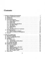
RF and SOC Devices Introduction A few years ago, an RF applications/test engineer would have been very focused in this very unique (often termed complex) field, performing tests on discrete RF devices such as mixers, power amplifiers, low noise amplifiers, and RF switches. Today, the test industry faces increasing levels of integration such that many of these discrete device functions are used as building blocks and are contained within one chip or module. Furthermore, the integration levels are such that system-on-achip (SOC) devices contain baseband (analog) functionality as well as digital functionality (earlier RF devices often contained three-wire serial communications for controlling things such as gain control, but current digital functionality of these devices is becoming more complex). Figure 2.1 shows a typical wireless digital radio, which is the foundation for many consumer devices such as mobile phones, cordless phones, pagers, and wireless LAN (WLAN) radios. It is apparent that many components are needed to bring signals into and out of the underlying microprocessor that acts as the brain of the device. While many components make up a complete wireless digital or analog radio as used in today’s telecommunications industry, this book will focus on the following:
ADC 0° LNA
VGA
Phase splitter
LO
90° ADC
Duplexer
2.1
LO
DSP DAC 0°
PA
VGA
Phase splitter
LO
90° DAC
Figure 2.1
Typical wireless radio block diagram.
13
14
RF and SOC Devices
• • • • • • • • • •
RF low noise amplifier (LNA); RF power amplifier (PA); RF mixer; RF switch; Variable gain amplifier (VGA); Baseband/IF modulator; Baseband/IF demodulator; Transmitter; Receiver; Transceiver.
SOC devices are those that have more than one of the above devices combined on a substrate to provide some function, for example, placing all of the devices that make up a mobile phone handset onto a single microchip. Over the past few years, there have been many attempts to place the complete wireless radio on a chip, but for practical reasons, what is termed SOC is often only a portion, such as that comprising the input/output at the antenna down to the analog baseband input/output on a wireless transceiver. Thus, an exception to the above statement is that a discrete transmitter, receiver, or transceiver may also be termed an SOC device. The recent trends have been moving toward much higher levels of integration. This is primarily due to two reasons: reduced-cost at the consumer level and the desire for reduced power consumption (longer battery life). It is apparent that lower-frequency analog and lower-level digital functionality is coresiding on the SOC chip with RF front-end devices. This trend will continue as pressures to achieve the above two goals surmount. SOC devices, as used in this discussion, have at least one RF input (or output). Based on that, SOC devices for wireless communications can be broken down into the following types, based on input/output configuration: • • • •
RF/RF; RF/IF; RF/baseband; RF/digital.
RF/RF and RF/IF are treated similarly with respect to testing procedures. The measurement techniques for IF frequencies still require attention to detail and an understanding of making measurements at high frequencies where traditional Ohm’s Law–based calculations will not work. Examples of these types of SOC devices would include a chip consisting of a filter/LNA combination or filter/ LNA/mixer combination to be used as the front end of a receiver. Additionally, they may have some digital signals for received signal strength indicator (RSSI) or automatic gain control (AGC). RF/baseband SOC devices are used quite commonly today in WLAN modems. The may contain everything (for a receiver, for example) from the input filter/LNA all the way to the in-phase, quadrature-phase (I/Q) outputs. When testing these devices, the engineer must have an understanding of RF measurement techniques,
2.2
RF Low Noise Amplifier
15
which are based on the frequency domain, and also have an understanding of making measurements in the time domain. RF/digital SOC devices are used quite commonly today in Bluetooth modems. The reason for this is that the Bluetooth architecture is relatively simple to implement on a single chip. It has been explored quite exhaustively, and as a result the low cost pushes a minimum number of chips to be used in a Bluetooth modem. Baseband/digital devices also fall under the category of SOC; however, from a testing point of view, these devices fall under the category of full mixed-signal devices. There are numerous resources available on the topic of testing mixed-signal devices, such as [1]. This chapter is intended to introduce the reader to the various types of discrete RF and SOC devices. The following sections of this chapter will provide an overview of each of the SOC components and then bring together the full SOC receiver. Examples are based upon the superheterodyne receiver, but they apply equally to the zero-intermediate frequency (ZIF) receiver. Afterwards, a brief overview of each of the two-transceiver architectures will be presented and a comprehensive listing of tests that are performed on each of the RF and SOC devices will be provided.
2.2
RF Low Noise Amplifier The low noise amplifier (LNA) is often the most critical device in the receiver chain of a wireless device. The LNA must amplify the extremely weak signals received by the antenna with large amounts of gain, while minimizing the amount of added noise. Since it is the first device that processes the incoming signal, it is critical that its additive noise be extremely low [see Friis equation, (8.13)]. Thus, the noise figure (NF) of the LNA is often the most difficult and critical parameter that is tested in production. From a design point of view, the difficult task is to provide high gain while minimizing the introduction of noise. These two items are historically mutually exclusive. Figure 2.2(a) shows the block diagram representation of an RF low noise amplifier.
2.3
RF Power Amplifier A discrete RF power amplifier (PA) is required at the output of a transmitter and is the one discrete device that often continues to remain a stand-alone discrete device (although for many Bluetooth and low-power wireless networking device
LNA
(a)
PA
(b)
(c)
Figure 2.2 Block diagram representations of RF devices: (a) low-noise amplifier, (b) power amplifier, and (c) mixer.
16
RF and SOC Devices
architectures, the PA is integrated). PAs are used at the output of a transmitter to boost the signal level so that it can reach its final destination, which may be a great distance away. There are many reasons why PAs still remain largely discrete devices and have not been integrated into SOC devices: PAs must be able to “boost” the transmitted signal to a relatively high power for it to traverse the long distance and be successfully received. This requires a rugged amplifier with lots of gain. Additionally, the PA is often pulsed (for example, GSM), which requires that the PA must also have fast response times. The large gain and fast response time requirements invariably mean that PAs produce large amount of power and generate large amounts of heat. Furthermore, PAs are normally in the 20% to 30% efficiency range and, thus, they drain the battery considerably. All of these requirements dictate that a specialized manufacturing process for PAs be used. This specialized manufacturing process is very different from that of other RF devices, often requiring hybrid semiconductors such as gallium arsenide (GaAs) and silicon germanium (SiGe) technologies. Chip manufacturers are constantly seeking an equivalent SiGe power amplifier that would allow integrating the PA with the rest of the SOC. Numerous efforts exist from the SiGe design community to make this combination successful [2]. Both scenarios, integrated and discrete, will likely be partially successful for different kinds of radios. Figure 2.2(b) shows the block diagram representation of an RF power amplifier.
2.4
RF Mixer A mixer is often referred to as a frequency-translating device because its purpose is to perform either upconversion or downconversion of a signal. Acting as an upconverter, a mixer can be found in the transmit chain of a wireless or SOC device. Mixers are also used as downconverters, such as where they convert RF to IF in a receiver. The mixer differs from the aforementioned devices with the first big difference being that a mixer is a three-port device. It has two input ports and one output port [see Figure 2.2(c) for a mixer’s symbolic representation]. The three ports are usually denoted as radio frequency (RF), intermediate frequency (IF), and local oscillator (LO). The mixer is a frequency-translating device; that is, the input and output frequencies differ from each other. The fundamental operation of a mixer is based upon its intentional nonlinear products, much like the nonlinear intermodulation products of an amplifier (albeit, those are unwanted in that case). The purpose of a mixer is to “move” the incoming frequency to some other outgoing frequency or, more concisely stated, to translate fin (the input frequency) to fout (the output frequency). The LO port is always an input port and is used as a kind of “pump” to translate fin to fout. The RF and IF ports are bidirectional ports. Since a mixer has three ports, this means that it has nine S-parameters. Typically only five of these are tested in practice. They are shown in Figure 2.3. S-parameters are discussed in detail in Chapter 4. As you may expect, the mixer is one of the most critical RF building blocks because it is always operating in the nonlinear region. As such, it is difficult to design and manufacture a mixer because during the normal operation of a mixer, there are many linear frequency translations and other unwanted nonlinear frequency translations that are occurring. These other frequency translations are, of
2.4
RF Mixer
17 S21, Conversion loss
S11, Input match
Port 2 IF
Port 1 RF
S13, LO to RF leakage
S22, Output match
S23, LO to IF leakage Port 3 LO
Figure 2.3
Mixer parameters and their equivalent S-parameters.
course, undesired and must be minimized and filtered. Overcoming these problems has been one of the major hurdles to the successful development of the zero-IF radio. A mixer is made up of one or more nonlinear devices (i.e., diodes, FET transistors, and so forth) acting in their nonlinear ranges. The simplest construction of an RF mixer is the single-ended mixer as shown in Figure 2.4, along with its block diagram representation. The input RF and LO signals are combined and passed into a diode. Afterwards, a filter may be used to remove unwanted frequencies resulting from the nonlinearity of the diode. There are several types of mixers, and each has its own purpose. Most of the more complex mixers are based upon the single-ended mixer. Table 2.1 shows the various types of mixers and their typical characteristics. Properties such as voltage standing wave ratio (VSWR), isolation, and conversion loss are described in Chapter 4. Another common type of mixer is the double-balanced mixer. This is shown in Figure 2.5. The four diodes in a configuration similar to a bridge rectifier produce an output signal that consists only of the sum and difference frequency components of the two inputs. Because of this, a double-balanced mixer has excellent isolation (typically 50 dB at wireless-communications-device operating frequencies), meaning that neither of the two input signals appears as a component of the output signal. This is often a problem of the single-ended mixer. The power consumption is low (low conversion loss) and most designs are broadband to cover wide frequency dc bias
RF
Combiner
Matching network
LO
Figure 2.4
Single-ended mixer as a downconverter.
dc return
Lowpass filter
18
RF and SOC Devices Table 2.1 Mixer Characteristics Type Number of Diodes Single ended 1 Balanced (90) 2 Balanced (180) 2 Double balanced 4 Image rejection 8
VSWR Poor Good Fair Poor Good
Isolation Fair Poor Excellent Excellent Good
Conversion Loss Good Good Good Excellent Good
RF input IF output
LO input
Figure 2.5
Double-balanced mixer as a downconverter.
ranges. The drawbacks of these mixers are that impedance matching at the ports is critical, so if it is being used for broadband applications, there may be difficulty in matching to maintain a constant impedance across all frequencies. Additionally, they require relatively high-powered local oscillator drive signals. Image-rejection mixers provide an output signal that consists of the desired output at the new frequency and two image signals that are 180° out of phase of each other. Because of the 180° phase shift, they cancel. Figure 2.6 shows that the primary phase cancellation comes from the use of two 90° hybrid couplers. A hybrid coupler, more commonly just called a hybrid, is a four-port device that divides power from each of ports 1 and 2 equally among ports 3 and 4. The signals at ports 3 and 4 have a 90° phase shift between them. Additionally, no energy is transferred, or coupled, between ports 1 and 2. Each of the hybrid’s output signals is then passed on to a separate path where it is downconverted (recall these signals are 90° out of phase with respect to each other) and then passed through another 90° hybrid. As a result, the two outputs of the final hybrid are referred to as the upper and lower sideband signals, absent of image signals, as the image signals end up with a total of 180°
RF input
1
90°
3
2
Hybrid
4
In-phase divider
LO input
Z0
Figure 2.6
1
90°
3
2
Hybrid
4
IF output
Z0
Image-rejection mixer as a downconverter.
2.5
RF Switch
19
between them at the output of the mixer. The image-rejection mixer is a good compromise between the properties of the single-ended and double-balanced mixers.
2.5
RF Switch RF switches are used in nearly every RF and wireless application. They are used inside phones and other wireless communications devices for duplexing and switching between frequency bands and modes. They are typically bidirectional. RF switches come in two primary varieties, absorptive switches and reflective switches. In reflective switches, the impedance of the “off” port is not 50 ohms, and often a mismatch occurs, hence the name reflective. As a result, this type of switch has a very high voltage standing wave ratio (VSWR). An absorptive switch has very good VSWR in both the on and off modes of the switch. The two major classes of technologies used to implement switches are p-type silicon/insulator/n-type silicon (PIN) diode switches and GaAs field effect transistor (FET)–based switches. GaAs switches can also be PIN types, but are more commonly FET-based. Diode-based switches make use of a PIN diode. Figure 2.7 shows how a PIN diode can be used to create an RF switch. Assuming that the RF signal is small relative to the dc bias established across the diode, the diode can either be forward biased (allowing the diode to conduct with low impedance) or reverse biased (making the diode appear as an open circuit). If the RF signal becomes relatively large, solid-state switches add distortion due to the nonlinearities of the diode I-V curve. There is an upper frequency limit for PIN switches due to the parasitic junction capacitance that shunts the diode. This capacitance reduces the overall impedance seen by the RF signal in both the on and off states. If that capacitance is too large, the diode will not turn off effectively. PIN switches are often used in pulsed RF applications, as they are able to handle the high power usually required of pulsed RF signals. Typical on/off switching times of PIN diode switches are on the order of microseconds. GaAs switches use gallium arsenide technology to create a FET, or field effect transistor, used in the nonlinear (switching) mode. The switch is either fully on or fully off, depending upon bias conditions. Switching times of GaAs FET switches
dc bias
Figure 2.7
Implementations of a PIN switch.
20
RF and SOC Devices
are on the order of nanoseconds. Additionally, they have a good frequency response all the way down to dc. A primary difference between PIN and FET switches is that PIN switches require significant dc current in the on state, while FETs consume only leakage current in both on and off states. Current drain can be a critical specification for RF switch selection and testing. It should be noted that in addition to being a DUT, RF switches are often used in automated test equipment and on production load boards to perform switching operations when routing signals. As an example, highly integrated wireless SOC devices with multiband radios are good candidates to implement RF switches on the production-test application. Only one of the multiple radios is “on” (i.e., transmitting or receiving) at any given time, so from a strictly hardware cost perspective, it is more cost effective to employ switches than to use dedicated hardware.
2.6
Variable Gain Amplifier It should be pointed out that wireless communications RF and SOC devices have enormous dynamic ranges. This trend of wider dynamic ranges is increasing. The further away from each other that two wireless devices are, whether they are Bluetooth devices, WLAN devices, cell phones (mobile phones) and base stations, pagers and base stations, satellite links, or any other wireless devices, the higher their output powers must be in order to sustain the wireless link between them. Conversely, if the two wireless devices are very close to one another, then their output powers must be lower so as not to overdrive or compress their wireless counterparts. The more wireless devices that are added to a specific area, (a downtown city district for example), the more confusing it becomes due to the large number of combinations of high powers, low powers, rejections, and compressions. Each wireless device must be able to change its transmitted and received power levels quickly to acclimate to its continuously changing surroundings. 1 This brings us to the subject of automatic gain control (AGC). To simplify the discussion and reduce the number of variables, the subject of AGC will be constricted to discussing only the transmitter chain of the wireless SOC device [although AGC/variable gain amplifer (VGA) amplifiers are also used in the receive chains in wireless communications]. It should now be very apparent why a wireless device would need to change its transmitted output power level quickly and dynamically. The most common way of doing this is to design the wireless SOC device to have multiple amplifier output stages with one or more of the stages designed to have variable gain control. The gain of the amplifier (and ultimately the output power) can then be controlled by adjusting the variable gain control. The variable gain control is usually in the form of a voltage or a current. For this discussion, it will be assumed that the gain of the amplifier is voltage controlled. That is, by adjusting the particular voltage up or down to that amplifier, the gain is also adjusted up or down respectively. One question might be, How does the wireless device know what to set
1.
The topic of AGC is associated with VGA. Whether automatic or not, a VGA has some means to adjust its power output.
2.6
Variable Gain Amplifier
21
the gain to? The answer is, the same way that you know or learn to speak louder or softer when speaking on a normal wire line phone. The other person tells you to talk louder if he cannot hear you. The same thing happens with two wireless devices. If a mobile phone call is being made and the mobile is very far away from the nearest base station, then the base station sends a signal to the mobile telling the mobile to “talk louder,” or increase your gain. The base station may only have to send the request once if the mobile is stationary, but the base station may have to tell the mobile constantly to increase or decrease its power if the mobile is actually moving (in a car, for example). A simple block diagram of an AGC connected to a test setup is shown in Figure 2.8. The input to the AGC is shown to be either an RF source or arbitrary waveform generator. A high-frequency input requirement to the device would dictate an RF source as the input. A low- or medium-frequency input requirement, perhaps with high impedance and with differential inputs, might require an arbitrary waveform generator as the input signal. The same holds true for the output. If the output of the device is high frequency in nature, then downconverting the output signal to an IF signal is probably mandatory before digitizing it. However, if the output signal already falls within the bandwidth and sample frequency limitations of the digitizer of the tester, then the output signal can be directly digitized. Additionally, digital control of the device is usually mandatory, so the test system must have this capability, and it must be synchronized to the measurement equipment. It is helpful to pause here for a moment and consider the simple block diagram of Figure 2.8. The block diagram really represents the merging of the mixed-signal world with the RF world, and it is this merging and understanding that are required to test wireless SOC devices. If the device were merely RF in nature, then the input would have been connected to an RF source and the output to an RF receiver. If the device were only mixed signal in nature, then the input would have been connected to an arbitrary waveform generator and the output to a digitizer. Because the device is an SOC device, it may be connected to either or both, so the test equipment must be able to accommodate either or both simultaneously. Additionally, the application/test/product engineers must adapt themselves to working in both worlds simultaneously.
RF source RX
AGC1
Digital control
Pout (RF)
Figure 2.8
Pout (IF or baseband)
LO
TX
AGC2
Variable gain amplifiers in an SOC device.
AWG
22
RF and SOC Devices
Wireless SOC devices have a range of gain states. It depends on the design and application of the particular device, but suffice it to say that the gain range is usually controlled by 8 to 16 bits. Even if a device only uses 8 bits of gain range, that is still 256 different gain settings. Most engineers are familiar with how analog-to-digital converters (ADCs) and digital-to-analog converters (DACs) work, but wireless amplifiers are different. Conceptually, they have a similar function, but RF amplifiers are highly dependent on their input and output impedance matching. The degree of impedance matching, in turn, is greatly dependent on frequency. What does that mean? If the AGC is programmed to a different gain level, then a different path through the amplifier may need to be used to achieve the new gain setting. A different path may have a different impedance match at that particular frequency. This means that more testing of the wireless device is suddenly required to ensure that it operates to its specifications.
2.7
Modulator The building blocks of today’s SOC devices are beginning to consist of multiples of the discrete RF devices that have already been presented. As an example, consider a modulator. A modulator can be built from discrete components consisting of two mixers, a few amplifiers, and various filtering components. However, a modulator can also be fabricated on a wafer as a single building block, and indeed, this is commonplace of today’s chip manufacturers. The modulator, or I/Q modulator, shown in Figure 2.9(a), is made up of two mixers and a phase splitter. The function of a modulator is to take an incoming baseband data signal and provide an output IF signal that has the information encoded, or modulated, onto it. The phase splitter takes an input signal from an LO and creates a 90° phase difference between the two outputs of the splitter (sinx and cosx, for example). The two offset signals are then passed on to the two mixers to be mixed with the baseband signal. The outputs of the mixers are IF frequencies (in a superheterodyne architecture). The two IF signals are then combined and passed on to the front end of the system. In a perfect world the splitter creates exactly 90° between the two signals that it outputs. For the modulation and demodulation process to function properly, it is important for the two signals to be orthogonal to one another (thus, the 90°). The receiver’s bit error rate (BER) or error vector magnitude (EVM) will increase with the decreasing phase balance of the two signals. As such, production testing is often done to determine the amount of phase difference that is present. Additionally, the mixers upconvert with no disturbance to phase or amplitude, thus proving that two equal-phase and equal-amplitude signals are combined at the IF frequency. When phase and amplitude distortion are introduced by the modulator in such a fashion, the carrier (LO frequency), which would ideally be canceled upon mixing, now appears in the IF signal. Carrier and sideband suppression testing are performed to determine the impact of this distortion. These are the two most important measurements that can be made on a modulator. Specifically, the carrier rejection indicates the amount of the unwanted carrier present at the output, and the sideband rejection indicates the phase and amplitude balance of the mixers.
Demodulator
23
IF output
Combiner
2.8
I data input Input analog signal containing I channel data
0° Phase splitter
LO
90° Q data input Input analog signal containing Q channel data
IF input
Combiner
(a)
I data output Output analog signal containing I channel data
0° Phase splitter
LO
90° Q data output Output analog signal containing Q channel data (b)
Figure 2.9
2.8
Block diagram of (a) modulator, and (b) demodulator.
Demodulator The demodulator is analogous to the modulator and can be thought of as a modulator working in reverse. A demodulator takes an IF or RF signal as the input and produces two baseband signals denoted as I and Q, which are shown in Figure 2.9(b). The I indicates in-phase and the Q indicates quadrature-phase. Often the modulator and demodulator functions can be had from the same device. As with the modulator, it is critical that minimal distortion is introduced in the form of amplitude and phase imbalance of the signal. Since the products of the demodulator are the I and Q baseband signals, the critical tests that are performed are I and Q amplitude and I and Q phase-balance measurements. Both, modulators and demodulators, have two basic designs, single ended or differential ended. Single-ended demodulators have only two outputs (I and Q). Differential-ended demodulators have four outputs (I, I, Q, and Q). Differential modulators/demodulators are growing in popularity due to their superior noise-reduction properties over single-ended designs. To better understand the basic tester hardware requirements necessary to test a demodulator, consider the following example. Let the input to a demodulator is a single continuous wave tone. The output I and Q signals ideally should have equal amplitudes and are orthogonal to one another. To test the amplitude and phase imbalance of the two signals, a test system must be able to capture both signals simultaneously. This can be realized either with a single
24
RF and SOC Devices
digitizer with a dual core or with two separate digitizers that are time synchronized. Most systems on the market offer at least one of these hardware configurations.
2.9
Transmitter An SOC transmitter is pictured in Figure 2.10(a). In general, a transmitter implies that its output is the signal that is RF and ready to be sent to a PA or directly to the antenna for transmission. The function of a transmitter in a wireless communications device is to take the data-containing signal, modulate it, and then send it to the antenna. As discussed in Section 2.3, the PA is typically a separate device and continues to be due to the different materials and processing that are used. One of the primary functions of the transmitter is that of the modulator. It is therefore not surprising that critical tests of transmitters are carrier and sideband suppression. Additionally, measuring the output power spectrum at inband and out-of-band frequencies of its intended use to locate any spurs is also critical to ensure that the device complies with the specifications to which it was designed.
2.10
Receiver The purpose of the receiver shown in Figure 2.10(b) is to amplify the weak RF signals that are received at the antenna and downconvert them to much lower
DAC 0° PA
Phase splitter
VGA
LO
DSP
90° DAC
LO (a)
ADC 0° LNA
VGA
Phase splitter
LO
DSP
90° ADC
LO (b)
Figure 2.10
Block diagram of a superheterodyne: (a) transmitter, and (b) receiver.
2.11
Transceiver
25
frequencies that can take advantage of less costly low frequency electronics to extract and process the information. With the superheterodyne receiver, multiple stages of gain and downconversion are employed. The incoming signal first is filtered to remove any unwanted RF energy that is outside the frequency band of interest. Then it is passed onto the LNA to amplify the signal while introducing minimum additional noise. Finally, the signal is downconverted with mixers to an IF frequency (typically less than 300 MHz) and converted to I and Q baseband signals through a demodulator. These are then to be sent to analog-to-digital converters (ADCs) that generate digital patterns to be processed by subsequent baseband/digital signal processing (DSP) functions. The DSP is often contained in a separate chip known as a baseband processor. One of the most critical test items for SOC receivers is sensitivity. Sensitivity is an extension of the discrete RF device noise figure. Noise figure is a measure of sensitivity. The higher the noise figure, the harder it will be for a device to receive lowlevel signals. With SOC devices, the all-encompassing term sensitivity is used because it is possible to measure their full functionality. For instance, it is possible to provide modulated RF signals to the SOC device. The device then processes the signal and produces either analog baseband signals (in-phase and quadrature-phase voltages) or digital data (bits) at the output.
Transceiver Building further upon the items that we have just discussed, the SOC transceiver pictured in Figure 2.11 consists of both transmitter and receiver functionality. The transmitter and receiver functions in the transceiver can either work simultaneously or in switched mode, whereby the device is either only transmitting or only receiving at any given time (this would, of course, require two antennae or a duplexer).
ADC 0° LNA
VGA
Phase splitter
LO
90° ADC
Duplexer
2.11
LO
DSP DAC 0°
PA
VGA
Phase splitter
LO
90° DAC
Figure 2.11
Superheterodyne transceiver.
26
RF and SOC Devices
All of the items that are tested for both the SOC transmitter and the SOC receiver are tested in the SOC transceiver, as one would expect. There are some additional tests that may arise depending upon the specific design of the transceiver. A transceiver can have a common LO that is shared between the transmit and receive paths. When this is incorporated, it becomes necessary to test each chain for signals that may arise due to the other chain. Additionally, if any form of duplexing is used at the front end of the device, then it also becomes necessary to test for TX/RX leakage. As with either the SOC transmitter or SOC receiver, the signals coming from the non-RF end of the device may be either digital or analog. The tests that must be performed on these are the same as those discussed in Sections 2.9 and 2.10.
2.12
Wireless Radio Architectures The preceding sections have based their descriptions upon the superheterodyne radio architecture. Wireless radio can incorporate various designs; however, the two most common are the superheterodyne and the zero-IF (ZIF). The superheterodyne structure is more prolific, but the ZIF has recently emerged due to new technological advances in the radio design industry.
2.13
Superheterodyne Wireless Radio In 1901, Guglielmo Marconi successfully transmitted a signal wirelessly across the Atlantic Ocean, and ever since, wireless communications has been developing. Today’s wireless radios have come a long way from the initial work of Heinrich Hertz, who created a spark across a gap and received it at another gap. The superheterodyne radio was invented by Edwin H. Armstrong in 1918 and first introduced to the market place in the mid-1920s. Because the superheterodyne radio was better performing and cheaper than the tuned radio frequency (TRF) transceiver, by the mid-1930s, it had become the de facto standard in radio design [3]. The superheterodyne transceiver is considered the classic radio architecture in which the received signal is downconverted to baseband frequency in two stages. The incoming RF signal is first downconverted to an intermediate (IF) frequency. This allows image suppression and channel selection by filtering out any unwanted signals. The filtering is commonly accomplished by use of surface acoustical wave (SAW) or ceramic filters. The filtered IF signal is then further downconverted to the baseband frequency, which is then digitized and demodulated with DSP. Because the radio has two stages of downconversion, it is generally more complex and more expensive due to the extra components like discrete SAW filters and voltage controlled oscillators (VCOs)/synthesizers. Figure 2.11 shows the superheterodyne receiver.
2.14
Zero Intermediate Frequency Wireless Radio In contrast, the homodyne, or zero-IF (ZIF), radio transceiver is a direct-conversion architecture, meaning that it utilizes one mixer stage to convert the desired signal
Zero Intermediate Frequency Wireless Radio
27
directly to and from the baseband without any IF stages and without the need for external filters. A block diagram of a ZIF radio is shown in Figure 2.12, where it can be noted that there are fewer components than in the superheterodyne radio. It is also common to integrate the LNA, or low noise amplifier, VCO, and baseband filters onto one single die. ZIF transceivers are not a new concept, and they have been used for years in cellular and pager applications. They are also beginning to emerge in WLAN applications, which play an important role in the SOC market. ZIF transceivers, although cheaper, have some inherent problems that must first be overcome before employing the technology [4]. Some of the common RF problems inherent to the ZIF architecture are dc offset, flicker noise, and LO pulling. The dc offsets are mainly generated by the LO leakage, which self-mixes, thereby creating a dc component in the signal chain. In contrast, the superheterodyne architecture has filters in the IF stage that eliminate this problem; however, dc offsets affect the receiver performance and can cause the RF stage to saturate. The dc offset problem in ZIFs can be addressed by designing a compensation scheme. The compensation scheme needs to measure the dc offset and then subtract it from the signal. This method is similar to noise cancellation, where the algorithm tracks the background noise and subtracts it from the original signal, thereby improving the signal to noise ratio. 1/f noise, or flicker noise, is low-frequency device noise that can corrupt signals in the receiver chain. Flicker noise is more pronounced with the ZIF architecture because of the direct conversion to low-frequency baseband. Again, in contrast, the superheterodyne architecture eliminates this problem through proper filtering. Another concern with direct conversion is the pulling of the LO by the power amplifier (PA) output, which affects the direct upconversion process. This is because the high-power PA output, which has a spectrum centered around the LO frequency, can disturb, or “pull,” the VCO.
ADC 0° LNA
Phase splitter
LO
90° ADC
Duplexer
2.14
DSP DAC 0° PA
Phase splitter
LO
90° DAC
Figure 2.12 Zero-IF transceiver.
28
RF and SOC Devices
Due to recent progress in technology, these issues can largely be compensated for, which is why we are seeing more and more ZIF radio structures emerging in wireless applications, and it is likely that this trend will continue.
2.15
Phase Locked Loop Aside from the fundamental building blocks presented earlier in this chapter that may be integrated to form an SOC device, there is one other component that is becoming more common in SOC devices. That is the phase locked loop (PLL). The PLL is a frequency-synthesis and -control circuit found on the SOC. It originated in the 1930s to work with the zero-IF receiver to allow a large number of frequencies to be synthesized from one circuit. The primary purpose of a PLL is to provide multiple, stable frequencies on a common time base within the same system. A basic PLL consists of a reference oscillator, phase detector, loop filter, and a VCO, as shown in Figure 2.13(a). PLLs have been used commercially for many years, beginning in the 1940s when they were used to synchronize the horizontal and vertical sweep oscillators in television receivers. There, they are used for frequency-shift key (FSK) modulation and FM demodulation, but with reference to SOC devices, they are generally used for frequency synthesis and frequency multiplication and division. Their most common use in SOC devices is to generate the local oscillator (LO) frequency used with the mixers in either superheterodyne or zero-IF transmitters or receivers. Figure 2.13(a) shows that the basic principle of operation of a PLL begins with the goal of achieving a stable frequency at the output of the VCO. In this simplest description, the VCO is first set to output a signal with a frequency equal
fref
Phase detector
Loop filter
fVCO VCO
fVCO (a)
fref
Phase detector
Loop filter
fVCO = N × fref VCO
fVCO N /N (b)
Figure 2.13 Components of a PLL circuit: (a) basic phase locked loop, and (b) fractional-N phase locked loop.
2.15
Phase Locked Loop
29
to that of the crystal oscillator reference. This is sent to another part of the SOC to be used for some function like providing an LO to a mixer. The foundation for the PLL circuit is the reference oscillator. It is usually a very stable crystal oscillator of the desired output frequency. It is used as a reference for the phase detector, which compares the phase of the reference oscillator with the negative feedback from the VCO output. If there is a difference in phase between the reference oscillator and the feedback from the VCO, the output voltage of the phase detector will cause the VCO to deviate toward the reference oscillator frequency until it “locks” onto it. A filter (termed a loop filter) is used to smooth the pulsed output of the phase detector so that the VCO can receive a clean control voltage. This entire cycle happens very quickly, typically within tens of microseconds. In production SOC testing this lock time, called the synthesizer lock time, is a common measurement. That explains how to achieve a stable output signal. Now, the obvious question is, Why wouldn’t one simply use the reference oscillator to achieve a desired frequency? Actually, that could be done, but it would not be very practical. If, for example, a signal were needed that could be used as an LO input to a mixer that downconverted a signal in a system having more than one channel, the system would require one PLL circuit for each channel (also one reference oscillator for each channel). This architecture would become expensive in both money and space. A solution to this is shown in Figure 2.13(b), where an integer divider is placed into the negative feedback path from the VCO. The divider divides the frequency of the VCO output by N and feeds the new signal back to the phase detector. Assume, for example, that the operating frequency of the VCO is N multiples of the crystal oscillator frequency. Then, the phase detector input from the VCO, after dividing by N, is once again the frequency of the crystal oscillator. The phase detector then stabilizes the signal to that of the crystal oscillator. Essentially, this method tricks the phase detector into believing that the VCO output frequency is at that of the crystal oscillator. This method allows the use of only one crystal oscillator, and the entire system is based upon the frequency of the same, stable crystal oscillator. The divider is typically digitally controlled and can have any number of values. For wireless communications systems, an upper limit of about 30,000 is placed on N due to the introduction of excessive phase noise (see Chapter 8) from frequency multiplication by N [5]. PLLs have three states of operation: 1. Free running; 2. Captured; 3. Phase locked. The free-running state describes when the output of the VCO has not yet locked onto the same time base as the reference oscillator and is not within ±2π of the reference oscillator phase, meaning that they are quite different in phase and frequency. In this stage, the output of the phase detector is pulsed, with a pulse period proportional to the frequency difference. The captured state is when the VCO (or divided VCO feedback) is at the same frequency as the
30
RF and SOC Devices
reference oscillator, but the phases differ. At this point, the output of the phase detector exhibits a dc offset voltage. Finally, in the phase-locked state, the VCO output signal has been adjusted to the same, stable time base as that of the reference.
2.16
RF and SOC Device Tests Table 2.2 shows many of the common parameters that are tested in RF and SOC devices. The table is not all inclusive, as many test items on a device are dependent upon the specific manufacturer, but it may be used as a guide to provide an estimate of what will be involved in writing a test plan. Some tests referenced in this book include BER and EVM. These types of tests are also referred to as system-level tests. The term system level is used because we are not discussing the testing of all of the discrete components that make up the SOC, but rather we are viewing the SOC as more of a traditional black box.
Table 2.2 Production Tests on RF and SOC Devices Parameter LNA PA Mixer Switch VSWR X X X Return loss X X X Insertion loss X Gain X X Gain flatness X Isolation X X X Linearity X Noise figure X X X Dynamic range X X X X X Power compression (e.g., P1 dB) Third-order intermodulation X X X product (IP3) Third-order intercept point (TOI) X Harmonic distortion X X Conversion loss/gain X Intermodulation distortion X Switching speed X Bandwidth X X Power-added efficiency (PAE) X Spurious output X X RF-LO rejection X ACPR/ACLR X Phase noise I/Q offset I/Q amplitude match I/Q phase match Output power Carrier suppression Error vector magnitude (EVM)
Transmitter Receiver X X X X X X
X X
X X X X X X
X
X X X
X X
X X X
X X X X
X
2.16
RF and SOC Device Tests
31
References [1] [2] [3] [4] [5]
Burns, M., and Roberts, G. W., An Introduction to Mixed-Signal IC Test and Measurement, Oxford: Oxford University Press, 2001. “IBM SiGe Technology Improves Power Amps for Cell Phones,” IBM press release, June 14, 2002. Poole, I., The Superhet Radio Handbook, London: Bernard Babani Publishing, 1994. Saidi, M., “Dual-Band Issue: Super-Heterodyne vs. Zero IF,” EETimes, February 18, 2002. Barrett, C., “Fractional/Integer-N PLL Basics,” Texas Instruments Technical Brief SWRA029, 1999.
.
CHAPTER 3
Cost of Test 3.1
Introduction Cost of test is of paramount importance to semiconductor manufacturers, and ATE vendors play a vital role in combating the increasing cost-of-test pressures of the market place. Sometimes the term cost of ownership (COO) is used instead of cost of test (COT), but they are synonymous and both refer to the overall cost of test. This chapter will discuss the many aspects associated with cost of test with particular emphasis on system-on-a-chip (SOC) COT. We will briefly discuss the evolution of wafer processing as it relates to cost of test and demonstrate the orders of magnitude savings that have been realized by increasing the dimensions of the wafer. Next, we will discuss how testing strategies have evolved from the initial days of using bench equipment setups (rack-and-stack solutions; see Chapter 1) for production solutions to the highly complex ATEs that are used to test today’s SOC devices. We will then discuss how the SOC has created a paradigm shift, which in many cases has invalidated the old COT models that have been in use for many years. Next, the differences between an IC device manufacturer (IDM) and a subcontract manufacturer (SCM) will be highlighted, and we will show some of the effects this has on cost-of-test modeling. We will then shift our focus into the details of cost-oftest modeling and discuss the key parameters and provide some rules of thumb that can help in determining a COT. Certain parameters are more heavily influenced by ATE than others, and examples will be provided emphasizing those parameters [1].
3.2
Wafer Processing Improves Cost of Test There is ever-increasing and continuous pressure on semiconductor chip suppliers to reduce their overall costs. One to two decades ago, the cost of silicon manufacturing was the number one cost contributor (of which wafer production was a large percentage). Wafer diameters were 3” (76.2 mm) and smaller, design sizes were comparatively large, and process controls were not as well defined as they are today, which meant lower yields, so chip manufacturers did not get many devices from a single wafer. At that time test cost was a fraction of a percent of the overall waferprocessing chip cost; thus, high cost-of-test issues were often overlooked because even a high cost of test was in the range of 1% of the overall wafer-processing cost. As a result, whenever a supplier wanted to test in mass production, they would simply take the solution that was used in the lab by the design engineers and duplicate that solution on the test floor. This method, although rudimentary, is justifiable
33
34
Cost of Test
as long as the cost of test never appears as a significant factor in the overall cost of the chip. However, wafer-fabrication companies were frantically building bigger waferprocessing and -handling facilities to reduce the silicon manufacturing costs. Increasing the size of the wafers provided orders of magnitude of improvement, and these improvements were enjoyed across the entire manufacturing process. As technology progressed, wafer production became more and more streamlined and continually migrated to bigger and bigger wafer diameters. The manufacturing savings that are realized through larger wafers is best demonstrated by example. If bigger diameter wafers could be produced using the current wafer-processing line, then more chips per single wafer could be had, thus reducing the chip cost. For digital microprocessor applications there is an added benefit from Moore’s Law that each new generation of chips shrinks itself in size. So, in effect, the manufacturer is getting multiplicative factors of increasing chip volumes without increasing cost by substantial amounts. For SOC applications that have integrated digital microprocessors or other integrated digital applications, the SOC application may also benefit from Moore’s Law (albeit with less effectiveness, since the digital circuitry is some percentage of the entire SOC).1 Thus, wafers are bigger, so there are more chips per wafer, and additionally the process dimensions continually shrink, giving the manufacturer even more chips from the same wafer. As an example, let’s compare a 6” (152.4 mm) wafer versus an 8” (203.2 mm) wafer. The percentage increase in the area is determined by %(increase) = 100%
Area final Area initial
= 100%
Area 8 r82 16 = 2 = 100% = 78% Area 6 r6 9
(3.1)
So, increasing the wafer dimensions slightly (by 2”) nearly doubles the effective area of the wafer. Now, let’s take a look at how the cost of test is positively affected when the wafer dimension increases from 6” (152.4 mm) to 8” (203.2 mm) in conjunction with the additional benefit of Moore’s Law (for digital circuitry) and reduced feature size and operating voltages, which has resulted in reduced chip area. As an example, let’s assume a particular die size has shrunk by 70% (from 12 × 12 mm to 2 7 × 7 mm, for example). The number of 12-mm devices that can be realized on a 6” (152.4 mm) wafer is 506 (not really, because near the edges, you can’t get a complete die): N devices =
Area wafer Area die
=
Area wafer Area12 mm 2
2
=
π(152.4) πr 2 = = 506 lw 144
(3.2)
The number of 7 × 7-mm devices that can be produced on an 8” (203.2 mm) wafer is 2,647: 1.
Although wireless chips do not follow the observations noted in Moore’s Law (i.e., wireless chip transistor counts have not doubled every 18 months), the trend toward reduced feature size and operating voltage has resulted in the reduction of the chip area required to achieve specific wireless functions (Mike Golio, Golio Consulting, Personal communication to author, September 20, 2003).
3.2
Wafer Processing Improves Cost of Test
Number of devices =
Area wafer Area die
35
=
Area wafer Area 7mm
2
=
. ) π(2032 πr 2 = = 2,647 lw 49
(3.3)
More than 5 times as many devices are produced on an 8” wafer versus a 6” wafer in conjunction with shrinking die sizes. This directly impacts the cost of test and has the potential to lower it by as much as 500%. In reality, what tends to happen is that more features are added to the chip so that the chip size can even increase over time. However, the kinds of functions that get tested may also change as the chip functions change. If lower-level tests can be eliminated, then there is a reduced cost of test. But, the added functionality may demand higher-level testing, which is 2 difficult and expensive, so that the cost of test is also increased. The question is, Is the decrease more than the increase? As an example demonstrating lower-level functional-testing costs versus higher-level functional-testing costs, consider a simple RF low noise amplifier (LNA) versus a multiband SOC radio. RF power is the staple of analysis used to test traditional RF devices like an LNA, and power measurements are still mainly used to test a highly integrated multiband SOC radio. Unfortunately, many more power measurements are required to test a multiband SOC radio versus the simple LNA; thus, even if the die sizes and manufacturing costs are approximately equal for the two, the cost of test is increasing for a multiband SOC radio. A higher-level functional test, like error vector magnitude (EVM; discussed in Chapter 5), could be used to test a multiband SOC radio, thus eliminating many of the traditional lower-level power tests and reducing the test cost. (Note, this is not the case with current SOC manufacturers [2]. In the extreme case, the lower-level tests and the higher-level tests are both being performed.) Still, this took some time to mature. Building bigger wafer-producing facilities is not a simple task by any means. Tuning new processes could sometimes take a year or more, and new chip designs must go through many design iterations before they meet all of their specifications and are ready for mass production. However, the constant demand for newer technologies drives this process, and it does not look as if this trend towards larger wafers and smaller process dimensions will slow down anytime soon (although there is a practical limit to silicon wafer dimensions).3 There are 12” wafer lines turning on, which offer 16 times more area than 3” wafers. In addition, device dimensions continue to shrink, thus affording faster time to market, in effect providing orders of magnitude of improvement. With largerdimensioned wafers also comes increased processing cost. The processing costs for wafers are, of course, highly dependent on the wafer fab itself and are a source of competition between manufacturers. As a gross estimate, we can use approximate values of U.S. $5,000 for an 8” wafer and U.S. $9,000 for a 12” wafer. Table 3.1 shows the die-per-wafer increase that is realized with increasing wafer dimensions.
2.
Mike Golio, Golio Consulting, personal communication to author, September 2003.
3.
Typically, SOCs have lower volumes compared to DRAMs or MPUs. So, it is possible that due to economic reasons, many SOCs will not move to the more advanced processes. For example, mask costs for the next generation technology node are being estimated at a few million U.S. dollars (Rudy Garcia, NPTest, personal communication to author, September 27, 2003).
36
Cost of Test Table 3.1 Chip Volume Increases with Wafer Dimensions Wafer Diameter Wafer Die per Increase from (in) Diameter Wafer Previous Size (mm) (%) 3 75 44 6 150 176 400 8 200 314 78 12 300 706 25
2
The table is normalized to a device that is 100 mm and does not consider the added benefit from shrinking technology. Clearly, as a minimum, a 12” waferfabrication facility can offer a 25% reduction in manufacturing costs versus an 8” wafer fab. Take a look at Figure 3.1, which shows the trends in manufacturing versus test cost that have been realized in part by larger wafer-processing facilities.4 The silicon manufacturing cost (of which the wafer-processing cost is a large percentage) has steadily been dropping, while the test cost has remained relatively flat or, in some instances, has risen slightly. This means that the once overlooked cost of test is now something of paramount importance. Currently, for many of today’s SOC manufacturers, cost of test is in the range of 3% to 30 % of overall manufacturing costs versus the fraction of a percent that it once was [3].
3.3
Early Testing of the SOC The system-on-a-chip (SOC) chipsets compound the cost-of-test problem. Because test costs were historically a much smaller percentage of overall manufacturing Silicon manufacturing cost per transistor
Cost
Test cost per transistor
2001
Figure 3.1
4.
Time
Manufacturing and test cost trends.
Figure 3.1 only deals with the processing costs and ignores the potentially much larger depreciation costs of implementing a new fab. It also ignores the wafer sort yield of these devices (Rudy Garcia, NPTest, personal communication to author, September 27, 2003).
3.4
SCM and IDM
37
costs, this allowed test methodologies and strategies to evolve without much attention or standardization. A manufacturer that is testing RF front-end power amplifiers has completely different needs than does a memory chip or DSP manufacturer. Thus, it should be no surprise that there are entire ATE companies that have existed only to build test solutions for a particular type of chip. For example, there are companies that historically have only built logic test systems to test logic devices, and there are other companies that have built only digital test systems to test strictly digital devices. This method supported market demands and expectations until a few years ago, when the industry started seeing multiple technologies merge onto a single chip, which was quickly coined SOC. Then, suddenly, no test equipment supplier offered a single complete solution to meet all of the test needs. This had an overall negative impact on the cost of test. In some cases, manufacturers were testing part of the chip’s functionality on one type of tester and then testing the chip’s remaining functionality on a second tester (this more than doubled the COT) [4]. SOC testing created a market that ATE companies are rushing to fill. The big issue has been that most of the ATE companies have been in existence for tens of years, and their specialized technologies are based upon years of experience in a particular testing discipline. It is extremely difficult to merge a completely new technology into an existing infrastructure and have the new merged technology meet the same performance and quality standards that the core technology offered.
3.4
SCM and IDM An integrated device manufacturer (IDM) is a company that offers all of the necessary processes to generate new devices (i.e., design, layout, wafer fabrication, packaging, testing, and so forth). A subcontract manufacturer (SCM) specializes in a particular area of the silicon process (these are either in the category of design houses or test houses). Outsourcing business aspects that are not part of your core competency is a very useful way to reduce COT. As COT became a larger percentage of the manufacturing cost, some silicon IDMs (whose core competency was in the wafer-fabrication process) decided to outsource testing. SCMs specializing in testing (test houses whose core competency was testing) emerged offering test services and tester rates by the hour (see Section 3.6.3). SCMs purchase ATE from multiple ATE vendors and then offer hourly rates. This has the effect of acutely highlighting COT differences among the various ATE companies (two major factors being acquisition cost and test time, which will be discussed later).
3.5
SOC Cost-of-Test Paradigm Shift The rapid introduction of successive generations of SOCs, each exhibiting higher levels of performance and integrating more digital, analog, and RF functions, has created a new range of innovative and affordable products. In the process, prices have plummeted. Bluetooth SOC devices, for example, were marketed to require a manufacturing cost of $5, before consumer acceptance could be widely
38
Cost of Test
achieved [5]. This cost entry point has already been achieved and surpassed by many manufacturers, but to do so, the testing methodologies were forced to become COT centric. Although low prices are beneficial for the consumer, unfortunately for the SOC manufacturer, this has given the SOC business three characteristics unique to this segment of the semiconductor industry [6]: 1. Unpredictable market demands; 2. Shrinking product life cycles; 3. Unrelenting cost pressures. The SOC manufacturer must continually innovate to remain competitive. Thus, they design highly complex devices on leading-edge processes that provide the best cost, performance, and feature sets [6]. The market unpredictability makes it impossible for the SOC manufacturer to predict which designs will win in the market place and which will lose. In many cases, the volumes never materialize, and those costs must be absorbed by a more successful SOC, further increasing the COT on the winner. Historically, semiconductor devices had a life span of 1 or more years with significant volume, but the SOC often has a significant volume measured only in months, before being replaced by the next emerging SOC device. This short life span makes it much more difficult to recover the heavy investments that were required in the first place, because the device undergoes severe price erosion shortly after introduction [6]. These three characteristics have been significant factors in increasing the cost of test that now is sometimes as high as 25% or more of the overall manufacturing costs (Figure 3.1) and is causing a paradigm shift in the traditional COT model. Purchasers of ATE equipment historically depreciated traditional ATE equipment costs over 5 years, but with continuous innovation in SOC devices, current ATE in some instances no longer has a life span of 5 years. Additionally, traditional ATE may not be fully equipped to handle all of SOC testing requirements, so the equipment’s utilization is poor. Many more upgrades can be required to keep up with the innovative trend of SOC devices, which further drives up the COT. Test-development costs also increase because multiple testing disciplines (digital, mixed-signal, and RF) are required to create a test solution (i.e., more engineers are needed). Thus, the ATE industry is under tremendous pressure to find innovative ways to lower the cost of test. To do that, new innovative test techniques and testing methodologies are being developed that can be measured and compared by using key cost-of-test modeling parameters.
3.6
Key Cost-of-Test Modeling Parameters Trying to model the COT of a test cell requires a fairly large number of parameters and can be a demanding task [6]. The key parameters include: • • •
Test time; ATE equipment cost (capital cost, fixed cost); Lifetime;
3.6
Key Cost-of-Test Modeling Parameters
• • • • •
39
Utilization (flexibility, upgradeability, availability); Yield; Measurement accuracy (repeatability); Space (floor space); Maintenance (spare kits, support contracts, calibration).
A simple expression relating the key parameters to COT is COT =
(Fixed cost + Recurring cost ) (Lifetime × Yield ×Utilization × Throughput )
(3.4)
It is also interesting to note that there is a cost of ownership (COO) standard defined by SEMI as E.35, which provides an extensive definition for COT/COO that has over 150 input variables. However, this standard is difficult to utilize without already knowing many of the variables (which is often the case), and the standard is currently being revised. Establishing exact values for (3.4) can be very time-consuming and expensive. Manufacturers have sophisticated process-tracking tools that track COT parameters that are critical to their individual models. Moreover, many of the parameters, like lifetime, yield, utilization, and throughput, are really only known after the life of the SOC. To make matters worse, SOC devices have shorter life cycles than other traditional devices. Models based on (3.4) are typically used in a more qualitative manner or to track perturbations on existing costs, rather than as exact evaluation tools. For these reasons, it is important to develop rules of thumb for many of the parameters and a general understanding of how the factors affect COT. With that in mind, let’s take a look at each individual parameter to determine what assumptions, if any, can be made to make it easier. 3.6.1
Fixed Cost
The fixed cost consists of the capital equipment cost and floor-space cost. With typical ATE equipment sometimes having acquisition prices well over $1 million, capital cost is usually one of the dominant factors still used to determine the COT. However, the importance of capital cost is often supplanted by the higher throughput that a more expensive ATE solution offers and should not be easily disregarded when evaluating COT. 3.6.2
Recurring Cost
Recurring cost can be defined as things like calibration, cleaning, general maintenance, support contract costs, and software subscription costs. Although each of these items is indeed a cost, it can be argued that any ATE purchase carries these costs and that their contribution to the overall COT is essentially the same for different ATE vendors. For instance, recurring costs are often taken to be 10% of the ATE acquisition cost [6]. If we accept that argument, then we can remove this parameter or normalize it out of the COT equation to obtain a COT model where the numerator only depends on the fixed cost of the ATE equipment, as shown in the following equation:
40
Cost of Test
COT =
3.6.3
Fixed cost (Lifetime × Yield ×Utilization × Throughput )
(3.5)
Lifetime
The lifetime of ATE equipment has historically been depreciated over 5 years, but if the ATE is inflexible, then perhaps a 3-year depreciation is called for. What does depreciating across 3 years do to the COT? If we take a simple COT example [6] and assume a $1 million acquisition price for the ATE, the test cost per hour is $114 per hour [5]. (Note that this assumes 100% utilization and 100% throughput.) COT =
1000 , ,000 = $114/ hour days hours 365 24 year day
(3.6)
In reality, the COT will be higher depending on the test yield, equipment utilization, handler costs, labor costs, and so forth. Continuing with (3.6), the COT per second of test time is calculated to be approximately 3 cents. It is more common to use 5 cents per second because the reality is that there are many other COT variables that are dynamic and not easily determined. One method to combat a decreasing depreciation period is to lengthen the useable life of the equipment. However, to lengthen the useable life, the ATE must be highly flexible and adaptable to the SOC market. The emergence of SOC platforms is one method by which ATE vendors are addressing the highly sensitive COT nature of the SOC market. The SOC platform is intended to lengthen the useful life of the ATE by offering IDMs and SCMs the ability to configure the equipment dynamically in a matter of hours to the testing requirements of the SOC. As long as the SOC platform can be dynamically configured and easily upgraded, the equipment has a longer useful life (5-year depreciation is justified) that can dramatically reduce the COT. 3.6.4
Utilization
Utilization is the percentage of time that the test equipment is actually being used for production testing. Repairs, maintenance, calibration cycles, test development, and basically anything other than production testing, are excluded. In the ideal case, the test equipment would be testing parts 24/7; however, in reality, even world-class manufacturers of high-volume devices have difficulty reaching utilization rates greater than 90% [6]. It is not uncommon to see ATE sitting idle on an SOC test floor while devices are waiting in queues because the tester does not have the right configuration [6]. If we return to the $114/hour rate, we can view the impact that utilization has on the COT. For every hour or day the ATE sits idle, it costs the manufacturer $114/hour, or $2,736/day. A 50% utilization rate means the COT increases to $228/hour or $5,472/day! These values are really just a measure of the absolute minimum COT to the manufacturer. In reality, the lost-opportunity cost and slower time to market due to low utilization rates can easily increase the COT by orders of magnitude. For example, a test time of 1.5 seconds with a device price of $2.00 would mean an extra $4,800 of revenue is not realized for every single hour the ATE is sitting idle. This is nearly 50 times greater than the depreciation cost! To
3.6
Key Cost-of-Test Modeling Parameters
41
help silicon manufacturers better control their utilization rates, ATE manufacturers are offering flexible, scalable platforms with short calibration cycles and low mean time between failures (MTBF) and mean time to repair (MTTR). Utilization is heavily dependent on the flexibility of the SOC ATE, as well as on the silicon manufacturer’s management of his test floor. If the SOC ATE is flexible enough to allow dynamic configuration on the test floor, this can provide enormous COT savings by increasing the utilization of the ATE. For the sake of argument, assume that an SOC is sufficiently flexible and dynamically configurable and that the test floor is perfectly managed so that it enjoys a 100% utilization rate. Even if the argument is rejected, it can at least be argued that the utilization burden is shared by the ATE vendor and the management of the test floor because the ATE must be capable of being easily utilized, but the test floor must keep the ATE loaded and testing. Additionally, assume that the lifetime has been sufficiently extended so not to be a critical factor in the COT equation. Given that scenario, the utilization and lifetime parameters can be normalized out of the COT equation to provide COT =
3.6.5
Fixed cost (Yield × Throughput )
(3.7)
Yield
An entire chapter could be written on the subject of yield. We will attempt to point out the most significant aspects of yield and its affect on COT. A lower bound on the COT can be calculated by assuming the COT due to yield losses is equivalent to the scrap costs. However, since SOC devices have such a short life cycle, it would be more accurate to treat yield loss as lost revenue [6]. To better comprehend lost revenue, let’s take a look at the two types of errors that impact yield, Type I, and Type II errors. 1. A Type I error (also called false negative, or alpha error) occurs when the ATE fails a good part. The part is then thrown away or scrapped. This results in building more wafers to achieve a specific volume and longer rental rates at SCMs [6]. The COT incurred from Type I errors can be lower bounded as the scrap cost. 2. A Type II error (false positive or beta error) occurs when the ATE passes a bad part. This means a bad part makes it through the screening process and into the customer’s product. Type II errors occur due to insufficient guard banding, can be more costly than Type I errors, and can have drastic consequences [6]. Shipping unacceptable devices risks having the device designed out of a product [6]. It is extremely difficult to quantify the COT due to a Type II error. A crude rule of thumb is that a Type II error costs 10 to 100 times more than a Type I error. With sufficient guard banding, Type II errors can be completely eliminated, but at the expense of increasing the Type I errors. Let’s assume this scenario to be the standard, in which case minimizing the necessary guard banding is the key underlining element of yield. To minimize the guard banding, the accuracy of the ATE must
42
Cost of Test
be maximized (unfortunately, maximizing accuracy often leads to longer test times, which increases COT, so a trade-off must be determined). Appropriate guard banding implies that the correct performance specs are implemented. Although this seems obvious, an improperly established spec can wreck havoc on yield. Consider this real example (although the absolute values have been changed to protect privacy), where a device has a third-order intercept (TOI) spec of 15 dBm. Previously, the device was characterized and known to have a TOI range of 15 to 18 dBm. The ATE is set to pass devices having higher than 15 dBm and lower than 20 dBm (the 20 dBm is used as a sanity check). The wafer processing shifts slightly over time such that the devices’ third-order tones drop into the noise floor of the ATE. This has the effect that the TOI is improved dramatically, but the ATE yield drops off as it starts failing good parts, when in fact all the parts are good parts and should pass. More than 4 days were spent running correlation lots to isolate the cause of the yield drop-off. Using our conservative lost-opportunity cost of $4,800/hour implies that more than $450,000 dollars were lost when, in fact, there was never a problem. 3.6.6
Accuracy as It Relates to Yield
Guard bands are required due to inaccuracies of the ATE. A more accurate SOC ATE will have a higher yield than a less accurate ATE. How accuracy (ATE specifications) affects yield is difficult to translate directly, but it can be reasonably estimated from prior-generation devices [6]. Tester accuracy is often undervalued in the COT model, because it is so buried in the details and difficult to quantify. Consider the following memory testing model from [7] to illustrate the point. DRAM yield impact versus tester accuracy for improving picosecond edge placements was generated for Table 3.2. Assuming a price premium of $5 between devices binned at 800 Mbps versus 600 Mbps, the 95% ideal yield case shows a 14% increase in the yield (69.2% to 83.3%), where the overall timing accuracy (OTA) of the ATE was improved by 60 ps. For 100 million parts produced annually, savings of 14% in yield results in savings of $70 million (i.e., $1.1 million for every extra picosecond of accuracy) [7]. If the tester tests 10 million parts a year, that translates to a $7 million savings, more than paying for itself in less than 1 year [7]. If this is the case, then why are IDMs and SCMs not eagerly purchasing an ATE for twice the capital cost amount, if it can save them $7 million in 1 year? The answer is often risk aversion; that is, an ATE purchaser would rather risk buying five cheaper ATEs with different configurations knowing that one or more of them might sit idle versus one expensive ATE, which when being properly utilized is of course saving a lot of money, but when sitting idle, is costing a fortune due to the
Table 3.2 Actual Yield Versus Tester Accuracy Ideal Yield (%) OTA = ±160 ps OTA = ±100 ps 60 51.67 55.3 75 53.3 63 95 69.2 83.3 (OTA = overall timing accuracy) Source: [3].
OTA = ±80 ps 56.4 66 86.6
OTA = ±60 ps 57.5 68.7 89.6
3.6
Key Cost-of-Test Modeling Parameters
43
5
higher fixed cost. Purchasing multiple less-expensive ATEs also makes it easier for the ATE purchaser to scale his test-capacity needs. If the manufacturer is utilizing the more expensive ATE strategy and needs slightly more test capacity, he is forced to purchase another expensive ATE, which may not be fully utilized, thus detracting 5 from his COT savings. Another point to consider is that in many testing situations, the accuracy has no effect on yield, whereas in other testing situations, the accuracy is of paramount importance. Consider Figure 3.2(a, b). In Figure 3.2(a), the ATE is highly inaccurate, but the measurement result is so far above the specification that even with guard banding included to compensate for the inaccuracy, there is no depreciable impact to the yield. Conversely, Figure 3.2(b) shows an ATE with higher accuracy, but because the measurement result falls well within the Gaussian distribution, there is a noticeable negative impact on the yield. This is one of the main reasons it is so difficult to quantify the impact of accuracy on yield. If the
Spec line Probability
Fail
Pass
Accuracy –3
0 (a)
3
Measurement distribution
Spec line
Probability Fail
Pass
–3
0 (b)
3
Measurement distribution
Figure 3.2 Impact of accuracy on yield: (a) low accuracy, low impact; and (b) high accuracy, high impact.
5.
John McLaughlin, Agilent Technologies, personal communication to author, August 2003.
44
Cost of Test
device is perfectly manufactured, then high inaccuracies of the ATE are negligible, whereas if the device is poorly manufactured, then smaller inaccuracies can have an enormous adverse effect on the yield. If the yield fallout is determined to be due to only one or two test items or specifications, then the testing strategy can be focused and the test cost reduced. If, however, the yield fallout is due to a wide range of test items, then increased testing or more accuracy may be required, and the test cost is increased. Both cases are common in industry. For traditional devices, the testing strategy evolves over the life of the device, and many nonessential tests are removed (see Section 1.2); still others are improved to reduce test time, and the test cost is continually reduced. However, for SOC devices that have a shorter life cycle, it is less likely that such benefits can be had, in which case accuracy can become a dominant COT factor. Therefore, again, it can be argued that yield is a shared COT element between the ATE and device manufacturer. The ATE vendor has no control of the waferfabrication process, and the SCM or IDM has no control over the accuracy of the ATE. For the moment, accept a very bold and completely unsupported statement, that yield is more heavily impacted by the fabrication process than by tester accuracy.6 Or, to state it differently, let’s assume that the device yield is always 100% and that the ATE has no inaccuracies. We are doing this only to simplify the COT equation to COT =
Fixed cost Throughput
(3.8)
where now the COT only depends on two factors, fixed cost and throughput. Recall the assumptions that were made to reduce (3.4) to (3.8). The assumptions of who more heavily influences a given COT parameter are shown in Table 3.3. As a final example, let’s examine two different COT scenarios using (3.8): Scenario 1 • •
ATE capital cost is $1 million. Test time is 4 seconds per SOC device (throughput is .25 devices/sec).
Table 3.3 Influence on Key COT Parameters COT Parameter ATE IDM/SCM Fixed cost * Test time * Accuracy * Utilization * Yield * Space * Maintenance * Labor *
6.
This can also be thought of in terms of device specification versus process capability/variation. Many of the defects found in the sub 0.18 µm are not “stuck at,” but are more parametric in nature (Rudy Garcia, NPTest, personal communication to author, September 27, 2003).
3.7
Other Factors Influencing COT
45
Scenario 2 • •
ATE capital cost is $2 million. Test time is 2 seconds per SOC device (throughput is .5 devices/sec).
In scenario 1 the capital cost is lower, but the test time is twice as long, while in scenario 2, the test time is lower, but the capital cost is twice as much. However, both scenarios have an equivalent COT at 2.5 cents/s. The equivalent COT of the two scenarios implies that either test solution can be chosen, resulting in the same COT. This result, while true in theory, is somewhat misleading. There are approximately 31.5 million seconds per year of available test time, and the object is to maximize the throughput. Another important point to consider is the number of devices that can be tested. For scenario 1, approximately 5.1 million parts per year can be tested, whereas for scenario 2, approximately 10.2 million parts per year can be tested. Depending on the profit earned from each device (say $1), the difference can be quite substantial (e.g., $5.1 million), which, after subtracting the extra capital cost of scenario 2, leaves a total of $4.1 million. One could argue that the same benefit is realized by purchasing two testers at $1 million each (i.e., twice scenario one). However, there would be many additional costs with the second ATE (floor space, handler, repairs, calibration, maintenance, labor, and so forth), so that in fact it is apparent that scenario 2 would be the better choice. In reality, however, risk aversion can nullify the extra savings that could be had because again ATE purchasers would rather risk having one of the less expensive ATEs sitting idle and one generating some revenue versus risk having the more expensive ATE sitting idle with no revenue being generated.5
3.7
Other Factors Influencing COT 3.7.1
Multisite and Parallel Testing
The SOC brings with it increasing cost-of-test reduction pressures that often cannot be met with single-site testing. Multisite testing is another method to reduce the cost of test. Testing devices in parallel increases the throughput considerably and thus lowers the COT. For example, if two SOC devices can be tested in parallel, theoretically the throughput can be doubled or, equivalently, the COT halved. Of course, handler capabilities and load board space must be considered along with the quantity of testing within a test plan that can be implemented in parallel from a multisite implementation. However, for large volumes, the savings that can be realized are hard to ignore. There are two basic types of multisite testing: (1) parallel, and (2) concurrent [8, 3, 9]. Parallel and concurrent testing of wireless SOC devices are discussed in detail in Chapter 7, along with the COT considerations associated with each. There is a multitude of parallel/concurrent implementations that can be had, especially when one considers that each wireless SOC usually has multiband radios. In such instances, if the ATE software and hardware are flexible and sophisticated enough, heterogeneous parallel (i.e., testing the TX section of device 1, while simultaneously testing the RX section of device 2, and then reversing the procedure),
46
Cost of Test
heterogeneous concurrent, and heterogeneous parallel/concurrent combinations are possible, which take advantage of the SOC and ATE architectures. 3.7.2
Test Engineer Skill
Ask any SOC engineer, and he will tell you the complexities of the job have risen by at least a factor of the number of technologies, that is, three, that have been integrated into SOC devices. There is a good reason that digital, mixed-signal, and RF engineering are classified as disciplines. Each discipline requires not only a broad understanding of the technology, but to be truly knowledgeable in any one field also requires a tremendous depth of knowledge within that discipline. SOC devices bring new challenges to the test/product/application engineer. The engineer must suddenly be able to understand and test aspects of the chip that are completely foreign to him. Indeed, this new breed of SOC engineer must be able to accommodate logic, memory, microprocessors, microcontrollers, digital, DSP cores, mixed-signal, and of course RF into his testing solutions. Therefore, the skill-level mastery or deficiency of each of the disciplines can greatly decrease or increase the COT. The engineer’s skill level can drastically impact the test-solution schedule (time to market) and, of course, test time (throughput). With SOC devices having such a short life cycle, late market introduction can seriously erode the manufacturer’s profit taking, and if the test time is not properly optimized, the resultant lower throughput (higher test time) will also increase the COT and detract from the manufacturer’s profits [10].
3.8
Summary An introduction to cost of test was discussed beginning with an emphasis on manufacturing costs that have largely been addressed with increasing wafer dimensions. This helped drive down the manufacturing cost to within the same COT magnitude range, thus underlining the need to address the rising COT. The SOC and SCM/IDM impacts on COT were then discussed. A simple COT model was offered, and the key parameters were examined in detail. Assumptions and arguments were presented to reduce or isolate certain key parameters so that conclusions and decision criteria for evaluating the COT of a test solution could be determined.
References [1] [2] [3]
[4] [5]
Newsom, Tom, “SOC Test Challenges for the New Millennium,” IEEE International Test Conference, Baltimore, MD, November 2001. Lowery III, Edwin, “Integrated Cellular Transceivers: Challenging Traditional Test Philosophies,” IEMT, San Francisco, CA, July 16–18, 2003. Fischer, Martin, “Concurrent Test—A Breakthrough Approach for Test Cost Reduction,” Semicon Europe 2000, at www.ra.informatik.uni-stuttgart.de/~rainer/Literatur/Online/T/ 15/3.pdf. Lecklider, Tom, “Reducing the Cost of Test in 2003,” Evaluation Engineering, at www.evaluationengineering.com/archive/articles/0803icate.htm, accessed 2003. “$5 Silicon: No Way or Yes Way,” at www.csr.com/enews/hw001.html.
3.8
Summary
47
[6] Garcia, Rudy, “Redefining Cost of Test in an SOC World,” Evaluation Engineering, at www.evaluationengineering.com/archive/articles/0603ic.htm, accessed 2003. [7] Dalal, Wajih, and Miao, Song, “The Value of Tester Accuracy,” IEEE International Test Conference, Atlantic City, NJ, September 1999. [8] Mast, K., “Reducing Cost of Test Through DFT,” Agilent Technologies application note, 2003. [9] Hilliges, Klaus-Dieter, et al., “Test Resource Partitioning for Concurrent Test,” IEEE International Test Conference, Baltimore, MD, November 1–2, 2001. [10] Burns, M., and Roberts, G. W., An Introduction to Mixed-Signal IC Test and Measurement, Oxford: Oxford University Press, 2001.
.
CHAPTER 4
Production Testing of RF Devices 4.1
Introduction Descriptions and examples of traditional RF production testing will be presented in this chapter. Each section throughout this chapter will build on the previous sections. Most of the traditional measurements presented in this chapter are still utilized today to determine the quality of RF SOC devices before they are shipped to the end customers (wireless phone and consumer device manufacturers). Nearly every traditional measurement is in some way connected to the basic “power measurement,” so detailed descriptions and definitions of the various forms of power are provided as a foundation to the reader. The remaining traditional RF measurements will be described from the perspective that the reader has a good understanding of making power measurements. Many of today’s RF measurements, whether they are performed on an RFcentric or SOC-centric device, have their roots tied to RF power. As such, it is useful to understand a little of the background and history of how these measurements were developed. For example, spurious tones, harmonics, third-order intercept, power compression, and adjacent channel power are all forms of RF power measurements. Additionally, if the input and output impedance matching of a device under test (DUT) are close to ideal, gain can also be considered a power measurement. In one form or another, it has always been necessary to determine the output power level of RF devices.
4.2
Measuring Voltage Versus Measuring Power Why not just measure voltage and current? Ohm’s Law is the linear estimate of Maxwell’s electromagnetic field equations. Maxwell’s equations show that voltage and current are actually waves dependent on frequency. Think about measuring a voltage sine wave with an oscilloscope. The location of the observation point determines the actual voltage that is measured. If the time base of the oscilloscope is continually reduced, eventually a straight line will be seen on the display because only a very tiny piece of the wavelength is being examined. This analogy can be applied to an RF signal that is being measured on the same oscilloscope. Instead of continually being reduced, the time base of the oscilloscope is held constant, and the frequency of the signal is continually reduced. The same thing happens on the display. At first, we can see a sine wave with multiple periods, but eventually we see only a straight line across the display. If we see a straight line on the display and ask the question,
49
50
Production Testing of RF Devices
What is the voltage? we can simply use Ohm’s Law, because at very low frequencies, the wavelength is immaterial. The higher the frequency is, the less meaning Ohm’s Law has. So, for frequencies starting at about 30 MHz and higher, power measurements become more important.
4.3
Transmission Line Theory Versus Lumped-Element Analysis Those readers who are not familiar with microwave circuit analysis may not be aware of the physics that lies beneath the simple equation of Ohm’s Law (R = V/I). Ohm’s Law is derived from, or more accurately, is a simplification of, Maxwell’s equations. Without getting into a detailed analysis, Ohm’s Law is derived from Maxwell’s equations based on some assumptions. Namely, those assumptions are the mathematical boundary conditions that state that frequency is assumed to be very low (relative to the entire frequency spectrum). Measurement of a voltage at dc or low frequency (less than approximately 30 MHz) is a straightforward task using a handheld multimeter or oscilloscope. Measuring voltage levels at frequencies higher than that becomes a more arduous task. Measurement of voltage, or power, at high frequencies involves analyzing where the energy is as a function of position. Therefore, the measurement involves the measuring of waveforms. This provides the user with information on phase, in addition to the other parameters. Spatial information is not used in low-frequency measurements because the wavelength of the electrical signal is much larger than the device that is being measured. For example, the wavelength of a signal at 100 Hz is 3,000m long. This is obviously much longer than the capacitor or inductor (which is, say, 10 mm in length) that the signal will pass through. From the time the signal has entered the device to the time it leaves the device, essentially no difference in the signal’s phase is seen from the device’s point of view (actually, there is some difference, but mathematically this assumption can be made). This is depicted in Figure 4.1 (a, b) for a long wavelength and short wavelength.
DUT Long wavelength Wavelength >> L L (a)
L DUT Short wavelength Wavelength 0)) { i—; } // Convert synthesizer settling time to micro seconds synthesizerSettleTime = (i + 1) * 1.0e6 / sampleRate;
Note: It is important not to search forward in the array; erroneous presettling indexes may be found, resulting in better (faster) settling times, which is undesirable.
5.18
Differential Phase Versus Time Another method to measure the frequency is based on the same test setup as show in Figure 5.5. Instead of using the time samples to calculate the power in the signal, however, the samples are used to calculate the phase of the signal, and then the derivative is calculated and used to determine directly the frequency of the signal. First, the phase of each individual sample must be calculated. VI (n ) ϕ(n ) = tan −1 ( ) V R n
(5.6)
Again, VR(n) and VI(n) represent the complex real and imaginary voltage waveform, and n is the sample number. VI (n + 1) ϕ(n + 1) = tan −1 ( VR n + 1)
(5.7)
VI (n + 512 ) ϕ(n + 512 ) = tan −1 ( VR n + 512 )
(5.8)
Note: Depending on the software package that you are using, take care to unwrap the phase about 2 π radians. Next, the differential phase for any n can be calculated by dφ φ(n ) − φ(n − 1) (n ) = = 0 ⇒ φ(n ) − φ(n − 1) = 0 d T
(5.9)
where T is the time step, but since the goal of the analysis is to find when this quantity goes to zero, the T term is canceled. Also, note that there is no 0th differential phase sample, and it is immaterial. Figure 5.7 shows what a typical synthesizer settling plot might look like for a frequency-versus-time method. Note, the frequency result will be relative to the LO.
Differential Phase Versus Time
111
π/2 Unfiltered high-frequency noise due to derivative
Radians
5.18
0
Synthesizer lock point –π/2
Time ( µs) n 90%
Figure 5.7
Synthesizer settling time using frequency-versus-time method.
Since the LO is tuned to the desired settling frequency, a lock condition will result when the frequency result is equal to zero (i.e., equals the LO). An important thing that must be considered is that taking the derivative will pronounce any high-frequency noise that may be present in the signal. If this is a problem for the application, then additional digital filtering within the algorithm to suppress the high-frequency noise may be required. Another point to consider is that arc tangents require more processing time than simple arithmetic, so this method may require more DSP time. For the most advanced engineers, look-up tables for arc tangents can be employed to reduce this intensive DSP calculation. The following is example C code to calculate the differential phase versus time. The code loops through the number of points and determines the phase in radians of each sample (phase[i]). It then determines the phase derivative and unwraps the result about± π. The frequency is then calculated by multiplying the result with the sample rate in hertz and dividing by 2π. //***************************************************************
//
Example c-code for calculating the phase derivative
//***************************************************************
for ( i = 0; i < num_points; i++ ) plex voltage array size
// num_points is the com-
{ phase[i] = atan2( Imag[i], Real[i] ); // Determine the phase of each complex sample
112
Production Testing of SOC Devices if (i > 0) { phaseDerivative[i] = phase[i] - phase[i-1]; // Compute the Derivative of the Phase if ( phaseDerivative[i] < -M_PI ) { phaseDerivative[i] = phaseDerivative[i] + 2*M_PI; // Unwrap about 2π } if ( phaseDerivative_[i] > M_PI ) { phaseDerivative[i] = phaseDerivative[i] - 2*M_PI; // Unwrap about 2π } // Compute the frequency in kHz frequency[i] = (sampleRate) * ( phaseDerivative[i] ) / (1000*(2*M_PI)); } }
This method requires that the RF receiver (IF downconverter with tunable digitizer) is time synchronized or phase locked with the digital system. The digital system and RF receiver system both require a common time base. This is usually implemented with a reference clock or master clock. If their clocks are not synchronized (i.e., phase locked), the resulting measurement will be erroneous.
5.19
Digital Control of an SOC Most SOC devices utilize a three-wire serial protocol interface (SPI) to program different modes, power levels, channels, and so forth, of the chip. A typical three-wire SPI timing diagram is shown in Figure 5.8. There are three control lines, namely clock, data, and enable. The enable line is used to enable (validate) the clock and data lines. Either a constant high or a constant low will be used to enable the data and clock. The SPI data is the actual word that programs the desired function to the SOC and is typically a 16-bit to 32-bit serial word. The frequency of the SPI data is typically in the 1- to 10-MHz range. The SPI clock is completely independent of any other clocks that may be required by the application; it always has a 50% duty cycle and runs at twice the frequency of the SPI data. The data is clocked into the application on either a rising or falling edge of the SPI clock; thus, the SPI clock must run at twice the speed of the data.
5.20
Transmitter Tests
Enable or latch
113
Enable line is high to enable the clock and data lines
10-bit data word
Clock
Data is clocked in on the rising edge of the clock
Figure 5.8
Typical three-wire SPI timing diagram.
One important programming aspect already mentioned is the ability to control the frequency. It is important to be able to program the SOC to hop to different frequencies. Other important programming aspects include power and gain control, switching among the various modes (i.e., transmit, receive, power down, or stand by), switching to different bands (i.e., 802.11a, 802.11b, or 802.11g, in the case of a WLAN SOC), and test modes. The manufacturer’s chip specifications describe the functionality of the digital control in detail, and each SOC will be slightly different. But the digital control requires digital testing, and this can be generalized by the following: •
The upper and lower voltage thresholds are tested.
•
The timing, including rise times and fall times, is tested.
•
The maximum frequency at which valid data can still be received is tested.
These are very basic tests by digital standards, but the point is that the test system must have digital capabilities that must be synchronized with the mixed-signal and RF functions of the test system.
5.20
Transmitter Tests Recall the various TX blocks in Figure 5.2, namely LPF, mixer, IF amplifier, PA, and modulator. We mentioned that many of the associated measurements (for example, filter roll-off, power compression, S-parameters, and phase imbalance) are covered in detail in other chapters. Loosely speaking, we can consider all of those measurements as parametric measurements. Now that all of the blocks are integrated into a single SOC, it is desirable to perform many of those parametric measurements across the SOC (for example, transmit CW output power with gain control). But it is also desirable (usually mandatory) to perform functional tests on the SOC to ensure that it will function in the end application. The remainder of this
114
Production Testing of SOC Devices
section will concentrate on the functional TX tests that are often performed on Bluetooth SOC devices. There are four challenging key functional TX tests that manufacturers may require for production. Table 5.5 lists these tests with common test parameters. The list in Table 5.5 is taken directly from the Bluetooth standard [3, 4]. Often, variants of these parameters are required by the SOC manufacturer. There are three different payload types called out by the standard: PRBS 9, 11110000, and 10101010. Each type stresses the modulator differently and is specifically chosen for a particular measurement. PRBS 9 stands for pseudorandom bit sequence, has a 9 periodicity of 2 – 1, and is intended to approximate live-traffic data. During normal operation, the data is completely random, so a PRBS 9 pattern simulates normal operation to produce the same spectral distribution. The 10101010 pattern is used to test the modulator’s filter. The 11110000 pattern is used to test the Gaussian filtering. 5.20.1
Transmit Output Spectrum
Bluetooth operates in the ISM band, so it must comply with both inband spurious emissions (within the ISM band) and out-of-band spurious emissions (outside of the ISM band) to ensure noninterference with other ISM and non-ISM devices. The transmit output spectrum of the device is compared to the inband mask shown in Table 5.6 and the out-of-band mask shown in Table 5.7. Where M is the channel number (channel 45 for example) and N is the adjacent channel that is being measured. The device is programmed to a specific channel in the TX mode. A digital PRBS 9 pattern is fed into the DUT. The modulator will respond to the pseudorandom pattern to produce a modulated RF output. The test system must capture this Table 5.5 TX Test Parameters Transmitter Test Transmit output spectrum Modulation characteristics Initial carrier frequency tolerance Carrier frequency drift
Frequency Hopping Off Off On or off On or off
Payload Data PRBS 9 11110000,10101010 PRBS 9 10101010
Table 5.6 Inband Spurious Emissions Mask Frequency Offset Transmit Power M ± 500 kHz –20 dBc |M – N| = 2 –20 dBm |M – N| >3 –40 dBm
Table 5.7 Out-of-Band Spurious Emissions Mask Frequency Band Operating (dBm) Idle (dBm) 30 MHz to 1 GHz –36 –57 1 to 12.75 GHz –30 –47 1.8 to 1.9 GHz –47 –47 5.15 to 5.3 GHz –47 –47
Transmitter Tests
115
modulated RF signal and compare it to the mask in either Table 5.6 or 5.7 for compliance. Figure 5.9 is a typical inband result. The figure highlights that the SOC device barely passes the first listed specification, where with M ± 500 kHz, the signal must be attenuated by 20 dB. This is also called the 20-dB bandwidth (BW) test. The manufacturer may concentrate on a particular area of a measurement if he is confident that he can guarantee that the rest of the specifications for that measurement are well within their limits. The 20-dB bandwidth measurement requires considerable test time as it is defined by the Bluetooth specification, so, naturally, chip manufacturers must develop testing strategies that ensure compliance, while minimizing test times. Examine the ideal 20-dB bandwidth graph shown in Figure 5.10. In the ideal case, the 20-dB bandwidth can easily be determined by first searching for the peak power; let’s call it Powerpeak. From the Powerpeak point we would then search left and right for points with 20 dB less power; let’s call them f20 dBc_Lower and f20 dBc_Higher, respectively. The 20-dB bandwidth is then BW 20 dB = f 20 dBc _ Higher − f 20 dBc _ Lower
(5.10)
where BW20 dB must be less than 1 MHz. Unfortunately, to acquire a nearly ideal curve would require seconds of test time. SOC costs demand that the complete test program (including all tests) for a Bluetooth SOC require just a few seconds. If a spectrum analyzer is used with the same testing methodology and with a minimum test time, then a curve similar to that shown in Figure 5.11 is obtained. This is obviously unacceptable as there is no reliable way to determine the peak power or the 20-dB crossings with any consistency. However, the result can be improved by tuning the measurement based on the specific requirements. Let’s assume the approach of capturing the complex voltage time samples where the
20 dB
Power (dBm)
5.20
2,448
Figure 5.9
2,450 Frequency (MHz)
Typical Bluetooth transmit spectrum.
2,452
116
Production Testing of SOC Devices
Power (dBm)
20 dB
BW < 1 MHz
Channel #
Figure 5.10
Frequency
Ideal Bluetooth 20-dB bandwidth plot: average power versus frequency.
Power (dBm)
No clear peak value
20-dB bandwidth indeterminate
Figure 5.11
Frequency (MHz)
Nonideal Bluetooth 20-dB bandwidth plot: average power versus frequency.
output signal has been downconverted to IF. The complex FFT of the samples will provide the output spectrum. A number of FFTs must be taken, and the maximum point for each index point across all of the FFT traces must be recorded to create a worst-case maximum (in spectrum analyzer terms, this is called a max hold). A bandwidth of at least 1 MHz must be captured, but the number of time samples and the number of FFTs are arbitrary, meaning, we need to use enough to provide a reliable and repeatable result. If too few samples are used, the result is not reliable, but
5.20
Transmitter Tests
117
the test time is acceptable. If too many samples are used, the result is reliable, but the test time is unacceptable. The absolute certainty of the measurement is constrained by the FFT resolution. Let’s assume that a 2-MHz capture bandwidth is used and the desired frequency resolution is 1 kHz. The number of points for the FFT is then N=
BW 2 e6 = = 2,000 Freq Resolution desired 1e3
(5.11)
where N is the number of FFT points, and BW is the bandwidth. Because FFTs execute much faster when powers of two are used, 2,048 points are used. Finally, the number of FFT blocks needed to obtain a repeatable result must be determined. This is an experimental venture where the test engineer must evaluate the measured results for different numbers of FFT blocks versus standard deviations until he has obtained a repeatable result with a low standard deviation. Figure 5.12 is a pictorial representation showing 8,192 points broken into four FFT blocks of 2,048 points each and how the standard deviation will improve with the additional points and additional FFT blocks (i.e., 4,096 points yields σ2, which is better than 2,048 points which yield σ1). Figure 5.13 shows the max hold results of the power-versus-frequency spectrum using four FFT blocks of 2,048 points each of the time samples of the IF’s complex voltage waveform. Notice that the result is much improved versus Figure 5.11. As a comparison, the test time for this implementation will be in the tens of milliseconds versus the original test time of a few seconds. 5.20.2
Modulation Characteristics
Modulation measurements check the modulator as well as the stability of the LO. Since both can be affected by noise problems, these tests were developed to check functionality. If the modulator is not functioning properly, then the frequency
0−2,047
2,048−4,095 4,096−6,143 6,144−8,191
8,192 total points
FFT block 1
FFT block 2
FFT block 3
FFT block 4
σ1
σ2
σ3
σ4
σ1 > σ 2 > σ 3 > σ 4 Standard deviation improves with additional points and additional FFTs
Figure 5.12
Standard deviation improvement with additional FFT blocks.
118
Production Testing of SOC Devices
Power (dBm)
20 dB
BW < 1 MHz
20-dB bandwidth
Figure 5.13 each).
Frequency (MHz)
Improved Bluetooth 20-dB bandwidth results using four FFT blocks (2,048 points
deviation could be incorrect, loosing all of the data. There can also be a pulling effect on the VCO from the power supply, which pulls the carrier frequency from its nominal position. This can also cause the complete loss of data. Finally, the VCO may drift over time so that the last data bits in the packet can be dropped. The modulation characteristics test is a frequency deviation measurement that tests both the modulator performance and the premodulation filtering. The test system must have vector signal analyzer capabilities because both phase and symbol information is needed for the computations. Two vector sequences (vector meaning a digital bit sequence), 11110000 and 10101010, are used. The first vector is sequenced over 10 packets, and the frequencies of each of the 8 bits are measured and averaged together. Then the maximum deviation for each bit is computed, as is the average of the maximum deviation. The entire procedure is then repeated for the second vector. The deviations must be between 140 and 175 kHz. The test system must be able to frequency demodulate the captured signal, or the test system must be able to provide the complex time domain of the captured signal. The signal processing can then be performed on the host computer or by the DSP of the digitizer if one is available. As is evident from the description, this test is a DSP-intensive activity and care should be taken to minimize the test time. 5.20.3
Initial Carrier Frequency Tolerance
The accuracy of the TX carrier frequency must be checked. Imagine that the Bluetooth SOC is hopping from one frequency to the next. It takes a certain amount of time for the VCO to jump (or slew) to each frequency, and this is measured by the settling time, which is discussed above. Now, assuming that the synthesizer has just settled, it immediately begins transmitting data. But there is finite accuracy between
5.20
Transmitter Tests
119
the programmed channel frequency (desired) and the frequency of where the VCO actually is (the initial frequency). This finite difference is what is measured by the initial carrier frequency tolerance (ICFT). The ICFT result must be less than 75 kHz, and it measured on the first 4 bits (the preamble). The ICFT test uses a standard DH1 packet with PRBS 9 data. The preamble should be 1010. The captured signal must be frequency demodulated, and the frequency offset of each preamble bit is averaged together. This measurement can also be performed with frequency hopping off. 5.20.4
Carrier Frequency Drift
Bluetooth specifications require a symbol timing accuracy of ± 20 ppm (parts per million). The baseband crystal must be accurate across all operating conditions, temperatures, and the life of the product. With this information a worst-case phase error can be calculated from the longest packet (DH5). A DH5 packet is five slots long, which is 2,870 µs. Thus, the worst-case phase error is 40 / 1000 , ,000 × 2,870 µS = 012 . µS
This is less than one eighth of a symbol period. This leads to the topic of frequency drift. As a Bluetooth SOC is transmitting a packet or series of packets, the synthesizer will slowly drift in frequency. If the synthesizer drifts too far during transmission, then the successive data bits will be lost or dropped during demodulation by the receiver. The maximum drift for one time slot is ± 25 kHz, for three time slots is ± 40 kHz, and for five time slots is ± 40 kHz. The carrier frequency drift measurement is designed to ensure compliance. A 10101010 vector should be used in the payload. The frequency of each of the preamble bits (see Figure 5.4) is measured and integrated; this provides the initial carrier frequency (see Section 5.20.3). Next, the frequencies of each successive 4 bits in the payload are determined and integrated. The frequency drift is then the difference between the average frequency of the preamble bits and the average frequency of any 4 bits of the payload. The maximum drift rate can also be measured and is defined as the worst-case drift between any two successive 4-bit sequences. The maximum drift rate must be less than 400 Hz/s. Figure 5.14 shows a carrier drift measurement where the carrier has drifted 25 kHz. Again, a test system with vector signal analyzing capabilities is needed to measure the phase and symbol information properly. Creative methods are sometimes used by manufacturers to provide the equivalent results using less DSP horsepower to obtain faster test times. For example, if the Bluetooth SOC has a certain carrier drift specification, then one could perform a “go, no-go” frequency drift test. To do that, the signal of interest is captured to obtain the downconverted complex voltage IF waveform with enough samples to span the time interval of interest (4 ms, for example). An FFT on the beginning samples to determine the initial frequency is performed, and a second FFT on the remaining samples is performed. The maximum drift is then the difference between the initial frequency and the largest frequency of the second FFT. Where exactly in the sequence the worst-case frequency drift occurred cannot be determined with this method, but this information may not be important enough to the manufacturer to pay for it with the additional test time
120
Production Testing of SOC Devices
Frequency (KHz)
225
0
25-KHz drift –225
Symbol (time)
Figure 5.14
Carrier drift of a Bluetooth signal.
that would be required. Using this method, production managers can determine if the device passes or fails its specification and that is usually enough. 5.20.5
VCO Drift
The above carrier frequency drift tests both the modulator’s ability to modulate and the drifting of the VCO simultaneously. However, it is also possible to test the drift of the VCO directly without checking the modulator. Testing the VCO drift frequency directly is less DSP intensive because software demodulation to recover the data bits is not required. Thus, this method has test-time advantages, and testing the drift frequency directly may satisfy the production specifications. The test setup required is equivalent to the synthesizer settling time’s test setup. Utilizing a differential phase approach (described previously), in many cases it is possible to test the synthesizer settling time and frequency drift simultaneously, thus further reducing test time. Figure 5.15 is a plot of both synthesizer settling time and frequency drift, where a frequency-versus-time method has been used. 5.20.6
Frequency Pulling and Pushing
Frequency pulling and pushing are two common synthesizer tests that are similar to frequency drift. Many wireless SOC devices can operate in a phase-locked or phaseunlocked mode. Switching between the modes will cause the synthesizer to pull the frequency slightly. This parameter can easily be tested utilizing the same methods that are used to obtain the synthesizer settling time and frequency drift. Variations in the power supply voltage to the wireless SOC device have the effect of pushing the frequency because the PLL and voltage regulator are fighting each other. The test setup required to test this parameter is slightly different in that the ability to change the device power supply voltage dynamically during the test is required, and it must be time synchronized to the test system. With the proper test setup, frequency pushing, frequency pulling, lock time, and frequency drift can be
Transmitter Tests
121
Frequency (KHz)
Signal is noisy and requires filtering
Drift frequency
15 0 –15
Lock time
Time ( µS)
Figure 5.15
Synthesizer settling time and drift using frequency-versus-time method.
tested simultaneously (with one single digitizer capture), thus further reducing production test time. For example, consider a digital word that is sent to the DUT to program the device to a specific channel. Simultaneously, the test system’s RF receiver can be triggered to begin acquiring time samples. Other digital words can subsequently be sent from the test system to the DUT to program drift, pushing, and pulling conditions to the wireless SOC device. The test system has captured one array that can be parsed into the individual lock time, drift, pushing, and pulling segments, which can then be processed or filtered to obtain the desired result. Figure 5.16 is a graph showing the synthesizer settling time and frequency pulling that occurs when the PLL is suddenly unlocked.
PLL is released from lock position
Frequency (KHz)
5.20
Pulling frequency
10 0 –10
Lock time Signal is noisy and requires filtering
Time ( µS)
Figure 5.16
Synthesizer settling time and pulling, using frequency-versus-time method.
122
Production Testing of SOC Devices
Below is pseudocode for determining the drift frequency, pushing frequency, and pulling frequency. The settling time, pulling time, drift time, and pushing time indexes have been predetermined for a “go, no-go” test. Each index is windowed to reduce the noise that is inherently enhanced by determining the phase derivative. After that, the resultant values are subtracted from each other to determine the 2 specified relative values. //*************************************************************** // Rolling Window Average is used to smooth the data // of the Synthesizer lock time, Pulling frequency, and Drift frequency arrays //***************************************************************
for ( i = locktime-2 * halfWindowSize; i < = locktime; i++ ) // Create a window size { // Determine average value inside window movingWindowAverageValue + = frequency[i];
}
// Initialize min and max values minLockValue = maxLockValue = movingWindowAverageValue; // Slide across window for ( i = locktime-halfWwindowSize+1; i < = locktime+halfWindowSize; i++) { movingWindowAverageValue - = frequency[i-halfWindowSize-1] + frequency[i+halfWindowSize]; // Re-compute average as you slide if (movingWindowAverageValue > = maxLockValue) maxLockValue = movingWindowAverageValue; // Update maximum if (movingWindowAverageValue < minLockValue) minLockValue = movingWindowAverageValue; // Update minimum } maxLockValue = maxLockValue/2.0/halfWindowSize;
2.
Windowing code portion written by Ashish Desai.
5.20
Transmitter Tests
123
minLockValue = minLockValue/2.0/halfWindowSize; // Slide across window for ( i = pullindexlow - 2 * halfWindowSize; i < = pullindexlow; i++) { averagePullingLow + = frequency[i]; // Determine average pulling low frequency } // Slide across window for ( i = pullindexhigh; i < = pullindexhigh + 2 * halfWindowSize; i++) { averagePullHigh + = frequency[i]; // Determine average pulling high frequency } // Compute the Pulling Frequency pullingFrequency = (averagePullHigh - averagePullLow)/2.0/halfWindowSize; for ( i = drifttime; i < = drifttime + 2*halfWindowSize; i++) { averageDriftFrequency + = frequency[i]; } // Compute the Drift Frequency driftValue = (averageDriftFrequency - averagePullHigh)/2.0/halfWindowSize; cout