Preserving privacy in on-line analytical processing (OLAP) 9780387462738, 9780387327235, 9780387327204, 0387276343, 0387290168, 0387302360, 0387341897, 0387462732, 9780387462745, 0387462740
Preserving Privacy for On-Line Analytical Processingaddresses the privacy issue of On-Line Analytic Processing (OLAP) sy
212 81 58MB
English Pages 180 [396] Year 2006;2007
Untitled......Page 77
Recommend Papers
![Malware Detection [1 ed.]
9780387327204, 0387327207, 0387276343, 0387290168, 0387302360, 0387341897, 0387258868, 9780387445991, 0387445994](https://ebin.pub/img/200x200/malware-detection-1nbsped-9780387327204-0387327207-0387276343-0387290168-0387302360-0387341897-0387258868-9780387445991-0387445994.jpg)
![Secure Data Management in Decentralized Systems [1 ed.]
9780387276342, 0387276343, 0387290168, 0387302360, 0387327215](https://ebin.pub/img/200x200/secure-data-management-in-decentralized-systems-1nbsped-9780387276342-0387276343-0387290168-0387302360-0387327215.jpg)


![Privacy-Preserving Machine Learning [1 ed.]
1617298042, 9781617298042](https://ebin.pub/img/200x200/privacy-preserving-machine-learning-1nbsped-1617298042-9781617298042.jpg)

![CryptoGraphics: Exploiting Graphics Cards For Security [1 ed.]
0387276343, 0387224263, 038726194X, 0387243437, 0387243410, 0387234020, 0387233989, 0387232273, 2006925092, 038729015X, 9780387341897, 0387341897](https://ebin.pub/img/200x200/cryptographics-exploiting-graphics-cards-for-security-1nbsped-0387276343-0387224263-038726194x-0387243437-0387243410-0387234020-0387233989-0387232273-2006925092-038729015x-9780387341897-0387341897.jpg)


- Author / Uploaded
- Wang
- Lingyu;Jajodia
- Sushil
File loading please wait...
Citation preview
Secure Localization and Time Synchronization for Wireless Sensor and Ad Hoc Networks
Advances in Information Security Sushil Jajodia Consulting Editor Centerfor Secure Information Systems George Mason University Fairfax, VA 22030-4444 email: iaiodia@,mu.edu The goals of the Springer International Series on ADVANCES IN INFORMATION SECURITY are, one, to establish the state of the art of, and set the course for future research in information security and, two, to serve as a central reference source for advanced and timely topics in information security research and development. The scope of this series includes all aspects of computer and network security and related areas such as fault tolerance and software assurance. ADVANCES IN INFORMATION SECURITY aims to publish thorough and cohesive overviews of specific topics in information security, as well as works that are larger in scope or that contain more detailed background information than can be accommodated in shorter survey articles. The series also serves as a forum for topics that may not have reached a level of maturity to warrant a comprehensive textbook treatment. Researchers, as well as developers, are encouraged to contact Professor Sushil Jajodia with ideas for books under this series.
Additional titles in the series: PREsER WNG PRIVACY IN ON-LINE ANALYTICAL PROCESSING (OLAP) by Lingyu Wang, Sushil Jajodia and Duminda Wijesekera; ISBN: 978-0-387-46273-8 SECURITY FOR WRELESS SENSOR NETWORKS by Donggang Liu and Peng Ning; ISBN: 978-0-387-32723-5 MAL WARE DETECTION edited by Somesh Jha, Cliff Wang, Mihai Christodorescu, Dawn Song, and Douglas Maughan; ISBN: 978-0-387-32720-4 ELECTRONIC POSTAGE SYSTEMS: Technology, Security, Economics by Gerrit Bleumer; ISBN: 978-0-387-29313-2 MULTIVARIATE PUBLIC KEY CRYPTOSYSTEMS by Jintai Ding, Jason E. Gower and Dieter Schmidt; ISBN-13: 978-0-378-32229-2 UNDERSTmING INTRUSION DETECTION THROUGH VISUALIZATION by Stefan Axelsson; ISBN-10: 0-387-27634-3 QUALITY OF PROTECTION: Security Measurements and Metrics by Dieter Gollmann, Fabio Massacci and Artsiom Yautsiukhin; ISBN-10: 0-387-29016-8 COMPUTER WRUSES AND MAL WARE by John Aycock; ISBN-10: 0-387-30236-0 HOP INTEGRITY IN THE INTERNET by Chin-Tser Huang and Mohamed G. Gouda; ISBN- 10: 0-387-22426-3 CRWTOGRAPHICS: Exploiting Graphics Cards For Security by Debra Cook and Angelos Keromytis; ISBN: 0-387-34189-7 PRIVACY PRESERVING DATA MINING by Jaideep Vaidya, Chris Clifton and Michael Zhu; ISBN-10: 0-387- 25886-8
Additional information about this series can be obtainedj-om http://www.springer.com
Secure Localization and Time Synchronization for Wireless Sensor and Ad Hoc Networks Edited by
Radha Poovendran University of Washington, USA
Cliff Wang Army Research Ofice, USA
Sumit Roy University of Washington, USA
Q - Springer
Radha Poovendran University of Washington Dept. Computer Science & Engineering P.O.Box 352350 Seattle WA 98195 [email protected]
Cliff Wang Computing and Information Science Div. U.S. Army Research Office P.O. Box 12211 Research Triangle Park, NC 27709-2211 [email protected]
Sumit Roy University of Washington Dept. Computer Science & Engineering P.O.Box 352350 Seattle WA 98195 [email protected]
Library of Congress Control Number: 2006934200 Secure Localization and Time Synchronization for Wireless Sensor and Ad Hoc Networks edited by Radha Poovendran, Cliff Wang, Roy Sumit
Printed on acid-free paper. O 2007 Springer Science+Business Media, LLC All rights reserved. This work may not be translated or copied in whole or in part without the written permission of the publisher (Springer Science+Business Media, LLC, 233 Spring Street, New York, NY 10013, USA), except for brief excerpts in connection with reviews or scholarly analysis. Use in connection with any form of information storage and retrieval, electronic adaptation, computer soRware, or by similar or dissimilar methodology now know or hereafter developed is forbidden. The use in this publication of trade names, trademarks, service marks and similar terms, even if the are not identified as such, is not to be taken as an expression of opinion as to whether or not they are subject to proprietary rights.
Printed in the United States of America.
Foreword
During the past three decades, every major advance in computing introduced new and largely unanticipated security challenges. Wireless sensor networks are only the latest technology that confirms this observation. These networks, which represent a basic tenet of what we call ubiquitous computing, are now or will soon be deployed in physical environments that are vulnerable not only to the vicissitudes of nature but also to acts that could be easily viewed as hostile attacks by potent adversaries. Indeed, unattended operation of sensor-network nodes in hostile environments requires that we rethink the definition of our adversary, its capabilities and modes of attack. There are few problems of wireless sensor network design and analysis that are as challenging as localization and time synchronization. Yet both are fundamental building blocks not just for new applications and but also security services themselves. Localization complexity is, to a significant degree, the result of deployment and operation in environments that lack of unobstructed line-of-site connectivity, reference points, and communications. Further, time synchronization gains added complexity due to the limited computing resources sensor nodes possess. As a consequence, the natural interplay between space and time measurements and bounds, which are basic to both localization and time synchronization, produces a largely uncharted research territory. And, of course, the new capabilities and attack modes of the new adversary complicates the landscape in unanticipated ways. This book represents a snapshot of our understanding in solving problems of robust, resilient and secure localization and time synchronizationat the inception of the sensor network technology development. It offers a clear view of the essential challenges posed by localization and time synchronizationin sensor networks, subtleties of potential solutions, and extensive discussion of specific protocols and mechanisms required by these solutions. In short, the book is an indispensable reference to both researchers and developers, and an invaluable aid to students. I am pleased and honored to have been asked to write the foreword for this book. The authors, all active researchers in the area of sensor network security, should be congratulated for providing this valuable reference book for the research community.
September 2006, College Park, Maryland
Virgil D. Gligor
Preface
This book is an outcome of a special workshop on Localization in Wireless Sensor Networks, held between June 13-14 of 2005, at the University of Washington, Seattle. During several technical discussions, Dr. Radha Poovendran of University of Washington and ARO Information Assurance (IA) program director Dr. Cliff Wang felt that robust and resilient localization for wireless sensor networks is an important research area and a special workshop was needed to address the research challenges and to promote innovative ideas for solutions. Dr. Sumit Roy from the University of Washington later joined the organizing committee. The workshop was organized and held successfully. Over 30 researchers participated in the workshop and a total of 18 presentations were made, covering various aspects of the localization problem. This book is a direct outcome of this special workshop. We have also expanded the scope of this book to include secure time synchronization since the techniques used for localization distance bounding protocols are dependent on correct time synchronization of wireless sensor networks. A total of sixteen contributed papers are received from both workshop participants and researchers active in wireless sensor network research. The collection of these high quality papers makes this edited volume a valuable resource for both researchers and engineers in related fields. We believe that this book will serve as a reference as well as the starting point of research in the exciting areas of secure location estimation, secure time synchronization, verification of sensor security protocols, and location privacy. The book is organized into three parts. The chapters in Part I present approaches for sensor location estimation under a benign environment and technical discussions focus on the quality of location estimation. The chapters in the Part I1 of the book contain the latest work on resilient sensor location estimation in the presence of an adversary that may inject Byzantine errors into the localization process. Also in Part I1 of the book, there is one chapter dedicated to distance bounding protocol verification and there is another chapter that focuses specifically on privacy protection against location tracking. The Part I11 of the book contains chapters addressing the problem of secure time synchronizationin wireless sensor networks.
VIII
Preface
We would like to express our thanks to Professor Sushi1Jajodia for including this book in his series. We thank Susan Lagerstrom-Fife and Sharon Palleschi of Springer, and Krishna Sampigethaya of University of Washington for working closely with us during the production of this book. We also thank Krishna Sampigethaya, Loukas Lazos, Mingyan Li, Patrick Tague, and Javier Salido for their help and support during the workshop.
September 2006, University of Washington September 2006, AROINCSU September 2006, University of Washington
Radha Poovendran Clzf Wang Sumit Roy
Contents
Part I Localization Techniques Range-Free Localization Radu Stoleru, Tian He, John A. Stankovic . . . . . . . . . . . . . . . . . . . . . . . . . . . . . .
3
A Beacon-Less Location Discovery Scheme for Wireless Sensor Networks Lei Fang, Wenliang Du, Peng Ning . . . . . . . . . . . . . . . . . . . . . . . . . . . . . . . . . . . .
33
Learning Sensor Location from Signal Strength and Connectivity Neal Patwari, Alfred 0.Hero 111, Jose A. Costa . . . . . . . . . . . . . . . . . . . . . . . . . .
57
Node Localization Using Mobile Robots in Delay-Tolerant Sensor Networks Pubudu Pathirana, Nirupama Bulusu, Andrey Savkin, Sanjay Jha, Thanh Dung
83
Experiences from the Empirical Evaluation of Two Physical Layers for Node Localization Dimitrios Lymberopoulos, Andreas Sawides . . . . . . . . . . . . . . . . . . . . . . . . . . . .I05 Part I1 Secure Localization Robust Wireless Localization: Attacks and Defenses Yanyong Zhang, Wade Trappe, Zang Li, Manali Joglekar, Badri Nath
. . . . . . . .137
Secure and Resilient Localization in Wireless Sensor Networks Peng Ning, Donggang Liu, Wenliang Du . . . . . . . . . . . . . . . . . . . . . . . . . . . . . . .I61 Secure Localization for Wireless Sensor Networks using RangeIndependent Methods LoukasLazos,RadhaPoovendran . . . . . . . . . . . . . . . . . . . . . . . . . . . . . . . . . . . . 185
X
Contents
TRaVarSeL-Transmission Range Variation based Secure Localization Santosh Pandey, Famoq Anjum, Prathima Agrawal . . . . . . . . . . . . . . . . . . . . . . .215 Secure Sequence-based Localization for Wireless Networks Bhaskar Krishnarnachuri, Kiran Yedavalli . . . . . . . . . . . . . . . . . . . . . . . . . . . . . .237 Securing Localization in Wireless Networks (using V e n . l e Multilateration and Covert Base Stations) srdjan capkun. .................................................. .249 Distance Bounding Protocols: Authentication Logic Analysis and Collusion Attacks Catherine Meadows, Radha Poovendran, Dusko Pavlovic, LiWu Chang, Paul Syverson . . . . . . . . . . . . . . . . . . . . . . . . . . . . . . . . . . . . . . . . . . . . . . . . . . . . . . . .
279
Location Privacy in Wireless LAN Leping Huang, Himshi Yamane, Kanta Matsuura, Kaoru Sezaki . . . . . . . . . . . .299 Part III Secure T i e Synchronization Time Synchronization Attacks in Sensor Networks Tanya Roosta, Mike Manzo, Shankar Sastiy . . . . . . . . . . . . . . . . . . . . . . . . . . . . .325 Secure and Resilient Time Synchronization in Wireless Sensor Networks KunSun,PengNing,Clz~Wang . . . . . . . . . . . . . . . . . . . . . . . . . . . . . . . . . . . . . 347 Securing Timing Synchronization in Sensor Networks Srdjan capkun, Saurabh Ganeriwal, Simon Hun, Mani Srivastava . . . . . . . . . . .369 Index
............................................................. 391
List of Contributors
Prathima Agrawal 200, Broun Hall Auburn University Auburn, Alabama 36830 [email protected] Farooq Anjum Telcordia Technologies One Telcordia Drive Piscataway, NJ 08854 [email protected] Nirupama Bulusu Department of Computer Science Portland State University Portland, OR 97207-0751 [email protected] Srdjan Capkun Informatics and Mathematical Modelling Department, Technical University of Denmark DK-2800 Lyngby, Denmark [email protected] LiWu Chang U.S. Naval Research Laboratory, Code 5543 Washington, DC 20375 [email protected]
Jose A. Costa Center for the Mathematics of Information California Institute of Technology 1200 E. California Blvd. Pasadena, CA 9 1106 [email protected] Thanh X Dang Department of Computer Science Portland State University Portland, OR 97207-0751 [email protected] Wenliang Du Department of Electrical Engineering and Computer Science Syracuse University 3-114 Sci-Tech Building Syracuse, NY 13244 [email protected] Lei Fang Department of Electrical Engineering and Computer Science Syracuse University 3-114 Sci-Tech Building Syracuse, NY 13244 [email protected]
XI1
List of Contributors
Saurabh Ganeriwal Networked and Embedded Systems Lab University of California Los Angeles, CA 90095-1594 [email protected] Simon Han Networked and Embedded Systems Lab University of California Los Angeles, CA 90095-1594 [email protected] Tian He Department of Computer Science and Engineering University of Minnesota 200 Union Street SE Minneapolis, MN 55455 [email protected] Alfred 0. Hero 111 Department of Electrical Engineering and Computer Science University of Michigan 1301 Bed Avenue Ann Arbor, MI 48109-2122 [email protected]
Leping Huang Nokia Research CenterIUniversity of Tokyo 1-8-1, Shimomeguro,Meguro-ku Tokyo, Japan [email protected] Sanjay Jha School of Computer Science and Engineering, University of New South Wales Sydney 2052, Australia [email protected] Manali Joglekar WINLAB Rutgers University 671 Route 1 South North Brunswick, N.J. 08902-3390 [email protected]
Bhaskar Krishnamachari Department of Electrical EngineeringSystems University of Southern Caliornia 3740 McClintock Avenue Los Angeles, CA 90089 [email protected]
Loukas Lazos Network Security Lab Department of Electrical Engineering Box 352500 University of Washington Seattle, WA 98195-2500 [email protected]
Zang Li WINLAB Rutgers University 671 Route 1 South North Brunswick, N.J. 08902-3390 [email protected]
Donggang Liu Department of Computer Science and Engineering University of Texas at Arlington 330 Nedderman Hall Arlington, Texas 76019-0015 [email protected]
Dimitrios Lymberopoulos Department of Electrical Engineering Yale University 51 Prospect St. New Haven, CT 065 11 dimitrios.lymberopoulos @yale.edu
List of Contributors
XIII
Michael Manzo Department of Electrical Engineering and Computer Sciences University of California at Berkeley 333 Cory Hall Berkeley, CA 94720 [email protected]
Neal Patwari Department of Electrical Engineering and Computer Science University of Michigan 1301 Beal Avenue Ann Arbor, MI 48 109-2122 [email protected]
Kanta Matsuura University of Tokyo 4-6-1 Komaba, Meguro-ku Tokyo, Japan [email protected]
Dusko Pavlovic Kestrel Institute, 3260 Hillview Avenue Palo Alto, CA 94304 [email protected]
Catherine Meadows U.S. Naval Research Laboratory, Code 5543 Washington, DC 20375 [email protected]
Radha Poovendran Network Security Lab Department of Electrical Engineering Box 352500 University of Washington Seattle, WA 98195-2500 [email protected]
Badri Nath Computer Science Department Rutgers University 110 Frelinghuysen Road Piscataway, NJ 08854 [email protected] Peng Ning Department of Computer Science North Carolina State University 890 Oval Dr. Raleigh, NC 27695-8206 [email protected] Santosh Pandey 200, Broun Hall Auburn University Auburn, Alabama 36830 [email protected] Pubudu N Pathirana School of Engineering and Technology Deakin University Geelong 32 17, Australia [email protected]
Tanya Roosta Department of Electrical Engineering and Computer Sciences University of California at Berkeley 333 Cory Hall Berkeley, CA 94720 [email protected] Shankar Sastry Department of Electrical Engineering and Computer Sciences University of California at Berkeley 5 14 Cory Hall Berkeley, CA 94720 [email protected] Andrey V Savkin School of Electrical Engineering and Telecommunications University of New South Wales Sydney 2052, Australia [email protected]
XIV
List of Contributors
Andreas Savvides Department of Electrical Engineering Yale University 51 Prospect St. New Haven, CT 065 11 [email protected] Kaoru Sezaki University of Tokyo 4-6- 1 Komaba, Meguro-ku Tokyo, Japan [email protected] Mani Srivastava Networked and Embedded Systems Lab University of California Los Angeles, CA 90095-1594 [email protected] John A. Stankovic Department of Computer Science University of Virginia 151 Engineer's Way, P.O. Box 400740 Charlottesville, VA 22904-4740 [email protected]
Paul Syverson U.S. Naval Research Laboratory, Code 5543 Washington, DC 20375 [email protected]
Wade Trappe WINLAB Rutgers University 671 Route 1 South North Brunswick, N.J. 08902-3390 [email protected] Cliff Wang Army Research Office 4300 S Miami Blvd. RTP,NC 27709 [email protected]
Hiroshi Yamane University of Tokyo 4-6- 1 Komaba, Meguro-ku Tokyo, Japan [email protected]
Radu Stoleru Department of Computer Science University of Virginia 151 Engineer's Way, P.O. Box 400740 Charlottesville, VA 22904-4740 [email protected]
Kiran Yedavalli Department of Electrical EngineeringSystems University of Southern California 3740 McClintock Avenue Los Angeles, CA 90089 [email protected]
Kun Sun Department of Computer Science North Carolina State University 890 Oval Drive Raleigh, NC 27695-8206 [email protected]
Yanyong Zhang WINLAB Rutgers University 671 Route 1 South North Brunswick, N.J. 08902-3390 [email protected]
Part I
Localization Techniques
Range-Free Localization Radu stolerul, Tian ~e~ and John A. stankovic3 Department of Computer Science, University of Virginia, [email protected]
Department of Computer Science and Engineering, University of Minnesota [email protected]
Department of Computer Science, University of Virginia, [email protected]
1 Introduction Advances in micro-electro-mechanical systems have triggered an enormous interest in wireless sensor networks (WSN). WSN are formed by large numbers of densely deployed nodes enabled with sensing and actuating capabilities. These nodes have very limited processing and memory capabilities, limited energy resources and it is envisioned that they will be mass produced, to reduce costs. Several challenging problems exist in wireless sensor networks. Among these is how to obtain location information for sensor nodes and events present in the network. From this perspective, we categorize the localization problem as: node localization, target localization and location service. Node localization is the process of determining the coordinates of the sensor nodes in the WSN. Target localization is the process of obtaining the coordinates of an event or a target present in the sensor network. The location of a target can be obtained either passively (the nodes sense the target) or actively, when the target cooperates and communicates with the sensor network. A location service acts as a repository that can be used to answer questions like "where is entity X?'. In the remaining part of this chapter we focus on the node localization problem in WSN. Node localization is a complicated and important problem for wireless sensor networks (WSN). The aspects of this problem that have challenged the research community can be summarized as follows:
Assumptions - The node localization problem remains a difficult challenge to be solved practically. To make the problem practically tractable, its complexity had to be reduced, by making simplifying assumptions. As a result, many localization schemes proposed solutions that are based on assumptions that do not always hold or are not practical. Examples of such assumptions are: circular radio range, symmetric radio connectivity, additional hardware (e.g., ultrasonic), lack of obstructions, lack of line-of-sight, no multipath and flat terrain.
Radu Stoleru, Tian He and John A. Stankovic
Localization Protocol Design - The problem of localization in WSN is further complicated by the large number of parameters that need to be considered when designing a localization system for a particular WSN deployment. Among these parameters are: the deployment method for the sensor network; the existence of a line-of-sight between sensor nodes and a remote, central point; the time required by the localization scheme; the presence of reference points (anchors) in the network, and the density; the cost for localization, represented by additional hardware (form factor) and energy expenditure (messages exchanged or time necessary for localization). Cost/Accuracy trade-off - Due to the mostly static nature of many WSN, obtaining the location information by each sensor node is often a one time or rare event. Adding hardware to each sensor node, to assist in the localization, is a costly solution, and, so far, has been ruled out from real system deployments. For example, GPS is a typical high-end solution, which requires sophisticated hardware to achieve high resolution time synchronization with satellites. The constraints on power and cost for tiny sensor nodes and the need for a line of sight from a sensor node to four or more satellites preclude this as a viable solution. Other solutions require per node devices that can perform ranging among neighboring nodes. The difficulties of these approaches are two-fold. First, under constraints of form factor and power supply, the effective ranges of such devices are very limited. For example the effective range of an ultrasonic transducer is on the order of a few meters, when the sender and receiver are not facing each other. Second, since most sensor nodes are static, i.e., the location is not expected to change, it is not cost-effective to equip these sensors with special circuitry just for a one-time localization. Performance Evaluation - The problem of localization in wireless sensor networks has been studied and evaluated predominantly in simulators. Due to the severe hardware constraints imposed on wireless sensor nodes, real system implementations of the proposed simulated solutions have not produced encouraging results. Solutions that use the most tempting means of evaluating relative distances between sensor nodes - RF signal strength, have largely failed in practice, due to the unreliable nature and irregular pattern of the radio communication. Localization schemes that are based on the receive signal strength indicator (RSSI) have been, however, intensively studied in simulators. Security - Since localization is a critical factor in WSN, attacks on it can render the sensor network ineffective. To date, very little work has been done on creating robust and secure localization schemes. A few notable exceptions are [15] [14] ~ 7 [ 1l a [51. For wireless sensor networks ranging is a difficult option. The hardware cost (hardware used only for localization), the energy expenditure, the form factor, the small range, all are difficult compromises, and it is hard to envision cheap, unreliable and resource-constraint devices make use of range-based localization solutions. Their high accuracy in localization is very desirable, however.
Range-Free Localization
5
To overcome the limitations of the range-based localization schemes, many range-free solutions have been proposed. These solutions estimate the location of sensor nodes by, either, exploiting the radio connectivity information among neighboring nodes, or exploiting the sensing capabilities that each sensor node possesses. Due to the distinct characteristics of these two approaches, we categorize the rangefree localization schemes into: anchor-based schemes (which assume the presence of sensor nodes in the network that have knowledge about their location) and anchorfree schemes, which require no special sensor nodes for localization. The range-free localization schemes eliminate the need of high-cost specialized hardware on each sensor node. The fact that the radio propagation characteristics vary over time and are environment dependent, imposes higher calibration costs for the anchor-based localization schemes. In this chapter we review a representative set of range-free localization schemes, from the perspective of the above proposed taxonomy: anchor-based and anchor-free solutions. We point out that hybrid solutions exist and, sometimes, one solution does not neatly fit in either one of the categories. Also, in addition to the localization schemes described below, many more have been proposed. To name a few: the ELA [32], Thunder [35], Hop-TERRAIN [26], KPS [7], RIPS [18], Resilient LSS [13], Robust Quadrilaterals [I91 and MAL [23] . In the remaining part of this chapter, we use R to denote the radio range of a sensor node.
2 Anchor-Based Solutions The location of a sensor node has to be expressed in a coordinate system. In a 2D space, three anchor nodes (three fixed points in the space) uniquely determine a coordinate system. In a 3D space, four anchor nodes are required. In this section, to demonstrate a wide range of possible solutions, we present several range-free localization schemes that use radio connectivity to infer proximity to a set of anchor nodes.
2.1 Centroid The Centroid scheme was proposed by Bulusu et al. in [2]. This localization scheme i n), with overlapping regions assumes that a set of anchor nodes (Ai, 1 of coverage, exist in the deployment area of the WSN. The main idea is to treat as point masses mi and to find the center of the anchor nodes, located at (Xi, gravity (centroid) of all these masses. In the most general form, the coordinates of the centroid of n point masses mi are given by:
<
Edge points
(a) With a pair of edge points
225
d Edge points
(b) With four edge points
3 0 Edge points
(c) With three edge points
(d) Four edge points and an internal point
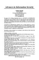
Fig. 7. Partitioning of sub-regionsin the A01 with different number of edge points and internal points
the several areas formed inside the area of interest by the intersecting circles as subregions. Thus, a sub-region is the smallest bounded area in the area of interest which corresponds to a unique subset of messages. Greater the size of the sub-region, more coarse would the location resolution be. Thus, our focus is on obtaining the expression for the average size of a sub-region in the area of interest. We achieve this by dividing the area of the A01 by the number of sub-regions within the AOI. We first seek to obtain the number of sub-regions that would be formed within the A01 for the scenario of Figure 5. We first define a few terms. The intersection point of a curve with the boundary of the A01 is called an 'edge points'. The intersection points of curves within the A01 are called 'internal points'. Further, a non-intersecting curve is a curve that does not intersect any other curve within the AOI. Given this, we have the following theorem.
Theorem 1. Each non-intersecting curve would intersect the boundary of the A01 in exactly two edge points and result in exactly one additional sub-region. Consider a simple case as shown in Figure 7, where the A01 is divided by the curve 12. The curve 12 intersects the boundary of the A01 in exactly two edge points (1 and 2) and divides the A01 into two sub-regions indicated as 'a' and 'b' in the figure. Now add a second non-intersecting curve to the A01 in Figure 7(a). The nonintersecting curve cannot intersect curve 12 already present in the A01 and thus would have to lie entirely in either the sub-region 'a' or the sub-region 'b'. We arbitrarily choose sub-region 'b', which is bounded by boundary of the A01 and curve 12. A new curve 34 is to be drawn in the sub-region 'b'. This is exactly the same as the previous case wherein a curve 12 was added to the AOI. Thus the curve 34 would intersect the boundary of region 'b' at exactly two points (3 and 4) and further divide 'b' into two more sub-regions. Since the curve 34 is a non-intersecting curve, points 3 and 4 cannot lie on curve 12 and hence have to lie on the boundary of the AOI. Figure 7(b) and Figure 7(c) show the two ways in which curve 34 can be created.
226
Santosh Pandey, Farooq Anjum, and Prathima Agrawal
Although the points 2 and 4 coincide in Figure 7(c), they are treated as two different points. This process can be carried out recursively for each added non-intersectingcurve. Hence the proof by induction. Corollary: Each pair of the edge points lying on the boundary of the A01 would form one additional region. This follows from the previous theorem. It should be noted that the edge points may be non-distinct as in Figure 7(c). Using the above theorem, the total number of sub-regions formed may be calculated based on the number of edge points and internal points.
2+ +
Theorem 2. The number of sub-regionsformed within the A01 is given by Ni 1, where Ne is the number of edge points and Ni is the number of internal points.
Proof: The proof is by induction. In the case of non-intersecting curves (Ni = O), the corollary above indicates that each pair of edge points will result in an additional additional sub-region. Thus in addition to the original single sub-region, a total of sub-regions would be added. Consider an addition of curve 34 to Figure 7(a) intersecting curve 12 at point 5 as shown in Figure 7(d). The effect of the curve 34 can be considered in parts, namely, the effect of curve 35 on sub-region 'by and effect of curve 54 on sub-region 'a'. For each of these parts, corollary of Theorem 1 implies that curve 35, with edge points 3 and 5 for sub-region 'b', would result in one additional sub-region in 'b'. Similarly curve 54, with edge points 5 and 4 for sub-region 'a', would result in one additional sub-region in 'a'. Thus the total number of additional sub-regions formed (2 in this case) is equal to half the total number of edge nodes for sub-regions 'a' and 'b', i.e. $.It should be noted that the internal point 5 is considered twice as edge node for adjacent sub-regions 'a' and 'b'. Thus, the theorem is true for one intersecting and one non-intersecting curve. & ( , I 1sub-regions due to Now assume that the A01 is divided into some m curves. Let us add a new curve to the AOI. Considering the case described for Figure 7(d), the number of additional sub-regions formed would be equal to half the total number of edge points when the additional curve is considered in parts (each part formed due an intersecting curve). Each of the internal points would be counted twice as edge points. Thus the additional sub-regions would be given as
%
+
+
where NL denotes the number of new edge points and N; denotes the number of new internal points formed due to the additional curve. It should be noted that the new edge and intersection points may coincide with the earlier points, but are treated as distinct points. Thus the total number of sub-regions due to the m+l curves is given by
TRaVarSeGTransmission Range Variation based Secure Localization
+
227
+
Setting Ne(,+l) = Ne(,) NL and Ni(m+l)= Ni(,) Ni we obtain the result. It is interesting to note that this equation is equivalent to the Eulers formula relating the number of faces to the number of edges and vertices in a graph [27]. We next need to determine the area of AOI. We assume that this is given by the area of an equilateral triangle with side R9. Therefore, considering the area of the A01 and Theorem 2, we have the following result.
Theorem 3. The average resolution using the proposed scheme is given by
Remarks: We can see from the above that as the number of power levels increases while keeping R the same, so does Ne and Ni. As a result the location resolution becomes finer. This indicates that larger number of power levels for the same maximum transmission range is desirable. Note though that in practice, too many power levels might also be undesirable since two different power levels might not lead to different transmission ranges. There will hence be an optimum number of power levels for an AP. We do not investigate this here as it is part of a separate study related to implementation of the proposed Secure Location Algorithm.
5 Security Analysis Several attacks on previous localization schemes have been discussed in [6].In this section, our focus will be on attacks on the proposed localization scheme. Our threat model specified earlier consists of an attacker working singly (no collusion) and a network protected by 802.11i. We start by proving that such an attacker will be unable to spoof his location under SLA.
Theorem 4. Consider an AP with large number of power levels for a given transmission range R. In this case, SLA is secure in that any attacker acting alone cannot falsify its location. Proof: Assume that the APs are spread as the vertices of equilateral triangles as given in Figure 5. Then a user device will be located in an A01 formed by 3
bases tat ion^'^. First consider a single AP of the three that make up the AOI. A user device is expected to transmit a set of messages to the AP. Now the user device will hear one or more messages from this AP depending on the distance. Let the AP have k transmission circles (each circle of radius jr, j = 1,2, ...k; note kr = R) corresponding to k power levels. Then a user device present at distance ir from the AP will hear (k-i+l) messages (i.e. the ir, (i l ) r ,...( k - l ) r and kr messages).
+
This is slightly imprecise as we remarked earlier and is only used for the area calculation earlier, we ignore the boundary cases
lo As
228
Santosh Pandey, Farooq Anjum, and Prathima Agrawal
Now if this user device wants to spoof its distance, it can suppress some messages. The user device cannot just select any of the messages to transmit back to the AP. For e.g. if the user device only transmits back to the AP controller messages ir and kr, then the AP controller can immediately conclude maliciousness as any user device that can obtain ir, must be able to obtain all other messages between ir and krl'. Therefore, all that a malicious user device can do is to pretend it did not hear the ithmessage and the (i l ) t hmessage and so on. Therefore, by spoofing the user device can only increase its distance from the AP. Now consider 3 APs A, B and C. Let a user device receive at most nu, nb and nc messages from each of the APs respectively. If the user device wants to spoof its location then the only thing it can do is increase its distance from each of the three APs. Therefore, it can pretend to have heard nka(na and nkb(nb messages from A and B but this means that it will have to be closer to node C. This implies that it will have to transmit back nkcjnc messages from the access point c12but this is a contradiction since the user device cannot hear more than nc messages from the access point C. Therefore, a user device cannot spoof its location under the given SLA. Remarks: When the number of power levels is small, then a malicious user device can appear to be in a neighboring region. For example, consider Figure 8. Here a user device present in location 1 hears the set of messages {N13,N14,N15,N23,N24, N25,N33,N34,N35). Such a user device can drop message N23 from the set of messages it hears and thereby appear to be in location 2 which corresponds to the message set {N13,N14,N15,N24,N25,N33,N34,N35).If the user device is present in location 2 though, it cannot pretend to be in location 1 although it can pretend to be in location 3 by skipping message N24. On the other hand a user device present in location 4 can hear a set of messages {N13,N14,N15,N24,N25,N34,N35) and such a user device cannot spoof its location at all. Similarly, a user device in location 3 also cannot spoof its location. Statements of Theorem 4 apply precisely to such locations which we call the non-spoofable locations. When the number of power levels increases, such non-spoofable locations dominate. One way to make it difficult for the intruder to spoof an area by using the above procedure (of ignoring some messages) is to make it difficult for the intruder to relate the message transmitted to the power level. This could be done by transmitting the messages randomly and not in the sequence of increasing or decreasing power levels. Note that if the intruder studies and tries to infer the power levels of all the transmissions at different regions, then the probability for the intruder being able to spoof his location increases. Later in Section 6, we will investigate via simulations the relationship between the area that can be spoofed and the number of power levels. We would also like to remark here that another way of preventing any spoofing could
+
An implicit assumption here is that the messages are transmitted reliably. There are many ways to ensure this and is hence justified l2 This is not strictly true if the number of power levels is small and hence the need for large number of power levels l1
TRaVarSeGTransmissionRange Variation based Secure Localization
229
Fig. 8. Possible spoofing for the proposed scheme
be to deploy the APs such that each location is covered by more than three APs. This will be considered as part of future work. A malicious user device can attempt the replay attack. Here it can store the set of messages recorded at multiple locations and then select the messages to transmit to the AP based on the location the user device wants to appear in. But such a scheme will not succeed due to the fact that the messages would change at each location for each location query. Further, given our assumption of a network protected by 802.11i mechanisms, a malicious user device cannot overhear the set of messages sent to a different user device by walking around but has to use the message set based on location queries directed to itself. Attacks based on delaying the response, signal strength manipulation etc would also not work with SLA as SLA does not depend on these properties.
6 Results In this section we investigate the performance of SLA using simulations. The simulations are performed using MATLAB. We assume that the APs are deployed such that the distance between them is equal to the maximum transmission range. A user device present in the A01 is localized using SLA. For such a scenario we assume two cases. In the first case, the case of uniform APs, each AP is assumed to have transmission ranges that vary in uniform increments. This implies that the adjacent concentric circles symbolizing the range of each AP for different power levels are equidistant. We relax this assumption to get the second case, the case of non-uniform M s . Here each AP has transmission ranges that vary in non-uniform increments. Since the APs deployed in the system have the same capabilities, the values of non-uniform increments are the same for all APs. This implies that the adjacent concentric circles symbolizing the range of each AP for different power levels are not equidistant. We look at each of these cases next.
230
Santosh Pandey, Farooq Anjum, and Prathima Agrawal
6.1 Uniform APs As explained earlier, in this case the transmitting range increments corresponding to increasing power levels are equal. Thus for five different power levels, the radii corresponding to the five transmission regions will be r , 2r, 3r, 4r and 5r. The A01 is the region formed by APs placed at the vertex of an equilateral triangle in a 100 x 100 square unit grid. Each side of the triangle is of length 57 units corresponding to a maximum range (R) of 57 units for each AP. We first consider the number of sub-regions formed within the A01 as given by Theorem 2. In Figure 9 we show the variation of the number of sub-regions within the A01 as the number of power levels is increased. Note that the maximum transmission range (R) is the same in all cases. We see from this figure that the number of subregions increases almost exponentially as a function of the number of power levels. The number of sub-regions indicate the resolution of localization in the proposed scheme. As expected, the resolution of localization increases with the increase in the number of power levels of an AP. We will see this next.
10 15 Number of power levels from each AP
20
Fig. 9. Number of sub-regions formed in the A01 corresponding to three access points
In Figure 10 we show the maximum, minimum and average area of the subregions as obtained via simulations. We also show the average area of the sub-regions given by Theorem 3 as the number of power levels varies. We plot the number of power levels of each AP on the x-axis. On the y-axis we plot the percentage area of the sub-region which is the ratio of the area of the sub-region to the area of the AOI. Thus, if we use a single power level, then the sub-region corresponds to the entire area. In such a case, the percentage area of the sub-region will be 100% for the maximum, minimum and average values. We see from this figure that the area of the sub-regions decreases exponentially with the increase in the number of power levels. Further, we also see from this figure that as the number of power levels increase, the maximum, minimum and average area of sub-regions converge, indicating that the sub-regions of approximately equal areas are formed which is very much desirable.
TRaVarSeGTransmission Range Variation based Secure Localization
23 1
o Mlnimum +-
Average
+ Theorem 3
umber d power levels from each AP
Fig. 10. Area of sub-regions as a function of the number of power levels
We next consider the number of messages heard at different sub-regions within the AOI. As is clear from our earlier discussion, the number of messages heard in each sub-region is different. Hence, in Figure 11we plot the maximum and minimum number of messages that are heard within the AOI. A client present in the sub-region where the minimum number of messages are heard will just have to transmit back these messages while a client present in the sub-region corresponding to the maximum number of messages will have to transmit all these back to the AP. Thus, the larger the variation between the minimum and maximum number of messages heard in the AOI, the harder it would be for the attacker to guess the correct set of messages that correspond to a location and hence more secure would the scheme be. Figure 11 shows that these values increase linearly with the number of power levels. More irnportantly, the spread between the maximum and the minimum number of messages also increases with power levels. This indicates that with the increase in the number of power levels, SLA becomes more robust to the presence of intruders.
"0
5 10 15 20 Number of power levels from each AP
Fig. 11. Number of messages heard in the A01
232
Santosh Pandey, Farooq Anjum, and Prathima Agrawal
We next consider the possibility of an attacker spoofing his location as the number of power levels of an AP increase. We have seen earlier that one possible way for a lone attacker to spoof her location is to ignore one of the messages heard in a sub-region. With increase in the number of power levels, the minimum number of message heard at a sub-region increases and hence the possibility of such a forged region is expected to decrease. This is also indicated in Figure 12 where we show the maximum, minimum and average area of region that can be spoofed by the intruder. In the x-axis we plot the number of power levels while on the y-axis we plot the percentage area of the sub-region that can be spoofed. This is the ratio of the area of the sub-region which can be spoofed to the area of the AOI. For example, in Figure 8, an attacker present in location 1 can spoof to be either in areas 2 or in area 3. So the corresponding value of the percentage area of the sub-region that can be spoofed is the value of the areas such as 2, 3 etc divided by the area of the AOI. As seen from the figure, in general as the number of power levels increase, the area that can be forged decreases. Thus based on Figures 11 and 12, it can be concluded that with the increase in the number of power levels the scheme would be more robust against attacks.
Fig. 12. Area of regions that may be forged in terms of percentage of common transmission area
Figure 12 also indicates that the deployment with three power levels results in a high value for the percentage of area that can be forged. This is mainly due to the use of equidistant circles, which leads to the formation of a huge spoofable sub-region at the center of the AOI. This implies that equidistant transmission ranges are not desirable which leads to the non-uniform APs case that we investigate in the next sub-section. But if equidistant transmission ranges have to be used, then this figure may be used to avoid using the number of power levels that result in a large area that can be forged. We would also like to remark here that almost every choice for the number of power levels has some regions where location spoofing is not possible (such as location 3 and 4 in Figure 8). This corresponds to a value of zero for the
TRaVarSeGTransmission Range Variation based Secure Localization
233
spoofed area. Thus an attacker present in such regions will not be able to spoof his location at all. This indicates that the network deployment can be done in such a manner so as to ensure that "physically" less secure locations such as a lobby would correspond to one of these non-spoofable sub-regions.
6.2 Non-uniform APs We have so far considered that the adjacent concentric circles signifying the transmission ranges of an AP are equidistant. We next consider the case whereby each AP has transmission ranges that vary in non-uniform increments. Different values for the ratios of different radii (for e.g. 1:2:3:4:513 corresponding to circles of radii r,3r,6r,lOr and 15r=R or 1:l:3:4:5 corresponding to circles of radii r',2r',5r',9r' and 14r'=R) would result in different number of sub-regions as well as in different number of messages heard in each sub-region. The area of each sub-region and the region that may be forged will also depend on the chosen radius ratio. Consider the deployment with an AP which can transmit at five different power levels. The ratio of these five power levels may be varied in order to obtain optimum performance. Figure 13 shows the percentage area that may be forged for different radius ratios of the concentric regions. In this figure, we consider 5 transmission ranges and about 7500 unique ratios for these ranges. This is obtained by having 6 possible values for each the value of each transmission range which will give us 65 = 7776 different ratios. Some of these will be identical. We remove these identical ratios and consider all the rest of the ratios which approximates to around 7500 different ratios. Each ratio corresponds to a number which is plotted on the x-axis of this figure. On the y-axis we plot the percentage area of the sub-region that can be spoofed. As earlier, this is the ratio of the area of the sub-region which can be spoofed to the area of the AOI. We plot the maximum, average and minimum area that can be spoofed for a given ratio. Thus, given a point on the x-axis, we can determine the maximum, average and minimum areas that can be spoofed for the ratio that this point represents. As seen from the figure depending on the radius ratio, the maximum forged area may be anywhere between 3.8 % to 99.65 %. This corresponds to ratio increments of (4: 1:1:1:4) and (6: 1:1:1:1) respectively. By choosing equidistant regions the maximum forged area obtained is about 21.94 %. Hence, from security perspective, choosing an appropriate non-uniform radius ratio (non-uniform AP case) results in better performance as compared to uniform AP case. Similar results were observed for the other parameters, such as number of messages received and number of sub-regions formed. Thus, we see that it is more beneficial to have nonuniform increments for the transmission ranges of an AP. Note that a combination of attenuators and amplifiers can be used along with the inbuilt capabilities of an AP to achieve non-uniform radius ratios (non-uniform AP case).
l3 Note that this corresponds to the ratio for the increments as opposed to the ratio of
which is obtained from this
the radii
234
Santosh Pandey, Farooq Anjum, and Prathima Agrawal
,000
moo
3000
m o
5 m
E m
mw
d saao
Different ratios of radlus from each AP
Fig. 13. Percentage area of regions that may be forged for different radius ratios of the concentric regions
7 Discussion There are two main abstractions that will have to be addressed in order to implement this scheme. The first abstraction is the assumption that every power level of an AP corresponds to a coverage given by a circle of some radius. This will not be true in practice. The area covered for a given power level is not a strict circle [ll]. Further, the transmission range corresponding to a given power level from an AP could also be time-varying. We plan to address this by making use of sniffers (acting as reference points) placed at the boundaries corresponding to a particular power level transmission from an AP. These sniffers would be connected to the AP controller and any variation with time in the transmission range for the same power level from access point A could then be reported to the AP controller. The AP controller could in turn request A to modify the power levels accordingly. Note that such a time varying range would make it difficult even for an attacker with specialized hardware to infer the relationship between power level and the location which thereby increases the security of SLA. We are currently working on these aspects and expect to report on these in the future. We are also currently considering a system based on the proposed scheme that is secure against colluding attackers. We are currently investigating the combination of SLA with the other conventional schemes such as schemes based on SS measurements (which should be done automatically without the need for laborious bootstrapping) in order to provide a secure scheme that can tolerate multiple colluding intruders. Finally although the localization scheme in this chapter is developed in the context of WiFi networks, it can be extended to other wireless networks such as, wireless sensor networks.
8 Conclusion In this chapter we focused on the location based access control problem in WLAN networks. We see that a solution to this problem is dependent on the design of se-
TRaVarSeGTransmission Range Variation based Secure Localization
235
cure localization schemes. Hence, in this chapter we propose a secure localization scheme that can work with current WLAN hardware. The proposed scheme is based on the capability of a WLAN AP to vary its power level. We propose that multiple APs cover each location from which a user device can access the wireless network. Further, each AP is expected to securely transmit a message at each different power level. A user device is expected to reflect back all the messages heard at its location back to the AP. Based on the set of messages heard back from the user device, the AP can determine the location of the user device. Assuming a user acting alone, we have shown the robustness of this scheme to several user misbehaviors. We have also shown that if the power level of an AP can be continuously varied from the minimum to maximum level, the proposed scheme would result in highly precise and secure localization of users.
9 Acknowledgment The authors would like to thank Dr. Wlodzimierz Kuperberg of the Department of Mathematics and Statistics, Auburn University, for his valuable comments.
References 1. D. E. Denning and P. E MacDoran, "Location-based authentication: grounding cyberspace for better security," Internet besieged: countering cyberspace scoflaws, pp. 167174,1998. 2. D. Hromin, M. Chladil, N. Vanatta, D. Naumann, W. Wetzel, E Anjum, and R. Jain, "CodeBLUE: A bluetooth interactive dance club system," IEEE Global Telecommunications Conference, vol. 5, pp. 2814 - 2818, December 2003. 3. T. Nadeem, L. Ji, A. Agrawala, and J. Agre, "Location enhancement to IEEE 802.11 DCF," Proceedings of ZEEE INFOCOM, vol. 1, pp. 651-663, March 2005. 4. M. G. Kuhn, "An asymmetric security mechanism for navigation signals," Proceedings of the Information Hiding Workshop,2004. 5. R. Anderson and M. Kuhn, "Tamper resistances cautionary note," Second USENZX Workshop on Electronic Commerce Proceedings, pp. 1-1 1, November 1996. 6. S.Capkun and J. Hubaux, "Secure positioning of wireless devices with application to sensor networks," Proceedings of IEEE INFOCOM, vol. 3, pp. 1917-1928, March 2005. 7. Proxim ORNOCO AP-2000 User Guide, Corporation, http://www.proxim.com/products/wiii/ap/ap2000/. 8. N.B.Priyantha, A. Chakraborty, and H. Balakrishnan, "The cricket location-support system,'' Proceedings of the Annual International Conference on Mobile Computing and Networking, MOBICOM, pp. 32-43, August 2000. 9. R. Want, A. Hopper, V. Falco, and J. Gibbons, "The active badge location system," ACM Transactions on Information Systems, vol. 10, no. 1, pp. 91-102, January 1992. 10. Y.Gwon, R. Jain, and T. Kawahara, "Robust indoor location estimation of stationary and mobile users," Proceedings of ZEEE INFOCOM, vol. 2, pp. 1032-1043, March 2004. 11. S. Ganu, A. S. Krishnakumar, and P. Krishnan, "Infrastructure-based location estimation in wlan networks," IEEE Wireless Communicationsand Networking Conference (WCNC 2004), vol. 1, pp. 465470, March 2004.
236
Santosh Pandey, Farooq Anjum, and Prathima Agrawal
12. P. Bahl and V. N. Padmanabhan, "RADAR: An in-building rf-based user location and tracking system," Proceedings of ZEEE ZNFOCOM, vol. 2,pp. 775-784,March 2000. 13. A. M. Ladd and et. al., "On the feasibility of using wireless ethernet for indoor localization,'' ZEEE Transactions on Robotics and Automation, vol. 20,no. 3, pp. 555-559,June 2004. 14. L. Lazos and R. Poovendran, "SeRLoc: Secure range-independent localization for wireless sensor networks," Proceedings of the 2004 ACM Workshop on Wireless Security, Wise, pp. 21-30,October 2004. 15. P. Castro, P. Chiu, T. Kremenek, and R. Muntz, "A probabilistic room location service for wireless networked environments," Proceedings of the 3rd international conference on Ubiquitous Computing,pp. 18 - 34,September 2001. 16. D. Madigan, E. Elnahrawy, R. P. Madn, W.-H. Ju, P. Krishnan, and A. S. Krishnakumar, "Bayesian indoor positioning systems," Proceedings of ZEEE ZNFOCOM, vol. 2,pp. 1217-1227,March 2005. 17. M. Youssef and A. Agrawala, "The Horus WLAN location determination system," Proceedings of the 3rd international conference on Mobile systems, applications, and services, pp. 205-218,June 2005. 18. S.Capkun, M. Srivastava, M. Cagalj, and J. Hubaux, "Securing positioning with covert base stations," NESL-UCLA Technical Report, Tech. Rep., March 2005. 19. L. Lazos, S. Capkun, and R. Poovendran, "ROPE: Robust position estimation in wireless sensor network," Proceedings of ZPSN, April 2005. 20. Z. Li, W. Trappe, Y. Zhang, and B. Nath, "Robust statistical methods for securing wireless localization in sensor networks," Proceedings of the International Conference on Znformation Processing in Sensor Networks (ZPSN),April 2005. 21. D. Liu, P. Ning, and W. Du, "Attack-resistant location estimation in sensor networks," In Proceedings of the Zntemtional Conference on Information Processing in Sensor Networks (ZPSN),pp. 99 - 106,April 2005. 22. N. Sastry, U.Shankar, and D. Wagner, "Secure verification of location claims," Pmceedings of the Workshop on WirelessSecurity, pp. 1-10,2003. 23. S. Pandey, B.Kim, E Anjurn, and P. Agrawal, "Client assisted location data acquisition scheme for secure enterprise wireless network," ZEEE WirelessCommunicationsand Networking Conference, WCNC,vol. 2,pp. 1174-1 179,March 2005. 24. P. Tao, A. Rudys, A. M. Ladd, and D. S. Wallach, "Wireless LAN location-sensing for security applications," Proceedings of the Workshop on Wireless Security, pp. 11-20, September 2003. 25. P. Calhoun, B. OHara, S. Kelly, R. Suri, D. Funato, and M. Vakulenko, "Light weight access point protocol (LWAPP)," ZETF Internet Draft, draft-calhoun-seamoby-lwapp-03, June 2003. 26. D-Link, DWL-2Z00AP Data Sheet, ftp://ftplO.dlink.com/pdfs/products/DWL-
2100AP/DWL2100AP-ds.pdf. 27. C. Dodson, P. Parker, and P. E. Parker, A User's Guide to Algebraic Topology (Mathematics and Its Applications). Springer, 1997.
Secure Sequence-based Localization for Wireless Networks Bhaskar Krishnamachari and Kiran Yedavalli Department of Electrical Engineering-Systems Viterbi School of Engineering University of Southern California Los Angeles, CA 90089 {bkrishna, kyedaval)@usc.edu
Summary. We present a unique sequence-basedapproach to localization that allows for automatic error correction. In dense deployments, this technique can provide accurate localization even in the face of malicious falsification of reference signals.
1 Introduction Providing mobile devices with accurate location information is a fundamental service in many current and envisioned deployments of wireless networks, including wireless local area networks, ad hoc networks and wireless sensor networks. Besides being useful in itself in providing end users with location awareness, localization can be a key building-block for other wireless network protocols such as those for routing, sleep-scheduling, call-admission, etc. As we enter a world where wireless devices are deployed pervasively in industrial and military settings as well as public and private buildings, there is increasing interest in providing robust localization techniques that are not only functional (in terms of providing the desired level of accuracy and speed), but also secure with respect to possible malicious attacks. In the abstract, of course, there are a large number of different security threats and concerns in a wireless network. In some settings, of greatest concern is protecting the privacy and confidentiality of localization, ensuring that the location of unknown nodes in the network is not revealed to outsiders. In others, a significant concern is preventing denial of service attacks that involve disabling location reference nodes, exploiting vulnerabilities associated with the MAC protocol, or physical-layer jamming. Another key concern, the one that we focus on primarily in this work, is that of preventing degradation of the accuracy of the location service itself. This involves detecting, correcting, and mitigating the deliberate insertion of false signals (spoofing) by attackers. We propose a novel methodology for secure localization that is inspired by error control coding techniques that have been used for many decades to provide robust-
Bhaskar Krishnamachari and Kiran Yedavalli
238
ness to noisy channels in traditional digital communications [S]. In enor control coding techniques, the message to be sent is fmt encoded into a higher-dimensional codeword. When the message passes through a communication channel, it may be distorted due to noise and interference effects. At the receiver end, errors introduced by the channel can be detected (to an extent that depends upon the coderate, the ratio of message bits to the bits in the codeword) by exploiting the fact that there are a relatively small number of correctlfeasible codewords in the codeword space. Erroneous messages can be corrected, again to an extent depending upon the code-rate, by mapping the distorted encoded message to the the nearest feasible codeword and then decoding back to the original message.
encoder
@SS
TDOA AOA
i~ ~
:
~
~
~
eic) ~
~~
-7
locabon sequence : codeword i
noise1 malicious errors
1
sequence
1
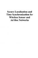
Fig. 1.Localization as analogous to emn mnml coding
We present a sequencebased self-error-correcting localization mechanism, that is depicted as being analogous to ermr control coding in Figure 1. In this mechanism, the codeword that is used for localization is formed as a sequence by ranking the distances from the mobile node (with unknown location) to the various nearby reference nodes. For a given deployment of reference nodes, different location regions in the deployment area have distinct and unique codewords that can be tabulated in advance. Given such a codeword, the location of the node is then determined by a reverse table-lookup. A key to the security of this technique is that the the density of feasible codewords (i.e. the codewords that correspond to an actual location region in the deployment area) decreases steeply with the number of location reference nodes. In particular, if N represents the number of reference nodes in a two-dimensional area, only O(N4)
Secure Sequence-based Localization for Wireless Networks
239
of the O ( N ! )possible sequences are feasible codewords. This low density of feasible location codewords provides the ability to detect, correct and mitigate errors in the encoded location sequence that may be deliberately introduced by malicious attackers by the spoofing of ranging signals. We present a brief numerical evaluation of the robustness of the proposed technique to signal spoofing by a powerful attacker. While the results from this technique are indeed encouraging, it is possible that the particular mechanism we propose may be just a tip of the iceberg. Extensions of this technique may reveal a large space of related secure location coding techniques that provide even greater immunity to malicious attacks.
2 Related Work Localization of nodes in the context of densely deployed wireless networks in benign settings has been the object of intense study in the past decade. Several articles have provided a thorough survey of the subject (e.g., see [2], [3, Ch. 31). However, it has been only even more recently that researchers have developed localization techniques suitable for settings involving malicious attackers. We briefly survey some of this work on secure localization: In [7], the authors propose a secure localization technique that offers protection against spoofing of reference node locations by attackers. In this technique, localization is performed using a set of public base stations as reference nodes, whose location claims are verified by another set of covert base stations. The probability of the attacker's success is shown to grow linearly with ranging error, inversely to the square-root of the area of the localization space, and inversely to the number of covert base stations. In [I], another work that studies secure localization against spoofing of locations of reference nodes, two techniques based on majority-vote are proposed. In the first technique, the spoofed location is assumed to appear as a "outlier" in the set of locations of all reference nodes. The outlier is detected and discarded by verifying the unknown node location estimate with different subsets of reference nodes. In the second technique, reference nodes vote on the unknown node location likelihood at each grid point in the localization space and the grid point with the highest number of votes is chosen as the location estimate. A statistical method of secure localization is proposed in [9]. In this method, the authors suggest that using the median of localization data is inherently more secure than using its average. Based on this, they propose that triangulation based localization techniques such as least sum of squares estimator should instead use least median of squares. They also argue that RF finger-printing based localization techniques should use minimum median distance instead of minimum average distance as the metric to determine the nearest neighbor. In a work that addresses other attacker models, the authors in [4] propose a secure localization technique that is robust to Wormhole and Sybil attacks. In this technique, secure localization is provided using a combination of encryption keys, power control, and directional antennas that can transmit in different directions at the same
240
Bhaskar Krishnamachari and Kiran Yedavalli
time. In [5], the authors propose a combination of distance bounding, exchange of challenge-response type of messages, and authentication keys to ensure security of location determination. The authors of [6] address the problem of location verification in which the location of a wireless node is verified for its authenticity. This is done by using the inherent constraints in round trip propagation times of RF and ultra sound signals. The technique that we describe here is quite different from prior work on secure localization in its use of ordered sequences as a location code. It is most similar to the Ecolocation technique that we previously proposed for localization using pure RF signals [lo]. A key difference from that work is that we focus here on errors introduced by malicious attackers, rather than RF channel errors due to multi-path fading and other environmental factors.
3 Secure Sequence-Based Localization Consider a two-dimensional location area in which N reference nodes with known locations are deployed. The goal is to enable a mobile node in the environment with an unknown location to locate itself. The mechanism can be implemented in either a node-centric or an infrastructure-centric mode. In the former implementation, the node obtains distance estimates to each reference node and computes its location according to the mechanism described below. In the latter, the reference nodes each obtain a distance estimate to the unknown node and transmit this information to a centralized node where the computation is performed. The exact mechanism for obtaining the distance estimate can vary in either case. For instance, it could be based on time difference of arrival between a radio and acoustic signal, or based on an estimate using pure radio signal strength, or possibly even via phase interferometry). For a detailed discussion of how sequence-based localization provides robustness to errors in the distance estimation in the context of pure-RF localization, we refer the reader to the evaluation of the Ecolocation technique presented in [lo]. In the discussion below, we shall assume that the ranging estimates are sufficiently accurate that they affect the accuracy of localization minimally. Thus our focus with regard to errors will be solely on those introduced by a malicious attacker.
3.1 Sequence Encoding of Locations We now give a description of how the ranging signals are interpreted for localization in the deployment region. First, the distance estimates between the unknown node and the reference nodes is converted to a sequence that represents the relative distance ranking of each reference node (from nearest to farthest). A correct sequence represents a valid location region in the deployment area where the distances to the different reference nodes are ranked accordingly. The two-dimensional deployment area can be partitioned into all valid location regions
Secure Sequence-based Localization for Wireless Networks
241
by drawing all lines that are perpendicular bisectors of lines joining all pairs of reference nodes. The two sides of each such line represent the distance inequalities with respect to a particular pair of reference nodes. The faces formed by the intersection of these lines represent all feasible regions, each forming unique combinations of the inequalities that result in the corresponding sequence.
Fig. 2. Illustration of location regions and sequences for four nodes in a square region
For example, consider figure 2. It shows a square region in which there are four reference nodes labeled A, B, C, and D. Because the perpendicular bisectors for the node pairs AB, DC and that if node pairs AD, BC overlap respectively, there are four bisecting lines in all, dividing the region into eight location regions. The unique sequences corresponding to each of the eight regions area also shown. For instance the region on the bottom of the top-left quadrant corresponds to the sequence ADBC because all points in this region are closest to A, closer to D than B and C, and finally closer to B than C. This mapping between location regions and location sequences can be encoded in a table a priori, during or before network initialization. In the absence of any errors, the unknown node can be located by performing a reverse look-up on this table to obtain the location given the sequence. Localization using a table look-up is quite feasible for intermediate-sized networks (we show in the following section
242
Bhaskar Krishnamachari and Kiran Yedavalli
that the size of the table is polynomial); the speed can be further improved using multi-resolution and gradient-based grid search techniques.
3.2 Density of Feasible Sequences We now investigate a bound on the number of feasible sequences for a given deployment. Given that there are N ! possible sequences in all, how many of these actually correspond to feasible locations? The following proposition addresses this question, which is of core relevance not only to the time and space complexity of the algorithm, but also its ability to detect and correct errors.
Proposition 1. In a two-dimensional area with N reference nodes, the number of feasible location sequences (i.e. sequence codewords that correspond to location regions in the 2 0 area) is O ( N ~ ) . Proot Each feasible location sequence represents a combination of pairwise inequality relationships with respect to the distance to two reference nodes. Each corresponding location region results from the intersection of these inequalities, each of which is represented by a line in the 2D plane that is a perpendicular bisector of the line joining each pair of reference nodes. It suffices to show that the number of faces . can do this in two steps. formed by these intersecting lines is O ( N 4 ) We a a
First, note that the number of bisecting lines is O ( N 2 ) ,since there is at most one line for each pair of reference nodes and there are C t = pairs of nodes. Next, we can prove that the arrangement of k lines in the plane can result in at most O ( k 2 )faces. This can be proved by induction by showing that each line added to an existing arrangement of i - 1lines adds at most i additional faces, which bounds the total number of faces by k(k 1)/2 1.
+
+
Combining these together, we get that the total number of faces with N reference nodes must be O ( N 4 ) .
Note that we have assumed here a strict ordering of references, ignoring any lines or intersection points in the region where two or more references are equidistant, otherwise there could be potentially N N total sequences (not N ! ) ,though the number of feasible sequences remains O ( N 4 )even in that case.
3.3 Decoding Falsified Sequences When there are no errors in the observed sequence, the localization algorithm is simple as it requires only a table look-up; it also provides excellent performance in ) in a given deployment area A, the terms of accuracy. Since there are O ( N ~regions average area of location regions decreases roughly as o($$), providing a rapid gain in location accuracy as the number of reference nodes increases.
Secure Sequence-based Localization for Wireless Networks
243
However, in the face of an attacker or even errors due to the environment, the original sequences may not be received correctly. The error detection and correction capabilities of the sequence-based localization mechanism are called for. These capabilities rely on the proposition we described in the last section: the ratio of feasible sequences (that correspond to valid locations in the deployment area) and the ratio of all possible sequences is very small for even moderate values of N, the number of reference nodes. Most changes to the reference nodes' signals will not result in a sequence with a feasible location -this provides the basis for error detection. If the ranging mechanism used is inherently highly accurate (such as TDoA techniques in some settings), then a sequence that does not correspond to any of the feasible location region provides an indicator that a malicious attack may be in progress. Another way to view this is that the location encoding provides a consistency check because they represent fundamental geographic constraints; when a received sequence fails this consistency check, one can infer that errors have been introduced into the system. Given that there is an error introduced into the sequence, a location can still be obtained from the sequence. This is done by mapping the erroneous sequence to the "nearest" feasible codeword sequence corresponding to a valid location region. The notion of "nearest" can be defined using different metrics suitable for sequences. A simple choice is to count the number of pairwise inequality constraints (pertaining to reference node distances) that are violated in the given erroneous sequence with respect to each feasible region, and pick the region that minimizes the number of unsatisfied constraints. Consider again the example deployment in figure 2. If the sequence ABCD is received, it can be detected immediately that an error has been introduced into the sequence since this sequence does not correspond directly to any of the location regions. The nearest feasible codeword to this sequence is ABDC, which corresponds to the region on the top of the top-left quadrant. This is because there is a difference of only one constraint violation between these two sequences (the inversion of the 'D is closer than C' constraint). If this mapping is assumed to be correct based on limitations on the attacker's capability, this may suggest that the attacker is either manipulating the signals of C to make it appear closer to the mobile node, or the signals of reference node D to make it appear farther than it really is to the mobile node. While there is no guarantee that this approach will necessarily result in a correct solution in all cases, it can mitigate significantly the impact of the errors in the location sequence. The likelihood of correction and the obtained accuracy both increase with the number of reference nodes.
4 Evaluation We briefly evaluate the proposed sequence-based localization mechanism though a set of simulations involving malicious attackers. Evaluating the performance of a localization mechanism with respect to a malicious attacker requires some care. In particular, we need to be explicit about the
244
Bhaskar Krishnamachari and Kiran Yedavalli
capabilities of the attacker and strike a balance between providing the attacker with sufficient power and imposing some costs for the attack. Our approach is to impose such a cost by limiting the number of reference nodes that the attacker can manipulate to k (we provide numerical simulations for k = 1and k = 2 here, but these can be extended to other values of k). At the same time, we provide an advantage to the attacker by allowing the attacker to know the 'true' location of the mobile node and switch accordingly at each time to the set of k reference nodes that hurts the localization technique the most in terms of accuracy. This allows the attacker to impose a worst-case penalty on the performance of our localization mechanism at all locations in the deployment area. In this sense, the provided results represent an upper bound on the damage that could be suffered at the hands of an intelligent attacker. In particular, the location accuracy in real attack scenarios may be substantially better than what is shown in these figures. This is because realistically, in some settings, the attacker may not able to observe the unknown node, and therefore may not be able to change which reference node is being spoofed or manipulated on the fly as the mobile node moves through the network.
One Attacker -1 60
0
Fig. 3. Impact of one powerful attacker on secure sequence-basedlocalization in a square area
We measure location error as the absolute distance between the true and estimated location as a percentage of D,, the average distance between pairs of reference nodes; this provides normalization with respect to the density of reference node deployment. In case of a single strong attacker, whose impact is evaluated in Figure 3, the attacker inflicts the most damage on the localization scheme by introducing N - 1 constraint violations; this is done by moving the first node on the sequence to the end of the sequence (by spoofing the nearest reference node to the
Secure Sequence-based Localization for Wireless Networks
245
Two Attackers
Fig. 4. Impact of two powerful collaborating attacker on secure sequence-based localization in a square area
mobile nodes' true location to make it seem the farthest). The three curves represent the normalized location error as a function of the number of reference nodes. The max, min and average shown are taken over all locations chosen uniformly from a square deployment area. The overall decreasing trends in all three curves is highly encouraging (although the max curve shows a small increase for less than five references). The steep falloff in the curve for min and the slower falloff for max suggests that there are some locations of the unknown node where a single attacker is quite powerless to affect the localization accuracy, and others where it has greater impact. On average, the proposed technique provides significant improvements (error less than 20% of inter-node spacing) when more than 12 reference nodes are present. Figure 4 shows the corresponding results when two intelligent attackers collaborate to spoof the readings from two different reference nodes. In this case the worst damage to the location technique is inflicted by moving the first node in the sequence to the end, and bringing the last node in the sequence to the front (by adjusting the distance estimates for these two reference nodes accordingly). We observe again that there are decreasing trends in max, min and average location error once there are sufficiently many reference nodes (though there is an initial increase for a small number of references). We also see that there exist locations where two attackers have negligible impact on localization error when there are at least 10 references. When relatively small-to-medium numbers of reference nodes are considered, the location regions obtained tend to exhibit some skewed boundary effects (the regions near the boundary are larger than those in the center). Eliminating these edge effects gives an idea of the performance in the context of a seamless deployment
246
Bhaskar Krishnamachari and Kiran Yedavalli
Avg. Error for Worst Case in a Torus
"
3
4
d
6
7
8
9
10
umber of reference nodes
11
12
Fig. 5. Impact of one and two attackers on secure sequence-based localization in a torus (no edge effect)
of a large number of reference nodes (only a subset of which are within range at any location of the unknown node). We therefore examine the performance of the normalized location error (averaged over all locations) on a torus, for both single and two-reference-node attacks, in Figure 5. We observe that for the single attacker case, while the initial localization error for a torus is higher compared to the grid, the falloff is faster so that by the time there are 12 reference nodes, the localization error is lower (less than 10%of the baseline inter-reference spacing). For two attackers, the average localization error also shows a steady (almost linear) decline for the torus, though it appears slightly worse than in the case of the grid. These simple experiments suggest on the whole that localization using sequences provides robust protection against malicious attacks in dense deployments.
5 Conclusions We have presented a novel sequence-based secure localization mechanism. The key to its performance (which improves rapidly with increasing density of reference nodes) is that the number of feasible sequences is considerably smaller than the set of all sequences that can be generated, allowing for robust detection and correction of errors in the sequence. In future work it would be of interest to evaluate this technique for attacks involving an even greater number of compromised nodes, and compare the security provided by this technique with other state-of-the-art approaches. Still, this technique is perhaps just the tip of an iceberg; much remains to
Secure Sequence-based Localization for Wireless Networks
247
be learned about such self-error-correctinglocalization techniques, particularly with respect to malicious attacks.
6 Acknowledgements The research in this work has been supported in part by National Science Foundation through grants NeTS-NOSS CNS-0435505, CAREER CNS-0347621, ITR CNS-0325875, and CCF-0430061, and through a gift from Bosch Research.
References 1. Donggang Liu, Peng Ning, and Wenliang Du. Attack-resistant location estimation in sensor networks. In Proceedings of the Fourth International Symposium on Information Processing in Sensor Networks, IPSN, pages 99-106, Los Angeles, CA, USA, 2005. 2. Jeffrey Hightower and Gaetano Borriello. Location systems for ubiquitous computing. Computer,34(8):5746, August 2001. 3. Bhaskar Krishnamachari Networking WirelessSensors Cambridge University Press, 2005. 4. Loukas Lazos and Radha Poovendran. SeRLoc: secure range-independent localization for wireless sensor networks. In Wise '04: Proceedings of the 2004 ACM workshop on Wirelesssecurity, pages 21-30, New York, NY, USA, 2004. ACM Press. 5. Loukas Lazos and Radha Poovendran and Srdjan Capkun. ROPE: Robust Position Estimation in Wireless Sensor Networks. In Proceedings of the Fourth International Symposium on Information Processing in Sensor Networks, IPSN, Los Angeles, CA, USA, 2005. 6. Naveen Sastry, Umesh Shankar and David Wagner. Secure verification of location claims. In Wise '03: Proceedings of the 2003 ACM workshop on Wireless security, pages 1-10, New York, NY, USA, 2003. ACM Press. 7. Srdjan Capkun, Mario Cagalj and Mani Srivastava. Secure Localization With Hidden and Mobile Base Stations. In IEEE INFOCOM, Barcelona, Spain, 2006. 8. Stephen Wicker, Error Control System for Digital Communication and Storage, PrenticeHall, 1995. 9. Zang Li, Wade Trappe, Yanyong Zhang and Badri Nath. Robust Statistical Methods for Securing Wireless Localization in Sensor Networks. In Proceedings of the Fourth International Symposium on Information Processing in Sensor Networks, IPSN, h s Angeles, CA, USA, 2005. 10. Kiran Yedavalli, Bhaskar Krishnamachari, Sharmila Rawla and Bhaskar Srinivasan. Ecolocation: A Sequence Based Technique for RF-only Localization in Wireless Sensor Networks In Proceedings of The Fourth International Conference on Information Processing in Sensor Networks, IPSN, Los Angeles, CA, April 2005.
Securing Localization in Wireless Networks (using VeriJiable Multihteration and Covert Base Stations) Srdjan Capkun Informatics and Mathematical Modelling Department, Technical University of Denmark (DTU), DK-2800 Lyngby, Denmark; sca@imm. d t u .dk
1 Introduction In the last decade, researchers have proposed a number of localization and ranging techniques for wireless networks [2,5,12,26,39,40].The use of these techniques is broad and ranges from enabling networking functions (i.e., location-based routing) to enabling location-related applications (e.g., access control, data harvesting). The proposed techniques were mainly studied in non-adversarial settings. Ranging and localization techniques are, however, highly vulnerable to attacks from internal attackers (e.g., dishonest nodes) and external attackers; internal attackers can report false location and distance information in order to cheat on their locations; external attackers can spoof measured locations of network nodes. Localization and ranging techniques in wireless networks mainly rely on measurements of the times of flight of radio (RF Tom or ultrasound signals (US ToF), and on the measurements of received strengths of radio signals of devices (RFRSS). An attacker can generally influence all these measurements by jamming and delaying signals, and by modifying their signal strengths. Localization systems based on ultrasound time of flight (US ToF) and those based on measurements of signal strength of radio signals (RF RSS) are particulary vulnerable to location spoofing attacks; systems based on radio time of flight measurements are less vulnerable to attacks because of the high speed of signal propagation, In this work, we first review attacks on ranging and localization techniques in wireless networks. We then describe two approaches for securing localization: Verifiable Multilateration (VM) and Secure Localization with Covert Base Stations. Verifiable Multilateration (VM) is based on the measurements of the time of radio (or sound) signal propagation (i.e., time-of-flight (ToF)); it consists of conventional multilateration with distance bounding or with authenticated ranging. This protocol enables verification of node locations by a set of (at least three) trusted base stations, which do not need to be tightly synchronized. O
The author acknowledges contributions from Mario Cagalj, Jean-Pierre Hubaux and Mani Srivastavato original publications [36-381 from which this chapter is compiled.
250
Srdjan Capkun
Secure Localization with Covert Stations is based on the unpredictability of locations of base stations performing localization. Notably, locations of covert base stations represent a secret input (a key) to the system. Covert base stations can be realized by hiding or disguising static base station or by the random motion of mobile base stations. Typically, covert base stations are passive. The organization of this chapter is as follows. In Section 2, we review localization techniques and analyze attacks against them. In Section 3, we describe secure localization with Verification Multilateration (VM). In Section 4, we present a scheme for secure localization based on hidden base stations. In Section 5, we present an review current proposals and techniques for secure localization in wireless networks. We conclude the paper in Section 6.
2 Attacks against location and distance estimation techniques We now review localization and distance estimation techniques and analyze their vulnerabilities. First, we briefly present our attacker model.
2.1 Attacker model We call an attacker external if it cannot authenticate itself as an honest network node to other network nodes or to a central authority. We call an attacker internal if the node is compromised or if the user controlling the node is malicious. We assume that malicious and compromised nodes can authenticate themselves to the authority and to other network nodes. When a node is compromised, its secret keys and other secrets that it shares with other nodes are known to the attacker. Furthermore, users have full access to their devices, meaning also to their authentication material. Similarly, we observe two types of attacks: internal and external. Internal attacks are those in which an internal attacker reports a false location or convinces the localization infrastructure that it is at a false location. External attacks are those in which an (external) attacker convinces an honest node and the localization infrastructure that the node is at a different location from its true location (i.e. the attacker spoofs node's location). We distinguish two types of localization systems: infrastructure-centric and node-centric. By a node-centric localization system we mean that a node computes its location by observing signals received from public base stations with known locations. If the localization system is node-centric, internal attacks are generally straightforward: the attacker simply lies about the location that it computed. Infrastructure-centriclocalization systems are those in which the infrastructure computes locations of nodes based on their mutual communication.
2.2 Attacks on Global Positioning System (GPS) The Global Positioning System is today the most widespread outdoor localization system for mobile devices. The system is based on a set of satellites that provide a
Securing Localization in Wireless Networks
25 1
three dimensional localization with an accuracy of around 3 m. GPS also provides devices with an accurate time reference. GPS, however, has several limitations: it cannot be used for indoor localization nor for localization in dense urban regions: in those cases, because of the interferences and obstacles, satellite signals cannot reach the GPS devices. Furthermore, civilian GPS was never designed for secure localization. Civilian GPS devices can be "spoofed" by GPS satellite simulators, that produce fake satellite radio signals that are stronger than the real signals coming from satellites. Most current GPS receivers can be totally fooled, accepting these stronger signals while ignoring the weaker, authentic signals. GPS satellite simulators are legitimately used to test new GPS products and can be bought for $10k-$50k or rented for just $lk per month. Some simple software changes to most GPS receivers would permit them to detect relatively unsophisticated spoofing attacks [41]. Nevertheless, more sophisticated spoofing attacks would still be hard to detect. Military GPS are protected from location spoofing by codes that cannot be reproduced by the attackers. Even if a mobile node is able to obtain its correct location from the GPS satellites, the authority or another mobile node have no way to verify the correctness of node's location, unless the mobile node is equipped with a trusted software or hardware module [I], providing the correct location.
2.3 Attacks on Ultrasound (US)-based localization Ultrasound-based systems operate by measuring ToF of the sound signal measured between two nodes. An interesting feature of these systems is that, if used with RF signals, they do not require any time synchronizationbetween the sender and the receiver. The limitations of the US-based systems are that, due to outdoor interferences, they can be mainly used indoors. US-based systems are vulnerable to distance reduction and distance enlargement attacks by external and internal attacks. To reduce the measured distance between two honest nodes, two attackers can use a radio link, as it transmits the signal several orders of magnitude faster than the US. Furthermore, by jamming and replaying the signals at a later time, attackers can enlarge the measured distances between honest nodes. With US-based techniques, an internal attacker can also reduce or enlarge the measured distance by laying about the signal sendinglreception times or by simply delaying its response to honest nodes. Recently, Sastry, Shankar and Wagner [31] have proposed a US-based distance bounding technique which resists to distance reduction attacks from internal attacks; it does not, however, resist to attacks from external nodes.
2.4 Attacks on Radio (RF)-basedlocalization In techniques based on the Received Signal Strength (RSS), the distance is computed based on the transmitted and received signal strengths. To cheat on the measured distance, an internal attacker therefore only needs to report a false power level to an honest node. Malicious attackers can also modify the measured distance between
252
Srdjan Capkun
two honest nodes by jamming the nodes' mutual communication and by replaying the messages with higher or lower power strengths. RF time-of-flight-based systems exhibit the best security properties. In these systems, nodes measure their mutual distance based on the time of propagation of the signal between them. Because RF signals travel at the speed of light, an attacker can, by jamming and replaying the signals, only increase, but not decrease the measured time-of-flight between the nodes. An internal attacker can further cheat on the distance by laying about the signal transmission and reception times. An RF distance bounding technique proposed by Brands and Chaum [3] exhibits better security properties than conventional RF ToF distance estimation; it allows the nodes to upper bound their distances to other nodes, meaning that it prevents an internal attacker from reducing the measured distance. As we will show in Section 3.1 in more detail, with RF ToF distance-bounding protocols, attackers can only increase, but not decrease the measured distances to honest nodes.
I
I
I
I
I
I
I
I
Internal attackers External attackers I Distance enlargement1 Distance enlargement RSS (Received Signal Strength) and reduction and reduction US time-of-flight (ToF) I Distance enlargement1 Distance enlargement and reduction and reduction RF time-of-flight (ToF) I Distance enlargement I Distance enlargement and reduction only US distance bounding I Distance enlargement1 Distance enlargement and reduction only RF distance bounding Distance enlargement Distance enlargement only only Civilian GPS False location reports Location spoofing
Table 1. Vulnerabilities of localization and distance estimation techniques to distance and location spoofing attacks.
2.5 Conclusion Our review of vulnerabilities of localization systems is summarized Table 1. This table illustrates that the RF ToF-based localization solutions are best suited for secure localization. The RF ToF distance estimation and distance bounding techniques are the most effective techniques to counter attacks. The reason is that with RF it is generally possible to perform precise non-line-of-sight distance estimations; the precision of the system can be very high (15 cm error with Ultra Wide Band systems at a distance of 2 km [8]). A potential drawback of these systems is that, because they operate with the speed of light, the devices require fast-processing hardware.
Securing Localization in Wireless Networks
253
u : Generate random nonce Nu : commitment (c, d) = commit (Nu) u+v: C v : Generate random nonce N, v + u : N, (bits sent from MSB to LSB) u + v : Nu $ Nu (bits sent from LSB to MSB) v: Measure time t,, between sending N, and receiving Nu @ N, u + v : Nu, N,, d, MACK,, (u,Nu, N,, d) v: Verify MAC and verify if
Nu = open(c,d) Fig. 1. Distance bounding protocol.
3 Secure Localization with Verifiable Multilateration In this section, we describe Verifiable Multilateration (VM) algorithm. Before describing the algorithm, we first introduce two constructs used in VM: distance bounding and authenticated ranging. 3.1 Distance bounding and Authenticated ranging Distance bounding techniques are used to upper-bound the distance of one device to another (compromised) device. As we indicated in Table 1, RF-based distance bounding protocols are vulnerable to distance enlargement attacks but not to distance reduction attacks. Distance bounding protocols are used by a verifier v to verify that a claimant node ubeing at a distance d,, from a verifier node v, cannot claim to be at a distance d;, (d,,. These protocols were first introduced by Brands and Chaum [3] to prevent Mafia Fraud attacks. The pseudocode of the distance bounding protocol is shown in Figure 1. In the first step of the protocol, the claimant u commits to a random value Nu. The verifier replies with a challenge nonce N,, sends it to u in a reverse bit order and starts its timer as soon as the last bit of the challenge has been sent. The claimant u responds immediately with N, @ Nu, upon receiving the challenge from v. Once the verifier has received the response from u it stops the timer and converts the challengeresponse time t,, to a distance d,,. In the last step of the protocol, u authenticates itself to v and reveals the decommit value 2. The authentication and the authenticity of d is ensured with a message authentication code (MAC), using a secret key K,, that u and v share. Finally, v verifies if the value Nu received in the time-measuring phase corresponds to the received (commit, decommit) pair (c, 2). The commitment scheme needs to satisfy two properties: (i) a user who commits to a certain value cannot change this value afterwards (we say that the scheme is binding), (ii) the commitment is hidden from its receiver until the sender "opens" it (we say that the scheme is hiding). A commitment scheme transforms a value m into a commitmentlopening pair (c, d), where c reveals no information about m, but (c, d) together reveal m, and it is infeasibleto find 2 such that (c, 2) reveals A # m. Simple
254
Srdjan Capkun
u : Generate random nonce Nu : commitment (c,d ) = commit(Nu) u+v:c v : Generate random nonce Nu v ( t l ) + (t:)u : Nu u ( t z ) + (t:)v : Nu $ N, u + v : t y , t:, d , MACK,, (u,Nu, Nu,t:, t:, d) v: Verify MAC and verify if Nu = open(c,d ) v: Compute d = (tz - t: - t; + t:)s Fig. 2. Authenticated ranging protocol.
commitment schemes can be realized with hash functions, which do not impose high computational requirements on sensor nodes. The described protocol is suitable for devices that can perform rapid message exchanges, execute XOR operations rapidly, and perform encryption. In the case of RF-based distance bounding, the most important assumptions are that the claimant needs to be able to bound its processing (XOR) to a few nanoseconds, and that the verifier v needs to be able to measure time with nanosecond precision (Ins corresponds to the time that it takes an electromagnetic wave to propagate over 30 cm). This requirement allows the node to perform distance bounding with radio signals with an uncertainty of 30 cm. We are aware that a nanosecond processing and time measurements are achievable only with dedicated hardware. Recent developments in location system show that RF time of flight systems based on Ultra Wide Band (UWB) can achieve nanosecond precision of measured times of signal flight (and consequently of the distances). The tests with Multispectral solution's UWB Precision Asset Location system [9] consisting of active tags and tracking devices show that this system can provide two- and three-dimensionallocation of objects to within a few centimeters. The range of the system is 100 m indoor and 2km outdoor. The used UWB tags are active and roughly the size of a wristwatch, weighing approximately 40 grams each. In the case of a US-based distance bounding, node processing speed and clock accuracy can be of the order of milliseconds. Thus, US distance bounding can be easily implemented with off-the-shelf components such as microphones and 802.1 1 wireless cards [31]. Authenticated ranging protocols enable two honest and trusted parties to measure their mutual distance in an authenticated manner. Figure 2 shows one possible realization of the authenticated distance ranging protocol, inspired by Brand's and Chaum's distance bounding protocol. Here, ty,t: and t:, t: are the message sending and reception times at nodes u and v, respectively; s is the speed of light. In this protocol, unlike in the distance bounding protocol, it is not required that the claimant replies within a nanosecond time, but only that it is able to measure time with that precision. Given that the claimant and the verifier are mutually trusted, the
Securing Localization in Wireless Networks
255
claimant (u) reports its processing time to the verifier (v) which then computes the range based on the reported times using speed of light. Like in the distance bounding protocol, in this protocol, the processing at the nodes is minimized during the ranging phase, and most processing (MAC and commitment verification) is performed a posteriori to the ranging. The advantages of the ranging protocol over distance bounding are in that the nodes do not need to have high-speed hardware to perform XOR and that the channel does not need to be reserved during the ranging phase (as processing and channel access times are measured and reported). One disadvantage is that ranging is not resistant to distance reduction by internal attackers. A very important observation here is that, essentially, authenticated ranging and distance bounding have the same resistance to external attackers: the only attack that the external attackers can successfully perform is distance enlargement. In case of internal attackers, distance bounding prevents distance reduction, whereas the authenticated ranging is vulnerable to this attack.
"4
(a)
(b)
Fig. 3. Examples of Verifiable Multilateration. a) with three verifiers. b) with six verifiers.
3.2 Verifiable Multilateration In Section 2, we described security problems related to various localization and distance estimation techniques and in Section 3.1 we showed how the devices can upperbound their mutual distances. We now propose a technique for location verification that we call VeriJiableMultilateration (VM). This technique enables a secure computation and verification of the locations of mobile devices in the presence of attackers. Here, by secure location computation we mean that base stations compute the correct location of a node in the presence of attacker, or that a node can compute its own location in the presence of an attacker; by secure location veriJicationwe mean that the base stations can verify the location reported by the node. Multilateration is a technique for determining the location of a (mobile) device from a set of reference points whose locations are known, based on the ranges mea-
256
Srdjan Capkun
sued between the reference points and the device. The location of the device in two (three) dimensions can be computed if the device measured its distance to three (four) reference points. As we already detailed in Section 2, distance estimation techniques are vulnerable to attacks from internal and external attacks, which can maliciously modify the measured distances. Multilateration is equally vulnerable to the same set of attacks because it relies on distance estimations.
Algorithm Verifiable Multilateration relies on distance bounding (or on authenticated ranging). It consists of distance bound measurements from at least three reference points (verifiers) to the mobile device (the claimant) and of subsequent computations performed by an authority. In this description, we will assume that the verification is performed with distance bounding. For simplicity, we show the algorithm for two dimensional localization;at the end of the section, we briefly comment on how a similar algorithm can be applied to the three dimensional case. The intuition behind the verifiable multilateration algorithm is the following. Because of the distance bounding property, the claimant can only pretend that it is more distant from the verifier than it really is. If it increases the measured distance to one of the verifiers, in order to keep the location consistent, the claimant needs to prove that at least one of the measured distances to other verifiers is shorter than it actually is, which it cannot because of the distance bounding. This property holds only if the location of the claimant is determined within the triangle formed by the verifiers. This can be explained with a simple example: if an object is located within the triangle, and it moves to a different location within the triangle, it will certainly reduce its distance to at least one of the triangle vertices. The same properties hold if an external attacker enlarges distances between verifiers and an honest claimant. This basic intuition is illustrated in Figure 3a. More precisely, the verifiable multilateration algorithm is executed by the verifiers as shown on Figure 4. In step 1 of the algorithm, the verifiers v l , ...,v, which are in the power range of the claimant u perform distance bounding to the claimant u and obtain distance bounds dbl, ..., db,. These distance bounds as well as the locations of the verifiers (which are known) are then reported to the central authority. In step 2, the authority computes an estimate (x', y') of the claimant's location; this location is computed by using distance bounds from all verifiers in U'S neighborhood, typically by the Minimum Mean Square Estimate (MMSE): Let fi(xl,yh) = dbi - J(xi
+ (yi
-
-
~ 1 ) ~
The location of u is obtained by minimizing
F(x:, Y:)
= CViE7f?(x:,
Yh)
over all estimates of u
In step 3 of the algorithm, the authority runs the following two tests: (i) &test: for all vi, does the distance between (x:, y:) and vi differ from the measured distance
Securing Localization in Wireless Networks
257
7 = 0; set of verification triangles enclosing u V = {vl ,...,v, ); set of verifiers in the power range of u 1 For all vi E V ,perform distance bounding from vi to u and obtain dbi 2 With all vi E V, compute the estimate (x:, yh) of the location by MMSE 3 Zffor all vi E V, ldbi - d ( x i - x:)~ (yi - y:)21 5 6 then
+
f o r d ( ~ i , ~ j , E~ v3, k ) $(X:,Y:) E A(Vi,Vj,Vk) then7= 'TU (vi,vj,vk) if 171)Othen location is accepted and xu = xl, yu = yh else the location is rejected else the location is rejected Fig. 4. Verifiable multilateration
bound dbi by less than the expected distance measurement error 6 and (ii) point in the triangle test: does (x:, y:) fall within at least one physical triangle formed by a triplet of verifiers. Note also that we call the triangle formed by the verifiers the verification triangle. If both the 6 and the point in the triangle tests are positive, the authority accepts the estimated location (x:, y;) of the claimant as correct; else, the location is rejected. The expected error 6 is a system parameter that depends on the number of verifiers and on the distance estimation techniques used. This error becomes smaller as more verifiers are used to compute (x: ,y): . If both the 6 and the point in the triangle tests are positive, this means that the claimant falls in at least one verification triangle vi, vj, vk, and that distance bounds (dbi, dbj, dbk) are consistent with the estimated location and with each other (Figure 3a). This means that none of the distance bounds (dbi, dbj, dbk) were enlarged. If any of the distance-bounds dbi differs from the estimated location (x:, y:) by more than 6, this indicates that there is a possible distance enlargement attack on one or more of the distance bounds that caused such an unexpectedly high error to occur. If a larger number of verification triangles can be formed around u, the authority can try to detect which of the distances are enlarged. Those distances can then be filtered-out and the location can be computed with the remaining set of distances. This detection is performed such that the location of u is computed independently in each triangle. If in a given triangle the computation is successful, then all the distance bounds from the verifiers forming that triangle are considered correct; otherwise, all three distance bounds are considered suspicious (see Figure 5). In this algorithm, the number of verification triangles and the number of enlarged distances will determine if the algorithm can detect which distance(s) is(are) enlarged. Nevertheless, in all cases, even if the number of verifiers is strictly equal to three, the Verifiable Multilateration algorithm will detect any distance enlargement attack (even if only one distance is enlarged), but it will not always be able to detect which distance it is.
258
Srdjan Capkun
C = 0;set of verifiers with correctly measured bounds NC = 0;set of verifiers whose bounds are suspicious 1 For all vi E I if in at least one of the verification triangles with vi the location of u is computed correctly then dbi is correct, C = C U {vi} else NC = NC u {vi} 2 For all vi E NC i f vi can create a verification triangle with any pair ( v j ,vk) E C2 then dbi is subject to an enlargement attack 3 With all vi E C , compute the estimate ( x l ,Y;) of the location by MMSE 4 For all vi E NC, if ldbi - d ( x i - x:)' (yi - yL)21 I 6 then dbi is subject to an enlargement attack
+
Fig. 5. Detection of enlarged distances.
Verifiable Multilateration can be also applied to three dimensional localization. For this, the system requires a minimum of four verifiers, that form a triangular pyramid, within which the secure determinationof the claimant's location is possible. The algorithm is then executed in a way similar to the two-dimensional case.
3.3 Security Analysis In this section, we analyze the security properties of verifiable multilateration in various scenarios. We observe verifiable multilateration with distance bounding or with authenticated ranging, assuming trusted or un-trusted users, and with radio-based or ultrasound-based boundinglranging.
Verifiable Multilateration with distance-bounding The most important properties of the Verifiable Multilateration mechanism with distance-bounding can be summarized as follows: 1. A node located at location p within the trianglelpyramid formed by the verifiers cannot prove to be at another location p' # p within the same trianglelpyramid. 2. A node located outside the trianglelpyramid cannot prove to be at any location p within the trianglelpyramid. 3. An external attacker performing a distance enlargement attack cannot trick the verifiers into believing that a claimant located at a location p in the trianglelpyramid is located at some other location p' # p in the trianglelpyramid. 4. An external attacker performing a distance enlargement attack cannot trick the verifiers into believing that a claimant is located at any location p within the trianglelpyramid, if the claimant is located outside of the trianglelpyramid. These properties hold for verifiable multilateration based on radio distance bounding (VM-RF-DB) in environments in which the signal propagates at the speed
Securing Localization in Wireless Networks
259
of light, and for an internal attacker that controls a single device (the claimant). VM-RF-DB therefore resists to external attacks and to internal attacks from a single un-trusted~compromisednode. However, if an attacker owns several devices and each device can authenticate to the authority as the same entity, the attacker can still successfully cheat on its location. The attacker can place threelfour devices within the triangleltriangularpyramid, such that each device is close to one of the verifiers. Each of the devices can then show to its corresponding base station (by delaying the messages) that it is locationed at any distance larger than their actual distance (which is small). As to the base stations these devices appear to be a single claimant, the attacker can prove to be at any distance to the base stations, and thus at any location in the verification triangleltriangularpyramid. This attack is shown on Figure 6 . Here, the attacker clones its device, or three attackers collude to appear as a single node to the verifiers. This enables the attacker (or colluding nodes) to prove that the location of the claimant is at an incorrect place within the verification triangle.
Fig. 6. Device cloningluser collusion. The attacker clones a device u and places one clone close to each verifier. The clones seem to the verifiers as a single device and can use distance enlargement to show that u is at any location within the verification triangle. Alternatively, three users collude in proving an incorrect location of node u.
A solution that prevents this attack is to make claimant devices tamper-proof such that their authentication material is not revealed to the attacker and that they cannot be cloned; however, as shown in [I], tamper-proofness has its limitations. Another possibility is that the base stations perform device fingerprinting [33] by which they identify each device as unique. In that case, the base stations can identify a claimant device by the unique "fingerprint" that characterizes its signal transmission1.
This process is used by cellular network operators to prevent cloning fraud; namely, a cloned phone does not have the same fingerprint as the legal phone with the same electronic identification numbers.
260
Srdjan Capkun
Verifiable multilateration with ultrasonic distance bounding (VM-US-DB) in air, exhibits only properties (1) and (2), meaning that it protects the localization system from an un-trusted claimant, but not against an external attacker nor from colluding internal attackers (claimants). However, if the devices are under water, VM-US-DB can exhibit the same properties as VM-RF-DB; this is because, underwater, the communication is limited to ultrasonic signals. VM-US-DB can be attacked if an attacker can use surface wormholes to perform distance reduction [16].
Verifiable Multilateration with authenticated ranging Verifiable multilateration with radio authenticated ranging (VM-RF-AR) exhibits only properties 3 and 4 of the VM-RF-DB. This means that this scheme provides protection against external attacks, but not against un-trusted claimants (internal attackers). VM-RF-AR is therefore most suitable for secure localization systems in which the infrastructure (the verifiers) and the users (the claimants) are mutually trusted. In these scenarios, VM-RF-AR resists to all distance enlargement attacks by external attackers. Verifiable multilateration with ultrasonic authenticatedranging (VM-US-AR) exhibits the same properties as VM-RF-AR, but only in underwater communications, whereas in air, it does not provide any security at all. The results of this analysis are summarized in Table 2. 1internal + colluding internal external attackers 1 internal attacker external attackers /cloning internal VM-RF-DB + DF Yes Yes Yes Yes no VM-RF-DB Yes Yes Yes no VM-US-DB no no (yes UW) yes VM-RF-AR no no no Yes no no no VM-US-AR no (ves W Table 2. Resistance of Verifiable Multilateration (VM) to attacks. RF=radio communication, US=ultrasonic communication, DB=distance-bounding, AR=authenticated ranging, DF=device fingerprinting,UW=underwater.
3.4 Maximum Attacker Impact In this section we analyze the impact of distance measurement errors on Verifiable Multilateration. As we have already described, for the computed location to be accepted by the verifiers, each distance bound needs to be less than 6 different from the distance between the computed location and the verifier measuring that distance bound. We defined 6 as the expected localization error. Here, we define 6 more precisely as 30, where a is the expected standard deviation of the computed location. This means that we expect, with probability of 0.997 (the confidence interval corresponding to 30) that the real node location will lay in the circle of radius 30 around the computed location x:, yh.
Securing Localization in Wireless Networks
261
Fig. 7. Standard deviation (u)of the location computed with MMSE of distance measurements to a UWB tag, performed by three UWB base stations. Localization is performed within a triangle formed by the three base stationss.
Within the Verifiable Multilateration this means that the maximal attacker impact on the computed location is upper-bounded by 30. To estimate the expected a of an UWB localization system, we used the results of the distance measurements between UWB base stations and UWB tags, published by Multispectral Solutions [8]. These results show that for indoor localization, the standard deviation of the measured distances increases with the distance length. The measured distances were from 0 to 50 m, and the standard deviation was from 0 to 1 m. From these distance measurements, we computed the standard deviation of the locations within a verifiable triangle formed by the three base stations. The results of this computation are shown on Figure 7. The values on the x and y axis denote the measured locations, and the z axis denotes the standard deviation of the location. We observe that the standard deviation is the highest at locations close to the base stations. This is an expected result, due to geometric dilution of precision. It is also important to observe that the value of a is lower than 0.5 m in the center part of the triangle, and that it increases to 1 m for locations closer to the base stations. Given that the verifiers do not know a priory if the location that they computed is correct or not, VM cannot operate with 6, as it depends on the computed location. This is notably because we do not want to give any advantage to the attacker by allowing him to modify the distances (the location) in order to influence the choice of 6. VM therefore needs to operate in a "worst case" scenario with a fixed value for 6. This also means that 6 needs to be chosen such that the locations which are not spoofed are not likely to be rejected, and that the locations which are spoofed are detected.
262
Srdjan Capkun
It is important to notice that by choosing 6, the verifiers are sure that the locations at which 30 I 6 will not be rejected if there was no attack on the distances. This means that by choosing different 6s, the verifiers will modify the verification area; for larger 6, the verification region will be larger, but so will be the maximum attacker impact.
3.5 Location Privacy So far, we have described the infrastructure-based verifiable multilateration (IBVM), in which the verifiers compute the location of the claimant. IB-VM does not preserve the claimant's location privacy. There are two reasons for that. The first reason is that the verifiers compute the location of the claimant, and therefore have full knowledge of where the claimant is located. The second reason is that the described distance bounding and ranging protocols are vulnerable to attacks by fake verifiers whose goal is to detect the location of a node by initiating the execution of the distance-bounding protocol. This second problem can be eliminated If the verifiers are authenticated to the claimants prior to the distance verification. In [34], Capkun et al., proposed a protocol for mutually authenticated distance bounding (MAD) that enables two nodes to determine their mutual distance bounds at the time of encounter. This protocol can be used to prevent attacks by fake verifiers. Still, even with mutual claimant-verifier authentication IB-VM does not fully protect the claimant's location privacy, because the infrastructure knows the location of the claimant. This problem can be solved through Node-based Verifiable Multilateration (NB-VM). In this protocol, the claimant performs distance bounding to the verifiers, and computes its location within the verification triangle in the same way as in the protocol in Figure 4. Here, the claimant trusts the verifiers about their locations, but not does allow them to find out its location. However, the verifiers could try to infer the claimant's location based on the readings of the strengths of the signals received from the claimant. This, and similar attacks on node's location privacy have been previously investigated [ l l , 14,15,27,28,30], but thwarting these attacks is out of the scope of this work.
4 Secure Localization with Hidden and Mobile Base Stations In the previous section, we introduced Verifiable Multilateration, a technique that makes use of the speeds of signal propagation and geometric properties of the space to verify locations of wireless devices. If implemented with RF distance bounding or authenticated ranging, VM, however, imposes high requirement on the clock precision of the devices. In this section, we introduce a secure localization scheme that removes this assumption, and instead leverages on the unpredictability of base station locations.
Securing Localization in Wireless Networks
263
4.1 Model Our system consists of a set of covert base stations (CBS) and a set of public base stations (PBS) forming a localization infrastructure. Here, by covert base stations we mean those base stations whose locations are known only to the authority controlling the verification infrastructure. To prevent that their locations are discovered through radio signal analysis, covert base stations are silent on the wireless channel; they only listen to the on-going communication. In our system covert and public base stations know their locations or can obtain their locations securely (e.g., through secure GPS [17]). Here, we assume that the attackers cannot tamper with these locations nor compromise the base stations. We also assume that every legitimate node shares a secret key with the base stations, or that base stations hold an authentic public key of the node. This key is establishedlobtainedthrough the authority controlling the verification infrastructure prior to location verification. Here, all communication between the authority and a node is performed through a public base station, whereas the hidden stations remain passive. We further assume that covert base stations can measure received signal strength or have an ultrasound interfaces through which they perform ranging. In most of this work, we assume that covert base stations are static. Thus, their mutual communication and their communication to the verification authority is performed through a channel that preserves their location privacy; this cornrnunication channel is typically wired (or infrared), such that they cannot be detected by the attackers. Here, we use the attacker model described in Section 3.2.
4.2 Infrastructure-centriclocalization with hidden base stations In this section, we describe a simple solution for securing infrastructure-centriclocalization systems, based on time difference of arrival (TDOA) and covert base stations. TDOA is the process of localization a source of signal in two (respectively three) dimensions by finding the intersection of multiple hyperbolas (or hyperboloids) based on the time difference of arrival between the signal reception at multiple base stations. An hyperboloid is defined as a surface, that has a constant distance difference from two points (in our case two base stations). Using two hyperbolas (three base stations) we can obtain two dimensional device locations, and using three hyperboloids (four receivers) we can determine three dimensional locations. The operation of the TDOA technique is shown on Figure 8. Node A sends a radio signal, and the verifiers measure the difference between the times t l ,t z ,ts,t4of the signal reception at each verifier and determine the location of A. One of the main advantages of TDOA is that node localization does not require communication from the base stations to the mobile nodes: the base stations locate mobile nodes measuring signal reception times at each base station. This is why TDOA is well suited for secure localization with hidden base stations.
264
Srdjan Capkun
In our protocol, the base stations are hidden, and only listen to the beacons sent by the nodes. Upon receiving the beacons, the base stations compute node's location with TDOA, and check if this location is well consistent with the time differences. By well consistent we mean that the computed location is not to far from the hyperbolas constructed with measured time differences (Figure 8). TDOA with hidden base stations is designed to detect both internal and external attacks, and relies on the assumption that the attackers can guess the locations of base stations only with a very low probability. The protocol is executed as follows.
TDOA with hidden base stations 1 PBS(t,) + A : N 2 A + * : m = { A , N , sigKA(A,N)) 3 CBS, : receive m at t: : with t:, ...,t:, compute p with TDOA : if Ci,j(lt: - t$l - h(p,i, j))' 5 A and maxi@: - t,) 5 T then P A = p; else reject p
Here, p is a location of node A computed from the measured time differences and it is the solution to the following least-square problem:
where h(i,j, p*) is the difference of signal reception times at CBSi and C B S j ,if the signal is sent from location p*. A is the maximal expected inconsistency between the computed location and the measured time differences. This inconsistency is caused by the errors in measurements of reception times and by pair-wise clock drifts of the base stations. T is the time within which a node needs to reply to a challenge issued by a public base station; this response time is important for the prevention of some replay attacks and to ensure message freshness. N is a fresh nonce. Note that the covert base stations know which nonce is sent by the public station.
Security analysis Conventional TDOA schemes are vulnerable to both internal and external attacks. An internal attacker can send messages to base stations, with appropriate delays (potentially using directional antennas) and thus cheat on its location; external attackers can jam and delay node's original messages and thus spoof its location. With covert base stations, these attacks are prevented; to successfully cheat, the attackers need to know where the base stations are located. Otherwise, the attacker needs to guess the locations of the base stations, and perform appropriate timing attacks. The attacker's cheating success depends on the system precision A. Essentially, A defines the size of attacker's guessing space. Simply, if A is large, a false location will be more likely accepted, as the tolerance to inconsistencies will be higher. In Section 4.4, we investigate in more detail the dependence of attacker's success on A.
Securing Localization in Wireless Networks
265
Fig. 8. An example of localization with Time Difference Of Arrival. The base stations CBS measure the differences of signal arrival times, and compute the location of node A.
In addition, we need to consider one more external attack to TDOA. This attack is performed as follows: (1) Attackerjams the original localization message ( m ) sent by node A; (2) Attacker replays m from a location p a . As a result, the base stations will be convinced that the node A is located at p a , whereas its true location is PA. In order to mount this attack, an attacker needs to be able to jam all hidden base stations, which without knowing where they are located requires a lot of power and resources. Furthermore, the attacker needs to have faster processing at nodes than regular mobile nodes. Finally, in order to show that the node A is at p a , the attacker needs to have access to this location. Still, this attack is feasible for a resourceful attacker. Using covert base stations, this attack is partially prevented by the challengeresponse scheme. In our protocol, the node is expected to reply to a challenge nonce N within a period T, which limits the time during which the attacker can mount the attack. Here, T is estimated based on the expected signal propagation times and node processing time. We note that if our simple challenge-response scheme is replaced by a more efficient distance-bounding protocol, this and similar attacks can be completely prevented. In some implementations, this will require some specialized hardware at the side of nodes and base stations [3]. The same attacks can also be prevented through precise time synchronization. In our protocol, node location privacy is not preserved. However, this protocol can be enhanced to include public base station authentication which prevents an attacker from challenging the node and from requesting from it to send localization signals disclosing its location. Other attacks are possible on node's location privacy [ l l , 14,15,27,28,30], but coping with these attacks is out of the scope of this paper.
266
Srdjan Capkun
4.3 Node-centric localization with hidden base stations
In this section, we present a protocol for secure localization in node-centric localization systems. Here, we assume that the node computed its location through a non-secure localization system. This location is then reported to the infrastructure comprised of covert base stations, which then verifies if the location is correct. In this context, internal attacks are related to nodes lying about their locations, whereas external attacks are more complex, and assume that the attacker spoofs node's location and then cheats on the location verification mechanisms. To cope with these attacks, we propose a location veriJicationprotocol that relies on hidden base stations. In this protocol, node A reports a location p~ to CBS. CBS then measures its distance d y to the node (passively) and verifies if the reported location p~ corresponds to the measured distance. Our protocol is executed as follows (assuming that the distance between the CBS and the node is measured using ultrasound): Location verification with hidden base stations 1 P B S ( t , ) +A : N 2 A + ( r f ) * : mrf = P F , s i g , , ( r f , p ~ , N ) ( U S ) : mu, = P F , s i g K A (US,P F , N ) 3 CBS : receive mrf at t,f and mu, at t,, : d$ = ~ ( P F , P C B S ) : d y = (t,, - t r f ) s : i f Id$ - d y l 5 A and ( t r f - t , ) 5 T then p a = p ~ e l; s e reject p a
Here, N is a nonce generated by the public base station, A is a combined localization and ranging error and T is the time within which a node needs to reply to a challenge issued by a public base station.
Fig. 9. False location report by node A to the covert base station. p~ is the true node location, p~ is the fake node location (reported by A to CBS), p c ~ iss the location of CBS. d $ = ~ ( P F , P C B S is ) the (false) distance between CBS and A, computed by CBS, d? is the (false) distance between A to CBS measured passively by CBS. If Id$ - d y l 5 A, then p a = p ~ .
Securing Localization in Wireless Networks
267
In this protocol, the infrastructure uses a public base station to communicate with the node, and a single covert base station to verify the reported location. PBS sends a challenge to the node A, which then replies by sending a radio and an ul. then measures trasound messages, containing the alleged node location p ~ CBS the time difference between the time at which it received the radio signal ( t T f )and the time at which it received the ultrasound signal (t,,), and computes the distance d$ = d ( p F ,pCBS) to A. If the reported (possibly fake) location corresponds to the measured (possibly fake) distance, CBS concludes that p~ is the location of A. To do this, CBS simply computes the distance dC, = d(pF,pcBs) between its own s is unknown to the node) and the reported location p~ and location p c ~ (which compares it with the measured distance d y (which A can enlarge or reduce). If two distances differ by more than the expected combined localization and ranging error A, then the location is rejected; else, the location is accepted as true node location. An additional verification is made by measuring the node response time T, in order to prevent replay attacks. We note that this protocol could be similarly designed with RF RSS-based ranging techniques.
Security analysis An internal attack in node-centric localization schemes is simply a false location re-
port from the node to the infrastructure. Our protocol detects false location reports through checking the consistency of the reported location and of the measured distance. This detection mechanism relies on the fact that the attacker can guess the distance of pF to the hidden base station only with a low probability. We analyze this in detail in Section 4.4. External attacks against location verification are more complex and include location spoofing, jamming and message replays. Figure 10 shows an external attack . on location verification. Node A is locationed at PA, the attacker at location p ~ The attacker first spoofs the location of A such that A believes that it is locationed at p ~ Then, . by replaying A's localization signals (radio and ultrasound) from p ~ the , attacker fools the location verification mechanism. This attack enables the attacker to convince the device A that it (A) is locationed at p~ and then convinces the covert . limitation of this attack is that an attacker needs to base station that A is at p ~ One have a device at the location where it wants to falsely place A and that the attacker nodes need to be fairly synchronized to perform it. Our location verification protocol partially prevents this attack by the same technique used in the TDOA protocol with hidden base stations; the base stations request that the node replies with the RF message to the PBS challenge within a time bound T. This limits the time within which the attacker can mount the attack. With distancebounding techniques [3], this attack can be entirely prevented, as the value of T can be reduced to nanoseconds. Similarly to our TDOA-based protocol, the location verification protocol is also vulnerable to location privacy threats. Here, the most obvious privacy problem is that the node discloses its location to any station that issues a location verification
268
Srdjan Capkun
Fig. 10. Location spoofing attack. Attacker spoofs node A and CBS into believing that it (the . attacker then replays node's message from p~ to node) is at its (attacker's) location p ~ The fool the location verification mechanism.
request (step 2 in the protocol). An attacker can simply listen to the node's messages and learn where the node is located. Similarly, an attacker could send a location verification request to the node to keep track of the nodes location. These attacks can be prevented by simply requiring a public base station to authenticate itself to the node, and by having a node encrypt the location information that it sends to the base stations.
4.4 Analysis In this section, we analyze the likeliness that the attacker succeeds in cheating our secure location schemes by guessing the locations of the covert base stations. This probability will notably depend on the size of attacker's search space (which depends on base station power ranges) and on the precision of the localization system. Here, we focus on the location verification protocol described in Section 4.3. We define the attacker's success as an event when the attacker A reports a location p~ different from its true location (pF # PA), and the CBS concludes that PA = p ~ . This event will realize only if Id$ - dF1 I A. This essentially means that for a chosen location p~ an attacker needs to guess the distance to the covert base station. The probability of attackers success is therefore
In our analysis we assume that the localization takes place on a disk (2D), and in a ball (3D). The location of the hidden base station and the reported location of the attacker are therefore on a disk (or in the ball). We assume that the location of the base station is uniformly chosen on the disk (in the ball). Other geometries can be observed, but we have chosen the circles as they best reflect the power ranges of the devices.
Attacker's average success probability To compute the average probability of attacker's success, we assume that the attacker chooses its fake location p~ uniformly over the diskhall. In this case, the probability
Securing Localization in Wireless Networks
269
distribution function (pdf) of its distance to the uniformly chosen location of the hidden base station is given by [29]:
for a disk and by
for a ball, where R is the radius of the diskhall. Pro and Prs are shown on Figure 11. The maximum values of these functions are Pro(dC, = 0.84R) = 0.809 and
Fig. 11. Probability distribution function of the distance d> = d ( p ~p c, s s ) on a disk ( P r o ) and in a ball ( P r s ) , when p c ~ and s p~ are chosen uniformly over the disk and ball, respectively.
Prs(dC, = 1.05R) = 0.942. This means that when the attacker guesses what is the length of d ( p F ,P C B S , it will have the highest chance of success if it guesses that it is 0.84R,and hence sets dy = 0.84R. In this case, the probability of attacker's success will be: 0.84R+A
24 (4) 0.84R-A R 1.05R+A 24 Prsdd G 0.942 x Pr~,uni= (5) 1.05R-A R These approximations hold for A((R.These results are important as they show that the the probability of attacker's success grows linearly with the localization and ranging error A and inversely proportional to radius of the region in which the hidden PrD,uni
=
J J
PrDdd G 0.809 x
-
270
Srdjan Capkun
base station is places. This means that the probability of attackers success is inversely proportional to the square root of the space in which localization is taking place. Simply, the more precise the localization and distance measurement is, and the larger the space is, the more secure is location verification. The probability of attacker's success can be significantly reduced if multiple covert base stations are used for location verification. In that case, the probability of attacker's success is simply
The probability of attacker's success in both disk and ball can therefore be upperbounded by PrEni=
(9)".
Attacker's maximum success probability So far, we have assumed that the attacker chooses p ~uniformly, meaning that we have assumed that the location at which the attacker wishes to pretend to be can be , which the anywhere within the diskhall. Here, we observe what is location p ~ for attacker will have the highest probability of success. We show that the attacker has the highest probability of success (Pmax) if it chooses its fake location p ~at the center of the diskhall and if it chooses d p = R as its fake measured distance to CBS. This probability is as follows (for disk):
i.
Similarly for the ball, we obtain that Prs(d$ = R) = From this it follows that the maximum probabilities of the attacker's success P m a x z = and P m a x z = (%)". This analysis shows that in the worst-case scenario, the maximum probability of attacker's success is approx 2.5 times (disk, 2D) and 3 times (ball, 3D) the average probability of attacker's success (when n = 1). Intuitive pro08 It is sufficient to observe that the set with the highest number of points equidistant from a single point p in a dischall is the set of points on a circle (sphere) of radius R, when p is at the center of a diskhall.
(9)"
Sensitivity In this subsection, we analyze the frequency of false positives and false negatives as a function of the expected localization and ranging error A. If the authority sets A to
Securing Localization in Wireless Networks
271
0, the probability of the attacker's success will be 0, but due to the localization and ranging errors the system will reject all reported locations, even if the device is not faking its location. In this case, the frequency of false negatives will therefore be 1. Similarly, if A is set to 2R (maximal distance in the localization region of radius R), then the probability of the attacker's success will be 1 (if the reported location is in the center of the disk~ball).However, then, all the false locations of the attacker will be accepted and the frequency of false negatives will be 1. It is therefore important to set A such that it minimizes the false negatives and false positives. This means that A should be chosen as a minimum value that properly reflects localization and ranging errors. As we have already noted, CBSs accept the location of the node if Id$ - dyl 5 A. There are two sources of error in this system. The first error is the localization . second error is the error e r r o r p , which is contained in the reported location p ~The ranging error e r r o r R and it is contained in the distance measurement of d y . The total error in Id$ -d y is therefore e r r o r = e r r o r p error^. If localization and ranging errors are already known and if we can assume that they are gaussian e r r o r p N(0,a;) and error^ N(0,a;) the the total error of Id$ - dyl is e r r o r N(0,a2 = a; a;). If the errors are non-gaussian or even not independent, then we do assume that the joint distribution of the e r r o r can be obtained experimentally. Without any loss of generality, we can express A in terms of a as follows:
I
+
-
N
N
where k is a positive real number and a is the standard deviation of e r r o r ( a = d m )for independent gaussian errors). In the case that e r r o r is gaussian, the probability that d$ - d y falls within the interval [-kc, ka]is given by [25]:
Here, interval [-ka, ku] is called the confidence interval. The frequency of false positives can be than computed as:
i.e., as the probability that d$ - d y does not fall within the interval [-ka, ku]. The frequency of false negatives is simply the probability of attacker's success given by (in 2D):
For n covert base stations, these probabilities are defined as follows. The frequency of false positives is defined as a probability that at least one of the covert
272
Srdjan Capkun
base stations rejects the reported location, even if the location is correct. This probability is given by
The frequency of false negatives is defined as the probability that all the base stations accept the reported location even if this location is false. This probability is given simply as a probability of attacker's success for n covert base stations:
PF. hequsncyof false negatives(pmbebilii ofaaacketr success)
,
P,fnquancyof false posiWes(pmbabl1lty Of rejechn ofa mrmd
0.05
0.1 0.15 0.2 LOSTsensiMy ($1
0.25
0.3
Fig. 12. The frequency of false positives and false negatives, and a crossover error rate for a = 0.005R,n = 10 (a), a = 0.005R,n = 5 (b), a = O.OlR,n = 10 (c), a = O.OlR,n = 5 (d). s = l / k is the sensitivity. A = ka is the tolerated localization and ranging error. a is the standard deviation of the localization and ranging error.
Figure 12 shows the the frequency of false positives and false negatives as a function sensitivity s. Here, s is defined as l/k. Sensitivity s is thus inversely proportional to the expected error A and is a measure of how sensitive is the location verification to errors; if s = co,this means that the system is very sensitive, and that localization and ranging errors will are not tolerated, if s = 0, this means that the
Securing Localization in Wireless Networks
273
system tolerates any error. Consequently, the frequencies of false positives and false negatives depend on s. The same figure shows the frequencies of false positives and false negatives for 10 and 5 covert base stations, and for a = 0.005R (0.5% of R) and a = 0.01R (1% of R).The emphasis in these figures is on the crossover error rate. The crossover error rate is the error rate at which the false positive frequency equals the frequency of false negatives. From these figures we observe, as expected, that with the increase in the number of covert base stations, and with the reduction of the standard deviation of the localization and ranging error a,the crossover error rate can significantly reduced. If the number of covert base stations is 5 and if a = 0.01, the crossover error rate will be 0.0002. This error rate is significantly reduced to 2 x l o p 9 if the a is reduced to 0.005 and if the number of covert base stations is increased to 10. Even if the crossover error rate is a good indicator of system performance, we emphasize that the security of the system can be significantly improved if the system can allow for a higher false positive frequency. We show on Figure 13 the frequency of false negatives (probability of attacker's success) as a function of the number of covert base stations, given that the frequency of false negatives is set to 1%. This figure shows that with the frequency of false negatives set to I%, the probability of attacker's success is significantly lower than the crossover error rate. We therefore observe that with 5 or more covert base stations, the probability of attacker's success is lower than l o p 5 with standard deviation of error smaller than 0.03R. We can also observe that with localization systems that exhibit high standard deviation of error (up to 30% or the region radius R), the probability of attacker's success can still be significantly reduced by increasing the number of covert base stations. For example, with a = 0.2R and 20 hidden stations, the probability of attacker's success is only 2 x
lea9
1
,
,
,
2
4
6 8 10 12 14 16 number of hidden base stations (n)
,
,
,
,
,
, 18
\, 20
Fig. 13. The frequency of false negatives (probability of attacker's success) if the frequency of false positives is set to 0.01R.
274
Srdjan Capkun
4.5 Integration with existing localization systems A number of systems for localization and ranging of wireless devices have already been proposed, based on the propagation of RF, ultrasound and infrared signals. Most of these systems can be adapted to work with covert base stations. Here, we present a short overview of the precision and area sizes of existing localization and ranging systems and we discuss how they can be integrated with secure localization based on covert base. If localization is based on GPS, the accuracy of the localization will be in 95% of cases better than l m . RF time of flight localization techniques aim to provide accuracy of 50-100m and 10m, in the case of UL-TOA, GSM and AGPS, CDMA, respectively. Note here that these systems are designed for area and cell sizes which can have radiuses of 500m (in highly dense urban areas) to 35km (in countryside). Indoor, localization with WiFi based on signal strength measurements with location fingerprinting can achieve localization accuracy of 2-3m, whereas ultrasound-based ranging and localization systems can be accurate up to several centimeters. Ultra wide band (UWB) time-of-flight based systems work both indoor and outdoor. Indoor they can achieve ranging precision better than l m for ranges of up to 50m and localization accuracy of up to 15cm. Outdoor the accuracy of UWB localization and ranging systems can be also very high, approx. l m for distances of up to 2km [9]. All the numbers presented in this paragraph are rough approximations of accuracies of these systems; each of these systems can perform better or worse, if one or more of system parameters change. Here, we use the term accuracy very loosely as the measures of accuracy vary from one system to another. For example, if GPS localization is used for providing location reference to a device, and UWB ranging is used for location verification, the standard deviation of the error can be estimated at up to 4 meters. Given that the range of UWB localization can be up to 2km than a(0.005R. Indoor, if ultrasound is used for localization and ultrasonic ranging for verification, we can assume the standard deviation of error to be of the order of 20 centimeters and ranges up to 20m, meaning that a = 0.01R. As we have shown in Figures 12 and 13, the probability of attacker's success in these scenarios will can then be as low as (in best case).
5 Related work In the last decade, a number of indoor localization systems were proposed, based notably on infrared [39], ultrasound [26,40], received radio signal strength [2,5,12] and time-of-flight radio signal propagation techniques [8, 191. These localization techniques were then extended and used for localization in sensor and ad hoc networks [4,6,7,22-24,32,35]. Recently, a number of secure distance and location verification have been proposed. Brands and Chaum [3] proposed a distance bounding protocol that can be used to verify the proximity of two devices connected by a wired link. Sastry,
Securing Localization in Wireless Networks
275
Shankar and Wagner [311 proposed a new distance bounding protocol, based on ultrasound and radio wireless communication. In that work, the authors also propose to make use of multiple base stations to narrow down the area in which the nodes lie. However, as this proposal is based on ultrasound distance bounding, it can therefore be used only for the verification of nodes' locations, and only if external nodes have no access to the area of interest. In [13], the authors propose a mechanism called "packet leashes" that aims at preventing wormhole attacks by making use of the geographic location of the nodes (geographic leashes), or of the transmission time of the packet between the nodes (temporal leashes). Kuhn [17] proposed an asy~nmetric security mechanism for navigation signals. That proposal aims at securing systems like GPS [lo]. Lazos et al. [18] proposed a set of techniques for secure localization of a network of sensors based on directional antennas and distance bounding. Li et al. [20] propose statistical methods for securing localization in wireless sensor networks. Liu et al. [21] propose techniques for the detection of malicious attacks against beacon-based location discovery in sensor networks, based on consistency of received beacons. Recently, a number of proposals have been made to protect the anonymity and location privacy of wireless devices [l 1,14,15,27,28,30].
6 Conclusion In this chapter, we have analyzed localization and distance estimation techniques in adversarial settings. We have shown that most proposed localization techniques are vulnerable to location spoofing attacks from internal and external attackers. We have further shown that localization and distance estimation techniques, based on radio signal propagation, exhibit the best properties for location verification. We have proposed two novel mechanism for secure localization. The first, Verifiable Multilateration (VM) enables secure computation and verification of node locations; VM is based on distance bounding and authenticated ranging protocols. The second, Secure Localization with Hidden Base stations, makes use of unpredictability of base station locations to enable secure localization. This approach enables secure localization with a broad spectrum of localization techniques: ultrasonic or RF, based on received signal strength or on time of signal flight. We have demonstrated that both VM and Secure Localization with Hidden Base stations can be easily integrated with several existing node-centric and infrastructurecentric localization schemes. We have further shown how security of these mechanisms depends on the precision of the localization systems, and on the number of base stations (reference points) used for localization.
References 1. R. Anderson and M. Kuhn, "Tamper resistance - a cautionary note," in Proceedings of the Second Usenix Workshop on Electronic Commerce, 1996.
276
Srdjan Capkun
2. P. Bahl and V. N. Padmanabhan, "RADAR: An In-Building RF-Based User Location and Tracking System," in Proceedings of the ZEEE Conference on Computer Communications (ZnfoCom),vol. 2,2000, pp. 775-784. 3. S. Brands and D. Chaum, "Distance-bounding protocols," in Workshop on the theory and application of cryptographic techniques on Advances in cryptology. Springer-Verlag New York, Inc., 1994, pp. 344-359. 4. N. Bulusu, J. Heidemann, and D. Estrin, "GPS-less low cost outdoor localization for very small devices," ZEEE Personal CommunicationsMagazine, vol. 7, no. 5, pp. 28-34, October 2000. 5. P. Castro, P. Chiu, T. Kremenek, and R. Muntz, "A Probabilistic Room Location Service for Wireless Networked Environments," in Proceedings of the Third International Conference Atlanta Ubiquitous Computing (Ubicomp), vol. 2201. Springer-Verlag Heidelberg, September 2001. 6. L. Doherty, K. Pister, and L. El Ghaoui, "Convex position estimation in wireless sensor networks:' in Proceedings of the ZEEE Conference on Computer Communications (ZnfoCom), April 2001. 7. T. Eren, D. Goldenberg, W. Whiteley, Y. Yang, A. Morse, B. Anderson, and P. Belhumeur, "Rigidity, computation, and randomization in network localization," in Proceedings of the ZEEE Conference on Computer Communications(ZnfoCom),2004. 8. R. Fontana, "Experimental Results from an Ultra Wideband Precision Geolocation System," Ultra-Wideband, Short-Pulse Electromagnetics, May 2000. 9. R. Fontana, E. Richley, and J. Barney, "Commercialization of an Ultra Wideband Precision Asset Location System," in ZEEE Conference on Ultra Wideband Systems and Technologies, November 2003. 10. I. Getting, "The Global Positioning System," ZEEE Spectrum, December 1993. 11. M. Gruteser and D. Grunwald, "Enhancing location privacy in wireless LAN through disposable interface identifiers: a quantitative analysis," in Proceedings of WMASH,2003. 12. J. Hightower, G. Boriello, and R. Want, "SpotON: An indoor 3D Location Sensing Technology Based on RF Signal Strength," University of Washington, Tech. Rep. 2000-02-02, 2000. 13. Y.-C. Hu, A. Perrig, and D. B. Johnson, "Packet Leashes: A Defense against Wormhole Attacks in Wireless Networks," in Proceedings of the ZEEE Conference on Computer Communications(ZnfoCom),San Francisco, USA, April 2003. 14. L. Huang, K. Matsuura, H. Yamane, and K. Sezaki, "Enhancing Wireless Location Privacy Using Silent Period," in Proceedings of the ZEEE Wireless Communications and Networking Conference(WCNC),2005. 15. J. Kong and X. Hong, "ANODR: ANonymous On Demand Routing with Untraceable Routes for Mobile Ad-hoc Networks," in Proceedings of MobiHoc, 2003. 16. J. Kong, Z. Ji, W. Wang, M. Gerla, R. Bagrodia, and B. Bhargava, "Low-cost Attacks against Packet Delivery, Localization and Time Synchronization Services in Under-Water Sensor Networks," in Proceedings of the ACM Workshop on Wireless Security (Wise), 2005. 17. M. G. Kuhn, "An Asymmetric Security Mechanism for Navigation Signals," in Proceedings of the Information Hiding Workshop,2004. 18. L. Lazos, S. Capkun, and R. Poovendran, "ROPE: Robust Position Estimation in Wireless Sensor Networks," in Proceedings of ZPSN, 2005. 19. J.-Y. Lee and R. Scholtz, "Ranging in a Dense Multipath Environment Using an UWB Radio Link," ZEEE Journal on Selected Areas in Communications,vol. 20, no. 9, December 2002.
Securing Localization in Wireless Networks
277
20. Z. Li, W. Trappe, Y. Zhang, and B. Nath, "Robust Statistical Methods for Securing Wireless Localization in Sensor Networks," in Proceedings of the International Conference on Znfomtion Processing in Sensor Networks (ZPSN),2005. 21. D. Liu, P. Ning, and W. Du, "Attack-Resistant Location Estimation in Sensor Networks," in Proceedings of the International Conference on Information Processing in Sensor Networks (ZPSN),2005. 22. D. Moore, J. Leonard, D. Rus, and S. Teller, "Robust distributed network localization with noisy range measurements," in Proceedings of the ACM Conference on Networked Sensor Systems (SenSys). ACM Press, 2004, pp. 50-61. 23. D. Niculescu and B. Nath, "Ad hoc positioning system (aps) using aoa," in Proceedings of the IEEE Conference on Computer Communications (InfoCom),San Francisco, USA, April 2003. "DV Based Positioning in Ad hoc Networks," Journal of Telecommunication Sys24. -, tems, vol. 22, no. 4, pp. 267-280,2003. 25. V. V. Nostrand, Mathematics of Statistics. Princeton, NJ, 1962. 26. N. B. Priyantha, A. Chakraborty, and H. Balakrishnan, "The Cricket location-support system,'' in Proceedings of the ACMIIEEE International Conference on Mobile Computing and Networking (MobiCom). ACM Press, 2000, pp. 32-43. 27. A. R. Beresford and F. Stajano, "Location Privacy in Pervasive Computing," Pervasive Computing, January-March 2003. 28. I. W. Jackson, "Anonymous Addresses and Confidentiality of Location," in Proceedings of International Workshop on Information Hiding, 1996. 29. M. G. Kendall and P.A.P. Moran, Geometrical Probability. Hafner, New York, 1963. 30. Y.-C. Hu and H. J. Wang, "Location Privacy in Wireless Networks," in Proceedings of the ACM SIGCOMMAsia Workshop,2005. 31. N. Sastry, U. Shankar, and D. Wagner, "Secure Verification of Location claims," in Proceedings of the ACM Workshop on Wireless Security (Wise). ACM Press, September 2003, pp. 1-10. 32. A. Savvides, C.-C. Han, and M. B. Strivastava, "Dynamic fine-grained localization in AdHoc networks of sensors," in Proceedings of the ACMIIEEE International Conference on Mobile Computing and Networking (MobiCom). ACM Press, 2001, pp. 166179. 33. D. Shaw and W. Kinsner, "Multifractal Modeling of Radio Transmitter Transients for Clasification," in Proceedings of the IEEE Conference on Communications,Power and Computing, May 1997, pp. 306312. 34. S. Capkun, L. Buttyh, and J.-P. Hubaux, "SECTOR: Secure Tracking of Node Encounters in Multi-hop Wireless Networks," in Proceedings of the ACM Workshop on Security of Ad Hoc and Sensor Networks (SASN),Washington, USA, October 2003. 35. S. f?apkun, M. Harndi, and J.-P. Hubaux, "GPS-free Positioning in Mobile Ad-Hoc Networks," Cluster Computing, vol. 5, no. 2, April 2002. 36. S. Capkun and J.-P. Hubaux, "Secure positioning of wireless devices with application to sensor networks," in Proceedings of the ZEEE Conference on Computer Communications (InfoCom),2005. 37. S. Capkun and J.-P. Hubaux, "Secure Positioning in Wireless Networks," IEEE Journal on Selected Areas in Communications,vol. 24, no. 2, February 2006. 38. S. Capkun, M. Cagalj, and M. Srivastava, "Secure Localization with Hidden and Mobile Base Stations," in Proceedings of the IEEE Conference on Computer Communications (InfoCom),2006. 39. R. Want, A. Hopper, V. Falcao, and J. Gibbons, "The Active Badge Location system," ACM Transactions on Information Systems, vol. 10, no. 1, pp. 91-102, 1992.
278
Srdjan Capkun
40. A. Ward, A. Jones, and A. Hopper, "A New Location Technique for the Active Office," ZEEE Personal Communications,vol. 4, no. 5, October 1997. 41. J. S. Warner and R. G. Johnston, "Think GPS Cargo Tracking = High Security? Think Again," Technical report, Los Alamos National Laboratory, 2003.
Distance Bounding Protocols: Authentication Logic Analysis and Collusion Attacks Catherine ~ e a d o w s,lRadha Poovendran2, Dusko Pavlovic3, LiWu Changl, and Paul Syversonl Naval Research Laboratory, Code 5543, Washington, DC 20375 { meadows, lchang, syverson ) @itd.nrl.navy.mil University of Washington, Department of Electrical Engineering, Seattle Washington, 981% rp3@u. washington. edu Kestrel Institute, 3260 Hillview Avenue, Palo Alto, CA 94304 dusko@kestrel. edu
Summary. In this paper we consider the problem of securely measuring distance between two nodes in a wireless sensor network. The problem of measuring distance has fundamental applications in both localization and time synchronization, and thus would be a prime candidate for subversion by hostile attackers. We give a brief overview and history of protocols for secure distance bounding. We also give the first full-scale formal analysis of a distance bounding protocol, and we also show how this analysis helps us to reduce message and cryptographic complexity without reducing security. Finally, we address the important open problem of collusion. We analyze existing techniques for collusion prevention, and show how they are inadequate for addressing the collusion problems in sensor networks. We conclude with some suggestions for further research.
1 Introduction Distance estimation, that is the estimate of the distance between two nodes, plays of a fundamental part in the setting up and maintenance of sensor networks. For example, a node trying to localize itself, can, if it learns its distance from three or more nodes with known locations, use multilateration to determine where it sits. This computation is a major part of many localization algorithms. Distance estimation can also be useful in synchronization: if node A knows its distance from node B, it can request a timestamp from node B and compute the clock skew by factoring in the round trip time of the request and the response. One of the most accurate means of distance estimation is to use the time of flight of a signal. For example, one can send a signal to a seated node, have it respond, and then use the time of the round trip to measure the distance. For example, Multispectral Solutions [I] has recently developed an ultra wide band ranging radio based on such technology that measures round trip times of packets to provide range resolution of better than one foot.
280
C. Meadows, R. Poovendran, D. Pavlovic, L. Chang, and P. Syverson
Although such a technique can provide accurate measurements, it is not easy to figure out how to make use of it when a node (from now on referred to as the veriJier) is attempting to find its distance form another node (from now on referred to as the prover ) in the face of hostile attackers. If the prover is dishonest, it can pretend to be closer to or further away from the verifier than it actually is by either jumping the gun and sending a response before the request, or pretend to be further away than it is by delaying its response. Even if the prover is honest, a hostile attacker could attach its own identity to the prover's response, and pass off honest verifier's location as its own. Finally, dishonest provers can conspire to mislead the verifier, one prover lending the other prover its identity so that the second prover can make the first prover look closer than it is. Probably the simplest secure distance measurement protocol is Sastry et al.'s Echo protocol [14], in which the verifier sends a nonce to the prover, and the prover returns it to the verifier. The use of a random nonce means that the prover can't respond until it has heard from the verifier, thus preventing the prover from jumping the gun. However, without any kind of authentication, it is possible for an attacker to usurp an honest prover's response and attach its own identity. The obvious defense is to have the prover authenticate its response, and indeed, a variant of Echo protocol offers this capability. However, the time involved in computing the authentication function can be so large with respect to the travel time as to make it difficult to compute the distance except for relatively slow (and less accurate) sound frequencies. An approach that gets around this problem is to have the prover send a rapid, unauthenticated, response and then send the authenticated response later. However, if this is not done carefully, it is again possible for an attacker to usurp an honest prover; he simply prevents the authenticated response from reaching the verifier, and substitutes his own authenticated response. Fortunately, a solution to this problem already exists. This is the notion of a secure distance bounding protocol. This idea was first introduced by Brands and Chaum [2] to defend against Desmedt's Mafia attack [5] on zero knowledge protocols. The idea is that the prover first commits to a nonce using a one-way function, the verifier sends a challenge consisting of another nonce, the prover responds with the exclusive-or of its and the verifier's nonces, and then follows up with the authentication information. The verifier uses the time elapsed between sending its nonce and receiving the prover's rapid response to compute its distance from the prover, and then verifies the authenticated response when it receives it. In the Brands and Chaum protocol, the challenge and the response are done as a bit-by-bit exchange, and the time of flight is taken as the average of the time of flight of each pair of bits. Other protocols that take a similar approach, such as the Capkun-~ubauxprotocol [16], rely on a single exchange of packets. It is also possible to consider other variants, in which a single nonce is broken into k-bit chunks, and multiple packets are used. Another, but related, approach is taken by Hancke and Kuhn in [6]. In this protocol the verifier sends the prover a nonce, and the prover computes the a collision-free one-way hash function over the nonce and a key shared between the prover and the
Distance Bounding Protocols
281
verifier. The principals then perform a rapid bit-by-bit exchange in which the verifier sends random challenges and the prover responds with a response based on the challenge and the hash.. In this case the authentication takes place previously to the rapid exchange. Assuming that there is no collusion between provers, the Capkun-~ubauxprotocol, like the Brands-Chaum protocol, prevents hijacking because of the commitment step, and also prevents the prover from lying about being any closer to the verifier than it is, although it can lie about being farther away simply by delaying its response. Likewise, the authentication used in the Hancke-Kuhn protocol prevents hijacking, and the verifier's random challenge prevents a premature reply. The problem of a delayed response can be dealt with in certain instances using multiple provers or verifiers. For example, in Capkun and Hubaux's SPINE protocol [16] three verifiers forming a triangle around a prover use a distance bounding protocol to localize it. A prover who wants to lie about its location must pretend to be closer to one of the verifiers than it is; the distance bounding protocol makes this impossible. Running all through this is the issue of guaranteeing correctness of distance bounding protocols. The presence of time as a factor puts an extra security requirement on the protocol: not only must messages have come from the indicated principal, but in the indicated amount of time. On the other hand, time may work for us as well. Certain types of message modification attacks will not be useful if a node is trying appear closer than it is, since intercepting and modifying the message will delay its arrival. In spite of this, very little work exists in the formal and mathematical analysis of distance bounding protocols. Sastry et al. include a security proof for the Echo protocol, but, since no authentication is involved, the proof is limited to showing that a prover cannot respond before receiving the verifier's nonce. Brands and Chaum provide a proof that their protocol is zero-knowledge but do not provide any extended analysis of the timing properties. Thus there appear to be no analyzes of distance bounding protocols available that take into account the subtle interplay between authentication and timing. In this paper we address all of these above issues. We first give an outline of requirements that distance bounding protocols should satisfy. We then describe a new distance bounding protocol, similar in structure to Brands-Chaum, and a generalized version of the protocol we presented in [12]. We then extend the authentication logic we used in [12] to so that it can be used to reason directly about distance bounding protocols, and use the logic to give a formal analysis of the protocol's security. This formal analysis allows us to simplify greatly the type of commitment used, and to omit one cryptographic operation. We then address the issue of collusion. The problem of collusion in distance bounding, in which two dishonest verifiers pool information to make one of the verifiers look closer than it is, was first noticed by Desmedt [5] who dubbed it the "terrorist attack." The Brands-Chaum protocol is vulnerable to a collusion attack, in which one prover sends the rapid response and then passes the information in its commitment over to another, who sends the authenticatedresponse. Brands and Chaum were
282
C. Meadows, R. Poovendran, D. Pavlovic, L. Chang, and P. Syverson
aware of this attack and left it as a an open problem. Since then, others have tackled it [3], but their solutions require colluders to share long term secrets. This approach, while possibly appropriate for the types of applications envisaged by Brands and Chaum, does not provide much help for sensor networks, in which colluding nodes are likely to be under control of the same attacker, and so would not be likely to have any objection to sharing any secret information. We study this problem in detail, showing how attacks are possible even on protocols such as ROPE [8] or SPINE that use multiple verifiers to detect cheating nodes, and make some recommendations.
2 Requirements for Distance Bounding Protocols In [14] Sastry et al. give a set of requirements for distance bounding protocols. They are: 1. Make few resource demands on the prover and veri6er. This means keeping the number of cryptographic operations and messages low. 2. No previous setup required. In particular, there should be no need for principals to share keys beforehand. 3. Guarantees should be quantifiable. Although the use of authentication means that we must use some form of cryptography in the authenticated response, we can still keep costs down by minimizing its use in the rapid response. Note that hash functions and nonce generation will both count as cryptographic operations. The second requirement seems completely at odds with any form of authenticated distance bounding protocol, but it can be partially satisfied by having the rapid exchange take place without the use of any cryptographic keys. A verifier could then request to have a key distributed to it and the prover, which the prover could then use to authenticate its authenticated response. This would be helpful, example, if a verifier was only interested in finding its nearest neighbor. This feature is present in the Brands-Chaum and Capkun-~ubauxprotocol, as well as the protocol that we present in this paper. However, it is not true of some other protocols, such as the Hanck-Kuhn protocol, which requires the prover's response to include a hash of its nonce with a key shared with the verifier. As for quantitative guarantees, at present the Echo protocol is the only one of which we know that satisfies such quantitative guarantees, and even qualitative guarantees in the form of formal analyzes seem rare. However, we provide qualitative guarantees in this paper that we believe could ultimately be extended to quantitative guarantees in the manner of [14]. We now consider the main security requirements that have been identified in the literature. 1. A prover should be able to correctly determine its distance from an honest verifier, even when hostile attackers are present.
Distance Bounding Protocols
283
2. A prover should be able to determine an upper bound for its distance from even a dishonest verifier, as long as the verifier does not collude with other verifiers. 3. A prover should be able to determine an upper bound for its distance from a dishonest verifier even if it does collude.
In this paper, we prove the somewhat weaker goal that, if the prover is honest in the sense that it follows the rules of the protocol but may either delay its response (either due to dishonesty or processing time), or attempt to respond early, the verifier can compute an upper bound on the distance. Finally for (3) we argue that the known techniques for detecting or preventing fraud in distance bounding protocols are either insecure against collusion or are not applicable in sensor networks.
3 Distance Bounding Protocol and its Analysis 3.1 Assumptions We assume that nodes have the ability to generate random or pseudorandom nonces and compute collision-free one-way hash functions. We also assume that provers have a means of authenticating themselves to verifiers, e.g. by shared keys or digital signatures. In this paper we use shared keys and message authentication codes (MACs), but the same analysis will work for digital signatures. We also assume that principals have the ability to compute the time that an event occurs with respect to their local clocks. The unit of time may or may not be of a finer granularity then the sending or receipt of a message. If the time granularity is finer, we let the time of a message denote the beginning of a send or receive. We will be particularly interested in timed sends and receives of individual packets. In this case we will assume that it is possible to predict the time of any subevent of a send or receive (such as the end) from the time of the beginning, and vice versa. We will also assume that all subevents of the send of a given packet are engaged in by a unique principal. That is, A cannot send part of a packet and B send another, and have them both accepted as part of the same packet. Our reason for doing so is the belief that this would need a degree of synchronization that would require, at very least, cooperation between A and B, and in our analysis we are not trying to rule out collusion attacks.
3.2 The Protocol in Detail We fix an interval I. that is the expected turnaround time between receiving a challenge and sending a response. Our protocol proceeds in five steps, four of which involve the sending of messages. 1. The prover P generates a nonce N p . This, and any other computations that do not involve information from the verifier, can be done in advance of P's participating in the protocol.
284
C. Meadows, R. Poovendran, D. Pavlovic, L. Chang, and P. Syverson
2. The verifier V requests a distance measurement. This is mainly to warn P that a challenge is on the way, and to let P know V's identity.
V sends V, request 3. The verifier V sends a nonce as a challenge:
V sends Nv 4. The prover P sends a response, of the application of a function F to Np, P, and Nv. We refer to this message as the rapid response. The only condition that we put on F is that the verifier be able to verify that F(NV,P, N p ) was constructed using Nv, P, and Np. Examples of such functions include Nv, P, Np, where , denotes concatenation, Nv, ( P €9 Np), assuming that names are a distinct recognizable type, and N v $ h(P,Np), where h is a collision-free hash function. P sends F (NV,P, N p ) The verifier, on receiving this message, calculates the time elapsed between sending the challenge and receiving the rapid response. 5. The prover sends a message authenticated with a key shared between it and the verifier. We refer to this message as the authenticated response.
P sends P, Posp, Np, Nv, MACK," (P,Posp, Np, NV) where Posp is P's position. V, on receiving the message, verifies the MAC. It also computes F from the values it receives in the authenticated response, and compares it with the value it received in the rapid response. If the two are the same, and the MAC checks out, it accepts P's response as valid. V then subtracts I. from the time elapsed between sending the challenge and receiving the rapid response and uses the result to calculate its distance from the prover, that is, the distance is calculated to be v . (t2- tl - Io)/2. An overview of the protocol is given in Figure 1.
4 Security Analysis 4.1 Overview
In this section we give a formal analysis of the distance bounding protocol using the combined authentication and secrecy logics of [4] and [13]. Although we are interested in authentication, not secrecy, we will use some of the concepts introduced in the secrecy logic, and so we will refer to that as well. We will use the logic to show what a verifier can conclude from interacting with an honest prover. We then show how the proof breaks down if the prover is dishonest, in particular if it is in collusion with another node.
Distance Bounding Protocols
V, request 0
285
>0
Fig. 1.Distance Bounding Protocol
4.2 The Authentication Logic
Basic Ideas and Notation We begin by setting the stage for the logic, and introducing a little notation. The interested reader can find a more complete discussion in [4,13]. We consider a protocol as a partially ordered set of actions, as in Lamport [7], in which a < b means that ac~ t being received by A, ( t ) denote ~ tion a occurs before action b. We let ( t ) denote a message being received by A. We let x 4 y denote the statement "if an action of the form y occurs, then an action of the form x must have occurred previously," and we let vn denote the generation of a fresh, unpredictable nonce, n. For the purpose of the derivations in this paper, we will use a term algebra T consisting of constants, variables, and the following operations:available to principals: concatenation , denoted by ',' , deconcatenation, computation of message authentication codes, denoted by MACK,, (Z), collision-free hash functions, denoted by h(Z), and exclusive-or, denoted by @. T is provided with the following equational theory:
for a distinguished term 0. We say that g = t if g and t can be made equal by applying the equational theory of T. We refer to rules (2) and (3) as the cancellation rules. We say that a term g is irreducible if no cancellation rules can be applied to g. We say that s L t if s is a subterm oft. We supply T with a simple type theory. There is a general type "term" and one subtype,"name". A variable not of type name will often be referred to as untyped.
286
C. Meadows, R. Poovendran, D. Pavlovic, L. Chang, and P. Syverson
Free untyped variables are used to refer to terms about which the recipient knows nothing. We say that a map from variables from to terms is a substitution if it is the identity on all but a finite number of variables and preserves types. If a is a substitution and t is a term, we let ta denote the image o f t under a. The logic also includes a number of predicates describing states of principals. A : stands for "A knows", and H P means that P is an honest principal who follows the rules of the protocol. Informally, a role is the set of actions that a principal performs to engage in a particular protocol. In the distance bounding protocol, we have two roles: the verifier and the prover. A run is the trace of a (possibly) partial execution of a protocol, i.e., the set of actions executed by the principals and their partial ordering. A state is a cut of the directed graph induced by the run;each action in the run should occur either before or after the state.
Stable Subterms In this section we will formalize the notion that a subterm s of a term t must have been used in computing t. In our earlier work, where no cancellation was involved, this could be guaranteed by requiring that s was a subterm oft, since the term structure o f t gave a unique history of the way in which t was built. However, when we allow cancellation rules, things become more complicated. For example, suppose that a principal receives a term x @ s where x is a free untyped variable. If x were further instantiated to y @ s, then s would vanish after the cancellation rules were applied. In order to avoid this we make the following definition.
Definition 1. Let s be a subterm oft. We say that s is a stable subterm oft, denoted by ss(s, t), i f for all possible substitutions a to the free variables in t and afer all possible applications of the equations governing the term algebra T , we have sa L to. We say that a term t is simply stable, denoted by ss(t), if every subterm of t is stable. The motivation behind the use of stable subterms is that it makes it possible to ascertain that, whatever values the free variables in t turn out to have, the stable subterm must have been used in the computation oft. We use this insight to make the following definition:
Definition 2. We use the notation ( ( s ) ) ~ (respectively, ( ( s ) ) ~to) denote A's receipt (respectively sending) of a message m containing s as a stable subterm. We note that our definition subsumes the definition used in [4,11,13], which required s merely to be a subterm of t. For the term algebras used in those papers, subterm implies stable subterm. When we want to make it clear that A is receiving (respectively sending a term t with stable subterm s, we will use the notation ((s L t ) ) (respectively ~ ((s L t ) ) ~ ) .
Distance Bounding Protocols
287
We can now formally describe the conditions on the term F used in our distance bounding protocol. We present this as an axiom that must be verified for particular choices of F.
We now consider the sorts of functions F that can be proved to satisfy st. For P)where N p is a free untyped variable and P is a variable example (Np$ NV), of type name, and Nv is a nonce generated by V does not satisfy st. Since Np is free and untyped, any substitution may be made to it. Thus, if Npa = X $ NV, then ((Np$ Nv), P) = (X@ Nv $ Nv), P) = (X, P)which can be computed without Nv.However, (Nv$P),Np)does satisfy st. The term Nv a random value, so we cannot make arbitrary substitutions to it. The same goes for P.We can made arbitrary substitutions to Np,but none of them will result in canceling out Nv,P, or NP,
Lemma 1. Let T be the term algebra described in section 4.2, and let m be an irreducible termfrom T . Every subterm of m is stable iffor every irreducible substitution a to the variables of m, ma is also irreducible. Pro06 (Sketch) Let m be a term satisfying the hypothesis of the lemma. We want to show that after any possible substitution a to the variables in m, to is still a subterm of ma after all possible reductions have been made. For the case of an irreducible a this follows directly from the hypothesis, since no reductions are possible. For the case of a reducible a it follows from the fact that the rewrite theory associated with our term system is Church-Rosser,modulo the associative commutativity axioms for exclusve-or, which, in our case means, that when several applications of the cancellation rule are possible, it does not matter in what order they are taken. Thus, we can apply the cancellation rules to the cancellations induced on the variables by a first. Once that is done, then a becomes an irreducible substitution, and we are back to the first case.
We also give as a corollary the following procedure for stable subterms:
Corollary 1. Suppose that t contains no subterm of the form X
$ Y , where
one of
X or Y is a free untyped variable. Then t is simply stable. Pro06 The proof follows from Proposition 1 and the fact that the only irreducible terms that do not necessarily remain irreducible after irreducible substitutions are those that contain Z $ Y, where either Z or Y is an untyped free variable.
The corollaries below follow directly from the fact that none of the terms in question contain subterms of the form X $ Y, where one of X or Y is an untyped free variable.
288
C. Meadows, R. Poovendran, D. Pavlovic, L. Chang, and P. Syverson
Corollary 2. Suppose that P is a variable of type name, Nv is a nonce, and N p is an untypedfree variable. Then Nv, P, Np, Nv, ( N p $ P ) , and Nv $ h(P,N p ) are simply stable. Corollary 3. Any variable or constant is simply stable. MACxy ( 2 )is simply stable as long as Z is. XI IY is simply stable as long as X and Y are. h ( X ) is simply stable as long as X is. Basic Axioms We are now ready to describe the basic axioms of the logic as given in [4]. The logic describes what a principal can conclude from interacting via the protocol with another principal. Two basic axioms of the logic are the receive axiom rcv and the freshness axiom new, which we describe below. The receive axiom says that everything that is received must have been originated by someone:
The freshness axiom describes the behavior of the v operator.
where F V ( a ) denotes the free variables of a The first part says that v is a binder, that is, any event a mentioning n necessarily occurs afer ( v n ) . The second line requires that if the agent B executing ( v n) and the principal A executing a are different, then B must have used a send action to transmit n and A must have acquired it by means of a receive action. The fact that we can use v as a binder means that it is possible to apply v outside s ) .will be convenient, since we often of a sequence of events S, e.g. as ( ~ n ) ~ (This will not care exactly when v n occurs, as long as it occurs before n is sent in a message.
Axioms Governing Message Authentication Codes The message authentication code has the property that it is possible to tell who created it. This property is formally derived in [4] for similar functions using their noninvertibility and assumptions about the secrecy of keys. Since we will not need the machinery of [4] for anything other than this result, we state it as an axiom here.
Distance Bounding Protocols
289
Timestamps, Distance, and the Axioms Governing Them Up to now we have considered only axioms that cover the ordering of messages. Now we will extend our logic to reasoning about distance. To do this will make use of the notion of a timestamp, which was already introduced in [13], although to reason different types of properties. A timestamp represents an entity's recording of its local time, For this we use the ~ A's reading its local time and storing it a local expression r t , where ( r t ) denotes variable. We use ay1"t21to denote A's engaging in event a some time between times tl and t 2 .Where appropriate, we can use the shorthand a; for as-"'t+E1. We note that in some cases the granularity of time measurement may actually be less than the time it takes to engage in an event. Thus, the time it takes for a principal to receive or send a message may take more than one time interval. In that case, we take a; to mean the time at which A begins to engage in the action. In this case, we will need to attach a stronger meaning to ( ( x ) ) ;and ( ( x ) ) ;as well. They will mean, not only that x must have been used in the construction of the message, but that either x or some term each of whose bits depends on x appears at the beginning of the message as well. Our analysis will hold for either definition of timed event. For the purposes of reasoning about time and distance, we introduce the function d(A,B ) where A and B are two principals (we ignore the possibility of node mobility at this point). We define d(A,B ) as follows:
Definition 3. Let A and B be two principals. We deJne the distance between A and B or d(A,B ) to be v t, where v is the velocity at which a signal travels, and t is the minimum of allpossible (tl - t2 - I ) / 2 such that the following occurs:
and I is the turnaround time at B.
The idea is, if that B receives a nonce created by A, or vice versa, either directly or indirectly, then the time it took must be bounded below by their distance times the velocity. If one pair of send and receive events occurs after another than the total time for the whole sequence of events to occur is bounded below by twice the distance times the velocity plus the turnaround time. The remainder of this section will be devoted to the construction and analysis of authentication techniques for proving that this sequence of events has taken place. This leads us to the following simple proposition, whose proof follows directly from the above definition.
Proposition 1. Suppose that A : ( m )( ~ v m ) (((n))tff< ~ < ( ( n ) )