Power System Analysis [1 ed.] 0070612935, 9780070585157, 0070585156
271 39 194MB
English Pages 811 Year 1994
POWER SYSTEM ANALYSIS
1.BASIC CONCEPTS
2.TRANSFORMERS
3.THE SYNCHRONOUS MACHINE
4.SERIES IMPEDANCE OF TRANSMISSION LINES
5.CAPACITANCE OF TRANSMISSION LINES
6.CURRENT AND VOLTAGE RELATIONS ON A TRANSMISSION LINES
7.THE ADMITTANCE MODEL AND NETWORK CALCULATIONS
8.THE IMPEDANCE MODEL AND NETWORK CALCULATIONS
9.POWER FLOW SOLUTIONS
10.SYMMETRICAL FAULTS
11.SYMMETRICAL COMPONENTS AND SEQUENCE NETWORKS
12.UNSYMMETRICAL FAULTS
13.ECONOMIC OPERATION OF POWER SYSTEMS
14.Z BUS METHOD IN CONTINGENCY ANALYSIS
15.STATE ESTIMATION OF POWER SYSTEMS
16.POWER SYSTEM STABILITY
APPENDIX
INDEX
Recommend Papers
![Power System Analysis [Third ed.]
9780984543809, 2010906755](https://ebin.pub/img/200x200/power-system-analysis-thirdnbsped-9780984543809-2010906755.jpg)


![Elements of Power System Analysis [4 ed.]
0070612781, 9780070612785](https://ebin.pub/img/200x200/elements-of-power-system-analysis-4nbsped-0070612781-9780070612785.jpg)
![Modern Power System Analysis [3 ed.]
0367655063, 9780367655068](https://ebin.pub/img/200x200/modern-power-system-analysis-3nbsped-0367655063-9780367655068.jpg)


![Power System Analysis [1 ed.]
0070612935, 9780070585157, 0070585156](https://ebin.pub/img/200x200/power-system-analysis-1nbsped-0070612935-9780070585157-0070585156.jpg)
- Author / Uploaded
- William D. Stevenson
- John J. Grainger
File loading please wait...
Citation preview
POWER SYSTEM ANALYSIS
McGraw-Hill Series in Electrical and Computer Engineering Senior Consulting Editor Stephen W. Director, Carnegie-Mellon University Circuits and Systems Communications and Signal Processing Computer Engineering Control Theory Electromagnetics Electronics and VLSI Circuits Introductory Power and Energy Radar and Antennas
Previous Consulting Editors Ronald N. Bracewell, Colin Cherry, James F. Gibbons, Willis W. Harman, Hubert Heffner, Edward W Herold, John G. Linvill, Simon Ramo, Ronald A. Rohrer, Anthony E. Siegman, Charles Susskind, Frederick E. Terman, John G. Truxal, Ernst Weber, and John R. Whinnery
Power and Energy Senior Consulting Editor Stephen W. Director, Carnegie-Mellon University Chapman: Electric Machinery Fundamentals Eigerd: Electric Energy Systems Theory Fitzgerald, Kingsley, and limans: Electric Machinery Gonen: Electric Power Distribution System Engineering Grainger and Stevenson: Power System Analysis Krause and Wasynczuk: Electromechanical Motion Devices Stevenson: Elements of Power System Analysis
Also available from McGraw-Hill Schaum’s Outline Series in Electronics & Electrical Engineering Most outlines include basic theory, definitions and hundreds of example problems solved in step-by-step detail, and supplementary problems with answers.
Related titles on the current list include: Analog & Digital Communications Basic Circuit Analysis Basic Electrical Engineering Basic Electricity Basic Mathematics for Electricity & Electronics Digital Principles Electric Circuits Electric Machines & Electromechanics Electric Power Systems Electromagnetics Electronic Circuits Electronic Communication Electronic Devices & Circuits Electronics Technology Engineering Economics Feedback & Control Systems Introduction to Digital Systems Microprocessor Fundamentals
Schaum’s Solved Problems Books Each title in this series is a complete and expert source of solved problems with solutions worked out in step-by-step detail.
Related titles on the current list include: 3000 2500 3000 2000 2000 3000 2000 3000
Solved Problems Solved Problems Solved Problems Solved Problems Solved Problems Solved Problems Solved Problems Solved Problems
in in in in in in in in
Calculus Differential Equations Electric Circuits Electromagnetics Electronics Linear Algebra Numerical Analysis Physics
Available at most college bookstores, or for a complete list of titles and prices, write to: Schaum Division McGraw-Hill, Inc. Princeton Road, S-l Hightstown, NJ 08520
J."?'
POWER SYSTEM ANALYSIS
John J. Grainger Professor, Department of Electrical and Computer Engineering North Carolina State University
William D. Stevenson, Jr. Late Professor of Electrical Engineering North Carolina State University
Me Graw Hill
Education
McGraw Hill Education (India) Private Limited NEW DELHI McGraw Hill Education Offices New York St Louis San Francisco Auckland Bogota Caracas Kuala Lumpur Lisbon London Madrid Mexico City Milan Montreal San Juan Santiago Singapore Sydney Tokyo Toronto
New Delhi
Me Graw Hill
Education
McGraw Hill Education (India) Private Limited
POWER SYSTEM ANALYSIS
Copyright © 1994 by The McGraw-Hill Companies, Inc.
23rd reprint 2013 RAZYYRAORQQQCX
All rights reserved no part of this publication may be reproduced or distributed in any form or by any means, or stored in a data base or retrieval system, without the prior written permission of the publisher.
McGraw Hill Education (India) Edition 2003
Reprinted in India by arrangement with The McGraw-Hill Companies, Inc., New York Sales territories: India, Pakistan, Nepal, Bangladesh, Sri Lanka and Bhutan
Library of Congress Cataloging-in-Publication Data Grainger, John J. Power system analysis / John J. Grainger, William D. Stevenson. p. cm. Based on: Elements of power analysis, by William D. Stevenson. Includes index. ISBN 0-07-061293-5 1. Electric power distribution. 2. Electric power systems. Power system analysis. III. Title. TK3OO1.G73 1994 620.319—dc20 93-39219 ISBN (13 digit): 978-0-07-058515-7 ISBN (10 digit): 0-07-058515-6
Published by McGraw Hill Education (India) Private Limited, P-24, Green Park Extension, New Delhi 110 016 and printed at Gopaljce Enterprises, Delhi 110053
ABOUT THE AUTHORS
John J. Grainger is Professor of Electrical and Computer Engineering at North Carolina State Unversity. He is a graduate of the National University of Ireland and received his M.S.E.E. and Ph.D. degrees at the University of WisconsinMadison. Dr. Grainger is the founding Director of the Electric Power Research Center at North Carolina State University, a joint university/industry coopera tive research center in electric power systems engineering. He leads the Center’s major research programs in transmission and distribution systems planning, design, automation, and control areas, as well as power system dynamics. Professor Grainger has also taught at the University of WisconsinMadison, The Illinois Institute of Technology, Marquette University, and North Carolina State University. His industrial experience has been with the Electric ity Supply Board of Ireland; Commonwealth Edison Company, Chicago; Wis consin Electric Power Company, Milwaukee; and Carolina Power & Light Company, Raleigh. Dr. Grainger is an active consultant with the Pacific Gas and Electric Company, San Francisco; Southern California Edison Company, Rose mead; and many other power industry organizations. His educational and technical involvements include the IEEE Power Engineering Society, The American Society of Engineering Education, the American Power Conference, CIRED, and CIGRE. Dr. Grainger is the author of numerous papers in the IEEE Power Engineering Society’s Transactions and was recognized by the IEEE Transmis sion and Distribution Committee for the 1985 Prize Paper Award. In 1984, Professor Grainger was chosen by the Edison Electric Institute for the EEI Power Engineering Educator Award.
William D. Stevenson, Jr. (deceased) was a professor and the Associate Head of the Electrical Engineering Department of North Carolina State University. A Fellow of the Institute of Electrical and Electronics Engineers, he worked in private industry and taught at both Clemson University and Princeton Univer sity. Dr. Stevenson also served as a consulting editor in electrical power engineering for the McGraw-Hill Encyclopedia of Science and Technology. He was the recipient of several teaching and professional awards.
•
To the Memory of William D. Stevenson, Jr. 1912-1988 True friend and colleague
CONTENTS
Preface Basic Concepts
2
xvii
1
1.1 Introduction 1.2 Single-Subscript Notation 1.3 Double-Subscript Notation 1.4 Power in Single-Phase AC Circuits 1.5 Complex Power 1.6 The Power Triangle Direction of Power Flow 1.7 Voltage and Current in Balanced Three-Phase Circuits 1.8 Power in Balanced Three-Phase Circuits 1.9 1.10 Per-Unit Quantities 1.11 Changing the Base of Per-Unit Quantities 1.12 Node Equations 1.13 The Single-Line or One-Line Diagram 1.14 Impedance and Reactance Diagrams 1.15 Summary Problems
1 3 4 5 10 10 11 14 24 25 29 30 34 36 37 37
Transformers
41 41 46 51 56 59 64 71 72 76 80 82 82
2.1 2.2 2.3 2.4 2.5 2.6 2.7 2.8 2.9 2.10 2.11
The Ideal Transformer Magnetically Coupled Coils The Equivalent Circuit of a Single-Phase Transformer Per-Unit Impedances in Single-Phase Transformer Circuits Three-Phase Transformers Three-Phase Transformers: Phase Shift and Equivalent Circuits The Autotransformer Per-Unit Impedances of Three-Winding Transformers Tap-Changing and Regulating Transformers The Advantages of Per-Unit Computations Summary Problems
xi
xii
CONTENTS
3 The Synchronous Machine 3.1 3.2 3.3 3.4 3.5 3.6 3.7 3.8 3.9 3.10
Description of the Synchronous Machine Three-Phase Generation Synchronous Reactance and Equivalent Circuits Real and Reactive Power Control Loading Capability Diagram The Two-Axis Machine Model Voltage Equations: Salient-Pole Machine Transient and Subtransient Effects Short-Circuit Currents Summary Problems
4 Series Impedance of Transmission Lines Types of Conductors Resistance Tabulated Resistance Values Inductance of a Conductor Due to Internal Flux Flux Linkages between Two Points External to an Isolated Conductor 4.6 Inductance of a Single-Phase Two-Wire Line 4.7 Flux Linkages of One Conductor in a Group 4.8 Inductance of Composite-Conductor Lines 4.9 The Use of Tables 4.10 Inductance of Three-Phase Lines with Equilateral Spacing 4.11 Inductance of Three-Phase Lines with Unsymmetrical Spacing 4.12 Inductance Calculations for Bundled Conductors 4.13 Summary Problems
4.1 4.2 4.3 4.4 4.5
5 Capacitance of Transmission Lines 5.1 5.2 5.3 5.4 5.5 5.6 5.7 5.8 5.9
Electric Field of a Long, Straight Conductor The Potential Difference between Two Points Due to a Charge Capacitance of a Two-Wire Line Capacitance of a Three-Phase Line with Equilateral Spacing Capacitance of a Three-Phase Line with Unsymmetrical Spacing Effect of Earth on the Capacitance of Three-Phase Transmission Lines Capacitance Calculations for Bundled Conductors Parallel-Circuit Three-Phase Lines Summary Problems
6 Current and Voltage Relations on a Transmission Line 6.1 6.2
Representation of Lines The Short Transmission Line
CONTENTS
The Medium-Length Line The Long Transmission Line: Solution of the Differential Equations 6.5 The Long Transmission Line: Interpretation of the Equations 6.6 The Long Transmission Line: Hyperbolic Form of the Equations 6.7 The Equivalent Circuit of a Long Line 6.8 Power Flow through a Transmission Line 6.9 Reactive Compensation of Transmission Lines 6.10 Transmission-Line Transients 6.11 Transient Analysis: Traveling Waves 6.12 Transient Analysis: Reflections 6.13 Direct-Current Transmission 6.14 Summary Problems
200
The Admittance Model and Network Calculations
238 239 245 251 255 257 263 271 274 279 280 280
6.3 6.4
7
7.1 Branch and Node Admittances 7.2 Mutually Coupled Branches in Ybus 7.3 An Equivalent Admittance Network 7.4 Modification of Ybus 7.5 The Network Incidence Matrix and Ybus 7.6 The Method of Successive Elimination 7.7 Node Elimination (Kron Reduction) 7.8 Triangular Factorization 7.9 Sparsity and Near-Optimal Ordering 7.10 Summary Problems
8
The Impedance Model and Network Calculations 8.1 8.2 8.3 8.4 8.5 8.6 8.7 8.8
9
Xiii
The Bus Admittance and Impedance Matrices Thevenin’s Theorem and Zbus Modification of an Existing Zbus Direct Determination of Zbus Calculation of Zbus Elements from Ybus Power Invariant Transformations Mutually Coupled Branches in Zbus Summary Problems
Power-Flow Solutions 9.1 9.2 9.3 9.4 9.5 9.6
The Power-Flow Problem The Gauss-Seidel Method The Newton-Raphson Method The Newton-Raphson Power-Flow Solution Power-Flow Studies in System Design and Operation Regulating Transformers
202 205 207 212 215 218 221 222 226 231 233 233
283 284 287 294 301 306 310 316 324 324 329 329 335 342 347 356 361
CONTENTS
9.7 9.8
The Decoupled Power-Flow Method Summary Problems
Symmetrical Faults 10.1 10.2 10.3 10.4 10.5 10.6
Transients in RL Series Circuits Internal Voltages of Loaded Machines under Fault Conditions Fault Calculations Using Zbus Fault Calculations Using Zbus Equivalent Circuits The Selection of Circuit Breakers Summary Problems
Symmetrical Components and Sequence Networks 11.1
11.2 11.3 11.4 11.5 11.6 11.7 11.8 11.9 11.10 11.11
Synthesis of Unsymmetrical Phasors from Their Symmetrical Components The Symmetrical Components of Unsymmetrical Phasors Symmetrical Y and A Circuits Power in Terms of Symmetrical Components Sequence Circuits of Y and A Impedances Sequence Circuits of a Symmetrical Transmission Line Sequence Circuits of the Synchronous Machine Sequence Circuits of Y-A Transformers Unsymmetrical Series Impedances Sequence Networks Summary Problems
Unsymmetrical Faults 12.1 Unsymmetrical Faults on Power Systems 12.2 Single Line-to-Ground Faults 12.3 Line-to-Line Faults 12.4 Double Line-to-Ground Faults 12.5 Demonstration Problems 12.6 Open-Conductor Faults 12.7 Summary Problems
Economic Operation of Power Systems 13.1 Distribution of Load between Units within a Plant 13.2 Distribution of Load between Plants 13.3 The Transmission-Loss Equation 13.4 An Interpretation of Transformation C 13.5 Classical Economic Dispatch with Losses 13.6 Automatic Generation Control 13.7 Unit Commitment
CONTENTS
14
15
13.8 13.9
Solving the Unit Commitment Problem Summary Problems
578 586 587
Zbus 14.1 14.2 14.3 14.4 14.5 14.6 14.7
Methods in Contingency Analysis
591 592 601 611 620 626 628 636 636
Adding and Removing Multiple Lines Piecewise Solution of Interconnected Systems Analysis of Single Contingencies Analysis of Multiple Contingencies Contingency Analysis by de Model System Reduction for Contingency and Fault Studies Summary Problems
State Estimation of Power Systems 15.1 15.2 15.3 15.4 15.5 15.6
16
XV
The Method of Least Squares Statistics, Errors, and Estimates Test for Bad Data Power System State Estimation The Structure and Formation of Hx Summary Problems
Power System Stability 16.1 16.2 16.3 16.4 16.5 16.6 16.7 16.8 16.9 16.10 16.11 16.12
The Stability Problem Rotor Dynamics and the Swing Equation Further Considerations of the Swing Equation The Power-Angle Equation Synchronizing Power Coefficients Equal-Area Criterion of Stability Further Applications of the Equal-Area Criterion Multimachine Stability Studies: Classical Representation Step-by-Step Solution of the Swing Curve Computer Programs for Transient Stability Studies Factors Affecting Transient Stability Summary Problems
Appendix A A.l A.2
Distributed Windings of the Synchronous Machine P-Transformation of Stator Quantities
Appendix B B.l B.2
Sparsity and Near-Optimal Ordering Sparsity of the Jacobian
Index
641 642 650 655 664 677 687 688
695 695 698 702 707 714 717 724 727 734 741 743 745 746 748 754 763 766 766 771 777
I
PREFACE
This book embodies the principles and objectives of Elements of Power System Analysis, the long-standing McGraw-Hill textbook by Professor William D. Stevenson, Jr., who was for many years my friend and colleague emeritus at North Carolina State University. Sadly, Professor Stevenson passed away on May 1, 1988, shortly after planning this joint venture. In my writing I have made great efforts to continue the student-oriented style and format of his own famous textbook that has guided the education of numerous power system engineering students for a considerable number of years. The aim here is to instill confidence and understanding of those concepts of power system analysis that are likely to to be encountered in the study and practice of electric power engineering. The presentation is tutorial with empha sis on a thorough understanding of fundamentals and underlying principles. The approach and level of treatment are directed toward the senior undergraduate and first-year graduate student of electrical engineering at technical colleges and universities. The coverage, however, is quite comprehensive and spans a wide range of topics commonly encountered in electric power system engineer ing practice. In this regard, electric utility and other industry-based engineers will find this textbook of much benefit in their everyday work. Modern power systems have grown larger and more geographically expan sive with many interconnections between neighboring systems. Proper planning, operation, and control of such large-scale systems require advanced computerbased techniques, many of which are explained in a tutorial manner by means of numerical examples throughout this book. The senior undergraduate engineer ing student about to embark on a career in the electric power industry will most certainly benefit from the exposure to these techniques, which are presented here in the detail appropriate to an introductory level. Likewise, electric utility engineers, even those with a previous course in power system analysis, may find that the explanations of these commonly used analytic techniques more ade quately prepare them to move beyond routine work. Power System Analysis can serve as a basis for two semesters of undergrad uate study or for first-semester graduate study. The wide range of topics facilitates versatile selection of chapters and sections for completion in the semester or quarter time frame. Familiarity with the basic principles of electric xvii
xviii
PREFACE
circuits, phasor algebra, and the rudiments of differential equations is assumed. The reader should also have some understanding of matrix operations and notation as they are used throughout the text. The coverage includes newer topics such as state estimation and unit commitment, as well as more detailed presentations and newer approaches to traditional subjects such as transform ers, synchronous machines, and network faults. Where appropriate, summary tables allow quick reference of important ideas. Basic concepts of computerbased algorithms are presented so that students can implement their own computer programs. Chapters 2 and 3 are devoted to the transformer and synchronous ma chine, respectively, and should complement material covered in other electric circuits and machines courses. Transmission-line parameters and calculations are studied in Chapters 4 through 6. Network models based on the admittance and impedance representations are developed in Chapters 7 and 8, which also introduce gaussian elimination, Kron reduction, triangular factorization, and the ^bus building algorithm. The power-flow problem, symmetrical components, and unsymmetrical faults are presented in Chapters 9 through 12; whereas Chapter 13 provides a self-contained development of economic dispatch and the basics of unit commitment. Contingency analysis and external equivalents are the subjects of Chapter 14. Power system state estimation is covered in Chapter 15, while power system stability is introduced in Chapter 16. Homework problems and exercises are provided at the end of each chapter. I am most pleased to acknowledge the assistance given to me by a number of people with whom I have been associated within the Department of Electri cal and Computer Engineering at North Carolina State University. Dr. Stan S. H. Lee, my colleague and friend for many years, has always willingly given his time and effort when I needed help, advice, or suggestions at the various stages of development of this textbook. A number of the homework problems and solutions were contributed by him and by Dr. Gamini Wickramasekara, one of my former graduate students at North Carolina State University. Dr. Michael J. Gorman, another of my recent graduate students, gave unstintingly of himself in developing the computer-based figures and solutions for many of the numerical examples throughout the various chapters of the text. Mr. W. Adrian Buie, a recent graduate of the Department of Electrical and Computer Engineering, undertook the challenge of committing the entire textbook to the computer and produced a truly professional manuscript; in this regard, Mr. Barry W. Tyndall was also most helpful in the early stages of the writing. My loyal secretary, Mrs. Paulette Cannady-Kea, has always enthusiastically assisted in the overall pro ject. I am greatly indebted and extremely grateful to each and all of these individuals for their generous efforts. Also within the Department of Electrical and Computer Engineering at North Carolina State University, the successive leadership of Dr. Larry K. Monteith (now Chancellor of the University), Dr. Nino A. Masnari (now Director of the Engineering Research Center for Advanced Electronic Materi als Processing), and Dr. Ralph K. Cavin III (presently Head of the Department),
PREFACE
xix
along with my faculty colleagues, particularly Dr. Alfred J. Goetze, provided an environment of support that I am very pleased to record. The members of my family, especially my wife, Barbara, have been a great source of patient understanding and encouragement during the preparation of this book. I ask each of them, and my friend Anne Stevenson, to accept my sincere thanks. McGraw-Hill and I would like to thank the following reviewers for their many helpful comments and suggestions: Vernon D. Albertson, University of Minnesota; David R. Brown, University of Texas at Austin; Mehdi Etezadi-Amoli, University of Nevada, Reno; W. Mack Grady, University of Texas at Austin; Clifford Grigg, Rose-Hulman Institute of Technology; William H. Kersting, New Mexico State University; Kenneth Kruempel, Iowa State University; Mangalore A. Pai, University of Illinois, Urbana-Champaign; Arun G. Phadke, Virginia Polytechnic Institute and State University; B. Don Russell, Texas A & M University; Peter W. Sauer, University of Illinois, UrbanaChampaign; and Ernie L. Stagliano, Jr., Drexel University.
John. J. Grainger
POWER SYSTEM ANALYSIS
CHAPTER
1 BASIC CONCEPTS
Normal and abnormal conditions of operation of the system are the concern of the power system engineer who must be very familiar with steady-state ac circuits, particularly three-phase circuits. The purpose of this chapter is to review a few of the fundamental ideas of such circuits; to establish the notation used throughout the book; and to introduce the expression of values of voltage, current, impedance, and power in per unit. Modern power system analysis relies almost exclusively on nodal network representation which is introduced in the form of the bus admittance and the bus impedance matrices.
1.1
INTRODUCTION
The waveform of voltage at the buses of a power system can be assumed to be purely sinusoidal and of constant frequency. In developing most of the theory in this book, we are concerned with the phasor representations of sinusoidal voltages and currents and use the capital letters V and I to indicate these phasors (with appropriate subscripts where necessary). Vertical bars enclosing V and /, that is, |U| and |/|, designate the magnitudes of the phasors. Magnitudes of complex numbers such as impedance Z and admittance Y are also indicated by vertical bars. Lowercase letters generally indicate instantaneous values. Where a generated voltage [electromotive force (emf)] is specified, the letter E rather than V is often used for voltage to emphasize the fact that an emf rather than a general potential difference between two points is being considered. 1
2
CHAPTER 1
BASIC CONCEPTS
If a voltage and a current are expressed as functions of time, such as
v — 141.4 cos(wt + 30°) and
i = 7.07cos cot
their maximum values are obviously Kmax = 141.4 V and Zmax = 7-07 A, respec tively. Vertical bars are not needed when the subscript max with V and I is used to indicate maximum value. The term magnitude refers to root-mean-square (or rms) values, which equal the maximum values divided by • Thus, for the above expressions for v and i
|K| = 100 V
and
\I\ = 5 A
These are the values read by the ordinary types of voltmeters and ammeters. Another name for the rms value is the effective value. The average power expended in a resistor by a current of magnitude |/| is |Z|2R. To express these quantities as phasors, we employ Euler’s identity ejB — cos 6 + j sin 0, which gives
cos 6 = Refe7®} = Re{cos 0 + j sin 0}
(1-1)
where Re means the real part of. We now write
v = Re{y2 100e7 = W yield
(1-6)
+ LbZA + ^bn = 0
Iab =
and so
= ( Vao - Vbn)YA
(1.7)
^A
1.4
POWER IN SINGLE-PHASE AC CIRCUITS
Although the fundamental theory of the transmission of energy describes the travel of energy in terms of the interaction of electric and magnetic fields, the power system engineer is usually more concerned with describing the rate of change of energy' with respect to time (which is the definition of power) in terms of voltage and current. The unit of power is a watt. The power in watts being absorbed by a load at any instant is the product of the instantaneous voltage drop across the load in volts and the instantaneous current into the load in amperes. If the terminals of the load are designated a and n, and if the voltage and current are expressed by Van = Knax COS
*nd
Zfl„ = /max COS( (Ot - 9)
the instantaneous power is T
^ani an
max ^max COS CO t COS( cot
6)
(1.8)
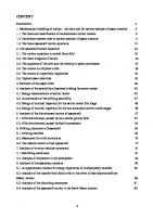
The angle 6 in these equations is positive for current lagging the voltage and negative for leading current. A positive value of p expresses the rate at which energy is being absorbed by the part of the system between the points a and n. The instantaneous power is obviously positive when both van and ian are positive and becomes negative when van and ian are opposite in sign. Figure 1.2 illustrates this point. Positive power calculated as vanian results when current is flowing in the direction of a voltage drop and is the rate of transfer of energy to the load. Conversely, negative power calculated as vanian results when current is flowing in the direction of a voltage rise and means energy is being transferred from the load into the system to which the load is connected. If va„ and ian are in phase, as they are in a purely resistive load, the instantaneous power will never become negative. If the current and voltage are out of phase by 90°, as in a purely inductive or purely capacitive ideal circuit element, the instantaneous
6
CHAPTER 1
BASIC CONCEPTS
FIGURE 12
Current, voltage, and power plotted versus time.
power will have equal positive and negative half cycles and its average value will always be zero. By using trigonometric identities the expression of Eq. (1.8) is reduced to
V r max I x max
V r max I * max
where Emax/max/2 may be replaced by the product of the rms voltage and current, that is, by |J/„| |7a„| or |E| |/|. Another way of looking at the expression for instantaneous power is to consider the component of the current in phase with van and the component 90° out of phase with van. Figure 1.3(a) shows a parallel circuit for which Fig. 1.3(b) is the phasor diagram. The component of ian in phase with van is iR, and from Fig. 1.3(b), IZ^I = |Zfl„|cos0. If the maximum value of ian is Zmax, the maximum value of iR is Zmax cos 6. The instantaneous current iR must be in phase with van. For van = Vmax cos ojt iR = ^max COS 3 COS
(1-10)
max iR
Similarly, the component of ian lagging van by 90° is ix with maximum value
FIGURE 13
(a)
Parallel RL circuit and the corre sponding phasor diagram.
1.4
POWER IN SINGLE-PHASE AC CIRCUITS
7
FIGURE 1.4
Voltage, current in phase with the voltage, and the resulting power plotted versus time.
Zmax sin 6. Since ix must lag van by 90°,
sin 3 sin
ix =
(1.11)
max ix
Then, VanlR = Knax Imax COS 6 COS2 101
V r max -I 1 max
2
cos 0(1 + cos2a)t)
(1-12)
which is the instantaneous power in the resistance and the first term in Eq. (1.9). Figure 1.4 shows vaniR plotted versus t. Similarly, ^an^X
^max Anax
0 Sin (i) t COS COt
Vmax Imax . = ——---- sin 0 sin 2u>r
(113)
which is the instantaneous power in the inductance and the second term in Eq. (1.9). Figure 1.5 shows and their product plotted versus t. Examination of Eq. (1.9) shows that the term containing cos 0 is always positive and has an average value of Vr maxI* max ~ „ P =---------- ------- COS0
(1.14)
or when rms values of voltage and current are substituted, P = I F| |/|cos 0
(1-15)
8
CHAPTER I
BASIC CONCEPTS
FIGURE 1.5
Voltage, current lagging the voltage by 90°. and the resulting power plotted versus time.
P is the quantity to which the word power refers when not modified by an adjective identifying it otherwise. P, the average power, is also called the real or active power. The fundamental unit for both instantaneous and average power is the watt, but a watt is such a small unit in relation to power system quantities that P is usually measured in kilowatts or megawatts. The cosine of the phase angle 6 between the voltage and the current is called the power factor. An inductive circuit is said to have a lagging power factor, and a capacitive circuit is said to have a leading power factor. In other words, the terms lagging power factor and leading power factor indicate, respectively, whether the current is lagging or leading the applied voltage. The second term of Eq. (1.9), the term containing sin 0, is alternately positive and negative and has an average value of zero. This component of the instantaneous power p is called the instantaneous reactive power and expresses the flow of energy' alternately toward the load and away from the load. The maximum value of this pulsating power, designated Q, is called reactive power or reactive voltamperes and is very' useful in describing the operation of a power system, as becomes increasingly evident in further discussion. The reactive power is Vmax 1 max sin 6 2
or
Q = | E| 111 sin 0
(1.16) (1.17)
The square root of the sum of the squares of P and Q is equal to the product of |E| and |/|, for //j2 + Q2 = ]/(I E| |/|cos0)2 + (I E| |/|sin0)2 = |E| \1\
(1.18)
Of course, P and (2 have llic sanie dimensional units, but it is usual to
14
POWER IN SINGLE-PHASE AC C IRCUITS
9
designate the units for Q as ears (for voltamperes reactive), lhe more practical units for Q are kilovars or megavars. In a simpie series circuit where Z is equal to R + jX we can substitute I\ \Z for El in Eqs. (1.15) and (1.17) to obtain
and
P = |/l2|Z|cos 6
(1-19)
Q = |/|2|Z|sin *
(1-20)
Recognizing that R = |Z|cos 6 and X = |Z|sin 0, we then find P = |/|27?
and
Q = \I\2X
(1-21)
Equations (1.15) and (1.17) provide another method of computing the power factor since we see that Q/P = tan 6. The power factor is therefore
cos 6 = cos tan-'1
or from Eqs. (1.15) and (1.18) cos fJ =
P ------- — y/p2 + Q2
If the instantaneous power expressed by Eq. (1.9) is the power in a predominantly capacitive circuit with the same impressed voltage, 6 becomes negative, making sin 8 and Q negative. If capacitive and inductive circuits are in parallel, the instantaneous reactive power for the RL circuit is 180° out of phase with the instantaneous reactive power of the RC circuit. The net reactive power is the difference between Q for the RL circuit and Q for the RC circuit. A positive value is assigned to Q drawn by an inductive load and a negative sign to Q drawn by a capacitive load. Power system engineers usually think of a capacitor as a generator of positive reactive power rather than a load requiring negative reactive power. This concept is very logical, for a capacitor drawing negative Q in parallel with an inductive load reduces the Q which would otherwise have to be supplied by the system to the inductive load. In other words, the capacitor supplies the Q required by the inductive load. This is the same as considering a capacitor as a device that delivers a lagging current rather than as a device which draws a leading current, as shown in Fig. 1.6. An adjustable capacitor in parallel with an inductive load, for instance, can be adjusted so that the leading current to the capacitor is exactly equal in magnitude to the component of current in the inductive load which is lagging the voltage by 90°. Thus, the resultant current is in phase with the voltage. The inductive circuit still requires positive reactive
10
CHAFFER 1
BASIC CONCEPTS
I
*7V J I
FIGURE 1.6
leads
V
by 90°
I lags V
Capacitor considered as: (a) a passive circuit element drawing leading current; (b) a generator supplying lag ging current.
by 90°
(a)
power, but the net reactive power is zero. It is for this reason that the power system engineer finds it convenient to consider the capacitor to be supplying reactive power to the inductive load. When the words positive and negative are not used, positive reactive power is assumed.
1.5
COMPLEX POWER
It the phasor expressions for voltage and current are known, the calculation of real and reactive power is accomplished conveniently in complex form. If the voltage across and the current into a certain load or part of a circuit are expressed by V = | F| /a and I = |Z|/(3, respectively, the product of voltage times the conjugate of current in polar form is FZ* =
x \I\£~jl3 = |k|
= |E| \I\/a - /3
(1.22)
This quantity, called the complex power, is usually designated by S. In rectangu lar form
S = KZ* = |F| |Z|cos(« - Z3) + jin |Z|sin(a - 0)
(1.23)
Since a - (3, the phase angle between voltage and current, is 6 in the previous equations,
5 = P + jQ
(l .24)
Reactive power Q will be positive when the phase angle a — [3 between voltage and current is positive, that is, when a > 0, which means that current is lagging the voltage. Conversely, Q will be negative for (3 > a, which indicates that current is leading the voltage. This agrees with the selection of a positive sign for the reactive power of an inductive circuit and a negative sign for the reactive power of a capacitive circuit. To obtain the proper sign for Q, it is necessary to calculate 5 as LZ* rather than K*Z, which would reverse the sign for Q.
1.6
THE POWER TRIANGLE
Equation (1.24) suggests a graphical method of obtaining the overall P, Q, and phase angle for several loads in parallel since cos 0 is P/ |5|. A power triangle can be drawn for an inductive load, as shown in Fig. 1.7. For several loads in
1.7
DIRECTION OF POWER FLOW
11
FIGURE 1.7
Power triangle for an inductive load.