Organic Materials in Civil Engineering 1905209118, 9781905209118
This book provides an inventory of organic materials and products, the major components of all civil engineering project
382 77 4MB
English Pages 357 Year 2006
Recommend Papers

![Civil Engineering Materials [1 ed.]
1305386647, 9781305386648, 1337400335, 9781337400336](https://ebin.pub/img/200x200/civil-engineering-materials-1nbsped-1305386647-9781305386648-1337400335-9781337400336.jpg)

![Civil Engineering Materials [1 ed.]
0367224828, 9780367224820](https://ebin.pub/img/200x200/civil-engineering-materials-1nbsped-0367224828-9780367224820.jpg)
![Advances in Mechanics of Materials for Environmental and Civil Engineering (Advanced Structured Materials, 197) [1st ed. 2023]
3031371003, 9783031371004](https://ebin.pub/img/200x200/advances-in-mechanics-of-materials-for-environmental-and-civil-engineering-advanced-structured-materials-197-1st-ed-2023-3031371003-9783031371004.jpg)


File loading please wait...
Citation preview
Organic Materials in Civil Engineering
This page intentionally left blank
Organic Materials in Civil Engineering
Yves Mouton
First published in France in 2003 by Hermès Science/Lavoisier entitled “Matériaux organiques pour le génie civil : approche physico-chimique” First published in Great Britain and the United States in 2006 by ISTE Ltd Apart from any fair dealing for the purposes of research or private study, or criticism or review, as permitted under the Copyright, Designs and Patents Act 1988, this publication may only be reproduced, stored or transmitted, in any form or by any means, with the prior permission in writing of the publishers, or in the case of reprographic reproduction in accordance with the terms and licenses issued by the CLA. Enquiries concerning reproduction outside these terms should be sent to the publishers at the undermentioned address: ISTE Ltd 6 Fitzroy Square London W1T 5DX UK
ISTE USA 4308 Patrice Road Newport Beach, CA 92663 USA
www.iste.co.uk © LAVOISIER, 2003 © ISTE Ltd, 2006 The rights of Yves Mouton to be identified as the author of this work has been asserted by them in accordance with the Copyright, Designs and Patents Act 1988. Library of Congress Cataloging-in-Publication Data Mouton, Yves. [Matériaux organiques pour le génie civil. English] Organic materials in civil engineering / Yves Mouton. p. cm. ISBN-13: 978-1-905209-11-8 ISBN-10: 1-905209-11-8 1. Polymers. 2. Organic compounds. 3. Civil engineering--Materials. I. Title. TA455.P58M6813 2006 624.1'8--dc22 2006008665 British Library Cataloguing-in-Publication Data A CIP record for this book is available from the British Library ISBN 10: 1-905209-11-8 ISBN 13: 978-1-905209-11-8 Printed and bound in Great Britain by Antony Rowe Ltd, Chippenham, Wiltshire.
Table of Contents
Introduction. . . . . . . . . . . . . . . . . . . . . . . . . . . . . . . . . . . . . . . . . 15 Chapter 1. Organic Polymers . . . . . . . . . . . . . . . . . . . . . . . . . . . . . . 21 1.1. Definitions . . . . . . . . . . . . . . . . . . . . . . . . . . . . . . . . . . 1.2. Macromolecular structure . . . . . . . . . . . . . . . . . . . . . . . . . 1.3. Synthesis of polymers. . . . . . . . . . . . . . . . . . . . . . . . . . . . 1.3.1. Step polymerization or polycondensation. . . . . . . . . . . . . . 1.3.1.1. Mechanism of polycondensation: polycondensation and polyaddition . . . . . . . . . . . . . . . . . . . . . . . . . . . . . . . 1.3.1.2. Practical applications. . . . . . . . . . . . . . . . . . . . . . . . 1.3.2. Chain polymerization or polymerization strictly speaking . . . . 1.4. Processing: thermoplastics and thermosets . . . . . . . . . . . . . . . 1.4.1. Thermoplastics and thermosets, thermorigid or thermohard. . . 1.4.2. Monocomponent and bicomponent . . . . . . . . . . . . . . . . . 1.5. Elastomers . . . . . . . . . . . . . . . . . . . . . . . . . . . . . . . . . . 1.6. Preliminary conclusions . . . . . . . . . . . . . . . . . . . . . . . . . . 1.7. Crystalline polymers and amorphous polymers: glass transition . . 1.7.1. Notion of crystalline polymer. . . . . . . . . . . . . . . . . . . . . 1.7.2. Amorphous polymers: glass transition . . . . . . . . . . . . . . . 1.8. Mechanical behaviors of polymers: time-temperature equivalence . 1.8.1. Elastic behavior . . . . . . . . . . . . . . . . . . . . . . . . . . . . . 1.8.2. Elasto-plastic behavior. . . . . . . . . . . . . . . . . . . . . . . . . 1.8.3. Rubber-like behavior . . . . . . . . . . . . . . . . . . . . . . . . . . 1.8.4. Case of cross-linked polymers . . . . . . . . . . . . . . . . . . . . 1.8.5. Pure products and formulated products: plasticization . . . . . . 1.8.6. Time-temperature equivalence . . . . . . . . . . . . . . . . . . . .
. . . .
. . . .
. . . .
23 25 26 26
. . . . . . . . . . . . . . . . . .
. . . . . . . . . . . . . . . . . .
. . . . . . . . . . . . . . . . . .
26 27 28 30 30 31 33 35 37 37 38 39 41 41 42 43 47 48
6
Organic Materials in Civil Engineering
1.9. Miscibility of polymers: concept of alloy . . . . . . . . . . . . . . . . . 1.9.1. Notion of solubility parameter . . . . . . . . . . . . . . . . . . . . . 1.9.2. Estimation of the solubility . . . . . . . . . . . . . . . . . . . . . . . 1.9.3. Polymer-polymer mixtures: notion of alloy . . . . . . . . . . . . . 1.10. Durability and aging of polymers: life cycles . . . . . . . . . . . . . . 1.10.1. Notion of aging . . . . . . . . . . . . . . . . . . . . . . . . . . . . . 1.10.2. Principles of the methods for appreciating the life of materials . 1.10.3. Fire behavior of polymers . . . . . . . . . . . . . . . . . . . . . . . 1.10.4. General information on the life cycle of polymers. . . . . . . . . 1.11. Organic materials, the environment and health: evolution of the market. . . . . . . . . . . . . . . . . . . . . . . . . . . . . . . . . . . . . 1.12. Main organic and organo-metallic polymers used in civil engineering. . . . . . . . . . . . . . . . . . . . . . . . . . . . . . . . . . . . . . 1.13. General conclusion. . . . . . . . . . . . . . . . . . . . . . . . . . . . . .
. . . . . . . . .
. . . . . . . . .
51 52 52 54 56 56 58 60 62
. . 64 . . 66 . . 69
Chapter 2. Organic Binders I. Bitumen and Road Construction . . . . . . . . 71 2.1. General terminology . . . . . . . . . . . . . . . . . . . . . . . . . . . . 2.2. Manufacture of bitumen . . . . . . . . . . . . . . . . . . . . . . . . . . 2.3. Physico-chemical composition of bitumens . . . . . . . . . . . . . . . 2.4. Various forms of bitumen . . . . . . . . . . . . . . . . . . . . . . . . . 2.4.1. Paving bitumens: characterization and classification . . . . . . . 2.4.2. Fluid binders. . . . . . . . . . . . . . . . . . . . . . . . . . . . . . . 2.4.3. Bitumen emulsions . . . . . . . . . . . . . . . . . . . . . . . . . . . 2.4.3.1. Formation of an emulsion . . . . . . . . . . . . . . . . . . . . . 2.4.3.2. Failure of emulsions . . . . . . . . . . . . . . . . . . . . . . . . 2.4.3.3. Characterization of emulsions: applications. . . . . . . . . . . 2.5. Usage properties of paving bitumen . . . . . . . . . . . . . . . . . . . 2.6. Adhesiveness . . . . . . . . . . . . . . . . . . . . . . . . . . . . . . . . . 2.7. Rheological properties . . . . . . . . . . . . . . . . . . . . . . . . . . . 2.7.1. Viscosity . . . . . . . . . . . . . . . . . . . . . . . . . . . . . . . . . 2.7.2. Viscoelasticity. . . . . . . . . . . . . . . . . . . . . . . . . . . . . . 2.7.3. Complex modulus . . . . . . . . . . . . . . . . . . . . . . . . . . . 2.7.4. Towards a rheological classification. . . . . . . . . . . . . . . . . 2.7.5. The SHRP program – Test methods and specifications of road binders . . . . . . . . . . . . . . . . . . . . . . . . . . . . . . . . . . . . . . 2.7.6. Bending beam creep or BBR test. . . . . . . . . . . . . . . . . . . 2.8. Aging of bitumen . . . . . . . . . . . . . . . . . . . . . . . . . . . . . . 2.9. Limits in the use of bitumen: quest for an ideal binder . . . . . . . .
. . . . . . . . . . . . . . . . .
. . . . . . . . . . . . . . . . .
. . . . . . . . . . . . . . . . .
74 76 78 82 82 83 84 85 86 87 87 88 92 92 93 95 96
. . . .
. . . .
. . . .
100 101 104 108
Table of Contents
2.10. Modified bitumens, bitumens with additives and special bitumens 2.10.1. Physico-chemical characterization of polymer modified bitumens . . . . . . . . . . . . . . . . . . . . . . . . . . . . . . . . . . . . . 2.10.2. Practical applications . . . . . . . . . . . . . . . . . . . . . . . . . 2.10.3. Bitumens with additives . . . . . . . . . . . . . . . . . . . . . . . 2.10.4. Special paving bitumens . . . . . . . . . . . . . . . . . . . . . . . 2.11. Regeneration binders . . . . . . . . . . . . . . . . . . . . . . . . . . . 2.12. Other uses of bitumen in civil engineering. . . . . . . . . . . . . . . 2.13. General conclusion. . . . . . . . . . . . . . . . . . . . . . . . . . . . .
7
. . . 109 . . . . . . .
. . . . . . .
. . . . . . .
113 114 116 116 117 117 118
Chapter 3. Organic Binders II. Materials for the Conservation of Heritage and Safety . . . . . . . . . . . . . . . . . . . . . . . . . . . . . . . . . . . . . . . . . . 119 3.1. Concrete repair and protection products . . . . . . . . . . . . . . . . . . . 3.1.1. Products and systems for the protection and repair of concrete structures: normative definitions. . . . . . . . . . . . . . . . . . . . . . . . . 3.1.2. Physicochemical classification of repair and protection products . 3.1.3. Products based on reactive organic binders: general introduction. . 3.1.3.1. Epoxy resins . . . . . . . . . . . . . . . . . . . . . . . . . . . . . . . 3.1.3.2. Polyurethanes . . . . . . . . . . . . . . . . . . . . . . . . . . . . . . 3.1.3.3. Unsaturated polyesters and derivatives . . . . . . . . . . . . . . . 3.1.3.4. Methacrylic resins . . . . . . . . . . . . . . . . . . . . . . . . . . . 3.1.3.5. Other acrylic derivatives. . . . . . . . . . . . . . . . . . . . . . . . 3.1.4. Repair produces based on reactive organic binders: usages and required characteristics . . . . . . . . . . . . . . . . . . . . . . . . . . . . 3.1.4.1. Surface repair products . . . . . . . . . . . . . . . . . . . . . . . . 3.1.4.2. Structural bonding and structure reinforcement products . . . . 3.1.4.3. Injection products. . . . . . . . . . . . . . . . . . . . . . . . . . . . 3.1.4.4. Anchoring or sealing or wedging products . . . . . . . . . . . . . 3.1.4.5. Required characteristics . . . . . . . . . . . . . . . . . . . . . . . . 3.1.5. Concrete protection products and systems . . . . . . . . . . . . . . . 3.1.5.1. Corrosion inhibitors . . . . . . . . . . . . . . . . . . . . . . . . . . 3.1.5.2. Impregnation products . . . . . . . . . . . . . . . . . . . . . . . . . 3.1.5.3. Paints and derivatives . . . . . . . . . . . . . . . . . . . . . . . . . 3.1.5.4. Required characteristics . . . . . . . . . . . . . . . . . . . . . . . . 3.1.6. Mixed matrix products (modified binder) . . . . . . . . . . . . . . .
. 119 . . . . . . . .
122 123 124 125 128 131 136 137
. . . . . . . . . . . .
137 138 138 139 141 141 143 144 144 145 145 147
8
Organic Materials in Civil Engineering
3.2. Paints for civil engineering. . . . . . . . . . . . . . . . . . . . . 3.2.1. General definitions . . . . . . . . . . . . . . . . . . . . . . . 3.2.1.1. Constituents of paints . . . . . . . . . . . . . . . . . . . 3.2.1.2. Paint drying modes . . . . . . . . . . . . . . . . . . . . . 3.2.1.3. Characteristics of the dry film . . . . . . . . . . . . . . 3.2.1.4. Paint systems . . . . . . . . . . . . . . . . . . . . . . . . 3.2.2. Anticorrosion paints for metal structures . . . . . . . . . . 3.2.2.1. Corrosion. . . . . . . . . . . . . . . . . . . . . . . . . . . 3.2.2.2. Anticorrosion protection processes . . . . . . . . . . . 3.2.2.3. Anticorrosion paints . . . . . . . . . . . . . . . . . . . . 3.2.2.4. Criteria for the choice of the protection paint system . 3.2.2.5. Surface preparation . . . . . . . . . . . . . . . . . . . . . 3.2.2.6. Main protection coatings . . . . . . . . . . . . . . . . . 3.2.3. Paints for concrete . . . . . . . . . . . . . . . . . . . . . . . 3.2.4. Road marking paints and products . . . . . . . . . . . . . . 3.2.4.1. Road marking . . . . . . . . . . . . . . . . . . . . . . . . 3.2.4.2. Retroreflection . . . . . . . . . . . . . . . . . . . . . . . 3.2.4.3. Choice of the products . . . . . . . . . . . . . . . . . . . 3.2.4.4. Main products available . . . . . . . . . . . . . . . . . . 3.3. Conclusions. . . . . . . . . . . . . . . . . . . . . . . . . . . . . .
. . . . . . . . . . . . . . . . . . . .
. . . . . . . . . . . . . . . . . . . .
. . . . . . . . . . . . . . . . . . . .
. . . . . . . . . . . . . . . . . . . .
. . . . . . . . . . . . . . . . . . . .
. . . . . . . . . . . . . . . . . . . .
. . . . . . . . . . . . . . . . . . . .
148 148 148 150 150 152 153 153 154 155 155 158 158 159 161 161 162 164 164 165
Chapter 4. Manufactured Products . . . . . . . . . . . . . . . . . . . . . . . . . . 167 4.1. Organic materials and the waterproofing of structures . . . . . . . . . . 4.1.1. Materials, products and systems for waterproofing the decks of civil engineering structures . . . . . . . . . . . . . . . . . . . . . . 4.1.1.1. Asphalt materials . . . . . . . . . . . . . . . . . . . . . . . . . . . . 4.1.1.2. Thin films bonding with the support (FMBS) . . . . . . . . . . . 4.1.1.3. Monolayer prefabricated membranes (MPM) . . . . . . . . . . . 4.1.1.4. Waterproofing products processed at high production rate with roadworks equipment (HPRE) . . . . . . . . . . . . . . . . . . . . . . . . . 4.1.1.5. Comparison of traditional types of products . . . . . . . . . . . . 4.1.2. Waterproofing materials, products and systems for underground structures. . . . . . . . . . . . . . . . . . . . . . . . . . . . . . . . . . . . . . . 4.1.2.1. Design of the waterproofing system . . . . . . . . . . . . . . . . . 4.1.2.2. Intrados waterproofing systems . . . . . . . . . . . . . . . . . . . 4.1.2.3. Extrados waterproofing systems . . . . . . . . . . . . . . . . . . . 4.1.2.4. Main products used (extrados waterproofing) . . . . . . . . . . .
. 168 . . . .
168 171 173 174
. 175 . 176 . . . . .
178 179 180 180 182
Table of Contents
4.1.3. Waterproofing materials, products and systems for surface structures: statement of the problem. . . . . . . . . . . . . . . . . . . . 4.2. Geosynthetics . . . . . . . . . . . . . . . . . . . . . . . . . . . . . . . 4.2.1. Geosynthetic materials for waterproofing: geomembranes and geosynthetic bentonite materials . . . . . . . . . . . . . . . . . . . 4.2.1.1. Geomembranes . . . . . . . . . . . . . . . . . . . . . . . . . . 4.2.1.2. Bentonite geosynthetics (BGS). . . . . . . . . . . . . . . . . 4.2.2. Geotextiles and related products . . . . . . . . . . . . . . . . . . 4.2.2.1. Functions provided . . . . . . . . . . . . . . . . . . . . . . . . 4.2.2.2. Constitutive materials . . . . . . . . . . . . . . . . . . . . . . 4.2.2.3. Assembling modes . . . . . . . . . . . . . . . . . . . . . . . . 4.2.2.4. Durability of geotextiles . . . . . . . . . . . . . . . . . . . . . 4.2.3. Waterproofing materials, products and systems for surface structures: different uses . . . . . . . . . . . . . . . . . . . . . . . . . . 4.2.3.1. Hydraulic structures strictly speaking . . . . . . . . . . . . . 4.2.3.2. Structures for road surface water. . . . . . . . . . . . . . . . 4.2.3.3. Lagooning ponds . . . . . . . . . . . . . . . . . . . . . . . . . 4.2.3.4. Tanks and reservoirs for chemicals . . . . . . . . . . . . . . 4.2.3.5. Structures for the containment of wastes . . . . . . . . . . . 4.2.3.6. Conclusions on geomembranes: installation and durability 4.3. Products for light geotechnical structures . . . . . . . . . . . . . . . 4.3.1. Expanded polystyrene (EPS) embankments . . . . . . . . . . . 4.3.2. Ultra-light cellular structures (ULCS). . . . . . . . . . . . . . . 4.3.3. Structures based on recovered tires . . . . . . . . . . . . . . . . 4.4. Other uses of synthetic organic materials in civil engineering . . . 4.4.1. Bearings of civil engineering structures. . . . . . . . . . . . . . 4.4.2. Products for joints . . . . . . . . . . . . . . . . . . . . . . . . . . 4.4.3. Warning devices for buried systems . . . . . . . . . . . . . . . . 4.5. Industrial wood used in civil engineering . . . . . . . . . . . . . . . 4.5.1. The wood material . . . . . . . . . . . . . . . . . . . . . . . . . . 4.5.2. Moisture sensitivity of wood . . . . . . . . . . . . . . . . . . . . 4.5.3. Durability of the wood . . . . . . . . . . . . . . . . . . . . . . . . 4.5.4. Fire behavior. . . . . . . . . . . . . . . . . . . . . . . . . . . . . . 4.5.5. Industrial wood . . . . . . . . . . . . . . . . . . . . . . . . . . . . 4.6. Conclusion . . . . . . . . . . . . . . . . . . . . . . . . . . . . . . . . .
9
. . . . 182 . . . . 183 . . . . . . . .
. . . . . . . .
. . . . . . . .
. . . . . . . .
186 186 187 187 187 188 189 189
. . . . . . . . . . . . . . . . . . . . . .
. . . . . . . . . . . . . . . . . . . . . .
. . . . . . . . . . . . . . . . . . . . . .
. . . . . . . . . . . . . . . . . . . . . .
189 190 191 193 193 194 195 199 199 201 203 204 204 206 207 208 209 210 211 211 211 212
10
Organic Materials in Civil Engineering
Chapter 5. Gluing and Composite Materials: Concrete Admixtures . . . . . 215 5.1. Gluing and its potential applications in civil engineering . . . . . . 5.1.1. Gluing: a future technique in civil engineering? . . . . . . . . . 5.1.2. Definitions, reference points . . . . . . . . . . . . . . . . . . . . 5.1.3. Adhesion and gluing: theoretical notions . . . . . . . . . . . . . 5.1.3.1. Theories of adhesion: physico-chemical approach . . . . . 5.1.3.2. Theories of adhesion: thermodynamic approach . . . . . . 5.1.3.3. Kinetic aspect of adhesion. . . . . . . . . . . . . . . . . . . . 5.1.3.4. Practical conclusions . . . . . . . . . . . . . . . . . . . . . . . 5.1.4. Surface treatment . . . . . . . . . . . . . . . . . . . . . . . . . . . 5.1.5. Implementation: importance of “in situ cross-linking time” . . 5.1.6. Principle adhesives used in civil engineering: notion of reversibility . . . . . . . . . . . . . . . . . . . . . . . . . . . . . . . . . . 5.2. Organic matrix composite materials . . . . . . . . . . . . . . . . . . 5.2.1. Constituents . . . . . . . . . . . . . . . . . . . . . . . . . . . . . . 5.2.2. General principles . . . . . . . . . . . . . . . . . . . . . . . . . . 5.2.3. Basic material used . . . . . . . . . . . . . . . . . . . . . . . . . . 5.2.3.1. Strengthening agents . . . . . . . . . . . . . . . . . . . . . . . 5.2.3.2. Conditioning of strengthening agents . . . . . . . . . . . . . 5.2.3.3. Matrices . . . . . . . . . . . . . . . . . . . . . . . . . . . . . . 5.2.4. Organic matrix composites and civil engineering . . . . . . . . 5.2.4.1. Repair and strengthening of structures . . . . . . . . . . . . 5.2.4.2. Prevention of seismic risks . . . . . . . . . . . . . . . . . . . 5.2.4.3. Cables, stays, anchoring systems. . . . . . . . . . . . . . . . 5.3. Concrete admixtures . . . . . . . . . . . . . . . . . . . . . . . . . . . 5.3.1. The introduction of admixtures in concrete technology. . . . . 5.3.2. Rheological admixtures . . . . . . . . . . . . . . . . . . . . . . . 5.3.2.1. Plasticizers and their growth: mode of action . . . . . . . . 5.3.2.2. Perspectives . . . . . . . . . . . . . . . . . . . . . . . . . . . . 5.3.3. Other classes of admixture reacting on the rheology of fresh concrete . . . . . . . . . . . . . . . . . . . . . . . . . . . . . . . . . . . . 5.3.3.1. Set retarders . . . . . . . . . . . . . . . . . . . . . . . . . . . . 5.3.3.2. Water retaining agent . . . . . . . . . . . . . . . . . . . . . . 5.3.4. Other admixtures and connected products organic in nature . 5.3.4.1. Water resisting admixtures . . . . . . . . . . . . . . . . . . . 5.3.4.2. Air entraining agents . . . . . . . . . . . . . . . . . . . . . . . 5.3.4.3. Curing compounds . . . . . . . . . . . . . . . . . . . . . . . . 5.3.4.4. Organic fibers . . . . . . . . . . . . . . . . . . . . . . . . . . . 5.4. General conclusions . . . . . . . . . . . . . . . . . . . . . . . . . . . .
. . . . . . . . . .
. . . . . . . . . .
. . . . . . . . . .
. . . . . . . . . .
216 216 220 222 223 227 233 237 238 239
. . . . . . . . . . . . . . . . .
. . . . . . . . . . . . . . . . .
. . . . . . . . . . . . . . . . .
. . . . . . . . . . . . . . . . .
241 242 242 243 243 243 245 245 246 247 248 248 248 251 253 254 259
. . . . . . . . .
. . . . . . . . .
. . . . . . . . .
. . . . . . . . .
260 260 260 261 261 261 263 264 264
Table of Contents
11
Chapter 6. Physico-Chemical Characterization of Organic Materials Used in Construction . . . . . . . . . . . . . . . . . . . . . . . . . . . . . . . . . . . 267 6.1. Chemical analysis of formulated products. . . . . . . . . . . . 6.2. Infrared spectrometry . . . . . . . . . . . . . . . . . . . . . . . . 6.2.1. Principle of the method . . . . . . . . . . . . . . . . . . . . 6.2.2. Case of ATR: theoretical considerations. . . . . . . . . . . 6.2.3. Utilization and limits of infrared spectroscopy . . . . . . 6.3. Methods of fractionation . . . . . . . . . . . . . . . . . . . . . . 6.3.1. Fractionation of complex mixtures. . . . . . . . . . . . . . 6.3.1.1. Separation of phases . . . . . . . . . . . . . . . . . . . . 6.3.1.2. Distillation . . . . . . . . . . . . . . . . . . . . . . . . . . 6.3.1.3. Solvent extraction. . . . . . . . . . . . . . . . . . . . . . 6.3.2. Chromatographic methods . . . . . . . . . . . . . . . . . . 6.3.2.1. Column chromatography . . . . . . . . . . . . . . . . . 6.3.2.2. Other types of chromatography. . . . . . . . . . . . . . 6.4. Thermal methods . . . . . . . . . . . . . . . . . . . . . . . . . . 6.5. Quantitative analysis and functional assays. . . . . . . . . . . 6.6. General diagram for in-depth analysis of complex mixtures . 6.7. Conclusions. . . . . . . . . . . . . . . . . . . . . . . . . . . . . .
. . . . . . . . . . . . . . . . .
. . . . . . . . . . . . . . . . .
. . . . . . . . . . . . . . . . .
. . . . . . . . . . . . . . . . .
. . . . . . . . . . . . . . . . .
. . . . . . . . . . . . . . . . .
. . . . . . . . . . . . . . . . .
268 269 269 273 275 277 277 278 278 279 280 280 285 286 288 290 291
Chapter 7. Organic Materials, Civil Engineering and Sustainable Development Prospective Thoughts from Experts . . . . . . . . . . . . . . . . . 293 7.1. Economic reality of synthetic materials in civil engineering 7.1.1. Preface . . . . . . . . . . . . . . . . . . . . . . . . . . . . . . 7.1.2. Positioning of the plastics: some figures . . . . . . . . . . 7.1.2.1. PVC windows . . . . . . . . . . . . . . . . . . . . . . . . 7.1.2.2. Protective sheaths for optical cable networks . . . . . 7.1.3. Civil engineering: a place in the construction market. . . 7.1.4. Incorporated or built-in materials . . . . . . . . . . . . . . 7.1.5. Bitumen-polymers . . . . . . . . . . . . . . . . . . . . . . . 7.1.6. Coatings . . . . . . . . . . . . . . . . . . . . . . . . . . . . . 7.1.6.1. Protection of stays and tension cables of bridges . . . 7.1.6.2. Sealing by geomembranes. . . . . . . . . . . . . . . . . 7.1.6.3. The “coil coating” market . . . . . . . . . . . . . . . . . 7.1.6.4. Tubes and pipes . . . . . . . . . . . . . . . . . . . . . . . 7.1.6.5. Noise screens . . . . . . . . . . . . . . . . . . . . . . . . 7.1.6.6. Composites . . . . . . . . . . . . . . . . . . . . . . . . . 7.1.7. Conclusion . . . . . . . . . . . . . . . . . . . . . . . . . . . .
. . . . . . . . . . . . . . . .
. . . . . . . . . . . . . . . .
. . . . . . . . . . . . . . . .
. . . . . . . . . . . . . . . .
. . . . . . . . . . . . . . . .
. . . . . . . . . . . . . . . .
. . . . . . . . . . . . . . . .
293 293 294 294 295 296 296 298 299 300 300 301 301 301 302 303
12
Organic Materials in Civil Engineering
7.2. Bitumens in civil engineering: their place and their future . . . . . . . 7.2.1. Introduction . . . . . . . . . . . . . . . . . . . . . . . . . . . . . . . . 7.2.2. Bitumens in waterproofing and ancillary industries. . . . . . . . . 7.2.2.1. Waterproofing . . . . . . . . . . . . . . . . . . . . . . . . . . . . . 7.2.2.2. Ancillary industries. . . . . . . . . . . . . . . . . . . . . . . . . . 7.2.3. Bitumens in road construction and maintenance. . . . . . . . . . . 7.2.3.1. Asphalts . . . . . . . . . . . . . . . . . . . . . . . . . . . . . . . . 7.2.3.2. Surface dressing. . . . . . . . . . . . . . . . . . . . . . . . . . . . 7.2.3.3. Cold mixes . . . . . . . . . . . . . . . . . . . . . . . . . . . . . . . 7.2.4. Conclusion . . . . . . . . . . . . . . . . . . . . . . . . . . . . . . . . . 7.3. Organic polymers in building: development and tendencies . . . . . . 7.3.1. Current usage tendencies . . . . . . . . . . . . . . . . . . . . . . . . 7.3.2. The polymers of tomorrow? . . . . . . . . . . . . . . . . . . . . . . 7.4. Importance of a physico-chemical approach in the behavior of the materials – with damage as an example . . . . . . . . . . . . . . . . . 7.4.1. Introduction . . . . . . . . . . . . . . . . . . . . . . . . . . . . . . . . 7.4.2. Problem overview . . . . . . . . . . . . . . . . . . . . . . . . . . . . 7.4.3. Application in case of a damagable elastic material . . . . . . . . 7.4.4. Case of organic polymers . . . . . . . . . . . . . . . . . . . . . . . . 7.5. Organic chemistry and molecular engineering: the future of cementing materials? . . . . . . . . . . . . . . . . . . . . . . . . . . . . . . . . 7.5.1. Mastering complexity . . . . . . . . . . . . . . . . . . . . . . . . . . 7.5.2. Using hybrids . . . . . . . . . . . . . . . . . . . . . . . . . . . . . . . 7.5.3. Molding and molecular imprints . . . . . . . . . . . . . . . . . . . . 7.5.4. Towards a green and intelligent concrete . . . . . . . . . . . . . . . 7.6. Synthetic organic materials and architecture . . . . . . . . . . . . . . . 7.6.1. Contrasting relationship during the 20th century . . . . . . . . . . . 7.6.2. A harmony in the making . . . . . . . . . . . . . . . . . . . . . . . . 7.6.3. A necessary partnership between architects and industrialists. . . 7.6.4. Organic materials at the core of the mega-technological choices in architecture . . . . . . . . . . . . . . . . . . . . . . . . . . . . . . . . . . . 7.7. Assessment of environmental impact of organic materials . . . . . . . 7.7.1. Problem overview and available tools. . . . . . . . . . . . . . . . . 7.7.2. Perspectives for organic materials used in civil engineering . . . 7.7.3. Conclusion . . . . . . . . . . . . . . . . . . . . . . . . . . . . . . . . . 7.7.4. Useful standards . . . . . . . . . . . . . . . . . . . . . . . . . . . . .
. . . . . . . . . . . . .
. . . . . . . . . . . . .
303 303 304 304 305 306 306 308 308 309 309 311 312
. . . . .
. . . . .
313 313 313 315 319
. . . . . . . . .
. . . . . . . . .
320 320 321 322 322 323 323 324 325
. . . . . .
. . . . . .
326 327 327 330 332 332
Table of Contents
7.8. Assessment of health hazards of organic materials. . . . . . . 7.8.1. General problem and definitions . . . . . . . . . . . . . . . 7.8.2. Health hazards of organic materials in civil engineering. 7.8.3. Methodology for assessment of health hazards . . . . . . 7.8.4. As a conclusion: why assess health hazards?. . . . . . . .
. . . . .
. . . . .
. . . . .
. . . . .
. . . . .
. . . . .
. . . . .
13
333 333 335 337 338
Bibliography . . . . . . . . . . . . . . . . . . . . . . . . . . . . . . . . . . . . . . . . 341
Abbreviations . . . . . . . . . . . . . . . . . . . . . . . . . . . . . . . . . . . . . . . . 351
Index . . . . . . . . . . . . . . . . . . . . . . . . . . . . . . . . . . . . . . . . . . . . . 353
This page intentionally left blank
Introduction
In the field of construction and particularly in civil engineering, organic materials are essentially perceived as bonding additives. Whether we are talking about bitumens for road surfacing, polymers for formulating products for repair and structural gluing or admixtures for a more compact concrete, all these products are intended for realizations where we want to ensure the cohesion of granular groups. This is in fact the primary role assigned to this class of materials, but we must not forget that there are other fields where plastic materials have been developed successfully, particularly sealing, environmental protection and engineering geology in general. Here, we enter into the field of manufactured products where the term “organic material” takes on its fullest meaning. We may also note in passing that industrial wood, the discovery of which is of course not recent, but whose industrial development is changing rapidly, falls under this second category. The presentation of organic materials used in civil engineering therefore compels us to study these two aspects in depth. As such, we will deal with these in the first few chapters, but we will not place our main focus on them, as our study is based on a physico-chemical approach, as suggested by the subtitle of this book. This point calls for a few explanations. In a construction project, the designer expects from the materials that he intends to use a set of properties, in particular: − mechanical properties, such as a certain compressive strength for the realization of a load-bearing unit, bending strength and therefore tensile strength for a structure that must present a certain flexibility, resistance to impact or other types of aggressions; − physical properties, if necessary, with respect to water or gas-tightness; sound insulation, for instance;
16
Organic Materials in Civil Engineering
− aesthetic or more generally sensorial properties, in order to better meet the aspirations of the project owner and future owners; − practical properties, as regards their handling or their use in general. All this is part of the art of the engineer and the architect, but also implies requirements in terms of the minimal durability of all the above properties as well as in terms of the waste management at the end-of-life of the materials used. These two aspects deserve particular attention insofar as they are today as important as the requirements in terms of mechanical strength. Man in the 21st century must know that he is not building for eternity and that his project must take into account the service life that he requires from the builder. It follows logically that he is compelled to comply with, willy-nilly, health and environmental requirements imposed on him to preserve the living environment of the community. The durability of a material structure brings into play the nature of the materials that constitute it, the manner in which they are arranged with respect to each other, the manner in which they are assembled, and their potential evolution within the structure, without forgetting the conditions under which they are placed. We thus enter the physico-chemical field: the evolution of a material under static or dynamic stress depends on its structure and its composition. The knowledge of these data and the laws that govern them is fundamental for anyone interested in the durability of structures and buildings. In some cases, this can even be a decisive criterion in the choice of materials. We must therefore never neglect the physico-chemical aspect in all the operations that involve materials. Even in cases where it might not seem useful to us, it is a precaution that can prove invaluable in responding efficiently in the event of an unfortunate development. Conversely, it would be stupid to think that the chemical analysis of a material, however meticulous, can suffice to inform the user of its capacity to meet a given need. We must remember that a material is never perfectly homogeneous. A specimen is representative only from a sample that is macroscopically homogenous and correctly fractioned or that is limited to a given geometric area. The role often reserved for analysis (in its widest sense, i.e., without forgetting the physical state, texture, etc.) is therefore relative: when two samples are subjected to similar physico-chemical analyses, we can affirm that the materials that represent them have a good chance of having the same behavior in service. This evidently calls into question the representativeness of the sampling, as we have just explained, but also the degree of sophistication of the analysis itself. Besides, this very simple reasoning is used in the certification procedures of some products.
Introduction
17
Lastly, we must mention that all organic materials are not polymers. We will see that bitumens are not polymers and that wood is a complex system in which polymers play a role, but is not a polymer in itself. However, the basic knowledge that will be presented about pure polymers will be useful to better understand these two complex materials. The book is therefore structured as below: – Chapter 1, Organic Polymers, is devoted to a general presentation of these physico-chemical entities, from the macromolecular structure of the pure material to the properties of formulated or manufactured products and their durability; the concepts developed here will help us understand all organic materials which are strictly speaking always mixtures. – Chapters 2 and 3, Organic Binders, are devoted to the “bonding additive” aspect of organic materials mentioned above. They contain three developments on bitumens and road construction (Chapter 2), products for repairing and protecting concrete and paints (anti-corrosion, on concrete and for road marking) – materials for the maintenance of heritage and safety (Chapter 3). – Chapter 4, Manufactured Products, deals primarily with sealing products and systems, the concept of material becoming less clear-cut when there are several elements to perform the required function, then with geosynthetics in general, with geotextiles and geomembranes, with materials and systems for the realization of light fills, tank structures, with devices for supporting works of art, with warning devices for buried networks, etc. In these three chapters, which illustrate the development of organic materials in the field of civil engineering, we will encounter unresolved issues and new notions that require a particular study. Besides, any physico-chemical approach is accompanied by methods for characterizing the matter that is the object of our study. The chemist would like to know on what he is working to be able to reason efficiently, which justifies the organization of the following two chapters. – Chapter 5, Gluing and Composite Materials: Concrete Admixtures, seeks to study in depth two aspects of the role of bonding additives of organic materials. First, we will discuss gluing already mentioned regarding organic binders and particularly the adhesiveness of bitumens. This will lead us logically to a quick overview of organic-matrix composite materials, which have appeared relatively recently in civil engineering. Second, we will present concrete admixtures and related products that can be considered as third degree materials insofar as they do not intervene directly as first degree materials – manufactured products – or second degree materials – binders – but are indispensable to realizing high performance products and structures and are the prototypes for the materials of tomorrow.
18
Organic Materials in Civil Engineering
– Chapter 6, Physico-Chemical Characterization of Organic Materials Used in Construction, is a summary of the methods most commonly used in civil engineering laboratories to characterize these materials. – Chapter 7 concludes the book by enlarging the reader’s field of vision, primarily by coming out of the physico-chemical approach that has been our vantage point so far, thanks to the contribution of external personalities – engineers, researchers, architects, physicians – who have given us their prospective reflections on the theme of organic materials, civil engineering and sustainable development. The first question dealt with is economic in nature: what is the importance of organic materials in civil engineering when compared to other classes of materials? Michel de Longcamp, building and public works delegate of the Société ATOFINA and President of the Commission of the Bâtiment du syndicat des producteurs de matières plastiques (SPMP), gives us precise insights to elucidate the discussion. We have seen that bitumen, an organic material in its own right, is not part of polymers. Bernard Lombardi, director of the Groupement professionnel des bitumes (GPB), completes the above point in the field of road construction and opens new avenues for reflection on the evolution of this atypical material. Separating the field of civil engineering from building could seem artificial to the reader familiar with the complementary nature these fields of activity. Robert Copé, Assistant Director of Research and Development at the Centre scientifique et technique du bâtiment (CSTB), seeks not to deal with the vast subject of the place of organic materials in building, but to highlight the main trends in this field, particularly those where significant progress has been made or should be made to meet the expectations of clients. After these technico-economic perspectives, it seemed important to us to make a leap forward into the future with the viewpoint of a scientific researcher. For this, we have had two contributions, one on method and the other on the design of new materials. Regarding method, Michel Frémond, European Coordinator of the Laboratoire Lagrange and Olivier Maisonneuve, Director of the Mechanics and Civil Engineering Laboratory of the University of Montpellier, affirm the importance of the physico-chemical approach for a mechanical engineer in the study of damage phenomena.
Introduction
19
Henri Van Damme, Director of the Structural and Macromolecular Physicochemistry Laboratory at the Ecole supérieure de physique et chimie industrielles of Paris (ESPCI), gives a glimpse into the birth of new structures at the nanoscopic level thanks to the use of organic molecules in cement matrices. Mineral-organic complementarity paves a new way here and prefigures a line of materials of the future. But the act of building will not be really complete if we do not consider the link between technique and society’s viewpoint on the realized construction, from its gestation to its delivery. For this, three players are indispensable: the architect of course, but also the environmentalist and the physician. Michel Paulin, Professor at the Ecole nationale supérieure d’architecture de Lyon (ENSAL) and at the Grands Ateliers de l’Isle d’Abeau, brings to us the architect’s perspective and illustrates the omnipresence, often ignored by the public, of organic materials in our everyday environment. He insists on the need to enhance their image in the collective unconscious through an in-depth action that is a challenge for both producers and clients. Among the obstacles identified above, we can note that organic materials are still a source of concern for the defenders of the environment and health. In an effort to sort the real problems from those that are born out of fantasies, we have asked two specialists to give us their insights. Yves Perrodin, Director of the Environmental Science Laboratory of the Ecole nationale des travaux publics de l’état (ENTPE), observing that the evaluation of the environmental impact of organic materials used in the field of construction is still in its initial stages, proposes a methodology applicable to these materials, based on his experience gained with the other types of materials. Guy Auburtin, epidemiologist, Director of the Institut d’hygiène industrielle et de l’environnement (Cnam – IHIE – Ouest), insists particularly on the necessity for all players to develop studies on the risks specific to these materials, for the health of workers involved in construction as well as that of residents and users. These last two contributions open the horizon for new research. Henceforth, the study of materials will no longer be the business of the technicians of physics and chemistry, but must also take into account the contributions of biologists and physicians. Consequently, these specialists must also play a role in the general approach. This is a long-term effort.
This page intentionally left blank
Chapter 1 1 Organic
Polymers
Organic polymers belong to a family of materials whose industrial development is very recent. It is believed that the first synthetic “plastic material” was developed in 1862 by the English chemist Parkes by mixing sulfuric acid and nitric acid with cotton wool. The nitrocellulose thus obtained was stabilized with castor oil and camphor, and dyes were added and various objects were produced using this mixture. However, for production on an industrial scale, this formula had to be modified slightly and “Parkesine” was forgotten, to be replaced by “celluloid”, developed by the American Hyatt brothers. It is believed that they developed this product in 1869 for a competition organized by New York City to discover a substitute material for ivory in the manufacture of billiard balls. The same scenario repeated with the other pioneers of plastics: “Bakelite”, patented in 1909, was in fact a laboratory discovery of the 1870s; “Plexiglass”, the first organic glass, was synthesized in 1877 but it would be developed only in the 20th century. Concurrent to this flowering of discoveries, which was occasionally fortuitous but always the achievement of brilliant chemists, there was a need for a comprehensive reflection on the structure of these materials. Thus was born macromolecular chemistry. Among the pioneers who marked the development of scientific studies on organic polymers, we must mention Staudinger, whose research dates back to the 1920s. He was one of the first to introduce the concept of macromolecule and his team’s research won the Nobel Prize for chemistry in 1953. In France, we can cite G. Champetier, who marked several generations of physicists and chemists with his passion for macromolecular chemistry [CHA 69, CHA 72, AUB 74].
22
Organic Materials in Civil Engineering
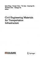
The main polymers were discovered before 1940 (“nylon” was commercialized in the United States in the beginning of the year 1940) but during this period their economic potential was not yet understood. It was only in 1945 that the annual production crossed the million ton mark. Since then, the development of polymers has literally exploded with a growth rate of 10 to 15% per year, in other words, practically doubling production every 5 years. Currently, it exceeds 130 Mt/year and there is a good correlation between a country’s GNP and its consumption of polymers. And in terms of volumes, the production of organic polymers currently surpasses the production of metals. A number of fields have gradually infiltrated into the construction of organic polymers, both as construction materials strictly speaking as well as substances incorporated into the cement matrices, such as products for repairing or reinforcing structures or materials for protecting and finishing structures. A recent European colloquium [ORG 02] has confirmed that organic materials, i.e. essentially polymers and bitumens, have a promising future in the field of civil engineering. This conclusion holds all the more true for the entire building industry, in which the applications of these products are even more numerous than in civil engineering. It is therefore interesting to examine the specific character of organic polymers, and why they are regarded as a distinct group of materials, just as metals form a specific class. The answer to these questions calls for a rather complex study – and this is the subject of this first chapter – but can be illustrated, to begin with, using a diagram on the behavior of organic polymers when subjected to an external load that is on the whole viscoelastic (Figure 1.1).
Stiffness HF load
LF load
Temperature Figure 1.1. General behavior of organic polymers
Organic Polymers
23
Organic polymer-based materials react differently to a mechanical load depending on load time (or frequency) and temperature. Thus, for a static load, the material already exhibits two types of behavior in the solid state, depending on whether they are above or below the temperature at which the above curve undergoes a rapid decrease. This temperature is called glass transition (Tg). This change in behavior in the solid state is specific to viscoelastic bodies to which organic polymers belong (and assimilated like silicones, which are strictly organometallic polymers). It forms the originality of these materials, which we will now present from a physico-chemical perspective [DOR 86, GFP 80, KUR 87, MER 93, OFT 95].
1.1. Definitions A polymer is a substance composed of macromolecules whose structure is characterized by a large number of repetitions of groups of atoms, called structural units, repeat units, monomeric units or constitutional units. These macromolecules are molecules with very high molecular weight. The macromolecular chains are composed of an array of a very large number of constitutional units linked together by covalent (and therefore very strong) bonds. They are bound by secondary bonds of lower energy but whose overall importance accounts for the originality of these materials. Macromolecular compounds generally have heterogeneous molecular weight. This property results from the random nature of most synthesis reactions. The average molecular weight and the distribution of molecular weights have a significant influence on the technical characteristics (elasticity modulus, breaking strength, impact strength, etc.) and the forming conditions of polymers. It is therefore important to specify this distribution. One way to do so is to consider the average molecular weights in number and in weight, the comparison of which helps determine the degree of heterogeneity in the molecular weight of the polymer.
24
Organic Materials in Civil Engineering
We can thus define: – the numerical average molecular weight M n by the expression:
∑n M ∞
Mn =
∑n i
i
i
∞
i
i
where ni is the number of molecules with degree of polymerization i and Mi is the molecular weight of the molecule with degree of polymerization i; – the weight-average molecular weight M p by the expression:
∑n M ∞
Mp =
i
2 i
i
i
∑n M i ∞ i
– the polymolecularity or polydispersity index I by the expression:
I=
Mp Mn
This index, which is equal to 1 for a strictly isomolecular polymer, is always greater for real compounds and can vary up to 30 or 50. The most common methods to determine M n are osmometry, cryometry and ebulliometry. The best technique to determine M p is by light diffusion. The technological properties of polymers depend highly on the distribution of molecular weights but also on the macromolecular structure, which we will discuss now. To use an organic polymer-based material correctly, the user needs some data on the macromolecular structure as well as on the synthesis of polymers.
Organic Polymers
25
1.2. Macromolecular structure
Macromolecular structure refers to the sequence of repeat units. We can distinguish linear macromolecules and cross-linked macromolecules. Linear macromolecules are made up of individual chains. They are often likened to cooked spaghetti. The cohesion of the corresponding material is primarily due to the cohesion of the chains, to their entanglement of the macromolecules and the presence of secondary bonds between chains. We can already note that an increase in temperature or the addition of a solvent will break these bonds and result in the individualization of the macromolecules. This means that the material is soluble in some solvents and generally fusible by an increase in temperature. Inversely, cooling or the evaporation of the solvent will return the product to its initial state. We will see further below that this material exhibits a thermoplastic behavior.
Branched macromolecules, i.e. with generally long chains connected to the main chain, also belong to this family. Cross-linked macromolecules form a three-dimensional network. They can be compared to a wire mesh (high voltage tower, for instance). Their cohesion results from the entanglement, but essentially from the high energy covalent bonds existing in the various branches of the network: these bonds cannot be broken by an increase in temperature (at least within certain limits beyond which the compound decomposes), or by the action of solvents. Such a material is infusible and insoluble. It is therefore not recyclable. In the presence of an appropriate solvent, it can, however, expand significantly (partial solubilization of the remaining oligomers).
Besides, we can also consider the nature of constitutional units or repeat units and their sequence. We can then distinguish: – homopolymers where the constitutional units are all identical to each other; – copolymers where the macromolecule is formed from several monomeric units with different chemical characteristics (in general, less than four different units). They are arranged in a wide range of ways. Thus, we can distinguish, depending on the manner in which the synthesis has been done: statistical copolymers where the monomeric units are distributed randomly on the macromolecular chain; alternating copolymers where two different units alternate regularly; block copolymers which are made up of sequences of homopolymers connected to each other (in general 2 or 3); and graft copolymers where a linear polymer carries grafts of another type. Star copolymers can be assimilated to this last category. All this is summarized in Figure 1.2.
26
Organic Materials in Civil Engineering
Sequence of the monomeric units
Linear
Branched
(Image: cooked spaghetti)
(Image: split hair, tree branches)
Cross-linked (Image: metallic mesh)
Homopolymer and copolymer
Homopolymer: - A - A - A - A - A Statistical: - A - A - A - B - B - A - B - B Alternating: - A - B - A - B - A - B Copolymer Block: - A - A - A - B - B - B - B Graft: - A – A – A – A – A – | B–B–B-
Figure 1.2. Macromolecular structure
1.3. Synthesis of polymers
Polymerization is generally described as the process of chemical transformation during which the monomers react with each other to give rise to a polymer. In reality, we must distinguish two chemical mechanisms for this reaction: polycondensation and chain polymerization. These reactions differ in terms of the energies that come into play, the process in which the macromolecules grow and the associated kinematics. They finally result in polymers whose molecular weights are very different. 1.3.1. Step polymerization or polycondensation
Here, the growth of the macromolecules is the result of chemical reactions between reactive functional groups of monomers (“steps”). 1.3.1.1. Mechanism of polycondensation: polycondensation and polyaddition The mechanism of polycondensation is that of a classic chemical reaction: two chemical entities A and B meet and give rise to a third entity, with possibly (but not necessarily) elimination of a volatile compound (or a compound with low molecular
Organic Polymers
27
weight). The rate of the reaction is proportional to the probability of the meeting of the two initial reactants according to the expression: v = k(T).[A]p.[B]q where [A] and [B] are the concentrations of the reactants A and B, p and q are the coefficients depending on the complexity of the reaction mechanism and k(T) is a function of the temperature. 1.3.1.2. Practical applications The creation of a polymer by the polycondensation process implies that every monomer molecule has at least two reactive chemical functions. Two scenarios can then arise: – when all the monomers have a functionality f = 2, the polymer obtained is linear; – when one of the monomers, at least, has a functionality f > 2, the reaction produces a cross-linked polymer. During the entire duration of the reaction, i.e. approximately several hours, all the reactional groups remain active. The size of the macromolecules obtained is relatively modest: about 200 to 300 constitutive units per molecule, i.e., molecular weights in the order of 20,000 to 50,000 g.mol-1. The kinetics of the reaction obeys the classic laws of probability. When the medium becomes too viscous, the exchanges can no longer occur and the reaction stops. A particular characteristic of polycondensation reactions that result in the formation of a three-dimensional network is the occurrence of the phenomenon of gelation: the first reactions between the monomers give rise to polymers of low molecular weight called oligomers (these are polymers containing less than 30 constitutional units, in terms of size). At this level, the material remains soluble in solvents adapted to its structure. But when the degree of progress of the reaction reaches a certain value, known as the critical value, the system suddenly gains weight, a process which is called gelation. From the gelation point onwards, the system can be separated into two fractions: the gel that is insoluble in all solvents that do not degrade it, and the sol that remains soluble. When the reaction continues, the sol fraction decreases progressively as the gel increases, and from a certain degree of progress onwards, we get a totally insoluble macromolecular compound. This is at the most a giant molecule or rather a relatively limited number of highly entangled giant molecules.
28
Organic Materials in Civil Engineering
To complete this description, we must however add that these processes can be disrupted at low temperatures by the phenomenon of vitrification, i.e. the transformation of the reactive phase into glass where molecular movements are frozen. We then use Gillham’s TTT diagrams (transformation, time, temperature) to describe the various types of phenomena observed [FEV 86]. Lastly, from a practical viewpoint, the fact that the kinetics of polycondensation obey laws of probability implies in particular that the proportions of the mixture to be made to obtain the desired polymer are not indiscriminate. Thus, for example, if we want to make a mixture between two components called “base” and “hardener” (as is the case for epoxy resins), it would be a gross error to add the hardener in excess in order to obtain a “harder” or faster cross-linked product. Only the contrary would be achieved. In this type of materials, we must compulsorily comply with the proportions indicated by the manufacturer. This is why these products are generally available in predosed packages (“kits”). In general, we must never forget to read the product’s technical data sheet. As examples of polymers formed by polycondensation, we can mention epoxy resins and polyurethanes (see sections 3.1.3.1 and 3.1.3.2). 1.3.2. Chain polymerization or polymerization strictly speaking
This type of reaction obeys a mechanism that is very different from polycondensation. It involves unsaturated monomer molecules (i.e., in this case, containing carbon-carbon double bonds that open when they are reactivated, giving rise to a carbon-carbon single bond and to two new bonds with other atomic groups). We give them an unsaturation index i equal to 1 per reactive double bond. The chain reaction mechanism comprises three steps: initiation, propagation and termination. The initiation of the reaction requires the presence of a polymerization initiator (commonly though incorrectly called “catalyst”) which creates active centers in very low concentration (10-7 to 10-8 mol.L-1 in the case of radical polymerization). These active centers make a large number of reactive double bonds of monomer molecules (103 to 105 molecules per second) react in a very short period of time (generally less than a second). The reaction continues until the depletion of the monomers present or deactivation of the active centers following termination reactions if any. In a chain polymerization, a macromolecule containing 1,000 to 10,000 constitutional units is built in an extremely short period of time (0.1 to 10 seconds). The macromolecules obtained are linear or cross-linked depending on the degree of unsaturation of the monomers. As this involves the opening of double bonds, it is
Organic Polymers
29
enough to transpose the logic followed for polycondensation by considering that a C=C double bond shows a functionality equal to 2 when it can be made reactive. As examples of polymers formed by chain polymerization, we can mention unsaturated polyester resins and methacrylic resins (see sections 3.1.3.3 and 3.1.3.4). The case of unsaturated polyesters as glass fiber reinforced composite matrices (see section 5.2) are sufficient to illustrate all the above notions: – preparation in the workshop of polymers by polycondensation (with elimination of water) of a mixture of saturated and unsaturated diacids with diol; this unsaturated polyester is then brought into solution in styrene (unsaturated solvent, so potential monomer); – in situ processing of the composite by chain polymerization, or more precisely copolymerization of that mixture (the unsaturated polymer, strictly speaking and the styrene itself) by the opening of the double bonds, reaction initiated using a “catalyst”, in reality a polymerization initiator, and an accelerator. Based on the above data, summarized in Figure 1.3, we can envisage the various ways of processing polymers.
Reactive functions
∀f = 2 ∃f > 2
MONOMER 1 MONOMER 2 ……………….. MONOMER n
Reactive unsaturation
POLYCONDENSATION or step polymerization
FORMING PROCESS
Oligomers ( 1 copolymer
∀i = 1 ∃i > 1
Chain POLYMERIZATION
Figure 1.3. Formation of polymers (f: number of reactive functions; i: number of reactive unsaturations of the monomers; when these terms appear in light face, the mechanism results in linear polymers but if they appear in bold, cross-linked polymers are obtained)
30
Organic Materials in Civil Engineering
1.4. Processing: thermoplastics and thermosets
Whether we want to form, mix or spread a material, the first thing to do is to make it deformable, even fluid. As regards organic polymers, we can distinguish two families of materials: thermoplastics and thermosets. The latter, once processed and correctly cross-linked, have a thermorigid behavior. They are also called thermohard materials. We will see further below that this distinction into two families does not cover all types of organic materials. 1.4.1. Thermoplastics and thermosets, thermorigid or thermohard
A polymer with a linear structure has the property of softening when it is heated, reversibly, as the essential characteristics of this class of polymers is the individuality of the macromolecules, which allows them to go to a liquid state (if their heat stability is sufficient) and to dissolve in certain solvents. Linear polymers therefore yield thermoplastics. As regards cross-linked three-dimensional polymers, we generally speak of thermosets, because these polymers owe their cohesion to the network that is constituted during the exothermic reaction that gave rise to them. There is no individuality of macromolecules. At the most, when the cross-linking has been completed, we could consider that the network forms a single macromolecule at the macroscopic level. They are in fact very large in number, highly entangled and held together by topological obstacles, i.e. by significant threshold energies. These notions are summarized in Figure 1.4. LINEAR û Individualizable macromolecules û
û
Softening Solubilization ù Fusion '***(***) possible ù THERMOPLASTIC behavior (materials called thermoplastics)
CROSS-LINKED û Impossible to individualize û Tangled macromolecules with topological obstacles û
Fusion
û
Solubilization '***(***) impossible ù THERMORIGID behavior (materials called thermosets, thermorigid, thermohard, thermohardened materials, etc.)
Figure 1.4. Thermoplastics and thermosets
Organic Polymers
31
1.4.2. Monocomponent and bicomponent
The processing of thermoplastics follows directly from their characteristics described in the above section. Thus: − we can soften them by heating them before their forming using one of the following processes:
- simple compression molding, transfer compression molding or injection molding, - extrusion, - calendaring, - cast, rotational or dip molding, - forming, forging, etc., or before their processing, by cold casting and a cooling system freezes the thermoplastic material in the desired form; − we can dissolve them in suitable solvents (essentially organic in nature) and process them in the form of solutions for applications in relatively thin coats; − we can disperse them in the form of water emulsions or stable dispersions for polymers that are not water-soluble, which presents the advantage of processing a vehicle (water in this case) that is not expensive and not polluting in itself. From this technique follow all the other types of dispersions that tend to replace organic solutions and use surface active agents to maintain a certain stability in the system (see section 2.4.3.1); we can mention in particular glues, flooring, paints, etc.; − lastly, the synthesis can be done in situ.
This last technique is the only one that can be applied to thermosets. This implies that, for manufactured objects, we must transpose any one of the methods described above for hot forming, and for construction materials, glues and structural adhesives, we must make the right mixture just before the processing. Therefore, for cross-linked polymers, we are compelled to use products that are in the form of two components (and sometimes three) that must be mixed at the time of usage. We can note in this context that this processing mode is exactly the same as that of classic hydraulic mortars in which we mix the cement (and the sand) and water at the last moment. We will see further below that this analogy can be observed with respect to the mechanical properties of the finished product.
32
Organic Materials in Civil Engineering
To illustrate all this, we can take the example of paints where the active element to be processed is the binder. We can see: − hot processing; this is the case of some road marking products spread using a heating device; − solutions in an organic solvent, which can be diluted with white spirit, for instance; − water emulsions or dispersions, which are increasingly developed currently (vinyl, acrylic paints, etc.); − for certain uses like the anticorrosion protection of metallic structures, epoxy paint or polyurethane systems that are applied just after the preparation of the mixture between two reactive components called “base” and “hardener”. Through these various examples, we can see two modes in which the material is presented: − when it is enough to fluidify it, to soften it by heating or apply it in the form of emulsion or solution, we directly use the product supplied by the manufacturer, without any chemical modification, and this is called a monocomponent product; − on the other hand, when it is necessary to mix two reactive constituents at the time of use to synthesize the polymer, we call this bicomponent. This term encompasses at times more complex mixtures, for instance when the product is filled and the filler is supplied separately or when the reactional system contains a base, a catalyst and an accelerator that must be mixed at the last moment and in the correct order. This is called tricomponent. Having said this, we must not conclude that all monocomponents result in thermoplastic materials and bicomponents in thermosetting materials. Thus, the chemistry of polyurethanes (see section 3.1.3.2) helps in the formulation of monocomponents reacting with the humidity in the air, which are in fact bicomponents insofar as atmospheric water plays the role of a second monomer, or monocomponents based on “blocked isocyanates” which use the thermoreversibility of the reaction by which polyurethanes are formed to free one of the reactants of the polycondensation. These two types of “monocomponents” can also yield both thermoplastic and thermosetting materials. As we can see, things are not as simple as they might appear. The user must never play the role of an “amateur chemist”, i.e. take initiatives in the preparation of the mixture to be applied. That is why formulators have developed mixing spray guns, screw systems, etc. that help obtain the desired product directly.
Organic Polymers
33
1.5. Elastomers
The distinction between linear and cross-linked polymers, if it takes into account a very important difference between the two families of polymers, is not always very clear-cut in practice. In fact, there are linear polymers, including those with a thermoplastic behavior, whose reactivity has not been fully exploited, for instance unsaturated compounds with a large number of free double bonds after the formation of the macromolecule. If we perform a slight bridging between the chains by reaction with a third body or by limited polymerization, we will create a partially cross-linked structure, consequently with characteristics somewhere between the two families described above. If moreover the entropic properties of the chains are such that the glass transition temperature of the product is markedly lower than its usage temperature, an elastomer is formed. This bridging reaction is normally called vulcanization. It is the reason for the development of a particular material: rubber. Natural rubber has been known to mankind for a very long time. Used for several centuries by the Indians for ball games or for making rainwear, it was discovered almost by chance in the middle of the 18th century by two French scholars, La Condamine, sent by the Paris Science Academy to Quito to measure an arc of the meridian near the equator and Fresneau, engineer and botanist based in Guyana, who studied in particular a rubber tree, hevea guianensis. The French term “caoutchouc” (i.e. rubber) means in the Mayan language “caa (tree) o-chu (that cries)”, thus illustrating the way in which latex was harvested. It was soon discovered that there are several kinds of trees or plant species capable of producing rubber, of which the most suitable for intensive cultivation was the hevea brasiliensis of the banks of the Amazon [CUR 84]. Latex is an ultrafine emulsion in a plant serum of natural polyisoprene, with the following constitutional unit:
H
CH3 C
CH2
C H2C
34
Organic Materials in Civil Engineering
After coagulation of this latex, the material obtained exhibits rubber-like characteristics with elastic recovery under low strains. Unfortunately, it is not stable and oxidizes rapidly in the presence of oxygen in the atmosphere. A whole century was to pass before mastication and more particularly vulcanization processes, the latter discovered fortuitously by the American industrialist Goodyear, could give rubber its true importance. Rubber elasticity strictly speaking, i.e. the elasticity observed in natural rubber, brings into play an energy variation of entropic origin (see section 1.8.3) particularly because of the existence of a double bond in the constitutional unit. The conformation of the macromolecule at rest corresponds to the formation of compact coils. When the material is subjected to a tensile force, the coils are undone reversibly until a certain stress level. Beyond this value, the material creeps. Vulcanization reaction is the creation of a bridging, by sulfur, of polyisoprene chains with small chains -(S-S)n-. The vital characteristic of rubbers is their great deformability, which can exceed 600%. This property results from the cross-linking density, which is lower than in the case of thermosetting polymers. Vulcanization is most often done by heating rubber to 130-150°C with 7 to 10% sulfur. If we gradually increase that rate, we observe that the elastic properties diminish progressively. When the fixation of sulfur reaches about 32%, we obtain a very rigid hard matter, ebonite. Rubber then behaves like a thermosetting material and has been used as an electrical insulator. The shortage of rubber experienced by the main adversaries of the Second World War promoted the creation and development of other types of elastomer, new macromolecules (neoprene, chloroprene) with other modes of vulcanization. Thus was developed what some have called reversible physical vulcanization: some block copolymers like SBR (styrene-butadiene rubber) or SBS (styrene-butadiene-styrene) containing in themselves a physical incompatibility between the block types. At rest, the polybutadiene blocks of the various macromolecules tend to place themselves outside the polystyrene coils created simultaneously. The bonds between the chains are physical here whereas in the case of the vulcanization of rubber, we have chemical bonds by polysulfur chains. SBR and SBS have at normal temperatures elastic characteristics comparable to those of vulcanized rubbers. Under stress, these bonds loosen and the coils are undone, reversibly. Likewise, when the temperature
Organic Polymers
35
increases, the freedom of the chains sliding over one another increases and the agglomerates loosen. These materials therefore behave at high temperature (above TgS) like thermoplastics. They are therefore called thermoplastic elastomers (see Figure 1.5).
Polybutadien block (B) Polystyrene block (S) in coils entangled in one another in the solid state: “physical vulcanization”
Solid state (elastomeric behavior)
Fusion zone
Fluid state (viscous behavior)
Temperature
Figure 1.5. Thermoplastic elastomers. Case of SBS copolymer
The thermodynamic interpretation of this behavior first requires the knowledge of the phenomenon of glass transition, which we will discuss further below.
1.6. Preliminary conclusions
All the above information already explains certain properties of polymers. These are summarized in Table 1.1. We will see further below that the precise definition of the materials presented in this table requires the knowledge of an internal transformation of macromolecules, marked by a specific temperature, viz. glass transition.
36
Organic Materials in Civil Engineering
Classification according to: macromolecular structure
The polymer is: Linear semi-crystalline or amorphous with Tuse > Tg
slightly
Elastomer
Technique of processing or use of the product
Polymer families in question
Thermoplastics and plastomers Polyvinyl chloride (PVC) Polyethylene and polypropylenes (LDPE, HDPE, PP) Polystyrenes (PS) Polyamides (PA) Linear polymethyl methacrylate(PMMA) Acrylic and vinyl derivatives (EVA, EVA-PIB, etc.)
As such (manufactured product)
Synthetic rubber and thermoplastic elastomers
Thermoset Bicomponent (tricomponent)
Monocomponent Manufactured product as such Binder, 3 possibilities: - heating - solution (organic solvent) - emulsion or aqueous dispersion
highly
Vulcanized rubbers
Mixing of the constituents at the time of use
Thermosets (resins)
Epoxy resins Butyl rubber Polyisoprenes (EP) Polychloroprene Silicones Methacrylic Neoprene resins (PMMA SBR, SBS, SIS derivatives) EPDM Unsaturated polyester (UPE) and vinylester resins
Polyurethanes
Table 1.1. Classification of the polymers used in civil engineering
Organic Polymers
37
Table 1.1 gives a preliminary overall picture of the organic polymers used in construction, the notions that have been introduced provide avenues for explaining the usage properties of these materials, but all this still does not help us understand the behavior constitutive laws that govern them: their cohesion in the solid state, their reactions to various strains depending on time and temperature, their capacity to associate with other materials and their durability. To try to answer these questions, we must get back to the study of the physical properties of polymers. This calls for the introduction of the notions of crystalline polymers and amorphous polymers.
1.7. Crystalline polymers and amorphous polymers: glass transition
Whereas small organic molecules are generally, in the solid state, in a crystalline or microcrystalline form, this state is exceptional in the case of polymers. Thus, at normal temperatures, natural rubber is a flexible elastic solid, polymethyl methacrylate (PMMA) is vitreous, hard and rigid, whereas polyethylene is hard but flexible. Further, the same material can exhibit a wide range of behaviors in the solid state depending on the temperature at which it is subjected to a load. Thus, natural rubber becomes hard and brittle when it is immersed in liquid nitrogen. The interpretation of these observations urges us to distinguish, firstly, two types of polymers in the solid state: crystalline polymers and amorphous polymers.
1.7.1. Notion of crystalline polymer
Chemical species of low molecular weight between which interactions (Van der Waals forces, hydrogen bonds), such as paraffin or water, are capable of organizing themselves in space according to a three-dimensional network made up of the repetition of an elementary unit called crystalline mesh. The edifice obtained, known as crystal, has a very high regularity and its free energy is minimal. As regards polymers, such an organization is not easy to achieve. It requires structural characteristics (in particular, the molecules must be identical) and particular preparation conditions (very slow decrease of the temperature from the molten state so that the system can reach its equilibrium conformation). We can then understand that the existence of totally crystalline polymers is exceptional. We can however observe semi-crystalline polymers characterized by a
38
Organic Materials in Civil Engineering
partial organization, juxtaposition of crystalline polymers, called crystallites, where the chains turn in on themselves to give rise to crystals whose outer geometric forms can reflect the crystalline arrangement and amorphous zones where the macromolecules are entangled and arranged in disorder. We can lastly note that it is in the crystalline zones that the compactness of the molecular edifice is the greatest, the number of secondary bonds the largest, and therefore the cohesion of the material (and consequently its strength) the greatest.
1.7.2. Amorphous polymers: glass transition
The cohesion of materials made up of amorphous polymers or polymers comprising a significant proportion of amorphous zones (crystalline polymers with low crystallinity rate) brings into play the essential role of the entanglement of macromolecular chains when the temperature exceeds a certain value, known as glass transition. Low molecular weight organic materials exhibit, when the temperature is raised, a direct solid–liquid transformation, called fusion. Things get complicated for amorphous polymers with high molecular weight: the entanglements of the chains maintain the cohesion between one another, which prevents this direct transformation and gives rise to a transitory state called rubber-like state where the molecular movements are restrained only by topological constraints such as the impossibility for a chain segment to move by sectioning a neighboring chain [MON 86]. The glass transition temperature (Tg) thus marks the transition between the vitreous, rigid state and the rubber-like state. It marks the appearance of movements of long chain segments. The viscous liquid state is reached only at even higher temperatures, during another transition, as can be seen in Figure. 1.6. We must however point out that the rubber-like state defined above does not imply that the material exhibits elastomeric properties. All amorphous polymers are capable of passing to the rubber-like state but only those that have a structure conforming to the definitions given above (see section 1.5) are elastomers. This point will be taken up again when we discuss the mechanical properties of polymers (section 1.8).
Organic Polymers
39
Viscous liquid Transitory rubber-like state
Glass transition Vitreous solid
Molecular weight (logarithmic scale)
Figure 1.6. Phenomenon of glass transition (based on [MON 86])
The disordered structure of amorphous polymers gives them a low strength and a relative flexibility. The term “plastic” is directly associated with this type of material. On the other hand, semi-crystalline polymers are by nature very resistant. They manifest both a glass transition temperature for the amorphous regions and a fusion temperature for crystallites. Glass transition manifests itself through a large number of physical properties: specific volume, dilatation coefficient, specific heat, dynamic modulus, dielectric loss angle, etc. It also manifests itself at the mechanical level as we will see now.
1.8. Mechanical behaviors of polymers: time-temperature equivalence
The mechanical properties of a solid material are generally studied under simple traction as this mode of stress is the easiest to apply and to interpret. The test consists of subjecting a material sample to a unidirectional deformation of constant rate; we then record the load depending on the deformation. We can thus measure the elasticity modulus, the breaking strength and the elongation at break. With the same device, we can characterize the rheologic behavior of the material by subjecting it to a creep test, as shown in Figure 1.7. This test also helps describe the various behaviors that are manifested through the creep test.
40
Organic Materials in Civil Engineering Stress Solicitation in simple traction
Time
Strain
Elastic response
Time
Strain Plastoelastic or delayed elastic response: Linear Cross-linked
Time
Strain Rubber-like or elastomeric response: Linear polymer Cross-linked = elastomer Time
Strain Viscous or viscoelastic response: Viscous liquid Viscoelastic liquid Time
Figure 1.7. Reactions of a polymer to a mechanical creep strain
Organic Polymers
41
1.8.1. Elastic behavior
This behavior is common to all polymers at low temperatures (Figure 1.8). Its traction curve shows a linear section corresponding to a reversible elastic deformation. Its modulus of elasticity is high (in the order of 103 to 104 MPa) but its elongation at break is low (in the order of 5%). When the break of the sample occurs after a low elastic deformation, but at high load, the material is described as fragile. Stress
Strain
Figure 1.8. Elastic behavior
The elasticity brought into play is essentially of enthalpic origin, as the configurational organization of the polymer has not been affected. It may be recalled in this context that the free enthalpy Γ of a body is the algebraic sum of two terms, enthalpic H and entropic TS where the temperature figures (Γ = H – TS). The behaviors described in the following two cases concern linear polymers. We will thereafter see (section 1.8.4) how cross-linked polymers behave. 1.8.2. Elasto-plastic behavior
A crystalline or semi-crystalline polymer with high crystallinity rate does not practically exhibit any glass transition when heated. However, before melting, it can go through a state where the chains tend to slide over one another under the effect of traction load.
42
Organic Materials in Civil Engineering
Its traction curve (Figure 1.9) starts with a linear portion corresponding to an elasticity (which ends at a point called plasticity threshold or yield point). Beyond this threshold, two phenomena are superposed: a delayed elastic deformation involving the conformational state of the molecules, therefore reversible, and an irreversible plastic deformation, often accompanied by a hardening of the material (a phenomenon that makes the behavior of polymers resemble that of steels). This is a plastic, or rather elasto-plastic, behavior, as the creep occurs only above the plastic threshold. Stress σp: Plasticity threshold
Strain
Figure 1.9. Elasto-plastic behavior
When the failure of the material occurs above this threshold, the material is called ductile. But when the strain is removed before failure, the material only retrieves the elastic part of its elongation, and evidently not its plastic deformation. Polymers that exhibit this behavior are also called plastomers. 1.8.3. Rubber-like behavior
When an amorphous polymer is brought above its glass transition temperature, it exhibits a particular elastic behavior characterized by a low modulus of elasticity and a very significant deformation. This behavior is essentially of entropic origin as it brings into play the conformational equilibrium of the macromolecules. This is confirmed experimentally by the fact that the stretching of rubber results in a heating.
Organic Polymers
43
During small deformations, i.e. for low stress levels, there is no difference between a vulcanized polymer and a non-vulcanized polymer. This reflects the first portion of the curve in Figure 1.10 (OA for example). But in order to completely deploy the chains without making them slide over one another, the polymer must be vulcanized. We then observe that elastic return does not occur according to the stretch curve but with some delay and dissipation of heat. The phenomenon of hysteresis thus observed shows the entropic nature of rubber-like elasticity. Polymers that exhibit this behavior are called elastomers.
Stress
Strain
Figure 1.10. Rubber-like behavior
Here a new element comes into play: rubber-like behavior explicitly refers to a cross-linking (vulcanization). But the above behaviors were related to linear polymers. We must therefore go back to all the concepts we had discussed earlier about cross-linked polymers.
1.8.4. Case of cross-linked polymers
The behaviors described in sections 1.8.1, 1.8.2 and 1.8.3 presuppose linear polymers. The existence of segments linking chains with one another creates restoring forces that give cross-linked polymers significantly different behaviors.
44
Organic Materials in Civil Engineering
At low temperatures, we do not observe any difference: the system is frozen and obeys Hooke’s law, whether the polymer is cross-linked or not (Figure 1.7). When the temperature rises, we observe a glass transition that corresponds to the liberation of segment movements between the cross-link nodes in amorphous zones. If the system has a relatively marked crystallinity or if the mesh due to crosslinking is particularly tight, this phenomenon can be attenuated. Above the glass transition temperature, the polymer exhibits a delayed elastic behavior (see Figure 1.7), i.e., the return to equilibrium requires both the retrieval of the instantaneous elasticity (as for linear polymers) but also the return to conformational equilibrium. This brings into play the entropy of the system, hence the delay observed for this operation. The existence of bond forces prevents the phenomenon of sliding and plastic return is practically complete. For amorphous polymers, we saw that linear polymers react to a large extent as in the vitreous state for small deformations even though the phenomena brought into play (and the magnitudes of the stress and strain) are very different: after a brief elastic response (OA branch of the curve in Figure 1.10), the material creeps under the stress and returns to equilibrium with a delay due to the conformational equilibrium of the macromolecules. Weakly cross-linked polymers behave like elastomers (“rubbers” as they are called commonly, which does not simplify our understanding of the phenomena ...), i.e. they describe the entire Figure 1.10 reversibly and return to equilibrium with the usual delay caused by entropic phenomena. Lastly, strongly cross-linked polymers are practically not used above their glass transition temperature: otherwise, they decompose before reaching it, or quite simply, cross-linking is accompanied by an increase in this temperature such that the product is used in its vitreous state [MON 86]. To make things clearer, we can compare two elastic behaviors that are seen with amorphous polymers: enthalpic behavior, corresponding to the vitreous state (identical to that of a metal as it brings into play the distances between atoms) and entropic behavior, corresponding to the rubber-like state of an elastomer as we have just described. The diagram in Figure 1.11 helps us understand the differences between these two behaviors and the energies brought into play by comparing the case of a schematic crystal (left) with that of a rubber-like medium (right).
Organic Polymers
Enthalpy H
0.2
Entropy S
0.4 Strain ε (%)
0.6
Enthalpy H
45
Entropy S
Strain ε (%)
Figure 1.11. Enthalpic elasticity and entropic elasticity (based on [KUR 87])
All the above data can be summarized in a general diagram given in Figure 1.12.
46
Organic Materials in Civil Engineering
Vitreous state
(I) Semi-crystalline polymer (II) Amorphous polymer
Plasto-elastic state
Rubber-like state
Glass transition zone
Fusion zone
Figure 1.12. Mechanical behavior of linear polymers depending on the temperature
This diagram requires the following notes: − the height of the rubber-like plateau informs us about the crystallinity of the polymer system studied, i.e. the polymer and its additives, because a finished product is always a mixture; − for an amorphous polymer, we can distinguish two categories of materials depending on the value of their glass transition temperature: - when Tg >> Tambient, it is a plastomer, - when Tg T. The time factor aT is better known by its logarithmic expression log10 aT, where the calculations are performed with respect to a reference temperature Ts, which is chosen for this purpose. It is then called the shift factor. Thus, by measuring the variations of G with the response time (or the frequency of dynamic tests) in a reduced range of this parameter, at various temperatures, i.e., by carrying out measurement isotherms, we can plot the entire curve G(t) at this reference temperature Ts by simple shift (Figure 1.15). Inversely, from this curve, we can determine the behavior of the material at other temperatures. That is why it is called the pilot curve or more commonly the master curve.
50
Organic Materials in Civil Engineering
-82.6 C -76.7 -74.1 -70.6 -65.5 -62 -56 -51.4 -60.1
Figure 1.15. Construction of a master curve (based on Mercier [MER 67])
This function, whose use supposes that the function log a (T) is known, could be determined experimentally graphically, but efforts have been made to formalize it. Thus, Williams, Landel and Ferry have observed that it can be assimilated to the expression: log a (T) =
− C1 (T − Ts) C 2 + (T − Ts)
where C1 and C2 are constants dependent on the reference temperature Ts. This expression is called the WLF relation. It applies relatively well to all the polymers around or above their glass transition temperature. At low temperatures, they rather obey the Arrhenius law whose expression is not, in the last analysis, very different from the above relation (linear in 1/T, whereas WLF is homographic in 1/T). Further, Williams, Landel and Ferry have observed that when Ts is close to the glass transition temperature of the studied material, C1 and C2 have practically the same values for all polymers, respectively 17.44 and 51.6 K. This rule is quite true in most cases, but shows deviations that we cannot ignore. We can then address the problem inversely by choosing the temperature Ts in such a manner that the values of the constants for the studied material are as close as possible to these quasiuniversal values.
Organic Polymers
51
The WLF relation finds its theoretical justification through the concept of free volume developed in the glass transition theory, which is reassuring for a result derived from experience. Lastly, we must add that the “reduced variables method” owes its name to the fact that it introduces not only a horizontal shift where the temperatures are brought to a reference temperature, but that it also takes into account the dimensional variations of the material and this introduces a slight vertical shift, which brings into play static complaisances and densities at both the temperatures. 1.9. Miscibility of polymers: concept of alloy
By virtue of their high molecular weights, polymers exhibit a behavior that is highly different from that of small molecules when we try to dissolve them in a solvent. The adaptation of the mixture theory to organic macromolecules is not simple but it is nevertheless possible to describe a few of its aspects, in the perspective of the study on modified bituminous binders, for instance. The notion of solubility can be defined as the possibility for a solvent to associate with the solute in such a manner that the association forms only one phase in the conditions of the experiment (temperature, proportions of the mixture). More precisely, the association is like the formation, around the solute molecules, of a set of several molecules of the solvent which “sheath” as it were the solute molecule. If we try to apply this definition to organic polymers playing the role of solute, we come up against a problem with quantity. What could be the meaning of “several” associated molecules encircling “one” solute molecule when the latter is a giant? Firstly, we can already eliminate three-dimensional cross-linked polymers which, as we have seen earlier, tend to form a single macromolecule (or a set of macromolecules definitively tangled) at the level of a solid. There cannot be solubility, but we can observe in some cases the absorption of the solvent, which “swells” the polymer. This swelling can be interpreted as a partial solubilization of the macromolecular medium, i.e. the dissolution of the oligomers that have not reached the critical molecular weight beyond which the network is formed. As regards linear or branched polymers, the mixture theory has highlighted a value that is called solubility parameter. We will discuss it briefly.
52
Organic Materials in Civil Engineering
1.9.1. Notion of solubility parameter
The miscibility of relatively non-polar compounds (which therefore exhibit weak and relatively non-directional interaction forces) supposes the existence of a low mixture enthalpy and can be translated by the expression: ∆Hm = k (δ1-δ2)
where ∆Hm represents the surplus enthalpy during the mixing, k a factor that takes into account the proportions of the mixture, and δi is defined as the solubility parameter relative to the constituent i. We can demonstrate that, for the solubility to be complete, this expression must be less than a certain critical value, i.e. that the difference δ1-δ2 must be low or zero. Hence the rule: two compounds are miscible in any proportions if their solubility parameters are close to one another. These parameters can be determined in two ways: – by calculation, for low molecular weight solvents, by means of the following formula: δ=
L − RT V
where L is the latent vaporization heat, and V the molar volume of the solvent in question; – experimentally in the other cases. 1.9.2. Estimation of the solubility
The knowledge of the parameters δ must, in principle, help resolve all the solubility problems of polymers in a given solvent. We can even envisage the case where we use a binary mixture with a parameter δmixture defined linearly from those of the constituents of the mixture:
δmixture = x1δ1 + x2δ2 if x1 and x2 are the proportions of the mixture of solvents with solubility parameters δ1 and δ2 respectively. This helps us find out how to dissolve a polymer using solvents which are both apparently non-compatible with the polymer, whether they are miscible with each other and whether their parameters δ1 and δ2 include that of the polymer. There is, however, a limitation in this method. We have said that it supposes that the molecules are relatively non-polar. It is certain that if non-negligible directional
Organic Polymers
53
interaction or intensity forces develop between the solvent and the polymer, the theoretical bases that we used to define δ are no longer valid and the method can only be considered as a preliminary approximation, which is at times misleading. The solubility law based on the analogy of parameters δ is not rigorous. It is preferable to see in it only a statistical result: the probability of dissolving a polymer in a given solvent is greater if their solubility parameters are close to each other. For information purpose only, Table 1.2 gives the solubility parameters of some solvents as well as their polarities. The above considerations apply to pure products only. We can then ask ourselves whether they are applicable to complex mixtures like bitumens. The method has been used for studying the compatibility of bitumen-polymer couples and it has been observed that the solubility parameters of compatible polymers range between 16.6 and 17.6, which suggests that the average parameter of bitumen is in the order of 17 (see section 2.10). Solvent
Electric moment Neopentane 0 n-butane 0 Isopentane 0 Isobutene 0 Butadiene 0 n-pentane 0 n-hexane 0 n-heptane 0 Diethyl ether 1.13 n-octane 0 Cyclohexane 0 Tetrachloromethane 0 Ethyl chloride 2.0 Ethylbenzene 0 p-xylene 0 Methylpropylcetone 2.8 Toluene 0 Ethyl acetate 1.74 Styrene 0 Benzene 0 Acetic acid 0.65 Dichlorethylene 0 Chloroform 1.0 Tetrachlorethane 1.36
δ (J0.5.cm-1.5) 6.3 6.64 6.75 6.78 6.83 7.02 7.25 7.43 7.70 7.80 8.25 8.62 8.67 8.75 8.81 8.92 8.94 9.08 9.20 9.21 9.24 9.27 9.4 9.4
Solvent
Electric moment Nitrobenzene 4.19 Ethyl formiate 1.92 Chlorobenzene 1.70 Acetonitrile 3.98 Acetaldehyde 2.72 Acetone 2.95 Cyclohexanone 2.75 Hexyl alcohol 1.64 Dichloromethane 1.63 Carbon sulfide Methyl chloride 0 Dioxanne n-pentanol 1.86 Pyridine 0.43 Butanol 1.65 n-propanol 2.22 Nitromethane 1.59 Ethanol 1.64 Cresol 3.17 Phenol 1.70 Methanol 1.57 Water 1.50 1.69 1.83
Table 1.2. Solubility parameters of a few solvents
δ (J0.5.cm-1.5) 9.58 9.65 9.70 9.75 9.84 9.81 9.92 9.97 10.04 10.1 10.2 10.15 10.55 10.87 11.25 11.92 12.70 12.80 13.3 14.5 14.48 23.41
54
Organic Materials in Civil Engineering
1.9.3. Polymer-polymer mixtures: notion of alloy
The quest for new materials in the general field of organic polymers [OFT 95] can take different roads: – develop new monomers; – enhance polymerization and copolymerization methods to develop polymers or copolymers with an increasingly controlled structure (configuration in particular); – search for stable polymer mixtures capable of cumulating their advantages and minimizing their weaknesses. The first path is narrow: we have seen earlier that most polymers were discovered before 1950 and developed before 1980. This does not mean that all the possible monomers are currently known, but rather that there is little scope in this field. The second regularly yields interesting results, whether for linear polymers with very low branching rate (which offers interesting mechanical and optical properties, for instance) or copolymers where we are increasingly in better control of the branching technology and which thus enables us to manufacture particularly pure polymers “à la carte” that can be produced at the industrial scale at affordable costs. The third path concerns polymers mixtures frequently called alloys [PAS 95]. This term, which refers to metallic structures (by insertion or by substitution), has been criticized by a number of polymerists who prefer the term mixture. We must admit that the analogy with steels is not always evident, but it is convenient to describe the phenomenon and the term is now commonly used, particularly by producers who often consider this path the most promising. We can say that two polymers are miscible when they are capable of giving a homogenous mixture. For two given polymers, this property can depend on the respective proportions of the partners and the temperature. When the two polymers are not miscible and therefore it is impossible to obtain a homogenous mixture in the strict meaning of the term, we speak about compatibilization to denote the action of stabilizing the dispersion of one of the phases in the other by chemical (sequencing, grafting), physical (introduction of surface active agents called interface or compatibilizing agents) or mechanical (interpenetration of the networks) action or by the combination of these three modes of action. It is more precisely in this latter case that we speak about alloys.
Organic Polymers
55
Lastly, the mixture of a semi-crystalline polymer and an amorphous polymer can result in a heterogeneous product where the amorphous phase is enriched with a part of the crystalline polymer (the parts that have low molecular weight or are hardly cristallizable). The study of the miscibility of polymers shows that it can exist only in relatively rare cases, for example when one of the partners is an oligomer. Another case is the preparation of a mixture between a copolymer and one of its homopolymers. Another uses the existence of specific interactions between the two partners. To make these mixtures, which can be macroscopically homogeneous or heterogeneous, we generally use mechanical means. Macroscopically homogeneous mixtures are made by high shear rate mixing of molten polymers. They have the drawback of exhibiting a bad thermal stability. Heterogeneous mixtures in particular call for the technique of emulsion, in this case, the manufacture of microemulsions specially formulated so that the dispersion obtained is sufficiently stable. To this end, we play on the fact that diffusion in the macromolecules is very slow and we create metastable systems by techniques of coreticulation, co-crystallization, in situ polymerization, etc. As a general rule, we can say that polymer mixtures or alloys help us develop very interesting materials that can be varied infinitely, but whose stability is exactly equivalent to that of polymers or simple copolymers. This restriction is however not a drawback for their development when the usage parameters of the targeted finished product (temperature range, exposure to water, to solvents, etc.) are known and the mixture can be stabilized under these conditions (see section 1.10.1, regarding the notion of shelf-life associated with manufactured products). As a result, opinions are divided as regards the future of this method of manufacturing innovative materials, but we cannot ignore their importance. On the one hand, the advances made in the process of synthesizing macromolecules have yielded materials with better performances and the new technologies developed in the field of grafting and the specific initiation of polymerization reactions are very promising. All this shows that we have not yet fully explored the secrets of organic and organo-metallic polymers and that it is certainly in their field or with their help that tomorrow’s materials will be developed. It may be noted in passing that organosilica polymers such as organosilanes and silicones can be considered in many respects as
56
Organic Materials in Civil Engineering
very close derivatives of strictly organic polymers. That is why they will be assimilated to organic polymers in the rest of the study. Lastly, it is remarkable to observe that the above discussion on polymer mixtures and alloys concerns molecules whose size is absolutely in the field of nanomaterials, i.e. systems of organized material ranging from a few nanometers to a few hundred nanometers. This is a recent approach in the knowledge of materials, which allows very interesting developments towards new achievements [OFT 01].
1.10. Durability and aging of polymers: life cycles
“Plastics” are still often considered as second choice materials, not very durable, and which we must not hesitate to replace at the slightest defect. This image is not entirely wrong insofar as the habits of users have changed since the arrival of these materials on the market: rather than repairing, we dispose of the defective part or object and we buy a new one. But what is true for toys or small equipment must not be generalized without nuance to important civil engineering works. Organic polymers like all materials have a service life that the user must know before any use. We must not systematically believe that it is weaker than other materials, for instance, stone: everyone knows that we must destroy plastic packages that pollute public places and protect certain friable stones used in construction or decoration. In this field where reactions are often too subjective, even passionate, we must adopt a scientific outlook.
1.10.1. Notion of aging
We call aging any slow and irreversible evolution (under usage conditions) of one or more properties of the material in question. This evolution can result from modifications in the structure of the molecules that provide its mechanical cohesion, its composition or its morphology. The influence parameters to be taken into account to study the aging of polymers include: – data related to material: constitutive polymers, additives and loads, the chemical history of the polymer and additives during the processing, the morphology of the object, its thickness, etc.; – data related to the environment and their variation over time: light, temperature, presence of oxygen, water, solvents, pollutants, application of mechanical stresses, etc.
Organic Polymers
57
The first set of data concerns the object that undergoes the aging and the second set concerns the factors involved in the deterioration of the object. Among the material’s characteristics that evolve during aging, we can mention in particular: – the structure of the macromolecules present such as defined in section 1.2 with the influence of the various types of bonds ensuring the cohesion of the material (Figure 1.1); – the composition of the formulated product, which includes, besides the main polymer, various additives and loads; if certain constituents disappear or just deteriorate, the product itself will suffer the consequences thereof; – finally, the morphology of the object. This term primarily includes three terms: the crystallinity when we have a semi-crystalline polymer: (PE, PP, PA, PET, PBT, PVDF, PTFE), the presence if any of microvoids capable of acting as pockets of concentration of stress, therefore sites sensitive to aging, and the gelation state of the polymer which, when it is significant, has a protective role for the object against mechanical aggressions. In general, we can note that crystalline zones are relatively not reactive and therefore resist chemical attacks, that impurities and structural irregularities are concentrated in the amorphous zones, which makes these vulnerable, but it is also here that the stabilizers added to the formulations are concentrated … Besides, in the use of “plastics”, we often look for a material capable of resisting deformations, therefore with a partially amorphous structure. Formulation is the art of compromise. Aging mechanisms are of various types: – physical aging, with or without transfer of weight (action of solvents, diffusion, deplasticization by the departure of the plasticizer, for instance); – chemical aging by the breaking of the chains, depolymerization, branching, reactions with additives or impurities. In this last case, aging can be initiated or accelerated by light, heat or the presence of aggressive water. This is called thermochemical aging, oxydative or not, photo-oxydation, photodegradation, hydrolytic aging, etc. To study and more importantly to try to foresee these mechanisms, we use accelerated or artificial aging methods, in which we must always specify the objectives and test conditions before arriving at conclusions.
58
Organic Materials in Civil Engineering
In general, we define the useful life of an object as the time between the commissioning of this object (or manufacture, as the case may be) and the moment it becomes unfit for service. This property is not intrinsic to the material but depends on a well defined property and use. Further, a given material, characterized by its structure and its composition has a limited commercial shelf life, at the end of which it is replaced by a new material whose long term behavior is different. Except in special cases, the commercial shelf life is no more than a few years. It is in the same order as the useful life and often shorter. Manufacturers are therefore confronted with the following problem: if they wait for the verdict of usage, they will effectively obtain indisputable information on the durability of the material, but will not be able to use it as this material will be obsolete (in the commercial meaning of the term) when they have this information. This means that it is vital to have methods to quickly evaluate their long term strength. Hence the importance of “accelerated” tests and the alertness that we must show in their interpretation. We can finally note that it is dangerous to make a judgment on the durability of the material as such based on the behavior of a particular object manufactured from this material for a given usage. Often, it is possible that the formulation of the object is made with the ulterior motive that its durability must not exceed a certain value in order to supply the market correctly. This practice is common but never clearly admitted. The role of the various additives in the formulation is very important, just like the quality of the base material, but a good formulator knows how to use it one way or the other depending on the needs of the market.
1.10.2. Principles of the methods for appreciating the life of materials
The prediction of a material’s long term behavior is a difficult task [VER 88]. To understand it, we can adopt several types of approaches: – the empirical approach, which proceeds by comparison and supposes that the kinetics of the evolution of the compared materials are the same; it is the simplest method, but is not always suitable; – a mathematical approach, which consists of finding by successive approximations the mathematical relation that comes the closest to experimental data, without worrying about the observed phenomena; this method is generally acceptable for the interpretation of data at play within the model (interpolation), but dangerous when it comes to extrapolation; – a physical or physico-chemical approach, i.e. trying to take into account the phenomena and to fit the model into the experimental data; this is evidently the best method as we can have a few assumptions at the start.
Organic Polymers
59
Based on these principles, we can discuss the study methodologies that always call for a judicious manipulation of the classic parameters: temperature (we know that the rates of physical evolution or chemical reaction increase with temperature), pressure in some cases, exposure to aggressive agents (solar or other radiation, oxygen, water, saline mist, etc.), mechanical fatigue, as the case may be, and the combination of all these processes within the “aging cycle” duly defined as such. We can also add an important comment of general import: temperature generally has only a kinetic effect. It also acts, in a significant manner, on the thermodynamic equilibriums that can differ significantly from one temperature to another. We must therefore be careful while manipulating this parameter and always reason as a physico-chemist before adopting a new test protocol. Every family of material has its battery of artificial aging tests. We will simply recall a few principles that have led to their use. A good methodology for the study of aging relies on three main requirements [VER 84]: – a scientific requirement first, which consists of defining precisely the parameters taken into account, separating as best as possible their specific actions by avoiding the formation of artifacts in the implementation of the chosen tests, and finally carrying out a rigorous analysis of the result using tested methods (statistical, in particular); – a technological requirement, which recalls that we are essentially interested in a usage property of the material, for what it is used, and not what might happen to it in other contexts; – and finally, an economic requirement: the study must be proportionate to the demand to justify the cost that it represents; in other words, we must use to the maximum existing data banks, available facilities and launch new studies only if we consider that the results will significantly increase the general level of knowledge. A recent analysis of the studies on the aging of materials [OFT 03] has shown, regarding polymers, that there is a long way to go before the difficult transition from the microscopic, physico-chemical vision (structural modifications, for instance) to the macroscopic, mechanical vision (modifications of the usage properties) enhances the relevance of predictive models. Lastly, we must never forget to resort to feedbacks.
60
Organic Materials in Civil Engineering
1.10.3. Fire behavior of polymers
Organic materials have the reputation of being relatively incapable of resisting the effects of high temperatures and all the more of fire. It is a fact that the first generation polymers have demonstrated, excluding very rare exceptions and which we must relativize now. We know at present how to prepare thermoresistive polymers, precursors of new generations of products that will sooner or later impose their importance in the field of civil engineering materials. The fire behavior of a part made from an organic polymer depends in reality on several factors [COL 99]. The polymer itself exhibits properties that we must consider only at the level of the order of magnitude as it is never used alone, but always formulated with various additives some of which are present just to increase its performances vis-à-vis fire, and particularly with a load rate that can be significant and which can considerably modify the behavior of the system. We must therefore consider the problem at the level of the part, the finished product. We must then consider that this part is inserted in a system and that it is this system that can be exposed to fire. If judicious constructive provisions have been made to both protect the part (fireproofing cover, firewall, etc.) and to drain the thermal flows in case of fire, the part is no longer a sufficient threat for the use of the material in question to be prohibited. Fire resistance brings into play notions that we need to recall briefly. We call the calorific value of a material the quantity of heat released by the complete combustion of a kilogram of this material (expressed in MJ/kg). But, as has been pointed out above, the material as such is not sufficient to define the risk being run. It is an integral part of an object or of a more complex set of pieces. We therefore use the notion of the calorific potential of a system of materials defined as the quantity of heat that this system would release by burning (expressed in MJ/kg). Besides, we define the reaction to fire as all the phenomena that are exhibited from a rise in temperature and which result in the disintegration and then the inflammation of the gases released by the decomposition of the material. These phenomena are softening, carbonization, pyrolysis, combustion, emission of smokes, gases and soot, production of lighted drops or debris. This gives the classification of materials presented succinctly in Table 1.3.
Organic Polymers
Samples studied
Classification
Incombustible materials
M0 Non-flammable
Combustible materials
61
M1
Not easily flammable
M2
Moderately flammable
M3
Easily flammable
M4
Not classified
NC
Table 1.3. Classification of codes of the fire resistance of materials
We can note here that the effects of a fire also include the emanation of gases and smokes whose composition depends on the type of material attacked by fire. Thus, polyethylene burns like candle, phenolic resins char and rigid PVC dies out by itself. For this particular aspect, we must therefore take into account the general behavior of the polymer when it is used in mass (Table 1.5) but without forgetting that it is incorporated into a system and that the probability of its catching fire or being consumed depends primarily on the heat flow that it receives. Lastly, fire resistance is characterized by the time during which a structural element continues to perform its function despite the fire. It is translated by the definition of the qualities summarized in Table 1.4. Samples studied
Classification
Stable in fire
SF
Fire break
PF
Fire stop
CF
Table 1.4. Classification code of the fire resistance of materials
These qualities are associated with a resistance rating that extends between a quarter of an hour and 6 hours. A set of standardized tests are associated with these two classifications. Thus, the fire behavior of a material is determined by its fire resistance classification whereas for a structural element, we must generally add the fire resistances of each of the materials composing it.
62
Organic Materials in Civil Engineering
Polymer family
Monomer unit
Polyethylene (PE)
– CH2 – CH2–
Type of smoke released Light white smoke
Polypropylene (PP)
– CH (CH3) –
White smoke
Polystyrene (PS)
– CH (C6H5) –
Heavy black smoke
Polyvinylchloride (PVC) Polyamides (PA)
– CH2 – CHCl –
Polyesters, saturated (thermoplastics) or unsaturated (UPE), Vinylesters Polyurethanes (PUR) (foam) Phenolics
Black smoke
– R1 – CO – NH – Light white smoke R2 – – COO – (common unit of the copolymers)
Black smoke
– R1 – COO – NH Light white smoke – R2 – Copolymers complexes
No smoke, charring
Content of the smoke CO, CO2, H2O, a few hydrocarbons CO, CO2, H2O, a few hydrocarbons CO, CO2, H2O, a few hydrocarbons CO, CO2, H2O and HCl CO, CO2, H2O, variable quantities of HCN CO, CO2, H2O, a few hydrocarbons
CO, CO2, H2O, variable quantities of HCN CO, CO2, H2O
Table 1.5. Smokes released by the main organic polymers used in bulk
All these data are incorporated into the construction project. To conclude, the fire behavior of a structural element comprising an organic polymer obviously depends on the nature of this polymer, but above all on its formulation and the architectural project of which it is a part, particularly construction dispositions that can increase the safety level of the project and make it comply with the specifications. 1.10.4. General information on the life cycle of polymers
Any finished product can be examined as a being which, after its manufacture, has been subject to a choice and to various movements to bring it to its place of use, performs a service for a certain time and ends its existence in various ways: recovery, recycling or disposal (Figure 1.16).
Organic Polymers
Transformation into object
63
Marketing
Use of the object
Preparation of the product
End-of-life of the object Collection of raw materials
Selective collection Recycling of materials
Other uses
Energy recovery
Final disposal
Figure 1.16. Life cycle of an object
This summary diagram immediately highlights the importance of selective collection. The current state of Western industrial fabric shows that this step is not idealistic as several projects are already operational and are operating well. But considerable advances are yet to be made. Besides, we must not underestimate energy recovery: beyond the term that has a positive connotation, it is true that the recourse to incineration helps recover energy even while preventing the environmental impacts arising from the production of the same quantities of energy by a conventional process. In the case of chloride polymers, PVC for instance, as the incineration is done with the release of hydrogen chloride, this gas is recovered in smoke washing systems made compulsory in Europe by a 1990 Directive. We can also add that more than half of the HCl gas thus recovered comes from other constituents of household wastes, with the result that water washing treatment has become the rule for smoke treatment. It is fast becoming widespread. It is clear that when we arrive at the stage when the object has completed its useful existence, and is therefore disposed of, it is the material that appears in the forefront and it is quite normal to come back to the life cycle of the material itself. We therefore define ecological balance sheets using life cycle analysis methods (ACV) [ROU 93], which are expressed, particularly on the technical datasheets of the materials, by indices such as those given in Table 1.6.
64
Organic Materials in Civil Engineering Indices Depletion of non-replenishable natural resources Increase in the greenhouse effect Atmospheric acidification (acid rains) Eutrophization of rivers Total production of solid wastes
Standard units kg.year-1.kg-1.10-15 t eq. CO2 g eq. H+ g eq. PO43g
Table 1.6. Indices used for an ecological balance sheet
The standard units given in this table are drawn from documents that have not yet received any recognized official approval but which have received a sufficient consensus for us to take them into account. We must first make the sum of the resources extracted to manufacture a kilogram of the product and weight them by a coefficient that reflect their relative scarcity. The coefficient chosen is equal to the number of reserve years multiplied by the reserve. The unit chosen for the contribution of a substance to the greenhouse effect is the CO2 equivalent in weight. For the contribution of a substance to acid rains, we have chosen the potential to release H+ ions (whose cologarithm is pH) and for the contribution of a substance to the eutrophization of rivers, we have chosen the phosphate equivalent (eq. PO43-). Every material can thus be evaluated, with the margin of uncertainty that this exercise implies, in the perspective of a general improvement of the living environment, but also that of the competitiveness of the various construction solutions available to designers. In this context, we can also point out there are too many preconceived ideas about the pollution caused by plastics. If these materials produce spectacular pollution, they are not the only ones, but our eyes, accustomed to other types of pollution, see only these. We must learn to relativize things. 1.11. Organic materials, the environment and health: evolution of the market
The notions developed about the life cycle of polymers are related to the effects of the consumption of the planet’s natural resources, their potential for consecutive replenishment and the effects of energy expenditures on the general functioning of the system. This is basically what we call the protection of the environment. All these problems have only recently become political concerns and have given rise in the dawn of the new millennium to new technical and economic constraints some of which have started to overturn the market of materials. We can mention in this
Organic Polymers
65
context the directives of the European Community, which regularly publishes the lists of products requiring more or less restrictive, even outright prohibitive, usage precautions. In these considerations, man is only a part of the reasoning, even though the concern behind the entire issue is his long term survival. But his physical presence is clearly manifested in another recent awareness of the actors of the industrial society: occupational safety, workers’ health and more generally public health about the use of materials whose toxicological effects, if any, are known. We are witnessing a profound change in habits and mindsets. Some products are disappearing, taking away with them processes and industries used “forever” according to practitioners or leaving their place to substitute compounds, if possible, called “bio-”, whose efficiency and usefulness are yet to be proved. When we study the aggressiveness or the potential harmfulness of the products found on the market, we generally bring to the forefront organic products, both by the fact that molecules recognized as carcinogenic belong to organic chemistry and that these are “new products”, and are therefore dubious. However, history associates the decline of the Roman Empire with the absorption by its leaders of tin salts from the goblets that they used to drink wine. Lead poisoning is the result of lead salts formed slowly in old pipes or old wall paints peeled by small children and not to mention arsenic so dear to all our legal columnists or asbestos … Whether we admit it or not, at the start of the third millennium, organic products are still sources of fear. In the field of construction, we will note in particular: – the gradual disappearance, at least in consumer goods, of the use of solutions, i.e. the use of organic solvents to dissolve and make viscous mixtures, in favor of processes using water emulsions or dispersions; – the more sudden disappearance of certain families of products used for synthesis, in situ, or even in workshops, because they are considered as seriously carcinogenic; – the calling into question of manufacturing processes likely to harm the environment or produce wastes that are difficult to store. The first series of constraints concerns firstly organic binders: disappearance of cutback and fluxed bitumens, solvent paints (to the great displeasure of amateur painters who see with nostalgia wholesale distributors selling off their good old paints with such pleasant odors …) and certain glues. But there is no cause for concern: chemists have already developed alternative solutions; they must simply perfect them and convince the public to change their habits a little.
66
Organic Materials in Civil Engineering
The second series is a challenge to manufacturers and formulators. The prohibition to use partially volatile aromatic amines for instance results in the obligation of either fixing them within non-volatile precursors or completely changing the manufacturing process. Besides, the obligation related to the marking of packages can exert a significant pressure to eliminate constituents whose use requires precautions rather ill-perceived by technicians. Lastly, the complete upheaval comes with the third series of constraints whose consequences are indirect and are reflected in the price of the material itself. It is therefore up to the chemists to take up these challenges and offer manufacturers “clean and healthy” but also “efficient” products – and it is certainly through a dynamic dialogue between the two professions that tomorrow’s technology can develop where organic materials will occupy an increasingly important place. From all these data, we can now present a panorama of the main polymers used in civil engineering. 1.12. Main organic and organo-metallic polymers used in civil engineering
The use of organic polymers in civil engineering is considered in the collective conscious as marginal. The reality is different [MOU 02]. Table 1.7 shows the various fields in which they are used extensively. For information purposes only, the statistics of the plastic manufacturing profession shows that the entire building and public works field used 23% of plastics consumed in France in 1998, i.e. a little over a million tons. We will see in the panorama presented by M. de Longcamp in Chapter 7 how things have changed and what trends can be seen in the coming years. The polymers in question are primarily: – polyvinylchloride, often called PVC: . . . . . . . . . . . . . . . . . . . . – manufactured thermosetting materials (phenoplasts, aminoplasts, unsaturated polyesters): . . . . . . . . . . . . . . . . . . . . . . . . . . . . . – polyolefins (polyethylene and polypropylene) (HDPE, LDPE, PP,...): – polystyrenes (PS and PSE): . . . . . . . . . . . . . . . . . . . . . . . . . . – polymethacrylates (PMMA and derivatives): . . . . . . . . . . . . . . . – polyurethanes (PUR): . . . . . . . . . . . . . . . . . . . . . . . . . . . . . – poly(ethylene terephtalate) (PET): . . . . . . . . . . . . . . . . . . . . . .
. . . 38% . . . . . .
. . . . . .
. . . . . .
25% 12% 8% 4% 4% 1%
Organic Polymers
67
In the remaining 8%, we find in particular products used for the interfaces, epoxy resins and glues, silicones, elastomers of the EVA family, fluorinated polymers, etc., materials technically important but used in small quantities. The above statistics describe the entire building and public works industry, i.e. both construction and civil engineering, the latter representing only about 15% of the whole. In other words, they cover rather faithfully the field of construction. But for civil engineering, the materials used are the same. Field of use
Applications Sealing: geomembranes and waterproofing system
Geotechnology, protection of the environment, below grade structures
Reinforcement, separation, filtration, drainage: geotextiles and related fields Ultra-light alveolar structures for backfills or rainwater discharge Energy or fluid transport networks (liquids or gas, water vapor) Surfacing: special mixes, surface coating, etc.
Routes
Road equipments: noise abatement walls, panels, posts, etc. Reinforcement, repairing of structures, structural gluing, damp-proof membrane
Aerial structures
Protection of structures by paint or plastic coating Sheaths for bracing cables or preload Support devices Cornices, other equipment
Main polymers used PVC, HDPE, LDPE, chlorinated PE PmB = Modified bitumens with polymers: SBS, SIS, EVA, etc. Elastomers EPDM, etc. Polyesters, polypropylenes (PP) Polyamides (PA) PP, PVC PS-E PVC, HDPE (gas) Modified bitumens with polymers (SBS, EVA, cross-linked polymer in place) Polycarbonates Methacrylic resins (PMMA) Glass fiber reinforced unsaturated polyester composite (UPE-GF) Epoxy resins (EP), carbon fiber reinforced EP composites (EP-FC) Polyurethanes (PUR) Waterproofing systems Chlorinated rubber Acrylic or vinyl copolymers Epoxy, polyurethanes, polyvinylidene fluoride (PVDF), polyamides (PA) High density polyethylene (HDPE) Other elastomers PVC, PP
Table 1.7. Main fields of use of polymers in civil engineering
68
Organic Materials in Civil Engineering
Another approach can be to classify polymers into large chemical families and to examine for each of them whether there are applications in the construction field in general and in civil engineering in particular (Table 1.8). Chemical families Polyolefins (or macromolecular paraffin) Polyvinyl, polyvinylidene
Acrylic derivatives
Diene polymers (special rubbers)
Polymers in question HDPE LDPE PP PS, PVC P.vinyl acetate and derivatives (EVA) P.vinylidene fluoride (PVDF) PMMA and derivatives P.acrylamides
Noise abatement walls, lighting accessories, coating of industrial floors, epoxy mortar Geotextiles, hydroswelling mortars, superplasticizers for hydraulic concretes
P.isoprene P.butadiene and deriv. (SBR, SBS, EPDM)
PmB (polymer modified polymer; see section 2.10) PmB, geomembranes, road joints, structure bearing systems
Polyesters – saturated – unsaturated
Geotextiles,
Polycarbonates
Copolymers (UPE), vinylesters PC
Polyamides Polyurethanes Polyether
PA PUR Epoxy resins (EP)
Polysulfide
Applications (manufactured products, binders, additives) Gas pipes, bracing and preload sheaths Network pipes, tank sealing Large diameter pipes, geotextiles Lighting accessories Geomembranes, pipes, various equipments, PmB, additives for hydraulic mortars Anti-fouling protection
Ethylene, propylene polysulfide Phenolic and related Phenoplasts, derivatives formophenolics or urea-form oligomers Polyorganosiloxanes Silicones
Chemical anchorage, cladding of structures, composites (glass fiber reinforced), industrial floors Noise abatement walls, lighting accessories, siding Geotextiles Protection, insulation, paints Repair, protection (paints), coating, gluing, composites (carbon fiber reinforced) Sealing of tanks, pipes Glues for wood (glue-laminated)
Superplasticizers for hydraulic concretes Sealing, anti-fouling protection
Table 1.8. Polymers and their applications in civil engineering
Organic Polymers
69
1.13. General conclusion
What must we remember from this presentation? There is no doubt that organic polymers are chemical products but also that the user does not need to be physico-chemist to make use of them. The knowledge of this science is necessary only when he wants to really understand how these materials function. He can however keep a few important ideas in mind. Organic polymers are the constituents of materials which, when subjected to a mechanical load, react different depending on the time (or frequency) of the load and the temperature. They exhibit in general a viscoelastic behavior. The influences of working temperature and the load time are closely interrelated (time-temperature equivalence). This change in behavior in the solid state is called glass transition (Tg). It is specific to amorphous polymers and to the amorphous part of semi-crystalline polymers. It is therefore all the more marked as the structure of the polymer is less crystalline. Below the glass transition temperature, the polymer is hard, rigid and brittle. It is in a vitreous, frozen state. Above this transition, it becomes soft, ductile and flexible, in a state described as rubber-like. Its cohesion is then essentially due to the entanglement of macromolecular chains. It is therefore important to know the position of the material’s Tg with respect to the usage temperature range to be able to use it correctly. However, commercial products are always mixtures. The art of plastic manufacturers and formulators of binder-based products consists of elaborating sufficiently stable mixtures for the expected effect – “softening”, plasticization, in this case, the decrease in the product’s glass transition temperature compared to that of the pure polymer – is durable. As regards semi-crystalline polymers, the cohesion of the crystallites (crystalline zones) is due to the interactions between macromolecular chains. These species can be compared to the crystals of mineral species and effectively exhibit a fusion temperature Tf if the polymer is still stable at this temperature. We can distinguish two categories of polymers, thermoplastics and thermosets.
70
Organic Materials in Civil Engineering
Thermoplastics are capable of relaxing when heated, according to the modalities shown above. When they are used as binders, they are in the form of monocomponents. Their behavior directly depends on their linear macromolecular structure. Thermosets owe their specific resistance properties, their infusibility and their insolubility in all solvent to their cross-linked polymer structure. Their applications as binders in the field of construction deserve our special attention: – Thermosetting resin based organic binders polymerize at the time of processing. – This reaction, which is related to taking of hydraulic binders, is markedly more rapid that classic cements with water but is not done in the same manner for all products as it depends on the polymerization mode. – Progressive and sensitive to temperature for epoxy resins and polyurethanes (polycondensation), it requires that the proportions of constituents must be meticulously complied with. – Much faster for unsaturated polyesters and methacrylic resins (chain polymerization), it is less sensitive to temperature and requires less rigor in the dosage of constituents.
In all cases, the user must compulsorily refer to the products’ datasheet supplied by the manufacturer.
Chapter 2
1 Organic Binders I. Bitumen and Road Construction
Organic binders have been known to humanity since the highest antiquity. With liana and interlaced ropes, they discovered the basic jointing technique, both for housing and for household furniture and objects of common use, even jewels. But whereas ropes functioned essentially by virtue of their mechanical properties and the entanglements that they formed, glue, excrements, pap, bitumen brought into play physico-chemical processes completely unknown to their users, though relatively well mastered in practice. Today’s materials are certainly better known but adhesive bonding mechanisms have not yet revealed all their secrets. We will see further below (Chapter 4) how far we must go to give this mode of jointing the place that could be its in civil engineering. In general, we call binder any substance used to bring together and maintain together particles that are generally solid. In civil engineering, we can distinguish: – hydraulic binders, such as cement, so-called because they require water for setting; – organic binders, such as bitumens or synthetic resins (polymers) so-called because they are made up of organic molecules. We may note in passing that in road engineering, we refer to the former as white binders in contrast to black binders or more commonly hydrocarbon binders for the latter category.
72
Organic Materials in Civil Engineering
The role of binder is particularly suitable for organic molecules. We will see about gluing (Chapter 4) that contact jointing, carried out by means of “natural” organic binders, is as old as the man. To limit ourselves to the field of current civil engineering, we will see that they are primarily used in three types of applications: road surfacing, products for the repair and protection of concrete structures and paints (protection of structures and road signaling). The first of these applications represents a world in itself. It includes in reality the entire field road construction. Bitumen is in fact used primarily for the construction and maintenance of roads. In France, so-called industrial uses of this material (waterproofing, special paints) account for only 10% of the total production. This explains why its recent history and its evolution are closely related to the history and evolution of road construction. This has not always been so, as it is one of the oldest materials used by man, not only for its adhesive strength, but also and perhaps especially for its hydrophobic qualities used in association with its gluing power to waterproof and caulk ships. It is also mentioned both in the epic of Gilgamesh and in the Bible: it was used to waterproof the floating cradles of Sardon and Moses, as well as Noah’s Ark. Its exceptionally long life explains why we can see testimonies of its use in the civilization of ancient Egypt, Assyria and Babylon: waterproofing of flooring of thermal baths, of reservoirs and waterworks, sculpted profiles, for instance. We can even add a peculiar use: bitumen was also used by the Egyptians to embalm bodies. The root “mum” of the word “bitumen” is the source of the term “mummy” [SAU 80]. All these uses refer to a natural material or, more precisely, a material extracted from relatively limited natural ores, which appeared at ground level in geologically unstable regions. This product was therefore considered as only exotic and without any significant importance in the field of construction. Even the caulking of ships required it only occasionally (Christopher Columbus at Trinidad, for instance) as the European market was chiefly dominated by the Scandinavians who used wood tar made from their immense forest resources. Over the centuries, the use of mineral oil (the word “petrol” means oil from stone), various bitumens and tars gave rise to numerous uses where the notions of stabilization and waterproofing were generally confused. The brief history of road construction is quite fascinating [BIL 98]. It is said, for example, that following the accidental spilling of a barrel of tar on the Montgeron road near Paris, the author of the damage was ordered to remove the offending traces and, as he was unable to do so, everyone could not but admit that the road was more resistant at this particular place …
Organic Binders: I. Bitumen and Road Construction
73
Things changed with the advent of the automobile whose development, from the outset, was seriously hampered by two drawbacks viz the state of the roads and the vehicle’s suspension. After many ups and downs, the use of pneumatic tires solved the second problem, at least with respect to the vehicle, because if the condition of the roads limited the endurance of these machines and their speeds, it was primarily the dust caused by the dynamic contact of the wheel on the pavement that made the simultaneous circulation of the high-powered cars of that time unbearable. In this context, we cannot forget to mention the name of Guglielminutti, a Swiss physician who became famous by his campaigns against this bane – dust – in the early years of the 20th century. He thus earned the nickname of Doctor Tar, a benefactor of humanity, medals and honors as well as a few caricatures in the newspapers [DES 35]. It is also because of him that even today we speak about tarring in connection with coating whereas the use of the tar for this purpose has practically disappeared. The situation was different in 1901 when 20,000 m2 were tarred in Paris. Three years later, it was 360,000 m2 and very quickly all the available tar was exhausted. It then became necessary to come up with other solutions. Thus appeared a whole range of dust-guard products with picturesque names like Pulvicide or Pulvivore, but these were only palliative. Finally it was by using oil and particularly its heaviest cuts that the pioneers of the construction of modern roads discovered the solution. This was called “tarring and oil-coating of roads” and for three-quarters of the century, these two types of binders were used concurrently in road construction. Finally, tar disappeared gradually for economic and environmental reasons. The basic hydrocarbon binder used today is therefore bitumen. It is true that today, dust control is no longer the primary concern of road manufacturers. The binding properties of bitumen are still topical, but are expressed differently. Thus, Figure 2.1 shows the profile of a standard pavement. The bitumen appears here primarily in the surfacing when it is coated or covered with a surface dressing. It can also be used in the base course if we use the technique of grave bitumen. Before embarking on the study on bitumen itself, we need to clarify a few terminological elements, essential to all who are not familiar with the specific world in which this material is manufactured and developed.
74
Organic Materials in Civil Engineering
Figure 2.1. Typical section of a pavement
2.1. General terminology We have seen that hydrocarbon binders are organic binders used in road engineering, because, as all organic materials, they are essentially made up of carbon and hydrogen with small proportions of oxygen, nitrogen and sulfur as well as trace metals. This family includes primarily: − bitumens, derived from the distillation of certain crude oils of essentially animal origin (transformation of marine sediments accumulated in lagoons, lakes and seas of the secondary era). This origin is confirmed by the presence, in crude oil, of compounds like cholesterol, which is the sign of animal origin, but also of small quantities of porphyrins, which are compounds derived from chlorophyll; it may be noted that the French word “bitume” is bitumen in English and bitumen cement (AC) in American English. We must note here that “bitumen” has a more accurate sense than “asphalt” which often appears as ambiguous – this is why we will use the European terminology concerning bitumen technology; − tars, prepared from coal or lignite by the destructive distillation in the absence of air, of plant origin (decomposition of plants and forests situated near marine banks and buried following the movements of the earth’s crust); − naturals binders, i.e.: - natural bitumens which are in the form of a paste containing a high proportion of heavy hydrocarbons (40% at least) impregnated in shale or calcareous marls; the largest deposit is found in the West Indies, in the island of Trinidad,
Organic Binders: I. Bitumen and Road Construction
75
- bitumen rocks or natural bitumens, made up of sand and fine calcareous and silicon particles, impregnated with 6–10% of bitumen; the mineral extracted according to the classic techniques of mining is then ground to yield natural bitumen powder. Hydrocarbon binders have been classified based on their use into three main types, which are themselves sub-divided into various classes as shown in Table 2.1.
Types
Bitumens
Classes
Comments
Paving bitumen
No addition
Oxidized bitumen
For particular uses
Cut-back bitumens
Addition of relatively volatile thinner to decrease the viscosity of the binder
Fluxed bitumens
Addition of a fluxing oil of low volatility (coal derived oil or oil) to soften the binder
“Compound” bitumens
Tar-bitumen Pitch-bitumen
Bitumen emulsions
Tars
Modified binder
Polymer modified bitumen (PmB)
Special binders
Multigrades, etc.
Classifications according to:
⇔ anionic or cationic
- stability
⇔ rapid setting, semi-rapid setting, slow setting, over-stabilised setting
- binder content
⇔ 50, 55, 60, 65 or 70%
- ionic nature
Pure tars
(to recapitulate) Modified tars
Addition of PVC or PS
“Compound” tars
Bitumen content < 50%
Table 2.1. Classification of hydrocarbon binders
76
Organic Materials in Civil Engineering
Tars today play, at least in France, only a marginal role in the road industry. The reasons of this almost complete disappearance are mainly economic but also because of health concerns: these products comprise in their composition a high proportion of condensed molecules which are particularly carcinogenic. Therefore, hydrocarbon binder and bitumen have become almost synonymous, regardless of the manner in which this material appears to the user. Finally as regards the road binder terminology, we must discuss the modes of processing bitumen in road engineering. Paving bitumen appears, depending on the samples, as a very viscous liquid or as a solid of pasty to hard consistency. Its processing modes are the same as those of thermoplastic polymers discussed in section 1.4, namely: − by plasticizing at high temperature (140 to 160°C), this is the technique of hot mixing; − by softening by the addition of a solvent, i.e. the use of thinners or fluxes, for surface dressings, for example; − by emulsifying in water for surface coatings, cold mixes, treated gravel (garveemulsion), repairs, etc. Paving bitumen, formerly a by-product of oil refineries, has become thanks to the constant increase in road traffic a full-fledged standardized product, subjected to an increasingly precise regulation. We must however mention that to arrive here, significant research had to be carried out; such is the complexity of this material from its origin, as we shall see now. 2.2. Manufacture of bitumen The production of bitumen can be schematized as below: a “crude bitumen” (i.e. rich in heavy fractions) or an in-line mixture containing this crude is sent to a distillation tower (also known as rectification tower) with atmospheric pressure. The distillation residue is then sent to another “vacuum” distillation tower (≈3 kPa). The residue of this second distillation can already be bitumen (called direct distillation bitumen or paving bitumen), or a soft base which yields a hard base after blowing (the sending of hot air which condenses light molecules with the elimination of water) or removing the bitumen (precipitation of the heavy fractions by pressurized liquid propane (propane precipitated bitumens)). Semi-blown bitumens are practically not used anymore for the manufacture of paving bitumens. The entire process is represented schematically in Figure 2.2.
Organic Binders: I. Bitumen and Road Construction
77
65°C P = 0.03 bar (3 kPa) Distillates
crude
P = 0.1 bar (10 kPa) 350°C
370°C oven
Atmospheric tower
oven Reduced pressure tower
Blowing tower
Oxidized bitumens
Precipitation tower Vacuum tower bottom Bitumens
Solvent
1 2 3 4 5 6 7 8 9 10 11 12
Vacuum oven bottom Bitumens
Gas Light naphta Gasoline White spirit Jet fuel Diesel fuel To vapor ejectors Diesel fuel Diesel fuel 1st vacuum 2nd vacuum 3rd vacuum
Propaneprecipited bitumen Mixture
Bitumen storage
Figure 2.2. Bitumen manufacturing (GPB documentation)
78
Organic Materials in Civil Engineering
2.3. Physico-chemical composition of bitumens To study the usage properties of bitumen, the physicochemical approach has been practiced from the beginning by various researchers interested in the question. Many studies have been carried out on the subject and we can affirm today that we have a rather good knowledge of the relations between the chemical structure and the properties of these materials [BRU 86, RAM 00]. The flow chart for the manufacture of bitumens brings to light the extreme complexity of the finished product. It is perfectly illusory to envisage an exhaustive chemical analysis of this mixture, which can vary at the molecular scale from one sample to another, including on the same production line, although the product exhibits in general some constant properties. Eminent chemists have despite all odds embarked on the adventure, but with the idea to making significant groups, i.e. to propose a classification of the various components into physico-chemical families. We will mention in particular Corbett [HORN 69] who succeeded in defining “generic groups” according to SARA fractionation, thanks to techniques which will be developed with Chapter 5 (Figure 2.3).
Bitumen
n-heptane
Maltenes
Asphaltenes
Chromatography
Resins
Oils
Chromatography
Saturated oils
Aromatic oils
Figure 2.3. SARA Fractionation diagram of bitumens
Organic Binders: I. Bitumen and Road Construction
79
Asphaltenes in the form of a solid mass, brown to black in color, with a molecular weight ranging between 800 and several tens of thousands g.mol-1. Their structure (Figure 2.4) is marked by the presence of aromatic and saturated cycles (known as naphtenic-aromatic cycles) whose formation can be attributed to a process of pseudo-polymerization [BES 77].
Figure 2.4. Example of a hypothetical structure of asphaltenes (based on Yen [YEN 61])
To clarify the role of maltenes, we must use the concept of the colloidal structure of bitumen. This interpretation has been consolidated by the study of the fractionation of maltenes by steric exclusion chromatography (also called gel permeation chromatography or GPC) according to an ultra-fast method [BRU 83]. Figure 2.5 shows that the bitumen is in the form of a system of agglomerates made up of micelles, which are themselves formed from asphaltene molecules peptized by the resins in the oily medium. In other words, the resins are adsorbed on the asphaltenes and allow their dispersion in the oily medium. If the asphaltenes are not peptized, they precipitate: this is called flocculation. This interpretation explains in particular the great sensitivity of bituminous pavements to the discharge of organic solvents or mineral oils: the colloidal equilibrium of bitumen is locally destroyed irreversibly and the paving must be repaired.
80
Organic Materials in Civil Engineering Asphaltene agglomerate
Inter-micellar medium (saturated and aromatic oils)
Individual asphaltene micelles
Resins
Figure 2.5. Colloidal structure of bitumen
By further developing this concept, we can define fundamental types of structures [KOL 73]: − the “gel” structure which is characterized by the agglomeration of asphaltene micelles thus forming a continuous network in a slightly dispersing medium structured by resins. Bitumens having this structure are rich in asphaltenes. Their maltenes are poor in aromatic hydrocarbons. They exhibit an elastic behavior; − the “sol” structure which is characterized by the total peptization of asphaltene micelles by the resins. The medium is in the form of a diluted and stable asphaltene solution in a strongly dispersing medium structured by the resins. The maltenes of the bitumens having this structure are rich in aromatic hydrocarbons. They exhibit a viscous behavior; − the “sol-gel” structure which is intermediate between the two preceding structures and corresponds to the majority of bitumens. They are thus characterized by a viscoelastic behavior. The stability of the bitumen in its environment largely depends on its micellar equilibrium. We have seen that the various types of structure bring into play the content of SARA fractions in the sample. The colloidal instability index IC, based on these values, characterizes the type of bitumen studied according to formula [GAE 71]: IC = [asphaltenes] + [ saturated oils] [resins] + [aromatic oils] where the terms between brackets represent the concentrations of the species considered. Thus, in a given oily medium, the greater the asphaltene content (in the case of the oxidized bitumens for instance), the more the bitumen is of gel type and
Organic Binders: I. Bitumen and Road Construction
81
the more unstable the structure is. This corresponds to a proportionally higher IC value. The thorough knowledge of the structure of bitumens has made great advances thanks to the development of specific chromatographic methods, which we shall now present briefly. They will be studied again and developed in their generality in Chapter 6. Steric exclusion chromatography or GPC used in a traditional way, i.e. under optimal conditions such that the phases can always be considered as in equilibrium with one another, classifies the analyzed compounds according to their molecular size (according to their hydrodynamic volume). It thus gives an image of the composition of the medium, i.e. the description of the intermicellar phase on the one hand, of the dispersed phase (micelles and agglomerates) on the other hand; but the high dilution of the solution and the low rate of elution, which guarantee the equilibrium condition mentioned above, result in the almost complete dissociation of the structures. It is this observation that led to the idea of working outside the equilibrium, using a “fast” method and even an “ultra-fast” method. Fast GPC highlights a bimodal distribution for asphaltenes, trimodal in the case of blown (or semi-blown) bitumens. The interaction between asphaltene micelles is hardly visible. It appears much more clearly when ultra-fast GPC is used. On the chromatogram, we can thus distinguish primarily three peaks: the molecules of the dispersing phase (which come out the last), the micelles which correspond to the dispersed phase with sol character, and finally the “interaction peak”, which comes out first and corresponds to the agglomerates, i.e. with the fraction of the dispersed phase, which gives the bitumen its gel character. The information drawn from this experiment must be compared with the rheological characteristics of the bitumen. High performance liquid chromatography or HPLC perfectly complements the above method in the dispersing phase. Like it, it makes it possible to analyze the bitumen directly without precipitating the asphaltenes beforehand and separates saturated oils (eluted at dead volume), aromatic oils (detected by UV) and the resins (detected by inversion of the solvent flow) from one another. Silica rod chromatography (IATROSCAN) is used to dose the fractions defined in SARA method: the asphaltenes are first separated by precipitation with N-heptane then the maltenes are analyzed by the apparatus. The resins do not migrate but oils are eluted by solvents of increasing polarity (n-pentane, toluene/chloroform 90/10 blend) and dosed by a flame ionization detector. Despite its name, simulated distillation is in fact a gas chromatography applied to bitumens and derivatives. Modified according to the needs [WIT 91, MIG 92], it
82
Organic Materials in Civil Engineering
is based on the principle of the elution of the components of the sample in the order of their boiling temperatures. It thus makes it possible to: − detect the presence of volatile fractions in a sample (commercial product, sample from a workshop following a disorder, etc.); − analyze cut-back and fluxed bitumens; − characterize regeneration binders; − follow the evolution of binders during their aging. All these methods allow a thorough and significant characterization of these complex materials [SUC 94]. We will see further below that other methods such as EES fluorescence are necessary when we study polymer-modified binders. 2.4. Various forms of bitumen We have seen that bitumens can be processed in three ways: by plasticizing “pure” bitumen at high temperature (hot coating), by fluidification using suitable solvents or by emulsification. The last two processes are called cold techniques. 2.4.1. Paving bitumens: characterization and classification When we admit that bitumen, although a finished product derived from the oil industry, cannot be qualified by the classic methods of characterization of chemical products, we must resort to physico-mechanical methods. Thus, the classification of paving bitumens is still based on a consistency test whose origin is empirical. It follows the same reasoning as the Vicat needle test for the setting of cements: to appreciate the consistency or the hardness of the sample, the first thing that comes to mind is to press it with our fingers. For more accuracy, we inspect it with a needle. The determination of needle penetration (EN 1426) is a measurement of the penetration, after 5 seconds, of a needle whose weight is 100 grams along with its support. The temperature must be rigorously controlled (and the sample stabilized at this temperature). The measurement is generally made at 25°C and is expressed in tenths of millimeter. This test thus defines the various classes of paving bitumens (Table 2.2).
Organic Binders: I. Bitumen and Road Construction Classes 20/30
35/50 50/70 70/100 160/220
83
Primary uses Sand asphalt High modulus grave-bitumen Road base asphalt Asphalt concrete Porous asphalts Grave-bitumen Asphalt concrete Cut-back or fluxed bitumen manufacturing Bitumen emulsion preparation Bitumen emulsion preparation
Table 2.2. Classification of paving bitumens
Among the other tests used for the characterization of the products, we must mention the determination of the softening point by the Ring and Ball (R&BT) method (EN 1427) which, along with penetration, informs us about the thermal susceptibility of the bitumen; in fact, this material does not have a clear-cut melting point – it is a blend – its consistency decreases when the temperature rises. R&BT is the temperature for which a steel ball goes through a bitumen disk contained in a metal ring under standardized conditions, the temperature of the medium being increased by 5°C/min (the device is placed in a controlled temperature bath). It can be regarded as an isoconsistency temperature correspondent to a modulus of 0.01 MPa for a load time of 0.4 second or to a penetration of 800 tenths of millimeter. The relevance and the validity of these tests will be studied in connection with the rheological properties of bitumen (section 2.7). 2.4.2. Fluid binders Figure 2.2 showed the various ways of obtaining bitumen. Based on this, in addition to raw bitumen, we can formulate solutions – cut-back or fluxed bitumen together called fluid binders – and emulsions. Cut-backs are formed from raw bitumen by adding an oil cut like kerosene. Their classification is still done using a consistency or rather pseudo-viscosity test, by a flow time, which resembles a measurement of kinematic viscosity, though it is not one strictly. They are used primarily for the development of surface dressings and
84
Organic Materials in Civil Engineering
minor repairs. The strong volatility of the solvent makes its quick evaporation after application easier, which is valuable for repair in service but requires much care. Fluxed bitumen are formed from raw bitumen by adding a relatively heavy oil compared to the cut-backs and extracted, either from coal or from crude oil. They are characterized just like cut-backs by their pseudo-viscosity. The low volatility of the flux allows a slow stabilization of the granular mixture before its hardening consecutive to the departure of the solvent. Moreover, a part of this addition remains in the binder and gives it particular characteristics, especially in its adhesiveness. In addition, it may be observed that if the viscosity of the binder is lower for cutback than for fluxed bitumens, the same is true for their cohesion and their adhesiveness in general. Lastly, we should not forget that when we use fluid binders, it is preferable to do so at the start of the season, precisely to allow the volatile parts to evaporate, rather than in autumn when disappointments may be in store ... These recommendations are however just a formality insofar as the future of fluid binders has been strongly called in question by changes in the legislation concerning the use and discharges of organic solvents. If this does not have very serious consequences on cut-backs whose emulsion is an advantageous alternative, this is not the case with fluxed bitumens where replacement techniques based on “bio” emulsions or fluxes, are yet to prove themselves, particularly for taking into account of the maturing period which gives the mixture its stability and its particular qualities. But it is certain that new processes will be developed to fill this gap. 2.4.3. Bitumen emulsions An emulsion is an intimate dispersion of two non-miscible liquids in one another, generally prepared in the presence of a surface-active agent called emulsifier. It thus comprises two phases: the dispersed phase in microscopic globules and the dispersing phase. We can distinguish two types of emulsions: direct emulsions or “oil in water” and inverse emulsions or “water in oil”. Bitumen emulsions belong to the first category and, when by misfortune they are reversed for too long a time in a road construction site, the result is appalling – we will find bitumen everywhere, sometimes even on the walls of the surrounding houses!
Organic Binders: I. Bitumen and Road Construction
85
2.4.3.1. Formation of an emulsion In the art of cooking, it is well known that if we shake a bottle containing of oil and vinegar, we obtain an emulsion, but the two phases quickly separate and superimpose over one another. We say that this emulsion is unstable. This example illustrates the principle that the internal energy of a liquid is minimal when its interface with the surrounding medium is minimal. That is why rainwater falls in the form of drops and emulsion globules are spherical. But it is also why, in the absence of other phenomena, the above dispersion of oil in vinegar tends to settle in two superimposed phases because the total surface of the globules is markedly higher than the interface between oil and vinegar after decantation. In fact, in the formation of an emulsion, the system requires: − a dispersion energy: this is the role of the emulsifying turbine creating contact between the phases by the laminating of two films; − an emulsifier to ensure the stability of the globules formed. How can we stabilize an emulsion? The simplest method consists of using bodies capable of creating repulsive electric charges on the surface of the globules. This is the role of emulsifiers, which are hypotensive surface-active agents, i.e. capable, at very low concentrations, of considerably lowering the interfacial tension between the bitumen and water. Their molecular structure is amphiphilic or polar-non-polar, i.e. they are made up of a highly elongated molecule, comprising a hydrophilic end (thus polar in character and ionizable in water) and a hydrophobic or lipophilic chain (thus nonpolar in nature and exhibiting strong affinity for the bitumen). Their effectiveness and their field of application depend on the equilibrium between these two effects, which is called hydrophilic-lipophilic balances (HLB) and which depends on the structure of the molecule. The emulsifier can be of two types: anionic if it leads to negatively charged particles or cationic if it leads to positively charged particles. Today’s bitumen emulsions are mostly cationic. For cationic emulsifiers, the molecule type can be schematized by R–NH2 where R corresponds to an aliphatic chain, therefore non-polar and lipophilic. It is an amine called fatty because of the aliphatic chain (also called fatty chain). The radical −NH2 is not in itself hydrophilic but, if we salify the amine beforehand by a strong acid, usually hydrochloric acid, this radical becomes −NH3+ which is highly polar and hydrophilic. This is a cation strictly speaking.
86
Organic Materials in Civil Engineering
The emulsion is in the form of a set of globules surrounded by a double layer of electrolytes, which serves as a screen with respect to the other globules and which prevents coagulation (Figure 2.6).
Bitumen
Figure 2.6. Cationic emulsion globule
2.4.3.2. Failure of emulsions This phenomenon occurs in the presence of the aggregates. Two mechanisms can come into play: evaporation and a chemical reaction. Evaporation occurs when, after the emulsion is spread, the surface to be covered is sufficiently large for the water to evaporate. We must mention that concentrated emulsions are spread at about 60-80°C. This is the main process in the failure of anionic emulsions. It has the big disadvantage of not automatically giving adhesiveness to the aggregate if this aggregate does not have any affinity for the binder, which is generally the case. This explains the unpopularity of anionic emulsions in France, except in the sunny Mediterranean region. Cationic emulsions also give rise to a real reaction between the emulsifier and the mineral. This is a rather complex mechanism, which is based on chemical nature of the emulsifier, the granularity of the emulsion and the surface properties of the aggregates (cleanliness, surface electric charges, mineralogical nature). Here, the failure is brutal, very fast, and provides good adhesiveness. Emulsifiers for cationic emulsions also include products used as adhesive dopes. It has been observed in workshops [LOM 03] that during the failure of an emulsion, the system imperceptibly goes through a phase of the water-in-oil emulsion: the binder is black, mat, without cohesion and it resembles wax. It then contains approximately 3% of water. The lifespan of this phase must be the shortest possible – and this is very generally the case – if not, it is a disaster ...
Organic Binders: I. Bitumen and Road Construction
87
2.4.3.3. Characterization of emulsions: applications The principal characteristics of an emulsion are: − its concentration, which is measured by its complement, its water content; the test used to measure it consists of heating a sample in the presence of a bitumen solvent which carries away the water by azeotropy and by measuring the volume of water collected, whereas the bitumen remains in the recipient with the solvent; − its pseudo-viscosity, measured using conventional apparatuses similar to those used for cut-back or fluxed bitumens; this characteristic is important for the proper functioning of spraybars; − its storage stability, of obvious interest, but which sometimes conflicts with the requirement for a good failure rate; − its granularity because the shape of the curve obtained informs us in particular about the stability and viscosity of the emulsion; − its failure rate, which is indirectly given by a “failure index”, the weight of siliceous filler necessary for the complete coagulation of a known quantity of emulsion; − adhesiveness of the residual bitumen on various aggregates. The applications of the emulsions classified based on the desired failure rates are summarized in Table 2.3. Type of emulsion Fast failure
Semi-fast or slow failure
Slow failure (stabilized)
Applications Spreading Penetration Precoating Pretreatment of aggregates Coating of materials containing little filler Gravel emulsion Cold dense coating Impregnation
Table 2.3. Applications of bitumen emulsions
2.5. Usage properties of paving bitumen Organic binders are used primarily for their adhesive properties in the broad sense of the term i.e. they must exhibit both good properties of physico-chemical adhesion on the support meant for them and specific cohesion. The traditional peeling test (also called pull-off test) can be easily transposed to the case of bitumen. In fact, let us try to extract an aggregate from a coating that has just been made. If
88
Organic Materials in Civil Engineering
the failure occurs in the interface, the adhesion is regarded as defective and this is called adhesion failure. If on the contrary the failure occurs in the bitumen, it is the cohesion of the bitumen that is blamed and we call this cohesion failure (Figure 2.7). Peel-off test 1st case: poor bitumenaggregate adhesiveness
2nd case: poor bitumen cohesion
Figure 2.7. Adhesion failure and cohesion failure
The adhesion theories will be developed in Chapter 4, which deals more with adhesion bonding or gluing. We will see that this involves the wetting of the support by the binder. In the case of the coating of aggregates with the bitumen, the problem generally becomes complicated by the presence of water and the competition between the two liquids to cover the solid surface. This is the problem of adhesiveness. As for the specific cohesion of bitumen, we will see that it falls under the more general study of its rheological properties, which constitute the essential contribution of research on this material over the last 20 years. 2.6. Adhesiveness The existence and maintenance of a contact bond between the bitumen and the aggregate suppose firstly that both the materials have been actually placed in contact and then that they preserve this contact. In this context, we must distinguish: − coating, when we place the partners together and want to wet the aggregate with the bitumen; if the setting is done at high temperature (hot coating) on clean aggregates (and automatically dry), the fixing is generally done well, even if the aggregate and the binder do not have any particular affinity for one another; on the other hand, with fluid binders used in cold techniques, there can be competition between the binder and the water present on the aggregates and the success of the
Organic Binders: I. Bitumen and Road Construction
89
coating will depend on the active adhesiveness of the binder for the aggregates in question; − stripping, when the coating in place undergoes the aggressions of water; this is called the passive adhesiveness of the binder for the aggregates of the coating. In the above reasoning, we consider bitumen as a liquid. This reflects well the reality of the coating done at high temperature with paving bitumens or at ordinary temperatures with cut-back or fluxed bitumens. For stripping problems, we can however note that the actual consistency of the binder in place is generally a favorable advantage. The concept of adhesiveness implicitly refers to the phenomenon of wetting, which will be developed in Chapter 5 in connection with the theory of adhesiveness (section 5.1.3.2). Figure 5.2 can be transposed as follows (Figure 2.8) where the values in question are: γGW: aggregate-water interfacial tension γBW: binder-water interfacial tension γGB: binder-aggregate interfacial tension α: wetting angle Water
Binder
Aggregate
Figure 2.8. Wetting of an aggregate by a fluid binder in the presence of water
The equilibrium is expressed as: γGW = γBW cos α+ γGB or: cos α =
γ GW − γ GB γ BW
90
Organic Materials in Civil Engineering
To ensure the proper spreading of the bitumen, the angle α must be acute and therefore its cosine must be positive and tending as much as possible towards 1. This condition is generally not met as aggregates have greater affinity for water, which is a liquid with high polarity, than for bitumen. So the interfacial tension between the aggregate and water γGE is weak, the cosine is negative and the wetting angle is obtuse. Experience corroborates the fact that the coating of a wet aggregate by fluid bitumen as such is impossible. To solve this problem, we must significantly lower the interfacial tension between the aggregate and the binder. For this, we use surface-active agents called adhesive dopes, which are not very different from the emulsifiers described in connection with emulsions. Dopes are primarily used in the following applications: – doping in mass (coating and surface dressing); – doping at the interface (surface dressing); – pre-treatment of aggregates. Moreover, in this representation, we have considered the phenomena at equilibrium. This is obviously a first approximation because coating as well as stripping is primarily dynamic. Let us consider the profile of a drop coming down an inclined plan. We note the dissymmetry between wetting in front of and behind the drop. We thus define the advancing angle and the receding angle (Figure 2.9). This phenomenon, which highlights the dynamic character of wetting, is sometimes called wetting hysteresis.
Displacement of the drop
αa: advancing angle αr: receding angle
Figure 2.9. Wetting hysteresis. Geometric manifestation
Organic Binders: I. Bitumen and Road Construction
91
The amplitude of this phenomenon, which is expressed here in the difference between the advancing and receding angles, depends primarily on the wetting rate, and therefore also on the viscosity of the liquid and the roughness of the support. As regards its applications in road engineering, we can say that it has practically no importance for hot mixing techniques in view of the setting conditions, and that it is even favorable for stripping because it then acts as a retarder with respect to the action of water given the high viscosity values of the binder at service temperatures. On the other hand, it is commonly used in cold mixing techniques where water is practically omnipresent. Physically, hysteresis can be translated by the response of a tensiometer to which is attached a sample of the studied material immersed in and withdrawn from a container containing the liquid (Figure 2.10 based on [RAM 77]).
Measured tension (mN/m)
Dynamometric sensor
Sample plate
Displacement
water
Figure 2.10. Wetting hysteresis. Thermodynamic manifestation (the slopes of the segments (b) and (f) are due to Archimedes thrust)
92
Organic Materials in Civil Engineering
2.7. Rheological properties The term “rheology” etymologically means the science of flows. Dealing primarily with viscous liquids, this discipline has gradually extended to all materials and sets of materials capable of exhibiting creep, from glaze putty that we mix with our fingers to the walls of Gothic cathedrals that have often acquired odd forms in the course of time, the difference between the two examples being only the time taken by the two sets of materials to become deformed. In current usage, we directly associate the concept of rheology with the laws of the mechanical behavior of the materials or sets of materials considered. The complexity of the composition of bitumens explains why they do not show a clear-cut transformation between the conventional solid state and liquid state. Rheological study therefore becomes a privileged means to characterize their cohesion depending on temperature, load time and the stresses applied. 2.7.1. Viscosity The variable directly related to the rheology of a liquid material is viscosity. For a material that passes from the liquid state to various solid states in a complex manner, we have long understood this variable using empirical tests called consistency tests. Starting from low temperatures, we use: – in the brittle elastic domain: Fraass point. The Fraass breaking point is determined using a specific apparatus in which a binder film of a thickness of 0.5 mm, deposited on a flexible steel strip, cracks when we fold this strip under defined conditions. We then carry out successive flexions, the temperature being decreased by 1°C/min. It is often believed that paving bitumens have, at the Fraass breaking point, a modulus of 100 MPa and a penetration at 25°C of 1.25 tenths of mm; – in the viscoelastic domain: penetration (see section 2.4); – at the start of the fluid domain: softening Ring and Ball Temperature (R&BT) (see section 2.4); – in the fluid domain: flow time on the cut, considered as a pseudo-viscosity easy to measure or true viscosity. We must say that the efforts towards the standardization of test standards made currently by the international community tend towards the return to fundamental variables. Viscosity is one of them but can be defined in two different ways: – Dynamic viscosity η, ratio between the shear stress (F/S) and the shear rate (v/e) is given by the formula: F v =η S e
Organic Binders: I. Bitumen and Road Construction
93
where “v” is the linear flow rate and “e” is the thickness of the sheared layer. It is measured using parallel plane (plan/plan mode), coaxial cylinder (annular shearing) or cone-plate rheometers or viscometers. It is expressed in Pa.s (old unit: poise; one centipoise is equal to one millipascal.second). The measurements are performed in dynamic state as we will see about complex modulus or in laminar and permanent state. – Kinematic viscosity ν, ratio between dynamic viscosity and density, is given by:
η µ and is obtained using capillary viscosimeters where the variable measured is the flow time between two reference points. It is expressed in m2.s-1 (old unit: stokes; one centistokes is equal to one square millimeter per second). ν=
2.7.2. Viscoelasticity Based on these data, we can characterize gel bitumens and sol bitumens defined previously (section 2.3) and develop the concept of thermal susceptibility (Figure 2.11). Viscosity
Gel
Sol bitumen Shear rate
Figure 2.11. Viscosity of sol and gel bitumens depending on the shear rate
Bitumens are usually of sol-gel type. They exhibit a marked viscoelastic character. This property results in particular in the fact that for short load times, bitumen behaves like an elastic body and as the time of application of the stress is prolonged, it tends towards a viscous behavior by passing through a transition zone.
94
Organic Materials in Civil Engineering
Bitumens are differentiated from one another by their viscous component and the transition zone. These two properties are in direct relation to the consistency of the bitumen and its thermal susceptibility (variation of the bitumen’s viscosity according to temperature). It can thus be observed that on roads, during fast traffic, the bituminous asphalts and bituminous coatings exhibit an elastic behavior. That is why this assumption is taken into account in most methods used to design pavements. Conversely, under prolonged stress that can result in a compaction of the supporting soil, bituminous materials exhibit a viscous behavior enabling them to follow its deformations without cracking. This property is particularly appreciated for the construction of pavements with light structure. In areas of slow and channeled traffic or in parking areas that give rise to prolonged stress, it is advisable to choose the formulation judiciously in view of limiting the viscous character of the material and avoiding permanent deformations. The stiffness modulus, generally denoted by S, ratio of the applied stress σ and the induced strain ε, characterizes this type of behavior: constant according to the load time for an ideal elastic solid material, linear in log-log co-ordinates for an essentially viscous body, it is in the form of a beam of curves where we find an elastic character for a short-term load application and at low temperatures and a viscous character under sustained loading and at high temperatures (Figure 2.12). (modulus)
Temperatures
(load time)
Figure 2.12. Modulus of stiffness of bitumens
To take into account all these data, we use more generally the concept of complex modulus.
Organic Binders: I. Bitumen and Road Construction
95
2.7.3. Complex modulus The study of the rheological behavior of pure bitumens is generally carried out using rheometers, which apply to the material a sinusoidal stress, under tractioncompression or shear. The response of the apparatus reveals a delay between the viscous deformation observed and the load application. The phase difference measured is called delay angle or loss angle ϕ. It appears in the definition of the complex modulus of stiffness S*:
S* =
σ iϕ e = S °e iϕ ε
where we come across S°, norm of the complex modulus, which effectively characterizes the stiffness. In general, we denote the complex modulus by E*: E* = E' + i E" The real part E' is called elastic or conservation modulus because it corresponds to the part of the energy stored in the bitumen and likely to be restored at the end of the loading. The imaginary part E" is called loss modulus because it reflects the dissipation of energy by internal friction (entropic component of the system). We also use the loss angle l defined by its tangent, ratio of the above two modulii: tan l =
E' ' E'
Thus, for a purely elastic body, l = 0 and E" = 0, whereas for a purely viscous, Newtonian body, l = ヾ/2 and E' = 0. This parameter is important because for l = ヾ/4 (or 45°), it separates the viscous domain from the elastic domain: below ヾ/4 we are in the predominantly elastic domain. We can thus see that a material, which at 60°C has an angle l < ヾ/4, therefore exhibits an essentially elastic behavior, predicts greater elasticity and therefore greater brittleness at lower temperatures (which results in a tendency to crack) because it evolves in the same direction as the temperature.
96
Organic Materials in Civil Engineering
If the measurement is performed under shear, we can define likewise the complex shearing modulus G* which, for an isotropic and incompressible body, is equal to the third of the tensile modulus: E* = 3 G* The results are used to trace the isotherms of the modulus, modulus norm according to the frequency, from which it is possible to establish the master curve, directly and in the same coordinate system, in the same manner as for polymers (see section 1.8.6. and Figure 1.13) and to transpose it to a Black diagram (loss angle according to the modulus norm) or a Cole-Cole diagram (loss modulus G" according to the elastic modulus G'). All these results enable us to truly know the mechanical behavior of the binder in the temperature range considered, on the fundamental plane. 2.7.4. Towards a rheological classification From a practical point of view, we understand the viscoelastic character of bitumen by its thermal susceptibility, i.e. the variation of its consistency with temperature. By measuring penetration at various temperatures, we note that the points are aligned in logarithmic co-ordinates according to: log10 PenT = A T + B Using this penetration line, it is possible to determine “A”, which is effectively the thermal susceptibility. Besides, we define the penetration index (PI) using the formula:
d (log10 PenT ) 1 20 − PI = dT 50 10 + PI which becomes, if we have determined the thermal susceptibility “A”: PI =
20 − 500 A 1 + 50 A
The determination of the coefficient A differs according to the various schools. Thus LCPC method consists of effectively measuring the penetration at five temperatures (to verify the linearity of the distribution) and determining “A” using a linear regression. The Pfeiffer and Van Dormaal method uses penetration at 25°C and the Ring and Ball softening Point by estimating at 800 the penetration of the bitumen at this temperature.
Organic Binders: I. Bitumen and Road Construction
97
PI is used to classify bitumens into three categories: – very susceptible, with a highly negative PI (< -2); – moderately susceptible, with a very low PI (close to 0); this category contains most direct distillation bitumens; – relatively unsusceptible, with a markedly positive PI; this category includes blown bitumens, which however remain a school case (see section 2.12) and multigrade bitumens (see section 2.10.4). The domain of significance of the PI does not however cover all the usage properties of bitumens, in particular at low temperatures. We have seen that the brittleness of bitumen at low temperatures is characterized by the Fraass breaking point. We saw that at this temperature the maximum deformation undergone by the bitumen before failure was 1.64%. Further, it is generally admitted that at this temperature, paving bitumens have a modulus of 100 MPa and a penetration of 1.25 tenths of millimeter. With high temperatures, i.e. above the Ring and Ball softening Point (R&BT), the fluid domain can be characterized by measurements of viscosity. Among the formulas suggested to describe the influence of temperature on viscosity, we have the Williams, Landel and Ferry formula (WLF) already discussed in connection with polymers and which can be written as below: log10
η(Ts) − C1 (T − Ts ) = = log10 a (T) η(T) C 2 + (T − Ts )
where Ts is the reference temperature, η(T) is the dynamic viscosity at temperature T, C1 and C2 are constants related to the choice of Ts, and log10 a(T) is the shift factor. For a polymer, we generally choose Ts in such a manner that the constants C1 and C2 have the conventional reference values, i.e. C1 = 8.86 and C2 = 101.6 K. This temperature is close to the glass transition temperature Tg of the polymer in question. For the bitumen, we will take for Ts a temperature close to its R&BT. This does not however mean that we must regard the softening marked by R&BT as a glass transition. The nature of bitumen is very different from that of a polymer. Likewise, the fact that it is possible to measure by DSC a glass transition temperature that is close to -20°C, i.e. not very far away from the Fraass Point, does not mean that the latter is an approximate measurement of a transition. The existence of the two functions connecting penetration and viscosity to temperature (penetration line and WLF equation) led Heukelom [HEU 75] to design a scale diagram connecting the two domains by assuming that the R&BT
98
Organic Materials in Civil Engineering
corresponds to the temperature giving a penetration of 800 tenths of mm (Figure 2.13) and on which we can plot the Fraass Point for a penetration of 1.25 tenths of mm.
Frass point
1.2
800
13,000
Penetration (0.1 mm)
R&B Direct distillation bitumen
Viscosity (Pa.s)
Semi-blown bitumen Parrafinic bitumen
Temperatrure (°C)
Figure 2.13. Heukelom diagram of 3 types of bitumen
Using this diagram, we can classify bitumens into three categories, which tallies rather well will those defined by the PI values: − class D bitumens: all the direct distillation bitumens are represented by a line; − class S bitumens: semi-blown bitumens present a diagram in two half-lines; at high temperatures, they behave like D bitumens with the same penetration; at low temperatures, they show a less susceptibility (positive PI); − class P bitumens, i.e. paraffinic: they are represented by two appreciably parallel line segments whose connection brings into play the change of status of the paraffin. This diagram is interesting insofar as it brings together vital information on the usage properties of the material in a simple manner.
Organic Binders: I. Bitumen and Road Construction
99
We can thus combine in a single diagram the results of the various types of conventional tests used to characterize paving bitumen (Figure 2.14).
Mixing
Spreading and
Using range
compaction
Temperature (°C)
Plasticity range Viscosity Fraass breaking Point
Standardized tests
Figure 2.14. Meaning of physical measurements
This system (which also brings to light RTFOT, which will be clarified in connection with the aging of bitumens) has been extremely useful but has been insufficient to characterize the behavior of binders when, to meet the requirements arising from the increase in heavy traffic, manufacturers developed the use of increasingly hard bitumens. As a result, new cases of cracking in the surface courses appeared – this new type of deterioration was called top-down cracking – which could be attributed to thermal fatigue due to the temperature cycles undergone by the mixes or possibly to their behavior at very low temperatures. However, if it is possible to establish correlations between the behavior of the bituminous concrete and certain characteristics of the binder used in the domain of high temperatures, this is not the case at low temperatures where Fraass point, for example, has never been sufficient to develop really satisfactory correlations. It has always been called into question for its poor reproducibility. It was therefore necessary to find a new test to overcome this obstacle. It was then that the research carried out at the Institute of Transport of Pennsylvania within the framework of the SHRP (Strategic Highway Research Program) succeeded, for the study of the behavior of binders at low temperature, in recommending two new tests:
100
Organic Materials in Civil Engineering
− a flexural creep test, using a specific equipment, the bending beam rheometer or BBR [BAH 92]; − a direct tensile test on dumb-bell shaped bitumen sample. Before dealing with the BBR creep test and developing their contributions to the rheological knowledge of bitumens, it can be interesting to discuss the American SHRP method. 2.7.5. The SHRP program – test methods and specifications of road binders
In the face of serious problems arising from the deterioration of road pavements, the American administration launched in the beginning of the 1990s a large-scale research program – the SHRP – which in particular completely called into question the specifications on binders. The specifications proposed are primarily performance-oriented whereas the previous ones were mainly based on intrinsic characteristics, whether physicochemical or physicomechanical. They are based on a new set of tests, denoted by the term SuperpaveTM [AND 94]. We must note that “binder” was primarily understood as “paving bitumen”. Experience has indeed shown that modified bitumens deserve a few particular considerations before conforming to these proposed specifications. The study leading to the choice of the variables to be measured brought to the foreground the rheological behavior of the binder because it reflects the need for the desired performances according to temperature and load time, in the operating ranges of the material. The method is based on four specific apparatuses: – viscosity thus comes first with the choice of the Brookfield viscometer, which characterizes Newtonian fluids well and consequently bitumen at the mixing and compaction temperatures; – for behavior at low temperatures, in particular those where the modulus of the binder exceeds 300 MPa, a specific apparatus was developed, viz. bending beam rheometer or BBR, which we mentioned above and which will described further below. It helps determine the modulus of stiffness directly at various temperatures and the susceptibility of the binder to load times; – besides, the entire behavior of the binder in the service temperature range is well described by the law of variation of its shear modulus G*. For this purpose, we use a dynamic shear rheometer functioning between parallel plates;
Organic Binders: I. Bitumen and Road Construction
101
– finally aged binders can exhibit their decrease in performances by a significant decrease of their resistance under direct traction and their evolution from a fragile rupture fracture to a ductile rupture. In addition to these tests, two methods for the simulation of aging help formulate specific “aged binders” in sufficient quantity to be subjected to certain tests envisaged on “new” binders for the purpose of comparison. We will investigate them within the framework of the aging of bitumen further below (section 2.10). The tests developed within the SHRP framework are taken into account in a rather complex specifications program, which involves a division into geographical or rather climatological zones. The comparison of this system with European specifications shows that [RAM 00]: – the American specifications are in general stricter, in particular with respect to the evolution of bitumen during the mixing and more complete as they take into account in situ aging; – the French specifications are generally satisfactory but must be completed; – the European specifications can appear, in their current version, a little lax.
2.7.6. Bending beam creep or BBR test
Among the tests proposed by the SHRP program, we saw that the study of the creep of a bitumen beam at low temperatures (BBR test) was of great interest insofar as it seemed to fill a gap in the knowledge of the material’s rheology. The French scientific and technical community entrusted the Laboratoire Régional des Ponts et Chaussées of Aix-en-Provence with the task of transposing this test, specifying the operating procedure and determining its potential scope in the corpus of European standards in force or under harmonization. Among the results of this study which called for important research, [MIG 96], we will mention the following results. The BBR test studies the deformation of a bitumen beam subject to a constant force applied for 240 seconds in its medium (Figure 2.15).
102
Organic Materials in Civil Engineering
Data acquisition and processing
Deflection sensor
Loading cell Thermostatic bath Bitumen beam Sample rack
Figure 2.15. Bending beam creep test – BBR. Equipment
The expected results are: – the slope m of the creep curve, i.e. the evolution of the bending or stiffness modulus S according to time, therefore the susceptibility of bitumen to the load time plotted in bilogarithmic coordinates (Figure 2.16); the characteristic value of m is the load time of 60 seconds; – the isomodulus temperature, i.e. for which the bending modulus is equal to 300 MPa. According to the specifications formulated by SHRP in the domain of low temperatures: – at a temperature greater than 10°C at the minimal temperature likely to be reached by the pavement (hence the division into climatic zones), the stiffness modulus of the binder characterized by the BBR must be less than 300 MPa and m greater than 0.300; – if the modulus is greater than 300 MPa but less than 600 MPa, the elongation at break measured by the tensile test must be greater than 1%.
Organic Binders: I. Bitumen and Road Construction
103
Log [Bending modulus S (MPa)] Slope m
Log [load time (S)]
Figure 2.16. Creep curve in BBR
This approach is definitely advantageous and that is why the research in view of appropriating this test was undertaken. Among the results, we can mention in particular: – a relatively good correlation between the isomodulus temperature 300 MPa and the Fraass Point (linear regression coefficient r = 0.911; T in °C): TFraass = 1.38 Tiso + 10.49 – a tendency of common evolution between this isomodulus temperature 300 MPa and the R&BT (linear regression coefficient r = 0.709), but not exactly a correlation. However, in the SHRP, the test is performed at only one temperature according to the bitumen class and climatic conditions. This last parameter was not taken into account in France where it does not have the same importance as in the United States of America. It transpired that the most significant factor was the susceptibility measured by m and this resulted in choosing the following method. The test is carried out at three temperatures, which allows us to make a linear regression and to calculate the values of the isomodulus temperature T(300 MPa) and susceptibility m. From this, we could deduce the isosusceptibility temperature T(m = 0.300), which seemed the most representative critical value after aging. In practice, if m < 0.300 it is this value that is taken into account, if not (if m > 0.300), we refer to the isomodulus temperature. Additionally, we must point out that the problem of the top-down cracking of the bituminous concretes has given rise to a full-scale experimental study on various sites [GNB 99] and to a laboratory study on the cold behavior of hard bitumens [MAR 00] which confirm the results of the above study.
104
Organic Materials in Civil Engineering
2.8. Aging of bitumen
Paving bitumen is used mainly to manufacture hot coatings. When it comes to studying its aging, we observe that the physicochemical evolution of the material comprises two distinct phases: mixing aging, which is its abrupt change following the thermal shock that it undergoes as a thin film in contact with hot aggregate, in the presence of atmospheric oxygen, and the on-road aging which is related to the aging of materials in situ. The former is fast and brutal, the latter occurs gradually. To try to understand the phenomena brought into play in these two phases, we must start by defining what we normally mean by the aging of bitumens. We can indeed distinguish: − physical aging, which results in an increase in the binder’s viscosity without modification in the components but with changes in the colloidal equilibrium of the bitumen; this can be highlighted particularly by the evolution of chromatograms obtained by fast GPC; − chemical aging, much more significant and much more complex, which corresponds to oxidation, cyclization and aromatization reactions; this is manifested particularly in infrared spectra with the appearance or reinforcement of carbonyl, sulfoxide or aromatic bands [PET 86]. Mixing aging, also called hardening, brings into play both types of aging but particularly its chemical aspect: the bitumen distributed as a thin film on aggregates heated at 160-170°C in the presence of air is under the best conditions to react chemically with oxygen and to carry out internal reactions impossible at service temperatures. This compulsory stage in the technology of hot mixing has given rise to many simulation studies that have led to the development of a standardized method known as the Rolling Thin Film Oven Test, “RTFOT” [PET 89]. This test seeks to measure the combined effects of heat and air on a thin moving film of bituminous binder. For this, a small quantity of bitumen is placed in a rolling container in an oven so as to form a thin film (Figure 2.17).
Organic Binders: I. Bitumen and Road Construction
105
Bitumen Rotating sill Air
Oven
Figure 2.17. RTFOT test. Block diagram
According to the standardized test, the thin film of bitumen thus formed is subjected to a temperature of 163°C in the presence of air for 75 minutes to simulate the aging that the binder undergoes during mixing in a coating plant. The apparatus comprises 8 jars in order to allow the preparation of a sufficient quantity of “aged” bitumen so that it can be subjected to the series of tests indicated in the experimental design. We can then measure on the recovered bitumen the changes in certain characteristics, particularly those related to consistency (R&BT and Pen25) and determine any one of the following “aging indices” (where the values measured before and after the RTFOT are respectively marked with the index° and an asterisk*): − increase in R&BT: ∆R&BT = R&BT* – R&BT°; − the minimal R&BT value after RTFOT (on 8 recovered samples); − the remaining penetration after the RTFOT expressed in percentage: Pen * - Pen ° x 100 Pen°
− the ratio of the viscosities at 135°C: η*/η° or ν*/ν°. We can also conduct a rheological study using a dynamic rheometer on this “aged” product, which requires a considerable quantity of the binder. The predictive capacity of RTFOT with respect to the coating behavior of current bitumens (i.e. except the modified bitumens and special bitumens) has been confirmed in France using full-scale tests [BAL 93]. It could thus be standardized (T 66 032 then EN 12607-1). For on-road aging, or in-service aging strictly speaking, several approaches have been proposed. The most widely used method currently was developed within the
106
Organic Materials in Civil Engineering
framework of the American research program SHRP, which sought to establish new specifications for bitumens. A specific apparatus had to be designed, Pressure Aging Vessel (PAV), which combines the action of air pressure and temperature to simulate the evolution of the material in time (Figure 2.18). The validity, the scope and the adaptation of this test to the context of French and European specifications are being discussed and are still topical before this test can be introduced into the corpus of the standards under harmonization [MIG 98].
Figure 2.18. PAV test. Equipment used
Among the other on-road aging simulation methods, we can mention the use of a simple and fast test developed recently at the LCPC ([FAR 98]), which is based on the oxidation of the material in an oxygen cylinder, i.e. practically based on the same assumptions as PAV. Its use is still only theoretical as it requires as a prerequisite a full-scale trial campaign to validate it on bitumens other than those used for the development of the method. It has the advantage of only requiring the conventional material used in a chemistry laboratory but also the disadvantage of only treating samples of small sizes, which seriously limits its use for rheological tests after aging. Finally, we must remember that these methods for simulating the evolution of the material have been developed for paving bitumens. They do not apply directly to modified bitumens and special bitumens, which will be dealt with further below. All these tests available for the study of pure bitumens are recapitulated in Table 2.4.
Organic Binders: I. Bitumen and Road Construction
Type of test
Name of the test
EN 1 426
Ring and Ball softening point Loss in mass on heating Flash point
Temperature (R&BT)
EN 1 427
Mass (in %)
NF T 66-011
Temperature
EN 22 592
Solubility
Mass (in %)
EN 12 592
Mass (in %) Differential enthalpic analysis
EN 12 606-2
Paraffin content Crystallizable fraction content Kinematic viscosity Dynamic viscosity Fraass breaking point Ductility Complex modulus: Tension/compression Annular shear Plane shear Isotherms of the modulus Master curve Mechanical tests Direct tensile test Determination of elastic recovery Bending beam creep test (BBR)
Simulation of aging
Chemical characterization
Standard reference
Depth of penetration (in 1/10 mm)
Needle penetration
Conventional characterization tests
Variable measured
Temperature Length
Comment Reference for the classification of bitumens
Toluene or xylene AFNOR method
test LCPC/Elf AFNOR Draft EN 12 595 EN 12 596 EN 12 593 T 66-006
Response of the rheometer in Complete modulus and phase study angle (or loss angle) Stress/strain
T 66-038
Length
T 66-040
Response of the apparatus
M.O. LRPC Aix (Pr AFNOR)
Cohesion with pendulum impact Rising height testing Rolling Thin Film Oven Test (RTFOT) All measurements Paving Aging Vessel on “aged” binder test (PAV) Silica rod chromatography Infrared spectrometry High speed chromatography on gel High performance liquid chromatography Simulated distillation (gas chromatography)
107
Computer process incorporated into the rheometer
Built-in computer process
T 66-037 EN 12 607-1
Table 2.4. Tests for the characterization and study of paving bitumen
108
Organic Materials in Civil Engineering
2.9. Limits in the use of bitumen: quest for an ideal binder
The advances made in the manufacture of bitumens and their modes of use have been considerable during the last few decades. Road engineering has won its spurs and paving bitumen, regarded in first half of the 20th century as a by-product of the oil industry, is now recognized as a material in its own right. This recognition does not however prevent users from demanding from it ever increasing performances, whereas, like all materials, it has its own limits. The characteristics of the ideal bitumen would then be: − a very low thermal susceptibility in all ranges of services temperature, but very high in processing temperatures (consequently, of minimal processing temperature); this implies, according to the principle of time-temperature equivalence, a low susceptibility load time with resistance to permanent deformation, rupture and high fatigue; − a minimal sensitivity to aging (both during processing and on-road); − maximal elasticity and cohesion; − maximal adhesiveness. The first two characteristics have been represented on the diagram based on the Heukelom diagram (Figure 2.17).
Penetration
Ideal binder
Viscosity (Pa.s)
R&B
Temperature (°C)
Figure 2.19. Notion of ideal binder (based on Brûlé)
To meet this expectation, the road industry has turned to new products, either by associating classic bitumen with polymers, or elaborating bitumen in refineries.
Organic Binders: I. Bitumen and Road Construction
109
These are modified bitumens, bitumens with additives and special bitumens [CFT 02], which are presented schematically in Figure 2.20.
Blending in reactor
Modified bitumens
Paving bitumens
Bitumen manufacturing (see Figure 2.2)
Additives
Special manufacturing processes
Bitumens with additives
M I X I N G
Special bitumens
Figure 2.20. Non-conventional bituminous binders
2.10. Modified bitumens, bitumens with additives and special bitumens
The term modified bitumen applies strictly to a binder that has been modified (in factory or in a separate mobile unit), before use the mixing plant, by introducing an additive in order to modify their chemical structure or their physical and mechanical properties. This additive is generally a polymer. We often use the abbreviation PmB (polymer modified bitumens) to denote this family of products, or at least its principal terms (Figure 2.21). The concept of modification refers in reality to the formation of a macroscopically homogeneous but microscopically polyphased medium. To clarify this concept developed in particular by Brûlé [BRU 75], we must return to the concepts of miscibility and compatibility discussed earlier in section 1.9. Thus, when we hot blend paving bitumen and a thermoplastic polymer, without taking particular precautions, we obtain as the case may be: − a heterogeneous blend: the polymer and the bitumen are said to be incompatible, the components of the mixture separate and the system does not have the characteristics of a road binder – this is the general case; − a microscopically homogeneous blend: the polymer and the bitumen are miscible in one another; this is also called perfect miscibility or solubility of the polymer in the bitumen, oils in the bitumen solvating the polymer perfectly; this
110
Organic Materials in Civil Engineering
case, occurring infrequently, has no practical interest, as even if the binder obtained is very stable, the modification of its usage properties is negligible compared to those of the original bitumen, only its viscosity is increased; − a microscopically heterogeneous but macroscopically homogeneous blend, i.e. made up of two distinct phases, very closely overlapping in one another, which remains stable during the normal handling of the product and has markedly enhanced characteristics compared to those of the bitumen alone; this is called compatibility and this is the desired effect of the modification of the bitumen. stabilized: copolymers SBS, SIS, SB, SBR elastomer
elastomer bitumens cross-linkable with the bitumen components
paving bitumens modified by
plastomer
stabilized: copolymers EVA, EMA, EBA, PIB
PmB
plastomer bitumens rubber in powder form
(recovered)
rubber bitumens
PmB
emulsions paving bitumen + latex
polychloroprene natural rubber SBR
Figure 2.21. Modified bitumens and binders
In such a system, the polymer absorbs a part of the light oil fractions from the bitumen and “swells” by forming a phase distinct from the residual bitumen phase made up of the heavy fractions of the binder (the remainder of oils, resins and asphaltenes). The colloidal equilibrium of the bitumen is modified but not destroyed and the system remains a road binder. This process highlights the structure of the bitumen and more precisely its aromaticity (Figure 2.22).
Organic Binders: I. Bitumen and Road Construction
111
Solubility of the polymer
Total
Heterogeneous medium
Elastic homogeneous medium
Viscous homogeneous medium
Swelling
Zero
Aromacity of the bitumen
Figure 2.22. Bitumen-polymer compatibility. Influence of the aromaticity of the bitumen
The modifying polymers used have been classified under two types, elastomers and plastomers: in other words, we have taken into account the direction of the interval between glass transition temperatures and the ambient temperature, but the mechanism of modification is the same in both cases. The most commonly used elastomers are copolymers like triblock or star polystyrene-polybutadiene-polystyrene (SBS) (Figure 2.23). Thermoplastic block (polystyrene): Elastic block (polybutadiene):
Linear copolymer
Star copolymer
Figure 2.23. Triblock and star SBS elastomers
We can also find polystyrene-polyisoprene-polystyrene (SIS) triblocks, or partial blocks like poly(styrene-butadiene) (SB) or even statistical rubber-like copolymers like poly(styrene-butadiene) rubber (SBR). In these formulas, the polystyrene blocks do not exhibit any affinity for bitumen whereas there is swelling of the elastomeric
112
Organic Materials in Civil Engineering
polybutadiene blocks. The variations in their mechanical behavior according to temperature were discussed earlier (section 1.5) in connection with thermoplastic elastomers. Another way of using elastomers is through a real chemical vulcanization by carrying out the corresponding reaction within the bitumen itself. Various studies have been undertaken to modify the composition of the bitumen by reaction with polyfunctional organic compounds but the most interesting results come from the in situ cross-linking of SB copolymers grafted on judiciously selected bitumen asphaltenes (Figure 2.24).
Asphaltene
Elastomer
Figure 2.24. Schematic structure of a cross-linked elastomer bitumen
The plastomers used belong primarily to the family of ethylene vinyl acetate (EVA) copolymers. We also find EMA and EBA, ethylene methyl acrylate and ethylene butyl acrylate copolymers respectively.
Organic Binders: I. Bitumen and Road Construction
113
2.10.1. Physico-chemical characterization of polymer modified bitumens
One of the questions raised to physicochemists is the verification of the presence and the dosing of the polymer in the bitumen. Infrared spectrometry is used in general to answer the first part of the question (Figure 2.25). 1 0 0 9 0 8 0
%Transmission
7 0 6 0 5 0 1 7 3 9
4 0
1 2 4 2
3 0 2 0 1 0 0 4 0 0 0
3 5 0 0
3 0 0 0
2 5 0 0 2 0 0 0 N u m b e r o f w a v e s (c m -1 )
1 5 0 0
1 0 0 0
a) EVA copolymer (plastomer bitumen)
50 45 40
%Transmission
35 30 25
966 700
20 15 10 5 4000
3500
3000
2500 2000 N u m b e r o f w a v e s (c m -1 )
1500
1000
b) SBS copolymer (elastomer bitumen) Figure 2.25. Infrared spectra of typical modified bitumens
We can thereafter carry out the dosing only if we have a suitable standard. We therefore use the polymer’s characteristic band and proceed by the addition method. However, the use of infrared spectrometry is not limited to this quantitative aspect. It is also used successfully to characterize the evolution of the material during aging [MOU 03]. Additionally, two study methods specific to the modified binders are commonly used.
114
Organic Materials in Civil Engineering
First, microscopic observation techniques that provide information on the dispersion state of the polymer in the bitumen: − Epifluorescence optical microscopy [BRU 75] is the most widely used. It is based on the principle that the polymers swelled by certain components of the bitumen to which they are added are fluorescent when they are lit by an ultraviolet light. They re-emit a yellow-green light whereas the remaining bituminous phase appears black. The observation is made on opaque samples resulting from cold (temperature lower than - 20°C, i.e. Tg of bitumens) but rigorously plane fractures. − For special cases where the analysis demands greater finesse (cross-linked elastomers bitumens, for example), we use techniques such as scanning electron microscopy (SEM) or transmission electron microscopy (TEM), if necessary, after the marking of the double bonds (butadiene for example) with the osmium tetroxide; we achieve even better results with environmental scanning electron microscopy (ESEM), or confocal scanning laser microscopy (CSLM) and atomic force microscopy (AFM). Second, storage stability, i.e. information on the tendency of the blend to decantation, evaluated by the so-called “toothpaste tube” test, which consists of maintaining a tube containing the binder in a vertical position for a defined time, to cool it abruptly and then cutting it into three equal parts; the separation, if any, of the phases is then assessed by determining certain characteristics of the binder such as R&BT or density, on the upper and lower parts. In addition to these physicochemical methods, we use physicomechanical tests such as the tenacity test – ductility or traction – ductility on dumb-bell shaped specimens, recovery test and elastic return, finally of the rupture tests (direct tensile tests or Charpy impact test). But the most interesting is the BBR test (bending beam rheometer) which is very relevant for the characterization of modified bitumens. 2.10.2. Practical applications
We generally consider that the advantages offered by associating polymers with bitumen are as follows: – increase in the plasticity range (Figure 2.26; see Figure 2.14), which results in particular in enhanced performances at temperatures greater than 50°C; – decrease in thermal susceptibility within the service temperature range; – improvement in mechanical properties (elasticity, cohesion).
Organic Binders: I. Bitumen and Road Construction
115
Penetration 160-220
Polymer bitumen base 70/100
R&B
Temperature
Figure 2.26. Variation in the plasticity range with the bitumen grade
We will not be able to develop these advantages here (along with a few disadvantages, of course). For this, we will refer to the recent study carried out under the aegis of the PIARC and presented in the form of technical guide [AIP 99]. We will only point out that these products have allowed, by complementing the range of paving bitumens, the development of techniques which would have remained marginal without them: mixes in thin or very thin layers, high performance surface dressings on high-traffic pavements, etc. It remains however that even if these binders are used, a contractor in a hurry cannot just ignore factors essential for the proper completion of the works (choice of components, work conditions, including bad climatic conditions before and after the normal season of work). The use of a modified binder does not exempt him from taking the normal precautions in using a road binder, failing which he will damage its reputation. Finally, we must point out that the durability of these binders is still the subject of particular research because the techniques used for the study of mixing and onroad aging of traditional paving bitumens are not often suitable for these types of binders, particularly because it is very difficult to recover aged binder by traditional stripping techniques. We must not forget that the binder itself is a sensitive colloidal medium.
116
Organic Materials in Civil Engineering
2.10.3. Bitumens with additives
The additives considered here are products introduced during the manufacture of the surfacing or the processing of the mixing. These include: – polymers added in the mixing plant (EPDM, polyolefines); – polymers and plastics thus recycled (PE recovered from telephone cable wastes, recycled polyolefines); – reground rubber (recycling of rubber from used tires); – fibers of various types – natural (cellulose), synthetic organic (polyesters, polyethylenes, polypropylenes, acrylics), mineral (glass, rock wool) or metallic (cast iron, steel); – bitumens and natural bitumens (Trinidad bitumen, gilsonite). The interactions between these additives and the bitumous phase are generally conventionally physical in nature. When the additive is organic, there can be a slightly stronger interpenetration of the molecules than for mineral or metallic additives, but we are far from solubility or even the compatibility described above. 2.10.4. Special paving bitumens
Besides traditional binders manufactured in view of meeting the specifications in force, manufacturers are developing bitumens resulting special particular production processes for specific uses in road engineering as well as for industrial or hydraulic uses. These are called special bitumens. We can distinguish [CFT 02]: – hard bitumens, i.e. with penetration lower than standardized bitumens, 15/25 and 10/20; 5/10 grade is still in its experimental phase; they are used mainly in base courses or binder courses but some 15/25 binders can be used in wearing courses under certain conditions; – multigrade special bitumens characterized by a markedly positive penetration index (0 < IPPfeiffer < 2); they are used to address the risks of rutting and cracking in view of their wide range of application temperature; – pigmentable special binders allowing colored coatings (in beige, red, white, green or blue); they are used mainly for urban roadways and signaling of dangerous zones in general; they owe their name more to their use than to their chemical origin.
Organic Binders: I. Bitumen and Road Construction
117
2.11. Regeneration binders
This is the name given to products used in processes of recycling mixes, formulated specially from oil cuts to decrease the consistency of aged (therefore hardened) bitumen and correct the chemical composition of this binder, particularly by adding aromatic fractions. It has in fact been observed in the analysis of the binder extracted from a bituminous coating in service for several years (10 years) that the rheological properties of the original bitumen have changed, in particular in several characteristics such as softening point, penetration, Fraass breaking point, dynamic modulus. On the whole, by aging, bitumen becomes harder, more viscous and less fit for self-repair. From the point of view of composition, the modifications are seen in the increase of asphaltene content and of their average molecular weight as well as in the decrease of naphtenic-aromatic resin and oil contents. That leads to an increase in the colloidal instability index (see section 2.3). To give a second life to the bitumen, formulators have shown that it is enough to add to the aged bitumen a specially prepared binder, containing a high proportion of naphtenic-aromatic resins and oils. In this connection, there are two schools of thought. The first proposes a “fluid” regeneration binder to obtain the correct maltene content. The second recommends, in addition to the rebalancing of maltenes, the introduction of small quantity of low molecular weight asphaltenes in order to give the regenerated binder a wider spectrum of the molecular weights of asphaltenes. The binder thus obtained has a colloidal equilibrium very close to that of “new” bitumen. 2.12. Other uses of bitumen in civil engineering
In this context, we are referring primarily to waterproofing materials that are discussed in depth in Chapter 3. We will however point out here that the nature of bitumens used for this purpose is different from that of road binders: they are mostly blown bitumens also called oxidized bitumens, recalling the origin of their manufacture. We also find jointing products, generally made up of PmB with a high dose of elastomer, used in the structures (section 4.4.2) or the repair of cracked coatings. All these products may be found in the contribution of B. Lombardi in Chapter 7 (section 7.2).
118
Organic Materials in Civil Engineering
2.13. General conclusion
The development and research carried out on bitumen over the last 50 years have been considerable. From a by-product spread on the road to stabilize it, a whole new family of materials has been born and has become indispensable in today’s society. Bitumen is an industrial product resulting from the refining of oil, made from “bitumen crudes”, an adhesive used mainly in road construction. It is an organic binder but not a polymer, a mixture that is extremely rich in various components whose organization forms a colloidal structure. This characteristic explains its sensitivity to the discharge of hydrocarbons that irreversibly destroy the colloidal equilibrium. This organization also makes the material mechanically self-repairing. Mechanically it is a strongly viscoelastic material. This property explains the flexibility of bituminous surfacing. The performance level of this material – mechanical and durability – can be enhanced by internal modification using specific polymers. These treatments, like the optimal use of existing products, require the contribution of physicochemists, both for rheological studies and for the design and development of new products.
Chapter 3
3 Organic Binders II. Materials for the Conservation of Heritage and Safety
The preceding chapter was devoted to the first application of organic binders used in civil engineering works. We will now focus on the two last applications: products for repair and protection of the concrete structures on the one hand, and paints for the protection of structures and road marking on the other hand. It may be noted that these concerns cover almost all the components of sustainable development applied to civil engineering works. 3.1. Concrete repair and protection products The management of the heritage of civil engineering structures includes in particular their maintenance and repairs that can be generated by an attentive surveillance or an accident. Thus arises the need for products especially formulated to meet the requirements of project managers, whether for repair strictly speaking or the protection of concrete, for servicing or after repair. It is true that in almost all cases, these products contain organic macromolecules. The repair market made great strides in developed countries during the last quarter of the century and particularly in France where civil engineering structures that are part of the national heritage were systematically inspected. Many repair, rehabilitation and maintenance projects were undertaken in the wake of these series of assessments whose repercussion on the market resulted particularly in the
120
Organic Materials in Civil Engineering
appearance of new products and the evolution of traditional formulas. Thus the products belonging to the chemical industry (synthetic resins) that appeared in the 1960s experienced a boom for about 20 years before suffering from what could be called the “wonder product complex”: the remarkable results obtained with epoxy resins, for instance, stimulated the development of a lucrative and not very scrupulous market where companies with just three or even two employees offered products that appeared efficient during demonstration but had a durability in the same order as that of the company in question ... Users therefore reacted by condemning this entire family of products, whereas in fact there were interesting promises of progress. It should be said that they could find a substitute solution: in the face of this invading phenomenon, the industrial mortar industry succeeded in reacting with a remarkable dynamism. It understood the stakes involved and invested accordingly in research effort so that it could offer a whole family of new products whose active principle remained cement matrix but which included organic macromolecules as additives to give the product qualities that cement alone could not provide, particularly adherence and flexibility. Organic matrix materials however continued to be used where they could not be replaced or when the formulators could sustain sufficient technical and commercial dynamism. It is always interesting to meditate on history. It yields several insights both into the design and feasibility of the processes. Firstly, it should not be imagined that “the repair product does the repair”, whatever the intrinsic qualities of the product in question may be. Aspirin has proved itself to be an excellent drug but has never repaired bone fractures. On the other hand, this product could be used successfully to bring relief to patients after the reduction of a fracture. When a project manager uses a repair product, he is in fact buying a service. The rejection of resin materials at the end of the 1980s is partly because this concept had not been well understood by both the parties involved: formulator of products and contractor in charge of the application, after which the key-audience came to a conclusion a little too quickly ... The use of new products is often accompanied by modifications in the processing practices. In this case, resin materials are not applied in the same manner as classic cement products. This leads to problems related to the qualification of the personnel in charge of this process, which should never be underestimated. Finally, the use of a repair product is part of a larger framework, viz. the “repair project”, where the mechanical aspect is essential: as the deteriorations to be
Organic Binders II. Materials for the Conservation
121
repaired are often caused by displacements or unexpected stresses, it is these causes that we must address in priority before repairing the structure. This being said, the choice of the repair product is not secondary as it is of vital importance in the development of the repair project. The method can be represented by a diagram (Figure 3.1), which places the processes in their correct context [MOU 83]. Repair
Reconstitute the structure
Address the cause of the damages
Provide a solution
Functions brought into play
Mechanical – restore the functioning – restore the surfaces
Bonding
Injection
Protection – against leaching – against corrosion
Esthetic – from “cleaning” – to “beautify”
Surface repairs
Application of a coating or paint
Main processes used
3 4 Figure 3.1. Concrete repair and protection processes. Origin of the method
We can distinguish three essential functions: – mechanical function, which covers practically what is usually called repair, i.e. giving a new integrity to the structure, primarily from a mechanical viewpoint; it is for this that we use repair products strictly speaking; – protection function, which primarily seeks to preserve as long as possible the structure in the state to which it has been restored after the repair, by preserving it particularly from environmental aggressions, rains and various pollutants; protective products are associated with this function; – esthetic function finally which ranges from the minimum – “cleaning”, treatment of the invisible parts of the structures – to the creation of veritable works
122
Organic Materials in Civil Engineering
of art; paint is used in particular for this function. It may be noted that in the case of paint, choices can range between restoring the original state of the structure and creating a new state in view of its new environment. The processes and materials used to meet all these needs have been studied in view of standardization; in this context, repair and protection products were grouped together on the one hand and paint on the other hand. This distinction has dominated the studies undertaken in France since the seventies. These studies resulted in the preparation of technical guides which served as basis for this corpus of standards. These guides were updated [MOU 96], [BOU 99] and are often easier to read than the standards themselves, which is in fact in line with French tradition. We will therefore follow the same distinction i.e. paints for concrete will be treated with other types of paints for civil engineering, in section 2.3.3. We may add that the recent publication of a technical guide specific to the protection of concretes by application of products to the concrete surface [MAH 02] will complement all this usefully because this subject had only been touched upon in the 1996 guide. 3.1.1. Products and systems for the protection and repair of concrete structures: normative definitions The plethora and multiplicity of the offer in this field compelled the European Standardization Committee to carry out a significant work of definition, which is the object of EN 1504-1, which distinguishes: – surface protection systems; – structural and non-structural repair products and systems; – structural bonding products and systems; – concrete injection products and systems; – anchoring and reinforcing steel bar products and systems; – products and systems for prevention against the corrosion of armatures (Reinforcement Corrosion Protection). In this study, we call “products” compounds formulated for the repair or protection of concrete structures and “systems” two or more products that are used together, or consecutively, to carry out repairs or to protect concrete structures. These definitions draw from the concepts of monocomponent and bicomponent introduced in Chapter 1 (section 1.4.2) but are specific to the application in question. We will see that for paints (section 3.2) the concept of system is used in a different sense, which we will also find in connection with waterproofing (section 4.1).
Organic Binders II. Materials for the Conservation
123
We can also distinguish “non-structural repairs” intended to restore the geometrical or esthetic aspect of the structure from “structural repairs” intended to replace the damaged concrete and to restore to the structure its integrity and its durability. 3.1.2. Physicochemical classification of repair and protection products From the physicochemical point of view, we can classify the products used for the repair of concrete structures into three categories depending on whether the binder that ensures the cohesion of the system is hydraulic (cement), reactive organic (synthetic resin) or mixed, i.e. both hydraulic and reactive organic. This is the approach adopted in the guide of 1996. It may however be noted that this classification departs slightly from the one proposed by Omaha in his Handbook [OHA 95] insofar as it stresses the important difference between reactive polymers and non-reactive polymers, but in the final analysis, it is only a question of presentation. Products based on hydraulic binders, which are subdivided, according to whether the binder in question is modified or not by an organic polymer, into: − produced based on hydraulic binders with additions, which are primarily made up of a binder (cement), aggregates (rolled or crushed) and additions if necessary (other than organic polymers). Water is added at the time of use. These products can be prepared on the worksite from ready-to-use dry industrial mortars (it is enough to add the necessary quantity of water without any other additive) or prepared in situ by mixing the various components, for instance, for shotcrete; − produced based on hydraulic binders modified by organic polymers, which use polymers called “miscible resins” (i.e. in stable dispersion in water − latex for example) and can be classified into large families, such as polyvinyls (acetate, propionate, laurate), polyacrylics, and poly(styrene-butadiene). They are in either of the two following forms: - monocomponent: the polymer is present in the form of a powder premixed with the hydraulic binder, or - bicomponent: the component A contains the polymer and the water necessary for hydrating the cement; the component B contains the cement, sand and inert fillers, as well as additives if any (fibers, silica fume, for example); the product is prepared on the worksite by mixing components A and B, without any other addition. Products based on synthetic resins, i.e. based on reactive organic binders, are defined by their original chemical family.
124
Organic Materials in Civil Engineering
Mixed matrix products, also called hybrids whose active binder is made up of both cement and reactive synthetic resin, bring into play both the setting and hardening of the hydraulic binder and the cross-linking of the organic polymer. The organic materials act as modifying agents in modified hydraulic binders and as such in the last two categories that will be studied specifically in the rest of this chapter. The study of the modification of cement matrices by the incorporation of organic polymers is not discussed here because it would be too lengthy and especially because it has been dealt with in the recent handbook by Omaha cited above. 3.1.3. Products based on reactive organic binders: general introduction Generally speaking, products for the repair and protection of concrete structures based on reactive organic binders differ from one another according to the physical and chemical transformations that occur during their processing and according to the structure of polymer obtained finally (linear or cross-linked). The synthetic resins in question are reactive organic polymers that can be: − monocomponent polymeric systems, admixtured or filled; they become reactive when the temperature is raised or react with atmospheric humidity; they belong to the polyurethane family; − bicomponent polymeric systems, available in predosed packages, where the components, admixtured or filled, must be mixed at the time of use; they are primarily epoxy resins; − tricomponent polymeric systems: an accelerator and a catalyst must be added to the resin at the time of application; they are mainly polyester and methacrylic resins. Organic binders occurring in the formulas of repair and protection products are therefore mainly epoxy resins, which are used both in repair products and in paints for the protection of concretes and steels, polyurethanes, which are primarily used for the protection of sidings or all kinds of surfaces, to a lesser degree, methacrylic resins, which were unpopular for a long time because of the odor of the monomers present but which seem to be developing now thanks to new more favorable components, unsaturated polyesters, which are used primarily in anchoring systems or anti-corrosive protection coatings of metal parts, and lastly acrylamides, used usually in geotechnonolgy for sluices but also in some cases for repairing concretes in constantly humid atmospheres.
Organic Binders II. Materials for the Conservation
125
Each of these families has specific characteristics but offers a wide range of possibilities to the formulator to vary the properties of the desired materials, either by acting on the formula of the monomers used or by a careful “formulation”; as a result, we must show extreme caution when we speak about their general properties. 3.1.3.1. Epoxy resins Epoxy resin materials used in civil engineering are in the form of bicomponents reacting in the ambient temperature, to be mixed at the time of processing using the fluidity of the mixture during its practical duration of use [MOU 78]. The epoxy resin family is vast and offers many applications in various technological fields. Those related to the field of civil engineering are mainly of amine-epoxies, primarily because these mixtures are capable of reacting in ambient temperature (between 5 and 25°C). Chemically, these are polyethers that are formed by a reaction between a polyepoxy “base” and a “hardener” comprising active hydrogen atoms. It must be pointed out that the expression epoxy resin is ambiguous because it indicates both the component called base as well as the result of the reaction of this base with the hardener associated with it. The base is made up of a mixture whose most widely used reactive part is a monomer (oligomer) denoted by the abbreviation DGEBA or DGEBF, commonly represented as below: ∇—Β—∇
to denote the following developed formula:
where n ranges between 0 and 1, and X = H for DGEBF; X = CH3 for DGEBA.
126
Organic Materials in Civil Engineering
The most common base (see above formula with X = CH3) is obtained by the reaction of bisphenol A (dihydroxy-4.4’ diphenylmethane) on glycerol epichlorhydrine (chloro-1 epoxy-2.3 propane). The hardener is also made up of a mixture whose reactive part is a polyamine (or a mixture of polyamines) with the general formula (highlighting the active hydrogen atoms): H2N — D — NH - Y where D is a generally aliphatic unit and Y is a aliphatic radical or a hydrogen atom. They are primarily aliphatic polyamines such as diethylene triamine (DETA), which are highly reactive, and their derivatives, amino condensates (adducts), polyamino amides, imidazolines, etc. We must add to this family polysulfides, molecules containing active hydrogens, which are used as flexible hardeners, generally in association with aliphatic polyamines. They furthermore have the advantage of reacting at low temperatures (below 0°C) but also the disadvantage of releasing a very unpleasant odor. It may be recalled that the cross-linking of epoxy resins can be also achieved with carboxylic acids or their anhydrides, but at high temperatures (150-200°C). These systems can thus be used only for reactions in workshop. Their reactional mechanism is very different from that of epoxy-amines. The reaction between the two active components of the mixture, the base and the hardener, is a polycondensation (see section 1.3.1) which can be written as below: — B — ∇ + HNH — D — ⎯→ — B — CH(OH) — CH2 — NH — D — The polymer obtained is highly cross-linked. As the base monomer is generally difunctional, this property is explained by the fact that the hardener used is at least trifunctional as can be seen in the formula used previously where mobile hydrogen atoms correspond to the reactive amine functions. The chemical mechanisms of these reactions are complex but they are well understood now. Thus we can describe the general outline as follows: after an initiation stage where the presence of tertiary amines acts as an accelerator, the primary amines react first, then the secondary amines according to their environment (inducer effects and steric hindrance). It first forms a linear chain and thereafter the system cross-links thanks to the remaining secondary amine functions.
Organic Binders II. Materials for the Conservation
127
The reaction is highly exothermic (about 400 J.g-1) and the stoichiometry is ensured between the epoxy functions and the number of reactive hydrogen atoms. It is therefore not enough to directly compare the epoxy index of the base with the basicity of the hardener (see section 6.5) to be assured of a good cross-linking. We must take into account the number of effective reactive functions. Finally, we must remember that commercial products are always mixtures and that some components present in negligible quantities can also intervene and distort the calculations. We have said that the most widely used bases have DGEBAs or DGEBDs as their main component. This is because their synthesis is significantly more economical than that of others di- or tri-epoxies. But this nevertheless enables formulators to prepare a wide range of mixtures which however remain generally difunctional as regards their reactivity. Hardeners are selected from several types of polyamines according to the reactivity required for the reactional mixture and properties desired for the polymer. The starting of the reaction requires a certain activation energy which is acquired after some time thanks to the heat released by initiation reactions. This gives the user the time to set up the material (called usual practice time or DPU in France and little different from the pot-life). It is however possible to decrease this time by using catalysts, or by replacing the original polyamine by another, more reactive polyamine. But we must not forget these reactions are temperature-sensitive. This explains why there are for certain products a “winter” formula and a “summer” formula comprising the same bases and whose hardeners differ only by the catalyst or the chain length of the polyamine. The influence of temperature on the polymer formation reaction, polycondensation, has several consequences depending on whether we are looking at the original mixture or the finished product: − more or less fast start of the reaction, as we have just seen, with impact on the usual practice time; − more or less fast and more or less complete curing (or hardening) of the resin in situ, which we can characterize by its in situ cross-linking time. The in situ cross-linking time is the time necessary for the monomer mixture to react as completely as possible and to acquire the mechanical properties expected from it in the practical conditions in which it is processed [MOU 78]. This parameter is not taken into account explicitly in the specifications but must not be forgotten in its principle because it directly determines the time need for restoration of serviceability and indirectly the working conditions (ambient temperature to be maintained in difficult cases). It can be compared, with all the caution appropriate in this kind of exercise, with hardening time of hydraulic concrete. It is however
128
Organic Materials in Civil Engineering
markedly shorter than the latter: about 10 days at the usual worksite temperatures for classic epoxy systems against one to three months for hydraulic concrete. Practically, it can be determined approximately by the Shore D hardness of a specimen placed under the conditions of the structure in progress. Isocyanates also react on the hydroxyl functions of the epoxy resins to create urethane bonds. We can thus obtain epoxy-polyurethane polymers, with the epoxy functions not affected by the reaction with isocyanates, which are then cross-linked by polyamines [BRU 75]. Likewise, it has been possible to develop epoxysilicones used for the protection of mineral surfaces or the improvement of the bonding between polymer and concrete [BRU 76]. The properties of the obtained materials can be summarized as follows: high mechanical resistance, strong bonding to usual materials, high chemical resistance, excellent dielectric properties, high dimensional stability and very low hardening shrinkage, excellent resistance to thermal cycles and good abrasion resistance. 3.1.3.2. Polyurethanes Polyurethanes form a very vast family and as their chemistry is rather complex, we will limit ourselves to the main reactions that we must know to understand the functioning of these products [MAR 00]. The urethane bond is obtained by the reaction of the alcohol function with the isocyanate function according to the diagram below: Y − N = C = O + H O − R ⎯→ Y − N H − C O − O − R isocyanate alcohol urethane If we disregard the secondary reactions, we can see here that the reaction of a diisocyanate with a diol according to the above schema results in the formation of a linear polyurethane. If, on the other hand, we use a polyol or a polyisocyanate with functionality > 2, we obtain a cross-linked polyurethane. This reaction is often called polyaddition but, from the thermodynamic point of view, it is a polycondensation without elimination of any volatile compound. In fact there are always secondary reactions. They result primarily from the fact that the isocyanate function is very sensitive to the presence of active hydrogen atoms such as the amines or quite simply water.
Organic Binders II. Materials for the Conservation
129
Thus, amines can react with isocyanates to yield ureas (and polyamines with polyisocyanates to give polyureas) according to: Y − N = C = O + H2N − M ⎯→ Y − N H − C O −N H − M isocyanate amine substituted urea or ureine This reaction is interesting because it brings into play an amine that can be used also as a hardener of an epoxy resin (see section 3.1.3.1). It has therefore been possible to prepare epoxy-polyurethanes copolymers (double cross-linked networks) [BRU 75]. As regards water, it takes part most often in a parasitic reaction. It reacts with isocyanates releasing gaseous carbon dioxide CO2, which could be advantageous to obtain foams but on the contrary is generally considered a drawback because the bubbles formed are not easy to control and give the material mechanical disturbances. The continuation of the reactions is written as: Y − N = C = O + H2O ⎯→ Y − N H − COOH ⎯→ Y − N H2 + CO2 ê isocyanate carbamic acid (unstable) reactive amine Y − NH2 + Y − N = C = O ⎯→ Y − NH − CO −NH − Y urea (symmetric) The latter reaction with water limited a long time the use of polyurethanes in external structures or on wet surfaces. This problem was solved by using a fluid epoxy resin anchoring primer. This reaction has however been used for the formulation of paints as monocomponent reactive system cross-linking with atmospheric humidity. This obviously supposes that the deposited coat is sufficiently thin for the reaction to be as complete as possible and that the formation of bubbles imprisoned by the polymer film is minimal. In addition, the rate of the reaction of isocyanates with the 0H function varies with the class of the alcohol, as well as with phenols, in the following order: R − CH2 OH > R,R’= CH OH > R,R’,R’’≡ C OH > Ar OH As regards phenols (denoted Ar OH), the reaction is a reversible equilibrium at average temperature such that this property can be used to prepare blocked systems, i.e. mixtures where the isocyanate has been blocked by reaction with a phenol and
130
Organic Materials in Civil Engineering
reacts with polyol only after being released by heating at the temperature of its manufacture. This is therefore another kind of monocomponent which however needs to be heated to initiate the reaction. The isocyanates used in practice are generally prepolymers because the usual basic monomers are toxic and volatile. For example, a derivative of toluylene diisocyanate (TDI) is used: C6H3 (CH3) (NCO)2, obtained by reaction of this product with a trivalent alcohol like trimethylolpropane: CH3 − CH2 − C (CH2OH)3 The triisocyanate obtained: CH3 − CH2 − C [CH2 − O − CO − NH − C6H3 (CH3) NCO]3 is no longer volatile. It is a prepolymer as a polyol is made to react with a diisocyanate but the proportions of the original mixture (1/3) are such that the reaction cannot result in complete cross-linking. MDI (4.4’-méthylène bis-phenylene diisocyanate) is also used: OCN − C6H4 − CH2 − C6H4 − NCO It is less toxic than TDI. However, aromatic polymers tend to turn yellow when exposed to light. Therefore, we use aliphatic isocyanates like HMDI (hexamethylene diisocyanate): OCN − (CH2)6 − NCO or IPDI (isophorone diisocyanate) for all works where the polymer is exposed to light. This is why, in the paint industry in particular, it is believed that polyurethanes resist UV better that epoxies (which are almost always formulated from aromatic bases as we have seen above).
Organic Binders II. Materials for the Conservation
131
With regard to polyols, we still use prepolymers, generally polyesters or polyethers containing free OH functions (bifunctional for thermoplastic polyurethanes, tri- or poly-functional for cross-linked polyurethanes). Their average molecular weights range between 150 and 4,500 g.mol-1 for polyethers, and 1,500 to 4,000 g.mol-1 for polyesters. As organic binders, polyurethanes are used in construction for the formulation of non-structural repair products, protection and paint systems, industrial floors, waterproof coating and joints. Theoretically, they offer an infinite range of polymers, which gives free course to the proliferation of various products called simply “polyurethanes”. We must therefore specify the type we are referring to when we use this term in a market. 3.1.3.3. Unsaturated polyesters and derivatives With unsaturated polyesters, we enter the specific field of chemistry because they are skillful mixtures that react at the right time and up to a certain point, in a context where we find all the concepts discussed previously [CAN 93-1, CAN 93-2]. Thus the product that must be processed on the worksite is already a polyester, linear (therefore soluble in a suitable solvent), but with a relatively low molecular weight in general. It reacts in situ by radical polymerization, using a peroxide added to the “monomer” at the time of use, by forming a three-dimensional network whose density depends on the nature of the monomers used in the mixture. This mixture contains the above-mentioned linear polyester (containing double bonds) as well as a reactive solvent (by its own double bonds), generally based on styrene. The system copolymerizes by forming a network whose density depends largely on the proportions of the various ingredients. The oligomer itself results from a polycondensation between several acids and a diol, most often ethylene glycol. This reaction is carried out in the workshop where it is possible to regulate the polycondensation and to stop it when necessary. All this can be summarized by a diagram (Figure 3.2).
132
Organic Materials in Civil Engineering
1. Manufacturing of the product Chemical reaction: Mixture of + diacids
Diol (or mixture of diols)
heating ⎯⎯⎯⎯⎯→ Linear unsaturated polyester elimination (copolymer) of water (Polycondensation reaction with elimination of volatile compounds) Dissolution of the above copolymer in a mixture of reactive solvent(s) + various additives ⎯⎯⎯⎯⎯→ Reactive base (mixture of “monomers”) 2. Processing Addition to the base of a “catalyst” (polymerization initiator) then if necessary an accelerator, at the last moment ⎯⎯⎯⎯⎯→ Material in situ (polymerization reaction and creation of three-dimensional network) 5 Figure 3.2. Unsaturated polyesters
The mixture of diacids is made up of: – an unsaturated diacid strictly speaking, maleic acid, presented generally by its anhydride, or sometimes its trans isomer, fumaric acid: O
H
H C=C
O
HOOC O
H
Anhydride and maleic acid COOH
C=C HOOC Fumaric acid
COOH
H
Organic Binders II. Materials for the Conservation
133
– saturated diacids used particularly to modify the mechanical properties of the final product, such as: - phtalic anhydride widely used because it is very economical:
O
O
O corresponding to orthophtalic acid: o-C6H4 (COOH)2 - or isophthalic acid, meta isomer of the above: m- C6H4 (COOH)2 - or adipic acid: HOOC – (CH2)4 – COOH Diols include in particular the compounds given in Table 3.1 among which the most common is propylene glycol. Name Propylene glycol (PG) Ethylene glycol (EG) Diethylene glycol (DEG) Dipropylene glycol (DPG) Neopentyl glycol (NPG)
Chemical formula CH3 – CH(OH) – CH2OH HO – CH2 – CH2 – OH O (CH2 – CH2OH)2 O ( CH2 – CH(OH) – CH3)2 (CH3)2 C (CH2OH)2
6 Table 3.1. Main diols used in the formulation of unsaturated polyesters
Solvents are generally styrene-based to which we add variable quantities of other products comprising single or double bonds, indicated in Table 3.2. The in situ polymerization reaction is not instantaneous; it comprises a first phase of initiation corresponding to the formation of the active sites then the temperature rises – this is gelation (the gelling point corresponds to the inflection of the curve representing the change in temperature according to time) – up to the exothermic peak, specific to the product and then goes down again, causing a shrinkage, which is also specific to the mixture that has reacted. The entire process is rather fast but there is certain latitude to play on the formulation and to modulate the first phase for instance in order to allow the time necessary for a good setting.
134
Organic Materials in Civil Engineering
Name
Formula C6H5 – CH = CH2
Styrene (to recapitulate)
or Ph – CH = CH2
α-methyl styrene
Ph – C(CH3) = CH2
Vinyl toluene
o-Ph (CH3) CH = CH2
Comments Base solvent, present almost always Decreases the temperature of the exothermic peak during a cold polymerization Increases the flash point, temperature resistance and => decrease of the shrinkage
o-Ph (CH = CH2)2
Increases the flash point, reactivity, toughness, T temperature but also brittleness
Methyl methacrylate (MAM)
CH2 = C (CH3) COO – CH3
Used in 50/50 coupling with styrene, enhances the wettability of the glass and resistance to aging and shocks
Diallyl phthalate
o-Ph– (COO – CH2 – CH = CH2)2
Improves the mechanical characteristics of the resin
Divinyl benzene
7 Table 3.2. Main reactive solvents used in the formulation of unsaturated polyesters
The essential difference with resins cross-linking by polycondensation is the fact that after the exothermic peak and the cooling of the product, the reaction can be regarded as completed. It is no need to wait for any curing. However these resins have two important drawbacks that prevent them from being used extensively in civil engineering: their shrinkage and especially their sensitivity to hydrolysis. Shrinkage can be decreased by adding various fillers but still remains significant. This parameter already poses problems in the hydraulic concrete industry, i.e. it does not encourage innovation in not well-known materials having this same drawback. But it is sensitivity to hydrolysis in particular that is the stone stumbling block for the user of polyesters in most civil engineering works [MOR 89]. It results from the ester function itself.
Organic Binders II. Materials for the Conservation
135
It may be recalled that the ester function results from the following equilibrium: acid + alcohol F ester + water This equilibrium is displaced to a basic medium, for example, in the presence of wet concrete (but concrete is always humid in our climate …) according to: ester + OH ¯ $ (anion)¯ of the salt + alcohol This saponification reaction (pure “soap” is chemically a salt of fatty acids extracted from the glycerides of oilseeds, which are glycerol esters) is active as long as the pH is alkaline. As the ester bonds are in the middle of the chain, it is believed that their attack compromises the durability of the material. This reaction is however hampered by the compactness of the medium – the product is in solid phase – but it can develop with the least defect in the structure. It has been observed that isophthalic polyesters are more resistant to hydrolysis than their ortho counterparts. Other products, with similar structure and similar use, are more efficient in this respect, namely vinyl esters or vinylesters. This family can be situated in a certain manner between unsaturated polyesters and epoxies, and is therefore also called epoxyvinylesters. They are obtained by reaction of an epoxy base with acrylic or methacrylic acid. For example: H2C = C X – COO – CH2 – CH (OH) – CH2 Y H2C = C X – COO – CH2 – CH (OH) – CH2 where X = H for acrylic esters and X = CH3 for methacrylic esters and Y corresponds to a bisphenol unit or a novolac unit. The possibilities of the use of unsaturated polyester and vinyl ester resins in civil engineering depend on the study of their resistance to mechanical stresses and chemical aggressions, in particular that of water. By comparing the water absorption of the various samples of these resins at various temperatures, it has been possible to highlight hydrolytic degradation and its
136
Organic Materials in Civil Engineering
kinetics [SPI 93]. The influence of the molecular structure has been confirmed and the methods have been proposed to predict the “risk-free” lifespan and the shelf-life of these materials for a specific use. 3.1.3.4. Methacrylic resins Methacrylic resins used in civil engineering form a very small part of the family of the acrylic adhesives whose variety and applicability are extremely vast. The products that interest us here are structural adhesives and therefore reactive products [COL 88]. The term “methacrylic” is a contraction of “methyl acrylic”, the radical methyl replacing the hydrogen atom in α of the carboxylic function: Acrylic acid: CH2 = CH − COOH Methacrylic acid: CH2 = C (CH3) − COOH Thus, the monomer of PMMA (for polymethylmethacrylate) is MAM (for methylmethacrylate monomer) with the formula: CH2 = C (CH3) − COO − CH3 The direct polymerization such monomers can thus yield only linear, and therefore thermoplastic, polymers. To obtain chemically cross-linked products, we need di-unsaturated monomers like the ethylene glycol dimethacrylate with the formula: CH2 = C (CH3) − COO − CH2 − CH2 − O− CO − C (CH3) = CH2 which plays the role of a cross-linking agent when added to MAM and copolymerized with it. The polymer formation reaction is here a chain polymerization where the acrylic double bonds come into play (see section 1.3.2). Initiation is generally ensured by a peroxide (generally called “catalyst” in common practice) which is formed at the time of use by thermal or photolytic dissociation (UV radiation) or by oxidation-reduction (Fe II/Fe III system, for instance).
Organic Binders II. Materials for the Conservation
137
The current applications of these products in the repair of structures are very few. The repair of an airport runway was carried out successfully on an experimental basis but the technique did not develop thereafter. However, it remains potentially interesting. These products are rather used for the manufacture of shock-resistant and weatherproof parts – rain, sun, various industrial atmospheres – for road safety equipment or street furniture, for example. 3.1.3.5. Other acrylic derivatives Acrylamides have found an original application in the field of civil engineering: stopping seepages into underground works. Similarly, they have been used as expanding plugs in cavities when the concrete is exposed to permanent humidity: injected into the cavity, the product acts like a sponge and hardens in the presence of water. However, unlike the sponge, it acts as a plug. They are usually in the form of a tricomponent system: − an acrylamide base in aqueous solution, generally colorless and with a viscosity equivalent to that of water (1 mPa.s or 1 cPo at 20°C); − a polymerization initiator; − a polymerization accelerator, generally ammonium persulfate. The main advantage of these polymeric systems lies in the fact that the gel formed during polymerization is very hydrophilic and can thus imprison large quantities of water, thus giving rise to a significant swelling (from 100 to 500% in volume depending on the formulation). It is the “plug” function referred to above. These gels however exhibit low mechanical resistances and can be used only in permanently wet mediums because they also have the property to retract in dry air and, as this behavior is not strictly reversible, their plug effect then disappears. These products have been widely used in civil engineering works but the acrylamide base had to be discarded because of its carcinogenic properties. We now use derivatives of acrylic salts of sodium, magnesium or calcium for example, which have similar properties with regard to the formation of hydrophilic gels. 3.1.4. Repair produces based on reactive organic binders: usages and required characteristics Depending on the type of deteriorations to be repaired or the type of structure to be reinforced, we can once again refer to the classification proposed by the technical guide. The products and systems concern: − surface repairs (structural or not);
138
Organic Materials in Civil Engineering
− structural bonding; − injection (cracks); − anchoring (sealing and wedging). 3.1.4.1. Surface repair products Also used for the partial reconstitution of structural elements, these products concern: − crazing and surface cracking; − defects without apparent reinforcements: bug holes, honeycombing, holes and cavities, misalignments of the formwork or flatness, excessive porosity, surface wear of the concrete, spalls and surface deteriorations, etc.; − defects with apparent reinforcements: holes (concreting defect), bursting of the concrete, corroded or broken reinforcement, possibly accompanied by traces of rust on the concrete. In this type of application, we generally use mortars based on polymer modified hydraulic binder, particularly because they are intrinsically passivating for metal reinforcements (highly basic pH in the presence of water). The use of resin mortars generally requires the preliminary application of a passivating agent also called a corrosion inhibitor (see further below). This constraint is however not a major obstacle because these mortars can offer interesting solutions for singular points, for example, when a fast setting is required and when the adhesion with the support is particularly precise. The repair of disorders affecting the weight of the massive structure and resulting from an internal chemical reaction such as an alkali-aggregate reaction or sulfatic reactions is part of a comprehensive approach, which can be completed by the application of a surface repair product, but which is not treated as such in the corpus of the standards on concrete repair and protection products. 3.1.4.2. Structural bonding and structure reinforcement products This is a field where the organic binders, in this case, epoxy resin formulations, are incontestably the most efficient. It concerns: − reinforcement by bonding of metal sheets or composite materials; − reinforcement by addition of metallic reinforcement elements;
Organic Binders II. Materials for the Conservation
139
− the bonding of concrete which includes both construction joints (where cheap formulations such as latexes or acrylic emulsions are used) and an original construction method: the in situ joining of prefabricated voussoirs. The construction of a concrete civil engineering structure by joint voussoirs requires a good conjugation of the surfaces involved. It was proposed to use the surface of the voussoir n-1 as a mould for voussoir n. The system is then glued using an epoxy adhesive specially formulated for this purpose, which plays the role of a lubricant for the placement, a waterproof material to prevent subsequent water flows and an adhesive to prevent displacements in the coupling during the assembly. The resistance of the system is finally assured by prestressing. In this list, we can observe that reinforcement by bonding of composite materials has not been mentioned in the Guide because these products were recent at the time and the feedback was not yet sufficient to enable the experts to standardize the rules for their use. However, this application became most important for organic materials in the repair of structures because composites are progressively replacing metal sheets. These materials and the reinforcement process will be studied in Chapter 5 (section 5.2.4.1). 3.1.4.3. Injection products Here the typical materials are epoxy resins, but we should not forget ultra fine cement grouts, which have been specially developed for this application. The question is to know what we can expect from an injection: a restoration of the monolithism of the damaged structure or a simple weatherstripping, i.e. a kind of waterproofing. The answer is obviously qualified but the experience provides us some general guidelines: − if we want to treat an active breathing crack, it is useless to inject; the best option is weatherstripping by bridging with a flexible product; − when the crack has stabilized and the concrete reinforcements do not seem to be particularly corroded, a reactive resin injection executed correctly, with qualified personnel, yields very good results quickly and easily, i.e. it ensures at least a weatherstripping effect and a partial restoration of the monolithism. Besides, the repaired structure acquires a very slightly viscoelastic behavior, the old cracks playing the role of shock absorbers [MOU 78];
140
Organic Materials in Civil Engineering
− the question is more delicate when we want to treat a concrete where the reinforcements are corroded and where it is difficult to be certain that the treated part is not likely to undergo new attacks because the entire part to be repaired cannot be completely weatherstripped. This is the stumbling block of all concrete repair techniques using reactive resins: it is certain that in itself a resin does not have any passivating power, as it is the case for cement, but a good resin putty plays its role very well as a barrier to prevent water from attacking the concrete and its reinforcements. Therefore, saying that the injection of a resin is ineffective, even harmful (in comparison with other processes such as injection of an ultra fine cement grout, which in fact does not provide the same adhesion with the adjoining concrete) because it cannot prevent the corrosion of a concrete is only begging the question. Everything depends on the state of the concrete and the accessibility of the part to be treated and on the environment of this part. If we can create the barrier and if the aggressiveness of the ambient medium is not too great, resin injection is the simplest, most practical and most effective technique. To limit risks of corrosion, we often use reinforcement protection products, generally epoxy organic primers, containing corrosion inhibitors, based on zinc or phosphate salts, for instance. We can mention another problem: if the injection is executed badly, it is very difficult intervene “to repair the repair”. Will chemists be able to find powerful and reversible products to solve this problem? Lastly, if we add to these potential drawbacks the fact that injection represents a relatively modest market in terms of tonnage, we can understand why manufacturers hesitate to invest in a certification procedure whose test and management expenses, justified per se, are not easily compatible with the expected sales volume. These reservations should not mask the considerable and very significant successes of these techniques for the repair of concrete structures and the important role that they play – and continue to play, as corroborated by their stable sales volume – in this field where they are generally indispensable.
Organic Binders II. Materials for the Conservation
141
3.1.4.4. Anchoring or sealing or wedging products Sealing products use reactive systems, generally based on epoxy resins or unsaturated polyesters. For the latter, the choice of the system must take into account the nature of the anchorage block. We know that polyesters are sensitive to hydrolysis (see section 3.1.3.3). If it is hydraulic concrete, there is a risk insofar as the alkalinity of the medium strongly increases this sensitivity (saponification). These reservations are, however, relative. There are currently formulations based on top-of-the-range polyesters and vinylesters which give a long life to anchorings but we must be prudent in this regard as the price of the product varies very quickly with the choice of the basic monomer. The result is in direct proportion with this choice. We can associate with these products or systems wedging products (reactor turbines for example) which also follow the same general method. 3.1.4.5. Required characteristics The choice of products must take into account both the characteristics of the materials in question and the loads to which the area of the structure to be repaired is subjected. For this, we have a corpus of standards for tests and definitions which have enabled to set up a NF Certification mark (NF 030) for “Special products intended for hydraulic concrete constructions”. Table 3.3 gives the effectiveness tests used in the various cases. The standards referred to are still national standards pending the constitution of the complete “package” of European standards which, after its adoption, will replace all the standards constituting EN 1504. Other tests are recommended on a purely optional basis: liquid permeability tests on sawn or rough surfaces, shock resistance on sawn or rough surfaces after freezing-thawing cycles and UV radiation resistance for surface repair products, resistance test in vertical surface for structural bonding products, adhesion test after aging by mechanical fatigue and adhesion resistance test under water circulation for injection products, tests for resistance to sea water or high sulfate content water for sealing and wedging products.
142
Organic Materials in Civil Engineering Test
Surface repair products Adhesion to sawn or rough surfaces Adhesion after thermal cycles on sawn or rough surfaces Shock resistance on sawn or rough surfaces Products for structural bonding between two concrete components Direct traction in sawn and reconstituted cylinder Compression-shear on sawn and reconstituted cylinder Bonding limit time Injection products Sand column injectability Splitting of specimens from sand column Brittleness on shock Adhesion before and after thermal cycles Polymerization shrinkage Shrinkage DPU (usual practice time) on 500 g Wedging and sealing products C Aptitude for placement C C S S
Bleeding in confined volume Compression creep Tearing** Tensile creep
Reference P 18-840 P 18852/58* P 18853/59* P 18854/60*
Hydraulic Reactive Mixed binder binder binder X
X
X
X
X
X
X
X
X
X
X
X
X
X
X
X
X
X X
X X
X X
X
X X
X X
X
X
X
X
X
X
X X X
X X X
P 18-870 P 18-871 P 18-872 NF P 18874 P 18-880 P 18-891 P 18-892 P 18-893 P 18-894 P 18-896 P 18-361 P 18-810 P 18821/22* P 18832/33* P 18-834 P 18-835 P 18-831 P 18-836
X
X** X X
* The first number refers to products based on hydraulic binders and the second on reactive organic binders or mixed binders ** The test method includes an exemption to the
standard included in the regulation of the
certification mark
8 Table 3.3. Efficiency tests required by the NF certification mark special products intended for hydraulic concrete constructions
Organic Binders II. Materials for the Conservation
143
It may be noted that these lists take into account the strains arising from the state of the support. Surface preparation is a very important concern that is necessary for all concrete repair and protection operations. It is developed in the guide of 1996 but we will speak about it more precisely further below in connection with protection and paint works. Apart from these effectiveness characteristics, we must mention identification tests, essentially physicochemical, used in inspections. We will not detail them here because this aspect will be developed in Chapter 6. All these criteria and characteristics rely on mechanical as well as physical and chemical concepts. The person in charge of the application, who has broken away from the usage practices of a given product, ends up transforming his knowledge into “experience”. But if he must change the type of material and uses this experience incorrectly, he risks serious trouble. This partly explains the relative conservatism of the profession – and we cannot blame it for some caution – as well as the success of cement derivatives whose setting is essentially rather traditional. It is, however, true that a number of repair products formulated based on an organic binder can meet needs where they remain unequalled, even irreplaceable.
3.1.5. Concrete protection products and systems The functions expected from the application of protection products or systems are primarily to prevent water from entering the concrete, whether it is pure water – and it is already aggressive even then – or charged with aggressive ions: primarily HCO3− (dissolved carbon dioxide), Cl− (chlorides) or SO4− − (sulfates). The 2002 guide thus defines a qualification reference frame for the following “qualifiable” functions: − protection against the penetration of water; − protection against chlorides; − protection against carbon dioxide; − protection against swelling reactions (alcali-aggregate reaction and sulfatic reaction); − protection against scaling due to frost; − protection against water pressure; to which it adds the capacity of cleaning resistance.
144
Organic Materials in Civil Engineering
The products and systems proposed to meet these requirements can thus be classified under the following families: − dampproofing agents; − mineralizers; which can be grouped under the term impregnation products, − paints, with which we can associate woodstains; − thin coatings based on modified hydraulic binders; − thin coatings based on synthetic resins; − thick plastic coatings. The entire range of products, whether qualifiable or not, is quite varied as we will see now. 3.1.5.1. Corrosion inhibitors These are products applied to the concrete surface and which migrate up to the reinforcements to protect them. They are primarily phosphate or amine compositions. Their migration inside the concrete can reach several centimeters. They cannot be qualified in the current state of knowledge because their efficiency has still not received a sufficient consensus. These products should not be confused with passivators or passivation agents used for the treatment of reinforcements before resurfacing (zinc salts for instance) mentioned in connection with epoxy resin patching mortars. 3.1.5.2. Impregnation products The purpose of the dampproofing agents is to decrease the wettability of the support while allowing it to breathe. They are generally siliconized or fluorinated derivatives. Mineralizers were designed based on the idea that it is possible to reconstitute damaged cement matrix by the application of silicates as such or associated with organic molecules. Their effectiveness depends on the rate of penetration into the damaged support and consequently on its porosity. It also depends on the mineralogical characteristic of the cement matrix in question.
Organic Binders II. Materials for the Conservation
145
3.1.5.3. Paints and derivatives Paints and woodstains will be studied further below, in section 3.2.3. With the various types of coatings discussed below, they form most of the “barrier” systems used to stop water in its destructive work. Thin coatings based on modified hydraulic binders are in general bicomponent systems made up of cement added with specific fillers to which a hydrodispersed polymer is added at the time of use (SBR latex, for example). Thin coatings based on synthetic resins are systems made up of several resin coats in order to obtain a thickness ranging between 0.5 and 2.5 mm. We thus use mono- or bicomponent polyurethanes, bicomponent methacrylic resins, monocomponent linear or photoreticulable acrylic resins. Thick flexible coatings have the same composition as traditional paint (see section 3.2.1) and are generally formulated with acrylic emulsion binders. They are distinct from them by their consistency particularly due to the presence of fillers. Applied at dosages of 1.5 to 3 kg/m2, they give “thick” coatings compared to paints, and which are a protective and highly rough in nature. 3.1.5.4. Required characteristics To help the project manager to make his choice, the 2002 guide [MAH 02] recommends the method summarized in Table 3.4. For qualifiable systems, it recommends a qualification reference frame defined with respect to the functions listed above (at the beginning of section 3.1.5) based on a combination of performance levels at basic tests. Thus, a system qualified for a given function can be qualified as class 2 or 1 according to its degree of efficiency: class 2 corresponding to systems very efficient in performing the corresponding protective function, and class 1 to efficient systems. The qualified products and systems are described in an identification record, which can be used for subsequent inspections.
146
Organic Materials in Civil Engineering Characterization of the support Mechanical characteristics
Sound or correctly repaired support
Geometric characteristics and surface texture of the supports
Absence of specific defects: - not flatness, lips, non-rectilinear edges - variations of colors, blooms, black spots, traces of rust, sweating, laitance, dapples, sand holes or honeycombs, bubbles, cracks, etc.
Physical characteristics
Porosity, humidity rate State of the concrete with respect to the gel
Chemical characteristics
Alkalinity Presence of various stains (oils, curing compound, calcite, rust run-outs, micro-organisms, etc.) State of the corrosion State of the concrete with respect to an internal swelling reaction: alkali-aggregate reaction or sulfatic reaction
Determination of aggressing agents Gel + salt Alkali-aggregate reaction Sulfates Rainwater Carbon dioxide (CO2)
Use of non-destructive tests for: open porosity, coating and rusting of reinforcements, resistivity and corrosion rate, cracking Sampling for carbonation analyses and measurement, Cl− ions permeability, bubble rate, mechanical characteristics, density and porosity, a petrographic analysis, swelling potentiality, chemical analysis
Chlorides List of constraints Climatic constraints
Temperature, hygrometry, rain, dew point, before and during application and service
Mechanical constraints
Thermal expansions, presence of cracks, etc.
Chemical constraints
Acid rains, salt water, etc.
Local constraints
Arising from access and placement conditions Arising from the orientations of the support, vertical surfaces, ceiling
Esthetic constraints Choice of products and systems
9 Table 3.4. Method preceding the choice of protection products or systems (based on [MAH O2])
Organic Binders II. Materials for the Conservation
147
Lastly, we must say a few words about the preparation of supports. The techniques that can be used are: − brushing and dedusting which help to remove only non-bonding particles; − sandblasting, which corrects geometric defects; − leaching, which removes localized stains (oils or exhaust gas residues); − acid washing, which is allowed only for non-reinforced concretes; − spraying of abrasives, which is a general and efficient technique (laitance and various stains) but must be well controlled to avoid creating geometric defects and must be followed by dedusting; − spraying of pressurized water which can be used to clean soiled zones (15 to 40 MPa), to descale the supports (40 to 100 MPa), while pressures greater than 100 MPa are not advised (disbonding of the concrete); − treatment of micro-organisms with suitable products such as biocides; − resurfacing when surface is particularly deteriorated. 3.1.6. Mixed matrix products (modified binder) The idea of manufacturing hydraulic binder mixed matrix products – reactive organic binder is not recent but the products derived from it, epoxy-cement mortars or concretes (ECC), remained for a long time inexhaustible subjects of laboratory research before finding an industrial opening in flooring. They are now venturing out of their original field of application. The system comprises three components: the first two are the base and the epoxy binder hardener, presented separately as emulsion in water, and the third is the granular mixture containing cement. It is often considered that the epoxy system reacts first and quickly gives a certain consistency to the mortar while the hydraulic binder develops its hydration more slowly. This continues and it is believed that the C−S−H crystals formed in this second phase get entangled through the network formed by the epoxy system. Eventually, the mechanical resistances of the mortar are primarily due to the cement network. These characteristics were taken into account for the treatment of the mixed binder products in the regulation of the NF certification mark special products intended for hydraulic concrete constructions. But this is only an initial approach and H. Van Damme will show in the last chapter that it is very promising for the development of new materials.
148
Organic Materials in Civil Engineering
3.2. Paints for civil engineering In civil engineering fields, paints play a very important role. They are used both for the protection of metal structures against corrosion and for the protection and restoration of concrete surfaces or even for road marking intended for the safety of users. They represent considerable stakes and markets for which physicochemical knowledge has been called upon to control their use, because they are also products resulting directly from the chemical industry [GRA 85]. 3.2.1. General definitions A paint is a film-forming product in liquid or powder form made up of an opaque and complex mixture of powdery materials – pigments and fillers, binders, additives and generally of a solvent called also vehicle more generally. The opacity of dry film, ensured by the powdery materials, makes the difference between a paint strictly speaking and a woodstain (see section 3.2.3). It may be remarked that “paint” indicates the original product as well as the result of its processing. The corresponding relation: Liquid paint in container
application drying
dry paint on the substrate
highlights the importance of the application and drying phases in the success of a paint operation. It also reflects the general recommendations made earlier for the processing of organic binder materials. 3.2.1.1. Constituents of paints We generally distinguish four types of constituents in the formulation from a paint, which are as follows: – Powdery materials Pigments primarily provide opacity (masking power), color (esthetic function) and possibly an anti-corrosion power (see section 3.2.3). Fillers have the function of providing physical and rheological characteristics (by granulometric filling, in particular) adapted to the required use: appearance, abrasion resistance, thixotropy, etc. In the absence of powdery materials, the composition is denoted by the term varnish.
Organic Binders II. Materials for the Conservation
149
– Binder Sometimes called resin, it is the noble part of the mixture. It ensures the coating of the powdery materials and the formation of the film during drying. It is therefore responsible for the resistance of the paint in time and to a large extent for the success of the application. It is also generally the most expensive constituent (except when the pigment is titanium dioxide, as is the case of road marking paints) and consequently the one with the most economic weight in a mass distribution market. It therefore deserves the user’s greatest attention. It is generally an organic polymer which gives its generic name to the paint itself: we speak about vinyls, glycerophthalics, polyurethanes, epoxies, silicones, etc. In each case, we are referring to families of products that offer a wide range of properties where the user must make a careful choice according to his particular usage. – Additives Added in small quantities, these are generally organic materials. They can have multiple functions: wetting agents, thixotropic agents, “anti-skinning” agents, fungicides, etc. – Solvent This term refers both to solvents strictly speaking as well as the water which tends to replace them and which does not play strictly the same role, hence the use of the term vehicle, which is more general but not widely used yet. However, it enables to make a classification between: – solvent phase paints, where we distinguish between traditional paints and high dry extract paints (higher than 75%); – water phase paints, where we distinguish solutions (water-soluble paints), dispersions (water-dispersed paints) and emulsions (water-emulsified paints); – paints from which the solvent is completely absent, as is the case of systems with hot processing or many bicomponent products (solventless paints). We thus have here three of the four processing modes of organic binder materials mentioned in section 1.4.2: solution, dispersion in water, mixture to be made at the time of use (bicomponents). In this last case, the binder used for application is not yet strictly a polymer since the purpose of the chemical reaction between the two components is to create it. This is therefore called reactive paint. The fourth mode, softening by heating, is used only for certain marking coatings, which are not strictly paints but related products.
150
Organic Materials in Civil Engineering
3.2.1.2. Paint drying modes The above classification is based on the solvent type. If we are interested in the mode of drying, which essentially concerns the binders, we can distinguish the following: – Binders with drying by oxidation (oils, stand oils, alkyds) This is the method of “old-fashioned” painting, i.e. with unsaturated oils. The mechanism includes essentially four stages: the departure of the solvent, the opening of the double bonds (where exposure to UV rays is desired to catalyze the reaction), the fixing of oxygen and finally the formation of oxygen bridges to cross-link the system and to harden it. These two last steps are catalyzed by siccatives. The system lasts quite long in our climates ... – Binders with physical drying (thermoplastic resins: acrylic resins, chlorinated rubber, etc.) This is the classic mode of processing thermoplastics or monocomponents: evaporation of the solvent and formation of the film by coalescence. The mechanism is physical and reversible. – Binders with drying by cross-linking: epoxies, polyurethanes This time, it is the mechanism of processing bicomponents cross-linking by polycondensation, chemically and irreversibly. It comprises three (or two) steps: mixture of the two components before application, departure of the solvent in the case of solvented products, chemical reaction between the two components creating the network (cross-linking). – Binders with drying by coalescence The mechanism associated with this class of binders resembles that of physical drying but differs from it by the role of the vehicle: the equilibrium of the dispersion must first break by the departure of water and its evaporation; then coalescence occurs according to the same principle as for solutions. It must be noted here that the mechanism is not reversible. 3.2.1.3. Characteristics of the dry film After investigating liquid paint in its container and the drying mechanisms, we must now focus our attention on dry film.
Organic Binders II. Materials for the Conservation
151
Its characteristics depend primarily on two factors: – the proportion between the powdery materials and the binder or rather the pigment volume concentration (PVC): PVC =
V (P + C) V ( P + C ) + V ( L)
where V(P+F) is the volume in the film occupied by the powdery materials (pigments + fillers) and V(B) is the volume in the film occupied by the binder; – the nature of the binder (and therefore its drying mode). The respective influences of these two factors are summarized in Table 3.5 and Figure 3.3. Family of products
Presentation Long term recoverability Water resistance Chemical resistance Mechanical strength Drying Low T/high H% High thicknesses
Products drying by Evaporation CrossCoalescence linking Monocomponents Monocomponents Bicomponents Monocomponents Good Excellent Low Excellent (except modified EP) Low Good Excellent Good Oxidation
Low
Excellent
Variable
Variable
Good (except solvents) Variable
Excellent
Variable
No
Yes
No (except modified EP)
No
No
Yes
Yes
Yes
10 Table 3.5. Characteristics of the dry film depending on the binder
As a comment to this table, we can add that, during painting, we must also take into account the potential toxicity of the various formulas: the first three families because of the presence of the solvent, and in the third, the presence of amines in the hardener. This reservation plays an important role primarily for works in confined environments.
152
Organic Materials in Civil Engineering
Varnish PVC = 0
Glossy paint Low PVC
Satin finish paint Moderate PVC
Flat paint High PVC
11 Figure 3.3. Appearance of the dry film depending on the PVC
3.2.1.4. Paint systems The painting of a structure, whether for the anti-corrosion protection of steel or of concrete, requires several coats, each of which has different roles. We thus create a paint system that is made up of: – a primer or priming coat to ensure adhesion of the complete system to the support; it can also reinforce the surface cohesion of the substrate, which is very necessary (for concrete, for instance) or perform a particular function (anticorrosion, for steels); – an intermediate coat, perfectly compatible with the two other coats, which confers on the system the desired thickness; it fulfills the protection function; – a top coat which is used to resist external aggressions and fulfill an esthetic function. Each one of these coats can be multiplied to reach the desired thickness, depending on the desired performance level.
Organic Binders II. Materials for the Conservation
153
3.2.2. Anticorrosion paints for metal structures The application referred to here corresponds to the oldest use of paints in civil engineering. Iron and steel, when they become building materials and are subjected directly to the aggression of their environment – atmospheric oxygen and water (atmospheric, running or stagnant, or even impregnating the supporting base) – tend to return to the oxide state, i.e. their state of natural equilibrium, in the absence of protection against corrosion. Paints were used very early as a defense against this fate, a simple passive barrier against the corrosive agents first, then rather quickly, an active barrier, helping to increase the durability of the treatment significantly, with specific formulations adapted to the problem. 3.2.2.1. Corrosion The phenomena brought into play are primarily electrochemical in nature. They can be summarized schematically in the formation of galvanic cells between sound metal and an impurity, where the metal plays the role of anode and dissolves according to the reaction: Fe ⎯→ Fe ++ + 2 e − The functioning of this cell requires an electron collector and an electrolyte. The former is the atmospheric oxygen which is active when it is dissolved in water according to the reaction (in the cathodic zone): ½ O2 + H2O + 2 e − ⎯→ 2 OH − The corrosion of the immersed metal structures is all the more active as the water is more acidic and in motion. Tidal zones are particularly exposed to the phenomenon. For atmospheric corrosion, the atmospheric moisture acts both as electrolyte and to dissolve the oxygen. The reaction continues as long as there is metal and sufficient moisture (higher than a critical value) because of the depolarizing nature of oxygen. The steel surface is in the form of a system of cells where the steel is anodic and dissolves while the impurities play the role of cathodes. The above mechanism in fact describes the case of pitting corrosion, but can be generalized to all of the phenomena bringing into play the corrosion of steel and that of metals in general. However, it supposes a hierarchy between the metals, which determines for each couple the one that plays the role of an anode and the one that plays the role of a cathode. We are referring to electrochemical potential, which is an intrinsic data of matter. Table 3.6 shows where iron is located in the scale of the
154
Organic Materials in Civil Engineering
potentials of other metals or compounds intervening in the corrosion of metal structures. Couple
E° (V)
Al / Al +++ Zn / Zn ++ Cr / Cr +++ Fe / Fe ++ H2 / H+ Calamine* Cu / Cu++
- 1.76 - 0.76 - 0.74 - 0.44 Reference + 0.30 + 0.34
Galvanic zones for ferrous metals
Anodic Reference
Cathodic
12 Table 3.6. Standard potentials at 25°C of a few redox couples related to the corrosion of metal structures
Note: the electrochemical potential used for the oxidation of calamine (mill scale) is actually a measurement whose interpretation is complex. In fact, we consider that calamine, which is not a pure substance with a well defined composition, consists of three laminar layers of iron oxides (more or less in the form of silicates or other salts) all the more richer in oxygen as they are closer to the surface of the steel. Therefore, we should start from steel and go towards FeO (wustite) then Fe3O4 (magnetite) and then Fe2O3 (hematite) surface. The mechanical characteristics, the coefficients of expansion and electrochemical potentials of these layers are different from those of steel. Thus, from the point of view of oxidationreduction, calamine is “noble” compared to steel, i.e. it behaves as an anode vis-àvis steel (cathode) which is then attacked. It is therefore absolutely necessary to eliminate calamine before applying a coating. 3.2.2.2. Anticorrosion protection processes From the above, we can think of protecting steel by making the cells function contrary to the corrosion mechanism thanks to the presence of more electronegative metals, which then play the role of a cathode with respect to anodic steel. In civil engineering, it is primarily zinc that is chosen to play the role of the sacrificial metal. The booklet 56 of the C.C.T.G. thus recommends various processes with specific frameworks for use: − hot galvanization where the metal part is immersed in a tank of molten zinc; − painting; − metal spraying followed by painting; − hot galvanization followed by painting.
Organic Binders II. Materials for the Conservation
155
Painting takes us back to organic materials. The products used are obviously specific to the expected function. 3.2.2.3. Anticorrosion paints The specificity of anti-corrosion paints primarily lies in their capacity to play the role of an active barrier. The components in question are therefore the binder (barrier if it is sufficiently impermeable) and the pigments (inhibitors or metals playing the role of a cathode). The pigments used can be classified as below: − pigments with a cathode effect, the main (and practically the only) representative of which is zinc powder; − pigments with inhibitor effect: phosphates zinc, barium metaborate; − pigments with barrier effect: aluminum powder, micaceous iron oxide, glass scale, etc. Binders that play the role of barrier must have two essential qualities: adhesion and impermeability. The former corresponds to the usual qualities required from a binder, with the additional characteristic that because in this case we are considering a paint system, adhesion involves not only the interface between steel and the anchorage paint, but also several interfaces between the paint coats. The influence of processing parameters – atmospheric conditions, the environment and execution of the project – has a great importance. The latter insists on the specific cohesion of the system and refers to the compatibility between coats described in connection to interfaces. The paint formulator is thus confronted with highly complex physicochemical problems. The certification method has considerably reduced the use of “à la carte” formulations (which would not be very profitable commercially) but compels each manufacturer to offer a wide range of products to meet the various needs of his customers. 3.2.2.4. Criteria for the choice of the protection paint system The anti-corrosion paint market is large, both in terms of production and with respect to the safety of structures. We can say today that it affects the sustainable development of steel constructions. This is why it has given rise to thorough studies for standardization and certification purposes. Thus, in France, the Association pour la Certification et la Qualification en Peinture Anticorrosion (ACQPA) was created in 1994 in view of certifying paint systems, the qualification of paint operators and inspectors of protection painting [AND 96]. It regularly publishes lists of systems certified as conforming to the “high durability” class of EN ISO 12944 standard
156
Organic Materials in Civil Engineering
[ACQ 01]. Without considering that the use of a certified system is compulsory – it is the specifications that must decide this – it is not possible to be unaware of the existence of this document which, moreover, recalls in its introduction the principal codes of practice. Thus, the project manager must select from the list of protection systems at his disposal the one that corresponds best to his needs, both in terms of the lifespan of the protection and ease of organizing the worksite for the application in question. To make his choice, he first takes into account the following criteria: − the number of coats; − the mode of application of the coats; − the drying time of each coat; − the minimum and maximum recoating time of each coat; − the dry thickness of the application; − the atmospheric conditions during the application and the product’s drying time. As a general guideline, ACQPA considers, for the certification of various paint systems, the following criteria: − The environment classes characterized by their aggressiveness according to the NF EN ISO 12 944-2 standard and divided into C2 (low), C3 (moderate), C4 (high), C5M (very high, marine), which is itself divided into C5Ma and C5Mm, depending on whether the part of the structure is subject to sprays only or to tides and lastly Im2 (submerged in seawater or brackish water). − The substrate type with three reference surfaces: – A for steel stripped by dry spraying of abrasives with the care degree Sa 3 or Sa 2 ½ according to ISO 8501-1 and a roughness “Moderate G” according to EN ISO 8503-2; – Z for metallization by hot spraying, according to EN 22063 with minimum 120 µm zinc or zinc/aluminum alloy 85/15 or 200 µm at least of aluminum; – G for hot galvanization by immersion, according to EN ISO 1461, with steels conforming to A 35-503 in a molten bath of normal type Z7 according to NF A 55-101; − The project type depending on whether we have new (N) or maintenance (M) works; − Exposure depending on whether we have visible (V) or invisible parts (I). The last parameter essentially concerns the colorimetric stability tests of the finishes of “V” systems, carried out in Florida for one year.
Organic Binders II. Materials for the Conservation
157
The application conditions also conceal problems such as: the protection of a new structure is done in two stages, first in the workshop of the metal manufacturer, just after abrasive stripping, by the application of the anti-corrosive primer; the following coats are applied, either partly in the workshop and partly on the site, or entirely on the site, after reconditioning of the zones deteriorated during transport and assembly. These deteriorated zones are always prepared by abrasive stripping before application of the paint but the reconditioning of the coats applied in the workshop before the application of the top coats on the site is very often nothing but simple washing with pressurized water. Therefore, there is a rupture in the “normal” application of the coats of the system and while making the choice, we must check whether this rupture is compatible with the technical possibilities of adaptation of the system. The paint system must therefore be selected both for its intrinsic protective qualities and for its compatibility with the application conditions specific to the site in question. We can thus draw general rules regarding the individual performances of the products constituting the paint system: − the drying time of each coat must be the shortest possible; for the primers applied in workshop, the aim must be the rapid shipment of the structural members; for the finish on the site, we must avoid pollutions by external agents present on the site; − the last coat applied in the workshop must moreover allow great ease of cleaning so that the elimination of all the stains due to transport and assembly is easy; − the maximum recoating times between coats must be the longest possible to allow better flexibility in the organization of work; − it must be possible to retouch easily on the site, preferably with monocomponent products whose use is relatively unhampered by atmospheric conditions; − the part of the system left below the top coats must have a sufficient strength to ensure a good protection of the metal for a period that can go up to 12 months, even more. These rules show that the initial concept of the choice of the protection of a civil engineering structure based solely on its anti-corrosive performances has become obsolete and that the choice of the system must include criteria related to the application of the coats, cleaning and the ease of retouching on site.
158
Organic Materials in Civil Engineering
3.2.2.5. Surface preparation The success of paintwork depends largely on the preparation of surfaces to be covered [MIG 96]. In this case, several scenarios can arise: − new works with three possibilities: - painting of stripped steel; - painting after metal spraying; - painting after hot galvanization; − maintenance works for repainting: - structures previously stripped and painted; - galvanized structured, whether painted or not; - painted metallized structures. Each of these cases requires special attention and call for the application of precise rules which we cannot enumerate here. We will however point out that the surface preparation methods range between: − naked stripping when the protection is planned for a particularly aggressive environment, an expensive operation requiring special precautions for the protection of the environment of the site itself; and − polishing which consists of removing the old paint up to the level where it exhibits a sufficient bonding adherence with the support [AND 93]. 3.2.2.6. Main protection coatings The formulation of current systems is changing constantly, in tune with the regulations that had to take into account increasingly serious environmental and health concerns. New products have appeared on the market and others still are being explored. We can however give some general indications on products currently used [MIG 94]. The typical system comprises three coats with a total dry film thickness of at least 180 to 210 µm depending on the environment, distributed as below: − epoxy anti-corrosive primer rich in zinc; − epoxy or modified epoxy intermediate coat; this coat must dry quickly, have the longest possible recoating time, a sufficiently waterproof and resistant pigmentation for on-site risks, particularly while waiting for the application of the finish; − polyurethane, acrylic resin or acrylic-polyurethane top coat, easy to apply on site and great color stability.
Organic Binders II. Materials for the Conservation
159
The systems’ minimum thicknesses to be recommended depend primarily on: − aggressiveness of the surrounding atmosphere (C2, C3, C4, C5, Im2); − type of work (new or maintenance). This example is given only as a general guideline. Other families of products can be used such as chlorinated rubber paints, monocomponent polyurethane hardening with atmospheric moisture or, for invisible parts, epoxy pitch paints, but the constraints pointed out above almost always call for three coat systems for visible parts and two coats for invisible parts. 3.2.3. Paints for concrete Many manufacturers consider that a concrete structure or building can do very well without paint or similar coating, its physical and esthetic properties being sufficient to give it the entire lifespan desired. It is indeed possible to create a beautiful and durable concrete structure, but it can be also necessary to paint a structure, either at the time of construction because it is the architect’s project, or subsequently, because it has aged badly or for other reasons such as an improvement of the following aspects: − esthetics, case of certain structures in urban environment or classified site, anti-noise walls; − security, case of the red and white marking of pylons or beacons where paint has a precise signaling function; − comfort, ease of cleaning and energy saving, case of the treatment of the tunnels by light color and non-dazzling coatings, washable to facilitate maintenance (cleaning with pressurized water); − protection strictly speaking of the concrete material, more precisely of its impermeability, i.e. a slowing down of the penetration of external moisture from run-off or condensation. The paints used to meet these needs fall within a system whose specific vocabulary must be clarified. Thus, the term painting means a protection operation by application of paints, woodstains or anti-graffiti products, with a total dry film thickness ranging between 20 and 600 µm. A woodstain – this term comes from wood technology – has a composition comparable to paint; it can be colorless or colored, but is non-opacifying with a more fluid consistency such that it impregnates the concrete well. It is made up of a
160
Organic Materials in Civil Engineering
binder (acrylic or polyurethane), a vehicle (content ranging between 40 and 80%), possibly fillers, pigments and dyes. An anti-graffiti function can be provided by paint, a varnish or a woodstain. The particular characteristic of binders used in these systems lies in their resistance to the basicity of the substrate. We saw previously that when the concrete is wet, it has a high pH (between 12.6 and 13.6). Thus, oil-based paints and glycerophthalic paints are absolutely unsuitable for use here. Therefore, the main constituents are epoxies, polyurethanes, acrylics and vinyls, chlorinated rubbers and certain oil resins. The basic tests used for their qualification are given in Table 3.7. Quality test Practical application and surface drying time test Pull-off test adhesion test Water permeability test Washability test Artificial aging strength Colorimetric characteristics
Test methods LCPC NF T 30-037 / NF EN ISO 1517 NF T 30-062 / NF EN 26624 / ISO 4624 NF T 30-801 LCPC NF T 30-049 NF ISO 7724-1, 2 and 3 / NF X 08-014 / NF T 34-554-1 and 2
13 Table 3.7. Quality tests used for the choice of paints for concrete
This set of tests can be supplemented by complementary tests required by particular conditions: resistance to steam (NF T 30-018), micro-organisms (NF X 41-520), hydrocarbons (NF T 30-053-1/NF EN ISO 2812-1 and 2), salt + gel couple (procedure of the LRPC of Lyon), to backpressure water (procedure based on NF P 18-855), fire resistance (decree of 20/08/1991), etc. Based on the experience gained since 1978, the writers of the guide of 1999 [BOU 99] have drawn the following lessons, which must be understood as trends and not as certainties: − in all cases, when durability is the decisive selection criterion, epoxy or polyurethane systems are the best; − when constancy of the color is sought primarily, systems comprising an aliphatic or acrylic polyurethane finish give the best results;
Organic Binders II. Materials for the Conservation
161
− epoxy and polyurethane systems have moreover the advantage of exhibiting good chemical inertia, which makes them particularly advantageous when the structure is in an aggressive environment or in contact with polluted water or soils; − these systems are also appropriate for the painting of tunnels because of their good leaching resistance necessary for the maintenance of the structure; there is no significant deterioration of colors but on the other hand as the processing of these products is done in a confined environment, we must choose systems in an aqueous phase or without solvent; − vinyl systems are suitable for car park ceilings, at very interesting costs; − lastly, we must never lose sight of the fact that the best results are always achieved when the processing is done with the utmost care and by following the codes of practice indicated in the technical guides. 3.2.4. Road marking paints and products Pavement markings form an integral part of road equipments. Compulsory in France on motorways and expressways as well as on all networks for certain transverse marks, it has became in a few decades an all the more indispensable complement to the safety of the driver as the traffic is denser and moves at higher speeds. The products used for markings are all based on organic binders. 3.2.4.1. Road marking Pavement markers are part of the entire road equipment. Depending on the case, they fulfill either one of the three main functions [COR 98]: − a regulatory function. This includes the continuous longitudinal lines, the transverse markings supplementing the “stop” signs and “yield right of way”, directional arrows, the parking and public transport markings, pedestrian crossings. − a warning function. This includes direction arrows, roundabout arrows, changes in the modulation of the discontinuous longitudinal lines, advance ground signaling “yield right of way”, zebra crossings and removal of the emergency stop line. − a guidance function. Here we find the marking of axis and stringers as well as the marking for delimiting specialized ways. The essential properties required from marking products are summarized schematically in Table 3.8.
162
Organic Materials in Civil Engineering
Visibility
Mechanical properties Technological properties
Properties in question In dry weather By day In wet weather By night In rainy weather
Variables measured Trichromatic components Coefficient of luminance under diffused light Retroreflective luminance coefficient
Sliding resistance SRT coefficient Resistance to wear during traffic Full-scale test Capacity for prolonged storage Drying time “Removability” (for temporary products)
14 Table 3.8. Criteria entering into the specifications of marking products
Among these criteria, the wear resistance and the retroreflection are original. The former concerns the durability of the marking. It requires a full-scale test, relatively rare to be underscored here, which is taken into account mainly for certification purposes. The latter refers to physical concepts, which will be presented now briefly. 3.2.4.2. Retroreflection When a ray of light meets a surface, it gives rise to several types of reflected rays whose energies depend on the texture of surface in question. Thus we can distinguish (Figure 3.4): − specular reflection, like a mirror, very intense on a smooth surface; − diffuse reflection, scattering in all directions and the more so as the surface is rough; − retroreflection, where the light meets an obstacle, for example glass beads correctly embedded in the surface considered, which enables it to return in its direction of incidence.
Retroflection Incident light
Diffuse reflection Specular reflection
15 Figure 3.4. Different types of reflection
Organic Binders II. Materials for the Conservation
163
The way in which the glass beads are embedded into the marking product has great importance because this affects the output of the retroreflection (Figure 3.5). Retroreflected light Air
Light coming from the vehicle’s lights Glass
Marking product
16 Figure 3.5. Phenomenon of retroreflection at the scale of a glass bead
We can thus see that: − if the bead is embedded too little, the ray can cross it and continue in its way; additionally, the bead in question will tend to be ejected by the vehicles; − if the bead is embedded inserted too deeply, the angle of incidence increases and a phenomenon of total reflection occurs at the air-glass diopter level with the result that the light makes a specular reflection on the bead’s external surface, increasingly intense as we approach the limit angle and the retroreflection dies out little by little. The above principles explain the functioning of retroreflection on dry surfaces. We can deduce from them that when the beads are covered with a water film, the retroreflection disappears. We must find a process where a significant part of marking exceeds the height of the water film. This is called visible night marking in rainy weather (VNTP). One of the processes used for this purpose consists of using micro-beads of various diameters, the largest acting during rainy weather while the finest are fully efficient in dry weather. These beads must further be surface treated (oiling) to be correctly wetted by the paint and remain attached there. Lastly, their density also affects the homogeneity and stability of the paint at the time of processing. This gives an idea of the importance of this component and the care required for its manufacture and explains why a certification procedure has been associated with them.
164
Organic Materials in Civil Engineering
The retroreflection is appreciated by the coefficient of retroreflected luminance RL which is measured using specific apparatuses (luminance meter, retroreflectometer, Ecodyn) by the ratio between the luminance and the orthogonal illumination at a given distance (NF EN 1436). 3.2.4.3. Choice of the products As for anti-corrosive paint systems, the markings used on the French road network are the object of a certification. L’ASsociation pour la QUalification des Equipements de la Route (ASQUER) has developed a certification reference frame and governs the NF certification mark dedicated to “Road equipments”. This reference frame comprises appendices both on the procedure to be followed by the manufacturer and tests and performance thresholds required by the products to be compliant with the certification mark. As regards products, there is a certification procedure for powdering products (glass beads, mixture of glass micro-beads and aggregates) and a procedure for the temporary (worksites) or permanent marking products (retroreflective products or not, VNTP products). Certification starts with the full-scale durability test mentioned above: the manufacturer is called upon to apply his products to one of the two road sites selected for this purpose by the certification mark committee, within the framework of an annual campaign. The measurements indicated schematically in Table 3.8 and adapted on request are performed at the time of processing and are reproduced after six months for temporary products or one year for permanent products. 3.2.4.4. Main products available Road marking primarily uses paints but also hot or cold coatings and various prefabricated tapes or objects. Paints are primarily based on acrylic binders: the trend is to use derivatives of acrylic acid for temporary marking and methacrylics for permanent marking. This is practically always true for water dispersion products and true to 90% for organic solutions. The old products used as solvent toluene, then xylene and now the trend is to formulate water dispersions. White pigment is titanium dioxide. It is the most expensive component in this type of paint. The incorporation of glass beads is generally done by powdering at the time of application. It obviously requires much care and workmanship, which shows the importance of specialized teams.
Organic Binders II. Materials for the Conservation
165
Hot coatings, also called thermoplastics, are generally manufactured using thermoplastic polydienic resins. They are processed at temperatures close to 200°C in melters and brought to the pavement in hollow shoes, with thicknesses in the order of a millimeter. The product “sets” quickly by cooling (1 min approximately). Cold coatings are based on methacrylic resins, aqueous monomer solutions which polymerize in situ after evaporation of water, by action of a peroxide. They are used in particular for setting the “yield right of way” mark with thicknesses of about 2 mm. Prefabricated or preformed tapes are manufactured industrially and are ready for use. They can be self-adhesive, heat-reactivatable or require the use of adhesive. Once placed, they are immediately usable. Their composition is generally based on polyurethane what gives them a long life and makes them easily removable, provided they are not too old ... The problem encountered here is the texture of the pavement (roughness, porosity). The fastening type to be chosen – self-adhesive or gluing – depends mainly on this parameter. It may be noted that prefabricated tapes are especially used in temporary marking, but that there is no major obstacle in using them for permanent marking. 3.3. Conclusions This second chapter on organic binders was dedicated to the maintenance of heritage and safety. The following main ideas can be retained. With regard to the maintenance of heritage, products for the repair and protection of concrete structures call for the use of two types of materials: mortars based on polymer modified hydraulic binders where the polymers contribute interesting characteristics such as flexibility and adhesion on the one hand, synthetic resins, which are products for specific use, very efficient resins like epoxy resins, polyurethanes, unsaturated polyesters and acrylic resins on the other hand. Synthetic resins are often little known, could be misused sometimes and as a result have earned the mistrust of those in charge of the application because their technology requires a minimum effort to be controlled. It should also be remembered that all these processes have been the object of standardization where the technological aspect has a dominant part. The case of steel is particular because its maintenance and the very life of the structures that it constitutes call for the careful application of paints adapted to its
166
Organic Materials in Civil Engineering
problems. Paint technology also includes a considerable set of standards and application rules all the more strict as it affects the safety of the structures. Lastly, in the specific field of road safety, marking products primarily paint and coating technology. They have an interesting particularity: to be approved in France, a product must have successfully undergone a durability test included in a full-scale test run on a trunk road for six months or one year.
Chapter 4
4 Manufactured Products
Manufactured organic products constitute what users usually call plastic materials or more simply plastics. The development of these materials during the second half of the 20th century was remarkably spectacular and figuratively invaded the most varied of fields, including those where traditional occupations were deeply established and where the stakeholders had the easy tendency of slowing down the inescapable developments of technology. Civil engineering was also caught in this sweeping wave, in particular geotechnics with geosynthetics, cellular structures and the more general field of waterproofing. Other applications like fluid conveyance systems, drainage, road equipments or civil engineering structures have also turned to these new materials. In these various applications, the material generally does not appear alone. Most often, it forms a part of a complex structure or system where it plays one of the roles assigned to the whole. This is a new approach, which makes it possible to make the most of the remarkable qualities of organic materials without having to suffer from their weaknesses. In addition, an old material that had been neglected for a long time in construction and public works is currently making efforts to make a comeback in the field. This is structural timber, still called industrial wood, which we believe should be mentioned in this chapter because it is also an organic material and, though its origin is a gift of nature, its use requires processing in a factory. Its use had almost disappeared from the field of civil engineering in many industrialized countries like France but it has recently made a comeback thanks to two favorable events:
168
Organic Materials in Civil Engineering
ecological thrust, developments in processing and assembling techniques, as well as the drastic modernization of professional structures. 4.1. Organic materials and the waterproofing of structures Water, essential for life, is also perceived by humanity as a threat when it is not tamed. Builders and project managers are well aware of this and must take this into account in their projects, whether they are short or long-term. In fact, pure water, when it circulates inside a material or a structure, can generate physicochemical degradations likely to jeopardize the structure itself and polluted water, if not retained perfectly, can cause considerable damage to the environment. This is a major concern for a project manager. We can classify waterproofing materials and systems under various groups according to their origin and the technologies used to implement them, but for the sake of simplicity, it is more interesting to define them based on the three fields where they are used: – bridges and viaducts where the element concerned is the deck of the structure; – underground tunnels and structures; – surface structures which include hydraulic structures: water retention basins, dams, canals and tanks as well as structures intended for environmental protection: lagooning ponds or reservoirs for surface water coming from the pavements, tanks and reservoirs for chemicals and structures for the storage of waste. 4.1.1. Materials, products and systems for waterproofing the decks of civil engineering structures Here we are interested in the field of road or railway bridges and viaducts, even aqueducts, whose structure can be in masonry, metal, reinforced or pre-stressed or mixed concrete. Should a bridge be waterproofed? The question is not innocent as it has received two types of answers based on economic criteria: the first, which was not to provide any protective cover on the structures, initially led to significant savings and accepted the risk of having to replace the structure at the end of a period considered as its lifespan; the second, opted for by the French administration, systematically included a waterproofing layer in the construction of structures. With 50 years of hindsight, there is no doubt that it is the second solution that proves to be more economical, at least because the manager generally expects from the structure a real lifespan markedly longer than the one envisaged at the time of its construction …
Manufactured Products
169
The French experience gave rise to a series of articles on the state of the art published in the Bulletin des Laboratoires des Ponts et Chaussées in 1989 [BON 89] and to a synthesis [BIC 93] whose main conclusions will be stated here. Rainwater does not practically contain any mineral salts, but it dissolves carbon dioxide, a compound present in the air as long as there is life, which makes it slightly acidic. It is therefore very aggressive on concrete because it can dissolve the soluble minerals present in the cement matrix, in particular crystallized lime in portlandite, which in the long term results in a reduction of the pH and the corrosion sensitivity of the reinforcements. Surface water charged with various salts is generally less aggressive than pure water, except when it brings with it deicing products which are nearly always chlorides, ions that favor the corrosion of steel, or in factory sites when the atmosphere is acidic as a result of the presence of sulfur dioxide and nitrogen oxides, for instance. The objective of waterproofing a road bridge is to prevent any penetration of water into the structure via the upper surface of the deck. The initial question thus becomes: must all civil engineering structures like bridges or viaducts be waterproofed? There is no need to study the case of metal structures whose manufacturers all know about their corrosion sensitivity. The installation of a waterproofing layer is a natural reflex for them. For reinforced concrete structures, the answer is clearly yes. As we mentioned above, both the concrete material as well as the reinforcements is water sensitive, all the more so if the environment is more aggressive (industrial or marine environment, common practice of salting in winter, etc.). For pre-stressed concrete structures, the first idea is to rely on a better compactness of the concrete, which as a result is more closed, if not waterproof. However, experience has shown that there are always defects in the structure and that these are then much more dangerous than in the case of reinforced concrete. The existence of a protective layer becomes indispensable. Masonry structures must not be forgotten. They were considered for a long time as capable of withstanding water circulation by themselves, but it has been observed that the wear of the filling material resulted particularly in the plugging of the weepholes and the loading of infiltrated water, which led to serious damages and the corrosion of the stone.
170
Organic Materials in Civil Engineering
Technically, we can understand the need for providing waterproofing for all these structures, i.e. the construction of a layer. It should be added that such an operation must receive all the care of the project manager, including during the decision-making process, because nothing is worse than poor waterproofing: the costs incurred by repairs are not proportionate to a good installation during construction through a serious enterprise that is worth its price. The properties expected from a waterproofing layer are as follows [STE 81]: − impermeability; − resistance to aggressive agents; − resistance to cracking; − bonding with the support and the wearing courses. Here we come across a particular problem: the layer must ensure the transmission of the strains due to traffic, but also manage the appearance of water vapor from the support, either by resisting the tension created by this vapor or by ensuring its diffusion. This point is specific to concrete works. The appearance of water vapor occurs following a heat gain on the surface, which vaporizes the water present in the concrete pores and causes the development of bubbles, blisters or sacs that can burst and annul the waterproofing locally. This phenomenon can occur during the placement of the layer as well as the placement of the wearing course on the structure in service; − adaptability to the surface condition of the support. The deck of the structure delivered by the manufacturer is supposed to have a texture compatible with the nature of the protection layer. This texture is defined for each family by standard plaques of the surface condition. In addition, it must be possible to install the waterproofing system on a wet or water loaded support, as is the case with hydraulic concrete, whose minimum age can be two weeks depending on the waterproofing techniques. However, it must be remembered that it is only after 28 days that the performance of the concrete is measured and the concrete is considered to have achieved most of its resistance. It is therefore believed that the water necessary for the hardening is trapped and that the remaining interstitial water evaporates, which makes it possible to place the protective layer with the minimum risk of bubbling and blistering. We can point out in this context the delicate problem caused by the curing of concrete: for the hardening to take place correctly, both on the surfaces and deep below, surface desiccation must be avoided during the initial hours and for this, it is recommended to spread a curing agent, a form of temporary protective paint or varnish, which will be eliminated by mechanical degradation (due to traffic) or photochemical degradation (sun), but which does not always disappear as well as desired. Therefore, brushing is done, which is not always as effective as required (see section 4.2.5.3). The placement of a protective layer on a concrete surface that
Manufactured Products
171
has been covered with a good curing agent is a problem which is not always well addressed nowadays because it is absolutely necessary to make the cover adhere to the concrete and the residues of the curing agent act as impurities between the two surfaces to be bonded: − impact resistance and resistance to punching, resistance to traffic conditions; − temperature resistance. The waterproofing system must maintain its efficiency following the placement of the wearing course (130-170°C for bituminous concretes) and within the service temperature range of the structure (-20 to +50°C in Metropolitan France). Based on these requirements, professionals have proposed a wide range of waterproofing materials and systems, which can be classified into four families: – asphalts and “prefabricated monolayer membrane + asphalt” systems; – thin films adhering to the support (FMBS); – prefabricated monolayer membranes (MPM); – waterproofing complexes processed by high production rate roadworks equipments (HPRE). The French regulation has developed a procedure for technical evaluation documents on the solutions suggested, entrusted to SETRA (the French Roads and Motorways Engineering Department). 4.1.1.1. Asphalt materials The technique used here consists of hot casting (220 < T < 250°C) a full granular mixture in the presence of a suitable bituminous binder. The product obtained is thermoplastic but reasonably stable in service temperatures. Strictly speaking, asphalt (the word being taken in its strict French meaning) is actually a mastic made up of a powder of natural asphalt impregnated with a bituminous binder (natural asphalt mastic) and if necessary sand whose granularity has been adjusted to obtain both good processing and good compactness after cooling (sanded cast asphalts, graveled cast asphalts). We can add polymers or rubber to this mastic to get polymer asphalt mastic. Lastly, because the mining of asphalt rocks is not very widespread (in France, there is only one mine, in Saint Jean de Marvejols), this phase is often replaced by specially chosen fines and this is called synthetic asphalt in all the above formulations. The system is applied without compaction, by simple hot spreading.
172
Organic Materials in Civil Engineering
Total thickness: 30 mm
Graveled cast asphalt
Graveled cast asphalt
2nd layer
Polymeric asphalt mastic
Asphalt mastic 1st layer
Partial independence layer (bonding with the suppory)
Anchoring layer
Deck concrete
3 Figure 4.1. Examples of waterproofing system made of asphalt materials
A system of road waterproofing that has proved itself reliable is installed as below (Figure 4.1): – an anchoring layer made up of a bituminous varnish or a bituminous emulsion; – an independence layer (kraft paper for instance) or semi-independence layer (perforated kraft paper or glass lattice); – a waterproofing layer in pure or polymer asphalt mastic; – a protection layer in graveled asphalt. But the most interesting technique that has been very successful is mixed waterproofing systems where graveled asphalt mastic is associated with a prefabricated membrane with a view to preventing the bubbling of the first asphalt layer and allowing a bridging of the cracks thanks to the continuity of its structure. The tests performed usually to characterize asphalts and asphalt materials concern: – the composition of the compound (using standards relating to asphalt powders, asphalt materials or hydrocarbon binders as the case may be, binder content and grading curve); – the consistency defined by the specific indentation test [NF T 66-002].
Manufactured Products
173
This system combines the mechanical and more precisely rheological approach with a markedly physicochemical support represented by the constancy of the expected composition. 4.1.1.2. Thin films bonding with the support (FMBS) These waterproofing systems are based on two interesting properties of some cross-linked polymers: their excellent impermeability in very low thicknesses and their very good adhesion to concrete (combined with good specific mechanical characteristics) which enable them to resist tangential stresses very well. In addition, they are relatively not sensitive to blistering caused by solar radiation. Initially, epoxy-amine resins were used with a filler made of coal-tar pitch (“pitch-epoxy” systems). Then, polyurethanes were used, followed by epoxy-polyurethanes, epoxysilicones, etc. This technique developed rapidly in the 1960s and reached its apogee in France in the 1970s. This success contributed paradoxically to its decline in the wake of a fierce competition between the various stakeholders, very often at the expense of the quality of the products and the processing. If the latter aspect – the quality of the processing and particularly the qualification of application personnel – is important in all fields, it is of primary importance in this case where the techniques used are not traditional, as is the case of mortar mixing for example, although they have existed for 40 years. The target set by the waterproofing is a zero defect barrier. It is not, however, the only drawback: the surface condition of unsurfaced concrete delivered by the company for the waterproofing layer to be placed is seldom flat and, if the surface roughness is too high, it must be planed or finished. The total cost of the waterproofing is thus greatly affected. But the problem of surface condition is not specific to FMBSs; it occurs in prefabricated membranes, which are also sensitive to the surface condition of the concrete. FMBSs, however, represent a very interesting technique. We can mention the development of pulverizable reactive polyurethane layers [CHA 89] and the recent arrival of methacrylic resins. This design of products polymerizing in a few minutes compulsorily requires a mechanization of the processing, which makes it possible to save time and correctly treat singular points of civil engineering structures. The tests used to characterize them concern: – the composition of the film: conditioning of the products, chemical characterization by IR spectroscopy and functional indices;
174
Organic Materials in Civil Engineering
– mechanical characterizations: adhesion to the support, resistance to prolonged cracking, tensile characteristics, Shore hardness, bonding with the subsequent coating, fatigue strength. 4.1.1.3. Monolayer prefabricated membranes (MPM) Designers had the idea of adapting the techniques used in construction to civil engineering structures. The main advantage of prefabricated materials is in terms of quality, greater ease of control in the workshop than when the mixing is done in the building site. But the transposition was possible only after the arrival on the market of the modified bitumens (PmB): traditional oxidized asphalts used for the waterproofing of terrace roofs proved to be insufficient to meet the requirements of waterproofing layers in civil engineering structures. Prefabricated membranes are used in a waterproofing system which includes: – an impregnation coat, bituminous emulsion anchoring primer; – bonding level; – the waterproofing membrane, strictly speaking; – a protection. The waterproofing membrane is generally a composite whose matrix is a PmB and whose reinforcement is a glass fiber fabric or a non-woven polyester fabric. It can also include a protection – a synthetic or metallic film with a slight chipping if necessary. Lastly, it is itself protected during its delivery and storage period by an adhesive resistant film on the underside. The processing is done by hot welding with the blowtorch, completed compulsorily by roller-processing. It is the asphalt in the membrane that is used to ensure the bonding level required in the system, but it is also possible to use filler asphalt. The evaluation criteria and the tests used to characterize the membrane concern: – the composition; – the mechanical characteristics: traction, adhesion to the support, perforating strength, resistance to simple cracking and after fatigue, bonding with the coating; – hydraulic characteristics: impermeability, water absorption. These products are processed manually in the traditional manner. For structures with difficult access, this technique has advantages, but in the case of large-scale structures, it presents serious drawbacks for the efficiency of the processing. To this we must add the fact that for large surfaces, the number of transverse and horizontal joints increases very quickly.
Manufactured Products
175
To solve these problems, completely mechanized placement systems have been developed, such as the unwinding and continuous welding of the membrane, without contact of the flame with the membrane, continuous heating temperature control and roller-pressing of the membrane. This also makes it possible to use much longer rolls and thus reduce the number of joints. The membranes are very sensitive to sunlight, which causes blisters: the heating of the surface area in the concrete results in the vaporization of the water present, which is then trapped by the membrane. They must therefore be quickly covered by the wearing course. We can also apply a resin film called sealer, in epoxy or polyurethane, bonded with the concrete to prevent the rising of the vapor. This technique has been used for several years in Germany, but its development in France is hindered by the extra cost incurred by the operation. 4.1.1.4. Waterproofing products processed at high production rate with roadworks equipment (HPRE) The waterproofing processes applied at high production rate, which have been used since the end of the 1980s [MIG 89], are primarily used to install waterproofing within very short timeframes, often incompatible with traditional techniques, except if these have been effectively mechanized. They have been made possible thanks to the development of modified bitumens or asphalts cements (PmB) and to the capacity to spread viscous binders with reliable equipment thanks to the progress made in road equipments [STE 81-1]. The main characteristic of these processes is to associate the installation of the waterproofing and the wearing course in the same project, by the same company. The system is thus based on the following principles: – all the layers of the system constitute the waterproofing; – the binder used is PmB, often rich in polymer; – they are processed using mechanical roadworks equipment. This technical advance is interesting, but its future depends primarily on the attitude of enterprises towards the waterproofing function, which must absolutely be regarded as a priority. The traditional waterproofing firm constantly thinks about the need for the absence of any defect likely to compromise its entire work. It seeks zero defect performance. The enterprise that is ready to provide waterproofing by HPRE must include this reflex among its major concerns.
176
Organic Materials in Civil Engineering
4.1.1.5. Comparison of traditional types of products Their main characteristics are summarized schematically in Tables 4.1 and 4.2. MPM Appreciation criteria
Surface quality
Bilayer asphalt
FMBS
SUPPORT Very good (=> possible reprise)
Average
Preparation of Relatively not the support important
Geometry
Avoid water circulation under the protective layer => raisings and special provisions
with protection integrated in the membrane
with protection by graveled asphalt
Very good
Very important
Important
Not important
Requires raisings in the notches and special provisions perpendicular to the penetrations (heads, fastenings, etc.) as there is a moderate risk of water circulation under the protective layer
ENTERPRISE
Place of manufacture
Fixed factory often far away
Manufacture in factory and delivery to site in pallets in advance Prepacked In fixed products and factory for prepared on site graveled asphalt
Qualification of the personnel
Moderate
Very high METEOROLOGY Possible after selection of the products (appreciation tests) T > 5°C No moisture, but not too much sun
Of the site (rigorous climate if T < 8°C)
To be verified
For the application
T > 2°C No rain
After the processing
Relatively not sensitive/cold; to be protected/strong sunlight
Sensitive to low T and to moisture
High
Possible after Possible but selection of the must be products verified (appreciation tests) T > 5°C No moisture, but not too much sun
Very sensitive to sunshine
Sensitive to strong sunlight
4 Table 4.1. Main appreciation criteria for waterproofing techniques, first part (based on [BIC 93])
Manufactured Products
177
MPM Appreciation criteria
Bilayer asphalt
FMBS
with protection
with protection
integrated in
by graveled
the membrane
asphalt
WORKSITE Application equipment
Heavy (trucks, kneader)
Layer thickness Adhesion to the support Average output per day and per team
About 30 mm Semiindependence
About 3 mm
Relatively less (heater, torch blow-pipe, light machine) 4 to 5 mm
Very good
Moderate anchoring
70 to 100 m²
100 to 200 m²
100 to 200 m²
80 to 150 m²
No joints, no extra thicknesses
Many transversal and longitudinal coatings with extra thicknesses
Coatings, extra thicknesses masked by the asphalt
Inadequate bonding, folding, blistering
Blistering during the processing of the asphalt
To be avoided
Possible
Continuity of the waterproofing
Few joints hot processed, no extra thicknesses
Excess of liquid varnish, Possible defects to bubbling, be monitored folds, semiindependence Worksite traffic
Possible
Very less (agitator, float, light machine)
Bubbling, pinholes, inadequate anchoring of the gravel Possible subject to reserve for LV
This is the case for asphalt again About 30 mm
Min. time before placement of the 1 day 7 days 1 day 1 day wearing course NATURE of the WEARING COURSE and RISKS OF DISORDER Possible if resin Graveled bilayer Possible No Possible binder Bituminous Possible Possible Possible Possible concrete Cast bituminous To be Possible To be studied Possible concrete prohibited Sliding Risks of disorder Creep Sliding Creep blistering
5 Table 4.2. Main appreciation criteria for waterproofing techniques, second part (based on [BIC 93])
178
Organic Materials in Civil Engineering
We can add the following comments: – Asphalt, by virtue of its thickness, best withstands the surface defects of the concrete support, is the only one that accepts the site traffic provided a few precautions are taken and is easy to deposit (semi-adhesion). But its effectiveness largely depends on the homogeneity of its manufacture and its transport conditions. Lastly, some precautions must be taken in the event of prolonged exposure to the sun. – Thin film adhering to support (FMBS), generally based on pitch mixed with an epoxy resin (pitch is generally present in the “hardener” component and the reaction with the “base” is done in situ), is the only product that really bonds with the concrete, which supports the prolonged solar exposure quite well and whose local rehandling is fairly easy to carry out. However, it is very sensitive to the surface condition of the support, it does not support site traffic without protection, its bonding with the wearing course is done by gravelling and, in case of repair, its removal is difficult. Lastly, it must be placed by a qualified firm. – Monolayer prefabricated membrane (MPM) allows a good bridging of the cracks and a good preparing of the parts which cannot be removed during repairs. Its processing does not require heavy human or material means. Moreover, it supports the immediate interruptions of the placement in case of rain. However, it requires a good finishing of the concrete substrate, and has to be avoided in the case of considerable solar exposure and does not withstand worksite traffic. 4.1.2. Waterproofing materials, products and systems for underground structures The problem with the waterproofing of underground structures is markedly different from what we discussed above insofar as the objective is no longer to protect the structure from rainwater or runoff, but from the water present or circulating in groundwater, possibly under pressure. We must understand that on the scale of the traversed massif, a tunnel behaves like a drain, which therefore tends to collect all underground water likely to converge towards it. Besides, the geometry of the waterproofing system prohibits the use of materials likely to creep by gravity. Here only large-scale membranes are used, in other words, geomembranes, generally included in a waterproofing system, which we will define now. To help engineers to control the whole problem, a group of experts from the various professions concerned met in the 1970s under the aegis of the French Association for Underground Works (AFTES) in view of drafting recommendations. The basic text [REI 79] was completed with other recommendations related to
Manufactured Products
179
various aspects and the technological advances in the field considered, in line with the official texts [Part 67 Title III of the CCTG]. 4.1.2.1. Design of the waterproofing system There are several ways to waterproof an underground structure. The choice is made by the project manager according to the terrain and the operating constraints. Thus, we can differentiate two main methods of waterproofing depending on whether we want to channel the water out of the space to be protected or prevent water from penetrating into the structure. It is with this second mode, very widely used, that use of waterproofing systems is associated, which we will now describe. A waterproofing system is defined as a set of products used in contact with or inside the structure to be sealed. It can include surface waterproofing (waterproofing system) and a waterproofing of discontinuities (waterproofing joints). Fastening device Shotcrete shell Rock Unwoven geotextile Waterproofing membrane Concrete vault
Surface protection Concrete vault
Concrete wall
Intrados waterproofing (trench structure) Groundwater
Raft
Extrados waterproofing (tunnel)
Raft Drainage
6 Figure 4.2. Intrados waterproofing and extrados waterproofing
The location of the waterproofing system can be upstream to the structure with respect to the direction of the percolation of water, i.e. extrados for road or railway
180
Organic Materials in Civil Engineering
tunnels, or downstream, therefore intrados for these same structures. It may be noted that for underground galleries, the upstream-extrados and downstream-intrados correspondences are reversed (Figure 4.2). 4.1.2.2. Intrados waterproofing systems Downstream location can be considered only if it is able, after its installation, to resist a possible cracking of the support. It thus supposes a particularly resistant system and cracks with relatively small openings; if not, it is vital to treat them. That is why it is used practically only for urban trenches, hoppers and urban underground structures immersed (partly or entirely) in groundwater. For this, we use films based on “flexible” epoxy resins, formulated specially for this purpose, or polyurethanes which must provide practically the same functional characteristics as for the decks of civil engineering structures. In this context, two important points must be borne in mind: − the intrados waterproofing system must bond perfectly with the support and must be able to resist water backpressures; − it is more vulnerable than extrados waterproofing but the damages that occur are visible and reparable, which is not possible in the other case. 4.1.2.3. Extrados waterproofing systems Excepting the above cases, it is practically always upstream location that is chosen, even if it is more costly than downstream location. The function required from the waterproofing system is primarily to be watertight under a given water pressure and to preserve its watertightness in the course of time. This supposes sufficient tensile mechanical characteristics and chemical characteristics that confer on it good resistance to aging in water. This last point deserves our attention. It brings into play: − a chemical inertia of the membrane with respect to the other materials with which it is in contact: dissociation and protection shields, concrete whose alkalinity is high (pH > 12); − good resistance to the action of micro-organisms (bacteria, fungus); − possible resistance to the action of the petrol and fuels likely to percolate through the cover embankment after an accidental spilling. The intrinsic characteristics of the membranes must also take into account the processing modalities.
Manufactured Products
181
We can thus understand that we must reason in terms of associations of materials as there is none that by itself can meet all the requirements listed above. The waterproofing system or GLS (geomembrane lining system, a term that we will define further below in connection with surface waterproofing and which is now used in underground structures) is installed as follows: − preparation of the support using a shotscrete bed to minimize the asperities of the rock; − placement of the dissociation layer, in this case unwoven geotextile, which is nailed on the wall in order to protect the geomembrane that will be placed from the static punching caused by the wall of the support, mainly during the concreting phase (see section 4.2.2); − placement of the waterproofing membrane or geomembrane, a material that provides the sealing; this membrane is fitted using specific devices made up of plastic washers onto which the geomembrane is welded and which are manufactured specially to guarantee the overall watertightness of the system; they also play the role of a “fuse”, i.e. of breaking before the membrane cracks in the event of a strong water pressure during the work phase; − placement, if necessary, of a surface protection layer, to reduce the risks of tearing by impact (dynamic punching) which can occur during the subsequent operations of reinforcement and the placement of formwork necessary for the installation of the tunnel’s coating concrete. The elementary waterproofing membranes are welded together in situ, by surface melting when they are made of PVC-P (plasticized polyvinylchloride). The welding area must be watertight and must preserve this watertightness as long as the running part of the membrane. To solve this problem, we generally carry out a double welding by means of a hot air automatic machine or heating blade which helps, during inspections, to detect possible leaks when a colored liquid is sent between the two weld beads. It must be possible to carry out the welding under difficult conditions: climate (up to 0°C and 95% relative humidity), in the presence of surface moisture (there are always sudden inflows of water into a tunnel; it is not possible to work with perfectly dry equipment), with membranes whose cleanliness is not absolutely guaranteed on all their surface, and under complex geometrical conditions (connections that are difficult to reach). In addition, the weldability of the material should not be affected by a storage for several months under normal conditions of conservation and protection. The total surface of the membrane is partitioned into compartments of 100 to 200 m2 by means of thermoplastic sections known as sub-divisions, welded on the
182
Organic Materials in Civil Engineering
one hand onto the membrane and comprising on the other hand pins for integrating them into the structural concrete of the structure. This technique facilitates the injections necessary for plugging possible leaks. Lastly, the durability of the waterproofing barrier depends on its resistance to puncture, the most probable causes of which are the various asperities of the concrete, clashing or falling of tools on the membrane and especially the installation of fabrics of metal reinforcements which always have sharp edges. 4.1.2.4. Main products used (extrados waterproofing) Based on this, manufacturers have proposed several types of products, bituminous membranes, based on oxidized asphalt or PmB and polymer synthetic membranes. The current trend in France is to use in preference translucent PVC-P membranes, weldable by simple heating and whose processing is easy to control by the process of double welding described above. The durability of these systems obviously depends on quality on the processing and the intrinsic properties on the constitutive materials. With regard to PVC-P membranes, we will see in section 4.2.3.7 that studies have demonstrated the satisfactory resistance of this material over time, but the problem encountered here is the absolute impossibility to directly observe the material in place over time since it is drowned in the structure (Figure 4.2). We must therefore rely on the simulations made in the laboratory and the observations gathered from the other uses of this material. All these considerations show the importance of a good overall diagnosis of the state of the structure in the event of damage in order to be able to choose the most relevant solution that is best suited to the case in question [HEM 88]. 4.1.3. Waterproofing materials, products and systems for surface structures: statement of the problem Preventing water from crossing a barrier can have various reasons. When it is good quality water, and therefore invaluable, we must prevent it from being lost in the terrains that it crosses. This is the problem of water conveyance or the management of canals and dams. When the water is polluted, it is the soil that we must protect and this is the problem of containment, which is one of the solutions used for waste management. But in general, it is always the watertight barrier effect that is sought.
Manufactured Products
183
It is in this context that geomembranes were introduced and developed. Then came the concept of geosynthetics, because it was soon necessary to reinforce geomembranes which exhibited mechanical weaknesses compared to the constraints imposed on them, and other materials that had appeared recently on the market, namely geotextiles which were also developing rapidly, were used. This context allows us to temporarily pause the development of our subject – the study of waterproofing materials for surface structures – to present all the materials denoted by the term “geosynthetics”. We will resume this subject, waterproofing, in section 4.2.3. 4.2. Geosynthetics The concept of geosynthetics was introduced relatively recently into technical vocabulary. It was created to denote all the synthetic materials used in geotechnics for works intended for the reinforcement and draining of the strata. The French Geosynthetics Committee (CFG) has defined the functions of these types of materials [COL 95]: − waterproofing: minimization of the transfers of liquid or gas; − protection: cushioning of external aggressions on a structure in order to preserve its functional characteristics; − drainage: collection and evacuation of liquids and gases; − filtration: retention of a calibrated fraction of soil, waste or suspended matter while allowing fluids to circulate freely; − separation: prevention of the mixing by mechanical action of two adjacent different materials (soil, wastes, granular materials, etc.); − reinforcement: improvement of the stability and resistance of a structure by the use of the mechanical properties of a component; − resistance to external erosion: prevention of the degradation of a material by the erosion of particles caused by climatic aggressions. Geosynthetic materials are therefore defined as manufactured polymer materials, in the form of a fabric, used in geotechnical and civil engineering applications, and performing one or more of the functions defined above. From this, we can immediately see what basically differentiates geotextiles from geomembranes, historically at the origin of geosynthetic materials: their behavior with respect to water. Thus, permeable products are called geotextiles and related products, whereas impermeable products include geomembranes and bentonite geosynthetic materials, although the relation between these has not received
184
Organic Materials in Civil Engineering
consensus of opinion from the experts. These systems associate with geosynthetic materials a bentonite filler, which swells in the presence of water in order to produce the sealing barrier. Geosynthetic materials include the following families, summarized in Figure 4.3: − geomembranes, which are thin, but with a thickness greater than one millimeter – below this, they are called geofilms – flexible, continuous, watertight, even under operating strains, mainly under traction. The concept of waterproofing is thus defined as follows: “the water flow crossing a plane geomembrane (without joints) under the measurement conditions of the standard NF P 84-515 must be lower than 10-4 m3.m-2.j-1 (i.e. 10-4m.j-1).” To minimize the number of welds, a minimal width of 1.5 m is required. Currently, products are available with widths up to 11 m. The geomembrane is generally included in a complex structure called a geomembrane lining system (GLS), which is a “system of components comprising a support structure, if necessary, the waterproofing structure and a protective structure, if necessary” according to the diagram in Figure 4.4. By way of example, we can mention the case of “arsenic tombs”, containment structures for arsenical wastes, whose construction applies all these principles: − geotextiles, permeable materials, which can be woven, unwoven or knitted, used in various geotechnical and civil engineering applications; the functions concerned are of two types: mechanical (separation, reinforcement, protection, resistance to internal erosion) and hydraulic (filtration, drainage); − geogrids, plane structures made up of an open network of tensile resistant elements linked to one another according to a regular pattern, used mainly as reinforcement; − geospacers, three-dimensional polymeric structures used to maintain the space between two materials, particularly for drainage. Geogrids and geospacers are used in particular to decrease the hydrostatic pressure on each side of a structure: − geocontainers, three-dimensional structures allowing containment, stability and reinforcement of a filling material; − geocomposites lastly, composite materials comprising at least one of five geosynthetic materials defined above.
Manufactured Products
185
GEOSYNTHETICS
Permeable to water
Impermeable to water
Waterproofing Mechanical resistance
BENTONITE GEOSYNTHETICS
Reinforcement Protection of geomembranes
Texture (filtration opening)
Filtration separation
Hydraulic properties
Drainage
GEOMEMBRANES
Geomembrane Lining System (GLS)
GEOTEXTILES and related products: – GEOGRIDS – GEOSPACERS – GEOCONTAINERS – CELL FABRICS – GEOCOMPOSITES
7 Figure 4.3. General presentation of geosynthetic materials
PROTECTIVE STRUCTURE (if necessary) GEOMEMBRANE LINING SYSTEM
One or more protective geotextiles – a geomembrane
WATERPROOFING STRUCTURE
(GLS)
SUPPORT STRUCTURE (if necessary)
– two geomembranes with intermediate draining layer – geosynthetic bentonite – support layer – drainage system (water and gas) if necessary – drainage layer
FORMATION LEVEL
Figure 4.4. Principle of a GLS based on the French standard NF P 84 500 and [COL 95]
186
Organic Materials in Civil Engineering
Generally, and as schema illustrated by this diagram, waterproofing comes first in the list of functions assigned to geosynthetic materials. We saw in the first part of this chapter that geomembranes occupy an important place in the list of materials used. It may be noted that the very term geomembrane is especially used by geotechnicians in connection with earthworks in the broadest sense. For tunnels, we still speak about waterproofing membranes as well as protective covers for bridges and viaducts, but this cultural distinction will grow blurred in the future because they generally refer to the same types of materials. 4.2.1. Geosynthetic materials for waterproofing: geomembranes and geosynthetic bentonite materials 4.2.1.1. Geomembranes These materials have been discussed in the first part of this chapter. They are the most widely used products in waterproofing works. They have been classified into various types according to several criteria (NF P 84-500): reinforced or not, composite or not, mono-fold or multi-fold, manufactured or cast in situ and in the first case, according to the type of manufacture (calendering, extrusion or impregnation, coating). However, in the list of available products, it must be noted that bituminous geomembranes exist practically only in the category of products manufactured by impregnation and reinforced. In all other cases, they are synthetic materials, i.e. polymers formulated for a given function, most often manufactured by calendering or extrusion and generally not reinforced. Some geomembranes, called composite geomebranes, are the result of an intimate association between a geomembrane and a geotextile, carried out in a factory. The system is interdependent whereas in a GLS, the two components are independent. We saw in connection with underground structures that if the waterproofing membrane comes into contact with a soil or a natural substrate, the term “geomembrane” gradually replaces the term “waterproofing membrane” but still refers to the same function: forming a barrier to prevent the penetration of water into the protected area and thus preventing the development of degradations or pollutions. Conversely, we will see in connection with environmental protection that the barrier can confine polluted water and direct it towards a discharge system intended to collect it. We must lastly study these materials from the physicochemical point of view, which can be relevant to explore problems related to processing and durability. These elements, which must take into account geomembranes in their generality, will be discussed at the end of the section on geosynthetic materials.
Manufactured Products
187
4.2.1.2. Bentonite geosynthetics (BGS) These systems are in the form of an association between a geosynthetic material and bentonite filler, montmorillonite clay that swells in the presence of water. They have been dealt with in a manual of recommendations prepared by the CFG [COL 98]. The composition of these products combines the swelling properties of the clay which fills the space to be sealed and the trapping of the water present with the impermeability of a geofilm for creating waterproofing barriers. These materials have the advantage of being self-healing. The hydrated bentonite provides an expansion of 500% compared to its dry volume such that, when a breach occurs, it is theoretically clogged immediately by the expansion of the material. Particular attention must however be given to the effectiveness and the functional durability of these materials according to the conditions of initial saturation, thermal variations and the effect of ion exchange, which can also play on the swelling characteristics in the relatively long term.
4.2.2. Geotextiles and related products Figure 4.3 shows the various functions required from geotextiles and related products, which we will now discuss. 4.2.2.1. Functions provided In the usual classification of the functions provided by geotextiles, water is still used as reference: we speak about the mechanical role and the hydraulic role. It may be noted however in Figure 4.3 that this distinction has its limits. If reinforcement and protection are clearly mechanical functions, and drainage is a clearly hydraulic function, filtration (hydraulic) and separation (mechanical) have many points in common (texture of the product in particular). The mechanical functions in question are as follows: − reinforcement: improvement of the stability and the resistance of a structure by the use of the mechanical properties of the geotextile. In a soil fill, a very resistant geotextile or several fabrics placed at regular intervals bear the tensile strains and increase the breaking strength of the fill; − protection: cushioning of the external aggressions on a structure in order to preserve its functional characteristics. Placed between a geomembrane and a support
188
Organic Materials in Civil Engineering
material (or the material that covers it), the geotextile absorbs the localized stresses and thus protects the geomembrane from perforations. This function is related to the support role that the geotextile can play. Thus, placed on the slope of a jetty or a bank, the geotextile fabric contributes to the stability of the material layer (for example when concrete slabs must be placed on an inclined surface) to which it is fixed by fastening or gluing. It can also fulfill a particular function described below; − resistance to external erosion: prevention of the degradation of a material by the erosion of particles due to climatic aggressions. If the above functions primarily rely on the material’s properties of mechanical resistance, the following function also brings into play the texture of the finished product; − separation: prevention of the mixing, by mechanical action, of two adjacent different materials such as soils, solid wastes, granular materials. Interposed between two different materials like clay and gravel, the geotextile prevents their mixing due to the effect of loads and enables each material to preserve its properties. The hydraulic functions considered are as follows: − filtration: retention of a calibrated fraction of soil, waste or suspended matter while allowing fluids to circulate freely. The fibrous structure of geotextiles enables them to be very permeable and at the same time prevent the passage of fine particles; in hydraulic structures, they advantageously replace filters of granular materials that are difficult and expensive to produce. We can clearly see the close relationship between the materials performing this function and separation materials. But it is certain that the reference to their behavior with respect to water is unavoidable; − drainage: collection and evacuation of liquids and gases. Thick and highly porous geotextiles can transport significant water flows in their thickness and can thus be used to drain the soils where they are placed. 4.2.2.2. Constitutive materials The textile fibers used for the manufacture of geotextiles are obtained by spinning then drawing molten polymers. The diameter of threads obtained is about 10 to 30 µm. We mainly come across four types of fibers: − polypropylene (PP), which is used the most; − polyethylene (primarily HDPE); − a saturated polyester, ethylene glycol polyterephthalate (PET); − polyamides, primarily the PA-6,6.
Manufactured Products
189
4.2.2.3. Assembling modes We can distinguish two assembling modes: woven and unwoven. Unwoven geotextiles are in the form of fabrics made up of continuous filaments or cut fibers, arranged randomly and linked by various mechanical, thermal or chemical processes. Needle punching is a purely mechanical process, which is done using a specific machine, the needle loom, and a press, thermowelding, which uses a hot compression and chemical assembly which uses a filler binder, which makes it expensive and consequently little used. Woven geotextiles are fabrics made up of an interlacing of fabrics of threads or strips. They are very resistant but sometimes insufficiently deformable. 4.2.2.4. Durability of geotextiles As for other types of materials, the study of the aging of geotextiles requires the association of two traditional methods: macroscopic or global on the one hand and microscopic or analytical on the other hand [LEF 88]. The difficulty encountered here lies in the fact that the global solution requires a large number of observations over rather long periods of time, whereas the use of these materials is too recent for a feedback to provide sufficient matter to draw statistically useable results. Nevertheless, the French experience shows in particular that geotextiles observed on the worksites and experimental sites do not exhibit any chemical or biochemical change in the course of time following their contact with natural soils. We must therefore examine the durability of the basic materials, polymers with well known properties whose quality depends primarily on their manufacture.
4.2.3. Waterproofing materials, products and systems for surface structures: different uses We saw in section 4.1.2 that this field covers hydraulic structures strictly speaking, retention basins, dams, canals and tanks as well as structures intended for environmental protection, lagooning or retaining tanks for runoff from roadways, tanks and reservoirs of chemicals and structures for the storage of wastes. It will be noted here that the environmental issue does not change the physicochemical approach of the materials considered. They are generally the same as those that we have seen above, but as the objectives are different, the selection criteria can also be different and that is why it is preferable to investigate them separately.
190
Organic Materials in Civil Engineering
4.2.3.1. Hydraulic structures strictly speaking The early manufacturers of canals and dams, who obviously did not know about geomembranes or GLSs, used argillaceous materials to obtain the impermeable layers that formed the banks and revetments of these structures. The advent on the market of geosynthetics and especially organic geomembranes changed the technical landscape considerably. Thus, in the general report of the Paris conference on the surface sealing of tanks, dams and canals in 1983, Gamski drew up the first list of the main materials used and their intrinsic characteristics to be taken into account in the choice of the geomembrane [GAM 83]. He presented them in the form of a table, according to a classification that has evolved slightly since then (Table 4.3) but whose basis remains the same. Today, we would speak rather about plastomers than thermoplastics, and would rather classify vinyl ethylene acetate copolymers (EVA) under the first category, but on the whole the panorama presented here still remains valid 20 years after its publication.
Thermoplastics CPE (black) Chlorinated polyethylene ECB (black or colored) Bituminous ethylene copolymer FIB (black) Fibers impregnated bitumen
Thermoplastic elastomers
Cast or sprayed membranes
CSM (transparent or colored) Chlorosulfoned polyethylene
MB (black) Cast asphalt mastic
EVA (white) Ethylene vinylacetate
EP (gray or colored) Epoxy
EPDM (black) Ethylene propylene diene
ED (brown, black) Epoxy diene
PE (transparent, colored, black) Polyethylene
EPDR (black) Ethylene propylene rubber
PIB (black) Polyisobutylene
CR (black) Polychloroprene
PUR (white or colored, brown) Polyurethane UPE (colored) Unsaturated polyester
IIR (black) Isoprene isobutylene
PA (colored) Acrylics
PVC (colored, black, flexible) Polyvinylchloride BM (black, flexible) Modified bitumen
8 Table 4.3. First classification of surface sealing membranes according to [GAM 83]
Manufactured Products
191
The characteristics described below are also presented in four classes: – mechanical characteristics relate to the tensile curve and its evolution in the temperature range between -20 to +80°C, the reversibility of the deformation, tear and perforation behavior, creep and the evolution of stiffness with temperature; − the physical characteristics taken into account are firstly the glass transition temperature (Tg), then dimensional stability, the coefficient of permeability, steam permeability (µ) and water absorption (porosity), the coefficients of thermal expansion (α) and conductivity (λ); − physicochemical characteristics relate to particular aggressions, for instance, cracking resistance under tension in the presence of surface-active agents, swelling of the membrane in the presence of pollutants (oils, solvents), conservation of mechanical properties after exposure to sunrays; − biological characteristics, i.e. resistance to micro-organisms, the perforation of roots, even resistance to rodents ... Based on this data and the research that it gave rise to, a geomembrane certification procedure was defined under the aegis of SETRA [COL 99] to give the project manager a guarantee on the quality of the products used and the skills of the staff in charge of the execution. The technical features required are therefore as follows: Property
Threshold
Tolerance
Standard
Conventional waterproofing level (flow)
< 0.1 l.j-1.m-2
+ 0%
NF P 84-515
Functional thickness
≥ 1 mm
- 0%
NF P 84-512
Production lengths
≥ 1.5 m
- 0.05 m
NF EN 1848
Static punching
NF P 84-507
Stress and strain
NF P 84-501
The values observed by approved laboratories on the samples taken in the factory by the technical auditor conform to the nominal value expected by the producer and within the specified relative deviation range of 95%. 9 Table 4.4. Technical characteristics of ASQUAL certified geomembranes
4.2.3.2. Structures for road surface water The waterproofing types studied so far relate primarily to the protection of civil engineering structures, whether aerial or underground, and incidentally the comfort of users in the concern for the protection of natural environments and more generally the environment.
192
Organic Materials in Civil Engineering
This last concern has, however, been present in France since the 1970s. It has grown constantly and has given rise to research, resulting in the publication of laws and technical guides intended to help the various stakeholders to manage the problems encountered. We can mention in particular a series of fascicules on “Water and road” [COL 93] and a technical guide on “Waterproofing by geomembrane of structures for road surface water” [BEN 00]. Pollution due to surface water can have several aspects: − chronic pollution, relating to transport by rain surface water of various wastes and residues present on the pavement; − accidental pollution related to discharges of chemicals among which most common are hydrocarbons and fuels; − seasonal pollution in winter due to the spreading of deicing products (chlorides); − temporary pollution, arising from works for the realization of the infrastructure. In this, all cases do not have the same severity. It is believed that waterproofing is necessary only in the following cases: − vulnerability of the natural environment into which the pollutants are released is average or high; − function of sequestrating an accidental pollution is necessary; − for the water retention basins when the operating mode and the structure require the presence of a permanent strip. This refers to in particular retention pits, shoulders, medians, storage and sequestration basins. The structures used for the collection and treatment of polluted surface water are primarily built of earth, with parts in concrete. They include: − retention structures, to ensure the temporary containment of pollutants and control of flows; these are watertight basins, sometimes pits or canals; − collection structures, pits and gutters that evacuate water from platforms towards the retention structures; they are watertight in the areas where the natural environment is vulnerable and where no infiltration can be allowed (catchment areas, for example); − intermediate structures, particularly those such as shoulders, base of cut slopes, medians and fill slopes which can be waterproofed by a geomembrane fitted with a protective structure.
Manufactured Products
193
The GLSs used are thin products (less than one centimeter thick), comprising a membrane with a functional thickness of more than one millimeter, flexible, watertight and continuous on its entire surface. We must point out in addition another family of products that have appeared recently, bentonite geosynthetics, where the waterproofing is ensured by a mineral barrier, bentonite (swelling clay). These materials are not currently regarded as geomembranes, but their use is the object of specific recommendations such as traditional geomembranes [CFG 98]. The geomembranes used in GLSs for road surface water are primarily manufactured products, packaged in rolls or fabrics and whose surface can reach 1,000 m2. We can also use geomembranes manufactured in situ based on cross-linkable systems like FMBS (see section 4.2.1.2), but the same kinds of problems occur (in situ laying of membranes of constant thickness and perfectly continuous on irregular supports and under suitable economic conditions). Their use is marginal. The most frequently used geomembranes belong to either one of the following two families: − bituminous geomembranes, based on oxidized bitumen or PmB; − synthetic polymer geomembranes, mainly plasticized PVC, HDPE, flexible PP, EPDM. 4.2.3.3. Lagooning ponds Here we confront the same types of problems as for hydraulic structures and more particularly retention structures for road surface water. The difference lies in the size of the pond and the fact that it is constantly in water. The characteristics of the GLSs used for these installations and the materials used are therefore practically the same as in this last case. 4.2.3.4. Tanks and reservoirs for chemicals It is generally considered that, in addition to large-scale structures, the field of civil engineering encompasses large industrial facilities, which include large tanks for solvents or raw materials whose containment must be ensured for environmental protection and safety in general. This same logic governs the construction of retention basins in the event of an accidental leak. The characteristics of waterproofing systems used in this case are quite different from the preceding systems insofar as we must use materials insensitive to the
194
Organic Materials in Civil Engineering
chemical attack of the product to be contained. For this, for large tanks used in refineries, we use membranes made of fuel-resistant materials, products similar to the materials described in Chapter 2 in connection with binders for the coating of airport runways. 4.2.3.5. Structures for the containment of wastes Containment of wastes has become today a vital necessity in the management of the planet, which can no longer manage by itself what it has tolerated for a long time because the population has exceeded the tolerable threshold and continues to grow. The awareness regarding this phenomenon during the last quarter of the 20th century led to the construction of special structures to address the problem. These structures must evidently be watertight ... To help manufacturers and the sanitation departments of the various communities to develop and manage such structures, the French Agency for the Environment and Energy Control (ADEME) has published a technical guide [SOY 99], which defines containment as “any technique, or combination of techniques, designed to maintain within a given space and for a given duration a pollution likely to affect the surrounding soil, water and atmosphere”. This technique corresponds to one of the three solutions currently used to prevent the underground migration of pollutants, the others being: − destruction or degradation of the pollutants by the use of a depollution technique; − immobilization in mass. The purpose of containment is therefore to create around the source of pollution a low permeability shield to minimize the flow of pollutants towards the outside. We can mention in this context the example of “arsenic tombs” used to contain wastes with high arsenic content. This implies associating with the containment structure strictly speaking the installation of maintained pumps or drainages as well as a wastewater treatment system. This obligation is fundamental and clearly differentiates the waste storage centers from other fields of application of waterproofing structures. It therefore becomes necessary to combine with the waterproofing system (generally a GLS) a geosynthetic drainage system or GDS.
Manufactured Products
195
This structure is similar in its principle to a GLS system, but its function is different (Figure 4.5).
PROTECTIVE
- Filtering geotextiles
STRUCTURE
Geotextiles and granular
(if necessary)
material
GEOSYNTHETIC DRAINAGE SYSTEM (GDS)
DRAINAGE STRUCTURE
SUPPORT STRUCTURE (if necessary)
- Geospacer Geocontainer filled with granular material
- Geotextiles, with or without granular material
10 Figure 4.5. Principle of a geosynthetic drainage system (GDS)
It will be noted that, when the GDS’s support structure is made up of a GLS, it is called a geosynthetic waterproofing and drainage system. Those systems are therefore installed by associating several structures that fulfill the various functions desired, in this case, waterproofing, protection, drainage, filtration, separation, reinforcement and resistance to external erosion. 4.2.3.6. Conclusions on geomembranes: installation and durability The processing of products in rolls is relatively easy when we know how to solve the problems of continuity, in other words welding or gluing between the breadths. This supposes the knowledge of an assembling technique suitable to the material and a method to check the absence of leaks. We must therefore start by listing the main polymers used for the formulation of these products. Table 4.5 updates the Gamski list presented in Table 4.3.
196
Organic Materials in Civil Engineering
Plastomers Plasticized PVC LDPE, HDPE Flexible PP Flexible polyolefines
Elastomer thermoplastics
Classic elastomers
EPDM Butyl rubber Chlorosulfoned PE
EPDM-PP mixture PVC alloys
Bituminous geomembranes
PmB (SBS, EVA or atactic PP)
11 Table 4.5. Geomembranes. Main constitutive polymers (the terms in italics are used rarely)
The physicochemical properties of these polymers require specific assembly methods, which are summarized in Table 4.6.
Bituminous geomembrane
Synthetic geomembrane P-PVC
HDPE
F-PP
EPDM
Glue or tape (in factory: Automatic: vulcanization hot iron or tape) Manual: hot air
Thermal welding by propane torch (partial melting)
Several days of drying
On cooling (one to a few hours)
Thermal welding Common mode of realization
Automatic: Automatic: hot air of hot iron hot iron Manual: Manual: extrusion hot air
Time before mechanical load
Almost immediate
Possibility of double weld for control
YES
Repairability
Difficult
Moderate
NO Not known
Moderate
Easy to moderate
12 Table 4.6. Modes for bonding geomembrane lengths (based on [BEN 00])
Manufactured Products
197
The study of the durability of geomembranes is similar to that of geotextiles (see section 4.2.2.4), but the important difference lies in the medium in which the material is bathed, which is much more aggressive for geomembranes than for geotextiles. The analytical approach to the problem was the subject of an important research undertaken by a partnership between ADEME, CETE of Lyon (LRPC Rhone-Alps), INERIS and LCPC [BEN 96] and dealing with the three most widely used geomembranes, namely, P-PVC, HDPE and bituminous geomembranes. For P-PVC membranes where the presence of plasticizers is essential, four methods have been particularly suitable (see Chapter 6): – the departure of the plasticizer can be identified by DSC thermal analysis (change in the glass transition temperature) and by extraction by a solvent when the phenomenon has made good progress; – the measurement of concentration gradients of the plasticizer in the thickness of the membrane, which helps detect significant surface losses, is possible by microscopic infra-red spectrometry, with current IRTF devices used for this kind of measurement; – when the plasticizer is a mixture, gas chromatography can provide invaluable information on the variation in the composition of this mixture in the course of time, particularly the release of the most volatile compounds. For HDPE membranes, the tests conducted by the various infra-red spectrometry methods and by various other methods have proved to be unfruitful, which confirms that this chemically inert material hardly evolves at all. For bituminous membranes lastly, the same methods used for pure bitumens are used when this is the case; but the problem becomes complicated when we have modified bitumens or bitumens to which fillers are added where the entire research is yet to be finalized. This system should not overlook the use of basic, simple and effective measurements such as variations in weight and volume of the sample during its aging. These measurements can highlight phenomena such as degradations or dissolutions for example. We can conclude the general presentation on geomembranes with a table summarizing their various uses in the field of civil engineering (Table 4.7).
198
Organic Materials in Civil Engineering
Field Road and railway works
Type of works
Applications or desired objectives
Waterproofing of underground structures
Tunnels and hoppers
Protection of roadfills
Fight against the erosion by rainwater
Foundations
Protection against the upswelling of groundwater Waterproofing of appurtenant structures
Storm basins Surface water drainage pits
Protection of the ballast by Drainage of rainwater (hence the placing a geomembrane reduction in the thickness of the under it foundation layers) + prevent the upswelling of fines Hydraulic works (water supply, irrigation, development)
Protection of the environment by placing geomembranes in various facilities
Industry
Aquaculture
Waterproofing coatings
Water retention basins Managed canals and rivers
Watertight revetments
Dykes and dams
Construction of water bodies
Leisure centers Landscaping
Source treatment of animal, vegetable or chemical wastes
Lagooning ponds, pits
Isolation of discharges containing household or industrial wastes
Drop-off centers
Prevention by creation of perfectly watertight overflow tanks
Treatment of the accidental break of tanks or accidental spilling of hazardous products
Creation of water tanks
Fight against fire and industrial usage
Storage areas for aggressive leachates
Recycling of leachates
Waterproofing of tanks
Animal husbandry (fish, crustaceans) and cultivation (algae)
Food industries, paper mills Chemical industries Treatment of drilling mud and brine (decantation)
Protection of the environment (sub-soil)
13 Table 4.7. The various usages of geomembranes in civil engineering
Manufactured Products
199
4.3. Products for light geotechnical structures Let us suppose that I am asked to build a road bypass through a valley where the river has deposited particularly unstable alluvia. I first build the bridge by laying a foundation of piles deeply into this soil, and then the access embankment in the conventional manner. The embankment packs (i.e. “stairs” that we come across sometimes when we arrive at a bridge ...). If I refill it, it packs again. I must therefore decrease the pressure on the soft ground. Should I act on the surface or on the weight? With traditional materials, the only option is to increase the surface, but with organic materials, I can solve the problem by decreasing the weight. And, in the final analysis, it is relatively economical too! The first organic materials used to build embankments on bad quality soils are peat and especially barks, which Norwegian engineers largely used before they came to know about more powerful and more durable materials, namely, expanded clay and expanded polystyrene (1972). 4.3.1. Expanded polystyrene (EPS) embankments The use of expanded polystyrene for the installation of light embankments on compressible soil (Figure 3.5) has spread to almost the whole world and particularly in France, where the need was quickly felt to draft recommendations [COL 85] and a technical guide to facilitate its use [MAG 90]. Coating 0.5m
Foundation Concrete slab
1m
Polystyrene
to 1m
0.5m 3m
Embankment material
Sand
Substrate
14 Figure 4.6. Structure of an EPS embankment on soft soil
The fields of application of EPS are: − lightening of embankments on soft soil; − lightening of the embankments on unstable slopes or during the repair of a road after a landslide;
200
Organic Materials in Civil Engineering
− reduction of the thrust on the supports or to limit the weight of an embankment on a buried culvert or structure; − protection of the pavements against freezing. The installation of EPS blocks is made easier by virtue of their low weight, but it obeys strict rules, both storage or laying (securing the blocks in case of wind, prohibition to smoke, for instance). We will see in connection with durability that important precautions must be taken for on-site storage, especially if it is for a long period. As regard durability, the following significant factors must be taken: − solubility of the PS in oil hydrocarbons and other organic solvents; − inflammability, fire sensitivity; − sensitivity to ultraviolet radiation (sunlight); − sensitivity to erosion by wind and rain; − appreciated by rodents. We can appreciate the following characteristics: − resistance to biological aggressions (enzymes and bacteria); − no “chemical aging” expected within service temperature range; − no “aging by fatigue” expected within the range of service loads, as long as the loads remain less than 50% of the compressive strength; − very good water resistance, low absorption and very low capillary rise of water into the EPS. Protection against hydrocarbons The solution generally adopted is to lay on the top part (under the pavement layers) a concrete slab that, in addition to its protective role, distributes the strains during the passage of vehicles, and laterally, either a simple argillaceous embankment or a polyethylene film surrounding the blocks (Figure 3.3). Protection against fire, ultraviolet radiation, wind and rain In these three cases, it is primarily the construction site that we have in mind. The embankment in place has no chance of burning, UV rays do not penetrate into the built embankment; as regards rain, we saw that PS is relatively water insensitive. Durability is therefore not affected by these parameters.
Manufactured Products
201
Protection against rodents Current experience shows that this risk does not follow the same reasoning as the first three. Rodents digging galleries in search of EPS have not yet been observed.
4.3.2. Ultra-light cellular structures (ULCS) Besides the EPS technique, experimental worksites have been conducted with other types of light materials. Thus, a cellular polypropylene structure (Figure 4.7 based on [MON 86]) has proved to be very interesting from the technical point of view though with a considerably high cost of materials. However, its compressive strength allows savings in terms of concrete slabs. These are extra-light cell structures or ULCS, which have given rise to in-depth studies at the Center for Road Studies in Rouen [PER 92]. Geotextiles 360g/m2
Geotextiles 150g/m2
Bituminous concrete Bituminous gravel
Embankment + top soil
slag sand Alveolar polypropylene
Fine sand -0.05 Geotextiles 240g/m2
15 Figure 4.7. Alveolar polypropylene embankment
A first use for these structures is to form an alternative to expanded polystyrene in the construction of light material embankments with the feature of allowing water to rise into them in the event of flood. Their fields of application in geotechnics are therefore the same as for expanded polystyrene (excepting protection against freezing, which is not an objective of ULCS) but we will see further below that they have other applications in the field of water management.
202
Organic Materials in Civil Engineering
Two ULCS were have been offered by the profession: − a cellular thermoplastic honeycomb structure obtained by extrusion of polypropylene; − a hexagonal cell structure obtained from thermoformed PVC sheets assembled by gluing. However, they retain their properties of lightness only if they are protected from the arrival of backfill fines. Therefore, a geotextile is installed all around the lightened fill to play the role of a filter. Their properties are summarized in Table 4.8. Properties Constitutive polymer Density (kg.m-3) Dimensions of the blocks (m): Length Width Height Vertical compression resistance Rcv (kPa) Initial modulus Ei (MPa) Lateral compression resistance Rct (kPa) Angle of friction block on block UV resistance during storage Resistance to common hydrocarbons Fire resistance Porosity
ULCS 1 Polypropylene (PP) 42
ULCS 2 Polyvinylchloride (PVC) 50
2.00 1.00 0.48 400 30-35 20 24° Sensitive beyond 3 months Good Sensitive 95%
2.00 1.00 0.50 400 30-35 30 35° Good Good Good 95%
16 Table 4.8. General properties of the two ULCS studied by the Center for Road Studies in Rouen (based on [PER 92 ] and [RAI 98])
But, unlike expanded polystyrene, ULCSs have a second field of application: rainwater drainage. This application developed so significantly and rapidly in the 1990s that there was an urgent need to prepare a technical guide [RAI 98], which highlights the contribution of organic materials to the systems used. The issue of the development of reservoir pavements in urban areas is relatively recent. This involves replacing the traditional solutions that consist of evacuating the increasingly large quantities of water to relatively distant discharge systems (“any pipe” solutions) by “pipe-less” new solutions that are more eco-friendly.
Manufactured Products
203
Thus, drainage techniques were developed, whose aim is to control surface water at the source, with or without infiltration. ULCS are used directly in these techniques for their capacity to store and control rainwater. Their lightness, their very high void fraction (95%) and their great mechanical resistance confer on them a number of advantages: − lightness and modular design, which make them easy to process and adaptable to the topographic difficulties that might arise; − an underground tank is very economical in site coverage and the very high void fraction of the ULCSs help to limit the total volume of cuts necessary; − their good mechanical resistance makes it possible to install the tank under moving loads; − their low resistance to the passage of water allows a quick filling in the event of a storm. These materials are very attractive, both for their technical performances and their contribution to environmental management. We might expect their durability to be good (the basic polymers are well-known and have good intrinsic durability) provided the processing and the storage management on the site have been handled correctly, but it is perhaps a little early to quantify their actual durability because feedback is still too meager. The first example can be regarded as encouraging [RAI 00], but it is clear that here, as in the case of the draining coatings mentioned in Chapter 2, the filling of porous structure is the enemy that we must know to fight. 4.3.3. Structures based on recovered tires Besides the noble products described above, other organic materials have imposed their use in the treatment of supporting structures or pavement structures in general. They are recovered tires permanently available in all countries and whose reuse can only benefit the environment. A first process [NGU 85] associating these tires, complete or partially cut up, with the native soil has been developed successfully in various applications: − creation of light embankments, as with materials described previously; the installation method is specific, but the overall result is similar, with a material that has the advantage of not floating in the event of immersion without leading to a heavier system, if we take into account the weight of the cover-slabs and the lateral embankments, than an embankment made of synthetic materials; it is insensitive to rodents and hydrocarbons; − installation of supporting structures, fills with direct action or intended to reduce thrusts behind a retaining wall;
204
Organic Materials in Civil Engineering
− creation of an arching to reduce the loads on a pipe crossing an embankment of great height; − creation of facilities or energy absorbent walls, ranging from the protection of automobile circuits to that of sites in unstable areas using barricades built with these materials to protect them from the fall of rocks; in this case, a geotextile must also be used to maintain the stability of the system; − pavement foundations in cold areas, etc. 4.4. Other uses of synthetic organic materials in civil engineering Organic materials also made inroads into small volume but important markets because of their impact on the durability of structures, comfort and the safety of road users. Thus, with regard to bridges and viaducts, we will mention bearings but also cornices where polyester now competes with traditional materials. Along the roads, we can notice anti-noise walls where wood and organic glass co-exist with concrete and mineral glass, traffic signs and equipment fixtures where metal mingles with organic polymers. When entering a bridge, we sometimes notice, when wear-andtear has taken its toll, the existence of rubber seals between the elements of the structure that must be replaced. To these traditional sectors, we can add the localization of buried networks in urban zones using warning systems – polypropylene ribbons with colors specific to the fluids to be identified. These applications are not very old but we now have some feedback enabling us to direct research towards increasingly more efficient materials, not only in their ease of use and their durability but also their environmental impact and their recycling capacity. By way of illustration, we will describe three of these applications briefly. 4.4.1. Bearings of civil engineering structures The design of today’s bridges generally relies on the assumption that the supports are free from small displacements (up to a few centimeters for the high ranges) and possibly small rotations while ensuring load transfers from the structure towards its support: the deal load of the structure, permanent loads and variable loads due to traffic. We can add to these actions the dimensional effects of daily and seasonal variations in temperature. Lastly, concerns regarding resistance to earthquakes added to the requirement of giving the support effective degrees of freedom in accordance with structural analysis.
Manufactured Products
205
To meet these requirements, we interpose between the bearings themselves and the support (abutment, pile), specific systems that transmit the vertical and horizontal reactions while accepting, without significant deformation, small horizontal displacements and possibly small rotations. These bearings are generally made up of a laminated composite of hooped elastomer. The French Association for Construction (AFPC) has defined the general problem and the installation in a booklet devoted to road equipment [FRA 94]. It distinguishes several classes of products: – fixed bearings that allow rotations on the support whole acting against the displacements of the structure; – one-way mobile bearings where rotations on the support as well as displacements in only one direction are allowed; – multidirectional bearings where not only rotations on the support but also displacements in both directions are allowed. The techniques used to produce these devices are classified into four types: – metallic, fixed bearings with beam or joints, mobile made up of a roller between two plates; – hooped elastomer bearings, mobile or fixed (in this case, grip blocks are added); – pot bearings, fixed or made mobile by the addition of a sliding range using a stainless steel plate and a PTFE sheet (polytetrafluoroethylene); – fixed concrete bearings made up of a narrowed concrete section forming a joint. In this range of products, hooped rubber devices occupy an important place. They are made up an alternated stacking of elastomer sheets, in natural rubber or more generally in chloroprene (derived from natural polyisoprene, as we can see below) vulcanized at the end of the manufacture of the system, and stainless steel plates called hoops, which give the bearing a certain stiffness and which control its deformations. H
CH3 C == C
⎯ CH2
CH2 ⎯
Isoprene unit H ⎯ CH2
Cl C == C
CH2 ⎯
Chloroprene unit
206
Organic Materials in Civil Engineering
Manufacturing consists of the following: – “mixing”, which consists of incorporating into the basic elastomer fillers and various necessary additives; – calendaring, in order to obtain a sheet of constant thickness; – confection, where cut elastomer blanks as well as hoops previously cut with shears to the sizes of the plan of the bearing twice less than the thickness of the coating and coated with a bonding agent are piled alternatively on the calendered sheets; – molding: the above stacking is transferred to a mold and the mold is placed between the heating plates of a press adjusted to reach an internal pressure of 5 to 10 MPa and a temperature of 150 to 200°C, according to a precise program; vulcanization takes place here. The durability of these products obviously depends on the formulation adopted and the manufacturing conditions. We can simply point out that elastomer is ozone sensitive and we must provide in its formulation the presence of specific antioxidant also called an anti-ozonant. 4.4.2. Products for joints The construction of concrete pavements was hampered for a long time by an intrinsic property of this material – its shrinkage in young age – which compelled the project manager to saw the beautiful brand new road into slabs of sufficiently small length so that the internal stresses generated by this shrinkage did not result in large cracks with a random pattern. Thus, artificial cracks were created in order to limit the level of shrinkage stresses. The advent and the development of the continuous reinforced concrete technique (CRC) resolved this problem, but the maintenance of existing roads still requires the use of products for joints of road slabs, which we will discuss now. These transverse joints were generally sawn with a depth equal to a fifth of the thickness of the slab, but the concrete in service is generally cracked down to the base, perpendicular to the sawing joint and this all the more quickly as the base course was of bad quality. This could lead in the long term to the penetration of water, then to the expulsion of fine elements (pumping), losses of load transfer and finally fluttering of the slabs culminating in their ruin. To limit the risks of the development of this process, it has been necessary to waterproof these joints as quickly as possible after the sawing by means of a filling product capable of ensuring, at least partially, the sealing of the crack and load transfers by virtue of its good cohesion and its good adhesion to the concrete walls.
Manufactured Products
207
For a new pavement, the width of the joint is about 5 to 6 mm. It can reach 12 mm for the repair of an old structure. It is then necessary to start by sawing the joint again to obtain a clear interface, a clean concrete with good cohesion, particularly on the edges of the joint. The products for joints are subjected as such to the usual climatic loads (variations in temperature, rains, solar radiation) or chemical loads (deicing salts, lubricating oils, various fuels). They undergo in addition particular stresses due to the structure and nature of the concrete pavements. These constraints are of two types: – slow, under traction and compression, due to the horizontal movement of the slabs produced by daily and seasonal variation in temperature; – rapid, under vertical shearing, due to the passage of wheels perpendicular to the joints themselves. The products that have been used belong to either one of the following families: – hot castable products based on polymer bitumens (PmB); – cold castable products, either mono-components hardening with atmospheric moisture (silicone), or bi-components (acrylic, polyurethanes, polysulfides, etc.). In the current state of the market, only those belonging to the first family are in practice used. However, the old hydraulic concrete roads are not the only ones to require the presence of flexible joints: the coatings of civil engineering structures also contain joints between the spans to ensure the continuity of the road surface. This other category of joints is comparable with the first and must meet similar requirements.
4.4.3. Warning devices for buried systems One of the specificities of urban engineering is to concentrate within a limited space distribution and drainage systems of all fluids (real or virtual) that are necessary for the life and comfort of today’s society. The moment there is a need to intervene to add, repair or remove an element from these systems, the trouble starts. It was therefore thought necessary to accompany the course of each type of fluid with a ribbon colored according to an agreed code in order to find the element sought during excavation.
208
Organic Materials in Civil Engineering
Thus, a (visual) warning device (NF EN 12613) has been defined as “a strip (type 1) or a grid (type 2) made of plastic for signaling the presence of cables or buried pipes during excavation operations”. In practice, the basic polymer used is generally polypropylene. The destination of the colors has been the object of a national consensus where the provisions laid down in the standard have been supplemented for the needs of the NF Mark in its particular regulation (Table 4.9). It may however be noted that the transition to the European standard might call this system into question. Color Blue Yellow Red Green Brown Orange White
Destination Drinking water (distribution, transport) Gas (combustible gases, distribution, transport, liquid or liquefied hydrocarbons) Electricity (LV and HTA electric networks, public lighting, dynamic road equipments) Low currents (telecommunication and video in open ground or in tubes) Drainage Gases, chemicals (pressurized fluids other than hydrocarbons and combustible gases) ELV Dynamic road equipments (< 50 V)
Reference
NF P 98-332
NF X 08-002
17 Table 4.9. Warning systems. Color code used in France
4.5. Industrial wood used in civil engineering The oldest building material of organic nature is wood. It exists almost everywhere in the world, i.e. excepting deserts, is part of the planet’s ecosystem and at times exhibits remarkable durability. It is still little used in France in the field of civil engineering, despite the fact that French forests are particularly numerous and continue to grow. We can however note that for a few years, great efforts have been made to revive the development of wood industry, including in the field of civil engineering, and that notable technological advances herald a notable evolution in the situation in the coming years. In this context, we will limit ourselves to a few basic concepts about the wood material, which is currently much more visible in the field of construction than in civil engineering.
Manufactured Products
209
4.5.1. The wood material Schematically, wood can be regarded as a composite material with a tubular structure whose resistance is ensured by a semicrystalline polymer, cellulose, partially cross-linked by hemicelluloses and tangled in a lignin matrix coming from dead cells. We can basically distinguish two classes of wood: – softwood or gymnospermes which include firs, spruces, Douglas firs, pinasters, scotch pines, larches, etc.; – hardwood or angiosperms, which include oaks, beeches, chestnuts, poplars, fruit-trees, etc. We can also add to this class tropical wood, which accounts for approximately 1% of world production. Structural timber is extracted from the central part of the trunk, called the heartwood, which corresponds to the physiologically dead and therefore stabilized part of the tree. The active layers, i.e. the vessels supplied with sap, constitute the sapwood. They develop according to a tubular structure, with alternation of porous and light spring structure and tighter summer (or autumn) wood. This distinction is more marked in hardwood than in softwood. Gradually, the deeper layers of the sapwood lose their supply of sap, get plugged and absorb various substances (resins, tannins). This is called heartwood formation [CND 00]. The essential characteristics of wood can be summarized in three adjectives: wood is a heterogeneous, anisotropic and hygroscopic material, i.e. moisture sensitive. The heterogeneous nature of the material is because the cells that compose it are of different nature and forms, its density is irregularly distributed and the singularities of growth make each part different. This factor can be considered as both an asset and a drawback. This aspect, impossible to ignore and arising from its structure, must be integrated in its use and managed as such. The asset is cultural and sensorial: known since time immemorial, wood is familiar to man and perceived well by him when it is well treated. The drawback arises evidently when wood must be subject to a traditional industrial process. We must however note that great advances were made in this field during last years of the 20th century and that, as a result, the development of wood on an industrial scale can be viewed in a new light. The anisotropy of wood is also an original character of the material. It also comes from the cellular structure which is oriented. It is this aspect that makes it a
210
Organic Materials in Civil Engineering
natural composite material. Its mechanical properties are actually different depending on the directions where a specific reference is used: axial co-ordinate according to the general direction of the trunk, radial, perpendicular to the previous direction and to the growth rings, tangential, tangential to these rings and orthogonal to the other two directions. It may be noted here that, in the axial direction, wood exhibits interesting mechanical performances both under traction (90 to 150 MPa depending on the species) and under compression (35 to 80 MPa depending on the species). As a result, it is used for various structural members as well as for the manufacture of piles in foundations or posts for supporting transmission lines. 4.5.2. Moisture sensitivity of wood It is the most important characteristic of this material insofar as it has to be controlled to consider any industrial use. We call water content of a wood sample H% the relative difference in mass before (MH) and after total desiccation (M0), i.e. keeping it in a ventilated oven at 105°C until constant mass, which is expressed by: H% =
MH − M0 x 100 M0
At the time of felling, the total moisture ranges between 42% (hardwood) and 57% (softwood). The moisture then decreases to 30%, which corresponds to the saturation point of the fibers. This is the balance below which wood shrinks and above which it swells. It then reacts by always trying to place itself in equilibrium with the environment in which it is found. It thus reaches its “equilibrium moisture content” or “hygroscopic moisture”, which therefore depends on the relative humidity of the air and the ambient temperature. The shrinkability of wood is not the same in the three directions. Although practically zero in the axial direction which corresponds to the direction of the fibers, it is not negligible in the other two directions. In practice, tangential shrinkage is always higher than radial shrinkage. The density also depends on the degree of moisture of the wood. It may be noted however that it is generally given for a rate of 12%, which does not correspond to its normal conditions of use but to that of the instrumentation used to perform the measurement.
Manufactured Products
211
4.5.3. Durability of the wood When preserved under dry conditions, wood can last for several centuries. Underwater, it can last 500 years. We can mention the story of the Tours bridge on the Loire, built in the 17th century with piers founded on wooden piles buried in the river bed and which collapsed suddenly in 1978 following large-scale dredging upstream, which led to a fall in the minimum low water level with the result that the head of the piles was subjected to a rise and fall. The contact with atmospheric oxygen cause a rapid rotting of the wood, which was no longer capable of fulfilling its bearing function and the piles fell down like a set of dominos [GRA 80]. However, raw wood has enemies, mainly xylophagous insects and fungus, which require treatments specific to the essence in question and the climatic conditions of service. Xylophagous insects eat the cellulose and dig galleries that weaken the wood elements. The most common inspects are longhorn beetles, which can be eliminated by a surface treatment (drilling holes then injection) and termites, which can be stopped by anti-termite barriers. 4.5.4. Fire behavior It is a fact that wood burns. However, in order to light it, certain time is needed as all old-fashioned campers or amateurs of countryside barbecues will corroborate. This “certain time” is invaluable and explains why well designed wooden structure holds out generally longer in the event of fire than light metal structures for example. We now have fire-resistant materials completely suitable for collective or industrial uses and which meet the current requirements. Here again, we must be wary of preconceived ideas and admit that wood has good potentials which should be used to the full. 4.5.5. Industrial wood To market a material free from the constraints of raw wood – dimensional sensitivity and brittleness due to environmental attacks – wood manufacturers have developed treatments to stabilize the material and to allow its use, just as steel is treated, for instance. This has resulted in the development of precision machines for cutting and assembling treated timber and in the spectacular growth of this material during the last few decades.
212
Organic Materials in Civil Engineering
As regards the field of construction in general and civil engineering in particular, the technology of the use of wood is complex and would deserve a discussion that the limits of this book do not permit. We will only point out that the wooden parts used on building sites, boards, beams and various structural elements are produced according to controlled industrial processes, where the fundamental characteristics of the wood material are taken into account. Thus, heterogeneity is used for its artistic qualities and minimized by all the assembling and mixing means necessary. Likewise, anisotropy can be developed or minimized as in plywood techniques where the direction of the boards is alternated. As for water content, this parameter is closely monitored and also controlled. We can point out in this context that the assembly techniques and even the manufacturing techniques of certain products require large quantities of adhesives. We will see in the following chapter that it is these adhesives that have decisively transformed the bonding technique. In other words, current structural timber is in reality a wood-adhesive system. If we add the treatments that it has to undergo for its protection, we are far from the ideal of a natural material in its pure state. This does not in any way diminish the sensorial qualities of the material or its efficiency, but we must qualify the discourse on the ecological balance sheet. Lastly, we must add that the assembling techniques specific to timber construction relate not only to adhesives but also to tightening, screwing and fitting devices, which are generally metallic. Besides, it is rare for a large-scale timber construction – we are interested in civil engineering – not to use concrete slabs or piles. All these materials thus come together and harmony can be found only in complementarity. Wood allows this. 4.6. Conclusion Manufactured products of organic origin used in the various fields of civil engineering are very varied. Bringing them together in a general presentation is a rather perilous exercise, with some difficulties in its organization, the first two themes being particularly interdependent. Waterproofing materials represent a world in themselves, although divided between geotechnics in general and road construction technology or civil engineering structures in particular. For the decks of civil engineering structures, there are four types of solutions: bituminous materials, thin films adhering to the support, prefabricated monolayer sheets and high production rate processes using roadworks equipments. In the other cases (tunnels, surface structures),
Manufactured Products
213
geomembranes are used, generally associated with geotextiles. For surface structures, geosynthetic lining systems (GLS) are also installed. Geosynthetics as a whole cover mainly two classes of products: geomembranes mentioned already, as they are highly used in waterproofing techniques, and geotextiles with more specific uses in geotechnics, among which we can find the reinforcement of geomembranes. Products for light geotechnic structures include in particular the construction of embankments on compressible soils, tank structures in urban environment, and the use of recovered tires for the construction of embankments. In addition, there is a whole range of products, namely: bearings of civil engineering structures, products for joints to ensure the continuity of the wearing course of pavements in various cases (motorway slabs, bridge with a flexible structure, repair of cracks), and warning devices for buried systems in urban engineering. Industrial wood lastly is not always recognized as a material for civil engineering but has qualities that can enable it to occupy a more important place in the future, following the example of some European countries. These materials, chemical in nature as, excepting industrial wood, they all are derived from the chemical industry, have become the concerns of physicochemists who had to use them for large projects so tardily that the literature concerning our approach, combining physiochemistry and civil engineering, is relatively poor. However, it seems that the current decade is preparing significant contributions that will invalidate the above statement.
This page intentionally left blank
Chapter 5
5 Gluing and Composite Materials: Concrete Admixtures
We have seen in the last three chapters that organic materials play a complementary role in civil engineering techniques, with respect to other classes of material, on the two aspects commonly experienced by users of cohesion additives, i.e. mainly as binders on the one hand and on the other as plastic or rather manufactured products, to which we have added industrial wood. The first aspect is more complex. Adhesion involves several partners who are not always in perfect harmony. There is often even competition involved, as seen with respect to bitumen where adhesiveness in fact concerns the preferential wetting of the aggregate for bitumen in the presence of water. Notions of adhesion and adhesive bonding or gluing have been evoked several times, but for the study of the utilization of organic material based on a physico-chemical approach, it seems important to develop the subject in a specific manner. When we speak of plastic, we normally imply qualities of flexibility, lightness and freedom of shape. However, flexibility goes hand in hand with its enemy, mechanical weakness. The recent development and appearance of organic matrix composites provide an original answer to the question. It is interesting to dedicate a few lines to the same, by pointing out that the significant amount of global scientific research taking place at the moment on this subject is almost exclusively on the mechanical aspect. The physico-chemical aspect does not appear very much. Lastly, it is interesting to note that due to the existence of water-soluble organic polymers, hydraulic concrete technology was capable of making considerable and
216
Organic Materials in Civil Engineering
unimaginable progress. Rheological admixtures have proved to be real cohesion additives acting as “third degree materials” and essential for present day concrete. 5.1. Gluing and its potential applications in civil engineering Gluing, an assembly technique known since time immemorial and developed in all sectors of human activity, is presently not very much used in civil engineering. And yet the engineer is always on the look-out for the best combination of the existing techniques in order to obtain constructions which are cheaper and more comfortable. Gluing forms a part of these techniques and should find its legitimate place. Taking these conditions into account, we felt the need to dedicate one chapter to this type of assembly, where organic binders play a fundamental role, and being aware at the same time of the difficulties encountered and the limited nature of the concerned applications. We will therefore consider gluing as an innovative process, even though this expression should make you smile since we know that it is a very old technique. The fact is that materials and techniques evolve, that the adhesives available today are different from those available 20 years ago (not mentioning those of our ancestors), application techniques have also evolved and finally there is also a great change in the way glued assemblies are used today. Problems which appeared blocked on the technical point of view need to be readdressed periodically. One of these is the use of gluing in civil engineering. As of now, gluing is not considered to be a reliable method of assembly by technicians in the building and civil engineering fields: both engineers and architects do not have faith in this technique [MOU 99]. In order to progress in this debate, it will be interesting to start with a few thoughts on the subject from a physicochemical point of view. 5.1.1. Gluing: a future technique in civil engineering? Present gluing applications in civil engineering essentially concern structure repairs or reinforcement. The most well known technique is the repair of structures in concrete by gluing sheets as per the L’Hermite process which is presently evolving to steel being replaced by carbon fiber reinforced epoxy composites (see section 5.2.4). In the area of new constructions, and particularly so in civil engineering, we are beginning to examine the possibilities offered by gluing as an alternative method to mechanical fixing of concrete on metal (mixed bridge connectors for example) or
Gluing and Composite Materials: Concrete Admixtures
217
metal on metal (tubular structure). The last case may also extend to changing the welding technique, which is recognized as a rough process for steel. But gluing can also be considered as a method of construction from prefabricated elements. Most importantly, the joint must be made to work in favorable conditions. Let us consider the hurdles, which block at various degrees, the development of gluing as a technique for civil engineering and which can be summarized in the following questions: what kind of durability and safety can we expect? To this aspect we must also add a cultural block: we have no faith in gluing for construction purposes even though we fly in aircrafts where wings are glued, and we use cars where organic materials are found everywhere, even in the engine, and where gluing is greatly used. Let us first examine the durability problem. A durable glue joint is first and foremost a well designed glue joint. This assumes that the design rules and the limits imposed are well known and put into practice, use shearing stress instead of tensile stress and control the range of operating temperature as much as possible. The first requirement is addressed mainly to designers and the second to adhesive manufacturers: an adhesive manufacturer must be able to respond concretely to well prepared technical specifications. Today, at least with respect to manufacturers, there no longer seems to be the problem of finding the adequate adhesive. There is therefore good reason to concentrate our efforts on precise definitions of requirements. Next, a durable glue joint is a well made glue joint. Here we come across an important difficulty, common to all the techniques of utilization of organic binders, specifically the qualification of applicators. In the construction field we find as many specialists capable of working miracles as under-qualified personnel who prefer to use proven methods and are reluctant to try out alternative rarely-used techniques. A well made glue joint in fact requires that great care be taken of: − surface preparation; − glue preparation (if it refers generally to a bicomponent); − hardening (or curing) of the glue; this operation being often shortened arbitrarily for immediate cost-saving reasons ... Even when the required conditions have been fulfilled, total success is not always obtained. Detachment could occur, either through adhesive break, i.e. at the
218
Organic Materials in Civil Engineering
interface level or through cohesive break, i.e. within one of the two partners and very close to the interface (see Figure 2.7). On this point, special emphasis must be laid on the particular case of concrete. Generally by cohesive break we mean a break in the glue joint because the substrate (the adherent) is more resistant than the adhesive. In case of concrete, it is very often the reverse, since this material has a very low skin strength. It can therefore be quickly deduced that gluing on concrete is impossible and unrealistic. This rash statement must not be considered as an irrevocable condemnation. The question must be again addressed to the architect or the designer, so that constructive measures based on the mechanical properties of the glue can be proposed, such as functioning based on shear strength or by applying strains linked to gluing to a part of the structure made in high strength concrete. Gluing, like all innovative techniques in the case of concrete, requires imagination. The significance of safety problems is totally different since these impart a subjective angle to the real technical obstacles, which brings us back to gluing as being culturally unacceptable. There are several problems. First, let us think about testing: we do not know how to check the reality of a glue joint. We have destructive, discontinuous and heavy methods (coring) and nondestructive continuous methods that are not always very reliable (ultra-sound). It is clear that a lot more research has to be done into this problem. In this direction, establishing continuous testing methods could even lead to “smart gluing” ... There is of course still a lot of work to be done to reach that point. Till then we sometimes have to use methods like clamping, developed to ensure that detached elements do not fall. But this is also a mistake: the addition of a mechanical attachment in the middle of a glued sheet makes us assume that we do not have faith in the gluing since the strain will get concentrated around the holes. This practice has meaning only if it is similar to a clamp meant to hold back the sheet in case of fatigue-driven detachment. Resistance to fire is also a real problem, but this does not systematically condemn gluing. Joints are sensitive areas in case of fire. This is the reason why gluing is not generally allowed in tunnels and confined spaces. But this is not the case outside. There are two known solutions: − cover the glued area through an anti-fire protective skin; − use constructive measures to evacuate the heat flow before the temperature rises to prohibitive levels.
Gluing and Composite Materials: Concrete Admixtures
219
Here the rule is simple: reasoning should not take place on the material level but on the structure to be built. These brief thoughts on the state of the art bring us directly to two questions: can gluing be considered presently as a reliable method of construction and, if so, which direction do we take to ensure its development? To answer the first question, let us once again go through the advantages of gluing: − it is a method of assembly where stress is distributed over a large surface, thus preventing local concentration and consequently incipient cracks; − it is a technique which is relatively easy to use when mastered well; it can be cost-effective through reduction in implementation costs, since the raw material cost becomes of secondary importance on account of the small quantities of glue used; − it is an alternative technique to the classical processes, which could encourage innovation or at least bring about competition between various technologies; and its disadvantages: − the method of construction must be suited for gluing (type and level of stress, and particularly condition of facing surfaces); − temperature sensitivity of the glue must be taken into account, the operating temperature ranges must be specified, in order to define the type of glue to be used and provide special measures for protection against fire if necessary; − the sensitivity of the adhesive to certain types of aging, such as fatigue of flexible structures subjected to vibrations. This questioning invites us to go deeper into the gluing phenomenon. We then realize that lying concealed in the collective unconscious is a mixture of established observations and ready-made ideas [COG 00] like: – gluing is not possible on greasy surfaces (which is not always true); – the surface substratum must be treated (which is vague); – the surface roughness and energy must be increased (rather more important are the processes of surface activation and other transformation); – the joint must be correctly made (?); – glue manufacturers must be consulted (yes of course, but not exclusively); – tests must be carried out (which ones? the right choice must be made). The following reflections will try to bring out some clarifications, but the debate certainly remains open.
220
Organic Materials in Civil Engineering
5.1.2. Definitions, reference points We mean by glue or adhesive any substance used to assemble bodies through interposition of their surfaces. Gluing can then be described as a method of assembly of two solids with the help of a third body interposed between the two facing surfaces, called glue or adhesive. The gluing technique is very old. Few examples can be given to prove this fact [MEY 74]. In Lower Egypt, remains of a wooden framework have been found, resin coated and with small flints originally stuck to form the teeth of a sickle. The object is dated to 4,500 B.C., i.e. at the end of prehistoric times in that region. Stone engravings show that nearly 3,500 years ago, Egyptians used gluing for wood using Arabic gum (drawn from acacia gum trees) and other plant-based resins. Phoenicians, Greeks and Romans used compounds with terebinth, beeswax or bitumen as bases to caulk boats. We can say that the very first aeronautical usage of gluing – especially mythical – goes back to the story of the labyrinth of Minos in Crete: to escape from the maze, Deadalus and Icarus created wings which they glued with the help of wax. Following this, the young Icarus experienced the disastrous effect of the thermoplastic property of wax by going too close to the sun … Glue was drawn by the Romans from mistletoe berries. When spread on a stand, the surface becomes sticky and can be used to catch birds who thus experience, at their own expense, gluing through contact. It is only later that fish glue, bone glue and compounds based on milk casein made their appearance. However, this material hardly changed for centuries. Techniques, on the other hand, evolved. We can take for example the case of veneering with strong glue which saw its rise in the West in the 17th century leading to magnificent works of art which still exist today. The same applies to the gilding on glued surface. And these glues are still used at the time of epoxides.
Gluing and Composite Materials: Concrete Admixtures
221
The industrial evolution of glues took place based on two complementary influences: − paper manufacturing is a big consumer of glue: in order to improve the competitiveness of firms in this sector, it was also necessary to create new development in the field of glue; − the general development of chemistry, which has given rise to new possibilities in a technology which can be used for various purposes. Here are some stages of this development for illustration purposes: − the development of new products from existing basic material by using transformation methods relevant to traditional chemistry: water-based glue obtained by the dextrinization of starch, flour resins for making plywood panels, gummed kraft paper for packing and automatic labeling, rubber-based natural industrial glue (“rubber solution”) or nitro-cellulose based glue (shoe industry); − the appearance of the first synthetic resins: phenolics, used mainly in the wood industry, then urea formaldehyde; − the increase in knowledge on adhesion, particularly regarding metals, the discovery and development of polyurethanes, followed by epoxides; − consequences of the appearance of epoxy resins, which are related to the development of gluing under reduced pressure and structural gluing, the last technique being likely to replace the traditional assembly processes; − gluing through fusion or thermogluing, which brings us back in some way to the Icarus myth … Today the research undertaken in the areas of glue and gluing applied to civil engineering and construction in general follows two main directions: − the assembly as such, − the development of composite. All the assembly techniques for construction materials are summarized in Table 5.1. A closer look at this table surprises us, since gluing figures as the universal method of assembly while in reality, in a sector like the construction sector, it is far from being in a dominant position. This condition requires clarifications, which brings us directly to the theory adhesion. The subject cannot of course be fully dealt with here, but a few notions will be elaborated upon with the aim of helping the reader get into this complex problem, which has once again become relevant in today’s construction world.
222
Organic Materials in Civil Engineering Material
Wood
Stones Bricks Concrete blocks Mineral glass
Fiber Fabric
Plastic material
Method of assembly Spigot-and-fancet joint, dovetail Nailing, screwing Wedges Gluing Mortar Lead sheet Joint
Gluing
(bonding or gluing?) Repair of cracks Contraction joints Assembly of pre-fabricated parts
Sewing, weaving, twisting Buttoning, hooking Gluing
Needle punched carpet, for example
Welding (thermoplastic) Mechanical assemblies, screwing or associated systems Gluing - bead welding - point welding Screwing, bolting, riveting Swaging, clamping, bending Gluing Welding
Metals
Observations Associated most often to gluing (except for traditional framework)
Main method of assembly particularly for PVC Metallic assembly Mechanical assembly Physico-chemical assembly?
Table 5.1. Main assembly methods for materials
5.1.3. Adhesion and gluing: theoretical notions Adhesion is the phenomenon which creates adherence. It is therefore a concept of obvious significance but which cannot be measured directly. Its evaluation therefore depends on the purpose for which it is used. This explains why there are several theories based on different approaches but which are complementary. A very deep bibliographic summary carried out recently at LCPC by Huynh [HUY 00] uses the following classification: – theory of wettability; – electrostatic theory; – diffusion theory;
Gluing and Composite Materials: Concrete Admixtures
223
– chemical bond theory; – theory of low diffusion interfacial layers; – mechanical theory. These theories have been taken into account earlier by Favre [FAV 74]. It seems interesting to repeat his reasoning from an educational perspective. Let us add that what he referred to as the “physical approach” corresponded, apart from an exception, to the physico-chemical approach, which is the driving principle of this work. The exception in question concerns the mechanical theory which is rather similar to a macroscopic view of adhesion, while all other theories are based on microscopic view of the phenomenon. 5.1.3.1. Theories of adhesion: physico-chemical approach In this approach we deal with adhesion in a more specifically molecular aspect (or the microscopic level), which brings into play all chemical bonds, whether these may be of low energy (Van der Waals bonds), medium energy (hydrogen bonds) or high energy (chemical bonds). Van der Waals bonds consist of: – the non-directional dispersive forces or London forces, of average energy Wd of the order of 5 kJ.mol-1 for equilibrium distances of the order of the nanometer; these apply particularly to non-polar polymers in contact with metal surfaces; – the induction or Debye forces, due to the respective polarities of existing partners; non-dispersive, these apply particularly to polar polymers in contact with metal surfaces; – the dipole-dipole or Keesom interactions which apply to the adhesion of polar polymers on surfaces susceptible of ionization. To these forces, which are low in energy but non-negligible when they get accumulated on a significantly large surface, must be added the hydrogen bond interactions, of clearly higher energy (of the order of 20 kJ.mol-1 for equilibrium distances of 0.2 to 0.5 nm) which are directives and whose effect is globally equivalent to the previous one if present; we can still add II-bond, acid-base or electrostatic forces to be complete. We can then get the relationship expressing the adhesion energies stated above (referred to as Fowkes relationship [FOW 67]):
WA = WAd + WAi + WAdd + WAH + WAΠ + WAab + WAe where the first term is generally dominant. We can thus show that the accumulation of dispersive forces is sufficient to ensure adherence without having to make use of high energy chemical bonds.
224
Organic Materials in Civil Engineering
The latter appear in the theory of chemical bonds which postulates the formation of very direct covalent bonds between the medium, and the adhesive. The energies that come into play are 10 to 100 times greater than those associated to the Van der Waals bonds for equilibrium distances of the order of the angström (1 to 2 Å i.e. 0.1 to 0.2 nm). This theory has been developed particularly with respect to the adhesion of rubber on brass: sulfur used as vulcanizing agent for elastomers (see section 1.5) plays, with respect to copper, the role of a coupling agent (intermediate formation of copper sulfide followed by reaction with polyisoprene (Figure 5.1)).
Polyisoprene
Brass
5 Figure 5.1. Formation of covalent bond between brass and polyisoprene
But its most important field of application is the use of organofunctional silanes on mineral surfaces and on various metals as activators for organic polymers (Table 5.2). Of all the related mineral media, mineral glass occupies an important position. In the domain of construction we can give as example the sizing of fiberglass used as reinforcement in certain composites (see section 5.2.1). The active surface is then represented by the sites Si-O¯ or Si-OH whose affinity for organosilanes or organosiloxanes can be well imagined.
Gluing and Composite Materials: Concrete Admixtures Name Vinyl triethoxysilane γ methacryloxypropyltrimethoxysilane γ glycidoxypropyltrimethoxysilane γ mercaptopropyltrimethoxysilane γ aminopropyltriméthoxysilane n-β aminoethylaminopropyltrimethoxysilane
Formula CH2 = CH − Si (O C2H5)3 CH2 = C (CH3) CO O − (CH2)3 − Si (OCH3)3 CH2 − CH − CH2 − O − (CH2)3 − Si (OCH3)3 O
225
Applications Unsaturated polymers
Most polymers
HS − (CH2)3 − Si (OCH3)3 H2N − (CH2)3 − Si (OCH3)3 H2N − (CH2)2 − NH − (CH2)3 − Si (OCH3)3
Epoxy, phenolic, polyamides, polyurethane resins
Table 5.2. Silanes commonly used as adhesion activators for polymers on mineral or metallic surfaces (based on Plüddemann [PLU 70])
The electrostatic theory is connected to the method of reasoning used previously. It assumes the existence of an electrical dual layer assimilating the bond to a flat capacitor. This was the idea of Deryaguin and Krotova [DER 48] who had noticed the emission of rapid electrons with significant energy (a few keV) when a contact was broken under vacuum. Subsequent studies carried out to measure this electrostatic component of adhesion have shown that it could reach in some cases values comparable to the contribution of Van der Waals forces but this was quite rare. Thus it applies reasonably well to the copper-PMMA couple. The theory of diffusion originated from the observation by Voyutskii [VOY 63] of the self-repair of rubber masses after incision. He considers diffusion to be the driving force of what he refers to the “autohesion” of rubber, i.e. their capacity to stick two surfaces to themselves when we press them one against the other. He got interested in the interdiffusion of polymers in contact and the corresponding adhesion between the elements of the couple polymer1-polymer2 (which obviously includes autohesion). This implies that both the polymers are miscible and that therefore their solubility parameters are similar (see section 1.9.1). This theory was completed by the introduction of the concept of creeping of polymeric chains [DEG 71] in a dummy tube [EDW 67] for analyzing the interpenetration kinetics of the chains for identical polymers placed in contact for time period less than the creep time [DEG 89].
226
Organic Materials in Civil Engineering
This has no direct application to gluing, but it opens interesting perspectives for making new assemblies using this technique. The theory of low cohesion interfacial layers was proposed by Bikerman [BIK 68] from the idea that the geometric interface, as a surface separating two bodies adhering to each other, has no physical reality strictly speaking: when we want to separate the substrate from the adhesive, the break takes place in an interfacial layer of low adhesion which in fact separates the substrate from the adhesive. He therefore defined seven possible classes of layers, which are as follows: – the first class is the air which was not displaced from the surface of the substrate by the adhesive and forms a series of pores between the two stuck solids; the joint breaks when the fractures moves from one pore to the next. We can see here why wetting needs to be well executed; – the second class includes zones that have low strength due to the presence of foreign bodies in the adhesive (pollution, additives etc.) which tend to accumulate at the interface during the curing of the adhesive; – a third class which is similar to the previous one concerns the impurities initially present in the upper layer of the substrate and likely to cause weakness at the interface; – the layers belonging to the fourth and fifth classes are a result of chemical reactions (oxidation, humidity) or physical reactions (adsorptions) between the atmosphere and the adhesive and medium respectively; – the layers of the sixth and seventh classes bring into play on the one hand the reactive products of the adhesive and the substrate, of the two partners and of the medium on the other. This classification may appear abstract and complex but it does have the advantages of analyzing the range of objects likely to intervene at the interface. It leads to the concept of interphase between the glued material, which assumes importance particularly when one of them itself is complex and with relatively low surface cohesion, as is the case for the standard hydraulic concrete. Further, it highlights the importance of wetting while creating the interface. This is the important point which makes us realize the deficiencies of the molecular approach the way we discussed it. All the interactions studied under this physico-chemical approach assumes equilibrium distances of the order of an angströms (or 0.1 of a nanometer). How can we in practical terms make a gluing between two real solid media by respecting such distances?
Gluing and Composite Materials: Concrete Admixtures
227
Let us consider the surface roughness obtained by various processes. We normally get: – by turning or drilling :
0.4 to 6.3 µm
i.e.
4 000 to 63 000 Å
– by grinding:
0.1 to 1.6 µm
i.e.
1 000 to 16 000 Å
– by polishing:
0.05 to 0.4 µm
i.e.
500 to 4 000 Å
The proposed exercise amounts to, as proposed by Meynis de Paulin [MEY 74], attempting to place two chains of mountains, such as the Pyrenees and the Alps, opposite each other. Only the peaks in the rough patches will be in contact! Salvation therefore came in the form of glue. Wetting of the glue on the substrate is a parameter up to now neglected, from its static and dynamic angles. We are once again confronted with the notions briefly dealt with in Chapter 2 on the aspect of the bitumen wetting the aggregate. This then leads us to look at the thermodynamic approach of adhesion. 5.1.3.2. Theories of adhesion: thermodynamic approach The thermodynamic approach completes the purely physical view of the molecular theory which describes the forces involved and bond energies ensured through the notion of static and dynamic wetting. We therefore come back to the theory of wetting, which figures at the beginning of the classification adopted by Huynh. We thus come back to the diagram in Figure 5.2 (which does not take into account the distortion of the solid at the drop edge and the resulting elastic force and thus ensures equilibrium in the vertical direction).
6 Figure 5.2. Wetting of solid by a liquid. Definitions
228
Organic Materials in Civil Engineering
Wetting magnitude Essentially, four parameters are considered. The contact angle solid/liquid α, easy to measure, which is considered as the most significant empirical criterion to define the wettability of the studied solid by the considered liquid; we thus define for this solid substrate, wetting and nonwetting liquids (Figure 5.3). Vapor
Solid substrate
Vapor
Solid substrate
Figure 5.3. Wetting liquid (a) and no-wetting liquid (b)
The surface tension of the liquid γL. i.e. its aptitude to find the geometrical shape which will enable a given volume of this liquid to expand on the smallest possible surface. Further, the work of cohesion required to increase the ds surface is expressed as: dWcohesion = γL ds which implies that γ is measured J/m² (and more specifically in mJ/m²). In addition, we have seen as far as molecular theory is concerned that it is possible to express γL as a function of the dispersive and non-dispersive forces which are exercised on the individual molecules as per the formula:
γ L = γ dL + γ nd L We can note that for water, the dispersive forces are essentially due to the hydrogen bonds, which are very intense to be specific, since their surface tension at 20°C is 79.7 mJ/m² while it is only 29.5 mJ/m² for benzene and 28.7 mJ/m² for ethanol.
Gluing and Composite Materials: Concrete Admixtures
229
We can now introduce the third parameter, the surface tension of the solid γS by going back to the expression proposed by Fowkes for work of adhesion but applied here to surface tension:
γ S = γ Sd + γ Si + γ Sdd + γ SH + γ SΠ + γ Sab + γ Se Finally, we define solid-liquid interfacial tension γSL by extending surface tension where the second medium is compared to vacuum or more precisely to vapor in equilibrium with the liquid. For this purpose, we can start by considering the case of two liquids (1 and 2) with the help of the Fowkes equation [FOW 67] modified by Tamai [TAM 67]:
γ12 = γ1 + γ 2 − 2 γ1d γ d2 which becomes by analogy the case of a liquid and a solid: nd γ SL = γ S + γ L − 2 γ S γ L − I SL
where the last term expresses the contribution of interactions due to non-dispersive constituents between the solid and the liquid. Conditions of wettability The equilibrium can be expressed by the Young equation: γSV = γSL + γLV cos α where γLV corresponds to γL (the liquid is in equilibrium with its vapor) and γSV is given by: γSV = γS - πe where γS is the surface energy in vacuum and πe is the spreading pressure due to vapor. We can then deduce that: γS = γSL + γL cos α + πe However, there is a major difficulty in measuring γS. We must therefore go back to the expression for work of adhesion.
230
Organic Materials in Civil Engineering
Work of adhesion The solid-liquid adhesion energy (reversible) is defined by the Dupré equation: WA = γS + γL - γSL which can be expressed by taking into account Young’s formula: WA = γLV (1 + cos α) + πe and shows that the adhesion energy is maximum when the angle of contact α is nil. The cohesion energies of the two partners involved can be expressed by equations of the type: WC = 2γ which reflect the creation of two new interfaces in case of cohesive break. Generally, this term can be applied only to a liquid since the break of most classical bonds takes place in the adhesive or at the interface. We can therefore introduce the spreading coefficient S which is equal to the difference between the adhesion energy and the cohesion energy, i.e.: S = WA - WC and becomes as per the Dupré formula: S = γSV - γSL - γLV We can therefore deduce that if the reversible energy of adhesion between liquid and solid WA is greater than the cohesion energy WC, spreading of the liquid is effective and: γSV - γSL - γLV ≥ 0 This result can be compared with Antonov’s rule: the interfacial tension between two uniform solutions mutually saturated is equal to the difference in surface tensions of the two phases, an empirical law which can be extended to the solidliquid interface and can then be expressed as: γSL = γS - γL
Gluing and Composite Materials: Concrete Admixtures
231
We can therefore deduce that if the spreading coefficient S is positive, the vapor can be in equilibrium with the solid. A liquid film will always form between the solid and the vapor. The solid-vapor interface is in fact replaced by two interfaces, solid-liquid and liquid-vapor, which finally cancels out S. This last result is not however always unanimous. We then use the notion of critical surface tension introduced by Zisman and Fox [FOX 52] with reference to the adhesiveness of bitumen as an important parameter. This term is explained here with respect to the overall context. Critical surface tension This concept was introduced to define the wettability of solids with low surface energies. By measuring the contact angles of a homologous series of liquids placed on the same solid surface, we can obtain a linear relationship between the surface tension of the placed liquids and the cosine of the contact angle measure. An extrapolation of the straight line obtained at cos α = 1 (which corresponds to the perfect wetting) gives us the value of the critical surface tension γC below which the liquids wet perfectly the solid considered (Figure 5.4). cos α
γL γc
Surface tension
Figure 5.4. Critical surface tension as per Zisman
The straight line obtained through the Zisman method can be defined by the equation: cos α = 1 + b (γC - γL) where b is an empirical constant and γL the surface tension of the liquid.
232
Organic Materials in Civil Engineering γC 10.6
Polymer Poly (1,1-dihydroperfluorooctylmethacrylate) Polyhexafluoropropylene Polytetrafluoroethylene (PTFE) Polytrifluoroethylene Polydimethylsiloxane Polyvinylidene fluoride (PVDF) Polyvinyltrimethylsiloxane Polyvinyl fluoride (PVF)
16.2 18.5 22 24 25 25 28
Polymer Polyvinyl alcohol (PVAL) Polyvinyl acetate (PVAC) Poly methyl methacrylate (PMMA) Polyvinylchloride (PVC) Polyvinylidene chloride (PVDC) Polymethyl acrylate Polycarbonate (PC) Polyamide-6 (PA-6) Polyurethanes (PUR)
Polyvinylmethyl ether Polypropylene (PP)
29-30 29
Polyethylene terephtalate (PET) Eproxy resins (EP)
Polyethylene (LDPE) Polycholorotrifluoroethylene (PCTFE) Propylene polyoxyde (PPOX) Polyacrylamide Polystyrene (PS) Polyethylmethacrylate Polyethylacrylate Cellulose acetate (CA)
31 31
Polyamide-11 (PA-11) Polyacrylonitrile (PAN)
32 33 33 33 35 36
Poly (1,4-cyclohexanedimethyleneterephtalate) Cellulose Polyamide-6,6 (PA-6,6) Resorcinol-formaldehyde resins Urea formaldehyde resins (UF)
γC 37 37 39 39 40 41 42 42 4245 43 4344 43 44 45 45 46 52 61
Table 5.3. Critical surface tensions γC (mJ.m-2 at 20 °C) of polymers, as per Lee [LEE 90]. The abbreviations of the main polymers used in civil engineering are indicated in brackets
Based on this, Lee [LEE 90] proposed a classification of polymers depending on their wettability defined by their critical surface tension γC. He thus identified three classes (Table 5.3): – polymers with low wettability (γC < 30 mJ.m-2): most fluoride polymers, polysiloxanes and polyolefins, etc.; – polymers with medium wettability (30 < γC < 40 mJ.m-2): most vinyl polymers (polyvinyl acetates, polystyrenes, polyvinyl chlorides, polyethyle acrylate, polymethyl methacrylate, etc.); – polymers with high wettability (γC > 40 mJ.m-2): most polymers obtained through polycondensation (polycarbonates, polyesters, polyamides, EP, etc.). The criterion of perfect wettability of a solid with low energy by a liquid with surface tension γL can then be expressed as: γL < γC
Gluing and Composite Materials: Concrete Admixtures
233
Further, the Young equation becomes for cos α = 1 or α = 0 (perfect wettability): γC = γS - γ°SL - Π°e where γ°SL is the interfacial tension solid-liquid when α = 0 and Π°e is the spreading pressure in the same case. This means that the critical surface tension for a given solid is at the most equal to the surface tension of this solid. From these general observations we can conclude that good adhesion requires an intimate contact between surfaces to be assembled and thus a good wettability of the adhesive on the medium. It refers here to a condition which is necessary but insufficient. This is reflected by striving for: – γS maximum, which assumes the elimination of all surface pollution; this precaution is well-known to meticulous craftsmen and handymen; we can also think of surface treatment (see section. 4.3); – γSL minimum, which depends essentially on the adhesive chosen, that is on the performance of glue formulators. But obtaining a good wettability also depends on the manner of application. The kinetics of wettability will have to come into play to correctly grasp these phenomena. To this is added the mechanical aspect of adhesion which is placed at the macroscopic level in the entire theoretical research on the origin of adherence. The pre-eminence of wettability does not however give it unanimity. Thus, Cognard [COG 00] does not consider wettability as a necessary condition, but as a favorable factor which should be combined with all the other interactions between the two surfaces. 5.1.3.3. Kinetic aspect of adhesion Mainly, two parameters come into play during the spreading of the adhesive: roughness of the medium and viscosity of the applied liquid. Substrate roughness is a complex factor. From a macroscopic point of view, we understand that the peel strength of the bond between the adhesive and the substrate is improved if the substrate is slightly rough. We thus come to mechanical anchorage and it is the cohesion of the glue which is at stake.
234
Organic Materials in Civil Engineering
In the same way, too much roughness can be dangerous since this does not allow very intimate contact between the spread out liquid (or the fluid mixture if it refers to a filled product) and the hollows of the substrate: the peaks will be wet while the troughs will not be in contact. We will therefore strive for a moderate roughness and ensure that the hollows are wet. It is interesting to note that the mechanical theory of adhesion stated at the beginning of this theoretical study is also based on the anchorage of the adhesive in the pores or between rough patches present on the surface of the solid. It was specially developed with respect to the adhesion of polymers on metals where the presence of oxides on the metal surface is used to increase adhesion. The second parameter involved in the kinetics of wetting is the viscosity of the adhesive. We have seen that wetting depends mainly on the wettability of the adhesive on the substrate. If wettability is very good, wetting can happen even with a highly viscous glue. In most cases when wettability is simply “good” it plays the role of a brake, which it is in essence, getting stronger with increasing size. Its role is therefore very significant. The application of a bicomponent epoxy glue, i.e. a reactive resin, on a mineral substrate forms an interesting case [MOU 78]. Wetting is ensured by the constituents of the mixture, followed by the reaction between these with increase in viscosity and change into the solid state by retaining at the interface its initial properties. The kinetics aspect of wetting includes the study of hysteresis linked to this phenomenon. We have already discussed this in Chapter 2 with respect to bitumen and will therefore not deal with the same once again. However, studies undertaken on the dynamics of spreading in a drop of liquid on a solid surface cannot be ignored. We have seen that that the most significant criterion of wettability is the contact angle (Figure 4.3), which is easy to measure and helps to develop the theory of wettability in agreement with the experimental reality. However, the shape of the drop edge examined for measurement purposes is not strictly the shape of drops represented in Figure 4.4. When a drop of liquid is placed on solid flat substrate, it can spread partially giving rise to a finite contact angle αequ (partial wetting), or form a wet film (total
Gluing and Composite Materials: Concrete Admixtures
235
wetting). We have seen earlier that wettability can therefore be defined by the coefficient of spreading S expressed as: S = γS - γSL - γL and there are two possible cases. The coefficient of spreading S is negative, wetting is partial and the contact angle αequ is defined by: cos α équ = 1 +
S γ LV
We can therefore see that the profile of the microscopic corner of the liquid film connecting to the solid is as is given in Figure 5.5.
Substrate
7 Figure 5.5. Microscopic corner of a liquid film (based on Joanny [JOA 85])
However, the profile of the drop itself (if it is relatively large) is as shown in Figure 5.6.
Substrate
Figure 5.6. Profile of the drop under dry spreading (based on De Gennes [DEG 90])
The coefficient of spreading S is positive, the drops spreads fully but stops at low but finite thickness and the contact angle is practically nil. For non-volatile liquids (polymers and heavy oils), the drop in equilibrium takes the shape of a pancake whose profile is the result of the equilibrium between the
236
Organic Materials in Civil Engineering
forces of gravity, the long range forces and the forces represented by the coefficient of spreading. If the liquid is volatile, in equilibrium with its vapor, a wet film appears covering the whole surfaces and which could eventually climb up a vertical wall up to very significant heights (several meters). We have even observed a precursor film when a drop of liquid was spread on a dry medium, in front of the macroscopic face of the drop. This film, of lower thickness than the micrometer, which therefore cannot be seen with the naked eye, is due to the long range Van der Waals forces which have a tendency to thicken the liquid layer and become very significant in the corner bordering it (Figure 5.7).
Precursor film Microscopic corner Substrate
Figure 5.7. Profile of a precursor film in front of a macroscopic corner (based on Joanny [JOA 85])
As far as the spreading of a drop of melted polymer on a solid surface, is concerned, we can see formation of a macroscopic “foot” before the drop body. This is attributed to the sliding effect of the polymer on the solid surface because of the entanglements of the chains which is reflected by an extrapolated length at zero of the speeds profile (Figure 5.8). Cap
Foot Precursor film
Substrate
Figure 5.8. Spreading of a drop of melted polymer on a solid surface (based on De Gennes [DEG 85])
Gluing and Composite Materials: Concrete Admixtures
237
5.1.3.4. Practical conclusions All the theoretical considerations made earlier have provided justification for the techniques practiced by glue users but these also bring to the fore some reflections which we will now dwell upon. In the field of civil engineering which concerns us, we mainly look for structural gluing, that is, gluing likely to withstand a certain level of stress. We have already mentioned this term with respect to products for repairing concrete (section 3.1.1) but without really being more specific about its meaning. The old French standard T 76-001 defined structural adhesive as an “Adhesive being involved in the whole structure, which could be subjected to a high percentage of its maximum load for a long period of time without any failure”. No consensus could define the parameters underlying this definition. Consequently, the current European version (EN 923) confines its definition to the notion of structural jointing: “Jointing capable, as an integral part of a structure, to show a specific level of strength when subjected to a combination of stresses for a specified period”. The adhesives which replace this function are rather defined on the basis of their chemical nature or their method of presentation. The glues used, still referred to as structural adhesives (or adhesives of structure) as per the old terminology, belong essentially to one of the three chemical families which we have already seen: epoxy-amines, polyurethanes and acrylics (more specifically the derivatives of PMMA). These can therefore be called the reactive adhesives [COG 00], i.e. in situ reaction through polycondensation for the first two or chain polymerization for the third. In current practice, the most commonly used adhesives are the epoxy amines. The action of these adhesives mainly involve two phenomena explained in the previous theoretical approach: wetting and mechanical anchorage. Wetting should not be only considered from the static angle. We have realized the importance of its dynamic aspect which specifically involves the roughness of the support, an essential parameter of the mechanical approach and which explains why it must often be relayed by the application of a contact pressure to stimulate the movement of the glue film, even the mastic. The effect of the support roughness highlights the complementary nature of the thermodynamic and mechanical approaches with the complex notion of wetting. This property encourages the interpenetration of the adhesive and the surface layers of the support but requires that the scale of roughness remains compatible with the
238
Organic Materials in Civil Engineering
overall viscosity of the glue, which puts forward the role of fillers eventually existing in the product. Next to the structural adhesives, which we have just discussed, we should not forget the particular case of gluing of elastomers on metal stirrups for structure bearing systems. Here it is rather the theory of the chemical bond which is applied as seen in Figure 5.1, with of course another type of support. In a general manner, these theoretical reflex ions can only be added to the wishes of the manufacturers regarding the care to be given for the preparation of the surfaces to be stuck and of the products to be used. It is up to the manufacturer to show their ingenuity to ensure that the users do not need to improvise much, while it is up to the users to attach the greatest importance to the recommendations of the manufacturers. 5.1.4. Surface treatment The theoretical notions which have just been stated are in agreement with the rule book taught by glue professionals and craftsmen: to successfully execute an operation with this technique, we must start to work with clean surfaces. This elementary precaution (which is not always easy to perform) is nevertheless not sufficient; everything depends on the material to be glued. Furthermore there are cases where surface oxidation, for example, may improve adherence of the applied layer. We therefore come to the conclusion that surface treatment forms a part of a whole new world and that the subject cannot be dealt with in a few lines. We will therefore restrict ourselves to the experience acquired on this subject in the field of civil engineering. As far as gluing on steel is concerned, experience specific to civil engineering is quite small. Does that mean that gluing holds no future in this field? Certainly not. We may feel that it could be an interesting alternative to welding which, as we know, can locally weaken the steel. It goes without saying that all welding cannot be replaced by gluing; this can be decided with the help of the resistance rating and the type of stress required, but there is a definite scope in this direction. To these concerns can also be added the recommendations proposed for the maintenance of metal works by the application of paint as given in section 3.2.2.5. For processes specific to treatment of metal surfaces before gluing, the reader is advised to refer to specialized works [COG 00, SCH 92]. The problem pointed out for gluing on concrete is, however, original and is very much part of our scope.
Gluing and Composite Materials: Concrete Admixtures
239
The experience specific to civil engineering concentrates around the process of reinforcement or repair of structures through outside gluing of metal plates (“glued sheets”) introduced by L’Hermite in the 1960s and which then went around the world. [LHE 67]. We will see further (section 4.2.3) how the appearance of carbonepoxy composites on the market led to the evolution of the process by progressively removing the steel plates. The low skin strength of concrete is the main difficulty encountered with respect to gluing on a concrete surface. Two paths can be explored: – the use of glue as a local reinforcement binder, through impregnation of the surface and improvement of the interphase observed after gluing; this is the gamble of the process of L’Hermite; – in new constructions, the use of high strength concrete which does not show skin weakness. As before, we can associate with this problem – concrete surface treatment before gluing – the recommendations proposed with respect to products for repairing and for painting works in concrete structures in sections 3.1 and 3.2.3 respectively. We could also mention gluing of wood and gluing of plastics, but here the experience specific to civil engineering is minimal and will increase as and when these materials take their places in the civil engineering field. For the time being, in the same way as gluing on steel, we request the reader to refer to specialized works (for example [COG 00]). 5.1.5. Implementation: importance of “in situ cross-linking time” Let us proceed by analogy. When we analyze hydraulic concrete implementation, we can distinguish various phases: placing, waiting time which is in turn divided into phases: – the dormant period; – the setting; – the hardening, These phases are defined at the macroscopic level and we explain that the active principle of cohesion of the finished material, cement, intervenes through a set of complex chemical reactions, whose progress does not cover in a simple manner the phases defined above.
240
Organic Materials in Civil Engineering
With the organic binders used for gluing, we can analyze in the same manner and define the following phases (without taking into account the prior operation of mixing, when dealing with a bicomponent): – the glue application; – the assembly; followed by the waiting time consisting of: – the setting; – the curing. Here we do not speak of the dormant period which is a term specific to cement setting, but on the whole the process takes place in the same manner. However, we should not make the mistake of pushing the analogy too far: it can be perfectly applied to certain bicomponent glues like epoxides where chemical reactions come into play, such as for cement, but for other types of glues, things are not as simple. We must come back to the method for implementing organic binders given in Table 1.1 where we distinguished: – the monocomponents where implementation involves the transformation of the physical state of the product; – the bicomponents where implementation involves chemical transformation of the glue. For monocomponents, setting corresponds to: – the evaporation of the solvent, for glues in solution; – the emulsion failure followed by dewatering, for glues in emulsion or aqueous dispersion; – rigidification through cooling for thermo fusible glues. Since the assembly is done, there is no additional curing to wait for. For bicomponents we again come across the two methods of polymer formation described in Chapter 1: – polycondensation for epoxides and polyurethanes; – chain polymerization for acrylics. In the first case we observe a curing time, which we have referred to as in situ cross-linking time (see section 3.1.3.1), for products for repairing used on site, which is the time required for the chemical reaction to attain its state of equilibrium under conditions of temperature and pressure of the application. This time should not be ignored so as to ensure an assembly that is effective and long-lasting.
Gluing and Composite Materials: Concrete Admixtures
241
In the second case, the reaction is very rapid and the curing time is generally negligible. On the whole we consider the assembly to be done when the setting is effective.
5.1.6. Principle adhesives used in civil engineering: notion of reversibility We have seen earlier that practically all glues currently used in civil engineering belong to the family of epoxy resins and more specifically to the epoxy-amine systems. What are the reasons for this type of exclusivity? In the first place, it refers to structural adhesives, meant for assemblies capable of withstanding significant stress level during a significant period of time. These materials exhibit thermosetting behavior and their glass transition temperature is generally above 50 or else 60°C (if processing took place correctly of course). Thus, they are in the vitreous state at normal operating temperatures. Their processing requires a certain minimum amount of care but is after all quite easy. However, qualified personnel is required. Lastly we can vary at will the composition of this mixture (called “formulation”) which could consist of, other than the polyepoxide base and the polyamine hardener, a plasticizer, a flexibilizer, a thixotropic agent (for use in verticals or undersurfaces), fillers, etc. Among the polymer families existing on the market, we could think of using polyurethanes, acrylics (copolymers of PMMA) or the silicones. These products are seen in the building industry but rarely in civil engineering. Lastly, a problem badly resolved by the epoxides but which may find practical answers in the next few years must be noted: how do you make a reversible glue joint? The present-day realization that human constructions have a limited lifespan, that must be managed as such, has brought designers and decision-makers to also think about demolition, about dismantling and even “deconstruction”, a neologism apt for the problem at hand. This operation comes with many forms of recovery, re-use and other recycling. Possibilities of detaching form part of the recovery methods which we would like to have at our disposal.
242
Organic Materials in Civil Engineering
In more simple terms, to be able to restart an operation which was not entirely satisfactory is also a form of freedom which both the contractors as well as the craftsmen would like to possess. The solution may come from the thermo fusible polymers, thermoplastics with high glass transition temperatures, a few instances of which have already been used in the building as well as other industrial sectors. In conclusion, we could add that gluing can be a very useful and very effective assembly technique on the condition that it is incorporated in the general design of the structure to be constructed. If considered early enough, it could be an important factor for progress. 5.2. Organic matrix composite materials Composite materials or more simply composites can be defined as materials resulting from the association of a continuous phase known as a matrix and a dispersed phase called strengthening, directed in a specific manner and mainly contributing mechanically. Thus wood may be considered as a natural example of a composite, lignin matrix strengthened with cellulose fiber. 5.2.1. Constituents The matrix is meant to ensure the cohesion of the material on its whole, i.e.: – to maintain the bond between the strengthening agent and their respective positions; – to protect them with respect to the external environment: humidity, chemical attacks, abrasion and in that case, if it refers to a viscoelastic material such as in the case of organic polymers, to limit the risk of damage by the absorption of energy received and delayed restitution; – to distribute stress and give the external shape to the part. Matrices could be mineral (ceramic, mortar, concrete), metal (aluminium for example) or organic in nature. In the latter case, we can distinguish between flexible matrix composites (thermoplastic resins, elastomers, bitumen modified or not by polymers) and rigid matrix composites (thermosetting resins or thermosets; see section 1.4.1). In everyday language, when we speak of composite without specifying the nature of the matrix, we generally refer to organic matrix composites [DAV 87].
Gluing and Composite Materials: Concrete Admixtures
243
The strengthening agent essentially plays a mechanical role. It brings rigidity and mechanical strength and can be set as per preferred orientation (it could be one, two or three dimensional as per the requirements of the planned structure). The strengthening agents are essentially made up of fibers in the general sense of the term; long or short individual fibers, eventually forming a real framework. These could also be mineral in nature like fiberglass, or metal like concrete frames or even organic like polyacrylonitrile fibers. To latter may be added carbon fibers through their method of fabrication. 5.2.2. General principles To strengthen, i.e. for improving the mechanical properties of the matrix, the strengthening agent must satisfy a certain number of criteria: – its module must be clearly higher that the matrix module; – it must be chemically inert with respect to the matrix. On the other hand, the matrix must ensure the protection of the strengthening agent and its geometrical position in the structure. Lastly, it must create a strong bond (adhesion) between the two partners so that the transfer of stress from the matrix to the strengthening agent is ensured. We can expect interesting properties from these materials – very light, high corrosion resistance, good thermal or sound insulation – and as far as their usage is concerned, very easy to process and great freedom of design on account of the shapes that they can assume. Making a composite satisfying specific requirements demands the optimum selection of the basic constituents, matrix and strengthening agent. The process chosen must also respect the correct placing of strengthening agents as well as good impregnation of the fiber by the matrix so as to obtain optimal adhesion. This last property calls for a surface treatment of the fibers known as sizing. 5.2.3. Basic material used 5.2.3.1. Strengthening agents We have seen previously that various types of strengthening agents are currently used: mineral fibers, organic fibers and carbon fibers.
244
Organic Materials in Civil Engineering
Mineral fibers are essentially made up of fiberglass, produced by the extrusion of molten glass through a die in a platinum based alloy heated by the Joule effect, a large range of which is meant for the fabrication of composites. Organic fibers appear mainly in the form of aramide fibers obtained from aromatic polyamides. Carbon fibers are fabricated based on two main processes: from petroleum pitch or polyacrylonitrile (PAN). The most efficient products are made from yarn in PAN oxidized at 300°C and carbonized (1,500°C) under nitrogen; these are largely used for making high-performance composite. Metal fibers (boron) and ceramic fibers (silicon carbide) also exist, but these do not have as of now any applications in the construction industry. These different products figure systematically in Table 5.4.
Nature of fiber Mineral
Basic material Glass
Organic
Aromatic polyamide (“aramide”)
Quality
E (GPa) C ⇔ good chemical resistance
70
D ⇔ good dielectric properties
50
E ⇔ good electric properties
70
R and S ⇔ high mechanical strength
85
standard
65
high module
130
new generation Inorganic
Carbon
Module
≥ 140
HR ⇔ high mechanical strength
230
HM ⇔ high module
390
THM ⇔ very high module
≥ 400
Table 5.4. Main strengthening agents used in the construction industry
Gluing and Composite Materials: Concrete Admixtures
245
5.2.3.2. Conditioning of strengthening agents As per the type of strengthening required, we can condition the strengthening agents in different ways. In construction we mainly use unidirectional forms, i.e.: – the yarn made-up of elementary parallel filaments, with or without torsion, continuous (very long) or cut (3 to 5 mm); – the roving or the mesh, set of continuous and parallel filaments, without intentional torsion; – the strip, made up of continuous yarn, placed in parallel side by side, defined by its width and weight per m²; – the unidirectional blanket which is a very big strip. There are also surface forms: – woven, fabric or taffetas, satins, serges, high module fabric, uni-dimensional or multi-dimensional fabric (3D, 4D, as per the direction of the weave); – mats, blankets of yarn, continuous or not, not woven, placed in a random manner in a plane. There are also strengthening agents coated with resin in the viscous state, ready to use, called preimpregnates, which must be stored at low temperature and used strictly within the recommended time. 5.2.3.3. Matrices We find two families of composites depending on whether the polymer which constitutes the matrix has a linear or cross-linked structure, i.e. with thermoplastic or thermorigid behavior. For thermoplastic matrices, technology is presently evolving rapidly. Not very long ago, we mainly had polymers that were not very expensive, which gave products that could be used in a limited temperature range but which were easy to process. Certain varieties were very ductile with very good thermal properties (polyether sulfide and polyether ketone, for example). Their usage in civil engineering remained marginal. Current research is directed towards high-module copolymers whose glass transition temperatures of the amorphous blocks is higher than the service temperature. It is nevertheless too early to consider them as material which is available for civil engineering. The thermosetting matrices or resins possess mechanical and thermomechanical properties which are clearly superior when compared to the previous ones. These are
246
Organic Materials in Civil Engineering
processed in the monomeric state, fluid, and their curing time depends on the polymerization reaction which comes into play. Low temperature storage areas are required for using felt and fabric of preimpregnated fibers. We can essentially see: – unsaturated polymers (UPE) and their derivatives, vinylesters for example, which if strengthened by fiberglass can produce cheap material, which can be used in ambient temperature; – the epoxy resins (EP) which possess superior mechanical, chemical and electrical properties when compared to the previous ones but of relatively higher price; they help to manufacture material that can be used up to 150 or 200°C. As of now, these two families of resins are practically the only ones to be used in the construction industry. We should also take note of: – phenolic resins which possess low plasticity; these do not have very good mechanical properties but the material obtained from these can withstand temperatures up to 400°C; however, for health reasons, the likelihood of using this material remains very low (carcinogenic constituents); – polyimide resins from which material usable at high temperatures (400°C) can be obtained but are particularly expensive; – the melamine resins with similar mechanical properties as phenolic resins. Their electrical properties are interesting. They are not very flammable and are highly resistant to abrasion. These may be colored and used for making decorative and protective panels; – silicon resins which are used for electrical insulation. Associated to fiberglass, these are used on account of their high heat resistance. 5.2.4. Organic matrix composites and civil engineering In spite of the efforts made by their proponents, organic matrix composites still do not benefit from a significant growth for construction in civil engineering, mainly for two reasons: firstly their cost, which cannot be significantly reduced for large quantities keeping the present state of the technique in mind, and secondly the feedback on the durability of these composites is not sufficient enough to be able to carry out large scale implementations in civil engineering. Studies are underway for better understanding and for preparing for the future [ACM 96]. We can however
Gluing and Composite Materials: Concrete Admixtures
247
claim today that “organic matrix composites have all the assets to become innovative materials for the 21st century” [HAM 02]. The situation is nevertheless very favorable in the field of structure strengthening as we will see now. 5.2.4.1. Repair and strengthening of structures We have seen previously that the L’Hermite process (see section 4.1.3) for gluing of metal sheets was commonly used for repairing and strengthening concrete structures. However, this technique had a disadvantage with respect to the weight of the sheets themselves: permanent overload for the structure, basic weight of the sheets to be handled and to be kept glued during and after processing, risk of accident in case of subsequent detachment. The appearance of high resistance composites has brought an alternative solution to this problem. We mainly consider composites of type carbon-epoxy: epoxy matrix and strengthening agent made of uni-directional or bi-directional carbon fibers. Gluing is ensured by an epoxy-amine adhesive adapted to the process which itself shows some variations: – gluing of prefabricated pultruded strips, which can be handled like initial steel sheets but with greater ease; – gluing of dry fabric in carbon fibers, the glue also playing the role of the composite matrix which is fabricated in situ from this fabric; – use of preimpregnates, resin impregnated fabric and stored at low temperatures to block the reaction till the time of use, appearing in the form of rolls like adhesive tape. This process is not used very much in civil engineering in spite of its advantages of excellent impregnation of fibers by the matrix, due to the disadvantage of the necessity of storage in a cold room and prolonged heating after processing for cross-linking completion. The first two processes, which both have advantages, are in fact complementary. [DAV 99]. We can state their overall advantages with respect to the metal sheets: – lightness of the material which facilitates processing and does not require heavy scaffolding; – insensitivity of the assembly to water (no corrosion). Their size is however not a direct adaptation of the process making use of metal sheets, on account of their lightness which greatly changes their inertia. These questions, which require significant supportive feedback, explain the delay in regulations for officially formalizing this type of repair.
248
Organic Materials in Civil Engineering
5.2.4.2. Prevention of seismic risks A new application is in the process of being developed presently in Europe based on American and Japanese experiences in seismic areas: the covering of bridge piers by means of high strength flexible fiberglass for prevention of seismic risks. It refers here to the increase in strength and ductility of load bearing structures to make them capable of absorbing sudden energy and to delay its effect. These are specific features of organic material which are used in this application, in addition to the overall strength brought by concrete. The composite used in this type of application is again epoxy resin based, but the strengthening agent is not necessarily carbon fibers, with the aramide being sometimes preferred. 5.2.4.3. Cables, stays, anchoring systems Another field where organic matrix composites have tried to bring about an original alternative solution is in the area of tight structures. This is how we have made on an experimental basis suspending cables strengthened with aramide fibers with high tensile strength, pre-stressing cables and even anchorage systems. This last application is interesting since anchorage still remains a worry for works managers. This however required meticulous research for fixing the anchorage: we had to avoid sliding without having to fold the fiber, a stress that it cannot bear. Lastly, we can mention tight structures particularly new self-bearing entities called “tensegrity” [MOT 03], where this type of composite can play an important role. 5.3. Concrete admixtures When we speak of organic material, we generally forget the role of discreet molecules which have proved to be indispensable in modern construction technology and which intervene through their physico-chemical properties or their mechanical properties. These refer to essentially concrete admixtures – air entraining agents, rheological admixtures (superplasticizers and derivatives) retarders, etc. – and organics fibers used in certain concrete or hydraulic mortar formulations. We also refer to these materials as built-in (in cement matrices). But more important are the admixtures.
Gluing and Composite Materials: Concrete Admixtures
249
Concrete is the base material for modern construction in developed societies. Everybody knows this but who can say what the concept of concrete holds? It is not enough to take a heap of stones and to sprinkle it with cement grout to obtain concrete. We will have to introduce the notion of the compactness of the aggregate structure and concretely consider the manner of obtaining a good packing. The processing associated to the physical, chemical and mechanical evolution of the initial mixture are an integral part of the definition of concrete. We should also not forget that this generic term can also be applied to certain types of mixes, bituminous concretes as well as cement specific material. The problem does not exactly unfold in the same manner since both type of binders react differently from one another, but the starting point remains the same: a good concrete is the result of good packing of the granular constituents. To obtain this effect, the mixture must be correctly lubricated. During the implementation of hydraulic concrete, the first idea is to increase the quantity of water, but then we come across another difficulty: the theory shows in fact that the quality of hardened concrete is better when the quantity of water used remains closest to the threshold necessary for the chemical reaction of cement, i.e. clearly less than what would be required to correctly handle the initial mixture (“fresh concrete”). This problem has been an obstacle for a long time to the development of high strength concrete. We can now claim to have solved this problem due to the arrival on the market and the development of new organic molecules which we will call rheological admixtures. Another example: the hydraulic concretes call on a reactive binder, cement. Its reaction with water is exothermic and sensitive to temperature. In some cases (concreting of buried piles for example) processing can be disturbed by a too rapid setting and we may need a retarder for smooth processing. Some organic molecules can satisfy this requirement. Lastly we can call on other admixtures which are organic in nature for specific uses like protection of concrete against frost (air entraining agents), projected concrete or mortar (water retaining agents, viscosity agents), even waterresisting (but here it refers more specifically to an application used in the building industry). To finish the quick introduction, it seems appropriate to give some information regarding standardization and certification of these products by specifying that we must not confuse normative definition of functions and usage: one definition rests on tests concerning a given parameter, while usage normally involves several parameters at the same time. Thus we define the function of superplasticizers on the one hand and that of high range water reducers on the other while in practice we use the admixture as a superplasticizer as well as a high range water reducer.
250
Organic Materials in Civil Engineering
Class
Desired effect (functions)
Without modifying consistency, helps to reduce water content (WR effect) Without changing the water content Water reducing/plasticizing increases the slump/spreading of the admixture mixture (P effect) Helps to obtain both the effects at the same time
Base molecules
organic (essentially lignosulfonates and gluconates)
High range water reducing/superplasticizing admixture
Same effect as above but stronger: To highly reduce the water content (HRE effect) To considerably increase slumping/spreading (SP effect) Both the effects at the same time
organic (synthesis oligomers and polymers)
Water retaining admixture
Helps to reduce the loss of water by reducing bleeding
organic (polysaccharides)
Air entraining admixture
Helps to integrate during the mixing of a controlled quantity of fine voids organic spread evenly and which remain after (natural or synthetic) hardening
Reduces time of start of transition of minerals Set accelerating admixture the mixture to pass from the plastic to (ions) the rigid state Hardening accelerating admixture
Increases growth velocity of the initial strength of concrete, with or without change in the setting time
Set retarding admixture
Increased time for start of transition of the mixture to pass from the plastic organic and minerals to the rigid state
Water resisting admixture
Reduces the capillary absorption of the hardened concrete
Multipurpose admixture
Affects various properties of fresh or hardened concrete by ensuring more than one function defined above
essentially minerals (ions)
organic salts and miscellaneous
Table 5.5. Classes of admixtures as per EN 934-2, with their chemical bases
Gluing and Composite Materials: Concrete Admixtures
251
The European standard EN 934-2 proposes the following definition: “[an admixture for concrete is a] material added during the mixing process of concrete in a quantity not more than 5% by mass of the cement content of the concrete, to modify the properties of the mix in the fresh and/or hardened state.” It then defines briefly various classes that we have incorporated in Table 5.5 by completing it with information on the nature of the major molecules which are used to formulate this product. We can see from this table that the organic molecules are used to react on the rheoloy of fresh concrete (plasticizers, water reducers and their more effective counter parts) and the kinetics of setting (retarders), or for special effects (carrying calibrated voids to increase the resistance against frost, water retention for better cement hydration and avoiding bleeding or even improvement in the pore closure of concrete). Thus it covers the main area of the field of admixtures which we will study now. Before we systematically present these materials, we would like to take a look to see the manner in which historically admixtures have asserted themselves in the technology of hydraulic concrete. 5.3.1. The introduction of admixtures in concrete technology Binders from the cement family are said to be hydraulic because they set and perform their function with the help of chemical reactions of some of their constituents with water. Chemically, we consider that the water requirement of classical Portland cement corresponds to a value of the W/C (weight ratio of quantity of water to the quantity of cement in the mixture) of 0.33, i.e. 1/3 liter of water per kilogram of cement. Any concrete or mortar thus mixed displays a consistency of type “wet earth”, not suitable for processing. We must reach approximately 0.6 to ensure that the mixture is perfectly fluid, but then the concrete obtained after hardening does not show high performance. In the minds of the classical user, the formulation of concrete remains the art of compromises. The idea to introduce in the initial mixture ingredients which are organic in nature to make it more plastic has enjoyed varying fortunes (use of blood, for example), but has really become operational only with the specific use of derivatives of the paper pulp industry, the lignosulfonates (see Figure 5.9). Thus the first “plasticizers” were marketed in 1935. These have been used in a few civil engineering sites of that time but have really developed in Europe only after 1945. Let us add that the air entraining agents appeared in the USA in 1939 and reached Europe in 1947.
252
Organic Materials in Civil Engineering
We can imagine the effects caused by the introduction of these “miracle products” in the construction market: contractors wondered whether what was proposed here was the result of a revolutionary technique or was just simply some “magical cure”, the invention of chemists. In fact it was really a revolution. It is curious to note how chemistry was isolated during those days in the world of civil engineering. There was in fact on one side mineral chemistry, a noble science, indispensable to cement manufacturers for developing concrete material which had great expectations, and on the other organic chemistry with tar and bitumen being its emblems, i.e. products marked with a strong sense of odor and with which we could easily get soiled. The idea of introducing organic products in concrete then appeared as a major sacrilege. Thus, for a long time, we could hear eminent specialists say that the best concrete could very well (and even should) do without admixtures or that admixtures were used only to save on cement. We can well imagine the controversy that developed from here … We were far from the present tendency where we finally recognize the complementary nature of all these products and materials and where we particularly consider admixtures as a fully-fledged constituent of concrete, or even cement since henceforth the delivery of cement with 1% admixtures is within European standards. Organic chemists thus had to accept an important challenge during that time and it required a lot of persistence on their part for them to be heard. Briefly, we can say that recognizing the role of admixtures and particularly the most symbolic ones, those which we refer to as rheological admixtures, took place in three steps. We have seen that the first product sold as plasticizers, the lignosulfonates, were by-products from the paper pulp industry. Other industries therefore became interested in this type of value addition and proposed bisulfitic “slop” and similar products, hoping to obtain interesting effects on a material which was quite tolerant in its composition, at least as seen by them. Unfortunately for these courageous innovators, the material in question did not always meet their expectations, even if these users then were not as demanding as today. Informed contractors quickly called researchers to their rescue to help them determine which of these proposals would lead them to the path of progress. We should note here that the French scientific and technical community played a pioneering role in this field: significant research work and work on regulations, carried out 1964 and 1985 by the various players concerned, producers and users in the large sense of the word, culminated in the establishment of a corpus of standards which would then serve as a base to the European standard EN 934 and to a national certification (NF make).
Gluing and Composite Materials: Concrete Admixtures
253
During this period, the environment changed inexorably: the notion of byproducts was quickly replaced by the notion of derived products, i.e. developed for the use which was assigned to them but not yet specially manufactured for this purpose. Lignosulfonates, already mentioned earlier, appear in this category, but these had to be better refined in order to display better controlled properties. This requirement of quality control would later lead to the use of gluconates, synthetic molecules with effects similar to lignosulfonates. At the same time, users also started to consider these products as fully-fledged secondary materials, to be provided as such in the price specifications. The development of admixtures could finally take place. We then reached the generalization of synthetic products. With their relatively early appearance, polynaphtalene sulfonates (PNS) and polymelamine sulfonates (PMS) were initially considered as high-end products, with their usage limited to important implementations, but later asserted themselves in construction and the “superplasticizers” class was specially created for them. Another contribution came more recently from the detergent industry: the search for new sequestering agents for Ca++ ions to soften water for washing led to the synthesis and the development of polycarboxylates polyethylenes (PCP) which could later be adapted to the problem of rheology of fresh concrete. These form the base of today’s products and have enabled the production of new types of concrete which cannot be made without them. We can even state with respect to these that some of the molecules can be placed in the category of nanomaterials (see section 1.9.3). 5.3.2. Rheological admixtures Admixtures which intervene in the rheology of fresh concrete have become during the course of time more and more significant, so much so that these can be considered today as fully-fledged constituents of concrete. Pumped concrete, hoisted to great heights, high strength concrete, very high strength concrete, self-leveling or self-placing and other types of special concrete could be designed only after rhenological admixtures were available and could thus prepare complicated mixtures, suited to each particular case, with the aim of attaining the expected performances. Our aim here is not to develop the theory of admixtures, particularly the theory of superplasticizers, but to just set out their principles and a broad outline. Several articles have appeared recently on this subject [RAM 98]. It is interesting to note in this respect that faced with the importance of the commercial stakes involved, literature (and communication in international symposiums, even those specialized on this subject) has remained for a long time confined to general aspects. The environment changed suddenly with the advent of
254
Organic Materials in Civil Engineering
the impressive development of new generation superplasticizers. We then saw a flourish of publications which were singularly in constrast with the earlier literature. 5.3.2.1. Plasticizers and their growth: mode of action We have seen that the first plasticizers, also called water reducers, to show that they can reduce the quantity of water required for obtaining an open mixture, were the lignosulfonates, by-products from the paper pulp manufacturing, which added value to lignin (Figure 5.9).
WOOD Cellulose – Lignin White liquor (soda + Na2S)
Cellulose (insoluble)
Black liquor Bisulfite liquor (Na2SO3 saturated with SO2) Crude lignosulfonates
Paper pulp
Fermentation and misc. processes “Unsugared” lignosulfonates
Figure 5.9. Diagram of fabrication of lignosulfonates
To interpret their mode of action [AIT 89, HUY 96, SPI 00] we should go back to the physico-chemical analysis of cement setting in concrete without admixtures. It has been noted for a long time that cement grains in the mixture tend to flocculate, i.e. to form masses called “flocs” by electrostatic attraction. Moreover, these masses tend to trap a non-negligible quantity of water, thus reducing furthermore its availability for lubricating the mixture. The first studied effect is therefore the deflocculation of cement grains.
Gluing and Composite Materials: Concrete Admixtures
255
Lignosulfonates, strong acid salts, are negatively polarized and meet the requirement. We then put forward the electrostatic effect (Figure 5.10) which applies quite correctly to plasticizers and water reducers as well as all first generation superplasticizers (PNS and PMS). For gluconates, it is the complexation of ions, including aluminium, which comes into play giving a slight wetting effect. The structures of these different molecules are outlined in Figure 5.11.
Water
Cement Grain
Cement Grain
: Simplified representation of the admixture where the terminations represented by
correspond to the functions
Figure 5.10. Deflocculation through electrostatic effect. Simplified diagram which does not show the effect of the double ionic layer
The polynaphtalene sulfonates (PNS) and the polymelamine sulfonates (PMS) are in reality oligomers obtained by polycondensation of formaldehyde HCH=O on naphthalene sulfonate or melamine sulfonate respectively in the presence of a bisulfite. Lignosulfonates, however, quickly showed their limitations: a strong dose brings about considerable retarding effect on cement setting without at the same time allowing sufficient reduction of water to remove the excess, according to the quantity required for the chemical reaction of cement. Furthermore, they have demonstrated a certain air entraining effect and their natural origin display a certain vulnerability of structure, and thus efficiency.
256
Organic Materials in Civil Engineering
Condensates
Polynaphtalene sulfonates (PNS)
Polymelamine sulfonates (PMS)
Figure 5.11. Schematic structures of classic plasticizers and superplasticizers
As far as the retarding effect was concerned, it was quickly attributed to the sugars (pentoses and hexoses) present as impurities in the industrial lignosulfonates, but we had to admit that the purest forms of lignosulfonates themselves show a retarding effect due to a partial covering of the cement surfaces [MOU 72]. In fact both the effects are complementary. The second aspect has greater consequence, which is derived from the tendency of lignosulfonates molecules to form a micro gel due to their strong anchorage and due to the presence of several hydrogen bonds. From this fact, they themselves consume water, their capacity for covering cement grains is greatly reduced and their efficiency is found to be limited. At the same time they can provoke a retarding effect (see section 5.3.3.1). In spite of these disadvantages, lignosulfonates are still very useful as water reducer plasticizers since their cost price remains very attractive and we do not always require maximum performances. They are however more often replaced in
Gluing and Composite Materials: Concrete Admixtures
257
their field by gluconates – which show a similar chemical structure, with the OH groups and hydrogen bonds – whose regularity can be better ensured. The appearance of the PMS on the market followed by PNS made it possible to go further: these do not demonstrate the effect of water retention like the lignosulfonates and further we noticed that by introducing the admixture at a later time, i.e. just before placing the concrete, we obtained results which were clearly better than the previous practices [PAI 90]. However, the method showed its limitations – mixing on site clearly produced lower quality than mixing in a concrete mixing plant – and we finally arrived at the compromise quite commonly used and which consists of 2/3 of the quantity of admixtures in the mixing plant and the addition of the remaining 1/3 on site. Concrete then becomes perfectly fluid and is easy to process. Furthermore, we observed that these admixtures not only reacted through the electrostatic process, but that we had to also take into account the stereochemistry of their adsorption on the cement grains. In this way we arrived at the development of sulfonates, phosphonates and especially carboxylates with long chains which mainly react through the steric effect (Figure 5.12).
Cement grain
Cement grain
Figure 5.12. Deflocculation and fluidization through steric effect
On this basis we can easily see that chemists have enough material to expand the field of development of new admixtures, particularly by making use of acrylic polymers whose chemistry can exhibit its numerous possibilities. It is interesting to note that these new products arrived just at the right time, to help concrete professionals escape from the increasing embarrassment of what we called at that time cement-admixture incompatibility. The French community had
258
Organic Materials in Civil Engineering
even made it the theme of the National Project for concerted research between the different players of concrete constructions. This work helped to better define the problem, particularly with the help of a new test method which was validated in this framework [CAL 01]. The dream of the concrete manufacturer is to find the universal admixture, i.e. the product which works equally well with all types of cement. It is based on this principle, non-written but repeated many times, that admixtures were accepted by specialists when these appeared. This miracle product has of course never existed, but things worked out rather well insofar as the requirements of the constructers were not too numerous. Tolerances on the results were quite high and the notion of high strength concrete had still not entered the thought process. Each admixture manufacturer had a range of products for a given use and it was rare not to find the appropriate product for the specific work to be undertaken. We found differences between the advisability tests carried out in the laboratories and the reality on site six months later, but the professional knew how to manage this type of problem. These ideal conditions did not stand up to several factors coming together which can be summarized in a well-known proverb: leave well alone. Even if the development of quality in the concrete industry contributed significantly to its progress, which it would be improper not to acknowledge, it also had adverse effects. We spoke of tolerances on material properties: these could be reduced on account of better control of manufacturing parameters. On their side, cements had to evolve to match with the new European standards. From this point on, when an admixture showed a relatively pointed effect with the chosen cement, problems could arise. Furthermore, the directives concerning environment protection brought in deep changes in the production of sand and aggregate. For example, water requirement for both alluvial material and broken rocks are not the same. We are not always masters of these parameters. Finally, taking count of the previous limitations, certain parameters whose influence up to now had gone unnoticed appeared in the front row. Such was the case of temperature and role of fillers in the mixture. For temperature we have noted the deviation between the advisability test and the site reality, which often occurs much later. The adjustment is not always easy since cement itself is a reactive product and thus changes. With all the precautions required, there still remains a certain uncertainty. This is why the method which consists in carrying out advisability tests and to follow the site with “the
Gluing and Composite Materials: Concrete Admixtures
259
equivalent mortar” of the considered concrete is a decisive progress vis-à-vis the stated problem. This method helps to work on the mortar after having set the parameters after a few tests on concrete. Lastly we should not forget the role of fillers whose water consumption varies depending on their nature. We should know this characteristic to be able to integrate it in the setting parameters of the mixing plant. 5.3.2.2. Perspectives As of now, plasticizers and superplasticizers which we have placed together under the term “rheological admixtures” represents a significant market since they have asserted themselves as indispensable constituents of concrete in civil engineering. We know relatively well their mode of action and can therefore make them evolve with full knowledge of the facts. Two questions remain however for today’s chemists. The first concerns specialists since the arrival of these products in the world of concrete: what does the admixture become in the hardened material? Does it play a mechanical role? Is it harmful to the environment? At first glance this question seems of academic importance, at least for three reasons: − the electrostatic and steric roles of the molecule in aqueous medium disappear when the concrete material has become a compact solid; − the small doses used “drown” the organic molecules in the mass; − the molecules, or rather the constituent ions of these products, are strongly attracted within the cement matrix through high energy electrovalent bonds, such that it is very difficult to extract them, particularly for analysis purposes, to check whether concrete has been correctly admixtured, for example … We must not just be content with this, but must remain watchful with respect to this problem. The second question is of more recent significance: are the admixtures in the concreting process aggressive on their environment and health in case of percolation into the water table? These questions – and particularly the second one – have formed the subject matter of several studies today in most parts of developed countries. It does not question the technique of admixture but specifically concerns the research on new products.
260
Organic Materials in Civil Engineering
5.3.3. Other classes of admixture reacting on the rheology of fresh concrete Next to plasticizers and derivatives, we can classify set retarders into the category of admixtures with rheological characteristics – which can increase the time for placing by extending the time during which the mixture retains a handy consistency – and their antonyms the set accelerators on the one hand, and water retaining agents or viscosity agents on the other. However, the set accelerators and the hardening accelerators, which are products essentially based on specific mineral salts, will thus not be taken into account with respect to our study. Let us just mention that we sometimes find in the formulation of set accelerators, triethanolamine or a derivative of this organic base. 5.3.3.1. Set retarders This class probably corresponds to the first use of an admixture in concrete even before the term or even the concept was defined. It is well known that the sugar – saccharose more precisely – is a powerful retarder which may even go up to provoking the complete stoppage of cement hydration in case of overdose. It is consequently prohibited French regulation for any utilization in prestressed concrete. We have then used all sorts of molasses based by-products and other similar compounds, but the results were different and so random that the producers followed the same path for plasticizers. Thus, today’s setting retarders are manufactured essentially based on pure sugars, gluconates (and eventually lignosulfonates) to obtain at the same time a plasticizing effect. We also come across derivatives of phosphorus, phosphates and phosphonates. We generally consider that the retarding effect is due to the excess covering of cement grains with admixture molecules, which disturbs the penetration of the water molecules, retards hydration and therefore the setting. The presence of the OH groups in these molecules reinforces the membrane effect by forming hydrogen bonds which act as water retentive agents. Retarders are used particulalry for concreting buried piles – their containment does not allow the discharge of heat due to cement hydration from escaping – and works carried out in hot weather. 5.3.3.2. Water retaining agents These products are defined by the standard as agents meant to reduce bleeding and the segregation that follows. This is the effect sought after in self-placing or self-leveling of concretes where they are considered as formulation stabilizers. But in civil engineering these admixtures are specially used in the technique of projected concrete. These are then meant to trap the water required for hydration of cement
Gluing and Composite Materials: Concrete Admixtures
261
during the projection phase and the anchorage of the mixture on the face which must receive it. Since this water retention is accompanied by an increase in the viscosity of the slurry, they are also called viscosity agents. The formulations used are of two types: mineral or organic. The latter are essentially polysaccharide-based consisting of a number of OH groups likely to retain the water molecule through the hydrogen bond. 5.3.4. Other admixtures and connected products organic in nature If processing problems are the source for obtaining high-performance concrete, that does not necessarily mean durability, particularly with respect to environmental aggression due to water, i.e. mainly frost. Furthermore, during the first few hours after placing, i.e. during the phase of cement hydration, concrete can be subjected to the effect of too rapid evaporation of water or micro cracking on account of shrinkage. We can then easily use water repellents and air entraining agents, which are strictly admixtures on the one hand and curing compounds and organic fibers which can be associated with them on the other. 5.3.4.1. Water resisting admixtures Defined as admixtures meant to reduce capillary absorption of hardened concrete, these products are not very often used in large structures where the concrete used in general are of high strength and thus very closed. They can however be very useful in the building field where we use traditional concrete which is more sensitive to humidity. The formulations used are generally stearate-based or based on molecules with similar structure. We also come across paraffin emulsions. 5.3.4.2. Air entraining agents This odd term is associated – in an unexpected manner for a layman – to the protection of concrete against gel. Hydraulic concrete is a porous material, which is generally found outdoors, therefore subjected to the action of water and temperature variations at the same time. In case of intense frost, a classical concrete has a tendency to behave like a porous frost sensitive rock i.e. to crack in a random manner. This tendency is slowed down if particular care was taken during production and if compactness was sufficient. The diameter of the capillaries is too small for water to travel, but the optimum is obviously not obtained everywhere and there is still a long way to go.
262
Organic Materials in Civil Engineering
The idea was then to provide for this effect by provoking the creation of a network of voids within the concrete with the help of surface active agents used during mixing. Its origin was the accidental discovery, during the end of the 1930s, of a pavement concrete particularly resistant to frost, where cement was lubricated with grease and soap used as grinding agent [LAW 39, quoted by RIV 95]. M. Pigeon – who devoted quite a few years with his team to the study of air entraining agents, which earned him the name of “Dr Bubble” – reminds us that several often contradictory theories have been put forward to interpret the way these micro bubbles act. These bring into play the hydraulic pressure in capillaries, the osmotic pressure and surface tensions. We generally consider that the bubbles act as an expansion tank for water and avoids the formation of a network of capillaries large enough to be able to move over long distances [PIG 88], [PIG 95]. The efficiency of the product can be seen in the size and the distribution of the voids, which can be analyzed based on a microscopic test on a test specimen of hardened concrete (for a minimum of seven days), which help to particularly determine the spacing factor L . The values retained by the standard (EN 934-2) correspond to L < 0.2 mm with an air content in fresh concrete between 4 and 6% in volume. The first products used industrially to generate these voids were plant based (“vinsol” resins drawn from roots of the Oregon cedar ) but other types of products were also used, from animal bases and specially from petroleum bases, which have given rise to the manufacturing of synthetic products of more controlled quality like alkylarylsulfonates, surface active agents of type anion-active. Both the types of products continue to be used, but there is a clear favorable tendency for the development of synthetic products, to satisfy at the same time the requirements of quality and compatibility with the different constituents, both major and more so minor constituents of concrete. The main difficulty encountered with these products is the reduction in strength due to the increase in voids (Feret’s Law) which must be perfectly controlled when dealing with large structures, for example. We also consider that the introduction of 1% air reduces the strength by 5%. This particularly implies the simultaneous use of superplasticizer compatible with the air entraining agent and in right quantities. Furthermore, the stability of voids during the cement hydration phase remains a worry for admixture formulators. Fundamental studies on this subject bring into play the very complex and very expensive means of analysis: electronic microscopes with scanning, environmental microscopes, etc. If we add to this the fact that the quantities of these products used are so low that at the end of the chain, the production tonnage is very low, we understand why producers are not inclined to invest in new research this area. However, it remains that protection of concrete
Gluing and Composite Materials: Concrete Admixtures
263
against the effects of frost is a definite concern for countries experiencing this kind of climatic effect. 5.3.4.3. Curing compounds The most delicate phase of hydraulic concrete setting is during the first few hours, when the water-cement mixture reacts. It is therefore important that the water necessary for the reaction, does not leave the system. Technically, it is a source for concern when setting takes place outdoors since the mixture is subjected to the action of heat created by hydration, the wind or just the atmospheric conditions when hygrometry is low. There various methods could have been used for safeguarding fresh concrete from drying – regular spraying, covering even with wet straw – but for processing large surfaces like highway slabs, we have developed a process which consists in covering the concrete through the projection of a curing compound which is very simply a type of paint with temporary effect. Later, its use spread to processing of all structures in concrete. This temporary effect brings forth questions which are difficult to answer since we need the film to form as soon as possible on the fresh concrete surface since the effect required takes place particularly during the first few hours (for effectiveness) and after concrete hardening it must as disappear quickly (for brushability). For pavements where road markings are required, we use the degradation of the film by the sun’s rays associated to the first effects of traffic, but for structures which must be covered by a damp-proof membrane (see section 4.1.1), we have to use brushing. Both the requirements are somewhat contradictory. As of now, efficiency is considered to be a determining factor as per French regulations and placed at a relatively higher level. From this fact, products which meet these requirements are formulations in the solvent phase since no emulsion could cross the barrier of the efficiency test. We can observe here that the test in question consists of measuring the loss of water from a test specimen protected by the product after being exposed to infrared rays in an oven. The test specimen used consists mainly of a concrete slab of large size (40 x 40 x 10 cm3) directly resulting from studies carried out in the laboratory while constructing concrete roads. The equipment used is a high precision weighing device taking into account the small loss for a large quantity. Furthermore, the test was carried out on three test specimens at the same time. This required three weighing devices and considerable investment when compared to the targeted market. When it was time to make a European standard, a long study had to be
264
Organic Materials in Civil Engineering
carried out within a European team to reduce the size of the test specimen by retaining at the same time the representative nature of the test. 5.3.4.4. Organic fibers Shrinkage of concrete in its raw form in the plastic phase can be controlled by adding polypropylene fibers with high molecular weight, hot extruded and cold drawn, 1 cm in length and with a diameter of around 10 µm [BUY 02]. We can see that the polypropylene fibers have a favorable effect on the increase in strength of the raw mortar and can replace the welded mesh used to restrict corresponding cracking. On the contrary, the fibers do not significantly influence long-term shrinking and must evidently not be considered as hardened concrete armoring. Another interesting and unexpected effect can be obtained with this material: polypropylene, existing in concrete walls of tunnels, can retard the effects of fire in concrete. We have in fact noted that if the fibers are dispersed correctly and if the overall performances required from the concrete are not very significant, the heat can melt the fibers which enter the cracks and the capillaries of the concrete, create canals and encourage the escape of water vapor, thus avoiding the concrete from spalling. 5.4. General conclusions Two aspects of organic material considered as cohesion admixtures were dealt in this chapter. The first concerns adhesive bonding or gluing, general adhesion and an interesting associated application, the formulation of organic matrix composites. The second is centered around concrete admixtures. We can try to remember a few general ideas. The study of gluing is quite disconcerting. Theories and techniques of gluing often display divergences which are difficult to surmount. There remains a lot of work to be done in this field. It is not a sufficient reason to ignore or abandon this type of construction technique but there is still a long way to go. We could however state that the development of gluing in construction must not be left to the specialists; it concerns all, designers, architects, engineers, multi-disciplinary researchers including those in life sciences. We must aim at a global design. Organic matrix composites, the material of the future, is being developed in the civil engineering field but has still not given rise to significant works in the physico-
Gluing and Composite Materials: Concrete Admixtures
265
chemical arena. Their introduction is too recent for possible problems to arise that require in-depth structural studies outside the laboratory of producers. Today admixtures have become a separate constituent of concrete. The essential part of production concerns the rheological admixtures as such – plasticizers, water reducers and their higher counterparts superplasticizers and high range water reducers – but the other types of admixtures have also become common. Concrete formula used in all the large sites and all mixing plants can no longer do without the range of admixtures proposed by the corresponding profession. This comes from the progress brought forward by new products along with the requirements of the user, the evolution in the quality of the aggregate available and better knowledge on the way they act.
This page intentionally left blank
Chapter 6
1 Physico-Chemical Characterization of Organic Materials Used in Construction
Characteristics of materials which figure in technical specifications are mainly mechanical in nature, i.e. mainly considered from the macroscopic level. Consequently, the tests employed for characterizing them, whether for a preliminary study or for an acceptance procedure, are mechanical in nature and may entail considerable duration since we have to wait for the maturation of the test body. A microscopic approach, which is physico-chemical in nature, may often result in saving time and money by employing simpler and shorter tests and above all in gaining some data useful for the subsequent evolution of the material in the structure. Thus a chemical analysis not only accomplishes an initial feasibility study, but is of prime importance in verifying that the material delivered is truly the same as the material planned in the project. A chemical analysis starts from the well known principle that if two samples have the same composition, these will in all probability demonstrate similar usage properties. However, this assumption should be taken with some reservations, as physical and constitutional properties may also come into play (for example, texture and isomerism). These principles apply mainly to organic binder-based materials dealt with in Chapter 3, particularly in certification procedures. For manufactured products the demand is less frequent: it concerns practically only pathological cases. We will therefore consider that the methods described here are mainly for organic binder based materials. These could also be applied to manufactured products, but with the necessary refinements. We will see later that thermal methods are exceptions to this rule.
268
Organic Materials in Civil Engineering
Besides, in certain cases, an analysis could yield elements for understanding or anticipating material behavior, by comparison with similar cases met with earlier. The diagnostic principle used in medicine finds a place in the field of pathology of structures, with all the necessary precautions required by an experimental science. Generally speaking, the methods for material characterization should be considered as a whole, where each element must find its place: chemical methods as well as mechanical or rheological tests. It is not always necessary to fully analyze a product to characterize it in the context of its utilization. In some cases, bitumen for example, it is even preferable to abandon classic analysis in the strict sense of the term and resort to typical global methods – chemical, physical or rheological – as long as these are based on proven reasoning and designing. 6.1. Chemical analysis of formulated products What is generally known as chemical “analysis” of a formulated product in the civil engineering field is nothing but, in most cases, the characterization of a material or product by chemical methods in order to answer one of the following questions: – to which chemical family does the major constituent of this product belong?; – how can a digital imprint of this product be established to check its delivery subsequently?; – how can a sample be verified to show that it contains the necessary strength of the active ingredient for obtaining the expected performance?; – how can it be verified whether a material is changing or not during the course of a given test? The most commonly adopted methods to deal with these problems are infrared spectrometry for identifying the chemical family, supported by chromatographic methods if the products are very complex, and functional assays for quantitative determinations. To this list we may add thermogravimetric methods, which are particularly interesting for the characterization of polymers. However, bituminous materials are to be treated in an original manner: chemical analysis plays an important role, but for example is not the most appropriate answer to the second question above. It pales in comparison with physico-mechanical tests (essentially rheological testing) which treats the sample in a global manner and completes the information with data yielded from research. It is for this reason that this subject has been amply developed in Chapter 2 (section 2.2).
Physico-chemical Characterization of Organic Materials
269
6.2. Infrared spectrometry Organic molecules are essentially composed of carbon and hydrogen atoms, frequently with a low proportion of oxygen and nitrogen atoms. These can be distinguished mainly by the manner in which these atoms are organized. Therefore, for classifying these, it is imperative to use a method which is likely to take into account the molecular structure. Infrared spectrometry (or infrared spectroscopy, both terms are freely used) is generally well-suited for this purpose.
6.2.1. Principle of the method All spectroscopic phenomena are associated to an interaction between electromagnetic radiation and the material being studied. The exchange of energy takes place following Planck’s law:
∆E = hν where ∆E represents a variation of the internal energy of the material and ν the frequency of the radiation emitted or absorbed. Given that variations of ∆E are quantified, values of ν are not random. We also understand that for structural reasons, all exchanges of energy are also not so easy, or in other words, are not of the same intensity. We therefore refer to all these frequencies and their relative intensities as the electromagnetic spectrum. This definition is very general and is valid irrespective of the sign of the phenomenon (absorption or emission) and irrespective of the amount of energies involved (Table 6.1). The infrared spectroscopy (IR) corresponds to where: – the exchange of energy is by absorption of light resulting in excitation of the material; – the scale of energy coming into play is that caused by molecular vibrations.
270
Organic Materials in Civil Engineering
Type
Wavelengths
Frequency
γ Rays
0.000 1 to 0.14 nm
3.1021 to 2.1018 Hz
X Rays
0.000 01 to 100 nm
3.1022 to 3.1015 Hz
Ultraviolet rays (UV)
10 to 400 nm/0.01 to 0.4 µm
3.1016 to 7.1014 Hz
Visible rays
0.4 to 0.8 µm
7.1014 to 4.1014 Hz
Infrared rays (IR) – used in analyses
0.8 to 400 µm 2.5 to 25 µm
4.1014 to 7.1011 Hz 1014 to 1013 Hz (4,000 to 400 cm-1)
Solar rays
0.2 to 5.3 µm
1015 to 6.1013 Hz
Hertzian waves
100 µm to 10,000 m
3.1012 Hz to 30,000 Hz
Electric waves
10 km to 1,000 km
30,000 to 300 Hz
Table 6.1. Electromagnetic radiation
The latter point is from where the use of radiation IR for the characterization of molecules and complex ions in general and particularly organic molecules originates. The infrared spectroscopy can therefore be defined as a spectroscopy of molecular absorption. We therefore, in practice, are faced with the following experience: the specimen is lit up by an infrared source and the light emitted is analyzed to determine which radiations are absorbed and to what intensities. The range of absorbed energies (or absorbance) depending on the frequency constitutes the infrared spectrum. Two techniques can be used for absorption of the radiation by the sample: transmission and reflection. The transmission technique is still the most often used today. This technique consists of placing the sample in a container, if it is a gas or liquid, or if a solid, in the form of a pellet obtained by pressurized plasticization of a dispersion of the finely ground sample with powdered KBr, or spread on a window with all supporting parts made in special optics, transparent to IR radiation (KBr, CsI, NaCl, KRS 5, ZnSe, CaF2, etc.). The IR beam passes through the sample and the light transmitted is received by a detector, then analyzed by a Fourier transforming device which processes the signal and displays the spectrum on a computer screen, enabling all desired operations: spectrum printing, comparison with a data bank, detailed analysis of a particular area, etc. (Figure 6.1).
Physico-chemical Characterization of Organic Materials
271
Transmitted Light
Incident Light
Detector Data Processing
Sample container
Figure 6.1. Producing an IR spectrum by transmission
The infrared spectrum strictly manifests itself as a diagram of transmittance T of the medium (reciprocal of its absorption A) according to the frequency ν of the radiation expressed in number of waves, the opposite of the wavelength λ as per the expression: T = A −1 = log
IT I0
where I0 is the intensity of the incident radiation at the considered frequency and IT is the intensity of transmitted radiation at the same frequency. The frequency scale is generally graduated in cm-1 and is defined by the expression: λ (micrometers) . ν (cm-1) = 104 As an example, the spectrum of a paint film taken on a structure is represented in Figure 6.2. The allocation of characteristic bands of the components is marked directly on the diagram. 100 90 80
%Transmission
70
1735 C=O Ester
60 50 40 30
1644 C=O Amides
3430 NH OH Amine
1247 C-O Ester
20 10 4000
3500
3000
2500
2000
1500
Number of waves (cm-1)
Figure 6.2. Infrared spectrum of a paint film
1000
272
Organic Materials in Civil Engineering
The reading of this spectrum is fairly straightforward. It was not always so: Fourier transform devices with the present clarity were available only in the last 10 years of the 20th century. It is for this reason that the IR spectrometry in vogue now is still often referred to by the term FTIR. In present day devices, the “detector” in Figure 6.1 is a Michelson Interferometer, wherein the global signal is processed mathematically. A Fourier transform therefore gives the “spectrum”. This way, we can obtain instantaneous results and even follow the reaction kinetics in certain favorable cases. Another technical improvement is the appearance on the market of the technique of Attenuated Total Reflection (ATR). It was rarely resorted to until recently because the reflected energy received was too small for available equipment to make use of the resultant spectrum. The technological progress in the design of equipment and devices enabling working by reflection (ATR, diffused or specular reflection) has made us re-examine this. As far as organic materials are concerned, it is predominantly the ATR which has proved to be interesting. Therefore, we can now directly analyze a sample whose surface composition is to be investigated (for example, paint or protective coating), avoiding not only the loss of time, but also easier handling of sample preparation and its presentation in the equipment, an operation wherein there is some unavoidable loss of information for the sample itself. For small samples it is effectively a non-destructive method. In practice, this technique consists of placing the sample in contact with a germanium crystal, which is lit by the infrared radiation having an incidence which allows total reflection but attenuated by the absorption of a spectrum of radiations corresponding to the vibrations of molecules constituting the sample (Figure 6.3).
Detector Set of Mirrors
Data Processing
Ge crystal Sample
Figure 6.3. Principle of Attenuated Total Reflection (ATR)
Physico-chemical Characterization of Organic Materials
273
The two spectra, by transmission and by reflection, are not strictly identical, but very similar. We can neglect these differences in a first approximation, always keeping in mind that when using IR spectroscopy, we always work by comparison and thus it is preferable to compare an ATR spectrum to another ATR spectrum. Let us however add that the problem posed by this difference can often be adjusted by the computer processing the data. 6.2.2. Case of ATR: theoretical considerations From a macroscopic point of view, when an electromagnetic wave propagating in vacuum encounters a dielectric under a suitable angle of incidence, it splits into two waves, one refracted in the dielectric and the other reflected. The energies coming into play and the beam directions are covered by the Descartes-Snellius and Fresnel’s laws. As a first approximation, we can consider that the material is nonabsorbent:
n=
c v
The angle of refraction is defined by the Descartes’ Law, which introduces the refraction index n, defined as the ratio of the speed of the light in vacuum and the speed of the phase of the light wave in the dielectric, the square of which is equal to the dielectric constant of the medium: ε = n² When the light wave propagates from a dense optical medium towards a less refracting medium, the diopter crossover can take place only if the angle of incidence is lower than a limit iL defined by: sin iL = n where n represents the refractive index of the less refracting medium with respect to the more refracting one. When i > iL, we observe a total reflection translating itself as a phasing out of the electric fields, which are incidental and reflected, from where it emerges that for every instance we cannot write E’ = - E. This assumes the existence of a refracted wave.
274
Organic Materials in Civil Engineering
This wave, known as evanescent when the medium is non-absorbent, is special in nature: it does not transport any energy, it propagates in parallel to the diopter and its amplitude decreases as a function of its distance to the diopter, faster with shorter wavelengths (Figure 6.4).
R S
I
Figure 6.4. Evanescent waves
This phenomenon becomes more important as soon as the studied medium can no longer be considered as perfectly transparent. In the spectral regions where it becomes absorbent, the preceding theory must be taken up not by using the electric field E but the electric displacement D: D=εE+p where ε is the dielectric constant of the medium and p is the polarization field of the dielectric. As p and E are generally in quadrature phase, the solution of Maxwell equations is obtained by using the complex index, n*: n* = n – jκ whose modulus can be bound to the dielectric constant with the equation: ε = n*2 – κ2 The considerations, studied earlier, remains correct when they are considered through the complex referential, i.e. when the parameter κ which causes the reduction of the wave in the medium throughout its propagation is taken into account. It is referred as the coefficient of extinction. This coefficient κ varies according to the length of the light wave under consideration and theses variations κ(λ) constitute the spectrum of absorption.
Physico-chemical Characterization of Organic Materials
275
6.2.3. Utilization and limits of infrared spectroscopy Analyzing a pure product by IR spectroscopy proves to be relatively easy: spectral libraries available on electronic media make their identification simple and quick. If it refers to a new molecule, a detailed study of its infrared spectrum gives indications about its structure and particularly about chemical functions contained therein (but this should always be confirmed by other methods in case a complete identification is desired, which however remains exceptional). The analysis of a formulated product, i.e. a mixture, is complicated because the spectra of its different constituents are superimposed (as well as those of their interactions) and could give the whole the impression of a chain of mountains being worked upon by erosion. However, a good spectroscopist is generally able to “view” something significant behind the spectrum of the product as is. He will have to follow it up with some chemistry for confirming his intuition or to start off with other hypotheses. We are obviously not dealing with the realm of occult science, but experimental science since the problem itself gives direction to research. To illustrate this proposition we may go back to the questions listed earlier: To which chemical family does the major component of the product analyzed belong? A similar question may arise during a study or an examination. The researcher formulates it in this manner based on his own experience and his knowledge of relations between the structure and property of materials. IR spectroscopy generally answers to this question well as a method for functional analysis. However the complexity of the sample may make the answer difficult and require a preliminary chemical treatment which we will see later while on the subject of fractionation methods. How can a “digital imprint” of the product be established in order to subsequently check its delivery? Here again the IR spectroscopy generally meets the requirement in principle, but we must ensure beforehand that the spectrum obtained has a minimum readability, otherwise it will be of no use. We encounter here, as in the first case, the problem of complex mixtures, which may require specific treatments before spectral analysis. Furthermore, we should not forget that the IR spectrum is not sensitive to the molecular weight of the molecules or the ions studied. Therefore, we should not
276
Organic Materials in Civil Engineering
consider this as sufficient for answering the concerned question, particularly when oligomers are involved. How can it be verified that a sample contains the necessary strength of the active ingredient for obtaining the expected performance? This question comes under quantitative analysis and more precisely functional assays where IR spectroscopy is used but rarely. We can simply recall that the method is based on the Beer-Lambert law: A = log
I0 = ε .l.c IT
where A represents the absorbence of the material at the frequency of the light considered and defined, as we have seen earlier from the ratio of intensities of incident and transmitted light of the same frequency. It is therefore sufficient to find a characteristic absorption band and trace a calibration straigth line to get the assay. How can it be verified whether a material is undergoing a change during the course of a given test? We now come back to the case raised in the second question: the comparison of a sample having undergone a physico-chemical change with respect to its original state is a field in which infrared spectroscopy excels, as long as the original spectrum is sufficiently “readable” and the structural transformations clearly appear on the spectrum of the changed sample. This technique is now commonly used in synthesis for verifying whether the desired compound has been obtained and its purity. It is also interesting to follow the change time brings about in a material, particularly with respect to artificial aging tests. This list is not exhaustive, but already gives indications on the range and general areas for using infrared spectrometry in the field of characterization of organic materials used in civil engineering. We can therefore see a difficulty arising, when the material is composed of a complex mixture. Two cases are then to be considered: – the product is composed of a major constituent and we have to define a method for preparing the sample so as to recognize the corresponding family in the “digital imprint” created by the spectrum;
Physico-chemical Characterization of Organic Materials
277
– the assigned objective is a fine analysis of the sample in the framework of a specific study. In the first instance, we can often answer this question through a simple single step separation. The “chemical survey” of the sample gives sufficient data for the spectroscopist to provide the information required by the interested person. This evidently supposes the availability of an experienced chemist, with good knowledge of the method, but today a very specialized person is not required as spectroscopy forms an integral part of the initial training of all chemists. On the other hand, experience is never acquired in one day. In the second case it is necessary to start with a fractionation, as we will see now. We will also see that the IR spectroscopy makes a strong contribution to this operation.
6.3. Methods of fractionation Behind this generic term we can classify two concepts: the actual fractionation of a complex mixture where the different components will then have to be analyzed and methods of fine fractionation, which themselves yield the information required to identify the fractions obtained. The first is similar to the immediate analysis and the second concerns essentially the chromatographic methods. The developments which follow mainly concern organic binder based material, products for repairing and protecting, paints, concrete admixtures and curing compounds, scrap or pollution collected during an examination as well as bituminous products. Finished products, geosynthetics or prefabricated elements are rarely subjected to a refined analysis in the present context.
6.3.1. Fractionation of complex mixtures The techniques used for separating, one from the other, the different constituents of a formulated organic product can be classified in three categories: separation by phases, distillation and extraction by solvents. We will try to give in the following lines a schematic overview of these techniques, the first of which forms part of the current practice, the second is used more rarely and the third rarer still.
278
Organic Materials in Civil Engineering
6.3.1.1. Separation of phases When a product is in the form of a suspension of solid particles in fluid medium (like the case of paints or all “filled” products), we always start the analysis by a separation of the product in two phases: the solid part on the one hand and the fluid part on the other. For this purpose, we resort to a vigorous centrifuging, either on the product as it is, or if the medium is too viscous, after dilution with an appropriate solvent, which can be eliminated later by distillation. The two phases thus obtained are then analyzed separately: firstly we record their infrared spectra, then the organic phase is studied using methods which will be described later and the mineral phase is identified by elementary centisemal analysis, if the IR spectrum cannot be used directly. The operation can be carried out in a quantitative manner. We can thereby determine the mineral content of the primary product. If, in another test sample, we evaluate the dry extract after evaporation of the solvent, we can obtain by difference the binder and the solvent content. 6.3.1.2. Distillation Strictly speaking, fractional distillation of binary mixtures assumes the utilization of a column, whose height increases with closer boiling points of the two constituents, and an exchange at all levels between the ascending gaseous phase and the descending liquid phase. In practice, where we no longer deal with binary exchanges, we generally mean by distillation (or more precisely, fractional distillation) the operation consisting of heating the mixture and separating by condensation in a cooler, the gaseous phase formed during heating, into different fractions. We identify these fractions by their distillation interval (temperature interval in which the distillate is collected in the recipient). This procedure yields in a number of cases, samples which are sufficiently pure for later identification by infrared spectroscopy, but should not be considered quantitatively except with great caution, because its reproducibility is not good except in simple instances. Moreover, to avoid degrading the initial mixture by prolonged heating at high temperature, we work more often under reduced pressure (“vacuum distillation”). We then notice that vacuum pumps generally do not provide a perfectly stable pressure, with rates of heating not always perfectly adjustable, there may be several disturbances, with the result that fractions obtained can no longer be validly identified by their distillation intervals. On the other hand, the
Physico-chemical Characterization of Organic Materials
279
technique remains interesting for isolating from a complex mixture a constituent with a relatively low molecular weight compared to others (hence with distant boiling point so that the separation is effective). These difficulties further explain the existence of “standard distillations”, which is only distillation for namesake, because there is practically no exchange between descending liquid phase and ascending gaseous phase, but which will help to characterize in certain “standard” conditions a mixture like coal tar. This technique can be used for the analysis of complex materials, such as certain coal tar epoxy based products (paints, waterproofing materials). 6.3.1.3. Solvent extraction This technique is a generalization of the separation phase, which was studied earlier: we add to the mixture to be identified a second phase, the solvent, the role of which is to dissolve a part of the mixture in order to obtain two fractions, with simpler chemical compositions: the solution and the insoluble fraction. We can carry out extractions by “selective solvents”, i.e. by liquids which dissolve only one constituent of the mixture at a time (or one part of the mixture). The phase separation already discussed earlier can be related to this type of extraction. Solvents most commonly used are: water, alcohols, ethyl ether, petroleum ether, acetone, benzene and chloroform. The separation generally takes place in the cold, using the technique called “stripping”, i.e. by washing the sample with the solvent till nothing more is dissolved, but we can also remove them at high temperature. In that case, we use an extractor of the Soxhlet or Kumagawa type. A second method consists of a “liquid-liquid extraction” where we make use of the difference in solubility between different constituents of the mixture with respect to two solvents, immiscible between themselves, for example an organic solvent (ether, benzene, chloroform) and water or a 50/50 mixture of water/alcohol. Making use of the pH of the aqua phase, we can separate basic and acidic constituents of a mixture. The extraction generally takes place in a separating funnel, but we can also make use of a more sophisticated crosscurrent apparatus.
280
Organic Materials in Civil Engineering
6.3.2. Chromatographic methods The term chromatography and the principle behind this process appeared due to the Russian botanist Tswett who used this around 1906 in his work for separating colored pigments (particularly chlorophyll). Forgotten since, chromatography was brought back into use by Khun and Lederer in 1931 and later by Martin and Synge in 1941. From then on, its use became widespread under this term which encompasses certain number of methods no longer related to its etymological meaning but which can be commonly defined. We will first deal with column chromatography, which is most commonly used, but its principle can be easily extended to other media: thin layer, silica sticks, paper, etc. 6.3.2.1. Column chromatography All separations in chromatographic column are based on the flow of a mobile phase initially containing the mixture to be analyzed across a fixed or stationary phase contained in the column, and on the partition of the different constituents of the mixture between the two phases. The elementary operation of partition takes place many times by the relative movement of the two phases; the greater the affinity of the constituents towards the stationary phase, the greater the retarding effect of the stationary phase on the mixture constituents, while the mobile phase tends to be reverse, drawing along its movement. The different constituents of the mixture migrate at very different rates and the separation occurs gradually. These techniques are used in the chemical or pharmaceutical industries as methods of fractionating mixtures, but only exceptionally in the field of civil engineering. These call for apparatuses specially adapted for obtaining significant quantities of separated fractions. On the contrary, when we need to detect only the presence of different constituents or even in certain cases to titrate them, its utilization is incomparably more pronounced, especially for the study of organic materials used in civil engineering. It is only this type of chromatography that we will henceforth deal with. At the column exit, the mobile phase is continuously analyzed by detectors: katharometer, flame ionization detector or electron capture detector for gaseous phase, differential diffractometer, fixed wavelength UV detector, viscometric detector for liquid phase. The signal obtained is recorded and converted graphically as a diagram giving its intensity as a function of time intervals called chromatogram (Figure 6.5).
Physico-chemical Characterization of Organic Materials
n-decane
281
Column: carbowax 20M Attenuation: 32 Concentration of thinner: 0.1% in CS2 Concentration of reference substance: 0.1% in CS2 Injected volume: 1 µL Programming of column temperature Initial temperature Initial temperature maintained for 10 minutes Rise in temperature of 10 Mate xylene Para xylene
Methody
Ortho-xylene
Holdup time
Internal reference substance Thinner EE77
Figure 6.5. Chromatogram in gaseous phase of a commercial solvent
There are different types of column chromatographies, which we can classify in two different ways, according to the physical nature of the phases or according to the phenomenon of differential preponderance used for the separation (Table 6.2). All these methods are not applied to the same degree for chemical analyses of organic materials and products: – the chromatography in gaseous phase is essentially used for analyzing paint solvents or the detection of organic pollutants with relatively low molecular weights (hydrocarbons or derivatives). An original use is the simulated distillation of bitumen (see section 2.3); – chromatography in liquid phase, SEC or HPLC is mainly used for study of bituminous binders as we have seen in Chapter 2.
282
Organic Materials in Civil Engineering
Mobile phase Gas
Stationary phase Mineral powder
Differential phenomenon Adsorption
Specific name
Common name
Gas-solid chromatography
Gas Chromatophy (GC)
Glass shell
Liquid
Capillary chromatography
Liquid
Partition
Gas-liquid chromatography
Mineral powder
Adsorption
Adsorption chromatography
Permeable gel
Steric exclusion
Liquid Chromatography
Steric exclusion chromatography or gel permeation chromatography (SEC or GPC)
High pressure liquid, solvent mixture
Ion exchanger resin
Ion exchange
Specific gel
Affinity with the gel according to solvent polarity (+ possibility to work with an elution gradient)
Chromatography on ion exchanger resin
High performance liquid chromatography (HPLC)
Table 6.2. Classification of column chromatography
Generally speaking, these methods belong to indirect analysis. Chromatography, which to begin with, was a fractionation method has thus become a method for identification. In fact, when we know to fabricate and calibrate columns precisely to internal dimensions and packing (chemical composition of medium, granularity, eventual water content, etc.) and thereby their effectiveness with respect to a given separation, if we have an apparatus guaranteeing a constant rate of the fluid vector and a definite temperature, we can obtain recurring and reproducible results. In these conditions, each substance can be identified in given experimental conditions by its
Physico-chemical Characterization of Organic Materials
283
coefficient of retention, or ratio of the movement of the substance considered with respect to the fluid vector at a given time, so much so that by injecting successively into the column the mixture to be examined and the reference substance (chosen from those which we are looking to reveal in the mixture), we can make identifications. We must add that with an appropriate detector, we can even work on the assays.
Solvent tanks
Mobile phase
Pumping system
Gradient instrument or microprocessor
(Automatic sample changer)
Sample
Stationary Phase
Injector
Automatic injection device
chromatographic Column(s) Temperature control Detector
Recorder
Data processing
Figure 6.6. Block diagram. Chromatography in liquid phase
The simple and compact equipment set-up used for the gaseous phase chromatography gets more complex when we pass on to the liquid phase. However, it is of the modular type and gets assembled like a game of building blocks (Figure 6.6). The steric exclusion chromatography (SEC) or gel permeation chromatography (GPC) corresponds to a case where the stationary phase is a gel, the mobile phase is a liquid, and where the fundamental criterion for separation is the size of the
284
Organic Materials in Civil Engineering
molecule. It therefore enables separation of two chemical families which are more or less identical in their structure, but with clearly different molecular weights (which is not possible with other chromatographies in liquid phase). Moreover, even if this fractionation is not strictly quantitative, the SEC chromatogram could be considered like a spectrum for distribution of molecular sizes of the sample, an element helpful to usefully complete more traditional means of analysis and inspection of products (particularly infrared spectrometry). Many interpretations are given to the phenomenon observed in this type of chromatography in liquid phase. It is now generally agreed that the elution of the molecules of the solute is slowed down by their penetration into the pores of the gel filled with solvents. The bigger molecules expelled from the pores are eluted before the smaller ones with the result that we can see a partition based on molecular sizes. However, for certain types of solutes, solvents and gels, other interactions also intervene which get superimposed on the principal phenomenon and it is difficult to give a simple, theoretical interpretation to the phenomena coming into play. The equipment assembly consists of a solvent tank, a constant rate pump, an injection system, a set of columns, a detector (differential refractometer, a UV spectrometer adjusted to an appropriate wavelength, or both the meters in series) and a recorder. The solvent used is very often tetrahydrofurane but we can also use, in certain cases, other products like benzene, chloroform, etc. If the GPC sorts the macromolecules according to their size (or strictly, according to hydrodynamic volume), we can use another method of sorting according to their polarity by making use of their differential affinities according to the solvent. High performance liquid chromatography (LCHP) uses the same type of equipment as the SEC but in different operating conditions: – the solvent is injected under pressure of a few MPa (it is possible to work up to 15 but in practice we use the range from 3 to 7) so as to accelerate the processes; – we can vary the composition of the elution solvent in a continuous manner as per a pre-selected program starting from two pure solvents (a technique known as elution gradient). The complementary nature of these two techniques has enabled research to make great progress, notably in the study of road binders like what we saw earlier.
Physico-chemical Characterization of Organic Materials
285
6.3.2.2. Other types of chromatography Chromatography can also be practiced on other types of media: paper, solid divided into thin layers, silica rods as mentioned earlier. If chromatography on paper and thin layer is rarely used at present for study of materials in civil engineering, chromatography on silicon rods constitutes an interesting technique, particularly for the characterization of bitumen by the SARA method (see section 2.2.3).
Resin
Aromatic
Saturated
0.1
Asphaltene
0.2
0.3
0.4
0.5
Figure 6.7. Chromatogram on silica rods of a common bitumen
The medium is in the form of fine silica rods or sticks which are placed in a rigid frame capable of receiving about 10 of these laid in parallel. A drop (1µL) of the mixture to be analyzed is placed on the rod, close to its tip, and the frame is then placed vertically in a recipient containing the first eluent. Then, after a first drying, we repeat the operation with a second eluent and so on. Finally the frame is installed in an apparatus containing a flame ionization detector before which the rod moves at constant speed. The detection signal gives a curve comparable to a classic chromatogram (Figure 6.7).
286
Organic Materials in Civil Engineering
6.4. Thermal methods Another information is obtainable from energy variations which occur at the time of phase changes or chemical reactions of the sample (dehydration, oxidation, etc.). Thermogravimetric methods are therefore very precious and find applications in the domain of organic materials for the analysis of paints, polyethylene sheaths used as protection of suspension cables, geomembranes and geosynthetics in general. Thermogravimetric analysis (TGA) is the technique which enables the measurement of variations of mass of a sample as according to the time and temperature following a predetermined program for raising the temperature. Thermal Differential Analysis (TDA) enables the recording of the difference of temperature between a sample and an inert reference subjected together to a given program of temperatures. Thereby a weight loss may correspond to an evaporation of a constituent (water of crystallization for a mineral constituent for example) or to the decomposition of a constituent of the mixture and helps to trace this constituent for identification. The transfer of oxygen into the measuring compartment at the end of the heating (800-1,000°C) is used to enable the proportioning of carbon in the sample.
, e Figure 6.8. Thermogram used for the proportioning of carbon black in a sample of geomembrane of the type filled PVC (the two initial of weighs losses correspond to the mixture constituting the formulated PVC and the last to the carbon black). The curve obtained helps to fix points of inflection
Physico-chemical Characterization of Organic Materials
287
A Differential Scanning Calorimetry (DSC) is used to determine phase transition temperatures of materials and their thermodynamic nature. This method consists of recording, according to time and temperature, the difference of thermal flow between the sample and the shell of the container, as well as the flow between the reference material and the shell, resulting from a predetermined rise in temperature. The chemical reactions and phase changes which involve absorptions or release of heat are reflected as endothermic or exothermic peaks on the curve recorded. Glass transitions is reflected as points of inflexion in the curve (Figure 6.9).
e
Figure 6.9. DSC curves of two samples of geomembranes (plastified PVC and HDPE)
The interpretation of this set of curves generally bring in other determinations and calls for a good knowledge of the phase change phenomenon. The DSC is mainly used, as far as organic materials are concerned, for the determination of glass transition temperatures, a fundamental characteristic in the field of amorphous polymers constituting materials under study. It is also used for the characterization of road asphalts: assays of crystallizable materials, detection and proportioning of certain added polymers.
288
Organic Materials in Civil Engineering
6.5. Quantitative analysis and functional assays An analysis based on only qualitative elements would be incomplete. The methods of identification and fractionation, which have been described earlier, are essentially to convey to the analyst a knowledge which is as complete as possible of the chemical nature of the constituents of the product studied, but generally do not give proportions of these constituents within the mixture. Moreover, and particularly when it refers to a reactive product, these methods are not always capable of specifying the reactivity of certain complex molecules. For this we have to resort to assays referred to as functional, when these are based on the reaction of a chemical function of the constituent to be proportioned with an appropriate reagent, which is the most common case. These assays are generally volumetric, i.e. the quantity of the added reagent is measured by its volume (with a burette). The titration is done more often in a nonaqueous medium because the organic molecules are only rarely soluble in water. The end of assay is identified by potentiometry: the products analyzed are generally colored, hence the use of color changing reagents is difficult and above all this technique enables automating the process and recording the assay curve. Lastly, we must add that these assays, whose first objective concerns quantitative determination of the constituents of a mixture, would also in many cases confirm the presence of a body previously identified by infrared spectrography or help in the interpretation of a particularly complex spectrum. We do not propose to develop the theory of volumetric assays in non-aqueous media and their monitoring by potentiometry, which forms an integral part of the basic formation of chemists. On the contrary, it would be interesting to draw up in the form of a table the full range of functional assays of organic materials as practiced by the Chemical Analysis Laboratory attached to LCPC, an organization for research and expertise in the field of civil engineering (Table 6.3). We will also note in passing the existence of a “non-thiophenic sulfur” assay specifically for bituminous materials [LAM 67].
Physico-chemical Characterization of Organic Materials
Function Acidity - carboxylic - hydroxylic
Alkalinity - total
Reaction - direct: ¦
Titration reagent CH3ONa/ methanol-benz.
Solvent Pyridine
Electrodes Pt/calomel
- by difference between carboxylic acidity and total acidity (¦) The second inflexion corresponds to the hydoxylic acidity. We titrate directly the carboxylic acidity and the total acidity
HClO4/acetic Acetic acid Glass/calomel acid HClO4/ - direct: ¡ Acetonitrile Glass/calomel dioxanne Imination of amines I by reaction with formaldehyde then dosing as - amines II+III per ¡ Acetylation of amines I and II by reaction with acetic anhydride then - amines III dosing as per - in return: Alcohol (index for * Esterification by acetic anhydride in excess then dosing by soda hydroxyle) * Reaction with phenylisocyanate in excess, destruction of excess by dibutylamine in excess then dosing as per . Ester (index of - in return: ¢ Saponification saponifiHCl/ethanol Ethanol Glass/calomel cation) by KOH alcohol in excess Epoxide (index of epoxide)
Isocyanate (index of isocyanate) Organic Chlorine
Sulfur (sulfur nonthiophenic)
- direct:
Concerned Products Bitumen Mineral Oils Products for repair and protection of concrete EP: “Hardener” part Dopes for adhesiveness and emulsions for bitumen PUR, EP and EPPUR: “base” part Glycerophtaliques and derivatives EP: “base” part
Indicat.colored: blue of bromophenol EP: “base” Ag/Hg2SO4 part - in return: ⁄ Dioxanne(or Hydrolysis by AgNO3/water acetone combination HCl in excess Ag / AgCl) PUR and - in return: EPPUR: Reaction with dibutylamine in excess then dosage in excess as per “hardener” part Mineralization as per Schöniger (combustion in O2) then direct Binders dosage as per below: chlorinated rubber, Direct dosage Ag/ chlorinated AgNO3/water Water ( ) Hg2SO4 paraf. PVAC - in two stages: * Total alkalinity as per in return, that is below * Complexation by mercuric acetate and dosage as per , or ¤ Bitumen î Result (S non-thiophenic) = Result (¤) – Result ( ) EP: Dosage (in “hardener” return after part CH3COONa/ Glass/ Acetic acid neutralization acetic acid calomel with HClO4 in excess) - direct: £
HI/water (KI + HCl added)
289
Propanol (reflux)
Table 6.3. Principal functional assays and applications
290
Organic Materials in Civil Engineering
6.6. General diagram for in-depth analysis of complex mixtures As a conclusion to this chapter on the analysis and identification of organic materials used in construction, we can show in a diagram (Figure 6.10) the general sequence of operations carried out by a chemist in charge of this work in the case of an unknown mixture. We may say that this is the very basis of his methodology, of his reflexes as an analyst. Product for analysis
IR spectrum
Purely organic mixture
Organic and mineral constituents
Functional assays
Solvent treatment
Soluble part
Fractionation as per techniques in section
Evaporation of solvent
7.3:
Insoluble part
Organic crosslinked thermoset
Mineral
- till isolating identifiables fractions by IR spectrum or - identification by specific
Centesimal IR spectrum
Identification possible if not
IR spectrum
Identification (when possible
analysis
Identification
chromatographic methods
Figure 6.10. Identification of complex mixtures. Theoretical diagram for fractionation
Physico-chemical Characterization of Organic Materials
291
In the majority of cases, however, the work of an analyst only concerns a part of this diagram: a particular methodology would apply to each family of products. The most striking example concerns bituminous material. Similarly, we may classify the use of thermal methods. These do not appear on this diagram but can be used at times for the identification of a given material. Finally, we need not stress the important fact that analysis is essentially a tool meant for unraveling the structure of a material at a given time, that it is indispensable in pathological diagnostics when we have taken the precaution to have made earlier an identification card of the “fresh” material, that it is a marvelous check tool for ensuring that the material conforms to the reference sample, but it cannot conclude directly ex abrupto, whether an unknown product is apt or not to render a service as defined by mechanical parameters. 6.7. Conclusions From this rapid survey of the physico-chemical methods of analysis of organic materials used in civil engineering, a few recommendations may stay in our minds: – the case of bituminous materials should be treated separately (see Chapter 2); – before “doing an analysis” we should always ask ourselves what we are exactly looking for and for what purpose the results will be used. This makes possible at the same time the justification of the analysis (or to abandon the requirement, if need be) and the determination of the level of accuracy; – the major questions that can easily be answered by analysis are the following: - to which chemical family does the major constituent of the product belong?; - how can a “digital imprint” of the product be established to inspect the delivery later?; - how can it be verified whether a sample contains the strength of the active material necessary for obtaining the performances expected?; - how can it be verified whether a material has changed or not during the course of a given test? We should finally emphasize that chemical analysis is never complete in the sense that it is always possible to push the investigation further with respect to accuracy. A conscientious analyst knows this and should take all necessary reservations in this regard. But reciprocally, we should not consider, for example, the infrared spectrum as exhaustive information and the spectroscopist as the most clear-headed visionary …
This page intentionally left blank
Chapter 7
1 Organic Materials, Civil Engineering and Sustainable Development Prospective Thoughts from Experts
Approaching civil engineering materials from a physico-chemical point of view is probably the simplest way to bring together products that are extremely different in their design as well as in their use. However, it is not just the method but other economic, technological and scientific realities that brings them closer. To do this, we need to add the real environmental and health impacts that they could actually cause or likely to cause in the collective unconscious. We then come straight to the point of sustainable development, the concept which drives development and research in the beginning of the 21st century. In order to fulfill this need, the best solution was to ask experts to give account of their knowledge of different fields: engineers, teachers, PhD professors, architects, doctors. Their contributions are given below. The authors of the different sections are given in the Introduction to this book. 7.1. Economic reality of synthetic materials in civil engineering1 7.1.1. Preface From the point of view of construction materials, plastics and by extension all polymers are in a situation where modesty is in vogue. They account only for 1% of 1 This section was written by Michel DE LONGCAMP, ATOFINA.
294
Organic Materials in Civil Engineering
the quantity of construction materials bought per annum in Europe. However, we can talk about economic reality today, because even if the tonnage is very small, we find it everywhere and especially in the creation of new materials: polymers become the major “ingredient” for the technological improvement of traditional materials. We find them in products incorporated into cement or bitumen matrices, in protective coatings, sealing or anti-corrosion, or for the development of new materials like the composites reinforced with glass, carbon or the Kevlar. Our aim here is to present this economic reality in three major applications where we find polymers: the incorporates, the coatings and the materials themselves. 7.1.2. Positioning of the plastics: some figures The building and public works market is one of the most important market for polymers contributing 20% of the tonnage of all the plastics, with an annual growth of 8 to 9% in the last 10 years in spite of a stagnating or very slow growing building and public works: Packaging Building and public works Transport Electricity/electronics Sport & leisure Furnishing Medical Miscellaneous
35% 20% or 6,850,000 tons 15% 10% 5% 4% 4% 7%
We must note that this particularly favorable growth is due not only to “plastics”, substitutes for other traditional products, but also to the increasingly complex requirements where the polymers associated or not with traditional materials can fulfill the requirements from increasingly more demanding specifications. Let us therefore take some examples. 7.1.2.1. PVC windows The production of PVC has dramatically increased. From 100 tons in 1974, we have moved to 780,000 tons in 2000. This progress occurred primarily on a twin requirement: a new standard on energy saving and a requirement of very low maintenance costs. Conclusion: an increase of 49% of market share in 25 years.
Organic Materials, Civil Engineering and Sustainable Development
295
7.1.2.2. Protective sheaths for optical cable networks The large plastic markets in civil engineering are (in thousands of tons) in 2000:
Sealing PVC: 200 450ktîShare of civil engineering: 60% = 270 kt
LDPE 250
Additives 486 Including super-plasticizers: 121.5 Share of civil engineering 15% = 73 kt
Insulation PSE: 593 XPE: 182 1,355ktî Share of civil engineering: 20% = 271 kt
PU: 580
Conduits PVC: 1,620 PE hd+bd+LL: 875 PP: 146 {total = 2,761 ktî Share of civil engineering: 40% = 1.104 kt}
UP120
We can see that the plastics’ share in civil engineering has reached 27%, i.e. nearly 1,655,000 tons just for the first four markets of plastics in the construction industry. We can therefore be sure that the economic reality of polymers exists in civil engineering. 7.1.2.2.1. Definition of new materials So, at this level the key words are future and forecasts: what will the future modes of transport be? At what speed will trains run? What is the level of safety that will be required for automobile transport? What kind of endurance will bridges require? What are the maximum risks which they can support in terms of wind resistance or transported weight? How can risks in tunnels be reduced? If we add large volumes, transparency, anti-corrosion, lightness, sealing, soundproofing, thermal or electrical insulation, intelligent materials, electricalpiezzo products, luminous-sensitive products, flexibility and elasticity to all these questions, we can well imagine that the varying presence of a polymer will hold the key to the problem, in the same way that PVC has solved the problem of windows or PMMA the problem of bath-tubs.
296
Organic Materials in Civil Engineering
7.1.2.2.2. Example of new material: protective sheaths for optical cable networks These were first created commercially in 1990 in high-density polyethylene, the first instalation was done by Alcatel in 1995 and the global market came into existence in 1998. Today it represents more than 200,000 tons of tubes, with forecasts for 2010 reaching 500,000 tons. But the latest work results have forced the producers to revise these forecasts downwards and to maintain a stagnant market. Again the material was chosen on account of its intrinsic qualities: no underground degradation, very good compression resistance (optical fiber protection) with good flexibility, large lengths between two welds, perfect electrical insulation, very good resistance to termites and other micro-organisms. 7.1.3. Civil engineering: a place in the construction market The market share of the civil engineering in construction is 18% in Europe, including 12% of new structures and 6% of restoration and maintenance. This 6% accounts for the major part of polymers consumption, as they are mostly used as products for repairing: concretes and resin mortars, polymeric cements, reinforcement fibers, glued plates, carbon fiber fabrics, injection resins etc. Renovation and maintenance
New Construction 24%
Residential
25%
20%
Non-residential
13%
12%
Civil engineering
6%
Table 7.1. Distribution of the construction sectors in Europe
We have found in the previous calculation that plastics alone represented nearly 25% of civil engineering, whereas we also noted that civil engineering accounted for only 18% of construction. So we understand that in this market for public works and major projects, polymers have penetrated significantly. 7.1.4. Incorporated or built-in materials This section concerns organic products which are incorporated within other construction materials. Concrete accounts for 71% of construction materials.
Organic Materials, Civil Engineering and Sustainable Development
Construction products
Tonnage 2000 (x1,000)
Rank in %
Concrete and the likes
503,000
71%
Tiles and bricks
73,000
10%
Wood
54,000
7%
Irons and steel
24,000
3%
Stone, quarry
16,000
2%
Asphalt and bitumen
16,000
2%
Plastics
6,850
0.97%
Flat glass
5,200
0.73%
Mineral wool
2,000
0.3%
Copper
1,300
0.2%
900
0.1%
Aluminum
297
Table 7.1a. Review on the situation in 2000
The idea to use chemistry to modify the characteristics of concretes is not new. However, from a few years back, chemists have been able to appreciate the enormous potential that this market represented. With the consent of the cementmanufacturers, they have started searching for polymeric materials exclusively meant for products for the concrete industry. With the help of the trio formed by the cement-manufacturers, the chemists and the additive producers, not forgetting the companies that took a significant part in this research, this family has made considerable progress in a few years in the following: – super plasticization; – reduction of E/C ratio; – self-leveling or self-placing concretes; – very high strength concretes (BTHP); – extrusible concretes; – ductile concretes; – ultra thin shells. The market for polymeric additives incorporated in concretes remains very confidential today: it must undoubtedly be in the range of few thousands of tons, with patent owners remaining extremely discrete on this subject. However, we can assume that in the next 10 years it will become one of the major polymer markets.
298
Organic Materials in Civil Engineering
The use of the chemicals in concretes as mentioned above is not new. Products like sulfonated melamine, lingosulfonates and stearates are in everyday use, but are used very differently in each European country. We have found that in countries with very strong cement consumption like Italy, England, Turkey and Russia, the admixture in concrete is less; on the other hand, in countries where maximum quality is required, as in Switzerland or in Belgium, the additives are present in 80% of the ready to use concrete. Found between the two are France and Germany, with approximately 25 to 15% admixture in ready to use concrete. Country
Consumption in tons
United Kingdom
4,600
Italy
6,200
Switzerland
9,800
Belgium
10,600
France
14,800
Germany
47,000
Europe
121,500
Table 7.2. Consumption of superplasticizers in Europe (1998)
Considering the new requirements that we have mentioned previously – new environmental standards (clean building site, soundless building site), new calculation Eurocodes – we are of the opinion that almost all ready to use concrete irrespective of its level of strength will contain admixtures. We therefore have a market of 6 million tons opening up for chemicals and polymers. 7.1.5. Bitumen-polymers This case has largely been dwelt upon by Bernard Lombardi; however, the economic reality of polymers in this sector is very important. In this case, we mainly look for flexibility and strength, therefore the products that will be developed will rather be plastomers, polymers with very strong elastic phase, some bitumens strengthened by vulcanizable rubbers (SBR) in the presence of sulfur. The major part, however, is represented by thermoplastic elastomers (SBS, EVA) and in some cases by the use of atactic polypropylenes (APP).
Organic Materials, Civil Engineering and Sustainable Development Polymers
299
Tonnage in kt (2000)
SBS
27
EVA
3
SBR (STYRELF)
15
Table 7.3. Consumption of polymers for road asphalt (year 2000)
However, following the example of concretes, polymers are not the only organic materials used in the bitumens. Amines are largely used in France and in Spain to make bitumen emulsions or as adhesiveness dopes.
Additive type
Tonnage (in t)
Emulsifiers
8,000
Dopes
2,000
Table 7.4. Consumption table of additives for bitumens
France
1,100,000
Germany
120,000
Spain
400,000
USA
2,200,000
UK
300,000
World
5,500,000
Italy
120,000 Table 7.5. European production of bitumen emulsions (in tons)
7.1.6. Coatings Coating is a type of material, solid or liquid and even in some cases gas deposited as a thin or ultra thin layer on a substrate from any origin, which actively contributes to the value addition of this substrate in order to guarantee the results and the required performances. Polymers are materials less sensitive to risks of degradation due to aqueous, saline or chemical corrosion and even insensitive to UV like fluorinated polymers. It is therefore in this field that the applications will multiply.
300
Organic Materials in Civil Engineering
7.1.6.1. Protection of stays and tension cables of bridges The use of HDPE and polyBD in the manufacturing of suspension cables for making “coherent” strands (Freyssinet patent) is a demonstration of the contribution of polymers in the development of new concepts to obtain high corrosive resistance. As for the protection of the cables for cable-stayed bridges, they are high-density polyethylene sheaths, co-extruded with an external layer specially conceived to resist UV. In some cases a third surface layer of a few microns in PVDF allows the effective flow of surface waters, thus avoiding the risks of wind vibration. Considered period
1995/2001
2001/2005
Km of cables
250
200
Number of bridges in this period
30
20
High-density polyethylene
450 tons
300 tons
Table 7.6. Market for stay sheaths
7.1.6.2. Sealing by geomembranes There is also a market for geomembranes in the following areas: – bridges; – water towers; – containment basins; – spoil areas; – insulation in infrastructure. In this field, the most widely used polymers are the linear or low-density polyethylenes, plastic coated PVC with or without textile reinforcement, polyurethanes or polypropylenes. This however does not concern liquid sealing compounds (rather small market) and the specific market of complexes with bitumen base. Polyethylene
60%, i.e. 210
PVC
18%, i.e. 63
Filled PVC
15%, i.e. 52.5
Polyurethanne
7%, i.e. 24.5
Polypropylene
NS
Table 7.7. Market of seals (in thousand tons)
Organic Materials, Civil Engineering and Sustainable Development
301
7.1.6.3. The “coil coating” market In civil engineering, we must mention coil coating because it is related to the large metal coatings of buildings, especially those which are high and thus enter into the domain of civil engineering. The market for surface treatments, which range from the antifouling treatments for concrete or stone works to lacquering of metal surfaces from epoxies, polyesters or PVDF, is particularly important in terms of surface if not tonnage. 7.1.6.4. Tubes and pipes As we saw earlier, conduits remain the spearhead of polymer volumes in civil engineering with some 1,104 thousand tons, used primarily in sanitation underground sleeves, and in the composition of pipes transporting gas – either new new pipes or fixed ones (casing). The main materials found in Western Europe are: Material
Application
Tonnages
PVC
Sanitation, evacuation, chemical engineering
486ö30%*
PEHD
Gas tubes, sleeves and networks, petroleum engineering
525ö60%*
UP
Chemical engineering
43ö35%*
PP
Large diameter sewerage
50ö34%*
*Share of the civil engineering with respect to the total tonnage for construction
However, we have noted the development of polyisobutylenes for transporting hot water or vapor (urban heating) in certain countries of Eastern and Central Europe, but tonnages are not very significant.
7.1.6.5. Noise screens The majority of the noise screens are made with “sound porous” materials intended to trap noise. In this field, some approaches with recycled plastics have found sure success on the technical and economic level, but their commercial development still remains limited to date. The main success in this field has been a concrete-wood system where wood enters into the scene like a component playing the part of porosity to sounds. This is an interesting approach of usage of an organic material in concretes.
302
Organic Materials in Civil Engineering
The most spectacular achievements of plastics in this market are the PMMA screens (methyl polymethacrylate), which are screens which only reflect, whereas the others are “absorbent”. However, they have the following advantages: – transparent (no phenomenon of confinement); – do not require maintenance; – have an excellent resistance to UV; – have a good impact resistance; – very light, easily usable on crossing passages. System
Market share (2000)
Concrete-wood system
~ 30%
Recycled plastic
~ 2%
Transparent plastics
~ 5%
Concrete
~ 10%
Wood
~ 15%
Metal
~ 10%
Vegetable panel
~ 10%
7.1.6.6. Composites The polyester-glass, epoxy-glass or epoxy-carbon composites have made a very spectacular entry into the world of civil engineering: – load-bearing structures for bridges and building; – covering of bridge; – wall cladding panels for large units; – repair of structures (epoxy/carbon fibers). But we can also relate mineral composites associated with organic binders to this world of composites: – mortars and resin concretes for repair; – protective shells inside tunnels; – epoxy resins for injection of cracks; – epoxy/fiberglass systems.
Organic Materials, Civil Engineering and Sustainable Development
303
The total European market in this field has been estimated at: Resin type
Pure resin tonnage
Polyester
150,900 tons
Epoxide
80,000 tons
Phenolic
7.1.7. Conclusion It will not be appropriate to summarize such an important subject in just a few pages. We offer our readers sincere apologies for having skimmed through the points mentioned here and particularly all omissions regarding the most common materials such as road, decorative or protective paints, coatings, chemical grouts or even glues. For we have tried to present our research in this document on the most emphatic fields either on account of their significance, their excellence or their originality. To make all types of construction lighter, this would surely open the doors to an architectural revolution in civil engineering structures, which could be all the more remarkable as their durable character would bring about new ambitions, like building today the “historic buildings” of tomorrow. 7.2. Bitumens in civil engineering: their place and their future2 7.2.1. Introduction Bitumen is an organic material par excellence. It is the heaviest cut of crude oil (if present in it) to which it gives its black color and viscosity. Crude oil represents the end of a very long process of physico-chemical evolution of marine organisms incorporated in sediments, which have settled and accumulated in sea beds gradually being subjected to an increase in temperature and pressure, resulting from the subsidence of the sedimentary basin. From the chronological point of view, the use of the bitumen for its hydrophobic properties has clearly appeared before its use on account of its binding properties. It should also be noted that the bitumen content in a waterproofing material is much greater than in a structural material. Sometimes though, the bituminous screen or membrane is a film of pure bitumen, with varying thickness. 2 This section was written by Bernard LOMBARDI, GPB.
304
Organic Materials in Civil Engineering
In the following part, we will first speak of the bitumen binders in the waterproofing industry, followed by binders used in the construction industry and the road maintenance, which overall account for approximately 3 millions tons (Figure 7.1).
3.6 Tonnage in Mt
3.4 3.2 3 2.8 2.6 2.4 2.2 2 1970
1980
1990
2000
Year
Figure 7.1. Graph explaining the French consumption of bitumen between 1970 and 2003
7.2.2. Bitumens in waterproofing and ancillary industries 7.2.2.1. Waterproofing Structures concerned by waterproofing requirements belong to the building trade (roofing, coating of foundations in wet ground) as well as to civil engineering (bridges, tunnels, dams, etc.). The most widely used bituminous material in terms of covered surface is the bituminous sheet, which appears in two main forms, felt and creed. These two products are constituents of the waterproofing complex known as “multi-layer”, intended to ensure perfect waterproofing of the building and if necessary to give the final appearance to its cover. During last 30 years, the development of increasingly efficient bitumen binders has helped the industrialists of the sector to develop bituminous sheets with everimproving qualities, leading to major changes at the level of complex design and laying. In fact, in the past, sheets were made of a reinforcement frame requiring an impregnation with pure bitumen before receiving the surfacing binder. This bitumen was generally formulated from oxidized bitumen, with varying amounts of fillers. The complex consisted of at least three layers, i.e. two layers of felt and one of creed, glued to each other as well as on the medium using a hot impregnation
Organic Materials, Civil Engineering and Sustainable Development
305
coating poured at more than 200°C at the time of laying. This coating is oxidized bitumen of type 100/40, or even more viscous. Research has never stopped, since 1968, when the first industrial tests intended to prepare an elastomer bitumen binder were carried out. The focus was still on the first objective, but other objectives were added. The limited elasticity of the oxidized bitumens did not pose a problem for the complexes well-protected against thermal variations due to heavy protection largely used in the 1950s and 1960s. But the development of new lighter covering techniques with strengthened heat insulation, thus directly exposing the complex to sun rays, showed that the rheological properties of the bitumen binder needed to be modified significantly. The bitumenSBS mixtures with strong SBS content finally asserted themselves as they conferred the expected properties on the bitumen sheets, making them capable of withstanding the most rigorous winters as well as the sunniest summers. An additional step was taken by the development of self-weldable or self-adhesive bitumen binders. These bitumen-SBS type binders contained other polymers, of polyolefin type for example, that was intended to confer these new properties. The sheets thus manufactured no longer required any hot impregnation coating with just a single layer ensuring the waterproofing of the cover. In 2003, we found that the felts and creeds in non-modified bitumen represented only a small percentage of the market. The development mentioned here shows that bitumen is capable of receiving macromolecules, which significantly modify its properties in the required direction while at the same time preserving its integrity and its fundamental characteristics, namely its waterproofness, its adhesiveness on many media and its endurance. Incidentally, the insolubility of bitumen in water is used to make paving of dams designed to retain the water intended for human consumption. From a long time ago, the health department officials wondered about the harmlessness of such material. All the studies undertaken so far according to the most recent protocols confirm that pure bitumen when placed in prolonged contact with water releases neither hydrocarbons, nor metals, nor metalloids. 7.2.2.2. Ancillary industries Many industries with extremely varied activities have developed during the rebuilding of Europe after the Second World War. All these industries called upon bitumen binders for purposes of gluing, protecting, insulating, coloring and compacting. However, as time passed, various synthetic materials gradually replaced bitumen binders or their activity almost disappeared, leading finally to the stop in supply of certain binders.
306
Organic Materials in Civil Engineering
The following list is just given as a reminder. Bitumen binders that were sometimes very special were used in the following applications: – protection of underground pipes; – insulation and protection of electrical equipment such as condensers, cells, batteries, junctions, electric and telephone cables; – conglomeration of coal fillers; – protection of storage of powder; – pigments and fillers in inks and rubbers; – binders in clay pigeons; – protective film of semi “bitumen mulch” and arboricultural mastic.
7.2.3. Bitumens in road construction and maintenance For this activity, we must make the distinction between two important functions: the first, which consists of providing or strengthening the load-bearing structure of the pavement and thus affects it on a minimum thickness of several centimeters, and the second, which is limited to the surface of the pavement, ensuring its impermeability and roughness. 7.2.3.1. Asphalts Asphalts, whose formulation varies according to the position occupied in the pavement, confer rigidity on the road foundation and function like a beam. Bitumen, whose strength varies from 3.5% to 6% in weight compared to the dry aggregates, is the element that increases considerably the rigidity modulus of the bituminous mix, subjected to compressive and tensile stresses. The mechanical strength of material under the strains of traffic would be smaller but for the presence of bitumen which is well distributed within the aggregate matrix. A pavement must be able to support the heaviest vehicles in all climatic conditions, without cracking at the coldest temperatures and without rutting at the highest temperatures. All these behaviors can be quantified through mechanical tests such as the dynamic module, fatigue and creep. These tests, conducted after immersion of the asphalt in water for several days, help evaluate the water resistance of the asphalt. With regard to surface bituminous concretes, an immersion in brines for de-icing followed by freeze-thaw cycles help to adjust the formulation mixes for severe winter viability conditions.
Organic Materials, Civil Engineering and Sustainable Development
307
For nearly 30 years, formulations have evolved to face the increase in the general traffic – heavy vehicles in particular – consequently, we have noted an increase in the aggressivity of the wheels related to the replacement of twin axles by single axles with the tires leaving a narrower contact area and inflated with higher pressure. The last trailers equipped with three very close single axles apply considerable tangential stresses to the road surface in short radius curves like the many traffic circles located in restrictive space. Modifications of formulae related at the same time, to the grading curve of the aggregate, the rigidity of the bitumen as well as its content. Selecting a bitumen belonging to class 35/50 by also optimizing its strength and the filler-bitumen ratio was the answer to the normal evolution of requirements. On the other hand, pavements with heavy channeled and aggressive traffic required the development of mixes using binders modified by polymers, either in physical mixture or by chemical cross-linking. With regard to physical mixtures, there are two schools of thought with conflicting views. For one the solution lies in elastomers and for the other in plastomers. We must recall that the main objectives of the modification consist of widening the plasticity interval of the binder, i.e. by increasing its resistance to high operating temperatures (softening point) and by lowering its brittle temperature to low temperatures (Fraass breaking point). By using the concepts of rheology, this is reflected in the search for a binder having a complex modulus less variable with respect to operating temperatures and strain frequency. In the current state of works, a good trade-off would be a combination from the two polymer families taking care of using a bitumen in its pure state, with good characteristics at low temperature. The case of the cross-linked binders is special because since it is a specific process, the manufacturer can choose the basic polymer(s) and carry out crosslinking so as to obtain the best trade-off. The cross-linking reaction brings a significant transformation of the binder properties at the cost of reasonable additional work. As we have just seen, solutions are available but the techno-economic context existing in France for around 10 years did not support the development of the polymer-bitumen type binders for the road. The share of these binders remains lower than 10% of the bitumen tonnage consumed and the experts do not forecast any notable change in the short run.
308
Organic Materials in Civil Engineering
7.2.3.2. Surface dressing This technique, exclusively intended to treat the surface course, is composed of alternative layers of binders and aggregates. The binder is used here to stick the aggregates directly on the medium. It must be able to resist the mechanical strains imposed by the tires in all climatic conditions, from the lowest temperatures to the highest temperatures, very often in the presence of water. As in the case of the asphalts, decision makers require binders that are able to support all operating aggressions for the longest possible period without exhibiting major disturbances like delamination or bleeding. Polymers based binders meet the needs well, but an additional difficulty must be taken into account. It is true that binders for surface dressing are either fluxed bitumens or emulsions. In case of the fluxed binders, the nature and the content of flux must be optimized so that after application the binder finds its optimal consistency rather quickly. In case of emulsions, the presence of macromolecules in bitumen strongly changes the behavior of the binder at the time of emulsification. The grading distribution of the binder globules dispersed in the aqueous phase is broader than in the case of pure bitumen and this greatly influences the viscosity and the sheer rate of the emulsion. Notable progress has been made on this, but other phenomena still remain to be discovered. 7.2.3.3. Cold mixes These are materials that help to structure a pavement but in which the binder is not hot mixed with dry and hot aggregates. The grave emulsion, the cold bitumen concretes and the slurry-seal or slurry surfacing are prepared by mixing cold and moistened aggregate with a cold emulsion. As in case of the hot mixes, the formulations continued to evolve to face demand and especially to be used on heavy traffic roadways, replacing in certain cases the solution initially proposed, based completely or partially on hot mixed materials.
Organic Materials, Civil Engineering and Sustainable Development
309
With particular regard to slurry surfacings, the achievement of such a surface course capable of supporting traffic approximately twenty minutes after its placing, makes use of modified binder emulsions or latex added emulsions. 7.2.4. Conclusion This rapid overview highlights the major part played by bitumen in civil engineering. It is a natural adhesive, at a reasonable cost and for exceptional performances. In addition to the suggested properties, we must also mention that bitumen can be entirely recycled. We just need to heat the bituminous material to rework it, and to correct its formula if required – aggregate grading on the one hand, and regenerating agent added binder on the other - before placing it again. 7.3. Organic polymers in building: development and tendencies3 The most important applications of synthetic organic materials in the building industry are related to plastics. These are usually used for making many products and structures, particularly: − tubes, pipes, joints; − insulators; − floor wall coatings; − shell and roofing products; − millwork frames; − sanitary and electrical equipment. The development of plastics took place through substitution of traditional materials: steel, copper, wood, ceramic and by following new specifications, in particular in the field of the heat insulation. The two major tendencies of the use of plastics in the building industry are: − to satisfy high requirement level specifications. For example, in the field of plumbing we have found that the first uses of plastics were related to draining and that current developments are related to conduits at high temperature and pressure: heating, supply;
3 This section was written by Robert COPÉ, CSTB.
310
Organic Materials in Civil Engineering
− to find new applications for exposed products outdoors: weatherboarding, wall panels, bays, translucent elements and cover parts. In these different fields, the technological capability to control coloring and their durability is a fundamental asset. Furthermore, beyond plastics, synthetic organic materials have multiple uses that are often less well-known but promoters of technical progress: paints and varnish, fibers, elastomers, mastics and resins. These applications of synthetic organic materials do not replace products or structural components, but are integrated into a structure or a product in order to improve performances: − anti-cracking fibers for coatings; − additives for mineral materials (mortar for coating, HP concrete, etc.), bitumens; − treatments of joints between components and products; − various assemblies: double glazing, bonded glass, etc. Figure 7.2 showing the position of various polymers on their life curve helps us to perceive the general dynamics of this family, since the position of synthetic organic materials in the building industry is not markedly different except for longer appearance/penetration duration when compared with other sectors of application.
5 Figure 7.2. Current state of the presence of main polymers in the building industry
Organic Materials, Civil Engineering and Sustainable Development
311
7.3.1. Current usage tendencies Polyvinylchloride (PVC) remains the main polymer used in the building industry; its main applications in decreasing order of importance are: − conduits for fluid conveyance or drainage, electric cable ducts; − floor or wall coverings; − sections: shutters, windows, and weatherboardings; − sealing films. For these different applications, PVC has replaced metals or wood gradually. Its growth prospects are in the area of material with great color diversity, more efficient at the thermomechanical level or with long term stable optical properties (transparency). Polymers used for heat insulation rank second as per their tonnage: they are either the expanded or extruded polystyrene used in the form of flat plates and molded components, or cellular polyurethane used in the form of flat plates projected in situ. These expanded polymers are in certain cases a substitute for fibrous insulators on account of their hygrothermal and mechanical performances. Important structures are done today aimed at improving not only their thermal characteristics but also other parameters which form weak points such as fire behavior, dimensional stability and acoustic performances. Polyolefins can be divided into several categories: low or high-density polyethylenes, cross-linked polyethylene, and polypropylene, which occupy an important place in the fields of pipes and films. The common formulations are characterized by a limited lifespan, when these products are subjected directly to the external climatic environment. Reinforced plastics are especially made of polyester resins reinforced with fiberglass that are used for manufacturing corrugated sheets, weatherboardings and various sections. It is possible that in the near future, thermoplastic matrix composites find new openings in the building trade, especially in the technology of thermoplastic impregnated fibers which can be developed on a large scale for manufacturing structural parts. The term organic glass includes three types of polymers: polymethylmethacrylate (PMMA), polycarbonate and PVC. PMMA has optical properties that
312
Organic Materials in Civil Engineering
are equivalent to mineral glass and has a good durability: polycarbonate is wellknown for its mechanical behavior and its great impact resistance. These organic glasses are presented in the form of flat homogeneous or architectonic plates and can be transformed to a significant degree into ribbed sheets related to the optical function of mechanical and thermal functions. Their durability remains very variable as per the various formulations. Many polymers are used in the building industry, but their quantitative development remains limited: − well-known epoxy resins in the fields of assembling, resurfacing and in the composite form (with carbon fibers) for strengthening structural elements; − elastomers like polychloroprene or the EPDM and even more generally thermoplastic elastomers (ETP) used in the from of sealing sections or expansion bellows; − technical polymers (polyaceta, polyimide, etc.) that are used in joinery hardware, valves and fittings or in the field of reinforcement fibers; − phenolic resins in the form of laminates or cellular foam that are characterized by a rather less unfavorable behavior in fire. 7.3.2. The polymers of tomorrow? Like composites, the future polymers will be synthesized to satisfy a combination of prior defined properties. This is why a very large number of new polymers will just be existing materials but modified: particularly in the case of alloys or polymer mixtures obtained with the help of very sophisticated techniques. The usage of synthetic materials in resistant structure could open a new field of application of significance. Experiments for creating elements subjected to strong mechanical strains do exist, in particular in the field of naval architecture. When used for making large building structures we need to take into account their behavior in temperature and their specific deformability. Perhaps this will form the “second wave” of development of synthetic organic materials in the Building industry. Prospects for development of synthetic organic materials in the Building industry could finally be influenced by possible regulatory restrictions related to the management of the life cycle of these materials, when their magnitude of development in all the industrial sectors poses ecological problems related to destruction or recycling at their end of life. But the challenge has already been accepted and for materials that were specifically targeted, their environmental and sanitary impacts have been put into perspective.
Organic Materials, Civil Engineering and Sustainable Development
313
7.4. Importance of a physico-chemical approach in the behavior of the materials – with damage as an example 7.4.1. Introduction To approach the behavior study of construction materials by a physico-chemical approach is not the usual way to proceed. The behavior constitutive laws belong primarily to the macroscopic field where mechanics is the reference science. It is true that this assertion is no longer completely true with problems of durability, aging or simply (if we may say) damage coming into play. On this last point, however, there are researchers who approached the problem under the physico-chemical angle, using in particular thermodynamics and chemical kinetics. Unfortunately, with respect to our study, their application field remained centered on traditional materials, i.e. metal and concrete. We find here once again the difficulties stated in the Foreword concerning the lack of data on the properties of organic materials generally in the field of civil engineering and construction in general. So, we thought it would still be interesting to present this physico-chemical approach of the phenomena of damage, even if it applies to mineral materials because it refers here to a model approach. It opens up numerous viewpoints, which go beyond the nature of these materials and can also very well inspire designers of organic materials, as well as the users, in civil engineering and construction in general. 7.4.2. Problem overview4 Let us consider a porous solid in which a gas or an aggressive fluid circulates, for example air with a little sulfuric acid content. While circulating, this fluid attacks the bonds that ensure material cohesion. The material gets gradually damaged. Even if this damage is slow, it is inevitable and can lead to the destruction of the material and to the collapse of the structure in which it is located. The temperature is indeed a factor that greatly influences the speed of damage. In a hot and oxygenated atmosphere, if the temperature is about 1,000°C, a Zirconium sample can be totally destroyed in less than 24 hours! We mean to say that the engineers who make predictive theories must take into account the physico-chemical phenomena. This can be done at the microscopic level: we can write all the equations that govern the phenomenon at the pore level. It 4 This part was written by Michel FRÉMOND, Laboratoire Lagrange.
314
Organic Materials in Civil Engineering
gives a particularly fine description of the life and the evolution of this small material element. But to use these results in engineering, we must come back to the macroscopic level: the engineer’s level. It is a delicate task but is never out of reach: the homogenization theory has made it possible to summarize or synthesize microscopic properties at a macroscopic level. This developing theory cannot always be applied in practice. Another approach would be to take into consideration macroscopic variables directly related to the microscopic phenomena and to apply carefully the basic laws of thermomechanics. In our case, we fcan choose the volume fraction of active bonds: i.e. a function of the material point x and time t. Its values lie between 0 and 1: when it is 1, the material is sound; when it is 0, all the bonds are destroyed and the material is no longer cohesive. We know that the speed of β, dβ/dt is a macroscopic representation for the destruction speed of the microscopic bonds. By applying the fertile idea of mechanics, which consists of defining the generalized forces by their power, we choose as power of the forces that take part in the destruction of the bond a linear functional of dβ/dt:
⎛ dβ f → dβ ⎞ ∫ dt + H . grad dt ⎟⎠ d Ω Ω⎝
P = ⎜B
where Ω is the domain occupied by the considered structure. The principle of virtual power leads to the equation that describes the microscopic motion: f −divH + B = A where A corresponds to the energy generated by the chemical reaction, and B and f H are the internal stresses related to β and dβ/dt by constitutive laws. Physical chemistry should be able to estimate the external action A that then gives the evolution of β. In the example of a break in bonds by chemical reaction, A corresponds to the energy provided by the destructive reaction. In other situations, this can be physical energy: for example, we know that radiations damage metals. So, A corresponds to the energy provided by the neutrons that destroy bonds ensuring the cohesion of the irradiated metal. The source of damage can also be mechanical: each one playing with a paper clip, which when twisted repetitively ended up breaking. A good expression for the f source of damage is in this case w − e ( x , t ) , where w is a quantity that represents f the cohesion of the material and e ( x , t ) is its elastic energy. The material will be damaged if elastic energy is greater than w or if the distortions are large. It will not be damaged if this energy is small ( w − e ( xf, t ) > 0 ), i.e. if the material is not deformed very much. These phenomena must be observed for purposes of gaining a better understanding. This is not easy but again thermomechanics opens a new window of
Organic Materials, Civil Engineering and Sustainable Development
315
observation: infrared thermography. In fact, the various phenomena that we have just mentioned have thermal repercussions. For example, mechanical damage is dissipative, i.e. it is exothermic. The measurement of the rise in temperature gives information on the evolution in β. 7.4.3. Application in case of a damagable elastic material5 Information on such an approach is provided by the study of thermomechanical behavior in a compression cycle of ordinary concrete (considered as a damagable elastic material). Combining mechanical tests with a follow-up of the temperature chart of the material obtained by infrared thermovision, we can quantify the associated thermal effects with respect to the elastic behavior (thermoelastic coupling) on the one hand and with respect to the evolution in damage on the other. Through the previously mentioned line of operation, we can present the observed phenomena in a satisfactory model.
s
Figure 7.3. Time evolution of the temperature profile of the median axis of the test specimen (1s = 5 pictures, 256 pixels = 80 mm). Superimposed white curve: load evolution
Figures 7.3 and 7.4 reflect the time evolution and the evolution at each median point of the observed face of the test specimen of the variations in temperature as a function of load evolution. The latter is made up of six load-unload compression cycles, carried out at a more or less constant deformation speed and up to a stress of about 35 MPa. 5 Sections 7.4.3 and 7.4.4 were written by Olivier MAISONNEUVE, LMGC-Montpellier University.
316
Organic Materials in Civil Engineering
s
Figure 7.4. Time evolution of the temperature variation at the median point of the test specimen
We can note the superposition of the two phenomena: – a positive temperature variation, constant along the test specimen, in phase with the load evolution. The maximum amplitude of the observed variations is 0.08°C for a stress of 35 MPa; – a small progressive heating of the test specimen reaching 0.04°C at the end of the test (see Figure 7.4). The first phenomenon corresponds to thermoelastic coupling. The second is related to the evolution of the material damage, the stress reached at the time of each cycle being very close to the rupture strain. Modeling takes into account the power of the internal forces respectively related to the damage and its gradient, whence laws of state, complementary laws and an equation for evolution of the original damage variables. Figures 7.5 and 7.6 show the simulation of the previous tests. Figure 7.5 shows that we find on the mechanical level the classic behavior of concrete in compression.
Organic Materials, Civil Engineering and Sustainable Development
317
0 -5
STRAIN (MPa)
-10 -15 -20 -25 -30 -35 -1.4
-1.2
-1
-0.8
-0.6
-0.4
-0.2
0 x 105
DEFORMATION
Figure 7.5. Stress-deformation response
With each loading cycle the material is damaged a little more, Figure 7.6 gives the evolution of damage. Since the thermal phenomena involved are small, there is no notable difference between the isothermal mechanical behavior and the modeled behavior. 1 0.98
DAMAGE
0.96 0.94 0.92 0.9 0.88
0
20
40
60
80
TIME (S)
Figure 7.6. Evolution of damage
100
120
318
Organic Materials in Civil Engineering
For thermal behavior, the model can simulate the evolutions of intrinsic dissipation, of terms representing the link between temperature and damage, the term for combining temperature and deformation as well as the variation in material temperature (Figure 7.7).
Temperature variation
0.10 0.08 0.06 0.04 0.02 0 0
20
40
60 Time (s)
80
100
120
Figure 7.7. Variation in temperature
The latter should be seen side by side with the simulated evolution of the heat sources (Figure 7.8).
Figure 7.8. Evolution of the heat sources
Organic Materials, Civil Engineering and Sustainable Development
319
We note that it is very easy to locate the experimental results on this model. However, the effectiveness of these macroscopic approaches should not hide the physico-chemical dimension of the damage phenomena that is crucial from the point of view of sustainable development. We can mention the case of concrete damage by freeze-thaw cycles with its effect on the thermomechanical behavior of the material. Today’s engineer is conscious of the fact that the control of design and use of materials will increasingly go through a thought process and a physico-chemical analysis of the phenomena conditioning the mechanical and/or thermomechanical behavior of materials and therefore structures. 7.4.4. Case of organic polymers The thermomechanical approach of polymers is also possible through energy balances based on measurements obtained by infrared thermovision. The results supplement or corroborate the results stemming from a physico-chemical approach. The notions of entropic elasticity and thermoviscoplasticity help to illustrate this subject. Certain thermoplastic copolymers, of low shore hardness, can undergo deformation of considerable percentage (rubberized hyperelastic behavior). To this hyperelasticity is added, for higher grades, not only effects of viscosity but also effects of threshold as in plasticity. The analysis of the behavior of these materials is all the more delicate when these are very sensitive to the effects of the environment like temperature or hygrometry. J.L. Saurel et al. have studied more specifically a “rigid” grade corresponding to a high density of cross-linking points and a more “flexible” grade. The mechanical behavior of the rigid grade was found first to be of viscoelastic type, and then plastic beyond a certain threshold. Dissipation was evaluated in the viscoelastic domain, and later in the plastic domain. For viscoelastic behavior, a model was proposed, whose relaxation spectrum was identified from creep tests. Predictions of this model were found to be matching with the thermomechanical observations made during the fluctuating axial tension tests. In the case of the flexible grade, intrinsic irreversibilities were less obvious. The thermomechanical couplings were found to be dominating with respect to dissipation, heat sources changing directions with the stress. Further, we observed that the quantity of heat involved was equal to the mechanical energy provided. It was shown that for this purpose, whatever the evolution of the state variables chosen to describe the behavior of the elastomer, the internal energy should be a function of temperature only, as for a perfect gas. Thus, we found again a fundamental hypothesis of molecular models having been used to define rubberized (entropic) elasticity from statistical thermodynamic results.
320
Organic Materials in Civil Engineering
7.5. Organic chemistry and molecular engineering: the future of cementing materials?6 Is it reasonable to think that fine organic chemistry, molecular engineering, and even biomimetism and soft nanotechnologies – everything well-established in pharmacology, microelectronics or in the world of advanced materials – have their place in civil engineering? We will hereby defend our point of view that the answer is “yes”. Specificities of civil engineering are by no means incompatible with an approach aimed at controlling matter on the finest scale with the help of the organic molecular world and by using, if necessary, the materials and the structures of the living world as sources of inspiration. 7.5.1. Mastering complexity Can we imagine a better example than biological fabrics or even just the cytoplasm to illustrate, with all proportions kept, what fresh cementing materials are in the process of becoming with the development of self-placing concretes or even coatings of all kinds? The part played by the physico-chemistry of interfaces, polymer solutions, gels and colloids is constantly increasing, just like the thought process on the structure-function relationship of (the macro) molecules of additives. This culture of molecular engineering and composites or, to be more precise, the formulation of complex mixtures of mineral grains, polymer particles (latex), associative colloids (micelles), microgels or soluble polymers is already wellestablished in petroleum engineering and the civil engineering world is acquiring the same at a high speed. The evolution followed by the various families of superplasticizers is a perfect example. Superplasticiers have evolved gradually from badly defined by-products, with almost nil value-addition which they were originally with the lignosulfonates, to simple and elegant molecules, wherein a precise function is assigned to each group. The first important milestone of this evolution was the transformation from a by-product to a synthetic molecule, in a context where the dogma as regards dispersion was based on electrostatic repulsions. The second was the awareness of the existence and the advantages (hardiness) of dispersion known as “steric” dispersion, followed by the design of molecules using this mechanism, with a main chain in charge of the anchorage of the molecule on the surface and the neutral side chains in charge of dispersion. The last stage has been to some extent the refinement of the concept, with the overall simplification of the anchorage function. This evolution is undoubtedly not over. The polyphase character of clinker grains and the resulting surface heterogeneity are not really taken into account at this 6 This section was written by Henri VAN DAMME, ESPCI.
Organic Materials, Civil Engineering and Sustainable Development
321
juncture. The same applies to the distinction between the separation function of grains and the lubrication function of contacts, which we assume will be of greater importance with increasing grain size. Without the fear of being wrong, we can also add micro-encapsulation to the list of possible evolutions. The controlled release of active ingredients is as interesting in civil engineering as in pharmacology, not only to prolong the action of an additive but to also stop its action, if required. Undoubtedly the dream of a “chemical trigger”, likely to light the fuse, is not far from taking shape … To improve workability by controling the interactions between grains is not sufficient to control rheology and the segregation phenomena in grouts or selfplacing concretes. The interstitial solution must itself be adapted just like the cytoplasmic solution is adapted in the intracellular medium. The required properties are mainly related to the aptitude of the solution to form a light gel, with given mechanical resistance and being reformed with specific kinetics during flow stoppage. The whole physico-chemistry of the self-assembled networks of the cytoskeleton is here to suit and adapt to the cementing medium. Hence we are close the design of stimulable interstitial gels likely to inflate, deflate, rigidify or fluidify under the action of an electric stimulus for example. The “artificial muscles” currently being studied show that the concept is feasible. 7.5.2. Using hybrids The impact of (macro) molecular engineering on cementing materials and more generally construction materials is not limited to the soft states of the material. The core of the applicative properties – the mechanical properties – could be affected. Even if primarily organic, the living world also frequently integrates mineral to its architectures. Certain tissues, like bone tissues of mammals or shells of mollusks, drive this integration to very fine scales and to a stage where the mineral is in majority, in a material that can be qualified as hybrid or nanocomposite. The presence of a small proportion of macromolecules – proteins or polysaccharides – judiciously placed modifies deeply the mechanical properties, the toughness and the bending strength in particular. The exploration of this path in cementing materials is not recent. MDF materials (“Macro Defect-Free”) are quite an old illustration (but not outdated) of this approach, which if refined, with finer control of polymer distribution in the cementing matrix, it could open the doors to specific applications, from which cementing materials are excluded for the time being.
322
Organic Materials in Civil Engineering
7.5.3. Molding and molecular imprints It is perhaps in the intermediate phase between the fresh state and the hardened state, where the material is literally built at the microscopic level, that the contribution of the organic chemistry will be most innovative. The synthesis of porous material was revolutionized in the last decade by what is now known as templating or molecular molding. The idea is to carry out the synthetic reactions of the inorganic solid in a self-organized molecular structure – spherical micelles, cylindrical micelles, lamellar phases, sponge phases, etc. – of amphiphilic molecules. When the inorganic solid is built in this matrix, it moulds itself to some extent into the geometry of the molecular system and freezes it. Thus the molecular assembly rules mainly determine the texture of the final inorganic solid and hence its properties of adsorption and transfer. In a different form, the alliance of an organic molecular architecture can also direct the inorganic growth towards specific crystallographic forms by molecular imprints. For example, a polyelectrolyte film, synthesized in contact with an aragonite crystal, is capable of, after having removed it and placed it in a calcareous solution, initiating the crystal growth of aragonite while, in its absence, calcite would have been obtained. In this case, it is the load distribution on the surface of the polymer film that directs the structure of the crystal nuclei. In more simple terms, this use of organic molecules to direct the inorganic growth at the level of the crystal lattice is already practiced and mastered relatively well in the case of plaster, when the essence lies in controling the shape of the gypsum crystals. It is still almost non-existent in the case of the cementing hydrates. The use of molecular molding, which would direct texture, is itself totally nonexistent. So, a lot remains to be done … 7.5.4. Towards a green and intelligent concrete We will discuss below the possibilities for fresh materials which would be adaptive, stimulable and programmable, in short “intelligent”; hardened materials which would present original mechanical properties, like non-negligible ductility or a great toughness; or even materials which would present combinations of properties usually considered to be irreconcilable, like good strength and good porosity, connected or not connected. It would be futile to conceal that an important obstacle for the generalization of this approach is the additional work that it would imply. This is why it should first make its appearance in the area of the surface – horizontal or vertical – of the structures and buildings. The coating trade is here to prove this point. Moving from surface organo-mineral to mass organo-mineral represents a tougher challenge. However, the circumstances there too are particularly favorable. The generalization of the judicious use of waste, slags, pozzolanas, and ashes, etc. gradually introduces the conditions to ensure the development of a basic soft
Organic Materials, Civil Engineering and Sustainable Development
323
organo-mineral chemistry (the pH of materials containing calcic binder will be never very acidic). If it is proven that the game is worth the candle and if it is done, then concrete and concreting materials in general will also become genuine “green” materials, with the help of molecular contribution. 7.6. Synthetic organic materials and architecture7 7.6.1. Contrasting relationship during the 20th century Since their appearance in the 20th century, synthetic organic materials have placed architecture in a dilemma. Different architectural trends have alternately accepted or rejected them. Why? Their appropriation by designers obviously highlight a range of choices based on contradictory cultural values, which we will examine rapidly. A very strong trend founded on the cottage industry tradition and exalted by the Art and craft movement at the beginning of the century, reflected later in Bauhaus architecture and still very alive, values “natural” material and the use of its intrinsic qualities. Thus woodwork should remind us that it was once a tree and that the craftsman through his skills knew to take advantage of its defects as well as its qualities. In the same spirit, concrete should remind us that it was framed and thus present the marks of this process, even if mediocre, as is the case of the immense wall of the chapel of La Tourette by Le Corbusier, without which the wall would not have been so interesting! This challenging attitude thrown towards nature goes hand in hand with mistrust when facing artificiality. But this last notion remains prone to many debates and the artificiality of materials can be measured in so many ways that both brick and plastic can probably be regarded as equivalent. Another trend, also existing within Bauhaus architecture and magnificently showcased by Jean Prouvé, values the industrial process more than the material itself. We have written much in connection with the influence of the famous sheetfolding machine of the Maxéville Workshops, on the aesthetic evolution of building and furniture in the 1950s. Close to this vision of material are found the approaches of a number of plastics technicians who – like Moholy-Nagy even before the war – turned away industrial productions in favor of artistic expression. Synthetic materials were welcomed here for the increase in productivity they brought about and for the aesthetic universes that they inspired. This way of approaching material should not be confused with the high-tech movement, which started with the attempts of the Archigram group in the 1960s. Its
7 This section was written by Michel PAULIN, ENSAL.
324
Organic Materials in Civil Engineering
promoters rather consider the industry like the tool of a new-found freedom of a constantly evolving urban society. For this reason, they recommend wide-ranging technology transfers and display of the industrial object everywhere, both for its use and its plastic value. Piano and Rogers were the first to dare to apply this approach on a national palace: the George-Pompidou Center. The separation of the technical functions consequently results in the design of distinct skins for the frame structure and for the internal parts of buildings. These skins must ensure precise and possibly interchangeable performances; synthetic materials are particularly suited, due to the infinite variability of their formulation and the futuristic nature that we generally assign to them. 7.6.2. A harmony in the making At the beginning of 21st century, it seems that all the trends exist together with none debarred, and that the explosion of the new communication technology has contributed to popularize – in the wake of the virtual reality – the sense of effect, appearance, change, ambiguity, etc. So plastic materials are no longer just “cheap plastics”. They have become so familiar in the daily environment that they have overcome the most radical reservations in several building structures. However, in today’s collective conscience, major fields still remain where plastic is still to be accepted, particularly in heritage and ecology. The French have a rather conservative approach with respect to their architectural heritage, even in its most ordinary state. Far from regarding it as a live object representing the ages of life till the present, as do the English or the Japanese for example, they look for the reassuring image of a past Golden Age as proof of the old roots of their national culture. In these conditions, what is needed are materials with the “antique” stamp and new materials are tolerated only if they go unnoticed. This absence of social demand is undoubtedly the reason for the low range of synthetic organic materials targeted at this market by industrialists. However, no longer do we find any renovation in groundwork, improvement or replacement of structures that do not require resins, composites or organic binders. At the same time, the growing concern of the public for environmental protection is accompanied naturally by a distrust with respect to the products made from nonrenewable material or as a result of dangerous manufacturing processes. The silence of synthetic materials with respect to their genesis is seen as an admission of guilt. So, these demand a greater level of information and if necessary greater levels of safety when compared to traditional materials. Organic materials profit objectively from important assets. Wood and many other organic materials are made from renewable or almost inexhaustible material (like salt). Their production channels are less heavy than metals and less localized than cements; they can evolve constantly
Organic Materials, Civil Engineering and Sustainable Development
325
and can adapt more easily to variations and demand constraints. The biomaterials produced by biological processes are also promising. In addition, the need for environmental quality is accompanied by a rise in performance standards and especially their fine-tuning in the global balance. There again, on account of their variability, organics can offer a more fitting response when compared to their mineral competitors. Finally – and perhaps most importantly – synthetic materials need to create a consistent cultural image. In fact, contrary to traditional materials, they are not easily identifiable by the unspecialized public. Indeed, their physical, economic and environmental characteristics are so varied that we cannot assimilate them once and for all. This endows them with a certain strangeness that can both repel and fascinate. The cultural heritage related to plastics cannot be of the same type as that of wood or iron, for example; it is not based on some prior knowledge of materials or trades, but on the memory of perceptions and the effects produced by the objects that are made from it. It is therefore up to the designers to arouse the appetite: this is well-done by artists and interior designers, but architects still have to catch up! 7.6.3. A necessary partnership between architects and industrialists The question of collaboration of various experts is crucial for the emergence of all new materials, and particularly so for those that require advanced industrial technology. On one hand, the products designed in the industrial design departments in the hope of meeting a potential demand are often disappointing because they are too dependent on the production tool and do not have enough cultural value. On the other hand, the ideas of the individual designers are often in vain, as they are not easily taken over by the industrial research organization. Small projects must start with the support of laboratories and independent experts till a stage of development is reached wherein we can find some resonance in the industrial processes. This will lead to the need for a larger reciprocal openness on the part of producers and applicators right from training and a very early collaboration in projects. This again requires effectiveness of technology transfer starting from the clothing industry, the automobile industry, the military, aeronautics, etc. or the withdrawal of series products to have them reintegrated into new ranges. We must also highlight the promises held by the systematic inventory of a mixing of materials, the combination of which transforms in a spectacular manner the most ordinary components, but which also requires at the same time that producers look beyond their narrow sphere of activity. We should not forget that strict building regulations are applicable, as a background to these debates, and these will undoubtedly weigh on innovation. A standard approach on the basis of performance is obviously more favorable, though
326
Organic Materials in Civil Engineering
there always remains some scope for freedom before each regulatory wave. The fact remains that the promoter of ideas must be remunerated and that the applicator of the invention must be guaranteed, for example within the Atex framework. 7.6.4. Organic materials at the core of the mega-technological choices in architecture The contemporary approach of architectural constructions favors wall over structure; this led to an explosion in the ranges of claddings and roofing directly available in the market or designed on demand. For roofing purposes, the traditional black products are softened by elastomer resins, reinforced with synthetic fibers, protected from the radiation by organic films. The diversification of polymer membranes and the development of its semiadherent gluing techniques have enabled its application on a broad range of slopes. The practice of the reversed roof drives the development of waterproofing, insulating and weather resistant materials: here again the possibility of changing the manufacturing processes of the organic foam helps in the search for specific solutions. The roof concept is increasingly threatened by the concept of “fifth facade”. The techniques for covering meet the techniques for facades, going through the same path taken from shingle roofs to weatherboards but in the reverse direction. Thus, “all slopes” products have developed, where stabilized wood is found as wall panels, snow-bearing or sun decking, but where the composites also have their place in troughs and draining modules. We have not yet spoken about canopies and translucent over roofs where organic glasses have made a notable impression. In case of facades, the changes are even clearer. The oil crisis as well as changes in taste led architects to think of the wall as a vanilla slice where each layer must ensure its specific performance and its continuity. In the pre-war period, the curtain wall that Prouvé developed for the Maison du Peuple of Clichy was thin and light, but their performances were poor. Then the wall complexes became thicker and even heavier. Now these are becoming thin again and still improving their performance due to increased rigidity of low density materials and development of insulators, microporous or waterproof films, sound proofing, anti-UV protections … all fields where organic materials are found by themselves or in composition with minerals and metals. Alternatively, the wall is split into two to project on the outside the facade-screens saving an intermediate space, a climatic buffer and a transition of intimacy. A place is thus created where the aesthetic functions of outer skins can be made by designers who can play freely with color, texture and volume by making use of the possibilities of pigmentation, calendering, thermoforming, gluing, co extrusion of simple or composite polymers as well as their resistance to the chemical
Organic Materials, Civil Engineering and Sustainable Development
327
agents, tags and shocks, etc. without forgetting wave-permeability required by our hypercommunicative society. Concepts related to the bay have also changed a lot. From the rhythmic opening of the Haussmann facade, we moved to the modern framing of the field of vision and now to the ludic transition between the inside and outside, the window concept being erased in front of a transparent wall. This releases first and foremost the geometric part giving the advantage to molding over lamination. It can introduce a large variety into the characteristics of transparency and permeability: glazing is no longer made simply of glass; screen-printing is already common, photo-reactive films are developed in laboratories, we work on dirt-proof surfaces, transparentbreathers, etc. All these products require as a matter of importance organic chemistry. Moreover, glazing attempts to fit every kind of support without requiring cumbersome mechanical fixing; this belongs to the field of primers, glues and interfacings etc. The space inside is also changing. The ceiling, wall and floor linings are mostly based on organic material. If wood makes its return, it is in a large variety of forms like stabilized, laminated and treated form. Textiles also use non-flammable, antistatic, anti-UV and even bioactive fibers. Developments in printing techniques using computer graphics can customize decor; inclusion techniques in transparent resins can introduce any material into the wall to evoke foliage growth as well as champagne bubbles; paints are adorned with silky finishes, spangled, lustrous, microbeaded and already thermochromic. The arrival of fiber optics and photoconductive plastics offers to the designer and the user the possibility of creating their space in keeping with their moods. All these techniques fortunately develop in an environment henceforth more demanding with respect to pollution and safety and health risks; industry is increasingly under scrutiny from the public and user groups. We can hope reasonably well that this surge in new materials will be more and more compatible with our vital needs. Anyway, it is up to the motivated professionals to take charge. 7.7. Assessment of environmental impact of organic materials8 7.7.1. Problem overview and available tools The use of organic materials in the field of civil engineering requires, as for other potentially polluting materials, the performance of a prior check to ensure that they have no impact the environment. As of now, at the European level, there are no
8 This section was written by Yves PERRODIN, ENTPE.
328
Organic Materials in Civil Engineering
procedures for environmental assessment suited to these materials. Further, material inspection procedures nowadays mainly deal with the characterization of the materials themselves and do not significantly reflect their behavior and impact when placed in their environment. It is therefore necessary to develop methodologies which help to study the environmental behavior of organic materials “in situ” or “in scenario”. For this purpose, two types of approaches can be envisaged: – The first is based on observations and studies in situ. This is an inevitable stage required to understand the way ecosystems respond, when subjected to anthropic disturbances. However, due to the complex nature of natural surroundings, it provides only a global answer and only ends in a finding (before and after comparisons, before and after disturbance, etc.), making it difficult to identify the different mechanisms involved and to predict future impacts on the environment due to the use of a particular material. – The second approach, the purpose of which is this prediction, corresponds to evaluation methodologies of ecological risks (or ecotoxicological, if we speak of the impact of pollutants). These methodologies, being developed presently in other fields, make it necessary to work in simplified surroundings, more often in laboratories, where all or part of the environmental factors are controlled. These include the successive study of the “source term” of pollution (characterization of intrinsic ecotoxicity of the materials used, quantification and study of space and time variability of polluting flows emitted by the structures, etc.), the fate of these pollutants in the environment (identification and quantification of mechanisms of transfer, dispersion, retention and transformation of pollutants) as well as the study of the response of the communities living in the specific conditions of exposure of the scenario studied. The development of a procedure adapted to organic materials used in civil engineering is to be established with respect to an interdisciplinary work (chemists, geotechnicians, hydrogeologists, biologists, etc.) and can draw on works which have been carried out recently for the study of environmental behavior of potentially pollutant materials used in civil engineering or placed under controlled conditions. We can mention in particular the European methodology ENV 12-920 for the behavioral study of waste in specific conditions, the ADEME methodology for the study of ecocompatibility of mineral wastes recovered as material, the CETMEF/VNF methodology for the assessment of ecological risks linked to the deposition of sediments as well as draft master standards of the AFNOR X31-E and ISO/TC-190 Commissions, which correspond to the operational tools for the application of national methodologies for the assessment of ecological risks associated to polluted sites.
Organic Materials, Civil Engineering and Sustainable Development
329
A synthesis of these four methodologies is given in Table 7.8 below. Master standard for diagnostic of polluted sites
Master standard on the behavior of wastes in situ (ENV 12-920)
Ecocompatibility of waste
CEN TC 292
ADEME (France)
CEN TC 292/WG6
INSA-POLDEN + 9 French teams
ENTPE + Cemagref Lyon (France)
AFNOR X31E/GT “cap standard”
1997
2000
2001
2001
Methodology for assistance in waste management
Methodology for assistance in management of contaminated sediments
French standard. Tool for application of EDR methodology for polluted sites of MATE
Same as ENV 12-920
Percolation tests in columns, sediment ageing tests
Multiparametric tests followed by parametric tests
Parametric tests + complete test
Percolation tests in columns
Multiparametric tests followed by parametric tests
Assessment of the impact of pollutants on the ecosystems
Tests on microcosms and on mesocosme
Tests on ecotoxicity + microcosms
Final characterization of risk
Comparison pollutant flow emitted or convoluted with the acceptable flow
Calculation of quotient (PEC/PNEC) + expertise
Not defined (outside scope)
Mineral
Mineral and organic
Mineral and organic
Holding organization(s) Design Year
Statute/Role
European standard
Evaluation of emission of pollutants
Parametric tests, modeling, simulation tests, calibration/validation of model
Evaluation of pollutant transfers
Nature of materials
Mineral
EDR contaminated sediments CETMEF/METL/ VNF (France)
Table 7.8. Summary of the four methodologies mentioned
AFNOR X31E
330
Organic Materials in Civil Engineering
From these, only the method for assessment of ecocompatibility of wastes of the ADEME, and the method CETMEF/VNF for evaluating the ecotoxicological risks associated to contaminated sediments are real methods for assessing ecological risks. The other two correspond to master standards, referring to one or more stages of risk assessment (emission of pollutants in the case of ENV12-920, emission and fate of pollutants in the case of AFNOR X31-E) and defining the adequate standardized tests to be implemented for a given situation or scenario, as well as their general structure. These standards neither deal with the impact of pollutants on the target ecosystems nor with the final characterization of the ecological risk. Both the methodologies meant for wastes concern only mineral pollutants, but have been considered for the expansion of their field of application. The methodologies for evaluating sediments and polluted sites concern mineral pollutants as well as organic pollutants. Both the standardized methodologies are international tools or are in the process of becoming international tools (CEN standard for wastes, AFNOR standard soon to be ISO for polluted sites). The methodologies for risk assessment dealt with are the French national methodologies. Lastly, all these methods share a common point: they deal with the evaluation of environmental risks produced by pollutant materials, with water as pollution vector. None of these methods deal with the risks resulting from gaseous pollutants, with air as pollution vector. 7.7.2. Perspectives for organic materials used in civil engineering Methodologies for assessment of ecological risks presently in use refer mainly to mineral materials or materials other than organic materials used in civil engineering. For the latter, we can make use of existing tools: – by going back to the general methodological approach expounded (definition of a scenario, on line study of the terms “source”, “transport” and “impact”, etc.) as well as to the structure of experimental tests and stages of modeling that these proposed; – then by adapting the methods concerning organic materials by taking into account their specificities. One of the specificities of these materials resides in the extent of biodegradability (or biodeteriorability), which can significantly influence the “source” term of pollution, as well as the fate of pollutants in the environment. This biodegradation is therefore one of the fundamental parameters to be taken into account for the evaluation of the global ecological risk of organic materials. We can also base this study on existing tools, like the many standardized procedures existing in France (AFNOR, 1961, 1968 and 1981) and elsewhere (ASTM, 1976, 1990,
Organic Materials, Civil Engineering and Sustainable Development
331
1993), meant to evaluate the resistance of various types of organic materials (mainly plastics and paints) to biological agents. These procedures can, through a certain number of modifications, be adapted to the study of microbial deterioration of most other organic materials used in civil engineering. The tests recommended in these procedures, can be divided into three categories: – tests in solid artificial culture; – tests in liquid artificial culture; – simulation tests (with various degrees of complexity, carried out in a real or a simulated medium). The classical approach consists of, as we do for characterization of the biodegradation of chemical substances (OCDE, 1992), placing the material in contact with a microbial agent for a few weeks (generally an inbred strain or a mixture of inbred strains of micro-organisms) in laboratory conditions favorable to microbial growth. Then, after the incubation period, the parameters which help to describe the material are measured and compared to the initial parameters. Biodegradation is therefore measured by the deterioration of the essential characteristics of the material. These tests provide only partial information, which is often difficult to use to correctly predict growth in real conditions. In fact, the influence of the external medium may be significant in the biological evolution of a material, particularly because of the indirect biodeterioation mechanisms which could prove to be dominating. It is therefore often necessary to try to reproduce or simulate the real environmental conditions which will be the conditions of the material during use. We therefore move towards “simulation tests” which are generally longer and more complex than the accelerated tests. We can think of the adaptation of procedures developed for a type of material (generally plastics or paints in the standardized procedures) to suit another type of organic material only after adapting the experimental conditions. The main factors which need to be reconsidered are the nature of the inoculum, the method of inoculation, conditions of incubation, and the composition of the incubation medium. Another particularity of organic compounds is their sensitivity to substances possessing the nature of an organic solvent. Thus, when organic materials are used in civil engineering, we will have to take into account the fact as to whether they are subjected or not to rain water rich in hydrocarbon (urban rain water for example) that could play the role of a co-solvent and favor making solutions of potentially polluting organic substances.
332
Organic Materials in Civil Engineering
7.7.3. Conclusion The use of organic materials in civil engineering has probably little impact on the environment in many cases. On the contrary, in certain situations, it could significantly disturb the terrestrial or aquatic ecosystems, as well as contribute to the degradation of drinking water resources. The parameters that could lead to one of these two situations depend not only on the material itself, but also especially on the method and context of utilization. This is why the assessment of ecological risks that they generate requires first and foremost, like for the other potentially polluting materials, the precise definition of the scenarios in which these will be implemented. Once these scenarios are defined, we will be able to develop the methodology for the assessment of ecological risks adapted to their specificities, based on the existing methodologies. These will particularly take into account the extent of biodegradability of the organic materials, as well as their sensitivity to organic solvents. 7.7.4. Useful standards ADEME/Direction de l’Industrie, 2000. Document de présentation de la méthodologie d'évaluation de l'écocompatibilité de scénarios de stockage et de valorisation des déchets, 15 p. (Presentation of the methodology for evaluating the ecocompatibility of storage scenarios and waste recovery). AFNOR (Association Française de NORmalisation) X 41-513, 1961. Protection des matières plastiques, 1ère partie. Méthode d'essai de résistance des constituants aux micro-organismes, 8 p. (Protection of plastics, part 1. Test methods for resistance of constituents against micro-organisms). AFNOR X 41-520, 1968. Protection. Méthode d'essai de résistance des peintures aux micro-organismes et de leur pouvoir de protection, 23 p. (Protection. Test method for resistance of paint against micro-organisms and their protective power). AFNOR X41-514, 1981. Protection des matières plastiques, 2ème partie. Détermination du comportement sous l'action des champignons et des bactéries; évaluation par estimation visuelle ou par mesurage des variations de masse ou de caractéristiques physiques. 16 p. (Protection of plastic materials, Part II. Determination of behavior under the action of mushrooms and bacteria, visual evalution or evaluation by measuring mass variations or physical characteristics). AFNOR X31-E, 2001. Projet de norme cadre pour l'étude du comportement à la lixiviation des sols pollués. Document de travail, 5p. (Draft of master standard for behavioural study of leaching of polluted soils).
Organic Materials, Civil Engineering and Sustainable Development
333
ASTM (American Society for Testing and Materials), 1976. Standard Practice for Determining Resistance of Plastic to Bacteria. ASTM G22-76. Annual Book of Standard, Part 35. ASTM, 1990. Standard Practice for Determining Resistance of Synthetic Polymeric Materials for Fungi. ASTM G21-90. Annual Book of Standard, Part 35. ASTM, 1993, ASTM Standards on environmentally degradable plastics. P.C. Fazio et al., Eds, Library of Congress Cataloging-in-Publication Data, 64 p. ENV 12-920, 1997. Caractérisation des déchets. Méthodologie pour la détermination du comportement à la lixiviation d'un déchet en conditions spécifiées, CEN TC 292/WG6. (Characterization of waste, Methodology for determination of the behavior of waste leaching under specific conditions). ISO/TC 190/SC 7/WG 6, 2001a. Resolutions of the meeting “Soils leaching”, Paris, 17-18 May 2001. Document N62 of the AFNOR X31-E commission. ISO/TC 190/SC7/WG 6 N 23, 2001b. Up-flow percolation test for (contaminated) soil. OCDE, 1992. Lignes directrices de l'OCDE pour les essais de produits chimiques. Section 3, Dégradation et accumulation. Adoptées le 17-7-92. (Guidelines from OCDE for chemical products tests. Section 3, Degradation and accumulation. Adopted 17-7-92). US-EPA, 1998a. Guidelines for Ecological Risk Assessment. EPA-630/R-95/002F. U. S. Environment Protection Agency, Washington D.C., USA. US-EPA, 1998b. Ecological Research Environmental Protection Agency.
Strategy.
EPA/600/R-98/086.
U.S.
7.8. Assessment of health hazards of organic materials9 7.8.1. General problem and definitions As for environmental impacts, the use of organic materials in the field of civil engineering requires an assessment of risks to the health of the different involved populations involved. For this, it is therefore useful to adopt a methodology for assessment of risks as developed in the last few years in the field of polluted sites or in the impact studies of industrial settings. Different terms should be defined beforehand: health, risk, hazard, etc.
9 This section is written by Guy AUBURTIN, Cnam-IHIE.
334
Organic Materials in Civil Engineering
The field of health10 is vast: when we are interested – like now – in materials, our first thoughts are for “chemical risks”, but we should not forget other possible effects on health arising out of the development, the processing and the fate of these materials. Practically, when we think of health, we usually refer to the state of “illness”, i.e. sickness or consequences of accidents. The effects on health could be immediate and of short duration or, on the contrary, delayed and permanent, or even transitional in terms of occurrence and persistence of the effect.11 A very general definition of risk is the probability of occurrence of damages. In the field of health, risk is the probability of occurrence of an effect(s) harmful to the health of a particular population.12 There are several definitions each quite different for the word hazard. In the spirit of the European directive for chemical agents (98/24/CE), hazard is an intrinsic property of a chemical agent13 likely to have a harmful effect. The danger is neither the effect by itself, nor the possibility of appearance of this effect. This intrinsic property could be directly linked to the physico-chemical properties of substances (corrosive nature, explosive nature, etc.) or could prove to be something more complex. Thus, for example, a carcinogenic substance is a substance which, by itself or in association with other substances, is capable of causing or provoking the occurrence of tumors or cancers. Hence, when considering of health hazards, it is necessary to talk about population(s) and exposure. The expression of this hazard, i.e. the realization of the risk, is closely linked to the circumstances of the exposure, i.e. the way in which the agent (chemical, physical or biological) and the concerned humans are brought face to face. Risk assessment therefore takes into account the modalities (qualitative aspects) and the importance (quantitative aspects) of the exposure in details such as: who, when, where, exposed and how much?
10 “Health is a state of complete physical, mental and social well-being and not merely the
absence of disease or infirmity” (Preamble of the constitution of the World Health Organization). 11 As an example, generally cancers appear several decades after the first exposure. 12 Is it necessary to mention that when we study populations, we are dealing with people, i.e. individuals, but particularly groups, in a collective approach? 13 But this also true for physical (noise, radiations, etc.) or biological agents.
Organic Materials, Civil Engineering and Sustainable Development
335
7.8.2. Health hazards of organic materials in civil engineering While considering health hazards related to organic materials in civil engineering, it is possible to start from materials or from populations. If materials are our starting point, then we would follow the fate of the materials, determine the methods of use, the concerned populations and their exposure and then determine the risks. Such an approach is often used for materials taken individually: bitumen, plastic, etc. If population is our starting point, like for example the workers in building and public works, we can then provide an overview of exposure patterns of different materials. In all cases, it is desirable, for the purpose of analysis, to distinguish the populations professionally exposed and the environmental population, susceptible to a potential exposure outside the workplace or site. In theory, these two approaches merge and help in the overall assessment of risks; in fact these complementary approaches reflect cultural and methodological points of view, which is a part of a field of research on public health. As an example, taking the case of bitumen, the four stages in the life of materials are quite easily distinguishable (Table 7.9): – the production of bitumen which starts from the residue of vacuum distillation directly concerns the petrochemical producing industries. The population concerned at this stage are refinery workers and neighboring residents. Pollutants involved are mainly in the gaseous form; – deployment as bituminous coats on pavements or water proofing compounds on roofs. Related industries are public works and buildings, target populations are mainly workers in industries who are exposed to bitumen in the form of fumes, sometimes containing polycyclic aromatic hydrocarbons (PAH), sulfur derivatives, mineral aggregate, solvents, aliphatic amines and aldehydes; – the productive life of the material, i.e., the pavements or roofs themselves. The populations involved are the users or the neighborhood and the eventual harmful effects of bitumen, probably very small, will only be an element, which is often difficult to identify. Therefore, the increase in PAH in the proximity of roads will often be linked to vehicle exhausts; – at the end of its life, a pavement needs to be reconditioned. The industries and population concerned are again the public works agencies. According to the technique employed and the age of the pavement (with the possible presence of old coal tar), exposures and therefore risks vary.
336
Organic Materials in Civil Engineering
Key questions
Production of Materials
The 4 stages in the life of materials. Processing Service Life
Material itself or What are we Basic precursors of included in the talking about? materials process Related industries
Composition
Processes
Concerns
Populations concerned
Form Via Health hazards
Regulation Standardization
Parties involved
Producers (chemical, petrochemical)
Construction and Public Works User Industries and Communities Chemical Parameters
Building and Public Works
of finished product of materials in the and each of its process constituents Processing Production, procedures formulation (Building and Public Works) materials, precursors, by products, intermediate products.
Materials incorporated
materials, object, agents released during processing (gas, fumes, etc.)
End of service Recycling Waste Recycled product Construction and Public Works Scrap industry
of materials in the object and its fate
of waste
Use of the object, natural fate, interactions with the environment materials in the object, agents released during the life of the object, directly or by interactions
Demolition, recycling, waste treatment, abandoning Materials in the waste, agents released during recycling, during waste treatment
Workers and Workers and Demolition and neighborhood neighborhood around scrap workers, around processing usage area neighborhood area Modes of exposure Gas, fumes, dust … water, food chain (differentiated as per populations) Road workers: mainly inhalation, through skin Neighborhood: mainly inhalation, imbibing (differentiated as per populations) Critical effects, different toxicological reference indices as per agents concerned, exposure media and time Regulation and standardization Workers and Environment International, European and National Players in France and Europe Producers: individual companies and professional bodies Trade Union and User Unions French and European Administrations Associations Institutions, Researchers, Consultants Public Bodies, Private Organizations, Consultants Workers and neighborhood of production sites
Research Evaluation and Risk Main Parties, Administrations, Standards Organizations, Consultants Management
Table 7.9. Health hazards in the four stages in the life of materials – an approach
Organic Materials, Civil Engineering and Sustainable Development
337
7.8.3. Methodology for assessment of health hazards Two complementary approaches can be envisaged: epidemiology and quantitative health risks assessment: – epidemiology is the study of the distribution of the state of health and health events of the populations, and its contributive factors. For example, in the case of bitumen cited earlier, numerous studies have been undertaken worldwide, conveying lots of information and now widely discussed, on the risk involved for professional populations; – the risks assessment is a methodical approach of risk forecasting in a field of uncertainties. The quantitative assessment of risks has a codified approach. As per the National Academy of Sciences of the United States (1983), the standard practice consists of four stages: – potential hazard identification, which consists of identifying for each relevant modality of exposure the possible after-effects. It is at this stage that we ask questions such as “Is this substance susceptible of provoking cancer?”14 for which possible replies are “certainly”, “probably”, “possibly”, “not decided” and “no” on the basis of national or international classification parameters;15 – the study of the dose (level of exposure) – response relationship. Starting from the data arising out of scientific research, national or international committees and agencies propose, following a discussion about typical assessment of risks, toxicological reference values (TRV)16. The modality for elaborating and using the different TRV are beyond the scope of this document, but it is necessary to distinguish situations with threshold effect levels17 and the situations with nothreshold effect levels where only non-exposure corresponds to no risk. The same substance can provoke threshold effects, no threshold effects and different effects for different modes of exposure (medium and time); – estimation of the exposure of populations. This stage consists of studying exposure indicators on a qualitative and quantitative level. It takes into account all the phenomena which contribute to exposure, including various means of transfer in different media. It calls on measurement and modeling. Measurement can be carried out in the exposure media (air – inside or outside – water, food, etc.) as well as in 14 We can ask this question for any type of effect. 15 Classification by the IARC (International Agency for Research on Cancer, which belongs to the (in the EU), the EPA (in the USA), etc. 16 Which are either “daily acceptable doses” for effect thresholds or “excess of unit risk” for no-effect threshold (see below). 17 An effect threshold is a level of exposure below which there is no effect and above which an effect is possible.
338
Organic Materials in Civil Engineering
the biological media (exhalation, blood, urine, saliva, etc.) integrating different modes of exposure and individual mechanisms of absorbing pollutants. There is no fundamental conceptual difference between estimation of professional and environmental exposures, nor between estimation of exposures in epidemiology and in risk evaluation. But, of course, in actual reality different situations require different methodologies leading to the appropriate indicators; – the characterization of risk consists of the summary of the preceding stages. It results in the introduction of “values” representing the risk(s) (a probability is a number) and in the discussion of uncertainties of this evaluation which come from different sources (scientific uncertainties, hypotheses concerning exposure, uncertainty/non-reliability of toxicological reference values, etc.). Risk characterization should enable production of useful information regarding risk management to the decision makers. The assessment of health risks in organic construction materials is a new field under development. Some partial evaluations have been made for certain phases in the life of materials (processing of bitumen for example) or in an extensive manner for materials on their life cycle as a whole (some plastics) but without particular reference to their use in the construction field. These will be developed in the implementation of the European REACH (Registration, Evaluation and Authorization of Chemicals) program. 7.8.4. As a conclusion: why assess health hazards? The assessment of health hazards, under “epidemiology” and “quantitative evaluation of risks”, is not (merely) an academic exercise. It should be useful to: – the generation of knowledge and new scientific hypotheses. The assessment of risks rests on scientific knowledge,18 but there is a scientific dimension in its approach and its results. The methodology is of the same nature as in all scientific approaches and its evaluation criteria are scientific publications at the international level and peer recognition; – risk management, the main aim of which is to provide answers to questions such as: “Is the risk associated with a particular project/particular situation acceptable or not?” and “what are the conditions of its acceptability?”. This belongs to the domain of industry, of politics and, more generally, of society. It is a field for the application of principles of risk management (precaution, proportionality, etc.) and logic such as consistency in decision making. The acknowledgement of the validity of decisions is political, economic and administrative in nature.
18 The principle of precaution brings about the “absence of certainties, report of scientific and technical knowledge of the times”.
Organic Materials, Civil Engineering and Sustainable Development
339
The acceptability of risk is by nature societal and is entrusted by society to either the authorities (sovereign role of the state), or consensus groups (social partners in the case of professional risks – consensus committee for environmental situations). This question of acceptability of risk is an important issue in environmental health and includes sociological concepts such as the perception and representation of risk. No human activity can henceforth avoid considering and examining the eventual risks related to its development. Despite a constant improvement of the state of health of populations in developed society, health factors such as the ever increasing incidence of cancers, notably that of infantile cancers, or the marked difference in life expectancies depending on the social and professional origins, become worrisome. Moreover, in the perspective of sustainable development, new responsibilities arise at social and environmental levels and at the level of globalization. Organic materials used in construction cannot escape this movement. In a broad way, the approach is progressing as needs be, but requires a structuring which is only in its infancy.
This page intentionally left blank
7 Bibliography
Organic polymers [AUB 74] AUBINEAU C., AUDEBERT R., Les polymères organiques, PUF, Paris, 1974. [CHA 69] CHAMPETIER G., MONNERIE L., Introduction à la chimie macromoléculaire, Masson, Paris, 1969. [CHA 72] CHAMPETIER G. et al., Chimie Macromoléculaire, 2 vols., Hermann, Paris, 1972. [COL 99] COLLECTIF, Les plastiques, le feu, l’habitation et les sapeurs-pompiers, Documentation SPMP, Puteaux, 1999. [CUR 84] CURCHOD J. (ed.), Synthèse, propriétés et technologie des élastomères, IFOCA, Paris, 1984. [D0R 86] DORLOT J.M., BAILON J.P., MASOUNAVE J., Des matériaux (2nd edition), Editions de l’Ecole Polytechnique de Montréal, Montréal, 1986. [GFP 80] G.F.P. (Groupe français d’étude et d’application des polymères), Initiation à la chimie et à la physico-chimie macromoléculaires, 3 vols., Strasbourg, 1980-82. [KUR 87] KURZ W., MERCIER J.P., ZAMBELLI G., Introduction à la science des matériaux, Presses Polytechniques et Universitaires Romandes (PPUR), Lausanne, 1987. [MER 67] MERCIER J.P., Quelques aspects de la physique des hauts polymères. II. Elasticité et viscoélasticité des polymères amorphes, Industr. Chim. Belg, 32 9, 957-964 1967. [MER 93] MERCIER J.P., MARÉCHAL E., Chimie des polymères, PPUR, Lausanne, 1993. [MON 86] Mise en évidence de la gélification et de la vitrification dans les matériaux thermodurcissables, 2e journée d’études du club “Techniques analytiques et caractérisation des matériaux macromoléculaires (AMAC)” edited by L. MONNERIE and F. LAUPRÊTRE, Paris, December 1986. [MOU 02] MOUTON Y., Les matériaux organiques : un avenir pour le génie civil ? Introduction au débat, in [ORG 02].
342
Organic Materials in Civil Engineering
[OFT 95] OFTA (Observatoire français des techniques avancées), Matériaux polymères. Enjeux et perspectives, ARAGO 16, Masson, Paris, 1995. [OFT 01] OFTA (Observatoire français des techniques avancées), Nanomatériaux, ARAGO 27, OFTA, Paris, 2001. [OFT 03] OFTA (Observatoire français des techniques avancées), Vieillissement et durabilité des matériaux, ARAGO 28, OFTA, Paris, 2003. [ORG 02] ORGAGEC’02, Les matériaux organiques : un avenir pour le génie civil ? des questions pour l’environnement ?, European Colloquium, Poitiers 13-15 March 2002, LCPC. [PAS 95] PASCAULT J.P., Matériaux polymères multiphasés, in [OFT 95], pp. 121-143, 1995. [ROU 93] ROUSSEAUX P., Evaluation comparative de l’impact environnemental global (ECIEG) du cycle de vie des produits, PhD Thesis, INSA Lyon, 1993. [VER 84] VERDU J., Vieillissement des plastiques, AFNOR Technique, Paris, 1984. [VER 88] VERDU J., Problèmes liés à la prédiction du comportement à long terme des matériaux polymères, RILEM, Durability of geotextiles, Chapman & Hall, New York, 1988.
Bitumens AFNOR, Enrobés hydrocarbonés, recueil de normes françaises et européennes, 666 p., 2000. [AIP 99] A.I.P.C.R./P.I.A.R.C. (Association mondiale de la route), Comité des routes souples (C8), Emploi des liants bitumineux modifiés, des bitumes spéciaux et des bitumes avec additifs en techniques routières, Routes/Roads, 303, 1999. [AND 94] ANDERSON D.A., Programme SHRP Méthodes d’essais et spécifications des liants, Revue Générale des Routes et Aérodromes, 714, pp. 48-52, 1994. [BAH 92] BAHIA H.U., ANDERSON D.W., CHRISTENSEN, The bending beam rheometer: a simple device for measuring low-temperature rheology of asphalt binders, The Asphalt Paving Technologists, vol. 61, pp. 117-148, 1992. [BAL 93] BALLIÉ M., BONONI A., COUSSIN M., LOMBARDI B., MIGLIORI F., RAMOND G., SAMANOS J., SIMONCELLI J.-P., SUCH C., Pouvoir prédictif de l’essai RTFOT, 5th Eurobitumen Congress, vol IA, p. 36-40, Stockholm, 1993. [BES 77] BESTOUGEFF M.A., MOUTON Y., Etude structurale des asphaltènes par spectrométrie infrarouge et thermolyse ménagée, in [SAU 77], p. 79-88. [BIL 98] Billard J., Abrégé d’histoire des routes, www.lcpc.fr, 1998. [BRU 75] BRÛLÉ B., DRUON M., La microscopie de fluorescence appliquée à l’observation des bitumes thermoplastiques, Bull. Lab. P. & Ch., 79, p. 11-14, 1975. [BRU 83] BRÛLÉ B., MIGLIORI F., Application de la chromatographie sur gel perméable (GPC) à la caractérisation des bitumes routiers et de leur susceptibilité au vieillissement artificiel, Bull. Labo. P. & Ch., 128, p. 107-120, 1983.
Bibliography
343
[BRU 86] BRÛLÉ B., MIGLIORI F., SUCH C., Composition, structure et comportement des bitumes routiers, Bull. Labo. P. & Ch., 141, 81-94, 1986. [CFT 02] CFTR (Comité français pour les techniques routières), Les liants modifiés, les bitumes spéciaux et les additifs, 2002. [COR 69] CORBETT L.W., Composition of asphalt based on generic fractionation, using solvent deasphaltening, elution-adsorption chromatography and densimetric characterization, Anal.Chem., vol. 41, no. 4, p. 576-607, 1969. [DES 35] DE SAUNIER B., L’Automobile, Histoire de la locomotion terrestre, L’Illustration, vol. II, p.380, 1935. [FAR 98] FARCAS F., Etude d’une méthode de simulation du vieillissement du bitume sur route, PhD Thesis, University of Paris VI (LPC CH 21), 1998. [GAE 71] GAESTEL C., SMADJA R., LAMMINAN K.A., Contribution à la connaissance des propriétés des bitumes routiers, Rev. Génér. des Routes et Aérod., 466, p. 85, 1971. [GNB 99] Groupe National Bitume, Etude de la fissuration par le haut des bétons bitumineux, Etudes et Recherches des Laboratoires des Ponts et Chaussées, 1999. [HEU 69] HEUKELOM W., Une méthode améliorée de caractérisation des bitumes par leurs propriétés mécaniques, J. Inst. Petrol., 55, p. 404, 1969 (reprinted in Bull. Labo. P. & Ch., 76, p. 55-64, 1975. [KOL 73] KOLBANOVSKAJA A.S., MIKHAILOV V.V., Dorozhnye bitumy, Transport, Moscow, 1973. [MAR 00] MARCIANO Y., Comportement à froid des bitumes durs, Etudes et Recherches des Laboratoires des Ponts et Chaussées, 2000. [MIG 92] MIGLIORI F., GRÉGOIRE R., Contribution de la distillation simulée à la caractérisation des liants hydrocarbonés, Bull. Labo. P. & Ch., 181, p. 47-52, 1992. [MIG 96] MIGLIORI F., DALIGAULT A., MOLINENGO J.C., Etude du comportement à basse température des bitumes routiers. Application du Bending Beam Rheometer, Bull. Labo. P. & Ch., 202, p. 11-24, 1996 [MIG 98] MIGLIORI F., CORTÉ J.F., Comparative study of RTFOT and PAV ageing simulation laboratory tests, Transport Research Boarding, 168, p. 53-63, 1998. [MOU 03] MOUILLET V., LAMONTAGNE J, DURRIEU, F., KISTER J., MARTIN D., Development of a new methodology for characterization of Polymer modified Bitumens ageing by infrared microspectrometry imaging, Proceed. 6th Intern. RILEM Symposium on Performance Testing and Evaluation of Bituminous Materials, Zürich, paper 80, 8 p.,14-16 April 2003, RILEM Publishing. [PET 86] PETERSEN J.C., Quantitative functional group analysis of asphalts using differential infrared spectrometry and selective chemical reactions – Theory and application, Transportation Research Record, 1086, 1-11, 1986. [PET 89] PETERSEN J.C., A thin film accelerated aging test for evaluating asphalt oxidative aging, Proceedings Association of Asphalt Paving Technologists, Vol. 58, 220-237, 1989.
344
Organic Materials in Civil Engineering
[RAM 00] RAMOND G., SUCH C., Comparaison des spécifications européennes et américaines portant sur les bitumes, 2nd Eurasphalt & Eurobitume Congress, Barcelona, vol. 1, p.711-718, 2000. [RAM 77] RAMOND G., L’adhésivité, aspects statique et dynamique, in [SAU 77], pp. 13-21. [SAU 77] Bitumes et enrobés bitumineux, edited by R. SAUTEREY, Bull. Labo. P. & Ch., 1977. [SAU 80] SAUTEREY R., Cours de Matériaux, ENPC, 1980 (unpublished). [SUC 94] SUCH C., FARCAS F., RAMOND G., WITIER P., MIGLIORI F., PLANCHE J.P., GERMANAUD L., Analyses physico-chimiques de 8 bitumes. Résultats des laboratoires LCPC, LRPC Aix en Provence et ELF, Journées des Sciences de l’Ingénieur du Réseau des LPC, vol. 1, LCPC Editions, p. 245-255, 1994. [SUC 97] SUCH C., LOMBARDI B., MIGLIORI F., RAMOND G., SAMANOS J., SIIMONCELLI J.P., Susceptibilité au vieillissement des bitumes – Expérimentation A 08, Etudes et recherches des Laboratoires des Ponts et Chaussées, CR 19, 163, 1997. [WIT 91] WITIER P., DIVET L., ADVIELLE P., Distillation simulée des bitumes par chromatographie en phase gazeuse. Principe et exemples d’application, Bull. Labo. P. & Ch., 172, p. 133-147, 1991. [YEN 61] YEN T.F., ERDMAN J.G., POLLACK S.S., Investigation of the structure of petroleum asphaltenes by X-ray diffraction, Anal. Chem., 33, p. 1587-1594, 1961.
Products to repair and protect concretes; paints AFNOR Norme NF EN 1504 Produits et systèmes pour la protection et la réparation des structures en béton – Définitions, prescriptions, maîtrise de la qualité et évaluation de la conformité, published in 1 (Définitions) and 9 (Principes généraux d’utilisation des produits et systèmes). [ACQ 01] ACQPA (Association pour la certification et la qualification en peinture anticorrosion), Peintures anticorrosion des structures métalliques par système de peinture. Systèmes certifiés par l’ACQPA, Référentiel et guide technique, Paris, 2001. [AND 93] ANDRÉ D., MIGLIORI F., GIUDICI J., LAFUENTE R., MAIRE G., Remise en peintures des ouvrages métalliques anciens. Echelle d’avivage, Guide technique LPC, 1993. [AND 96] ANDRÉ D., BURGUN M., JACQUES P., La certification des produits et des personnels en anticorrosion. La création de l’ACQPA organisme certificateur, Actes du colloque Peintures anticorrosion, pp. 19-28, CEFRACOR, Paris 25-26 March 1996. [BOU 99] Mise en peinture du béton de génie civil, technical guide edited by V. BOUTEILLER and P. CLÉMENT, LCPC, 1999.
Bibliography
345
[BRU 75] BRUN. G., Etude de la modification chimique des résines époxydes en vue de leur réticulation à la température ambiante par des isocyanates. Propriétés et domaines d’application en Génie Civil des réticulats époxy-uréthannes obtenus, PhD Thesis, Paris VI University, 1975. [BRU 76] BRUN G., Les époxy-silicones. Préparation, propriétés et applications possibles en génie civil, Bull. Labo. P. & Ch. 86, 125-133, 1976. [CAN 93-1] CANARD P., CHRÉTIEN G., ZALMANSKI A., Polyesters insaturés, Techn. Ing., vol. A 3445, 19 p., 1993. [CAN 93-2] CANARD P, Résines vinylesters, Techn. Ing., vol. A 3450, 11 p., 1993. [COL 88] Le PMMA, collected work, Altulor/Orkem/Techno-Nathan, Paris, 1988 [COR 98] L’équipement des routes interurbaines, technical guide edited by M. CORFDIR, SETRA, vol. 1, 1998. [GRA 85] GRANDOU P., Connaissance et application des peintures et vernis, Librairie des Traitements de surface, 1985. [MAH 02] Protection des bétons par application de produits à a surface du parement, technical guide edited by B. MAHUT, LCPC – SETRA, 2002. [MAR 00] MAROTEL Y., Polyuréthannes, Techn. Ing., vol. AM 3425, 18 p., 1993. [MIG 96] MIGLIORI F., Maintenance de la protection anticorrosion. Comparaison de techniques de préparation de surface, Actes du colloque Peintures anticorrosion, pp. 141-147, CEFRACOR, Paris, 25-26 March 1996. [MOR 89] MORTAIGNE B., Vieillissement hydrolytique de polyesters insaturés réticulés par le styrène, Thesis, ENSAM Paris, 1989. [MOU 78] MOUTON Y., Réparation des structures en béton fissuré par injection de liants époxydiques, Thesis, INSA Lyon (1978), Rapp.Recherches LPC no. 86, 1979. [MOU 83] MOUTON Y., D. PRIN, Reconstitution du béton : injection, ragréage, peinture, Ann. ITBTP, 411, pp, 85-89, 1983. [MOU 96] Choix et application des produits de réparation et de protection des ouvrages en béton, technical guide edited by Y. MOUTON, LCPC – SETRA, 1996. [OHA 95] OHAMA Y., Handbook of polymer-modified concretes and mortars, Noyes N-J USA, 1995. [SPI 93] SPITERI P., DENIS V., FONTANILLE M., VILLENAVE J.J., Influence de la structure moléculaire sur l’hydrolysabilité des résines polyester insaturé, Rapp. EDF, 1993.
Manufactured products [AFP 94] AFPC (Association française pour la construction), Appareils d’appui en caoutchouc, July 1994. [BEN 00], Etanchéité par géomembranes des ouvrages pour les eaux de ruissellement routier, technical guide edited by J.-P. BENNETON, 2 vol, LCPC, 2000.
346
Organic Materials in Civil Engineering
[BEN 96] BENNETON J.-P. et al., Modalités d’examen du vieillissement des géomembranes utilisées en centres de stockage de déchets – Approche analytique, general report, CETE, Lyon, ADEME, INERIS, LCPC., May 1996. [BIC 93] BICHERON G., Les chapes d’étanchéité, unpublished, LRPC Aix en Provence, 1993. [BON 89] BONNOT J. et al., Chapes et revêtements d’étanchéité pour ouvrages d’art, Bull. Labo. P. & Ch. 159 11-48, 1989. [CHA 89] CHABERT A., Nouvelle chape en polyuréthanne pulvérisable, in [BON 89]. [CFG 85] CFGG (Comité français des géotextiles et géomembranes), Recommandations pour l’emploi des géotextiles sous remblais sur sols compressibles, Paris, 1985. [CFG 91] CFGG (Comité français des géotextiles et géomembranes), Recommandations générales pour la réalisation d’étanchéité par Géomembranes, 1998. [CFG 95] CFG (Comité français des géosynthétiques), Recommandations pour l’utilisation des géosynthétiques dans les centres de stockage des déchets, 1995. [CFG 98] CFG (Comité français des géosynthétiques), Recommandations générales pour la réalisation d’étanchéité par Géosynthétiques Bentonitiques, 1998. [CND 00] CNDB (Comité national pour le développement du bois), Le matériau bois et ses dérivés, Module de formation no. 1, Paris, January 2000. [COL 93] Collectif, L’eau et la route, technical guide in 7 volumes, SETRA, 1993-98. [COL 99] Procédure de certification des géomembranes, SETRA, 1999. [GRA 80] GRATTESAT G., Causes et enseignements de l’effondrement partiel du pont Wilson, Travaux, 544, Bull. Labo. P. & Ch. 109, 57-68 (1980). [HEM 88] HÉMOND G., La réparation de l’étanchéité des ouvrages souterrains, Proceed. Int. Cong. on Tunnels and Water, vol 2, pp. 731-42, Madrid 1988. [LEF 88] LEFLAIVE E., The different aspects of long-term behaviour of geotextiles, in Durability of Geotextiles, RILEM seminar 4-6 Nov. 1986, Chapman and Hall ed.(1988). [MAG 90] MAGNAN J.-P., Utilisation de polystyrène expansé en remblai routier, technical guide LCPC-SETRA (1990). [MAT 99] MATICHARD Y., “Géosynthétiques et centres de stockage de déchets”, Rencontres Géosynthétiques 99, suppl. 10 pp., Comité Français des Géosynthétiques, Bordeaux 1999. [MIG 89] MIGLIORI F., Complexes étanchéité/roulement réalisés à grande cadence sur les tabliers en béton, in [BON 89]. [MON 86] Nouvelle expérience de remblais légers. Des blocs de polypropylène utilisés pour la première fois dans l’Essonne, Le Moniteur, 17 October 1996. [NGU 85] NGUYEN T.L., Le Pneusol, Rapp. Rech. LCPC, GT 7, 1985. [PER 92] PERRIER H., Utilisation de structures alvéolaires ultra-légères en remblai routier, technical guide LCPC (1992).
Bibliography
347
[RAI 98] Les structures alvéolaires ultra légères (SAUL) en assainissement pluvial, technical guide edited by G. RAIMBAULT, CERTU – LCPC – Water Agency (1998). [RAI 00] RAIMBAULT G., Bilan de la chaussée à structure-réservoir de la rue de la Classerie à Rezé dix ans après sa construction, Etudes et Recherches des LPC, Environnement et génie urbain EG series 16 (2000). [REI 79], REITH J.L. et al., Recommandations sur l’étanchéité des ouvrages en souterrain, Tunnels et Travaux Souterrains 35, 250-285 and 36, 1979. [SOY 99], Procédés de confinement appliqués aux sols pollués, technical guide edited by B. SOYEZ, 2 vol., ADEME, 1999. [STE 81] S.T.E.R. 81, Surfaçage, Etanchéité et couches de Roulement des Tabliers d’ouvrages d’art, SETRA, 1981. [STE 81-1] S.T.E.R. 81, mise à jour n° 1, Etanchéité constituée par des complexes mis en œuvre par des moyens à haute cadence, 1990. [STE 81-2] S.T.E.R. 81, mise à jour n° 2, Réfection des étanchéités et des couches de roulement des tabliers d’ouvrages d’art. Réparations localisées, 2001.
Gluing and composite materials [BIK 68] BIKERMANN J.J., The Science of Adhesive Joints, 2nd edition, Academic Press, New-York, 1968. [COG 00] COGNARD J., Science et technique du collage, Presses Polytechniques et Universitaires Romandes, 2000. [DAV 87] DAVIAUD R., FILLIATRE C., Introduction aux matériaux composites 1 – Matrices organiques, CNRS and IMCI editions, 1987. [DAV 99] DAVID E., Comportement mécanique de poutres en béton armé renforcées ou réparées par collage de composites : étude expérimentale et modélisation, PhD Thesis, University of Artois, 1999. [DEG 71] DE GENNES P.G., J.Chem.Phys., 55, 572, 1971. [DEG 85] DE GENNES P.G., Rev. Mod. Phys. 57, 827, 1985. [DEG 89] DE GENNES P.G, C.R. Acad. Sci., Ser. II, 308, 13, 1989. [DEG 90] DE GENNES P.G., in Fundamentals of Adhesion (Lee L.H. ed.), Plenum Press, New-York, 173, 1990. [DER 48] DERJAGUIN B.V., KROTOVA N.A., Dokl. Akad. Nauk, SSSR, 61, 849, 1948. [EDW 67] EDWARDS S.F., Proc. Phys. Soc., 92, 9, 1967. [FAV 74] FAVRE J.P., Introduction aux théories moléculaires de l’adhésivité, in [MEY 74] [FOW 67] FOWKES F.M., “Treatise on adhesion and adhesives” (Patrick R.L. ed.), Marcel Dekker, New-York, 1967. [FOW 67] FOWKES F.M., Wetting, Soc. Chem. Ind. (London) Monograph 25, 3, 1967.
348
Organic Materials in Civil Engineering
[FOX 52] FOX H.W., ZISMAN W.A., J. Coll. Sci., 7, 109 and 428, 1952. [HUY 00] HUYNH H.T., Le collage en génie civil. Etude bibliographique sur les bases théoriques de l’adhésion, internal communication, LCPC, 2000. [JOA 85] JOANNY J.F., Thesis, University of Paris VI, 1985. [LEE 90 ] LEE L.H., in Fundamentals of Adhesion, Lee L.H. ed., Plenum Press, New-York, 1990. [LHE 67] L’HERMITE R., BRESSON J., Béton armé d’armatures collées, RILEM symposium “Les résines de synthèse dans la construction”, vol. 2, 175-203, Eyrolles, Paris, 1967. [MEY 74] MEYNIS DE PAULIN J.J. et al., Les colles et adhésifs et leurs emplois industriels, Guy Le Prat ed., Paris, 1974. [MOU 78] see supra in “Les produits de réparation et de protection des bétons, les peintures”
[MOU 99] MOUTON Y., Some thoughts about gluing and its applications in construction, ISAP’99, 2nd International Symposium on Adhesion between Polymers and Concrete, RILEM ed., Dresden, September 1999. [PLU 70] PLUEDDEMANN E.P., J. Adhesion, 2, 184, (1970). [REY 98] REYNE M., Technologie des composites, Hermès, Paris, 3rd edition, 1998. [SCH 92] SCHINDEL-BIDINELLI E.H., Pratique du collage industriel, Tec & Doc, Paris, 1992. [TAM 67] TAMAI Y., MAKUUCHI K., SUZUKI M., J. Phys. Chem., 71, 4176, 1967. [VOY 63] VOYUTSKII S.S., Autohesion and Adhesion of High Polymers, Interscience, New York, 1963. [ZIS 64] ZISMAN N.A., Relations of the equilibrium contact angle to liquid and solid constitution, in Contact Angle, Wettability and Adhesion, ACS Press, Advances in chemistry series, vol. 43, Washington, 1964.
Concrete admixtures and related products AFNOR, Adjuvants du béton, recueil de normes françaises et européennes, 2002. [AIT 89] AÏTCIN P.C., Les fluidifiants, des réducteurs d’eau pas comme les autres, Annal. I.T.B.T.P., 473, Béton series 263, 151-155, 1989. [BUY 02] BUYLE-BODIN F., MESBAH H., Influence des fibres de polypropylène sur les caractéristiques mécaniques du mortier de sable recyclé au très jeune âge, in [ORG 02]. [CAL 01] Projet national CALIBE Opération du Plan Génie Civil, La méthode MBE, formulation et suivi rhéologique des bétons, IREX BETONS, January 2001. [HUY 96] HUYNH H.T., La compatibilité ciment-superplastifiant dans les bétons à hautes performances. Synthèse bibliographique, Bull. Labo. P. & Ch. 206, 4053, 63-73 (1996). [LAW 39] Lawton E.C., Durability of concrete pavement: experiences in New York State, Journ. Am. Conc. Instit., Proceedings, vol 35, p.561.
Bibliography
349
[PIG 88] PIGEON M., La durabilité au gel du béton, ENPC seminar, March 1988. [PIG 95] PIGEON M., PLEAU R., La durabilité du béton dans les climats froids, E & FN SPON ed., 1995. [MOU 72] MOUTON Y., De l’influence des sucres présents dans les lignosulfonates sur la prise des mortiers et bétons, Bull. Labo. P. & Ch. 58, 1185, 117-134, 1972. [PAI 90] PAILLÈRE A.M., SERRANO J.J., GRIMALDI G., Influence du dosage et du mode d’introduction des superplastifiants sur le maintien de la maniabilité optimale des bétons à hautes performances avec et sans fumées de silice, Bull. Labo. P. & Ch. 170, 37-45, 1990. [RAM 98] RAMACHANDRAN V.S., MALHOTRA V.M., JOLICOEUR C., SPIRATOS N., Superplasticizers: Properties and Applications in Concrete, CANMET, 404 pp., 1998. [RIV 95] RIVERA R., Air entraining admixtures, Rapport RILEM 10 “Application of Admixtures in Concrete”, A.M. Paillère (ed.), E & FN SPON 1995. [SPI 00] SPIRATOS N., JOLICOEUR C., Trends in concrete chemical admixtures for the 21st century, 6th CANMET/ACI Conf. Intern. “Les superplastifiants et autres adjuvants chimiques dans le béton”, V.M. Malhotra (ed.), 1-16, SP 195-1, Nice, October 2000.
Physico-chemical methods of characterization [LAM 67] LAMATHE J., Dosage potentiométrique des fonction soufrées non thiophéniques. Application aux produits d’origine pétrolière, Chimie Analytique, 49, no. 3, 119, 1967. [WIT 99] WITIER P, PLATRET G., HUYNH H.T., FARCAS F., BOUTEILLER V., ANDRÉ D., MOUTON Y., ANTOINE J.M., Analyse et caractérisation des matériaux de construction, Techn. Ing., vol. P 3660, 27 p., 1999.
This page intentionally left blank
Abbreviations
ACQPA ADEME AFM AFPC AFTES APP ATR BBR BGS CFG CRC CSLM DGEBA DGEBF DSC EBA EMA EP EPDM EPS ESEM ETP EVA FTIR GDS GLS GPL HDMI
Association for the Certification and Quantification of Anticorrosive Paintwork French Agency for the Environment and Energy Control Atomic force microscopy French Association for Construction French Association for Underground Works Atactic polypropylenes Attentuated Total Reflection Bending beam rheometer Bentonite geosynthetics French Geosynthetics Committee Continuous reinforced concrete Confocal scanning laser microscopy Diglycidyl ether of bisphenol A Diglycidyl ether of bisphenol F Differential scanning calorimetry Ethylene butyl acrylate Ethylene methyl acrylate Epoxy resins Ethylene-propylene-direne terpolymer Expanded polystyrene Environmental scanning electron microscopy Thermoplastic elastomers Ethylene vinyl acetate copolymer Fourier Transform Infrared Spectroscopy Geosynthetic drainage system Geomembrane lining system Gel permeation chromatrography Hexamethylene diisocyanate
352
Organic Materials in Civil Engineering
HPLC HPRE IPDI LDPE LS MPM PA PAN PAV PBT PC PE PET PI PIB PmB PMS PNS PP PS PUR PVAC PVC PVC-P PVDF R&BT RFTOT SB SEC SEM TDA TEM TGA TRV ULCS UPE VNTP WLF
High performance liquid chromatography Waterproofing products processed at high production rate with roadworks equipment Isophorone diisocyanate Low density polyethylene Lignosulfonates Monolayer prefabricated membranes Polyamide Polyacrylonitrile Paving aging vessel Polybutylene terephtalate Polycarbonate Polyethalene Polyethylene terephtalate Penetration index Polyisobutylene Polymer modified bitumen Polymelamine sulfonates Polynaphtalene sulfonates Polypropylene Polystyrene Polyurethane Polyvinyl acetate Polyvinylchloride Plasticized polyvinylchloride Polyvinylidene fluoride Ring and Ball Temperature Rolling thin film oven test Styrene-butadiene block-polymer Steric exclusion chromatography Scanning electron microscopy Thermal differential analysis Transmission electron microscopy Thermogravimetric analysis Toxicological reference values Ultra-light cellular structures Unsaturated polyester Visible at night and in wet weather marking Williams, Landel and Ferry relation
Index
A Accelerator 29, 32, 124, 126, 132 hardening (for concrete) 260 of polymerization 137 set (for concrete) 260 Adherence 120, 158, 222, 223, 238 Adhesion 87, 88, 138, 140, 141, 142, 152, 160, 165, 173, 174, 177, 215, 222-227, 230, 233, 234, 241, 247 Adhesion bonding 88 Adhesive dopes 86, 90 Adhesiveness 84, 86, 87, 88-91, 215 Admixture 124 concrete 248-264, 277, 298 Aging 134, 141, 160, 180, 189, 197, 200, 219 of bitumen 99, 101, 104 of polymer 56 Anticorrosion paint 153-154, 155 Anti-graffiti function 160 Asphaltene 79, 80, 81, 110, 112, 117
B Bicomponent 31-32, 36, 122, 123, 124, 125, 145, 149, 150, 151, 217, 234, 240 base 126, 127
Bitumens 22, 53, 65, 71-118, 215, 220, 227, 231, 298-310, 335
C Chromatography 81, 280-285 gas chromatography 81, 107, 197, 202 gel permeation chromatography (GPC) 79, 81 high performance liquid chromatography (HPLC) 81, 107 silica rod chromatography 81, 107 Colloidal instability index 80, 117 Complex modulus (of bitumen) 93, 94, 95, 107 Composites 29, 67, 68, 138, 139, 174, 184, 186, 205, 209, 210, 215, 216, 221, 224, 239, 242-248 Containment (of water, waste) 194195, 300 Copolymers 25, 54, 111, 112, 113, 129, 131, 132, 136, 190, 241, 245, 319 Cross-linking 30, 34, 43-47, 112, 124, 126, 129, 130, 150, 151 Curing compound (for concrete) 263264, 277
354
Organic Materials in Civil Engineering
D
H
Digital imprint 276, 291
Hardener 28, 32, 125, 126, 127, 129, 147, 151, 178, 239 Hardening 42, 84, 104, 124, 127, 128, 159, 170, 251, 260, 263 Health 64-66, 76, 158, 246, 259, 333339 Hydraulic binder 70, 123, 124, 138, 142, 144, 145, 147, 165 Hydrocarbon binder 71, 172 Hysteresis 43, 90, 91, 234
E Ecological balance sheet 63, 64, 212 Elastomers 33-35, 36, 38, 43, 44, 46, 67, 110, 111, 112, 113, 117, 205, 206, 224, 238, 242 Emulsifiers 84, 85, 86, 90 Emulsions 31, 32, 33, 55, 65, 75, 76, 83, 84-87, 139, 145, 147, 149, 172, 174, 240, 261, 263, Environment 73, 80, 114, 121, 122, 126, 140, 151, 153, 155, 156, 158, 159, 161, 242, 253, 258, 259, 261, 262, 311, 319, 324, 327, 328
F Fire resistance 60, 61, 160, 202 Flux 76, 82, 83, 84, 87, 89 Functional analysis, 275
I In situ cross-linking time 127, 239241 Industrial wood 205-212 Infrared spectrometry 107, 113 Injection (concrete cracks) 302 Interfacial tension 85, 89, 90, 229, 230, 233 Interphase 226, 239
G L Gel 27, 79, 80, 81, 93, 107, 137, 146, 160, 256, 261 Gelation 27, 133 Geomembrane 178, 181, 183, 184, 186-198 Geomembrane lining system (GLS) 181, 184 Geosynthetic 186, 187, 190, 193, 194, 195, 213 Geotextile 181, 183, 187-189 Glass transition 23, 33, 35, 37-39, 41, 42, 44, 46-51, 69, 97, 111, 191, 197, 241, 242, 245, 287 Gluing 72, 88, 165, 188, 195, 202, 215-265
Latex 33, 34, 109, 123 Life cycle 62-64, 312, 338 Lignosulfonate 251, 252, 253, 254, 255, 256, 257, 320
M Maltene 79, 80, 81, 117 Master curve 49, 50, 96, 107 Micelle 79, 80, 81, 320, 322 Monocomponent 31, 32, 70, 122, 123, 124, 129, 130, 145, 150, 151, 157, 159, 240
Index
N, O Natural asphalt 171 Oligomere Organic binders 65, 70, 71, 72, 74, 87, 118, 119, 123, 124, 131, 137, 138, 142, 143, 147, 148, 149, 161, 165, 240, 216, 217, 302, 324
P Paint 72, 119, 122, 124, 129, 145, 147-165, 170, 238, 263, 271. 272, 277, 287, 279, 281, 286, 303, 310, 327 Paint drying 150, Penetration index (PI) 96, 116 Plasticity threshold or yield point 42 Plasticizer 47, 57, 197, 241, 251, 254-259, 295 Polycondensation 26-29, 32, 70, 126, 127, 128, 131, 132, 134, 150, 232, 237, 240, 255 Polymer 225, 232, 234, 235, 236, 237, 240, 242, 245, 268, 287 cross-linked 27, 31, 33, 41, 4344, 51, 70 linear 25, 30, 33, 41, 43, 44, 54 Polymer alloy Polymerization 26-29, 33, 54, 131134, 136, 137, 142, 237, 240, 246
R Recovered tires 203, 213 Reservoir pavement 202 Retroreflection 162-164 Road marking 119, 148, 149, 161, 164 Roughness 91, 156, 165, 173, 219, 227, 233-234, 237, 306 Rubber 33-34, 36-38, 42-44, 46-48, 109, 111, 116, 150, 159, 160, 171, 190, 196, 204, 205, 221, 224, 225
355
Rubber-like elasticity 43 Rubber-like plateau 46
S Sealer 175 Sealing 138, 141-142, 181, 190, 206 Set retarder 260 Setting 71, 82, 88, 91, 124, 133, 138, 143, 165, 239, 240, 254, 255, 333 Shift factor 49, 97 Sizing 224, 243 Solubility parameter 52-53, 225 Solvent 25, 27, 29, 30, 31, 32, 47, 51, 52-53, 56, 57, 65, 70, 76, 79, 81, 82, 84, 87, 131, 132, 133, 134, 148, 149151, 161, 164, 191, 193, 197, 200, 277, 278, 279-280, 281, 284, 331, 332, 335 Strengthening agent 242-245, 247, 248 Superplasticizer 248, 249, 253, 254, 255, 256, 259, 262, 265, 298, 320 Surface treatment 211, 233, 238-239, 243, 301
T, U Tar 72-76 Thermogravimetric analysis 286 Thermoplastics 30-32, 33, 35, 47, 69, 70, 76, 109, 112, 131, 136, 150, 165, 171, 181, 190, 196, 202, 220, 222, 242, 245, 298, 311, 312, 319 Thermoplastic elastomers 35, 36, 46, 112 Thermoset 30-32, 69, 70 Thermosetting 32, 34, 70, 241, 242, 245 Time-temperature equivalence 39, 48-51, 69, 108
356
Organic Materials in Civil Engineering
Usual practice time (pot life) 127, 142
V, W Varnish 148, 152, 160, 170, 172, 310 Viscosity agent 260, 261, 249 Vulcanization 33, 34, 43, 112, 206 Waterproofing 72, 117, 122, 139, 167, 168-183, 279, 303, 304-305, 326 Weatherstripping 119 Wedging 138, 141, 142 Wetting 88, 89, 90, 91, 149, 226, 227, 228, 234, 235, 237