New Concepts for Parallel Object-Relational Query Processing (Lecture Notes in Computer Science, 2169) 3540427813, 9783540427810
During the last few years, parallel object-relational database management systems have emerged as the leading data manag
125 45 4MB
English Pages 175 [172] Year 2001
New Concepts for Parallel Object-Relational Query Processing
Preface
Abstract
Table of Contents
Chapter 1: Introduction
1.1 ORDBMS: The Next Great Wave
1.2 Extensible DBMS
1.3 Overview
Chapter 2: Background on User-Defined Routines
2.1 User-Defined Routines
2.2 Definition, Implementation, and Execution of New UDR
2.2.1 User-Defined Functions
2.2.2 User-Defined Aggregate Functions
2.2.3 User-Defined Table Functions
2.2.4 User-Defined Functions and Large Objects
2.3 Comparison with Stored Procedures
2.4 Optimization of Queries with UDF
Chapter 3: Parallel Processing of User-Defined Functions
3.1 Introduction
3.2 Limits of Current ORDBMS
3.3 Parallel Processing of UDF
3.3.1 Two Step Parallel Aggregation of UDAF
3.3.2 Partitioning Classes and Partitionable Functions
3.3.3 Parallel Sorting as a Preprocessing Step for UDAF
3.3.4 Extended Syntax for Function Registration
3.4 Example Applications
3.4.1 The UDAF Most_Frequent
3.4.2 The UDSF Running_Average
3.4.3 The UDAF Median
3.4.4 Further Applications
3.5 Plausibility Considerations Regarding Performance
3.6 Related Work
3.7 Summary
Chapter 4: Intra-function Parallelism
4.1 Introduction
4.2 Compose/Decompose Operators for Intra-function Parallelism
4.2.1 Compose/Decompose Operators
4.2.2 Extensibility of Compose Operators by Combine Functions
4.2.3 Application of Intra-function Parallelism
4.2.4 Intra-function Parallelism for Function Pipelines
4.3 Experimental Performance Study
4.3.1 Experimental Scenario and Implementation
4.3.2 Performance Results
4.4 Related Work
4.5 Summary
Chapter 5: The Multi-operator Method
5.1 Introduction
5.2 Performance Problems with Complex UDF in Current ORDBMS
5.2.1 The PRSM Algorithm as a Sophisticated UDP Implementation
5.3 The Multi-operator Method as a New Technique to Implement Complex UDF
5.3.1 The Multi-operator Method and Its Benefits
5.3.2 A Multi-operator Implementation of the PRSM Algorithm
5.4 Supporting the Multi-operator Method
5.4.1 Executing Query Execution Plans
5.4.2 Example for a Textual Specificatin of Query Plans
5.4.3 Parallel Evaluation
5.5 Performance Evaluation
5.5.1 Experimental Results
5.5.2 Performance Results
5.6 Related Work
5.7 Summary
Chapter 6: User-Defined Table Operators
6.1 Introduction
6.2 User-Defined Table Operators
6.2.1 A Generalization Relationship for Row Types
6.2.2 Defining and Implementing UDTO
6.2.3 The Different Usages of the UDTO Concept
6.2.4 Parallel Processing of Procedural UDTO
6.2.5 Extension to Multiple Output Tables
6.3 Example Applications for UDTO
6.3.1 Computing a Spatial Join
6.3.2 Different UDTO for the Same Predicate
6.3.3 Computing the Median: An Aggregation Operator
6.3.4 A UDTO for a Complex Aggregation
6.3.5 Association Rule Mining
6.4 Related Work
6.5 Summary and Conclusions
Chapter 7: Implementation of UDTO
7.1 Introduction
7.2 The MIDAS Prototype
7.2.1 Architectural Overview
7.2.2 Query Compilation and Execution
7.2.3 The MIDAS System Table
7.2.4 UDSF in MIDAS
7.3 Implementation of SQL Macros
7.3.1 DDL Statements
7.3.2 SQL Macro Expansion in DML Statements
7.3.3 Expanding SQL Macros in Preprocessors and Middleware
7.4 Implementation of Procedural UDTO
7.4.1 Extensions to the SQL Compiler
7.4.2 Extensions to the Optimizer and the Parallelizer
7.4.3 Extensions to the Scheduler
7.4.4 Extensions to the Execution Engine
7.4.5 Extensions to Transaction Management
7.4.6 Implementation of Input and Output Tables
7.5 Optimization Issues for UDTO
7.5.1 UDTO and Implied Predicates
7.5.2 Estimating Costs and Selectivity of UDTO
7.5.3 Application of Traditional Optimization Rules
7.6 Using UDTO to Generate Alternative Execution Plans for UDF
7.7 Evaluation of the Implementation
7.7.1 Evaluation of SQL Macros
7.7.2 Evaluation of Procedural UDTO
7.8 Summary
Chapter 8: Summary, Conclusion, and Future Work
8.1 Summary
8.2 Conclusions
8.3 Future Work
References
Appendix A
A.1 The Program sequential_invert
A.2 The Program parallel_invert
A.3 The Query Execution Plan for the Spatial Join with SQL Macro
Recommend Papers


- Author / Uploaded
- Michael Jaedicke
File loading please wait...
Citation preview
Lecture Notes in Computer Science Edited by G. Goos, J. Hartmanis, and J. van Leeuwen
2169
3
Berlin Heidelberg New York Barcelona Hong Kong London Milan Paris Tokyo
Michael Jaedicke
New Concepts for Parallel Object-Relational Query Processing
13
Series Editors Gerhard Goos, Karlsruhe University, Germany Juris Hartmanis, Cornell University, NY, USA Jan van Leeuwen, Utrecht University, The Netherlands Author Michael Jaedicke Donnersbergerstr. 34 80634 München Germany E-mail: [email protected]
Cataloging-in-Publication Data applied for Die Deutsche Bibliothek - CIP-Einheitsaufnahme Jaedicke, Michael: New concepts for parallel object relational query processing / Michael Jaedicke. - Berlin ; Heidelberg ; New York ; Barcelona ; Hong Kong ; London ; Milan ; Paris ; Tokyo : Springer, 2001 (Lecture notes in computer science ; Vol. 2169) Zugl.: Stuttgart, Univ., Diss., 1999 ISBN 3-540-42781-3
CR Subject Classification (1998): E.2, H.2 ISSN 0302-9743 ISBN 3-540-42781-3 Springer-Verlag Berlin Heidelberg New York This work is subject to copyright. All rights are reserved, whether the whole or part of the material is concerned, specifically the rights of translation, reprinting, re-use of illustrations, recitation, broadcasting, reproduction on microfilms or in any other way, and storage in data banks. Duplication of this publication or parts thereof is permitted only under the provisions of the German Copyright Law of September 9, 1965, in its current version, and permission for use must always be obtained from Springer-Verlag. Violations are liable for prosecution under the German Copyright Law. Springer-Verlag Berlin Heidelberg New York a member of BertelsmannSpringer Science+Business Media GmbH http://www.springer.de © Springer-Verlag Berlin Heidelberg 2001 Printed in Germany Typesetting: Camera-ready by author, data conversion by Christian Grosche, Hamburg Printed on acid-free paper SPIN: 10840389 06/3142 543210
Preface
When I started this research, no commercial database system supported both objectrelational features and parallelism. In the meantime this situation has changed dramatically. All major vendors now offer a parallel, object-relational DBMS as their high-end product. However, there is still a lot to do. Firstly, object-relational (or extensible) DBMS have yet to mature fully. Secondly, the integration of parallelism and extensibility has not yet been completed. This work is my attempt to make a contribution to both issues. Some of the concepts and techniques developed have been implemented in a prototypical parallel database system called MIDAS. This system is the result of a team effort to which many people have contributed. My own contributions to the system are the user-defined functions and user-defined table operators, the extension of the system tables for those user-defined objects and for detailed statistics, and the new query optimizer, for which I worked with Clara Nippl. She contributed especially to the cost model, the physical operators, and implementation rules. Furthermore, I provided support for the development of concepts for the query parallelizer, the query execution control system, and the send/receive operators of the execution system. Acknowledgments I am very thankful to Professor Dr.-Ing. habil. Bernhard Mitschang, who gave me the opportunity to carry out this research. His continuous support, encouragement, and useful comments during many fruitful discussions and during the preparation of joint publications are especially acknowledged. I am very grateful to Prof. Dr.-Ing. Theo Härder who introduced me thoroughly to database systems and taught me a lot about engineering. I am also grateful to him for the analysis of my results and his valuable remarks. I also acknowledge the help of my colleagues Giannis Bozas, Clara Nippl, Angelika Reiser, and Stephan Zimmermann with whom I worked together on the MIDAS project. Stephan provided software engineering support for the whole group and was always helpful. His work centered on PVM communication, the process architecture, buffer and transaction management, the parallelization of the execution system, the
V I
Preface
scheduler and benchmarking, and performance. Clara worked on the parallelization of the execution system, the scheduler, the parallelizer, and the optimizer. Giannis focussed on the lock manager and the buffer management. I also thank Prof. Rudolf Bayer, who led the project together with Prof. Mitschang, for his support. I also enjoyed giving practical courses on RDBMS together with Angelika. I thank all my colleagues in Munich and Stuttgart, especially Aiko Frank, Volker Markl, Jürgen Sellentin, and Martin Zirkel for their help and comradeship during the last years. I am grateful to my colleague Ralf Rantzau and to Prof. Härder for improving my English. Special thanks also go to the students that I have supervised: Pascal Frantz, Stefan Haas, Karl Hahn, Sebastian Heupel, Bernd Holzhey, Kay Krueger-Barvels, Sabine Perathoner, Ralf Schumacher, Robert Seehafer, and Susanne Stamp. It was a pleasure to work with them. Many of them made significant contributions to this work. I also thank the many other students who worked on the MIDAS project. I also gratefully acknowledge the valuable comments of the anonymous referees of diverse papers, which have also improved this work. The feedback from C. Mohan, G. Lohman, and M. Carey on the issue of interfaces for query execution plans and the feedback from Harald Schöning on the parallel execution of user-defined functions is much appreciated. Finally, I would like to thank the Deutsche Forschungsgemeinschaft (DFG) for funding the MIDAS project (SFB 342, B2). I also acknowledge the support of the Studienstiftung des Deutschen Volkes during my university course. Special thanks go to Springer-Verlag, especially to Alfred Hofmann, and the series editors, for publishing my work in LNCS. Last but not least I am grateful to my parents for their affection and continuous care.
July 2001
Michael Jaedicke
Abstract
During the last few years parallel object-relational database management systems have emerged as the leading data management technology on the market place. These systems are extensible by user-defined data types and user-defined functionality for the data. This work focuses on the efficient parallel execution of user-defined functionality. The main contributions describe techniques to support data parallelism for user-defined scalar and aggregate functions, to support intra-function parallelism for the execution of a scalar function on a large object, and a new technology to prov ide extensibility with regard to new set-oriented database operations that can efficiently implement user-defined functionality in parallel object-relational database management systems. Some of these techniques hav e been implemented in the MIDAS prototype or on top of a commercial object-relational database management system.
Table of Contents CHAPTER 1 1.1 1.2 1.3
ORDBMS: The Next Great Wave .................................................................................. 1 Extensible DBMS ........................................................................................................... 2 Overview ......................................................................................................................... 3
CHAPTER 2 2.1 2.2 2.2.1 2.2.2 2.2.3 2.2.4 2.3 2.4
Parallel Processing of User-Defined Functions
Introduction ................................................................................................................... 14 Limits of Current ORDBMS ......................................................................................... 15 Parallel Processing of UDF ........................................................................................... 17 Two Step Parallel Aggregation of UDAF ..................................................................... 17 Partitioning Classes and Partitionable Functions .......................................................... 18 Parallel Sorting as a Preprocessing Step for UDAF ..................................................... 21 Extended Syntax for Function Registration .................................................................. 22 Example Applications ................................................................................................... 24 The UDAF Most_Frequent ........................................................................................... 24 The UDSF Running_Average ....................................................................................... 25 The UDAF Median ....................................................................................................... 25 Further Applications ..................................................................................................... 26 Plausibility Considerations Regarding Performance .................................................... 28 Related Work ................................................................................................................ 30 Summary ....................................................................................................................... 31
CHAPTER 4 4.1 4.2 4.2.1 4.2.2 4.2.3 4.2.4 4.3 4.3.1 4.3.2 4.4 4.5
Background on User-Defined Routines
User-Defined Routines ................................................................................................... 5 Definition, Implementation, and Execution of New UDR ............................................. 6 User-Defined Scalar Functions ....................................................................................... 7 User-Defined Aggregate Functions ................................................................................ 9 User-Defined Table Functions ...................................................................................... 10 User-Defined Functions and Large Objects .................................................................. 11 Comparison with Stored Procedures ............................................................................. 12 Optimization of Queries with UDF .............................................................................. 12
CHAPTER 3 3.1 3.2 3.3 3.3.1 3.3.2 3.3.3 3.3.4 3.4 3.4.1 3.4.2 3.4.3 3.4.4 3.5 3.6 3.7
Introduction
Intra-function Parallelism
Introduction ................................................................................................................... 33 Compose/Decompose Operators for Intra-function Parallelism ................................... 34 Compose/Decompose Operators ................................................................................... 34 Extensibility of Compose Operators by Combine Functions ....................................... 36 Application of Intra-function Parallelism ..................................................................... 37 Intra-function Parallelism for Function Pipelines ......................................................... 38 Experimental Performance Study ................................................................................. 39 Experimental Scenario and Implementation ................................................................. 39 Performance Results ..................................................................................................... 41 Related Work ................................................................................................................ 43 Summary ....................................................................................................................... 44
X
Table of Contents
CHAPTER 5 5.1 5.2 5.2.1 5.3 5.3.1 5.3.2 5.4 5.4.1 5.4.2 5.4.3 5.5 5.5.1 5.5.2 5.6 5.7
Introduction ................................................................................................................... 45 Performance Problems with Complex UDF in Current ORDBMS .............................. 46 The PBSM Algorithm as a Sophisticated UDP Implementation .................................. 47 The Multi-operator Method as a New Technique to Implement Complex UDF ......... 49 The Multi-operator Method and Its Benefits ................................................................ 49 A Multi-operator Implementation of the PBSM Algorithm ......................................... 51 Supporting the Multi-operator Method ......................................................................... 53 Executing Query Execution Plans ................................................................................ 53 Example for a Textual Specification of Query Execution Plans .................................. 55 Parallel Evaluation ........................................................................................................ 55 Performance Evaluation ................................................................................................ 56 Experimental Scenario .................................................................................................. 56 Performance Results ..................................................................................................... 62 Related Work ................................................................................................................ 64 Summary ....................................................................................................................... 65
CHAPTER 6 6.1 6.2 6.2.1 6.2.2 6.2.3 6.2.4 6.2.5 6.3 6.3.1 6.3.2 6.3.3 6.3.4 6.3.5 6.4 6.5
User-Defined Table Operators
Introduction ................................................................................................................... 67 User-Defined Table Operators ...................................................................................... 68 A Generalization Relationship for Row Types ............................................................. 68 Defining and Implementing UDTO .............................................................................. 69 The Different Usages of the UDTO Concept ............................................................... 74 Parallel Processing of Procedural UDTO ..................................................................... 77 Extension to Multiple Output Tables ............................................................................ 80 Example Applications for UDTO ................................................................................. 81 Computing a Spatial Join .............................................................................................. 81 Different UDTO for the Same Predicate ...................................................................... 85 Computing the Median: An Aggregation Operator ...................................................... 89 A UDTO for a Complex Aggregation .......................................................................... 90 Association Rule Mining .............................................................................................. 94 Related Work .............................................................................................................. 101 Summary and Conclusions ......................................................................................... 102
CHAPTER 7 7.1 7.2 7.2.1 7.2.2 7.2.3 7.2.4 7.3 7.3.1 7.3.2 7.3.3
The Multi-operator Method
Implementation of UDTO
Introduction ................................................................................................................. 106 The MIDAS Prototype ................................................................................................ 106 Architectural Overview .............................................................................................. 107 Query Compilation and Execution ............................................................................. 108 The MIDAS System Tables ........................................................................................ 111 UDSF in MIDAS ........................................................................................................ 112 Implementation of SQL Macros ................................................................................. 113 DDL Statements .......................................................................................................... 113 SQL Macro Expansion in DML Statements ............................................................... 115 Expanding SQL Macros in Preprocessors and Middleware ....................................... 116
Table of Contents
7.4 7.4.1 7.4.2 7.4.3 7.4.4 7.4.5 7.4.6 7.5 7.5.1 7.5.2 7.5.3 7.6 7.7 7.7.1 7.7.2 7.8
Implementation of Procedural UDTO ........................................................................ 123 Extensions to the SQL Compiler ................................................................................ 123 Extensions to the Optimizer and the Parallelizer ........................................................ 125 Extensions to the Scheduler ........................................................................................ 126 Extensions to the Execution Engine ........................................................................... 126 Extensions to Transaction Management ..................................................................... 128 Implementation of Input and Output Tables ............................................................... 131 Optimization Issues for UDTO ................................................................................... 134 UDTO and Implied Predicates .................................................................................... 134 Estimating Costs and Selectivity of UDTO ................................................................ 135 Application of Traditional Optimization Rules .......................................................... 137 Using UDTO to Generate Alternative Execution Plans for UDF ............................... 138 Evaluation of the Implementation ............................................................................... 139 Evaluation of SQL Macros ......................................................................................... 140 Evaluation of Procedural UDTO ................................................................................ 142 Summary ..................................................................................................................... 144
CHAPTER 8 8.1 8.2 8.3
XI
Summary, Conclusions, and Future Work
Summary ..................................................................................................................... 145 Conclusions ................................................................................................................. 146 Future Work ................................................................................................................ 149
References R eferences ............................................................................................................................ 151
Appendix A A.1 The Program sequential_invert .................................................................... 157 A.2 The Program parallel_invert ......................................................................... 158 A.3 The Query Execution Plan for the Spatial Join with SQL Macro .............................. 159
CHAPTER 1
Introduction
1.1 ORDBMS: The Next Great Wave During the last few years, it became obvious that object-relational database management systems (ORDBMS) are the next great wave in database technology ([15], [96], [104]). ORDBMS have been proposed for all data intensive applications that need both complex queries and complex data types [104]. Typical ORDBMS application areas are e.g. multi-media [70] and image applications [77], especially for web databases [58], geographic information systems ([89], [107]), and management of time series [6] and documents [52]. Many of these applications pose high requirements with respect to functionality and performance on ORDBMS. Since the data volumes that come along with new data types like satellite images, videos, CAD objects, etc. are gigantic and the queries are complex, parallel database technology is essential for many of these applications. These observations have in recent years led to significant development efforts for parallel ORDBMS (PORDBMS) of some database vendors ([19], [81], [83], [85]). Although first industrial implementations enter the marketplace and the SQL3 standard [69] is maturing, there are still many topics left for research in this area ([13], [23], [24], [85], [98]). One of the current goals for ORDBMS is to move towards a framework for constructing parallel ADT [13] and more sophisticated query optimization and execution ([13], [98]). User-defined functions (UDF) are completely opaque for query optimizers and thus allow only very restricted query optimization and execution techniques, if no further optimization and execution information is provided. Additional information enables more sophisticated query optimization and execution as the ORDBMS knows and understands at least part of the semantics of the ADT. This results in great performance improvements ([98], [104]). While there are different approaches to reach this goal ([13], [98], [104]), most ORDBMS vendors currently offer ADT developers only a few parameters to describe the semantics of userdefined functions. This is by far not sufficient. In this work, we make several contributions to query processing in PORDBMS. First, we have proposed techniques to support parallel execution for a broad class of M. Jaedicke: Parallel Object-Relational Query Processing, LNCS 2169, pp. 1-4, 2001. © Springer-Verlag Berlin Heidelberg 2001
2
Introduction
user-defined functions. This includes not only techniques for the traditional parallel execution based on data parallelism, but also methods that support intra-function parallelism. The latter is useful, when a single, expensive function is evaluated on a large object (LOB). Second, we have proposed two approaches to enhance query execution plans with user-defined functions by means of semantic information. One approach allows developers to manipulate query execution plans directly. The other approach allows developers to extend the query optimizer so that it has more alternatives for the implementation of a user-defined function. This method can also be used to provide a convenient invocation of complex operations in SQL statements, i.e., as a ‘macro’ concept for SQL. Third, we have designed and implemented a method to extend the compiler and the database engine by new application-specific database operators. The main concept is here the invention of a generic database operator, whose functionality can be programmed by developers. Before we start with the main topics, we briefly review some aspects of the historic development of extensible DBMS in subsection 1.2 and present an overview over this work in subsection 1.3.
1.2 Extensible DBMS The idea to develop extensible DBMS has been around for a while now. During the last fifteen years, the concept of extensible DBMS matured considerably. In the early times of extensible DBMS, with prototypes like POSTGRES [108], STARBURST [37] and EXODUS [14], two different directions evolved: on the one hand, the focus was on constructing DBMS that could be easily extended by the DBMS vendors themselves. The goal of this line of research was to construct specialized DBMS with extensions for certain application domains. The other direction of extensibility is best described as DBMS customizing and corresponds to the view of the current commercial ORDBMS technology. In this view DBMS vendors build complete systems that have a generic or universal character. That is, the DBMS has a set of interfaces that allows to register external programs together with information on their appropriate use within the DBMS. This allows third-party vendors like independent software vendors (ISVs) to build packages that extend the DBMS functionality for some application domain (there are package standardization efforts for some application domains in SQL/MM [101]). Furthermore, it is possible to combine several of these packages. This allows to support a broad range of applications with a single system. DBMS vendors have different names for their packages like DataBlades, Extenders, Cartridges, or Snap-Ins.
Overview
3
The core technology of current ORDBMS consists of a set of generic components. These components can invoke external routines that have been registered before and they can use information from the system tables. As a result, they are highly flexible and can be used to customize the DBMS functionality. Examples of such components are rule- and cost-based query optimizers, generic index structures, generic storage structures (LOBs), and database operators that can invoke user-defined routines.
1.3 Overview We give here an overview over the following chapters. The second chapter provides the necessary background. We restrict ourselves to the concepts of direct relevance for this work. Chapter 3 considers the parallel execution of UDF. In this chapter, we develop techniques that allow to process user-defined scalar and aggregate functions with data parallelism. We describe the class of partitionable functions that can be processed in parallel. We also propose an extension which allows to speed up processing of another large class of functions by means of parallel sorting. Functions that can be processed by means of our techniques are often used in decision support queries on large data volumes, for example. Hence, a parallel execution is indispensable. In Chapter 4 we propose an approach to intra-function parallelism, which has the goal to support parallel processing of an expensive function on a single large object. This kind of parallelism is important, because many object-relational extensions support expensive functions on large data objects. One important application of large objects is the processing of digital images as for example generated by digital cameras. Intra-function parallelism is orthogonal to data parallelism and to our knowledge is not yet exploited in any PORDBMS. Our approach is to extend the execution system of a PORDBMS by means of two new operators: decompose and compose. The decompose operator breaks a large object into pieces and the compose operator assembles a large object from these pieces. As we show, these operators can be implemented efficiently by means of descriptors for large objects. We present an initial performance evaluation using an implementation on top of a PORDBMS that demonstrates the effect of the new operators. As our measurements indicate, a good speedup can be achieved. Chapter 5 introduces the multi-operator method for the implementation of specific algorithms for user-defined join predicates that take the predicate semantics into account. There has been a long record of research for efficient join algorithms in RDBMS, but user-defined join predicates in ORDBMS are typically evaluated using a restriction after forming the complete Cartesian product. While there has been some research on join algorithms for non-traditional data (e.g. spatial joins), today’s ORDBMS offer developers no general mechanism that allows to implement user-
4
Introduction
defined join predicates in an efficient way. We propose the multi-operator method to achieve this goal and show that it is suitable to implement joins with complex userdefined predicates much more efficiently than today. Our approach fits well into the architectural framework of current PORDBMS. A further significant benefit is that the multi-operator method, in our view, can serve as an enabling technique for the parallel execution of complex user-defined functions. Chapter 6 introduces user-defined table operators. We view this concept as our main contribution to object-relational query processing. A central enhancement of objectrelational database technology is the possibility to execute arbitrary user-defined functions within SQL statements. We show the limits of this approach and propose user-defined table operators as a new concept that allows the definition and implementation of arbitrary new N-ary database operators, which can be programmed using SQL or embedded SQL (with some extensions). Our approach leads to a new dimension of extensibility that allows to push more application code into the server with full support for efficient and parallel processing. We present and discuss some example applications of user-defined table operators that demonstrate their benefits. Furthermore, user-defined table operators allow performance enhancements of orders of magnitude for the evaluation of various classes of queries with complex user-defined functions. While our approach fits well into the architectures of current commercial object-relational database management systems, it affects nevertheless many DBMS components. Chapter 7 presents the implementation of user-defined table operators in the PORDBMS prototype MIDAS. We show the necessary extensions of the SQL compiler, the optimizer, the parallelizer, the database engine and transaction management and give a brief evaluation. We also discuss further optimization issues for the execution of UDTO. Chapter 8 contains a summary of this work, our conclusions, and our suggestions for future work. Appendix A provides some additional material.
CHAPTER 2
Background on User-Defined Routines
We now briefly present the basic concepts and definitions that we use in this work. We refer the reader to the literature for the general concepts of parallel relational ([4], [22], [29], [41], [73], [103], [110]) and object-relational query processing ([13], [15], [17], [20], [40], [45], [47], [102], [104]).
2.1 User-Defined Routines Every RDBMS comes with a fixed set of built-in functions. These functions can be either scalar functions or aggregate functions. The latter are also called set or column functions. A scalar function can be used in SQL queries wherever an expression can be used. Typical scalar functions are arithmetic functions like + and * or concat for string concatenation. Functions for type casting are special scalar functions, too. A scalar function is applied to the values of a row of an input table. By contrast, an aggregate function is applied to the values of a single column of either a group of rows or of all rows of an input table. A group of rows occurs if a GROUP-BY clause is used. Thus, aggregate functions can be used in the projection part of SQL queries and in HAVING clauses. The aggregate functions of the SQL-92 standard are MAX, MIN, AVG, SUM and COUNT. Other statistical aggregate functions like standard deviation and variance are provided by some RDBMS implementations, e.g. [15]. In ORDBMS it is possible to use a user-defined function (UDF) at nearly all places where a system-provided built-in function can appear in SQL-92. Thus, there are two subsets of UDF: user-defined scalar functions (UDSF) and user-defined aggregate functions (UDAF). A UDSF that returns a boolean value is also called user-defined predicate (UDP). Finally, some ORDBMS (e.g. [50]) offer the possibility to write user-defined table functions (UDTF), which return a table. UDTF can be referenced exactly in the same way as views or tables in the FROM clause of SELECT statements. We use the term user-defined routines (UDR) as a generic term for all userM. Jaedicke: Parallel Object-Relational Query Processing, LNCS 2169, pp. 5-13, 2001. © Springer-Verlag Berlin Heidelberg 2001
6
Background on User-Defined Routines
defined procedural extensions of DBMS. With the term routines we denote both, user-defined procedural extensions and built-in (or system-generated) functions. ORDBMS need an extensible parser, an extensible optimizer, an extensible executor (or engine), an extensible index and storage manager and extensible utilities to be able to handle statements which contain UDR. All extensible components need metadata to deal with UDR correctly. Often metadata is also useful to improve the efficiency of the execution. This metadata is stored in the system tables as usual. For UDR, important kinds of metadata are: the signature, the description of its implementation, auxiliary functions for cost and selectivity estimation, and options for optimization or execution. This metadata is provided by developers when they create new UDR. We will discuss the details in the next section.
2.2 Definition, Implementation, and Execution of New UDR We now briefly describe how UDR are created in ORDBMS. The creation of a new UDR consists of two steps: First, an implementation for the UDR must be provided. Second, the UDR must be registered with the DBMS. During this registration the needed metadata must be provided, too. Developers can implement a UDR either as a so-called external UDR or reuse the implementation of an already existing routine (sourced UDR). Sourced UDR are primarily of interest in connection with user-defined distinct types (UDTs). UDTs are created as a new type, but they share their representation with a built-in data type like INTEGER. This built-in data type is called source type. They have been introduced to support application-specific domains by means of strong typing. Sourced UDR simply allow to transfer UDR of a source type to its UDTs. Because a sourced UDR is directly derived from an existing routine, it is handled exactly as this routine during the compilation, optimization and execution of queries. Hence, we do not deal with sourced UDR in the remainder of this work and concentrate on external UDR. An external UDR is implemented as a function in a third-generation programming language (typically C, C++ and Java are supported as languages). This function is compiled into a dynamic link library (DLL), which can be linked to a process at runtime. The DBMS needs only access to the DLL to execute the function. Therefore, developers do not have to ship the source code along with the package that contains the UDR. This has the advantage that the implementation of the UDR is not disclosed, which is often a requirement of independent software vendors. On the other hand, the implementation is opaque for the DBMS, i.e., the UDR is a black-box. For this reason, the DBMS cannot reasonably try to analyze the implementation of a UDR in order to obtain information for query optimization and execution. Another important aspect of external functions is that they may be a threat for DBMS reliability and security, because it is desirable to execute the UDR directly
Definition, Implementation, and Execution of New UDR
7
within the DBMS kernel process. In this case, the UDR is executed with all privileges. That is, it can access and modify all data in the database as well as internal data structures of the DBMS. Moreover, errors in the UDR can bring down the entire DBMS. Hence, vendors have created the possibility to use sand-boxing techniques in order to make the execution of UDR safe. One such technique is to execute a UDR in a different less privileged process. Another technique is to code the UDR in Java and to integrate a Java virtual machine directly into the DBMS kernel. Because Java allows only restricted access to system resources this results in safe UDR. However, all sand-boxing techniques can aggravate performance. For example, if an additional process is used then the parameters of the UDR must be passed via inter-process communication. Therefore, some vendors also offer quality control and certification programs for independent software vendors that develop packages. Certified packages should be safe and are allowed to run directly within the DBMS kernel. UDR are not limited with regard to the effect of their actions. UDR can perform external actions, e.g. read from or write to a file, send an email to the database administrator, start a program, etc. Moreover, the Informix Illustra ORDBMS supports UDF that consist of one or more SQL statements. However, these SQL statements cannot be embedded into procedural code. We say that such a UDR performs database actions. A UDR that performs external or database actions has an external context. So far the description holds for all kinds of UDR. In the following subsections, we provide more details for the different kinds of UDR. We also describe the corresponding metadata and its usage. 2.2.1
User-Defined Scalar Functions
Figure 1 provides an example of the syntax of the CREATE FUNCTION statement that is used in DB2 UDB [15] to register a new UDSF with the DBMS. The scalar function add returns the sum of its two arguments of the UDT dollar. It is created as an external function in the example, but we could have derived it also from a corresponding function of the source type of dollar. As can be seen from this example, some options provide metadata that describe the characteristics of the registered function. We discuss these options briefly and refer the reader to [15] for further details. First, the name of the UDSF and its signature are specified. The clause EXTERNAL NAME provides the name of the DLL and the name of the function within this library that serves as implementation. Then, the developer has specified that the C programming language was used for the implementation. PARAMETER STYLE DB2SQL specifies the way in which the DBMS passes the parameters to the UDSF. The option NOT VARIANT tells the DBMS that the UDSF has a deterministic behavior. The UDSF can be executed directly within the DBMS kernel process, because the option NOT FENCED is specified. Otherwise
8
Background on User-Defined Routines
CREATE FUNCTION add (dollar, dollar) RETURNS dollar EXTERNAL NAME ‘dollar!add’ LANGUAGE C PARAMETER STYLE DB2SQL NOT VARIANT NOT FENCED NOT NULL CALL NO SQL NO EXTERNAL ACTION NO SCRATCHPAD NO FINAL CALL;
Figure 1. Registration of a New UDSF add in DB2.
the function is executed within a process that runs under a special user ID which is determined by the database administrator. NOT NULL CALL specifies that the result of the function is NULL, if one or more of its arguments are NULL. In this case the function is not invoked. This option can be used to avoid the handling of NULL values in the implementation, if this is not needed. This function does neither perform database actions (NO SQL) nor external actions (NO EXTERNAL ACTION). Database actions are currently not supported in DB2. The last two options tell the DBMS that the UDSF does not use a so-called SCRATCHPAD. A scratchpad area is a small piece of memory that is passed to a UDSF with all calls and that is not deleted after the executed function returns the control. This allows to preserve information from one function invocation to the next. Thus, it is possible for a function to maintain a global context (or global state). After the last call to the function within an SQL statement, the scratchpad is deallocated by the system. However before this happens, there is an optional FINAL CALL to the function that can be used to clean up resources that were allocated by the function. For example, developers can allocate more memory than the rather small scratchpad area by dynamically allocating a piece of memory and hooking it up in the scratchpad. Often a scratchpad is used to store intermediate results that have been computed from the arguments of former function calls. We say that such UDSF have an input context. A simple example of a UDSF with a scratchpad is a function sequence_no that returns the number of its invocations so far. After the function has been registered with DB2, the developer should provide the query optimizer some information about the expected execution costs of this UDSF. ORDBMS have to provide a suitable interface for this. In general, a user-defined cost estimation function could be provided. However, for UDSF the costs will typically be estimated as a simple combination of several parameters. Therefore a simpler interface is usually considered as sufficient. For example, DB2 UDB [15] allows to specify the I/O and CPU costs that are expected for the first call to a function, for
Definition, Implementation, and Execution of New UDR
9
each further call, and per argument byte that is read by the function. In addition to this, the percentage of the argument’s storage size that is processed at the average call to the UDF should be specified. The costs that are related to the size of arguments are primarily of interest for UDSF which operate on LOB data, since the size of the arguments (and therefore the cost of the function) can vary by several orders of magnitude. Based on this information and the estimated number of invocations the DBMS computes the estimated costs. If a UDSF returns a boolean value the developer should be able to specify a user-defined selectivity estimation function [104]. This is helpful for the case that the UDSF is used as a predicate in the WHERE or HAVING clause. However, if the UDSF is used within an expression, it is necessary to estimate the value distribution of the UDSF results. We are not aware of support for this in current commercial ORDBMS or research prototypes. In general, providing these details for cost and selectivity estimation can be a time-consuming task. Hence, easy to use graphical environments are offered for the development of UDF ([19], [55], [81]). 2.2.2
User-Defined Aggregate Functions
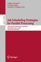
UDAF are applied to a set of values that corresponds to the values of an entire column of a table. The execution of UDAF is well integrated into the usual one-tuple-ata-time processing style of the engine. Hence, they are not called once with all values of a column as an argument, but instead they are called once for each value of the column. This results into two requirements: First, there must be an appropriate interface for developers that is tailored to this style of processing and second, there is the need to preserve the intermediate result from one invocation to the next. Let us now see how the Informix Illustra ORDBMS [53] supports UDAF, for example. The system computes aggregate functions one-tuple-at-a-time, i.e., there is one function call for each element of the argument set. The user has to write the three following external functions to implement a new UDAF: - Init(): The Init function is called only once and without arguments to initialize the aggregate computation before the actual computation of the aggregate begins. It returns a pointer to a memory area, which it has allocated to store intermediate results during the aggregation. - Iter(pointer, value): The Iter function is called once for each element of the input set. One parameter passes the value of the input element and the other passes the pointer to the allocated memory area. It aggregates the next value into the current aggregate that is stored using the pointer. It returns the pointer to the allocated memory area. - aggregate value = Final(pointer): The Final function is called once after the last element of the input set has been
10
Background on User-Defined Routines
pointer = Init() Iter(pointer, value) value
=
Figure 2. Control Flow During the Computation of a UDAF.
processed by the Iter function. It computes and returns the resulting aggregate using the pointer to the allocated memory area. In addition, it deallocates the memory. The control flow during the aggregate computation is presented in Figure 2. The pointer, similar to the scratchpad area mentioned in subsection 2.2.1, allows to store the input context of the computation. For example to compute the average of a set of values, the Iter function would store both the sum of all values seen so far and their number as intermediate results in the allocated memory area. The Final function would divide the sum by the number and return the result. The reader should note that all practical aggregate functions have an input context. Obviously this design matches the usual Open-Next-Close protocol ([29], [73]) for relational operators. After the three functions have been registered with the ORDBMS (cf. Figure 1), the user can create the aggregate function (e.g. average) using a CREATE AGGREGATE statement. This statement specifies the three functions that implement the Init, Iter and Final functions for the new aggregate function. 2.2.3
User-Defined Table Functions
A UDTF is invoked with some scalar arguments and returns a table. In DB2 UDB, a UDTF together with its arguments can only be referenced in the FROM clause of a SELECT statement [50]. It can be referenced in exactly the same way as a table or view. The purpose of a table function is typically to access external data that is not stored in the database, convert it dynamically into a table and make it available within a SELECT statement. Examples are the access to emails that are stored in a file or the access to a collection of World Wide Web pages. A difference to references of base tables or views is that one can also use correlated table functions. In this case an argument of the UDTF is the attribute of a row. The reference to the corresponding table T must be either in a higher-level of the hierarchy of subqueries or in the same FROM clause left to the reference of the UDTF. Such a correlated UDTF is not evaluated once. Rather it is evaluated once for each row r of the table T and produces result tables E(r). The result of a reference to the
Definition, Implementation, and Execution of New UDR
11
table T and the correlated UDTF is then the union of the Cartesian products between a row of T and the corresponding result table E(r), i.e.:
∪r ∈T { {r} × E(r) }.
(EQ 1)
There are roughly the same options for the registration of UDTF as for UDSF. However, one important exception holds. The optimizer has no way to estimate the cardinality of the result table of the UDTF. Therefore it should be possible to provide a user-defined cardinality estimation function. However, in practice, a constant value that provides the expected average cardinality might be sufficient. For example, this scheme is used in DB2 UDB. In DB2 UDB, UDTF are implemented and executed similar to UDSF. Although a table function delivers a table, the interface between the DBMS kernel and the UDTF is one-tuple-at-a-time. To support the return of multiple rows, there are three types of calls available: OPEN, FETCH and CLOSE. A special parameter indicates the type of call to the UDTF. The first call to a UDTF is the OPEN call. For this call all argument values are passed. This call serves to do all initializations (e.g. of a scratchpad), but no result tuple should be returned. Then the DBMS makes as many FETCH calls to the UDTF, until the table function returns the end-of-table condition in the SQLSTATE parameter. With each FETCH call the same argument values as in the OPEN call are passed. After the last tuple has been fetched, the DBMS makes a final CLOSE call. No argument values are passed with this CLOSE call and no tuple should be returned. It serves to release system resources acquired during the OPEN and FETCH calls. The reader may have already noticed that similar techniques are used for the execution of UDSF with a scratchpad, UDAF, and UDTF. In all cases, a set of rows is processed as input to or output from a UDR. Hence, a technique to integrate the passing of sets with the usual one-tuple-at-a-time processing has to be made available. 2.2.4
User-Defined Functions and Large Objects
In some ORDBMS descriptors (called locators) can be used to manipulate large objects (LOBs) in an efficient way ([15], [63]). These locators can also be used as parameters for UDF in order to avoid the passing of the complete LOB as a parameter. A special LOB locator API allows the manipulation of LOBs by means of these locators within the body of an external UDF. For example, there are functions like length, substr, append, create_locator and free_locator in the API of DB2 UDB [50]. Manipulations of LOBs by means of locators and these functions are first done with the locators. The LOB data in the database is modified only if this is necessary, e.g., if a modified LOB is inserted into a table.
12
Background on User-Defined Routines
2.3 Comparison with Stored Procedures In [104] one can find some interesting remarks that give insight into the relationship between UDF and stored procedures in relational systems that we want to cite here: ... Basically, a database procedure is a collection of SQL statements with other statements interspersed in a vendor-proprietary programming language. Database procedures were pioneered by Britton-L ee as a performance enhancement for transaction processing applications and subsequently adopted by all major relational vendors. Using traditional SQL, the TPC-C benchmark is five commands that result in 10 messages between client and server processes [31]. With a database procedure defined on the server, the user merely executes it and only two messages are required. Note that a database procedure is merely a user-defined function written in a proprietary language that accepts SQL-92 data types as arguments. Unfortunately, the only operation available for database procedures is to execute them. In contrast to userdefined functions they cannot appear in the middle of SQL commands. Thus, they should be considered “brain-dead” user-defined functions. [citation: [104], pp. 33-34]
However, one problem with UDF is that current ORDBMS are still to a large extent “brain-dead” with regard to the optimization and efficient execution of UDF. We will briefly present this optimization problem in the next section. Later, we will present our improvements to this situation.
2.4 Optimization of Queries with UDF One of the most challenging areas in query processing is query optimization. It is the goal of query optimization to find for a given query a query execution plan (QEP) with very low (or even the lowest possible) costs. The search for a suitable plan is usually constrained by time and space limits. The overall set of query execution plans is determined by the abilities of the database engine. The search space for a given query is the set of all semantically equivalent query execution plans (the equivalence class of a certain query). The size of this equivalence class is determined by the semantic knowledge of the optimizer. In modern rule- and cost-based optimizers ([30], [36], [67]) this semantic knowledge is typically expressed as a set of rules. A cost model is used to estimate the costs of the QEPs. Of course, this cost model and the set of rules contain semantic information. Obviously, new UDF have also certain semantics that must be made known to the optimizer. Otherwise, the resulting QEP might be incorrect, because certain rules are no longer correct equivalence transformations, or no efficient plan can be found, because the equivalence class of the query is too small. If the cost model is not appropriate, errors in cost estimation might lead to the choice of an actually bad QEP. We have already discussed that developers can influence the cost model by
Optimization of Queries with UDF
13
giving constant cost factors for UDF. These cost factors are used to calculate the estimated costs during the optimization. We remark here that traditional optimizers had to be extended to place predicates with expensive UDF in the best possible way into QEPs [45]. The reason is that traditionally restrictions have been considered as cheap compared to joins. As a result, they were pushed down as far as possible independent of their cost. This approach had to be modified with the introduction of expensive predicates. Chaudhuri and Shim proposed how the well-known optimization approach of System R can be extended appropriately [17]. The central question is, how developers can influence the set of optimization rules. It seems that current systems have only a limited possibility to do this. Obviously, it would be desirable to be able to extend the rule set of the optimizer by arbitrary new rules. This is immediately clear with respect to commutativity and associativity of UDF, since the order of operations can have a huge impact on performance. For example, consider that we want to invert a small part of a digital photo. We can invert the photo and then clip the desired part from the result. However, if we change the order of the operations, then we have to invert only the clipped part of the photo. Naturally, the second execution strategy is by far better [98]. No commercial database system supports extensibility of the optimizer by arbitrary new rules. However, developers can influence the applicability of certain optimization rules by providing appropriate metadata during the registration of UDF. Depending on the properties of a given function some rules are applicable or not. For example, developers must specify for a UDSF, whether this function is deterministic or not. If a function is not deterministic, this function should not be computed several times during the query execution, even if this is cheaper than the materialization of the function’s result. The same holds for UDF with external actions, since these actions must normally be executed exactly once. So far, we have only considered the sequential execution of UDR. In the next chapter, we propose new techniques to parallelize the execution of UDR. We provide the necessary background on parallelism there.
CHAPTER 3
Parallel Processing of User-Defined Functions
3.1 Introduction Our main contribution in this chapter is to show how a broad class of user-defined functions can be processed in parallel. This class includes both, user-defined scalar functions and user-defined aggregate functions. To this aim we propose a framework covering both the necessary interfaces that allow the appropriate registration of userdefined aggregate functions with the ORDBMS and their parallel processing. Parallel computing of user-defined aggregate functions is especially useful for application domains like decision support (e.g. based on a data warehouse that stores traditional as well as non-traditional data, like spatial, text or image data), as decision support queries often must compute complex aggregates. For example, in the TPC-D Benchmark 15 out of the 17 queries contain aggregate operations [99]. In addition, if scalar functions with a global context are processed in parallel, caution is needed in order to get semantically correct results. Our framework can help in this case, too. Furthermore, we show that some aggregate functions can easily be implemented, if their input is sorted, and they can thus profit from parallel sorting. We do not consider the parallel execution of table functions due to the following reasons: First, data parallelism cannot be reasonably applied to table functions since a table function is conceptually only invoked once and does not operate on a set. Second, table functions are often used to access external data in practical applications [21], i.e., they perform external actions like reading from a file. This kind of behavior usually inhibits a parallel execution of the body. The remainder of this chapter is as follows: In section 3.2, we show the limits of user-defined functions with respect to parallel execution. Our framework for parallel processing of user-defined functions is introduced in section 3.3. Section 3.4 presents some examples for the application of the proposed techniques and section 3.5 contains a brief performance analysis. After a discussion of related work in section 3.6, the closing section 3.7 contains a short summary. M. Jaedicke: Parallel Object-Relational Query Processing, LNCS 2169, pp. 14-32, 2001. © Springer-Verlag Berlin Heidelberg 2001
Limits of Current ORDBMS
15
3.2 Limits of Current ORDBMS We will now describe the limits of current ORDBMS with respect to the parallel execution of UDF. To provide a concrete example, we refer to the user-defined aggregate function MOST_FREQUENT, which computes the most frequently occurring integer value in a column of type integer. We have omitted some details (for example the registration parameters, cf. Figure 1) to make the presentation as simple as possible. We first have to create three UDSF INIT_MF, ITER_MF, FINAL_MF that provide the implementation routines of the MOST_FREQUENT aggregate function. These three routines are programmed as external functions, i.e., they are written e.g. in C and can use the system-provided API for UDF to handle tasks like memory allocation, etc. Then they are registered using the CREATE FUNCTION statement: CREATE FUNCTION INIT_MF() RETURNS POINTER EXTERNAL NAME ‘libfuncs!mf_init’ LANGUAGE C ...; CREATE FUNCTION ITER_MF(POINTER, INTEGER) RETURNS POINTER EXTERNAL NAME ‘libfuncs!mf_iter’ LANGUAGE C ...; CREATE FUNCTION FINAL_MF() RETURNS INTEGER EXTERNAL NAME ‘libfuncs!mf_final’ LANGUAGE C ...;
The function INIT_MF allocates and initializes memory to store the integer values together with a count and returns a pointer to that memory. The function ITER_MF stores its argument in the allocated memory, if it is an integer value not seen so far, and increments the count for this value. Finally, the FINAL_MF function searches for the value with the maximum count and returns this value. Next, we create the UDAF with the CREATE AGGREGATE statement: CREATE AGGREGATE MOST_FREQUENT ( init = INIT_MF() iter = ITER_MF(POINTER, INTEGER) final = FINAL_MF(POINTER) );
Now the MOST_FREQUENT function can be used as a new aggregate function in queries. We will now explain, why this aggregate function cannot be processed in parallel.
16
Parallel Processing of User-Defined Functions
SELECT
Partitioning
SELECT
SELECT
Data
Figure 3. Parallel Selection in RDBMS.
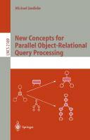
UDSF without context can be executed in parallel using data parallelism. Instead of executing a set of function invocations in a sequential order, one simply partitions the data set (horizontal fragmentation) and processes the UDSF for each data partition in parallel. This parallel execution scheme is shown in Figure 3 for a selection. Obviously aggregate functions cannot use this approach without modification as they have an input context and deliver only a single result for a set of input tuples. Parallel aggregation operations in RDBMS use an execution scheme consisting of two steps [29] as shown in Figure 4. After the data has been partitioned, it is first aggregated locally for each partition and then, in a second step, the locally computed sub-aggregates are combined in a global aggregation (merging step in Figure 4). For the aggregate function COUNT the local aggregation counts while the global aggregation computes the sum of the local counts. Generally speaking, the local and global aggregation functions needed for parallel execution are different from the aggregate function that is used for sequential execution. For built-in aggregate functions local and global aggregation functions are system-provided. Thus, the DBMS can use these functions for parallel execution. For UDAF there is currently no possibility to register additional local and global aggregation functions. This is the reason, why a UDAF like the MOST_FREQUENT function cannot be executed with the usual two step parallel aggregation scheme. Another problem is that current ORDBMS do not allow the developer to define a special partitioning function for a UDAF. However, unfortunately not all UDAF can be processed in parallel on all kinds of partitions as we will show later. The latter is also valid with respect to scalar functions that have an input context. In some cases, the result will be semantically incorrect if the data partitioning does not take the semantics of the function into consideration.
Global Aggregation
Merging Local Agg.
Partitioning
Local Agg.
Data
Local Agg.
Figure 4. Parallel Aggregation in RDBMS.
Parallel Processing of UDF
17
We can summarize the discussion as follows: UDSF with an input context and all practical UDAF cannot be processed in parallel without special support by the DBMS. This situation will result in a performance bottleneck in parallel ORDBMS query processing. In shared-nothing and shared-disk parallel architectures the input data is often distributed over various nodes and must be shipped to a single node to process a UDF with input context correctly, i.e., sequentially, and afterwards the data possibly has to be redistributed for further parallel processing. This results in additional communication costs and hence even worse performance.
3.3 Parallel Processing of UDF In this section, we describe several orthogonal approaches to enhance the parallel processing of UDF with an input context. In subsection 3.3.1 we introduce local and global aggregation functions for UDAF as a generalization of the relational processing scheme. In subsection 3.3.2 we introduce partitioning classes and define the class of partitionable functions that can be processed with data parallelism. In subsection 3.3.3 we propose sorting as a preprocessing step to enhance the parallel execution for non-partitionable UDAF. Subsection 3.3.4 contains corresponding syntactic extensions to the DDL statements for the registration of UDF. 3.3.1
Two Step Parallel Aggregation of UDAF
In this subsection we will show how aggregates can be processed in two steps using local and global aggregate functions. To simplify the presentation below, we will omit constant input parameters to UDF. Given a set S, we will use shorthand notations like f(S) for the resulting aggregate value of an aggregate function f applied to S. We will also use the notation f(S) to denote the result of repeatedly invoking a scalar function f for all elements of S. We want to emphasize that in this case f(S) denotes a multi-set of values (a new column). Next, we define the class of aggregate functions that can be processed in parallel using local and global aggregation functions. An aggregate function f is partitionable iff two aggregate functions fl and fg exist, such that for any multi-set S and some partition Si of S, 1 ≤ i ≤ k, the following equation holds: f(S) = fg(∪1 ≤ i ≤ k {fl(Si)})
(EQ 2)
The notation fl indicates that the function is applied locally (for each partition), whereas fg is applied globally. In addition the result size of the local function fl must be either bound by a constant or it must be a small fraction of the input size. This requirement is important, since otherwise one could use the identity as local function and the sequential aggregation function as the global function. Clearly, this is not desirable, since it would not improve processing. In general, the smaller the size of
18
Parallel Processing of User-Defined Functions
the local results, the better the speedup that can be expected, as there is less data to be exchanged and less input for the global aggregation. Obviously, if an aggregate function is partitionable, the local aggregate function can be executed for all partitions Si in parallel, while the global aggregation must be processed sequentially. If an aggregate function is used in combination with grouping, the optimizer can also decide to process several groups in parallel. In this case grouping can be done with the algorithms described in [99]. The algorithms discussed there can be applied orthogonally to our approach. Of course, if enough parallelism is possible by processing different groups in parallel, the optimizer might decide that no further parallel processing of the aggregate function is needed. One disadvantage of this two step approach to parallel aggregation is that we are not always able to apply one aggregate function to both sequential and parallel processing. Therefore the developer might have to implement and register six additional functions (Init, Iter, and Final functions for local aggregation and the same for global aggregation) to enable parallel as well as sequential processing of a UDAF. However, if one does not need maximum efficiency for sequential evaluation, one can simply use the local and global functions for sequential execution, too. This, however, will incur at least the overhead for the invocation of an additional function. On the other hand, the additional work for the developer will pay off with all applications that profit from the increased potential for parallelism. Besides that, there seems to be no solution that results in less work for the developer. 3.3.2
Partitioning Classes and Partitionable Functions
One prerequisite for data parallelism is that one has to find a suitable partitioning of the data. This means that the partitioning must allow a semantically correct parallel processing of the function. In order to ease the specification of all partitionings that are correct for the parallel processing of a UDF, we describe a taxonomy of the functions that can be used for data partitioning. All partitioning functions take a multi-set as input and return a partition of the input multi-set, i.e., a set of multi-sets such that any element of the input multi-set is contained exactly in one resulting multi-set. Actually in some cases we will allow functions returning subsets that are not disjoint, i.e., functions that replicate some of the elements of the input set. We define the following increasingly more special classes of partitioning functions: - ANY: the class of all partitioning functions. Round-robin and random partitioning functions are examples that belong to no other class. All partitioning functions that are not based on attribute values belong only to this class. - EQUAL (column name): the class of partitioning functions that map all rows of the input multi-set with equal values in the selected column into the same multi-set of the result. Examples of EQUAL functions are partitioning functions that use hashing.
Parallel Processing of UDF
19
1 5 7 2 4 6 9 1 4 3 3 6 7 8 2
RANGE, 2 1 5 7
2
4
2 4 6
9
1
4 3
4 3 3
6
7 8
2
running_sum_3 -
- 13 14 13
12 19 16 14 8
10 12 16 21 17
Figure 5. An Example for Range Partitioning: Computing Running Sums over 3 Elements.
- RANGE (column name [, N]): the class of partitioning functions that map rows, whose values of the specified column belong to a certain range, into the same multi-set of the result. Obviously there must exist a total order on the data type of the column. The range of all values of the data type is split into some sub-ranges that define which elements are mapped into the same multi-set of the resulting partition. Based on the total order of the data type the optional parameter N allows to specify that the largest N elements of the input set which are smaller than the values of a certain range have to be replicated into the resulting multi-set of this range. Replicated elements must be processed in a special way and are needed only to establish a “window” on a sorted list as a kind of global context for the function. The number of elements that belong to a certain range should be much greater than the value N. This class of partitioning functions is especially useful for scalar functions that require a sorted input, for example scalar functions that compute moving averages or running sums (see subsection 3.4.4). An example for range partitioning with replication of two elements (N=2) is shown in Figure 5. It is used to compute the running sum of the three most recently seen elements of the input set. I n the example there are three partitions and replicated elements are shown inside rectangles in the second and third partition. Please note that the following inclusion property holds: RANGE ⊂ EQUAL ⊂ ANY. This taxonomy is useful to classify UDF according to their processing requirements as we will see below. The database system can automatically provide at least a partitioning function of class ANY for all user-defined data types (e.g. round-robin). We define that a class C partition of a multi-set is a partition that is generated using a partitioning function of class C (C denotes either ANY, EQUAL or RANGE). Based on these definitions we can now define the classes of partitionable aggregate and scalar functions. These classes describe the set of UDF that can be processed in parallel with the usual execution schemes for data parallelism (cf. Figure 3 and Figure 4) and a particular class of partitioning functions. A scalar function f is partitionable for class C iff a function fl exists, such that for any multi-set S and any class C partition Si of S, 1 ≤ i ≤ k, the following equation holds: f(S) = ∪1 ≤ i ≤ k fl(Si)
(EQ 3)
20
Parallel Processing of User-Defined Functions
A scalar function f that is partitionable for class C using the associated function fl can be evaluated in parallel using the following scheme, given a multi-set S and a partitioning function p of class C: 1. Partition S in k subsets Si, 1 ≤ i ≤ k, using p. Distribute the partitions to some nodes in the system. 2. Compute fl(Si) for 1 ≤ i ≤ k for all Si in parallel. Figure 6. Parallel Processing Scheme for Partitionable Scalar Functions.
An aggregate function f is partitionable for class C iff two functions fl and fg exist, such that for any multi-set S and any class C partition Si of S, 1 ≤ i ≤ k, the following equation holds: f(S) = fg(∪1 ≤ i ≤ k {fl(Si)})
(EQ 4)
The schemes in Figure 6 and Figure 7 show how partitionable functions can be processed in parallel. All k partitions can be processed in parallel. The actual degree of parallelism (i.e., mainly the parameter k) has to be chosen by the optimizer as usual. Please note that for the scheme in Figure 6, there is not always a need to combine the local results. Hence, the optional combination step (computing f(S) = ∪1 ≤ i ≤ k fl(Si)) is left out. In order to enable the DBMS to process a UDF in parallel the developer must specify the allowed partitioning class when the function is registered (cf. subsection 3.3.4). We have introduced some extensibility to the traditional parallel execution schemes by parameterizing the partitioning step by means of the partitioning function. In addition, we have defined classes of partitions to allow the optimizer more flexibility w.r.t. to the choice of the partitioning function. The query optimizer can try to avoid data repartitioning, when multiple UDF are processed, if the developer specifies only the class of the partitioning functions. For example, if two UDSF f and g must be processed, f is registered with ANY and g with EQUAL, then both functions can be parallelized with a partitioning function of class EQUAL. In general, the optimizer has to find a partitioning function in the intersection of the partitioning classes of all functions that occur in a given query. Computing the intersection is easy due to the inclusion property between the classes (However, one must also consider the columns that are used for partitioning). This can reduce processing costs dramatically, especially for shared-disk and shared-nothing architectures. If the developer specifies a single partitioning function for each UDF, in almost all cases a repartitioning step will be needed to process several UDF in parallel. Vice versa, if a single partitioning function satisfies all of the partitioning classes of a given set of UDF, then repartitioning can be avoided. Because UDF can have arbitrary semantics, we believe that it is not possible to define a fixed set of partitioning functions that allows to apply data parallelism to all UDF. If a given UDF is partitionable using some partitioning function p, but none of
Parallel Processing of UDF
21
An aggregate function f that is partitionable for class C using the two associated functions f l and f g can be evaluated in parallel using the following scheme, given an input multi-set S and a partitioning function p of class C: 1. Partition S in k subsets Si, 1 ≤ i ≤ k, using p. Distribute the partitions to some nodes in the system. 2. Compute Ii := fl(Si) for 1 ≤ i ≤ k for all Si in parallel. Send all intermediate results Ii to a single node for processing of step 3. 3. Compute f(S) := fg(∪1 ≤ i ≤ k {Ii}); fg can be applied to the intermediate results Ii in arbitrary order. Figure 7. Parallel Processing Scheme for Partitionable Aggregate Functions.
the partitioning classes defined above, the developer should be enabled to specify that this function p must be used. We call this function p user-defined partitioning function. However, using a special partitioning function should be avoided in general, since all data has to be repartitioned before such a UDF can be processed. We want to remark here that implementing RANGE partitioning is a bit complicated, since a user-defined sort order and partial replication have to be supported. One difficulty is for example to find equally populated ranges for a given user-defined sort order. We believe that range partitioning with partial replication can be best supported by an appropriate extension of the built-in sort operator of the ORDBMS. This operator has to support user-defined sort orders anyway. The definition of ranges and partial replication can be supported, if information about the data is collected during the sorting process. In addition to that extension, the operator that invokes UDSF has to be extended. The UDSF that needs the range partitioning is evaluated immediately after the partitioning. Replicated data elements (that have to be marked) are processed by the UDSF in a special mode that has to be indicated by turning on a special switch. In this mode only the global context of the UDSF is initialized and no results are produced. For example, when the moving average over five values is computed, the first four values of a partition will be replicated ones and are stored in the global context of the function. Then, the fifth invocation produces the first result. Though this extension is conceptually simple, it may be difficult to add it to an existing engine. 3.3.3
Parallel Sorting as a Preprocessing Step for UDAF
Some user-defined aggregate functions can be easily implemented, if their input is sorted according to a specified order. In this case the sort operation can be executed in parallel. Of course, this is especially interesting for UDAF that are not partitionable.
22
Parallel Processing of User-Defined Functions
An aggregate function f that requires a sorted input can be evaluated using the following scheme given input multi-set S: 1. Sort the input S. This can be done in parallel. 2. Compute f(S) without parallelism (use early termination, if possible). Figure 8. Parallel Processing Scheme for Aggregate Functions with Sorted Input.
Sorting as a preprocessing step for UDAF can be introduced by using an additional parameter in the CREATE FUNCTION statement (see subsection 3.3.4 for details of the syntax we propose). Of course the developer must have the possibility to specify a user-defined order by providing a specific sort function for the argument data types of the UDF which are often user-defined data types. In most cases such functions will be needed anyway, to support sorted query results, to build indexes (like generalized B-Trees ([102], [104]) or GiSTs [46]) or for sort merge joins to efficiently evaluate predicates on user-defined data types, to quote some examples. One interesting point to observe is that many aggregate functions, which operate on a sorted input, do not need to read the complete input set to compute the aggregate. Thus, it might be well worth to provide the aggregate function with the option to terminate the evaluation as early as possible and return the result. We call this feature early termination. The parallel processing scheme for aggregate functions with sorted input is shown in Figure 8. The optional sort requirements can be integrated into rule-based query optimization (see e.g. [30], [36], [67], [73]) simply by specifying the sort order as a required physical property for the operator executing the UDF. Then a sort enforcer rule ([30], [38]) can guarantee this order requirement by putting a sort operation into the execution plan, if necessary. Informix Illustra [53] already supports optional sorting of inputs for UDF that have two arguments and return a boolean value. The developer can specify a user-defined order for the left and right input of such a function. Obviously this allows to implement a user-defined join predicate using a sort-merge join instead of a Cartesian product followed by a selection. Thus, our proposal can be seen as an extension of this approach w.r.t. to a broader class of supported UDF and their parallel execution. 3.3.4
Extended Syntax for Function Registration
In this subsection, we present the syntax extensions for the statements that allow the registration of UDF with support for the features introduced in the previous subsections.
Parallel Processing of UDF
23
CREATE FUNCTION () RETURNS EXTERNAL NAME [ORDER BY { [USING ] [ASC | DESC] } [EARLY TERMINATION]] [ALLOW PARALLEL WITH PARTITIONING CLASS ( ANY | EQUAL () | RANGE { [, ] [USING ] [ASC | DESC]} | )] LANGUAGE ...
Figure 9. Extensions to the DDL Statement for UDSF Registration.
Figure 9 shows the extensions for the CREATE FUNCTION statement. We have marked our extensions by boldface. The ORDER BY clause can be used to specify a sort order that is required for the input table, on which the function is executed. The input table can be sorted on multiple columns applying user-defined sort functions to define the sort order. Furthermore, the developer must specify if early termination is used. To enable parallel evaluation, the partitioning class has to be specified. In addition to ANY, EQUAL and RANGE partitioning, the developer can register a special (user-defined) partitioning function for a UDF. Figure 10 shows the extensions for the CREATE AGGREGATE statement. It now includes the local and global function options that are needed to register the aggregate functions that have to be used for the parallel evaluation of the new aggregate function. Of course the various Init, Iter, and Final functions that are registered must be consistent w.r.t. their argument types. For example the sequential and the global Final functions must have the same return types (but often will have different argument types) As we mentioned already in chapter 2 additional information about these functions should be supplied by the developer. In addition to the usual cost parameters, information about the size of the results of the local aggregation function (perhaps depending on the cardinality of the input set, if the function returns a collection type or LOB) would be desirable. CREATE AGGREGATE (
[local ] [global ] )
Figure 10. Extensions to the DDL Statement for UDAF Registration.
24
Parallel Processing of User-Defined Functions
3.4 Example Applications In this subsection, we present some example applications to illustrate the benefits of the introduced techniques. 3.4.1
The UDAF Most_Frequent
First, we will demonstrate how parallel execution can be enabled for the aggregate function Most_Frequent. How can we use the two step processing scheme to process the function Most_Frequent in parallel? A straightforward approach could be to compute the most frequent value for each partition in parallel using the local aggregate function. This implies that the local aggregate function returns the most frequent value together with the number of its occurrences (i.e., the return type of the local function contains two values). Then the overall most frequent value is computed by the global function. Obviously this scheme is only correct if EQUAL is specified as the partitioning class for the local aggregation function. If ANY would be used as a partitioning class, the local aggregate function would have to return all distinct values together with the number of their occurrences for each partition. Thus, the local aggregation step would not be useful. One difficulty of this approach is to implement the local aggregation function, since it must temporarily store all distinct values together with a counter. It is difficult to implement this efficiently in a user-defined function, since the function must be able to store an arbitrarily large data set. By contrast, the local aggregation can be done much easier if the developer uses sorting as a preprocessing step. The function must then only store two values and two counters: one for the most frequent value seen so far and one for the last value seen. This approach is much more practical. Based on the syntax from subsection 3.3.4 we show the registration of the Iter function for the local aggregation (‘$i’ denotes the argument at position i in the parameter list of the function). CREATE FUNCTION ITER_MF_LOCAL(POINTER, INTEGER) RETURNS POINTER EXTERNAL NAME ‘libfuncs!mf_iter_local’ ORDER BY $2 ASC ALLOW PARALLEL WITH PARTITIONING CLASS EQUAL $2 LANGUAGE C ...;
With EQUAL as partitioning class in case of a parallel execution the data is first partitioned and then only the partitions are sorted as specified in the ORDER BY clause.
Example Applications
25
SELECT MIN(Age) FROM Persons AS P WHERE (SELECT Ceiling((COUNT(*) + 1) / 2) FROM Persons) P(d) + I(d). In summary, we have seen that a near-linear speedup can be expected in many cases. Thus, our framework for parallel processing can be advantageous for the overall query processing time. Whether or not parallelism for UDAF should be used for a given query is a cost-based decision the optimizer has to make. The same is true for partitionable scalar functions, too.
30
Parallel Processing of User-Defined Functions
3.6 Related Work User-Defined Functions (UDF) have attracted increasing interest of researchers as well as industry in recent years (see e.g. [3], [17], [45], [47], [68], [70], [83], [89], [98], [102], [104]). Despite this, most of the work discusses only the non-parallel execution of UDF. We see our contribution as a generalization and extension of the existing work on the execution of user-defined functions using data parallelism. Recently, IBM added the optional clause ALLOW PARALLEL or DISALLOW PARALLEL to the create function statement for UDSF in DB2 UDB [50]. We view this as a first step of support for parallel execution of UDSF that is consistent with our more comprehensive framework. To the best of our knowledge there is no work on parallel processing of scalar user-defined functions with an input context. In [29] and [99] parallel processing of aggregate functions in RDBMS has been studied. The proposed concepts are applicable to built-in aggregation functions and consider also aggregation in combination with GROUP-BY operations and duplicate elimination. The proposed algorithms in [99] may be combined with our framework, if user-defined aggregate functions are used with GROUP-BY. It has been observed in [29] that different local and global functions are needed for parallel aggregation operations in RDBMS. In [89] the concept to process user-defined aggregate functions in parallel using two steps is proposed as a general technique, but neither are details nor more sophisticated processing techniques (like sorting as a preprocessing step, early termination or partitioning classes) presented. Recently, Informix added a two-step scheme for parallel aggregation to their Universal Data Option [95]. Their design is similar to ours, however they need only 4 functions (only one init and final function, whereas we use two: one for the local and one for the global function). In [76], RDBMS are extended by ordered domains, but neither is an object-relational approach taken nor are functions considered. It is interesting to compare our classification of aggregate functions in partitionable and non-partitionable aggregate functions with other classifications. In [33], a classification of aggregate functions into three categories is developed primarily with the goal to be able to determine, if super-aggregates in data cubes can be computed based on sub-aggregates for a given aggregate function. It is pointed out that this classification is also useful for the parallel computation of user-defined aggregate functions. In the classification that is proposed in [33] an aggregate function f with a given input multi-set S and an arbitrary partition Si of S is: - distributive iff there is a function g such that f(S) = g(∪1 ≤ i ≤ k f(Si)).
(EQ 5)
- algebraic iff there is an M-tuple valued function g and a function h such that f(S) = h(∪1 ≤ i ≤ k g(Si)).
(EQ 6)
It is pointed out that the main characteristic of algebraic functions is that a result of fixed size (an M-tuple) can summarize sub-aggregates.
Summary
31
- holistic iff there is no constant bound on the size of the storage needed to represent a sub-aggregate. Clearly, distributive and algebraic functions are both partitionable aggregate functions for the partitioning class ANY. Note that our definition of partitionable aggregate functions is less restrictive with regard to the size of the sub-aggregates. Aggregate functions that are easy to implement using a sorted input are typically holistic. Aggregate functions that are partitionable with a less general partitioning class than ANY, e.g. the function MOST_FREQUENT, are holistic in this scheme, but can be evaluated in parallel by our framework. Other holistic functions like e.g. the function Median can be efficiently evaluated in our approach, by using parallel sorting as a preprocessing step and early termination. Note that the application scenario in [33] is different to ours with regard to partitioning and parallel evaluation, because the sub-aggregates in data cubes must be computed for fixed partitions that are determined by semantically defined sub-cubes and not by the application of some partitioning function. The classification of Gray et al. was designed with the goal to compute data cubes efficiently. However, the rationale behind our work was to find a classification of functions that is useful for parallel evaluation. In [111] the class of decomposable aggregate functions is introduced to characterize the aggregate functions that allow early and late aggregation as a query optimization technique. This class of aggregate functions is identical to partitionable aggregate functions of partitioning class ANY except that no size restriction for sub-aggregates is required in [111]. Thus, for these partitionable functions also certain rewrite optimizations are possible that provide orthogonal measures to improve the performance. In [16] the class of group queries is identified for relational queries. This class is directly related to data partitioning. Our framework provides support for the concept of group queries in object-relational processing as well.
3.7 Summary In this chapter we have proposed a framework that allows parallel processing of a broad class of user-defined functions with input context in ORDBMS. This is an important step in removing a performance bottleneck in parallel object-relational query processing. Since it was clear that a straightforward application of data parallelism is not possible, we had to devise more sophisticated parallelization techniques. The three key techniques that we have proposed here are the following: First, we have generalized the parallel execution scheme for aggregation in relational systems by means of local and global aggregations to allow its application to user-defined aggregations. Second, we have introduced some extensibility to the parallel execution schemes for scalar and aggregate functions by means of user-defined partitioning functions. We have defined classes of partitioning functions to make the specification of all allowed
32
Parallel Processing of User-Defined Functions
partitioning functions easier and to enable the optimizer to avoid data repartitioning as much as possible. Third, we have introduced parallel sorting as a preprocessing step for user-defined aggregate functions. This enables an easier implementation of UDF and the use of parallelism in the preprocessing phase. Furthermore, we have defined new interfaces that allow developers to use these techniques by providing the needed information to the DBMS. As a summary Table 2 shows the different kinds of contexts that can occur for UDF and the implications for parallel execution with respect to data parallelism. As can be seen from Table 2, our techniques support data parallelism with respect to many, but not all UDF with input context. Additional techniques might emerge in the future. Please note that a general solution for UDF with external context is beyond the scope of this work. Table 2. UDF with Different Contexts and their Parallel Execution scalar functions
aggregate functions
no context
partitionable for class ANY
(not reasonable)
input context
partitionable for some class
partitionable for some class with local and global aggregation parallel sorting (& early termination) not partitionable
external context
not treated here
An important remaining question with respect to the parallel execution of UDF is the following: How can we execute a UDF that operates on a single LOB in parallel? The next chapter is dedicated to the solution of this problem.
CHAPTER 4
Intra-function Parallelism
4.1 Introduction In this chapter we focus on intra-function parallelism for expensive functions that operate on large objects (LOBs). Intra-function parallelism means that the invocation of a scalar function which operates on a single LOB is computed in parallel. Intrafunction parallelism is orthogonal to data parallelism and hence this kind of parallelism can still be exploited, if data parallelism is not applicable. In this chapter we present an approach to enable intra-function parallelism in PORDBMS. Since LOBs can be used to implement collection data types like arrays and sets that are proposed for future SQL standards, our technique to enable intra-function parallelism might be useful for parallel processing of collection types as well. As pointed out in [85] intra-function and inter-function parallelism are important, because many object-relational extensions support expensive functions on large data objects. The reason is that LOBs are used to implement a rich variety of new data types, for example in applications which deal with multimedia, financial or spatiotemporal data. Some of these data types like digital photos, satellite images and video data have a really huge size. For example, currently a single high resolution digital photo has a size of 18 MB. Note that in current commercial systems (see for example [50], [54], [86]) large data types ranging to tera byte sizes are supported. Moreover, one can expect that computationally expensive scalar functions are used to extract knowledge from such LOBs or to transform these LOBs. Hence, processing a single large object like a satellite image or a video film already consumes significant resources. Unfortunately neither data parallelism nor pipeline parallelism can be employed for the processing of a single large object. In the rest of this chapter, we discuss how intra-function parallelism can be used to overcome this limit of current PORDBMS and to speed up query processing further. This chapter is organized as follows. Section 4.2 presents our approach to intra-function parallelism and section 4.3 contains a performance study that shows the viability and the benefits of our approach. Section 4.4 covers the related work and section 4.5 summarizes the chapter. M. Jaedicke: Parallel Object-Relational Query Processing, LNCS 2169, pp. 33-44, 2001. © Springer-Verlag Berlin Heidelberg 2001
34
Intra-function Parallelism
4.2 Compose/Decompose Operators for Intra-function Parallelism In this section we describe our approach to intra-function parallelism for expensive user-defined scalar functions on LOBs. The rationale of our design is the following: first, a necessary requirement is that the application of intra-function parallelism remains completely transparent for users of UDSF in SQL statements. Second, the design should provide developers of UDSF with a model of intra-function parallelism that combines ease of use with the highest possible degree of flexibility. 4.2.1
Compose/Decompose Operators
The basic idea of our approach is shown in Figure 14. The left side of Figure 14 shows the state of the art. A UDSF F is processed sequentially on a LOB (the white box) and returns another LOB (the hatched box). We propose to enable intra-function parallelism by means of two new database operators: a decompose and a compose operator. This is depicted on the right side of Figure 14. First the decompose operator is applied to the LOB which results in a set of pieces of this LOB (the small white boxes in Figure 14). Then the UDSF F is invoked for each of these pieces. Some or all of these invocations can be done in parallel (indicated by the two operator instances for the evaluation of the UDSF F in Figure 14). The result is a set of modified LOB pieces (the small hatched boxes in Figure 14). Finally the compose operator assembles the LOB from the pieces. Hence, in general a UDSF can be computed in parallel by adding a pair of decompose/compose operators that encloses the evaluation of the function. One might expect that the use of decompose and compose operators incurs a high overhead. But in fact this is not the case if LOB locators (cf. subsection 2.2.4) are used properly. If the size of the LOB is significantly larger than the size of the locator, then the overhead for the decompose and compose operations is relatively low as we show in the following. Because in most applications the size of the LOB will usually be some orders of magnitude larger than the size of the LOB locator (which is for example less than 312 Bytes in DB2 UDB [50]), the overhead is usually acceptable. Typically a developer will code the UDSF in such a way that not the LOB itself is passed as a parameter, but the LOB locator. In this case the LOB locator can be used to access some or all LOB data using positioned access. Similarly the UDSF will return a locator that refers to the result LOB and not the result LOB itself. The decompose operator can work in the same way: instead of reading the entire LOB and returning a set of LOB pieces, it is sufficient to work with LOB locators. This means that we pass a LOB locator to the decompose operator. The decompose operator simply makes N copies of the LOB locator and attaches to each copy the number
Compose/Decompose Operators for Intra-function Parallelism
35
N and a unique number K between 1 and N as access information. The numbers N and K describe the piece of the LOB on which the UDSF should work. Hence, the result of the decompose operator is a collection of rows. This corresponds exactly to the functionality of a correlated table function (cf. subsection 2.2.3 and [50]). The compose operator uses the values of N and K to determine how to construct the result of the LOB. Please note that the number of pieces (N) is a parameter for the decompose operator that is provided by the optimizer (cf. subsection 4.2.3 below). In this approach, a copy of the LOB locator and the corresponding access information are passed as parameters to the UDSF. The UDSF can infer from the value of K on which of the N pieces it should operate. Therefore, the developer has to explicitly consider that the UDSF might operate only on a part of a LOB and that access information is passed to the UDSF as two additional, internal parameters (these parameters are not visible in SQL statements and, if no decomposition is done, i.e., if no intra-function parallelism is used, then these parameters have NULL values). Then, the UDSF normally accesses only the part of the LOB that is described by the access information. This is usually easy to integrate into the code of the UDSF. The reason is that the UDSF will typically use the locator to fetch only a small portion of the LOB at the same time into main memory. This kind of processing is necessary to limit main memory requirements. Please note that providing a copy of the locator for the complete LOB as a parameter to the UDSF has the following benefit: if the partial result of the UDSF cannot be computed by looking only at the specific piece of the LOB then the UDSF can read further LOB data as needed. Therefore our approach supports intra-function parallelism for a broad range of UDSF. The compose operator can exploit LOB locators in a similar way. The use of copies of complete LOB locators is important to support a maximum of flexibility for developers of UDSF as discussed in the next section.
compose
... UDSF F
UDSF F
...
UDSF F
... decompose
Figure 14. Application of a Compose and a Decompose Operator to Parallelize the UDSF F.
36
Intra-function Parallelism
compose combine
Figure 15. Extending Compose Operators by Combine
Finally, we want to point out that the decompose/compose operators work with the usual tuple streams that allow to pass data from one operator to the next. The LOB locators and the values N and K are fields of the tuples and can be handled as usual. The LOBs themselves are accessed only from within the body of the UDSF and are therefore not themselves included into tuple streams. Hence, the handling of intermediate results is not affected by decompose and compose operators. 4.2.2
Extensibility of Compose Operators by Combine Functions
In this subsection, we explain how compose operators can be made extensible. The compose operator should be extensible itself with respect to the way in which LOBs are assembled. This is necessary to allow developers to deal with the semantic differences of various data types and functions. Such a kind of extensibility can be achieved by providing a user-defined combine function to the compose operator. This is shown in Figure 15. The combine function tells the compose operator how the LOB can be assembled from the pieces. The system has to provide default combine functions that work on the different kinds of LOBs (BLOBs, CLOBs, DBCLOBs) without taking data semantics into account. Sometimes a single combine function might suffice for all UDSF that operate on a LOB data type, but in general there can be a specific combine function for each UDSF that operates on a LOB data type. Please note that in the latter case the combine function is tailored to the specific UDSF and can be used to complete the computation of the UDSF during the combination. This can be necessary, if the UDSF cannot be computed completely by invoking it only for each piece of the LOB. In this case the UDSF is computed in two steps: first, the UDSF is invoked for each piece and second, the combine function is executed during the compose operation. This approach is similar to the divide-and-conquer strategy that can be used to compute (user-defined) aggregates in parallel (cf. chapter 3). In the example of Figure 14 we have assumed that the UDSF returns a LOB. This assumption is not necessary. In fact, with user-defined combine functions the decompose/compose-approach can be used for all UDSF that operate on LOBs because the combine function can compute the correct return value. We provide now a very simple example of a UDSF that needs a combine function to support intra-function parallelism. Consider the UDSF:
Compose/Decompose Operators for Intra-function Parallelism
37
CREATE FUNCTION count_char(CLOB text, CHAR(1) c) RETURNS INTEGER ...
that counts how often the character c occurs in a given text. We can implement intra-function parallelism in the following three steps: 1. Decompose the CLOB into N pieces. This step is done by the decompose operator. 2. For each piece in parallel: count how often the character c occurs. This step is implemented by the UDSF count_char. 3. Add the counts for all pieces and return the sum. This is the functionality of the combine function that is invoked by the compose operator. In order to implement this approach, developers must be enabled to create combine functions that can be applied to the instances of a certain LOB data type. Because combine functions are user-defined functions, too, no special support for this is needed (that is, the combine function can be registered as a UDSF). However, it is necessary to register a new UDSF with parameters that allow the developer to specify which combine function has to be used to enable intra-function parallelism for this UDSF. For example an optional clause like “DECOMPOSABLE [USING ]” could be added to the CREATE FUNCTION statement for the registration of UDSF. If no specific combine function is specified, the system can use the default combine functions for BLOBs, CLOBs, or DBCLOBs. Please note that in our approach a similar extensibility for the decompose operator is not needed. The reason is that the decompose operator simply makes copies of the locator for the complete LOB. Therefore the UDSF can decide itself, which portion of the LOB should be accessed for the processing of a given piece. This kind of virtual decomposition allows a maximum flexibility. 4.2.3
Application of Intra-function Parallelism
In our view intra-function parallelism is best applied by a rule-based optimizer (for example [30], [36]). Such an optimizer has to be extended my means of a rule that inserts appropriate pairs of compose/decompose operators. Obviously, the compose/ decompose operator pair should be only inserted by the optimizer, if it estimates that the application of intra-function parallelism reduces the response time. Intra-function parallelism can reduce the response time, if data parallelism is not sufficient to speed up processing. This is the case, if the number of LOBs that have to be processed with a UDSF is less than the number of available CPUs. For example, if we have a multi-processor but only a single LOB. The question is how to determine the number of pieces (i.e., the parameter N) into which a LOB should be decomposed. If the cost of the function is significantly higher than the overhead for intrafunction parallelism (that is, if either the function evaluation is expensive or the
38
Intra-function Parallelism
result compose
result expression A(B(...))
input
UDSF A decompose compose UDSF B decompose
input
Figure 16. Insertion of Compose/Decompose Operators in a Function Pipeline.
LOBs are huge), then the number of pieces can be set roughly to the number of available CPUs (the exact value might be system-dependent). In general, as our measurements in the following section 4.3 show, a number of pieces that is much higher than the number of CPUs does not result in a significant overhead. In general a thorough cost-based decision should be needed only, if the UDSF is cheap to compute or if an expensive user-defined combine function has to be used. In both of these cases, intrafunction parallelism might not be useful at all. Of course, if a UDSF operates only on a small part of the LOB data, then intra-function parallelism should not be used. In this case the developer should not register the UDSF as decomposable.
4.2.4
Intra-function Parallelism for Function Pipelines
In this subsection, we will consider the case that we have a pipeline of functions that can be processed with intra-function parallelism. This applies for example, if two UDSF A and B are nested in an expression like A(B(...)). As it is shown in Figure 16 one can now insert a pair of decompose/compose operators around each function. This allows intra-function parallelism for both functions. In some cases it is possible to optimize this scenario further by an elimination of the compose and decompose operators between the UDSF A and B. However, this is not possible in general and requires additional support. The reason is that the combine and decompose operator are needed to generate copies of the LOB locator for the complete result LOB of UDSF A which is the expected input for the evaluation of UDSF B.
Experimental Performance Study
39
4.3 Experimental Performance Study We have evaluated our approach by implementing the functionality of decompose and compose operators on top of IBM’s DB2 Universal Data Base, Version 5, running on SUN Solaris V2.5 for a simple UDSF that operates on a CLOB (cf. [40]). The goal of these measurements was to show the feasibility of this approach. That is, we wanted to show that performance gains can be achieved in some scenarios. A real implementation within a core parallel data base system would have been too expensive in relationship to the additional insight into this topic that could have been gained. One reason for this is that a sophisticated, high performance implementation of LOBs with locators in a PORDBMS is needed. Such implementations are already available in commercial products [63], but for example they are not available in our PORDBMS prototype MIDAS [9]. Without a suitable implementation of LOBs with locators, the overhead of the decompose/compose approach would be unrealistically high. The disadvantage of an implementation on top of a commercial system is that the overhead for communication between client and server is significant and limits the speedup. Hence, this implementation cannot show the full benefit of compose/ decompose operators. All measurements have been made on a SUN SPARC 20 symmetric multi-processor machine (SMP) with four SPARC processors with 100 MHz each, 128 MB main memory and a disk array with four 4.2 GB hard disks. We have used a SMP for our measurements, because we see that commodity SMPs become available and that the scalability of SMPs improves. Therefore, we believe that intra-function parallelism will be used primarily on SMPs. In a hybrid shared-nothing architecture (in which the nodes are SMPs) data parallelism can be used for processing on different nodes and intra-function parallelism can be used for parallel processing on a single SMP node. This is possible due to the orthogonality of the parallelization concepts. 4.3.1
Experimental Scenario and Implementation
For our performance study we have considered a UDSF on a CLOB because this seemed to be favorable to development. As UDSF we have implemented a function invert that inverts the characters within the CLOB (that is A is changed into Z, B into Y, etc.). To be able to increase the cost of this simple function we have added an empty for-loop that is executed once for each character and increments the loop variable 100 times. We have then generated random character strings and stored them as CLOBs in a table clobtable with two columns: a column id that contains a primary key and a column text that contains the CLOB. We have implemented two programs that perform essentially the following task: one or more CLOBs are selected from the clobtable and then the function invert is applied to these CLOBs. The result is then inserted into a persistent table in the database.
40
Intra-function Parallelism
The first program without decompose/compose operators performs essentially the following insert statement (see appendix A.1 for the complete program): INSERT INTO result (id, text) SELECT id, invert(text,1,1) FROM clobtable WHERE id < param;
The value of param is constant and used only to select a specified number of CLOBs from the clobtable. For example, if param has the value 4 then the number of selected tuples - each containing a CLOB - is 4. In the following, we call this program sequential_in-vert. The function invert was registered with the DBMS as follows: CREATE FUNCTION invert ( CLOB(150M) AS LOCATOR text, INTEGER piece, INTEGER num_pieces) RETURNS CLOB(150M) AS LOCATOR ...;
This function accepts three parameters: first the locator of the CLOB that should be inverted. The second parameter corresponds to the number of the LOB piece (cf. the variable K in subsection 4.2.1). The third parameter contains the number of pieces into which a LOB is decomposed (cf. the variable N in subsection 4.2.1). Since we cannot use intra-function parallelism in the program sequential_invert, the values for the parameters are always N = K = 1. Please note that the parameters N and K would not be visible for users in SQL statements. However, in our case of an on-top implementation this was unavoidable. The second program implements the operation in a way that comes close in effect to the decompose/compose operator approach. Our first approach to implement the decompose operation was to use a UDTF that generates the necessary number of copies of the CLOB locator. Unfortunately, we found no way to execute the resulting statement with the UDTF in parallel. Therefore we have simply used a join with another persistent table (named join-table) that contains exactly N rows for each LOB. Each of these N rows consists of two integer values: the first value (id1) corresponds to the id of the CLOB, the second (id2) contains a unique number in the range 1, 2, ... , N and is used to give each piece a unique identifier (that is, it serves as value for the parameter K). The latter value is used as a parameter for the function invert. The following statement shows the decompose operation and the application of the function invert (for N = 4): SELECT a.id + 0 AS id1, b.id2 + 0 AS id2, invert(a.text,b.id2,4) AS text FROM clobtable AS a, jointable AS b WHERE a.id = b.id1 ORDER BY id1, id2;
We have to explain here, why we have used an ORDER BY clause and the two additions in the SELECT clause. The compose operation could have been easily written
Experimental Performance Study
41
as a user-defined aggregate operation. But DB2 UDB V5 does not support this feature. Therefore, we used a cursor to fetch locators of the pieces and assembled the result using the system-provided concatenation operator (‘||’). For this approach, it was most efficient to sort the pieces by their number. This ensures that all pieces of one LOB arrive in order. Hence, only one LOB is assembled at a time. However, since id is the primary key of the table clobtable the optimizer decided to use an index scan for an ordered access to the base table. While this avoided the sort operation, it also forced sequential execution. Therefore, we introduced the additions to prevent the optimizer from using the index access. Appendix A.2 shows the complete program parallel_invert. 4.3.2
Performance Results
We have conducted a series of performance measurements to show the effect of decompose/compose operations. Experiment 1: Speedup with Decompose/Compose Operators In the first experiment, we have studied the effect of the number of LOB pieces and the degree of parallelism for the processing of a single CLOB of size 10*106 Byte (i.e., ten million characters). This LOB size is moderate and we have used a version of the function invert with higher cost to increase the overall costs: for each character in the CLOB, the function inverts the character as mentioned above and increments a counter 100 times. Figure 17a shows the response time (in seconds), if we use the value 4 as a default degree of parallelism for the programs. In this case the DBMS tries to execute all statements with this degree of parallelism, that is, it employs 4 processes to execute the function invert. This is only possible for the select query that is executed in the program parallel_invert. The parallelism is actually only useful, if more than a single piece is generated for processing. As one can see in Figure 17b, the best speedup that can be achieved is about 2.7. This is less than the optimum speedup value 4. However, we can expect this, as not all 4 processors can be used exclusively to process the test program because of the operating system and DBMS overhead. An even more important limit for the speedup is however that we use a program on-top of the DBMS for the implementation. All work on the client side and the client/server communication represent thus a part of the program that cannot be executed in parallel. This limits the overall speedup significantly according to Amdahl’s law [2] and is an important reason for the less than optimal speedup. Therefore when the decompose/compose operators are integrated into the execution engine a better speedup can be achieved. Furthermore, as Figure 17 shows, the response time depends in some rather unforeseeable way on the number of pieces into which the CLOB is decomposed. We have
42
Intra-function Parallelism 1 CLOB, 4 CPUs: Response Time
120
1 CLOB, 4 CPUs: Speedup
4 3.5
100
2.5
Speedup
Response Time
3 80 60
2 1.5
40
1 20 0
with D/C without D/C 0
1
Speedup
0.5
2 3 4 5 6 Number of Pieces
7
0
8
a) Response Time in Seconds.
0
1
2 3 4 5 6 Number of Pieces
7
8
b) Speedup.
Figure 17. Results for 1 CLOB with 10*106 Bytes on an SMP with 4 CPUs and Varying Number of Pieces.
not been able to determine the reason for the changes in the system behavior. However, while the response time is influenced by the number of pieces, the overhead from copying the LOB locators for an increasing number of pieces has not a dramatic effect on the overall performance. This is clearly demonstrated by the results in Table 3. Here we show the response times for 1 CLOB with 4, 8, 16, and 40 pieces, respectively. In all of these cases, the DBMS used all 4 CPUs for parallel query execution. Ideally the response time should be roughly the same in all cases. Differences should result only from the overhead for creating a higher number of copies of LOB locators. However, as the measurements show, the response time is not determined by this overhead. In our view, it seems that the handling of LOBs within the data base engine does not yet fully support the requirements for intrafunction parallelism. This again demonstrates that an integration of decompose/compose operators into the database engine would be even more beneficial. In general, the results show that decompose/compose operators can support intra-function parallelism appropriately. Table 3. Response Times in Seconds for a Varying Number of Pieces number of pieces
4
8
16
40
response time
80
44
61
48
Experiment 2: Trade-Off between Intra-function Parallelism and Data Parallelism In another experiment, we have considered the execution of the UDSF for several CLOBs at a time to study the trade-off between intra-function parallelism and data parallelism. All CLOBs had the same size (1*106 Bytes) and they were all processed
Related Work
43
with the same function. Figure 18 shows response times and speedups for the processing of a varying number of CLOBs in the programs. Figure 18a shows that intrafunction parallelism with decompose/compose operations can provide an additional speedup, if data parallelism alone cannot fully utilize system resources. This is the case for the processing of up to 3 CLOBs. Figure 18b shows that the actual speedup is lower than the optimal speedup. This is due to the same reasons as in the first experiment. For 4 CLOBs, when data parallelism alone can achieve a degree of parallelism of 4, additional intra-function parallelism results in a small overhead. However, if the size of the CLOBs varies considerably, intra-function parallelism might be desirable even for 4 or more CLOBs. The reason is that the decomposition reduces the skew for data parallelism that results from LOBs with different sizes. In general these results show that intra-function parallelism can be beneficial, if the number of LOBs is lower than the number of available CPUs. In this case intra-function parallelism can supplement data parallelism as demonstrated by the second experiment. We want to emphasize again that an implementation of the decompose/ compose approach within the database engine would show a much better performance than indicated by our on-top implementation.
4.4 Related Work In [85] intra- and inter-function parallelism were proposed for expensive function evaluations on LOBs, but no implementation concepts were described. As an example of a UDSF for which intra-function parallelism is useful, a function that scales large images up or down is discussed. It is pointed out that this function can be processed in parallel because the result pixels are all independent of each other. Our 1-4 CLOBs, 4 CPUs: Response Time with D/C without D/C
20
1-4 CLOBs, 4 CPUs: Speedup
4 3.5 3
15
Speedup
Response Time in sec.s
25
10
2.5 2 1.5 1
5
0.5 0
0
1 2 3 Number of CLOBs
a) Response Time in Seconds.
4
0
actual speedup optimal speedup 0
1 2 3 Number of CLOBs
4
b) Speedup.
Figure 18. Results for Different Numbers of CLOBs (Each with 1*106Bytes) on an SMP with 4 CPUs.
44
Intra-function Parallelism
decompose/compose operator method can support even functions for which this is not the case. If the UDSF needs to access overlapping parts of a LOB when different pieces are processed, this is possible, since all instances of the UDSF get the locator for the complete LOB as input. Moreover, if the different parts of the result are not completely independent then the combine function can be used to achieve an appropriate composition of the pieces. In [28] parallel processing of operations on complex data structures (for example with sets of references) is discussed. This is done in the framework of the PRIMA DBMS which has a proprietary data model. UDSF are not considered.
4.5 Summary In this chapter, we have proposed decompose/compose operators as an approach to support intra-function parallelism for user-defined scalar functions that operate on large objects. This approach was designed to be orthogonal to data parallelism. Initial measurements have shown that our concept looks promising and can lead to a good speedup. For example, the results showed significantly improved response times, if the number of LOBs is lower than the number of available CPUs and if the UDSF is expensive. Our system design and evaluation as presented in this chapter clearly shows two important results: First, our approach based on decompose/compose operators fits into current database engines. However, to achieve maximum benefit, it should be integrated into the DBMS engine. Second, our implementation shows that this parallelization concept is applicable right now as a solution on top of commercial PORDBMS. With respect to future work, we believe that the applicability of decompose/compose operators for the case of collection data types that are internally implemented by means of LOBs deserves some further study because this would enable data parallelism for operations on collection data types. In chapters 3 and 4 we have introduced new techniques for the parallel execution of UDF. While these measures can speed up response times considerably, we have not changed the concept of UDF and their implementation in a fundamental way. In the next chapters we present new approaches to extensible query processing that try to use the semantics of UDF to speed up set-oriented operations during query processing. One important goal is to avoid Cartesian products, if UDPs are available as join predicates. In this case user-defined join algorithms can improve the response times by orders of magnitude as we will demonstrate. Because set-oriented operations are the core of query execution, this issue is in our view very important.
CHAPTER 5
The Multi-operator Method
5.1 Introduction Though the move to PORDBMS emphasizes the demand for high performance in object-relational query-processing, some techniques for efficient query processing that have been very successful in relational query processing are still missing. One obvious example is the support for join algorithms. There has been a lot of research on joins in RDBMS (see e.g. [29], [72] for a survey), but this topic has not been covered in depth for ORDBMS. The state of the art is essentially that user-defined join predicates in ORDBMS are evaluated by performing a nested-loops join that evaluates the user-defined predicate on the Cartesian product. A similar approach in RDBMS would make all queries with equi-joins awfully slow. In ORDBMS the performance is deteriorated even further, since user-defined predicates are often extremely expensive to evaluate. Thus, an evaluation of these predicates on the full Cartesian product (even if not materialized) results in unacceptable performance. In the context of special application areas, there has been some research on efficient join algorithms for data types like spatial or temporal data (see e.g. [11], [87], [88], [112]). Unfortunately, some of these techniques cannot be integrated well into current ORDBMS. The reason is that the current implementation model for user-defined functions is too simple to allow for sophisticated implementations. Our main contribution in this chapter is to propose the multi-operator method as an implementation technique to solve these fundamental problems. The multi-operator method allows to integrate complex implementations of user-defined functions and predicates in ORDBMS with the best possible support for parallel evaluation. The basic idea of the multi-operator method is to use multiple operators instead of a single one. This results into a simple, yet powerful technique. We believe that it offers the potential for immense performance gains for many object-relational applications. Performance measurements that we present later will demonstrate this. Our approach fits well into the overall architectural framework of current parallel ORDBMS. In fact to enable the use of this method, ORDBMS have to support only M. Jaedicke: Parallel Object-Relational Query Processing, LNCS 2169, pp. 45-66, 2001. © Springer-Verlag Berlin Heidelberg 2001
46
The Multi-operator Method
an interface that allows the execution of a query execution plan that is specified by the developer. Thus, we are convinced that this method is easy to use for developers and can be supported in ORDBMS without major difficulties. In fact, as we will discuss later, there are other reasons for database vendors to support this kind of interface. The remainder of this chapter is organized as follows. We give an introduction to the problem in section 5.2. The multi-operator method is presented in section 5.3 and we discuss a spatial join algorithm as an example application. Section 5.4 considers the interface that is necessary to make the multi-operator method available in ORDBMS. In section 5.5 we report on performance measurements for our spatial join example which indicate significant performance gains. We cover the related work in section 5.6 and conclude the chapter with a summary in section 5.7.
5.2 Performance Problems with Complex UDF in Current ORDBMS We claim that there is currently not enough support for the efficient implementation of complex UDF in ORDBMS. We will demonstrate this in the following using a spatial join as an example of a complex UDP. Our example is the following spatial query, which selects all pairs of polygons from a single table that overlap with each other: select from where
* Polygon_Table a, Polygon_Table b overlaps(a.p_geometry, b.p_geometry)
How is this query evaluated in a current commercial ORDBMS? Let us assume that no spatial indexes can be used to evaluate the join predicate overlaps. Because this is not a traditional join (like an equi-join), no system will use a hash or a merge join. Hence, all ORDBMS will use a nested-loops join for evaluation, i.e., the UDP overlaps has to be evaluated on the full Cartesian product. Please note that in this scenario data parallelism can be applied to the nested-loops join by partitioning the outer input stream and replicating the inner input stream (at least, if the system supports data parallelism for UDF). In general the developer must be able to disallow such a parallel evaluation, since the function that implements the UDP might have a global state or side effects, as we have discussed in chapter 3. In fact, most sophisticated algorithms have such a global state or side effects, since it is often necessary to hold temporary data. Despite of the parallel evaluation the performance of this straightforward approach is poor. It is known that a much better performance can be achieved, if a filter-andrefine approach ([11], [87], [88], [112]) is taken. This approach uses two phases: the
Performance Problems with Complex UDF in Current ORDBMS
47
filter phase finds pairs of candidates for the result using a relatively inexpensive test. This test is only a rough filter in the sense that some false candidates can pass the test. All candidate pairs are therefore tested with the original join predicate (the overlaps predicate) in the refinement phase. It has been observed in the literature that this approach results in a much better performance, as the filtering reduces the input for the refinement phase significantly and the latter is the most expensive one. Typically the test in the filter phase is not evaluated using the exact geometries. Rather a simple approximation like the bounding box is used for the test. This reduces the CPU costs for the test and also reduces the storage requirements considerably. We will provide more details in the following subsection. 5.2.1
The PBSM Algorithm as a Sophisticated UDP Implementation
We will now use the Partition Based Spatial-Merge Join algorithm (PBSM) proposed in [88] for a detailed example. We want to emphasize again that we are not aware of a practical way for developers of DBMS class libraries [13] to implement such a sophisticated algorithm in any ORDBMS. It is the goal of the multi-operator method to make this possible with full support for parallel evaluation. The PBSM algorithm is based on a two-phase filter-and-refine-scheme and is processed sequentially, though the authors of [88] believe that it can be parallelized efficiently. We will first give an outline of the algorithm (cf. Figure 19). The input of the PBSM are two sets of spatial object geometries (like polygons). It is assumed that each spatial object can be identified via an OID. We will assume that the spatial join predicate is the overlaps function. We will number the steps of the algorithm using numbers in brackets like [1.1]. The first number denotes the phase, the second one the step within this phase. The first phase is the filtering phase. It begins with creating key-pointer elements (step [1.1]), i.e., (MBR, OID) pairs, where MBR denotes the minimum bounding rectangle. These key-pointer elements are then written to temporary tables on disk (step [1.2]). Next a decision is made (step [1.3]): if the temporary relations fit into main memory, the algorithm proceeds with step [1.4], otherwise with step [1.5]. In step [1.4] the candidate pairs are computed using the MBRs and a filter algorithm. The filter algorithm is based on plane-sweeping techniques from computational geometry and is viewed as a kind of spatial-merge join in [88]. This set of candidate pairs forms the input for the refinement phase. In step [1.5] the data for the filter step is first partitioned. This begins with an estimation of the spatial universe (the MBR of all spatial input objects) using data from the system catalog. Step [1.6] decomposes this universe into P subparts. Given this partitioning of the space, the corresponding spatial data partitioning function is applied to the temporary tables that contain the key-pointer elements (step [1.7]). Finally, partitions with the same index
48
The Multi-operator Method
1. Filtering Phase 1.1
Create key-pointer elements, i.e., (MBR, OID) pairs;
1.2
Write key-pointer elements to temporary tables on disk;
1.3
IF (temporary tables fit into main memory)
1.4
{ Compute candidate pairs using the MBRs and a filter algorithm } ELSE
1.5
{ Estimate the spatial universe;
1.6
Decompose this universe into P subparts;
1.7
Apply the resulting spatial data partitioning function to the
1.8
Apply the filter algorithm to partitions with the same index
temporary tables that contain the key-pointer elements; };
2. Refinement Phase 2.1
Remove duplicates in the set of candidate pairs;
2.2
Sort the OID pairs on the OID of the first input;
2.3
WHILE (not all candidate pairs have been processed)
2.4
{ Fetch a subset of the base data of the first input that fits into main memory;
2.5
Swizzle the corresponding OIDs to main memory;
2.6
Sort the corresponding OIDs of the other input;
2.7
Read the tuples corresponding to these OIDs
2.8
IF (exact join predicate holds) append tuple to output
sequentially from disk; }
Figure 19. Outline of the PBSM Algorithm.
are processed with the filter algorithm (step [1.8]). This produces the set of candidate OID pairs for the refinement step. The second phase, refinement, proceeds as follows. First, duplicates in the set of candidate pairs are removed (step [2.1]). Such duplicates can occur, since the keypointer elements are partially replicated during the partitioning to deal with spatial objects overlapping several partitions as shown in Figure 20. In step [2.2] the OID pairs are sorted on the OID of the first input (this will avoid random I/O). While there are still candidate pairs that have to be processed (step [2.3]), the algorithm performs steps [2.4]-[2.8] as follows: a subset of the base data of the first input is fetched that fits into main memory (step [2.4]) and the corresponding OIDs are swizzled to main memory (step [2.5]). Next the corresponding OIDs of the other input are sorted (step [2.6]). The tuples corresponding to these OIDs are then read sequentially from disk (step [2.7]). Finally, a tuple is appended to the output, if the exact join predicate (i.e., overlaps) holds for the candidate pair (step [2.8]). Please note that the PBSM algorithm must manage intermediate results, retrieve objects based on their OID and partition data using a special partitioning scheme.
The Multi-operator Method as a New Technique to Implement Complex UDF
❶
❷ A
❶
B
B ❸
C
C ❹
D
❸
C
❷
49
A
B ❹
D
Figure 20. Spatial Partitioning of Bounding Boxes with Partial Replication.
Currently there exists no technique that allows developers to integrate an algorithm with such features into an ORDBMS in a way that enables a completely parallel execution. Note that the complexity of the PBSM algorithm is by no means an exception. As pointed out in [89] for the geo-spatial application domain, complex UDF often consist of multiple steps.
5.3 The Multi-operator Method as a New Technique to Implement Complex UDF Next we will describe our approach to overcome the performance problems discussed in the previous section. We introduce the multi-operator method in subsection 5.3.1 and discuss its principal benefits. Subsection 5.3.2 illustrates the method by studying a multi-operator implementation of the PBSM algorithm as an example. 5.3.1
The Multi-operator Method and Its Benefits
The basic idea of the multi-operator method is quite simple. Current ORDBMS allow the implementation of a UDF only by means of a function that is (repeatedly) invoked within the execution of a single operator (e.g. a restriction, projection or a nested-loops join) of a query execution plan. By contrast, we will allow an implementation by means of several functions that are invoked by multiple operators (i.e., by an operator graph, where the operators may invoke several other UDF). This method can be viewed as an extension and generalization of the well-known implementation scheme used in relational engines for sort-merge joins. Here, instead of a single operator typically three operators are used to implement this join algorithm: one sort operator for each of the inputs and an operator for the merge join. There are at least three good reasons for this design. The first reason is that a sort operation is needed for other purposes (like producing a sorted output), too. Thus,
50
The Multi-operator Method
this operator can simply be reused. The second reason is that sometimes an input stream may already arrive sorted from previous operations - in this case no sort is needed and the superfluous sort operation can be eliminated. In general, optimizations of the query execution plan are enabled. The third reason is that using three operators instead of one allows to use more parallelism. For example, the two inputs can be sorted in parallel by means of the highly optimized system-provided parallel sort operation. All of these arguments - reuse, optimizability, and parallelism - are in our view applicable to multi-operator implementations of UDF in general. This is not so much surprising, given that the operator concept is one of the basic abstractions and building blocks used in query execution. Therefore replacing a single complex operator by a set of simple ones offers the possibility for improved query execution plans due to the finer granularity that is introduced. As we will show below in detail, a multi-operator implementation supports all kinds of parallel execution, i.e., intra-operator parallelism, pipelining, independent parallelism, and intra-function parallelism. If a traditional implementation by means of a single function is used, it is often impossible to execute the operator containing this function with data parallelism due to the complexity of the UDF implementation (e.g. side effects, storage of temporary data). A multi-operator implementation allows the developer to code the UDF in a set of operators, where each operator can possibly be executed in parallel and where the DBMS knows the dataflow between the operators. We believe that the multi-operator method provides the developer with the right method to offer the DBMS an implementation that can be executed in parallel, since operators are a natural granule for parallel execution in relational database systems ([22], [29]). The multi-operator method can achieve especially high performance gains when it is applied to UDPs that can serve as join predicates as described in section 5.2. In this case, a multi-operator implementation will allow to replace the standard execution plan consisting of a Cartesian product and a restriction with the UDP by a multioperator implementation of that UDP that is a user-defined join algorithm that exploits multiple operators and several UDF. It is easy to see that this will enhance the performance of many object-relational queries, when one considers the importance of joins in relational systems: without the various highly optimized join algorithms that avoid Cartesian products for the most commonly used join predicates like e.g. equality predicates, relational systems would have been hardly successful in the marketplace. Figure 21 shows a schematic view of a multi-operator implementation for a UDP. Without special support a UDP is evaluated by means of a nested-loops join on the complete Cartesian product as shown on the left side of Figure 21. A complex UDF often executes a number of steps, here N. The multi-operator implementation allows to perform a number of processing steps (K steps in Figure 21) before the two input relations are actually joined. Thus, a part of the UDP can be pushed down. Please
The Multi-operator Method as a New Technique to Implement Complex UDF
51
STEP M
...
NESTED-LOOPS JOIN WITH USER-DEFINED PREDICATE STEP N
...
➾
➾
JOIN (STEP K+1) STEP K
STEP K
➾
UDP
STEP K+2
...
...
STEP 1
STEP 1
STEP 2 STEP 1
Figure 21. Multi-operator Implementation of a UDP with Implicit Join.
note that now the Cartesian product can be avoided. Instead, a specialized join algorithm (Step K + 1 in Figure 21) can be used. After the join some postprocessing is done. In general, the preprocessing steps will have often the goal to map user-defined data types to approximations (sometimes also called features) that are represented by built-in data types. These approximations can then be processed with the traditional built-in operators to perform a filter step. The postprocessing steps then do the refinement based on the results of the filter step. Note that the number of steps in the single-operator (N) and the multi-operator implementation (M) may differ as already mentioned before. In general the design of both implementations may vary significantly. If the developer does a careful design, parallelism can be exploited to a full extent in the multi-operator implementation. 5.3.2
A Multi-operator Implementation of the PBSM Algorithm
To provide a detailed example application of the multi-operator method, we will now discuss, how the PBSM algorithm from subsection 5.2.1 can be redesigned and mapped to a multi-operator implementation (no details concerning the integration of PBSM into Paradise [89] are given in [88], but it seems to be implemented by a new database operator). Of course, one goal of such a redesign should be to allow as much parallelism as possible for the multi-operator implementation. Figure 22 shows a multi-operator implementation of a simplified version of the PBSM algorithm. In the first step, the key-pointer elements are generated for both inputs. These keypointer elements are then partitioned. It is necessary to have a common spatial partitioning for both input streams to be able to compute the join by joining only corresponding partitions. The next operator joins the partitions and generates the candidate pairs. This corresponds to step [1.8] of the PBSM algorithm. The second phase, refinement, starts with the duplicate elimination. Then the next two operators fetch the exact geometries from disk using the OIDs. Finally, the spatial join predicate is evaluated on the exact geometries for each candidate pair.
52
The Multi-operator Method result
result restriction using exact predicate on exact geometries
(simplified) PBSM join 1. Filter step: - compute key-pointer elements
fetch B.OID
- partition inputs spatially
fetch A.OID
- process corresponding partitions with filter algorithm
duplicate elimination
2. Refine step: - eliminate duplicate candidate pairs - fetch tuples via OID - process exact geometries
input A
input B
data parallelism possible
generate candidate pairs spatial
spatial partitioning
partitioning
generate key-pointer elements
generate key-pointer elements
input A
input B
pipelining parallelism possible
Figure 22. Multi-operator Implementation of a Complex Spatial Join Algorithm that Supports Pipelining and Intra-operator Parallelism.
Several remarks w.r.t. the multi-operator implementation are in order. Our redesign did really simplify the PBSM algorithm: there is no decision on the processing strategy based on the amount of temporary data (cf. step [1.3] above). In a parallel processing scenario this is desirable, since it avoids a blocking of the evaluation, until the decision is made. Furthermore, the refinement step was simplified substantially, as there are no efforts to avoid random I/O. Though this will lead to higher resource requirements for disk I/O, we believe it is much harder to avoid random I/O, if parallel evaluation is used. There are also two major advantages of the overall design. First, pipelining parallelism can be applied between all operators. Second, data parallelism can be used for all operators. Especially, the join and the very expensive predicate in the refinement phase can be evaluated in parallel (see Figure 22). When one compares this implementation with the original PBSM as described above, it is obvious that all control structures (like conditional statements and loops, cf. steps [1.3] and [2.3] in subsection 5.2.1) have been eliminated. As a direct benefit, query parallelization as known from traditional relational DBMS is enabled and in addition the processing model of relational execution engines is matched perfectly.
Supporting the Multi-operator Method
53
This example clearly shows that a multi-operator implementation increases the potential for parallelism in query execution plans. Thus, it allows to implement efficient join algorithms for UDPs that can be evaluated in parallel by existing objectrelational execution engines.
5.4 Supporting the Multi-operator Method The multi-operator method fits well into current system architectures. We want to point out here that its implementation in a commercial ORDBMS requires no changes in the core data base system. It is only necessary to add a new interface to the current APIs (like embedded SQL, ODBC and JDBC) that allows the execution of a query execution plan that is specified by the developer. In the following we will first argue why we believe that such an interface is useful for current DBMS anyway. In subsection 5.4.2 we describe then the interface that we have used. 5.4.1
Executing Query Execution Plans
We believe that there are several reasons why an interface that allows the specification and execution of query execution plans is needed. We want to emphasize that such an interface will only be used in addition to SQL, not as a replacement. In our opinion this interface will typically be used by sophisticated developers of third party software vendors that produce packaged applications like enterprise resource planning software, geographic information systems, CAD software, etc. The first reason is that very often developers have the problem that they know an execution plan that is better than the plan that is generated by the optimizer. There are many reasons for this situation like, for example, erroneous selectivity estimation. Currently there is only the possibility to view the plan that the optimizer has generated. If this plan is not the desired one, one must then try to manually transform the corresponding SQL statement until one reaches a more satisfying result. This process needs some exercise and can be both time-consuming and disappointing. There is a further shortcoming of this approach in practice. When vendors upgrade their DBMS they often improve their optimizer somehow. While such improvements may be beneficial for most queries they can degrade the performance of some others - maybe just the important ones. Therefore developers face the problem that the optimizer might change the plan of the ‘tuned’ SQL query in the next release. Moreover the choice of the concrete execution plan might also depend on database statistics and the settings of the various tuning knobs of the DBMS both of which may vary from customer to customer. This makes it pretty hard to guarantee a good performance for a specific query and to provide customer support. Obviously all these problems can be avoided if the execution plans are specified by the developer. On
54
The Multi-operator Method
the other hand all these particular situations could be taken care of by a comprehensive and sophisticated optimizer. However, such an optimization technology is not (yet) available. Hence, it can be seen as a conceivable strategy by some vendors to add support for this feature. The second reason for supporting query specification at the plan level is that the full power of the query execution system cannot be exploited by SQL. For example, it is well-known that in SQL sorting can only be used in the outermost query block. This is too restrictive in specific situations (cf. subsection 3.3.3). When developers can specify query execution plans directly they can go beyond these limits. We believe that these issues themselves justify the extension of the current APIs. The multi-operator method adds just another reason, why such an interface is highly desirable. However, there is also a drawback of this approach, if we add no further enhancements: without any query optimization, i.e., when the query execution plans are executed exactly as specified by the developer, the plan is not automatically adapted to changes of the database like a drastically increased table size or changing value distributions. An improvement of this situation is to allow the DBMS the optimization of some, but not all properties of a manually specified execution plan. For example, one can allow the optimizer to remove superfluous sort operators, or to optimize the join order, or to optimize the implementation methods of the plan (e.g. switch from merge join to hash join), or to choose a different access path (using a table scan instead of an index scan). In a rule-based optimizer like Cascades [30] this can be supported by grouping the rule set into subsets. Then only some subsets of the whole rule set (for example only the rules that eliminate superfluous sort operators) are activated when a manually crafted plan is optimized. In this case, the developer must be enabled to specify which properties of the plan can be optimized. Such specifications can be viewed as optimizer hints (cf. [3], [53], [86]). One could object that it is difficult for a developer to come up with a plan for a complex query which involves many tables, many predicates and subqueries. However, the developer can always use a query execution plan that is generated by the optimizer as a starting point. This plan can then be modified by the developer. For example, this allows to start with a join order that the optimizer considers as good for a given database. There are different ways how query execution plans can be specified. One possibility is to store plans in tables (query explain tools of some vendors do this already [50]) and then allow developers to update these plans and execute the modified ones. In the following, we describe a different interface that is based on a textual description of operator trees.
Supporting the Multi-operator Method (N1:sel { no_update } (N2:group { count[*] } (N3:restr (N4:times (N5:rel { pg1 } ) (N6:rel { pg1 } ) ) (N7:eq (N8:func { integer } (N9:const { ‘exact_overlaps’ } ) (N10:attr { N3[2] } ) (N11:attr { N3[4] } ) ) (N12:const { 1 tinyint } ) ) ) ) )
55
TOP
AGGREGATION: COUNT *
RESTRICTION WITH PREDICATE EXACT_OVERLAPS(POLY1,POLY2) = 1
CARTESIAN PRODUCT
SCAN ON PG1
SCAN ON PG1
Figure 23. Textual and Graphical Representations of a Query Execution Plan.
5.4.2
Example for a Textual Specification of Query Execution Plans
In MIDAS [9], our prototype of a parallel object-relational DBMS, execution plans can be specified in a text notation for internal test and debugging purposes. Parentheses form the boundary of the textual description of each node of the operator graph. Each node has a unique label and contains the name of its operation and additional parameters. The sons of a node are nested within the description of the node itself. One can refer to the attributes of the input tuple of another node by using the label of this node. Figure 23 shows the textual description of a query execution plan together with the corresponding operator graph as an example. The sel node represents the top operator of SELECT queries. The group operator does grouping and aggregation and the times operator builds a Cartesian product. The restr operator performs a restriction, the rel operator does a relation scan. The eq node specifies an equality predicate, the const node generates a constant value and the attr node fetches an attribute value. Finally, the func node allows to evaluate a (user-defined) function. Of course syntactic and semantic checks have to be done when an execution plan is parsed and transformed into the internal representation of the DBMS. In MIDAS a part of the routines that perform the semantic checks for SQL statements are simply reused for this task, too. 5.4.3
Parallel Evaluation
Since our parallelization approach is operator-based, we can introduce various forms of parallelism by integrating specific send and receive operators that manage data
56
The Multi-operator Method
partitioning (cf. [80] and subsections 5.5.1 and 7.2.2). The parallelization can be done by the parallelizer of the DBMS itself or the developer can specify this directly within the execution plan. In any case the UDF used in the multi-operator implementation have to be registered with metadata that describes how they can be parallelized (cf. subsection 3.3.4).
5.5 Performance Evaluation In this section, we will present initial performance measurements that indicate a significant performance increase for the evaluation of complex UDF according to the multi-operator method. Our example is a query with a spatial join, similar to the one in section 5.2. For our measurements we have used the following environment: - Hardware: We have performed our experiments using a SUN Ultra-2 workstation (model 2200) with 2 Ultra SPARC-1 processors (200 MHz each), 1MB external cache, 512 MB main memory, and 2 SUN 4 GB hard disks. - Software: We have conducted our initial performance measurements using our parallel ORDBMS prototype MIDAS. MIDAS supports full intra-query parallelism on symmetric multi-processors and workstation clusters. Please refer to section 7.2 for details. To implement the different query execution plans for the spatial join we have used the interface described in subsection 5.4.2 and in addition defined and implemented some UDF (using an interface similar to that of commercial ORDBMS). 5.5.1
Experimental Scenario
We demonstrate the performance of the multi-operator method for the example query of section 5.2 that selects all pairs of overlapping polygons from a table with polygon geometries. We have generated random data for our experiments due to two reasons. First, this eased control over our experimental setting and second, we only wanted to demonstrate the benefits of the multi-operator method. Especially, we have not focussed on designing or evaluating special algorithms for spatial joins. Thus, using real application data seemed not to be critical to our experiments. We have used 3 tables PG1, PG2, and PG3 that contained 1 000, 10 000 and 100 000 regular N-corners as polygons. The polygons were generated with 3 random parameters: N (the number of corner points of the polygon), the radius (distance of the corners to the center) and the location of the center in the 2 dimensional plane. The
Performance Evaluation
57
polygons of table PG2 were placed in a rectangle (our spatial universe) bounded by the points (0, 0) and (100 000, 100 000). For the table PG1 we have reduced the area of the spatial universe by a factor of 10, for table PG3 we have enlarged the area by a factor 10. Therefore, in the average the number of polygons in an area of constant size is about the same for all tables. This results in a linear growth in the number of overlapping polygon pairs in the three tables. The number of points per polygon was randomly chosen between 3 and 98 with an average of about 50. The radius was chosen as 20 + N + r * N; the value r is a random number between 0 and 1. This means that the more points a polygon had, the larger was its area. Table 4 contains some statistics about the three tables. As one can see, the number of polygon pairs that actually do overlap roughly increases linearly with the cardinality of the table. We have stored the polygon data as a list of points in a VARCHAR data type and have defined the 3 tables PG1, PG2, and PG3 that contain the polygons together with an integer value as primary key as follows: CREATE TABLE PG1(INTEGER id PRIMARY KEY, VARCHAR p_geometry)
The tables were stored on a single disk. We have then implemented the UDF overlaps (polygon1, polygon2) performing a test, whether the two argument polygons overlap. The function returns an integer value of 1, if the two polygons overlap geometrically and 0 otherwise1. We have used the C++-library LEDA [75] for a rapid implementation of the geometric functionality. Table 4. Statistics of the Test Data Tables property
table PG1
table PG2
table PG3
cardinality of table
1 000
10 000
100 000
disk space (KB) [clustered in B-tree]
736
6 464
71 584
avg(# corner points / polygon):
48.35
49.97
50.01
avg(area(polygon))
31 276.7
32 689.8
32 754.3
# overlapping bounding boxes
1 188
12 144
121 460
# overlapping polygons
1 140
11 550
115 336
To avoid including the time to display the result into the measurements, we simply counted the number of result tuples. Given these explanations, our test query was simply the following, with Polygon_Table being PG1, PG2, or PG3: Test Query: SELECT FROM WHERE
1.
COUNT(*) Polygon_Table AS a, Polygon_Table AS b overlaps(a.p_geometry, b.p_geometry) = 1
Boolean return type would be more appropriate, but MIDAS currently does not support this.
58
The Multi-operator Method
The first implementation of the UDF overlaps is straightforward: simply test whether the polygons overlap using the exact geometry (the implementation uses a (slightly modified) plane-sweeping algorithm from computational geometry provided by the library LEDA). In the following we will call this function exact_overlaps. Now we will explain how we have tried to speed up the evaluation of the overlaps predicate with the multi-operator method. This is done in several steps that are increasingly sophisticated. The first step was to use a simple filter-and-refine scheme to improve the efficiency of the implementation. The filtering step uses bounding boxes as approximations of the polygons. Bounding boxes were represented by their lower left and upper right corner coordinates and were also stored as strings. We have implemented this in the following function: - filter_overlaps(polygon1, polygon2): Generate and overlap bounding boxes for the input polygons first, then overlap their exact geometries, if necessary. While filter_overlaps improves the performance of a single-operator implementation, it does not represent a sophisticated multi-operator implementation based on the PBSM algorithm as described in subsection 5.3.2. Thus, we implemented three additional UDF to provide suitable building blocks for the multi-operator method: - bbox(polygon): Create a bounding box for a given polygon. - bbox_overlaps(bbox1, bbox2): Test whether two bounding boxes overlap. - bbox_partition(bbox): Compute all buckets to which a given bounding box has to be copied. The UDF bbox_overlaps does a relatively simple geometric test and is very inexpensive compared to the exact_overlaps function for polygons. The partitioning function bbox_partition divides the spatial universe in B equally sized rectangular regions that we call buckets. The function then computes all buckets, which a given bounding box overlaps. Since we divided both dimensions T times, actually B is equal to (T+1)2. The actual implementation has additional parameters not shown above that define the partitioning (e.g. the value T). In Figure 20, T is 1 and B is 4. Now we are ready to describe the four implementations of the UDP overlaps that we have evaluated (the implementation of the spatial join is marked in the operator graphs by the grey area)1: 1. We want to remark here that our prototype currently does not support real nested-loops joins, but is only able to perform a restriction after forming the Cartesian product. But since the execution is demand-driven and tuple-at-a-time, the intermediate Cartesian product is not materialized. In addition, MIDAS does not support OIDs. For our tests, we replaced OIDs simply by the primary key id.
Performance Evaluation
59
TOP AGGREGATION: COUNT *
RESTRICTION WITH PREDICATE EXACT_OVERLAPS(POLY1,POLY2)
CARTESIAN PRODUCT
SCAN ON PG1
SCAN ON PG1
Figure 24. Query Execution Plan of Plan A.
- Plan A (naive single-operator implementation; cf. Figure 24 and Figure 23): Evaluate the UDF exact_overlaps on the Cartesian product ( a × b ) . - Plan B (single-operator implementation of filter-and-refine strategy; cf. Figure 25): Evaluate the UDF filter_overlaps on the Cartesian product ( a × b ) . - Plan C (simple multi-operator implementation; cf. Figure 26): Generate the bounding boxes with the UDF bbox for both relations a and b and store the bounding boxes of the inner relation b temporarily together with the primary key column (in Figure 26 denoted by PK). Then build the Cartesian product of the result. Evaluate the UDF bbox_overlaps next. For all candidate pairs - described by their primary keys (PK, PK) - retrieve the polygon data (via a B-tree) using a join on the id value and finally evaluate the UDF exact_overlaps. Altogether plan C employs four UDF: bbox (2x), bbox_overlaps, and exact_overlaps. - Plan D (multi-operator implementation with spatial partitioning and merge join; cf. Figure 27): Plan D extends plan C by spatial partitioning for the bounding boxes. This is done by applying the user-defined partitioning function bbox_partition to the lower TOP
AGGREGATION: COUNT * RESTRICTION WITH PREDICATE FILTER_OVERLAPS(POLY1, POLY2)
CARTESIAN PRODUCT
SCAN ON PG1
SCAN ON PG1
Figure 25. Query Execution Plan of Plan B.
60
The Multi-operator Method
TOP AGGREGATION: COUNT *
σ : EXACT_OVERLAPS INDEX-NL-JOIN INDEX-NL-JOIN
π : PK, PK
CARTESIAN PRODUCT
SCAN ON PG1
FETCH INDEX SCAN (PK) ON PG1
σ : BBOX_OVERLAPS( ... )
π : PK, BBOX
π : GEOMETRY
π : GEOMETRY FETCH INDEX SCAN (PK) ON PG1
π : PK, BBOX SCAN ON PG1
Figure 26. Query Execution Plan of Plan C.
send operators in Figure 27. We give some more details on the send and receive operators here. A send operator splits its input data stream and writes it into one or more partitions. A receive operator reads one or more data partitions and merges them into a single data stream. Usually, send and receive operators are executed by different processes. However, the send operator can optionally be executed in the same process as one of his father receive operators. Hence, if the send operator writes only into one partition then both operators can be executed
by the same process, i.e., in a sequential manner. Please note that the implementation of data partitioning with user-defined partitioning functions in MIDAS also allows a partial replication. That is, if the partitioning function computes b buckets for a given tuple then this tuple is replicated b times. The effect of applying the partitioning function bbox_partition is exactly the same as that of joining a correlated table function that returns the numbers of the buckets to which a given tuple belongs. Hence, a correlated table function could be used instead of the user-defined partitioning function bbox_partition. However, correlated table functions are not available in MIDAS. Consequently, the spatial partitioning is only a logical partitioning that is achieved by labeling the tuples with a bucket number. This means that the number of physical data partitions into which the send operator writes its output is not determined by the partitioning function. A split of the data stream into several physical data partitions is only needed for parallel execution. In this case, the topmost send and receive operator pair is needed to combine results of different partitions. As a consequence, the plan shown in Figure 27 can be executed either
Performance Evaluation
61
TOP AGGREGATION: COUNT (*) DUPLICATE ELIMINATION RECEIVE SEND
σ : EXACT_OVERLAPS INDEX-NL-JOIN INDEX-NL-JOIN DUPLICATE ELIMINATION
π : GEOMETRY FETCH INDEX SCAN (PK) ON PG1
σ : BBOX_OVERLAPS( ... )
π : GEOMETRY
MERGE-JOIN ON BUCKETNO SORT
SORT
RECEIVE
RECEIVE
SEND: BBOX_PARTITION
SEND: BBOX_PARTITION
π : PK, BBOX
π : PK, BBOX
SCAN ON PG1
SCAN ON PG1
FETCH INDEX SCAN (PK) ON PG1
Figure 27. Query Execution Plan of Plan D.
sequentially or in parallel. The degree of parallelism is directly determined by the number of physical data partitions generated by the lower send operators which do the spatial partitioning. The number of these partitions is determined by a separate parameter of the send operator. This parameter is typically set by the parallelizer [80]. As a result of this spatial partitioning step, the bucket number is appended to each temporary tuple. This allows to join the tuples that belong to corresponding buckets using a merge join on the bucket number. Thus, the function bbox_overlaps is evaluated only on the set of all pairs of bounding boxes with the same bucket number (and not on the complete Cartesian product like in plan C). Next the elimination of duplicate candidate pairs is done and finally the UDP exact_overlaps is evaluated on the exact geometries. Altogether plan D employs six UDF: bbox (2x), bbox_partition (2x), bbox_overlaps, and exact_overlaps. Please note that plans A and B are still traditional single-operator implementations, whereas plans C and D are multi-operator implementations. Furthermore, the quality of the UDP implementation steadily increases from the straightforward solution of plan A to the sophisticated solution of plan D, which is very similar to the redesigned PBSM algorithm (cf. subsection 5.3.2).
62
The Multi-operator Method
5.5.2
Performance Results
We present now some initial performance results. With respect to the absolute execution times, please note that we used our prototype database system and did not fine tune our UDF implementations. But the relative performance measures should give a first impression of the possible performance gains. In Table 5, we present the sequential execution times in seconds for all plans. The last row shows the time that is needed to do the exact geometry processing for the candidate pairs (refinement). Some execution times are not available, since we did not evaluate plans with execution times higher than 100 000 seconds (nearly 28 hours). Several conclusions can be drawn from Table 5: First, there are significant performance increases for plans B, C, and D. Processing queries with expensive UDF on large tables in acceptable times obviously requires sophisticated implementations. Second, the multi-operator method (plans C and D) allows to reduce the execution time drastically. Especially, it allows to reduce the complexity of the join operation from quadratic complexity to O(N*log(N)), as can be seen for plan D. In plan D nearly all execution time is needed for the processing of the exact geometries. Given the times for exact geometry processing, we can see that the overall execution times for plans B and C still grow quadratically (i.e., they grow by a factor 100, as we move to a table that is larger by a factor of 10), if the overall execution time is dominated by the join costs. Since plan D uses spatial partitioning, the asymptotic complexity of the plan is determined by the merge join and has only a complexity of O(N *log(N)). Thus, the increase in the execution times is much slower. Since the total execution time of plan D for the test tables is dominated by the time for refinement, the overall increase of the execution time is roughly linear. Table 5. Performance Results of Different Sequential Plans of the Test Query (Time in Seconds) sequential execution of plan
table PG1
table PG2
table PG3
A
13582.6
not avail.
not avail.
B
430.9
41663.1
not avail.
C
50.8
3388.8
not avail.
a
17.6
189.6
1908.6
D (time without refinement)
0.6
6.5
96.2
D (time for refinement only)
17.0
183.1
1812.4
D
a.
Please note that for plan D the results shown in Table 5 are for the spatial partitioning that yielded the lowest execution time from Table 6.
Table 6 demonstrates directly that the spatial partitioning allows to reduce the complexity of the join operation from quadratic to near linear complexity. It shows the effect of different numbers of buckets for the spatial partitioning on the number of replicated polygons and the execution time for plan D. In addition we computed the
Performance Evaluation
63
execution time minus the time for refinement. As can be seen, the execution time decreases until the number of buckets approaches the number of polygons in the table. The execution time of plan D without refinement is reduced roughly linearly with an increasing number of buckets, until the number of polygons per bucket is small. This is what we expected, as corresponding buckets are joined with a nestedloops join. Therefore, if the number of buckets is increased by a factor K, the time to join two buckets is reduced by K2, since the number of tuples in a bucket is reduced by a factor of about K. If more buckets than polygons are used, the number of replicated polygons grows and the overall execution time goes up slightly. This is not surprising, since most of the time is needed for the exact geometry processing in these cases. Table 6. Impact of the Number of Buckets and Replication on the Performance of Plan D (Time in Seconds) # buckets
1
PG1: number of replicated polygons
PG1: exec. time for plan D
PG1: exec. time for plan D without refinement
PG 2: number of replicated polygons
0
53.9
36.9
0
3 696.8
PG 2: exec. time for plan D
PG 2: exec. time for plan D without refinement
PG 3: number of replicated polygons
PG3: execution time for plan D
PG3: exec. time for plan D without refinement
3 513.7
0
not avail.
not avail.
4
11
26.5
9.5
38
1 073.5
890.4
143
90 172.8
88 360.4
16
37
19.6
2.6
125
412.9
229.8
423
24 078.4
22 266.0
64
100
17.9
0.9
310
245.2
60.6
973
7 402.7
5 590.3
256
221
17.6
0.6
678
202.7
19.6
2 107
3 317.2
1 504.8
1 024
489
17.6
0.6
1 445
192.1
9.0
4 419
2 311.1
498.7
4 096
1 132
17.6
0.6
3 080
189.6
6.5
9 100
2 037.1
224.7
16 384
2 628
17.9
0.9
6 652
189.7
6.6
18 904
1 962.0
149.6
65 536
7 155
18.7
2.7
15 308
191.8
8.7
39 975
1 908.6
96.2
262 144
21 666
21.0
4.0
38 249
192.5
9.4
87 068
1 996.0
183.6
In Table 7, we present the effect of parallelism on the execution time. We executed plans B, C, and D with a degree of parallelism of 2 for the nested-loops/merge join and the restriction by exact_overlaps. Parallelization could be achieved as usual (cf. subsections 5.4.3 and 5.5.1, especially the description of plan D), i.e., for the nested-loops join by splitting one input into 2 partitions and by replicating the other input and for the merge join by splitting both inputs into 2 partitions using hash partitioning on the join attribute (i.e., the bucket number). Then the restriction with exact_overlaps was evaluated on both resulting partitions. Since the execution is always CPU-bound and we used all processors of our machine, the maximum obtainable speedup is slightly less than two, because the operating system uses some CPU resources. For sequential execution this operating system overhead can be handled by the CPU that is not used for query processing. As one can see from the speedup (shown in the shaded rows), all plans were able to profit from parallel execution, as we expected, since the execution is CPU bound. The speedup is decreasing
64
The Multi-operator Method
from plan B to D, since the execution becomes less CPU-bound and I/O parallelism was not fully exploited during these tests. We did not evaluate plan A in parallel, as this plan is not usable anyway. These initial performance results show clearly the impressive performance gains that are possible with the multi-operator method (plan D compared to the single-operator implementation plan B). In addition, the results show that parallelism can be applied to the multi-operator implementations in the usual way to speed up processing further, i.e., by means of data parallelism and pipelining. Table 7. Performance Results for Parallel Processing of Plans B, C, and D (Time in Seconds) plan
degree of parallelism
table PG1
table PG 2
table PG3
B
1
430.9
41 663.1
not avail.
B
2
218.6
22 129.4
not avail.
speedup
-
1.97
1.88
not avail.
C
1
50.8
3 388.8
not avail.
C
2
28.0
1 848.4
not avail.
speedup
-
1.81
1.83
not avail.
D
1
17.6
189.6
2 037.1
D
2
11.2
111.1
1 094.3
speedup
-
1.57
1.70
1.86
5.6 Related Work User-Defined Functions (UDF) have attracted increasing interest of researchers as well as the industry in recent years (see e.g. [13], [17], [45], [47], [68], [70], [83], [89], [98], [104]). However, most of the work discusses only the non-parallel execution of UDF, special implementation techniques like caching, or it is directed towards query optimization for UDF. Patel et al. discuss in [89] support for the parallel implementation of ADT and UDF in the area of geo-spatial applications. They report that in this area complex multi-step operations are commonplace. Also special new join techniques [88] and other special implementation techniques have been proposed. However, to the best of our knowledge, there is no approach that allows the execution of such special techniques in current ORDBMS. In [98] E-ADT (enhanced ADT) are proposed as a new approach for the architecture of ORDBMS. An ORDBMS is envisioned as a collection of E-ADT. These E-ADT encapsulate the complete functionality and implementation of the ADT. Especially all knowledge about the query language, its optimization and the execution engine are encapsulated in an E-ADT. All E-ADT implementations are linked via common interfaces. Furthermore, the implementation of new E-ADT can use a common
Summary
65
library with base services, e.g. for storage management. We believe that this is an interesting approach that is in general more ambitious than the multi-operator method discussed here, but parallel execution is not examined for E-ADT. Basically it should be possible to use multi-operator implementations also within the E-ADT approach. While the multi-operator method might be useful for the E-ADT approach, in addition it fits very well to the architectures of current commercial ORDBMS. This is in contrast to the E-ADT approach. Therefore, the effort for ORDBMS vendors to support the multi-operator method is not too big, but its benefits are immense as reported in this chapter. In chapter 3, we have presented techniques for the parallel execution of user-defined scalar and aggregate functions in PORDBMS. While these techniques provide some support for the parallel execution of user-defined functions that have an input context (like aggregation), the multi-operator method supports the efficient and parallel execution for much more user-defined functions. Therefore the multi-operator method should be seen as a further generalization and important supplementation of the previous techniques: The possibility to use several operators allows the developer to separate different parts of the implementation. This will often allow to use data parallelism for the individual parts, though a data parallel execution might not be possible for a complex single-operator implementation with external effects or a global state.
5.7 Summary In this chapter, we proposed the multi-operator method as a new technique for the implementation of user-defined functions. The goal of this method is to provide a general implementation method that enables developers to implement efficient algorithms for complex UDPs and execute them in ORDBMS. The main advantage of the multi-operator method is that a new database operation can be implemented easily. It is only necessary to write a few UDF and place them in a database operator graph. The alternative for developers would be to write a new specialized database operator, but this is not possible in current ORDBMS. Hence, the multi-operator method is in our view a feasible and practical method that can be used without changes of the current ORDBMS core systems. The multi-operator method offers some important further advantages: the finer granularity of the implementation structure enhances reuse, optimization, and especially parallelization. The multi-operator method provides developers with a method for the implementation of complex UDPs that enables all kinds of parallelism. This support for parallel execution is a significant advantage of the multi-operator method. An important application of the multi-operator method are user-defined join algorithms that allow highly efficient implementations of UDPs as our performance measurements have demonstrated.
66
The Multi-operator Method
In the next chapter we present a new approach to user-defined database operators and user-defined implementation rules for query optimization that in our view supersedes the multi-operator method. However, it may require a major implementation effort by ORDBMS vendors.
CHAPTER 6
User-Defined Table Operators
6.1 Introduction Parallel database technology makes it possible to handle ever-increasing data volumes. However, this is not sufficient to process complex queries on large databases fastly. For queries that must apply complex algorithms to the data and especially for those that correlate data from several tables, it is essential to enable an efficient and completely parallel evaluation of these algorithms within the DBMS. For example, as we have shown in chapter 5, new tailored join algorithms can increase the performance for certain operations like spatial joins, etc. by orders of magnitude. But, as we have already pointed out there, it is not yet possible for third-party developers to implement efficient user-defined join algorithms in current commercial ORDBMS. In fact, one cannot implement any new database operators. UDF cannot be used to implement new operators, as they are invoked by built-in database operators. The limitation of UDTF is obvious: although they can produce an entire output table, they can only have scalar arguments. Hence, UDTF are helpful in accessing external data sources [21] etc., but cannot be used to implement new database operators like new join algorithms. Our main contribution in this chapter is to propose a new approach to user-defined database operators [61]. To the best of our knowledge this is the first approach that allows third-party developers to add a new database operator to a running DBMS. The main goals of our design were to provide extensibility with respect to new database operators and to ensure that the design fits well to the existing technology. Especially, it should be possible to integrate the technology into current commercial ORDBMS without a major change of the system architecture. Furthermore, we considered full support for parallel execution and ease of use for developers of new operators as crucial requirements. We believe that we have met these goals. The central new concept of our approach is to allow tables as arguments for userdefined routines and to allow the manipulation of these input tables by SQL DML commands in the body of these routines. Moreover, these routines are internally used as new database operators. One could at first expect that such an extension would M. Jaedicke: Parallel Object-Relational Query Processing, LNCS 2169, pp. 67-105, 2001. © Springer-Verlag Berlin Heidelberg 2001
68
User-Defined Table Operators
lead to an increased complexity with respect to the development of such routines. But this is not the case, since the body of these new routines can be implemented similar to embedded SQL programs - a widely used programming concept. The remainder of this chapter is organized as follows. Section 6.2 introduces and discusses user-defined table operators as our approach to make database systems extensible by new operators. We discuss several examples of new operators in detail in section 6.3. Finally, we discuss the related work in section 6.4 and provide our conclusions in section 6.5.
6.2 User-Defined Table Operators If we review the current concepts for UDR from a more abstract point of view, we can observe the following: there are routines that operate on a tuple and produce a tuple (UDSF), there are routines that are invoked for each tuple of a set of tuples and produce an aggregate value (UDAF) and finally there are routines that operate on a tuple and return a table (UDTF). So obviously there is something missing: namely routines that operate on one or more tables and maybe some additional scalar parameters and can return a tuple or a table. We want to point out that the argument tables (input tables) for this kind of routines can be intermediate results of a query, that is, they are not restricted to be base tables. We call these routines user-defined table operators (UDTO), since they can be used to define and implement new N-ary database operators. This classification is expressed in Table 8. As one can observe, UDTO improve the orthogonality of SQL. Table 8. A Classification of User-Defined Routines Based on their Parameter Types output parameter types
input parameter types
scalar
table
scalar
UDSF
UDTF (UDTO)
table(s)
UDAF (UDTO)
UDTO
In the following, we will explain, how UDTO can be defined and implemented and how their processing can be integrated into parallel (object-)relational execution engines. However, we will first define a generalization relationship among row types. This will allow the application of a given UDTO to a broad range of tables, as we will see later. 6.2.1
A Generalization Relationship for Row Types
A row type R = (R1, R2, ... , RN) is a structured type that consists of N attributes. Each of these attributes has a data type Ri. Now we can define that a row type S =
User-Defined Table Operators
69
(S1, S2, ... , SK) is a subtype of R, if N ≤ K and {R1, R2, ... , RN} ⊆ {S1, S2, ... , SK}. In other words, for each attribute with data type Ri of R there is some attribute with the same data type Sj = Ri in S, but S may contain additional attributes with arbitrary data types. The order of the attributes in R and S is not important. We call R also supertype of S. Please note that each table has an associated row type. We want to point out that this generalization relationship between subtypes is different from the supertable/subtable concept which describes a collection hierarchy and is already available in some ORDBMS [53]. As we describe in the next subsection, UDTO can be defined in such a way that they are applicable to all tables whose row type is a subtype of the row type of the formal input tables of the UDTO. Because the row type of a subtable is a subtype of the row type of the corresponding supertable, a UDTO can be applied to all subtables of a given supertable, if it is applicable to the supertable. 6.2.2
Defining and Implementing UDTO
In this subsection, we describe how UDTO can be defined and implemented based on SQL. The basic idea of this approach is easy to understand: the effect of all operators can be viewed as a mapping from a set of tables to a new table or a single tuple. This is very similar to the effect of an algebraic operator. One fundamental difference is that a user-defined operator usually does not need to have base tables as input, but tables that represent intermediate results. It also produces an intermediate result table that can be processed further. Based on these observations, we propose to implement new UDTO by means of an extended version of embedded SQL. To enable this we propose the following extensions to user-defined procedures: the definition of N input tables and a single output table for a user-defined procedure is permitted and SQL DML commands in the body of this procedure are allowed to refer to these tables. Please note that these input tables can represent intermediate results as well as base tables, table expressions, or views. Generally speaking, a new UDTO can be executed sequentially as follows: All input tables are first materialized. That means they can furtheron be accessed in a similar way as permanently stored base tables. Then the UDTO is executed using these input tables. The UDTO produces and materializes the output table that represents the result of the UDTO and that can be processed further. Of course, the input tables cannot be manipulated and the only SQL command that is permitted for the manipulation of the output table is the INSERT command. In chapter 7 we will describe optimizations of this basic execution scheme that will allow a much more efficient execution in many cases. Moreover, we will describe how UDTO can be processed in parallel in subsection 6.2.4. Obviously, ORDBMS must provide a statement to create UDTO. We describe the CREATE TABLE_OPERATOR statement in the syntax diagram shown in Figure 28
70
User-Defined Table Operators CREATE TABLE_OPERATOR operator-name
(
)
,
type-description
parallel-exec RETURNS
type-description
AS
(
)
body-description
Figure 28. Syntax of the Statement CREATE TABLE_OPERATOR .
(we use | to denote beginning and end of a definition; terms in small ovals are described in additional syntax diagrams or in the text). After the name of the table operator the argument list and the return type are described. The parallel execution option allows to specify how the function can be executed in parallel (we will describe the corresponding syntax diagram in subsection 6.2.4). Finally, the body of the function follows. Please note that we have not shown other options in the syntax diagram, which are useful for other purposes like query optimization. We propose such options in the next chapter when we discuss the implementation of the UDTO concept within a DBMS. The syntax diagram in Figure 29 presents the type description including input and output tables. Each table is described by specifying the name and data type for each column. In this syntax diagram the term ‘datatype’ should denote all allowed data types for columns, including user-defined types. We will explain the notation table-name.+ later. variable-name datatype TABLE
table-name
(
)
, column-name table-name
datatype
.
+
Figure 29. Syntax of the Type Description Including Input and Output Tables.
We do not provide a syntax diagram for the description of the body, because we allow here embedded SQL program code or a single INSERT statement - with some extensions of SQL. We try to use SQL/PSM as a procedural language in our examples, but our concept is not limited to a specific procedural language. That means that all procedural languages like C, C++, Java, or COBOL can be used. In addition, proprietary APIs or other techniques could be used instead of embedded SQL. We distinguish two kinds of UDTO that differ in the implementation of their body: procedural UDTO and SQL macros. A procedural UDTO is a UDTO whose body contains procedural statements with embedded SQL statements. As for UDSF one can implement the body of a procedural UDTO in a programming language (with
User-Defined Table Operators
71
embedded SQL), compile it, put it into a library and register it with the DBMS. On the other hand, if the body of a UDTO consists of a single INSERT statement we call this UDTO an SQL macro. This kind of UDTO has some similarity to views, but an SQL macro can refer to the formal input tables of the UDTO and is not limited to references to base tables or views. In the following, we present some definitions of UDTO. These examples are extremely simple and they are not intended to demonstrate the usefulness of the UDTO approach (cf. section 6.3 for applications). They only serve to illustrate the concept and the syntax and to introduce further details of the concept. We will refer to these examples also later in subsection 6.2.3 when we discuss the application of UDTO. Example 1: The UDTO minimum In the first example, we create a UDTO that computes the minimum for a table with an integer column: CREATE TABLE_OPERATOR minimum (TABLE Input (number INTEGER)) RETURNS INTEGER AS { RETURN(SELECT MIN(value) FROM Input) };
This example demonstrates how a new aggregation operator can be defined. In case of aggregations, there is usually no output table, but only an aggregate value. Of course there are many aggregate functions that should be implemented as a UDAF, since this allows to compute multiple aggregates in a single pass over an input table. Hence, an implementation as a UDAF will often outperform an implementation as a UDTO in many cases. Before we present further examples, we introduce the following extensions for the usage of SQL within the body of UDTO: First, all SQL DML statements can read the input tables in the same manner as base tables. Especially, an input table can be read by several different SQL statements. Second, tuples can be appended to the output table by INSERT commands. With these extensions, we can define our next example. Example 2: The UDTO has_job This UDTO performs a restriction of the input table and does some decoding. Let us assume that a table employees(emp_no, job) has been defined with an integer column job that is used to code the job of the employees. We assume that the names of the jobs and their code are stored in a table jobcodes(code, jobname). The UDTO has_job reads the name for a given code from the table jobcodes and selects all jobs from the input table with this code. This UDTO is created as follows:
72
User-Defined Table Operators CREATE TABLE_OPERATOR has_job (TABLE Input (job INTEGER), jname VARCHAR) RETURNS TABLE Output (job INTEGER) AS { INSERT INTO Output SELECT I.job FROM Input AS I, jobcodes AS C WHERE I.job = C.code and C.jobname = jname };
Please note that the database can be fully accessed from within the body of the UDTO. In our example the table jobcodes is accessed. This supports information hiding, since the accessed objects are not visible to the user of the UDTO. All side effects of a UDTO evaluation belong to the associated transaction. That is, the UDTO is executed within the same transaction as the statement that invokes it. So far, UDTO can be applied reasonably only to tables that match the row types of the corresponding formal parameter tables exactly. For example, the UDTO has_job can be applied to a table with a single integer column. Of course, it is desirable to allow the application of a UDTO to a more general class of tables. Our goal is to allow all tables as input tables whose row types are subtypes (cf. subsection 6.2.1) of the row types of the formal UDTO input table. The UDTO operates only on columns that appear within the formal input table. All additional columns which may be present in the actual input tables are neglected or can be propagated to the output table, if this is desired (attribute propagation). To support attribute propagation, developers of UDTO must be able to determine that the additional columns of an actual input table have to be appended to the output table. We denote these additional columns by the expression table_name.+ (the ‘+’ denotes only the values of the additional columns. By contrast, all columns are u s u a l l y d e n o t e d b y t h e ‘ * ’ i n S Q L ) . T h a t m e a n s, a n e x p r e s s io n l i k e table_name.+ has to be replaced by the values of all additional columns of the corresponding input table table_name, which are present in the actual argument table, but not in the formal argument table of the UDTO. For example, if the actual argument table that is bound to the input table input1 has one additional column, then input1.+ represents exactly the value of this column. We permit also a table variable instead of a table name in combination with ‘+’. Normally all additional columns of the input tables will be appended to the output table. That is, the row type of the formal output table is a supertype of the row type of the actual output table. As we will see below, these additional columns have to appear in the definition of the output table. Now, we can redefine the UDTO has_job with attribute propagation as follows (changes are in bold face):
User-Defined Table Operators
73
CREATE TABLE_OPERATOR has_job (TABLE Input (job INTEGER), jname VARCHAR) RETURNS TABLE Output (job INTEGER, Input.+) AS { INSERT INTO Output SELECT I.job, I.+ FROM Input AS I, jobcodes AS C WHERE I.job = C.code and C.jobname = jname };
As the example shows, we have to define the columns of each input table, but only those columns that are needed within the function’s body should be defined. The expression I.+ appends all additional columns to the output. This allows the application of the UDTO has_job as a restriction operator, because a subset of the rows of the input table is returned. The specification of the output table contains the term Input.+ to enable type checking. Example 3: The UDTO equal Finally, we present an equi-join as new operator equal: CREATE TABLE_OPERATOR equal(TABLE Input1(value1 INTEGER), TABLE Input2(value2 INTEGER)) RETURNS TABLE Output (value1 INTEGER, Input1.+, value2 Input2.+) AS { INSERT INTO Output SELECT value1, Input1.+, value2, Input2.+ FROM Input1, Input2 WHERE Input1.value1 = Input2.value2 };
INTEGER,
The UDTO equal can now be applied to join all tables with a column of type integer. This UDTO, same as the other examples, is an SQL macro. Row Identification Finally, we want to propose an extension that allows to implement UDTO more efficiently. Within the body of a UDTO it can be necessary to have access to a unique identifier for each row of an input table (cf. subsection 6.3.1 for an example). To support this, we introduce the special column data type ID for the type description of table columns that are UDTO arguments. The special type ID means that the column contains a unique identifier for each row of an input table. Note that an ID can be either a primary key or an internal identifier like a row identifier or a reference type as proposed in SQL3. Such an ID can always be generated automatically by the DBMS (this can be viewed as a kind of type promotion for row types). An ID column could also be created explicitly in the body of the UDTO by the developer, but, if it is defined as a column of an input table, the DBMS can use an already existing identifier as an optimization. In general, it is not useful to append a column value of
74
User-Defined Table Operators
type ID explicitly to the output table. In case the primary key is used internally to represent the ID, the system does this automatically, if the ‘+’ option has been specified in the projection list of the subquery of the INSERT statement. 6.2.3
The Different Usages of the UDTO Concept
In this subsection, we will describe two ways in which UDTO can be applied: first they can be used explicitly by programmers within SQL commands. This allows to extend the functionality of SQL in arbitrary ways and it allows to use UDTO to enhance the performance in special situations (that the query optimizer might not be able to detect and optimize appropriately). Second, UDTO can additionally be used as new implementation methods for query execution plans. In this case, the query optimizer employs the UDTO during the plan generation whenever the use of this UDTO leads to a cheaper query execution plan. This is especially useful to provide more efficient implementations of UDF. We discuss these two applications now in more detail. Augmentation of SQL through the Explicit Usage of UDTO UDTO can be used explicitly in SQL statements by programmers. This allows to extend the functionality of SQL by arbitrary new set operations or to say it in other words: UDTO make object-relational query processing universal in the sense that the set of database operations becomes extensible. For example, over time a lot of special join operations were proposed: cross join, inner join, anti-join, left, right, and full outer join, union join, etc. Moreover, other operations like recursion or more application-specific ones (for data mining, etc.) have been introduced. UDTO allow developers to define a parallelizable implementation for such operators. These operators can then be invoked in SQL commands by application programmers, as we explain in the following. A UDTO that returns a table can be used in all places within SQL commands where a table expression is allowed. Moreover, UDTO with two input tables can be written in infix notation to allow an easy integration into the current SQL command syntax. For example, one could define a UDTO named ANTI_JOIN. Then one can write the following expression in the FROM clause: Table1 ANTI_JOIN Table2. Seen from a conceptual point of view, in this case the Cartesian product of the output table of the UDTO and of all other tables, views, and table expressions in the FROM clause is computed. In addition, UDTO can also be written in infix notation between two SELECT blocks like the usual set operations (UNION, INTERSECT, EXCEPT). To allow the application of UDTO to base tables and views whose row type is a subtype of the row type of the formal input table, we propose the following syntax to bind columns of the actual input table to columns of the formal input table. The programmer can specify an ordered list of columns from a given table (or view) that is bound to the corresponding columns in the parameter list of the UDTO. For exam-
User-Defined Table Operators
75
ple, the expression TO1 (T1 USING (C1, C2, ..., CN)) describes that the columns named C1, C2, ..., CN of table T1 are bound to the N columns of the formal input table parameter of the UDTO TO1. The keyword USING is optional and can be skipped. This notation can also be used, if binary UDTO are written in infix notation (it can be seen as a generalization of the ON clause for traditional join expressions). If input tables are given as table expressions then the columns of the resulting table are bound to the columns of the formal input table in exactly the order in which these columns appear in the SELECT clause of the table expression. The following statements illustrate this syntax. They invoke the UDTO has_job explicitly with a base table and a table expression: SELECT * FROM has_job(employees USING (job), ‘manager’) SELECT * FROM has_job( (SELECT job, emp_no FROM employees), ‘manager’)
UDTO as an Augmentation of the Implementation of UDF Next, we describe how UDTO can be used to improve the performance for queries with UDF. A very important usage of UDTO is to provide more efficient operators that can be used by the query optimizer during the plan generation. While there might be many relational queries that can be enhanced by UDTO, the move to object-relational query processing with UDF creates a need for UDTO as we have already outlined in section 5.2. The reason is that UDTO allow to implement database operations that involve UDF sometimes more efficiently than in current ORDBMS, where a built-in database operator invokes the UDF. UDTO provide a different implementation technique for operations involving UDF compared to the traditional approach for UDF implementation. For example, a UDSF can be used as a UDP in a join, i.e., in a restriction involving attributes from different tables on top of a Cartesian product. In this case, a UDTO will often allow a more efficient implementation. The reason is that in current ORDBMS, the UDP is evaluated by a nested-loops join operator which has quadratic complexity. By contrast, there might exist implementation methods with much lower complexity. Therefore joins are an important application of UDTO, where performance enhancements of orders of magnitude are possible (often because nested-loops joins can be replaced by hash- or sort-merge-based join algorithms; cf. subsection 6.3.1). Furthermore, UDTO might sometimes be useful as aggregation, restriction, or projection operators. For example, in case of UDAF it can be useful to provide an implementation by means of a UDTO, since this allows access to the whole input column for the aggregation (cf. subsection 6.3.3 for an example). The query optimizer must decide when a UDTO should be used. In a rule-based query optimizer ([30], [36], [67]) this means the following: there must be a rule that
76
User-Defined Table Operators
generates a plan with the UDTO as an alternative implementation. Such a rule has to be specified by the developer. This is not difficult in this scenario, because the UDTO is always associated with a specific UDF for which it implements a specific database operator (for example, a join that has exactly this UDF as join predicate). Hence, the developer must tell the query optimizer only that the UDTO can be used to evaluate the UDF. For this purpose, the CREATE FUNCTION statement used to register UDF with the DBMS can be extended. The statement should include the option to specify that a UDTO can be used as an implementation for a specific operation such as a join. For example, one could extend the CREATE FUNCTION statement as follows: ALLOW AS (JOIN | RESTRICTION | PROJECTION | AGGREGATION) OPERATOR
The relationship between the UDF and the UDTO is stored in the system tables and can be used by the query optimizer. The query optimizer has to be extended by general rules that can perform these transformations for arbitrary UDF. The optimizer uses information from the system tables to decide whether the transformation is possible for a given UDF. Please note that for some functions like a UDAF, the UDTO might be the only implementation. In this case, the UDF must be executed by means of the UDTO. Let us assume that we want to create two UDPs has_job and equal for the UDTO that we have introduced in subsection 6.2.2. Then one can register the UDP has_job with the UDTO has_job as restriction operator and the UDP equal with the UDTO equal as join operator: CREATE FUNCTION has_job (INTEGER, VARCHAR) RETURNS BOOLEAN ALLOW has_job AS RESTRICTION OPERATOR ... CREATE FUNCTION equal (INTEGER, INTEGER) RETURNS BOOLEAN ALLOW equal AS JOIN OPERATOR ...
Then the query optimizer considers the UDTO has_job as an implementation for the restriction with the UDP has_job in the following query: SELECT * FROM employees AS E WHERE has_job(E.job, ‘manager’)
The same holds with respect to equal in the query: SELECT * FROM projects AS P, employees AS E WHERE equal(E.emp_no, P.mgr_no)
If the application of the UDTO equal is properly optimized, the latter statement will have exactly the same query execution plan as the query:
User-Defined Table Operators
procedural UDTO
77
QEP with procedural UDTO
optimize this operator output table
original QEP
QEP of a SQL macro
QEP with expanded SQL macro
input tables Figure 30. Application of a Procedural UDTO and an SQL Macro During Query Optimization.
SELECT * FROM projects AS P, employees AS E WHERE E.emp_no = P.mgr_no
Figure 30 illustrates how a traditional database operator that invokes a UDF is replaced by a UDTO. First the operator has to be identified in the original query execution plan (QEP). Then the optimizer replaces this operator either by a procedural UDTO or by an SQL macro. Because the body of an SQL macro consists essentially of a QEP we can simply replace the operator by this QEP (SQL macro expansion). However the QEP of the SQL macro has to be modified so that it fits to the comprising QEP. For example, proper attribute propagation has to be considered. The result of this SQL macro expansion is a traditional QEP, which can be further optimized and evaluated as usual. Especially, no materialization of input and output tables is necessary. We close this subsection with the remark that the application of procedural UDTO to UPDATE and DELETE commands is permitted only, if proper identification of output tuples to input tuples is given. This is necessary in the case that tuples of the output table are used to identify tuples that must be modified. 6.2.4
Parallel Processing of Procedural UDTO
Nowadays new operators would not be a concept of great use, if these operators could not be executed in parallel. That is why we will discuss the parallel execution of new UDTO in this subsection. Please note that all SQL DML commands within
78
User-Defined Table Operators
the body of UDTO of the implementation are parallelizable as usual. If the UDTO is an SQL macro that is a single SQL statement, the complete UDTO can be parallelized automatically by the DBMS. In the more general case of a UDTO that is implemented by embedded SQL, the developer must specify how a parallel execution can be done, if it is possible at all. We provide a method that allows to specify, if an operator can be executed with data parallelism and, should the occasion arise, how the operator can be processed. Applying data parallelism means that one or more of the input tables of an operator are split horizontally in several partitions by means of a suitable partitioning function. We demand that all input tables that have to be partitioned are split into the same number of partitions. If one or more, but not all input tables can be partitioned, the other input tables are replicated. Then the operator is executed once for each partition with the following input tables: if the argument table is partitionable, the respective partition of this table is used. If the argument table is not partitionable, then the complete replicated table is used as an argument. As a consequence, if one or more input tables are split into N partitions, then N instances of the operator are executed in parallel. Hence, the degree of parallelism is N. In this case, the final result is computed by combining the N intermediate output tables by means of a union (without elimination of duplicates). If no input table is partitioned the operator is executed without data parallelism - that is sequentially. There can be several options for the parallelization of an operator, depending on which input tables are partitioned and depending on how this partitioning is done. Hence, we must describe the set of all combinations of partitioning functions that can be used to partition the input tables of a given UDTO. We permit different partitioning functions for different tables, but all partitioned input tables must have the same number of partitions. Therefore the partitioning functions must have a parameter that allows to specify the number of generated partitions. This parameter enables the optimizer to set the degree of parallelism for a given UDTO. In some cases, it may be also necessary to specify that exactly the same partitioning function has to be used for some or all input tables. For example, this is needed for equi-joins in relational processing. In chapter 3 we have already proposed the following classes of partitioning functions: ANY, EQUAL and RANGE. In addition to these three partitioning classes we have proposed that a special user-defined partitioning function can be specified, too. Based on these considerations we have developed the parallel execution option in the CREATE TABLE_OPERATOR statement that allows to specify all parallel execution schemes which are possible for a new operator. For operators having multiple input tables many options are conceivable. But since we doubt that there will be many complex operators with more than two input tables in practice, we have not tried to optimize the description for this special case. Figure 31 shows the syntax diagram for this option.
User-Defined Table Operators
79
, ALLOW PARALLE L (
(
)
ANY EQUAL
equal-spec
RANGE
range-spec
)
function-spec
, Figure 31. Syntax of the ALLOW PARALLEL Option.
If the partitioning class is not ANY, we have to specify the columns to which the partitioning function should be applied. The same is necessary, if a specific partitioning function must be used. We have left out these details in the syntax diagram. If no partitioning is possible for a given input table, this is denoted by ‘-’ (in case of parallel processing, this input table is replicated). In the following, we will describe some examples of parallel execution schemes for familiar (relational) operations: a restriction, a nested-loops join, a hash join and a merge join. To simplify the examples, we have left out the column specifications of the input and the output tables and the bodies of the operators. CREATE TABLE_OPERATOR restriction(TABLE Input1(..)) RETURNS TABLE Output1(...) ALLOW PARALLEL ((ANY)) AS { ... };
Because the class ANY is specified in the ALLOW PARALLEL option of the UDTO restriction all partitioning functions can be used to partition the input table for the restriction operator which is defined in this example. CREATE TABLE_OPERATOR nested_loops(TABLE Input1(...), TABLE Input2(...)) RETURNS TABLE Output1(...) ALLOW PARALLEL ((ANY,-), (-,ANY)) AS { ... };
CREATE TABLE_OPERATOR hash_join(TABLE Input1(...), TABLE Input2(...)) RETURNS TABLE Output1(...) ALLOW PARALLEL ((EQUAL pf1(Column_List), EQUAL pf1(Column_List)), (ANY,-), (-,ANY)) AS { ... };
80
User-Defined Table Operators
union
UDTO UDTO
replication
partitioning
Figure 32. Parallel Execution of the UDTO nested_loops with Degree of Parallelism 2.
CREATE TABLE_OPERATOR merge_join(TABLE Input1(...), TABLE Input2(...)) RETURNS TABLE Output1(...) ALLOW PARALLEL ((EQUAL pf1(Column_List), EQUAL pf1(Column_List)), (ANY,-), (-,ANY)) AS { ... };
The options for the three join algorithms specify that if one table is replicated, the other table can be partitioned with any partitioning function. Figure 32 illustrates data partitioning and parallel execution for the UDTO nested_loops with degree of parallelism 2. In addition, the hash join can be parallelized with the partitioning scheme (EQUAL pf1(Column_List), EQUAL pf1(Column_List)) that means both input tables are partitioned with the same partitioning function pf1. The same holds for the merge join, if we restrict it to the computation of equi-joins. If we want to use the merge join for more general join predicates - for example an interval join (to execute a predicate like ‘x = y - k’ more efficiently) then we need a partitioning with a function of class RANGE(k), that is, the option should be ALLOW PARALLEL (RANGE(k) pf1(Column_List), RANGE(k) pf1(Column_List)). The parameter k could be an argument of th is join o pe ra tor (th e co rre spo nd in g UDP w ou ld be u se d a s follows: interval_join (table1.x, table2.y, k)). 6.2.5
Extension to Multiple Output Tables
We can provide even more extensibility, if we allow multiple output tables for UDTO: one application could be to return a set of tables perhaps holding complex objects that are linked via OIDs. This is something like pushing Starburst’s XNF
Example Applications for UDTO
81
([74], [93]) into the middle of SQL commands. Using such a UDTO at the top of a query would allow for composite objects as a result. Internally, the top operator of queries has to be extended to allow the direct output of several tables as a result of a query. Another use of multiple output tables could be to support a nesting of complex UDTO. The output tables of one UDTO can then serve as input tables for other UDTO. UDTO with multiple output tables can be used within the FROM clause of queries but not in the WHERE clause, since they do not return a table expression. The renaming of the result tables and their columns should be allowed. UDTO with multiple output tables can be evaluated in the same manner as UDTO with a single output table, but they produce multiple output tables. These output tables can be processed further. The result tables in case of a parallel evaluation are obtained by a union of all corresponding partial result tables.
6.3 Example Applications for UDTO In this section, we will describe several examples of UDTO in order to demonstrate the broad applicability with regard to the implementation of complex operations in different processing scenarios. We present joins and restrictions for spatial data, complex aggregations and data transformations and association rule mining as examples. Some examples contain additional material or show further benefits of the UDTO concept. 6.3.1
Computing a Spatial Join
In our first example we use the UDTO concept to define a spatial join based on the partition-based spatial-merge join (PBSM) algorithm [88]. Thus, we show that the UDTO concept allows among other things a much more elegant implementation than the multi-operator method, which we have demonstrated using the same example scenario in chapter 5. Let us briefly recall this scenario. We consider the following polygon intersection query (that searches for all gold deposits intersecting lakes) as a concrete example of a spatial join: SELECT FROM WHERE
* Lakes as L, Gold_Deposits as G overlaps(L.poly_geometry, G.poly_geometry)
The predicate overlaps (polygon, polygon) returns TRUE, if the two polygons overlap geometrically and FALSE otherwise. In order to define a UDTO for overlaps based on the PBSM algorithm we create some UDF introduced in subsection 5.5.1 for the multi-operator implementation:
82
User-Defined Table Operators
• bbox(polygon):
This UDSF creates and returns the minimum bounding rectangle for a given polygon.
• bbox_overlaps(bbox1, bbox2):
This UDP returns true, if the two bounding boxes overlap.
• exact_overlaps(polygon1, polygon2):
This UDP returns true, if the exact geometries of the input polygons overlap.
• bucket_no(bbox):
This UDTF divides the spatial universe into B equally sized rectangular regions called buckets. Then it computes and returns all buckets, which the input bounding box intersects. Please note that this is a table function, that is, it returns a table with a single column of type integer.
With these UDF we are prepared to create the UDTO overlaps. This operator uses three techniques to improve the efficiency of the join algorithm. First, it uses a simple filter-and-refine scheme [87]. The filtering step uses bounding boxes as approximations of the polygons. This means that we test whether the bounding boxes overlap, before we check whether the exact geometries overlap. Second, spatial partitioning is used. This allows to join only the corresponding buckets. Third, the exact geometry is eliminated to reduce the data volumes of the input tables of the join. For the refinement the exact geometry is retrieved. This results in the following implementation of the overlaps predicate by means of a new join operator: CREATE TABLE_OPERATOR overlaps(TABLE Input1(id1 ID, poly1 POLYGON), TABLE Input2(id2 ID, poly2 POLYGON)) RETURNS TABLE Output1(poly1 POLYGON, Input1.+, poly2 POLYGON, Input2.+) AS { INSERT INTO Output1 WITH Temp1(id, bbox, bucket) AS (SELECT id1, bbox(poly1), bucket FROM Input1, TABLE (bucket_no(bbox(poly1))) AS B(bucket)), Temp2(id, bbox, bucket) AS (SELECT id2, bbox(poly2), bucket FROM Input2, TABLE (bucket_no(bbox(poly2))) AS B(bucket)) SELECT poly1, Input1.+, poly2, Input2.+ FROM
(SELECT DISTINCT Temp1.id AS id1, Temp2.id AS id2 FROM Temp1,Temp2 WHERE Temp1.bucket = Temp2.bucket AND bbox_overlaps(Temp1.bbox, Temp2.bbox)) AS Temp3, Input1, Input2
WHERE
Temp3.id1 = Input1.id1 AND Temp3.id2 = Input2.id2 AND exact_overlaps(Input1.poly1, Input2.poly2)
};
Example Applications for UDTO
83
CREATE FUNCTION overlaps (POLYGON, POLYGON) RETURNS BOOLEAN ALLOW overlaps AS JOIN OPERATOR ...
As one can observe, this SQL macro allows a very readable representation of the algorithm (at least if one is experienced with SQL). The subqueries in the WITH clause generate two temporary tables with the bounding boxes and the bucket numbers for spatial partitioning. Since the UDTF bucket_no is used in the FROM clause with a correlated tuple variable, the Cartesian product with the corresponding tuple is generated. That is, we replicate the tuple for each intersecting bucket and append the bucket number (a single polygon can intersect several buckets [88]). This allows later on to join the temporary tables on the bucket number (Temp1.bucket = Temp2.bucket in the innermost SELECT query). Hence, the function bbox_overlaps is only evaluated on the Cartesian product of all polygons within the same bucket. Next, duplicate candidate pairs, which might have been introduced by the spatial partitioning, are eliminated. Finally, in the outermost SELECT statement, the UDF exact_overlaps is processed on the exact polygon geometries that are fetched from the input tables using an equi-join on the unique values of the ID columns. We want to add some remarks concerning this example. The UDTO overlaps is an SQL macro and can be parallelized automatically. Thus, there is no need to specify an option for parallel execution. In order to process the join with data parallelism the bucket number would be selected as a partitioning column due to the equi-join on the bucket number. Therefore no specific user-defined partitioning function is needed for parallel processing, as the usual partitioning functions can be applied to the bucket number, which is an integer value. Please note that if the join on the bucket number is done via a hash join with linear complexity, the overall complexity of the UDTO is still linear. This is much better than the quadratic complexity of the Cartesian product that has to be used, if no UDTO is provided. In subsection 5.5.2 we have evaluated an implementation of a spatial join with a similar execution plan (plan D). Our measurements have demonstrated that this approach leads to performance gains of orders of magnitude compared to current technology and makes parallel processing of the join possible. We present a brief evaluation of the implementation with an SQL macro later in subsection 7.7.1. A final, but important point concerns the function bucket_no which computes a spatial partitioning. Actually this function is too simple for applications. The reason is that it is crucial for the performance of the algorithm to find a suitable partitioning of the spatial universe as our measurements in subsection 5.5.2 have demonstrated. The spatial universe is the area which contains all polygons from both relations. The task is to find a suitable partitioning of the spatial universe into buckets such that each bucket contains roughly the same number of polygons (or at least the number of polygons per bucket should not vary extremely). This task is difficult, because it should ideally take the following parameters into account: the number of polygons in
84
User-Defined Table Operators
each input table, their spatial location, their area, the number of points per polygon and their spatial distribution. For traditional relational queries the optimizer tries to use more or less sophisticated statistics that are stored in the system tables to estimate value distributions, etc. In the same manner one could now use such metadata from (user-defined) system tables to compute parameters for the spatial partitioning. However, the fundamental problem with this approach is that the input tables do not correspond to base relations and may have therefore different value distributions (furthermore, the statistics might not be up to date). A more sophisticated approach would be to analyze the polygons in the input tables by extracting statistics about the bounding boxes and to use these statistics to derive an appropriate spatial partitioning. UDTO provide full support for this method as we will show below. Therefore UDTO support run-time optimization taking the actual contents of the input tables into account. A More Sophisticated Spatial Partitioning Step In the following, we propose a more sophisticated version of the spatial join with an enhanced user-defined data partitioning. We assume here that the polygons are roughly uniformly distributed in the spatial universe and therefore partition the space into rectangular buckets of the same size. If a polygon overlaps several buckets, the function bucket_no returns the numbers of all these buckets. We analyze the input data in the following way: We first compute the coordinates of the (rectangular) spatial universe using functions like x_lower that extract the lower x-coordinate from a bounding box and the overall number of polygons and pass these values as parameters to the UDF bucket_no. This function divides the spatial universe into buckets in such a way that each bucket holds roughly 10 polygons. The value 10 - being a constant in the function bucket_no - is chosen as a heuristic (cf. subsection 5.5.2) that will not always yield the highest performance. However, it should lead to a good performance in many situations. An improved version of the UDTO overlaps that demonstrates this method is shown below: CREATE TABLE_OPERATOR overlaps(TABLE Input1(id1 ID, poly1 POLYGON), TABLE Input2(id2 ID, poly2 POLYGON)) RETURNS TABLE Output1(poly1 POLYGON, Input1.+, poly2 POLYGON, Input2.+) AS { INSERT INTO Output1 WITH NEW1 (ID, bbox) AS (SELECT ID1, bbox(poly1) FROM Input1) NEW2 (ID, bbox) AS (SELECT ID2, bbox(poly2) FROM Input2) NEW3 (XMIN, YMIN, XMAX, YMAX, CARD) AS (SELECT MIN(xmin1), MIN(ymin1), MAX(xmax1), MAX(ymax1), SUM(card1) FROM (SELECT MIN(x_lower(bbox)) AS xmin1, MIN(y_lower(bbox)) AS ymin1, MAX (x_upper(bbox)) AS xmax1, MAX (y_upper(bbox)) AS ymax1, COUNT(*) AS card1
Example Applications for UDTO
85
FROM NEW1 UNION SELECT MIN(x_lower(bbox)) AS xmin1, MIN(y_lower(bbox)) AS ymin1, MAX (x_upper(bbox)) AS xmax1, MAX (y_upper(bbox)) AS ymax1, COUNT(*) AS card1 FROM NEW2)), Temp1(ID, bbox, bucket) AS (SELECT ID, bbox, bucket FROM NEW1, NEW3, TABLE (bucket_no(bbox, XMIN, XMAX, YMIN, YMAX, CARD)) AS B(bucket)), Temp2(ID, bbox, bucket) AS (SELECT ID, bbox, bucket FROM NEW2, NEW3, TABLE (bucket_no(bbox, XMIN, XMAX, YMIN, YMAX, CARD)) AS B(bucket)) SELECT poly1, Input1.+, poly2, Input2.+ FROM (SELECT DISTINCT Temp1.id AS id1, Temp2.id AS id2 FROM Temp1, Temp2 WHERE Temp1.bucket = Temp2.bucket AND bbox_overlaps(Temp1.bbox, Temp2.bbox)) AS Temp3, Input1, Input2 WHERE Temp3.id1 = Input1.id1 AND Temp3.id2 = Input2.id2 AND exact_overlaps(Input1.poly1, Input2.poly2) };
In addition to the previous algorithm this one computes the table NEW3 that contains the statistics for the data in the input tables. Then these statistics are used to derive the tables Temp1 and Temp2. The remainder of the algorithm is the same as in the previous algorithm. 6.3.2
Different UDTO for the Same Predicate
In this subsection, we would like to discuss the spatial predicate distance_less_than that checks whether the distance between two points is less than a given maximum distance. We define a UDT POINT for points in a 2-dimensional plane with appropriate UDF like x() and y() that return the coordinates of a point. For example, in the following query we would like to find all IT businesses located within 50 km of a university. In our example, columns with the name location have always the data type POINT: Statement 1: SELECT U.name, B.name FROM universities U, businesses B WHERE
B.type = ‘IT’ AND distance_less_than(U.location,B.location,50)
86
User-Defined Table Operators
In this query the predicate distance_less_than is used as a join predicate like the overlaps predicate in the previous subsection. However, the predicate could also be used as a restriction as in the following example where we want to find only IT businesses near the given location (10, 40) that may represent a specific university: Statement 2: SELECT B.name FROM
businesses B
WHERE
B.type = ‘IT’ AND distance_less_than(B.location, point(10,40), 50)
In general, the different operations in which a UDP can be evaluated depend on its actual use within the QEP of a given SQL statement. In the following we will discuss these different operations and demonstrate how we can employ UDTO as more efficient implementations. Because we will define UDTO only as SQL macros, we can view this approach also as a way to write new rules for an extensible query optimizer. However, no new rules are created. We create only new instances of generic optimization rules for UDPs. We will discuss query optimization in the next chapter in more detail. Obviously we can distinguish between different operations based on the type of the parameters of the corresponding UDP distance_less_than. The first and the second parameter can be constant values or they can be attribute values from a tuple. Moreover, the tuples can come from a single table or from two tables. Hence, we can define the following UDTO that have a different signature and are discussed below in detail: CREATE TABLE_OPERATOR distance_restriction_1 (TABLE Input (p1 POINT), p2 POINT, maxdist DOUBLE) RETURNS TABLE Output (p1 POINT, Input.+) AS INSERT INTO Output SELECT p1, I.+ FROM Input AS I WHERE internal_distance_less_than(p1, p2, maxdist) AND contains(buffer(p2, maxdist), p1) CREATE TABLE_OPERATOR distance_restriction_2 (p1 POINT, TABLE Input (p2 POINT), maxdist DOUBLE) RETURNS TABLE Output (p2 POINT, Input.+) AS INSERT INTO Output SELECT p2, I.+ FROM Input AS I WHERE internal_distance_less_than(p1, p2, maxdist) AND contains(buffer(p1, maxdist), p2)
Example Applications for UDTO
87
CREATE TABLE_OPERATOR distance_restriction_3 (TABLE Input (p1 POINT, p2 POINT), maxdist DOUBLE) RETURNS TABLE Output (p1 POINT, p2 POINT, Input.+) AS INSERT INTO Output SELECT p1, p2, I.+ FROM Input AS I WHERE internal_distance_less_than(p1, p2, maxdist) CREATE TABLE_OPERATOR distance_join_1 (TABLE Input1 (p1 POINT), TABLE Input2 (p2 POINT), maxdist DOUBLE) RETURNS TABLE Output (p1 POINT, Input1.+, p2 POINT, Input2.+) AS INSERT INTO Output SELECT p1, I1.+, p2, I2.+ FROM Input1 AS I1, Input2 AS I2 WHERE internal_distance_less_than(p1, p2, maxdist) AND contains(buffer(p2, maxdist), p1) CREATE TABLE_OPERATOR distance_join_2 (TABLE Input1 (p1 POINT), TABLE Input2 (p2 POINT), maxdist DOUBLE) RETURNS TABLE Output (p1 POINT, Input1.+, p2 POINT, Input2.+) AS INSERT INTO Output SELECT p1, I1.+, p2, I2.+ FROM Input1 AS I1, Input2 AS I2 WHERE internal_distance_less_than(p1, p2, maxdist) AND contains(buffer(p1, maxdist), p2) CREATE FUNCTION distance_less_than (POINT, POINT, DOUBLE) RETURNS BOOLEAN ALLOW distance_join_1, distance_join_2 AS JOIN OPERATOR ALLOW distance_restriction_1, distance_restriction_2, distance_restriction_3 AS RESTRICTION OPERATOR
Let us now discuss the different UDTO. The first three UDTO are used for restriction operations. The UDTO, distance_restriction_1 and distance_restriction_2, have symmetric definitions. In their body we have used two UDSF: contains and buffer. The function buffer (point, distance) generates a box with the point as center and sides with length 2*distance. Then the function contains(box,point) is used to test if the point is contained within the box. In general, a restriction with such an additional predicate is more expensive than the evaluation of the original UDP (that has the same implementation as the function internal_distance_less_than). However, if there is a spatial index on the input table that can be used to evaluate the predicate contains , a performance enhancement of orders of magnitude can be achieved because a full table scan is replaced by an index access which typically selects only a tiny fraction of the table. It is the task of a cost-based optimizer to decide which of the two implementations, a restriction with the original UDP or the UDTO, is more efficient for a given query. The registration of a UDTO as a restric-
88
User-Defined Table Operators
tion operation simply tells the query optimizer that a second implementation method is available. Finally, there is the case that both points are contained in the same table. This can happen, if a restriction on a base table is specified, or if several join predicates exist between two tables. In the latter case only one join predicate can be evaluated by a join operator and the others have to be evaluated on the result. The UDTO distance_restriction_3 is trivial, since it seems to be difficult to enhance such operations. The only technique that we can imagine, is predicate caching [47]. In practice one would not define a UDTO for this kind of restriction operation. Please note that in this example the optimizer has to select one of the three UDTO for the restriction based on their signature. In addition, different implementations with the same signature may exist, as we will discuss below. The last UDTO, distance_join_1 and distance_join_2, may be applied as an alternative implementation for a join between two tables when distance_less_than is used as a join predicate. Of course, other implementation methods are possible and we could register several UDTO as alternative join methods (for example methods that use spatial partitioning similar to the UDTO for the predicate overlaps in the previous subsection). These two UDTO are useful, if there is a spatial index on the points of an input table that can be used to evaluate the contains predicate. In this case, an index-nested-loops join can be used instead of a nested-loops join. The optimizer will then generate alternative execution plans using both UDTO, if appropriate. Because these alternatives have an additional predicate, they will be only selected if the contains predicate can be evaluated using an index nested-loops join. This is cheaper than the evaluation of the predicate distance_less_than by a nestedloops join. One could add the following pseudo UDTO that describes the case that no table is involved: CREATE TABLE_OPERATOR distance_scalar_function (p1 POINT, p2 POINT, maxdist DOUBLE) RETURNS BOOLEAN AS RETURN(internal_distance_less_than(p1,p2,maxdist))
Of course this is not a correct UDTO, because we have no input table. However, this pseudo UDTO represents the case that is always reasonably implemented as a UDSF. Since no input table is involved, it is not possible to improve the efficiency by a UDTO. This example shows clearly two points: first, it is beneficial to study the different operations in which a UDP can be evaluated. UDTO allow to describe these different scenarios in an adequate syntax. Second, it can be beneficial to provide one or more UDTO as alternative high-performance implementations for these different operations. This allows to make use of indexes as well as special algorithms and data structures.
Example Applications for UDTO
6.3.3
89
Computing the Median: An Aggregation Operator
In this section, we will reconsider the aggregate function median (cf. subsection 3.4.3) as a complex aggregation operation and show that it can be implemented in a clean and efficient way as a procedural UDTO. SELECT Median(P.Age) FROM Persons AS P
Figure 33. Computing the Median by Means of a UDTO.
As in subsection 3.4.3 let us assume that we want to select the median of the ages of certain persons. The corresponding query with the UDAF Median is shown in Figure 33. In contrast to the query in subsection 3.4.3 (Figure 12) we do not need to pass the count of the input table explicitly to the median operator and hence do not need to nest aggregation operations. The reason is that we can implement the counting step within the body of the UDTO. In the UDTO the position of the median is first determined by counting the input table. Then the input table is sorted and the median is computed by fetching values from the sorted table, until the correct position is reached. Here are the statements to create the UDTO median and the corresponding UDAF: CREATE TABLE_OPERATOR median (TABLE Input1(value INTEGER)) RETURNS INTEGER AS { DECLARE count, cardinality, median_pos, result INTEGER; SET count = 1; SELECT COUNT(*) FROM Input1 INTO cardinality; SET median_pos = ceiling ((cardinality + 1) / 2); F1: FOR result AS SELECT * FROM Input1 ORDER BY value ASC DO IF (count = median_pos) THEN LEAVE F1; SET count = count + 1; END FOR; RETURN result; }; CREATE AGGREGATE Median (INTEGER) RETURNS INTEGER ALLOW median AS AGGREGATION OPERATOR ...
This example demonstrates how SQL DML statements and procedural statements can be mixed in the body of a UDTO. While this implementation does not use the most efficient algorithm known to compute the median, the algorithm is easy to implement based on SQL and allows a computation for arbitrary large data sets, as it does not rely on explicit intermediate data storage in main memory. Moreover, both embedded SQL queries can be evaluated in parallel as usual. That means that the optimizer can automatically decide to perform the sort operation for the ORDER BY
90
User-Defined Table Operators
clause in parallel. Moreover, if the input table has already the required sort order, the sort operation can be omitted by the optimizer. This example shows again, how our technique can enable a parallel execution of complex user-defined operators. This is a significant progress compared to other approaches. Implementing the median as an aggregate function based on the usual iterator paradigm for UDAF is much more difficult as we have already pointed out in chapter 3. 6.3.4
A UDTO for a Complex Aggregation
In this subsection we will describe the application of a UDTO to implement a new feature for an existing document management system called ODS [18]. We first describe ODS and the profiling service as a new feature that must be implemented in ODS. Then we show how UDTO can be applied to enable the processing of all profiles in a single SQL statement (cf. [79] for an alternative implementation method that is applicable only by a DBMS vendor). ODS provides a boolean retrieval model that answers queries on the existence of word patterns, words, phrases, and boolean expressions of them in documents. Syntax and semantics of the query language can be informally described as follows:
Exact match of
%
Wild card character usable in a , allowing to specify simple pattern matching
.
Distance operator, used to combine terms to phrases
&
Boolean AND of phrases
|
Boolean OR of phrases.
A term is defined as a word or a word pattern. Terms connected by distance operators form phrases. This simple language defines the basis of the retrieval service, as for example, the phrase “deduct% . database” asks for all documents in which there is an occurrence of a word starting with the string ‘deduct’ together with a word ‘database’ and having at most one other arbitrary word in between as indicated by the distance operator. The document retrieval model of ODS is based on full-text indexing that, in the case of ODS, refers to plain relational tables, which are organized in such a way that document retrieval can be done efficiently. There are two important tables, a table Words (Word, Word-ID), which maps each word which appears in at least one document to a numeric key Word-ID, and a table Documents (Word-ID, DocID, Pos), which maps word keys to numeric document keys Doc-ID and position numbers Pos depending on where the word appears in the documents; primary keys of the tables are underlined. A query that is specified as a boolean retrieval expression is mapped to an SQL query that uses the full-text index tables to search for all
Example Applications for UDTO
91
document keys that match the given expression. These queries can be quite complex. In practical applications, the full-text tables are more complex and optimized but these details are not of interest here. We will now present our new application, the profiling service as described in [64]. Basically, a profile represents the user’s reading interests and can be expressed as a single full-text retrieval query in ODS. The profiling service is the (batch) execution of a large set of profiles, which can be launched at fixed time intervals, for example once per night. A sample profile, also used in the following, may look like this: (‘deduct% . database | multimedia database’)
Please observe that profiles are usually evaluated in batch mode, which provides opportunities for multi-query optimization, i.e., to process a set of queries in an integrated, tightly coupled and optimized fashion. Obviously, it is a great advantage if one evaluates common subexpressions that occur in different profiles only once. Common subexpressions can be identified by searching for identical terms. This analysis can be done off-line and the result can be stored in three tables shown in Figure 34 for an example with two profiles. Each term that occurs in a profile, i.e., each word or word pattern, is assigned a term identifier (Term-ID) and stored in the Terms table. Terms connected by distance operators and boolean AND operators form subprofiles. In our example, there are 3 subprofiles. As the number of terms in a subprofile is variable, we have chosen to describe a subprofile in the Subprofiles table in the following way: for each term of a subprofile a corresponding tuple is inserted; the last column, ProfilePos, holds the position of the term within its subprofile; the Distance column expresses the number of words between the actual term and the next term in the subprofile as is defined by the distance operator used in that subprofile. The special value -1 of the Distance column expresses that this term is the last term of a phrase, and the special value -2 describes that this is the last term in the subprofile (the ProfilePos of this term gives the total number of terms in this subprofile). Finally, the Profiles table represents the profiles in disjunctive normal form over subprofiles. The tables store the description of the profiles and have to be updated if the set of profiles changes. Please note that common search terms occur only once in the Terms table. This reduces the costs of searching considerably. Given these tables, how can we evaluate the profiles? Clearly, writing a single SQL query that does the complete work would be desirable. Unfortunately, finding the documents which match a subprofile is not possible in traditional SQL, i.e., without a UDTO. This is due to the fact that subprofiles define patterns consisting of a varying number of terms. In addition the terms have to occur in a certain order and within certain distances in a document. Even grouping with a UDAF in the HAVING clause cannot be used, because the UDAF would need to operate on several columns. To the best of our knowledge, this is currently not supported in commercial systems
92
User-Defined Table Operators Table Terms
Table Subprofiles
Table Profiles
Term
Term-ID
SubPro-ID
Term-ID
Distance
ProfilePos
architect%
6
1
1
1
1
data%
4
1
2
-2
2
database
2
2
3
0
1
deduct%
1
2
2
-2
2
multimedia
3
3
4
-1
1
system
5
3
5
0
2
3
6
-2
3
ProfileID
SubProID
1
1
1
2
2
2
2
3
Figure 34. Profile Representation for Two Sample Profiles (primary keys are underlined, common expressions are shaded): Profile 1: ‘deduct% . database | multimedia database’ Profile 2: ‘multimedia database | data% & system architect%‘.
([50], [53], [95]). On the other hand, a UDTO can provide the needed functionality. Let us call such a UDTO Match_SubProfile. This UDTO returns for each subprofile all matching documents. The following query retrieves the Doc-ID of matching documents for all profiles using the full-text index tables Words and Documents and the UDTO Match_SubProfile: SELECT DISTINCT Profile-ID, Doc-ID FROM Profiles AS P, (SELECT SubPro-ID, Doc-ID FROM Match_SubProfile( SELECT SubPro-ID, Doc-ID, Pos, ProfilePos, Distance FROM Terms, Subprofiles, Words, Documents WHERE Words.Word LIKE Terms.Term AND Words.Word-ID = Documents.Word-ID AND Subprofile.Term-ID = Terms.Term-ID) ) AS S WHERE P.SubPro-ID = S.SubPro-ID;
In this query the UDTO Match_SubProfile operates on a table expression (the corresponding input table is called Subprofile_Infos below) that contains for each subprofile the set of all positions in all documents that contain a word matching a term of a this subprofile. As a result of the application of the function Match_SubProfile, the table expression S returns a tuple containing a SubproID and a Doc-ID for each document and subprofile pair, if the document matches the expression of the subprofile. Finally, in the outer query block all matches found are joined with the Profiles table. This results in a list of profiles and the matching Doc-IDs. The operator Match_SubProfile can be defined as follows:
Example Applications for UDTO
93
CREATE TABLE_OPERATOR Match_SubProfile (TABLE Subprofile_Infos (SubPro-ID INTEGER, Doc-ID INTEGER, Pos INTEGER, ProfilePos INTEGER, Distance INTEGER) RETURNS TABLE Subprofile_Docs (SubPro-ID INTEGER, Doc-ID INTEGER) ALLOW PARALLEL (EQUAL (SubPro-ID, Doc-ID)) AS { // declaration of local variables ... // for each subprofile and for each document: // scan found term positions in order FOR input_tuple AS SELECT SubPro-ID, Doc-ID, ProfilePos, Pos, Distance FROM Subprofile_Infos ORDER BY SubPro-ID, Doc-ID, ProfilePos, Pos DO // use the input tuples for a single document and subprofile // to check whether all needed terms occur and // whether they occur in the correct order and with correct distances ... IF (/* document matches subprofile */) THEN // insert subprofile-ID and Document-ID into output table INSERT INTO Subprofile_Docs VALUES (input_tuple.SubPro-ID, input_tuple.Doc-ID); END FOR; }
For each subprofile and for each document the UDTO Match_SubProfile scans all tuples that describe the positions where terms of the subprofile occur in the document. These input tuples are then used to check whether all phrases of the subprofile occur in the document as specified in the definition of the subprofile. Because an efficient algorithm for this subprofile matching is rather complex (a special string matching algorithm is needed) and not relevant for our examination we have skipped it in the definition of Match_SubProfile. However, we want to remark that this subprofile matching can be done without additional SQL DML statements. Please observe that all profiles are now evaluated with a single query that can be processed completely in parallel including the UDTO Match_SubProfile. To support this, we have specified the option ALLOW PARALLEL (EQUAL(SubPro-ID, Doc-ID)) for the UDTO. This is the most fine-grained data partitioning that is possible. The optimizer can choose any data partitioning that is compliant with this partitioning. A compliant partitioning can be obtained by the union of none, some, or all partitions. Hence, the optimizer could also choose the partitioning EQUAL(SubProID) for the UDTO Match_SubProfile. Without the possibility to use a UDTO, the profile evaluation must be done with embedded SQL. This results in much less parallelism as only a part of the profile evaluation can be processed by the following SQL query:
94
User-Defined Table Operators SELECT SubPro-ID, Doc-ID, Pos, ProfilePos, Distance FROM Terms, Subprofiles, Words, Documents WHERE Words.Word LIKE Terms.Term AND Words.Word-ID = Documents.Word-ID AND Subprofile.Term-ID = Terms.Term-ID ORDER BY SubPro-ID, Doc-ID, Pos
Such a traditional ESQL approach results in a poor response time because expensive parts of the evaluation have to be done in the application. Furthermore, this evaluation is only done in a sequential manner. In summary, the UDTO Match_SubProfile shows that the evaluation of application logic can be integrated into the database system. 6.3.5
Association Rule Mining
In this subsection we want to apply UDTO to the problem of association rule mining. We will first explain the problem and then we will show how UDTO can be applied to solve this problem. We present our ideas directly based on [97], where the integration of association rule mining with ORDBMS by means of UDF is presented. Especially, we do not propose any new algorithms here. The sole purpose is to show how UDTO allow to integrate algorithms for new applications into ORDBMS. We begin with a brief introduction to the problem of association rule mining. The input for association rule mining consists of a single table with two columns of type integer: the first column contains a so-called Transaction-ID (TID) that identifies a specific business transaction like the buying of a set of products. The second column contains the identifiers of items (e.g. products) that are associated with a transaction. Each row contains exactly one TID and one item, i.e., the table is in first normal form. The output of the association rule mining algorithm is a set of association rules. For two itemsets S and T the association rule S -> T has the intuitive meaning that transactions that contain the items in S tend to also contain the items in T. The set S is the premise, the set T the consequence of the rule. For example, this may mean that some set of products is often bought together with a set of other products. Each rule has two associated measures: support and confidence. The confidence of a rule expresses the percentage of those transactions containing the itemset S that also contain the itemset T. The support of a rule is the percentage of all transactions that contain both itemsets S and T. The problem of mining association rules is to find all rules that satisfy a user-specified minimum support and minimum confidence. In practical applications, rules contain always only a small subset of the set of all items. Therefore the number of items per rule is limited in advance to a fixed number N of items. Hence, the resulting set of rules can be stored within a table where each row corresponds to one rule. The table has N columns to store items and a column that contains the actual number of items in this rule. This allows to represent rules
Example Applications for UDTO
95
with less than N items. Furthermore, another column contains the cardinality of the itemset in the premise of the rule, i.e. |S|. This allows to determine the items that appear in the premise of the rule, because these items are stored in the first attributes of a row. An additional column contains the support of this rule. An example for this rule table for N = 4 is Table 9. Table 9. An Example Table with Association Rules for N = 4 item1
item2
item3
item4
num_items
len_premise
support
s1
s2
t1
NULL
3
2
0.10
s1
t1
NULL
NULL
2
1
0.07
...
...
...
...
...
...
...
The association rule mining problem can be decomposed into two subproblems: 1. Find all combinations of items, called frequent itemsets, whose support is greater than minimum support. 2. Use the frequent itemsets to generate the desired rules. The second step is not crucial for overall performance [97]. Therefore we restrict our discussion mainly to the first step. However we remark that one can define a UDTO Generate_Rules that operates on a table that contains the frequent itemsets and delivers all rules that match the specifications with respect to support and confidence in the output table. The first step, generating the frequent itemsets, can be done using the Apriori algorithm [1] which makes multiple passes over the data. In the kth pass it finds all itemsets having k items, called k-itemsets. Each pass consists of two phases. Let Fk represent the set of frequent k-itemsets, and Ck the set of candidate k-itemsets (potentially frequent k-itemsets). During the first phase, candidate generation, we generate Ck using Fk-1, the set of (k-1)-itemsets found in pass k-1. Ck is a superset of F k. In the second phase, support counting, the frequent itemsets in Ck are determined. This is done as follows: for each transaction all itemsets in Ck are examined. If an itemset is contained in the transaction then its support count is incremented. At the end all itemsets with greater than minimum support are inserted into Fk. The algorithm terminates when either Fk or Ck+1 becomes empty. The set of frequent 1itemsets, F1, serves as the starting point of the algorithm. It can be computed directly by means of the following SQL statement: SELECT item, Count(*) FROM Transactions GROUP BY item HAVING Count(*) >= msupport);
In this statement the table Transactions contains the set of transactions that form the input of the algorithm and msupport denotes the number of transactions in which an item must occur in order to fullfil the requirement with respect to the minimum support. F1 is then used to generate the first needed set of candidate k-itemsets, i.e., C2.
96
User-Defined Table Operators
In the following we will create UDTO to support both phases, candidate generation and support counting. We want to remark that support counting is more expensive than candidate generation. Please note that all UDTO presented in the following are directly based on the algorithms or SQL commands given in [97]. Candidate Generation F ir st, w e c o ns id er c a n d id a te g e n e r a tio n . W e de f i ne a c la s s o f U DT O Candidate_Gen_K for this task. Please note that we need a different UDTO for each pass, i.e., for each value of k between 2 and N. The reason is the lack of flexibility of UDTO with respect to different row types of the input tables. Attribute propagation cannot help in cases like this. With these UDTO, we can generate Ck in pass k as follows: INSERT INTO CK SELECT * FROM Candidate_Gen_K (Fk-1)
We assume here that Ck and Fk are tables to hold the candidate k-itemsets and the frequent k-itemsets, respectively. Please note that the table Ck must not be materialized before the support counting phase. With UDTO we can directly pipe Ck into the support counting phase and nevertheless yield compact code that is easy to understand. We can create the UDTO Candidate_Gen_K as follows: CREATE TABLE_OPERATOR Candidate_Gen_K (TABLE Fk-1 (item1 INTEGER, item2 INTEGER, ... , itemk-1 INTEGER)) RETURNS TABLE Ck (item1 INTEGER, item2 INTEGER, ... , itemk INTEGER) AS INSERT INTO Ck SELECT I1.item1, I1.item2, ... , I1.itemk-1, I2.itemk-1 FROM Fk-1 I1, Fk-1 I2, ... , Fk-1 Ik WHERE // first define a new k-itemset using the (k-1)-itemset of I1 // and the (k-1)th item of I2, if this is smaller than // the (k-1)th item of I1 I1.item1 = I2.item1 AND I1.item2 = I2.item2 AND ... I1.itemk-2 = I2.itemk-2 AND I1.itemk-1 < I2.itemk-1 AND // test whether all (k-1)-itemsets of new k-itemset // are frequent, i.e., are elements of Fk-1 // use an equi-join with Fk-1 to test this membership // do this for the k-2 (k-1)-itemsets obtained // by omitting one of the first k-2 items from I1 // omit I1.item1 I1.item2 = I3.item1 AND I1.item3 = I3.item2 AND ... I1.itemk-1 = I3.itemk-2 AND
Example Applications for UDTO AND
AND ... AND
97
I2.itemk-1 = I3.itemk-1 // omit I1.item2 I1.item1 = I4.item1 AND I1.item3 = I4.item2 AND ... I1.itemk-1 = I4.itemk-2 AND I2.itemk-1 = I4.itemk-1
// omit I1.itemk-2 I1.item1 = Ik.item1 AND I1.item2 = Ik.item2 AND ... I1.itemk-3 = Ik.itemk-3 AND I1.itemk-1 = Ik.itemk-2 AND I2.itemk-1 = Ik.itemk-1
The idea behind this algorithm is that all (k-1) subsets of frequent k-itemsets are frequent (k-1)-itemsets. Therefore we can generate Ck as follows: first, we join Fk-1 with itself using an equi-join on the first (k-2) columns and a restriction with ‘ msupport
First, this UDTO generates the set of all k-itemsets for each transaction by invoking the UDTO Subsets_K, that we will describe below. Please note that one k-itemset can occur in many transactions, i.e., there are duplicates in the output table of Subsets_K. Then all subsets that do not occur in the candidate set Ck are removed (remember that Ck is a superset of Fk). This is achieved by an equi-join with C k. Finally, the number of duplicates of each k-itemset is computed. It corresponds to the number of transactions in which the k-itemset occurs. If this number is greater than the required minimum support msupport , the k-itemset and its count are inserted into the output table Fk. The UDTO Subsets_K can be implemented as a procedural UDTO, but we omit it here for the sake of brevity. This UDTO fetches for each transaction all rows with items from this transaction from the input table. Then for each transaction, all kitemsets are generated and inserted into the output table. If the itemset of a transaction has a size smaller than k, no itemsets are generated for this transaction. An upper bound for the asymptotic complexity of the UDTO Subsets_K can be derived as
Example Applications for UDTO
99
follows: Let us assume that the number of rows in the input table is i, that the number of transactions is t, and that the largest itemset of a transaction has cardinality a. First, the input table must be sorted by the transaction ID. An upper bound for this is O( i ⋅ log ( i ) ). Furthermore, there are at most ak k-itemsubsets for a transaction and at most t ⋅ ak < t ⋅ 2a k-itemsubsets for all transactions. Consequently, an upper bound for the overall complexity is O( i ⋅ log ( i ) + t ⋅ 2a ). Finally, we present an implementation of the UDTO Support_Count_K that chooses between the three algorithms for support counting at run-time using costestimates that can be computed using analytic formulas as given in [97]. Please note that all three algorithms GatherJoin, GatherCount and Vertical can be implemented as UDTO. Here is the definition of Support_Count_K: CREATE TABLE_OPERATOR Support_Count_K (TABLE Transactions (TID INTEGER, item INTEGER), TABLE Ck (item1 INTEGER, item2 INTEGER, ... , itemk INTEGER), minsupport INTEGER) RETURNS TABLE Fk (item1 INTEGER, item2 INTEGER, ... , itemk INTEGER, count INTEGER) AS { FLOAT cost1, cost2, cost3; INTEGER cardinality; // estimate costs SELECT Count(*) FROM Ck INTO cardinality; set cost1 = GatherJoinCost(cardinality); set cost2 = GatherCountCost(cardinality); set cost3 = VerticalCost(cardinality); // use estimated costs to choose algorithm IF (cost1 < cost2 AND cost1 < cost3) INSERT INTO Fk SELECT * FROM Gather_Join_K(Transactions, Ck, minsupport) ELSEIF (cost2 < cost1 AND cost2 < cost3)) INSERT INTO Fk SELECT * FROM Gather_Count_K(Transactions, Ck, minsupport) ELSE INSERT INTO Fk SELECT * FROM Vertical_K(Transactions, Ck, minsupport) }
As for candidate generation we can exchange the implementation of the UDTO to improve the performance. We can now define a procedural UDTO Association_Rules that does the complete association rule mining. Its input is the table with the transactions, the minimum confidence, and the minimum support and its output is the table with the rules. The following is a simple definition of this UDTO:
100
User-Defined Table Operators CREATE TABLE_OPERATOR Association_Rules (TABLE Transactions (TID INTEGER, item INTEGER), minsupport FLOAT, minconfidence FLOAT) RETURNS TABLE Rules (item1 INTEGER, item2 INTEGER, ... , itemN INTEGER, number INTEGER, length INTEGER, support INTEGER) AS { INTEGER i, k, card, msupport; // compute number of transactions that correspond to the minimum support SELECT Count(*) FROM Transactions GROUP BY TID INTO card; SET msupport = Ceiling(card*minsupport); // derive set of frequent 1-itemsets, F1 CREATE TABLE F1 (item1 INTEGER, count INTEGER); INSERT INTO F1 SELECT item, Count(*) FROM Transactions GROUP BY item HAVING Count(*) >= msupport); SET k = 1; // derive sets of frequent k-itemsets, Fk, for 2 50. This predicate uses the greater-than operator. It is difficult to handle the optimization of such predicates involving user-defined functions because all combinations of comparison operators and UDF must be considered. This task becomes significantly easier, if we rewrite such predicates internally to specialized UDPs that combine the evaluation of a UDF and a comparison, e.g. distance_greater_than (p1, p2, 5 0) . The comparison operator is transformed into a suffix of the UDP (greater_than) and the expression is passed on as the last argument to the UDP. This technique provides users with the traditional interface, where comparisons are
Optimization Issues for UDTO
137
expressed by the usual comparison operators. On the other hand, the optimizer can invoke estimation routines that perform the selectivity and cost estimation for a specialized UDP. 7.5.3
Application of Traditional Optimization Rules
Rules for pushing-down restrictions and projections were among the first optimization rules for relational query processing. These rules are still very important. Hence, the question arises whether we can also apply them for queries with UDTO. Our first observation is that these and all other optimization rules may be applied to SQL macros. Since the input tables of an SQL macro may be arbitrary table expressions this can be a significant benefit. The reason is that if a restriction is pushed down through the SQL macro then it may be pushed down further into the QEP of an input table. Hence, it is possible to significantly reduce the cardinality of the input table. Projections can be pushed down in the same manner. For procedural UDTO the application of push-down optimization rules is in general restricted to the INSERT statements that append tuples to the output table. It is not possible in general to push down restrictions or projections to the input tables, since the effect of the procedural code is not known. However, if a procedural UDTO is used as a high-performance implementation for a UDF operation, we can do better. The reason is that the optimizer knows the effect of the UDTO. For example, if the UDTO serves as an implementation method for a restriction with a UDP then we know that the UDTO is a restriction with some predicate, i.e., its result is a subset of the input tuples. Since the semantics of restrictions is known in advance, we can push-down selections as if the UDTO would be the usual restriction operator that invokes the corresponding UDP. In other words: because the UDTO is simply one implementation alternative, we can perform all optimizations as it would be possible with the traditional implementation by means of an external function. As a conclusion, we see that procedural UDTO as implementation methods should be applied after push-down rules. In this case, all optimizations for restrictions and projections are already accomplished, when the UDTO is considered as an implementation method. A final optimization is possible that is already used in DB2 UDB for UDTF [50]: if some columns of the output table of a UDTF are not needed for further processing of a statement then one can avoid their production within the body of the UDTF. Since UDTF are always implemented by means of an external function, the optimizer passes to the UDTF a description of the columns actually needed. In case of UDTO the optimizer can automatically add projection operators to the INSERT statements that insert into the output table.
138
Implementation of UDTO
7.6 Using UDTO to Generate Alternative Execution Plans for UDF This subsection presents an implementation concept for the application of UDTO as high-performance implementations for operations involving UDF. This application was proposed in subsection 6.2.3. The main idea is to extend the rule- and cost-based optimizer of MIDAS (i.e., Model_M) by means of generic optimization rules that insert UDTO instead of a traditional operator subtree for UDF into a QEP. Figure 43 shows an example of such a transformation rule. In this example a UDP serving as a join predicate is evaluated as a restriction on top of a Cartesian product (left side of Figure 43). The transformation rule replaces this subtree by a UDTO that implements a user-defined join algorithm for this predicate (right side of Figure 43). In case of a procedural UDTO a new plan with the udto operator and the necessary send and receive operators is generated. In case of an SQL macro a new plan with an expanded macro is generated. The new operator tree can then be transformed by further rule applications.
receive
restriction UDP Cartesian product
udto send
send
Figure 43. Generic Optimization Rule Replacing a Cartesian Product and a UDP by a Procedural UDTO.
Please note that currently the search engine of Model_M also enumerates Cartesian products. Hence, an operator tree with the subtree shown on the left side of Figure 43 is always generated. If we introduce pruning and do not enumerate all plans that are possible with Cartesian products, the premise of a transformation rule that uses the UDTO might never become true, i.e., the rule is never applied. In this case, the rules of the optimizer must be able to directly introduce a UDTO as a special kind of join, when the join order is changed. This discussion shows that the generic rules generating UDTO as high-performance implementations must fit to the other rules in the rule set. Otherwise, the generic rules for UDTO implementations might not be applicable during the optimization. Next, we explain how generic transformation rules work. In contrast to other rules, they need information from the system tables to work. Of course, it is not necessary to look up this information each time the rule fires. It is sufficient to read the infor-
Evaluation of the Implementation
139
mation when the system is initialized and to notify the optimizer about modifications of the system tables. These generic rules are used to transform operator trees that contain operators with user-defined functionality. In MIDAS these are the func and the udto operator. If one of these operators occurs in the premise of the rule then it will need to check the metadata from the system tables to decide if the rule is actually applicable. As we have discussed in section 6.3 there can be several UDTO that implement a UDP. In this case, several alternative plans are possible. All these alternatives can be generated by a single rule application, because the Cascades search engine supports rules that have several consequences. For some generic rules, the subtree representing the consequence of the rule is generated based on information from the system tables. In case of procedural UDTO, only the parameters of the udto operator must be set correctly. However, for SQL macros the macro expansion must be done when the alternative plan is inserted into the memo structure that manages the set of generated operator trees during the optimization. This step is difficult to implement in the MIDAS prototype and will probably also require changes to the search engine. One difficulty is for example that the generic transformation rules work with operator trees that contain logical Cascades operators, while the macro trees are stored as gentrees in the system tables, i.e., as physical MIDAS operator trees. Therefore this extension will need some programming effort. During the optimization the search engine has to invoke the user-defined estimator functions for costs, selectivity, and value distributions. This is another difference that is caused by the introduction of operators with user-defined functionality: the estimation of the logical and physical properties can be influenced by developers, i.e., parts of the cost model become user-defined.
7.7 Evaluation of the Implementation The prototypical integration of procedural UDTO into the execution engine of MIDAS has required considerable extensions and some modifications of the existing system. This has been achieved in such a way that changes of existing code were avoided whenever possible. The reason was that we did not want to compromise the stability of the existing system by our implementation. One drawback of our implementation is the use of several additional processes. To reduce this overhead, one approach could be to integrate procedural UDTO more tightly into the execution system. However, this would increase the complexity of the implementation considerably. Especially, the logic of the application server would become more complex, if only one application server is used. Then the application server must be enabled to execute nested SQL statements, i.e., during the
140
Implementation of UDTO
evaluation of a given SQL statement other SQL statements must be parsed and executed. Since procedural UDTO can be nested arbitrarily, the application server must be extended to manage a nested set of SQL statements. For these reasons, we believe that it is better to improve the performance of the system by using threads instead of processes. This approach will reduce the overhead and nevertheless keep the code simple. Some of the implementation concepts might be reused for commercial ORDBMS, but this largely depends on the existing architecture of commercial systems. Since commercial ORDBMS differ considerably in their architectures from the MIDAS prototype, it is difficult to predict the effort needed to implement UDTO in a given commercial system. However, we believe that this is always possible without major changes of the architecture. The reason is that current commercial PORDBMS should have the key features that were needed to implement UDTO: temporary tables, the use of transaction IDs for transaction management and extensibility of the compiler, the optimizer, and the system tables. In the following we present some measurements that demonstrate the benefits of SQL macros and procedural UDTO in MIDAS for two applications already described in section 6.3. 7.7.1
Evaluation of SQL Macros
In this section we discuss again the spatial join with the predicate overlaps already introduced in subsections 5.5.1 and 6.3.1. We compare the performance of the following two queries on the table pg2 (cf. subsection 5.5.1): Query 1: SELECT COUNT(*) FROM pg2 a, pg2 b WHERE filter_overlaps(a.poly, b.poly) = 1 AND a.id < Num AND b.id < Num Query 2: SELECT COUNT(*) FROM overlaps_d((SELECT id,poly FROM pg2 WHERE id < Num), (SELECT id,poly FROM pg2 WHERE id < Num) ) a (id1,poly1,id2,poly2)
Both queries have the parameter Num (number of tuples) that serves to restrict the query to a subset of the table pg2 . The first query invokes the function filter_overlaps that is the sophisticated implementation of the UDP overlaps as a UDSF. The resulting query execution plan is exactly the plan B that was described in subsection 5.5.1. The second query explicitly invokes the SQL macro overlaps_d that is similar to the SQL macro proposed in subsection 6.3.1. However, we had to implement the partitioning step differently, because MIDAS does currently not support correlated UDTF. Instead of the UDTF bucket_no we simply used a procedural UDTO. Appendix A.3 shows a visualization of the QEP and the
Evaluation of the Implementation Computing a Spatial Join with and without an SQL macro
100000 Response Time in Seconds (log scaling)
141
with SQL macro 10000 without SQL macro
1000
100
10
1
100
1000 Number of Tuples (log scaling)
10000
Figure 44. Performance of a Spatial Join Query with and without an SQL Macro.
DDL statements that were used to create the SQL macro and the procedural UDTO. We want to remark here that the SQL macro was optimized by the TransBase optimizer after the expansion. Hence, the resulting plan was slightly different from our manually crafted plan D (cf. subsection 5.5.1). This demonstrates that SQL macro expansion and optimization can seamlessly work together. Figure 44 shows the response times for the sequential evaluation of the two queries for a varying number of tuples between 100 and 10 000 tuples. The measurements were performed on a 4-processor (each with 100 MHz) SUN SPARC SMP with 128 MB main memory. Obviously, the SQL macro enhances the performance by orders of magnitude: the response time for 10 000 tuples with the SQL macro is 397.4 seconds versus 94 839.2 seconds without the SQL macro. The reason is - as we have already discussed in subsection 5.5.2 - that the asymptotic complexity of the query is O(N*logN) (the selectivity factor of the join predicate is very low), whereas the complexity of the query without the SQL macro is determined by the Cartesian product, i.e., it is O(N2). These complexities can be directly observed in Figure 44 (please note the log scaling on both axes). Furthermore, the query containing the SQL macro can be processed in parallel. Actually, the query is already processed in parallel, because the procedural UDTO cut the operator tree into several subtrees by means of send/receive operators. These subtrees are evaluated in parallel. However, the restriction with the exact geometry that accounts for most of the work (cf. subsection 5.5.2) is not processed in parallel. Since the parallelizer has not yet been extended for procedural UDTO, we have parallelized the plan manually in a such way that the restriction is processed by four
142
Implementation of UDTO
processes. The response times for the sequential and the parallel execution as well as the speedup are shown in Figure 45. The speedup is well below of the theoretic optimum 4. Several factors contribute to this result: first, as we have already pointed out, the sequential execution already uses some parallelism. Second, the implementation of procedural UDTO (and also of other parts of the execution system) is not fully optimized. Third, we did not use parallel I/O and finally, there was no spare processor to handle the operating system overhead. We would have preferred to conduct the ‘sequential’ execution on a uniprocessor machine. However, we had no appropriate uniprocessor machine with comparable hardware characteristics for such measurements. Sequential and Parallel Evaluation of a Spatial Join with an SQL macro
Speedup of the Spatial Join with an SQL macro
4.5 4
100
3.5 Speedup
Response Time in Seconds (log scaling)
5
DOP = 1 DOP = 4
3 2.5
10
2 1.5
1
1
100
1000 Number of Tuples (log scaling)
10000
100
a) Response Times.
1000 Number of Tuples (log scaling)
10000
b) Speedup.
Figure 45. Execution of a Spatial Join: Sequential vs. Parallel Execution with Degree of Parallelism (DOP) 4.
7.7.2
Evaluation of Procedural UDTO
In this subsection we demonstrate the benefit of procedural UDTO by means of performance measurements. We have implemented the UDTO median described in subsection 6.3.3 as an example of a procedural UDTO. Performance measurements were made to compare the performance of the procedural UDTO with the performance of an SQL query without a UDTO that can also be used to compute the median. The query should find the median of the size column in the table parts of the TPC-D benchmark [31]. We have evaluated both queries for a different number of tuples, ranging from 1 000 to 20 000. The measurements were conducted on a 4-processor SUN SPARC SMP with 100 MHz per processor and 128 MB main memory. The first query with the UDTO median is as follows: SELECT * FROM median(
(SELECT p_size FROM part WHERE p_partkey