Muskeg Engineering Handbook 9781442654129
This handbook is a compendium of the recommendations and conclusions of annual muskeg conferences, which have been held
314 115 20MB
English Pages 322 [321] Year 1969
Contents
Foreword
Preface
Acknowledgments
Contributors
Glossary of Terms
Symbols
1. Muskeg as an Engineering Problem
2. Classification of Muskeg
3. Airphoto Interpretation of Muskeg
4. Engineering Characteristics of Peat
5. Preliminary Engineering Investigations
6. Road and Railway Construction
7. Special Construction Problems
8. Trafficability and Vehicle Mobility
Index
Recommend Papers


- Author / Uploaded
- Ivan MacFarlane (editor)
File loading please wait...
Citation preview
MUSKEG ENGINEERING HANDBOOK Canada includes within its boundaries at least 500,000 square miles of muskeg (peatland). Only in relatively recent years has this remarkable organic terrain been subject to scientific study; study which became vitally necessary with the increased pace of Canada's northern development and the need for more accurate prediction regarding transportation arrangements. This handbook is a compendium of the recommendations and conclusions of annual muskeg conferences (sponsored by the National Research Council of Canada) which have been held since 1955. Detailed coverage is given of several important topics: the recognition and classification of muskeg areas, muskeg as an engineering problem, investigations which must be carried out in muskeg areas prior to any engineering operation, engineering properties of the peaty material, and its trafficability and mobility. Written by experts in various aspects of muskeg research and practice, the book will be a guide to engineers involved with the various problems of constructing buildings, railways, highways, airstrips and other structures on muskeg, and with the movement of vehicles in these areas. The problems of muskeg are universal; although this book is concerned mainly with Canada, it will be very useful in countries where tracts of organic terrain pose the same problems for engineers. c. MACFARLANE is an associate research officer with the Division of Building Research of the National Research Council's Soil Mechanics Section. He has done research into the engineering aspects of muskeg and peat and has published several papers on this topic. IVAN
CANADIAN BUILDING SERIES Sponsored by the Division of Building Research National Research Council of Canada Editor: Robert F . Legget
1 Canada Builds, by T. Ritchie 2 Performance of Concrete, edited by E . G . Swenson 3 Muskeg Engineering Handbook, edited by Ivan C . MacFarlane
Muskeg Engineering Handbook By the Muskeg Subcommittee of the NRC Associate Committee on Geotechnical Research EDITED BY
Ivan C. MacFarlane
UNIVERSITY OF TORONTO PRESS
© University of Toronto Press 1969 Printed in Canada SBN 8020 1595 6
NATIONAL RESEARCH COUNCIL OF CANADA
ASSOCIATE
COMMITTEE
G E O T E C H N I C A L C A R L B. C R A W F O R D ,
M U S K E G DR.
N.
c. o. c. T .
w.
ON
R E S E A R C H
Chairman
S U B C O M M I T T E E RADFORTH*
BRAWNER* ENRIGHT
DR. R. M . H A R D Y T. A. H A R W O O D J . V. HEALY
R. A . H E M S T O C K * I. C . M A C F A R L A N E * DR. J . T E R A S M A E G. TESSIER* MISS J . B U T L E R
University of New Brunswick, Fredericton,
NB.
Chairman
Golder, Brawner and Associates, Limited, Vancouver, B C Hydro-Electric Power Commission of Ontario, Toronto, Ontario University of Alberta, Edmonton, Alberta Defence Research Board, Ottawa, Ontario Newfoundland Department of Agriculture, St. John's, Newfoundland Imperial O i l Limited, Calgary, Alberta National Research Council of Canada, Ottawa, Ontario Brock University, St. Catharines, Ontario Ministère de la Voirie du Quebec, Quebec (Secretary) National Research Council of Canada, Ottawa, Ontario
* Member, Muskeg Handbook Editorial Committee, †Chairman, Muskeg Handbook Editorial Committee.
This page intentionally left blank
Contents
FOREWORD
Xi
PREFACE
Xiii
ACKNOWLEDGMENTS
xiv
CONTRIBUTORS
XV
GLOSSARY OF T E R M S
xxiii
SYMBOLS CHAPTER
1.1 1.2 1.3 1.4 1.5 CHAPTER
2.1 2.2 2.3 2.4 2.5 2.6 2.7 2.8 2.9 2.10 CHAPTER
3.1 3.2 3.3
Xvii
1 : MUSKEG AS A N ENGINEERING P R O B L E M The Meaning and Significance of Muskeg Recognition of Muskeg Conditions Engineering Significance of Distributional Phenomena Design for Research Muskeg and Economics
3 9 16 21 26
2 : CLASSIFICATION OF MUSKEG Natural Relation: The Basis of Classification Classification and Peat Structure Floristic Constitution of Peat Structure and Properties of Peat Typification of Peat Structure Structural Typification of Muskeg Cover Interpretative Value of Symbol System Graphic Symbols for Total Cover Typification Complementary Systems of Muskeg Reference Cover Designation and Terrain Properties
31 31 32 33 34 40 44 44 46 46
3 : AIRPHOTO INTERPRETATION OF MUSKEG Airform Patterns Low-Altitude Airform Pattern Prediction
53 58 59
viii
CONTENTS
4 : ENGINEERING CHARACTERISTICS OF PEAT
CHAPTER
4.1 4.2 4.3 4.4 4.5
The Structural Aspect of Peat Physical and Chemical Characteristics Thermal Characteristics Stress-Deformation Characteristics Correlation of Engineering Properties of Peat 5 : PRELIMINARY ENGINEERING
CHAPTER
5.1 5.2 5.3
78 80 90 95 115
INVESTIGATIONS
Terrain Analysis Field Testing Sampling
127 129 141
6 : R O A D A N D R A I L W A Y CONSTRUCTION
CHAPTER
P A R T I: P R I M A R Y H I G H W A Y S
6.1 6.2 6.3 6.4 6.5 6.6 6.7 6.8 P A R T II:
Introduction Preliminary Design Considerations Evaluation of Economics Preliminary Site Appraisal Design and Construction Construction Costs Drainage Maintenance of Highways Constructed in Peat Areas
150 151 156 158 159 176 177 180
SECONDARY A N D ACCESS ROADS
6.9 6.10 6.11 6.12 6.13 6.14 6.15 6.16
Introduction Location and Geographical Considerations Preliminary Studies Design Criteria Construction Methods Drainage Maintenance A Case History
181 182 182 183 184 187 187 191
P A R T III: R A I L W A Y S
6.17 6.18 6.19 6.20 6.21 6.22 6.23 CHAPTER
7.1 7.2
Introduction Planning Considerations Evaluation of Economics Site Exploration Design and Construction Drainage Maintenance of Track
192 193 195 196 196 204 205
7 : SPECIAL CONSTRUCTION PROBLEMS Dams and Dykes Airstrips
209 216
CONTENTS
7.3 7.4 7.5 7.6 7.7 7.8 CHAPTER
8.1 8.2 8.3 8.4 8.5 8.6 8.7 8.8 8.9 8.10 8.11 8.12 8.13 8.14 INDEX
ix
Building Foundations Transmission Line Structure Foundations Pipelines Construction over Frozen Muskeg Corrosion in Muskeg Drainage of Muskeg
219 222 234 242 248 251
8 : TRAFFICABILITY A N DVEHICLE MOBILITY Introduction Terrain Characteristics Terrain Trafficability Classification Vehicle Mobility Drawbar-Pull Test Measuring Vehicle Capability Vehicle Performance in Muskeg Vehicles and Their Environment Vehicle Design Considerations Practical Vehicle Characteristics Existing Vehicles Vehicle Maintenance Some Vehicles Available in Canada
261 262 262 263 264 264 264 265 267 268 269 271 272 274 287
This page intentionally left blank
Foreword
Canada includes within its terrain at least 500,000 square miles of muskeg. Only in relatively recent years has this remarkable organic terrain been subject to scientific study. This study has developed in keeping with Canada's northern development and the need for more accurate prediction regarding transportation arrangements in undeveloped areas that are featured by muskeg. The National Research Council of Canada, through its Associate Committee on Geotechnical Research (formerly the Associate Committee on Soil and Snow Mechanics), first gave serious consideration to the problem of muskeg in 1947. It was fortunate to obtain the interested co-operation of D r . N . W . Radforth then of McMaster University, whose palaeobotanical research had direct relevance to the scientific study of muskeg. The Defence Research Board shared this interest. With financial assistance from both these bodies, muskeg studies in Canada had a slow but steady beginning. A turning point was reached when the first Canadian muskeg conference was held in 1955. A s a result, national attention was focused on the problems associated with muskeg. The subsequent annual meetings have continued to be useful, and this Handbook is the outcome of the discussions that have taken place at them. The Handbook presents a review of the state of the art of muskeg utilization, with particular emphasis on Canadian development. It has been written by experts in the various aspects of muskeg research and practice under the guidance and direction of the Muskeg Subcommittee of the Associate Committee on Geotech nical Research. Although the styles of the individual contributors have been pre served, the Handbook has been edited to ensure a minimum of duplication and a maximum of uniformity in terminology and the use of symbols. The practical approach has been emphasized and each chapter has an extensive bibliography to assist with further studies of particular facets of the subject. The first three chapters of the Handbook reflect the range and extent of the research carried out by the pioneer in this field in Canada, D r . N . W . Radforth. These chapters also show how the information from fundamental research can be put to practical engineering use. Chapter 4 is a compilation of available information on physical and chemical properties of peat relative to engineering design. Chapter
xii
FOREWORD
5 presents advice on preliminary investigations to be carried out in muskeg prior to any engineering operation, while Chapter 6 is a thorough treatment of the subject of road and railway construction in muskeg areas, perhaps the most common muskeg problem encountered by engineers. Chapter 7 discusses a wide variety of individual and important problems presented by muskeg, ranging from corrosion to construction of airstrips in organic terrain. Chapter 8 treats another very com mon muskeg problem in Canada, that of trafficability and vehicle mobility. It is a pleasure to be able to include this Handbook in the Canadian Building Series which, in time, will form a collection of textbooks on the science and tech nology of building, using that word in its broadest sense, the sense so well indi cated by the companion word in Canada's other language - bâtiment. Division of Building Research Ottawa, 1969
R. F .
LEGGET
Director
Preface
The Muskeg Subcommittee is one of several national groups devoted to the task of interpreting Canada's terrain. It is an interdisciplinary organization composed of engineers and scientists, and reports to the Associate Committee on Geotechnical Research of the National Research Council of Canada. The members of the Subcommittee and their associates have been active for a number of years in the promotion of technical sessions at various centres across Canada. A t these sessions, known collectively as the Muskeg Conferences, accounts of muskeg research have been presented and co-ordinated in the form of Annual Proceedings. A s a self-imposed challenge, the Subcommittee undertook to con solidate its work in handbook form under the editorship of M r . Ivan MacFarlane, Research Adviser to the Subcommittee, in the belief that in this form the account would lend itself more readily to application. Fredericton, 1969
N. W.
RADFORTH
A C K N O W L E D G M E N T S
Sincere appreciation is recorded for the efforts of all contributors to this Handbook, without whose willing co-operation its appearance would never have been possible. A word of thanks is also due to the members of the Editorial Committee for their assistance, and particularly to M r . G . Tessier, who assisted in the onerous task of compiling the subject index. The Editor is grateful for the continued interest of Miss F . G . Halpenny, Miss J . C . Jamieson, and Mrs. G . H . Stevenson, University of Toronto Press. Special appreciation must also be expressed for the support, moral and other wise, of this project on the part of D r . R . F . Legget, Director, Division of Building Research, and past Chairman of the Associate Committee on Geotechnical Research. Ottawa, 1969
IVAN C. M A C F A R L A N E
CONTRIBUTORS
J.
ADAMS
C. O. B R A W N E R
D.
CAMPBELL
C. T. ENRIGHT
D R . R. M . H A R D Y
T. A. H A R W O O D
R. A . H E M S T O C K
v. H E L E N E L U N D
DR.
K.
w.
J.KEYS
I. C . M A C F A R L A N E
M.
MARKOWSKY
G. E . M C C L U R E N. J . MCMURTRIE
W . R.
NEWCOMBE
Supervising Engineer, Soils Section, Structural Research Dept., Hydro-Electric Power Commission of Ontario, Toronto Golder, Brawner and Associates Ltd., Consulting Civil Engineers, Vancouver Senior Construction Equipment Engineer, Hydro-Electric Power Commission of Ontario, Toronto Roads and Railroads Supervisor, Hydraulic Development Dept., Hydro-Electric Power Commission of Ontario, Toronto Dean, Faculty of Engineering, University of Alberta, Edmonton Head, Geophysical Section, Defence Research Board, Dept. of National Defence, Ottawa Arctic Co-ordinator, Producing Dept., Western Regional Office, Imperial O i l Limited, Calgary Institute of Technology, Helsinki, Finland (Visiting Scientist, Division of Building Research, National Research Council of Canada, 1966-7) Senior Design Engineer, Imperial O i l Limited, Calgary Geotechnical Section, Division of Building Research, National Research Council of Canada, Ottawa Supervising Design Engineer, Transmission and Distribution Dept., Hydro-Electric Power Commission of Ontario, Toronto Structural Design Engineer, Manitoba Hydro, Winnipeg Senior Design Engineer, Transmission and Distribution Dept., Hydro-Electric Power Commission of Ontario, Toronto Dept. of Mechanical Engineering, McMaster University, Hamilton
XVI
CONTRIBUTORS
F. L. PECKOVER
J . R. R A D F O R T H
DR. N . W .
RADFORTH
Engineer of Geotechnical Services, Canadian National Railways, Montreal Development Engineer, Muskeg Research Institute, University of New Brunswick, Fredericton Director, Muskeg Research Institute, University of New Brunswick, Fredericton
J. E. RYMES
J . E . Rymes Engineering Ltd., Calgary
G. SCHLOSSER
Producing Dept., Imperial O i l Limited, Edmonton
G. TESSIER
Service des Sols et Matériaux, Ministére de la Voirie du Quebec, Quebec
J . G. T H O M S O N
Manager, Defence Engineering, Chrysler Canada Ltd., Windsor
D R . S.
Dept. of C i v i l Engineering, University of Alberta, Edmonton
THOMSON
G. P. W I L L I A M S
Geotechnical Section, Division of Building Research, National Research Council of Canada, Ottawa
GLOSSARY
OF TERMS
Aapa fen See Fen, aapa Aapa moor See Fen, aapa Absolute specific gravity See Specific gravity, absolute Acidity See p H Acidity, total See Total soil acidity Airform pattern A n arrangement of shapes, apparent at a particular alti tude, which is characteristic for sig nificant terrain entities and their spatial relationship and thus useful in the application of aerial interpre tation A-line In a plasticity chart, the A-line represents the empirical boundary between typical inorganic clays which are generally above this line, and the plastic soils containing or ganic colloids which are below it Amorphous-granular A descriptive term applied to one of the primary macro scopic elements of peat which is granular in nature but to which no particular shape can be ascribed Angle of internal friction See Internal friction, angle of Apiculoid A descriptive term designat ing a 5000 foot airform pattern characterized by a fine-textured ex panse, bearing minute projections Ash content The ash or mineral residue remaining after a peat sample has been ignited, expressed as a percent age of the dry weight; also known as ignition loss. Expressed as ratio of dry weight, it is known as ignition loss ratio A-value A pore pressure coefficient, measured experimentally in an undrained triaxial test Axon A well-preserved, non-woody, fos silized plant component of peat, con sisting of tubular axis, system of leafy appendages, and with the cell struc ture clearly defined. The maximum outside diameter of the linear com
ponent of the axon (when wet) is 1 mm Bearing capacity The ability of a soil to support load without shear failure or excessive deformation within the soil mass Bearing capacity, ultimate The ultimate value of the average contact pres sure, or stress, transmitted by the base of the footing of a foundation to the soil, causing the soil mass to rupture or fail in shear Blanket bog Also blanket mire. See Bog, blanket Bog A n area of confined organic terrain, the limits of which are imposed by the physiography of the local mineral terrain. Differentiated from "mus keg" mainly in terms of area but often because variations in coverage, peat structure, and topography occur more frequently than in extensive areas of organic terrain Bog, blanket Equivalent of blanket mire, also "Terrainbedeckendmoore." Peat formation initiated in basins, drain age axes, and on all water partings where the drainage slope is not too great, the peat forming a blanket over all gently undulating terrain. In Ireland it includes a variety of peatland types, both ombrogenous (water supplied by precipitation) and soligenous (water supplied by high water table), occurring between 200 and 700 m. Variation in surface vegeta tion is related to climate (and perhaps supply of atmospheric nu trients), geology, topography, state of erosion, land use, etc. Bog mire Confined organic terrain; equi valent of bog Bog, raised Equivalent of raised mire and "Hochmoore." Peat develop ment initiated in basins, peat growth producing a dome or cupola rising
xviii above the mineral ground water table. The classic case is the Baltic raised bog with ring lagg Bog, spruce See Spruce bog Bog, string See String bog Category, cover Also referred to as a Cover formula. A combination of two or three Class letters arranged in descending order of prominence of coverage classes as estimated by an observer at ground level. (Classes with an apparent representation of less than 25 per cent are excluded from a category or formula) Category, peat A descriptive term, one of a series of 17, applied to combina tions of primary elements of peat structure. See amorphous-granular, fine-fibrous, and coarse-fibrous Classification, cover A subdivision of vegetal coverage based upon differ ence in properties such as woodiness vs. non-woodiness, stature, texture (where required), and growth habit Coarse-fibrous A descriptive term ap plied to one of the primary macro scopic elements of peat which may be woody or non-woody and has a diameter greater than 1 mm Coefficient of compressibility A stressstrain ratio of a soil. Numerically it is the slope of the void ratio - pres sure curve from a consolidation test Coefficient of consolidation Obtained by plotting degree of consolidation against square root of time for any particular consolidation test Coefficient of earth pressure at rest Ratio of the horizontal effective stress to the vertical effective stress for a con dition of zero lateral strain during consolidation Coefficient of secondary compression Is expressed as the shape of the settle ment - log time plot divided by the thickness of the peat sample at the beginning of the long-term or straight-line stage; is also expressed in terms of change in void ratio over 1 cycle of the logarithmic scale on a plot of void ratio vs. log time
GLOSSARY
Compressibility, coefficient of See Co efficient of compressibility Compression index The slope of the void ratio - log pressure curve from a consolidation test. The larger the compression index, the greater the compressibility of a soil Compression, secondary Also called "Secondary consolidation." Is com pression of a viscous or plastic na ture, its magnitude affected by temperature, the nature of the soil, and the rate of stress Compression, secondary, coefficient of See Coefficient of secondary com pression Conductive capacity A n index of the rate of heat flow through a medium because of an imposed temperature regime Cone index A n index of the shearing re sistance of the soil obtained with the cone penetrometer. The number, although usually considered dimensionless in trafficability studies, ac tually denotes pounds of force on the handle divided by the area of the cone base in square inches Consistency limits The liquid limit, plas tic limit, and shrinkage limit of a clay or other cohesive soil; the standard way of describing clays; also known as Atterberg limits Consolidation, coefficient of See Coef ficient of consolidation Consolidation, primary The gradual compression of a soil due to a weight acting on it, which occurs as water is squeezed out of the voids in the soil Cumuloid A descriptive term applied to a 5000-foot airform pattern charac terized as a coarse textured expanse with lobed or fingerlike "islands" prominent; components shaped like cumulus clouds Density, bulk See Unit weight, natural Density, dry See Unit weight, dry Dermatoid A descriptive term applied to a 30,000-foot airform pattern charac terized as chiefly featureless and
GLOSSARY
plane: a simple covering lacking ornamentation (skinlike in the funda mental and literal sense) Diffusivity, thermal See Thermal diffusivity Drawbar coefficient Drawbar pull di vided by gross vehicle weight Drawbar pull Also known as net trac tion. That portion of the gross trac tion which may be extracted through a drawbar. Alternatively, the net traction may be used to supply the extra thrust required for hill climb ing. The numerical value varies with track slip Drumlin A n elongated or oval hill of glacial drift Earth pressure at rest, coefficient of See Coefficient of earth pressure at rest Esker A long, narrow, often sinuous, ridge or mound of sand, gravel, and boulders deposited between ice walls by a stream flowing on, within, or beneath a stagnant glacier External motion resistance See Motion resistance, external Fen Muskeg (mire or peatland) con sisting of organic terrain supplied with water previously in contact with mineral soil. If the area or areas are large this minerotrophic condition arises through contact with mineral subsoil rather than from surrounding mineral soil or rock slopes Fen, aapa Mixed, wide open (unconfined) muskeg mostly flat and minerotrophic; with irregular microtopography, e.g. airform patterns Vermiculoid i, ii, and iii; sometimes terraced; equivalent of aapa moor Fen, horizontal Permanently flooded or ganic terrain (minerotrophic condi tion obtains) Fen, retention Horizontal fen in which flood water is retained for as much as a whole year. May be covered by F I , E I , or B F I Fen, sloping Aapa fen in less flat topog raphy often in conditions of high rainfall; equivalent of "Hangmoor" peat formation in relation to spring
xix seepage lines and perched water tables, usually along the sides of small valleys or in the valley heads; equiva lent of "Flachmoor" - peat formation in open basins with permanent inflow and outflow streams, and subject to the ground water flowing through the system Fine-fibrous A descriptive term applied to one of the primary macroscopic elements of peat which may be woody or non-woody and has a diameter less than 1 mm Formula, cover See Category, cover Gross traction See Traction, gross Grouser The part of the track shoe which projects outward from the plate and mechanically engages the soil. Grouser aggressiveness refers to the depth of engagement with the soil Growth habit A contributory distin guishing property of vegetal coverage used in conjunction with stature and woodiness vs. non-woodiness to de termine cover class. A description of plant form and arrangement Hardness, temporary See Temporary hardness Heat capacity See Volumetric specific heat Horizontal fen See Fen, horizontal Hummock A microtopographical fea ture, includes Tussock. Has tufted top, usually vertical sides, occurring in patches, several to numerous Ignition loss See Ash content Ignition loss ratio See Ash content Internal friction, angle of Also angle of shearing resistance. Is the slope of the stress-strain plot for a particular soil Internal motion resistance See Motion resistance, internal Intrusoid A descriptive term applied to a 5000-foot airform pattern charac terized as a coarse textured expanse caused by frequent interruptions of unrelated, widely separated mostly angular "islands"; interrupted Kame A short ridge, hill, or mound of
XX
stratified drift deposited by glacier meltwater Lagg A natural ditch around the peri phery of a confined muskeg, particu larly of a raised bog Latent heat See Volumetric latent heat of fusion Liquid limit The percentage of moisture (based on oven-dry weight) at which a soil will just begin to flow and assume the characteristics of a liquid Marbloid A descriptive term applied to a 30,000-foot airform pattern show ing a polished marble effect Marsh Low-lying tract of land with a high water table, usually covered with grass or sedgelike plants growing directly on mineral terrain Moisture content See Water content Moraine Deposit of glacial drift, gener ally in ridges, formed at the margin of a moving ice sheet Motion resistance, external The portion of the gross traction required to move the vehicle under its own power Motion resistance, internal The part of the engine power used in overcoming mechanical losses between the engine and the track Motion resistance, towed The drawbar pull which must be exerted to move the unpowered vehicle through the test media. Although the engine is disengaged at the clutch, mechanical losses at the sprocket and in the dif ferential axle are included. Loosely interchangeable term with rolling re sistance Mound A microtopographical feature with a rounded top, often elliptic or crescent shaped in plane view Muskeg The term designating organic terrain, the physical condition of which is governed by the structure of peat it contains, and its related min eral sublayer, considered in relation to topographic features and the sur face vegetation with which the peat co-exists. (See Organic terrain) Net traction See Drawbar pull Organic content The weight of the or-
GLOSSARY
ganic material present in a sample of soil, expressed as a percentage of the dry weight Organic terrain A tract of country com prising a surficial layer of living vege tation and a sublayer of peat or fossilized plant detritus of any depth, existing in association with various hydrological conditions and underly ing mineral formations Peat A component of organic terrain consisting of more or less fragmented remains of vegetable matter sequen tially deposited and fossilized Peat plateau, extensive Also even peat plateau. A topographical feature usually extensive and involving sud den elevation Peat plateau, irregular A topographical feature often wooded, localized, and much "contorted" Peat ridge See Ridge, peat Permafrost A thermal condition of earth materials such as rock and soil when their temperature remains below 0 ° C continuously for a number of years, which may be as few as two or as many as tens of thousands Permeability The property of a sub stance which permits the passage of fluids through the pores of the material p H The measure of soil acidity. Defined as the negative logarithm of the hydrogen ion concentration in an aqueous suspension of the soil Planoid A descriptive term applied to a 5000-foot airform pattern character ized by an expanse lacking textural features, plane Plastic limit The lowest percentage of moisture at which a soil will cease to behave as a plastic mass and will be gin to assume a condition of semisolidity Plasticity index The numerical differ ence between the liquid and plastic limits; indicates the degree of plas ticity of a soil Polygoid A descriptive term applied to a 5000-foot airform pattern charac-
GLOSSARY
terized by a coarse-textured expanse cut by intersecting lines; bearing polygons Polygon, free A topographic feature having many sides and forming a rimmed depression Preconsolidation A construction tech nique whereby a load in excess of that which will be finally carried by the soft stratum is placed and allowed to settle until the ultimate settlement that would occur under the final load has been reached. The excess load or surcharge is then removed and the construction is completed; also called preloading Primary consolidation See Consolida tion, primary Pull-slip test A method of measuring net traction as the track slip is increased in increments by the external applica tion of drawbar restraint Raised bog Also Raised mire. See Bog, raised Resistivity, soil See Soil resistivity Retention fen See Fen, retention Reticuloid A descriptive term applied to a 30,000-foot airform pattern charac terized by a network effect Ridge, peat A topographic feature simi lar to mound, but extended, often irregular, and numerous; vegetation often coarser on one side Rolling resistance See Motion resistance, towed Secondary consolidation See Compres sion, secondary Sensitivity A term designating the sen sitivity of a cohesive soil to remould ing. It is the ratio of the undisturbed shear strength to the remoulded shear strength Sloping fen See Fen, sloping Soil resistivity The electrical resistance of a soil. It is usually measured as the number of ohms resistance across one cubic centimetre of soil (ohmcm) Specific gravity, absolute The ratio of the density of soil solids (in ovendried condition) to that of distilled
xxi water Specific gravity of soil solids (oven-dried condition) See Specific gravity, ab solute Spruce bog A term in common use loosely applied to confined areas of organic terrain where coniferous trees (often not spruce) are a promi nent feature of the vegetal coverage Stipploid A descriptive term applied to a 30,000-foot airform pattern. The stipploid condition seems to be con structed of closely applied dots String bog See Vermiculoid iii Swamp Similar to marsh but usually with higher water table and interrup tions in the vegetal mat Temporary hardness The quality of water containing dissolved salts of calcium and magnesium, i.e., bicarbonates which are removable by boiling Terrazoid A descriptive term applied to a 30,000-foot airform pattern that shows a "patchwork" quality Thermal conductivity A n empirical co efficient defined as the number of calories per second flowing through a plate 1 cm square and 1 cm thick with a temperature difference of 1 ° C between the two surfaces of the plate Thermal diffusivity A n index of the facility with which a substance will undergo a temperature change Thermokarst Subsidence of the ground surface in permafrost regions, pro ducing uneven undulations and hol lows caused by the melting of ground ice Total soil acidity The total quantity of ionizable hydrogen in the soil Towed motion resistance See Motion re sistance, towed Track pitch Originally the centre-tocentre distance between track shoe pins. On a continuously flexible track this is the distance between grousers Traction, gross The total thrust de veloped by the vehicle tracks. Equi valent to the track belt tension
xxii Traction, net See Drawbar pull Tussock See Hummock Type, peat See Category, peat Unit weight, dry The weight of dry material (oven-dried to a constant weight) in a unit volume of original material Unit weight, natural The total weight (including solid material and any contained water) of a material per unit volume (including voids) Vehicle cone index The minimum cone index that will permit the vehicle to complete 50 passes Vermiculoid, primary A descriptive term applied to a 5000-foot ]airform pattern characterized as striated, mostly coarse-textured expanse; fea tured markings tortuous. Subdivided into three secondary configurations, Vermiculoid i, II, and III Vermiculoid i As above, but striations webbed into a close net and usually joined Vermiculoid II As above, but striations in close association, often fore shortened, and rarely completely joined
GLOSSARY
Vermiculoid III As above, but striations webbed into an open net, usually joined, but very tortuous Vertical snaking The vertical undula tions of the track on elastic ground caused by the wheels running over it. Horizontal snaking can occur during turns and side hill operation Void ratio The ratio of the volume of voids to the volume of soil solids Volumetric latent heat of fusion The number of calories required to change the ice in one cubic centi metre of soil from solid to liquid without temperature change Volumetric specific heat The number of calories required to raise one cubic centimetre of soil 1 ° C Water content The amount of water contained in the voids of a soil. In standard soil mechanics terminology it represents the loss in weight ex pressed as a percentage of the ovendry material when the soil is dried to a constant weight at 1 0 5 - 1 1 0 ° C
SYMBOLS
thermal diflusivity; cross-sectional area of narrow-bore tube of permeameter coefficient of compressibility cross-sectional area of peat sample; area of load contact surface ash content width of strip load perimeter shear coefficient effective cohesion intercept apparent cohesion coefficient of consolidation specific heat of air compression index coefficient of secondary compres sion; specific heat of soil volumetric specific heat specific heat of water normal stress in soil element effective normal stress tensile strength void ratio Young's Modulus angular strain apparent angle of internal friction effective angle of internal friction specific gravity of soil solids bulk density dry density unit weight of water height of peat sample (beam tests) thickness of peat layer (or sample) at beginning of secondary compres sion phase; height of shear vane change in thickness of sample (or layer) during primary consolidation phase; settlement
initial peat thickness exponential parameter permeability coefficient thermal conductivity coefficient of earth pressure at rest length of peat sample (beam tests) volumetric latent heat of fusion ultimate resisting moment uniformly distributed load consolidating load increment critical load ultimate bearing capacity perimeter of loaded area radius of load contact area; radius of shear vane sum of shearing resistance in surface of rupture elastic settlement primary compression (consolida tion) secondary compression total settlement time interval of secondary compres sion time of primary consolidation vane torque shear stress average shear stress shear strength maximum shear stress Poisson's Ratio volume fraction of air in a soil volid fraction of solid material in a soil volume fraction of water in a soil
This page intentionally left blank
MUSKEG ENGINEERING HANDBOOK
This page intentionally left blank
1
Muskeg as an Engineering Problem
Chapter Co-ordinator N. W. RADFORTH
1.1
T H E M E A N I N G
A N D
SIGNIFICANCE
O F
M U S K E G
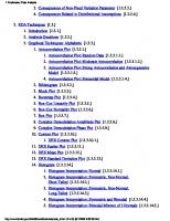
In North America the expression "muskeg" is in wide use. Those involved in the development of terrain are the primary users of the expression. The Chippewa Indians were among the first to recognize that the terrain to which "muskeg" is applicable has characteristic features. They named it "maskeg," which means grassy bog, a typical example of which is shown in Figure 1.1. This literal
FIGURE 1.1
Muskeg derived from Chippewa Indian "maskeg," meaning grassy bog
4
MUSKEG ENGINEERING
HANDBOOK
interpretation is not broad enough i n implication to meet contemporary need. Modern argument insists that vegetation other than grass (for example, F i g . 1.2) very frequently occurs and "bog" has uncertain meaning for the uninitiated. A survey to obtain the consensus of understanding on the accepted meaning of muskeg was started i n 1945 by N . W . Radforth, with the encouragement of the National Research Council of Canada. It was found that several basic aspects of meaning were needed to satisfy most of those who used the expression. T o provide widest satisfaction the following definition, which emphasizes "organic terrain" as a substitute expression, was provided: " 'muskeg' has become the term designating organic terrain, the physical condition of which is governed by the structure of the peat it contains, and its related mineral sub-layer, considered in relation to topo graphic features and the surface vegetation with which the peat co-exists." "Muskeg" is thus a term commonly used to convey "organic terrain" (Radforth 1952). The definition recognizes physiographic character, vegetal cover, peat, environmental association with underlying mineral soil, and topographic character. The living vegetation covering the terrain is composed of mosses, sometimes lichens, sedges and/or grasses, with or without tree and shrub growth. Usually combinations of these plant forms are found. Underneath this cover there is a
FIGURE 1.2
Contemporary usage of muskeg has broader connotation respecting vegetation
(a)
(b)
FIGURE 1.3 Peat (sometimes muck) is constituted of partially fragmented and chemically modified fossilized plant constituents
6
FIGURE 1.4
MUSKEG ENGINEERING
HANDBOOK
Muskeg implies organic landscape in a three-dimensional sense
mixture of fragmented organic material derived from past vegetation but now chemically changed and fossilized (Figs. 1.3 (a), ( b ) ) . This material is commonly known as "peat" or (less acceptably) as "muck." It is known that this subsurface material is highly compressible (MacFarlane 1958) compared with most mineral soils. The general terrain condition is typically very high in water content and is usually of extremely low bearing capacity. Implicit in the definition is a certain other connotation. The importance of three dimensions (area and depth) is implied (Fig. 1.4). The recognition that the materials (living cover and fossilized remains of past vegetation, i.e. peat) have generic association with the mineral base also has significance (cf. Fig. 1 . 5 ( a ) , ( b ) ) . Other features appear implicit in an understanding of muskeg. The presence of water is implied because of its necessary role as a fossilizing agent in the formation of the peat. Additional inference entails the presence of aerobic conditions, usually (though not always) high acidity, humic acids, peculiarities in ionic relations, a partly colloidal constitution, specialized physical and mechanical properties i m parted by the organic constituents, etc.
FIGURE 1.5 Muskeg signifies relationship between organic overburden and underlying mineral foundation
(a)
(b)
(a)
(d)
(e) (b)
(c)
(f)
FIGURE 1.6 Special engineering treatment is required for access and construction in muskeg. Mining, reclamation, conservation of water, forestry, and agricultural application are examples of operations that require special design
ENGINEERING
9
PROBLEMS
F o r some people "muskeg" may have a broader connotation, for example, specialized environmental control. Others may think of the terrain in terms of its behavioural characteristics; for example, its response to the forces of erosion, its change in organization with modification in water deployment, its response to freezing temperatures, or characteristics of either the peat or the terrain in relation to insulation. Thus, the meaning of muskeg is complex and the phenomenon it represents should not be viewed in simple terms if application is anticipated. Emphasis on meaning teaches the user to understand at the outset that organic terrain contrasts markedly with mineral terrain and that evaluation of it must involve new methods of approach and research. The importance of muskeg may now be appreciated. Engineers who must deal with it are already accustomed to designing for features characterizing mineral rather than organic terrain. The peculiarities of muskeg in terms of its properties arise embarrassingly in land-use engineering because these properties usually im pose limitations on the application of standard design approach which is devised for ordinary terrain conditions. In the first instance, access to organic terrain, whether by foot or vehicle, is difficult and in some circumstances impossible. The significance of muskeg is such that special engineering treatment is required for access and construction. Special design is needed for mining, reclamation, water conservation, forestry and agricultural operations (cf. Figs. 1 . 6 ( a ) - ( f ) ) . Estab lishment of primary and local road systems also calls for a particular approach where muskeg is encountered. Changes in terrain properties, for instance those associated with seasonal succession, further complicate the access problem (see Fig. 1.7(a), (b) showing vehicular access on the same kind of muskeg but at dif ferent seasons). The construction of foundations for a muskeg environment requires new design formulation and technique. Operations such as exploration for and^ production of petroleum and other resources, including peat itself, require s o c i a l consideration as does drainage control. Note, in addition, the examples suggested pictorially: (1) Figure 1.8, summer access over muskeg in a condition common to forestry practice; (2) Figure 1.9, establishing a pipeline in muskeg (note the immobilized dragline); (3) Figure 1.10, reclaimed muskeg. Where organic terrain is developed for use, engi neers are invariably required and may be called upon to re-establish or intensify drainage. There must be awareness and special ability concerning the use of machinery for working the peatland, disposing of the peat, or reclaiming the land for agricultural purposes. :
1.2
R E C O G N I T I O N
O F
M U S K E G
C O N D I T I O N S
Observers have little difficulty in recognizing organic terrain from the deck of an off-road vehicle or from a road. This is usually the case whether or not one can see exposed peat in the area. The reason is that where organic terrain commences
(a)
(b)
FIGURE 1.7
Vehicular access on a given kind of muskeg, but at different seasons
FIGURE 1.8 Summer access over muskeg in a condition common to forestry practice
FIGURE 1.9 in muskeg
Establishing a pipeline
FIGURE 1.10
Reclaimed muskeg
there is a change in the type of vegetation, and the new type persists far enough in the field of vision to form a significant component of the landscape. O n adjacent mineral terrain one can see, by contrast, great variability in the stature and form of individual plants and groups of plants constituting the cover. On organic terrain, the stature of the vegetation resolves itself into characteristic orders of height, with a single order featured by neighbouring plants en masse. If
12
MUSKEG ENGINEERING
HANDBOOK
(a)
(b)
(c)
FIGURE 1.11 Vegetal cover on muskeg is regularized as to stature, form, and texture (woodiness or non-woodiness). Differentiation of cover results in the presence of areas of contrasting physical arrangements
there is a change in stature, it is more often abrupt than gradual. In addition to uniform stature of the constituent plants, form also becomes regularized (cf. Figs. 1.11 ( a ) - ( c ) ) . Organic terrain may, and frequently does, show evidence of demar-
ENGINEERING
PROBLEMS
13
FIGURE 1.12 Building on a main street in Prince Rupert, BC, said to have one corner resting on a pile driven into peat over 70 feet deep
cation based on texture (woodiness as opposed to non-woodiness) as a feature conveyed by the plants en masse. Thus height, form, and texture in the cover, when considered comprehensively, serve not only to differentiate organic from mineral terrain, but also to enable the observer to distinguish different kinds of landscape within the organic terrain. The presence of areas of contrasting physical arrange ments is often encountered, even in small expanses of organic terrain extending for only one or two acres. On the organic terrain, when superficial vegetation is removed, there is no diffi culty in recognizing the underlying fossilized organic matter. This is the peat. It varies in colour from straw through golden brown to chocolate and black. It is the "legacy" of past cover. It may be coarse or fine, depending upon the structure of the proportionate components of past cover that became fossilized successionally. Sometimes it is only 2 or 3 inches (5.1 or 7.6 cm) in depth, but there are cases where deposits 90 feet (27.5 m) deep are said to have been encountered (Fig. 1.12). The peat may be so dry as to show no evidence of free water even when a sample is squeezed, or, on the other hand, it may give up sufficient water to run between the fingers (Figs. 1.13-1.15).
FIGURE 1.13
Peat with ice incorporated
FIGURE 1.14.
Peat with no free water
FIGURE 1.15
Peat in situ showing presence of free water
FIGURE 1.16 Aerial photograph showing organic terrainfillingthe depressions between the folds of Precambrian igneous foundation
16
MUSKEG ENGINEERING
HANDBOOK
If the peat is shallow, there will be no difficulty in detecting the underlying mineral soil or rock. Radforth (1962a) has found a complete range of mineral soil types beneath peat of one kind or another. Pure clay, silt, sand, coarse gravel, or boulders may occur, but usually there are admixtures of mineral soil. The soils may have been derived from glacial or lacustrine activity or may be on eroded non-glaciated upland. Occasionally one may find muskeg lying almost directly on sedimentary or igneous rock (Fig. 1.16). Differences contrasting vegetal cover for organic and mineral terrain are accom panied by a change in topography. This factor, apart from those characterizing the structure in vegetal cover, facilitates recognition of the immediate boundary of the muskeg. Topographic difference applies particularly and is most useful when the muskeg is "confined," that is, enclosed by upland of mineral soil or rock. One may encounter organic terrain on slopes (glaciated or unglaciated), in deltas, or on foundations of ancient lakes and rivers on any continent in tropical, subtropical, temperate, or arctic zones. Sometimes it is associated with kettle-holes or other postglacial features of the land, for example, with kames, eskers, and drumlins (Figs. 1.17(a), (b) and 1.18). When the peat has originated in a shallow basin, often the edge of the original depression in the landscape is overgrown by extensions of the peat deposit. Where this occurs, it is now known that the condition is detectable by the vegetal cover. It is not always a simple matter to discover the ultimate edge of the area of organic terrain under investigation. If the original peat deposit has spread excessively or a number of secondary centres each overgrowing have arisen spontaneously, analysis of the situation becomes very complex. This complexity will be appre ciated if reference is to be made to the type of underlying mineral soil or to the prevalence of one type of peat or another in the organic overburden. In these cir cumstances, the organic terrain is "continuous" or "unconfined" (Radforth 1962b). The "interruptions" of features of inorganic landscape enclosing "con fined" muskeg are lacking. Where muskeg is unconfined, the vegetation will continue to show structural differentials, but often the differences noted characterize phenomena inherent in the organic overburden itself and are thus recent in origin. In both confined and unconfined muskeg, topographic features often characterize local conditions. These are known as microtopographic features and are sometimes helpful as indices of ready reference in recognizing local conditions within organic terrain (Fig. 1.19(a), ( b ) ) (Radforth 1952, 1955).
1.3
E N G I N E E R I N G
S I G N I F I C A N C E
O F
D I S T R I B U T I O N A L
P H E N O M E N A
Concern for the muskeg phenomenon for engineering purposes will be broad or narrow, depending upon the kind of implication facing the observer or investigator. Ultimately, engineers must assess the muskeg state and the problems it presents
(a)
(b)
FIGURE 1.17
Muskeg boundary in apposition with kames (confined muskeg)
1 8
MUSKEG ENGINEERING
HANDBOOK
FIGURE 1.18 Muskeg boundary in apposition with esker (confined muskeg)
prior to a design intended to meet the specified objectives associated with one or more operations. "Design" is the important word in this complex. It is also important to recognize that muskeg with its panorama of characteristics and peculiarities presents limitations. Often the limitations are characteristic, and represent recurring circumstances. This is probably due to repetitious states which for each type of muskeg produce a peculiar range of mechanical potential. The behaviour of the design model will always give the same response when the model is applied in such circumstances. This effect should reassure rather than dismay the engineer because it helps in the delineation of safety factors and may also facilitate prediction. Another element in gaining adequate application is implied in the expression "operations" and this circumstance imposes another kind of limitation for engineer ing implementation. Usually the terms of operations are inflexible. Time, method, and financing are involved. From the point of view of engineering interests in muskeg, therefore, there are three areas to which attention must be directed with some emphasis: (1) design and the two limiting factors, (2) total muskeg consti tution, which is unique and fixed, and (3) operations in which stringency is in herent. It matters little what branch of engineering is involved; planning, design, and implementation must adjust to a formula in which conditions imposed by the limiting factors are satisfied. This circumstance specifies for and controls engineer ing practice in muskeg. If the designer acknowledges it, empiricism will be avoided and testing will be minimized; much preliminary analysis will be unnecessary and avoided. Inadequacy or failure will ensue, or over-design will arise if adjustments for proposed installations do not allow for total environmental assessment of the organic medium. If the operation contemplated is highway construction, the design engineer must be aware of the dynamics of the water regime in the muskeg
(a)
(b)
FIGURE 1.19
Contrast in microtopographic difference in two areas of organic terrain
20
FIGURE 1.20
MUSKEG ENGINEERING
HANDBOOK
One condition of muskeg which invariably floods in spring
to be crossed. Design should not be regarded as complete until he has considered the seasonal behaviour of the water-ice components within the environment. For instance, one kind of muskeg will invariably flood in spring, another will not (Fig. 1.20). Design for consolidation and stability, construction of grade and subgrade, and location of culverts will require appropriate treatment. Require ments for intensity and frequency of loading will also have to be considered in relation to total, year-round environment. The process of modification naturally commences with the survey for road location and if, finally, the muskeg must be crossed, its fixed conditions become limiting and must be met. The mechanical engineer is also closely involved with the problems posed by muskeg. The importance of specified design and limitation already mentioned is encountered in vehicle mechanics when off-the-road access over muskeg is required. There are examples where expensive vehicles and drainage machinery have been developed without proper consideration of the inherent, fixed design in the organic terrain. Immobilization, when it ensues in these cases, portrays failure of purpose, serious interruption in operations, and perhaps more significantly inadequacy, if not irresponsibility, in engineering practice. It is not generally known that the feature of muskeg which now provides the
ENGINEERING
PROBLEMS
21
greatest difficulty for amphibious vehicles is microtopography. One would expect that shear or bearing capacity might provide the major source of trouble. This was the case several years ago perhaps, but it is no longer so. In vehicle design, the limits of tolerance for ground pressure are known, whereas much still has to be learned about design for suspension systems (Fig. 1.21 (a), ( b ) ) . This is not to say that the other features characterizing muskeg, now sometimes expressed in quantitative or quasi-quantitative terms, are not significant, but they are not as important as they once were. Ultimately, for optimum success, all repetitive features of the terrain must be matched by analogous mechanical equivalents aptly co-ordinated in the vehicle. The muskeg environment calls for specialization in sampling. The design of testing equipment requires interdisciplinary application and involves the co operation of electrical, mechanical, hydraulics, and materials engineers with soil and design experts. The muskeg environment also requires the judgment of the geologist, geographer, and applied palaeobotanist whose interests overlap those of engineers. The agricultural and forestry experts working with the engineers provide specialized knowledge without which operational success cannot be expected. Chemical engineering in muskeg studies also involves specialization. The manu facture of commodities from peat is virtually undeveloped, but research must precede utilization. It is here that there is need for the services of chemical engi neers. The physical and chemical differences in peat which could lead to its exploitation have not yet received sufficient attention. F o r example, there is interest in the use of peat in the pelletizing process in iron ore refinement. In this connection, insufficient attention has been given to the primary constituents of peat and to the properties of various peat structural categories. These may vary widely, but in a reasonably predictable way. Table 1.1 categorizes engineering discipline and the muskeg environment in relation to engineering significance.
1.4
DESIGN
F O R
R E S E A R C H
Confusion sometimes arises between engineering research and engineering testing. It is important to differentiate between these kinds of endeavour as a principle in a design system. Examination of Table 1.1 suggests, with respect to all the items listed, that interpretative study reflecting organization in muskeg establishes the main direction to be taken in research. In an effort to reveal the unknown - the basic objective of research - one could easily slip into an elaborate programme of ad hoc field sampling and testing to secure data for an immediate engineering need. Economic and operational pressures often encourage this approach. The results, having been empirically sought, are too often narrow in their application and
(a)
(b)
ENGINEERING
23
PROBLEMS
TABLE 1.1 Engineering significance of muskeg Engineering discipline Aerial interpretation
Purpose of involvement Road location Drainage survey Reservoir location Communications installations Hydro-electric systems locations Land utilization interpretation Foundations analysis Resource location
Single examples Service road (Fig. 1.22) Peat exploitation To satisfy requirements for dam site Rail-bed maintenance Service transmission line right-of-way Economics for timber exploitation Tank farm installation Drilling sites (petroleum)
Operations optimization Transportation research Trafficability analysis Vehicle-terrain adaptation Mechanical design (appliances) Instrumentation Drainage assessment Drainage control Drainage manipulation (forestry, agriculture, high ways, general construction) Peat exploitation Peat product manufacturing Vehicle adaptation Equipment adaptation
Military transport Track design Off-road supply Specified off-road access Drainage ploughs Peat density probe
Engineering survey
Townsite location
Sanitation engineering
Services distribution Subsurface ice evaluation Industrial waste dispersal Water utilization Pollution control Sewage disposal
Planning appropriate road network Positioning sewage Foundation stabilization Sewer location Water source selection Peat water diversion Disposal bed improvement
Materials evaluation Physical properties of peat Peat mechanics Muskeg characterization Prediction for utilization Environmental interpretation Optimization studies Environmental manipulation
Bearing strength Permeability study Stability analysis Peat structure representation Pelletizing Range of foundation conditions Pulpwood operations Water diversion
Design engineering
Hydraulics
Agricultural engineering
Engineering research
Watershed capacity Dam construction Water diversion techniques Pipeline construction Water content assessment Four-wheel-drive tractor Ditch location
FIGURE 1.21 An amphibious vehicle which can successfully accommodate to bearing capacity and strength of muskeg, but not to microtopography, if its performance is to be regarded in relation to the optimal requirements
24
MUSKEG ENGINEERING
HANDBOOK
FIGURE 1.22 Service road through tree-covered muskeg area (Hydro-Electric Power Com mission of Ontario, Little Long Rapids Development)
inspire little confidence because they fail to interpret the total muskeg environment. They signify testing but not research. They do not portray fact in an adequate context. A s an example, it is not enough to embark upon an elaborate scheme for deter mining the properties of peat and associated mineral soil in anticipation of road design since seasonal change in the water regime, for instance, will so change local conditions as to seriously influence subsidence. Cases exist for which a soil sampling programme (or something less) has been accepted. Usually it has been accepted on an assumption that basic design for roads has been established. The sampling for properties, it should be emphasized, constitutes testing and is neces sary, but the results will not guarantee stability of the road until the proposed engineered configuration meets all the implications of the muskeg factor (Fig. 1.23). In addition to properties of material, several other factors should be assessed: affect of physiographic dynamics, disposition of peat types, association with mineral soil (interface geometry and its causes), behaviour of environmental water, and stability of the site. This does not exclude the possibility of revising basic design to accomplish new levels of standardization. Formulation of design for categories of cases still constitutes practical procedure, but a fair measure of sophistication is a necessary ingredient.
ENGINEERING
FIGURE 1.23
PROBLEMS
25
An example of severe subsidence in a highway over muskeg
Theory and hypotheses provide the background for interpretative judgment on muskeg conditions. There is an argument that propositional analysis imposes frustration on engineering practice because engineering application follows from factual not hypothetical evaluation. Theory and hypothesis about muskeg condi tions still beg the question in many instances when engineering requirement is imposed. O n the other hand, neither theory nor hypothesis will survive unless they arise from observation involving data derived by measurement. They set the pattern of evaluation and assist in departmentalizing reliable approach and field data to good practical purpose. Thus, where a road is to be constructed in the North, it is unwise to ignore the hypothesis that permafrost exists beneath peat cover of a certain definable type. That it does exist is so probable (and reasonable) that it has been demonstrated and tested as a predictable circumstance. Where it exists spasmodically, a road foundation, particularly if installed in the late summer, will show differential subsidence if the design is inappropriate. There is no excuse for ignoring this possible muskeg-permafrost relation, even though proof of its existence is not statistically a fact. If theory and hypothesis are accepted attitudes for engineering evaluation and design, the second argument is that engineering practice follows naturally on the disclosure of scientific principle and conclusion. To use examples so sharply
26
MUSKEG ENGINEERING
HANDBOOK
specified as road subsidence or instability to illustrate the relation between research and testing may be considered irrelevant. It is believed, however, that engineering research is a matter for consideration at all levels of application and that, where muskeg is involved, every engineered event should be preceded by pertinent pre liminary research. The event also involves special problems which must be solved before design consistent with good engineering practice can be judged as reliable. These are the problems that embody the research at whatever level they impinge.
1.5
M U S K E G
A N D
E C O N O M I C S
Operations in which muskeg is a primary factor are governed not only by the physical limitations of the terrain but also by economic systems. In relatively un developed countries the economics usually centre on the problems of undisturbed terrain. When the terrain already has been exploited, secondary adjustments are evident in the physical properties of the peat. The changes are caused either by long-term drainage or manipulation of gravitational water or by fires. The effects of these processes on the terrain result from the consolidation of the peat and inter ruption of the homogeniety of the deposits. The secondary disturbances reduce the ordinarily different terrain examples to a single order of likeness. The effect is superficial and, because of this, the application of economics and the classification of the deposits in depth is difficult to achieve by reference to the surface cover. This is transient and secondary and therefore not truly representative of conditions that would have ensued had man not interfered. Whether secondary manifestations are present or not, the first requirement for development or operations of all kinds is effective access to the area in question. A t first, if there has been no secondary change in the terrain, vehicles with a ground pressure no greater than 1.5 pounds per square inch (0.105 kg per sq cm) should be used to gain access in order to assist in the initiation of a drainage pro gramme. Where signs of secondary change exist, local consolidation in the peat sometimes permits the use of vehicles with a ground pressure of up to 5 pounds per square inch (0.39 kg per sq c m ) , provided the tracks are not aggressive to the point of destroying the top zone of the terrain profile where living and fossil components are mixed. Where open water occurs, vehicles should be amphibious. Observations gleaned from an adequate survey of the pertinent terrain conditions form the foundation for success in the economics of development. Once effective access and optimum drainage have been achieved, the peculiari ties of the imposed industry dictate the economics. In Britain, the Scandinavian countries, and particularly in Canada, the forestry industry relies upon year-round field activity. The economics of exploitation for organic terrain must be worked out accordingly. Special costing involving summer and interseasonal use of labour and the use of access and servicing roads for all phases of forestry operations have to be considered and absorbed in preparing cost estimates. Thus, the year-round
ENGINEERING
PROBLEMS
27
FIGURE 1.24 View showing peat stacks (blue peat), for use by the Highland Park Distillery, on the Orkney Islands
practice of forestry, either on or across muskeg, requires special economic evalua tion entailing examination of special machinery - track and/or wheel vehicles (especially articulated ones) - to effect access, grubbing, road construction over muskeg, cropping, and transport in and over exploited muskeg areas. This is now being achieved with remarkable success in forestry operations in Canada and to some extent in Sweden. In Britain (for example, in Wales, northern England, and Scotland) drainage of organic terrain for controlled reforestation has become highly successful as an economic venture. It has been pointed out (Hemstock 1959) that "wildcat wells in muskeg areas have shown summer road building and transportation costs as high as $500,000 per location." This statement was made in the hope of encouraging attention to the problems of working in muskeg. Hemstock has pointed to the need for scheduling work in the field to fit the seasons so that the work to be executed is of a type appro priate to the seasonal character of the muskeg in question. Emphasis is placed on the need for good engineering planning involving wisely chosen access routes and the use of airphoto interpretation and field reconnaissance. A n approach to relieve economic pressure at the drilling stage involves a method called "island drilling." If muskeg forms part of the overburden, the drilling site is placed on an "island" of clay which is floated on the muskeg. The ensuing directional drilling increases the costs but lessens the engineering difficulty. In the exploitation of the Pembina field, about $30 million was judged to be the price of dealing with the muskeg factor. Building gravel access roads over
28
FIGURE 1.25 settlement
MUSKEG ENGINEERING HANDBOOK
Cracking of house foundation in Prince Rupert, BC, caused by differential
muskeg costs about twice as much as it would if only mineral terrain were involved. Walsh (1957) indicated that access roads over muskeg in oilfields cost 1.45 times as much as those placed directly on mineral soil. In northern development to assist in the exploitation of resources and to facili tate tourism, the Alaska Highway provides a useful communication route. Muskeg impeded development of this highway and the high costs of construction bear wit ness to this fact (us Government Printing Office 1961). During its construction, costs were kept to a minimum by avoiding either excavation of peat or placing of corduroy. Usually fill was placed directly on the muskeg surface. Costs to restore the grade after expected settlement amounted to about $15,000 per mile in five years (Thomson 1957). Where muskeg intervened, costs for grading were in creased by 60 per cent. Thomson (1957) stated that the life of a road constructed over muskeg is shorter than it is for one where peat is lacking i n the foundation. Also, the subsequent cost of patching and raising the grade has to be anticipated. Davis (1961) and Harrison (1955) have both reported on the high and variable costs for roads over muskeg in establishing access and haul roads in forestry practice.
ENGINEERING
PROBLEMS
29
The principles of economics turn about certain special aspects of muskeg development. In government surveys the distribution and classification of muskeg are under consideration with a view to making the wisest use of the resource. O n the northern fringe of land development in Canada, the existing economic principle appears to stress the use of muskeg for forestry purposes except in northern Alberta and British Columbia, where some agricultural use of muskeg has been suggested. A s mining of peat becomes more economical, it is anticipated that a trend already begun to move large quantities of peat to the greenhouses of the south to increase crop productivity will be intensified. Recently, the mining of peat by hydraulic methods and its subsequent delivery by pipeline has been attempted in Canada. Because peat regenerates so slowly, it is classifiable as a non-renewable resource. Exploitation of it as an energy source (for example, in the Falkland Islands, Ireland, and the U S S R ) or as a product for use in industry (see, for example, F i g . 1.24) will require restudy if the outlook for the economics of food productivity continue to darken. The main economic factor for organic terrain, pending further exploitation for certain major industries, relates to construction. The building of roads, tank farms, northern townsites and buildings is the contemporary concern (Fig. 1.25). In permafrost country the need to preserve the muskeg in its natural state is para mount in the construction of building foundations. The problem is how to maintain the insulating effect of the peat and vegetal cover to discourage differential and local thawing below the ground surface. A most important economic implication of muskeg is related to the northern source of Canada's water supply. Modification of peat type following engineering activities undoubtedly alters the permeability of peat and may destroy or greatly change the natural control system for retaining seasonal gravitational water.
REFERENCES DAVIS, A. E . 1961. Road construction for forestry practice in Northern Ontario. Proc. Seventh Muskeg Res. Conf., NRC, ACSSM Tech. Memo. 71, pp. 92-102. HARRISON, w. c. 1955. Primary and secondary access over muskeg in forestry practice. Proc. Western Muskeg Res. Meeting, NRC, ACSSM Tech. Memo. 38, pp. 6-13. HEMSTOCK, R. A. 1959. Muskeg - a review of engineering progress. Can. Surveyor, Vol. 14, No. 10, pp. 470-477. M A C F A R L A N E , I. c. 1958. Guide to a field description of muskeg (based on the Radforth Classification System), NRC, ACSSM Tech. Memo. 44, rev. ed. 36 pp. RADFORTH, N . w. 1952. Suggested classification of muskeg for the engineer. Eng. J., Vol. 35, No. 11, pp. 1199-1210. 1955. Organic terrain organization from the air (Altitudes less than 1000 ft.): Handbook No. 1, Defence Research Board, Dept. Nat. Defence, DR. NO. 95, Ottawa, 49 pp. 1962a. Organic terrain and geomorphology. Can. Geog., Vol. VI, No. 3-4, pp. 166-171.
30
MUSKEG ENGINEERING
HANDBOOK
1962b. Why and how does muskeg occur. Proc. Eighth Muskeg Res. Conf., NRC, ACSSM Tech. Memo. 74, pp. 145-151. THOMSON, s. 1957. Some aspects of muskeg as it affects the Northwest Highway System. Proc. Third Muskeg Res. Conf., NRC, ACSSM Tech. Memo. 47, pp. 42-49. us GOVT, PRINTING O F F I C E . 1961. Transport requirements for the growth of northwest
North America. House Doc. No. 176, Vol. 2, pp. viii-2-36, ix-2-7, Washington, DC Res. Rept. Battelle Memorial Inst, on an integrated transport system to encourage economic development of Northwest North America. WALSH, j . p. 1957. Some economic aspects of construction in muskeg areas, with par ticular reference to oilfield roads. Proc. Third Muskeg Res. Conf., NRC, ACSSM Tech. Memo. 47, pp. 33-41.
2
Classification of Muskeg
Chapter Co-ordinator N. W. RADFORTH
2.1
N A T U R A L
RELATION.*
T H E BASIS
O F
C L A S S I F I C A T I O N
In the methodology of reference to the phenomena, character, and dynamics of muskeg, engineering classification must satisfy requirements in two areas of inter est: the muskeg condition itself and its two kinds of constituent material, peat and the overlying living vegetation. In both areas the natural relation (basically biotic), if used as the expression of organization, makes possible the prediction of terrain states and an intelligent design for engineering application. Utilization of an arti ficial (unnatural) approach to classification does not render it invalid but does invoke extensive explanation and interpretation because of the need for reconcilia tion with natural trends. Otherwise, prediction techniques would be cumbersome and oblique and have less than desirable reliability. Furthermore, a natural system of classification facilitates comparison and integration with other subsidiary or different approaches to classification which are used in other disciplines and are not emphasized in this Handbook. A n example of the latter is the differentiation of peat by reference to p H or chemical content (Woods 1950). In acknowledging muskeg condition as distinct from its constituent material, it is appreciated that gross differences in muskeg are often the expressions of inte grated characteristics or the result of environmental character combined with that of the constituents. T o justify classification of muskeg states, therefore, one must rely upon the classification of type features exemplifying peat and vegetal cover types and account somehow for the significance of the environments in which they exist. Classification, as presented here, conforms to this logic and presents first the hidden features, i.e. those characterizing the structure of the peat.
2.2
C L A S S I F I C A T I O N
A N D
P E A T
S T R U C T U R E
Only two structural entities are appreciated in gross samples of peat. One is fibrous, the other is granular. These designations imply shape only and take no account of size, orientation, texture, or chemical constitution. They symbolize a value that is
32
MUSKEG ENGINEERING
HANDBOOK
not necessarily botanical or even organic. It is important to understand that the very small granules may behave as colloidal particles, which implies that peat is partly colloidal. Varying degrees of the colloidal state must be expected. The water and dissolved compounds associated with peat are important physical constituents, but they are no more intrinsic than water would be in establishing the meaning of "clay." In engineering application, some if not all qualifications to the descriptions of the constituents must be incorporated if either a qualitative or quantitative concept of peat structure is to be gained. F o r classification purposes it can be assumed that peat is entirely organic, even though wind- or water-conveyed mineral matter occasionally adulterates it. The texture of the elements has obvious significance, and an attempt has been made to explain this quality, particularly with reference to fibres, by MacFarlane and Radforth (1968), who proposed the name "axon" not only to convey linearity but also to provide a model upon which secondary physical attributes of the fibres could be imposed. Where the concentration of "axons" varies in characteristic ways i n the peat sample, and distribution of cellu lose (non-woody) and lignocellulose (woody) is involved, texture becomes signifi cant as a structural quality. Laboratory analysis is necessary to assess texture if quantitative answers are required, but woodiness and non-woodiness in the gross sense can be determined qualitatively from hand samples in the field. A qualitative analysis is often all that is required for initial engineering reference and purpose. F o r comprehensive interpretation, botanical (anatomical) knowledge of the two basic ingredients of peat is a help and encourages precision (Eydt 1962), together with an understanding of the environment from which the sample was taken and an appreciation of the range of textural difference occurring at the site. There are other advantages to the application of botanical knowledge, but these are referred to elsewhere (Radforth 1967).
2.3
FLORISTIC
C O N S T I T U T I O N
O F
P E A T
Apart from texture, botanical inference occasionally has to be considered by the engineer if the only information available about the peat has been provided in botanical terms. Sometimes peat type is named in floristic terms. One of these is sphagnum peat, which designates peat containing 60 per cent or more of sphagnum moss ( A S T M 1967). Sedge peat, another floristic designation, implies that the major botanical constituent is composed of one or more species of sedge (plants that are grasslike in appearance). Sphagnum peat has great water holding capacity and high insulating value in contrast with sedge peat, which has better binding qualities and in gross samples is less elastic. Neither constituent is woody. In the United States, when the fibrous condition is implied, the components involved may be either sphagnaceous or sedge-grassy, or both, in structural character, but in Britain sphagnaceous peat is designed separately and fibrous peat is always
33
CLASSIFICATION
sedge peat. The confusion thus created can be largely avoided if physical values, no matter how qualitative, can be used instead of botanical ones. If it is necessary to use floristic names for general purposes - say, to effect broad understanding of the material - this has some engineering merit and explains the origin of the struc tural units. Physical value enables understanding and eventual computation in deriving mechanical properties. Texture in the sense claimed has significance for the evaluation of bearing strength, compaction and consolidation, elasticity, poro sity, permeability, cohesion, and tensile strength. T o these features, botanical derivatives contribute proportionately, but all of them are functions of physical quality.
2.4
S T R U C T U R E
A N D
P R O P E R T I E S
O F
P E A T
Both fibres and granules have variable and partial influence on the gross mechani cal potential, depending upon the three-dimensional size of the elements. Fibres a foot (30.5 cm) or more in length are stronger than shorter fibres. This has great significance in the field. Under either static or dynamic load, long-fibre peat endures and sustains load under critical circumstances. Granules will respond physically in one way when colloidal in size, in another way when larger and participating as particles in a mechanical mixture. Both orders of size occur, often in the same sample, but in differing proportions. It is recorded that the largest linear elements constituting the primary matrix of peat are of tree-trunk proportions (MacFarlane and Radforth 1968). These elements, when less numerous and sporadic, are desig nated in the literature as "woody erratics," an expression not originally intended to signify any particular orientation of the element in the matrix. If the connotation is now allowed to apply for all values of frequency within the matrix, the term has wider usefulness. There does not appear to be any reported method of assessing what provides the greatest contribution to strength and other mechanical properties of peat. Does this contribution come from the integrated mechanical effect of all the elements, or from the collective effect provided by special orientation and mechanical interrela tion of both fibres and granules in different densities of mesh? T o provide the best information on classification, information on gross arrangement should be given only after inspection of field samples is followed by structural analysis in the laboratory. If precise detail is required with statistical accuracy, no fewer than thirty samples from randomly selected sites in the muskeg involved should be examined. This procedure will assist in establishing data characterizing the pre dominating and characteristic structural arrangement with 80 per cent reliability (Ashdown and Radforth 1961). A t the outset, the investigator is advised to deter mine the peat category (Radforth 1952) to which the samples belong. This step in classification will place the sample in the main peat type without recourse to botanical interpretation.
34
2.5
MUSKEG ENGINEERING
T Y P I F I C A T I O N
O F
P E A T
HANDBOOK
S T R U C T U R E
In order to specify and account for basic structural identity, it is necessary to provide nomenclature that is referable to the botanical source of the elements in the peat and to the biological control system governing its structure. Acceptance of this principle helps in describing and delineating homogeneity (or perhaps heterogeneity) in the peat, consistency and persistence of character, and recur rence of distributional phenomena. More important, adherence to this principle facilitates relation between peat and cover. The cover, obviously biologically governed and the "progeny" of the ancestral constitution characterizing the peat, accounts indirectly for the peat structure subtending it. If there is provision for cross-reference, and proper use is made of it, interpretative reference to cover will indirectly imply the required structural information about the peat. When it is appreciated that cover may be viewed readily from either surface or air whereas peat structure cannot, the advantages of the correlative terminology are obvious. This provision is a particularly useful corollary of the principle proposed. Usually the typification required is for the peat deposit as a whole. Frequently this has to be attempted from a single core sample by an analyst who has not seen the deposit. In this case, the results of structural (macrofossil) analysis of the core will apply for the site from which the core was removed; but experience shows that extrapolation as to type beyond about 20 feet (6.10 m) from the core hole is dependent upon supportive evidence. Either more cores should be procured (which is sometimes impractical and expensive) or the existing sample should be microanalysed for additional evidence. Frequency relations of the fossil spores or cuticles procured from successive depths in the core can be taken as typical for a more extensive region than that defined by the structural (macrofossil) analysis and a region more extensive than that prescribed by the single core structural analysis (Radforth 1952). In addition, macrofossil remains cannot always be identified botanically to pro vide the information needed to suggest whether the structural entity itself would have characteristically widespread distributional significance. Microfossil consti tution gives less emphasis to highly local features atypical of the order of structural homogeneity than the observer sees in the main mass of peat for which microfossil characterization obtains. The microfossil conspectus thus offers an acceptable general basis for classification. It suggests (and also confirms) the composite macro-type. Moreover, the micro-type, through comparative study, facilitates com prehension of the macro-type in terms of biotic organization because identification is now in generic as well as structural terms, the generic evidence having been supplied by the microfossil factor. When structural typification of the peat deposit is confirmed and complete, categorization of the types encountered is possible. Descriptions of the peat cate gories (Table 2.1) combine information about structural essentials in the peat
35
CLASSIFICATION
TABLE 2.1 Classification of peat structure Predominant characteristic 4#norphous-granular
Category 1 2 3 4 5 6 7
Fine-fibrous
8 9
Coarse-fibrous
10 11 12 13 14 15 16 17
Name Amorphous-granular peat Non-woody,fine-fibrouspeat Amorphous-granular peat containing non-woody fine fibres Amorphous-granular peat containing woodyfinefibres Peat, predominantly amorphous-granular, containing non-woodyfinefibres,held in a woody, fine-fibrous framework Peat, predominantly amorphous-granular containing woodyfinefibres,held in a woody, coarse-fibrous framework Alternate layering of non-woody,fine-fibrouspeat and amorphous-granular peat containing non-woody fine fibres Non-woody,fine-fibrouspeat containing a mound of coarse fibres Woody,fine-fibrouspeat held in a woody, coarse-fibrous framework Woody particles held in non-woody,fine-fibrouspeat Woody and non-woody particles held infine-fibrouspeat Woody, coarse-fibrous peat Coarsefibrescriss-crossingfine-fibrouspeat Non-woody and woodyfine-fibrouspeat held in a coarsefibrous framework Woody mesh of fibres and particles enclosing amorphousgranular peat containingfinefibres Woody, coarse-fibrous peat containing scattered woody chunks Mesh of closely applied logs and roots enclosing woody coarse-fibrous peat with woody chunks
matrix and are sufficiently comprehensive and detailed to characterize the basis for identification of the recurring peat types. Each category of the list of 17 is pictorially represented in a comparative series (Figs. 2.1-2.16) except for Category 17 (Fig. 2.17). In this category the woody erratics are so large and so frequent that a photograph to the same scale as those for the other 16 categories would show merely a surface view of part of a single piece of fossilized wood. A view of the peat category as it appears in the landscape has been provided instead. This photograph shows how large and numerous the woody erratics are. Although for the inexperienced observer the photographs are aids to identification, the help they afford is limited and they are least useful when isolated. When classifying, the observer must use all the photographs compara tively along with the associated descriptions. A decision on identification should be made only following a fully comparative inspection of all sources of information. The choice of the expression "category" is deliberate. It is intended to imply that a range in proportion of the constituent materials is to be expected. Despite
FIGURE 2.1
Peat category 1
FIGURE 2.2
Peat category 2
FIGURE 2.3
Peat category 3
FIGURE 2.4
Peat category 4
FIGURE 2.5
Peat category 5
FIGURE 2.6
Peat category 6
FIGURE 2.7
Peat category 7
FIGURE 2.8
FIGURE 2.9
Peat category 9
FIGURE 2.10
Peat category 10
FIGURE 2.12
Peat category 12
FIGURE 2.11
Peat category 11
Peat category 8
FIGURE 2.13
Peat category 13
FIGURE 2.14
Peat category 14
FIGURE 2.15
Peat category 15
FIGURE 2.16
Peat category 16
this range, each category is distinctive and therefore acceptable. Every known "type" of peat fits naturally into one or another of these categories. Category descriptions (Table 2.1) not only convey basic form-texture informa tion, they suggest as well, but only in general terms, the primary feature of arrange ment of the peat constituents. The precise orientation of fibres and their size relations are not represented in the descriptions. The opacity of the samples makes it difficult to describe the orientation without more than normal field inspection of the samples. Laboratory dissection involving mechanical sorting reveals the rough proportions of described constituents, but the sorting interferes with the natural orientation and arrangement patterns of the constituents.
CLASSIFICATION
FIGURE 2.17
39
Peat category 17
A s a further aid to structural interpretation, Rockley and Radforth (1967) attempted to apply X-ray photography of samples taken with a Davis sampler. The photograph of the peat type for category 6 (Fig. 2.6) shows confusion between non-woody, woody fine-fibrous, and amorphous-granular constituents. A n X-ray photograph shows woody coarse fibres to be distinct and tortuous, travelling in no particular plane (Fig. 2.18). Non-woody fine-fibrous elements appear to lie usually in a horizontal plane and to alternate as layers with shallow plates of amorphousgranular. To symbolize the constituents graphically, diagrammatic configurations are shown in Figure 2.19. Combinations of these symbols in appropriate proportions make it possible to convey proportions of constituents and to differentiate pictorially between peat types (cf. dial configurations in Fig. 2.19(a), ( b ) ) . A peat category may include several types, but a type cannot belong to more than one category. F o r the present it is customary to accept a peat type as a commonly recurring subcategory. Until or unless there are types in certain or all categories that have special significance in either the scheme of biological order or in engineer ing application, no systematic value is assigned to them.
40
MUSKEG ENGINEERING HANDBOOK
FIGURE 2.18
2.6
X-ray photos of the peat type in peat category 6
S T R U C T U R A L
T Y P I F I C A T I O N
O F M U S K E G
C O V E R
The method of reference used here to describe cover is referred to by botanists as based on life form. Usually botanical systems are designed to describe or account for plant communities and are not directly applicable to engineering use. Dansereau (1951) and Dansereau and Segadas-Vienna (1952) developed this kind of phytosociological system based on life form. If in engineering application - say, to drain age - there is need for intensive study on distribution of plant communities in muskeg, Dansereau's system or its equivalent is recommended. The system recom mended here, on the other hand, is direct and has the advantage of revealing
41
CLASSIFICATION
TABLE 2.2 Properties designating nine pure coverage classes Woodiness vs. nonwoodiness
Stature (approximate height)
Texture (where required)
A B
Woody Woody
15 ft or over 5-15 ft
— —
C D
Non-woody Woody
2-5 ft 2-5 ft
— —
E F
Woody Non-woody
Up to 2 ft Up to 2 ft
— —
G
Non-woody
Up to 2 ft
—
H
Non-woody
Up to 4 in.
I
Non-woody
Up to 4 in.
Leathery to crisp Soft or velvety
Coverage type (class)
Growth habit Tree form Young or dwarfed tree or bush Tall, grasslike Tall shrub or very dwarfed tree Low shrub Mats, clumps, or patches, sometimes touching Singly or loose association Mostly continuous mats Often continuous mats, sometimes in hummocks
evaluations which relate the cover to the subsurface structural conditions already described. Detailed examination of the constituents of the peat types represented in Table 2.2, Figure 2.19(a), ( b ) , and comparison of them with the cover suggests that a given peat associates with characteristic cover composition, the classification of which will now be explained. The nine classes of vegetal cover listed in Table 2.2 and referred to in column 1 by the letters A to I are, like the peat categories, symbols of and functions of the structure in that they refer to the shape and texture of the individual elements making up the composition. In addition, they are indicative of size in that they refer to the height of the individuals. They also have reference to habit, the equiva lent of arrangement. This feature was implied in the description of peat categories. Thus each class is a characteristic entity conceived on structural evidence and in which limited range of variation occurs in one or several of the structural components. The occurrence of pure classes in nature is rare; association of classes is more normal. T o indicate proportionate representation of class, the letter symbols are combined into formulae. A formula is constructed as the observer in the field views the area which he has already delineated geographically; he mentally circum scribes the area. The predominating class of cover is usually, but not necessarily, the tallest. The components of lesser stature appear in the formula after the one indicating predominance, in the order of the relative lesser amounts of cover they constitute. If the estimated percentage of cover for any class is less than 25 per cent, it should not appear in the formula. Therefore, since four classes of cover are
(a)
FIGURE 2.19(a),(b) The commonly recurring cover formulae and associated peat types presented diagrammatically (cf. Table 2.2). Subsurface constitution: w cf, woody coarse-fibrous; w fT, woodyfine-fibrous;nwff,non-woodyfine-fibrous;ag, amorphousgranular
(q)
44
MUSKEG ENGINEERING
HANDBOOK
statistically unlikely to appear in exactly equal proportions of 25 per cent, no formula will show more than three classes. In many instances only two classes comprise a formula. Within the range of 25 per cent no attempt is made to provide secondary levels of class, because those classes with a share greater than 25 per cent constitute together the characterizing contribution of the structure of the underlying peat. It is known that this characterizing contribution, when completely fossilized, does not correspond exactly with cover class percentages. Some components of cover struc ture fossilize more readily and contribute more bulk to the peat than proportions of class factors in the cover formulae suggest. F o r a given cover formula, however, the end product of structural contribution is consistently the same. When classifying in the field, one is apt to forget that class symbols represent composite ideas. Stature is very important in the operation of classifying, but form, habit, and texture are equally important though perhaps less obvious to the observer. A l l these qualities share prominence with proportionate amounts for each cover class. A proportionate amount of class representation in cover formulae is as important as the fact of class presence in the formula.
2.7
I N T E R P R E T A T I V E
V A L U E
O F
S Y M B O L
S Y S T E M
Identification, achieved in the performance of selecting the appropriate symbols to characterize site, is an end in itself. Engineering use of this information affords further gains if interpretative implication is exploited. Each cover class indirectly signifies the occurrence of prevailing conditions which may be taken into account for purposes of engineering design. These conditions are listed in Table 2.3. Certain formulae signify qualification for the claims indicated in the several conditions of Table 2.3: (a) where Class A is prominent but followed by F in the formula, the peat is less well drained or drainable than if Class E follows; (b) where Class A is involved in a formula with H , drainage conditions are better throughout the year than for conditions in item 3 under Class A in Table 2.3; (c) the situation expressed in items (a) and (b) also obtain when, in those circumstances, B replaces A .
2.8
G R A P H I C
S Y M B O L S
F O R
T O T A L
C O V E R
T Y P I F I C A T I O N
Understanding of the meaning conveyed in formulae comprised of the class sym bols can be enhanced if diagrammatic synopses accompany the formula. Table 2.2 and Figures 2.19(a), (b) show proposed graphic characterization of the letter symbols. They also indicate how combinations of diagrams appear in association with their corresponding cover formulae. The combinations selected represent the commonest structural configurations and are shown in association with the cor responding diagrammatic expressions depicting the peat structure types.
TABLE 2.3 Occurrence of prevailing conditions for the various cover classes Predominant class in formula
Engineering significance
A
(1) Presence of large woody erratics in the peat (2) The position of relatively shallow depths of peat for the landscape as a whole (3) Location of best drained peat (qualified by items (a) and (b) in text) (4) Location of best drained mineral soil sublayer (5) Presence of highly permeable peat (6) Vicinity of lowest summer temperatures in the peat (7) Location of the coarsest, most durable peat (8) Best conditions for static load (see, however, item (c) in text) and dynamic loading
B
Same as for A above, but less intensively represented
C
Predominance rare, except in tropical and subtropical locations (for example, Guyana, Brazil, Paraguay and Uruguay, and possibly Southern Rhodesia, Nigeria, Tsrael, Malaysia, etc.) (1) Linear drainage, often an open water course (2) Lagg condition around a confined muskeg (bog) (3) Traps present (4) Good, but highly elastic, bearing conditions; difficult to consolidate and with marked patterned local differentials as to rate of consolidation (5) Features highly conducive to spring flooding (6) Silt in the mineral soil sublayers with highly mixed aggregate from outwash (7) Features conducive to differential settlement (often abrupt) under load
D
E
F
G H
I
Equally important as D above and is very common in temperate, arctic, and subarctic zones (1) High order of homogeneity in peat, even in relation to microtopography in which mounds, ridges, and ice knolls are important (2) Peat difficult to re-wet once drained of gravitational water (3) Conditions accommodating to certain articulated wheeled vehicles (Enright 1962) (4) Good cohesion and tensility, moderate elasticity even when water shows at the surface in the field (5) Easily drainable conditions (for free water) Presence of highly critical conditions when prominent in the formula: (1) Low points on drainage gradients (2) Muskeg with centres of extremely low bearing potential whether wet or relatively dry (3) Peat of low tensile strength and showing little elasticity unless the local water table is consistently high (small open pools the year round) (4) Sites where shear strength is lowest in muskeg at frequent intervals; water is not excessive Rarely predominates in the formula, is indicative of a highly fluctuating water table When predominant indicates presence of: (1) Permafrost and late seasonal subsurface ice conditions of uneven contour (2) Maximum range of microtopographic amplitude (often abrupt) for all muskeg (3) Local imponding and highly irregular, dissected drainage gradients (4) Relatively locally degraded peat (structurally and mechanically dis rupted (Eydt 1962)) Unless Class i is the only component comprising the cover formula (which is rare), it lacks prominence. When it is a single contributing factor in cover it is very local, usually no more than 4 or 5 m in area of coverage, and the following occur: (1) Vehicle immobilization on the second pass for amphibious vehicles (2) The base of minor or major drainage gradients
MUSKEG ENGINEERING
46 2.9
C O M P L E M E N T A R Y
S Y S T E M S
O F M U S K E G
HANDBOOK
R E F E R E N C E
The British Mires Research Group, realizing that characterization of structural features i n vegetal cover of peatland provides the lead to identification of terrain characterization i n the sense appreciated i n the present approach, recently de veloped another system. Their system, still tentative, is referred to in Table 2.4. A combination of this system with that shown i n Table 2.2 has been devised and presented in Table 2.5. The latter combines the essential values from both systems without being overcomplex. It is suggested that, even though the compromise is not used, it at least affords the means whereby the two fundamental systems (which arose independently) can be correlated. The combined system allows for the use of the class symbols now widely adopted in Canada (cf. Keeling 1961; Enright 1962) which are known to obtain for other areas of the world where peatlands occur (Radforth 1967). There is some advan tage i n using symbols because, if they are available, experience shows that field observers quickly learn how to use the letters without recourse to the details of description conveyed by them. This promotes rapid and convenient forms of notetaking and recording in comparative study and in communication among observers, field operators, and laboratory personnel. It also affords a medium of convenience in the comparison of conditions observed by different workers in widely separated areas and is useful in techniques of mapping or producing overlays for airphoto mosaics.
2.10
C O V E R
D E S I G N A T I O N
A N D T E R R A I N
P R O P E R T I E S
Microfossil constitution provides the ultimate key by which relations between vegetal cover and macro-structure in the peat are established. It also provides the TABLE 2.4 Vegetation (structure) Percentage of each structural type* 0-10 Trees over 5 m Trees under 5 m Shrub habit 50 cm-2 m Shrub habit up to 50 cm Creeping shrub up to 50 cm Broad-leaved herbs Sedge-graminoid habit 1-3 m (a) mats (b) hummocks Sedge-graminoid habit under 1 m (a) mats (b) hummocks Moss habit Lichen habit * Observer to insert percentages.
10-30
30-50
50-70
70-90
90-100
T A B L E 2.5 Structural classification of vegetal cover of muskeg (peatland) (integration of British and Canadian systems) British Mires Research Group*
Radforth system Class symbol
Texture
Form
Stature
Trees over 5 m
A
Woody
15 ft or over (4.5 m or over)
Tree form
Trees under 5 m
B
Woody
5-15 ft (1.5-4.5 m)
Young or dwarfed tree or bush
Shrub habit 50 cm to 2 m
D
Woody
2-5 ft (0.6-1.5 m)
Tall shrub or very dwarfed tree
Shrub habit up to 50 cm Creeping shrub up to 50 cm
E
Woody
Up to 2 ft (up to 0.6 m)
Low shrub
Broad-leaved herbs
G
Non-woody
Up to 2 ft (up to 0.6 m)
Singly or loose association
Sedge-graminoid habit 1-3 m (a) mats (b) hummocks
C
Non-woody
2-5 ft (0.6-1.5 m)
Tall, grasslike
Sedge-graminoid habit under 1 m (a) mats (b) hummocks
F
Non-woody
Up to 2 ft (up to 0.6 m)
Mats, clumps, or patches sometimes touching
Moss habit
I
Non-woody
Up to 4 in. (up to 10 cm)
Often continuous mats, sometimes in hummocks
Lichen habit
H
Non-woody
Up to 4 in. (up to 10 cm)
Mostly continuous mats
NOTE: Following classification, observer states percentage of cover class within 20%. * Adapted by Radforth.
48
MUSKEG ENGINEERING HANDBOOK
link with natural attributes. Although classification of subsurface mechanical composition made indirectly by reference to structural composition in vegetal cover is on a non-floristic basis, explanations of relation - if required - are floristically entailed through the medium of microfossils. It is possible in very general terms to place additional quasi-quantitative values on qualitative structural composition as developed to this point. MacFarlane (1968) attempted to assess peat type with the use of a shear vane, but identity of type for classification purposes is difficult to establish because shear values are functions not only of structure but also of water content. Furthermore, the size of vanes relative to the arrangement of the structural elements in the peat is difficult to optimize and the values obtained are highly empirical (see Section 5.2(1) ) . O n the other hand, the results suggest the effect of water and mechanical degradation of peat type in relation to depth for peat beneath specified cover formulae. The results also differentiate peat types in depth and in association with accompanying water but on a relative basis only. Other attempts at demonstrating the strength of the peat-cover complex were made through the application of a field instrument which became known as a "fluke" or "anchor." This instrument (Fig. 2.20) is secured to the muskeg mat by
FIGURE 2.20 A muskegflukeinserted in the cover and underlying peat to determine strength values when the terrain complex undergoes shear
49
CLASSIFICATION
its steel rods, and the mat will shear when an appropriate force is applied to an attached cable. If a dynamometer is attached to the cable, tension values can be read off at the time the mat shears. Table 2.6 shows comparative values obtained for different cover formulae. Their usefulness becomes apparent for purposes of identification only when it is appreciated that cover formulae indicate the presence of range in strength value for a given peat category. Individual values may differ with differences in water content. TABLE 2.6 Fluke test results on muskeg (August 1961, Parry Sound, Ont.) Test site Area VTS* 1 1 1 1 1 2 2 2 2 5 3 3 4 4 4 4
1 1 2 3 3 1 1 2 2 1 1 1 2 2 3 3
Cover formula
Average forceshearing (lb)
FI, wet between EI mounds EI mounds, E ~ i FIE EI mounds, E ~ i FI (low, wet area) FI (very wet), dense F EI mounds, dense E IF, i very dense EI mounds, E = i DFI (very wet) FI (very wet) EI mounds, E = i FI, F = i IE hummocks FIE, F = i EI hummocks
2100 1650 2450 1467 2667 2483 2788 1700 1933 1950 1650 2050 2417 1717 2367 2600
*VTS = Vehicle test site.
Similar attempts at establishing identity on a quantitative basis have involved the use of the cone penetrometer (cf. Rush, Schreiner, and Radforth 1965). With out some means of correcting for the influence of water and possible secondary compression phenomena, it is difficult to demonstrate characterization in accord ance with cover or peat category. Strength (shear) values regularly increase with depth, but the degree to which this change occurs is now known to depend upon the local prevalence of gravita tional water i n the terrain. In well-drained muskeg, cone penetrometer values generally double with depth for given cover formulae. This relation is hard to demonstrate however for cover formulae; the values are erratic and show great deviation from the average ( O A T R U , McMaster University 1966). If the water factor is considered on the basis of macro-climate rather than micro climate, for a given cover formula there are wide differences in the strength of peat type as expressed by cone penetrometer values. F r o m comparisons of values taken at 3-inch (7.62-cm) intervals of depth, peat beneath E I cover deposits are con siderably stronger near the surface in the Falkland Islands (unconfined muskeg) than they are in the Parry South district of Ontario (confined muskeg). The same
50
FIGURE 2.21
MUSKEG ENGINEERING
Peat density measurements, Parry Sound, Ontario
HANDBOOK
CLASSIFICATION
51
relation holds for peat deposits beneath FI cover in the two areas, but do not hold where F E I is encountered. F o r F E I , Parry Sound peats were stronger up to a depth of 2 feet (61.0 c m ) , after which strengths were comparable for the two areas. For peat below 2 feet, greater strength was experienced in the Parry Sound peat than in the Falkland Island peat. In these analyses the local conditions with respect to free water in the terrain were judged comparable on a qualitative basis. The peat per given structure category is denser and harder where water sources are largely from high humidity and precipitation rather than from lateral inflow of water in the ground. Recently, a nuclear density-moisture probe for measuring relative differences in density of peat type was devised (Radforth and Radforth 1965) and is still being tested. This instrument shows great promise for assessing the influence of water on density. But even before the water factor is accounted for, total density in the mass can vary with the cover formula as expressed in Figure 2.21. Subsequent work has shown, however, that peat density under a given cover category has a range of values, and that the ranges for different cover categories overlap to some degree. To the extent that characteristic delineation is possible, density difference is a feature of identity and can be incorporated into the general classification system with other physical measurements derived on the quasi-quantitative basis. The allusion to water and climate as bearing on classification suggests that, once the materials (peat and cover) are classified by a method incorporating reference to observable features in the field, the physiographic connotation in muskeg can be accounted for in classifiable terms. Thus, the geographic extent and shape of areas, characterized according to a given cover formula can be mapped. The shape of the areas so characterized indicates ground-water deployment and microand macro-configurations which relate to the natural aspects of order symbolized by the pertinent formulae (MacFarlane 1958). There are still features of order that have not been accounted for. Deploy ment of subsurface ice (Radforth 1954, 1961), permafrost occurrence, geomorphic difference (Radforth 1968), and major drainage systems are the end reflections of organization involvement yet to be identified and classified in both confined and unconfined states. Some may argue that extension of the system so far into environmental values (extra biotic) requires application not only of classification but also of interpretation. This aspect is emphasized in chapter 3 and the broadest aspects of muskeg character will be dealt with there.
REFERENCES 1967. Rules On packaging peat and peat moss. Proposal submitted to Nat. Conf. on Weights and Measures. ASHDOWN, K . H . and N . W . RADFORTH. 1961. The procurement of physical and mechani cal data for organic terrain. Proc. Sixth Muskeg Res. Conf., N R C , A C S S M Tech. Memo. 67, pp. 88-104. A M E R I C A N SOCIETY FOR T E S T I N G A N D MATERIALS ( A S T M ) .
52
MUSKEG ENGINEERING HANDBOOK
DANSEREAU, P. 1951. Description and recording of vegetation upon a structural basis. Ecology, Vol. 30, No. 2, pp. 172-229. DANSEREAU, p. and F . SEGADAS-VIENNA. 1952. Ecological study of the peat bogs of eastern North America. Can. J. Botany, Vol. 30, pp. 490-520. ENRIGHT, c. T . 1962. The muskeg factor in the location and construction of an Ontario Hydro service road in the Moose River basin. Proc. Eighth Muskeg Res. Conf., NRC, ACSSM Tech. Memo. 74, pp. 42-58. E Y D T , H . R. N . 1962. A n assessment of the component tissues of peat in their in situ arrangement. Unpubl. PHD thesis. McMaster University, Hamilton. 89 leaves. K E E L I N G , L . 1961. The organic terrain factor and its interpretation. Proc. Seventh Mus keg Res. Conf., NRC, ACSSM Tech. Memo. 71, pp. 102-126. M A C F A R L A N E , I. C 1958. Guide to a field description of muskeg (based on the Radforth Classification System). NRC, ACSSM Tech. Memo. 44, rev. ed., 36 pp. 1968. Engineering studies of peat soils (muskeg). Trans., Second Internat. Peat Congress (Leningrad, 1963), Vol. II, pp. 853-862, H.M.S.O., Edinburgh. M A C F A R L A N E , I. c and N . W . RADFORTH. 1966. Structure as a basis of peat classification. Unpublished manuscript. ORGANIC A N D ASSOCIATED TERRAIN RESEARCH UNIT
(OATRU).
1966. Unpublished field
notes. Muskeg Lab., McMaster University, Hamilton. RADFORTH, N . w. 1952. Suggested classification of muskeg for the engineer. Eng. J., Vol. 35, No. 11, pp. 1199-1210. 1954. Paleobotanical method in the prediction of subsurface summer ice con ditions in northern organic terrain. Trans. Roy. Soc. Can., Vol. XLVIII, Series III, Section Five, pp. 51-64. 1961. Organic terrain. In Soils in Canada, edited by R. F . Legget. University of Toronto Press. Roy. Soc. Can., Spec. Publ. 3, pp. 113-139. 1967. Muskeg and climate. Paper presented at Can. Bot. Assoc. Meetings, Ottawa (manuscript). 1968. The principles of airphoto interpretation as related to organic terrain. Trans., Second Internat. Peat Congress (Leningrad, 1963), Vol. I, pp. 231-240, H . M . S . O . , Edinburgh.
RADFORTH, N . w. and J . R. RADFORTH. 1965. The significance of density as a physical property in peat deposits. J. Terramechanics, Vol. 2, No. 3, pp. 81-88. ROCKLEY, J . c and N . w. RADFORTH. 1967. Structural interpretation of peat by X-ray techniques. Unpublished manuscript. RUSH, E . s., B. G. SCHREINER, and N . w. RADFORTH. 1965. Trafficability tests on confined organic terrain (muskeg): Rep. 2, volume 1: Summer 1962 tests. U.S. Army Corps of Engrs., Waterways Exp. Sta., Tech. Rept. No. 3-656, pp. 1-48. Vicksburg, Miss. WOODS, A. B. 1950. Unpublished data from work-book at Muskeg Laboratory, McMaster University, Hamilton.
3
Airphoto Interpretation of Muskeg
Chapter Co-ordinator N. W. RADFORTH
3.1
A I R F O R M
P A T T E R N S
Inspection of muskeg cover at ground level does not readily reveal the presence or absence of organization beyond that suggested by cover formulae. O n unconfined muskeg contiguous cover formulae show a random distribution in which characterization is not apparent. It is not until the association of cover formulae is viewed from the air that evidence of other kinds of organization can be appre ciated. The most convincing demonstration of how organization reveals itself and provides the basis of large-scale patterned landscape comes from examination of aerial photographs taken at successive levels of altitude (Figs. 3.1-3.4). Vehicle tracks may be noted through F I muskeg in Figure 3.1. In the perspective repre sented by the 5000-foot (1525-m) altitude photograph ( F i g . 3.2), they facilitate orientation for the interpreter whose attention also turns to the development of a patch pattern. This pattern resembles terrazzo and consequently it has been given the designation "Terrazzoid" (Radforth 1956a, b ) . The full visual effect of the pattern can be appreciated best at 17,000 feet (5185 m) (Fig. 3.4). Even in the photograph taken at 10,000 feet (3050 m ) ( F i g . 3.3) the pattern attracts the attention of the observer perhaps more than any other feature, and there is no difficulty about its identification. It is important to emphasize that this pattern recurs, and that in Canada it is found almost without exception in the northern part of the Northwest Territories and in northern Quebec. It is now known to occur in northern U S S R near the Ob River, and is commonest where permafrost is continuous on lands where the underlying mineral terrain is almost flat, or where, if irregularities do occur, they are infrequent and low in contour (usually 2 to 3 feet (0.61 to 0.91 m ) ). Farther south, where Terrazzoid is lacking, if the hidden mineral terrain is largely featureless, the cover is likewise largely featureless, i.e. textureless. In these circumstances there is little outcropping of underlying mineral terrain and where it does occur, the outcrop is low, with long, gently rising shoulders. The featurelessness is so marked, especially from altitudes of 10,000-30,000 feet ( 3 0 5 0 -
FIGURE 3.1
Terrazzoid airform pattern near Churchill area from 1000-ft altitude
FIGURE 3.2
Terrazzoid airform pattern near Churchill area from 5000-ft altitude
FIGURE 3.3
Terrazzoid airform pattern near Churchill area from 10,000-ft altitude
FIGURE 3.4
Terrazzoid airform pattern near Churchill area from 17,000-ft altitude
FIGURE 3.5 A map of Canada showing distribution of areas where common cover formulae occur most frequently (published with permission of the Defence Research Board, Canada Department of National Defence)
FIGURE 3.6 Arrangement of airform pattern distribution when the limits of the patterns are estimated in accordance with present knowledge
58
MUSKEG ENGINEERING
HANDBOOK
9150 m ) , that the condition has been named "Dermatoid" (skinlike) (Radforth 1956a, b ) . If water is relatively plentiful in this environment, the vegetal cover on the peat is F I ; if less plentiful, its structure appears as E I . Dermatoid, unlike Terraz zoid, has maximum distribution in the south, usually south of the discontinuous permafrost zone. Evidence of a third expression of organization is in the form of a marbled pattern. The components of pattern are highly convoluted and make fre quent contact. This pattern was named "Marbloid." It is common in muskegcovered terrain in which permafrost exists, but it may occur where permafrost is discontinuous. In this circumstance it is isolated and not easily discernible. There is a fourth pattern, with a background usually featureless, superimposed with stippling in various arrangements, called "Stipploid." Although it does occur in permafrost country, it is commoner to the south of it. Finally, a fifth pattern reveals itself as composed of a network or reticulum of terrain elements. The "net" is normally associated with open water which is dis tributed in characteristic fashion. This pattern is called "Reticuloid." It occurs independently of permafrost and is found as far north as Terrazzoid. These patterns, when first described, were designated "Airform Patterns" (Radforth 1956a, b) (Figs. 3.7-3.14). They recall similar associations of com ponents of certain other natural media. Consequently, inexperienced observers can easily recognize these patterns. O n a map of Canada showing the distribution of areas where common cover formulae occur plentifully (Fig. 3.5), areas where each airform pattern occurs in highest frequency can easily be superimposed (Fig. 3.6). In the designation of airform pattern, it is concluded from Handbooks Nos. 1 and 2 published earlier (Radforth 1955, 1958) that altitude is important. Handbook No. 1, describing experience gained through direct observation of the terrain for altitudes up to 5000 feet (1525 m ) , deals with a relatively narrow geographical perspective and the pattern is therefore in large scale. Elements of the pattern seen at 20,000-30,000 feet (6100-9150 m) (Radforth 1956b), in terms of indirect (airphoto) inspection, represent a scale of 1 mile to the inch (approx.).
3.2
L O W - A L T I T U D E
A I R F O R M
P A T T E R N
When Reticuloid is viewed at altitudes lower than 5000 feet (1525 m ) , secondary features of organization may become evident. The components of the reticulum are of three orders of length, the longest being greatly attenuated (Fig. 3.7). Decreasingly lesser degrees of attenuation will be noted in Figures 3.8 and 3.9 respectively. To facilitate classification and reference, these three kinds of reticula, the com ponents of which are tortuous, have been named Vermiculoid I, n, and i n (worm like) (Radforth 1958). Certain other airform patterns, when viewed at altitudes of less than 5000 feet
AIRPHOTO
INTERPRETATION
59
(1525 m) reveal elements of organization not appreciated at high altitude. The stippled effect in Stipploid takes on a third dimension which can be interpreted in terms of stature and form. T o emphasize this feature, the units involved are referred to as "apiculations" and the collective condition is designated "Apiculoid" (Fig. 3.10). Marbloid when viewed at low altitude reflects considerable relief, and the marbled units appear to have depth and sometimes to overlap as do cumulus clouds. The detailed pattern was, therefore, named "Cumuloid" (Fig. 3.11). Terrazzoid reflects its basic character when viewed from altitudes of less than 5000 feet (1525 m) and more than 1000 feet (305 m ) , but secondary attributes also appear. The lighter units in Terrazzoid are raised "islands" in an open roughtextured background which they appear to interrupt. The high frequency of inter ruption suggests the name "Intrusoid" (Fig. 3.12). Dermatoid from altitudes between 5000 and 1000 feet remains textureless in that the vegetation is not broken either in form or (significantly) in stature. For this reason the condition was designated "Planoid" (Fig. 3.13), but one can detect changes in the colour of the vegetation across an area. One feature of the secondary pattern which arises in permafrost country and as a relic beyond the zone of permafrost discontinuity is the closed polygon (Rad forth 1958). Sometimes it overlaps Cumuloid, Terrazzoid, Dermatoid, or Apicu loid. "Polygoid" (Fig. 3.14) is the term used for this condition. Definitions of these low-altitude airform patterns are given in Table 3.1, and mapping symbols are shown in Fig. 3.15.
3.3
P R E D I C T I O N
Airphoto interpretation leading merely to identification of terrain features (for example, airform patterns), though basic, is of little use to the engineer without additional analysis. The next step involves interpretation directed towards user re quirement, with the primary airform pattern as the medium on which interpretation TABLE 3.1 Description of airform patterns for 1000-5000-foot altitudes over organic terrain Planoid Apiculoid Vermiculoid Vermiculoid i Vermiculoid n Vermiculoid in Cumuloid Polygoid Intrusoid
An expanse lacking textural features; plane Fine-textured expanse; bearing projections Striated, mostly coarse textured expanse; featured markings tortuous Striations webbed into a close net and usually joined Striations in close association, often foreshortened and rarely completely joined Striations webbed into an open net, usually joined and very tortuous Coarse-textured expanse with lobed or fingerlike "islands" prominent; components shaped like cumulus clouds Coarse-textured expanse cut by intersecting lines; bearing polygons Coarse-textured expanse caused by frequent interruptions of unrelated, widely separated mostly angular "islands"; interrupted
FIGURE 3.7
Vermiculoid i airform pattern near the Churchill area from 5000-ft altitude
F I G U R E 3.8
Vermiculoid n airform pattern near the Churchill area from 1000-ft altitude
FIGURE 3.9
FIGURE 3.10
Vermiculoid in airform pattern near the Churchill area from 1000-ft altitude
Apiculoid airform pattern near the Churchill area from 1000-ft altitude
FIGURE 3.11
Cumuloid airform pattern near the Churchill area from 1000-ft altitude
FIGURE 3.12
Intrusoid airform pattern near the Churchill area from 1000-ft altitude
FIGURE 3.13
Planoid airform pattern near the Churchill area from 1000-ft altitude
FIGURE 3.14
Polygoid airform pattern near the Churchill area from 1000-ft altitude
FIGURE 3.15
Mapping symbols for airform patterns, 1000-5000-ft altitudes (after the author)
AIRPHOTO
INTERPRETATION
65
should be made. To anticipate every engineering need is virtually impossible, but it will help to propose a number of broad semi-hypothetical examples, each general in implication yet narrow enough to be of practical use. It is intended that each example will offer direction for a wider spectrum of common but subsidiary or related types of engineering need. In the first of these examples, the site is in Precambrian Shield country where granitic folds have precipitous sides. The centre of reference is the cover formula F I classified either from direct low-altitude inspection (under 5000 feet (1525 m) ) or the equivalent in an airphotograph by application of interpretative knowledge. If the latter approach is used, determination of the cover begins by recognizing the presence and distribution of medium gray texture in the photograph (cf. Radforth 1955). The airform pattern (Dermatoid) will show distribution of colour (patchiness) in irregular "blotchy" admixtures with slightly darker gray background, which represents relatively drier muskeg with another kind of cover (transient and casual in influence). Perhaps the predominating cover formula ( F I ) is already known from a site examination. If airform pattern is required to effect wider interpretation, the use of collateral evidence derived from ecological and physiographic features will lead to the designation of Dermatoid. F o r Stipploid, Terrazzoid, or Reticuloid, experience has also confirmed that the structure of these patterns as it appears on airphotos would be correspondingly characteristic and recognizable from the ground. If inspection is first made from the ground, the beginner will have some difficulty deciding on the pattern because of either inadequate perspective or overdevotion to, and misplaced emphasis on, local detail. The combination of the relatively wet condition of the F I with the slope, dispo sition, and kind of associated mineral terrain limiting the Dermatoid pattern en ables the observer to conclude that the water promoting peat formation is from run-off and/or springs, probably from the latter. The hydrology is defined by the expression "horizontal fen." Fen implies that most of the flood or retained water originates from the surrounding mineral terrain. If the disposition and frequency of the surrounding upland elevations compare favourably with the granitic folds of the Precambrian Shield in Quebec province, the muskeg will be floating and the depth is likely to be 20-30 feet (6.1-9.1 m ) , and is often more. If, in the photograph or at the actual site, little rock is exposed and vegetation is not interrupted significantly, the slopes will be soil covered. The enclosed muskeg is then shallow, unless localized glacial action induced formation of a kettle hole (Radforth 1962), in which case the peat is deep and floating. In making summaries, it is useful to designate geological conditions with appropriate expressions, for example, kame, esker, drumlin, and moraine (see Glossary). These expressions usually indicate that, where F I occurs, the underlying peat will be deeper and wetter the year round (this is also the case for F I within granitic folds) than for F I bordered by terraces or strands. In interpretative information, it is useful to indicate clearly whether the muskeg
66
MUSKEG ENGINEERING
HANDBOOK
is confined or unconfined. This knowledge helps in deciding how the water re sources of the muskeg behave and how they can be controlled. Construction and drainage require an approach and a design that are appropriate to local conditions. F I in confined muskeg is usually associated with either the lagg (an open-water rim at the perimeter of the muskeg) or an open or hidden drainage channel that runs generally in the long axis of the confined area. Interpretative activity leads directly to recognition of the engineering problem predictable in the light of all applicable facts. Cone penetrometer values and peat density determinations made i n accordance with the explanation in the foregoing chapters will reveal strength differences and will assist in arriving at engineering decisions. The mechanical attributes of the peaty material are characteristically different from those for any other cover formula (cf. Table 2.2). Collectively, the values will signify: (1) need for corduroy (or equivalent), (2) design to allow for medium to high primary consolidation with little secondary compression, (3) low elasticity, (4) most rapid rate of deterioration under mechanical stress or drying action, (5) low buoyancy, and (6) very low cohesive strength following remoulding. It is realized that these interpretative expressions are highly qualitative and - in the range of peat types (Table 2.1) - relative in meaning. Their usefulness lies in the fact that they segregate the mechanical behaviour of this recurring peat type from the behaviour of other common types. The terms are those of first approxima tion, but they assist the judgment process in determining the design parameters, and augment other advice in the prediction summary. Finally, with the other interpretative features they facilitate identification of specific problems within the major engineering problem. It is not yet possible to differentiate peat types or categories in quantitative soil mechanics terms of void ratio and permeability. For peat, cohesive strength, elasticity, density, water content, water diffusion potential, and bearing strength may be the significant quantitative expressions for design detail. A s yet, these values have to be determined empirically in the field and laboratory once classifica tion is complete. F r o m the total analyses, the primary engineering problem and design parameters are identified. By the use of prediction summaries, a kind of knowledge that soils engineers will find strange can be co-ordinated. Departure from the procedure used for mineral soils is to be expected; the media are genetically distinct, ordered differ ently, and behave in contrasting fashion. If these differences are acknowledged, soil mechanics may provide secondary (detailed) information for extended prediction summaries. F o r example, information of the type shown in Figure 3.16 may be utilized to express qualitative values of peat structure and behaviour. Prediction for engineering purposes is difficult for the observer using high-alti tude airphotography unless there is some indication of what airform pattern means in terms of cover formula. Table 3.2 shows the common cover formula characteriz ing airform patterns. Classes H , F , and E , in that order, signify increasing intensity
AIRPHOTO
INTERPRETATION
FIGURE 3.16 The association of cone index values in peat beneath related cover formulae showing attempt to express order of homogeneity in peat on the basis of distribution of strength relations (after Radforth and Ashdown 1963)
67
68
MUSKEG ENGINEERING
HANDBOOK
of grayness in the airphotos. This information, along with any collateral material gleaned from interpretative practice, will help in deciding on the correct formula. The observer should then consult the earlier chapters of this Handbook for peat type distribution and record the results on overlays on the airphotos. TABLE 3.2 High-altitude airform patterns and related cover formulae Marbloid Stipploid Reticuloid Dermatoid Terrazzoid
E H , HE, EI, BEH, BHE A E H , AEI, AFI, BEI, DFI FI, FIE, FEI, BFI FI, EI, FEI HE, FI, E H
If the engineering purpose is known, interpretative activity allows the observer to predict basic engineering problems that will occur for given muskeg conditions. Association of proposed types of engineering purpose with muskeg conditions and the problems that arise for the designer are given below. The first of these examples is the summary for the analysis already presented. Prediction Summary 1 Purpose: Gravel service road - limited light traffic; Precambrian Shield, Northern Quebec Airform pattern: Dermatoid Cover formula and peat type: F I Peat category: 2 interrupted by 3 (cf. MacFarlane 1958); 8 and 9 locally present immediately to east Interpretative features: (a) Geomorphology of site: confined muskeg; Precambrian trough; shallow sand to gravel overburden separates outcrops; floor of deposit uneven with mineral deposit (clay locally, silt sand to gravel more widespread, especially silt); no subsurface ice after early spring flooding (b) Hydrological type: horizontal fen; spring-fed and run-off source; water retention not (as yet) due to beaver dam; persistent lagg; seasonal flooding; diffuse drainage direction to narrow channel shallow gradient (c) Microtopography: featureless (cf. MacFarlane 1958, Table n, pp. 26, 27) (d) Macrotopography Engineering problems and predictions (through interpretation) : subsidence with unidirectional sliding to west highly possible; no lateral ditching required (or desirable); establish off-takes to channel; culvert 6 f t ( 1 . 8 3 m ) i n diameter at south end of traverse or bridge essential; culvert 3 ft (0.91 m) in diameter at northwest end of traverse essential; corduroy entire length of traverse (design embankment for flotation); do not excavate peat anywhere on traverse; peat must not be drained (keep wet to surface)
AIRPHOTO
INTERPRETATION
69
Prediction Summary 2 Purpose: Proposed traverse by an armoured amphibious, tracked personnel vehicle Airform pattern: Dermatoid Cover formula and peat type F I Peat category: 2 interrupted by 3 (cf. MacFarlane 1958); 8 and 9 locally present immediately to east Interpretative features: (a ) Geomorphology of site: as for Summary 1 (b) Hydrological type (c) Microtopography: featureless (cf. MacFarlane 1958, Table n, pp. 26, 2 7 ) ; presence of soft patches 2 ft ( 0 . 6 m ) in diameter every 20 to 25 ft (6.1 t o 7 . 6 m ) (d) Macrotopography: as above Engineering problems and predictions (through interpretation): the vehicle will make a single pass under half load without immobilization in any direction; the soft spots signify limitation for full load pass - otherwise two passes without load, one with load, may be made Prediction Summary 3 Purpose: Forestry road; heavy transport Airform pattern: Dermatoid Cover formula and peat type: E I Peat category: 13 Interpretative features: (a) Geomorphology of site: granitic folds dipping characteristically (cf. Summary 1) (b) Hydrological type: fen with water retention (see Summary 1) (c) Microtopography: mounds; knolls (ice) spring and autumn; peat depth 16.5 ft (5 m) max. or 11.5 ft (3.5 m) av. overlying sand and some granitic domes (d) Macrotopography: as above Engineering problems and predictions (through interpretation): completely dis place peat at laggs (with sand); corduroy not necessary; excavation not neces sary; drainage to F I with off-takes; no lateral ditches: will cause subsidence; install berm on loaded side of highway; culverts at laggs (allow for quite tempo rary thaw flooding); use slash in foundation; do not destroy E cover: endfill over it Prediction Summary 4 Purpose: Traverse for same armoured vehicle as used in Summary 2 Airform pattern: Dermatoid Cover formula and peat type: E I Peat category: 13
70
MUSKEG ENGINEERING
HANDBOOK
Interpretative features: (a) Geomorphology of site: granitic folds dipping characteristically (cf. Summary 1) (b ) Hydrological type: fen with water retention (see Summary 1) (c) Microtopography: mounds; knolls (ice) spring and autumn; peat depth 16.5 ft (5 m) max. or 11.5 ft (3.5 m) av. overlying sand and some granitic domes (d) Macrotopography: as above Engineering problems and predictions (through interpretation): 25 passes, full load; 75 passes, no load Prediction Summary 5 Purpose: Secondary road with asphalt Airform pattern: Stipploid Cover formula and peat type: A E I Peat category: 16 Interpretative features: (a) Geomorphology of site: continuous muskeg; morainic outwash on old preglacial lake-bed; eskers traverse the area at intervals not shorter than 5 miles; peat depth 2 to 5 ft (0.61 to 1.52 m ) : 5 ft depths rare (b) Hydrological type: horizontal fen (treed); flooding very rare; not spring fed; retains enough moisture to enable peat to form (c) Microtopography: mounds (amplitude of height max. 3 ft (0.91 m ) ) and knolls (ice); few visible deadfalls (d) Macrotopography Engineering problems and predictions (through interpretation): excavate peat; establish lateral ditching; off-takes seldom required; interim culverts essential; subsurface silt; clay beneath "dirty" coarse aggregate (shallow - about 1.65 ft (0.5 m ) ) Prediction Summary 6 Purpose: Traverse for same armoured vehicle used in Summary 2 Airform pattern: Stipploid Cover formula and peat type: A E I Peat category: 16 Interpretative features: (a ) Geomorphology of site: as for Summary 5 (b ) Hydrological type: as for Summary 5 (c) Microtopography: as for Summary 5 (d) Macrotopography Engineering problems and predictions (through interpretation): difficult to mount coalescing ice knolls from softer foundation (other cover formula) until mid-
AIRPHOTO
INTERPRETATION
71
summer; track wear severe; smaller trees must be overridden; difficulty reversing; expect down-time; driver fatigue Prediction Summary 7 Purpose: Construction of forestry service road Airform pattern: Stipploid Cover formula and peat type: A D E Peat category: 15 Interpretative features : (a) Geomorphology of site: shallow glacial imponding; much local outwash from moraine sources and mixed glacial deposits leaving shallow silts and clays (mostly the former); mixed aggregate beneath. (b) Hydrological type: horizontal fen muskeg; flood-plain type but in local sites in major area, i.e. multiple flooding for extended period of the spring thaw and run-off; some residual pools in summer and water courses traversing with D F I cover (c) Microtopography: traps in groups every 100 ft (30.5 m) (approx.); group about 300 ft (91.5 m) wide; single trap shallower than for D F I ; peat commonly only 1.65 to 3.3 ft (0.5 to 1 m) deep; many deadfalls (d) Macrotopography: as above Engineering problems and predictions (through interpretation): excavate peat; frequent 2 ft (0.61 m) culverts sometimes at regular 200-ft intervals; occasional 5 f t ( 1 . 5 2 m ) diameter culverts; ditches deep and close to foot of embankment; construct off-takes from lateral ditches to D F I natural gradients; spring flooding severe; construct gradient accordingly; some berming necessary if fill inadequate Prediction Summary 8 Purpose: Traverse for same armoured vehicle as used in Summary 2 Airform pattern: Stipploid Cover formula and peat type: A D E Peat category: 15 Interpretative features: (a ) Geomorphology of site: as for Summary 7 (b ) Hydrological type: as for Summary 7 (c) Microtopography: as for Summary 7 (d ) Macrotopography: as for Summary 7 Engineering problems and predictions (through interpretation): track damage; driver fatigue (pitch, roll, and evasion) - deadfalls will be a problem; imponded areas and D F I drainage gradients will present no problem for full load (10 passes) unless track approach is below upper edge of mat in emerging from a drainage course; approach narrow drainage courses on a slight angle if they are no wider than half the width of the vehicle
72
MUSKEG ENGINEERING
HANDBOOK
Prediction Summary 9 Purpose: Construction of service road: petroleum production programme Airform pattern: Stipploid (stippling uniform-not marginal) Cover formula and peat type: A F I Peat category: 10 Interpretative features: (a) Geomorphology of site: ancient shallow lake and flood plain with deeper 50 to 100-ft (15.25 to 30.5 m) wide local depressions; continuous muskeg (b ) Hydrological type: horizontal fen; combined flood and retention type (c) Microtopography: local areas of hummocks (estimated for av. 30 ft (9.15 m) across) (d) Macrotopography: local imponding (areas wider and deeper by 2 to 3 ft (0.61 to 0.91 m) than for A D E condition (cf. Summary 7 ) ) and sluggish gradients connecting Engineering problems and predictions (through interpretation) : high maintenance costs (re-establishment of grade) - local subsidence; "dishing" at shoulders; drain to chain of F I sites; maintain culverts joining F I interruptions of A F I ; design for interrupted corduroy where A = F in cover formula; no lateral ditching, use off-takes at culverts Prediction Summary 10 Purpose: 10-mile cross-country traverse with fully loaded armoured vehicle, same one as used for Summary 2 Airform pattern: Stipploid (stippling uniform-not marginal) Cover formula and peat type: A F I Peat category: 10 Interpretative features: (a) Geomorphology of site: ancient shallow lake and flood plain with deeper 50 to 100 ft (15.25 to 30.5 m) wide local depressions; continuous muskeg (b ) Hydrological type: horizontal fen; combined flood and retention type (c) Microtopography: local areas of hummocks (estimated for av. 30 ft (9.15 m) across) (d) Macrotopography: local imponding (areas wider and deeper by 2 to 3 ft (0.61 to 0.91 m) than for A D E conditions (cf. Summary 8 ) ) and sluggish gradients connecting Engineering problems and predictions (through interpretation): local immobiliza tion (where A = F ) likely; if route chosen to favour >70 per cent cover for A , travel will be optimized (i.e. deviation minimum, subsidence least embarrassing, minimum slip, pitch and roll, two passes) Prediction Summary 11 Purpose: Construction of asphalt road; secondary road for mixed travel - public use
AIRPHOTO
INTERPRETATION
73
Airform pattern: Dermatoid (linear) Cover formula and peat type: D F I Peat category: 15, with occasional interruptions of 11, especially to right and left of proposed right-of-way Interpretative features: (a) Geomorphology: glacial outwash configurations; subsequent erosion by paralleling stream drainage; confined muskeg (b ) Hydrological type: horizontal fen; terraced flooding type (c) Microtopography: traps (av. width about 5 ft (1.52 m) ) (d ) Macrotopography: lining shallow stream; some open water Engineering problems and predictions (through interpretation): excavate peat; use bridge - culvert system; install lateral ditching 20 ft (6.1 m) wide and centred 70 ft (21.35 m) from foot of shoulder on downstream side of crossing gradient; displace silt and/or clay under roadbed; high spring flooding and rapid flow around culvert and bridge abutments Prediction Summary 12 Purpose: Traverse of 50 ft (15.25 m) by fully loaded armoured vehicle, same one as used for Summary 2 Airform pattern: Dermatoid (linear) Cover formula and peat type: D F I Peat category: 15, with occasional interruptions of 11, especially to right and left Interpretative features: (a) Geomorphology of site: glacial outwash configurations; subsequent erosion by paralleling stream drainage; confined muskeg (b ) Hydrological type: horizontal fen; terraced flooding type (c) Microtopography: traps (av. width about 5 ft (1.52 m) ) (d ) Macrotopography: lining shallow stream; some open water Engineering problems and predictions (through interpretation): avoid widest traps causing immobilization; cover obstructs vision but do not remove it; force vehicle over traps; 50 passes in one direction if stream bank mounted where D = F locally, otherwise bank cannot be mounted Prediction Summary 13 Purpose: Secondary road construction (gravel top) Airform pattern: Stipploid in vicinity of infrequent Marbloid and Reticuloid Cover formula and peat type: A E H Peat category: 16 Interpretative features: (a) Geomorphology of site: glacial outwash; shallow ridges, domes and fans; continuous muskeg (b) Hydrological type: horizontal fen interrupted by aapa fen; sometimes sloping fen; sometimes "bog mire" (blanket and raised types: European systems)
74
MUSKEG ENGINEERING
HANDBOOK
(c ) Microtopography: mounds; ice knolls persist to mid-August (d) Macrotopography Engineering problems and predictions (through interpretation): site changes character (ice action and thawing); disturbance of properties i n foundation; extended season of thaw (subsurface); differences in gravitational water con tent; construction problems of supply and fill installation; excavation and corduroying not recommended; lateral ditching acceptable; ditches 3 to 5 ft (0.61 to 0.91 m ) in width 80 ft (24.4 m ) from toe of embankment; shoulder sloughing probable at irregular intervals; differential subsidence and consolida tion a function of peat and thaw subsidence sudden; construct in summer Prediction Summary 14 Purpose: Cross-country traverse of fully loaded armoured vehicle, same one as used for Summary 2 Airform pattern: Stipploid in vicinity of infrequent Marbloid and Reticuloid Cover formula and peat type: A E H Peat category: 16 Interpretative features: (a) Geomorphology of site: glacial outwash; shallow ridges, domes and fans; continuous muskeg (b) Hydrological type: horizontal fen interrupted by aapa fen; sometimes sloping fen; sometimes "bog mire" (blanket and raised types: European systems) (c ) Microtopography: mounds; ice knolls persist to mid-August (d) Macrotopography Engineering problems and predictions (through interpretation): no immobiliza tion except in late summer; very rough; driver fatigue; route deviation a factor; treed obstacles; deadfalls no problem; immobilization mounting edge of coales cing ice knolls (late summer) Prediction Summary 15 Purpose: Construction of segment of secondary road (gravel) Airform pattern: Marbloid 80 per cent; interrupted with Reticuloid, some Poly goid (5000 ft (1525 m ) inspection) Cover formula and peat type: 80 per cent H E ; F I depressions; E H edges plateaus Peat category: 6 interrupted by 1 (where ponding occurs); 3 (low areas F I ) ; 4 (plateau edges) Interpretative features: (a) Geomorphology of site: glacial outwash configurations in permafrost landscape (b) Hydrological type: unconfined muskeg; combination horizontal fen (aapa type) and coalescing "bog mire" (raised) (c) Microtopography: mounds, ridges
AIRPHOTO
INTERPRETATION
75
(d) Macrotopography: open and closed ponds; vertical banks; irregular peat plateaus; subterranean drainage; ice is active and on short- to long-term perma frost Engineering problems and predictions (through interpretation): foundation to be kept frozen all year; differential thawing; do not excavate; search for gravel where H predominates or A interrupts locally; no ditching; off-takes infrequent and short Prediction Summary 16 Purpose: Traverse with fully loaded armoured vehicle, same one as used for Summary 2 Airform pattern: Marbloid 80 per cent; interrupted with Reticuloid, some Polygoid (5000 ft (1525 m ) inspection) Cover formula and peat type: 80 per cent H E ; F I depressions; E H edges plateaus Peat category: 6 interrupted by 1 (where ponding occurs); 3 (low areas F I ) ; 4 (plateau edges) Interpretative features: (a) Geomorphology of site: glacial outwash configurations in permafrost landscape (b) Hydrological type: unconfined muskeg; combination horizontal fen (aapa type) and coalescing "bog mire" (raised) (c) Microtopography: mounds, ridges (d) Macrotopography: open and closed ponds; vertical banks; irregular peat plateaus; subterranean drainage; ice is active and on short- to long-term perma frost Engineering problems and predictions (through interpretation): slippery slopes (subsurface ice); steep short slopes (3 ft (0.91 m ) ) ; shallow narrow clefts cause deviation; serious pitch and roll; bearing strength fails i n closed ponds (immobilization); open ponds have steep banks; heavy fuel consumption; driver fatigue; passes: number unpredictable depending on standard of terrain knowl edge, otherwise 20 loaded, 50 unloaded Prediction Summary 17 Purpose: Road construction-secondary road (gravel) Airform pattern: Marbloid with frequent (40 per cent) interruptions of Derma toid Cover formula and peat type: E H Peat category: 13 interrupted at irregular intervals by 6 Interpretative features: (a ) Geomorphology of site: as for Summaries 15 and 16 (b) Hydrological type: unconfined muskeg; horizontal fen with superimposed "bog mire" (European) (c) Microtopography: mounds, ice knolls, ridges
76
MUSKEG ENGINEERING
HANDBOOK
(d) Macrotopography: regular peat plateaus; gentle slopes 1 ft in 50 ft (0.3 m in 15.25 m) (frequent) Engineering problems and predictions (through interpretation): shoulder dishing; irregular consolidation; sliding; avoid parallel ditching; berms locally distri buted (i.e. not continuous); difficult to keep frozen; do not disturb cover; no corduroy if berms used; culverts at F I ; F E H interruptions; do not cause i m ponding Prediction Summary 18 Purpose: Traverse with fully loaded armoured vehicle, same one as used for Summary 2 Airform pattern: Marbloid with frequent (40 per cent) interruptions of Derma toid Cover formula and peat type: E H Peat category: 13 interrupted at irregular intervals by 6 Interpretative features: (a ) Geomorphology of site: as for Summaries 15 and 16 (b) Hydrological type: unconfined muskeg; horizontal fen with superimposed "bog mire" (European) (c) Microtopography: mounds, ice knolls, ridges (d) Macrotopography: regular peat plateaus; gentle slopes 1 ft in 50 ft (0.3 m in 15.25 m) (frequent) Engineering problems and predictions (through interpretation): driver fatigue but not so intensive as for Summary 16; pitch and roll moderate; F I interruptions should be avoided (can be done with little deviation); slippage at near peak of slopes; little downtime Prediction Summary 19 Purpose: Construction of local road (gravel) near mining community Airform pattern: Dermatoid (circular to circular-lobed) Cover formula and peat type: E F I Peat category: 6 Interpretative features: (a) Geomorphology of site: drumlin landscape with general morainic features; kettle holes (b) Hydrological type: horizontal fen spring fed or "bog mire" (flat bog com plex: European system); confined muskeg (bog) (c) Microtopography: mounds and ridges (d) Macrotopography Engineering problems and predictions (through interpretation): corduroying necessary (i.e. float road); appropriate construction at lagg (with large diameter culverts); avoid possibility of "folding" or "sinking" along centre line; spring flooding at lagg (edge of E F I ) deeper and wider than for D F I conditions (cf.
AIRPHOTO
INTERPRETATION
77
Summary 11); sinkage will certainly occur without corduroy; avoid parallel ditching; construct off-takes to F I thence to lagg; keep foundation moist; flooding will be mainly at lagg; keep road embankment to 3 ft (0.91 m) of aggregate; settlement is severe but uniform Prediction Summary 20 Purpose: Traverse using armoured vehicle, same one as used in Summary 2 Airform pattern: Dermatoid (circular to circular-lobed) Cover formula and peat type: E F I Peat category: 6 Interpretative features: (a) Geomorphology of site: drumlin landscape with general morainic fea tures; kettle holes (b) Hydrological type: horizontal fen spring fed or "bog mire" (flat bog complex: European system); confined muskeg (bog) (c) Microtopography: mounds and ridges (d) Macrotopography Engineering problems and predictions (through interpretation): bellying (im mobilization) after two passes with full load; ten passes (no load); failure likely at one track (locally soft, Cover Class i ) ; proper navigation and good operator can avoid sinkage for four passes (full load)
REFERENCES C . 1958. Guide to a field description of muskeg (based on the Radforth Classification System). N R C , A C S S M Tech. Memo. 44, rev. ed. 36 pp. R A D F O R T H , N . w. 1955. Organic terrain organization from the air (altitudes less than 1000 feet): Handbook No. 1. Defence Res. Board, Dept. Nat. Defence, DR NO. 95, Ottawa, 49 pp. 1956a. The application of aerial survey over organic terrain. Proc. Eastern Muskeg Res. Meeting, N R C , A C S S M Tech. Memo. 42, pp. 25-30. 1956b. Muskeg access, with special reference to problems of the petroleum industry. Trans. Can. Int. M i n . Metall., Petrol, and Nat. Gas Div., V o l . L I X , pp. 271-277. 1958. Organic terrain organization from the air (altitudes 1000 to 5000 feet): Handbook No. 2. Defence Res. Board, Dept. Nat. Defence, DR NO. 124, Ottawa, 23 pp. 1962. Airphoto interpretation of organic terrain for engineering purposes. Trans. Symp. Photo Interpretation, Intern. Archives of Photogrammetry, Vol. X I V , Delft, Holland, pp. 507-513. R A D F O R T H , N . W . and K . H . ASHDOWN. 1963. Design in organic terrain and its effect on trafficability. Paper presented at First Regional Meeting, Intern. Soc. for TerrainVehicle Systems, Durham, NC.
M A C F A R L A N E , I.
4
Engineering Characteristics of Peat Chapter Co-ordinator* IVAN C. MACFARLANE
4.1
T H E S T R U C T U R A L
A S P E C T
O F
P E A T
A soil may be regarded as a system comprised of two or three spatially co-existent phases: a solid phase, a liquid phase, and usually a gas phase. This three-phase con cept applies equally well to peat soils and to mineral soils except that for peats the "solid" phase is not always solid but in the microscopic aspect is usually a secon dary system of biological entities consisting of cellular structures with contained liquid and/or gas. A recognition of these three phases in peat is basic to an under standing of its engineering characteristics. In this context, structure refers to the morphology and arrangement of the constituent peat elements, both in the macro- and microscopic aspect. Since peats are comprised of fossilized remains of plant communities, they will contain elements of varying morphology, complexity, and texture. One form of plant remains may be the most predominant visually, another may be secondary in importance, another tertiary, and so on. The structure of peat implies an arrange ment of these primary, secondary, tertiary, etc. elements into a certain structural pattern. Figure 4.1 is an example of two such structural patterns. Photomicro graph (a) represents a non-woody fine-fibrous peat and photomicrograph (b) represents an amorphous-granular peat. The microstructure of the two peat types is obviously quite different. It is this structure of peat, in its various aspects, that affects the retention or expulsion of water in the system, gives it its strength, and ultimately differentiates one peat type from another. This is reflected in Table 2.1 (Chapter 2 ) , which indi cates qualitatively the structural spectrum of peat as represented by the Radforth categories 1-17. Category 1 has as its constituents highly disintegrated botanical tissues along with identifiable microfossils; macroscopically its constituents are structurally formless. O n the other hand, category 17 is characterized by an open framework of highly preserved fossilized elements, including, with other macroand micro-constituents, very large woody elements. *Chapter Consultants: J. I. Adams - Consolidation and Settlement; R. M . Hardy - Shear Strength; K,. V. Helenelund - Bearing Capacity; G. P. Williams - Thermal Characteristics.
ENGINEERING
CHARACTERISTICS
79
tea
(b)
FIGURE 4.1 Photomicrographs of different types of peat structure: (a) a non-woody finefibrous peat (magnification 170x)> (b) an amorphous-granular peat (magnification 275x)
80
MUSKEG ENGINEERING
HANDBOOK
Virtually no research has been carried out on the correlation of different struc tural types of peat and their physical, chemical, and strength properties. This is largely due to the fact that no method has yet been devised for expressing peat structure in quantitative terms. MacFarlane (1966) has commenced work on this aspect, supplementing earlier work by Ohira (1962), but much research remains to be done. O n a qualitative basis, however, and for the three predominant peat types, relative values of various peat properties are suggested in Table 4.1.
4.2
P H Y S I C A L
A N D
C H E M I C A L
C H A R A C T E R I S T I C S
Certain fundamental physical and chemical properties of peat characterize, to some extent, the quality of that peat relative to engineering purposes. Some of the relevant physical properties are: water (or moisture) content, shrinkage, per meability, void ratio, gas content, unit weight, specific gravity, and per cent ash. Acidity is the chemical property of peat most relevant for engineering purposes, particularly with relation to potential aggressive action on structures. (1) Water Content The amount of water contained in the voids of a peat in its natural state is called the natural water content. Peat has a great capacity for taking up and holding water; this affinity for water is one of the most important characteristics of the material, and in its ability to soak up and hold water, peat acts somewhat like a sponge. The same drying temperatures as for mineral soils ( 1 0 5 - 1 1 0 ° C ) are normally used in the determination of the water content of peat. There is evidence, however, that such high temperatures may actually char certain types (Goodman and Lee 1962; MacFarlane and A l l e n 1964; Miyakawa 1959a). Jackson (1958) suggests that the weight loss from drying at temperatures up to 100° C can be attributed to absorbed water, and that the weight loss due to drying at temperatures above 100° C can be attributed to water plus organic matter. Consequently, to reduce the hazard of burning off part of the organic matter, a drying temperature of less than 100° C is recommended, a temperature of 85° C being suggested as appropriate (Goodman and Lee 1962; MacFarlane and A l l e n 1964), particularly for fibrous peats. Laboratory determination of the water content of peat is made i n much the same way as for mineral soils. T o obtain an average value of water content and to avoid local variations, a large representative sample should be used; a suggested minimum size for the sample is one that would contain at least 10 g of dry solids. Drying to constant weight at 85° C will be expedited by the use of a forced-draft drying oven, but even so will require two or three days for a large sample. Table 4.2 indicates several observed water contents. Except where otherwise noted, however, these values were determined at temperatures of 1 0 5 - 1 1 0 ° C .
TABLE 4.1 Relative values of various peat properties for predominant types Peat property* Predominant structural characteristic Amorphous-granular Fine-fibrous (woody and non-woody) Coarse-fibrous (woody)
Water content
Natural permeability
Natural void ratio
Natural unit weight
Shear strength
Tensile strength
Compressibility
3
3
2
1
3
3
2
1
2
1
3
2
2
1
2
1
3
2
1
*On relative scale, 1 is greatest, 3 is least.
1
3
TABLE 4.2 Summary of physical properties of peat
Reference
Water content (%)
Adams (1965)
200-600 355-425 330-375
Anderson and Haas (1962)
105^70 100-470
Unit weight Cg/cm) 3
Permeability (cm/sec)
Void ratio
Natural
Dry
3.4
Specific gravity
Acidity (pH)
Ash content (%)
1.62 1.73 1.65
4.8-6.3 6.7 6.2
12.2-22. 15.9 12.3
2.3
47-85 47-95 10-25
Anderson and Hemstock (1959) Boelter (1965)
38.1 x lO-
3
55.8-104 x lO" 0.75 x 10-
5
5
Brochu and Par6 (1964) Casagrande (1966) Colley (1950) Cook (1956) Farnham (1957)
Feustel and Byers (1930)
Goodman and Lee (1962)
300-650 250-800 485-910 120-800 185-370 300-470 1135-2770 530-1260 350-710 550-875 1475-3235 1070 185-380 515-1485 350-695 280-320 240-575
7-11 3 x 10-
5
1.04-1.07
0.147-0.194
0.95
0.20
1.3-1.75
5-7
15-40
7.1
4.6-10.3 2.8-13.1
17 (av.) 1.85-2.45 6.2 7.5 3.8 5.4 7.5
6.0
5.23,5.48 4.85,5.50
0.24-0.41 0.24-0.26
66.6 55.9 4.5 15.8 43.9 12.5
1.39-1.59 46 1.381-1.55 1.49-1.61 98 1.51- 62 4.7-8.6 24.8-59. 53 6.1-7.1 25-58
Remarks Cover: A D I - B E I . Peat Cat. 9-11 Cover: F / J . Peat Cat. 2 Cover: D F I / B Peat Cat. 6-4 D F I cover. Peat disturbed contaminated by u n d i s t u r b e d inwash of mineral soil @300° C. B E I , F I muskeg Undecomposed moss peat near surface Woody peats and deep undecomposed moss peat More dense, decomposed, and herbaceous peats Black fibrous peat (Napierville, Que.) Near Boston, Mass. Fla. peat Vancouver area peat Amorphous peat Aggregate peat Moss peat Minn. Herbaceous peat Aquatic peat Woody peat Sphagnum peat (Maine) Woody peat (Wash.) Heath peat (NC) Sawgrass peat (Fla.) Sedimentary peat (Fla.) Syracuse, NY 1 Water contents East Aurora NY \ obtained at J 85° C.
I
Hanrahan (1952) Hanrahan (1954) Hardy and Thomson (1956) Hillis and Brawner (1961) Kapp et al. (1966) Lake (1960) Lake (1961) Lea and Brawner (1963) Lewis (1956) Lo and Wilson (1965) Lyttle and Driskell (1954) MacFarlane and Ruika (1962) Mickleborough (1961)
Miyakawa (1960)
340-1465 470-760
0.4 x l O "
4
9-25 Up to 25
0.961-1.01 0.946-1.027
0.064-0.13
1.2-1.7 1.1-1.8 1.4
0.881-1.202
0.064
1.5-1.6
Ireland Ireland Fibrous peat (Alta.) Maillardville peat, BC Lulu Island peat, BC Tidal marsh deposits (Newark, N J ) Eaglesham, Renfrewshire Dal W e l l i n g t o n , Ayrshire Concorrat, Dunbartonshire •Usual range \ . J./^ • ii r Vancouver, BC •[•Occasionally J
2-15 5-20 Up to 600 800 av. 1550 a v. 400-2000 500-1500* 10- -102000t 520 av. 600-700 2
4
x
1.046 74.5
1.95-2.05 4.0-5.5
105-2780 145-480
3.21-9.86 0.918-1.241 0.0401-0.344
1.6-1.8
155-810
6.5-11.4
. 33-1.91
2-13 x 10-3 (horizontal) 2-7 x 10⁻³ (vertical) 5.7-4.86 x 10(horizontal) 1.68-7.1 x 10(vertical) 10-M04.2
0.95-1.12
0.10-0.27
17-43
Parallel to layer
1 Kushiro [ Dist. Perpendicular to layer J Japan Parallel to layer ] lshikari { Dist. Perpendicular to layer f Japan
5
5
Phalen (1961) Radforth (1955)
205
7
Amorphous-granular peat (Parry Sound, Ont.) Med i an range Variety of peat types in Northern Ont. Radforth Cat. 9. Deg. of sat. = 80-98 % (Prince Albert Sask.) lshikari Peat, Japan. Dried at 60° C
1.125
0.114
1.9 5-7 8-8.5 8 4-7
Deg. of sat. = 93.2% Top of peat plateaus Bottom of peat plateaus Flat poorly drained } Churchill terrain area Uneven, better drainage
TABLE 4.2 (continued)
Reference Ripley and Leonoff (1961) Risi et al. (1950-55) Root (1958) Shea (1955) Smith (1950)
Water content (%)
Unit weight (g/cm ) 3
Permeability (cm/sec)
Void ratio
Natural
Dry
Specific gravity
Acidity (PH)
Ash content (%)
100-2100 1000 av.
Radforth Cat. 9, changing to Cat. 4 with depth Wide variety of Que. peats Fibrous peat (Antioch. Calif.) Fla. peat
4.9-6.1 550-650 Usually 500 Often 1000
10
0.08-0.16
150-535 145-625 495-1340 610-1715
Tessier (1966) Thompson and Palmer (1951) Tveiten (1956)
200-890 300-650 240-340 1-9 1-5 1-3 1-2
Van Mierlo and Den Breeje (1948) Waksman (1942) Ward (1948)
5-16 7-11 1-7.09 x x x x
10101010-
0.933-1.028 0.095-0.152 1.038-1.086 0.148-0.194 0.956-1.134 0.233-0.334
1.9-2.7 6-7 1.9-2.68 5-7 1.795-2.036
2.0 0.6 14.5 2.5 10.0 7-13 15-40
4 6 6
6
10-
5
2.2-2.5 6.9 22-37.5 800-1000
6-17
1.2-1.5
Remarks
Min. contamination, highly humified Highly humified, no recognizable plant remains Humified, plant remains still recognizable Fresh peat Sphagnum moss Cottongrass peat Reed peat Birchwood peat Heath humus St. Elie d'Orford, Que. Napierville, Que. Deg. of sat. = 82.5-95.6% Raw sphagnum peat Mixed medium peat Grassy medium peat Dark grassy peat Holland Moss peat Decomposed heat peat Sedge and wood peat Wales
ENGINEERING
85
CHARACTERISTICS
The quantity of water held in peats varies considerably, being less for the more decomposed and amorphous types than for the more fibrous types. F o r pure peats, when saturated, the water content is more than 600 per cent of dry weight, generally varying between 750 and 1500 per cent. A small percentage of inorganic material in the peat will seriously affect the water content value, which will drop sharply as the mineral contamination increases. (2)
Shrinkage
When^peat dries out it shrinks and becomes harder and firmer. Under drought conditions, or because of effective drainage, the surface of a peat bog area may develop shrinkage cracks. In laboratory samples, shrinkage up to 50 per cent of the original volume (Colley 1950) has been observed. When peat is excavated and the material dumped in spoil banks, it can be expected that considerable shrinkage will take place as the peat dries out. Furthermore, when peat is exposed to air, the process of decomposition of the organic matter (which was interrupted by the conditions giving rise to the formation of the deposit) will continue. In due course, the peat will actually disappear under favourable conditions of oxidation and temperature. Once peat has been dried, it will not again take up as much water as it held prior to drying. Feustel and Byers (1930) observed that, on the average, the amount of water that is taken up again by peat after air drying varies from 55 per cent of that capable of being held in a sphagnum peat to 33 per cent of that capable of being held in a heath peat. (3)
Permeability
The physical structure and the arrangement of constituent particles in peat greatly affect the size and continuity of the pores and/or capillaries. Such differences result in a wide range of permeabilities in peats. The highly colloidal, amorphous peats tend to discourage permeability by water, whereas the open-meshed fibrous peats are initially quite permeable. The permeability of peats varies widely, depending upon: (i) the amount of mineral matter present in the peat, (ii) the degree of consolidation, and (iii) the extent of decomposition. The range of values for permeability of a variety of peat types, as observed in the literature, is shown in Table 4.2. In general, the horizontal permeability of peat (particularly of the predominantly fibrous types) is greater than that in the vertical direction (Colley 1950; Miyakawa 1960). Although peat is generally assumed to be quite permeable, the values shown in Table 4.2 indicate that many peat types are, in fact, relatively impermeable. This characteristic has long been recognized in Norway, where peat has been used for the impermeable core of rock dams (Tveiten 1956). The coefficient of permeability (k) of saturated peat can be measured in the laboratory with the variable head permeameter, in which the flow of water is metered at the inflow end. If h and h are heights above the free water level of ±
2
86
MUSKEG ENGINEERING
HANDBOOK
water in the inflow tube at times 11 and t respectively, k is given by the equation 2
(1) where a and A are the respective cross-sectional areas of the narrow bore tube and the peat sample, and / is the length of the sample. Falling head permeability tests are sometimes carried out in conjunction with consolidation tests on peat. The permeability of peat does not remain constant under load but decreases markedly for all types of peat. A n example of the effect of consolidation on per meability has been given by Hanrahan (1954), who loaded a specimen of partly humified peat with a natural void ratio of 12 and initial permeability of 4 x 1 0 cm per second. After two days under a load of 8 pounds per square inch (0.56 kg per sq cm) the void ratio was reduced to 6.75 and the permeability to 2 x 1 0 ~ cm per second. After seven months under the same load the void ratio was reduced to 4.5 and the permeability to 8 x 1 0 cm per second or 1/50,000 of the initial permeability. - 4
6
- 9
(4) Void Ratio The void ratio gives an indication of the compressibility of a material; the higher the initial void ratio, the greater the potential compressibility. The natural void ratio of fibrous peats is usually very high, a value as high as 25 having been reported (Hanrahan 1954). The natural void ratio of amorphous peats, on the other hand, is generally quite low, with values as low as 2 having been reported (Hillis and Brawner 1961). The usual range, however, is from 5 to 15 as seen in Table 4.2. (5) Gas Content The organic material of which peat is composed and which is submerged beneath the water table is not entirely inert, but undergoes a very slow decomposition, accompanied by the production of marsh gas (methane) with lesser amounts of nitrogen and carbon dioxide. In deposits containing sulphur, hydrogen sulphide is another characteristic product of decomposition. When the water table is lowered, oxidation of the peat occurs, with the subsequent release of carbon dioxide. The gas content is of considerable theoretical and practical importance. A l l physical tests are affected by it and, in the field, permeability, rate of consolidation, measurements of pore pressures, etc. are all believed to be substantially affected by the presence of gas (Lea and Brawner 1963). The effects of gas in peat show up particularly in consolidation results. In a laboratory consolidation test, a large initial compression and an indistinct com pletion of primary consolidation in time-compression curves reflect the presence of gas (Moran et al. 1958). The effects on the time-compression curves are similar in appearance to secondary compression and some of the large secondary com pressions in peats and organic soils may be due to the presence of gas.
ENGINEERING
CHARACTERISTICS
87
The gas (or air) content of peat is difficult to measure and no widely recognized method is yet available. The gas content, when determined, is obtained from data procured during the consolidation test. Moran et al. (1958) report a free gas con tent of peats of 5-10 per cent of the total volume of the soil at atmospheric pres sure. Lea and Brawner (1963) similarly report a gas (or air) content of 7-10 per cent for Vancouver, B C peats. Moran et al. (1958) analysed consolidation tests to determine the volumes of free gas typically present in laboratory samples of highly organic soils (not neces sarily pure peats). They produced curves of volumes of free gas and of total gas plotted against void ratio for various degrees of saturation. These curves are reproduced in Figure 4.2. The presence of marsh gas may be a cause for concern when buildings or fills (for parking lots, etc.) are built on a peat bog. The possibility of marsh gas escap ing through fissures, holes, or borings and burning upon union with atmospheric oxygen is reported by Moran et al. (1958). A n examination of the literature and personal inquiries to various agencies involved in construction on peat, however, have failed to reveal a single instance of safety problems arising from the presence of marsh gas. Nevertheless, if in a particular instance the engineer considers it a potential danger, adequate venting to the atmosphere should be provided, possibly by using a coarse granular fill.
FIGURE 4.2
Volume of gas in a laboratory sample of peat (after Moran et al. 1958)
88
MUSKEG ENGINEERING
HANDBOOK
(6) Unit Weight The natural unit weight depends upon the water and organic content of peat; for a saturated pure peat this weight is usually about the same as that of water. Higher unit weights are usually associated with substantial inorganic content. Natural unit weights have been observed to range from 25.0 pounds per cubic foot (0.4 g per cu cm) for a moss peat to 75.0 pounds per cubic foot (1.2 g per cu cm) for an amorphous peat. D r y unit weights range from 5 pounds per cubic foot (0.08 g per cu cm) to 20 pounds per cubic foot (0.32 g per cu c m ) , the latter value represent ing considerable mineral soil contamination. A summary of observed values is given i n Table 4.2. The natural unit weight can be determined by the liquid displacement method, similar to that for inorganic soils. Alternatively, a chunk sample or a sample obtained in a large diameter, thin-walled sampler can be carefully measured and weighed and the unit weight determined in this manner. The dry unit weight (y ) may be determined from the formula d
(2) where G is the specific gravity of soil solids, e is the void ratio, and y weight of water.
w
is the unit
(7) Specific Gravity The specific gravity of the solids in peat is greater than 1. In the literature (see Table 4.2) the range of specific gravities is from 1.1 to 2.5, with the average being about 1.5 or 1.6. Specific gravity values greater than 2.0 indicate a peat with a considerable degree of mineral soil contamination. Accurate determination of the specific gravity is somewhat difficult owing to the presence of entrapped air or gases. This can be overcome by pulverizing the ovendried peat with a mortar and pestle. The specific gravity can then be measured in the usual way by the liquid displacement method. Water can be used, but more accurate results are achieved by using kerosene with a known specific gravity. A satisfactory experimental procedure for determining the specific gravity of peat solids is outlined by A k r o y d (1957, pp. 4 6 - 5 4 ) . Essentially it involves placing the pulverized peat sample in a flask or density bottle, covering it with de-aired, filtered kerosene, and applying a high vacuum until air bubbles cease to be emitted from the sample. The container is then filled with kerosene and per mitted to reach a constant temperature. The specific gravity may be calculated from the equation weight of dry soil .„ . G = —— — —: ; x specific gravity of kerosene. weight of kerosene displaced
, . (3) '
v
A n approximate and more rapid method of determining the specific gravity of peat has been suggested by Cook (1956) and L e a and Brawner (1963). They
ENGINEERING
89
CHARACTERISTICS
used the concept of ash content, assuming that the ash is composed of clay minerals with a specific gravity of 2.7 and that the organic material (liquid and wood) burnt off during the firing has a specific gravity of 1.5. The average specific gravity of the peat solids is then calculated from the equation G = (1 -A ) c
1.5 + 2.7 A
(4)
where A is the ash content. Doyle (1963) has estimated, however, that these assumptions can result in an error of 18 per cent in an extreme case. c
(8) Acidity Usually peat has an acidic reaction caused by the presence of carbon dioxide and humic acid arising from its decay. Some of the simpler organic acids (such as acetic acids) may also be produced in small quantities. Peaty waters, which are practically free from salts, generally show p H values of 4-7 (Lea 1956), although values as low as 2.0 and as high as 8.0 have been reported. Table 4.2 shows observed values for several peats. The acidity of peat waters fluctuates with the seasons and weather conditions and is usually highest after a heavy rain following a warm dry period. This characteristic is important because peats and peaty waters can be potentially corrosive to concrete and steel structures (see Section 7.7). Soil and water p H can be simply measured in the field with special litmus paper avail able commercially for this purpose. Alternatively, various small portable batteryoperated p H meters are commercially available for field measurements, as well as much more sophisticated and accurate models for laboratory operation. (9 ) Ash Content, Organic Content The organic material of peat is generally combustible carbonaceous matter, whereas the mineral constituent - whether part of the plant growth or extraneous matter - is incombustible and ash forming. Peat that is mainly free of extraneous mineral matter may have an ash content as low as 2 per cent (see Table 4.2) based on oven-dry weight. From this minimum, every gradation is found up to the point at which the soil is no longer considered to be predominantly peat, but can be classed as an organic clay or silt. The ash content of peat is determined by firing an oven-dried peat sample in a muffle furnace at a temperature of 8 0 0 - 9 0 0 ° C for three hours or until the peat has obviously been reduced to an ash. Alternatively, the peat sample can be fired in a crucible over a bunsen burner, in which case extreme care must be taken that the ash is not carried away by the hot air currents. With either method, the ash content is determined from the equation
(5) The organic content has a considerable effect on the physical and mechanical
90
MUSKEG ENGINEERING
HANDBOOK
properties of peat. In general, the greater the organic content the greater the water content, void ratio, and compressibility of the peat. Accurate determination of the organic content of peat is a rather long and laborious procedure which involves treating the peat sample with chromic acid in hot sulphuric acid, then quantitatively determining, by titrating against a standard ferrous ammonium sulphate solution, the excess chromic acid that remains after oxidation of the carbon (MacFarlane and Allen 1964). Consequently, in standard engineering practice the ash content is determined as already described and the per cent organic content is considered to be 100 — A . In the firing process, how ever, more than organic carbon is burned off. This can, therefore, be considered only an approximate method of determining the organic content, and can err from 5 to 15 per cent. c
(10) Consistency Limits The consistency, or Atterberg, limits indicate the range of water content in which a soil may be considered as a fluid, plastic, or solid. Peats generally do not lend themselves to the carrying out of standard consis tency tests. The presence of fibres in most peats makes both the liquid and plastic limit tests difficult, if not impossible. For amorphous-granular peats, however, such tests may be practicable, although reports in the literature are extremely rare. Lewis (1956) carried out Atterberg limit tests on an English peat with an average water content of 520 per cent. He found the liquid limit to be 670 per cent and the plasticity index to be 230 per cent. Casagrande (1966) suggests that peat ranges from low plasticity for thoroughly weathered deposits to non-plasticity for highly fibrous deposits. He showed a plasticity chart for peats (reproduced in Fig. 4.3) in which all points are located below the A-line (see Glossary). The two heavy lines and the encircled area repre sent an average of numerous test results for a thoroughly weathered peat in northern Germany and slightly fibrous peat deposits in the United States, with liquid limits ranging between approximately 300 and 1000 per cent. Casagrande suggests that, with increase in fibrosity, the points on the chart move down and to the left, as indicated by the two dashed lines.
4.3
T H E R M A L
C H A R A C T E R I S T I C S
Peats have a low coefficient of heat conduction, the specific value of which depends upon the porosity and water content of the peat. In any condition, peat acts as a good insulator (Brown 1963). F o r example, the organic mantle on the ground surface forms a natural insulator for permafrost from the thawing effects of the summer. This concept has long been recognized qualitatively and construction techniques in permafrost areas involve disturbing the moss and peat as little as possible (see Section 7.6). Even early attempts at a quantitative appraisal of the
ENGINEERING
91
CHARACTERISTICS
insulation quality of peat recognized the abnormally high water-retention capacity of peat and its varying thermal conductivity i n the thawed and frozen states (Muller 1945). This insulating value of peat has been recognized for many years in Norway, where it has been used beneath the bearing layer in railway embankments to pro tect against frost heaving (Skaven-Haug 1959). In the Soviet Union, also, peat is used in the production of insulating board for the housing industry (New Scientist 1964). To calculate the rate of freezing and rate of thawing under changing water con tent, information is needed on the thermal properties of peat soils, and on how they change with changing water content (Williams 1966). The thermal properties that determine heat transfer in a soil and, hence, depth of freezing or thawing are: (1) volumetric specific heat (or heat capacity) ( C ) , (2) latent heat ( L ) , (3) thermal conductivity (K), (4) thermal diffusivity (a), which is defined by the ratio K/C , and (5 ) conductive capacity, which is defined by the product C Va. v
v
x
(1) Volumetric Specific Heat The specific heat per unit volume of soil can be found by adding the heat capacities of volume fractions of solid material, water (or ice), and air. If X , X , and X s
FIGURE 4.3
Plasticity chart for peat (after Casagrande 1966)
w
a
92
MUSKEG ENGINEERING
HANDBOOK
denote the volume fractions of solid material, water, and air respectively, then Cy = X C S
(6)
+ XyyCy? + X C ,
S
&
a
where C , C , and C are the specific heat of the different soil constituents. The third term can be neglected ( C is small), so that s
w
a
a
Cy — X C S
S
(7)
+ XyfCyr.
Assuming a value of C for peat soil as 0.6 calories per cu cm per ° C and a value of C as 1.0 calories per cu cm per °C, the heat capacity of the soil is C = 0.6 X + 1.0 X calories per cu cm per ° C . Table 4.3 gives calculated values of C for different values of X and X . s
w
v
s
v
w
s
w
T A B L E 4.3
Calculated values of volumetric specific heat for unfrozen peat
x
s
Aw
0.10
0.20
0.30
0.5 0.6 0.7 0.8 0.9
0.56 0.66 0.76 0.86 0.96
0.62 0.72 0.82 0.92 1.02
0.68 0.78 0.88 0.98 1.08
T A B L E 4.4
Calculated values of volumetric specific heat for frozen peat
x
s
^ice
0.10
0.20
0.30
0.5 0.6 0.7 0.8 0.9
0.29 0.33 0.37 0.42 0.46
0.34 0.38 0.42 0.46 0.51
0.39 0.44 0.48 0.52 0.56
For frozen organic soil, C = 0.45 calories per cu cm per ° C and C frozen = 0.6 X + 0.45 Z . Table 4.4 gives calculated values of C frozen (calories per cu cm per ° C ) . i c e
i c e
s
v
v
(2) Volumetric Latent Heat of Fusion The volumetric latent heat of fusion, L , is easily calculated if Z is known. F o r example, if X = 0.5, then L equals 0.5(79.7) or 39.8 calories per cu cm and at X = 0.9, L equals 72 calories per cu cm. A column of soil, 45 cm deep with a cross-sectional area of 1 sq cm would have w
w
w
ENGINEERING
93
CHARACTERISTICS
a total L of 1790 calories at Z = 0.5, and 3240 calories at X = 0.9. The volu metric specific heat for the same volume would be only about 25 calories (at X = 0.5 and X = 0.1). Since the volumetric specific heat is much less, it is often neglected in depth-of-freezing and rate-of-thaw formulae (Kersten 1959). w
w
w
s
(3 ) Thermal Conductivity De Vries (1963) has developed an equation for calculating the thermal conduc tivity of soil, including peat, if X , X , and X are known or can be estimated. H e assumes that for peat the soil particles are long cylinders of circular cross-section, that the air-filled pores are also long cylinders, and that, for values of Z > 0.5, water is a continuous medium. De Vries' procedure, based on these assumptions, can now be used to calculate values of K (millicalories per cm per sec per ° C ) for unfrozen and frozen peat soil (Tables 4.5,4.6). &
w
s
a
TABLE 4.5 Calculated values of thermal conductivity for unfrozen peat
x
s
X
w
0.10
0.20
0.30
0.5 0.6 0.7 0.8 0.9
0.66 0.79 0.94 1.08 1.25
0.72 0.86 1.01 1.17 1.35
0.79 0.93 1.09 1.25 1.45
TABLE 4.6 Calculated values of thermal conductivity for frozen peat
x
s
X
0.10
0.20
0.30
0.5 0.6 0.7 0.8 0.9
2.2 2.7 3.3 3.9 4.6
2.3 2.8 3.4 4.1 4.8
2.4 2.9 3.5 4.3 5.0
ice
If the volumetric water content is doubled, the thermal conductivity is more than doubled. If the percentage of solid material ( Z ) is doubled or tripled, there is only a slight increase i n the thermal conductivity. The thermal conductivity of the frozen soil is about four times that of unfrozen soil. Thermal conductivity values are useful not only in heat exchange considerations but also in estimating the insulating value of peat used i n construction to retard frost action, as an insulating board, etc. s
94
MUSKEG ENGINEERING
HANDBOOK
( 4 ) Thermal Diffusivity The calculated values of thermal conductivity and specific heat are used to calcu late values of the thermal diffusivity (sq cm per second), for a range of X and X . The thermal diffusivity of frozen and unfrozen peat soils is compared in Table 4.7. To slide rule accuracy, there is no change i n a for unfrozen soil, as X changes from 0.1 to 0.3, and only a small change i n a as Z changes from 0.5 to 0.9. F o r frozen soil there is a slight decrease in a, as X increases, and a small increase as Z increases. The thermal diffusivity of the frozen soil is 8-10 times that of the unfrozen soil. w
s
s
w
s
w
T A B L E 4.7
Calculated values of thermal diffusivity for unfrozen and frozen peat X
s
X
0.10
0.20
0.30
0.5 0.9
0.0011 0.0013
0.0011 0.0013
0.0011 0.0013
w
x
s
Xjce
0.10
0.20
0.30
0.5 0.9
0.008 0.010
0.007 0.009
0.006 0.009
T A B L E 4.8
Calculated values of conductive capacity for unfrozen and frozen peat
x
s
Xy,
0.10
0.20
0.30
0.5 0.9
0.019 0.034
0.021 0.036
0.023 0.039
X\
0.10
0.20
0.30
0.5 0.9
0.025 0.046
0.028 0.049
0.031 0.053
x
s
cc
(5 ) Conductive Capacity The calculated values of C and K are also used to calculate values of the conduc tive capacity C y/a (calories per sq cm per ° C per V s e c o n d ) . The conductive capacities of frozen and unfrozen peat soils are compared in Table 4.8. The conductive capacity of the frozen soil is only about 30 per cent higher than that of the unfrozen soil. This indicates that the rate of heat transfer into frozen v
v
ENGINEERING
95
CHARACTERISTICS
soil will be only about 30 per cent greater than the rate of transfer in unfrozen soil under similar surface temperature conditions. In Table 4.9 these results are com pared with values reported in the literature (Priestley 1959). TABLE 4.9 Conductive capacity for various materials Material New snow Old snow Organic soil Ice Peat soil Unfrozen Frozen
0.002 0.012 0.04 0.05 0.019-0.039 0.046-0.053
The value of C \/a for frozen peat soil of high water content approaches that of ice. The value for unfrozen peat soil is an order of magnitude larger than that of new snow, and double that of old snow. v
4.4
S T R E S S - D E F O R M A T I O N
C H A R A C T E R I S T I C S
(1) Shear Strength The great majority of practical engineering problems involving peat, if they are to be rationally analysed, require a knowledge of its shear strength charac teristics. Problems of trafficability are primarily concerned with the surface mat of live material, but those involving the stability of road embankments and dykes are concerned with the strength throughout the whole depth of the peat deposit, and its variation under loading. This section deals primarily with the shear strength properties of the peat below the surface mat of living vegetation. The "spongy" nature of peat is one of its obvious characteristics. Technically this means that large deformations occur as the peat develops its inherent resistance to applied loads. In fact, the deformations are extraordinarily large as compared to almost all inorganic soils with which engineering practice is usually concerned. A second property of peat that is unusual, in comparison with the inorganic soils that are normally encountered in engineering practice, is the range of natural water content over which peat exists, as low as 50 per cent but as high as 2000 per cent, based on the dry weight of its solid phase. This means that its natural water content may be from 10 to 100 times greater than the natural water content normally found in inorganic soils. In addition, peat usually exhibits a high degree of anisotropy with respect to permeability, which is much higher in the horizontal direction in the deposit than in the vertical direction. Moreover, there are reasons to doubt that the solid phase
96
MUSKEG ENGINEERING
HANDBOOK
in peat can indeed be considered as inert and incompressible, for practical pur poses, as is assumed for the inorganic soils. For these reasons early research concerning the engineering characteristics of peats was directed to the problem of whether they could be assessed in terms of the current concepts of soil mechanics which were developed primarily for inor ganic soils. Since about 1952 extensive data have been accumulated from both laboratory and field tests which show that the normal principles of soil mechanics are applicable, for practical purposes, to peat soils, but some anomalies do exist. Qualitatively, the shear strength of peat varies inversely with its water content and directly with its ash content and degree of deformation in compression (Wyld 1956). Generally, there is an increase in strength with depth, but the available field data are not completely consistent in confirming this trend. Higher quality peat, as evidenced by heavier tree growth, appears to show a substantial increase in strength with depth, but poorer quality peat may show little, if any, increase (Anderson and Hemstock 1959; L e a 1962). A l l published test results show that peat exhibits a relatively high degree of sensitivity, as measured by the ratio of maximum shear strength developed to that finally remaining after continued straining. Sensitivity values ranging from 1.5 to as high as 10 have been reported (MacFarlane 1962). A l l published test results also indicate that peat shows an extraordinarily high increase in strength as it consolidates. For purposes of engineering design, numerical values must be assigned to the shear strength of peat. In the first instance, the in situ strength must be estimated. A large body of strength data have been published since 1954, based on in situ strength measurements using shear vanes and on a variety of types of laboratory tests, with the data covering all the more common types of peat (Assoc. Comm. on Soil and Snow Mech. 1954-1962; Hanrahan 1954). In situ shear strengths have been reported in the range from 30 pounds per square foot (146.5 kg per sq m) to 2000 pounds per square foot (9765 kg per sq m ) . A t peat depths of less than 5 or 6 feet (1.52 or 1.83 m ) , however, the in situ shear strength will generally be within the range of 100 to 400 pounds per square foot (488 to 1953 kg per sq m ) . Refinements to these figures for a particular project require in situ shear vane tests on the actual site. F o r a fuller discussion of the shear vane test and for additional test results, the reader is referred to Section 5.2( 1) and to Table 5.4. In the great majority of practical situations, however, values are also required for parameters that will reflect the change in shear strength with variations in stress environment and loading history for the peat. A n integral part of such considera tions is the compressibility characteristics of peat. Two separate approaches have been used. The earlier efforts were directed to the establishment of relations between shear strength and water content, with these in turn being related to com pressibility characteristics as indicated by compression index values (Hanrahan 1954; L e a and Brawner 1959). The preferable approach, and the one that pre dominates in more recent publications, is that of assessing the shear strength in terms of an angle of internal friction. This brings the problem into the realm of the conventional approach used in soil mechanics for inorganic soils.
ENGINEERING
97
CHARACTERISTICS
Conventional practice in soil mechanics uses the Coulomb-Hvorslev equations, which give the shear strength in terms of a cohesion component and a frictional component expressed in terms of the angle of internal friction for the soil and the normal stress acting on the soil element. The classical Coulomb equation states Tf — c
+ or tan , u
u
(8)
where 77 is the shear strength, c is the apparent cohesion, or is the normal stress on the soil element, and is the apparent angle of internal friction. Equation (8) is known as the shear strength relationship in terms of total stress. The difficulty with equation (8) is that both c and