M88 Armored Recovery Vehicle 9780897475990
315 17 42MB
English Pages [82]
0
01
02
SSP 5716 01_003
97
98
99
Recommend Papers


- Author / Uploaded
- David Doyle
File loading please wait...
Citation preview
5716
David Doyle
Walk Around®
Don Greer 2010
About the Walk Around®/On Deck Series® The WalkAround~/On Deck~ series is about the details ofspecific military equipment using color and black-and-white archival photographs and photographs ofin-service, preserved, and restored equipment. Walk Around~ titles are devoted to aircraft and military vehicles, while On Deck ~ titles are devoted to warships. They are picture books of 80 pages, focusing on operational equipment, not one-off or experimental subjects.
Copyright 2010 Squadron/Signal Publications 1115 Crowley Drive, Carrollton, TX 75006-1312 U.S.A. Printed in the U.S.A. All rights reserved. No part of this publication may be reproduced, stored in a retrieval system, or transmitted in any form by means electrical, mechanical, or otherwise, without written permission of the publisher. ISBN 978-0-89747-599-0
Military/Combat Photographs and Snapshots
(Front Cover) An M881ifts a disabled M113 onto a recovery trailer. The initial order for the M88 armored recovery vehicle was placed in 1959. By the time that U.S. armored forces If you have any photos of aircraft, armor, soldiers, or ships of any nation, particularly were on the ground in Vietnam, the M88 was the standard recovery vehicle, and also the wartime snapshots, please share them with us and help make Squadron/Signal's books all the largest and heaviest armored vehicle operated by the U.S. Army in that country.
more interesting and complete in the future. Any photograph sent to us will be copied and
(Back Cover) Remarkably, more than 30 years later when U.S. troops went into the returned. Electronic images are preferred. The donor will be fully credited for any photos used. Mideast in Operation Desert Storm, the M88A1, a Diesel-powered variant, was still Please send them to: America's primary armored recovery vehicle. Squadron/Signal Publications
1115 Crowley Drive Carrollton, TX 75006-1312 U.S.A. www.SquadronSignalPublications.oom (Title Page) An M88A1 armored recovery vehicle from the 1st Platoon, 48th Brigade, 108th Armored Division, Georgia National Guard, rolls toward a training area at Ft. Stewart, Georgia, to participate in Exercise COMPANY TEAM DEFENSE. (U.S. Army)
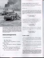
Acknowledgments This book would not have been possible without the generous assistance of the late Jacques Littlefield and the Military Vehicle Technology Foundation; Chris Hughes; Michael Green; Tom Kailbourn; John Adams-Graf, Verne Kindschi; and the staff of the TACOM History Office. Special thanks to Denise - who patiently inspires me to persevere - and the veterans who crewed these vehicles. All photos by the author unless otherwise noted.
As tanks grew bigger and heavier over time, the need for specialized recovery equipment increased. Through the 1940s and 1950s, the U.S. Army relied on armored recovery vehicles based first on the M3 Medium Tank, and later the M4 family of medium tanks. The latter reached its zenith with the M74. Plans for a new generations of tanks were in place, and it was evident that the M74 would be overburdened. An armored recovery vehicle based on the components of the MI03 heavy tank, designated the M51, was developed, but it was huge, and placed a considerable burden on the logistics system, and like the rank upon which it is based, was produced only in limited numbers. Hence, yet another vehicle was developed. Designated M88, this vehicle combined the power plant of the M51, suspension components of the M48, and an all-new hull and recovery system. Bowen-McLaughlin-York Inc., of York, Pennsylvania, developed the vehicle and was awarded a contract for 1,075 of them in 1959. Remarkably, the standard armor recovery vehicle (ARV) of the U.S. Army as of 2010 is the M88A2, an updated version of the 1959 model. The original, gasoline-powered M88 served admirably in Vietnam. In the 1970s, however, the army began a move toward an all-Diesel tactical vehicle fleet, and accordingly the M88 retrievers were re-engined with Diesel powerplants. At the same time, a Dieselpowered Auxiliary Power Unit (APU) was installed. The Diesel-powered retriever was classified as the M88Al, and is readily distinguished by the APUs grille just behind the right side door of the retriever. · en ded·m 1989 aft er 3042 h ad ro 11ed 0 ff th e 1·me. Th e too 1·mg M88A1 pro d uctlon 1 . ' '. was paced 111 storage, and BMY even had the foresight to cast and store some extra hulls. These allowed a quick restart of production to meet foreign orders in 1991. The design of the armored hulls is similar to those of a tank, and, as mentioned, many of the suspension and drive train components are common to the M48/M60 Medium Tanks that were its contemporaries. The lower portion of the cast-armor hull is occupied by two hydraulically powered winches - one to operate the hoist, and a massive 90,000-lbs capacity main recovery winch. The recovery winch, mounted near the front of the vehicle, is wrapped with 200 feet of 1.25-inch diameter wire rope. The hoisting winch is used in conjunction with a hydraulically raised A-frame boom and is equipped with 400 feet of 5/8" wire rope. The winch is rated with a 50,000-lbs. capacity when the front ground spade is lowered. There are, however, several films showing two M88s being used in concert in Vietnam to lift an M48 and drive, tank dangling, to a recovery trailer, onto which the tank is then lowered. The hoist winch is mounted near the center of the vehicle, beneath the floor plates. Other equipment incorporated in the design include a hydraulically-driven heavy duty impact wrench, a hydraulically operated refueling pump, and the bow-mounted blade. This blade was to be used primarily for stabilizing the vehicle during heavy lifts, and as a ground anchor during heavy winching operations. It could also be used for minor earth work in conjunction with recovery operations, but despite the use by some crews, was specifically not for use in heavy earth moving such as preparing defensive positions.
. _ _ 0 -·.·
=t=--j;..JI
.. .
An early U.S. design for a tank recovery vehicle was the T2, shown here using the boom and stiff legs to lift the front end of an M3 medium tank, upon which the T2 design was based. The T2's maximum lifting capacity of 30,000 pounds was later dwarfed by the 50,000-pound capacity of the M88 tank recovery vehicle. (U.S. Army Transportation Museum) The M74 medium recovery vehicle w.as a postwar d~sign based on the .M4A3 medi~m tank. Produced by Bowen-McLaughlin-York, the vehicles had a collapsible boom With a 25,000-pound. . lifting. capacity, a towing winch with a gO,OOO-pound capacity, as well . . as several auxIliary Winches. The concept of the spade for braCing the front end during heavy lifting operations was later applied to the M88. (Verne Kindschi) i
. o w'
The M51 heavy recovery vehicle, developed in the early 1950s, was based on the M103 heavy tank. It featured a 30-ton crane mounted behind the crew compartment and a hydraulic main winch rated at 45 tons capacity. Like the earlier M74 and the later M88, it had a stabilizing spade at the front of the vehicle; it also had a spade at the rear of the hull. (The Patton Museum) The M728 combat engineer vehicle was based on the M60 tank. At one time consideration was given to combining the roles oftank recovery vehicles and combat engineer vehicles. Features included a turret-mounted boom rated at a hoisting capacity of 17,500 pounds with a 360 0 traverse; a hydraulically operated, 146"-wide bulldozer blade; a two-speed hydraulic winch, and a 165mm M135 short-barreled gun for demolition. From 1966 to 1972,243 ofthese vehicles were manufactured. (TACOM LCMC History Office)
The M32-series recovery vehicles saw heavy use in World War II and the Korean War. Based on several versions of the M4 medium tank, they had a tubular boom pivoted near the front of the hull and a winch in the center of the vehicle. Rated at 60,000 pounds, the Gar Wood 6M814 winch could recover any U.S. Army vehicle at the time the M32 was introduced. The boom served many lifting duties. On the glacis was a roller assembly for routing a drag line to the front of the vehicle. (The Patton Museum)
4
Ultimately, the M88 design would, with improvements, remain the Army's standard recovery vehicle for over five decades. This M88 tank recovery vehicle is owned and preserved by the Military Vehicle Technology Foundation. (Jacques Littlefield)
5
This file photo of an M88 was taken during tests by the Detroit Arsenal on 9 February 1961 . The spade is in a partially lowered position, and the vehicle is heavily streaked and spattered with mud. Extensive stencilings are visible, especially on the side of the vehicle. (TACOM LCMC History Office)
6
Introduction, continued fro m page 3. The crew of a M88 consists of four men. In addition to the commander, whose position '-./ is near the center of the vehicle, the crewmen include a driver/operator, a mechanic, and a rigger. In addition to the cupola-mounted M2 HB machine gun, the crew of the M88 ~ '-..../ was provided with a n umber of LAW rockets and submachine guns. ~ When new, the M88 was among the heaviest armored vehicles in the American arsenal, ~ almost a necessity for safe recovery operations. W ith the advent of the Ml Abrams, the M88Al was at last faced with more tank than it could safely recover in a timely fashion. Due to concerns that the heavier Abrams would push the retriever around, it was required that rwo M88Als, or an M88Al and a second Abrams, be used to recover a dead Abrams - the second vehicle being towed behind the dead tank to act as a brake. This prevented the disabled tank from overtaking the M88Al. To answer this logistical nightmare, another improvement was made to the M88 family. Dubbed the Hercules, the M88A2 was created by rebuilding older vehicles with more powerful engines, brakes, winches, lifting apparatus, suspension and armor protection. A single Hercules can safely recover an Abrams, thus the five-decade old design is expected The compensating idler wheels (the left one is shown here) at the front ofthe vehicle have to soldier on for years to come. rubber tires. There is a lubricating fitting on the top of the hubcap. A shock absorber for the front road wheel appears to the rear of the idler. The two forward and the rearmost road wheels on each side of the M88 are fitted with shock absorbers.
I I
"'"""__
M88A ilAl Recovery Vehicles ...
~ m~ ~~~ ffiUHl'~~~I:1Ikmi)
Between the left idler wheel (left) and front road wheel (right) is the track tightening arm (also called the compensating idler link), which adjusts the idler forward or backward to adjust the tension ofthe track. Above the road wheel is a volute bumper spring assembly; these are mounted above the road wheel arms of the number one and number six road
I
I
This instructional sheet stressed the importance of placing lockout blocks on the front suspension arms to prevent serious damage to the suspension when using the boom to lift loads in excess of six tons. The lockout blocks acted as locks to immobilize the bogie arms.
'~elling
up your M88A I /A2 recovery vehicle to lift a heavy load-more than 6 tons-is a lot of trouble. That "trouble," though, can mean the difference between
an easy li ft and equipment damage.
-.......;
Loads over 6 tons can play havoc with torsion bars, shock absorbers and road
arms. That's why you should always use lockout blocks when lifting
heavy loads. It's also a good idea when you're not sure j ust how
heavy the load is. Lockout blocks take the extra stress off the front suspension system . You 'll find the
procedures for installing and using lockout blocks on Page 2- 144 of TM 9-2350-256-10 and Page 2156 of TM 9- 2350-292-10. Don't think you 're in the clear, though. even if the load's less than 6 tons . Some openuors leave the engine deck on the ground between the tank and the recovery vehicle while pulling a powerpack. The M 88A I straddles the deck as it
gets ready to lift the pack. As the pack goes up, the weight compresses the suspension enough that the hull bottoms out on the deck. The Dressure can warn the deck.
7
Shock absorbers are mounted on the numbers one, two, and six suspensions on each The bumpers with dual springs provide secondary springing action for the front and side. To the upper right is the edge of the forward left track support roller (often called rear road wheels, supplementing the action of the torsion bars. return roller). Part numbers are cast on the bumper spring assembly. The upper part of the personnel step shows the grooves for the lugs that limit the Extending from each crew compartment door is a collapsible, fold-up step. The tread downward travel of the lower tube. Visible in profile above the top of the road wheel pattern on the footpad of the lower part of the left step is visible here. Like the bogie at the center is the upper part of the bump-stop bracket, mounted over the road wheel wheels, the return rollers, or track support rollers, have rubber tires. Track guides are arms of the numbers two through five road wheels, to limit the arms from flexing upward visible at the top left. beyond acceptable limits.
The center-left return roller seen here is one of the three return rollers on each side of Three elongated holes are incorporated into the outer part of the drive sprocket hubs. the M88. Bolted to the inside of the track between each track shoe is a center guide. To Details of the left rear fender and mud flap are also visible. the upper right is the compensating idler link. The nuts securing the sprockets to the hub are visible and there is a clear view of how The inner part of the sprocket hub shows the channel at the center for engaging the the track guides fit into the channel at the center of the hub. To the left is the left output track guides. At the top is the rear tie-down eye. There are four of these on the lower hull, reduction drive, with numerous countersinkings on the face for the recessed locking for securing the vehicle to a transporting vehicle. nuts that secure the mechanism to the hull.
,
,
\/ \ \ l TIl '~-,
~
Three stored track end connectors are mounted on the front end of the left side of the Track shoes, a return roller, sledge hammer, and a tow cable are stored on the left front hull. To the left are the left headlight and brush guard assemblies. of the vehicle. The housing below the return roller contains a pull-handle for actuating the interior fire extinguisher. Moving slightly towards the rear, the left crew compartment door is open, revealing the olive drab paint used on the interior of the door, as well as the five-gallon liquid The crew compartment appears through the open left door. Overhead is the vehicle's container and holder. Standard stencilings identify storage points on the interior and boom , with rungs. To the right is a spare road wheel. There is a fire extinguisher in a clamp-type bracket fixed inside the door. exterior of the vehicle.
A spare road wheel is fixed to the rear of the left door, with the boom above, and a tow The tow bar has pivoting attachment points. Casting numbers are visible on the hull cable clamp below the wheel. Part of a tow bar is to the right. below the stored road wheel. The tow cable is in its storage clamp on the left side of an MSS hull, with the lower half of This door on the left rear side of the hull covers a small compartment where chains and other gear are stored. the tow bar and a storage bracket above it. There are non-slip panels on the fender.
The crew of this M88, photographed at Camp Beavers, Korea, on 12 January 1971 , has On 1 November 1965, Saigon witnessed a parade marking the second anniversary of the painted the towing shackles and lifting eyes on the front of the vehicle yellow, making overthrow of the Diem Regime in 1963. Taking part was a U.S. First Infantry Division M88 them stand out against the olive drab hull of the FS595A 24087. (National Archives) that led a LARC V along a city street. (National Archives) A stay cable is fastened to the left crank arm assembly, seen above the tow bar. The An extra sprocket is bolted to the left rear of the hull. To the left of it is the center pivot apex of the lowered boom appears to the upper right of the photo. and towing eye of the tow bar. .,
OJ
An M88 deploys to pull an M48A3 tank (not visible) from a deep creek bed north of Fire Support Base Bandit II in Vietnam during late November 1970. The left rear mud guard is missing, allowing the track to throw clumps of mud on the rear fender and hull. A considerable amount of additional external stowage has been added to this vehicle. (National Archives)
13
The tow hooks on either side of the lower rear hull of the MSS were rated with a capacity of 500,000 Ibs - five times that of those mounted on the front. The pintle hook has a 300,000·lb rating. (Chris Hughes)
14
The left blackout taillight/stoplight (left) and rigger's service light, to the right of it, are A straight-on view of the left side of the rear deck shows the positioning of the lights. mounted near the rear of the deck. To the right is the left part of the exhaust shroud, with The bar at the far right is one of several braces that support a hinged exhaust deflector, the hinged exhaust deflector grille door at the aft end. To the left is the rear of the hull, part of which is visible at the lower right. There is a lifting eye forward of the taillight. with part of the spare sprocket. As viewed from the rear of the M88, two center exhaust doors are located in the recess Both exhaust deflector grille doors are hinged on the outboard side, and swing open in the rear deck between the exhaust shrouds. There are hinges on the forward ends of to provide access to the engine exhaust tubes and caps, one of which is inside each the doors, and the boom support is above them. The louvers of the exhaust shrouds, shroud. The exhaust deflector is at the bottom of the photo attached to the brace. visible at the sides of the photo, are fabricated from relatively heavy-gauge plate.
This view of the apex of the boom from the rear of an M88 shows the boom sheave and These exhaust grilles (also called louvers) are at the rear of an M88. The hinged, the attachment points of the two stays on either side of the sheave. The boom rests on adjustable exhaust deflector is at the bottom of the photo. the boom support. At either side of the bottom of the photo are the exhaust shrouds. The connections at the ends of the tow bar are below the exhaust deflector. Below the A view from the right rear corner of an M88 shows the center exhaust doors and the tow bar is the towing pintle. Above the tow bar is the left edge of the exhaust deflector left exhaust shroud and grille. The boom support is visible in the upper right of the and, running diagonally above it, the support bar. On the underside of the exhaust photograph. deflector are two T-shaped strengtheners, seen here in profile.
;\·t;~1t~
The forks of the tow bar are termed clevises. The lateral stiffeners are on the underside Mud flaps are bolted to the mudguards which, like this left rear guard, are hinged. of the exhaust deflector. The left mounting bracket for the bar has a toggling screw and wing nut to secure the upper jaw in place. The stored tow chain appears in the foreground of this shot of the inboard side of the left rear tow hook. The lip on either side of the outer end of each tow hook helps retain A gusset braces the towing eye on each side of the left rear tow hook. The heavy welded the tow cable in place until tension is put on it. Once pull is exerted on the hook, it rises, seams are plainly visible. and the curve in it keeps the cable secure.
,
-
.
•.
......-
--
' ,:
The ends of the tow chain are secured with clamps at the upper left of the rear of the The latch is situated above and pinned to the hook on the towing pintle and mount of an M88. The left tow bar bracket is between the ends of the chain. M88. The retainer chain helps keep the latch from getting lost when it is removed. Casting marks are visible on the lower rear of the hull, below the small national star. The The tow bar appears above the M88's towing pintle and mount in this nearly head-on view. bottom of the pintle mount is at the top center.
Inside of the mount, shown here from the right, a large, slotted nut secures the pintle to A clamp secures the large towing ring at the center of the tow chain onto the rear of the the mount. hull. The pintle mount is to the left of it and the right tow hook to the right. Above the tow hook is the lower part of the right storage bracket for the tow bar. To the right of the right rear tow hook, in this straight-on view, are the right mud guard, mud flap, and inner sprocket. Both rear tow hooks are visible in this view.
The towing eye and pivot joint ofthe two sections ofthe tow bar appear in the foreground. The louvers of the right exhaust shroud are seen from the rear of the M88. To the right Above them are the engine exhaust deflector, shrouds, and louvers. is the right rigger's light and its brush guard, above which is visible the top of the right crank arm. The taillights are mounted on plates that, when removed , allow access to the hydraulic cylinders that power the crank arms for the staylines of the boom. The inside of the rear The right side of the right exhaust shroud and grille door shows the brace for the exhaust hull plate at the right features a scooped-out design. There are hinges on the outside of deflector, with two notches in the bottom for adjusting the angle of the deflector. There is a triangular tie-down on the upper side of the shroud. the exhaust deflector grille door.
The crewmen of an M88 tank recovery use the boom to lift the engine cover of an M60 tank. The hoist cable roller cover between the driver's and mechanic's hatches has been opened. For a light-duty lifting operation like this one, it was unnecessary to deploy the spade. The pioneer tool rack on the vehicle is empty and the sledgehammer normally stored above the rack is missing. This vehicle is painted in the four-color MERDC camouflage scheme. (U.S. Army Engineer History Office)
21
The tool rack on this MBB contains a full complement of pioneer tools, including an axe, shovel, pick, and pick handle. Above the rack is a sledgehammer, with its head resting in a bracket to the front of the sprocket.
22
An M88 is being positioned to remove the turret of a Sheridan tank in Vietnam. A rigger has climbed up to the top of the boom to adjust the cables. The spare track links are missing from the front of the upper hull, but the pioneer tools and spare sprocket and wheels are in place, as are the two radio antennas. (The Rock Island Arsenal Museum)
23
The cutouts are visible in the outer part of the hub of the right sprocket assembly, as In this view of the hub of the right drive sprocket of an MSS, casting markings are faintly are the volute bumper spring and the shock absorber of the rear (or number-six) road visible below the oval cutout and on the other side of the hub, opposite the channel for wheel. the track guides. The retractable step forthe right crew compartment door is extended next to the numberthree road wheel. Numerous details of the suspension are evident, such as the rusty surfaces of the track end connectors and guides, as well as the design of the road wheel mount, bump-stop bracket, and the road wheel arm.
This close-up shows the forward end of a road wheel arm where it attaches to the road wheel arm support housing, a bearing which is bolted to the hull. The road wheel arms are fastened to torsion bars, the opposite ends of which are secured to torsion bar anchors on the other side of the interior of the hull.
The return rollers are fitted with rubber tires. A grease fitting is visible near the top of the The molding seams at the centers of the tires of the road wheels and return rollers are hub. To the right of the right forward return roller is the volute bumper spring assembly evident in this view of the running gear of an M88 on the right side facing aft. To the right for the number-one road wheel arm. is a bump-stop bracket. Beneath the number-one (or, front) right road wheel, the end connectors of the tracks are secured to pins running through the track shoes by means of wedging nuts and wedge bolts. The bolt heads are visible on the inner horizontal surfaces of the connectors. To the right is the compensating idler link.
Above the number-one right road wheel are the volute bumper spring assembly and shock absorber and mounting bracket. To the left of the tie-down eye at the upper right is a vertical casting number and mark. At the top are the rubber shoes on the inside of the tracks, and the track guides, which exhibit considerable rust.
Further details of the compensating idler link are seen here.
There is a relief valve at the center of the hub cap on the right idler wheel.
A crewman uses some of the M88's onboard repair tools - specifically the oxy-acetylene This 1st Battalion, 63rd Armor, First Infantry Division M88 crosses a light tactical bridge torch - to break a thrown track on the vehicle. The big retriever will then be pulled from during REFORGER (Return of Forces to Germany) II in October 1970. The strain on the this ditch near Vo Oat, Vietnam , and the track will be reinstalled. (National Archives) bridge is indicative of the M88's great weight. (National Archives)
n'-A
-f\ " A spare sprocket is stored at the right rear of the hull. To the right of it is a sledgehammer, Brackets and webbing straps secure the pioneer tools to the tool rack. Below the rack the head of which fits into a storage bracket. is a tow cable storage clamp. Above the door to the sma" storage compartment on the right rear of the hull are the There is a hinged access door on top of the housing for the auxiliary power unit (APU) of hinges for the right forward engine air intake door. the M88. The M88A1 would introduce a louvered door on the side of the housing.
~h Ull "!)
wurrJ..
r-
r.
The spare road wheel stored to the rear of the right crew compartment door is secured To the right of the right crew compartment door of the M88 is a door bumper. On the by hex nuts to three threaded lugs mounted on the hull. Just visible on the roof above roof are the air cleaner inlet cover (left) and the radio antenna mounts (center and right). the road wheel and below the boom is the right air cleaner inlet cover. (Chris Hughes) A return roller and three spare track shoes are stored on the upper front end of the right side of the hull. Later, on the M88A1, the spare tracks were stored lower, to make room for a smoke grenade box above them. A boom pivot can be seen above the center of the top track link.
!iA/~A~}'
SJ
~J()
Four spare track guides are stored on the lower part of the front right side of the hull. The M88 maintenance manuals specified stencillings identifying where many items of equipment and spare parts were to be stored on the vehicle. Below the 2 in the registration number at left is one of several clamps for securing the tow cable.
A front-right three-quarters view of "Haulin' Ass," the M88 owned and preserved by the Military Vehicle Technology Foundation, reveals the relatively sleek lines of the hull and the tidy arrangement of the accessories. In the right background is a British Grant tank undergoing restoration.
29
Dominating the front of the M88 is a retractable spade mounted on two heavy-duty operating arms. At the front of each spade-arm joint is a steel-plate gusset that gives extra strength.
30
With the spade in its raised position, the curve of the blade is visible in profile. On the The wedging nuts that secure the end connectors to the track pins are seated in the glacis above the spade is the front drag line cable roller. oblong recesses in the outer face of the end connectors. This right front tow hook of an MSS has been flipped up. To the upper right is the gusset The bow of an MSS is seen from the left, showing the flipped-up tow hook on the towing of the spade arm. eye and the right arm of the spade.
This view of the inner side of the right spade arm shows that six hex bolts and locking This shot of the trunnion and lower part of the right arm of the spade shows the pad nuts fasten the lower part of the arm to the upper part of the arm , which is connected to cast into the arm that makes contact with the plate bolted to the lower part of the recess when the spade is fully deployed. the spade. Casting numbers are on the recess below the nuts. The towing eye appears in the center of this head-on view of the lower front end of the From the front of the MSS, this is the view of the underside of the vehicle and the right MSS's hull. Flanked by spade arms right and left, the eye lies below a bolted-on plate. side of the suspension.
This view of the underside of the MSS from the front shows the insides of the road The bottom of the left spade arm and the recess in the hull to accommodate are seen at wheels and the road wheel arms. the lower left corner of the front of the hull. The inside of the compensating idler wheel is to the right in this detail photo of the The upper part ofthe underside ofthe spade arms are in the form of a gusset, reinforcing trunnions of the left spade arm. At the bottom of each recess in the hull for a spade arm the arm's attachment points to the spade. On the outboard side of the left arm are a is a small, rectangular plate secured with two fasteners. towing lug and hook.
Tracks specified for the M88 were the T107, a center-guide, double-pin type with 28" In this view of the underside of the raised spade, the left spade arm is at the lower center wide shoes and a rubber chevron-type tread. There are 84 links, or shoes, per side. of the photo, and the front of the left tracks is to the lower right. The spade was to be used as a steadying and weight-bearing device below the front of the vehicle during The left headlight assembly and brush guard. Each headlight assembly includes four lifting operations, and was to be used for only very light scraping duties during site lighting elements, arranged the same on both the left and right assembly: the service preparation. headlight (left in this view), blackout drive lamp (upper center), blackout marker lamp (lower center), and infrared headlight (left). A quick-disconnect nut secures the assembly The spade is at the bottom in this overhead view of the left headlight and brush guard, to the base. To the right of center is a bracket for stowing a snatch block, and at the top The number 56 in the circle is the bridge classification marking. The U-shaped bracket toward the right secures the lower part of the gO-ton snatch block when stored here. right is the mechanic's vision prism .
...
-:;':.1 T (;// II LtIl:I(
t-A~~
MW
50 cahber MG \lSI>.
'9.'
------l
Spade Assembly
The spade assembly (lower) is attached to the winch cover (upper right). For serviceability, the spade consists of several parts - two heavy duty support arms, a center section , and two end sections.
35
Above the left headlight is the left lifting eye. The smaller eye to the right of it secures The mechanic's cupola (sometimes referred to as the commander's cupola) is at the top center of the photo, with part of the driver's cupola to the far right. Each cupola has three the top of the gO-ton snatch block when stored. periscopes. Below the cupola is an oval vision prism; there is one at the corresponding The swell in the glacis that houses the mechanic's vision prism is seen from above. location in front of the driver's position. The vision prism is a thick, bulletproof glass block that provided a secure means for the mechanic to view activities to the front of the MBB. A similar vision prism and housing Centered on the glacis above the position of the raised spade are the winch cable are also on the opposite side of the glacis to the front of the driver's position. For front opening and roller. Attached to the interior side of the winch cover bolted to the glacis and side vision, the mechanic and driver each also had three vision prisms in their are the main winch assembly and the spade actuating cylinders. The lifting eye at the top of the bolt-on plate is used when removing or replacing the winch assembly. cupolas.
Upside-down casting marks are on the glacis above the winch cover's lifting eye.
Two half-bushings enclose the cable where it exits the main winch cover. Two retainers (the horizontal rectangular plates with four hex bolts) secure the half-bushings in place, The driver's vision prism, with the storage lug for the 25-ton snatch block to the right of and the vertical guides hold the retainers in place. it. The C-shaped plate hanging from the chain is the retainer washer, which slips over the end of the lug when the snatch block is in place on it. This diagram shows the removable winch cover and winch cable roller assembly. liZ 2 a :; '.r.Rt.J6IIIii
')-~II
Above the left headlight assembly and brush guard on the glacis is a mount and brush Visible in the lower left of this downward view of the glacis is the left side of the main guard for the front flashing signal light, not installed here. winch cover. Immediately to the right is the retainer bracket for the lower part of the 25ton snatch block. The raised spade is at the bottom, with the headlight assembly and The horizontal weld joint between the glacis and roof is apparent in this photo. At the top signal light mount and their brush guards to the right of center. of the glacis is a heavy-duty lifting eye and there are casting marks on the roof next to the driver's cupola. On the glaCis above the storage lug for the 25-ton snatch block is the The driver's cupola hatch with periscope mount and brush guard, as well as the three attachment point for the chain for the retainer washer seen in the preceding photo. periscopes around the face of the cupola, are seen from in front of the vehicle.
The driver's hatch pivots and swings backward when opened. The sprung cover for the periscope is in the down position here, as the periscope is not installed. The periscope brush guard fits over threaded lugs on the top of the hatch and is secured with hex nuts.
Between the driver's and mechanic's cupolas on the front of the roof is the armored door for the hoisting cable rollers. When the boom is erected, the hoisting cable passes up through an opening in this door to the boom sheave. To the front and rear of the opening are cable rollers.
The mechanic's cupola incorporates a hatch and three vision prisms. The vision prisms The pivot of the right arm of the boom is incorporated into the roof of the crew provide a protected means of viewing to the front and sides. Unlike the driver's hatch, compartment. Hydraulic boom-actuating cylinders within the vehicle raise and lower the mechanic's hatch does not feature a periscope. the tubular boom, and steel cables act as stays when the boom is erected.
E
Q)
e
....e "C
..c:
o!!l
os;~
'0
-e u
o
cQ): E t:: ra c.. E
~ Q)
u
I-
..c:
Machine gun shields were frequently installed on the commander's machine gun mounts during the Vietnam War. Below the shield is the commander's cupola, and in the foreground are the forward hatches, with the hOisting cable roller door between them. A view of the commander's cupola and machine gun mount are seen here from the left. The hatch is open, and several of the six vision blocks around the cupola are visible. The cupola is mounted on a plate that is bolted to the roof.
This 11th Armored Cavalry Regiment M88, dubbed "Main Fly" by its crew, rests in its assigned parking space within a motor pool in Vietnam. Typical of vehicles operating in the Central Highlands, the retriever is covered in red clay. The hoist boom is raised, and the hook rigged to the front lifting lugs to secure it. (Patton Museum, Fort Knox, Kentucky)
Details of the commander's cupola, machine gun mount, and shield are seen here. The gun mount is on a ring assembly, allowing it to be swung around 360 degrees. The round indentations on the base of the cupola next to the viewing prisms accommodate screws that secure the cupola to the roof plate.
43
The right boom stayline cable is captured in a cable retainer on the roof. The right boom In this view of the roof of the M88 from the left rear of the commander's cupola facing forward, the thicker cable is the left boom stayline, while the thinner cable is the hoisting arm is to the right of the roof. cable. When the boom is raised, the hoisting cable is routed from the front of the crew At the center of the rear of the roof over the crew compartment is a hatch for the rigger. compartment up to and over the boom sheave. It is pivoted open in this view, looking toward the rear of the vehicle. The rigger has a rotating periscope mount with a protective cover on top of the hatch. The left boom arm The rigger's spotlight, operable from inside the vehicle, is on the roof to the right of the rigger's hatch. The lower crossmember of the boom is parallel to the rear of the roof. is visible to the right and in the background.
An M88 employs its front spade in a decidedly disapproved application: digging an emplacement for Troop B, 3rd Battalion , 4th Cavalry, in the Iron Triangle area northwest of Saigon in January 1967. The spade was not intended for bulldozing and could be severely damaged as a result. An improvised gun shield has been installed over the commander's cupola.
45
Viewing the rear deck from the rear of the crew compartment roof, at the bottom is an oxygen cylinder for the oxy-acetylene welding system, stored in its brackets. To the rear of it are the front air inlet grilles with grab handles, the tarpaulin storage rack, and, flanking it, the tie-down rings. To the far left are the base for a vise and, to the rear of it, part of the right intake grille.
A vise is mounted on top of the APU access cover. The rear of the crew compartment is to the lower left.
The McKissick three-pulley hoisting block is shown stored between the apex of the boom and the upper crossmember (foreground). Using the lifting advantage offered by the hoisting block and the boom sheave, the MBB could hoist up to 50,000 pounds. The The forward left part of the engine deck is viewed from the rigger's hatch, showing the hook on the near side of the hoisting block is secured to the cast steel top of the block. The sides of the block are made of plates secured by nuts and bolts. front air inlet grille and, to the right, the left inlet grille.
E~~
The boom staylines are attached to crank arms on either side of the engine deck. The A view over the side of the vehicle shows the right-side crew compartment door open. A crank arms are mechanisms that are linked to hydraulic cylinders inside the vehicle, five-gallon liquid container is stored on a holder on the inside of the door. To the lower acting to provide four feet of backward and forward movement to the boom. This left is a radio antenna mount and guard. principle is called "live boom." Another view of the boom and engine deck, with the rear of the crew compartment roof To the rear of the APU housing in the center foreground is the right crank arm, with a to the lower right. Note the rungs on the boom arm and the positioning of the boom cable stay attached to it. The tilted angle iron toward the rear of the engine deck is the support. The McKissick three-pulley hOisting block is resting just beyond the upper cross member of the boom. right leg of the boom support.
Boom and Crane Assembly
The tubular steel boom and crane were raised and lowered by a pair of hydraulic cylinders (lower right). A pair of heavy wire ropes support the boom when it is in the raised pOSition.
49
Over the right crew compartment door is the base of the radio antenna. The right boom The business end of the pry bar is at the center, secured by a small bracket. Below arm is to the upper left. Near the bottom of the photo can be seen the handle of a pry bar, it, to the lower left, is the top of a spare bogie wheel, with the seam in its rubber tire one of the dozens of tools furnished with these retrievers. being apparent. An M88A1, the Diesel-powered variant of the M88, prepares to ford a stream in South Korea during the joint U.S.-South Korean maneuver "Exercise Team Spirit '86." A thick layer of dust coats most of the hull, while exhaust residue stains the rear of the vehicle. (Department of Defense)
This M88A1 tows an M1A1 Abrams off a Roll On/Roll Off cargo ship during Operation Desert Shield. Since the Abrams weighed too much for the M88A1 to recover safely in field conditions, the more heavy-duty M88A2 was developed to handle the massive tank. (Department of Defense)
General Data
Engine Data
M88
M88A1
WEIGHT"
112,000 pounds
112,000 pounds
LENGTH*
325.5 inches
325.5 inches
WIDTH*
135 inches
135 inches
HEIGHT*
115 inches
115 inches
TRACK
135 shoes
TRACK WIDTH
M88
M88A1
Continental
Continental
ENGINE MODEL
AVSI-1790-6A
AVDS-1790-2DR
CYLINDERS
90 degree V-12
90 degree V-12
DISPLACEMENT
1,790 cubic inches
1,790 cubic inches
135 shoes
HORSEPOWER
980 @ 2,800 rpm
750 @ 2,400 rpm
28 inches
28 inches
TORQUE
1940 @ 2,800 rpm
1842 @ 1,800 rpm
MAX SPEED
30 mph
26 mph
2,800 rpm
2,400 rpm
FUEL CAPACITY
445 gal.
400 gal.
222 miles
300 miles
24 volt negative ground
24 volt negative ground
Pivot
Pivot
MODEL
RANGE ELECTRICAL TURNING RADIUS
VEHICLE MODEL ENGINE MAKE
GOVERNED SPEED
*Overall dimensions listed in inches. " Fighting weight.
The M88 is powered by a 980 horsepower Continental AVSI-1790-6A fuel -injected The M88A1 is powered by the 750 horsepower AVDS-1790 supercharged Diesel gasoline engine, which is an improved version of the naturally aspirated AV-1790-5a engine. Like its gasoline-powered predecessor, the eng ine is a 90-degree V-12 shown here. The engines are a V-12 configuration. (TACOM LCMC History Office) configuration with a 1,790-cubic-inch displacement. (Quartermaster Museum)
To the left of the steering wheel in the driver's compartment is the gauge panel, and to the right is the main switch panel. Below and to the front of the steering wheel are steering linkages. Over the steering wheel are three periscope objectives and their retainer wing nuts.
52
On the right side of the main switch panel are the master lighting switch and blackout! infrared selector switch. To the right side, top, is the main light switch, with the starter switch below it. Below the right bottom of the steering wheel is the blackout receiver switch and indicator. The top row of gauges on the gauge panel are, left to right, the battery generator voltage indicator, engine temperature, and engine pressure. Middle row: fuel level, transmission temperature, and transmission pressure. Bottom row: tachometer and speedometerl odometer. Also on the panel are warning lights, instrument panel lights, and fuel selector switch.
The vertical stanchion to the left of the gauge panel is called the seat support. The fixture with black padding next to it is the seat frame, which slides up and down the seat support, and to which the folding seat (bottom center) is attached. Partially hidden beyond the support is the left boom actuating cylinder. At the upper left is the housing for the boom operating lever, to which the piston of the actuating cylinder is coupled . The four fixed fire extinguishers on the left side of the MBS are stored forward of the storage racks for .50-caliber machine gun ammunition boxes. The fire extinguishers comprise a central system that is plumbed into a network of lines to provide fireextinguishing coverage to the entire interior of the vehicle.
The four fixed fire extinguishers on the left side of the M88 are stored forward of the storage racks for .50-caliber machine gun ammunition boxes. The fire extinguishers comprise a central system that is plumbed into a network of lines to provide fireextinguishing coverage to the entire interior of the vehicle. The commander's seat is an intricate assembly mounted on the floor below the commander's cupola. It can be articulated in various ways, including raising and lowering and moving forward and to the rear. The sloping enclosure to the right with the periscope storage box mounted on it is the boom cable housing (also called the wire rope shield), which encloses the cable running from the boom winch below the floor up through the roof and to the boom sheave when the boom is deployed.
The two red handles above and to the rear of the fixed fire extinguishers are manual actuating controls for the right and left extinguishers. The black switch panel below them is the heater control. The hose is part of the M8A3 gas/particulate filter system, and provided purified air to the driver via a face mask in the event of a nuclear-biologicalchemical (NBC) attack. Several of the viewing prisms and the wedge plates that hold them in place in the commander's cupola are at the top. Above the machine gun ammunition boxes are storage brackets for two LAW antitank rocket launchers. A dome light is immediately to the top of the forward end of the ammunition rack, toward the right of the photo. Also visible are various gas/particulate filter system hoses.
~
The crew compartment appears through the left side door. The commander's seat and cupola are to the far left. The white box to the left of the fire extinguisher is an M2A2 gasparticulate filter; another one is on the opposite side of the compartment. Beyond and below the purifier is the rigger's seat, and above it at the rear of the roof is the rigger's open hatch. The hatch opening mechanism is the cylindrical object on the roof next to the hatch.
55
Forward ofthe open left crew compartment door ofthe M88 are the .50-caliber ammunition racks. The bottom shelf was intended for storing heavy items. Part of the commander's seat is visible to the far right. Each box contains 100 linked rounds of ammunition, arranged in sequences of one M17 tracer round and four M33 ball rounds.
A cupola and hatch are above the commander's seat. Immediately to the front of the seat is the boom cable housing, on both sides of which are five-gallon liquid containers secured in holders. There are protective pads above each of the viewing prisms in the cupola.
This USMC M88A1 at Cherry Point, North Carolina, is painted in the four-color An M88A1 exits a landing craft at Pensacola, Florida, during Exercise Agile Sword Mobility Equipment Research and Development Command (MERDC) paint scheme. '86. Covers are fitted over the smoke grenade launchers to protect them from dirt A spreader bar is attached to the hoist cable. (Department of Defense) and debris. (Department of Defense)
At the rear of the crew compartment is the rigger's station. Like the commander, he had a heavy-duty seat that could be configured in numerous positions. Stored on the rear bulkhead is a power cable reel for using the spotlight away from the vehicle in a trouble light configuration - the spotlight head is a separate item - below which is the rigger's intercom box, a hook for a telephone, and the spotlight itself. The welding hoses and red-handled bolt cutters are stored on a compartment containing the acetylene tank. A gasparticulate filter is to the right.
57
(J:7
r
]
Protruding into the roof to the left of the open rigger's hatch is the control handle for the The dark colored fixture to the left of the photo is the personnel heater, near the right spotlight. Two vision prisms flank the rigger's periscope above his seat, and above the rear corner of the crew compartment. To the right is the rigger's seat and pedestal. On periscope is a forehead pad. the floor is a disassembled 3.5" antitank rocket launcher. The rigger's intercom control box, part of the personnel heater, and the trouble light To the left is the right-side M2A2 gas-particulate filter with air hoses for various crew reel are in the rear of the crew compartment. The hand grip above the " Phone" placard stations issuing from it. To the right of center is the personnel heater. The rear bulkhead attaches to the spotlight at the bottom to form a portable trouble light. of the crew compartment is to the right.
Two air cleaners for the engine are in the rear corners of the crew compartment. The A note on the side of the air cleaner cautions that it should be drained, cleaned, and right filter is the large drum between the gas-particulate figure and the heater. To the far refilled every day when operating on dirt roads or cross-country, and every 250 miles left is the open right side door. when operating on paved roads or in wet weather. This view across the crew compartment from the right side door reveals the open left side door at the center background (and beyond it, a German vehicle). The commander's seat at the center is in the lowered position, as is the rigger's seat at the far left. On the floor at the lower left is a disassembled 3.5" antitank rocket launcher.
This five-gallon liquid container is in front of the commander's seat, to the right of the boom cable housing (lower left). To the upper right is an oddments container. The floor panels are removable, to allow access to the transmission, hydraulic pump, hoist winch , and other mechanisms under the floor.
Under the oddments container, seen from behind, is storage for ten 3.5" antitank rockets, Radio transmitters and receivers are positioned on top of the oddments container on the which would have been fired by an M20A1 or M20A1B1 launcher. To the right is an oil right side of the crew compartment. In this view looking forward, the three periscopes in the mechanic's station are visible at the upper left. The contour of the roofline is visible can. To the left background is the mechanic's station, with folded-up seat. above the radio. The unit to the left is a receiver-transmitter, while the two sets to the right of it are R-442A1 VRC receivers. Above the receiver-transmitter is a dome light. Several of the fixed fire Above the dome light is the air purifier control switch. To the left, or front, of the canteen extinguishers are at the lower left. Stowed in a clip above the fire extinguisher tanks is is the right boom pivot, below which is the mechanic's seat support and seat frame with black padding. Attached to the frame is the operating handle. an elbow-type flashlight.
@ DDME NIJ
~
The spade is raised here. Near the front of each side of the hull are a 10-ton snatch block Below the spare return roller is the cover for the external actuating handle for the and three track links. Above the top link are four mounting studs for a smoke grenade internal fire extinguisher system. The boom pivot is on the roof above the spare track storage box, not installed. The boxes on the sides and two glacis-mounted smoke links. (John Adams-Graf) grenade launchers (not installed) were M88A1 characteristics. (John Adams-Graf) A spare sprocket is stored at the rear of the left side of the hull. Below the tow bar To the rear of the left side door are a spare road wheel and tow bar. The door hinge assembly is the door to a small storage compartment. The stowage compartment door incorporates a torsion bar. There are grab bars and a grab handle over and to the rear of has a rubber gasket around the perimeter of its inner side, to keep the compartment weatherproof. (John Adams-Graf) the door. (John Adams-Graf)
A tow bar and tow chain are stored on the rear of this M88A1. There are two handles on the tow bar assembly. The tilted panel above the tow bar is the exhaust deflector, a hinged, adjustable assembly. (John Adams-Graf)
64
The right rear of the hull of the M88A1 displays a spare sprocket, pioneer tool rack, The apex of the boom, the sheave, and the attachment point of the right stay are seen and tow cable. Above the tool rack is the right crank arm, to which the lower end of from the right rear of the M88A1. The mesh tray is intended to hold the hoisting block the boom stay is secured. Powered by hydraulic cylinders inside the vehicle, the crank when the boom is in the stored position. (John Adams-Graf) arms provide four feet of front and back movement to the boom. (John Adams-Graf) To the rear (or to the left) of the spare road wheel is the armored housing for the auxiliary Stored at the front end of the side of the hull are three spare track links and a 10-ton power unit (APU) and its louvered door, which not present on the M88. Behind the small snatch block. The three lugs to the rear (to the left) of the track links are for mounting a door to the left of the APU door is a compartment containing a pneumatic coupling spare return roller. The eye of the tow cable toward the bottom center is secured in place for running compressed-air tools. To the far right is the right side door to the crew compartment. (John Adams-Graf) with a clamp-type bracket. (John Adams-Graf)
The spade on the front of this M88A1 is raised. With the smoke launchers removed, the front of this vehicle appears virtually identical to the front of an M88. (John Adams-Graf)
66
Above the left headlight are three mounting lugs (two upper and one just above the horn behind the light) for a smoke grenade launcher, not installed on this vehicle. Next to the Sowa & Sons 90-ton snatch block is the mechanic's vision block, with the mechanic's cupola, periscopes, and hatch above. (John Adams-Graf)
Centered on the glacis behind the spade is the main winch housing, secured to the glacis with hex bolts. The end of the drag line cable is projecting through the half-bushings and is resting on the cable roller. There are casting marks on the glacis behind the lifting eye on the winch housing. (John Adams-Graf)
Outboard of the 25-ton snatch block stored at the top left of the glacis of the M88A1 is This M88A1 has a louvered door for theAPU compartment but lacks the smoke grenade a flashing, red signal light. Above it is a lifting eye. There are three mounting lugs for a launchers on the glacis and the smoke grenade boxes above the spare track links. smoke grenade launcher above the headlight assembly. (John Adams-Graf) (TACOM LCMC History Office)
Members of the 3rd ARVN Cavalry, training with Troop A, 1st Squadron, 10th Cavalry, 4th Infantry Division, use an MBB in a repair operation at Fire Base "Action," west of An Khe, on 27 October 1970. Several chains and clevises in a variety of sizes have been stowed on the front of the retriever. (National Archives)
68
In preparation for Operation Desert Storm, during a training exercise a Marine Corps M88A1 in Kuwait uprights an overturned M-60A1 main battle tank. The exercise, part of Operation Desert Shield, honed the skills of the retriever crew, and demonstrated how well the M88 design matched the vehicles it was intended to recover. (Marine Corps).
69
An M88 of the 11th Armored Cavalry has thrown a track and has become stuck as a During joint exercises with the 3rd ARVN Cavalry in October 1970, members of Troop A, result. 1st Squadron, 10th Cavalry use an M88 to lift an M113A1 ACAVengine. "Cherry Buster" - an unusually camouflaged M88 operating in Vietnam - moves past In orderto cope with the increased weight ofthe M1 Abrams, the M88 was upgraded to the ARVN soldiers on patrol near Cu Chi on 28 January 1966. The M88 was operating with A2 configuration, which features improved braking, lifting, and powertrain components. the 25th Infantry Division. (National Archives) (TACOM LCMC History Office)
Color Distribution FS595A 45%
45%
5%
5%
Winter US & Europe verdant
Forest Green 34079
Field Drab 30118
Sand 30277
Black 37038
Snow - temperate wi trees & shrubs
Forest Green 34079
White 37875
Sand 30277
Black 37038
Snow - temperate w/open terrain
White 37875
Field Drab 301 18
Sand 30277
Black 37038
Summer US & Europe - verdant
Forest Green 34079
Light Green 34151
Sand 30277
Black 37038
Tropics - verdant
Forest Green 34079
Dark Green 34102
Lt Green 34151
Black 37038
Gray desert
Sand 30277
Field Drab 30118
Earth Yellow 30257
Black 37038
Red desert
Earth Red 30117
Earth Yellow 30257
Sand 30277
Black 37038
White 37875
White 37875
White 37875
White 37875
Condition
Winter Arctic
I
The spade on the front of the M88, though sometimes used for minor earthwork projects, was actually designed to stabilize the vehicle during recovery operations. Lowered partially, it could anchor the retriever during heavy drag winch operations. Lowered fully, as it is here, the blade actually was beneath the forward portion of the vehicle. The sagging track seen here is indicative of the weight of the vehicle being transferred from the tracks to the spade. This use of the blade relieved the stress on the M88's torsion bar suspension during heavy lifting operations. It also provided a firm , stable footing for the vehicle during the lift. (Patton Museum, Fort Knox, Kentucky)
;
.
.71
1-----
~
::s
CD
= ..,
"m
CD
-ca....
o c m
3
n m
CD
..,
3
c 3
en
m ::s
"C CD
a
cm
:-u c n
m
p==-_ _
CD
= ... :::s
I»
."
CD
ca
....I-»
o c
3
n I»
::l
CD U» CD
c
~
Ci)
n
a= m ::a c
:::s
~
:: CD
I»
."
CD
ca
I»
:::!!
c
o
3
n I»
z ~ o
::::s
CD
..
3
CD
n
I»
."
-
n CD
::::s
I»
Do ::::s
o ...
0') ,....
The rear of the hull plates are raised above the sloping rear deck, offering some side protection to the taillight and rigger's light assemblies. A towing pintle is at the center of the rear of the hull below the tow bar, with towing hooks to either side of the pintle. (John Adams-Graf)
80
The seat panlcushion and backrest have been removed from the folded-down mechanic's The mechanic's station is surveyed here from the rear. To the left is the hoist cable seat assembly. To the left of the assembly are the mechanic's intercom control box and, housing, to the top right of which is the operating mechanism for the mechanic's hatch. To the upper right of center is the closed hatch, with the three M17 periscopes below partially visible, his vision block. and to the front of it. Below the hoist cable housing to the left is the hydraulic control The hoist mechanism is located between the driver's and mechanic's seats. A storage panel with controls for operating the boom, spade, hoisting and main winches, and box for periscopes is on top of the housing. Above the stowed canteen is the openingl main and auxiliary hydraulic systems. closing mechanism for the driver's overhead hatch door. To the left are the driver's seat, The interior of the driver's hatch is seen here. (Chris Hughes) controls, and instrument panel. (Chris Hughes)
This thee-quarters front left view of an M88A1 shows that there were few visible differences in the exteriors of the M88 and the M88A1, especially from this angle. Among other improvements, the M88A1 substituted an air-cooled V-12 Diesel supercharged engine for the gasoline engine of the M88. (John Adams-Grat).
62
----- ®
00006 0-66~-L~L69-0-9L6
NaSI