Light Gauge Metal Structures Recent Advances (CISM International Centre for Mechanical Sciences, 455) 3211252584, 9783211252581
The aim of this book is to review recent research and technical advances, including the progress in design codes, relate
142 105 13MB
English Pages 260 [257] Year 2005
Recommend Papers


![Computational Contact Mechanics (CISM International Centre for Mechanical Sciences, 498) [2007 ed.]
9783211772973, 3211772979](https://ebin.pub/img/200x200/computational-contact-mechanics-cism-international-centre-for-mechanical-sciences-498-2007nbsped-9783211772973-3211772979.jpg)


- Author / Uploaded
- Jacques Rondal (editor)
- Dan Dubina (editor)
File loading please wait...
Citation preview
^
SpringerWienNewYork
CISM COURSES AND LECTURES
Series Editors: The Rectors Giulio Maier - Milan Jean SaIen9on - Palaiseau Wilhelm Schneider - Wien
The Secretary General Bemhard Schrefler - Padua
Executive Editor Carlo Tasso - Udine
The series presents lecture notes, monographs, edited works and proceedings in the field of Mechanics, Engineering, Computer Science and Applied Mathematics. Purpose of the series is to make known in the international scientific and technical community results obtained in some of the activities organized by CISM, the International Centre for Mechanical Sciences.
INTERNATIONAL CENTRE FOR MECHANICAL SCIENCES COURSES AND LECTURES - No. 455
LIGHT GAUGE METAL STRUCTURES RECENT ADVANCES
EDITED BY JACQUES RONDAL UNIVERSITY OF LIEGE DAN DUBINA TECHNICAL UNIVERSITY OF TIMISOARA
SpringerWien NewYork
This volume contains 168 illustrations
This work is subject to copyright. All rights are reserved, whether the whole or part of the material is concerned specifically those of translation, reprinting, re-use of illustrations, broadcasting, reproduction by photocopying machine or similar means, and storage in data banks. © 2005 by CISM, Udine Printed in Italy SPIN 11405207
In order to make this volume available as economically and as rapidly as possible the authors' typescripts have been reproduced in their original forms. This method unfortunately has its typographical limitations but it is hoped that they in no way distract the reader.
ISBN 3-211-25258-4 SpringerWienNewYork
PREFACE
In recent years, it has been recognized that both cold-formed steel and aluminium alloy sections can be used effectively as primary framing components. In what concerns cold-formed steel sections, after their primarily application as purlins or side rails, the second major one in construction is in the building envelope. Options for steel cladding panels range from inexpensive profiled sheeting for industrial applications, through architectural flat panels used to achieve a prestigious look of the building. Light steel systems are widely used to support curtain wall panels. Coldformed steel in the form of profiled decking has gained widespread acceptance over the past fifteen years as a basic component, along with concrete, in composite slabs. These are now prevalent in the multi-storey steel framed building market. Cold-formed steel members are efficient in terms of both their stiffness and strength. In addition, because the steel may be even less than 1 mm thick, the members are light weight. The already impressive load carrying capabilities of cold formed steel members will be enhanced by current work to develop composite systems, both for wall and floor structures. Recent studies have shown that because the coating loss for galvanised steel members is sufficiently slow, and indeed slows down to effectively zero, a design life in excess of 60 years can be guaranteed. The production of economic coated steel coils has also given interesting solutions to architectural demands increasing the range of use of cold-formed sections. Higher yield stress steels are also becoming more common for the fabrication of cold-formed sections. However, the use of high strength steels and thinner sections leads inevitably to complex design problems, particularly in the field of structural stability and joints. In recent years, stainless steel profiles and aluminium alloy profiles have also been used increasingly as structural members. The aims of the ''Advanced Professional Training on Light Gauge Metal Structures Recent Advances" organized at the International Centre for Mechanical Sciences in Udine, June 3-7, 2002, were to review recent research and technical advances, including the progress in design codes, related to the engineering applications of light gauge metal sections made in carbon, high strength and stainless steel, as well as aluminium alloys. The lectures include also a review of the new technologies for connections of light gauge metal members. Main advanced applications, for residential, non residential and industrial buildings and pallet rack systems are also covered.
This monograph is a revised version of the lecture notes. However, the lectures given by F.M. Mazzolani on the aluminium structural design have not been included in this monograph because a full CISM monograph, edited by F.M. Mazzolani (CISM Courses and Lectures n^ 443, 2003) has been entirely dedicated to the use of Aluminium-Alloys in structures. The other lectures have been prepared by : • • • • •
J.M. Davies, The University of Manchester, England; D. Dubina, Technical University ofTimisoara, Romania; R. Laboube, University of Missouri-Rolla, USA; K.J.R. Rasmussen, University of Sydney, Australia; J. Rondal, University of Liege, Belgium.
The editors wish to thank warmly these colleagues for the excellence of the work performed during the preparation of this advanced professional training, which is well reflected in this monograph. Special thanks are also due to the CISM Rector, Prof. M.G. Velarde, the CISM Secretary General, Prof B. Schrefler, the Executive Editor of the Series, Prof C Tasso, and to all the CISM staff in Udine.
Jacques Rondal Dan Dubina
CONTENTS
Preface Introduction to Light Gauge Metal Structures by J. Rondal
1
Peculiar Problems in Cold-formed Steel Design by D. Dubina and J. Rondal
5
Recent Advances and Progress in Design Codes : Instability Problems by J. Rondal
23
Recent Advances and Progress in Design Codes : Connections by R. LaBoube
37
Stainless Steel Structures by K.J.R. Rasmussen
67
High Strength Steel Structures by K.J.R. Rasmussen
121
Residential Buildings byJ.M.Davies
143
Industrial and Non-Residential Buildings by D. Dubina
189
Pallet Racking byJ.M. Davies
233
Chapter 1: Introduction to Light Gauge Metal Structures J. Rondal Department of Mechanics of Materials and Structures, University of Liege, Belgium E-mail: [email protected] 1.1 Historical considerations The use of cold-formed steel members in building construction began in the mid of the eighteenth century in United States and United Kingdom. However such steel members w^ere not w^idely used as structural members until around 1946 and the publication of the first edition of the "Specification for the Design of Light Gage Steel Structural Members" by the American Iron and Steel Institute (AISI). Since that period, thousands of researches in the field have led to a wide use of cold-formed metal elements in all types of buildings. If, in the past, cold-formed products were mainly used as secondary components in steel or concrete structures, there is now a wide marked for cold-formed structural elements. These structural elements are used as single members like columns, beams or purlins but also as components of industrialized building systems. In these systems, the cold-formed elements play fi'equently a multifunctional role leading to economy and simplicity of the structure. Sometimes, they make the traditional steel skeleton unnecessary or, at least, they contribute largely to its load bearing capacity. For example, the combination of cold-formed members and sheeting can be such that instability phenomena are prevented, leading to a space covering fiinction and an improvement of the resistance. 1.2 Peculiarities of cold-formed steel members In general, cold-formed steel structural members provide the following advantages in building construction (Yu, 1985): • as compared with thicker hot-rolled shapes, cold-formed light members can be manufactured for relatively light loads and/or short spans; • unusual sectional configurations can be produced economically by cold-forming operations and, consequently, favourable strength-to-weight ratios can be obtained; • nestable sections can be produced, allowing for compact packaging and shipping; • load-carrying panels and decks can provide useful surfaces for floor, roof, and wall construction, and in other cases, they can also provide enclosed cells for electrical and HVAC conduits; • load-carrying panels and decks not only withstand loads normal to their surfaces, but they can also act as shear diaphragms to resist force in their own planes if they are adequately interconnected to each other and to supporting members. Compared with other materials such as timber and concrete, the following qualities can be realized for cold-formed steel structural members:
J. Rondal • • • • • • • • •
lightness; high strength and stiffiiess; ease of prefabrication and mass production; fast and easy erection and installation; substantial elimination of delays due to weather; more accurate detailing; nonshrinking and noncreeping at ambient temperature; uniform quality; economy in transportation and handling.
The combination of the above-mentioned advantages can result in important cost saving during construction. However, because cold-formed members are usually thin-walled, special care must be given to the design. Compared to classical hot-rolled sections, they are characterized by some peculiarities, e.g.: • large width to thickness ratios; • singly symmetrical or unsymmetrical shapes; • unstiffened or partially unstiffened parts of sections; which can lead to difficult buckling problems : • combined torsional and flexural buckling; • local plate buckling; • distorsional buckling; • interaction between local and global buckling,... Also connections must be designed with care because the thickness of the members can lead to local failures. For these reasons, dedicated specifications have been published in United States firstly, and after in Europe, Australia and in other countries to cover these important questions. 1.3 Recent Advances In recent years, it has been recognized that both cold-formed steel and aluminium alloy sections can be used effectively as primary framing components. In what concerns cold-formed steel sections, after their primarily application as purlins or side rails, the second major one in construction is in the building envelope. Options for steel cladding panels range from inexpensive profiled sheeting for industrial applications, through architectural flat panels used to achieve a prestigious look of the building. Light steel systems are widely used to support curtain wall panels. Cold-formed steel in the form of profiled decking has gained widespread acceptance over the past fifteen years as a basic component, along with concrete, in composite slabs. These are now prevalent in the multi-storey steel framed building market. Cold-formed steel members are efficient in terms of both their stiffiiess and strength. In addition, because the steel may be even less than 1 mm thick, the members are light weight. The already impressive load carrying capabilities of cold formed steel members will be enhanced by current work to develop composite systems, both for wall and floor structures.
Introduction to Light Gauge Metal Structures Recent studies have shown that because the coating loss for galvanised steel members is sufficiently slow, and indeed slows down to effectively zero, a design life in excess of 60 years can be guaranteed. The production of economic coated steel coils has also given interesting solutions to architectural demands increasing the range of use of cold-formed sections. As younger products, cold-formed steel sections are more open to development than classical hot-rolled profiles (Davies, 2000). An important trend is the use of higher quality steels with an increased yield stress. The steel used actually for mass-produced products such as purlins, sheeting and decking has a yield stress in the range 280 to 600 N/mm^. This trend is likely to continue in the fixture. However, the applications of high strength steels are limited by stiffiiess considerations in many situations. The use of high strength steel leads inevitably to a reduction of the thickness of the profiles and to complex local stability problems. To improve the load stability of the sections, complex shapes have been developed with more folds and stiffeners. Important progresses have also been made in the rolling and forming technology (Pekoz, 1999). Modem rolling lines are computer controlled fi'om the design office so that not only highly accurate complex shapes of precise lengths be produced to order but also holes, perforations, web opening for services can be punched in precise positions during the rolling process. In recent years, stainless steel profiles and aluminium alloy profiles have also been used increasingly as structural members. This Advanced Professional Training aims to review recent research and technical advances, including the progress in design codes, related to the engineering applications of light gauge metal sections made in carbon, high strength and stainless steel, as well as aluminium alloys. References Davies, J.M. (2000). Recent Research Advances in Cold-Formed Steel Structures. Journal of Constructional Steel Research, 55, 267-288. Pekoz, T. (1999). Possible Future Developments in the Design and Application of ColdFormed Steel. ICSAS 99, 4'^ International Conference on Light-Weight Steel and Aluminium Structures. Espoo, Finland, 20-23 June 1999. Yu, W.W. (1985). Cold-Formed Steel Design, J. Wiley and Sons, New-York.
Chapter 2: Peculiar Problems in Cold-formed Steel Design Parti D. Dubina Department of Steel Structures and Structural Mechanics, Civil Engineering and Architecture Faculty, "Politehnica" University of Timisoara, Romania E-mail: [email protected] 2.1 Elements 2.2.1. Cold-formed steel sections: linear profiles, cladding and sheeting panels In recent years, cold-formed steel sections started to be used effectively as primary framing components. In w^hat concerns cold-formed steel sections, after their primarily applications as purlins or side rails, the second major one in construction is in the building envelope. Options for steel cladding panels range from inexpensive profiled sheeting for industrial applications, through architectural flat panels used to achieve a prestigious look of the building. Light steel systems are vv^idely used to support curtain wall panels. Cold-formed steel in the form of profiled decking has gained v^idespread acceptance over the past fifteen years as a basic component, along with concrete, in composite slabs. These are now prevalent in the multistorey steel framed building market. Cold-formed steel members are efficient in terms of both their stiffness and strength. In addition, because the steel may be even less than 1 mm thick, the members are light weight. The already impressive load carrying capabilities of cold-formed steel members will be enhanced by current work to develop composite systems, both for wall and floor structures. The continuously increasing of cold-formed steel structures throughout the world is sustained by production of more economic steel coils particularly in coated form with zinc or aluminium / zinc coatings. These coils are subsequently formed into thin-walled sections by the cold-forming process. They are commonly called "Light gauge sections" since their thickness has been normally less than 3 mm. However, more recent developments have allowed sections up to 25 mm to be cold-formed, and open sections up to approximately 8mm thick are becoming common in building construction. The steel used for these sections may have a yield stress ranging from 250 MPa to 550 MPa (Hancock, 1997). The higher yield stress steels are also becoming more common as steel manufacturers produce high strength steel more efficiently. Improving technology of manufacture and corrosion protection applied to cold-formed structural steelwork, provide competitiveness of resulting products and extend the area of new applications. Recent studies have shown that the coating loss for galvanized steel members is sufficiently slow, and indeed slows down to effectively zero, than a design life in excess of 60 years can be guaranteed (Owens, 2000). Thin walled sections and high strength steels leads to design problems for structural engineers which may not normally be encountered in routine structural steel design. Structural
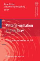
D. Dubina and J. Rondal instability of the sections is more likely to occur as a result of the reduced buckling loads (and stresses), and the use of higher strength steel which may make the buckling stress and yield stress of the thin-walled sections approximately equal (Hancock, 1997). Further, the shapes which can be cold-formed are often considerably more complex than hot-rolled steel shapes such as I-sections and unlipped channel sections. The cold-formed sections commonly have mono-symmetric or point symmetric shapes, and normally have stiffening lips on flanges and intermediate stiffeners in wide flanges and webs. Both simple and complex shapes can be formed for structural and non-structural applications as shown in Figure 1. Special design standards have been developed for these sections.
Figure 1. Collection of different cold-formed section shapes (Trebilcock, 1994). Cold-formed members and profiles sheets are steel products made from coated or uncoated hot rolled or cold-rolled flat strip of coils. Within the permitted range of tolerances, they have constant or variable cross section. Cold-formed structural steel members can be classified into two major types: 1. Long profile - individual structural framing 2. Cladding panels and sheeting decks Individual structural members (bar members) obtained from so called "long products" include: • single open sections, sown in Figure 2a; • open built-up sections. Figure 2b; • closed built-up sections, Figure 2c.
Peculiar Problems in Cold-formed Steel Design
J
I
a) Single open sections
b) Open built-up sections
L. L
c) Closed built-up sections
Figure 2. Typical forms of sections for cold-formed structural members.
Usual, the depth of cold-formed sections for bar members ranges from 50-70 mm to 350400 mm, with thickness from 1 to 6 mm about. Panel and decks are made from profiled sheets and linear trays (cassettes) shown in Figure 3. The depth of panel usually ranges from 20 to 200 mm, while thickness is from 0.4 to 1.2 (1.5) mm. They can be produced as flat or smooth curved shapes and can be used for roofmg, wall cladding systems and load bearing deck panels.
Figure 3. Profiled sheets and linear trays. Smooth curved shape sheeting can be also produced by roll forming and bending special applications, like self-supporting arch and roof structures and also to provide a specific architectural appearance of facades. In general, cold-formed steel sections provide the following advantages in building constructions (Yu, 2000): 1. As compared with thicker hot-rolled shapes, cold-formed light members can be manufactured for relatively light loads and/or short spans; 2. Unusual sectional configurations can be produced economically by cold-forming operations (Figure 1), and consequently favourable strength-to-weight ratios can be obtained; 3. Nestable sections can be produced, allowing for compact packaging and shipping;
D. Dubina and J. Rondal 4.
Load carrying panel and decks can provide useful surface for floor, roof, and wall construction, and in other cases they can also provide enclosed cells for electrical and other conduits; 5. Load-carrying panels and decks not only withstand loads normal to their surfaces, but they can also act as shear diaphragms to resist force in their own panels if they are adequately interconnected to each other and to supporting members. Compared with other materials such timber and concrete, the following qualities can be realized for cold-formed steel structural members: 1. Lightness; 2. High strength and stiffness; 3. Ability to provide long spans (up to 10 m, Rhodes, 1991); 4. Ease of prefabrication and mass production; 5. Fast and easy erection and installation; 6. Substantial elimination of delays due to weather; 7. More accurate detailing; 8. Non-shrinking and non-creeping at ambient temperatures; 9. Formwork unneeded; 10. Termite-proof and root-proof; 11. Uniform quality; 12. Economy in transportation and handling; 13. Non-combustibility; 14. Recyclable material. Combination of above mentioned advantages can result in cost and erection time saving in construction. 2.1.2 Comparison with hot-rolled steel sections: Peculiar problems in Cold-formed steel design The use of thin walled sections and cold-forming effects can result in special design problems, not normally encountered when tick hot-rolled sections are used. A brief summary of some special problems in cold-formed steel design is reviewed on the following. Buckling strength of cold-formed members. Steel sections may be subjected to one of four generic types of buckling, namely local, global, distortional and shear (Davies, 2000). Local buckling is particularly prevalent in cold-formed sections and is characterised by the relatively short wavelength buckling of individual plate element. The term "global buckling" embraces Euler (flexural) and lateral-torsional buckling of columns and lateral buckling of beams. It is sometimes termed "rigid-body" buckling because any given cross-section moves as a rigid body without any distortion of the cross-section. Distortional buckling, as the term suggested, is buckling which takes place as a consequence of distortion of the cross section. In coldformed sections, it is characterised by relative movement of fold-lines. The wavelength of distortional buckling is generally intermediate between that of local buckling and global buckling.
Peculiar Problems in Cold-formed Steel Design It is a consequence of the increasing complexity of section shapes that local buckling calculation is becoming more complicated and the torsional buckling takes on increasing importance. Local and distortional buckling can be considered as "sectional" modes, and they can interact with each other as well as with global buckling (Dubina, 1996). Figure 4 shows single and interactive (coupled) buckling modes for a lipped channel section in compression. The results have been obtained using an elastic eigenbuckling FEM analysis. For given geometrical properties of member cross-section, the different buckling modes depend of buckling length. For shorter members, sectional buckling modes (L and D) are dominant, while for slender ones, the bar buckling modes (F and FT) prevail. Intermediate lengths are, generally, characterised by interactive sectional-bar buckling modes. Sectional modes and their interaction with bar buckling ones do not appear in case of hot rolled sections.
k) c) d) e) f) g) h) i) J) Figure 4. Buckling modes for a Upped channel in compression. Single modes: (a) local (L); (b) distortional (D); (c) flexural (F);(d) torsional (T); (e) flexural-torsional {ViyCoupled (interactive) modes: (f) L + D; (g) F + L; (h) F + D; (i) FT + L; (j) FT + D; (k) F + FT
The effect of interaction between sectional and global buckling modes consists in increasing sensitivity to imperfections, leading to the erosion of theoretical buckling strength. In fact, due to the inherent presence of imperfection, buckling mode interaction always occurs in case of thin-walled members. Figure 5 shows the difference in behaviour of a tick-walled slender bar in compression (Figure 5a), and a thin-walled one (Figure 5b). Both cases of ideal perfect bar and imperfect one are presented. Looking to the behaviour of actual tick-walled bar it can be seen that it begins to depart from the elastic curve at point B when the first fibre reaches the yield stress and it reaches its maximum (ultimate) load capacity, Nu, at point C; after which it declines and the curve approaches the theoretical rigid-plastic curve asymptotically. The elastic theory is able to define the deflections and stresses up to the point of first yield and to define the load at which first yield occurs. The position of rigid-plastic curve determinates the absolute limit of load carrying capacity, for above it is a region in which the structures cannot carry a load and remain in a state of equilibrium.
10
D. Dubina and J. Rondal
Figure 5. Behaviour of (a) slender tick-walled (hot-rolled section) and (b) thin-walled (cold-formed section) compression bar. In case of thin-walled bar the sectional buckling, e.g. local or distortional buckling, occurs prior to the initiation of plastification. Sectional buckling is characterised by the stable postcritical path and bar does not fail when it occurs, but significantly lose from its stiffness. The yielding starts at the comers of cross-section, a few time before the failure of the bar, when sectional buckling changes into local plastic mechanism quasi-simultaneously with global buckling occurrence (Dubina, 2000). In Figure 6 are shown the comparison between the buckling curves of a lipped channel member in compression, calculated according to ENV 1993-1-3, considering the full effective cross-section (e.g. no local buckling effect, which is generally the case of hot-rolled sections), and the reduced (effective) cross-section (e.g. when the local buckling occurs and interacts with global buckling). N=N/Npi (Np,=AXfy) Nt (Euler)
N=Ae«/A0.673
(10)
b \ fy t\Ek„
(11)
in which the plate slendemess is given by:
Ap= 1^ = 1.052
30
J. Rondal
The specifications give the value of ^^rfor different stress distributions on the element and also the distribution of the effective parts of the section. The reduced properties of effective plate elements in compression may then be combined with the foil width of plate elements in tension to give an effective cross-section for use in strength calculations. If the critical stress has been calculated for the entire member by means of semi-empirical formulae or with a computer program, the Winter's formula can be directly used at the level of the entire member by replacing in formula (11) the critical stress of the plate element by the critical stress of the entire member. The design strength under local buckling is then calculated by the relation:
A=A/,.
(12)
For the determination of the design strength under distorsional buckling, Hancock (1985) has given expressions established on the base of effective widths for distorsional buckling. Schafer (2001) proposes to calculate the design stress under distorsional buckling with the following relation: 0.6
J D ~ JV
(J.
1-0.25 /,.
(13)
/v
'^ i^>^'^^^'^^^''fo=fy
(14)
where O"^, is the elastic distorsional critical stress. 3.3 Global and Interactive Buckling 3.3.1 Buckling curves In Eurocode3 (1993) an Ayrton-Perry formula is used for the calculation of the design strength of columns under compression (Rondal and Maquoi, 1979). To take into account the interaction between local and global buckling, the calculation of the load bearing capacity has to be based upon the effective cross-section, calculated for uniform compression. A member is subject to concentric compression if the line of action goes through the neutral axis of the effective cross-section under uniform compression. It the line of action does not go through the neutral axis of the effective cross-section, the member has to be checked for compression and bending. The design buckling resistance Nj^ ^^ with respect to flexural buckling shall be taken as:
Recent Advances and Progress in Design Codes: Instability Problems
31
(15)
^b.Rd=%-Afffyly •ffJy'/M\ X
^+ r-^
—2
(16)
but ;tf < 1 1/2
= 0.5[l + a(/I-0.2) +A'
(17)
where: A = area of gross cross-section
non - effective zones
V\ /
Nsd
a) Gross cross-section Buckling about y-axis: ^^ = 0 Buckling about z-axis: ^^v z ^ ^
b) Effective cross-section for uniform compression A i l / ^^ = 0 =^ concentric compression AAf^ ^^ = A^^^^ .^^ ^ => bending and compression
Figure 6. Shift of neutral axis due to the effective cross-section Arr = area of effective cross-section (at uniform compression at yield stress level)
^ = 'eff-Jy W•fylN^"-{^l\)\fiT PA=AfflA
J. Rondal
32
A^^^ = the elastic critical axial force for flexural buckling for the gross cross-section X = slendemess for the relevant buckling mode A = Ili^ (either A,, = I, li^ ^, or A^ = L li^ , ) 5
y
y
s-y
^
-
s-^
1/2
ig = radius of gyration about the relevant axis (either i^^ or igj) determined by using the properties of the gross cross-section a = imperfection factor, depending on the appropriate buckling curve The imperfection factor a corresponding to the appropriate buckling curve shall be obtained from Table 1. Table 1. The cir imperfection factor Buckling curve a
a
a
b
c
c
0.13
0.21
0.34
0.49
0.76
Buckling curve b is used for C and Z profiles and buckling curve C is used for U profiles and angles. Similar relations are also given for lateral-torsional buckling of beams. 3.3.2 Erosion of the critical bifurcation load On the basis of the erosion of critical bifurcation load theory, Dubina et al. have proposed, for simple and coupled instability modes, a different approach (Dubina, 1990). This approach assumes that the two theoretical instability modes that couple in a thin-walled compression member, are the Euler overall instability mode, NE =l/A
and the local
instability mode described by means of ^ factor, i.e. N L =Q (Figure 7) where Q = A^j^ IA^ .
33
Recent Advances and Progress in Design Codes: Instability Problems
Bar instability mode
(1-y)Q
Coupled instability mode
''
1/Q^
Figure 7. The Interactive Buckling Model based on the ECBL Theory
It must be underlined that N L =Q is not the equation of the theoretical local buckling curve, but it can be assumed (in a simplified way, of course) as a level of the cross-section local buckling mode. The maximum erosion of the critical load, due both to the imperfections and coupling effect is occurring in the coupling point, A = 1/^Q
. The interactive buckling curve,
N{A^Q^y/)
that pass through this point, is plotted in Figure 7; the corresponding value of ultimate buckling load is N{A = I—^Q^y^) = (1 ~ y^)Q ? where ^ i s the erosion factor. _It is now imposed that the Ayrton-Perry buckling curve must be equal to (l — y/) in point A = l, because it corresponds to the maximum erosion of the member theoretical buckling curve (Figure 8):
iV(/l = l,«) = i 2 + 0.8a - V(2 + 0.8a)'-4 = that gives :
respectively,
l-y^
(18)
¥
(19)
¥ = 0.4(-\l5a + a^ - a)
(20)
a = 0.8(1-^y)
34
J. Rondal
AYRTON - PERRY NEULER"''^^^
0
0.2
1
2
Figure 8. The erosion of bar buckling curve When local buckling occurs prior the bar buckling, then: —2
- ^ l + a(A-0,2)
+ QA
1
2/l'
and with A =
2/1
, it gives a =
V
l^a{Z-0,2)
+ QA
-AQX
^{\-xi/)Q{l\)
4Q \-W l-0.2Ve V^
(22)
This represents the new formula of a imperfection coefficient which should be introduced in the European buckling curves in order to adapt these curves to overall-local buckling. Extensions of the ECBL approach to lateral-torsional buckling of thin-walled steel beams have also been proposed (Dubina, 1998). 3.3.3 Direct strength methods Schafer and Pekoz (1998) have recently proposed a new procedure which works only with the gross properties of a member and can take into account the interaction between local and global buckling but also the interaction between distorsional and global buckling. Direct strength methods are the extension of column curves to other modes such as local and distorsional buckling. Formulae are proposed for beams (Schafer and Pekoz, 1998) and for columns (Schafer, 2001). They are here only given for columns. For local buckling, the following formula is proposed:
1-0.15 p
P
^
0.4 \
,0.4
for
> 0.776, else
P„=P
(23)
Recent Advances and Progress in Design Codes: Instability Problems
35
where: Pn is the nominal capacity P is the squash load {P = P^ "= ^ g / ) except when interaction with other modes is considered, then P=v4g./where/is the limiting stress of the interaction mode (global buckling for example) P^^ij is the critical elastic local buckling load ( A f^^.^). For distorsional buckling, the nominal capacity of the member is given by: f
p
1-0.25
P ^
crd
J
V
J
J
>0.561,elseP
for
=P.
(24)
crd
where: P„ is the nominal capacity P is the squash load {P = Py = Ag fy) when interaction with other modes is not considered, otherwise P = Agf, where/is the limiting stress of a mode that may interact Pcrd is the critical elastic distorsional buckling load (Agfc-d). For global buckling, these authors proposed to use the following expressions:
''„ = AJ„
for A, < l,5/„ = (0.658^^ ) / , for ^ > l,5/„ =
^0.877^
A
(25)
where: P^ is the nominal capacity \ . = {fy I f^)
and f^ is Euler buckling stress (min. of flexural and flexural-torsional, with
appropriate braced lengths) / , is the yield stress. References Batista, E.M. (1988). Etude de la stabilite des profils a parois minces et section ouverte de type U et C. Ph.D. Thesis, University of Liege, Belgium. Davies, J.M., Jiang, C. (1996). Design of Thin-Walled Beams for Distorsional Buckling. 13^^ Int. Specialty Conference on Cold-Formed Steel Structures, St-Louis, Missouri, 1996, 141153.
36
J. Rondal
Davies, J.M. (1999). Modelling, Analysis and Design of Thin-Walled Steel Structures; ICSAS99, 4^^ International Conference on Light-Weight Steel and Aluminium Structures, Espoo, Finland, 20-23 June 1999, 3-18. Dubina, D. (1990). A new approach to the interaction of local and overall buckling in thinwalled cold-formed compressed members. 4^^ International Colloquium on Stability of Steel Structures, Final Report, Budapest, Hungary, April 25-27, 1999, 412-419. Dubina, D. (1998). Interactive Buckling Analysis of Thin-Walled Cold-Formed Steel Members. Coupled Instabilities in Metal Structures, Edited by J. Rondal, Springer, Wien, 1998. Eurocode 3 (1993). Part 1.1. Design of Steel Structures; General Rules and Rules for Buildings. Hancock, G.J. (1985). Distorsional Buckling of Steel Storage Rack Columns. ASCE, Journal of Structural Engineering, 111, 12,2770-2783. Kwon, Y.B., Hancock, G.J. (1992).Strength Tests of Cold-Formed Channel Sections undergoing Local and Distorsional Buckling, ASCE, Journal of Structural Engineering , 117,2, 1786-1803. Lau, S.C.W., Hancock, G.J. (1987). Distorsional Buckling Formulas for Channel Columns. ASCE, Journal of Structural Engineering, 113, 5, 1063-1078. Rondal, J., Maquoi, R. (1979). Formulation d'Ayrton-Perry pour le flambement des barres metalliques. Construction Metallique, 4, 41-53. Schafer, B.W., Pekoz, T. (1998). Direct Strength Prediction of Cold-Formed Steel Members using Numerical Elastic Buckling Solutions. 14^^ International Specialty Conference on Cold-Formed Steel Structures, St Louis, Missouri, 1998. Schafer, B.W., Pekoz, T. (1999). Local and Distorsional Buckling of Cold-Formed Steel Members with Edge Stiffeners Flanges. ICSAS 99, 4^^ International Conference on LightWeight Steel and Aluminium Structures, Espoo, Finland, 20-23 June 1999, 89-97. Schafer, B.W. (2001). Thin-Walled Column Design Considering Local, Distorsional and Euler Buckling. Structural Stability Research Council. Annual Technical Session and Meeting 2001.
Chapter 4: Recent Advances and Progress in Design Codes: Connections Roger A. LaBoube Department of Civil Engineering, University of Missouri-Rolla, USA E-mail: [email protected] 4.1 Introduction Because cold-formed steel members are fabricated from thin sheet steel, the potential limit states, or failure modes, differ from a similar connection in thicker hot-rolled steel members. Also, the thinner sheet steel offers the opportunity for the application of a broader array of connector. For example, in hot-rolled construction, only two types of connectors, a bolt or a weld, are routinely employed. However in cold-formed steel construction, bolts, welds and screws are routinely used, and pins and rivets are also often employed. Thus, connection design is more complex and challenging to the engineer. This paper and subsequent papers will explore the types and connectors and the key limit states that must be considered to ensure an adequate structural design. 4.2 General Design Rules Design of cold-formed steel members and connections are governed by Eurocode 3: Design of Steel Structures, Part 1.3: General Rules, Supplementary Rules for Cold-Formed Thin Gauge Members and Sheeting (Eurocode 3-1.3, 1996). Noteworthy is the limitation on the core thickness of the steel sheet. In Section 3.1.3, Eurocode 3 stipulates that when design is to be based on calculation given in Part 1.3, steel sheet must be within the following thickness ranges: for sheeting: 0.5 mm < tcor ^ 4.0 mm for members: 1.0 mm < tcor ^8.0 mm where core thickness, tcor, is the sheet thickness exclusive of zinc or organic coating. Section 8.4 in the code (ENV 1993-1.8) summarizes the general rules that apply to the design of the four types of mechanical fasteners: bolts, screws, rivets, and pins. When determining the positions of fasteners, care should be given to place the fasteners as close as practical, but allowance must be given for satisfactory assembly and maintenance. The behavior of connections having mechanical fasteners is extremely complex and highly indeterminate. Research has shown that the actual shear forces on fasteners in a group vary with the location of the fastener. However, because of the favorable ductility of steel connections, local stress concentrations do not detrimentally effect the structural performance of the member or its connection. To simplify design using mechanical fasteners. Section 8.4 states that the shear forces on individual mechanical fasteners is a connection may be assumed equal provided: the fasteners have sufficient rigidity, and
38
R. A. LaBoube shear is not the critical failure mode.
When design employs a bolt, the fastener resistance is usually defined by the grade of bolt. However, resistances for a screw, rivet, or pin are not stipulated by an industry grade. Thus, the shear or tension resistance for a screw, rivet, or pin must be determined by test in accordance with Section 9. In fact, Eurocode 3, in an effort to not limit innovation or application of cold-formed steel members and connections permits the use of steel sheet thicker or thinner than the above limits provided that the load carrying capacity is determined by test in accordance with Section 9. 4.3 Connecting Devices Section 3.2 of Eurocode 3 summarizes the types of connecting devices that are recognized by the standard. Section 3.2.1 states that bolts, nuts, and washers shall conform to the requirements of ENV 1993-1-1. Section 3.2.2 states that screws, pins and rivets are may also be used for connecting coldformed steel members. Section 3.2.2 also stipulates that screws may be of the thread-forming or thread-cutting type and may be either self-drilling or self-tapping. Welding of cold-formed steel members shall conform to the requirements of ENV 1993-11, as stated in Section 3.2.3 of Eurocode 3, Part 1.3. Because cold-formed members are typically formed from thin sheet, connecting devices are not necessarily limited to the conventional connectors. For example, in addition to the above named fastener types, thin sheets can be connected by press joints or clinches, self-piercing rivets or nails, and cold-formed seams. Clinch joining is a process by which metal parts are connected by cold-forming. A punch is used to press the metal into a die with sufficient force to cause a portion of the metal to flow sideways thus forming a lock with the bottom sheet. The feature of the connection is that the metal itself provides the fastener (Light, 1999). The Rosette connector is a form of a clinch, but does not rely on the sideways material flow to accomplish the connection (Makelainen, 1998). The self-piercing rivet or nail is made of high carbon steel and are heat treated to make it very hard, yet ductile. This enables the nail to penetrate steel but will not create a brittle failure. The nail has a ballistic shaped point and a deformed, knurled, surface. The nail is pneumafically driven into the steel member (Light, 1998). A major short coming of a screw attached roof panel is the potential for leaks resulting from movement of the panel due to thermal forces. To provide a more weather tight membrane, roof panel manufacturers have developed the standing seam panel. The standing seam panels are interconnected at their side laps by seaming the panels together. The seaming is actually a cold-forming procedure that is accomplished on the construction site. 4.4 Bolted Connections Although the same grade of bolt may be used for either cold-formed steel connections or hot-rolled, thicker sheet, connections, the behavior of the bolted connections may be different. The difference in behavior is attributed to the thinness of sheets used in cold-formed steel connections.
Recent Advances and Progress in Design Codes: Connections
39
Eurocode 3, Part 1.3 lists six different strength grades of fasteners that may be used in coldformed steel construction: 4.6, 5.6, 8.8, 4.8, 5.8, 6.8, and 10.9. The yield and tensile strengths for jach bolt grade is given in Section 3.3.2.1 of Part 1.1 of the Eurocode 3. In hot-rolled steel construction, bolted connections may be designed as either a bearing type connection or a slip resistant type connection. However, in cold-formed steel construction, only bearing type connections are used. The slip resistant type connection is not recognized in cold-formed steel construction primarily because of the difficulty to achieve the requisite pretension in the bolt. In fact, in the United States, pretensioning of bolts in not required. Research has demonstrated that the strength of a bearing type connection is independent of the level of bolt preload. Thus, installation must only ensure that the bolted assembly will not come apart during service. Experience has shown that bolts installed to a snug tight condition, that is no preload, do not loosen under normal building load conditions. Holes for bolts may be drilled or punched, although punched is the preferred for speed of fabrication. The nominal clearance in standard holes shall be as follows: 1 mm for M12 and M14 bolts 2 mm for M16 to M24 bolts 3 mm for M27 and larger bolts. When design is based on calculation, as summarized in Table 8.4 of Part 1.3, the thinner connected part or sheet must be equal to or greater than 1.25 mm. Four general types of failure modes must be considered when designing a bolted connection. When insufficient end distance from the centre of the fastener to the adjacent end of the connected part in the direction of the load, Ci, a longitudinal shear failure may occur (Fig. la.). If sufficient end distance is provide, such that a longitudinal shear failure is prevented, bearing failure of the connected part may occur (Fig. lb.). Although not a common limit state, fracture in the net section of the connected part must be evaluated (Fig. Ic). Another infrequently occurring limit state, shear failure of the bolt, must also be investigated. 4.4.1 Longitudinal Shear The minimum edge distance of each connected part, Ci, is determined by the following design equation: Fb,Rd 1.25 Ftb,Rd and Fv,Rd > 1.25 Fe,Rd and Fv,Rd > 1.25 Fn,Rd 4.6.5.6 Design Equations for Lap Welds In building construction, however, welds are generally made using the arc welding process. Section 8.6 of Part 1.3 of the Eurocode 3 defines the design resistance for the arc spot weld (puddle weld), the arc seam weld, and the fillet weld. However, the use of Section 8.6 of Part 1.3 is limited to welded connections where the parent material, that is connected part, is less than or equal to 4 mm. For welding of thicker material, the design resistance must be defined by ENV 1993-1-1. When designing a welded connection, the weld size must be chosen such that the resistance of the connection is governed by the thickness of the connected part, not the weld itself This requirement may be assumed to be satisfied if the throat size of the weld is at least equal to the thickness of the connected part. 4.6.5.7 Fillet Weld Resistance When fillet welds are used in cold-formed steel construction, the fillet weld throat is commonly at least equal to the thickness of the connected part or sheet. Based on research findings, the ultimate strength of a fillet weld connection has been found to occur by tearing the sheet, not failure of the weld (Figure 7). In most cases, the higher strength of the weld material prevents a weld failure. The resistance equations in Section 8.6.2 of Part 1.3 are based on sheet tearing. Critical section t = 0.707W
i
ter^
^
U Critical r-L,riTi
^ section
'G Figure 7. Fillet Weld Failure Modes
52
R. A. LaBoube
Because sheet tearing is the governing failure mode, the direction of the load with respect to the axis of the weld, will influence the connection resistance. Section 8.6.2 of Part 1.3 contains the following equations for determining the design resistance of a fillet weld: For a side fillet weld that comprises of a pair of side fillets, that is a fillet weld parallel to the direction of the applied force, Fw,Rd = t Lw,s (0.9 - 0.45 U,s / b) fu / yM2 For an end fillet weld, that is a fillet weld perpendicular to the direction of the applied force, Fw,Rd = t Lw,e ( 1 - 0 . 3 Lw,e / b) fu / yM2 where b = width of the connected part or sheet, L^^ = effective length of the end fillet weld, Lw,s = effective length of a side fillet weld. When a combination of a side fillets and end fillets are used to resist the same applied force, the total resistance is taken as the sum of the resistance of the side and end fillets. The effective length is taken as the overall length of a full-size fillet weld including end returns. If the weld size is full-size along the entire length, no reduction in the effective length need be made for either the start or termination of the weld. Short welds are not effective to transfer load, therefore Section 8.6.2 of Part 1.3 indicates that fillet welds with effective lengths less than 8 times the thickness of the thinner connected part should not be designed to transmit forces. 4.6.5.8 Arc Spot Weld Resistance Eurocode 3 Part 1.3 only contains design resistance equations for connections that transmit shear forces (Figure 8). Arc spot welded connections are often made by melting through the top sheet(s) and ftising the sheets together with additional filler metal. Thus, the spot welds should not be used through connected parts or sheets with a total thickness of more than 4 mm or the thinnest connected part is more than 4 mm thick. To ensure proper penetration and to avoid excessive burning of the sheet, if the thickness of the sheet is less than 0.7 mm, a weld washer must be used.
Figure 8. Arc Spot Weld Behavior
Recent Advances and Progress in Design Codes: Connections
53
4.6.5.8.1 Circular Arc Spot Weld. When determining the design resistance of a circular arc spot weld both the weld resistance and the sheet resistance must be evaluated. The failure mode of the sheet may be either a tearing of the sheet along the contour of the weld in a shear, tension, or combined shear and tension failure plane (Figure 2). Sheet tearing combined with a buckling near the trailing edge of the weld may also occur. The weld metal may fail in a shear failure of in the fused area. The design shear resistance of a circular arc spot weld is determined as follows: Fw,Rd = (71/4) ds^ X 0.5 fuw / yM2 where fuw = ultimate tensile strength of weld electrode and ds = the interface diameter of the spot weld. The interface diameter is the diameter of the weld is the fusion diameter of the weld and is defined by the following equation based on measured fusion diameters: ds = 0.7dw-1.5t where d^ = visible diameter of the arc spot weld and t = thickness of the connected sheet(s). The above equation for Fw,Rd assesses the shear resistance of the weld itself, to evaluate the design resistance of the connected sheet(s), the following equations are provided in Section 8.6.3 of Part 1.3: If dp/t^ 300
y ^
\
/: / !
/
k \
/
1 /
-
•
• ^ \
•
200 100 0
• • ^ i - - - .
20
30
40
20
30
40
Cold-Work (%)
Cold-Work (%
(a) 304
(b) 304L
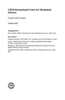
Figure 2. Effect of cold-work on AISI 304, 304L and 316 stainless steel alloys The pronounced cold-working ability is often utilised by cold-reducing stainless steel plate and coil to various tempers before fabrication. The tempers are referred to as %- and V^- and ftiUhard, according to requirements of minimum proof stress and tensile strength, as specified in
73
Stainless Steel Structures
material standards, eg (ASTM-A176 1999; ASTM-A276 2000; ASTM-A666 2000; ASTMA240 2002). (Note that the temper is not directly related to the percentage cold-reduction so that, for instance, Vi -hard does not imply a 50% reduction in thickness). Figures 3a, 3b and 3c show stress-strain curves for annealed, !/2- and full-hard AISI 302 and 304 stainless steel alloys respectively. Cold-working is also utilised in structural design of stainless steel tubes. The design guidelines proposed in (Rasmussen and Hancock 1993a; 1993b) for stainless steel structural hollow sections were based on the properties of the finished cold-formed product. The coldworking of the steel during forming produced compressive and bending strengths of about double the magnitude of those based on the annealed properties. Such increases are unrivaled by carbon steel tubes for which cold-forming enhances the strength by 10-30%. However, given the considerable number of manufacturers of stainless steel tubes and the fact that most of the tubes on the market are annealed after cold-forming, it is imperative that the mechanical properties be certified by the manufacturer if increases in 0.2% proof stress and tensile strength above the annealed values are to be incorporated in design. 1400
^
1300 LT - Longitudinal Tension \ LC - Longitudinal Compression TT - Transverse Tension \ TC - Transverse Compression i
1200 1100 1000
TT
LT J
TC
j
900 ^
TC
i V
'
V
i
//
^ ^
160
LT
140 120 9^
800
^ 700
///^
500
h 100 %
LC
TT
j ^ ^y^
I 600
LC
400 300
/
100 /
0 0
0.002
0.004 0.006 0.008 Strain (mm/mm)
(a) Annealed
0.010 0
0.002
0.004 0.006 0.008 Strain (mm/mm) (b) Half hard
0.010 0
40
'
/
200
20
^ 1 1 0.002 0.004 0.006 0.008 Strain (mm/mm)
0.010
(c) Full hard
Figure 3. Stress-strain curves for annealed, 1/2- and full-hard 302 and 304 stainless steel alloys. Stainless steel is anisotropic, (i.e. the mechanical properties are different in different directions), and behaves differently in tension and compression. The anisotropy depends on the degree of cold-work, as shown in Figure 3, and on the fabrication process. Figure 4a shows stress-strain curves for annealed AISI 304 stainless steel pertaining to the (longitudinal, L) direction of rolling and the (transverse, T) direction perpendicular to this. The coupons were tested in both tension (T) and compression (C). The four stress-strain curves are different, thus demonstrating the anisotropy and the difference between compressive and tensile properties. From a structural viewpoint it is important to notice that the lowest stressstrain curve is that for longitudinal compression (LC), since this is the curve of primary concern in designing compression members and flexural members. Similar stress-strain curves
74
K. J. R. Rasmussen
are shown in Figure 4b for the flat part of a cold-formed square tube of AISI 304L stainless steel. In this case, the lowest stress-strain curve is that for transverse tension (TT) rather than longitudinal compression (LC). The initial modulus of elasticity (EQ) of stainless steel alloys is slightly lower than that of carbon steel, depending on the alloy and on the fabrication process. It is also slightly different in the longitudinal and transverse directions. As a general rule, the initial modulus may be assumed to be £"0=195 GPa which compares with approximately 205 GPa for carbon steel. In design, accurate values of the initial modulus should be used, such as those specified in (ANSI/ASCE-8 1991; AS/NZS4673 2001).
LT - Longitudinal Tension l LC - Longitudinal Compression i TT - Transverse Tension TC - Transverse Compression r
500
400
0.001
0.002 0.003 0.004 Strain (mm/mm) (a) 304 annealed sheet
0.005
0.006
0
0.001
0.002 0.003 0.004 Strain (mm/mm)
0.005
0.006
(b) 304L cold-formed SHS tube
Figure 4. Stress-strain curves for annealed 304 stainless steel sheet and cold-formed AISI 304L stainless steel square tube. The behaviour of stainless steel at elevated temperatures is superior to that of carbon steel. This is demonstrated in Figures 5a and 5b which show graphs of yield stress (or 0.2% proof stress) and tensile strength as functions of temperature. The graphs are shown for AISI 304, 304L, 316 and 316L stainless steels and for Grade 350 carbon steel. The fact that stainless steel maintains substantial strength at elevated temperatures is important in design against fire and in design of vessels containing hot gasses or liquids. Detailed information on the chemical composition and mechanical properties of most of the austenitic and ferritic stainless steel alloys that are likely to be used in structural applications can be obtained from (AISI 1974b). The properties at elevated temperatures are covered comprehensively in (Simmons and Echo 1965). The coefficients of expansion of austenitic stainless steel alloys are generally larger than those of carbon steel, as shown in Table 3. At the same time, the thermal conductivity is lower, as also shown in the table. While the larger coefficient of expansion is important in determining thermally induced stresses and deformations, the combination of larger coefficient of expansion and lower thermal conductivity has the effect of inducing greater welding distortions than those experienced in fabricating carbon steel structural members.
75
Stainless Steel Structures
Temperature ( F)
Temperature ( F) 200
400
600
200
800 1000 1200 1400 1600
400
600
800 1000 1200 1400 1600
70 60
400 J 350 Grade carbon steel I (AS3678)
50
300 40 30
200
20 10 0 0
100 200 300 400 500 600 700 Temperature ( C)
900
0
100 200 300 400 500 600 700 800 900 Temperature ( C) (b) Tensile strength
(a) 0.2% Proof stress
Figure 5. Mechanical properties of stainless steel and carbon steel at elevated temperatures (Simmons and Echo 1965) Table 3. Room temperature values of density, coefficient of expansion, and thermal conductivity of stainless steel alloys and carbon steel (Peckner and Bernstein 1977) Alloy
Density
(kg/mp 201 301 304 316 409 430 S31803 Carbon steel
5.3.3
7700 7700 8000 8000 7700 7700 7800 7850
Lin. Coef. Of expansion (10") 18.4 18.0 18.2 17.5 11.7 11.2 13.7 11.7
Thermal conductivity (W/m°C) 16 15 14 14 25 21
19 58
Analytical expression for the stress-strain curve and its moduli
It is common practice to use the Ramberg-Osgood expression (Ramberg and Osgood 1943), s = — + 0.002
G
(1)
for modelling the stress strain curve of stainless steel alloys. It involves the initial elastic modulus (£0)5 the 0.2% proof stress (ao.2) and the parameter {n) which defines the sharpness of the knee of the stress-strain curve, as shown in Figure 6.
76
K. J. R. Rasmussen
Eo = 200 000 MPa = 400 MPa = ao2/Eo= 0.002
0.002
0.004
0.006
0.008
0.01
Figure 6. Ramberg-Osgood stress-strain curves In the limit where «->oo, the Ramberg-Osgood expression produces a bi-hnear curve (such as that of carbon steel). The slope of the stress-strain curve, or the tangent modulus (Et), is frequently used in design calculations as is the secant modulus (^s), defined as the slope of the line connecting the origo with the current stress point, as shown in Figure 7. Analytical expressions for these moduli are readily obtained from eqn. (1), E =
.n-l
(2)
\-h0.002nEJa^2
E^
=•
^n-\
l + 0.002£,/orn
Figure 7. Initial (EQ), tangent (EiX and secant (E^) moduli
(3)
Stainless Steel Structures
5.3.4
77
Mechanical properties for structural design
The American (ANSI/ASCE-8 1991), Australian (AS/NZS4673 2001) and South African (SABS-0162-4 1997) specifications for cold-formed stainless steel structures include tables of mechanical properties for the stainless steel alloys most commonly used in structural practice. The properties include the initial Young's modulus (EQ), the equivalent yield stress (Fy), defined as the 0.2 % proof stress, the ultimate tensile strength (Fu), the proportionality stress (Fp), defined as the 0.01 % proof stress, and the Ramberg-Osgood ^-parameter. The mechanical properties specified in the Australian standard for cold-formed stainless steel structures (AS/NZS4673 2001) are shown in Table 4. The values are for alloys in their annealed state. The table shows the mechanical properties for compression and tension for loading in the (longitudinal) direction of rolling (see Figure 8) and the transverse direction, as well as shear. In addition to these properties, the American ANSI/ASCE Specification for the Design of Cold-formed Stainless Steel Structural Members (ANSI/ASCE-8 1991) also includes mechanical properties for 1/16, 1/4 and 1/2 hard tempers of 201, 301, 304 and 316 austenitic alloys.
Figure 8. Longitudinal and transverse directions of rolling Table 4. Mechanical properties as included in Appendix B of AS/NZS4673 (2001)
Initial modulus (EQ) 0.2% proof stress (Fy) Ult. tensile strength (F^) Proportionality stress (Fp) ^-parameter
(GPa) (MPa) (MPa) (MPa)
304 316 195 205 520 140 7.5
304L 316L 195 205 485 140 7.5
409 185 205 380 155 11
1.4003 (3Crl2) 195 250 435 180 9
430 185 275 450 195 8.5
S31803 (2205) 200 430 590 245 5.5
a) Long]tudinal terision
Initial modulus (EQ) (GPa) 0.2% proof stress (Fy) (MPa) Proportionality stress (Fp) (MPa) ^-parameter
304 316 195 195 90 4
304L 316L 195 195 90 4
409 185 205 150 9.5
b) Longitudinal compression
1.4003 (3Crl2) 210 260 170 7.5
430 185 275 170 6.5
S31803 (2205) 195 435 245 5
78
K. J. R. Rasmussen
Initial modulus (£"0) 0.2% proof stress (Fy) Ult. tensile strength (Fy) Proportionality stress (Fp) ^-parameter
(GPa) (MPa) (MPa) (MPa)
304 316 195 205 520 118 5.5
304L 316L 195 205 485 118 5.5
409 200 240 380 200 16
1.4003 (3Crl2) 220 280 460 215 11.5
430 200 310 450 250 14
S31803 (2205) 205 450 620 245 5
c) Transverse tension
Initial modulus (EQ) (GPa) 0.2% proof stress (Fy) (MPa) Proportionality stress (Fp) (MPa) w-parameter
304 316 195 205 135 7
304L 316L 195 205 135 7
409 200 240 200 16
1.4003 (3Crl2) 230 285 220 11.5
430 200 310 255 15
S31803 (2205) 205 445 265 5.5
d) Transv(^rse compression
Initial modulus (Go) 0.2% proof stress (Fyy) ^-parameter
(GPa) (MPa) |
304 316 75 115 6
304L 316L 75 115 6
409 75 130 13
1.4003 (3Crl2) 75 155 10
430 75 165 11
S31803 (2205) 75 255 5.5
e) Shear 5.3.5
Corrosion
Some guidance to selecting the alloy on the basis of corrosion resistance is given in Table 2. Further information may be obtained from (Lula 1965; CMC 1966; AISI 1974b; Sedriks 1979). However, for specialised applications in highly corrosive environments, expert advice should be sought. The types of corrosion which in some instances can be encountered in stainless steel structures are summarised in (Eurocode3-1.4 1996; AS/NZS4673 2001) as: pitting, crevice corrosion, bimetallic corrosion, stress corrosion cracking, general corrosion, and intergranular attack (or sensitisation). The same references define these types of corrosion and suggest ways of guarding against them.
Stainless Steel Structures
79
5.4 Effect of Material Nonlinearity on Strength and Deformation Calculations 5.4.1
General
In Section 5.3, we saw that stainless steel alloys have nonlinear stress-strain curves with low proportionality stress. At stresses above the proportionality stress, the material yields and loses stiffness gradually. The stiffness is measured as the tangent of the stress-strain curve, as shown in Figure 7, which varies with the stress level. The tangent modulus plays an important role in stability calculations, since the buckling resistance depends on the current stiffness among other factors. 5.4.2
Strength of columns
Engesser (1889) published one of the earliest studies of the effect of yielding on the buckling resistance of columns. He proposed that the first term of the buckling equation for a column. d\
=0
(4)
be changed to reflect the loss of stiffness. The term encapsulates the bending moment that develops during overall buckling and as such is related to the current stiffness of the material. Engesser originally proposed that the bending stress resulting from overall buckling could be assumed to be proportional to E^. In this case, the buckling equation changes to. EJ
d w d\ +p =0 ~d^ dx'
(5)
and the buckling load is obtained as, TT'EJ
(6)
PE =
where LQ is the effective length which depends on the end support conditions. Compression
Neutral! axis Tension-
Bending strain
^
k.
(a) Tangent Modulus Approach
Bending strain
Compression
Neutral [ axis
I Cetroidal
K ""^^o
Tension (b) Reduced Modulus Approach
Figure 9. Tangent and reduced moduli approaches Engesser's first proposal was critisised because it did not recognise that during overall buckling, tension may be induced on the concave side of the columns which therefore would elastically unload, and the initial modulus (EQ) would pertain to this part of the cross-section. In response, Engesser (1895), modified eqn. (6) to account for elastic unloading in the part of the cross-section in tension, as shown in Figure 9. This required a new position of the neutral axis which was determined so that the axial force remained unchanged. The bending moment
80
K. J. R. Rasmussen
depended upon the initial elastic modulus (EQ) for the parts of the cross-section in tension and the tangent modulus (£'t) for the parts of the section in compression, as shown in Figure 9. The buckling load could then be determined as, TT'EI.. PE
=
(V)
where the reduced modulus {E^) was a function of the elastic modulus {EQ) and the tangent modulus (£"1), E^=E,^
+ E,^
(8)
In eqn. (8), I^ and /t are the second moments of area of the parts of the cross-section in compression and tension with respect to the neutral axis, respectively, and / is the second moment of area of the full cross-section with respect to the centroidal principal axis. However, when compared to test results on concentrically loaded columns, it was found that the tangent modulus approach (eqn. (6)) provided better agreement than the reduced modulus approach. Shanley (1947) used a simple strut model to explain this resuh by pointing out that: 1.
The column cannot remain straight at loads above the tangent modulus buckling load (P^ ), since if it did the tangent stiffness of all point in the cross-section would be E^ and the column would be in a state of unstable equilibrium. The column must therefore start to buckle at P^ .
2.
The axial force cannot be assumed to remain constant during overall buckling but may increase, as shown in Figure 10.
Figure 10. Load-deflection curve However, the inelastic post-buckling reserve is generally small for columns and so the tangent modulus buckling load (P^ ) is a conservative and yet reasonably accurate measure of the inelastic buckling strength. The tangent modulus is used in the American, South African and Australian standards to determine the strength of compression and unbraced flexural members.
81
Stainless Steel Structures
5.4.3
Strength of plates
Stowell (1948) developed a theory for calculating the inelastic buckling load of plates. Based on Shanley's work, he assumed that in the inelastic range, an increase in load proceeds simultaneously so that strain reversal does not occur. For a plate uniformly compressed in the x-direction (see Figure 11), the following buckling equation was derived, D
d'w
(i-l4 dx'
9 w + 2dx'dy^
aV dy'
+ ta^
dx"
0
(9)
where / is the plate thickness and, D
Ef
(10)
(11)
E, V// Simply supported
—•
V
|
Y///////////////////////////////////////////4///A, w(x,y)
^ —• ^ —^ /,/ V777777777777777777777777777777777777777777777777.
Section A-A
Figure 11. Buckling of rectangular plate under uniform compression In equations (9-11), E^ is the secant modulus and QX is the applied compressive stress. Equation (9) is the equivalent of St Venant's equation for the elastic buckling of plates. D
_dx'
dx^dy'
" dx"
(12)
where £.'• (13) 12(1-1^0 The equivalence between eqns (9) and (12) follows from the fact that for plastic buckling, Poisson's ratio (v) is taken as 0.5, and for elastic buckling E^ = Ei- EQ. It can be concluded from eqns (9-11) that. n -
82
K. J. R. Rasmussen
1.
The plate buckling stress depends on two moduli (^s, ^t), and
2.
The buckling stress is not simply proportional to D* because of the factor d^w/dx^-tQvm of eqn. (9).
(1-3/4K)
on the
The solution of eqn. (9) is involved and generally not suited for design calculations. Bleich (1952) proposed the simplified version of the equation, 2d w ^ d w dw . . . . - ^ =0 D T —7- + 2r—-—^ + dx' dx^dy- dy'
(14)
in which i is a plasticity reduction factor that he chose as,
Bleich solved eqn. (14) for several support conditions and obtained the following expression for the minimum buckling stress,
where k is the plate buckling coefficient which is independent of i and takes the same values as for elastic buckling. When the plasticity reduction factor (i) is taken as "^E^IEQ (eqn. (15)), the minimum buckling stress can be written as. k/r^jEr^E. f t\
"
12(1-v') U>
Evidently, this equation simplifies to the expression for the elastic buckling stress when assuming Et=Eo. By comparing eqns (6,17), it can be seen that the inelastic buckling of plates is less affected by gradual yielding than columns. Furthermore, while the buckling of columns can be assumed to represent the ultimate load for all practical purposes, slender plates are post-buckling stable and can support loads in excess of the inelastic buckling stress. It follows from eqn. (17) that when the buckling stress reduces below the proportionality stress, the tangent modulus approaches the initial elastic modulus (Et-^Eo), and so the buckling stress becomes the elastic buckling stress. Since the elastic buckling stress is a conservative estimate of plate strength, equation (17) becomes increasingly conservative for predicting plate strength as the slendemess increases. 5.4.4
Deflection calculations
The material softening associated with early yielding increases the deformations when the stress exceeds the proportionality stress. Consequently, in design, there is a greater need for checking that the deflections occurring during normal service do not exceed acceptable limits.
Stainless Steel Structures
83
Furthermore, if the section is prone to local buckling, the reduction in flexural stiffness of the locally buckled section must be used in the deflection calculations. Johnson and Winter (1966) first proposed that the deflection of a beam can be determined using. PL'
(18)
where /g is the second moment of area of the effective cross-section and E^ is the average of the secant moduli (E^ , E^ ) calculated at the extreme fibres in tension and compression at the cross-section of maximum moment,
^. - - ^ Y ^
(19)
The secant moduli for tension (E^ ) and compression (E^ ) can be determined using eqn. (3) in conjunction with the Ramberg-Osgood parameters for tension and compression respectively. In eqn. (18), the constant k^ depends upon the loading and support conditions and is defined such that eqn. (18) reproduces the linear-elastic expression for the deflection when E^ is replaced by EQ. (For instance, the mid-span deflection of a linear-elastic simply supported beam subjected to two point loads acting at a quarter from each end is v=\ 1/192 PL^/(EQI) and so A:v =11/192 for this case). Since the moment generally varies along the length of a beam, the stress and hence secant modulus vary along the beam as well. (The secant modulus also varies through the depth of the cross-section but its values at the extreme fibres are most important for deflection calculations). Johnson and Winter (1966) proposed that the secant moduli (E^ ,E^ ) be determined at the point of maximum moment. However, when applied to SHS and CHS beams, Rasmussen and Hancock (1993b) observed that the combination of determining the average secant modulus (E^ ) at the section of maximum moment using the stresses at the extreme fibres produced excessive estimates of deflection. They proposed that the secant modulus be determined at the stress, CT = K
^
(20)
where M^^ix is the maximum moment in the span, Sf is the elastic modulus and k^ is a factor less than unity which was obtained from calibration against finite element deflection calculations (Rasmussen and Hancock 1992; 1993b). The values of A:cf=2/3 and ^^""3/4 were obtained for single span SHS and CHS beams respectively, whereas A:cr=l/2 was obtained for SHS and CHS beams continuous over two spans. Figures 12a and 12b show comparisons of deflections predicted using the modified method proposed by Rasmussen and Hancock (1993b) with tests on SHS and CHS beams respectively. Good agreement can be observed over the loading range shown. The horizontal lines labeled Mo.2/1-85 are the loads producing maximum moments equal to Mo.2/1.85 where Mo.2=*S'pao.2 is the plastic moment based on the 0.2% proof stress and the factor 1.85 is the safety factor for allowable stress design specified in Appendix E of the ANSI/ASCE-8 Specification. These
84
K. J. R. Rasmussen
loads are representative of those likely to develop during normal service. It follows that for the beams tested, the beams behave nearly linear-elastically during service loads. More recent studies on the deflection of stainless steel beams (Mirambell and Real 2000; Chryssantholopoulos and Low 2001) have verified the approach suggested by Rasmussen and Hancock (1993b), and more general methods have been proposed (Chryssantholopoulos and Low 2001). 120
1
Linear-elastk theory 100
1
1
Approximate method
"V
—-
•
-
80 h
y^ ^
60
h
/
.P/2
P/2.
/////
\
\ ^max ~
V7
///}/
Mo.2 1.85 • Test
L.,
..
1 10
1
20
15
25
v(mm)
(a) SHS
Approximate method P/2
i
P/2
I
• Test 10
15
20
25
v(mm)
(b) CHS Figure 12. Comparison of experimental and predicted load-deflection curves for SHS and CHS beams (Rasmussen and Hancock 1993b)
Stainless Steel Structures
85
5.5 Development of specifications for stainless steel structures The first American specification (AISI 1968b) for stainless steel structural members was published by the American Iron and Steel Institute in 1968. This applied specifically to annealed and strain-flattened light-gauge steel, cold-formed into structural shapes. A revision of this specification (AISI 1974a), which included 1/4- and 1/2-hard tempers, was published in 1974. The 1968 and 1974 editions were based mainly on the 1968 edition of the AISI specification for cold-formed carbon steel structural members (AISI 1968a). A major revision of the 1968 specification for cold-formed carbon steel structural members was published in 1986 (AISI 1986), prompting a revision of the 1974 cold-formed stainless steel specification. This (Lin et al. 1988a) was prepared at the University of Missouri-Rolla but not published as a specification. Concurrently with the revision of the 1974 stainless steel specification, the 1986 cold-formed carbon steel specification was being converted from allowable stress design format to limit state design format. It was then decided to also convert the stainless steel cold-formed specification to limit state format before publication. Details of the limit state calibration are contained in (Lin et al. 1988b). The same document was published as a specification (ANSI/ASCE-8 1991) by the American Society of Civil Engineers (ASCE) in 1991. The ANSI/ASCE-8 Specification is closely aligned with the AISI limit state specification for cold-formed carbon steel structures (AISI 1997). In Britain, the Steel Construction Institute prepared a guide (Burgan 1993) on the design of stainless steel structures. The guide is essentially an addendum to the British steel structures standard (BSI 2001), containing design rules that are specific to stainless steel. (It also contains useful guidance on selection and corrosion of stainless steel structures). More recently, the British Steel Institute published a similar guide incorporating research undertaken primarily in Europe during the 1990s (Baddoo and Burgan 2001). In a similar approach to the British guidelines, the draft Part 1.4 of Eurocode3 (EurocodeS1.4 1996) for stainless steel structures contains design rules to be used in conjunction with those of Parts 1.1 (Eurocode3-l.l 1992) and 1.3 (Eurocode3-1.3 1996) for hot-rolled and coldformed carbon steel structures. Thus the British and European approaches are not to have separate standards for stainless steel structures, but a limited set of rules that replace those for carbon steel structures for only the types of members that are affected by differences in mechanical properties of stainless and carbon steel. Standards Australia recently published a joint Australian-New Zealand standard (AS/NZS4673 2001) for the design of stainless steel cold-formed structures. The standard is based on the ANSI/ASCE-8 Specification but includes mechanical properties for a wider range of alloys, as well as additional provisions for tubular members and welded connections. The notation and layout of the standard are the same as those for the Australian/New Zealand standard for cold-formed carbon steel structures (AS/NZS4600 1996), which is based on the limit state edition of the AISI Specification (AISI 1991b).
86
K. J. R. Rasmussen
5.6 Design of Compression Members 5.6.1
General
The strength of compression members (or columns) is usually determined as a product of an overall buckling stress and an area, which may be an effective area if the section is prone to local buckling. In this approach, the local buckling stress is implicitly determined in calculating the effective area. The local and overall buckling modes are the most common modes encountered in design. However, if the column is likely to buckle in other modes in its ultimate limit state including the distortional mode, such buckling modes must be accounted for as well. In calculating the local and overall buckling stresses, it is necessary to consider the loss of stiffness associated with early yielding. This can be done by using tangent and/or secant moduli in the buckling strength equations as discussed in Section 5.4. In this case, the design procure is implicit (the strength calculations are iterative). Alternatively, strength curves may be used which are lower than those for sections not subject to early yielding. In this case, the strength calculations are direct (the design procedure is explicit). In the following sections, the implicit and explicit formulations are explained in detail. 5.6.2
Implicit Approach
5.6.2.1 Overall Buckling Strength As discussed in Section 5.4, the ultimate limit stress (a^) can be taken as the inelastic buckling stress a^ = P^ / A determined using the tangent modulus approach. (21) where r is the radius of gyration, r-^l
(22)
This procedure is valid for doubly and point-symmetric sections which fail by flexural buckling. It generally leads to slightly conservative design strengths compared to tests on concentrically loaded columns. This is demonstrated in Figure 13 which compares tests on cold-formed circular sections (Rasmussen and Hancock 1993a) with design strengths obtained using eqn. (21).
87
Stainless Steel Structures
400
Column Length (feet) 6 8 10 12 14 \ \ \ \ o Concentric long column test strength • Eccentric long column test strength Fixed-ended stub column test strength
o
300
Euler(EQ=201GPa)
X
AS/NZS 4643 200 .(iterative procedure)
600 500
>
\
Stiffened Elements
PQ
0.4
1
V o
0.2 Unstiffened Elements
\ 20
J
J
40
60
__i
80
J
100
b/t Figure 16. Buckling stress vs slendemess Van den Berg further proposed that the effective width of plates in uniform compression should be determined using the Winter expression, 1 1-0.22//1 A
for A < 0.677 for >1> 0.677
(30)
where (31)
kTT E^T cr,. = -
12(1
(32)
•v')
In eqns (31-32), a is the applied stress, k is the plate buckling coefficient equal to 4 and 0.425 for stiffened and unstiffened plates respectively, v is the Poisson's ratio taken as 0.3, and x is the plasticity reduction factor given in Table 5 which is to be calculated at the stress a. It should be noticed that when the term 0.22/?i is ignored in eqn. (30), the effective width is proportional to 1/^ and hence VT. This implies that the plate strength is less affected by yielding than the inelastic buckling stress (GCO which is proportional to i.
Stainless Steel Structures
5.6.3
91
Explicit Approach
5.6.3.1 General From Section 5.4, we know that the local and overall buckling strengths are affected by early yielding and that the reduction in strength is related to the stress-strain curve. We also know that different alloys have different stress-strain curves and so, different strength curves apply to different alloys. Since the stress-strain curve can be represented closely by the RambergOsgood expression (eqn. (1)), it is possible to express the strength curve directly in terms of the Ramberg-Osgood parameters. Rasmussen and Rondal (1997) developed the relationship for columns failing by flexural buckling. More recently, Rasmussen et al. (2002) have developed the relationship for plates. Table 6: («, ^)-combinations in Rasmussen and Rondal (1997) n
3
5
10
20
40
100
e
0.001
0.0015
0.002
0.0025
0.003
0.004
{n,e)
0.006
0.008
(3, 0.001), (3, 0.0015),... (3, 0.008),.. (5, 0.001), (5,0.0015),..., (100, 0.008)
5.6.3.2 Overall Buckling Strength Rasmussen and Rondal (1997) used the finite element program developed by Clarke (1994) to obtain strength curves for the combinations of the ^-parameter and the nondimensional proof stress {e^GQilE^) shown in Table 6. The column strength (P^) was normalised wrt the "yield" load (P0.2), PQ2
-
^O'QI
(33)
and expressed in terms of the column slendemess. (34) where P^ is the elastic Euler buckling stress. 7T-EJ
(35)
92
K. J. R. Rasmussen
^
'
^
1
"1
••\ 1 e = CTQT/EQ =0.001
" \ '\ ' 1.2
1
'
1 1 e = ao2/Eg =0.008
H
v\\ W\
\
0.8 N / \
\
/Euler(Eo)
/Euler(Eo)
0.6 0.4
3 ^
3/
"
0.2
0
0.25
0.5
0.75
—L-. 1.0
1 1.25
_.„1 1.5
1 1.75
2.0
0
1 0.25
\ 0.5
J 0.75
\ 1.0
1.25
1.5
1.75
2.0
(b)
'\ \ V \
1
'
1
T
1 /7=3
r
I
1
77=100
^ -
^" ^°^ ^ ° S c ^ V \V
0.008
/Euler(EJ 0.008 " O v z \ ? \ \ ^•^^ / " " ^ v N .sNv \ / ^
0.002 ^'\x 0.001 -^
0
1 0.25
L, ,., 1 0.5 0.75
^ 0 ^
1.0
1.25
1.5
1.75
0.002 0.001
-
^^$^^^1:^^
2.0
0
xJ^^^^ V V
/Euler(Eo)
^ y ^ ^
^^^^^ '
,1 0.25
1 0.5
1 0.75
_l— 1.0
1.25
1.5
1.75
2.0
Figure 17. Finite element column strength curves Figures 17a and 17b show strength curves for a range of w-values for e=0.001 and e=0.008 respectively. Similarly, Figures 17c and 17d show strength curves for a range of e-values for «=3 and «=100 respectively, where «=100 represents carbon steels with a bi-linear stress-strain curve. The following observations can be made from Figures 17a-17d:
Stainless Steel Structures
93
•
There is a significant difference in strength for different values of n for low values of e but not for large values oie, (cmp. Figs 17a and 17b).
•
There is significant difference in strength for different values of ^ for low values oin but not for large values of «, (cmp. Figs 17c and 17d). Consequently, the proof stress has much greater effect on the strength curves for small values oin than for large values ofn.
•
For ^->0, the strength exceeds the yield load for small values of/?, while for larger values of n the strength approaches the yield load. This result is a consequence of the stressstrain curves detailed in Fig. 6 which show that the stress may significantly exceed the proof stress at large strain for small values oin.
•
For low values of «, the strength curves have single curvature while for large value of w, they have double curvature, (cmp. Figs 17c and 17d).
To obtain an analytic expression for the strength strain curve, Rasmussen and Rondal (1997) adopted a Perry curve in the form
X-—rT==r-^
^^^^
where x is the nondimensional column strength, and cp is defined as,
^fn
(68)
((> = 0.7
(69)
N fd where
(70)
^f.=KF,
In equation (70), A^ is the net area of the connected part in the Hne of bolts transverse to the line of the applied force and the strength (F,) is given by, f(l -Vf -¥ l.Srrd f I s fF^ < F„
for single shear connections
F.=\
(71) (1 - 0.9r^ -vlr^d ^ I s fF^ < F^ for double shear connections
Stainless Steel Structures
107
where ^f is the spacing between the bolts transverse to the line of the force (or in the case of a single bolt, the width of the connected part), see Fig. 25, and r^ is the force transmitted by the boh or bolts at the section considered, divided by the tensile force in the member at that section. If rf is less than 0.2, it may be taken as zero. The procedure for calculating rf is shown in the example in Section 5.7.4. As set out under Tension Members in AS/NZS4673 and the ANSI/ASCE-8 Specification, the tensile capacity of the connected member shall be limited to, N,,,=^N.,n
(72)
where ^ = 0.85
(73)
^,,,=A^v
(74)
Equation (74) checks that general yielding does not occur. It should be noticed that the net area (Aj,) is used in this calculation rather than the gross area. 3. Bearing failure. The design bearing force shall be determined as,
K,=K„
(75)
^ = 0.65
(76)
where
[idftF^ for single shear connections V =i (77) if tF,, for double shear connections ^" ' 3(i. 4. Bolt shear failure. The design shear force of bolts to ASTM standards shall be determined as, ^ > . = ^ ^ / . . (ASTM bolts)
(78)
where ^ = 0.65 (ASTM bolts)
(79)
V^,^ = Aj.F^^. (ASTM boks)
(80)
In equation (80), Af is the boh shank area and Fnv is the nominal shear strength, which is specified in the standards for shear planes through the shank and thread. The Australian standard includes separate bolt shear design equations for bohs to ISO3506. The equations are based on those of Parts 1.1 and 1.4 of Eurocode3, According to the Australian standard, the design bolt shear force of bolts to ISO3506 shall be determined as, ^/v.=^^A« (ISO 3506)
(81)
^ = 0.75 (ISO 3506)
(82)
where
108
K. J. R. Rasmussen
\0.6A.F^f
shear plane through shank
F^„=
(ISO 3506)
(83)
\0.6Aj-^F^^ shear plane through thread In equation (83), ^fs is the tensile area of the bolt and Fnt is the nominal tensile strength. (B) Tension. The design tensile force of bolts to ASTM standards shall be determined as, Nft,-(l>Nf.
(ASTM)
(84)
where ^ = 0.75
(ASTM)
Nf,.=AfF,
(ASTM)
(85) (86)
In equation (86), Af is the shank area and Fnt is the nominal reduced tensile strength which is specified in the Australian and American specifications. A reduced tensile strength is used because the strength is calculated on the shank area rather than the tensile area. The specifications require that the pull-over capacity of the connected part be considered but does not provide design equations for this purpose. For bolts to ISO3506, the Australian standard requires the design tensile force be determined as, Nf.,=^Nf.
(ISO 3506)
(87)
where ^ = 0.67 ^f.=AjsK.
(ISO 3506) (ISO 3506)
(88) (89)
In equation (89), ^fs is the tensile area and Fnt is the nominal tensile strength which is specified in the Australian Standard. European standard. According to Section 6 of Part 1.4 of Eurocode3, the design of bolted connections shall be to Section 6 of Part 1.1 of Eurocode3. The following two specific clauses are added: •
A separate check on the hole elongation under service loading can be avoided by using a reduced ultimate tensile strength calculated as, ^„,w=0-5F^.+0.6F„
•
(90)
The shear resistance for bolts to ISO3506 shall be determined as, ^ . = — y \fb
(91)
109
Stainless Steel Structures where
(92)
rM*=i-35 Vfvn
0.6A^F„,
shear plane through shank
0.6A,,F„,
shear plane through thread
(93)
In equation (93), Af and ^fs are the shank area and tensile area respectively and Fnt is the nominal tensile strength of the bolt. Equations (91-93) produce virtually the same design strength (Ffvd) as eqns (81-83). Since Section 6.1 of Eurocode3, Part 1.4, only refers to Part 1.1 of Eurocode3, it is not clear whether the design provisions for connections of light-gauge structures covered by Part 1.3 of Eurocode3 can be used for cold-formed stainless steel structures. An exception is connections of stainless steel sheets using self-tapping screws, which according to Section 6.1 of Part 1.4 of Eurocode3 can be designed according to Part 1.3 of Eurocode3. 5.7.2.3 Design of welds American and Australian/New Zealand specifications The Australian and American provisions for welds are the same except that the Australian standard refers to AS/NZS 1554.6 (1994) for prequalification and welding procedures, whereas the American specification refers to AWS D1.3 (1998). Design guidance is included for butt (groove) welds, fillet welds and resistance spot welds. The specifications do not contain design rules for arc spot (puddle) welds, arc seam welds or flare welds. The Australian standard contains guidance on the design of welded tubular connections. The rules for butt and fillet welds are as follows: (A). Butt welds. A distinction is made between butt welds subjected to tension (or compression) and shear, as shown in Figs 26a and 26b respectively
(a) Longitudinal tension and compression
(b) Shear
Figure 26. Butt welds in tension/compression and shear 1. Tension or compression. The design force in the connected part shall be determined as, N..,=N^,„
(94)
110
K. J. R. Rasmussen
where (j) = 0.6
(95)
A^ =1 tF
(96)
In equation (96), /^ is the length of the weld, / is the thickness of the thinnest welded part, and (Fua) is the tensile strength of the annealed base metal. The nominal strength equation (96) differs from equivalent equations for cold-formed and hot-rolled carbon steel structures, which use the yield stress rather than the tensile strength. Equation (96) originates from research at Cornell University (Errera et al. 1970) which showed good correlation between test strength and tensile strength. For 1/16, 1/4 and 1/2 hardened tempers, tests showed that the tensile strength of the annealed base metal should be used. 2. Shear. The design force in the connected part shall be determined as, (97) where (98) (99)
v.. =0.6 IjF.,..
Equation (99) corresponds to eqn. (96) except that the approximate value of 0.6Fua is used for the ultimate shear strength of the annealed base metal. (B). Fillet welds. Design equations are provided for welds transferring loads by longitudinal and transverse shear, as shown in Figs 27a and 27b respectively.
t
t -l
(a) Longitudinal shear
(b) Transverse shear
Figure 27. Fillet welds in longitudinal/transverse shear 1. Longitudinal loading. The design force in the connected part shall be determined as,
where
Stainless Steel Structures
111
«z> = 0.55
(101)
K„=mm{V^^„^,V„J ^
^ 1(0.7-0.009/„//)?/,F„, """
[0.43;/^F„„
(102) forC/;30
^^„,.=0.75rX,F„
(104)
In equation (104), ty, is the effective throat (min[wi/V2, W2/V2]) where Wi and W2 are the leg lengths), and F^^ is the tensile strength obtained from an all-weld-metal tensile test. Values for Fxx are given in the specifications for a wide range of electrodes. 2. Transverse loading. The design force in the connected part shall be determined as, F,, =min{^.'^/v,. '.*» Nj^J = mm{0Jx65.H
kN,0.85x67.4 kN}-46.1kN
3. Bearing capacity. Use eqns (75-77). Nominal bearing capacity of one boh: F,„ =2cI^tF^ = 2 x l 2 x 3 x 5 3 0 N = 38.2kN Design bearing capacity of plate, (six bolts): Kd = ^^Kn = 6 X 0.65 X 38.2 kN = 166 kN 4. Bolt shear capacity. Use eqns (81-83). Nominal shear capacity of one bolt assuming fracture through the shank: V^^ ^ 0 . 6 - ( ^ ^ ) ' F „ , = 0 . 6 x - x ( 1 2 ) ' x 7 0 0 N = 47.5kN
116
K. J. R. Rasmussen
Design shear capacity of plate, (six bolts): ^_fvd = ^^^,fvn = 6 X 0.75 X 47.5 kN = 214 kN The factored ultimate limit state design capacity of the lap joint can now be obtained as the minimum of the tear-out, net tension, bearing and shear capacities, N^ =min{F^^,7V^^,F,^,F^^} = min{148kN,46.1kN,166kN,214kN} = 46.1kN The predicted failure mode is net section fracture. References AISI (1968a). Specification for the Design of Cold-formed Steel Structural Members, American Iron and Steel Institute, Washington, DC. AISI (1968b). Specification for the Design of Light Gage Cold-formed Stainless Steel Structural Members, American Iron and Steel Institute, Washington, DC. AISI (1974a). Specification for the Design of Cold-formed Stainless Steel Structural Members, American Iron and Steel Institute, Washington, DC. AISI (1974b). Steel Products Manual - Stainless and Heat Resisting Steels, American Iron and Steel Institute, Washington, DC. AISI (1986). Specification for the Design of Cold-formed Steel Structural Members, Washington, DC. AISI (1991a). Design Guidelines for the Selection and Use of Stainless Steel, A Designer's Handbook Series No. 9014, American Iron and Steel Institute, Washington, DC. AISI (1991b). Load and Resistance Factor Design Specification for Cold-formed Steel Structural Members, American Iron and Steel Institute, Washington D.C. AISI (1997). Load and Resistance Factor Design Specification for Cold-formed Steel Structural Members, American Iron and Steel Institute, Washington, DC. ANSI/ASCE-8 (1991). Specification for the Design of Cold-formed Stainless Steel Structural Members, American Society of Civil Engineers, New York, NY. AS/NZS1554.6 (1994). Structural Steel Welding, Part 6: Welding Stainless Steels for Structural Purposes, AS/NZS 1554.6, Standards Australia, Sydney. AS/NZS4600 (1996). Cold-formed Structures, AS/NZS 4600, Standards Australia, Sydney. AS/NZS4673 (2001). Cold-formed Stainless Steel Structures, AS/NZS4673, Standards Australia, Sydney. ASSDA (2002). Australian Stainless Steel Reference Manual, Australian Stainless Steel Development Association, Brisbane. ASTM (2002). Metals and Alloys in the Unified Numbering System, 9th ed, American Society for Testing and Materials, Philadelphia. ASTM-A176 (1999). Standard Specification for Stainless and Heat-Resisting Chromium Steel Plate, Sheet, and Strip, A176, American Society for Testing and Materials, Philadelphia. ASTM-A193 (2001). Standard Specification for Alloy-Steel and Stainless Steel Bolting Materials for High-Temperature Service, A193, American Society for Testing and Materials, Miami. ASTM-A240 (2002). Standard Specification for Chromium and Chromium-Nickel Stainless Steel Plate, Sheet, and Strip for Pressure Vessels and for General Applications, A240, American Society for Testing and Materials, Philadelphia.
Stainless Steel Structures
117
ASTM-A276 (2000). Standard Specification for Stainless Steel Bars and Shapes, A276, American Society for Testing and Materials, Philadelphia. ASTM-A666 (2000). Standard Specification for Annealed or Cold-Worked Austenitic Stainless Steel Sheet, Strip, Plate, and Flat Bar, A666, American Society for Testing and Materials, Philadelphia. ASTM-F593 (2001). Standard Specification for Stainless Steel Bolts, Hex Cap Screws, and Studs, F593, American Society for Testing and Materials. AWS-Cl.l (2000). Recommended Practices for Resistance Welding, Cl.l, American Welding Society, Miami. AWS-D1.3 (1998). Structural Welding Code - Sheet Steel, D1.3, American Welding Society, Miami. Baddoo, N. and B. Burgan (2001). Structural Design of Stainless Steel, Steel Construction Institute, London. Berg, G. v. d. (2000). "The Effect of the Non-Hnear Stress-strain Behaviour of Stainless Steels on Member Capacity." Journal of Constructional Steel Research 54(1): 135-160. Bleich, F. (1952). Buckling Strength of Metal Structures. New York, NY, McGraw-Hill. BSI (2001). Structural use of Steelwork in Building. Specification for Materials, Fabrication and Erection: Hot-Rolled Sections, British Standards Institution, London. Burgan, B. (1993). Concise Guide to the Structural Design of Stainless Steel, The Steel Construction Institute, Ascot, UK. Chryssantholopoulos, M. and Y. Low (2001). "A Method for Predicting the Flexural Response of Tubular Members with Non-linear Stress-strain Characteristics." Journal of Constructional Steel Research 57(11): 1197-1216. Clarke, M. (1994). Plastic-zone Analysis of Frames. Advanced Analysis of Steel Frames: Theory, Software and Applications. W. C. a. S. Toma. London, CRC Press: Chapter 6. CMC (1966). Corrosion in Action, Climax Molybdenum Company, Greenwich, Conn. EN-10088 (1995). Stainless Steels, EN-10088, European Committee for Standardisation, Brussels. Engesser, F. (1889). Zeitschriftfur Architektur undIngenieurwesen 35: 455. Engesser, F. (1895). Schweizerische Bauzeitung 26: 24. Errera, S., B. Tang and D. Popovich (1970). Strength of Bolted and Welded Connections in Stainless Steel, Report No. 335, Department of Civil Engineering, Cornell University, Ithaca, NY. Eurocode3-l.l (1992). Eurocode3: Design of Steel Structures, Part 1.1: General Rules and Rules for Buildings, ENV-1993-1-1, European Committee for Standardisation, Brussels. Eurocode3-1.3 (1996). Eurocode3: Design of Steel Structures, Part 1.3: Cold Formed Thin Gauge members and Sheeting, ENV-93-1-3, European Committee for Standardisation, Brussels. Eurocode3-1.4 (1996). Eurocode3: Design of Steel Structures, Part 1.4: Supplementary Rules for Stainless Steel, prENV-93-1-4, European Committee for Standardisation, Brussels. Gerard, G. (1946). "Secant Modulus Method for Determining Plate Instability above the Proportionality Limit." Journal of the Aeronautical Sciences 13: 38. UihhitUKarlsson Sind SoYQYiSQn (1995). ABAQUS Standard, Users Manual, Ver. 5.5. ISO-3506 (1997). Mechanical Properties of Corrosion-resistant Stainless-steel Fasteners, ISO 3506, International Standards Organisation, Geneva.
118
K. J. R. Rasmussen
Johnson, A. and G. Winter (1966). "Behaviour of Stainless Steel Columns and Beams." Journal of Structural Engineering, American Society of Civil Engineers, ASCE 92(ST5): 97-118. Lin, S.-H., W.-W. Yu and T. Galambos (1988a). Design of Cold-formed Stainless Steel Structural Members, Proposed Allowable Stress Design Specification with Commentary, Progress Report No. 3, University of Missouri-RoUa, RoUa, MO. Lin, S.-H., W.-W. Yu and T. Galambos (1988b). Load and Resistance Factor Design of Coldformed Stainless Steel, Statistical Analysis of Material Provisions and Development of the LRFD Provisions, Progress Report No. 4, University of Missouri-Rolla, Rolla, MO. Lula, R. (1965). Stainless Steel, American Society of Metals, Ohio. Mann, A. (1993). "The Structural Use of Stainless Steel." The Structural Engineer 71(4): 6069. Mirambell, E. and E. Real (2000). "On the calculation of deflections in structural stainless steel beams: an experimental and numerical investigation." Journal of Constructional Steel Research 54(1): 109-133. NiDI (1990). Advantages for Architects: An Architect's Guide on Corrosion Resistance, Nickel Development Institute, Toronto. NiDI (1992). Guidelines for the Welded Fabrication of Nickel-containing Stainless Steels for Corrosion Resistant Services, Nickel Development Institute, Toronto. Packer, J., J. Wardenier, Y. Kurobane, D. Dutta and N. Yeomans (1992). Design Guide for Rectangular Hollow Section (RHS) Joints under Predominantly Static Loading, Comite International pour le Developpement et I'Etude de la Construction Tubulaire (CIDECT), Verlag TUV Rheinland, Cologne. Peckner, D. and I. Bernstein (1977). Handbook of Stainless Steels. New York, N.Y., McGrawHill. Ramberg, W. and W. Osgood (1943). Description of Stress Strain Curves by Three Parameters, Technical Note No. 902, National Advisory Committee for Aeronautics, Washington, DC. Rasmussen, K. (2001). Full-range Stress-strain Curves for Stainless Steel Alloys, Research Report R811, Department of Civil Engineering, University of Sydney. Rasmussen, K., P. Bezkorovainy and T. Bums (2002). Strength Curves for Metal Plates, Research Report, Department of Civil Engineering, University of Sydney. Rasmussen, K. and G. Hancock (1992). Design of Co Id formed Stainless Steel Tubular Beams, Recent Developments in Cold-formed Steel Design and Construction, 11th International Specialty Conference on Cold-formed Steel Structures, Ed(s) W.-W. Yu and R. LaBoube, St Louis, University of Missouri-Rolla. Rasmussen, K. and G. Hancock (1993a). "Stainless Steel Tubular Members. I: Columns." Journal of Structural Engineering, American Society of Civil Engineers, ASCE 119(8): 2349-2367. Rasmussen, K. and G. Hancock (1993b). "Stainless Steel Tubular Members. II: Beams." Journal of Structural Engineering, American Society of Civil Engineers, ASCE 119(8): 2368-2386. Rasmussen, K. and A. Hasham (2001). "Tests of X- and K-joints in CHS Stainless Steel Tubes." Journal of Structural Engineering, American Society of Civil Engineers 127(10): 1183-1189. Rasmussen, K. and J. Rondal (1997). "Strength Curves for Metal Columns." Journal of Structural Engineering, ASCE 123(6): 721-728.
Stainless Steel Structures
119
Rasmussen, K. and J. Rondal (2000). "Column Curves for Stainless Steel Alloys." Journal of Constructional Steel Research 54( 1): 89-107. Rasmussen, K. and B. Young (2001). "Tests of X- and K-joints in SHS Stainless Steel Tubes." Journal of Structural Engineering, American Society of Civil Engineers 127(10): 11731182. SABS-0162-4 (1997). Structural Use of Steel, Part4: The design of Cold-formed Stainless Steel Structural Members, SABS 0162-4, South African Bureau of Standards, Pretoria. Sedriks, A. (1979), Corrosion of Stainless Steels. New York, N.Y., John Wiley and sons. Shanley, F. (1947). "Inelastic Column Theory." Journal of the Aeronautical Sciences 14(5): 261-267. Simmons, W. and J. v. Echo (1965). The Elevated-temperature Properties of Stainless Steel, ASTMData Series Publication DS5-S1, American Society for Testing and Materials, Philadelphia. Stowell, E. (1948). A Unified Theory of Plastic Buckling of Columns and Plates, Technical Note No. 1556, National Advisory Committee for Aeronautics, Washington, DC. Talja, A. and P. Salmi (1995). Design of Stainless Steel RHS Beams, Columns and Beamcolumns, Research Notes 1619, Technical Research Centre of Finland, VTT, Espoo. Wardenier, J., Y. Kurobane, J. Packer, D. Dutta and N. Yeomans (1991). Design Guide for Circular Hollow Section (CHS) Joints under Predominantly Static Loading, Comite International pour le Developpement et I'Etude de la Construction Tubulaire (CIDECT), Verlag TUV Rheinland, Cologne.
Chapter 6: High Strength Steel Structures K.J.R. Rasmussen Department of Civil Engineering, University of Sydney, Sydney, Australia E-mail: [email protected] 6.1 Introduction The efficiency of steel structural members and connections can in many cases be enhanced by using steels with high values of yield stress and/or tensile strength. Good economy can be achieved by utilizing the superior strength-to-weight ratio of such steels, particularly in relatively heavy construction. In light gauge construction, high strength steels offer ease of handling and quick construction. The mechanical properties, notably strength and ductility, of steel depend primarily on its microstructure, that is the arrangement and chemical composition of the microscopic crystals of which the steel is composed. The microstructure depends mainly on: • • •
chemical composition, thermal history and work-hardening history,
and can be changed greatly by changing any of these influencing factors. With respect to chemical composition, the mechanical properties are most significantly influenced by the carbon content. The strength increases with increasing carbon content but the weldability decreases. If the steel is to be weldable, the permitted range of carbon content is relatively limited and consequently, the most common processes for enhancing the mechanical properties of steel are by changing the thermal history and/or the work-hardening history. In relatively heavy construction, say plate thickness of 5 mm or larger, the most common process for enhancing strength is by quenching and tempering. This is a thermal process in which the steel is first cooled rapidly (quenched) to achieve high strength and subsequently heated (tempered) to partially anneal the steel and gain ductility and weldability. The most common grades of structural quenched and tempered steels have yield stress values in the range from 420 MPa to 690 MPa. The process for producing quenched and tempered steels and the design of such steels are described further in Section 6.2. Cold-reduced light-gauge steels fall in the category of work-hardened steels. These steels have typical thicknesses less than 3 mm and yield stress values in the range from 300 MPa to 550 MPa depending mainly on thickness. They gain increased strength by the plastic deformations occurring during the thickness-reducing rolling process. The production of these steels and the design of such steels are briefly described in Section 6.3.
122
K. J. R. Rasmussen
6.2 Quenched and Tempered High Strength Steels 6.2.1
General
Quenched and tempered steels are typically used in long span applications, such as bridges, where it is desirable to minimize the self-weight. Because of their relatively high cost, they may be combined with ordinary steel to form hybrid sections, such as deep I-girders with high strength steel flanges and ordinary steel webs. The most common American and Australian quenched and tempered structural steels conform to ASTM standards A852 (2001) and A514 (2000). The European standard covering quenched and tempered structural steels is ENlOl 13 (1997). 6.2.2
The Quenching and Tempering Process
The metallurgical characteristics of constructional alloy steels were described by Murphy (1964). The following excerpt is useful in explaining specific procedures required in the design and fabrication of quenched and tempered steels. The fundamental property of steel, from which its response to heat treatment derives, is the ability to exist with its atoms arranged in two distinctly different crystallographic forms: one which is characteristic of steel at high temperatures (above 830°C for a 0.2% carbon content) and one which is characteristic of steel at lower temperatures. The higher temperature crystallographic form of steel, called austenite, can dissolve nearly 2% carbon in solid solution, whereas the low-temperature crystallographic form, .called ferrite, can hold no more than about 0.001% carbon in solid solution at room temperature. The excess carbon is rejected as the intermetallic compound iron carbide. The microstructure thus produced consists of ferrite and lamellar mixture of iron carbide and ferrite called pearlite. Ferrite is a relatively low strength but relatively tough and ductile material whereas iron carbide is an extremely strong but brittle material. Fortunately, mixtures of these two constituents, in general, combine the properties of both to produce a relatively strong and yet ductile and tough material. Non-heat-treated weldable steels used for general structural applications generally exhibit ferrite-pearlite microstructures and have a yield stress (or 0.2%) proof stress) in the range from 200 MPa to 300 MPa. The toughness of these steels is generally adequate as indicated by their widespread use. The microstructure of steel can be changed radically by increasing the rate of cooling from the austenising temperature. Cooling of the 0.2% carbon steel from the austenising temperature of 930°C to room temperature at an extremely rapid rate results in a yield stress of about 1000 MPa, an increase of about 750 MPa over that obtained as a result of slow cooling to room temperature. The increase in strength is a result of the transformation of the austenite to a microstructure completely different from the ferrite-pearlite microstructure observed previously. Because the transformation from austenite to the high temperature transformation products is time dependent, high cooling rates prevent the transformation to pearlite. In addition, the temperature of transformation of austenite to ferrite is suppressed by relatively rapid cooling rates. The microstructural constituents resulting from the rapid cooling of steel are, therefore, generally called low temperature transformation products. One of these microconstituents is martensite, and is generally considered to be the strongest of the microstructures of steel. Martensite forms during cooling from the austenite when the cooling
High Strength Steel Structures
123
rate is sufficiently rapid so that there is not sufficient time for rejection of carbon as iron carbide. The result is a super-saturated solid solution of carbon in ferrite. Another microconstituent that can be formed as a result of rapid cooling is the low-temperature transformation product called bainite. The primary function of alloying elements in steel is to increase the ease with which low temperature transformation products such as martensite can be obtained when slower and slower cooling rates are used. The property of steel that refers to its capacity to be hardened, that is to form low temperature transformation products is called hardenability. It should be noticed that hardness and hardenability are not synonymous; hardenability refers to the ease with which a specific level of hardness may be obtained in a steel. The heat-treating process whereby steels are hardened or strengthened consists of three separate steeps: 1. 2.
3.
The steel is heated to a temperature at which it is completely austenitic and at which the carbon (and alloying elements) can dissolve in solid solution. The steel is held at the austenising temperature for a time sufficient to ensure uniformity of temperature through the section thickness and to ensure complete solution of the carbon and alloying elements. The steel is cooled at a rate that will result in high percentages of low temperature transformation products such as martensite. The cooling rate depends on the alloy and carbon content of the steel. However, for 0.1 to 0.25% carbon constructional steels, water quenching is almost invariably used.
Although steels that have been quenched to obtain martensitic microstructures exhibit high strength, they do generally not exhibit adequate toughness and ductility for use in engineering structures. Therefore, after quenching they are subjected to an additional heat treatment called tempering. The tempering process involves heating the steel to a temperature below which the austenite begins to re-form (at about 700°C) and holding at this temperature for a specific period of time before cooling to room temperature. At the tempering temperature, the carbon atoms present are thermally activated and can diffuse readily through the ferrite. As a result, the carbon in the martensite precipitates from solid solution and forms a uniform dense dispersion of iron and alloy carbides in a ferrite matrix. Carbide precipitation during tempering produces a reduction in strength and an increase in toughness and ductility. Tempering times and temperatures can be chosen so that a desired combination of strength and toughness may be obtained. 6.2.3
The Stress-strain Curve
Figure 1 shows typical stress-strain curves obtained from tension and compression coupon tests on 6 mm thick Grade 690 quenched and tempered steel (Rasmussen and Hancock 1992). The following observations can be made, which apply generally to quenched and tempered steels: • •
The stress-strain curves do not have upper and lower yield stress values as for ordinary Grade 250 MPa and 350 MPa steel. Gradual yielding takes place near the yield plateau, and accordingly, the yield stress is usually defined as the 0.2% proof stress.
124
K. J. R. Rasmussen
• •
The uniform elongation corresponding to the ultimate tensile strength is of the order of 8%. The ratio of ultimate tensile strength to tensile yield stress is of the order of 1.1.
The ratio of uhimate tensile strength to tensile yield stress is significantly lower than for ordinary steel grades for which it is about 1.4. Furthermore, the ductility is significantly less than for ordinary steel grades for which is it about 30%. Thus, as the yield stress is increased, the ductility and the capacity to strain harden gradually decrease. The reduction in ductility and strain hardening capacity have ramifications for the structural design of quenched and tempered steels, as described in Sections 6.2.4 and 6.2.5 following. The welding of quenched and tempered steels also requires added care in order to maintain the high percentage of martensite in the crystal structure, and avoid weld-metal cracking in restrained welds. Preheat is often used to overcome these welding problems. ^
^
c^Y, = 740 MPa ///^ _^y^
^
Compression coupon
—TN Cfu = 775 MPa
Tension coupon CTY, = 725 MPa
Strain rate: 500 |.ie/s •
^
Strain rate: 15f.i8/s
£u = 8%
Change of scale 4
6
8
10
12
£ (X 100)
Figure 1. Typical stress-strain curves of Grade 690 quenched and tempered steel, (Rasmussen and Hancock 1992)
6.2.4
Design of compression members
6.2.4.1 Section capacity, (design for local buckling) In the stocky slendemess range where plate elements reach yield before failing, the strength is affected by the strain hardening capacity. It is well-known from early tests at Cambridge University (Moxham 1971), that stocky plates may reach ultimate average stresses up to 30% higher than the yield stress. Hence, high strength steels can be expected to have relatively low strength in the stocky slenderness range. At the same time, welding residual stresses may have less influence on the strength of high strength steels compared to ordinary grades because the magnitudes of compressive residual stress found in welded high strength sections do not differ greatly from those found in ordinary steel sections, so that the ratio of compressive residual
High Strength Steel Structures
125
stress to yield stress may be lower for high strength steels than for ordinary steels. It is the ratio of compressive residual stress to yield stress, rather than the magnitude of compressive residual stress itself, which determines the reduction in strength. For these reasons, it can be expected that the plate strength curves for high strength steels are different from those for ordinary steel. Numerous tests have been conducted to determine strength curves for high strength steel plates (Fukumoto and Itoh 1984). Some of these tests (Nishino et al. 1966; Usami and Fukumoto 1982) and more recent tests (Rasmussen and Hancock 1992) on stiffened and unstiffened elements are shown in Figures 2a and 2b respectively. The solid markers in these figures are for tests on 690 MPa quenched and tempered steels, and the open markers and numerals are for Cambridge University tests on ordinary steel plates. As shown by the test points in Figs 2a and 2b, the nondimensional plate strength of high strength steel is generally lower in the stocky slendemess range, say Xa
(3)
where the reduction factor (a) is given by, (4)
« = .l
(5) kTl'E o",, = •
12(l-v^)
(t^
(6)
According to eqns (3,4), the reduction factor (a) and hence the plate strength decrease with increasing value of a^ /Oy. Furthermore, the reduction factor (a) decreases with increasing slendemess (ke). Consequently, the difference in nondimensional strength of ordinary and high strength steel plates should increase as the slendemess increases. This conclusion was also drawn by Nishino et al. (1966). However, in drawing these conclusions it is tacitly assumed that the residual stress (Gr) is the same for ordinary and high strength steel plates of a certain slendemess (XQ). This assumption is generally not correct as may be seen by considering an ordinary and a high strength steel plate of the same slendemess (^e), as shown in Fig. 3. The superscrips "o" and "h" denote "ordinary" and "high strength" respectively. When the plates are assumed to have the same slendemess and have the same thickness, their widths are related by, (7) The plate areas (A=bt) are similarly related by. (8)
128
K. J. R. Rasmussen
Same slenderrless (A) O
^ ,
r^
-^——-^ _-_
0
/
:
n
\
1
n
^^7 (b) High strength steel
(a) Ordinary steel
Figure 3. Ordinary and high strength steel plate of same slendemess. The resultant of the compressive residual stress (a, A) is proportional to the heat put into the plate during welding. The heat input depends on the voltage, amps and welding speed, as well as the number of weld runs. It is therefore a function of thickness while is can be assumed to be independent of plate width. Thus, the heat input can be assumed to be equal for the two plates of equal thickness shown in Fig. 3. It follows that the compressive residual stresses in the two plates are related by,
->§r-:
(9)
Combining eqns (8,9), the residual stresses in the two plates are related as follows, C^, =J-^cr,"
(10)
Using eqn. (4), the reduction factors (a) for the two plates are.
a"=h-^A:
(11)
«* - ti^ o':\o
Combining eqns (11,12), the relationship between the reduction factors (a) for ordinary and high strength steel plates is obtained as.
High Strength Steel Structures
129
HHi]
« 'ji-.i^f-wn
(13)
By substituting the following typical values ((T|' ^ 690 MPa , O-|'= 300 MPa , a°=0.7) into eqn. (13), the reduction factor (a^') for high strength steel is obtained as 0.81, or 16 % higher than for ordinary steel. So far, the effect of residual stresses on plate strength has been discussed and equations have been derived to qualitatively assess differences in strength of ordinary and high strength steel plates. However, residual stresses also affect the strength of members, notably columns and unbraced beams for which tensile and compressive residual stresses precipitate yielding in the parts of the cross-section subjected to tension and compression respectively. In the case of columns, the member slendemess ?^=Vav/at: is a function of the yield stress and the Euler buckling stress, ""'^
(14)
where LQ is the effective length, which depends on the end support conditions, and r is the radius of gyration, J
(15)
The Euler buckling stress is independent of the yield stress, and so an ordinary and a high strength steel column with the same cross-section and same support conditions will have the same Euler buckling stress. They will also have approximately the same level of compressive residual stress because the heat input would be approximately the same in the two columns. Thus, if one considers two geometrically identical columns, one fabricated from ordinary steel and one from high strength steel, then the residual stress to yield stress ratio will be significantly lower for the high strength steel column and hence its nondimensional strength should be higher. 6.2.4.3 Member capacity, (flexural buckling) To investigate the strength of high strength steel columns, Nishino and Tall (1970) performed tests on rolled and welded high strength ASTM-514 steel columns with a nominal yield stress of 690 MPa. Numerical studies on high strength steel columns were carried out in Europe at about the same time (ECCS 1977). Both studies suggested that high strength steel columns may be designed to a higher column curve than ordinary steel columns when compared on a nondimensional basis. However, in the American tests, the columns were loaded concentrically in accordance with the American design philosophy which was to base the design strength on straight concentrically loaded columns and allow for overall imperfections by using a relatively small resistance factor. The positions of the loading points were adjusted so that the effects of geometric imperfections and loading eccentricity approximately counteracted each other, leading to nearly perfect bifurcation behaviour. Further tests were conducted by Rasmussen and Hancock (1995) for determining the strength of high strength steel columns with initial crookedness. Tests were performed on box
K. J. R. Rasmussen
130
and I-sections fabricated from nominally 690 MPa steel plates. The sections were designed to reach yield before local buckling. Long column tests were performed between pinned ends at three lengths, and short (stub column) tests were performed between fixed ends. Two tests were performed at each long column length. In the first, the column was nominally concentrically loaded whereas in the second, the load was applied with a nominal eccentricity of L/1000, where L is the pin-ended column length. This was the maximum out-of-straightness permitted of a column in the Australian steel structures standard AS4100 (1998). The main purpose of the tests was to use the eccentric tests to select an appropriate column curve for high strength steel columns. The I-sections buckled about their minor axis.
_Pu
Concentric loading Eccentric loading 0
0.2
0.4
0.6
0.^
1
1.2
1.4
1.6
\.\
\
\
\
X
(a) Box column tests "1
r
Concentric loading Eccentric loading J
0
0.2
0.4
0.6
0.8
1
1.2
\
1.4
L.
1.6
1.8
2
(b) I-section tests Figure 4. Test strengths and Australian strength curves for Grade 690 MPa long columns (Rasmussen and Hancock 1995)
High Strength Steel Structures
131
The tests results are shown in Figs 4a and 4b for box and I-section columns respectively. The column strengths are nondimensionalised with respect to the squash load (AGy) and the slendemess (X) is defined as, (16) where GE is the Euler buckling stress, (see eqn. (20) following). The test strengths are compared with the five column curves included in the Australian standard, defined by the parameter ab which takes the values -1, -0.5, 0, 0.5 and 1. For box and I-sections fabricated from ordinary steel grades, the appropriate column curve is the ab=0 curve. However, it follows from Figs 4a and 4b that the ab=-0.5 curve is appropriate for 690 MPa steel columns, as shown by the correspondence between this curve and the tests on eccentrically loaded columns. The box and 1-section test strengths are compared in Figs 5a and 5b respectively with the column strength curves specified in the American Institute of Steel Construction Load and Resistance Specification (AISC-LRFD 1999), the British Standard BS5950, Part 1, (BSI 2001) EurocodeS, Part 1.1, (Eurocode3-l.l 1992) and the Australian steel structures standard AS4100 (1998). The Eurocode3 curves are based on Section 5.5.1 of the specification. Annex D of Eurocode3 allows higher design curves to be used for hot-rolled Grade 420 MPa and 460 MPa I-sections compared to hot-rolled I-sections of ordinary Grade 225 MPa, 275 MPa and 355 MPa European steel. However, the strength curves nominated in Annex D for welded Grade 420 MPa and 460 MPa box and I-sections are the same as those given in Section 5.5.1 of Part 1.1 for ordinary steel grades. The Eurocode3 adoption of the Rondal-Maquoi approximations (Rondal and Maquoi 1979) to the multiple ECCS (1977) "a", "b" and "c" column curves is used as reference in the following discussion of the strength curves shown in Figs 5a and 5b. According to Rondal and Maquoi (1979), the ECCS "a", "b" and "c" curves are approximated closely by the slendemess reduction factor, Z =^ = ^ ^ l
(17)
where (p = \(\ + r] + 2})
(18) (19)
^. = - T ^ ^
(20) (21)
132
K. J. R. Rasmussen
0.21 "a" curve (22)
a -< 0.34 "b" curve 0.49 "c" curve
e = 1.83L
1000
- = 1.64L
1000
c = 0.84L
AS4100
1000 -
AISC - LRFD
o
Concentric loading
BS5950: Part 1
•
Eccentric loading
Eurocode 3. Part
A Stub column
\
\
60
20
80
(a) Box column tests •• • • —r
A
1
1
1
f
1
\
2,000 r
e= 1.30L'1000
r
\ .
^^'^SN^
\
^^H^ ° \
^
c = 0.61 L/ 1000 ^ .
/ Euler
% ^
\
1,000
"*^
c = 0.68L / 1000
, AS^ioo 1
AISC-LRFD
o
Concentric loading
BS5950: Part 1
•
Eccentric loading
A
Stub column , 1 80
Eurocode 3. Part 1.1
1 0
-
J
1
1
20
40
60
'^
100
L/r
(b) I-section column tests Figure 5. Test strengths and strength curves for Grade 690 MPa long columns (Rasmussen and Hancock 1995) Equations (17-22) are implemented in Eurocode3. It is implicit in this formulation that the slendemess reduction factor x(^) is uniquely defined by the slendemess (?i).
High Strength Steel Structures
133
The strength curves shown in Figs 5a and 5b were obtained on the following basis: • In using the Australian Standard, the ab=-0.5 curve was used in accordance with the conclusion drawn from Figs 4a and 4b. The ab=-0.5 curve is a close fit (Rotter 1981) to the "a"-curve of the ECCS Recommendations. • The American Specification has not adopted the multiple column curve concept, but uses a single curve which is a fit to the SSRC 2P curve (Galambos 1988). The SSRC 2P curve is based on a mean overall geometric imperfection of 1/1470 of the length (Bjorhovde 1972), and lies between the ''a" and "b" curves of the ECCS Recommendations at intermediate and long column lengths but below the "b"-curve at short lengths. • The column curves of the British Standard are defined by eqns (17-22), except that the imperfection parameter (r|) is given by, r] = OM\a p - ^ ( i - 0 . 2 )
(23)
V ^.^ rather than by eqn. (21). The constant a takes the values 2.0, 3.5 and 5.5 for the British "a", "b" and "c"-curves respectively. Consequently, in using the British Standard, the slendemess reduction factor (x(?i,ay)) is a function of the yield stress. The curve to be used for box and I-section (minor axis bending) columns fabricated from flame-cut plates (K40mm) is the "b"-curve. For mild steel with a yield stress of 235 MPa this curve coincides with the ECCS ''b"-curve, but for high strength steel with a yield stress of 690 MPa the imperfection parameter (eqn. (23)) becomes, r] = 0A9(A-0.2)
(24)
and so for this value of yield stress the British "b"-curve is nearly the same as the ECCS "a"-curve, as defined by eqns (16,17), although slightly higher. • The Eurocode3 column curves are defined by eqns (17-22). The curve specified for welded box-columns is the "b"-curve. For welded 1-sections bent about their minor axis, the specified column curve is the ''c"-curve. This curve is lower that those specified in AS4100 and BS5950, partly because 1-sections fabricated from flame-cut plates may be designed using a higher column curve than sections fabricated from asrolled plates according to AS4100 and BS5950, whereas no such distinction is made inEurocode3. In summary, the column curves of the Australian, American and British specifications to be used in the comparison with test strengths all fit closely the ECCS ''a"-curve. However the column curves specified in Eurocode3 are the "b" and "c"-curves for welded box-sections and welded I-sections bent about their minor axis respectively. As shown in Fig. 5a, the design strengths are generally in close agreement with the tests of the eccentrically loaded box columns, although the Eurocode3 design curve is conservative at intermediate and long lengths. The design strength of the Australian Standard is slightly higher than the test strength at an Z/r-value of about 30. However, the loading eccentricity (1.83Lt/1000) used in this test was significantly higher than the nominal value of It/1000.
K. J. R. Rasmussen
134
The Australian, American and British specifications generally agree with the tests on Isections, although the design specifications are conservative at short to intermediate lengths, as shown in Figure 5b. The Eurocode3 design curve is significantly lower than the tests at intermediate and long lengths. This is partly because I-sections fabricated from flame-cut plates are designed using the same column curve as sections fabricated from as-rolled plates, as explained above. The following general conclusions can be drawn from the tests results shown in Figs 5a and 5b: • The appropriate column curve to use in the Australian standard AS4100 for welded box-columns with plate thickness less than 40mm is the ab=-0.5 curve. This is also the appropriate curve for welded I-section columns (minor axis buckling) fabricated from flame-cut plate with thickness less than 40 mm. The ab=-0.5 curve fits closely the "a"-curve of the ECCS Recommendations. • If the test specimens had been fabricated from ordinary steel, the column curve would have been the ab=0 curve according to the Australian Standard. This curve is lower than the ab=-0.5 curve, which demonstrates that columns fabricated from high strength steel are stronger than columns fabricated from ordinary steel when compared on a nondimensional basis. The reason for this is attributed to the fact that (a) the compressive residual stresses are significantly lower than the yield stress for high strength steels compared to ordinary steel grades, and (b) when compared on a nondimensional basis and assuming negligible levels of residual stress, the strength curve for high strength steel is higher than for ordinary steel, as shown in Fig. 6, (the parameter value rj=\00 represents an elastic-perfectly-plastic material). 1.4
I
""
1
1
1
1
1
1 1 /7=100
1.2 1.0
H
"
0.8
CTyCMPa)^^^^^^
1600 yy^x^ S \ 800 y^y^ 400 ^y^ 200 ^
^u/^y
0.6 0.4
k
0.2
k
0 0.25
\
1
1
0.5
0.75
1.0
/ Euler
^^^^^
1 1.25
1 1.5
1 1.75
1 2.0
\ Figure 6. Effect of yield stress on non-dimensional column strength (no residual stress) The design curves of the Australian, American and British specifications are nearly identical for welded high strength box-columns and I-sections bent about their minor axis, and are shown to be in close agreement with the test strengths. However, the Eurocode3 design curves are conservative compared with the tests. This is because
High Strength Steel Structures
135
Eurocode3 uses the ECCS "b"-curve for welded box-sections, whereas curves similar to the higher ECCS "a"-curve are specified in the Australian, American and British specifications. The British curve closely fits the ECCS "a"-curve, which is partly because the imperfection parameter is a function of the yield stress in the British Standard. For welded I-sections bent about their minor axis, the EurocodeS design curve is conservative because it was based on the ECCS "c"-curve whereas the Australian, American and British specifications are based on curves similar to the ECCS "a"-curve. In the comparison, the Eurocode3 design curves were obtained from Section 5.5.1 of EurocodeS. Annex D of Eurocode3 allows 460 MPa yield hot-rolled I-sections bent about their minor axis to be designed to the ECCS "a"-curve which is consistent with the Australian, American and British specifications. The test results shown in Figs 5a and 5b suggest that the Eurocode3 "a"-curve can also be used for welded I-sections bent about their minor axis and welded box sections. 6.2.5
Limitations on the Use of Quenched and Tempered Steels in Structural Design
The Australian standard AS4100 (1998) limits the yield stress to 450 MPa. It does not rule out the use of high strength quenched and tempered steels but requires the yield stress be taken as 450 MPa for steels with nominal yield stress values greater than 450 MPa. The research described in Rasmussen and Hancock (1992; 1995) was undertaken in an effort to allow structural design of high strength steels with yield stress values up to 690 MPa to be covered by AS4100. However, such amendment has not yet been made. The British standard BS5950, Part 1, (BSI 2001) includes steel grades with yield stress values up to 460 MPa. This is consistent with Annex D of Eurocode3, Part 1.1, which allows design of quenched and tempered steels with yield stress values of 420 MPa and 460 MPa. However, according to Section 3.2.2.2 of Eurocode3, Part 1.1, the use of plastic analysis requires that GjGy>l.2, where a^ is the ultimate tensile strength, 8t > 15%, where St is the total strain at failure, and Su>20Sy where 8u and Sy are the strains corresponding to the ultimate tensile strength and yield stress respectively. Some of the 460 grade steels included in Annex D do not satisfy these requirements. The main AISC-LRFD Specification (1999) allows quenched and tempered steels to be used in design, including steels to ASTM A852 (2001)with a yield stress of 485 MPa and ASTM A514 (2000) with a yield stress of 690 MPa. However, these steels are not permitted in the AISC Seismic Provisions for Structural Steel Buildings (AISC 1997). Furthermore, Section 5.1 of the main specification does not permit plastic design for steels with yield stress greater than 448 MPa. This restriction was imposed because of lack of information on the moment rotation behaviour of quenched and tempered steel beams. Early tests by McDermott (1969) showed that Grade 690 MPa steel beams to ASTM A514 may have limited rotation capacity.
136
K. J. R. Rasmussen
6.3 Cold-reduced steels 6.3.1
General
The steels here referred to are light-gauge steels typically to AS 1397 (1993), ASTM A653 (2001), ASTM A792 (2002) and ASTM A875 (2001), EN10214 (1995), EN10215 (1995) and EN 10292 (2000). The steels included in these specifications range in yield stress from about 200 MPa to 550 MPa, depending mainly on the amount of cold-work induced in rolling the steel and subsequent heat treatment. The thickness range varies from about 0.4 mm up to about 5 mm with the highest strengths obtained for the thinner gauges. The enhanced strength is derived from strain-hardening induced by cold-reducing the thickness. Cold-reduced high strength steels are used in a wide range of applications. For instance, 13 mm thick material is commonly used for purlins in roofmg and uprights in steel storage racking among many other applications, while the thinner gauges with thickness less than 1 mm are used frequently for floor decking, as well as roof and wall sheeting. In Australia, cold-reduced steels with thickness less than 1 mm are now also being used for roof trusses, and residential steel framing. The maximum yield stress considered in the European material specifications EN 10214, EN10215 and EN10292 is 400 MPa, while high strength steels with a yield stress value of 550 MPa are included in the Australian specification AS 1397 and the American ASTM Standards A653, A792 and A875. Common to Eurocode3, Part 1.3, (Eurocode3-1.3 1996), the American Iron and Steel Institute Specification (AISI 1997) and the Australian specification for cold-formed steel structures (AS/NZS4600 1996) is that structural steels are required to have sufficient ductility to provide safe and serviceable structures. Section 3.2.1 of Eurocode3, Part 1.3, requires that the ratio (a^/ay) of ultimate tensile strength to yield stress is greater than or equal to 1.1. In Section A3.3 of the AISI Specification and Section 1.5.1.5 of AS/NZS4600, this requirement is relaxed to 1.08. However, further requirements are imposed on the elongation (total, uniform and/or local), as obtained from tensile tests. If these ductility requirements are met, the design strength provisions of the three specifications can be used without restriction. This applies to the steels included in the abovementioned materials specifications for all yield stress values up to 500 MPa. The design of these relatively ductile steels is covered elsewhere in this lecture series. Of particular interest is the design of the Australian G550 steel to AS 1397, which has a nominal yield stress of 550 MPa and a thickness range from 0.42 mm to 1 mm. This steel corresponds closely to the ASTM A653, A792 and A875 Grade 80 steels. The ajoy-mtio for these steels is generally less than 1.08, depending on the thickness. Hence, specific design guidelines are included for these steels in the AISI Specification and AS/NZS4600, as described briefly in Section 6.3.4. 6.3.2
The Cold-reducing and Galvanising Process
The following excerpt of the fabrication process of high strength cold-reduced steels is based on Rogers and Hancock (1997). Initially the sheet steel is rolled to size in a hot strip mill with finishing and coiling temperatures of approximately 940°C and 670°C respectively. The hot-worked coil, with typical yield stress of 300 MPa, is later uncoiled, cleaned, trimmed to size and fed through a
High Strength Steel Structures
137
cold-reducing mill. High compressive roller forces and strip tension gradually reduce the thickness of the steel sheet to the desired dimension. For 0.42 mm and 0.6 mm thick G550 steel, the thickness is reduced by 75 to 85%. The milling process causes the grain structure of cold-reduced steels to elongate in the rolling direction, which produces an increase in material strength and a decrease in ductility. The grain distortion increases with cold-reduction, however, it is possible to change the distorted grain structure and control the steel properties through subsequent heat treatment. The temperature may be increased beyond the recrystallisation temperature in which case the grain structure returns to its original state as in the case of G300 steel, or may be stress relief annealed as in the case of G550 steel. Stress relief annealing involves heating the steel to below the recrystallisation temperature, holding the steel to ensure uniform temperature through the thickness and then slowly cooling the steel. Annealing is carried out in a hot dip coating line prior to application of either a zinc or aluminium/zinc coating. Upon final cooling, the steel sheet proceeds through a tension leveling or skin-passing mill to improve the finish quality and flatness of the coil. The mechanical properties of the finished coil depend on the amount of cold-reduction, stress relief annealing temperature and finishing treatment (tension leveling or skin-passing). 6.3.3
The Stress-strain Curve
The strain-hardening capacity and ductility reduces with the amount of cold-working. For the thinnest steels of about 0.4 mm thickness, the ductility is of the order of a few percent, and there is no difference between the yield stress and the ultimate tensile strength. Table 7 shows the nominal values of yield stress, tensile strength and minimum elongation of Australian coldreduced steels to AS 1397 (1993). Table 7. Yield stress, ultimate tensile strength and elongation for longitudinal tensile tests according to AS 1397 (1993) Steel grade Min. elongation (%) Gy ^u designation^ MPa MPa Lc,=50 mm Lc,=80 mm 25 22 250 320 G250 300 20 18 340 G300 14 350 15 420 G350 9 450 10 480 G450 7 8 500 520 G500 2 2 550 550 G550 # The letter "G" indicates that the mechanical properties have been achieved or modified by in-line heat treatment prior to application of either a zinc or aluminium/zinc coating. The three digits following are the nominal yield stress in MPa * Applies to test pieces equal to or greater than 0.6 mm thick. L^ =original gauge length Figure 5 shows typical stress-strain curves for G550 steel to AS 1397 with nominal thickness varying from 0.95 mm to 0.42 mm. Several observations can be made from these figures: •
The stress-strain curves do not have upper and lower yield values as for mild steel.
138
K. J. R. Rasmussen •
• •
The stress-strain curves are rounded with a proportionaUty stress of about 70% of the yield value. For this reason, the yield stress is often determined as the 0.2 % proof stress. The proportionality limit depends on the amount of cold reduction, stress relief annealing and the finishing process (tension leveling or skin passing). The ductility decreases with decreasing thickness: The Su/8y-ratio varies from about 13 for 0.95 mm thick sheet to about I for a 0.42 mm thick sheet. For the 0.6 m and 0.42 mm thick sheets, the strain-hardening capacity is eroded and the yield stress equals the ultimate tensile strength.
The mechanical properties of cold-reduced steels are described in further detail in Chapter 2 of Hancock etal. (2001)
10%
Figure 8. 0.42 mm. 6.3.4
(a) 0.95 mm G550 steel to AS 1397
(b) 0.75 mm G550 steel to AS1397
(c) 0.6 mm G550 steel to AS 1397
(d) 0.42 mm G550 steel to AS 1397
Stress-strain curves of G550 steels varying in thickness from 0.95 mm to
Structural Design of Cold-reduced 550 MPa Steels
Because of the limited ductility and lack of research data to support the structural use of thin gauge cold-reduced steels, current Australian design provisions (AS/NZS4600 1996) impose limits on the nominal yield stress and ultimate tensile strength of G550 steel to be used in structural design. The American specification (AISI 1997) goes fiirther and rules out the use of
High Strength Steel Structures
139
thin-gauge cold-reduced GradeSO steels for main structural members, but allows their use in roof and wall sheeting as well as floor decking. Section 1.5.1.5(b) of the Australian cold-formed steel structures standard AS/NZS4600 (1996) requires the yield stress and ultimate tensile strength of G550 steel less than 0.9 mm thick be reduced to 75% of the nominal values. A similar requirement is made in the AISI Specification (AISI 1997) and its Supplement (AISI 1999) for GradeSO steels to ASTM A653, A792 and A875. A less stringent requirement is made in the Supplement, where the reduction factor varies between 0.75 and 1 depending on the slendemess of the panel. However, the AISI Specification limits the application of GradeSO steels to multiple-web configurations used in roofing, siding and floor decking. Research is ongoing into the structural use of cold-reduced steels Grade 550 steels. The research so far indicates that the limited ductility of G550 steel does not by itself lead to lower strength. However, because of the thinness of the steel, new failure modes are observed which require modifications to existing design provisions for connections (Rogers and Hancock 199S) and compression members (Yang and Hancock 2001). References AISC (1997). Seismic Provisions for Structural Steel Buildings, American Institute of Steel Construction, Chicago. AISC-LRFD (1999). Specification for Structural Steel Buildings, Load and Resistance Factor Design, American Institute of Steel Construction, Chicago. AISI (1997). Load and Resistance Factor Design Specification for Cold-formed Steel Structural Members, American Iron and Steel Institute, Washington, DC. AISI (1999). Supplement No. 1 to the Specification for the Design of Cold-formed Steel Structural Members, American Iron and Steel Institute, Washington, DC. AS 1397 (1993). Steel sheet and strip—Hot-dipped zinc-coated or aluminium/zinc-coated. Standards Australia, Sydney. AS4100 (199S). Steel Structures, AS4100, Standards Australia, Sydney. AS/NZS4600 (1996). Cold-formed Structures, AS/NZS 4600, Standards Australia, Sydney. ASTM-A514 (2000). Standard Specification for High-Yield-Strength, Quenched and Tempered Alloy Steel Plate, Suitable for Welding, A514, American Society for Testing and Materials, Philadelphia. ASTM-A653 (2001). Standard Specification for Steel Sheet, Zinc-Coated (Galvanized) or Zinc-Iron Alloy-Coated (Galvannealed) by the Hot-Dip Process, A653, American Society for Testing and Materials, Philadelphia. ASTM-A792 (2002). Standard Specification for Steel Sheet, 55 % Aluminum-Zinc AlloyCoated by the Hot-Dip Process, A792, American Society for Testing and Materials, Philadelphia. ASTM-A852 (2001). Standard Specification for Quenched and Tempered Low-Alloy Structural Steel Plate with 70 ksi [4S5 MPa] Minimum Yield Strength to 4 in. [100 mm] Thick, AS52, American Society for Testing and Materials, Philadelphia. ASTM-AS75 (2001). Standard Specification for Steel Sheet, Zinc-5% Aluminum Alloy-Coated by the Hot-Dip Process, AS75, American Society for Testing and Materials, Philadelphia. Bjorhovde, R (1972). Deterministic and Probabilistic Approaches to the Strength of Steel Columns. Bethelehem, PA, Lehigh University.
140
K. J. R. Rasmussen
BSI (2001). Structural use of Steelwork in Building. Specification for Materials, Fabrication and Erection: Hot-Rolled Sections, British Standards Institution, London. ECCS (1977). European Recommendations for Steel Construction, Proceedings of European Convention for Constructional Steelwork (ECCS), Brussels. EN-10113 (1997). Hot-rolled products in Weldable Fine Grain Structural Steels, EN-10113, European Committee for Standardisation, Brussels. EN-10214 (1995). Continuously hot-dip zinc-aluminium (ZA) coated steel strip and sheet, EN10214, European Committee for Standardisation, Brussels. EN-10215 (1995). Continuously hot-dip zinc-aluminium (AZ) coated steel strip and sheet, EN10215, European Committee for Standardisation, Brussels. EN-10292 (2000). Continuously hot-dip coated strip and sheet of steels with higher yield strength for cold forming, EN-10292, European Committee for Standardisation, Brussels. Eurocode3-l.l (1992). Eurocode3: Design of Steel Structures, Part 1.1: General Rules and Rules for Buildings, ENV-1993-1-1, European Committee for Standardisation, Brussels. Eurocode3-1.3 (1996). Eurocode3: Design of Steel Structures, Part 1.3: Cold Formed Thin Gauge members and Sheeting, ENV-93-1-3, European Committee for Standardisation, Brussels. Fukumoto, Y and Itoh, Y (1984). "Basic Compressive Strength of Steel Plates from Test Data." Japanese Society of Civil Engineers, Transactions No. 344: 129-139. Galambos, T (1988). Guide to Stability Design Criteria for Metal Structures. New York, John Wiley and Sons. Hancock, GJ, Murray, TM and Ellifrit, DS (2001). Cold-formed Steel Structures to the AISI Specification. New York, Marcel Dekker, Inc. McDermott, J (1969). "Plastic Bending of A514 Steel Beams." Journal of the Structural Division, American Society of Civil Engineers 95(ST9): 1851-1871. Moxham, K (1971). Buckling Tests on Individual Welded Steel Plates in Compression, Technical Report NO CUED/C-Struct/TR3, Department of Civil Engineering, Cambridge University, Cambridge. Murphy, W (1964). Mettallurgical Advantages of Heat-treated Steels, Design and Engineering Seminar -1964, Publication No. ADUSS91-1008, US Steel Corporation. Nishino, F and Tall, L (1970). Experimental Investigation of the Strength of T-1 Steel Columns, Fritz Engineering Laboratory Report No 290.9, Lehigh University, Bethelehem, PA. Nishino, F, Ueda, Y and Tall, L (1966). Experimental Investigation of the Buckling of Plates with Residual Stress, Fritz Engineering Laboratory Report No 290.3, Lehigh University, Bethelehem, PA. Rasmussen, K and Hancock, G (1992). "Plate Slendemess Limits for High Strength Steel Sections." Journal for Constructional Steel Research 54(1-3): 73-96. Rasmussen, K and Hancock, G (1995). "Tests of High Strength Steel Columns." Journal for Constructional Steel Research 34(1): 27-52. Rogers, C and Hancock, G (1997). Bolted Connection Tests of Thin G550 and G300 Sheet Steels, Research Report No. R749, Department of Civil Engineering, University of Sydney, Sydney. Rogers, C and Hancock, G (1998). "Bolted Connection Tests of Thin G550 and G300 sheet steels." Journal of Structural Engineering, American Society of Civil Engineers 124(7): 798-808.
High Strength Steel Structures
141
Rondal, J and Maquoi, R (1979). "Single Equation for SSRC Column-strength Curves." Journal of the Structural Division, American Society of Civil Engineers 105(ST1): 247-250. Rotter, J (1981). A Simple Approach to Multiple Column Curves, Proceedings of Metal Structures Conference, Newcastle, Australia. Usami, T and Fukumoto, Y (1982). "Local and Overall Buckling of Welded Box Columns." Journal of the Structural Division, American Society of Civil Engineers 108(ST3): 525-542. Yang, D and Hancock, G (2001). Compression Tests of Box Shaped Cold-Reduced High Strength Steel Sections, Proceedings of Sixth Pacific Structural Steel Conference, Beijing.
Chapter 7: Residential Buildings J. M. Davies The Manchester School of Engineering, University of Manchester, Manchester, England E-mail: jmdavies@fsl .eng.man.ac.uk
Residential and Commercial Buildings 7.1
Light gauge steel framing systems for residential and commercial buildings
7.1.1
Introduction
All over the industrialised world, the use of light gauge steel framing for residential and other lowrise construction is increasing rapidly. In some countries, such as the UK and most of Europe, this is from a small base. In others, such as Australia, Japan, the USA and Canada, there is a welldeveloped industry with well-established practices. This is encouraging news for those of us in Europe who are interested in light gauge steel construction. The present generation of steel framed house construction systems has evolved from traditional construction to timber frame to steel frame without any significant change in either the architecture or the interior and exterior finishing materials. The early timber framed designs simply involved placing a framing system based on 4 inch x 2 inch vertical timber members at 18 inch centres behind traditional facades. In many current steel frame designs, the timber has merely become 100 mm X 50 mm cold formed steel channel sections (wall studs) at 450 mm (or possibly 600 mm) centres. This is disappointing because a facade designed for construction in (say) load-bearing brickwork is unlikely to be optimal for construction based on steel framing. However, this is changing and indeed it has to change. Traditional construction designed to conceal a steel frame is not the way forward into the 21st Century. This series of papers attempts to consider what the structural solutions behind the architecture will look like. It is implicit in this discussion that the steel structures will not remain concealed for ever. The time will surely come when house owners will be proud to own their steel framing. 7.1.2
Primary features of modern steel framed construction
There are a number of features that make steel framed construction essentially different from traditional construction. Different authors may place these in a different order of priority. However, the list which follows is what the author of this paper considers should be the distinctive features. It is clear that the primary feature ought to be factory-based prefabrication. In every other walk of life, (e.g. cars, TV sets, computers) the trend has been to dramatically reduce the number of components in the final installation. The construction industry has been surprisingly slow to follow this trend. However, sooner rather than later, this has to happen with house and related low-rise construction too. The economic driving forces for this change are speed of construction
144
J. M. Davies
linked to levels of quality control that are only possible under factory conditions. Another significant factor is the increasing shortage of skilled tradesmen on site. The next important parameter has to be dry construction. The dirt, dust, shrinkage and general lack of precision associated with hand-laid masonry, in-situ concrete and wet plaster should be unacceptable in modem construction. The architect of the future will have to accept a stricter modular discipline. This will primarily affect the dimensions and locations of openings such as doors and windows. Rational steel frame designs will only be obtained when the engineer works side by side with the architect to realise a modular frame design with members on a regular grid and sensible paths to ground for both vertical and wind loads. This requirement leads naturally to the related requirement for simplified engineering design. The engineering design of a complete light gauge steel framed house from basic code of practice principles is unacceptably labour intensive. This will require that more attention is given to prescriptive methods of design so that, ultimately, a steel framed solution will require no more engineering input than the timber-framed or load bearing masonry competition. Simpler engineering has logically to be associated with simpler detailing of connections. In particular, this entails taking a long look at how wind forces are transmitted through the structure to the foundations. Many of the rather "fiissy" details which tend to characterise current designs are concerned with this aspect of design whereas the vertical load bearing structure is relatively simple. Ideally, the steel frame should be frilly integrated with both the external and internal wall panel systems as well as the floor systems so that they are mutually supporting. This leads naturally to considerations of stressed skin design. A special case of this, which is considered in more detail later, is to use a steel cassette wall system with the wide flange outwards in "cold frame" construction. The steel cassette is thus both the frame and the outer cladding combined and just needs a suitable internal finish to complete the wall construction. Finally, but by no means least in economic importance, the construction should provide a usable roof space. This is not logically essential. However, the point is that a habitable roof area can be provided at little additional cost. When this is done, it can be the single factor that makes steel framed construction significantly cheaper than the alternatives. 7.1.3
Framing systems for house construction (CSSBI, 1987; Grubb and Lawson, 1997)
Figure 1 shows typical steel framed construction (CSSBI, 1987)
Residential Buildings
Rafter (bridging not shown)
Wind — bracing
145
Ceiling joist (bridging not sliown)
Axial load bearing stud
J
Stair opening with trimming joists
Top track Lintel Wall stud bridging Jamb studs Window cill
Bottom track
Floor joist bridging
Floor joist with web stiffeners at supports
Figure 1. Typical light gauge steel framing for house construction The basic elements of construction are: 1. Walls: Typically 100 x 50 x 1.5 cold-formed steel studs with top and bottom tracks, framing for window and door openings, etc. 2. Floors: Typically with 150 x 50 x 2.0 cold-formed steel joists 3. Roof: Various systems including cold-formed steel rafters as shown. 4. Wind bracing: There are two basic framing systems in current use which are usually defined as "platform" and "balloon". Additional fiindamental differences arise as a consequence of the degree of prefabrication that is used and whether the primary fixing technology is welding or the use of mechanical connections (eg bolts or screws). Differences may also arise in the way that in plane wind shear (racking) forces are resisted. Most of the options can be found in current practice. The main framing systems referred to above are generally constructed using vertically spanning 'C shaped cold-formed sections, which are generally referred to as wall studs. A completely different system, which will be described later, uses cassette sections. With cassette sections, the two basic platform and balloon framing systems remain available. In platform construction, as shown in Figure 2(a), the structure is built storey by storey so that each floor can serve as a working platform for the construction of the floor above. The walls are
J. M. Davies
146
not structurally continuous and loads from the walls above are generally transferred through the floor structure to the walls below. The wall studs are connected to horizontal tracks top and bottom and the floor joists are seated on the top track of the studs below. Sufficient stiffening is incorporated in the connection to ensure the safe transfer of vertical load through the floor construction. In balloon construction, as shown in Figure 2(b), the wall panels are continuous over two or more storeys and the floors are attached to them. It follows that loads from the floors above pass down the load-bearing studs without affecting the incoming floor construction. Both of the above methods of framing may use 'stick' construction, in which individual members are assembled on site, or they may use varying degrees of prefabrication. The advantages of stick construction are (Grubb and Lawson, 1997): > > > >
The system can accommodate larger construction tolerances The workshop facilities associated with modular construction are not necessary Simple construction techniques without heavy lifting equipment may be used Members can be densely packed for transport
Load bearing stud
Edge support Load bearing — | W ffl stud jj
Bottom track
Top track
Bottom track Floor joist Floor joist
(a)
(b)
Figure 2: Framing details with (a) platform and (b) balloon construction (CSSBI1987) Members may be cut to length on site with a hand-held saw and connections may be made by any of the usual mechanical methods such as bolts, self-drilling, self-tapping screws or blind rivets. Alternatively, in 'panel' construction, wall and floor sub-frames and roof trusses may be prefabricated in the factory in purpose-made jigs. Factory-made connections may be welded or they may employ any of the conventional mechanical methods such as bolts, screws or rivets. Welding has the advantage of simplicity and permanence but has the disadvantage of destroying the advantage of pre-galvanising at critical locations in the structure. An attractive modem method of making permanent connections without the disadvantages associated with welding is pressjoining. This is considered later. Thermal insulation and some of the lining and finishing materials may also be applied to the steel sub-frames in the factory. Factory-prefabricated units are then generally connected together on site by bolting. The main advantages of panel or sub-frame construction are (Grubb and Lawson, 1997):
Residential Buildings
> > > >
147
Speed of erection Factory standards of quality control during fabrication of the units Reduction of site labour costs Scope for automation in factory production
Prefabrication of wall, floor and roof units is taken a stage further in modular or Volumetric' construction. Here, light gauge steel boxes, which may for example be hotel room units, are completely prefabricated in the factory before being delivered to the site. It is usual for all internal finishes,fixturesand fittings, and even the carpets, curtains and furniture, to be fitted in the factory. On site, the units are stacked side-by-side and up to several storeys high on prepared foundations and service connections made to form the complete structure. Nowadays, "many out-of-town" hotels and motels are built in this way. 7.1.4
Cassette wall construction
The cassette wall system has been pioneered in France by the company 'Produits Acier Batiment' (PAB) under the name 'CIBBAP'. A fuller description of this form of construction with some case studies will be given later.
Figure 3. Cassette wall construction The basic arrangement for cassette wall construction is shown in Fig. 3. Lipped C-shaped cassettes span vertically between top and bottom tracks. Either platform or balloon construction may be used although practical examples to date have generally used balloon construction. Cassette construction may be viewed as stud construction integrally combined with a metal lining sheet to provide a metal fi-ame together with a flat steel wall. Light gauge steel cassettes do not readily lend themselves to sfick construction and it is usual to prefabricate complete sub-frames comprising the cassettes and their top and bottom tracks in the factory. 7.1.5
Floor construction
Floor construction is logically lightweight and dry. However, there are circumstances where heavier construction is specified, usually to meet requirements for fire and/or sound insulation.
J. M. Davies
148 Timber-based flooring Ceiling
Flooring trimmed around opening
C-section steel joists
Figure 4. Lightweight steel floor construction There are, therefore, three generic systems for steel-based floor construction: >
Steel joists (usually C- or Z-section) with a timber-based deck as shown in Fig. 4. The joists are usually on a module which coincides with studs on the supporting elevations.
>
Trapezoidally profiled steel deck supported on steel primary beams and carrying a timber-based walking surface.
>
Composite (steel-concrete) deck supported on steel primary beams. /~^
nr?\
/-TTK^ 1. 2. 3. 4.
Steel deck Transfer panel Resilient layer Walking surface (floor covering over) 5. Insulation 6. False ceiling
Figure 5. Typical internal structure of a dry floor on a steel deck (Engel, 1998) Superficially, the structural engineering design is conventional and elementary. However, joist designs are rarely based on the bending resistance of the cross-section. Normally, the serviceability criteria of deflection and vibration control the design. Suspended floors can sometimes resonate with the vibrations induced by human footsteps and, although this does not usually lead to failure, it can be a source of significant discomfort. This problem tends to become more acute when lightweight construction is used. Engel (1998) discusses the advantages of dry floor construction and shows how the requirements of building physics may be achieved. He offers the scheme shown in Fig. 5 as a tried and tested means of providing a performance which meets all of the criteria of strength, stiffhess, serviceability (vibration), acoustic and thermal insulation. Grubb and Lawson (1997) also give examples of internal floors of dry construction with varying degrees of sound insulation.
Residential Buildings 7.1.6
149
Roof construction
A steel truss with similar proportions to a conventional gang-nailed timber truss is often about six times as strong as the timber equivalent and is uneconomic at modest spans and load levels. For this reason, when a habitable roof space is not required, steel framed houses are often completed with timber roof trusses. Steel trusses can, however, be used economically when they are spaced at wider centres with purlins spanning between the trusses. All-steel solutions become much more favourable when a usable roof space is required. Figure 6 (Grubb and Lawson, 1997) shows a typical solution in which attic frames are spaced at 600 mm centres and battened and tiled in a conventional manner. An alternative system could use sandwich panels either spanning from eaves to ridge or supported on intermediate purlins.
Lipped channel joist
Lipped channel rafter
Single bolt connection
Figure 6. Steel roof construction with usable loft space 7.1.7
Structural stability
One of the fiindamental requirements in light steel framed construction is the provision of resistance to the in-plane forces arising as a result of horizontal (wind) loads on the building. There are two components of this problem, as shown in Figure 7: The floor and roof planes must be able to act as diaphragms in plan to transmit wind forces on the windward and leeward elevations back to the walls parallel to the direction of the wind. The walls themselves must be able to transmit the in-plane forces from the floor and roof planes down to the foundations. It is then found that significant uplift forces may arise at the leeward end of the wind-frames. Providing an adequate tie to adequate foundations is another aspect of this problem.
150
J. M. Davies
Wind bracing or diaphragm action in floor and roof Wind bracing, frame action or diaphragm action in front and rear walls Wind load on gable elevation Wind forces transmitted to the foundations
Figure 7. Resistance to horizontal wind loads in house construction Both of these requirements can be problematical and the critical importance of diaphragm action in the first floor should be particularly noticed. Most structural systems place a high reliance on this element. Floor construction often takes the form of a timber-based product supported by steel joists. It is sometimes assumed that this form of construction can provide the necessary diaphragm action without formal calculations. This is a highly dangerous assumption! Diaphragm action in the floor is fundamental to the stability of the structure and the in-plane forces can be very significant. The situation is not helped by the presence of a stair well. The diaphragm action of the floor must always be properly calculated when it will be found that the main problem is in providing the required shear connection to the primary structure at the same time bearing in mind the absence of any 'seam strength' between the individual sheets of floor material. With light steel framing, a more reliable solution is to provide a light gauge steel floor deck. This allows the formal calculation procedures of stressed skin design to be used. When this calculation procedure is used, it is found that the required shear strength can be readily achieved, helped by the provision of seam fasteners. The demands made on the relatively reliable metal to metal fasteners in this form of construction highlight the potential difficulties with timber floors. It is necessary to make similar provision at the roof level and, here, designers have tended to be more circumspect and often provide a wind girder as shown in Fig. 8. However, if, as is readily possible with light gauge steel framing, it is intended to utilise the roof space, an alternative and advantageous solution is to take advantage of the diaphragm action of the floor deck. The considerations then become similar to those discussed above.
Residential Buildings
151 Gable frame Lightweight steel or timber truss
Wind girder
/ ^
Wall frame
Masonry
Insulation
Figure 8. Wind girder at eaves level (Grubb and Lawson, 1997) There are several methods available for providing in-plane stability in vertical walls: •
The most common method is the use of X-bracing whereby crossed flat straps of thin steel pass over the faces of the studs, as shown in Fig. 9(a). These straps act only in tension so that only one is active at any given time. They are usually nominally fixed to the studs in order to reduce their tendency to sag. They must, of course, be properly anchored at their ends in order to transfer the calculated tensile force to the primary structure. An alternative system is K-bracing which takes the form of C-sections fixed within the depth of the stud walls as shown in Fig. 9(b). These members act in either tension or compression and, together with the adjacent studs, form a vertical truss. They again require appropriate connections at their ends. The additional compressive stresses in the leeward member of this truss may require that the adjacent studs have a larger section than the norm. In the example shown, where the wind trusses are relatively narrow, providing the resistance to the uplift forces in the leeward vertical member may be problematic. Fig 9(b), taken from Grubb and Lawson (1997), provides a nice illustration of a fundamental point. The designers of the steel framing have evidently been provided with an existing elevation, presumably designed for masonry construction, and instructed to fit a steel frame into it. The result can hardly be described as satisfactory. There is little evidence of the modular coordination necessary for economic steel framed construction
J. M. Davies
152
and the somewhat random arrangement of windows and doors in the right hand half of the diagram makes the provision of sensible load paths more difficult. In particular, little thought has been given to the provision of resistance to in plane wind shears and arrangement of the two narrow vertical wind trusses is far from ideal. The contrast with Fig. 9(a) is clear. - Diagonal wind bracing --;
Straps on the faces of the studs form vertical X-bracing
- Studs carry additional axial load
(a)
(b)
Figure 9. Elevations of a building with (a) vertical 'X' bracing and (b) vertical 'K' bracing As a practical point, it is important to detail either form of diagonal bracing system to avoid significant eccentricities at the connections. Whichever of these first two systems is adopted, it is clear that designing and detailing wind bracing in the plane of the walls is a significant expense and disadvantage. Evidently, X-bracing should be used wherever possible and current practice is to use this method for the party walls of semi-detached and terraced houses and for other gable walls where there are few door and window openings. However, the currently popular building style results in front and rear elevations which contain much more opening than solid wall. In such cases, X-bracing of the type shown in Figure 9(a) may not be possible and it is necessary to seek alternative solutions. The wall structure can act as a 'rigid-jointed' plane frame. When bolted stick construction is used for site assembly, this is probably essential for elevations with significant openings. It is difficult to see how vertical wind trusses, as shown in Fig. 9(b), could be fabricated satisfactorily on site. Furthermore, consider the elevation shown in Fig. 10, which is not a figment of the author's imagination but the elevation of an actual steelframed house. How else could in-plane strength be obtained in such a case? It is important to appreciate here that bolted joints in light-gauge steel construction are by no means rigid to the extent that a convention rigid-jointed plane frame analysis is unlikely to be valid. It is essential to estimate the flexibility of the connections and to include these in a semi-rigid analysis. Our understanding of semi-rigid construction has
Residential Buildings
153
improved dramatically in recent years so that this requirement need present no significant practical difficulties.
F^
Window opening
^-~7 Window
~
opening
/
\
y
1
., Window opening
\y^
\
\ Door ^ v : opening
Garage door opening
|
1
11 1
\
\J
Figure 10. Front elevation with large openings Elevations such as are shown in Figs. 9(b) and 10 are quite typical of current practice and clearly present difficulties in providing practical and economic steel framed solutions in the presence of wind shear. There is an alternative solution to this problem. If the floor and roof (or more advantageously the loft floor) are considered to be 'cantilever diaphragms', the wind shear in the problematic fi-ont elevation can be transferred to the other three elevations where there may be fewer openings. The static principles of this solufion are shown in Fig. 11. Clearly, if this approach is adopted, it is necessary to pay particular attention to the diaphragm strength of the floor construction. Rear elevation Paths to ground for diaphragm forces
Gable
Wind shear on front elevation
Figure 11. Statical system for carrying wind shear on thefi-ontelevation by diaphragm action The wall structure can, of course, also act as a diaphragm. With conventional stud walling, it is possible to take advantage of suitable board materials when they are properly fixed to the supporting members and some research has been carried out in order to determine the relevant limits. Without quoting their sources or the limitations, Grubb and Lawson (1997) specify "self-drilling self-tapping screws, or the equivalent, at a maximum spacing of 300 mm, although a spacing of 150 mm is more likely to be appropriate at the edges of the panels." It appears that this recommendation is based on
154
J. M. Davies tests carried out at the University of Surrey for British Steel (Griffiths and Wickens (1995). However, although interesting, these tests do not appear to justify the universal use of the above specification without the consideration of specific situations. Before using the diaphragm action of conventional walling, it is necessary to justify it by test or calculation in the light of the actual forces present. There does not appear to be a definitive design approach to this situation. Other authors report test results that demonstrate that there is a significant effect. However, none can be said to offer a definite design procedure.
•
It is possible to use conventional diaphragm action with either a flat or trapezoidally profiled sheet metal lining although this may not always be economically practical. However, the author does know of one example where a flat sheet metal outer skin has proved to be successful in the construction of modular hotel room units.
•
However, what is clearly practical is to use conventional diaphragm action in cassette wall construction. The special considerations in this case will be discussed later.
With all of the wall systems discussed above, it is expedient to space the holding down points as far apart as possible in order to reduce the shear forces in the wall and, at the same time, reduce the holding down forces into the foundations. This has implications for the architectural design so that early interaction between the Architect and the Engineer is required. The design of the holding down detail itself is another critical point in the structural design.
Residential Buildings
155
7.2
Stressed skin Design in Residential and Commercial Buildings
7.2.1
Introduction
Stressed skin action was originally discovered in the context of industrial buildings with pitched roof portal frames. As shown in Figure 1, under vertical load, the frames try to spread and this action is resisted by the roof sheeting and purlins which, together, act rather in the manner of a very deep (and therefore stiff) plate girder. Because of the proportions, considerations of shear predominate over bending. Notwithstanding this origin, most practical applications of stressed skin design have been concerned with flat roof construction, as shown in Fig. 2. The diaphragm action of the roof sheeting and its supporting members can be used to replace wind bracing in the plane of the roof with both a saving in material and a simplification of the detailing. In Fig. 2, the gables of the building are shown braced in order to provide a path to the foundations for the diaphragm forces. This gable may itself be sheeted and act as a stressed skin diaphragm, in which case the gable bracing may also be omitted.
sheeting
flange forces in edge members
gable tie required to resist forces in roof sheeting
frames cannot spread without mobilising deep plate girder action in roof sheeting
Figure 1. Stressed skin action in a pitched roof portal frame structure carrying vertical load Early research into diaphragm action was concemed with buildings clad with a single skin of trapeziodally profiled metal sheeting. As the result of extensive testing and theoretical analysis over many years, a complete design procedure was produced (Davies and Bryan, 1981). The generic design document is the "European Recommendations" (ECCS, 1995) which were first published in 1977 and updated in 1995. This design procedure has now been incorporated into many National Codes of Practice (eg BSI, 1996) and enabling clauses are included in Eurocode 3: Part 1.3 (EC3, 1996). Recent research has extended consideration to a wide range of "modem" cladding systems such as two-skin built-up systems (Davies and Lawson, 1999). The standard design element is the basic shear panel, a typical case of which is shown in Fig. 3. This case may be described as a "cantilever diaphragm" and includes the sheeting, the supporting members and the individual fasteners. There are a number of failure modes to be examined and it is frequently the fasteners which provide the ultimate limit state design criteria. Design expressions are available for the strength and stifftiess of both cantilever diaphragms and the assemblies of panels (often termed "diaphragm beams") shown in Figs. 1 and 2. These design expressions include many practical factors such the orientation of the sheeting, the arrangement of sheet lengths and openings for roof lights.
156
J. M. Davies
flange forces in edge merr^jers
roof sheeting acts as a deep plate girder carrying
load took to stiffened
gables
Figure 2. Stressed skin action in a flat-roofed structure with non-rigid frames (a) individual lengths of profiled sheet
(cj parallel member (rafter)
(b) perpendicular member (jxirlin J g) shear connector
f) sheet/parallel member fasteners {e) sheetlpeipendicutar fjl member ^Bsxeiyexs///
{b) perpendicular member (purlin)
/--Figure 3. Basic arrangement of a cantilever diaphragm Evidently, this whole scenario is directly applicable to the design of steel framed houses and similar constructions although it does not appear to have been widely used in this context. 7.2.2
Types of diaphragm
As discussed above, the twofrindamentaltypes of stressed skin diaphragm are: > >
Diaphragm beams, typified by Figs. 1 and 2, in which the diaphragm spans between two gables or similar paths to ground for diaphragm forces. Cantilever diaphragms, typified by Fig. 3 in which a rectangular shear panel is loaded on one side and restrained on the other three.
Residential Buildings
157
Diaphragm beams arise more frequently in practice although cantilever diaphragms may be important in special situations. The great majority of the tests used to establish current stressed skin design theory have been carried out using cantilever diaphragms. For both types of diaphragm, there are two sub types. Fig. 4 shows the case of the sheeting or decking spanning at right angles to the span of the diaphragm whereas Fig. 5 shows the alternative arrangement in which the sheeting or decking spans in the same direction as the span of the diaphragm. From the practical point of view, both arrangements give rise to similar levels of strength and stiffiiess although they have to be calculated differently. vertical bracing
direction of span / o f decking
I M M M M M vertical /bracing
«C1
II
» purlin (perpendiIcular member)
Span L^n ^ a
Diaphragm
Figure 4. beam with decking spanning perpendicular to the span direction of span of decking
edge member (parallel member)/ Span
L-Pxb
Figure 5. Diaphragm beam with decking spanning parallel to the span Another sub-grouping of diaphragms is illustrated in Fig. 6. This concerns the way that they are fastened to the supporting structure. The normal procedures for fixing sheeting and decking result in diaphragms fastened on two sides only (indirect shear connection). Four side fastening (direct shear connection) is very advantageous but usually requires that special measures are taken. One possibility is to provide "shear connectors" in the form of purlin offcuts, as shown in Fig. 3.
J. M. Davies
158
With all of these arrangements, it is necessary to provide a path to ground for the forces in the diaphragms. With diaphragm beams, this usually takes the form of end gables to the building which are cross braced or otherwise stiffened, as illustrated in Figs. 1 and 2. With a cantilever diaphragm, three reaction forces must be provided, as shown in Fig. 3. 1 0000 1 0 o o 1
1 1 \
^oooo - 0 Cos6 (1) Decking perpendicular A sides fostened
Case (2) Decking parallel Asides fastened
-»•-»«|-o-
iUxxxh
!$
«-»«^ Case (3) Decking perpendicular 2 sides fastened
Case(4) Decking parallel 2 sides fastened
Figure 6. Arrangements of diaphragms with either 2 or 4 sides fastened to the supporting structure 7.2.3
Irregular roof shapes
Many buildings have an irregular plan form, as illustrated by Fig. 7. In such cases, it is necessary to divide the roof into a number of rectangular diaphragms and to ensure that each individual diaphragm has the required path to ground for the relevant forces. In providing this path to ground, it has to be appreciated that wind can blow from all sides! Thus, in Fig. 7, A and C are diaphragm beams whose extent is indicated by the diagonal lines. These are provided with a path to ground for wind blowing either up and down or across the page. D is a cantilever diaphragm for wind blowing from side to side, which requires a path to ground on three sides. B is an area that is not required to act as a diaphragm for wind blowing in any direction. This is as well because it contains rather a lot of roof light openings in a small area. 7.2.4
Calculation of diaphragm flexibility
Although structural engineers usually think in terms of stiffness, here it is logistically simpler to work in terms of flexibility, the reciprocal of stiffness, and this section briefly summarises the calculations of the flexibility of a complete diaphragm assembly such as shown in a number of previous figures. The design expressions embrace both beam and cantilever diaphragms and all sub-types.
159
Residential Buildings
K n
Tm H M
1 Y\ 1
J1 N iN Grid 0.9 m X 0.9 m
M i
i
1
1 Trti T\ i L> K Mr ^ 1 Si n ml rV\^ 4 \ M 11 \l/ I\l I
1 I T / 1 1H i l l
\\v\n\ M I
.
pKJ ] 1 1 f
I M r tr-lI t A
/nwi
U
n
J
.
.
[ /
J/
N^ 1 11 \ 1 N 1 TI II
iiJr'--IM ^
I [ I fi^Hiii rn LI 1 1 11 H H H mtri 1n1 ITi-il 1 in 11 ILHTI i iMl L
[J'-nS-J J 1111 1 1 1i 1 1 1 \Jr^\ 1 1 r r r4-i 1 1 1 1 i 1 1 /I\ MN 1 1 1
rv T 1
1
H r f ti
T 1 II T 1 1 M
\A\
M J^\y±\
MM
n>I Nw1 Li
Ci.2
shear strain
>
C2.1
flexibility of the sheet end fasteners
>
C2.2
flexibility of the seam fasteners
>
C2.3
flexibility of the "shear connector" (longitudinal edge) fasteners
He showed that all are of similar magnitude and stated (without further explanation) that their resultant stiffness could be approximated by:
200016,, S., = — : ^
.... . (N/mm)
which is the equation to be found in clause 10.3.5 of the Eurocode. This rather crude approach to stiffness appears to be justified because, in the absence of the distortion term, the deflections tend to be small and because cassettes tend to be of fairly similar proportions and to have similar fastening systems, the individual fasteners of which have similar flexibilities. However, this simplification is not essential and, if the deflections are at all critical, the more fundamental approach to the calculation of deflections given in Davies and Bryan (1991) and ECCS (1995) is to be preferred. More importantly, the wording of the clauses in EC3, and the above equation for the shear flow to cause local buckling, may lead designers to overlook that fastener strength may also be critical. In addition to considering local buckling of the wide flange, it is essential also to consider the possibility of failure in each of the fastener failure modes considered in conventional stressed skin theory, namely: > >
failure in the seam fasteners between adjacent cassettes failure in the fasteners connecting the ends of the cassettes to the foundation or the primary structure
>
failure in the shear connector (longitudinal edge fasteners)
172
J. M. Davies
It appears clear to the author that the excessive simpHcity in the approach in EC3 to the design of cassettes subject to diaphragm action is Ukely to lead to a lack of fundamental understanding and over-confidence. The inevitable result will be serious design errors. For a typical vertically-spanning cassette wall, at first sight, it might be thought that providing a continuous connection to the foundations at every seam line might reduce the forces in the vertical edge members and thus avoid high local uplift forces at the ends of the diaphragms. However, the following simple calculation carried out for an individual cassette with reference to Fig. 7 demonstrates that this is not the case:
p;
=
FH
PH nh
PH 5,
It follows that continuous connection to the foundations merely has the potential to reduce the forces in the seam fasteners between adjacent cassettes but has no influence at all on the critical forces at the ends of the diaphragm. Indeed, resisting the uplift forces at the ends of the diaphragm walls is one of the more troublesome aspects of cassette wall design and there is scope for some ingenuity in achieving good practical details.
p;
,i'r m p,"
4
p' j
n panels of width b^ = B^ total
I
Figure 7. Diaphragm forces in cassette wall construction It is expedient to space the holding down points as far apart as possible in order to reduce the shear forces in the wall and, at the same time, reduce the holding down forces into the foundations. This has implications for the architectural design so that early interaction between the Architect and the Engineer is required. The design of the holding down detail itself is another critical point in the structural design. Fig. 8 shows an elevation of a cassette wall as used in a typical house facade. The lines x-x show the division into prefabricated sub-panels for factory construction. The wind-shear diaphragms are indicated by cross-hatching. More recently, it has become clear that it is often better to treat a cassette wall with openings as a whole, as shown in Fig. 9, and to provide holding down points at the comers only. This reduces both the in-plane shear forces and the uplift forces on the foundations. Shear transfer across the window and door openings is via the roof and floor edge beams and the (concrete) ground beam. In the present state-of-the-art, this requires a finite element analysis but research is in progress to determine a more appropriate simplified design procedure.
Residential Buildings
173
X
X
X
X
X
Figure 8. Typical cassette wall in house construction wind shear roof edge beam
floor edge beam
bottom track and (concrete) ground beam
foundation resists downward force
Figure 9. Improved treatment of diaphragm action in a cassette wall 7.3.2.5 Combined effects Although considered separately in sections 3.2.1 to 3.2.4 of this paper, axial load, bending and shear effects may evidently interact. Noting that there is no major axis bending or buckling, minor axis bending and axial load can be readily combined according to clause 6.5.1 of EC3. The shear stresses in stressed skin action are very low and it is usual to neglect interaction between in plane shear and primary axial load and bending. However, the axial compressive forces arising from stressed skin action in the edge of a diaphragm (see Fig. 7) must be combined with the axial force arising from load from the floors and roofs above. This will usually be of major design significance. Cassette wall panels can, therefore, be readily designed on the basis of EC3 together with the established procedures for stressed skin design and it is found that, for most low-rise construction, a standard panel and fastener specification is sufficient to carry the wind shear without any special provision other than for holding down forces at the leeward end of the diaphragm.
174
7.3.3
J. M. Davies
Connections
Connections between individual cassettes and between cassettes and other structural elements may be made with any of the usual mechanical connections such as bolts, screws or blind rivets. Cassettes are substantial structural members and site connections are usually made by bolting. However, when forming prefabricated panels in the factory, a particular advantageous possibility is the use of press-joined connections (Davies et al., 1996) to form the seams between individual cassettes. Press-joining is quick, cheap and does not destroy the galvanising. The structural details tend to be simpler than those with stud construction so that erection is rapid. The use of welding is not recommended as it destroys the galvanising leaving the wall more susceptible to corrosion damage. 7.3.4
InHUed cassettes
Cassettes are usually infilled with loose insulation. However, many insulation products, such as polyurethane, polystyrene and mineral wool, have inherent rigidity. When these materials are bonded to the thin steel, they increase the resistance to local buckling and site damage. Because of the slendemess of the wide flange, the increased resistance to local buckling under both axial compression and shear may be considerable. At the present time the design procedures required to take advantage of this effect require further research. However, preliminary investigations which reveal its magnitude may be found in Davies and Hakmi (1991) (axial stress) and Davies and Dewhurst (1997) (shear).
Residential Buildings 7.4
Some Additional considerations in Light Gauge Steel Framed Construction
7.4.1
Introduction
175
This part of the series of papers discusses some of the more general consideration that arise when using cold-formed steel members as primary components in building construction. It draws heavily on previous papers written by the author, in particular Davies (1999). 7.4.2
Wall studs in steel framing systems
The primary building block of most steel framing systems is the wall stud. The author has long proclaimed that thin-walled, cold-formed steel is often at its best when interacting with other materials. This is particularly true in the case of wall studs where interaction with the lining (sheathing) material can substantially increase the load carrying capacity of the stud. Wall studs generally have two and possibly three separate functions. Their primary function is to carry vertical load from the floors and roof above. In external walls, they also have to resist the lateral pressure from the wind and transmit this to the floor and roof diaphragms and to the foundations. In addition, certain studs may also form part of the system resisting in-plane forces from wind shear. Wall studs are typically C-shaped galvanised cold-formed sections with dimensions of the order of 100 x 50 x 1.5 placed with their flanges in contact with the wall surface. The wall material may be, for example, a gypsum or wood fibre based board or plywood and, if this material has adequate strength and stiffness and if there is adequate attachment to the studs, then the axial load bearing capacity may be substantially increased by the resulting structural interaction. This is mainly as a consequence of the resistance provided against lateral buckling modes. Evidently, wall studs can be designed as free-standing members without taking advantage of the influence of the other elements of the wall construction and modem codes of practice allow this on the basis of calculations alone. Inclusion of the stiffening influence of the walls has to be semi-empirical based on the interpretation of test results. This effect has been included in the American design code (AISI, 1996) for many years and Yu (2000) outlines the historical development. The first tests date back to the 1940's and these showed that, in order for the necessary support to the stud to exist, the assembly must satisfy three requirements: 1.
The spacing between attachments must be close enough to prevent the stud from buckling in the direction of the wall between attachments.
2.
The wall material must be rigid enough to minimise deflection of the studs in the direction of the wall.
3.
The strength of the connection between the wall material and the stud must be sufficient to develop a lateral force capable of resisting bucking of the stud without failure of the attachment.
176
J. M. Davies
The first AISI provisions were based on these findings. Subsequent research in the 1970's indicated that the bracing to the studs provided by the wall panels was of the shear diaphragm type rather than the linear spring type assumed in the earlier study. The AISI clauses were modified in 1980 to reflect these research findings. After some minor modifications in 1989, the current state of the art was defined in 1996 when extensive revisions were made to permit the use of wall studs with either solid or perforated webs (to permit the passage of services) (Miller and Pekoz, 1994). Yu (2000) gives a detailed example of the calculation procedure according to the AISI code. Even more interesting is the use of studs (and tracks) with arrays of longitudinal slits in their webs as shown in Fig. 1. The purpose of such slits is, of course, to substantially reduce thermal bridging. Some manufacturers claim that their slotted studs are more thermally efficient than a timber equivalent. The one illustrated is said to have only slightly lower thermal performance than a wooden stud. Kesti and Makelainen (1998) have considered the design of this type of stud and have shown that, by reducing the transverse bending stiffness of the web, the slits make them particularly susceptible to distortional buckhng. Taking into account the restraining influence of gypsum sheathing increases the design capacity but the sheathing cannot fully overcome the deleterious influence of the slits. Because of the more onerous requirements for thermal insulation, slotted studs have originated in Scandinavia and most of the development work has taken place in the Nordic countries. Hoglund (1998) summarises some of this research and gives fiirther details of the appropriate design procedures.
Figure 1. Wall construction with slotted thermal studs (Kesti and Makelainen, 1998) Perhaps the ultimate wall element is the cold-formed steel cassette, filled with rigid insulation material and having slotted webs. To the best of the author's knowledge, this does not exist in practice and it is certainly worthy of development. 7.4.3
Connections for light gauge steel framing systems
In cold formed steel frame construction, a significant proportion of the structural cost is in the connections, with bolts being particularly expensive. Welds are also to be avoided because they destroy the protective galvanised coating, which is one of the fundamental advantages of the cold formed steel section. Attention therefore must be paid to developments in connection technology, particularly those methods which do not require the use of expensive components. Evidently, any of the conventional methods of joining cold formed steel members together can be used in steel framed house construction and, despite their disadvantages, bolting and welding
Residential Buildings
177
feature prominently in current design solutions. However, a relatively new technique, imported from the motor industry, known a press-joining can advantageously be used, particularly when panels are prefabricated in the factory. Press joining is a single-step process which requires a tool consisting of a punch and expanding die as shown in Fig. 2. The tool parts have a rectangular profile and the punch tapers along the line of cut. The die has a fixed anvil with spring plates on either side. Although the process is a single action, it consists of two phases. In the first phase, the punch moves towards the die and forms a double cut in the two steel sheets. In the second phase, the pressed area is flattened against an anvil in order to spread the pressed out strip laterally and form a permanent connection.
Punch Sheet 1 Yy///X^///A YZZ^HZIJ
Sheets being joined
Sheet 2
Joint
Anvil
Shearing
Joining
(b) Steps in the procedure
(a) Principle components
Figure 2. Press jointing The advantages of press-joining in the context of construction are (Davies et al, 1996): >
The join is formed using the material of the sheets to be connected and no additional items are required.
>
It does not destroy protective coatings such as galvanising
>
It is very rapid, taking less than one second to form a joint
>
It is very energy efficient, requiring about 10% of the energy for spot welding
>
Multipoint jointing tools can produce several joints simultaneously
>
The joint can be made air and watertight
Davies at al. (1996) have discussed the strength and stiffness of press joins and have shown that these are entirely suitable for structural purposes. Helenius (2000) has given a detailed discussion of their mechanical strength and Davies et al (1995) have described their successfiil application in modular construction. Joins of this type have been extensively used in a number of buildings in the 'CIBBAP' cassette wall project in France. Evidently, this is a technique that should have a prominent place in the panel or modular construction of steel framed houses. The "Rosette" is another jointing method which is particularly suited to the prefabrication of light gauge steel frames (Makelainen and Kesti, 1999). A Rosette joint is made between a pre-
178
J. M. Davies
formed hole in one of the parts to be joined and a collared hole in the other. The parts are snapped together and then a special hydraulic tool is used pull back the collar and crimp it over the noncollared part of the connection, as shown in Fig. 3. A Rosette typically has a nominal diameter of 20 mm and a strength several times that of a press joint or conventional mechanical connection such as a screw or blind rivet.
OTDSD D^ Figure 3. The "Rosette" jointing process (Makelainen and Kesti, 1999) 7.4.4
Fire Safety
In conventional multi-storey construction, fire has been perceived as the "Achilles heel" of steel framed solutions and has tended to direct designers towards the use of reinforced concrete. This has been the driving force for a huge development in the fire engineering design of steel structures and a search for solutions which reduce, or even eliminate expensive fire protection from the economic equation. As a result of this research, Eurocode 3 (EC3) includes simple models for fire engineering design based on first-order theory. With the important exception of composite floors, the same is not true for light gauge steel construction where there has been almost no comparable research. This means that the EC3 calculation models have not been extended to include cold-formed sections. There may be a number of reasons for this: >
Many of the considerations are similar to those for hot-rolled construction so that separate research into the performance of cold-formed sections in fire may be considered to be less necessary. For example, the use of cold-formed sections is not relevant to the risk of a fire starting, to the spread of smoke or the design of fire-safe escape routes.
>
Cold-formed sections are generally used in low rise construction where the fire resistance requirements may be less onerous.
>
Development of cold-formed steel framing solutions has been slow, particularly in Europe, so that the necessary research may not have been considered to be costeffective.
Nevertheless, the use of cold-formed sections is relevant to the risk of structural collapse or the spread of fire to other compartments of the building. There are, therefore, some special consideration with cold formed steel framing which are associated with the thin material and the rather different fire protection arrangements found with this form of construction:
Residential Buildings
179
>
Structural collapse in a fire occurs when the influence of the rise in temperature reduces the load bearing capacity of the structure to less than the actual load. All structural materials decrease in strength with a strong rise in temperature. In the case of unprotected steel sections, the high thermal conductivity and the relatively small thermal capacity result in a rapid temperature increase of the whole section. This is particularly true for cold-formed sections where the thin material means that the thermal capacity is even more limited.
>
For hot-rolled sections, the critical steel temperature, at which structural failure may be anticipated, is in the region 450 - 700^C, depending on the structural system and the load level in the vicinity of the fire. In the absence of any calculation model, a conservative approach for cold-formed sections is to design the fire protection system to achieve a critical temperature of 350^C (EC3, 1995). Some recent fire tests on rectangular hollow sections (Ala-Outinen T and Myllymaki J, 1995) with class 4 cross sections show a critical temperature which is well above 350^C. The same paper also proposes a calculation model in which the effective width of the slender elements of the cross-section is determined using the same formula as at ambient temperature but with the yield strength and modulus of elasticity reduced according to the curves given in EC3. This model gives results which are safe when compared with the test results.
>
However, as shown later, with mono-symmetrical cold-formed steel studs, the temperature distribution is likely to be significantly non-uniform. This renders any conventional local buckling theory inappropriate so that special design procedures need to be developed. Evidently, this is a subject worthy of further study and this research is currently in progress in the author's laboratories at the University of Manchester
>
Even if the load bearing structure is protected in order to ensure that no structural collapse occurs in a fire, there may still be a risk of fire spread to adjacent compartments through the walls or floors. Light gauge steel floors or steel stud walls must therefore, retain their integrity in a fire for an adequate time and have sufficient thermal insulation to ensure that there is not excessive heat transfer through them.
The fire resistance of structural elements is usually expressed in terms of the resistance time with reference to a standard furnace test which follows a specified time-temperature curve. This curve is according to ISO 834 and national specifications in Europe are generally in accordance with this. A harmonised European classification system has now been adopted which gives separate times for resistance (load bearing capacity), integrity (separating capability) and insulation. Evidently, the required fire resistance time will differ for different types of buildings. It may also differ from country to country for otherwise similar buildings. For residential and office buildings of one or two stories, a normal requirement would be one hour fire resistance for load-bearing elements (R60) and one hour fire resistance for separating elements (EI60). In conventional hot-rolled construction, this fire resistance may be provided by protection applied to the individual members in the form of boards or sprayed on materials which delay the temperature increase in the steel by providing thermal insulation. However, cold-formed steel members in residential buildings are more often part of a wall or floor structure such that they do not require specially applied fire protection of this sort. Walls and floors are usually built up of
180
J. M. Davies
layers of materials such as mineral wool and gypsum board in order to meet the requirements of sound and thermal insulation and these materials generally also have favourable properties of fire insulation. Thus, these elements of the construction can be built up in such a way that they meet all of the performance requirements with regard to resistance to fire, sound and thermal loss in a consistent manner. There are some practical points to note here: >
Some fire resistance materials such as gypsum board contain significant quantities of entrapped moisture. Gypsum contains about 20% of crystalline water and, during the time that it takes to evaporate this water, the temperature remains constant at about lOO^C. Depending on the number and thickness of the gypsum boards, this effect can delay the rise in the steel temperature by between 15 and 40 minutes.
>
Ordinary gypsum boards start to disintegrate rapidly after the evaporation of the entrapped moisture whereas special gypsum fire boards, which are usually reinforced with glass fibres, stay intact much longer.
>
Mineral wool insulation based on stone is preferable to mineral wool based on glass because the temperature softening point is higher in the former.
Node
30 minutes
60 minutes
1 2 3 4 5 6
416 343 220 137 84 49 35
740 638 478 338 215 107 92
1^
1, 15 mm Gyproc V . / / / . / / »
"
''
\
i'
"^
1
^
'
1
t-
t,
•
'y///////////\ /////////Z//A ^
"
6
o
*
'
t
* • * 150 mm mineral wool '
' •• '
•
'
'^
i.
.
*•
»
c
1
^
[ 1 *