IP Networking over Next-Generation Satellite Systems: International Workshop, Budapest, July 2007 [1 ed.] 067232945X
With the boom of Internet, IP-based applications, such as WWW and multimedia, bave been an essential part of our life, a
290 8 6MB
English Pages 376 Year 2007
Recommend Papers


![IP Networking over Next-Generation Satellite Systems: International Workshop, Budapest, July 2007 [1 ed.]
067232945X](https://ebin.pub/img/200x200/ip-networking-over-next-generation-satellite-systems-international-workshop-budapest-july-2007-1nbsped-067232945x.jpg)
- Similar Topics
- Education
- International Conferences and Symposiums
File loading please wait...
Citation preview
IP Networking over Next-Generation Satellite Systems International Workshop, Budapest, July 2007
Linghang Fan • Haitham Cruickshank • Zhili Sun Editors
IP Networking over Next-Generation Satellite Systems International Workshop, Budapest, July 2007
Linghang Fan Centre for Communication Systems Research University of Surrey Guildford, Surrey, GU2 7HX United Kingdom [email protected]
Haitham Cruickshank Centre for Communication Systems Research University of Surrey Guildford, Surrey, GU2 7HX United Kingdom [email protected]
Zhili Sun Centre for Communication Systems Research University of Surrey Guildford, Surrey, GU2 7HX United Kingdom [email protected]
ISBN-13: 978-0-387-75427-7
e-ISBN-13: 978-0-387-75428-4
Library of Congress Control Number: 2007939454 © 2008 Springer Science + Business Media, LLC All rights reserved. This work may not be translated or copied in whole or in part without the written permission of the publisher (Springer Science+Business Media, LLC, 233 Spring Street, New York, NY-10013, USA), except for brief excerpts in connection with reviews or scholarly analysis. Use in connection with any form of information storage and retrieval, electronic adaptation, computer software, or by similar or dissimilar methodology now known or hereafter developed is forbidden. The use in this publication of trade names, trademarks, service marks, and similar terms, even if they are not identified as such, is not to be taken as an expression of opinion as to whether or not they are subject to proprietary rights. Printed on acid-free paper. 9 8 7 6 5 4 3 2 1 springer.com
Preface
With the boom of Internet, IP-based applications, such as WWW and multimedia, have been an essential part of our life, and there is an ever-increasing demand for accessing high-speed Internet services anywhere and anytime. This trend unavoidably has huge impact on the design of the next-generation satellite systems. In addition, with its broadcasting nature and global coverage, satellite systems also can play an important role in the next-generation Internet. For example, satellite systems can be a good driver for the deployment of IPv6 in the Internet and can provide a fast way to reach end-users because they do not rely on construction of a high-speed terrestrial networks. Thus satellites have the potential to bridge significant gaps in global connectivity issues. To the naïve observer IP over satellite problem has been solved in the past and does not have any new challenges. However, recent satellite research in several EU projects show that there are still many unresolved issues; such as efficient deployment of IPv6 over satellites, interworking with other access technologies such as WLAN and WiMax, QoS provisioning over multi-segment networks (including satellites), security and On-Board Processing satellites usage for challenging applications such as IP multicast over satellites. The papers in this book were selected from the ‘International Workshop on IP Networking over Next-generation Satellite Systems (INNSS’07)’, which was held on July 5, 2007 in Budapest, Hungary as a part of the 16th IST Mobile and Wireless Communications Summit conference. This workshop focuses on the IP networking issues in the next-generation satellite systems and the papers cover the following topics: – – – – – – – –
IPv6 over satellites Architecture of the next-generation satellite systems Satellite and terrestrial network integration Quality of Service (QoS) and Resource management Mobility management Multicast Security and privacy Communication protocols
v
vi
Preface
– Network monitoring and measurement – Performance enhancement It is hoped that this book, which is the proceeding of this workshop, will be found useful as a reference work for engineers and researchers. We sincerely thank IST projects: Satellite-based Communications Systems within IPv6 (SATSIX), IST European Satellite Communications Network of Excellence (SATNEX) and IST Integrated Multi-layer Optimization in broadband DVB-S.2 Satellite Networks (IMOSAN) for sponsoring the publication of this book. We also thank the members of advisory board and technical committees for their support (listed below).
Advisory Board – – – – – – – – – – –
Michel Mazzella (Alcatel Alenia Space, France) Anton Donner (DLR, Germany) Avi Gal (Gilat, Israel) Tasos Kourtis (Demokritos Research Institute, Greece) Catherine Morlet (ESA) Istvan Frigyes (Budapest Univ. of Technology and Economics, Hungary) Isabelle Buret (Alcatel Alenia Space, France) Barry Evans (University of Surrey, United Kingdom) Erich Lutz (DLR, Germany) Zhili Sun (University of Surrey, United Kingdom) Carlo Caini (University of Bologna, Italy)
Technical Program Committee – – – – – – – – – – – – – –
José Antonio Guerra Expósito (Hispasat SA, Spain) Cedric Baudoin (Alcatel Alenia Space, France) Pascal Berthou (CNRS/LAAS, France) Hermann Bischl (DLR, Germany) Ricardo Castellot (Telefonica I + D, Spain) Bernhard Collini-Nocker (University of Salzburg, Austria) Tomaso de Cola (CNIT, Italy) Borja de la Cuesta (University of Valladolid, Spain) Gorry Fairhurst (University of Aberdeen, United Kingdom) Georgios Gardikis (Demokritos Research Institute, Greece) Thierry Gayraud (CNRS/LAAS, France) Giovanni Giambene (University of Siena, Italy) Sunil Iyengar (University of Surrey, United Kingdom) Lei Liang (University of Surrey, United Kingdom)
Preface
– – – – – – – – – – – – –
vii
Mario Marchese (University of Genoa, Italy) Inge Melhus (SINTEF, Norway) Robert Mort (Systek, United Kingdom) Niovi Pavlidou (Aristotle University, Greece) Antonio Pietrabissa (University of Rome, Italy) Filippo Rodriguez (Telespazio, Italy) Robert Rumeau (CNES, France) Arjuna Sathiaseelan (University of Aberdeen, United Kingdom) Sandro Scalise (DLR, Germany) Alessandro Vanelli-Coralli (University of Bologna, Italy) Andreas Voigt (Fokus Fraunhofer, Germany) Lloyd Wood (Cisco) Ana Yun Garcia (Alcatel Alenia Space, Spain) Linghang Fan Haitham Cruickshank Zhili Sun
Contents
Contributors . . . . . . . . . . . . . . . . . . . . . . . . . . . . . . . . . . . . . . . . . . . . . . . . . . . xiii Chapter 1
Chapter 2
New Architecture for Next Generation Broadband Satellite Systems: The SATSIX Approach . . . . . . . . . . . . . . . . C. Baudoin, L. Fan, E. Callejo, A. Pietrabissa, F. Rodriguez, A. Ramos, G. Fairhurst, F. Arnal, and G. Santoro Satlife: A Big Step into the Enhancement of the Regenerative Satellite Generation. . . . . . . . . . . . . . . . . . . . . . . Miriam Catalán de Domingo, Isaac Moreno Asenjo, Ana Yun García, Fernando Vallejo Lázaro, and José Antonio Guerra Expósito
Chapter 3
SATSIX Satellite System and Network . . . . . . . . . . . . . . . . . . . E. Callejo, A. Yun, C. Baudoin, F. Rodriguez, and J.A. Guerra
Chapter 4
Fast IP Handover Between Satellite Networks and Wireless LAN Networks for High-Speed Trains . . . . . . . Myunghee Han, Namkyung Lee, Kiseop Han, and Dongjun Lee
Chapter 5
Chapter 6
SATSIX Mobility Architecture and Its Performance Evaluation . . . . . . . . . . . . . . . . . . . . . . . . . . . . . . . . . . . . . . . . . . I. Melhus, F. Arnal, T. Gayraud, and B. Jacquemin Cross-Layer Anticipation of Resource Allocation for Multimedia Applications Based on SIP Signaling over DVB-RCS Satellite System . . . . . . . . . . . . . . . . . . . . . . . . F. Nivor, M. Gineste, C. Baudoin, P. Berthou, and T. Gayraud
1
15
31
49
59
77
ix
x
Contents
Chapter 7
Radio Resource Management for Next Generation DVB-RCS Systems . . . . . . . . . . . . . . . . . . . . . . . . . . . . . . . . . . A. Pietrabissa and C. Baudoin
91
Chapter 8
SATSIX: A Network Architecture for Next-Generation DVB-RCS Systems . . . . . . . . . . . . . . . . . . . . . . . . . . . . . . . . . . 103 L. Fan, C. Baudoin, F. Rodriguez, A. Ramos, J.A. Guerra, B. de la Cuesta, G. Fairhurst, A. Sathiaseelan, P. Berthou, T. Gayraud, L. Liang, A. Yun, E. Callejo, I. Melhus, S. Iyengar, H. Cruickshank, and Z. Sun
Chapter 9
Interworking Strategy Between DVB-RCS and WiMAX. . . . . 127 F. Rodriguez, I. Melhus, L. Fan, A. Pietrabissa, C. Baudoin, and Z. Sun
Chapter 10
The Satellite Communications Network of Excellence ‘SatNEx’ Removing Barriers, Integrating Research, Spreading Excellence . . . . . . . . . . . . . . . . . . . . . . . . . . . . . . . . 143 Anton Donner
Chapter 11
The Use of Novel Satellite Broadcast Technologies for the Provision of Integrated Services . . . . . . . . . . . . . . . . . 151 Evangelos Pallis, George Mastorakis, Athina Burdena, Ahmed Mehaoua, and Yassine Hadjadj Aoul
Chapter 12
Service Integration in SatLife Regenerative Network. . . . . . 157 I. Moreno, A. Yun, E. Callejo, F. Vallejo, J.A. Torrijos, R. Giménez, C. Miguel, Dr. H.S. Cruikshank, S. Iyengar, J. A. Guerra, and M. Catalán
Chapter 13
A Novel QoS Architecture for Next Generation Broadband Satellite Systems . . . . . . . . . . . . . . . . . . . . . . . . . . 177 A. Ramos, B. de la Cuesta, B. Carro, J. Aguiar, D. Pérez, C. Baudoin, P. Berthou, S. Abdellatif, and T. Gayraud
Chapter 14
SatSix and Recent Standardisation Results in ETSI Broadband Satellite Multimedia (BSM) Networks . . . . . . . . 191 R.J. Mort and H. Cruickshank
Chapter 15
IPv6 Networking over Satellite for Mobile User Groups . . . . . . . . . . . . . . . . . . . . . . . . . . . . . . . . . 217 Àngels Via Estrem and Axel Jahn
Contents
xi
Chapter 16
Multicast Architecture for IPv6 over DVB-RCS Satellite Networks . . . . . . . . . . . . . . . . . . . . . . . . . . . . . . . . . . . 233 A. Yun, D. Elkouss, E. Callejo, L. Liang, L. Fan, and Z. Sun
Chapter 17
PLATINE: DVB-S2/RCS Enhanced Testbed for Next Generation Satellite Networks . . . . . . . . . . . . . . . . . 251 C. Baudoin, M. Dervin, P. Berthou, T. Gayraud, F. Nivor, B. Jacquemin, D. Barvaux, and J. Nicol
Chapter 18
Overview of the SATSIX Trials . . . . . . . . . . . . . . . . . . . . . . . . 271 A. Ramos, D. Pérez, R. Muñoz, F. Vallejo, B. de la Cuesta, J. Aguiar, B. Carro, N. Hennion, and P. Zautasvili
Chapter 19
ULE Link Layer Security for DVB Networks . . . . . . . . . . . . 287 S. Iyengar, H. Cruickshank, L. Duquerroy, Z. Sun, and C. Baudoin
Chapter 20
Implementing VoIP Support in a VSAT Network Based on SoftSwitch Integration . . . . . . . . . . . . . . . . . . . . . . . 309 Yosy Hecht
Chapter 21
Performance Evaluation of CRTP and Enhanced CRTP Within the DVB/RCS Context . . . . . . . . . . . . . . . . . . . 317 G. Dimitriadis, S. Karapantazis, and F.-N. Pavlidou
Chapter 22
Secure Multicast in the Broadband Satellite Multimedia Networks. . . . . . . . . . . . . . . . . . . . . . . . . . . . . . . . 329 H. Cruickshank, S. Iyengar, L. Fan, Z. Sun, R.J. Mort, and M. Mezzalla
About the Editors. . . . . . . . . . . . . . . . . . . . . . . . . . . . . . . . . . . . . . . . . . . . . . . 371 Index . . . . . . . . . . . . . . . . . . . . . . . . . . . . . . . . . . . . . . . . . . . . . . . . . . . . . . . . . 373
Contributors
S. Abdellatif LAAS-CNRS, University of Toulouse, France J. Aguiar University of Valladolid, Calle del Cementerio s/n, 47011 Valladolid, Spain F. Arnal Thales Alenia Space, 26 Avenue J-F Champollion, 31037 Toulouse Cedex 1, France Y.H. Aoul University of Versailles, CNRS-PRiSM Lab, 45 Av.des Etats Unis, 78035 Versailles, France D. Barvaux B2i, 1 avenue de l’Europe, 31400 Toulouse, France C. Baudoin Thales Alenia Space, 26 Avenue J-F Champollion, 31037 Toulouse Cedex 1, France P. Berthou University of Toulouse, LAAS-CNRS, 7 avenue du Colonel Roche, 31077 Toulouse Cedex 4, France A. Burdena Centre for Technological Research of Crete, Estavromenos, Heraklion 71500, Greece E. Callejo Thales Alenia Space Espana, 7 calle Einstein (PTM), 28760 Tres Cantos (Madrid), Spain B. Carro University of Valladolid, Calle del Cementerio s/n47011 Valladolid, Spain
xiii
xiv
Contributors
M. Catalán Hispasat S.A., C/ Gobelas 41, 28023 Madrid, Spain H. Cruickshank University of Surrey, CCSR, Guildford GU2 7XH, Surrey, UK B. de la Cuesta University of Valladolid, Calle del Cementerio s/n47011 Valladolid, Spain M. Dervin Thales Alenia Space, 26 Avenue J-F Champollion, BP 33787, 31037 Toulouse Cedex 1, France G. Dimitriadis Aristotle University of Thessaloniki, Greece A. Donner Deutsches Zentrum für Luft- und Raumfahrt e.V. (DLR), Institute of Communications and Navigation, Germany L. Duquerroy Thales Alenia Space, 26 Avenue J-F Champollion, 31037 Toulouse Cedex 1, France D. Elkouss Thales Alenia Space, 7 calle Einstein (PTM), 28760 Tres Cantos (Madrid), Spain À.V. Estrem TriaGnoSys GmbH, Wessling, Germany G. Fairhurst Department of Engineering, University of Aberdeen, Fraser Noble Building, Kings College, Aberdeen AB24 3UE, UK L. Fan University of Surrey, Guildford GU2 7XH, Surrey, UK T. Gayraud CNRS/LAAS, Toulouse University of Science, 7 avenue du Colonel Roche, 31077 Toulouse Cedex 4, France R. Giménez Telefonica Investigación y Desarrollo, C/ Emilio Vargas 6, 28043 Madrid, Spain M. Gineste University of Toulouse/LAAS-CNRS, France J.A. Guerra Hispasat S.A., C/Gobelas 41, 28023, Madrid, Spain K. Han Radio Broadcasting Research Division Broadband Wireless Multimedia Research Team, Electronics and Telecommunications Research Institute (ETRI), Korea
Contributors
xv
M. Han School of Electronics, Telecommunications and Computer Engineering, Korea Aerospace University, Korea Y. Hecht Gilat Satellite Networks, Petah Tikva, Israel N. Hennion Thales Alenia Space, 100 bd du midi – BP 99, 06156 Cannes la bocca, France S. Iyengar University of Surrey (CCSR), Guildford GU2 7XH, Surrey, UK B. Jacquemin CNRS/LAAS, Toulouse University of Science, France A. Jahn TriaGnoSys GmbH, Wessling, Germany S. Karapantazis Aristotle University of Thessaloniki, Greece D. Lee School of Electronics, Telecommunications and Computer Engineering, Korea Aerospace University, Korea N. Lee Radio Broadcasting Research Division Broadband Wireless Multimedia Research Team, Electronics and Telecommunications Research Institute (ETRI), Korea L. Liang University of Surrey (CCSR), Guildford GU2 7XH, Surrey, UK G. Mastorakis Department of Information and Communication Systems Engineering, University of the Aegean, Samos 83200, Greece A. Mehaoua University of Versailles, CNRS-PRiSM Lab, 45, Av. des Etats Unis, 78035 Versailles, France I. Melhus SINTEF ICT – Communication Systems, O.S Bragstads plass 2C, Norway M. Mezzalla Thales Alenia Space, 26 Avenue J-F Champollion, 31037 Toulouse Cedex 1, France C. Miguel Universidad Politécnica de Madrid, Escuela Técnica Superior de Ingenieros de Telecomunicación, Avda. Complutense s/n, Ciudad Universitaria, 28040 Madrid, Spain
xvi
Contributors
I. Moreno Thales Alenia Space, 7 calle Einstein (PTM), 28760 Tres Cantos (Madrid), Spain R. J. Mort Systek Consulting Ltd., Havant, UK R. Muñoz Hispasat, Gobelas 41, 28023 Madrid, Spain J. Nicol B2i, 1 avenue de l’Europe, 31400 Toulouse, France F. Nivor University of Toulouse France/LAAS-CNRS, 7 avenue du Colonel Roche, 31077 Toulouse Cedex 4, France E. Pallis Department of Applied Informatics and Multimedia, TEI of Crete, Estavromenos, Heraklion 71500, Greece F.-N. Pavlidou Aristotle University of Thessaloniki, Greece D. Pérez Telefonica I + D, Parque Tecnológico de Boecillo 47151 BoecilloValladolid, Spain A. Pietrabissa Dipartimento di Informatica e Sistemistica (DIS), Università degli Studi di Roma “La Sapienza”, Via Ariosto 25, 00184 Rome, Italy A. Ramos Telefonica I + D, Spain, Parque Tecnológico de Boecillo, 47151 Boecillo, Valladolid, Spain F. Rodriguez Telespazio S. P .A., Via Tiburtina 965, 00156 Rome, Italy G. Santoro Dipartimento di Informatica e Sistemistica (DIS), Università degli Studi di Roma “La Sapienza”, Via Ariosto 25, 00184 Rome, Italy A. Sathiaseelan Department of Engineering, University of Aberdeen, Fraser Noble Building, Kings College, Aberdeen AB24 3UE, UK Z. Sun University of Surrey (CCSR), Guildford GU2 7XH, Surrey, UK J.A. Torrijos Telefonica Investigación y Desarrollo, C/ Emilio Vargas 6, 28043 Madrid, Spain
Contributors
F. Vallejo Thales Alenia Space, 7 calle Einstein (PTM), 28760 Tres Cantos (Madrid), Spain A. Yun Thales Alenia Space, 7 calle Einstein (PTM), 28760 Tres Cantos (Madrid), Spain P. Zautasvili Hungaro Digitel Plc, Komp str. 2., H-2310 Szigetszentmiklós-Lakihegy, Hungary
xvii
Chapter 1
New Architecture for Next Generation Broadband Satellite Systems: The SATSIX Approach C. Baudoin, L. Fan, E. Callejo, A. Pietrabissa, F. Rodriguez, A. Ramos, G. Fairhurst, F. Arnal, and G. Santoro
Abstract The EU-funded IST FP6 Project Satellite-based communications systems within IPv6 (SATSIX) is implementing and validating innovative concepts and cost-effective solutions for broadband satellite systems that build upon the DVB-RCS/S2 standards and services. It promotes the introduction of IPv6 into satellite-based communications systems and the development of hybrid networks that combine the use of satellite with wireless access technologies. The main objective is to lower the cost of broadband satellite access, through the development of new satellite access techniques and the integration of wireless local loops (WiFi and WiMax). Simulations, test beds and trial networks will show how satellite broadband access can be integrated into Next Generation Networks, based on IPv6, to support new multimedia applications.
Introduction The SATSIX project focuses on the use of satellite systems to offer attractive solutions for the access networks in three key scenarios, targeting the corporate, the collective and residential users. New application scenarios have been defined for both corporate and consumer markets (including 3-play and TV over DVB-S2). The corresponding user requirements and services definition define the overall SATSIX network, satellite access and payload architectures, where key techniques are investigated. At the network layer, WLL with a satellite access using WiFi or WiMax will enhance network services including mobility, multicast, security, and QoS. At the access layer, performance will be enhanced by use of an adaptive physical layer and the associated Radio Resource Management (RRM) and Connection Acceptance Control (CAC), optimized encapsulation and header compression, cross-layer optimization and state-of-the-art multimedia transport protocols. The introduction of a convergent payload will improve both the performance and flexibility of the satellite segment. These key techniques are being validated by simulation and tested by developing an end-to-end emulation test bed allowing evaluation of IPv6 multimedia applications (voice, data, video) using an emulation of next generation satellite access. Live L. Fan et al. (eds.), IP Networking over Next-Generation Satellite Systems © Springer 2008
1
2
C. Baudoin et al.
experimentation will also be performed to evaluate user requirements with key technologies including IPv6 over DVB-RCS and WiFi.
Scenarios and Services Three different scenarios have been analysed in the Satsix project, Corporate, Collective, and Residential. In the following sections the main characteristics will be shown together with an overview of the services for each scenario.
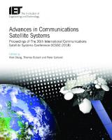
Corporate Scenario The Corporate scenario (see Fig. 1.1) is based on a complete and integrated solution for the provision of applications for companies that have distant offices, warehouses, manufactures, subsidiaries or individual workers located in rural or hardly reachable areas by wired backbone. The high-level architecture includes support for tunnelling between distant offices located beyond the satellite access on the local loop and the Headquarters located on the terrestrial backbone, forming an end-to-end Virtual Private Network, VPN.
Fig. 1.1 Corporate scenario
1 New Architecture for Next Generation Broadband Satellite Systems
3
This kind of scenario allows distant offices to have broadband connection with their headquarters without deployment of wired terrestrial infrastructure. The connection to the local loop may be Wireless Local Loop, WLL, or wired; whatever their local loop topology, the corporate VPN’s need total integrity of their data, and an appropriate QoS level for the type of information they carry. In all cases, the distant offices have direct access to the Internet through the Headquarters. The distant offices which are not located in the same spot can however ‘talk’ to each other without passing through the Headquarters, provided they are using their Intranet facilities only. This figure represents a configuration with both WiFi and WiMax accesses. The principal services that will be provided within this type of scenario are internal LAN-to-LAN connectivity, access to the internet and extranet networking, assuring secured connections with business customers. Beyond the interconnection services, VoIP and Video conferencing are allowed, supported by an ad hoc QoS architecture, multicasting and broadcasting capabilities (intrinsically provided by the satellite architecture) and applications including video surveillance and resource sharing.
Collective Scenario The collective scenario aims to provide a high level of connectivity to citizens and small companies, belonging to rural communities that are not able to currently be connected via ADSL. This solution is based on a hybrid network combining a satellite segment and terrestrial wiring as well as wireless access such as WiFi, or WiMAX. Three types of interconnections may be provided for the local loop and may be used simultaneously: ●
●
●
Wired access: the Satellite Terminal (ST) interfaces with Ethernet wiring, providing access in a building. WiFi: the ST interfaces with WiFi Access Point, which distributes and collects the traffic over a local area. PCs are equipped with WiFi cards that allow them to move within or at a short distance from the premises. WiMax: the ST interfaces with a WiMax Base station, which distributes and collects the traffic over a local area. WiMAX may also be used as a backhaul for WiFi, where a 802.11 network is connected to the 802.16 Subscriber Station (SS). These solutions can be put in place for medium-sized local areas, (e.g. a dock area).
In this scenario, the link between the ST and the Satellite Access Provider’s Gateway is seen as a LAN. The local loop is a sub-LAN and no direct Internet connectivity is possible between two STs connected to a local loop. The connection to the satellite on the WLL side is a single link for the whole community that shares the satellite segment.
4
C. Baudoin et al.
Fig. 1.2 Collective scenario, WLL access example
Fig. 1.2 shows an example of collective terminal scenario with WLL access. The collective scenario is represented by public places in which people can access the service without specific requirements but requiring a subscription for access to the broadband wireless network and applications. Examples of this scenario are: a hotel, public places, a mountain hut, islands, harbour areas, places in emergency (war or natural disasters). The applications in this kind of scenario, include: e-Learning, tele-Medicine, e-Payment, games and any other services, may improve the comfort of users located far from large urban areas or that are not reached by broadband wired networks. Different type of services may be provided within this architecture, from web browsing and email to instant messaging, support for the peer to peer, interactive gaming, movie/music streaming and VoIP. Emergency messages e.g. alert messages may be broadcast locally to users in potentially dangerous situations.
Residential Scenario Finally, a residential user scenario is directly related to the ‘Triple Play’ concept, which should is a key goal to achieve competition with other solutions like ADSL or Cable in low-density population areas. The principle of the ‘Triple Play’ concept
1 New Architecture for Next Generation Broadband Satellite Systems
5
is to provide the three basic access services (Television, Internet access and Telephony) through one single satellite communication network. This contrasts with the ‘terrestrial’ communications offered by telecom operators today using ‘Dual play’, which provides both voice telephony and ADSL internet access over the same network (via traditional copper telephone cables). A ‘Triple Play’ satellite service will offer the three access services together to remote communities, at an affordable cost. The architecture will make use of both transparent and regenerative satellite systems. The optimal solution is a hybrid satellite system, which includes both transparent and regenerative satellite systems, each used depending on the service. Users may either benefit from the on-board processing of the regenerative satellite system (to reduce delay in real time traffic for example) or may instead use instead the transparent transponder. A graphical view of the scenario is depicted in Fig. 1.3. In the transparent mode (red), users make use of the Hub & NOC station to communicate one to each other, whereas a direct communication will be achieved if a regenerative mode is used (green). Applications include Digital TV, in particular Television over IP (TVoIP) on DVB-S2 and video broadcasting (SDTV and HDTV) directly over DVB-S2. Television is mainly broadcasted digitally and therefore can be combined with different services to make it highly interactive. New experiences will be offered to users through a wide range of applications varying from video on demand (VoD),
Fig. 1.3 Residential scenario
6
C. Baudoin et al.
time shifting or multiple audio streaming to the complete thematic personalization of the video images and scenes. Other applications include general Internet access (web browsing), VoIP, telephony, videoconference, and peer to peer applications.
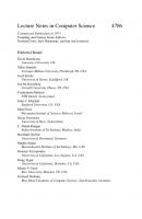
SATSIX Network Architecture The SATSIX network architecture may be applied to two network scenarios: the transparent star and the regenerative mesh/star. The main difference between these two is the support for a regenerative mesh topology, using satellite has the on-board processing (OBP), allowing a Return Channel Satellite Terminal (RCST) to not only communicate with the gateway/NCC via the satellite, but also to directly communicate with other RCSTs (in a single satellite hop) as depicted in Fig. 1.4. The SATSIX project also addresses an approach for the convergence of these two satellite network scenarios that would provide advantages due to the exploitation of regenerative or transparent connectivity only for those services or applications that really require each of them (i.e. depending on the type of service and application). Both WiFi and WiMAX terrestrial access networks may be connected to the RCSTs to provide shared access to the traffic forwarded on the satellite link. The RCSTs for a next generation communications satellite system must be low cost and high-performance satellite terminals, and support IPv6. All terminals will use adaptive DVB-RCS air interface for transmission and DVB-S/S2 for reception
Fig. 1.4 Network architecture for the Regenerative Mesh Topology
1 New Architecture for Next Generation Broadband Satellite Systems
7
(DVB-S has to be maintained for backwards compatibility). At present the terminals transmission is based on the non-adaptive DVB-RCS specification and the reception on DVB-S. A reference functional architecture has been proposed for each of the two topologies, respectively. These two architectures integrate QoS, multicast, security, mobility and transport functions. The highlights are: ●
● ●
●
●
The satellite segment can interwork with Internet DiffServ QoS to provide endto-end QoS at the network level. This architecture supports end-to-end QoS, and also dynamic QoS according to application and user needs. The architecture provides multicast management (i.e. MLDv2 [1]) for IPv6. The architecture supports key management protocols (i.e. SATIPSec [2] and GSAKMP), key distribution systems e.g. LKH and Layer 2 security enhancing security level provided by Layer 3 solutions such as SatIPSec. The architecture has enhanced standard IPv6 mobility (i.e. HMIPv6 [3] and FMIPv6 [4], to enable Mobile IPv6 in a satellite system. The architecture provides an enhanced TCP PEP in order to efficiently manage TCP-based connections.
Figure 1.5 describes the reference network architecture: The network and functional architectures may be applied to three different scenarios: a corporate application scenario, a residential application scenario and a collective access terminal scenario.
Satellite Access Architecture The SATSIX satellite access architecture (see Fig. 1.6) supports both transparent and regenerative/hybrid payload based on the features provided by the connectioncontrol protocol, C2P. SATSIX brings innovative access techniques to this architecture: ●
●
●
Adaptive physical layer support: a complete definition of the adaptive return and forward physical layer has been defined that meets the scenarios and system requirements, and supports an optimised RRM and CAC using innovative control-theoretic and operations research methodologies. Integrated QoS at MAC layer: interactions between IP QoS and RRM have been defined, enabling the layer 2 to operate as an efficient and integrated global QoS framework. An IP/MAC back pressure feedback has been introduced to improve the overall scheduling and reduce the MAC queues sizes, and cross layer optimization has been defined to modify allocation provided by the DAMA according to SIP information. Layer 2 security framework: this architecture aims to ensure a very high security level to satellite applications by protecting the data and the control plane at MAC layer. It relies on GSE [5] or ULE [6] security extension header [7, 8] and DVB-
8
C. Baudoin et al.
Applications QoS aware SIP sig SIP client
QoS demand
QoS unaware QoS Agent
SIP sig
SIP Proxy QoS Server QoS LPEP
C2P agent
Cnx info
QoS demand RRM Configuration
Traffic flows
QoS
IP QoS
Marking Queuing Shaping Scheduling
PEP
QoS LPDP IP QoS
MF classification & marking (remarking) Shaping / policing / droping Scheduling
IP compression
MAC QoS
ROHC
MLD proxy
MAP
Group member
User terminal
Access router
Proxies
C2P server
IDU - MAC part
RCST IDU - IP part
QoS
ARC + CAC
Applications RRM QoS aware SIP sig SIP client
QoS demand
QoS unaware QoS Agent
SIP sig
SIP Proxy QoS Server QoS LPEP
Cnx info
C2P agent
MLD adapter
QoS demand HA / MLD proxy for mobility
RRM Traffic flows
Multicast router
Configuration
QoS
IP QoS
Marking Queuing Shaping Scheduling
PEP
QoS LPDP IP QoS
MF classification & marking (remarking) Shaping / policing / droping Scheduling
IP compression
Group Controler/ Key server MAC QoS
ROHC
NCC
MLD proxy
MAP
Group member
User terminal
Access router
Proxies
RCST IDU - IP part
IDU - MAC part
Optional component or link
Fig. 1.5 SATSIX reference network architecture for the Regenerative Mesh Topology
1 New Architecture for Next Generation Broadband Satellite Systems To/from network layer
9
SLA modification
Traffic mask, QoS C2P messages
C2P agent Traffic mask, identifier Connection characteristics, QoS Local CAC
To network layer/PEP
C2P Server Connection Acceptance
Modocd information
From physical layer Capacity requests
DRA information
Back pressure
ARC
RRC agent
Allocation modification
Allocation Traffic mask
Trafic metering
RRC server (DAMA)
Cnx information
Allocation Global CAC From physical layer
To/from network layer IF IP/MAC
Header compression
ModCod DRA scheme
OBP (TBD)
Encapuslation Air interface traffic
To network layer (SatIPSec client)
MAC Queuing
MAC Scheduling
Layer 2 security
RCST
Satellite
NCC
Fig. 1.6 SATSIX reference satellite access architecture for the Regenerative Mesh Topology
●
●
●
●
RCS optional security mechanisms for AAL5 and uses SATIPSec or GSAKMP key management protocols adapted to the DVB-RCS context. IPv6-friendly encapsulation schemes: The ULE and GSE encapsulations provide an efficient way to transport IPv4 and IPv6 traffic over satellite systems with GSE also providing a scheduling algorithm that can optimize the filling of DVB-S2 frames based on QoS constraints. Efficient header compression: header compression has been introduced to reduce the transmission overhead. The satellite access architecture is compliant with the BSM SI-SAP definition with an evolution to focus on QoS, RRM, security and IPv6. C2P adaptation: an extension provides services for access and network functionalities such as IPv6, DVB-S2 support, full dynamic multicast, ATM and MPEG profiles support and DVB-RCS security in a star and mesh.
Evaluation and Validations The SATSIX project relies on different methods to evaluate and validate access and network features. Simulations validate specific algorithms in a convenient way and are the more appropriate tools when no implementation is available or when conditions cannot be met in a test bed or trial context (load for example). Emulation is the key tool to test innovative access mechanisms that cannot be implemented in real equipment within the frame of the project. It also offers an ideal environment to evaluate network functions with real applications. Finally, trials are the right way to demonstrate how features defined within the frame of SATSIX can be handled in deployed satellite systems.
10
C. Baudoin et al.
Simulations The first validation and evaluations of the SATSIX architecture and algorithms and procedures are being performed using simulation. The simulations take as inputs the system and user requirements, the architecture and the algorithms defined within the project, and identify requirements for the emulation test bed and system trials. The simulations include: adaptive physical layer characterization; Radio Resource Management (RRM) procedures (Connection Admission Control (CAC) and Bandwidth-on-Demand (BoD) algorithms); Internet multimedia transport protocols; multicast protocols. The physical layer simulations seek to provide input data to the RRM simulations. These are performed for different system scenarios and take into account Fade Mitigation Techniques (FMT) on the return and forward links. The FMT mechanisms consist of a feedback loop between the satellite terminal and the gateway, designed to track and mitigate the channel attenuation on the physical link: Based on regular estimations of the signal to noise ratio (SNR), the FMT loop allows to control the modulation type, the code rate and the symbol rate, to optimize the spectral efficiency on the transmission. A realistic time-series (including worst case rain attenuation) has been considered for the simulations of the FMT loop. These simulations allowed to generate the required combinations of {modulation/coding/symbol rate} for a set of users located in the same spot affected by rain. These data are provided as an input to the RRM simulations. Connection Acceptance Control (CAC) simulations evaluate the research-based algorithm in terms of scalability with respect to the number of classes, fairness among traffic classes (in terms of blocking probabilities), and is capable of supporting adaptive traffic. The algorithm integrates the adaptive physical layer model. Bandwidth on Demand (BoD) simulations test the control theoretic-based algorithms under different network loads and with different traffic mixes (VoIP, Video Conference, Multimedia Streaming, Data). The algorithms seek to optimize the satellite access delay. These results provide data to the transport layer simulations. The transport layer simulations analyse the approaches and techniques used by applications to enable effective congestion control for multimedia when the network path includes a DVB-RCS satellite system. The following protocols are simulated: TCP, UDP with TFRC, Datagram Congestion Control Protocol (DCCP) with Faster Restart (FR) and Quick Start (QS). The considered multimedia traffic sources are voice over IP (real-time audio streaming), audio (non-real-time audio streaming), video (including TV streaming over IP) and data using TCP. A set of multicast simulations evaluate the two standardized multicast service models, i.e., Any Source Multicast and Source Specific Multicast, over the architecture. The results will show the mean end-to-end delay under different network conditions. A Wireless Local Loop (WLL) scenario consisting of WiFi and WiMAX networks connected to a satellite terminal is defined, and simulation scenarios for QoS and mobility. These simulations will test protocols and algorithm development in
1 New Architecture for Next Generation Broadband Satellite Systems
11
SATSIX: protocols to handle micro- and macro-mobility (like MIPv6, HMIPv6 and FMIPv6), FMT techniques in the forward link scenarios, scheduling algorithms in the satellite terminals, frame constitution and DAMA Controller algorithms for adaptive coding.
Emulation The SATSIX emulation test bed (PLATINE) will demonstrate network and application service integration with the possibility to interoperate with terrestrial networks. PLATINE emulates DVB-RCS and DVB-S2 transparent or regenerative satellite systems and offers full native IPv4 and IPv6 support. It includes ULE/MPEG2-TS and AAL5/ATM stacks together with the adaptive physical layer simulation and the associated RRM. A complete QoS architecture mixing SIP proxies, QoS Agent /QoS Server architecture, enhanced IP/MAC scheduling and cross layer techniques is available. Finally, a layer 2 security framework will be implemented. Various network features, such as IPv6 mobility, dynamic multicast and its interaction with mobility (using an MLD proxy) are conducted in the frame of SATSIX, allowing testing of new schemes, protocols and services for next generation satellite networks. The PLATINE architecture is distributed over a LAN and relies on services offered by a synchronization and bloc library. This allows a modular design (see Fig. 1.7) and preserves room for future evolution.
Fig. 1.7 PLATINE architecture
12
C. Baudoin et al.
PLATINE also offers a convenient way to collect results, where various measurement points, as well events or errors, are handled by a distributed framework and displayed in real time using a dedicated user interface.
Trials Live demonstrators in SATSIX will prove the capability of the satellite to provide affordable services to a large range of customers. The SATSIX trials will validate this concept, demonstrating its feasibility in demonstration scenarios. The tests will be performed over four real Satellite Systems: the Regenerative AMERHIS system of HSA and the Transparent DVB-RCS systems of AASF, HDT and HSA, to validate key SATSIX features selected, the subsequent recording of results and the methods of evaluating the results, as well as the implementation plan and overall integration tests. All these tasks will be performed for each of the following trial scenarios: ●
●
●
●
Scenario 1: Corporate applications using the AASF DVB-RCS transparent access platform will assess and validate the IPv6 application scenarios over a DVB-RCS star network and operational architecture. In the frame of this trial, native IPv6 prototypes will be developed, based on DVB-RCS/S2 Thales Alenia Space Hub and terminal. In addition, an IPv6 PEP will be implemented, as well as dynamic QoS support features with the integration of an Access Resource Controller linked with a SIP proxy. These features will be evaluated using innovative collaborative working applications. Scenario 2: Collective Access Terminal on DVB-RCS transparent access platform. This scenario is developed and evaluated at HDT premises with the participation of HDT for the Collective Access Terminal. HDT’s DVB-RCS Hub will be used. This combination of access technologies can reduce the costs for users and allowing sharing the cost of the satellite connection using WLL. This live trial is able to assess the real user’s behaviour and help evaluate not only the measured parameters but also the user experience. Moreover, IPv6 mobility and multicast will be demonstrated to Scenario 3: Corporate applications on DVB-RCS regenerative access platform, developed and evaluated on HSA’s pilot AMERHIS system. This trial will benefit from improvements brought by the SATLIFE IST project. It will assess and validate the IPv6 application scenarios defined in the project over a DVB-RCS mesh network and operational architecture. The objective of this scenario is to demonstrate that the regenerative platform (the OBP) is able to work with IPv6 and ULE. This will require the integration of an IPv6/ULE encapsulator with an IPv6/ULE receiver, which can be seen as a first step towards a future move to GSE integration. Scenario 4: Residential applications on the DVB-RCS transparent access platform. The applications are developed and evaluated using HSA’s pilot DVB-RCS
1 New Architecture for Next Generation Broadband Satellite Systems
13
system. The principal residential application of satellite networks is Digital TV services (audio, video and data broadcasting to end users). This trial will focus on IPTV over DVB-S2 with IP QoS functionalities. For the different scenarios the most innovative IPv6 network features that will be demonstrated inside SATSIX are: WLL inter-working, dynamic multicast, dynamic QoS, application/Network security, mobility and PEP/RRM interaction.
Conclusions The SATSIX project is studying key techniques to decrease the cost of satellite access and to improve the functionalities offered by satellite systems. It will promote the introduction of IPv6 in this context and demonstrate the relevance of these solutions with regards to real users requirements by performing trials involving real users and equipments. Acknowledgements This work is supported by the IST FP6 SATSIX project, funded by European Commission (EC). The financial contribution of the EC towards this project is greatly appreciated.
References [1] R. Vida, L. Costa, Multicast Listener Discovery Version 2 (MLDv2) for IPv6, IETF RFC 3810, June 2004. [2] L. Duquerroy, S. Josset, O. Alphand, P. Berthou, T. Gayraud, SatIPSec: An Optimized Solution for Securing Multicast and Unicast Satellite Transmissions, 22nd AIAA International Communications Satellite Systems Conference (ICSSC), Monterey (USA), 9–12 May 2004. [3] H. Soliman, C. Castelluccia, K. El Malki, L. Bellier, Hierarchical Mobile IPv6 Mobility Management (HMIPv6), IETF RFC 4140, August 2005. [4] R. Koodli, Fast Handovers for Mobile IPv6, IETF RFC 4068, July 2005. [5] ETSI, Digital Video Broadcasting (DVB); Generic Stream Encapsulation (GSE) Protocol, DVB Project A116, May 2007. [6] G. Fairhurst, B. Collini-Nocker, Unidirectional Lightweight Encapsulation (ULE) for Transmission of IP Datagrams over an MPEG-2 Transport Stream (TS), IETF RFC 4326, December 2005. [7] H. Cruickshank, P. Pillai, S. Iyengar, L. Duquerroy, Security Extension for Unidirectional Lightweight Encapsulation Protocol, IETF Work-in-Progress, draft-cruickshank-ipdvb-sec02.txt, June 2006. [8] H. Cruickshank, L. Duquerroy, P. Pillai, Security Requirements for the Unidirectional Lightweight Encapsulation (ULE) Protocol, IETF Work-in-Progress, draft-ietf-ipdvb-sec-req02.txt, 2007.
Chapter 2
Satlife: A Big Step into the Enhancement of the Regenerative Satellite Generation Miriam Catalán de Domingo, Isaac Moreno Asenjo, Ana Yun García, Fernando Vallejo Lázaro, and José Antonio Guerra Expósito
Abstract This paper offers an overview in the new developments carried out and services offered thanks to SATLIFE project [1]. Based on the AmerHis system [2], SATLIFE [3] has been working in the improvement of the new AmerHis capabilities, looking for a decrease in costs and the provision of new services not yet offered over a regenerative DVB-RCS platform. Satlife concept is introduced, and an analysis of Amerhis/Ibis service enhancements is carried out, together with a deep overview of the new services and functionalities developed. In the phase of real trials, Satlife is testing all the features developed over these two last years.
Satlife Concept ‘Satellite Access Technologies: Leading Improvements for Europe’, Satlife, has been the first project to bring technological innovations and solutions in the DVBRCS regenerative systems through the AmerHis improvement. Today, after two years, most of the objectives have been reached: SATLIFE has become a key project in the innovation area for positioning and adoption of DVB-RCS regenerative systems, promoting the development of the Information Society. Hispasat, together with the group of leading companies participants in the project (Thales Alenia Space España, Telefónica I + D, Thales Alenia Space Francia, Nera, EMS, Shiron, Indra Espacio, Thales, University of Surrey, Universidad Politécnica de Madrid and Telefónica Pesquisas e Desenvolvimento), face the challenge of real trials. Therefore, all the prototypes and developments design for each company have been integrated and tested in the laboratory.
L. Fan et al. (eds.), IP Networking over Next-Generation Satellite Systems © Springer 2008
15
16
M. Catalán de Domingo et al.
Amerhis/Ibis Service Enhancements Digital TV One of the main uses of satellite networks today is the provision of Digital TV services. Audio, video and data are broadcasted to final users by satellite in a oneway communication, but two-way communication is needed for interactive applications. Thus, broadcast is ensured in one or several spot beams through on-board switching and duplication. The Video Broadcasting service is improved in Satlife. A specific terminal is introduced to transmit the video from the Service Provider to the Users. As it is shown in Fig. 2.1, when having several VSPs some signalling information has to be assembled in the NCC (Network Control Center) and redistributed to the receivers. The Video Service Provider is based on the RCST, having its functionality and in addition being able to transmit MEPG2 video and data. Thus, it is necessary to add a Video Streaming Unit to the RCST, which must feed the RCST with the MPEG-2 video stream to be broadcasted. The main difference of this Service Provider RCST is that it implements an interface between the streaming unit with the purpose of receiving the video in MPEG-2 format to be broadcasted. This interface consists of video input and a clock output. The clock is required to synchronize the Video Unit with the RCST (Fig. 2.2). As shown in Fig. 2.3, this SP-RCST removes the IP, UDP and RTP headers to obtain MPEG2 original packets transmitted to the satellite. Thus, all the MPEG2
Fig. 2.1 Video broadcast service
2 A Big Step into the Enhancement of the Regenerative Satellite Generation
Fig. 2.2 Satlife video service provisioning
Fig. 2.3 Protocol stack for video broadcasting
17
18
M. Catalán de Domingo et al.
contributions from each station are multiplexed on board of the satellite and transmitted in a DVB-S saturated carrier to be received by an IRD, who recovers the MPEG2 signal sent by the Service Provider. The commercial advantages of this system are very clear, since it removes the need to have a centralized installation in the uplink to give DVB-S services as it is currently happening in the existing digital TV platforms. Now, small service providers may distribute them in different places and have their own uplinks from their premises.
Multiconference This service allows to establish multimedia communication between two or more users. It provides the same communication capabilities than POTS with new added value services provided by the multimedia technology. Thanks to the mesh regenerative scheme, QoS can be improved, taking advantage of a single satellite hop. In particular, the system allows the use of multicast connections, session and conference control establishment, security and adaptation of the different audio/video topologies depending on the kind of users. Multiconference functionalities that have been improved specifically in the project are: 1. SIP introduction and compatibility and new H.323 aspects, allowing a new basic interaction between both protocols, avoiding that H.323 clients can only establish multiconference sessions with other H.323 clients and similar with SIP clients. This task is carried out by the regenerative gateway. Besides, H.323 final users with IP private addresses can be registered with the RSGW Gatekeeper while they are carrying out calls towards H.323 users in the Internet network. Thus, now there is no need to remove from the Gatekeeper register as it was necessary with AmerHis. Between novelties introduced by Satlife, there is the audio/video communication based on SIP protocol; thus, Satlife regenerative gateway supports the following SIP services using a SIP proxy: ●
●
SIP voice calls with ISDN/PSTN terminals: the Satlife RSGW allows a voice call to be established from a Satlife subscriber with a SIP user agent registered in the RSGW SIP proxy to an ISDN/PSTN terminal. Thus, the RSGW is in charge of translating both traffic and signalling from ISDN protocol to/from SIP protocol. For this internetworking service, calls can be initiated from both ends, ISDN or Satlife, with independence of the RSGW subscriber address type (public or private) (Fig. 2.4). SIP voice/video with SIP terminals located at the Internet: a Satlife subscriber SIP user agent is able to establish a communication (voice and video) to an external SIP terminal located at the Internet. Both of them will communicate using SIP protocol through the Access Router located at the RSGW (Fig. 2.5).
2 A Big Step into the Enhancement of the Regenerative Satellite Generation
19
Fig. 2.4 SIP voice call to ISDN/PSTN
Fig. 2.5 SIP voice/video calls to Internet SIP endpoints
For this service it is necessary to differentiate based on the type of IP address assigned to the subscriber: ❍
A SatLife UT with a public IP address is able to send and receive SIP voice/ video calls being actively registered in the RSGW SIP Proxy. It means that the SIP proxy is in charge of finding the Internet user agent (in case of an outgoing call) or finding the SatLife user agent (in case of an incoming call).
20
M. Catalán de Domingo et al. ❍
●
A SatLife UT with a private IP address is able to make outgoing SIP voice/ video calls only if it is deregistered from the RSGW SIP proxy. In any case, it could be registered to a third party SIP proxy located in the Internet.
Voice/Video calls with SIP terminals within the same VSN (Virtual Satellite Network): A Satlife subscriber with a SIP user agent registered in the RSGW SIP proxy is able to establish a communication (voice and video) to another Satlife subscriber located in the same VSN and registered at the same or a different RSGW. Thus, the RSGW will be in charge on the signalling communication in order to allow both parties to start the communication, but after this phase a direct communication from one user to the other (without going through the RSGW) will be performed. In that way only one satellite hop will be performed as the OBP will be in charge of routing the traffic. Calls can be set-up with independence of the RSGW subscriber address type (public or private) (Fig. 2.6).
2. Call termination optimization for ISDN/PSTN voice/video calls The Satlife RSGW allows optimizing the termination of the H.323 voice/video service by not terminating an ISDN/PSTN call initiated by a Satlife UT necessarily in the subscriber’s RSGW, but by using a collaborative ITSP node. As a collaborating ITSP node we understand an external ITSP, accessible through Internet/Intranet and
Fig. 2.6 Voice/video calls between satlife SIP terminals
2 A Big Step into the Enhancement of the Regenerative Satellite Generation
21
Fig. 2.7 H.323 voice/video call termination optimization
with an adequate network infrastructure, or a secondary RSGW belonging to the same VSN. If the RSGW service provider reaches adequate agreements, it may be more convenient for cost reasons to let these ITSPs terminate certain calls instead of doing so locally. The RSGW service provider decides for each collaborating ITSP the conditions under which the routing of a call is going to be performed. These conditions are based on call destination and/or type of service (voice/video) and may be defined taking into account the best rates offered by each ITSP in each case (Fig. 2.7). 3. H.323 service improvements ●
●
Internet calls improvements: thanks to improved NAT traversal functionality, a SatLife H.323 endpoint with private IP address can be actively registered with the RSGW Gatekeeper while placing calls towards H.323 users located in the Internet. It is no longer necessary to de-register first from the Gatekeeper, as required for AmerHis. NATed endpoints support: the Satlife RSGW supports NAT traversal, allowing a H.323 terminal, which is NATed at the subscriber RCST, to make voice/video calls towards ISDN/PSTN, Internet H.323 endpoints and non-NATed H.323 endpoints within the same VSN. Thus a NATed H.323 terminal is able to perform H.323 voice/video calls even if the subscriber RCST NAT does not support a H.323 ALG.
22
M. Catalán de Domingo et al.
Internet/Intranet Access improved Using PEP Protocol in Mesh and Star Configurations The purpose of the TCP/IP enhancement functionality is to speed up TCP connections over a large latency satellite link. The functionality can be used for both TCP connections between terminals and TCP connection between terminals and Internet hosts. Typical popular applications that use TCP as transport protocol are FTP and HTTP (for web browsing). Conditions particular to geostationary satellites severely constrict the performance of TCP and reduce the end users experience of accessing the Internet over satellite. Large latency, high bit error rates and asymmetric bandwidth which are characteristic for satellite networks makes TCP less suitable when used over satellite. Some performance improvements can be achieved by simply tuning the TCP parameters, but the effectiveness of this is limited (Fig. 2.8). To overcome the TCP problems over satellite, several commercial products (commonly known as TCP accelerators) have been developed which optimize the TCP performance over satellite. These products have in common that they all use mechanisms described in RFC 3135, TCP Performance Enhancing Proxy (TCP PEP).
Fig. 2.8 Internet access scenario with a gateway station
2 A Big Step into the Enhancement of the Regenerative Satellite Generation
23
Fig. 2.9 TCP Acceleration over satellite
The TCP PEP implementations make use of the split-connection principle. A split connection terminates the TCP connection from an end system (client) and establishes a corresponding TCP connection to the other end system (server). This is done in order to use a third connection between two TCP PEPs which is optimized for the satellite link (see Fig. 2.9). Both connection 1 and 3 in Fig. 2.9 are complete separate TCP connections, while connection 2 is normally a proprietary satellite optimized protocol or a modified TCP protocol optimized for the satellite link. Data streams are forwarded from one connection to another, and extensive buffering mechanisms are required. Other traffic than TCP shall simply be forwarded untouched through the TCP PEPs. This architecture makes it possible to achieve vastly improved performance while remaining entirely transparent to the end user and fully compatible with the Internet infrastructure. No changes are required to the client and server, and all applications continue to function without modifications. TCP congestion avoidance mechanisms remain in place over the terrestrial connections and also maintain full TCP reliability and end-to-end flow control.
Multicast Service Thanks to Satlife project, Multicast service combines for the first time star and mesh configurations simultaneously in a satellite system, and allows the definition of multicast routes at the NCC (Fig. 2.10).
24
M. Catalán de Domingo et al.
Fig. 2.10 Satlife multicast scenario
Fig. 2.11 Multicast scenario with multicast terminal users outside of the satellite network
The multicast service implies that a data packet can be delivered to a group of different receivers. Here, three architectural scenarios may be considered: ‘star’ multicast, ‘mesh’ multicast, and a final one which combines properties from both of them. The main different is the involvement of a RSGW in the first one, because
2 A Big Step into the Enhancement of the Regenerative Satellite Generation
25
the multicast source is outside the satellite network; in the mesh setup, the multicast server is a RCST receiving an IP stream, which is multicasted to several users. The third case also implies the use of an RSGW, but the source is inside the satellite. In Fig. 2.11, the multicast source is inside the satellite network, but multicast terminals are either inside or outside the network. In fact, this is similar to the star configuration, but implies that the gateway must support bidirectional multicast.
New Services and Functionalities E-Learning There are several kinds of E-learning applications, each one having different service requirements. Two main groups can be established: ● ●
Real-time conversational e-learning service (Synchronous E-learning). Low-interactivity e-learning service (Asynchronous E-learning) (Fig. 2.12).
The scenario for e-learning is similar to the multiconference scenarios. The conference model suitable for SATLIFE imposes the usage of multicast with only one satellite hop for the media flows. Both ‘star’ and ‘mesh’ multicast might be used depending on the involved users and the place where the teacher or teachers are located. The scenario also shows some users that might have unicast access to the network. They need some way to access the multicast lecture using MCUs.
Fig. 2.12 E-learning scenario
26
M. Catalán de Domingo et al.
Video on Demand Video On Demand (VoD) is an audiovisual service where a streaming server is remotely controlled by the user, so that it emulates the functionality of a home video player. The interactivity provided by the service implies both content selection and streaming control. This VoD service uses mesh connections, allowing a DVB-RCST to be a video service provider, in this case, for VoD services. The video client is a commercial IP set-top-box that supports IP unicast connections using RTSP connected to the satellite network through another DVB-RCST (Fig. 2.13). The previous picture shows the VoD server connected to the DVB-RCST, so the video and audio transported is encapsulated in IP. The upper layers include UDP for audio and video real-time transmission and TCP for the session control. The DVB-RCST in the client side de-encapsulates IP traffic and distributes it to the IP set-top-boxes, which in turn extract and decode video.
Software Download A satellite data service targeting PCs that provides value-added services at high speed. The broadcast service is similar to TV point-to-multipoint transmissions. Basically, the contents are transmitted in a carousel, which enables users to access
Fig. 2.13 Video on demand service conceptual architecture
2 A Big Step into the Enhancement of the Regenerative Satellite Generation
27
Fig. 2.14 Satellite connection scheme
relevant Internet contents without being on-line since the contents are received continuously through the satellite link. Through this service, users will access a huge diversity of contents in a near-ondemand fashion. Data will be supplementary available not only in broadcast but also in the more versatile multicast mode (Fig. 2.14). In the previous figure, the user terminal is a PC with a DVB-S card, or some kind of multimedia set-top box with a hard disk. The idea is to use a transparent DVB-S and thus encapsulate software into MPEG2-TS; otherwise, DVB-RCS and IP could be used, which is regenerated in the satellite and received as DVB-S in the user terminal.
Nomadic Access The nomadic access to the satellite system is based on a fixed mobile solution with an automatic scanner polarizer and beam positioning system for a auto folding twoway satellite antenna. This service is aimed for the nomad users who want to have high speed access in remote locations where cable and DSL do not exist, or for mobile terminals. Figure 2.15 below shows an architecture sample from a scenario where all agents and application providers are inside the satellite network. Figure 2.16 shows the architectural scenario with the application provider outside the satellite network.
28
M. Catalán de Domingo et al.
Fig. 2.15 Nomadic access scenario. Application provider inside the satellite network
Fig. 2.16 Nomadic access scenario. Application provider outside the satellite network
SNMP Based DVB-RCS Authentication Protocol The authentication protocol to be used by SNMP follows the Quick Key Exchange as mentioned in the DVB-RCS document, thus making the design conformant with the DVBRCS specifications. This Key Exchange protocol uses the cookie value
2 A Big Step into the Enhancement of the Regenerative Satellite Generation
29
Fig. 2.17 Flow Diagram of the QKE Authentication protocol
(secret static value shared between the RCST and NMC) to authenticate the RCST to the NCC via NMC. The flow diagram and the byte structure of these messages are shown in Fig. 2.17. The QKE and QKE Response messages are encapsulated via SNMP get and the response to SNMP Get messages. SNMP is used for transport of the authentication messages. The NMC knows the OID of each client which is defined in the MIB of the RCST. Thus, security at RCST level is improved in the project.
Conclusions As explained in the paper, Satlife has become a key project in the way to enhance the regenerative systems. As a first step in the AmerHis improvements, Satlife has carried out new developments in order to improve AmerHis features and being able to offer new innovative services. The new on-board processor concept introduced by AmerHis has been a clear revolution in the satellite arena. Thus, Satlife means a first step in order to evolve this new concept towards the optimization of the system to be able to decrease costs and increase efficiency and QoS between others.
References [1] Deliverable DE422—SATLIFE. [2] ESA-AMERHIS PROJECT 3. [3] IST-1-507675. SATLIFE PROJECT.
Chapter 3
SATSIX Satellite System and Network E. Callejo, A. Yun, C. Baudoin, F. Rodriguez, and J.A. Guerra
Abstract Satellite platforms that already provide broadband access for Internet/ Intranet (IPv4) and PSTN/ ISDN terrestrial networks are evolving towards the convergence with other network access technologies as WiFi and WiMax searching for mobility, QoS and IPv6 protocol evolution. This paper presents the benefits of the Next Generation Broadband Satellite Multimedia Systems and Network architecture future enhancements in the frame of EC-funded IST FP6 SATSIX (Satellitebased communications systems within IPv6) project.
Introduction Satellite communication is becoming an established part of the institutional communications, both for civilian and military use. Broadband Satellite Networks do help to reduce the Digital Divide in regions with little accessibility to terrestrial network access or where it is uneconomic to install cable or fixed wireless. These regions with low density might be low, but does not mean communication is less important. Consumers and business customers sparse in remote areas may benefit from broadband satellite networks and enjoy broadband services. This will surely, enhance the quality of life and comfort of users located far from large urban areas. The consortium of the SATSIX project wants to go a step beyond in satellite communication. The objectives identified have been: IPv6, mobility and new generation of satellite payloads based on ACM/DVB-S2. For the complete design of the satellite architecture, three different service scenarios with threes kinds of users have been identified. These services scenarios are: Residential, Collective and Corporate. Each scenario has several service profiles associated, including e-learning, telemedicine, e-payment, games, VoIP, VoD, interactive TV, e-mail, Web browsing or file sharing among others. In the frame of SATSIX project, the satellite network architecture presented must accomplish the needs of the services scenarios defined. This paper will introduce this architecture based on the different criteria followed in its definition. It will also point out the NGN Satellite Systems requirements that will allow introducing L. Fan et al. (eds.), IP Networking over Next-Generation Satellite Systems © Springer 2008
31
32
E. Callejo et al.
concepts such as IPv6, mobility or DVB-S2 into already existing Broadband Satellite Multimedia (BSM) networks. Then, the main criteria for the evolution of BSM network within the frame of SATSIX project will be summarized. The next section presents SATSIX communication satellite network reference architectures, protocol stack and services supported. Finally, the paper deals with each one of main aspects analyzed for this evolution towards a New Generation Satellite Network, that will improve satellite communications in terms of efficiency (i.e. DVB-S2, GSE), IPv6 support (ULE), mobility (i.e. MIP), QoS (i.e. SIP, C2P) and interworking with other networks (i.e. interface with WiFi/WiMAX access networks).
SATSIX Satellite Architecture The aim of SATSIX project is to define the future IPv6 satellite network architecture taking into account previous lines of evolution [8]. For this design, SATSIX satellite network is built taking as baseline already existing DVBRCS/DVB-S networks [1, 5] and tries to enhance them in terms of flexibility, QoS support, efficient multicast, and integration with terrestrial wired and wireless networks (i.e. WiFi and WiMAX). SatLife (FP6 project) is the reference considered for the regenerative satellite network scenario. SATIP6 (FP6 project) as a preliminary study for IPv6 support for DVB-RCS [2, 7] systems. Finally, ESA-SatLabs compliant star transparent DVB-RCS network as the reference transparent satellite network scenario.
Standards SATSIX architecture is based on European standards, DVB-S(2) [3, 4] for the forward link and DVB-RCS for the return link. DVB-S2 standard is an evolution from DVB-S. The main benefits of DVB-S2 are: – 30% greater efficiency than DVB-S. – An increased range of applications by combining the functionality of DVB-S (for direct-to-home applications), and DVB-DSNG (for professional applications). – Techniques such as adaptive coding to maximize the usage of value satellite transponder resources. – Four modulation modes: QPSK, 8PSK, 16APSK and 32APSK. – Additional roll-off factors for tighter bandwidth. – Powerful FEC system that results in a performance which is at times only 0.7 dB from the Shannon limit. The forward link waveform uses a TDM access and is based on DVB-S2 standard in ACM mode. The possible MODCODs (value that identifies the modulation
3 SATSIX Satellite System and Network
33
and FEC code) to be used within SATSIX framework is a subset of all possible DVB-S2 MODCODs proposed by the standard. The selection of the best MODCOD (value that identifies the modulation and FEC code) will be determined by the level of robustness and protection required by the information to be transmitted. DVB-RCS was reopened last January. Its main objective is to create a new version of the standard, backward compatible only adding whatever is required to support DVB-RCS mobile and C2P (Connection Control Protocol) for mesh DVBRCS communications, plus small clarifications and corrections. In the scope of SATSIX, the influence of standards have been considered in the migration towards DVB-S2 and the use of an adaptive return link: intended as the signaling to transfer MODCOD, modulation and coding formats among space and ground segment elements. Mobility is being considered in the sense of a seamless integration of DVB-RCS satellite networks with terrestrial WiFi and WiMAX networks. WiMAX / WiFi users will communicate with the WiFi / WiMAX base station, and the base station is connected to the DVB-RCS system via a Return Channel Satellite Terminal (RCST). In this context WiFi / WiMAX are used as wireless local loops integrated with the satellite network.
Payload The reference broadband satellite network architectures addressed in this paper are based on geosynchronous orbit satellites. These satellites are classified based on the type of payload. ●
Transparent: Transparent payload refers both to a pure transparent satellite transponder (bent-pipe) and to a satellite transponder which does not perform any demodulation but is able to perform some form of physical layer switching, e.g.: ❍
❍
by switching uplink carriers in a beam to different downlink beams by means of IMUX (Input Multiplexer) and OMUX (Output Multiplexer); or by performing ADC (Analogue-to-Digital Conversion) operation on the uplink carriers, digital switching, and DAC (Digital-to-Analogue Conversion) operation.
Its evolution is moving towards a new concept of flexible payloads. This is a way to search for innovative solutions to reduce cost and production cycle, to add value to services and develop new applications. Flexible payloads should provide tunable performances and allow the satellite operator a mechanism to adapt to new business. Different domains of flexibility may be considered: orbit location, coverage, frequency plan, allocation, routing (e.g. RF switching) and waveform. ●
Regenerative based on Adaptive Switching OBP: The regenerative payload, the On-Board Processor (OBP), provides regeneration functions that decouple the uplink and downlink air interface formats (modulation, coding, framing, etc.).
34
E. Callejo et al.
A DVB-RCS air interface is used on the return link (uplink) while a DVB-S/S2 air interface is used on the forward link (downlink). The OBP capability of the satellite transponder, allows both star and mesh (single-hop) communications. The definition of a new generation satellite payload compatible with ACM and DVB-S2, the Adaptive Switching OBP architecture had been considered. This Adaptive Switching OBP should be capable to route traffic from any or several U/L to any or several D/L, based on different criteria and uplink encapsulation methods (e.g. ATM, MPEG, GSE). Special care is taken in order to analyze the impact of GSE over DVB-S2/ACM OBP. A third type of payload has also been considered, a hybrid payload. This type of payload is built from the concept of dual transponders. Both transparent and regenerative transponders are mixed in the satellite, and they are used with a certain intelligence based on the service requested. This hybrid payload provides advantages to the system in terms of system capacity, system coverage and system services, but with an increment in complexity due to the flexible use of the transponders.
NGN Next Generation Networking technologies are impacting current and future Satellite-based networks. SATSIX satellite architecture has open the pave to new ways to enhance QoS based on the usage of SIP proxies. SIP proxies allow the support of dynamic QoS control that reduces delay and jitter, and ensures a more efficient usage of the satellite resources.
IPv6 Internet is running out of IP addresses. Terrestrial networks are already experiencing the move towards IPv6. IPv6 does not only solves the IP addresses limitation, but brings solutions for better routing mechanisms, improvements in IP mobility, changes in IP multicasting and QoS. Satellite network manufacturers are not yet convinced of the need to change to IPv6, but the satellite world must be prepared for the IPv4 to IPv6 transition.
Networks, Topologies, Connectivity Types and Services The reference broadband transparent and regenerative satellite network architectures addressed in this paper are classified in two different families depending on the network topology:
3 SATSIX Satellite System and Network
35
1. Star/mesh transparent (no processing on board): “Traditional” VSAT network with a single Hub that can broadcast information to all terminals within the satellite beam. One transmission from the hub can reach all terminals in the coverage area, and multicasting from terminals is solved with a double-hop communication through the hub. This Hub or gateway allows the interconnectivity with external terrestrial networks. 2. Star/mesh regenerative (based on OBP, On Board Processing technologies). One single Hub or NCC is used for control and management. Multiple gateways/ feeders are envisaged to provide distributed interconnectivity with external terrestrial networks. The new generation satellite based on OBP allows direct connectivity between two terminals (only one hop), cross full connectivity between different beams, and replications on board, allowing an efficient multicast service. The end user will have access to services like high speed Internet, VoIP, ISDN/PSTN low delay audio/video conferencing thanks to star connectivity. On the other hand, mesh connectivity will allow services like VPN or Lan to Lan interconnectivity.
Regenerative Platform SATSIX baseline for the definition of a new generation regenerative platform has been AmerHis System. The AmerHis System represents the first regenerative DVB-S/DVB-RCS satellite platform. It was designed as a response to cover the growing demand in multimedia broadband services and the adaptation of real time services to the satellite world. This kind of system has been standardized under ETSI SES BSM families as RSM-B (Regenerative Satellite Multimedia) Family B 0. The regenerative platform is composed of the OBP (On Board Processor), a fleet of standard RCS (Return Channel Satellite) Terminals, a MS (Management Station) acting as Network Control Center and Network Management Center, several RSGWs (Regenerative Satellite Gateways) for interconnection with terrestrial networks and a group of VSPs (Video Service Providers) for the transmission of video. The core of the system is the OBP, a multibeam switch in the sky. The regenerative platform provides mesh and star topology, both cases in a single hop, allowing real time and multimedia connectivity (Fig. 3.1). A DVB-RCS Terminal behaves as an IP router. It can transmit up to 4 Mbps and receive up to 8–16 Mbps allowing the deployment of any IP application (e.g. Internet/Intranet Access and Virtual Private Networks between terminals) and being interoperable with the terrestrial networks. The RCSTs supports different customer service profiles, given a correspondence between traffic profiles and SLAs defined by the operator. The elements of the regenerative platform are introduced next:
36
E. Callejo et al.
RCST
Direct mesh connection
Volp, Internet, Video: Multimedia Services
External networks RSGW
DVB-S Rx DVB-RCS Tx Video Service Provider
WiMAX
Nomadic Terminal
NCC/NMC
WiFi
Fig. 3.1 Different services on DVB-S regenerative access platform
The Management Station (MS) manages all the elements of the system. It also controls the sessions, resources and connections of the ground terminals. It is composed by: – Network Control Center (NCC), which controls the Interactive Network, provides session control, routing and resource access to the subscriber regenerative RCSTs and manages the OBP configuration and DVB-S/DVB-RCS tables. – NCC-RCST, the satellite terminal of the MS, supporting modulation and demodulation functions to access to the satellite. – Network Management Center (NMC), in charge of the management of all the system elements. The AmerHis NMC is split in two systems: – Element Manager (EM): It is responsible for the management of the redundant NCC (including NCC-RCST) and of the GWs. – Network and Service Manager (NSM): It is responsible for the management of the VSNs, Service Providers, RCSTs, and telecom services and NCC-initiated connections. – The Regenerative Satellite Gateway (RSGW) provides functions similar to those offered by the GW in the transparent networks (TSGW). It provides interconnection with terrestrial networks (ISDN/POTS, Internet, and Intranet). At the same time, it manages all its subscribers, guaranteeing their Service Level Agreement (SLA). It also establish point to multipoint connections to provide a dynamic Star Multicast Service.
3 SATSIX Satellite System and Network
37
Within one Interactive Network, it may be possible to define a “two-level” architecture by introducing the concept of Virtual Satellite Network (VSN). The VSN is a group of RCSTs with a certain addressing plan assigned and with a GW assigned to it also. Each VSN may be considered a specific Administrative Domain, which receives a set of satellite physical resources, a set of logical resources etc. If included in Interactive Network, the VSNs do not modify the typologies of communication supported between network elements. The VSN (Virtual Satellite Network) concept is introduced to allow the definition of isolated networks within the whole Satellite Interactive Network. One VSN represents a group of RCSTs and RSGWs, an amount of traffic capacity and an independent IP addressing plan. The Network Management System, part of the MS, allows provisioning different VSNs, each one of them may be assigned to a different service provider. The VSN concept represents a more efficient and flexible way to manage and distribute the satellite resources.
Transparent Platform The network has a typical star topology. The central node or Hub contains the NMS, the satellite front-end, IP infrastructure and terrestrial networks interfaces (Fig. 3.2).
Fig. 3.2 Transparent platform equipment
38
E. Callejo et al.
The Hub or Gateway is mainly composed of the following subsystems: Network Management System (NMS): Interfaces between ISP/operator and Hub. It manages the users’ traffic and services provision. NMS also performs the control and supervision of HUB equipment, network and terminals. Forward Link Subsystem (FLS): Encapsulates IP packets in MPEG-2 frames and transmits these frames on a TDM carrier, base-band modulated. In the RF equipment, the modulated bitstream is upconverted and sent to the antenna, which transmits it up to the satellite at frequencies in the Ku band. Return Link Subsystem (RLS): The Gateway antenna receives the downlink signal at Ku band and downconvertes it to the 950–1450 MHz IF band. Thereafter, RLS filters the different return channels that compose a superframe, demodulates the signal, decodes the TDMA bursts form the terminal and extracts the frames containing the IP packets and sends them to the Hub station Ethernet. Reference and Synchronization Subsystem (REFS): Receives time signals from GPS and provides synchronization and timing for the different Gateway subsystems. IP infrastructure: It makes possible the establishment of the management and traffic networks as well as the routing between Internet and the different subsystems. This platform provides star connectivity Fig. 3.3.
Double hop for mesh 2 Way Sat
External Networks
DVB-S Rx DVB-RCS Tx
Acce ss to te rre stria l netw orks
AD SL, AD SL2 ,...
< 5 km Video Se rvice Provide r
WiFi, WiMAX,...
WiFi Inte rconne ction w ith re m ote ne tw orks
Fig. 3.3 Different services on DVB-S transparent access platform
3 SATSIX Satellite System and Network
39
Fig. 3.4 SATSIX user plane protocol stack
Fig. 3.5 SATSIX control plane protocol stack
Protocol Stack Taking into account the impact of IPv6, DVB-S2 and new encapsulation techniques the protocol stack proposed within the frame of SATSIX project is the following one (Figs. 3.4 and 3.5).
Services over the Network Reference Scenarios To cover the support of corporate, residential and collaborative services scenarios defined in SATSIX framework [6], one of the task for system engineering include the mapping between the services and the network scenarios and topologies and connection types, taking into account both regenerative and transparent platforms. In the star transparent platform we can divide the IP connectivity in two groups:
40
E. Callejo et al.
– Star connectivity between an RCST and external networks. The RCST sends the data to the NCC/TSGW and it routes it to the Internet through an ISP network. – Star connectivity between two RCSTs, all the data is received in the NCC/TSGW and routed to the other RCST. This means that the connection between RCSTs is indirect (double hop), the RCSTs only have direct connectivity to the GW. In both cases all the data goes through the NCC/TSGW, the first one needs two satellite hops while the second one requires a satellite hop to reach the ISP. This is applied both for unicast and multicast communications, but for multicast in multibeam system the flow has to be replicated by the NCC/TSGW as many times as the destination beams, so if there are four destination beams the multicast flow is transmitted four times in the Return Link. The star/mesh Regenerative scenario allows the following kinds of connections: – Mesh communications between RCSTs in any user beam with RCSTs in the same beam or any other user beam in one hop. The RCSTs can be connected to an isolated LAN or to the Internet; in the case that one of them has Internet access and the other don’t have it the first one can act as gateway of the second. This connection can be unicast or multicast. Mesh multicast service consists on the ability to statically transmit multicast flows receivable by the rest of the terminals in the VSN (see 0), which can be in the same or different beams. – Star communication between an RCST and a RSGW for Internet access. This connection is also in a single hop. Star multicast connectivity allows the RCSTs
Service Internet/intranet access Web browsing FTP E-mail Peer-to-Peer E-services (e-medicine, e-commerce, e-government, e-learning) VoIP and video conferencing Video Broadcast Service Audio and video on demand (streaming) Alert messages Media content download (Store and Forward) Interactive gaming Software downloads Remote control of applications Shared applications Video surveillance Web conference
Corporate scenario
Residential scenario
Collective scenario
X X X X
X X X X X
X X X X X
X
X X X X
X X X X X
X X X
X X X
X X
X X X
X X X X X X X
3 SATSIX Satellite System and Network
41
to statically or dynamically receive a multicast flow coming from the RSGW. “Dynamically” means that the star flow will start only when a user “joins” a certain multicast session and it will stop when the RSGW Access Router does not receive membership reports for the group. Next table presents the association between the presented services and the User Scenarios they are applicable to: Depending on the network architecture the same service can be provided with mesh or star connectivity. Both payload scenarios have to be able to provide the previous list of services, although depending on the features of the service the performance will be different in the two payload scenarios.
Functional Layers Overview The next step in SATSIX System Engineering consisted in the definition of the System functional requirements. From the System point of view both star transparent and star/mesh regenerative network scenarios were analyzed to tackle with SATSIX main objectives: – – – – –
NGN QoS, SIP proxy Connections support IPv6 support, ULE/GSE encapsulation DVB-S2/ACM WiFi/WiMAX interconnectivity
Connections Support, Connection Control Protocol (C2P) The Connection Control Protocol (C2P) provides the interaction between RCSTs/ RSGWs and NCC/Hub to support set-up, modification and release of connections and channel bandwidth modification. C2P implementation was done for AmerHis/SatLife, a star/mesh regenerative scenario following Annex J from DVB-RCS Guidelines and the C2P specification given in ETSI SES BSM 102 429-3, as the perfect solution to solve mesh connectivity. Anyhow, C2P can be extended to other DVB-RCS scenarios. Within the frame of SATSIX, C2P definition is studied to accomplish a star transparent DVB-RCS scenario, IPv6, DVB-S2 support and full dynamic multicast group management (in star and mesh scenarios). The aim of C2P is to enhance the control plane of DVBRCS systems by means of the following:
42
E. Callejo et al.
– Dynamic control of the set of communication parties; – Quality of service driven dynamic allocation of bandwidth resources to satellite connections, closely linked to NGN SIP signaling; – Configuration of the logical channel identifiers for ATM and MPEG profiles; – Identification of calling and called addresses in either MAC or IPv4/IPv6 syntaxes, performing embedded ARP functionality or dynamic IP routing; – DVB-S2 parameters dynamic assignment; – Provide dynamic control of the set of communicating parties in DVB-RCS systems for both mesh and star topologies, in transparent and regenerative, mono and multi beam scenarios. – Dynamic multicast group management, both for star and mesh topologies. In a Next Generation Satellite System the NCC and the terminals shall support the C2P protocol, being capable of triggering C2P connections.
NGN QoS, SIP Proxy In order to meet users requirements defined in the corporate, collective and residential scenarios, the following QoS components shall be used in both transparent and regenerative system architectures [11]: ●
●
●
●
●
●
● ● ● ●
● ●
SIP proxy, in charge of the QoS aware applications. It mostly in charge of the SIP signalization capture to feed the other QoS components; QoS Agent, in charge of the non QoS aware applications. It sends the wanted QoS level for a given traffic flow to the QoS Server; QoS Server, in charge of collecting the QoS information on traffic flows and to configure accordingly the IP and MAC layers; PEP, in charge of the TCP and HTTP acceleration in order to limit the delay for the corresponding applications; IP Compression, in charge of the header compression in order to decrease the overhead introduced by the successive stacks and thus decrease the load and the delay; IP QoS, in charge of the classification, the marking; the policing/shaping/dropping and the scheduling at IP layer; MAC QoS, in charge of the queuing, dropping and scheduling at MAC layer; C2P agent, in charge of the MAC connection handling at the terminal side; C2P server, in charge of the MAC connection handling at the NCC side; Access Resources Controller (ARC), in charge of the management of MAC resources; MAC QoS, in charge of the queuing, dropping and scheduling at MAC layer; RRC agent, in charge of the capacity request emission and the extraction of the uplink packets function of the allocation carried in the TBTP;
3 SATSIX Satellite System and Network ●
43
RRC server, in charge of the capacity requests gathering and the allocation processing
Two approaches can be envisaged for the dynamic QoS architecture. – The first one is based on an “IP-oriented” approach using SIP proxies or specific signalization (QoS agent / QoS server / Access Resource Controller) between the ST and the GW. Proxies are in charge of configuring IP and MAC components directly, without any MAC signaling path. – The second one relies on the concept of access connection in a “MAC-oriented” approach. The dynamic QoS depends on information provided by proxies (SIP, QoS server, …) but the communication between the ST and the GW is based on the C2P.
Mobility In the frame of SATSIX it has been defined the functional architecture to be deployed in order to support application layer mobility scenarios. Different definitions of mobility are emerging, and in SATSIX three mobility scenarios are defined [9], namely discrete mobility, continuous mobility and seamless mobility. Next, two mobility contexts; macromobility and micromobility, according to network hierarchy have been considered. To improve the mobility management, and reducing signaling overhead and handover delay when using MIPv6, the enhancement protocols HMIPV6, FMIPv6 and the combination FHMIPv6 are investigated. When needed (for QoS purposes for instance), upper layer mobility in SATSIX provides SIP applications with QoS support, maybe combined with MIP6 architecture. The localization of the access router, separated or integrated, with the satellite terminal/base station determines the transport format over the satellite (tunneling or native IPv6 transport). With an integrated access router more than one subnet can exist behind the satellite terminal/base station. In this case, optimized techniques such as hierarchical mobile IP can improve the mobility process if moving to another subnet, since micro mobility inside the visited network is managed locally without involving the home agent. This case also includes Layer 2 mobility and handover in the WiMAX/ WiFi part of the local network [10], where handover (fast handover) has to be combined with Mobile IPv6 solutions (MIPv6). With an access router separated from the satellite terminal/base station, the transport over the satellite will be at Layer 2. The Layer 3 mobility will be anchored in the core network (behind the satellite gateway for a transparent satellite). Two alternatives of the Mobile IP(v4 or v6) protocol are then supported in the WiMAX NWG specifications:
44 ●
●
E. Callejo et al.
Client MIP (CMIP), where CMIP is an IETF compliant Mobile IP solution based on a Mobile IP enabled MS (Mobile Node) Proxy MIP (PMIP), where PMIP is an embodiment of the standard Mobile IP framework, performing on behalf of a client that is not MIP-aware or MIP-capable. The PMIP should be placed at the access router.
To support SIP mobility, the architecture has to implement all the devices defined in SIP architecture such as SIP registrars,…These elements are to be available once in the satellite access network. If the network topology is meshed, its location depends on the choice of satellite network operator. In a star topology, these elements will be located behind the gateway.
Security The SATSIX system has to provide security mechanism to meet users’ security requirements for the corporate, collective and residential scenarios: – IPSec for end-user to end-user and site-to-site communications protection shall be provided (notice: incompatibility with PEPs and firewalls). – IPSec/SATIPSEC for satellite/WLL segment protection shall be provided. – Layer 2 security mechanisms of WIFI/Wimax standards shall be provided – Layer 2 SATIPSEC and ULE /AAL5 security dataplane shall be provided – DVB-S/RCS signaling protection mechanisms may be provided The compliance with these requirements is critical for users as militaries, business organizations or Government customers.
DVB-S2 Both regenerative and transparent platforms shall be fully compliant with DVBS2. Once analyzed the different topologies and connectivity types, the MODCODs selection procedure will not only be based on the type of traffic to be transmitted or the weather conditions, but will take into the source and destination of each communication. The MODCOD selected for a unicast connection in the DVB-S2 forward link will depend only on the source and destination terminals and the Hub/NCC. The MODCOD selected for a multicast connection in the DVB-S2 forward link will depend on the source terminal, all destination terminals receiving that flow and the Hub/NCC. The new generation satellite payload should also be compatible with ACM and DVB-S2. The new Adaptive Switching OBP architecture, should be capable to route traffic from any or several U/L to any or several D/L based on a convergent
3 SATSIX Satellite System and Network
45
architecture. The routing will done based on different criteria and uplink encapsulation methods (e.g. ATM, MPEG, GSE). Special care will be taken to analyze the impact of GSE over DVB-S2/ACM OBP.
ULE/GSE Unidirectional Lightweight Encapsulation (ULE) mechanism permits the transport of IPv4 and IPv6 datagrams and other network protocol packets directly over the MPEG2 Transport Stream as TS Private Data. The introduction of Generic Streams by DVB-S2 makes necessary a new encapsulation, the Generic Stream Encapsulation, that relies in some fundamental design choices of ULE. Within the SATSIX project these two protocols are mainly considered for IPv6 encapsulation support. Their processing will impact not only on the OBP but also on the ground segment equipment. The Next Generation Satellite System has to be designed to be as far as possible compatible with GSE/ULE. However, given that the vast majority of existing satellite systems use MPE, it has to be maintained during the transition to a long term solution.
Convergent Platform The convergent or hybrid communication topology is indented as the combination of transparent and regenerative connections, in a way that could be observed by the end-user and INAP operators as a unique platform. The advantage is the exploitation of regenerative or transparent connectivity only for those services or applications that really require each of them (i.e. depending on the type of service and application). The number of transponders available and its bandwidth determine the capacity of the system. When talking about the capacity of a convergent system, two different choices can be considered: – To maintain separately the capacity of the transparent and the regenerative networks using dedicated transponders. – To share transponders between both networks. A certain bandwidth of the transponder would be reserved to be used by each system. This option would fit better to the real case; transparent and regenerative services will coexist in the system, a percentage of the capacity would be dedicated to each type. The first approach (vand the one considered in this paper) is to use dedicated transponders for the different parts, the payload will mot be integrated in the first step.
46
E. Callejo et al.
The convergent system should allow full connectivity between different beams. Depending on the level of integration of transparent and regenerative parts there are different modes of operation based on the level of integration of transparent and regenerative management systems: Loose Integration: it only exists a common management system for configuring a terminal as transparent or regenerative. It is decided at provisioning time what system the terminal will use. Medium integration: the terminal assignment as transparent or regenerative is changed by the NCC/HUB depending on the service. A logoff of the terminal is necessary to change DVB-S2 flow. Tight integration: there is collaboration between the NCC / HUB to manage the available resources. If there are not resources in the first assigned platform the terminal will perform the communications with the second best configuration and no switching between platforms. Full integration: terminals with two DVB-S2 receivers to handle both DVB-S2 streams. Depending on the type of service it will decide to use one path or the other. SATSIX recommends the second/third option (medium integration) as a preliminary step in the development of convergent solutions, the other ones are much complex.
Conclusions This paper presents the system and network architecture requirements of the Next Generation Satellite System. Three user scenarios (residential, corporate and collaborative) and two satellite network scenarios based on payloads transparent and regenerative have been considered as the framework for SATSIX system architecture specification. Even more the concept of a new approach, a hybrid system that integrates both types of payloads has been considered. Finally, the main features considered within SATSIX frame such as standards evolution as DVB-S2/ACM techniques, adaptive return link, the enhancement of Connection Control Protocol (C2P) for DVB-RCS systems, the support of IPv6 and new encapsulation techniques (ULE and GSE), introduction of IP mobility (MIP and HMIP), the development of a dynamic QoS architecture (SIP proxies) and the interworking with WiFi/WiMAX have represented the main drivers for the complete definition of SATSIX new generation satellite network and have been described in this paper. Acknowledgments The SATSIX consortium greatly appreciates the financial contribution and technical comments of the EC towards this project. This work is supported by the IST FP6 SATSIX project, funded by European Commission (EC).
3 SATSIX Satellite System and Network
47
References [1] M. Wittig, and J. M. Casas, “A communications switchboard in the sky: AmerHis”, ESA Bulletin, No. 115. Aug. 2003. [2] ETSI EN 301 790, Digital Video Broadcasting (DVB); Interaction channel for satellite distribution systems, ver 1.4.1. [3] ETSI EN 301 192, Digital Video Broadcasting (DVB); DVB specification for data broadcasting, ver 1.3.1. [4] ETSI EN 302 307, Digital Video Broadcasting (DVB); Second generation framing structure, channel coding and modulation systems for Broadcasting, Interactive Services, News Gathering and other broadband satellite applications, ver 1.1.1. [5] F. Vallejo, and A. Yun, “AmerHis: Triple Play over an OBP-based DVB-RCS Satellite Platform”, 23rd AIAA International Communications Satellite Systems Conference (ICSSC2005) and 11th Ka Band Broadband Communications Conference. [6] E. Callejo, A. Yun, I. Jiménez, J. Prat, C. Baudoin, P. Loyer, L. Duquerroy, F. Arnal, M. Catalán, J. A. Guerra, R. Muñoz, F. Rodriguez, P. Zautasvili, and T. Gayraud, “Satellite network requirements”, SATSIX-IST-026950. [7] ETSI TS 102 429-1,2,3,4, “Satellite Earth Stations and Systems (SES); Broadband Satellite Multimedia; Regenerative Satellite Mesh – B (RSM-B); DVB-S/DVB-RCS family for regenerative satellites; Part 1 System Overview; Part 2 Satellite Access Layer; Part 3 Connection Control Protocol; Part 4 Specific Management Information Base”. [8] C. Baudoin, L. Fan, E. Callejo, A. Pietrabissa, F. Rodriguez, A. Ramos, G. Fairhurst, F. Arnal, and G. Santero, “New Architecture for Next Generation Broadband Satellite Systems: The SATSIX Approach”. INNSS07. [9] I. Melhus, F. Arnal, T. Gayraud, and B. Jacquemin, “SATSIX Mobility architecture and its performance evaluation”. INNSS07. [10] F. Rodríguez, L. Fan, and I. Melhus, “Interworking Strategy between DVB-RCS and WiMAX”. INNSS07. [11] A. Ramos, B. de la Cuesta, B. Carro, J. Aguiar, D. Pérez, C. Baudoin, T. Berthou, and T. Gayraud. “SATSIX QoS Architecture”. INNSS07.
Chapter 4
Fast IP Handover Between Satellite Networks and Wireless LAN Networks for High-Speed Trains Myunghee Han, Namkyung Lee, Kiseop Han, and Dongjun Lee
Abstract Internet services using satellites for high-speed trains are being widely studied these days. The major drawback of satellite networks is that antennas on the trains can not receive signals from the satellites in train stations. To solve this problem, IP handover to terrestrial wireless networks in the stations is considered. However, due to long disconnection time of layer 2 and layer 3, the performance of current IP handover schemes is not good in this handover case. In this paper, we propose a new IP handover scheme between a geo-satellite network and a terrestrial wireless LAN network for high-speed trains. Through simulations, we show that proposed handover scheme greatly reduces overall handover latency and increases TCP throughputs.
Introduction There have been wide research efforts to provide internet service to high-speed mobiles such as fast trains. Particularly satellite communication systems have advantages of covering extensive area, which is incomparable with that of terrestrial wireless communication systems, and being less affected by fast fading. Previous satellite communication systems were mostly unidirectional multimedia broadcast systems using large bandwidth, however the needs of high rate data and bi-directional multimedia communication for satellite communication systems have been growing much recently. In this respect, ETSI (European Telecommunications Standards Institute) approved standards DVBS (Digital Video Broadcasting via Satellite) [1, 2] and DVBRCS (Digital Video Broadcasting and Return Channel via Satellite) [3, 4] for interactive broadband internet services using satellites. For internet service to high-speed trains, satellite networks are being considered seriously due to less amount of handover compared to using terrestrial wireless networks. However, the major drawback of satellite networks is that trains’ antennas cannot receive signals from the satellites in train stations or other shadow zones. L. Fan et al. (eds.), IP Networking over Next-Generation Satellite Systems © Springer 2008
49
50
M. Han et al.
To solve this problem, handover to a terrestrial wireless network in the stations is considered. However, due to inherent long disconnection time of layer 2 and layer 3 in this handover case, the performance of current IP handover scheme is not good. The major problem in handover between satellite and wireless network is that handover latency is too large. Therefore, it is necessary to reduce the handover latency. Although Fast Handover for Mobile IPv6 scheme [11] is proposed to reduce handover latency, the scheme does not show enough performance in this handover case. Also, as far as we know, there have been few researches regarding IP handover between terrestrial wireless networks and satellite networks. Therefore, we propose a new IP handover scheme for high-speed trains between satellite networks and terrestrial wireless networks. This paper is organized as follows. The second section presents an overview of the operation of Fast Handover for Mobile IPv6 referenced from RFC 4068 [5]. In the third section, we examine latency of current fast handover scheme and propose a new IP handover scheme between satellite and wireless networks for high-speed trains. In the fourth section, we present simulation environments and results for the proposed handover scheme. The fifth section presents conclusions.
Fast Handover for Mobile IPv6 The material given below is from RFC 4068 [5]. The Fast Handover Protocol is an extension of Mobile IPv6 (FMIPv6) that anticipates the layer 3 handover based on layer 2 triggers. The layer 2 triggers could be utilized as in IEEE 802.21 [6]. Because trains move in fixed paths, FMIPv6 that reduces handover time by anticipating movements is easily applicable to trains. Figure 4.1 describes signal flows of Fast MIPv6 between a MN (Mobile Node) and ARs (Access Routers). The MN exchanges a RtSolPr (Router Solicitation for Proxy Advertisement) message and a PrRtAdv (Proxy Router Advertisement) message with the PAR (Previous Access Router). With the information provided in the PrRtAdv, the MN formulates a NCoA (New Care of Address) and sends a FBU (Fast Binding Update) message. The FBU authorizes PAR to bind PCoA (Previous Care of Address) to NCoA, so that newly coming packets can be forwarded to the current location of the MN. The PAR starts buffering arriving packets with PCoA as destination and determines whether the NCoA is acceptable to the NAR through the exchange of HI (Handover Initiate) and Hack (Handover Acknowledgment) messages. After receiving Hack the PAR tunnels buffered and arriving packets to the NAR (New Access Router). When a link up trigger is delivered, the MN sends an FNA (Fast Neighbor Advertisement) message to the NAR to inform its existence. Until NAR receives FNA, it also buffers arriving packets from PAR. The gap of receiving time between the FBU at the PAR and the FNA at the NAR causes disconnection time that means MN actually can’t receive packets
4 Fast IP Handover Between Satellite Networks
51
Fig. 4.1 Fast Handover for MIPv6 operation
from CN (Correspondent node). In the third section, we discuss about disconnection time in detail.
Proposed Handover Scheme Between Satellite Networks and Wireless LAN Networks for High-Speed Trains Satellite signals cannot be reached to trains in train stations. Consequently, when a high-speed train enters a train station being connected to a satellite network, it should handover from the satellite network to a terrestrial wireless network for seamless internet service. Afterwards, when the train leaves the train station, it handovers to the satellite network again. Users in the train can communicate with CNs (Correspondent nodes) through MR (Mobile Router) in the train. NEMO BS (Network Mobility Basic Support), specified as RFC 3963 [7], adds a mobility function to IPv6 routers. It hides the address change of the mobile router and provides the nodes inside the mobile network with transparent access to the Internet. The users in the train can use static IPv6 addresses that do not change.
52
M. Han et al.
The Disconnection Time of Current FMIPv6 Scheme In the current Fast Handover scheme, layer 2 access delays to new network are included in disconnection time. Figure 4.2 describes signal flows for access to WLAN (Wireless Local Area Network) and satellite network. In addition, the current scheme has a layer 3 delay. After receiving the FBU, the PAR forwards packets to the NAR. At this time, if NAR cannot receive FNA quickly from the MR, the NAR cannot forward packets to the MR right away. If the propagation delay between MR and NAR is large such as in satellite networks, the disconnection time is also large. The disconnection time can be calculated by the equation below: TD = N SIG * TMR − NAR + TFNA + TP ,
(4.1)
where NSIG is number of layer 2 access signals (entry signals), TMR-NAR is the propagation delay between MR and NAR, TFNA is the propagation delay for FNA from MR to NAR and TP is the processing delay including scheduling delays at NCC (Network Control Centre) or APs (Access Points). In this paper, we assume that the propagation delays on WLAN and geo-satellite network are 35 ms and 240 ms respectively. In consequence, disconnection times are at least 245 ms and 1200 ms respectively by (4.1) and Fig. 4.2. This is the minimum calculated value that would take much longer in actual operating conditions. Because of the long disconnection time, the current scheme cannot meet the requirement of delay-critical service such as VoIP (Voice over Internet Protocol) [9] or cause TCP performance deterioration. Hence we propose a new handover scheme that can eliminate disconnection time TD.
Fig. 4.2 Layer 2 signal flows (a) joining a network at IEEE 802.11 MAC layer [8] (b) example of RCST (Return Channel Satellite Terminals) network entry signaling flow for DVB-RCS
4 Fast IP Handover Between Satellite Networks
53
The Proposed Handover Scheme Typical fast handover schemes are based on the assumption of hard handover. In trains, simultaneous connection to different networks for a relatively long period is possible because the train is long so that antennas at its head and tail can be connected to different networks respectively. In IPv6, the MR can be assigned several IP care-of addresses. Hence it is able to connect to both satellite network and wireless network simultaneously. We use this feature in proposing a new handover scheme. Figure 4.3 shows the proposed handover scheme used between satellite network and WLAN. The operation of the proposed scheme is as follows. While an MR is connected to PAR, it completes layer 2 connection to the new network and sends FBU to PAR via NAR. After receiving the FBU, the PAR stops sending packets to the previous network and start sending packets to the MR via NAR. The MR cuts off the connection with PAR, after it receives a packet from NAR. The MIH Commands could be utilized as specified in IEEE 802.21 [6]. MIH Handover Complete command is a notification that handover has been completed, and newly coming packets may now be forwarded by NAR. It means that the MR can disconnect from PAR. Comparing with the previous Fast Handover scheme, there are two differences. 1. Layer 2 connections are maintained through two networks simultaneously until the MR receives packets via NAR. The MIH commands can be used to inform MR to disconnect with previous network. Therefore, layer 2 access delay to new network does not affect TCP performance of the MR. 2. The MR sends a FBU via NAR after it attaches to NAR. This operation has some profits. In case of handover from WLAN to satellite network, in previous
Fig. 4.3 Proposed handover scheme between satellite network and WLAN
54
M. Han et al.
Fast Handover scheme, after receiving the FBU, PAR starts sending packets to the MR via NAR. But NAR can not forward packets to the MR right away because NAR receives a FNA from the MR after 240 ms propagation delay in this handover case. This delay could be a major cause for TCP congestion control due to timeout. The proposed handover scheme can solve this problem. In case of handover from Satellite to WLAN, The FNA and the FBU are sent via faster paths (WLAN and wire-line between PAR and NAR), so that total delays of handover procedure can be reduced.
Simulation Environments and Results In this paper, we assume that the propagation delays on WLAN and geo-satellite network are 35 ms and 240 ms respectively. In consequence, disconnection time are at least 245 ms and 1200 ms respectively by (4.1) and Fig. 4.2. We use a simulation network as shown in Fig. 4.4. The simulator is implemented using NS-2 [10]. We simulate two different cases that the train handovers from WLAN to satellite network (case1 on Fig. 4.4) and from satellite to WLAN network (case 2 on Fig. 4.4). Users inside a train communicate with a CNs through the MR in the train. To simulate the movement of the MR, we turned on/off the link between the MR and ARs. Satellite network has bandwidths of 80 Mbps downlink and 10 Mbps uplink. The WLAN has bandwidths of 50 Mbps. We use “TCP-Reno” and “TCPSink” that embodied by NS-2. The TCP segment size is 1040 byte and receiver window size is 104 KB (rounded up to 100 segments). For an application, we use FTP application protocol. The file size is large enough so that mobile user can download a ftp
Fig. 4.4 Simulation configuration the network
4 Fast IP Handover Between Satellite Networks
55
Fig. 4.5 TCP throughputs during handover from WLAN to satellite network
file from the CN infinitely. HA forwards the traffic through satellite network or WLAN. We added “MIPAgent class” to NS-2 for roles of deciding routing path and exchanging handover signals. Figures 4.5 and 4.6 show TCP throughputs of downlink during handover from WLAN to satellite and from satellite to WLAN respectively. Vertical axis represents the TCP throughputs in Mbps, Horizontal axis represents time in seconds. In Fig. 4.5, the throughput of previous scheme goes down to zero during handover due to disconnection time, while the throughput of proposed scheme goes down to 0.5 Mbps at the lowest. In the proposed scheme, we could not avoid falling throughput due to increase of RTT (Round-trip Time) because the MR moves to the slower satellite link. However it is still shown that the restoration of the throughput is advanced by around 15 s comparing with the previous scheme. Figure 4.6 shows that the proposed scheme takes about 2 s to reach the maximum throughput after handover, while the previous scheme takes about 6 s. This is because there are no TCP congestion controls caused by disconnection time in case of the proposed scheme. The throughput decrease of the previous scheme results from TCP congestion control. The simulation results show that the proposed scheme outperforms the previous Fast Handover scheme with respect to TCP throughput for both handover scenarios.
56
M. Han et al.
Fig. 4.6 TCP throughputs during handover from satellite network to WLAN
Conclusions In this paper we proposed an IP handover mechanism between geo-satellite network and WLAN for high-speed trains. The main characteristics of the proposed scheme are that the MR maintains connections of previous network and new network simultaneously until packets arrive at the MR through new access router, and the MR sends an FBU via NAR after it attaches to NAR. This scheme can eliminate disconnection time due to handover. The proposed handover scheme outperforms the previous Fast Handover scheme with respect to TCP throughput.
References [1] ETSI, EN 300 421, Framing structure, channel coding and modulation for the 11/12 GHz satellite services, v.1.1.2, Aug. 1997. [2] ETSI, EN 301 192, DVB specification for data broadcasting, v.1.2.1, Jan. 1999. [3] ETSI, EN 301 790, Interactive channel for satellite distribution systems, v.1.4.1, April 2005. [4] ETSI, TR 101 790, Interactive channel for satellite distribution systems; guidelines for the use of EN 301 790, v.1.4.1, Sept. 2005. [5] R. Koodli, et al., Fast handovers for mobile IPv6, RFC 4068, July 2005. [6] IEEE 802.21 Working Group. http://www.ieee802.org/21/ [7] V. Devarapalli, R. Wakikawa, A. Petrescu, and P. Thubert, Network mobility (NEMO) basic support protocol, IETF, Tech. Rep. RFC3963, Jan. 2005.
4 Fast IP Handover Between Satellite Networks
57
[8] IEEE 802.11. http://www.ieee802.org/11/ [9] T.C. Schmidt and M. Wahlisch, Roaming real-time applications mobility services in Ipv6 networks, A technical presentation, 2003. [10] NS2, Network simulator version 2.29, http://www.isi.edu/nsnam/ns/ [11] D. Johnson, et al., Mobility support in IPv6, RFC 3775, June 2004.
Chapter 5
SATSIX Mobility Architecture and Its Performance Evaluation I. Melhus, F. Arnal, T. Gayraud, and B. Jacquemin
Abstract As wireless and satellite networks become widely used, new ways to think communication can be envisaged. In particular, a greater degree of connectivity is almost becoming a necessity for the users on the go, being connected whatever their locations are. Different definitions of mobility are emerging, and in SATSIX three mobility scenarios are defined, namely discrete mobility, continuous mobility and seamless mobility. Next, two mobility contexts; macro-mobility and micromobility, according to network hierarchy have been considered. To improve the mobility management, and reducing signaling overhead and handover delay when using MIPv6, the enhancement protocols HMIPV6, FMIPv6 and the combination FHMIPv6 are investigated. Application mobility is analyzed as a complement to network layer mobility. The project also addresses the impacts on several others key networking functions like multicast, QoS and PEP.
Introduction As wireless and satellite networks become widely used, new ways to think communication can be envisaged. In particular, a greater degree of connectivity is almost becoming a necessity for the users on the go, being connected whatever their locations are. A mobile user wants to move freely from one access network to another or roam within a domain while keeping a session alive, and he may demand the same service or resource for the active session on the new routing path as he had on the old path. In principle, mobility can be implemented in various layers of the Internet architecture; link layer, network layer, transport layer and finally application layer. Link layer mobility is associated only with a specific access link technology while the mobile node (MN) or host is moving within the same subnet. Moreover, if mobility is implemented at the transport layer or the application layer, it would have to be implemented separately for each different transport and application layer protocol. In contrast, if mobility management is implemented at the IP layer, this layer is common to all link layer, transport layer and application layer protocols. L. Fan et al. (eds.), IP Networking over Next-Generation Satellite Systems © Springer 2008
59
60
I. Melhus et al.
In SATSIX, mobility is specified at the network and application layers, where architecture and protocols focuses on terminal mobility, which is the ability of the mobile node or host to change its location. Mobility of the DVB-RCS terminal while moving is not investigated, mobility while moving is only defined for the user (subscriber) terminal connected to a satellite terminal. The Mobile IP protocol is the standard mobility mechanism at the network layer. It makes sure that the moving node or host is reachable anywhere by its original address. In IPv6, the Mobile IPv6 protocol (MIPv6) [1] is part of the standard and uses features of the IPv6 protocol like Address Autoconfiguration and Neighbor Discovery. Two enhancement protocols are also defined: Hierarchical Mobile IPv6 (HMIPv6) [2] and Fast Handover Mobile IPv6 (FMIPv6) [3] or the combination of the two (FHMIPv6). While the network mobility is managed by MIPv6 and its optimizations for TCP connections, the Session Initiation Protocol (SIP) [4] is used for real-time application mobility over UDP. SIP and application mobility makes a complement to the network layer mobility in a large range of applications like VoIP, instant messaging and multimedia conferencing. In SATSIX two scenarios are described: nomadic mobility and mid-call mobility. Multicast is a central feature in SATSIX, so is also the combination of multicast and mobility. In the literature three approaches for multicast mobility are specified: remote subscription, home subscription and MLD proxying, the last one being a mix of the other two. The different approaches used in SATSIX scenarios are described. Due to the high bandwidth* delay product, satellite links make use of accelerators or PEPs (Performance Enhancing Proxies). When the mobile node is visiting a foreign network, the combination of network mobility (Mobile IP) and PEPs causes various problems. Different issues and solutions needs to be considered and are thoroughly discussed and analyzed in the project. Mobility gives a significant impact to the QoS management, and generates a new challenge for QoS provision as it will have to deal with terminals (nodes) changing their point of attachment to the network. For active application sessions on the mobile, the network should negotiate QoS along the new route as part of the handover procedure which could allow the mobile terminals with ongoing applications to keep or adapt the QoS in the visited networks.
Functional Requirements Three mobility scenarios are defined: ● ● ● ●
Discrete mobility, i.e. nomadic (roaming) mobility. Continuous mobility, i.e. suspended service sessions. Seamless mobility, i.e. local (micro) mobility with handover and no interrupting. Further, two mobility contexts according to the network hierarchy are considered:
5 SATSIX Mobility Architecture and Its Performance Evaluation ● ●
61
Macro-mobility, which refers to inter-technology and/or inter-domain mobility Micro-mobility, which refers to intra-technology and intra-domain mobility.
The functional requirements of mobility architecture in SATSIX are illustrated in Fig. 5.1. (a) Nomadic: The user/teleworker, whose home network is located in a small town with satellite connection, is moving from the Home Network to his home (visited network/teleworker home) or to another other village offering public infrastructures or where his company is located (visited network/remote office), while keeping his/hers nomadic communication support. (b) Continuous: The user/teleworker, is moving between different villages covered by a WiMAX BS linked to a satellite terminal while keeping the ongoing connections opened. (c) Seamless: The user/teleworker is visiting and moving in a network linked with one satellite terminal, but composed of several separate local WiMAX/WiFi networks/hot zones (i.e. hospital, school, town hall,..).
Network Layer Mobility and MIPv6 The Mobile IP protocol enables a mobile host or node to maintain its IP address and transport layer connections while its point of attachment to the network changes. Each mobile node is always identified by its Home Address, regardless of its current point of attachment to the network. While away from home, MN is
Fig. 5.1 Functional requirements of mobility architecture
62
I. Melhus et al.
associated with a Care-of Address (CoA), which provides information about the MN’s current location. The main difference between MIPv4 and MIPv6 is that there is no FA (Foreign Agent) in MIPv6. For packets delivery a MIPv6 mobile node uses its CoA as source address in the foreign link, in this way there will be no ingress filtering problem. The correspondence node (CN) uses IPv6 routing header rather than IP encapsulation, and therefore naturally supports Route Optimization (RO) to be used instead of Triangular Routing.
Mobile IPv6 Optimization Using HMIPv6 In order to reduce handover delay and signaling overhead over the satellite link for local mobility in the LAN (Local Area Network) usually connected to the satellite terminal, SATSIX defines the use of the two MIPv6 enhancement protocols, Hierarchical Mobile IP (HMIPv6) [2] and Fast Handover Mobile IPv6 (FMIPv6) [3] or the combination of the two FHMIPv6. Hierarchical Mobile IPv6 (HMIPv6) aims at reducing signaling messages during intra-domain and local movement by introducing a new network element called Mobility Anchor Point (MAP). FMIPv6 attempts to acquire information that is needed to join a new link before disconnecting communication at the old link and in that way minimizing handover latency. In HMIPv6 the MAP provides a simplified signaling scheme as the mobile node sends Binding Updates to the local MAP rather than to the Home Agent (usually further away) and the CNs. Only one Binding Update message needs then to be transmitted by the MN before traffic from the HA and all CNs is rerouted to its new location. The use of the MAP mode is based on two other new entities, the Regional Care-of Address (RCoA) and the Local Care-of Address (LCoA). When a mobile node enters a foreign HMIPv6 domain for the first time, it has to configure two CoAs, one Local CoA that equals the MIPv6 CoA, and a Regional CoA. The RCoA is an IPv6 address obtained from the MAP subnet. Subsequent a successful registration with the MAP, a bidirectional tunnel is established between the mobile node and the MAP, and all packets sent by the mobile node are tunneled to the MAP and vice versa. Fig. 5.2 illustrates the HMIPv6 architecture and operation for macroand micro- or local movement of the mobile node.
Mobile IPv6 Optimization Using FMIPv6 While Mobile IPv6 describes the protocol operations for a mobile node to maintain connectivity to the network during its handover from one access router to another, the combined handover latency is often sufficient to affect real-time
5 SATSIX Mobility Architecture and Its Performance Evaluation
63
Fig. 5.2 Optimized MIPv6 with HMIPv6
applications. Throughput-sensitive applications can also benefit from reducing this latency. These handover operations involve movement detection, IP address configuration, and location update. The problems to be solved are: ● ●
How to allow a mobile node to send packets as soon as it detects a new subnet link? How to deliver packets to a mobile node as soon as its attachment is detected by the new access router?
The main idea in FMIPv6, see Fig. 5.3, is to reduce the Binding Update latency in MIPv6 by specifying a tunnel between the Previous CoA (PCoA) and the New CoA (NCoA). Fast Handover can be either mobile-initiated or network-initiated, depending on whether the network (Access Router) or Mobile Node initiate the handover. When mobile-initiated, the MN sends a FBU (Fast Binding Update) message to its Previous Access Router (PAR) to establish the tunnel. When feasible, the MN sends an FBU from PAR’s link (predictive). Otherwise, it should be sent immediately after attachment to NAR (Next Access Router) has been detected (reactive). As a result, PAR begins tunneling packets arriving for PCoA to NCoA without waiting for the MIPv6 handover procedure to finish. Such a tunnel remains active until the MN completes the Binding Update with its correspondents. In the opposite direction, the MN reverses tunnel packets to PAR until it completes the Binding Update. PAR forward the inner packet in the tunnel to its destination (i.e. to the MN’s correspondent). The reverse tunnel ensures that packets containing PCoA as a source IP address are not dropped due to ingress filtering.
64
I. Melhus et al.
Fig. 5.3 Optimized MIPv6 with FMIPv6
Mobile IPv6 Optimization Using FHMIPv6 In the combined solution HFMIPv6, the tunnel for a handover is established between the MAP and the NAR, rather than between PAR and NAR. In this way the mobile node are doing the signaling for the handover with the MAP and not with PAR.
Application Layer Mobility The Session Initiation Protocol (SIP) [4] is an application-layer signaling protocol for creating, modifying, and terminating sessions with one or more participants. SIP is based on a client-server architecture. It is used in a large range of applications like VoIP, instant messaging or multimedia conferencing and since November 2000, SIP has been accepted as a 3GPP signaling protocol and a permanent element of the IMS (IP Multimedia Subsystem) architecture. SIP endpoints are addressed by URL/URIs which looks like email addresses (sip:user@addressing_space.com) and SIP defines several logical entities. ● ●
User Agents (UA) originate and terminate sessions. Localization Servers (LS) locate the user agents, mapping one public URI to a set of local URIs (sip:[email protected]_space.com) related to one terminal.
5 SATSIX Mobility Architecture and Its Performance Evaluation ●
●
65
Registrar Servers (RS) provide databases in which the location of the users is stored and modified when needed (if the user is moving for example). Proxy Servers (PS) relay requests to another server. They can be stateless or stateful.
Typically, a “SIP server” implements a localization server and a proxy server, with information provided by a built-in registrar. Depending on configuration and the specific request, the server acts as either a proxy or redirect server or a registrar. SIP requests and responses consist of a text header and a MIME (Multipurpose Internet Mail Extensions) body, very similar to the format of HTTP requests. One major difference is that SIP requests can use any transport protocol, including UDP, with user agents and stateful proxies ensuring request reliability via retransmission for unreliable protocols, see Fig. 5.4.
Nomadic Mobility SIP firstly allows managing the nomadic mobility, where the mobile node acquires a new address before having or receiving a call. In this case, the MN only registers his new address to his “home” Registrar Server. When a correspondent node wants to initiate a session with this mobile node, the call will be redirected to the new position of the MN, see Fig. 5.5.
Fig. 5.4 SIP messages IETF RFC 3261
66
I. Melhus et al.
Fig. 5.5 Nomadic mobility with SIP
Mid-Call Mobility The main mobility issue appears when the network change occurs during a communication (while a session is active). In this case, the main objective is to allow the user to carry on his communications in the new network. Firstly, we consider that, the mobile node is registered with a “SIP server” located in its home network. Each time the mobile node changes its location, it sends a new registration message to its home “SIP server”, in the same way as the MN sends a registration message (Binding Update) to its home agent in Mobile IP. When the mobile node moves during an ongoing session, it must send a new INVITE message, called re-INVITE, to the correspondent node, using the same call identifier as in the original call. The new IP address must be put in the Contact field of the SIP message, in order that the correspondent node knows where he has to send the future messages and in the SDP field to redirect the data traffic flow. However, the Home Address is used in the From field for identification. Finally, the mobile node updates its registration at its home “SIP server” in order that other calls can be correctly redirected, see Fig. 5.6. In both case of mobility (nomadic and mid call), a significant issue is the ability to detect at the application layer when the IP address has changed. A simple solution is that the client polls the OS periodically, but the ability to have applications being aware of such changes are preferable.
5 SATSIX Mobility Architecture and Its Performance Evaluation
67
Fig. 5.6 Mid Call mobility with SIP
Multicast and Mobility Multicasting is a main networking service in SATSIX, and there is a need for the mobile multicast protocol to enable a mobile node to take part in IPv6 multicast sessions irrespectively of its current point of attachment.
Different Approaches The IETF draft [5] discusses three different approaches of mobility extensions to current layer multicast solutions (listener mobility): (1) Remote subscription where the mobile node joins a multicast group via a local multicast router on the foreign link by using its Care-of-Address instead of its Home Address. – The advantages are: simple approach for multicast routing as no support is needed from the network, except the presence of multicast router in visited networks, and the absence of multicast filtering in the new visited network. – The disadvantages are: in case of frequent MN movement, the resulting frequent join/leaves to update the multicast routing tree would imply significant signaling traffic and possibly long handover latencies for the MN. (2) Home subscription where the mobile node joins the group, send and receive packets from its Home Agent through the bidirectional tunneling.
68
I. Melhus et al.
– The advantages are: bidirectional tunneling does not require any reconstruction of the multicast tree while the multicast receiver is changing its location, as its mobility is transparent to the multicast tree. Furthermore, no other network support is required (in particular, multicast router on the visited networks!). MIPv6 extensions like HMIPv6 and FMIPv6 are natively maintained. – The disadvantages are: triangle routing, long tunnels, large number of tunnels with overhead, tunnel congregating, packet latency. (3) MLD (Multicast Listener Discovery) proxying is a mix of the previous ones where a multicast agent, near the Home Agent network, joins the multicast session on behalf of mobile node in the visiting network, it then forwards traffics to attached mobile nodes (as in unicast addressing). After the BU with the HA has been completed, the MN may even trigger a route optimization procedure with the multicast source. – The advantages are: best handover latency and static path delays between the two possible routes when route optimization is possible. Permanent overhead due to tunneling encapsulation may also be saved. – The disadvantages are: an unnecessary routing path may be maintained between the multicast source and the HA after the MN has started operating with an optimization route. Conversely, if the HA leaves the group after a certain delay, the MN could not always benefit from fast handovers. These approaches are schematized in Figs. 5.7, 5.8 and 5.9.
Solution Analysis for the SATSIX Network Architecture To analyze the previous solutions in the SATSIX network, it is worth reminding that limiting unnecessary signaling traffic over the satellite link is important to save
Fig. 5.7 Multicasting from remote subscription
5 SATSIX Mobility Architecture and Its Performance Evaluation
69
Fig. 5.8 Multicasting from bidirectional tunneling with HA
Fig. 5.9 Multicasting from MLD proxying at HA
radio resources, to optimize end-to-end packet delays, and to beneficiate from cheaper terrestrial networks resources. In order to perform the analysis, we will assume a dynamic multicast routing with mutlicast agent entities (routers or proxies) in all satellite terminals sub networks, and limiting the analysis to the case where MN is only a multicast listener. Four criterions are proposed to assess the different approaches of mobility with multicast routing: ●
Because the number of required satellite hops (1 or 2) to route packets from the multicast source to the MN have direct impact on the satellite network usage and
70
● ● ●
I. Melhus et al.
on the end-to-end packet delays (roughly RTT/2 or RTT), how many hops are required in each solution ? The answer being linked to the system configurations, and we identify the cases for which a single hop is possible. Does a permanent overhead over the satellite links exists? How good are the handover performances in terms of delay? Additional issues being present?
The following conclusion is drawn from this Table 5.1. Solution 1 may be quite complex with regards to the required protocol update which could induce routing signaling, and long delays to complete the handover (according to the protocol parameters tuning). Conversely, as an interesting point, mesh system configuration would allow an optimal routing independently from the relative location between the multicast source and the HA. In Solution 2, the permanent overhead, the routing constraint, and the scalability issue at the HA (network congestion plus CPU load) make this approach having only limited interest. Solution 3 finally appears as a best trade-off between the previous two solutions: the static routing is optimized (no overhead, best end-to-end delay) and the handover latency can be maintained low thanks to the HA membership. However, to avoid a permanent or too long HA membership could be difficult if the handover latency was simultaneously important to achieve. Trade-off on this leaving delay would require advanced mobility prediction models that do not exist yet.
PEP and Mobility TCP Performance Enhancements Proxies (TCP-PEPs) are the general solution to overcome TCP limitations in wireless and especially in GEO satellite networking. Unfortunately, during active connections, they introduce new issues in the context Table 5.1 Multicast mobility analysis in SATSIX Conditions required for Permanent Responsiven ess single satellite hop overhead to handover 1) Remote subscription 2) Bidirectional tunneling
No Mesh configuration or source and HA/ MAP behind the same ST Source and HA/MAP Yes behind the same ST
No 3) MLD proxying Mesh configuration or source and HA behind the same ST
Additional issues
Routing protocol dependent Good
Best
Scalability issue: static point of convergence at the HA Temporary duplicate routing Trade-off required to make the HA leave the group or not
5 SATSIX Mobility Architecture and Its Performance Evaluation
71
of mobility managed with MIP6. In order to analyze them, we consider a worst-case study in which a MN moves from one satellite terminal subnet to another one (i.e. macro-mobility scenario) without coordination between the old and previous access routers. In this scenario, PEPs are implemented at the system gateway and at the satellite terminals in a symmetric and dual architecture.
Context Loss Firstly, TCP-PEP connections require to be initialized as any classical TCP connection does. The most convenient way to do it for PEPs is to detect connection opening from the TCP SYN segments sent at their beginning; in order to initialize a new connection accordingly. Along the connection, data are buffered (added and removed) and ACKs are generated according to the current Tx and Rx window values. This information represents the context of a TCP connection. After a MN has changed from the PEP1 to the PEP2 “attachment”, PEP2 will suddenly receive segments or ACKs for which no connection context is normally known. In order to avoid discarding them (which should be the default behavior in current PEP implementation) finally leading to a forced TCP connection close, PEPs aware of mobility should implement a resynchronizing strategy in order to manage data and ACK during a transient period of uncertainty (e.g. optimistic or pessimistic approach). An alternate approach would be to transfer contexts between PEP1 and PEP2 (similarly to FMIP), but this would require good synchronization and heavy signaling between PEP1, PEP2, and MN, and could lead to much longer handover. Moreover, in case this last approach would not be implemented, a deterministic sequence numbering should be implemented in the TCP-PEP connection segment with respect to the original segment.
Addressing Considering the previous issue solved, the change of CoA must now be considered at the PEP level. Therefore, in order to guarantee that PEPs are always receiving incoming packets to relevant connection in any situation, only the Home Address (and not the CoA) plus the port numbers should be used as TCP flow identifiers. Therefore, PEP implementations should be carefully designed to detect the presence of Home Addresses in IPv6 datagrams.
Misrouting Due to the latency to complete the binding update process (half a RTT at least) some data segment could be routed to the old PoA (i.e. to PEP1) whereas the MN
72
I. Melhus et al.
is only reachable from PEP2 (note that this situation can only occur in dual-PEP architectures). Overcoming this problem is not straightforward because data segments could be ACKed to the gateway PEP after their reception from PEP1 without the possibility to retransmit them to PEP2 if they were suppressed from the gateway PEP buffer. Consequently, in the absence of context transfers, gateway PEP should only be authorized to drop data segments after the corresponding distant PEP has received corresponding ACKs from the MN. Other approach could be to set a minimum delay before any segment suppression; in order PEP1 may report to the gateway PEP the absence of the MN on its sub network.
Security Independently from mobility, end-to-end security (e.g. based on IPSec) is a main issue with PEP because IP payload data like TCP headers they have to inspect are encrypted. Consequently, when tunneling between HA and MN is used, the IPSec ESP option to protect MIP6 tunneled data seems to prohibit the enabling of PEP acceleration.
QoS and Mobility Mobile IP ensures correct routing of packets to a mobile node as the mobile node changes its point of attachment to the Internet. However, it is also required to provide proper Quality of Service (QoS) forwarding treatment to the mobile node’s packet stream at the intermediate nodes in the network, so that QoS-sensitive IP services can be supported over Mobile IP [6]. Currently, the mobile IP routing decision algorithms do not combine any information regarding the availability of the resources such as network bandwidth. When the mobile node changes its point of attachment to the network, the path across the access network will change. For active application sessions on the mobile, the network should negotiate QoS along the new route as part of the handover procedure. The QoS contract negotiated with the network should be maintained where possible, or renegotiated if a lower service level that is still suitable for the application can be achieved.
QoS-Architecture In the following is presented an overview of one possible QoS-architecture which could allow mobile terminals with ongoing applications to keep or adapt their QoS in the visited networks. The QoS part of the architecture will be based on the QoS server, the QoS agent for non QoS-aware applications and the enhanced SIP Proxy
5 SATSIX Mobility Architecture and Its Performance Evaluation
73
for QoS-aware applications (using SIP). The mobility part of the architecture will be managed by Mobile IPv6 and its optimizations (HMIP, FMIP, FHMIP) for the TCP connections and by SIP-based mobility for real time communications over UDP. This can be achieved if we allow the mobile host to choose when to use its home address or care-of address. When sending RTP streams it will use the care-of address, and when establishing TCP connections, it will use the home address. We consider here a mobile node with an ongoing SIP session (VoIP for example) and some TCP connections (ftp, web browsing …) which moves from its home network to a visited network. It is considered, to simplify the problem, that all applications are exchanged with the same correspondent node. Moreover, a QoS agent is implemented on the MN and the CN and an enhanced SIP Proxy and a QoS server are implemented on each satellite terminal, see Fig. 5.10. This architecture allows the QoS to be properly configured for each application.
Procedure When the mobile node is in the visited network, it has to register its new location with the home agent and the home SIP server. However, in order not to duplicate the registration messages (BU and SIP Register), some solutions must be found. To do that, it is possible to colocate the home agent and the SIP server in the same network device or to allow the home SIP server to query the home agent. At the same
Fig. 5.10 QoS and mobility architecture
74
I. Melhus et al.
time as the MN sends a Binding Update to it’s HA, it can simultaneously send an INVITE request to its correspondent node. After having received the BA and the SIP OK, the TCP connections can continue via the home agent or directly with the CN if the Route Optimization is activated and the SIP session directly between the MN and the CN. Concerning the SIP session, in order to keep or adapt the QoS previously established in the home network, the enhanced SIP Proxy implemented on the new access router intercept the SIP INVITE to manage QoS reservation with the QoS server. Concerning the other applications, if the new quality is not sufficient, the user could manually configure the QoS thanks to an enhanced QoS agent which could dynamically discover its new QoS Server.
Conclusions The principles of the Mobile IPv6/IPv4 protocol which is the standard mobility mechanism at the network layer, is basically described. To improve the mobility management, and reducing signaling overhead and handover delay when using MIPv6 in SATSIX, the hierarchical (HMIPV6) and fast handovers (FMIPv6) protocols have been investigated and also the combination of the two FHMIPv6. HMIPv6 is an extension to MIPv6 that aims at reducing signaling messages during intra-domain and local movement and handover. By further introducing the SIP-protocol, SIP-mobility and application mobility is analyzed as a complement to network layer mobility. Multicast is a focal feature in SATSIX, so is also the combination of multicast and mobility. Three approaches for multicast mobility have been described. Due to the high bandwidth*delay product, satellite links make use of accelerators or PEPs. When the mobile node is visiting a foreign network, the combination of network mobility and PEPs causes various problems. Different issues and solutions that need to be considered have been thoroughly discussed and analyzed. Mobility gives a significant impact to the QoS management, and generates a new challenge for QoS provision as it will have to deal with terminals changing their point of attachment to the network. An overview of a possible QoS architecture has been presented which could allow the mobile terminals with ongoing applications to keep or adapt their QoS in the visited networks. Acknowledgments This work is supported by the IST FP6 SATSIX project, funded by European Commission (EC). The financial contribution of the EC towards this project is greatly appreciated.
References [1] D. Johnson, C. Perkins, J. Arkko,“Mobility Support in Ipv6”, IETF RFC 3775, June 2004. [2] H. Soliman, C. Castelluccia, K. El Malki “Hierarchical Mobile IPv6 Mobility Management (HMIPv6)”, IETF RFC 4140 (Experimental), August 2005.
5 SATSIX Mobility Architecture and Its Performance Evaluation
75
[3] P. McCann, “Mobile IPv6 Fast Handovers for 802.11 Networks”, IETF RFC 4068 (Informative), November 2005. [4] J. Rosenberg “SIP Session Initiation Protocol”, IETF RFC 3261, June 2002. [5] T. C. Schmidt, M. Waehlisch “Multicast Mobility in MIPv6: Problem Statement”, IETF, draftschmidt-mobopts-mcastv6-ps-02.txt, March 2007. [6] H. Chaskar, “Requirements of a Quality of Service (QoS) Solution for Mobile IP”, IETF RFC 3583 (Informative), September 2003.
Chapter 6
Cross-Layer Anticipation of Resource Allocation for Multimedia Applications Based on SIP Signaling over DVB-RCS Satellite System F. Nivor, M. Gineste, C. Baudoin, P. Berthou, and T. Gayraud Abstract This paper introduces a cross-layer approach for improving QoS guaranties to interactive multimedia applications over an efficient satellite access assignment scheme (on-demand). It particularly focuses on the communication opening which represents the weakness of on-demand capacity allocation in the satellite context (due to significant delays). It finally presents experimental results of the various proposed enhancements.
Introduction Geostationary satellite offers practical and easy-to-deploy way for Internet communications over the world. Nevertheless, satellite communication’s characteristics, such as large delay and resource variability require particular treatments in terms of resource management and optimization. In this context, the introduction of on-demand Quality of Service (QoS) support over satellite communications is very important for interactive multimedia applications. This is particularly accurate for the return link that can be considered as a bottleneck due to the large set of distributed end-users accessing a limited uplink resource. QoS guarantee on the return link has been often implemented using static resource reservation (e.g. for TV journalists who work where terrestrial infrastructure is not available). This technique avoids complex resource management and allows strong QoS guaranties. However, multimedia application customers requiring interactivity, such as audio-video conferencing, cannot use static reservations due to the high cost. In order to allow at the same time a more efficient use of the resource and reduce the cost from their perspective, the DVB-RCS proposes a dynamic approach through its DAMA access scheme (Demand Assignment Multiple Access). DAMA is a classical technique to offer such dynamicity thanks to a distributed mechanism. It offers various types of services to the satellite operator. In spite of these advances, QoS-enabled satellite services still have to be used efficiently for multimedia communications, particularly regarding the delay accumulation issue that can result from the use of dynamic allocation. In this context, L. Fan et al. (eds.), IP Networking over Next-Generation Satellite Systems © Springer 2008
77
78
F. Nivor et al.
several propositions have been done to improve performances of the access scheme for multimedia communications [1, 2]; however, there is currently no solution to significantly reduce initial delay introduced by on-demand capacity assignment type for interactive multimedia applications. Yet, this incompressible delay seriously deteriorates user experience for interactive applications [3]. To fill up a part of this gap, the work presented in this paper is aimed to improve the quality of interactive applications from the end user point of view by enhancing provisioning of on-demand DAMA resources. The paper proposes a cross-layer approach to provision resource on session start-up taking into account the QoS application requirements. Several experiments making use of the provisioning methods are carried out for different scenarios of interactive session initiation. Their impact on QoS is measured through different application level metrics, i.e. end-to-end (e2e) delay of applicative data. The rest of the paper is structured as follow. The “QoS Over Satellite” section presents the considered satellite communication framework and the state of art of propositions improving QoS for interactive multimedia applications using ondemand satellite resources. The “Contributions” section shows the core of the paper contribution: The cross layer approach and the various provisioning methods proposed. The “Experiments and Results” section introduces a case study and several experiments that allow showing the improvements of these provisioning methods. Final the “Conclusion” section concludes this paper.
QoS over Satellite Satellite Communication Context The main concern in the satellite communication context, and more particularly on satellite return link, is to make an efficient use of the resources, scarce and costly, while taking into account different traffic types (data, voice, video), each having specific QoS performance parameters. Thus, protocols have been designed to optimize the use of these resources and especially to share properly and efficiently the return link resources accessed by multiple distributed Satellite Terminals (ST) which act as satellite boundary nodes. A combination of static and dynamic techniques has been integrated into the DAMA (Demand Assignment Multiple Access) protocol. This protocol is integrated in the DVB-RCS standard [4], in order to ensure both high utilization of the return link resources and to offer QoS-oriented capacity assignment types. The return link scheduler of the DAMA protocol supports four main capacity assignment types to reach its objective: CRA (Constant Rate Assignment), RBDC (Rate Based Dynamic Capacity), VBDC (Volume Based Dynamic Capacity), FCA (Free Capacity Assignment). CRA allocation type offers real high QoS guarantees but at a high cost: the delay is reduced to propagation delay and a guaranteed bandwidth is constantly allocated.
6 Cross-Layer Anticipation of Resource Allocation for Multimedia Applications
79
However, due to this constant allocation to a ST, even when it is not required, this allocation type leads to a suboptimal usage of resources. Compared to CRA allocation type, RBDC offers a good trade-off between QoS guarantees and bandwidth efficiency at a lower cost. Indeed, this traffic assignment is based on requests that reflect the average rate of incoming data on the ST. So we will focus more particularly on RBDC assignment type in this paper. The return access scheme of the satellite is able to provide different types of service. However, QoS differentiation needs architectural solutions at upper layers to be effective. The next section presents an overview of these solutions and the QoS-oriented architecture considered in this study.
QoS in the Satellite Context In the satellite networking context, the interaction between the IP Layer, where the QoS might be set, and the lower layers where the traffic is finally prioritized is not covered by any standard specification [5]. However, QoS techniques and architectures for satellite networks have been widely studied in the literature. [6, 7] proposes to use Diffserv architecture [8] on both forward and return link. This architecture is well adapted to the return link due to the different classes of service of DVB-RCS capacity allocation. The satellite system, in this study, is assumed to be an access network to the Internet for end-users. Thus, as a boundary node, the ST is the most important component regarding QoS support on the Return Link. It has to implement traffic conditioning/policing functions, in addition to packet classification and per hop forwarding/scheduling according to packet’s class of service, as illustrated in the Fig. 6.1. These recommendations introducing QoS in the ST are the starting point on which our contribution is based. The proposed mapping and admission control based on these recommendations are detailed in the following section.
Fig. 6.1 Mapping between MAC and IP queuing in the ST
80
F. Nivor et al.
Considered QoS-Oriented Architecture We assume in this paper that an e2e QoS Architecture is deployed, integrating IP differentiated services. It includes signaling mechanisms for admission control as well as resource pre reservation, such as proposed in [9, 10]. In order to meet the DiffServ forwarding requirements, the IP classes of service need to be appropriately mapped into MAC QoS classes and then into DAMA capacity categories supported by the Scheduler. Here we consider that EF CoS is mapped to the highest priority MAC buffer DVB-RT using CRA capacity. AF CoS is mapped to the medium priority MAC buffer DVB-VR using RBDC capacity. And BE traffic is mapped to the lowest priority MAC buffer DVB-JT using VBDC and remaining capacity. The Network Control Centre (NCC), which manages the satellite resources, knows the available resources on the return link. It provides this information to the Resource Allocator (RA) which performs the Admission Control. A Service Level Agreement (SLA) is passed at logon between ST and the Satellite System. The bandwidth guaranteed for high priority classes (CRA, RBDC) in this SLA, are generally restricted due to their cost. Thus, to avoid the waste of high priority capacity, admission control is based on the remaining satellite resources and limitation per end-user. If bandwidth is available for a specific IP CoS in relation with remaining satellite resources in the corresponding DAMA class, the flow is admitted, if the user is under its contract limitation. No per-flow admission control is done for BE traffic type, but its global rate is limited to the remaining bandwidth unused by high priority traffic. This ensures full resources utilization and limitations of congestion inside the ST. This QoS Architecture includes differentiated services and admission control. It enables a flow to use a satellite access type without any interference with concurrent traffic. Thus, a prioritized flow is able to use CRA or RBDC access class, and won’t be delayed by Best Effort traffic that would rather use VBDC capacity when available. However, the pre reservation of resource realized by the QoS Architecture is different from the actual allocation done by the satellite system with internal requests. Indeed, reservation could be pre reserved on the control plane but the connection could finally fail. Thus, immediate allocation of resource in a satellite environment is not feasible because of efficiency and cost considerations.
Contributions in This Context As previously exposed, CRA assignment type offers real high QoS guarantees but at a high cost. So the proposed QoS guarantees of RBDC access class at a lower cost is of great interest; Thanks to the QoS-oriented architecture previously presented, applicative multimedia flows can take benefit of differentiated access to the satellite system (where AF CoS is mapped toward RBDC).
6 Cross-Layer Anticipation of Resource Allocation for Multimedia Applications
81
However, RBDC suffers from initial requests issue. Indeed, initial requests introduce delay, at least 900 ms (data buffering 300 ms + request delay 300 ms + response delay 300 ms), that is not compatible with interactive multimedia application constraints [3]. This delay might be reduced during the communication by requesting more resource. However, this initial delay degrades the overall interactivity of two-way conversational voice and video applications. Indeed, the delay accumulated in the destination receiver’s buffers cannot be reduced, except if packets are discarded. In both cases the applicative quality is degraded. Then, it enlightens the need of anticipation in provisioning resources in order for interactive applications to take benefit of this efficient access class. However, this anticipation must be as close as possible to the real application data transmission, taking into account the main concern of efficiency of a satellite system. Thus, the contribution of this paper is to propose anticipation for provisioning RBDC resources, based on a cross-layering approach between application and link layer, in order to set up an interactive multimedia session.
Contributions The OSI (Open System Interconnection) model has been the initial guide for developments in networking. Recent evolutions, notably in the area of wireless communications, have shown that the layered model, in which each layer is implemented independently, may lead to suboptimal performances [11]. In order to avoid such scenarios, one solution is to use cross-layering while designing mechanisms by taking the behavior of other layers into account. This study provides a downward cross-layering approach, achieved in a control plane, in order to provision RBDC resources when interactive sessions start. The solution should not require modifications of layers interfaces or even to the packet headers. Indeed, this approach should take advantage of information already included within session signaling messages to provide generic QoS and session information (e.g. bitrate, packet size, session id), thus hiding the complexity introduced by dealing with the diversity of multimedia streams. In this study, we describe a cross-layer approach using SIP (Session Initiation Protocol)/SDP (Session Description Protocol) to signal session start-up and session stream details. However, this cross-layer approach can be used with any session signaling protocol. This cross-layer approach to provision RBDC is divided in three steps described now:
Application Dependent Mapping (First Step) In order to do a precise anticipation of resources reservation and request when multimedia session starts, we need to know the amount of resources required by
82
F. Nivor et al.
this session. We also need to know the ST Identifier, behind which the session starts, in the satellite network. However, information integrated in session protocols cannot be directly used to perform this resource provisioning. Then, this proposed first step consists in translating application dependent information (i.e. session protocol syntax) into a normalized representation of this information (e.g. application types, codec names). During the SIP establishment phase, the SIP User Agents (UAs) exchange and negotiate the type of application, media and codec that is used during data transfer of the session. SIP proxies route requests to UAs because they are initially not aware of their respective location. Knowing that the gateway (GW) represents the entry point of the satellite network, we propose to install an Outbound SIP Proxy (OSP) within the GW/NCC. This access topology allows the OSP to intercept all SIP establishment messages (SIP INVITE). A control plane is then used to retrieve from these session messages, the application and media types as well as the codec name. A first translation toward generic application media and codec name is done if needed. In the case of SIP/SDP protocols, audio and video codecs used during session establishment are standardized by the IANA organization [12]. To make resource reservation for multimedia flow, we also need the ST MAC Identifier behind which the session is initiated. In order to obtain this Id, we also use information from establishment session messages. The control plane at the OSP is in charge to extract the IP address and port of UAs. From this transport information, we propose to use the SARP protocol (Satellite Address Resolution Protocol) to retrieve the ST Id giving access to the UA IP Address in the satellite network. The control plane keeps track of the SIP session Id associated to the ST Id.
From Session Description Toward Precise QoS Parameters (Second Step) The first step provides normalized session information especially on application, media types, codec names and ST Identifier associated to the session. However, this information are purely qualitative and cannot be used to request resource reservation to the NCC. So we propose to translate this qualitative information into precise quantitative QoS parameters. To achieve this translation, we use standard information on QoS required by generic application types [12] as well as main features of each codec available in standard specifications (like encoding/ decoding bitrate). This bitrate corresponds to the throughput of the multimedia flow. The list of correspondence between application, media types and codec names toward associated quantitative QoS parameters (like throughput, maximum e2e delay, and loss rate) is stored in a Media Type Repository (MTR) defined in [10]. We implement an MTR in the architecture, located on the NCC side in the satellite network to reduce access delays to MTR.
6 Cross-Layer Anticipation of Resource Allocation for Multimedia Applications
83
Once the control plane has extracted the media type and codec from the establishment session message, it passes this information to the MTR. This later responds with the corresponding QoS parameters. The obtained QoS parameters (in particular, bitrate and packets size) and the targeted ST Id, allows us (1) to perform admission control, as described in the “Contributions in the Context” section, (2) to provision, later on, the appropriate RBDC resources on satellite return link, at the very moment the data transmission will start. We now focus on the method used to send a RBDC capacity request to the NCC.
Capacity Request for RBDC Resource Provisioning (Third Step) The TBTP (Terminal Burst Time Plan) represents the resource allocation plan for all STs to access the return link of the satellite system during one super-frame. In the best case scenario, for on-demand capacity (RBDC), the TBTP takes into account new session data 600 ms after it reaches the ST (due to satellite crossings of request and response), implying at least 900 ms of one way delay for the first data packets. To face this issue, three approaches will be considered to anticipate provisioning of RBDC resources for interactive multimedia sessions. For these three approaches the same process is followed to anticipate RBDC provisioning of resources: 1. Every SIP session initiated behind a ST is tracked by the OSP located on the GW side. 2. If the session is admitted in AF CoS by the RM, part of the QoS-oriented architecture (cf. “Contributions in the Context” section), then on reception of the SIP OK message on GW side, session information is retrieved using cross layering approach [cf. “Application Dependent Mapping (First Step)” section]. 3. If the session requires interactivity (known by analyzing session requirements retrieved in the previous step, in particular the required one-way delay): – A Capacity Request (based on required bitrate and packet size to evaluate overhead) is directly sent by the control plane to the NCC in the DAMA Server. It uses the same format as usual capacity requests. Two capacity requests are sent for the first two super-frames of the session communication. This avoids any satellite crossings because the OSP and the NCC are on the GW side. For the rest of the communication, the normal capacity request mechanism based on a calculation of incoming throughput on the ST is used. Thus, due to the two first capacity requests, the initial delay should not be experienced by the streams of the session. – NCC updates its resource allocation and sends the corresponding TBTP to all STs. Three solutions are proposed to achieve this third step:
84
F. Nivor et al.
Anticipation of Resource Allocation with No Modification of Access Scheme The NCC updates its resources distribution to integrate the new Capacity Requests (as it would normally do) but TBTP frequency is not modified (sent every super-frame). Knowing that a SIP session could start at any moment, two borderline cases have to be considered (cf Fig. 6.2): ●
●
The OSP sends the SIP OK message and the RBDC capacity request just before the generation and emission of the TBTP: this is the best case scenario; indeed, the request is taken into account in the current TBTP computation, and immediately sent on the forward link. Consequently, the ST receives in the same time the authorized SIP OK message and RBDC resources allocation enabling ST to immediately send data of the new session for the next two super-frames on the return link. The satellite e2e delay should be close to the satellite propagation delay (300 ms). The OSP sends the SIP OK message and the RBDC capacity request just after the calculation and broadcast of the TBTP: this is the worst case scenario; indeed, the capacity request is not taken into account in the current TBTP that has just been emitted on the forward link. Consequently, the ST receives the authorized SIP OK message but no resource is available to emit data of the new session. Consequently, it has to wait the next TBTP for resources allocation (530 ms later). The pros and cons of this approach are the following: pros: cons:
No modification of access scheme signaling. RBDC provisioning anticipation is not optimal.
In order to eliminate this worse case scenario, a solution could be to increase the TBTP emission frequency. Thus, for a super-frame of 530 ms, that corresponds
Ua
St
Gw
OSP
Sip Invite TBTP Sip Ok
Sip Ok Request
data
initial delay
TBTP with session allocation data
Fig. 6.2 Cross-layering RBDC request
6 Cross-Layer Anticipation of Resource Allocation for Multimedia Applications
85
to 10 frames of 53 ms, the TBTP could be proceeding and emitting for each frame. Thus, the maximum delay added to every allocation is of 53 ms. However, it tends to increase signaling traffic on the satellite network. The pros and cons of this approach are the following: pros: cons:
RBDC provisioning is optimal. Significant signaling overhead.
Anticipation of Resource Allocation Based on New TBTP Calculation In order to avoid increasing signaling in the satellite system, we propose to keep TBTP frequency broadcast every super-frame. However, to provision RBDC capacity requested by the OSP, we propose to update the current TBTP to integrate the new session. Thus the NCC broadcasts in the following frame to all STs, the newly calculated TBTP for the current super-frame, including the new distribution of the return link resources (cf Fig. 6.3). Due to the QoS-oriented architecture considered (cf. “Considered QoS-Oriented Architecture” section), once the STs have received their allocation, they serve MAC queues by priority order: DVB-RT > DVB-VR > DVB-JT queues. Knowing that the RBDC capacity request concerns the DVB-VR class, we propose to reallocate resources dedicated to the service of lower priority that concern DVB-JT class, namely VBDC and FCA assignment types. Indeed, the DVB-JT service is not guaranteed, so the current TBTP can be recalculated, decreasing VBDC allocations to reallocate these resources toward RBDC capacity, requested for the new session. However, when the NCC recalculates the TBTP, it must take care to not reallocate DVB-JT resource already consumed by the current position in the super-frame. When the amount of DVB-JT resources is not sufficient to satisfy the request of the OSP, the remaining resources are computed to be allocated in the next TBTP. This
Ua
St
Gw
OSP
Sip Invite TBTP Request
Acknowledge
TBTP Sip Ok
data
data
Fig. 6.3 Cross-layering request with TBTP update and emission
Sip Ok
86
F. Nivor et al.
method allows the ST concerned by the SIP multimedia session to receive at the same time the authorized SIP OK message and the required RBDC resources allocation, in order to send immediately data of the new session on the return link. However the update of the TBTP for every asynchronous RBDC capacity request coming for the control plane at the OSP requires a significant modification of the DAMA server implementation, and significant computation capacities of NCC. The pros and cons of this approach could then be summarized as follow: pros: cons:
RBDC provisioning is optimal. Significant modification of the access scheme.
Anticipation of Resource Allocation Based on SIP Adaptation This third solution described in Fig. 6.4 permits to avoid the modification of the allocation plan in real time. When the OSP receives the SIP OK message, we propose to keep it within the OSP until the TBTP is emitted by the NCC; it’s equivalent at user level to let the call ringing (one super-frame = 530 ms at most). So the OSP emits an RBDC capacity request to the NCC. Then, when the TBTP is being broadcasted on the forward link, the NCC emits upwards an acknowledgment to the OSP, indicating that the TBTP is about to be sent. Consequently, the OSP releases the authorized SIP OK message; thus, the SIP message and the RBDC resource allocation are transmitted at the same time to the ST. This later is then able to send immediately data of the new session on the return link for the two next super-frames. The pros and cons of this approach could be summarized as follow: pros: cons:
RBDC provisioning is optimal, modification is minimal. slight modification of access scheme and SIP.
Ua
St
Gw
OSP
Sip Invite TBTP Request
Acknowledge
TBTP Sip Ok
data
data
Fig. 6.4 Cross-layering request with Sip adaptation
Sip Ok
6 Cross-Layer Anticipation of Resource Allocation for Multimedia Applications
87
Experiments and Results Platform Description Experiments were conducted on Platine. Platine is a satellite emulation platform proposed in SatSix European project, aiming at functionally validate the DVB-RCS access and network layers definitions. Platine architecture emulates components and implements communication protocols (IP/MAC/DAMA) of a regenerative satellite system. Fig. 6.5 represents the emulation platform for experiments. The platform is composed by two domains, named “domainsat.org” and “domainter.org”. Domainsat. org uses a DVB-RCS satellite access network emulated by the Platine platform. Behind the ST, which acts as an access router, there is an Ethernet user network. The over-provisioning of the Ethernet network permits us to abstract its characteristics for the experiments. The UA and Proxy of domainsat.org are located in the user network behind the ST. The Sip Proxy, according to QoS requirements of the user, starts the configuration of QoS mechanisms up inside the ST (admission control, classification…). The terrestrial part of the satellite network is an Ethernet network. It’s composed by the GW and the OSP. On the other side, domainter.org uses an Ethernet network. This destination domain is composed by the remote UA and Proxy. This latter is in charge of Sip connection management of this domain. These domains are interconnected by a router, represented by a machine with its routing IP layer activated. Sip Proxies in these experiments are achieved by the partysip software and Sip UAs by minisip software. Using this platform, we evaluate the impact of our proposal on the e2e applicative delay for a period of time corresponding to the first two superframes of the communication on the return link.
satellite network
Ua
Pr
domainsat.org
St
Gw OPr
domainter.org
Ro
Pr Ua
Ua : User Agent
GW : Gateway
Pr : Sip Proxy
Ro : Router
St : Satellite Terminal
OPr : Outbound Sip Proxy
Fig. 6.5 Emulation platform
88
F. Nivor et al.
Test Scenarios Description In our test scenarios, the UA inside the satellite network initiates a Sip audio communication by calling the remote UA inside the terrestrial network. To measure the performance of the proposed cross-layering RBDC access, we use an audio flow with G711 audio codec at 64 kbit/s. This flow is mapped toward AF 1 DiffServ class and queued in the DVB-VR-RT buffer which used RBDC capacity request at MAC level inside the ST. Parameters of the emulated satellite system are setup to: ● ● ● ● ●
Forward link Capacity: 1024 kbps Frame periodicity: 53 ms Super-frame periodicity: 10 frames: 530 ms Capacity request period: 1 super-frame: 530 ms TBTP emission period: 1 super-frame: 530 ms
For each proposition of the “Cotributions” section is associated an evaluation scenario: Scenario 0 is the reference test evaluating resources allocation with no anticipation (current access behavior). Scenarios 1.1 and 1.2 evaluate the first solution with emission of the request respectively before and after the TBTP computation-emission; scenario 1.3 evaluates the first solution with a TBTP emission period each frame (53 ms). Scenario 2 evaluates the second proposition (TBTP update and emission) with TBTP emission period at 1 super-frame (530 ms). Scenario 3 evaluates the third solution evaluation (acknowledgment from NCC).
Results Presentation and Analysis The Fig. 6.6 represents the satellite e2e delay for the two first super-frames for each scenario. ●
●
In the reference test without resource anticipation (scenario 0), the e2e delay is around 1500 ms which represents the sum of delay for the data buffering (530 ms) in the ST, the delay for the satellite crossings of the request and response (600 ms), and the propagation delay (300 ms). The e2e delay experimented for this scenario is not compatible with the strict time constraints associated to interactive multimedia flow [3]. The e2e delay of first solution varies between 300 ms when the request is emitted right before the TBTP calculation (scenario 1.1) and 900 ms when the request is emitted just after (scenario 1.2). Then, this approach cannot fully guaranty that the time constraints of interactive flow will be met. However, the packets’ e2e delay with TBTP emission frequency set to 1 frame is always around 300 ms
6 Cross-Layer Anticipation of Resource Allocation for Multimedia Applications
89
1800 reference scenario
e2e delay [ms]
1500
scenario 1.1 1200
900
scenario 1.2 scenario 2 scenario 1.3 scenario 3
600
Fig. 6.6 e2e applicative delay for each scenario (mean delay for each scenario)
●
(scenario 1.3), so the time constraints objective is met in any cases for this scenario, but at the price of a significant signaling overhead. For both second and third solutions (scenario 2 and 3) the observed e2e delay is around 300 ms. These two solutions enable to guaranty a delay compatible with time constraints of interactive flows. However, the third solution will be preferred, as the second introduces complex modification of the access scheme mechanisms and might generate significant computation overhead inside the NCC.
Experimental results confirm theoretical behavior and suggest that enhancements are required to guaranty satisfactory quality for interactive application’s user over the satellite. The proposed solutions (from scenario 1.3) are satisfactory in terms of provided QoS. However, if we take into account the various overhead, the third solution will be preferred because it introduces slight modifications of the present satellite architecture along with optimal results for the communication.
Conclusions This paper has introduced and evaluated enhancements for interactive applications’ user experience over satellite, using a highly efficient (thus less costly) assignment type of DVB-RCS access scheme (RBDC). This enhancements concern the communication opening where accumulation of delay introduced by this on-demand assignment type may badly degrades applicative quality. The experiments conducted, proved that the proposed anticipation of resource improves communication quality, without loosing efficiency of the satellite system (no capacity is wasted). Among the three proposed enhancements, the third solution will be the preferred one, due to the slight modifications it requires. These enhancements may gain to be
90
F. Nivor et al.
coupled with other enhancements proposing to anticipate requests during the communication [1, 2]. Use of dynamic CRA allocation have been foreseen but not studied for three main reasons: 1) not easy to predict release of resources, 2) constant assignment may lead to suboptimal use of resources, 3) implies modification of the global agreement of the satellite system. In the future, we will study more in details other scenarios (including other enhancements) as well as overhead (signaling and computation) introduced by our contributions.
References [1] F. Delli Priscoli et al. (2004). Design of a bandwidth-on-demand protocol for satellite networks modeled as timedelay systems. Automatica, Vol 40, Issue 5. [2] F. Nivor et al. (2006). Optimization of a Dynamic Resource Allocation in DVB-RCS Satellite Networks, Anipla, Roma. [3] ITU-T (2001). Transmission systems and media, digital systems and networks; end-user multimedia QoS categories, IUT-T G.1010. [4] ETSI (2003). Digital Video Broadcast (DVB); Interaction channel for satellite distribution systems, ETSI EN 301 790 v1.3.1. [5] H. Skinnemoen et al. (2005). VoIP over DVB-RCS with QoS and bandwidth on demand, IEEE Wireless Communications Magazine, Vol 12, Issue 5, pp 46–53. [6] S. Kota et al. (2003). Quality of service for satellite IP networks: a survey, International Journal of Satellite Communications and Networking, Vol 21, Issue 4–5, pp 299–301. [7] ETSI (2006). Satellite Earth Stations and Systems (SES); Broadband Satellite Multimedia (BSM) Services and Architectures: QoS Functional Architecture, ETSI TS 102 462 V0.4.2. [8] S. Blake et al. (1998). An Architecture for Differentiated Services, IETF RFC 2475. [9] IST (2006–2007). Satellite-Based Communications Systems Within IPv6, IST project. [10] IST (2004–2007). End to End Quality of Service support over Heterogeneous Networks, IST project. [11] Q. Wang et al. (2003). Cross layer signaling for next-generation wireless systems, Proc. IEEE Wireless Communication and Networks Conference, New Orleans, LA. [12] Internet Assigned Numbers Authority, unit of Internet Corporation for Assigned Names and Numbers (ICANN).
Chapter 7
Radio Resource Management for Next Generation DVB-RCS Systems A. Pietrabissa and C. Baudoin
Abstract The EU-funded IST FP6 Satellite-based communications systems within IPv6 (SATSIX) project aims to study, implement and validate innovative concepts and cost-effective solutions for broadband satellite systems relying on DVB-RCS/S2 standards and services. This paper presents a description of the Radio Resource Management protocols and algorithms developed so far. The major objective is to propose efficient resource management for satellite systems using Fade Mitigation Techniques to face deep fading caused by the attenuation and scintillation effects of atmospheric gas, clouds, rain and melting. The procedures will be simulated as well as tested and evaluated via a satellite emulation testbed developed within the project.
Introduction The objective of Radio Resource Management (RRM) procedures is to guarantee an efficient use of the valuable satellite capacity and to respect the Quality of Service (QoS) requirements of the in-progress connections. In general, depending on the QoS requirements, the access to a satellite network is provided by means of two main approaches: (i) Static capacity assignment: At connection set-up the Connection Admission Control (CAC) assigns a certain amount of capacity to the connection for its lifetime. Since this pre-assigned capacity is always available to the connection, low delays can be granted; the drawback is that, since capacity assignments are independent of the actual offered traffic, the satellite links is underutilised. This approach is advantageous for connections characterised by regular traffic and for connections having stringent transfer delay requirements (e.g., real-time traffic such as voice or video). (ii) Dynamic capacity assignment: No capacity is fixedly assigned to the connections. Conversely, the Network Control Centre assigns the capacity to a certain connection on the basis of the capacity requested by the satellite terminals, according to the so-called Bandwidth-on-Demand (BoD) mechanism. Since the L. Fan et al. (eds.), IP Networking over Next-Generation Satellite Systems © Springer 2008
91
92
A. Pietrabissa and C. Baudoin
satellite terminals have to send capacity requests to receive capacity assignments, the latency of this approach is affected by the propagation delay of the satellite links; the advantage is that capacity assignments to the connections can actually track the traffic offered to the satellite system and hence an efficient capacity exploitation can be achieved. DVB-RCS standard defines a set of different resources allocation schemes at MAC layer that make possible, in principle, to offer different kinds of guarantees to IP traffics [2]. The management of the satellite bandwidth resources has a major impact on the QoS levels a DVB-RCS network is capable to offer. The DVB-RCS standard defines the assignment of satellite resources on the return link, whereas bandwidth assignment on the forward link (i.e., from the Hub towards the RCSTs) is left open. In fact, the DVB-RCS standard has left many issues open, as for instance the BoD and the admission control strategy. Moreover, the utilisation of Fade Mitigation Techniques (FMT) that allow to counteract these varying attenuations by enabling link adaptation in term of modulation, coding and symbol rate according to the propagation conditions have severe impacts on classical RRM algorithms since the capacity is now variable. This paper describes the RRM procedures and the CAC approach developed for SATSIX. In particular, after a brief system overview ( ‘Reference System’ section) and a description of the Fade Mitigation Techniques (‘Fade Mitigation Techniques’ section ), the following procedures are described: – Frame constitution algorithms, aimed at assigning the proper DRA scheme to each frame carrier ( ‘Frame Constitution and DAMA Controller Algorithms’ section); – DAMA Controller algorithm, aimed at deciding the capacity shares to be assigned to the RCST on-demand, and the time-slot allocation on the uplink frame ( ‘Frame Constitution and DAMA Controller Algorithms’ section); – Bandwidth-on-Demand algorithm, aimed at determining the capacity request policy ( ‘Bandwidth-on-Demand (BoD) Algorithm’ section); – CAC algorithm, aimed at controlling the blocking and dropping probabilities of the traffic classes supported by SATSIX ( ‘Adative CAC’ section). – Finally, the ‘Conclusions’ section draws the conclusions.
System Overview Reference System The reference satellite communication system (see Fig. 7.1) provides connectivity to corporate, collective or residential users connected to satellite terminals through a unique gateway thanks to a transparent Ka band satellite. DVB-S2 is used on the
7 Radio Resource Management for Next Generation
93
Internet
Transparent Satellite
RCST GW
User LAN
GW LAN
Satellite Access Network RCST
GW: Gateway RCST: Satellite terminal
User LAN
Fig. 7.1 Reference system
forward link (from NCC to RCST) and DVB-RCS on the return link (from RCST to NCC). The network is based on end-to-end IP (Internet Protocol): The medium access is composed of a basic TDM access on the Forward link and a MF-TDMA access on the Return Link.
Fade Mitigation Techniques Multimedia satellite systems operating at high frequency bands (Ka band and above) suffer a lot from attenuations caused by rain, tropospheric scintillations, Gaussian noise (thermal and system internal interferences). Those atmospheric losses limit the satellite communication link availability, therefore the system performances. In order to avoid fixed margin based on the poorest channel quality (worst case of the coverage), new communication systems with high attenuation levels adapt the system transmission parameters to the signal fading. This allows the channel to be used more efficiently since the power and the rate can be allocated to take advantage of favourable conditions. Those methods that counteract the atmospheric propagation losses and permit link adaptation are referred to as IFMT (Interference and Fade Mitigation Techniques). The basic idea behind adaptive transmission is to maintain the quality of service, and therefore the bit error rate, during a fade event by adapting transmission parameters to the propagation conditions by varying either the transmitted power, the transmission symbol rate, the constellation size, the coding rate/scheme, the space diversity, or any combination of these parameters.
94
A. Pietrabissa and C. Baudoin
Thus, while maintaining the bit error rate above the required value, these schemes provide a high average spectral efficiency by transmitting at high rates under favourable channels conditions (clear sky) and then reducing the throughput as the channel degrades (rain conditions).
Frame Constitution and DAMA Controller Algorithms One of the main focus of the SATSIX researches is devoted to the exploitation of the adaptive coding capabilities offered by the DVB-S2 standard [3]. Dynamic Rate Adaptation (DRA) is defined as the mechanism which maintains the return link of each RCST by switching the type of carrier it is allowed to use according to the variable return link conditions experienced by the RCST. The variable return link conditions are due to atmospheric attenuation. A type of carrier is defined by a triplet of symbol, modulation and coding rates. The advantage of DRA is to use the variation of spectral efficiency and symbol rate to cope with system’s power variation instead of requiring a large power dynamic range. It thus helps in reducing RCST cost, since the RCST includes a less powerful amplifier. Two options are possible to handle the radio resource management: static and dynamic resource configurations. (1) The former solution relies on a logical separation of the resource according to a given modcod (DRA pool). The RCSTs are dynamically affected to a DRA pool in function of its return link conditions. This kind of approach leads to a non optimal resource affectation, with a statically configured set of fragmented resource that does not correspond to user needs and conditions. (2) The latter solution is based on a dynamic configuration of resources according to the users’ capacity requests and link conditions. The main drawback of this mechanism is that it increases the signalling overhead needed to periodically transmit the frame configuration to the RCSTs. The frame constitution optimisation problem is strictly linked to the Connection Admission Control (CAC) and the DAMA Controller assignments. In fact, the optimal frame constitution depends on the following inputs: – DRA scheme usable by each active RCST; – amount of time-slot allocations reserved to the connections admitted by the CAC; – amount of time-slot allocations requested by the RCST and subject to the DAMA Controller algorithm. Given the size of the overall problem, it is not conceivable to have a single optimisation algorithm which, frame-by-frame, assigns the DRA schemes to the carriers in an optimal way. In fact, the number of combinations is huge, considering that in the total available bandwidth of 125 MHz there could be up to 1300 carriers, and
7 Radio Resource Management for Next Generation
95
that in a single frame of 0.53 sec. there could be up to 17000 time-slots. Moreover, even if it were feasible, this kind of approach would give rise to and excessive amount of traffic overhead, since it would lead to different frame constitutions on a frame-by-frame basis. Thus, the suggested approach is to divide the whole problem in a number of sub-problems and to solve each sub-problem with an heuristic. First of all, we divide each frame into a number of ‘subband’ frames, which have the same duration of the whole frame (0.53 s) but a reduced bandwidth with respect to the whole frame. For the sake of brevity, hereafter we will refer to a sub-band frame as a subframe. By defining M subframes, each subframe bandwidth is equal to 125 MHz/M and denoted with BSUBFRAME. Then, we associate each transmitting RCST to a subframe: in this way, the size of the overall problem of assigning the DRA schemes to the carriers is reduced. Even more important is the fact that we will define the number of subframes M in such a way that each subframe bandwidth is lower than 20÷25 MHz. This facilitates the DAMA Controller function, since the frequency hopping constraint is intrinsically verified, and the only remaining constraint in the timeslot assignment is the overlapping constraint. With this approach, the first problem to solve is the association of each RCST to the most suitable subframe, based on the RCST requirements (DRA scheme, capacity reserved by the CAC and dynamic capacity requirements) and on the load of each subframe. If the requirements of a given RCST change and the subframe it is assigned to is no more capable of guaranteeing its transmission capacity, the NCC tries to change the association of the RCST by checking if there is a more suitable subframe. Then, the subframe constitution problem is considered, independently for each subframe: considering the generic subframe m, the associations of the subframe carriers with the most appropriate DRA scheme is based on the characteristics of the RCSTs associated to subframe m. A by-product of this procedure is the reserved time-slot allocation: the capacity granted by the CAC to the high priority connections is mapped onto each subframe time-slots. Finally, on each subframe, the DAMA Controller will decide the assignment of the remaining time-slots over the frame carriers, separately on each subframe, based on the dynamic capacity request of the RCSTs associated to each subframe. Figure 7.2 shows the modules for the frame constitution procedure and their relation with the CAC and the DAMA Controller modules. The figure shows that the two modules need to know the assignments of the DAMA controller—the socalled Terminal Burst Time Plan (TBTP)—the CAC decisions and the DRA scheme which can be used by each RCST. Preliminary simulation results show that the proposed dynamic resource configurations outperforms the static configurations. In the simulations, each RCST of a spotbeam is modelled by a Markov chain, characterised by a transition matrix T whose generic element tij expresses the probability that DRA scheme j is selected, given that the current DRA scheme is i. From the matrix T, by exploiting the Markov chain properties, we can compute the long-term probability πi that the DRA scheme i is selected by the RCST.
96
A. Pietrabissa and C. Baudoin RCSTs On-demand capacity requests
Connection setup/release requests
TBTP
DAMA Controller
Frame constitution and reserved timeslots assignment
TBTP
CAC
DRA scheme
RCST-subframe associations SubframecarriersDRA schemes association
(Possible) connection refusal FRAME CONSTITUTION
RCST-subframe association
New connection/ connection release
Fig. 7.2 Frame constitution scheme and interactions
The static configuration is set according to the probabilities πi. Figure 7.3 shows the simulation results in terms of blocking probabilities and of dropping probabilities1. If the simulation is performed by following the same transition matrix T used to compute the probabilities πi, as in Fig. 7.3 case a), the results of the static configuration are comparable to the results obtained by the dynamic configuration, with an advantage for the dynamic solution which has a smaller dropping probability. On the other hand, if the simulation is performed by following different transition matrixes, the results of the static configuration are considerably worse than the results obtained by the dynamic configuration. For example, in Fig. 7.3 case b) the simulation is performed by following a transition matrix T’ modelling the spotbeam in more sunny conditions with respect to T: in this case, both blocking and dropping probabilities are significantly improved if the dynamic approach is used.
If the channel conditions are such that the DRA scheme of a given RCST must be lowered, due to the reduction of the available transmission bitrate, it might happen that one or more already active connections must be dropped. Note that connection dropping is more disruptive with respect to connection blocking. 1
7 Radio Resource Management for Next Generation
97
Case a)
Case b)
0.15
0.15
0.1
0.1
0.05
0.05
0
0 Blocking Probability
Dropping Probability
Blocking Probability
Dropping Probability
Dynamic frame configuration Static frame configuration
Fig. 7.3 Dynamic vs. static frame configuration
Radio Resource Management (RRM) Algorithms RRM algorithms deal with the problem of dynamically assigning link capacity to the RCSTs. Two modules are required: the DAMA Agents, located within the RCSTs, are in charge of computing the bandwidth requests via the Bandwidth-onDemand (BoD) algorithm in such a way that the RCST needs are suitably represented; the DAMA Controller (dealt with in the preceding Section), located within the NCC, is in charge of distributing the link capacity among the RCSTs based on the requests.
Bandwidth-on-Demand (BoD) Algorithm The work underlying the SATSIX BoD algorithm is based on the results of the SATIP6 project, and represents an enhancement of the BoD algorithm implemented in the SATIP6 emulator. The main approach is the same as the SATIP6 one (see [6]): the system is modelled as a time-delay system, and the bandwidth request is computed based on control-theoretic methodologies. The novelties proposed in SATSIX concern the DVB-RCS adaptive modulation, coding and symbol rate and the enhancing of access delay performances. With reference to the adaptive coding, from the BoD algorithm viewpoint it has an impact due to the fact that the available capacity varies in time. However, this is not a critical issue, since the BoD protocol is already developed with the capability
98
A. Pietrabissa and C. Baudoin
of dealing with variable capacity: in fact, unpredictable reduction of available capacity might happen also because of concurrent traffic from the other RCSTs, and because of the high priority traffic. The SATSIX algorithm addresses this problem by modelling the available capacity as an unknown disturbance; this allows to deal with the capacity variations due to the adaptive coding as with variations due to concurrent traffic. The control-theoretic algorithm is developed with the aim of achieving a certain desired behaviour, modelled by a reference queue length; the queue length in the RCST buffer is then driven to this reference queue length by the control algorithm. The queue-based algorithm has the property of congestion recovery: even if during congestions, i.e., reductions of available transmission capacity, the queue length grows, as soon as the congestion terminates the queue length is driven to the reference one. By defining the desired queue length, the RCST might pursue a conservative BoD policy, which is operator-friendly, since no transmission opportunity is lost by the RCST, or a more aggressive policy, which is RCST-friendly, since the queuing delays are lowered at the price of some transmission opportunity is lost by the RCST. The SATSIX algorithm presents an adaptive multi-Model Reference Control (MRC) approach to adaptively define the reference queue length: based on the incoming traffic characteristics and on the inferred uplink load, the queue length is driven to a reference queue length that will assure a given network utilisation. This target network utilisation efficiency is adaptively varied based on the inferred network load. In fact, if the uplink load is scarce, the BoD policy can be rendered more aggressive—i.e., the target queue length can be lowered—since there is plenty of available transmission capacity; on the other hand, if the uplink is congested, no resourced should be wasted and the BoD policy must be rendered more conservative—i.e., the target queue length must be risen. The critical point is that the RCSTs must be capable of estimating the link status without the help of additional exchange of control messages with the NCC or with the satellite; in fact, the definition of these messages would not be compliant with the DVB-RCS standard, and their transmission would increase the signalling overhead. Thus, the proposed approach is to infer the link status based on measures of the RCST queue lengths themselves. When the RCST transmits a bandwidth requests, it expects to receive it after the transmission and processing time; thus, based on this fact, we can define an expected queue length. If the measured queue lengths are larger then the expected ones, we infer that a congestion is rising and decrease the target network utilisation; if the measured queue lengths are smaller then the expected ones, we infer that the link is lightly loaded and decrease the target network utilisation. The critical issue it such a distributed algorithm is the overall system stability.
Adaptive CAC Future satellite network infrastructures are expected to support a variety of applications—e.g., data, audio, video, peer-to-peer, and so on—and, therefore, traffic belonging
7 Radio Resource Management for Next Generation
99
to Traffic Classes (TC), characterised by different requirements [4, 5, 8]. Calls belonging to different traffic classes (TC) compete for bandwidth, and are regulated by an admission control strategy. The objective of the CAC algorithm is to control the blocking and dropping probabilities of the different TCs [4]. To address these objectives, the admission control algorithm proposed in SATSIX is based on a Markov Decision Process (MDP) methodology. By formulating the MDP problem as a Linear Programming (LP) one (as described in [7]), blocking and dropping probabilities can be explicitly taken into account in the problem formulation itself; in other words, it is possible to directly control the blocking and blocking probabilities. An admission policy consist in associating to each supported TC and to the channel load an admission probability: the MDP approach relies on the fact that the decision to accept or reject a call impacts on whether future calls will be accepted or not [1]. The MDP approach is based on the fact that different admission policies correspond to different probabilities associated to the channel loads (e.g., by applying two different CAC policies, policy A and policy B, the probabilities that the channel load is x% are generally different); these percentage can be computed by describing the admission control problem as a Markov chain—based on the statistical characteristics of the TCs—and can be used to compute the expected throughput and the expected blocking probabilities of the different TCs. The MDP approach allows one to find the optimal admission policy without the need of explicitly evaluate all the feasible policies. The MDP approach suitable in satellite networks: it requires a centralised implementation, feasible in the Network Control Centre (NCC); the ‘Curse of dimensionality’ is limited by the network topology, since the CAC algorithm is executed for each link independently of the other links; the NCC explicitly assigns bandwidth to the Satellite Terminals. The described standard CAC problem formulation is not totally suited for the SATSIX scenario due to the following problems: Stationary Hypothesis and Scalability with Respect to the Number of Traffic Classes The policy obtained by the MDP is optimal under stationary hypothesis. The solution is to estimate on-line the traffic statistical characteristics and to update the admission policy periodically or when the network detects changes in traffic characteristics. The periodic update of the admission policy gives rise to the scalability problem; In SATSIX an alternative LP formulation of the MDP problem is proposed which is much more scalable with the number of traffic classes (TC) C. In particular, the LP problem size of the standard formulation grows with 2C, whereas the LP problem size of the proposed formulation grows with (C + 1)2.
100
A. Pietrabissa and C. Baudoin CPU Time: Proposed / Standard 1
10−1
10−2 3
4 5 6 7 8 9 10 Number of TCs supported by the network
Fig. 7.4 Comparison between CPU times required to compute the admission policy with the standard and the proposed problem formulation
The following figure (Fig. 7.4) shows how the proposed problem formulation improves the algorithm scalability with respect to the standard one as the number of TCs C grows. With 10 classes the difference is about one order of magnitude.
DVB-RCS/S2 Adaptive-Coding The DVB-RCS/S2 dynamic coding must be taken into account, therefore the channel models must be included within the MDP problem. The adaptive coding capability impacts on the CAC function; in particular, the capacity availability is varying both at the network level and at the RCST level. If the channel availability is varying, which is the optimal admission policy? If the channel availability is reduced, the network can react in two manners: (1) by lowering the allocated bitrates to adaptive connections (i.e., connections characterised by the fact that they can transmit with different bitrates); (2) when all the adaptive connections are downgraded, it must decide to drop one or more connections ( forced dropping). Obviously, this last event is rather disruptive and should be avoided. It is clear that, if the operator wants to completely avoid forced connection dropping, he would have to reduce the admission probability of the different TCs—i.e., to increase the blocking probability—and dedicate a large part of the channel capacity to best effort traffic and to the traffic served via the BoD algorithm, which can react fast to the channel variations. The channel model can be used to alleviate this problem. With the proposed CAC, we define the maximum acceptable forced dropping probabilities (total and/or per TC); based on the statistical traffic characteristics and on the statistical channel model, the CAC then computes an admission policy which respect the constraint on the dropping probabilities. Thus, the operator will be then capable of deciding on the trade-off between channel bitrate utilisation and the tolerable forced dropping percentages. The solution relies on incorporating the channel model in the MDP.
7 Radio Resource Management for Next Generation
101
Conclusions This paper provides an overview of the approaches for the Radio Resource Management and CAC algorithms, with some brief simulation results. There is still on-going work aimed at optimising the algorithm performances and at facilitating the implementation within the SATSIX project. In particular, the frame constitution heuristics are being comprehensively simulated and evaluated; the Bandwidth-on-Demand algorithm is being rendered adaptive with respect to the network load and to the traffic characteristics; finally, the Connection Admission Control algorithm will be enhanced to cope with the implementation constraints. Acknowledgements This work is supported by the IST FP6 SATSIX project, funded by European Commission (EC). The financial contribution of the EC towards this project is greatly appreciated.
References [1] E. Altman (2000). Applications of Markov decision processes in communication networks— A survey. Tech. Rep., INRIA, Available from www.inria.fr/RRRT/RR-3984.html [2] ETSI EN 301 790 V1.4.1 (2005–09). Digital Video Broadcasting (DVB): Interaction channel for satellite distribution systems. [3] ETSI TR 102 376 V1.1.1 (2005–02). Digital Video Broadcasting (DVB): User guidelines for the second generation system for Broadcasting, Interactive Services, News Gathering and other broadband satellite applications (DVB-S2). [4] S. Kalyanasundaram, E. K. P. Chong, N. B. Shroff (2002). Optimal resource allocation in multi-class networks with user-specified utility functions. Computer Networks, Vol. 38, pp. 613–630. [5] J. Liebeherr (1995). Multimedia networks: issues and challenges. Computer, Vol. 28, No. 4, pp. 68–69. [6] A. Pietrabissa, T. Inzerilli, O. Alphand, P. Berthou, T. Gayraud, M. Mazzella, E. Fromentin, F. Lucas (2005). Validation of a QoS architecture for DVB/RCS satellite networks via the SATIP6 demonstration platform. Computer Networks, Vol. 49, pp. 797–815. [7] M. L. Puterman (1994). Markov Decision Processes. New Jersey, John Wiley & Sons. [8] S. Shenker (1995). Fundamental design issues for the future Internet. IEEE Journal on Selected Areas in Communications, Vol. 13, No. 7, pp. 1176–1188.
Chapter 8
SATSIX: A Network Architecture for Next-Generation DVB-RCS Systems L. Fan, C. Baudoin, F. Rodriguez, A. Ramos, J.A. Guerra, B. de la Cuesta, G. Fairhurst, A. Sathiaseelan, P. Berthou, T. Gayraud, L. Liang, A. Yun, E. Callejo, I. Melhus, S. Iyengar, H. Cruickshank, and Z. Sun
Abstract Broadband satellite will play an important role to provide universal broadband access for the users. In order to lower the cost, the next-generation satellite systems should support IPv6 and seamlessly integrate with terrestrial networks, including wireless local loops. Based on the studies on the requirements and design constraints, in this paper, a novel network architecture has been proposed as a potential solution to the above problems. The proposed network architecture supports both transparent and regenerative topologies and can seamlessly interworking with WLL. It also integrates QoS, multicast, security, and mobility functions to support a range of transport requirements. How to apply this network architecture to support three different scenarios, namely corporate application scenario, residential application scenario and collective access terminal scenario, are also described.
Introduction Current broadband satellite services are regarded as a niche market due to the cost of launching a satellite system, and the relatively limited available bandwidth compared to terrestrial counterparts. Cost-effective solutions are essential to improve up-take of broadband satellite and to efficiently accommodate new multimedia applications, integrating satellites into next generation networks. These issues are being addressed in the SATSIX, which will implement innovative concepts and for broadband satellite systems and services. This paper describes the design of the SATSIX network architecture, with particular reference to support for IPv6 and the integration of hybrid satellite and wireless local loops (WiFi and WiMAX), which together will enable low-cost universal broadband access. Three network architectures have been identified that use this reference network architecture to support three different scenarios, namely corporate application scenario, residential application scenario and collective access terminal scenario. In each case the related protocol stacks are presented.
L. Fan et al. (eds.), IP Networking over Next-Generation Satellite Systems © Springer 2008
103
104
L. Fan et al.
Requirements and Constraints This section focuses on the requirements and design constraints that were faced in the design of the network-layer of the SATSIX system utilising the IP protocol suite. TCP provides a reliable byte-stream interface to the IP protocol suite. It is used by many popular applications, including web transfer (http, shttp), terminal access (telent, ssh, rlogin), file transfer (ftp, nfs) and email (smtp, pop, imap). TCP may also be used for multimedia services (e.g. streaming over RTP). Although TCP is the most widely used transport protocol and contributes the majority of traffic seen on the Internet backbone, most current Internet multimedia applications use UDP as the transport protocol (e.g. video and audio streaming, gaming). UDP is also used for many signalling applications (e.g. SIP, routing protocols, network management) and for IP multicast (e.g. IPTV). Multimedia traffic may be associated with an explicit resource reservation, a DiffServ (DS) class, or the Best Effort (BE) service. Each of these approaches has merit. When the entire transmission path is under the control of a network operator, explicit QoS may be configured and used to provide a service guarantee for each configured session. This is the approach favoured in many current IPTV deployments. It is however difficult to manage when the traffic has unknown or highly variable characteristics. An alternative is to use a DiffServ class provisioning capacity to the service as a whole (rather than individual sessions). This can be significantly better than the unrestricted behaviour offered by a Best Effort service, particularly when traffic patterns are well understood. However, in both the BE and DS approaches, several traffic flows can share common capacity, and it is highly desirable to provide a method to fairly distribute the available capacity between the various flows, known as congestion control. Although for many years TCP and IP offered the only transport protocols within the Internet Protocol Suite, the Internet Engineering Task Force (IETF) has more recently added three new protocols to supplement these specifications: UDP-Lite (a variant of UDP for multimedia optimised for wireless environments), the Stream Control Transport Protocol (SCTP, for transaction-based signalling protocols), and the Datagram Congestion Control Protocol (DCCP) transport protocol as an alternative to UDP for unicast multimedia applications. The features of the various transport protocols are summarised in the Table 8.1 below. Current UDP-based applications can (and often do) transmit at a constant rate, irrespective of available capacity. Although congestion control is a standard feature of TCP, it is not provided by most current applications that use UDP for multimedia. Growth of such long-lived non-congestion-controlled traffic poses a threat to the overall health of the Internet. Congestion control is particularly desirable for sessions that need to operate over the dynamically changing properties that may result from Internet paths that combine both wired networks and wireless (e.g. satellite broadband). Standards-based Congestion-Control and NAT-traversal are key features of the new DCCP protocol, while supporting the flow-based semantics of TCP, but not the in-order delivery and reliability of TCP. DCCP is designed to operate with any QoS, including the best-effort service, however it can not effectively deliver
8 SATSIX: A Network Architecture for Next-Generation DVB-RCS Systems
105
Table 8.1 IETF-defined Transport Protocol Features (Note* These features may be provided above the transport-layer, but not in a uniform and standard way) Transport Protocol / Feature UDP Method Unicast & Multicast Mode Datagram Setup None NAT support Reliability Partial Integrity ECN support Congestioncontrol Options Typical Applications
None* None* None Not defined None*
TCP Unicast Byte-Stream Connectionsetup Supported Fully-reliable None Standard Standard
None Supported Data Control Data Multimedia Control
UDP-Lite Unicast & Multicast Datagram None
SCTP Unicast
DCCP Unicast
None* None* Supported Not defined None*
Datagram Connectionsetup Supported* Partial None Standard Standard
None Multimedia
Supported Control
Datagram Connectionsetup Supported Partial Supported Standard Standard, Various. Supported Multimedia
real-time multimedia flows over highly variable network paths, since like TCP, it utilises transport layer feedback to determine an appropriate transmit rate, and will result in penalising flows that see abrupt changes in delay and/or capacity. While the IP transport protocols are designed to operate over any IPv4 or IPv6 network service, there are important network characteristics (network QoS, support for multicast and mobility, security and wireless constraints) that can significantly impact performance when used in a satellite environment. It is therefore important to asses the requirements for each individual application using the network service.
QoS Requirements Managing bandwidth allocation is a difficult task because different applications, and their associated network traffic, do not usually share the same requirements. This becomes even tougher when we take different users profiles into account. Bandwidth requirements refer to traffic volume/intensity and they will have impact on the configuration of the node mechanisms; they are also important for traffic engineering and/or overall network dimensioning. The other performance parameters can be directly associated with service categories. Different services exhibit different sensitivities to packet losses, delay and delay variations, from low to medium to high. Some requirements (or performance parameters) are not relevant to some services. The most difficult applications to deal with are those with variable performance requirements. They may lead to either inadequate service or waste of resources.
106
L. Fan et al.
The degree of symmetry is not considered criteria for class definition, as QoS is in general independently provided on the forward and return links. However, for strongly asymmetric applications (such as broadcasting, VoD, cinema distribution) QoS would make sense only on the forward link. Nevertheless, the degree of asymmetry is considered a factor in network dimensioning on the forward and return links. To fully understand the different applications requirements and the constraints on bandwidth and delay associated, we will consider the applications behaviour with respect to five characteristics: ●
●
●
●
●
Delay sensibility: Interactive applications are especially sensitive to delay issues, in a scenario like ours, where delay is already high due to the satellite link propagation time (@ 270 ms), delay plays an important role in the link quality. If the end-to-end delay is too high, an interactive communication is difficult or impossible. Applications including gaming, videoconference, or VoIP are the services directly affected by this issue and therefore are the most restrictive applications. Jitter: Jitter is usually tied to delay, in the sense that applications requiring small delays will also require small delay variation or jitter. But not only applications requiring small delays (the ones specified earlier) request small values of jitter, also applications like TV Broadcast or VoD need small delay variation to offer really competitive video. A way to compensate for excessive jitter is to increase the size of the jitter buffer which is responsible for reassembling packet streams. When there is an issue with packets, such as arriving out of sequence or too late, the buffer will try and adjust to compensate or fill in with white comfort noise if necessary. Adjusting the buffer can minimise jitter problems, but it can also introduce other issues such as latency, which can cause conversations to be clipped. Packet loss sensibility: Packet loss can be caused by many different reasons. Normally, packet loss starts to be a real problem when the percentage of lost packets exceeds a certain threshold, or when packet losses are grouped together in large packet bursts. When a packet is does not arrive the receiver correctly and if TCP is being used, retransmission takes place, making delay and jitter greater and forcing a larger use of bandwidth, but assuring that no packet will be lost. That is the reason that makes us set as a constraint no packet loss for applications like email, web-browsing, ftp, p2p and those using TCP. Bandwidth: Bandwidth is by far the most common parameter in users mind thanks to the proliferation of bandwidth consuming applications like p2p, streaming or services like iTunes. This forces us to consider bandwidth as the most important requirement for our network. Some of the applications mentioned above would use as much bandwidth available as possible, and maybe the more the user gets, the more they are going to use, and therefore to demand. It is necessary to take into account that allocating a certain amount of bandwidth (higher than the actual needs of the user) will allow the transmission of higher definition videos, larger files, etc., … driving us to a higher bandwidth consumption. Burstiness: A traffic session that tends to swell to use increasing amounts of bandwidth and produce large surges of packets is said to be ‘bursty’. TCP’s slowstart algorithm creates or exacerbates the traffic tendency to burst. As TCP addresses
8 SATSIX: A Network Architecture for Next-Generation DVB-RCS Systems
107
the sudden demand of a bursting connection, congestion and retransmissions occur. Applications such as P2P, FTP, multimedia components of HTTP traffic, and the graphics portion of HTTP traffic (*.gif, *.jpg) are considered bursty since they generate large amounts of download data. Finally, to sum up, the requirements of each factor involved in the analysis can be summarised in the Table 8.2 below.
IPv6 Network Architecture Requirements IPv6 solves the Internet scaling problem, provides a flexible transition mechanism for IPv4 which reduces the risk of architectural problems, and it has been designed to meet the needs of new markets such as nomadic personal computing devices, networked entertainment, and device control. IPv6 provides a platform for new Internet functionality. This includes support for real-time flows, provider selection, host mobility, end-to-end security, autoconfiguration, and auto-reconfiguration. And it is designed to run well on high performance networks and at the same time is still efficient for low bandwidth networks (e.g., wireless). Therefore, the use of IPv6 in SATSIX will solve the problem of the shortage of IPv4 addresses, which are needed by all new machines added to the Internet, adding also many improvements to IPv4 in areas such as routing and network auto configuration. For IPv6 support by the terminals it is required that the terminal network and air interfaces support IPv6, both the terrestrial and satellite networks can use IPv6 packets. The terminal should also include an IPv4/IPv6 gateway. The ‘calling’ terminal network interface receives the IPv6 packets; they are translated to IPv4 and sent to the air interface. The ‘called’ terminal receives the IPv4 packets and translates them to IPv6 to send them to the network interface. ●
●
Multicast: Multicast is intended to allow a single device to send datagrams to a group of recipients in the most efficient way and without requiring sending several identical packets to each of the receivers. IPv6 uses a new protocol called Multicast Listener Discovery (MLD), which is embedded in ICMPv6 instead of using a separate protocol. IPv6 multicast supports three service modes, SSM (as in IPv4), ASM (in IPv6, constrained to a single administrative domain) and embedded RP (offering services that would otherwise require MSDP in IPv4). Mobility: Mobile Ipv6 is a protocol which allows nodes to remain reachable while moving around in the IPv6 Internet. To reduce the amount of signalling required by MIPv6 a new Hierarchical Mobile IPv6 (HMIPv6) protocol was designed by the Internet Engineering Task Force (IETF). It also improves handoff speed for mobile connections. The main problem of MIPv6 is its inefficient use of resources in the case of local mobility, since it uses the same mechanisms in both global al local cases. HMIPv6, on the other hand, separates local from global mobility and the later one is managed locally.
As available
32–384 kbps 32–384 kbps
2 Mbps 4–82 kbps
50–460 kbps
256 kbps
FTP E-mail
Messenger
Internet Services E-Government E-Commerce
E-Health VoIP
Videoconference
P2P Streaming Video
Audio Alert Messages
>14 kbps > 20 kbps
Web-Browsing
1–2 Mbps (CBR) 64–128 kbps 10–20 kbps
Bandwidth Return 16 kbps
64 kbps
Forward 64 kbps
N.A.
250 B
MB