HVAC System Control
317 94 1MB
English Pages 81 [89] Year 2002
Recommend Papers


![The Control Handbook: Control System Applications [2nd ed.]
9781420073607](https://ebin.pub/img/200x200/the-control-handbook-control-system-applications-2ndnbsped-9781420073607.jpg)


File loading please wait...
Citation preview
Air Conditioning Clinic HVAC System Control One of the Systems Series
TRG-TRC017-EN
NO POSTAGE NECESSARY IF MAILED IN THE UNITED STATES
BUSINESS REPLY MAIL FIRST-CLASS MAIL
PERMIT NO. 11
LA CROSSE, WI
POSTAGE WILL BE PAID BY ADDRESSEE
Crop to width of 7.75”
TRANE Attn: Applications Engineering 3600 Pammel Creek Road La Crosse WI 54601-9985
NO POSTAGE NECESSARY IF MAILED IN THE UNITED STATES
BUSINESS REPLY MAIL FIRST-CLASS MAIL
PERMIT NO. 11
LA CROSSE, WI
POSTAGE WILL BE PAID BY ADDRESSEE
TRANE Attn: Applications Engineering 3600 Pammel Creek Road La Crosse WI 54601-9985
Perforation 0.75” from edge
Comment Card We want to ensure that our educational materials meet your ever-changing resource development needs. Please take a moment to comment on the effectiveness of this Air Conditioning Clinic.
HVAC System Control One of the Systems Series
Level of detail (circle one)
Too basic
Just right
Too difficult
Rate this clinic from 1–Needs Improvement to 10–Excellent… TRG-TRC017-EN
Content
1
2
3
4
5
6
7
8
9
10
Booklet usefulness
1
2
3
4
5
6
7
8
9
10
Slides/illustrations
1
2
3
4
5
6
7
8
9
10
Presenter’s ability
1
2
3
4
5
6
7
8
9
10
Training environment
1
2
3
4
5
6
7
8
9
10
Other comments? _________________________________________________________ _______________________________________________________________________________ _______________________________________________________________________________ About me … Type of business Job function Optional: name phone address
_________________________________________________________ _________________________________________________________ _________________________________________________________ _________________________________________________________ _________________________________________________________
Give the completed card to the presenter or drop it in the mail. Thank you! Trane An American Standard Company www.trane.com For more information contact your local sales office or e-mail us at [email protected]
Perforation 5.5” from bottom/top
Response Card We offer a variety of HVAC-related educational materials and technical references, as well as software tools that simplify system design/analysis and equipment selection. To receive information about any of these items, just complete this postage-paid card and drop it in the mail.
Education materials
Software tools
Periodicals Other?
❏ Air Conditioning Clinic series ❏ Engineered Systems Clinic series ❏ Trane Air Conditioning Manual ❏ Trane Systems Manual ❏ Equipment Selection ❏ System design & analysis ❏ Engineers Newsletter ❏ _____________________________
About me… Name
___________________________________________
Title
___________________________________________
Business type ___________________________________________ Phone/fax
_____________________
____________________
E-mail address ___________________________________________ Company
___________________________________________
Address
___________________________________________ ___________________________________________ ___________________________________________
Thank you for your interest!
Trane An American Standard Company www.trane.com For more information contact your local sales office or e-mail us at [email protected]
HVAC System Control One of the Systems Series
A publication of Trane, a division of American Standard Inc.
Preface
HVAC System Control A Trane Air Conditioning Clinic
Figure 1
Trane believes that it is incumbent on manufacturers to serve the industry by regularly disseminating information gathered through laboratory research, testing programs, and field experience. The Trane Air Conditioning Clinic series is one means of knowledge sharing. It is intended to acquaint an audience with various fundamental aspects of heating, ventilating, and air conditioning (HVAC). We have taken special care to make the clinic as uncommercial and straightforward as possible. Illustrations of Trane products only appear in cases where they help convey the message contained in the accompanying text. This particular clinic introduces the reader to HVAC system control.
Trane and the Trane logo are registered trademarks of Trane, which is a division of American Standard Inc. BACnet is a registered trademark of the American Society of Heating, Refrigerating and Air-Conditioning Engineers, Inc. LonTalk, LonMark, the LonMark logo, and Neuron are registered trademarks of Echelon Corporation. MODBUS is a trademark of Schneider Automation.
ii
© 2002 American Standard Inc. All rights reserved TRG-TRC017-EN
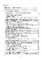
Contents period one
Fundamentals of Automatic Control ............. 1 Control Loops ......................................................... 1 Types of Control Action ........................................... 5 Controller Technologies ......................................... 13
period two
Automatic Control of HVAC Systems ......... 21 Unit-Level Control ................................................. 23 System-Level Control ............................................ 31 System Optimization ............................................. 40 Failure Recovery ................................................... 44
period three Building Automation Systems ....................... 47 period four
Interoperability ................................................... 58
period five
Review ................................................................... 71 Quiz ......................................................................... 75 Answers ................................................................ 76 Glossary ................................................................ 77
TRG-TRC017-EN
iii
iv
TRG-TRC017-EN
period one Fundamentals of Automatic Control
notes HVAC System Control period one
Fundamentals of Automatic Control
Figure 2
Properly applied, automatic controls ensure that a correctly designed HVAC system will maintain a comfortable environment and perform economically over a wide range of operating conditions. Before discussing the use of automatic control in an HVAC system, however, an understanding of the fundamentals behind automatic control is needed.
Terminology controlled variable airflow sensor
controller controlled device
controlled agent
Figure 3
Control Loops Figure 3 contains an illustration of a basic HVAC control system. Warm air flows through a finned-tube cooling coil, where heat is transferred from the air passing over the tubes and fins to the water flowing through the tubes. A valve is used to vary the amount of water flowing through the coil and, therefore, the cooling capacity of the coil.
TRG-TRC017-EN
1
period one Fundamentals of Automatic Control
notes
This basic control system includes a controlled variable, a sensor, a controller, a controlled device, and a controlled agent. n The controlled variable is the parameter being measured and controlled. In this example, the controlled variable is the dry-bulb temperature of the air leaving the cooling coil. n The sensor measures the condition of the controlled variable and sends an input signal to the controller. In this example, the sensor is a dry-bulb temperature sensor located in the airflow. n The controller is the brain of the system. It compares the measured condition of the controlled variable to the desired condition (setpoint), and transmits a corrective output signal to the controlled device. n The controlled device is the component that reacts to the output signal from the controller and takes action to vary the controlled agent. In this example, the controlled device is the valve. n The controlled agent is the medium that is manipulated by the controlled device. In this example, the controlled agent is the chilled water. As the valve opens, more chilled water is allowed to flow through the cooling coil, increasing the cooling capacity of the coil. Coordination of these elements is the basis for automatic control. This systematic operation is frequently referred to as a control loop.
Open Loop outdooroutdoor-air sensor airflow
controller
chilled water valve Figure 4
Typically, there are two types of control loops used in HVAC applications: open and closed. The open loop strategy assumes a fixed relationship between an external condition and the controlled variable. Figure 4 demonstrates an open-loop control strategy. The sensor measures outdoor-air temperature. The controller compares this temperature to a given set of criteria and adjusts the valve to vary the capacity of the coil.
2
TRG-TRC017-EN
period one Fundamentals of Automatic Control
notes
This arrangement assumes a fixed relationship between the outdoor temperature and the required cooling capacity of the system. The drawback of the open loop is that it does not take into account variables that may affect the air temperature downstream of the coil, such as variations in either airflow or water temperature. In this example, the air may be too hot or too cold, resulting in wasted energy or poor comfort control. This is often the consequence of trying to control the condition of the controlled variable based on an assumed fixed relationship to an external variable. For this reason, open control loops are not often used in HVAC systems.
Closed Loop dischargedischarge-air temperature sensor airflow
controller valve chilled water
Figure 5
The closed loop strategy senses the actual condition of the controlled variable. In this example, the controller compares the temperature of the air leaving the coil to the desired setpoint, and adjusts the valve to meet that desired temperature. In other words, closed-loop control is based directly on the condition of the controlled variable, such as the leaving-air temperature in this example. A closed loop provides better control than the open loop strategy, resulting in more-efficient use of energy and improved occupant comfort. For this reason, closed-loop control is generally preferred in HVAC applications.
TRG-TRC017-EN
3
period one Fundamentals of Automatic Control
notes Control Reset dischargedischarge-air temperature sensor
outdooroutdoor-air sensor airflow
controller valve chilled water
Figure 6
Sometimes, a controller may use a combination of these two loops. In this example, a closed control loop measures the temperature of air leaving the coil, and adjusts the valve to maintain the desired setpoint. A second sensor measures the outdoor temperature. As the temperature of the outdoor air decreases, the controller resets the setpoint to a higher value. This strategy is called control reset. The closed-loop sensor acts as the primary source of information, and the open-loop sensor acts as the secondary source. Control reset is often used to minimize energy consumption while still maintaining acceptable comfort.
Control "Points" ▲
Binary input point (BIP)
▲
Binary output point (BOP)
▲
Analog input point (AIP)
▲
Analog output point (AOP)
◆
◆
◆
◆
Examples: fan status (on/off), dirty filter Examples: start/stop fan or pump, open/close damper Examples: temperature, pressure, airflow Examples: control valve or damper position, temperature setpoint
Figure 7
A control point is an individual input to, or output from, a controller. The term binary refers to a control signal that has only two possible states, such as on or off. Examples of binary input points (BIP) include a switch that indicates whether a fan is on or off, and a pressure limit switch that indicates when a
4
TRG-TRC017-EN
period one Fundamentals of Automatic Control
notes
filter is dirty and needs to be replaced. Examples of binary output points (BOP) include a signal to start or stop a pump or fan, and a signal to open or close a damper. The term analog refers to a control signal that varies. Examples of analog input points (AIP) include a varying voltage, current, or resistive signal from a sensor that measures temperature, pressure, or airflow. Examples of analog output points (AOP) include a varying voltage or current signal that is used to change the position of a control valve or a damper, or to indicate a temperature setpoint.
Types of Control Action ▲
Two-position (on/off)
▲
Floating
▲
Proportional
▲
Proportional–Integral (PI)
▲
Proportional–Integral–Derivative (PID)
Figure 8
Types of Control Action Controllers can be classified by the type of control action taken when the condition of the controlled variable deviates from the setpoint. The most common types of action taken by HVAC controllers include: n Two-position (on/off) n Floating n Proportional n Proportional–Integral (PI) n Proportional–Integral–Derivative (PID) Each of these types of control action will be discussed using the same example chilled-water cooling coil. The controlled variable is the temperature of the air leaving the coil, and the controlled device is the valve.
TRG-TRC017-EN
5
period one Fundamentals of Automatic Control
notes
controlled--variable controlled deviation
controller output
Two-Position (On/Off) 100%
0%
+ 5°F 0°F - 5°F
A setpoint
on differential
B off
time
Figure 9
Perhaps the most common control action is two-position, or on/off, control. With two-position control, the controller changes the value of the controlled agent from one extreme (open) to the other (closed). This action is taken when the measured condition of the controlled variable goes above or below the setpoint. Disadvantages of this type of control action are relatively wide temperature variations and the potential for rapid cycling between open and closed positions. To reduce cycling, an allowed deviation (or differential) from the setpoint is used. The differential in this example is plus-or-minus 5°F (2.8°C). When the condition of the controlled variable (temperature of the air leaving the cooling coil) rises to 5°F (2.8°C) above the setpoint (A), the controller responds by opening the valve. Chilled water flows through the coil and the temperature of the air begins to decrease back toward the setpoint. When the temperature of the air drops to 5°F (2.8°C) below the setpoint (B), the controller responds by closing the valve.
6
TRG-TRC017-EN
period one Fundamentals of Automatic Control
notes
controlled--variable controlled deviation
controller output
Floating 100%
0%
+ 5°F
A
switch differential
B
open stop
0°F - 5°F
setpoint
D
differential stop close
C time
Figure 10
A variation of two-position control is floating control, sometimes called threeposition control (open-stop-close). Typically, floating control uses a slowmoving actuator and a fast-responding sensor. The controlled device either modulates toward the open position, modulates toward the closed position, or holds its current position. Again, a differential is used to reduce cycling. When the leaving-air temperature rises to the open differential (A), the controller sends a signal to begin opening the valve. As the valve slowly opens, more chilled water flows through the coil, and the temperature of the air begins to decrease back toward the setpoint. When the temperature reaches the stop differential (B), the controller directs the valve to stop opening and hold its current position. As the temperature continues to decrease below the setpoint, it eventually reaches the close differential (C). At this point, the controller sends a signal to begin closing the valve. As the valve slowly closes, less chilled water flows through the valve and the air temperature begins to increase back toward the setpoint. The valve stops closing and holds its current position when the temperature reaches the stop differential (D). This type of control action typically results in more-stable control and less cycling than two-position control.
TRG-TRC017-EN
7
period one Fundamentals of Automatic Control
notes
controlled--variable controlled deviation
controller output
Proportional 100%
0%
+ 5°F 0°F
A
offset setpoint
throttling range
- 5°F
time
Figure 11
With proportional control, the response of the controller is proportional to the deviation of the controlled variable from the setpoint. In other words, the output from the controller is proportional to the difference between the input signal (condition of the controlled variable) and the setpoint. The amount of change in the controlled variable, over the full range of operation of the controlled device, is called the throttling range. In this coolingcoil example, the throttling range is 10°F (5.6°C), or the setpoint plus-or-minus 5°F (2.8°C). At the setpoint plus 5°F (2.8°C), the valve is fully open. At the setpoint minus 5°F (2.8°C), the valve is fully closed. The center of the throttling range, where the valve is 50 percent open, corresponds to the setpoint. As the temperature of the air leaving the coil rises above the setpoint (A), the difference between the current temperature and the setpoint is 4°F (2.2°C). The controller responds by signaling the valve to open to 90 percent open, increasing the cooling capacity of the coil. Although proportional control can often provide stable control, an inherent disadvantage is its offset characteristic. Offset is the difference between the measured controlled variable and the setpoint. Because the valve position is a function of temperature deviation from the setpoint, some deviation must persist in order to hold the current valve position. This characteristic results in a steady-state error (offset) from the setpoint at all load conditions, except at the condition that requires the valve to be 50 percent open. In this example, the temperature of the air leaving the coil is only at the setpoint when the valve is 50 percent open. At other valve positions, the air is either too cold or too hot. This offset may or may not be acceptable for a given application.
8
TRG-TRC017-EN
period one Fundamentals of Automatic Control
notes
controlled--variable controlled deviation
controller output
Integral 100%
0%
+ 5°F 0°F - 5°F
A setpoint
B time
Figure 12
Integral control overcomes the offset characteristic of proportional control. It responds based not only on the magnitude of deviation from the setpoint, but also on how long the deviation exists. In response to a deviation from the setpoint, integral control steadily changes the corrective signal sent to the controlled device, returning the controlled variable to the setpoint. It stops adjusting the control signal only after the deviation from the setpoint is zero. As the temperature rises above the setpoint (A), the controller responds by steadily opening the valve. The greater the deviation from the setpoint, and the longer the deviation persists, the more the valve opens to increase the capacity of the cooling coil. As a result, the temperature is brought back down to the setpoint. The valve does not stop opening until the temperature reaches the setpoint. This is too much capacity, however, and the temperature drops below the setpoint (B). The controller responds by modulating the valve toward closed until the temperature rises back toward the setpoint. The advantage of integral control is that it always attempts to return the condition of the controlled variable toward the setpoint, thereby eliminating the offset characteristic of proportional control. However, integral control often results in the controlled variable oscillating above and below the setpoint instead of reaching a steady state at the setpoint condition.
TRG-TRC017-EN
9
period one Fundamentals of Automatic Control
notes
controlled--variable controlled deviation
controller output
Proportional–Integral (PI) PI
100% integral
proportional
0%
+ 5°F 0°F
setpoint
- 5°F
time
Figure 13
Some controllers combine proportional and integral control action. The result is called proportional–integral (PI) control and is widely used within the HVAC industry, due primarily to the improved accuracy and ease of implementation. In response to the temperature of the air deviating from the setpoint, the proportional and integral control signals occur simultaneously. The proportional component provides a relatively fast response to the deviation from the setpoint. The integral component is used to drive the controlled variable back toward the setpoint, eliminating the offset characteristic of proportional control. The two signals are additive. The response of a PI control loop can be adjusted by changing the proportional and integral gains. The term gain refers to a weighting factor that determines the impact of each of these two control actions on the resulting response of the controller. If the proportional gain is larger that the integral gain, the proportional component will have a greater influence on the response of the controller. Changing these gains to improve the response of the control loop is called tuning the loop. When properly tuned, PI control is fast-acting, it eliminates the steady-state error (offset) of proportional control, and it reduces the amount of oscillation common with integral control.
10
TRG-TRC017-EN
period one Fundamentals of Automatic Control
notes
controlled--variable controlled deviation
controller output
Derivative 100%
0%
B
+ 5°F 0°F
A
C
setpoint
- 5°F
time
Figure 14
Derivative control generates a corrective output signal only when the condition of the controlled variable is changing. When the controlled variable is not changing, the controller takes no corrective action. If the controlled variable is changing quickly, the corrective action of the controller is more dramatic. Derivative control acts to oppose change, whether that change is away from or toward the setpoint. The magnitude of the corrective action depends on the rate of change. As the leaving-air temperature begins to rise above the setpoint (A), initially the rate of change is very fast, so the controller responds dramatically by opening the valve to nearly fully open. As the rate of change begins to decrease (B), the valve modulates back toward closed. When the temperature begins to decrease toward the setpoint (C), the valve modulates further closed, below 50 percent. The valve only stops modulating when the temperature is no longer changing, regardless of whether the temperature is at the setpoint. Derivative control will only try to prevent a change in the condition of the controlled variable. It will not take corrective action as long as the deviation from the setpoint is constant, even if the condition of the controlled variable is far away from the setpoint. For this reason, derivative control is most effective when used in combination with other types of control action.
TRG-TRC017-EN
11
period one Fundamentals of Automatic Control
notes
controlled--variable controlled deviation
controller output
Proportional–Integral–Derivative (PID) 100%
0%
PID PI derivative
+ 5°F 0°F
setpoint
- 5°F
Figure 15
time
Finally, some controllers combine derivative control with PI control, resulting in proportional–integral–derivative (PID) control action. Proportional control provides a relatively fast response to a deviation from the setpoint. The integral component is used to return the condition of the controlled variable to the setpoint, eliminating offset. The rapid response of derivative control anticipates a change in the condition of the controlled variable and reduces the magnitude of the deviation from the setpoint. Again, the three signals are additive and work together to maintain the setpoint. When properly tuned, PID control results in more-stable control, making it possible to accurately control systems that experience rapid changes.
controlled--variable deviation controlled
Comparison of Control Actions
P offset PID setpoint PI
overshoot
time
Figure 16
As a review, this illustration shows the variation of the controlled variable from the setpoint. With proportional (P) control, the corrective action is proportional to the magnitude of the deviation from the setpoint. The condition of the
12
TRG-TRC017-EN
period one Fundamentals of Automatic Control
notes
controlled variable stabilizes with an offset that is proportional to the load. Proportional control is typically used in applications where this offset from the setpoint is considered acceptable. With proportional–integral (PI) control, the controlled variable returns to the setpoint over a period of time, typically with some overshoot, either minimizing or eliminating offset. PI control is used in applications where offset is unacceptable, but the condition of the controlled variable does not change too rapidly. This is indicative of most HVAC control applications. Finally, proportional–integral–derivative (PID) control reduces overshoot and anticipates changes, to provide more-stable, fast-acting control. PID control is typically used in applications where the condition of the controlled variable may change very rapidly. Proper tuning of the gains for each control component is important to ensure stable control action. The integral and derivative components of the control action can be very destabilizing when the control loop is not tuned properly.
Controller Technologies ▲
Pneumatic
▲
Analog-electric
▲
Microprocessor-based
Figure 17
Controller Technologies HVAC control systems are often classified by the energy source used to power the controlled devices. The most common forms of energy used are electricity and compressed air. Systems that use compressed air to operate controlled devices are called pneumatic control systems. Systems that use electricity as the primary energy source are categorized as either analog-electric or microprocessor-based control systems. For the purpose of this discussion, the term analog-electric represents the operating characteristics of electromechanical and electronic controls.
TRG-TRC017-EN
13
period one Fundamentals of Automatic Control
notes Pneumatic Control System pressurepressurereducing valve main line compressor air drier
branch line
air filter
controller storage tank
controlled device drain Figure 18
Pneumatic control systems vary the pressure of compressed air to operate controlled devices, such as valve and damper actuators. Pneumatic control systems consist of the following major components: n Air compressor with storage tank n Air drier n Air filter n Pressure-reducing valve n Controller n Controlled device The air compressor maintains the air pressure in the storage tank above the minimum pressure required to operate the other devices in the system. The air drier removes moisture from the compressed air to prevent condensation when the air passes through lines that are exposed to cold temperatures. Moisture that condenses out of the compressed air can lead to erratic operation or failure of the controlled devices. The air filter removes particles and oil from the compressed air, preventing these contaminants from clogging the controllers and controlled devices. The pressure-reducing valve drops the pressure of the compressed air from the storage tank to the desired pressure needed to operate the system. The compressed air is delivered through a system of plastic or copper tubing called the main line. Air pressure in the main line is typically 15 to 20 psig (103 to 138 Pa). The controllers in a pneumatic system are connected to the main line. Each controller signals a controlled device to move by adjusting the air pressure in the branch line.
14
TRG-TRC017-EN
period one Fundamentals of Automatic Control
notes Pneumatic Controller bimetal element
set screw main line
orifice
nozzle
flapper
branch line Figure 19
An example of a pneumatic temperature controller is shown in Figure 19. This is a bleed-type controller that uses a nozzle-flapper assembly. A bimetal sensing element, consisting of two different metals fused together, is used to adjust the position of the flapper. As the temperature increases, one metal expands more than the other, and the bimetal element bends in one direction. As the temperature decreases, the element bends in the other direction. When the flapper is pushed tightly against the nozzle opening, no air can escape. As the temperature of the bimetal element increases, it bends away from the nozzle (as shown), allowing the flapper to move away from the nozzle opening. More air escapes from the nozzle, and the air pressure in the branch line decreases. Adjusting the set screw changes the tension of the spring, varying the setpoint temperature at which air begins to escape from the nozzle.
TRG-TRC017-EN
15
period one Fundamentals of Automatic Control
notes Pneumatic Controlled Device branch line
actuator chamber valve stem
diaphragm spring plug
valve seat
Figure 20
Figure 20 shows an example of a pneumatically-controlled water valve. Compressed air is supplied to the actuator chamber by the branch line. The air pressure in the branch line varies between 3 and 15 psig (21 and 103 kPa). As the compressed air pushes down on the diaphragm, it exerts a downward force on the valve stem. This force causes the plug to move toward the valve seat, reducing the flow of water through the valve. When air is allowed to bleed from the actuator chamber, a spring exerts an upward force, causing the plug to rise and allow more water to flow through the valve.
Analog-Electric Controller
Figure 21
Analog-electric control systems vary the electric current or voltage to operate the controlled devices. A sensor sends an electric signal to the controller, and the controller sends an electric signal to operate the controlled device.
16
TRG-TRC017-EN
period one Fundamentals of Automatic Control
notes
An analog-electric controller is a solid-state device that uses an assortment of electronic hardware devices (such as mercury switches, snap-acting contacts, or potentiometers) to process the input signal and generate the desired corrective output signal. Analog-electric control systems require much less maintenance than pneumatic systems, which typically leads to improved comfort control and more-efficient use of energy.
Electronic Controlled Device
actuator
valve stem plug
valve seat
Figure 22
Similar to the pneumatically-controlled valve, the body of a valve used in an analog-electric control system also contains a plug that travels up and down to vary the flow of water through the valve. The difference is in the valve actuator. The example electronic valve actuator in Figure 22 consists of a small electric motor connected to a gear, linkage, and shaft. The shaft is coupled to the valve stem that extends from the body of the valve, and is used to move the plug up and down. Some actuator motors can run in only one direction, with a spring that is used to return the stem to the open or closed position. Other motors can run in either direction and can stop to hold a specific position.
TRG-TRC017-EN
17
period one Fundamentals of Automatic Control
notes Microprocessor-Based Controller
Figure 23
Similar to analog-electric control systems, microprocessor-based control systems vary the electric current or voltage to operate controlled devices. In fact, the sensors and controlled devices used in microprocessor-based control systems are often the same as those used in analog-electric systems. A microprocessor-based controller, however, uses digital software programs, rather than electronic hardware devices, to process the input signal and generate the desired corrective output signal. This type of control is often referred to as direct digital control (DDC). Microprocessor-based controllers are able to accommodate more-sophisticated control sequences at a lower cost than pneumatic or analog-electric controllers can. These sophisticated control sequences can often reduce energy use while still maintaining acceptable comfort. Microprocessor-based controllers can also incorporate adaptive control algorithms, which change the parameters of the control loop as external conditions change. This allows for very accurate control over a wide range of conditions. Because they are software-based, rather than hardware-based, microprocessorbased controllers are also more flexible. Changes to control sequences can easily be accomplished through software changes instead of changing hardware devices. Finally, microprocessor-based controllers allow for cost-effective, system-wide communication. Basic control functions can occur independent of others, integrating the control functions of a given piece of equipment; integrating the control of the various pieces of equipment in a system can provide substantial performance and operating-cost benefits. The benefits of communicating controls will be discussed further in Periods Two and Three.
18
TRG-TRC017-EN
period one Fundamentals of Automatic Control
notes DDC Controlled Device
Figure 24
As mentioned, many of the controlled devices used in microprocessor-based control systems are the same as those used in analog-electric systems. The communicating capabilities of microprocessor-based controls, however, have led to the use of digital control logic within the sensors and controlled devices themselves. These are sometimes called “smart” end devices. As an example, Figure 24 shows an electronic expansion valve used to regulate the flow of refrigerant to the evaporator in an air-cooled water chiller. This valve includes a small circuit board that communicates with the main controller. Smart end devices can be programmed with the operating characteristics of the particular controlled device, allowing for easier tuning and requiring less programming at the main controller. They can also communicate their operating status. If there is a problem with a certain end device, the controller will recognize it immediately and can take action to minimize the impact of the problem, while notifying the operator of a problem with the particular device.
TRG-TRC017-EN
19
period one Fundamentals of Automatic Control
notes Comparison of Technologies Pneumatic
Microprocessor-based
▲
No communication capabilities
▲
Allows system-wide communication
▲
Expensive and complicated to provide complex control strategies
▲
Fewer hardware components
▲
Easily accommodates complex control strategies
▲
Provides many types of control action
▲
Fewer maintenance requirements
▲
Inherently proportional
▲
Extensive maintenance requirements
Figure 25
In the past, pneumatic control systems were quite popular due to the perceived simplicity of operation and low first cost. Pneumatic controlled devices can be used to control HVAC equipment and systems with relatively simple modes of operation. However, pneumatic controls do not easily allow for system-wide communication and require much more maintenance and calibration than microprocessor-based control systems. Failure to properly maintain the pneumatic system may lead to poor comfort control and wasted energy. Finally, when complex control strategies are required, pneumatic systems become very complicated, more expensive, and more difficult to maintain. Microprocessor-based controls can easily provide system-wide communication, which allows them to more-easily perform complex control sequences and provides more flexibility for changing system parameters. They also require fewer hardware components and less maintenance and calibration. A microprocessor-based control system can often use a single controller in a situation where a comparable pneumatic system would require several controllers. This will be demonstrated in Period Two. Pneumatic controlled devices (such as valve and damper actuators) can be used with microprocessor-based controllers. This requires the use of an electronicto-pneumatic transducer to convert the electrical signal from the controller to a compressed-air signal that can be used to operate the controlled device. When large actuation forces are required, this option combines high power, which is inherent to pneumatic systems, with the operating intelligence of microprocessor-based controls.
20
TRG-TRC017-EN
period two Automatic Control of HVAC Systems
notes HVAC System Control period two
Automatic Control of HVAC Systems
Figure 26
Proper design, installation, and operation of the control system is an important factor in achieving the desired performance of an HVAC system. In general, automatic control can: n Satisfy occupant comfort demands n Bolster occupant productivity n Minimize system energy consumption n Work effectively with other building systems
Control of an HVAC System
building management systemsystem-level control
unitunit-level control Figure 27
For the purposes of this clinic, automatic control of an HVAC system will be separated into the three levels depicted by the pyramid in Figure 27. The base of the pyramid is formed by the unit-level control of each individual piece of
TRG-TRC017-EN
21
period two Automatic Control of HVAC Systems
notes
HVAC equipment. This most often involves the use of a separate controller for each piece of equipment. The next level of the pyramid is system-level control. The question is frequently asked, “If each piece of HVAC equipment has its own controller, why is systemlevel control needed?” A common analogy is to view the individual unit-level controllers as members of an orchestra, and the system-level controller as the conductor. This second level of the pyramid provides intelligent, coordinated control so that the individual pieces of equipment operate together as an efficient system. Examples of this coordinated, system-level control will be presented later in this period. Often, this involves connecting the individual unit-level controllers to a centralized, system-level controller. In some cases, however, the system-level control functions for simpler systems can be accomplished within the same pieces of hardware used to provide unit-level control, eliminating the need for separate system-level control hardware. The bottom two levels of the pyramid, by themselves, can provide a functional operating HVAC system. However, operators frequently want to monitor the system, receive alarms and diagnostics at a central location, and integrate the HVAC system with other systems in the building. These are some of the primary functions of the top level of the pyramid, the building-management level. This level will be discussed further in Period Three.
Benefits of Unit-Level Control ▲
Stand-alone control
▲
Safeties, alarms, and diagnostics
▲
Installed, tested, and commissioned in factory
unitunit-level control Figure 28
The primary focus of this clinic will be on using a separate piece of hardware to provide unit-level and system-level control functions. This type of distributed architecture provides several benefits. The first is that it allows stand-alone control of each piece of HVAC equipment. This improves the reliability of the system, because the unit-level controller can control and protect the equipment even if communication from the system-level controller fails. The second benefit is the ease and cost-effectiveness of providing built-in safeties, alarms, and diagnostics. The safeties protect the piece of equipment both from mechanical failure and from electrical failure caused by poor
22
TRG-TRC017-EN
period two Automatic Control of HVAC Systems
notes
incoming power characteristics. Alarms and diagnostics aid in troubleshooting problems with the equipment or controller, and can even alert an operator to a potential problem before it occurs. With the advent of microprocessor-based unit controllers, these safeties, alarms, and diagnostics have become more cost-effective to provide, and they are more valuable to the operator and service personnel. The third benefit of this distributed architecture is that the unit controllers can be installed, tested, and commissioned in the factory. This results in faster, onsite startup and commissioning of HVAC systems and subsystems.
Unit-Level Control
Figure 29
Unit-Level Control The primary function of the unit-level controller is to control and protect the piece of equipment. Again, the unit-level controller is capable of performing these functions even if a system-level controller is not connected to it. Air handlers, fan-coil units, water chillers, packaged rooftop air conditioners, water-source heat pumps, and VAV boxes are just a few examples of HVAC equipment that is commonly equipped with unit-level controllers.
TRG-TRC017-EN
23
period two Automatic Control of HVAC Systems
notes VAV air handler
Discharge-Temperature Control Loop
dischargedischarge-air temperature sensor
valve
controller
Figure 30
Unit-level control for a piece of HVAC equipment typically involves the use of several control loops. To demonstrate this, assume that the same example cooling coil that was introduced in Period One is installed inside a variable-airvolume (VAV) air handler. This air handler delivers a variable quantity of constant-temperature air down the supply-duct system. The first control loop maintains the desired discharge-air temperature. A sensor measures the temperature of the air leaving the air handler. The controller compares this measured temperature to the desired setpoint, and signals the valve to adjust the flow of chilled water through the coil to achieve the setpoint.
VAV air handler
Ventilation Control Loop
returnreturn-air damper
outdooroutdoor-air damper controller
Figure 31
In addition to controlling discharge-air temperature, this example VAV air handler must also ensure that the proper amount of fresh outdoor air is brought into the building for ventilation. In an air handler that delivers a constant volume of air, this typically involves opening the outdoor-air damper to a
24
TRG-TRC017-EN
period two Automatic Control of HVAC Systems
notes
predetermined minimum position whenever the building is occupied. This results in a relatively constant percentage of outdoor air entering the air handler, therefore bringing a constant quantity of outdoor air into the building whenever the outdoor-air damper is at this minimum position. In a VAV air handler, however, the supply airflow changes throughout the occupied period. At part-load conditions, if the outdoor-air requirement remains constant, the VAV system requires a higher percentage of outdoor air. A fixed-position outdoor-air damper would result in an underventilated VAV system. In order to maintain the proper amount of outdoor air while varying the supply airflow, many VAV air handlers use an airflow-monitoring station or a flowmeasuring outdoor-air damper. In this second control loop, a flow-measuring damper measures the quantity of outdoor air entering the air handler. The controller compares this flow rate to the desired quantity of outdoor air and adjusts the damper to bring in the proper amount.
VAV air handler
Economizer Control Loop
outdooroutdoor-air temperature sensor
controller
Figure 32
Use of an airside economizer is a common energy-conserving control strategy. It involves using outdoor air as a source of “free” cooling whenever possible. When the outdoor air is cool enough, the air handler switches to the economizer mode and modulates the positions of the outdoor-air and return-air dampers so that the cool outdoor air handles as much of the cooling load as possible. The decision to switch to economizer mode is typically made automatically, based on the condition of the outdoor air and possibly the recirculated return air. In a VAV air handler, economizer mode can be initiated using one of several strategies. One common strategy, called fixed dry-bulb control, enables the economizer whenever the outdoor dry-bulb temperature is below a predetermined on-point. Another strategy, called comparative enthalpy control, enables the economizer whenever the enthalpy of the outdoor air is lower than the enthalpy of the return air.
TRG-TRC017-EN
25
period two Automatic Control of HVAC Systems
notes
The third control loop in this example VAV air handler uses a fixed dry-bulb control strategy to initiate the economizer mode. A sensor measures the drybulb temperature of the outdoor air, and the controller compares this temperature to the economizer on-point. When the outdoor temperature drops below this on-point, the outdoor-air damper opens and the return-air damper closes. Assuming that the outdoor dry-bulb temperature is higher than the discharge-air temperature setpoint, the cooling coil remains on to do the rest of the cooling.
VAV air handler
Mixed-Air-Temperature Control Loop
mixedmixed-air temperature sensor
controller
Figure 33
When the dry-bulb temperature of the outdoor air drops below the dischargeair temperature setpoint, continuing to bring in 100 percent outdoor air would require heating the air. At this point, the outdoor-air and return-air dampers modulate, mixing the two airflows to avoid overcooling the mixed air. The fourth control loop maintains the desired mixed-air temperature. A sensor measures the dry-bulb temperature of this mixture of outdoor air and return air. The controller compares this temperature to a setpoint, called the mixed-air low limit. This low limit is the discharge-air temperature setpoint minus heat gain from the draw-thru fan. If the mixed-air temperature drops below this low limit, the outdoor-air damper and return-air damper modulate to maintain the desired mixed-air temperature. The outdoor-air damper modulates between 100 percent and the minimum position required for proper ventilation.
26
TRG-TRC017-EN
period two Automatic Control of HVAC Systems
notes VAV air handler
Static-Pressure Control Loop
supply fan
controller
duct staticstaticpressure sensor
Figure 34
As the cooling load changes, the VAV terminal units vary the airflow supplied to the various spaces served by this system. In response, the capacity of the supply fan in the air handler is modulated to vary the airflow delivered down the supply duct. The fifth control loop modulates the capacity of the supply fan. In this example, a sensor measures the static pressure at a particular location in the supply duct. The controller compares this measured pressure to the setpoint, and adjusts the capacity of the supply fan to deliver enough air to maintain the desired static pressure in the supply duct. Four methods commonly used to modulate fan capacity are: inlet vanes, fanspeed control, discharge dampers, and variable-pitch blade control.
TRG-TRC017-EN
27
period two Automatic Control of HVAC Systems
notes VAV air handler
Building-Pressure Control Loop relief fan indoorindoorpressure sensor outdooroutdoorpressure sensor
controller
Figure 35
The use of an airside economizer, wind, stack effect, and intermittent operation of local exhaust fans can all cause undesirable changes in building pressure. The indoor-to-outdoor pressure difference is controlled by adjusting the quantity of air brought into, and exhausted from, the building. If more air is brought into the building than is exhausted, the building will be overpressurized. Too much overpressurization can hinder proper air distribution, lead to loss of temperature control, and cause doors to stand open. If less air is brought into the building than is exhausted, the building is underpressurized. Too much underpressurization can result in hard-to-open doors, drafts, and infiltration of unconditioned outdoor air. Infiltration not only impacts thermal comfort, but infiltration of humid outdoor air can also lead to microbial growth and associated indoor air quality (IAQ) problems. The final control loop in this example VAV air handler maintains proper building pressure. One sensor measures the static pressure inside the building while another sensor measures the outdoor static pressure. The controller compares the static-pressure difference to the setpoint, and modulates the capacity of the central relief fan to maintain the desired static-pressure difference between indoors and outdoors. Figure 35 shows this example VAV air handler equipped with microprocessorbased controls. A single microprocessor-based unit controller coordinates all of the control loops. In addition, the controller includes all the safeties to protect the equipment, and alarms and diagnostics to assist the operator and service personnel.
28
TRG-TRC017-EN
period two Automatic Control of HVAC Systems
notes VAV air handler
Pneumatic Controls
main line
controllers Figure 36
Figure 36 shows this same VAV air handler equipped with pneumatic controls. Each control loop requires its own separate controller, each needing routine maintenance and calibration. Adding to the complexity, the controllers each have individual setpoints and gain and range settings, which must all be coordinated. Adjustment and calibration of any individual controller affects the performance of the other controllers. Even in relatively simple applications, pneumatic controls can quickly become very complicated. Overall, microprocessor-based controls typically require fewer hardware components than pneumatic control systems. This reduces the complexity of the system, and reduces the associated maintenance and calibration requirements. In addition, microprocessor-based controls can significantly improve accuracy and reliability, and provide more flexibility for changing system parameters.
TRG-TRC017-EN
29
period two Automatic Control of HVAC Systems
notes Equipment Protection
unitunit-level controller
airair-cooled water chiller Figure 37
As described earlier, another important function of a unit-level controller is to protect the equipment from damage. As an example, Figure 37 shows an aircooled water chiller with a microprocessor-based unit controller. Suppose a condenser fan motor fails during hot weather. With less air flowing through the air-cooled condenser, the temperature (and pressure) of the refrigerant inside the condenser gradually rises. Some unit-level controllers have the ability to adapt to this type of potentially harmful condition, by varying the operation of the equipment in order to keep it running as long as possible. In this example, the controller begins to unload the compressor in response to the rising condensing pressure. Although the chiller may no longer be able to provide the required cooling capacity, at least it is still running, providing as much capacity as possible. Along with taking this corrective action, the unit controller initiates an alarm and diagnostic message to tell the operator what is wrong. If conditions worsen and the condensing pressure continues to rise until it eventually reaches the maximum allowable limit, the controller will turn off the chiller to protect it from damage. The controller also initiates another alarm and diagnostic message.
30
TRG-TRC017-EN
period two Automatic Control of HVAC Systems
notes System-Level Control
systemsystem-level control
unitunit-level control Figure 38
System-Level Control An HVAC system typically includes several different pieces of equipment, and often each has its own unit-level controller. This second level of the pyramid provides intelligent, coordinated control, so that the individual pieces of equipment operate together as a system. This next section will use four example HVAC systems to introduce the importance of this system-level control. Again, these system-level control functions may be performed by a separate piece of hardware, or may be provided by the same device used to provide unitlevel control for one of the pieces of equipment.
TRG-TRC017-EN
31
period two Automatic Control of HVAC Systems
notes Chilled-Water VAV System VAV terminal units
cooling tower VAV air handler pumps
waterwater-cooled chiller
exhaust fan
systemsystem-level controller boiler
Figure 39
The first example system uses the same VAV air handler that was introduced earlier in this period. This air handler is equipped with a unit-level controller, as are each of the VAV terminal units to which the air handler delivers air. The water chiller that provides cold water to the cooling coil, and the boiler that provides hot water to the heating coils, also have their own, individual, unitlevel controllers. Each piece of equipment is capable of being controlled independently. The unit controller on each VAV terminal unit controls the quantity of air delivered to each zone, in response to the temperature in that zone. The unit controller on the air handler controls both the temperature and the quantity of the air supplied to the VAV terminal units. Finally, the unit controller on the water chiller ensures a flow of chilled water whenever it is required, and the boiler controller ensures a flow of hot water whenever it is required. In order for these various pieces of equipment to operate in a coordinated and efficient manner, a controller with a higher level of authority is required. In this example, a separate, system-level controller is used to coordinate the VAV terminal units, air handler, chiller, boiler, and other pieces of equipment during the various modes of operation.
32
TRG-TRC017-EN
period two Automatic Control of HVAC Systems
notes System-Level Operating Modes Occupied Mode
Unoccupied Mode
▲
Terminal units maintain “occupied” setpoints
▲
Terminal units maintain “unoccupied” setpoints
▲
Outdoor-air damper delivers proper amount of ventilation air
▲
Outdoor-air damper is closed
▲
▲
Air is cooled or heated to desired setpoint
Supply fan, cooling coil, and heating coil operate only as needed
▲
Supply fan operates continuously, modulating to maintain system staticpressure setpoint
Figure 40
During the occupied mode, each VAV terminal unit varies the supply airflow to maintain the occupied setpoint temperature in the zone it serves. The air handler brings in the required amount of outdoor air for ventilation, cools or heats the mixed air to the desired discharge-air temperature, and modulates the supply fan to maintain the proper amount of static pressure in the duct. During the unoccupied mode, each VAV terminal unit maintains the unoccupied setpoint temperature in the zone. The air handler closes the outdoor-air damper and shuts off the supply fan. The air handler only operates to maintain the unoccupied setpoint when enough zones require heating or cooling to satisfy the minimum airflow requirement. Coordinating the operation of the VAV terminal units and the air handler during these different operating modes is one of the functions provided by the systemlevel controller. In this example system, the same system-level controller is also used to coordinate the operation of the chilled-water plant and boiler plant. This involves turning on and off, and modulating the capacity of, the pumps, chiller, boiler, and cooling-tower fans.
TRG-TRC017-EN
33
period two Automatic Control of HVAC Systems
notes Rooftop VAV System
packaged rooftop air conditioner
VAV terminal units
systemsystem-level controller Figure 41
The second example system uses a packaged rooftop VAV air conditioner, instead of the chilled-water air handler, to deliver air to the VAV terminal units. Similar to the air handler, this packaged rooftop air conditioner includes a unit controller that provides many of the same control-loop functions discussed earlier. However, instead of modulating the flow of chilled water through the cooling coil, the rooftop unit controller cycles compressors and stages of heat to vary its cooling and heating capacity. In addition, because this piece of equipment includes the complete refrigeration system, the unit controller must perform several other control functions related to the refrigeration system. In terms of system-level control, the VAV terminal units and rooftop unit must be coordinated during the various modes of operation. The same occupied and unoccupied modes that were discussed previously also apply to this system. Next, another operating mode of the system will be introduced.
34
TRG-TRC017-EN
period two Automatic Control of HVAC Systems
notes Morning Warm-Up system on
system off
occupied setpoint
zone temperature
occupied hours unoccupied setpoint
6 AM
Noon
6 PM
Figure 42
Typically, the temperature inside a building is allowed to drift overnight when the occupants have gone home. The HVAC system is started the next morning, and is operated long enough for the indoor temperature to reach the desired occupied setpoint by the time the people enter the building. During cold weather, this is called the “morning warm-up” mode. For this example rooftop VAV system, each VAV terminal unit is fully opened. The rooftop unit turns on the supply fan, closes the outdoor-air damper, and heats the recirculated return air. As a zone reaches the occupied setpoint, the corresponding VAV terminal unit closes. The supply fan modulates its capacity until all zones (or a single, representative zone) have reached their occupied setpoints. Just like the example chilled-water VAV system, coordinating the operation of the VAV terminal units and the rooftop unit during these different operating modes is one of the functions provided by the system-level controller. A unique characteristic of a rooftop VAV system, however, is that the same piece of hardware that provides the unit-level control functions for the packaged rooftop air conditioner can also perform many of these system-level control functions.
TRG-TRC017-EN
35
period two Automatic Control of HVAC Systems
notes Air-Cooled Chiller, Fan-Coil System dedicated outdooroutdoor-air unit fanfan-coil units airair-cooled chiller
systemsystem-level controller pumps boiler
Figure 43
The third example system includes fan-coil units served by an air-cooled chiller and boiler. A fan-coil unit is located in each zone, and each one includes its own unit-level controller to modulate the flow of water through the coil in response to the temperature in the zone. The unit controller on the air-cooled water chiller ensures a flow of chilled water whenever it is required, and the boiler controller ensures a flow of hot water whenever it is required. This example is a two-pipe system. It uses a common piping system to alternatively supply cold water or hot water to all the fan-coil units in the system. Finally, a dedicated outdoor-air unit conditions all of the outdoor air brought into the building for ventilation, before delivering it directly to the individual zones. In this example, a separate, system-level controller coordinates starting and stopping the water circulation pumps, the dedicated outdoor-air unit, and stand-alone exhaust fans. It also determines when to change over from cooling to heating mode, and coordinates the operation of the chiller and boiler to prevent them from operating simultaneously.
36
TRG-TRC017-EN
Two-Pipe Changeover Requirements 140°F
supply--water temperature supply
(60°C)
deadband
120°F
(49°C)
15°F
hot water
(8°C)
80°F
(27°C)
30°F (17°C)
40°F
chilled water
(4°C)
0°F
(-18°C)
20°F
(-7°C)
40°F (4°C)
60°F
(16°C)
outdoor drydry-bulb temperature
80°F
(27°C)
Figure 44
Changing between cooling and heating modes in a two-pipe system requires a lot of excess energy to heat or cool the mass of water in the piping system. Therefore, ASHRAE Standard 90.1–2001 (Section 6.3.2.2.2) includes the following requirements to minimize the energy impact of this switchover: n The system must allow a deadband, between changeover from one mode to the other, of at least 15°F (8°C) outdoor-air temperature. n The system must include controls that allow the system to operate in one mode for at least four hours before changing to the other mode. n Reset controls must be provided to allow heating and cooling supply-water temperatures, at the changeover point, to be no more than 30°F (17°C) apart. In this example, when the outdoor temperature is below 45°F (7.2°C), the system operates in the heating mode. The setpoint for the water leaving the boiler is reset based on the outdoor dry-bulb temperature. When the outdoor temperature is 10°F (-12.2°C) or below, the boiler setpoint is 140°F (60°C). When the outdoor temperature is between 10°F (-12.2°C) and 60°F (15.6°C), the boiler setpoint is varied between 140°F (60°C) and 70°F (21.1°C). The system remains in the heating mode above the changeover point of 45°F (7.2°C) outdoor temperature due to the 15°F (8°C) deadband. When the outdoor temperature reaches 60°F (15.6°C), the system changes over to the cooling mode and the setpoint for the water leaving the chiller is 40°F (4.4°C). When the outdoor temperature drops back below 60°F (15.6°C), the system remains in the cooling mode due to the 15°F (8°C) deadband. When the outdoor temperature is between 60°F (15.6°C) and 45°F (7.2°C), the chiller setpoint is varied between 40°F (4.4°C) and 55°F (12.8°C). When the outdoor temperature reaches 45°F (7.2°C), the system changes to the heating mode. Finally, the system-level controller includes a timer to prevent this changeover from occurring within four hours of the last time the system changed modes.
TRG-TRC017-EN
37
period two Automatic Control of HVAC Systems
notes Water-Source Heat-Pump System exhaust fan cooling tower
dedicated outdooroutdoor-air unit
pumps
waterwater-source heat pumps
boiler
systemsystem-level controller
Figure 45
The fourth example system is a water-source heat-pump system. Each heat pump includes a unit-level controller that cycles its compressor to maintain the desired temperature in the zone it serves. All the heat pumps are connected by a common water loop. The temperature of the water in this loop is controlled within a defined range by a cooling tower and a boiler. Like the fan-coil system, this water-source heat-pump system also includes a dedicated outdoor-air unit to condition all of the outdoor air brought into the building for ventilation. The cooling tower, boiler, and dedicated outdoor-air unit are all equipped with their own unit controllers. A separate, system-level controller coordinates these pieces of equipment, including starting and stopping the water-circulation pumps, the dedicated outdoor-air unit, and the stand-alone exhaust fans. It also coordinates operation of the cooling tower and the boiler to maintain the proper temperature in the water loop.
38
TRG-TRC017-EN
period two Automatic Control of HVAC Systems
notes Loop Temperature Control cooling tower off
pumps on
boiler off
heat pumps in cooling mode
heat pumps in heating mode Figure 46
The temperature of the water in the loop is typically controlled between 60°F (16°C) and 90°F (32°C). During warm weather, when all of the heat pumps are operating in cooling mode, heat removed from the air inside the building is transferred to the water loop. This causes the temperature of the water in the loop to increase. A cooling tower, or evaporative water cooler, rejects heat from the water loop to the outdoor air, maintaining a leaving-water temperature of approximately 90°F (32°C). During cold weather, when most of the heat pumps are operating in heating mode, heat is removed from the water loop and transferred to the air. This causes the temperature of the water in the loop to decrease. A boiler, or water heater, adds heat to the water loop, maintaining a leaving-water temperature of approximately 60°F (16°C). During mild weather, such as spring and fall, some heat pumps operate in heating mode. Others operate in cooling mode and naturally offset the heat absorbed by the heat pump in heating mode. If the water temperature stays between 60°F (16°C) and 90°F (32°C), neither the boiler nor the cooling tower need to operate.
TRG-TRC017-EN
39
period two Automatic Control of HVAC Systems
notes System Optimization
systemsystem-level control unitunit-level control
Figure 47
System Optimization When there is a device that provides system-level coordination for the equipment in the system, the next logical step is to optimize the control of the system. For this discussion, optimization is defined as minimizing the cost to operate the entire HVAC system, while still maintaining comfort. In other words, this means maximizing the efficiency of the entire system, not just an individual component. The same four example systems will be used to discuss this concept of system optimization.
VAV system
Fan-Pressure Optimization
supply fan
staticstaticpressure sensor
fan speed or inletinlet-vane position systemsystem-level controller
damper positions
VAV terminal units Figure 48
In a VAV system, there is no reason to generate more static pressure in the supply duct than is necessary to push the required amount of air through the most demanding VAV terminal unit. As described earlier, the unit controller on a VAV air handler typically maintains the static pressure in the supply duct. The
40
TRG-TRC017-EN
period two Automatic Control of HVAC Systems
notes
controller compares the measured pressure to a setpoint and modulates the supply fan to maintain the setpoint at the sensor location. With microprocessor-based unit-level and system-level controllers, it is possible to optimize the static-pressure control function to minimize fan energy consumption. The unit controller on each VAV terminal unit knows the current position of its air-modulation damper. The system-level controller continually polls the individual unit controllers, looking for the one with the most-open damper. This controller then resets the static-pressure setpoint so that at least one damper, the one requiring the highest inlet pressure, is nearly wide open. The result is that the supply fan generates only enough static pressure to push the required airflow through this “critical” VAV terminal unit. This concept is called fan-pressure optimization. Overall, this strategy has several benefits, including less fan energy consumption at part load, lower noise levels, and reduced risk of fan surge. It also allows the static-pressure sensor to be located near the fan outlet, where it can be installed and tested in the factory,and also serve as the duct highpressure sensor.
rooftop VAV system
Optimum Start time clock optimum start occupied setpoint
zone temperature
occupied hours unoccupied setpoint
6 AM
Noon
6 PM
Figure 49
The morning warm-up mode was discussed earlier in this period. In many systems, a simple time clock or a time-of-day schedule is used to start and stop the HVAC system. However, the start time is typically set to ensure that the indoor temperature reaches the desired occupied setpoint on the coldest and warmest days of the year. In other words, the system is programmed to start early enough so that the building will warm up or cool down fast enough on the worst-case day. The result is that, for most days in the year, the system starts much earlier than it needs to. This increases the number of operating hours for the system and increases energy use. An alternative is to use an optimum start strategy. The microprocessor-based controller is programmed to determine the length of time required to bring the space from its current temperature to the occupied setpoint temperature. The controller waits as long as possible before starting the system, so that the space
TRG-TRC017-EN
41
period two Automatic Control of HVAC Systems
notes
reaches the occupied setpoint temperature just in time for occupancy. This start time is determined using the difference between the space temperature and the occupied setpoint temperature, by comparing this difference with the historical performance of how quickly the space can warm up or cool down.
air-cooled chiller, fan-coil system
Chilled-Water Reset airair-cooled chiller 47°F
leavingleaving-water temperature
(8.3°C)
constantconstant-volume pump
coil
54°F (12.2°C)
valve position
systemsystem-level controller Figure 50
In the example fan-coil system, raising the temperature of the water leaving the chiller will reduce the energy consumed by the air-cooled chiller. In a constantflow pumping system, this chilled-water reset strategy can reduce system energy consumption. In a variable-flow pumping system, however, as the chilled-water temperature increases, more water must be pumped to handle the same cooling load, and pump energy use increases. Typically, this increase in pump energy will be more than the amount of chiller energy saved, and system energy consumption actually increases. In many constant-flow pumping systems, the leaving chilled-water temperature setpoint is reset based on the outdoor dry-bulb temperature. In other words, as the outdoor temperature decreases, the chilled-water setpoint is reset upwards. Unfortunately, outdoor temperature is often a poor indicator of the actual building cooling load. A good indicator of the cooling load on a fan-coil unit, however, is the position of the coil control valve. Similar to the concept of fan-pressure optimization, the unit controller on each fan-coil unit knows the current position of its control valve. The system-level controller continually polls the individual unit controllers, looking for the one with the most-open valve. This controller then resets the chilled-water temperature setpoint until at least one valve, the one requiring the coldest water, is nearly fully open. The result is that the chiller makes water that is only cold enough to meet the load on the “critical” fan-coil. A potential problem with chilled-water reset is that space humidity control can be compromised if the water gets too warm. However, with microprocessorbased controls, the unit controller can receive an input from a humidity sensor in the space. Again, the system-level controller can be used to continually poll the individual unit controllers (or a single, representative space), looking for any
42
TRG-TRC017-EN
period two Automatic Control of HVAC Systems
notes
space where the space humidity level reaches the desired upper limit. If one or more spaces are too humid, then the chilled-water temperature can be reset downward until the space humidity level is below the upper limit.
water-source heat-pump system
Optimized Loop Control combined energy use, kW
100 90
cooling tower
80 70
heat pumps
60 50
optimized control loop waterwater-temperature setpoint water-temperature 90°F
(32°C)
Figure 51
In the example water-source heat pump system, a communicating system-level controller offers the opportunity to optimize the temperature of the water in the loop, minimizing total system energy consumption. In the cooling mode, a water-source heat pump operates more efficiently with cooler water flowing through it. In the heating mode, it operates more efficiently with warmer water. Additionally, making cooler water requires the cooling tower to use more energy. A system-level controller can determine when it makes sense for the cooling tower to work harder, producing cooler water and minimizing the combined energy use of the heat pumps and cooling tower.
TRG-TRC017-EN
43
period two Automatic Control of HVAC Systems
notes failure recovery
Sequences of Operation
chillerchiller-plant controller
Figure 52
Failure Recovery An often-overlooked function of both unit-level controllers and system-level controllers is the responsibility to respond to failures. On the system control level, failure recovery often involves the definition of control sequences in the event that one piece of equipment fails. An example is a system-level controller that sequences the operation of multiple chillers in a chilled-water plant. This controller has a set of instructions that define the order in which to start and stop the chillers in response to changing cooling load. If any of the pumps, valves, cooling towers, or chillers break, it is important for the system-level controller to realize this and have a contingency plan. The simplest and most reliable failure-recovery sequence is likely to turn on the next piece of equipment in the predefined sequence. Also, it is especially important to notify the operator of the failure.
44
TRG-TRC017-EN
period two Automatic Control of HVAC Systems
notes failure recovery
Stand-Alone Operation heat pump with unitunit-level controller
systemsystem-level controller thermostat
Figure 53
As mentioned earlier, one of the benefits of a distributed control architecture is that it allows stand-alone control of each piece of equipment. In the event that communication with the system-level controller is lost, the unit-level controller should contain a set of instructions and setpoints that would protect the piece of equipment and allow it to continue providing cooling or heating. The system-level controller in the example water-source heat-pump system directs the individual heat pumps when to operate in occupied and unoccupied modes. In the event that communication with the system-level controller is lost, the unit-level controller for each heat pump includes default setpoints and continues operating in the occupied mode as long as water is flowing through it. It operates in this manner until communication is restored, or until the operator intervenes. So, even though the system may not be operating as efficiently as possible, the individual heat pumps continue to provide comfort and to protect themselves from harm.
TRG-TRC017-EN
45
period two Automatic Control of HVAC Systems
notes failure recovery
Selection of Controlled Devices ▲
Normally-closed actuator
▲
Normally-open actuator
▲
Position-maintained actuator
Figure 54
Another means of providing protection in case of a failure is to use the proper types of controlled devices. Normally-closed, normally-open, and positionmaintained devices are available. The type chosen depends on the desired operation of the device in the event of a loss of the control signal. For example, a normally-closed damper actuator is typically used with an outdoor-air damper in an air handler. In the case of a power loss, a normallyclosed actuator contains a spring, a battery, or a capacitor that forces the outdoor-air damper closed. If the control system fails when the temperature of the outdoor air is below 32°F (0°C), this normally-closed damper actuator will help protect downstream water coils from freezing. A second example is to use a normally-opened valve actuator with a hot-water preheat coil in an air handler. If the valve controller or actuator fails, the normally-open actuator forces the valve to the fully-open position. This allows hot water to flow through the coil, protecting it from freezing.
46
TRG-TRC017-EN
period three Building Automation Systems
notes HVAC System Control period three
Building Automation Systems
Figure 55
The primary function of the building HVAC system is to provide acceptable comfort for the occupants. As explained in Period Two, the first two levels of the pyramid can generally provide this function. The communications capability of microprocessor-based controls, however, provides an opportunity to improve the operation and management of the entire building.
TRG-TRC017-EN
47
period three
Building Automation Systems
notes Building Management
building management systemsystem-level control
unitunit-level control Figure 56
The building-management level is the top level of the pyramid. The hardware needed for this top level is typically a personal computer (PC) with communications ports, a color display, and a printer. Many buildings include several HVAC system-level controllers. For example, the VAV air handler and the VAV terminal units may be controlled by one system-level controller, while the chilled-water system (chillers, cooling towers, pumps, and so forth) may be controlled by a separate system-level controller. These system-level controllers may include a display that allows the operator to access data in the system.
48
TRG-TRC017-EN
period three
Building Automation Systems
notes Responding to Comfort Complaints
Figure 57
Linking all of the system-level controllers to a building automation system, however, allows the building operator to quickly and efficiently respond to comfort-related complaints from a central location. The PC permits the operator to assess the current status and performance of the entire system, or any component of the system, from a central location. One of the primary benefits of using a PC as the interface to the building automation system is its ability to provide a graphical user interface. This interface can be customized to mimic the actual floor plan of the building, as well as the actual equipment and systems installed. Providing a graphical depiction of the building floor plan allows the operators to easily focus on one particular area of the building. It can also allow them to see the current comfort conditions in any specific location.
TRG-TRC017-EN
49
period three
Building Automation Systems
notes Graphical User Interface
Figure 58
Graphical representations of the HVAC equipment and systems often make it easier to navigate the system when investigating problems. This is because the graphics on the screen mimic what the operator knows to be installed on the roof, in the equipment rooms, and in the ceilings. This example shows a VAV air handler similar to the one described in Period Two. The use of graphics provides a logical organization for the many pieces of data available for this equipment. The operator can read the current dischargeair temperature, the positions of the outdoor-air damper and chilled-water control valve, and any other pieces of data necessary to diagnose a problem. While the graphical view of the VAV air handler shows many key pieces of data, the building automation system can also include screens of text that contain even more data for this same system.
50
TRG-TRC017-EN
period three
Building Automation Systems
notes Time-of-Day Scheduling
Figure 59
For a building, time-of-day scheduling is one of the most important energysaving strategies. Schedules can be used to: n Ensure that equipment, such as air conditioning and lights, only operates when it is needed n Keep the equipment running at minimal energy-use levels at night, on weekends, and on holidays n Define exceptions (such as holidays or planned shutdowns) to the normal operating schedule n Change the setpoints at different times of the day or times of the year n Define optimal start periods to minimize energy use while maintaining comfort A building automation system centralizes this scheduling function, making it easier for the operator to set up the schedules and make building-wide changes. Additionally, unit-level controllers for HVAC equipment, lights, and other equipment can be grouped together as members of a common area. This makes it easier to create a schedule or to change the setpoints for all the equipment assigned to that area.
TRG-TRC017-EN
51
period three
Building Automation Systems
notes Centralized Alarms and Diagnostics
Figure 60
As explained in Period Two, one of the primary functions of a unit-level controller is to protect the equipment from damage. The example discussed was the impact of a broken condenser fan motor on the operation of an aircooled water chiller. One of the actions taken by the unit-level controller was to initiate an alarm to inform the operator of the problem. The communications capability of microprocessor-based controls makes them well-suited for automatically reporting problems when they occur in the system. While this example alarm message originates at the chiller unit controller, it can also be transmitted by the building automation system to the centralized PC, where the building operator can be alerted. These alarm messages can then be stored in a log so the operator can review the history of a problem or track any ongoing problems. In addition to alarm messages, the building automation system can transmit informational diagnostic messages that help the building operator pinpoint the cause of a problem. Centralizing alarms and diagnostics allows the operator to respond to problems faster.
52
TRG-TRC017-EN
period three
Building Automation Systems
notes Remote Access ▲
Alarm notification
▲
Dial-in access
Figure 61
Another function of a building automation system is to allow remote communication. For example, an alarm message can be transmitted through a modem to a pager, or through e-mail to another computer. If an equipment failure occurs over the weekend, when nobody is in the building, this allows the building operator to be alerted to the problem at home, long before people return to work on Monday morning. The alarm message can also be sent to an outside service contractor that monitors, maintains, and repairs the equipment and systems in that building. This may allow the problem to be fixed before people return to work. In the same manner, the building operator or service contractor can connect to the building automation system from a remote PC through a phone line, the Internet, or a wireless communications link. This allows the operator or service contractor to diagnose the cause of a problem, just as if he or she were inside the building.
TRG-TRC017-EN
53
period three
Building Automation Systems
notes Reports ▲
Trend logs
▲
Alarm activity
▲
Building energy use
▲
After-hours tenant occupancy
▲
Equipment diagnostics and performance
▲
Commissioning Figure 62
Many of the benefits of a building automation system come from taking advantage of the processing power and data storage capacity of the PC. Microprocessor-based control systems have the capability of gathering and transmitting large quantities of data. Presenting this data in an easy-to-use format is critical to ensuring that it is useful to the operator. In addition to the graphical user interface, another useful tool for effectively using this data is reports. Example types of reports include trend logs, alarm activity logs, building energy use, after-hours tenant occupancy, equipment diagnostics and performance, and equipment and system commissioning. These reports can be viewed on the PC screen as requested by the user, or they can be automatically generated and saved to the hard drive, printed, or emailed.
54
TRG-TRC017-EN
period three
Building Automation Systems
notes Preventive Maintenance
Figure 63
Preventive maintenance is an important part of keeping an HVAC system, and the entire building, in optimum working condition. Another function of a building automation system is to notify maintenance personnel when preventive maintenance procedures should be performed. This notification can be triggered by calendar dates, run-time hours, the number of times a piece of equipment has started, or sensors installed in the system (such as a pressure switch that indicates when an air filter is too dirty and needs to be replaced). Additionally, the building automation system can link to electronic documentation that may aid in troubleshooting or performing various maintenance procedures. Some examples include: n Troubleshooting guides for the actual pieces of equipment in the building n Maintenance manuals that describe preventive-maintenance procedures n Online help for using or modifying the building automation system
TRG-TRC017-EN
55
period three
Building Automation Systems
notes Integration with Other Systems returnreturn-air damper
smokesmokecontrol dampers
normal HVAC operation
smokesmoke-control operation Figure 64
Building automation systems provide the opportunity to simplify the control of the various HVAC systems within a facility. In addition, they can be used to integrate the operation of the HVAC systems with other building systems, such as lighting, security, and fire protection. For example, the time-of-day scheduling function used to schedule the HVAC system may also be used to turn on and off lights inside the building. Integrating these two systems allows the building operator to interact with both systems from the same user interface. This integration may also involve changing the operation of one system component to assist another system. For example, one approach for providing smoke control in a large building is to share components with the HVAC and exhaust systems. Activation of a fire alarm causes these other systems to change modes and perform smoke-control operations. In this example building, a fire alarm on the third floor causes the supply-side smoke-control damper on this floor to close, while the respective return-side damper remains open. Meanwhile, the return-side smoke-control dampers on the first, second, and fourth floors close, while their respective supply-side dampers remain open. The central return damper in the air handler closes so that all of the air from the building is exhausted, and no smoke is recirculated. This coordinated control is intended to purge the smoke from the building as much as possible.
56
TRG-TRC017-EN
period three
Building Automation Systems
notes Connecting Multiple Sites ▲
Centralized monitoring
▲
Diagnose or predict problems with systems
▲
Combine energy usage for negotiating energy contracts
Figure 65
For companies that own multiple buildings in several locations, a building automation system can be used to provide all of these functions from a single location. For example, a retailer who owns 20 stores in a large city can schedule and monitor all 20 stores from a central building automation system that is installed in one of the stores or at the company’s headquarters. In addition, equipment performance and energy-use data from each location can be gathered at the central monitoring location. This data can be analyzed to determine any degradation in equipment or system performance. Also, the energy use of all the buildings can be combined for use in negotiating energy contracts with potential suppliers.
TRG-TRC017-EN
57
period four Interoperability
notes HVAC System Control period four
Interoperability
Figure 66
The trend in the building automation industry is toward interoperability. Interoperability is defined as digital communication between independently manufactured products that are designed to the same open, standard, communications protocol. It means that a single controller can monitor and control independently designed, microprocessor-based control products. Before discussing the issue of interoperability, a basic understanding of networks is required. As described in Period Three, linking all of the microprocessor-based controllers together with a building automation system provides an opportunity to improve the operation and management of the entire building. To enable this communication between controllers, there needs to be a communications network within the facility.
58
TRG-TRC017-EN
period four
Interoperability
notes Network node
node
server
node node
Figure 67
A network is the means by which two or more communicating devices are connected together so they can exchange data. Physically, the connections can be made with cables or through a wireless network. Each device that is connected to a network is called a node. A server is a device that shares its resources with the other computers on the network. For example, a file server stores application programs or data files, while a print server enables all computers on the network to print to a shared printer.
Dedicated Versus Shared Networks ▲
▲
Dedicated network ◆
Easier to design and install
◆
More expensive
Shared network ◆
Less expensive (shares infrastructure)
◆
More difficult to ensure security
Figure 68
Historically, most building automation systems have been installed on dedicated networks. This means that the communications media is used only by the building automation system, and not shared with other systems such as telecommunications or e-mail. Dedicated networks are easier to design and install because they do not need to consider the needs or limitations of
TRG-TRC017-EN
59
period four
Interoperability
notes
these other systems. They may also be more reliable due to less “traffic” on the network. Shared networks, on the other hand, take advantage of an existing network infrastructure that is installed in the building for some other purpose. A shared network allows each connected PC to have a single network-interface card that provides access, not only to the building automation system, but also to other functions of the network such as print servers, shared files, and e-mail. Installing the BAS on a shared network, however, requires close cooperation with the owner’s information services (IS) or information technology (IT) staff. A shared network does not offer the same level of security as a dedicated network. Shared networks that are accessed by multiple users, such as on a college campus, can be prone to internal security problems. Security, installed cost, and system flexibility must all be considered when deciding between a dedicated or shared network for a building automation system.
LAN Versus WAN building A
building B
router
router
Figure 69
A local area network (LAN) is a communications network that is intended to serve a relatively small area, typically up to approximately one square mile (2.5 square kilometers). Because the network serves only a small area, it can be optimized to allow faster exchange of data. A LAN generally works well for a single building. By connecting two or more LANs together, this distance limitation can be overcome. A router is a device that transmits signals between networks. When used with a communications service, such as telephone lines or satellites, a network can be expanded to provide data communications across a city, state, country, or even across the entire planet. This connection of multiple LANs is called a wide area network (WAN). A single WAN can connect all of the facilities owned by a company or organization. For example, in a school district, a WAN might be used to allow the students to access shared applications, send and receive e-mail, and access the Internet, regardless of their location in the district.
60
TRG-TRC017-EN
period four
Interoperability
notes Intranet Versus Internet building A
building B
router
router
firewall
Internet Figure 70
The best known example of a wide area network is the Internet. The Internet is an open, public network that is available to anyone with access to an Internet Service Provider (ISP). An intranet, on the other hand, is a closed, private implementation of a wide area network. An intranet uses the same technology as the Internet, but access is limited to authorized users only. Often, PC workstations that are connected to an intranet also have access to the public Internet. This access is typically controlled by a security filter called a firewall. The firewall can be set up to limit outside access to the intranet, as well as limit the data that users can request from the Internet. For example, e-mail is typically allowed to travel from the Internet to an intranet, and users connected to an intranet are able to view Web sites on the Internet from their PC workstations. Typically, a building automation system is installed on an intranet, not on the public Internet. Due to security concerns, most firewalls will not allow the type of communication required to directly access a building automation system from the Internet. However, many networks already have a method for secure remote access. Users of the network can typically dial into the network to access their e-mail or access shared files. This method of secure remote access can also be used to remotely access the building automation system. An alternative is to install a separate modem in the PC or system control panel of the building automation system.
TRG-TRC017-EN
61
period four
Interoperability
notes "Tiered" BAS Architecture PC workstation LAN for system controllers
HVAC system controller
lighting system controller
LAN for unit controllers
firefire-protection system controller
security system controller
equipment with unit controllers
Figure 71
Figure 71 illustrates a conventional approach to installing a building automation system. This tiered architecture delineates subsystems by function. The unit-level controllers on the HVAC equipment are connected to a dedicated network and are coordinated by a separate system-level controller. The HVAC system-level controller resides on a local area network, along with other system-level controllers that coordinate additional HVAC equipment or other building control functions such as lighting, security, and fire protection. The building automation system coordinates these various subsystems. This tiered architecture reduces the number of interface points between subsystems and isolates each subsystem for commissioning and diagnostics.
Communications Protocols ▲
Proprietary ◆
▲
Open ◆
▲
Used, produced, or marketed under exclusive legal right of an individual or organization Available to public domain and is shared among vendors
Standard ◆
Open protocol that has been formalized by a governing body
Figure 72
In order for microprocessor-based devices to communicate with one another, they need to “speak a common language.” A communications protocol is a set of rules or standards that govern the exchange of data over a digital
62
TRG-TRC017-EN
period four
Interoperability
notes
communications network. A protocol is proprietary if it is used, produced, or marketed under the exclusive legal right of an individual or organization. An open protocol is available to public domain and is shared among vendors. An open protocol is considered standard if it is formalized by a governing body. As an example, the Internet Protocol (IP) is an open, standard protocol with a set of rules that allow data to move from one computer to another. Using IP, a message can be sent between two computers in an office that are connected by a LAN, or between systems on different sides of the planet that are connected by a WAN. Examples of open, standard protocols used within the building automation industry include BACnet® and LonTalk®. These two protocols will be discussed later in this period.
Gateways PC workstation proprietary protocol LAN
gateways HVAC
proprietary protocol LAN
lighting fire protection
security
gateways
Figure 73
In the past, due to the lack of open, standard communications protocols, manufacturers of microprocessor-based building automation systems developed their own unique, proprietary protocols for communicating information between unit-level and system-level controllers, and between system-level controllers and the building automation system. These proprietary protocols resulted in customers being limited to buying from a single manufacturer when they wanted to expand the system. Over time, customer demands led some manufacturers to develop interfaces between these proprietary protocols. These interfaces, called gateways or integrators, translate between different communications protocols, and allow different subsystems to communicate with each other. A gateway becomes obsolete, however, as soon as changes are made to either of the proprietary protocols involved.
TRG-TRC017-EN
63
period four
Interoperability
notes System-Level Interoperability PC workstation open, standard protocol LAN
HVAC
proprietary protocol LAN
lighting fire protection
security
gateways
Figure 74
As stated at the beginning of this period, interoperability is defined as digital communication between independently manufactured products that are designed to the same open, standard communications protocol. It means that a single controller can monitor and control independently designed microprocessor-based control products. In this first scenario, a system-level controller provided by manufacturer A is used to control the HVAC system. The unit-level controllers on the air handler and VAV terminal units are provided by the same manufacturer, and communicate with the system-level controller through a proprietary protocol. The unit-level controllers on the chiller and pumps are provided by manufacturer B, and communicate with the system-level controller through gateways. Finally, the building automation system is provided by manufacturer C. Through the use of an open, standard communications protocol at the building control level, the HVAC system-level controller can communicate with the building automation system without the need to install a gateway. This allows the building operator to access all of the systems in the facility from one building automation system workstation. Also, it gives the building owner flexibility when selecting control providers for the various subsystems in the building. This prevents owners from being limited to buying from one manufacturer if they need to upgrade a system, or add a new subsystem, when a building automation system already exists.
64
TRG-TRC017-EN
period four
Interoperability
notes Unit-Level Interoperability PC workstation proprietary protocol LAN
gateways HVAC
open, standard protocol LAN
lighting fire protection
security
Figure 75
In this second scenario, unit-level controllers provided by manufacturer A are used to control the VAV terminal units. The unit-level controllers on the other pieces of HVAC equipment, and the system-level controller, are provided by manufacturer B. By using an open, standard communications protocol at the unit control level, the unit-level controllers on the VAV terminal units can communicate with the HVAC system-level controller without the need to install a gateway. This allows the customer the flexibility of selecting equipment and unit-level controllers from various manufacturers, and the system-level controls from another manufacturer. Also, it keeps the customer from being limited to buying from one manufacturer when they need to replace one component of the HVAC system.
TRG-TRC017-EN
65
period four
Interoperability
notes Interchangeability ▲
Plug-and-play
Figure 76
Too often, interoperability is confused with interchangeability. Interchangeability is defined as the capability of multiple manufacturers’ products to functionally replace each other on the same communications network, without custom hardware or software. This is sometimes referred to as “plug-and-play” capability. An example of an interchangeable device is a cable-ready television set. Regardless of which manufacturer you purchase the television from, you can plug it into your cable and receive the additional channels. This type of interchangeability in an HVAC system would require an open, standard protocol that includes criteria to govern the programming, setup, and sequence of operation of compatible devices. In order for devices to be interchangeable, all manufacturers would have to reduce the functionality of their devices to a common set of functions. Most of the current open, standard protocols define methods of data exchange, scheduling, trending, reporting, alarm management, and network management. However, they do not define standards for programming or sequences of operation. Without these, even devices supporting the same open protocol cannot be interchangeable.
66
TRG-TRC017-EN
period four
Interoperability
notes ▲
Standard object types ◆
Analog input
◆
Binary input
◆
Analog output
◆
Binary output
◆
Analog value
◆
Binary value
◆
Multi-state input
◆
Loop
◆
Multi-state output
◆
Command
◆
Device
◆
File
◆
Event enrollment
◆
Calendar
◆
Notification class
◆
Schedule
◆
Trend
◆
Program
◆
Group
Figure 77
Interoperability at the unit-control and building-control levels is important to the overall flexibility of the BAS infrastructure, as well as for competitive procurement. Today, within the building automation industry, there are two dominant open, standard protocols used to provide interoperability at these two levels. BACnet (Building Automation Control Network) is an open, standard protocol that allows building automation systems, or subsystems, from different manufacturers to share information and control functions. This protocol is defined by ANSI/ASHRAE Standard 135, first published in August 1995, and is governed by an ASHRAE committee. This standard describes a digital communications protocol that is optimized for commercial building control applications. Although it was defined by ASHRAE, it was designed to accommodate all types of building control systems, including HVAC, lighting, security, and fire-protection systems. The BACnet protocol identifies several standard object types, each having a defined list of properties. BACnet also defines common building-control applications, such as scheduling, trending, and alarm management. The power of BACnet comes from the fact that these objects and applications are defined by an ASHRAE standard. They are published and available to anyone, and they remain consistent over time. Therefore, manufacturers can develop BACnetcompatible products independently. When those products are connected at the job site, they can communicate without the need for a custom-programmed gateway. Figure 77 includes a sample list of standard BACnet object types. BACnet works very well for communicating between system-level controllers, allowing subsystems such as HVAC and lighting to exchange information through a single user interface. BACnet also works well for providing centralized control of multiple, stand-alone buildings.
TRG-TRC017-EN
67
period four
Interoperability
notes LonTalk ▲
LonMark functional profiles ◆
Rooftop unit controller
◆
Space-comfort controller
◆
Temperature sensor
Discharge-air controller
◆
Thermostat
Fan-coil controller
◆
Unit-ventilator controller
◆
Variable-speed motor drive
◆
VAV controller
◆
Boiler controller
◆
Chilled ceiling controller
◆
Chiller
◆
CO2 sensor
◆
Damper actuator
◆ ◆ ◆
Heat pump
◆
Lighting-panel controller
◆
Occupancy sensor
◆
Pressure sensor
Figure 78
LonTalk is a communications protocol developed by the Echelon Corporation, and adopted as an open, standard protocol by ANSI/EIA Standard 709-1. Many industries, including HVAC, lighting, security, and fire protection, are beginning to use the LonTalk communications protocol in their products. LonTalk uses standard network variable types (SNVT) and standard configuration property types (SCPT) to share information between devices. SNVTs and SCPTs are software elements similar to BACnet standard objects. The LonMark® Interoperability Association is an organization comprised of manufacturers and users of LonTalk products. This organization defines standard uses and implementation guidelines for the LonTalk protocol. LonMark functional profiles are written descriptions of what data, using SNVTs and SCPTs, must be made available for a given system component. Functional profiles exist for dozens of HVAC system components, including temperature sensors, variable-speed drives, fan-coil units, rooftop units, and chillers, as well as components of other building systems. Figure 78 includes a sample list of these published functional profiles. These profiles are used to ensure interoperability between devices. LonTalk is particularly well-suited for communication with unit-level controllers. The LonTalk protocol is packaged on a microprocessor chip called a Neuron®. This provides a cost-effective method for adding open, standard protocol communications to many smaller controllers that otherwise could not justify the overhead cost.
68
TRG-TRC017-EN
period four
Interoperability
notes "Tiered" BAS Architecture PC workstation BACnet protocol
HVAC
lighting LonTalk protocol
fire protection
security
Figure 79
Some people in the building-automation industry insist that BACnet is the only feasible, standard communications protocol for building automation; others make a similar claim for LonTalk. Both protocols, however, are important tools for delivering interoperability. While LonTalk and BACnet share some common objectives, they each have unique characteristics that make them bestequipped for different parts of the building automation system. Designing the BAS architecture to take advantage of the respective strengths of these two protocols offers the best opportunity to provide interoperability while minimizing cost. BACnet is efficient at passing large packages of data over a high-speed network and also allows for native connections to IP networks. LonTalk is most efficient for communication from unit-level control devices. It is a cost-effective tool for communication between equipment controllers or smart end devices, because a manufacturer can easily implement it by using the Neuron chip and LonMark functional profiles. Figure 79 shows a tiered BAS architecture that uses both BACnet and LonTalk protocols to provide interoperability. The unit-level controllers are connected to a dedicated network and communicate with a system-level controller using LonTalk. All of the system-level controllers are connected to a local area network and communicate with the building automation system using BACnet. While this clinic introduced BACnet and LonTalk, there are several other communications protocols that are used in the building automation industry. For instance, MODBUS® is an open protocol originally created by Modicon. It is widely used in industrial manufacturing control applications. Some types of industrial control hardware, such as variable-speed drives, electrical generators, and laboratory and computer-room equipment, are also installed in commercial building-control systems. It is not truly a standard protocol because it is not governed by a third-party organization, but it is widely used.
TRG-TRC017-EN
69
period four
Interoperability
notes "Flat" BAS Architecture PC workstation open, standard protocol LAN
Figure 80
An alternative to tiered architecture uses an open, standard protocol to flatten out the BAS architecture, by connecting the unit-level controllers directly to the main LAN. This approach may reduce hardware costs by eliminating the system-level controllers, but requires the system-coordination logic (scheduling, trending, and optimization routines) to be scattered throughout the network. This can make the building automation system more difficult to install and commission. Troubleshooting the system and assigning responsibility for maintenance or service can be difficult and expensive. This usually requires the services of a system-integrator consultant, however, now the customer is locked into this consultant for upgrades and maintenance.
70
TRG-TRC017-EN
period five Review
notes HVAC System Control period five
Review
Figure 81
We will now review the main concepts that were covered in this clinic on HVAC system control.
Review—Period One controlled variable airflow sensor
controller controlled device
controlled agent
Figure 82
Period One introduced the concept of the control loop, using a chilled-water cooling coil as an example. A control loop consists of a controlled variable, a sensor, a controller, a controlled device, and a controlled agent. For the cooling coil example, the controlled variable is the dry-bulb temperature of the air leaving the cooling coil. The sensor is measuring this temperature. The controller compares the measured condition of the controlled variable to the desired condition (setpoint), and transmits a corrective output signal to the controlled device. The controlled device is the water valve, and the controlled agent is the chilled water.
TRG-TRC017-EN
71
period five
Review
notes
Period One also reviewed the various types of control action, including twoposition (on/off), floating, proportional, proportional-integral (PI), and proportional-integral-derivative (PID). Finally, it discussed the differences between pneumatic, analog-electric, and microprocessor-based (DDC) controls.
Review—Period Two
building management systemsystem-level control
unitunit-level control Figure 83
Period Two introduced the pyramid shown in Figure 83 to depict three levels of automatic control for an HVAC system. The base of the pyramid represents the stand-alone, unit-level controllers on individual pieces of HVAC equipment. The primary function of a unit-level controller is to control and protect the piece of equipment. Air handlers, fan-coil units, water chillers, packaged rooftop air conditioners, water-source heat pumps, and VAV boxes are just a few examples of HVAC equipment that are commonly equipped with unit-level controllers. The next level of the pyramid represents system-level control. Often, this involves connecting the individual unit-level controllers to a centralized, system-level controller. System-level control provides intelligent, coordinated control so that the individual pieces of equipment operate together as a system. In this period, four HVAC systems were used to give examples of common system-level control functions and system optimization strategies.
72
TRG-TRC017-EN
period five
Review
notes Review—Period Three ▲
Building automation system functions ◆
Respond to comfort complaints
◆
Centralize scheduling
◆
Receive alarms and diagnostics
◆
Provide remote access
◆
Integrate with other building systems
◆
Connect multiple sites
Figure 84
The combination of unit-level and system-level control can provide a functional operating HVAC system for a building. However, operators frequently want to monitor the building, receive alarms and diagnostics at a central location, centralize scheduling functions, and integrate the HVAC system with other building systems. These are some of the functions, which are provided by a building automation system, that were discussed in Period Three.
Review—Period Four PC workstation LAN for system controllers
HVAC
LAN for unit controllers
lighting fire protection
security
Figure 85
Period Four discussed some basic concepts related to communications networks and communications protocols. Interoperability is defined as digital communication between independently manufactured products that are designed to the same open, standard communications protocol. Open, standard communications protocols, such as BACnet and LonTalk, are providing a level of integration that was not possible
TRG-TRC017-EN
73
period five
Review
notes
with proprietary protocols, but which stops short of plug-and-play interchangeability.
Figure 86
For more information, refer to the following references: n Trane Systems Manual (literature order no. MP-MNL-4) n Investing in Interoperability, Trane Engineers Newsletter, Volume 29, number 3 n ASHRAE Handbook – Fundamentals (chapter 15, 2001) n ASHRAE Handbook – HVAC Applications (chapter 40, 1999) Visit the ASHRAE Bookstore at www.ashrae.org. For information on additional educational materials available from Trane, contact your local Trane sales office (request a copy of the Educational Material price list—Trane order number EM-ADV1) or visit our online bookstore at www.trane.com/bookstore/.
74
TRG-TRC017-EN
Quiz Questions for Period 1 1 Define offset as it relates to proportional control. 2 What does PID mean? 3 What type of controller technology uses digital software algorithms, rather that hardware devices, to process the input signal and generate the desired corrective output signal?
Questions for Period 2 4 Name one of the benefits of providing a unit-level controller for a piece of air-conditioning equipment.
5 List two basic control loops for a VAV air handler. 6 What is the primary purpose of a system-level controller? 7 What is the purpose of the “morning warm-up” mode of operation? 8 Why is chilled-water reset not necessarily beneficial in a variable-flow pumping system?
Questions for Period 3 9 Describe why time-of-day scheduling is an important energy-saving strategy.
Questions for Period 4 10 What is an open, standard communications protocol? 11 What is the term used to describe a device that is used to translate between different communications protocols?
12 True or False: Both BACnet and LonTalk enable “plug-and-play” interchangeability.
TRG-TRC017-EN
75
Answers 1 Offset is the difference between the condition of the controlled variable and the setpoint, under stable conditions.
2 PID stands for proportional-integral-derivative control. It is the combination of proportional control quickness, integral control offset reduction, and derivative control fast-acting stabilization.
3 Microprocessor-based control or direct digital control (DDC). 4 Unit-level controllers allow stand-alone control on each piece of HVAC equipment if communication from the system-level controller fails. Secondly, the use of a unit-level controller makes it easier and more costeffective to provide built-in safeties, alarms, and diagnostics. Finally, each unit-level controller can be installed, tested, and commissioned in the factory.
5 Discharge-temperature control loop, ventilation control loop, economizer control loop, mixed-air-temperature control loop, static-pressure control loop, and building-pressure control loop.
6 To provide intelligent, coordinated control so that the individual pieces of equipment operate as a system.
7 The HVAC system is started before the people arrive at the building, and is operated long enough for the indoor temperature to reach the desired occupied setpoint by the time the people enter the building.
8 In a variable-flow pumping system, as the chilled-water temperature increases, more water must be pumped to meet the same load, and pumping energy increases. Typically, the increase in pump energy will be more than the amount of chiller energy saved.
9 Time-of-day scheduling is used to ensure that equipment, such as air conditioning and lights, only operates when it is needed. It also can be used to change setpoints at different times of the day, or of the year, to keep the equipment running at minimal energy-use levels on weekends and holidays.
10 A set of rules or standards, governing the exchange of data over a digital communications system, that is available to the public domain, is shared among vendors, and is formalized by a governing body.
11 Gateway. 12 False. BACnet and LonTalk enable interoperability, but neither protocol currently enables “plug-and-play” interchangeability.
76
TRG-TRC017-EN
Glossary airside economizer A method of free cooling that involves using cooler outdoor air for cooling instead of recirculating warmer indoor air. analog-electric control A type of control technology that varies the electric current or voltage, using solid-state devices, to operate controlled devices. analog input point (AIP) A varying voltage, current, or resistive signal that can be converted to units of temperature, pressure, humidity, and so forth. analog output point (AOP) A varying voltage or current signal used to change the position of a controlled device (such as a valve damper) or change a temperature setpoint. ANSI
American National Standards Institute (www.ansi.org)
ANSI/ASHRAE Standard 135 A publication, titled “BACnet - A Data Communication Protocol for Building Automation and Control Networks,” which defines data communications services and protocol for computer equipment that is used for monitoring and control of HVAC and other building systems. ANSI/ASHRAE/IESNA Standard 90.1 A publication, titled “Energy Standard for Buildings, Except Low-Rise Residential Buildings,” which provides minimum requirements for the energy-efficient design of buildings (except lowrise residential buildings), including the HVAC system. ANSI/EIA Standard 709-1 A publication, titled “Control Network Protocol Specification,” which defines the open, standard LonTalk communications protocol. ASHRAE American Society of Heating, Refrigerating and Air Conditioning Engineers (www.ashrae.org) bimetal A temperature-sensing element that consists of two different metals welded together. As the temperature increases, one metal expands more than the other, and the bimetal element bends in one direction. As the temperature decreases, the element bends in the other direction. binary input point (BIP) A two-position input to a controller to indicate on/off status. Some typical examples are flow switches, limit switches, or other contacts. binary output point (BOP) An on/off control output from a controller. Typical examples include control signals to vary the position of valves and damper actuators. Building Automation Control Network (BACnet) An open, standard protocol that allows building automation systems, or subsystems, from different manufacturers to share information and control functions. This protocol is defined by ANSI/ASHRAE Standard 135 and is governed by an ASHRAE committee (www.bacnet.org). building automation system (BAS) A centralized control and monitoring system for a building.
TRG-TRC017-EN
77
Glossary
chilled-water reset A control strategy that raises the temperature of the water leaving a water chiller, in an effort to reduce the energy consumed by the chiller. chilled-water system A type of air-conditioning system that uses cold water as the cooling media. A water chiller produces cold water that is pumped to cooling coils, in order to absorb heat from the air used for space conditioning. closed control loop A type of control loop that measures actual changes in the controlled variable and manipulates the controlled device to bring about change. communications protocol A set of rules or standards governing the exchange of data over a digital communications system. controlled agent The medium that is manipulated by the controlled device in a control loop. controlled device The component of a control loop that reacts to the output signal from the controller, and takes action to vary the controlled agent. controlled variable The parameter being measured and controlled in a control loop. controller The component of a control loop that compares the measured condition of the controlled variable to the desired condition (setpoint), and transmits a corrective output signal to the controlled device. dedicated outdoor-air unit An air handler used to cool, heat, dehumidify, or humidify all of the outdoor air brought into the building for ventilation. This conditioned outdoor air may be delivered directly to the conditioned space or to other air handlers or terminal equipment. Also called a makeup-air unit or 100% outdoor-air unit. direct digital control (DDC) See microprocessor-based control. EIA
Electronics Industries Alliance (www.eia.org)
fan-coil unit A piece of HVAC equipment that contains a fan and a finned-tube heat exchanger, factory-assembled within a common casing. A fan coil is typically located within each space, or in the wall or ceiling of the space. fan-pressure optimization An optimized method of VAV system staticpressure control, which uses the benefits of DDC control to continuously reset the static-pressure setpoint of the system so the VAV terminal requiring the highest inlet pressure is nearly fully open. floating control A type of control action where the controlled device either modulates toward the “on” (or open) position, modulates toward the “off” (or closed) position, or holds its current position. gain A “weighting factor” that determines the impact of each of multiple, simultaneous control actions, such as proportional and integral, on the resulting response of the controller. gateway A device used to translate between different communications protocols on a network.
78
TRG-TRC017-EN
Glossary
interchangeability The capability of multiple manufacturers’ products to functionally replace each other on the same digital communications network, without custom hardware or software. Sometimes referred to as “plug-andplay” capability. Internet An open, public implementation of a wide area network where access is available to anyone with access to an Internet Service Provider (ISP). interoperability Digital communication between independently manufactured products that are designed to the same open, standard communications protocol. intranet A closed, private implementation of a wide area network where access is limited to authorized users only. local area network (LAN) area.
A data network intended to serve a relatively small
LonMark Interoperability Association An organization, comprised of manufacturers and users of LonTalk products, which defines standard uses and implementation guidelines for the LonTalk protocol (www.lonmark.org). LonTalk An open, standard communications protocol developed by the Echelon Corporation and adopted by ANSI/EIA Standard 709-1. microprocessor-based control A type of control technology that uses digital software programs, rather than hardware devices, to process the input signal and generate the desired corrective output signal. Also known as direct digital control (DDC). MODBUS A communications protocol originally created by Modicon for industrial control systems. morning warm-up A typical operating mode for transition from the unoccupied mode to the occupied mode during the heating season. It establishes the space occupied comfort conditions, because they were allowed to drift from the occupied setpoint during the unoccupied mode, usually to save energy. network The means by which two or more communicating, microprocessorbased devices are connected together so they can exchange data. Neuron A microprocessor chip, sold by the Echelon Corporation, which contains the embedded LonTalk protocol. node A communicating, microprocessor-based device that is connected to a network. normally-closed device A controlled device that returns to the closed position when the power supplied to it is turned off. normally-open device A controlled device that returns to the open position when the power supplied to it is turned off. occupied mode A typical daytime operating mode of a system. The building must be ventilated, and the comfort cooling or heating temperature setpoints must be maintained in all occupied spaces.
TRG-TRC017-EN
79
Glossary
notes
offset The difference between the condition of the controlled variable and the setpoint under stable conditions. on/off control
See two-position control.
open control loop A type of control loop that measures an external condition, not the actual changes in the controlled variable, and manipulates the controlled device to bring about change. open protocol A type of communications protocol that is available to public domain and is shared among vendors. open, standard protocol An open communications protocol that has been formalized by a governing body. optimum start An optimized morning warm-up routine that determines the length of time required to bring the space from its current temperature to the occupied setpoint temperature, and then waits as long as possible before staring the system, so the space reaches the occupied setpoint just in time for occupancy. pneumatic control A type of control technology that varies the pressure of compressed air to operate controlled devices. proportional control A type of control action in which the response of the controller is proportional to the deviation of the controlled variable from the setpoint. proportional-integral (PI) control A type of control action that combines proportional control with an integral control component that eliminates offset. proportional-integral-derivative (PID) control A type of control action that combines proportional-integral control with a derivative control component that provides a rapid response to reduce deviation from the setpoint. proprietary protocol A type of communications protocol that is used, produced, or marketed under the exclusive legal right of an individual or organization. rooftop air conditioner A piece of roof-mounted HVAC equipment that contains a fan, a finned-tube heat exchanger, all the components of the refrigeration circuit, and possibly a heating section, factory-assembled within a common casing. sensor The component of a control loop that measures the condition of the controlled variable and sends an input signal to the controller. server A device on a network that shares its resources with the other computers on the network. setpoint The desired condition of the controlled variable in a control loop. tuning The process of changing the gains, and other characteristics, to improve the response of the control loop. two-position control A type of control action in which the controller changes the value of the controlled agent from one extreme (on) to the other (off).
80
TRG-TRC017-EN
Glossary
notes
unoccupied mode The typical nighttime operating mode of a system. The building does not require ventilation because it is not occupied, and the space temperatures are allowed to drift to unoccupied setpoints. variable-air-volume (VAV) system A type of air-conditioning system that varies the volume of constant-temperature air supplied to meet the changing load conditions of the space. water-source heat pump A device that transfers heat from air to water and vice-versa. It includes the basic refrigeration components of a compressor, a condenser, an evaporator, and an expansion device. The difference is that it can also reverse the refrigeration cycle to perform heating as well as cooling. wide area network (WAN) A connection of multiple local area networks (LANs) that provides data communication across a city, state, country, or even across the entire planet.
TRG-TRC017-EN
81
Literature Order Number
Trane An American Standard Company www.trane.com
For more information contact your local district office or e-mail us at [email protected]
TRG-TRC017-EN
File Number
E/AV-FND-TRG-TRC017-0402-EN
Supersedes
CNT-CLC-1, CNT-CLC-2, CNT-CLC-3, CNT-CLC-4, and 2803-14
Stocking Location
La Crosse
Since Trane has a policy of continuous product and product data improvement, it reserves the right to change design and specifications without notice.