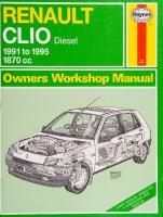
Haynes Renault Clio 1991 to May 1998 Service and Repair Manual [1853] 1859604595, 9781859604595
Renault Clio Petrol: 1991 to May 1998: models covered: Renault Clio petrol engine models, including 16-valve (except Wil
138 39
English Pages 404 Year 1999
Recommend Papers


![Haynes Renault Clio 1991 to May 1998 Service and Repair Manual [1853]
1859604595, 9781859604595](https://ebin.pub/img/200x200/haynes-renault-clio-1991-to-may-1998-service-and-repair-manual-1853-1859604595-9781859604595.jpg)
- Author / Uploaded
- Matthew Minter
- Steve Rendle
- Similar Topics
- Technique
- Transportation: Cars, motorcycles
File loading please wait...
Citation preview
E : i k a B O I L C 1991 to May 1998 (Hie R registration Petrol
ae Includes
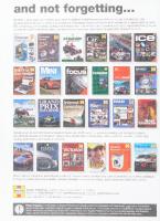
=o) Whatever your area of interest, laynes have got it covered...
VW
RCP RAL ea
Washing a | Machine Manual @eaWielgibiclias
od
|
g
Golf
and Jetta
From Car Service and Repair Manuals covering 95% of cars on the roads today, to TechBooks and Restoration Manuals... ..Service and Repair Manuals for motorcycles ranging from Superbikes to Scooters and Motorcycle TechBooks... ...books for cyclists feature The Bike Book and the Racing Bike Book... ..books for the home covering Washing Machine and appliance repairs and home decorating... ..books for travelling, including The Caravan Manual and the highly aoe CVH Engine | regarded Alan Rogers’ Good Camps Guide series and, last but not least, books for reading and enjoying... ..Motorsport biographies, Formula 1, Rallying, Motorcycling, Classic Cars, and much, much more...
ALBERTO ASCARI FERRARI'S FIRST DOUBLE CHAMPION
ssn
— a
Fromage emp Baki Miers
hs
——
—
~
Se
-
All the books featured on this page are available variously through motorcycle dealers, car accessory shops, cycle shops, mail order outlets and book stores. Our policy of continuous updating and development means that titles are being constantly added to the range. For up-to-date information on our complete list of titles, please telephone: UK (01963) 442030
France
(1) 47 7850 50
Sweden USA Australia
(4) 618-124016 (805) 498-6703 (613) 9763 8100
E-mail:
|[email protected]
Web site: Www.haynes.co.uk Haynes Publishing, Sparkford, Nr Yeovil, Somerset BA22 7JJ England
ae
ES oF!
Renault Clio
ervice and Repair Manual eo
Matthew Minter and Steve Rendle -Wlodels covered
Si:
(1853 - 400 -6AC2)
‘enault Clio petrol engine models, including 16-valve (except Williams models) and special/limited editions 1108 cc ohv, 1149 cc, 1171 cc, 1390 cc, 1783 cc & 1794 cc sohc and 1764 cc dohc petrol engines
Does not cover Diesel engine, “Williams” models or “Clio 2” range introduced in May 1998
;
|
_© Haynes Publishing
OOWNWOW 24
(624 2
1999
ABCDE
A book in the Haynes Service and Repair Manual Series
Printed in the USA
Haynes Publishing Sparkford, Nr Yeovil, Somerset BA22 7JJ, England
All rights reserved. No part of this book may be reproduced or transmitted in any form or by any means, electronic or mechanical, including photocopying, recording or by any information storage or retrieval system,
Haynes North America, Inc
861 Lawrence Drive, Newbury Park, California 91320, USA
without permission in writing from the copyright holder.
Editions Haynes S.A. Tour Aurore - IBC, 18 Place des Reflets,
ISBN 1 85960 459 5
92975 Paris La Défense 2, Cedex, France
British Library Cataloguing in Publication Data
AYR
ee
P
Haynes Publishing Nordiska AB
A catalogue record for this book is available from .
é
—
Cane
7s plelis é|
adit aLae
“A
*
,
0041404394
’
r
'
>rige
Contents LIVING WITH YOUR
RENAULT
CLIO
4
Introduction to the Renault Clio
Page
094
Safety first!
Page
O*5
If your car won’t start
Page
0*6
Jump starting
Page
007
Wheel changing
Page
08
Towing
Page
099
Identifying leaks
Page
0e10
/
Introduction
Page
O11
)
Underbonnet check points
Page
0911
Roadside Repairs
Weekly Checks Engine oil level
Page
0¢12
Coolant level
Page
0913
Brake fluid level
Page
0913
Power steering fluid level
Page
0914
Tyre condition and pressure
Page
0e15
Battery
Page
0°16
Wiper blades
Page
0°16
Electrical systems
Page
0e*17
Screen washer fluid level
Page
0°17
Lubricants, fluids and tyre pressures
Page 0018
MAINTENANCE Routine maintenance and servicing “Phase 1” and “Phase 2” models (models up to April 1996)
Page
1Ae1
Servicing specifications
Page
1Ae2
Maintenance schedule
Page
1A*4
Page
1A°7
Page
1Be1
Maintenance procedures
.
“Phase 3” models (models from May 1996)
Servicing specifications Maintenance schedule Maintenance procedures
:
Page 1Be2 ESE
CRS
-{5° Vig, ek ts Ana Seal ean Page
1Be7
Contents REPAIRS AND OVERHAUL Engine and Associated Systems 1108 cc (C-type) engine in-car repair procedures
Page
1149 cc (D-type) engine in-car repair procedures
Page
2Be1
1171 cc and 1390 cc (E-type) engine in-car repair procedures
Page
2Ce1
1764 cc, 1783 cc and 1794 cc (F-type) engine in-car repair procedures
Page
2De1
Engine removal and overhaul procedures
Page
2Ee1
Cooling, heating and air conditioning systems
Page
3e1
Fuel and exhaust systems — carburettor models
2Ae1
Page
4Ae1
. Fuel and exhaust systems - single-point fuel injection models
Page
4Be1
Fuel and exhaust systems — multi-point fuel injection models
Page
4Ce1
Emission control systems
Page
4De1
Starting and charging systems
Page
5Ae1
Transistor-assisted contact breaker ignition system (C-type engines)
Page
5Be1
Electronic ignition system
Page
5Ce1
Transmission Clutch
Page
61
Manual gearbox
Page
7Ae1
Automatic transmission
Page
7Be1
Driveshafts
Page
8e1
Page
9e1
Page
11¢1
Brakes and suspension Braking system
.
Body equipment Bodywork, trim and fittings
Bees secessionist 1... chine diab Ogun celha cepa Daten Wiring diagrams
Page 12°22
BEEERENCE
Page
REFe1
Conversion factors
Page
REFe2
General repair procedures Buying spare parts
Page Page
REFe3 REFe4
Vehicle and Engine identification
Page
REFe4
Jacking and Vehicle Support
Page
REFe6
Disconnecting the battery
Page
REFe7
Tools and working facilities
Page
REFe8
MOT test checks
Page REFe10
Fault finding
Page REFe14
Glossary of technical terms
Page REFe22
Index
Page REF*27
oe4 INtroduction The Renault Clio range covered by this manual was first introduced in France in May 1990, and to the UK in March 1991, to replace the popular Renault 5 range of cars. This manual covers models fitted with petrol engines, but other models in the range were available with Diesel engines. The Clio range was produced with 1.1, 1.2, 1.4, 1.7, and 1.8 litre single overhead camshaft (SOHC) types, and a 1.8 litre double overhead camshaft (DOHC) type, which is fitted to the performance-
orientated 16-valve model. Apart from the 1.1 litre unit, all of the engines available in the UK used fuel-injection, although carburettor engines were available in other markets. All the engines are of a well-proven design and, provided regular maintenance is carried out, are unlikely to give trouble. The Clio was available in 3- and 5-door Hatchback and 3-door Van
Fully-independent front suspension is fitted, with the components
attached to a subframe assembly, and the rear suspension is semiindependent, with trailing arms and torsion bars. Four- and five-speed manual gearboxes, and three- and four-speed automatic transmissions were available, although the three-speed automatic transmission was not available in the UK. The four-speed automatic transmission is electronically-controlled. A wide range of standard and optional equipment is available within the Clio range to suit most tastes, including an anti-lock braking system and driver’s airbag. The Clio is conventional in design, and the DIY mechanic should find most servicing work straightforward.
body styles, with a wide range of fittings and interior trim depending on the model specification. The range underwent a minor cosmetic facelift in March 1994, and these revised models are known as “Phase 2” models. The range underwent a more extensive facelift in May 1996 (“Phase 3”), when a number of mechanical improvements were made.
Renault Clio 16V
Your Renault Clio Manual Renault Clio 1.4 RT
The Renault Clio Team Haynes manuals are produced by dedicated and enthusiastic people working in close co-operation. The team responsible for the creation of this book included:
Authors
Matthew Minter Steve Rendle
Sub-editor Editor & Page Make-up Workshop manager
| Photo Scans Cover illustration & Line Art
Wiring diagrams
Sophie Yar
Steve Churchill Paul Buckland Steve Tanswell John Martin
Roger Healing Matthew Marke
We hope the book will help you to get the maximum enjoyment from your car. By carrying out routine maintenance as described you will ensure your car’s reliability and preserve its resale value.
The aim of this manual is to help you get the best value from your vehicle. It can do so in several ways. It can help you decide what work must be done (even should you choose to get it done by a garage), provide information on routine maintenance and servicing, and give a logical course of action and diagnosis when random faults occur. However, it is hoped that you will use the manual by tackling the work yourself. On simpler jobs, it may even be quicker than booking the car into a garage and going there twice, to leave and collect it. Perhaps most important, a lot of money can be saved by avoiding the costs a garage must charge to cover its labour and overheads. The manual has drawings and descriptions to show the function of the various components, so that their layout can be understood. Then the tasks are described and photographed in a clear step-by-step
sequence. References to the ‘left’ or ‘right’ are in the sense of a person in the driver's seat, facing forward.
Acknowledgements Thanks are due to Champion Spark Plug who supplied the illustrations showing spark plug conditions. Certain other illustrations are the copyright of Renault (UK) Limited, and are used with their permission. Thanks are also due to Draper Tools Limited, who provided some of the workshop tools, to John and Sally Brooks for the use of their car, and to all those people at Sparkford who helped in the production of this manual. Technical authors who contributed to this project include Andy Legg and Mark Coombs. We take great pride in the accuracy of information given in this manual, but vehicle manufacturers make alterations and design changes during the production run of a particular vehicle of which they do not inform us. No liability can be accepted by the authors or publishers for loss, damage or injury caused by any errors in, or omissions from, the information given.
Safety first! os Working on your car can be dangerous. This page shows just some of the potential risks and hazards, with the aim of creating a safety-conscious attitude.
General hazards Scalding
;
¢ Don’t remove the radiator or expansion tank cap while the engine is hot. ¢ Engine oil, automatic transmission fluid or power steering fluid may also be dangerously hot if the engine has recently been running.
Burning ¢ Beware of burns from the exhaust system and from any part of the engine. Brake discs and drums can also be extremely hot immediately after use.
Crushing»
e Mains voltage is also dangerous. Make sure that any mains-operated equipment is correctly earthed. Mains power points should be protected by a residual current device
(RCD) circuit breaker.
Fume or gas intoxication ° Exhaust fumes are poisonous; they often contain carbon monoxide, which is rapidly fatal if inhaled. Never run the engine ina confined space such as a garage with the doors shut. e Fuel vapour is also poisonous, as are the vapours from some cleaning solvents and paint thinners.
Poisonous or irritant substances
e When working under or near a raised vehicle, always ' supplement the
under a car which is only supported by a jack. ® Take care if loosening or tightening hightorque nuts when the vehicle is on stands. Initial loosening and final tightening should be done with the wheels on the ground.
e Avoid skin contact with battery acid and with any fuel, fluid or lubricant, especially antifreeze, brake hydraulic fluid and Diesel fuel. Don’t syphon them by mouth. If such a substance is swallowed or gets into the eyes, seek medical advice. e Prolonged contact with used engine oil can cause skin cancer. Wear gloves or use a barrier cream if necessary. Change out of oilsoaked clothes and do not keep oily rags in your pocket. e Air conditioning refrigerant forms a poisonous gas if exposed to a naked flame (including a cigarette). It can also cause skin burns on contact.
Fire
Asbestos
¢ Fuel is highly flammable; fuel vapour is explosive. * Don’t let fuel spill onto a hot engine. © Do not smoke or allow naked lights (including pilot lights) anywhere near a vehicle being worked on. Also beware of creating sparks (electrically or by use of tools). e Fuel vapour is heavier than air, so don’t
e Asbestos dust can cause cancer if inhaled or swallowed. Asbestos may be found in gaskets and in brake and clutch linings. When dealing with such components it is safest to assume that they contain asbestos.
jack with axle
lf
stands, or use drive-on
- ramps. Never
((
venture
work on the fuel system with the vehicle over an inspection pit. oe e Another cause of fire is an electrical =. overload or short-circuit. Take care when-,,.. repairing or modifying the vehicle wiring. © Keep a fire extinguisher handy, of a type suitable for use on fuel and electrical fires.
Electric shock Ignition HT voltage can be
to a
dangerous,
especially to: Reale people withheartt 7 problems or a oe pacemaker. Don’t ~*~ work on or near the ignition system with the engine running or the ignition switched on.
Mato
Special hazards Hydrofluoric acid ¢ This extremely corrosive acid is formed when certain types of synthetic rubber, found in some O-rings, oil seals, fuel hoses etc, are exposed to temperatures above 400°C. The rubber changes into a charred or sticky substance containing the acid. Once formed, the acid remains dangerous for years. If it gets onto the skin, it may be necessary to amputate the limb concerned. ¢ When dealing with a vehicle which has suffered a fire, or with components salvaged from such a vehicle, wear protective gloves and discard them after use.
The battery e Batteries contain sulphuric acid, which attacks clothing, eyes and skin. Take care when topping-up or carrying the battery. e The hydrogen gas given off by the battery is highly explosive. Never cause a spark or allow a naked light nearby. Be careful when connecting and disconnecting battery chargers or jump leads.
Air bags e Air bags can cause injury if they go off accidentally. Take care when removing the steering wheel and/or facia. Special storage instructions may apply.
Diesel injection equipment * Diesel injection pumps supply fuel at very high pressure. Take care when working on the fuel injectors and fuel pipes. Warning: Never expose the hands, © face or any other part of the body to injector spray; the fuel can penetrate the skin with potentially fatal results,
Remember... i ate) ¢ Do use eye protection when using power tools, and when working under the vehicle.
e Do wear gloves or use barrier cream to protect your hands when necessary. e Do get someone to check periodically that all is well when working alone on the vehicle. ¢ Do keep loose clothing and long hair well out of the way of moving mechanical parts. e Do remove rings, wristwatch etc, before working on the vehicle — especially the
electrical system. © Do ensure that any lifting or jacking | equipment has a safe working load rating adequate for the job.
DON’T ¢ Don’t attempt to lift a heavy component which may be beyond your capability — get assistance.
¢ Don’t rush to finish a job, or take unverified short cuts.
¢ Don’t use ill-fitting tools which may slip and cause injury.
* Don’t leave tools or parts lying around where someone can trip over them. Mop up oil and fuel spills at once. ¢ Don't allow children or pets to play in or near a vehicle being worked on.
oe Roadside repairs
e
The following pages are intended to help in dealing with common roadside emergencies and breakdowns. You will find more detailed fault finding information at the back of the manual, and repair information in the main chapters.
If your car won’t,] start and the starter motor doesn’tb] turn
If your car won'tJ start even though the starter motor turns as normal
If it's a model with automatic transmission, make sure the selector is in ‘P’ or ‘N’. [|] Open the bonnet and make sure that the battery terminals are clean and tight. L] Switch on the headlights and try to start the engine. If the headlights go very dim when you're trying to start, the battery is probably flat. Get out of trouble by jump starting (see next page) using a friend’s car.
L] Is there fuel in the tank? (] Is there moisture on electrical components under the bonnet? Switch off the ignition, then wipe off any obvious dampness with a dry cloth. Spray a water-repellent aerosol product (WD-40 or equivalent) on ignition and fuel system electrical connectors like those shown in the photos. Pay special attention to the ignition coil wiring connector and HT leads.
e
Check the condition and security of the battery connections. ~
ha
Check that the spark plug HT leads are securely connected by pushing them onto the ignition coil or DIS module (as applicable).
Check that the ignition coil or DIS module (as applicable) wiring plug is secure.
D Check that the fuel injector wiring harness connector is secure (fuel injection models).
nod
Check that electrical connections are secure (with the ignition switched off) and spray them with a water dispersant spray like WD40 if you suspect a problem due to damp :
Check that the fuel cut-off switch has not been activated (fuel injection models).
ee
Roadside repairs o-7 (BROT
Jump starting
Jump starting will get you out of trouble, but you must correct |
whatever made the batterygo
|
When jump-starting a car using a
flat in the first place. There are
three possibilities: : | mf The battery has been drained by repeated attempts to start, or by leaving the lights on.
@¥
eee
:
e
4
precautions:
one in the vehicle.
Before connecting the booster battery, make sure that the ignitionis switched off.
tie
The charging system is not working 5
v
wv
each other.
¥Y Take note of any special precautions printed on the battery case.
(electrolyte low, or battery worn out).
Connect one end of the red jump lead to the positive (+) terminal of the flat battery (remove the plastic sleeve from the battery post)
2
Ifthe battery is being jump-started from the battery in another vehicle, the two vehicles MUST NOT TOUCH
Ensure that all electrical equipment (lights, heater, wipers, etc) is switched off. ¥
| @Q The battery itself is at fault |
Make sure that the booster battery is the same voltage as the discharged
¥
| &= properly (alternator drivebelt stack _or broken, alternator wiring fault or alternator itself faulty).
v
booster battery, observe the following
Connect the other end of the red lead to the positive (+) terminal of the booster battery.
3
-Make sure that the transmission is in neutral (or PARK, in the case of automatic transmission).
Le
west
Connect one end of the black jump lead to the negative (-) terminal of the booster battery
I I t I al
pa
4 i I
Connect the other end of the black jump lead to a bracket on the cylinder head on the vehicle to be started
Make sure that the jump leads will not come into contact with the fan, drivebelts or other moving parts of the engine.
ee ee ee ee
A Engine oil level dipstick 8B Engine oil filler cap
C Coolant expansion tank D Brake fluid reservoir ‘E Washer fluid reservoir F
Power steering fluid reservoir
G Battery
FSP (1794 cc) p> multi-point fuel injection engine A Engine oil level dipstick
B Engine oil filler cap
C Coolant expansion tank D Brake fluid reservoir
E Washer fluid reservoir
F Power-steering fluid reservoir G Battery
Refer to “Engine identification” on page REFe4 for details of engine identification.
o12 Weekly checks Underbonnet check points Note: Refer to “Engine identification” on page REFe4 for details of engine identification.
F7P
>
fi
(16-valve) engine Engine oil level dipstick Engine oil filler cap Coolant expansion tank
Brake fluid reservoir Washer fluid reservoir Power steering fluid reservoir
Battery Py Qo7m7nmoogDd
Engine oil level Before you start V Make sure that your car is on level ground. v¥ Check the oil level before the car is driven, or at least 5 minutes after the engine has been switched off. If the oil is checked immediately after driving the vehicle, some of the oil will remain in the upper engine
pan poaents: resulting in an inaccurate | reading on the dipstick!
The correct oil
The aipsieic|is located at the Font of ee engine (see “Underbonnet Check Points” on pages 0°11 and O12 for exact location). Withdraw the dipstick.
Using a clean rag or paper towel, wipe all ’ the oil from the dipstick. Insert the clean dipstick into the tube as far as it will go, then withdraw it again.
Note the oil level on the end of the dipstick, which should be between the upper (“MAX”) mark and the lower
4 Oil is added through the filler cap. Unscrew the filler cap, then top-up the level. A funnel may help to reduce
Madern engines place great demands on their oil. It is very important that the correct oil for your car is used (See “Lubricants and Fluids” on page 0°78).
Car Care @ If you have to add oil frequently, you should check whether you have any oil leaks. Place some clean paper under the car overnight, and check for stains in the morning. If there are no leaks, the engine may be burning oil (see “Fault Finding”).
@ Always maintain the level between the upper and lower dipstick marks (see photo 3). If the level is too low severe engine damage may occur. Oil seal failure may result if the engine is overfilled by adding too much oil.
(“MIN”) mark.
spillage. Add the oil slowly, checking the level
on the dipstick often. Don’t overfill.
Weekly checks 0613 Coolant level
rN
Warning: remove pressure is hot, as
DO NOT attempt to . the expansion tank cap when the engine there is a very great
risk of scalding. Do not leave open containers of coolant about, as it is poisonous.
Car Care @ With a sealed-type cooling system, adding coolant should not be necessary on a regular basis. lf frequent topping-up is required, it is likely there is a leak. Check the radiator, all hoses and joint faces for signs of staining or wetness, and rectify as necessary. @ It is important that antifreeze is used in the cooling system all year round, not just during the winter months. Don’t top-up with water alone, aS the antifreeze will become too diluted.
The coolant level varies with the temperature of the engine. The level should be checked in the expansion tank, which is located at the left-hand rear corner of the engine compartment. The expansion tank has “MAXI” and “MINI” level markings. When the engine is cold, the level should be between the two marks. When the engine is hot, the level may rise slightly above the “MAXI” mark.
If Geoie up is necessary, wat until the engine is cold. Slowly unscrew and remove the expansion tank cap to release any pressure in the system. Add a mixture of water and antifreeze to the expansion tank, until the coolant is up to the “MAX” mark. Refit the cap, turning it clockwise. as far as it will go until it is secure. Re-check that the cap is securely tightened once the engine is warm.
The “MAX” and “MIN” marks are indicated on the side of the reservoir, which is located at the right-hand rear corner of the engine compartment. The fluid level must be kept between these two marks (make sure that the car is parked on level ground when making the check).
If topping-up is necessary, first wipe the area around the filler cap with a clean rag, then hold the fluid level sensor wiring plug as the cap is unscrewed. When adding fluid, it’s a good idea to inspect the reservoir. The system should be drained and refilled if dirt is seen in the fluid (see Chapter 9 for details).
Carefully add fluid, avoiding spilling it on surrounding paintwork. Use only the specified hydraulic fluid; mixing different types of fluid can cause damage to the system and/or a loss of braking effectiveness. Bear in mind that the level in the reservoir will rise slightly when the cap/float assembly is refitted. After filling to the correct level, refit the cap securely. Wipe off any spilt fluid.
When checking the fluid level it is a good idea to check the operation of the low fluid level warning light. Switch on the ignition
2
Brake fluid level ‘
Warning: ® Brake fluid can harm your eyes and damage _ painted surfaces, so use _ extreme caution. when handling and pouring it. @ Do not use fluid that has been standing open for some time, as it absorbs moisture from the air, which can cause a dangerous loss of braking effectiveness.
HAYNES
HINT,
Make sure that your car is on level ground.
¢ The
fluid
level in the
reservoir will drop slightly as the brake pads wear down, but the fluid level must never be allowed z drop below the “MIN” mark.
Before you start @ Cleanliness is of great importance when dealing with the braking system, so take care to clean around the reservoir cap before topping-up. Use only clean brake fluid.
Safety First! @ If the reservoir requires repeated toppingup this is an indication of a fluid leak somewhere in the system, which should be investigated immediately. @ If a leak is suspected, the car should not be driven until the braking system has been checked. Never take any risks where brakes are concerned. 4s
and ask an assistant to press the test button on top of the brake fluid reservoir cap. When the button is pressed, the brake fluid level/ handbrake “on” warning light should come on if not, the level switch, wiring or bulb may be faulty. If the warning light comes on and the fluid level is not low, check that the handbrake
is not on. Switch off the ignition after testing.
o14 Weekly checks Power steering fluid level Before you start: V Park the vehicle on level ground. v Set the steering wheel straight-ahead. V The engine should be turned off.
MyWaNiacsy
HINT
For
the
check
to
be
accurate, the steering must not be turned once the
engine has been stopped.
Safety First! @ The need for frequent topping-up indicates a leak, which should be_ investigated immediately.
Wee steering fluid reservoir varies from model to model. a) On E-type engine models not equipped with air conditioning, the reservoir is an integral part of the pump assembly, and is mounted on the front right-hand corner of the cylinder head. b) On F3P engine models equipped with air conditioning, the reservoir is an integral part of the electric pump assembly, and is
On E-type engine models not equipped with air conditioning, wipe the area around the reservoir filler cap, then unscrew the cap and withdraw it from the fluid reservoir. Wipe the dipstick clean, then insert it into the reservoir and withdraw it and check the fluid level. The fluid should be between the marks (“A” and “B”) on the dipstick. If not, top-up to the higher mark using the specified
type of fluid, then refit the reservoir cap, tightening it securely.
situated by the side of the battery. c) On all other models, the reservoir is either circular in shape and situated at the front of the engine compartment, or is rectangular in shape and is mounted on the right-hand side of the engine compartment, just in front of the suspension turret.
On models equipped with an electric power steering pump, or with the circular reservoir which is mounted in the righthand corner of the engine compartment, the fluid level is visible through the translucent material of the reservoir. The level should be between the “MAX” and “MIN” level lines cast on the side of the reservoir. If necessary, wipe the area around the reservoir cap clean, then
remove the cap and top-up to the “MAX” mark using the specified type of fluid.
On models equipped with the rectangular fluid reservoir, wipe the area around the cap clean, then unscrew the cap. The fluid level indicator is in the form of a block fixed to the centre of the filler neck filter. The fluid level should be between the upper (“A”) and lower (“B”) edges of the block. If not, topup to the upper edge of the indicator block using the specified type of fluid, then refit the reservoir cap, tightening it securely.
On all models, take great care not to allow any dirt or foreign matter to enter the hydraulic system, and do not overfill the reservoir. When the level is correct, refit the cap. Note that the need for frequent topping-up of the system indicates a leak, which should be investigated immediately.
_—
Weekly checks oe«15
Tyre condition and pressure It is very important that tyres are in good condition, and at the correct pressure - having a tyre failure at any speed is highly dangerous. Tyre wear is influenced by driving style - harsh braking and acceleration, or fast cornering, will all produce more rapid tyre wear. As a general rule, the front tyres wear out faster than the rears. Interchanging the tyres from front to rear ("rotating" the tyres) may result in more even wear. However, if this is completely effective, you may have the expense of replacing all four tyres at once! Remove any nails or stones embedded in the tread before they penetrate the tyre to cause deflation. If removal of a nail does reveal that
a
SK
BO ede
aoe
Me
the tyre has been punctured, refit the nail so that its point of penetration is marked. Then immediately change the wheel, and have the tyre repaired by a tyre dealer. Regularly check the tyres for damage in the form of cuts or bulges, especially in the sidewalls.
Periodically remove
the wheels,
and clean any dirt or mud from the inside and outside surfaces. Examine the wheel rims for signs of rusting, corrosion or other damage. Light alloy wheels are easily damaged by "kerbing" whilst parking; steel wheels may also become dented or buckled. A new wheel is very often the only way to overcome severe damage.
New tyres should be balanced when they are fitted, but it may become necessary to rebalance them as they wear, or if the balance weights fitted to the wheel rim should fall off. Unbalanced tyres will wear more quickly, as will the steering and suspension components. Wheel imbalance is normally signified by vibration, particularly at a certain speed (typically around 50 mph). If this vibration is felt only through the steering, then it is likely that just the front wheels need balancing. If, however, the vibration is felt through the whole car, the rear wheels could be out of balance. Wheel balancing should be carried out by a tyre dealer or garage.
ce
Tread Depth - visual check The original tyres have tread wear safety bands (B), which will appear when the tread depth reaches approximately 1.6 mm. The band positions are indicated by a triangular
Tread Depth - manual check Alternatively, tread wear can be monitored with a simple, inexpensive device known as a tread depth indicator gauge.
3 Tyre Pressure Check Check the tyres pressures been used,
the tyre pressures regularly with cold. Do not adjust the tyre immediately after the vehicle has or an inaccurate setting will result.
Tyre pressures are shown on page 0°18.
mark on the tyre sidewall (A).
Tyre tread wear patterns
Shoulder Wear
Centre Wear
Uneven Wear
Underinflation (wear on both sides) Under-inflation will cause overheating of the tyre, because the tyre will flex too much, and the tread will not sit correctly on the road ‘surface. This will cause a loss of grip and excessive wear, not to mention the danger of sudden tyre failure due to heat build-up. Check and adjust pressures incorrect wheel camber (wear on one side) Repair or renew suspension parts Hard cornering Reduce speed!
Overinflation Over-inflation will cause rapid wear of the centre part of the tyre tread, coupled with reduced grip, harsher ride, and the danger of shock damage occurring in the tyre casing. Check and adjust pressures
Front tyres may wear unevenly as a result of wheel misalignment. Most tyre dealers and garages can check and adjust the wheel alignment (or "tracking") for a modest charge. Incorrect camber or castor Repair or renew suspension parts Malfunctioning suspension Repair or renew suspension parts Unbalanced wheel Balance tyres
If you sometimes have to inflate your car’s tyres to the higher pressures specified for maximum load or sustained high speed, don’t forget to reduce the pressures to normal afterwards.
Incorrect toe setting
Adjust front wheel alignment Note: The feathered edge of the tread which typifies toe wear is best checked by feel.
o16 Weekly checks
Battery Caution: Before carrying out any work on the vehicle battery, read the precautions given in "Safety first" at the start of this manual. V Make sure that the battery tray is in good condition, and that the clamp is tight. Corrosion on the tray, retaining clamp and the
battery itself can be removed with a solution of water and baking soda. Thoroughly rinse all cleaned areas with water. Any metal parts damaged by corrosion should be covered with a zinc-based primer, then painted. V Periodically (approximately every three months), check the charge condition of the battery as described in Chapter 5A. v If the battery is flat, and you need to jump start your vehicle, see Roadside Repairs.
e
=
a layer of clamps and
| terminals after they are reconnected.
cracked case or cover.
Check the tightness of the battery cable clamps to ensure good electrical connections. You should not be able to move them. Also check each cable for cracks and frayed conductors.
See
| Battery corrosion can be kept to a | minimum by appiying | petroleum jelly to the
side of the engine compartment. The exterior of the battery should be inspected periodically for damage such as a
If corrosion
(white, fluffy deposits)
is
4
... as well as the battery cable clamps
evident, remove the cables from the battery terminals, clean them with a small wire brush, then refit them. Automotive stores
sell a tool for cleaning the battery post...
Wiper blades
Check the condition of the wiper blades;
if they are cracked or show any signs of deterioration, or if the glass swept area is smeared, renew them. For maximum clarity of vision, wiper blades should be renewed annually, as a matter of course.
To remove a windscreen wiper blade, pull the arm fully away from the screen until it
locks. Swivel the blade through 90°, then depress the locking clipat the base of the mounting block, and slide the blade out of the hooked end of the arm. Where applicable, ‘don’t forget to check the tailgate wiper blade as well. The blade can be removed by swivelling the blade through 90°, then pulling the blade from the arm.
Weekly Checks 0017
Electrical systems © ¥ Check all external lights and the horn. Refer to the appropriate Sections of Chapter 12 for details if any of the circuits are found to be inoperative. ‘ : ¥ Visually check all accessible wiring connectors, harnesses and retaining clips for security, and for signs of chafing or damage.
My \WaAiscn
/f you need to check your brake lights and indicators
unaided, back up to a wall or garage door and operate the lights. The reflected light should show if | they are working properly.
1
If a single indicator light, brake light or headlight has failed, it is likely that a bulb has blown and will need to be replaced.
Refer to Chapter 12 for details. If both brake lights have failed, it is possible that the brake light switch operated by the brake pedal has failed. Refer to Chapter 9 for details.
If more than one indicator light or headlight has failed, it is likely that either a fuse has blown or that there is a fault in the circuit (see “Electrical fault finding” in Chapter 12). The main fuses are in the fusebox under the passenger's side of the facia. For access to the fuses, press the two plastic securing tabs, then lower the fusebox panel from the facia. The circuits protected by the fuses are marked on a sticker at the bottom of the fusebox panel.
.
Additional auxiliary
fuses fusebox
are
located
under
the
in an bonnet,
beneath the hinged flap in the windscreen cowl panel on the left-hand side. For access to these fuses, lift the cowl panel flap, then unclip the cover from the fusebox. The circuits protected by the fuses are marked on the inside of the panel cover. The fuse for the radio/cassette player is mounted on the rear of the unit
To replace a blown fuse, remove it, where applicable, using the plastic tool provided. Fit a new fuse of the same rating, available from car accessory shops. It is important that you find the reason that the fuse blew (see “Electrical fault finding” in Chapter 12).
Screen washer
fluid level Screenwash additives not only keep the winscreen clean during foul weather, they also prevent the washer system freezing in cold weather - which is when you are likely to need it most. Don’t top up using plain water as the screenwash will become too diluted, and will
freeze during cold weather. On no account use coolant antifreeze in the washer system this could discolour or damage paintwork.
The windscreen/tailgate/headlight washer fluid reservoir is located under the lefthand access hatch in the windscreen
cowl panel at the rear of the engine compart-ment. If topping-up is necessary, open the hatch, then remove the cap from the reservoir.
When topping-up the reservoir a screenwash additive should be added in the quantities recommended on the bottle.
ois Lubricants, fluids and tyre pressures Lubricants and fluids
Rasnitial GOAarbOX: 6 «6 5 kale x o's be Ns HRS eee ae Automatic transmission Note final Grive cei5-ciie ysis ialtscoolcay ee eaepst Rireae ete eran tse etaata
Multigrade engine oil, viscosity 15W/40 to 15W/50, to ACEA A2/A3 (Duckhams QXR Premium Petrol Engine Oil, or Duckhams Hypergrade Petrol Engine Oil) Tranself TRX 75W 80W Elf Renaultmatic D2, Dexron type ATF (Duckhams ATF Autotrans III) Tranself TRX 80W Elf Renaultmatic D2 or Mobil ATF 220 (Duckhams ATF Autotrans III) Ethylene-glycol based antifreeze (AL Glaecol type C coolant) (Duckhams Antifreeze and Summer Coolant) Hydraulic fluid to SAE J1703, DOT 3 or DOT 4 (Duckhams Universal Brake and Clutch Fluid)
Choosing your engine oil Engines need oil, not only to lubricate moving parts and minimise wear, but also to maximise power output and to improve fuel economy.
+¢ Cleaning the engine internally
By introducing a simplified and improved range of engine oils, Duckhams has taken away the confusion and made it easier for you to choose the right oil for your engine.
HOW ENGINE OIL WORKS ¢ Beating friction Without oil, the moving surfaces inside your engine will rub together, heat up and melt, quickly causing the engine to seize. Engine oil creates a film which separates these moving parts, preventing wear and heat build-up.
¢ Cooling hot-spots Temperatures inside the engine can exceed 1000° C. The engine oil circulates and acts as a coolant, transferring heat from the hot-spots to the sump.
Good quality engine oils clean the inside of your engine, collecting and dispersing combustion deposits and controlling them until they are trapped by the oil filter or flushed out at oil change.
OIL CARE - FOLLOW THE CODE To handle and dispose of used engine oil safely, always: e Avoid skin contact with used engine oil. Repeated or prolonged contact can be harmful. e Dispose of used oil and_empty packs in a responsible manner in an authorised disposal site. Call 0800 663366 to find OL, saw et Lime 0800 66 33 66 the one nearest to you. Never tip oil down drains or onto the ground.
DUCKHAMS ENGINE OILS For the driver who demands a premium quality oil for complete reassurance, we
recommend synthetic formula Duckhania’ QXR Premium Engine Oils. : For the driver who requires a salad forward quality engine. oil, we recommend Duckhams Hypergrade Engine Ome: i,
af For further information and advice, calltha’ Duckhams UK Helpline on 0800 212988. — Ey
Tyre pressures (cold) Note: Pressures given here are a guide only, and apply to original-equipment tyres - the recommended pressures may vary if any other make or
type of tyre is fitted; check with the vehicle handbook, or the tyre manufacturer or supplier for latest recommendations.
Front* 145/70 R 13S tyres 155/70 R 13S and 165/65 R 13T tyres.... 145/80 R 13S and 155/80 R 13T tyres....
165/60 R 14H tyres
185/60 R 14V and 185/55 R15Vtyres....
2.4 2.1 2.1 2.3 2.2
bars bars bars bars bars
“For models equipped with automatic transmission, add 0.1 bar (1.5 Ibf/in2)
(35 (30 (30 (33 (32
Ibf/in2) Ibf/in2) Ibf/in2) Ibf/in2) Ibf/in2)
Rear 2.4 bars (35 Ibf/in2) 2.3 2.1 2.3 2.2
bars bars bars bars
(33 (30 (33 (32
Ibf/in?) Ibf/in?) Ibf/in2) Ibf/in2)
,
1Ae1
Chapter 1 Part A: Routine maintenance and servicing — “Phase 1” and “Phase 2” models (up to April 1996) Contents Air cleaner air temperature control system check (carburettor and single-point fuel injection engines) ...........6. 0.0. eeee eee 25 Aloiitenclementrenewal Us cca apes 0 tees etree wate, Deets 21 Automatic transmission fluid and filter renewal ................-. 27 Automatic transmission fluid level check ...........00000000ee 4
AUXaL VicuIVEbeltiChecktarntittase ct nee a foe Se eee ae cen ee 6 Bodywork and underbody condition check ..........0...00000 15: ExaleriCMCl ROMOWell intinks mews aysysiel pipette sac wale RiGee eessea wea’ a eee 30 PEC EM ODErAtOM GHECK Uses s cice sc saan cise lans « bia male eid cleats 11 Contact breaker points check (C-type engine) ................. 9 Momlaainene Wallies cicta sre irsusitage ois che cations cesiern ie Mabus.cnlacoi'eVenal a 36 PINE tient etl ChOG Kase aistetaryn atelitizis,c fewisicce osc a lenwt noe 18 PENCE OM aNCRALOT MEM OWALerceayn mjeareos Planarlacsoern alecssye's foeare Blsaaes 3 ExTausHovsreniiGnoGK mines sie cinco cfnm s cues cine Muskie tee eyes wets 12 Renee itesARCHIE Kale iste eee Pe play cet cirogte feialoicay Sriiteka shdoce, u Riestene oe tay BE) Front brake pad and disc check ........ (shia s ei eee Beate fess PLOutawiOeranGnim lent CMEC sci,2 sua oe, sisualsyasshtgg yeelse a,c 0 ee lesege aes 31
BECO toMreMeWalien
tshitei cits cee co sudeetak sat gise ares «4 aseauees 26
reapercunt litynct tl mace meccen Coe cinta
Easy, suitable for novice with little experience
Handbrake adjustment Check. = 32. . smc a1 aan tetera eee 29 Headlight beam alignment check ...........0c00eec cess eeees 16 Heating and air conditioning system check ..............+.05- 20 Rings and lock lubrication.:. ...4% 2. 2.5 Saar eee en 33 HT lead, distributor cap and rotor arm check................4-. 23 Idle'speed:and-mixture check’ .... «./2.< 06 os « Semele eee 7 Ignition timing check (C-type engine) ..............0ee ee eee ee 10 Intensiveymaintenance: 2s. . cas. oo sl dane ee 2 Manuatigearbox oil level Check, «fo... 1. yas. 2 «115s Seen 34 Rear brake’pad and disc Check 4..... emesis 14 Rear brakeshoe and drumicheck .. ..... .. =. ssc wisshnaeeaee Ei 28 ROA OSE acu,gualSic.c.0 m7, 3 ORS RM pe crepe aTeee 2 Eee Si eee 24 Seat belt: GheGk gianni ema ys ccsom 2 syn ese ehe!607, Gears, 32 Spark: plug Check’ jsiccsiceee Pus oe atsiete ede we tanalel elnore) 8 Spark PUG MENSWaAl! ia idx Biuele dike, So acter wien vn ace 22 Steering and suspension component check ................0005 WA Timing belt renewal wae casaies ott adie aia. e cine ntak a eee eae 35 Wheel: bolttighiness checks 2. a.c cas 4.24.00» ayn orealee ae 19
Sie aise veinsvil atvie:e usta @ acne were 4
Fairly easy, suitable for beginner with some experience”
EN Fairly difficult, && | suitable for competent EN DIY mechanic
Difficult, suitable for
N
Very difficult,
s
or professional
®W | suitable for expert DIY
1ae2 Servicing specifications - “Phase 1” and “Phase 2” Note: Refer to “Engine identification” on page REFe4 for details of engine identification.
Lubricants and fluids Refer to “Weekly checks”
Capacities
Engine oil Excluding oil filter: GSetvpaeng ine sarwewiaarest waste, fodcececdew elie laecn gett aca!wp tava a altelhya Hee SCAN TSQO/GC tyNO SNGINGS a ints ele cia:sieiabeta wie are Vie remem
4
ESP :ehg lines rere ctv ries Gales ir poate ental, clr ureMeambenat antral aieteats F7P (16-valve) engine: Enginesavithisteelisump': & acstaca ihe tlsracays Same etya RM VOM Re Daneel ead EMgines: With alUrminilurry SuUniype siciisss sae) wsbrielielatieuatgy oy alte al'e tee Including oil filter: Alliengines‘except F7P (1G-valve)s. cc.8 Songun sianciearstatodee elas stele
ARATE-VAIVE)NONGING sinc secey ochaaa a iauane Coleg ea Rene
anit
Difference between “MAX” and “MIN” dipstick marks: By GN CAS at vatanswsea eect bre Ac cageGepooja wi ER i ee TE PSSEYIOG QNIGINOS Santas wisn areas sated acrelapMERTENS nae Sar mata aoe tbe rls Shale EelE elave|alcks weet enna aoe reer ies Opt en ts eer AS ep F7P (16-valve) engine: Engines fitted with blue marked dipstick ..............0--005 PIROIMORONGINGSS sachs test 3 oracace ce aiueese wararabuleaisteselaraters ogem ee
‘Cooling system (Sh aleke lela s[als weasel arena copy er ae eeprom mes ire oe IR eR a oy ee PERV IDO SOMME Stesraaeeslee oo aoa. sosta llc cos sales ethics aa egeat acinar osteoid Scmaetes PRR OIGHIOS rapes prciec ce Sumla ae oo ee saw ca a ela tasapetaeg Tbe FEEL GRVALVO)-GNGING: sisrericea e sevee > wlkyi 0! worele ibaa a aA ae owe Boel
3.0 litres 3.5 litres 4.7 litres 3.5 litres 4.2 litres 0.5 litre
0.2 litre 1.0 litre 1.5 litres 2.0 litres 1.1 litres 0.6 litre 5.4 5.2 6.4 7.0
litres litres litres litres
Fuel tank AUSINOGSIS OX Cept-
Savane nmiOdpIss
16-VAIVO: 3. 4". asset n comet earn ee ipece en aces Sep De
ee te oe
Se
ee
anes
Manual gearbox Four-speed: ESC) acces cites mes aree ent pe ate a GIN Weta ce oc misage ea paste menapa See ere we eee eaters ee Bosca) ge IE PAIS toe DEPT nae ep ns VTS ce Five-speed: cdf EPS ae | 16 eee mar ere pene Ro eer Sie ne ce ee Shr Ras ee A Rea Met ss EP an er ae a are gene RUSE
43 litres
50 litres
3.25 litres 2.75 litres 3.4 litres 2.9 litres
Automatic transmission Main section:
OLACA DECK Yer gays als,pospeass: imle ak iepeewee ena emeeee aie Seater: YZfarts Uae Bigo)1] SS Sgt errer eens aes ree eee FelbigeCiv GSCCL ON ry paseo mutes iia wrakeane a a Teaban satiyedacse areiaiy. =e xs"
5.7 litres 3.5 litres 1.0 litre
Power-assisted steering reservoir =-Modelsawithimechanical DuUMPater. sn ae ome eee aceis a cmed ets Models witheleetric: DUMP tats ase = sca s-car cunttuetaae tswcorstely Wiaawieng apalaloices
1.1 litres 0.7 litre
Engine Oil filter type: SALVO LONGING: veteran tO ae ae tee NEI celsantas) alate Sonora! ws EStVDeGHGINCS sai nants aie agen nin smear ina ake ene dary con Leta)PATSVa9 |UN)SKSseated ernie ee A ecto eaStESeet hag Sore) eae ar Ra ee ECEACLO-VAIVG)SLIGIMOS is coma -clacacaitecccin alors ope euesaimeatelsc¥eics: ayncaauanel aa
Champion Champion Champion Champion
F101 F103 F103 F120
Cooling system Antifreeze mixture: PEGLECUGR Ore aan Gee ra caeaknnpione Ricca n coe tear oatatine mete twimtavasne emsttrs ROLOCTIONS Oia 4 Ontatene
Sinkcssncrep oan a acitaca stance Sed ede Geet aren
clara
Antifreeze 35% 50%
Water 65% {
:
50%
-
Servicing specifications - “Phase 1” and “Phase 2” 4a03 Fuel system Air cleaner element type: CAPS ONOINGS SA ae Haier ee SANGOU Tale[piscaseaeny teehee Ne eee | encan On
Ee Ser gt ae OO SR rn
PAP ORGINGS eeniea ga «ley DES wa ee a a oR Nh Ean F7P:(16-valve) engine J< 7 Zoe ye haere ee cat Fuel filter element type: CaMDUrettor QNGIHOS:
Refitting
8
»
8 Refitting is a reversal of removal. Adjust the handbrake as'described in Chapter 1A or 1B. Note that on models with rear drum brakes, the cable is adjusted-before the brake drum is refitted.
22 Anti-lock braking system (ABS)- general information °
1 ABS is available as an option on certain Clio models. The purpose of the system is to
prevent wheel(s) locking during heavy braking. This is achieved by automatic release of the brake on the relevant wheel, followed by reapplication of the brake (see illustration).
21.2b ...and unscrew the stop-light switch (facia panel removed for clarity)
2 The main components of the system are four wheel sensors (one per wheel), and a modulator block which contains the ABS computer, the hydraulic solenoid valves and accumulators, and an _ electrically-driven return pump.
3 The solenoids are controlled by the computer, which receives signals from the wheel sensors. The sensors detect the speed of rotation of a toothed ring, known as a reluctor ring, attached to the wheel hub.
21 Stop-light switch‘removal, refitting
a
and adjustment
9¢19
HE i
Removal 1 The stop-light switch is located on the pedal bracket beneath the facia. 2 To remove the switch, reach up behind the ~ facia, disconnect the wiring connector and unscrew the switch from the bracket (see illustrations).
Refitting and adjustment 3 Screw the switch back into position in the mounting bracket.
4 Connect a continuity tester (ohmmeter or self-powered test light) across the switch terminals. Screw the switch in until an opencircuit is present between the switch terminals (infinite resistance, or light goes out). Gently depress the pedal and check that continuity exists between the switch terminals (zero resistance, or light comes on) after the pedal has travelled approximately 5 mm. If necessary, reposition the switch until it operates as specified. 5 In the absence of a continuity tester, the same adjustment can be made by reconnecting the switch and having an assistant observe the stop-lights (ignition on). 6 Once the stop-light switch is correctly adjusted, remake the original wiring connections, and recheck the operation of the stop-lights.
22.1 Layout of anti-lock braking system (ABS) components Modulator assembly Master cylinder and servo unit Wheel sensor Reluctor ring Load-sensitive pressureregulating valve
9°20
Braking system
|
| | | | H2bre¢
22.3 ABS system normal operation
1 Master cylinder 2 Solenoid valve
3 4
Brake caliper Wheel sensor and reluctor ring
5 ABS computer 6 Return pump
A_ Flow of electrical signal
7 Accumulator 8 Accumulator B
|
22.4 ABS system “pressure-maintain” phase
Refer to illustration 22.3 for keys
Flow of hydraulic fluid
Braking system
. ee
ts
os
9¢21
——
22.5 ABS system “pressure-decrease” phase
Refer to illustration 22.3 for keys By comparing the speed signals from the four wheels, the computer can determine when a wheel is decelerating at an abnormal rate, and can therefore predict when a wheel is about to lock. During normal operation, the system functions in the same way as a non-ABS braking system does (see illustration). 4 lf the computer senses that a wheel is about to lock, the ABS system enters the “oressure-maintain” phase (see illustration).
The computer operates the relevant solenoid valve in the modulator block; this isolates the
brake caliper on the wheel in question from the master cylinder, effectively sealing-in the
hydraulic pressure, 5 If the speed of rotation of the wheel continues to decrease at an abnormal rate, the ABS system then enters the “pressuredecrease” phase (see illustration). The return pump operates and pumps the hydraulic fluid back into the master cylinder, releasing pressure on the brake caliper. When the speed of rotation of the wheel returns to an acceptable rate, the pump stops and the solenoid valve opens, allowing hydraulic pressure to return to the caliper and reapply
the brake. This cycle can be carried out at up to 10 times a second. 6 The action of the solenoid valves and return pump Creates pulses in the hydraulic circuit. When the ABS system is functioning, these pulses can be felt through the brake pedal. 7 The solenoid valves connected to the front
calipers operate independently, but the valve connected to the rear calipers, together with the load-sensitive pressure-regulating valve, operates both calipers simultaneously. Since the braking circuit is split diagonally, a separate mechanical plunger valve in the
modulator block divides the rear solenoid valve hydraulic outlet into two separate circuits. 8 The operation of the ABS system is entirely dependent on electrical signals. To prevent the system responding to any inaccurate signals, a built-in safety circuit monitors all signals received by the computer. If an inaccurate signal or low battery voltage is detected, the ABS system is automatically
shut down, and the warning lamp on the instrument panel is illuminated to inform the driver that the ABS system is not operational. Normal braking is unaffected. 9 If a fault does develop in the ABS system, the vehicle must be taken to a Renault dealer for fault diagnosis and repair. Check first, however, that the problem is not due to loose or damaged wiring connections, or badlyrouted wiring picking up spurious signals from the ignition system.
23 Anti-lock braking system : (ABS) components removal and refitting Modulator assembly Note: Before starting work, refer to the warning at the beginning of Section 6 concerning the dangers of hydraulic fluid.
Removal
1 Remove the battery as described in Chapter 5A. 2 Where applicable, remove the two retaining nuts, then slide the ignition module
remove the ignition module from its mounting studs
off its
retaining studs, and position it clear of the modulator (see illustration). 3 Release the rubber strap, and position the expansion tank clear of the modulator (see illustration).
9e22
Braking system
23.3 Release the expansion jana and
23.5 Slacken the retaining screw and
position it clear of the modulator assembly
remove the relay cover
4 On left-hand drive models, remove the brake master cylinder as described in Section 8. 5 Undo the retaining screw, and remove the relay cover from the modulator assembly (see illustration). 6 Disconnect the large 15-pin connector, the square 4-pin connector and the return pump earth lead from the modulator. 7 On right-hand drive models, remove the master cylinder reservoir filler cap. Place a piece of polythene over the filler neck, and securely refit the cap (taking care not to damage the sender unit). This will minimise brake fluid loss during subsequent operations. On all models, be prepared for some fluid spillage. As a precaution, place absorbent rags beneath the modulator brake pipe unions. 8 Wipe clean the area around the modulator brake pipe unions. Make a note of how the
coded, and the modulator outlet unions are marked to aid refitting. Unscrew the union nuts and carefully withdraw the pipes (see illustrations). Plug or tape over the pipe ends and valve orifices, to minimise the loss of brake fluid and to prevent the entry of dirt into the system. Wash off any spilt fluid immediately with cold water. 9 Slacken the mounting nuts, and remove the modulator assembly from the engine
pipes are arranged, to use as a reference on refitting; the four outlet pipes are colour-
compartment. Caution: Do not attempt to dismantle the modulator block hydraulic assembly. Overhaul of the unit is a complex job, and
23.12a Disconnect the three wiring connectors (arrowed)...
HL Rear left (blue) HR Rear right (red)
VL Front left (yellow) VR Front right (green)
12 Disconnect the three wiring connectors
Refitting 10 Refitting is the reverse of the removal procedure, noting the following points:
a) Tighten the modulator block mounting nuts securely. b) Refit the brake pipes to the correct unions, and tighten the union nuts to the specified torque. c) Ensure the wiring is correctly routed, and the connectors firmly pressed into position. d) Before refitting the battery, bleed the
Removal
slacken modulator union nuts
Identification of outlet unions on ABS modulator
from the computer unit. Remove the six Torx retaining screws, and lift the computer away from the modulator assembly (see illustrations).
ABS computer
Using a brake pipe spanner to
23.8a
should be entrusted to a Renault dealer.
complete braking system as described in Section 6. Ensure the system is bled in the correct order, to prevent air entering the return pump.
23.8b
:
11 Disconnect the battery negative lead. Slacken the retaining screw, and remove the relay cover from the modulator assembly.
23.12b
. .
.undo the six retaining screws (arrowed)...
Refitting 13 Refitting is a reversal of the removal procedure. Ensure that the computer retaining screws are securely tightened, and that the wiring connectors are firmly reconnected.
Front wheel sensor Removal 14 Chock the rear wheels and apply the handbrake. Jack up the front of the vehicle and support it on axle stands (see “Jacking and vehicle support”). Remove the appropriate front roadwheel. 15 From inside the engine compartment, release the sensor wiring connector from its clip on the side of the suspension turret.
23.12c . care remove the ABS Ps from the modulator
et
Braking system
(arrowed) clipped to engine compartment wing valance - right-hand connector shown
Disconnect the connector, and remove the sensor wiring grommet from the wing valance (see illustration). 16 Pull the sensor wiring lead through from under the wheel arch, and free the sensor wiring from its bracket on the suspension strut (see illustration). 17 Remove the bolt securing the sensor to the swivel hub, and remove the sensor and lead assembly from the vehicle (see illustrations).
Refitting 18 Prior to refitting, apply a thin coat of multipurpose grease to the sensor tip. 19 Ensure that the sensor and swivel hub sealing faces are clean. Fit the sensor, using hand pressure only; in particular, do not hit it with a hammer. Fit the sensor retaining bolt, and tighten it to the specified torque.
23.16 Release the wiring from the suspension strut bracket...
20 Rotate the hub until one of the reluctor ring teeth is aligned with the sensor tip. Using feeler gauges, measure the air gap between the tooth and the sensor tip (see illustration). Rotate the hub and repeat the check on several other teeth. If the air gap is not within the range given in the Specifications, then the advice of a Renault dealer must be sought. 21 Ensure the sensor wiring is correctly routed, then clip it back into position in the strut bracket. 22 Feed the wiring through into the engine compartment, and reconnect the wiring connector. Refit the connector to its retaining clip, then refit the sealing grommet to the wing valance. 23 Refit the roadwheel. Lower the vehicle to the ground and tighten the roadwheel bolts to the specified torque.
Rear wheel sensor
ne
2 7
a)
24 Chock the front wheels, engage reverse gear (or “P”) and release the handbrake. Jack up the rear of the vehicle and support it on axle stands (see “Jacking and vehicle support”), Remove the appropriate roadwheel. 25 Trace the wiring back from the sensor to the wiring connector on the right-hand side of the vehicle (see illustration). Free the connector from its retaining clip, and disconnect the wiring from the main wiring loom. 26 Work back along the sensor wiring, and free it from any retaining clips.
...and withdraw the sensor from the swivel hub
27 Remove the bolt securing the sensor unit to the trailing arm. Remove the sensor and lead assembly from the vehicle (see illustration).
28 Prior to refitting, apply a thin coat of multipurpose grease to the sensor tip. 29 Ensure that the sensor and trailing arm sealing faces are clean. Fit the sensor, using hand pressure only; in particular, do not hit it with a hammer. Tighten the retaining bolt to the specified torque. 30 Rotate the disc until one of the reluctor ring teeth is aligned with the sensor tip. Using feeler gauges, measure the air gap between the tooth and the sensor tip (see illustration). Rotate the disc and repeat the procedure on
several other teeth. If the air gap is not within the range given in the Specifications, then the advice of a Renault dealer must be sought.
5
ea
23.25 Rear wheel sensor wiring connectors are located on right-hand side of the vehicle
23.17b
... undo the retaining bolt...
Refitting
Removal
23.20 Checking front wheel sensor-toreluctor ring clearance
23.17a
i. 23.27
9¢23
Removing a rear wheel sensor retaining bolt
7
z
23.30
{( r
a
Checking rear wheel sensor-toreluctor ring clearance
9e24
Braking system Front reluctor ring Removal 33 The front reluctor rings are a press fit on the driveshaft outer constant velocity (CV) joints. They should not normally need any attention, but if damage is found such as chipped or missing teeth, they can be renewed as follows. 34 Remove the appropriate driveshaft as
23.40
Removing an ABS relay fr ‘om the modulator block
31 Ensure that the sensor wiring is correctly routed and retained by all the necessary retaining clips. Reconnect the wiring connector, and clip it into its retaining bracket. 32 Refit the roadwheel. Lower the vehicle to the ground and tighten the roadwheel bolts to the specified torque.
described in Chapter 8. 35 Using a heavy-duty puller, carefully draw the reluctor ring off the end of the CV joint.
Refitting 36 Ensure the mating surfaces of the reluctor ring and CV joint are clean and dry. Apply a thin
coat of locking fluid to the inside of the ring. 37 Locate the reluctor ring on the CV joint, and tap the ring squarely onto the locating shoulder. Note that, to ensure the correct operation of the ABS system, it is important that the ring is correctly and squarely seated
against the CV joint shoulder. 38 Refit the driveshaft to the vehicle as described in Chapter 8, then check the sensor tip air gap as described in paragraph 30 of this Section.
Rear reluctor ring 39 The rear reluctor rings are an integral part of the rear discs, and cannot be renewed separately. Examine the rings for signs of damage such as chipped or missing teeth, and renew as necessary. If renewal is necessary, the brake disc must be renewed as described in Section 18.
Relays 40 Both the solenoid relay and return pump relay are located in the modulator block assembly. To gain access to them, undo the relay cover retaining screw and lift off the cover. Either relay can then be simply pulled out of position (see illustration). Refer to Chapter 12 for further information on relays.
10¢1
Chapter 10
Suspension and steering Contents Electric power steering pump - general information, removal and ELAVARTTG [ty AS ees ea coe ER Oe ee eS 24 Front anti-roll bar - removal and refitting.......0............0. 6 Front hub bearings - checking, removal and refitting ............ 3 7 Front lower arm - removal, overhaul and refitting ............... 8 Front lower arm balljoint - removal and refitting ................ Front strut - dismantling, inspection and reassembly ............ 5 Front’strut=‘removal.and refitting 0.0.55 os cnet oe wets viene soe 4 Front suspension and steering check ......... See Chapter 1A or1B Front swivel hub assembly - removal and refitting .............. 2 his cule cu Gis ia date oo scee lanes >.... 1 Generaliitatonmathomiecaccnici Manual steering gear assembly - removal, overhaul and refitting ...21 Mechanical power steering pump - removal and refitting ......... 23 Power steering fluid level check .:............ See “Weekly checks”’ Power steering gear assembly - removal, overhaul and refitting ...22 Power steering pump drivebelt check, adjustment and FOMOWalles cevonetuntrrtiac aatartd cisl's.areleters ela a aioeSee Chapter 1A or 1B Power steering system - bleeding ............00c ep eceeneenes 25
Rear anti-roll bar (enclosed-bar rear axle) - removal and refitting . . . 11 Rear axle (open-bar type) - removal, overhaul and refitting ....... 16 Rear bearing bracket bushes (enclosed-bar rear axle) - renewal ... 15 Rearhub bearings - checking, removal and refitting ............ 9 Rear shock absorber - removal, testing and refitting ............ 10 eee 12 Rear torsion bar - removal and refitting...:.......¢.0+..-s Rear trailing arm (enclosed-bar rear axle) - removal and refitting ... 13 Rear trailing arm bearings (enclosed-bar rear axle) - renewal ...... 14 Steering column - removal, checking and refitting .............. 19 Steering gear rubber gaiter - renewal ...............0ceaceeee 20 Steering wheel - removal and refitting ...............0.-0e0aee 18 Track rod and inner balljoint - removal and refitting ............. 27 ‘Track rod end balljoint - removal and refitting .................. 26 Underbody height - checking and adjustment ................. Fe Wheel alignment and steering angles ................0.00000- 28 Wheel and tyre maintenance and tyre pressure GHECKS. Wauhsura's s cites se encanta eareeeNeras See “Weekly checks”
Degrees of difficulty Easy, suitable for novice with little experience
& | Fairly easy, suitable for beginner with some experience
Fairly difficult, Difficult, suitable for xSS | suitable \ | experienced x| for competent a DIY
S
DIY mechanic
S
mechanic
S
Very difficult, suitable for expert DIY or professional
Specifications Note: Refer to “Engine identification” on page REFe4 for details of engine identification.
Front suspension ByOmen
eens tae ects tiraicie,ieactneiotlacete Tan Gcgabamnantferiuae's syainte Mibls,a ebeeee le
Pati DOaMINCENICIOclmen ttn Scuraccedate me evainys olerect isatelsata) a 010i olen ss Front underbody height (H1 minus H2 — see text): All except E-type engine and F7P (16-valve) engine models ....... E-type"engine modelsy. t250. (mite ala « wists wwayald elsiale «a tole elelels pc ee! « E/P(i6-valveyiengine modelst.srecsie. ankle hie ele eile sce wirisig> ase
Independent by MacPherson struts, with inclined coil springs and integral shock absorbers. Anti-roll bar on larger-engined models 0 to 0.05 mm
87+7.5mm 82+7.5mm 117+7.5mm
:
Rear suspension TAGHTS) rr. Birnet Sle Olen eshte Chen ORONO RONCAGE Seren A eget
e IC
Trailing arms, with transverse torsion bars (enclosed or open type, according to model) and telescopic shock absorbers. Rear anti-roll bar(s) on all models
EU BOeririg eM flOath russ paysierctisoyn Syh oataitnrsitah palidevtataae wis Shae stenis eyes Rear underbody height checking dimension (H4 minus H5 - see text): sees eee C-type, D-type and E-type engine models ..........-+. FOP: enigiria models, siren mie tiaisintiate os,wera apn) tips wale «Fe ase es see cere eee eee eens F7P (16-valve) engine models .... 66...
0 to 0.038 mm 6+7.5mm 4+7.5mm 45+7.5mm
10 ,
10°2
Suspension and steering
Steering Rack-and-pinion, power-assisted on some models
Type
Wheel alignment and steering angles Front wheel camber angle at underbody height (H1 minus H2) stated: All other models:
“Nolstaa)gaeeorarenk ene
meric swait il ace rc e Re PREC RO ieee
iN 18109eecaratere ere a Rem Reheat Alioth Ca
oP
ee
Id
kaa
tae Tes br neeSema
-0° -0° -0° -0° -0°
10’ 20’ 30’ 30’ 10’
+ + + + +
30’ 30’ 30’ 30’ 30’
-0° -1° -1° -1° -0°
43’ 33’ 30’ 25’ 26’
+ + + + +
30’ 30’ 30’ 30’ 30’
Maximum difference between left- and right-hand sides .......... Castor angle at underbody height (H5 minus H2) stated: All other models:
SPRMae
eeesoiacoca Sis ceo Gas
PESTERGLE eee
sasetCoR toe Ee
eae Sask
ACURA
ORT ee
ea LMR
de TEE
a
Oe
an
ETE
La
Lanes
2° 2° 1° 1° 0°
56’ 25’ 55’ 25’ 55’
+30’ + 30’ + 30? + 30’ + 30’
SOR SU; 20s: 2-05’ = 30° 1°:352 30" 1205" 4:30;
SIMBA NUR cetera, Re Vaioiaae tae moreprlesx caretateat age a Rene Uap area ec ace 4° Maximum difference between left- and right-hand sides .......... Steering axis inclination/kingpin inclination at underbody height (H1 minus H2) stated: All other models:
SEES HT IAEU estes see 3sope LSE INET Naya sR
tag
ta
ea
aaa a A na ceca uD cg en se wa He
ES SIE
WEGNER Gt SRSA
ge sea
Conan
al
pleceebal ania Sect etrenec Sect mc abhsce ateaivra-e'v slap aia Bc PG meek laes MPa eis mom
Maximum difference between left- and right-hand sides .......... Front wheel toe setting (vehicle unladen): All other models F7P (16-valve) engine models .............ccc eee ee eee eee Rear wheel camber setting (vehicle unladen) ................2.-00Rear wheel toe setting (vehicle unladen): Open-bar rear axle Sfigheiah-sicw\ aie) 18) e608) ©. 6 ) Alea 8 W is vis 6 ale am eee» oa) 6)win) Enclosed-bar rear axle aoe ecehpiswG Oe ee) wite\ se, eels ee wee oon mse ce @ ls Be ne
0° + 10’ (1 + 1 mm) toe-out 0° 20’ + 10’ (2 + 1 mm) toe-in -0° 50’ + 30’
0° 20’ + 10’ (2 + 1 mm) toe-in 0° 15’ + 10’ (1.5 + 1 mm) toe-in
Tyres Tyre size
Gye e es
6) acmye\n
Pressures
le!
6s
«6
pee
Qa
ws
= seis
p88
eee
ee
em
wep
Oe
ee ia
145/70 R 13S, 155/70 R 13S, 165/65 R 13T, 145/80 R 13S, 155/80 R 13T, 165/60 R 14H, 185/60 R 14V or 185/55 R 15V (depending on model) See end of “Weekly checks”
Roadwheels | Pressed-steel or aluminium alloy (depending on model) 4.5B x 13, 5B x 13, 5.5J x 14, ee ee (depending on model) 1.2mm
Suspension and steering Torque wrench settings
Nm
Front suspension MMESEO-SWIVEL MUL DORS Soe ase tin cee et weil oe SUEUR RSr Mourning NUE see. a A, oe os ae ay Ae ak Anti-roll bar mounting:clamp. bolts... 2ices6 oss cade Sek
10¢3
Ibf ft
110 os ces
60 35
Ant-rolt bar-to-lower arm Bolt8UU07 ST104Bq(260g
OWNS424SNTD BBS)
AIX OL
4unug HON
1 Ase4i0g Zz
wesbeig :ez
aan ;
1A/OH
tw
40190}xq Hunybi -
SST
‘
s}YHI|-doys pue
‘
UODeIp
Goan AC H
a.
ea
UO
LIGHTING
232 No—et?
238 No
SJO}JESIPU!
eee
YS9ONS3SSed cy xogasnai
i ns oo
TST og
4]
Wiring diagrams 12¢31
Wiring diagrams 12°32
xogasnd
|
3
»
AB» OL SWI
1
€ qunug +n
ST@pOY Saag AO] - 4UNUS ST
U4OH PUY S4OFO3/PU] UOL4L38.1G) ‘Sursubr] - Yrpmg UDILOUIQWOD
AvasiDg
LO}428UU03 ST!049q (250g Z JOUsALL] BBS) 48ESNTD USMS
=
s}46160) pue (Ajuo sjapow xoqueeb jenuew) $461 Burssene, - Bunybr 401eyxy :qz wesbeiq
ANISNA
SW3i!
"6u1suBIT
PUY UsOH S4OZODIPY
VOILOUIQWOD UrLAS ~
U>4IRS5 HY
solve BwOT
sOI4eyU;
31
ZT
00g
W248 H3
442813 AOPLIA YPHAS HY
244>8TZ AOPLIR USMS H]
(S4o6u95s0g)
(Ssa6uassog)
P4OZ0H Gurus5,_ 7 Gwo U24"5 4ubLoL WHA 314433T2AOPUIA GRAS HT (S4BA14Q)
dwo]604 UD4IaS BY
OWOIb04 Y24185 44044
TO4sUaD BuIyD07 ~8480K Y2418S payoaysey AOPUIA LP41A5 281.00, 28R01g UD4IAS
_LO143841Gg
[OL4aLy)
VorysBuLOD s:04299(950g
4o;ve,u d¥o7 200g
SI
fb]
ET
BIT TT ZT
ABW OL
4394409 pVEUN.44e4SN1D aes)
4unus Un
SY]
gaz 2g TIE ON
s
1
1
a
IE
2
H
5/985,
zi
2€
(S21285
dwO7
ROT) Se,
BB
8 og 6 at
¥ sg c:)
fg
sz
Rw 23
|
278 pe
45 Bo/No
r4 8 NN 6
sd 3ebe
UOHeUILUNY! pue
ee A
On
—————___—$—___ 31z_.88
4: a
°
nN
| ee
Seles-mo] Jo1L93u1 7461]
eze
(rv
33
WesbeIg oz
se BEE
26s
2ele
23
see
@ze ON
—————_____ cet
221 Ag —-—— 216 Ag
s0183U] HunyBy YOUMS
S6EBLS3SeFETZI
SIE On
—G $16 ON OTE ON
mallcs
place
SEE On
ea 27
.
OoSt!
| je8
[-—¢——} &
ED
~y, GEE ON ED —G ZEE on [ze
yl| Zu Sal
|
a ee
E> ~~ 987 28 —G 28% Pa +e +67 2G
ED ac 68z =e
| ize 16Z 26 EB aY pee
© ore
xoa3sn4‘
HS9N3SSbed i
3 ———— 1:
Sa
resem eense (aoe
gee
121 ON
- a
a?
:ie
1:
H
!
1
Nm
a
’ ‘8b uel)
ea > Sees Ti ' wes : 162 38 94 167 28
‘
ez by
B8z 36
g 3
Wiring diagrams 12¢33
EE
SWALI
UoLZoUIquoz U>yAg -—
4unuS HUN
GuayBr] S-\
— '
a aez
Hunjyby s01ezuU :pg wesbeiq
5
ASD OL
>
‘48ZZNq UO-S}UBI|
Ave440g yUBUNySsJASN]Bag) py TOU. vo1422WUv03 spojeg(960g
:ust 4
1 Z
oer 814
Y39N3SSud xogasns
bee
afebbn|
jueuedwos pue xoqeaoj6 $146
12°34 Wiring diagrams
34 No —f— 4
fea
1461 Setas-ybiy JoWeyU!
¢ 11
4
jvemasy voLyu6) YPHAS
*6u14y6I7
S20,031PU) PUY 20H
SWALI
vol,oulwnT] To.4,U09
uci~oUiquoz YadiAs -
VOI42=ag
Ama4408
Aly OL
a
saz of
682 =
|
69 or
tz Sy sez Su £8Z oF
rata ae =
aa >
é4
at ‘ Co
‘
e
at” sca
——— oC ’
za
eae ee Cie es
YH39NASSUd
xog3sn4
JoWe}U] BunYyby -
BSE
2g/or
sowIWIp “yinoswIdyooj9pue
meV Zz Suseg eat OF
48 Bo/No
Wesbeig :ez
=)— : 1!
'
>— ‘
’
Sh zs
BSE of
Iz 6y bez Sy $ez or
1e619
493461)
Wiring diagrams 12035
§
5
SW3LI 0u14U8I7
wesbeig :¢
Y3ONASSUd xo@asna
Aueyiouy s}inowi9 Woy pue
Seoa
i)
’
420.0q U1 S20LO31PUL PUY UsOH VOI;ONIqQuo] U>HAG BALA/USOR
Volyo”NQeaD Uayas -
1Asayy0g ¢€ 4unus 41Un
Aaa OL
euUe) spojeg (@6oq 4unys 41un ? Say TeeUA 40suag 11 4u044
10g
YASNASSbd
5
222%
Samn
2228 g Sanon 8
33 2
Ra §
WesbeIg :p
R28 ass
&3 oad
4Oo|-HuUYyBuryesq weayshs pue
ayesseosoipes
12°40 Wiring diagrams
My ,
&
Also called a driveshaft or a halfshaft.
B Alternator (exploded view) Ampere (amp) A unit of measurement for the flow of electric current. One amp is the amount of current produced by one volt acting through a resistance of one ohm. Anaerobic sealer A substance used to prevent bolts and screws from loosening. Anaerobic means that it does not require
Ball bearing An_anti-friction bearing consisting of a hardened inner and outer race with hardened steel balls between two races.
Brake bleeding Procedure for removing air from lines of a hydraulic brake system. Brake disc The component of a disc brake that rotates with the wheels. Brake drum The component of a drum brake that rotates with the wheels. Brake linings The friction material which contacts the brake disc or drum to retard the vehicle’s speed. The linings are bonded or riveted to the brake pads or shoes. Brake pads The replaceable friction pads that pinch the brake disc when the brakes are applied. Brake pads consfSt ef a friction material bonded or riveted to a rigid backing plate.
Brake shoe The crescent-shaped carrier to witch the brake linings are mounted and which forces the lining against the rotating drum during braking. Braking systems For more information on braking systems, consult the Haynes Automotive Brake Manual.
Breaker bar A long socket wrench handle providing greater leverage. Bulkhead The insulated partition between the engine and the passenger compartment.
C
oxygen for activation. The Loctite brand is widely used. Antifreeze A substance (usually ethylene glycol) mixed with water, and added to a vehicle’s cooling system, to prevent freezing of the coolant in winter. Antifreeze also contains chemicals to inhibit corrosion and the formation of rust and other deposits that
Brake bleeding
Bearing
Caliper The non-rotating part of a disc-brake assembly that straddles the disc and carries the brake pads. The caliper also contains the hydraulic components that cause the pads to pinch the disc when the brakes are applied. A caliper is also a measuring tool that can be set to measure inside or outside dimensions of an object.
.
.
|; .
Glossary of technical terms rere2s Camshaft A rotating shaft on which 4 series of cam lobes operate the valve mechanisms. The camshaft may be driven by gears, by sprockets and chain or by sprockets and a belt. Canister A container in an evaporative emission control system; contains activated charcoal granules to trap vapours from the fuel system.
Catalytic converter A silencer-like device in
the exhaust system which converts certain pollutants in the exhaust gases into less harmful substances.
Crocodile clip See Alligator clip
D Diagnostic code Code numbers obtained by accessing the diagnostic mode of an engine management computer. This code can be used to determine the area in the system where a malfunction may be located. Disc brake A brake design incorporating a rotating disc onto which brake pads are squeezed. The resulting friction converts the energy of a moving vehicle into heat. Double-overhead
cam (DOHC)
An engine
that uses two overhead camshafts, usually one for the intake valves and one for the Catalytic converter Circlip A ring-shaped clip used to prevent endwise movement of cylindrical parts and shafts. Canister
Carburettor A device which mixes fuel with air in the proper proportions to provide a desired power output from a spark ignition internal combustion engine.
An
internal circlip is installed
in a
groove in a housing; an external circlip fits into a groove on the outside of a cylindrical piece such as a shaft. Clearance The amount of space between two parts. For example, between a piston and a cylinder, between a bearing and a journal,
space. Compression ratio The relationship between cylinder volume when the piston is at top dead centre and cylinder volume when the piston is at bottom dead centre. Constant velocity (CV) joint A type of
Castellated Resembling the parapets along the top of a castle wall. For example, a castellated balljoint stud nut.
accessories
such
belt(s)
used
universal joint that cancels out vibrations caused by driving power being transmitted through an angle. Core plug A disc or cup-shaped metal device inserted in a hole in a casting through which core was removed when the casting was formed. Also known as a freeze plug or expansion plug. Crankcase The lower part of the engine block in which the crankshaft rotates. Crankshaft The main rotating member, or
Accessory drivebelts Driveshaft Any shaft used to transmit motion. Commonly used when referring to the axleshafts on a front wheel drive vehicle.
Driveshaft
Drum brake A type of brake using a drumshaped metal cylinder attached to the inner surface of the wheel. When the brake pedal is pressed, curved brake shoes with friction linings press against the inside of the drum to slow or stop the vehicle.
shaft, running the length of the crankcase,
Castellated nut
In wheel alignment, the backward or tilt of the steering axis. Castor is when the steering axis is inclined at the top.
drive water
pump, power steering pump, air conditioning compressor, etc. off the crankshaft pulley.
with offset “throws” to which the connecting rods are attached.
Castor forward positive rearward
to
as the alternator,
etc.
Coil spring A spiral of elastic steel found in various sizes throughout a vehicle, for example as a springing medium in the suspension and in the valve train. Compression Reduction in volume, and increase in pressure and temperature, of a gas, caused by squeezing it into a smaller
Carburettor
exhaust valves. Drivebelt(s) The
Crankshaft assembly
Drum brake assembly
reFe2a Glossary of technical terms E EGR valve A valve used to introduce exhaust
gases into the intake air stream.
Feeler blade A thin strip or blade of hardened steel, ground to an exact thickness, used to check or measure clearances between parts.
electrode in a spark plug. Also refers to the spacing between the points in a contact breaker assembly in a conventional pointstype ignition, or to the distance between the reluctor or rotor and the pickup coil in an electronic ignition. Gasket Any thin, soft material - usually cork, cardboard, asbestos or soft metal - installed between two metal surfaces to ensure a good seal. For instance, the cylinder head gasket seals the joint between the block and the cylinder head. (a3
EGR valve
Electronic control unit (ECU) A computer which controls (for instance) ignition and fuel injection systems, or an anti-lock braking system. For more information refer to the Haynes Automotive Electrical and Electronic Systems Manual. Electronic Fuel Injection (EFI) A computer controlled fuel system that distributes fuel through an injector located in each intake port of the engine. Emergency brake A braking system, independent of the main hydraulic system, that can be used to slow or stop the vehicle if the primary brakes fail, or to hold the vehicle stationary even though the brake pedal isn’t depressed. It usually consists of a hand lever that actuates either front or rear brakes mechanically through a series of cables and linkages. Also known as a handbrake or
parking brake. Endfloat The amount of lengthwise movement between two parts. As applied to a crankshaft, the distance that the crankshaft can move forward and back in the cylinder block. Engine management system (EMS) A computer controlled system which manages the fuel injection and the ignition systems in an integrated fashion. Exhaust manifold A part with several passages through which exhaust gases leave the engine combustion chambers and enter the exhaust pipe.
Feeler blade
Firing order The order in which the engine cylinders fire, or deliver their power strokes, beginning with the number one cylinder. Flywheel A heavy spinning wheel in which energy is absorbed and stored by means of momentum. On cars, the flywheel is attached to the crankshaft to smooth out firing impulses. Free play The amount of travel before any action takes place. The “looseness” in a linkage, or an assembly of parts, between the initial application of force and actual movement. For example, the distance the brake pedal moves before the pistons in the master cylinder are actuated.
Fuse An electrical device which protects a circuit against accidental overload. The typical fuse contains a soft piece of metal which is calibrated to melt at a predetermined current flow (expressed as amps) and break the circuit. Fusible link A circuit protection device consisting of a conductor surrounded by heat-resistant insulation. The conductor is smaller than the wire it protects, so it acts as the weakest link in the circuit. Unlike a blown fuse, a failed fusible link must frequently be cut from the wire for replacement.
G Gap The distance the spark must travel in jumping from the centre electrode to the side
F Fan clutch A viscous (fluid) drive coupling device which permits variable engine fan speeds in relation to engine speeds.
Adjusting spark plug gap
Gasket
Gauge An instrument panel display used to monitor engine conditions. A gauge with a movable pointer on a dial or a fixed scale is an analogue gauge. A gauge with a numerical readout is called a digital gauge.
H Halfshaft A rotating shaft that transmits power from the final drive unit to a drive wheel, usually when referring to a live rear axle. Harmonic balancer A device designed to reduce torsion or twisting vibration in the crankshaft. May be incorporated in the crankshaft pulley. Also known as a vibration damper. Hone An abrasive tool for correcting small
irregularities or differences in diameter in an engine cylinder, brake cylinder, etc. Hydraulic tappet A tappet that utilises hydraulic pressure from the engine’s lubrication system to maintain zero clearance (constant contact with both camshaft and
valve stem). Automatically adjusts to variation in valve stem length. Hydraulic tappets also reduce valve noise.
Ignition timing The moment at which the spark plug fires, usually expressed in the number of crankshaft degrees before the piston reaches the top of its stroke. Inlet manifold A tube or housing with passages through which flows the air-fuel mixture (carburettor vehicles and vehicles with throttle body injection) or air only (port fuel-injected vehicles) to the port openings in the cylinder head.
_ J Jump start
Starting the engine of a vehicle
with a discharged or weak battery by attaching jump leads from the weak battery to a charged or helper battery.
L _Load Sensing Proportioning Valve {LSPV) A brake hydraulic system control-valve that works like a proportioning valve, but also takes into consideration the amount of weight carried by the rear axle. Locknut A nut used to lock an adjustment nut, or other threaded component, in place. For example, a locknut is employed to keep the adjusting nut on the rocker arm in position. Lockwasher A form of washer designed to prevent an attaching nut from working loose.
Glossary of technical terms rere2s
Overhead cam (ohc) engine An engine with the camshaft(s) located on top of the cylinder head(s). Overhead valve (ohv) engine An engine with the valves located in the cylinder head, but with the camshaft located in the engine block. Oxygen sensor A device installed in the engine exhaust manifold, which senses the oxygen content in the exhaust and converts this information into an electric current. Also called a Lambda sensor.
N
inside the cap that connects the centre electrode and the outer terminals as it turns,
distributing the high voltage from the coil secondary winding to the proper spark plug. Also, that part of an alternator which rotates
p Phillips screw A type of screw head having a cross instead of a slot for a corresponding type of screwdriver. Plastigage A thin strip of plastic thread, available in different sizes, used for measuring clearances. For example, a strip of Plastigage is laid across a bearing journal. The parts are assembled and dismantled; the width of the crushed strip indicates the clearance between journal and bearing.
Plastigage
Runout The amount of wobble (in-and-out movement) of a gear or wheel as it’s rotated. The amount a shaft rotates “out-of-true.” The out-of-round condition of a rotating part.
S Sealant A liquid or paste used to prevent
leakage
at a joint.
Sometimes
used
in
conjunction with a gasket.
Sealed beam lamp An older headlight design which integrates the reflector, lens and filaments into a hermetically-sealed one-piece unit. When a filament burns out or the lens cracks, the entire unit is simply replaced. Serpentine drivebelt A single, long, wide accessory drivebelt that’s used on some newer vehicles to drive all the accessories, instead of a series of smaller, shorter belts. Serpentine drivebelts are usually tensioned by an automatic tensioner.
Propeller shaft The long hollow tube with universal joints at both ends that carries power from the transmission to the differential on front-engined rear wheel drive vehicles. Proportioning valve A hydraulic control valve which limits the amount of pressure to the rear brakes during panic stops to prevent wheel lock-up.
R
O Ohm The unit of electrical resistance. One volt applied to a resistance of one ohm will produce a current of one amp. Ohmmeter
of the pushrod into a downward
movement to open a valve. Rotor In a distributor, the rotating device
inside the stator. Also, the rotating assembly
form, a simple lateral link with the anti-roll bar
NOx Oxides of Nitrogen. A common toxic pollutant emitted by petrol and diesel engines at higher temperatures.
movement
of a turbocharger, including the compressor wheel, shaft and turbine wheel.
MacPherson strut A type of front suspension system devised by Earle MacPherson at Ford of England. In its original creates the lower control arm. A long strut an integral coil spring and shock absorber - is mounted between the body and the steering knuckle. Many modern so-called MacPherson strut systems use a conventional lower A-arm and don’t rely on the anti-roll bar for location. Multimeter An electrical test instrument with the capability to measure voltage, current and resistance.
Rocker arm A lever arm that rocks on a shaft or pivots on a stud. In an overhead valve engine, the rocker arm converts the upward
An
instrument
for measuring
electrical resistance. O-ring A type of sealing ring made of a special rubber-like material; in use, the O-ring is compressed into a groove to provide the sealing action.
Rack-and-pinion steering A steering system with a pinion gear on the end of the steering shaft that mates with a rack (think of a geared wheel opened up and laid flat). When the steering wheel is turned, the pinion turns, moving the rack to the left or right. This movement is transmitted through the track rods to the steering arms at the wheels. Radiator A liquid-to-air heat transfer device designed to reduce the temperature of the coolant in an internal combustion engine cooling system. Refrigerant Any substance used as a heat transfer agent in an air-conditioning system. R-12 has been the principle refrigerant for many years; recently, however, manufacturers have begun using R-134a, a non-CFC
substance that is considered less harmful to the ozone in the upper atmosphere.
Serpentine drivebelt
Shim Thin spacer, commonly used to adjust the clearance or relative positions between two parts. For example, shims inserted into or
under bucket tappets control valve clearances. Clearance is adjusted by changing the thickness of the shim. Slide hammer A special puller that screws into or hooks onto a component such as a
shaft or bearing; a heavy sliding handle on the shaft bottoms against the end of the shaft to knock the component free. Sprocket
A
tooth
or projection
on
the
periphery of a wheel, shaped to engage with a chain or drivebelt. Commonly used to refer to the sprocket wheel itself.
reFe26 Glossary of technical terms Starter inhibitor switch On vehicles with an automatic transmission, a switch that
prevents starting if the vehicle is not in Neutral or Park. Strut See MacPherson strut.
Tappet A cylindrical component which transmits motion from the cam to the valve stem, either directly or via a pushrod and rocker arm. Also called a cam follower. Thermostat A heat-controlled valve that regulates the flow of coolant between the
cylinder block and the radiator, so maintaining optimum engine operating temperature. A thermostat is also used in some air cleaners in which the temperature is regulated. Thrust bearing The bearing in the clutch assembly that is moved in to the release levers by clutch pedal action to disengage the clutch. Also referred to as a release bearing. Timing belt A toothed belt which drives the camshaft. Serious engine damage may result if it breaks in service. Timing chain A chain which drives the camshaft. Toe-in The amount the front wheels are closer together at the front than at the rear. On rear wheel drive vehicles, a slight amount of toe-in is usually specified to keep the front wheels running parallel on the road by offsetting other forces that tend to spread the wheels apart.
Toe-out The amount the front wheels are closer together at the rear than at the front. On front wheel drive vehicles, a slight amount of toe-out is usually specified. Tools For full information on choosing and using tools, refer to the Haynes Automotive Tools Manual. Tracer A stripe of a second colour applied to a wire insulator to distinguish that wire from another one with the same colour insulator. Tune-up A process of accurate and careful adjustments and parts replacement to obtain the best possible engine performance. Turbocharger A centrifugal device, driven by exhaust gases, that pressurises the intake air. Normally used to increase the power output from a given engine displacement, but can also be used primarily to reduce exhaust emissions (as on VW’s “Umwelt” Diesel engine).
U Universal joint or U-joint A double-pivoted connection for transmitting power from a driving to a driven shaft through an angle. A U-joint consists of two Y-shaped yokes and a cross-shaped member called the spider.
V Valve A device through which the flow of liquid, gas, vacuum, or loose material in bulk
may be started, stopped, or regulated by a movable part that opens, shuts, or partially obstructs one or more ports or passageways. A valve is also the movable part of such a device. Valve clearance The clearance between the valve tip (the end of the valve stem) and the rocker arm or tappet. The valve clearance is measured when the valve is closed. Vernier caliper A precision measuring instrument that measures inside and outside dimensions. Not quite as accurate as a micrometer, but more convenient. Viscosity The thickness of a liquid or its resistance to flow. Volt A unit for expressing electrical “oressure” in a circuit. One volt that will produce a current of one ampere through a resistance of one ohm.
W Welding Various processes used to join metal items by heating the areas to be joined to a molten state and fusing them together. For more information refer to the Haynes Automotive Welding Manual. Wiring diagram A drawing portraying the components and wires in a vehicle’s electrical system, using standardised symbols. For more information refer to the Haynes Automotive Electrical and Electronic Systems Manual.
INdex REFe27
Note: References throughout this index are in the form - “Chapter number” « “Page number”
A
ABS - 9e19, 9¢21 Accelerator cable - 4Ae2, 4Be3, 4Ce4 pedal - 4Ae2, 4Be3, 4Ce4 Aerial - 12¢18 Air cleaner air temperature control system - 1A°22 housing assembly - 4Ae2, 4Be2, 4Ce2 Air conditioning system - 3°1 et seq check - 1A9¢19, 1B°17 removal and refitting - 3°12, 3°13 Air filter element - 1A°20, 1Be17 Airbag - 12°18, 12°19 Alternator - 5Ae2, 5Ae3 brush holder/regulator module - 5Ae¢5 Anti-lock braking system - 9°19, 9°21 Anti-percolation system - 4Ce14 Anti-roll bar - 10¢7, 10¢9 Anti-theft alarm system - 12°18
Auxiliary drivebelt - 1Ae9, 1Be9 fuel pump - 4C°6
fuel tank - 4Ce6 gauges - 12¢14
shaft - 2Ee12 water pump - 3¢8
Battery - 0°16, 5Ae2 disconnection - REFe7 Bearings bracket bushes - 10¢12 engine - 2Ee18
speed sensor - 7Be3 speedometer drive - 7Be3
hub - 10¢4, 10e9 trailing arm - 10¢11 Big-end bearings - 2Ee18 Bleeding brakes - 9e4 power steering - 10°22 Body electrical system - 12¢1 et seq Body exterior fittings - 11°17 Bodywork - 11¢1 et seq condition check - 1Ae18, 1B°15 Bonnet - 11°7 Braking system - 9°71 et seq bleeding - 9¢4 calipers - 9¢9, 9¢16 discs - 1Ae¢18, 1Be15, 9°10, 9¢17 drums - 1A°24, 1Be20, 9e11 fluid - 0°13, 0°18, 1A9¢24, 1Be21 pads - 1Ae18, 1Be15, 9e6, 9°14 pedal - 9e2 shoes - 1A924, 1Be20, 9°12 Bulbs - 12°7, 12°10
throttle potentiometer - 7Be4
Bumpers - 11¢4
Antifreeze - 0°13, 0°18, 1A92, 1A9°25, 1Be2, 1Be22 Automatic transmission - 7Be1 et seq and engine removal - 2Ee7 computer - 7Be4
differential output oil seals - 7Be4 filter - 1Ae23, 1Be20 fluid - 0°18, 1A92, 1Ae8, 1A°23, 1Be2, 1Be8, 1Be20 fluid cooler - 7Be4 kickdown switch - 7Be3 line pressure sensor - 7Be4 multi-function switch - 7Be3 overhaul - 7Be4 removal and refitting - 7Be4 selector cable - 7Be3 selector mechanism - 7Be2
REFe28 INdeX
C Calipers - 9°9, 9°16 Camshaft - 2Be7, 2De10, 2De11 followers - 2Ee13 oil seals - 2Be7, 2Ce7, 2De10
Capacities - 1Ae2, 1Be2 Carburettor - 4A*4 Carpets - 11°2 Central locking - 11°13 Centre console - 11°24 Charging system - 5Ae1 et seq Choke cable - 4Ae2 Cigarette lighter - 12°15 Clock - 12°14 Clutch - 6°71 et seq assembly - 6¢4 cable - 6e2 operation - 1Ae18, 1Be15 pedal - 6¢3
release bearing - 6¢6 Component location - 1Ae5, 1Be5 Compression test - 2A°3, 2Be2, 2Ce2, 2De4 Contact breaker points - 1A°¢15 Conversion factors - REFe2
Coolant - 0°13, 0°18, 1Ae2, 1A9°25, 1Be2, 1Be22 pump - 3e6 Cooling fan - 3¢5 thermostatic switch - 3°6 Cooling system - 3¢1 et seq
hoses - 3e2
Crankshaft - 2E°14, 2E°18 main bearing running clearance - 2Ee19 oil seals - 2Ae10, 2Be11, 2Ce11, 2De17 pulley - 2Be5
CV joint gaiter - 8¢4, 8e7 Cylinder block/crankcase and bores - 2Ee15
compression test - 2Ae3, 2Be2, 2Ce2, 2De4 head - 2Ae6, 2Be8, 2C98, 2De12, 2De13, 2Ee9, 2E*10, 2Ee11
D Dents - 112 Dimensions - REFe1
Disconnecting the battery - REFe7
Discs - 1A°18, 1B°15, 9°10, 9°17 Distributor - 5Be4, 5Ce2 cap check - 1A¢21, 1Be18 Doors check straps - 11°7 handle and lock components - 11°8 window glass and regulators - 11°9 Driveshafts - 8¢1 et seq
gaiters - 1A°19, 1Be17, 85, 8°7 overhaul - 8¢7
removal and refitting - 8°2 Drums - 1A924, 1Be20, 9°11
E Electric
cooling fan and thermostatic switch - 3e5, 3°6 power steering pump - 10°21 windows - 11°14
Electrical fault finding - 12¢2 systems - 0°17 Electronic ignition system - 5Ce1 et seq Emissions control systems - 4De1 et seq Engine in-car repair procedures - 2A°1, 2Be1, 2Ce1, 2De1 et seq Engine removal and overhaul procedures - 2E*1 et seq and automatic transmission removal - 2Ee7 and manual gearbox removal - 2Ee5 bearings - 2Ee18 identification - REFe4
oil - 0°12, 0°18, 1A92, 1Ae7, 1Be2, 1Be7 overhaul - 2Ee9, 2Ee19 start-up after overhaul - 2Ee22 won't start - 0e6 Engine/gearbox mountings - 2Ae10, 2Be12, 2Ce12, 2De18 Exhaust gas emissions check - 1Be15 Exhaust manifold - 4Ae5, 4Be12, 4Ce17 Exhaust system - carburettor models - 4A¢1 et seq Exhaust system - multi-point fuel injection models - 4Ce1 et seq Exhaust system - single-point fuel injection models - 4Be1 et seq check - 1A918, 1Be15 component renewal - 4Ae5, 4Be13, 4C°e17 Expansion tank - 3e4 Exterior lights - 12°10 bulbs - 12¢7
Index rere29
Facia panel - 11°24
Fault finding - REFe14 electrical - 12¢2
Fittings - 11¢1 et seq Fluids - 0°18, 1Ae2, 1Be2 leaks - 0°10, 1A°9, 1Be9 Flywheel/driveplate - 2A°10, 2Be12, 2Ce12, 2De18
Fuel filter - 1A°23, 1Be19 Fuel gauge sender unit - 4A°3, 4Be7, 4Ce6 Fuel injection system - 4Be8, 4Be9, 4C°7, 4Ce8 fault finding - 4Be3, 4Ce5 Fuel injectors - 4B°9, 4Be10, 4C°8, 4Ce10 Fuel pump - 4Ae3, 4Be6, 4C°6 Fuel system - carburettor models - 4A¢1 et seq Fuel system - single-point fuel injection models - 4Be1 et seq ’ Fuel system - multi-point fuel injection models - 4Ce1 et seq depressurisation - 4Be6, 4Ce5
pressure check - 4Be6, 4Ce5 Fuel tank - 4Ae4, 4Be8, 4Ce6
filler pipe - 4Ae4, 4Be8, 4Ce7 Fusebox - 12¢3 Fuses - 12°3
G Gaiters, driveshaft - 1A°19, 1B°17, 8e5, 8e7
Gearbox see Manual gearbox or Automatic transmission Glossary of technical terms - REFe22
H .
Handbrake
adjustment - 1A°24, 1Be20 cables - 9¢18 lever - 9¢18 Headlight beam alignment - 1A°18, 1Be16 components - 12°13
Headlights - 12°10, 12¢11 washer system components - 12°16
Heater components - 3e9 controls - 3¢11 ducts and vents - 3¢11 Heating system - 3°71 et seq check - 1A°19, 1B°17, 3°8 Hinge lubrication - 1Ae25, 1Be21 Horn - 12°15 HT lead check - 1A¢21, 1B°18 Hub bearings - 104, 10e9 Hydraulic pipes and hoses - 9e5 Hydraulic system bleeding - 9¢4
Idle speed and mixture check - 1A¢13 Ignition system - 5Be1 et seq, 5Ce1 et seq coil - 5Be4 module - 5Ce3 switch - 5Ae8
testing - 5Be2, 5Ce2 timing - 1Ae¢17 Injectors - 4Be9, 4Be10, 4Ce8, 4C*10 Inlet manifold - 4A¢5, 4Be12, 4Ce15 Instrument panel - 12°13, 12°14 Interior lights - 12°13 bulbs - 12°10 Interior trim - 11°20, 11°21 Introduction - 0¢4
J Jacking - REFe6 Jump starting - 0¢7
K Knock sensor - 5Ce4
REFes0 INdeXx
p
L Leaks - 0¢10, 1A°9, 1Be9 Lights - 12¢10, 12¢13 “Lights on” warning buzzer - 12¢5 Load-sensitive pressure-regulating valve - 9¢10 Lock lubrication - 1A°®25, 1Be21 Loudspeakers - 12°17 Lower arm - 10¢7 balljoint - 10¢8 Lubricants - 0°18, 1Ae2, 1Be2
M Main bearings - 2E*18 Maintenance schedule - 1A¢4, 1Be4 Major body damage - 11°4
Manifolds - 4Ae5, 4Be12, 4Ce15, 4Ce17 Manual gearbox - 7Ae7 et seq and engine removal - 2E*5 differential output oil seal - 7Ae4 gearchange linkage/mechanism - 7Ae3 oil - 0°18, 1A92, 1A925, 1Be2, 1Be21 overhaul - 7Ae11
removal and refitting - 7Ae5, 7Ae®7 reversing light switch - 7Ae5 speedometer drive - 7Ae4 steering gear assembly - 10°18 Master cylinder - 9°6 Mechanical power steering pump - 10°20 Minor scratches - 11°2
Pads - 1A¢18, 1Be15, 9°96, 9°14 Piston/connecting rod assemblies - 2Ee14, 2E*e16, 2E*20 Power steering bleeding - 10°22 fluid - 0°14 gear assembly - 10°19 pumps - 10°20, 10°21 Punctures - 0°8
R Radiator - 3e3 grille panel - 11¢6 Radio/cassette player - 12°17 aerial - 12°18 Rear axle - 10°13
quarter window - 11°16 Reference - REFe1 et seq Relays - 12¢3 Repair procedures - REFe3 Road test - 1A°22, 1Be19 Roadside Repairs - 0°6 et seq Rotor arm check - 1Ae21, 1B°18 Routine maintenance and servicing - 1A¢1 et seq, 1B*1 et seq Rust - 11¢°3
-. Mirrors - 11014 MOT test checks - REFe10
O
Safety first! - 0¢5
Oil engine - 0°12, 0¢18, 1Ae2, 1A°7, 1Be2, 1Be7 filter - 1Ae7, 1B°7 manual gearbox - 0¢18, 1Ae2, 1Ae25, 1Be2, 1Be21
pick-up pipe - 2Be10 pressure warning light switch - 5Ae8
«pump
Ss
- 2Ae9, 2Be11, 2Ce10, 2De16
Oil seals camshaft - 2Be7, 2Ce7, 2De10 Bs crankshaft - 2Ae10, 2Be11, 2Ce11, 2De17 ve differential output - 7A*e4, 7Be4 ~~ Outer constant velocity joint gaiter - 84, 8¢7 ;os » Outside air temperature display components - 12°15
Screen washer fluid - 0°17 Seat belts - 1A°25, 1Be21, 11°18 pre-tensioner system - 11°19 Seats - 11°18 Servicing see Routine maintenance Shock absorber - 10¢9 Shoes - 1A924, 1Be20, 9e¢12 Short-circuit - 12¢3 Spare parts - REFe4 Spark plugs check - 1A9¢14, 1B°13 renewal - 1A9e21, 1Be18 Speedometer cable - 12°15
a —_
Index rere31
Starter motor - 5A°6, 5Ae8 Starting problems - 0¢6 Starting system - 5Ae¢1 et seq testing - 5Ae6 Static ignition module - 5Ce4 Steering - 10¢1 et seq angles - 10°23 check - 1Ae¢18,
1B°16
column - 10°17 gear gaiters - 10°18 wheel - 10°16 Stop-light switch - 9°19 Strut - 10°5, 10°6
Sump - 2Ae8, 2Be10, 2Ce9, 2De15 Sunroof - 11°16 Suspension - 10¢1 et seq check - 1A¢18, 1B°16 Switches - 12¢5 Swivel hub - 10¢4
+
U Underbody condition check - 1A°18, 1Be15 height - 10°14 views - 1Ae5, 1A°6, 1Be5, 1Be6 Underbonnet check points - 0°11, 1A*5, 1A°6, 1Be5, 1Be6 Unleaded petrol - 4A¢e3, 4Be3, 4Ce4 Upholstery - 11¢2
V Vacuum servo unit - 9¢3 air filter - 9¢4
check valve - 9e3 Valves - 2Ee10 clearances - 2A®3, 2Be4, 2Ce4, 2De5 Vehicle identification - REFe4
support - REFe6
Tailgate -
11°11
lock - 11¢12 washer system components - 12°16
window glass - 11°16 wiper motor and linkage - 12°16 Tappets - 2De10, 2De11 TDC - 2Ae3, 2Be3, 2Ce3, 2De4 Temperature gauge and warning light sender unit - 3°6
Thermostat - 3¢4 Thermostatic switch (cooling fan) - 3°6 Timing belt - 1A¢25, 1B°21, 2Ce4, 2De6, 2De8 covers - 2Be5, 2Ce4 tensioner and sprockets - 2Be6, 2Ce6, 2De9 Timing chain and sprockets - 2A°¢4 Tools - REFe8 Torsion bar - 10°10 Towing - 0°9 Track rod and balljoints - 10°22 Trailing arm and bearings - 10°11 Transistor-assisted contact breaker ignition system - 5Be1 et seq Transistorised assistance unit - 5Be4 Tyres - 0°15 pressures - 0°18
W Water pump - 3¢6
Weekly checks - 0¢11 et seq Weights - REFe1
Wheel alignment - 1A°25, 1Be21, 10°23 bolt tightness check - 1A°¢19, 1B°17 changing - 0°8 cylinder - 9¢14 Window glass and regulators - 11°9 Windscreen cowl panels - 11°6 washer system components - 12°16 window glass - 11°16 wiper motor and linkage - 12°16 Wiper arms - 12°15 btades - 0°16
Wiring diagrams - 12°22 et seq Working fasilities - REFe8
ae
Haynes Manuals - The Complete List Title
Book No.
Alfa Romeo Alfasud/Sprint (74 - 88) uptoF Alfa Romeo Alfetta (73 - 87) up to E
ALFA ROMEO
Audi 80 (72 - Feb 79) up to T
‘Title
Fiat Tipo (88 - 91) E to J
Book No.
0292 — Fiat Uno (83 - 95) up to M 0531 ‘Fiat X1/9 (74 - 89) up toG
0207
Audi 80, 90 (79 - Oct 86) up to D & Coupe
1625 0923 0273
Ford Capri Il (& Ill) 2.8 & 3.0 (74 - 87) up toE
Mazda 626 (May 83 - Sept 87) up to E
1309
(Nov 88 - 90) F to H Audi 100 (Oct 82 - 90) up to H & 200
1491
0907
(May 91 - May 97) H to P Audi A4 (95 = Feb 00) M tov
3504 3575
Austin/MG/Rover Maestro 1.3 & 1.6 fee ee Ure 0922 Austin/MG Metro (80- May 90)uptoG___O718
Austin/Rover Montego 1.3 & 1.6 (84 - 94) A to L1066
pusta/MG/Rover Montego 2.0(84-95) AiO M1067 eee
es
Ford Escort (Sept 80 - Sept 90) up to H Ford Escort & Orion (Sept 90 - 97) H to P
0686 1737
(75 & 80) up to W
0735
Ford Fiesta (76 - Aug 83) up to Y Ford Fiesta (Aug 83 - Feb 89) A to F
0334 1030
Ford Fiesta (Feb 89 - Oct 95) F to N
1595
Ford Escort Mk II Mexico, RS 1600 & RS 2000
Ford Fiesta Petrol & Diesel (Oct 95 - 97) Nto R 3397 Ford Granada (Sept 77 - Feb 85) up to B 0481 Fy Granada & Scorpio (Mar 85-94) BtoM 1245
Ford Ka (96 - 99) P to T
Mondeo Petrol (09 99) K:to 7
3570
1923
0527
Ford Mondeo Diesel (93 - 96) L to N
3465
a ee Ne ee et Austin/Rover 2.0 litre Diesel Engine (86 - 93)
NS.
Ford Orion (83 - Sept 90) up to H Ford Sierra 4 cyl, (82 - 93) up to K
1009 0903
Hue BEDFORD
eS
Ford Sierta Ve (a2 eet) an ou
0904
Bedford CF (69 - 87) up toE Bedford/Vauxhall Rascal & Suzuki Supercarry (86 - Oct 94) C to M BMW BMW 316, 320 & 320i (4-cyl) (75 - Feb 83) up to Y BMW 320, 320i, 323i & 325i (6-cyl) (Oct 77 - Sept 87) up to E BMW 3-Series (Apr 91 - 96) H to N BMW 3- & 5-Series (sohc) (81-91) uptoJ BMW 520i & 525e (Oct 81 - June 88) uptoE BMW 525, 528 & 528i (73 - Sept 81) up toX CITROEN Citroén 2CV, Ami & Dyane (67-90) uptoH Citroén AX Petrol & Diesel (87 - 97) D to P Citroén BX (83 - 94) Ato L Citroén C15 Van Petrol & Diesel (89 - Oct 98) F to S Citroén CX (75 - 88) up to F Citroén Saxo Petrol & Diesel (96-98) NtoS Citroén Visa (79 - 88) up to F Citroén Xantia Petrol & Diesel (93-98) KtoS Citroén XM Petrol & Diesel (89-98)GtoR Citroén ZX Diesel (91 - 93) J to L Citroén ZX Petrol (91 - 94) Hto M Citroén 1.7 & 1.9 litre Diesel Engine (84 - 96) A to
COLT Colt/Mitsubishi 1200, 1250 & 1400 (79 - May 84) up to A FIAT Fiat Fiat Fiat Fiat Fiat
500 (57 - 73) up to M Cinquecento (93 - 98) K to R Panda (81 - 95) up to M Punto Petrol & Diesel (94 - Oct 99) Regata (84 - 88) A to F
0276 0815 3210 1948 1560 0632 0196 3014 0908
3509 0528 3506 0620 3082 3451 1922 1881 N1379
0600
LtoV
0090 3501 0793 3251 1167
(58 - 85) up.to C
Ford Capri II (& III) 1.6 & 2.0 (74 - 87) up to E 0283
0605 — Ford Cortina Mk IV (& V) 1.6 & 2.0 (76 - 83) up to A 0343 Ford Escort (75 - Aug 80) up to V 0280
(Feb 84 - Oct 89) A to G
Book No.
Land Rover Series II, IIA & III Petrol
MAZDA Mazda 323 (Mar 81 - Oct 89) up to G Mazda 323 (Oct 89 - 98) Gto R
(81 - Nov 88) up to F Audi 80, 90 (Oct 86 - 90) D to H & Coupe
Audi 100 & A6 Petrol & Diesel
Title
Ford Transit Petrol (Mk 2) (78 - Jan 86) up to C 0719 Ford Transit Petrol (Mk 3) (Feb 86 - 89) CtoG 1468 Ford Transit Diesel (Feb 86 - 99) C to T 3019 Ford 1.6 & 1.8 litre Diesel Engine (84 - 96) AtoN 1172 Ford 2.1, 2.3 & 2.5 litre Diesel Engine ahf=7][—][=>] (77 - 90) up to H FREIGHT ROVER Freight Rover Sherpa (74 - 87) up to E HILLMAN Hillman Avenger (70 - 82) up to Y Honda Accord (76 - Feb 84) up to A
0351
Honda Civic (Feb 84 - Oct 87) Ato E 1226 Honda Civic (Nov 91 - 96) J to N 3199 HYUNDAI Hyundai Pony (85 - 94) C toM woeoo oc JAGUAR Jaguar E Type (61 - 72) up to L ao= > i—] Jaguar MkI & Il, 240 & 340 (55-69) uptoH 0098 Jaguar XJ6, XJ & Sovereign; Daimler Sovereign (68 - Oct 86) up to D 0242 Jaguar XJ6 & Sovereign (Oct 86 - Sept 94) DtoM 3261 Jaguar XJ12, XJS & Sovereign; Daimler Double Six (72 - 88) up to F JEEP Jeep Cherokee Petrol (93 - 96) K to N —_oe= wo LADA Lada 1200, 1300, 1500 & 1600 (74-91) uptoJ 0413 Lada Samara (87 - 91) D to J 1610 LAND ROVER Land Rover 90, 110 & Defender Diesel (83 - 95) up to N3017 Land Rover Discovery Diesel (89-95) GtoN 3016 Land Rover Series IIA & III Diesel (58 - 85) up to C 0529
0314
1608 3455 0929
Mazda B-1600, B-1800 & B-2000 Pick-up (72 - 88) up to F MERCEDES BENZ
0267
Mercedes-Benz 190, 190E & 190D
Petrol & Diesel (83 - 93) A to L Mercedes-Benz 200, 240, 300 Diesel (Oct 76 - 85) up to C Mercedes-Benz 250 & 280 (68-72) uptoL Mercedes-Benz 250 & 280 (123 Series) (Oct 76 - 84) up to B Mercedes-Benz 124 Series (85 - Aug 93) C to K
3450
MGB (62 - 80) up toW MG Midget & AH Sprite (58 - 80) up to W
0111 0265
Mitsubishi Shogun & L200 Pick-Ups (83 - 94) up to M
1944
Morris Ital 1.3 (80 - 84) up to B Morris Minor 1000 (56 - 71). up to K
0705 0024
Nissan Nissan Nissan Nissan
1223 1473 1031 0931
PNOHHS er tee eee
1114 0346 0677 3253
re Sscd
Bluebird (May 84 - Mar 86) A to C Bluebird (Mar 86 - 90) C to H Cherry (Sept 82 - 86) up to D Micra (83 - Jan 93) up to K
Nissan Micra (93 - 99) K to T Nissan Primera (90 - Aug 99) H to T Nissan Stanza (82 - 86) up to D Nissan Sunny (May 82 - Oct 86) up to D Nissan Sunny (Oct 86 - Mar 91) D to H Nissan Sunny (Apr 91 - 95) H to N OPEL Opel Ascona & Manta (B Series) (Sept 75 - 88) up to F Opel Ascona (81 - 88) (Not available in UK see Vauxhall Cavalier 0812)
3254 1851 0824 0895 1378 3219
Opel Astra (Oct 91 - Feb 98)
(Not available in UK see Vauxhall Astra 1832) Opel Calibra (90 - 98) (See Vauxhall/Opel Calibra Book No. 3502) Opel Corsa (83 - Mar 93) (Not available in UK see Vauxhall Nova 0909) Opel Corsa (Mar 93 - 97) (Not available in UK see Vauxhall Corsa 1985) Opel Frontera Petrol & Diesel (91 - 98) (See Vauxhall/Opel Frontera Book No. 3454) Opel Kadett (Nov 79 - Oct 84) Opel Kadett (Oct 84 - Oct 91) (Not available in UK see Vauxhall Astra & Belmont 1136) Opel Omega & Senator (86 - 94) (Not available in UK see Vauxhall Carlton & Senator 1469) 3157 Opel Omega (94 - 99) (See Vauxhall/Opel Omega Book No. 3510)
Opel Rekord (Feb 78 - Oct 86) up to D
v 0543
Title Book No Opel Vectra (Oct 88-- Oct 95) (Not available in UK see Vauxhall Cavalier 1570).3158
Title
Book No
Seat Ibiza & Cordoba Petrol & Diesel
Title Book No. Volkswagen Golf & Jetta Mk 1 1.1 & 1.3 (74 - 84) up toA 0716 Volkswagen Golf, Jetta & Scirocco Mk 1 1.5,1.6 & 1.8 (74 - 84) up toA 0726 Volkswagen Golf & Jetta Mk 1 Diesel (78 - 84) up to A 0451
(Oct 93 - Oct 99) L to V
3571
(Not available in UK see Vauxhall Vectra 3396) PEUGEOT
3523
Seat Ibiza & Malaga (85 - 92) B to K
1609
Peugeot Peugeot Peugeot Peugeot
1882 0932 0538 3073
Skoda Estelle (77 - 89) up to G 0604 _1801 Skoda Favorit (89 - 96) F to N Skoda Felicia Petrol & Diesel (95-99)MtoT 3505
Volkswagen Golf & Jetta Mk 2 (Mar 84 - Feb 92) A to J 1081 Volkswagen Golf & Vento Petrol & Diesel (Feb 92-96) JtoN 3097 Volkswagen LT vans & light trucks (76 - 87) up to E 0637
Subaru 1600 & 1800 (Nov 79 - 90) up toH
Volkswagen Passat & Santana
Opel Vectra Petrol & Diesel (95 - 98)
106 205 305 306
Petrol & Diesel (91-98) JtoS (83 - 95) A to N (78 - 89) up to G Petrol & Diesel (93-99) KtoT
Peugeot 309 (86 - 93) C to K
1266
Peugeot 405 Petrol (88 - 96) E to N Peugeot 405 Diesel (88 - 96) E to N
1559 3198 — Suzuki SJ Series, Samurai & Vitara (4-cyl)
Peugeot 406 Petrol & Diesel (96-97)NtoR
3394
(82-97) uptoP
0762
Suzuki Supercarry (86 - Oct 94) C to M
0950
Talbot Alpine, Solara, Minx & Rapier (75 - 86) up to 00337 ©Volkswagen Polo (Nov 90-Aug94)HtoL
Peugeot 505 (79 - 89) up to G
Peugeot 1.7/1.8 & 1.9 litre Diesel Engine (82 - 96) up to N Peugeot 2.0, 2.1, 2.3 & 2.5 litre Diesel Engines
(74 - 90) up to H
0814
1942
(May 88 - 96) Eto P
3498
3015
Volkswagen Polo & Derby (76 - Jan 82) up to X 0335
Volkswagen Polo (82 - Oct 90) up to H
0813
_—-3245
Talbot Horizon (78 - 86) up to D
0473
Volkswagen Polo Hatchback Petrol & Diesel
0823
(94-99) MtoS
3256 1024 0683 1683 3259 0304
Volkswagen Transporter 1600 (68 - 79) up to V 0082 Volkswagen Transporter 1700, 1800 & 2000 (72 - 79) up to V 0226 Volkswagen Transporter (air-cooled) (79 - 82) up to Y 0638 Volkswagen Transporter (water-cooled) (82 - 90) up to H 3452 VOLVO Volvo 142, 144 & 145 (66 - 74) up to N 0129 Volvo 240 Series (74 - 93) up to K 0270 Volvo 262, 264 & 260/265 (75-85) uptoC 0400 Volvo 340, 343, 345 & 360 (76-91) uptoJ 0715 Volvo 440, 460 & 480 (87 - 97) D to P 1691 Volvo 740 & 760 (82 - 91) up to J 1258 Volvo 850 (92 - 96) J to P 3260 Volvo 940 (90 - 96) H to N 3249 Volvo $40 & V40 (96 - 99) N to V 3569 Volvo S70, V70 & C70 (96 - 99) P to V 3573 YUGO/ZASTAVA Yugo/Zastava (81 - 90) up to H 1453 AUTOMOTIVE TECHBOOKS Automotive Brake Manual 3050 Automotive Carburettor Manual 3288 Automotive Diagnostic Fault Codes Manual 3472 Automotive Diesel Engine Service Guide 3286 Automotive Disc Brake Manual 3542 Automotive Electrical and Electronic Systems Manual 3049 Automotive Engine Management and Fuel Injection Systems Manual 3344 Automotive Gearbox Overhaul Manual 3473 Automotive Service Summaries Manual 3475 Automotive Timing Belts Manual — Austin/Rover 3549 Automotive Timing Belts Manual - Ford 3474 Automotive Timing Belts Manual — Peugeot/Citroén 3568 Automotive Timing Belts Manual — Vauxhall/Opel3577 Automotive Welding Manual 3053 In-Car Entertainment Manual (3rd Edition) 3363 OTHER TITLES Haynes Diesel Engine Systems & Data Book (91 -00) 3548
ROVER
1116 1689 1830 3399 3453 3257 1380 0365 1711
SAAB
Saab 90, 99 & 900 (79 - Oct 93) up to L Saab 900 (Oct 93 - 98) L to R Saab 9000 (4-cyl) (85 - 95) C to N
(Sept 81 - May 88) up to E Volkswagen Passat Petrol & Diesel
1607 — Talbot Samba (82 - 86) up to D
Porsche 911 (65 - 85) up to C 0264 Porsche 924 & 924 Turbo (76 - 85) up to C PROTON Proton (89 - 97) F to P 3255 RANGE ROVER Range Rover V8 (70 - Oct 92) up to K RELIANT Reliant Robin & Kitten (73 - 83) up to A RENAULT Renault 5 (Feb 85 - 96) B to N 1219 Renault.9 & 11 (82 - 89) up to F 0822 Renault 18 (79 - 86) up to D 0598 Renault 19 Petrol (89 - 94) F to M 1646 Renault 19 Diesel (89 - 95) F to N 1946 Renault 21 (86 - 94) C toM 1397 Renault 25 (84 - 92) B to K 1228 Renault Clio Petrol (91 - May 98) H to R 1853 Renault Clio Diesel (91 - June 96) H to N 3031 Renault Espace Petrol & Diesel (85 - 96) C to N 3197 Renault Fuego (80 - 86) up to C 0764 Renault Laguna Petrol & Diesel (94 - 96) Lto P 3252 Renault Mégane & Scénic Petrol & Diesel (96 - 98) Nto R 3395
Rover 213 & 216 (84 - 89) Ato G Rover 214 & 414 (89 - 96) G to N Rover 216 & 416 (89 - 96) GtoN Rover 211, 214, 216, 218 & 220 Petrol & Diesel (Dec 95 - 98) Nto R Rover 414, 416 & 420 Petrol & Diesel (May 95 - 98) M to R Rover 618, 620 & 623 (93 - 97) K to P Rover 820, 825 & 827 (86 - 95) D toN Rover 3500 (76 - 87) up to E Rover Metro, 111 & 114 (May 90-96) GtoN
0995
0765 3512 1686
Toyota Carina E (May 92 - 97) J to P Toyota Corolla (Sept 83 - Sept 87)
Toyota Toyota Toyota Toyota
Corolla Corolla Corolla Hi-Ace
Ato E
(80 - 85) up to C (Sept 87 - Aug 92) E to K (Aug’92 - 97) K to P & Hi-Lux (69 - Oct 83) uptoA
Triumph Acclaim (81 - 84) up to B Triumph GT6 & Vitesse (62 - 74) up to N
0792 0112
Triumph Spitfire (62 - 81) up to X Triumph Stag (70 - 78) up to T Triumph TR7 (75 - 82) up to Y
0113 0441 0322
Vauxhall Astra (80 - Oct 84) up to B 0635 Vauxhall Astra & Belmont (Oct 84 - Oct 91) B toJ 1136 Vauxhall Astra (Oct 91 - Feb 98) J to R 1832 Vauxhall/Opel Calibra (90 - 98) G to S 3502 Vauxhall Carlton (Oct 78 - Oct 86) up to D 0480 Vauxhall Carlton & Senator (Nov 86 - 94) D to L 1469 Vauxhall Cavalier 1600, 1900 & 2000 (75 - July 81) up to W 0315 Vauxhall Cavalier (81 - Oct 88) up to F 0812 Vauxhall Cavalier (Oct 88 - 95) F to N 1570 Vauxhall Chevette (75 - 84) up to B 0285 Vauxhall Corsa (Mar 93 - 97) K to R 1985 Vauxhall/Opel Frontera Petrol & Diesel (91 - Sept 98) J to S 3454 Vauxhall Nova (83 - 93) up to K 0909 Vauxhall/Opel Omega (94 - 99) L to T 3510 Vauxhall Vectra Petrol & Diesel (95 - 98) N to R 3396 Vauxhall/Opel 1.5, 1.6 & 1.7 litre Diesel Engine (82 - 96) up to N 1222 VOLKSWAGEN Volkswagen Beetle 1200 (54 - 77) up to S 0036 Volkswagen Beetle 1300 & 1500 (65 - 75) up to P 0039 Volkswagen Beetle 1302 & 1302S (70 - 72) up to L 0110 Volkswagen Beetle 1303, 13035 & GT (72 - 75) up to P 0159
Haynes Petrol Models Data Book (94 - 00)
3500
3718 CLO8.04/00
ilable through most motor accessory shops, cycle shops and book stores. Our policy of continuous e being constantly added to the range. For up-to-date information on our complete list of titles, please updating and development means that tit (France) +331 47 78 50 50 « (Sweden) +46 18 124016 « (Australia) +61 3 9763 8100 telephone: (UK) +44 1963 440635 * (USA) +1 805 498 6703
Preserving Our Motoring Heritage
The Model J Duesenberg Derham Tourster. Only eight of these magnificent cars were ever built — this is the only example to be found outside the United States of America
Almost every car you’ve ever loved, loathed or desired is gathered under one roof at the Haynes Motor Museum. Over 300 immaculately presented cars and motorbikes represent every aspect of our motoring heritage, from elegant reminders of bygone days, such as the superb Model JDuesenberg to curiosities like the bug-eyed BMW Isetta. There are also many old friends and flames. Perhaps you remember the 1959 Ford Popular that you did your courting in? The magnificent ‘Red Collection’ is a spectacle of classic sports cars including AC, Alfa Romeo, Austin Healey, Ferrari, Lamborghini, Maserati, MG, Riley, Porsche and Triumph.
A Perfect Day Out Each and every vehicle at the Haynes Motor Museum has played its part in the history and culture of Motoring. Today, they make a wonderful spectacle and a great day out for all the family. Bring the kids, bring Mum and Dad, but above all bring your camera to capture those golden memories for ever. You will also find an impressive array of motoring memorabilia, a comfortable 70 seat video cinema and one of the most extensive transport book shops in Britain. The Pit Stop Cafe serves everything from a cup of tea to wholesome, home-made meals or, if you prefer, you can enjoy the large picnic area nestled in the beautiful rural surroundings of Somerset.
John Haynes O.B.E.,
Founder and Chairman of the museum at the wheel of a Haynes Light 12.
: 5.
[je
‘: We PS
“s
; ea
ie
ey
’ si
Py Cy
ny
MUSEUM :
A303 ANDOVER —»
“i
= on Bese ;
= ‘ Sears
7