Haynes Peugeot 504 Owners Workshop Manual 0856961612, 9780856961618
“240 pages : 28 cm Includes index Cover title: Peugeot 504 petrol (gasoline) models '68 to '74, 1796 cc (109
133 41
English Pages 244 Year 1975
Recommend Papers


- Author / Uploaded
- John H. Haynes
- B. L. Chalmers-Hunt
- Similar Topics
- Technique
- Transportation: Cars, motorcycles
File loading please wait...
Citation preview
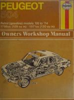
Petrol (gasoline) models ‘68 to ‘74 1796cc (109 cu in) 01971¢cc¢ (120 cu in) .
|
|
3
Peugeot 504 Owners Workshop Manual by J H Haynes Associate Member of the Guild of Motoring Writers
and B L Chalmers- Hunt TEng (CEI), AMIMI, AMIRTE, AMVBRA
Models covered
UK:
504 504 504 504
Saloon, 1796cc and 1971cc. 1969 on Estate, 1971cc. 1971 on Coupe, 1971cc. 1972 on Cabriolet, 1971cc. 1972 on
USA:
504 Sedan, 120 cu in. 1970 on 504 Wagon, 120 cu in. 1972 on
Covers fuel injection, carburettor, automatic and manual gearbox versions of above. Does not cover 504 diesel ISBN 0 85696 161 2
© JH Haynes and Company Limited 1975 All rights reserved. No part of this book may be reproduced or transmitted in any form or by any means, electronic or mechanical, including photocopying, recording or by any information storage or retrieval system, without permission
in writing from the copyright holder.
Printed in England
JH HAYNES AND COMPANY LIMITED SPARKFORD YEOVIL SOMERSET ENGLAND distributed in the USA by
HAYNES PUBLICATIONS INC. 9421 WINNETKA AVENUE CHATSWORTH LOS ANGELES CALIFORNIA 91311 USA
ae
Acknowledgements Thanks are due to Peugeot Limited who provided certain technical information. Castrol
Automobiles United Kingdom illustrations and much useful Limited: supplied information
regarding lubrication requirements. Car Mechanics magazine kindly supplied many of the photographs in the bodywork repair sequence of Chapter 1 2.
Special
thanks
are due
to all of those
people
at Sparkford
who helped in the production of this manual. Particularly, Brian Horsfall and Les Brazier who carried out the mechanical work and took the photographs respectively and Stanley Randolph who planned the layout of each page.
About this manual [ts aims This is a manual for the do-it-yourself minded Peugeot 504 owner. It shows how to maintain these cars in first class condition and how to carry worn or break. By doing selves owners will gain in been done properly; they the job themselves; and
out repairs when components become all maintenance and repair work themthree ways: they will know the job has will have had the satisfaction of doing they will have saved garage labour
charges. Regular and careful maintenance is essential if maximum reliability and minimum wear are to be achieved. All the major mechanical ones
assemblies and a lot of the minor
require special service tools, but in many instances it is possible to get round their use with a little care and ingenuity.
Throughout this manual ingenious ways of avoiding the use of special equipment and tools are shown. In some cases the Proper tool must be used. Where this is the case a description of the tool is usually included. Given the time, mechanical do-it-yourself aptitude, and a reasonable collection of tools, this manual will show the enthusiastic owner how to maintain and repair his car really economically with minimum recourse to professional assistance and expensive tools and equipment.
as well, have been stripped, overhauled, and rebuilt. Only
through working in this way can solutions be found to the sort of problems facing private owners. Other hints and tips are also
Using the manual
given which can only be obtained through practical experience. The step-by-step photographic strip and rebuild sequences show how each of the major components was removed, taken
The book is divided into twelve Chapters. Each Chapter is divided into numbered Sections which are headed in bold type between horizontal lines. Each Section consists of serially numbered paragraphs.
apart, and rebuilt. In conjunction with the text and exploded illustrations this should make all the work guite clear - even to the novice
who
has never
previously attempted
the more com-
plex job. Although Peugeot cars are hardwearing and robust, it is inevitable that their reliability and performance will decrease as they become older. Hepairs and general reconditioning will become necessary if the car is to remain roadworthy. It is in these circumstances that the manual will prove to be of maximum help, as it is the on/y workshop manual written from practical experience especially for owners of cars covered in this manual (as opposed to service operators and garage proprietors). Manufacturers’ official manuals are usually splendid publications which contain a wealth of technical information. Because they are issued primarily to help the manufacturer’s authorised
dealers and distributors they tend to be written in a very technical language, and tend to skip details of certain jobs which are common knowledge to garage mechanics. Haynes Owner’s Workshop Manuals are different as they are intended primarily to help the owner, and therefore contain details of all sorts of jobs not normally found in official manuals. Owners who intend to do their own maintenance and repairs should have a reasonably comprehensive tool kit. Some jobs
There are two types of illustration: (1) Figures which are numbered according to Chapter and sequence of occurrence in that Chapter and having an individual caption to each figure; (2) photographs which have a reference number in the caption. All photographs apply to the Chapter in which they occur so that the reference numbers pinpoint the pertinent Section and paragraph within that Chapter. Procedures, once described in the text, are not normally repeated. If it is necessary to refer to another Chapter the
reference will usually be given in Chapter number and Section number (eg; Chapter 1/16). If it is considered
necessary to refer to a particular paragraph
in another Chapter the reference is given in the following form:
1/6:5. Cross-references given without use of the word ‘Chapter’ apply to Sections and/or paragraphs in the same Chapter (eg; ‘see
Section 8’ means also ‘in this Chapter’). When the left or right-hand side of a car is mentioned it is as if one were looking in the forward direction of travel. Whilst every care is taken to ensure that the information in this manual is correct, no liability can be accepted by the authors or the publishers for loss, damage or injury caused by any errors in, or omissions from, the information given.
Contents Chapter
Section
Introductory sections
English usage
4
Buying spare parts
5 _ Lubrication chart
1
Engine.
2
Cooling system
3
Fuel system, carburation, fuel injection and emission control
4 Ignition system
5 Clutch :
6
Page
Section Routine maintenance
Page 8 10
Removal Dismantling Renovation
16 24 34
Reassembly — Replacement Fault diagnosis
40 54 54
Draining/flushing/filling
58
Fanbelt tension
60
Radiator Water pump
59 Heating system 60 ~—-Fault diagnosis
62 64
Carburettor engines Emission control system
69 82
86 97
Fuel injection system Controls
Contact breaker points
102
Spark plugs
108
Distributor Timing
102 103
Fault diagnosis
108
Bleeding Removal and refitting Inspection
411° 111 112
~+Master cylinder Slave cylinder Faults
112 114 114
Manual gearbox and
Manual gearbox
Reassembly
130
automatic transmission
Removal Replacement Dismantling Overhaul
122 123 125 130
Automatic transmission Fluid level and maintenance Removal and replacement Fault diagnosis
138 138 140
Inspection Centre bearing
145 145
7
Propeller shaft
Removal Replacement
142 144
8
Rear axle and driveshafts
Differential
152
9
Braking system
Bleeding Front brakes
163 165
Handbrake Vacuum servo unit
175 176
Rear brakes Master cylinder
167 172
Hydraulic pipes and hoses Fault diagnosis
177 179
181 183
Windscreen wiper Fuses
189 191
184 186
Fault diagnosis Wiring diagrams
194 196
206 207
Steering rack and pinion ~=Fault diagnosis
215 220
10 Electrical system
Battery Alternator Starter motor Lights
11 Suspension and steering
Front suspension Rear suspension
12 Bodywork and fittings
Maintenance Repairs a
EE
ae
Metric conversion tables Index
a
‘
~~ Driveshafts
221 Doors 222 Windscreen glass a
156
226 235 en 236 238
4
Use of English
a
As this book has been written in England, it uses the appropriate English component names, phrases, and spelling. Some of these differ from those used in America. Normally, these cause no difficulty, but to make sure, a glossary is printed below. In ordering spare parts remember the parts list will probably use these words:
Glossary English
American
English
American
Accelerator Alternator Anti-roll bar Choke/venturi Battery
Gas pedal
Layshaft (of gearbox) Leading shoe (of brake)
Counter shaft Primary shoe Latches Freeway, turnpike etc. Licence plate Kerosene Gasoline Gas tank
Generator (AC)
Energizer
axe
Bonnet (engine cover Boot lid
Hood ioe
xe
Boot (luggage compartment) Bottom gear
‘
Bulkhead : Camfollower or tappet Carburettor
Catch Circlip Clearance Crownwheel Disc (brake)
aes
Carburetor Latch
Snap ring Lash
Ring gear (of differential) Rotor/disk
Earth (electrical) Engineer's blue
Ground Prussion blue Station wagon
Estate car Exhaust manifold
Fast back (Coupe) Fault finding/diagnosis Float chamber
Halfshaft Handbrake
Hood Hot spot Indicator
Interior light
‘Pinking’ Quarter light
1st gear Firewall Valve lifter or tappet
Propellor shaft Pitman arm Convertible
Generator (DC)
Header Hard top
Trouble shooting Float bowl Lash Coast Piston pin or wrist pin Shift Transmission
Axle-shaft
Parking brake Soft top Heat riser Turn signal Dome lamp
nas
Petrol Petrol tank
Trunk lid Trunk
Driveshaft Drop arm Drop head coupe Dynamo
Free-play Freewheel Gudgeon pin Gearchange Gearbox
Locks Motorway Number plate Paraffin
Stabiliser or sway bar Barrel
Retread Reverse Rocker cover Roof rack Saloon Seized
fre Side indicator lights Side light : Silencer ‘ Spanner ae Sill panel (beneath doors)
‘Pinging’ Quarter window Recap Back-up Valve cover
Car-top carrier Sedan Frozen
Side marker lights Parking light Muffler Wrench Rocker panel
Split cotter (for valve spring cap)
Lock (for valve spring retainer)
Split pin
Cotter pin
Steering arm Sump
Spindle arm
Tab washer Tailgate Tappet Thrust bearing
Top gear = Trackrod (of steering
Trailing shoe (of brake) Transmission Tyre Van Vice Wheel nut Windscreen
Wing/mudguard
Oil pan Tang; lock Liftgate
Valve lifter | Throw-out bearing High
Tie-rod (or connecting rod) Secondary shoe Whole drive line Tire
Panel wagon/van Vise
Lug nut Windshield Fender
Miscellaneous points An “'Oil seal” is fitted to components lubricated by grease! A “Damper” is a ‘Shock absorber’ it damps out bouncing, and absorbs shocks of bump impact. Both names are correct, and both are used haphazardly. Note that British drum brakes are different from the Bendix type that is common in America, so different descriptive names result. The shoe end furthest from the hydraulic wheel cylinder is on a pivot; interconnection between the shoes as on Bendix brakes is most
uncommon.
Therefore the phrase ‘’Primary’’ or “‘Secondary”’ shoe does not apply. A shoe is said to be Leading or Trailing. A “Leading”
shoe is one on which a point on the drum, as it rotates forward, reaches the shoe at the end worked by the hydraulic cylinder before the anchor end. The opposite is a trailing shoe, and this one has no self servo from the wrapping effect of the rotating drum.
Buying spare parts and vehicle identification numbers Buying spare parts Spare
Peugeot
parts
are available from
garages,
other
garages,
many
sources,
accessory
shops,
for example:
and
motor
factors. Our advice regarding spare part sources is as follows: Officially appointed Peugeot garages: This is the best source of parts which are peculiar to your car and are otherwise not generally available (eg; complete cylinder heads, internal gearbox components, badges, interior trim etc). It is also the only place at which you should buy parts if your car is still under warranty; non-Peugeot components may invalidate the warranty. To be sure of obtaining the correct parts it will always be necessary to give the.storeman your car’s engine and chassis number, and if possible, to take the ‘old’ part along for positive identification. Remember that many parts are available on a factory exchange scheme - any parts returned should always be clean! It obviously
makes good sense to go straight to the specialists on your car for this type of part for they are best equipped to supply you. Other garages and accessory shops: These are often very good places to buy materials and components needed for the maintenance of your car (eg; oil filters, spark plugs, bulbs, fan belts,
oils and greases, touch-up paint, filler paste, etc). They also sell
general accessories, usually have convenient opening hours, often charge lower prices and can usually be found not far from home. Motor factors: Good factors will stock all the more important components which wear out relatively quickly (eg; clutch com: ponents, pistons, valves, exhaust systems, brake cylinders/pipes/ hoses/seals/pads, etc). Motor factors will often provide new or reconditioned components on a part-exchange save a considerable amount of money.
basis - this can
Vehicle identification numbers When ordering spare parts it is essential to give full details of your car to the storeman. He will want to know the car type and serial number, car and engine numbers. When ordering parts for the transmission or body it is best if the transmission number or body number can be quoted, The locations ot the important vehicle numbers are shown in the accompanying illustration.
1 2
Maker’s plate Type and serial numbers
3
Engine serial number (on fixing lug)
uoljeaipisads jf) - UOOIeS HOG OebnaY
dibs hbebt
efit
at Wail; :rT jeed PEL TEU ||
specification the of variants Estate 504 UK One Peugeot -
Routine maintenance Introduction 1 In the schedule that follows this introduction, the routine maintenance that should be carried out is tabulated. Routine maintenance has two important functions. First, is that of making adjustments and lubricating those parts which require it to ensure the least wear and-greatest efficiency. But the second function, could almost be the more important. By looking over your car thoroughly, you have'the opportunity to check that all is in order and to find and rectify faults before they become serious. 2 Every component should be looked at, working systematically over the whole car. Dirt cracking near a nut or.flange can
indicate something working loose. clearly, as will chafed or broken
Fluid leaks will show up electrical cables and rust
appearing through damaged paintwork or underseal. All these things, and more, should be found before they bring on a failure
on the road, or an expensive repair.
3
The
tasks to be done
-commended
on
the car are in general those re-
by the manufacturer.
We
have
also
put in some
5 Screwdrivers should have large handles for a good grip; you need large, ordinary and small ‘electrical’ and medium crossheaded types. Do not purchase one handle with interchangeable heads. The
large screwdriver must have a tough handle that will take hitting with a hammer when you misuse it as a chisel! 6 You can use an adjustable spanner and a self-grip or pipe
wrench of the ‘Mole’ or ‘Stillsons’ type. 7. With these tools you will get by. Do but be prepared to spend a little extra. 8 If you undertake major dismantling mission you will need a drift. This is
about 3/8 in (9.53 mm) in diameter. Where possible use a steel drift which will withstand hammering.
Do not use brass as little
chips can fly off, and get into the component and ruin it. You will need a ‘ball pein’ hammer, fairly heavy too, because it is easier to use a heavy hammer gently, than a light one hard.
9
Files are soon needed. The four listed make a good selection:
additional ones. For someone having his servicing done at a garage it may be more economical to purchase, and fit, a new or reconditioned component. Your garage proprietor has many things to consider when giving you a quote for any work, (eg; labour costs, availability of his labour force, overheads etc). You may, therefore, make considerable savings in time and costs provided you know you are capable of tackling the job and are prepared to do it. To leave an obviously developing fault ‘until
not purchase cheap ones They will last far longer. of the engine and transa steel or soft metal rod
6 inch half round smooth
8 inch flat second cut 8 inch round second cut 10 inch half round bastard
10 You will need a good, firm, hydraulic jack. A trolley jack is of considerable value when removing any of the major
the next service’ may prove costly and even disastrous - do it now! 4 When checking the car, if someting looks wrong, look it up in the appropriate Chapter. If something seems to be working badly look in the relevant fault finding Section. 5 Always road-test after a repair. Then re-inspect your work, checking nuts etc. for tightness. Check again after about 150
units. If you do ever get one, it must be in addition to and
miles (250 km).
Maintenance schedule
Tools
The manufacturers base their own servicing operations on a 3,000 mile (5,000 km) interval basis. The maintenance procedure for more complicated tasks is
1 The most useful type of spanner is a combination spanner. This has one open-ended jaw, the other a ring of the same size. Alternatively, a set of open ended and ring spanners will be
cannot replace a simple jack, which the smaller jobs.
not detailed in this Section - as full information, where necessary, will be found in the appropriate Chapters of this
required. Whenever possible use a ring spanner as it will not slip off the nut or bolt especially when very tight. Remember metric sized tools will be required in most cases.
book.
2
1 2 3 4 for 5 6 7
You will need a set of feeler gauges. Preferably these should
be metric sizes too, but if an Imperial set is to hand the equiva-
lents are quoted throughout this manual. 3 You will see we specify tightening torques for many
nuts.
This needs a relatively expensive torque wrench - but we think it
is a. useful investment. 4 Torque wrenches use the sockets from normal socket spanner sets. Sockets, with extensions and ratchet handles are a boon. In the meantime you will need box spanners for such things as cylinder head attachments, and the spark plugs. They are thinner
will still be needed for
Daily Check Check Check Check other Check Check Check
coolant level. engine sump oil level. battery electrolyte level. tyre pressures. Examine tread depth and generally signs of damage. operation of all lights. windscreen washer fluid level. brake and clutch master cylinder hydraulic fluid
levels.
than socketsin small sizes, and will often go where the latter
Weekly
cannot, sockets.
1
Check tightness of roadwheel nuts.
2
Check automatic transmission oil level (where applicable).
so
will
always
be useful
even
if you
later purchase
Routine Maintenance 3,000 miles (5,000 km) or 3 months interval
12,000 miles (20,000 km) or 12 months interval
Carry out daily and weekly service plus:
Carry out 6,000 miles service, plus: 1 Check tightness of engine mountings. 2 Check operation of starter motor and the tightness of all cable attachments. Check tightness of door locks, catches and hinges.
1 Change engine oil. 2 Generally check operation of brake and clutch hydraulic systems. Inspect all pipes and unions for signs of leaks.
Check brake pad lining thickness. Check gearbox oil level (manual transmission).
Check steering assembly attachments for security.
Check differential oil level. Clean and reset spark plugs. Inspect driveshaft rubber boots for damage or oil leaks. Clean air cleaner. Bleed the water trap fuel filter. ODNOOLHW 10 Bleed fuel injection pump. ; 11 Check steering system joints for security and backlash. 12 Check brake pedal travel and handbrake operation. Adjust
as necessary.
Check operation of brake vacuum servo unit. Tune engine using electronic test equipment. NOOO DW Check HT leads for damage and secure connections. check ignition LT leads for security.
36,000 (60,000 km) or 3 years interval
‘
Discuss with Peugeot garage advisability of changing all brake hydraulic seals and fluid.
13 Check operation of horns and windscreen wipers. 14 Check specific gravity of battery electrolyte. 15 Check headlight beam alignment and reset as necessary.
16 Clean
windscreen
wiper
blades
and
renew
if worn
Also
Other aspects of Routine Maintenance
or
perished. 17 Check exhaust system for security and also for leaks. 18 Check condition and security of seats and seat belts.
1
Wheel nuts These should be cleaned and lightly smeared with grease as necessary during work, to keep them moving easily. If the nuts are stubborn to undo due to dirt or overtightening, it may be necessary to hold them by lowering the jack until the wheel rests on the ground. Normally if the wheel brace is used across the hub centre, a foot or knee held against the tyre will prevent the wheel from turning, and so save the wheels and nuts from wear if the nuts are slackened with weight on the wheel. After replacing a wheel make a point of iater rechecking the nuts for tightness.
19 Lubricate the following points using a grease gun filled with Castrol LM Grease: a) Left-hand steering knuckle pivot
b) Left-hand track arm balljoint c) Right-hand steering knuckle pivot d) Right-hand track arm balljoint e) Steering rack f) Propeller shaft bearing 20 Lubricate all door locks and hinges. 6,000 miles (10,000 km or 6 months interval)
2
Safety Whenever
Carry out 3,000 miles service, plus: Fit new engine oil filter cartridge. Drain and refill gearbox.
extra strong box or piece of timber underneath onto which the car will fall rather than onto you.
working,
even
partially,
under
the car,
put an
3
Clean and reset contact breaker points gap.
Check ignition timing. Check operation of self disengaging fan. examine all cooling system and heater
= QOahWN Carefully
hoses for
perishing or leaks. Check hose clip security.
Cleanliness Whenever you do any work allow time for cleaning when some component is in pieces, or parts removed to improve access to other areas, give an opportunity for a thorough clean. This cleanliness will allow you to cope with a possible future crisis on the road withoutegetting yourself too dirty. During bigger jobs
7 Lubricate accelerator control linkage and pedal fulcrum with a little engine oil. 8 Lubricate distributor parts. 9 Lubricate handbrake mechanical linkage and cables. 10 Check all fuel lines and joints for lLakage. Check tightness of clips. . 11 Check tightness of all engine attachments. 12 Check tightness of battery Connections. Clean off corrosion and apply vaseline to terminals. 13 Check efficiency of charging system. 14 Check front and rear suspension attachments for security.
and you are more likely to spot trouble. Dirt on the ignition system is a common cause of poor starting. Large areas such as the engine compartment, inner wings or bulkhead should be brushed thoroughly with a solvent such as Gunk, allowed to soak and then very carefully hosed down. Water in the wrong places,
15 If wished, change round the roadwheels in a diagonal manner also using the spare to equalise wear. This is not advised if radial tyres are fitted.
particularly the carburettor or electrical components more harm than dirt. Use petrol or paraffin and Paintbrush to clean the more inaccessible places.
16 Balance front wheels. 17 Generally check all electrical connections for security.
cables
for
damage
and
the
18 Check engine/gearbox/differential units for oil leaks. 9,000 miles (15,000 km) or 9 months interval Carry
out
3,000
miles
service
(with
the exception
items, 6 and 8), plus: Drain and refill differential unit. Clean fuel pump filter. Renew spark plugs.
Renew air cleaner element (when fitted). Clean fuel filter cartridge. Drain and refill fuel injection pump.
Change automatic NQOOBWN
transmission oil.
of service
when ated,
you expect some dirt it is less extreme at least whilst removing a component.
and can be tolerWhen an item is
being taken to pieces there is less risk of ruinous grit finding its way inside. The act of cleaning also focuses
your
attention
onto
parts
will do a small
4
Waste oil disposal Old oil and cleaning paraffin must be destroyed. Although it makes a good base for a bonfire this practice is dangerous. It is also illegal to dispose of oil and paraffin down domestic drains. By buying your new engine oil in one gallon cans you can refill them with the old oil and take the cans back to the local garage who have facilities for disposal or recycling of the oil (for agri-
cultural and industrial use). 5
Long journeys Before taking the car on long journeys, particularly such trips as continental holidays make sure that the car is given a full visual inspection well in advance so that any faults found can be rectified in time.
10
Recommended
lubricants
1
rr
she
as
ait
ae
Ena
+
ais
Engine
oa
an
Pa
sue
Castrol GTX
-
ee
avi
i
aie
sf
ans
et
nh
Gearbox: Manual _... Automatic
ane
vas
vi
Castrol GTX
he
Ae
doe
Castro! TO Dexron
...
ats
Castro! Hypoy Light (80 EP)
LIZZ
re +
Ms
YSYZZZLLL & ¢; Fig 5.2 Cross-sectional view of clutch assembly
Fig 5.1 Cutaway view of clutch assembly
1 Clutch housing 2 Starter ring gear 3 Flywheel
§ 6 7
4
8
Clutch plate
Clutch cover Release bearing Control fork Slave cylinder
112
Chapter 5/Clutch
whilst the engine can be removed relatively easily. 2 With a scriber or file mark the relative position of the clutch cover and flywheel to ensure correct refitting if the original parts are to be used. 3 Remove the clutch
assembly by unscrewing the six screws and special Onduflex washers that secure the cover to the rear face of the flywheel. For this a 6 mm Allen key and wrench will be required. Unscrew the screws, in diagonal order, half ee at
a time to prevent distortion of the cover flange, also to |
ent
the cover flange binding on the dowels and suddenly flying off. 4 With the screws and washers removed, lift the clutch cover assembly off the locating dowels. The driven plate or clutch disc will fall out at this stage as it is not attached to either the clutch cover assembly or the flywheel. Carefully make a note of which
way round it is fitted. (Fig. 5.3). 5 it is important that no oil or grease gets on the clutch disc friction linings, or the pressure plate and flywheel faces. It is advisable to handle the parts with clean hands and to wipe down the pressure plate and flywheel faces with a clean dry rag before inspection or refitting commences. 6 To refit the clutch place the clutch disc against the flywheel with
the larger hub
boss towards
that the clutch disc is gripped but can still
must now be centralised so that when the are mated, the gearbox input shaft splines splines in the centre of the hub. 9 Centralisation can be carried out quite easily by inserting a round bar or long screwdriver through the hole in the centre of the clutch, so that the end of the bar rests in the small hole in the end of the crankshaft containing the input shaft bearing bush. Moving the bar sideways or up and down will move the clutch disc in whichever direction is necessary to achieve centralisation. 10 Centralisation is easily judged by removing the bar and viewing the driven plate hub in relation to the hole in the centre of the diaphragm spring. When the hub opens exactly in the centre of the release bearing hole all is correct. Alternatively, if an old input shaft can be borrowed this will eliminate all the guesswork as it will fit the bush and centre of the clutch hub exactly, obviating the need for visual alignment. 11 Tighten the clutch screws firmly in a diagonal sequence to ensure that the cover plate is pulled down evenly and without distortion of the flange. Tighten the screws to a final torque
wrench setting of 11 Ib f ft (1.5 kg fm). 12 Mate the engine to the gearbox, this being a direct reversal of the
procedure
decided
upon
If either is badly
grooved it should be re-machined
until
plate is cracked or split it must be renewed. 6 Examine the hub splines for wear and also make sure that the centre hub is not loose.
6
Clutch flexible pipe - removal and replacement
1
Wipe the union
ends
of the flexible pipe to prevent dirt in-
gress. 2 Using a correctly sized open-ended spanner carefully unscrew the union nuts and lift away the flexible pipe. 3 Plug the holes in the master cylinder and slave cylinder to prevent dirt ingress. : 4 Refitting the flexible pipe is the reverse sequence to removal. {t will be necessary to bleed the hydraulic system, as described in Section 2. 5 If the pipe between the reservoir and master cylinder is to be removed the same general comments apply. However take care when detaching the union from the master cylinder.
the flywheel. On no account
should the clutch disc be replaced the wrong way round as it will be found quite impossible to operate the clutch with the disc incorrectly fitted. 7 Replace the clutch cover assembly loosely on the dowels. Replace the six screws and new Onduflex washers and tighten them finger-tight so be moved. 8 The clutch disc engine and gearbox will pass through the
plate.
smooth, or replaced with a new item (Fig. 5.5). If the pressure
for removal,
bleed
the hydraulic
system (if necessary) and check the clutch for correct operation.
7
Clutch master cylinder - removal and replacement
1 Wipe the top of the master cylinder reservoir and unscrew the cap. Place a piece of polythene sheet over the top of the reservoir and replace the cap. This will stop hydraulic fluid syphoning out during subsequent operations. 2 Wipe the exterior of the master cylinder and then disconnect the pipe that connects the reservoir to the master cylinder. Catch any fluid in a suitable container taking care that hydraulic fluid does not come into contact with paintwork as it acts as a solvent. 3 Disconnect the pipe that connects the master cylinder to the slave cylinder and plug the end to prevent dirt ingress. 4% Working inside the car disconnect the clutch pushrod from
the clutch pedal. 5 Undo and remove the two nuts (or bolts) and washers securing the clutch master cylinder to the bulkhead. Lift away the master cylinder. 6 Refitting the master cylinder is the reverse sequence to removal. Bleed the system as described in Section 2.
8 Clutch assembly
master
Important:
A01/101
cylinder
On models
- dismantling,
manufactured
examination
and re-
up to serial numbers
504.
4917 and 504. A02/1012919 the master cylinder con-
tained a residual valve and spring to ensure a constant contact of
the
thrust
cylinder
bearing
on
the
clutch
mechanism
contained a special cup. The residual
and
pressure
the
slave
is in the
region of 11.3 ib/in2 (0.8 kg/cm2).
1 In the normal course of events ‘clutch dismantling and reassembly’ is the term used for simply fitting a new clutch
On models manufactured from serial numbers 504 A01/1014918 and 504. A02/1012920 and a// models in the 504. BO2 and 504. CO2 series the residual pressure valve in the master cylinder was fitted with. a special spring in addition to a special cup. This ‘revised arrangement serves the same
pressure
Purpose as the earlier system.
5
the
Clutch - inspection
plate and friction disc. Under no circumstances should
diaphragm
spring
clutch
unit
be dismantled.
If a fault
develops in the pressure plate assembly an exchange replacement unit must be fitted.
2
If a new clutch disc is being fitted it is false economy not to
renew the release bearing at the same time. This will preclude having to replace it at a later date when wear on the clutch linings is very small.
3
Examine
the clutch
disc friction
linings for wear or loose
rivets and the disc for rim distortion, cracks and worn splines. 4 It is always best to renew the clutch driven plate as an assembly to preclude further trouble, rather than trying a d-i-y renovation on the existing unit. 6 Check the machined faces of the flywheel and the pressure
When
servicing,
the
later
type
slave cylinder may
be used
with the earlier type of master cylinder but the earlier type slave cylinder must not be used with the later type master cylinder. During dismantling take great care to note the location of each part.
1 To dismantle the master cylinder use a pair of circlip pliers to release the circlip retaining the piston stop washer.
2 Carefully remove the piston stop washer from the cylinder — bore and follow this with the piston assembly, main and secondary cups and return spring.
:
3 If they prove stubborn carefully use a foot pump or air jet on the hydraulic pipe connection and this should move the internal
ae
113
Fig 5.4 Tightening clutch cover securing screws (Sec 4) Fig 5.3 Removal of clutch cover assembly from flywheel (Sec 4)
Note: metal rod used to align clutch disc
Fig 5.6 Layout of clutch control system
Fig 5.5 If the flywheel is to be machined to remove score marks at ‘a’, the same thickness must be removed from part ‘b’ to retain correct diaphragm spring tension (Sec 5)
Fig 5.7 Master cylinder and slave cylinder as fitted to earlier
models. [For change points see text] 1
Master cylinder
2
Spring
3
Pressure valve
4
Slave cylinder
5
Cup
: s bert Ih aAie ag AS UL caf
3
: Reservoir
Fig 5.8 Master cylinder and slave cylinder as fitted to later
_ models [For change points see text] ;
he Master cylinder
2
Spring
4
Slave cylinder
5
6
Cup
Spring
114
Chapter 5/Clutch
parts, but do take care as they will fly out. Place a cloth pad over the end to catch the parts. 4 Note which way round the primary and secondary cups are fitted. 5 Thoroughly clean the parts in brake fluid or methylated spirits. After drying the items inspect the cups for signs of distortion, swelling, splitting or hardening although it is re-
commended
new rubber cups are always fitted after dismantling
as a matter of course. 6 Inspect the bore and piston for signs of deep scoring marks which, if evident, means a new cylinder should be fitted. Make sure all drillings are clear by poking gently with a piece of thin wire. 7 As the parts are refitted to the cylinder bore make sure that they are thoroughly wetted with clean hydraulic fluid. 8 Fit the secondary cup onto the piston making sure it is the correct way round. 9 Refit all parts in the reverse order to removal. Make sure that the lips of the cups do not roll over as they enter the bore. 10 Finally replace the circlip and ensure that it is fully seated. 11 The master cylinder is now ready for refitting to the car.
9
Clutch slave cylinder - removal and replacement
1
Wipe the top of the master cylinder reservoir and unscrew the
cap.
Place
a piece
of polythene
sheet
over
reservoir and replace the cap. This will stop syphoning out during subsequent operations.
the
top of the
hydraulic
fluid
2 Wipe the area around the hydraulic pipe on the slave cylinder and unscrew the hydraulic pipe union nut. 3 The slave cylinder is retained by a clip located in a groove near to the rubber boot end of the cylinder. This must be released using a screwdriver. 4 If difficulty is experienced in removing the circlip due to tension from the clutch assembly use a metal bar or large screwdriver to ease the release fork away from the slave cylinder. 5 Draw the slave cylinder towards the front of the clutch bellhousing noting that the pushrod will remain connected to the clutch release fork. 6 Refitting the slave cylinder is the reverse sequence to removal. It is important that the bleed nipple is in its lowermost position. 7 Bleed the clutch hydraulic system as described in Section 2.
11 Clutch release bearing and fork assembly - removal, overhaul and replacement 1
To
gain
access
it is necessary
to
remove
the
engine
(See
Section 4, paragraph 1). 2 Whilst inspecting the clutch assembly it is worthwhile checking the release bearing assembly. The bearing assembly can be detached without removing the clutch fork. 3 Release the bearing retaining clip and rotate in an anticlockwise direction. 4 If the bearing is worn or shows signs of overheating it should
be renewed. (Fig. 5.9). 5 Should it be necessary to remove the bearing guide sleeve it can be detached using a bench vice and suitable packing. However this is one little job best left to the local Peugeot garage. 6 The clutch release fork can be removed by working inside the housing and removing the rubber cup and fork thrust ball (Fig.
5.10). 7 To reassemble pack the rubber cup with a little grease and slide the release fork from the inside towards the outside of the clutch housing. 8 It will be beneficial to use a screwdriver to lift the clutch release fork backing spring whilst engaging the fork on the ball head. The spring should be backed against the rubber cup.
9
Smear the guide sleeve with a little high melting point grease
and engage the new bearing by positioning the retaining jaw towards the starter motor housing. 10 Engage the thrust bearing with the clutch release fork and lock by rotating the bearing clockwise and refitting the retaining clip.
12 Clutch squeal - diagnosis and cure 1 If on taking up the drive, or when changing gear, the clutch squeals, this is a sure indication of a badly worn release bearing. As well as regular wear due to normal use, wear of the clutch release bearing is much accentuated if the clutch is ‘ridden’, or held down by long periods with a gear selected and the engine running. 2 The clutch release bearing is not an expensive item to renew, but access to it requires engine removal.
13 Clutch slip - diagnosis and cure
10 Clutch
slave
cylinder
- dismantling,
examination
and _ re-
assembly
1 2
Refer to the introduction to Section 8. Clean the outside of the slave cylinder before dismantling.
3 Pull off the rubber dust cover and by shaking hard, the piston and cup assembly should come out of the cylinder bore. 4 \f they prove stubborn carefully use a foot pump or air jet on the hydraulic pipe connection and this should remove the internal parts, but do take care as they will fly out. Place a cloth pad over the end to catch the parts. 5 Note which way round the cup is fitted. 6 Wash all internal parts with either brake fluid or methylated spirits and dry using a non-fluffy rag. 7 Inspect the bore and piston for signs of deep scoring which, if evident, means a new cylinder should be fitted. 8 Carefully examine the rubber components for signs of ‘swelling, distortion, splitting, hardening or other wear although it is recommended new rubber parts are always fitted after dismantling. 9 All parts should be reassembled wetted with clean hydraulic
fluid. 10 Fit tne cup to the piston the correct way round the piston into the bore. Take care not to roll the lip 11 Pack the dust cover with a little rubber grease and end of the slave cylinder body engaging the lips over in the body.
and insert of the cup. fit over the the groove
1 Clutch slip is a self-evident condition which occurs when the clutch friction plate (driven plate) is badly worn; the release arm free-travel is insufficient, oil or grease has found its way onto the flywheel or pressure plate faces, or the pressure plate itself is faulty. 2 The reason for clutch slip is that, due to one of the faults listed above, there is either insufficient pressure from the
pressure plate, or insufficient-friction from the friction plate to ensure a solid drive. 3 If small amounts of oil get onto the clutch, they will be burnt off under the heat of clutch engagement, in the process gradually
darkening the linings.
Excessive oil on the clutch will burn off
leaving a carbon deposit which can cause quite bad slip, or fierceness, spin and judder. 4 If clutch slip is suspected, and confirmation of this condition is required, there are several tests which can be made:
a) With the engine in second or third gear and pulling lightly up a moderate incline, sudden depression of the accelerator pedal may cause the engine to increase its speed without any increase in road speed. Easing off on the accelerator will then give a definite drop in engine speed without the car slowing. b) Drive the car at a steady speed in top gear and, braking with
the left foot, try and maintain the same speed by depressing the accelerator pedal. Providing the same speed is maintained, a change in the speed of the engine confirms that slip is taking place.
Chapter 5/Clutch
115
Fig 5.9 Cross-sectional view through clutch thrust bearing assembly (Sec 11)
(\_\
a I,
H)
\
.
(4) (2) ~
wd
ass
~
=
=
-
SES)
SaaS @\
& aN
Fig 5.12 Refitting clutch release for x
=
Fig 5.11 Clutch release fork pivot assembly (Sec 11) 7
Rubber cup
c) In extreme
cases
2 of clutch
Ball head
slip the engine
will race under
normal acceleration conditions. If the slip is due to oil or grease on the linings cure can sometimes be effected by squirting carbon into the clutch housing. The permanent cure, of renew the clutch driven plate and trace and rectify
a temporary tetrochloride course, is to the oil leak.
14 Clutch spin - diagnosis and cure
1
Clutch release fork
2
Retaining spring clip
3
Screwdriver
the fully depressed end of the clutch pedal travel as the clutch is released. 4 Check the clutch master and slave cylinders and the connecting pipes for leaks. Fluid in the rubber boot fitted over the end of the slave cylinder or fluid around the clutch master cylinder mounting on the bulkhead is a sure sign of a leaking piston seal. 5 If these points are checked and found to be in order then the fault lies internally in the clutch, and it will be necessary to remove it for examination.
1 Clutch spin is a condition which occurs when there is a leak in the hydraulic actuating mechanism, the release arm free travel is excessive, there is an obstruction in the clutch either on the input shaft splines or in the unit itself, or oil may have partially
15 Clutch judder - diagnosis and cure
burnt off the clutch
1 Clutch judder is a self evident condition which occurs when the power unit mountings are loose or too flexible; when there is
linings and
have
left a resinous deposit
which is causing the clutch disc to stick to the pressure plate or
flywheel. 2 Thereason for clutch spin is that due to any or a combination of, the faults just listed, the clutch pressure plate is not completely freeing from the centre plate even with the clutch pedal fully depressed. 3 If clutch spin is suspected, the condition can be confirmed by extreme difficulty in engaging first gear from rest, difficulty in changing gear, and very sudden take up of the clutch drive at
oil on the faces of the clutch friction plate, or when has been assembled incorrectly.
the clutch
2 The reason for clutch judder is that due to one of the faults just listed, the clutch pressure plate is not freeing smoothly from the friction disc and is snatching. 3 Clutch judder normally occurs when the clutch pedal is released in first or reverse gears, and the whole car shudders as it moves backwards or forwards. ;
Chapter 6 Manual gearbox and automatic transmission Contents
Automatic transmission - fluid level and maintenance Automatic transmission - removal and replacement Fault diagnosis - automatic transmission Fault diagnosis - manual gearboxes
Floor mounted gearchange (manual) - Evericul aaa ae justment
Gearbox Gearbox Gearbox
Gearbox Gearbox Gearbox
...
enue . dismantling
General description
(Automatic
transmission)
General description (manual). ost Input shaft (manual) - aeaeriiy and shim ‘lection Input shaft assembly
(manual) - dismantling
Layshaft (manual) - shim size selection aX Mainshaft and input shaft (manual) - reassembly ... Mainshaft assembly (manual) - dismantling
(manual) - final reassembly
Mainshaft
(manual) (manual) (manual) (manual)
Selector and interlock mechanism
-
initial reassembly inspection and overhaul removal ... replacement
(manual)
Steering column justment
- shim
gearchange
size selection
(manual)
(manual)
- dismantling
- overhaul and ad-
...
Specifications
Manual gearbox Gearbox
series
BA7
Number
of gears
4 forward,
1 reverse
Type of gears ...
Helical, constant
Synchromesh
All forward gears
...
mesh
Ratios: 3.663 2.169 1.409 1.000 S274
First Second TK. ccs Top Reverse
Speedometer
: : : : eS =— Tan et
(0.281) (0.475)
(0.732) (1) (0.275)
drive gear ratio:
Saloon, family and estate ... Station wagon nae Fuel injection models
ratio 10 x 20 10 x 21
colour Black Blue
10 x 19
White
Input shaft Number of teeth... ase End float adjustment shims: Outer diameter ... Inner diameter
Shim thickness range
1.6535 in. (42.00 mm) 1.4645 in. (37.20 mm) 0.006 - 0.014 in. (0.15 - 0.35 mm) in increments of 0.002 in.
(0.05 mm)
~Mainshaft Front end needle roller bearing Number of teeth: First gear wheel ...
Second gear wheel Third gear wheel Reverse gear wheel
0.071 x 1.02 x 0.622 in. (18 x 26 x 15.8 mm)
35 29 26 31
Adjustment shims:
Outer diameter Inner diameter
1.8110 in. (46.00 mm) 1.3858 in. (35.2 mm)
117
Chapter 6/Manual gearbox and automatic transmission Shim thickness range Needle roller bearing
0.006, 0.008, 0.10 and 0.20 in. (0.15, 0.20, 0.25 and 0.50 mm)
1.53 x 2.29 x 0.394 in. (38.8 x 58.2 x 10 mm)
Layshaft Number of teeth: First gear ... Second gear Third gear : Constant drive gear Adjustment shims: Outer diameter Inner diameter Shim thickness range
15 21 29 33 1.102 in. (28.00 mm)
0.850 in. (21.6 mm) 0.085 - 0.134 in. (2.25 - 3.40 mm) in increments of 0.002 in. (0.05 mm)
Idler gear shaft Diameter Length
oad
0.7874 in. (20.00 mm) 3.5433 in. (90.00 mm)
= ne
Idler gearwheel Number of teeth
19
Lubricant capacity Automatic
2.1 pints (2.34 US pints, 1.150 litres)
Transmission
Type
ZF . 3HP . 12., 3 speed epicyclic gear trains with 3 element hydrokinetic tor que converter.
Ratios Converter reduction ratio (max)
2.2901
Mechanical reduction ratios: First Second
0.391 0.658 1.000
Third
Range multiplication (including converter reduction range): 0.170 - 0.391 0.287 - 0.658 0.437 - 1.000
First Second Third
Typical performance data: Gearchanges
Throttle opening
Up
Down
2nd to 3rd
1st to 2nd
mile/h 9
at vat Full ‘Kick-down’
Acces i ete ou 24 ee
km/h
mile/h
15 17 31 38 60
16 17 55 57 62
km/h 25 27 89 92 100
3rd to 2nd
mile/h 14 16 37 38 60 70*
km/h 23 25 60 62 97 112*
2nd to 1st
mile/h
km/h
7 9 16 19 33 42**
12 15 25 30 53 68**
*Maximum speed for change down to 2nd when selecting 2nd **Maximum speed for change down to 1st when selecting 1st
Hydraulic fluid capacity: Transmission unit
8.3 - 9.2 Imp pints (10.0 - 11.2 US pints, 4.75 - 5.25 litres)
Transmission unit and oil cooler
10 Imp pints (12.00 US pints, 5.5 litres)
Torque wrench settings
Ib f ft
kg fm
Manual gearbox Gearbox drain plug Gearbox to engine bolts Radiator mounting bolts
Differential unit (1RS) ... Starter motor Gearbox filler plug Detent spring and ball plug
Clutch bellhousing
20 43.5 7.2 27 14.5 20 a2 20
2.75 6.0 1.0 3.75 2.0 2.75 1.0 2.76
118
Chapter 6/Manual gearbox and automatic transmission
Ib f ft a.
es
‘.
7.2
1.0
Gearbox backing plate screws ... Reverse pinion nut ee sud Rear housing nuts and bolts... Reverse light switch:
ane ae oe
By es Sen
ata a aT
Ses a =
ae 40 11
1.0 5.5 1.5
ff ee
ae =
a is
ass a
oe Ee
9.0 20
1.25 RY |
a
“se
a
ae
oe
16
2.25
11.6- 17.4 7.0
1.6-2.3 1.0
Copper body ... Steel body...
ae eee
Torque tube to gearbox
Automatic Transmission Diaphragm securing bolts Oil sump ... ass ea
1
kg fm
Gearbox casing halves nuts and bolts ...
General description (manual gearbox) The gearbox fitted to the 504 models covered by this manual
has remained basically the same throughout its production life. There have, however, been some minor detail modifications so whenever spare parts are being ordered always be sure to quote
the vehicle chassis number. Fig. 6.2 shows a cutaway
view
of the gearbox
with
the
bellhousing and rear extension attached. The extension houses the speedometer drive pinion which is driven from the wormwheel towards the end of the mainshaft and the two levers on the side operate the gear selectors. As can
be seen from
Fig. 6.1 the longer of these two levers moves the
shaft of the short cranked underside of the gearbox) up short levers on the other end other of the selector rods.
lever (which sticks out from the and down causing one of the two of this shaft to engage with one or Once engaged the selector rod is
=
moved in and out by the operation of the lever on the underside of the gearbox to select the gear required. The two levers are connected by linkages to the gearchange lever - which may be mounted on the steering column or on the floor - so that when the gear lever is moved across the centre of the gate the lever on the side of the gearbox rotates, and when the gearchange lever is moved into one of the gear selection Positions the lever on the underside of the gearbox rotates. Originally the selector lever system was designed for a steering column gearchange hence the rather complicated linkage associated with the floor mounted gearchange lever. The gearbox has four forward speeds and reverse with synchromesh on all forward gears. The split-case construction makes dismantling a simple matter and provided that the layout and operation of the gearbox is understood no problems should arise. Consider the gear train first. Photo 6:13 shows the whole assembly being lifted from the casing and gives an excellent
7?
(TTT Vs
ma! Nouns
—=—_—
Reverse
Fig 6.1 Manual gearbox showing gear movement
€
wey
qyeys
yeysinduy
yeysuley 9g
op
li
ea
A
AeH ‘an
B14 Z°9
JajawopaadsS aalip 4ea6
10,9E/a8 /O12U09
=
abueyneay josquoa
Sh &
—f
Seer AY AA IN C=a laa
Mh
)
z
q
©)
tj
§ Stetee! x
5 ae
{
Ht
ae ea
SSA NF sR
ZZ
es
‘i
igl=
—
Win.
a
|}
“jn YI
WN l
aa —y
foes uoiuid 4 puz/ist 4ea6
xoqueeh
a |>
~ ysawosyouds sauoo
uotuid
asianay sea6
=f
8g
sp
jeuol}9eS-ssolg Maia yfnoiy} jenuew
!
ae 4 Ge
ace
a
+
eT
(€)
I
er >
(y)
os
SSS
aa
Hg
(S)
pat“ f VAAL
|
puz 4ea6
IND7, WU “=
eee =| .= It p' Ty
4
uoiuid
ee ae pk Ee
Ol
(9)
= Ss ss
wy Wg4| SI SSy In) Y
et) 4 = Z
eon |
an
fa
Fy Ws
| sae Clim:
D RSH ~
rd
pha
BL
seeere sauoo
a
Z
Wa s lee
ln,
CIE
119
120 |
a
Chapter 6/Manual gearbox and automatic transmission aS A NS eae ak
picture of the general arrangement. It should be appreciated that although the assembly looks as one complete unit in fact the input and output ends are completely independent of each other. This must be so, because the engine drives the input end whilst the output end drives the
propeller shaft. The input shaft is sometimes referred to as the driveshaft and the output shaft as the mainshaft. The input shaft assembly is shown in Fig. 6.3. It carries a
single gear which is integral with the shaft. The gear drives the layshaft which is shown in Fig. 6.2. The layshaft assembly is shown in Fig. 6.4 and it carries four gears which are integral with the shaft and a fifth gear - the reverse pinion which is splined to it. The gear on the input shaft is always in mesh with its opposite number on the layshaft and both rotate when the engine is running whether a gear has been selected or
not. The remaining Opposite numbers the reverse pinion does not drive the
attached to it which engages in a channel on the idler pinion. Built into the gearbox are locators for the selector rods and interlock arrangement prevents two gears being engaged at once. These are shown in Fig. 6.6. The locator balls and springs work in notches in the selector rods. The third/fourth speed selector rod has its locator at front end while the other two rods are retained by balls springs which are inserted through plugs on either side of gearbox casing. The extra ball and two small pieces known as locking needles and the locking finger form the interlock.
the and the the
When the third/fourth speed selector rod (the centre one) is moved forwards, or backwards, it will carry with it the interlock needed which is located in a hole in the shaft. At the same time the interlock needle will push the interlock finger and the interlock ball outwards so that these engage with notches in the reverse selector shaft and the first/second speed selector shaft
gears integral with the layshaft drive their on the mainshaft, the exception however, is which although in mesh with the mainshaft mainshaft gear directly but is coupled to it
through an intermediate gear when reverse is selected. Selecting a forward speed is a matter of locking the appropriate gear on the mainshaft assembly to the mainshaft (output gear) itself. In the case of the fourth gear the mainshaft is locked directly to the input shaft. This locking is achieved by moving a splined sleeve which forms part of the synchroniser assembly so that it simultaneously engages with the synchronising hub which is locked to the output shaft and a corresponding hub on the selected gear. The mainshaft, shaft assembly is shown in Fig. 6.5. To engage third gear, the selector fork pushes the synchroniser over the synchroniser
hub towards the hub on the
gear. This causes the synchronising cone to engage with the corresponding cone which is fixed to the gear. Friction between these two cones soon makes the gear revolve at the same speed as the synchroniser, and once this has occurred the splines on the synchroniser itself will move over the hub on the gear and the two hubs will be locked together. The synchroniser cone is sprung away from the synchroniser itself so that it makes contact with the cone on the gear before the hubs are locked, and when the synchroniser is fully home the cone clicks into a fixed position.
To engage fourth gear the synchroniser is moved in the other direction and engages with an exactly similar cone and hub on the input shaft, thus locking the input and output shafts together. The synchroniser for second and first gears is identical Principle but the two synchronisers are not interchangeable.
The arrangements
for reverse are quite obvious
in
in Fig. 6.1.
An extra pinion - the reverse idler pinion - is interposed between the reverse pinion on the mainshaft and the corresponding gear on the output shaft. It is brought into mesh by the operation of the reverse selector rail which carries a half fork permanently
Fig 6.3 Input shaft assembly
1 2 3
Shims Deflector washer Ball race
4 5
Spring washer Snap-ring
Fig 6.4 Layshaft assembly Bearing Selective shim Layshaft Spindle Lock pin
Reverse idler gear Reverse gear Washer DONAAAWK» Snap-ring
:
_
Chapter 6/Manual gearbox and automatic transmission respectively.
When
this has happened, these two shafts cannot be
moved. lf the first/second speed shaft is moved, it will force the interlock ball away, displacing the needle in the third/fourth
is moved. The neutral
121
position of the selector lever which moves in and
will in
out on the underside of the gearbox is located by another ball and spring as shown in Fig. 6.6. The ball used is larger than those used on the selector shafts.
turn push the interlock finger firmly into its notch on the reverse selector shaft, making this immovable too. The same thing happens in the opposite direction when the reverse selector shaft
Automatic transmission is fitted as a factory production extra. Further information on this unit will be found in Sections 17 to 20 inclusive.
speed
shaft and thus immobilising
this shaft. The needle
Fig 6.5 Mainshaft assembly
Needle cage Snap-ring Washer 3rd/4th speed synchroniser assembly
2nd speed gear
6 1st/2nd speed synchroniser assembly
7 1st speed gear
8 Shim (selective) 9 Bearing 10 Lock ring 11 Backplate (Rear
bearing retainer) 12 Electronic flux sender
ring [USA anti pollution device only] 13 3rd speed gear 14 Mainshaft
15 16 17 18 19 20
Allen screw Reverse gear Locking nut Speedometer drive gear Needle bearing Oil seal
122
2
Chapter 6/Manual gearbox and automatic transmission 3
Gearbox (manual) - removal
Using an overhead hoist support the weight of the engine and
free it sufficiently to allow it to be turned on its mountings later
(see paragraph 1
The gearbox
is not very
easy
to remove
and involves some
fiddly work. The engine is carried on two rubber mountings only and is supported at the rear through the gearbox so facilities must be to hand to take the weight of the engine when the gearbox is being removed. Added to this it will be necessary to turn the engine slightly before the gearbox can be drawn rearwards. This can be carried out without undoing the engine mountings. The steering housing gets in the way but this can be easily dealt with by releasing it and letting it hang down by its balljoints. These considerations form the basis of the detailed removal procedure described in the rest of this Section. One other point that needs special mention. When the gearbox is detached from the engine, be sure never to let its weight rest on the input shaft. This can lead to distortion in the shaft or in the clutch which means trouble sooner or later. 2 When removing the gearbox carry out what needs to be done inside the car first whilst you are still clean. With the steering column gearchange there are no inside jobs, but for the floor mounted gearchange it is necessary to remove the console and detach the lever mounting assembly and its linkage from the gearbox. Figs. 6.14, 6.15 and 6.16 give supplementary information on this operation.
1). Start by disconnecting
the battery positive
lead and then drain the oil from the gearbox. Then remove the following: a) The ignition coil - note all cable connections. b) The upper radiator mounting. c) Both bolts of the lower radiator mounting on the front cross member
d) The securing bolts
from
the starter motor.
The motor
itself does not have to be removed but do remove the closure plate. 4 On carburettor engines, remove the air cleaner so preventing damage to the regulator cover whilst working on the engine.
5
On fuel injection engines disconnect the following: a)
The electro-valve supply pipe.
b) c)
The air cleaner to air distribution chamber union. The engine oil filler plug. Note: There is no need to undo the oil vapour recirculating rubber hose connections.
6 The exhaust system does not need to disturbed when the gearbox is being removed.
be extensively Disconnect the
downpipe from the manifold, and then release the bracket holding the front silencer or the equivalent to this bracket with
other exhaust system layouts (Chapter 3). Allow the whole assembly to rest on the rear crossmember. Where a heat dissipation plate is fitted above the front silencer it will be neces-
Fig 6.6 Gearbox selector mechanism 1 2 3 4 5 6 7
3rd/4th speed selector Pin 1st/2nd speed selector Plug Spring Ball Needle Finger Ball head 1st/2nd shaft
8 9 10 11 3rd/4th shaft
12 Reverse selector
13 Spring 14 Ball head
15 16 17 18 19 20 21
Ball Spring Plug Expansion plug Washer Rubber bush Eyelet
Chapter 6/Manual gearbox and automatic transmission
123
sary to remove this next. Do not attempt to separate the exhaust
system into its component parts. (Fig. 6.7) 7 Undo and remove the three upper Allen bolts (Key size 8 mm across flats), leaving one of the bottom ones still in position but
slackened off. 8 Unless the vehicle is a station wagon or equivalent which has a normal rear axle and more conventional propeller shaft, remove the Allen bolts holding the differential unit under the rear suspension crossmember. 9 On fuel injection engines, free the electric fuel pump from its
holding brackets to allow the differential unit to be moved rear wards. 10 Remove the remaining Allen bolt from the underside of the gearbox and push back the torque tube from the gearbox by
about 0.75 in (20 mm) and fit the propeller shaft holding plate Or a suitable substitute as described in Chapter 7. With the holding plate inserted, remove the propeller shaft assembly from the gearbox and allow it to rest somewhere out of the way. 11 For models with fixed rear axles refer to Chapter 7, for information on detaching the propeller shaft. 12 The rest of the removal sequence really needs two people, one to guide the engine whilst the other works underneath the car. For those concerned about time the next sequence will take
Fig 6.7 Exhaust system front mounting
1 (Sec 2)
about 30 minutes. 13 Raise the front part of the engine, taking care to allow the radiator to come up with it without dragging on the radiator hoses - for example, by supporting it with a piece of rope attached to the sling on the underside of the engine and taken to the hoisting hook or if the whole assembly is being jacked up ensure the radiator as well as the engine is supported by the jack. 14 The gearbox should now be sloping downwards towards the rear, reasonably free from the tunnel and with the three uppermost Allen bolts securing it to the engine reasonably
accessible. 15 Check that all connections have been detached (including the speedometer drive cable) and well tucked out of the way to prevent damage. 16 Undo and remove the Allen bolts, disengage the clutch housing from the engine (it is dowelled in two places) and turn it about % turn anticlockwise to enable the starter motor boss to
come through the tunnel. (Fig. 6.9). 17 The gearbox should now be drawn rearwards and lifted away from the underside of the car.
3
Gearbox (manual) - replacement
1 Refitting the gearbox is basically the reverse of the removal procedure but there are several points which should be noted. 2 Be sure that the clutch thrust bearing is correctly fitted. It should be offered to the clutch release fork with the retaining tag pointing to the starter motor housing and then turned clockwise so that this tag hooks over the release fork.
Fig 6.8 Items to be detached from gearbox (Sec 2) 1 2 3
Clutch slave cylinder Counter lever Counter lever rods
4 5 6
Reverse light switch Main earth lead Speedometer cable
3 The guide sleeve of the bearing and the part of the input shaft bearing retainer over which it runs should be smeared with Molycote 321 before the bearing is fitted. 4 Presuming the engine has been left hoisted or jacked-up in the position it was in during gearbox removal replacement of the gearbox is straightforward, the only point to watch being the engagement of the input shaft with the clutch disc on the flywheel. This is a matter of alignment of the mating splines. 5 Once the input shaft has been engaged with the clutch disc the dowels on the housing will make it easy to align the gearbox to the engine and secure it with the three uppermost Allen bolts. It is preferable to use new lockwashers. Tighten the bolts to a torque wrench setting of 43.5 Ib f ft (6.0 kg f m). The jack supporting the weight of the gearbox may now be removed.
6
The
following
items
may
now
be refitted/reconnected
as
applicable:
a) Earth lead to gearbox. b) Reverse light switch leads. c) Speedometer drive cable. ' d) Steering column gear change only: gearlever connecting
Fig 6.9 Turning gearbox anticlockwise to remove (Sec 2)
Note that the steering rack has been detached
124
Chapter 6/Manual gearbox and automatic transmission rods. e) Gearbox
drain
plug.
Use a new
seal and
tighten
to a
torque wrench setting of 20 Ib f ft (2.27 kg fm). f) Clutch housing closure plate. g) Clutch release slave cylinder. h) The steering gear housing.
Be
sure
the
wheels
10 Refit the starter motor securing bolts and tighten to a torque
wrench setting of 14.5 Ib f ft (2.0 kg f m). point
straight-ahead, the steering wheel is correctly positioned and marks on steering rod and universal coupline line up.
(See also Chapter 11). i) Secure the radiator to the front of the car and tighten the bolts to a torque wrench setting of 7.2 Ib f ft (1.0
11 Reconnect all other items that were detached from the engine when preparing to remove the gearbox. 12 Floor gearchange models. Refit the gearchange lever, and adjust as described in Section 5. 13 Column gearchange models. Adjust the linkage as described in Section 4.
14 Finally, refill the gearbox with the correct amount of oil and
Working under the car refit/reconnect the following items: a) Heat shield to front silencer (where applicable).
tighten the filler plug to a torque wrench setting of 20 Ib f ft (2.75 kg f m). 15 Check for correct operation of the clutch and then road test.
b) Reconnect exhaust downpipe to manifold. Always use a new gasket. c) Reconnect the exhaust system front support bracket.
4
kg fm). 7
ft (3.75 kg f m). 9 On fuel injection models refit the electric fuel pump.
8 On models with independent rear suspension, bolt the differential unit to the suspension crossmember using new washers. Tighten the bolts to a torque wrench setting of 27 Ib f
Steering
column
gearchange
1
The
design of the gearbox
Fig 6.10 Column gearchange systems [manual and automatic transmission] Note: Alternatives shown.
It will be necessary to identify which
(manual)
-
overhaul
and
adjustment
parts are actually fitted.
is such that the steering column
(Sec 4)
Chapter 6/Manual gearbox and automatic transmission mounted
gearchange
linkage is comparatively
simple.
Fig. 6.10
gives an exploded view of the component parts, and in the main access to these requires removal of the steering column as described in Chapter 11. 2 Adjustment starts by checking the relative positions of the gearchange lever and the actuating lever at the bottom of the control rod. There should be an angle of 10° between them as illustrated. If this is not the case, remove the locknut and plain washer and move the lower lever into the correct position on the splines of the rod. Replace the washer and tighten the nut.
3
Check that the dimension ‘a’ (Fig. 6.12) is 9.76 + 0.04 in (248
+41 mm).
4 With these two adjustments correctly set, refit the selector control link and move the gearchange lever to the neutral position. Refer to Fig. 6.13 and unscrew the nut (2). Ensure that
the selector lever (3) is in the neutral position. It will be found that there
is a certain amount
the
centrally
lever
between
of free-play in this position. Set the
extreme
play
positions
and
retighten the nut (2). 5
them as necessary. Unless there has been gross neglect or the car has covered a high mileage it is unlikely that replacement will be
necessary. 2 To adjust the system, set the length, of the two control links
(dimensions ‘a’ and ‘b’ in Fig. 6.7) to 3.51 + 0.02 in (89 + 0.5 mm) and 11.3+ 0.04 in (287+ 1 mm) respectively. 3
Lubricate the balljoints before refitting the levers.
6
Gearbox (manual) - dismantling
1 Place the complete unit on a firm bench or table and ensure that exterior is clean. 2 Read the whole of this Section before starting: work, referring to the illustrations or photographs as applicable.
3 Slacken off the locknut and remove the screw that holds the speedometer drive socket in place. Remove the speedometer
drive socket (Fig. 6.18). 4
Finally check the gear selection in al! gears and road test.
125
Remove
the clutch
the bellhousing.
release thrust bearing and its lever from
(The lever hides one of the fixing screws), undo
and
the screws and remove the bellhousing. Do not try to lever it off with a@ screwdriver as the mating faces would be damaged resulting in subsequent oil leaks. 5 Set the control lever to the neutral position and pull the selector lever fully to the rear. Undo and remove the seven fixing
1 The floor mounted gearchange mechanism is shown in Figs. 6.14 and 6.16. Overhaul consists of checking the various bushes and linkages for wear and/or damage, greasing them and replacing
bolts and remove the rear housing. Tap it gently with a soft faced hammer if it is difficult to part as it is dowelled to the rear face of the gearbox main casing. Once again do not use a screw-
5
Floor
mounted
gearchange
(manual)
-
overhaul
adjustment
Fig 6.12 Steering column gearchange adjustment (Sec 4)
a=9.76 + 0.04 in. (248 t 1mm)
& Fig 6.11 Steering column gearchange lever (manual and auto-
! = Gear selector control link
matic transmission ) [Sec 4]
a
Fig 6.13 Steering column gearchange adjustment points (Sec 4) 1
Gear selector control link
2 3
Nut Selector lever
Fig 6.14 Floor mounted gearchange lever (Sec 5) (Saloon de-luxe and utility models)
126
Fig 6.15 Manual transmission control rods and linkage (Sec 5)
Note: Alternatives shown. It will be necessary to identify which parts are actually fitted
Fig 6.17 Floor mounted gearchange adjustment (Sec 5)
Fig 6.16 Fl stalblis tigse sendinelgg Ftc Rise : (Saloon except de-luxe, Cabriolet and Coupe)
a=3.51 * 0.02 in. (89 * 0.5mm) b=11.3
9? pnul.2s-
©
0.04 in. (287 =
1mm)
Gear selector control tink
Chapter 6/Manual gearbox and automatic transmission
127
driver (photo). 6 Note the exact position of the speedometer pinion on the mainshaft and using a universal puller draw off the pinion.
(photo) 7 Undo the large nut that secures the reverse pinion to the mainshaft (photo). If it is difficult to move try using two thin screwdrivers gently wedged between the reverse pinion and the
bearing locking plate. 8 Slide the reverse pinion off the mainshaft noting which way round it is fitted (photo). 9 Undo and remove the bearing locking plate securing screws
using an Allen key and lift off the bearing locking plate (photos). 10 Undo and remove the screws securing the two halves of the gearbox main casing. From this photo note which half is on the
table. Lift away the top half of the casing (photo). 11 This photo shows the correct layout of the gear trains.
12 Carefully lift out the layshaft gear assembly (photo)... 13...
followed
by the
input
shaft
and
mainshaft
assembly
(photo). Fig 6.18 Speedometer drive assembly (Sec 6) 1 Screw 2 Nut 3 Speedometer drive assembly 4 5 6
Cup Spring Gear
7 8 9 10 11
Washer Housing ‘O’ ring Pin Shaft
14 The gearbox itself may now be considered to be dismantled and it now remains for the various sub-assemblies to be attended to, as determined by a thorough inspection for wear or damage.
7
Mainshaft assembly (manual) - dismantling
1
To part the input shaft from the mainshaft, first slide the
third/fourth speed synchroniser as far as it will go into the third
Fig 6.19
Gearbox main casing and rear housing attachments
(Sec 6) 71 Dowel
2 3
Reverse light switch (except station wagon) Speed sensor assembly (USA only)
6.4 Removal of clutch bellhousing
a
a
™“
6.5 Removal of rear housing
al
e
Pall
;
‘
6.7 The nut that retains the reverse pinion on the mainshaft
6.8 Sliding off the reverse pinion
6.9A Removal of bearing locking plate screws with Allen key
6.9B Removal of bearing locking plate
6.10 Parting the two halves of gearbox main casing
6.11 The gear train layout
‘
6.12 Lifting out layshaft assembly
;
+
~
ha
;
.
B
6.13 Removal of input shaft and main-
7.1 Separating input shaft from main-
shaft assembly
shaft
Chapter 6/Manual gearbowsand automatic transmission
129
speed synchroniser cone and simply pull apart (photo). 2 It is important that when the synchronisers are reassembled after having been taken apart the hubs and sliders should go back in exactly the same position as they were found to be in on removal. Before dismantling mark the various components if there is to be any doubt. The other thing to be certain of is that the various
shims
are
put
back exactly
where
they came
from.
They take up manufacturing tolerances and their number and thickness varies with individual gearboxes. 3 Start dismantling the mainshaft by marking the third/fourth speed sliding gear and hub. Using a pair of circlip pliers release and then remove the snap ring and spring washer from the end of
the mainshaft (photo). 4 Slide the third/fourth
speed
synchroniser
assembly
from
mainshaft (photo). 5 Lift off the third/fourth speed synchroniser assembly hub and gearwheel (photo). 6 Should by chance the reverse pinion and retaining nut still be in position on the rear end of the mainshaft these must be removed. Hold the reverse gear between soft faces in a large bench vice and unscrew the nut. Slide off the reverse pinion. 7 Itisnownecessary to remove the rear bearing. For this ideally a press is necessary but can be done by judicious levering. Note which way the circlip in the outer track is positioned (photo). 8 Recover any shims from behind the bearing and then slide off the,
first speed
spacer
bushing,
needle
bearing
cage
and
first
speed pinion (photo). 9
Remove
the first/second speed synchroniser without
parting
Fig 6.20 Mainshaft assembly (Sec 7)
the sliding gear from the hub (photo). 10 Slide the second speed gear from the mainshaft.
1 2 3
8
Input shaft assembly (manual) - dismantling
: aes
10
es gear
1
Fig.
6
11.
2nd speed
6.3
shows
an
‘ view
exploded
of
‘ input
the
shaft
Speedometer drive gear Nut
Reverse pinion 1st speed spacer bush
ee’
Rutty
ert
scelell Oy
: ese
yeas.
:
TAS
© Sieg aeeh hae
7 8 9
me
7.3 Removal of snap-ring from end of
7.4 Sliding off third/fourth speed syn-
mainshaft
chroniser
Bees
q
Needle bearing cage 1st speed pinion
1st/2nd speed synchroniser
Se =
~S teal
Zz
¥
7.5 Lifting away third/fourth speed hub
as
7.7 The rear bearing on mainshaft being removed
7.8 Sliding off the first speed spacer bushing, bearing and first speed pinion
7.9 Removal of first/second speed synchroniser
130 components.
Chapter 6/Manual gearbox and automatic transmission Dismantling
this
assembly
is perfectly
straight-
forward and should present no problems. 2 First recover the needle bearing from the end of the input shaft. 3 Using a pair of circlip pliers release the snap-ring and then remove followed by the dished washer underneath it. 4 Support the bearing between soft faces in a large bench vice and drive the input shaft assembly through the bearing using a soft faced hammer.
5
Recover any shims from behind the bearing.
9
Selector and interlock mechanism
(manual) - dismantling
1 The selector forks are fixed to their respective shafts by spring pins which are easily drifted out. In all cases use a suitable diameter parallel pin punch. The simplest order of operations is:
a) Put first/second gearshaft in the second gear position (ie; as far forward as it will go). b) Drive out the pin from the first/second gear shifting fork. c) Return shaft to neutral position.
d) Put third/fourth speed shaft in fourth gear position (ie; as far forward as it will go). e) Remove pin from third/fourth gear shifting fork. 2 Withdraw the third/fourth gear selector shaft from the gearbox casing, watching for the locking needle which is located in a hole about half way along it. Put the locking needle in a safe place. The locating ball which engages with notches at the end of this shaft will probably have come out and be rolling about inside the housing. Recover the ball and hook out the spring. Note in some early models the arrangement is somewhat different, the spring and ball being retained by a plug.
3
Remove the plugs on either side of the housing which retain
the locking springs and balls for the other two selector rods. Hook out the springs and with luck the balls will shake out quite easily. If for any reason they do not, temporarily replace the retainer plugs. 4 Pull out the two selector rods, sliding the reverse idler pinion
off its spindle as the reverse rod comes out. 5 Remove the retaining plugs again and poke out the retaining balls if not already removed. Also recover the locking ball and locking finger which lie between the selectors. By now the following should have been recovered: Three locking springs. Four balls. One locking finger. 6 The reverse shaft can be removed by drifting out the pin which holds it in and driving the shaft towards the inside of the housing.
10 Gearbox (manual) - inspection and overhaul 1 If the gearbox has been stripped because of some obvious fault such as failure to stay in the selected gear, difficulty in engaging gear or the sort of noise which can no longer be ignored, the cause of the fault is usually pretty obvious (see also Fault diagnosis, Section 21). A not so obvious cause ot noise and trouble is bearing wear, which it is well worthwhile to nip in the bud by replacing the bearings concerned before things get to
such a state that a shaft has to be renewed. 2 If movement in the bearings exists when they are still well lubricated it is a fair assumption that when dry movement will be even worse. Give them a good wash in paraffin and a final rinse in white spirit. Examine them for signs of wear such as scoring, blueing or excessive play. If there is any doubt they should be renewed. 3 If the cones of a synchroniser are obviously worn or heavily scored or if the synchroniser teeth which engage with the gear pinions have a battered look, the synchroniser should be replaced. Replacement synchronisers come complete with the synchroniser hub and care should be taken to see that the hub
belonging to a particular synchroniser remains with it and that its position relative to the synchroniser
does not get altered (ie; the
hub does not get turned over relative to the synchroniser). 4 Examine the teeth of all gears for signs of uneven or excessive wear and chipping. If the gear is in a bad state have a good look at the gear it engages with - this may have to be renewed as well. 5 All gears should be a good running fit on the shaft with no sign of rocking. The synchronising hubs should not be a sloppy fit on the shaft splines. 6 Examine the selector rods and forks for damage, wear or distortion. Replace any item that is doubtful. 7 Examine the control levers in the rear housing for wear or damage. If any defect is found, this will be expensive because the levers are not detachable from the rear housing and the whole housing has to be renewed. The ball heads or adjustable joints connecting these levers to the link rods of the gearchange mechanism can, however be replaced.
8 Peugeot recommend that when the gearbox is overhauled, parallelism of the front and rear faces of the clutch housing should be checked. Fig. 6.21 shows this being done. This is a very simple matter if a surface table and dial gauge are to hand. If the surfaces are not parallel the input shaft to the gearbox will not be properly aligned with the crankshaft. This can lead to excessive wear in the gearbox bearings, particularly the front bearing which supports the input shaft. If bearing wear is excessive take the housing to the local Peugeot garage or a local engineering works and get them to check it. Peugeot recommend that if the lack of parallelism exceeds 0.0039 inch (0.10 mm) the housing should be renewed. However, to save unnecessary expense if there is a small lack of parallelism up to say 0.012 in (0.30 mm) careful maching should be carried out. 9 Replacement of a worn guide sleeve is shown in Fig. 6.22. The sleeve is held in position by a snap-ring which can be levered out with a screwdriver. Fig. 6.23 shows the sleeve being pressed out, but if a piece of wood is held over it, it should be possible to tap it out with a soft faced hammer. When fitting a new one, be very careful not to distort it. Fig. 6.22 shows the use of a special Peugeot tool but no doubt a substitute can be found. Be careful to drive the sleeve in straight and avoid hitting it directly with the soft faced hammer. Use a new snap-ring to hold it in position. 10 Turning now to the rear housing, it has already been stated that the gear control levers cannot be detached from it and that the housing must be renewed if these are worn or defective. Remove the plug retaining the locking ball and spring for the
selector lever (see Fig. 6.24), take out the ball and spring, check that they are in good condition. Give the plug and the recess a good clean, smear the ball and spring with oil, put them back and screw in the plug, smearing its threads with a suitable sealing compound. The plug should be screwed flush with the housing and then locked into position by two punch marks. 11 The rear bearing and oil seal should be replaced every time
the gearbox
is dismantled.
Fig. 6.25 shows the oil seal being
removed. Notice the safety bar secured to the housing to protect the mating surface.
12 The needle bearing can be drifted out with a suitable diameter drift and hammer. Be careful when doing this that the surface at the other end of the housing is not damaged. Stand it on some cardboard. The replacement rear bearing is fitted with the engraved face turned outwards (ie; upwards). Here again,a suitable drift can be used to fit the new bearing. The end of the bearing should be level with the shoulder in the housing. Well lubricate the bearing before inserting it. The same applies to the oil seal which sits on top of the bearing and should be pressed in
as far as it will go.
11 Gearbox (manual) - initial reassembly 1
Although
the
split
case
construction
makes
reassembly
a
fairly simple matter, a certain amount of engineering judgement and common sense is called for, and it is recommended that the whole
of
this
Section
be
thoroughly
read
before
work
Chapter 6/Manual gearbox and automatic transmission
131
Fig 6.21 Ideal method of checking clutch housing surfaces for
parallelism (Sec 10) Fig 6.22 Refitting new guide sleeve (Sec 10) 1
Suitable drift
2
Guide sleeve
Fig 6.23 Guide sleeve removal (Sec 10) 1 2
Snap-ring Guide sleeve
3 4
Drift Supports
Fig 6.24 Cross-section through neutral ball lock (Sec 10) 1
Plug
2
Punch marks to lock plug
commences. As discovered during dismantling, both the input shaft and the mainshaft assemblies incorporate adjusting shims which are individually chosen for each gearbox. The function of these shims is to ensure that the synchromesh hubs are correctly positioned. The layshaft also carries adjusting shims which contro! the distance between the layshaft bearings. These bearings, being taper roller bearings, should be “preloaded” on assembly, that is, they should be squeezed slightly when the
Fig 6.25 Levering out rear housing oil seal (Sec 10) 71 Fulcrum for lever 2 Oil seal
gearbox is assembled. Determination of the shim thickness is very easy if all the correct gauges and dial depth indicator are available but these gauges (issued to Peugeot garages by the manufacturers) may well be difficult to come by. However, more often than not they can be done without. 2 Reassembly starts with the refitting of the reverse pinion. First assemble the reverse pinion shaft with the roll pin hole in
132
Chapter 6/Manual gearbox and automatic transmission
5 Follow this with the spring and having smeared the threads of the plug with a little sealing compound tighten the plug to a
10 Insert the spring into the casing web hole (photo)... 11 ...and follow with the ball bearing. Push the bearing down with a small screwdriver and ease the shaft into position (photo). 12 Line up the holes in the third/fourth gearchange fork and shaft and lock with a roll-pin (photo). 13 Insert the first/second gearchange fork shaft, line up the holes in the fork and shaft and lock with a roll-pin (photo). 14 Move the selector shafts to the neutral position and then insert the last ball bearing into the hole in the side of the casing
torque wrench setting of 7.2 Ib f-ft (1 kg f m). (photo)
(photo)...
6 Draw out the reverse shift fork until the neutral position is felt and then insert the third/fourth and reverse locking finger. This must pass through the reverse shift rod (photo). 7 Insert the third/fourth gearchange fork shaft until the hole in the centre is well into the casing and then slide on the
15...and follow this with the spring and plug. The same comments as in paragraph 5 apply. (photo) 16 The description given in this Section is applicable to most gearboxes but should any deviations have been noted during dismantling then obviously they will have to be taken into account during reassembly.
alignment with the hole in the casing web. Also slide on the reverse pinion and the reverse shift fork assembly, the latter two
parts in engagement (photo). 3
Insert the roll pin into the hole in the casing web and tap
fully home (photo). 4
Insert the ball into the locking passage
leading to the shift
rod (photo).
third/fourth gearchange fork (photo). 8 Smear the locking needle with a little grease and insert it into the hole in the third/fourth gearchange fork shaft (photo). 9 Do not forget that the third/fourth gearchange fork shaft
12 Input shaft (manual) - assembly and shim selection
Passes through the first/second gearchange fork so this must be placed in the casing before the shaft is pushed through the centre
1. The only reason for dismantling the input shaft is usually to fit a new ball bearing assembly or, if the input shaft is being
web of the casing half (photo).
rt cae mS
S
a:aS
Le i
GS)
ees,
a4
_—
Sy y
—ZF ==ecFSSeS
=a = WN
25
me Will page
7 i
igs Se
ALLA
C
Wittthtttirh*
AZ WULLt ht tihy Zia WS vY he
=VUE 7
&
cry
LN LM AMM LLEL
Fig 6.26 Gearbox adjustment points
2
2nd gear synchroniser cone position
3
Pre-load of layshaft gearshaft
conical roller bearings
11.2 Reverse selector engaged with re-
11.3 Inserting reverse pinion
verse pinion
shaft locking pin
11.4 Inserting ball into locking passage leading to shaft rod
? vail
11.7 Sliding in third/fourth gearchange
11.5 The spring and plug follow the ball
fork shaft
Beatie
a
11.8 Locking needle inserted into third/
11.9 Do not forget that the first/second
11.10 Inserting spring into casing web
fourth gear change fork shaft
gearchange fork must be positioned at this stage
hole
.
i
11.12 Fitting third/fourth gearchange fork locking roll pin
11.14 Inserting the last ball bearing...
11.13 Inserting first/second gearchange fork shaft
11.15 .... followed by the spring and plug
134
Chapter 6/Manual gearbox and automatic transmission
ee
renewed and the old bearing is in excellent condition then the fitting of a new shaft to an old bearing.
shaft is, as nearly as possible, the same as that obtained with the old shaft.
2 During dismantling it was probably found that there were some shims behind the bearing and these should be transferred to
13 It will be seen that measurements must be made accurately and it is the difference between two measurements which is important rather than the absolute value of either of them. If necessary use spacing blocks of unknown thickness but always use them the same way round. It is only when damage or wear is involved that problems arise because the original thickness will not be known. In this case the correct gauges will be necessary and if not to hand it may be best to place the gearbox in the hands of the local Peugeot garage.
the new assembly. There are special gauges to determine any change in shim thickness required and these are at the local Peugeot garage. However, from experience although it is desirable to reassemble all parts ‘‘according to the book’’ it has been found that without using these gauges the job can still be done and in most cases a reasonable result obtained. For those with the necessary equipment however, full information is given.
3
As shown
in Fig. 6.3 the
input shaft assembly
includes
shims between the bearing and gear head. These shims determine the distance between the fourth gear synchronizer cone and the end of the case. The thicker the shims, the further away from the case the synchronizer will be.
4 Fig. 6.27 shows how the shim thickness is determined when the special gauges are available. The object is to ensure that the edge of the synchronizer cone is exactly the same height above the end of the case as the gauge ‘C’. The adjustment is carried out with the shaft and gauge fitted into the right-hand half of the gearbox case which is assembled to the clutch housing - be sure to tighten the assembling bolts to the
correct setting of 14.5 Ib f ft (2.0 kg f m) before starting. before starting.
13 Mainshaft (manual) - shim size selection 1 The purpose of the shims on the mainshaft is to ensure that the second gear synchronizer cone is accurately placed relative to
the gearbox casing. The officially recommended setting up procedure is almost identical with that described for the input shaft, except that a longer gauge is used and the dial indicator is positioned on the case, not on the gauge itself. 2 The right-hand half of the gearbox casing should be fixed to the clutch housing exactly as described in Section 12, paragraph 2 and the input shaft correctly assembled. Then fit the following parts: Mainshaft second gear pinion
5 The shaft is assembled first of all without any shims and without the oil deflector washer between the bearing and drive pinion. Be sure that the bearing is the correct way round (ie; the groove with the lock ring in it should be furthermost from the drive pinion). 6 This being done, set up the dial indicator in its support resting on the gauge, as shown in Fig. 6.27, rotate the input shaft and set the indicator to zero at the average high spot found for one complete revolution of the input shaft. 7 Move the dial indicator gauge support until the indicator rests on the gauge surface as in Fig. 6.27. The clearance found is the total shim and washer thickness to be inserted between the drive pinion and the bearing. The measured value should be rounded off to the nearest 0.05 mm. For example an indicator reading of
0.58
mm
is taken
accordingly.
as
0.60
mm
and
the
shims
selected
Shims are available in thicknesses of 0.15 mm, 0.20
mm, 0.25 mm, 0.30 mm and 0.35 mm. The total shim thickness must include the thickness of the deflector washer which is 0.15 mm so in this case choose two shims, one of 0.20 mm and one of 0.25 mm to bring the total thickness of shims and washer to 0.60 mm. 8 This is the official way of selecting shim thickness, for those lucky enough to have access to the gauges. 9 The purpose of this shimming is to take up tolerances in the machining of the gearbox casing and the input shaft. 10 Clearly if neither the shaft nor the gearbox casing has to be replaced the same shims can be used. If the bearing alone is replaced, but the shaft itself shows no signs of wear such as might be caused by a seized bearing moving on the shaft, it is reasonable to assume that the original shims will be satisfactory. 11 If for any reason, the case has to be replaced but the shaft assembly is satisfactory, assemble the shaft complete with its shims and fit it into the old half casing as described in paragraphs 2 and 3, and with whatever equipment is available measure the distance between the synchronizing cone face and the case. Bear in mind that this distance should be within 0.02 mm. This being done, repeat the process using the corresponding half of the new case (Note: if one half of the case requires renewal both halves must be renewed as they are a matched pair) and measure the
distance. If the difference between the two distances exceeds 0.05 mm, alter the shim size to make this difference as small as possible. 12 If the input shaft is being renewed, reassemble the bearing and shims on the original shaft and measure the distance
between the edge of the synchromesh cone and the back of the
bearing.
Now
repeat the process exactly with the new shaft. If
the difference between the measured distances exceeds 0.05 mm
alter the shim sizes until the measurement obtained with the new
1st/2nd gear synchroniser hub 1st gear pinion spacer
Bearing
New snap-ring (fitted to bearing) Press the bearing fully home until it bottoms against the first gear pinion spacer. 3 Assemble the needle cage into the input shaft end and insert the mainshaft spigot. Place the whole assembly in the right-hand
half casing and position the gauge as shown in Fig. 6.28 but with the probe on the top of the gauge. 4 Set the dial indicator gauge to zero when its finger is touching the top of the gauge. 5
Put the indicator finger in contact with the upper edge of the
second gear synchronizer cone and obtain the mean
reading for
this as the input shaft is rotated. Because there are no shims on the mainshaft assembly, the second gear synchronizer cone will
be slightly above the gauge surface and the indicator gauge will show by how much. Round off this reading to the nearest 0.05 mm. For example, if the indicator reads 0.47 mm, call this 0.45 mm and use shims of 0.20 mm and 0.25 for the pack, and prepare a shim pack of the appropriate thickness. Shims are
available in the following thicknesses; 0.15 mm,
0.20 mm, 0.25
mm and 0.50 mm.
14 Layshaft (manual) - shim size selection 1 The purpose of the layshaft shims is to preload the taper roller bearings on the ends of the layshaft. ‘Preloading’ means ensuring that they are squeezed slightly when the gearbox is assembled, this being achieved by choosing the correct spacing between them on the shaft. It is important when selecting the shims that everything is properly lined up, hence the somewhat
elaborate procedure outlined in this Section.
2 Start by installing the layshaft, equipped with assemblies in the left-hand housing (see Fig. 6.30). 3
Secure
the
right-hand
housing
its bearing
with the four housing bolts
and hand-tighten. Next fix the rear plate with the four Allen screws and again hand-tighten. 4 Support the gearbox as rigidly as possible on the bench with the front part facing upwards. Push down on the layshaft front bearing with a suitable piece of tubing so bedding the bearings
well down onto the shaft. (Fig. 6.30). 5 Secure the clutch housing to the gearbox housing with the four bolts and hand-tighten. Now tighten all bolts and Allen screws to a torque wrench setting of 7.2 Ib f.ft (1 kg fm). Then remove the clutch housing and check that the half housings are not out of flush by more than 0.02 mm. For
135
\
TIT
|a
Fig 6.27 Input shaft shim thickness measurement (Sec 12) 1 2
Input shaft RH housing
3 C
Synchroniser cone Gauge
F
Support
Fig 6.29 Layshaft reverse pinion assembly removal (Sec 14) H 1 2
Circlip pliers Snap-ring Spring washer
3 4
Reverse pinion Bearing outer race
——_ ——=_
we)
Wi wes
MINN if Saami l|
Fig 6.28 Selecting mainshaft shim size (Sec 13) 1 2
2nd gear synchronisercone 1st gear pinion bushing
3 4
Rear bearing Gauge
Fig 6.30 Layshaft shim selection (Sec 14)
136
Chapter 6/Manual gearbox and automatic transmission
this a dial indicator gauge is best but feeler gauges and a straight
edge can
be used.
If the housings are too far out of line, go
through the procedure described in this paragraph again.
6 Because there are no shims on the layshaft, the outer race of the front bearing will now be slightly below the level of the front face of the housing. Measure this distance using a dial indicator gauge or feeler gauges and a straight edge. This distance should not vary by more than 0.02 mm and if it does try straightening the bearing by gentle tapping. If this tapping causes the layshaft to bind,
slacken
off the two
nearest
housing
fixing bolts and
then retighten. Round off this reading to the nearest 0.05 mm and add 0.10 mm for the preload. For example: depth below housing 2.52 mm, add preload 0.10 mm, total 2.62 mm. Round off to 2.60 mm. This should be the thickness of the shim. Shims are available in thicknesses between 2.25 and 3.25 mm, in increments of 0.05 mm. 7 Draw the front bearing off the layshaft and thread the shim over the shaft with its chamfered side towards the pinion. Replace the bearing ensuring it beds down firmly onto the shim.
16 Mainshaft and input shaft (manual) - reassembly 1 With the mainshaft, start by assembling the components shown in Fig. 6.5. Make sure when assembling the synchronizer hub and its sliding gear that they are in their original positions. Be careful when pressing on the bearing that pressure is exerted only on the part of the bearing that is in
contact with the shaft (ie; the inner track). 2 Leave the backing plate, reverse pinion and retaining nut and speedometer drive until later. 3 Working on the other end of the mainshaft, fit the third gear pinion and the third/fourth gear synchronizer, taking note of any previously made marks. Complete this assembly by fitting a new spring washer and snap-ring. It will be necessary to push the snap-ring down the shaft against the action of the spring washer
housing.
4
Slide
6
Install the needle cage in the end of the input shaft and slip
the input shaft over the mainshaft.
7
Secure
1 Assemble the shaft to the mainshaft, not forgetting the needle cage in the end. Put the third/fourth sliding gear in the neutral position. 2 Carefully lower the assembly into the left-hand housing, engaging the selector forks with the synchromesh assemblies. 3 Next mesh and lower the layshaft assembly into the
the two
halves together
with
8
the
the four corner
bolts.
the correct way round. (photo) 10 Refit the reverse pinion securing nut and tighten to a torque
wrench setting of 40 Ib f ft (5.5 kg f m). 11 Lock the nut to the mainshaft using a suitable diameter punch to depress part of the nut lip into the mainshaft
indentation. (photo) 12 Refit the gearbox oil level and drain plugs. (photo) 13 Smear sealing compound on the rear face of the clutch housing and fasten it to the gearbox housing with six bolts. Tighten these in a progressive and diagonal manner to a final
torque wrench setting of 20 Ib f ft (2.75 kg f m). (photo} 14 Now loosen the four housing bolts and tap the half-housings with a_ soft-faced hammer whilst rotating the mainshaft. Retighten the four bolts to a torque wrench setting of 11 Ib f ft (1.5 kg f m). When this is done the half-housings should not be out of flush at their rear mating surface by more than 0.02 mm. Check this with a dial indicator gauge or feeler gauges and a
straight edge. If more
than the permitted amount
four bolts and repeat the operation. 15 Replace the remaining nuts and
slacken the :
bolts securing
the housing
halves and tighten to a torque of 7.2 Ib f ft (1.0 kg f m). kg f m). the and
speedometer tap
up
drive
gear
to its original
onto
the
position
end
of the
using a suitable
diameter tube. (photo) 17 Make sure that the mating surfaces of the rear housing and the main housing are clean and dry. Smear the mating surfaces with a sealing compound and assemble it to the gearbox. (photo)
(photo)
:
18 There will be no problem in engaging the selectors if the external selector lever is pulled fully rearwards. (photo) 19 Replace the rear housing securing nuts and bolts and tighten to a torque wrench setting of 11.0 Ib f ft (1.5 kg f m). 20 Turning to the clutch housing, insert the rubber cup in the groove behind the ball head and fill with grease. The guide sleeve be smeared
with a little molybdenum
disulphide grease.
21 Attach the clutch release fork to the ball head. (photo) 22 It now only remains to refit the reverse light switch, and the speedometer drive socket assembly. Always use a new ‘O’ ring smeared with grease before refitting the speedometer drive socket assembly. When tightening the reverse light switch, if the body is of copper tighten to a torque wench setting of 9 Ib f ft
(1.25 kg f m) or 20 lb f ft (2.7 kg f m) if it has a steel body. 23 The gearbox is now ready for refitting to the car.
Symptom
Reason/s
Remedy
Weak of ineffective synchromesh
Synchronising cones worn, split or damaged
Dismantle and overhaul transmission unit. Fit new gear wheels and synchronising cones
Jumps out of gear
Broken gearchange fork rod spring Transmission unit coupling dogs badly worn Selector fork rod groove badly worn Selector fork securing pin loose Incorrect grade of oil in transmission unit or oil level too low Bush or needle roller or ball bearings worn or damaged Gearteeth excessively worn or damaged
Dismantle and replace spring. Dismantle and fit new coupling dogs.
Qutch fault
See Chapter 5
Excessive difficulty in engaging gears
over
Secure the rear backing plate with its four Allen scews and
17 Fault diagnosis - manual gearboxes
Excessive noise
retainer)
tighten to a torque wrench setting of 7.2 Ib f ft (1.0 kg f m). 9 Slide the reverse pinion onto the mainshaft ensuring that it is
should
16 Gearbox (manual) - final reassembly
bearing
Tighten to a torque wrench setting of 3.6 Ib f ft (0.5 kg f m).
16 Refit
be
(rear
housing into position. (photo)
mainshaft
as well as the snap-ring on the bearing should
plate
6 Lightly smear the mating surfaces of the half housings with a suitable sealing compound and carefully lower the right-hand
4 Fit the third/fourth gear sliding gear, positioning it in accordance with the previously made marks. Push it right home so that third gear is engaged. 5 Fig. 6.3 shows the order in which the components are assembled on the input shaft. There is no particular problem here except making quite sure that the snap-ring is properly engaged in its groove. It will have to be pushed down against the pressure exerted by the spring washer. The spring washer renewed.
backing
that all mating faces are clean. (photo)
before it will engage in its groove.
and snap-ring
the
mainshaft and layshaft end and up to the housing. (photo) 5 The gearbox should now appear as in the photograph. Check
Fit new selector fork rod. Dismantle and renew worn parts. Drain, refill, or top up transmission unit with
correct grade of oil. Dismantle and overhaul! transmission unit. Renew bearings. Dismantle, overhaul and renew gearwheels. new gearwheels.
16.9 Reverse pinion fitted to mainshaft
16.11 Locking the reverse pinion retain-
16.12 Refitting gearbox oil level and
ing nut to mainshaft
drain plugs
16.16 The speedometer drive gear on mainshaft ready to be drifted into pos-
ition
eR 16.13 Refitting clutch housing
ition
Al7
(F
HA
~
| |
Mellbes Elf Y HEE f seh
blHee
Fig 6.31 Clutch release lever ball head
and bearing guide sleeve (Sec 16) =
=~
ay
&
~~
16.18 The internal selectors which engage with the selector fork rods
7 2
Rubber cup Ball head
3
thrust Guide sleeve
‘
*®
-
Vm
;
16.21 Clutch release fork and bearing fitted to bell housing
138
Chapter 6/Manual gearbox and automatic transmission
CTT OO
2
Lock in 2nd ratio. The first two gear ratios are
18 General description (automatic transmission)
used without passing from second to third. Useful for engine braking for descending steep hills or fast overtaking. Lock in 1st ratio. The first gear ratio is used without passing to second. Useful for descending
The automatic transmission unit is fitted as an alternative to the manual gearbox on models covered by this manual. It is manufactured by Zahnradfabrik Friedrichshafen AG and is of the
7
ZF type. The unit comprises three main parts namely, hydraulic torque converter, a gearbox and an automatic control unit. The torque converter is driven by the engine crankshaft and automatic operation is obtained by the torque converter transmitting its hydrokinetic energy to the propeller shaft, via a hydraulically controlled epicyclic gear train. The fluid or hydraulic drive is directly employed in all
Note: In ‘I’ position the car may be started from standstill using the gear selector as with a conventional gearbox. For example: Start and accelerate in ‘I’, change to position ‘2’ for normal increase in speed and then to 3 for normal driving.
transmission stages which results in the automatic selection of forward low and high gear ranges taking place with a smooth and continuously variable torque output governed by road speed and position of the accelerator pedal. The gearbox position, as opposed to the torque converter, provides three forward ratios and one reverse which are obtained by manipulating two concentric planetary pinions connected by three pairs of planet gears. For those unfamiliar with automatic transmissions an epicyclic or planetary gear system is one in which a central sun wheel has smaller planet pinions rotating around it. The planet
pinions
themselves
mesh
with
an
internally toothed
ring gear
which surrounds the assembly. The drive through an epicyclic gear can give varied output ratios depending on which elements of the gear set are held stationary or driven. In the ZF automatic transmission unit a Ravignaux or compound planetary gear system is used which combines two sets of planetary pinions and two sun gears. Gear ratio changes are carried out by the locking of the respective gears by disc brakes and two multi plate clutches. The
automatic
control
unit
is housed
inside
the
oil pan
located below the main gearbox casing and controls the operation of the multi-plate clutches through a number of hydraulic valves. The oil filled torque converter has three main parts: an impeller which is driven by the engine, a rotor or turbine which is attached to the gearbox input shaft and a stator which is
mounted
on a uni-directional
clutch
(free-wheel)
between
the
impeller and the turbine. The objective of the free-wheel is that the stator can only rotate in the same direction as the impeller. When the impeller is rotated by the engine, the hydraulic fluid with which the torque converter is kept full by a pump, is
thrown
outwerds
by centrifugal
action
through
the impeller
vanes and is directed onto the turbine. This causes the turbine to rotate as well. The hydraulic fluid then passes through the turbine vanes and is directed backwards into the stator which remains still as it cannot rotate in a reverse direction against the one way clutch. The direction of hydraulic fluid passing through the stator is changed so that on re-entering the impeller the hydraulic fluid assists in driving it and thus provides a multiplication in torque. The selector lever has six positions and are as follows:
Park (P)
The gearbox is in the neutral position and the rear wheels are locked by a mechanical device located inside the transmission unit. The starter motor may be operated to start the engine.
Reverse (R)
Neutral (N)
3 (D)
This enables
the car to be driven backwards.
There is a safety notch to prevent accidental engagement when the car is being driven forwards. The gearbox is in the neutral position and the rear wheels are not locked. The starter motor may be operated to start the engine.
Drive. Full automatic range for normal road use. Car starts in first and as speed increases automatic changes to second and third speeds. Change point depends on position of accelerator pedal.
steep hills.
Due to the complexity of the automatic transmission unit, if performance is not up to standard or overhaul is necessary, it is imperative that this be left to the local Peugeot garage or a specialist who will have the special equipment and knowledge required for diagnosis and rectification of faults.
19 Automatic transmission - fluid level and maintenance
1 It is important that transmission fluid manufactured to the correct specification is used. The system should be drained and
refilled at intervals of 600 miles (1,000 km), 3,000 miles (5,000 km), 9,000 miles (15,000 km), 18,000 miles (30,000 km) and 27,000 miles (45,000 km). 2 Regularly check the hydraulic fluid level; the manufacturers recommend every 600 miles (1,000 km). The car should be on level ground, the handbrake well applied and the unit at normal
operating temperature (after a 5 miles (8 km) run). 3
Select ‘N’, start the engine and allow to idle for 2-3 minutes.
Withdraw the dipstick, wipe it clean and replace it. Quickly withdraw it again, and if the level is below the ‘MINI’ mark top-up to the recommended ‘MAXI’ mark. The difference
between the two marks is approximately 1 Imp. pint (1.2 US pints, 0.56 litre). Do not overfill the unit as damage can result. 4 When draining the unit remember that if the unit has run recently the hydraulic fluid will be extremely hot so take care.
5 Refit the recommended poured
drain plug and refill with new fluid. It is that 3.5 Imp. pints (4.2 US pints, 2 litres) is
in first. The engine is then started and allowed to idle.
Topping-up
is then continued until the level of hydraulic fluid is
up to the ‘MAXI’ mark (paragraph 3).
20 Automatic transmission - removal and replacement Any suspected fault must be referred to the local Peugeot garage or specialist before unit removal as with this type of transmission the fault must be confirmed, using specialist equipment, before the unit has been removed from the car. As the car will probably be in the hands of the specialist already they will prefer to remove the old unit and fit the new one, making any adjustments as necessary. To act as a guide however a summary of the necessary operations are given in the following paragraphs. 1 For safety reasons, disconnect the battery.
2 pit 3 the 4
Jack-up the car and support on firmly based stands if a lift or are not available. Detach the exhaust downpipe from the manifold and release front support. Tie the system back out of the way. Undo
and
remove
the
speedometer
drive
securing
screw
located at the rear end of the transmission casing and detach the speedometer drive. Also detach the cables from the starter lock/ reverse light switch noting their exact locations. 5 Detach the propeller shaft at the transmission drive flange and move the shaft to one side. 6 Disconnect the starter motor
cables and remove starter motor. 7 Disconnect the manual selector lever fromthe lever on the side of the transmission casing. 8 Using a jack or overhead hoist take the weight of the engine.
139
Pump 7 Stator Freewheel 5 mechanism Flywheel 4 6 Transmission shaft input Gear 8 type pump 2 3Turbine Governor 9 Planetary 10 train gear Clutches 11
f Y= i
©
|\Pere 6.32 Fig view Cross-sectional of automatic unit transmission
N Ses Ro
men
SNS
4
Sag ae
PA
anne
140
Chapter 6/Manual and automatic transmission
Fig 6.33 Automatic transmission linkage at gearbox 9
Slacken the bolts securing the engine to the torque converter
Fig 6.34 Automatic transmission gear selector lever assembly
20 Note the two dowel sleeves located in the front face of the
housing.
converter housing. This is important when a factory or specialist
10 Withdraw the oil filler pipe and plug the hole to prevent loss of hydraulic fluid. 11 Undo and remove the lower torque converter housing cover
exchange assembly is being fitted. A defective sleeve can cause serious damage to the converter and driving disc. 21 Tighten the four diaphragm securing bolts, that are located through the hole in the flywheel, to a torque wrench setting of 11.6 - 17.4 Ib f ft (1.6 -2.3 kg f m). 22 When refitting the cables to the starter lock/reverse light switch, the two opposed pins furthest apart should be connected to the cables coloured green/black and green/white. The other two pins which are closer together should be connected to the cables coloured brown/black and brown. 23 Do not forget to refill the unit with the correct amount of hydraulic fluid before starting the engine.
plate bolts. 12 Undo and remove the four diagphragm securing bolts. Access to these is through the hole in the flywheel. Rotate the crankshaft a quarter of a turn at a time. 13 Very carefully ease the ergine upwards and towards the front as far as movement of the rubber mountings will allow. 14 Now remove the previously slackened engine to torque converter housing securing bolts. 15 Using a garage hydraulic jack take the weight of the transmission unit. 16 Make quite sure that the torque converter remains on the transmission unit and does not slip forwards. Remember it will be full of hydraulic fluid. 17 Push back the converter with a screwdriver inserted through the hole in the flywheel as the transmission unit is withdrawn. 18 When the unit is free lower and remove from under the car. 19 Refitting the automatic transmission unit is the reverse sequence to removal but the following additional information should be of use.
21 Fault diagnosis - automatic transmission As has been mentioned elsewhere in this Chapter, no service repair work or adjustments should be carried out by anyone without the specialist knowledge and equipment to undertake
the work. This is also relevant to fault diagnosis. If a fault is evident consult the local Peugeot garage or specialist.
Chapter 7 Propeller shaft Contents
Centre bearing (Saloon model) - removal, inspection and replacement eee ac! ae ot ai See E~
Propeller shaft and transmission tube (Saloon) - inspection 5
General description me 1 Propeller shaft (Automatic transmission and estate cars) -removal, overhaul and replacement = ee irc eS
Propeller shaft (Saloon) - removal ae Propeller shaft (Saloon) - replacement
=
me
4 ee
2 3
Specifications
Type Saloon
Torque tube secured to rear of gearbox and front of differential unit As saloon but with thrust bearing at front of torque tube
ae
Estate ...
Shaft diameter Centre bearing:
42 mm
Outer diameter of cage Width.
71mm
62mm 47x 55x 16
Needle roller bearing
Torque wrench settings Torque tube to gearbox Torque tube to differential Differential to crossmember Crossmember to body
Ib f ft
Kg f m
41-44 41-44 24 - 30
5.7 - 6.3 5.7 - 6.3 3.5-4.0
See text
that the propeller shaft rotates. The shaft has splined ends which
1
General description
mate
The propeller shaft arrangement on the saloon models is of a rather unusual layout. The gearbox and differential unit are connected to each other by a rigid tube and it is inside this tube
Fig 7.1 Cross-sectional view through propeller shaft
1
Torque tube
2
Propeller shaft
with female splines in the gearbox and differential
unit.
There are no universal joints. The shaft is supported at its centre point by a needle bearing assembly located inside the tube. This bearing is lubricated by a grease nipple positioned half way along the tube.
A Saloon models B Estate wagon models 3 Bearing 4
Grease nipple
142
Chapter 7/Propeller shaft
At the end of the shaft which engages with the differential unit a spring is inserted inside the shaft which prevents any fore and aft movement which might otherwise produce wear as well as transmission noise. This unusual arrangement is only possible when the differ-
ential unit is rigidly mounted
Provided that the instructions for saloon models and the differences at the gearbox end noted.
2
are followed
Propeller shaft (saloon models) - removal
as in the case with independent
rear suspension. The propeller shaft arrangement for the estate car models and those vehicles with automatic transmission is similar to that fitted to the saloon models and will present no problems
1 Peugeot garages have two special tools which make this work far easier (Fig. 7.3). It is considered worthwhile either borrowing these or making up from odd scraps of metal. example long bolts can be substituted for the guide rods.
Fig 7.2 Propeller shaft component parts 1
Rubber bush
2
Spring
3
Propeller shaft
4
Torque tube (Saloon
models) _ Grease nipple
Snap-ring (circlip) Centre bearing assembly
8 Rubber packing 9 Alternative torque tube 10 Torque tube - Estate wagons
(utility vehicles) 11 Propeller shaft - Estate
wagons (utility vehicles) 12 Rubber boot
For
Chapter 7/Propeller shaft 2 The holding plate will present a little There of a problem but can be made from any material that is not too brittle. For example a hard plywood about 20 mm thick. ‘The thickness is important because the plate engages with a groove in the propeller shaft and holds it steady during reassembly. More important than this perhaps is the fact that when the propeller shaft is held by the holding plate it cannot move from side to side in the tube and thereby impose a strain on the needle bearing. Without the holding plate it is very difficult to prevent this movement taking place. 3 Start by removing the rear seat from inside the car. 4 On the seat pan will be found two groups of three nuts. These nuts secure the rear crossmember, and must not be confused with those for the rear suspension crossmember. These particular nuts are locked by a tab washer. 5 Undo and remove the front nut and raise the tab. This will reveal a hole containing a plastic plug which should next be removed. 6 A threaded hole should now be visible and is in fact in the rear crossmember. Screw the bolt or guide rod into this hole. If a bolt is being used it is wise to place a large diameter plain washer under the head to prevent it pulling through the body panel. If the guide rod and tommy bar is being used leave the tommy bar
143
in the guide rod (Fig. 7.4). 7
Replace the front nut and tighten.
8 Repeat the operations other side of the car.
in paragraphs 4 to 7 inclusive for the
9 Chock the front wheels, raise the rear wheels off the ground and place on blocks so that they are 12-18 inches (304-457 mm) from the ground. 10 Disconnect the exhaust pipe assembly from the car but do not attempt to remove it. It can rest on the rear crossmember at one end and be tied up with string at the other. 11 Undo and remove the two Allen screws holding the differential housing to the rear suspension crossmember. Allow the connecting tube to rest on the rear crossmember. 12 Place a jack under one of the rear crossmember supports (not the rear suspension crossmember) and allow it to support a little weight. 131f a second jack is available place this under the other
support. 14 Working inside the car undo and remove the three nuts which secure the supports that have just been jacked-up.
15 Lower
the supports
until the stop on the guide rod or the
head of the bolt used instead bears against the floor (Fig. 7.5). 16 Undo and remove the four nuts holding the transmission tube
Fig 7.3 Two special tools desirable to have for propeller shaft removal (Sec 2)
A
Rear crossmember guide rods [Long bolts will do]
B
Propeller shaft holding plate [An old scale weight or make up from wood]
Fig 7.5 Guide rod [on bolt] lowered taking weight off rear cross-
member (Sec 2)
-
Chapter 7/Propeller shaft
144 to the differential
housing.
Draw the differential
back, taking
care that the propeller shaft does not come out of the tube as you do this. The idea is to leave the shaft in the tube supported at two points - the spline at the gearbox and the needle bearing
in the middle of the tube (Fig. 7.6). in the end of the propeller shaft
17 Remove the spring located and put in a safe place.
and
18Undo mission
remove
the four Allen screws
tube to the rear of the gearbox,
holding the trans-
withdraw
the tube a
little way and locate the holding plate in the groove in the propeller shaft. Fasten this plate to the tube flange (Fig. 7.7). 19 The transmission tube containing the propeller shaft can now be removed by drawing it forwards. It may be necessary to untie
the exhaust pipe to do this (Fig. 7.8).
3
Propeller shaft (saloon models) - replacement
1 Generally speaking, refitting the propeller shaft is the reverse sequence to removal. There are several important points to be
noted and these are given in the following paragraphs (Fig. 7.9). 2
Make sure that all mating surfaces are perfectly clean.
3 Start at the gearbox end. The holding plate should, of course, be fitted to the tube flange and this will keep the propeller shaft in position whilst being connected to the gearbox shaft. Just before doing this, smear the end with alittle Castrol LM Grease. Once the splines have engaged, remove the holding plate, allowing the rear end of the transmission tube to rest on the rear crossmember. Bolt the flange to the gearbox, taking precautions to ensure that the propeller shaft does not move about too much
within
the
tube.
Use
new
Blockfor
washers
and tighten
the
screws to a torque wrench setting of 41-44 Ib f ft (5.7-6.3 kg f m)(Fig. 7.10). 4 Turning to the other end of the shaft, do not forget to replace the spring. Grease it and insert it into the shaft. Smear the splines with Castrol LM Grease and engage them with the differential. 5 Bolt the flange of the tube to the differential housing using new Blocfor washers and tighten the nuts to a torque wrench
setting of 41 - 44 Ib f ft (5.7 - 6.3 kg f m). 6 The remainder of reassembly is now the reverse sequence to removal. Use new Blocfor washers on the two Allen screws Which
secure
the
differential
housing
to the
rear
suspension
crossmember and tighten these screws to a torque wrench setting of 24 - 30 Ib f ft (3.5- 4.0 kgf m). 7 Refit the exhaust pipe assembly, using a new clamp gasket. Make sure that the exhaust pipe is not in contact with the connecting tube or any part of the suspension or body.
8
Finally, jack-up one of the rear crossmember supports, taking
care as the studs approach the holes in the floor. Ease these through and continue raising the support until it makes contact with the floor. If a second jack is being used, repeat this operation for the second side. It then only remains to remove
the guide rods or bolts, plug the guide holes with their plastic plugs, replace the flat washers on the studs, followed by a new tab washer and then the nuts which are tightened to a torque
wrench setting of 27.6 - 30.4 Ib f ft (3.8 - 4.2 kg f m) for models as follows:
504 504
A01-1 005 A02-1 003
504
A03 - Beginning of series
504 504
B02-1 032 CO2-1 009
All cars produced
546 649 357 769
later than those listed must have the nuts
tightened to a torque wrench setting of 44.7 - 49.3 Ib f ft (6.2 6.8 kg f m) (Fig. 7.11). 9 Do not forget to bend up‘the tab washers. 10 Apply a little Castrol LM Grease to the nipple linked to the
propeller shaft bearing (Fig. 7.12).
Fig 7.8 Lifting away propeller shaft assembly (Sec 2)
Chapter 7/Propeller shaft 4 Propeller inspection
shaft
and
transmission
tube
(saloon
models)
-
the tube and ends of the shaft are thoroughly clean,
withdraw the shaft from the tube, being careful that no strain is placed on the needle bearing by too much lateral movement of
the shaft. 3 Clean the shaft as necessary and inspect for signs of damage and wear - especially at the splines and at the centre where it is supported in the needle bearing.
4 Inspect the tube carefully for signs of damage. If it shows signs of having been damaged by driving over rocky ground it must
be checked
for out of true as described
in the next para-
To
6 The propeller shaft should be treated in the same way; the maximum ‘out of true’ at the central bearing surface should not exceed 0.008 inch (0.2 mm). 7
\t is unlikely that the average owner
will be able to carry out
these checks for himself, but there is nothing difficult about them and any reasonably equipped engineering works or garage should be able to do them. Whatever course of action is decided upon it is really only worthwhile if trouble is being experienced in the transmission system. Very often the propeller shaft is removed as part of some other job such as removing the gearbox or differential, and in this case, though it seems a pity not to have a quick look at the propeller shaft and tube, more elaborate checking is unnecessary.
5
Centre
bearing
(saloon
models)
- removal,
inspection
and
replacement
graph. 5
nipple. The maximum permitted is 0.08 inch (2.0 mm). At the same time check the warping of the bearing surfaces, this should
not exceed 0.002 inch (0.05 mm).
1 Before separating the shaft from the transmission tube, give the outside a good clean using paraffin or Gunk. Be careful that your cleaning operations do not allow dirt to enter the tube - a piece of rag wrapped round the propeller shaft where it emerges from the tube should prevent this.
2 When
145
carry
out this check,
the tube
must
be placed
between
centres and the runout checked at the centre close to the grease
1
The remarks
made about checking the shaft and tube in the
Fig 7.10 Tightening Allen screws at rear of gearbox (Sec 3) 7
Allen screws
Fig 7.11 Securing suspension crossmember to body (Sec 3) Fig 7.12 Do not forget to grease propeller shaft centre bearing
(Sec 3)
146 previous
Chapter 7/Propeller shaft Section
apply equally to the removal
and checking of
the centre bearing. Unless vibration in the transmission has been experienced
or
that all is not
inspection
well
of the propeller shaft has indicated
it is simplest
to leave this bearing alone.
However, it is not possible to inspect it properly removed, and removal is not very difficult.
unless
it is
2 A drift will be required and this can be of brass about 0.8 inch (20 mm thick). Also something to drive it will be required. This must be somewhat longer than the transmission tube and should preferably have some means of holding the drift. A piece of pipe would do or perhaps the wooden handle of a garden tool. 3 Before actually driving the bearing out, insert the drift at the differential end and push it up against the bearing with the rod
to be used for drifting it out. Make a mark on this rod just where it enters the tube so that when the new bearing is being fitted its correct location in the middle of the bearing must line up with the grease nipple.
4
Drive out the bearing until it leaves the tube at the gearbox
end (Fig. 7.13). 5
When
the bearing is out of the tube, wash it thoroughly
in
cleaning fluid giving it a final rinse with White Spirit. Examine it carefully for signs of wear, blueing of the rollers or damage to the cage. If it passes this test, smear it very lightly with oil and put it on the propeller shaft in its correct position. Check for play and if there is an appreciable amount the bearing should be renewed. 6 To fit the bearing, carry out the removal procedure in reverse. Lubricate the inside of the transmission tube with engine grade oil, insert the bearing at the differential end being very careful that it is fitted squarely. Start it off by tapping it very gently with a soft faced hammer. Once inserted into the tube, drift it along until the mark on the rod has been reached. At this stage go very carefully checking through the grease nipple hole that the groove in the bearing is correctly placed. Finally replace the grease nipple. It is best not to grease the bearing until the propeller shaft is back into the tube. Do not forget to lubricate it
otherwise the bearing will fail within a short period of time.
Fig 7.13 Propeller shaft centre bearing (Sec 5)
6
Propeller shaft
(automatic transmission
and estate models) -
removal, overhaul and replacement There are slight differences in the propeller shaft assembly fitted to cars with automatic transmission and also estate car models. These differences in the main occur at the gearbox end
of the shaft (Fig. 7.1). Study the text for Saloon models and then follow the instructions but noting any differences found.
Chapter 8 Rear axle and driveshafts Contents
Differential (convertible and coupe models) - removal and replacement Differential (saloon models) - removal and replacement Differential unit -overhaul Driveshafts -dismantling, overhaul and reassembly ..
Driveshafts (convertible and coupe models) - removal and replacement ey a Driveshafts (saloon models) - removal ‘and replacement i, General description wae a6 44 ae =e wech
OC oD eral
WO NPN
Specifications
Type Saloon
Hypoid bevel mounted on crossmember with driveshafts to rear wheels. Hypoid bevel mounted in conventional ‘banjo’ casing with halfshafts driving rear wheels.
Estate models
Ratio Carburettor models ... Fuel injection models
3.89: 1 3.7051
Capacity
2.1 Imp pints (2.5 US pints, 1.136 litres)
Torque Wrench settings Réar arm pivot nut Damper lower nut Damper upper nut
...
Hub/knuckle to suspension arm Anti-roll bar link Torque tube to differential housing Differential to crossmember Driveshaft nut
1
kg f m 6.5 4.5 1.25 4.0 4.5 6.0 3379 189
the rear suspension. On Estate car models a more conventional system is used. A ‘banjo’ type rear axle is secured to the torque tube and drive
General description
The whether With from a flexible
lb f ft 47 33 9 29 33 44.0 27.1 25
rear axle fitted comes in two forms depending on it is a Saloon or Estate car. Saloon car models the hypoid rear axle is suspended
crossmember which is secured to the bodywork by brackets. The transmission to the rear drive wheels is ensured by two “’Glaenzer - spicer’’ shafts, each one fitted with two internal sliding velocity three pronged pot joints. The outer three pronged pot joint (wheel end) ensures the sliding action of the shaft and includes a spring which exerts constant pressure on
the shaft. This combined with the design of the high sliding qualities of three pronged pot joints enables the length variation of the transmission, consecutive with the lateral movement of
a:
from the differential unit to the rear wheels is via halfshafts. The axle is suspended from a crossmember which is secured to the body. Two tie rods are connected between the axle and torque tube. Due to the need for special gauges and equipment the servicing and repair operations should be confined to those described in this Chapter. Most of the detailed information given in this Chapter is applicable to Saloon models. When information is required for Estate car models either this is obvious (the method of servicing is similar to that of the Saloon), or the work involved is described in Chapter 9 or 11.
—
a
2
Fig 8.1 Driveshaft showing ‘Pot’ Joint
148
{i=a £4 y A
Ss ——@
Hi
transmission shafts Longitudinal transmission shaft propeller orTransverse
7 2 3Sprung hypoid axle rear
models] [Saloon 8.2 Fig of view Cross-sectional assembly axle rear
\
—— 4 ad:
ARE
Z
|
uyuidaalig
UMOIQD /8°?YM
BI4 ¢'g
pp
apig
jeUOI}eS MeIAjo
Bulsojojuosy ajejd Bulsojaajejd
plodAy sees a;xe
Uoojes] [Sjepow GC 9
BINSSAld JAI/A4 BA/EA jenuasayig 6ursnoy
Ee
Wi 2
zy
teh
MESS
WAAAY Raa Y/
H
b
\
\ \
(t)
()
62)
|
O}
|
|
+
HE
| |\3
j
5
A
Ae
|
|
Z
—)
;
¥
Nl po
+4 SK
g
(L)
N/V,
©
a
x
PAS
I. /
1" g
ay
——