Haynes Guide to Automotive Air Conditioning Systems [3748] 1859607403, 9781859607404
“1 volume (various pagings) : 28 cm”.
130 86 14MB
English Pages 164 Year 2000
Recommend Papers


![Heating, Ventilation and Air Conditioning (HVAC) Controls Variable Air Volume (VAV) Systems, VisSim Tutorial [Part 2]](https://ebin.pub/img/200x200/heating-ventilation-and-air-conditioning-hvac-controls-variable-air-volume-vav-systems-vissim-tutorial-part-2.jpg)
![Haynes Guide to Automotive Air Conditioning Systems [3748]
1859607403, 9781859607404](https://ebin.pub/img/200x200/haynes-guide-to-automotive-air-conditioning-systems-3748-1859607403-9781859607404.jpg)
File loading please wait...
Citation preview
AIR CONDITIONIN
SYSTEMS
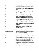
Understanding, servicing, testing and diagnosing air Cp eeenis systems on all popular cars and "ont commercial vehicles
lm From basic theory to in-depth service operations a Step-by-step procedures — alEasy-to-follow fault diagnosis. : : a alECHBOd flow charts
NISSAN wich’
\ ii ee
|
STAGE
4
SSS H31176
ELIVERY PORT ; a FIXED SCROLL
Ia
Fare
Sal
ge ee
a
yg
Air conditioning system components 2¢11 le le
Compressor clutch All vehicle air conditioning compressors are belt-driven from the end of the engine crankshaft. An electro-magnetic clutch disengages the compressor from the drive pulley when compressor operation is unnecessary or is not required. The clutch is operated by the air conditioning control system according to the demands of the air conditioning system. In some systems, the clutch constantly cycles the compressor on and off, whilst in other systems the compressor runs continuously as long as the system is turned on.
Older compressors had a rotating coil clutch design, where the magnetic coil which engages or disengages the compressor was mounted within the pulley, and rotated with the pulley. A stationary coil design is used on all modern compressors. On the majority of compressors, the coil is mounted behind (or inside) the compressor drive pulley, and the drive plate is mounted at the front of the pulley. When the air conditioning system is switched on, the coil is energised, and the magnetic field created pulls the driveplate into engagement with the pulley, which drives the compressor (see illustration).
H31177
Typical compressor clutch components
1 Shaft nut 2 Circlip 3
Spacer
4 Clutch drive plate
5 6 7 8
Clutch hub key Bearing-to-compressor circlip Bearing-to-pulley circlip Pulley bearing
9 Pulley assembly 10 Coil housing circlip 11 Coil and housing assembly
2e12
Air conditioning system components
a
ae
ee
Condenser The condenser is a simple heat exchanger, normally made from copper or aluminium. Several different designs of condensers have been used over the years, including parallel
flow, serpentine, and most commonly, tube and fin (similar to a vehicle cooling system radiator). The condenser is usually mounted directly in front of the radiator, so that it can
receive the full airflow from
the vehicle’s
forward motion (see illustration). The
condenser
receives
the
heated,
pressurised refrigerant vapour from the high pressure side of the compressor. The refrigerant vapour enters at the top of the condenser
and
flows
through
the
coils,
conducting heat through the walls of the tubing and into the cooling fins, then radiating heat from the cooling fins into the atmosphere. As the refrigerant vapours are cooled and
ee
eee
ee
ee
flow down through the condenser, they gradually condense back into liquid form. At the point where the refrigerant vapours condense to liquid, they shed a large amount of latent heat (see Chapter 1). In an air conditioning system operating under an average heat load, the condenser will have a combination of hot refrigerant vapour in
the upper two-thirds, and liquid refrigerant which has condensed in the lower third of the coils. The high pressure liquid refrigerant flows out of the condenser, and moves towards the evaporator.
Bear in mind that an air conditioning condenser is built to withstand the high pressures present in the high side of a system. Never be tempted to fit a cooling system radiator in place of a condenser, as aside from not being designed for air conditioning use, it will probably not cope with the high pressures.
RADIATOR HEAT
FLOW
OUTLET
RAM AIR
CONDENSER
H31178
The condenser is usually mounted in front of the radiator to receive the full airflow from the vehicle’s forward motion
ee
Air conditioning system components
COOLED
2¢13
AIR
OUTLET
H31179
WARM AIR FROM BLOWER
Warm air blown over the evaporator is cooled before passing to the vehicle interior
Condenser fan The correct operation of the condenser cooling fan is essential to allow the air conditioning system to operate efficiently. The condenser must have an adequate flow of air passing through it at all times to carry heat
away from the refrigerant inside. Most vehicles have an electric condenser cooling fan, but a few vehicles may have a viscous-coupled fan or a fan belt-driven directly from the engine. The condenser may share the radiator cooling fan, but on many vehicles an extra fan is fitted to provide the necessary additional airflow. It is common for the fan to operate whenever the air conditioning system is switched on.
Evaporator Like the condenser, the evaporator is similar to a vehicle cooling system radiator. The condenser is usually mounted in a housing behind the vehicle facia, so it must provide the maximum amount of heat transfer for a minimum size. When the air conditioning system
is turned
on,
warm
air from
the
passenger compartment is blown through the coils
and
fins
of
the
evaporator
(see
illustration). The evaporator receives refrigerant as a low pressure, low temperature atomised liquid. As the cold refrigerant passes through the evaporator coils, heat is transferred from the warm air into the cooler refrigerant. When the liquid refrigerant receives.enough
heat,
it vaporises,
changing
from
a low
pressure liquid into a low pressure vapour. In an expansion valve type system, all the liquid refrigerant is turned into a vapour in the evaporator, but in an orifice tube type system the refrigerant is only partially vaporised by the evaporator. The expansion valve or orifice tube controls
the
amount
evaporator
of
refrigerant
to maintain
entering
the optimum
the heat
transfer to the refrigerant. If too much refrigerant is allowed to enter, the evaporator floods, which results in poor heat transfer because the’ higher pressure (and temperature) of the refrigerant prevents it from vaporising easily. If too little refrigerant is allowed into the evaporator, the evaporator is starved, which results because the refrigerant before passing through The warm air blown
in poor heat transfer vaporises too quickly the evaporator. over the evaporator
usually contains some moisture (humidity). This moisture will usually condense on the evaporator coils and drain off as water. A drain tube in the bottom of the evaporator housing allows this water to drain outside the
vehicle. This is why a puddle of water often forms under the vehicle when the vehicle has been parked after the air conditioning has been running. This dehumidification of the air is an added feature of air conditioning which adds to passenger comfort, and also helps to controi fogging of the windows. The evaporator is usually mounted in the same housing as the heater matrix, with a set of moveable flaps between the two © components to allow regulation the airflow and temperature inside the vehicle.
Blower fan and motor An important factor in the cooling action of the evaporator is the blower fan/motor assembly (usually the same unit which blows air through the heater matrix), located in the evaporator housing. The fan draws air from outside the vehicle, or from the passenger compartment, over the evaporator and blows the cooled air into the passenger compartment. The fan may be manually controlled, but is often automatically controlled on modern
air conditioning systems with climate control. A high fan speed will circulate a greater volume of air, but will not provide maximum cooling. A reduction in fan speed will reduce
2°14 Air conditioning system components the volume of air circulated, but the air will remain in contact with the evaporator fins for a longer time. This will allow greater heat transfer from the warm air to the cold refrigerant, and so the coldest air temperature is obtained when the fan is operated at its slowest speed.
Filter/drier (expansion valve type systems) If moisture is allowed to build up inside an air conditioning system, in some cases the water can react with the refrigerant to form an acidic substance which is highly corrosive to the system components. Moisture can also freeze inside the system and block the refrigerant flow, resulting in no cooling action at the evaporator, and possible damage to the compressor. So, moisture in an. air conditioning system can lead to serious problems, and can eventually cause system failure.
A filter/drier (also known as a receiver/drier) is used in expansion valve type air conditioning systems to clean the refrigerant and to remove any moisture. The filter/drier is mounted between the condenser and the evaporator, and consists of a tank, a filter, a drying agent, a pick-up tube and, on some units, a sight glass which allows a view into the refrigerant line (see illustration). The filter/drier protects the system from moisture. The reservoir contains a drying
agent, which may take the form of a bag of desiccant silica gel, although this is being superceded by molecular sieve drying agents on the latest systems. The desiccant can be renewed
in some
filter/driers,
condenser,
until
it’s
.
RK
N .: \)
Cutaway view of a typical filter/drier assembly 1 Filter screen
Filter/drier casing Desiccant bag
required
by
the
evaporator (the evaporator requires a varying amount of refrigerant depending on operating conditions).
N
2 3
further
The filter/drier also acts as a storage reservoir for liquid refrigerant from the
: NN
H31180
and
details are given in Chapter 6.
4 Inlet 5 Sight glass 6 Outlet
Air conditioning system components 2¢15 Ce eS ee teen ER SEE NL i A a SeEL OE Accumulator (orifice tube type systems) An accumulator is used in orifice tube type air conditioning systems. The accumulator is mounted between the evaporator and the compressor, and consists of a tank, a vapour return tube, and a drying agent (see illustration). The accumulator acts as a storage reservoir for liquid refrigerant passed out of the evaporator (liquid refrigerant will damage the compressor), and boils any remaining liquid refrigerant back to vapour. The liquid will sink to the bottom of the accumulator, whilst the vapour is sucked out through a calibrated vapour tube by the
compressor. The accumulator is mounted in the warm engine compartment, and so any liquid refrigerant inside the accumulator rapidly boils to vapour (the boiling point is approximately -30°C), and is passed to the
If moisture is allowed to build up inside an air conditioning system, in some cases the water can react with the refrigerant to form an acidic substance which is highly corrosive to the system components. Moisture can also freeze inside the system and block the refrigerant flow, resulting in no cooling action at the evaporator, and possible damage to the compressor. So, moisture in an_ air conditioning system can lead to serious problems, and can eventually cause system failure. The accumulator also protects the system from moisture. The reservoir contains a drying agent, which may take the form of a bag of desiccant silica gel, although this is being superceded by molecular sieve drying agents on the latest systems. The desiccant can be renewed in some accumulators, and further details are given in Chapter 6.
compressor.
» . V
H31181
Cutaway view of typical accumulator assembly
1 2 3
Desiccant bag Outlet pipe Pressure-sensitive compressor clutch cycling switch
4 Inlet pipe 5 Vapour return tube 6 Liquid bleed hole 7 Filter screen
2°16 Air conditioning system components eS
ee
te
ee
Expansion valve The expansion valve is located between the filter/drier and the evaporator, and its purpose is to control the flow of refrigerant to the evaporator. The expansion valve lowers the pressure (and temperature) of the refrigerant sufficiently to enable the liquid refrigerant to vaporise as it passes through the evaporator coils, absorbing heat from the vehicle interior. The valve assembly consists of a metered orifice, and a thermostatically-controlled valve (see illustration). A calibrated orifice in the valve lowers the pressure of the incoming
refrigerant liquid.
Refrigerant from the filter/drier enters the expansion valve as a liquid under high pressure. As the liquid reaches the orifice in the valve, it’s forced through the small orifice, and sprayed out the other side. This results in a pressure differential, ie, the liquid enters the orifice at high pressure and temperature, and leaves at a lower pressure and temperature,
which allows the atomised mixture of liquid and vapour refrigerant to flow through the evaporator and vaporise completely. A thermostatically-controlled valve located
inside the expansion valve assembly moves from an open to a closed position as required to control the flow of refrigerant passing
through the calibrated orifice. This ensures that the evaporator receives the correct quantity of refrigerant to ensure that all the refrigerant entering the evaporator is boiled to a vapour before it leaves. The valve must respond quickly to changes in heat. As increased heat is sensed, the valve will move towards an open position to increase the flow of refrigerant. A decrease in heat will cause the valve to move towards a closed position, restricting the amount of refrigerant entering the evaporator. Some expansion valves have an inlet filter to prevent any contamination from entering the valve.
SsA
Nii!
Wy4
H31182
Cutaway views of a typical expansion valve
1 Refrigerant flow to
4
Push pins
evaporator inlet
5
Diaphragm
Spring Valve ball and plate assembly
6
2 3
Temperature sensing bulb 7 Capillary tube
8
Liquid refrigerant inlet
9 Orifice 10 Pressure equalising passage
Air conditioning system components
2¢17
H31183 Cutaway of a typical H-type expansion valve with integral temperature sensor and equalising passage 1 2 3
Ball valve and spring Refrigerant flow from condenser Refrigerant flow to compressor
Expansion valve operation Note: The following description of expansion valve operation is for a typical design used in many air conditioning systems. Although there may be detailed differences between this and other types, the basic principles are the same for all types of valve. In a typical expansion valve, the refrigerant flow is controlled by a spring-loaded valve, which, in turn, is contrclled by the difference
in pressure above and below a diaphragm. The movement of the diaphragm is transmitted to the valve through operating pins linking the diaphragm plate and the valve. The pressure above the diaphragm (upper diaphragm chamber) varies according to the pressure inside a temperature sensing bulb (or coil) and capillary tube. The pressure below the diaphragm (lower diaphragm chamber) varies according to the temperature of the refrigerant leaving the expansion valve and entering the evaporator. The valve spring controls a temperature differential across the valve, often known as ‘superheat’.
Temperature sensing bulb and capillary tube The capillary tube, tube end (bulb, coil or plain end) and upper diaphragm chamber form a closed system filled with a temperaturesensitive gas (refrigerant, carbon dioxide or a similar substance). The capillary tube end is clamped onto the evaporator outlet pipe (or fitted in a housing in the outlet pipe), and is insulated from the outside air using special tape. The capillary
4 5
6
Temperature sensor Refrigerant flow from evaporator Refrigerant flow to evaporator
tube end is therefore subjected only to the temperature of the refrigerant as it leaves the evaporator.
Any increase in refrigerant temperature at the evaporator outlet increases the pressure in the capillary tube. This in turn exerts a downward pressure on the expansion valve diaphragm, opening the valve. Similarly, a decrease in refrigerant temperature decreases the pressure in the capillary tube. This reduces the pressure on the diaphragm, allowing the valve to close. The lower diaphragm chamber is subjected to the pressure of the refrigerant leaving the expansion valve and entering the evaporator. On some types of valve, an internal passage connects the valve refrigerant outlet directly to the lower diaphragm chamber, whilst on other types of valve, an external tube is used to supply refrigerant pressure (see illustration).
Expansion valve spring A spring below the valve tends to move the valve towards the closed position, and works in conjunction with the diaphragm to control valve movement. The spring is preset to ensure that there is always a differential between the evaporator inlet and outlet temperatures. This temperature differential is often known as ‘superheat’. The few extra
degrees of heat (typically between 2 and 9°C) ensures that the refrigerant is fully vaporised in the evaporator, and that the vapour leaving the evaporator outlet doesn’t contain any droplets of liquid refrigerant when it reaches the compressor.
2°18 Air conditioning system components EE EE
through the small orifice, and sprayed out the
Orifice tube The orifice tube is located between the condenser and the evaporator, and its purpose is to control the flow of refrigerant to the evaporator. The orifice tube lowers the pressure (and temperature) of the refrigerant sufficiently to enable the liquid refrigerant to vaporise as it passes through the evaporator coils, absorbing heat from the vehicle interior. The orifice tube assembly consists of a tube containing a filter or filters, and a calibrated orifice (see illustration). The calibrated orifice lowers the pressure of the incoming refrigerant liquid. Refrigerant from the condenser enters orifice tube as a liquid under high pressure. As the liquid reaches the calibrated orifice, it’s forced
other side. This results in a pressure differential, ie, the liquid enters the orifice at
high pressure and temperature, and leaves at a lower pressure and temperature, which allows the atomised refrigerant to flow through the evaporator and easily vaporise. The orifice tube meters a steady flow of refrigerant when the compressor is operating, and so the flow of refrigerant through the orifice tube is controlled by the operation of the compressor. A compressor clutch switch, either a thermostatic type or a pressuresensitive type is used to switch the compressor
on and off. The intermittent operation of the compressor controls the refrigerant flow and
pressure.
H31184
Cutaway view of typical orifice tube 1 2
Removal tabs Inlet filter screen
3 4
Orifice O-rings
5
Arrow shows direction of refrigerant flow
Outlet filter screen
a
Air conditioning system components
2°19
Air conditioning system control components So far, we’ve discussed the main components necessary to enable any air conditioning system to do its job. Although these components are necessary to enable an air conditioning system to work, they do not provide enough control to allow the system to work efficiently. For this reason, all automotive air conditioning systems must have additional control devices which allow monitoring of the
system operation and a degree of control to enable the system to operate at optimum efficiency. Two of the main control devices have already been discussed because they are common to every automotive air conditioning system — namely the compressor clutch, and the expansion valve or orifice tube, depending on the type of system. These devices are used to regulate the flow of refrigerant (and therefore the transfer, and eventual removal of
heat) through the air conditioning system. Regulating the refrigerant flow through the system does not guarantee optimum cooling efficiency, and a number of additional control devices are necessary to improve the efficiency of the system, to protect various system components, and to maintain acceptable driveability of the vehicle with the air conditioning system is operating. These additional components can be divided up into four main groups: Compressor controls. Condenser fan controls. Evaporator controls. Driveability controls. Additionally, a high pressure relief valve may be fitted to some systems. The components described in the following pages are amongst the most widely used components in modern automotive air conditioning systems, but additional components not mentioned here, or variations on those found here may be encountered in some systems. The information given is general, and it’s advisable to refer to the appropriate vehicle manufacturer’s information for specific details of a particular system.
Compressor controls Before discussing compressor controls, it’s necessary to understand that compressors
used
in modern
vehicle
air conditioning
systems may either run constantly whenever the air conditioning system is switched on, or may be cycled (switched on and off)
according to the requirements of the system. Most modern constant-running compressor systems use a variable-displacement compressor. With this type of compressor, the refrigerant flow can be controlled without switching the compressor on and off (see Variable-displacement piston-type compressors). Note that constant-running compressors still have a compressor clutch in order to allow the compressor to be stopped
when the air conditioning system is switched off, and when necessary for safety reasons (eg, low or excessive system pressure). The compressor can be effectively switched on and off by controlling the power supply to the compressor clutch coil. Switching of the compressor can be used to prevent excessively high or low system pressures, and overcooling, and to protect the compressor itself from damage due to extreme operating conditions. Switching of the compressor is ~ also used to control the refrigerant flow on systems with a cycling compressor. The most commonly used compressor controls include the following:. Low pressure cut-out switch. High pressure cut-out switch.
Trinary switch. Ambient temperature switch. Pressure-sensitive (cycling) switch (orifice tube type systems). Thermal fuse/superheat switch. ~Thermostatic switch. Compressor crankcase pressure control valve (variable displacement compressors). Various other compressor controls may be used, particularly on modern vehicles with engine management systems, where the compressor clutch is often controlled by the engine management system electronic control unit (ECU). For example, the compressor may have a maximum recommended rotational speed beyond which the internal components may be damaged, so the compressor clutch may be disengaged if the engine speed reaches a level which is likely to damage the compressor. Similarly, if the air conditioning system is switched on, and the driver presses the accelerator pedal fully when the engine speed is low, the compressor clutch may disengaged for a period to increase the engine power available for acceleration. Let’s take a look at the more common compressor controls in more detail.
©
2°20
Air conditioning system components
oe eS SS
The switch
Low pressure cut-out switch The switch is usually wired in series with the compressor clutch, and is used to stop the compressor if the system pressure falls below a predetermined level, which will usually be due to a refrigerant leak somewhere in the system, a blockage in the refrigerant circuit, or very low temperature. If the refrigerant pressure is low because of a leak, or there is no pressure, compressor oil may have been lost along with the refrigerant, and the compressor may be damaged due to lack of lubrication if it continues to run. If the refrigerant pressure drops below a predetermined level, the switch contacts open, stopping the compressor. If the pressure rises above the predetermined level, the switch contacts close, and the compressor is reactivated. As well as stopping the compressor if there is a refrigerant leak, the switch will also stop the compressor if the ambient temperature falls to a very low level (causing low pressure), when there is a risk of damage to the compressor seals, gaskets and reed valves due to poor oil circulation.
pressure
is usually fitted to the high
side of the system
on expansion
valve-type systems, often in the filter/drier or the expansion valve assembly (see illustration). On orifice tube-type systems,
the switch is fitted to the low side of the system, usually in the accumulator.
High pressure cut-out switch This switch is usually wired in series with the compressor clutch, and is used to stop the compressor if the system pressure rises beyond a predetermined level, which will usually be due to a blockage somewhere in the refrigerant circuit, or overheating of the condenser. If the refrigerant pressure reaches a predetermined level, the switch contacts open, stopping the compressor. If the pressure drops back below the predetermined level, the switch contacts close, and the compressor is re-activated. The switch is fitted to the high pressure side of the system, often in the compressor casing (see illustration).
H31186
Typical high pressure cut-out switch located in refrigerant line
H31185
Typical low pressure cut-out switch location — expansion valve system with filter/drier 71 Low pressure cut-out switch 2 Filter/drier
eens
Air conditioning system components Trinary switch This switch is basically a high pressure cutout switch, low pressure cut-out switch, and a condenser fan switch combined into one assembly (see illustration). If the system pressure falls, the low pressure switch opens, stopping the compressor. If the system pressure is excessively
SYSTEM
2¢21
high, the high pressure switch opens, stopping the compressor. If the condenser
temperature rises beyond a preset limit, the fan switch closes, activating the condenser
cooling fan. Trinary switches are common on expansion valve-type systems, and are usually fitted to the filter/drier assembly.
PRESSURE
TRINARY SWITCH ASSEMBLY
AIR CONDITIONING “ON'SWITCH
+12V TO COMPRESSOR +12V +12V TO CONDENSER
FAN
H31187
Schematic view of a typical trinary switch
A
Low-pressure cut-out switch
B_ High pressure cut-out switch
C
Condenser fan start switch
2°22
Air conditioning system components
Ambient temperature switch The ambient temperature switch measures the outside air temperature, and is used in some systems to prevent compressor operation when the outside air temperature is low. If the compressor is operated in extremely cold conditions, it can cause poor oil circulation, damaging the compressor
seals, gaskets and/or valves. If the ambient temperature drops below the range suitable for compressor operation, the switch opens, preventing current flow to the compressor, which stops the compressor. When the ambient temperature reaches the predetermined minimum operating temperature, the switch contacts close, and the compressor starts again. The switch is usually located at the front of the engine compartment, often behind the front grille panel, where it can quickly and accurately sense outside air temperature (see illustration).
Pressure-sensitive (cycling) switch (orifice tube type systems) The switch senses the pressure on the low side of the system, and uses the pressure as an indicator to evaporator temperature (see illustration). The compressor is then cycled on and off by the switch to control the
evaporator
temperature.
Additionally,
the
switch provides freeze protection, and stops the compressor when the ambient temperature (and hence the system pressure) is low. This switch also usually acts as a low pressure cut-out switch (described previously).
H31188 H31189
Typical ambient temperature switch (arrowed)
Typical pressure-sensitive (cycling) switch (arrowed) located in accumulator
Air conditioning system components Thermal fuse/superheat switch A thermal fuse and superheat switch are used to stop the compressor in the event of low system pressure. The two components are used on some vehicles (eg, certain Jaguars) instead of a low pressure cut-out switch (see illustration). The superheat switch is located in the rear of the compressor, and is exposed to the flow of cold refrigerant. The switch contacts are normally open, but if a predetermined temperature is reached (due to a reduction in refrigerant flow), the contacts close, earthing the heater circuit in the thermal fuse through
2¢23
the body of the compressor. When the air conditioning circuit is switched on, the thermal fuse and its heater coil receive a 12-volt supply from the battery, and when the superheat switch contacts close, the circuit is completed
(earthed) which causes the heater coil to heat the fuse. The heater coil will eventually melt the fuse, which cuts the supply to the compressor coil, stopping the compressor. The thermal fuse is often mounted on a bracket on the compressor. If the thermal fuse blows, it must be renewed. A blown fuse can usually be recognised from its melted casing.
AIR CONDITIONING “ON” SWITCH
THERMAL FUSE ASSEMBLY
COLD REFRIGERANT GAS
SUPERHEAT SWITCH
H31190
ie Schematic view of a typical thermal fuse/superheat switch
COMPRESSOR
2°24
Air conditioning system components
ec
te
Thermostatic switch The thermostatic switch fitted to some systems is used to control the compressor according to the temperature of the evaporator. The switch has a temperature-
sensing capillary tube located to sense the evaporator temperature (see illustration). The capillary action will cause the switch contacts to open or close according to the temperature of the evaporator. The switch works within a predetermined temperature range, switching the compressor off at a preset temperature and back on again at another preset
temperature. Some switches are adjustable so that the compressor switching can be
controlled according to the system venicle occupants’ requirements.
When the temperature in the evaporator approaches freezing, the thermostatic switch contacts open, disengaging the compressor clutch, which stops the compressor. This allows the temperature in the evaporator to
rise (due to the lack of refrigerant flow) until, at the predetermined temperature, the switch contacts close, engaging the compressor clutch, and restarting the compressor.
H31191
Typical thermostatic switch
1 Evaporator
2
and
Thermostatic switch
3
Capillary tube
Air conditioning system components Compressor crankcase pressure control valve (variable displacement compressors) This valve is mounted in the rear of the compressor, and regulates the compressor crankcase pressure (see illustration). The crankcase pressure controls the angle of the variable; angle squish-plate, which in turn controls the compressor displacement (see Variable displacement piston-type compressors). The control valve contains a pressuresensitive diaphragm, which is exposed to pressure on the suction side of the compressor. The diaphragm acts on a valve exposed to the compressor high-side pressure. The diaphragm also controls the opening and closing of a bleed port which is exposed to suction side pressure. When the temperature of the evaporator decreases, or the speed of the compressor
2°25
increases (due to engine speed), the low-side pressure (suction) at the compressor decreases. This reduction in pressure is sensed by the control valve, which allows pressure from the high-side of the compressor through the bleed port into the crankcase. The high pressure in the crankcase pushes against the undersides of the compressor pistons, reducing the angle of the squish-plate, and effectively shortening the stroke of the pistons. When the temperature of the evaporator increases, or the speed of the compressor reduces, the low-side pressure at the com-
pressor increases. The increase in pressure moves the control valve diaphragm to close off the high pressure bleed port into the crankcase. This reduces the crankcase pressure, increasing the angle of the squish-
plate, and effectively lengthening the stroke of the pistons.
Cutaway view of rear of typical variable displacement compressor showing crankcase pressure control valve location (arrowed)
2°26 Air conditioning system components a
Condenser fan controls Most vehicles use an electric cooling fan to ensure an adequate flow of air through the condenser and the cooling system radiator. On vehicles with air conditioning, two fans are often fitted, and they’re usually connected to the air conditioning control system and operate when the system is turned on. This ensures an adequate airflow through the
Pressure-sensitive air conditioning system fan switch
condenser at all times, and helps to prevent
This type of switch may be encountered on certain vehicles fitted with a variable-displacement compressor (which runs constantly). This switch controls the cooling fan(s) according to the compressor high-side pressure, and is located in the compressor refrigerant discharge line. The switch operates in conjunction with the cooling system fan temperature switch.
excessive system pressure.
Evaporator controls
Although the fan system does not have a direct affect on the operation of the air conditioning system, if a fan does not operate when required, it can rapidly lead to excessive system pressures and temperatures.
The most commonly used condenser fan controls include the following: Cooling fan switch (located in the engine coolant circuit). Air conditioning system high pressure fan switch. Air conditioning system trinary switch. Air conditioning system ‘on’ switch. Pressure-sensitive air conditioning system fan switch. Further
details
of each
component
are
given in the following paragraphs.
Cooling system fan temperature switch This sensor is not part of the air conditioning system, and switches on the cooling fan(s) when the engine coolant reaches a predetermined temperature. The switch interrupts power to the fan(s) when the coolant temperature drops below a second predetermined temperature (usually lower than the switch on temperature). Note that on many vehicles, the cooling fan(s) will run even when the ignition is switched off.
Air conditioning system high pressure fan switch On some vehicles, a high pressure switch in the air conditioning system refrigerant circuit activates the cooling fan(s) when the refrigerant pressure rises above a predetermined level, shortly after the compressor
starts to operate. When the air conditioning system is switched off, the cooling fan system is controlled purely by the cooling system fan temperature switch. On some vehicles, the air conditioning system high pressure fan switch may provide an input signal to the engine management system.
Air conditioning system trinary switch On some. vehicles, an air conditioning system high pressure fan switch (described previously) is incorporated in the trinary switch (see Compressor controls).
Air conditioning system ‘on’ switch Many vehicles have an air conditioning system ‘on’ fan switch, which activates the
fan(s) whenever the air conditioning system is switched on. This ensures that there is always an adequate airflow through the condenser.
Note: The controls described here are used to control the evaporator temperature by directly controlling the refrigerant flow through the evaporator. It’s important to note that the evaporator temperature is also effectively controlled by the cycling of the compressor, which indirectly controls the flow of refrigerant through the evaporator. Details of compressor’s controls are given earlierin this Chapter. Evaporator controls tend to be found on older US specification vehicles with compressors which run constantly. Evaporator controls
are
rare
on
European
vehicles,
although they may be found on some older vehicles such as the Rover SD1 series. As we’ve already seen, the refrigerant flow through the evaporator is the key to the efficient operation of an air conditioning system. Sometimes, under certain operating conditions, the condensation which forms on the outside of the evaporator may freeze, which can block the evaporator fins, and reduce the airflow through the evaporator. This reduces the evaporator’s cooling ability, and hence the efficiency of the system. Evaporator controls help to prevent freezing, and help keep the air conditioning
system operating efficiently. The most commonly used evaporator controls include: Suction throttling valve (STV). Pilot Operated Absolute Suction Throttling Valve (POA STV). Valves-In-Receiver (VIR). Evaporator-Equalised Valves-In-Receiver (EEVIR). Evaporator Pressure Regulator (EPR) valve.
Suction Throttling Valve (STV) The suction throttling valve (STV) was used on some early expansion valve type air conditioning systems to control the refrigerant flow leaving the evaporator. In an air conditioning system containing an STV, the compressor is running constantly, as long as the air conditioning system is switched on. A typical STV opens or closes in response
to refrigerant pressure to keep the pressure in the evaporator within a predetermined range. This maintains the evaporator temperature at a level which ensures efficient operation of the air conditioning system without allowing the evaporator to freeze up.
Air conditioning system components Pilot Operated Absolute Suction Throttling Valve (POA STV) Most modern STVs are of the pilot operated absolute (POA) type. A POA STV valve is really nothing more than a spring-loaded valve, controlled by an evacuated bellows and needle valve assembly inside a housing (see illustration). The valve operates indepen-dently of atmospheric pressure, and is not affected by altitude changes. By providing an opposing force to evaporator pressure, the valve can maintain
the
evaporator
pressure
very
Provided the evaporator pressure is above a predetermined level, the POA STV valve remains open to allow refrigerant to flow freely out of the evaporator. When the pressure drops below the predetermined level, the valve closes, and the refrigerant flow from the evaporator is restricted. The pressure in the evaporator then increases, which raises the temperature and prevents possible freezing
on the outside of the evaporator. The opening and closing cycle of the valve continues as long as the compressor is running.
accurately (often within a 1 psi/7 kPa range).
H31193
Typical Pilot Operated Absolute Suction Throttling Valve (POA STV)
1 2 3 4
Refrigerant flow from evaporator Service valve Protective cap Liquid bleed line connection
2°27
5
6
Expansion valve equaliser line connection (not used on all valves) Refrigerant flow to compressor
2°28
Air conditioning system components
Valves-In-Receiver (VIR) : : A valves-in-receiver
combined
expansion
(VIR)
Ai
In a VIR unit, the temperature-sensing bulb assembly
‘ a is
Sat anette
absolute suction throttling valve (POA STV),
and filter/drier in one unit. The unit is usually mounted near the evaporator (see illustration).
i and capillary tube for the expansion valve are
eliminated because the diaphragm end of the
expansion valve Is SPY
"€f"igerant vapour entering te evaporator outlet.
SEs
the
=
G= Z= Z=
22>
;
H31194
1k"
Cutaway view of typical Valve-In-Receiver (VIR) assembly 1 Receiver (filter)/drier casing 2 Desiccant bag 3 Valve housing-to-receiver O-ring 4 POA valve capsule 5 Equaliser port 6 POA valve O-ring
7 Service valve 8 Inlet connector casing 9
Valve capsule securing screw and washer assembly 10 Inlet connector casing-tovalve housing O-ring
17 Expansion valve upper Orings
12 Expansion valve capsule 13 Expansion valve lower O-ring 14 Expansion valve inlet 15 Liquid pick-up tube O-ring 16 Liquid pick-up tube ‘17 Pick-up tube filter screen
Air conditioning system components Evaporator-Equalised Valves-InReceiver (EEVIR) The evaporator-equalised __valves-inreceiver unit is a modified version of the VIR unit (described previously) which has a redesigned expansion valve in order to eliminate temperature fluctuations in the system which occur under certain operating conditions. The expansion valve is also modified so that it is always partially open instead of closing completely, which helps to prevent freezing at the expansion valve (which will block the refrigerant flow and stop the system from operating).
2°29
Note: On most modern vehicles fitted with engine management systems, the air
conditioning compressor clutch is controlled by the engine management electronic control unit (ECU). The compressor is controlled according to the information received from the various engine management system sensors, to ensure that the driveability of the vehicle does not suffer. This reduces the need for separate driveability controls.
Time delay relay A time delay relay is sometimes used to delay the engagement of the compressor for a
few seconds after engine start-up if the air
Evaporator Pressure Regulator (EPR) valve
Wide-open throttle switch
The evaporator pressure regulator (EPR) valve is normally fitted to the inlet port of the compressor (see illustration). The valve maintains the evaporator outlet pressure within predetermined limits. An EPR valve performs the same function as the suction throttling valve described previously.
A wide-open throttle switch is sometimes used on vehicles with small capacity engines. The switch is operated by the throttle linkage. When the throttle pedal is fully depressed, the switch activates a relay which interrupts the compressor clutch circuit. This reduces the load on the engine, and improves acceleration.
Driveability controls
Closed throttle switch
An air conditioning compressor takes a significant amount of power to run (on average between 7 and 11 kW/ 10 and 15 hp of engine power), and the effect of compressor operation, in conjunction with other demands placed on the engine, can impose loads which reduce vehicle performance. This is a significant problem on vehicles with small capacity engines. Driveability controls are used to control the operation of the compressor to relieve the load on the engine under conditions when driveability may suffer. These controls do not usually affect the cooling performance of the air conditioning system.
A closed throttle switch is sometimes used on vehicle with small capacity engines. The switch is operated by the throttle linkage, and interrupts the compressor clutch. circuit to prevent the risk of the compressor load stalling the engine when the throttle is closed under overrun conditions.
conditioning is switched on.
Low vacuum
switch
Low vacuum switches are used on some vehicles to interrupt the operation of the air conditioning compressor when engine loads are heavy, resulting in low vacuum in the inlet manifold.
H31195
Typical Evaporator Pressure Regulator (EPR) valve
2°30
Air conditioning system components
Power steering pressure switch
Constant run relay
On a vehicle with a small capacity engine and power steering, under normal driving conditions, the power steering has little effect on the performance of the vehicle. However, during parking manoeuvres, the power steering system imposes its heaviest loads on the engine. When parking, the engine speed and power output are usually low, and so compressor operation is likely to reduce the engine power available even further, which may cause rough idling and stalling. To prevent these problems, some vehicles are fitted with a power steering pressure switch, which disengages the compressor whenever the power steering hydraulic pressure exceeds a predetermined level. Some vehicles are equipped with a more sophisticated version of this system where the switch sends a signal to the engine management system. The engine management ECU can then adjust the engine idle speed to compensate for the higher steering loads, without the need to disengage the compressor.
Some vehicles are equipped with a constant run relay which is controlled by the engine management system, and is used to maintain idle quality. The relay prevents compressor cycling when the engine is idling, for a predetermined period after normal driving. If the engine is left idling for an extended
time,
the
relay
returns
the
compressor to its normal cycling mode for a short time, to prevent the evaporator from freezing up.
Compressor delay timer This device is sometimes used on vehicles equipped with an engine management system. When the engine is idling (or running below a predetermined speed), and the air conditioning system is switched on, the timer delays the engagement of the compressor clutch for a few seconds whilst the engine idle speed is raised to compensate for the additional load. The compressor clutch is engaged as soon as the engine idle speed has stabilised.
Anti-dieseling relay Power brake switch On a vehicle with a small capacity engine, if the air conditioning compressor is running when the brakes are applied, it’s possible that
Some engines have a tendency to run on or ‘diesel’ after the ignition is switched off. To prevent this, on some vehicles the compressor is used to prevent dieseling. As
the
soon
engine
may
stall,
which
could
be
potentially dangerous. A power brake switch may be fitted to disengage the compressor under certain circumstances when the brakes are applied, to prevent the possibility of engine stalling.
Engine coolant high temperature switch The air conditioning condenser is usually positioned in front of the engine cooling system radiator. The air conditioning system transfers heat to the air passing through the condenser, which then has to pass through the radiator. When the ambient temperature is high, the already heated air passing over the radiator is unable to carry away sufficient heat from the engine coolant, and overheating can result. To prevent the possibility of overheating, some vehicles are equipped with a coolant temperature switch which disengages the compressor clutch when the coolant temperature exceeds a predetermined level.
as
the
ignition
is switched
off, the
compressor clutch is engaged for a few seconds. This additional load stalls the engine and prevents dieseling.
High pressure relief valve Many systems incorporate a high pressure relief valve, although a few systems use a disc which will burst when a pre-determined pressure is reached. The valve or disc is fitted to the high pressure side of the system, and is used as a safety device in the event of excessive pressure in the system. Most valves will close when the pressure has dropped to a
safe level. Any excess pressure is likely to be due to an overheated condenser or an overcharge of refrigerant. The valve is often located on the receiver/ drier (expansion valve type systems) or on the compressor, usually in a safe place, so that there is no risk of refrigerant being discharged towards anyone working on the vehicle. If the valve opens for any reason, the system will require recharging with refrigerant and compressor oil.
Air conditioning system components
2°31
Refrigerants As we discussed in Chapter 1, there are two refrigerants commonly used in vehicle air
oils). If the wrong refrigerant is used, it will not mix with the oil in the system,
conditioning
resulting in a lack of lubrication, and serious damage to the compressor.
systems,
known
as
R12
and
R134a. Other types of refrigerant may be used if the system is serviced, but R12 and R134a are currently the only refrigerants which have been approved by the vehicle manufacturers for use in their air conditioning systems (see illustration). At this stage, it’s important to point out that the components used in most air conditioning systems are designed specifically to be used with either R12 refrigerant, or R134a refrigerant, but not both. R12 system components and refrigerant must never be used in an R134a system, and vice versa. There are three main reasons for this: 1) R12 systems use a mineral-based compressor oil, whereas R134a systems use synthetic PAG oil (see Compressor
2) The seals and flexible hoses used in R134a systems are specially designed to prevent the extremely small R134a molecules from escaping from the system (the molecules are small enough to pass through a normal hose). If R134a is used in an R12 system, the refrigerant will leak out. 3) In general, R134a systems operate at higher pressures than R12 systems. If
R134a is used in a system designed for R12, the higher pressures may cause damage to components (particularly the compressor) and seals. Now let’s look at the two refrigerants in more detail.
Typical R12 bulk refrigerant cylinder
2°32
Air conditioning system components
R12
R134a
General
General
e
R12 refrigerant is a CFC (ChioroFluoro Carbon) and has been used since it was first discovered in the 1930s.
_¢@
¢
An air conditioning system which uses R12 refrigerant can be identified from its screw-on service port connections (see
e
Chapter 6).
Advantages
Advantages
e
R12 is non-flammable.
¢ ¢
R12 is non-poisonous in small quantities. R12 mixes with mineral oil (mineral oil can be used to lubricate
_
the compressor).
_
non-flammable. non-poisonous in small quantities. ozone-friendly. of R134a is low compared to that of R72.
Disadvantages e e ®
¢
There are numerous alternatives to R12 and R134a on the market for use when servicing air conditioning systems, but at the time of writing, R12 and R134a were the only refrigerants approved by the vehicle manufacturers for use in their systems. It’s strongly recommended that only the manufacturer’s specified refrigerant is used
Anair conditioning system which uses R134a refrigerant can be identified from its snap-on service port connections (see Chapter 6). R134a is R134a is R134a is The cost
Disadvantages e R12 destroys ozone. ‘ e R12 is a greenhouse gas. e Inthe presence of an open flame, it produces phosgene (mustard gas) which is deadly to humans.
Alternative refrigerants
134a refrigerant has been used instead of R12 since around 1992.
R134a is a greenhouse gas (less damaging than R12). Inthe presence of an open flame, it produces hydrogen fluoride (HF) gas which is deadly to humans. R134a needs special barrier refrigerant hoses to keep refrigerant in (due to the very small size of R134a molecules) and moisture out (the compressor oil is very hygroscopic). R134a does not mix with mineral oil, so a special oil (PAG oil) must be used in the compressor. This oil is very expensive and hygroscopic (see Compressor oils).
during any service operations (see Chapter 6). Bear in mind that if some of the alternative refrigerants are introduced into equipment designed for handling R12 or R134a (even dual circuit machines designed to handle both R12 and R134a), the equipment may be contaminated. It’s strongly recommended that the refrigerant in the system is identified before connecting refrigerant handling equipment — see Chapter 6.
Air conditioning system components
2°33
Compressor oils All compressors
need
lubricating
oil to
protect the internal components and, in the case of rotary vane compressors, to provide a sealing action. Without oil, a compressor will fail very quickly, and this could prove to be very expensive! Although the purpose of the oil is purely to lubricate the compressor, the oil and the refrigerant mix together, and are pumped around the system by the compressor. This means that although a high proportion of the oil will be in the compressor at any one time, a proportion of the oil will be circulating around the other system components. This in turn means that if there is a refrigerant leak, some oil will also be lost from the system.
Two
different
types
of oil are
used
in
automotive air conditioning systems, and the type of oil used depends on the type of refrigerant used in the system. R12 refrigerant mixes with mineral oil, so a mineral oil can be used to lubricate the compressor.
Most compressors use the same
grade of mineral oil, but a number of grades of oil are available. The grade of oil recommended
by
the
compressor
manufacturer
should
always be used. R134a refrigerant does not mix with mineral oil, SO a special synthetic oil has been developed specifically for use with R134a. The oil used is Known as Poly Alkaline Glycol, or PAG oil. PAG oils are available in a range of viscosities to suit different systems. The viscosity of oil required depends on the requirements of the compressor, and the diluting affect of the refrigerant in the system. Always use the grade of oil recommended by the compressor manufacturer.
Note: Compressor oils, particularly PAG oils are very hygroscopic — ie, they absorb water. To prevent problems, compressor oil containers must always be tightly sealed, and should not be left open to atmosphere. Some compressor oil manufacturers recommend that the oil is discarded if it is left open to the atmosphere for more than 20 minutes! Similarly, whenever system components are disconnected, the open pipes and components should be sealed immediately (cover or plug the openings) to minimise the entry of moisture.
Chapter 3
Typical air conditioning systems Contents MAT OCHICTION Brac nsec isiers ite Cato epane eiche tale saeRne a isles ie soe 3e1 High and low sides of the air conditioning system ............. 3e2 GLO LEH Sete wa et Weecic A ARAL G nS Ee eateR onet a SREP aA 3°3 MESSI COM arrern dens create: orkad teins pea ticksrale elvan Oke close sanele inseho 3°3 Manually-controlled air conditioning systems ...............- 304 EXDASION ValVO:- SYSUGM aes citaciatetateuas taterelshebett sist=