Errata for USB revision 2.0
370 65 166KB
English Pages 31 Year 2000
Recommend Papers

![Errata [1ª Edição]](https://ebin.pub/img/200x200/errata-1-ediao.jpg)
![Errata [1ª Edição]](https://ebin.pub/img/200x200/errata-1-ediao-a-5911838.jpg)


- Similar Topics
- Technique
- Electronics: Microprocessor Technology
File loading please wait...
Citation preview
Errata for “USB Revision 2.0 April 27, 2000” as of 12/7/2000 Check the http://www.usb.org website for the latest errata.
Chapter 5 Reversed Values in Transaction Overhead Tables: Background: The tables in chapter 5 showing high-speed transaction overheads have typographical errors where the interpacket gap and minimum bus turnaround time values were reversed. No functional impact. Change: p. 43, table 5-3 & p. 45, table 5-5 and p. 51, table 5-8: change “…8 bit interpacket gap, 88 bit min bus…” to “…88 bit interpacket gap, 8 bit min bus…”. Table 5-3. High-speed Control Transfer Limits (Based on 480 Mb/s and 88 bit interpacket gap, 88 bit min bus turnaround, 32 bit sync, 8 bit EOP: (9x4 SYNC bytes, 9 PID bytes, 6 EP/ADDR+CRC,6 CRC16, 8 Setup data, 9x(1+11) byte interpacket delay (EOP, etc.))
Protocol Overhead (173 bytes)
Max
Data Payload
Max Bandwidth (bytes/second)
Microframe Bandwidth per Transfer
Max Transfers
Bytes Remaining
1
344000
2%
43
18
43
2
672000
2%
42
150
84
4
1344000
2%
42
66
168
8
2624000
2%
41
79
328
16
4992000
3%
39
129
624
32
9216000
3%
36
120
1152
64
15872000
3%
31
153
1984
60000000
Bytes/ Microframe Useful Data
7500
1
Table 5-8. High-speed Interrupt Transaction Limits
Max
Protocol Overhead
(Based on 480 Mb/s and 88 bit interpacket gap, 88 bit min bus turnaround, 32 bit sync, 8 bit EOP: (3x4 SYNC bytes, 3 PID bytes, 2 EP/ADDR+CRC bytes, 2 CRC16 and a 3x(1+11) byte interpacket delay(EOP, etc.))
Data Payload
Microframe Bandwidth per Transfer
Max Transfers
Bytes Remaining
Max Bandwidth (bytes/second)
Bytes/ Microframe Useful Data
1
1064000
1%
133
52
133
2
2096000
1%
131
33
262
4
4064000
1%
127
7
508
8
7616000
1%
119
3
952
16
13440000
1%
105
45
1680
32
22016000
1%
86
18
2752
64
32256000
2%
63
3
4032
128
40960000
2%
40
180
5120
256
49152000
4%
24
36
6144
512
53248000
8%
13
129
6656
1024
49152000
14%
6
1026
6144
2048
49152000
28%
3
1191
6144
3072
49152000
42%
2
1246
6144
60000000
7500
2
Table5-5. High-speed Isochronous Transaction Limits Protocol Overhead
Data Payload
Max
(Based on 480 Mb/s and 88 bit interpacket gap, 88 bit min bus turnaround, 32 bit sync, 8 bit EOP: (2x4 SYNC bytes, 2 PID bytes, 2 EP/ADDR+addr+CRC5, 2 CRC16, and a 2x(1+11)) byte interpacket delay (EOP, etc.))
Max Bandwidth (bytes/second)
Microframe Bandwidth per Transfer
Max Transfers
Bytes Remaining
Bytes/ MicroFrame Useful Data
1
1536000
1%
192
12
192
2
2992000
1%
187
20
374
4
5696000
1%
178
24
712
8
10432000
1%
163
2
1304
16
17664000
1%
138
48
2208
32
27392000
1%
107
10
3424
64
37376000
1%
73
54
4672
128
46080000
2%
45
30
5760
256
51200000
4%
25
150
6400
512
53248000
7%
13
350
6656
1024
57344000
14%
7
66
7168
2048
49152000
28%
3
1242
6144
3072
49152000
41%
2
1280
6144
60000000
7500
3
Chapter 7 Issue with Test_SE0_NAK Behavior: Background: While in test mode Test_SE0_NAK, upstream facing ports “must respond to any IN token packet with a NAK handshake (only if the packet CRC is determined to be correct) within the normal device response time.” The question has been raised as to the meaning of “any IN token” and whether a device must NAK even if the packet is not directed to the device or directed to any endpoint on that device. If it must, a device placed in this test mode will NAK even when an IN token is directed to another devices, such as a mouse or keyboard, resulting in possible problems for other devices connected to the bus during compliance testing. At this point, there are probably implementations that interpret the spec both ways, so this erratum expands the spec to allow either interpretation. This will have to be dealt with in compliance testing. There will be no impact on non-test-mode operation. Change: p. 169, section 7.1.20, 1st bullet, 3rd sentence: Change complete sentence to: “In addition, while in this mode, upstream facing ports (and only upstream facing ports) must respond to any IN token packet directed to the device (with an endpoint number supported by the device), and optionally to any IN token packet which is not directed to the device or optionally with any endpoint number, with a NAK handshake (only if the packet CRC is determined to be correct) within the normal device response time. Note: This means that the host should send test packets to a device under test with the device’s current address and endpoint number zero to ensure that the device will respond.”
7.1.20 Test Mode Support To facilitate compliance testing, host controllers, hubs, and high-speed capable functions must support the following test modes: •
Test mode Test_SE0_NAK: Upon command, a port’s transceiver must enter the highspeed receive mode and remain in that mode until the exit action is taken. This enables the testing of output impedance, low level output voltage, and loading characteristics. In addition, while in this mode, upstream facing ports (and only upstream facing ports) must respond to any IN token packet with a NAK handshake (only if the packet CRC is determined to be correct) within the normal allowed device response time. In addition, while in this mode, upstream facing ports (and only upstream facing ports) must respond to any IN token packet directed to the device (with an endpoint number supported by the device), and optionally to any IN token packet which is not directed to the device or optionally with any endpoint number, with a NAK handshake (only if the packet CRC is determined to be correct) within the normal device response time. Note: This means that the host should send test packets to a device under test with the device’s current address and endpoint number zero to ensure that the device will respond. This enables testing of the device squelch level circuitry and, additionally, provides a general purpose stimulus/response test for basic functional testing.
4
Issue with Test_Force_Enable Behavior: Background: The question has been raised as to the meaning of the language that says “…the disconnect bit can be polled while varying the loading on the port, allowing the disconnect detection threshold voltage to be measured.” Some implementations have allowed the port to exit the test mode and return to the disconnected port state when the disconnect threshold is exceeded. Others have let the port stay in the test mode and allowed the bit to be “live”. This erratum allows either behavior. There will be no impact on non-test-mode operation. Change: p. 170, section 7.1.20, bullet on Test_Force_Enable: Add sentence at end of paragraph, “Disconnect detection is optionally allowed to exit test_mode and return the port to the disconnected port state.” •
Test mode Test_Force_Enable: Upon command, downstream facing hub ports (and only downstream facing hub ports) must be enabled in high-speed mode, even if there is no device attached. Packets arriving at the hub’s upstream facing port must be repeated on the port which is in this test mode. This enables testing of the hub’s disconnect detection; the disconnect detect bit can be polled while varying the loading on the port, allowing the disconnect detection threshold voltage to be measured. Disconnect detection is optionally allowed to exit test_mode and return the port to the disconnected port state.
Issue with Test_Packet behavior: Background: The question has been raised as to the minimum inter-packet gap allowed for an upstream facing port in test mode Test_Packet. The spec states that “The inter-packet timing must be no less than the minimum allowable inter-packet gap as defined in Section 7.1.18 and no greater than 125us.” Unfortunately, an upstream facing port never sends back-to-back packets, so this parameter is actually not defined. Since an upstream facing port may send a packet in response to an incoming packet after a minimum of 8 bit times, some designers have interpreted this to mean the minimum inter-packet gap in the test mode should be 8 bit times. This erratum allows this interpretation. It will meet the needs of compliance testing, and there will be no impact on non-test-mode operation. Change: p. 170, section 7.1.20, bullet on Test_Packet: Add sentence at end of paragraph, “For an upstream facing port, the inter-packet timing must be no less than 8 bit times.” •
Test mode Test_Packet: Upon command, a port must repetitively transmit the following test packet until the exit action is taken. This enables the testing of rise and fall times, eye patterns, jitter, and any other dynamic waveform specifications. The test packet is made up by concatenating the following strings. (Note: For J/K NRZI data, and for NRZ data, the bit on the left is the first one transmitted. “S” indicates that a bit stuff occurs, which inserts an “extra” NRZI data bit. “* N” is used to indicate N occurrences of a string of bits or symbols.)
5
• NRZI Symbols (Fields)
NRZ Bit Strings
Number of NRZ Bits
{KJ * 15}, KK
{00000000 * 3}, 00000001
32
11000011
8
JKJKJKJK * 9
00000000 * 9
72
JJKKJJKK * 8
01010101 * 8
64
JJJJKKKK * 8
01110111 * 8
64
JJJJJJJKKKKKKK * 8
0, {111111S *15}, 111111
97
JJJJJJJK * 8
S, 111111S, {0111111S * 7}
55
{JKKKKKKK * 10}, JK
00111111, {S0111111 * 9}, S0
72
JJJKKKJJKKKKJKKK
0110110101110011
16
01111111
8
(SYNC) KKJKJKKK (DATA0 PID)
(CRC16) JJJJJJJJ (EOP)
A port in Test_Packet mode must send this packet repetitively. The inter-packet timing must be no less than the minimum allowable inter-packet gap as defined in Section 7.1.18 and no greater than 125 µs. For an upstream facing port, the inter-packet timing must be no less than 8 bit times.
Issue with TDR Loading Specification: Background: On page 144, Section 7.1.6.2, 4th paragraph, there is a sentence which reads “No single excursion, however, may exceed the Through limits for more than twice the TDR rise time (400 ps).” This is confusing, since the TDR risetime is required to be 400 ps, not 200 ps. This erratum clarifies the language. There is no negative impact caused by this clarification. Change: Change the sentence to read “No single excursion, however, may exceed the Through limits for more than twice the TDR rise time (twice the 400 ps risetime is 800 ps).” No single excursion, however, may exceed the Through limits for more than twice the TDR rise time (twice the 400 ps risetime is 800 ps).No single excursion, however, may exceed the Through limits for more than twice the TDR rise time (400 ps).
6
Chapter 8 Issue with Some PING STALL Response Omissions: Background: The PING protocol state machines and “railroad diagrams” show (correctly) that STALL is an allowed response to PING. However, two sentences in the spec do not explicitly mention STALL. This change should cause no functional impact since the more explicit and detailed figures show the full set of allowed responses. Any potential impact is limited to bulk OUT and control endpoints in high-speed devices. Change: p. 217, section 8.5.1, 4th paragraph, last sentence: change “… a NAK or an ACK handshake.” to “…. a NAK, STALL or an ACK handshake.” The host controller queries the high-speed device endpoint with a PING special token. The PING special token packet is a normal token packet as shown in Figure 8-5. The endpoint either responds to the PING with a NAK, STALL, or an ACK handshake. Change: p. 219, section 8.5.1.1, 3rd paragraph, change “…. the allowed ACK, NAK or an NYET handshakes for the PING mechanism.” to “…. the allowed ACK, NAK, STALL or an NYET handshakes for the PING mechanism.” Figure 8-27 shows the host controller state machine for the interactions and transitions between PING and OUT/DATA tokens and the allowed ACK, NAK, STALL, or an NYET handshakes for the PING mechanism.
Clarifying PING Related OUT NAK Responses: Background: The PING protocol tries to limit NAK responses to OUT transactions. However, a description in the spec suggests that NAK responses to PING transactions are unusual, (which it not true). This change should cause no functional impact since the other descriptions of PING more clearly identify that PING can be NAK’d “forever”. Any potential impact is limited to bulk OUT and control endpoints in high-speed devices. Change: p. 218, section 8.5.1.1, 2nd paragraph, 1st sentence: change “A NAK response is expected to be an unusual occurrence.” to “A NAK response to an OUT is expected to be an unusual occurrence.” p. 218, section 8.5.1.1, 2nd paragraph, 3rd sentence: change “…allowed to NAK…” to “… allowed to NAK an OUT…”
A NAK response to an OUT is expected to be an unusual occurrence. A high-speed bulk/control endpoint must specify its maximum NAK rate in its endpoint descriptor. The endpoint is allowed to NAK an OUT at most one time each bInterval period. A NAK suggests that the endpoint responded to a previous OUT or PING with an inappropriate handshake, or that the endpoint transitioned into a state where it (temporarily) could not accept data. An endpoint can use a bInterval of zero to indicate that it never NAKs. An endpoint must always be able to accept a PING from the host, even if it never NAKs.
7
Incorrect Figure 8-27 (Host High-speed Bulk OUT/Control Ping State Machine): Background: The Host High-speed Bulk OUT/Control Ping State Machine figure was incorrectly cut and pasted from the draft specification (where it was correct). The current (incorrect) figure is a total duplicate of figure 8-32. Any potential impact is limited to bulk OUT and control endpoints in high-speed devices. Change: p. 218: Replace incorrect Figure 8-27 with below: (HSU2.PID /= STALL and HSU2.PID /= NAK and HSU2.PID /= ACK and HSU2.PID /= NYET) or HSU2.timeout
Wait_resp1 Wait_for_packet( HSU2, ITG);
BCI_error1 IncError;
ErrorCount >= 3 RespondHC(Do_halt);
Packet_ready(HSU2)
ErrorCount < 3 RespondHC(Do_ping);
&
Issue_packet(HSD1, datax);
HSU2.PID = NYET RespondHC(Do_next_ping); Do_data1
not HC_cmd.setup and not HC_cmd.ping
HSU2.PID = STALL
Issue_packet( HSD1, tokenOUT);
RespondHC(Do_halt); HSU2.PID = NAK
HC_cmd.setup
RespondHC(Do_ping);
Issue_packet(HSD1, tokensetup);
HSU2.PID = ACK RespondHC(Do_next_cmd); Do_token1
HSU2.PID = ACK RespondHC(Do_OUT); HSU2.PID = NAK
HC_cmd.ping and not HC_cmd.setup
RespondHC(Do_same_cmd);
Issue_packet(HSD1, ping); Ping_resp Wait_for_packet( HSU2, ITG);
HSU2.PID = STALL RespondHC(Do_halt);
Packet_ready(HSU2) &
ErrorCount >= 3 RespondHC(Do_halt);
Not allowed for control setup transaction
(HSU2.PID /= NAK and HSU2.PID /= ACK and HSU2.PID /= STALL) or HSU2.timeout
P_err IncError;
ErrorCount < 3 RespondHC(Do_same_cmd);
HC_HS_BCO
Figure 8-27. Host High-speed Bulk OUT/Control Ping State Machine
8
Clarifying Figure Title for Figure 8-31 & 8-32: Background: The titles on figures 8-31 and 8-32 are misleading. The current titles suggest that the figure is uniformly applicable for all speeds, bulk/control/interrupt OUT transactions, (which is not true). No functional impact. Change: p.222, figure 8-31: caption should be “FS Bulk, FS/LS Control, or HS/FS/LS Interrupt OUT Transaction Host State Machine”
(HSU2.PID /= STALL and HSU2.PID /= NAK and HSU2.PID /= ACK) or HSU2.timeout
Wait_resp Wait_for_packet( HSU2, ITG);
BCI_error IncError;
Packet_ready(HSU2) ErrorCount < 3 &
Issue_packet(HSD1, datax);
RespondHC(Do_same_cmd); ErrorCount >= 3 RespondHC(Do_halt);
Do_data not HC_cmd.setup Issue_packet( HSD1, tokenOUT);
HSU2.PID = STALL RespondHC(Do_halt); HC_cmd.setup
Issue_packet(HSD1, tokensetup);
HSU2.PID = NAK RespondHC(Do_same_cmd);
HSU2.PID = ACK
Do_token
RespondHC(Do_next_cmd); Not allowed for control setup transaction
HC_Do_BCINTO
Figure 8-31. FS Bulk, FS/LS/ Control, or HS/FS/LS Interrupt/ OUT Transaction Host State Machine
9
Change: p. 223, figure 8-32: caption should be “FS Bulk, FS/LS Control, or HS/FS/LS Interrupt OUT Transaction Device State Machine”.
HSD2.x or not device.ep(token.endpt).space_avail (not HSD2.x) and HSD2.CRC16 = ok and device.ep(token.endpt).space_avail &
Dev_accept_data; HSD2.x /= device.ep(token.endpt).toggle and HSD2.CRC16 = ok
token.PID = tokenSETUP and HSD2.PID = datax
HSD2.x = device.ep(token.endpt).toggle and HSD2.CRC16 = ok and device.ep(token.endpt).space_avail &
Dopkt
Dev_accept_data; Issue_packet(HSU1, ACK);
token.PID = tokenOUT and HSD2.PID = datax HSD2.x = device.ep(token.endpt).toggle and HSD2.CRC16 = ok and not device.ep(token.endpt).space_avail
Dchkpkt2
Issue_packet(HSU1, NAK);
Packet_ready(HSD2)
device.ep(token.endpt).ep_trouble Issue_packet(HSU1, STALL);
(HSD2.PID = datax and HSD2.CRC16 = bad) or HSD2.PID /= datax or HSD2.timeout
Dev_wait_Odata Wait_for_packet( HSD2, ITG);
Dev_Do_BCINTO
Figure 8-32. FS Bulk, /FS/LS Control, /or HS/FS/LS Interrupt OUT Transaction Device State Machine
10
Clarifying No Data PID Sequencing for Interrupt: Background: Typographical error in the description of high-speed, high-bandwidth endpoints suggests that data PID sequencing is used for both isochronous and interrupt endpoints. Data PID sequencing is only applicable to isochronous endpoints. Also a reference to chapter 5 is incorrect. No functional impact. Change: p. 232, last paragraph, first sentence: strike “… and interrupt…”. 2nd sentence change reference from Section 5.9.1 to 5.9.2. High-speed, high-bandwidth isochronous and interrupt endpoints support a similar but different data synchronization technique called data PID sequencing. That technique is used instead of data toggle synchronization. Section 5.9.12 defines data PID sequencing.
11
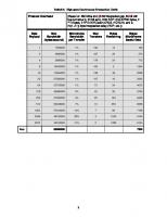
Chapter 9 Background: The table summarizing the standard device requests doesn’t reflect the test selector value for SET_FEATURE. This value is correctly described in other places in the spec. Also, the tabular representation of the test selector in the SET_FEATURE definition has the subcolumns reversed (incorrectly) while the text precisely (correctly) defines the organization. No functional impact. Change: p. 250, table 9-3, row for “SET_FEATURE”: change column for wIndex into two subcolumns; left sub-column has current text, new right sub-column has “Test Selector” to correspond with Test_mode support. Table 9-3. Standard Device Requests bmRequestType
bRequest
wValue
wIndex
wLength
Data
00000000B 00000001B 00000010B
CLEAR_FEATURE
Feature Selector
Zero Interface Endpoint
Zero
None
10000000B
GET_CONFIGURATION
Zero
Zero
One
Configurati on Value
10000000B
GET_DESCRIPTOR
Descriptor Type and Descriptor Index
Zero or Language ID
Descriptor Length
Descriptor
10000001B
GET_INTERFACE
Zero
Interface
One
Alternate Interface
10000000B 10000001B 10000010B
GET_STATUS
Zero
Zero Interface Endpoint
Two
Device, Interface, or Endpoint Status
00000000B
SET_ADDRESS
Device Address
Zero
Zero
None
00000000B
SET_CONFIGURATION
Configuratio n Value
Zero
Zero
None
00000000B
SET_DESCRIPTOR
Descriptor Type and Descriptor Index
Zero or Language ID
Descriptor Length
Descriptor
00000000B 00000001B 00000010B
SET_FEATURE
Feature Selector
Zero
None
00000001B
SET_INTERFACE
Alternate Setting
Interface
Zero
None
10000010B
SYNCH_FRAME
Zero
Endpoint
Two
Frame Number
12
Zero Interface Endpoint
Test Selector
Change: p. 258, Section 9.4.9: the figure field wIndex reverses the “Test Selector” and “Zero Interface Endpoint” columns to more accurately reflect the order of bitfields described in the text.
9.4.9 Set Feature This request is used to set or enable a specific feature. bmRequestType
bRequest
wValue
00000000B 00000001B 00000010B
SET_FEATURE
Feature Selector
13
wIndex Zero Interface EndpointTest Selector
Test SelectorZ ero Interface Endpoint
wLength
Data
Zero
None
Chapter 11 Incorrect Cross Reference: Background: Wrong cross reference was made for full speed microframe timer ranges. No functional impact. Change: p. 300, section 11.2.1, 2nd paragraph, last sentence: Replace reference to “Table 11-2” with reference to “Table 11-1”.
11.2.1 High-speed Microframe Timer Range The range for a microframe timer must be from 59904 to 60096 high-speed bits. The nominal microframe interval is 60000 high-speed bit times. The hub microframe timer range specified above is 60000 +/- 96 high-speed bit times in order to accommodate host accuracy, hub accuracy, repeater jittter, and hub quantization. The +/-96 full-speed bit time variation is calculated in Table 11-2Table 11-1.
Typographical Error in Full Speed EOF1/EOF Timing Reference: Background: A reference to EOF1 was incorrectly used instead of EOF2 in describing the EOF points of full speed frames. Other figures clearly show the required relationships of EOF1 and EOF2. No functional impact. Change: p. 305, section 11.2.5.2, first sentence: Replace text ”…, the EOF1 point is 10 bit times before EOF and EOF1 is …” with “.., the EOF2 point is 10 bit times before EOF and EOF1 is …”. 11.2.5.2 Full-speed EOF1 and EOF2 Timing Points When the hub operates as a full-/low-speed repeater, the EOF12 point is 10 bit times before EOF and EOF1 is 32 bit times before EOF as shown in Figure 11-8.
14
Illegally Specified bInterval Values for Hub Class Descriptors: Background: In section 11.23.1, the hub descriptors have several typographical errors. These errors were introduced when the descriptors were copied from the USB 1.1 specification. Most of the errors have an illegal USB2.0 value (FFH) for the bInterval of the hub polling period. This was the correct value for USB1.x hubs. One descriptor incorrectly repeats the same bAlternateSetting value for two different AlternateSettings. The changes allow both previous USB1.1 allowed values and compliant USB2.0 values to avoid silicon changes to hub designs in progress. The change only impacts USB2.0 hubs. Change: p. 410, in the other_speed endpoint descriptor for the status change endpoint: the bInterval value should be 0CH (i.e. 2(12-1) or 256ms). The current value of FFH in the specification is a holdover from the USB 1.1 for full-speed and is an illegal value for high-speed. Similarly, the endpoint descriptors for the status change endpoints on pages 411, 412, 415 and 416 should be changed to 0CH. The expectation is that compliance testing will accept values in the range of 0CH to 10H (12-16) or FFH for some time with an eventual convergence on the value of 0CH for long term compliance. p. 410, in the hub descriptor other speed interface descriptor for multiple TT hub case (i.e. 2nd interface descriptor on page): the bAlternateSetting should be set to 1 (not 0).
11.23.1 Standard Descriptors for Hub Class The hub class pre-defines certain fields in standard USB descriptors. Other fields are either implementationdependent or not applicable to this class. A hub returns different descriptors based on whether it is operating at high-speed or full-/low-speed. A hub can report three different sets of the descriptors: one descriptor set for full-/low-speed operation and two sets for highspeed operation. A hub operating at full-/low-speed has a device descriptor with a bDeviceProtocol field set to zero(0) and an interface descriptor with a bInterfaceProtocol field set to zero(0). The rest of the descriptors are the same for all speeds. A hub operating at high-speed can have one of two TT organizations: single TT or multiple TT. All hubs must support the single TT organization. A multiple TT hub has an additional interface descriptor (with a corresponding endpoint descriptor). The first set of descriptors shown below must be provided by all hubs. A hub that has a single TT must set the bDeviceProtocol field of the device descriptor to one(1) and the interface descriptor bInterfaceProtocol field set to 0. A multiple TT hub must set the bDeviceProtocol field of the device descriptor to two (2). The first interface descriptor has the bInterfaceProtocol field set to one(1). Such a hub also has a second interface descriptor where the bInterfaceProtocol is set to two(2). When the hub is configured with an interface protocol of one(1), it will operate as a single TT organized hub. When the hub is configured with an interface protocol of two(2), it will operate as a multiple TT organized hub. The TT organization must not be changed while the hub has full-/low-speed transactions in progress.
15
Note: For the descriptors and fields shown below, the bits in a field are organized in a little-endian fashion; that is, bit location 0 is the least significant bit and bit location 7 is the most significant bit of a byte value. Full-/Low-speed Operating Hub Device Descriptor (full-speed information):
bLength bDescriptorType bcdUSB bDeviceClass bDeviceSubClass bDeviceProtocol bMaxPacketSize0 bNumConfigurations
12H 1 0200H HUB_CLASSCODE (09H) 0 0 64 1
Device_Qualifier Descriptor (high-speed information):
bLength bDescriptorType bcdUSB bDeviceClass bDeviceSubClass bDeviceProtocol bMaxPacketSize0 bNumConfigurations
0AH 6 200H HUB_CLASSCODE (09H) 0 1 (for single TT) or 2 (for multiple TT) 64 1
Configuration Descriptor (full-speed information):
bLength bDescriptorType wTotalLength bNumInterfaces bConfigurationValue iConfiguration bmAttributes bMaxPower
09H 2 N 1 X Y Z The maximum amount of bus power the hub will consume in full-/low-speed configuration
16
Interface Descriptor:
bLength bDescriptorType bInterfaceNumber bAlternateSetting bNumEndpoints bInterfaceClass bInterfaceSubClass bInterfaceProtocol iInterface
09H 4 0 0 1 HUB_CLASSCODE (09H) 0 0 i
Endpoint Descriptor (for Status Change Endpoint):
bLength bDescriptorType bEndpointAddress bmAttributes
wMaxPacketSize bInterval
07H 5 Implementation-dependent; Bit 7: Direction = In(1) Transfer Type = Interrupt (00000011B) Implementation-dependent FFH (Maximum allowable interval)
Other_Speed_Configuration Descriptor (High-speed information):
bLength bDescriptorType wTotalLength bNumInterfaces bConfigurationValue iConfiguration bmAttributes bMaxPower
09H 7 N 1 (for single TT) or 2 (for multiple TT) X Y Z The maximum amount of bus power the hub will consume in high-speed configuration
17
Interface Descriptor:
bLength bDescriptorType bInterfaceNumber bAlternateSetting bNumEndpoints bInterfaceClass bInterfaceSubClass bInterfaceProtocol iInterface
09H 4 0 0 1 HUB_CLASSCODE (09H) 0 0 (for single TT) 1 (for multiple TT) i
Endpoint Descriptor (for Status Change Endpoint):
bLength bDescriptorType bEndpointAddress bmAttributes
wMaxPacketSize bInterval
07H 5 Implementation-dependent; Bit 7: Direction = In(1) Transfer Type = Interrupt (00000011B ) Implementation-dependent 0CHFFH (Maximum allowable interval)
Interface Descriptor (present if multiple TT hub):
bLength bDescriptorType bInterfaceNumber bAlternateSetting bNumEndpoints bInterfaceClass bInterfaceSubClass bInterfaceProtocol iInterface
09H 4 0 01 1 HUB_CLASSCODE (09H) 0 2 i
18
Endpoint Descriptor (present if multiple TT hub):
bLength bDescriptorType bEndpointAddress bmAttributes
wMaxPacketSize bInterval
07H 5 Implementation-dependent; Bit 7: Direction = In(1) Transfer Type = Interrupt (00000011B ) Implementation-dependent 0CHFFH (Maximum allowable interval)
High-speed Operating Hub with Single TT Device Descriptor (High-speed information):
bLength bDescriptorType bcdUSB bDeviceClass bDeviceSubClass bDeviceProtocol bMaxPacketSize0 bNumConfigurations
12H 1 200H HUB_CLASSCODE (09H) 0 1 64 1
Device_Qualifier Descriptor (full-speed information):
bLength bDescriptorType bcdUSB bDeviceClass bDeviceSubClass bDeviceProtocol bMaxPacketSize0 bNumConfigurations
0AH 6 200H HUB_CLASSCODE (09H) 0 0 64 1
19
Configuration Descriptor (high-speed information):
bLength bDescriptorType wTotalLength bNumInterfaces bConfigurationValue iConfiguration bmAttributes bMaxPower
09H 2 N 1 X Y Z The maximum amount of bus power the hub will consume in this configuration
Interface Descriptor:
bLength bDescriptorType bInterfaceNumber bAlternateSetting bNumEndpoints bInterfaceClass bInterfaceSubClass bInterfaceProtocol iInterface
09H 4 0 0 1 HUB_CLASSCODE (09H) 0 0 (single TT) i
Endpoint Descriptor (for Status Change Endpoint):
bLength bDescriptorType bEndpointAddress bmAttributes
wMaxPacketSize bInterval
07H 5 Implementation-dependent; Bit 7: Direction = In(1) Transfer Type = Interrupt (00000011B) Implementation-dependent 0CHFFH (Maximum allowable interval)
20
Other_Speed_Configuration Descriptor (full-speed information):
bLength bDescriptorType wTotalLength bNumInterfaces bConfigurationValue iConfiguration bmAttributes bMaxPower
09H 7 N 1 X Y Z The maximum amount of bus power the hub will consume in high-speed configuration
Interface Descriptor:
bLength bDescriptorType bInterfaceNumber bAlternateSetting bNumEndpoints bInterfaceClass bInterfaceSubClass bInterfaceProtocol iInterface
09H 4 0 0 1 HUB_CLASSCODE (09H) 0 0 i
Endpoint Descriptor (for Status Change Endpoint):
bLength bDescriptorType bEndpointAddress bmAttributes
wMaxPacketSize bInterval
07H 5 Implementation-dependent; Bit 7: Direction = In(1) Transfer Type = Interrupt (00000011B ) Implementation-dependent FFH (Maximum allowable interval)
21
High-speed Operating Hub with Multiple TTs Device Descriptor (High-speed information):
bLength bDescriptorType bcdUSB bDeviceClass bDeviceSubClass bDeviceProtocol bMaxPacketSize0 bNumConfigurations
12H 1 200H HUB_CLASSCODE (09H) 0 2 (multiple TTs) 64 1
Device_Qualifier Descriptor (full-speed information):
bLength bDescriptorType bcdUSB bDeviceClass bDeviceSubClass bDeviceProtocol bMaxPacketSize0 bNumConfigurations
0AH 6 200H HUB_CLASSCODE (09H) 0 0 64 1
Configuration Descriptor (high-speed information):
bLength bDescriptorType wTotalLength bNumInterfaces bConfigurationValue iConfiguration bmAttributes bMaxPower
09H 2 N 1 X Y Z The maximum amount of bus power the hub will consume in this configuration
22
Interface Descriptor:
bLength bDescriptorType bInterfaceNumber bAlternateSetting bNumEndpoints bInterfaceClass bInterfaceSubClass bInterfaceProtocol iInterface
09H 4 0 0 1 HUB_CLASSCODE (09H) 0 1 (single TT) i
Endpoint Descriptor (for Status Change Endpoint):
bLength bDescriptorType bEndpointAddress bmAttributes
wMaxPacketSize bInterval
07H 5 Implementation-dependent; Bit 7: Direction = In(1) Transfer Type = Interrupt (00000011B) Implementation-dependent 0CHFFH (Maximum allowable interval)
Interface Descriptor:
bLength bDescriptorType bInterfaceNumber bAlternateSetting bNumEndpoints bInterfaceClass bInterfaceSubClass bInterfaceProtocol iInterface
09H 4 0 1 1 HUB_CLASSCODE (09H) 0 2 (multiple TTs) i
23
Endpoint Descriptor:
bLength bDescriptorType bEndpointAddress bmAttributes
wMaxPacketSize bInterval
07H 5 Implementation-dependent; Bit 7: Direction = In(1) Transfer Type = Interrupt (00000011B ) Implementation-dependent 0CHFFH (Maximum allowable interval)
Other_Speed_Configuration Descriptor (full-speed information):
bLength bDescriptorType wTotalLength bNumInterfaces bConfigurationValue iConfiguration bmAttributes bMaxPower
09H 7 N 1 X Y Z The maximum amount of bus power the hub will consume in high-speed configuration
Interface Descriptor:
bLength bDescriptorType bInterfaceNumber bAlternateSetting bNumEndpoints bInterfaceClass bInterfaceSubClass bInterfaceProtocol iInterface
09H 4 0 0 1 HUB_CLASSCODE (09H) 0 0 i
24
Endpoint Descriptor (for Status Change Endpoint):
bLength bDescriptorType bEndpointAddress bmAttributes
wMaxPacketSize bInterval
07H 5 Implementation-dependent; Bit 7: Direction = In(1) Transfer Type = Interrupt (00000011B) Implementation-dependent FFH (Maximum allowable interval)
The hub class driver retrieves a device configuration from the USB System Software using the GetDescriptor() device request. The only endpoint descriptor that is returned by the GetDescriptor() request is the Status Change endpoint descriptor.
Inconsistency in ClearPortFeature Descriptions: Background: The description of ClearPortFeature is inconsistent in some places in the spec. The description of the PORT_INDICATOR in section 11.24.2.7.1.10 is correct, but the state machine figure (11-11) omits a label for ClearPortFeature and the description of the ClearPortFeature request incorrectly specifies an explicit indicator value, where there is no value that would be meaningful. Also, the PORT_INDICATOR is not explicitly listed for SetPortFeature as a case for having the MSB of wIndex set to zero. This change only impacts hubs that provide port indicator control. Change: p. 317, figure 11-11: Add “or ClearPortFeature(PORT_INDICATOR, indicator_selector = n/a)” to the label on the transition from Manual mode to Automatic mode. Automatic Mode SetPortFeature (PORT_INDICATOR, indicator_selector != 0)
Enabled or Transmit or TransmitR
Off
Green
Manual Mode
! (Enabled or Transmit or TransmitR) and PORT_OVER_CURRENT != 1 PORT_OVER_CURRENT = 1 PORT_OVER_CURRENT = 1 SetPortFeature (PORT_POWER)
Amber
SetPortFeature (PORT_INDICATOR, indicator_selector = 0) or ClearPortFeature (PORT_INDICATOR, indicator_selector = n/a)
Figure11-11. Port Indicator State Diagram
25
Change: p. 423, 3rd paragraph before section 11.24.2.3: replace the sentence beginning “The selector field…” with the sentences “Clearing the PORT_INDICATOR causes a transition of the port indicator state machine back to automatic mode (see Figure 11-11). The indicator_selector field is ignored for ClearPortFeature.”
Clearing the PORT_ENABLE feature causes the port to be placed in the Disabled state. If the port is in the Powered-off state, the hub should treat this request as a functional no-operation. Clearing the PORT_POWER feature causes the port to be placed in the Powered-off state and may, subject to the constraints due to the hub’s method of power switching, result in power being removed from the port. Refer to Section 11.11 on rules for how this request is used with ports that are gang-powered. The selector field identifies the port indicator selector when clearing a port indicator. Clearing the PORT_INDICATOR causes a transition of the port indicator state machine back to automatic mode (see Figure 11-11). The indicator selector field is ignored for the ClearPortFeature. The selector field is in bits 15..8 of the wIndex field. It is a Request Error if wValue is not a feature selector listed in Table 11-17, if wIndex specifies a port that does not exist, or if wLength is not as specified above. It is not an error for this request to try to clear a feature that is already cleared (hub should treat as a functional no-operation). If the hub is not configured, the hub's response to this request is undefined. Change: p. 435, 1st paragraph: add “… or PORT_INDICATOR.” to end of the last sentence. 11.24.2.13 Set Port Feature This request sets a value reported in the port status. bmRequestType
bRequest
wValue
00100011B
SET_ FEATURE
Feature Selector
wIndex Selector
Port
wLength
Data
Zero
None
The port number must be a valid port number for that hub, greater than zero. The port number is in the least significant byte (bits 7..0) of the wIndex field. The most significant byte of wIndex is zero, except when the feature selector is PORT_TEST or PORT_INDICATOR.
26
Clarifying Standard Hub Class Requests: Background: GET_/SET_INTERFACE requests to the hub in the summary hub class request table do not currently indicate that they are required for multiple TT hub implementations. Since the hub descriptors report alternate interfaces and other descriptions indicate how these interfaces are used, these commands are clearly required. This change only impacts hubs that support multiple TTs. Change: p. 419, table 11-14: change Hub Response descriptions for GET_INTERFACE and SET_INTERFACE from “Undefined….” to “Standard for multiple TT hub operating at highspeed.” Table 11-14. Hub Responses to Standard Device Requests bRequest
Hub Response
CLEAR_FEATURE
Standard
GET_CONFIGURATION
Standard
GET_DESCRIPTOR
Standard
GET_INTERFACE
Undefined. Hubs are allow to support only one interface.Standard for multiple TT hub operating at highspeed.
GET_STATUS
Standard
SET_ADDRESS
Standard
SET_CONFIGURATION
Standard
SET_DESCRIPTOR
Optional
SET_FEATURE
Standard
SET_INTERFACE
Undefined. Hubs are allow to support only one interface.Standard for multiple TT hub operating at highspeed.
SYNCH_FRAME
Undefined. Hubs are not allowed to have isochronous endpoints.
27
Minor Typographical Errors: Background: No functional changes. Change: p. 426, section 11.24.2.7, 2nd paragraph after figure: change “refer to Table 11-20” to “refer to Table 11-22”
11.24.2.7 Get Port Status This request returns the current port status and the current value of the port status change bits. bmRequestType
bRequest
wValue
wIndex
wLength
Data
10100011B
GET_STATUS
Zero
Port
Four
Port Status and Change Status
The port number must be a valid port number for that hub, greater than zero.
The first word of data contains wPortStatus (refer to ). The second word of data contains wPortChange (refer to Table 11-20Table 11-22).
28
Change: p. 427, table 11-21, row for bit 10: change name from “High-speed Device Attached” to “Full- or High-speed Device Attached”. Table 11-21. Port Status Field, wPortStatus Bit
Description
0
Current Connect Status: (PORT_CONNECTION) This field reflects whether or not a device is currently connected to this port. 0 = No device is present. 1 = A device is present on this port.
1
Port Enabled/Disabled: (PORT_ENABLE) Ports can be enabled by the USB System Software only. Ports can be disabled by either a fault condition (disconnect event or other fault condition) or by the USB System Software. 0 = Port is disabled. 1 = Port is enabled.
2
Suspend: (PORT_SUSPEND) This field indicates whether or not the device on this port is suspended. Setting this field causes the device to suspend by not propagating bus traffic downstream. This field may be reset by a request or by resume signaling from the device attached to the port. 0 = Not suspended. 1 = Suspended or resuming.
3
Over-current: (PORT_OVER_CURRENT) If the hub reports over-current conditions on a per-port basis, this field will indicate that the current drain on the port exceeds the specified maximum. For more details, see Section 7.2.1.2.1. 0 = All no over-current condition exists on this port. 1= An over-current condition exists on this port.
4
Reset: (PORT_RESET) This field is set when the host wishes to reset the attached device. It remains set until the reset signaling is turned off by the hub. 0 = Reset signaling not asserted. 1 = Reset signaling asserted.
5-7
Reserved These bits return 0 when read.
8
Port Power: (PORT_POWER) This field reflects a port’s logical, power control state. Because hubs can implement different methods of port power switching, this field may or may not represent whether power is applied to the port. The device descriptor reports the type of power switching implemented by the hub. 0 = This port is in the Powered-off state. 1 = This port is not in the Powered-off state.
9
Low- Speed Device Attached: (PORT_LOW_SPEED) This is relevant only if a device is attached. 0 = Full-speed or High-speed device attached to this port (determined by bit 10). 1 = Low-speed device attached to this port.
10
Full- or High-speed Device Attached: (PORT_HIGH_SPEED) This is relevant only if a device is attached. 0 = Full-speed device attached to this port. 1 = High-speed device attached to this port.
11
Port Test Mode : (PORT_TEST) This field reflects the status of the port's test mode. Software uses the SetPortFeature() and ClearPortFeature() requests to manipulate the port test mode. 0 = This port is not in the Port Test Mode. 1 = This port is in Port Test Mode.
12
Port Indicator Control: (PORT_INDICATOR) This field is set to reflect software control of the port indicator. For more details see Sections 11.5.3, 11.24.2.7.1.10, and 11.24. 0 = Port indicator displays default colors. 1 = Port indicator displays software controlled color.
13-15
Reserved These bits return 0 when read.
29
Chapter Appendix A Missing Information in Example Split Transactions: Background: One of the split transaction examples is missing some labels and a final complete split transaction. No functional impact.
30
Change: p. 553, example 12 “HS CS too early…”: Add “NYET” label on final arrow from Hub to Host. Add new uframe M+4 with HS transaction arrows: 1) host to hub: “CSPLIT” and “IN” arrows, 2) hub to host “data” arrow.
12) HS CS too early (full-speed data not available yet)
HUB
Host 0
0
st1 uFrame M
SS = Free
SSPLIT
st2
IN
Create SS entry with status = Pending
uFrame M + 1 ct1
CSPLIT
ct2
IN
uFrame M + 2
Search not complete in time
Timeout ce7 Err_count = 1 -> ce3 Immediate retry CS ct1
CSPLIT
ct2
IN No split response found
NYET
ch4
Respond with NYET
This is not the last CS -> ch3
ct1
IN
CSPLIT Create CS entry SS = Free
ct2 uFrame M + 3
DATA0
IN
CS = Ready/last data ch4
NYET
ch3
ct1 uFrame M + 4
ct2
CSPLIT IN cd1 DATA0
Send last data with DATA0 CS = Old/last data
ch1
31