Continuous Casting 9783527302833, 3527302832
355 65 18MB
English Pages 341 Year 2000
Recommend Papers


File loading please wait...
Citation preview
Continuous Casting Edited by K. Ehrke and W. Schneider
Deutsche Gesellschaft für Materialkunde e.V.
Weinheim · New York · Chichester Brisbane · Singapore · Toronto
Dipl.-Ing. Kurt Ehrke ALUMINIUM Essen GmbH Sulterkamp 71 D-45356 Essen Germany
Prof. Dr. Wolfgang Schneider VAW Aluminium AG Forschung und Entwicklung Georg-von-Boeselager-Str. 25 D-53117 Bonn Germany
International Congress Continuous Casting held from 1315 November 2000 in Frankfurt /Main Organizer: DGM · Deutsche Gesellschaft für Materialkunde e.V. Program Committee Dipl.-Ing. Kurt Ehrke, ALUMINIUM Essen GmbH (Chairman) Dr. Hilmar R. Müller, Wieland Werke AG, Ulm Prof. Dr. Wolfgang Schneider, VAW Aluminium AG, Bonn Dipl.-Ing. Gunnar Halvorsen, Elkem Aluminium AG, Oslo (N) Dr. Dirk Rode, KM Europametal AG, Osnabrück
This book was carefully produced. Nevertheless, authors, editors and publisher do not warrant the information contained therein to be free of errors. Readers are advised to keep in mind that statements, data, illustrations, procedural details or other items may inadvertently be inaccurate.
Cover photo: Lüko GmbH Casting Unit for Extrusion Billets VAW aluminium AG AIRSOL VEIL® technology
Library of Congress Card No. applied for A catalogue record for this book is available from the British Library Deutsche Bibliothek Cataloguing-in-Publication Data A catalogue record for this publication is available from Die Deutsche Bibliothek ISBN 3-527-30283-2 © WILEY-VCH Verlag GmbH, D-69469 Weinheim (Federal Republic of Germany), 2000 Printed on acid-free paper. All rights reserved (including those of translation in other languages). No part of this book may be reproduced in any form by photoprinting, microfilm, or any other means nor transmitted or translated into machine language without written permission from the publishers. Registered names, trademarks, etc. used in this book, even when not specifically marked as such, are not to be considered unprotected by law. Composition: WGV Verlagsdienstleistungen GmbH, Weinheim Printing: betz-druck, Darmstadt Bookbinding: Schaumann, Darmstadt Printed in the Federal Republic of Germany
Preface The aim of the conference, organized by the DGM Continuous Casting Committeee, is to highlight the importance of continuous casting of aluminium, copper and magnesium to the international fabricating industry. The conference lectures, generated by the Call for Papers, cover technological advances in all sectors which are important for the manufacture of high quality continuously cast products. Besides melt treatment, casting processes and structure of continuously cast ingots, modelling of casting will be a major topic of the conference. Numerical modelling becomes more and more dominant as a research tool to improve casting processes and the resulting products. The advantages are reduced development times and development costs. The programme of the symposium reflects this with numerous papers dealing with modelling of nucleation, heat and fluid flow as well as stresses and structure. Another new approach of the conference are the supplier sessions. The organizing committee hopes that the conference programme encourages specialists of the non-ferrous industry worldwide to take part in this meeting. K. Ehrke Chairman of the Conference
Contents 25 Years of DGM Continuous Casting Research W. Schneider, VAW aluminium AG, Research and Development, Bonn (D)..............................1
Melt Treatment Hydrogen in Aluminum Containing Copper Alloy Melts – Solubility Measurement and Removal K. Neumann, B. Friedrich, K. Krone, IME Process Metallurgy and Metal Recycling, RWTH Aachen (D) J. Jestrabek, E. Nosch, Schwermetall Halbzeugwerk GmbH, Stolberg (D) .............................15 Fundamental Research About Liquid Metal Filtration B. Hübschen, J. Krüger, RWTH Aachen (D) N. Keegan, Pyrotek Engineering Materials Limited, Dudley (GB) W. Schneider, VAW Aluminium AG, Bonn (D) .........................................................................20 Impact of Grain Refiner Addition on Ceramic Foam Filter Performance N. Towsey, W. Schneider, H.-P. Krug, VAW aluminium AG, Research and Development, Bonn (D) A. Hardman , London & Scandinavian Metallurgical Co. Limited, Rotherham, South Yorkshire (GB) N. Keegan, Pyrotek Engineering Materials Ltd., Netherton, West Midlands (GB)..................26 Review of Dissolution Testing and Alloying Methods in the Casthouse G. Borge, Bostlan, S.A., Larragane, Mungia (E) P. Cooper, S. Thistlethwaite, LSM Co.Ltd., Rotherham (GB) ..................................................33 The Effect of Casting Parameters on the Metallurgical Quality of Twin Roll Cast Strip Y. Birol, Marmara Research Center, Gebze-Kocaeli (TR) G. Kara, A. Soner Akkurt, ASSAN Aluminum Works, Istanbul (TR) C. Romanowski, FATA Hunter Inc., Riverside (USA) ..............................................................40
Casting Technology and Processes – Aluminium Influence of Different Lubricants on the Friction between the Solidifying Shell and the Mould during the DC Casting of AlMgSi0.5 F. Dörnenburg, VAW aluminium AG, Research and Development, Bonn (D) S. Engler, Foundry Institute, Aachen University of Technology, Aachen (D)..........................47 Prediction of Boundary Conditions and Hot Spots during the Start-up Phase of an Extrusion Ingot Casting S. Benum, Hydro Aluminium R&D Materials Technology, Sunndalsøra (N) D. Mortensen, H. Fjær, Institute for Energy Technology, Kjeller (N) .....................................54 Continuous Casting. Edited by K. Ehrke and W. Schneider. © WILEY-VCH Verlag GmbH, Weinheim. ISBN: 3-527-30283-2
VIII Improved Metal Distribution during DC-casting of Aluminum Alloy Sheet Ingots P. Tøndel, J. Hayes, I. Thorvaldsen, Elkem Aluminium, Mosjøen (N) G. Grealy, G. Tahitu, Corus Research Development & Technology, Ijmuiden (NL) E. Jensen, Elkem Research, Kristiansand (N) D. Brandner, Corus Aluminium Walzprodukte GmbH, Koblenz (D) .......................................61 Determination of Material Properties and Thermal Boundary Condition from Casting Trial on Alloy AA7075 J. Rabenberg, J. Storm, Corus Research Development & Technology, Ijmuiden (NL) I. Opstelten, Corus Research Development & Technology, now with TNO Bouw, Delft (NL) J.-M. Drezet, École Polytechnique Fédérale de Lausanne, Lausanne (CH)............................71 Single-roll Strip Casting of Aluminium Alloys E. Straatsma, W. Kool , L. Katgerman, Delft University of Technology, Laboratory for Materials, Delft (NL) ................................................................................................................77 Continuous Casting of Semisolid Al-Si-Mg Alloy T. Motegi, F. Tanabe, Chiba Institute of Technology...............................................................82
Casting Technology and Processes Yield and Quality Improvements for Semi-Continuously Cast Copper Alloys C.-M. Raihle, Outokumpu Process Automation, Västerås (S) ..................................................89 Continuous Casting Technology for Magnesium U. Holzkamp, H. Haferkamp, M. Niemeyer, University of Hanover, Institute of Materials Science, Hanover (D)................................................................................................................94 Local Distribution of the Heat Transfer in Water Spray Quenching F. Puschmann, E. Specht, J. Schmidt, University of Magdeburg, Institute of Fluid Dynamics and Thermodynamics, Magdeburg (D) ........................................................101 Grain Structure, Microstructure and Texture of Copper Ingots Produced during the Continuous Casting Process V. Plochikhine, V. Karkhin, H. Bergmann, Department of Metallic Materials, University of Bayreuth (D)......................................................................................................109 Technologies and Installation for Electrochemical Hardening of Wear Surfaces R. Boiciuc, V. Munteanu, G. Petrache, Uzinsider Engineering S.A., Galati (ROM).............115
IX Modelling – Heat and Fluid Flow; Nucleation Numerical Mass and Heat Flow Predictions in Aluminum DC Casting: A Comparison of Simulations with Melt Pool Measurements A. Buchholz, Corus Research Development &Technology, Ijmuiden (NL) B. Commet, Pechiney Centre de Recherches de Voreppe (F) G.-U. Grün, VAW aluminium AG, Research and Development, Bonn (D) D. Mortensen, Institute for Energy Technology, Kjeller (N) ..................................................123 Investigations of the Primary Cooling in Sheet Ingot Casting H. Fjær, D. Mortensen, Institute for Energy Technology, Kjeller (N) A. Buchholz, Corus Research Development & Technology, Ijmuiden (NL) B. Commet, Pechiney Centre de Recherches de Voreppe (F) J.-M. Drezet, Laboratoire de Métallurgie Physique, EPFL, Lausanne (CH) ........................131 Boiling Curve Approach for Thermal Boundary Conditions in DC Casting J. Zuidema jr., L. Katgerman, Netherlands Institute for Metals Research, Laboratory for Materials, Advanced Materials and Solidification Technology, Delft (NL) I. Opstelten, Corus Research Development & Technology, Ijmuiden (NL)............................138 Theoretical and Experimental Study of Vertical Continuous Casting of Copper M. Uoti, Helsinki University of Technology, Laboratory of Metallurgy, Helsinki (SF) M. Immonen, K. Härkki, Outokumpu Poricopper OY, Kuparitie, Pori (SF)..........................143 Modeling of Grain Refinement in Aluminum Alloys A. Greer, A. Tronche, University of Cambridge (GB) ............................................................149 Modeling of the Grain Refinement in Directionally Solidified Al -4.15 wt.% Mg Alloys using Cellular Automaton – Finite Element Approach M. Vandyoussefi , A. Greer, University of Cambridge (GB) ..................................................154
Modelling – Stress and Structure ContiSim™: Process and Material Modelling of Continuous Casting in Macro and Micro Scale J. Boehmer, Process Modelling and Informatics, Betzdorf/Sieg (D)......................................163 Crystal Growth Morphology during Continuous Casting C. Caesar, Munich (D)............................................................................................................169 3D-Modeling of Ingot Geometry Development of DC-Cast Aluminum Ingots during the Start-Up Phase W. Droste, G.-U. Grün, W. Schneider, VAW aluminium AG, Research and Development, Bonn (D) J.-M. Drezet, CALCOM SA, Parc Scientifique, Lausanne (CH) ............................................175
X The Influence of Casting Practice on Stresses and Strains in 6xxx Billets – A Statistical and Modelling Study B. Henriksen, S. Braathen, E. Jensen, Elkem ASA Reasearch, Kristiansand (N)...................184 Modelling of Macrosegregation in Continuous Casting of Aluminium T. Jalanti, M. Rappaz, École Polytechnique Fédérale de Lausanne, Laboratoire de Métallurgie Physique, Lausanne (CH) M. Swierkosz, M. Gremaud, Calcom SA, Lausanne (CH) ......................................................191 The Effect of the Differencing Scheme on the Numerical Diffusion in the Simulation of Macrosegregation B. Venneker, Netherlands Institute for Metals Research, Delft (NL) L. Katgerman, Delft University of Technology, Laboratory for Materials, Advanced Materials and Solidification Technology, Delft (NL) ............................................199 Application of a New Hot Tearing Analysis to Horizontal Direct Chill Cast Magnesium Alloy AZ91 J. Grandfield, Cooperative Reasearch Centre for Cast Metals Manufacturing, CSIRO Manufacturing Science & Technology, The University of Queensland (AUS) C. Davidson, J. Taylor, Department of Mining, Minerals and Materials Engineering, The University of Queensland (AUS)......................................................................................205
Micro- and Macrostructures Nucleation Studies of Grain Refiner Particles in Al-Alloys P. Schumacher, University of Oxford (GB) ............................................................................213 Effect of Solute Elements on the Grain Structures of Al-Ti-B and Al-Ti-C Grain-Refined Al Alloys A. Tronche, University of Cambridge (GB) A. Greer, University of Cambridge (GB) and Péchiney Centre de Recherches de Voreppe (F) .......................................................................................................................218 Grain Refinement Process in Aluminium Alloys Type AlZnMgZr T. Stuczyn´ski, M. Lech-Grega, Institute of Non-Ferrous Metals, Light-Metals Division, Skawina (PL) ..........................................................................................................224 Coupled Influence of Convection and Grain-refining on Macrosegregation of 1D Upwardly Solidified Al 4.5% Cu P. Jarry, Pechiney Centre de Recherches de Voreppe (F) H. Combeau, G. Lesoult, LSG2M, Ecole des Mines de Nancy (F).........................................233 Tensile Behaviour of DC-cast AA5182 in Solid and Semi-solid State W. van Haaften, W. Kool, L. Katgerman, Laboratory of Materials, Delft University of Technology, Delft (NL) ...........................................................................................................239
XI The Columnar to Equiaxed Transition in Horizontal Direct Chill Cast Magnesium Alloy AZ91 J. Grandfield, Cooperative Reasearch Centre for Cast Metals Manufacturing, CSIRO Manufacturing Science & Technologiy, The University of Queensland (AUS) C. Davidson, J. Taylor, Department of Mining, Minerals and Materials Engineering, The University of Queensland (AUS)......................................................................................245 Study of Heterogeneous Nucleation of α-Al on Grain Refiner Particles during Rapid Solidification P. Cizek, B. McKay, P. Schumacher, University of Oxford (GB)...........................................251 Effect of Instability of TiC Particles on the Grain-Refining Behavior of Al-Ti-C Inoculants in Aluminum Alloys M. Vandyoussefi, A. Greer, University of Cambridge (GB) ...................................................257 Grain Refiners for Thin Strip Twin Roll Casting R. Cook, London & Scandinavian Metallurgical Co. Limited, Rotherham (GB)...................263 Characterisation and Optimisation of Thixoforming Feedstock Material S. Engler, Gießereiinstitut, RWTH Aachen (D) D. Hartmann, EFU Gesellschaft für Ur-/Umformtechnik mbH, Simmerath (D) I. Niedick, Volkswagen AG, Braunschweig (D), (former EFU GmbH)..................................269 Experimental Study of Linear Shrinkage during Solidification of Binary and Commercial Aluminum Alloys D. Eskine , L. Katgerman, Netherlands Institute for Metals Research, Delft (NL) ................276 The Influence of the Cooling Rate on the Type of the Intermetallic Phases in the Aluminium Alloys of the 3XXX (AlMnMgSi) Group T. Stuczyn´ski, M. Lech-Grega, Institute of Non-Ferrous Metals, Light Metals Division, Skawina (PL) ..........................................................................................................................282
Suppliers Session – Aluminium Horizontal Direct Chilled (HDC) Casting Technology for Aluminium F. Niedermair, Hertwich Engineering GmbH, Braunau (A) ..................................................293 Automatic “Bleed Out” Detection and Plug Off in VDC Billet Casting M. Lück, Wagstaff Inc., Spokane WA (USA)...........................................................................300 The AIRSOL VEIL® Technology Package for Aluminium Billet Casting G. Bulian, M. Langen, VAW aluminium AG, Bonn (D) ..........................................................302 The Manufacturing, Design and Use of Combo Bag Distributors in Sheet Ingot Casting S. Tremblay, Pyrotek High-temperature Industrial Products Inc., Chicoutimi (CAN) R. Green, Pyrotek Engineering Materials Ltd., Netherton (GB) ............................................310
XII Recent Quality and Efficiency Improvements Through Advances in In-Line Refining Technology V. Dopp, S. Simmons, Pyrotek, Inc., Tarrytown, New York (USA).........................................316
Suppliers Session – Copper Horizontal Continuous Casting of Copper Alloy Billets M. Brey, SMS Meer GmbH, Demag Technica, Veitshöchheim (D)........................................325 The Outokumpu UPCAST® System L. Eklin, Outokumpu Castform Oy, Pori (SF) ........................................................................333
Author Index .........................................................................................................................341 Subject Index.........................................................................................................................343
25 Years of DGM Continuous Casting Research Wolfgang Schneider VAW aluminium AG, Research and Development, 53117 Bonn, Germany
1
Introduction
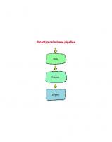
Continuous casting experts from the non-ferrous metal industry in Germany, Netherlands, Austria, Norway and Switzerland have taken part in the Continuous Casting Committee of the Deutsche Gesellschaft für Materialkunde DGM since its foundation 1972. During the formation of the committee the different technologies used in DC. casting resp. continuous casting of semis feedstock were taken into consideration. Working groups were therefore formed to deal with the vertical DC. casting of Al and Cu as well as the horizontal casting of Al, Cu and Zn. Over the years, goals were redefined and changes were made to the organisation structure when the industrial requirements made this necessary. In former times the vertical DC casting experts were associated all together in one working group, but due to the Copper DC casting experts being underrepresented, the priority of the work centred on Aluminium DC casting In 1990 an own working group specifically for the DC. casting of Cu was founded. A further important change was the foundation of the Working Group Spray Forming in 1993. It must be mentioned however that not only an expansion of the activities of the Committee took place in the past but also activities had to be stopped and working groups had to be disbanded. Among these, for example, is the working group which dealt many years with the strip casting of Al. The closing of the last strip casting unit in Germany led to this step because the working group saw little reason for a continuation of its work. The actual organisation structure of the Committee Continuous Casting can be seen in Figure 1. The current existing working groups are to be seen in this figure. The activities carried out in these working groups will however not be considered here. One working group will be described in more detail which was not mentioned previously but was an important part of the Continuous Casting Committee for many years.. This is the Working Group Research, as seen in Figure 1. In the following beside the structure and the tasks of this working group the research activities of the past will be described. By means of exemplary results, projects which have been carried out within the framework of the activities of the Working Group Research will be presented. Finally, the future outlook of the working group will be given.
Continuous Casting. Edited by K. Ehrke and W. Schneider. © WILEY-VCH Verlag GmbH, Weinheim. ISBN: 3-527-30283-2
2 DGM Committee Continuous Casting
Working Group
Working Group
Working Group
Vertical Casting D.C.
Vertical Casting D.C.
Horizontal Casting C.C.
Aluminium
Copper
Copper / Zinc
Working Group Spray Forming
Working Group Research
Figure 1: Structure of the DGM Continuous Casting Committee
2
Research Working Group: Objectives, Tasks and Structure
The foundation of the Working Group Research took place in the year 1975. Since then, the working group is in nearly unchanged structure part of the Committee Continuous Casting. A major objective of the foundation of the Working Group Research was to interest the universities in continuous casting research and to get it established there over the long term by means of the concerted execution of research projects. This has been successful for nearly two decades. The working group was, and is still today, made in such a way that, besides the members from universities, also members of the different working groups of the Committee also take part. These are the heads of the working groups whose task it is among others, to make suggestions about research projects discussed before in their working groups. The project ideas are discussed with the university representatives concerned and a research proposal is prepared for the submission to relevant funding organisations. The working group normally meets once a year. In these meetings the progress of the actual projects is reported and new project suggestions are discussed. In the beginning the working group had to ensure that adequate equipment was available at the universities for the continuous casting research and it should give support in the procurement of funding for agreed research projects. With regard to the latter it was and will be important in the future that the industry partners were and are concerned in the preparation of the research proposals. At this point, however, it has to be mentioned that the execution and the care for research projects were not alone reserved to the Working Group Research but that there have been carried out also research projects in the other working groups of the Committee. Another important aspect of the work of the working group in the past was, to awaken the interest of the university students in continuous casting. Numerous graduates from universities who carried out the research work within the scope of their doctoral thesis subsequently took up a position in the continuous casting industry on finishing their work. In the beginning the working group´s activities focused on investigations dealing with material science of DC casting. Over the years the activities were expanded with investigations into melt quality and process technology. Correspondingly the university institutes as members of the working group expanded too. In Figure 2 the structure of the
3 Working Group Research is shown and the university institutes are named which were resp. still are long-term members of the working group. Special mention has to be made here of the Gießerei-Institut of the RWTH Aachen where under the management of Professor Engler and with the assistance of the Working Group Research in the mid of the Seventies the first DC casting unit at a university was installed. Unfortunately the unit was dismantled recently and thus is no longer available for future research work. In Figure 3 the number of research projects completed at the universities since 1979 is shown. It can be seen that the number of projects has decreased since 1995, at present no research projects are being carried out within the scope of the working group. The reasons for this will be discussed later. Working Group
Research
Foundry Institute
Heads of Committee Working Groups
RWTH Aachen Prof. S. Engler
Inst. of Non Ferrous Metallurgy RWTH Aachen Prof. J. Krüger
Inst. of Metal Science TU Berlin Prof. W. Reif
Inst. of Energy Technology TU Clausthal Prof. R. Jeschar
Inst. of Metal Research MPJ Stuttgart Prof. B. Predel, Dr. E. Fromm
Inst. of Material Sciene TU München Prof. H. M. Tensi
Number of Projects
Figure 2: Structure of the research working group
8
Working Group RESEARCH
7
DGM Continuous Casting Committee
6
5
4
3
2
1
1975
1977
1979
1981
1983
1985
1987
1989
1991
1993
1995
Year
Figure 3: Number of completed research projects per year since 1975
1997
1999
4
3
Research Working Group: Research Priorities
The list of past research projects of the Working Group Research can be divided into the following subjects: • Melt Quality • Ingot Solidification • Process Technology In the following, an overview of the research projects carried out in these subjects will be given and exemplary results from chosen works presented. Naturally a selection must be made at this point since not all projects can be dealt with. Of course this does not mean that the projects not considered here made no important contribution to the understanding of DC casting. 3.1
Melt Quality (MPI Stuttgart, RWTH Aachen)
As is well known non-ferrous metal melts show complex interactions with the surrounding atmosphere. The centre of interest of the research work carried out was therefore on diluted hydrogen in Al and Cu melts and its measuring. Moreover the oxidation of the liquid aluminium as well as the properties of oxide layers on the melt were investigated. This knowledge is of importance to the handling of melts in the cast house. In further research work the thermodynamic fundamentals of Li removal from primary aluminium as well as investigations into the removal of Na and Li from Al melts were carried out. Within the scope of the research work on the hydrogen solubility in Al and Cu melts, a measuring method was developed which allows the continuous measurement of the hydrogen content by the means of H2 partial pressure measurement. The measurement principles of this method are shown schematically in Figure 4. In this method the probe consists of a graphite disc which is connected to a pressure meter by a gas tight ceramic pipe. After immersing the probe in the melt the probe is quickly evacuated allowing the hydrogen to diffuse into the probe until the pressure in the probe and the hydrogen partial pressure in the melt are equal. The actual hydrogen content is then calculated with simultaneous temperature measurement with the help of Sievert´s equation. An essential advantage of this method in comparison to other methods is that by dosing of the probe with hydrogen the measurement time can be shortened substantially, so that a continuous hydrogen measurement is practicable. The above described method is commercially available today as measurement equipment under the trademark CHAPEL. Within the scope of the investigations on the oxidation behaviour of Al melts the strength of oxide layers as well as the initial stage of the oxidation were investigated. For this a measuring method for the measurement of the strength of the oxide layer was developed, which is shown in a schematic depiction in Figure 5. With this measuring method the maximum torque is determined that the oxide layer can put up a rotating circular stamp in a fixed ring before it tears. In extensive tests the strength of oxide layers on pure aluminium melts as well as on AlMg and AlSi melts with different Mg and Si contents was measured. It could be seen that with increasing age of the oxide layer and with increasing temperature the strength of the oxide layer increases significantly. Moreover, it could be measured, among other things that an enrichment of defined elements increases the strength of the oxide layer. To these elements belong for example Mg, Ca, Na and Li. Their effect decreases with the holding time of the melt.
5 vacuum pump data storage
computer measuring probe data acquisition valve 2
pressure measuring instrument
temp. measuring device
valve 1 dosing valve
H2
ceramic pipe
graphite disc
thermocouple aluminium melt
Figure 4: Principles of the CHAPEL hydrogen measurement method
The investigation of the initial state of the oxidation of Al melts was carried out at pressures below 10-6 bar. In these investigations it was determined that after skimming of the melt surface, the re-covering time until the formation of a protecting oxide layer with a thickness of about 1 µm was in the time scale of 10-3 to 10-2 sec.
Figure 5: Apparatus for measuring of the strength of oxide skins
3.2
Ingot Solidification (RWTH Aachen, TU Berlin, TU München)
The as-cast structure of the DC cast ingots has as well known considerable influence on their processing and the quality of the subsequently produced semis. DC cast ingots show structural defects which are related to the casting and solidification process. The research
6 work carried out was therefore aimed at investigating the solidification processes in the DC casting of non-ferrous metals. The main focus of interest was, among others the solidification of the sub surface of the DC cast ingots. In several research projects the formation of surface segregations and the stability of solidifying shell zones were investigated. A further priority was the melt treatment for the achievement of a fine equiaxed as-cast grain structure. Here, basic investigations into the understanding of the grain refining mechanism of Al with Titanium and Boron were carried out, new effective grain refiners for Al and Cu alloys were also developed. In additional projects the starting phase of the DC casting of Al rolling ingots and the influence of fluid flow on the as-cast structure in vertical DC casting of Al rolling ingots and of CuSn alloy billets were investigated. In the following, extraordinary results from some of the above mentioned investigations will be presented. The investigations on surface segregation of DC cast ingots with specially developed test moulds showed that the essential transport mechanism for the formation of segregations is the metallostatic pressure of the melt in front of the shell zone, i.e. this is main responsible for the structure defect surface segregation. Beside this, it could also be seen that with increasing thickness and finer as cast structure of the shell zone a significant decrease in the degree of the surface segregations can be achieved. water controller
electronic controller testing procedure lifting system
chill shell extensometer load-cell
pneumatic closing system
hydraulic cylinder
hydraulic pump
Figure 6: Test equipment for measuring the mechanical properties of solidifying shell zones
In series of interesting investigations the stability of shell zones of Al and Cu alloys solidifying in the mould were investigated. For these investigations a test equipment was developed so that by tensile test the mechanical properties of a solidifying shell zone in dependency of the solid portion in the solidification range could be measured. The developed measuring equipment is schematically shown in Figure 6. Essential items of this equipment comprise the water-cooled copper mould: from this mould the shell zone grows into the melt which is located in an insulating box. A measuring device projects through the insulating form into the hollow space and into the cast shell. This device is connected to a tensile measuring machine. The most important results of these extensive investigations can be summarised as follows. The mechanical properties of solidifying shell zones are on a low level as shown by the examples of an Al alloy and Cu alloy respectively in Figure 7. With increasing solid portion of the shell zone during its duration in the air gap region the tensile strength increases and the elongation of fracture decreases. This is seen in Figure 8.
7 CuSn30
2,5
AlCu4
2,5
547 - 551 °C 850 - 929 °C
2,0
Tensile Strength in N/mm2
2
Tensile Strength in N/mm
2,0
882 - 927 °C 845 - 937 °C 879 - 940 °C
1,5
888 - 937 °C 860 - 938 °C
1,0
Temperature in Shell Zone
854 - 942 °C 870 - 940 °C
0,5
Temperature in Shell Zone
1,5 576 - 583 °C
1,0
581 - 591 °C
597 - 603 °C
0,5
881 - 932 °C
608 - 616 °C
905 - 937 °C
0
0
0,5
1,0
608 - 614 °C
0
1,5
623 - 629 °C
0
0,2
0,4
Elongation in %
0,6
0,8
1,0
Elongation in %
Figure 7: Mechanical properties of solidifying shell zones
99
2,5
AlMgSi0,5 94 91
0,5
2,0
0,4
1,5
0,3
1,0
0,2
0,5
0,1
0
0
600
610 620 Temperature in °C
630
Elongation in %
Tensile Strength in N/mm
2
Tensile Strength Elongation
0
Figure 8: Mechanical properties of shell zones in solidification range
For defined alloys a grain refinement can lead to an increase in the elongation of the solidifying shell zone. As already mentioned the grain refinement is an important melt treatment measure for achieving a fine equiaxed as-cast structure of the DC cast ingots. Among others the deformation behaviour of the billets is improved by an equiaxed grain structure. For the DC casting people, however, it is of particular importance that with the grain refinement the crack formation can be avoided. For Al alloys with the TiB2 containing AlTiB master alloys effective grain refiners are available. Projects carried out in co-operation with the Working
8 Group Research made a substantial contribution to the understanding of the grain refining mechanism of Al with TiB2. For the first time, reports were made on the importance and differing effect of the different alloying elements. Moreover TiB2 could be proved in the grain centre as well as Ti enrichments could be analysed at the borides for the first time. In addition a new grain refiner for Al was developed on the basis of TiC. The same holds true for the grain refinement of Cu alloys. Here the working mechanism of Zirconium as grain refiner could be clarified and the achieved knowledge was used for the development of a Zirconium containing grain refiner master alloy. The effectiveness of the newly developed grain refiners is shown in exemplary manner in Figure 9. CuSn - Alloy
Al99,7 T= 700°C th = 5min
700
Average Grain Diameter in µm
Average GrainDiameter in µm
800
AlTi5B0,2
600 AlTi5B1
500 400 300 200 100
AlTi5C0,25
0
1
2
3
4
E - Cu + m%Zr GT: 1474 K CuSn4 + m%Zr GT: 1523 K CuSn8 + m%Zr GT: 1473 K
1600
1200 Holding Time 1,5min
800
400
5
Grain Refiner Addition Rate in kg/t
0
0
0,02 0,04 0,06 0,08 0,10 Zr Concentration in m%
Figure 9: Grain refinement of aluminium and copper alloys
It has been mentioned several times that within the scope of the research projects carried out to some extent new test techniques were developed to facilitate work on the set task. To these belongs a method which has been developed for the measurement of the butt curl of Al rolling ingots during the start up phase. In this method steel wires are cast into the narrow sides of the ingot butt. These are connected with at the starter block mounted inductive linear transducers so that the progress of the butt curl can be recorded during the start-up phase. With the recorded data it is then possible to evaluate the curling speed and to determine the maximum butt curl. The above described measuring method proved to be very effective and reliable and is nowadays used for butt curl measurements world wide. 3.3
Process Technology (TU Clausthal, RWTH Aachen)
Besides the metallurgical aspects of continuous casting the casting technology is also of importance for the quality of the cast products. Due to the different products different technologies in vertical and horizontal casting are used. In the centre of the research activities of the Working Group Research concerning the process technology were the direct cooling in DC casting and the processes occurring in the mould used for the horizontal DC casting of Cu alloys. Additionally a project was carried out to investigate the working mechanism of lubrication in DC casting of A alloys. Direct cooling in DC casting by impinging of water onto the hot ingot surface is a complex process. According to the metal being cast different cooling techniques are used. In the scope of long-term research the different cooling techniques and cooling conditions were simulated in laboratory-scale tests and, on the basis of the subsequent test results, calculation models
9 were elaborated. In the projects carried out the influence of the most important parameters of spray water cooling as used in the DC casting of Copper and the film cooling as is used in the DC. casting of Aluminium were investigated. The composition of the cooling water also formed part of the investigation. During the cooling of hot metal surfaces with liquids, different stages of cooling are gone through. These are obvious in Figure 10. Of these the stable film boiling stage is unwelcome because it leads to a reduction in the heat extraction and as a result to a slower overall solidification of the ingot. In the investigations on spray and film cooling stable film boiling and the Leidenfrost temperature were of particular interest. The Leidenfrost temperature is the temperature of a hot surface at which the evaporation time of the liquid in contact with the metal surface is the longest, and the extracted heat amount per time interval in dependence on the surface temperature is at a minimum. The investigations into spray cooling showed that the heat transfer in the stable film boiling stage can only be influenced by the water flow rate. The Leidenfrost temperature is moved to higher temperatures with increasing water flow rate while the heat transfer below the Leidenfrost temperature additionally depends on the thermophysical material data and the surface roughness of the ingot to be cooled. The investigations into film cooling showed similar results as those reported on above. It could be measured too that, with increasing exit speed of the cooling water at the gate of a slotted nozzle, the heat extraction is increased during the stable film boiling stage and the vapour film thickness is decreased. That means the vapour film breaks down earlier and the Leidenfrost temperature is moved to higher values. At this point it must be mentioned that stable film boiling only takes place in DC casting of steel while in DC casting of Cu the partial film boiling stage is also of importance. In DC casting of Al, however, the partial or stable film boiling can only be watched during the start-up phase, especially of rolling ingots, while in the stationary casting phase nucleate boiling is the dominant cooling mechanism because of the actual surface temperatures. B
6
C
q in W/m
2
10
10 5
1. free convection 2. nucleate boiling 3. partial film boiling 4. stable film boiling
A 10
4
2
1 10
3
4
3
1
10
1
w
10 sa
2
10
3
in K
Figure 10: Heat flux density as a function of temperature difference between surface and water
In continuing investigations into the influence of the cooling water composition on the cooling of hot surfaces it could be detected that the influence of the salt content (e.g. NaCl, KCl) is interconnected with the gas content (O2, CO2) of the water. Due to the results of tests and theoretical considerations it could be concluded that with decreasing salt content the gas content increases. This results in a more stable vapour film and leads to a decrease of the
10 Leidenfrost temperature. Because of the aforementioned results a continuation of the investigations into the influence of lubricants in cooling water seems to be necessary. Finally, investigations into the horizontal DC casting of Cu alloys will be considered shortly. Within the scope of these investigations the solidification behaviour of different Cu alloys was examined. By means of temperature measurements in the mould the influence of different casting parameters on the heat transfer conditions was determined. Furthermore, the influence of the withdrawal parameters of the ingot on the friction mechanisms acting between shell zone and mould was determined by making force measurements. On the basis of the achieved knowledge, solidification models have been developed with which the as-cast structure quality of horizontal DC cast Cu ingots can be optimised.
4
Research Working Group: Outlook
The working Group Research is currently in a difficult situation. In Figure 3 it has been shown how the number of research projects has dropped significantly in the last years. For three years no more publicly funded projects have been carried out at the member universities under the umbrella of the working group. The few activities which are still running are bilateral projects with the industry and therefore not accessible to the public. The decrease in number of the projects is mainly related to the fact that it is more and more difficult to find project financing: in comparison to former times, significant reduced financial resources are available for the funding organisations. This has the consequence that markedly fewer research projects can be funded or longer waiting periods have to be accepted before the start of funding of the approved projects. This often has the consequence that applications are either withdrawn or not made at all because years can pass before work can begin. A further problem seems to be that the importance of continuous casting is no longer recognised. This means that suitable projects are not given the necessary priority and therefor are very often not considered for public funding. To overcome the aforementioned problems it was tried some time ago to found a private funding organisation for DC casting research with industry members. The aim was to fund research projects at the universities with the membership fees. Unfortunately the foundation of the society did not take place because the interest of the industry was not sufficient enough to get the necessary seven foundation members together. The difficult financial situation concerning project funding also decreases the interest of the universities in continuous casting research. A further problem is that a change of university members due to age considerations takes place frequently and it is hard to interest new members in continuous casting research under the circumstances described above. For a survival of the continuous casting research and of the work of the Working Group Research of the Committee Continuous Casting new efforts are required. One possible solution could be a further expansion of the Working Group Research at European level. By further internationalisation of the working group, additional funding programs for the financing of research projects could be claimed. Furthermore the importance of continuous casting would be promoted more and the funding of projects by funding organisations would be facilitated. In addition, this could mean more direct funding of research projects by the industry at the universities and the idea of the private funding organisation of continuous casting research could be taken up again.
11
5
Research Working Group: Selected Publications
Melt Quality [1] W. Kahl and E. Fromm: Examination of the Strength of Oxide Skins on Aluminium Melts, Met. Trans. 16B (1985) S. 47-51 [2] E. Fromm: Bestimmung der Wasserstoffkonzentration in Al-Schmelzen durch eine kontinuierliche Messung des H2-Gleichgewichtsdruckes, Aluminium 65 (1989), S. 12401243 [3] X.-G. Chen and S. Engler: Measuring Hydrogen Content in Molten Aluminium Alloys using the CHAPEL Technique, Cast Metals 6 (1993) 2, S. 99-108 [4] F. Patak: Untersuchungen zur Natrium- und Lithiumentfernung aus Hüttenaluminium, Dissertation. RWTH Aachen 1983 Ingot Solidification [5] R. Ellerbrock und S. Engler: Oberflächenseigerungen von Stranggußlegierungen, Metall 37 (1983), S 784-788 [6] L. Ohm und S. Engler: Festigkeitseigenschaften erstarrender Randschalen aus AlLegierungen, Gießereiforschung 42 (1990) 3, S.131-147 und 4, S. 149-162 [7] W. Droste und S. Engler: Vorgänge beim Angießen von Al-Walzbarren im Stranggießverfahren, 8. Internationale Leichtmetalltagung, Wien, 1987 [8] C.H. Dickhaus und S. Engler: Mechanische Eigenschaften erstarrender Randschalen aus Al- und Cu-Legierungen, in Stranggießen, DGM-Informationsgesellschaft GmbH 1995, S 55-66 [9] W. Schneider und W. Reif: Untersuchungen zur Deutung der Vorgänge bei der Kornfeinung von Aluminium mit AlTiB-Vorlegierungen, Gießereiforschung 32 (1980) S. 53 [10] A. Banerji and W. Reif: Development of AlTiC Grain Refiners Containing TiC, Metall. Trans. 17A (1986), S 2127 [11] R. Mannheim und W. Reif: Kornfeinung von CuSn-Legierungen mit Zirkon, Bor und Eisen sowie CuAl-Legierungen mit Titan, Bor und Zinn., in Erstarrung metallischer Schmelzen, Deutsche Gesellschaft für Materialkunde 1981, S. 109-140 Process Technology [12] H.R. Müller und R. Jeschar: Wärmeübergang bei der Spritzwasserkühlung von Nichteisenmetallen, Zeitschr. f. Metallkunde 74 (1983), S. 257-264 [13] C. Köhler, E. Specht and R. Jeschar: Heat Transfer with Film Quenching of Vapourizing Liquids, Steel Research 61 (1990) 11, S. 553-559 [14] H. Kraushaar, H. Griebel und R. Jeschar: Einfluß der Kühlwasserqualität auf den Abkühlvorgang heißer Oberflächen, in Stranggießen, DGM-Informationsgesellschaft GmbH, 1995, S 231-240 [15] D. Hartmann und S. Engler: Erstarrungsverhalten von Cu-Legierungen beim horizontalen Stranggießen, Metall 46 (1992) H.2, S. 139-144 und H.4, S. 333-340
Melt Treatment
Continuous Casting. Edited by K. Ehrke and W. Schneider. © WILEY-VCH Verlag GmbH, Weinheim. ISBN: 3-527-30283-2
Hydrogen in Aluminum Containing Copper Alloy Melts – Solubility, Measurement and Removal Karsten Neumann, Bernd Friedrich, Klaus Krone IME Process Metallurgy and Metal Recycling, RWTH Aachen, Aachen, Germany
Jürgen Jestrabek, Elmar Nosch Schwermetall Halbzeugwerk GmbH, Stolberg, Germany
1
Introduction
Aluminum containing copper alloys show a significant hydrogen pick up during melting which is caused by reduction of humidity from various sources like atmosphere, scrap and melt covering agents. Reaction products are aluminum oxide and hydrogen, which is easily taken up by the melt. In combination with the solubility change during solidification, gas porosity may arise in cast products if critical limits of hydrogen concentration in the melt are exceeded. Currently, major quantities of CuAl5Zn5Sn1 (Nordic Gold) strip are produced for the fabrication of Euro currency coins. Some production lots show material defects caused by gas pores. The current project identifies sources for increased hydrogen contents and investigates the possibility of a quality improvement by removing increased hydrogen contents from CuAl5Zn5Sn1 melts.
2
Hydrogen Solubility
In order to predict expected hydrogen contents in the melt, the hydrogen solubility in copper melts and the influence of the main alloying elements on the solubility have to be considered. In copper alloys, the alloying elements aluminum, zinc and tin all lower the hydrogen solubility in both solid and liquid state [1,2]. However, no consistent thermodynamic data set is available to describe the effects of these elements in dependence of concentration and temperature. A previously published investigation [2] contains data to estimate solubility for one temperature in each solid and liquid state. The solubility is calculated by adding up the influences of the alloying elements. (Table 1). This simplification is limited to low contents of alloying elements. Table 1. Influence of alloying element i on hydrogen solubility in mass-ppm H per mass-% i [1] Alloying Element i 700 °C 1150 °C Aluminum -0,06 ppm / [% Al] -0,52 ppm / [% Al] Tin -0,01 ppm / [% Sn] -0,22 ppm / [% Sn] Zinc -0,01 ppm / [% Zn] -0,22 ppm / [% Zn]
Continuous Casting. Edited by K. Ehrke and W. Schneider. © WILEY-VCH Verlag GmbH, Weinheim. ISBN: 3-527-30283-2
16 Using this data, the hydrogen contents in copper and CuAl5Zn5Sn1 at 700 °C and 1150 °C in equilibrium with water vapor have been calculated (Table 2). Partial pressures of 1013 hPa and of 25 hPa as present in usual atmospheres have been considered. Table 2. Estimated hydrogen solubilities for pure copper and CuAl5Zn5Sn1 in mass-ppm Material Partial pressure of water 700 °C 1150 °C 0,56 ppm 6,4 ppm p H O = 1013 hPa Copper, oxygen free 0,09 ppm 1,0 ppm p H O = 25 hPa 0,20 ppm 2,48 ppm p H O = 1013 hPa CuAl5Zn5Sn1 0,03 ppm 0,39 ppm p H O = 25 hPa 2
2
2
2
From binary alloy solution data, a solubility curve for hydrogen in CuAl5Zn5Sn1 has been estimated. The effect of the melting interval has been included (Figure 1).
Figure 1: Equilibrium solubility of hydrogen in CuAl5Zn5Sn1 in equilibrium with 25 hPa total water pressure
3
Methods for Hydrogen Determination
Hydrogen can be determined in copper alloy melts either by in-situ measurement or by sampling and subsequent analysis of the samples. The major advantage of the in-situ measurement is the elimination of hydrogen losses during casting and solidification of the samples. Two principles for in-situ-determination are currently available. One method already in use in the steel industry works by contacting a well defined volume of carrier gas with the melt; this results in an equilibrium hydrogen content in the carrier gas corresponding to the hydrogen content of the melt which can be measured by thermal conductivity. This method requires expensive disposable probes for each measurement. The second method measures the electromotive force between a reference material and the melt with a proton-conducting ceramic serving as the electrolyte. However, this method has not yet been introduced into industrial practice and it is still uncertain whether the electrolyte is resistant to the alloying elements contained in copper alloy melts. In the present work, for technical and economical reasons it was decided to use the classical two step method with sampling/solidification and subsequent analysis of samples.
17 3.1
Sampling Method
A major requirement for reproducible hydrogen determination by sampling is the rapid solidification and further cooling of samples to avoid hydrogen losses during sampling. The samples can be cast into moulds or be taken using disposable sampling probes of different shapes which are immersed into the melt. The advantages of casting samples are low sampling costs and rapid solidification caused by the heat capacity of the mould. A major disadvantage is the possible influence of different mould temperatures on the solidification speed and thus on the hydrogen contents determined. Disposable samplers may offer a higher reproducibility concerning thermal conditions and by avoiding the casting step. However, due to the insufficient surface quality of the samples and the slower solidification inside the thermally insulating probes, the cast samples typically deliver better results. Therefore, samples cast into a steel mould have been used in the current project (Figure 2).
70 mm
Sample ∅ 6 mm ca. 4 g
10 mm
Figure 2: Sample shape used
Water has been used for quenching the samples after solidification. Due to the rapid cooling (> 500 K/min), a hydrogen pick up by decomposition of water can be neglected. Liquid nitrogen has also been tested, but led to slower cooling rates due to an isolating gas film forming on the sample surface (Leydenfrost phenomenon), which caused significant hydrogen losses during cooling (Figure 3).
Figure 3: Effect of water and nitrogen quenching on hydrogen content determined in CuAl5Zn5Sn1
3.2
Analysis Procedure
The samples are cut into pieces 2-5 g of weight and are degreased using organic solvents. The hydrogen content of the samples is determined by carrier gas hot extraction, using a LECO RH-402 analyzer with an extraction time of approx. 5 minutes at 800 °C. The equipment is
18 calibrated daily by gas dosing and blank measurement. Hydrogen determination by melt extraction has also been tested, but has not been used as standard procedure because of the increased zinc evaporation during the extraction which leads to contamination of the analysis equipment and is less reproducible.
4
Influences on Hydrogen Contents
As the production batches differed substantially in hydrogen content, investigations have been made to determine possible correlations between environmental or process parameters and hydrogen contents of melts. Atmospheric water vapor and humidity of scraps are considered to be the main source for hydrogen pick up. According to the reaction gas 1 + 13 Al = H+ 16 Al2 O3 ( H,Al:species dissolved in the melt ) 2 H 2O the decomposition of water vapor leads to increased hydrogen contents in the melt. In the present study, the hydrogen contents determined in CuAl5Zn5Sn1 melts show a significant correlation with the atmospheric humidity at cast time (Figure 4).
Figure 4: Correlation between atmospheric partial pressure of water vapor and hydrogen contents in CuAl5Zn5Sn1 melts
Lubrication agents contained in chips and other scrap materials may be another possible source of hydrogen. However, a significant correlation between the amount of humid scraps and the hydrogen contents has not been determined yet. Further investigations in this respect are in progress.
5
Production Scale Testwork
Many of the material defects occurring in CuAl5Zn5Sn1 coin strip production have to be attributed to increased hydrogen contents of the melts. Because the main source for hydrogen
19 is the atmosphere, hydrogen pick up is more or less inevitable in normal melting practice. Thus, an additional melt treatment step for hydrogen removal is required. In general, hydrogen can be removed either by a vacuum treatment or by inert gas purging, the latter being the only feasible alternative for economical reasons. Gas Purging with nitrogen using an impeller injection system (Foseco) was chosen as the best suitable method. The purging operation is carried out in a 40 t short coil, crucible type induction furnace (diameter: 1,80 m; impeller immersion depth: 1,50 m). Currently, in a 30 minute treatment with 40 l/min of Nitrogen, a decrease in hydrogen content of 0,15-0,2 ppm is achieved. The hydrogen content in CuAl5Zn5Sn1 melts can be reduced below a critical value, and the quality of the rolled product can be significantly improved. Meanwhile, all production lots are treated by this gas purging operation.
6
Conclusions
Different possibilities for determination of hydrogen in zinc and aluminum containing copper alloy melts have been evaluated. A sampling procedure has been developed which allows reproducible determination of hydrogen in CuAl5Zn5Sn1 (Nordic Gold) melts by carrier gas hot extraction using a LECO RH-402 analyzer. Atmospheric water vapor has been identified as a source of increased hydrogen contents found in production melts of CuAl5Zn5Sn1. Due to this fact, a melt treatment step for hydrogen removal is advisable. Production scale tests show that impeller gas purging of CuAl5Zn5Sn1 melts in a 40 t induction furnace is an effective way to reduce hydrogen content to an acceptable level. Meanwhile, all production lots are treated with the gas purging operation developed. Further optimization is still required to enhance the reproducibility and stability of the process.
7
References
[1] R.O. Thomas, S. Harper, J.E. Bowers, Gaseous and Gas-forming Elements in Copper and Copper Alloys, International Copper Research Association, Inc., New York 1983 [2] E. Fromm, E. Gebhardt, Gase und Kohlenstoff in Metallen, Springer-Verlag, Berlin, Heidelberg, New York 1976 [3] K. Neumann, B. Friedrich, K. Krone, Wasserstoffgehalte in aluminium- und zinkhaltigen Kupferlegierungen, in NiM 2000 (Ed. D. Hirschfeld), Schriftenreihe der GDMB, Clausthal 2000
Fundamental Research About Liquid Metal Filtration Bettina Hübschen1, Joachim G. Krüger1, Neil J. Keegan2, Wolfgang Schneider3 1
RWTH Aachen, Aachen, Germany Pyrotek Engineering Materials Limited, Dudley, UK 3 VAW Aluminium AG, Bonn, Germany 2
1
Introduction
Increased quality demands for aluminum have led to the fact that in today’s casthouses filtration of molten aluminum has become a standard operation. For filtration the use of Ceramic Foam Filters (CFF) is a common method to remove inclusions. Deep bed filtration is considered as a dominant filtration mode in Ceramic Foam Filters. Inclusion capture in deep bed filters is the result of two sequential events: transport of the particle to the filter wall and attachment of the particle at the wall [1]. For both events the fluid flow in the channels of the filter is a very important parameter. As inclusions are generally smaller than the pore sizes of the filters used, they are deposited on the pore walls of these filters. So already detached particles can be carried away with the liquid and washed out of the filter during hydrodynamic perturbations, for example if flow velocity rapidly changes or if sudden vibrations occur [2]. The aim of this work was to investigate the flow behavior inside a CFF as a function of flow rate, pore size, pore shape and flow direction. For these investigations two different water models were used.
2
Fundamentals
In Ceramic Foam Filters the liquid has to find its way through a tortuous path of pores connected by channels. Since inside the filter the pore size changes, also the velocity of the melt changes and there are region of turbulent and of laminar flow. In regions of laminar flow, a deposition of particles can occur while in turbulent flow regions very small particles can agglomerate and then be attached in the laminar flow regions. However rapid increases in flow velocity due to perturbations can lead to the fact that previously laminar flow regions will become turbulent and already detached particles will be released as a consequence. Within the pores of the CFF different flow conditions and mixing behavior can occur, depending on flow velocity. The CFF can be regarded as a continuous reactor and the different volume fractions can be determined to characterize the flow behavior inside the filter. One important characterization of the fluid flow is the average residence time which is given by equation 1 [3]. V t= (1) v& where t : average residence time, V: volume of fluid in the vessel, v& : volumetric rate of fluid flow.
Continuous Casting. Edited by K. Ehrke and W. Schneider. © WILEY-VCH Verlag GmbH, Weinheim. ISBN: 3-527-30283-2
21 Usually the residence time in reactors differs from the calculated residence time and a variety of different residence times can be found. This means that some fluid elements spend a longer and others a shorter period of time in the system. This distribution of residence times is an important characteristic and describes the performance of a reactor. Tracer measurements are a tool to investigate the flow behavior. There are several methods for introducing tracer material into a system of which pulse input of tracer was used in this work. This involves the feeding of a quantity of tracer over a short time period into the system. The tracer material must not interact with the fluid in the reactor or the reactor itself and the amount of tracer has to be negligible in comparison with the amount of fluid present in the system. In addition the time period over which the tracer is introduced to the system has to be very small compared to the calculated residence time. The concentration of the tracer in the outlet stream is measured and plotted against time. The results can be plotted in dimensionless and therefore more general form by using the variables (C-Diagrams) [3]: c C= (2) Q V where Q = quantity of tracer injected, V = Volume of fluid in the vessel, C = dimensionless exit concentration. And t (3) Θ= t where: Θ = dimensionless time, t = actual time, t = average residence time. The area under each C curve must be unity since all the tracer introduced to the system must eventually leave the system. ∞
∫ CdΘ ≡ 1
(4)
0
According to the distribution of residence times it is possible to define different reactor types of which the C Diagrams have a typical design. This is to be seen in figure 1.
Figure 1: Basic reactor types: left: plug flow, middle: backmix flow, right: presence of dead volume [3]
In the case of plug flow the tracer elements introduced to the system do not mix at all while they pass the reactor and arrive at the outlet exactly at Θ = 1. So there is no spread of residence time. (figure 1,left). In a backmix flow reactor the tracer is dispersed immediately and uniformly throughout the system. This means the tracer concentration in the outlet stream is equal to the concentration inside the reactor. Thus the C diagram shows a decrease in tracer
22 concentration starting from unity during the test run. This means that a fraction of the tracer stays inside the system for a time much longer than expected while another fraction passes the system much quicker (figure 1, middle). The presence of dead volume regions is indicated by a maximum in the C diagram at a time smaller than the average residence time and C > 1 (figure 1, right). The volume of the reactor seems to be much smaller than it actually is. Real reactors usually are a mixture of plug flow, backmix and dead volume. The C diagram for such a mixed model is shown in figure 2. The volume fractions can be determined from the diagram.
Figure 2: Determination of the volume fractions in a mixed model [3]
Figure 3: Full Scale filter box model
FWhile in most cases dead volume decreases the performance of a rector, for filtration a certain amount of dead volume is essential for the deposition of particles.
3
Experimental Setup
For the testwork two different model types were used. The first one was a full scale filter box model. Tracer tests on real CFF were made to investigate the change of flow behavior with the flow rate and filter pore size. The second water model type used was a specially designed single channel model to simulate the flow in one channel of a CFF. Three different single channel models were tested to investigate the influence of pore shape and flow direction on the flow behavior. The setup of the models used for the investigations is shown in figures 3 and 4. For all tests sulphuric acid was used as tracer and also KMnO4 was added for visualization of the flow. A small amount of tracer was added at the inlet of the filter/model and an electrode at the outlet measured the electric conductivity which gives an immediate signal for any change in concentration. The signal was recorded by a computer and thus the concentration-time-curve could be plotted. A valve in the outlet stream allowed different flow rates to be adjusted.
23
Figure 4: Experimental setup and design of single channel models
4
Results
4.1
Single Channel Models
The C-diagrams for each model were evaluated and the different volume fractions determined. Thus the influence of flow rate could be presented in a flow rate-volume fraction diagram. The first single channel model tested consisted of a sequence of spherical pores (model 1). The results of the different volume fractions measured are shown in figure 5. 100
100
Vp
90
Vd
Vm
Vp
90
80
80
70
70
60
60
50
50
40
40
30
30
20
20
10
10
Vd
Vm
0
0 0
0,2
0,4
0,6
flow velocity, mm/s
Figure 5: Model with spherical pores
0,8
1
1,2
0
0,1
0,2
0,3
0,4
0,5
0,6
0,7
flowvelocity, mm/s
Figure 6: Model with elongated pores
The amount of dead volume was very high in this model. With rising flow rate however the amount of dead volume decreased and plug flow volume increased. Due to the fact that the pore shape of this model did not correspond to the pore shape of CFF’s, a second model with elongated pores was tested (model 2). The results are shown in figure 6. In this model the amount of dead volume was generally smaller than in the spherical pores model. At the same time the variation of the results was higher.
24 The third model tested finally considered the change in flow direction the fluid experiences during its passage through the CFF. So a specially designed tortuosity model was constructed (model 3) and the results of the measurement are to be seen in figure 7. 100
100
90
Vp
Vd
Vm
80
80
70 60
60
50 40
40
30 20
20
10 0 0
0,2
0,4
0,6
0,8
1
1,2
flowvelocity, mm/s
0 10
15
20
25
Vd
Figure 7: Volume fractions as function of flow rate
30
35
40
FlowRate, gal/min Vm
Vp
Figure 8: Volume Fractions in a 80 ppi CFF
for tortuosity model
While in the model with spherical pores the amount of dead volume was much higher than the amount of mixing volume, now both parts are similar up to a certain flow rate. Then mixing volume increases rapidly and dead volume decreases at the same time. 4.2
Full Scale Model
In analogy to the single channel model tests, the volume fraction distribution in real CFF’s was measured. Figure 8 shows the results for a 80 ppi filter. In this CFF the amount of dead volume was smaller than in the single channel models. The amount of dead volume is smaller than the amount of mixing volume even for very small flow rates. From a certain flow rate on, the amount of mixing volume decreases rapidly and dead volume increases at the same time. This indicates highly turbulent conditions inside the filter. This also shows a very good correlation to the results of the single channel models. 4.3
Tests with Inclusions
Another test series with the single channel model involved the addition of Al2O3 particles to the model and the observation of their flow behavior as a function of flow rate. Results of the elongated pores model for small and high flow rates are shown in figures 9 and 10. While in figure 9 the particles flow down the model without any turbulences, in figure 10 the particles are circling in one pore for several seconds. In this case no dead volume was available to make a deposition of particles possible.
25
Figure 9: Particle flow in the elongated pores model for low flow rates
5 • • • • • • •
6
Figure 10: Particle flow in the elongated pores model for high flow rates
Conclusions The single channel models used showed an increase in mixing volume when flow velocity increased At the same time dead volume - which is essential for the deposition of particles decreased. Also the shape of the pores was found to be very important. The amount of dead volume was higher if the pores were spherical. If the liquid changes its flow direction, the amount of dead volume is smaller and decreases more rapidly with flow rate. In the real CFF the amount of dead volume was generally smaller than in the single channel models In the CFF the amount of dead volume decreased when flow velocity increased. If there are turbulent conditions inside the pores and no dead volume is available the deposition of particles becomes very unlikely.
References
[1] Eckert, C. E.; Miller, R. E., Molten Metal Filtration: Fundamentals and Models, Light Metals 1984, 1281-1304 [2] Desmoulin, J.-P., Reliability of molten metal filtration, Light Metals 1992, 1093-1099 [3] Szekely, J.; Themelis, N., Rate Phenomena in Process Metallurgy; Wiley-Interscience, 1971
Impact of Grain Refiner Addition on Ceramic Foam Filter Performance Nicholas Towsey1, Wolfgang Schneider1, Hans-Peter Krug1, Angela Hardman2, Neil J. Keegan3 1
VAW aluminium AG, Research and Development, Bonn, Germany London & Scandinavian Metallurgical Co.Limited, Rotherham, South Yorkshire, UK 3 Pyrotek Engineering Materials Ltd., Netherton, West Midlands, UK 2
1
Abstract
An extensive program of work has been carried out to evaluate the efficiency of ceramic foam filters (CFF’s) under carefully controlled conditions. The first phase of this work, reported at previous international meetings, showed that ceramic foam filters have the capacity for high filtration efficiency and consistent, reliable performance. The next phase of the program was to study their performance under conditions closer to those in production. Work was carried out to establish the influence of grain refiner (Al-3%Ti-1%B) additions made before the filter. The evaluation program was again conducted using AA 1050 alloy and metal quality was, as before, determined using LiMCA and PoDFA. Spent filters were also analyzed. In order to better understand the impact that a grain refiner addition has on filter performance, trials were also undertaken using specially produced commercial purity aluminum and Al-0.7%Ti rods.
2
Introduction
The performance of ceramic foam filters (CFF’s) under simulated production conditions has been studied extensively for an AA1050 alloy as reported previously1-3. In these studies, grain refiner was deliberately omitted in order that a baseline understanding of filter performance could be established. Under such conditions, LiMCA results showed that ceramic foam filters could give mean filtration efficiencies comparable in range to those of competitive filter systems such as bed filters and rigid media filters. The mechanism of filtration appeared to be associated with the formation of `bridges´ of inclusions across the `windows´ of the ceramic foam pore structure in 50ppi and finer filters. In the work presented here, the impact of a grain refiner addition (in rod form) on melt quality and ceramic foam filter performance has been studied for 3:1 TiBAl (Al-3%Ti-1%B) grain refiner and 50 ppi filters.
3
Experimental Procedure
Trials were carried out at the specially dedicated production scale R&D unit at VAW’s Rheinwerk plant. An AA 1050 alloy, batched using reduction line metal, was cast into ingots
Continuous Casting. Edited by K. Ehrke and W. Schneider. © WILEY-VCH Verlag GmbH, Weinheim. ISBN: 3-527-30283-2
27 by the direct chill process at a flowrate of 10 tonne/hr, whilst metal quality measurements were made in the launder. A schematic of the experimental layout employed for this work is shown in Figure 1. Grain refiner rod was fed via a guide tube into the melt as far as possible upstream of the filter box. The time available for the rod to dissolve before the metal entered the filter was approximately 1.5 minutes. LiMCA was the main technology used for assessing inclusion concentrations. PoDFA was used as a back up, with the added benefit of providing particle identification capabilities. Spent filters were also assessed for each trial. The majority of this work was carried out with 3:1 TiBAl rod as normally used in production. A number of additional trials were devised to study the impact of grain refiner on melt cleanliness in more detail. The possible `mechanical´ effects of a rod addition, such as vibration and oxide pull-in at the point of entry, were addressed by feeding a rod of commercial purity Al into the melt. A binary Al-Ti rod containing 0.7% Ti (approximately the same amount of `free´ Ti as that found in a 3:1 TiBAl grain refiner) was used to study the dissolution of TiAl3 platelets along the length of the launder in the absence of TiB2 particles. All the rod material used in this program was evaluated metallographically. In most cases the rod alloys were fed at a rate of 1kg/tonne, slightly higher than that for routine production to deliberately intensify any effects that might occur. For most trials the rod was only entered into the melt partway through the cast after about 20-30 minutes of stable LiMCA readings, to clearly highlight the effect of the rod addition on LiMCA counts. To simulate `real´ casting conditions, additional trials were conducted where the rod was fed from the start of the cast.
Furnace LiMCA/PoDFA Rod feed
±4.5m
LiMCA/ PoDFA Mold Ceramic Foam Filter
LiMCA/ PoDFA
Figure 1: Pilot plant schematic
The `loading´ on the filter, here defined as the inclusion content of the AA1050 metal flowing from the furnace, was varied by a stirring (high load) or settling (low load) practice. The impact of sustained high loading throughout casting was investigated by stirring the furnace during casting. Finally, trials were conducted without a CFF where LiMCA was used to evaluate the effects of TiAl3 dissolution rate. Here three LiMCA units along the length of the launder system were used to monitor the changes in particle concentration with increased distance from the rod insertion point. For all categories of trials, replicate casts were made to confirm reproducibility of the results.
28
4
Results and Discussion
4.1
Impact of a 3:1 TiBAl Rod on the Efficiency of a CFF
Figure 2 shows the impact of a 3:1 TiBAl addition on the performance of a CFF when the incoming inclusion loading is high. It can be seen that before the grain refiner rod was introduced (after 28mins) the high level of filter efficiency found in the previous trial series for the 50ppi CFF’s was confirmed. The CFF has once again removed the vast majority of the incoming inclusion loading. After the 3:1 TiBAl rod is introduced a steady rise in the inclusion value can clearly be seen exiting the filter. In order to get a more realistic appraisal of this effect the grain refiner was also fed from the start of some casts (Figure 3). 50ppi CFF, 3:1 T iBAl 1kg/T , stirred before cast 14
12
Before filter
Impurity Level N15 (k/kg)
10
After filter 8
6
4
ROD IN 2
0 0
10
20
30
40
50
60
70
Ca sting Time (min.)
Figure 2: 3:1TiBAl rod – fed partway through cast – “high” inclusion load 50ppi CFF, 3:1 T iBAl in at start of cast, stirred 14
12
Impurity Level N15 (k/kg)
10
8
6
Before filter After filter 4
ROD IN 2
0 0
10
20
30
40
50
60
70
80
Casting Time (min.)
Figure 3: 3:1TiBAl rod – fed from the start of casting – “high” inclusion load
Figures 3 and 4 indicate that the overall efficiency for this cast and the efficiency across the inclusion size distribution range are decreased compared to casts where grain refiner was not used1-3. These efficiency levels are now more consistent with those reported previously under production conditions4. More significantly the downstream cleanliness levels for the cast in Figure 3 were around 2 – 3k/kg as opposed to the 0.2 – 0.3k/kg level without grain refiner. The observed effect was found to occur mainly in the 15 – 35 µm size range.
29 To appreciate the magnitude and implication of this post filter effect, it is necessary to consider the pre filter effect of adding grain refiner rod. This is best seen on a well settled melt where the effect of adding the rod results in an increase in N15 of 0.5 – 1.5 k/kg – Figure 5. Comparing Figure 2 and Figure 5, it is believed reasonable to assume that the pre filter effect when the loading is `high´ is of a similar order of magnitude to when it is `low´. The post filter effect when the loading is `high´ (4-6k/kg) is thus `disproportional´ to the pre filter effect (0.5-1.5k/kg). When the loading is low as in Figure 5, the post filter effect is much milder. This very fact suggests that it is not the agglomeration of 20k/kg) no release effects at all are evident. In fact, despite there being severe metal level disturbances due to the vigor of the stirring, the 50ppi CFF displayed a very high efficiency and a stable and consistently low post filter LiMCA value (0.25k/kg). It could be concluded therefore, that inclusion loading alone at the levels investigated did not reduce the filter efficiency. This is accepting that at even higher loading levels filter saturation and diminished efficiency may occur. Figure 8 looks at the problem in another way, with the rod entered at the start, as per normal practice, but this time with stirring occurring later in the cast. Here, the same response as before can be noted. When a higher loading is introduced from the furnace in the presence of the grain refiner, a sharp decline in the filter efficiency occurs. 50 ppi CFF, NO rod, stirred during cast
18 16
Impurity Level N15 [k/kg]
14 12 10
after filter
8
STIR
6
before filter
STIR
4 2 0 0
10
20
30
40
50
60
70
80
90
Cast ing T ime (min.)
Figure 7: No grain refiner – stirred throughout cast – “high” inclusion load
In summary, it is postulated that the introduction of Ti & B containing grain refiner material alters the behavior of the ceramic foam filter in trapping and/or retaining particles thus causing them to have a diminished efficiency compared to those found in the absence of grain refiner. This was only found to be significant when the incoming inclusion loading is high. If good furnace practices are followed and the inclusion loading is low (settled melts) there appears to be only a minimal impact of the grain refiner on the filter’s performance. Metallographic assessment of spent filters suggested that the `bridges´ of inclusions across the filter cell junctions seen in the absence of grain refiner1-3, do not appear when grain refiner
32 is employed. It is believed that the interaction of the TiB2 particles and the inclusions in the metal or filter alter this mechanism of filtration and is responsible for the significant increase in inclusion counts at the filter outlet when the grain refiner was introduced later in the cast. `Bridges´ across the `window´ regions (at least for the particle types in the study) may be a form of cake filtration and appear to be associated with high filtration efficiencies. 50 ppi, LSM 3:1 TiBAl rod 1kg/T, ’pre-settled’ 90min.
14
Impurity Level N15 [k/kg]
12
after cff before cff
10 8
5min.air stir started
6 4
Rod in 1kg/T
2 0 0
10
20
30
40
50
60
70
80
90
Casting T ime (min.)
Figure 8: 3:1 TiBAl – fed from start of casting plus stirred partway through cast –“low” inclusion load
5
Conclusions
1. Ceramic foam filters have the capacity for high efficiencies in the absence of grain refiner, even under severe disturbance conditions and with sustained high loading throughout the cast. 2. At high inclusion loading the introduction of a 3:1 TiBAl grain refining rod leads to a reduced filtration efficiency. When the inclusion loading is low there appears to be a minimal impact of the grain refiner on the filter’s performance.
6
Acknowledgments
Sincere thanks are due to VAW Rheinwerk personnel and D.Gründler & N. Ozturk of VAW’s R&D division, without whose dedication the success of this program would not have been possible.
7
References
[1] N.J.Keegan, W.Schneider, H.P.Krug, Light Metals 1999, pp 1031 - 1041 [2] N.J.Keegan, W.Schneider, H.P.Krug, 6th Australasian Asian Pacific Course & Conference, Aluminium Cast House Technology : Theory & Practice (Ed.: M.Nilmani), TMS 1999, 159-174. [3] N.J.Keegan, W.Schneider, H.P.Krug, Light Metals 1997, 973-982. [4] C.Dupuis, G.Beland, J.P.Martin, Proceedings of the 32nd Annual Conference of Metallurgists, Quebec, Canada, CIM, 1993, 349-358.
Review of Dissolution Testing and Alloying Methods in the Casthouse Gregorio Borge1, Paul S. Cooper2 and Stuart R. Thistlethwaite2 1
Bostlan, S.A., Larragane, 1 E-48100 Mungia (Spain). [email protected] LSM Co.Ltd., Fullerton Road, Rotherham, South Yorkshire S601DL (Great Britain), [email protected]; [email protected] 2
1
Introduction
The properties of Al alloys are largely dependent on the correct addition of the alloying elements before the casting process. There are a number of ways of performing these alloying additions such as pure metal, master alloys, powder injection and a variety of compacted powders additives (tablets, mini tablets and briquettes). The choice of which alloying addition to use for each element is complex [Thistlethwaite 1992]. A number of competing factors have to be taken into account and their relative importance may vary from plant to plant and product to product. Some of the key criteria include metal temperature available, virgin:scrap ratio, furnace type and layout, addition and stirring practices, alloy change frequency and end product quality. The cost of alloying is not always easily defined. There are not only raw materials costs, but also processing, yield, quality and overhead considerations, which need to be taken into account when selecting the most appropriate alloying technique. LSM and Bostlan´s experience as worldwide suppliers of different products for the aluminium alloying industry is that in recent years consumption of compacted additives has noticeably increased. Some casthouses have stopped their injection production lines, and new facilities for this addition practice are rarely set up, mainly due to capital costs and further the strict quality control requirements of the raw materials because of safety risks when handling powders. Compared to master alloys additives, compacted powder additives are easy to handle; cold metal quantity to be added to the furnace is not very high (since the lowest concentration of the alloying metal in the compact is 75%); accurate additions for compositional adjustments can be performed if necessary; and stocking costs are reduced. In the mid 90s some studies on dissolution of compacted powders were published [Young 1993; Campbell 1994; Fisher, 1994; Perry 1994; Shafyei 1995]. Many of these works are focused on laboratory studies, so it can be said that the general mechanism and the behaviour of the compacted additives in small furnaces is known (exothermic heating of the compact, intermetallic compounds and swelling of the compact). During subsequent years, the literature concerning dissolution and recovery of alloying metals from compacted powders has significantly decreased. The most recent work covers deeper studies on the intermetallic compounds influence for the explanations of the dissolution mechanisms [Bristow 1999; Lee 2000]. All this background literature is useful for understanding the behaviour of the compacted additives, but it could be said that in general no recommendations for an industrial practice have been given. There are several issues the casthouse is interested in including dissolution Continuous Casting. Edited by K. Ehrke and W. Schneider. © WILEY-VCH Verlag GmbH, Weinheim. ISBN: 3-527-30283-2
34 rates and final recoveries in industrial scale furnaces; production of skims/drosses and correct skimming practices for each additive; correct stirring. The challenge is to know how laboratory tests relate to industrial practice.
2
Products
Pressing mixtures of metallic powders (Mn, Fe, Ti, Cu, Cr, Ni, Pb, etc) with aluminium, a flux, or a mixture of both components produces compacted powder additives for the aluminium alloying industry. Alloying metal contents range from 75% to 85%. The most common compacted additives are tablets and mini tablets. Both are cylindrical. Tablets are nominally 90 mm diameter; height and weight depend on the alloying element, but usual figures range from 1250 to 1333 g and approximately 45 mm height. For mini tablets, 40 to 45 mm diameters are available, with 50 to 200 g weights and different heights as well. Tablets and mini tablets are produced in hydraulic presses, using special steel punches and dies. To maintain acceptable tool life requires the use of a lubricant in the formulation of the product. A comparable product is a briquette with the pressure produced between two compacting rolls with “pillow shaped” indentations in the rolls to form the tablet shape.
3
Techniques
The performance and behaviour of compacted additives in molten aluminium furnaces is usually studied by the TP-2 test as published by The Aluminum Association [Aluminum Association 1990], although many laboratories adapt the procedures or equipment to their own facilities. The TP-2 test includes the use of crucible furnaces, temperature ranges around 732±10ºC, sampling every minute during the test’s first ten minutes, and frequent stirring practices. Following the test, dissolution rates and final recoveries of the alloying metal can be studied, as well as skims produced and reactivity phenomena (bubbles, flames, fumes). Scientific literature [Perry 1994; Shafyei, 1995] mentions also microscopic techniques for the study of the intermetallic compounds, whose formation is the first step before the dissolution. The connection of these study techniques, and their corresponding application, to industrial practice can be sometimes confusing or not clearly seen, mainly due to problems arising from the different scale when working in the casthouse. New techniques or working methodologies applied to the study of the compacted additives can help to understand the dissolution process. 3.1
The Microscopic Behaviour (the Monitoring of what Happens in the Furnace)
3.1.1 Classical Monitoring Using a steel cone as in the Aluminum Association TP-1 grain refiner test 10 kg of Al is heated in a small resistance furnace. A whole or part tablet is placed on its edge in the bottom of the steel cone mould. The tablet and mould are preheated and then lowered into the bath and allowed to fill to the level of the notch. The mould is held in the bath for the time required before removing and quenching. The experiment is repeated with different hold times if necessary.
35 The cast cones are sectioned vertically, bisecting the circular face of the mini tablet. The cut faces of the samples are ground flat to reveal the structure and any undissolved remnants of the tablet. Figure 1 shows some scanned images of the cast samples for 85% Mncontaining 200 grams mini tablets.
Figure 1: Steel cone mould test for 200 g 85%Mn mini tablets. Mini tablets were extracted after 60 seconds, 120 seconds, and 240 seconds after addition
Visual information given by this technique is direct. The methodology has not been widely mentioned in the literature [Bristow 1999], but comparisons between different materials can be performed easily and at relatively low cost by this technique, especially if dissolution rates in the first few minutes are important. Thus, fast checking of the behaviour of the material is possible. As disadvantages, no micrographic studies are possible, and scaling problems could arise when applying results to an industrial furnace. As an example, there is no possibility of using complete standard tablets [only a portion]. 3.1.2 X-Ray Monitoring Recently, the Department of Materials of the University of Birmingham has developed a technique that allows a direct view through the dissolution process based on X-Ray radiations. Using this technique, a continuous monitoring of the compacted additive can be recorded on videotape. For the test a mini tablet can be added into a sand mould 125 mm wide and 250 mm deep containing 7 kg aluminium. This technique confirms directly the results obtained from others, especially those concerning the swelling and breaking down of the compacted additive. Flames in the first seconds are due to the presence of solid lubricants in the formulation of the additives for proper compaction. Further swelling phenomena are due to the formation of intermetallic compounds between the alloying element powder and the aluminium. The additive is finally broken due to the melting of the aluminium/flux within the mini tablet. This stage does not mean that the alloying metal (for example Mn) has been recovered at this time, but that the compacted structure has been broken down. The X-ray technique is costly, although direct and comparative results can be quickly obtained. However the dimensions of the sand mould are not adequate for standard tablets or for adding more than one mini tablet as the alloying level would be too high, and swelling phenomena could be uncontrolled. In addition temperature control is not possible during the experiments.
36 3.1.3 Swollen Compacted Additives The techniques described are only useful for direct monitoring of one mini tablet due to the size limitations. Real additions are never like this: many compacted additives are added together usually in the same part of the furnace, so liquid aluminium may not enter into the mini tablet so easily. Swelling phenomena and further metal recovery may thus be delayed. Swollen compacted additives (one mini tablet, one standard tablet, or some mini tablets) can be obtained from industrial scale test furnaces with a more realistic approach to the customer’s situation. As an example, Figure 2 shows some results for 75% Mn 100 grams mini tablets added at 730ºC and extracted from the furnace at the times shown. The furnace used was a rotary oxycombustion 400 kg facility and a 15 cm diameter by 8 cm height holed ladle was used for sinking and extracting the samples. Table 1 below summarizes data from the tablet samples. Table 1: Tablet samples Time (s) Temp (ºC) W (g) 0 N/A 100 30 728-725 103 45 730-728 137 60 731-729 59 70 732-730 23
h (mm) 17.55 24.95 25.00 N/A N/A
Ø (mm) 40.05 49.90 55.10 N/A N/A
ρ (gcm-3) 4.6 2.4 2.3 N/A N/A
The extracted and swollen samples can be cut and polished for examining on an optical microscope. Figure 3 shows an example for the piece extracted at 45 seconds. The intermetallic compounds can be seen. Advantages of this technique include a direct monitoring of the real process in a furnace. Samples extracted can be weighed, and directly analysed. For example, it can be seen that at 30 seconds the swelling phenomena has started but no aluminium has entered into the mini tablet yet. If related to previous techniques (X-Ray), it can be concluded that even if the mini tablet is destroyed at 70 seconds, dissolution is not complete. Conclusions from the micrographic analysis can also be obtained; in this case the samples are closer to what would be obtained from an industrial furnace. Finally, this 400 kg furnace allows also the addition and retention of swollen standard tablets or groups of mini tablets. The main disadvantage of this technique is the cost. 3.2
The Macroscopic Behaviour
In terms of the use of compacted additives, issues of importance in the casthouse include high recovery in a short time, the production of skims and/or dross due to the operation, and the reactivity (flames, fumes, bubbles) of the material added to the furnace. Knowledge of the dissolution mechanism given by the microscopic techniques helps the manufacturer to produce materials with different characteristics for achieving better results. However these results have to be accomplished in an aluminium furnace. The Aluminum Association’s TP-2 test does not specify any furnace size for the dissolution and recovery test. Crucible furnaces of any size could be used. Laboratory costs imply that small (10 to 40 kg) furnaces are generally used. The results of these tests are subject to doubt because they are on a much smaller scale:
37
Mn75% - 730ºC
0’’
30’’
45’’
60’’
70’’
Figure 2: Swollen samples extracted from the 400 kg furnace
Figure 3: Microscopy of the sample extracted at 45 seconds (x50)
•
Standard tablets cannot be directly studied, since they add too much material for the final alloying level. • Stirring practices are different to those used in the casthouse. The TP-2 test proposes a highly effective stirring system for every minute of the test for the first 10 minutes. • Dross production and reactivity have to be estimated in a very small surface. Skimming practices are thus also different from those used in the casthouse. Issues of relevance to practical dissolution of compacted additive powders cannot be explained just by experiments carried out in small crucible furnaces. With the size of the experiment being such an important factor, a methodology was developed for a 400 kg furnace in order to perform continuous and reproducible dissolution tests. The furnace is shown in Figure 4. The main aim of using an almost industrial furnace is to obtain results with no scaling problems. The content of this kind of furnace should be stirred for research work, since homogenisation of the melting bath is necessary for maintaining the temperature and for adequate and repetitive sampling. Stirring is performed before every sampling process, using a rake not hitting the tablets (or mini tablets) added. Samples are usually taken every five
38 minutes for 40 minutes (for Mn, Fe or Cr tests, for example) or even for 90 minutes (for Ti). For performing a proper comparison of the results, materials are added without any packaging, whereas industrial practice is usually to add plastic or foil wrapping, and/or cardboard boxes or paper sacks. Temperature control is performed with a thermocouple sunk in the bath; it is usually accepted to have a range of ±10ºC for each experiment, but usually a ±4ºC after material addition can be achieved.
Figure 4: A rotary 400 kg furnace for aluminium dissolution tests
Some advantages of this facility for reproducing the industrial practices are: • Realistic stirring practices. A ceramic rake is used in this case, which is longitudinally used for homogenisation. This can be taken as a very similar practice to that of many customers. • Distribution studies can be performed. Since differences arise from adding all the material in the same point or in evenly distributed points, a furnace with an adequate surface as this can be used for this kind of research. • Realistic skimming practices. Experiments can be also performed following the customer’s practices for skimming: either before or after addition, or with addition of drossing fluxes if required. • Furnace capacity ensures the researcher or the customer that any final alloying level of any aluminium series alloy required can be achieved. Addition of standard complete tablets is not a problem. The main issue with this kind of experiments is the cost, which is affected by the large aluminium quantity used, even if aluminium can be recovered after the experiment. This technique usually yields dissolution curves closer to real situations in the casthouse, but the control of the experimental factors is more difficult and costly than with a smaller (and more easily controlled) furnace.
4
Conclusions
The increase in consumption of compacted powders for alloying aluminium in the casthouse has focused recent research developments in this field. This work has presented different working methodologies and new-in-the-field applications for ascertaining and proving the behaviour of tablets and mini tablets in aluminium furnaces. It could be said that a supplier
39 controlling these diverse techniques can give a more complete answer to many problems of the customer/producer. In this sense, the most evident application in order to satisfy/answer a customer’s dissolution problem is the large capacity furnace. This furnace combines an almost industrial facility with the possibility of performing designed and highly controlled work: working conditions are closer to those of the casthouse, and macroscopic research work can be performed to obtain results concerning dissolution rates, final recoveries, dross production, and reactivity. Dissolution rate results given by this furnace are usually lower than those given by the typically used laboratory scale crucible furnaces. In most cases this should not be taken as an ineffective method or product, but as a different approach to the problem. On the other hand, the microscopic monitoring of the behaviour of the compacted additives has been improved with new technologies and different methodologies. Fast and low cost comparative analysis of the dissolution rate can be performed sinking a steel cone mould containing a mini tablet or a tablet portion into a prepared crucible furnace. A direct insight of the swelling and breaking down of a mini tablet can be performed using a sand mould and an X-Ray technique. Fast and comparative (but costly) direct results can be obtained. Finally, different types of real swollen samples obtained from a furnace without scaling problems can be classically studied with the microscope. All of these research results are useful in order to propose new developments/products by the supplier, and to understand specific customer related problems under many different situations.
5
References
[1] Aluminum Association, The, Standard Test Procedure for Measuring the Dissolution of Aluminum Hardeners, The Aluminum Association, 1990 [2] Bristow, D.J., Lockwood, S., Woodcock, T.G., and Cook, R., 128th TMS Annual Meeting and Exhibition, 1999. [3] Campbell, G.T., Bridges, R.E. and Niedzinski, M., Light Metals, 1093-1097, 1994. [4] Fisher, P., Cooper, P.S., and Thistelthwaite, S.R., Dissolution Mechanisms in Aluminium alloy additives. 123rd TMS Annual Meeting and Exhibition, 1994. [5] Lee, Y.E., and Houser, S.L., Dissolution mechanism for high melting point transition elements in aluminium melt, 129th TMS Annual Meeting and Exhibition, 2000 [6] Perry, W.H., Aluminium recovery from ‘all metallic’ hardener briquettes, Light Metals, 841-848, 1994. [7] Shafyei, A., and Guthrie, R.I.L., Dissolution mechanism of compact briquettes of high melting point additives stirred in liquid aluminium, Light Metals, 831-839, 1995. [8] Thistlethwaite, S.R., Review of alternative methods for alloying aluminium, Light Metals, 1005-1011, 1992. [9] Young, D.K., Setzer, W.C. and Boone, G.W., New concept in alloying aluminum, Light Metals, 745-751, 1993.
The Effect of Casting Parameters on the Metallurgical Quality of Twin Roll Cast Strip Yucel Birol1, Gökhan Kara2, A. Soner Akkurt2, Chris Romanowski3 1
Marmara Research Center, P.O. Box 21, 41470 Gebze-Kocaeli, Turkey ASSAN Aluminum Works, Tuzla, Istanbul 81700, Turkey 3 FATA Hunter Inc., Riverside, California 92507, USA 2
1
Abstract
31 different samples covering a range of casting parameters for the AA8006 alloy, were cast on industrial scale with 1725mm and 2184 mm wide Speed Casters. This paper describes the general trends correlating casting parameters to the metallurgical quality of the cast strip.
2
Introduction
When compared to the traditional hot mill process, the relatively low capital cost of twin roll casters, in combination with their lower energy and manning costs, have made twin roll casting an increasingly popular method of producing a wide range of aluminum flat rolled products [1]. The recent trend has been to reduce the gauge at which these casters operate to 800 0,3 - 0,6 Approx. 0,6 to 1,0 approx. 750 2,5 – 4 approx. 850 to 900 5 - 7 The horizontally cast T-bar and foundry ingot are chilled at least ten times faster than sows and pigs. This ensures a fine and uniform grain structure as well as a uniform analysis throughout the cast product. A further step ahead in the production of remelt products in terms of quality is the combination of the HDC process together with an Inline Degasser and ceramic foam filter. Both items can be delivered by Hertwich Engineering to obtain foundry ingot and T-bars free from porosity and inclusions.
296
3
Extrusion Billet and SSM-feedstock
Especially for extrusion mills and “thixoforming die casters”, a Compact Type Remelt Plant, which includes a Horizontal Direct Chilled casting machine, offers commercial and technological advantages for in-house recycling. The capacity of these plants covers a range of 2.000 – 20.000 tpy. Figure 3 shows the schematic of a Compact Type Remelt Plant.
Figure 4: Schematic of compact type remelt plant
In-house generated extrusion or thixoforming scrap can be charged by means of a charging machine into the Two Chamber Melting and Casting Furnace. The stationary furnace consist of a melting and a holding chamber. Applying the submersion melting process permits to remelt profile scrap at a melting loss of lower than 0,5%. Primary metal and clean scrap from the market may be remelt as well. Contaminated scrap, like painted profiles, can be processed in a recently developed 3 chamber furnace. This furnace evaporates and combusts the hydrocarbons from the paint prior to melting. Thus avoiding additional metal losses, increasing the thermal efficiency and destroying harmful compounds like dioxins etc. Through a tap hole in the holding chamber, the metal flows via an Inline Degasser and CFF to the Horizontal Direct Chilled Casting machine. Extrusion billets up to 10“ and SSM feedstock up to 6“ are cast as single or multiple strands. For extrusion billets, the logs are directly fed into Hertwich Continuous Homogenizing Furnace for heat treatment. SSM feedstock is produced on the HDC, by fitting a electromagnetic stirrer around the mould, as shown in figure 4. The solidifying metal is stirred in a helicoidal manner. This avoids growth of fringe crystals and leads to a fine grained and uniform globular structure throughout each slug. The HDC Rheocaster produces high quality SSM feedstock, with reproducible thixotropic properties to an attractive low price.
297
Figure 5: HDC Rheocaster casting 4” SSM feedstock
4
Casting of Forging Stock
Forging stock of 25mm to 125mm diameter can be directly produced in 5 to 30 strands casting process. For many forged products forging stock being free from extrusion grain texture is of great advantage. For many applications the cast bars will require a scalping process. However, HDC casting of forging stock plus scalping is in any case more cost effective than billet casting and extruding.
5
Plant Description and Capacities of the Universal Caster
The mechanical structure of the plant embraces the following major parts: Casting conveyor, flying saw and saw run out system (figure 6).
Figure 6: Major assembly groups of a HDC
298 The Horizontal Caster is the key machine in the effective HERTWICH Compact Type Remelt Plant (figure 7)
Figure 7: Layout of a compact type remelt plant for production of extrusion billets from clean and contaminated scrap
In the primary aluminium field, initially a HDC plant is often bought for producing busbar for potline construction. In phase two the busbar caster is then typically turned into a T-bar or foundry ingot caster to produce high quality remelt products for foundries. The caster can produce up to 13 tonnes per hour T-bar or 8 t/h foundry ingot. A wide range of alloys can be produced, for instance from pure aluminium to 11% silicon and 5% magnesium. Each product type follows its own exit downstream the flying saw (Figure 8).
Figure 8: Typical layout of the Universal Caster
Once all these exit systems have been installed, a product change can be undertaken within one shift, by changing to a different tundish and mould as well as loading the new applicable cast recipe on the PC. Even a changeover to SSM feedstock would be possible by adding a stirrer.
299 The HERTWICH HDC plants are highly automated. They require only one to two operators per shift. Over the past years the plants were improved consistently and feature now automatic cast starts and stops as well as automatic tundish adjustment. The plant is controlled by the Hertwich PCPLC system, which offers an error manager system as well as menu-type casting recipes. Besides, all important plant parameters are monitored and controlled.
6
Conclusion
The Universal Caster from Hertwich Engineering has become a familiar sight in cast houses and extrusion mills. Its versatility, the low investment costs involved, the high quality products produced and requiring few personnel makes this plant unique.
Automatic “Bleed Out” Detection and Plug Off in VDC Billet Casting Manfred Lück Wagstaff Inc., Spokane WA, USA
1
Casting of Extrusion Billets
The Vertical Direct Chill (VDC) semi continuous casting of extrusion billets employs a water-cooled mold through which molten aluminium is solidified and afterwards cooled by the direct impingement of circular water jets or a water curtain. The solidification of the billet shell, providing physical stability for the billet exiting the mold, takes place within the mold bore (indirect cooling). In this area the shell created has to withstand mechanical forces caused be friction, contraction and shrinkage, including the danger of billet surface damage. The advantages of minimal billet shell zones to the extrusion process led to the development of the hot top casting technology, including the use of shorter mold bores resulting in less time for indirect billet cooling. Consequently the achievable shell thickness decreases, and mold bore friction was minimized by installing continuous oil lubrication systems, using graphite as a mold bore material or a combination of both principals. Modern billet casting systems, which today are ‘state of the art’ technology, in addition to this implant an air cushion between the mold bore and the solidifying billet shell, avoiding any direct metal surface/mold bore contact and so again reduce the heat extraction within this area. Consequently the billet’s shell thickness is reduced further, making it more vulnerable to any mechanical damage which can cause an opening of the billet surface and a run out of molten metal. Such defect, known as a “bleed out” , can be a hazardous situation with the high potential of molten metal/water reactions. The start of a cast includes a higher risk for “bleed outs”, which can be related to variations from established casting practice parameters or to the casting equipment not operating correctly. The practice of preventive maintenance and thorough training of operators have combined to significantly reduce, but not fully eliminate , the possibility of “bleed outs”. Localizing the bleeding position can be challenging and the common practice to manually plug of a bleeding billet by hand with a stop off cone brings an operator close to molten metal. To enhance operator safety and to take a further step into the direction of fully automated billet casting Wagstaff developed a technology called Wagstaff StopCastTM Automatic Bleed Out Detection System (further referred to as StopCast)which includes several new patents. Three major goals were identified at the start of the development project in 1997: • A “bleed out” within a casting table needs to be positively identified as quick as possible. • The “bleed out” identification needs to be reliable. • The “bleed out” identified must be plugged off promptly. The new system was dedicated to become an option to Wagstaff’s MaxiCastTM Billet Casting Systems of which more than 550 – mostly equipped with the Wagstaff AirSlipTM Air Casting Process – are operated worldwide today. During the development within Wagstaff’s research department it turned out to be necessary introducing a new trough design, providing Continuous Casting. Edited by K. Ehrke and W. Schneider. © WILEY-VCH Verlag GmbH, Weinheim. ISBN: 3-527-30283-2
301 metal to each mold individually, to make the system work reliable. The StopCast system itself consists of individual dams, located at the entry of each mold, which are raised and lowered by a guided air cylinder. At the start of a cast, the dams are in the up position. With an identified bleed out the air cylinder is activated, rotates the dam to a position above the mold entry, lowers the dam and so shuts off the metal flow to the affected mold. Each dam position is connected to the “bleed out” detection system which is integrated into conventional AirSlip billet moulds.(Although not demanded yet MaxiCast moulds can be equipped with this feature too). The mold has a groove machined into its alignment lugs around the mold’s circumference where a sacrificial nylon tube is placed to act as a detection circuit providing 360° of bleed out detection. The pressurized tube ruptures when contacted by molten metal and the releasing air pressure activates the related StopCast dam via a pilot valve. A control logic assures a lowered dam cannot be opened again until the cast is finished. StopCast was first installed at Alcoa Lafayette, Indiana, USA in June 1998, and has been developed there in a production environment . A second system was commissioned at Aluminium Ranshofen (AMAG) in April 2000 and is in constant operation since, a third system for this plant will be commissioned in December 2000.
2
Summary
A „bleed-out“ is a condition where molten metal runs out of an opening of the billet surface during VDC casting. A „bleed-out“ can be a hazardous situation with the potential of water/metal reactions. When a „bleed-out“ occurs, the bleeding position must be positively identified and plugged off promptly. The use of modern billet casting systems, the practice of preventive maintenance, and thorough training of operators have combined to significantly reduce, but not fully eliminate, the possibility of bleed-outs. Localizing the bleeding position can be challenging and the common practice to manually plug off a bleeding billet by hand with a stop off cone brings an operator close to molten metal. As an advanced step in VDC billet casting a system for automatic bleed-out detection and plug off is presented. Experimental results and field results from the first European application in a production environment are reported.
3
Acknowledgements
Wagstaff Inc. wishes to acknowledge and thank the Aluminium Ranshofen Hüttengießereigesellschaft m.b.H., Austria, especially Mr. Carl van Gils and Mr. Helmut Suppan for strongly supporting this work and contributing to this presentation.
The AIRSOL VEIL® Technology Package for Aluminium Billet Casting Gerd W. Bulian VAW Aluminium Technologie GmbH, Bonn, Germany
Manfred Langen VAW aluminium AG, Bonn, Germany
1
Summary
Mould systems working with air are the dominant technology for casting aluminium billets. To achieve high billet quality, it is important to have a reliable air feed to the mould and a uniform distribution of the melt temperature within a multiple casting unit. The AIRSOL VEIL® Technology Package, consisting of moulds, designed with the aid of pressure-loss calculations and a computerised air-feeding system, guarantees uniform air distribution over the mould circumference as well as optimum feeding of the necessary air-flow rate during casting. Also incorporated in the mould system unit is an optimised metal distribution system (launder) and an advanced design of starter blocks. The launder system, optimised by means of computer modelling, reduces the temperature variation across the casting unit to less than 10° Celsius. The Technology Package is rounded off by a starter block design which avoids the formation of starting cracks in the billets. This and the uniform melt temperature distribution lead to a significant reduction in the cut-off length of the billet butt.
2
The AIRSOL VEIL® Technology Package
The first production unit for extrusion billets and forging ingots came on stream in 1985 [1]. It soon became clear, however, that an air-regulating system operated by conventional flow adjustment alone was insufficient. On the one hand, the correct backpressure in the system must be at the exactly same level as the metallostatic pressure formed by the melt height in the mould. On the other hand, the required airflow rates should remain within a defined range depending on the mould diameter. [2] Conventional multiple casting systems operate with constant airflow rates and the same amount of air in every mould. As noted previously, this should be controlled individually to provide optimum billet quality. The AIRSOL VEIL® Technology Package consists of a specially designed mould, a computerised air feeding system, an optimised launder system and a specially designed starter block. The different parts of the technology will be described in more detail in the following sections of this paper.
Continuous Casting. Edited by K. Ehrke and W. Schneider. © WILEY-VCH Verlag GmbH, Weinheim. ISBN: 3-527-30283-2
303
3
The AIRSOL VEIL® Mould
The AIRSOL VEIL® mould is an advanced VAW Hot Top Mould with an optimised indirect and direct cooling system . This type of mould was introduced into VAW casthouses between 1971 and 1974. An advantage of the mould is that there is no dependence on costly special spare parts, such as graphite rings. This greatly simplifies the maintenance procedures. Figure 1 shows two current generation AIRSOL VEIL® moulds, one round and one rectangular. These moulds display a major modification compared with the Hot Top System, i.e. the addition of an air and oil distribution ring. This is shown in Figures 2 and 3.
Figure 1: AIRSOL VEIL® mould
Figure 2: Configuration of rings
304 The channels in the oil and air distribution ring were designed using pressure-loss calculations [3,4]. To ensure uniform air and oil supply, all channel sizes have been carefully optimised. Another advantage is the fact, that no mineral oil is used as a lubricant but only vegetable oils such as rape seed oil, which does not generate any cracked, cancerogenic vapour during casting. Oil residues in the water can be effectively skimmed off by a hydrocyclone system in the water basin. Top of Plate
Bottom of Plate
Air distribution
Lubricant distribution
Figure 3: Air and oil distribution plate
4
Computerised Air-Feeding System
Besides the mould system, the main reason for the high billet quality is the sophisticated aircontrol system, which allows individual pressure control of the air supply to each mould [5]. Using this system, the respective air pressure is always equal to the metallostatic pressure in every mould. In conventional casting systems with an air cushion, the airflow can become too high, which creates overpressure. The resulting surplus air escapes from the mould by bubbling through the melt surface and creating oxides in the melt. If the air flow is lower than the metallostatic pressure, the heat flow through the mould wall is higher; this results in a thicker surface segregation layer. In AIRSOL VEIL® moulds, these quality-impairing effects are eliminated by means of the computerised air-control system, which regulates each individual mould. Figure 4 shows an air-control cabinet for up to 48 moulds. This system is based on a process control computer, which allows the required pressure of the air-volume flow rate to all moulds to be set simultaneously and independently during the continuous casting process. Depending on the selected casting phase, the relevant control-system variable is either the required air-volume rate to the mould (start-up phase with a constant, high air-volume rate, end phase with a constant low air-volume rate) or the pending air pressure in the mould (constant air pressure during the casting phase). The desired values for the maximum or minimum air-volume flow rates, as well as for the air pressure, can be set by means of the relevant input menu on the operator control panel.
305
Figure 4: Air-control cabinet
A special feature of this system lies in the fact that the control-loop parameters are adjustable via the operator interface. This facilitates the individual adjustment of the control loop to the specific requirements, which can vary according to the composition of the alloy and the layout of the compressed-air system. In this way, the pressure loss in the tubing between the control cabinet and the moulds is adjusted to zero by the system.
Figure 5: Visualisation of process parameters
306 Figure 5 shows the main control menu during casting. The screen displays 4 moulds with their parameters simultaneously. This is the optimum number since more would make the screen unintelligible.
Figure 6: Mould menu during the stationary pressure-control phase. Channel #21 is disturbed
The display, which normally appears on the screen during casting, is shown in Figure 6. This figure shows the mould parameters during the stationary pressure-control phase of the cast. In this case, the condition indicator reports a disturbance in Channel #21 (red alarm light). Detailed information about the operating parameters of the affected channel can be obtained through the Control menu.
5
Launder System
The launder system was designed using numerical modelling of the starting or filling time as well as for the casting period [6,7,8]. The optimisation resulted in very even filling of all moulds and also gives a very small variance in the temperature of the metal entering each individual mould. Figure 7 shows the simulation of the metal velocity in the launder. Figure 8 shows the filling of a 48-strand casting unit before and after optimisation. The filling behaviour of the new launder design is considerably improved. Figure 9 shows the photo of a launder system of a 72-strand 7" casting unit. The temperature difference between the coldest and warmest region of this unit is less than 10 °C.
307
Figure 7: Metal velocity of a 48-strand launder
Original
Improved
Figure 8: Filling of a 48-strand launder system before and after optimisation
308
Figure 9: Launder system of a 72-strand casting unit (K 7